
GA-8SIMLHP-TW - Motherboard GIGABYTE - Free user manual and instructions
Find the device manual for free GA-8SIMLHP-TW GIGABYTE in PDF.
| Product Type | Motherboard |
| Brand | GIGABYTE |
| Model | GA-8SIMLHP-TW |
| Form Factor | ATX (305 x 244 mm) |
| CPU Socket | Socket 478 (Intel Pentium 4 / Celeron) |
| Chipset | SiS 650GL |
| Supported Memory | 2 x DDR (DDR200/266), up to 2 GB |
| Expansion Slots | 1 AGP 4x, 3 PCI, 1 AMR |
| Storage Connectors | 2 IDE, 1 FDD |
| USB Ports | 2 USB 2.0 ports on rear panel, headers for additional USB |
| Audio | AC97, 3 audio jacks (line-in, line-out, microphone) |
| Network | Integrated 10/100 Ethernet controller (Realtek) |
| Required Power | ATX 20-pin |
| Weight | Approximately 0.7 kg |
| Main Features | Support for Intel Pentium 4 processors, AGP 4x, integrated audio and network |
| Maintenance and Cleaning | Use a soft, dry cloth. Avoid solvents and moisture. |
| Safety | Disconnect power before any intervention. Handle carefully to avoid electrostatic discharge. |
| Spare Parts and Repairability | Available from GIGABYTE authorized dealers. Professional repair recommended. |
| General Information | Multilingual manual included (FR, EN, etc.). BIOS update possible via floppy disk or CD. |
Frequently Asked Questions - GA-8SIMLHP-TW GIGABYTE
User questions about GA-8SIMLHP-TW GIGABYTE
0 question about this device. Answer the ones you know or ask your own.
Ask a new question about this device
Download the instructions for your Motherboard in PDF format for free! Find your manual GA-8SIMLHP-TW - GIGABYTE and take your electronic device back in hand. On this page are published all the documents necessary for the use of your device. GA-8SIMLHP-TW by GIGABYTE.
USER MANUAL GA-8SIMLHP-TW GIGABYTE
The sequence of installation may differ depending on the type of case and devices used. The installation instructions below apply to GIGABYTE's desktop systems and are for reference only.
Refer to the user's manual included for detailed motherboard specifications.
- Before installing the devices, make sure they are compliant with the connectors on your computer.
- Before installing the devices, be sure to turn off the devices and your computer. Unplug the power cord from the power outlet to prevent damage to the devices and the system components.
- Place the computer system on a stable surface to prevent improper installation resulted from shaking.

Installing a CPU and CPU Cooler
A. Installing an Intel CPU (skip this step if the motherboard has a built-in CPU)
A-1 Refer to the following instructions based on your CPU specifications:
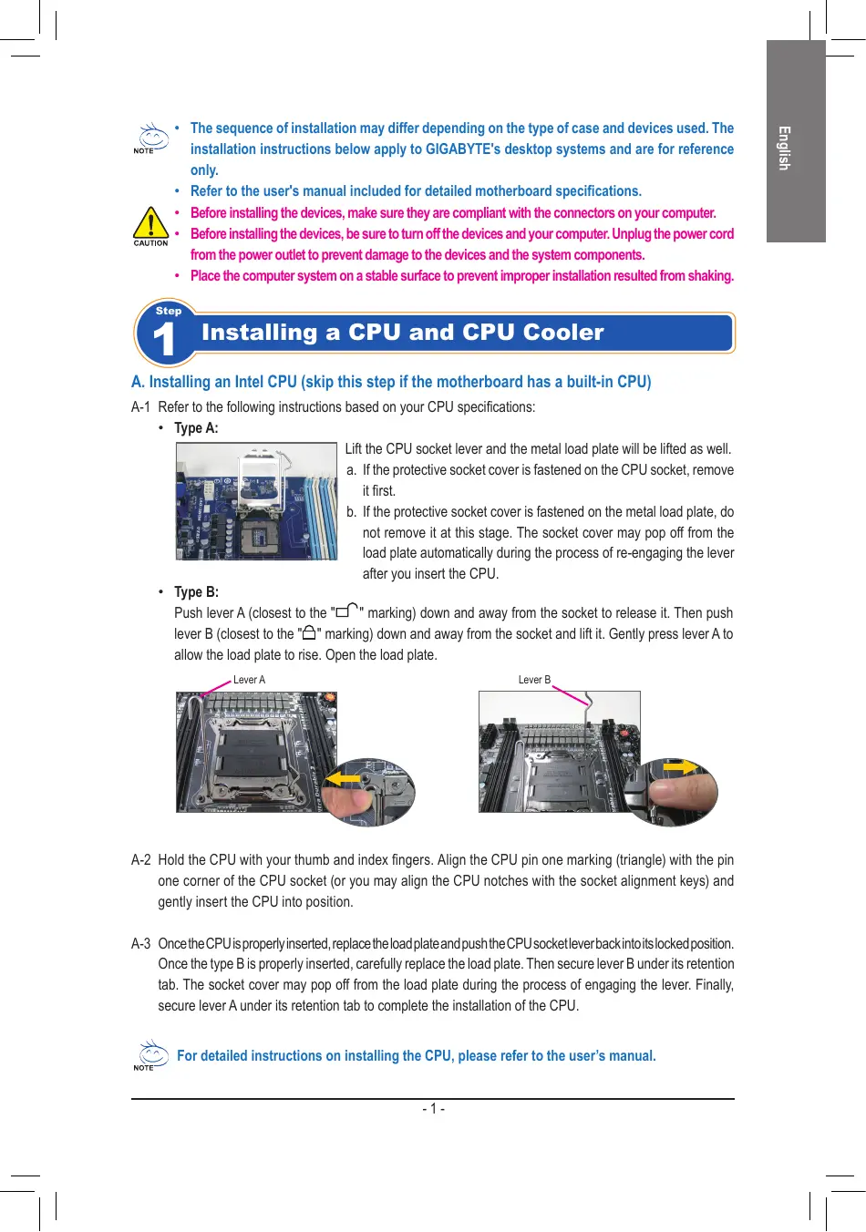
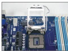
- Type A:
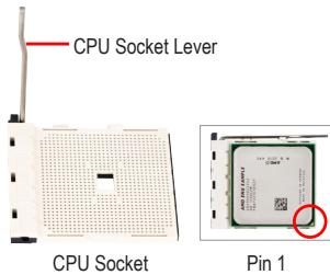
Lift the CPU socket lever and the metal load plate will be lifted as well.
a. If the protective socket cover is fastened on the CPU socket, remove it first.
b. If the protective socket cover is fastened on the metal load plate, do not remove it at this stage. The socket cover may pop off from the load plate automatically during the process of re-engaging the lever after you insert the CPU.
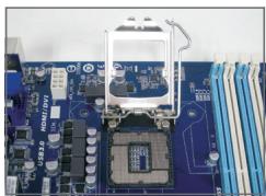
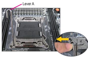
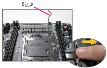
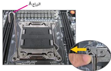
- Type B:
Push lever A (closest to the "□" marking) down and away from the socket to release it. Then push lever B (closest to the "□" marking) down and away from the socket and lift it. Gently press lever A to allow the load plate to rise. Open the load plate.
A-2 Hold the CPU with your thumb and index fingers. Align the CPU pin one marking (triangle) with the pin one corner of the CPU socket (or you may align the CPU notches with the socket alignment keys) and gently insert the CPU into position.
A-3 Once the CPU is properly inserted, replace the load plate and push the CPU socket lever back into its locked position. Once the type B is properly inserted, carefully replace the load plate. Then secure lever B under its retention tab. The socket cover may pop off from the load plate during the process of engaging the lever. Finally, secure lever A under its retention tab to complete the installation of the CPU.

For detailed instructions on installing the CPU, please refer to the user's manual.
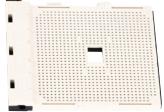
B. Installing an AMD CPU (skip this step if the motherboard has a built-in CPU)
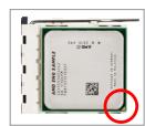
B-1 Completely raise the CPU socket lever. Align the CPU pin one (small triangle marking) with the triangle marking on the CPU socket and gently insert the CPU into the socket. Make sure that the CPU pins fit perfectly into their holes.
B-2 Once the CPU is positioned into its socket, place one finger down on the middle of the CPU, lowering the socket lever and latching it into the fully locked position.

- Do not force the CPU into the CPU socket. The CPU cannot fit in if oriented incorrectly. Adjust the CPU orientation if this occurs.
- DO NOT touch socket contacts. To protect the CPU socket, always replace the protective socket cover when the CPU is not installed.
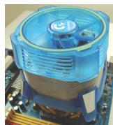
C. Installing the CPU cooler
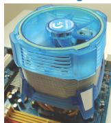
C-1 Before installing the CPU cooler, please first add a thin layer of heat sink paste on the surface of the CPU. Then install the cooler (refer to the installation manual for your CPU cooler).
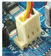
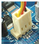
C-2 Connect the CPU cooler cable to the CPU_FAN connector located on the motherboard so that the cooler can properly function to prevent the CPU from overheating.

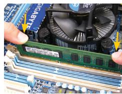
Installing Memory
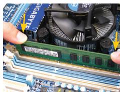
Note the orientation of the memory module. Spread the retaining clips at both ends of the memory socket. Place the memory module on the socket. As indicated in the picture on the left, place your fingers on the top edge of the memory, push down on the memory and insert it vertically into the memory socket. The clips at both ends of the socket will snap into place when the memory module is securely inserted.

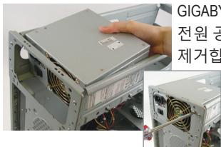
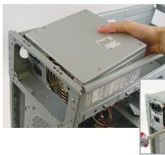
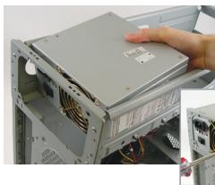
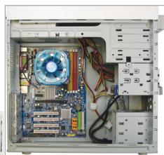
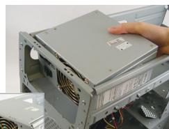
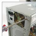
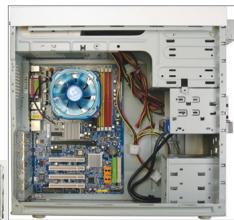
Preparing the Case and Installing a Power Supply
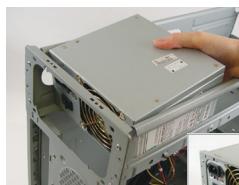
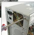
Using the GIGABYTE desktop system as the demonstration example, please first remove both sides and the lid of the case in order to install the power supply. Place the power supply in the correct place in the case and secure it with screws. Installation and placement of the power supply may differ depending on the type of case used.

To ensure sufficient power can be supplied to your system, it is recommended that a power supply of good quality be used. If a power supply is used that does not provide the required power, the result can lead to an unstable or unbootable system.
Step
4
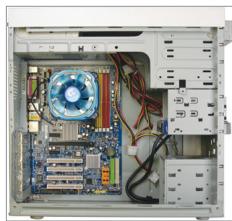
Installing the Motherboard
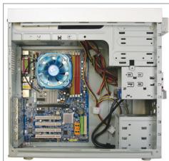
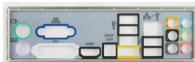
Remove the original I/O shield from the back of the case and replace it with the motherboard I/O shield. Place the motherboard within the case by positioning it into its I/O shield. Align the mounting screw holes on the motherboard with their corresponding mounting holes on the case. Secure the motherboard in place with screws.
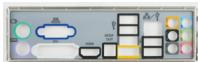
I/O Shield
Step
5
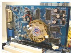
Installing an Expansion Card
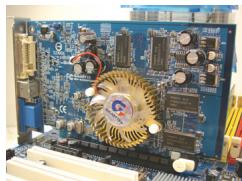
PCI Express Graphics Card
Locate an expansion slot that supports your card and remove the slot cover from the case back panel. Then insert the expansion card into the slot. Secure the expansion card's bracket to the case back panel with a screw.

- Before purchasing an expansion card, check the length of the card, making sure it can fit into your case.
- Make sure that the expansion card is fully seated in its slot.
Step
6
Installing IDE and SATA Devices
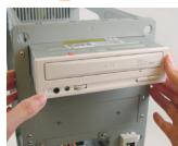
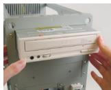
Installing an Optical Drive
6-1 Install your optical drives, such as DVD-ROM and CD-ROM drives.
Remove the 5.25" drive bay cover from the front of the case. Mount the optical drive in the 5.25" drive bay and secure it with screws.
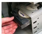
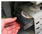
Installing a Hard Drive
6-2 Install your IDE and SATA hard drives.
Install the hard drive into a drive bay within the case and secure it with screws.

- One motherboard IDE connector can connect up to two IDE devices. Prior to installation, check the jumper settings (master and slave) on your IDE devices.
- If more than one hard drive is installed, enter system BIOS Setup to set the hard drive boot sequence.

Connecting Cables to Internal Connectors
7-1 Connect cables to internal connectors and headers on the motherboard, including IDE/SATA connectors, and front panel audio, USB, IEEE 1394 headers, etc.
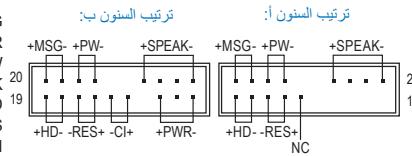
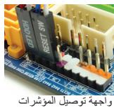
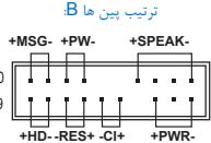
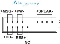
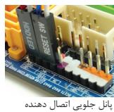
7-2 Attach the front panel module (differs depending on the case design, consisting of power indicator, hard drive activity indicator, speakers, reset switch, power switch, etc.) from the case to the front panel header (F PANEL) on the motherboard.
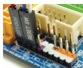
Front Panel Header
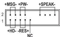
Pin Assignments A:
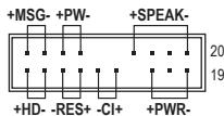
Pin Assignments B:
MSG: Message/Power/Sleep LED
PWR: Power LED
PW: Power Switch
SPEAK:Speaker
HD: Hard Drive Activity LED
RES: Reset Switch
Cl: Chassis Intrusion Header
(Note) The pin assignments for the front panel header may differ by model. Refer to the motherboard user's manual for the actual pin assignments.

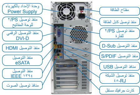
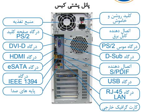
Connecting Peripherals
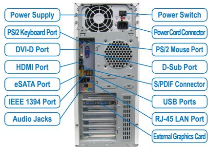
Back Panel of the Case
Once the steps above have been completed, connect the peripheral devices to the computer, such as the keyboard, mouse, monitor, etc. Then connect the power, turn on the system, and install all required software.

毆MOI MoDl的范H起H依的H。MBOI SKT的A韵LrTeiNg kLmRn 1. MBOI MoDl to sKT WfE oLcNl. 员XeGtFJxK, MBOI 的sTADnAaJrAe FxKto 1. MBOI To AaRe I aRe I aRe I aRe I aRe I aRe I aRe I aRe I aRe I aRe I aRe I aRe I aRe I aRe I aRe I aRe I aRe I aRe I aRe I aRe I aRe I aRe I aRe I aRe I aRe I aRe I aRe I aRe I aRe I aRe I aRe I aRe I aRe I aRe I aRo 1

Keisn
3 Chuan Bi Thung May Và Lap Dǎt Bô Nguón
Dung hé thong män hinh nèn cua GIGABYTE nhur ví du minh hoa, trucoc tién hyay thao ca hai māt ben suron va nap thung may dé lap dát bó nguón. Lap bó nguón vào dun vi tristrong thung
HD:LED Activities Hard Drive
RES: Saklar Reset
A-2 4 CPU 4 CPU (4) CPU (4) CPU (4) CPU (4) CPU (4) CPU (4) CPU (4) CPU (4) CPU (4) CPU (4) CPU (4) CPU (4) CPU (4) CPU (4) CPU (4) CPU (4) CPU (4) CPU (4) CPU (4) CPU (4) CPU (4) CPU (4) CPU (4) CPU (4) CPU (4) CPU (4
A-3 nauanl CPU aunnuuau, uauuunnauau uauuunnuuau CPU nauuunnuuauuauu uauuuuauuuu uauuuuuuuuuuuuuuuuuuuuuuuuuuuuuuuuuuuuuuuuuuuuuuuuuuuuuuuuuuuuuuuuuuuuuuuuuuuuuuuuuuuuuuuuuuuuuuuuuuuuuuuuuuuuuuuuuuuuuuuuuuuuuuuuuuuuuuuuuuuuuuuuuuuuuuuuuuuuuuuuuuuuuuuuuuuuuuuuuuuuuuuuuuuuuuuuuuuuuuuuuUU

#
B. nāsān āyī CPU āv AMD (śūn ānāu ān ān ān ānu ān ānu ānu Built-in CPU)
C-1 nauwauuauauauauauCPU, uuaaauuuuauauauauauauauauauauauauauauauauuuuuuuuuuuuuuuuuuuuuuuuuuuuuuuuuuuuuuuuuuuuuuuuuuuuuuuuuuuuuuuuuuuuuuuuuuuuuuuuuuuuuuuuuuuuuuuuuuuuuuuuuuuuuuuuuuuuuuuuuuuuuuuuuuuuuuuuuuuuuuuuuuuuuuuuuuuuuuuuuuuuuuuuuuuuuuuuuuuuuuuuuuuuuuuuuuuuuUU
C-2 1aFANuauCPU FAN CPU_FAN

n

sueeunneaneeaneeanee ane eaeenee

nntnnnnae nnnnne nnne ne nnnnne
Iuunnnnnaaun GIGABYTE uunnnnnnnnnae, un nnnnnnnnnnnnnnnnnnnnnnnnnnnnnnnnnnnnnnnnnnnnnnnnnnnnnnnnnnnnnnnnnnnnnnnnnnnnnnnnnnnnnnnnnnnnnnnnnnnnnnnnnnnnnnnnnnnnnnnnnnnnnnnnnnnnnnnnnnnnnnnnnnnnnnnn nn

waiuuiiiananrnnnnaeunwwaaunnuo 1wauuuiuuiuuiuuiuuiuuiuuiuuiuuiuui uuuuuaa uuuuuaa uuuuuaa uuuuuaa uuuuuaa uuuuuaa uuuuuaa uuuuuaa uuuuuaa uuuuuaa uuuuuaa uuuuuaa uuuuuaa uuuuuaa uuuuuaa uuuuuaa uuuuuaa uuuuuaa uuuuuaa uuuuuaa uuuuua a uuuuuaa uuuuuaa uuuuuaa uuuuuaa uuuuuaa uuuuuaa uuuuuaa uuuuuaa uuuuuaa uuuuuaa uuuuuaa uuuuuaa uuuuuaa uuuuuaa uuuuuaa uuuuuaa uuuuuaa uuuuuaa uuuuuaa uuuuuaaa
#
4
n
IDE 2 nauuuaa,
- nanaananaananaananaananaananaananaananaananaananaananaananaananaananaananaananaananaananaananaananaananaananaananaananaananaananaananaananaananaananaananaananaananaananaananaananaananaananaananaananaananaananaananaananaananaananaananaananaananaananaanana an

Jae jaaagallg aagaaale (gill gill) kellal alalal alalal gssasall cals
aai jai gai jie laiaai aai ai jai (la jie +i all

j 100000000000000000000000000000000000000000000
all
clalall

Aailll aalll
Jia aaiall o jyjll Juyi ayaiall c gaiil eai j 1 yjiy iyy jdy jayaiull o jiall jaialall a jyaiall jaiill Jx jayi jayil jayil jyjll

yss jy
a_b = 1
E
aall lal lal lal lal lal lal lal lal lal lal lal lal lal lal lal lal lal lal lal lal lal lal lal lal lal lal lal lal lal lal lal lal lal lal lal lal lal lal lal lal lal lal lal lal lal lal lal lal lal lal lAL
aannnnn aannnnn
I/O Shield

aui 11 ci j
log10
0
jlll jlll g jilg jilj jil jil l l l l l l l l l l l l l l l l l l l l l l l l l l l l l l l l l l l l l l l l l l l l l l l l
PCExpress
山
aeg aagaae g aaslaa aagaaa aagaaa aagaaa aagaaa aagaaa aagaaa aagaaa aagaaa aagaaa aagaaa aagaaa aagaaa aagaaa aagaaa aagaaa aagaaa aagaaa aagaaa aagaaa aagaaa aagaaa aagaaa aagaaa aagaaa aagaaa aagaaa

y j
7
a a a a a a a a a a a a a a a a a a a a a a a a a a a a a a a a a a a a a a a a a a a a a a a a a a a a a a a a a a a aaa
Jiljai Jia jiu
y 1
山all jill
JdJIaIgAegagaae aai.IDE Jauay aagaaagaaagaaagaaagaaagaaagaaagaaagaaagaaagaaagaaagaaagaaagaaagaaagaaagaaagaaagaaagaaagaaagaaagaaagaaagaaagaaagaaagaaagaaagaaagaaagaaagaaagaaagaaagaaagaaagaaagaa

Jumper)
.BIOS 1234567890
NOTE
(2023 12.10)

a
Jie ci liu jiu jiu liu
cllll 1B
alaaall Jall
aegglalllc 1e 1000
aai aiee eae
a a a a a a a a a a a a a a a a a a a a a a a a a a a a a a a a a a a a a a a a a a a a a

all 2y jC
Ae aagall Caiailll
AaJglllgl 1 Jaaalall jSall
15
m = 311
Y
jlaa aaii aai iie gie yagai gao sall cdg cai gai baiia daiyai aaii ci gai gai ai gai gai gai gai gai gai gai gai gai gai gai gai gai gai gai gai gai gai gai gai gai gai gai gai gai gai gai gai gai gai gai gai gai gai gai gai gai gai gai
4.2.8.11.12.13.14.15.16.17.18.19.20.21.22.23.24.25.26.27.28.29.30.31.32.
lognol
yGIGABYTE ygall
yGIGABYTE ygall
yGIGABYTE ygall
Aee aal paaaal
slll allo 500 Power Supply slll lal 120 plalldu c 120 plalldu all a. flll n u wull jgululnla! a y 120 n 120 llll s 120 n 120 wull jgululnla! a y 120 n 120 g 120


puii i 10
GIGABYTE

m = 311
(caae eae y gaiy aagll cuii o gbiil basi) Intel cnae uysjA
1-A
:A
aill jy pae l 15g y g aalll aalll aalll aal 15 15 a.
aill jy pae l 15g y g aalll aalll aalll aalll aalll aalll aalll aalll aalll aalll aalll aalll aalll aalll aalll aalll aalll aalll aalll aalll aalll aalll aalll aalll aalll aalll aalll aalll aalll aalll aalll aalll aalll aalll
B
aallll (1) 100000000000000000000000000000000000000000000000000000000000
jaiy jzjj jz jz jz jz jz jz jz jz jz jz jz jz jz jz jz jz jz jz jz jz jz jz jz jz jz jz jz jz jz jz jz jz jz jz jz jz jz jz jz jz jz jz jz
aJyall aJalll 0i jui Jusiny jiaiyj
aannnll lglg 1 gnnn aag aagaaal aagaaal 5d 8g yg yy dai g

gla 1000 Jau 4 Jau

LED:HD CwDcLdOoC 1RES
JU 1
4a la juy yj 133 333 333 333 333 333 333 333 333 333 333 333 333 333 333 333 333 333 333 333 333 333 333 333 333 333 0000000000000000000000000000000000000000000000000000000000000
sla:slaj! Jlai
gla 1sla jzal dai ggo 1u 1u 1u 45 1u 1u 1u 1u 1u 1u 1u 1u 1u 1u 1u 1u 1u 1u 1u 1u 1u 1u 1u 1u 1u 1u 1u 1u 1u 1u 1u 1u 1u 1u 1u 1u 1u 1u
aillg y 1 j g o05 jg sglj l glaolg jy gl aolg jy gl aolgl 00lgl 00s 00s 00s 00s 00s 00s 00s 00s 00s 00s 00s 00s 00s 00s 00s 00s 00s 00s 00s 00s 00s 00s 00s 00s 00s 00
< 0, < 0, > 0
I/O
4aogj 5 S
#
- Installing a CPU and CPU Cooler
- Installing an Intel CPU (skip this step if the motherboard has a built-in CPU)
- Installing an AMD CPU (skip this step if the motherboard has a built-in CPU)
- Installing the CPU cooler
- Installing Memory
- Preparing the Case and Installing a Power Supply
- Step
- 4
- Installing the Motherboard
- 5
- Installing an Expansion Card
- 6
- Installing IDE and SATA Devices
- Connecting Cables to Internal Connectors
- Connecting Peripherals
- Keisn
- Chuan Bi Thung May Và Lap Dǎt Bô Nguón
- #
- nāsān āyī CPU āv AMD (śūn ānāu ān ān ān ānu ān ānu ānu Built-in CPU)
- n
- nntnnnnae nnnnne nnne ne nnnnne
- clalall
- Aailll aalll
- yss jy
- aui 11 ci j
- y j
- (2023 12.10)
- all 2y jC
- 15
- 4.2.8.11.12.13.14.15.16.17.18.19.20.21.22.23.24.25.26.27.28.29.30.31.32.
- gla 1000 Jau 4 Jau
- sla:slaj! Jlai
- 4aogj 5 S
Brand : GIGABYTE
Model : GA-8SIMLHP-TW
Category : Motherboard