
ODIN PRO 800W - Computer power supply GIGABYTE - Free user manual and instructions
Find the device manual for free ODIN PRO 800W GIGABYTE in PDF.

| Product Type | ATX 12V v2.2 Computer Power Supply |
| Brand | GIGABYTE |
| Model | ODIN PRO 800W |
| Total Power | 800 W |
| Dimensions (L x W x H) | 150 x 160 x 86 mm |
| Weight | Approximately 2.5 kg |
| Fan | 140 mm, automatic speed control |
| Efficiency | ≥ 80% at typical load |
| Capacitors | 100% Japanese, high durability |
| Cable Management | Smart Cable Management, sleeved cables with protected connectors |
| Built-in protections | OCP, OVP, UVP, OTP, short circuit |
| Main connectors | 1 x 24-pin ATX, 1 x 8-pin CPU, 2 x PCI-E 6+2-pin |
| Number of +12V rails | 4 rails (12V1, 12V2, 12V3, 12V4) |
| Max +12V current | 62 A combined |
| Max +5V current | 28 A |
| Max +3.3V current | 30 A |
| LED switch | Yes, on the rear panel |
| Safety standards | CE, FCC, TUV, CB, CCC, RoHS |
| MTBF | 100,000 hours at 25°C |
| Maintenance | Regular external dusting, do not open |
| Warranty | 5 years (typical, non-contractual) |
Frequently Asked Questions - ODIN PRO 800W GIGABYTE
User questions about ODIN PRO 800W GIGABYTE
0 question about this device. Answer the ones you know or ask your own.
Ask a new question about this device
Download the instructions for your Computer power supply in PDF format for free! Find your manual ODIN PRO 800W - GIGABYTE and take your electronic device back in hand. On this page are published all the documents necessary for the use of your device. ODIN PRO 800W by GIGABYTE.
USER MANUAL ODIN PRO 800W GIGABYTE
Power Supply User's Manual
ATX 12V version 2.2 power supply
Products: ODIN GT / ODIN PRO
Models: GE-S800A-D1, GE-S680A-D1, GE-S550A-D1 /
GE-M800A-D1, GE-M680A-D1, GE-M550A-D1
Specifications are subject to change without notice. All brand names and products are registered trademarks of their respective companies
Introduction
The GIGABYTE Odin series power supply delivers outstanding compatibilities and performance for power users and hardcore gamers. It also delivers a comprehensive set of tuning utilities for performance optimization. Additionally, the all Japan-made capacitor design within the Odin series enhances overall system durability and stability.
The Odin series power supply complies with the newest ATX 12V version 2.2 specifications, and goes beyond. This includes 4 × 12V outputs that deliver powerful, safer and more reliable power to your hardware. With 80%+ efficiency, the power supply helps save more energy and money on user's electricity cost compared to typical power supplies. It also generates less heat thanks to the high efficiency of the 14cm cooling fan keeping the power supply itself cooler, silent and prolong its life. In addition, the Odin series power supply includes a variety of industrial-grade protective circuitries.
The Odin series power supply features Smart Cable Management function and all cables are in sleeved finishing with connector protectors, allowing users to connect the cables which are only in use for better internal air flow and tidier internal space.
As a member of the global community, Gigabyte provides environment friendly products and observes the European Union's Restriction of Hazardous Substances (RoHS) directive, which limits the use of lead, mercury, cadmium and other hazardous substances in electronic products. From components and material selection to production processes, making up of accessories, packaging/color boxes etc; GIGABYTE has carefully examined and designed this product to be 100% RoHS compliant.
GIGABYTE will continue to develop RoHS compliant PC components and provide valuable resources to promote and advance RoHS directive goals and objectives.
The following are not covered by the warranty:
- Using the product incorrectly or in a manner other than the designed purpose.
2.Nonobservance of the proper operation provided.
3.Malfunction due to interference from other devices - Unapproved medication of the product.
- Consequential damage to other objects due to the product's fault.
6.Malfunction arising from natural hazards E.g. earthquake, lightning, fire, and floods. - The product's warranty label has been removed or damaged.
- The devices inside, including power supply, hard disk, CD-ROM drive, motherboard, ventilator, etc, are not detached from the casing prior to transportation of the computer system, resulting in damage to the casing or computer-related devices.
9.Any loss/damage caused by failure to follow the installation process within the user manual.

CAUTION
Caution! Hazardous
Do not open this power supply unit!
No serviceable components inside!
Refer Servicing to Qualified service personnel only! No modification to this power supply unit!
Incorrect connector installation may possible burn out the motherboard and other components. Be sure to observe the instructions on installation in the manual.
Please refer to the English version for all pictures.
System Requirement
- Windows 2000\XP\Vista
2.CD-Rom
3.Recommended HDD Space: 30Mb - Recommended RAM: 512mb RAM
- Recommended display resolution: >1024 × 768
| Power Supply Unit | Fixing Screws | System fan speed con-trol and power cable(ODIN GT only) | Thermal sensor cable(ODIN GT only) |
| 1 | 4 | 1 | 4 |
| USB Converter(ODIN GT only) | PCI-E (Red) power cable | PCI-E (Blue) power cable(800W & 680W only) | Peripheral power withFDD connector cable |
| 1 | 1 | 1 | 1 |
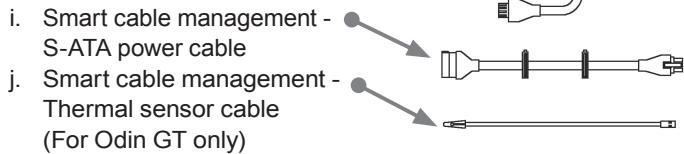
| S-ATA power cable | Peripheral power cable | CD (ODIN GT only) | |
| 2 | 1 | 1 |
Contain Item
1. Power Supply
Power Supply Unit. P.06
Power Supply Cables. P.07
Power Supply Connectors .P.08
2. Specification
Input .P10
Output .P.11
Remote On/Off .P.12
Hold-Up Time .P.12
Power Good Delay .P.12
Power Fail Delay. P.12
Turn-On Delay Time. P12
Transient Overshoot. P.12
Rise Time. P12
Protection. .P.13
Environment. P13
HI-POT (Input/Out Isolation).P.14
CE Requirements. P14
MTBF .P.14
Dimensions. P14
3. Installation Instruction
4. Power Tuner Installation Instruction (ODIN GT series only)
1. Power Supply
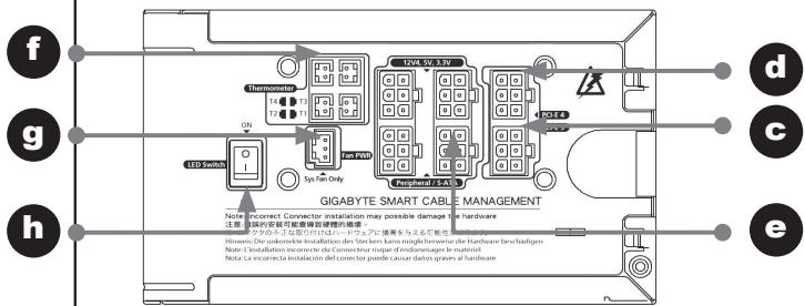
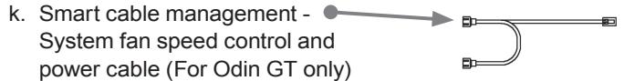
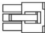
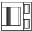
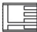
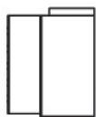
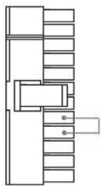
1-1.Power Supply Unit
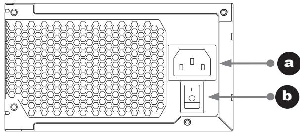
a. AC In
b. AC power switch
c. PCI-E 1 cable management Red
d. PCI-E 2 cable management Blue
e. 12V, 5V, 3.3V peripheral power cable management
f. Thermal sensor cable management (For Odin GT only)
g. Fan speed control power cable management
(For Odin GT only)
h. LED light switch (For Odin Pro only)
1-2.Power Supply Cables
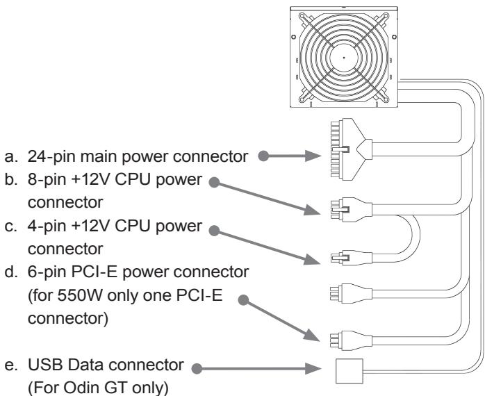


1-3.Power Supply Connectors
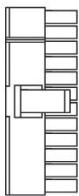
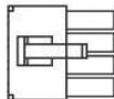
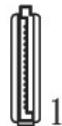
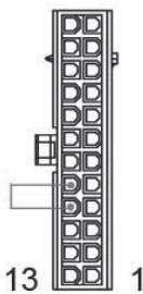
1-3-1. 24-PIN Main Power Connector
| 18AWG (Wire) | Signal | Pin | Pin | Signal | 18AWG (Wire) |
| Orange | +3.3Vdc | 13 | 1 | +3.3Vdc | Orange |
| Blue | -12Vdc | 14 | 2 | +3.3Vdc | Orange |
| Black | COM | 15 | 3 | COM | Black |
| Green (22AWG) | PS-ON | 16 | 4 | +5Vdc | Red |
| Black | COM | 17 | 5 | COM | Black |
| Black | COM | 18 | 6 | +5Vdc | Red |
| Black | COM | 19 | 7 | COM | Black |
| 20 | 8 | POK | Gray (22 AWG) | ||
| Red | +5Vdc | 21 | 9 | +5VSB | Purple |
| Red | +5Vdc | 22 | 10 | +12V1dc | Yellow |
| Red | +5Vdc | 23 | 11 | +12V1dc | Yellow |
| Black | COM | 24 | 12 | +3.3Vdc | Orange |
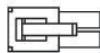
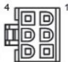
1-3-2. +12 V CPU Power Connector
8 PIN 12V+


| 18AWG (Wire) | Signal | Pin | Pin | Signal | 18AWG (Wire) |
| Yellow | +12V2DC | 5 | 1 | COM | Black |
| Yellow | +12V2DC | 6 | 2 | COM | Black |
| Yellow | +12V2DC | 7 | 3 | COM | Black |
| Yellow | +12V2DC | 8 | 4 | COM | Black |
4 PIN 12V+

| 18AWG (Wire) | Signal | Pin | Pin | Signal | 18AWG (Wire) |
| Yellow | +12V2DC | 3 | 1 | COM | Black |
| Yellow | +12V2DC | 4 | 2 | COM | Black |
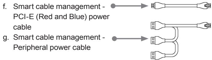
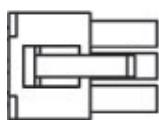
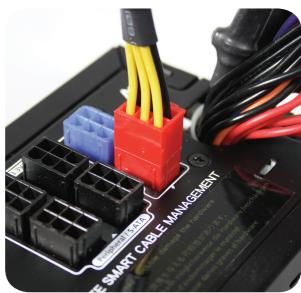
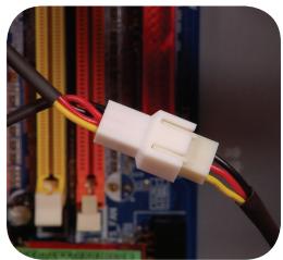
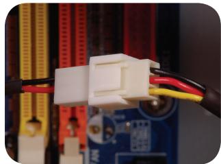
1-3-3. +12 VPCI Express Power Connector
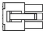

Odin GT, PRO Smart Cable Management PCI-Express connector to PSU (There are Red and Blue connectors for different 12V rails)
| 18AWG (Wire) | Signal | Pin | Pin | Signal | 18AWG (Wire) |
| Black | COM | 4 | 1 | 12V1DC | Yellow |
| Black | COM | 5 | 2 | 12V1DC | Yellow |
| Black | COM | 6 | 3 | 12V1DC | Yellow |

1-3-4. Smart cable management - Peripheral power with FDD connector cable

| Pin | Signal | 18AWG (Wire) |
| 1 | +12V4DC | Yellow |
| 2 | COM | Black |
| 3 | COM | Black |
| 4 | +5VDC | Red |

1-3-5. FDD connector cable

| Pin | Signal | 18AWG (Wire) |
| 1 | +5VDC | Red |
| 2 | COM | Black |
| 3 | COM | Black |
| 4 | +12V4DC | Yellow |
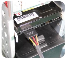
1-3-6. Peripheral power with S-ATA HDD connector cable
| Pin | Signal | 18AWG (Wire) |
| 1 | +3.3 VDC | Orange |
| 2 | COM | Black |
| 3 | +5VDC | Red |
| 4 | COM | Black |
| 5 | +12V4DC | Yellow |


1-3-7. Smart cable management - Peripheral power with SATA HDD connector cable
| Pin | Signal | 18AWG (Wire) |
| 1 | +12 VDC | Yellow |
| 2 | COM | Black |
| 3 | +5VDC | Red |
| 4 | COM | Black |
| 5 | +3.3VDC | Orange |
| 6 | NC | NC |
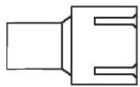
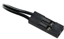
1-3-8. USB Data Connector
For ODIN GT series power supply only, please refer to the motherboard's user manual for connecting the USB data connector to motherboard's USB port or using the USB converter to connect the rear I/O.


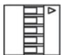

PIN1
| Pin | Signal | 20AWG (Wire) |
| 1 | ||
| 2 | Data - | White |
| 3 | Data + | Green |
| 4 | Ground | Black |
| 5 |
Incorrect connector installation may possible burn out the motherboard and other components. Be sure to observe the instructions on installation in the manual. Double check the pin definition color to match with motherboard's users' manual.


1-3-9. Fan Speed Control connectors
Pin 1
| Pin | Signal | 24 AWG (Wire) |
| 1 | Com | Black |
| 2 | +5VDC | Red |
| 3 | Signal | Yellow |
1-3-10. Smart Cable Management - Fan Speed Control connectors


Pin 1
| Pin | Signal | 24 AWG (Wire) |
| 1 | Com | Black |
| 2 | +5VDC | Red |
| 3 | Signal | Yellow |
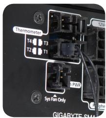
1-3-11. Smart cable management - Thermal sensor

Smart cable management - Thermal sensor Connector
CAUTION
Don't place the Thermal sensor between CPU and Cooler; it will damage the thermal sensor and probably cause the CPU overheating, and could damage the CPU.
2. Specification
2-1 INPUT
2-1-1 VOLTAGE
| Model Name | Minimum | Nominal | Maximum | Units |
| GE-S800A-D1 | 90 | 115~230 | 264 | VAC rms |
| GE-S680A-D1 | 90 | 115~230 | 264 | VAC rms |
| GE-S550A-D1 | 90 | 115~230 | 264 | VAC rms |
2-1-2 FREQUENCY
47Hz~63Hz
2-1-3 CURRENT
115Vac - 8.0A max / 230Vax - 4.0A max
115Vac - 10.0A max / 230Vax - 5.0A max
(800W only)
2-1-4 INRUSH CURRENT
55A max. when AC input 115Vac at 25^ cold start
110A max. when AC input 230Vac at 25^ cold start
2-1-5 POWER EFFICIENCY
80% (min) at full load (typical) and 115Vac and
230Vac input
(For 20% , 50% , 100% load condition)
2-1-6 LEAKAGE CURRENT
3.5mA max.
2-1-7 POWER FACTOR
PF>0.9
2-2 OUTPUT
| Voltage | +5V | +3.3V | +12V1 | +12V2 | +12V3 | +12V4 | -12V | +5Vsb |
| Max Load *1 | 28.0 | 30.0 | 18.0 | 18.0 | 18.0A | 18.0A/ | 0.8 | 3.0 |
| A | A | A | A | 25.0A | 25.0A | A | A | |
| Min Load | 2.0 | 0.5 | 1.0 | 1.0 | 1.0 | 1.0 | 0.0 | 0.0 |
| A | A | A | A | A | A | A | A | |
| Peak Load | -- | -- | -- | -- | -- | -- | -- | 3.5 |
| A | ||||||||
| Regula tion | +5, -4% | +5, -3% | +5, -4% | +5, -4% | +5, -4% | +5, -4% | +9, -5% | +5, -4% |
| Ripple & Noise | 50 mV | 50 mV | 120 mV | 120 mV | 120 mV | 120 mV | 120 mV | 50 mV |
*1 The continuous total power is 800W MAX (GE-S800A-D1; GE-M800A-D1)/680W (GE-S680A-D1; GE-M680A-D1)/550W (GE-S550A-D1; GE-M550A-D1)
-
The Combined power of +5V + 3.3V is 180W max. (GES800A-D1; GE-M800A-D1; GE-S680A-D1; GE-M680A-D1)/140W (GE-S550A-D1; GE-M550A-D1)
-
Peak currents may last up to 12 seconds with no more than one occurrence per minute.
-
Total combined +12V output load not exceeding 62A (GE-S800A-D1; GE-M800A-D1)/52A (GE-S680A-D1; GE-M680A-D1)/41A (GE-S550A-D1; GE-M550A-D1)
2-3 REMOTE ON/OFF
TTL High/PS-OFF; TTL Low/PS-ON
VIL = 0.8V max, IIL = -1.6mAmax@Vin=0.4V
VIH = 2.0Vmin @ lin=-200uA, VIH = 5.25Vmax@open ckt.
2-4 HOLD-UP TIME
16msec (min.) at 80% of full load at 230Vac input
2000 msec max. At nominal line full load
2-8 TRANSIENT OVERSHOOT
Step load changes of up to 50% of full load, while other loads remains constant within the rating. The DC output voltage will stay within regulation during the 20% load changes.
Load slew rating is 0.5A/uS and capacitive load as below:
20ms max at full load
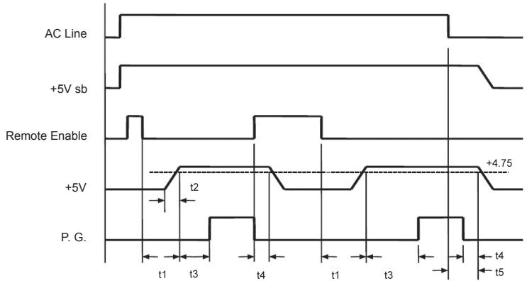
t1:TURN-ON DELAY TIME
t2:RISE TIME
t3: POWER GOOD DELAY
t4: POWER FAIL DELAY
t 5: HOLD-UP TIME
2-10 PROTECTION
When OCP, OVP, OTP, or short protection is triggered, the main output will be latched off. The main outputs can be reset by cycling the DC remote on/off or AC power +5Vsb output is automatically recovered when a fault condition is removed.
2-10-1.OVER CURRENT PROTECTION
No exceeding 240VA every output voltage (Beside of 12V)
+12V1, +12V2 output 25A max (GE-S800A-D1;
GE-M800A-D1; GE-S680A-D1; GE-M680A-D1)
+12V3, +12V4 output 38A max (GE-S800A-D1;
GE-M800A-D1; GE-S680A-D1; GE-M680A-D1)
2-10-2.OVER VOLTAGE PROTECTION
+3.3V output 4.5V max.
+5.0V output 7.0V max.
+12.0V output 15.6V max.
2-10-3.UNDER VOLTAGE PROTECTION
12V1 & 12V2 output 9.5V min
12V3 & 12V4 output 9.5V min
+5V output 4.1V min
+3.3V output 2.55V min
2-10-4.SHORT PROTECTION
All output to GND
2-10-5.OVER TEMPERATURE PROTECTION
The power supply includes an over-temperature sensor, which can trip and shutdown the power supply at 100^ . Such an overheated condition is typically the result of internal current overloading or a cooling fan failure.
2-11 ENVIRONMENT
2-11-1 Operating Temp
0^ C to +50^ C
2-11-2 Storage Temp
-20°C to +70°C
2-11-3 Operating Humidity
20% to 90%, non condensing
2-11-4 Storage Humidity
5% to 95%, non condensing
2-11-5 Operating Altitude
0-10,000 feet
2-11-6 Storage Altitude
0-50,000 feet
2-12 HI-POT (Input/Out isolation)
2-12-1 PRIMARY TO SECONDARY
3535 Vdc for 3 seconds
2-12-2 INSULATION RESISTANCE
Primary to earth ground 500Vdc, 50M ohms Min.
2-13 CE REQUIREMENTS
2-13-1 Conducted EMI
- Meet FCC: Class B
- Meet CISPR 22: Class B
- Meet BSMI: Class B
2-13-2 Safety Standards
-Meet CUL (UL60950)
-Meet TUV (EN60950)
- Meet CB (IEC 950)
- Meet CE
- Meet CCC
2-13-3 Harmonic
- Meet IEC 1000-3-2 Class D
2-14 MTBF
@25°C (demonstrated) - 100K hours minimum
2-15 DIMENSIONS
150 × 160 × 86 mm( W × L × H)

3. Installation Instruction
(For a new system, please go directly to Section 4)
- Switch off the system.
- Disconnect the power cord from your old power supply.
- Follow the direction provided in your case's user manual to open your computer case.
- Disconnect all the power connectors from the power supply to the motherboard and the peripheral devices such as the case fans, hard drives, and floppy drives, etc.
- Remove the existing power supply from your computer case
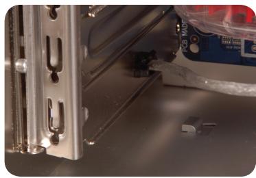
- Insert Odin GT power supply into the chassis and secure it with screws
- Connect the 24-pin main power connector and the 4-pin/8-pin +12V to your motherboard as needed.
- Connect the 4 / 8-pin 12V CPU power connector to your motherboard as needed
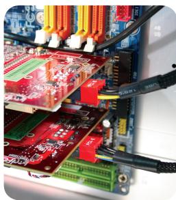
- When there is a need for PCI-E power, please use the PCI-E connector from the power supply unit first. When you are using more than two graphic cards (SLI, crossfire or quad - SLI), please use Smart Cable management PCI-E power connectors. Note: Please refer to your PCI express graphic card's user manual for usage details.
- To connect peripheral devices, please use Smart Cable Management power connectors.

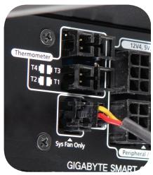
- With a Smart Cable Management -Fan speed control power connector, users may connect two 3-pin system fans. This allows Odin GT power supply to monitor and control the speed of the fans you've connected (Odin GT only). CAUTION: Do not connect to the CPU fan
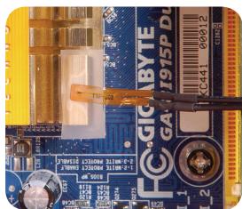
- Connect Smart Cable Management - Thermal Sensor cable, use the thermal tape to stick the thermal sensor to the surface where you want to monitor the temperature. The thermal tape has an insulating property. It can be used in high temperature environment. Caution: Do not place the thermal sensor between the CPU and cooler; it will damage the thermal sensor and CPU. (Odin GT series only)


- To enable the software control function, connect the USB connector from the power supply to Motherboard. If there is no USB connector on the motherboard, please use the USB converter to connect to the rear of the motherboard or an add-on card with a USB I/O port. (Odin GT series only)
To connect the USB connector to the rear I/O USB port, please use the converter, which is included in the package, and connect the converter to the rear USB port by passing the rear slot. (Odin GT series only)
- After installation, connect the power cord to the Odin GT power supply unit. Now you are ready to experience the performance of the Odin series power supply. (Odin GT series only)
4. Power Tuner Installation Instruction (ODIN GT series only)
For the first time of the system's boot-up, Windows will inform that a new hardware is found, and there is no driver needed for Odin GT.
To enable the software control function, please install the power supply management software, "Power Turner", in the system to monitor and adjust the hardware function.
- Start up the system.
- Insert the CD in the ODD drive, and the installation should start automatically. If it doesn't start, please open the ODD folder and double click on the setup.exe file to install manually.
- Follow the instruction and install Power Tuner into the system step by step.
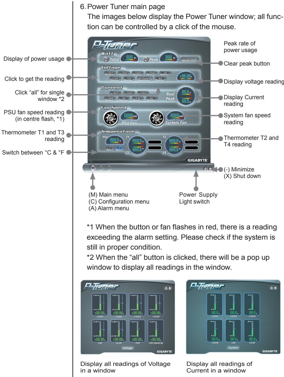
- When the installation completes, there will be a window of P-Tuner shown as left.
(It's possible that your P-Tuner may differ slightly from the sample in this manual. This is not a problem; it's simply an improvement. We continually refine and improve our products to ensure the highest quality)
- When the system starts up, P-tuner should start automatically; if not, please start up by double clicking on the "Power Tuner" logo on the desktop or in the menu. Copy the link into the "start up" folder in the menu for automatic start when booting up the PC.

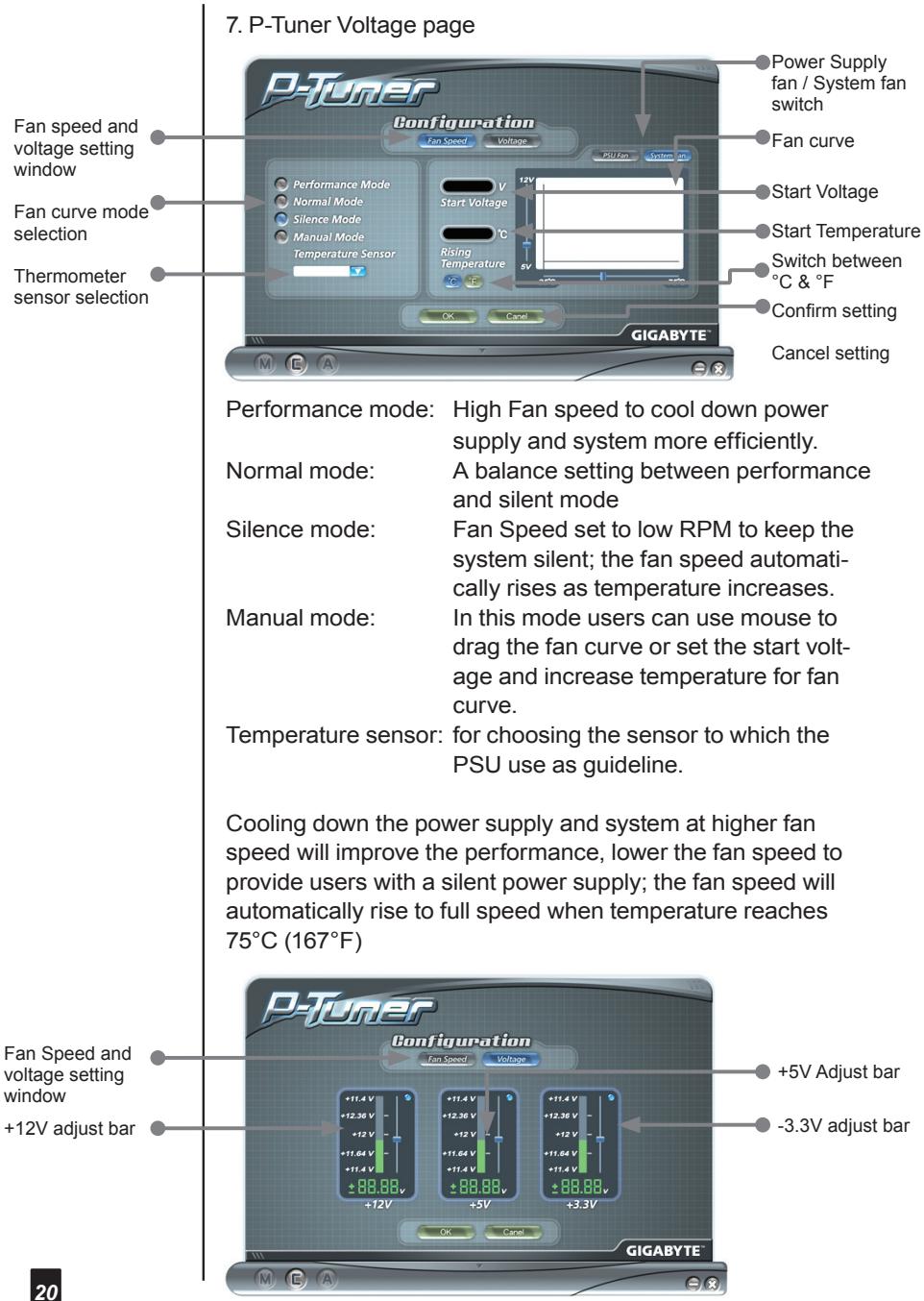
Please don't set the voltage over Intel spec. It may cause the system into protection mode.
(Power Tuner only allows the power supply to adjust the voltage within Intel spec. It is safe to adjust the voltage setting.)

8. P-Tuner Alarm: Watt

9. P-Tuner Alarm: Voltage
10. P-Tuner Alarm Current

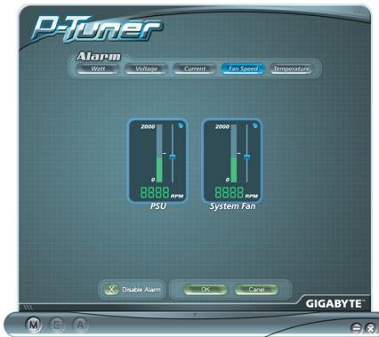
11. P-Tuner Alarm Fan Speed
12. P-Tuner Alarm Temperature

NOTE:
- When the program crashes, simply close the program and re-start it.
- When there is an error within the settings, it will cause a boot-up failure to the hardware, normally caused by over-voltage or under-voltage protection. Therefore, to protect the hardware, the system will not boot up. Please follow the steps below to recover the system.
a. Remove the AC power cord.
b. Disconnect all the power connectors from the power supply to motherboard, and the peripheral devices such as the case fan, hard drives, and floppy drives, etc.
c. Use the USB converter kit to connect the Power supply to another computer, and install Power Tuner.
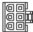
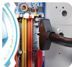
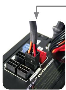
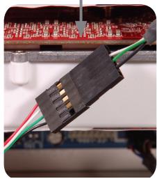
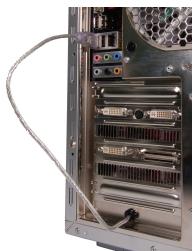
d. Short the connector as in the image below, or use ODIN GT PSU jump start kit to start ODIN GT power supply.
e. Use the USB converter to connect the Odin GT power supply to another computer.
f. Install Power Tuner in the computer, which the USB cable connects to.
g. Connect the power cord into the Odin GT power supply.
h. Now the Odin GT should automatically start.
i. Use Power Tuner to re-adjust the ODIN GT power supply.
j. Now revise the steps, and ODIN GT should be able to boot the system.
- Power Supply User's Manual
- Introduction
- Caution! Hazardous
- System Requirement
- Contain Item
- Power Supply
- Specification
- Installation Instruction
- Power Tuner Installation Instruction (ODIN GT series only)
- 1-2.Power Supply Cables
- 1-3.Power Supply Connectors
- 1-3-2. +12 V CPU Power Connector
- 1-3-3. +12 VPCI Express Power Connector
- 1-3-4. Smart cable management - Peripheral power with FDD connector cable
- 1-3-5. FDD connector cable
- 1-3-6. Peripheral power with S-ATA HDD connector cable
- 1-3-7. Smart cable management - Peripheral power with SATA HDD connector cable
- 1-3-8. USB Data Connector
- 1-3-9. Fan Speed Control connectors
- 1-3-10. Smart Cable Management - Fan Speed Control connectors
- 1-3-11. Smart cable management - Thermal sensor
- CAUTION
- 2-1 INPUT
- 2-1-1 VOLTAGE
- 2-1-2 FREQUENCY
- 2-1-3 CURRENT
- 2-1-4 INRUSH CURRENT
- 2-1-5 POWER EFFICIENCY
- 2-1-6 LEAKAGE CURRENT
- 2-1-7 POWER FACTOR
- 2-3 REMOTE ON/OFF
- 2-4 HOLD-UP TIME
- 2-8 TRANSIENT OVERSHOOT
- 2-10 PROTECTION
- 2-10-1.OVER CURRENT PROTECTION
- 2-10-2.OVER VOLTAGE PROTECTION
- 2-10-3.UNDER VOLTAGE PROTECTION
- 2-10-4.SHORT PROTECTION
- 2-10-5.OVER TEMPERATURE PROTECTION
- 2-11 ENVIRONMENT
- 2-11-1 Operating Temp
- 2-11-2 Storage Temp
- 2-11-3 Operating Humidity
- 2-11-4 Storage Humidity
- 2-11-5 Operating Altitude
- 2-11-6 Storage Altitude
- 2-12 HI-POT (Input/Out isolation)
- 2-12-1 PRIMARY TO SECONDARY
- 2-12-2 INSULATION RESISTANCE
- 2-13 CE REQUIREMENTS
- 2-13-1 Conducted EMI
- 2-13-2 Safety Standards
- 2-13-3 Harmonic
- 2-14 MTBF
- 2-15 DIMENSIONS
- P-Tuner Alarm Current
- P-Tuner Alarm Fan Speed
- P-Tuner Alarm Temperature
- NOTE:
Brand : GIGABYTE
Model : ODIN PRO 800W
Category : Computer power supply