
G52-76151X4 - Laptop MSI - Free user manual and instructions
Find the device manual for free G52-76151X4 MSI in PDF.
| Product Type | Laptop |
| Supported Processor | AMD Phenom II, Phenom, Athlon II, Athlon, Sempron (socket AM3) |
| Chipset | NVIDIA GeForce7025 / nForce630a |
| Memory | DDR3 1600/1066/800 SDRAM, maximum 8 GB, 2 DIMM slots |
| Storage | 2 SATA 3 Gb/s ports |
| Network | LAN 10/100/1000 Fast Ethernet (Realtek RTL8111E) or 10/100 (Realtek RTL8105E) |
| Audio | Realtek ALC887, 7.1 channel audio |
| Rear Panel Connectors | 1 PS/2 mouse, 1 PS/2 keyboard, 1 serial port, 6 USB 2.0 ports, 1 LAN jack, 3 audio jacks |
| Internal Connectors | 2 USB 2.0, chassis intrusion, CD-In, S/PDIF-Out, front audio, TPM (optional), serial, parallel, CPU and system fans |
| Expansion Slots | 1 PCIE x16, 1 PCIE x1, 4 PCI |
| Dimensions | 30.5 cm x 19.0 cm (ATX form factor) |
| Power Supply | ATX 24-pin connector and ATX 8-pin connector for CPU |
| Security | Chassis intrusion detection, CMOS clear jumper |
| Maintenance and Cleaning | Disconnect the device before cleaning, use a soft dry cloth, avoid harsh chemicals. |
| General Information | Manual available in multiple languages (FR, DE, EN). 154-page manual. |
Frequently Asked Questions - G52-76151X4 MSI
User questions about G52-76151X4 MSI
0 question about this device. Answer the ones you know or ask your own.
Ask a new question about this device
Download the instructions for your Laptop in PDF format for free! Find your manual G52-76151X4 - MSI and take your electronic device back in hand. On this page are published all the documents necessary for the use of your device. G52-76151X4 by MSI.
USER MANUAL G52-76151X4 MSI
FCC-B RADIO FREQUENCY INTERFERENCE STATEMENT
This equipment has been tested and found to comply with the limits for a class B digital device, pursuant to part 15 of the FCC rules. These limits are designed
to provide reasonable protection against harmful interference in a residential installation. This equipment generates, uses and can


N1996
radiate radio frequency energy and, if not installed and used in accordance with the instruction manual, may cause harmful interference to radio communications. However, there is no guarantee that interference will occur in a particular installation. If this equipment does cause harmful interference to radio or television reception, which can be determined by turning the equipment off and on, the user is encouraged to try to correct the interference by one or more of the measures listed below.
Reorient or relocate the receiving antenna.
Increase the separation between the equipment and receiver.
Connect the equipment into an outlet on a circuit different from that to which the receiver is connected.
Consult the dealer or an experienced radio/ television technician for help.
Notice 1
The changes or modifications not expressly approved by the party responsible for compliance could void the user's authority to operate the equipment.
Notice 2
Shielded interface cables and A.C. power cord, if any, must be used in order to comply with the emission limits.
VOIR LA NOTICE D'INSTALLATION AVANT DE RACCORDER AU RESEAU.

Micro-Star International MS-7615
This device complies with Part 15 of the FCC Rules. Operation is subject to the following two conditions:
(1) this device may not cause harmful interference, and
(2) this device must accept any interference received, including interference that may cause undesired operation.
PART NUMBER
G52-76151X4
COPYRIGHT NOTICE
The material in this document is the intellectual property of MICRO-STAR INTERNATIONAL. We take every care in the preparation of this document, but no guarantee is given as to the correctness of its contents. Our products are under continual improvement and we reserve the right to make changes without notice.
TRADEMARKS
All trademarks are the properties of their respective owners.
MSI is registered trademark of Micro-Star Int'l Co., Ltd.
NVIDIA® is registered trademark of NVIDIA Corporation.
ATI® is registered trademark of ATI Technologies, Inc.
AMD is registered trademarks of AMD Corporation.
Intel is registered trademarks of Intel Corporation.
Windows® is registered trademarks of Microsoft Corporation.
AMI is registered trademark of American Megatrends Inc.
Award® is a registered trademark of Phoenix Technologies Ltd.
Sound Blaster® is registered trademark of Creative Technology Ltd.
Realtek® is registered trademark of Realtek Semiconductor Corporation.
■ JMicron® is registered trademark of JMicron Technology Corporation.
Netware is a registered trademark of Novell, Inc.
REVISION HISTORY
| Revision | Revision History | Date |
| V2.0 | First release for PCB 2.X | September 2010 |
SAFETY INSTRUCTIONS
Always read the safety instructions carefully.
- Keep this User Manual for future reference.
- Keep this equipment away from humidity.
Lay this equipment on a reliable flat surface before setting it up.
- The openings on the enclosure are for air convection hence protects the equipment from overheating. Do not cover the openings.
- Make sure the voltage of the power source is at 110/220V before connecting the equipment to the power inlet.
- Place the power cord such a way that people can not step on it. Do not place anything over the power cord.
Always Unplug the Power Cord before inserting any add-on card or module.
All cautions and warnings on the equipment should be noted.
- Never pour any liquid into the opening that can cause damage or cause electrical shock.
If any of the following situations arises, get the equipment checked by a service personnel:
The power cord or plug is damaged.
Liquid has penetrated into the equipment.
The equipment has been exposed to moisture.
The equipment does not work well or you can not get it work according to User Manual.
The equipment has been dropped and damaged.
The equipment has obvious sign of breakage.
- Do not leave this equipment in an environment above 60^ (140^) , it may damage the equipment.
CAUTION
There is a risk of explosion, if battery is incorrectly replaced. Replace only with the same or equivalent type recommended by the manufacturer.
警告使用者
For better environmental protection, waste batteries should be collected separately for recycling or special disposal.
ENGLISH
To protect the global environment and as an environmentalist, MSI must remind you that...
Under the European Union ("EU") Directive on Waste Electrical and Electronic Equipment, Directive 2002/96/EC, which takes effect on August 13, 2005, products of "electrical and electronic equipment" cannot be discarded as municipal wastes anymore and manufacturers of covered electronic equipment will be obligated to take


back such products at the end of their useful life. MSI will comply with the product take back requirements at the end of life of MSI-branded products that are sold into the EU. You can return these products to local collection points.
DEUTSCH
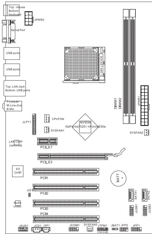
Thank you for choosing the NF725-C35/ NF725-C21 series (MS-7615 v2.x) ATX mainboard. The NF725-C35/ NF725-C21 series is design based on NVIDIA® GeForce 7025/nForce 630a chipset for optimal system efficiency. Designed to fit the advanced AMD® AM3 processor, the NF725-C35/ NF725-C21 series deliver a high performance and professional desktop platform solution.
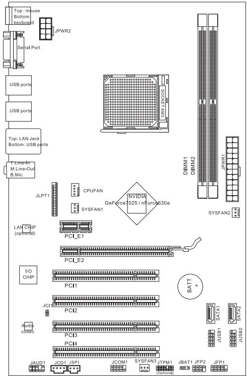
Layout
SPECIFICATIONS
Processor Support
Supports AMD PhenomTM II, PhenomTM, AthlonTM II, AthlonTM and SempronTM processors in AM3 package (For the latest information about CPU, please visit http://www.msi.com/index.php?func=cpuform2)
HyperTransport
Hyper Transport 2.0 supports speed up to 1GHz
Chipset
NVIDIA® GeForce7025 / nForce630a chipset
Memory Support
DDR3 1600/1066/800SDRAM(totalMax.8GB)
- 2 DDR3 DIMMs (240pin/ 1.5V)
*(For more information on compatible components, please visit http://www.msi.com/index.php?func=testreport)
LAN
Supports LAN 10/ 100/ 1000 Fast Ethernet by Realtek® RTL8111E (for NF725-C35)
Supports LAN 10/ 100 Fast Ethernet by Realtek® RTL8105E (for NF725-C21)
Audio
Chip integrated by Realtek ALC887
Supports 7.1 channels audio out
Compliant with Azalia 1.0 Spec
SATA
2 SATA 3Gb/s ports
Connectors
Back panel
-1PS/2 mouse port
- 1 PS/2 keyboard port
-1 Serial port
- 6 USB 2.0 ports
- 1 LAN jack
- 3 flexible audio jacks
On-Board Connectors
- 2 USB 2.0 connectors
- 1 Chassis Intrusion connector
- 1 CD-In connector
- 1 S/PDIF-Out connector
- 1 Front Panel Audio connector
- 1 TPM connector (optional)
- 1 Serial Port connector
- 1 Parallel Port connector
- 1 CPU Fan Power connector
- 2 System Fan Power connectors
Slots
1 PCIE x16 slot
1 PCIE x1 slot
4 PCI slots, support 3.3V/5V PCI bus Interface
Form Factor
ATX (30.5cm× 19.0cm)
Mounting
6 mounting holes
If you need to purchase accessories and request the part numbers, you could search the product web page and find details on our web address below http://www.msi.com/index.php
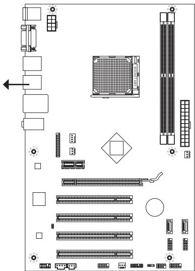
SCREW HOLES
When you install the mainboard, you have to place the mainboard into the chassis in the correct direction. The locations of screws holes on the mainboard are shown as below.
The side has to toward the rear, the position for the I/O shield of the chassis.
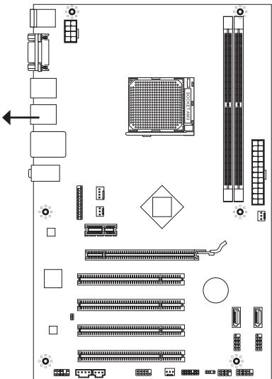


Screw holes
Refer above picture to install standoffs in the appropriate locations on chassis and then screw through the mainboard screw holes into the standoffs.
IMPORTANT
- To prevent damage to the mainboard, any contact between the mainboard circuit and chassis or unnecessary standoffs mounted on the chassis is prohibited.
- Please make sure there are no metal components placed on the mainboard or within the chassis that may cause short circuit of the mainboard.
REAR PANEL
The rear panel provides the following connectors:
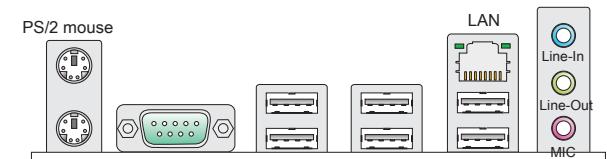
PS/2 keyboard
Serial port
USB ports
USB ports
USB ports
HARDWARE SETUP
This chapter provides you with the information about hardware setup procedures. While doing the installation, be careful in holding the components and follow the installation procedures. For some components, if you install in the wrong orientation, the components will not work properly. Use a grounded wrist strap before handling computer components. Static electricity may damage the components.
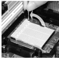
CPU & Cooler Installation for AM3
When you are installing the CPU, make sure the CPU has a cooler attached on the top to prevent overheating. Meanwhile, do not forget to apply some thermal paste on CPU before installing the heat sink/cooler fan for better heat dispersion.
Follow the steps below to install the CPU & cooler correctly. Wrong installation will cause the damage of your CPU & mainboard.
- Pull the lever sideways away from the socket. Make sure to raise the lever up to a 90-degree angle.
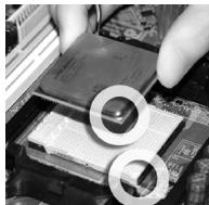
- Look for the gold arrow of the CPU. The gold arrow should point as shown in the picture. The CPU can only fit in the correct orientation.
- If the CPU is correctly installed, the pins should be completely embedded into the socket and can not be seen. Please note that any violation of the correct installation procedures may cause permanent damages to your mainboard.
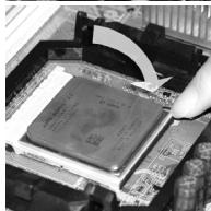
- Press the CPU down firmly into the socket and close the lever. As the CPU is likely to move while the lever is being closed, always close the lever with your fingers pressing tightly on top of the CPU to make sure the CPU is properly and completely embedded into the socket.
- Position the cooling set onto the retention mechanism. Hook one end of the clip to hook first.
- Then press down the other end of the clip to fasten the cooling set on the top of the retention mechanism. Locate the Fix Lever and lift up it.
- Fasten down the lever.
- Attach the CPU Fan cable to the CPU fan connector on the mainboard.
IMPORTANT
- Mainboard photos shown in this section are for demonstration only. The appearance of your mainboard may vary depending on the model you purchase.
- While disconnecting the Safety Hook from the fixed bolt, it is necessary to keep an eye on your fingers, because once the Safety Hook is disconnected from the fixed bolt, the fixed lever will spring back instantly.
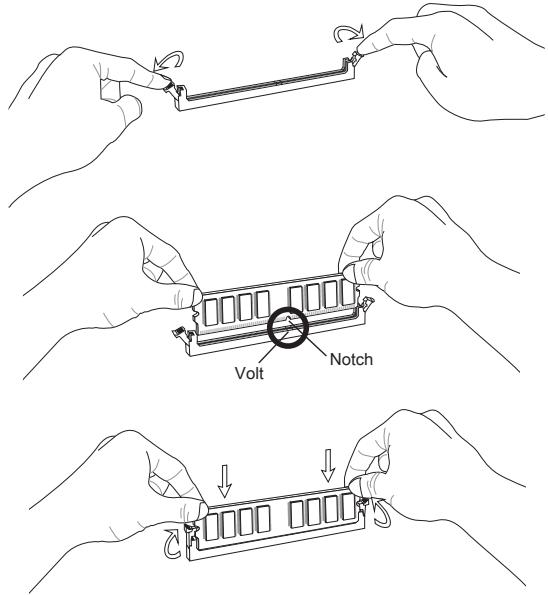
Installing Memory Modules
- The memory module has only one notch on the center and will only fit in the right orientation.
- Insert the memory module vertically into the DIMM slot. Then push it in until the golden finger on the memory module is deeply inserted in the DIMM slot. You can barely see the golden finger if the memory module is properly inserted in the DIMM slot.
- The plastic clip at each side of the DIMM slot will automatically close.
IMPORTANT
- DDR3 memory modules are not interchangeable with DDR2 and the DDR3 standard is not backwards compatible. You should always install DDR3 memory modules in the DDR3 DIMM slots.
- In Dual-Channel mode, make sure that you install memory modules of the same type and density in different channel DIMM slots.
- To enable successful system boot-up, always insert the memory modules into the DIMM1 first.
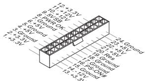
ATX 24-Pin Power Connector: JPWR1
This connector allows you to connect an ATX 24-pin power supply. To connect the ATX 24-pin power supply, make sure the plug of the power supply is inserted in the proper orientation and the pins are aligned. Then push down the power supply firmly into the connector.
ATX 8-Pin Power Connector: JPWR2
This 12V power connector is used to provide power to the CPU.
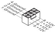
IMPORTANT
Make sure that all the connectors are connected to proper ATX power supplies to ensure stable operation of the mainboard.
Serial ATA Connector: SATA1/2
This connector is a high-speed Serial ATA interface port. Each connector can connect to one Serial ATA device.

IMPORTANT
Please do not fold the Serial ATA cable into 90-degree angle. Otherwise, data loss may occur during transmission.
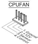
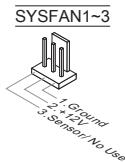
Fan Power Connectors: CPUFAN, SYSFAN1~3
The fan power connectors support system cooling fan with +12V . When connecting the wire to the connectors, always note that the red wire is the positive and should be connected to the +12V ; the black wire is Ground and should be connected to GND. If the mainboard has a System Hardware Monitor chipset onboard, you must use a specially designed fan with speed sensor to take advantage of the CPU fan control.
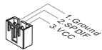
S/PDIF-Out Connector: JSP1
This connector is used to connect S/PDIF (Sony & Philips Digital Interconnect Format) interface for digital audio transmission.
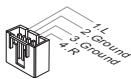
CD-In Connector: JCD1
This connector is provided for external audio input.
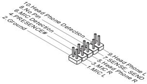
Front Panel Audio Connector: JAUD1
This connector allows you to connect the front panel audio and is compliant with Intel® Front Panel I/O Connectivity Design Guide.
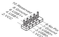
Front USB Connector: JUSB1/ JUSB2
This connector, compliant with Intel® I/O Connectivity Design Guide, is ideal for connecting high-speed USB interface peripherals such as USB HDD, digital cameras, MP3 players, printers, modems and the like.
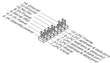
TPM Module Connector: JTPM1 (optional)
This connector connects to a TPM (Trusted Platform Module) module. Please refer to the TPM security platform manual for more details and usages.
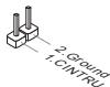
Chassis Intrusion Connector: JCI1
This connector connects to the chassis intrusion switch cable. If the chassis is opened, the chassis intrusion mechanism will be activated. The system will record this status and show a warning message on the screen. To clear the warning, you must enter the BIOS utility and clear the record.
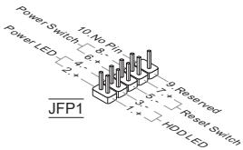
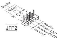
Front Panel Connectors: JFP1, JFP2
These connectors are for electrical connection to the front panel switches and LEDs. The JFP1 is compliant with Intel® Front Panel I/O Connectivity Design Guide.
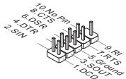
Serial Port Connector: JCOM1
This connector is a 16550A high speed communication port that sends/receives 16 bytes FIFOs. You can attach a serial device.
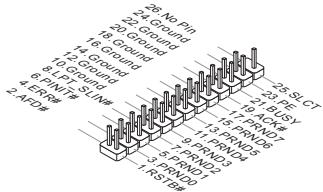
Parallel Port Connector: JLPT1
This connector is used to connect an optional parallel port bracket. The parallel port is a standard printer port that supports Enhanced Parallel Port (EPP) and Extended Capabilities Parallel Port (ECP) mode.
Clear CMOS Jumper: JBAT1
There is a CMOS RAM onboard that has a power supply from an external battery to keep the data of system configuration. With the CMOS RAM, the system can automatically boot OS every time it is turned on. If you want to clear the system configuration, set the jumper to clear data.


Keep Data
Clear Data
IMPORTANT
You can clear CMOS by shorting 2-3 pin while the system is off. Then return to 1-2 pin position. Avoid clearing the CMOS while the system is on; it will damage the mainboard.
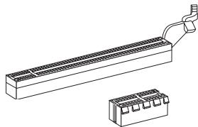
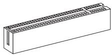
PCI Express Slot
The PCI Express slot supports the PCI Express interface expansion card.
The PCIE x16 slot
The PCIE x1 slot
PCI Slot
The PCI slot supports LAN card, SCSI card, USB card, and other add-on cards that comply with PCI specifications.
IMPORTANT
Make sure that you unplug the power supply first. Meanwhile, read the documentation for the expansion card to configure any necessary hardware or software settings for the expansion card, such as jumpers, switches or BIOS configuration.
PCI Interrupt Request Routing
When adding or removing expansion cards, make the IRQ, acronym of interrupt request line and pronounced I-R-Q, are hardware lines over which devices can send interrupt signals to the microprocessor. The PCI IRQ pins are typically connected to the PCI bus pins as follows:
| Order Slot | 1 | 2 | 3 | 4 |
| PCI 1 | C# | D# | A# | B# |
| PCI 2 | B# | C# | D# | A# |
| PCI 3 | A# | B# | C# | D# |
| PCI 4 | D# | A# | B# | C# |
BIOS SETUP
Power on the computer and the system will start POST (Power On Self Test) process. When the message below appears on the screen, press key to enter Setup.
Press DEL to enter SETUP
If the message disappears before you respond and you still wish to enter Setup, restart the system by turning it OFF and On or pressing the RESET button. You may also restart the system by simultaneously pressing
Main Page

Standard CMOS Features
Use this menu for basic system configurations, such as time, date etc.
Advanced BIOS Features
Use this menu to setup the items of special enhanced features.
Integrated Peripherals
Use this menu to specify your settings for integrated peripherals.
Power Management Setup
Use this menu to specify your settings for power management.
H/W Monitor
This entry shows the status of your CPU, fan, warning for overall system status.
Green Power
Use this menu to specify the power phase.
BIOS Setting Password
Use this menu to set BIOS setting Password.
Cell Menu
Use this menu to specify your settings for frequency/voltage control.
M-Flash
Use this menu to read/ flash (or backup) the BIOS from (to) storage drive (FAT/ FAT32 format only).
Overclocking Profile
Use this menu to save/ load your settings to/ from CMOS for BIOS.
Load Fail-Safe Defaults
Use this menu to load the BIOS default values that are factory settings for system operations.
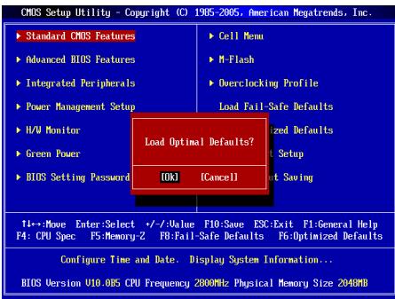
Load Optimized Defaults
Use this menu to load factory default settings into the BIOS for stable system performance operations.
Save & Exit Setup
Save changes to CMOS and exit setup.
Exit Without Saving
Abandon all changes and exit setup.
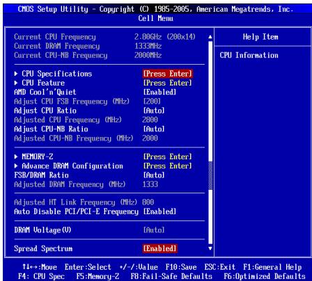
Cell Menu
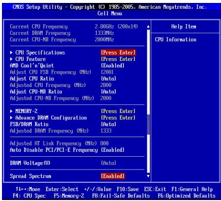
Current CPU/ DRAM/ CPU-NB Frequency
It shows the current frequency of CPU/ Memory. Read-only.
CPU Specifications
Press
CPU Technology Support
Press
CPU Feature
Press
AMD Cool'n'Quiet
The Cool'n'Quiet technology can effectively and dynamically lower CPU speed and power consumption.
SVM Support
This item is used to enable/ disable SVM.
AMD Cool'n'Quiet
The Cool'n'Quiet technology can effectively and dynamically lower CPU speed and power consumption.
IMPORTANT
To ensure that Cool'n'Quiet function is activated and will be working properly, it is required to double confirm that:
- Run BIOS Setup, and select Cell Menu. Under Cell Menu, find AMD Cool'n'Quiet, and set this item to "Enabled".
- Enter Windows, and select [Start]->[Settings]->[Control Panel]->[Power Options]. Enter Power Options Properties tag, and select Minimal Power Management under Power schemes.
Adjust CPU FSB Frequency (MHz)
This item allows you to adjust the CPU FSB frequency.
Adjust CPU Ratio
This item is used to adjust CPU clock multiplier (ratio). It is available only when the processor supports this function.
Adjusted CPU Frequency (MHz)
It shows the adjusted CPU frequency (FSB x Ratio). Read-only.
Adjust CPU-NB Ratio
This item is used to adjust CPU-NB clock multiplier (ratio).
Adjusted CPU-NB Frequency (MHz)
It shows the adjusted CPU-NB frequency. Read-only.
MEMORY-Z
Press
DIMM1~2 Memory SPD Information
Press
Advance DRAM Configuration
Press
DRAM Timing Mode
This field has the capacity to automatically detect the DRAM timing when it sets as [Auto].
1T/2T Memory Timing
When the DRAM Timing Mode is set to [Manual], the field is adjustable. This field controls the command rate. Selecting [1T] makes DRAM signal controller to run at 1 clock cycle rate. Selecting [2T] makes DRAM signal controller run at 2 clock cycles rate.
DCT Unganged Mode
This feature is used to Integrate two 64-bit DCTs into a 128-bit interface.
FSB/DRAM Ratio
This item will allow you to adjust the ratio of FSB to memory.
Adjusted DRAM Frequency (MHz)
It shows the adjusted memory frequency. Read-only.
Adjusted HT Link Frequency (MHz)
It shows the adjusted HT link frequency. Read-only.
Auto Disable PCI/PCI-E Frequency
When set to [Enabled], the system will remove (turn off) clocks from empty PCI and PCI-E slots to minimize the electromagnetic interference (EMI).
DRAM Voltage (V)
This item is used to adjust the voltage of Memory.
Spread Spectrum
When the motherboard's clock generator pulses, the extreme values (spikes) of the pulses create EMI (Electromagnetic Interference). The Spread Spectrum function reduces the EMI generated by modulating the pulses so that the spikes of the pulses are reduced to flatter curves.
IMPORTANT
- If you do not have any EMI problem, leave the setting at [Disabled] for optimal system stability and performance. But if you are plagued by EMI, select the value of Spread Spectrum for EMI reduction.
- The greater the Spread Spectrum value is, the greater the EMI is reduced, and the system will become less stable. For the most suitable Spread Spectrum value, please consult your local EMI regulation.
- Remember to disable Spread Spectrum if you are overclocking because even a slight jitter can introduce a temporary boost in clock speed which may just cause your overclocked processor to lock up.
Load Optimized Defaults
You can load the default values provided by the mainboard manufacturer for the stable performance.

中国
#
NF725-C35/NF725-C21 SIRIUS (MS-7615 v2.x) ATX 电话本版由来,中书社
SIRIUS 2014/2015/2016/2017/2018/2019/2020/2021

Reioh
SELMG
志园存是
- AM3 陀螺机里有某个 AMD® Phenom™ II, Phenom™, Athlon™ II, Athlon™ 同 Sempron™ 扭力泵电机 (CPU上都有一颗独立的 CPU)。http://www.msi.com/index.php?func=cpuform2 查询)
HyperTransport
ACKSRETLIeRtoHJF 1000000000000000000000000000000000000000000000000000000000000000000000000
nuaqu
ATX24FJ1JFJFJFJFJFJFJFJFJFJFJFJFJFJFJFJFJFJFJFJFJFJFJFJFJFJFJFJFJFJFJFJFJFJFJFJFJFJFJFJFJFJ
H/W Monitor (H/W MoNlTeI)
i
Green Power
Current CPU/DRAM/CPU-NB Frequency (端子CPU/DRAM/QPI主卡数)
CPU Specifications (CPU字样)
CPU Technology Support (CPU 設務服務)
CPU Feature (CPU 信号)
Adjust CPU Ratio (CPU bit to 0)
Adjusted CPU Frequency (MHz) (主锁回CPU主功) (MHz)
i
Adjust CPU-NB Ratio (CPU-NB bit to 0)
DRAM Timing Mode (DRAM TaHInM MoT)
Adjusted HT Link Frequency (MHz)(王詠則詞HT劉克丶爭囍) (MHz)
i
Auto Disable PCI/PCI-E Frequency (PCI/PCI-E 主音卡数)
Press DEL to enter SETUP
Advanced BIOS Features
Integrated Peripherals
BIOS Setting Password
Overclocking Profile
Current CPU/ DRAM/ CPU-NB Frequency
CPU Technology Support
Adjust CPU FSB Frequency (MHz)
Adjusted CPU Frequency (MHz)
Adjusted CPU-NB Frequency (MHz)
Adjusted DRAM Frequency (MHz)
Adjusted HT Link Frequency (MHz)
ATX (30,5 cm X 19,0 cm)
Montage
6 Montagebohrungen
CPU & Cooler Installation for AM3
ATX 8-Pin Power Connector: JPWR2
Press DEL to enter SETUP
Advanced BIOS Features
Integrated Peripherals
BIOS Setting Password
Overclocking Profile
Current CPU/ DRAM/ CPU-NB Frequency
CPU Technology Support
Adjust CPU FSB Frequency (MHz)
Adjusted CPU Frequency (MHz)
Adjusted CPU-NB Frequency (MHz)
Adjusted DRAM Frequency (MHz)
Adjusted HT Link Frequency (MHz)
KOMHOENTbI CNCTEMHOI NaTbI
XAPAKTEPNUCTIKN
Пюцeccор
Пюразс紫外tby AMDPhenomTMII,PhenomTM, AthlonTM II, AthlonTM SempronTM BOKHTpyTBE AM3
(IJIyIPOUyHnIcMoHOBIOINHOpMaUNO CPU,IOCeTHe caIT
http://www.msi.com/index.php?func=cpuform2)
HyperTransport
Hyper Transport 2.0 noДержИBaet ckopoctbdo 1GHz
Unncet
NVIDIA® GeForce7025 / nForce630a
NamrTb
DDR3 1600/ 1066/800 SDRAM (Max. 8GB)
2 cnoTRA DDR3 DIMM (240KOH/1.5V)
*(3a donoHnHTeBnHO nHfOpMaueH o coMBecTmBx KOMNoHEtAX, nocTeHTe caHt http://www.msi.com/index.php?func=testreport)
LAN
Плобджka LAN 10/100/1000 Fast Ethernet на чincere Realtek® RTL8111E (Для NF725-C35)
Плобдержka LAN 10/100 Fast Ethernet на чипсete Realtek® RTL8105E (дяг. NF725-C21)
Aydno
INTerpnoBaHHbY uIncet Realtek ALC887
7.1-kaHajbHoe aydno c rnbKm npeHa3NaeHHe m pa3bEmOB
Cobmectmoctb co cneunkauei Azalia 1.0
SATA
2 nopTa SATA 3Γ6/c
KOHHeKTopbl
3aDne nane
-1PS/2npTmbiH
-1PS/2npTKnaBnAtypbl
- 1 nocneobatelhno npT
- 6 nopTOB USB 2.0
- 1 pa3bem LAN
-33ByKObBix pa3bemaC rN6KIM nepeHa3HaueHHeM
Pa3bem, yctahOBJIeHHbIe Ha IIJIaTe
- 2 pa3bema USB 2.0
- 1 pa3bem DaTchka OTKpbBaHnK Kopnyca
- 1 pa3bem CD-In
- 1 pa3bem S/PDIF-Out
-1pa3bEmIpynoNpOKnIOUeHnayDNOHapeDneNaHeM - 1pa3bem TPM (onuohalbo)
- 1 pa3bem nocleidobateIbHoro nopTa
- 1 pa3bem napaJIenbHoro nopTa
- 1 pa3bem nItaHn BENTINrAToPOB npouecccopa
- 2 pa3bema nITaHnBEHTINrAToPOB CnCTembl
Cnotbl
1 cnot PCIE x16
1 cnot PCIE x1
4 cnoTa PCI, noDepkka INTeppeca PCI uHbI c nTuHaem 3.3V/5V
ΦopM ΦakTop
ATX (30.5 cm X 19.0 cm)
KpennneHne
6 OTBepCTn DnI KpeJIeHnI
TOMoub B pIIO6pETeHnON DOnOIHNITbIbX akCEccyapOB NOnICke HOMepa
NtEDeJI MoxHOH aHTNI O aDcpcy http://www.msi.com/index.php
OTBEPCTNДЛВИNTOB
Pn yctaHOBKe CNTeMHo INaTbI HyKHO BCTaBtB eB KOpNyc B npaBnHOM HapabHeHH. Pa3MeueHra OTBepCtn DnI BHTOB NOKa3Ahb Hnke.
Bokobbie cstopohb
cneyet npotnb
3aJero h Kopnyca,
pa3Meuenie
dI npoteKTopo
BXOda/ bXOda
kopnyca.


OTBepCTNДIЯ BINTOB
Cnduyue yka3aHmM BbIe Uyka3aHNO IyctaHOBKn depXATEneB npabuHbOM Mecte B Kopnyce n 3aTeEM BBINHTite BInHTbl yepe3 OTBepCTna Ipy BInTOB B dePkATenn.
BHIMAHHE
Integrated Peripherals (BCTpoehhble nepupepnhbye yctpoicta)
3ToMeHIOIcnpIb3yeTc4dIaNHaCTpOIKnnapaMetPOB BCTPOeHNbIX nepiΦepriNbIX yuctpOBCTB.
Power Management Setup (Hactpoika ynpablenia nntaHneM)
3TO MEHIO N03BOJAreT 3aDaTb npaMeTpbl ynpaBNeHn NITAHmCnCTEmbl.
H/W Monitor (MoHTop annapaTHou actn)
3TOT nyHKT OTO6pKaaET COCTOHNe annapatHou actn PIK.
Green Power
3To MeHIO nCnOlb3yeTcI dI pyeXIMOB 3HePrc6bepeXeHna.
BIOS Setting Password (Паров досун Книсторikam BIOS)
3To MeHIO nCnOJb3yETcA, TTO6bl 3aDaTb napoiB.
Cell Menu (Mehio y3na "Cell")
3TO MEOHIOBBOJET YnpabTb TAKTOBMu qACTOTAMN HANPRAKENYRMn Pnip paoRHO CICTMEn.
M-Flash
Overclocking Profile
IcnoIb3yETcIaXpaHEnI/ 3arpy3kn npametpoB I/3 CMOS BIOS.
Load Fail-Safe Defaults
3To MEHIO NcNOB3yETcN 3aqrpy3n 3aHcNEHHBIOS,yCTaHOBENbIX npno3BtIeTmE nTcAStbHbONpaBoTbN CNTeMbI.
Load Optimized Defaults (YctaHOBITb ONTINMAbNbIe HAcTpOKn)
3TO MeHIO INCJbIyETcRd yCtAHOBK HACTPQeI INOTUMJIHOI PNOB3DIOENTBJHOCTN CHTEMHNOI PnATb.
Save & Exit Setup (BbIXoD c coXpaHHeHem HactpoeK)
3aIINcB n3MeHEnB CMOs u BbIXoN u pexKmHaNCTpoKn.
Exit Without Saving (BbIXoD 6e3 coxpaHEnHa)
OTmeHa BceX n3MeHEnn n3 peXmHa HaCTpOKn.
Cell Menu
Current CPU/ DRAM/ CPU-NB Frequency
3TOT NNYKT NOKAbaeT Tekyuee 3Hauhenie TAKTOBOI qACTObl npoceccopa / naMATr. TOLKBIO DnI TNEHJ.
CPU Specifications
JahMkme
CPU Technology Support
HakmITE
CPU Feature
Haxmte
AMD Cool'n'Quiet
TexHONORI Cool Neop 30BnOReT 3ffQeKTBHO DnAMMHCN 3MMeHTb 卷CTOT CPU nHeepronTOpe6BneHc HcTeMb.
SVM Support
TOT nyHKT nCnONb3yETcra dIe BkHIOUeHn/ BblKlIOUeHn TExHOrOHN SVM.
AMD Cool'n'Quiet
TexohonorHa Cool'Quiet 03noBlaye 3DpEkeTNBDO HnAmHmCckn N3MeHrtb YactOty CPU n3hePronotpe6neHne CnCTeMbI.
BHIMAHHE
YtObIy y6eIITbc8 B TOM, YTO TexHONOrn4 Cool'n'Quiet BkIouHeu npabotaet npabInbHo, Heo6xOdmo:
- 3aithn b porpammy BIOS Setup, u bivapb Cell Menu. Haidnite AMD Cool'n Quiet noct Cell Menu, u yctahonbrite ero b "Enabled".
- B Windows „BыбөртIDE [Start]-->[Settings]-->[Control Panel]-->[Power Options]. BoYнITE B Power Options Properties, „BыбөртIDE Minimal Power Management BpyнITE Power schemes.
Adjust CPU FSB Frequency (MHz)
3TOT nyHKT no3BOJAEr BbIbpaTb yactOry FSB npouecoppa.
Adjust CPU Ratio
3TOT nyHT IcNoIb3yeTcI dIe peryIINPOBk MHOxNtEa Ipoceccopa. OH DoCTyNEH ToJIbKO ToIa, KOrJa IpoCeCCOP NIOdEepXnBaET 3Ty FyHKuHIO.
Adjusted CPU Frequency (MHz)
3TOT NpHKT NOKa3bYBaET TekuIyU qACTOty CPU (FSB x Ratio). Tonbko dny TchEN.
Adjust CPU-NB Ratio
3TOT nyHKT nCnonb3yetyaI pyereynipobknuacToB CPU-NB (ratio).
Adjusted CPU-NB Frequency (MHz)
3TOT nyHKT nOKa3bIbaET TeKyujo yactOry CPU-NB. TOnbKO dnyTeHnA.
MEMORY-Z
Haxmnte
DIMM1~2 Memory SPD Information
HakMMTE
Advance DRAM Configuration
Haxmnte
DRAM Timing Mode
3TOT nyHK NTNOBERT ABOTMATMueckn ONpeDeJIbB CBe BpEMeHbIe napametprD DRAM npYCTAHOBKeB [Auto].
1T/2T Memory Timing
Pn yctahOBke DRAM Timing Mode B [Manual], 3T0 nYHK t cTaHOBtca DOCTyNHbIM. 3T0 nYHK opepeJeT CKOcOte b YuDaH KOMaHSDRAM. Bb6Op [1T] nepeBoDT CnHaJIbHbI KOHTpONlEP SDRAM B peKIM pa6oTBt 1T (T=clock cycles). B6Op [2T] nepeBoDT CnHaJIbHbI KOHTpONlEP SDRAM B peKIM pa6oTBt 2T.
DCT Unganged Mode
3TOTyNHTICNPOIbayetcIЯнObSEbIMENHЯДБx64-6nTHbIXDCTBODHN 128-6nTHbINHInTepeFck
FSB/DRAM Ratio
3TOTyHKITNo3BONJET peryIINPOBaTB Ko3ΦΦnIeHT MEXdy ChACTOTAMi FSB n NaMBAbTO.
Adjusted DRAM Frequency (MHz)
TOT nyHKT NOKa3bIbaET TekuIyU cactOty namrIn. TOnbKO dIyTeHnA.
Adjusted HT Link Frequency (MHz)
3TOT nyHKT noka3bIbaeTekyUO qactoty HT link. TOnbKO dnyuTeHnA.
Auto Disable PCI/PCI-E Frequency
PnynyctahOBBe 3aHcHEnb [Enabled] cnCTeMa OTKnIOuHT NHeCNPOB3yEmbe pa3bEmb namTn npa3bEmb DI MM nPCI, TTO npInBeET K ChNKeHIO yOboHn 3neKpTOMaHRHTbIX nomEx (EMI).
DRAM Voltage (V)
3TOT nyHKT no3BONJrE peryIINPOBaT HanpXeHne naMAtn.
Spread Spectrum
Tak kak taktobbl rehepatop cintemhoI pntbI MMynbcbl, to ero paoba Bblbaet 3neKtpormaHHTbIe nomexn - EMI (Electromagnetic Interference). FyHKpiae Spread Spectrum Chnkaet 3TN nomexn, rHeeppyra crnaKeHbIe IMTyNbCbl.
BHIMAHHE
- Ecnny y Bac het npobnem c nomexamn, octabte 3nauehme [Disabled] (aanpeuho) nianyue stcbnBHOCTN n pno3BODHTNBHOCTN. Ondako, ecnny y Bac BO3HnAOT 3neKpromarHnthe Nomexn, BbIbepnte Spad Spectrum dny uMeHNBEHnien.
* Yem 6oIbIwe 3aHaeHne Spread Spectrum, tem Hnke bdyet ypoBHeN 3eKTPOMAHHTHbIX NOMEX, HO CNTcema cTahET MeHEE cTaONbHOJ. IyBa IbIObe NOxOJaIeO 3HaueHne SpurS EumTeM, cBePbTeC bOaHaeRMn ypoBHeN 3eKTPOMAHHTHbIX NOMEX, yCTaHOJIeHHbIX 3AKOHDoTeNbCTBOM.
* He 3a6yblte 3anp9tntb IcnoIb3oBaHne FynKcnn Spread Spectrum, ecn Bby (pa3roHnEeT) CNTeMThy nIaTy. 3To He6xOJIMMo, TAK KaK DaJke He6onlsuOn dpe6e3r CInHaNoR TAkTOBOr reHepatopA MoKeT npBecT N O kTaKa3y (pa3orHaHHoro) npOceccopa.
YcTaHOBKa 3NaueHnI NO yMOnuHaHIO
IaTc76bHbNO paBoTbI cNTBMe bI BO MeKTe 3aRyTHaN HCTPOIKI BIOS NO umYHAnu, yctAOhONHHe IpoN3BOdHTENEM CHTEMHO pNAtb.
简体中文
简介
CPU Specifications (CPU 属性)
Press DEL to enter SETUP
(按DEL鍵進入設定)
Integrated Peripherals (整合型週邊)
使用本選單設定整合型週邊裝置。
CPU Specifications (CPU 規格)
CPU Feature (CPU 功能)
按下
AMD Cool'n'Quiet
Adjust CPU FSB Frequency (MHz) (調整CPU外頻)
本項設定CPU前端匯流排的頻率。
Adjust CPU Ratio (调整CPU倍频比率)
Adjusted CPU Frequency (MHz) (調整後CPU頻率)
Press DEL to enter SETUP
一押七设定画面呼出
Integrated Peripherals (內藏機能の設定)
CPU Technology Support (CPUtekNoJ-saPb-1)
CPU Feature (CPUの機能)
Adjusted CPU Frequency (MHz) (調整たCPU周波数)
DRAM Voltage (V) (DRAM電圧)
×モリの電圧を調整いたします。
Spread Spectrum
- FCC-B RADIO FREQUENCY INTERFERENCE STATEMENT
- Notice 1
- Notice 2
- PART NUMBER
- COPYRIGHT NOTICE
- TRADEMARKS
- REVISION HISTORY
- SAFETY INSTRUCTIONS
- CAUTION
- 警告使用者
- ENGLISH
- DEUTSCH
- SPECIFICATIONS
- Processor Support
- HyperTransport
- Chipset
- Memory Support
- LAN
- Audio
- SATA
- Connectors
- Slots
- Form Factor
- Mounting
- SCREW HOLES
- IMPORTANT
- REAR PANEL
- HARDWARE SETUP
- CPU & Cooler Installation for AM3
- Installing Memory Modules
- ATX 24-Pin Power Connector: JPWR1
- ATX 8-Pin Power Connector: JPWR2
- Serial ATA Connector: SATA1/2
- Fan Power Connectors: CPUFAN, SYSFAN1~3
- S/PDIF-Out Connector: JSP1
- CD-In Connector: JCD1
- Front Panel Audio Connector: JAUD1
- Front USB Connector: JUSB1/ JUSB2
- TPM Module Connector: JTPM1 (optional)
- Chassis Intrusion Connector: JCI1
- Front Panel Connectors: JFP1, JFP2
- Serial Port Connector: JCOM1
- Parallel Port Connector: JLPT1
- Clear CMOS Jumper: JBAT1
- PCI Express Slot
- PCI Slot
- PCI Interrupt Request Routing
- BIOS SETUP
- Press DEL to enter SETUP
- Main Page
- Standard CMOS Features
- Advanced BIOS Features
- Integrated Peripherals
- Power Management Setup
- H/W Monitor
- Green Power
- BIOS Setting Password
- Cell Menu
- M-Flash
- Overclocking Profile
- Load Fail-Safe Defaults
- Load Optimized Defaults
- Save & Exit Setup
- Exit Without Saving
- Current CPU/ DRAM/ CPU-NB Frequency
- CPU Specifications
- CPU Technology Support
- CPU Feature
- AMD Cool'n'Quiet
- SVM Support
- Adjust CPU FSB Frequency (MHz)
- Adjust CPU Ratio
- Adjusted CPU Frequency (MHz)
- Adjust CPU-NB Ratio
- Adjusted CPU-NB Frequency (MHz)
- MEMORY-Z
- DIMM1~2 Memory SPD Information
- Advance DRAM Configuration
- DRAM Timing Mode
- 1T/2T Memory Timing
- DCT Unganged Mode
- FSB/DRAM Ratio
- Adjusted DRAM Frequency (MHz)
- Adjusted HT Link Frequency (MHz)
- Auto Disable PCI/PCI-E Frequency
- DRAM Voltage (V)
- Spread Spectrum
- 中国
- #
- SELMG
- 志园存是
- nuaqu
- ATX24FJ1JFJFJFJFJFJFJFJFJFJFJFJFJFJFJFJFJFJFJFJFJFJFJFJFJFJFJFJFJFJFJFJFJFJFJFJFJFJFJFJFJFJ
- H/W Monitor (H/W MoNlTeI)
- Montage
- XAPAKTEPNUCTIKN
- Пюцeccор
- Unncet
- NamrTb
- Aydno
- KOHHeKTopbl
- Cnotbl
- ΦopM ΦakTop
- KpennneHne
- OTBEPCTNДЛВИNTOB
- BHIMAHHE
- Integrated Peripherals (BCTpoehhble nepupepnhbye yctpoicta)
- Power Management Setup (Hactpoika ynpablenia nntaHneM)
- H/W Monitor (MoHTop annapaTHou actn)
- BIOS Setting Password (Паров досун Книсторikam BIOS)
- Cell Menu (Mehio y3na "Cell")
- Load Optimized Defaults (YctaHOBITb ONTINMAbNbIe HAcTpOKn)
- Save & Exit Setup (BbIXoD c coXpaHHeHem HactpoeK)
- Exit Without Saving (BbIXoD 6e3 coxpaHEnHa)
- YcTaHOBKa 3NaueHnI NO yMOnuHaHIO
- 简体中文
- 简介
- (按DEL鍵進入設定)
- Integrated Peripherals (內藏機能の設定)
Brand : MSI
Model : G52-76151X4
Category : Laptop