
Max Total 40 - Elliptical bike BOWFLEX - Free user manual and instructions
Find the device manual for free Max Total 40 BOWFLEX in PDF.


| Product Type | Elliptical Bike / Hybrid Stepper |
| Model Number | Max Total 40 |
| Brand | Bowflex |
| Dimensions (L x W x H) | Approx. 58" x 30" x 70" (147 cm x 76 cm x 178 cm) |
| Product Weight | Approx. 180 lbs (82 kg) |
| Maximum User Weight | 300 lbs (136 kg) |
| Resistance System | Air Resistance with adjustable fan blades |
| Resistance Levels | Unlimited (infinitely variable via air resistance) |
| Display | LCD console with time, distance, calories, RPM, speed, and heart rate |
| Programs | Manual, Preset workouts, Heart Rate Control |
| Heart Rate Monitoring | Contact grips and optional chest strap (Bluetooth) |
| Power Source | Self-powered (generator); no AC adapter needed |
| Seat Adjustment | Vertical and horizontal adjustment |
| Pedal Straps | Adjustable toe straps |
| Wheels for Transport | Yes, front transport wheels |
| Assembly Required | Yes, moderate level |
| Warranty | 15 years frame, 2 years parts, 1 year labor |
| Care and Cleaning | Wipe with damp cloth; avoid solvents. Lubricate moving parts annually. |
| Safety | Safety key included; keep away from children under 14. |
| Spare Parts & Repairability | Replacements available via Bowflex customer service; detailed manual for DIY repairs. |
Frequently Asked Questions - Max Total 40 BOWFLEX
User questions about Max Total 40 BOWFLEX
0 question about this device. Answer the ones you know or ask your own.
Ask a new question about this device
Download the instructions for your Elliptical bike in PDF format for free! Find your manual Max Total 40 - BOWFLEX and take your electronic device back in hand. On this page are published all the documents necessary for the use of your device. Max Total 40 by BOWFLEX.
USER MANUAL Max Total 40 BOWFLEX
Bowflex™ Max Total™ 16/40 Service Manual
Service Manual 8027706.021523.C
Table of Contents
| Section | Code | Section | Page | ||
| 1 | Important Safety Instructions | 2 | |||
| 1 | Safety Warning Labels and Serial Number | 3 | |||
| 1 | Specifications | 4 | |||
| 1 | Moving / Leveling the Machine | 5 | |||
| 1 | Bluetooth Heart Rate Armband | 6 | |||
| 1 | Maintenance | 8 | |||
| 1 | Maintenance Parts Exploded View | 9 | |||
| 1 | Troubleshooting - Sections | 11 | |||
| 1 | No Power / Display Will Not Turn On | 12 | |||
| 1 | Machine Goes to Sleep While in Use | 13 | |||
| 1 | Resistance Does Not Respond | 14 | |||
| 1 | Machine Seized Up | 15 | |||
| 1 | Machine Slips During Use | 16 | |||
| 1 | Rollers and Pedals | 17 | |||
| 1 | Noises | - | Main | ||
| 1 | Noises - Metallic Grinding or Scraping | 19 | |||
| 1 | Noises - Rubbing / Belt | 20 | |||
| 1 | Noises - Clicking, Clunking or Knocking | 21 | |||
| 1 | Noises - Squeaking, Squealing or Chirping | 22 | |||
| 1 | Contact Heart Rate Issues | 23 | |||
| 1 | Bluetooth Heart Rate Issues | 24 | |||
| 1 | Upper (Drive) Pulley | 25 | |||
| 1 | Power Off and Restart the Machine | 26 | |||
| 1 | Replacement Procedure Skill Level | 27 | |||
| Mechanical / Modification Procedures | |||||
| 2 | Adjust the Brake Assembly | 28 | |||
| 3 | Adjust the Leg Assembly Alignment | 33 | |||
| 4 | Modify the Resistance Knob Cable Part Replacement | 36 | |||
| 5 | Replace the Brake Assembly | 40 | |||
| 6 | Replace the Console Assembly | 46 | |||
| 7 | Replace the Console Rear Panel | 49 | |||
| 8 | Replace the Crank Arm, Left | 53 | |||
| 9 | Replace the Crank Arm, Right | 57 | |||
| 10 | Replace the Drive Belt | 62 | |||
| 11 | Replace the Drive Pulley | 67 | |||
| 12 | Replace the Drive Pulley Hardware | 74 | |||
| 13 | Replace the Fan Assembly | 79 | |||
| 14 | Replace the Fan Belt | 82 | |||
| 15 | Replace the Fan Pulley | 89 | |||
| 16 | Replace the Frame Assembly | 97 | |||
| 17 | Replace the Handlebar Pivot Assembly | 106 | |||
| 18 | Replace the Mid Mast Cables | 108 | |||
| 19 | Replace the PCBA Board | 113 | |||
| 20 | Replace the Power Inlet | 119 | |||
| 21 | Replace the Roller Wheel Assembly | 122 | |||
| 22 | Replace the Servo Motor | 124 | |||
| 23 | Replace the Shrouds | 129 | |||
| 24 | Replace the Speed Sensor Assembly | 134 | |||
| 25 | Replace the Static Handlebar Assembly | 136 | |||
| 26 | Replace the Upper Body Sensor Assembly | 140 | |||
| 27 | Replace the Wiring Harness, Main | 148 | |||
NOTICE: This document provides important safety instructions, adjustments, and general troubleshooting information for the maintenance of the Bowflex ^™ Max Total ^™ 16/40.
If you need assistance, please contact Customer Service (if purchased in US/Canada) or your local distributor (if purchased outside US/Canada). To find your local distributor, go to: www.nautilusinternational.com

This icon means a potentially hazardous situation which, if not avoided, could result in death or serious injury. Read and understand all Warnings on this machine.
Nautilus, Inc., (800) 605-3369, www.NautilusInc.com - Customer Service: North America (800) 605-3369, csnls@nautilus.com | outside U.S. www.nautilusinternational.com | Printed in China | © 2019 Nautilus, Inc. | Bowflex, the B logo, and Max Total are trademarks owned or licensed by Nautilus, Inc., registered or otherwise protected by common law in the United States and other nations. App Store is a service mark of Apple Inc. The Bluetooth® word mark and logos are registered trademarks owned by Bluetooth SIG, Inc., and any use of such marks by Nautilus, Inc. is under license. | ORIGINAL DOCUMENT - ENGLISH VERSION ONLY
Important Safety Instructions

This icon means a potentially hazardous situation which, if not avoided, could result in death or serious injury. Read and understand all Warnings on this machine.
Before servicing or using this equipment, obey the following warnings:

Read and understand the Service Manual before working on the machine. Failure to obey the instructions and safety warnings could cause injury to the service technician or bystanders.
! DANGER
To reduce the risk of electrical shock or unsupervised usage of the equipment, always unplug the power cord from the wall outlet and/or the machine before cleaning, maintaining or repairing the machine. Place the power cord in a secure location.
- Keep bystanders and children away from the product being serviced at all times.
• Make sure that the repair is done in an appropriate work space away from foot traffic and exposure to bystanders. - Some components of the equipment can be heavy or awkward. Enlist the service of a second person when you do maintenance steps involving these components. Do not try to do heavy or awkward steps on your own.
- Use only replacement parts and hardware that are supplied or approved by Nautilus. Failure to use Nautilus-approved replacement parts can adversely affect the safety and functionality of the equipment creating a risk to users and will void the warranty.
- Be sure that all warning stickers and instructional placards applied to the product stay present and in good condition when doing maintenance or replacing components. If at any time the Warning labels become loose, unreadable or dislodged, replace the labels. If purchased in US/Canada, contact Customer Service for replacement labels. If purchased outside US/Canada, contact your local distributor for them.
- Do not try to change the design or functionality of the machine being serviced as this can adversely affect user safety and will void the warranty.
- Do not put the machine back in service until all shrouds, instructions, warning labels and correct functionality have been verified and tested for correct performance.
· SAVE THESE INSTRUCTIONS.
SAFETY WARNING LABELS AND SERIAL NUMBER

Console Serial Number Label
WARNING!
- Injury or death is possible if caution is not used while using this machine.
- Keep children and pets away.
- Read and follow all warnings on this machine.
- Refer to the Owner's Manual for additional warnings and safety information.
- The heart rate displayed is an approximation and should be used for reference only.
- Not intended for use by anyone under 14 years of age.
• The maximum user weight for this machine is 136 kg. (300 lbs)
• This machine is for home use only. - Consult a physician prior to using any exercise equipment.
(Label on machine is available in English and French Canadian only.)
Product Specification Label and Serial Number Label (under Right Stabilizer Shroud)
FCC Compliance

Changes or modifications to this unit not expressly approved by the party responsible for compliance could void the user's authority to operate the equipment.
The machine and power supply comply with part 15 of the FCC rules. Operation is subject to the following two conditions: (1) This device may not cause harmful interference, and (2) this device must accept any interference received, including interference that may cause undesired operation.
Note: This machine and power supply have been tested and found to comply with the limits for a Class A digital device, pursuant to Part 15 of the FCC Rules. These limits are designed to provide reasonable protection against harmful interference in a residential installation. This equipment generates, uses and can radiate radio frequency energy and, if not installed and used in accordance with the instructions, may cause harmful interference to radio communications.
However, there is no guarantee that interference will not occur in a particular installation. If this equipment does cause harmful interference to radio or television reception, which can be determined by turning the equipment off and on, the user is encouraged to try to correct the interference by one or more of the following measures:
- Reorient or relocate the receiving antenna.
- Increase the separation between the equipment and receiver.
- Connect the equipment into an outlet on a circuit different from that to which the receiver is connected.
- Consult the dealer or an experienced radio/TV technician for help.
This product complies with the European Radio Equipment Directive 2014/53/EU
SPECIFICATIONS
Maximum User Weight: 136 kg (300 lbs.)
Total Surface Area (footprint) of equipment: 9648.8 cm² (1494.5 in²)
Maximum Pedal Height: 48.5 cm (19.1 inches)
Machine Weight: approx. 70.5 kg (155.4 lbs.)
Power Requirements:
(AC Adaptor)
Input Voltage: 100-240V AC, 50-60Hz, 1.5A
Output Voltage: 12V DC, 5A
Heart Rate Armband: 1 Lithium Polymer battery (not replaceable)


DO NOT dispose of this product as refuse. This product is to be recycled. For proper disposal of this product, please follow the prescribed methods at an approved waste center.
For safe operation, the location must be on a hard, level surface. Allow a workout area of a minimum 139.2 cm (54.8 in) x 186.2 cm (73.3 in). Keep the workout area clear 0.6 m (24 in) along the side used to access the machine and to the rear of the machine. Be sure that the workout space you are utilizing has adequate height clearance, taking into consideration the height of the user and the maximum pedal height of the fitness machine.

Moving the Machine

The machine may be moved by one or more persons depending on their physical abilities and capacities. Make sure that you and others are all physically fit and able to move the machine safely.
- Grasp the Main Bar of the Static Handlebar Assembly to carefully tilt the machine toward you onto the transport rollers. Be sure not to grab the Console Display.

Be aware of the Handlebars and the weight of the machine before tilting the machine.
- Push the machine into position.
- Carefully lower the machine into position.
NOTICE: Be careful when you move the machine. All abrupt motions can affect the computer operation.

natural_image
Line drawing of a person using an exercise machine with visible gears and shafts (no text or symbols)Leveling the Machine
The machine needs to be leveled if your workout area is uneven or if the Rail Assembly is slightly off the floor. To adjust:
- Place the machine in your workout area.
- Loosen the locking nuts and adjust the levelers until they are evenly balanced in contact with the floor.

Do not adjust the levelers to such a height that they detach or unscrew from the machine. Injury to you or damage to the machine can occur.
- Tighten the locking nuts.

Make sure the machine is level and stable before you exercise.

natural_image
Technical line drawing of a mechanical exercise machine with an inset showing a device's rotation mechanism (no text or symbols present)Media Rack (Optional Accessory)
An optional accessory can be added to your fitness machine that will hold additional media above the Console. The optional Media Rack easily attaches to your machine, adding more space for media and devices.
To order the optional Media Rack, contact Customer Service (if in US/Canada) or your local distributor (if outside US/Canada).

natural_image
Line drawing of a handheld electronic device with a small device attached (no text or symbols visible)USB Charging
If a USB Device is attached to the USB Port, the Port will attempt to charge the Device. The power supplied from the USB Port may not be enough to operate the Device and charge it at the same time.
Using the Bowflex™ JRNY™ App on your Portable Device (Optional)
Though you can access your completed workout information from your console with your JRNY ^™ membership, you can also access this information remotely on your own device. Simply download the JRNY ^™ app to your device for access to your JRNY ^™ membership.
- Download the app, named "Bowflex™ JRNY™ App". The app is available on Google Play™ and the App Store.
Note: For a complete list of supported devices, review the app on the App Store or Google Play™.
- Follow the instructions on the app to sync your device to your Bowflex™ JRNY™ membership.
When your device has access to the account, you will be able to review past workouts, coaching, and upcoming workouts with your JRNY™ membership*.
Bluetooth® Heart Rate Monitor Enabled
Your fitness machine is equipped to be able to receive a signal from a Bluetooth® Heart Rate (HR) Monitor. Follow the instructions provided with your Bluetooth® HR monitor.

If you have a pacemaker or other implanted electronic device, consult your doctor before using a Bluetooth® strap or other Bluetooth® heart rate monitor.
Note: Be sure to remove the protective cover (if provided) from the Heart Rate Sensor before use.
Bluetooth® Heart Rate Armband
A Bluetooth® Heart Rate Armband is provided with your fitness machine. To use the Bluetooth® Heart Rate Armband, follow the instructions that were included with the Armband.

If you have a pacemaker or other implanted electronic device, consult your doctor before using a Bluetooth® armband or other Bluetooth® heart rate monitor.
Note: Be sure to remove the protective cover (if provided) from the Heart Rate Sensor before use.
- Put the Bluetooth ^® Heart Rate Armband onto the upper portion of your forearm.
- Confirm that the Bluetooth® wireless connection is active on the machine. If the Bluetooth® icon is blue, then it is active.
If the icon is red, then the Bluetooth ^ wireless connection must be activated. To activate the Bluetooth ^ wireless connection:
a. Tap the Bluetooth ^® icon.
b. Tap "Manage Bluetooth"
c, Slide the option from "OFF" to "ON".
d. Tap Back to exit.
- When ready to exercise, start your workout.
-
Push the On/Off LED button on the Heart Rate Armband. Be sure to only push the On/Off LED button once.
-
During your workout, the Heart Rate Armband may take up to 60 seconds to connect. When connected, the Bluetooth ^® Heart Rate Device icon will be displayed along with your heart rate.
Note: The Armband can only be connected once to an active workout. If the On/Off LED button is pushed after being connected, the workout must be restarted.

Bluetooth® Audio (in or out)
Your machine is able to play audio across a Bluetooth ^® connection from your smart device through the console speakers. The machine can also stream audio from the console to your Bluetooth ^® device (such as Bluetooth ^® headphones).
Note: Bluetooth ^® audio can only be streamed in one direction (in or out) at a time.
Read all maintenance instructions fully before you start any repair work. In some conditions, an assistant is required to do the necessary tasks.

Equipment must be regularly examined for damage and repairs. The owner is responsible to make sure that regular maintenance is done. Worn or damaged components must be repaired or replaced immediately. Only manufacturer supplied components can be used to maintain and repair the equipment.
If at any time the Warning labels become loose, unreadable or dislodged, replace the labels. If purchased in US/Canada, contact Customer Service for replacement labels. If purchased outside US/Canada, contact your local distributor for them.
To reduce the risk of electrical shock or unattended/unsupervised usage, always unplug the power cord from the wall outlet and the machine and wait 5 minutes before cleaning, maintaining or repairing the machine. Place the power cord in a secure location.
Daily:
Before each use, examine the exercise machine for loose, broken, damaged, or worn parts. Do not use if found in this condition. Repair or replace all parts at the first sign of wear or damage. After each workout, use a damp cloth to wipe your machine and Console free of sweat.
Note: Avoid excessive moisture on the Console.
Weekly:
Check for smooth roller operation. Wipe the machine to remove dust, dirt, or grime. Clean the rails and surface of the rollers with a damp cloth.
Apply silicone lubricant to a dry cloth and wipe the rails to eliminate roller noise.

Silicone lubricant is not intended for human consumption. Keep out of reach of children. Store in a safe place.
Note: Do not use petroleum based products.
Monthly or after 20 hours:
Make sure all bolts and screws are tight. Tighten as necessary.
NOTICE: If necessary, only use a mild dish soap with a soft cloth to clean the Console. Do not clean with a petroleum based solvent, automotive cleaner, or any product that contains ammonia. Do not clean the Console in direct sunlight or at high temperatures Be sure to keep the Console free of moisture.
Maintenance Parts

| A Console Assembly L Pedal W Shroud, Right | |||||
| B Static Handlebars Cap M Foot Pad X Power | Inlet | ||||
| C Console Rear Cover N Foot Pad Insert Y Shroud, Right Fan | |||||
| D Upper Wiring Harness/Resistance Cable/Heart Rate Cable | O Leveler Z Rail Assembly | ||||
| E Static Handlebar P Stabilizer AA AC Adapter | |||||
| F | Upper Shroud | Q | Transport Wheel | BB | Stabilizer Shroud, Right |
| G | Shroud, Left | R | Stabilizer Shroud, Left | CC | Cap |
| H | Crank Cover | S | Shroud, Left Fan | DD | Shroud, Rear |
| I | Dynamic Handlebar, Left | T | Fan Assembly Inserts | EE | Tray Insert |
| J | Leg | U | Frame Assembly | FF | Dynamic Handlebar, Right |
| K Roller | V Lower | Wiring Harness | |||
| GG Arm Drive Assembly |
| HH Crank Arm, Left |
| II Drive Pulley, Upper |
| JJ Drive Belt |
| KK Tensioner |
| LL Fan Assembly |
| MM Speed Sensor |
| NN Disc Brake |
| OO Fan Belt |
| PP Drive Pulley, Lower |
| QQ Crank Arm, Right |
| RR Upper Body Sensor |

Troubleshooting - Sections
A. No Power / Display Will Not Turn On
B. Machine Goes to Sleep While in Use
C. Resistance Does Not Respond
D. Machine Seized Up
E. Machine Slips During Use
F. Rollers and Pedals
G. Noises - Main
H. - Metallic Grinding or Scraping
I. - Rubbing / Belt
J. - Clicking, Clunking or Knocking
K. - Squeaking, Squealing or Chirping
L. Contact Heart Rate
M. Bluetooth® Heart Rate
N. Upper (Drive) Pulley
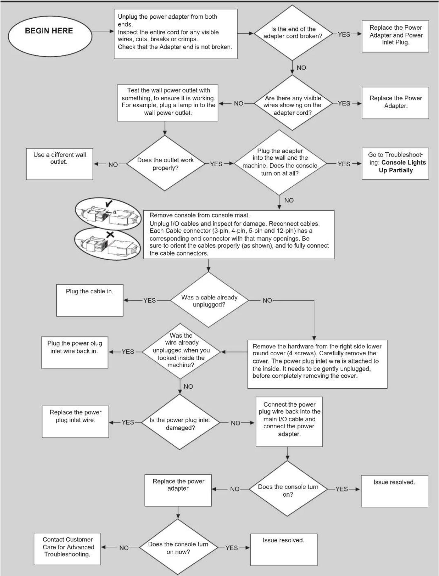
flowchart
graph TD
    A["BEGIN HERE"] --> B["Unplug the power adapter from both ends. Inspect the entire cord for any visible wires, cuts, breaks or crimps. Check that the Adapter end is not broken."]
    B --> C{Is the end of the adapter cord broken?}
    C -->|YES| D["Replace the Power Adapter and Power Inlet Plug."]
    C -->|NO| E{Are there any visible wires showing on the adapter cord?}
    E -->|YES| F["Replace the Power Adapter."]
    E -->|NO| G["Test the wall power outlet with something, to ensure it is working. For example, plug a lamp in to the wall power outlet."]
    G --> H{Does the outlet work properly?}
    H -->|NO| I["Use a different wall outlet."]
    H -->|YES| J{Plug the adapter into the wall and the machine. Does the console turn on at all?}
    J -->|YES| K["Go to Troubleshooting: Console Lights Up Partially"]
    J -->|NO| L["Remove console from console mast. Unplug I/O cables and inspect for damage. Reconnect cables. Each Cable connector (3-pin, 4-pin, 5-pin and 12-pin) has a corresponding end connector with that many openings. Be sure to orient the cables properly (as shown), and to fully connect the cable connectors."]
    L --> M{Was a cable already unplugged?}
    M -->|YES| N["Plug the cable in."]
    M -->|NO| O{Was the wire already unplugged when you looked inside the machine?}
    O -->|YES| P["Plug the power plug inlet wire back in."]
    O -->|NO| Q{Is the power plug inlet damaged?}
    Q -->|YES| R["Replace the power plug inlet wire."]
    Q -->|NO| S["Connect the power plug wire back into the main I/O cable and connect the power adapter."]
    S --> T{Does the console turn on?}
    T -->|YES| U["Issue resolved."]
    T -->|NO| V["Replace the power adapter"]
    V --> W{Does the console turn on now?}
    W -->|YES| X["Contact Customer Care for Advanced Troubleshooting."]
    W -->|NO| Y["Issue resolved."]

flowchart
graph TD
    A["BEGIN HERE"] --> B["Remove console from console mast. Unplug I/O cables and inspect for damage. Reconnect cables. Each Cable connector (3-pin, 4-pin, 5-pin and 12-pin) has a corresponding end connector with that many openings. Be sure to orient the cables properly (as shown), and to fully connect the cable connectors."]
    B --> C{Was a cable already unplugged?}
    C -->|YES| D["Plug the cable in."]
    C -->|NO| E["Remove the hardware from the right lower round cover. To remove the right lower round cover, the power plug inlet wire must be gently released from the inside of the cover. Once the power plug inlet wire is released, remove the cover from the machine."]
    E --> F["The speed sensor is located at the front of the frame pointing at the fan. Look closely at the tip of the sensor and check for any damage."]
    F --> G{Is the sensor damaged?}
    G -->|YES| H["Replace the Speed Sensor Assembly"]
    G -->|NO| I{Is the sensor wire unplugged from the main wire harness?}
    I -->|YES| J["Issue resolved."]
    I -->|NO| K["Rotate the fan so that one of the magnets meets the tip of the sensor. Adjust the sensor so that there is an 1/8 inch (3mm) gap between the sensor and the magnet (about the thickness of 2 pennies held together). Plug the power back in and test the machine."]
    K --> L{Does the issue persist?}
    L -->|YES| M["Contact Customer Care for Advanced Troubleshooting"]
    L -->|NO| N["Issue resolved."]
Resistance Does Not Respond

flowchart
graph TD
    A["BEGIN HERE"] --> B{Is the red light around the Resistance Knob lit?}
    B -->|NO| C["Remove console from console mast. Unplug I/O cables and inspect for damage. Reconnect cables. Each Cable connector (3-pin, 4-pin, 5-pin and 12-pin) has a corresponding end connector with that many openings. Be sure to orient the cables properly (as shown), and to fully connect the cable connectors."]
    B -->|YES| D{Does the fan turn freely?}
    D -->|NO| E["Plug the cable in."]
    D -->|YES| F["Remove the right side lower round cover."]
    E --> G{Was a cable already unplugged?}
    G -->|NO| H["If still not working, replace the Static Handlebar Assembly"]
    G -->|YES| I["Go to Troubleshooting: Machine Seized Up"]
    I --> J["Plug the power cord back in, and power up the display. If the inlet wire was unplugged, plug it back in."]
    J --> K["Begin any workout using the console. Turn the Resistance Knob up and see if the Servo Motor and Brake Arm move. Did they move?"]
    K -->|NO| L["Replace the Mast Harness Cable"]
    K -->|YES| M["Visually inspect the motor. Check to make sure that the metal cable is properly attached to the motor and the brake arm."]
    L --> N{Has the metal tension cable come off track, or need adjustment?}
    N -->|YES| O["Reattach / adjust the tension cable"]
    N -->|NO| P{Is the red, magnetic brake arm broken?}
    P -->|YES| Q["Replace the brake assembly"]
    P -->|NO| R{Is the metal tension cable broken?}
    R -->|YES| S["Replace the cable"]
    R -->|NO| T["Issue resolved."]
    S --> U{Does the resistance respond now?}
    U -->|NO| V["Replace the Servo Motor."]
    U -->|YES| W["Issue resolved."]
Machine Seized Up

flowchart
graph TD
A["BEGIN HERE"] --> B{Are the Crank Arms opposite each other 180*?}
B -->|NO| C["Follow the "Replace the Crank Arms" procedure to remove and reorient one Crank Arm so that they are 180* opposite each other as shown."]
B -->|YES| D["Attempt to rotate the Crank Arms by hand.<br>The Pedals may also be "bottomed out".<br>Safely grasp the Static Handlebars and apply your weight to the heel of the higher foot. While still grasping the Static Handlebar, lean back slightly applying more weight onto the heel. Once the Pedals begin to move, resume your intended workout."]
D --> E{Does the issue persist?}
E -->|NO| F["Issue resolved."]
E -->|YES| G["Remove the right side, lower round cover."]
G --> H{Are the magnets stuck to the brake disc?}
H -->|YES| I["Go to Troubleshooting: Metallic Grinding and Scraping"]
H -->|NO| J["Attempt to spin the fan by hand, back and forth. Inspect the 4 round magnets on the fan."]
J --> K{Are the magnets, or the fan making contact with either the motor, or the frame?}
K -->|NO| L["Inspect the lower belt. Is the belt physically damaged? Has the belt become jammed in the frame?"]
K -->|YES| M["Replace Machine Engine"]
K -->|NO| N{Does the Lower Belt need to be replaced?}
N -->|YES| O["Replace Lower Belt"]
N -->|NO| P["Remove the left pedal arm, and left side crank cover. This will expose the left crank and upper belt pulley.<br>Is the belt physically damaged? Has the belt become jammed in the frame?"]
P --> Q{Does the Upper Belt need to be replaced?}
Q -->|YES| R["Replace Upper Belt"]
Q -->|NO| S["Contact Customer Care for Advanced Troubleshooting"]

flowchart
graph TD
    A["BEGIN HERE"] --> B["Refer to the "Replace The Drive Belt" procedure."]
    B --> C["Follow the directions until it tells you to loosen the Drive Belt Tensioner Screw."]
    C --> D{Does the issue persist?}
    D -->|NO| E["Issue resolved."]
    D -->|YES| F{Does it slip less?}
    F -->|NO| G["Replace the Upper Belt Tensioner and Upper Belt"]
    F -->|YES| H["Tighten the belt tension a little more."]
    H --> I{Does the issue persist?}
    I -->|NO| E
    I -->|YES| J["End"]
Rollers and Pedals

flowchart
graph TD
    A["BEGIN HERE"] --> B{Are Wave Washers installed between Pedals and Crank Arms.}
    B -->|NO| C["Install Wave Washer between Pedals and Crank Arms."]
    B -->|YES| D{Is a clicking or rubbing noise being caused by contact between the roller wheel and the roller arm bracket?}
    D -->|NO| E["Remove both pedal arms and swap them around."]
    D -->|YES| F["The noise is a normal function, and is not harmful to the machine."]
    E --> G{Did this resolve the issue?}
    G -->|NO| H{Has the problem now switched sides?}
    G -->|YES| I["Issue resolved."]
    H -->|YES| J{Are the roller wheels visibly damaged?}
    H -->|NO| K["Replace one of the pedal arms."]
    J -->|NO| L["Follow the "Adjust the Leg Assembly Alignment" procedure."]
    L --> M{Did this resolve the issue?}
    M -->|NO| N["Remove both pedal arms. Remove both plastic crank covers. Be careful not to use a Phillips head screw-driver that is too small. These screws are sometimes very tight, and can strip easily. Use a 14mm socket to tighten both crank nuts, as much as possible."]
    M -->|YES| O["Issue resolved. Replace both crank. Did this resolve the issue?"]
    M -->|NO| P["arms."]
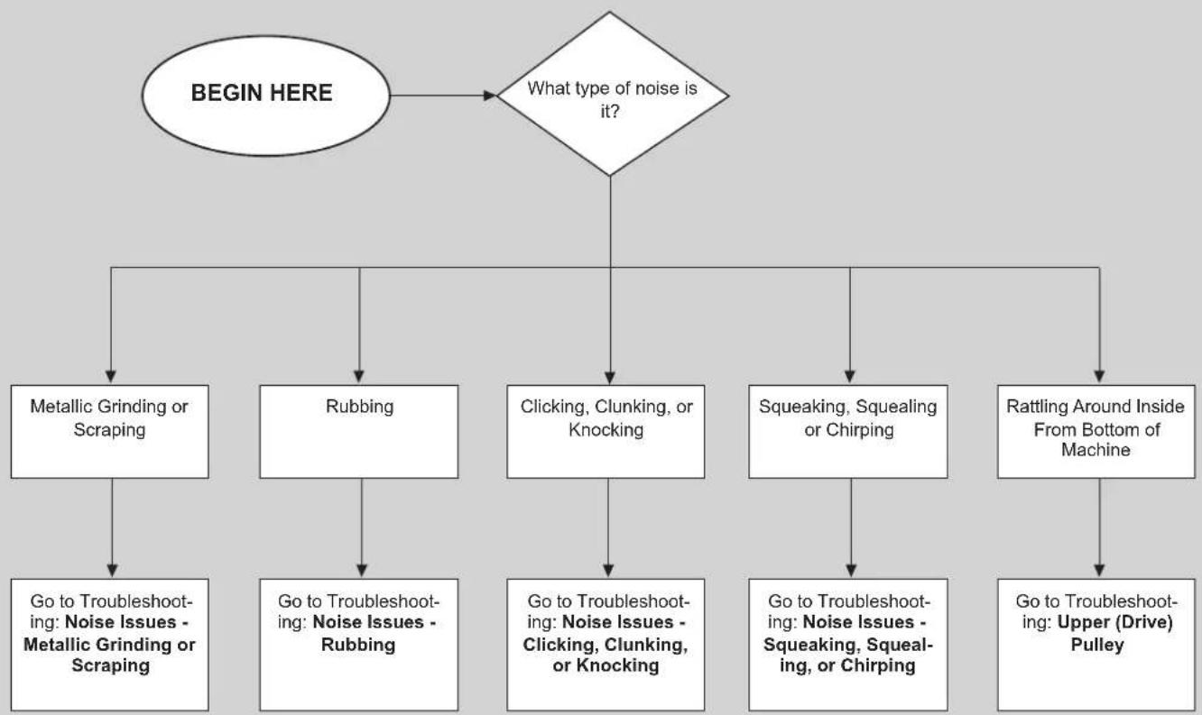
flowchart
graph TD
    A["BEGIN HERE"] --> B{What type of noise is it?}
    B --> C1["Metallic Grinding or Scraping"]
    B --> C2["Rubbing"]
    B --> C3["Clicking, Clunking, or Knocking"]
    B --> C4["Squeaking, Squealing or Chirping"]
    B --> C5["Rattling Around Inside From Bottom of Machine"]
    C1 --> D1["Go to Troubleshooting: Noise Issues - Metallic Grinding or Scraping"]
    C2 --> D2["Go to Troubleshooting: Noise Issues - Rubbing"]
    C3 --> D3["Go to Troubleshooting: Noise Issues - Clicking, Clunking, or Knocking"]
    C4 --> D4["Go to Troubleshooting: Noise Issues - Squeaking, Squealing, or Chirping"]
    C5 --> D5["Go to Troubleshooting: Upper (Drive) Pulley"]

flowchart
graph TD
A["BEGIN HERE"] --> B["Remove the user right side lower round cover (4 screws)."]
B --> C{Are the magnets making contact with the metallic brake disc?}
C -->|YES| D{Have the magnets broken off the red plastic arm?}
C -->|NO| E["Carefully operate machine and attempt to locate the source of the noise.<br>Contact Customer Care for Advanced Troubleshooting."]
D -->|YES| F["Replace the Brake Assembly"]
D -->|NO| G["Follow the "Adjust the Brake Assembly" procedure.<br>Note: It is normal for the brake disc to appear to "wobble", as long as it does not contact the magnets while spinning."]
G --> H{Can the magnets be adjusted so they don't touch the brake disc?}
H -->|YES| I["Adjust magnets so they stop making contact. Issue resolved."]
H -->|NO| J{Is the brake disc visibly forced away from the frame in such a way that it is causing the contact with the magnets?}
I --> K["Replace Machine Engine"]
J -->|YES| L["Replace the Brake Assembly and Brake Disc."]
J -->|NO| M["End"]

flowchart
graph TD
    A["BEGIN HERE"] --> B{Which side is the noise coming from, the left or right side?}
    B -->|LEFT| C["Remove the left pedal arm and left side crank cover. This will expose the left crank and upper belt pulley."]
    B -->|RIGHT| D["Remove the right lower round cover (4 screws). Then remove the metal brake disc (3 screws)."]
    C --> E{Is the upper belt traveling off the pulley?}
    D --> F{Is the lower belt traveling off the pulley?}
    E -->|YES| G{Is the upper pulley loose, wobbly, or crooked? Are the 4 bolts loose? Are any of the 4 bolts missing? Is the noise coming from the upper pulley?}
    F -->|YES| H{Is the belt damaged?}
    G -->|YES| I["Go to Troubleshooting: Upper (Drive) Pulley"]
    H -->|NO| J{Is the belt damaged?}
    I --> K["The belt needs to be replaced."]
    I --> L["Loosen the belt tensioner and replace the belt."]
    J -->|YES| M["Replace the belt tensioner."]
    J -->|NO| N["Loosen the belt tensioner and reset the belt."]
    K --> O["No"]
    L --> P["No"]
    M --> Q{Is any part of the belt tensioner bent or damaged?}
    N --> R["No"]
    O --> S["Yes"]
    P --> T["Yes"]
    Q --> U["Yes"]
    R --> V["Yes"]
Noise Issues - Clicking, Clunking, or Knocking
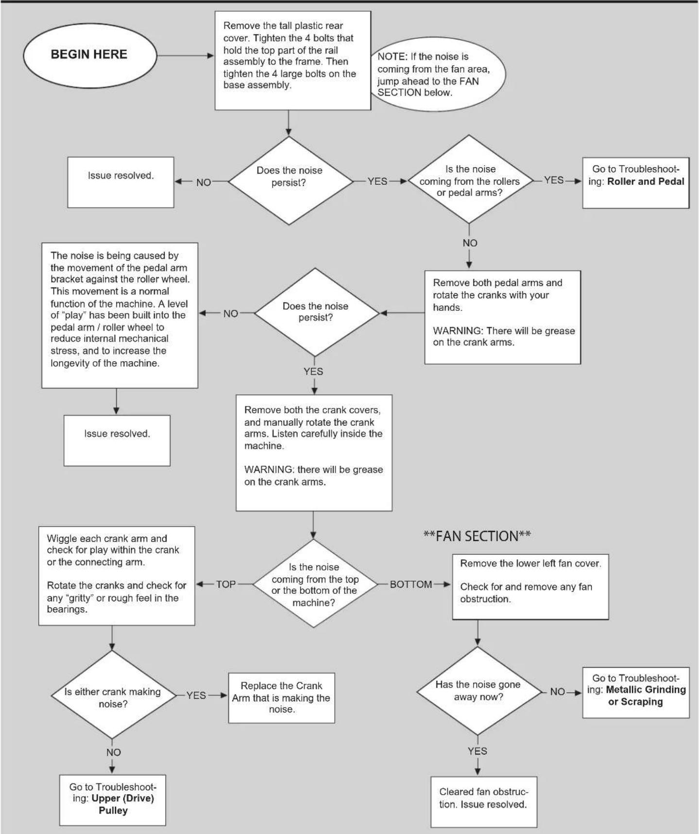
flowchart
graph TD
    A["BEGIN HERE"] --> B["Remove the tall plastic rear cover. Tighten the 4 bolts that hold the top part of the rail assembly to the frame. Then tighten the 4 large bolts on the base assembly."]
    B --> C{Does the noise persist?}
    C -->|NO| D["Issue resolved."]
    C -->|YES| E{Is the noise coming from the rollers or pedal arms?}
    E -->|NO| F["Remove both pedal arms and rotate the cranks with your hands. WARNING: There will be grease on the crank arms."]
    E -->|YES| G{Does the noise persist?}
    G -->|NO| H["Issue resolved."]
    G -->|YES| I["Remove both the crank covers, and manually rotate the crank arms. Listen carefully inside the machine. WARNING: there will be grease on the crank arms."]
    I --> J{Is the noise coming from the top or the bottom of the machine?}
    J -->|TOP| K[" Wiggle each crank arm and check for play within the crank or the connecting arm. Rotate the cranks and check for any "gritty" or rough feel in the bearings."]
    J -->|BOTTOM| L{Has the noise gone away now?}
    L -->|NO| M["Go to Troubleshooting: Metallic Grinding or Scraping"]
    L -->|YES| N["Cleared fan obstruction. Issue resolved."]
    L -->|YES| O["Replace the Crank Arm that is making the noise."]
    O --> P{Is either crank making noise?}
    P -->|NO| Q["Go to Troubleshooting: Upper (Drive) Pulley"]
    P -->|YES| R["Remove the lower left fan cover. Check for and remove any fan obstruction."]
    R --> S{Are not balanced?}
    S -->|NO| T["Go to Troubleshooting: Roller and Pedal"]
    S -->|YES| U["Remove both pedal arms and rotate the cranks with your hands. WARNING: There will be grease on the crank arms."]
    U --> V["Remove both pedal arms and rotate the cranks with your hands. Warning: There will be grease on the crank arms."]
    V --> W{Does the noise persist?}
    W -->|NO| X["The movement of the pedal arm bracket against the roller wheel. This movement is a normal function of the machine. A level of "play" has been built into the pedal arm / roller wheel to reduce internal mechanical stress, and to increase the longevity of the machine."]
    X --> Y["Issue resolved."]

flowchart
graph TD
    A["BEGIN HERE"] --> B["Remove the rubber end cap, where the pedal arm connects to the crank arm, on both sides of the machine."]
    B --> C{Does the noise persist?}
    C -->|NO| D["Re-attach the end caps loosely. If they are pushed on too tight, they will make squeaking noises."]
    C -->|YES| E["Apply a small drop of silicone based lubricant on the rails, and then wipe the rails with a dry towel. If too much lubricant is applied then the roller wheel may not roll. Pedal the machine slowly to ensure that the roller wheels are turning freely."]
    E --> F{Does the noise persist?}
    F -->|NO| G["Issue resolved."]
    F -->|YES| H["Apply a drop of silicone to the bushings on each side of the roller wheel (No need to disassemble) one side at a time.<br>Do NOT apply lubricant directly to the wheel. Catch any excess lubricant with a towel or cloth.<br>Test for noise on each side."]
    H --> I{Does the noise persist?}
    I -->|NO| J["Issue resolved."]
    I -->|YES| K{Does the noise sound like it's coming from the wheels/pedal arms?}
    K -->|YES| L["Go to Troubleshooting: Roller and Pedal"]
    K -->|NO| M["Go to Troubleshooting: Noises - Rubbing / Belt"]

flowchart
graph TD
    A["BEGIN HERE"] --> B["Ensure hands are centered on the Heart Rate (HR) sensors with equal pressure, and as little movement as possible without touching the metal frame."]
    B --> C["Explain that the HR may spike initially at a high rate, when first touching the contact plates. This is normal, and it will normalize out after waiting a couple of minutes. Try not to move the hands while waiting. If a quicker HR reading is required, switch to a Bluetooth® HR Strap."]
    C --> D["Dry or heavily calloused hands may need a heart rate cream to make better contact. Search for Buh-Bump Heart Rate Cream online."]
    D --> E{Does the issue persist?}
    E -->|NO| F["Issue resolved. Replace the Static"]
    E -->|YES| G["Handlebar Assembly"]
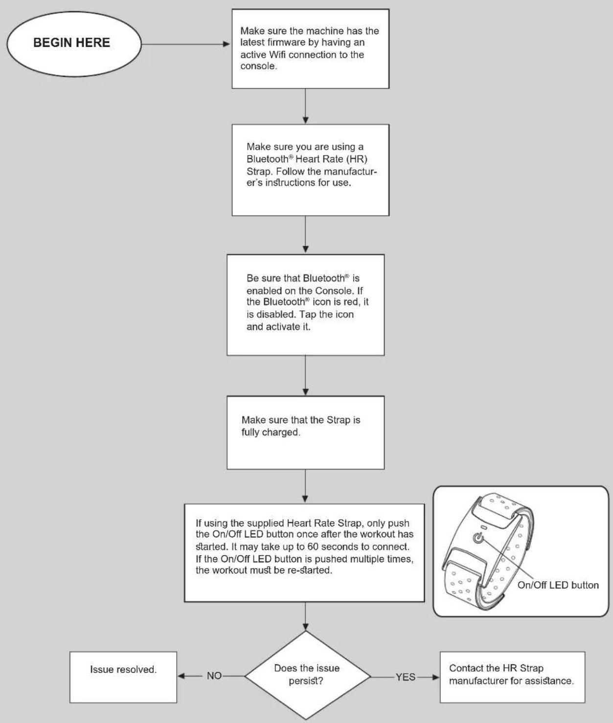
flowchart
graph TD
    A["BEGIN HERE"] --> B["Make sure the machine has the latest firmware by having an active Wifi connection to the console."]
    B --> C["Make sure you are using a Bluetooth® Heart Rate (HR) Strap. Follow the manufacturer's instructions for use."]
    C --> D["Be sure that Bluetooth® is enabled on the Console. If the Bluetooth® icon is red, it is disabled. Tap the icon and activate it."]
    D --> E["Make sure that the Strap is fully charged."]
    E --> F["If using the supplied Heart Rate Strap, only push the On/Off LED button once after the workout has started. It may take up to 60 seconds to connect. If the On/Off LED button is pushed multiple times, the workout must be re-started."]
    F --> G{Does the issue persist?}
    G -->|NO| H["Issue resolved."]
    G -->|YES| I["Contact the HR Strap manufacturer for assistance."]
Begin by inspecting around the machine for any hardware that may have fallen out of the machine.
Next remove the rear shroud, and inspect the upper, or drive, pulley. A flashlight may be needed.
Note the pulley screws, which can be seen protruding from the back of the pulley.
By manipulating the foot pedals the pulley will rotate, allowing the ability to check all four screws.
* Note whether all four screws are in place.
* Note whether all screws stick out about the same distance.
* Check that the belt is in place, and is not visibly damaged.
* Attempt to wiggle the pulley towards and away from the mast.
* Observe whether the pulley wobbles as it rotates.
After inspection, proceed with the troubleshooting steps in order.
Crank Puller: A Crank Puller is required to replace the drive pulley.
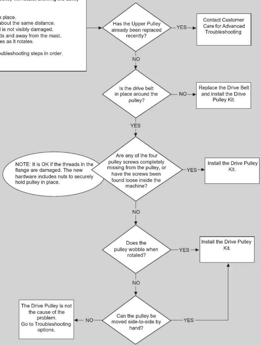
flowchart
graph TD
    A{Has the Upper Pulley already been replaced recently?}
    B["Contact Customer Care for Advanced Troubleshooting"] -->|YES| A
    C{Is the drive belt in place around the pulley?}
    D["Replace the Drive Belt and install the Drive Pulley Kit."] -->|NO| C
    E{Are any of the four pulley screws completely missing from the pulley, or have the screws been found loose inside the machine?}
    F["Install the Drive Pulley Kit."] -->|YES| G{Does the pulley wobble when rotated?}
    G -->|NO| H{Can the pulley be moved side-to-side by hand?}
    G -->|YES| I["Install the Drive Pulley Kit."]
    H -->|NO| J["The Drive Pulley is not the cause of the problem. Go to Troubleshooting options."]
    H -->|YES| K["No"]
    L["In place, about the same distance, is not visibly damaged, and is not moving away from the mast, as it rotates. Troubleshooting steps in order."] --> M["No"]
    N["NOTE: It is OK if the threads in the flange are damaged. The new hardware includes nuts to securely hold pulley in place."] --> O["No"]
Power Off and Restart the Machine
Note: When active, the Bowflex™ machine checks for software updates and installs them. If the machine is de-activated for a period of time, it may try to install updates when restarted.
- To power off the machine, log the user out from the Console.
- Unplug the power cord from the machine.

To prevent unsupervised operation of the machine always disconnect the power cord from the wall outlet and machine power input. Place the power cord in a secure location.
To restart the machine:
- Plug in the machine to a functioning wall outlet. The machine will start up, and the red Status LED will activate.
REPLACEMENT PROCEDURE SKILL LEVEL
Level I: Low - very little mechanical knowledge or exposure.
Level II: Intermediate - some experience with mechanical procedures
Level III : Advanced - knowledgeable about mechanical procedures

To reduce the risk of electrical shock or unsupervised usage of the equipment, always unplug the power cord from the wall outlet before cleaning, maintaining or repairing this machine. Place the power cord in a secure location.

When disposing of old parts, obey the applicable local and provincial requirements.
NOTICE: This document provides instructions for the adjustment of the Brake Assembly on the Bowflex™ Max Total™ machine / Max Total™ 16/40 / Max Trainer™ M9.
If you need assistance, please contact Customer Service (if purchased in US/Canada) or your local distributor (if purchased outside US/Canada). To find your local distributor, go to: www.nautilusinternational.com

This icon means a potentially hazardous situation which, if not avoided, could result in death or serious injury. Read and understand all Warnings on this machine.
Nautilus, Inc., www.NautilusInc.com, 5415 Centerpoint Parkway, Groveport, OH 43125 U.S.A. - Customer Service: North America (800) 605-3369, csnls@nautilus.com | outside U.S. www.nautilusinternational.com | Printed in China | © 2019 Nautilus, Inc. | Bowflex, the B logo, Max Total, and Max Trainer are trademarks owned or licensed by Nautilus, Inc., registered or otherwise protected by common law in the United States and other nations. | ORIGINAL DOCUMENT - ENGLISH VERSION ONLY
Important Safety Instructions - Before servicing or using this equipment, obey the following warnings:

This icon means a potentially hazardous situation which, if not avoided, could result in death or serious injury. Read and understand all Warnings on this machine.
- Read and understand the Part Replacement Procedure before working on the machine. Failure to obey the instructions and safety warnings could cause injury to the service technician or bystanders.
- Keep bystanders, children and pets away from the product being serviced at all times.
- Make sure that the repair is done in an appropriate work space away from foot traffic and exposure to bystanders.
- Disconnect all power and allow to sit for 5 minutes before you service this machine.
- Some components of the equipment can be heavy or awkward. Enlist the service of a second person when you do maintenance steps involving these components. Do not try to do heavy or awkward steps on your own.
- If replacement parts are necessary, use only genuine Nautilus replacement parts and hardware. Failure to use genuine replacement parts can cause a risk to users, keep the machine from operating correctly and will void the warranty.
- Be sure that all warning stickers and instructional placards applied to the product stay present and in good condition when doing maintenance or replacing components. If at any time the Warning labels become loose, unreadable or dislodged, replace the labels. If purchased in US/Canada, contact Customer Service for replacement labels. If purchased outside US/Canada, contact your local distributor for them.
- Do not try to change the design or functionality of the machine being serviced as this can adversely effect user safety and will void the warranty.
- Do not use the machine until all shrouds, instructions, warning labels and correct functionality have been verified and tested for correct performance.
- SAVE THESE INSTRUCTIONS.
Tools Required (not included)
2 Phillips screwdriver
10mm hex wrench
8mm open ended wrench


Note: Your machine may not match the images provided exactly.
- With power supplied to the machine, adjust the resistance to the maximum setting.
- When the machine has completed the adjustments to the resistance, unplug the AC Adapter from the wall outlet and machine.
-
Remove the Right Stabilizer Shroud from the machine (if equipped).
-
Using a #2 Phillips screwdriver, remove the indicated (by ovals) screws and only loosen the lowest indicated screw (arrow) from the Right Fan Cover.
Note: Loosen the lowest screw by at least 3 full rotations.
- The Right Fan Cover has a tab that needs to be pushed upward to clear the loosened screw. While pushing up on the tab, remove the Right Fan Cover from the assembly.
Note: The Power Cable is attached to the inside of the Right Fan Cover. Be sure not to crimp the cable by placing the Right Fan Cover close to the front of the machine.
To assist with assembly, note that the upper screw is a machine screw and not a self-tapping screw.


natural_image
Close-up of a black stationary exercise bike with visible mesh grille and mounting feet (no text or symbols)

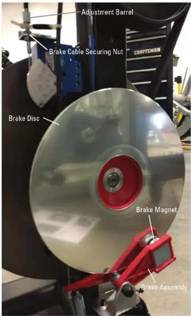
- At the maximum resistance setting, the outer edge of the Brake Magnet should line up with the outer edge of the Brake Disc.
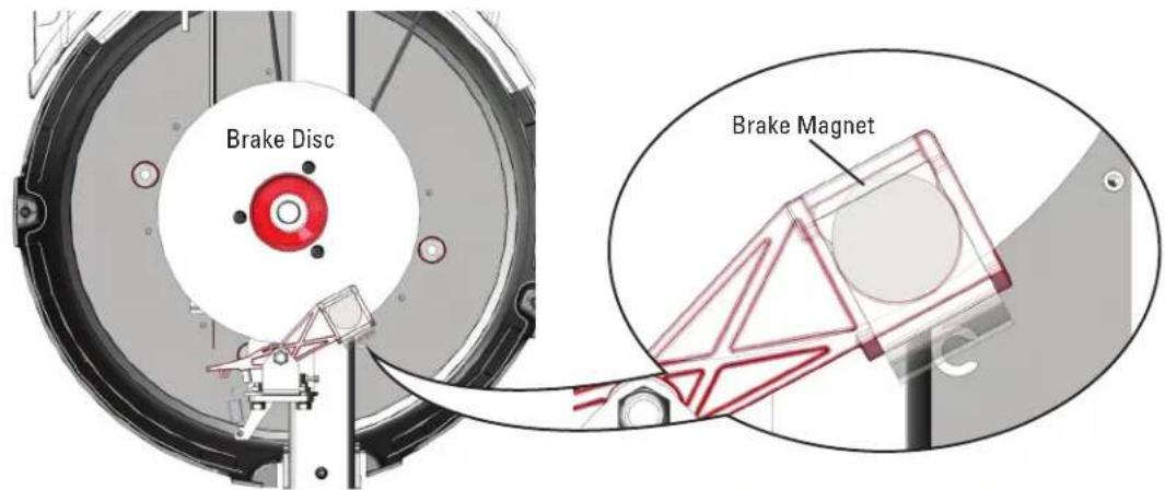
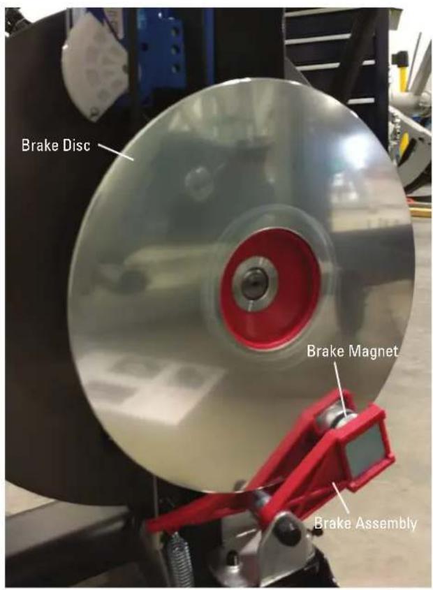
- If the Brake Assembly needs to be adjusted, use a 8mm open ended wrench to loosen the Brake Cable Securing Nut. Turn the Adjustment Barrel by hand until the magnet is placed correctly.
- Carefully rotate the Brake Disc. If the Brake Disc does not rub against the Brake Magnet, skip to step 11.

Keep fingers out of any pinch opportunities when rotating the Brake Disc.
Note: The Brake Disc may appear to have a slight "wobble". This is normal and will not affect machine function.
- The Brake Magnets should be aligned with the Brake Disc and centered around the Brake Disc.
- If the Brake Assembly only needs to be slightly adjusted, loosen the front screw (indicated by double-tailed arrow) that secures the Brake Assembly using a 10mm wrench. Rotate the Brake Assembly until the Magnets are aligned and of equal distance from the Brake Disc.
If the Brake Assembly must be fully shifted, loosen the 2 screws (indicated by arrows) that secure the assembly and shift it until centered and aligned with the Brake Disc. Fully tighten the hardware.

Rotate the Brake Disc to be sure it does not make contact with the magnets. If further adjustment is needed, repeat step 10.

Keep fingers out of any pinch opportunities when rotating the Brake Disc.

Note: The Brake Disc may appear to have a slight "wobble". This is normal and will not affect machine function.
-
Installation is the reverse procedure.
-
Final Inspection
Inspect your machine to ensure that all hardware is tight and components are properly assembled.

Do not use until the machine has been fully assembled and inspected for correct performance in accordance with the Owner's Manual.
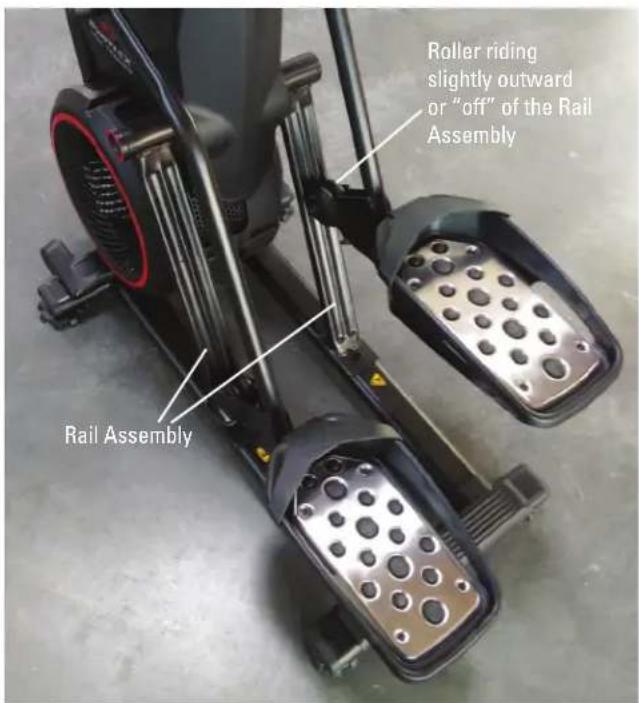
NOTICE: This document provides instructions for the adjustment of the Leg Assembly Alignment on the Bowflex™ Max Total™ machine / Max Total™ 16/40 / Max Trainer™ M9. The Rollers on the Leg Assemblies may be slightly "off", or not fully centered onto the Rail Assembly. This procedure may assist with this condition.
If you need assistance, please contact Customer Service (if purchased in US/Canada) or your local distributor (if purchased outside US/Canada). To find your local distributor, go to: www.nautilusinternational.com

This icon means a potentially hazardous situation which, if not avoided, could result in death or serious injury. Read and understand all Warnings on this machine.
Nautilus, Inc., www.NautilusInc.com, 5415 Centerpoint Parkway, Groveport, OH 43125 U.S.A. - Customer Service: North America (800) 605-3369, csnls@nautilus.com | outside U.S. www.nautilusinternational.com | Printed in China | © 2019 Nautilus, Inc. | Bowflex, the B logo, Max Total, and Max Trainer are trademarks owned or licensed by Nautilus, Inc., registered or otherwise protected by common law in the United States and other nations. | ORIGINAL DOCUMENT - ENGLISH VERSION ONLY
Important Safety Instructions - Before servicing or using this equipment, obey the following warnings:

This icon means a potentially hazardous situation which, if not avoided, could result in death or serious injury. Read and understand all Warnings on this machine.
- Read and understand the Part Replacement Procedure before working on the machine. Failure to obey the instructions and safety warnings could cause injury to the service technician or bystanders.
- Keep bystanders, children and pets away from the product being serviced at all times.
- Make sure that the repair is done in an appropriate work space away from foot traffic and exposure to bystanders.
- Disconnect all power and allow to sit for 5 minutes before you service this machine.
- Some components of the equipment can be heavy or awkward. Enlist the service of a second person when you do maintenance steps involving these components. Do not try to do heavy or awkward steps on your own.
- If replacement parts are necessary, use only genuine Nautilus replacement parts and hardware. Failure to use genuine replacement parts can cause a risk to users, keep the machine from operating correctly and will void the warranty.
- Be sure that all warning stickers and instructional placards applied to the product stay present and in good condition when doing maintenance or replacing components. If at any time the Warning labels become loose, unreadable or dislodged, replace the labels. If purchased in US/Canada, contact Customer Service for replacement labels. If purchased outside US/Canada, contact your local distributor for them.
- Do not try to change the design or functionality of the machine being serviced as this can adversely effect user safety and will void the warranty.
- Do not use the machine until all shrouds, instructions, warning labels and correct functionality have been verified and tested for correct performance.
- SAVE THESE INSTRUCTIONS.
Tools Required (not included)
2 Phillips screwdriver
6mm hex wrench
8mm hex wrench
2 standard screwdriver



If the Rollers seem to be "off" and not fully tracked on the Rail Assembly, this procedure may assist.
-
Unplug the AC Power Adapter from the machine.
-
Using a #2 Phillips screwdriver, remove the 1 indicated screw from the Rear Shroud.
-
Carefully remove the Rear Shroud from the machine. Place a standard screwdriver behind and near the middle of the Rear Shroud and gently pry until it just releases. Then move the screwdriver to the bottom and gently pry until the Rear Shroud comes off.

- Using a 6mm hex wrench, slightly loosen the indicated bolts that secure the Rail Assembly to the Frame Assembly.

Do not fully remove the hardware.
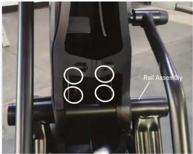
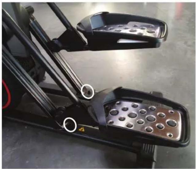
- Using a 8mm hex wrench, slightly loosen the indicated bolts that secure the Rail Assembly to the Base Assembly.

Do not fully remove the hardware.
natural_image
Close-up of a black and white bicycle pedal mechanism with visible control buttons and safety markings (no text or symbols)-
Shift the Rail Assembly back and forth, or "wiggle", until it seems to settle into the correct configuration. The Rollers will have adjusted with the Rail Assembly, and should be more "on" with the groove of the Roller centered onto the Rail Assembly.
-
Installation is the reverse procedure.
-
Final Inspection
Inspect your machine to ensure that all hardware is tight and components are properly assembled.

Do not use until the machine has been fully assembled and inspected for correct performance in accordance with the Owner's Manual.
NOTICE: This document provides instructions to modify the Resistance Knob Cable on the Bowflex™ Max Total™ machine / Max Total™ 16/40 / Max Trainer™ M9.
Note: Only perform this procedure if directly instructed to do it by Customer Service or your local distributor.
If you need assistance, please contact Customer Service (if purchased in US/Canada) or your local distributor (if purchased outside US/Canada). To find your local distributor, go to: www.nautilusinternational.com

This icon means a potentially hazardous situation which, if not avoided, could result in death or serious injury. Read and understand all Warnings on this machine.
Nautilus, Inc., www.NautilusInc.com, 5415 Centerpoint Parkway, Groveport, OH 43125 U.S.A. - Customer Service: North America (800) 605-3369, csnls@nautilus.com | outside U.S. www.nautilusinternational.com | Printed in China | © 2020 Nautilus, Inc. | Bowflex, the B logo, Max Total, and Max Trainer are trademarks owned or licensed by Nautilus, Inc., registered or otherwise protected by common law in the United States and other nations. | ORIGINAL DOCUMENT - ENGLISH VERSION ONLY
Important Safety Instructions - Before servicing or using this equipment, obey the following warnings:

This icon means a potentially hazardous situation which, if not avoided, could result in death or serious injury. Read and understand all Warnings on this machine.
- Read and understand the Part Replacement Procedure before working on the machine. Failure to obey the instructions and safety warnings could cause injury to the service technician or bystanders.
- Keep bystanders, children and pets away from the product being serviced at all times.
- Make sure that the repair is done in an appropriate work space away from foot traffic and exposure to bystanders.
- Disconnect all power and allow to sit for 5 minutes before you service this machine.
- Some components of the equipment can be heavy or awkward. Enlist the service of a second person when you do maintenance steps involving these components. Do not try to do heavy or awkward steps on your own.
- If replacement parts are necessary, use only genuine Nautilus replacement parts and hardware. Failure to use genuine replacement parts can cause a risk to users, keep the machine from operating correctly and will void the warranty.
- Be sure that all warning stickers and instructional placards applied to the product stay present and in good condition when doing maintenance or replacing components. If at any time the Warning labels become loose, unreadable or dislodged, replace the labels. If purchased in US/Canada, contact Customer Service for replacement labels. If purchased outside US/Canada, contact your local distributor for them.
- Do not try to change the design or functionality of the machine being serviced as this can adversely effect user safety and will void the warranty.
- Do not use the machine until all shrouds, instructions, warning labels and correct functionality have been verified and tested for correct performance.
.SAVE THESE INSTRUCTIONS.
Tools Required (not included)
2 Phillips screwdriver

natural_image
Icon of a pen tip with a cross symbol, no text or labels presentScissors or Cable Cutters

natural_image
Black silhouette of scissors inside a rounded square frame (no text or symbols)
Note: Your machine may not match the images provided exactly.
- Unplug the AC Adapter from the wall outlet and machine.
-
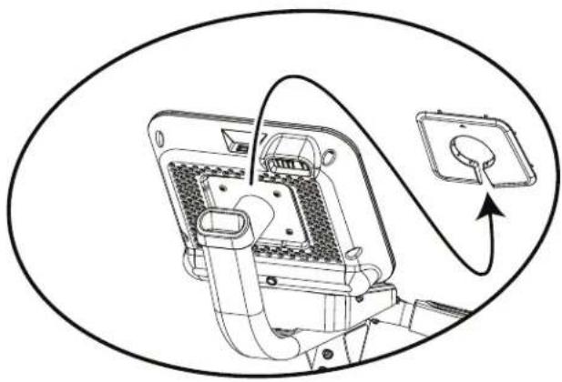
Remove the Rear Console Cover from the Console Assembly.
-
Using a #2 Phillips screwdriver, remove the screws (indicated by ovals) from the Console Assembly.
-
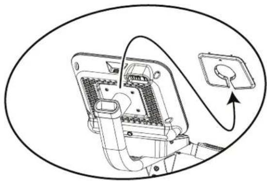
Carefully tilt the Console Assembly off of the Static Handlebar and expose the Cable Connections.
Note: Do not crimp any of the Console Cables. This step may require two people.
- Carefully disconnect the Cables and place the Console outside the work area.
Note: Do not crimp any of the Console Cables.
natural_image
Diagram of an electrical plug with wiring and socket, no text or symbols present

natural_image
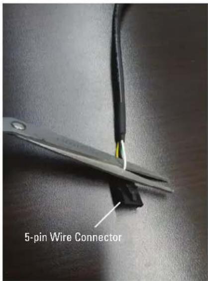
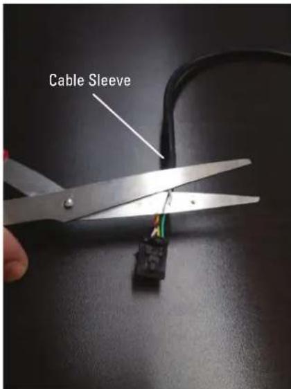
Technical line drawing of a mechanical device with no visible text or symbols- Locate the Resistance Knob Cable which has the 5-pin Wire Connector coming from the Console Mast. This Cable will have Red, Yellow, Black, Green and White Wires inside of it.


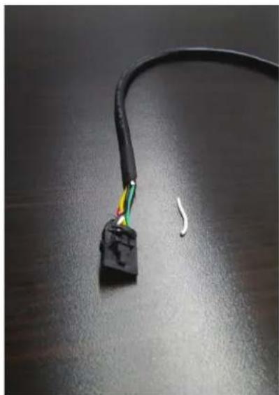
- Slightly pull out the White Wire from the others and cut it twice with scissors or wire cutters. The first cut should be as near the 5-pin Wire Connector as possible, and the second cut should be where the Cable Sleeve covers all the Wires.
Note: Be sure not to cut or crimp any of the other Wires.
natural_image
Close-up of a black cable with multicolored wires and a small white wire on a dark surface (no text or symbols visible)-
Dispose of the removed piece of White Wire.
-
Re-assemble the machine in the reverse order of when the parts were removed.
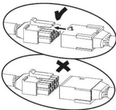
Note: Do not cut or crimp the Cables. Each Cable connector (3-pin, 4-pin, 5-pin and 14-pin) has a corresponding end connector with that many openings. Be sure to fully connect the cable connectors. When attaching the Console Assembly, do not fully tighten the hardware until all hardware has been hand tightened.
- Final Inspection
Inspect your machine to ensure that all hardware is tight and components are properly assembled.

Do not use until the machine has been fully assembled and inspected for correct performance in accordance with the Owner's Manual.
NOTICE: This document provides instructions for the replacement of the Brake Assembly on the Bowflex™ Max Total™ machine / Max Total™ 16/40 / Max Trainer™ M9.
If you need assistance, please contact Customer Service (if purchased in US/Canada) or your local distributor (if purchased outside US/Canada). To find your local distributor, go to: www.nautilusinternational.com

This icon means a potentially hazardous situation which, if not avoided, could result in death or serious injury. Read and understand all Warnings on this machine.
Nautilus, Inc., www.NautilusInc.com, 5415 Centerpoint Parkway, Groveport, OH 43125 U.S.A. - Customer Service: North America (800) 605-3369, csnls@nautilus.com | outside U.S. www.nautilusinternational.com | Printed in China | © 2019 Nautilus, Inc. | Bowflex, the B logo, Max Total, and Max Trainer are trademarks owned or licensed by Nautilus, Inc., registered or otherwise protected by common law in the United States and other nations. | ORIGINAL DOCUMENT - ENGLISH VERSION ONLY
Important Safety Instructions - Before servicing or using this equipment, obey the following warnings:

This icon means a potentially hazardous situation which, if not avoided, could result in death or serious injury. Read and understand all Warnings on this machine.
- Read and understand the Part Replacement Procedure before working on the machine. Failure to obey the instructions and safety warnings could cause injury to the service technician or bystanders.
- Keep bystanders, children and pets away from the product being serviced at all times.
- Make sure that the repair is done in an appropriate work space away from foot traffic and exposure to bystanders.
- Disconnect all power and allow to sit for 5 minutes before you service this machine.
- Some components of the equipment can be heavy or awkward. Enlist the service of a second person when you do maintenance steps involving these components. Do not try to do heavy or awkward steps on your own.
- If replacement parts are necessary, use only genuine Nautilus replacement parts and hardware. Failure to use genuine replacement parts can cause a risk to users, keep the machine from operating correctly and will void the warranty.
- Be sure that all warning stickers and instructional placards applied to the product stay present and in good condition when doing maintenance or replacing components. If at any time the Warning labels become loose, unreadable or dislodged, replace the labels. If purchased in US/Canada, contact Customer Service for replacement labels. If purchased outside US/Canada, contact your local distributor for them.
- Do not try to change the design or functionality of the machine being serviced as this can adversely effect user safety and will void the warranty.
- Do not use the machine until all shrouds, instructions, warning labels and correct functionality have been verified and tested for correct performance.
- SAVE THESE INSTRUCTIONS.
Tools Required (not included)
2
Phillips
screwd
10mm
8 wrench

natural_image
Black and white icon of a wrench inside a rounded square frame (no text or symbols)2.5mm hex wrench

Tape, any type (only used as a place holder)

Note: Your machine may not match the images provided exactly.
- With power supplied to the machine, adjust the resistance to the maximum setting.
- Unplug the AC Adapter from the wall outlet and machine.
-
Remove the Right Stabilizer Shroud from the machine.
-
Using a #2 Phillips screwdriver, remove the indicated (by ovals) screws and only loosen the lowest indicated screw (arrow) from the Right Fan Cover.
Note: Loosen the lowest screw by at least 3 full rotations.
- The Right Fan Cover has a tab that needs to be pushed upward to clear the loosened screw. While pushing up on the tab, remove the Right Fan Cover from the assembly.
Note: The Power Cable is attached to the inside of the Right Fan Cover. Be sure not to crimp the cable by placing the Right Fan Cover close to the front of the machine.
To assist with assembly, note that the upper screw is a machine screw and not a self-tapping screw.


natural_image
Close-up of a black stationary exercise machine with visible mesh speaker and circular components (no text or symbols)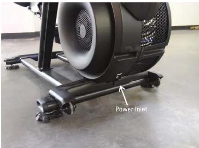

- Using a #2 Phillips screwdriver, remove the 3 indicated screws from the Brake Disc.
- Carefully remove the Brake Disc from the machine.
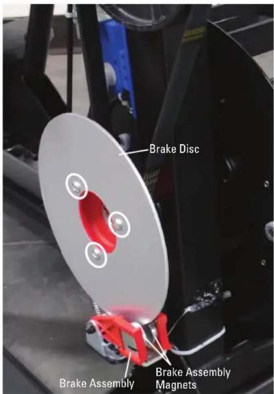
- Place a piece of tape (as a marker) on the Brake Cable immediately above the Brake Arm. During re-assembly, the tape will be a guide for the placement of the new Brake Arm on the Brake Cable.

- While applying upward pressure to the Brake Arm, remove the hardware that secures the Brake Cable to the Brake Arm with a 2.5mm hex wrench. Once loose, gradually lower the Brake Arm.
Note: Be aware that the Spring will pull the Brake Arm once released. An object can be placed under the Brake Arm to supply resistance during the release of the Brake Cable Hardware.
- Remove the Brake Spring from the Brake Arm.

-
Using a 10mm open-end wrench, remove the screws that connect the Brake Assembly and remove it.
-
Attach the new Brake Assembly, but do not fully tighten the hardware.
-
Attach the Brake Disc.
-
Reattach the Brake Spring and the Brake Cable to the Brake Arm, and adjust to the tape marker. Tighten the hardware that attaches to the Brake Cable to 2.6-3.0 Nm torque.
-
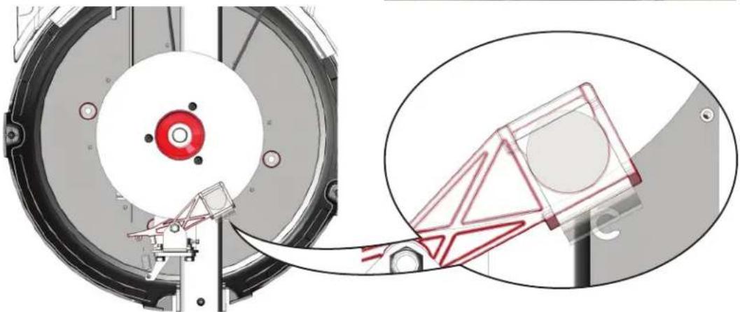
At the maximum resistance setting, the outer edge of the Brake Magnet should line up with the outer edge of the Brake Disc.

natural_image
Technical diagram of a mechanical assembly with a circular component and a magnified inset showing a 3D model (no text or symbols present)- If the Brake Assembly needs to be adjusted, use a 8mm open ended wrench to loosen the Brake Cable Securing Nut. Turn the Adjustment Barrel by hand until the magnet is placed correctly.
- Carefully rotate the Brake Disc. If the Brake Disc does not rub against the Brake Magnet, skip to step 20.

Keep fingers out of any pinch opportunities when rotating the Brake Disc.
Note: The Brake Disc may appear to have a slight "wobble". This is normal and will not affect machine function.

- The Brake Magnets should be aligned with the Brake Disc and centered around the Brake Disc.
- If the Brake Assembly only needs to be slightly adjusted, loosen the front screw (indicated by double-tailed arrow) that secures the Brake Assembly using a 10mm open-end wrench. Rotate the Brake Assembly until the Magnets are aligned and of equal distance from the Brake Disc.
If the Brake Assembly must be fully shifted, loosen the 2 screws that secure the assembly and shift it until centered and aligned with the Brake Disc. Fully tighten the hardware.

Rotate the Brake Disc to be sure it does not make contact with the magnets. If further adjustment is needed, repeat step 20.


Keep fingers out of any pinch opportunities when rotating the Brake Disc.
Note: The Brake Disc may appear to have a slight "wobble". This is normal and will not affect machine function.
-
Installation is the reverse procedure.
-
Final Inspection
Inspect your machine to ensure that all hardware is tight and components are properly assembled.

Do not use until the machine has been fully assembled and inspected for correct performance in accordance with the Owner's Manual.
NOTICE: This document provides instructions for the replacement of the Console Assembly on the Bowflex™ Max Total™ machine / Max Total™ 16/40 / Max Trainer™ M9.
If you need assistance, please contact Customer Service (if purchased in US/Canada) or your local distributor (if purchased outside US/Canada). To find your local distributor, go to: www.nautilusinternational.com

This icon means a potentially hazardous situation which, if not avoided, could result in death or serious injury. Read and understand all Warnings on this machine.
Nautilus, Inc., www.NautilusInc.com, 5415 Centerpoint Parkway, Groveport, OH 43125 U.S.A. - Customer Service: North America (800) 605-3369, csnls@nautilus.com | outside U.S. www.nautilusinternational.com | Printed in China | © 2019 Nautilus, Inc. | Bowflex, the B logo, Max Total, and Max Trainer are trademarks owned or licensed by Nautilus, Inc., registered or otherwise protected by common law in the United States and other nations. | ORIGINAL DOCUMENT - ENGLISH VERSION ONLY
Important Safety Instructions - Before servicing or using this equipment, obey the following warnings:

This icon means a potentially hazardous situation which, if not avoided, could result in death or serious injury. Read and understand all Warnings on this machine.
- Read and understand the Part Replacement Procedure before working on the machine. Failure to obey the instructions and safety warnings could cause injury to the service technician or bystanders.
- Keep bystanders, children and pets away from the product being serviced at all times.
- Make sure that the repair is done in an appropriate work space away from foot traffic and exposure to bystanders.
- Disconnect all power and allow to sit for 5 minutes before you service this machine.
- Some components of the equipment can be heavy or awkward. Enlist the service of a second person when you do maintenance steps involving these components. Do not try to do heavy or awkward steps on your own.
- If replacement parts are necessary, use only genuine Nautilus replacement parts and hardware. Failure to use genuine replacement parts can cause a risk to users, keep the machine from operating correctly and will void the warranty.
- Be sure that all warning stickers and instructional placards applied to the product stay present and in good condition when doing maintenance or replacing components. If at any time the Warning labels become loose, unreadable or dislodged, replace the labels. If purchased in US/Canada, contact Customer Service for replacement labels. If purchased outside US/Canada, contact your local distributor for them.
- Do not try to change the design or functionality of the machine being serviced as this can adversely effect user safety and will void the warranty.
- Do not use the machine until all shrouds, instructions, warning labels and correct functionality have been verified and tested for correct performance.
- SAVE THESE INSTRUCTIONS.
Tools Required (not included)
2 Phillips screwdriver

natural_image
Icon of a pen tip with a cross symbol, no text or labels present
Note: Your machine may not match the images provided exactly.
- Unplug the AC Adapter from the wall outlet and machine.
-
Remove the Rear Console Cover from the Console Assembly.
-
Using a #2 Phillips screwdriver, remove the screws (indicated by ovals) from the Console Assembly.

natural_image
Diagram of an electrical plug with wiring and socket, no text or symbols present
- Carefully tilt the Console Assembly off of the Static Handlebar and expose the Cable Connections.
Note: Do not crimp any of the Console Cables. This step may require two people.
- Carefully disconnect the Cables.
Note: Do not crimp any of the Console Cables.

natural_image
Technical line drawing of a mechanical device with no visible text or symbols- Installation is the reverse procedure.
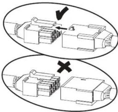
Note: Do not cut or crimp the Cables. Each Cable connector (3-pin, 4-pin, 5-pin and 12-pin) has a corresponding end connector with that many openings. Be sure to fully connect the cable connectors.

natural_image
Diagram showing two views of a connector assembly with arrows indicating process (no text or symbols)7. Final Inspection
Inspect your machine to ensure that all hardware is tight and components are properly assembled.

Do not use until the machine has been fully assembled and inspected for correct performance in accordance with the Owner's Manual.
NOTICE: This document provides instructions for the replacement of the Console Rear Panel on the Bowflex™ Max Total™ machine / Max Total™ 16/40 / Max Trainer™ M9.
If you need assistance, please contact Customer Service (if purchased in US/Canada) or your local distributor (if purchased outside US/Canada). To find your local distributor, go to: www.nautilusinternational.com

This icon means a potentially hazardous situation which, if not avoided, could result in death or serious injury. Read and understand all Warnings on this machine.
Nautilus, Inc., www.NautilusInc.com, 5415 Centerpoint Parkway, Groveport, OH 43125 U.S.A. - Customer Service: North America (800) 605-3369, csnls@nautilus.com | outside U.S. www.nautilusinternational.com | Printed in China | © 2019 Nautilus, Inc. | Bowflex, the B logo, Max Total, and Max Trainer are trademarks owned or licensed by Nautilus, Inc., registered or otherwise protected by common law in the United States and other nations. | ORIGINAL DOCUMENT - ENGLISH VERSION ONLY
Important Safety Instructions - Before servicing or using this equipment, obey the following warnings:

This icon means a potentially hazardous situation which, if not avoided, could result in death or serious injury. Read and understand all Warnings on this machine.
- Read and understand the Part Replacement Procedure before working on the machine. Failure to obey the instructions and safety warnings could cause injury to the service technician or bystanders.
- Keep bystanders, children and pets away from the product being serviced at all times.
- Make sure that the repair is done in an appropriate work space away from foot traffic and exposure to bystanders.
- Disconnect all power and allow to sit for 5 minutes before you service this machine.
- Some components of the equipment can be heavy or awkward. Enlist the service of a second person when you do maintenance steps involving these components. Do not try to do heavy or awkward steps on your own.
- If replacement parts are necessary, use only genuine Nautilus replacement parts and hardware. Failure to use genuine replacement parts can cause a risk to users, keep the machine from operating correctly and will void the warranty.
- Be sure that all warning stickers and instructional placards applied to the product stay present and in good condition when doing maintenance or replacing components. If at any time the Warning labels become loose, unreadable or dislodged, replace the labels. If purchased in US/Canada, contact Customer Service for replacement labels. If purchased outside US/Canada, contact your local distributor for them.
- Do not try to change the design or functionality of the machine being serviced as this can adversely effect user safety and will void the warranty.
- Do not use the machine until all shrouds, instructions, warning labels and correct functionality have been verified and tested for correct performance.
- SAVE THESE INSTRUCTIONS.
Tools Required (not included)
2 Phillips screwdriver

natural_image
Icon of a pen tip with a cross symbol, no text or labels present
Note: Your machine may not match the images provided exactly.
- Unplug the AC Adapter from the wall outlet and machine.
-
Remove the Rear Console Cover from the Console Assembly.
-
Using a #2 Phillips screwdriver, remove the screws (indicated by ovals) from the Console Assembly.
natural_image
Diagram of a device with cable and connector, no text or symbols present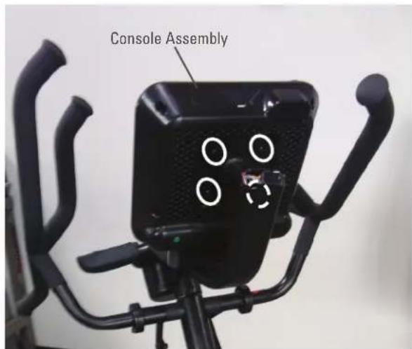
- Carefully tilt the Console Assembly off of the Static Handlebar and expose the Cable Connections.
Note: Do not crimp any of the Console Cables. This step may require two people.
- Carefully disconnect the Cables.
Note: Do not crimp any of the Console Cables.

natural_image
Technical line drawing of a mechanical device with internal components and a curved base, enclosed in an oval frame (no text or symbols)-
To protect the Console display from scratches, gently place the Console Assembly face down on a towel or piece of cardboard.
-
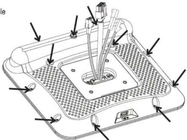
Using a #2 Phillips screwdriver, remove the screws (indicated by arrows) from the back of the Console Assembly.

natural_image
Technical line drawing of a computer motherboard with mounting holes and wiring (no text or symbols)- Carefully tilt the Console Rear Panel outward off of the Console Assembly, exposing the USB Cable connected to the Console Front Panel.
Note: Do not crimp any of the Cables. This step may require two people.
- Carefully disconnect the USB Cable from the Console Front Panel to the Console Rear Panel.
Note: Do not crimp any of the Cables.
- Swap in the new Console Rear Panel.

- Carefully bring the new Console Rear Panel over to the Console Front Panel. Route the four Cables from the Console Front Panel through the opening on the new Console Rear Panel.
Note: Do not crimp any of the Cables. This step may require two people.
- Carefully connect the USB Cable from the new Console Rear Panel to the Console Front Panel.
Note: Do not crimp any of the Cables.

- Using a #2 Phillips screwdriver, attach the new Console Rear Panel to the Console Front Panel.
- Installation is the reverse procedure.
Note: Do not cut or crimp the Cables. Each Cable connector (3-pin, 4-pin, 5-pin and 12-pin) has a corresponding end connector with that many openings. Be sure to fully connect the cable connectors.
- Final Inspection
Inspect your machine to ensure that all hardware is tight and components are properly assembled.

Do not use until the machine has been fully assembled and inspected for correct performance in accordance with the Owner's Manual.
natural_image
Diagram showing two views of a mechanical component with arrows indicating process (no text or symbols)NOTICE: This document provides instructions for the replacement of the Left Crank Arm on the Bowflex™ Max Total™ machine and Max Total™ 16/40.
If you need assistance, please contact Customer Service (if purchased in US/Canada) or your local distributor (if purchased outside US/Canada). To find your local distributor, go to: www.nautilusinternational.com

This icon means a potentially hazardous situation which, if not avoided, could result in death or serious injury. Read and understand all Warnings on this machine.
Nautilus, Inc., www.NautilusInc.com, 5415 Centerpoint Parkway, Groveport, OH 43125 U.S.A. - Customer Service: North America (800) 605-3369, csnls@nautilus.com | outside U.S. www.nautilusinternational.com | Printed in
China | © 2019 Nautilus, Inc. | Bowflex, the B logo, and Max Total are trademarks owned or licensed by Nautilus, Inc., registered or otherwise protected by common law in the United States and other nations. | ORIGINAL
DOCUMENT - ENGLISH VERSION ONLY
Important Safety Instructions - Before servicing or using this equipment, obey the following warnings:

This icon means a potentially hazardous situation which, if not avoided, could result in death or serious injury. Read and understand all Warnings on this machine.
- Read and understand the Part Replacement Procedure before working on the machine. Failure to obey the instructions and safety warnings could cause injury to the service technician or bystanders.
- Keep bystanders, children and pets away from the product being serviced at all times.
- Make sure that the repair is done in an appropriate work space away from foot traffic and exposure to bystanders.
- Disconnect all power and allow to sit for 5 minutes before you service this machine.
- Some components of the equipment can be heavy or awkward. Enlist the service of a second person when you do maintenance steps involving these components. Do not try to do heavy or awkward steps on your own.
- If replacement parts are necessary, use only genuine Nautilus replacement parts and hardware. Failure to use genuine replacement parts can cause a risk to users, keep the machine from operating correctly and will void the warranty.
- Be sure that all warning stickers and instructional placards applied to the product stay present and in good condition when doing maintenance or replacing components. If at any time the Warning labels become loose, unreadable or dislodged, replace the labels. If purchased in US/Canada, contact Customer Service for replacement labels. If purchased outside US/Canada, contact your local distributor for them.
- Do not try to change the design or functionality of the machine being serviced as this can adversely effect user safety and will void the warranty.
- Do not use the machine until all shrouds, instructions, warning labels and correct functionality have been verified and tested for correct performance.
- SAVE THESE INSTRUCTIONS.
Tools Required (not included)
2
Phillips
screwdr

5mm hex wrench
6mm
hex
wrench

Wrench

9/

14mm
Crank Puller (non-handled,
JIS/ISO square taper
with M22x1.0 threads)

Note: Your machine may not match the images provided exactly.
- Remove the indicated Cap from the left side of the machine.
- Using a 6mm hex wrench, remove the hardware exposed from below the Cap.
- Lift the Foot Pedal and slide the Leg Assembly straight off the machine. Be sure to pull straight out, or the Leg Assembly may be difficult to remove.
- Remove the Wave Washer from the Crank Arm, and place it in a secure location for re-use.
- Using a 5mm hex wrench, remove the indicated hardware from the Left Upper Handlebar and place it out of the work area.
Note: Be aware that the Left Upper Handlebar must be supported when removing the hardware.
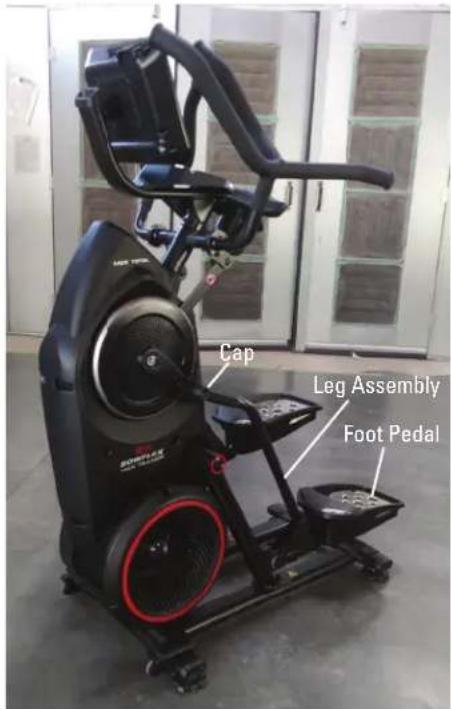

- Place a rag or protective material below the Connector Arm to protect the Shrouds from potential scratches from the Connector Arms.
- Using a 6mm hex wrench, remove the hardware that connects the Connector Arm and the Pivot Arm.
Note: The Connector Arm will pivot downward if not lowered slowly onto the rag protecting the Shroud.

- Using a #2 Phillips screwdriver, remove the 2 indicated screws from the Left Crank Cover.
Note: The Left Crank Cover screws may have been over-tightened when installed. Try not to strip the screws when removing them.
-
Remove the Left Crank Cover from the machine.
-
Using a 9/16" or 14mm socket and wrench, remove the indicated nut from the Crank Assembly.
-
Adjust the Crank Puller until the end of the Bolt is inside the Nut (as shown).


natural_image
Close-up of a robotic device with a circular dial and mechanical components, no visible text or symbols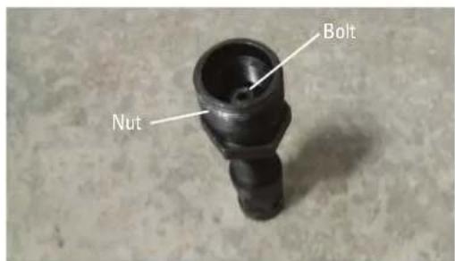
-
Carefully thread the Crank Puller into the Left Crank Arm. Be sure the Crank Puller has at least three rounds of threads inserted.
-
Using an adjustable wrench, turn the inner portion (the Bolt) of the Crank Puller clockwise. The Crank Arm will slide off as it is tightened.
Note: Be aware that the Crank Arm will be loose and will need to be supported.
-
Remove the Crank Puller from the Crank Arm.
-
Installation is the reverse procedure excluding steps with the Crank Puller. The Crank Puller is not required for re-assembly.
Note: When replacing the Crank Arm be sure the Right and Left Crank Arms are oriented inline and opposite each other. The Crank Nut should be tightened to a torque value of 29-32.5 ft lbs (or 350-390 in lbs).
- Final Inspection Inspect your machine to ensure that all hardware is tight and components are properly assembled.

Do not use until the machine has been fully assembled and inspected for correct performance in accordance with the Owner's Manual.

natural_image
Close-up of a motorcycle wheel assembly with visible mechanical components (no text or symbols)
natural_image
Technical line drawing of a mechanical assembly with no visible text or symbolsNOTICE: This document provides instructions for the replacement of the Right Crank Arm on the Bowflex™ Max Total™ machine and Max Total™ 16/40.
If you need assistance, please contact Customer Service (if purchased in US/Canada) or your local distributor (if purchased outside US/Canada). To find your local distributor, go to: www.nautilusinternational.com

This icon means a potentially hazardous situation which, if not avoided, could result in death or serious injury. Read and understand all Warnings on this machine.
Nautilus, Inc., www.NautilusInc.com, 5415 Centerpoint Parkway, Groveport, OH 43125 U.S.A. - Customer Service: North America (800) 605-3369, csnls@nautilus.com | outside U.S. www.nautilusinternational.com | Printed in China | © 2019 Nautilus, Inc. | Bowflex, the B logo, and Max Total are trademarks owned or licensed by Nautilus, Inc., registered or otherwise protected by common law in the United States and other nations. | ORIGINAL
DOCUMENT - ENGLISH VERSION ONLY
Important Safety Instructions - Before servicing or using this equipment, obey the following warnings:

This icon means a potentially hazardous situation which, if not avoided, could result in death or serious injury. Read and understand all Warnings on this machine.
- Read and understand the Part Replacement Procedure before working on the machine. Failure to obey the instructions and safety warnings could cause injury to the service technician or bystanders.
- Keep bystanders, children and pets away from the product being serviced at all times.
- Make sure that the repair is done in an appropriate work space away from foot traffic and exposure to bystanders.
- Disconnect all power and allow to sit for 5 minutes before you service this machine.
- Some components of the equipment can be heavy or awkward. Enlist the service of a second person when you do maintenance steps involving these components. Do not try to do heavy or awkward steps on your own.
- If replacement parts are necessary, use only genuine Nautilus replacement parts and hardware. Failure to use genuine replacement parts can cause a risk to users, keep the machine from operating correctly and will void the warranty.
- Be sure that all warning stickers and instructional placards applied to the product stay present and in good condition when doing maintenance or replacing components. If at any time the Warning labels become loose, unreadable or dislodged, replace the labels. If purchased in US/Canada, contact Customer Service for replacement labels. If purchased outside US/Canada, contact your local distributor for them.
- Do not try to change the design or functionality of the machine being serviced as this can adversely effect user safety and will void the warranty.
- Do not use the machine until all shrouds, instructions, warning labels and correct functionality have been verified and tested for correct performance.
- SAVE THESE INSTRUCTIONS.
Tools Required (not included)
2
Phillips
screwdriver
5mm hex wrench
6mm
hex
wrench

Wrench
Adjustable wrench
9/
14mm
Crank Puller (non-handled, JIS/ISO square taper with M22x1.0 threads)
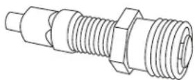
Note: Your machine may not match the images provided exactly.
- Remove the Cap from the right side of the machine.
- Using a 6mm hex wrench, remove the hardware exposed from below the Cap.
-
Lift the Foot Pedal and slide the Leg Assembly straight off the machine. Be sure to pull straight out, or the Leg Assembly may be difficult to remove.
-
Remove the Wave Washer from the Crank Arm, and place it in a secure location for re-use.
-
Using a 5mm hex wrench, remove the indicated hardware from the Right Upper Handlebar and place it out of the work area.
Note: Be aware that the Upper Handlebar must be supported when removing the hardware.
-
Place a rag or protective material below the Connector Arm to protect the Shrouds from potential scratches from the Connector Arms.
-
Using a 6mm hex wrench, remove the hardware that connects the Connector Arm and the Pivot Arm.
Note: The Connector Arm will pivot downward if not lowered slowly onto the rag protecting the Shroud.

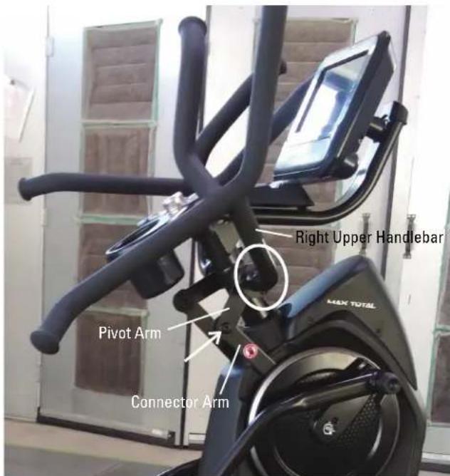
-
Using a #2 Phillips screwdriver, remove the 4 screws (2 indicated on one side) from the Upper Shroud.
-
Using a #2 Phillips screwdriver, remove the 2 indicated screws from the Crank Cover.
Note: The Crank Cover screws may have been over-tightened when installed. Try not to strip the screws when removing them.
-
Remove the Crank Cover from the machine.
-
Place a towel or rag inside of the machine below the indicated screws (with arrows). The towel or rag should be placed so that it will catch the screws if dropped.
-
Using a #2 Phillips screwdriver, remove the screws (indicated by arrows) that secure the Upper Body Sensor. Allow the Upper Body Sensor to hang on the Cable, away from the Right Crank Arm.

Note: View into Shrouds from above.

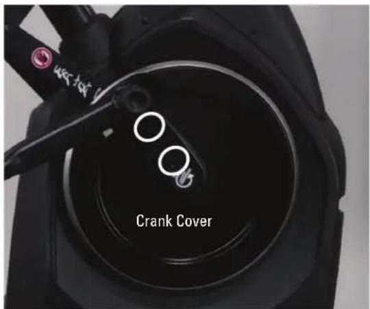

Note: Shrouds are removed for clarity.
-
Using a 9/16" or 14mm socket and wrench, remove the indicated nut from the Crank Assembly.
-
Adjust the Crank Puller until the end of the Bolt is inside the Nut (as shown).
-
Carefully thread the Crank Puller into the Crank Arm. Be sure the Crank Puller has at least three rounds of threads inserted.
-
Using an adjustable wrench, turn the inner portion (the Bolt) of the Crank Puller clockwise. The Crank Arm Assembly will slide off as it is tightened.
Note: Be aware that the Crank Arm Assembly will be loose and will need to be supported.

natural_image
Close-up of a robotic vacuum cleaner with visible mechanical components and a white arrow pointing to a circular component (no text or symbols)
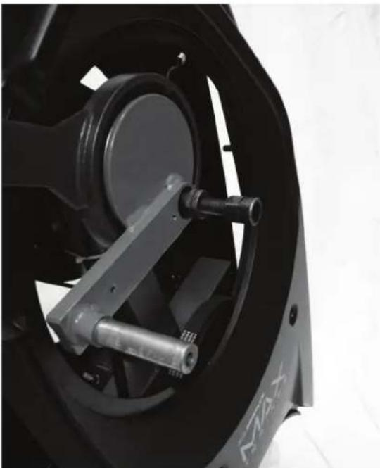
natural_image
Close-up of a motorcycle wheel assembly with mechanical components (no visible text or symbols)-
Remove the Crank Puller from the Crank Arm.
-
Slide the new Right Crank Arm Assembly onto the machine.
Note: Be sure not to damage or break the Codewheel on the new Right Crank Arm or the one still remaining on the machine.
-
Re-attach the Upper Body Sensor so that it is centered on the Codewheels.
-
With the Upper Body Sensor centered on the Codewheels, confirm that the Upper Body Sensor does not rub anything by using the machine briefly. Adjust the Upper Body Sensor as necessary.
-
Installation is the reverse procedure excluding steps with the Crank Puller. The Crank Puller is not required for re-assembly.
Note: When replacing the Right Crank Arm, be sure the Right and Left Crank Arms are oriented inline and opposite each other.
The Crank Nut should be tightened to a torque value of 29-32.5 ft lbs (or 350-390 in lbs).
- Final Inspection
Inspect your machine to ensure that all hardware is tight and components are properly assembled.

Do not use until the machine has been fully assembled and inspected for correct performance in accordance with the Owner's Manual.

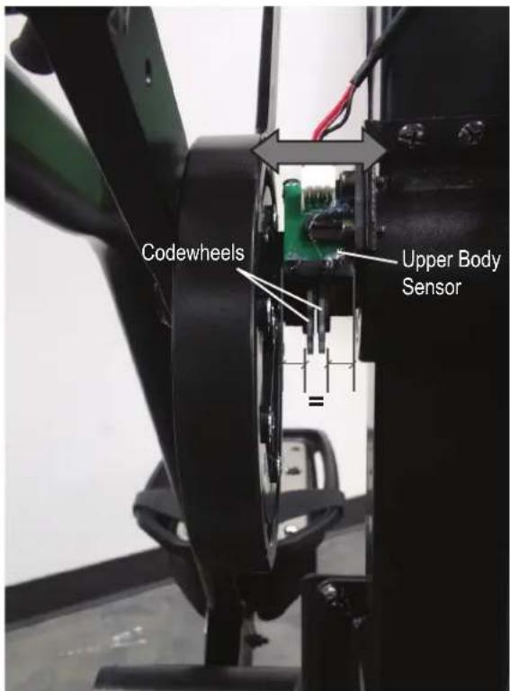
Note: The image shows a properly installed Upper Body Sensor. Shrouds are removed for clarity.

natural_image
Technical line drawing of a mechanical assembly with no visible text or symbolsNOTICE: This document provides instructions for the replacement of the Drive Belt on the Bowflex™ Max Total™ machine / Max Total™ 16/40 / Max Trainer™ M9.
If you need assistance, please contact Customer Service (if purchased in US/Canada) or your local distributor (if purchased outside US/Canada). To find your local distributor, go to: www.nautilusinternational.com

This icon means a potentially hazardous situation which, if not avoided, could result in death or serious injury. Read and understand all Warnings on this machine.
Nautilus, Inc., www.NautilusInc.com, 5415 Centerpoint Parkway, Groveport, OH 43125 U.S.A. - Customer Service: North America (800) 605-3369, csnls@nautilus.com | outside U.S. www.nautilusinternational.com | Printed in China | © 2019 Nautilus, Inc. | Bowflex, the B logo, Max Total, and Max Trainer are trademarks owned or licensed by Nautilus, Inc., registered or otherwise protected by common law in the United States and other nations. | ORIGINAL DOCUMENT - ENGLISH VERSION ONLY
Important Safety Instructions - Before servicing or using this equipment, obey the following warnings:

This icon means a potentially hazardous situation which, if not avoided, could result in death or serious injury. Read and understand all Warnings on this machine.
- Read and understand the Part Replacement Procedure before working on the machine. Failure to obey the instructions and safety warnings could cause injury to the service technician or bystanders.
- Keep bystanders, children and pets away from the product being serviced at all times.
- Make sure that the repair is done in an appropriate work space away from foot traffic and exposure to bystanders.
- Disconnect all power and allow to sit for 5 minutes before you service this machine.
- Some components of the equipment can be heavy or awkward. Enlist the service of a second person when you do maintenance steps involving these components. Do not try to do heavy or awkward steps on your own.
- If replacement parts are necessary, use only genuine Nautilus replacement parts and hardware. Failure to use genuine replacement parts can cause a risk to users, keep the machine from operating correctly and will void the warranty.
- Be sure that all warning stickers and instructional placards applied to the product stay present and in good condition when doing maintenance or replacing components. If at any time the Warning labels become loose, unreadable or dislodged, replace the labels. If purchased in US/Canada, contact Customer Service for replacement labels. If purchased outside US/Canada, contact your local distributor for them.
- Do not try to change the design or functionality of the machine being serviced as this can adversely effect user safety and will void the warranty.
- Do not use the machine until all shrouds, instructions, warning labels and correct functionality have been verified and tested for correct performance.
- SAVE THESE INSTRUCTIONS.
Tools Required (not included)
2
Phillips
screwdriver

2

screwdriver
4mm hex wrench 6mm hex wrench 8mm hex wrench

Note: Your machine may not match the images provided exactly.
-
Unplug the AC Adapter from the wall outlet and machine.
-
Using a 6mm hex wrench, remove the indicated hardware from the Upper Handlebars and place them out of the work area.
Note: Be aware that the Upper Handlebars must be supported when removing the hardware.
-
Using a #2 Phillips screwdriver, remove the 4 screws (2 indicated on one side) from the Upper Shroud and remove it.
-
Remove the Right and Left Stabilizer Shrouds from the machine (if equipped).

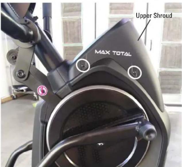
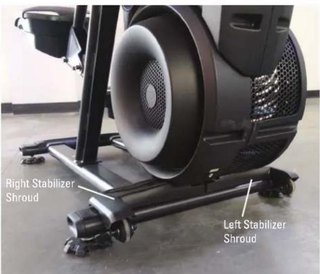
- Using a #2 Phillips screwdriver, remove the indicated (by ovals) screws and only loosen the lowest indicated screw (arrow) from the Right Fan Cover.
- The Right Fan Cover has a tab that needs to be pushed upward to clear the loosened screw. While pushing up on the tab, remove the Right Fan Cover from the assembly.
Note: The Power Cable is attached to the inside of the Right Fan Cover. Be sure not to crimp the cable by placing the Right Fan Cover close to the front of the machine.
To assist with assembly, note that the upper screw is a machine screw and not a self-tapping screw.

natural_image
Close-up of a black stationary exercise machine with visible mesh speaker and mounting feet (no text or symbols)
- Remove the indicated Cap from the left side of the machine.
- Using a 6mm hex wrench, remove the hardware exposed from below the Cap.
- Lift the Foot Pedal and slide the Leg Assembly straight off the machine. Be sure to pull straight out, or the Leg Assembly may be difficult to remove.
Note: A rubber mallet may be necessary if the Leg Assembly will not slide off.
- Remove the Wave Washer from the Crank Arm, and place it in a secure location for re-use.
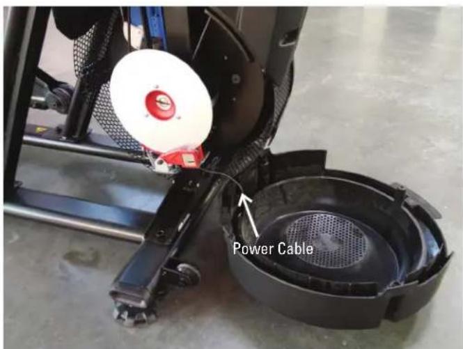

- Using a #2 Phillips screwdriver, remove the indicated screw from the Rear Shroud.
- Carefully remove the Rear Shroud from the machine. Place a standard screwdriver behind and near the middle of the Rear Shroud and gently pry until it releases. Then move the screwdriver to the bottom and gently pry until the Rear Shroud comes off.
-
Remove the indicated Caps from the machine.
-
Using a #2 Phillips screwdriver, remove the indicated (by oval) screw and only loosen the lowest indicated screw (arrow) from the Left Fan Cover.
-
The Left Fan Cover Assembly has a tab that needs to be pushed upward to clear the loosened screw. While pushing up on the tab, remove the Left Fan Cover Assembly.
-
Remove the Left Fan Cover Assembly from the machine. Be sure to note how the fan screens are set into the Left Fan Cover to assist with the replacement procedure.
-
Using a #2 Phillips screwdriver, remove the 2 indicated (by ovals) screws from the Crank Cover. Repeat on the other side of the machine.
-
Remove the Crank Covers from the machine.
Note: The Crank Cover screws may have been over-tightened when installed. Try not to strip the screws when removing them.
-
Place a rag or protective material below the Connector Arm to protect the Shrouds from potential scratches from the Connector Arms.
-
Using a 6mm hex wrench, remove the hardware (indicated by arrows) that connects the Connector Arms and the Pivot Arms.
Note: The Connector Arm will pivot downward if not lowered slowly onto the rag protecting the Shrouds

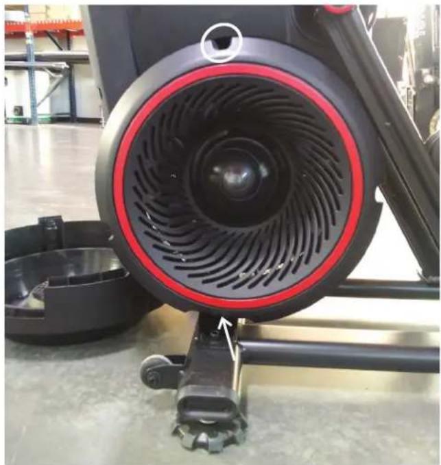
natural_image
Close-up of a black stationary exercise bike with red circular vent and gear mechanism, no visible text or symbols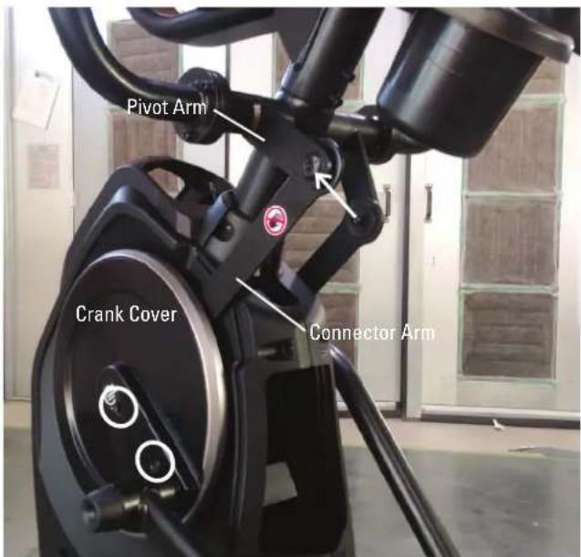
- Using a #2 Phillips screwdriver, remove the screws from the Left Shroud. (9 screws on the Left Shroud) Remove the upper screws labeled ‘*’ last.

Left Side
-
Using a 4mm hex wrench, remove the screw indicated by "A" from the Drive Belt Tensioner Arm.
-
Using a 8mm hex wrench, loosen the screw indicated by "B" until the Drive Belt is free enough to be removed from the Drive Pulley. Remove the Drive Belt.

Keep fingers out of any pinch opportunities when removing the Fan Belt.
-
Replace and tighten the "A" screw on the Drive Belt Tensioner Arm, and then tighten the "B" screw.
-
Installation is the reverse procedure.
-
Final Inspection
Inspect your machine to ensure that all hardware is tight and components are properly assembled.

Do not use until the machine has been fully assembled and inspected for correct performance in accordance with the Owner's Manual.
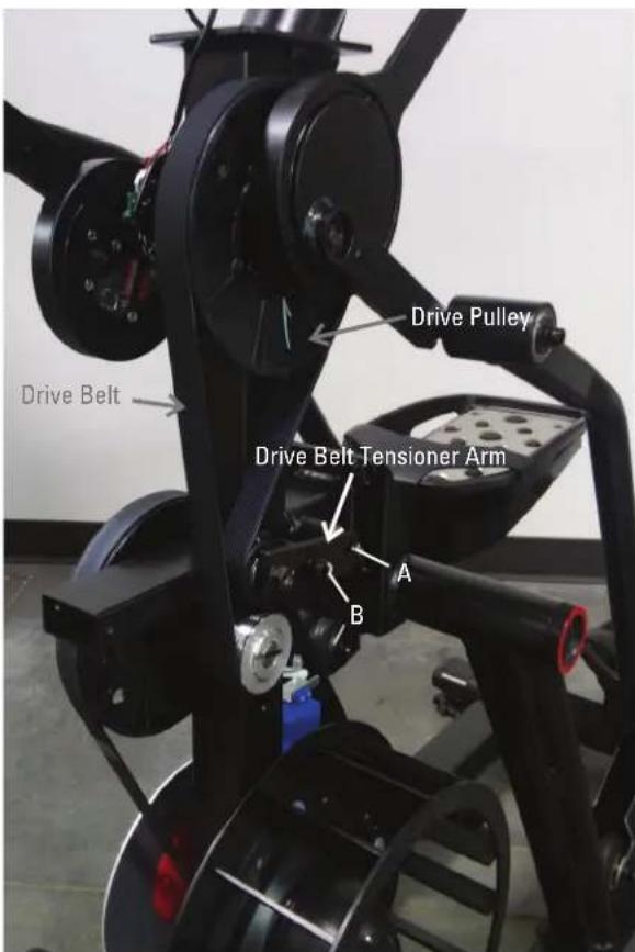
Note: Shrouds are removed for clarity.
NOTICE: This document provides instructions for the replacement of the Drive Pulley on the Bowflex™ Max Total™ machine / Max Total™ 16/40 / Max Trainer™ M9.
If you need assistance, please contact Customer Service (if purchased in US/Canada) or your local distributor (if purchased outside US/Canada). To find your local distributor, go to: www.nautilusinternational.com

This icon means a potentially hazardous situation which, if not avoided, could result in death or serious injury. Read and understand all Warnings on this machine.
Nautilus, Inc., www.NautilusInc.com, 5415 Centerpoint Parkway, Groveport, OH 43125 U.S.A. - Customer Service: North America (800) 605-3369, csnls@nautilus.com | outside U.S. www.nautilusinternational.com | Printed in China | © 2020 Nautilus, Inc. | Bowflex, the B logo, Max Total, and Max Trainer are trademarks owned or licensed by Nautilus, Inc., registered or otherwise protected by common law in the United States and other nations. | ORIGINAL DOCUMENT - ENGLISH VERSION ONLY
Important Safety Instructions - Before servicing or using this equipment, obey the following warnings:

This icon means a potentially hazardous situation which, if not avoided, could result in death or serious injury. Read and understand all Warnings on this machine.
- Read and understand the Part Replacement Procedure before working on the machine. Failure to obey the instructions and safety warnings could cause injury to the service technician or bystanders.
- Keep bystanders, children and pets away from the product being serviced at all times.
- Make sure that the repair is done in an appropriate work space away from foot traffic and exposure to bystanders.
- Disconnect all power and allow to sit for 5 minutes before you service this machine.
- Some components of the equipment can be heavy or awkward. Enlist the service of a second person when you do maintenance steps involving these components. Do not try to do heavy or awkward steps on your own.
- If replacement parts are necessary, use only genuine Nautilus replacement parts and hardware. Failure to use genuine replacement parts can cause a risk to users, keep the machine from operating correctly and will void the warranty.
- Be sure that all warning stickers and instructional placards applied to the product stay present and in good condition when doing maintenance or replacing components. If at any time the Warning labels become loose, unreadable or dislodged, replace the labels. If purchased in US/Canada, contact Customer Service for replacement labels. If purchased outside US/Canada, contact your local distributor for them.
- Do not try to change the design or functionality of the machine being serviced as this can adversely effect user safety and will void the warranty.
- Do not use the machine until all shrouds, instructions, warning labels and correct functionality have been verified and tested for correct performance.
- SAVE THESE INSTRUCTIONS.
Tools Required (not included)

- Unplug the AC Adapter from the wall outlet and machine.
-
Using a 5mm hex wrench, remove the indicated hardware from the Left Upper Handlebar and place it out of the work area.
Note: Be aware that the Upper Handlebar must be supported when removing the hardware. -
Using a #2 Phillips screwdriver, remove the 4 screws (2 indicated on one side) from the Upper Shroud and remove it.
-
Remove the Right and Left Stabilizer Shrouds from the machine.


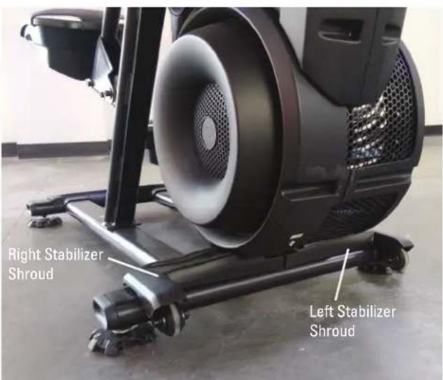
- Using a #2 Phillips screwdriver, remove the indicated (by ovals) screws and only loosen the lowest indicated screw (arrow) from the Right Fan Cover.
- The Right Fan Cover has a tab that needs to be pushed upward to clear the loosened screw. While pushing up on the tab, remove the Right Fan Cover from the assembly.
Note: the Power Cable is attached to the inside of the Right Fan Cover. Be sure not to crimp the cable by placing the Right Fan Cover close to the front of the machine.
To assist with assembly, note that the upper screw is a machine screw and not a self-tapping screw.

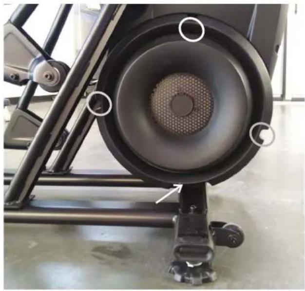
natural_image
Close-up of a black stationary exercise machine with visible mesh and mounting feet (no text or symbols)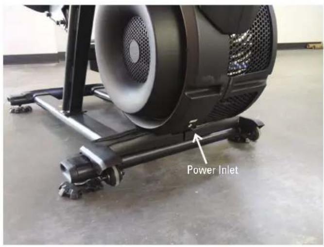
- Remove the indicated Cap from the machine.
- Using a 6mm hex wrench, remove the hardware exposed from below the Cap.
- Slide the Left Leg Assembly off of the machine.


-
Using a #2 Phillips screwdriver, remove the indicated screw from the Rear Shroud.
-
Carefully remove the Rear Shroud from the machine. Place a standard screwdriver behind and near the middle of the Rear Shroud and gently pry until it releases. Then move the screwdriver to the bottom and gently pry until the Rear Shroud comes off.
-
Using a #2 Phillips screwdriver, remove the indicated (by oval) screw and only loosen the lowest indicated screw (arrow) from the Left Fan Cover.
-
The Left Fan Cover Assembly has a tab that needs to be pushed upward to clear the loosened screw. While pushing up on the tab, remove the Left Fan Cover Assembly.
-
Remove the Left Fan Cover Assembly from the machine. Be sure to note how the fan screens are set into the Left Fan Cover to assist with the replacement procedure.
-
Using a #2 Phillips screwdriver, remove the 2 indicated screws from the Left Crank Cover.
-
Remove the Left Crank Cover from the machine.
-
Place a rag or protective material below the Left Connector Arm to protect the Shroud from potential scratches from the Connector Arm.
-
Using a 6mm hex wrench, remove the hardware that connects the Left Connector Arm and the Pivot Arm.
Note: The Connector Arm will pivot downward if not lowered slowly onto the rag protecting the Shroud.
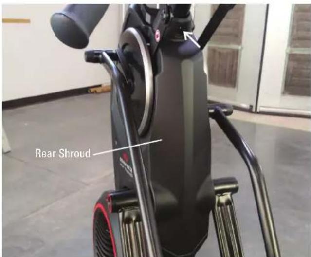

natural_image
Close-up of a black stationary exercise bike with red circular head and visible exhaust fan, mounted on a wheeled platform (no text or symbols)
-
Using a 9/16" or 14mm socket and wrench, remove the nut from the Left Crank Assembly.
-
Adjust the Crank Puller until the end of the Bolt is inside the Nut (as shown).
-
Carefully thread the Crank Puller into the Left Crank Arm. Be sure the Crank Puller has at least three rounds of threads inserted.
-
Using a 16mm wrench, turn the inner portion (the Bolt) of the Crank Puller clockwise. The Left Crank Arm will slide off as it is tightened.
Note: Be aware that the Left Crank Arm will be loose and will need to be supported.
- Remove the Crank Puller from the Left Crank Arm.


- Using a #2 Phillips screwdriver, remove the screws from the Left Shroud. (9 screws on the Left Shroud) Remove the upper screws labeled ‘*’ last.
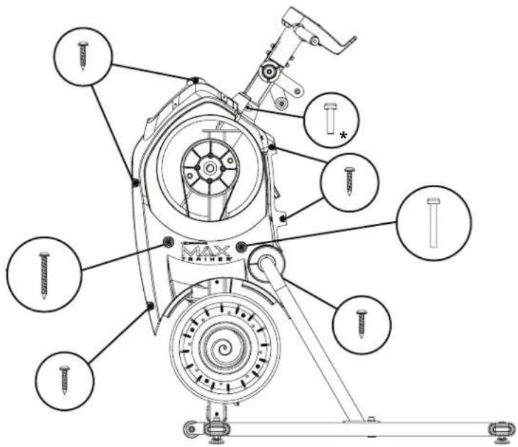
Left Side
- Using a 4mm hex wrench, remove the screw indicated by "A" from the Drive Belt Tensioner Arm.
- Using a 10mm wrench, remove the securing nuts (if present) from the back side of the Drive Pulley.
- Using a 8mm hex wrench, loosen the screw indicated by "B" until the Drive Belt is free enough to be removed from the Drive Pulley. Remove the Drive Belt.

Keep fingers out of any pinch opportunities when removing the Fan Belt.
- Using a 5mm hex wrench, remove the four screws that attach the Drive Pulley. Be sure to support the weight of the Drive Pulley when removing hardware because it will fall.
- Using a 5mm hex wrench, attach the new Drive Pulley to the Frame Assembly.
- Replace the Drive Belt around the new Drive Pulley.
- Replace and tighten the "A" screw on the Drive Belt Tensioner Arm, and then tighten the "B" screw.

- Installation is the reverse procedure excluding steps with the Crank Puller. The Crank Puller is not required for re-assembly.
Note: When replacing the Crank Arm be sure the Right and Left Crank Arms are oriented inline and opposite each other.
The Crank Nut should be tightened to a torque value of 29-32.5 ft lbs (or 350-390 in lbs).
- Final Inspection
Inspect your machine to ensure that all hardware is tight and components are properly assembled.

Do not use until the machine has been fully assembled and inspected for correct performance in accordance with the Owner's Manual.
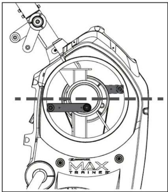
natural_image
Technical line drawing of a mechanical assembly with no visible text or symbolsNOTICE: This document provides instructions for the replacement of the Hardware that attaches the Drive Pulley on the Bowflex™ Max Total™ machine / Max Total™ 16/40 / Max Trainer™ M9.
If you need assistance, please contact Customer Service (if purchased in US/Canada) or your local distributor (if purchased outside US/Canada). To find your local distributor, go to: www.nautilusinternational.com

This icon means a potentially hazardous situation which, if not avoided, could result in death or serious injury. Read and understand all Warnings on this machine.
Nautilus, Inc., www.NautilusInc.com, 5415 Centerpoint Parkway, Groveport, OH 43125 U.S.A. - Customer Service: North America (800) 605-3369, csnls@nautilus.com | outside U.S. www.nautilusinternational.com | Printed in China | © 2020 Nautilus, Inc. | Bowflex, the B logo, Max Total, and Max Trainer are trademarks owned or licensed by Nautilus, Inc., registered or otherwise protected by common law in the United States and other nations. | ORIGINAL DOCUMENT - ENGLISH VERSION ONLY
Important Safety Instructions - Before servicing or using this equipment, obey the following warnings:

This icon means a potentially hazardous situation which, if not avoided, could result in death or serious injury. Read and understand all Warnings on this machine.
- Read and understand the Part Replacement Procedure before working on the machine. Failure to obey the instructions and safety warnings could cause injury to the service technician or bystanders.
- Keep bystanders, children and pets away from the product being serviced at all times.
- Make sure that the repair is done in an appropriate work space away from foot traffic and exposure to bystanders.
- Disconnect all power and allow to sit for 5 minutes before you service this machine.
- Some components of the equipment can be heavy or awkward. Enlist the service of a second person when you do maintenance steps involving these components. Do not try to do heavy or awkward steps on your own.
- If replacement parts are necessary, use only genuine Nautilus replacement parts and hardware. Failure to use genuine replacement parts can cause a risk to users, keep the machine from operating correctly and will void the warranty.
- Be sure that all warning stickers and instructional placards applied to the product stay present and in good condition when doing maintenance or replacing components. If at any time the Warning labels become loose, unreadable or dislodged, replace the labels. If purchased in US/Canada, contact Customer Service for replacement labels. If purchased outside US/Canada, contact your local distributor for them.
- Do not try to change the design or functionality of the machine being serviced as this can adversely effect user safety and will void the warranty.
- Do not use the machine until all shrouds, instructions, warning labels and correct functionality have been verified and tested for correct performance.
- SAVE THESE INSTRUCTIONS.
Tools Required (not included)
2
Phillips
screwd
5mm
hex
6mm
hex
wrench
wrench
Crank Puller (non-handled, JIS/ISO square taper with M22x1.0 threads)


14mm

- Unplug the AC Adapter from the wall outlet and machine.
-
Using a 5mm hex wrench, remove the indicated hardware from the Left Upper Handlebar and place it out of the work area.
Note: Be aware that the Upper Handlebar must be supported when removing the hardware. -
Using a #2 Phillips screwdriver, remove the 4 screws (2 indicated on one side) from the Upper Shroud and remove it.
-
Remove the indicated Cap from the machine.
- Using a 6mm hex wrench, remove the hardware exposed from below the Cap.
- Slide the Left Leg Assembly off of the machine.
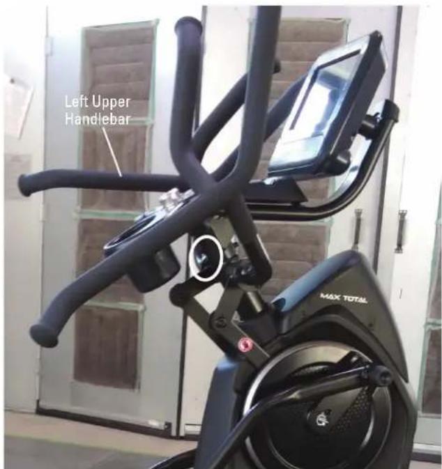

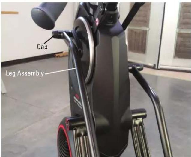
- Using a #2 Phillips screwdriver, remove the 2 indicated screws (by ovals) from the Left Crank Cover.
- Remove the Left Crank Cover from the machine.
- Place a rag or protective material below the Left Connector Arm to protect the Shroud from potential scratches from the Connector Arm.
- Using a 6mm hex wrench, remove the indicated hardware (with arrows) that connects the Left Connector Arm and the Pivot Arm.
Note: The Connector Arm will pivot downward if not lowered slowly onto the rag protecting the Shroud.
-
Using a 9/16" or 14mm socket and wrench, remove the nut from the Left Crank Assembly.
-
Adjust the Crank Puller until the end of the Bolt is flush with the Nut (as shown).


natural_image
Close-up of a black mechanical component with a white arrow pointing to it (no visible text or symbols)-
Carefully thread the Crank Puller into the Left Crank Arm. Be sure the Crank Puller has at least three rounds of threads inserted.
-
Using a 16mm wrench, turn the inner portion (the Bolt) of the Crank Puller clockwise. The Left Crank Arm will slide off as it is tightened.
Note: Be aware that the Left Crank Arm will be loose and will need to be supported.
-
Remove the Crank Puller from the Left Crank Arm.
-
Inspect the Drive Pulley and the screws that secure it.
* If the Drive Pulley is worn or damaged OR any of the screws have been sheared off, use the "Replace the Drive Pulley" Procedure for replacement instructions.
* If one or more screws are currently missing, skip to Step 21.
* If all four screws are present, use an appropriately sized hex wrench to remove one of the four screws that attach the Drive Pulley.
-
Using a 5mm hex wrench, attach one of the replacement screws and lock washers provided in the kit. Fully tighten the screw. Once fully tightened, secure the screw with one of the provided securing nuts using a 10mm wrench.
-
Rotate the Drive Pulley to replace each screw with the provided hardware (screw and securing nut) one at a time.
Note: The kit contains a replacement Drive Pulley. This part will not be used if this procedure is performed correctly.


- Installation is the reverse procedure excluding steps with the Crank Puller. The Crank Puller is not required for re-assembly.
Note: When replacing the Crank Arm be sure the Right and Left Crank Arms are oriented inline and opposite each other.
The Crank Nut should be tightened to a torque value of 29-32.5 ft lbs (or 350-390 in lbs).
- Final Inspection
Inspect your machine to ensure that all hardware is tight and components are properly assembled.

Do not use until the machine has been fully assembled and inspected for correct performance in accordance with the Owner's Manual.

natural_image
Technical line drawing of a mechanical assembly with labeled components (no readable text or symbols)NOTICE: This document provides instructions for the replacement of the Fan Assembly on the Bowflex™ Max Total™ machine / Max Total™ 16/40 / Max Trainer™ M9.
If you need assistance, please contact Customer Service (if purchased in US/Canada) or your local distributor (if purchased outside US/Canada). To find your local distributor, go to: www.nautilusinternational.com

This icon means a potentially hazardous situation which, if not avoided, could result in death or serious injury. Read and understand all Warnings on this machine.
Nautilus, Inc., www.NautilusInc.com, 5415 Centerpoint Parkway, Groveport, OH 43125 U.S.A. - Customer Service: North America (800) 605-3369, csnls@nautilus.com | outside U.S. www.nautilusinternational.com | Printed in China | © 2020 Nautilus, Inc. | Bowflex, the B logo, Max Total, and Max Trainer are trademarks owned or licensed by Nautilus, Inc., registered or otherwise protected by common law in the United States and other nations. ORIGINAL DOCUMENT - ENGLISH VERSION ONLY
Important Safety Instructions - Before servicing or using this equipment, obey the following warnings:

This icon means a potentially hazardous situation which, if not avoided, could result in death or serious injury. Read and understand all Warnings on this machine.
- Read and understand the Part Replacement Procedure before working on the machine. Failure to obey the instructions and safety warnings could cause injury to the service technician or bystanders.
- Keep bystanders, children and pets away from the product being serviced at all times.
- Make sure that the repair is done in an appropriate work space away from foot traffic and exposure to bystanders.
- Disconnect all power and allow to sit for 5 minutes before you service this machine.
- Some components of the equipment can be heavy or awkward. Enlist the service of a second person when you do maintenance steps involving these components. Do not try to do heavy or awkward steps on your own.
- If replacement parts are necessary, use only genuine Nautilus replacement parts and hardware. Failure to use genuine replacement parts can cause a risk to users, keep the machine from operating correctly and will void the warranty.
- Be sure that all warning stickers and instructional placards applied to the product stay present and in good condition when doing maintenance or replacing components. If at any time the Warning labels become loose, unreadable or dislodged, replace the labels. If purchased in US/Canada, contact Customer Service for replacement labels. If purchased outside US/Canada, contact your local distributor for them.
- Do not try to change the design or functionality of the machine being serviced as this can adversely effect user safety and will void the warranty.
- Do not use the machine until all shrouds, instructions, warning labels and correct functionality have been verified and tested for correct performance.
- SAVE THESE INSTRUCTIONS.
Tools Required (not included)
2
Phillips
screwdriver

5mm hex wrench
Standard Screwdriver


- Unplug the AC Adapter from the wall outlet and machine.
-
Remove the Right and Left Stabilizer Shrouds from the machine.
-
Using a #2 Phillips screwdriver, remove the indicated (by ovals) screws and only loosen the lowest indicated screw (arrow) from the Right Fan Cover.
- The Right Fan Cover has a tab that needs to be pushed upward to clear the loosened screw. While pushing up on the tab, remove the Right Fan Cover from the assembly.
Note: the Power Cable is attached to the inside of the Right Fan Cover. Be sure not to crimp the cable by placing the Right Fan Cover close to the front of the machine.
To assist with assembly, note that the upper screw is a machine screw and not a self-tapping screw.


natural_image
Close-up of a black stationary exercise machine with visible mesh and mounting feet (no text or symbols)
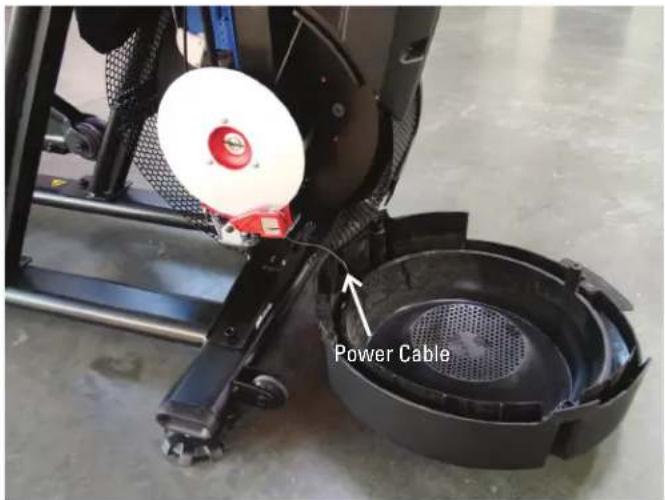
- Using a #2 Phillips screwdriver, remove the indicated (by oval) screw and only loosen the lowest indicated screw (arrow) from the Left Fan Cover.
- The Left Fan Cover Assembly has a tab that needs to be pushed upward to clear the loosened screw. While pushing up on the tab, remove the Left Fan Cover Assembly.
- Remove the Left Fan Cover Assembly from the machine. Be sure to note how the fan screens are set into the Left Fan Cover to assist with the replacement procedure.
Note: Your machine may not match the images provided exactly.
- Remove the Cone from the Fan Assembly. There are 4 clips that attach the Cone that can be accessed behind the Fan Assembly. Using a small standard screwdriver, gently release the clips.

natural_image
Close-up of a black stationary exercise bike with red circular vent and blue rim, mounted on a wheeled platform (no visible text or symbols)
-
Using a 5mm hex wrench, remove the 4 screws from the Fan Assembly. Be sure to support the Fan Assembly when removing hardware.
-
Installation is the reverse procedure.
-
Final Inspection
Inspect your machine to ensure that all hardware is tight and components are properly assembled.

Do not use until the machine has been fully assembled and inspected for correct performance in accordance with the Owner's Manual.

NOTICE: This document provides instructions for the replacement of the Fan Belt on the Bowflex™ Max Total™ machine / Max Total™ 16/40 / Max Trainer™ M9.
If you need assistance, please contact Customer Service (if purchased in US/Canada) or your local distributor (if purchased outside US/Canada). To find your local distributor, go to: www.nautilusinternational.com

This icon means a potentially hazardous situation which, if not avoided, could result in death or serious injury. Read and understand all Warnings on this machine.
Nautilus, Inc., www.NautilusInc.com, 5415 Centerpoint Parkway, Groveport, OH 43125 U.S.A. - Customer Service: North America (800) 605-3369, csnls@nautilus.com | outside U.S. www.nautilusinternational.com | Printed in China | © 2019 Nautilus, Inc. | Bowflex, the B logo, Max Total, and Max Trainer are trademarks owned or licensed by Nautilus, Inc., registered or otherwise protected by common law in the United States and other nations. | ORIGINAL DOCUMENT - ENGLISH VERSION ONLY
Important Safety Instructions - Before servicing or using this equipment, obey the following warnings:

This icon means a potentially hazardous situation which, if not avoided, could result in death or serious injury. Read and understand all Warnings on this machine.
- Read and understand the Part Replacement Procedure before working on the machine. Failure to obey the instructions and safety warnings could cause injury to the service technician or bystanders.
- Keep bystanders, children and pets away from the product being serviced at all times.
- Make sure that the repair is done in an appropriate work space away from foot traffic and exposure to bystanders.
- Disconnect all power and allow to sit for 5 minutes before you service this machine.
- Some components of the equipment can be heavy or awkward. Enlist the service of a second person when you do maintenance steps involving these components. Do not try to do heavy or awkward steps on your own.
- If replacement parts are necessary, use only genuine Nautilus replacement parts and hardware. Failure to use genuine replacement parts can cause a risk to users, keep the machine from operating correctly and will void the warranty.
- Be sure that all warning stickers and instructional placards applied to the product stay present and in good condition when doing maintenance or replacing components. If at any time the Warning labels become loose, unreadable or dislodged, replace the labels. If purchased in US/Canada, contact Customer Service for replacement labels. If purchased outside US/Canada, contact your local distributor for them.
- Do not try to change the design or functionality of the machine being serviced as this can adversely effect user safety and will void the warranty.
- Do not use the machine until all shrouds, instructions, warning labels and correct functionality have been verified and tested for correct performance.
• SAVE THESE INSTRUCTIONS.
Tools Required (not included)

Wire Cutter
Heavy
Duty
Zip-Tie
Note: Your machine may not match the images provided exactly.
-
Unplug the AC Adapter from the wall outlet and machine.
-
Using a 6mm hex wrench, remove the indicated hardware from the Right Upper Handlebar and place it out of the work area.
Note: Be aware that the Right Upper Handlebar must be supported when removing the hardware.
-
Using a #2 Phillips screwdriver, remove the 4 screws (2 indicated on one side) from the Upper Shroud and remove it.
-
Remove the Right and Left Stabilizer Shrouds from the machine (if equipped).


- Using a #2 Phillips screwdriver, remove the indicated (by ovals) screws and only loosen the lowest indicated screw (arrow) from the Right Fan Cover.
- The Right Fan Cover has a tab that needs to be pushed upward to clear the loosened screw. While pushing up on the tab, remove the Right Fan Cover from the assembly.
Note: The Power Cable is attached to the inside of the Right Fan Cover. Be sure not to crimp the cable by placing the Right Fan Cover close to the front of the machine.
To assist with assembly, note that the upper screw is a machine screw and not a self-tapping screw.


natural_image
Close-up of a black stationary exercise machine with visible mesh and mounting feet (no text or symbols)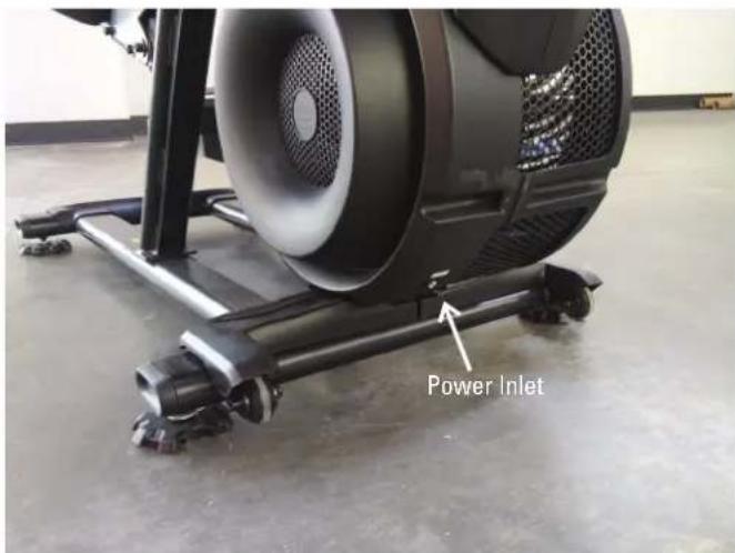
- Remove the indicated Cap from the machine.
- Using a 6mm hex wrench, remove the hardware exposed from below the Cap.
- Slide the Right Leg Assembly off of the machine.


-
Using a #2 Phillips screwdriver, remove the indicated screw (by arrow) from the Rear Shroud.
-
Carefully remove the Rear Shroud from the machine. Place a standard screwdriver behind and near the middle of the Rear Shroud and gently pry until it releases. Then move the screwdriver to the bottom and gently pry until the Rear Shroud comes off.
-
Remove the indicated Caps from the machine.
-
Using a #2 Phillips screwdriver, remove the indicated (by oval) screw and only loosen the lowest indicated screw (arrow) from the Left Fan Cover.
-
The Left Fan Cover Assembly has a tab that needs to be pushed upward to clear the loosened screw. While pushing up on the tab, remove the Left Fan Cover Assembly.
-
Using a #2 Phillips screwdriver, remove the 2 indicated screws from the Right Crank Cover.
-
Remove the Right Crank Cover from the machine.
Note: The Right Crank Cover screws may have been over-tightened when installed. Try not to strip the screws when removing them.
-
Place a rag or protective material below the Right Connector Arm to protect the Shrouds from potential scratches from the Connector Arms.
-
Using a 6mm hex wrench, remove the hardware that connects the Right Connector Arm and the Pivot Arm.
Note: The Connector Arm will pivot downward if not lowered slowly onto the rag protecting the Shroud.

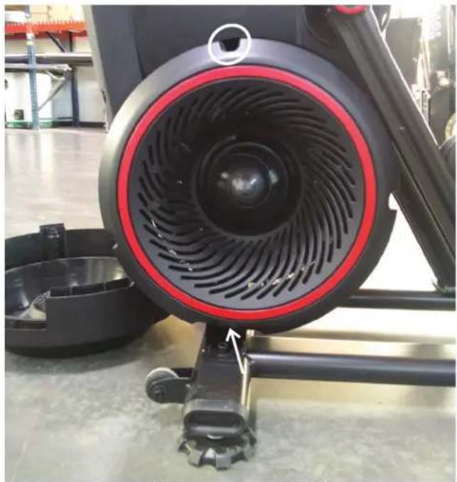
natural_image
Close-up of a black and red circular exercise bike with visible fan blades and wheels, no text or symbols present.
- Using a #2 Phillips screwdriver, remove the screws from the Right Shroud (3 screws on the Right Shroud). Remove the upper screws labeled '*' last.

Right Side
-
Using a #2 Phillips screwdriver, remove the 3 screws (indicated by arrows) from the Brake Disc.
-
Carefully remove the Brake Disc from the machine exposing the lower Fan Belt.
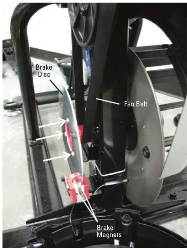
- Turn the Fan Pulley while forcing the Fan Belt to the outside. Belt will come off of the Fan Pulley.

Keep fingers out of any pinch opportunities when removing the Fan Belt.
-
Loop the new Fan Belt around the lower Pulley and start it on the face of the Fan Pulley.
-
Be sure the Fan Belt is centered on both pulleys.
-
Secure the Fan Belt to the Fan Pulley with a Heavy Duty Zip-Tie. Be sure to attach the Zip-Tie where the Fan Belt is fully in contact with the Fan Pulley.

natural_image
Close-up of a hand adjusting a mechanical component with meshed fan and gear (no visible text or symbols)
- Grasp the Fan Pulley where the Fan Belt is engaged on it, and forcibly rotate the Fan Pulley until the Fan Belt is fully engaged.

Keep fingers out of any pinch opportunities when rotating the Fan Pulley.
-
Cut the Zip-Tie without damaging the new Fan Belt or Fan Pulley.
-
Installation is the reverse procedure.
-
Final Inspection
Inspect your machine to ensure that all hardware is tight and components are properly assembled.

Do not use until the machine has been fully assembled and inspected for correct performance in accordance with the Owner's Manual.

natural_image
Close-up of hands installing a black plastic component on a vehicle chassis (no visible text or symbols)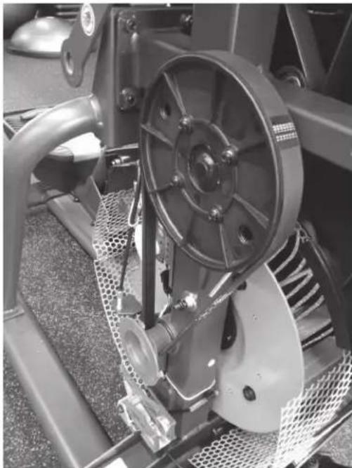
natural_image
Close-up of a mechanical assembly with visible gears and levers (no text or symbols)NOTICE: This document provides instructions for the replacement of the Fan Pulley on the Bowflex™ Max Total™ machine / Max Total™ 16/40 / Max Trainer™ M9.
If you need assistance, please contact Customer Service (if purchased in US/Canada) or your local distributor (if purchased outside US/Canada). To find your local distributor, go to: www.nautilusinternational.com

This icon means a potentially hazardous situation which, if not avoided, could result in death or serious injury. Read and understand all Warnings on this machine.
Nautilus, Inc., www.NautilusInc.com, 5415 Centerpoint Parkway, Groveport, OH 43125 U.S.A. - Customer Service: North America (800) 605-3369, csnls@nautilus.com | outside U.S. www.nautilusinternational.com | Printed in China | © 2020 Nautilus, Inc. | Bowflex, the B logo, Max Total, and Max Trainer are trademarks owned or licensed by Nautilus, Inc., registered or otherwise protected by common law in the United States and other nations. | ORIGINAL DOCUMENT - ENGLISH VERSION ONLY
Important Safety Instructions - Before servicing or using this equipment, obey the following warnings:

This icon means a potentially hazardous situation which, if not avoided, could result in death or serious injury. Read and understand all Warnings on this machine.
- Read and understand the Part Replacement Procedure before working on the machine. Failure to obey the instructions and safety warnings could cause injury to the service technician or bystanders.
- Keep bystanders, children and pets away from the product being serviced at all times.
- Make sure that the repair is done in an appropriate work space away from foot traffic and exposure to bystanders.
- Disconnect all power and allow to sit for 5 minutes before you service this machine.
- Some components of the equipment can be heavy or awkward. Enlist the service of a second person when you do maintenance steps involving these components. Do not try to do heavy or awkward steps on your own.
- If replacement parts are necessary, use only genuine Nautilus replacement parts and hardware. Failure to use genuine replacement parts can cause a risk to users, keep the machine from operating correctly and will void the warranty.
- Be sure that all warning stickers and instructional placards applied to the product stay present and in good condition when doing maintenance or replacing components. If at any time the Warning labels become loose, unreadable or dislodged, replace the labels. If purchased in US/Canada, contact Customer Service for replacement labels. If purchased outside US/Canada, contact your local distributor for them.
- Do not try to change the design or functionality of the machine being serviced as this can adversely effect user safety and will void the warranty.
- Do not use the machine until all shrouds, instructions, warning labels and correct functionality have been verified and tested for correct performance.
- SAVE THESE INSTRUCTIONS.
Tools Required (not included)
2
Phillips
screwdriver

16mm
wrench
wrench
9/16" or 14mm Socket and Wrench
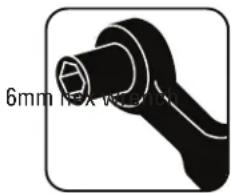
natural_image
Black mechanical component with hexagonal end, shown without any text or symbols5mm
hex

Cutter

Crank Puller (non-handled, JIS/ISO
with M22x1.0 threads)
square
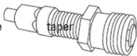

Heavy Duty Zip-Tie
- Unplug the AC Adapter from the wall outlet and machine.
-
Using a 5mm hex wrench, remove the indicated hardware from the Left Upper Handlebar and place it out of the work area.
Note: Be aware that the Right Upper Handlebar must be supported when removing the hardware. -
Using a #2 Phillips screwdriver, remove the 4 screws (2 indicated on one side) from the Upper Shroud.
-
Remove the Right and Left Stabilizer Shrouds from the machine.


- Using a #2 Phillips screwdriver, remove the indicated (by ovals) screws and only loosen the lowest indicated screw (arrow) from the Right Fan Cover.
- The Right Fan Cover has a tab that needs to be pushed upward to clear the loosened screw. While pushing up on the tab, remove the Right Fan Cover from the assembly.
Note: the Power Cable is attached to the inside of the Right Fan Cover. Be sure not to crimp the cable by placing the Right Fan Cover close to the front of the machine.
To assist with assembly, note that the upper screw is a machine screw and not a self-tapping screw.

natural_image
Close-up of a black stationary exercise machine with visible mesh and mounting base (no text or symbols)
- Remove the indicated Cap from the machine.
- Using a 6mm hex wrench, remove the hardware exposed from below the Cap.
- Slide the Right Leg Assembly off of the machine.
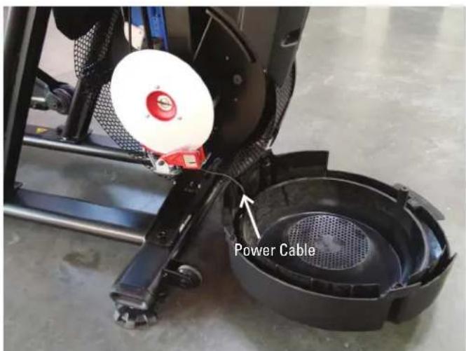
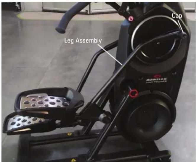
-
Using a #2 Phillips screwdriver, remove the indicated screw from the Rear Shroud.
-
Carefully remove the Rear Shroud from the machine. Place a standard screwdriver behind and near the middle of the Rear Shroud and gently pry until it releases. Then move the screwdriver to the bottom and gently pry until the Rear Shroud comes off.
-
Remove the indicated Caps from the machine.
-
Using a #2 Phillips screwdriver, remove the indicated (by oval) screw and only loosen the lowest indicated screw (arrow) from the Left Fan Cover.
-
The Left Fan Cover Assembly has a tab that needs to be pushed upward to clear the loosened screw. While pushing up on the tab, remove the Left Fan Cover Assembly.
-
Using a #2 Phillips screwdriver, remove the 2 indicated screws from the Right Crank Cover.
-
Remove the Right Crank Cover from the machine.
-
Place a rag or protective material below the Right Connector Arm to protect the Shrouds from potential scratches from the Connector Arms.
-
Using a 6mm hex wrench, remove the hardware that connects the Right Connector Arm and the Pivot Arm.
Note: The Connector Arm will pivot downward if not lowered slowly onto the rag protecting the Shroud.

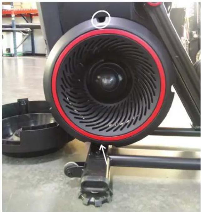
natural_image
Close-up of a black and red circular exercise bike with visible fan blades and wheels, mounted on a wheeled platform (no text or symbols)
-
Using a 9/16" or 14mm socket and wrench, remove the nut from the Right Crank Assembly.
-
Adjust the Crank Puller until the end of the Bolt is inside the Nut (as shown).
-
Carefully thread the Crank Puller into the Right Crank Arm. Be sure the Crank Puller has at least three rounds of threads inserted.
-
Using a 16mm wrench, turn the inner portion (the Bolt) of the Crank Puller clockwise. The Right Crank Arm will slide off as it is tightened.
Note: Be aware that the Right Crank Arm will be loose and will need to be supported.
- Remove the Crank Puller from the Right Crank Arm.

natural_image
Close-up of a hand adjusting a mechanical component with a circular dial and lever mechanism (no visible text or symbols)

natural_image
Close-up of a mechanical component with a circular dial and lever mechanism (no visible text or symbols)- Using a #2 Phillips screwdriver, remove the screws from the Right Shroud (3 screws on the Right Shroud). Remove the upper screws labeled ‘*’ last.

Right Side
-
Using a #2 Phillips screwdriver, remove the 3 indicated screws from the Brake Disc.
-
Carefully remove the Brake Disc from the machine exposing the lower Fan Belt.

- Turn the Fan Pulley while forcing the Fan Belt to the outside. Belt will come off of the Fan Pulley.

Keep fingers out of any pinch opportunities when removing the Fan Belt.
-
Using a 10mm wrench, remove the securing nuts (if present) from the back side of the Drive Pulley.
-
Using a 5mm hex wrench, remove the four screws that attach the Fan Pulley. Be sure to support the weight of the Fan Pulley when removing hardware because it will fall.
-
Using a 5mm hex wrench, attach the new Fan Pulley to the Frame Assembly.
-
Loop the new Fan Belt around the lower Pulley and start it on the face of the Fan Pulley.
-
Be sure the Fan Belt is centered on both pulleys.
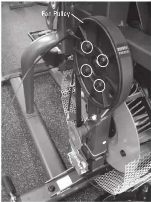
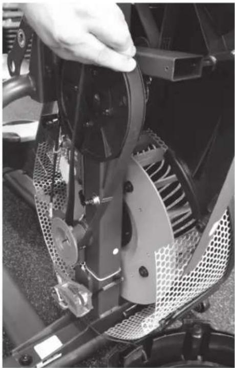
natural_image
Close-up of a hand adjusting a mechanical brake system with meshed components (no visible text or symbols)-
Secure the Fan Belt to the Fan Pulley with a Heavy Duty Zip-Tie. Be sure to attach the Zip-Tie where the Fan Belt is fully in contact with the Fan Pulley.
-
Grasp the Fan Pulley where the Fan Belt is engaged on it, and forcibly rotate the Fan Pulley until the Fan Belt is fully engaged.

Keep fingers out of any pinch opportunities when rotating the Fan Pulley.
-
Cut the Zip-Tie without damaging the new Fan Belt or Fan Pulley.
-
Installation is the reverse procedure excluding steps with the Crank Puller. The Crank Puller is not required for re-assembly.
Note: When replacing the Crank Arms, be sure the Right and Left Crank Arms are oriented inline and opposite each other.
The Crank Nuts should be tightened to a torque value of 29-32.5 ft lbs (or 350-390 in lbs).
- Final Inspection
Inspect your machine to ensure that all hardware is tight and components are properly assembled.

Do not use until the machine has been fully assembled and inspected for correct performance in accordance with the Owner's Manual.


natural_image
Technical line drawing of a mechanical assembly with no visible text or symbolsNOTICE: This document provides instructions for the replacement of the Frame Assembly on the Bowflex™ Max Total™ machine / Max Total™ 16/40 / Max Trainer™ M9.
If you need assistance, please contact Customer Service (if purchased in US/Canada) or your local distributor (if purchased outside US/Canada). To find your local distributor, go to: www.nautilusinternational.com

This icon means a potentially hazardous situation which, if not avoided, could result in death or serious injury. Read and understand all Warnings on this machine.
Nautilus, Inc., www.NautilusInc.com, 5415 Centerpoint Parkway, Groveport, OH 43125 U.S.A. - Customer Service: North America (800) 605-3369, csnls@nautilus.com | outside U.S. www.nautilusinternational.com | Printed in China | © 2020 Nautilus, Inc. | Bowflex, the B logo, Max Total, and Max Trainer are trademarks owned or licensed by Nautilus, Inc., registered or otherwise protected by common law in the United States and other nations. | ORIGINAL DOCUMENT - ENGLISH VERSION ONLY
Important Safety Instructions - Before servicing or using this equipment, obey the following warnings:

This icon means a potentially hazardous situation which, if not avoided, could result in death or serious injury. Read and understand all Warnings on this machine.
- Read and understand the Part Replacement Procedure before working on the machine. Failure to obey the instructions and safety warnings could cause injury to the service technician or bystanders.
- Keep bystanders, children and pets away from the product being serviced at all times.
- Make sure that the repair is done in an appropriate work space away from foot traffic and exposure to bystanders.
- Disconnect all power and allow to sit for 5 minutes before you service this machine.
- Some components of the equipment can be heavy or awkward. Enlist the service of a second person when you do maintenance steps involving these components. Do not try to do heavy or awkward steps on your own.
- If replacement parts are necessary, use only genuine Nautilus replacement parts and hardware. Failure to use genuine replacement parts can cause a risk to users, keep the machine from operating correctly and will void the warranty.
- Be sure that all warning stickers and instructional placards applied to the product stay present and in good condition when doing maintenance or replacing components. If at any time the Warning labels become loose, unreadable or dislodged, replace the labels. If purchased in US/Canada, contact Customer Service for replacement labels. If purchased outside US/Canada, contact your local distributor for them.
- Do not try to change the design or functionality of the machine being serviced as this can adversely effect user safety and will void the warranty.
- Do not use the machine until all shrouds, instructions, warning labels and correct functionality have been verified and tested for correct performance.
- SAVE THESE INSTRUCTIONS.
Tools Required (included)

| Item Qty Description | |||||
| A 6 Socket Head Hex Screw, M8x1.25x20 Black I 2 Wave Washer, 17 | 2x22 Black | ||||
| B | 6 | Lock Washer, M8x14.8 Black | J | 4 | Socket Head Hex Screw, M8x1.0x55 Black |
| C | 12 | Washer, Flat M8x18 Black | K | 4 | Lock Nut, M8 Black |
| D | 4 | Socket Head Hex Screw, M10x1.5x25 Black | L | 8 | Socket Head Hex Screw, M6x1.0x8 Black |
| E | 4 | Washer, Flat M10x23 Black | M | 4 | Socket Head Hex Screw, M6x1.0x20 CL10.9 Black |
| F | 1 | Pan Phillips Screw, M5x0.8x20 Black | N | 10 | Lock Washer, M6x14.8 Black |
| G | 2 | Washer, Flat M8x24 Black | O | 4 | Washer, Flat M6x13 Black |
| H 2 Cap | P 6 Socket Head Hex Screw, M6x1.0x20 CL12.9 Black | ||||


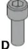




Note: Replace any damaged hardware with the new hardware provided with this kit for re-assembly.
- Unplug the AC Adapter from the wall outlet and machine.
-
Remove the Right and Left Stabilizer Shrouds from the machine.
-
Using a 5mm hex wrench, remove the indicated hardware from the Right and Left Upper Handlebar and place them out of the work area.
Note: Be aware that the Right and Left Upper Handlebar must be supported when removing the hardware.
- Using a #2 Phillips screwdriver, remove the indicated screw from the Rear Shroud.
- Carefully remove the Rear Shroud from the machine. Place a standard screwdriver behind and near the middle of the Rear Shroud and gently pry until it releases. Then move the screwdriver to the bottom and gently pry until the Rear Shroud comes off.
- Remove the Caps from the machine.
- Using a 6mm hex wrench, remove the hardware exposed from below the Cap from both sides of the machine.
- Slide the Leg Assemblies off of the machine.


-
Using a 5mm hex wrench, remove the screws (indicated by ovals) from the Static Handlebar Assembly.
-
Carefully lift the Static Handlebar Assembly and expose the Cable Connections.
Note: Do not crimp any of the Console Cables. This step may require two people.
- Carefully disconnect the Cables while not allowing them to fall into the Console Mast.
Note: Do not crimp any of the Console Cables.

- Using an 8mm hex wrench, remove the indicated hardware from the Rail Assembly.


natural_image
Technical line drawing of a mechanical assembly with no visible text or symbols
natural_image
Close-up of a black and white bicycle pedal mechanism with visible control panels and mounting holes (no text or symbols)- Using a 6mm hex wrench, remove the indicated hardware from the Rail Assembly. Be prepared to support the weight of the Rail Assembly.

- Using new Hardware Items C, B, and A, attach the Rail Assembly to the new Frame Assembly.

Some components of the machine can be heavy or awkward. Use a second person when doing the assembly steps involving these parts. Do not do steps that involve heavy lifting or awkward movements on your own.
NOTICE: Hand tighten hardware.


A second person is recommended to stabilize the Frame Assembly.
- Using an 8mm hex wrench, remove the indicated hardware from the old Frame Assembly. Be prepared to support the Frame Assembly before removing the hardware.

The Frame Assembly may be awkward when released from the Stabilizer Assembly. Some components of the machine can be heavy or awkward. Use a second person to hold the Frame Assembly stable and upright. Do not do steps that involve heavy lifting or awkward movements on your own.
-
With the assistance of a second person, carefully lift the old Frame Assembly from the Stabilizer Assembly and place outside the assembly area. To protect your flooring, carefully place it onto its side on some cardboard or a blanket.
-
Using a 13mm wrench, remove the hardware that secures the new Frame Assembly to the shipping plate.
-
Carefully Lift the new Frame Assembly and Attach It to the Stabilizer Assembly
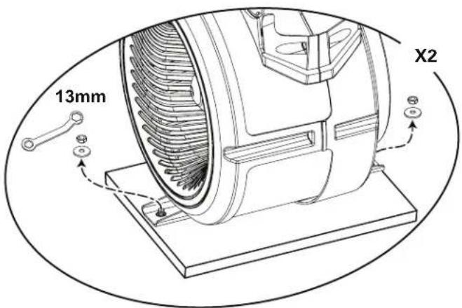

Some components of the machine can be heavy or awkward. Use a second person when doing the assembly steps involving these parts. Do not do steps that involve heavy lifting or awkward movements on your own. Lift the Frame Assembly from the exterior of the pivot assembly as indicated below.
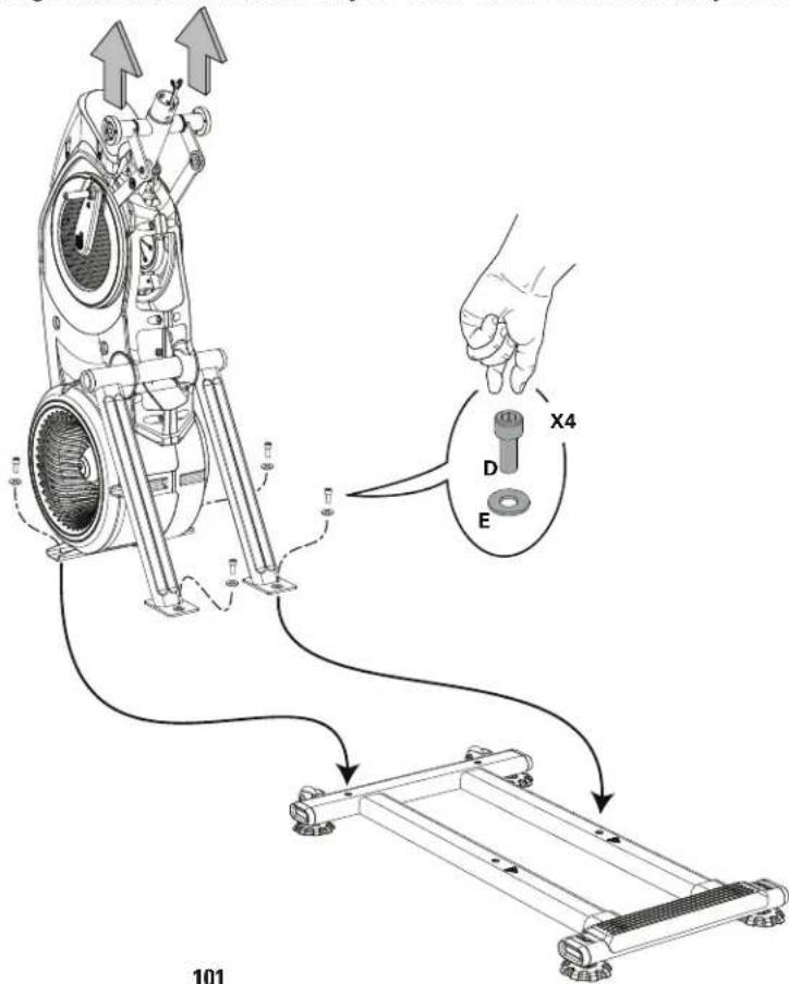
-
Fully tighten the hardware that attaches the Rail Assembly to the new Frame Assembly (from Step 13), and then the hardware just installed to the Stabilizer Assembly.
-
Using a #2 Phillips screwdriver, attach the Upper Shroud to the Frame Assembly.
-
Attach the Rear Shroud and Caps to the Frame Assembly
NOTICE: Place the inside hook of the Rear Shroud on the Frame Assembly and then pivot it up into place.

22. Attach Leg Assemblies to Frame Assembly

Be aware that the Legs are connected and when either of these parts move the other does as well.
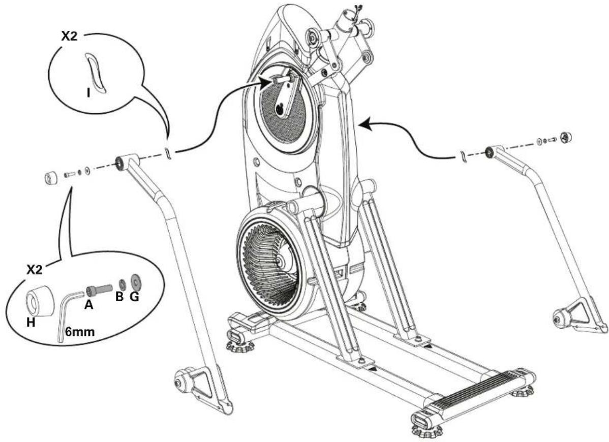
- Connect the Static Handlebar Assembly to the Frame Assembly
Note: When attaching the Static Handlebar Assembly, do not fully tighten the hardware until all hardware has been hand tightened. Do not crimp any of the Console Cables.

24. Attach the Upper Handlebars to Frame Assembly

Be aware that the Pedals and the Upper Handlebars are connected and when either of these parts move the other does as well. Some components of the machine can be heavy or awkward. Use a second person when doing the assembly steps involving these parts. Do not do steps that involve heavy lifting or awkward movements on your own.
NOTICE: Be sure to attach the Upper Handlebars so they can be correctly grasped by a User when on the machine.

25. Final Inspection
Inspect your machine to ensure that all hardware is tight and components are properly assembled.

Do not use until the machine has been fully assembled and inspected for correct performance in accordance with the Owner's Manual.
NOTICE: This document provides instructions for the replacement of the Handlebar Pivot Assembly on the Bowflex™ Max Total™ machine / Max Total™ 16/40 / Max Trainer™ M9.
If you need assistance, please contact Customer Service (if purchased in US/Canada) or your local distributor (if purchased outside US/Canada). To find your local distributor, go to: www.nautilusinternational.com

This icon means a potentially hazardous situation which, if not avoided, could result in death or serious injury. Read and understand all Warnings on this machine.
Nautilus, Inc., www.NautilusInc.com, 5415 Centerpoint Parkway, Groveport, OH 43125 U.S.A. - Customer Service: North America (800) 605-3369, csnls@nautilus.com | outside U.S. www.nautilusinternational.com | Printed in China | © 2020 Nautilus, Inc. | Bowflex, the B logo, Max Total, and Max Trainer are trademarks owned or licensed by Nautilus, Inc., registered or otherwise protected by common law in the United States and other nations. | ORIGINAL DOCUMENT - ENGLISH VERSION ONLY
Important Safety Instructions - Before servicing or using this equipment, obey the following warnings:

This icon means a potentially hazardous situation which, if not avoided, could result in death or serious injury. Read and understand all Warnings on this machine.
- Read and understand the Part Replacement Procedure before working on the machine. Failure to obey the instructions and safety warnings could cause injury to the service technician or bystanders.
- Keep bystanders, children and pets away from the product being serviced at all times.
- Make sure that the repair is done in an appropriate work space away from foot traffic and exposure to bystanders.
- Disconnect all power and allow to sit for 5 minutes before you service this machine.
- Some components of the equipment can be heavy or awkward. Enlist the service of a second person when you do maintenance steps involving these components. Do not try to do heavy or awkward steps on your own.
- If replacement parts are necessary, use only genuine Nautilus replacement parts and hardware. Failure to use genuine replacement parts can cause a risk to users, keep the machine from operating correctly and will void the warranty.
- Be sure that all warning stickers and instructional placards applied to the product stay present and in good condition when doing maintenance or replacing components. If at any time the Warning labels become loose, unreadable or dislodged, replace the labels. If purchased in US/Canada, contact Customer Service for replacement labels. If purchased outside US/Canada, contact your local distributor for them.
- Do not try to change the design or functionality of the machine being serviced as this can adversely effect user safety and will void the warranty.
- Do not use the machine until all shrouds, instructions, warning labels and correct functionality have been verified and tested for correct performance.
- SAVE THESE INSTRUCTIONS.
Tools Required (not included)
5mm hex wrench 6mm hex wrench


- Unplug the AC Adapter from the wall outlet and machine.
-
Using a 5mm hex wrench, remove the indicated hardware from the Left Upper Handlebar and place it out of the work area.
Note: Be aware that the Upper Handlebar must be supported when removing the hardware. -
Place a rag or protective material below the Connector Arm to protect the Shroud from potential scratches from the Connector Arm.
-
Using a 6mm hex wrench, remove the indicated hardware (by oval) that connects the Connector Arm and the Handlebar Pivot Assembly.
Note: The Connector Arm will pivot downward if not lowered slowly onto the rag protecting the Shroud.
-
Using a 6mm hex wrench, remove the indicated hardware (by arrow) that connects the Handlebar Pivot Assembly to the Console Mast.
-
Slide the Handlebar Pivot Assembly off of the Console Mast and replace with the new assembly.
-
Installation is the reverse procedure.
-
Repeat Steps 2 - 7 on the right side of the machine.
-
Final Inspection
Inspect your machine to ensure that all hardware is tight and components are properly assembled.

Do not use until the machine has been fully assembled and inspected for correct performance in accordance with the Owner's Manual.

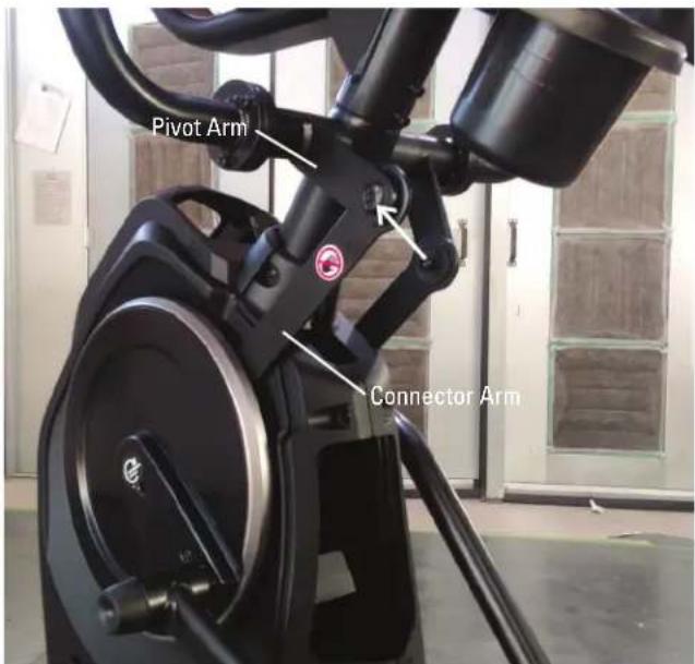
NOTICE: This document provides instructions for the replacement of the Cables that are the Mid Mast Cables on the Bowflex™ Max Total™ machine / Max Total™ 16/40 / Max Trainer™ M9.
If you need assistance, please contact Customer Service (if purchased in US/Canada) or your local distributor (if purchased outside US/Canada). To find your local distributor, go to: www.nautilusinternational.com

This icon means a potentially hazardous situation which, if not avoided, could result in death or serious injury. Read and understand all Warnings on this machine.
Nautilus, Inc., www.NautilusInc.com, 5415 Centerpoint Parkway, Groveport, OH 43125 U.S.A. - Customer Service: North America (800) 605-3369, csnls@nautilus.com | outside U.S. www.nautilusinternational.com | Printed in China | © 2019 Nautilus, Inc. | Bowflex, the B logo, Max Total, and Max Trainer are trademarks owned or licensed by Nautilus, Inc., registered or otherwise protected by common law in the United States and other nations. | ORIGINAL DOCUMENT - ENGLISH VERSION ONLY
Important Safety Instructions - Before servicing or using this equipment, obey the following warnings:

This icon means a potentially hazardous situation which, if not avoided, could result in death or serious injury. Read and understand all Warnings on this machine.
- Read and understand the Part Replacement Procedure before working on the machine. Failure to obey the instructions and safety warnings could cause injury to the service technician or bystanders.
- Keep bystanders, children and pets away from the product being serviced at all times.
- Make sure that the repair is done in an appropriate work space away from foot traffic and exposure to bystanders.
- Disconnect all power and allow to sit for 5 minutes before you service this machine.
- Some components of the equipment can be heavy or awkward. Enlist the service of a second person when you do maintenance steps involving these components. Do not try to do heavy or awkward steps on your own.
- If replacement parts are necessary, use only genuine Nautilus replacement parts and hardware. Failure to use genuine replacement parts can cause a risk to users, keep the machine from operating correctly and will void the warranty.
- Be sure that all warning stickers and instructional placards applied to the product stay present and in good condition when doing maintenance or replacing components. If at any time the Warning labels become loose, unreadable or dislodged, replace the labels. If purchased in US/Canada, contact Customer Service for replacement labels. If purchased outside US/Canada, contact your local distributor for them.
- Do not try to change the design or functionality of the machine being serviced as this can adversely effect user safety and will void the warranty.
- Do not use the machine until all shrouds, instructions, warning labels and correct functionality have been verified and tested for correct performance.
- SAVE THESE INSTRUCTIONS.
Tools Required (not included)
2
Phillips
screwdr

5mm
hex
wrench
Piece of wire or string (around 6" in length)

Note: Your machine may not match the images provided exactly.
- Unplug the AC Adapter from the wall outlet and machine.
-
Remove the Rear Console Cover from the Console Assembly.
-
Using a #2 Phillips screwdriver, remove the screws (indicated by ovals) from the Console Assembly.
-
Carefully tilt the Console Assembly off of the Static Handlebar and expose the Cable Connections.
Note: Do not crimp any of the Console Cables. This step may require two people.
- Carefully disconnect the Cables.
Note: Do not crimp any of the Console Cables.
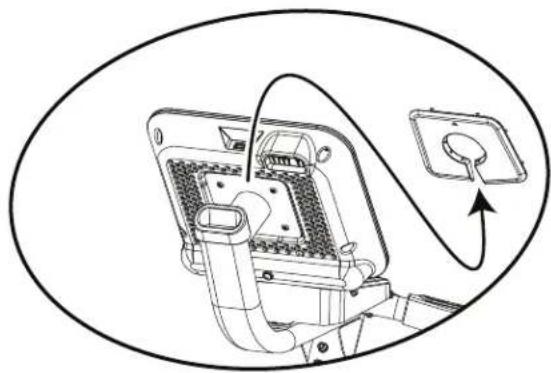
natural_image
Diagram of an electrical plug with wiring and socket, no text or symbols present

natural_image
Technical line drawing of a mechanical device with no visible text or symbols- Using a 5mm hex wrench, remove the four screws (indicated by oval) from the Static Handlebar Assembly.

- Carefully lift the Static Handlebar Assembly and expose the Cable Connections.
Note: Do not crimp any of the Console Cables. This step may require two people.
- Carefully disconnect the Cables while not allowing them to fall into the Console Mast.
Note: Do not crimp any of the Console Cables.
-
To protect the paint and finishes from scratches, gently place all parts on a towel or piece of cardboard before attempting to replace any Cable(s).
-
From the top of the Static Handlebar Assembly, there are 4 Cables:
Upper Body Sensor Cable (3-pin, flat connector) To replace, go to the next Step.
Input/Output (I/O) Cable (14-pin, two-row connector) To replace, go to the next Step.
Resistance Knob Cable (5-pin, flat connector) To replace, go to Step 14.
Contact Heart Rate Cable (4-pin, flat connector) The Contact Heart Rate Cable is not available for replacement.

natural_image
Technical line drawing of a mechanical assembly with no visible text or symbols
- To replace the Upper Body Sensor or the Input/Output (I/O) Cables, attach the ends of the new Cable to the old Cable using a piece of wire or string.
Note: Only replace one Cable at a time because of the limited space.
- Gently pull the old Cable out of the top of the Static Handlebar Assembly, routing the new Cable into place.
Note: Do not crimp any of the Console Cables.
- Remove the piece of wire or string, and discard the old Cable.
If not replacing the Resistance Cable, go to Step 21.
-
To replace the Resistance Cable that connects to the Resistance Knob, remove the hardware (indicated by an arrow) from the Static Handlebar Assembly using a #2 Phillips screwdriver.
-
Gently flip over the Static Handlebar Assembly onto a towel or piece of cardboard.
-
Using a #2 Phillips screwdriver, remove the hardware (indicated by arrows) from the Static Handlebar Assembly.
-
Slightly lift the Static Handlebars from the Tray, and disconnect the Resistance Cable.

natural_image
Technical line drawing of a medical device with tubing and connector, showing a close-up inset (no text or symbols)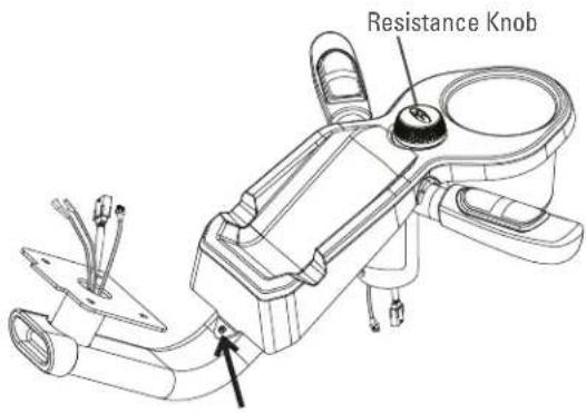

natural_image
Technical line drawing of a mechanical device with no visible text or symbols
natural_image
Technical line drawing of a robotic arm with attached components (no text or symbols)-
Using a piece of wire or string, attach the new Resistance Cable to the end of old Resistance Cable where it connected to the Resistance Knob. Be sure to connect the Cables so that when the new Resistance Cable is routed the connectors will match the old Resistance Cable connectors
-
Gently pull the old Resistance Cable out of the top of the Static Handlebar, routing the new Resistance Cable into place.
Note: Do not crimp any of the Console Cables.
-
Remove the piece of wire or string, and discard the old Resistance Cable.
-
Re-assemble the machine in the reverse order of when the parts were removed.
Note: Do not cut or crimp the Cables. Each Cable connector (3-pin, 4-pin, 5-pin and 14-pin) has a corresponding end connector with that many openings. Be sure to fully connect the cable connectors. When attaching the Console Assembly, do not fully tighten the hardware until all hardware has been hand tightened.
- Final Inspection
Inspect your machine to ensure that all hardware is tight and components are properly assembled.

Do not use until the machine has been fully assembled and inspected for correct performance in accordance with the Owner's Manual.

natural_image
Medical procedure diagram showing a catheter insertion into a tube with an inset close-up of the cable (no text or labels)
NOTICE: This document provides instructions for the replacement of the PCBA Board Assembly on the Bowflex™ Max Total™ 16/40 and Max Trainer™ M9. If you need assistance, please contact Customer Service (if purchased in US/Canada) or your local distributor (if purchased outside US/Canada). To find your local distributor, go to: www.nautilusinternational.com

This icon means a potentially hazardous situation which, if not avoided, could result in death or serious injury. Read and understand all Warnings on this machine.
Nautilus, Inc., www.NautilusInc.com, 5415 Centerpoint Parkway, Groveport, OH 43125 U.S.A. - Customer Service: North America (800) 605-3369, csnls@nautilus.com | outside U.S. www.nautilusinternational.com | Printed in China | © 2022 Nautilus, Inc. | Bowflex, the B logo, Max Total, and Max Trainer are trademarks owned or licensed by Nautilus, Inc., registered or otherwise protected by common law in the United States and other nations. | ORIGINAL DOCUMENT - ENGLISH VERSION ONLY
Important Safety Instructions - Before servicing or using this equipment, obey the following warnings:

This icon means a potentially hazardous situation which, if not avoided, could result in death or serious injury. Read and understand all Warnings on this machine.
- Read and understand the Part Replacement Procedure before working on the machine. Failure to obey the instructions and safety warnings could cause injury to the service technician or bystanders.
- Keep bystanders, children and pets away from the product being serviced at all times.
- Make sure that the repair is done in an appropriate work space away from foot traffic and exposure to bystanders.
- Disconnect all power and allow to sit for 5 minutes before you service this machine.
- Some components of the equipment can be heavy or awkward. Enlist the service of a second person when you do maintenance steps involving these components. Do not try to do heavy or awkward steps on your own.
- If replacement parts are necessary, use only genuine Nautilus replacement parts and hardware. Failure to use genuine replacement parts can cause a risk to users, keep the machine from operating correctly and will void the warranty.
- Be sure that all warning stickers and instructional placards applied to the product stay present and in good condition when doing maintenance or replacing components. If at any time the Warning labels become loose, unreadable or dislodged, replace the labels. If purchased in US/Canada, contact Customer Service for replacement labels. If purchased outside US/Canada, contact your local distributor for them.
- Do not try to change the design or functionality of the machine being serviced as this can adversely effect user safety and will void the warranty.
- Do not use the machine until all shrouds, instructions, warning labels and correct functionality have been verified and tested for correct performance.
- SAVE THESE INSTRUCTIONS.
Tools Required (not included)
Short
2
2 Phillips
Phillips screwdriver

5mm hex wrench 6mm hex wrench


Note: Your machine may not match the images provided exactly.
-
Unplug the AC Adapter from the wall outlet and machine.
-
Using a 6mm hex wrench, remove the indicated hardware from the Right and Left Upper Handlebar and place them out of the work area.
Note: Be aware that the Right and Left Upper Handlebar must be supported when removing the hardware.
-
Using a #2 Phillips screwdriver, remove the 4 screws (2 indicated on one side) from the Upper Shroud and remove it.
-
Remove the Right and Left Stabilizer Shrouds from the machine.


- Using a #2 Phillips screwdriver, remove the indicated (by ovals) screws and only loosen the lowest indicated screw (arrow) from the Right Fan Cover.
Note: Loosen the lowest screw by at least 3 full rotations.
- The Right Fan Cover has a tab that needs to be pushed upward to clear the loosened screw. While pushing up on the tab, remove the Right Fan Cover from the assembly.
Note: The Power Cable is attached to the inside of the Right Fan Cover. Be sure not to crimp the cable by placing the Right Fan Cover close to the front of the machine.
To assist with assembly, note that the upper screw is a machine screw and not a self-tapping screw.


-
Remove the indicated Cap from both sides of the machine.
-
Using a 6mm hex wrench, remove the hardware exposed below the Cap from both sides of the machine.
-
Slide the Leg Assemblies off of the machine.
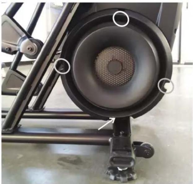
natural_image
Close-up of a black stationary exercise machine with visible mesh and circular components (no text or symbols)
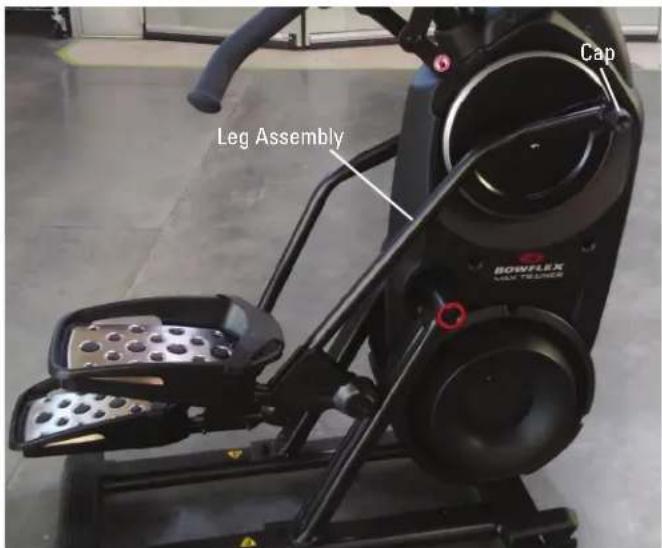
-
Using a #2 Phillips screwdriver, remove the indicated screw (by arrow) from the Rear Shroud.
-
Carefully remove the Rear Shroud from the machine. Place a standard screwdriver behind and near the middle of the Rear Shroud and gently pry until it releases. Then move the screwdriver to the bottom and gently pry until the Rear Shroud comes off.
-
Using a #2 Phillips screwdriver, remove the indicated (by oval) screw and only loosen the lowest indicated screw (arrow) from the Left Fan Cover.
-
The Left Fan Cover Assembly has a tab that needs to be pushed upward to clear the loosened screw. While pushing up on the tab, remove the Left Fan Cover Assembly.
-
Remove the Left Fan Cover Assembly from the machine. Be sure to note how the fan screens are set into the Left Fan Cover to assist with the replacement procedure.
-
Using a #2 Phillips screwdriver, remove the 2 indicated screws from the each of the Crank Covers.
Note: The Crank Cover screws may have been over-tightened when installed. Try not to strip the screws when removing them.
-
Remove the Crank Covers from the machine.
-
Place a rag or protective material below each of the Connector Arms to protect the Shrouds from potential scratches from the Connector Arms.
-
Using a 6mm hex wrench, remove the hardware that connects each of the Connector Arms to the Pivot Arms.
Note: The Connector Arm will pivot downward if not lowered slowly onto the rag protecting the Shroud.


natural_image
Close-up of a black stationary exercise bike with red rim and circular vent, mounted on a wheeled platform (no visible text or symbols)

- The PCBA Board Assembly is located above the Servo Motor. After noting how the cables connect to the PCBA Board Assembly, disconnect the cables from it.
Note: Be sure not to crimp or cut any of the cables.


- Using a short #2 Phillips screwdriver, remove the 4 screws (indicated with red ovals) that secure the PCBA Board Assembly to the Frame and remove it.
Note: Be sure to remove the screws from the PCBA Board Assembly and not the PCBA Board.

PCBA Board Assembly

-
Using a short #2 Phillips screwdriver, attach the new PCBA Board Assembly to the Frame and connect the cables.
-
Re-install all remaining parts that were removed in reverse order.
-
Final Inspection Inspect your machine to ensure that all hardware is tight and components are properly assembled.

Do not use until the machine has been fully assembled and inspected for correct performance in accordance with the Owner's Manual.
NOTICE: This document provides instructions for the replacement of the Power Inlet on the Bowflex™ Max Total™ machine / Max Total™ 16/40 / Max Trainer™ M9.
If you need assistance, please contact Customer Service (if purchased in US/Canada) or your local distributor (if purchased outside US/Canada). To find your local distributor, go to: www.nautilusinternational.com

This icon means a potentially hazardous situation which, if not avoided, could result in death or serious injury. Read and understand all Warnings on this machine.
Nautilus, Inc., www.NautilusInc.com, 5415 Centerpoint Parkway, Groveport, OH 43125 U.S.A. - Customer Service: North America (800) 605-3369, csnls@nautilus.com | outside U.S. www.nautilusinternational.com | Printed in China | © 2020 Nautilus, Inc. | Bowflex, the B logo, Max Total, and Max Trainer are trademarks owned or licensed by Nautilus, Inc., registered or otherwise protected by common law in the United States and other nations. | ORIGINAL DOCUMENT - ENGLISH VERSION ONLY
Important Safety Instructions - Before servicing or using this equipment, obey the following warnings:

This icon means a potentially hazardous situation which, if not avoided, could result in death or serious injury. Read and understand all Warnings on this machine.
- Read and understand the Part Replacement Procedure before working on the machine. Failure to obey the instructions and safety warnings could cause injury to the service technician or bystanders.
- Keep bystanders, children and pets away from the product being serviced at all times.
- Make sure that the repair is done in an appropriate work space away from foot traffic and exposure to bystanders.
- Disconnect all power and allow to sit for 5 minutes before you service this machine.
- Some components of the equipment can be heavy or awkward. Enlist the service of a second person when you do maintenance steps involving these components. Do not try to do heavy or awkward steps on your own.
- If replacement parts are necessary, use only genuine Nautilus replacement parts and hardware. Failure to use genuine replacement parts can cause a risk to users, keep the machine from operating correctly and will void the warranty.
- Be sure that all warning stickers and instructional placards applied to the product stay present and in good condition when doing maintenance or replacing components. If at any time the Warning labels become loose, unreadable or dislodged, replace the labels. If purchased in US/Canada, contact Customer Service for replacement labels. If purchased outside US/Canada, contact your local distributor for them.
- Do not try to change the design or functionality of the machine being serviced as this can adversely effect user safety and will void the warranty.
- Do not use the machine until all shrouds, instructions, warning labels and correct functionality have been verified and tested for correct performance.
- SAVE THESE INSTRUCTIONS.
Tools Required (not included)
2 Phillips screwdriver
15mm wrench


- Unplug the AC Adapter from the wall outlet and machine.
- Remove the Right Stabilizer Shroud from the machine.

- Using a #2 Phillips screwdriver, remove the indicated (by ovals) screws and only loosen the lowest indicated screw (arrow) from the Right Fan Cover.
Note: Loosen the lowest screw by at least 3 full rotations.
- The Right Fan Cover has a tab that needs to be pushed upward to clear the loosened screw. While pushing up on the tab, remove the Right Fan Cover from the assembly.
Note: the Power Cable is attached to the inside of the Right Fan Cover. Be sure not to crimp the cable by placing the Right Fan Cover close to the front of the machine.
To assist with assembly, note that the upper screw is a machine screw and not a self-tapping screw.


natural_image
Close-up of a black stationary exercise bike with visible mesh speaker and circular components (no text or symbols)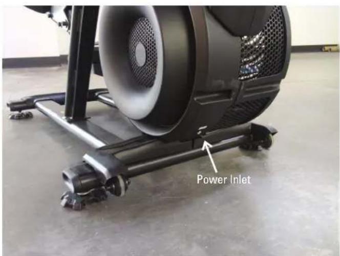
-
Disconnect the Power Inlet from the Power Connector behind the Brake Disc.
-
Using a 15mm open end wrench, remove the Securing Ring from the outside of the Right Fan Cover.
-
Remove the Power Inlet from the inside of the Right Fan Cover.
-
Installation is the reverse procedure.
-
Final Inspection Inspect your machine to ensure that all hardware is tight and components are properly assembled.

Do not use until the machine has been fully assembled and inspected for correct performance in accordance with the Owner's Manual.


NOTICE: This document provides instructions for the replacement of the Roller Wheel Assembly on the Bowflex™ Max Total™ machine / Max Total™ 16/40 / Max Trainer™ M9.
If you need assistance, please contact Customer Service (if purchased in US/Canada) or your local distributor (if purchased outside US/Canada). To find your local distributor, go to: www.nautilusinternational.com

This icon means a potentially hazardous situation which, if not avoided, could result in death or serious injury. Read and understand all Warnings on this machine.
Nautilus, Inc., www.NautilusInc.com, 5415 Centerpoint Parkway, Groveport, OH 43125 U.S.A. - Customer Service: North America (800) 605-3369, csnls@nautilus.com | outside U.S. www.nautilusinternational.com | Printed in China | © 2020 Nautilus, Inc. | Bowflex, the B logo, Max Total, and Max Trainer are trademarks owned or licensed by Nautilus, Inc., registered or otherwise protected by common law in the United States and other nations. | ORIGINAL DOCUMENT - ENGLISH VERSION ONLY
Important Safety Instructions - Before servicing or using this equipment, obey the following warnings:

This icon means a potentially hazardous situation which, if not avoided, could result in death or serious injury. Read and understand all Warnings on this machine.
- Read and understand the Part Replacement Procedure before working on the machine. Failure to obey the instructions and safety warnings could cause injury to the service technician or bystanders.
- Keep bystanders, children and pets away from the product being serviced at all times.
- Make sure that the repair is done in an appropriate work space away from foot traffic and exposure to bystanders.
- Disconnect all power and allow to sit for 5 minutes before you service this machine.
- Some components of the equipment can be heavy or awkward. Enlist the service of a second person when you do maintenance steps involving these components. Do not try to do heavy or awkward steps on your own.
- If replacement parts are necessary, use only genuine Nautilus replacement parts and hardware. Failure to use genuine replacement parts can cause a risk to users, keep the machine from operating correctly and will void the warranty.
- Be sure that all warning stickers and instructional placards applied to the product stay present and in good condition when doing maintenance or replacing components. If at any time the Warning labels become loose, unreadable or dislodged, replace the labels. If purchased in US/Canada, contact Customer Service for replacement labels. If purchased outside US/Canada, contact your local distributor for them.
- Do not try to change the design or functionality of the machine being serviced as this can adversely effect user safety and will void the warranty.
- Do not use the machine until all shrouds, instructions, warning labels and correct functionality have been verified and tested for correct performance.
- SAVE THESE INSTRUCTIONS.
Tools (not included)
(2) 6mm hex wrenches


-
Unplug the AC Power Adapter from the machine.
-
Using two 6mm hex wrenches, remove the hardware (indicated by arrows) from the Roller Wheel Assembly.

In order to avoid possible serious injury when removing the Roller Wheel Assembly, be careful to avoid fingers or hands being caught or pinched.

Be aware that the Pedal Arms and the Upper Handlebars are connected and when either of these parts move the other does as well.
- Remove and dispose of the old Roller Wheels, Axle, Screws, and any Washers that were installed.
Note: Some Washers may stick to the Wheel Bracket on the Pedal Arm. Be sure to remove them before re-assembly.
- Attach the new Roller Wheel Assembly with the provided hardware. The new Roller Wheel Assembly includes two Small Metal Washers and two Large Felt Washers. Make sure the Small Metal Washers are installed on the outside of the Wheel Brackets, while the Large Felt Washers are on the inside of the Wheel Bracket to the outside of the Roller Wheels.
Note: The Wheel Bracket is sized so the Axle can only be inserted in one direction.
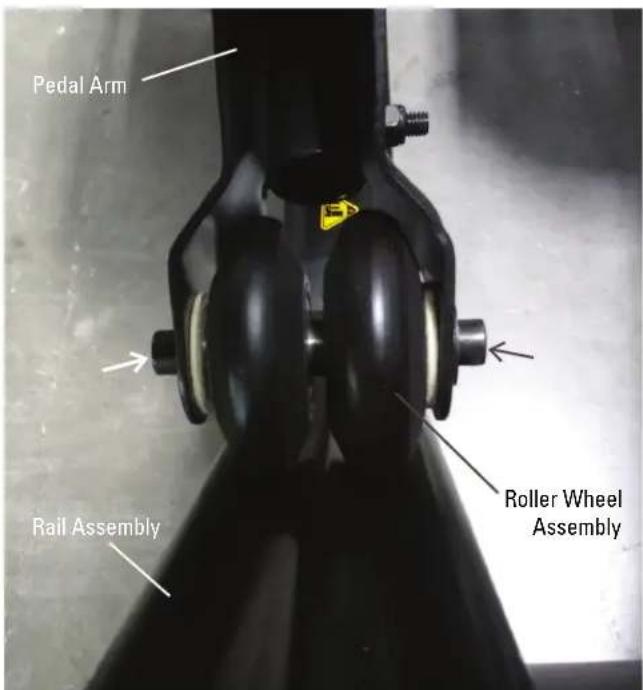
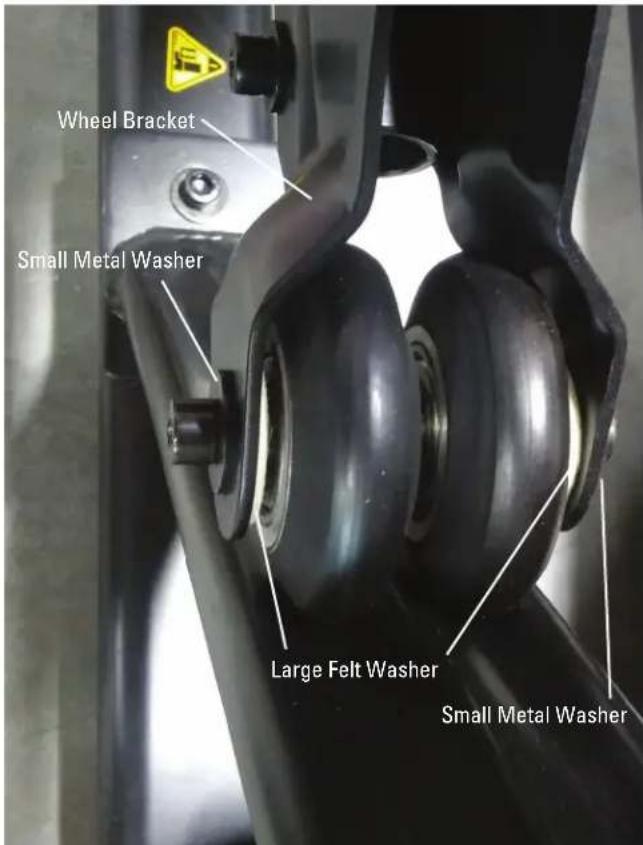
5. Final Inspection
Inspect your machine to ensure that all hardware is tight and components are properly assembled.

Do not use until the machine has been fully assembled and inspected for correct performance in accordance with the Owner's Manual.
NOTICE: This document provides instructions for the replacement of the Servo Motor on the Bowflex™ Max Total™ machine / Max Total™ 16/40 / Max Trainer™ M9.
If you need assistance, please contact Customer Service (if purchased in US/Canada) or your local distributor (if purchased outside US/Canada). To find your local distributor, go to: www.nautilusinternational.com

This icon means a potentially hazardous situation which, if not avoided, could result in death or serious injury. Read and understand all Warnings on this machine.
Nautilus, Inc., www.NautilusInc.com, 5415 Centerpoint Parkway, Groveport, OH 43125 U.S.A. - Customer Service: North America (800) 605-3369, csnls@nautilus.com | outside U.S. www.nautilusinternational.com | Printed in China | © 2019 Nautilus, Inc. | Bowflex, the B logo, Max Total, and Max Trainer are trademarks owned or licensed by Nautilus, Inc., registered or otherwise protected by common law in the United States and other nations. | ORIGINAL DOCUMENT - ENGLISH VERSION ONLY
Important Safety Instructions - Before servicing or using this equipment, obey the following warnings:

This icon means a potentially hazardous situation which, if not avoided, could result in death or serious injury. Read and understand all Warnings on this machine.
- Read and understand the Part Replacement Procedure before working on the machine. Failure to obey the instructions and safety warnings could cause injury to the service technician or bystanders.
- Keep bystanders, children and pets away from the product being serviced at all times.
- Make sure that the repair is done in an appropriate work space away from foot traffic and exposure to bystanders.
- Disconnect all power and allow to sit for 5 minutes before you service this machine.
- Some components of the equipment can be heavy or awkward. Enlist the service of a second person when you do maintenance steps involving these components. Do not try to do heavy or awkward steps on your own.
- If replacement parts are necessary, use only genuine Nautilus replacement parts and hardware. Failure to use genuine replacement parts can cause a risk to users, keep the machine from operating correctly and will void the warranty.
- Be sure that all warning stickers and instructional placards applied to the product stay present and in good condition when doing maintenance or replacing components. If at any time the Warning labels become loose, unreadable or dislodged, replace the labels. If purchased in US/Canada, contact Customer Service for replacement labels. If purchased outside US/Canada, contact your local distributor for them.
- Do not try to change the design or functionality of the machine being serviced as this can adversely effect user safety and will void the warranty.
- Do not use the machine until all shrouds, instructions, warning labels and correct functionality have been verified and tested for correct performance.
- SAVE THESE INSTRUCTIONS.
Tools Required (not included)
2
Phillips
screwdriver

8mm wrench
10mm wrench

Note: Your machine may not match the images provided exactly.
- With power supplied to the machine, adjust the resistance to the maximum setting.
- Unplug the AC Adapter from the wall outlet and machine.
-
Remove the Right Stabilizer Shroud from the machine (if equipped).
-
Using a #2 Phillips screwdriver, remove the indicated (by ovals) screws and only loosen the lowest indicated screw (arrow) from the Right Fan Cover.
Note: Loosen the lowest screw by at least 3 full rotations.
- The Right Fan Cover has a tab that needs to be pushed upward to clear the loosened screw. While pushing up on the tab, remove the Right Fan Cover from the assembly.
Note: The Power Cable is attached to the inside of the Right Fan Cover. Be sure not to crimp the cable by placing the Right Fan Cover close to the front of the machine.
To assist with assembly, note that the upper screw is a machine screw and not a self-tapping screw.
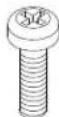


natural_image
Close-up of a black stationary exercise machine with visible mesh and mounting base (no text or symbols)

- Using a #2 Phillips screwdriver, remove the 3 indicated screws from the Brake Disc.
- Carefully remove the Brake Disc from the machine.

- Using an 8mm open ended wrench, loosen the Brake Cable Securing Nut until the Brake Cable can be released from the Servo Motor Arm.
- Remove the Brake Spring from the Brake Arm.
- Disconnect the Cables from the Servo Motor.
- Using a #2 Phillips screwdriver, remove the 4 screws that attach the Servo Motor to the Frame.
- Attach the new Servo Motor to the Frame and reconnect the Cables.
- Carefully replace the Brake Disc.

- At the maximum resistance setting, the outer edge of the Brake Magnet should line up with the outer edge of the Brake Disc.

-
If the Brake Assembly needs to be adjusted, use a 8mm open ended wrench to loosen the Brake Cable Securing Nut. Turn the Adjustment Barrel by hand until the magnet is placed correctly.
-
Carefully rotate the Brake Disc. If the Brake Disc does not rub against the Brake Magnet, skip to step 19.

Keep fingers out of any pinch opportunities when rotating the Brake Disc.
Note: The Brake Disc may appear to have a slight "wobble". This is normal and will not affect machine function.

-
The Brake Magnets should be aligned with the Brake Disc and centered around the Brake Disc. If they are not aligned and centered, then the Magnets are adding drag.
-
If the Brake Assembly only needs to be slightly adjusted, loosen the front screw (indicated by double-tailed arrow) that secures the Brake Assembly using a 10mm hex wrench. Rotate the Brake Assembly until the Magnets are aligned and of equal distance from the Brake Disc.
If the Brake Assembly must be fully shifted, loosen the 2 screws (indicated by arrows) that secure the assembly and shift it until centered and aligned with the Brake Disc. Fully tighten the hardware.

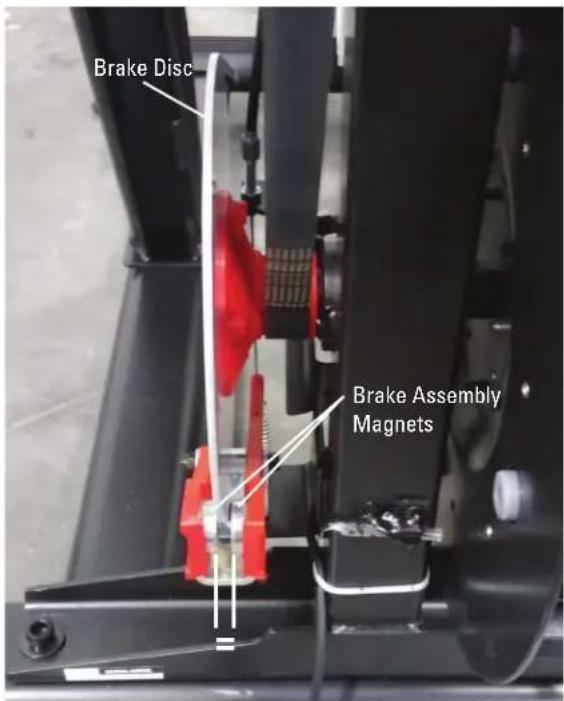
-
Installation is the reverse procedure.
-
Final Inspection
Inspect your machine to ensure that all hardware is tight and components are properly assembled.

Do not use until the machine has been fully assembled and inspected for correct performance in accordance with the Owner's Manual.
NOTICE: This document provides instructions for the replacement of the Shrouds on the Bowflex™ Max Total™ machine / Max Total™ 16/40 / Max Trainer™ M9.
If you need assistance, please contact Customer Service (if purchased in US/Canada) or your local distributor (if purchased outside US/Canada). To find your local distributor, go to: www.nautilusinternational.com

This icon means a potentially hazardous situation which, if not avoided, could result in death or serious injury. Read and understand all Warnings on this machine.
Nautilus, Inc., www.NautilusInc.com, 5415 Centerpoint Parkway, Groveport, OH 43125 U.S.A. - Customer Service: North America (800) 605-3369, csnls@nautilus.com | outside U.S. www.nautilusinternational.com | Printed in China | © 2019 Nautilus, Inc. | Bowflex, the B logo, Max Total, and Max Trainer are trademarks owned or licensed by Nautilus, Inc., registered or otherwise protected by common law in the United States and other nations. | ORIGINAL DOCUMENT - ENGLISH VERSION ONLY
Important Safety Instructions - Before servicing or using this equipment, obey the following warnings:

This icon means a potentially hazardous situation which, if not avoided, could result in death or serious injury. Read and understand all Warnings on this machine.
- Read and understand the Part Replacement Procedure before working on the machine. Failure to obey the instructions and safety warnings could cause injury to the service technician or bystanders.
- Keep bystanders, children and pets away from the product being serviced at all times.
- Make sure that the repair is done in an appropriate work space away from foot traffic and exposure to bystanders.
- Disconnect all power and allow to sit for 5 minutes before you service this machine.
- Some components of the equipment can be heavy or awkward. Enlist the service of a second person when you do maintenance steps involving these components. Do not try to do heavy or awkward steps on your own.
- If replacement parts are necessary, use only genuine Nautilus replacement parts and hardware. Failure to use genuine replacement parts can cause a risk to users, keep the machine from operating correctly and will void the warranty.
- Be sure that all warning stickers and instructional placards applied to the product stay present and in good condition when doing maintenance or replacing components. If at any time the Warning labels become loose, unreadable or dislodged, replace the labels. If purchased in US/Canada, contact Customer Service for replacement labels. If purchased outside US/Canada, contact your local distributor for them.
- Do not try to change the design or functionality of the machine being serviced as this can adversely effect user safety and will void the warranty.
- Do not use the machine until all shrouds, instructions, warning labels and correct functionality have been verified and tested for correct performance.
- SAVE THESE INSTRUCTIONS.
Tools Required (not included)
2
Phillips
screwdriver
5mm hex wrench 6mm hex wrench
(if replacing Right Fan Cover) 14mm wrench

Note: Your machine may not match the images provided exactly.
-
Unplug the AC Adapter from the wall outlet and machine.
-
Using a 6mm hex wrench, remove the indicated hardware from the Right and Left Upper Handlebar and place them out of the work area.
Note: Be aware that the Right and Left Upper Handlebar must be supported when removing the hardware.
-
Using a #2 Phillips screwdriver, remove the 4 screws (2 indicated on one side) from the Upper Shroud and remove it.
-
Remove the Right and Left Stabilizer Shrouds from the machine.


- Using a #2 Phillips screwdriver, remove the indicated (by ovals) screws and only loosen the lowest indicated screw (arrow) from the Right Fan Cover.
Note: Loosen the lowest screw by at least 3 full rotations.
- The Right Fan Cover has a tab that needs to be pushed upward to clear the loosened screw. While pushing up on the tab, remove the Right Fan Cover from the assembly.
Note: The Power Cable is attached to the inside of the Right Fan Cover. Be sure not to crimp the cable by placing the Right Fan Cover close to the front of the machine.
To assist with assembly, note that the upper screw is a machine screw and not a self-tapping screw.


-
Remove the indicated Cap from both sides of the machine.
-
Using a 6mm hex wrench, remove the hardware exposed below the Cap from both sides of the machine.
-
Slide the Leg Assemblies off of the machine.
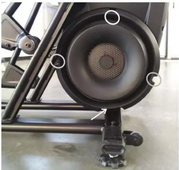
natural_image
Close-up of a black stationary exercise machine with visible mesh and circular components (no text or symbols)
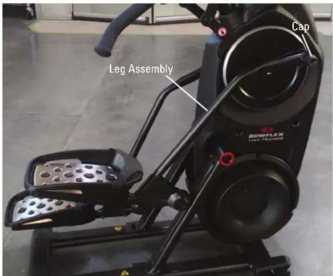
-
Using a #2 Phillips screwdriver, remove the indicated screw (by arrow) from the Rear Shroud.
-
Carefully remove the Rear Shroud from the machine. Place a standard screwdriver behind and near the middle of the Rear Shroud and gently pry until it releases. Then move the screwdriver to the bottom and gently pry until the Rear Shroud comes off.
-
Using a #2 Phillips screwdriver, remove the indicated (by oval) screw and only loosen the lowest indicated screw (arrow) from the Left Fan Cover.
-
The Left Fan Cover Assembly has a tab that needs to be pushed upward to clear the loosened screw. While pushing up on the tab, remove the Left Fan Cover Assembly.
-
Remove the Left Fan Cover Assembly from the machine. Be sure to note how the fan screens are set into the Left Fan Cover to assist with the replacement procedure.
-
Using a #2 Phillips screwdriver, remove the 2 indicated screws from the each of the Crank Covers.
Note: The Crank Cover screws may have been over-tightened when installed. Try not to strip the screws when removing them.
-
Remove the Crank Covers from the machine.
-
Place a rag or protective material below each of the Connector Arms to protect the Shrouds from potential scratches from the Connector Arms.
-
Using a 6mm hex wrench, remove the hardware that connects each of the Connector Arms to the Pivot Arms.
Note: The Connector Arm will pivot downward if not lowered slowly onto the rag protecting the Shroud.


natural_image
Close-up of a black stationary exercise bike with red rim and circular vent, mounted on a wheeled platform (no visible text or symbols)
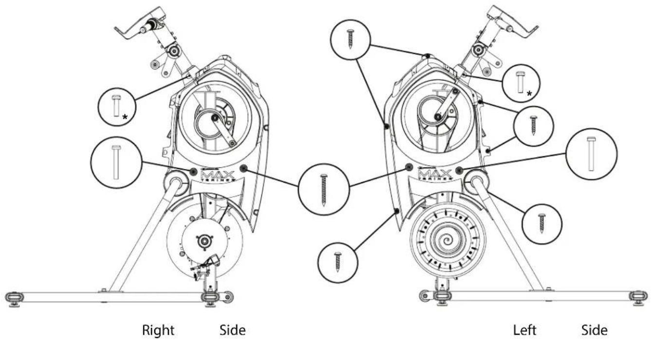
-
Using a #2 Phillips screwdriver, remove the screws from the Right and Left Shrouds. (3 screws on the Right Shroud, 9 on the Left Shroud) Remove the upper screws labeled ‘*’ last.
-
Carefully remove the Shrouds from the machine.
If replacing the Right Fan Cover:
A. Using a 14mm open face wrench, remove the Securing Ring from the outside of the Right Fan Cover.
B. Remove the Power Inlet from the inside of the Right Fan Cover.
-
Installation is the reverse procedure.
-
Final Inspection
Inspect your machine to ensure that all hardware is tight and components are properly assembled.

Do not use until the machine has been fully assembled and inspected for correct performance in accordance with the Owner's Manual.

NOTICE: This document provides instructions for the replacement of the Speed Sensor on the Bowflex™ Max Total™ machine / Max Total™ 16/40 / Max Trainer™ M9.
If you need assistance, please contact Customer Service (if purchased in US/Canada) or your local distributor (if purchased outside US/Canada). To find your local distributor, go to: www.nautilusinternational.com

This icon means a potentially hazardous situation which, if not avoided, could result in death or serious injury. Read and understand all Warnings on this machine.
Nautilus, Inc., www.NautilusInc.com, 5415 Centerpoint Parkway, Groveport, OH 43125 U.S.A. - Customer Service: North America (800) 605-3369, csnls@nautilus.com | outside U.S. www.nautilusinternational.com | Printed in China | © 2020 Nautilus, Inc. | Bowflex, the B logo, Max Total, and Max Trainer are trademarks owned or licensed by Nautilus, Inc., registered or otherwise protected by common law in the United States and other nations. | ORIGINAL DOCUMENT - ENGLISH VERSION ONLY
Important Safety Instructions - Before servicing or using this equipment, obey the following warnings:

This icon means a potentially hazardous situation which, if not avoided, could result in death or serious injury. Read and understand all Warnings on this machine.
- Read and understand the Part Replacement Procedure before working on the machine. Failure to obey the instructions and safety warnings could cause injury to the service technician or bystanders.
- Keep bystanders, children and pets away from the product being serviced at all times.
- Make sure that the repair is done in an appropriate work space away from foot traffic and exposure to bystanders.
- Disconnect all power and allow to sit for 5 minutes before you service this machine.
- Some components of the equipment can be heavy or awkward. Enlist the service of a second person when you do maintenance steps involving these components. Do not try to do heavy or awkward steps on your own.
- If replacement parts are necessary, use only genuine Nautilus replacement parts and hardware. Failure to use genuine replacement parts can cause a risk to users, keep the machine from operating correctly and will void the warranty.
- Be sure that all warning stickers and instructional placards applied to the product stay present and in good condition when doing maintenance or replacing components. If at any time the Warning labels become loose, unreadable or dislodged, replace the labels. If purchased in US/Canada, contact Customer Service for replacement labels. If purchased outside US/Canada, contact your local distributor for them.
- Do not try to change the design or functionality of the machine being serviced as this can adversely effect user safety and will void the warranty.
- Do not use the machine until all shrouds, instructions, warning labels and correct functionality have been verified and tested for correct performance.
- SAVE THESE INSTRUCTIONS.
Tools Required (not included)
2
Phillips
screwdriver

- Unplug the AC Adapter from the wall outlet and machine.
-
Remove the Right Stabilizer Shroud from the machine.
-
Using a #2 Phillips screwdriver, remove the indicated (by ovals) screws and only loosen the lowest indicated screw (arrow) from the Right Fan Cover.
Note: Loosen the lowest screw by at least 3 full rotations. -
The Right Fan Cover has a tab that needs to be pushed upward to clear the loosened screw. While pushing up on the tab, remove the Right Fan Cover from the assembly.
Note: the Power Cable is attached to the inside of the Right Fan Cover. Be sure not to crimp the cable by placing the Right Fan Cover close to the front of the machine.
To assist with assembly, note that the upper screw is a machine screw and not a self-tapping screw.

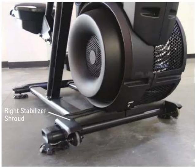
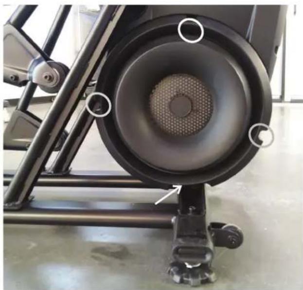
natural_image
Close-up of a black stationary exercise bike with visible speaker grille and mounting feet (no text or symbols)

Note: Left Fan Cover is hidden for image clarity.
- Using a #2 Phillips screwdriver, remove the screw that attaches the Speed Sensor.
Note: To assist with re-assembly, note that the new Speed Sensor must be 3mm (1/8") from the Speed Sensor Magnet on the Fan Disc.
- Disconnect the Speed Sensor Cable noting how it was routed for re-assembly.
Note: Do not crimp the Cables.
-
Using a #2 Phillips screwdriver, attach the new Speed Sensor. Be sure to place it 3mm (1/8") from the Speed Sensor Magnet on the Fan Disc.
-
Route the new Speed Sensor Cable under the bracket and connect the cable.
-
Installation is the reverse procedure.
-
Final Inspection Inspect your machine to ensure that all hardware is tight and components are properly assembled.

Do not use until the machine has been fully assembled and inspected for correct performance in accordance with the Owner's Manual.

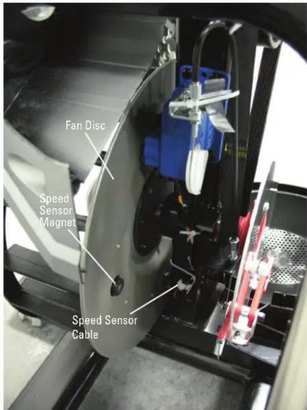
NOTICE: This document provides instructions for the replacement of the Static Handlebar Assembly on the Bowflex™ Max Total™ machine / Max Total™ 16/40 / Max Trainer™ M9.
If you need assistance, please contact Customer Service (if purchased in US/Canada) or your local distributor (if purchased outside US/Canada). To find your local distributor, go to: www.nautilusinternational.com

This icon means a potentially hazardous situation which, if not avoided, could result in death or serious injury. Read and understand all Warnings on this machine.
Nautilus, Inc., www.NautilusInc.com, 5415 Centerpoint Parkway, Groveport, OH 43125 U.S.A. - Customer Service: North America (800) 605-3369, csnls@nautilus.com | outside U.S. www.nautilusinternational.com | Printed in China | © 2019 Nautilus, Inc. | Bowflex, the B logo, Max Total, and Max Trainer are trademarks owned or licensed by Nautilus, Inc., registered or otherwise protected by common law in the United States and other nations. | ORIGINAL DOCUMENT - ENGLISH VERSION ONLY
Important Safety Instructions - Before servicing or using this equipment, obey the following warnings:

This icon means a potentially hazardous situation which, if not avoided, could result in death or serious injury. Read and understand all Warnings on this machine.
- Read and understand the Part Replacement Procedure before working on the machine. Failure to obey the instructions and safety warnings could cause injury to the service technician or bystanders.
- Keep bystanders, children and pets away from the product being serviced at all times.
- Make sure that the repair is done in an appropriate work space away from foot traffic and exposure to bystanders.
- Disconnect all power and allow to sit for 5 minutes before you service this machine.
- Some components of the equipment can be heavy or awkward. Enlist the service of a second person when you do maintenance steps involving these components. Do not try to do heavy or awkward steps on your own.
- If replacement parts are necessary, use only genuine Nautilus replacement parts and hardware. Failure to use genuine replacement parts can cause a risk to users, keep the machine from operating correctly and will void the warranty.
- Be sure that all warning stickers and instructional placards applied to the product stay present and in good condition when doing maintenance or replacing components. If at any time the Warning labels become loose, unreadable or dislodged, replace the labels. If purchased in US/Canada, contact Customer Service for replacement labels. If purchased outside US/Canada, contact your local distributor for them.
- Do not try to change the design or functionality of the machine being serviced as this can adversely effect user safety and will void the warranty.
- Do not use the machine until all shrouds, instructions, warning labels and correct functionality have been verified and tested for correct performance.
• SAVE THESE INSTRUCTIONS.
Tools Required (not included)
5mm hex wrench

2 Phillips screwdriver

Note: Your machine may not match the images provided exactly.
- Unplug the AC Adapter from the wall outlet and machine.
-
Remove the Rear Console Cover from the Console Assembly.
-
Using a #2 Phillips screwdriver, remove the screws (indicated by ovals) from the Console Assembly.
-
Carefully tilt the Console Assembly off of the Static Handlebar and expose the Cable Connections.
Note: Do not crimp any of the Console Cables. This step may require two people.
- Carefully disconnect the Cables.
Note: Do not crimp any of the Console Cables.
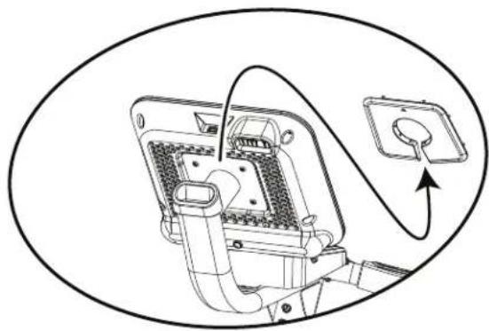
natural_image
Diagram of an electrical plug with wiring and socket, no text or symbols present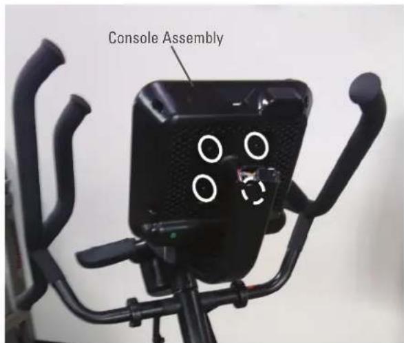

natural_image
Technical line drawing of a mechanical device with no visible text or symbols- Using a 5mm hex wrench, remove the four screws (indicated by oval) from the Static Handlebar Assembly.

- Carefully lift the Static Handlebar Assembly and expose the Cable Connections.
Note: Do not crimp any of the Console Cables. This step may require two people.
- Carefully disconnect the Cables while not allowing them to fall into the Console Mast.
Note: Do not crimp any of the Console Cables.
-
Replace the old Static Handlebar Assembly for the new one.
-
Installation is the reverse procedure.
Note: Do not cut or crimp the Cables. Each Cable connector (3-pin, 4-pin, 5-pin and 12-pin) has a corresponding end connector with that many openings. Be sure to fully connect the cable connectors.
- Final Inspection
Inspect your machine to ensure that all hardware is tight and components are properly assembled.

Do not use until the machine has been fully assembled and inspected for correct performance in accordance with the Owner's Manual.
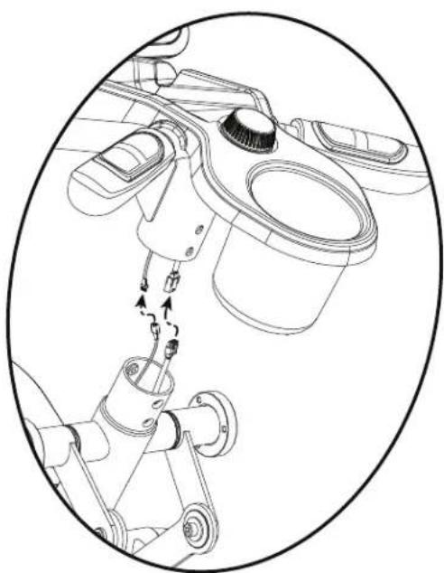
natural_image
Technical line drawing of a mechanical assembly with no visible text or symbols
NOTICE: This document provides instructions for the replacement of the Upper Body Sensor Assembly on the Bowflex™ Max Total™ machine / Max Total™ 16/40.
If you need assistance, please contact Customer Service (if purchased in US/Canada) or your local distributor (if purchased outside US/Canada). To find your local distributor, go to: www.nautilusinternational.com

This icon means a potentially hazardous situation which, if not avoided, could result in death or serious injury. Read and understand all
Warnings on this machine.
Nautilus, Inc., www.NautilusInc.com, 5415 Centerpoint Parkway, Groveport, OH 43125 U.S.A. - Customer Service: North America (800) 605-3369, csnls@nautilus.com | outside U.S. www.nautilusinternational.com | Printed in China | © 2020 Nautilus, Inc. | Bowflex, the B logo, and Max Total are trademarks owned or licensed by Nautilus, Inc., registered or otherwise protected by common law in the United States and other nations. | ORIGINAL
DOCUMENT - ENGLISH VERSION ONLY
Important Safety Instructions - Before servicing or using this equipment, obey the following warnings:

This icon means a potentially hazardous situation which, if not avoided, could result in death or serious injury. Read and understand all Warnings on this machine.
- Read and understand the Part Replacement Procedure before working on the machine. Failure to obey the instructions and safety warnings could cause injury to the service technician or bystanders.
- Keep bystanders, children and pets away from the product being serviced at all times.
- Make sure that the repair is done in an appropriate work space away from foot traffic and exposure to bystanders.
- Disconnect all power and allow to sit for 5 minutes before you service this machine.
- Some components of the equipment can be heavy or awkward. Enlist the service of a second person when you do maintenance steps involving these components. Do not try to do heavy or awkward steps on your own.
- If replacement parts are necessary, use only genuine Nautilus replacement parts and hardware. Failure to use genuine replacement parts can cause a risk to users, keep the machine from operating correctly and will void the warranty.
- Be sure that all warning stickers and instructional placards applied to the product stay present and in good condition when doing maintenance or replacing components. If at any time the Warning labels become loose, unreadable or dislodged, replace the labels. If purchased in US/Canada, contact Customer Service for replacement labels. If purchased outside US/Canada, contact your local distributor for them.
- Do not try to change the design or functionality of the machine being serviced as this can adversely effect user safety and will void the warranty.
- Do not use the machine until all shrouds, instructions, warning labels and correct functionality have been verified and tested for correct performance.
- SAVE THESE INSTRUCTIONS.
Tools Required (not included)
2
Phillips
screwdriver
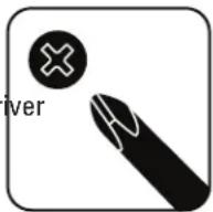
2mm hex wrench
5mm hex wrench
6mm hex wrench

(if replacing Right Fan Cover)
14mm wrench

Note: Your machine may not match the images provided exactly.
-
Unplug the AC Adapter from the wall outlet and machine.
-
Using a 6mm hex wrench, remove the indicated hardware from the Right and Left Upper Handlebar.
Note: Be aware that the Right and Left Upper Handlebar must be supported when removing the hardware.
-
Using a #2 Phillips screwdriver, remove the 4 screws (2 indicated on one side) from the Upper Shroud.
-
Remove the Right Stabilizer Shroud from the machine.

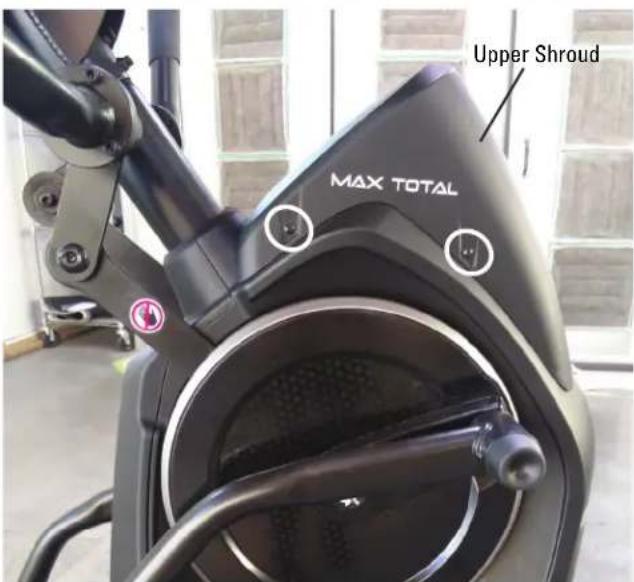

- Using a #2 Phillips screwdriver, remove the indicated (by ovals) screws and only loosen the lowest indicated screw (arrow) from the Right Fan Cover.
Note: Loosen the lowest screw by at least 3 full rotations.
- The Right Fan Cover has a tab that needs to be pushed upward to clear the loosened screw. While pushing up on the tab, remove the Right Fan Cover from the assembly.
Note: The Power Cable is attached to the inside of the Right Fan Cover. Be sure not to crimp the cable by placing the Right Fan Cover close to the front of the machine.
To assist with assembly, note that the upper screw is a machine screw and not a self-tapping screw.
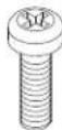
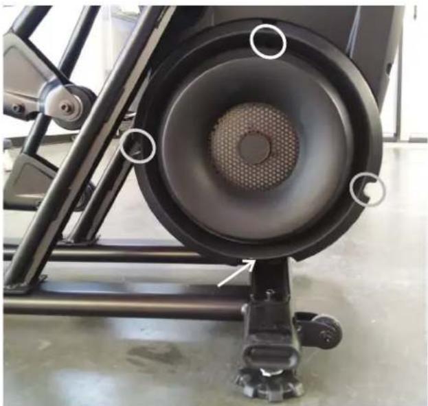
natural_image
Close-up of a black stationary exercise bike with visible mesh grille and mounting feet (no text or symbols)
-
Remove the indicated Cap from the machine.
-
Using a 6mm hex wrench, remove the hardware exposed below the Cap from the machine.
-
Slide the Right Leg Assembly off of the machine.


-
Using a #2 Phillips screwdriver, remove the indicated screw (by arrow) from the Rear Shroud.
-
Carefully remove the Rear Shroud from the machine. Place a standard screwdriver behind and near the middle of the Rear Shroud and gently pry until it releases. Then move the screwdriver to the bottom and gently pry until the Rear Shroud comes off.
-
Using a 5mm hex wrench, remove the hardware (indicated by ovals) from the Right Upper Handlebar.
Note: Be aware that the Upper Handlebar must be supported when removing the hardware.
-
Place a rag or protective material below the Right Connector Arm to protect the Shrouds from potential scratches from the Right Connector Arm.
-
Using a 6mm hex wrench, remove the hardware that connects the Right Connector Arm to the Right Pivot Arm (indicated by arrow).
Note: The Connector Arm will pivot downward if not lowered slowly onto the rag protecting the Shroud.
- Using a #2 Phillips screwdriver, remove the 2 indicated screws from the Right Crank Cover.
Note: The Crank Cover screws may have been over-tightened when installed. Try not to strip the screws when removing them.
- Remove the Right Crank Cover from the machine.


- Using a #2 Phillips screwdriver, remove the indicated screws from the Right shroud (3 screws on the Right Shroud). Remove the upper screws labeled '*' last.
- Carefully remove the Right Shroud from the machine.
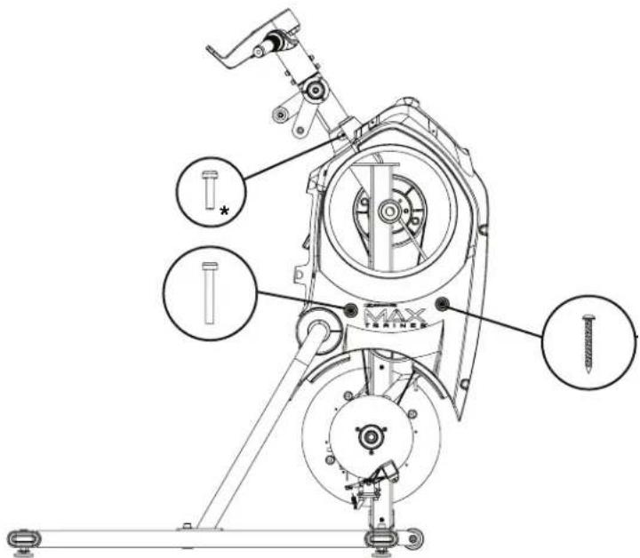
Right Side
- Using a #2 Phillips screwdriver, remove the screws (indicated by arrows) that secure the Upper Body Sensor. Allow the Upper Body Sensor to hang on the Cable, away from the Right Crank Arm.

Note: View into Shrouds from above.

Note: Shrouds are removed for clarity.
- Using a 9/16" or 14mm socket and wrench, remove the indicated nut from the Crank Assembly.
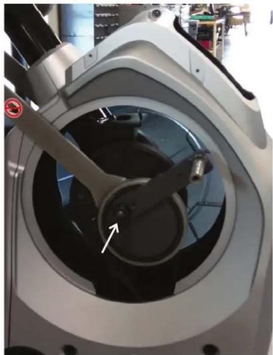
natural_image
Close-up of a robotic device with a white arrow pointing to a circular component, no visible text or symbols.- Adjust the Crank Puller until the end of the Bolt is inside the Nut (as shown).
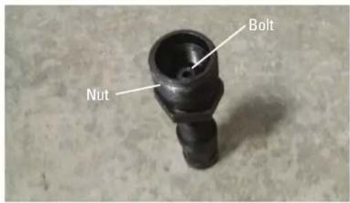
-
Carefully thread the Crank Puller into the Crank Arm. Be sure the Crank Puller has at least three rounds of threads inserted.
-
Using an adjustable wrench, turn the inner portion (the Bolt) of the Crank Puller clockwise. The Crank Arm Assembly will slide off as it is tightened.
Note: Be aware that the Crank Arm Assembly will be loose and will need to be supported.
- Remove the Crank Puller from the Crank Arm.

natural_image
Close-up of a motorcycle wheel assembly with a metallic tool and mechanical components (no visible text or symbols)-
Using a 2mm hex wrench, loosen the two screws (indicated by arrows) that secure the Inner Codewheel Assembly.
-
After noting the orientation of the Inner Codewheel Assembly on the axle, remove the old Inner Codewheel Assembly. Replace with the new Inner Codewheel Assembly so it is in the same orientation.
-
Using the 2mm hex wrench, tighten the two screws that secure the Inner Codewheel Assembly.
-
Slide the Right Crank Arm Assembly onto the machine.
Note: Be sure not to damage or break the Outer Codewheel on the Right Crank Arm or the one still remaining on the machine.
-
Re-attach the Upper Body Sensor so that it is centered on the Outer and Inner Codewheels.
-
With the Upper Body Sensor centered on the Codewheels, confirm that the Upper Body Sensor does not rub anything by using the machine briefly. Adjust the Upper Body Sensor as necessary.
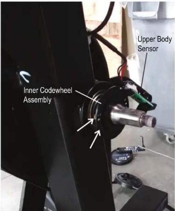

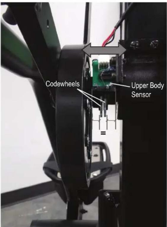
Note: The image shows a properly installed Upper Body Sensor. Shrouds are removed for clarity.
- Installation is the reverse procedure excluding steps with the Crank Puller. The Crank Puller is not required for re-assembly.
Note: When replacing the Right Crank Arm, be sure the Right and Left Crank Arms are oriented inline and opposite each other. The Crank Nut should be tightened to a torque value of 29-32.5 ft lbs (or 350-390 in lbs).
- Final Inspection Inspect your machine to ensure that all hardware is tight and components are properly assembled.

Do not use until the machine has been fully assembled and inspected for correct performance in accordance with the Owner's Manual.
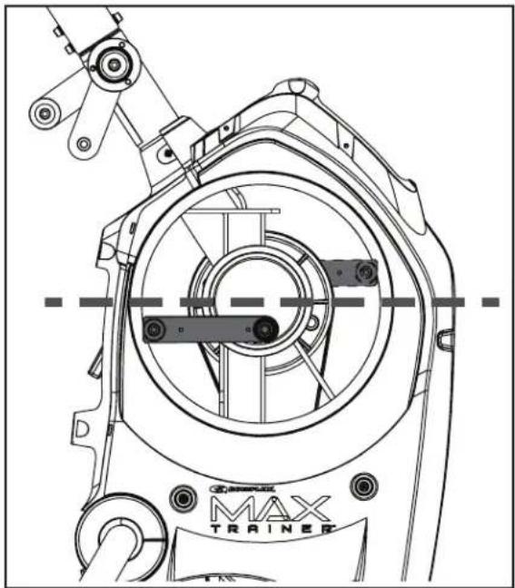
natural_image
Technical line drawing of a mechanical assembly with labeled components (no readable text or symbols)NOTICE: This document provides instructions for the replacement of the Main Wiring Harness on the Bowflex™ Max Total™ machine / Max Total™ 16/40 / Max Trainer™ M9.
If you need assistance, please contact Customer Service (if purchased in US/Canada) or your local distributor (if purchased outside US/Canada). To find your local distributor, go to: www.nautilusinternational.com

This icon means a potentially hazardous situation which, if not avoided, could result in death or serious injury. Read and understand all Warnings on this machine.
Nautilus, Inc., www.NautilusInc.com, 5415 Centerpoint Parkway, Groveport, OH 43125 U.S.A. - Customer Service: North America (800) 605-3369, cnls@nautilus.com | outside U.S. www.nautilusinternational.com | Printed in China | © 2020 Nautilus, Inc. | Bowflex, the B logo, Max Total, and Max Trainer are trademarks owned or licensed by Nautilus, Inc., registered or otherwise protected by common law in the United States and other nations. | ORIGINAL DOCUMENT - ENGLISH VERSION ONLY
Important Safety Instructions - Before servicing or using this equipment, obey the following warnings:

This icon means a potentially hazardous situation which, if not avoided, could result in death or serious injury. Read and understand all Warnings on this machine.
- Read and understand the Part Replacement Procedure before working on the machine. Failure to obey the instructions and safety warnings could cause injury to the service technician or bystanders.
- Keep bystanders, children and pets away from the product being serviced at all times.
- Make sure that the repair is done in an appropriate work space away from foot traffic and exposure to bystanders.
- Disconnect all power and allow to sit for 5 minutes before you service this machine.
- Some components of the equipment can be heavy or awkward. Enlist the service of a second person when you do maintenance steps involving these components. Do not try to do heavy or awkward steps on your own.
- If replacement parts are necessary, use only genuine Nautilus replacement parts and hardware. Failure to use genuine replacement parts can cause a risk to users, keep the machine from operating correctly and will void the warranty.
- Be sure that all warning stickers and instructional placards applied to the product stay present and in good condition when doing maintenance or replacing components. If at any time the Warning labels become loose, unreadable or dislodged, replace the labels. If purchased in US/Canada, contact Customer Service for replacement labels. If purchased outside US/Canada, contact your local distributor for them.
- Do not try to change the design or functionality of the machine being serviced as this can adversely effect user safety and will void the warranty.
- Do not use the machine until all shrouds, instructions, warning labels and correct functionality have been verified and tested for correct performance.
- SAVE THESE INSTRUCTIONS.
Tools Required (not included)
2
Phillips
screwdriver

5mm
hex
wrench

(2) Replacement Zip-Ties
Something to cut Zip-Ties
Piece of wire or string (around 6" in length)
Note: Your machine may not match the images provided exactly.
- Unplug the AC Adapter from the wall outlet and machine.
-
Remove the Right Stabilizer Shroud from the machine.
-
Using a #2 Phillips screwdriver, remove the indicated (by ovals) screws and only loosen the lowest indicated screw (arrow) from the Right Fan Cover.
Note: Loosen the lowest screw by at least 3 full rotations.
To assist with re-assembly, note that the upper screw is a machine screw and not a self-tapping screw.

- The Right Fan Cover has a tab that needs to be pushed upward to clear the loosened screw. While pushing up on the tab, remove the Right Fan Cover from the assembly.
Note: The Power Cable is attached to the inside of the Right Fan Cover. Be sure not to crimp the cable by placing the Right Fan Cover close to the front of the machine.


natural_image
Close-up of a black stationary exercise machine with visible mesh and mounting feet (no text or symbols)

Note: Shrouds are removed for clarity.
-
Note how the I/O Cable routes through the machine.
-
Cut the two lower Zip-Ties without damaging the Cables.
-
Disconnect all the Cables that connect to the lower part of the old I/O Cable.
-
Connect all the Cables to the new I/O Cable.
-
Attach the unattached end of the new I/O Cable to the old I/O Cable using a piece of wire or string.


- Using a 5mm hex wrench, remove the screws (indicated by ovals) from the Static Handlebar Assembly.

- Carefully lift the Console and Static Handlebar Assembly and expose the Cable Connections.
Note: Do not crimp any of the Cables. This step may require two people.
- Carefully disconnect the Cables while not allowing them to fall into the Frame Assembly.
Note: Do not crimp any of the Cables.
-
Carefully place the Console and Static Handlebar Assembly out of the work area without crimping any of the Cables.
-
Gently pull the old I/O Cable out of the frame, routing the new I/O Cable into place.
-
Remove the piece of wire or string, and discard the old I/O Cable.
-
Secure the lower Cables with a replacement Upper Zip-Tie.
-
Re-assemble the machine in the reverse order of when the parts were removed.
Note: When attaching the Console and Static Handlebar Assembly, do not fully tighten the hardware until all hardware has been hand tightened. Do not crimp any of the Cables.
- Final Inspection
Inspect your machine to ensure that all hardware is tight and components are properly assembled.

natural_image
Technical line drawing of a mechanical assembly with no visible text or symbols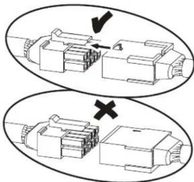
natural_image
Diagram showing two views of a mechanical component with arrows indicating direction (no text or symbols)
Do not use until the machine has been fully assembled and inspected for correct performance in accordance with the Owner's Manual.


- Bowflex™ Max Total™ 16/40 Service Manual
- Service Manual 8027706.021523.C
- Important Safety Instructions
- ! DANGER
- SAFETY WARNING LABELS AND SERIAL NUMBER
- WARNING!
- FCC Compliance
- SPECIFICATIONS
- Power Requirements:
- Moving the Machine
- Leveling the Machine
- Media Rack (Optional Accessory)
- USB Charging
- Using the Bowflex™ JRNY™ App on your Portable Device (Optional)
- Bluetooth® Heart Rate Monitor Enabled
- Bluetooth® Heart Rate Armband
- Bluetooth® Audio (in or out)
- Daily:
- Weekly:
- Monthly or after 20 hours:
- Troubleshooting - Sections
- Machine Seized Up
- Power Off and Restart the Machine
- REPLACEMENT PROCEDURE SKILL LEVEL
- Important Safety Instructions - Before servicing or using this equipment, obey the following warnings:
- - SAVE THESE INSTRUCTIONS.
- Tools Required (not included)
- Phillips screwdriver
- standard screwdriver
- .SAVE THESE INSTRUCTIONS.
- 2
- Final Inspection
- • SAVE THESE INSTRUCTIONS.
- Keep fingers out of any pinch opportunities when removing the Fan Belt.
- Attach Leg Assemblies to Frame Assembly
- Attach the Upper Handlebars to Frame Assembly
- Final Inspection
- Phillips
- Final Inspection
Brand : BOWFLEX
Model : Max Total 40
Category : Elliptical bike