GSC 18 DGN 3 DWQH - Air Conditioning Godrej - Free user manual and instructions
Find the device manual for free GSC 18 DGN 3 DWQH Godrej in PDF.


| Product Type | Split Air Conditioner |
| Brand | Godrej |
| Model | GSC 18 DGN 3 DWQH |
| Cooling Capacity | 18000 BTU / 1.5 Ton |
| Power Supply | 220-240 V, 50 Hz, Single Phase |
| Refrigerant | R32 |
| Energy Efficiency | 3 Star (BEE Rated) |
| Indoor Unit Dimensions (WxHxD) | 990 x 316 x 230 mm |
| Outdoor Unit Dimensions (WxHxD) | 828 x 626 x 300 mm |
| Indoor Unit Weight | 12 kg |
| Outdoor Unit Weight | 35 kg |
| Modes | Cool, Heat, Dry, Fan, Auto |
| Fan Speeds | 4 (Auto, Low, Medium, High) |
| Timer | 24-hour programmable on/off timer |
| Remote Control | Included with LCD display |
| Sleep Mode | Yes, with gradual temperature adjustment |
| Self-Cleaning | Yes, evaporator self-clean function |
| Air Filter | Washable antibacterial filter |
| Maintenance | Clean filter every 2 weeks; professional service annually |
| Safety Features | Overheat protection, anti-freeze, voltage fluctuation protection |
| Spare Parts | Filters, remote control, drain pipe, mounting brackets |
| Repairability | Serviceable by authorized technicians; spare parts available for 10 years |
| General Information | Includes installation kit, user manual, warranty card |
Frequently Asked Questions - GSC 18 DGN 3 DWQH Godrej
User questions about GSC 18 DGN 3 DWQH Godrej
0 question about this device. Answer the ones you know or ask your own.
Ask a new question about this device
Download the instructions for your Air Conditioning in PDF format for free! Find your manual GSC 18 DGN 3 DWQH - Godrej and take your electronic device back in hand. On this page are published all the documents necessary for the use of your device. GSC 18 DGN 3 DWQH by Godrej.
USER MANUAL GSC 18 DGN 3 DWQH Godrej
Dear Customer,
On behalf of Godrej Appliances, we welcome you to the Godrej family, and thank you for giving us an opportunity to serve you.
Godrej Appliances is a leading brand not just in technology and performance but also for its excellent customer service, we have more than 550 service centers across India, so that we can be close to our customers and serve them better.
In order to get the maximum out of your superior Air Conditioner, we urge you to go through this detailed user manual, if you need any assistance at any time, do not hesitate to call us on 1800 209 5511 or write to us at smartcare@godrej.com
We again thank you for giving us the privilege to serve you, and look forward to a long and delightful association.
Warm Regards, Team Godrej
| PERFORMANCE PARAMETERS | |||
| MODEL NAME | GSC 18 DGN 3 DWQH | GSC 18 TGN 3 DWQH | |
| OPERATING MODE | Cooling | Cooling | |
| RATED VOLTAGE | 230 V | 230 V | |
| RATED FREQUENCY/PHASE | 50 Hz/1∅ | 50 Hz/1∅ | |
| COOLING CAPACITY (W) | 5350 W | 5350 W | |
| RATED POWER INPUT (W) | 1528 W | 1528 W | |
| AIR FLOW VOLUME | 1250 CMH | 1250 CMH | |
| RATED INPUT CURRENT | 7.4 A | 7.4 A | |
| REFRIGERANT | R32 | R32 | |
| REFRIGERANT CHARGE | 1.00 kg | 1.00 kg | |
| COMP LRA | 38.0 A | 38.0 A | |
| WEIGHT | IDU | 17.0 kg | 17.0 kg |
| ODU | 42.0 kg | 42.0 kg | |
Content
Operation Notices
The Refrigerant ....1
Precautions 2
Parts Name 8
Screen Operation Guide
Buttons on remote controller 10
Introduction for icons on display screen 10
Introduction for buttons on remote controller 11
Function introduction for combination buttons....15
Operation guide 16
Replacement of batteries in remote controller 16
Emergency operation ....17
Maintenance
Clean and Maintenance 17
Malfunction
Malfunction analysis 20
Installation Notice
Installation dimension diagram 24
Safety precautions for installing and relocating the unit....25
Tools for installation 26
Selection of installation location 26
Requirements for electric connection 27
Installation
Installation of indoor unit 28
Installation of outdoor unit 33
Vacuum pumping 36
Leakage detection 36
Check after installation 37
Test and operation
Test operation 37
Attachment
Configuration of connection pipe 38
Safety operation of flammable refrigerant 40
Pipe expanding method 42
This appliance is not intended for use by persons (including children) with reduced physical, sensory or mental capabilities or lack of experience and knowledge, unless they have been given supervision or instruction concerning use of the appliance by a person responsible for their safety.
Children should be supervised to ensure that they do not play with the appliance.
If it needs to install, move or maintain the air conditioner, please contact dealer or local service center to conduct it at first. Air conditioner must be installed, moved or maintained by appointed unit. Otherwise, it may cause serious damage or personal injury or death.
Explanation of Symbols

DANGER
Indicates a hazardous situation that, if not avoided, will result in death or serious injury.

WARNING
Indicates a hazardous situation that, if not avoided, could result in death or serious injury.

CAUTION
Indicates a hazardous situation that, if not avoided, may result in minor or moderate injury.

NOTICE
Indicates important but not hazard-related information, used to indicate risk of property damage.

Indicates a hazard that would be assigned a signal word WARNING or CAUTION.

Appliance filled with flammable gas R32.

Before use the appliance, read the owner's manual first.

Before install the appliance, read the installation manual first.
Before repair the appliance, read the service manual first.
The Refrigerant
- To realize the function of the air conditioner unit, a special refrigerant circulates in the system. The used refrigerant is the fluoride R32, which is specially cleaned. The refrigerant is flammable and inodorous. Furthermore, it can leads to explosion under certain conditions. But the flammability of the refrigerant is very low. It can be ignited only by fire.
- Compared to common refrigerants, R32 is a nonpolluting refrigerant with no harm to the ozonosphere. The influence upon the greenhouse effect is also lower. R32 has got very good thermodynamic features which lead to a really high energy efficiency. The units therefore need a less filling.
WARNING:
Do not use means to accelerate the defrosting process or to clean, other than those recommended by the manufacture. Should repair be necessary, contact your nearest authorized Service Centre. Any repairs carried out by unqualified personnel may be dangerous. The appliance shall be stored in a room without continuously operating ignition sources. (for example: open flames, an operating gas appliance or an operating electric heater.) Do not pierce or burn.
Appliance shall be installed, operated and stored in a room with a floor area larger than X m^2 . (Please refer to table "a" in section of "Safety Operation of Inflammable Refrigerant" for Space X.)
Appliance filled with flammable gas R32. For repairs, strictly follow manufacturer's instructions only. Be aware that refrigrants not contain odour. Read specialist's manual.


WARNING
Operation and Maintenance
• This appliance can be used by children aged from 8 years and above and persons with reduced physical, sensory ormental capabilities or lack of experience and knowledge if they have been given supervision or instruction concerning use of the appliance in a safe way and understand the hazards involved.
•Children shall not play with the appliance.
- Cleaning and user maintenance shall not be made by children without supervision.
- Do not connect air conditioner to multi-purpose socket. Otherwise, it may cause fire hazard.
- Do disconnect power supply when cleaning air conditioner. Otherwise, it may cause electric shock.
- If the supply cord is damaged, it must be replaced by the manufacturer, its service agent or similarly qualified persons in order to avoid a hazard.
- Do not wash the air conditioner with water to avoid electric shock.
- Do not spray water on indoor unit. It may cause electric shock or malfunction.
•After removing the filter, do not touch fins to avoid injury.
- Do not use fire or hair dryer to dry the filter to avoid deformation or fire hazard.

WARNING
- Maintenance must be performed by qualified professionals. Otherwise, it may cause personal injury or damage.
- Do not repair air conditioner by yourself. It may cause electric shock or damage. Please contact dealer when you need to repair air conditioner.
- Do not extend fingers or objects into air inlet or air outlet. It may cause personal injury or damage.
- Do not block air outlet or air inlet. It may cause malfunction.
- Do not spill water on the remote controller, otherwise the remote controller may be broken.
- When below phenomenon occurs, please turn off air conditioner and disconnect power immediately, and then contact the dealer or qualified professionals for service.
• Power cord is overheating or damaged. - There's abnormal sound during operation.
• Circuit break trips off frequently.
• Air conditioner gives off burning smell. - Indoor unit is leaking.
- If the air conditioner operates under abnormal conditions, it may cause malfunction, electric shock or fire hazard.
- When turning on or turning off the unit by emergency operation switch, please press this switch with an insulating object other than metal.
- Do not step on top panel of outdoor unit, or put heavy objects. It may cause damage or personal injury.

WARNING
Attachment
•Installation must be performed by qualified professionals. Otherwise, it may cause personal injury or damage.
- Must follow the electric safety regulations when installing the unit.
- According to the local safety regulations, use qualified power supply circuit and circuit break.
- Do install the circuit break. If not, it may cause malfunction.
- An all-pole disconnection switch having a contact separation of at least 3mm in all poles should be connected in fixed wiring.
- Including an circuit break with suitable capacity, please note the following table. Air switch should be included magnet buckle and heating buckle function, it can protect the circuit-short and overload.
• Air Conditioner should be properly grounded. Incorrect grounding may cause electric shock.
- Don't use unqualified power cord.
• Make sure the power supply matches with the requirement of air conditioner. Unstable power supply or incorrect wiring or malfunction. Please install proper power supply cables before using the air conditioner.
• Properly connect the live wire, neutral wire and grounding wire of power socket.
- Be sure to cut off the power supply before proceeding any work related to electricity and safety.

WARNING
- Do not put through the power before finishing installation.
- If the supply cord is damaged, it must be replaced by the manufacturer, its service agent or similarly qualified persons in order to avoid a hazard.
- The temperature of refrigerant circuit will be high, please keep the interconnection cable away from the copper tube.
- The appliance shall be installed in accordance with national wiring regulations.
• Installation must be performed in accordance with the requirement of NEC and CEC by authorized personnel only. - The air conditioner is the first class electric appliance. It must be properly grounding with specialized grounding device by a professional. Please make sure it is always grounded effectively, otherwise it may cause electric shock.
- The yellow-green wire in air conditioner is grounding wire, which can't be used for other purposes.
- The grounding resistance should comply with national electric safety regulations.
- The appliance must be positioned so that the plug is accessible.
- All wires of indoor unit and outdoor unit should be connected by a professional.
- If the length of power connection wire is insufficient, please contact the supplier for a new one. Avoid extending the wire by yourself.

WARNING
- For the air conditioner with plug, the plug should be reachable after finishing installation.
- For the air conditioner without plug, an circuit break must be installed in the line.
- If you need to relocate the air conditioner to another place, only the qualified person can perform the work. Otherwise, it may cause personal injury or damage.
- Select a location which is out of reach for children and far away from animals or plants. If it is unavoidable, please add the fence for safety purpose.
- The indoor unit should be installed close to the wall.
- Please notice that the unit is filled with flammable gas R32. Inappropriate treatment of the unit involves the risk of severe damages of people and material. Details to this refrigerant are found in chapter “refrigerant”.
- Check whether the maintenance area or the room area meet the requirement of the nameplate.
- It's only allowed to be operated in the rooms that meet the requirement of the nameplate.
- Check whether the maintenance area is well-ventilated. - The continuous ventilation status should be kept during the operation process.
- Check whether there is fire source or potential fire source in the maintenance area.
- The naked flame is prohibited in the maintenance area; and the “no smoking” warning board should be hanged.
- Check whether the appliance mark is in good condition.
- Replace the vague or damaged warning mark.
- Please use the flammable gas detector to check before unload and open the container.
• No fire source and smoking.
• According to the local rules and laws.

WARNING
- The air conditioner is not allowed to use in a room that has running fire (such as fire source, working coal gas ware, operating heater).
- It is not allowed to drill hole or burn the connection pipe.
- The air conditioner must be installed in a room that is larger than the minimum room area. The minimum room area is shown on the nameplate or following table a.
- Leak test is a must after installation.
- Instructions for installation and use of this product are provided by the manufacturer.
Working temperature range
| Indoor side DB/WB(°C) | Outdoor side DB/WB(°C) | |
| Maximum cooling 35 | 24 48/30 | |
| Maximum heating 27 | - 24/18 |
NOTICE:
- The operating temperature range (outdoor temperature) for cooling only unit is 18^ 48^ ; for heat pump unit is -7^ 48^ .
Indoor Unit

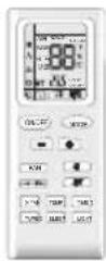
(Display content or position may be different from above graphics, please refer to actual products)
remote control
Outdoor Unit

NOTICE:
Actual product may be different from above graphics, please refer to actual products.
Display
For some model:

For some model:

For some model:
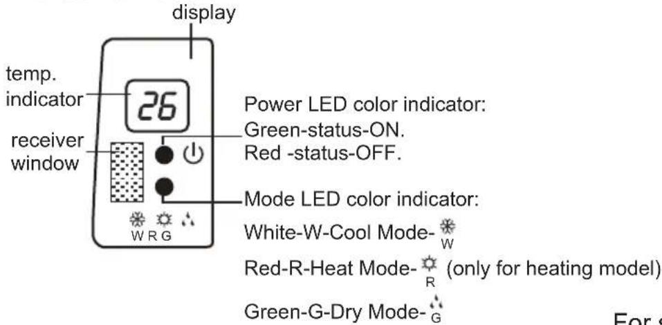
For some model:
For some model:


Display content or position may be different from above graphics, please refer to actual products.
Buttons on remote controller

1 ON/OFF button
2 MODE button
3 +/- button
4 FAN button
5 dutton
6 button
7 HEALTH SAVE button
8 X-FAN button
(Note: X-FAN is same with BLOW)
9 TEMP button
10 TIMER button
11 TURBO button
12 SLEEP button
13 LIGHT button
Introduction for icons on display screen

Introduction for buttons on remote controller
Note:
- This is a general use remote controller, it could be used for the air conditioners with multifunction; For some function, which the model doesn't have, if press the corresponding button on the remote controller that the unit will keep the original running status.
- After putting through power, air conditioner will give out a sound and operation indicator "⏻" is ON (red indicator, the colour is different for different models). You can operate the air conditioner through the remote controller.
- At ON status, after each pressing button on remote controller, the signal icon "💡" on remote controller will flash once. Air conditioner will give out a sound, which indicates the signal has been sent to air conditioner.
- At OFF status, display screen on remote controller displays set temperature. At on status, display screen on remote controller displays the corresponding startup function's icon.
1 ON/OFF button
Press this button to turn on the unit. Press this button again to turn off the unit.
2 MODE button
Press this button can select your required operation mode.

flowchart
graph LR
    A["Δ"] --> B["☀️"]
    B --> C["☀️"]
    C --> D["☀️"]
    D --> E["☀️"]
- After selecting auto mode, air conditioner will operate automatically according to ambient temperature. Set temperature can't be adjusted and also can't be displayed. Press"FAN" button can adjust fan speed. Press "→" button can adjust swing angle.
- After selecting cool mode, air conditioner operates under cool mode. Cool indicator "✿" on indoor unit is ON (This indicator is not available for some models). You can press "+" or "-" button to adjust set temperature. Press "FAN" button can adjust fan speed. Press "✿" g angle.niws tsujda nac nottub
- After selecting dry mode, air conditioner operates under dry mode at low speed. Dry indicator " 🔊" on indoor unit is ON (This indicator is not available for some models). Under dry mode, fan speed can't be adjusted. Press " ➕" button to adjust swing angle.
- After selecting fan mode, air conditioner operates only under fan mode, All mode indicators on indoor unit is OFF. Operation indicator is ON(This indicator is not available for some models). Press "FAN" button can adjust fan speed. Press "→" button to adjust swing angle.
- After selecting heat mode, air conditioner operates under heat mode. Heat indicator "💡" on indoor unit is ON(This indicator is not available for some models).
You can press "+" or "-" button to adjust set temperature.
Press "FAN" button to adjust fan speed. Press "→" button to adjust swing angle. (Cooling only unit can't receive the signal for heating mode.)
Introduction for buttons on remote controller
Note:
For preventing cold wind, after starting up heating mode, indoor fan will blow fan afterdelaying 1-5min. (Details time is decided by indoor ambient temperature) Temperature setting range on remote controller: 16^ C -30°C . Fan speed setting range: auto, low speed, medium speed and high speed.
3 "+" or "-" button
- After each pressing of "+" or "-" button, it can increase or decrease set temperature 1°C. Hold "+" or "-" button, 2s later, set temperature on remote controller will change quickly. After reaching to your required time, loosen the button. Temperature indicator on indoor unit will also change accordingly. (Temperature can't be adjusted under auto mode)
- Under TIMER ON, TIMER OFF or Clock setting, you can press "+" or "-" button to adjust time. (Refer to TIMER button for details)
4 FAN button
Pressing this button can set fan speed circularly as: auto (AUTO), low(▲), medium(▲), high(▲).

flowchart
graph LR
    A["Auto"] --> B["Step 1"]
    B --> C["Step 2"]
    C --> D["Step 3"]
    D --> E["Step 4"]
Note:
- Under AUTO Speed, IDU fan motor will adjust the fan speed (high, medium or low speed) according to ambient temperature.
- Fan speed under dry mode is low speed.
5 button
- Press this button to start or stop up & down swing function. The remote controller defaults to simple swing condition.
- Press + button and ➕ button at the same time at unit OFF to switch between simple swing and static swing; ➕ blinks for 2 seconds.
- In static swing condition, pressing ➕ button, the swing angle of up & down louver changes as below:

flowchart
graph LR
    A["Start"] --> B{Display}
    B --> C["Horizontal Louvers Stops at Current Position"]
    C --> D["End"]
    style A fill:#f9f,stroke:#333
    style D fill:#bbf,stroke:#333
- If the unit is turned off during swing operation, the louver will stop at present position.
Introduction for buttons on remote controller
Note:
When selecting "→1" with remote controller, it's auto swing. Horizontal louver of air conditioner will swing up&down automatically at the maximum angle.
When selecting "I、"I、-I、"I、"I" with remote controller, it's the fixed position swing. Horizontal louver of air conditioner will stop at that position as shown by the icon to swing.
6 button
- Press this button to start or stop left & right swing function. The remote controller defaults to simple swing condition.
- Press + button and 📁 button at the same time at unit OFF to switch between simple swing and static swing; 📁 blinks for 2 seconds.
- In static swing condition, pressing 📄 button, the swing angle of left & right louver changes as below:
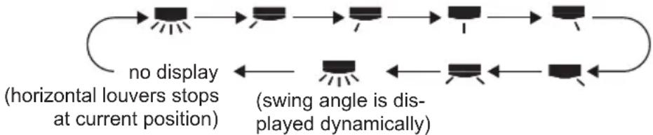
flowchart
graph LR
    A["Start"] --> B["Horizontal Louvers Stop at Current Position"]
    B --> C["Switch Angle Display"]
    C --> D["Current Position"]
    D --> E["Switch Angle Display"]
    E --> F["Current Position"]
    F --> G["Switch Angle Display"]
    G --> H["Current Position"]
    H --> I["Switch Angle Display"]
    I --> J["Current Position"]
    J --> K["Switch Angle Display"]
    K --> L["Current Position"]
    L --> M["Switch Angle Display"]
    M --> N["Current Position"]
    N --> O["Switch Angle Display"]
    O --> P["Current Position"]
    P --> Q["Switch Angle Display"]
    Q --> R["Current Position"]
    R --> S["Switch Angle Display"]
    S --> T["Current Position"]
    T --> U["Switch Angle Display"]
    U --> V["Current Position"]
    V --> W["Switch Angle Display"]
    W --> X["Current Position"]
    X --> Y["Switch Angle Display"]
- If the unit is turned off during swing operation, the louver will stop at present position.
- When selecting "■" with remote controller, it's auto swing. Horizontal louver of air conditioner will swing left&right automatically at the maximum angle.
- When selecting "■、▼、▼、▼、▼" with remote controller, it's the fixed position swing. Horizontal louver of air conditioner will stop at that position as shown by the icon to swing.
- When selecting " (swing angle is displayed dynamically) ", it's the circulating swing. Horizontal louver of air conditioner will swing circularly according to the angle as shown by the icon.
Note: There is no this function for the units. If press this key, the main unit will click, but it also runs under original status.
7 HEALTH|SAVE button
HEALTH FUNCTION:
After pressing HEALTH button, remote controller will switch circularly as below: "HEALTH"→"AIR"→"AIR HEALTH"→"no display"
- When selecting "HEALTH" by remote controller, HEALTH function will be started up.
- When selecting "AIR" by remote controller, AIR function will be started up.
- When selecting "AIR HEALTH", AIR and HEALTH function will be started up.
- When there's no display on remote controller, AIR and HEALTH function will be turned off.
• AIR function is applicable for some models. - HEALTH function is applicable for some models.
Introduction for buttons on remote controller
SAVE function:
Under cool mode, press SAVE button and the unit will operate under SAVE mode. Dual-8nixie tube on remote controller displays "SE". Air conditioner will operate at auto speed. Set temperature can't be adjusted. Press SAVE button again to exit SAVE mode. Air conditioner turn back to original set speed and set temperature.
8 X-FAN button
After pressing this button under cooling or dry mode, remote controller displays the character of "X-FAN" and X-FAN function is started up. Press this button again to cancel X-FAN function. The character of "X-FAN" will disappear.
Note:
- After starting up X-FAN function, when turning off the unit, indoor fan will continue to operate for a while at low speed to dry the residual water inside the indoor unit.
- When the unit operates under X-FAN mode, press "X-FAN" button can turn off X-FAN function. Indoor fan stops operation immediately.
9 TEMP button
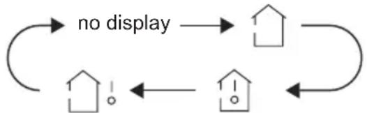
Press this button can see indoor set temperature, indoor ambient temperature or outdoor ambient temperature on indoor unit's display. Temperature is set circularly by remote controller as below:
flowchart
graph TD
    A["no display"] --> B["House"]
    B --> C["House"]
    C --> D["House"]
    D --> E["House"]
    E --> F["House"]
    F --> A
- When selecting "☐" by remote controller or no display, temperature indicator on indoor unit displays set temperature.
- When selecting "☐" by remote controller, temperature indicator on indoor unit displays indoor ambient temperature.
- When selecting "♡!" by remote controller, temperature indicator on indoor unit displays outdoor ambient temperature.
Note:
- Outdoor ambient temperature display may can't be selected for some models. When indoor unit receives "↑" signal, it displays indoor set temperature.
- Only for the model whose indoor unit has dual-8 display.
10 TIMER button
- At ON status, press this button once can set TIMER OFF. The character of HOUR and OFF will flash. Press "+" or "-" button within 5s can adjust the time of TIMER ON. After each pressing of "+" or "-" button, time will increase or decrease half an
Introduction for buttons on remote controller
hour. When holding "+" or "-" button, 2s later, the time will change quickly until to reach to your required time. After that, press "TIMER" button to confirm it. The character of HOUR and OFF won't flash again.
Cancel TIMER OFF: Press "TIMER" button again under TIMER OFF status.
- At OFF status, press this button once can set TIMER ON. Please refer to TIMER off for detailed operation.
Cancel TIMER ON: Press "TIMER" button again under TIMER ON status.
Note:
• Time setting range: 0.5-24 hours.
- Time interval between two operations can't exceed 5s. Otherwise, remote controller will exit the setting status automatically.
11 TURBO button
When pressing this button under cooling or heating mode, air conditioner will enter into quick cooling or quick heating mode. The character of "TURBO" is displayed on remote controller. Press this button again to exit turbo function and the character of "TURBO" will be disappeared on remote controller.
12 SLEEP button
Press this button under cooling, heating mode can start up sleep function. "©" icon will be displayed on remote controller. Press this button again to cancel sleep function. "©" icon on remote controller will be displayed.
13 LIGHT button
Press this button can turn off the light for indoor unit's display. "💡" icon on remote controller will disappear. Press this button again to turn on the light for indoor unit's display. "💡" icon on remote controller will be displayed.
Function introduction for combination buttons
Child lock function
Press "+" and "-" buttons simultaneously can turn on or turn off child lock function. When child lock function is started up, "💡" icon will be displayed on remote controller. If operate remote controller, "💡" icon will flash three times, while remote controller won't send signal.
Switchover function for temperature display
After turning off the unit by remote controller, press "-" button and "MODE" button simultaneously to switch between °C and °F.
Operation guide
- After putting through the power, press "ON/OFF" button on remote controller to turn on the air conditioner.
- Press "MODE" button to select your required mode: AUTO, COOL, DRY, FAN, HEAT.
- Press "+" or "-" button to set your required temperature. (Temperature can't be adjusted under auto mode).
- Press "FAN" button to set your required fan speed: auto, low, medium and high speed.
- Press "☐" button to select fan blowing angle.
Replacement of batteries in remote controller
- Press the back side of remote controller marked with "OPEN", as shown in the fig, and then push out the cover of battery box along the arrow direction.
- Replace two 7# (AAA 1.5V) dry batteries, and make sure the position of "+" polar and "-" polar are correct.
- Reinstall the cover of battery box.

NOTICE
- During operation, point the remote control signal sender at the receiving window on indoor unit.
- The distance between signal sender and receiving window should be no more than 8m, and there should be no obstacles between them.
- Signal may be interfered easily in the room where there is fluorescent lamp or wireless telephone; remote controller should be close to indoor unit during operation.
- Replace new batteries of the same model when replacement is required.
- When you don't use remote controller for a long time, please take out the batteries.
- If the display on remote controller is fuzzy or there's no display, please replace batteries.
Emergency operation
If remote controller is lost or damaged, please use auxiliary button to turn on or turn off the air conditioner. The operation in details are as below: As shown in the fig. Open panel, press aux. button to turn on or turn off the air conditioner. When the air conditioner is turned on, it will operate under auto mode.

WARNING:
Use insulated object to press the auto button
Clean and maintenance
WARNING
■ Turn off the air conditioner and disconnect the power before cleaning the air conditioner to avoid electric shock.
■ Do not wash the air conditioner with water to avoid electric shock.
■ Do not use volatile liquid to clean the air conditioner.
Clean surface of indoor unit
When the surface of indoor unit is dirty, it is recommended to use a soft dry cloth or wet cloth to wipe it.
NOTICE:
- Do not remove the panel when cleaning it.
Clean filter

Open panel
Pull out the panel to a certain angle as shown in the fig.

natural_image
Illustration of a hand holding a rectangular device with arrows indicating motion or force (no text or symbols)2
Remove filter
Remove the filter as indicated in the fig.

natural_image
Hand placing a grid pattern into a curved panel with an arrow indicating downward motion (no text or symbols)
Clean filter
Use dust catcher or water to clean the filter.
- When the filter is very dirty, use the water (below 45°C) to clean it, and then put it in a shady and cool place to dry.

natural_image
Illustration of hands holding a grid-like object with a tool, no text or symbols present4
Install filter
Install the filter and then close the panel cover tightly.

natural_image
Line drawing of a car air conditioner unit with hand and clamped parts (no text or symbols)
WARNING
■ The filter should be cleaned every three months. If there is much dust in the operation environment, clean frequency can be increased.
■ After removing the filter, do not touch fins to avoid injury.
■ Do not use fire or hair dryer to dry the filter to avoid deformation or fire hazard.
NOTICE: Checking before use-season
- Check whether air inlets and air outlets are blocked.
- Check whether air switch, plug and socket are in good condition.
- Check whether filter is clean.
- Check whether mounting bracket for outdoor unit is damaged or corroded. If yes, please contact dealer.
- Check whether drainage pipe is damaged.
NOTICE: Checking after use-season
- Disconnect power supply.
- Clean filter and indoor unit's panel.
- Check whether mounting bracket for outdoor unit is damaged or corroded. If yes, please contact dealer.
Notice for recovery
- Many packing materials are recyclable materials.
Please dispose them in appropriate recycling unit. - If you want to dispose the air conditioner, please contact local dealer or consultant service center for the correct disposal method.
Malfunction analysis
General phenomenon analysis
Please check below items before asking for maintenance. If the malfunction still can't be eliminated, please contact local dealer or qualified professionals.
| Phenomenon | Check items Solution | |
| Indoor unit can't receive remote controller's signal or remote controller has no action. | Whether it's interfered severely (such as static electricity, stable voltage)? | Pull out the plug. Reinsert the plug after about 3min, and then turn on the unit again. |
| Whether remote controller is within the signal receiving range? | Signal receiving range is 8m. | |
| Whether there are obstacles? | Remove obstacles. | |
| Whether remote controller is pointing at the receiving window? | Select proper angle and point the remote controller at the receiving window on indoor unit. | |
| Is sensitivity of remote controller low; fuzzy display and no display? | Check the batteries. If the power of batteries is too low, please replace them. | |
| No display when operating remote controller? | Check whether remote controller appears to be damaged. If yes, replace it. | |
| Fluorescent lamp in room? | Take the remote controller close to indoor unit.Turn off the fluorescent lamp and then try it again. |
| No air emitted from indoor unit | ● Air inlet or air outlet of indoor unit is blocked? | ● Eliminate obstacles. |
| ● Under heating mode, indoor temperature is reached to set temperature? | ● After reaching to set temperature, indoor unit will stop blowing out air. | |
| ● Heating mode is turned on just now? | ● In order to prevent blowing out cold air, indoor unit will be started after delaying for several minutes, which is a normal phenomenon. |
Malfunction analysis
| Phenomenon | Check items Solution | |
| Air conditioner can't operate | Power failure? | Wait until power recovery. |
| Is plug loose? | Reinsert the plug. | |
| Air switch trips off or fuse is burnt out? | Ask professional to replace air switch or fuse. | |
| Wiring has malfunction? | Ask professional to replace it. | |
| Unit has restarted immediately after stopping operation? | Wait for 3min, and then turn on the unit again. | |
| Whether the function setting for remote controller is correct? | Reset the function. | |
| Mist is emitted from indoor unit's air outlet | Indoor temperature and humidity is high? | Because indoor air is cooled rapidly. After a while, indoor temperature and humidity will be decrease and mist will disappear. |
| Set temperature can't be adjusted | Unit is operating under auto mode? | Temperature can't be adjusted under auto mode. Please switch the operation mode if you need to adjust temperature. |
| Your required temperature exceeds the set temperature range? | Set temperature range: 16°C ~30°C . | |
| Cooling (heating) effect is not good. | Voltage is too low? | Wait until the voltage resumes normal. |
| Filter is dirty? | Clean the filter. | |
| Set temperature is in proper range? | Adjust temperature to proper range. | |
| Door and window are open? | Close door and window. |
Malfunction analysis
| Phenomenon | Check items Solution | |
| Odours are emitted | Whether there's odour source, such as furniture and cigarette, etc. | Eliminate the odour source.Clean the filter. |
| Air conditioner operates abnormally suddenly | Whether there's interference, such as thunder, wireless devices, etc. | Disconnect power, put back power, and then turn on the unit again. |
| Outdoor unit has vapor | Heating mode is turned on? | During defrosting under heating mode, it may generate vapor, which is a normal phenomenon. |
| "Water flowing" noise | Air conditioner is turned on or turned off just now? | The noise is the sound of refrigerant flowing inside the unit, which is a normal phenomenon. |
| Cracking noise | Air conditioner is turned on or turned off just now? | This is the sound of friction caused by expansion and/or contraction of panel or other parts due to the change of temperature. |
Malfunction analysis
Error Code
- When air conditioner status is abnormal, temperature indicator on indoor unit will blink to display corresponding error code. Please refer to below list for identification of error code.
| Error code | Troubleshooting |
| E5 | It can be eliminated after restarting the unit. If not, please contact qualified professionals for service. |
| U8 | It can be eliminated after restarting the unit. If not, please contact qualified professionals for service. |
| H6 | It can be eliminated after restarting the unit. If not, please contact qualified professionals for service. |
| H3 | It can be eliminated after restarting the unit. If not, please contact qualified professionals for service. |
| C5 | Please contact qualified professionals for service. |
| F1 | Please contact qualified professionals for service. |
| F2 | Please contact qualified professionals for service. |
| F4 | Please contact qualified professionals for service. |
| F0 | Please contact qualified professionals for service. |
| E1 | It can be eliminated after restarting the unit. If not, please contact qualified professionals for service. |
Note: If there're other error codes, please contact qualified professionals for service.

WARNING
■ When below phenomenon occurs, please turn off air conditioner and disconnect power immediately, and then contact the dealer or qualified professionals for service.
- Power cord is overheating or damaged.
- There's abnormal sound during operation.
- Circuit break trips off frequently.
• Air conditioner gives off burning smell.
- Indoor unit is leaking.
■ Do not repair or refit the air conditioner by yourself.
■ If the air conditioner operates under abnormal conditions, it may cause malfunction, electric shock or fire hazard.
Installation dimension diagram

To ensure safety, please be mindful of the following precautions.
Warning
- When installing or relocating the unit, be sure to keep the refrigerant circuit free from air or substances other than the specified refrigerant.
Any presence of air or other foreign substance in the refrigerant circuit will cause system pressure rise or compressor rupture, resulting in injury.
- When installing or moving this unit, do not charge the refrigerant which is not comply with that on the nameplate or unqualified refrigerant.
Otherwise, it may cause abnormal operation, wrong action, mechanical malfunction or even series safety accident.
- When refrigerant needs to be recovered during relocating or repairing the unit, be sure that the unit is running in cooling mode. Then, fully close the valve at high pressure side (liquid valve). About 30-40 seconds later, fully close the valve at low pressure side (gas valve), immediately stop the unit and disconnect power. Please note that the time for refrigerant recovery should not exceed 1 minute.
If refrigerant recovery takes too much time, air may be sucked in and cause pressure rise or compressor rupture, resulting in injury.
- During refrigerant recovery, make sure that liquid valve and gas valve are fully closed and power is disconnected before detaching the connection pipe.
If compressor starts running when stop valve is open and connection pipe is not yet connected, air will be sucked in and cause pressure rise or compressor rupture, resulting in injury.
- When installing the unit, make sure that connection pipe is securely connected before the compressor starts running.
If compressor starts running when stop valve is open and connection pipe is not yet connected, air will be sucked in and cause pressure rise or compressor rupture, resulting in injury.
- Prohibit installing the unit at the place where there may be leaked corrosive gas or flammable gas.
If there leaked gas around the unit, it may cause explosion and other accidents.
- Do not use extension cords for electrical connections. If the electric wire is not long enough, please contact a local service center authorized and ask for a proper electric wire.
Poor connections may lead to electric shock or fire.
- Use the specified types of wires for electrical connections between the indoor and outdoor units. Firmly clamp the wires so that their terminals receive no external stresses.
Electric wires with insufficient capacity, wrong wire connections and insecure wire terminals may cause electric shock or fire.
Tools for installation
| 1 Level meter 2 Screw driver 3 Impact drill | ||
| 4 Drill head 5 Pipe expander 6 Torque wrench | ||
| 7 Open-end wrench 8 Pipe cutter 9 Leakage detector | ||
| 10 Vacuum pump 11 Pressure meter 12 Universal meter | ||
| 13 Inner hexagon spanner 14 Measuring tape | ||
Note:
- Please contact the local agent for installation.
- Don't use unqualified power cord.
Selection of installation location
Basic requirement
Installing the unit in the following places may cause malfunction. If it is unavoidable, please consult the local dealer:
- The place with strong heat sources, vapors, flammable or explosive gas, or volatile objects spread in the air.
- The place with high-frequency devices (such as welding machine, medical equipment).
- The place near coast area.
- The place with oil or fumes in the air.
- The place with sulfureted gas.
- Other places with special circumstances.
- The appliance shall not be installed in the laundry
Indoor unit
- There should be no obstruction near air inlet and air outlet.
- Select a location where the condensation water can be dispersed easily and won't affect other people.
- Select a location which is convenient to connect the outdoor unit and near the power socket.
- Select a location which is out of reach for children.
- The location should be able to withstand the weight of indoor unit and won't increase noise and vibration.
- The appliance must be installed 2.5m above floor.
- Don't install the indoor unit right above the electric appliance.
- Please try your best to keep way from fluorescent lamp.
Outdoor unit
- Select a location where the noise and outflow air emitted by the outdoor unit will not affect neighborhood.
- The location should be well ventilated and dry, in which the outdoor unit won't be exposed directly to sunlight or strong wind.
- The location should be able to withstand the weight of outdoor unit.
- Make sure that the installation follows the requirement of installation dimension diagram.
- Select a location which is out of reach for children and far away from animals or plants. If it is unavoidable, please add the fence for safety purpose.
Requirements for electric connection
Safety precaution
- Must follow the electric safety regulations when installing the unit.
- According to the local safety regulations, use qualified power supply circuit and air switch.
- Make sure the power supply matches with the requirement of air conditioner. Unstable power supply or incorrect wiring or malfunction. Please install proper power supply cables before using the air conditioner.
- Properly connect the live wire, neutral wire and grounding wire of power socket.
- Be sure to cut off the power supply before proceeding any work related to electricity and safety. For models with a power plug, make sure the plug is within reach after installation.
- Do not put through the power before finishing installation.
- If the supply cord is damaged, it must be replaced by the manufacturer, its service agent or similarly qualified persons in order to avoid a hazard.
- The temperature of refrigerant circuit will be high, please keep the interconnection cable away from the copper tube.
- The appliance shall be installed in accordance with national wiring regulations.
- Appliance shall be installed, operated and stored in a room with a floor area larger than Xm^2 . (Please refer to table "a" in section of "Safety Operation of Inflammable Refrigerant" for Space X.)

Please notice that the unit is filled with flammable gas R32. Inappropriate treatment of the unit involves the risk of severe damages of people and material. Details to this refrigerant are found in chapter "refrigerant".
Grounding requirement
- The air conditioner is the first class electric appliance. It must be properly grounding with specialized grounding device by a professional. Please make sure it is always grounded effectively, otherwise it may cause electric shock.
- The yellow-green wire in air conditioner is grounding wire, which can't be used for other purposes.
- The grounding resistance should comply with national electric safety regulations.
- The appliance must be positioned so that the plug is accessible.
- An all-pole disconnection switch having a contact separation of at least 3mm in all poles should be connected in fixed wiring.
- Including an air switch with suitable capacity, please note the following table. Air switch should be included magnet buckle and heating buckle function, it can protect the circuit-short and overload. (Caution: please do not use the fuse only for protect the circuit)
| Air-conditioner | Air switch capacity |
| 09K 10A | |
| 12K 16A | |
| 15/18/24K 25A | |
Installation of indoor unit
Step one: choosing installation location
Recommend the installation location to the client and then confirm it with the client.
Step two: install wall-mounting frame
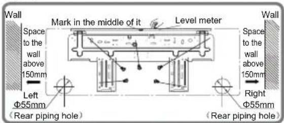
- Hang the wall-mounting frame on the wall; adjust it in horizontal position with the level meter and then point out the screw fixing holes on the wall.
- Drill the screw fixing holes on the wall with impact drill (the specification of drill head should be the same as the plastic expansion particle) and then fill the plastic expansion particles in the holes.
- Fix the wall-mounting frame on the wall with tapping screws (ST4.2X25TA) and then check if the frame is firmly installed by pulling the frame. If the plastic expansion particle is loose, please drill another fixing hole nearby.
Step three: open piping hole
- Choose the position of piping hole according to the direction of outlet pipe. The position of piping hole should be a little lower than the wall-mounted frame, shown as below.
QC:

QD:
QE:

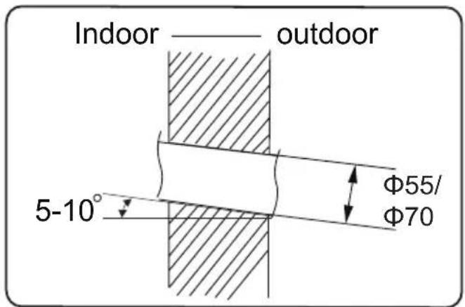
- Open a piping hole with the diameter of 55 or 70 on the selected outlet pipe position. In order to drain smoothly, slant the piping hole on the wall slightly downward to the outdoor side with the gradient of 5 - 10^ .
Installation of indoor unit
Note:
- Pay attention to dust prevention and take relevant safety measures when opening the hole.
- The plastic expansion particles are not provided and should be bought locally.
Step four: outlet pipe

- When select leading out the pipe from left or right, please cut off the corresponding hole on the bottom case.

Step five: connect the pipe of indoor unit
-
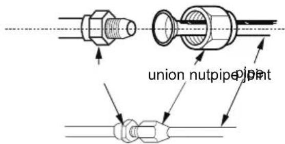
Aim the pipe joint at the corresponding bellmouth.
-
Pretightening the union nut with hand.
-
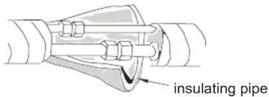
Adjust the torque force by referring to the following sheet. Place the open-end wrench on the pipe joint and place the torque wrench on the union nut. Tighten the union nut with torque wrench.
Installation of indoor unit

- Wrap the indoor pipe and joint of connection pipe with insulating pipe, and then wrap it with tape.
| Hex nut diameter | Tightening torque (N ·m) |
| Φ 6 | 15~20 |
| Φ 9.52 | 30~40 |
| Φ 12 | 45~55 |
| Φ 16 | 60~65 |
| Φ 19 | 70~75 |
Step six: install drain hose
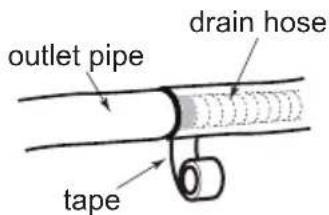
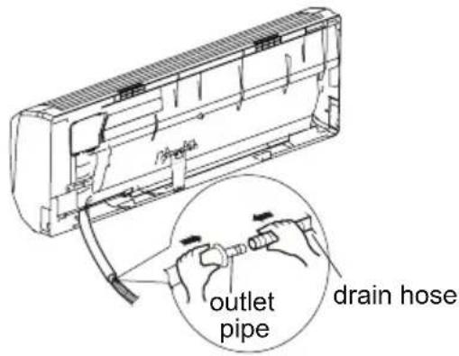
-
Connect the drain hose to the outlet pipe of indoor unit.
-
Bind the joint with tape.
Note:
- Add insulating pipe in the indoor drain hose in order to prevent condensation.
- The plastic expansion particles are not provided.

Step seven: connect wire of indoor unit
- Open the panel, remove the screw on the wiring cover and then take down the cover.

Installation of indoor unit
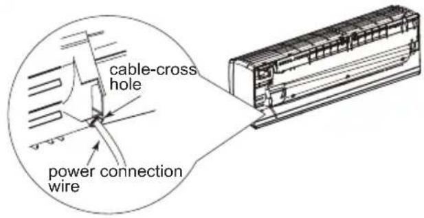
-
Make the power connection wire go through the cable-cross hole at the back of indoor unit and then pull it out from the front side.
-
Remove the wire clip; connect the power connection wire to the wiring terminal according to the color; tighten the screw and then fix the power connection wire with wire clip.

-
Put wiring cover back and then tighten the screw.
-
Close the panel.
Note:
- All wires of indoor unit and outdoor unit should be connected by a professional.
- If the length of power connection wire is insufficient, please contact the supplier for a new one. Avoid extending the wire by yourself.
- For the air conditioner with plug, the plug should be reachable after finishing installation.
- For the air conditioner without plug, an circuit break must be installed in the line. The air switch should be all-pole parting and the contact parting distance should be more than 3mm.
Installation of indoor unit
Step eight: bind up pipe
- Bind up the connection pipe, power cord and drain hose with the band.

- Reserve a certain length of drain hose and power cord for installation when binding them. When binding to a certain degree, separate the indoor power and then separate the drain hose.

indoor power cord
- Bind them evenly.
- The liquid pipe and gas pipe should be bound separately at the end.
Note:
- The power cord and control wire can't be crossed or winding.
- The drain hose should be bound at the bottom.
Step nine: hang the indoor unit
- Put the bound pipes in the wall pipe and then make them pass through the wall hole.
- Hang the indoor unit on the wall-mounting frame.
- Stuff the gap between pipes and wall hole with sealing gum.
- Fix the wall pipe.
- Check if the indoor unit is installed firmly and closed to the wall.

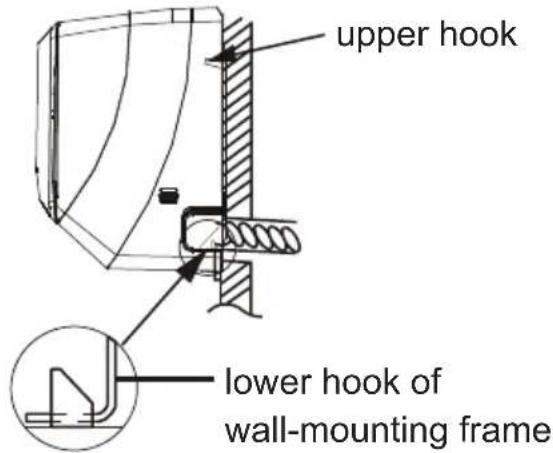
Note:
- Do not bend the drain hose too excessively in order to prevent blocking.
Installation of outdoor unit
Step one: fix the support of outdoor unit (select it according to the actual installation situation)
- Select installation location according to the house structure.
- Fix the support of outdoor unit on the selected location with expansion screws.
Note:
- Take sufficient protective measures when installing the outdoor unit.
- Make sure the support can withstand at least four times of the unit weight.
- The outdoor unit should be installed at least 3cm above the floor in order to install drain joint.
- For the unit with cooling capacity of 2300W \~5000W, 6 expansion screws are needed; for the unit with cooling capacity of 6000W \~8000W, 8 expansion screws are needed; for the unit with cooling capacity of 10000W \~16000W, 10 expansion screws are needed.

natural_image
Line drawing of a rectangular air conditioner unit mounted on a base, showing grille and vent slots (no text or symbols)at least 3cm above the floor
Step two: install drain joint
unit)
- Connect the outdoor drain joint into the hole on the chassis, as shown in the picture below.
- Connect the drain hose into the drain vent.

Step three: fix outdoor unit gnitaeh dna gnilooc rof ylnO(
support.
- Fix the foot holes of outdoor unit with bolts.
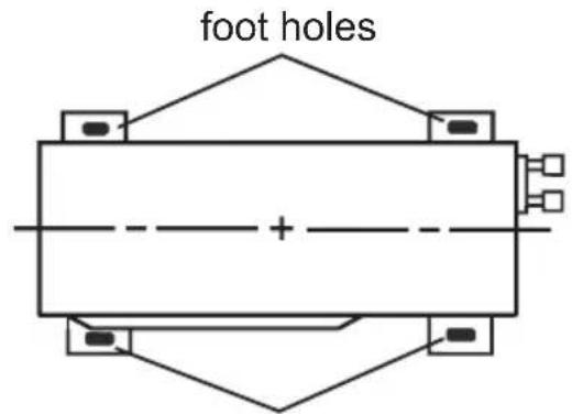
foot holes
Installation of outdoor unit
Step four: connect indoor and outdoor pipes
- Remove the screw on the right handle of outdoor unit and then remove the handle.
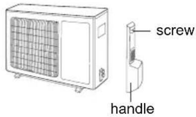
- Remove the screw cap of valve and aim the pipe joint at the bellmouth of pipe.

- Pretightening the union nut with hand.

- Tighten the union nut with torque wrench by referring to the sheet below.
| Hex nut diameter | Tightening torque (N·m) |
| Φ 6 | 15~20 |
| Φ 9.52 | 30~40 |
| Φ 12 | 45~55 |
| Φ 16 | 60~65 |
| Φ 19 | 70~75 |
Step five: connect outdoor electric wire
- Remove the wire clip; connect the power connection wire and signal control wire (only for cooling and heating unit) to the wiring terminal according to the color; fix them with screws.

Installation of outdoor unit
- Fix the power connection wire and signal control wire with wire clip (only for cooling and heating unit).
Note:
- After tighten the screw, pull the power cord slightly to check if it is firm.
- Never cut the power connection wire to prolong or shorten the distance.
Step six: neaten the pipes
- The pipes should be placed along the wall, bent reasonably and hidden possibly. Min. semidiameter of bending the pipe is 10cm.
- If the outdoor unit is higher than the wall hole, you must set a U-shaped curve in the pipe before pipe goes into the room, in order to prevent rain from getting into the room.
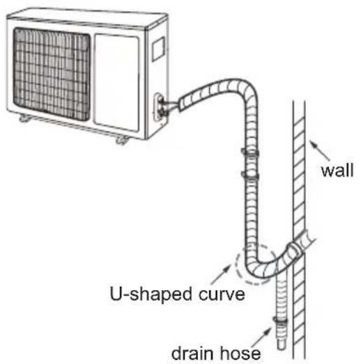
Note:
- The through-wall height of drain hose shouldn't be higher than the outlet pipe hole of indoor unit.
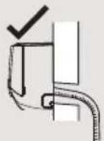

- The water outlet can't be placed in water in order to drain smoothly.

- Slant the drain hose slightly downwards. The drain hose can't be curved, raised and fluctuant, etc.
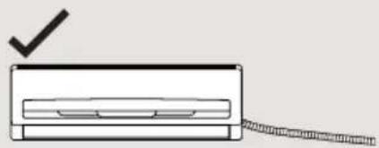
natural_image
Simple line drawing of a device with a checkmark and a string attached (no text or symbols)

natural_image
Simple line drawing of a rectangular device with a coiled cable extending from its side (no text or symbols)
Vacuum pumping
Use vacuum pump
-
Remove the valve caps on the liquid valve and gas valve and the nut of refrigerant charging vent.
-
Connect the charging hose of piezometer to the refrigerant charging vent of gas valve and then connect the other charging hose to the vacuum pump.
-
Open the piezometer completely and operate for 10-15min to check if the pressure of piezometer remains in -0.1MPa.
-
Close the vacuum pump and maintain this status for 1-2min to check if the pressure of piezometer remains

in -0.1MPa. If the pressure decreases, there may be leakage.
-
Remove the piezometer, open the valve core of liquid valve and gas valve completely with inner hexagon spanner.
-
Tighten the screw caps of valves and refrigerant charging vent.
-
Reinstall the handle.
Leakage detection
- With leakage detector:
Check if there is leakage with leakage detector.
- With soap water:
If leakage detector is not available, please use soap water for leakage detection. Apply soap water at the suspected position and keep the soap water for more than 3min. If there are air bubbles coming out of this position, there's a leakage.
Check after installation
- Check according to the following requirement after finishing installation.
| Items to be checked Possible malfunction | |
| Has the unit been installed firmly? | The unit may drop, shake or emit noise. |
| Have you done the refrigerant leakage test? | It may cause insufficient cooling (heating) capacity. |
| Is heat insulation of pipeline sufficient? | It may cause condensation and water dripping. |
| Is water drained well? | It may cause condensation and water dripping. |
| Is the voltage of power supply according to the voltage marked on the nameplate? | It may cause malfunction or damaging the parts. |
| Is electric wiring and pipeline installed correctly? | It may cause malfunction or damaging the parts. |
| Is the unit grounded securely? It may cause electric leakage. | |
| Does the power cord follow the specification? | It may cause malfunction or damaging the parts. |
| Is there any obstruction in the air inlet and outlet? | It may cause insufficient cooling (heating) capacity. |
| The dust and sundries caused during installation are removed? | It may cause malfunction or damaging the parts. |
| The gas valve and liquid valve of connection pipe are open completely? | It may cause insufficient cooling (heating) capacity. |
| Is the inlet and outlet of piping hole been covered? | It may cause insufficient cooling (heating) capacity or waster electricity. |
Test operation
1. Preparation of test operation
- The client approves the air conditioner.
- Specify the important notes for air conditioner to the client.
2. Method of test operation
- Put through the power, press ON/OFF button on the remote controller to start operation.
- Press MODE button to select AUTO, COOL, DRY, FAN and HEAT to check whether the operation is normal or not.
- If the ambient temperature is lower than 16^ , the air conditioner can't start cooling.
Configuration of connection pipe
- Standard length of connection pipe
- 5m、7.5m、8m
- Min length of connection pipe
For the unit with standard connection pipe of 5m, there is no limitation for the min length of connection pipe. For the unit with standard connection pipe of 7.5m and 8m, the min length of connection pipe is 3m.
- Max length of connection pipe
Sheet 1 Max length of connection pipe Unit: m
| capacity capacity | Max length of connection pipe |
| 5000Btu/h (1465W) | 15 25 |
| 7000Btu/h (2051W) | 15 30 |
| 9000Btu/h (2637W) | 15 30 |
| 12000Btu/h (3516W) | 20 30 |
| 18000Btu/h (5274W) | 25 30 |
| Max length of connection pipe | |
| 24000Btu/h (7032W) | |
| 28000Btu/h (8204W) | |
| 36000Btu/h (10548W) | |
| 42000Btu/h (12306W) | |
| 48000Btu/h (14064W) |
- The calculation method of additional refrigerant oil and refrigerant charging amount after prolonging connection pipe
After the length of connection pipe is prolonged for 10m at the basis of standard length, you should add 5ml of refrigerant oil for each additional 5m of connection pipe.
The calculation method of additional refrigerant charging amount (on the basis of liquid pipe):
(1) Additional refrigerant charging amount= prolonged length of liquid pipe × additional refrigerant charging amount per meter
(2) Basing on the length of standard pipe, add refrigerant according to the requirement as shown in the table. The additional refrigerant charging amount per meter is different according to the diameter of liquid pipe. See Sheet 2.
Configuration of connection pipe
Sheet 2. Additional refrigerant charging amount for R32
| Diameter of connection pipe mm | Indoor unit throttle | Outdoor unit throttle | ||
| Liquid pipe Gas pipe | Cooling only, cooling and heating (g / m) (g / m) | Cooling only (g / m) | cooling and heating | |
| Φ6 | Φ9.5 or Φ12 | 16 | 12 | 16 |
| Φ6 or Φ9.5 | Φ16 or Φ19 | 40 | 12 | 40 |
| Φ12 | Φ19 or Φ22.2 | 80 | 24 | 96 |
| Φ16 | Φ25.4 or Φ31.8 | 136 | 48 | 96 |
| Φ19 | - | 200 200 | 200 | |
| Φ22.2 | - | 280280 | 280 | |
Note: The additional refrigerant charging amount in Sheet 2 is recommended value, not compulsory.
Safety operation of flammable refrigerant
Qualification requirement for installation and maintenance man
- All the work men who are engaging in the refrigeration system should bear the valid certification awarded by the authoritative organization and the qualification for dealing with the refrigeration system recognized by this industry. If it needs other technician to maintain and repair the appliance, they should be supervised by the person who bears the qualification for using the flammable refrigerant.
- It can only be repaired by the method suggested by the equipment's manufacturer.
Installation notes
- The air conditioner is not allowed to use in a room that has running fire (such as fire source, working coal gas ware, operating heater).
- It is not allowed to drill hole or burn the connection pipe.
- The air conditioner must be installed in a room that is larger than the minimum room area. The minimum room area is shown on the nameplate or following table a.
- Leak test is a must after installation.
table a - Minimum room area ( m^2 )
| Minimum room area( m^2 ) | Charge amount (kg) | ≤1.2 | 1.3 | 1.4 | 1.5 | 1.6 | 1.7 | 1.8 | 1.9 | 2 | 2.1 | 2.2 | 2.3 | 2.4 | 2.5 |
| floor location | / | 14.5 | 16.8 | 19.3 | 22 | 24.8 | 27.8 | 31 | 34.3 | 37.8 | 41.5 | 45.4 | 49.4 | 53.6 | |
| window mounted | / | 5.2 | 6.1 | 7 | 7.9 | 8.9 | 10 | 11.2 | 12.4 | 13.6 | 15 | 16.3 | 17.8 | 19.3 | |
| wall mounted | / | 1.6 | 1.9 | 2.1 | 2.4 | 2.8 | 3.1 | 3.4 | 3.8 | 4.2 | 4.6 | 5 | 5.5 | 6 | |
| ceiling mounted | / | 1.1 | 1.3 | 1.4 | 1.6 | 1.8 | 2.1 | 2.3 | 2.6 | 2.8 | 3.1 | 3.4 | 3.7 | 4 |
Maintenance notes
- Check whether the maintenance area or the room area meet the requirement of the nameplate.
- It's only allowed to be operated in the rooms that meet the requirement of the nameplate.
- Check whether the maintenance area is well-ventilated.
- The continuous ventilation status should be kept during the operation process.
- Check whether there is fire source or potential fire source in the maintenance area.
- The naked flame is prohibited in the maintenance area; and the "no smoking" warning board should be hanged.
- Check whether the appliance mark is in good condition.
- Replace the vague or damaged warning mark.
Welding
- If you should cut or weld the refrigerant system pipes in the process of maintaining, please follow the steps as below:
Safety operation of flammable refrigerant
a. Shut down the unit and cut power supply
b. Eliminate the refrigerant
c. Vacuuming
d. Clean it with N2 gas
e. Cutting or welding
f. Carry back to the service spot for welding
- The refrigerant should be recycled into the specialized storage tank.
- Make sure that there isn't any naked flame near the outlet of the vacuum pump and it's well-ventilated.
Filling the refrigerant
- Use the refrigerant filling appliances specialized for R32. Make sure that different kinds of refrigerant won't contaminate with each other.
- The refrigerant tank should be kept upright at the time of filling refrigerant.
- Stick the label on the system after filling is finished (or haven't finished).
- Don't overfilling.
- After filling is finished, please do the leakage detection before test running; another time of leak detection should be done when it's removed.
Safety instructions for transportation and storage
- Please use the flammable gas detector to check before unload and open the container.
- No fire source and smoking.
- According to the local rules and laws.
Pipe expanding method
Note:
Improper pipe expanding is the main cause of refrigerant leakage. Please expand the pipe according to the following steps:
A: Cut the pipe
- Confirm the pipe length according to the distance of indoor unit and outdoor unit.
- Cut the required pipe with pipe cutter.


B: Remove the burrs
- Remove the burrs with shaper and prevent the burrs from getting into the pipe.
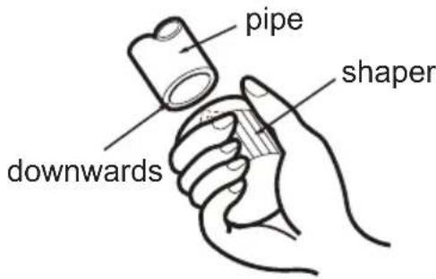
C: Put on suitable insulating pipe
D: Put on the union nut
- Remove the union nut on the indoor connection pipe and outdoor valve; install the union nut on the pipe.

E: Expand the port
- Expand the port with expander.

Note:
- "A" is different according to the diameter, please refer to the sheet below:
| Outer diameter (mm) | A(mm) | |
| Max Min | ||
| Φ6 - 6.35(1/4") | 1.3 | 0.7 |
| Φ9.52(3/8") | 1.6 | 1.0 |
| Φ12-12.7(1/2") | 1.8 | 1.0 |
| Φ15.8-16(5/8") | 2.4 | 2.2 |
F: Inspection
- Check the quality of expanding port. If there is any blemish, expand the port again according to the steps above.
smooth surface

natural_image
Pure diagram of a cylindrical object with internal flow arrows, no text or symbols presentthe length is equal
improper expanding

leaning

damaged surface

crack uneven
thickness
WARRANTY AIR CONDITIONER
The Godrej Air Conditioner comes with a FIVE year warranty on compressor and a ONE year warranty on all other parts (except grill & plastic parts) from the date of purchase, against defective material or workmanship. In case of any such defect found during the first year from date of purchase, Godrej & Boyce Mfg. Co. Ltd. - Appliance Division will undertake repairs to the warranted part free of charge, subject to terms and conditions below. In the warranty period beyond the first year from date of purchase, only the compressor will be provided free of cost, when necessary. However, the Air Conditioner will repaired on payment of necessary charges. The warranty does not cover the demonstration/installation of the Air Conditioner.
INSTRUCTIONS FOR THE CUSTOMER
- Kindly ensure that the dealer fills the warranty card correctly and completely.
- You should retain the warranty card for record and produce the same in the event of any warranty repairs.
- In the event of a defect developing in the product, contact the nearest authorized Godrej & Boyce Service Center for obtaining warranty service and inform the defect, Model details & Serial No.
- Product will function between +/-10% of rated volts at 50Hz. For any fluctuation beyond specified limit, company shall not be responsible and warranty stands terminated.
- In areas where voltage fluctuates below 10% of rated voltage, customer is advised to use a voltage stabilizer which steps up voltage to a minimum of 190V.
- Earthing provision is necessary for safety. Improper domestic wiring leading to hazards such as shock or fire is not covered under this warranty.
- The product must be maintained to ensure hygiene. If there are any insects or rodents in it causing obstruction to the functioning of the product, the company shall not be responsible and in-turn warranty stands terminated.
TERMS AND CONDITIONS
- Repairs and replacement will be carried out by the companies authorized service centers or through authorized dealer's service center.
- All transportation and handling expenses incurred while repairing will be payable by the customer in advance.
- For any Air Conditioner installed beyond the municipal limits of the jurisdiction of the authorized customer service center, charges towards technician's visit will be borne by the customer
- While the company will make every effort to carry out the repairs at the earliest, it however is made expressly clear that the company is under no obligation to do so in a specified period of time.
- The company will retain any part(s), compressor and/or other components when replaced at its discretion.
- Warranty does not cover accessories to the Air Conditioner.
- Refrigeration system gas charging and consumables will be charged for any such repairs after one year from the date of purchase.
- Company will not be liable for any consequential loss or compensation nor refund of purchase price nor replacement of the Air Conditioner.
- Customer must ensure the routine maintenance including cleaning of filter etc. for proper operation.
- Any change in location/damages on handling will be serviced at extra material and labor cost.
- While Company would take all necessary steps to repair the Air Conditioner supplied under the warranty and keep sufficient stock of the spare parts of the Air Conditioner with them, however, in certain cases, at the sole discretion of the Company, the Company may due to non-availability of spare parts of the Air Conditioner, resulting into the Air Conditioner not being repaired by the Company, offer a replacement scheme to the purchasers of such Air Conditioner which cannot be repaired due to non-availability of spare parts of the Air Conditioner, purchased under the warranty, the Company would offer a replacement of the Air Conditioner. The details of the replacement offer is subject to change from year to year and shall also be applicable on the MRP of the product to be purchased as a replacement.
- Two (2) free preventive maintenance service (Labour only) will be provided to the customer during first year warranty period. To avail these free services customer has to register the call at the call center number 1800 209 5511. After expiry of 12 (twelve) months from date of purchase company is not liable for any free service.
- Any Damage due to rodent attacks or environment conditions like electrical surges or low voltages will be repaired on chargeable basis.
Godrej & Boyce Mfg. Co. Ltd.- Appliance Division CUSTOMER COPY
MODEL NO. AIR CONDITIONER SERIAL No.:
CUSTOMER'S NAME & ADDRESS
TEL.
DATE OF PURCHASE
DEALER'S NAME & ADDRESS
TEL.
Customer's Signature:
This warranty is valid only if it is filled in and stamped by our authorized dealer on the date of purchase.
Warranty Voids If:
- The warranty card is not completed properly at the time of purchase. 2. The completed warranty card is not presented to the authorized personnel at the time of service of the product. 3. The Air Conditioner is not operated and maintained according to instructions given in the 'User Guide'. 4. Defects are caused by improper use, which shall be determined by the company personnel. 5. Unauthorized persons carry out any repair work. 6. Defects are caused by reasons beyond control, like abnormal voltage (exceed 253 V or below 207 V), acts of God, or while in transit to service center or purchaser's residence. 7. The warranty is not valid in case the serial number is deleted, defaced or altered. 8. Damage to the Air Conditioner or any parts due to transportation or shifting is not covered by the warranty. 9. The warranty automatically expires after the stipulated period from the original date of purchase, even if the Air Conditioner may not be in use for any time for whatever reasons.
| GODREJ & BOYCE MFG. CO. LTD., Appliances Division | |
| Branch | Address |
| Ahmedabad | 4th Floor, APM Shopping Mall Near IOCL Petrol Pump, Shyamal-Karnavati, 100 ft. Road, Satellite, Ahmedabad - 380 015 |
| Bangalore | 3rd Floor, The Karnataka Film Chamber of Commerce Bldg. 28, 1st Main,Crescent Road, High Grounds Nr. Shivanand Circle, Bangalore - 560 001 |
| Bhopal | 217, Zone I, M.P. Nagar, Beh. Jyoti Talkies, Bhopal - 462 011 |
| Bhubaneshwar | Highway Complex, NH-5, Rudrapur, Bhubaneshwar - 752 101 |
| Chandigarh/Mohali | Plot No. A-40, Phase VIII-A, Industrial Area, Mohali - 160 059 |
| Chennai | No. 1, Sidco Industrial Estate, Ambattur, Chennai - 600 098 |
| Coimbatore | No. 585 - 590 3rd Floor, Sathya Towers, DB Road, R S Puram, Coimbatore- 641002 |
| Delhi | Godrej Bhavan, 2nd Floor, Shershah Suri Marg, Mathura Road, Okhla,New Delhi - 110 065 |
| Faridabad | Godrej Bhavan, 2nd Floor, Shershah Suri Marg, Mathura Road, Okhla,New Delhi - 110 065 |
| Ghaziabad | Plot No. 229/230, Sardar Pashu Ahaar, Bulandshahar Road, Village-chaprolla, Ghaziabad |
| Guwahati | Basundhara Enclave, 1st & 2nd Floor Ulubari, Guwahati – 781007 |
| Hyderabad | 201 & 202, Lala-1 Land Mark, 5-4-94 to 97, 2nd Floor, Above DigitalShoppy, Ranigunj, M.G. Road, Secunderabad -500 003 |
| Jaipur | 502-506, 5th Floor, Gaurav Towers, Malviya Nagar, Jaipur - 302 017 |
| Kochi | 2nd floor, Angels Arcade, South Kalamasserry, Near CUSAT PO Kochi –682022 |
| Kolkata | Plot-30, Block-GN, Sector-V, Salt Lake city, Kolkata - 700 091 |
| Lucknow | C-3/3 & C-3/4, Sanjay Complex, Near All India Radio, Vidhan Sabha Marg,Lucknow-226001 |
| Mumbai | Appliance Division, Plant 4, Pirojshahnagar, Vikhroli, Mumbai - 400 079 |
| Nagpur | Dr. Bhiwapurkar Chamber, 2nd Floor, Opp. Yashwant Stadium, Dhantoli,Nagpur - 440 012 |
| Patna | Grand Plaza 6th Floor, 6001-6004, Dakbunglow Crossing. Frazer Road.Patna-800001 |
| Pune | Apollo Building Square, Plot No. 60, Survey No. 599, Sahaney Sujan Park,Lullanagar, Bibewadi Road, Pune - 411 040 |
| Raipur | 9/1, Besides Bharat Petrol Pump, Opp, Hotel Picadelly, Mahoba Bazaar,G.E. Road, Raipur - 492 001, Chhatisgarh |
| Ranchi | C/o. Surya Motors, Near Krishi Bazaar Samiti Panda, Ranchi (Jharkand) -835 222 |
| Toll-Free :1800-209-5511 | |
| Website: www.godrejappliances.com & www.godrejsmartcare.comE-mail: smartcare@godrej.com | |
Please fill the warranty card and send it to your nearest branch to avail of 2 free services
 | AIR CONDITIONERS | AIR CONDITIONERS | Dry | Dry | Wet |   | ||
| Bill No. | Date of Sale | Model No. | Sr. No. | |||
| Customer/User's Name | Phone No. | |||||
| Address | Sp. instructions, if any | |||||
| City | Pin Code | |||||
| Dealer/ASP's Name & Address | I confirm that the service has been provided to my satisfactionCustomer's Sign & Date | |||||
 | AIR CONDITIONERS | AIR CONDITIONERS | Dry | Dry | Wet |  |  | ||
| Bill No. | Date of Sale | Model No. | Sr. No. | ||||
| Customer/User's Name | Phone No. | ||||||
| Address | Sp. instructions, if any | ||||||
| City | Pin Code | ||||||
| Dealer/ASP's Name & Address | I confirm that the service has been provided to my satisfactionCustomer's Sign & Date | ||||||
Protection of Environment:

natural_image
Symbol of a trash bin crossed with a diagonal line, representing no waste or discharge (no text or numbers present)"Protection of environment" is one of the core values of Godrej and we seek your co-operation to make sure that this product is not disposed as unsorted municipal waste.
This symbol is known as the "Crossed-out Wheelie Bin Symbol". It means that the product should not be disposed of with your general household waste.
It should be disposed of only through the company's collection centers with special treatment so as to prevent any damage to the environment. Please call: 1800 209 5511 or visit: www.godrejappliances.com/green-think for
details about Godrej Appliances authorized collection centers.
Godrej

- Content
- Operation Notices
- Screen Operation Guide
- Maintenance
- Malfunction
- Installation Notice
- Installation
- Test and operation
- Attachment
- Explanation of Symbols
- DANGER
- WARNING
- CAUTION
- NOTICE
- The Refrigerant
- WARNING:
- Operation and Maintenance
- Working temperature range
- NOTICE:
- Display
- Buttons on remote controller
- Introduction for icons on display screen
- Introduction for buttons on remote controller
- Note:
- ON/OFF button
- MODE button
- "+" or "-" button
- FAN button
- button
- button
- HEALTH|SAVE button
- HEALTH FUNCTION:
- SAVE function:
- X-FAN button
- TEMP button
- TIMER button
- TURBO button
- SLEEP button
- LIGHT button
- Function introduction for combination buttons
- Child lock function
- Switchover function for temperature display
- Operation guide
- Replacement of batteries in remote controller
- Emergency operation
- Clean and maintenance
- Clean surface of indoor unit
- Clean filter
- Open panel
- Remove filter
- Install filter
- NOTICE: Checking before use-season
- NOTICE: Checking after use-season
- Notice for recovery
- Malfunction analysis
- General phenomenon analysis
- Error Code
- Installation dimension diagram
- To ensure safety, please be mindful of the following precautions.
- Tools for installation
- Selection of installation location
- Basic requirement
- Indoor unit
- Outdoor unit
- Requirements for electric connection
- Safety precaution
- Grounding requirement
- Installation of indoor unit
- Step one: choosing installation location
- Step two: install wall-mounting frame
- Step three: open piping hole
- Step four: outlet pipe
- Step five: connect the pipe of indoor unit
- Step six: install drain hose
- Step seven: connect wire of indoor unit
- Step eight: bind up pipe
- Step nine: hang the indoor unit
- Installation of outdoor unit
- Step one: fix the support of outdoor unit (select it according to the actual installation situation)
- Step two: install drain joint
- unit)
- Step three: fix outdoor unit gnitaeh dna gnilooc rof ylnO(
- Step four: connect indoor and outdoor pipes
- Step five: connect outdoor electric wire
- Step six: neaten the pipes
- Vacuum pumping
- Use vacuum pump
- Leakage detection
- Check after installation
- Test operation
- Preparation of test operation
- Method of test operation
- Configuration of connection pipe
- Safety operation of flammable refrigerant
- Qualification requirement for installation and maintenance man
- Installation notes
- Maintenance notes
- Welding
- Filling the refrigerant
- Safety instructions for transportation and storage
- Pipe expanding method
- WARRANTY AIR CONDITIONER
- INSTRUCTIONS FOR THE CUSTOMER
- TERMS AND CONDITIONS
- Godrej & Boyce Mfg. Co. Ltd.- Appliance Division CUSTOMER COPY
- MODEL NO. AIR CONDITIONER SERIAL No.:
- DATE OF PURCHASE
- Protection of Environment:
- Godrej
Brand : Godrej
Model : GSC 18 DGN 3 DWQH
Category : Air Conditioning