L5460HSTCC - Tractor KUBOTA - Free user manual and instructions
Find the device manual for free L5460HSTCC KUBOTA in PDF.


| Product Type | Compact Utility Tractor |
| Brand | Kubota |
| Model | L5460HSTCC |
| Engine Power | 46 HP (34.3 kW) |
| Engine Type | 4-cylinder diesel, liquid-cooled |
| Displacement | 2.4 L |
| Fuel Type | Diesel |
| Transmission | Hydrostatic (HST) with creep mode |
| Number of Speeds | Infinite (HST) |
| PTO Power | 37 HP (27.6 kW) |
| PTO Type | Independent, rear (540 rpm) |
| Hydraulic System | Open center |
| Hydraulic Flow | 11.4 gpm (43.2 L/min) |
| Steering | Power steering |
| Brakes | Wet disc brakes |
| Front Tires | 8-16 (Ag) or 27x8.50-15 (Turf) |
| Rear Tires | 12.4-24 (Ag) or 44x18-20 (Turf) |
| Dimensions (L x W x H) | 136.6 x 67.1 x 94.5 in (3470 x 1705 x 2400 mm) |
| Wheelbase | 79.5 in (2020 mm) |
| Ground Clearance | 14.0 in (355 mm) |
| Weight | 3,790 lb (1720 kg) |
| Fuel Tank Capacity | 11.9 gal (45 L) |
| ROPS Type | Foldable ROPS (Roll-Over Protective Structure) |
| Safety Features | Operator presence system, PTO shield, seat belt |
| Maintenance Interval | Every 50 hours (engine oil, filter) |
| Warranty | 2 years / 2,000 hours (limited) |
| Parts Availability | Widely available through Kubota dealers |
Frequently Asked Questions - L5460HSTCC KUBOTA
User questions about L5460HSTCC KUBOTA
0 question about this device. Answer the ones you know or ask your own.
Ask a new question about this device
Download the instructions for your Tractor in PDF format for free! Find your manual L5460HSTCC - KUBOTA and take your electronic device back in hand. On this page are published all the documents necessary for the use of your device. L5460HSTCC by KUBOTA.
USER MANUAL L5460HSTCC KUBOTA
3401 Del Amp Blvd., Torrance, CA 90503, U.S.A.
Telephone : (310)370 3270
Western Division : 1175 S. Guild Ave., Lodi, CA 95240
Telephone : (209)334-9910
General Division : 1485 FAA Blvd. East Worth, TX 76150
Telephone (817)571-0600
Northern Division : 6300 at One Kubota Way, Gtownport, OH 43125
Northern English : 000 at one Russia Way, Europe, CH 45125 Telefonica : /814936-1100
Telephone : (014)639-1100 Southwest Division : 1995 Northbrook Parkway Subway, CA 70021
Sundinbank Division, Tokyo North
Telephone : (770)956-865
KUBOTA CANADA LTD.
5800-14th Avenue, Markhar
Telephone: 1905)294-7477
UBOTA EUROPE S.A.S
19-25. Rue Jules Vercrusse, Z.I. BP08 95101 Amenteuil Cedex, France
Telephone: (3301-3426-3434)
UBOTA EUROPE S.A.S Italy Branch
Via Graci, 29.20068 Dauchiera Bergama (MI) Italy
Teléfono - (39/27 51650377
Corner Road, Thame, Oxfordshire, OX9 SUN, U.K.
Telephone : (44)1844-214500
UBOTA ESPAÑA S.A.
Avenida Recomba No.6, Poligno Industrial la Laguna, Leganes, 20914 (Madrid) Spain
Telephone: (34)81-508-6442
UBOTA TRACTOR AUSTRALIA PTY LTD
25-29 Piemas Way, Iumanina, VIC 3028 Australia
Telephone: (61) 9-2004-4423
THE WORLD'S
IME KOBOTA SDN. BHD. No 3 John Soredy, 25/102 Tenera Reinduction Axis
No.3 Jadih Sepba: 25/123 Teman Perhitubahan Axis.
Seksyen 25, 40400 Shan Alam. Selangor Darul Ehsan Malaysia
Telephone: (09)3-736-1386
UBOTA PHILIPPINES, INC.
232 Quirino Highway, Baesa, Quezon City 1106, Philippines
Telephone: (6312-422-3500)
HIN TAIWAN AGRICULTURAL MACHINERY CO., LTD.
- Fengping 2nd Rd. Teliao Shuang Kaohsiung 83107. Taiwan R.O.C.
Telephone: (885)7.712-2333
T KUBOTA MACHINERY INDONESIA
Tower A of Eighty-Eight@Kasobianka Ljrotei 15
Inglee, Paul Canghini, Koy, 88, Jakarta 19970 Indonesia
Jahari Haya Casadharal Kay. By
Telephone: (02)21-29566-72
IAM KUBOTA CORPORATION CO., LTD.
101/19-24 Moo 20, Navnakom Industrial Estate, Tambon Khiongrueng. Amphur Khiongluang
Pathunithani 12120, THAI LAN
Telephone: (06)2-908-000
UBOTA KOREA CO., LTD
41-27. Joyumuyoxi-gil, Backsan-myeon, Gimje-si, Jeollabu-do, Korea
Telephone: (021)63-544-5822
UBOTA AGRICULTURAL MACHINERY INDIA PVT. LTD
ho 15 Mednunikam Road Shalinganallur, Chepoc-600119 T.N. india
Telegrapha - (01)44 6124 1500
UBOTA VIETNAM CO., LTD.
UBOTA VIETNAM CO., LTD.
Lot B-3N2-ON. My Phobe 3 Industrial Park. Ben Cat District, Binh Dong Province, Vietnam
Техерополе : (84)650-3577-537
KUBOTA Corporation
English (U.S.A.)
Cade No. TD350-7958-2
OPERATOR'S MANUAL
KUBOTA
TRACTOR
L3560·L4060·L4760MODELS
L5460·L6060

natural_image
Line drawing of a white tractor with large tires and front wheel, no text or symbols presentABBREVIATION LIST
| Abbreviations | Definitions |
| 2WD | 2 Wheel Drive |
| 4WD | 4 Wheel Drive |
| API | American Petroleum Institute |
| ASABE | American Society of Agricultural and Biological Engineers, USA |
| ASTM | American Society for Testing and Materials, USA |
| DIN | Deutsches Institut für Normung, GERMANY |
| DT | Dual Traction [4WD] |
| fpm | Feet Per Minute |
| GST | Glide Shift Transmission |
| Hi-Lo | High Speed-Low Speed |
| HST | Hydrostatic Transmission |
| m/s | Meters Per Second |
| PTO | Power Take Off |
| RH/LH | Right-hand and left-hand sides are determined by facing in the direction of forward travel |
| ROPS | Roll-Over Protective Structures |
| rpm | Revolutions Per Minute |
| r/s | Revolutions Per Second |
| SAE | Society of Automotive Engineers, USA |
| SMV | Slow Moving Vehicle |
California Proposition 65
▲ WARNING ▲
Engine exhaust, some of its constituents,
certain vehicle components and fluids,
contain or emit chemicals known to the
State of California to cause cancer and birth
defects or other reproductive harm.
KUBOTA Corporation is …
Since its inception in 1890, KUBOTA Corporation has grown to rank as one of the major firms in Japan.
To achieve this status, the company has through the years diversified the range of its products and services to a remarkable extent, until today, 19 plants and 16,000 employees produce over 1,000 different items, large and small.
All these products and all the services which accompany them, however, are unified by one central commitment.
KUBOTA makes products which, taken on a national scale, are basic necessities. Products which are indispensable, products intended to help individuals and nations fulfill the potential inherent in their environment. For KUBOTA is the Basic Necessities Giant.
This potential includes water supply, food from the soil and from the sea, industrial development, architecture and construction, transportation.
Thousands of people depend on KUBOTA's know-how, technology, experience and customer service. You too can depend on KUBOTA.
L3560·L4060·L4760
L5460-L6060
AT.F.5-8.12.AK
FOREWORD
Thank you very much for choosing the L series tractor with CAB.
This operator's manual covers the operation, inspection and preventive maintenance instructions that are specific to the L series CAB models. For other information and instructions, refer to the separately issued operator's manual for their sister models.
Please read this manual carefully along with the tractor operator's manual, to operate the machine properly and safely.
Proper daily inspection, servicing and lubrication keeps your machine in good condition.

SAFETY FIRST
This symbol, the industry's "Safety Alert Symbol", is used throughout this manual and on labels on the machine itself to warn of the possibility of personal injury. Read these instructions carefully. It is essential that you read the instructions and safety regulations before you attempt to assemble or use this unit.

DANGER : Indicates an imminently hazardous situation which, if not avoided, will result in death or serious injury.

WARNING : Indicates a potentially hazardous situation which, if not avoided, could result in death or serious injury.

CAUTION : Indicates a potentially hazardous situation which, if not avoided, could result in minor or moderate injury.
IMPORTANT :
Indicates that equipment or property damage could result if instructions are not followed.
NOTE :
Gives helpful information.
CONTENTS
SAFE OPERATION....▲-1
SPECIFICATIONS....1
SPECIFICATION TABLE 1
CAB OPERATION 3
DOOR AND WINDOW 3
Locking and Unlocking the Door....3
Opening the Door 3
Rear Window 3
Side Window....4
Emergency Exit....4
DOME LIGHT 4
Dome Light 4
WORK LIGHT 4
Work Light Switch....4
Front Work Light 4
Rear Work Light (if equipped)......5
WIPER 5
Front Wiper / Washer Switch....5
Rear Wiper / Washer Switch (if equipped)....5
Using the Wipers in Cold Season....5
AIR CONDITIONER....5
Airflow....5
Air Control Vent 6
Control Panel....7
Operation....8
REÀR / SIDE DEFOGGER WITH TIMER (if equipped).... 10
ELECTRICAL OUTLET 10
Electrical Outlet....10
MAINTENANCE....11
SERVICE INTERVALS 11
PERIODIC SERVICE....12
DAILY CHECK 12
Cleaning Air Conditioner Condenser Screen....12
EVERY 200 HOURS....12
Cleaning Inner Air Filter....12
Cleaning Fresh Air Filter....12
Checking Air Conditioner Condenser ....13
Adjusting Air-Conditioner Belt Tension....13
EVERY 1 YEAR....13
Checking Air-Conditioner Pipe and Hose 13
Checking CAB Isolation Cushion....13
EVERY 4 YEARS....13
Replacing Air Conditioner Hose....13
SERVICE AS REQUIRED....14
Lubricating Points 14
Adding Washer Liquid....14
Checking the Amount of Refrigerant (gas) 14
APPENDICES....15
INDEX 15

SAFE OPERATION
Careful operation is your best insurance against an accident.
Read and understand carefully this section of the separately issued operator's manual before operating the tractor.
■DANGER, WARNING AND CAUTION LABELS
(1) Part No. TD170-4933-1

WARNING

natural_image
Simple line drawing of a person pushing a large vehicle on a slope (no text or symbols)BEFORE DISMOUNTING TRACTOR:
- ALWAYS SET PARKING BRAKE.
Leaving transmission in gear with the engine stopped will not prevent tractor from rolling. - PARK ON LEVEL GROUND WHENEVER POSSIBLE. If parking on a slope, position tractor across the slope.
- LOWER ALL IMPLEMENTS TO THE GROUND. Failure to comply to this warning may allow the wheels to slip, and could cause injury or death.
- STOP THE ENGINE.
1AGAMAOAP079E
(2) Part No. TA040-4902-1

WARNING

natural_image
Illustration of a person using a device to avoid accidents, with a circular icon showing a person in the background (no text or symbols)TO AVOID INJURY OR DEATH FROM ROLL-OVER:
Always use seat belt when driving.
1AGAMAOAP0780
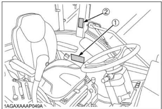
1AGAXAAAP091A
(1) Part No. TD170-4938-1
CAUTION
TO AVOID PERSONAL INJURY:
- Read and understand the operator's manual before operation.
- Before starting the engine, make sure that everyone is at a safe distance from the tractor and that the PTO is OFF.
- Do not allow passengers on the tractor at any time.
- Before allowing other people to use the tractor, have them read the operator's manual.
- Check the tightness of all nuts and bolts regularly.
- Keep all shields in place and stay away from all moving parts.
- Lock the two brake pedals together before driving on the road.
- Slow down for turns, or rough roads, or when applying individual brakes.
- On public roads use SMV emblem and hazard lights, if required by local traffic and safety regulations.
- Pull only from the drawbar.
- Before dismounting, lower the implement to the ground, set the parking brake, stop the engine and remove the key.
- Securely support tractor and implements before working underneath.
1AGAMAOAP0800

1AGAXAAAP092A
■ CARE OF DANGER, WARNING AND CAUTION LABELS
- Keep danger, warning and caution labels clean and free from obstructing material.
- Clean danger, warning and caution labels with soap and water, dry with a soft cloth.
- Replace damaged or missing danger, warning and caution labels with new labels from your local KUBOTA Dealer.
- If a component with danger, warning and caution label (s) affixed is replaced with new part, make sure new label (s) is (are) attached in the same location (s) as the replaced component.
- Mount new danger, warning and caution labels by applying on a clean dry surface and pressing any bubbles to outside edge.
SPECIFICATIONS
SPECIFICATION TABLE
| Model | L3560 L4060 | L4760 L5460 L6060 | |||||||
| 4WD | |||||||||
| Engine | Model D1803-CR-E4 V2403-CR-E4 V2403-CR-TE4 | 2403-CR-TE4 | |||||||
| Type Direct injection vertical, water-cooled, 4-cycle diesel | |||||||||
| Number of cylinders 3 4 | |||||||||
| Total displacement L (cu. in.) 1.826 (111.4) 2.434 (148.5) | |||||||||
| Bore and stroke mm (in.) 87 x 102.4 (3.4 x 4.0) | |||||||||
| Rated revolution | rpm | 2600 | |||||||
| Low idling revolution | rpm | 800 | |||||||
| Net power* | kW (HP) | 26.1 (35.0) | 29.8 (40.0) | 35.1 (47.0) | 40.3 (54.0) | 44.8 (60.0) | |||
| PTO power*(factory observed) | kW (HP)/rpm | 20.9 (28.0)/2600 | 24.2 (32.5)/2600 | 29.5 (39.5)/2600 | 34.7 (46.5)/2600 | 39.5 (53.0)/2600 | |||
| Maximum torque | N-m(ft-lbs.) | 114.1 (84.2) | 133.5 (98.5) | 157.4 (116.1) | 182.6 (134.7) | 195.6 (144.3) | |||
| Battery capacity | 12V, RC: 133 min, CCA: 582A | ||||||||
| Capacities | Fuel tank | L(U.S.gals.) | 51 (13.5) | ||||||
| Engine crankcase(with filter) | L(U.S.qts.) | 6.7 (7.1) | 8.2 (8.7) | 9.4 (9.9) | |||||
| Engine coolant | L(U.S.qts.) | 7.5 (7.9) | 8.2 (8.7) | ||||||
| Transmission case | L(U.S.gals.) | 42 (11.1) | 43 (11.4) | 45 (11.9) | |||||
| Dimensions | Overall length(without 3p) | mm (in.) | 2920 (115.0) | 3085 (121.5) | 3210 (126.4) | ||||
| Overall width(min. tread) | mm (in.) | 1520 (59.8) | 1690 (66.5) | 1710 (67.3) | |||||
| Overall height | mm (in.) | 2300 (90.6) | 2315 (91.1) | 2350 (92.5) | |||||
| Wheel base | mm (in.) | 1805 (71.1) | 1895 (74.6) | 1915 (75.4) | |||||
| Min. ground clearance | mm (in.) | 342 (13.5) | 360 (14.2) | 392 (15.4) | |||||
| Tread | Front | mm (in.) | 1155 (45.5) | 1300 (51.2) | 1340 (52.8) | ||||
| Rear | mm (in.) | 1200 (47.2)1300 (51.2)1385 (54.5)1480 (58.3) | 1285 (50.6)1435 (56.5)1530 (60.2) | 1325 (52.2)1430 (56.3) | |||||
| Weight (with CAB) | kg (lbs.) | 1760 (3880) | 1875 (4134) | 1915 (4222) | 1980 (4365) | ||||
| Model | L3560 | L4060 | L4760 | L5460 | L6060 | ||||
| 4WD | |||||||||
| Traveling system | Standard tire size | Front 7-16 8.3-16 9.5-16 | |||||||
| Rear 12.4-24 14.9-24 | 14.9-26 | ||||||||
| Clutch --- | |||||||||
| Steering Hydrostatic power steering | |||||||||
| Transmission Hydrostatic transmission (3 speeds) | |||||||||
| Braking system Wet disk type | |||||||||
| Min. turning radius (with brake) | m (feet) 2.7 (8.9) 2.8 (9.2) | ||||||||
| Hydraulic unit | Hydraulic control system Position control | ||||||||
| Pump capacity | L (U.S.gals)/ min. | 30.4 (8.0) | 35.6 (9.4) | ||||||
| 3-point hitch | SAE category 1 | SAE category 1, 2 | |||||||
| Max. lift force | At lift points | kg (lbs.) | 1700 (3750) | 1750 (3860) | |||||
| 24 in. behind lift points | kg (lbs.) | 1200 (2650) | 1250 (2760) | 1350 (2980) | |||||
| System pressure | MPa (kgf/cm2) | 17.7 (180) | |||||||
| PTO | Rear PTO | SAE 1-3/8, 6 splines | |||||||
| PTO/ Engine speed | rpm | 540/2426 | 540/2476 | 540/2403 | |||||
| MID-PTO (if equipped) | USA No.5 (KUBOTA 10-tooth) involute spline | ||||||||
| PTO/ Engine speed | rpm | 2000/2451 | 2000/2502 2000/2429 | ||||||
NOTE : *Manufacturer's estimate
The company reserve the right to change the specifications without notice.
CAB OPERATION
DOOR AND WINDOW
■Locking and Unlocking the Door
From the outside ..... Insert the key into the door lock.
Turn the key clockwise to unlock the door. To lock the door, turn the key in the opposite direction. The key can be removed when it is in the vertical direction.
From the inside ..... Push down the lock knob to lock the door.
Pull up the lock knob to unlock the door.
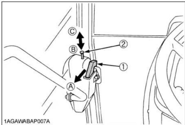
(1) Inner door handle
(A) "PULL"
(2) Lock knob
(B) "PUSH" (Lock)
(C) "PULL" (Unlock)
■Opening the Door
From the outside ..... Unlock the door, and pull the outer door handle.

(1) Outer door handle
(A) "PULL"
(2) Door lock
■Rear Window
Turn the rear window handle clockwise to the vertical position and push the handle. The rear window is opened by the gas spring cylinder.

(1) Rear window handle (A) "OPEN"
(B) "CLOSE"
From the inside ..... Unlock the door and pull the inner door handle.
■Side Window
Pull the side window handle and push the side window to open the window.

(1) Side window handle
Emergency Exit
- Open the right door of the cab if the left door is blocked, and vice versa in an emergency situation.
- Exit through rear window if CAB doors are blocked in an emergency situation.
DOME LIGHT
■Dome Light
Sliding the dome light switch will give the following light condition:
OFF .... The light does not turn on when the door is opened.
ON .... The light remains on regardless of the door position.

(1) Dome light
(A) "OFF"
(2) Dome light switch
(B) "ON"
WORK LIGHT
■Work Light Switch
Turn on the key switch and press the top half of the work light switch. The work light and the switch's indicator light up. Press the bottom half of the work light switch to turn off the light and indicator.
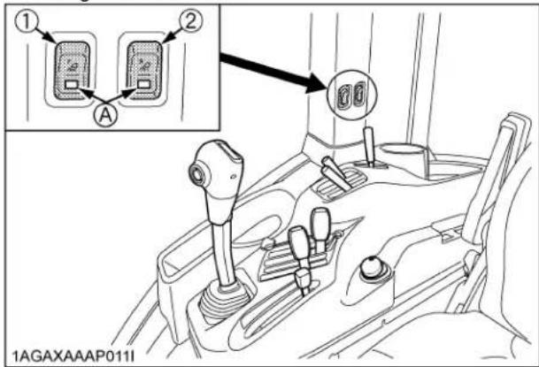
(1) Front work light switch
(A) Indicator for work lights
(2) Rear work light switch (if equipped)
■Front Work Light

(1) Front work light
■Rear Work Light (if equipped)
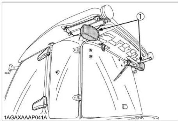
(1) Rear work light
WIPER
■Front Wiper / Washer Switch
- Turn on the key switch and press the top half of the wiper switch to the first step, and the wiper is activated. When the switch is pressed further to the second step, washer liquid jets out.
The jetting continues while the switch is pressed and the wiper is activated continuously.
- Press the bottom half of the wiper / washer switch, washer liquid only jets out.
■Rear Wiper / Washer Switch (if equipped)
See "Front wiper / Washer switch" section, for instructions to use this switch.

(1) Front wiper / washer switch
(2) Rear wiper / washer switch
IMPORTANT :
- Do not activate the wipers when the windows are dry, they may be scratched.
Be sure to jet washer liquid first and then activate the wipers.
■Using the Wipers in Cold Season
- While not used in cold season, keep the wiper blades off the windshield to prevent them from being stuck with ice.
- If the windshield is covered with snow, scrape it off the windshield before using the wipers.
- If the wiper blades are stuck on the windshield with ice and fail to move, be sure to turn the main key switch to "OFF" and remove the ice off the blades. Then place the main key switch back to "ON".
- When commercially available cold-season wiper blades are used, make sure their size is the same as or smaller than that of the standard ones.
IMPORTANT :
- In cold season, the wiper blades and the wiper motor might get overloaded causing damage. To avoid this, be sure to take the above precautions.
AIR CONDITIONER
Airflow
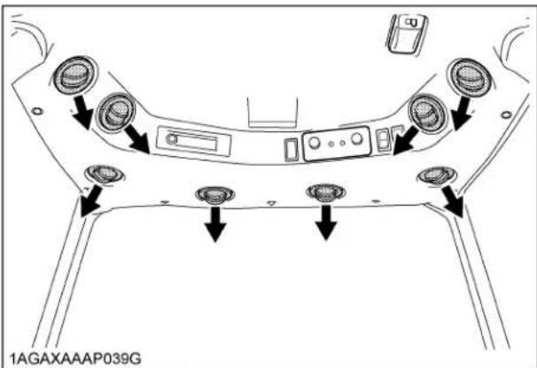
Air in the CAB and fresh air introduced into the CAB flow as shown below. Adjust the eight air ports to obtain the desired condition.

(1) Control panel
(A) Inner air recirculation
(2) Side air outlet (face area)
(3) Front air outlet
(4) Door air outlet

(A) Fresh air inlet
Air Control Vent
◆Front air outlet
The front air outlets can be independently adjusted as required. To defrost the windshield, rotate the outlets toward the windshield.
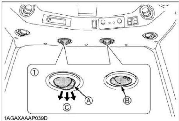
(1) Front air outlet (A) "OPEN"
(B) "CLOSED"
(C) "WINDSHIELD"
◆Side air outlet and door air outlet
The side and door air outlets can be adjusted to direct air on to the operator, door window or the rear of the CAB.
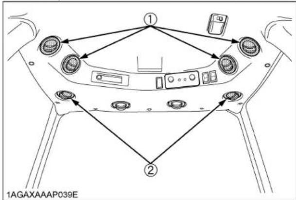
(1) Side air outlet
(2) Door air outlet
NOTE :
- If the airflow rate at the face is too low, close the door air outlet.

CAUTION
To avoid personal injury;
- Replace the water hoses every 2 years.
● Daily inspection
Have the tractor repaired immediately if any of the following defects are discovered.
(Such defects may cause burns or injury. They may also cause engine seizure or other serious failure.)
●Scratches, cracks or swelling in water hoses.
● Water leakage at water hose joints.
● Missing or damaged water hose protective wrap or grommets.
- Loose mounting bolts, damaged brackets.
● Do not touch the water hoses and the heater with your hand. You may get burned.
- If the window fails to defrost in extreme conditions or becomes cloudy when dehumidifying the CAB, wipe off moisture with a soft cloth.
- Do not block all the air outlets of the air conditioner. A problem could occur.
Control Panel

1AGAXAAAP042B
(1) Temperature control dial (A) "WARM"
(2) Recirculation / fresh air selection switch (B) "COOL" with indicator light
(3) Air conditioner switch with indicator light
(4) Blower switch
◆Temperature Control Dial
Set this dial at the desired position to obtain the optimum air temperature. Turn the dial in the "WARM" direction to obtain warmer air. Turn it in the "COOL" direction to obtain cooler air.
◆Blower Switch
Air volume can be changed in 4 steps. At the "4" position, the largest air volume is obtained.
◆Air Conditioner Switch
Push this switch to activate the air conditioner. An indicator light will light up when the switch is set to "ON". Push the switch again to turn the air conditioner off, in which case the indicator light will be off.
NOTE :
- With the blower switch at the "OFF" position, the indicator light will not light up even when the air conditioner switch is set to "ON".
IMPORTANT :
- To operate the air conditioner after the tractor has not been used for one week or longer, run the engine at idling speed first and then set the air conditioner switch to "ON". Keep this for one minute or so. If the air conditioner switch is set to "ON" with the engine running at high rpm, the compressor may get in trouble.
◆Recirculation / fresh air selection switch
Each time the switch is pressed, the air flow position changes for "RECIRCULATION" or "FRESH AIR". An indicator light will light up when the switch is set to "RECIRCULATION". And the indicator light will be off when the switch is set to "FRESH AIR".
FRESH AIR: (Indicator: OFF)
Fresh air will flow into the CAB. This is helpful when you work in dusty conditions or if the glass windows get foggy.
RECIRCULATION: (Indicator: ON)
In-CAB air will be recirculated. This is useful for cooling or heating the CAB quickly or keeping it extra cool or warm.

(1) Recirculation / fresh air selection switch with indicator light
(A) "RECIRCULATION"
(B) "FRESH AIR"
NOTE :
- When heating, do not keep the switch at the "RECIRCULATION" position for a long time. The windshield easily gets foggy.
● While working in a dusty conditions, keep the switch at the "FRESH AIR" position. This increases the pressure in the CAB, which helps prevent dust from coming into the CAB.
Operation
◆Heating
- Set the recirculation / fresh air selection switch to the "FRESH AIR" position. To raise the temperature in the CAB quickly, set this switch to the "RECIRCULATION" position.
- Adjust the blower switch and the temperature control dial to achieve a comfortable temperature level.
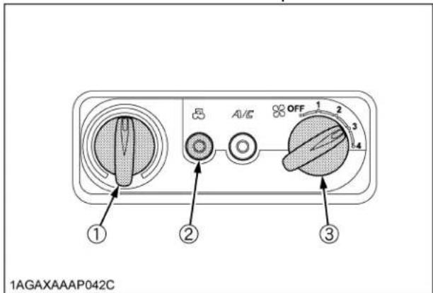
(1) Temperature control dial
(2) Recirculation / fresh air selection switch with indicator light
(3) Blower switch

◆Cooling or dehumidifying-heating
- Set the recirculation / fresh air selection switch to the "FRESH AIR" position. To lower the temperature in the CAB quickly, set this switch to the "RECIRCULATION" position.
- Press and turn on the air-conditioner switch with indicator.
- Turn on the blower switch.
- Adjust the temperature control dial to the "COOL" or an intermediate position to achieve a comfortable temperature level.
NOTE :
- In summer when the heater is not used, keep the temperature control dial at the max "COOL" (end of counterclockwise) position. Otherwise, hot air will raise the temperature in the CAB.

(1) Temperature control dial
(A) "WARM"
(2) Recirculation / fresh air selection switch with indicator light
(B) "COOL"
(3) Air conditioner switch with indicator light
(4) Blower switch
◆Foot warming and head cooling
- In the cooling or dehumidifying-heating mode, set the temperature control dial at the center position area.
- Open the front air outlet and the door air outlet direct it to your feet. Close the side air outlet.
- You can feel your head cool and your feet warm.

(1) Temperature control dial (A) Center position area
flowchart
graph TD
    A["Component A"] --> B["Component B"]
    A --> C["Component C"]
    A --> D["Component D"]
    A --> E["Component E"]
    A --> F["Component F"]
    style A fill:#f9f,stroke:#333
    style B fill:#ccf,stroke:#333
    style C fill:#cfc,stroke:#333
    style D fill:#fcc,stroke:#333
    style E fill:#cff,stroke:#333
    style F fill:#ffc,stroke:#333
(A) "OPEN"
(B) "CLOSED"
◆Defrosting or demisting
To defrost or demist the windshield, take the following steps.
- Open the front air outlet and the door air outlet direct it to the windshield. Close the side air outlet.
- Set the recirculation / fresh air selection switch to the "FRESH AIR" position.
- Set the blower switch and the temperature control dial to the "4" and max "WARM" (end of clockwise) positions, respectively.

(1) Temperature control dial
(2) Recirculation / fresh air selection switch with indicator light

flowchart
graph TD
    A["Component A"] --> B["Component B"]
    A --> C["Component C"]
    A --> D["Component D"]
    A --> E["Component E"]
    A --> F["Component F"]
    A --> G["Component G"]
    style A fill:#f9f,stroke:#333
    style B fill:#ccf,stroke:#333
    style C fill:#cfc,stroke:#333
    style D fill:#fcc,stroke:#333
    style E fill:#cff,stroke:#333
    style F fill:#ffc,stroke:#333
    style G fill:#fcf,stroke:#333
(A) "OPEN"
(B) "CLOSED"
REAR / SIDE DEFOGGER WITH TIMER (if equipped)
To activate the rear / side window defoggers, press the switch marked ☐ while the key switch is in the "ON" position. Then, the yellow light on the switch turns on. After about 15 minutes, the defoggers automatically turn off as well as the yellow light. To turn the defogger off, press the switch once more.

(1) Defogger switch
(2) Yellow light
IMPORTANT :
● The battery will discharge if the defogger and the key switch remain in the "ON" or "ACC" positions with the engine stopped.
Always use the defogger with the engine running.
ELECTRICAL OUTLET
Electrical Outlet
A electrical outlet is supplied for use with implement.

(1) Accessory electrical outlet (Total 20 A)
MAINTENANCE
SERVICE INTERVALS
(Only the Check Points for Tractors with CAB)
| No. | Items Daily | Indication on hour meter | Interval | Ref. page | |||||||||
| 100 | 200 | 300 | 400 | 500 | 600 | 700 | 800 | ||||||
| 1 | Clogging of air conditioner condenser screen | Clean 12 | ○ | ||||||||||
| 2 | Tension of air conditioner drive belt Adjust | every 200 Hr | 13 | ○ | ○ | ○ | ○ | ||||||
| 3 | Clogging of inner air filter Clean every 200 | Hr 12 | ○ | ○ | ○ | ○ | |||||||
| 4 | Clogging of fresh air filter Clean every 200 | Hr 12 | ○ | ○ | ○ | ○ | |||||||
| 5 | Clogging of air conditioner condenser Check | every 200 | Hr 13 | ○ | ○ | ○ | ○ | ||||||
| 6 | Air conditioner pipes and hoses | Check every 1 year | 13 | ||||||||||
| Replace every 4 years | 13 | ||||||||||||
| 7 | CAB isolation cushion | Check every | 1 year | 13 | |||||||||
| 8 | Washer liquid | Check | service as required | 14 | |||||||||
| 9 | Amount of refrigerant (gas) | Check | service as required | 14 | |||||||||
PERIODIC SERVICE
DAILY CHECK
■Cleaning Air Conditioner Condenser Screen

WARNING
To avoid personal injury or death:
-
Be sure to stop the engine before removing the screen.
● The condenser and receiver become hot while the air conditioner is running. Before checking or cleaning them, wait enough until they cool down. -
Detach the air conditioner condenser screen and remove all foreign materials.

(1) Air conditioner condenser screen
IMPORTANT :
- Grill and screen must be clean from debris to prevent engine from overheating and to allow good air intake for air cleaner.
EVERY 200 HOURS
■Cleaning Inner Air Filter
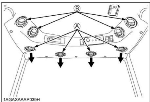
Press the inner air filter in the arrow-marked directions to unlock it and remove the inner filter, and blow air from the direction opposite to the filter's normal air flow.
Pressure of compressed air must be under 205 kPa (2.1 kgf/cm², 30 psi).

(1) Inner air filter (A) "PUSH"
■Cleaning Fresh Air Filter
Remove the knob bolts and pull out filter.

(1) Fresh air filter
(A) Air inlet port
(2) Cover
(3) Knob bolt
NOTE :
- Attach the filter and cover as the illustration above.
◆Cleaning the air filter
- Normal use
Blow air from the opposite direction to the filter's normal air flow.
Pressure of compressed air must be under 205 kPa (2.1 kgf/cm ^4 , 30 psi).
IMPORTANT :
- Do not hit the filter. If the filter becomes deformed, dust may enter into the air-conditioner, which may cause damage and malfunction.
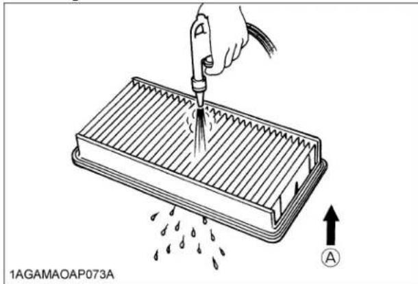
(A) "AIR CONDITIONER AIRFLOW"
NOTE :
- If the filter is very dirty:
Dip the filter in lukewarm water with mild dish washing detergent.
Move it up and down as well as left and right to loosen dirt. Rinse the filter with clean water and let it air-dry.
IMPORTANT :
- Do not use gasoline, thinner or similar chemicals to clean the filter as damage to the filter may occur.
- It may also cause an unpleasant odor in the CAB when the system is used next.
■Checking Air Conditioner Condenser
Check air conditioner condenser to be sure it is clean of debris.
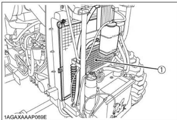
(1) Air conditioner condenser
■Adjusting Air-Conditioner Belt Tension

WARNING
To avoid personal injury or death:
- Be sure to stop the engine before checking belt tension.
| Proper air-conditioner belt tension | A deflection of between 10 to 12 mm (0.4 to 0.48 in.) when the belt is pressed (98 N [10 kgf, 22.1 lbs.]) in the middle of the span. |
- Stop the engine and remove the key.
- Apply moderate thumb pressure to belt between pulleys.
- If tension is incorrect, loosen the tension pulley mounting nut and turn the adjusting bolt to adjust the belt tension within acceptable limits.
- Replace air-conditioner belt if it is damaged.

(1) Adjusting bolt
(A) Check the belt tension
(2) Tension pulley mounting nut
EVERY 1 YEAR
■ Checking Air-Conditioner Pipe and Hose
- Check to see that all lines and hose clamps are tight and not damaged.
- If hoses and clamps are found worn or damaged, consult your local KUBOTA Dealer for this service.
■ Checking CAB Isolation Cushion
Check the cushion for any breakage or fatigue. Replace them if they are deteriorated.
EVERY 4 YEARS
■Replacing Air Conditioner Hose
Consult your local KUBOTA Dealer for this service.
SERVICE AS REQUIRED
■Lubricating Points

(1) Door hinge
(2) Rear window hinge
■Adding Washer Liquid
Add a proper amount of automobile washer liquid.

(1) Washer liquid tank
Washer tank capacity 2.0 L (2.1 U.S.qts.)
■ Checking the Amount of Refrigerant (gas)

WARNING
To avoid personal injury or death:
● Liquid contact with eyes or skin may cause frostbite.
● In the event of a leakage, wear safety goggles. Escaping refrigerant can cause severe injuries to eyes.
● In contact with a flame, R134a refrigerant gives a toxic gas.
- Do not disconnect any part of the refrigeration circuit of the air conditioning system. Consult your local KUBOTA Dealer for assistance and service.
A shortage of refrigerant impairs the air-conditioner performance. Check the following points. If it is indicated that the amount of refrigerant is extremely low, ask your dealer to inspect and charge.
◆ Checking procedure
- Run the air-conditioner in the following conditions.
● Engine speed: About 1500 rpm
● Temperature control dial: Maximum cooling position
● Fan switch: Highest blow (HI)
● Air-conditioner switch: ON
- Look into the sight glass to see if the refrigerant is flowing through its circuit.
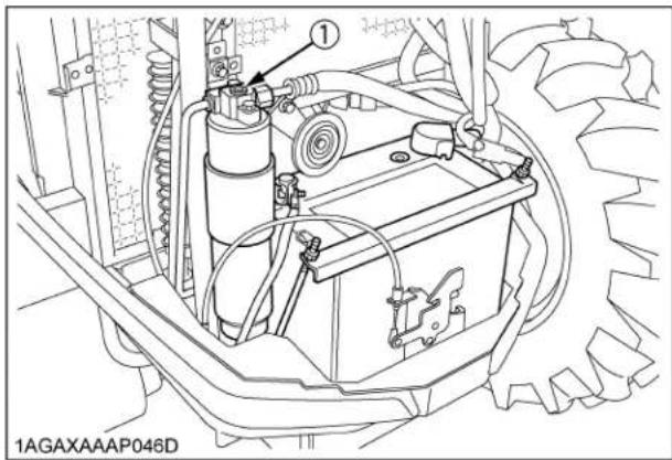
(1) Sight glass

Proper
Little or no air bubbles in the refrigerant flow.

Low
Lots of air bubbles in the refrigerant flow (air bubbles or foam passing continuously).

Overfull or no refrigerant
Colorless and transparent.
1AGAMAOAP077A
IMPORTANT :
● Charge only with R134a not R12 refrigerant (gas).
APPENDICES
INDEX
Air Conditioner Condenser 13
Air Conditioner Condenser Screen....12
Air Conditioner Hose 13
Air Control Vent 6
Air-Conditioner Belt Tension 13
Air-Conditioner Pipe and Hose....13
Airflow....5
CAB Isolation Cushion 13
Control Panel....7
Dome Light....4
Door....3
Door....3
Electrical Outlet 10
Emergency Exit 4
Fresh Air Filter....12
Front Wiper / Washer Switch....5
Front Work Light....4
Inner Air Filter....12
Lubricating Points....14
Operation....8
Rear Window....3
Rear Wiper / Washer Switch (if equipped) .....5
Rear Work Light (if equipped) 5
Refrigerant (gas) 14
Side Window 4
Washer Liquid 14
Wipers in Cold Season....5
Work Light Switch....4
- OPERATOR'S MANUAL
- KUBOTA
- TRACTOR
- ABBREVIATION LIST
- California Proposition 65
- ▲ WARNING ▲
- KUBOTA Corporation is …
- FOREWORD
- SAFETY FIRST
- CONTENTS
- SAFE OPERATION....▲-1
- SPECIFICATIONS....1
- SPECIFICATION TABLE 1
- CAB OPERATION 3
- DOOR AND WINDOW 3
- DOME LIGHT 4
- WORK LIGHT 4
- WIPER 5
- AIR CONDITIONER....5
- REÀR / SIDE DEFOGGER WITH TIMER (if equipped).... 10
- ELECTRICAL OUTLET 10
- MAINTENANCE....11
- SERVICE INTERVALS 11
- PERIODIC SERVICE....12
- DAILY CHECK 12
- EVERY 200 HOURS....12
- EVERY 1 YEAR....13
- EVERY 4 YEARS....13
- SERVICE AS REQUIRED....14
- SAFE OPERATION
- ■DANGER, WARNING AND CAUTION LABELS
- WARNING
- BEFORE DISMOUNTING TRACTOR:
- TO AVOID INJURY OR DEATH FROM ROLL-OVER:
- CAUTION
- TO AVOID PERSONAL INJURY:
- ■ CARE OF DANGER, WARNING AND CAUTION LABELS
- SPECIFICATIONS
- CAB OPERATION
- DOOR AND WINDOW
- ■Locking and Unlocking the Door
- ■Opening the Door
- ■Rear Window
- ■Side Window
- Emergency Exit
- DOME LIGHT
- ■Dome Light
- WORK LIGHT
- ■Work Light Switch
- ■Rear Work Light (if equipped)
- WIPER
- ■Front Wiper / Washer Switch
- ■Rear Wiper / Washer Switch (if equipped)
- IMPORTANT :
- ■Using the Wipers in Cold Season
- AIR CONDITIONER
- Airflow
- Air Control Vent
- ◆Front air outlet
- ◆Side air outlet and door air outlet
- NOTE :
- Control Panel
- ◆Temperature Control Dial
- ◆Blower Switch
- ◆Air Conditioner Switch
- ◆Recirculation / fresh air selection switch
- Operation
- ◆Heating
- ◆Cooling or dehumidifying-heating
- ◆Foot warming and head cooling
- ◆Defrosting or demisting
- REAR / SIDE DEFOGGER WITH TIMER (if equipped)
- ELECTRICAL OUTLET
- MAINTENANCE
- PERIODIC SERVICE
- DAILY CHECK
- ■Cleaning Air Conditioner Condenser Screen
- EVERY 200 HOURS
- ■Cleaning Inner Air Filter
- ■Cleaning Fresh Air Filter
- ◆Cleaning the air filter
- ■Checking Air Conditioner Condenser
- ■Adjusting Air-Conditioner Belt Tension
- EVERY 1 YEAR
- ■ Checking Air-Conditioner Pipe and Hose
- ■ Checking CAB Isolation Cushion
- EVERY 4 YEARS
- ■Replacing Air Conditioner Hose
- SERVICE AS REQUIRED
- ■Lubricating Points
- ■Adding Washer Liquid
- ■ Checking the Amount of Refrigerant (gas)
- ◆ Checking procedure
- APPENDICES
- INDEX
Brand : KUBOTA
Model : L5460HSTCC
Category : Tractor