
UTM10 - Firewall NETGEAR - Free user manual and instructions
Find the device manual for free UTM10 NETGEAR in PDF.


| Product Type | Unified Threat Management (UTM) Firewall / VPN Gateway |
| Model | NETGEAR UTM10 |
| Dimensions | 8.5 x 5.1 x 1.2 in (216 x 130 x 30 mm) |
| Weight | 1.3 lbs (0.59 kg) |
| Power Supply | 12V DC, 1.5A external adapter |
| Ports | 4 Gigabit LAN + 1 Gigabit WAN + 1 USB 2.0 for management |
| Firewall Throughput (Stateful) | 100 Mbps |
| VPN Throughput (IPSec) | 10 Mbps |
| IPS Throughput | 10 Mbps |
| Antivirus Throughput | 10 Mbps |
| Max Concurrent Sessions | 10,000 |
| VPN Tunnels | Up to 20 |
| Recommended User Capacity | 10-25 users |
| Memory | 256 MB RAM |
| Flash Storage | 128 MB |
| Management | Web interface, CLI, SNMP |
| Security Features | Stateful firewall, IPS, antivirus, anti-spam, web filtering, intrusion prevention, VPN (IPSec/SSL), bandwidth management, QoS, VLAN support |
| MAC Address Filtering | Yes |
| DHCP Server | Built-in |
| Logging & Reporting | Internal logs, SNMP, email alerts |
| Firmware Updates | Via web interface |
| Maintenance & Cleaning | Use a dry cloth; do not use liquids or sprays. Keep vents clear. |
| Safety | Use only the supplied power adapter. Keep away from water and heat sources. |
| Spare Parts & Repairability | Contact NETGEAR support for replacement parts. No user-serviceable internal components. |
| General Information | Compliant with FCC, CE, RoHS. Operating temperature: 0-40°C. Humidity: 10-90% non-condensing. |
Frequently Asked Questions - UTM10 NETGEAR
User questions about UTM10 NETGEAR
0 question about this device. Answer the ones you know or ask your own.
Ask a new question about this device
Download the instructions for your Firewall in PDF format for free! Find your manual UTM10 - NETGEAR and take your electronic device back in hand. On this page are published all the documents necessary for the use of your device. UTM10 by NETGEAR.
USER MANUAL UTM10 NETGEAR
ProSecure Unified Threat Management (UTM) Appliance
Support
Thank you for choosing NETGEAR.
After installing your device, locate the serial number on the label of your product and use it to register your product at https://my.netgear.com. You must register your product before you can use NETGEAR telephone support. NETGEAR recommends registering your product through the UTM's Registration screen (see Register the UTM with NETGEAR on page 65). You can also register your product through the NETGEAR website. For product updates and web support, visit http://support.netgear.com.
Phone (US & Canada only): 1-888-NETGEAR.
Phone (Other Countries): Check the list of phone numbers at http://support.netgear.com/general/contact/default.aspx.
NETGEAR recommends that you use only the official NETGEAR support resources.
Trademarks
NETGEAR, the NETGEAR logo, and Connect with Innovation are trademarks and/or registered trademarks of NETGEAR, Inc. and/or its subsidiaries in the United States and/or other countries. Information is subject to change without notice. Other brand and product names are registered trademarks or trademarks of their respective holders. © NETGEAR, Inc. All rights reserved.
ProSecure Product Updates
Product updates are available on the NETGEAR website at http://prosecure.netgear.com or http://support.netgear.com.
ProSecure Forum
Visit http://prosecure.netgear.com/community/forum.php for information about the ProSecure forum and to become part of the ProSecure community.
Revision History
| Publication Part Number | Version Publish Date Comments | ||
| 202-10780-03 | 1.0 | October 2012 | Added the UTM25S, which supports the same features as the UTM9S.Stated support for the NETGEAR Network Management System NMS200.Updated the figures and menu paths in Chapter 6, Content Filtering and Optimizing Scans, because the Application Security configuration menu of the web management interface was revised and several minor features were added.Added Configure HTTPS Smart Block.Revised Use a Simple Network Management Protocol Manager because new SNMP features, including support for SNMPv3, were added.Revised Chapter 11, Monitor System Access and Performance because several minor features were added.Updated Appendix B, Wireless Network Module for the UTM9S and UTM25S, because the wireless network module now supports four wireless security profiles and the Wireless Settings configuration menu of the web management interface was revised. |
| 202-10780-03(continued) | 1.0(continued) | October 2012(continued) | (continued)AddedAppendix C, 3G/4G Dongles for the UTM9S and UTM25S.Added many more default values toAppendix H, Default Settings and Technical Specifications. |
| 202-10780-02 | 2.0 May 2012 | Updated the main | navigation menus and configurationmenus for many figures in the manual to show consistency in the presentation of the web management interface (GUI).Updated the outbound rules overview (seeTable 27) and inbound rules overview (Table 28).UpdatedFeatures That Reduce Traffic and Features That Increase Traffic. |
| 202-10780-02 | 1.0 April 2012 | Added new features for all UTM models:- Application control (seeConfigure Application Control)- Traffic metering for LAN usage (seeCreate Traffic Meter Profiles)- The use of custom user groups in firewall rules (seeOverview of Rules to Block or Allow Specific Kinds of Traffic and VLAN Rules)Application control and traffic metering also affect the way that firewall rules are implemented (seeOverview of Rules to Block or Allow Specific Kinds of Traffic)Added support of the following features for all UTM models (these features were previously supported on the UTM9S only):- ReadyNAS integration, quarantine options, and quarantine logs (seeConnect to a ReadyNAS and Configure Quarantine Settings, Query and Manage the Quarantine Logs, andAppendix E, ReadyNAS Integration)- PPTP server (seeConfigure the PPTP Server)- L2TP server (seeConfigure the L2TP Server)Revised the following existing features:- Firewall scheduling (seeSet a Schedule to Block or Allow Specific Traffic and Overview of Rules to Block or Allow Specific Kinds of Traffic)- IPS (seeEnable and Configure the Intrusion Prevention System)- System status, dashboard, and report functions (seeChapter 11, Monitor System Access and Performance)- Diagnostics (seeUse Diagnostics Utilities)Reorganized the web management interface (GUI) menus (for example, the Email Notification configuration menu link has been moved to the Monitoring main menu; the Custom Groups configuration menu link has been moved to the Users main menu) | |
| 202-10780-01 | 1.0 September | 2011 • Added the | UTM9S with the following major new features:- xDSL module (see Chapter 1, Introduction and Chapter 3, Manually Configure Internet and WAN Settings)- Wireless module (see Chapter 1, Introduction and Appendix B, Wireless Network Module for the UTM9S and UTM25S)- ReadyNAS integration, quarantine options, and quarantine logs (see Connect to a ReadyNAS and Configure Quarantine Settings, Query and Manage the Quarantine Logs, and Appendix E, ReadyNAS Integration)- PPTP server (see Configure the PPTP Server)- L2TP server (see Configure the L2TP Server)• Updated the VPN client sections with the new VPN client (see Chapter 7, Virtual Private Networking Using IPSec, PPTP, or L2TP Connections) |
| 202-10674-02 | 1.0 March 2011 | • Added the UTM | 150.• Removed the platform-specific chapters and sections because the UTM5, UTM10, and UTM25 now support the same web management interface menu layout that was already supported on the UTM50. The major changes for the UTM5, UTM10, and UTM25 are documented in Chapter 3, Manually Configure Internet and WAN Settings, and in the following sections:- Set Exception Rules for Web and Application Access- Configure Authentication Domains, Groups, and Users• Added new features (for all UTM models). The major new features are documented in the following sections:- Electronic Licensing-VLAN Rules- Create Service Groups- Create IP Groups-Manage SSL Certificates for HTTPS Scanning- Update the Firmware- View, Schedule, and Generate Reports |
| 202-10674-01 | 1.0 | September 2010 | • Added the UTM50 and UTM50-specific chapters and sections.• Revised the DMZ WAN and LAN DMZ default policies. |
| 202-10482-03 | 1.0 May 2010 | • Applied numerous | nontechnical edits.• Added the Requirements for Entering IP Addresses section.• Added a note about the processing of normal email traffic in the Configure Distributed Spam Analysis section.• Updated the NTP section. |
| 202-10482-02 | 1.0 January 2010 | 10 Updated the web | management interface screens, made the manual platform-independent, added a model comparison table, and removed performance specifications (see marketing documentation for such specifications). |
| 202-10482-01 | 1.0 September | 2009 Initial publication | of this reference manual. |
Contents
Chapter 1 Introduction
What Is the ProSecure Unified Threat Management (UTM) Appliance? . .15
Key Features and Capabilities 16
Multiple WAN Port Models for Increased Reliability or
Outbound Load Balancing 17
Wireless Features....18
DSL Features 18
Advanced VPN Support for Both IPSec and SSL.....18
A Powerful, True Firewall 19
Stream Scanning for Content Filtering .....19
Security Features 20
Autosensing Ethernet Connections with Auto Uplink .....20
Extensive Protocol Support 21
Easy Installation and Management 21
Maintenance and Support .....22
Model Comparison 22
Service Registration Card with License Keys. 23
Package Contents 24
Hardware Features....24
Front Panel UTM5 and UTM10 25
Front Panel UTM25 26
Front Panel UTM50 .....26
Front Panel UTM150 27
Front Panel UTM9S and UTM25S and Network Modules .....28
LED Descriptions, UTM5, UTM10, UTM25, UTM50, and UTM150 . . . 30
LED Descriptions, UTM9S, UTM25S, and their Network Modules. . . . 32
Rear Panel UTM5, UTM10, and UTM25 33
Rear Panel UTM50 and UTM150....34
Rear Panel UTM9S and UTM25S 35
Bottom Panels with Product Labels 36
Choose a Location for the UTM 39
Use the Rack-Mounting Kit. 40
Chapter 2 Use the Setup Wizard to Provision the UTM in Your Network
Steps for Initial Connection....41
Qualified Web Browsers....42
Requirements for Entering IP Addresses .....42
Log In to the UTM. 42
ProSecure Unified Threat Management (UTM) Appliance
Web Management Interface Menu Layout 44
Use the Setup Wizard to Perform the Initial Configuration. 47
Setup Wizard Step 1 of 10: LAN Settings. 48
Setup Wizard Step 2 of 10: WAN Settings ..... 51
Setup Wizard Step 3 of 10: System Date and Time. 54
Setup Wizard Step 4 of 10: Services ..... 55
Setup Wizard Step 5 of 10: Email Security. 57
Setup Wizard Step 6 of 10: Web Security 58
Setup Wizard Step 7 of 10: Web Categories to Be Blocked. . . . . . . . . 60
Setup Wizard Step 8 of 10: Email Notification ..... 62
Setup Wizard Step 9 of 10: Signatures & Engine. 63
Setup Wizard Step 10 of 10: Saving the Configuration .....64
Register the UTM with NETGEAR 65
Use the Web Management Interface to Activate Licenses. . . . . . . . . 65
Electronic Licensing 67
Automatic Retrieval of Licenses after a Factory Default Reset . . . . . . 67
Verify Correct Installation 68
Test Connectivity 68
Test HTTP Scanning 68
What to Do Next. 68
Chapter 3 Manually Configure Internet and WAN Settings
Internet and WAN Configuration Tasks....71
Automatically Detecting and Connecting the Internet Connections ..... 71
Manually Configure the Internet Connection 75
Configure the WAN Mode 80
Overview of the WAN Modes 80
Configure Network Address Translation (All Models)....81
Configure Classical Routing (All Models) 82
Configure Auto-Rollover Mode and the Failure Detection
Method (Multiple WAN Port Models) 82
Configure Load Balancing and Optional Protocol Binding
(Multiple WAN Port Models) 85
Configure Secondary WAN Addresses 89
Configure Dynamic DNS 91
Set the UTM's MAC Address and Configure Advanced WAN Options . . . 94
Additional WAN-Related Configuration Tasks 97
Chapter 4 LAN Configuration
Manage Virtual LANs and DHCP Options 98
Port-Based VLANs 99
Assign and Manage VLAN Profiles 100
VLAN DHCP Options 101
Configure a VLAN Profile 103
Configure VLAN MAC Addresses and Advanced LAN Settings. . . . . 108
Configure Multihome LAN IP Addresses on the Default VLAN ..... 109
Manage Groups and Hosts (LAN Groups) 111
ProSecure Unified Threat Management (UTM) Appliance
Manage the Network Database .....112
Change Group Names in the Network Database .....115
Set Up Address Reservation 116
Configure and Enable the DMZ Port .....117
Manage Routing 121
Configure Static Routes .....121
Configure Routing Information Protocol....123
Static Route Example 126
Chapter 5 Firewall Protection
About Firewall Protection 127
Administrator Tips. 128
Overview of Rules to Block or Allow Specific Kinds of Traffic .....128
Outbound Rules (Service Blocking) .....129
Inbound Rules (Port Forwarding)....133
Order of Precedence for Rules....138
Configure LAN WAN Rules 139
Create LAN WAN Outbound Service Rules .....140
Create LAN WAN Inbound Service Rules .....141
Configure DMZ WAN Rules 142
Create DMZ WAN Outbound Service Rules. 144
Create DMZ WAN Inbound Service Rules 144
Configure LAN DMZ Rules....145
Create LAN DMZ Outbound Service Rules 147
Create LAN DMZ Inbound Service Rules. 147
Examples of Firewall Rules 148
Inbound Rule Examples ..... 148
Outbound Rule Example....153
Configure Other Firewall Features 154
VLAN Rules 154
Attack Checks, VPN Pass-through, and Multicast Pass-through . . . . 157
Set Session Limits ....160
Manage the Application Level Gateway for SIP Sessions and VPN Scanning 161
Create Services, QoS Profiles, Bandwidth Profiles, and
Traffic Meter Profiles 162
Add Customized Services....163
Create Service Groups 165
Create IP Groups 167
Create Quality of Service Profiles....169
Create Bandwidth Profiles .....171
Create Traffic Meter Profiles....174
Set a Schedule to Block or Allow Specific Traffic. .....177
Enable Source MAC Filtering 179
Set Up IP/MAC Bindings 181
Configure Port Triggering .....183
Configure Universal Plug and Play....186
Enable and Configure the Intrusion Prevention System.....187
Chapter 6 Content Filtering and Optimizing Scans
About Content Filtering and Scans. 192
Default Email and Web Scan Settings .....193
Configure Email Protection....194
Customize Email Protocol Scan Settings....194
Customize Email Antivirus and Notification Settings ..... 196
Email Content Filtering 199
Protect Against Email Spam. 202
Configure Web and Services Protection .....210
Customize Web Protocol Scan Settings.....210
Configure HTTPS Smart Block. 212
Configure Web Malware or Antivirus Scans. 216
Configure Web Content Filtering 218
Configure Web URL Filtering .....224
Configure HTTPS Scanning and SSL Certificates .....228
How HTTPS Scanning Works 228
Configure the HTTPS Scan Settings 230
Manage SSL Certificates for HTTPS Scanning .....231
Specify Trusted Hosts for HTTPS Scanning .....235
Configure the SSL Settings for HTTPS Scanning .....237
Configure FTP Scanning .....238
Customize FTP Antivirus Settings 238
Configure FTP Content Filtering. 239
Configure Application Control. 240
Set Exception Rules for Web and Application Access . . . . . . . . . . . . . . . . . . . . . . . . . . . . . . . . 248
Create Custom Categories for Exceptions for Web and
Application Access 258
Set Scanning Exclusions for IP Addresses and Ports ..... 262
Chapter 7 Virtual Private Networking Using IPSec, PPTP, or L2TP Connections
Considerations for Dual WAN Port Systems
(Multiple WAN Port Models Only)....264
Use the IPSec VPN Wizard for Client and Gateway Configurations . . . .266
Create Gateway-to-Gateway VPN Tunnels with the Wizard .....266
Create a Client-to-Gateway VPN Tunnel 271
Test the Connection and View Connection and Status Information. . . . 287
Test the NETGEAR VPN Client Connection .....287
NETGEAR VPN Client Status and Log Information .....289
View the UTM IPSec VPN Connection Status 289
View the UTM IPSec VPN Log. 290
Manage IPSec VPN and IKE Policies 291
Manage IKE Policies .....292
Manage VPN Policies....300
Configure Extended Authentication (XAUTH) 308
Configure XAUTH for VPN Clients .....309
User Database Configuration . . . . . . . . . . . . . . . . . . . . . . . . . . . . . . . . . . . . . . . . . . . . . . . . . . . . . . . . . . 310
ProSecure Unified Threat Management (UTM) Appliance
RADIUS Client and Server Configuration. 310
Assign IP Addresses to Remote Users (Mode Config)....312
Mode Config Operation....312
Configure Mode Config Operation on the UTM .....312
Configure the ProSafe VPN Client for Mode Config Operation .....319
Test the Mode Config Connection .....326
Modify or Delete a Mode Config Record....327
Configure Keep-Alives and Dead Peer Detection .....328
Configure Keep-Alives ....328
Configure Dead Peer Detection .....329
Configure NetBIOS Bridging with IPSec VPN ....330
Configure the PPTP Server ....331
View the Active PPTP Users 333
Configure the L2TP Server....334
View the Active L2TP Users ....336
For More IPSec VPN Information....336
Chapter 8 Virtual Private Networking Using SSL Connections
SSL VPN Portal Options....337
Build a Portal Using the SSL VPN Wizard .....338
SSL VPN Wizard Step 1 of 6 (Portal Settings) .....339
SSL VPN Wizard Step 2 of 6 (Domain Settings) .....342
SSL VPN Wizard Step 3 of 6 (User Settings)....347
SSL VPN Wizard Step 4 of 6 (Client IP Addresses and Routes) . . . . .348
SSL VPN Wizard Step 5 of 6 (Port Forwarding)....350
SSL VPN Wizard Step 6 of 6 (Verify and Save Your Settings).....351
Access the New SSL VPN Portal .353
View the UTM SSL VPN Connection Status. . . . . . . . . . . . . . . . . . . . . . . . . . . . . . . . . . . . . . . . . . . . . . . . . . 356
View the UTM SSL VPN Log 357
Manually Configure and Modify SSL Portals .....357
Manually Create or Modify the Portal Layout . . . . . . . . . . . . . . . . . . . . . . . . . . . . . . . . . . . . . . . . . . . . . . 359
Configure Domains, Groups, and Users. 362
Configure Applications for Port Forwarding .....363
Configure the SSL VPN Client 365
Use Network Resource Objects to Simplify Policies. . . . . . . . . . . . . . . . . . . . . . . . . . . . . . . . . . . . . . . . . . . . . . . . . . . . . . 369
Configure User, Group, and Global Policies. . . . . . . . . . . . . . . . . . . . . . . . . . . . . . . . . . . . . . . . . . . . . . . . . . . 371
For More SSL VPN Information ....377
Chapter 9 Manage Users, Authentication, and VPN Certificates
Authentication Process and Options .....378
Configure Authentication Domains, Groups, and Users. . . . . . . . . . . . . . . . . . . . 380
Login Portals....380
Active Directories and LDAP Configurations .....384
Configure Domains....388
Configure Groups .....394
Configure Custom Groups 397
ProSecure Unified Threat Management (UTM) Appliance
Configure User Accounts 401
Set User Login Policies 404
Change Passwords and Other User Settings. 408
DC Agent 409
Configure RADIUS VLANs 415
Configure Global User Settings 416
View and Log Out Active Users 417
Manage Digital Certificates for VPN Connections 419
VPN Certificates Screen. 420
Manage CA Certificates 421
Manage Self-Signed Certificates .....422
Manage the Certificate Revocation List 426
Chapter 10 Network and System Management
Performance Management. 428
Bandwidth Capacity 428
Features That Reduce Traffic....429
Features That Increase Traffic 432
Use QoS and Bandwidth Assignments to Shift the Traffic Mix. . . . . . 435
Monitoring Tools for Traffic Management. 436
System Management 436
Change Passwords and Administrator and Guest Settings . . . . . . . 436
Configure Remote Management Access .....438
Use a Simple Network Management Protocol Manager. 440
Manage the Configuration File 445
Update the Firmware 448
Update the Scan Signatures and Scan Engine Firmware ..... 454
Configure Date and Time Service 456
Connect to a ReadyNAS and Configure Quarantine Settings .....458
Log Storage 459
Connect to a ReadyNAS 459
Configure the Quarantine Settings ..... 460
Chapter 11 Monitor System Access and Performance
Enable the WAN Traffic Meter 462
Configure Logging, Alerts, and Event Notifications 466
Configure the Email Notification Server 466
Configure and Activate System, Email, and Syslog Logs. . . . . . . . . . . . . 467
How to Send Syslogs over a VPN Tunnel between Sites ..... 471
Configure and Activate Update Failure and Attack Alerts 473
Configure and Activate Firewall Logs. 476
Monitor Real-Time Traffic, Security, and Statistics 477
Monitor Application Use in Real Time 483
View Status Screens 486
View the System Status 486
View the Active VPN Users 499
View the VPN Tunnel Connection Status. . . . . . . . . . . . . . . . . . . . . . . . . . . . . . . . . . . . . . . . . . . . . . . 500
ProSecure Unified Threat Management (UTM) Appliance
View the Active PPTP and L2TP Users .....501
View the Port Triggering Status .....502
View the WAN, xDSL, or USB Port Status .....504
View Attached Devices and the DHCP Leases .....505
Query and Manage the Logs ....507
Overview of the Logs ....508
Query and Download Logs....509
Example: Use the Logs to Identify Infected Clients .....513
Log Management ....514
Query and Manage the Quarantine Logs ....514
Query the Quarantined Logs ....515
View and Manage the Quarantined Spam Table .....517
View and Manage the Quarantined Infected Files Table .....518
Spam Reports for End Users ....519
View, Schedule, and Generate Reports .....520
Enable Application Session Monitoring .....521
Report Filtering Options 522
Use Report Templates and View Reports Onscreen .....524
Schedule, Email, and Manage Reports .....529
Use Diagnostics Utilities....531
Use the Network Diagnostic Tools ....532
Use the Real-Time Traffic Diagnostics Tool . . . . . . . . . . . . . . . . . . . . . . . . . . . . . . . . . . . . . . . . . . . . . . . . . . . . . . . . . 533
Gather Important Log Information and Generate a
Network Statistics Report ....534
Perform Maintenance on the USB Device, Reboot the UTM, or Shut Down the UTM....536
Chapter 12 Troubleshoot and Use Online Support
Basic Functioning .....539
Verify the Correct Sequence of Events at Startup .....539
Power LED Not On....539
Test LED Never Turns Off ....539
LAN or WAN Port LEDs Not On ....540
Troubleshoot the Web Management Interface .....540
When You Enter a URL or IP Address, a Time-Out Error Occurs .....541
Troubleshoot the ISP Connection....541
Troubleshoot a TCP/IP Network Using a Ping Utility .....543
Test the LAN Path to Your UTM. 543
Test the Path from Your Computer to a Remote Device .....544
Restore the Default Configuration and Password .....545
Problems with Date and Time ....546
Use Online Support ....546
Enable Remote Troubleshooting .....546
Send Suspicious Files to NETGEAR for Analysis .....547
Access the Knowledge Base and Documentation .....548
Appendix A xDSL Network Module for the UTM9S and UTM25S
xDSL Network Module Configuration Tasks. 550
Configure the xDSL Settings 550
Automatically Detecting and Connecting the xDSL Internet Connection .553
Manually Configure the xDSL Internet Connection .....556
Configure the WAN Mode 561
Overview of the WAN Modes 561
Configure Network Address Translation....562
Configure Classical Routing .563
Configure Auto-Rollover Mode and the Failure Detection Method. . . .563
Configure Load Balancing and Optional Protocol Binding ..... 566
Configure Secondary WAN Addresses ....570
Configure Dynamic DNS 572
Set the UTM's MAC Address and Configure Advanced WAN Options . .574
Additional WAN-Related Configuration Tasks .....577
Appendix B Wireless Network Module for the UTM9S and UTM25S
Overview of the Wireless Network Module. 579
Configuration Order 579
Wireless Equipment Placement and Range Guidelines. . . . . . . . . . . . . . . . . . . . . . . . . . . . . . . . . . . . . . . . . . . . . . . . . . . . . . . . . . 579
Configure the Basic Radio Settings .....580
Operating Frequency (Channel) Guidelines....583
Wireless Data Security Options 584
Wireless Security Profiles....585
Before You Change the SSID, WEP, and WPA Settings ..... 587
Configure and Enable Wireless Profiles....588
Restrict Wireless Access by MAC Address 593
View the Access Point Status and Connected Clients
for a Wireless Profile 595
Configure a Wireless Distribution System 596
Configure Advanced Radio Settings 598
Configure WMM QoS Priority Settings. 600
Test Basic Wireless Connectivity 602
For More Information About Wireless Configurations 602
Appendix C 3G/4G Dongles for the UTM9S and UTM25S
3G/4G Dongle Configuration Tasks 603
Manually Configure the USB Internet Connection 604
Configure the 3G/4G Settings 608
Configure the WAN Mode 610
Overview of the WAN Modes 611
Configure Network Address Translation....612
Configure Classical Routing 613
Configure Load Balancing and Optional Protocol Binding ..... 614
Configure Dynamic DNS 618
Additional WAN-Related Configuration Tasks .....621
ProSecure Unified Threat Management (UTM) Appliance
Appendix D Network Planning for Dual WAN Ports (Multiple WAN Port Models Only)
What to Consider Before You Begin. 622
Plan Your Network and Network Management and Set Up Accounts .622
Cabling and Computer Hardware Requirements . . . . . . . . . . . . . . . . . . . . . . . . . . . . . . . . . . . . . . . . . . . . . . . 624
Computer Network Configuration Requirements .....624
Internet Configuration Requirements .....624
Overview of the Planning Process ....626
Inbound Traffic 627
Inbound Traffic to a Single WAN Port System . . . . . . . . . . . . . . . . . . . . . . . . . . . . . . . . . . . . . . . . . . . . . . . . . . . . . . . . . . 628
Inbound Traffic to a Dual WAN Port System . . . . . . . . . . . . . . . . . . . . . . . . . . . . . . . . . . . . . . . . . . . . . . . . . . . . . . 628
Virtual Private Networks....629
VPN Road Warrior (Client-to-Gateway) 630
VPN Gateway-to-Gateway 633
VPN Telecommuter (Client-to-Gateway through a NAT Router) . . . . .635
Appendix E ReadyNAS Integration
Supported ReadyNAS Models 638
Install the UTM Add-On on the ReadyNAS 639
Connect to the ReadyNAS on the UTM .....641
Appendix F Two-Factor Authentication
Why Do I Need Two-Factor Authentication? .644
What Are the Benefits of Two-Factor Authentication? . . . . . . . . . . . . . . . . . . . . . . . . . . . . . . . . . . . . . . . . . . . . . . . . . . 644
What Is Two-Factor Authentication?....645
NETGEAR Two-Factor Authentication Solutions .....645
Appendix G System Logs and Error Messages
System Log Messages ....649
System Startup 649
Reboot .649
NTP....650
Login/Logout....650
Firewall Restart. 651
IPSec Restart 651
WAN Status ....651
Traffic Metering Logs .655
Unicast, Multicast, and Broadcast Logs .655
Invalid Packet Logging 656
Service Logs....658
Content-Filtering and Security Logs 658
Web Filtering and Content-Filtering Logs . . . . . . . . . . . . . . . . . . . . . . . . . . . . . . . . . . . . . . . . . . . . . . . . . . . . . . . . . . 659
Spam Logs ....660
Traffic Logs....661
Malware Logs ....661
ProSecure Unified Threat Management (UTM) Appliance
Email Filter Logs....661
IPS Logs....662
Anomaly Behavior Logs 662
Application Logs 663
Routing Logs 663
LAN-to-WAN Logs 663
LAN-to-DMZ Logs. 664
DMZ-to-WAN Logs 664
WAN-to-LAN Logs 664
DMZ-to-LAN Logs. 665
WAN-to-DMZ Logs 665
Appendix H Default Settings and Technical Specifications
Default Settings 666
Physical and Technical Specifications 673
Appendix I Notification of Compliance (Wired)
Appendix J Notification of Compliance (Wireless)
Index
This chapter provides an overview of the features and capabilities of the NETGEAR ProSecure® Unified Threat Management (UTM) Appliance. This chapter contains the following sections:
- What Is the ProSecure Unified Threat Management (UTM) Appliance?
• Key Features and Capabilities
• Service Registration Card with License Keys - Package Contents
- Hardware Features
- Choose a Location for the UTM
Note: For more information about the topics covered in this manual, visit the Support website at http://support.netgear.com.
Note: Firmware updates with new features and bug fixes are made available from time to time at downloadcenter.netgear.com. Some products can regularly check the site and download new firmware, or you can check for and download new firmware manually. If the features or behavior of your product do not match what is described in this guide, you might need to update your firmware.
What Is the ProSecure Unified Threat Management (UTM) Appliance?
The ProSecure Unified Threat Management (UTM) Appliance, hereafter referred to as the UTM, connects your local area network (LAN) to the Internet through one or two external broadband access devices such as cable modems, DSL modems, satellite dishes, or wireless ISP radio antennas, or a combination of those. Dual wide area network (WAN) ports allow you to increase the effective data rate to the Internet by utilizing both WAN ports to
carry session traffic, or to maintain a backup connection in case of failure of your primary Internet connection.
As a complete security solution, the UTM combines a powerful, flexible firewall with a content scan engine that uses NETGEAR Stream Scanning technology to protect your network from denial of service (DoS) attacks or distributed DoS (DDoS) attacks, unwanted traffic, traffic with objectionable content, spam, phishing, and web-borne threats such as spyware, viruses, and other malware threats.
The UTM provides advanced IPSec and SSL VPN technologies for secure and simple remote connections. The use of Gigabit Ethernet LAN and WAN ports ensures high data transfer speeds.
The UTM is a plug-and-play device that can be installed and configured within minutes.
Key Features and Capabilities
- Multiple WAN Port Models for Increased Reliability or Outbound Load Balancing
- Wireless Features
- DSL Features
- Advanced VPN Support for Both IPSec and SSL
• A Powerful, True Firewall - Stream Scanning for Content Filtering
- Security Features
• Autosensing Ethernet Connections with Auto Uplink - Extensive Protocol Support
- Easy Installation and Management
- Maintenance and Support
- Model Comparison
The UTM provides the following key features and capabilities:
- For the single WAN port models, a single 10/100/1000 Mbps Gigabit Ethernet WAN port. For the multiple WAN port models, dual or quad 10/100/1000 Mbps Gigabit Ethernet WAN ports for load balancing or failover protection of your Internet connection, providing increased system reliability or increased data rate.
- Built-in four- or six-port 10/100/1000 Mbps Gigabit Ethernet LAN switch for fast data transfer between local network resources.
- Wireless network module (UTM9S and UTM25S only) for either 2.4-GHz or 5-GHz wireless modes.
- xDSL network module (UTM9S and UTM25S only) for ADSL and VDSL.
• 3G/4G dongle (UTM9S and UTM25S only) for wireless connection to an ISP. - Advanced IPSec VPN and SSL VPN support.
ProSecure Unified Threat Management (UTM) Appliance
- Depending on the model, bundled with a one-user license of the NETGEAR ProSafe VPN Client software (VPN01L).
- Advanced stateful packet inspection (SPI) firewall with multi-NAT support.
- Patent-pending Stream Scanning technology that enables scanning of real-time protocols such as HTTP.
- Comprehensive web and email security, covering six major network protocols: HTTP, HTTPS, FTP, SMTP, POP3, and IMAP.
- Malware database containing hundreds of thousands of signatures of spyware, viruses, and other malware threats.
- Very frequently updated malware signatures, hourly if necessary. The UTM can automatically check for new malware signatures as frequently as every 15 minutes.
- Multiple antispam technologies to provide extensive protection against unwanted mail.
- Application control for multiple categories of applications and individual applications to safeguard data, protect users, and enhance productivity.
- Easy, web-based wizard setup for installation and management.
- SNMP manageable with support for SNMPv1, SNMPv2, and SNMPv3.
- Support for the NETGEAR Network Management System NMS200.
- Front panel LEDs for easy monitoring of status and activity.
- Flash memory for firmware upgrade.
- Internal universal switching power supply.
Multiple WAN Port Models for Increased Reliability or Outbound Load Balancing
The UTM product line offers models with two broadband WAN ports. The second WAN port allows you to connect a second broadband Internet line that can be configured on a mutually exclusive basis to:
- Provide backup and rollover if one line is inoperable, ensuring that you are never disconnected.
- Load balance, or use both Internet lines simultaneously for outgoing traffic. A UTM with dual WAN ports balances users between the two lines for maximum bandwidth efficiency.
See Appendix D, Network Planning for Dual WAN Ports (Multiple WAN Port Models Only) for the planning factors to consider when implementing the following capabilities with dual WAN port gateways:
- Single or multiple exposed hosts
• Virtual private networks
Wireless Features
Wireless client connections are supported on the UTM9S and UTM25S with an NMWLSN wireless network module installed. The UTM9S and UTM25S support the following wireless features:
- 2.4-GHz radio and 5-GHz radio. Either 2.4-GHz band support with 802.11b/g/n/ wireless modes or 5-GHz band support with 802.11a/n wireless modes.
- Wireless security profiles. Support for up to four wireless security profiles, each with its own SSID.
- WMM QoS priority. Wi-Fi Multimedia (WMM) Quality of Service (QoS) priority settings to map one of four queues to each Differentiated Services Code Point (DSCP) value.
- Wireless Distribution System (WDS). WDS enables expansion of a wireless network through two or more access points that are interconnected.
- Access control. The Media Access Control (MAC) address filtering feature can ensure that only trusted wireless stations can use the UTM to gain access to your LAN.
- Hidden mode. The SSID is not broadcast, assuring that only clients configured with the correct SSID can connect.
- Secure and economical operation. Adjustable power output allows more secure or economical operation.
• 3G/4G dongle. Mobile broadband USB adapter for a wireless connection to an ISP.
DSL Features
DSL is supported on the UTM9S and UTM25S with an NMVDSLA or NMVDSLB DSL network module installed. The UTM9S and UTM25S support the following types of DSL connections:
• ADSL, ADSL2, and ADSL2+
- VDSL and VDSL2
Annex A, Annex B, and Annex M are supported to accommodate PPPoE, PPPoA, and IPoA ISP connections.
Advanced VPN Support for Both IPSec and SSL
The UTM supports IPSec and SSL virtual private network (VPN) connections.
- IPSec VPN delivers full network access between a central office and branch offices, or between a central office and telecommuters. Remote access by telecommuters requires the installation of VPN client software on the remote computer.
- IPSec VPN with broad protocol support for secure connection to other IPSec gateways and clients.
- Depending on the model, bundled with a one-user license of the NETGEAR ProSafe VPN Client software (VPN01L).
- SSL VPN provides remote access for mobile users to selected corporate resources without requiring a preinstalled VPN client on their computers.
- Uses the familiar Secure Sockets Layer (SSL) protocol, commonly used for e-commerce transactions, to provide client-free access with customizable user portals and support for a wide variety of user repositories.
- Allows browser-based, platform-independent remote access through a number of popular browsers, such as Microsoft Internet Explorer, Mozilla Firefox, and Apple Safari.
- Provides granular access to corporate resources based on user type or group membership.
A Powerful, True Firewall
Unlike simple NAT routers, the UTM is a true firewall, using stateful packet inspection (SPI) to defend against hacker attacks. Its firewall features have the following capabilities:
- DoS protection. Automatically detects and thwarts (distributed) denial of service (DoS) attacks such as Ping of Death and SYN flood.
- Secure firewall. Blocks unwanted traffic from the Internet to your LAN.
- Schedule policies. Permits scheduling of firewall policies by day and time.
- Logs security incidents. Logs security events such as blocked incoming traffic, port scans, attacks, and administrator logins. You can configure the firewall to email the log to you at specified intervals. You can also configure the firewall to send immediate alert messages to your email address or email pager whenever a significant event occurs.
Stream Scanning for Content Filtering
Stream Scanning is based on the simple observation that network traffic travels in streams. The UTM scan engine starts receiving and analyzing traffic as the stream enters the network. As soon as a number of bytes are available, scanning starts. The scan engine continues to scan more bytes as they become available, while at the same time another thread starts to deliver the bytes that have been scanned.
This multithreaded approach, in which the receiving, scanning, and delivering processes occur concurrently, ensures that network performance remains unimpeded. The result is that file scanning is up to five times faster than with traditional antivirus solutions—a performance advantage that you really notice.
Stream Scanning also enables organizations to withstand massive spikes in traffic, as in the event of a malware outbreak. The scan engine has the following capabilities:
• Real-time protection. The patent-pending Stream Scanning technology enables scanning of previously undefended real-time protocols, such as HTTP. Network activities susceptible to latency (for example, web browsing) are no longer brought to a standstill.
- Comprehensive protection. Provides both web and email security, covering six major network protocols: HTTP, HTTPS, FTP, SMTP, POP3, and IMAP. The UTM uses enterprise-class scan engines employing both signature-based and distributed spam
analysis to stop both known and unknown threats. The malware database contains hundreds of thousands of signatures of spyware, viruses, and other malware.
- Objectionable traffic protection. The UTM prevents objectionable content from reaching your computers. You can control access to the Internet content by screening for web services, web addresses, and keywords within web addresses. You can log and report attempts to access objectionable Internet sites.
- Application control. The UTM provides application control for entire categories of applications, individual applications, or a combination of both. You can either globally allow or block applications or configure custom application control profiles for groups of users, individual users, or a combination of both. The UTM supports multiple applications.
- Automatic signature updates. Malware signatures are updated as frequently as every hour, and the UTM can check automatically for new signatures as frequently as every 15 minutes.
Security Features
The UTM is equipped with several features designed to maintain security:
- Computers hidden by NAT. NAT opens a temporary path to the Internet for requests originating from the local network. Requests originating from outside the LAN are discarded, preventing users outside the LAN from finding and directly accessing the computers on the LAN.
- Port forwarding with NAT. Although NAT prevents Internet locations from directly accessing the computers on the LAN, the UTM allows you to direct incoming traffic to specific computers based on the service port number of the incoming request. You can specify forwarding of single ports or ranges of ports.
- DMZ port. Incoming traffic from the Internet is usually discarded by the UTM unless the traffic is a response to one of your local computers or a service for which you have configured an inbound rule. Instead of discarding this traffic, you can use the dedicated demilitarized zone (DMZ) port to forward the traffic to one computer on your network.
Autosensing Ethernet Connections with Auto Uplink
With its internal four- or six-port 10/100/1000 Mbps switch and single or dual (model-dependant) 10/100/1000 WAN ports, the UTM can connect to either a 10-Mbps standard Ethernet network, a 100-Mbps Fast Ethernet network, or a 1000-Mbps Gigabit Ethernet network. The four LAN and one or two WAN interfaces are autosensing and capable of full-duplex or half-duplex operation.
The UTM incorporates Auto Uplink™ technology. Each Ethernet port automatically senses whether the Ethernet cable plugged into the port should have a normal connection such as to a computer or an uplink connection such as to a switch or hub. That port then configures itself correctly. This feature eliminates the need for you to think about crossover cables, as Auto Uplink accommodates either type of cable to make the right connection.
Extensive Protocol Support
The UTM supports the Transmission Control Protocol/Internet Protocol (TCP/IP) and Routing Information Protocol (RIP). For further information about TCP/IP, see Internet Configuration Requirements on page 624. The UTM provides the following protocol support:
- IP address sharing by NAT. The UTM allows many networked computers to share an Internet account using only a single IP address, which might be statically or dynamically assigned by your Internet service provider (ISP). This technique, known as Network Address Translation (NAT), allows the use of an inexpensive single-user ISP account.
- Automatic configuration of attached computers by DHCP. The UTM dynamically assigns network configuration information, including IP, gateway, and Domain Name Server (DNS) addresses, to attached computers on the LAN using the Dynamic Host Configuration Protocol (DHCP). This feature greatly simplifies configuration of computers on your local network.
- DNS proxy. When DHCP is enabled and no DNS addresses are specified, the firewall provides its own address as a DNS server to the attached computers. The firewall obtains actual DNS addresses from the ISP during connection setup and forwards DNS requests from the LAN.
- PPP over Ethernet (PPPoE). PPPoE is a protocol for connecting remote hosts to the Internet over a DSL connection by simulating a dial-up connection.
- Quality of Service (QoS). The UTM supports QoS, including traffic prioritization and traffic classification with Type of Service (ToS) and Differentiated Services Code Point (DSCP) marking.
Easy Installation and Management
You can install, configure, and operate the UTM within minutes after connecting it to the network. The following features simplify installation and management tasks:
- Browser-based management. Browser-based configuration allows you to easily configure the UTM from almost any type of operating system, such as Windows, Macintosh, or Linux. A user-friendly Setup Wizard is provided, and online help documentation is built into the browser-based web management interface.
- Autodetection of ISP. The UTM automatically senses the type of Internet connection, asking you only for the information required for your type of ISP account.
- IPSec VPN Wizard. The UTM includes the NETGEAR IPSec VPN Wizard so you can easily configure IPSec VPN tunnels according to the recommendations of the Virtual Private Network Consortium (VPNC). This ensures that the IPSec VPN tunnels are interoperable with other VPNC-compliant VPN routers and clients.
-
SSL VPN Wizard. The UTM includes the NETGEAR SSL VPN Wizard so you can easily configure SSL connections over VPN according to the recommendations of the VPNC. This ensures that the SSL connections are interoperable with other VPNC-compliant VPN routers and clients.
-
SNMP. The UTM supports the Simple Network Management Protocol (SNMP) to let you monitor and manage log resources from an SNMP-compliant system manager. The SNMP system configuration lets you change the system variables for MIB2.
- Diagnostic functions. The UTM incorporates built-in diagnostic functions such as ping, traceroute, DNS lookup, and remote reboot.
- Remote management. The UTM allows you to log in to the web management interface from a remote location on the Internet. For security, you can limit remote management access to a specified remote IP address or range of addresses.
- Visual monitoring. The UTM's front panel LEDs provide an easy way to monitor its status and activity.
Maintenance and Support
NETGEAR offers the following features to help you maximize your use of the UTM:
- Flash memory for firmware upgrades.
- Technical support seven days a week, 24 hours a day. Information about support is available on the NETGEAR ProSecure website at http://prosecure.netgear.com/support/index.php.
Model Comparison
The following table compares the UTM models to show the differences. For performance specifications and sizing guidelines, see NETGEAR's marketing documentation at http://prosecure.netgear.com.
Table 1. UTM model comparison
| Feature | UTM5 | UTM9S | UTM10 | UTM25 | UTM25S | UTM50 | UTM150 | |||
| IPSec VPN tunnels | ||||||||||
| Number of supported site-to-site IPSec VPN tunnels (from which the model derives its model number, with the exception of the UTM9S) | 5 | 1 | 0 | 1 | 0 | 2 | 5 | |||
| Hardware | ||||||||||
| L | A | N | p | o | r | t | s | ( | G | i |
| W | A | N | p | o | r | t | s | ( | G | i |
| D | M | Z | i | n | t | e | r | f | a | c |
| U | S | B | p | o | r | t | s | 1 | ||
| C | o | n | s | o | l | e | p | o | r | t |
| Flash memory RAM | 2 GB 512 MB | 2 GB 512 MB | 2 GB 512 MB | 2 GB 1 GB | 2 GB 1 GB | 2 GB 1 GB | 2 GB 1 GB | |||
2 5
g a
g a
e s
1 1
s (
Table 1. UTM model comparison (continued)
| Feature UTM5 UTM9S UTM10 UTM25 UTM25$ UTM50 UTM150 | |||||||
| Network Modules and Broadband Adapters | |||||||
| xDSL network module with RJ11 port | √ | √ | |||||
| Wireless network module | √ | √ | |||||
| 3G/4G USB dongle | √ | √ | |||||
| Deployment | |||||||
| VLAN support | √ | √ | √ | √ | √ | √ | √ |
| Dual WAN auto-rollover mode | √ | √ | √ | √ | √ | ||
| Dual WAN load balancing mode | √ | √ | √ | √ | √ | ||
| Single WAN mode | √ | √ | √ | √ | √ | √ | √ |
Service Registration Card with License Keys
Be sure to store the license key card that came with your UTM (see a sample card in the following figure) in a secure location. If you do not use electronic licensing (see Electronic Licensing on page 67), you need these service license keys to activate your product during the initial setup. The service license keys are assigned to the serial number of your product.

Figure 1.
Note: When you reset the UTM to the original factory default settings after you have entered the license keys to activate the UTM (see Register the UTM with NETGEAR on page 65), the license keys are erased. The license keys and the different types of licenses that are available for the UTM are no longer displayed on the Registration screen. However, after you have reconfigured the UTM to connect to the Internet and to the NETGEAR registration server, the UTM retrieves and restores all registration information based on its MAC address and hardware serial number. You do not need to reenter the license keys and reactivate the UTM.
Package Contents
The UTM product package contains the following items:
• ProSecure Unified Threat Management (UTM) Appliance
- One AC power cable
- Rubber feet (4)
- One rack-mounting kit (depends on UTM model)
• ProSecure Unified Threat Management UTM Installation Guide
• resource CD, including:
- Application Notes and other helpful information
- ProSafe VPN Client software (VPN01L) (depends on the UTM model)
• Service Registration Card with license keys
If any of the parts are incorrect, missing, or damaged, contact your NETGEAR dealer. Keep the carton, including the original packing materials, in case you need to return the product for repair.
Hardware Features
• Front Panel UTM5 and UTM10
- Front Panel UTM25
- Front Panel UTM50
- Front Panel UTM150
- Front Panel UTM9S and UTM25S and Network Modules
• LED Descriptions, UTM5, UTM10, UTM25, UTM50, and UTM150
• LED Descriptions, UTM9S, UTM25S, and their Network Modules
• Rear Panel UTM5, UTM10, and UTM25
ProSecure Unified Threat Management (UTM) Appliance
- Rear Panel UTM50 and UTM150
• Rear Panel UTM9S and UTM25S - Bottom Panels with Product Labels
The front panels contain ports and LEDs; the rear panels contain ports, connectors, and other components; and the bottom panels contain product labels.
Front Panel UTM5 and UTM10
Viewed from left to right, the UTM5 and UTM10 front panel contains the following ports:
- One nonfunctioning USB port. This port is included for future management enhancements. The port is currently not operable on the UTM.
• LAN Ethernet ports. Four switched N-way automatic speed negotiating, Auto MDI/MDIX, Gigabit Ethernet ports with RJ-45 connectors. - WAN Ethernet port. One independent N-way automatic speed negotiating, Auto MDI/MDIX, Gigabit Ethernet ports with RJ-45 connectors.
The front panel also contains three groups of status indicator light-emitting diodes (LEDs), including Power and Test LEDs, LAN LEDs, and WAN LEDs, all of which are explained in detail in Table 2 on page 30. In addition, the front panel provides some LED explanation to the left of the LAN ports.
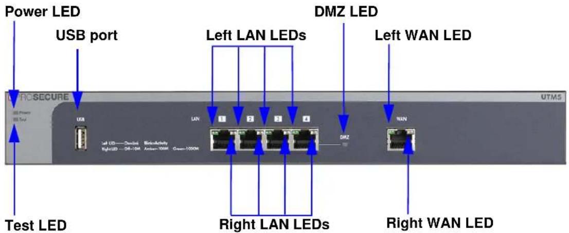
Figure 2. Front panel UTM5 and UTM10
Front Panel UTM25
Viewed from left to right, the UTM25 front panel contains the following ports:
- One nonfunctioning USB port. This port is included for future management enhancements. The port is currently not operable on the UTM.
• LAN Ethernet ports. Four switched N-way automatic speed negotiating, Auto MDI/MDIX, Gigabit Ethernet ports with RJ-45 connectors. - WAN Ethernet ports. Two independent N-way automatic speed negotiating, Auto MDI/MDIX, Gigabit Ethernet ports with RJ-45 connectors.
The front panel also contains three groups of status indicator LEDs, including Power and Test LEDs, LAN LEDs, and WAN LEDs, all of which are explained in detail in Table 2 on page 30. In addition, the front panel provides some LED explanation to the left of the LAN ports.

Figure 3. Front panel UTM25
Front Panel UTM50
Viewed from left to right, the UTM50 front panel contains the following ports:
• One nonfunctioning USB port. This port is included for future management enhancements. The port is currently not operable on the UTM.
• LAN Ethernet ports. Six switched N-way automatic speed negotiating, Auto MDI/MDIX, Gigabit Ethernet ports with RJ-45 connectors.
- WAN Ethernet ports. Two independent N-way automatic speed negotiating, Auto MDI/MDIX, Gigabit Ethernet ports with RJ-45 connectors.
The front panel also contains three groups of status indicator LEDs, including Power and Test LEDs, LAN LEDs, and WAN LEDs, all of which are explained in detail in Table 2 on page 30. In addition, the front panel provides some LED explanation to the right of the WAN ports.

Figure 4. Front panel UTM50
Front Panel UTM150
Viewed from left to right, the UTM150 front panel contains the following ports:
- One nonfunctioning USB port. This port is included for future management enhancements. The port is currently not operable on the UTM.
• LAN Ethernet ports. Four switched N-way automatic speed negotiating, Auto MDI/MDIX, Gigabit Ethernet ports with RJ-45 connectors. - WAN Ethernet ports. Four independent N-way automatic speed negotiating, Auto MDI/MDIX, Gigabit Ethernet ports with RJ-45 connectors.
The front panel also contains three groups of status indicator LEDs, including Power and Test LEDs, LAN LEDs, and WAN LEDs, all of which are explained in detail in Table 2 on page 30. In addition, the front panel provides some LED explanation to the right of the WAN ports.
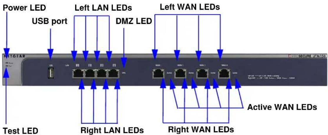
Figure 5. Front panel UTM150
Front Panel UTM9S and UTM25S and Network Modules
Viewed from left to right, the UTM9S and UTM25S front panel contains the following ports and slots:
• One USB port that can accept a 3G/4G dongle for wireless connectivity to an ISP. The port is currently operable on the UTM9S and UTM25S only.
• LAN Ethernet ports. Four switched N-way automatic speed negotiating, Auto MDI/MDIX, Gigabit Ethernet ports with RJ-45 connectors.
- WAN Ethernet ports. Two independent N-way automatic speed negotiating, Auto MDI/MDIX. Gigabit Ethernet ports with RJ-45 connectors.
The front panel also contains three groups of status indicator LEDs, including Power and Test LEDs, LAN LEDs, and WAN LEDs, all of which are explained in detail in Table 3 on page 32. Some LED explanation is provided on the front panel below the LAN and WAN ports.

Figure 6. Front panel UTM9S and UTM25S
ProSecure Unified Threat Management (UTM) Appliance
xDSL Network Modules
The following xDSL network modules are available for insertion in one of the UTM9S or UTM25S slots:
• NMSDSLA. VDSL/ADSL2+ network module, Annex A.
• NMSDSLB. VDSL/ADSL2+ network module, Annex B.
Note: In previous releases for the UTM9S, these network modules were referred to as the UTM9SDSLA and UTM9SDSLB. The UTM9SDSLA is identical to the NMSDSLA, and the UTM9SDSLB is identical to the NMSDSLB.
The xDSL network module provides one RJ-11 port for connection to a telephone line. The two LEDs are explained in Table 3 on page 32.

Figure 7. xDSL network module
Wireless Network Modules
The wireless network module (NMSWLSN) can be inserted in one of the UTM9S and UTM25S slots. The wireless network module does not provide any ports. The antennas are detachable. The two LEDs are explained in Table 3 on page 32.
Note: In previous releases for the UTM9S, this network module was referred to as the UTM9SWLSN. The UTM9SWLSN is identical to the NMSWLSN.

Figure 8. Wireless network module
LED Descriptions, UTM5, UTM10, UTM25, UTM50, and UTM150
The following table describes the function of each LED.
Table 2. LED descriptions UTM5, UTM10, UTM25, UTM50, and UTM150
| LED Activity | Description | |
| Power LED On | On (green) Power is supplied to the UTM. | |
| Off Power is not supplied to the UTM. | ||
| Test LED On | (amber) during startup | Test mode. The UTM is initializing. After approximately 2 minutes, when the UTM has completed its initialization, the Test LED goes off. |
| On (amber) during any other time | The initialization has failed, or a hardware failure has occurred. | |
| Blinking (amber) The UTM is writing to flash memory (during upgrading or resetting to defaults). | ||
| Off The UTM has booted successfully. | ||
| LAN ports | ||
| Left LED Off | The LAN port has no link. | |
| On (green) The LAN port has detected a link with a connected Ethernet device. | ||
| Blinking (green) Data is transmitted or received by the LAN port. | ||
| Right LED Off | The LAN port is operating at 10 Mbps. | |
| On (amber) The LAN port is operating at 100 Mbps. | ||
| On (green) The LAN port is operating at 1000 Mbps. | ||
| DMZ LED Off | Port 4 (UTM5, UTM9S, UTM10, UTM25, and UTM150) or port 6 (UTM50) is operating as a normal LAN port. | |
| On (green) Port 4 (UTM5, UTM9S, UTM10, UTM25, and UTM150) or port 6 (UTM50) is operating as a dedicated hardware DMZ port. | ||
| WAN ports | ||
| Left LED Off | The WAN port has no physical link, that is, no Ethernet cable is plugged into the UTM. | |
| On (green) The WAN port has a valid connection with a device that provides an Internet connection. | ||
| Blinking (green) Data is transmitted or received by the WAN port. | ||
| Right LED Off | The WAN port is operating at 10 Mbps. | |
| On (amber) The WAN port is operating at 100 Mbps. | ||
| On (green) The WAN port is operating at 1000 Mbps. | ||
| Active LED (multiple WAN port models only) | Off The WAN port either is not enabled or has no link to the Internet. | |
| On (green) The WAN port has a valid Internet connection. | ||
LED Descriptions, UTM9S, UTM25S, and their Network Modules
The following table describes the function of each LED on the UTM9S and UTM25S and their network modules.
Table 3. LED descriptions UTM9S and UTM25S
| LED Activity | Description | |
| Power LED On | On (green) Power is supplied to the UTM. | |
| Off Power is not supplied to the UTM. | ||
| Test LED On | (amber) during startup | Test mode. The UTM is initializing. After approximately 2 minutes, when the UTM has completed its initialization, the Test LED goes off. |
| On (amber) during any other time | The initialization has failed, or a hardware failure has occurred. | |
| Blinking (amber) The UTM is writing to flash memory (during upgrading or resetting to defaults). | ||
| Off The UTM has booted successfully. | ||
| USB LED On | (green) A USB device is connected to the USB port. | |
| Off A USB device is not connected to the USB port. | ||
| LAN ports | ||
| Left LED Off | The LAN port has no link. | |
| On (green) The LAN port has detected a link with a connected Ethernet device. | ||
| Blinking (green) Data is transmitted or received by the LAN port. | ||
| Right LED Off | The LAN port is operating at 10 Mbps. | |
| On (amber) The LAN port is operating at 100 Mbps. | ||
| On (green) The LAN port is operating at 1000 Mbps. | ||
| DMZ LED Off | Port 4 is operating as a normal LAN port. | |
| On (green) Port 4 is operating as a dedicated hardware DMZ port. | ||
| WAN ports | ||
| Left LED | Off | The WAN port has no physical link, that is, no Ethernet cable is plugged into the UTM. |
| On (green) The WAN port has a valid connection with a device that provides an Internet connection. | ||
| Blinking (green) Data is transmitted or received by the WAN port. | ||
| Right LED Off | The WAN port is operating at 10 Mbps. | |
| On (amber) The WAN port is operating at 100 Mbps. | ||
| On (green) The WAN port is operating at 1000 Mbps. | ||
| Active LED Off | If The WAN port either is not enabled or has no link to the Internet. | |
| On (green) The WAN port has a valid Internet connection. | ||
| Wireless network module | ||
| Module Status LED | Off The module is not enabled. | |
| On (green) The module is enabled. | ||
| Wireless Link LED | Off The wireless access point is not enabled. | |
| On (green) The wireless access point is enabled in 2.4-GHz operating mode. | ||
| Blinking (green) There is wireless activity in 2.4-GHz operating mode. | ||
| On (yellow) The wireless access point is enabled in 5-GHz operating mode. | ||
| Blinking (yellow) There is wireless activity in 5-GHz operating mode. | ||
| xDSL network modules | ||
| Module Status LED | Off The module is enabled or has a link to the telephone line. | |
| On (green) The module either is not enabled or has no link to the telephone line. | ||
| Link LED Off | The xDSL port has no Internet connection. | |
| On (green) The xDSL port functions in ADSL mode. | ||
| On (yellow) The xDSL port functions in VDSL mode. | ||
Rear Panel UTM5, UTM10, and UTM25
The rear panel of the UTM5, UTM10, and UTM25 includes the cable lock receptacle, the console port, the Factory Defaults reset button, and the AC power connection.
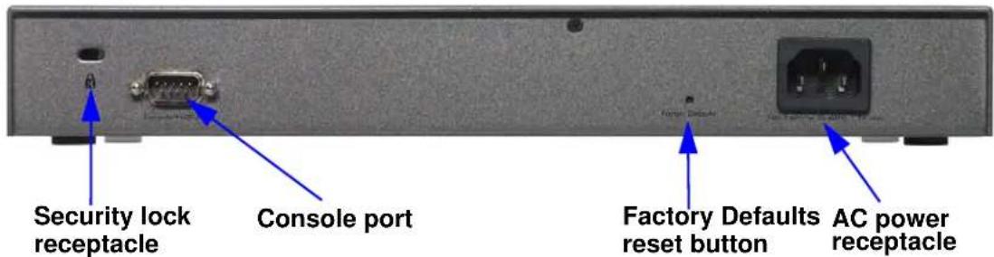
Figure 9. Rear panel of the UTM5, UTM10, and UTM25
Viewed from left to right, the rear panel of the UTM5, UTM10, and UTM25 contains the following components:
- Cable security lock receptacle.
- Console port. Port for connecting to an optional console terminal. The port has a DB9 male connector. The default baud rate is 9600 K. The pinouts are (2) Tx, (3) Rx, (5) and (7) Gnd.
- Factory Defaults Reset button. Using a sharp object, press and hold this button for about 8 seconds until the front panel Test LED flashes to reset the UTM to factory default settings. Configuration changes are lost, and the default password is restored.
- AC power receptacle. Universal AC input (100–240 VAC, 50–60 Hz).
Rear Panel UTM50 and UTM150
The rear panel of the UTM50 and UTM150 includes the cable lock receptacle, the console port, the Factory Defaults reset button, and the AC power connection.

Figure 10. Rear panel of the UTM50 and UTM150
Viewed from left to right, the rear panel of the UTM50 and UTM150 contains the following components:
- Console port. Port for connecting to an optional console terminal. The port has a DB9 male connector. The default baud rate is 9600 K. The pinouts are (2) Tx, (3) Rx, (5) and (7) Gnd.
-
Factory Defaults reset button. Using a sharp object, press and hold this button for about 8 seconds until the front panel Test LED flashes to reset the UTM to factory default settings. Configuration changes are lost, and the default password is restored.
-
Cable security lock receptacle.
-
AC power receptacle. Universal AC input (100–240 VAC, 50–60 Hz).
Rear Panel UTM9S and UTM25S
The rear panel of the UTM9S and UTM25S includes the cable lock receptacle, the console port and console switch, the Factory Defaults reset button, the AC power connection, and the power switch.

Figure 11. Rear panel of the UTM9S and UTM25S
Viewed from left to right, the rear panel of the UTM9S and UTM25S contains the following components:
- Cable security lock receptacle.
- Factory Defaults Reset button. Using a sharp object, press and hold this button for about 8 seconds until the front panel Test LED flashes to reset the UTM to factory default settings. Configuration changes are lost, and the default password is restored.
- Console switch to select the console connection: Main Board (left position), Slot 1 (middle position), or Slot 2 (right position).
- Console port (9600,N,8,1). Port for connecting to an optional console terminal. The port has a DB9 male connector. The default baud rate is 9600 K. The pinouts are (2) Tx, (3) Rx, (5) and (7) Gnd.
- AC power receptacle. Universal AC input (100–240 VAC, 50–60 Hz).
- Power On/Off switch.
Bottom Panels with Product Labels
The product label on the bottom of the UTM's enclosure displays factory defaults settings, regulatory compliance, and other information.
The following figure shows the product label for the UTM5:

Figure 12.
The following figure shows the product label for the UTM10:

Figure 13.
The following figure shows the product label for the UTM25:

Figure 14.
The following figure shows the product label for the UTM50:

Figure 15.
The following figure shows the product label for the UTM150:
NETGEAR
ProSecure Unified Threat Management UTM150
This device complies with part 15 of the FCC Rules and Canada ICES-003. Operation is subject to the following two conditions: (1) this device may not cause harmful interference, and (2) this device must accept any interference received, including interference that may cause undesired operation.
| MAC (WAN 1) | MAC (WAN 2) | ||
| MAC (WAN 3) | SERIAL | ||
| MAC (WAN 4) | MAC (LAN) |
Mode in China
272-11191-01
Figure 16.
The following figure shows the product label for the UTM9S:
NETGEAR®
ProSecure Unified Threat Management UTM9S
This device complies with part 15 of the FCC Rules and Canada ICES-003. Operation is subject to the following two conditions: (1) this device may not cause harmful interference, and (2) this device must accept any interference received, including interference that may cause undesired operation.
DEFAULT ACCESS
http://192.168.1.1
user name: admin password: password


US LISTED
(五) 2012/7/6


N10947 Z1067


Input Rating: AC 100-240V\~, 50-60Hz, 1.0A max.
| MAC (WAN 1) | SERIAL | ||
| MAC (WAN 2) | MAC (LAN) |
Mode in China
272-11187-02
Figure 17.
The following figure shows the product label for the UTM25S:
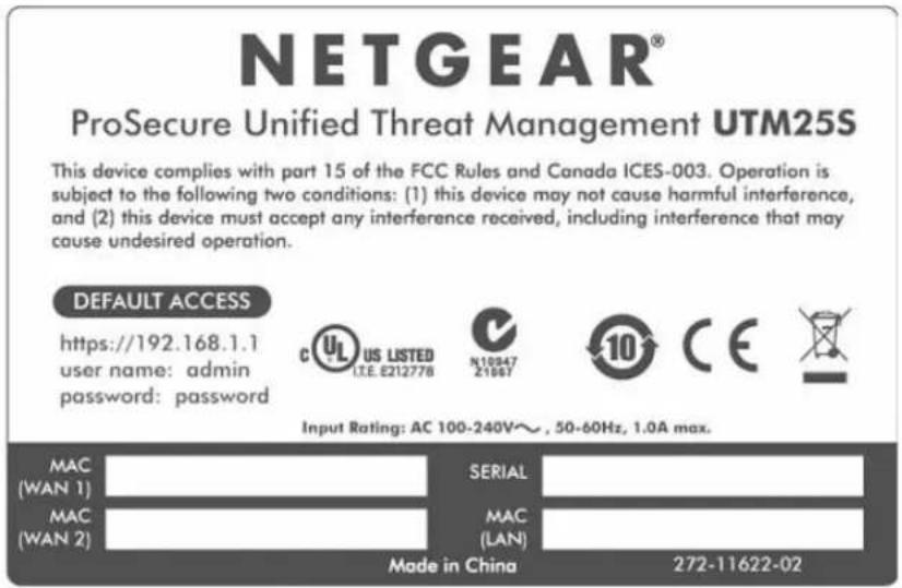
Figure 18.
Choose a Location for the UTM
The UTM is suitable for use in an office environment where it can be freestanding (on its runner feet) or mounted into a standard 19-inch equipment rack. Alternatively, you can rack-mount the UTM in a wiring closet or equipment room. A rack-mounting kit, containing two mounting brackets and four screws, is provided in the package for the multiple WAN port models.
Consider the following when deciding where to position the UTM:
• The unit is accessible, and cables can be connected easily.
- Cabling is away from sources of electrical noise. These include lift shafts, microwave ovens, and air-conditioning units.
• Water or moisture cannot enter the case of the unit.
- Airflow around the unit and through the vents in the side of the case is not restricted. Provide a minimum of 25-mm or 1-inch clearance.
• The air is as free of dust as possible.
- Temperature operating limits are not likely to be exceeded. Install the unit in a clean, air-conditioned environment. For information about the recommended operating temperatures for the UTM, see Appendix H, Default Settings and Technical Specifications.
Note: For the UTM9S and UTM25S, see also Wireless Equipment Placement and Range Guidelines on page 579.
Use the Rack-Mounting Kit
Use the mounting kit for the UTM to install the appliance in a rack. (A mounting kit is provided in the package for the multiple WAN port models.) Attach the mounting brackets using the hardware that is supplied with the mounting kit.

natural_image
Technical diagram of a mechanical device with labeled components and connectors (no readable text or symbols)Figure 19.
Before mounting the UTM in a rack, verify that:
- You have the correct screws (supplied with the installation kit).
- The rack onto which you will mount the UTM is suitably located.
Use the Setup Wizard to Provision the UTM in Your Network
2
This chapter explains how to log in to the UTM and use the web management interface, how to use the Setup Wizard to provision the UTM in your network, and how to register the UTM with NETGEAR. The chapter contains the following sections:
• Steps for Initial Connection
- Log In to the UTM
• Web Management Interface Menu Layout
- Use the Setup Wizard to Perform the Initial Configuration
- Register the UTM with NETGEAR
- Verify Correct Installation
• What to Do Next
Steps for Initial Connection
• Qualified Web Browsers
- Requirements for Entering IP Addresses
Typically, the UTM is installed as a network gateway to function as a combined LAN switch, firewall, and content scan engine to protect the network from all incoming and outgoing malware threats.
Generally, five steps are required to complete the basic and security configuration of your UTM:
- Connect the UTM physically to your network. Connect the cables and restart your network according to the instructions in the Installation Guide. See the ProSecure Unified Threat Management UTM Installation Guide for complete steps. A PDF of the Installation Guide is on the NETGEAR website at http://www.prosecure.netgear.com/resources/document-library.php.
- Log in to the UTM. After logging in, you are ready to set up and configure your UTM. See Log In to the UTM on page 42.
-
Use the Setup Wizard to configure basic connections and security. During this phase, you connect the UTM to one or more ISPs (more than one ISP applies to multiple WAN port models only). See Use the Setup Wizard to Perform the Initial Configuration on page 47.
-
Verify the installation. See Verify Correct Installation on page 68.
- Register the UTM. See Register the UTM with NETGEAR on page 65.
Each of these tasks is described separately in this chapter. The configuration of the WAN mode (required for multiple WAN port models), Dynamic DNS, and other WAN options is described in Chapter 3, Manually Configure Internet and WAN Settings.
The configuration of LAN, firewall, scanning, VPN, management, and monitoring features is described in later chapters.
Qualified Web Browsers
To configure the UTM, you need to use a web browser such as Microsoft Internet Explorer 6 or later, Mozilla Firefox 3 or later, or Apple Safari 3 or later with JavaScript, cookies, and SSL enabled.
Although these web browsers are qualified for use with the UTM's web management interface, SSL VPN users should choose a browser that supports JavaScript, Java, cookies, SSL, and ActiveX to take advantage of the full suite of applications. Java is required only for the SSL VPN portal, not for the web management interface.
Requirements for Entering IP Addresses
The fourth octet of an IP address needs to be between 1 and 254 (both inclusive). This requirement applies to any IP address that you enter on a screen of the web management interface.
Log In to the UTM
To connect to the UTM, your computer needs to be configured to obtain an IP address automatically from the UTM through DHCP.
To connect and log in to the UTM:
- Start any of the qualified web browsers, as explained in the previous section, Qualified Web Browsers.
- In the address field, enter https://192.168.1.1. The NETGEAR Configuration Manager Login screen displays in the browser. (The following figure shows the screen for the UTM50.) This screen also provides the User Portal Login Link. For general information about the User Portal Login Link, see Access the New SSL VPN Portal on page 353; for platform-specific information, see Login Portals on page 380.

Figure 20.
- In the User Name field, type admin. Use lowercase letters.
- In the Password / Passcode field, type password. Here, too, use lowercase letters.
Note: The UTM user name and password are not the same as any user name or password you might use to log in to your Internet connection.
- Click Login. The web management interface displays, showing the System Status screen. The following figure shows the top part of the UTM50 System Status screen. For more information, see View the System Status on page 486.
Note: After 5 minutes of inactivity (the default login time-out), you are automatically logged out.
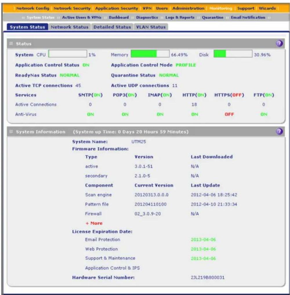
Figure 21.
Web Management Interface Menu Layout
The following figure shows the menu at the top the UTM50 web management interface as an example.

Figure 22.
The web management interface menu consists of the following components:
- 1st level: Main navigation menu links. The main navigation menu in the orange bar across the top of the web management interface provides access to all the configuration functions of the UTM, and remains constant. When you select a main navigation menu link, the letters are displayed in white against an orange background.
- 2nd level: Configuration menu links. The configuration menu links in the gray bar (immediately below the main navigation menu bar) change according to the main navigation menu link that you select. When you select a configuration menu link, the letters are displayed in white against a gray background.
- 3rd level: Submenu tabs. Each configuration menu item has one or more submenu tabs that are listed below the gray menu bar. When you select a submenu tab, the text is displayed in white against a blue background.
- Option arrows. If there are additional screens for the submenu item, links to the screens display on the right side in blue letters against a white background, preceded by a white arrow in a blue circle.
The bottom of each screen provides action buttons. The nature of the screen determines which action buttons are shown. The following figure shows an example:

Figure 23.
Any of the following action buttons might display on screen (this list might not be complete):
- Apply. Save and apply the configuration.
- Reset. Cancel the changes and reset the configuration to the current values.
- Test. Test the configuration before you decide whether to save and apply the configuration.
- Auto Detect. Enable the UTM to detect the configuration automatically and suggest values for the configuration.
- Next. Go to the next screen (for wizards).
ProSecure Unified Threat Management (UTM) Appliance
- Back. Go to the previous screen (for wizards).
- Search. Perform a search operation.
- Cancel. Cancel the operation.
- Send Now. Send a file or report.
When a screen includes a table, table buttons display to let you configure the table entries. The nature of the screen determines which table buttons are shown. The following figure shows an example:





Figure 24.
Any of the following table buttons might display on screen:
- Select All. Select all entries in the table.
- Delete. Delete the selected entry or entries from the table.
- Enable. Enable the selected entry or entries in the table.
- Disable. Disable the selected entry or entries in the table.
- Add. Add an entry to the table.
- Edit. Edit the selected entry.
- Up. Move up the selected entry in the table.
- Down. Move down the selected entry in the table.
- Apply. Apply the selected entry.
Almost all screens and sections of screens have an accompanying help screen. To open the help screen, click the (question mark) icon.
Use the Setup Wizard to Perform the Initial Configuration
- Setup Wizard Step 1 of 10: LAN Settings
- Setup Wizard Step 2 of 10: WAN Settings
- Setup Wizard Step 3 of 10: System Date and Time
- Setup Wizard Step 4 of 10: Services
- Setup Wizard Step 5 of 10: Email Security
- Setup Wizard Step 6 of 10: Web Security
- Setup Wizard Step 7 of 10: Web Categories to Be Blocked
- Setup Wizard Step 8 of 10: Email Notification
- Setup Wizard Step 9 of 10: Signatures & Engine
- Setup Wizard Step 10 of 10: Saving the Configuration
The Setup Wizard facilitates the initial configuration of the UTM by taking you through 10 screens, the last of which allows you to save the configuration. If you prefer to perform the initial WAN setup manually, see Chapter 3, Manually Configure Internet and WAN Settings.
To start the Setup Wizard:
- Select Wizards from the main navigation menu. The Welcome to the Netgear Configuration Wizard screen displays:

Figure 25.
- Select the Setup Wizard radio button.
- Click Next. The first Setup Wizard screen displays.
The following sections explain the 9 configuration screens of the Setup Wizard. On the 10th screen, you can save your configuration.
The tables in the following sections explain the buttons and fields of the Setup Wizard screens. Additional information about the settings in the Setup Wizard screens is provided in other chapters that explain manual configuration; each of the following sections provides a specific link to a section in another chapter.
Setup Wizard Step 1 of 10: LAN Settings

Figure 26.
Enter the settings as explained in the following table, and then click Next to go the following screen.
Note: In this first step, you are configuring the LAN settings for the UTM's default VLAN. For more information about VLANs, see Manage Virtual LANs and DHCP Options on page 98.
Table 4. Setup Wizard Step 1: LAN Settings screen settings
| Setting Description | ||
| LAN TCP/IP Setup | ||
| IP Address Enter the IP | address of the UTM's default VLAN (the factory default address is 192.168.1.1).Note:Always make sure that the LAN port IP address and DMZ port IP address are in different subnets.Note:If you change the LAN IP address of the UTM's default VLAN while being connected through the browser, you are disconnected. You then need to open a new connection to the new IP address and log in again. For example, if you change the default IP address from 192.168.1.1 to 10.0.0.1, you now need to enterhttps://10.0.0.1in your browser to reconnect to the web management interface. | |
| Subnet Mask | Enter the IP subnet mask. The subnet mask specifies the network number portion of an IP address. The UTM automatically calculates the subnet mask based on the IP address that you assign. Unless you are implementing subnetting, use 255.255.255.0 as the subnet mask (computed by the UTM). | |
| DHCP | ||
| Disable DHCP Server | If another device on your network is the DHCP server for the default VLAN, or if you will configure the network settings of all of your computers manually, select theDisable DHCP Serverradio button to disable the DHCP server. By default, this radio button is not selected, and the DHCP server is enabled. | |
| Enable DHCP Server | Select theEnable DHCP Serverradio button to enable the UTM to function as a Dynamic Host Configuration Protocol (DHCP) server, providing TCP/IP configuration for all computers connected to the default VLAN. Enter the following settings. | |
| Domain Name This setting is optional. Enter the domain name of the UTM. | ||
| Starting IP Address | Enter the starting IP address. This address specifies the first of the contiguous addresses in the IP address pool. Any new DHCP client joining the LAN is assigned an IP address between this address and the ending IP address. The IP address 192.168.1.2 is the default starting address. | |
| Ending IP Address | Enter the ending IP address. This address specifies the last of the contiguous addresses in the IP address pool. Any new DHCP client joining the LAN is assigned an IP address between the starting IP address and this IP address. The IP address 192.168.1.100 is the default ending address.Note:The starting and ending DHCP IP addresses should be in the samenetworkas the LAN TCP/IP address of the UTM (that is, the IP address in the LAN TCP/IP Setup section as described earlier in this table). | |
| Enable DHCP Server (continued) | Primary DNS Server | This setting is optional. If an IP address is specified, the UTM provides this address as the primary DNS server IP address. If no address is specified, the UTM provides its own LAN IP address as the primary DNS server IP address. |
| Secondary DNS Server | This setting is optional. If an IP address is specified, the UTM provides this address as the secondary DNS server IP address. | |
| WINS Server This | setting is optional. Enter a WINS server IP address to specify the Windows NetBIOS server, if one is present in your network. | |
| Lease Time Enter | a lease time. This specifies the duration for which IP addresses are leased to clients. | |
| DHCP Relay | Select the DHCP Relay radio button to use the UTM as a DHCP relay agent for a DHCP server somewhere else on your network. Enter the following setting: | |
| Relay Gateway The IP address of the DHCP server for which the UTM serves as a relay. | ||
| Enable LDAP information | Select the Enable LDAP information check box to enable the DHCP server to provide Lightweight Directory Access Protocol (LDAP) server information. Enter the following settings.Note:The LDAP settings that you specify as part of the VLAN profile are used only for SSL VPN and UTM authentication, but not for web and email security. | |
| LDAP Server The IP address or name of the LDAP server. | ||
| Search Base The search objects that specify the location in the directory tree from which the LDAP search begins. You can specify multiple search objects, separated by commas. The search objects include:CN (for common name)OU (for organizational unit)O (for organization)C (for country)DC (for domain)For example, to search the Netgear.net domain for all last names of Johnson, you would enter:cn=Johnson,dc=Netgear,dc=net | ||
| Port The port number for the LDAP server. The default setting is 0 (zero). | ||
| DNS Proxy | ||
| Enable DNS Proxy | This setting is optional. Select the Enable DNS Proxy radio button to enable the UTM to provide a LAN IP address for DNS address name resolution. This radio button is selected by default.Note:When the DNS Proxy option is disabled, all DHCP clients receive the DNS IP addresses of the ISP but without the DNS proxy IP address. | |
Table 4. Setup Wizard Step 1: LAN Settings screen settings (continued)
| Setting Description | |
| Inter VLAN Routing | |
| Enable Inter VLAN Routing | This setting is optional. To ensure that traffic is routed only to VLANs for which inter-VLAN routing is enabled, select the Enable Inter VLAN Routing check box. This setting is disabled by default. When the Enable Inter VLAN Routing check box is not selected, traffic from this VLAN is not routed to other VLANs, and traffic from other VLANs is not routed to this VLAN.Note: For information about inter-VLAN firewall rules, see VLAN Rules on page 154. |
After you have completed the steps in the Setup Wizard, you can change the LAN settings by selecting Network Config > LAN Settings > Edit LAN Profile. For more information about these LAN settings, see VLAN DHCP Options on page 101.
Setup Wizard Step 2 of 10: WAN Settings
![Setup Wizard Step 2 of 10 :WAN Settings DHCP service detected. ISP Login Does Your Internet Connection Require a Login? Yes No Login: Password: ISP Type Which type of ISP connection do you use? Austria (PPTP) Other (PPPeE) Account Name: Domain Name: Idle Timeout: Keep Connected Idle Timeout: 5 [Minutes] Connection Reset: Disconnect Time: HH MM Delay: 0 Sec My IP Address: Server IP Address: Internet (IP) Address (Current IP Address) Get Dynamically from ISP Client Identifier Vendor Class Identifier Use Static IP Address IP Address: 0 0 0 0 Subnet Mask: 0 0 0 0 Gateway IP Address: 0 0 0 0 Domain Name Server (DNS) Servers Get Automatically from ISP Use These DNS Servers Primary DNS Server: 0 0 0 0 Secondary DNS Server: 0 0 0 0 Back Next Auto Detect Cancel](/content/2026/06/1371942/images/7dc6b74143b68de20a19639548edc3f1567cd6b1434af17c90e762fb1fa178d2.jpg)
Figure 27.
Enter the settings as explained in the following table, and then click Next to go the following screen.
Note: Instead of manually entering the settings, you can also click the Auto Detect action button at the bottom of the screen. The autodetect process probes the WAN port for a range of connection methods and suggests one that your ISP is most likely to support.
Table 5. Setup Wizard Step 2: WAN Settings screen settings
| Setting Description | ||
| ISP Login | ||
| Does your Internet connection require a login? | If you need to enter login information every time you connect to the Internet through your ISP, select the Yes radio button. Otherwise, select the No radio button, which is the default setting, and skip the ISP Type section. If you select the Yes radio button, enter the following settings. | |
| Login The login name that your ISP has assigned to you. | ||
| Password The password that your ISP has assigned to you. | ||
| ISP Type | ||
| What type of ISP connection do you use? | If your connection is PPPoE or PPTP, then you need to log in. Select the Yes radio button. Based on the connection that you select, the text fields that require data entry are highlighted. If your ISP has not assigned any login information, then select the No radio button and skip this section. If you select the Yes radio button, enter the following settings. | |
| Austria (PPTP) | If your ISP is Austria Telecom or any other ISP that uses PPTP for login, select this radio button and enter the following settings: | |
| Account Name The account name is also known as the host name or system name. Enter the valid account name for the PPTP connection (usually your email ID assigned by your ISP). Some ISPs require you to enter your full email address here. | ||
| Domain Name Your domain name or workgroup name assigned by your ISP, or your ISP's domain name. You can leave this field blank. | ||
| Idle Timeout | Select the Keep Connected radio button to keep the connection always on. To log out after the connection is idle for a period:1. Select the Idle Timeout radio button.2. In the time-out field, enter the number of minutes to wait before disconnecting.This is useful if your ISP charges you based on the period that you are logged in. | |
| Setting | Description | |
| Austria (PPTP)(continued) | My IP Address The IP address assigned by the ISP to make the connection with the ISP server. | |
| Server IP Address The IP address of the PPTP server. | ||
| Other (PPPoE) | If you have installed login software such as WinPoET or Ethernet, then your connection type is PPPoE. Select this radio button and enter the following settings: | |
| Account Name The valid account name for the PPPoE connection. | ||
| Domain Name The name of your ISP's domain or your domain name if your ISP has assigned one. You can leave this field blank. | ||
| Idle Timeout | Select theKeep Connectedradio button to keep the connection always on. To log out after the connection is idle for a period:1. Select theIdle Timeoutradio button.2. In the time-out field, enter the number of minutes to wait before disconnecting.This is useful if your ISP charges you based on the period that you are logged in.Note:When you use a PPPoE connection and select the Idle Timeout radio button, you cannot configure load balancing (seeConfigure Load Balancing (Multiple WAN Port Models) on page 86). To use load balancing on a PPPoE connection, select theKeep Connectedradio button. | |
| Connection Reset | Select theConnection Resetcheck box to specify a time when the PPPoE WAN connection is reset, that is, the connection is disconnected momentarily and then reestablished. Then, specify the disconnect time and delay. | |
| Disconnect Time Specify | the hour and minutes when the connection should be disconnected. | |
| Delay Specify the period | in seconds after which the connection should be reestablished. | |
| Internet (IP) AddressClick theCurrent IP Addresslink to see the currently assigned IP address. | ||
| Get Dynamically from ISP | If your ISP has not assigned you a static IP address, select theGet dynamically from ISPradio button. The ISP automatically assigns an IP address to the UTM using DHCP network protocol. | |
| Client Identifier | Select theClient Identifiercheck box if your ISP requires the client identifier information to assign an IP address using DHCP. | |
| Vendor Class Identifier | Select theVendor Class Identifiercheck box if your ISP requires the vendor class identifier information to assign an IP address using DHCP. | |
| Setting Description | ||
| Use Static IP Address | If your ISP has assigned you a fixed (static or permanent) IP address, select the Use Static IP Address radio button and enter the following settings. | |
| IP Address The static IP | address assigned to you. This address identifies the UTM to your ISP. | |
| Subnet Mask The subnet mask, which is usually provided by your ISP. | ||
| Gateway IP Address The IP address of the ISP's gateway, which is usually provided by your ISP. | ||
| Domain Name Server (DNS) Servers | ||
| Get Automatically from ISP | If your ISP has not assigned any Domain Name Servers (DNS) addresses, select the Get Automatically from ISP radio button. | |
| Use These DNS Servers | If your ISP has assigned DNS addresses to you, select the Use These DNS Servers radio button. Make sure that you fill in valid DNS server IP addresses in the fields. Incorrect DNS entries might cause connectivity issues. | |
| Primary DNS Server The IP address of the primary DNS server. | ||
| Secondary DNS Serve The IP address of the secondary DNS server. | ||
After you have completed the steps in the Setup Wizard, you can change to the WAN settings by selecting Network Config > WAN Settings. Then click the Edit button in the Action column of the WAN interface for which you want to change the settings.
For more information about these WAN settings, see Manually Configure the Internet Connection on page 75.
Setup Wizard Step 3 of 10: System Date and Time

Figure 28.
ProSecure Unified Threat Management (UTM) Appliance
Enter the settings as explained in the following table, and then click Next to go the following screen.
Table 6. Setup Wizard Step 3: System Date and Time screen settings
| Setting Description | ||
| Set Time, Date, and NTP Servers | ||
| Date/Time | From the drop-down list, select the local time zone in which the UTM operates. The correct time zone is required in order for scheduling to work correctly. The UTM includes a real-time clock (RTC), which it uses for scheduling. | |
| Automatically Adjust for Daylight Savings Time | If daylight savings time is supported in your region, select the Automatically Adjust for Daylight Savings Time check box. | |
| NTP Server (default or custom) | From the drop-down list, select an NTP server:Use Default NTP Servers. The UTM's RTC is updated regularly by contacting a default NETGEAR NTP server on the Internet.Use Custom NTP Servers. The UTM's RTC is updated regularly by contacting one of the two NTP servers (primary and backup), both of which you need to specify in the fields that become available with this selection.Note: If you select this option but leave either the Server 1 or Server 2 field blank, both fields are set to the default NETGEAR NTP servers.Note: A list of public NTP servers is available athttp://support.ntp.org/bin/view/Servers/WebHome. | |
| Server 1 Name / IP Address | Enter the IP address or host name of the primary NTP server. | |
| Server 2 Name / IP Address | Enter the IP address or host name of the backup NTP server. | |
After you have completed the steps in the Setup Wizard, you can change the date and time by selecting Administration > System Date & Time. For more information about these settings, see Configure Date and Time Service on page 456.
Setup Wizard Step 4 of 10: Services
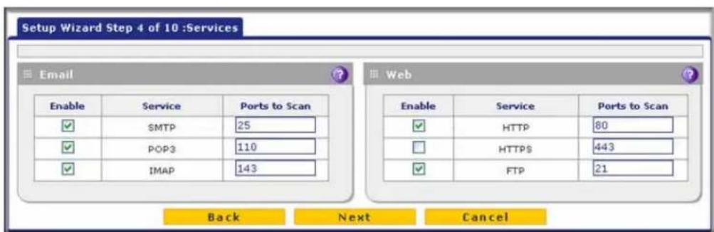
Figure 29.
Enter the settings as explained in the following table, and then click Next to go the following screen.
Table 7. Setup Wizard Step 4: Services screen settings
| Setting Description | ||
| SMTP SMTP scanning is enabled by default on standard service port 25. | To disable any of these services, clear the corresponding check box. You can change the standard service port or add another port in the corresponding Ports to Scan field. | |
| POP3 POP3 scanning is enabled by default on standard service port 110. | ||
| IMAP IMAP scanning is enabled by default on standard service port 143. | ||
| Web | ||
| HTTP HTTP scanning is enabled by default on standard service port 80. | To disable HTTP scanning, clear the corresponding check box. You can change the standard service port or add another port in the corresponding Ports to Scan field. | |
| HTTPS HTTPS scanning is disabled by default. | To enable HTTPS scanning, select the corresponding check box. You can change the standard service port (443) or add another port in the corresponding Ports to Scan field. | |
| FTP FTP scanning is enabled by default on standard service port 21. | To disable FTP scanning, clear the corresponding check box. You cannot change the standard service port in the corresponding Ports to Scan field. | |
IMPORTANT:
To enable scanning of encrypted emails, you need to configure the SSL settings (see Configure HTTPS Scanning and SSL Certificates on page 228).
After you have completed the steps in the Setup Wizard, you can change the security services by selecting Application Security > Services. For more information about these settings, see Customize Email Protocol Scan Settings on page 194 and Customize Web Protocol Scan Settings on page 210.
Setup Wizard Step 5 of 10: Email Security

Figure 30.
Enter the settings as explained in the following table, and then click Next to go the following screen.
Table 8. Setup Wizard Step 5: Email Security screen settings
| Setting Description | ||
| Action | ||
| SMTP From the S | SMTP drop-down list, select one of the following actions to be taken when an infected email is detected:Block infected email. This is the default setting. The email is blocked, and a log entry is created.Delete attachment. The email is not blocked, but the attachment is deleted, and a log entry is created.Log only. Only a log entry is created. The email is not blocked, and the attachment is not deleted.Quarantine attachment. The email is not blocked, but the attachment is quarantined on a ReadyNAS, and a log entry is created (see the Note on page 193).Quarantine infected email. The email is quarantined on a ReadyNAS, and a log entry is created (see the Note on page 193). | To disable antivirus scanning, clear the corresponding check box. |
| POP3 From the P | POP3 drop-down list, select one of the following actions to be taken when an infected email is detected:Delete attachment. This is the default setting. The email is not blocked, but the attachment is deleted, and a log entry is created.Log only. Only a log entry is created. The email is not blocked, and the attachment is not deleted.Quarantine attachment. The email is not blocked, but the attachment is quarantined on a ReadyNAS, and a log entry is created (see the Note on page 193). | |
| Setting Description | ||
| IMAP From the IM | MAP drop-down list, select one of the following actions to be taken when an infected email is detected:Delete attachment. This is the default setting. The email is not blocked, but the attachment is deleted, and a log entry is created.Log only. Only a log entry is created. The email is not blocked, and the attachment is not deleted.Quarantine attachment. The email is not blocked, but the attachment is quarantined on a ReadyNAS, and a log entry is created (see the Note on page 193). | To disable antivirus scanning, clear the corresponding check box. |
| Scan Exceptions | ||
| The default maximum size of the file or message that is scanned is 2048 KB, but you can define a maximum size of up to 10240 KB. However, setting the maximum size to a high value might affect the UTM’s performance (see Performance Management on page 428).From the drop-down list, select one of the following actions to be taken when the file or message exceeds the maximum size:Skip. The file is not scanned but skipped, leaving the end user vulnerable. This is the default setting.Block. The file is blocked and does not reach the end user. | ||
After you have completed the steps in the Setup Wizard, you can change the email security settings by selecting Application Security > Email Anti-Virus. The Email Anti-Virus screen also lets you specify notification settings and email alert settings. For more information about these settings, see Customize Email Antivirus and Notification Settings on page 196.
Setup Wizard Step 6 of 10: Web Security

Figure 31.
Enter the settings as explained in the following table, and then click Next to go the following screen.
Table 9. Setup Wizard Step 6: Web Security screen settings
| Setting Description | ||
| Action | ||
| HTTP From the H | HTTP drop-down list, select one of the following actions to be taken when an infected web file or object is detected:Delete file. This is the default setting. The web file or object is deleted, and a log entry is created.Log only. Only a log entry is created. The web file or object is not deleted.Quarantine file. The web file or object is quarantined, and a log entry is created (see the Note on page 193).Select the Streaming check box to enable streaming of partially downloaded and scanned HTTP file parts to the user. This method allows the user to experience more transparent web downloading. Streaming is enabled by default. | To disable antivirus scanning, clear the corresponding check box. |
| HTTPS From the | HTTPS drop-down list, select one of the following actions to be taken when an infected web file or object is detected:Delete file. This is the default setting. The web file or object is deleted, and a log entry is created.Log only. Only a log entry is created. The web file or object is not deleted.Quarantine file. The web file or object is quarantined, and a log entry is created (see the Note on page 193).Select the Streamingcheck box to enable streaming of partially downloaded and scanned HTTPS file parts to the user. This method allows the user to experience more transparent web downloading. Streaming is enabled by default. | |
| FTP From the FTP | drop-down list, select one of the following actions to be taken when an infected web file or object is detected:Delete file. This is the default setting. The FTP file or object is deleted, and a log entry is created.Log only. Only a log entry is created. The FTP file or object is not deleted.Quarantine file. The FTP file or object is quarantined, and a log entry is created (see the Note on page 193). | |
| Scan Exceptions | ||
| The default maximum size of the file or object that is scanned is 2048 KB, but you can define a maximum size of up to 10240 KB. However, setting the maximum size to a high value might affect the UTM's performance (see Performance Management on page 428).From the drop-down list, select one of the following actions to be taken when the file or message exceeds the maximum size:Skip. The file is not scanned but skipped, leaving the end user vulnerable. This is the default setting.Block. The file is blocked and does reach the end user. | ||
After you have completed the steps in the Setup Wizard, you can change the web security settings by selecting Application Security > HTTP/HTTPS > Malware Scan. The Malware
Scan screen also lets you specify HTML scanning and notification settings. For more information about these settings, see Configure Web Malware or Antivirus Scans on page 216.
Setup Wizard Step 7 of 10: Web Categories to Be Blocked
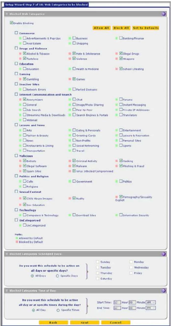
Figure 32.
Enter the settings as explained in the following table, and then click Next to go the following screen.
Table 10. Setup Wizard Step 7: Web Categories to be blocked screen settings
| Setting Description | |
| Blocked Web Categories | |
| Select the Enable Blocking check box to enable blocking of web categories. (By default, this check box is selected.)Select the check boxes of any web categories that you want to block. Use the action buttons at the top of the section in the following way:Allow All. All web categories are allowed.Block All. All web categories are blocked.Set to Defaults. Blocking and allowing of web categories are returned to their default settings. See Table 41 on page 193 for information about the web categories that are blocked by default. Categories that are preceded by a green square are allowed by default; categories that are preceded by a pink square are blocked by default. | |
| Blocked Categories Scheduled Days | |
| Make one of the following selections:Select the All Days radio button to enable content filtering to be active all days of the week.Select the Specific Days radio button to enable content filtering to be active on the days that are specified by the check boxes. | |
| Blocked Categories Time of Day | |
| Make one of the following selections:Select the All Day radio button to enable content filtering to be active all 24 hours of each selected day.Select the Specific Times radio button to enable content filtering to be active during the time that is specified by the Start Time and End Time fields for each day that content filtering is active. | |
After you have completed the steps in the Setup Wizard, you can change the content-filtering settings by selecting Application Security > HTTP/HTTPS > Content Filtering. The Content Filtering screen lets you specify additional filtering tasks and notification settings. For more information about these settings, see Configure Web Content Filtering on page 218.
Setup Wizard Step 8 of 10: Email Notification
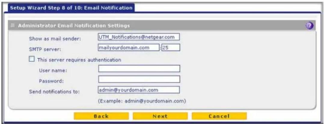
Figure 33.
Enter the settings as explained in the following table, and then click Next to go the following screen.
Table 11. Setup Wizard Step 8: Email Notification screen settings
| Setting Description | ||
| Administrator Email Notification Settings | ||
| Show as mail sender A descriptive name of the sender for email identification purposes. For example, enter UTM_Notifications@netgear.com. | ||
| SMTP server The IP address and port number or Internet name and port number of your ISP's outgoing email SMTP server. The default port number is 25.Note: If you leave this field blank, the UTM cannot send email notifications. | ||
| This server requires authentication | If the SMTP server requires authentication, select the This server requires authentication check box, and enter the user name and password. | |
| User name The user name for SMTP server authentication. | ||
| Password The password for SMTP server authentication. | ||
| Send notifications to | The email address to which the notifications should be sent. Typically, this is the email address of the administrator. | |
After you have completed the steps in the Setup Wizard, you can change the administrator email notification settings by selecting Network Config > Email Notification. For more information about these settings, see Configure the Email Notification Server on page 466.
Setup Wizard Step 9 of 10: Signatures & Engine
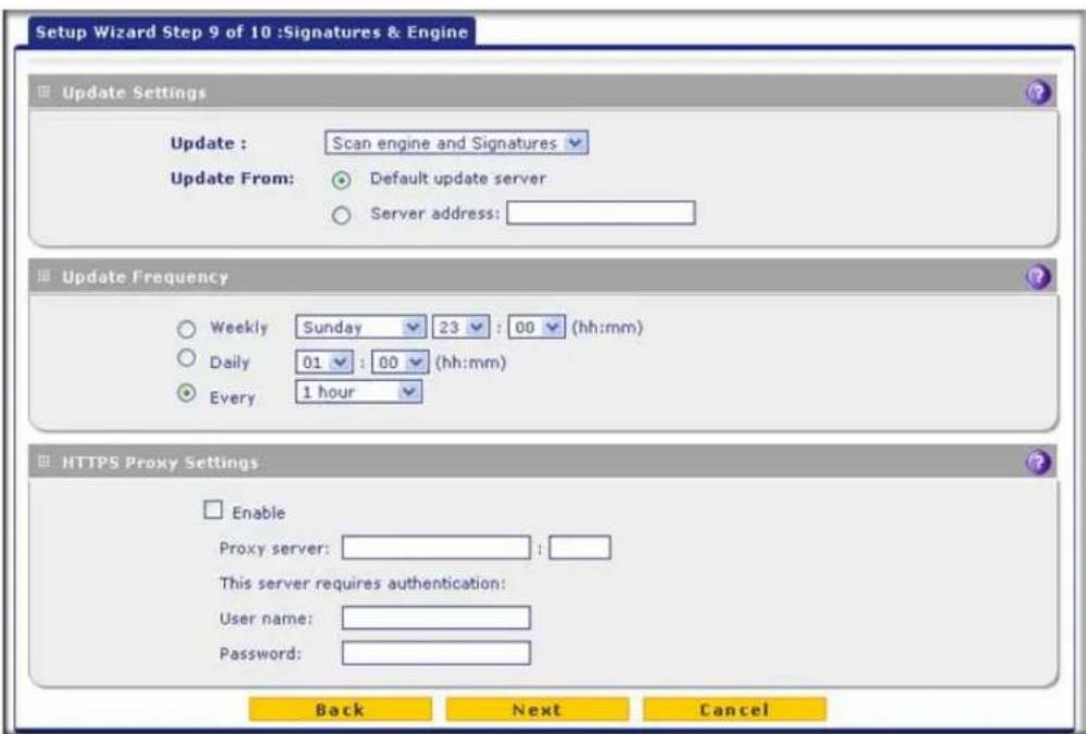
Figure 34.
Enter the settings as explained in the following table, and then click Next to go the following screen.
Table 12. Setup Wizard Step 9: Signatures & Engine screen settings
| Setting Description | |
| Update Settings | |
| Update From the drop-down | list, select one of the following options:Never. The pattern and firmware files are never automatically updated.Scan engine and Signatures. The pattern and firmware files are automatically updated according to the settings in the Update Frequency section onscreen (see explanations later in this table). |
| Update From Set the update | source server by selecting one of the following radio buttons:Default update server. Files are updated from the default NETGEAR update server.Server address. Files are updated from the server that you specify. Enter the IP address or host name of the update server in the Server address field. |
Table 12. Setup Wizard Step 9: Signatures & Engine screen settings (continued)
| Setting Description | ||
| Update Frequency | ||
| Specify the frequency with which the UTM checks for file updates:Weekly. From the drop-down lists, select the weekday, hour, and minutes that the updates occur.Daily. From the drop-down lists, select the hour and minutes that the updates occur.Every. From the drop-down list, select the frequency with which the updates occur. The range is from 15 minutes to 12 hours. | ||
| HTTPS Proxy Settings | ||
| Enable If computers on the network connect to the Internet through a proxy server, select the Enable check box to specify and enable a proxy server. Enter the following settings. | ||
After you have completed the steps in the Setup Wizard, you can change the signatures and engine settings by selecting Administration > System Update > Signatures & Engine. For more information about these settings, see Update the Scan Signatures and Scan Engine Firmware on page 454.
Setup Wizard Step 10 of 10: Saving the Configuration

Figure 35.
Click Apply to save your settings and automatically restart the system.
Register the UTM with NETGEAR
- Use the Web Management Interface to Activate Licenses
• Electronic Licensing
• Automatic Retrieval of Licenses after a Factory Default Reset
Use the Web Management Interface to Activate Licenses
To receive threat management component updates and technical support, you need to register your UTM with NETGEAR. The UTM comes with four 30-day trial licenses:
- Web protection
- Email protection
• Support and maintenance
• Application control and IPS
The service license keys are provided with the product package (see Service Registration Card with License Keys on page 23). For electronic licensing, you do not need the service license keys (see Electronic Licensing on page 67).
IMPORTANT:
Activating the service licenses initiates their terms of use. Activate the licenses only when you are ready to start using this unit. If your unit has never been registered before, you can use the 30-day trial period for all four types of licenses to perform the initial testing and configuration. To use the trial period, do not click Register in Step of the following procedure, but click Trial instead.
If your UTM is connected to the Internet, you can activate the service licenses:
- Select Support > Registration. The Registration screen displays (see Figure 36 on page 66).
- Enter the license key in the Registration Key field.
- Fill out the customer and value-added reseller (VAR) fields.

WARNING:
To activate the 30-day trial period for a license, do not click Register but click Trial instead. For more information, see the Important information at the beginning of this section.
Note: If you have used the 30-day trial licenses, these trial licenses are revoked once you activate the purchased service license keys. The purchased service license keys offer 1 year or 3 years of service.
- Click Register. The UTM activates the license and registers the unit with the registration and update server.
- Repeat Step 2 and Step 4 for additional license keys.

Figure 36.
To change customer or VAR information after you have registered the UTM:
- Make the changes on the Registration screen.
- Click Update Info. The new data is saved by the registration and update server.
To retrieve and display the registered information:
Click Retrieve Info. The registered data is retrieved from the registration and update server.
Electronic Licensing
If you have purchased the UTM with a 1- or 3-year license, you can use the electronic licensing option. When the UTM is connected to the Internet, you need to enter only your customer information and optional value-added reseller (VAR) information on the Register screen but do not need to enter the license numbers. When you click Register, the UTM automatically downloads and activates the license keys because the serial number of the UTM is linked to the license.
If you have purchased a license from a VAR (either directly or over the web) after purchase of the UTM, the VAR should email you the license keys or provide them to you in another way. To register and activate the license keys, follow the regular registration procedure that is explained in the previous section.
Automatic Retrieval of Licenses after a Factory Default Reset
When you reset the UTM to the original factory default settings after you have entered the license keys to activate the UTM, the license keys are erased. The license keys and the different types of licenses that are available for the UTM are no longer displayed on the Registration screen. However, after you have reconfigured the UTM to connect to the Internet and to the NETGEAR registration server, the UTM can retrieve and restore all registration information based on its MAC address and hardware serial number. You do not need to reenter the license keys and reactivate the UTM.
To let the UTM automatically retrieve and restore all registration information:
- Select Support > Registration. The Registration screen displays (see Figure 36 on page 66).
- Click Retrieve Info.
Note: In the unlikely situation that you have been directed to use a nondefault update server, you first need to enter the update server address in the Server address field on the Signatures & Engine screen and click Apply (see Update the Scan Signatures and Scan Engine Firmware on page 454) before you can let the UTM automatically retrieve and restore all registration information.
Verify Correct Installation
- Test Connectivity
- Test HTTP Scanning
Test the UTM before deploying it in a live production environment. The following instructions walk you through a couple of quick tests that are designed to ensure that your UTM is functioning correctly.
Test Connectivity
▶ Verify that network traffic can pass through the UTM:
- Ping an Internet URL.
- Ping the IP address of a device on either side of the UTM.
Test HTTP Scanning
▶ Verify that the UTM scans HTTP traffic correctly:
- Log in to the UTM web management interface, and then verify that HTTP scanning is enabled. HTTP scanning is enabled by default (see Setup Wizard Step 4 of 10: Services on page 55).
- Take note of the web security settings for HTTP (see Setup Wizard Step 6 of 10: Web Security on page 58).
- If client computers have direct access to the Internet through your LAN, try to download the eicar.com test file from http://www.eicar.org/download/eicar.com.
The eicar.com test file is a legitimate denial of service (DoS) attack and is safe to use because it is not a malware threat and does not include any fragments of malware code. The test file is provided by EICAR, an organization that unites efforts against computer crime, fraud, and misuse of computers or networks.
- Check the downloaded eicar.com test file, and note the attached malware information file.
What to Do Next
You have completed setting up the UTM to the network. The UTM is now ready to scan the protocols and services that you specified and perform automatic updates based on the update source and frequency that you specified.
If you need to change the settings, or to view reports or logs, log in to the UTM web management interface, using the default IP address or the IP address that you assigned to the UTM in Setup Wizard Step 1 of 10: LAN Settings on page 48.
ProSecure Unified Threat Management (UTM) Appliance
The UTM is ready for use. However, the following sections describe important tasks that you might want to address before you deploy the UTM in your network:
- Configure the WAN Mode (required if you want to use multiple WAN ports)
- Configure Authentication Domains, Groups, and Users
- Manage Digital Certificates for VPN Connections
- Use the IPSec VPN Wizard for Client and Gateway Configurations
• Build a Portal Using the SSL VPN Wizard
Manually Configure Internet and WAN Settings
3
This chapter contains the following sections:
- Internet and WAN Configuration Tasks
• Automatically Detecting and Connecting the Internet Connections - Manually Configure the Internet Connection
- Configure the WAN Mode
- Configure Secondary WAN Addresses
- Configure Dynamic DNS
- Set the UTM's MAC Address and Configure Advanced WAN Options
• Additional WAN-Related Configuration Tasks
Note: The initial Internet configuration of the UTM is described in Chapter 2, Use the Setup Wizard to Provision the UTM in Your Network. If you used the Setup Wizard to configure your Internet settings, you need this chapter only to configure WAN features such as multiple WAN connections (not applicable to the single WAN port models) and dynamic DNS, and to configure secondary WAN addresses and advanced WAN options.
Note: The Wireless Settings configuration menu is shown on the UTM9S and UTM25S only, accessible under the Network Config main navigation menu.
Internet and WAN Configuration Tasks
Note: For information about configuring the DSL interface of the UTM9S and UTM25S, see Appendix A, xDSL Network Module for the UTM9S and UTM25S. The information in this chapter also applies to the WAN interfaces of the UTM9S and UTM25S.
Generally, five steps, three of which are optional, are required to complete the WAN Internet connection of your UTM.
Complete these steps:
- Configure the Internet connections to your ISPs. During this phase, you connect to your ISPs. See Automatically Detecting and Connecting the Internet Connections on page 71 or Manually Configure the Internet Connection on page 75.
- Configure the WAN mode (required for multiple WAN port models). For all models, select either NAT or classical routing. For the multiple WAN port models, select dedicated (single WAN) mode, auto-rollover mode, or load balancing mode. For load balancing, you can also select any necessary protocol bindings. See Configure the WAN Mode on page 80.
- Configure secondary WAN addresses on the WAN ports (optional). Configure aliases for each WAN port. See Configure Secondary WAN Addresses on page 89.
- Configure Dynamic DNS on the WAN ports (optional). Configure your fully qualified domain names during this phase (if necessary). See Configure Dynamic DNS on page 91.
- Configure the WAN options (optional). Optionally, you can enable each WAN port to respond to a ping, and you can change the factory default MTU size and port speed. However, these are advanced features, and changing them is not usually required. See Set the UTM's MAC Address and Configure Advanced WAN Options on page 94.
Each of these tasks is detailed separately in this chapter.
Note: For information about how to configure the WAN meters, see Enable the WAN Traffic Meter on page 462.
Automatically Detecting and Connecting the Internet Connections
To set up your UTM for secure Internet connections, the web management interface provides the option to detect the network connections and configure the WAN port or ports automatically. You can also configure the Internet connections and ports manually (see Manually Configure the Internet Connection on page 75).
To configure the WAN ports automatically for connection to the Internet:
- Select Network Config > WAN Settings. The WAN screen displays. (The following figure shows the UTM50.)

Figure 37.
The UTM5 and UTM10 screens show one WAN interface; the UTM25 and UTM50 screens show two WAN interfaces; the UTM150 screen shows four WAN interfaces; the UTM9S and UTM25S screens show two WAN interfaces, a slot (SLOT-1 or SLOT-2) in which a xDSL network module can be installed, and a USB port in which a 3G/4G dongle can be installed.
The WAN Settings table displays the following fields:
• WAN. The WAN interface.
- Status. The status of the WAN interface (UP or DOWN).
- WAN IP. The IP address of the WAN interface.
- Failure Detection Method. The failure detection method that is active for the WAN interface. The following methods can be displayed:
- None
- WAN DNS (WAN DNS servers)
- Custom DNS (the IP address of the configured DNS server is displayed)
- Ping (the configured IP address is displayed)
You can set the failure detection method for each WAN interface on its corresponding WAN Advanced Options screen (see Configure Auto-Rollover Mode and the Failure Detection Method (Multiple WAN Port Models) on page 82).
- Action. The Edit button provides access to the WAN ISP Settings screen (see Step 2) for the corresponding WAN interface; the Status button provides access to the Connection Status screen (see Step 6) for the corresponding WAN interface.
- Click the Edit button in the Action column of the WAN interface or slot for which you want to configure the connection to the Internet automatically. The WAN ISP Settings screen displays.
The following figure shows the WAN1 ISP Settings screen of the UTM50 as an example:
ProSecure Unified Threat Management (UTM) Appliance
![Network Config Network Security Application Security VPN Users Administration Monitoring Support Wizards WAN Settings Protocol Binding Dynamic DNS WAN Metering LAN Settings DMZ Setup Routing WAN1 ISP Settings Secondary Addresses Advanced Operation succeeded. ISP Login Does Your Internet Connection Require a Login? Yes No Login: isp-user-name Password: ************ ISP Type Which type of ISP connection do you use? Austria (PPTP) Other (PPPoE) Account Name: Domain Name: Idle Timeout: Keep Connected Idle Timeout 5 [Minutes] Connection Reset: Disconnect Time: 0 0 HH MM Delay: 0 Sec My IP Address: Server IP Address: Internet (IP) Address (Current IP Address) Get Dynamically from ISP Client Identifier Vendor Class Identifier Use Static IP Address IP Address: 0 0 0 0 Subnet Mask: 0 0 0 0 Gateway IP Address: 0 0 0 0 Domain Name Server (DNS) Servers Get Automatically from ISP Use These DNS Servers Primary DNS Server: 0 0 0 0 Secondary DNS Server: 0 0 0 0 Apply Reset Test Auto Detect](/content/2026/06/1371942/images/56d37579a4ac55933e001aaf261080d139595a1201cd9ccd53aa29a76b655e2f.jpg)
Figure 38.
- Click the Auto Detect button at the bottom of the screen. The autodetect process probes the WAN port for a range of connection methods and suggests one that your ISP is most likely to support.
The autodetect process returns one of the following results:
- If the autodetect process is successful, a status bar at the top of the screen displays the results (for example, DHCP service detected).
- If the autodetect process senses a connection method that requires input from you, it prompts you for the information. All methods with their required settings are explained in the following table:
Table 13. Internet connection methods
| Connection method | Manual data input required |
| DHCP (Dynamic IP) No data is required. | |
| PPPoE Login, password, account name, and domain name. | |
| PPTP Login, password, account name, your IP address, and the server IP address. | |
| Fixed (Static) IP | IP address, subnet mask, and gateway IP address, and related data supplied by your ISP. |
- If the autodetect process does not find a connection, you are prompted to check the physical connection between your UTM and the cable or DSL modem, satellite dish, or wireless ISP radio antenna, or to check your UTM's MAC address. For more information, see Set the UTM's MAC Address and Configure Advanced WAN Options on page 94 and Troubleshoot the ISP Connection on page 541.
- Click Apply to save your changes.
- Click Test to evaluate your entries. The UTM attempts to make a connection according to the settings that you entered.
- To verify the connection:
a. Return to the WAN screen by selecting Network Config > WAN Settings.
b. Click the Status button in the Action column for the WAN interface that you just configured to display the Connection Status pop-up screen.
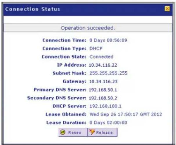
Figure 39.
Note: The Connection Status screen should show a valid IP address and gateway. For more information about the Connection Status screen, see View the WAN, xDSL, or USB Port Status on page 504.
What to do next:
- If the automatic ISP configuration is successful:
You are connected to the Internet through the WAN interface that you just configured. For the multiple WAN port models, continue with the configuration process for the other WAN interfaces. If you are done with the configuration of WAN interfaces, continue with Configure the WAN Mode on page 80.
- If the automatic ISP configuration fails:
You can attempt a manual configuration as described in Manually Configure the Internet Connection on page 75 or you might need to change the MAC address as described in Set the UTM's MAC Address and Configure Advanced WAN Options on page 94. For information about troubleshooting, see Troubleshoot the ISP Connection on page 541.
Manually Configure the Internet Connection
Unless your ISP automatically assigns your configuration through DHCP, you need to obtain configuration parameters from your ISP to establish an Internet connection manually. The necessary parameters for various connection types are listed in Table 13 on page 74.
To configure the WAN ISP settings for an interface manually:
- Select Network Config > WAN Settings. The WAN screen displays (see Figure 37 on page 72, which shows the UTM50).
- Click the Edit button in the Action column of the WAN interface for which you want to configure the connection to the Internet. The WAN ISP Settings screen displays (see Figure 38 on page 73, which shows the WAN1 ISP Settings screen as an example).
- Locate the ISP Login section onscreen:

Figure 40.
In the ISP Login section, select one of the following options:
-
If your ISP requires an initial login to establish an Internet connection, select Yes. (The default is No.)
• If a login is not required, select No, and ignore the Login and Password fields. -
If you selected Yes, enter the login name in the Login field and the password in the Password field. This information is provided by your ISP.
- In the ISP Type section of the screen, select the type of ISP connection that you use from the two listed options. By default, Other (PPPoE) is selected, as shown in the following figure:
![Which type of ISP connection do you use? ○ Austria (PPTP) ● Other (PPPoE) Account Name: Domain Name: Idle Timeout: ○ Keep Connected ○ Idle Timeout 0 [Minutes] Connection Reset: □ Disconnect Time: 0 HH 0 MM Delay: 0 Sec My IP Address: Server IP Address:](/content/2026/06/1371942/images/07eb094cf584125cfdf21501dca551be3cb9e4ed0bcd4a6f3962dec905be605d.jpg)
Figure 41.
- If your connection is PPTP or PPPoE, your ISP requires an initial login. Enter the settings as explained in the following table:
Table 14. PPTP and PPPoE settings
| Setting Description | ||
| Austria (PPTP) | If your ISP is Austria Telecom or any other ISP that uses PPTP for login, select this radio button, and enter the following settings: | |
| Account Name The account name is also known as the host name or system name.Enter the account name for the PPTP connection (usually your email ID assigned by your ISP). Some ISPs require you to enter your full email address here. | ||
| Domain Name Your domain name or workgroup name assigned by your ISP, or your ISP's domain name. You can leave this field blank. | ||
| Idle Timeout | Select theKeep Connectedradio button to keep the connection always on. To log out after the connection is idle for a period:1. Select theIdle Timeoutradio button.2. In the time-out field, enter the number of minutes to wait before disconnecting.This is useful if your ISP charges you based on the period that you are logged in. | |
| My IP Address The IP address assigned by the ISP to make the connection with the ISP server. | ||
| Server IPAddress | The IP address of the PPTP server. | |
| Other (PPPoE) | If you have installed login software, then your connection type is PPPoE. Select this radio button, and enter the following settings: | |
| Account Name The account name for the PPPoE connection. | ||
| Domain Name The name of your ISP's domain or your domain name if your ISP has you assigned one. You can leave this field blank. | ||
| Idle Timeout | Select theKeep Connectedradio button to keep the connection always on. To log out after the connection is idle for a period:1. Select theIdle Timeoutradio button.2. In the time-out field, enter the number of minutes to wait before disconnecting.This is useful if your ISP charges you based on the period that you are logged in.Note:When you use a PPPoE connection and select the Idle Timeout radio button, you cannot configure load balancing (seeConfigure Load Balancing (Multiple WAN Port Models) on page 86). To use load balancing on a PPPoE connection, select theKeep Connectedradio button. When you have configured load balancing, the Idle Timeout radio button and time-out field are masked out. | |
| Connection Reset | Select theConnection Resetcheck box to specify a time when the PPPoE WAN connection is reset, that is, the connection is disconnected momentarily and then reestablished. Then, specify the disconnect time and delay. | |
| Disconnect TimeSpecify the hour and minutes when the connection should be disconnected. | ||
| Delay Specifythe period in seconds after which the connection should be reestablished. | ||
- In the Internet (IP) Address section of the screen (see the following figure), configure the IP address settings as explained in the following table. Click the Current IP Address link to see the currently assigned IP address.
![Internet (IP) Address [Current IP Address] Get Dynamically from ISP Client Identifier Vendor Class Identifier Use Static IP Address IP Address: 0 -0 -0 -0 Subnet Mask: 0 -0 -0 -0 Gateway IP Address: 0 -0 -0 -0](/content/2026/06/1371942/images/b7ce89172247433bd767d738abef6d0363c7c0fae4e75157abc47c93ab571f6c.jpg)
Figure 42.
Table 15. Internet IP address settings
| Setting Description | ||
| Get Dynamically from ISP | If your ISP has not assigned you a static IP address, select the Get Dynamically from ISP radio button. The ISP automatically assigns an IP address to the UTM using DHCP network protocol. | |
| Client Identifier If your ISP | requires the client identifier information to assign an IP address using DHCP, select the Client Identifier check box. | |
| Vendor Class Identifier If | your ISP requires the vendor class identifier information to assign an IP address using DHCP, select the Vendor Class Identifier check box. | |
| Use Static IP Address | If your ISP has assigned you a fixed (static or permanent) IP address, select the Use Static IP Address radio button, and enter the following settings: | |
| IP Address Static IP address assigned to you. This address identifies the UTM to your ISP. | ||
| Subnet Mask The subnet mask is usually provided by your ISP. | ||
| Gateway IP Address The IP address of the ISP's gateway is usually provided by your ISP. | ||
- In the Domain Name Server (DNS) Servers section of the screen (see the following figure), specify the DNS settings as explained in the following table.

Figure 43.
Table 16. DNS server settings
| Setting Description | ||
| Get Automatically from ISP | If your ISP has not assigned any Domain Name Server (DNS) addresses, select the Get Automatically from ISP radio button. | |
| Use These DNS Servers | If your ISP has assigned DNS addresses, select the Use These DNS Servers radio button. Make sure that you fill in valid DNS server IP addresses in the fields. Incorrect DNS entries might cause connectivity issues. | |
| Primary DNS Server The IP address of the primary DNS server. | ||
| Secondary DNS Server The IP address of the secondary DNS server. | ||
ProSecure Unified Threat Management (UTM) Appliance
- Click Apply to save any changes to the WAN ISP settings. (Or click Reset to discard any changes and revert to the previous settings.)
- Click Test to evaluate your entries. The UTM attempts to make a connection according to the settings that you entered.
- To verify the connection:
a. Return to the WAN screen by selecting Network Config > WAN Settings.
b. Click the Status button in the Action column for the WAN interface that you just configured to display the Connection Status pop-up screen.

Figure 44.
Note: The Connection Status screen should show a valid IP address and gateway. For more information about the Connection Status screen, see View the WAN, xDSL, or USB Port Status on page 504.
What to do next:
- If the manual ISP configuration is successful:
You are connected to the Internet through the WAN interface that you just configured. For the multiple WAN port models, continue with the configuration process for the other WAN interfaces. If you are done with the configuration of WAN interfaces, continue with Configure the WAN Mode on page 80.
- If the manual ISP configuration fails:
You might need to change the MAC address as described in Set the UTM's MAC Address and Configure Advanced WAN Options on page 94. For information about troubleshooting, see Troubleshoot the ISP Connection on page 541.
Configure the WAN Mode
• Overview of the WAN Modes
- Configure Network Address Translation (All Models)
- Configure Classical Routing (All Models)
- Configure Auto-Rollover Mode and the Failure Detection Method (Multiple WAN Port Models)
- Configure Load Balancing and Optional Protocol Binding (Multiple WAN Port Models)
Overview of the WAN Modes
For the multiple WAN port models, the UTM can be configured on a mutually exclusive basis for either auto-rollover (for increased system reliability) or load balancing (for maximum bandwidth efficiency). If you do not select load balancing, you need to specify one WAN interface as the primary interface.
Note: For the UTM9S and UTM25S only, you can also use a DSL or USB interface for load balancing mode, primary WAN mode, and auto-rollover mode. However, in auto-rollover mode, a USB interface can function only as a rollover interface. For information about how to configure the DSL WAN interface, see Appendix A, xDSL Network Module for the UTM9S and UTM25S. For information about how to configure the USB WAN interface, see Appendix C, 3G/4G Dongles for the UTM9S and UTM25S.
- Load balancing mode. The UTM distributes the outbound traffic equally among the WAN interfaces that are functional. Depending on the UTM model, you can configure up to four WAN interfaces. The UTM supports weighted load balancing and round-robin load balancing (see Configure Load Balancing and Optional Protocol Binding (Multiple WAN Port Models) on page 85).
Note: Scenarios could arise when load balancing needs to be bypassed for certain traffic or applications. If certain traffic needs to travel on a specific WAN interface, configure protocol binding rules for that WAN interface. The rule should match the desired traffic.
- Primary WAN mode. The selected WAN interface is made the primary interface. The other interfaces are disabled.
- Auto-rollover mode. A WAN interface is defined as the primary link, and another interface needs to be defined as the rollover link. If the UTM model has more than two
WAN interfaces, the remaining interfaces are disabled. As long as the primary link is up, all traffic is sent over the primary link. When the primary link goes down, the rollover link is brought up to send the traffic. When the primary link comes back up, traffic automatically rolls back to the original primary link.
If you want to use a redundant ISP link for backup purposes, select the WAN interface that needs to function as the primary link for this mode. Ensure that the backup WAN interface has also been configured and that you configure the WAN failure detection method on the WAN Advanced Options screen to support auto-rollover (see Configure Auto-Rollover Mode and the Failure Detection Method (Multiple WAN Port Models) on page 82).
Whichever WAN mode you select for the multiple WAN port models, you also need to select either NAT or classical routing, as explained in the following sections.
Note: NAT and classical routing also apply to the single WAN port models.

WARNING:
When you change the WAN mode, the WAN interface or interfaces restart. If you change from primary WAN mode to load balancing mode, or the other way around, the interface through which you can access the UTM might change. Take note of the IP addresses of the interfaces before you change the WAN mode.
Configure Network Address Translation (All Models)
Network Address Translation (NAT) allows all computers on your LAN to share a single public Internet IP address. From the Internet, there is only a single device (the UTM) and a single IP address. Computers on your LAN can use any private IP address range, and these IP addresses are not visible from the Internet.
Note the following about NAT:
- The UTM uses NAT to select the correct computer (on your LAN) to receive any incoming data.
- If you have only a single public Internet IP address, you need to use NAT (the default setting).
- If your ISP has provided you with multiple public IP addresses, you can use one address as the primary shared address for Internet access by your computers, and you can map incoming traffic on the other public IP addresses to specific computers on your LAN. This one-to-one inbound mapping is configured using an inbound firewall rule.

WARNING:
Changing the WAN mode from classical routing to NAT causes all LAN WAN and DMZ WAN inbound rules to revert to default settings.
To configure NAT:
- Select Network Config > WAN Settings > WAN Mode. The WAN Mode screen displays (see Figure 45 on page 83).
- In the NAT (Network Address Translation) section of the screen, select the NAT radio button.
- Click Apply to save your settings.
Configure Classical Routing (All Models)
In classical routing mode, the UTM performs routing, but without NAT. To gain Internet access, each computer on your LAN needs to have a valid static Internet IP address.
If your ISP has allocated a number of static IP addresses to you, and you have assigned one of these addresses to each computer, you can choose classical routing. Or, you can use classical routing for routing private IP addresses within a campus environment.
To view the status of the WAN ports, you can view the Router Status screen (see View the System Status on page 486).

WARNING:
Changing the WAN mode from NAT to classical routing causes all LAN WAN and DMZ WAN inbound rules to revert to default settings.
To configure classical routing:
- Select Network Config > WAN Settings > WAN Mode. The WAN Mode screen displays (see Figure 45 on page 83).
- In the NAT (Network Address Translation) section of the screen, select the Classical Routing radio button.
- Click Apply to save your settings.
Configure Auto-Rollover Mode and the Failure Detection Method (Multiple WAN Port Models)
To use a redundant ISP link for backup purposes, ensure that the backup WAN interface has already been configured. Then select the WAN interface that should function as the primary link for this mode, and configure the WAN failure detection method on the WAN Mode screen to support auto-rollover.
ProSecure Unified Threat Management (UTM) Appliance
When the UTM is configured in auto-rollover mode, it uses the selected WAN failure detection method to detect the status of the primary link connection at regular intervals. Link failure is detected in one of the following ways:
• DNS queries sent to a DNS server
• Ping request sent to an IP address
• None (no failure detection is performed)
From the primary WAN interface, DNS queries or ping requests are sent to the specified IP address. If replies are not received after a specified number of retries, the primary WAN interface is considered down, and a rollover to the backup WAN interface occurs. When the primary WAN interface comes back up, another rollover occurs from the backup WAN interface back to the primary WAN interface. The WAN failure detection method that you select applies only to the primary WAN interface, that is, it monitors the primary link only.
Configure Auto-Rollover Mode
To configure auto-rollover mode:
- Select Network Config > WAN Settings > WAN Mode. The WAN Mode screen displays:

Figure 45.
- In the Load Balancing Settings section of the screen, configure the following settings:
a. Select the Primary WAN Mode radio button.
b. From the corresponding drop-down list on the right, select a WAN interface to function as the primary WAN interface. The other WAN interface or interfaces become disabled.
c. Select the Auto Rollover check box.
d. From the corresponding drop-down list on the right, select a WAN interface to function as the backup WAN interface.
Note: Ensure that the backup WAN interface is configured before enabling auto-rollover mode.
- Click Apply to save your settings.
Configure the Failure Detection Method
To configure the failure detection method:
- Select Network Config > WAN Settings. The WAN screen displays (see Figure 37 on page 72).
- Click the Edit button in the Action column of the WAN interface that you selected as the primary WAN interface. The WAN ISP Settings screen displays (see Figure 38 on page 73, which shows the WAN1 ISP Settings screen as an example).
- Click the Advanced option arrow at the upper right of the screen. The WAN Advanced Options screen displays for the WAN interface that you selected. (For an image of the entire screen, see Figure 53 on page 95.)
- Locate the Failure Detection Method section onscreen (see the following figure). Enter the settings as explained in the following table.

Figure 46.
Table 17. Failure detection method settings
| Setting Description | ||
| WAN Failure Detection MethodSelect a failure detection method from the drop-down list. DNS queries or pings are sent through the WAN interface that is being monitored. The retry interval and number of failover attempts determine how quickly the UTM switches from the primary link to the backup link in case the primary link fails, or when the primary link comes back up, switches back from the backup link to the primary link. | ||
| WAN DNS DNS queries are sent to the DNS server that is configured in the Domain Name Server (DNS) Servers section of the WAN ISP screen (see Manually Configure the Internet Connection on page 75). | ||
| Custom DNS DNS queries are sent to the specified DNS server. | ||
| Ping | Pings are sent to a server with a public IP address. This server should not reject the ping request and should not consider ping traffic to be abusive. | |
| IP Address The IP address of the ping server. | ||
| Retry Interval is The retry interval in seconds. The DNS query or ping is sent periodically after every test period. The default test period is 30 seconds. | ||
| Failover after The number of failover attempts. The primary WAN interface is considered down after the specified number of queries have failed to elicit a reply. The backup interface is brought up after this situation has occurred. The failover default is four failures. | ||
Note: After the primary WAN interface fails, the default time to roll over is 2 minutes. The minimum test period is 30 seconds, and the minimum number of tests is 4.
5. Click Apply to save your settings.
Note: You can configure the UTM to generate a WAN status log and email this log to a specified address (see Configure Logging, Alerts, and Event Notifications on page 466).
Configure Load Balancing and Optional Protocol Binding (Multiple WAN Port Models)
To use multiple ISP links simultaneously, configure load balancing. In load balancing mode, any WAN port carries any outbound protocol unless protocol binding is configured.
When a protocol is bound to a particular WAN port, all outgoing traffic of that protocol is directed to the bound WAN port. For example, if the HTTPS protocol is bound to the WAN1 port and the FTP protocol is bound to the WAN2 port, then the UTM automatically routes all outbound HTTPS traffic from the computers on the LAN through the WAN1 port. All outbound FTP traffic is routed through the WAN2 port.
Protocol binding addresses two issues:
- Segregation of traffic between links that are not of the same speed.
High-volume traffic can be routed through the WAN port connected to a high-speed link, and low-volume traffic can be routed through the WAN port connected to the low-speed link.
- Continuity of source IP address for secure connections.
Some services, particularly HTTPS, cease to respond when a client's source IP address changes shortly after a session has been established.
Configure Load Balancing (Multiple WAN Port Models)
To configure load balancing:
- Select Network Config > WAN Settings > WAN Mode. The WAN Mode screen displays:

Figure 47.
Note: You cannot configure load balancing when you use a PPPoE connection and have selected the Idle Timeout radio button on the WAN ISP Settings screen (single WAN port models) or on one of the WAN ISP Settings screens (multiple WAN port models); to use load balancing on a PPPoE connection, select the Keep Connected radio button. For more information, see Figure 41 on page 76 and the accompanying PPPoE information in Table 14 on page 76.
- In the Load Balancing Settings section of the screen, configure the following settings:
a. Select the Load Balancing Mode radio button. b. From the corresponding drop-down list on the right, select one of the following load balancing methods:
- Weighted LB. With weighted load balancing, balance weights are calculated based on WAN link speed and available WAN bandwidth. This is the default setting and the most efficient load-balancing algorithm.
- Round-robin. With round-robin load balancing, new traffic connections are sent over a WAN link in a serial method irrespective of bandwidth or link speed. For example on a UTM150, if the WAN1, WAN2, and WAN3 interfaces are active in round-robin load balancing mode, an HTTP request could first be sent over the WAN1 interface, then a new FTP session could start on the WAN2 interface, and then any new connection to the Internet could be made on the WAN3 interface.
ProSecure Unified Threat Management (UTM) Appliance
This load-balancing method ensures that a single WAN interface does not carry a disproportionate distribution of sessions.
- Click Apply to save your settings.
Configure Protocol Binding (Optional)
To configure protocol binding and add protocol binding rules:
- Select Network Config > Protocol Binding. The Protocol Bindings screen displays. (The following figure shows two examples in the Protocol Bindings table.)

Figure 48.
The Protocol Bindings table displays the following fields:
-
Check box. Allows you to select the protocol binding rule in the table.
• Status icon. Indicates the status of the protocol binding rule: -
Green circle. The protocol binding rule is enabled.
- Gray circle. The protocol binding rule is disabled.
• Service. The service or protocol for which the protocol binding rule is set up.
- Local Gateway. The WAN interface to which the service or protocol is bound.
- Source Network. The computers on your network that are affected by the protocol binding rule.
- Destination Network. The Internet locations (based on their IP address) that are covered by the protocol binding rule.
- Action. The Edit button provides access to the Edit Protocol Binding screen for the corresponding service.
- Click the Add table button below the Protocol Bindings table. The Add Protocol Binding screen displays:

Figure 49.
- Configure the protocol binding settings as explained in the following table:
Table 18. Add Protocol Binding screen settings
| Setting Description | ||
| Service From the | drop-down list, select a service or application to be covered by this rule. If the service or application does not appear in the list, you need to define it using the Services screen (seeOutbound Rules(Service Blocking)on page 129). | |
| Local Gateway From the drop-down list, select one of the WAN interfaces. | ||
| Source Network | The source network settings determine which computers on your network are affected by this rule. Select one of the following options from the drop-down list: | |
| Any All devices on your LAN. | ||
| Single address In the Start IP field, enter the IP address to which the rule is applied. | ||
| Address Range In the Start IP field and End IP field, enter the IP addresses for the range to which the rule is applied. | ||
| Group 1-Group 8 If this option is selected, the rule is applied to the devices that are assigned to the selected group.Note:You can also assign a customized name to a group (seeChange Group Names in the Network Databaseon page 115). | ||
| Destination Network | The destination network settings determine which Internet locations (based on their IP address) are covered by the rule. Select one of the following options from the drop-down list: | |
| Any All Internet IP address. | ||
| Single address In the Start IP field, enter the IP address to which the rule is applied. | ||
| Address range In the Start IP field and End IP field, enter the IP addresses for the range to which the rule is applied. | ||
ProSecure Unified Threat Management (UTM) Appliance
- Click Apply to save your settings. The protocol binding rule is added to the Protocol Bindings table. The rule is automatically enabled, which is indicated by the ! status icon, a green circle.
To edit a protocol binding:
- On the Protocol Bindings screen (see Figure 48 on page 87), in the Protocol Bindings table, click the Edit table button to the right of the binding that you want to edit. The Edit Protocol Binding screen displays. This screen shows the same fields as the Add Protocol Binding screen (see the previous figure).
- Modify the settings as explained in the previous table.
- Click Apply to save your settings.
To enable, disable, or delete one or more protocol bindings:
- On the Protocol Bindings screen (see Figure 48 on page 87), select the check box to the left of each protocol binding that you want to enable, disable, or delete, or click the Select All table button to select all bindings.
-
Click one of the following table buttons:
-
Enable. Enables the binding or bindings. The ! status icon changes from a gray circle to a green circle, indicating that the selected binding or bindings are enabled. (By default, when a binding is added to the table, it is automatically enabled.)
- Disable. Disables the binding or bindings. The ! status icon changes from a green circle to a gray circle, indicating that the selected binding or bindings are disabled.
- Delete. Deletes the binding or bindings.
Configure Secondary WAN Addresses
You can set up a single WAN port to be accessed through multiple IP addresses by adding aliases to the port. An alias is a secondary WAN address. One advantage is, for example, that you can assign different virtual IP addresses to a web server and an FTP server, even though both servers use the same physical IP address. You can add several secondary IP addresses to a single WAN port.
After you have configured secondary WAN addresses, these addresses are displayed on the following firewall rule screens:
- In the WAN Destination IP Address drop-down lists of the following inbound firewall rule screens:
- Add LAN WAN Inbound Service screen
- Add DMZ WAN Inbound Service screen
- In the NAT IP drop-down lists of the following outbound firewall rule screens:
- Add LAN WAN Outbound Service screen
- Add DMZ WAN Outbound Service screen
For more information about firewall rules, see Overview of Rules to Block or Allow Specific Kinds of Traffic on page 128).
It is important that you ensure that any secondary WAN addresses are different from the primary WAN, LAN, and DMZ IP addresses that are already configured on the UTM. However, primary and secondary WAN addresses can be in the same subnet. The following is an example of correctly configured IP addresses on a multiple WAN port model:
• Primary WAN1 IP address. 10.121.0.1 with subnet 255.255.255.0
• Secondary WAN1 IP address. 10.121.26.1 with subnet 255.255.255.0
• Primary WAN2 IP address. 10.216.75.1 with subnet 255.255.255.0
• Secondary WAN2 IP address. 10.216.82.1 with subnet 255.255.255.0
• DMZ IP address. 192.168.10.1 with subnet 255.255.255.0
• Primary LAN IP address. 192.168.1.1 with subnet 255.255.255.0
• Secondary LAN IP address. 192.168.2.1 with subnet 255.255.255.0
To add a secondary WAN address to a WAN interface:
- Select Network Config > WAN Settings. The WAN screen displays (see Figure 37 on page 72).
- Click the Edit button in the Action column of the WAN interface for which you want to add a secondary address. The WAN ISP Settings screen displays (see Figure 37 on page 72, which shows the WAN1 ISP Settings screen as an example).
- Click the Secondary Addresses option arrow at the upper right of the screen. The WAN Secondary Addresses screen displays for the WAN interface that you selected (see the following figure, which shows the WAN1 Secondary Addresses screen as an example, and which includes one entry in the List of Secondary WAN addresses table).

Figure 50.
The List of Secondary WAN addresses table displays the secondary WAN IP addresses added for the selected WAN interface.
-
In the Add WAN Secondary Addresses section of the screen, enter the following settings:
-
IP Address. Enter the secondary address that you want to assign to the WAN interface.
-
Subnet Mask. Enter the subnet mask for the secondary IP address.
-
Click the Add table button in the rightmost column to add the secondary IP address to the List of Secondary WAN addresses table.
Repeat Step 4 and Step 5 for each secondary IP address that you want to add to the List of Secondary WAN addresses table.
To delete one or more secondary addresses:
- In the List of Secondary WAN addresses table, select the check box to the left of each address that you want to delete, or click the Select All table button to select all addresses.
- Click the Delete table button.
Configure Dynamic DNS
Dynamic DNS (DDNS) is an Internet service that allows devices with varying public IP addresses to be located using Internet domain names. To use DDNS, you need to set up an account with a DDNS provider such as DynDNS.org, TZO.com, Oray.net, or 3322.org. (Links to DynDNS, TZO, Oray, and 3322 are provided for your convenience as option arrows on the DDNS configuration screens.) The UTM firmware includes software that notifies DDNS servers of changes in the WAN IP address, so that the services running on this network can be accessed by others on the Internet.
If your network has a permanently assigned IP address, you can register a domain name and have that name linked with your IP address by public Domain Name Servers (DNS).
However, if your Internet account uses a dynamically assigned IP address, you do not know in advance what your IP address will be, and the address can change frequently—hence, the need for a commercial DDNS service, which allows you to register an extension to its domain, and forwards DNS requests for the resulting fully qualified domain name (FQDN) to your frequently changing IP address.
After you have configured your account information on the UTM, when your ISP-assigned IP address changes, your UTM automatically contacts your DDNS service provider, logs in to your account, and registers your new IP address.
Consider the following:
- For auto-rollover mode, you need an FQDN to implement features such as exposed hosts and virtual private networks regardless of whether you have a fixed or dynamic IP address.
- For load balancing mode, you might still need an FQDN either for convenience or if you have a dynamic IP address.
To configure DDNS:
- Select Network Config > Dynamic DNS. The Dynamic DNS screen displays (see the following figure).
The WAN Mode section onscreen reports the currently configured WAN mode (for example, Single Port WAN1, Load Balancing, or Auto Rollover). Only those options that match the configured WAN mode are accessible onscreen.
- Click the submenu tab for your DDNS service provider:
• Dynamic DNS for DynDNS.org (which is shown in the following figure)
• DNS TZO for TZO.com
• DNS Oray for Oray.net
• 3322 DDNS for 3322.org
![Network Config | Network Security | Application Security | VPN | Users | Administration | Monitoring | Support | Wizards | WAN Settings || Protocol Binding || Dynamic DNS || WAN Metering || LAN Settings || DMZ Setup || Routing || Dynamic DNS DNS TZO DNS Oray 3322 DDNS DynDNS Information WAN Mode Current WAN Mode: Single Port WAN1 WAN1(Dynamic DNS Status: service is not enabled) Configured DDNS : none Change DNS to DynDNS.org? Yes No Host and Domain Name: [Example: yourname.dyndns.org] Username: Password: Use wildcards Update every 30 days WAN2(Dynamic DNS Status: service is not enabled) Configured DDNS: none Change DNS to DynDNS.org? Yes No Host and Domain Name: [Example: yourname.dyndns.org] Username: Password: Use wildcards Update every 30 days Apply Reset](/content/2026/06/1371942/images/ec553e6b642f915c057b23301b68565588a7c19ace53cb264b222c674a670b91.jpg)
Figure 51.
- Click the Information option arrow in the upper right of a DNS screen for registration information.
ProSecure Unified Threat Management (UTM) Appliance

Figure 52.
-
Access the website of the DDNS service provider, and register for an account (for example, for DynDNS.org, go to http://www.dyndns.com/).
-
Configure the DDNS service settings as explained in the following table:
Table 19. DNS service settings
| Setting Description | ||
| WAN (Dynamic DNS Status: ... )orWAN1 (Dynamic DNS Status: ...) | ||
| Change DNS to (DynDNS, TZO, Oray, or 3322) | Select theYesradio button to enable the DDNS service. The fields that display onscreen depend on the DDNS service provider that you have selected. Enter the following settings: | |
| Host and Domain Name The host and domain name for the DDNS service. | ||
| Username orUser Email Address | The user name or email address for DDNS server authentication. | |
| Password or User Key The | password that is used for DDNS server authentication. | |
| Use wildcards If your DDNS | provider allows the use of wildcards in resolving your URL, you can select theUse wildcardscheck box to activate this feature. For example, the wildcard feature causes *.yourhost.dyndns.org to be aliased to the same IP address as yourhost.dyndns.org. | |
| Update every 30 days If you | our WAN IP address does not often change, you might need to force a periodic update to the DDNS service to prevent your account from expiring. If theUpdate every 30 dayscheck box displays, select it to enable a periodic update. | |
| WAN2 (Dynamic DNS Status: ... )orWAN3 (Dynamic DNS Status: ... )orWAN4 (Dynamic DNS Status: ... ) | ||
| See the information for WAN or WAN1 about how to enter the settings. You can select different DDNS services for different WAN interfaces. | ||
- Click Apply to save your configuration.
Set the UTM's MAC Address and Configure Advanced WAN Options
The advanced options include configuring the maximum transmission unit (MTU) size, the port speed, and the UTM's MAC address, and setting a rate limit on the traffic that is forwarded by the UTM.
Note: You can also configure the failure detection method for the auto-rollover mode on the WAN Advanced Options screen for the corresponding WAN interface. This procedure is discussed in Configure the Failure Detection Method on page 84.
IMPORTANT:
Each computer or router on your network has a unique 48-bit local Ethernet address. This is also referred to as the computer's Media Access Control (MAC) address. The default, on the WAN Advanced Options screen, is Use Default Address. If your ISP requires MAC authentication and another MAC address has been previously registered with your ISP, then you need to enter that address on the Advanced Options screen for the DSL interface.
To configure advanced WAN options:
- Select Network Config > WAN Settings.
- Click the Edit button in the Action column of the WAN interface for which you want to configure the advanced options. The WAN ISP Settings screen displays (see Figure 38 on page 73, which shows the WAN1 ISP Settings screen of the UTM50 as an example).
- Click the Advanced option arrow in the upper right of the screen. The WAN Advanced Options screen displays for the WAN interface that you selected. (The following figure shows the WAN1 Advanced Options screen of the UTM50 as an example.)
ProSecure Unified Threat Management (UTM) Appliance
![Network Config Network Security Application Security VPN Users Administration Monitoring Support Wizards WAN Settings Protocol Binding Dynamic DNS WAN Metering LAN Settings DMZ Setup Routing WAN1 Advanced Options WAN1 ISP Settings Secondary Addresses MTU Size Default Custom 1500 [Bytes] Speed Port Speed: AutoSense Router's MAC Address Use Default Address Use this computer's MAC Address Use this MAC Address c0:3f:0e:38:3e:62 Failure Detection Method Failure Detection Method: None DNS Server: 0 -0 -0 -0 IP Address: 0 -0 -0 -0 Retry Interval is: 0 (Seconds) Failover after: 0 (Failures) Upload/Download Settings WAN Connection Type: Other WAN Connection Speed Upload: 1 Gbps 1000000 [Kbps] WAN Connection Speed Download: 1 Gbps 1000000 [Kbps] Apply Reset](/content/2026/06/1371942/images/d38a6ecfe4944a1fe09470178ff4b21e5b09590209c2e19f72cd6797edf99f55.jpg)
Figure 53.
- Enter the settings as explained in the following table:
Table 20. Advanced WAN settings
| Setting Description | |
| MTU SizeMake one of the following selections: | |
| Default | Select the Default radio button for the normal maximum transmit unit (MTU) value. For most Ethernet networks, this value is 1500 bytes, or 1492 bytes for PPPoE connections. |
| Custom | Select the Custom radio button, and enter an MTU value in the Bytes field. For some ISPs, you might need to reduce the MTU. This is rarely required, and should not be done unless you are sure that it is necessary for your ISP connection. |
| Speed | |
| In most cases, the UTM can automatically determine the connection speed of the WAN port of the device (modem or router) that provides the WAN connection. If you cannot establish an Internet connection, you might need to select the port speed manually. If you know the Ethernet port speed of the modem or router, select it from the drop-down list. Use the half-duplex settings only if the full-duplex settings do not function correctly.Select one of the following speeds from the drop-down list:AutoSense. Speed autosensing. This is the default setting, which can sense all Ethernet speeds and duplex modes, including 1000BASE-T speed at full duplex.10BaseT Half_Duplex. Ethernet speed at half duplex.10BaseT Full_Duplex. Ethernet speed at full duplex.100BaseT Half_Duplex. Fast Ethernet speed at half duplex.100BaseT Full_Duplex. Fast Ethernet speed at full duplex.1000BaseT Full_Duplex. Gigabit Ethernet. | |
| Router's MAC AddressMake one of the following selections: | |
| Use Default Address | Each computer or router on your network has a unique 32-bit local Ethernet address. This is also referred to as the computer's Media Access Control (MAC) address. To use the UTM's own MAC address, select the Use Default Address radio button. |
| Use this computer's MAC Address | Select the Use this computer's MAC Address radio button to allow the UTM to use the MAC address of the computer you are now using to access the web management interface. This setting is useful if your ISP requires MAC authentication. |
| Use this MAC Address | Select the Use this MAC Address radio button, and manually enter the MAC address in the field next to the radio button. You would typically enter the MAC address that your ISP is requiring for MAC authentication.Note:The format for the MAC address is 01:23:45:67:89:AB (numbers 0–9 and either uppercase or lowercase letters A–F). If you enter a MAC address, the existing entry is overwritten. |
| Failure Detection MethodSee Configure the Failure Detection Method on page 84, including Table 17 on page 84. | |
| Upload/Download SettingsThese settings rate-limit the traffic that is forwarded by the UTM. | |
| WAN Connection Type | From the drop-down list, select the type of connection that the UTM uses to connect to the Internet: DSL, ADSL, Cable Modem, T1, T3, or Other. |
| WAN Connection Speed Upload | From the drop-down list, select the maximum upload speed that is provided by your ISP. You can select from 56 Kbps to 1 Gbps, or you can select Custom and enter the speed in Kbps in the field below the drop-down list. |
| WAN Connection Speed Download | From the drop-down list, select the maximum download speed that is provided by your ISP. You can select from 56 Kbps to 1 Gbps, or you can select Custom and enter the speed in Kbps in the field below the drop-down list. |
5. Click Apply to save your changes.

WARNING:
Depending on the changes that you made, when you click Apply, the UTM restarts, or services such as HTTP and SMTP might restart.
If you want to configure the advanced settings for an additional WAN interface, select another WAN interface and repeat these steps.
Additional WAN-Related Configuration Tasks
• To register the UTM with NETGEAR, see Register the UTM with NETGEAR on page 65.
• To test connectivity, see Test Connectivity on page 68.
- If you want the ability to manage the UTM remotely, enable remote management (see Configure Remote Management Access on page 438). If you enable remote management, NETGEAR strongly recommend that you change your password (see Change Passwords and Administrator and Guest Settings on page 436).
- You can set up the traffic meter for each WAN interface. See Enable the WAN Traffic Meter on page 462.
This chapter describes how to configure the advanced LAN features of your UTM. This chapter contains the following sections:
- Manage Virtual LANs and DHCP Options
- Configure Multihome LAN IP Addresses on the Default VLAN
- Manage Groups and Hosts (LAN Groups)
- Configure and Enable the DMZ Port
- Manage Routing
Note: The initial LAN configuration of the UTM's default VLAN 1 is described in Chapter 2, Use the Setup Wizard to Provision the UTM in Your Network.
Note: The Wireless Settings configuration menu is shown on the UTM9S and UTM25S only, accessible under the Network Config main navigation menu.
Manage Virtual LANs and DHCP Options
- Port-Based VLANs
- Assign and Manage VLAN Profiles
• VLAN DHCP Options - Configure a VLAN Profile
- Configure VLAN MAC Addresses and Advanced LAN Settings
A local area network (LAN) can generally be defined as a broadcast domain. Hubs, bridges, or switches in the same physical segment or segments connect all end node devices.
Endpoints can communicate with each other without the need for a router. Routers connect LANs together, routing the traffic to the appropriate port.
A virtual LAN (VLAN) is a local area network with a definition that maps workstations on some basis other than geographic location (for example, by department, type of user, or primary application). To enable traffic to flow between VLANs, traffic needs to go through a router, just as if the VLANs were on two separate LANs.
A VLAN is a group of computers, servers, and other network resources that behave as if they were connected to a single network segment—even though they might not be. For example, all marketing personnel might be spread throughout a building. Yet if they are all assigned to a single VLAN, they can share resources and bandwidth as if they were connected to the same segment. The resources of other departments can be invisible to the marketing VLAN members, accessible to all, or accessible only to specified individuals, depending on how the IT manager has set up the VLANs.
VLANs have a number of advantages:
- It is easy to set up network segmentation. Users who communicate most frequently with each other can be grouped into common VLANs, regardless of physical location. Each group's traffic is contained largely within the VLAN, reducing extraneous traffic and improving the efficiency of the whole network.
- They are easy to manage. The addition of nodes, as well as moves and other changes, can be dealt with quickly and conveniently from a management interface rather than from the wiring closet.
- They provide increased performance. VLANs free up bandwidth by limiting node-to-node and broadcast traffic throughout the network.
- They ensure enhanced network security. VLANs create virtual boundaries that can be crossed only through a router. So standard, router-based security measures can be used to restrict access to each VLAN.
Port-Based VLANs
The UTM supports port-based VLANs. Port-based VLANs help to confine broadcast traffic to the LAN ports. Even though a LAN port can be a member of more than one VLAN, the port can have only one VLAN ID as its port VLAN identifier (PVID). By default, all four LAN ports of the UTM are assigned to the default VLAN, or VLAN 1. Therefore, by default, all four LAN ports have the default PVID 1. However, you can assign another PVID to a LAN port by selecting a VLAN profile from the drop-down list on the LAN Setup screen.
After you have created a VLAN profile and assigned one or more ports to the profile, you need to enable the profile to activate it.
The UTM's default VLAN cannot be deleted. All untagged traffic is routed through the default VLAN (VLAN1), which you need to assign to at least one LAN port.
Note the following about VLANs and PVIDs:
- One physical port is assigned to at least one VLAN.
- One physical port can be assigned to multiple VLANs.
-
When one port is assigned to multiple VLANs, the port is used as a trunk port to connect to another switch or router.
-
When a port receives an untagged packet, this packet is forwarded to a VLAN based on the PVID.
- When a port receives a tagged packet, this packet is forwarded to a VLAN based on the ID that is extracted from the tagged packet.
When you create a VLAN profile, assign LAN ports to the VLAN, and enable the VLAN, the LAN ports that are members of the VLAN can send and receive both tagged and untagged packets. Untagged packets that enter these LAN ports are assigned to the default PVID 1; packets that leave these LAN ports with the same default PVID 1 are untagged. All other packets are tagged according to the VLAN ID that you assigned to the VLAN when you created the VLAN profile.
This is a typical scenario for a configuration with an IP phone that has two Ethernet ports, one of which is connected to the UTM, the other one to another device:
Packets coming from the IP phone to the UTM LAN port are tagged. Packets passing through the IP phone from the connected device to the UTM LAN port are untagged. When you assign the UTM LAN port to a VLAN, packets entering and leaving the port are tagged with the VLAN ID. However, untagged packets entering the UTM LAN port are forwarded to the default VLAN with PVID 1; packets that leave the LAN port with the same default PVID 1 are untagged.
Note: The configuration of the DHCP options for the default VLAN is explained in Chapter 2, Use the Setup Wizard to Provision the UTM in Your Network. For information about how to add and edit a VLAN profile, including its DHCP options, see Configure a VLAN Profile on page 103.
Assign and Manage VLAN Profiles
To assign VLAN profiles to the LAN ports and manage VLAN profiles:
- Select Network Config > LAN Settings. The LAN submenu tabs display, with the LAN Setup screen in view. The following figure shows the LAN Setup screen for the UTM25 with four LAN ports, and the default VLAN profile and another VLAN profile as examples. Note that the LAN Setup screen for the UTM50 (not shown in this manual) has six LAN ports in the Default VLAN section.
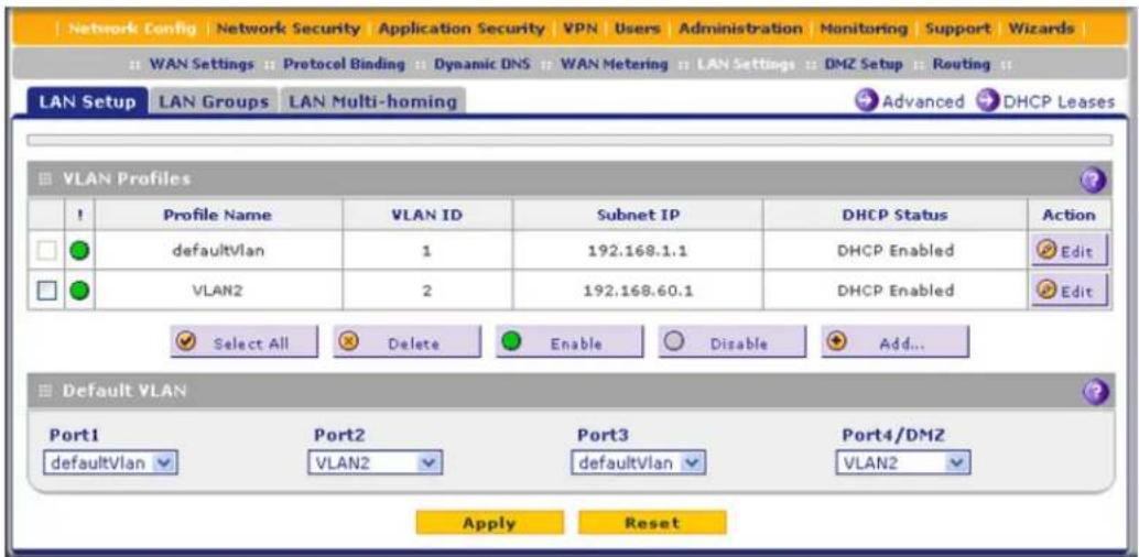
Figure 54.
For each VLAN profile, the following fields display in the VLAN Profiles table:
- Check box. Allows you to select the VLAN profile in the table.
-
Status icon. Indicates the status of the VLAN profile:
-
Green circle. The VLAN profile is enabled.
- Gray circle. The VLAN profile is disabled.
- Profile Name. The unique name assigned to the VLAN profile.
• VLAN ID. The unique ID (or tag) assigned to the VLAN profile.
- Subnet IP. The subnet IP address for the VLAN profile.
- DHCP Status. The DHCP server status for the VLAN profile, which can be either DHCP Enabled or DHCP Disabled.
• Action. The Edit table button, which provides access to the Edit VLAN Profile screen.
-
Assign a VLAN profile to a LAN port (For the UTM5, UTM10, UTM25, and UTM150: Port 1, Port 2, Port 3, or Port 4/DMZ; for the UTM50: Port 1, Port 2, Port 3, Port 4, Port 5, or Port 6/DMZ) by selecting a VLAN profile from the drop-down list. Both enabled and disabled VLAN profiles are displayed in the drop-down lists.
-
Click Apply to save your settings.
VLAN DHCP Options
For each VLAN, you need to specify the Dynamic Host Configuration Protocol (DHCP) options (see Configure a VLAN Profile on page 103). The configuration of the DHCP options for the UTM's default VLAN, or VLAN 1, is explained in Chapter 3, Manually Configure Internet and WAN Settings. This section provides further information about the DHCP options.
DHCP Server
The default VLAN (VLAN 1) has the DHCP server option enabled by default, allowing the UTM to assign IP, DNS server, WINS server, and default gateway addresses to all computers connected to the UTM's LAN. The assigned default gateway address is the LAN address of the UTM. IP addresses are assigned to the attached computers from a pool of addresses that you need to specify. Each pool address is tested before it is assigned to avoid duplicate addresses on the LAN. When you create a VLAN, the DHCP server option is disabled by default.
For most applications, the default DHCP server and TCP/IP settings of the UTM are satisfactory.
The UTM delivers the following settings to any LAN device that requests DHCP:
- An IP address from the range that you have defined
- Subnet mask
- Gateway IP address (the UTM's LAN IP address)
- Primary DNS server (the UTM's LAN IP address)
- WINS server (if you entered a WINS server address in the DHCP Setup screen)
- Lease time (the date obtained and the duration of the lease).
DHCP Relay
DHCP relay options allow you to make the UTM a DHCP relay agent for a VLAN. The DHCP relay agent makes it possible for DHCP broadcast messages to be sent over routers that do not support forwarding of these types of messages. The DHCP relay agent is therefore the routing protocol that enables DHCP clients to obtain IP addresses from a DHCP server on a remote subnet. If you do not configure a DHCP relay agent for a VLAN, its clients can obtain IP addresses only from a DHCP server that is on the same subnet. To enable clients to obtain IP addresses from a DHCP server on a remote subnet, you need to configure the DHCP relay agent on the subnet that contains the remote clients, so that the DHCP relay agent can relay DHCP broadcast messages to your DHCP server.
DNS Proxy
When the DNS proxy option is enabled for a VLAN, the UTM acts as a proxy for all DNS requests and communicates with the ISP's DNS servers (as configured on the WAN ISP Settings screens). All DHCP clients receive the primary and secondary DNS IP addresses along with the IP address where the DNS proxy is located (that is, the UTM's LAN IP address). When the DNS proxy option is disabled for a VLAN, all DHCP clients receive the DNS IP addresses of the ISP but without the DNS proxy IP address. A DNS proxy is particularly useful in auto-rollover mode. For example, if the DNS servers for each WAN connection are different servers, then a link failure might render the DNS servers inaccessible. However, when the DNS proxy option is enabled, the DHCP clients can make requests to the UTM, which, in turn, can send those requests to the DNS servers of the active WAN connection. However, disable the DNS proxy if you are using a multiple WAN
ProSecure Unified Threat Management (UTM) Appliance
configuration in auto-rollover mode with route diversity (that is, with two different ISPs) and you cannot ensure that the DNS server is available after a rollover has occurred.
LDAP Server
A Lightweight Directory Access Protocol (LDAP) server allows a user to query and modify directory services that run over TCP/IP. For example, clients can query email addresses, contact information, and other service information using an LDAP server. For each VLAN, you can specify an LDAP server and a search base that defines the location in the directory (that is, the directory tree) from which the LDAP search begins.
Configure a VLAN Profile
For each VLAN on the UTM, you can configure its profile, port membership, LAN TCP/IP settings, DHCP options, DNS server, and inter-VLAN routing capability.
The preconfigured default VLAN is called defaultVLAN.
To add or edit a VLAN profile:
- Select Network Config > LAN Settings. The LAN submenu tabs display, with the LAN Setup screen in view. The following figure shows the LAN Setup screen for the UTM25 with four LAN ports, and the default VLAN profile and another VLAN profile as examples. Note that the LAN Setup screen for the UTM50 (not shown in this manual) has six LAN ports in the Default VLAN section.
Note: For information about how to manage VLANs, see Port-Based VLANs on page 99. The following information describes how to configure a VLAN profile.
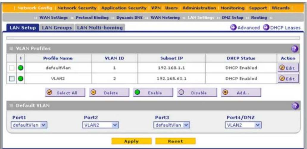
Figure 55.
- Either select an entry from the VLAN Profiles table and click the corresponding Edit table button, or add a VLAN profile by clicking the Add table button under the VLAN Profiles table. The Edit VLAN Profile screen displays. The following figure shows the Edit VLAN Profile screen for the UTM with four ports in the Port Membership section. Note that the Edit VLAN Profile screens for the UTM50 (not shown in this manual) has six ports in the Port Membership section.

Figure 56.
- Enter the settings as explained in the following table:
Table 21. Edit VLAN Profile screen settings
| Setting Description | ||
| VLAN Profile | ||
| Profile Name Enter a unique | que name for the VLAN profile. Note: You can also change the profile name of the default VLAN. | |
| VLAN ID Enter a unique ID | ID number for the VLAN profile. No two VLANs can have the same VLAN ID number. Note: You can enter VLAN IDs from 2 to 4093. VLAN ID 1 is reserved for the default VLAN; VLAN ID 4094 is reserved for the DMZ interface. | |
| Port Membership | ||
| UTM5, UTM9S, UTM10, UTM25, UTM25S, and UTM150: Port 1, Port 2, Port 3, and Port 4 / DMZ | Select one, several, or all port check boxes to make the ports members of this VLAN. Note: A port that is defined as a member of a VLAN profile can send and receive data frames that are tagged with the VLAN ID. | |
| UTM50: Port 1, Port 2, Port 3, Port 4, Port 5, and Port 6 / DMZ | ||
| LAN TCP/IP Setup | ||
| IP Address | Enter the IP address of the UTM (the factory default address is 192.168.1.1). Note: Always make sure that the LAN port IP address and DMZ port IP address are in different subnets. Note: If you change the LAN IP address of the VLAN while being connected through the browser to the VLAN, you are disconnected. You then need to open a new connection to the new IP address and log in again. For example, if you change the default IP address 192.168.1.1 to 10.0.0.1, you now need to enter https://10.0.0.1 in your browser to reconnect to the web management interface. | |
| Subnet Mask Enter the IP | subnet mask. The subnet mask specifies the network number portion of an IP address. Based on the IP address that you assign, the UTM automatically calculates the subnet mask. Unless you are implementing subnetting, use 255.255.255.0 as the subnet mask (computed by the UTM). | |
| DHCP | ||
| Disable DHCP Server | If another device on your network is the DHCP server for the VLAN, or if you will configure the network settings of all of your computers manually, select the Disable DHCP Server radio button to disable the DHCP server. By default, this radio button is not selected, and the DHCP server is enabled. | |
| Enable DHCP Server | Select the Enable DHCP Server radio button to enable the UTM to function as a Dynamic Host Configuration Protocol (DHCP) server, providing TCP/IP configuration for all computers connected to the VLAN. Enter the following settings: | |
| Domain Name This setting is optional. Enter the domain name of the UTM. | ||
| Starting IP Address | Enter the starting IP address. This address specifies the first of the contiguous addresses in the IP address pool. Any new DHCP client joining the LAN is assigned an IP address between this address and the ending IP address. The IP address 192.168.1.2 is the default starting address. | |
| Ending IP Address | Enter the ending IP address. This address specifies the last of the contiguous addresses in the IP address pool. Any new DHCP client joining the LAN is assigned an IP address between the starting IP address and this IP address. The IP address 192.168.1.100 is the default ending address.Note:The starting and ending DHCP IP addresses should be in the samenetworkas the LAN TCP/IP address of the UTM (that is, the IP address in the LAN TCP/IP Setup section as described earlier in this table). | |
| Primary DNS Server | This setting is optional. If an IP address is specified, the UTM provides this address as the primary DNS server IP address. If no address is specified, the UTM uses the VLAN IP address as the primary DNS server IP address. | |
| Secondary DNS Server | This setting is optional. If an IP address is specified, the UTM provides this address as the secondary DNS server IP address. | |
| WINS Server This setting is optional. Enter a WINS server IP address to specify the Windows NetBIOS server, if one is present in your network. | ||
| Lease Time Enter a lease time. This specifies the duration for which IP addresses are leased to clients. | ||
| DHCP Relay To use the UTM as a DHCP relay agent for a DHCP server somewhere else in your network, select theDHCP Relayradio button. Enter the following setting: | ||
| Enable LDAP information | To enable the DHCP server to provide Lightweight Directory Access Protocol (LDAP) server information, select the Enable LDAP information check box.Enter the following settings.Note:The LDAP settings that you specify as part of the VLAN profile are used only for SSL VPN and UTM authentication, but not for web and email security. | |
| LDAP Server The IP address or name of the LDAP server. | ||
| Search Base The search objects that specify the location in the directory tree from which the LDAP search begins. You can specify multiple search objects, separated by commas. The search objects include:CN (for common name)OU (for organizational unit)O (for organization)C (for country)DC (for domain)For example, to search the Netgear.net domain for all last names of Johnson, you would enter:cn=Johnson,dc=Netgear,dc=net | ||
| Port The port number for the LDAP server. The default setting is 0 (zero). | ||
| DNS Proxy | ||
| Enable DNS Proxy | This setting is optional. To enable the UTM to provide a LAN IP address for DNS address name resolution, select the Enable DNS Proxy check box. This setting is disabled by default.Note:When the DNS proxy option is disabled for a VLAN, all DHCP clients receive the DNS IP addresses of the ISP but without the DNS proxy IP address. | |
| Inter VLAN Routing | ||
| Enable Inter VLAN Routing | This setting is optional. To ensure that traffic is routed only to VLANs for which inter-VLAN routing is enabled, select the Enable Inter VLAN Routing check box. This setting is disabled by default. When the Enable Inter VLAN Routing check box is not selected, traffic from this VLAN is not routed to other VLANs, and traffic from other VLANs is not routed to this VLAN.Note:For information about inter-VLAN firewall rules, see VLAN Rules on page 154. | |
- Click Apply to save your settings.
Note: When you have completed the LAN setup, all outbound traffic is allowed and all inbound traffic is discarded except responses to requests from the LAN side. For information about how to change these default traffic rules, see Chapter 5, Firewall Protection.
To edit a VLAN profile:
- On the LAN Setup screen (see Figure 55 on page 103), click the Edit button in the Action column for the VLAN profile that you want to modify. The Edit VLAN Profile screen displays (see the previous screen).
- Modify the settings as explained in the previous table.
- Click Apply to save your settings.
To enable, disable, or delete one or more VLAN profiles:
- On the LAN Setup screen (see Figure 55 on page 103), select the check box to the left of each VLAN profile that you want to enable, disable, or delete, or click the Select All table button to select all profiles. (You cannot select the default VLAN profile.)
- Click one of the following table buttons:
- Enable. Enables the VLAN or VLANs. The ! status icon changes from a gray circle to a green circle, indicating that the selected VLAN or VLANs are enabled. (By default, when a VLAN is added to the table, it is automatically enabled.)
- Disable. Disables the VLAN or VLANs. The ! status icon changes from a green circle to a gray circle, indicating that the selected VLAN or VLANs are disabled.
- Delete. Deletes the VLAN or VLANs.
Configure VLAN MAC Addresses and Advanced LAN Settings
By default, all configured VLAN profiles share the same single MAC address as the LAN ports. (All LAN ports share the same MAC address.) However, you can change the VLAN MAC settings to allow up to 16 VLANs to each be assigned a unique MAC address.
You can also enable or disable the broadcast of Address Resolution Protocol (ARP) packets for the default VLAN. If the broadcast of ARP packets is enabled, IP addresses can be mapped to physical addresses (that is, MAC addresses).
To configure a VLAN to have a unique MAC address:
- Select Network Config > LAN Settings. The LAN submenu tabs display, with the LAN Setup screen in view (see Figure 55 on page 103).
- Click the Advanced option arrow in the upper right of the LAN Setup screen. The LAN Advanced screen displays:
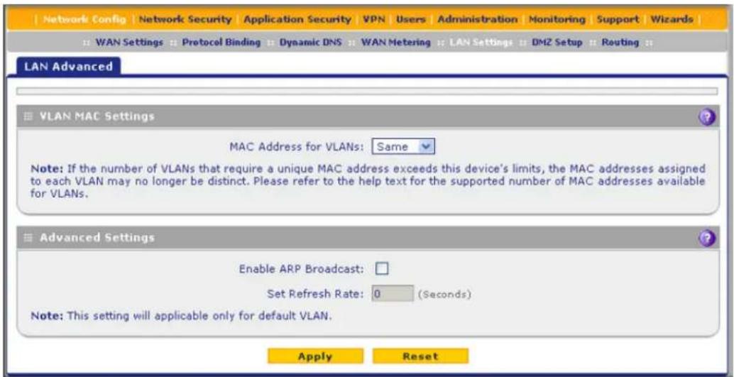
Figure 57.
- From the MAC Address for VLANs drop-down list, select Unique. (The default is Same.)
- As an option, you can disable the broadcast of ARP packets for the default VLAN by clearing the Enable ARP Broadcast check box. (The broadcast of ARP packets is enabled by default for the default VLAN.) If you choose to keep the broadcast of ARP enabled, you can enter an ARP refresh rate in the Set Refresh Rate field. The default setting is 180 seconds. The maximum ARP refresh rate is 86400 seconds (24 hours).
- Click Apply to save your settings.
Configure Multihome LAN IP Addresses on the Default VLAN
If you have computers using different IP networks in the LAN, (for example, 172.16.2.0 or 10.0.0.0), you can add aliases to the LAN ports and give computers on those networks access to the Internet, but you can do so only for the default VLAN. The IP address that is assigned as a secondary IP address needs to be unique and cannot be assigned to the VLAN.
It is important that you ensure that any secondary LAN addresses are different from the primary LAN, WAN, and DMZ IP addresses and subnet addresses that are already configured on the UTM.
The following is an example of correctly configured IP addresses on a multiple WAN port model:
• WAN1 IP address. 10.0.0.1 with subnet 255.0.0.0
- WAN2 IP address. 20.0.0.1 with subnet 255.0.0.0
• DMZ IP address. 192.168.10.1 with subnet 255.255.255.0
• Primary LAN IP address. 192.168.1.1 with subnet 255.255.255.0
• Secondary LAN IP address. 192.168.20.1 with subnet 255.255.255.0
To add a secondary LAN IP address:
- Select Network Config > LAN Settings > LAN Multi-homing. The LAN Multi-homing screen displays:

Figure 58.
The Available Secondary LAN IPs table displays the secondary LAN IP addresses added to the UTM.
- In the Add Secondary LAN IP Address section of the screen, enter the following settings:
• IP Address. Enter the secondary address that you want to assign to the LAN ports.
- Subnet Mask. Enter the subnet mask for the secondary IP address.
- Click the Add table button in the rightmost column to add the secondary IP address to the Available Secondary LAN IPs table.
Repeat Step 2 and Step 3 for each secondary IP address that you want to add to the Available Secondary LAN IPs table.
Note: Secondary IP addresses cannot be configured in the DHCP server. The hosts on the secondary subnets need to be manually configured with the IP addresses, gateway IP address, and DNS server IP addresses.
To edit a secondary LAN IP address:
- On the LAN Multi-homing screen (see the previous screen), click the Edit button in the Action column for the secondary IP address that you want to modify. The Edit Secondary LAN IP address screen displays.
- Modify the IP address or subnet mask, or both.
- Click Apply to save your settings.
To delete one or more secondary LAN IP addresses:
- On the LAN Multi-homing screen (see the previous screen), select the check box to the left of each secondary IP address that you want to delete, or click the Select All table button to select secondary IP addresses.
- Click the Delete table button.
Manage Groups and Hosts (LAN Groups)
- Manage the Network Database
- Change Group Names in the Network Database
- Set Up Address Reservation
The Known PCs and Devices table on the LAN Groups screen (see Figure 59 on page 113) contains a list of all known computers and network devices that are assigned dynamic IP addresses by the UTM, or have been discovered by other means. Collectively, these entries make up the network database.
The network database is updated by these methods:
- DHCP client requests. When the DHCP server is enabled, it accepts and responds to DHCP client requests from computers and other network devices. These requests also generate an entry in the network database. This is an advantage of enabling the DHCP server feature.
- Scanning the network. The local network is scanned using Address Resolution Protocol (ARP) requests. The ARP scan detects active devices that are not DHCP clients.
Note: In large networks, scanning the network might generate unwanted traffic.
Note: When the UTM receives a reply to an ARP request, it might not be able to determine the device name if the software firewall of the device blocks the name.
- Manual entry. You can manually enter information about a network device.
These are some advantages of the network database:
- Generally, you do not need to enter an IP address or a MAC address. Instead, you can just select the name of the desired computer or device.
- There is no need to reserve an IP address for a computer in the DHCP server. All IP address assignments made by the DHCP server are maintained until the computer or device is removed from the network database, either by expiration (inactive for a long time) or by you.
- There is no need to use a fixed IP address on a computer. Because the IP address allocated by the DHCP server never changes, you do not need to assign a fixed IP address to a computer to ensure that it always has the same IP address.
- A computer is identified by its MAC address—not its IP address. The network database uses the MAC address to identify each computer or device. Therefore, changing a computer's IP address does not affect any restrictions applied to that computer.
- Control over computers can be assigned to groups and individuals:
- You can assign computers to groups (see Manage the Network Database on this page) and apply restrictions (outbound rules and inbound rules) to each group (see Overview of Rules to Block or Allow Specific Kinds of Traffic on page 128).
- You can select groups that are allowed access to applications, web categories, and URLs that you have blocked for all other users, or the other way around, block access to applications, web categories, and URLs that you have allowed access to for all other users (see Set Exception Rules for Web and Application Access on page 248).
- If necessary, you can also create firewall rules to apply to a single computer (see Enable Source MAC Filtering on page 179). Because the MAC address is used to identify each computer, users cannot avoid these restrictions by changing their IP address.
Manage the Network Database
You can view the network database, manually add or remove database entries, and edit database entries.
To view the network database, select Network Config > LAN Settings > LAN Groups. The LAN Groups screen displays. (The following figure shows some examples in the Known PCs and Devices table.)
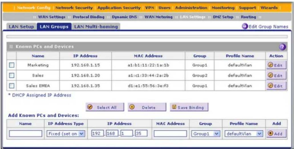
Figure 59.
The Known PCs and Devices table lists the entries in the network database. For each computer or device, the following fields display:
- Check box. Allows you to select the computer or device in the table.
- Name. The name of the computer or device. For computers that do not support the NetBIOS protocol, the name is displayed as Unknown (you can edit the entry manually to add a meaningful name). If the computer or device was assigned an IP address by the DHCP server, then the name is appended by an asterisk.
- IP Address. The current IP address of the computer or device. For DHCP clients of the UTM, this IP address does not change. If a computer or device is assigned a static IP address, you need to update this entry manually after the IP address on the computer or device has changed.
• MAC Address. The MAC address of the computer or device's network interface. - Group. Each computer or device can be assigned to a single LAN group. By default, a computer or device is assigned to Group 1. You can select a different LAN group from the Group drop-down list in the Add Known PCs and Devices section or on the Edit Groups and Hosts screen.
• Profile Name. The VLAN to which the computer or device is assigned. - Action. The Edit table button, which provides access to the Edit Groups and Hosts screen.
Add Computers or Devices to the Network Database
To add computers or devices manually to the network database:
- In the Add Known PCs and Devices section of the LAN Groups screen (see the previous figure), enter the settings as explained in the following table:
Table 22. Known PCs and devices settings
| Setting Description | |
| Name Enter the name of the computer or device. | |
| IP Address Type | From the drop-down list, select how the computer or device receives its IP address:Fixed (set on PC). The IP address is statically assigned on the computer or device.Reserved (DHCP Client). Directs the UTM's DHCP server to assign the specified IP address always to this client during the DHCP negotiation (seeSet Up Address Reservationon page 116).Note:When you assign a reserved IP address to a client, the selected IP address needs to be outside the range of addresses allocated to the DHCP server pool. |
| IP Address | In the IP Address field, enter the IP address that this computer or device is assigned. If the IP address type is Reserved (DHCP Client), the UTM reserves the IP address for the associated MAC address. |
| MAC Address | Enter the MAC address of the computer's or device's network interface. The MAC address format is six colon-separated pairs of hexadecimal characters (0–9 and A–F), such as 01:23:45:67:89:AB. |
| Group From the drop-down list, select the group to which the computer or device is assigned. (Group 1 is the default group.) | |
| Profile Name | From the drop-down list, select the VLAN profile to which the computer or device is assigned. (defaultVlan is the default VLAN group.) |
- Click the Add table button to add the computer or device to the Known PCs and Devices table.
- As an optional step: To enable DHCP address reservation for the entry that you just added to the Known PCs and Devices table, select the check box for the table entry, and click the Save Binding button to bind the IP address to the MAC address for DHCP assignment.
Modify Computers or Devices in the Network Database
To modify computers or devices manually in the network database:
- In the Known PCs and Devices table of the LAN Groups screen (see the previous figure), click the Edit table button of a table entry. The Edit Groups and Hosts screen displays (see the following figure, which contains an example).

Figure 60.
- Modify the settings as explained in Table 22 on page 114.
- Click Apply to save your settings in the Known PCs and Devices table.
Delete Computers or Devices from the Network Database
To delete one or more computers or devices from the network database:
- On the LAN Groups screen (see Figure 59 on page 113), select the check box to the left of each computer or device that you want to delete, or click the Select All table button to select all computers and devices.
- Click the Delete table button.
Change Group Names in the Network Database
By default, the groups are named Group1 through Group8. You can rename these group names to be more descriptive, such as GlobalMarketing and GlobalSales.
To edit the names of any of the eight available groups:
- Select Network Config > LAN Setting > LAN Groups. The LAN Groups screen displays (see Figure 59 on page 113, which shows some examples in the Known PCs and Devices table).
- Click the Edit Group Names option arrow to the right of the LAN submenu tabs. The Network Database Group Names screen displays. (The following figure shows some examples.)
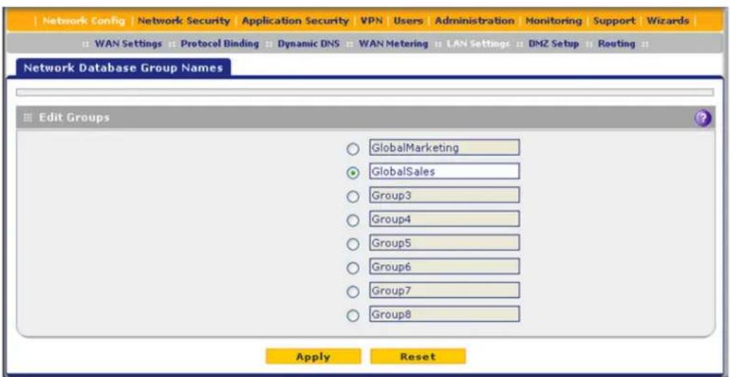
Figure 61.
- Select the radio button next to the group name that you want to edit.
- Type a new name in the field. The maximum number of characters is 15; spaces and double quotes (") are not allowed.
- Repeat Step 3 and Step 4 for any other group names.
- Click Apply to save your settings.
Set Up Address Reservation
When you specify a reserved IP address for a computer or device on the LAN (based on the MAC address of the device), that computer or device always receives the same IP address each time it accesses the UTM's DHCP server. Reserved IP addresses should be assigned to servers or access points that require permanent IP address settings. The reserved IP address that you select needs to be outside of the DHCP server pool.
To reserve an IP address, select Reserved (DHCP Client) from the IP Address Type drop-down list on the LAN Groups screen as described in Add Computers or Devices to the Network Database on page 114 or on the Edit Groups and Hosts screen as described in Modify Computers or Devices in the Network Database on page 114.
Note: The reserved address is not assigned until the next time the computer or device contacts the UTM's DHCP server. Reboot the computer or device, or access its IP configuration and force a DHCP release and renew.
Configure and Enable the DMZ Port
The demilitarized zone (DMZ) is a network that, by default, has fewer firewall restrictions than the LAN. The DMZ can be used to host servers (such as a web server, FTP server, or email server) and provide public access to them. The rightmost LAN port on the UTM can be dedicated as a hardware DMZ port to provide services to the Internet safely without compromising security on your LAN. On the UTM5, UTM10, UTM25, and UTM150, this is LAN port 4; on the UTM50, this is LAN port 6.
By default, the DMZ port and both inbound and outbound DMZ traffic are disabled. Enabling the DMZ port and allowing traffic to and from the DMZ increases the traffic through the WAN ports.
Using a DMZ port is also helpful with online games and videoconferencing applications that are incompatible with NAT. The UTM is programmed to recognize some of these applications and to work correctly with them, but there are other applications that might not function well. In some cases, local computers can run the application correctly if those computers are used on the DMZ port.
Note: A separate firewall security profile is provided for the DMZ port that is also physically independent of the standard firewall security component that is used for the LAN.
The DMZ Setup screen lets you set up the DMZ port. It permits you to enable or disable the hardware DMZ port (LAN port 4 or LAN port 6; see Front Panel UTM5 and UTM10 on page 25) and configure an IP address and subnet mask for the DMZ port.
To enable and configure the DMZ port:
- Select Network Config > DMZ Setup. The DMZ Setup screen displays:
ProSecure Unified Threat Management (UTM) Appliance

Figure 62.
- Enter the settings as explained in the following table:
Table 23. DMZ Setup screen settings
| Setting Description | ||
| DMZ Port Setup | ||
| Do you want to enable DMZ Port? | Select one of the following radio buttons:Yes. Enables you to configure the DMZ port settings. Fill in the IP Address and Subnet Mask fields.No. Allows you to disable the DMZ port after you have configured it. | |
| IP Address Enter the | IP address of the DMZ port. Make sure that the DMZ port IP address and LAN port IP address are in different subnets (for example, an address outside the LAN address pool, such as 192.168.1.101). | |
| Subnet Mask Enter | the IP subnet mask of the DMZ port. The subnet mask specifies the network number portion of an IP address. | |
| DHCP | ||
| Disable DHCP Server | If another device on your network is the DHCP server for the VLAN, or if you will configure the network settings of all of your computers manually, select the Disable DHCP Server radio button to disable the DHCP server. By default, this radio button is not selected, and the DHCP server is enabled. | |
| Enable DHCP Server | Select the Enable DHCP Server radio button to enable the UTM to function as a Dynamic Host Configuration Protocol (DHCP) server, providing TCP/IP configuration for all computers connected to the VLAN. Enter the following settings: | |
| Domain Name This setting is optional. Enter the domain name of the UTM. | ||
| Starting IP Address | Enter the starting IP address. This address specifies the first of the contiguous addresses in the IP address pool. Any new DHCP client joining the LAN is assigned an IP address between this address and the ending IP address. The IP address 192.168.1.2 is the default start address. | |
| Ending IP Address | Enter the ending IP address. This address specifies the last of the contiguous addresses in the IP address pool. Any new DHCP client joining the LAN is assigned an IP address between the starting IP address and this IP address. The IP address 192.168.1.100 is the default ending address.Note:The starting and ending DHCP IP addresses should be in the same network as the LAN TCP/IP address of the UTM (that is, the IP address in the DMZ Port Setup section as described earlier in this table). | |
| Primary DNS Server | This setting is optional. If an IP address is specified, the UTM provides this address as the primary DNS server IP address. If no address is specified, the UTM provides its own LAN IP address as the primary DNS server IP address. | |
| Secondary DNS Server | This setting is optional. If an IP address is specified, the UTM provides this address as the secondary DNS server IP address. | |
| WINS Server This setting is optional. Enter a WINS server IP address to specify the Windows NetBIOS server, if one is present in your network. | ||
| Lease Time Enter a lease time. This specifies the duration for which IP addresses are leased to clients. | ||
| DHCP Relay To use the UTM as a DHCP relay agent for a DHCP server somewhere else in your network, select the DHCP Relay radio button. Enter the following setting: | ||
| Enable LDAP information | To enable the DHCP server to provide Lightweight Directory Access Protocol (LDAP) server information, select the Enable LDAP information check box. Enter the following settings: | |
| LDAP Server The IP address or name of the LDAP server. | ||
| Search Base | The search objects that specify the location in the directory tree from which the LDAP search begins. You can specify multiple search objects, separated by commas. The search objects include:• CN (for common name)• OU (for organizational unit)• O (for organization)• C (for country)• DC (for domain)For example, to search the Netgear.net domain for all last names of Johnson, you would enter:cn=Johnson,dc=Netgear,dc=net | |
| Port The port number for the LDAP server. The default setting is 0 (zero). | ||
| DNS Proxy | ||
| Enable DNS Proxy This setting is optional. To enable the UTM to provide a LAN IP address for DNS address name resolution, select the Enable DNS Proxy check box. This check box is selected by default.Note:When the DNS Proxy option is disabled, all DHCP clients receive the DNS IP addresses of the ISP but without the DNS proxy IP address. | ||
3. Click Apply to save your settings.
Note: For all UTM models except for the UTM50, the DMZ LED next to LAN port 4 (see Hardware Features on page 24) lights green to indicate that the DMZ port is enabled. For the UTM50, the DMZ LED next to LAN port 6 lights green to indicate that the DMZ port is enabled.
For information about how to define the DMZ WAN rules and LAN DMZ rules, see Configure DMZ WAN Rules on page 142 and Configure LAN DMZ Rules on page 145, respectively.
Manage Routing
- Configure Static Routes
- Configure Routing Information Protocol
• Static Route Example
Static routes provide additional routing information to your UTM. Under normal circumstances, the UTM has adequate routing information after it has been configured for Internet access, and you do not need to configure additional static routes. You should configure static routes only for unusual cases such as multiple firewalls or multiple IP subnets on your network.
Note: The UTM automatically sets up routes between VLANs and secondary IP addresses that you have configured on the LAN Multi-homing screen (see Configure Multihome LAN IP Addresses on the Default VLAN on page 109). Therefore, you do not need to add a static route manually between a VLAN and a secondary IP address.
Configure Static Routes
To add a static route to the Static Route table:
- Select Network Config > Routing. The Routing screen displays:

Figure 63.
- Click the Add table button under the Static Routes table. The Add Static Route screen displays:
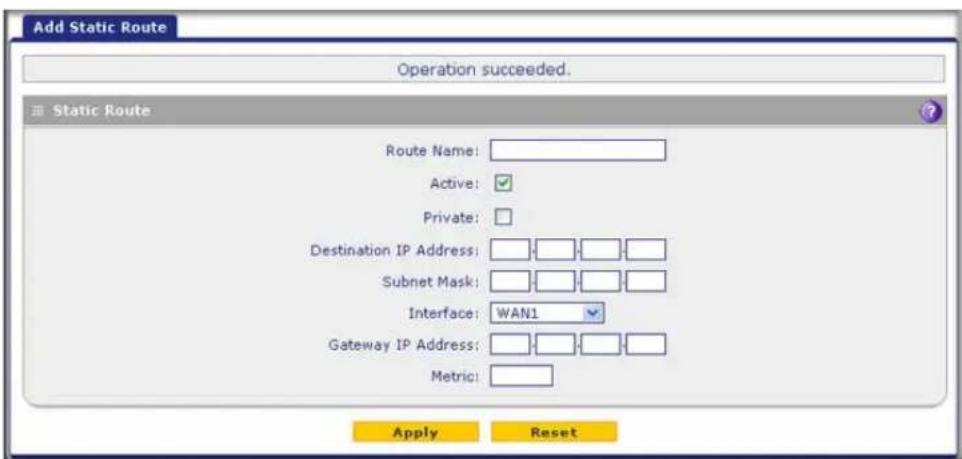
Figure 64.
- Enter the settings as explained in the following table:
Table 24. Add Static Route screen settings
| Setting Description | |
| Route Name The route | name for the static route (for purposes of identification and management). |
| Active | To make the static route effective, select the Active check box.Note: A route can be added to the table and made inactive if not needed. This allows you to use routes as needed without deleting and re-adding the entry. An inactive route is not advertised if RIP is enabled. |
| Private | If you want to limit access to the LAN only, select the Private check box. Doing so prevents the static route from being advertised in RIP. |
| Destination IP Address | The destination IP address of the host or network to which the route leads. |
| IP Subnet Mask The IP | subnet mask of the host or network to which the route leads. If the destination is a single host, enter 255.255.255.255. |
| Interface | From the drop-down list, select the interface that is the physical network interface (a WAN interface, LAN, or DMZ for the multiple WAN port models; WAN, LAN, or DMZ for the single WAN port models) or virtual interface (VLAN profile) through which the route is accessible. |
| Gateway IP Address | The gateway IP address through which the destination host or network can be reached. |
| Metric | The priority of the route. Select a value between 2 and 15. If multiple routes to the same destination exist, the route with the lowest metric is used. |
- Click Apply to save your settings. The new static route is added to the Static Routes table.
To edit a static route that is in the Static Routes table:
- On the Routing screen (see Figure 63 on page 121), click the Edit button in the Action column for the route that you want to modify. The Edit Static Route screen displays. This screen is identical to the Add Static Route screen (see the previous screen).
- Modify the settings as explained in the previous table.
- Click Apply to save your settings.
To delete one or more routes:
- On the Routing screen (see Figure 63 on page 121), select the check box to the left of each route that you want to delete, or click the Select All table button to select all routes.
- Click the Delete table button.
Configure Routing Information Protocol
Routing Information Protocol (RIP), RFC 2453, is an Interior Gateway Protocol (IGP) that is commonly used in internal networks (LANs). RIP enables a router to exchange its routing information automatically with other routers, to adjust its routing tables dynamically, and to adapt to changes in the network. RIP is disabled by default.
To enable and configure RIP:
- Select Network Config > Routing.
- Click the RIP Configuration option arrow to the right of the Routing submenu tab. The RIP Configuration screen displays:

Figure 65.
- Enter the settings as explained in the following table:
Table 25. RIP Configuration screen settings
| Setting Description | ||
| RIP | ||
| RIP Direction | From the RIP Direction drop-down list, select the direction in which the UTM sends and receives RIP packets:None. The UTM neither advertises its route table, nor accepts any RIP packets from other routers. This effectively disables RIP, and is the default setting.In Only. The UTM accepts RIP information from other routers but does not advertise its routing table.Out Only. The UTM advertises its routing table but does not accept RIP information from other routers.Both. The UTM advertises its routing table and also processes RIP information received from other routers. | |
| RIP Version | By default, the RIP version is set to Disabled. From the RIP Version drop-down list, select the version:• RIP-1. Classful routing that does not include subnet information. This is the most commonly supported version.• RIP-2. Routing that supports subnet information. Both RIP-2B and RIP-2M send the routing data in RIP-2 format:- RIP-2B. Sends the routing data in RIP-2 format and uses subnet broadcasting.- RIP-2M. Sends the routing data in RIP-2 format and uses multicasting. | |
| Authentication for RIP-2B/2M | ||
| Authentication for RIP-2B/2M required? | Authentication for RP-2B or RIP-2M is disabled by default, that is, the No radio button is selected. To enable authentication for RP-2B or RIP-2M, select the Yes radio button, and enter the settings for the following fields. | |
| First Key Parameters | ||
| MD5 Key Id | The identifier for the key that is used for authentication. | |
| MD5 Auth Key The | password that is used for MD5 authentication. | |
| Not Valid Before | The beginning of the lifetime of the MD5 key. Enter the month, date, year, hour, minute, and second. Before this date and time, the MD5 key is not valid. | |
| Not Valid After The | end of the lifetime of the MD5 key. Enter the month, date, year, hour, minute, and second. After this date and time, the MD5 key is no longer valid. | |
| Second Key Parameters | ||
| MD5 Key Id | The identifier for the key that is used for authentication. | |
| MD5 Auth Key The | password that is used for MD5 authentication. | |
| Authentication for RIP-2B/2M required?(continued) | Not Valid Before | The beginning of the lifetime of the MD5 key. Enter the month, date, year, hour, minute, and second. Before this date and time, the MD5 key is not valid. |
| Not Valid After The | end of the lifetime of the MD5 key. Enter the month, date, year, hour, minute, and second. After this date and time, the MD5 key is no longer valid. | |
- Click Apply to save your settings.
Static Route Example
In this example, we assume the following:
- The UTM's primary Internet access is through a cable modem to an ISP.
- The UTM is on a local LAN with IP address 192.168.1.100.
- The UTM connects to a remote network where you need to access a device.
• The LAN IP address of the remote network is 134.177.0.0.
When you first configured the UTM, two implicit static routes were created:
- A default static route was created with your ISP as the gateway.
- A second static route was created to the local LAN for all 192.168.1.x addresses.
With this configuration, if you attempt to access a device on the 134.177.0.0 remote network, the UTM forwards your request to the ISP. In turn, the ISP forwards your request to the remote network, where the request is likely to be denied by the remote network's firewall.
In this case, you need to define a static route, informing the UTM that the 134.177.0.0 IP address should be accessed through the local LAN IP address (192.168.1.100).
The static route on the UTM needs to be defined as follows:
- The destination IP address and IP subnet mask need to specify that the static route applies to all 134.177.x.x IP addresses.
- The gateway IP address needs to specify that all traffic for the 134.177.x.x IP addresses should be forwarded to the local LAN IP address (192.168.1.100).
- A metric value of 1 should work since the UTM is on the local LAN.
- The static route can be made private only as a precautionary security measure in case RIP is activated.
This chapter describes how to use the firewall features of the UTM to protect your network. This chapter contains the following sections:
- About Firewall Protection
• Overview of Rules to Block or Allow Specific Kinds of Traffic - Configure LAN WAN Rules
- Configure DMZ WAN Rules
- Configure LAN DMZ Rules
• Examples of Firewall Rules - Configure Other Firewall Features
- Create Services, QoS Profiles, Bandwidth Profiles, and Traffic Meter Profiles
- Set a Schedule to Block or Allow Specific Traffic
- Enable Source MAC Filtering
- Set Up IP/MAC Bindings
- Configure Port Triggering
- Configure Universal Plug and Play
- Enable and Configure the Intrusion Prevention System
About Firewall Protection
A firewall protects one network (the trusted network, such as your LAN) from another (the untrusted network, such as the Internet), while allowing communication between the two. You can further segment keyword blocking to certain known groups. For information about how to set up LAN groups, see Manage Groups and Hosts (LAN Groups) on page 111.
A firewall incorporates the functions of a Network Address Translation (NAT) router, protects the trusted network from hacker intrusions or attacks, and controls the types of traffic that can flow between the two networks. Unlike simple NAT routers, a firewall uses a process called stateful packet inspection to protect your network from attacks and intrusions. NAT performs a very limited stateful inspection in that it considers whether the incoming packet is in response to an outgoing request, but true stateful packet inspection goes far beyond NAT.
Administrator Tips
Consider the following operational items:
- As an option, you can enable remote management if you have to manage distant sites from a central location (see Configure Authentication Domains, Groups, and Users on page 380 and Configure Remote Management Access on page 438).
-
Although rules are the basic way of managing the traffic through your system (see Overview of Rules to Block or Allow Specific Kinds of Traffic on page 128), you can further refine your control using the following features and capabilities of the UTM:
-
Groups and hosts (see Manage Groups and Hosts (LAN Groups) on page 111)
- Services (see Outbound Rules (Service Blocking) on page 129)
- Schedules (see Set a Schedule to Block or Allow Specific Traffic on page 177)
- Allow or block sites and applications (see Set Exception Rules for Web and Application Access on page 248)
- Source MAC filtering (see Enable Source MAC Filtering on page 179)
-
Port triggering (see Configure Port Triggering on page 183)
-
Content filtering is a firewall component. The UTM provides such extensive content-filtering options that an entire chapter is dedicated to this subject; see Chapter 6, Content Filtering and Optimizing Scans.
- Some firewall settings might affect the performance of the UTM. For more information, see Performance Management on page 428.
- You can monitor blocked content and malware threats in real time. For more information, see Monitor Real-Time Traffic, Security, and Statistics on page 477.
- The firewall logs can be configured to log and then email denial of access, general attack, and other information to a specified email address. For information about how to configure logging and notifications, see Configure Logging, Alerts, and Event Notifications on page 466.
Overview of Rules to Block or Allow Specific Kinds of Traffic
- Outbound Rules (Service Blocking)
• Inbound Rules (Port Forwarding)
• Order of Precedence for Rules
Firewall rules are used to block or allow specific traffic passing through from one side to the other. You can configure up to 800 rules on the UTM. Inbound rules (WAN to LAN) restrict access by outsiders to private resources, selectively allowing only specific outside users to access specific resources. Outbound rules (LAN to WAN) determine what outside resources local users can have access to.
A firewall has two default rules, one for inbound traffic and one for outbound. The default rules of the UTM are:
- Inbound. Block all access from outside except responses to requests from the LAN side.
- Outbound. Allow all access from the LAN side to the outside.
The firewall rules for blocking and allowing traffic on the UTM can be applied to LAN WAN traffic, DMZ WAN traffic, and LAN DMZ traffic.
Table 26. Number of supported firewall rule configurations
| Traffic rule Maximum | number of outbound rules | Maximum number of inbound rules | Maximum number of supported rules |
| LAN WAN 300 300 600 | |||
| D | M | Z | W |
| LAN DMZ 50 50 100 | |||
| Total Rules 400 400 800 |
N
The rules to block traffic are based on the traffic's category of service:
- Outbound rules (service blocking). Outbound traffic is usually allowed unless the firewall is configured to disallow it.
- Inbound rules (port forwarding). Inbound traffic is usually blocked by the firewall unless the traffic is in response to a request from the LAN side. The firewall can be configured to allow this otherwise blocked traffic.
- Customized services. Additional services can be added to the list of services in the factory defaults list. These added services can then have rules defined for them to either allow or block that traffic (see Add Customized Services on page 163).
- Quality of Service (QoS) priorities. Each service has its own native priority that impacts its quality of performance and tolerance for jitter or delays. You can change the QoS priority, which changes the traffic mix through the system (see Create Quality of Service Profiles on page 169).
Outbound Rules (Service Blocking)
The UTM allows you to block the use of certain Internet services by computers on your network. This is called service blocking or port filtering.
Note: See Enable Source MAC Filtering on page 179 for yet another way to block outbound traffic from selected computers that would otherwise be allowed by the firewall.

WARNING:
Allowing inbound services opens security holes in your UTM. Enable only those ports that are necessary for your network.
The following table describes the fields that define the rules for outbound traffic and that are common to most Outbound Service screens (see Figure 68 on page 141, Figure 71 on page 144, and Figure 74 on page 147).
The steps to configure outbound rules are described in the following sections:
- Configure LAN WAN Rules
- Configure DMZ WAN Rules
- Configure LAN DMZ Rules
Table 27. Outbound rules overview
| Setting Description | Outbound Rules | |
| Service(also referred to as Service Name) | The service or application to be covered by this rule. If the service or application does not display in the list, you need to define it using the Services screen (see Add Customized Services on page 163). | All rules |
| Action(also referred to as Filter) | The action for outgoing connections covered by this rule:• BLOCK always• ALLOW alwaysNote:Any outbound traffic that is not blocked by rules you create is allowed by the default rule.Note:ALLOW rules are useful only if the traffic is already covered by a BLOCK rule. That is, you wish to allow a subset of traffic that is currently blocked by another rule. Similarly, BLOCK rules are useful only if the traffic is already covered by an ALLOW rule. That is, you wish to block a subset of traffic that is currently allowed by another rule. | All rules |
| Select Schedule The | time schedule that is used by this rule. By default, there is no schedule assigned (that is, None is selected from the Schedule drop-down list), and the rule is in effect permanently. For information about creating schedules, see Set a Schedule to Block or Allow Specific Traffic on page 177. | All rules |
| LAN Users The settings that determine which computers on your network are affected by this rule. The options are:Any. All computers and devices on your LAN.Single address. Enter the required address in the Start field to apply the rule to a single device on your LAN.Address range. Enter the required addresses in the Start and End fields to apply the rule to a range of devices.Group. Select the LAN group to which the rule applies. Use the LAN Groups screen to assign computers to groups. See Manage Groups and Hosts (LAN Groups) on page 111.IP Group. Select the IP group to which the rule applies. Use the IP Groups screen to assign IP addresses to groups. See Create IP Groups on page 167. | LAN WAN rulesLAN DMZ rules | |
| WAN Users The settings that determine which Internet locations are covered by the rule, based on their IP address. The options are:Any. All Internet IP addresses are covered by this rule.Single address. Enter the required address in the Start field.Address range. Enter the required addresses the Start and End fields.IP Group. Select the IP group to which the rule applies. Use the IP Groups screen to assign IP addresses to groups. See Create IP Groups on page 167. | LAN WAN rulesDMZ WAN rule | |
| DMZ Users The settings that determine which DMZ computers on the DMZ network are affected by this rule. The options are:Any. All computers and devices on your DMZ network.Single address. Enter the required address in the Start field to apply the rule to a single computer on the DMZ network.Address range. Enter the required addresses in the Start and End fields to apply the rule to a range of DMZ computers. | DMZ WAN rulesLAN DMZ rules | |
| Users Allowed The settings that determine which user or group on the network is affected by this rule. You can select a local user, local group, or customer group. To create a custom group, select + Create New from the Users Allowed drop-down list on a firewall screen that lets you add or edit a rule (you can find the + Create New link under the Custom Groups heading on such a screen). For information about setting up custom groups, see Configure Custom Groups on page 397. | LAN WAN rulesLAN DMZ rules | |
| QoS Profile The priority assigned to IP packets of this service. The priorities are defined by Type of Service (ToS) in the Internet Protocol Suite standards, RFC 1349. The QoS profile determines the priority of a service, which, in turn, determines the quality of that service for the traffic passing through the firewall.The UTM marks the Type of Service (ToS) field as defined in the QoS profiles that you create. For more information, seeCreate Quality of Service Profileson page 169.Note:There is no default QoS profile on the UTM. After you have created a QoS profile, it can become active only when you apply it to a nonblocking inbound or outbound firewall rule.Note:This field is not applicable to LAN DMZ rules. | LAN WAN rulesDMZ WAN rule | |
| Log The settings that determine whether packets covered by this rule are logged. The options are:Always. Always log traffic considered by this rule, whether it matches or not. This is useful when you are debugging your rules.Never. Never log traffic considered by this rule, whether it matches or not. | All rules | |
| Bandwidth Profile Bandwidth limiting determines how the data is sent to and from your host. The purpose of bandwidth limiting is to provide a solution for limiting the outgoing and incoming traffic, thus preventing the LAN users from consuming all the bandwidth of the Internet link. For more information, seeCreate Bandwidth Profileson page 171. Bandwidth limiting occurs in the following ways:For outbound traffic. On the available WAN interface in the primary WAN mode and auto-rollover mode, and on the selected interface in load balancing mode.For inbound traffic. On the LAN interface for all WAN modes.Note:Bandwidth limiting does not apply to the DMZ interface. | LAN WAN rules | |
| Traffic Meter Profile Select a traffic meter profile to measure and control traffic that is downloaded, uploaded, or both. The traffic meter profile applies only to traffic that is covered by this rule. Depending on the configuration of the traffic meter profile, when traffic has reached its configured limit, traffic is either logged or blocked. For information about creating traffic meter profiles, seeCreate Traffic Meter Profileson page 174.Note:You cannot assign traffic meter profiles to LAN DMZ firewall rules. | LAN WAN rulesDMZ WAN rule | |
| Application Control | Select an application control profile to allow, block, or log traffic for entire categories of applications, for individual applications, or for a combination of both. The application control profile applies only to traffic that is covered by this rule. To create an application control profile, select + Create New from the Application Control drop-down list. The Add or Edit Application Control Profile pop-up screen displays. For information about creating and enabling application control profiles, see Configure Application Control on page 240.Note: You cannot assign application control profiles to LAN DMZ firewall rules. | LAN WAN rulesDMZ WAN rule |
| NAT IP The setting that specifies whether the source address of the outgoing packets on the WAN should be assigned the address of the WAN interface or the address of a different interface. You can specify these settings only for outbound traffic on the WAN interface. The options are:WAN Interface Address. All the outgoing packets on the WAN are assigned to the address of the specified WAN interface.Single Address. All the outgoing packets on the WAN are assigned to the specified IP address, for example, a secondary WAN address that you have configured.Note: The NAT IP option is available only when the WAN mode is NAT. The IP address specified should fall under the WAN subnet. | LAN WAN rulesDMZ WAN rule |
Inbound Rules (Port Forwarding)
If you have enabled Network Address Translation (NAT), your network presents only one IP address to the Internet, and outside users cannot directly access any of your local computers (LAN users). (For information about configuring NAT, see Configure Network Address Translation (All Models) on page 81.) However, by defining an inbound rule you can make a local server (for example, a web server or game server) visible and available to the Internet. The rule informs the firewall to direct inbound traffic for a particular service to one local server based on the destination port number. This process is also known as port forwarding.
Whether or not DHCP is enabled, how the computer accesses the server's LAN address impacts the inbound rules. For example:
- If your external IP address is assigned dynamically by your ISP (DHCP enabled), the IP address might change periodically as the DHCP lease expires. Consider using Dynamic DNS so that external users can always find your network (see Configure Dynamic DNS on page 91).
- If the IP address of the local server computer is assigned by DHCP, it might change when the computer is rebooted. To avoid this, use the Reserved (DHCP Client) feature in the LAN Groups screen to keep the computer's IP address constant (see Set Up Address Reservation on page 116).
ProSecure Unified Threat Management (UTM) Appliance
- Local computers need to access the local server using the computers' local LAN address. Attempts by local computers to access the server using the external WAN IP address will fail.
Note: See Configure Port Triggering on page 183 for yet another way to allow certain types of inbound traffic that would otherwise be blocked by the firewall.
Note: The UTM always blocks denial of service (DoS) attacks. A DoS attack does not attempt to steal data or damage your computers, but overloads your Internet connection so you cannot use it (that is, the service becomes unavailable).
Note: When the Block TCP Flood and Block UDP Flood check boxes are selected on the Attack Checks screen (see Attack Checks, VPN Pass-through, and Multicast Pass-through on page 157), multiple concurrent connections of the same application from one host or IP address (such as multiple DNS queries from one computer) trigger the UTM's DoS protection.
Note: For more information about protecting the UTM from incoming threats, see Enable and Configure the Intrusion Prevention System on page 187.
The following table describes the fields that define the rules for inbound traffic and that are common to most Inbound Service screens (see Figure 69 on page 142, Figure 72 on page 145, and Figure 75 on page 148).
The steps to configure inbound rules are described in the following sections:
- Configure LAN WAN Rules
- Configure DMZ WAN Rules
- Configure LAN DMZ Rules
Table 28. Inbound rules overview
| Setting Description Inbound Rules | ||
| Service(also referred to as Service Name) | The service or application to be covered by this rule. If the service or application does not display in the list, you need to define it using the Services screen (see Add Customized Services on page 163). | All rules |
| Action(also referred to as Filter) | The action for outgoing connections covered by this rule:• BLOCK always• ALLOW alwaysNote: Any inbound traffic that is not blocked by rules you create is allowed by the default rule.Note: ALLOW rules are useful only if the traffic is already covered by a BLOCK rule. That is, you wish to allow a subset of traffic that is currently blocked by another rule. Similarly, BLOCK rules are useful only if the traffic is already covered by an ALLOW rule. That is, you wish to block a subset of traffic that is currently allowed by another rule. | All rules |
| Select Schedule The | time schedule that is used by this rule. By default, there is no schedule assigned (that is, None is selected from the Schedule drop-down list), and the rule is in effect permanently. For information about creating schedules, see Set a Schedule to Block or Allow Specific Traffic on page 177. | All rules |
| Send to LAN Server T | The LAN server address determines which computer on your network is hosting this service rule. (You can also translate this address to a port number.) The options are:• Single address. Enter the required address in the Start field to apply the rule to a single device on your LAN.• Address range. Enter the required addresses in the Start and End fields to apply the rule to a range of devices. | LAN WAN rules |
| Send to DMZ Server T | The DMZ server address determines which computer on your network is hosting this service rule. (You can also translate this address to a port number.) | DMZ WAN rules |
| Translate to Port Number | If you want to assign the LAN server or DMZ server to a specific port, you can enable this setting and specify a port number. | LAN WAN rulesDMZ WAN rules |
| WAN Destination IP Address | The settings that determine the destination IP address applicable to incoming traffic. This is the public IP address that maps to the internal LAN server.On the multiple WAN port models, it can be either the address of a WAN interface or another public IP address (when you have a secondary WAN address configured). On the single WAN port models, it can be either the address of the single WAN interface or another public IP address (when you have a secondary WAN address configured).You can also enter an address range. Enter the required addresses in the Start and End fields to apply the rule to a range of devices. | LAN WAN rulesDMZ WAN rules |
| LAN Users The settings that determine which computers on your network are affected by this rule. The options are:Any. All computers and devices on your LAN.Single address. Enter the required address in the Start field to apply the rule to a single device on your LAN.Address range. Enter the required addresses in the Start and End fields to apply the rule to a range of devices.Group. Select the group to which the rule applies. Use the LAN Groups screen to assign computers to groups. See Manage Groups and Hosts (LAN Groups) on page 111.IP Group. Select the IP group to which the rule applies. Use the IP Groups screen to assign IP addresses to groups. See Create IP Groups on page 167.Note: For LAN WAN inbound rules, this field is not applicable when the WAN mode is NAT because your network presents only one IP address to the Internet. | LAN WAN rulesLAN DMZ rules | |
| WAN Users The settings that determine which Internet locations are covered by the rule, based on their IP address. The options are:Any. All Internet IP addresses are covered by this rule.Single address. Enter the required address in the Start field.Address range. Enter the required addresses in the Start and End fields.IP Group. Select the IP group to which the rule applies. Use the IP Groups screen to assign IP addresses to groups. See Create IP Groups on page 167. | LAN WAN rulesDMZ WAN rules | |
| DMZ Users The settings that determine which DMZ computers on the DMZ network are affected by this rule. The options are:Any. All computers and devices on your DMZ network.Single address. Enter the required address in the Start field to apply the rule to a single computer on the DMZ network.Address range. Enter the required addresses in the Start and End fields to apply the rule to a range of DMZ computers.Note: For DMZ WAN inbound rules, this field is not applicable when the WAN mode is NAT because your network presents only one IP address to the Internet. | DMZ WAN rulesLAN DMZ rules | |
| Users Allowed The settings that determine which user or group on the network is affected by this rule. You can select a local user, local group, or customer group. To create a custom group, select + Create New from the Users Allowed drop-down list on a firewall screen that lets you add or edit a rule (you can find the + Create New link under the Custom Groups heading on such a screen). For information about setting up custom groups, see Configure Custom Groups on page 397. | LAN WAN rulesDMZ WAN rules | |
| Setting Description | Inbound Rules | |
| QoS Profile The priority | assigned to IP packets of this service. The priorities are defined by Type of Service (ToS) in the Internet Protocol Suite standards, RFC 1349. The QoS profile determines the priority of a service which, in turn, determines the quality of that service for the traffic passing through the firewall.The UTM marks the Type of Service (ToS) field as defined in the QoS profiles that you create. For more information, seeCreate Quality of Service Profileson page 169.Note:There is no default QoS profile on the UTM. After you have created a QoS profile, it can become active only when you apply it to a nonblocking inbound or outbound firewall rule.Note:This field is not applicable to LAN DMZ rules. | LAN WAN rulesDMZ WAN rules |
| Log The settings that determine whether packets covered by this rule are logged. The options are:Always. Always log traffic considered by this rule, whether it matches or not. This is useful when you are debugging your rules.Never. Never log traffic considered by this rule, whether it matches or not. | All rules | |
| Bandwidth Profile Bandwidth limiting determines how the data is sent to and from your host. The purpose of bandwidth limiting is to provide a solution for limiting the outgoing and incoming traffic, thus preventing the LAN users from consuming all the bandwidth of the Internet link. For more information, seeCreate Bandwidth Profileson page 171. Bandwidth limiting occurs in the following ways:For outbound traffic. On the available WAN interface in the primary WAN mode and auto-rollover mode, and on the selected interface in load balancing mode.For inbound traffic. On the LAN interface for all WAN modes.Note:Bandwidth limiting does not apply to the DMZ interface. | LAN WAN rules | |
| Traffic Meter Profile Select a traffic meter profile to measure and control traffic that is downloaded, uploaded, or both. The traffic meter profile applies only to traffic that is covered by this rule. Depending on the configuration of the traffic meter profile, when traffic has reached its configured limit, traffic is either logged or blocked. For information about creating traffic meter profiles, seeCreate Traffic Meter Profileson page 174.Note:You cannot assign traffic meter profiles to LAN DMZ firewall rules. | LAN WAN rulesDMZ WAN rules | |
| Setting Description Inbound Rules | ||
| Application Control | Select an application control profile to allow, block, or log traffic for entire categories of applications, for individual applications, or for a combination of both. The application control profile applies only to traffic that is covered by this rule. To create an application control profile, select + Create New from the Application Control drop-down list. The Add or Edit Application Control Profile pop-up screen displays. For information about creating and enabling application control profiles, see Configure Application Control on page 240.Note: You cannot assign application control profiles to LAN DMZ firewall rules. | LAN WAN rulesDMZ WAN rules |
Note: Some residential broadband ISP accounts do not allow you to run any server processes (such as a web or FTP server) from your location. Your ISP might periodically check for servers and might suspend your account if it discovers any active servers at your location. If you are unsure, see the acceptable use policy of your ISP.
Order of Precedence for Rules
As you define a new rule, it is added to a table in a Rules screen as the last item in the list, as shown in the LAN WAN Rules screen example in the following figure:
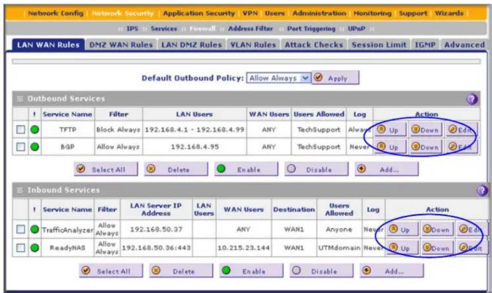
Figure 66.
For any traffic attempting to pass through the firewall, the packet information is subjected to the rules in the order shown in the Rules table, beginning at the top and proceeding to the bottom. In some cases, the order of precedence of two or more rules might be important in determining the disposition of a packet. For example, you should place the most strict rules at the top (those with the most specific services or addresses). The Up and Down table buttons in the Action column allow you to relocate a defined rule to a new position in the table.
Configure LAN WAN Rules
- Create LAN WAN Outbound Service Rules
- Create LAN WAN Inbound Service Rules
The default outbound policy is to allow all traffic to the Internet to pass through. Firewall rules can then be applied to block specific types of traffic from going out from the LAN to the Internet (outbound). This feature is also referred to as service blocking. You can change the default policy of Allow Always to Block Always to block all outbound traffic, which then allows you to enable only specific services to pass through the UTM.
To change the default outbound policy:
- Select Network Security > Firewall. The Firewall submenu tabs display, with the LAN WAN Rules screen in view.
- Next to Default Outbound Policy, select Block Always from the drop-down list.

Figure 67.
- Next to the drop-down list, click the Apply table button.
To change an existing outbound or inbound service rule:
In the Action column to the right of to the rule, click one of the following table buttons:
- Edit. Allows you to make any changes to the definition of an existing rule. Depending on your selection, either the Edit LAN WAN Outbound Service screen (identical to Figure 68 on page 141) or Edit LAN WAN Inbound Service screen (identical to Figure 69 on page 142) displays, containing the data for the selected rule.
- Up. Moves the rule up one position in the table rank.
- Down. Moves the rule down one position in the table rank.
To enable, disable, or delete one or more rules:
- Select the check box to the left of each rule that you want to enable, disable, or delete, or click the Select All table button to select all rules.
-
Click one of the following table buttons:
-
Enable. Enables the rule or rules. The ! status icon changes from a gray circle to a green circle, indicating that the selected rule or rules are enabled. (By default, when a rule is added to the table, it is automatically enabled.)
- Disable. Disables the rule or rules. The ! status icon changes from a green circle to a gray circle, indicating that the selected rule or rules are disabled.
- Delete. Deletes the selected rule or rules.
Create LAN WAN Outbound Service Rules
You can define rules that specify exceptions to the default rules. By adding custom rules, you can block or allow access based on the service or application, source or destination IP addresses, and time of day. An outbound rule can block or allow traffic between an internal IP LAN address and any external WAN IP address according to the schedule created in the Schedule screen.
You can also tailor these rules to your specific needs (see Administrator Tips on page 128).

WARNING:
This feature is for advanced administrators. Incorrect configuration might cause serious problems.
To create an outbound LAN WAN service rule:
- In the LAN WAN Rules screen, click the Add table button under the Outbound Services table. The Add LAN WAN Outbound Service screen displays:

Figure 68.
- Enter the settings as explained in Table 27 on page 130.
- Click Apply to save your changes. The new rule is now added to the Outbound Services table.
Create LAN WAN Inbound Service Rules
The Inbound Services table lists all existing rules for inbound traffic. If you have not defined any rules, no rules are listed. By default, all inbound traffic (from the Internet to the LAN) is blocked. Remember that allowing inbound services opens potential security holes in your firewall. Enable only those ports that are necessary for your network.
To create an inbound LAN WAN service rule:
- In the LAN WAN Rules screen, click the Add table button under the Inbound Services table. The Add LAN WAN Inbound Service screen displays:

Figure 69.
- Enter the settings as explained in Table 28 on page 135.
- Click Apply to save your changes. The new rule is now added to the Inbound Services table.
Configure DMZ WAN Rules
- Create DMZ WAN Outbound Service Rules
- Create DMZ WAN Inbound Service Rules
The firewall rules for traffic between the DMZ and the Internet are configured on the DMZ WAN Rules screen. The default outbound policy is to block all traffic from and to the Internet. You can then apply firewall rules to allow specific types of traffic either going out from the DMZ to the Internet (outbound) or coming in from the Internet to the DMZ (inbound).
There is no drop-down list that lets you set the default outbound policy as there is on the LAN WAN Rules screen. You can change the default outbound policy by enabling all outbound traffic and then blocking only specific services from passing through the UTM. You do so by
ProSecure Unified Threat Management (UTM) Appliance
adding outbound services rules (see Create DMZ WAN Outbound Service Rules on page 144).
To access the DMZ WAN Rules screen, select Network Security > Firewall > DMZ WAN Rules. The DMZ WAN Rules screen displays. (The following figure shows some rules as an example.)

Figure 70.
To change an existing outbound or inbound service rule:
In the Action column to the right of to the rule, click one of the following table buttons:
- Edit. Allows you to make any changes to the definition of an existing rule. Depending on your selection, either the Edit DMZ WAN Outbound Service screen (identical to Figure 71 on page 144) or the Edit DMZ WAN Inbound Service screen (identical to Figure 72 on page 145) displays, containing the data for the selected rule.
- Up. Moves the rule up one position in the table rank.
- Down. Moves the rule down one position in the table rank.
To delete or disable one or more rules:
- Select the check box to the left of each rule that you want to delete or disable, or click the Select All table button to select all rules.
- Click one of the following table buttons:
- Disable. Disables the selected rule or rules. The ! status icon changes from a green circle to a gray circle, indicating that the selected rule is or rules are disabled. (By default, when a rule is added to the table, it is automatically enabled.)
- Delete. Deletes the selected rule or rules.
Create DMZ WAN Outbound Service Rules
You can change the default outbound policy or define rules that specify exceptions to the default outbound policy. By adding custom rules, you can block or allow access based on the service or application, source or destination IP addresses, and time of day. An outbound rule can block or allow traffic between the DMZ and any external WAN IP address according to the schedule created in the Schedule screen.
To create an outbound DMZ WAN service rule:
- In the DMZ WAN Rules screen, click the Add table button under the Outbound Services table. The Add DMZ WAN Outbound Service screen displays:

Figure 71.
- Enter the settings as explained in Table 27 on page 130.
- Click Apply. The new rule is now added to the Outbound Services table. The rule is automatically enabled.
Create DMZ WAN Inbound Service Rules
The Inbound Services table lists all existing rules for inbound traffic. If you have not defined any rules, no rules are listed. By default, all inbound traffic (from the Internet to the DMZ) is blocked.
Inbound rules that are configured on the LAN WAN Rules screen take precedence over inbound rules that are configured on the DMZ WAN Rules screen. As a result, if an inbound packet matches an inbound rule on the LAN WAN Rules screen, it is not matched against the inbound rules on the DMZ WAN Rules screen.
To create an inbound DMZ WAN service rule:
- In the DMZ WAN Rules screen, click the Add table button under the Inbound Services table. The Add DMZ WAN Inbound Service screen displays:

Figure 72.
-
Enter the settings as explained in Table 28 on page 135.
-
Click Apply to save your changes. The new rule is now added to the Inbound Services table.
Configure LAN DMZ Rules
- Create LAN DMZ Outbound Service Rules
- Create LAN DMZ Inbound Service Rules
The LAN DMZ Rules screen allows you to create rules that define the movement of traffic between the LAN and the DMZ. The default outbound and inbound policies are to block all traffic between the local LAN and DMZ network. You can then apply firewall rules to allow specific types of traffic either going out from the LAN to the DMZ (outbound) or coming in from the DMZ to the LAN (inbound).
There is no drop-down list that lets you set the default outbound policy as there is on the LAN WAN Rules screen. You can change the default outbound policy by allowing all outbound traffic and then blocking specific services from passing through the UTM. You do so by adding outbound service rules (see Create LAN DMZ Outbound Service Rules on page 147).
To access the LAN DMZ Rules screen and to change an existing outbound or inbound service rule, select Network Security > Firewall > LAN DMZ Rules. The LAN DMZ Rules screen displays:

Figure 73.
In the Action column to the right of to the rule, click one of the following table buttons:
- Edit. Allows you to make any changes to the rule definition of an existing rule. Depending on your selection, either the Edit LAN DMZ Outbound Service screen (identical to Figure 74 on page 147) or the Edit LAN DMZ Inbound Service screen (identical to Figure 75 on page 148) displays, containing the data for the selected rule.
- Up. Moves the rule up one position in the table rank.
- Down. Moves the rule down one position in the table rank.
To delete or disable one or more rules:
- Select the check box to the left of each rule that you want to delete or disable, or click the Select All table button to select all rules.
-
Click one of the following table buttons:
-
Disable. Disables the selected rule or rules. The ! status icon changes from a green circle to a gray circle, indicating that the selected rule is or rules are disabled. (By default, when a rule is added to the table, it is automatically enabled.)
- Delete. Deletes the selected rule or rules.
Create LAN DMZ Outbound Service Rules
You can change the default outbound policy or define rules that specify exceptions to the default outbound policy. By adding custom rules, you can block or allow access based on the service or application, source or destination IP addresses, and time of day. An outbound rule can block or allow traffic between the DMZ and any internal LAN IP address according to the schedule created in the Schedule screen.
To create an outbound LAN DMZ service rule:
- In the LAN DMZ Rules screen, click the Add table button under the Outbound Services table. The Add LAN DMZ Outbound Service screen displays:

Figure 74.
- Enter the settings as explained in Table 27 on page 130.
- Click Apply. The new rule is now added to the Outbound Services table. The rule is automatically enabled.
Create LAN DMZ Inbound Service Rules
The Inbound Services table lists all existing rules for inbound traffic. If you have not defined any rules, no rules are listed. By default, all inbound traffic (from the LAN to the DMZ) is blocked.
To create an inbound LAN DMZ service rule:
- In the LAN DMZ Rules screen, click the Add table button under the Inbound Services table. The Add LAN DMZ Inbound Service screen displays:

Figure 75.
-
Enter the settings as explained in Table 28 on page 135.
-
Click Apply to save your changes. The new rule is now added to the Inbound Services table.
Examples of Firewall Rules
• Inbound Rule Examples
- Outbound Rule Example
Inbound Rule Examples
LAN WAN Inbound Rule: Host a Local Public Web Server
If you host a public web server on your local network, you can define a rule to allow inbound web (HTTP) requests from any outside IP address to the IP address of your web server at any time of the day.
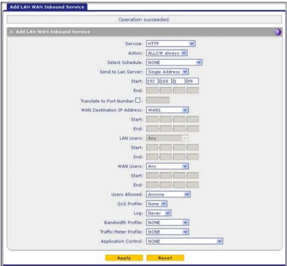
Figure 76.
LAN WAN Inbound Rule: Allow Videoconference from Restricted Addresses
If you want to allow incoming videoconferencing to be initiated from a restricted range of outside IP addresses, such as from a branch office, you can create an inbound rule (see the following figure). In the example, CU-SeeMe connections are allowed only from a specified range of external IP addresses.

Figure 77.
LAN WAN or DMZ WAN Inbound Rule: Set Up One-to-One NAT Mapping
In this example, multi-NAT is configured to support multiple public IP addresses on one WAN interface. An inbound rule configures the UTM to host an additional public IP address and associate this address with a web server on the LAN. (For information about how to configure a secondary WAN IP address, see Configure Secondary WAN Addresses on page 89.)
The following addressing scheme is used to illustrate this procedure:
• NETGEAR UTM:
- WAN IP address. 10.1.0.118
- LAN IP address subnet. 192.168.1.1 with subnet 255.255.255.0
- DMZ IP address subnet. 192.168.10.1 with subnet 255.255.255.0
• Web server computer on the UTM's LAN:
- LAN IP address. 192.168.1.2
- DMZ IP address. 192.168.10.2
- Access to web server is (simulated) public IP address. 10.1.0.52
ProSecure Unified Threat Management (UTM) Appliance
Tip: If you arrange with your ISP to have more than one public IP address for your use, you can use the additional public IP addresses to map to servers on your LAN or DMZ. One of these public IP addresses is used as the primary IP address of the router that provides Internet access to your LAN computers through NAT. The other addresses are available to map to your servers.
To configure the UTM for additional IP addresses:
- Select Network Security > Firewall. The Firewall submenu tabs display.
- If your server is to be on your LAN, click the LAN WAN Rules submenu tab. (This is the screen used in this example). If your server is to be on your DMZ, click the DMZ WAN Rules submenu tab.
- Click the Add table button under the Inbound Services table. The Add LAN WAN Inbound Service screen displays:

Figure 78.
- From the Service drop-down list, select HTTP for a web server.
- From the Action drop-down list, select ALLOW Always.
ProSecure Unified Threat Management (UTM) Appliance
- In the Send to LAN Server field, enter the local IP address of your web server computer (192.168.1.2 in this example).
- For the multiple WAN port models only: From the WAN Destination IP Address drop-down list, select the web server (the simulated 10.1.0.52 address in this example) that you have defined on a WAN Secondary Addresses screen (see Configure Secondary WAN Addresses on page 89).
Note: For the single WAN port models: The WAN Destination IP Address field is a fixed field.
- Click Apply to save your settings. The rule is now added to the Inbound Services table of the LAN WAN Rules screen.
To test the connection from a computer on the Internet, type http://
LAN WAN or DMZ WAN Inbound Rule: Specify an Exposed Host
Specifying an exposed host allows you to set up a computer or server that is available to anyone on the Internet for services that you have not yet defined.
To expose one of the computers on your LAN or DMZ as this host:
- Create an inbound rule that allows all protocols.
- Place the rule below all other inbound rules.
See an example in the following figure.

Figure 79.

WARNING:
For security, NETGEAR strongly recommends that you avoid creating an exposed host. When a computer is designated as the exposed host, it loses much of the protection of the firewall and is exposed to many exploits from the Internet. If compromised, the computer can be used to attack your network.
Outbound Rule Example
Outbound rules let you prevent users from using applications such as Instant Messenger, Real Audio, or other nonessential sites.
LAN WAN Outbound Rule: Block Instant Messenger
If you want to block Instant Messenger usage by employees during working hours, you can create an outbound rule to block such an application from any internal IP address to any external address according to the schedule that you have created in the Schedule screen. See an example in the following figure.
You can also enable the UTM to log any attempt to use Instant Messenger during the blocked period.

Figure 80.
Configure Other Firewall Features
- VLAN Rules
- Attack Checks, VPN Pass-through, and Multicast Pass-through
- Set Session Limits
- Manage the Application Level Gateway for SIP Sessions and VPN Scanning
You can configure global VLAN rules, configure attack checks, set session limits, and manage the application level gateway (ALG) for SIP sessions.
VLAN Rules
The VLAN Rules screen allows you to specify inter-VLAN firewall rules (that is, firewall rules for VLANs that are created on the UTM) when inter-VLAN routing is not enabled (see Configure a VLAN Profile on page 103). For example, you can create one VLAN with IP address 192.168.1.0 and a second VLAN with IP address 192.168.2.0. You can then specify a VLAN firewall rule to allow access from all 192.168.1.* IP addresses to a web server with IP address 192.168.2.10 on the second VLAN and block all other traffic between the two VLANs.
To create a VLAN rule:
- Select Network Security > Firewall > VLAN Rules. The VLAN Rules screen displays. (The following figure shows one rule in the VLAN Services table as an example.)

Figure 81.
- Under the VLAN Services table, click the Add table button. The Add VLAN-VLAN Service screen displays:

Figure 82.
- Enter the settings as explained in the following table.
Table 29. Add VLAN-VLAN Service screen settings
| Setting Description | |
| Service | The service or application to be covered by this rule. If the service or application does not display in the list, you need to define it using the Services screen (see Add Customized Services on page 163). |
| Action The action for VLAN | N connections covered by this rule:• BLOCK always• ALLOW always |
| Source VLAN User | The settings that determine which VLAN users who send traffic are affected by this rule. The options are:Any. All computers and devices that are part of the VLAN.Single address. Enter the required address in the Start field to apply the rule to a single computer in the VLAN.Address range. Enter the required addresses in the Start and End fields to apply the rule to a range of computers in the VLAN. |
| Destination VLAN User | The settings that determine which VLAN users who receive traffic are affected by this rule. The options are:Any. All computers and devices that are part of the VLAN.Single address. Enter the required address in the Start field to apply the rule to a single computer in the VLAN.Address range. Enter the required addresses in the Start and End fields to apply the rule to a range of computers in the VLAN. |
| User Allowed | The settings that determine which user or group on the network is affected by this rule. You can select a local user, local group, or customer group. To create a custom group, select + Create New from the Users Allowed drop-down list. (You can find the + Create New link under the Custom Groups heading.) The Add Custom Group pop-up screen displays. For information about setting up custom groups, see Configure Custom Groups on page 397. |
| Log The settings that determine whether packets covered by this rule are logged. The options are: • Always. Always log traffic considered by this rule, whether it matches or not. This is useful when you are debugging your rules.• Never. Never log traffic considered by this rule, whether it matches or not. | |
- Click Apply to save your settings. The new VLAN rule is added to the VLAN Services table.
To change the position of an existing VLAN rule in the VLAN Services table:
In the Action column to the right of the rule, click one of the following table buttons:
- Up. Moves the rule up one position in the table rank.
- Down. Moves the rule down one position in the table rank.
To edit a VLAN rule:
- In the VLAN Services table, click the Edit table button to the right of the VLAN rule that you want to edit. The Edit VLAN-VLAN Service screen displays.
- Modify the settings that you wish to change (see the previous table).
- Click Apply to save your changes. The modified VLAN rule is displayed in the VLAN Services table.
To delete or disable one or more VLAN rules:
- Select the check box to the left of each VLAN rule that you want to delete or disable, or click the Select All table button to select all VLAN rules.
- Click one of the following table buttons:
- Disable. Disables the selected VLAN rule or rules. The ! status icon changes from a green circle to a gray circle, indicating that the selected VLAN rule is or rules are disabled. (By default, when a VLAN rule is added to the table, it is automatically enabled.)
- Delete. Deletes the selected VLAN rule or rules.
Attack Checks, VPN Pass-through, and Multicast Pass-through
The Attack Checks screen allows you to specify whether the UTM should be protected against common attacks in the DMZ, LAN, and WAN networks, and lets you configure VPN pass-through and multicast pass-through. The various types of attack checks are listed on the Attack Checks screen and defined in Table 30 on page 157.
To enable the appropriate attack checks for your network environment:
- Select Network Security > Firewall > Attack Checks. The Attack Checks screen displays:

Figure 83.
- Enter the settings as explained in the following table:
Table 30. Attack Checks screen settings
| Setting Description | |
| WAN Security Checks | |
| Respond to Ping on Internet Ports | Select the Respond to Ping on Internet Ports check box to enable the UTM to respond to a ping from the Internet. A ping can be used as a diagnostic tool. Keep this check box cleared unless you have a specific reason to enable the UTM to respond to a ping from the Internet. |
| Enable Stealth Mode | Select the Enable Stealth Mode check box (which is the default setting) to prevent the UTM from responding to port scans from the WAN, thus making it less susceptible to discovery and attacks. |
| Block TCP flood | Select the Block TCP flood check box to enable the UTM to drop all invalid TCP packets and to protect the UTM from a SYN flood attack.A SYN flood is a form of denial of service attack in which an attacker sends a succession of SYN (synchronize) requests to a target system. When the system responds, the attacker does not complete the connections, thus leaving the connection half open and flooding the server with SYN messages. No legitimate connections can then be made. By default, the Block TCP flood check box is cleared. |
| LAN Security Checks | |
| Block UDP flood | Select theBlock UDP floodcheck box to prevent the UTM from accepting more than 20 simultaneous, active User Datagram Protocol (UDP) connections from a single device on the LAN. By default, the Block UDP flood check box is cleared.A UDP flood is a form of denial of service attack that can be initiated when one device sends many UDP packets to random ports on a remote host. As a result, the distant host does the following:1. Checks for the application listening at that port.2. Sees that no application is listening at that port.3. Replies with an ICMP Destination Unreachable packet.When the victimized system is flooded, it is forced to send many ICMP packets, eventually making it unreachable by other clients. The attacker might also spoof the IP address of the UDP packets, ensuring that the excessive ICMP return packets do not reach the attacker, thus making the attacker's network location anonymous. |
| Disable Ping Reply on LAN Ports | Select theDisable Ping Reply on LAN Portscheck box to prevent the UTM from responding to a ping on a LAN port. A ping can be used as a diagnostic tool. Keep this check box cleared unless you have a specific reason to prevent the UTM from responding to a ping on a LAN port. |
| VPN Pass through | |
| IPSecPPTPL2TP | When the UTM functions in NAT mode, all packets going to the remote VPN gateway are first filtered through NAT and then encrypted according to the VPN policy. For example, if a VPN client or gateway on the LAN side of the UTM wants to connect to another VPN endpoint on the WAN side (placing the UTM between two VPN endpoints), encrypted packets are sent to the UTM. Because the UTM filters the encrypted packets through NAT, the packets become invalid unless you enable the VPN Pass through feature.To enable the VPN tunnel to pass the VPN traffic without any filtering, select any or all of the following check boxes:IPSec.Disables NAT filtering for IPSec tunnels.PPTP.Disables NAT filtering for PPTP tunnels.L2TP.Disables NAT filtering for L2TP tunnels.By default, all three check boxes are selected. |
- Click Apply to save your settings.
Configure Multicast Pass-Through
To configure multicast pass-through:
- Select Network Security > Firewall > IGMP. The IGMP screen displays. (The following figure shows one alternate network as an example.)

Figure 84.
- In the Multicast Pass through section of the screen, select the Yes radio button to enable multicast pass-through. (By default the Yes radio button is enabled.)
When you enable multicast pass-through, an Internet Group Management Protocol (IGMP) proxy is enabled for the upstream (WAN) and downstream (LAN) interfaces. This proxy allows the UTM to forward relevant multicast traffic from the WAN to the LAN, and to keep track of the IGMP group membership when LAN hosts join or leave the multicast group.
- For multiple WAN port models, if load balancing is configured, select the upstream interface to which multicast traffic is bound because only a single interface can function as the upstream interface. From the Bind Upstream interface to drop-down list, select the interface or the slot (UTM9S and UTM25S only). The default interface is WAN1.
When you change the WAN mode to load balancing, multicast traffic is bound by default to the active interface of the previous WAN mode.
If the interface to which multicast traffic is bound is configured for PPPoE, PPPoA (UTM9S and UTM25S only), or PPTP, you need to add the multicast source address to the Alternate Networks table:
a. In the Alternate Networks section of the screen, below the table, enter the following settings:
• IP Address. Enter the multicast source IP address.
- Subnet Mask. Enter the subnet mask for the multicast source address.
b. Click the Add table button in the rightmost column to add the multicast source address to the Alternate Networks table.
Repeat Step a and Step b for each multicast source address that you need to add to the Alternate Networks table.
To delete one or more multicast source addresses:
- In the Alternate Networks table, select the check box to the left of each address that you want to delete, or click the Select All table button to select all addresses.
- Click the Delete table button.
Set Session Limits
The session limits feature allows you to specify the total number of sessions that are allowed, per user, over an IP connection across the UTM. The session limits feature is disabled by default.
To enable and configure session limits:
- Select Network Security > Firewall > Session Limit. The Session Limit screen displays:
![Network Config | Network Security | Application Security | VPN | Users | Administration | Monitoring | Support | Wizards | IPS | Services | Firewall | Address Filter | Port Triggering | UPnP | LAN WAN Rules | DMZ WAN Rules | LAN DMZ Rules | VLAN Rules | Attack Checks | Session Limit | IGMP | Advanced Session Limit You want to enable Session Limit? Yes No User Limit Parameter: Percentage of Max Sessions User Limit: 1 Number of Packets Dropped due to Session Limit: 0 Session Timeout TCP Timeout: 1200 [Seconds] UDP Timeout: 180 [Seconds] ICMP Timeout: 8 [Seconds] Apply Reset](/content/2026/06/1371942/images/05be1124ec8f25ee918bddd9aeba2ba08d8b63ef52d3c560189d23afaee7cd8d.jpg)
Figure 85.
- Select the Yes radio button under Do you want to enable Session Limit?
- Enter the settings as explained in the following table:
Table 31. Session Limit screen settings
| Setting Description | |
| Session Limit | |
| User Limit Parameter | From the User Limit Parameter drop-down list, select one of the following options:Percentage of Max Sessions. A percentage of the total session connection capacity of the UTM.Number of Sessions. An absolute number of maximum sessions. |
| User Limit Enter a number | ber to indicate the user limit.If the User Limit Parameter is set to Percentage of Max Sessions, the number specifies the maximum number of sessions that are allowed from a single-source device as a percentage of the total session connection capacity of the UTM. (The session limit is per-device based.)If the User Limit Parameter is set to Number of Sessions, the number specifies an absolute value.Note: Some protocols such as FTP and RSTP create two sessions per connection, which should be considered when configuring a session limit. |
| Total Number of Packets Dropped due to Session Limit | This is a nonconfigurable counter that displays the total number of dropped packets when the session limit is reached. |
| Session Timeout | |
| TCP Timeout | For each protocol, specify a time-out in seconds. A session expires if no data is received for the session during the time-out period. The default time-out periods are 1200 seconds for TCP sessions, 180 seconds for UDP sessions, and 8 seconds for ICMP sessions. |
| UDP Timeout | |
| ICMP Timeout | |
4. Click Apply to save your settings.
Manage the Application Level Gateway for SIP Sessions and VPN Scanning
The application level gateway (ALG) facilitates multimedia sessions such as voice over IP (VoIP) sessions that use the Session Initiation Protocol (SIP) across the firewall and provides support for multiple SIP clients. ALG support for SIP is disabled by default.
You can enable scanning of VPN traffic that passes through the UTM. VPN scanning increases the level of security but degrades the IPSec performance. By default, VPN scanning is disabled.
To enable ALG for SIP and VPN scanning:
- Select Network Security > Firewall > Advanced. The Advanced screen displays:

Figure 86.
- In the ALG section, select the Enable SIP ALG check box.
- In the ALG section, click Apply to save your settings.
- In the VPN scan section, select the Enable VPN scan check box.
- In the VPN scan section, click Apply to save your settings.
Create Services, QoS Profiles, Bandwidth Profiles, and Traffic Meter Profiles
- Add Customized Services
- Create Service Groups
- Create IP Groups
- Create Quality of Service Profiles
- Create Bandwidth Profiles
- Create Traffic Meter Profiles
When you create inbound and outbound firewall rules, you use firewall objects such as services, service groups, IP groups (LAN and WAN groups), QoS profiles, bandwidth profiles, traffic meter profiles, and schedules to narrow down the firewall rules:
- Services. A service narrows down the firewall rule to an application and a port number. You can also narrow down the firewall rule to a group of services. For information about adding services and service groups, see Add Customized Services on page 163 and Create Service Groups on page 165.
-
IP groups. An IP group is a LAN group or a WAN group to which you add individual IP addresses. You can narrow down the firewall rule to such an IP group. For information about creating IP groups, see Create IP Groups on page 167.
-
QoS profiles. A Quality of Service (QoS) profile defines the relative priority of an IP packet for traffic that matches the firewall rule. For information about creating QoS profiles, see Create Quality of Service Profiles on page 169.
- Bandwidth profiles. A bandwidth profile allocates and limits traffic bandwidth for the LAN users to which a firewall rule is applied. For information about creating bandwidth profiles, see Create Bandwidth Profiles on page 171.
- Traffic meter profiles. A traffic meter profile measures downloaded or uploaded traffic, or both, for users to which a firewall rule is applied, and logs or blocks traffic that exceeds the preset limit or limits. For information about creating traffic meter profiles, see Create Traffic Meter Profiles on page 174.
Note: A schedule narrows down the period during which a firewall rule is applied. For information about specifying schedules, see Set a Schedule to Block or Allow Specific Traffic on page 177.
Add Customized Services
Services are functions performed by server computers at the request of client computers. You can configure up to 125 custom services.
For example, web servers serve web pages, time servers serve time and date information, and game hosts serve data about other players' moves. When a computer on the Internet sends a request for service to a server computer, the requested service is identified by a service or port number. This number appears as the destination port number in the transmitted IP packets. For example, a packet that is sent with destination port number 80 is an HTTP (web server) request.
The service numbers for many common protocols are defined by the Internet Engineering Task Force (IETF) and published in RFC 1700, Assigned Numbers. Service numbers for other applications are typically chosen from the range 1024 to 65535 by the authors of the application.
Although the UTM already holds a list of many service port numbers, you are not limited to these choices. Use the Services screen to add additional services and applications to the list for use in defining firewall rules. The Services screen shows a list of services that you have defined, as shown in Figure 87 on page 164.
To define a new service, you need to determine first which port number or range of numbers is used by the application. You can usually determine this information by contacting the publisher of the application, user groups, or newsgroups. When you have the port number information, you can enter it on the Services screen.
You use a customized service as a firewall object to which you apply a firewall rule, that is, you select the customized service from the Service drop-down list on a screen on which you add or edit a firewall rule.
To add a customized service:
- Select Network Security > Services. The Services screen displays. The Custom Services table shows the user-defined services. (The following figure shows some examples.)
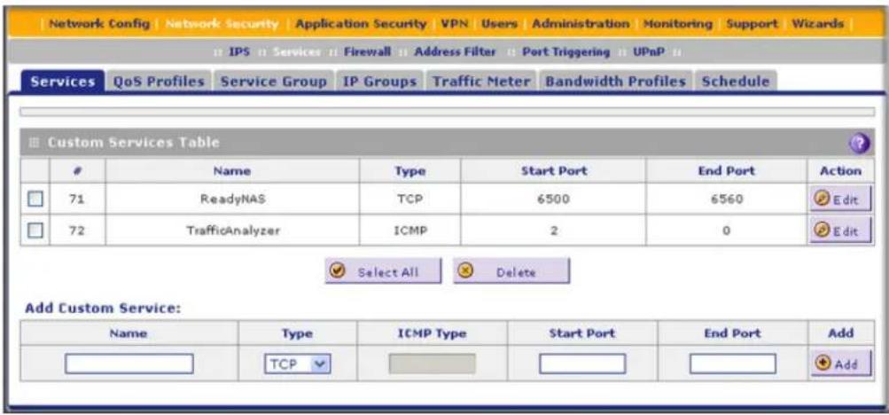
Figure 87.
- In the Add Customer Service section of the screen, enter the settings as explained in the following table:
Table 32. Services screen settings
| Setting Description | |
| Name | A descriptive name of the service for identification and management purposes. |
| Type | From the Type drop-down list, select the Layer 3 protocol that the service uses as its transport protocol:TCPUDPICMP |
| ICMP Type A numeric value that can range between 0 and 40. For a list of ICMP types, see http://www.iana.org/assignments/icmp-parameters.Note: This field is enabled only when you select ICMP from the Type drop-down list. | |
| Start Port The first TCP or UDP port of a range that the service uses.Note: This field is enabled only when you select TCP or UDP from the Type drop-down list. | |
| End Port | The last TCP or UDP port of a range that the service uses. If the service uses only a single port number, enter the same number in the Start Port and End Port fields.Note: This field is enabled only when you select TCP or UDP from the Type drop-down list. |
- Click Apply to save your settings. The new custom service is added to the Custom Services table.
To edit a service:
- In the Custom Services table, click the Edit table button to the right of the service that you want to edit. The Edit Service screen displays:

Figure 88.
- Modify the settings that you wish to change (see the previous table).
- Click Apply to save your changes. The modified service is displayed in the Custom Services table.
To delete one or more services:
- In the Custom Services table, select the check box to the left of each service that you want to disable, or click the Select All table button to select all services.
- Click the Delete table button.
Create Service Groups
A service group can contain a collection of predefined and customized services. (TCP and UDP customized services can be included in a service group.) You use a service group as a firewall object to which you apply a firewall rule, that is, you select the service group from the Service drop-down list on a screen on which you add or edit a firewall rule.
One advantage of a service group is that you can create a single firewall object with multiple noncontiguous ports (for example ports 3000, 4000, and 5000) and apply the object in a single firewall rule. For example, if there are 10 web servers, each of which requires the same three port-forwarding rules, you can create a service group for the port-forwarding rules, an IP group for the web servers (see Create IP Groups on page 167), and then create only one firewall rule.
To create a service group:
- Select Network Security > Services > Service Group. The Service Group screen displays. (The following figure shows two groups in the Custom Service Group table as an example.)

Figure 89.
- Under the Custom Service Group table, click the Add table button. The Add Service Group screen displays:

Figure 90.
- In the Name field, enter a name for the service.
- Use the move buttons (<< and >>) to move services between the Available Services field and the List of Selected Services field to specify the services that you want to be part of the group.
- Click Apply to save your changes. The new service group is displayed in the Custom Services Group table on the Service Groups screen.
To edit a service group:
- In the Custom Services Group table, click the Edit table button to the right of the service group that you want to edit. The Edit Service group screen displays.
- Modify the settings that you wish to change (see Step 3 and Step 4 in the previous procedure).
- Click Apply to save your changes. The modified service group is displayed in the Custom Services Group table.
Create IP Groups
An IP group contains a collection of individual IP addresses that do not need to be within the same IP address range. You specify an IP group as either a LAN group or WAN group. You use the group as a firewall object to which you apply a firewall rule, that is, you select the group from the LAN Users or WAN Users drop-down list on a screen on which you add or edit a firewall rule.
To create an IP group:
- Select Network Security > Services > IP Groups. The IP Groups screen displays. (The following figure shows two groups in the Custom IP Groups table as an example.)
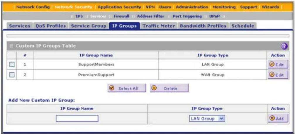
Figure 91.
- In the Add New Custom IP Group section of the screen, do the following:
• In the IP Group Name field, enter a name for the group.
• From the IP Group Type drop-down list, select LAN Group or WAN Group.
- Click Apply to save your changes. The new IP group is displayed in the Custom IP Groups table.
- In the Custom IP Groups table, click the Edit table button to the right of the IP group that you just created. The Edit IP Group screen displays. (The following figure shows three IP addresses in the IP Addresses Grouped table as an example.)

Figure 92.
- In the IP Address fields, type an IP address.
- Click the Add table button to add the IP address to the IP Addresses Grouped table.
- Repeat the previous two steps to add more IP addresses to the IP Addresses Grouped table.
- Click the Edit table button to return to IP Groups screen.
To edit a service group:
- In the Custom IP Groups table, click the Edit table button to the right of the IP group that you want to edit. The Edit IP Group screen displays.
- In the Edit New Custom IP Group section of the screen, modify the settings that you wish to change:
• You can change the group name.
• You can change the group type.
- You can delete an IP address from the IP Addresses Grouped table by selecting the check box to the left of the IP address that you want to delete and then clicking the Delete table button. You can delete all IP addresses by selecting the Select All table button and clicking the Delete table button.
- You can add IP addresses to the IP Addresses Grouped table (see Step 4, Step 5, and Step 6 in the previous procedure).
- Click the Edit table button to return to IP Groups screen.
To delete an IP group:
- In the Custom IP Groups table, select the check box to the left of each IP group that you want to delete, or click the Select All table button to select all groups.
- Click the Delete table button.
Create Quality of Service Profiles
A Quality of Service (QoS) profile defines the relative priority of an IP packet when multiple connections are scheduled for simultaneous transmission on the UTM. A QoS profile becomes active only when it is associated with a nonblocking inbound or outbound firewall rule, and traffic matching the firewall rule is processed by the UTM.
After you have created a QoS profile, you can assign the profile to firewall rules and application control profiles on the following screens:
- Add LAN WAN Outbound Services screen (see Figure 68 on page 141).
- Add LAN WAN Inbound Services screen (see Figure 69 on page 142).
- Add DMZ WAN Outbound Services screen (see Figure 71 on page 144).
- Add DMZ WAN Inbound Services screen (see Figure 72 on page 145).
- Application Control Policy pop-up screens (see Figure 136 on page 245 and Figure 137 on page 245). You can access these pop-up screens from the Add or Edit Application Control Profile screen (see Figure 135 on page 243).
Priorities are defined by the Type of Service (ToS) in the Internet Protocol Suite standards, RFC 1349.
There are no default QoS profiles on the UTM. Following are examples of QoS profiles that you could create:
- Normal service profile. Used when no special priority is given to the traffic. You would typically mark the IP packets for services with this priority with a ToS value of 0.
- Minimize-cost profile. Used when data needs to be transferred over a link that has a lower cost. You would typically mark the IP packets for services with this priority with a ToS value of 1.
- Maximize-reliability profile. Used when data needs to travel to the destination over a reliable link and with little or no retransmission. You would typically mark the IP packets for services with this priority with a ToS value of 2.
- Maximize-throughput profile. Used when the volume of data transferred during an interval is important even if the latency over the link is high. You would typically mark the IP packets for services with this priority with a ToS value of 3 or 4.
- Minimize-delay profile. Used when the time required (latency) for the packet to reach the destination needs to be low. You would typically mark the IP packets for services with this priority with a ToS value of 7.
To create a QoS profile:
- Select Network Security > Services > QoS Profiles. The QoS Profiles screen displays. (The following figure shows some profiles in the List of QoS Profiles table as an example.)

Figure 93.
The screen displays the List of QoS Profiles table with the user-defined profiles.
- Under the List of QoS Profiles table, click the Add table button. The Add QoS Profile screen displays:

Figure 94.
- Enter the settings as explained in the following table.
Note: This document assumes that you are familiar with QoS concepts such QoS priority queues, IP precedence, DHCP, and their values.
Table 33. Add QoS Profile screen settings
| Setting Description | |
| Profile Name | A descriptive name of the QoS profile for identification and management purposes. |
| Re-Mark | Select the Re-Mark check box to set the differentiated services (DiffServ) mark in the Type of Service (ToS) byte of an IP header by specifying the QoS type (IP precedence or DHCP) and QoS value. If you clear the Re-Mark check box, the QoS type and QoS value are ignored, and you can configure the QoS priority only. |
| QoS From the QoS | drop-down list, select one of the following traffic classification methods:IP Precedence. A legacy method that sets the priority in the ToS byte of an IP header.DSCP. A method that sets the Differentiated Services Code Point (DSCP) in the Differentiated Services (DS) field (which is the same as the ToS byte) of an IP header. |
| QoS Value The QoS | value in the ToS or DiffServ byte of an IP header. The QoS value that you enter depends on your selection from the QoS drop-down list:For IP precedence, select a value from 0 to 7.For DSCP, select a value from 0 to 63. |
| QoS Priority | From the QoS Priority drop-down list, select one of the following priority queues:DefaultHighMedium HighLow |
- Click Apply to save your settings. The new QoS profile is added to the List of QoS Profiles table.
To edit a QoS profile:
- In the List of QoS Profiles table, click the Edit table button to the right of the QoS profile that you want to edit. The Edit QoS Profile screen displays.
- Modify the settings that you wish to change (see the previous table).
- Click Apply to save your changes. The modified QoS profile is displayed in the List of QoS Profiles table.
To delete one ore more QoS profiles:
- In the List of QoS Profiles table, select the check box to the left of each QoS profile that you want to delete, or click the Select All table button to select all profiles.
- Click the Delete table button.
Create Bandwidth Profiles
Bandwidth profiles determine how data is communicated with the hosts. The purpose of bandwidth profiles is to provide a method for allocating and limiting traffic, thus allocating LAN users sufficient bandwidth while preventing them from consuming all the bandwidth on your WAN link. A single bandwidth profile can be for both outbound and inbound traffic.
For outbound traffic, you can apply bandwidth profiles on the available WAN interfaces in both the primary WAN mode and auto-rollover modes, and in load balancing mode on the interface that you specify. For inbound traffic, you can apply bandwidth profiles to a LAN interface for all WAN modes. Bandwidth profiles do not apply to the DMZ interface.
When a new connection is established by a device, the device locates the firewall rule corresponding to the connection.
- If the rule has a bandwidth profile specification, the device creates a bandwidth class in the kernel.
- If multiple connections correspond to the same firewall rule, the connections all share the same bandwidth class.
An exception occurs for an individual bandwidth profile if the classes are per-source IP address classes. The source IP address is the IP address of the first packet that is transmitted for the connection. So for outbound firewall rules, the source IP address is the LAN-side IP address; for inbound firewall rules, the source IP address is the WAN-side IP address. The class is deleted when all the connections that are using the class expire.
After you have created a bandwidth profile, you can assign the profile to firewall rules and application control profiles on the following screens:
- Add LAN WAN Outbound Services screen (see Figure 68 on page 141).
- Add LAN WAN Inbound Services screen (see Figure 69 on page 142).
- Application Control Policy pop-up screens (see Figure 136 on page 245 and Figure 137 on page 245). You can access these pop-up screens from the Add or Edit Application Control Profile screen (see Figure 135 on page 243).
To add and enable a bandwidth profile:
- Select Network Security > Services > Bandwidth Profiles. The Bandwidth Profiles screen displays. (The following figure shows one user-defined profile in the List of Bandwidth Profiles table as an example.)

Figure 95.
- Under the List of Bandwidth Profiles table, click the Add table button. The Add Bandwidth Profile screen displays:
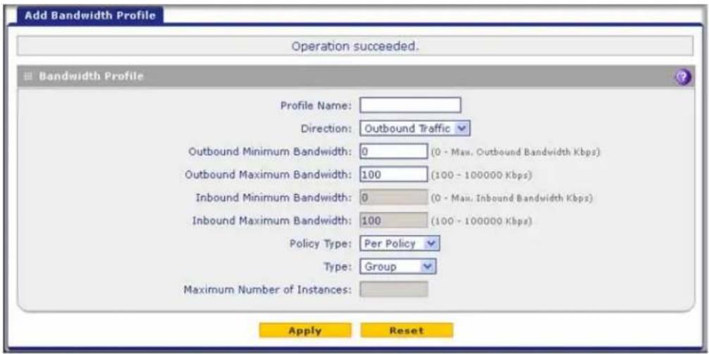
Figure 96.
- Enter the settings as explained in the following table:
Table 34. Add Bandwidth Profile screen settings
| Setting Description | ||
| Profile Name A descriptive name of the bandwidth profile for identification and management purposes. | ||
| Direction | From the Direction drop-down list, select the traffic direction for the bandwidth profile:Outbound Traffic. The bandwidth profile is applied only to outbound traffic. Specify the outbound minimum and maximum bandwidths.Inbound Traffic. The bandwidth profile is applied only to inbound traffic. Specify the inbound minimum and maximum bandwidths.Both. The bandwidth profile is applied to both outbound and inbound traffic. Specify both the outbound and inbound minimum and maximum bandwidths. | |
| Outbound Minimum Bandwidth | The outbound minimum allocated bandwidth in Kbps. The default setting is 0 Kbps. | |
| Outbound Maximum Bandwidth | The outbound maximum allowed bandwidth in Kbps. The default setting is 100 Kbps (you cannot configure less than 100 Kbps); the maximum allowable bandwidth is 100,000 Kbps. | |
| Inbound Minimum Bandwidth | The inbound minimum allocated bandwidth in Kbps. The default setting is 0 Kbps. | |
| Inbound Maximum Bandwidth | The inbound maximum allowed bandwidth in Kbps. The default setting is 100 Kbps (you cannot configure less than 100 Kbps); the maximum allowable bandwidth is 100,000 Kbps. | |
| Policy Type From the | Policy Type drop-down list, select how the policy is applied when it is assigned to multiple firewall rules:Per Policy. The policy limits apply to each firewall rule separately. For example, an outbound maximum bandwidth of 25,000 Kbps would apply to each firewall rule to which the policy is assigned.All Policies. The policy limits apply to all firewall rules together. For example, an outbound maximum bandwidth of 25,000 Kbps would be shared together by all firewall rules to which the policy is assigned. | |
| Type From the Type | drop-down list, select the type for the bandwidth profile:Group. The profile applies to all users, that is, all users share the available bandwidth.Individual. The profile applies to an individual user, that is, each user can use the available bandwidth. | |
| Maximum Number of Instances | If you select Individual from the Type drop-down list, you need to specify the maximum number of class instances that can be created by the individual bandwidth profile. | |
- Click Apply to save your settings. The new bandwidth profile is added to the List of Bandwidth Profiles table.
- In the Bandwidth Profiles section of the screen, select the Yes radio button under Enable Bandwidth Profiles? (By default the No radio button is selected.)
- Click Apply to save your setting. You now can select the profile when you create or change a firewall rule.
To edit a bandwidth profile:
- In the List of Bandwidth Profiles table, click the Edit table button to the right of the bandwidth profile that you want to edit. The Edit Bandwidth Profile screen displays.
- Modify the settings that you wish to change (see the previous table).
- Click Apply to save your changes. The modified bandwidth profile is displayed in the List of Bandwidth Profiles table.
To delete one or more bandwidth profiles:
- In the List of Bandwidth Profiles table, select the check box to the left of each bandwidth profile that you want to delete, or click the Select All table button to select all profiles.
- Click the Delete table button.
Create Traffic Meter Profiles
Traffic meter profiles allow you to measure and control traffic that is downloaded and uploaded by users to whom a firewall rule is assigned. When traffic for a profile has reached its configured limit, you can either log or block the traffic. A traffic meter profile differs from the WAN traffic meter (see Enable the WAN Traffic Meter on page 462) in that it applies to one or more firewall rules instead of a WAN interface. A single bandwidth profile can be used for
ProSecure Unified Threat Management (UTM) Appliance
both downloaded and uploaded traffic. When applied to multiple firewall rules, a single profile can be applied to each firewall rule separately, or to all firewall rules together.
After you have created a traffic meter profile, you can assign the profile to firewall rules and application control profiles on the following screens:
- Add LAN WAN Outbound Services screen (see Figure 68 on page 141).
- Add LAN WAN Inbound Services screen (see Figure 69 on page 142).
- Add DMZ WAN Outbound Services screen (see Figure 71 on page 144).
- Add DMZ WAN Inbound Services screen (see Figure 72 on page 145).
- Application Control Policy pop-up screens (see Figure 136 on page 245 and Figure 137 on page 245). You can access these pop-up screens from the Add or Edit Application Control Profile screen (see Figure 135 on page 243).
To add a traffic meter profile:
- Select Network Security > Services > Traffic Meter. The Traffic Meter screen displays. (The following figure shows two profiles in the List of Traffic Meter Profiles table as an example.)

Figure 97.
Note: If a traffic meter profile is assigned to a firewall rule, the Download (MB) and Upload (MB) columns display the downloaded and uploaded traffic in MB. To reset the traffic meter for a profile, click the Reset table button to the right of the profile.
- Under the List of Traffic Meter Profiles table, click the Add table button. The Add Traffic Meter Profile screen displays:
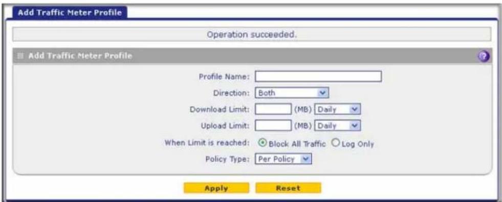
Figure 98.
- Enter the settings as explained in the following table:
Table 35. Add Traffic Meter Profile screen settings
| Setting Description | |
| Profile Name | A descriptive name of the traffic meter profile for identification and management purposes. |
| Direction | From the Direction drop-down list, select the traffic direction for the bandwidth profile: ·Download only. The traffic meter profile is applied only to downloaded traffic. Specify the download limit and measurement period. ·Upload only. The traffic meter profile is applied only to uploaded traffic. Specify the upload limit and measurement period. ·Both. The traffic meter profile is applied to both downloaded and uploaded traffic. Specify both the download and upload limits and measurement periods. |
| Download Limit | Enter the download limit in MB, upload limit in MB, or both. Then, from the drop-down list, for each limit, select the period to which the limit applies: ·Daily. The limit applies to one day and is reset after one day at 00.00 AM. ·Weekly. The limit applies to one week and is reset on Sunday at 00.00 AM. ·Monthly. The limit applies to one month and is reset on the first day of the next month at 00.00 AM. |
| Upload Limit | |
| When Limit is reached | From the Direction drop-down list, select the action that should occur when the limit is reached: ·Block All Traffic. The traffic that you selected from the Direction drop-down list is blocked. ·Log Only. Traffic is not blocked but logged. |
| Policy Type From the | Policy Type drop-down list, select how the policy is applied when it is assigned to multiple firewall rules: ·Per Policy. The policy limits apply to each firewall rule separately. For example, a download limit of 1000 MB would apply to each firewall rule to which the policy is assigned. ·All Policies. The policy limits apply to all firewall rules together. For example, a download limit of 1000 MB would be shared together by all firewall rules to which the policy is assigned. |
ProSecure Unified Threat Management (UTM) Appliance
- Click Apply to save your settings. The new traffic meter profile is added to the List of Traffic Meter Profiles table. You now can select the profile when you create or change a firewall rule.
To edit a traffic meter profile:
- In the List of Traffic Meter Profiles table, click the Edit table button to the right of the traffic meter profile that you want to edit. The Edit Traffic Meter Profile screen displays.
- Modify the settings that you wish to change (see the previous table).
- Click Apply to save your changes. The modified traffic meter profile is displayed in the List of Traffic Meter Profiles table.
To delete one or more traffic meter profiles:
- In the List of Traffic Meter Profiles table, select the check box to the left of each traffic meter profile that you want to delete, or click the Select All table button to select all profiles.
- Click the Delete table button.
Set a Schedule to Block or Allow Specific Traffic
Schedules define the time frames under which firewall rules can be applied. You can create multiple schedules and select any one them when defining firewall rules.
To add a schedule:
- Select Network Security > Services > Schedule. The Schedule screen displays. The following figure shows two schedules in the List of Schedules table as an example.)

Figure 99.
- Under the List of Schedules table, click the Add table button. The Add Schedule screen displays:
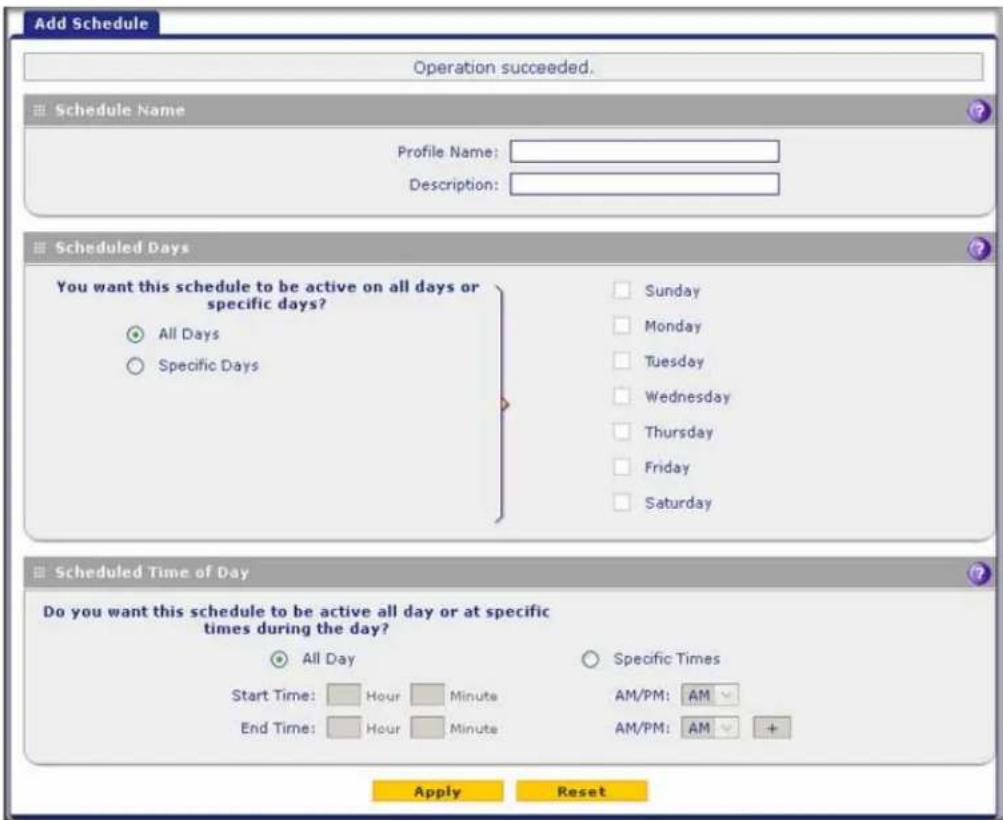
Figure 100.
- Enter the settings as explained in the following table:
Table 36. Add Schedule screen settings
| Setting Description | |
| Profile Name A name | of the schedule for identification and management purposes. |
| Description A description | to further help identification for management purposes. |
| Scheduled Days | |
| Select one of the following radio buttons:All Days. The schedule is in effect all days of the week.Specific Days. The schedule is in effect only on specific days. To the right of the radio buttons, select the check box for each day that you want the schedule to be in effect. | |
| Scheduled Time of Day | |
| Select one of the following radio buttons:All Day. The schedule is in effect all hours of the selected day or days.Specific Times. The schedule is in effect only during specific periods of the selected day or days. To the right of the radio buttons, fill in the Start Time and End Time fields (Hour, Minute) and make a selection from the AM/PM drop-down lists to specify the periods during which the schedule is in effect.Note:To add an another period to the schedule, click + (plus). This option allows you to specify two distinctive periods within one 24-hour period. | |
- Click Apply to save your settings. The new schedule is added to the List of Schedules table. You now can select the schedule when you create or change a firewall rule.
To edit a schedule:
- In the List of Schedules table, click the Edit table button to the right of the schedule that you want to edit. The Edit Schedule screen displays.
- Modify the settings that you wish to change (see the previous table).
- Click Apply to save your changes. The modified schedule is displayed in the List of Schedules table.
To delete one or more schedules:
- In the List of Schedules table, select the check box to the left of each schedule that you want to delete, or click the Select All table button to select all schedules.
- Click the Delete table button.
Enable Source MAC Filtering
The Source MAC Filter screen enables you to permit or block traffic coming from certain known computers or devices.
By default, the source MAC address filter is disabled. All the traffic received from computers with any MAC address is allowed. When the source MAC address filter is enabled, depending on the selected policy, traffic is either permitted or blocked if it comes from any computers or devices whose MAC addresses are listed in MAC Addresses table.
Note: For additional ways of restricting outbound traffic, see Outbound Rules (Service Blocking) on page 129.
To enable MAC filtering and add MAC addresses to be permitted or blocked:
- Select Network Security > Address Filter. The Address Filter submenu tabs display, with the Source MAC Filter screen in view. (The following figure shows one address in the MAC Addresses table as an example.)

Figure 101.
- In the MAC Filtering Enable section, select the Yes radio button.
- In the same section, from the Policy for MAC Addresses listed below the drop-down list, select one of the following options:
• Block. Traffic coming from all addresses in the MAC Addresses table is blocked.
- Permit. Traffic coming from all addresses in the MAC Addresses table is permitted.
- Click Apply to save your settings. The MAC Address field in the Add Source MAC Address section of the screen now becomes available.
- Build your list of source MAC addresses to be permitted or blocked by entering the first MAC address in the MAC Address field. A MAC address needs to be entered in the format xx:xx:xx:xx:xx:xx, in which x is a numeric (0 to 9) or a letter between a and f (inclusive), for example: aa:11:bb:22:cc:33.
- Click the Add table button. The MAC address is added to the MAC Addresses table.
- Repeat the previous two steps to add more MAC addresses to the MAC Addresses table.
To remove one or more entries from the table:
- Select the check box to the left of each MAC address that you want to delete, or click the Select All table button to select all entries.
- Click the Delete table button.
Set Up IP/MAC Bindings
IP/MAC binding allows you to bind an IP address to a MAC address and the other way around. Some computers or devices are configured with static addresses. To prevent users from changing their static IP addresses, the IP/MAC binding feature needs to be enabled on the UTM. If the UTM detects packets with an IP address that matches the IP address in the IP/MAC Bindings table but does not match the related MAC address in the IP/MAC Bindings table (or the other way around), the packets are dropped. If you have enabled the logging option for the IP/MAC binding feature, these packets are logged before they are dropped. The UTM displays the total number of dropped packets that violate either the IP-to-MAC binding or the MAC-to-IP binding.
Note: You can bind IP addresses to MAC addresses for DHCP assignment on the LAN Groups submenu. See Manage the Network Database on page 112.
As an example, assume that three computers on the LAN are set up as follows, and that their IP and MAC addresses are added to the IP/MAC Bindings table:
- Host 1. MAC address (00:01:02:03:04:05) and IP address (192.168.10.10)
- Host 2. MAC address (00:01:02:03:04:06) and IP address (192.168.10.11)
- Host 3. MAC address (00:01:02:03:04:07) and IP address (192.168.10.12)
There are three possible scenarios in relation to the addresses in the IP/MAC Bindings table:
- Host 1 has not changed its IP and MAC addresses. A packet coming from Host 1 has IP and MAC addresses that match those in the IP/MAC Bindings table.
- Host 2 has changed its MAC address to 00:01:02:03:04:09. The packet has an IP address that matches the IP address in the IP/MAC Bindings table but a MAC address that does not match the MAC address in the IP/MAC Bindings table.
- Host 3 has changed its IP address to 192.168.10.15. The packet has a MAC address that matches the MAC address in the IP/MAC Bindings table but an IP address that does not match the IP address in the IP/MAC Bindings table.
In this example, the UTM blocks the traffic coming from Host 2 and Host 3, but allows the traffic coming from Host 1 to any external network. The total count of dropped packets is displayed.
To set up IP/MAC bindings:
- Select Network Security > Address Filter > IP/MAC Binding. The IP/MAC Binding screen displays. (The following figure shows some bindings in the IP/MAC Binding table as an example.)

Figure 102.
- Enter the settings as explained in the following table:
Table 37. IP/MAC Binding screen settings
| Setting Description | |
| Email IP/MAC Violations | |
| Do you want to enable E-mail Logs for IP/MAC Binding Violation? | Select one of the following radio buttons:Yes. IP/MAC binding violations are emailed.No. IP/MAC binding violations are not emailed.Note:Click the Email Notification link to ensure that emailing of logs is enabled on the Email and Syslog screen (see Configure Logging, Alerts, and Event Notifications on page 466). |
| IP/MAC Bindings | |
| Name A descriptive | name of the binding for identification and management purposes. |
| MAC Address The MAC address of the computer or device that is bound to the IP address. | |
| IP Address | The IP address of the computer or device that is bound to the MAC address. |
| Log Dropped Packets | To log the dropped packets, select Enable from the drop-down list. The default setting is Disable. |
- Click the Add table button. The new IP/MAC rule is added to the IP/MAC Bindings table.
- Click Apply to save your changes.
To edit an IP/MAC binding:
- In the IP/MAC Bindings table, click the Edit table button to the right of the IP/MAC binding that you want to edit. The Edit IP/MAC Binding screen displays.
- Modify the settings that you wish to change (see the previous table).
- Click Apply to save your changes. The modified IP/MAC binding displays in the IP/MAC Bindings table.
To remove one or more IP/MAC bindings from the table:
- Select the check box to the left of each IP/MAC binding that you want to delete, or click the Select All table button to select all bindings.
- Click the Delete table button.
Configure Port Triggering
Port triggering allows some applications running on a LAN network to be available to external applications that would otherwise be partially blocked by the firewall. Using the port-triggering feature requires that you know the port numbers used by the application.
Once configured, port triggering operates as follows:
- A computer makes an outgoing connection using a port number that is defined in the Port Triggering Rules table.
- The UTM records this connection, opens the additional incoming port or ports that are associated with the rule in the port triggering table, and associates them with the computer.
- The remote system receives the computer's request and responds using the incoming port or ports that are associated with the rule in the port triggering table on the UTM.
- The UTM matches the response to the previous request and forwards the response to the computer.
Without port triggering, the response from the external application would be treated as a new connection request rather than a response to a request from the LAN network. As such, it would be handled in accordance with the inbound port-forwarding rules, and most likely would be blocked.
Note these restrictions on port triggering:
- Only one computer can use a port-triggering application at any time.
- After a computer has finished using a port-triggering application, there is a short time-out period before the application can be used by another computer. This time-out period is required so the UTM can determine that the application has terminated.
Note: For additional ways of allowing inbound traffic, see Inbound Rules (Port Forwarding) on page 133.
To add a port-triggering rule:
- Select Network Security > Port Triggering. The Port Triggering screen displays. (The following figure shows a rule in the Port Triggering Rule table as an example.)

Figure 103.
- In the Add Port Triggering Rule section, enter the settings as explained in the following table:
Table 38. Port Triggering screen settings
| Setting Description | ||
| Name A descriptive name of the rule for identification and management purposes. | ||
| Enable | From the drop-down list, select Yes to enable the rule. (You can define a rule but not enable it.) The default setting is No. | |
| Protocol From the drop-down list, select the protocol to which the rule applies:TCP. The rule applies to an application that uses the Transmission Control Protocol (TCP).UDP. The rule applies to an application that uses the User Datagram Protocol (UDP). | ||
| Outgoing (Trigger) Port Range | Start Port The | start port (1–65534) of the range for triggering. |
| End Port The | end port (1–65534) of the range for triggering. | |
| Incoming (Response) Port Range | Start Port The | start port (1–65534) of the range for responding. |
| End Port The | end port (1–65534) of the range for responding. | |
- Click the Add table button. The new port-triggering rule is added to the Port Triggering Rules table.
To edit a port-triggering rule:
- In the Port Triggering Rules table, click the Edit table button to the right of the port-triggering rule that you want to edit. The Edit Port Triggering Rule screen displays.
- Modify the settings that you wish to change (see the previous table).
- Click Apply to save your changes. The modified port-triggering rule is displayed in the Port Triggering Rules table.
To remove one or more port-triggering rules from the table:
- Select the check box to the left of each port-triggering rule that you want to delete, or click the Select All table button to select all rules.
- Click the Delete table button.
To display the status of the port-triggering rules:
Click the Status option arrow in the upper right of the Port Triggering screen. A pop-up screen displays, showing the status of the port-triggering rules.
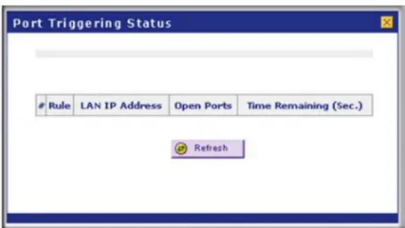
Figure 104.
Configure Universal Plug and Play
The Universal Plug and Play (UPnP) feature enables the UTM to discover and configure devices automatically when it searches the LAN and WAN.
1. Select Security > UPnP. The UPnP screen displays:
![Network Config | Network Security | Application Security | VPN | Users | Administration | Monitoring | Support | Wizards IPS | Services | Firewall | Address Filter | Port Triggering | UPnP | UPnP Do you want to enable UPnP? Yes No Advertisement Period: 30 [Minutes] Advertisement Time To Live: 4 [Hops] Apply Reset UPnP Portmap Table Active Protocol Int. Port Ext. Port IP Address Refresh](/content/2026/06/1371942/images/72e98783ce0c76e7435703cbc780f14bc2ba81a0e24f9361c4fbb390cfb0dfe5.jpg)
Figure 105.
The UPnP Portmap Table in the lower part of the screen shows the IP addresses and other settings of UPnP devices that have accessed the UTM and that have been automatically detected by the UTM:
• Active. A Yes or No indicates if the UPnP device port that established a connection is currently active.
- Protocol. Indicates the network protocol such as HTTP or FTP that is used by the device to connect to the VPN firewall.
- Int. Port. Indicates if any internal ports are opened by the UPnP device.
- Ext. Port. Indicates if any external ports are opened by the UPnP device.
• IP Address. Lists the IP address of the UPnP device accessing the VPN firewall.
- To enable the UPnP feature, select the Yes radio button. (The feature is disabled by default.) To disable the feature, select No.
- Fill in the following fields:
- Advertisement Period. Enter the period in minutes that specifies how often the UTM should broadcast its UPnP information to all devices within its range. The default setting is 40 minutes.
- Advertisement Time to Live. Enter a number that specifies how many steps (hops) each UPnP packet is allowed to propagate before being discarded. Small values limit the UPnP broadcast range. The default setting is four hops.
- Click Apply to save your settings.
To refresh the contents of the UPnP Portmap Table, click Refresh.
Enable and Configure the Intrusion Prevention System
The intrusion prevention system (IPS) of the UTM monitors all network traffic to detect, in real time, distributed denial-of-service (DDoS) attacks, network attacks, and port scans, and to protect your network from such intrusions. You can set up alerts, block source IP addresses from which port scans are initiated, and drop traffic that carries attacks. You can configure detection of and protection from specific attacks such as web, email, database, malware, and other attacks. The IPS differs from the malware scan mechanism (see Configure Web Malware or Antivirus Scans on page 216) in that it monitors individual packets, whereas the malware scan mechanism monitors files.
The IPS also allows you to configure port scan detection to adjust it to your needs and to protect the network from unwanted port scans that could compromise the network security.
The IPS is disabled by default.
To enable intrusion prevention:
- Select Network Security > IPS. The IPS screen displays (see Figure 106 on page 189 and Figure 107 on page 190).
- To enable the IPS, select the Yes radio button in the IPS section of the screen. The default setting is No.
- Click Apply to save your settings.
Note: When you enable the IPS, the default IPS configuration goes into effect. The default IPS configuration is the configuration that the IPS screen returns to when you press the Factory Defaults reset button.
To configure intrusion prevention:
- Select Network Security > IPS. The IPS screen displays (see Figure 106 on page 189 and Figure 107 on page 190).
- Enter the settings as explained in the following table:
Table 39. IPS screen settings
| Setting Description | |
| Anomaly Behavior Settings | |
| Detect Port Scans | Detect the action that is taken when the UTM detects a port scan:Alert. An alert is emailed to the administrator that is specified on the Email Notification screen.Disable. Port scan detection is disabled. This is the default setting.Block Source IP for. The IP address of the computer that scans the port is blocked for the duration that you specify in the Seconds field. The default setting is 300 seconds. |
| Detect DDoS Detect the action that is taken when the UTM detects a DDoS attack:Alert. An alert is emailed to the administrator that is specified on the Email Notification screen.Disable. DDoS attack detection is disabled.Block Source IP for. The IP address of the attacking computer is blocked for the duration that you specify in the Seconds field. The default setting is 300 seconds. This is the default setting. | |
| Security Category Settings | |
| This section displays the different categories of attacks such as Web, Mail, Databases, and so on. The Action column shows the default settings (Disable, Drop, or Alert).In the Action column for each category, either select the actions for individual attacks by making selections from the drop-down lists to the right of the names, or select a global action for all attacks for that category by making a selection from the top drop-down list for that category. Some of the less familiar web and miscellaneous attacks are explained inTable 40on page 190.The drop-down lists let you select one of the following actions:Disable. The application is not controlled by the IPS.Drop. The traffic that carries the attack is dropped, and an alert is logged.Alert. An alert is logged but the traffic that carries the attack is not dropped.The default action for all attacks is Disabled, except for the following attacks, for which the default action is Drop:Web attacks: XSS, IIS, Apache, PHP, CGI, Web-Client, Web-Attack, Web-Misc.Databases: SQL-injection.Misc: ShellCode. | |
3. Click Apply to save your settings.
Note: Traffic that passes on the UTM's VLANs and on the secondary IP addresses that you have configured on the LAN Multi-homing screen (see Configure Multihome LAN IP Addresses on the Default VLAN on page 109) is also scanned by the IPS.
ProSecure Unified Threat Management (UTM) Appliance

Figure 106. IPS, screen 1 of 2
| Category | Name | Action |
| Application | All Application attacks | - Select -✓ |
| IM | Disable✓ | |
| P2P | Disable✓ | |
| Media | Disable✓ | |
| Tunnel | Disable✓ | |
| Game | Disable✓ | |
| Adobe | Disable✓ | |
| Apple | Disable✓ | |
| Microsoft | Disable✓ | |
| Category | Name | Action |
| Malware | All Malware attacks | - Select -✓ |
| Exploit | Drop✓ | |
| Virus | Disable✓ | |
| Worm | Disable✓ | |
| Backdoor | Disable✓ | |
| Trojan | Disable✓ | |
| Bot | Disable✓ | |
| Category | Name | Action |
| Network Protocol | All Network Protocol attacks | - Select -✓ |
| FTP | Disable✓ | |
| ICMP | Disable✓ | |
| SNMP | Disable✓ | |
| NNTP | Disable✓ | |
| SIP | Disable✓ | |
| Category | Name | Action |
| Misc | All Misc attacks | - Select -✓ |
| Policy | Disable✓ | |
| ProtocolNormalization | Disable✓ | |
| ShellCode | Drop✓ | |
| Misc | Disable✓ | |
Figure 107. IPS, screen 2 of 2
- Click Apply to save your settings.
The following table explains some of the less familiar attack names in the IPS:
Table 40. IPS: uncommon attack names
| Attack Name Description | |
| Web | |
| Web-Misc Detects some spec | specific web attack tools, such as the fingerprinting tool and the password-cracking tool. |
| Web-Attacks Detects the web | attacks that cannot be placed under other web categories, such as DoS and overflow attacks against specific web services. These web services include IMail Web Calendaring, ZixForum, ScozNet, ScozNews, and other services. |
| Inappropriate Detects traffic | that involves visiting pornographic websites. |
| Misc | |
| Policy Detects traffic that violates common policies, such as traffic that flows because of certain network installer applications, and traffic that flows when Google SafeSearch is turned off. | |
| ProtocolNormalization Detects an attempt to set all protocols to their standard formats. | |
| ShellCode Detects shellcode, which can initiate an attack. | |
| Misc Detects the web attacks that cannot be placed in other categories, such as attacks specifically against SNMP or DNS. | |
Note: To ensure that alerts are emailed to an administrator, you need to configure the email notification server (see Configure the Email Notification Server on page 466) and the IPS alerts (see Configure and Activate Update Failure and Attack Alerts on page 473).
Content Filtering and Optimizing Scans
6
This chapter describes how to apply the content-filtering features of the UTM and how to optimize scans to protect your network. This chapter contains the following sections:
- About Content Filtering and Scans
- Configure Email Protection
- Configure Web and Services Protection
- Configure HTTPS Scanning and SSL Certificates
- Configure FTP Scanning
- Configure Application Control
- Set Exception Rules for Web and Application Access
- Set Scanning Exclusions for IP Addresses and Ports
About Content Filtering and Scans
The UTM provides very extensive web content and email content-filtering options, web browsing activity reporting, email antivirus and antispam options, and instant alerts via email. You can establish restricted web access policies that are based on the time of day, web addresses, and web address keywords. You can also block Internet access by applications and services, such as instant messaging and peer-to-peer file-sharing clients.
Note: Traffic that passes on the UTM's VLANs and on the secondary IP addresses that you have configured on the LAN Multi-homing screen (see Configure Multihome LAN IP Addresses on the Default VLAN on page 109) is also scanned for content and malware threats.
Note: For information about how to monitor blocked content and malware threats in real time, see Monitor Real-Time Traffic, Security, and Statistics on page 477. For information about how to view blocked content and malware threats in the logs, see Query and Manage the Logs on page 507.
Note: The UTM can quarantine spam and malware only if you have integrated a ReadyNAS (see Connect to a ReadyNAS on page 459) and configured the quarantine settings (see Configure the Quarantine Settings on page 460).
Default Email and Web Scan Settings
For most network environments, the default scan settings and actions that are shown in the following table work well, but you can adjust these to the needs of your specific environment.
Table 41. Default email and web scan settings
| Scan type | Default scan setting | Default action (if applicable) |
| Email server protocols | ||
| SMTP Enabled Block infected email | ||
| POP3 Enabled Delete attachment if infected | ||
| IMAP Enabled Delete attachment if infected | ||
| Web server protocols^a | ||
| HTTP Enabled Delete file if malware threat detected | ||
| HTTPS Disabled No action (scan disabled) | ||
| FTP Enabled Delete file if malware threat detected | ||
| Applications | ||
| All applications Allowed | ||
| Web objects | ||
| Embedded Objects (ActiveX/Java/Flash) | Allowed | |
| Javascript | Allowed | |
| Proxy | Allowed | |
| Cookies | Allowed | |
| Web content categories | ||
| Commerce | Allowed | |
| Drugs and Violence | Blocked | |
| Education | Allowed except for School Cheating | |
| Gaming | Blocked | |
| Inactive Sites | Allowed | |
| Internet Communication and Search Allowed | ed except for Anonymizers | |
| Leisure and News Allowed | ||
| Malicious | Blocked | |
| Politics and Religion Allowed | ||
| Sexual Content Blocked | ||
| Technology Allowed | ||
a. Files or messages that are larger than 2048 KB are skipped by default.
Configure Email Protection
- Customize Email Protocol Scan Settings
- Customize Email Antivirus and Notification Settings
- Email Content Filtering
- Protect Against Email Spam
The UTM lets you configure the following settings to protect the network's email communication:
- The email protocols that are scanned for malware threats
- Actions that are taken when infected emails are detected
- The maximum file sizes that are scanned
- Keywords, file types, and file names in emails that are filtered to block objectionable or high-risk content
- Customer notifications and email alerts that are sent when events are detected
- Rules and policies for spam detection
Customize Email Protocol Scan Settings
For each email protocol (SMTP, POP3, and IMAP), you can globally enable or disable scanning for viruses, contents, and spam.
To configure the email protocols and ports to scan:
- Select Application Security > Services. The Services submenu tabs display with the Services screen in view.
Note: For information about web protocols and ports, see Customize Web Protocol Scan Settings on page 210.

Figure 108.
-
In the Email section of the screen, select the protocols to scan by selecting the Enable check boxes, and enter the port numbers if different from the default port numbers:
-
SMTP. Simple Mail Transfer Protocol (SMTP) scanning is enabled by default on port 25.
- POP3. Post Office Protocol 3 (POP3) scanning is enabled by default on port 110.
- IMAP. Internet Message Access Protocol (IMAP) scanning is enabled by default on port 143.
IMPORTANT:
To enable scanning of encrypted emails, you need to configure the SSL settings (see Configure HTTPS Scanning and SSL Certificates on page 228).
- If a protocol uses a port other than the standard service port (for example, port 25 for SMTP), enter this nonstandard port in the Ports to Scan field. For example, if the SMTP service on your network uses both port 25 and port 2525, enter both port numbers in the Ports to Scan field and separate them by a comma.
The following protocols are not supported by the UTM:
- SMTP over SSL using port number 465
-
POP3 over SSL using port number 995
• IMAP over SSL using port number 993 -
Click Apply to save your settings.
Customize Email Antivirus and Notification Settings
Whether or not the UTM detects an email virus, you can configure it to take a variety of actions (some of the default actions are listed in Table 41 on page 193) and send notifications, emails, or both to the end users.
To configure the antivirus settings for email traffic:
- Select Application Security > Email. The Email submenu tabs display, with the Anti-Virus screen in view.
![Network Config Network Security Application Security VPN Users Administration Monitoring Support Wizards Services Email HTTP/HTTPS FTP Exceptions Application Control SSL Settings Anti-Virus Email Filters Whitelist/Blacklist Real-time Blacklist Distributed Spam Analysis Anti-Virus Service Action ✓ SMTP Block infected email ✓ POP3 Delete attachment ✓ IMAP Delete attachment Scan Exceptions Skip if the file or message is larger than 2040 KB(Maximum: 10240 KB) Notification Settings Insert Warning Into Email Subject (SMTP) Malware Found: [MALWARE INFECTED] No Malware Found: [MALWARE FREE] Append Safe Stamp (SMTP and POP3) Message: No malware was found: NETGEAR ProSecure Web and Email Threat Manager has scanned this mail and its attachment(s). Append Warning if Attachment Exceeds Scan Size Limit (SMTP and POP3) Message: Skip scanning for malware because the message(email) is larger than scan size limit. Replace Infected Attachments with the Following Warning Message Message: %VIRUSINFO% Note: Insert the following meta word(s) to automatically include the relevant malware detection information %VIRUSINFO% Email Alert Settings Send Alert to: Sender Recipient Subject: Malware alert Message: %VIRUSINFO% Note: Insert the following meta word(s) to automatically include the relevant malware detection information %TIME%, %PROTOCOL%, %DOMAIN%, %USER%, %FROM%, %TO%, %SUBJECT%, %FILENAME%, %ACTION%, %VIRUSNAME%, %VIRUSINFO% Apply Reset](/content/2026/06/1371942/images/312ea6dfcf9700066b1b15d868036b260dabff11db42dcfe84c2768427e2a247.jpg)
Figure 109.
- Enter the settings as explained in the following table:
Table 42. Anti-Virus screen settings for email traffic
| Setting Description | |
| Action | |
| SMTP The Anti-Virus check box for SMTP is selected by default. When the UTM detects an infected email that is processed through an SMTP server, the default setting causes the email to be blocked.From the SMTP drop-down list, select one of the following actions to be taken when an infected email is detected:Block infected email. This is the default setting. The email is blocked, and a log entry is created.Delete attachment. The email is not blocked, but the attachment is deleted, and a log entry is created.Log only. Only a log entry is created. The email is not blocked, and the attachment is not deleted.Quarantine attachment. The email is not blocked, but the attachment is quarantined on a ReadyNAS, and a log entry is created (see the Note on page 193).Quarantine infected email. The email is quarantined on a ReadyNAS, and a log entry is created (see the Note on page 193). | |
| POP3 The Anti-Virus check box for POP3 is selected by default. When the UTM detects an infected email that is processed through a POP3 server, the default setting causes the attachment to be deleted.From the POP3 drop-down list, select one of the following actions to be taken when an infected email is detected:Delete attachment. This is the default setting. The email is not blocked, but the attachment is deleted, and a log entry is created.Log only. Only a log entry is created. The email is not blocked, and the attachment is not deleted.Quarantine attachment. The email is not blocked, but the attachment is quarantined on a ReadyNAS, and a log entry is created (see the Note on page 193). | |
| IMAP The Anti-Virus check box for IMAP is selected by default. When the UTM detects an infected email that is processed through an IMAP server, the default setting causes the attachment to be deleted.From the IMAP drop-down list, select one of the following actions to be taken when an infected email is detected:Delete attachment. This is the default setting. The email is not blocked, but the attachment is deleted, and a log entry is created.Log only. Only a log entry is created. The email is not blocked, and the attachment is not deleted.Quarantine attachment. The email is not blocked, but the attachment is quarantined on a ReadyNAS, and a log entry is created ( see the Note on page 193).Scan Exceptions | |
| The default maximum size of the email message that is scanned is 2048 KB, but you can define a maximum size of up to 10240 KB. However, setting the maximum size to a high value might affect the UTM's performance (seePerformance Managementon page 428).From the drop-down list, select one of the following actions to be taken when the file or message exceeds the maximum size:Skip. The file is not scanned but skipped, leaving the end user vulnerable. This is the default setting.Block. The file is blocked and does not reach the end user. | |
| Notification Settings | |
| Insert Warning into Email Subject (SMTP) | For SMTP email messages, select this check box to insert a warning into the email subject line:Malware Found. If a malware threat is found, a [MALWARE INFECTED] message is inserted. You can change this default message.No Malware Found. If no malware threat is found, a [MALWARE FREE] message is inserted. You can change this default message.By default, this check box is cleared, and no warnings are inserted. |
| Append Safe Stamp (SMTP and POP3) | For SMTP and POP3 email messages, select this check box to insert a default safe stamp message at the end of an email. The safe stamp insertion serves as a security confirmation to the end user. You can change the default message. By default, this check box is cleared, and no safe stamp is inserted. |
| Append Warning if Attachment Exceeds Scan Size Limit (SMTP and POP3) | Select this check box to append a default warning message to an email if the message or an attachment to the message exceeds the scan size limit. The warning message informs the end user that the attachment was skipped and might not be safe to open. You can change the default message. By default, this check box is selected, and a warning message is appended to the email. |
| Replace Infected Attachments with the Following Warning Message | Select this check box to replace an email that is infected with a default warning message. The warning message informs the end user about the name of the malware threat. You can change the default message to include the action that the UTM has taken (see the following note). By default, this check box is selected, and a warning message replaces an infected email.Note: Make sure that you keep the %VIRUSINFO% metaword in a message to enable the UTM to insert the correct malware information. The following is a sample message in which the %VIRUSINFO% metaword is replaced with the Trojan.Cyxorp virus:This attachment contains malware: File 1.exe contains malware Trojan.Cyxorp Action: Delete. |
| Email Alert SettingsNote: Ensure that the email notification server (see Configure the Email Notification Server on page 466) is configured before you specify the email alert settings. | |
| Send alert to | In addition to inserting a warning message to replace an infected email, you can configure the UTM to send a notification email to the sender, the recipient, or both by selecting the corresponding check box or check boxes. By default, both check boxes are cleared, and no notification email is sent. |
| Subject | The default subject line for the notification email isMalware detected! You can change this subject line. |
| Message | The warning message informs the sender, the recipient, or both about the name of the malware threat. You can change the default message to include more information.Note: Make sure that you keep the %VIRUSINFO% metaword in a message to enable the UTM to insert the correct malware information. In addition to the %VIRUSINFO% metaword, you can insert the following metawords in your customized message: %TIME%, %PROTOCOL%, %FROM%, %TO%, %SUBJECT%, %FILENAME%, %ACTION%, %VIRUSNAME%. |
3. Click Apply to save your settings.
Email Content Filtering
The UTM provides several options to filter unwanted content from emails. You can filter content from emails based on keywords in the subject line, file type of the attachment, and file name of the attachment. You can also set an action to perform on emails with password-protected attachments. By default, email content filtering is enabled.
Several types of email content filtering or email blocking are available:
- Keyword blocking. You can specify words that, should they appear in the email subject line, cause that email to be blocked by the UTM.
- Password-protected attachments. You can block emails based on password-protected attachments such as .zip or .rar attachments.
- File extension blocking. You can block emails based on the extensions of attached files. Such files can include executable files, audio and video files, and compressed files.
- File name blocking. You can block emails based on the names of attached files. Such names can include, for example, names of known malware threat such as the Netsky worm (which usually arrives as netsky.exe).
To configure email content filtering:
- Select Application Security > Email > Email Filters. The Email Filters screen displays:

Figure 110.
- Enter the settings as explained in the following table:
Table 43. Email Filters screen settings
| Setting Description | ||
| Email Filters | ||
| By default, the email filters are blank and enabled, that is, the Yes radio button is selected. After you have created email filters but do not yet want to enable them, disable them by selecting the No radio button. | ||
| Filter by Subject Keywords | ||
| Keywords | Enter keywords that should be detected in the email subject line. Use commas to separate different keywords. The total maximum length of this field is 2048 characters, excluding duplicate words and delimiter commas. | |
| Action SMTP | From the SMTP drop-down list, select one of the following actions when a keyword that is defined in the Keywords field is detected:Block email. The email is blocked, and a log entry is created.Log only. This is the default setting. Only a log entry is created. The email is not blocked. | |
| POP3 From the POP3 drop-down list, select one of the following actions when a keyword that is defined in the Keywords field is detected:Block email. The email is blocked, and a log entry is created.Log only. This is the default setting. Only a log entry is created. The email is not blocked. | ||
| Filter by Password-Protected Attachments (ZIP, RAR, etc.) | ||
| Action SMTP | From the SMTP drop-down list, select one of the following actions when a password-protected attachment to an email is detected:Block email. The email is blocked, and a log entry is created.Delete attachment. The email is not blocked, but the attachment is deleted, and a log entry is created.Log only. This is the default setting. Only a log entry is created. The email is not blocked, and the attachment is not deleted. | |
| POP3 From the POP3 drop-down list, select one of the following actions when a password-protected attachment to an email is detected:Delete attachment. The email is not blocked, but the attachment is deleted, and a log entry is created.Log only. This is the default setting. Only a log entry is created. The email is not blocked, and the attachment is not deleted. | ||
| IMAP From the IMAP drop-down list, select one of the following actions when a password-protected attachment to an email is detected:Delete attachment. The email is not blocked, but the attachment is deleted, and a log entry is created.Log only. This is the default setting. Only a log entry is created. The email is not blocked, and the attachment is not deleted. | ||
| Filter by File Type | ||
| File Extension | By default, the File Extension field lists the most common file extensions. You can manually add or delete extensions. Use commas to separate different extensions. You can enter a maximum of 40 file extensions. The maximum total length of this field, excluding the delimiter commas, is 160 characters.You can also use the drop-down list to add predefined file extensions from a specific category to the File Extension field:None. No file extensions are added to the File Extension field. This is the default setting.Executables. Executable file extensions (exe, com, dll, so, lib, scr, bat, and cmd) are added to the File Extension field.Audio/Video. Audio and video file extensions (wav, mp3, avi, rm, rmvb, wma, wmv, mpg, mp4, and aac) are added to the File Extension field.Compressed Files. Compressed file extensions (zip, rar, gz, tar, and bz2) added to the File Extension field. | |
| Action SMTP | From the drop-down list, select an action to be taken when an email attachment with a file extension that is defined in the File Extension field is detected. The drop-down list selections and defaults are the same as the ones for the Filter by Password-Protected Attachments (ZIP, RAR, etc.) section that is described earlier in this table. | |
| POP3 | ||
| IMAP | ||
| Filter by File Name | ||
| File Name | Enter the file names that are detected. Use commas to separate multiple file names. For example, to block the Netsky worm (which normally arrives as netsky.exe), enter netsky.exe. | |
| Action SMTP | From the drop-down list, select an action to be taken when an email attachment with a name that is defined in the File Name field is detected. The drop-down list selections and defaults are the same as the ones for the Filter by Password-Protected Attachments (ZIP, RAR, etc.) section that is described earlier in this table. | |
| POP3 | ||
| IMAP | ||
- Click Apply to save your settings.
Protect Against Email Spam
The UTM integrates multiple antispam technologies to provide comprehensive protection against unwanted email. You can enable all or a combination of these antispam technologies. The UTM implements these spam-prevention technologies in the following order:
- Whitelist. Emails from the specified sources or to the specified recipients are not considered spam and are accepted.
- Blacklist. Emails from the specified sources are considered spam and are blocked.
- Real-time blacklist. Emails from known spam sources that are collected by blacklist providers are blocked.
- Distributed spam analysis. Emails that are detected as spam by the NETGEAR Spam Classification Center are either tagged or blocked.
This order of implementation ensures the optimum balance between spam prevention and system performance. For example, if an email originates from a whitelisted source, the UTM delivers the email immediately to its destination inbox without implementing the other spam-prevention technologies, thereby speeding up mail delivery and conserving the UTM system resources. However, regardless of whether an email is whitelisted, the email is still scanned by the UTM's antimalware engines.
You can configure these antispam options in conjunction with content filtering to optimize blocking of unwanted mails.
Note: Emails that are processed through the UTM over an authenticated email connection between a client and a mail server are not checked for spam.
Note: An email that has been checked for spam by the UTM contains an X-STM-SMTP (for SMTP emails) or X-STM-POP3 (for POP-3 emails) tag in its header.
Set Up the Whitelist and Blacklist
You can specify that emails are accepted or blocked based on the originating IP address, domain, and email address by setting up the whitelist and blacklist. You can also specify that emails are accepted based on the destination domain and email address.
The whitelist ensures that emails from listed (that is, trusted) sources and recipients are not mistakenly tagged as spam. Emails going to and from these sources and recipients are delivered to their destinations immediately, without being scanned by the antispam engines. This can help to speed up the system and network performance. The blacklist, on the other hand, lists sources from which all email messages are blocked. You can enter up to 200 entries per list, separated by commas.
Note: The whitelist takes precedence over the blacklist, which means that if an email source is on both the blacklist and the whitelist, the email is not scanned by the antispam engines.
To configure the whitelist and blacklist:
- Select Application Security > Email > Whitelist/Blacklist. The Whitelist/Blacklist screen displays.

Figure 111.
- Enter the settings as explained in the following table:
Table 44. Whitelist/Blacklist screen settings
| Setting Description | |
| Whitelist/Blacklist | |
| By default, the whitelist and blacklist are blank and enabled, that is, the Yes radio button is selected. After you have entered email addresses and domains on the whitelist and blacklist but do not yet want to enable the lists, disable them by selecting the No radio button. | |
| Click Apply to save your settings, or click Reset to reset your selection. | |
| Sender IP Address (SMTP Only) | |
| Whitelist Enter the source IP addresses from which emails can be trusted. | |
| Blacklist Enter the source IP addresses from which emails are blocked. | |
| Click Apply to save your settings, or click Reset to clear all entries from these fields. | |
| Sender Domain (SMTP Only) | |
| Whitelist Enter the email domains from which emails can be trusted. | |
| Blacklist Enter the sender email domains from which emails are blocked. | |
| Click Apply to save your settings, or click Reset to clear all entries from these fields. | |
| Sender Email Address (SMTP Only) | |
| Whitelist Enter the email addresses from which emails can be trusted. | |
| Blacklist Enter the email addresses from which emails are blocked. | |
| Click Apply to save your settings, or click Reset to clear all entries from these fields. | |
| Recipients Domain (SMTP Only) | |
| Whitelist | Enter the sender email domains of the recipients to which emails can be safely delivered. |
| Click Apply to save your settings, or click Reset to clear all entries from this field. | |
| Recipients Email Address (SMTP Only) | |
| Whitelist Enter the email addresses of the recipients to which emails can be safely delivered. | |
| Click Apply to save your settings, or click Reset to clear all entries from this field. | |
Note: In the fields of the Whitelist/Blacklist screen, use commas to separate multiple entries. For IP addresses, use a hyphen to indicate a range (for example, 192.168.32.2-192.168.32.8).
Configure the Real-Time Blacklist
Blacklist providers are organizations that collect IP addresses of verified open SMTP relays that might be used by spammers as media for sending spam. These known spam relays are compiled by blacklist providers and are made available to the public in the form of real-time blacklists (RBLs). By accessing these RBLs, the UTM can block spam originating from known spam sources.
By default, the UTM comes with two predefined blacklist providers: Spamhaus and Spamcop. There is no limit to the number of blacklist providers that you can add to the RBL sources.
To enable the real-time blacklist:
- Select Application Security > Email > Real-time Blacklist. The Real-Time Blacklist screen displays:

Figure 112.
- To enable the Real-Time Blacklist function, select the Enable check box.
- Select the Active check boxes to the left of the default blacklist providers (Spamhaus, and Spamcop) that you want to activate.
- Click Apply to save your settings.
To add a blacklist provider to the real-time blacklist:
- In the Add Real-Time Blacklist section, add the following information:
• In the Provider field, add the name of the blacklist provider.
• In the RBL Domain Suffix field, enter the domain suffix of the blacklist provider.
- Click the Add table button in the Add column. The new blacklist provider is added to the real-time blacklist, and it is disabled by default.
To delete a blacklist provider from the real-time blacklist:
- In the real-time blacklist, click the Delete table button next to the blacklist provider that you want to delete.
- Click Apply to save your settings.
Configure Distributed Spam Analysis
Spam, phishing, and other email-borne threats consist of millions of messages intentionally composed differently to evade commonly used filters. Nonetheless, all messages within the same outbreak share at least one unique, identifiable value that can be used to distinguish the outbreak.
With distributed spam analysis, message patterns are extracted from the message envelope, headers, and body with no reference to the content itself. Pattern analysis can then be applied to identify outbreaks in any language, message format, or encoding type. Message patterns can be divided into distribution patterns and structure patterns. Distribution patterns determine if the message is legitimate or a potential threat through analysis of the way it is distributed to the recipients, while structure patterns determine the volume of the distribution.
The UTM uses a distributed spam analysis architecture to determine whether an email is spam for SMTP and POP3 emails. Any email that is identified as spam is tagged as spam (an option for both SMTP and POP3) or blocked (an option possible only for SMTP).
Note: Unlike other scans, you do not need to configure the spam score because the NETGEAR Spam Classification Center scores the spam automatically as long as the UTM is connected to the Internet. However, this does mean that the UTM needs to be connected to the Internet for the spam analysis to be performed correctly.
Note: The UTM transfers normal email (also referred to as HAM) to the users and marks this email as Pass in the traffic logs.
To configure distributed spam analysis and the antispam engine settings:
- Select Application Security > Email > Distributed Spam Analysis. The Distributed Spam Analysis screen displays:
ProSecure Unified Threat Management (UTM) Appliance
![Network Config | Network Security | Application Security | VPN | Users | Administration | Monitoring | Support | Wizards | Services Email HTTP/HTTPS FTP Exceptions Application Control SSL Settings Anti-Virus Email Filters Whitelist/Blacklist Real-time Blacklist Distributed Spam Analysis Distributed Spam Analysis SMTP POP3 Sensitivity: Medium-high Action: SMTP Tag spam email POP3 Tag spam email Tag: Add tag to mail subject: [SPAM] (Maximum 32 characters) Add tag X-NETGEAR-SPAM to mail header Apply Reset Anti-Spam Engine Settings Use a proxy server to connect to the Detection Center Proxy Server: This proxy server requires authentication: User Name: Password: Apply Reset Send Quarantine Spam Report To enable this feature, please configure Quarantine Settings first. Enable Weekly Sunday 04 05 (hh:mm) Daily 04 05 (hh:mm) Apply Reset](/content/2026/06/1371942/images/f2ed710d440fcc185a6eb5264de621d83b34d3eb217fa0f4ce6df81205e1d083.jpg)
Figure 113.
- Enter the settings as explained in the following table:
Table 45. Distributed Spam Analysis screen settings
| Setting Description | ||
| Distributed Spam Analysis | ||
| SMTP | Select the SMTP check box to enable distributed spam analysis for the SMTP protocol. (You can enable distributed spam analysis for both SMTP and POP3.) | |
| POP3 | Select the POP3 check box to enable distributed spam analysis for the POP3 protocol. (You can enable distributed spam analysis for both SMTP and POP3.) | |
| Setting | Description | |
| Sensitivity | From the Sensitivity drop-down list, select the level of sensitivity for the antispam engine that performs the analysis:Low.Medium-Low.Medium.Medium High. This is the default setting.High.Note:A low sensitivity allows more emails to pass through but increases the risk of spam messages. A high sensitivity allows fewer emails to pass through but diminishes the risk of spam messages. | |
| Action SMTP | From the SMTP drop-down list, select the action that is taken when spam is detected by the antispam engine:Tag spam email. This is the default setting. The email is tagged as spam, and a log entry is created.Block spam email. The email is blocked, and a log entry is created.Quarantine spam email. The email is quarantined on a ReadyNAS, and a log entry is created (see the Note on page 193). | |
| POP3 The only option is to tag spam email. | ||
| Tag Add tag to mail subject When Tag | spam email is selected from the Action drop-down list (see the preceding explanation in this table), select this check box to add a tag to the email subject line. The default tag is [SPAM], but you can customize this tag. The default setting is to add the default tag to the subject line. | |
| Add tag X-NETGEAR-SPAM to mail header | When Tag spam email is selected from the Action drop-down list (see the explanation earlier in this table), select this check box to add the X-NETGEAR-SPAM tag to the email header. The default setting is to add the default tag to the email header. | |
| Anti-Spam Engine Settings | ||
| Use a proxy server to connect to the Detection Center | Select this check box if the UTM connects to the Netgear Spam Classification Center (also referred to as the Detection Center) over a proxy server. Then specify the following information. | |
| Proxy server The IP address and the port number of the proxy server. | ||
| User name Optional: The user name for proxy server authentication. | ||
| Password Optional: The password for proxy server authentication. | ||
| Setting Description | ||
| Send Quarantine Spam Report | ||
| Enable | To enable the UTM to automatically email a spam report, select the Enable check box, and specify when the reports should be sent. | |
| Specify when the reports should be sent by selecting one of the following radio buttons:• Weekly. From the drop-down lists, specify the day, hour, and minute that the report should be sent.• Daily. From the drop-down lists, specify the hour and minute that the report should be sent. | ||
- Click Apply to save your settings. The Distributed Spam Analysis section and the Anti-Spam Engine Settings section each have their own Apply and Reset buttons to enable you to change these sections separately.
Configure Web and Services Protection
- Customize Web Protocol Scan Settings
- Configure HTTPS Smart Block
- Configure Web Malware or Antivirus Scans
- Configure Web Content Filtering
- Configure Web URL Filtering
The UTM lets you configure the following settings to protect the network's Internet and web services communication:
- The web protocols that are scanned for malware threats
- Applications that are scanned for malware threats
- Actions that are taken when infected web files or objects are detected
- The maximum file sizes that are scanned
• Web objects that are blocked - Web categories, keywords, and file types that are filtered to block objectionable or high-risk content
- Domains and URLs that are blocked for objectionable or high-risk content
- Customer notifications and email alerts that are sent when events are detected
- Schedules that determine when content filtering is active
Customize Web Protocol Scan Settings
For each web protocol (HTTP, HTTPS, and FTP), you can globally enable or disable scanning for malware threats and objectionable content and scanning of instant messaging applications, peer-to-peer applications, media applications, and web tools.
ProSecure Unified Threat Management (UTM) Appliance
Scanning all protocols enhances network security but might affect the performance of the UTM. For an optimum balance between security and performance, enable scanning of only the most commonly used protocols on your network. For example, you can scan FTP and HTTP, but not HTTPS (if this last protocol is not used often). For more information about performance, see Performance Management on page 428.
To configure the web protocols and ports to scan:
- Select Application Security > Services. The Services submenu tabs display with the Services screen in view.
Note: For information about email protocols and ports, see Customize Email Protocol Scan Settings on page 194.

Figure 114.
-
In the Web section of the screen, select the protocols to scan by selecting the Enable check boxes, and enter the port numbers if different from the default port numbers:
-
HTTP. Select the HTTP check box to enable Hypertext Transfer Protocol (HTTP) scanning. This service is enabled by default and uses default port 80.
- HTTPS. Select the HTTPS check box to enable Hypertext Transfer Protocol over Secure Socket Layer (HTTPS). This service is disabled by default. The default port is 443.
Note: You can keep HTTPS scanning disabled and still block selected HTTPS websites by configuring the HTTPS Smart Block feature. For more information, see Configure HTTPS Smart Block on page 212.
- FTP. Select the FTP check box to enable File Transfer Protocol (FTP). This service is enabled by default and uses default port 21. You cannot change the default port in the corresponding Ports to Scan field.
- If a protocol uses a port other than the standard service port (for example, port 80 for HTTP), enter this nonstandard port in the Ports to Scan field. For example, if the HTTP
service on your network uses both port 80 and port 8080, enter both port numbers in the Ports to Scan field and separate them by a comma.
- Click Apply to save your settings.
Configure HTTPS Smart Block
You can block access to HTTPS domains without enabling HTTPS scanning, which tends to slow down HTTPS traffic. (For information about HTTPS scanning, see Configure HTTPS Scanning and SSL Certificates on page 228.)
The HTTPS Smart Block feature lets you combine domains that you want to block into profiles. For example, you might want to block domains of a similar nature into one profile. You can add multiple profiles, and enable or disable profiles individually. Enabling profiles blocks access to the domains that are included in the profile. You can also assign these profiles in exception rules for users and members of a group to allow access to domains that you have blocked for all other users. (For information about creating exception rules, see Set Exception Rules for Web and Application Access on page 248.) You can create up to 200 profiles.
The default port on which the HTTPS Smart Block feature functions is port 443, but you can change this port, and you can add up to four more ports.
To configure the HTTPS Smart Block feature and add profiles:
- Select Application Security > Services < HTTPS Smart Block. The HTTPS Smart Block screen displays:
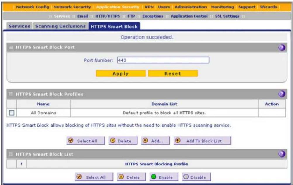
Figure 115.
ProSecure Unified Threat Management (UTM) Appliance
-
In the HTTPS Smart Block Port section of the screen, enter up to five port numbers, separated by commas, for which you want the HTTPS Smart Block feature to function. Each port number needs to be between 1 and 65535. By default, the feature functions for port 443.
-
In the HTTPS Smart Block Profiles section of the screen, click the Add table button. The Add or Edit HTTPS Smart Block Profile screen displays. (The following figure shows examples.)
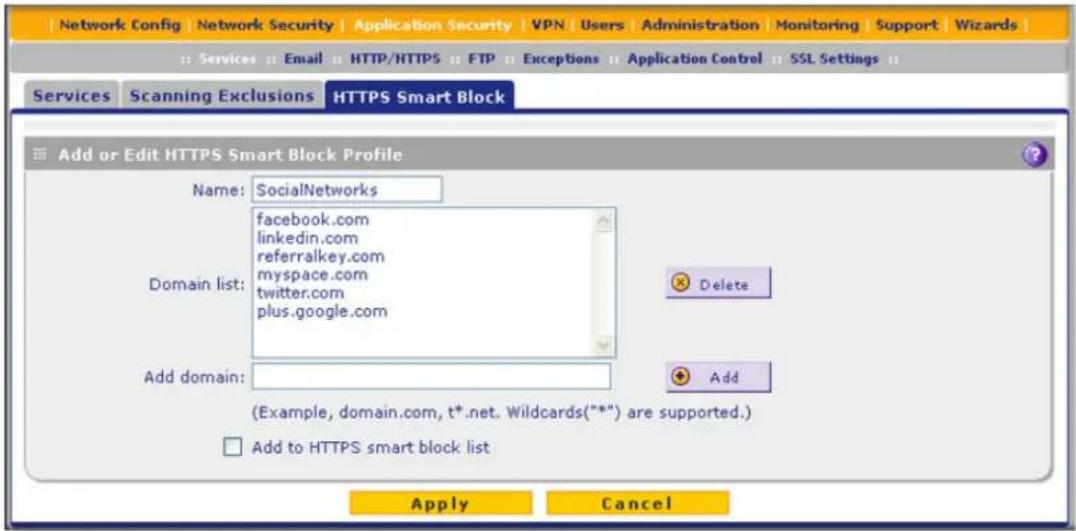
Figure 116.
- Enter the settings as explained in the following table:
Table 46. Add or Edit HTTPS Smart Block Profile settings
| Setting Description | ||
| Name | Type a name for the profile for identification and management purposes. | |
| Domain list | This field contains the domains that are included in the profile. To add a domain to this field, use the Add domain field (see the explanation later in this table). You can add a maximum of 200 domains in a profile. | |
| Delete | To delete one or more domains, highlight the domains, and click the Delete table button. | |
| Add domain | Type or copy a domain name in the Add domain field. Then click the Add table button to add the domain to the Domain list field. | |
| Add to HTTPS smart block list | Select the Add to HTTPS smart block list check box to add the profile to both the HTTPS Smart Block Profiles table and the HTTPS Smart Block List (both on the HTTPS Smart Block screen) when you click Apply. If you clear the check box, the profile is added to the HTTPS Smart Block Profiles table only when you click Apply. | |
- Click Apply save the changes and add the profile to the HTTPS Smart Block Profiles table on the HTTPS Smart Block screen. If you have selected the Add to HTTPS smart block list check box, the profile is also added to the HTTPS Smart Block List and is enabled globally.

Figure 117.
The HTTPS Smart Block Profiles table shows all the configured profiles, whether enabled or disabled. The HTTPS Smart Block List shows all the profiles that are enabled globally.
By default, the table contains the All Domains profile. If you add the All Domains default profile to the HTTPS Smart Block List and keep it enabled, all HTTPS domains are blocked.
- (Optional) To add the profile to the HTTPS Smart Block List and enable it globally, click Add To Block List.
- Click Apply to save the settings.
To change a profile:
- In the Action column of the HTTPS Smart Block Profiles table, click the Edit table button for the profile that you want to change. The Add or Edit HTTPS Smart Block Profile screen displays (see Figure 116 on page 213).
- Modify the settings that you wish to change (see Table 46 on page 213).
- Click Apply to save your changes.
To delete one or more profiles from the HTTPS Smart Block Profiles table:
- In the HTTPS Smart Block Profiles table, select the check box to the left of each profile that you want to delete, or click the Select All table button to select all profiles. (You cannot delete the default profile.)
- Click the Delete table button.
Note: You cannot delete a profile that is in use on the HTTPS Smart Block List, whether or not the profile is enabled.
To enable or disable one or more profiles on the HTTPS Smart Block List:
- In the HTTPS Smart Block List, select the check box to the left of each profile that you want to enable or disable, or click the Select All table button to select all profiles.
- Click one of the following table buttons:
- Enable. Enables the profile or profiles globally.
- Disable. Disables the profile or profiles globally.
Note: When you disable a profile on the HTTPS Smart Block List, the profile is disabled globally but is still available for use in an exception profile. (For information about exception rules, see Set Exception Rules for Web and Application Access on page 248.)
To delete one or more profiles from the HTTPS Smart Block List:
- In the HTTPS Smart Block List, select the check box to the left of each profile that you want to delete, or click the Select All table button to select all profiles.
- Click the Delete table button.
Note: The profile or profiles are deleted from the HTTPS Smart Block List but not from the HTTPS Smart Block Profiles table.
Configure Web Malware or Antivirus Scans
Whether or not the UTM detects web-based malware threats, you can configure it to take a variety of actions (some of the default actions are listed in Table 41 on page 193) and send notifications, emails, or both to the end users.
To configure the antivirus settings for HTTP and HTTPS traffic:
- Select Application Security > HTTP/HTTPS. The HTTP/HTTPS submenu tabs display with the Anti-Virus screen in view:
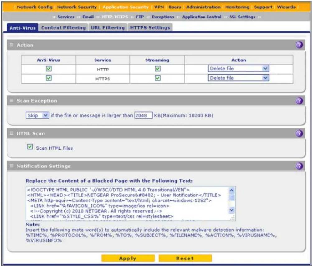
Figure 118.
- Enter the settings as explained in the following table:
Table 47. Anti-Virus screen settings for HTTP/HTTPS traffic
| Setting Description | ||
| Action | ||
| HTTP and HTTPS | Action The | Anti-Virus check boxes for HTTP and HTTPS are selected by default. When the UTM detects infected traffic, the default settings cause the downloaded files to be blocked and deleted.From the HTTP or HTTPS drop-down list, specify one of the following actions to be taken when an infected web file or object is detected:Delete file. This is the default setting. The web file or object is blocked and deleted, and a log entry is created.Log only. Only a log entry is created. The web file or object is not blocked and deleted.Quarantine file. The web file or object is quarantined, and a log entry is created (see the Note on page 193). |
| Streaming | Select the Streaming check box to enable streaming of partially downloaded and scanned HTTP or HTTPS file parts to the user. This method allows the user to experience more transparent web downloading. Streaming is enabled by default. | |
| Scan Exception | ||
| The default maximum size of the file or object that is scanned is 2048 KB, but you can define a maximum size of up to 10240 KB. However, setting the maximum size to a high value might affect the UTM's performance (see Performance Management on page 428).From the drop-down list, select one of the following actions to be taken when the file or message exceeds the maximum size:Skip. The file is not scanned but skipped, leaving the end user vulnerable. This is the default setting.Block. The file is blocked and does reach the end user. | ||
| HTML Scan | ||
| Scan HTML Files | Select this check box to enable scanning of HyperText Markup Language (HTML) files, which is enabled by default. | |
| Notification Settings | ||
| By default, the content of a web page that is blocked because of a detected malware threat is replaced with the following text, which you can customize:NETGEAR ProSecure UTM has detected and stopped malicious code embedded in this web site or web mail, for protecting your computer and network from infection.%VIRUSINFO%Note: Make sure that you keep the %VIRUSINFO% metaword in a message to enable the UTM to insert the correct malware information. In addition to the %VIRUSINFO% metaword, you can insert the following metawords in your customized message: %TIME%, %PROTOCOL%, %FROM%, %TO%, %SUBJECT%, %FILENAME%, %ACTION%, %VIRUSNAME%. | ||
- Click Apply to save your settings.
Configure Web Content Filtering
If you want to restrict access by internal LAN users to certain types of information and objects on the Internet, use the UTM's content filtering and web objects filtering. Except for the web content categories that are mentioned in Default Email and Web Scan Settings on page 193, all requested traffic from any website is allowed. You can specify a message such as Blocked by NETGEAR that is displayed onscreen if a LAN user attempts to access a blocked site (see the Notification Settings section that is described at the bottom of Table 48 on page 221).
Several types of web content blocking are available:
- File extension blocking. You can block files based on their extension. Such files can include executable files, audio and video files, and compressed files.
- Keyword blocking. You can specify words that, should they appear in the website name (URL) or in a newsgroup name, cause that site or newsgroup to be blocked by the UTM.
The following are keyword blocking examples:
- If the keyword XXX is specified, the URL www.zzyyqq.com/xxx.html is blocked, as is the newsgroup alt.pictures.XXX.
- If the keyword .com is specified, only websites with other domain suffixes (such as .edu or .gov) can be viewed.
- If a period (.) is specified as the keyword, all Internet browsing access is blocked.
Note: Wildcards (*) are supported. For example, if www.net*.com is specified, any URL that begins with www.net is blocked, and any URL that ends with .com is blocked.
You can apply the keywords to one or more groups. Requests from the computers in the groups for which keyword blocking has been enabled are blocked. Blocking does not occur for the computers that are in the groups for which keyword blocking has not been enabled.
Note: The whitelist has priority over the blacklist (for these lists, see Configure Web URL Filtering on page 224), and both the whitelist and the blacklist have priority over keyword blocking.
- Web object blocking. You can block the following web objects: embedded objects (ActiveX, Java, Flash), proxies, and cookies, and you can disable JavaScripts. Even sites on the whitelist (see Configure Web URL Filtering on page 224) are subject to web object blocking when the blocking of a particular web object is enabled.
- Web category blocking. You can block entire web categories because their content is undesired, offensive, or not relevant, or simply to reduce traffic.
Note: You can bypass any type of web blocking for trusted hosts by adding the exact matching domain names to the trusted host list (see Specify Trusted Hosts for HTTPS Scanning on page 235). Access to the domains on the trusted host list is allowed for computers in the groups for which file extension, keyword, object, or category blocking, or a combination of these types of web blocking has been enabled.
Note: You can bypass any type of web blocking for trusted URLs by adding the URLs to the whitelist (see Configure Web URL Filtering on page 224). Access to the URLs on the whitelist is allowed for computers in the groups for which file extension, keyword, object, or category blocking, or a combination of these types of web blocking has been enabled.
To configure web content filtering:
- Select Application Security > HTTP/HTTPS > Content Filtering. The Content Filtering screen displays. Because of the large size of this screen, it is presented in this manual in three figures (the following figure, Figure 120 on page 220, and Figure 121 on page 221).
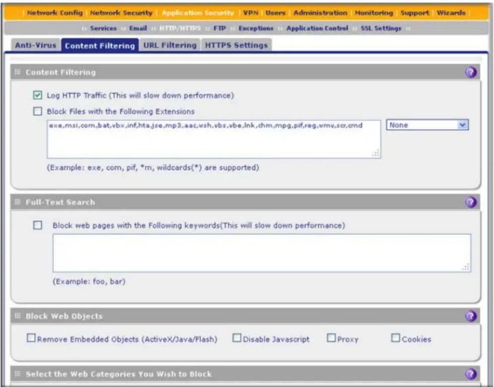
Figure 119. Content filtering, screen 1 of 3

Figure 120. Content filtering, screen 2 of 3

Figure 121. Content filtering, screen 3 of 3
- Enter the settings as explained in the following table:
Table 48. Content Filtering screen settings
| Setting Description | |
| Content Filtering | |
| Log HTTP Traffic Select this check box to log HTTP traffic. For information about how to view the logged traffic, seeQuery and Manage the Logson page 507. By default, HTTP traffic is logged.Note: Logging HTTP traffic might affect the UTM’s performance (seePerformance Managementon page 428).Note: If you want to generate web traffic reports (seeView,Schedule,and Generate Reportson page 520), you do need to select the Log HTTP Traffic check box. | |
| Block Files with the Following Extensions | By default, the File Extension field lists the most common file extensions. You can manually add or delete extensions. Use commas to separate different extensions. You can enter a maximum of 40 file extensions. The maximum total length of this field, excluding the delimiter commas, is 160 characters.You can also use the drop-down list to add predefined file extensions from a specific category to the File Extension field:None. No file extensions are added to the File Extension field. This is the default setting.Executables. Executable file extensions (exe, com, dll, so, lib, scr, bat, and cmd) are added to the File Extension field.Audio/Video. Audio and video file extensions (wav, mp3, avi, rm, rmvb, wma, wmv, mpg, mp4, and aac) are added to the File Extension field.Compressed Files. Compressed file extensions (zip, rar, gz, tar, and bz2) added to the File Extension field. |
| Full-Text SearchNote: Full-text search allows you to block keywords. | |
| Block web pages with the Following keywords | Select the check box to enable keyword blocking. Then, enter keywords that you want to be blocked. Separate the keywords by a comma.Note: Keywords searching and blocking might affect the UTM's performance (see Performance Management on page 428). |
| Block Web ObjectsSelect any or all of the following check boxes: | |
| Remove Embedded Objects | All embedded objects such as ActiveX, Java, and Flash objects are removed from downloaded web pages.Note: Because embedded objects are commonly used on legitimate websites, blocking embedded objects globally might have a negative impact on a user's web browsing experience. |
| Disable Javascript JavaScript is disabled on downloaded web pages. | |
| Proxy All web proxy | servers are blocked. |
| Cookies All cookies | are blocked. |
| Select the Web Categories You Wish to Block | |
| Select the Enable Blocking check box to enable blocking of web categories. (By default, this check box is selected.)Select the check boxes of any web categories that you want to block. Use the action buttons at the top of the section in the following way:Allow All. All web categories are allowed.Block All. All web categories are blocked.Set to Defaults. Blocking and allowing of web categories are returned to their default settings. See Table 41 on page 193 for information about the web categories that are blocked by default. Categories that are preceded by a green square are allowed by default; categories that are preceded by a pink square are blocked by default. | |
| Blocked Categories Scheduled Days | |
| Select one of the following radio buttons:All Days. The schedule is in effect all days of the week.Specific Days. The schedule is in effect only on specific days.To the right of the radio buttons, select the check box for each day that you want the schedule to be in effect. | |
| Blocked Categories Time of Day | |
| Select one of the following radio buttons:All Day. The schedule is in effect all hours of the selected day or days.Specific Times. The schedule is in effect only on specific hours of the selected day or days.To the right of the radio buttons, fill in the Start Time and End Time fields (Hour, Minute, AM/PM) during which the schedule is in effect. | |
| Notification Settings | |
| The UTM replaces the content of a web page that is blocked because of violating content with the following text, which you can customize:Internet Policy has restricted access to this location:%URL%Full-text search found the content to have the keyword: %KEYWORD%Belongs to category : %CATEGORY%Click here to Report a URL MisclassificationYou are logged in as %USER%Click here to log in as another user %USER_PORTAL_URL% | |
| Note:The text is displayed on the Content Filtering screen with HTML tags. However, when the UTM replaces the content of a blocked web page, the screen displays the notification text in HTML format.Note:Make sure that you keep the %URL% and %KEYWORD% metawords in the text to enable the UTM to insert the blocked URL and the keyword that caused the web page to be blocked in the notification text. The %CATEGORY% metaword enables the UTM to insert the category of the blocked URL; the %USER% metaword enables the UTM to insert the user login name; the %USER_PORTAL_URL% metaword enables the UTM to insert the User Portal Login screen.Web Category Lookup | |
| URL Enter a URL to | find out if it has been categorized, and if so, in which category. Then click the lookup button. If the URL has been categorized, the category displays next to Lookup Results. If the URL appears to be uncategorized, you can submit it to NETGEAR for analysis. |
| Submit to NETGEAR | To submit an uncategorized URL to NETGEAR for analysis, select the category in which you think that the URL needs to be categorized from the drop-down list. Then click the Submit button. |
3. Click Apply to save your settings.
Note: When the UTM blocks access to a link of a certain blocked web category, the UTM displays an HTML warning screen that includes a link to submit a URL misclassification. To submit a misclassified or uncategorized URL to NETGEAR for analysis, click the Click here to Report a URL Misclassification link. A second screen opens that allows you to select (from drop-down lists) up to two categories in which you think that the URL could be categorized. Then click the Submit button.
Configure Web URL Filtering
If you want to allow or block access by internal LAN users to certain sites on the Internet, use the UTM's web URL filtering. You can create or import a whitelist that contains domain names and URLs that are accepted and a blacklist with domain names and URLs that are blocked. The whitelist takes precedence over the blacklist. Both the whitelist and the blacklist take precedence over keyword blocking.
Note: A URL that you enter on the whitelist or blacklist might contain other embedded URLs such as URLs for advertisements or sponsors, causing unexpected behavior. If you want to allow a URL by placing it on the whitelist, make sure that all embedded URLs are also placed on the whitelist. Similarly, if you want to block a URL by placing it on the blacklist, make sure that all embedded URLs are also placed on the blacklist.
To configure web URL filtering:
- Select Application Security > HTTP/HTTPS > URL Filtering. The URL Filtering screen displays.

Figure 122.
- Enter the settings as explained in the following table:
Table 49. URL Filtering screen settings
| Setting Description | ||
| Whitelist | ||
| Enable Select this check | box to bypass scanning of the URLs that are listed in the URL field. Users are allowed to access the URLs that are listed in the URL field. | |
| URL This field contains | the URLs for which scanning is bypassed. To add a URL to this field, use the Add URL field or the Import from File tool (see the explanation later in this table). You can add a maximum of 200 URLs.Note: If a URL is in both on the whitelist and blacklist, then the whitelist takes precedence, and URLs on the whitelist are not scanned.Note: Wildcards (*) are supported. For example, if you enter www.net*.com in the URL field, any URL that begins with www.net is allowed, and any URL that ends with .com is allowed. | |
| Delete | To delete one or more URLs, highlight the URLs, and click the Delete table button. | |
| Export | To export the URLs, click the Export table button, and follow the instructions of your browser. | |
| Add URL | Type or copy a URL in the Add URL field. Then click the Add table button to add the URL to the URL field.Note: Start the URL with http:// or https://. If you do not specify http:// or https://, the UTM automatically adds http://. | |
| Import from File | To import a list with URLs into the URL field, click the Browse button and navigate to a file in .txt format that contains line-delimited URLs (that is, one URL per line). Then click the Upload table button to add the URLs to the URL field.Note: Any existing URLs in the URL field are overwritten when you import a list of URLs from a file. | |
| Blacklist | ||
| Enable | Select this check box to block the URLs that are listed in the URL field. Users attempting to access these URLs receive a notification (see the explanation later in this table). | |
| URL This field contains | the URLs that are blocked. To add a URL to this field, use the Add URL field or the Import from File tool (see the explanation later in this table). You can add a maximum of 200 URLs.Note: If a URL is in both the whitelist and blacklist, then the whitelist takes precedence, and URLs on the whitelist are not scanned.Note: Wildcards (*) are supported. For example, if you enter www.net*.com in the URL field, any URL that begins with www.net is blocked, and any URL that ends with .com is blocked. | |
| URL(continued) | Delete | To delete one or more URLs, highlight the URLs, and click theDeletetable button. |
| Export | To export the URLs, click theExporttable button, and follow the instructions of your browser. | |
| Add URL | Type or copy a URL in the Add URL field. Then click theAddtable button to add the URL to the URL field.Note: Start the URL with http:// or https://. If you dot no specify http:// or https://, the UTM automatically adds http://. | |
| Import from File | To import a list with URLs into the URL field, click theBrowsebutton and navigate to a file in .txt format that contains line-delimited URLs (that is, one URL per line). Then click theUploadtable button to add the URLs to the URL field.Note:Any existing URLs in the URL field are overwritten when you import a list of URLs from a file. | |
| Replace the Content of a Blocked Pagewith the Following Text | By default, a blocked URL is replaced with the following text, which you can customize:Internet Policy has restricted access to this location:%URL%You are logged in as %USER%Click here to log in as another user %USER_PORTAL_URL%Note:The text is displayed on the URL Filtering screen with HTML tags. However, when the UTM replaces the content of a blocked web page, the screen displays the notification text in HTML format.Note: Make sure that you keep the %URL% metaword in the text to enable the UTM to insert the blocked URL in the notification text. The %USER% metaword enables the UTM to insert the user login name; the %USER_PORTAL_URL%metaword enables the UTM to insert the User Portal Login screen. | |
- Click Apply to save your settings.
Configure HTTPS Scanning and SSL Certificates
• How HTTPS Scanning Works
- Configure the HTTPS Scan Settings
- Manage SSL Certificates for HTTPS Scanning
- Specify Trusted Hosts for HTTPS Scanning
- Configure the SSL Settings for HTTPS Scanning
How HTTPS Scanning Works
HTTPS traffic is encrypted traffic that cannot be scanned or the data stream would not be secure. However, the UTM can scan HTTPS traffic that is transmitted through an HTTP proxy. The UTM can break up the SSL connection between the HTTPS server and the HTTP client, scan the HTTPS traffic, and then rebuild the SSL connection. The following figure shows the HTTPS scanning traffic flow.

flowchart
graph TD
    A["HTTPS Server"] -->|UTM communicates on Client's behalf| B["Internet"]
    B -->|UTM sends its own Cert to Client| C["HTTPS Client"]
    C -->|UTM requests| B
    B -->|Server returns Cert to UTM for authentication| A
Figure 123.
The HTTPS scanning process functions with the following principles:
- The UTM breaks up an SSL connection between an HTTPS server and an HTTP client in two parts:
- A connection between the HTTPS client and the UTM
- A connection between the UTM and the HTTPS server
- The UTM simulates the HTTPS server communication to the HTTPS client, including the SSL negotiation, certificate exchange, and certificate authentication. In effect, the UTM functions as the HTTPS server for the HTTPS client.
- The UTM simulates the HTTPS client communication to the HTTPS server, including the SSL negotiation, certificate exchange, and certificate authentication. In effect, the UTM functions as the HTTPS client for the HTTPS server.
ProSecure Unified Threat Management (UTM) Appliance
During SSL authentication, the HTTPS client authenticates three items:
• Is the SSL certificate trusted?
- Has the SSL certificate expired?
- Does the name on the SSL certificate match that of the website?
If one of these items is not authenticated, a security alert message displays in the browser window:

Figure 124.
However, even when a certificate is trusted or still valid, or when the name of a certificate does match the name of the website, a security alert message still displays when a user who is connected to the UTM visits an HTTPS site. The appearance of this security alert message is expected behavior because the HTTPS client receives a certificate from the UTM instead of directly from the HTTPS server. If you want to prevent this security alert message from displaying, install a root certificate on the client computer. The root certificate can be downloaded from the UTM's Manager Login screen (see Figure 20 on page 43).
If client authentication is required, the UTM might not be able to scan the HTTPS traffic because of the nature of SSL. SSL has two parts—client and server authentication. HTTPS server authentication occurs with every HTTPS request, but HTTPS client authentication is not mandatory, and rarely occurs. Therefore it is of less importance whether the HTTPS request comes from the UTM or from the real HTTPS client.
However, certain HTTPS servers do require HTTPS client certificate authentication for every HTTPS request. Because of the design of SSL, the HTTPS client needs to present its own certificate in this situation rather than using the one from the UTM, preventing the UTM from scanning the HTTPS traffic. For information about certificates, see Manage SSL Certificates for HTTPS Scanning on page 231.
You can specify trusted hosts for which the UTM bypasses HTTPS traffic scanning. For more information, see Specify Trusted Hosts for HTTPS Scanning on page 235.
Configure the HTTPS Scan Settings
To configure the HTTPS scan settings:
- Select Application Security > HTTP/HTTPS > HTTPS Settings. The HTTPS Settings screen displays:

Figure 125.
- Enter the settings as explained in the following table:
Table 50. HTTPS Settings screen settings
| Setting Description | |
| HTTP Tunneling | |
| Select the check box in the HTTP Tunneling section to allow scanning of HTTPS connections through an HTTP proxy, which is disabled by default. Traffic from trusted hosts is not scanned (seeSpecify Trusted Hosts for HTTPS Scanning on page 235).Note:For HTTPS scanning to occur correctly, you need to add the HTTP proxy server port in the Ports to Scan field for the HTTPS service on the Services screen (seeCustomize Web Protocol Scan Settings on page 210). | |
| Show This Message When an HTTPS Connection Attempt Fails | |
| By default, a rejected HTTPS connection is replaced with the following text, which you can customize:The SSL connection cannot be established. URL: %URL% REASON: %REASON%Note:Make sure that you keep the %URL% and %REASON% metawords in a message to enable the UTM to insert the correct URL information and the reason for the rejection. | |
- Click Apply to save your settings.
Manage SSL Certificates for HTTPS Scanning
Note: For information about digital certificates for VPN connections, see Manage Digital Certificates for VPN Connections on page 419.
Before enabling HTTPS scanning, you can specify which digital certificate is used by the UTM to handle HTTPS requests. The UTM uses digital certificates to authenticate connecting HTTPS servers, and to allow HTTPS clients to be authenticated by remote entities. A digital certificate that authenticates a server, for example, is a file that contains the following elements:
- A public encryption key to be used by clients for encrypting messages to the server.
• Information identifying the operator of the server. - A digital signature confirming the identity of the operator of the server. Ideally, the signature is from a trusted third party whose identity can be verified.
There can be three reasons why a security alert is generated for a security certificate:
• The security certificate was issued by a company you have not chosen to trust.
• The date of the security certificate is invalid.
• The name on the security certificate is invalid or does not match the name of the site.
When a security alert is generated (see the following figure), the user can decide whether to trust the host.

Figure 126.
The UTM contains a self-signed certificate from NETGEAR. This certificate can be downloaded from the UTM login screen or from the Certificate Management screen for browser import. However, before you deploy the UTM in your network, NETGEAR
recommends that you replace this digital certificate with a digital certificate from a well-known commercial certification authority (CA) such as an internal Windows server or an external organization such as VeriSign or Thawte. Because a commercial CA takes steps to verify the identity of an applicant, a digital certificate from a commercial CA provides a strong assurance of the server's identity. On the UTM, the uploaded digital certificate is checked for validity and purpose. The digital certificate is accepted when it passes the validity test and the purpose matches its use.
To display the Certificate Management screen, select Web Security > Certificate Management. Because of the size of this screen, and because of the way the information is presented, the Certificate Management screen is divided and presented in this manual in three figures (the following figure, Figure 128 on page 233, and Figure 129 on page 234).
The UTM's Certificate Management screen lets you view the currently loaded digital certificate for HTTPS scans, upload a new digital certificate, manage the trusted CA authorities list, and manage the untrusted certificates list.
Manage the Active HTTPS Certificate
To manage the UTM's active certificate that is used for HTTPS scans, select Application Security > SSL Settings > Certificate Management. The Certificate Management screen displays. The following figure shows only the Certificate Used for SSL Scans section of the screen:
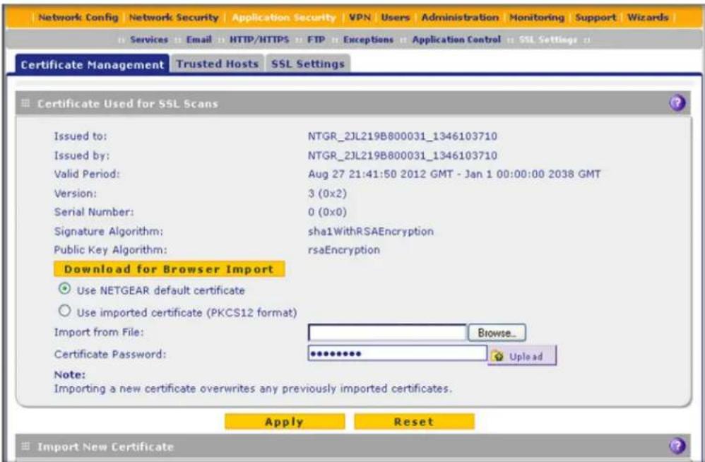
Figure 127. Certificate management, screen 1 of 3
The top part of the Certificate Used for SSL Scans section displays information about the current certificate that is used for SSL scans.
ProSecure Unified Threat Management (UTM) Appliance
To download the current certificate into your browser:
- Click Download for Browser Import.
- Follow the instructions of your browser to save the RootCA.crt file on your computer.
To reload the default NETGEAR certificate:
- Select the Use NETGEAR default certificate radio button.
- Click Apply to save your settings.
To import a new certificate:
- Select the Use imported certificate (PKCS12 format) radio button.
- Click Browse next to the Import from File field.
- Navigate to a trusted certificate file on your computer. Follow the instructions of your browser to place the certificate file in the Import from File field.
- If necessary, enter the appropriate password in the Certificate Password field.
- Click the Upload button.
Note: If the certificate file is not in the pkcs12 format, the upload fails. Importing a new certificate overwrites any previously imported certificates.
6. Click Apply to save your settings.
Manage Trusted HTTPS Certificates
To manage trusted certificates, select Web Security > Certificate Management. The Certificate Management screen displays. The following figure shows only the Import New Certificate and Trusted Certificates sections of the screen:
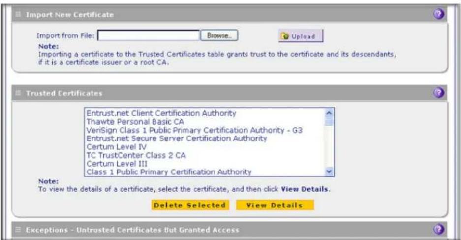
Figure 128. Certificate management, screen 2 of 3
The Trusted Certificates table contains the trusted certificates from third-party websites that are signed by the certification authorities. The UTM comes standard with trusted certificates that are preloaded in the Trusted Certificates table.
To import a trusted certificate:
- In the Import New Certificate section of the screen, click Browse next to the Import from File field.
- Navigate to a trusted certificate file on your computer. Follow the instructions of your browser to place the certificate file in the Import from File field.
- Click the Upload button. The newly imported trusted certificate is added to the Trusted Certificates table.
To view details of a trusted certificate:
- From the Trusted Certificates table, select the certificate.
- Click View Details. A new screen opens that displays the details of the certificate.
To delete a trusted certificate:
- From the Trusted Certificates table, select the certificate.
- Click Delete Selected.
Manage Untrusted HTTPS Certificates
To manage untrusted certificates, select Web Security > Certificate Management. The Certificate Management screen displays. The following figure shows only the Exceptions - Untrusted Certificates But Granted Access section of the screen:
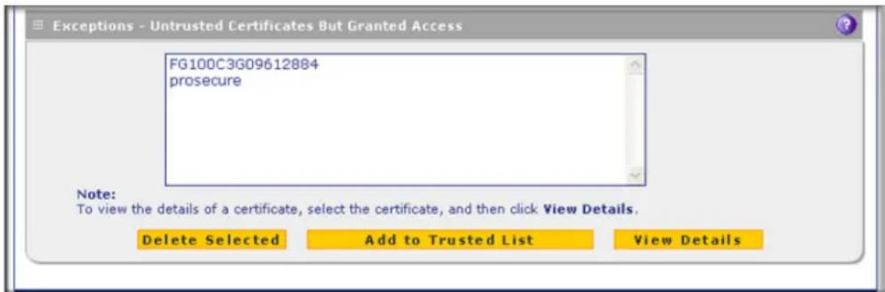
Figure 129. Certificate management, screen 3 of 3
When the UTM detects an untrusted or invalid certificate, it automatically places the certificate in the Exceptions - Untrusted Certificates But Granted Access table.
To view details of an untrusted certificate:
- From the Exceptions - Untrusted Certificates But Granted Access table, select the certificate.
- Click View Details. A new screen opens that displays the details of the certificate.
To delete an untrusted certificate:
- From the Exceptions - Untrusted Certificates But Granted Access table, select the certificate.
- Click Delete Selected.
To move an untrusted certificate to the Trusted Certificate Authorities table:
- From the Exceptions - Untrusted Certificates But Granted Access table, select the certificate.
- Click Add to Trusted List. The previously untrusted certificate is added to the Trusted Certificates table.
Specify Trusted Hosts for HTTPS Scanning
You can specify trusted hosts for which the UTM bypasses HTTPS traffic scanning and security certificate authentication. The security certificate is sent directly to the client for authentication, which means that the user does not receive a security alert (see Figure 126 on page 231) for trusted hosts.
Note that certain sites contain elements from different HTTPS hosts. As an example, assume that the https://example.com site contains HTTPS elements from the following three hosts:
- trustedhostserver1.example.com
- trustedhostserver2.example.com
- imageserver.example.com
To bypass the scanning of the https://example.com site completely, you need to add all three hosts to the trusted hosts list because different files from these three hosts are also downloaded when a user attempts to access the https://example.com site.
To specify trusted hosts:
- Select Application Security > SSL Settings > Trusted Hosts. The Trusted Hosts screen displays.

Figure 130.
- Enter the settings as explained in the following table:
Table 51. Trusted Hosts screen settings
| Setting Description | ||
| Do Not Intercept HTTPS Connections for the following Hosts | ||
| Enable | Select this check box to bypass scanning of trusted hosts that are listed in the Hosts field. Users do not receive a security alert for trusted hosts that are listed in the Hosts field. | |
| Hosts | This field contains the trusted hosts for which scanning is bypassed. To add a host to this field, use the Add Host field or the Import from File tool (see the explanation later in this table). You can add a maximum of 200 URLs. | |
| Delete | To delete one or more hosts, highlight the hosts, and click the Delete table button. | |
| Export | To export the hosts, click the Export table button, and follow the instructions of your browser. | |
| Add Host | Type or copy a trusted host in the Add Host field. Then click the Add table button to add the host to the Hosts field. | |
| Import from File | To import a list with trusted hosts into the Hosts field, click the Browse button, and navigate to a file in .txt format that contains line-delimited hosts (that is, one host per line). Then click the Upload table button to add the hosts to the Hosts field.Note: Any existing hosts in the Hosts field are overwritten when you import a list of hosts from a file. | |
- Click Apply to save your settings.
Configure the SSL Settings for HTTPS Scanning
To configure the SSL settings for HTTPS scanning:
- Select Application Security > SSL Settings > SSL Settings. The SSL Settings screen displays.

Figure 131.
- Enter the settings as explained in the following table:
Table 52. SSL Settings screen settings
| Setting Description | |
| SSL 3rd Party Website Certificate Handling | |
| Select the Allow the device to present the website to the client check box to allow a Secure Sockets Layer (SSL) connection with a valid certificate that is not signed by a trusted certification authority (CA). The default setting is to block such a connection. | |
| SSL Settings | |
| Select the Allow the device to handle SSL connections using SSLv2 check box to allow HTTPS connections using SSLv2, SSLv3, or TLSv1. If this check box is cleared, the UTM allows HTTPS connections using SSLv3 or TLSv1, but not using SSLv2. | |
- Click Apply to save your settings.
Configure FTP Scanning
- Customize FTP Antivirus Settings
- Configure FTP Content Filtering
Some malware threats are specifically developed to spread through the FTP protocol. By default, the UTM scans FTP traffic, but you can disable scanning of FTP traffic, or specify how the UTM scans FTP traffic and which action is taken when a malware threat is detected. The UTM does not scan password-protected FTP files.
Customize FTP Antivirus Settings
To configure the antivirus settings for FTP traffic:
- Select Application Security > FTP. The FTP submenu tabs display with the Anti-Virus screen in view:

Figure 132.
- Enter the settings as explained in the following table:
Table 53. Anti-Virus screen settings for FTP
| Setting Description | ||
| Action | ||
| FTP Action The Anti-Virus | check boxes for FTP is selected by default. When the UTM detects infected traffic, the default settings cause the downloaded files to be blocked and deleted.From the FTP drop-down list, select one of the following actions to be taken when an infected FTP file or object is detected:Delete file.This is the default setting. The FTP file or object is deleted, and a log entry is created.Log only. Only a log entry is created. The FTP file or object is not deleted.Quarantine file.The FTP file or object is quarantined, and a log entry is created (see the Note on page 193). | |
Table 53. Anti-Virus screen settings for FTP (continued)
| Setting Description |
| Scan Exception |
| The default maximum size of the file or object that is scanned is 2048 KB, but you can define a maximum size of up to 10240 KB. However, setting the maximum size to a high value might affect the UTM's performance (seePerformance Managementon page 428).From the drop-down list, select one of the following actions to be taken when the file or message exceeds the maximum size:Skip. The file is not scanned but skipped, leaving the end user vulnerable. This is the default setting.Block. The file is blocked and does not reach the end user. |
- Click Apply to save your settings.
Configure FTP Content Filtering
To configure the FTP filters:
- Select Application Security > FTP > FTP Filters. The FTP Filters screen displays:

Figure 133.
- Enter the settings as explained in the following table:
Table 54. FTP Filters screen settings
| Setting Description |
| Block Files with the Following Extensions |
| By default, the file extension field lists the most common file extensions. You can manually add or delete extensions. Use commas to separate different extensions. You can enter a maximum of 40 file extensions. The maximum total length of this field, excluding the delimiter commas, is 160 characters.You can also use the drop-down list to add predefined file extensions from a specific category to the file extension field:None. No file extensions are added to the file extension field. This is the default setting.Executables. Executable file extensions (exe, com, dll, so, lib, scr, bat, and cmd) are added to the file extension field.Audio/Video. Audio and video file extensions (wav, mp3, avi, rm, rmvb, wma, wmv, mpg, mp4, and aac) are added to the file extension field.Compressed Files. Compressed file extensions (zip, rar, gz, tar, and bz2) added to the file extension field. |
3. Click Apply to save your settings.
Configure Application Control
Application control enables you to safeguard data, protect users, and enhance productivity. You can control multiple applications in the following categories:
- Instant messaging
• P2P - File transfer
- Streaming media
- Mail and collaboration
- Voice over IP
- Database
- Games
• Network management - Remote access terminals
- Bypass proxies and tunnels
- Web and web 2.0
- Security updates
- Web IM
- Business
- Network protocols
-
Mobile
-
Private protocols
- Social networks
Control is set for entire categories of applications (for example, to block gaming during business hours), for individual applications (for example, to allow Skype but block some other applications), or for a combination of both. Individual application rules take priority over category rules. After you have allowed or blocked applications, you can easily create exceptions for individual users and groups of users (see Set Exception Rules for Web and Application Access on page 248).
Application control is disabled by default. When you enable application control, you can either use a single global profile or create multiple custom profiles:
- Global profile. There is a single global application control profile. All traffic between the WAN and LAN is scanned according to the settings in the global profile. The global profile functions as a standalone control engine; you do not assign the global profile to a firewall rule.
- Custom profiles. There are no default custom application control profiles; you need to create custom profiles. A custom application control profile takes effect only after it has been assigned to a firewall rule and the firewall rule has been enabled. Traffic that matches the firewall rule is scanned according to the settings in the custom profile.
For any profile, you can configure which categories of applications and individual applications are allowed and blocked, and you can even differentiate between application login and application connection. Traffic that does not match a profile is not scanned.
After you have configured a custom application control profile, you can assign it to firewall rules on the following screens:
- Add LAN WAN Outbound Services screen (see Figure 68 on page 141).
- Add LAN WAN Inbound Services screen (see Figure 69 on page 142).
- Add DMZ WAN Outbound Services screen (see Figure 71 on page 144).
- Add DMZ WAN Inbound Services screen (see Figure 72 on page 145).
To configure an application control profile and enable application control:
- Select Application Security > Application Control. The Application Control screen displays. (The following figure contains an example in the Application Control Profiles table).

Figure 134.
- Take one of the following actions:
• To configure the Global Application Control profile, click Edit next to it.
- To create and configure a custom profile, click Add under the Application Control Profiles table.
The Add or Edit Application Control Profile screen displays. (The following screen contains examples in the Active Categories and Individual Applications table.)

Figure 135.
- Configure the common settings in the upper part of the screen as explained in the following table:
Table 55. Common settings on the Add or Edit Application Control Profile screen
| Setting Description | |
| Name | A name of the profile for identification and management purposes. |
| Brief Description | A description of the profile for identification and management purposes. |
Table 55. Common settings on the Add or Edit Application Control Profile screen
| Setting Description | ||
| All Other Known Applications | Known applications are the applications that you can select in the lower part of the screen. Specify whether all known applications that are not included in this profile are allowed or blocked. Make a selection from the drop-down list:Allow. All other known applications are allowed. This is the default setting.Drop. All other known applications are blocked. Only the applications that are included in this profile are allowed. | |
| All Other Unknown Applications | Unknown applications are the applications that you cannot select in the lower part of the screen, that is, they are not included in any categories. Specify whether all unknown applications are allowed or blocked. Make a selection from the drop-down list:Allow. All other unknown applications are allowed. This is the default setting.Drop. All other unknown applications are blocked. Only the applications that are included in this profile are allowed. | |
| Enable SSL Decryption | Select this check box to enable decryption of SSL traffic for which the TCP destination port number is the same as the port number that you specify in the Port field. | |
| Port The d | destination port number of SSL traffic that should be decrypted. | |
- In the lower part of the screen, select the categories of applications and individual applications that you want to include in the profile by using the following methods:
• To select one or more categories of applications:
In the left pane, select one or more categories from the Categories list by clicking the + next to each category. The categories display in the Active Categories and Individual Applications table.
• To select one or more individual applications:
a. In the left pane, select a category from the Categories list by clicking the + next to the category.
b. In the right pane, select applications by clicking the + next to each application. The applications display in the Active Categories and Individual Applications table.
Note: Rules for individual applications take priority over rules for categories of applications.
• To search for an application:
a. In the right pane, click Show All.
b. Type the name of the application (or the first few letters) in the search field.
- To remove one or more categories or applications from the Active Categories and Individual Applications table:
a. Select the check boxes that are associated with the categories or applications, or select all entries in the table by clicking the Select All table button.
b. Click the Remove table button.
- In the Active Categories and Individual Applications table, set the policy for each selected category of applications and individual application by clicking the Edit table button to the right of each selection. The Application Control Policy pop-up screen displays.
This screen differs for a category of applications (see the next figure) and for an individual application (see the example in Figure 137 on page 245). The content of a pop-up screen for an individual application depends on the application.
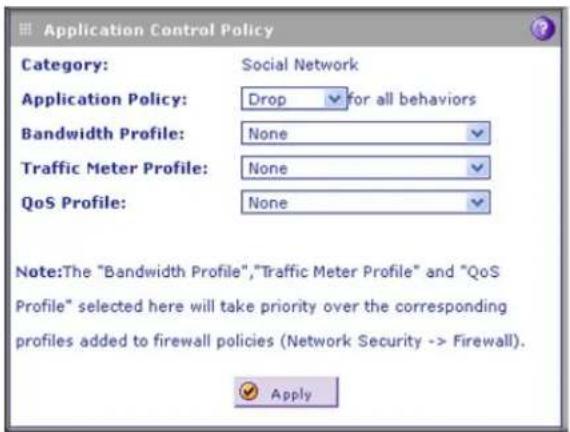
Figure 136. Application Control Policy pop-up screen for a category of applications

Figure 137. Application Control Policy pop-up screen for an individual application
- Configure the policy as explained in the following table:
Table 56. Application Control Policy pop-up screen settings
| Setting Description | ||
| Policy for a category of applications | ||
| Application Policy | From the drop-down list, select the action for the policy of the selected category of applications:Allow. The applications in the selected category are allowed.Drop. The applications in the selected category are blocked.Log Only. The applications in the selected category are allowed, but traffic is logged. | |
| Bandwidth Profile | From the drop-down list, select the bandwidth profile that is assigned to the selected category of applications, or leave the default selection (None). By default, no profile is assigned. For information about bandwidth profiles, seeCreate Bandwidth Profileson page 171. | |
| Traffic Meter Profile | From the drop-down list, select the traffic meter profile that is assigned to the selected category of applications, or leave the default selection (None). By default, no profile is assigned. For information about traffic meter profiles, seeCreate Traffic Meter Profileson page 174. | |
| QoS Profile | From the drop-down list, select the QoS profile that is assigned to the selected category of applications, or leave the default selection (None). By default, no profile is assigned. For information about QoS profiles, seeCreate Quality of Service Profileson page 169. | |
| Policy for an individual applicationNote: The content of a pop-up screen for an individual application depends on the application. The previous figure is just an example for one application. | ||
| Application Policy | (action) for all behaviors | From the drop-down list, select the action for the policy of the selected application:Allow. The application is allowed.Drop. The application is blocked.Log Only. The application is allowed, but traffic is logged. |
| Specify the action(s) for each behavior.Note: This option is displayed for select applications only. | If access to an application consists of two steps such as first logging in and then connecting, you can select the action for each step:Login. From the drop-down list, select the action:- Allow. Logging in to the application is allowed.- Drop. Logging in to the application is blocked.- Log Only. Logging in to the application is allowed, but traffic is logged.Connect. From the drop-down list, select the action:- Allow. Connecting to the application is allowed.- Drop. Connecting to the application is blocked.- Log Only. Connecting to the application is allowed, but traffic is logged. | |
| Bandwidth Profile | From the drop-down list, select the bandwidth profile that is assigned to the selected application, or leave the default selection (None). By default, no profile is assigned. For information about bandwidth profiles, see Create Bandwidth Profiles on page 171. | |
| Traffic Meter Profile | From the drop-down list, select the traffic meter profile that is assigned to the selected application, or leave the default selection (None). By default, no profile is assigned. For information about traffic meter profiles, see Create Traffic Meter Profiles on page 174. | |
| QoS Profile | From the drop-down list, select the QoS profile that is assigned to the selected application, or leave the default selection (None). By default, no profile is assigned. For information about QoS profiles, see Create Quality of Service Profiles on page 169. | |
- Click Apply to save the policy settings. The pop-up screen closes.
- Repeat Step 5 through Step 7 for other selections in the Active Categories and Individual Applications table.
- On the Add or Edit Application Control Profile screen, click Apply to save your settings. The Application Control screen displays again.
- In the Application Control section of the screen, select the Yes radio button to enable application control. By default, application control is disabled.
-
From the Mode drop-down list, select how application control is applied:
-
Global. Applications are controlled by the single global profile. This is the default setting.
• Profile. Applications are controlled by multiple custom profiles.
A custom application control profile takes effect only after it has been assigned to a firewall rule and the firewall rule has been enabled. When you configure a firewall rule, you need to select the profile from the Application Control drop-down list. (For more information, see Overview of Rules to Block or Allow Specific Kinds of Traffic on page 128.)
- Click Apply to save your settings.
Note: The bandwidth profile, traffic meter profile, and QoS profile that you select in an application control profile take priority over the corresponding profiles that you select in a firewall rule to which you assign the custom application control profile.
To change an existing application control profile:
-
In the Action column to the right of the application control profile, click the Edit table button. The Add or Edit Application Control Profile screen displays (see Figure 135 on page 243).
-
Modify the settings that you wish to change (see the previous procedure).
- Click Apply to save your changes. The modified application control profile is displayed in the Global Application Control Profile table or the Application Control Profiles table.
To delete one or more application control profiles:
- Select the check box to the left of each custom application control profile that you want to delete, or click the Select All table button to select all custom application control profiles. (You cannot delete the global application control profile.)
- Click the Delete table button.
Set Exception Rules for Web and Application Access
You can set up to 200 exception rules for users and members of a group to allow access to HTTPS Smart Block profiles, applications, file extensions and protocols, web categories, and URLs that you have blocked for all other users. Or you can do it the other way around—block access to HTTPS Smart Block profiles, applications, file extensions and protocols, web categories, and URLs that you have allowed access to for all other users.
If you have not created a custom group, an exception rule can apply to either one of the following groups or individual users:
- All users
- All authenticated users
- All unauthenticated users
• A local group or local user - A group or users that is defined by its IP address
- A Lightweight Directory Access Protocol (LDAP) group or LDAP user
• A RADIUS VLAN group
To further refine exception rules, you can create custom groups that allow you to include a combination of local groups and local users, groups and users that are defined by their IP address, LDAP groups and users, and RADIUS groups and users. For more information, see Configure Custom Groups on page 397.
Note: Users and groups to which access exception rules apply are not the same as LAN groups. For information about how to specify members of a LAN group and to customize LAN group names, see Configure Authentication Domains, Groups, and Users on page 380.
If you have not created a custom category, a single exception rule can apply to one of the following components:
• One HTTPS Smart Block profile
• One built-in application group or built-in individual application
ProSecure Unified Threat Management (UTM) Appliance
• A combination of file extensions and protocols
• One URL or URL expression
• One built-in web category group or built-in individual web category
To further refine exception rules, you can create custom categories that allow you to include either a selection of applications, or a selection of URLs, or a selection of web categories. For more information, see Create Custom Categories for Exceptions for Web and Application Access on page 258.
Tip: If you want to use a custom group and custom category, first create the custom group and custom category, then create the exception rule.
To set web access exception rules:
- Select Application Security > Exceptions. The Exceptions submenu tabs display, with the Exceptions screen in view. This screen shows the Application table, URL Filter & Web Category table, and File Extension table, all of which are empty if you have not specified any exception rules. (The following figure shows exception rules in the tables as examples.)

Figure 138.
ProSecure Unified Threat Management (UTM) Appliance
- Under the File Extension table at the bottom of the screen, click the Add table button to specify an exception rule. The Add or Edit Exceptions screen displays. The content of the lower part of the screen depends on the selection of the Category drop-down list, which is by default set to Application.
- From the Category drop-down list, select the exception category. The following four screens display the different options that can be shown on screen. The content of the upper part of the screen (that is, above the Category drop-down list) is the same on all screens, and all screens contain a Note field.
- Application.
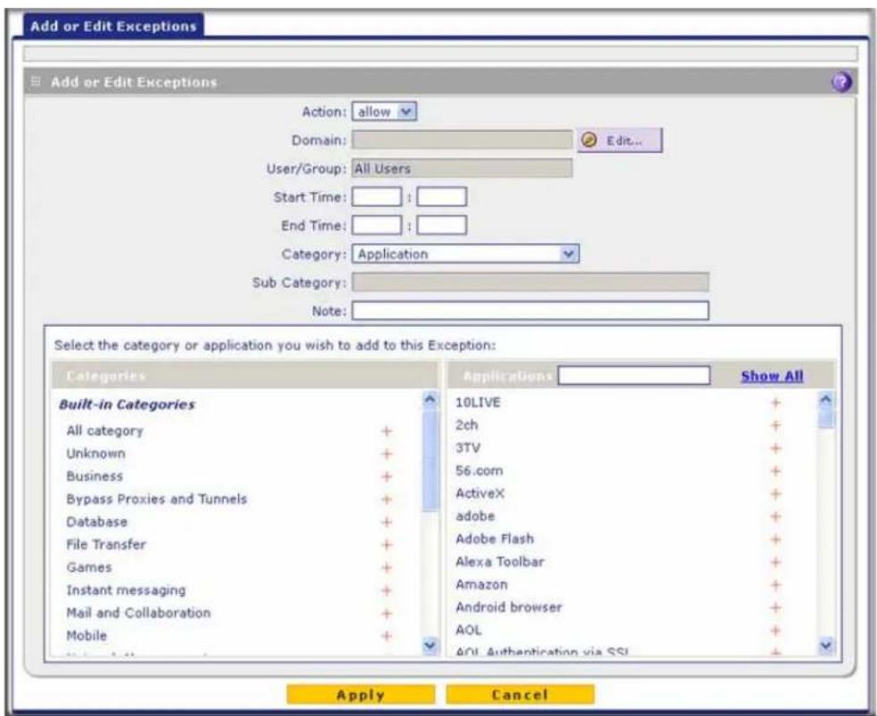
Figure 139. Add or edit exceptions: applications
- File Extension.
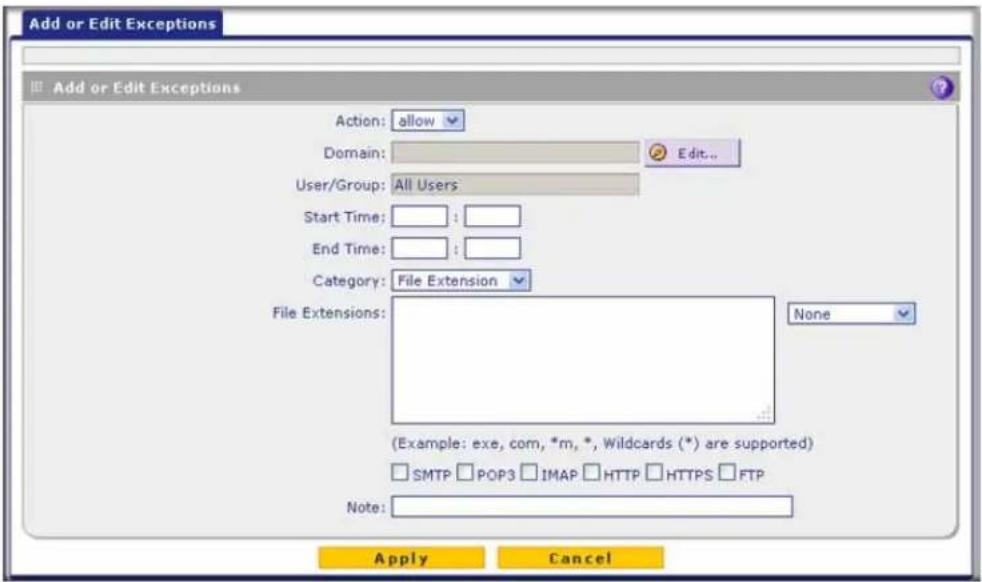
Figure 140. Add or edit exceptions: file extensions
- HTTPS Smart Block.

Figure 141. Add or edit exceptions: HTTPS Smart Block
- URL Filtering.
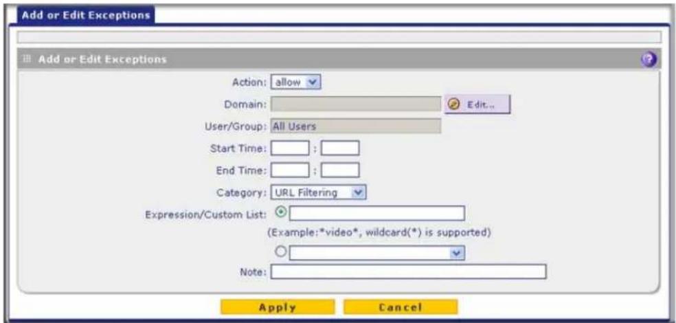
Figure 142. Add or edit exceptions: URL filtering
- Web Category.
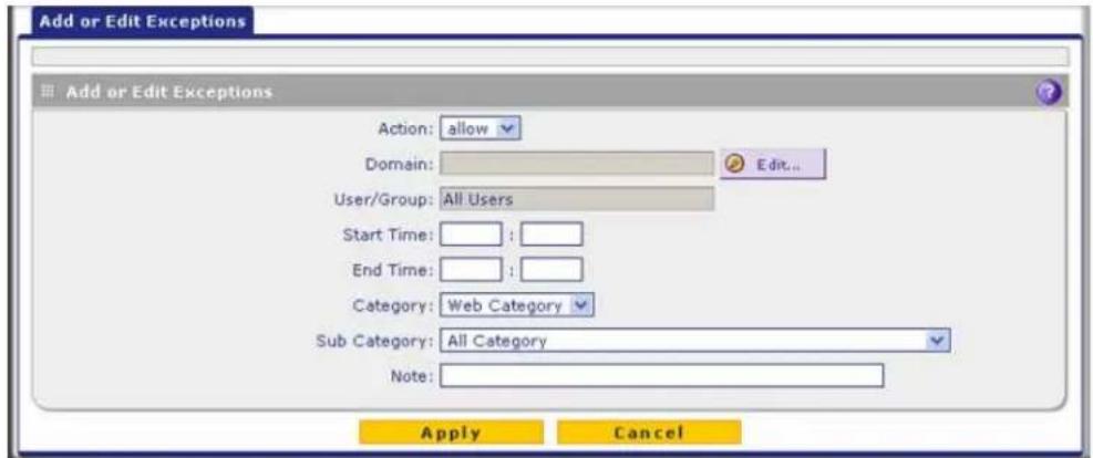
Figure 143. Add or edit exceptions: web categories
- Complete the fields and make your selections from the drop-down lists as explained in the following table:
Table 57. Add or Edit Exceptions screen settings
| Setting Description |
| Action From the drop-down list, select the action that the UTM applies:allow. The exception allows access to an application or category of applications, one or more file extensions, a URL or URL expression, or a web category that is otherwise blocked.block. The exception blocks access to an application or category of applications, one or more file extensions, a URL or URL expression, or a web category that is otherwise allowed. |
Table 57. Add or Edit Exceptions screen settings (continued)
| Setting Description | |
| DomainUser/Group | Click theEditbutton to open the Applies To pop-up screen, which lets you configure a domain, group, or individual user to which the exception needs to apply (see the screen later in this table).If applicable, on the Applies To screen, click aLookupbutton to retrieve a group or user.When you have made your decision, click anApplybutton to add the domain to the Domain field on the Add Exception screen and the group and user to the User/Group field on the Add Exception screen.Note:The Domain field can remain blank for some special users or groups.The following screen and rows in this table explain the options on the Applies To screen. |
 | |
| All Users | Click theApplybutton to apply the exception to all users, both authenticated and unauthenticated. |
| Authenticated | Click theApplybutton to apply the exception to all authenticated users.These are users who have actively logged in to the UTM and who have been authenticated. |
| Unauthenticated | Click theApplybutton to apply the exception to all unauthenticated users.These are users who have not actively logged in to the UTM. By default, these users are assigned the account name anonymous. |
Table 57. Add or Edit Exceptions screen settings (continued)
| Setting Description | ||
| DomainUser/Group(continued) | Local Groups Do | the following:1. From the Name drop-down list, select a local group.2. Click theApplybutton to apply the exception to the selected local group.You can specify local groups on the Groups screen (seeCreate and Delete Groupson page 395. |
| GroupMembershipby IP | Do the following:1. From the Name drop-down list, select a group that is defined by its IP address.2. Click theApplybutton to apply the exception to the selected group.You can specify groups that are defined by their IP address on the LAN Groups screen (seeManage the Network Databaseon page 112). | |
| Local UserSearch | Do the following:1. In the Name field, enter a user name.2. Click theLookupbutton. If the user is found, he or she is listed to the left of the Apply button.3. Click theApplybutton to apply the exception to the selected user. | |
| LDAPUser/GroupSearch | Do the following:1. From the Domain drop-down list, select an LDAP domain.2. From the Type drop-down list, selectUser, Group, orUser&Group.3. In the Name field, enter the name of the user, group, or user and group, or leave this field blank.4. Click theLookupbutton. If the user or group is found, it is listed to the left of the Apply button. If you left the Name field blank, all users, groups, or users and groups are listed; in this case, make a selection.5. Click theApplybutton to apply the exception to the selected user or group.You can specify LDAP domains, groups, and users on the Domains screen (seeConfigure Domainson page 388). | |
| RADIUS User Do | the following:1. From the Domain drop-down list, select a RADIUS domain.2. From the VLAN ID/Name drop-down list, select a VLAN ID or VLAN name.3. Click theApplybutton to apply the exception to the selected VLAN.You can specify RADIUS domains on the Domains screen (seeConfigure Domainson page 388) and RADIUS VLANs on the List of VLAN screen (seeConfigure RADIUS VLANs on page 415). | |
| DomainUser/Group(continued) | Custom Groups Do the following:From the Name drop-down list, select a custom group.Click theApplybutton to apply the exception to the selected group.You can specify custom groups on the Custom Groups screen (seeConfigure Custom Groupson page 397). | |
| Start Time | The time in 24-hour format (hours and minutes) when the action starts. If you leave these fields empty, the action applies continuously. | |
| End Time | The time in 24-hour format (hours and minutes) when the action ends. If you leave these fields empty, the action applies continuously. | |
| Category(and related information) | From the Category drop-down list, select the category to which the action applies. Your selection determines which drop-down lists, fields, radio buttons, and check boxes display onscreen. | |
| Applications The action applies either to an entire category of applications or to a single application. For each exception that you create, you can specify only one category of applications or one application.To select a category of applications:In the left pane, select a category from the Built-in Categories list or the Custom Categories list by clicking the + next to the category. The category displays in the Sub Category field. (For information about custom application categories, seeCreate Custom Categories for Exceptions for Web and Application Accesson page 258.)To select a single application:In the left pane, select a category from the Built-in Categories list or the Custom Categories list by clicking the + next to the category.In the right pane, select an application by clicking the + next to the application. The application displays in the Sub Category field.To search for an application:In the right pane, clickShow All.Type the name of the application (or the first few letters) in the search field. | ||
| Category(and related information)(continued) | File Extensions The action applies to one or more file extensions and one or more protocols, which you need to specify onscreen:1. File Extensions. Manually enter up to 40 file extensions. Use commas to separate multiple file extensions. Wildcards (*) are supported. A single asterisk (*) matches any file extension. You can also use the drop-down list to the right of the File Extension field to add file extensions from the following categories automatically:- None. No file extensions are added to the File Extension field. This is the default setting.- Executables. Executable file extensions (exe, com, dll, so, lib, scr, bat, and cmd) are added to the File Extension field.- Audio/Video. Audio and video file extensions (wav, mp3, avi, rm, rmvb, wma, wmv, mpg, mp4, and aac) are added to the File Extension field.- Compressed Files. Compressed file extensions (zip, rar, gz, tar, and bz2) are added to the File Extension field.2. Protocols. Select one or multiple check boxes to specify which protocols the action applies to:- SMTP- POP3- IMAP- HTTP- HTTPS- FTP | |
| HTTPS Smart Block | The action applies to an HTTPS Smart Block profile. Select a profile name from the HTTPS Smart Block Profile drop-down list. For information about HTTPS Smart Block profiles, see Configure HTTPS Smart Block on page 212. | |
| URL Filtering The action applies to a URL. The following radio buttons, field, and drop-down list display onscreen. Select a radio button to either enter a URL expression or select a custom URL list:Expression. Select the upper radio button, and enter a URL or URL expression such as *video* or *chat*. Wildcards (*) are supported. The maximum supported size of the URL or URL expression is 1024 bytes.Custom List. Select the lower radio button and a custom URL list from the drop-down list.For information about custom URL lists, see Create Custom Categories for Exceptions for Web and Application Access on page 258. | ||
| Web Categories The action applies to a web category. Select a web category from the Sub Category drop-down list. For information about custom web categories, see Create Custom Categories for Exceptions for Web and Application Access on page 258. | ||
| Note | A description of the exception rule for identification and management purposes or any other relevant information that you wish to include. | |
ProSecure Unified Threat Management (UTM) Appliance
- Click Apply to save your settings. The new exception rule is added to the associated table on the Exceptions screen and is enabled by default. To return to the Exceptions screen without adding the rule, click Cancel.
- Optional step: If you do not immediately want to enable a new rule, select the check box to the left of the rule that you want to disable (or click the Select All table button to select all rules). Then click the Disable table button to disable the selected rule or rules.
Note: Enabled exception rules are preceded by a green circle in the ! column; disabled exception rules are preceded by a gray circle in the ! column.
To change an existing exception rule:
- In the Action column to the right of to the exception rule, click the Edit table button. The Add or Edit Exception screen that is associated with the exception rule displays (see the previous four figures).
- Modify the settings that you wish to change (see the previous table).
- Click Apply to save your changes. The modified exception rule is displayed in the associated table on the Exceptions screen.
To disable, enable, or delete one or more exception rules:
- Select the check box to the left of each rule that you want to delete or disable, or click the Select All table button to select all rules.
-
Click one of the following table buttons:
-
Disable. Disables the rule or rules. The ! status icon changes from a green circle to a gray circle, indicating that the rule is or rules are disabled. (By default, when a rule is added to the table, it is automatically enabled.)
- Enable. Enables the rule or rules. The ! status icon changes from a gray circle to a green circle, indicating that the rule is or rules are enabled.
- Delete. Deletes the rule or rules.
The table rank of an exception rule in a table on the Exceptions screen determines the order in which the rule is applied (from the top down). To change the position of rules in a table, select one or more rules, and then click one of the following table buttons:
- Up. Moves the rule or rules up one position in the table rank.
- Down. Moves the rule or rules down one position in the table rank.
Create Custom Categories for Exceptions for Web and Application Access
Use custom categories to set exceptions for web and application access on the Exceptions screen (see Set Exception Rules for Web and Application Access on page 248). Each custom category can include a selection of applications, or a selection of URLs, or a selection of web categories, but no combination of applications, URLs, and web categories. You can create up to 200 custom categories.
To create and manage custom categories:
- Select Application Security > Exceptions > Custom Categories. The Custom Categories screen displays. This screen shows the Custom Categories table, which is empty if you have not specified any custom categories. (The following figure shows three custom categories in the table as an example.)
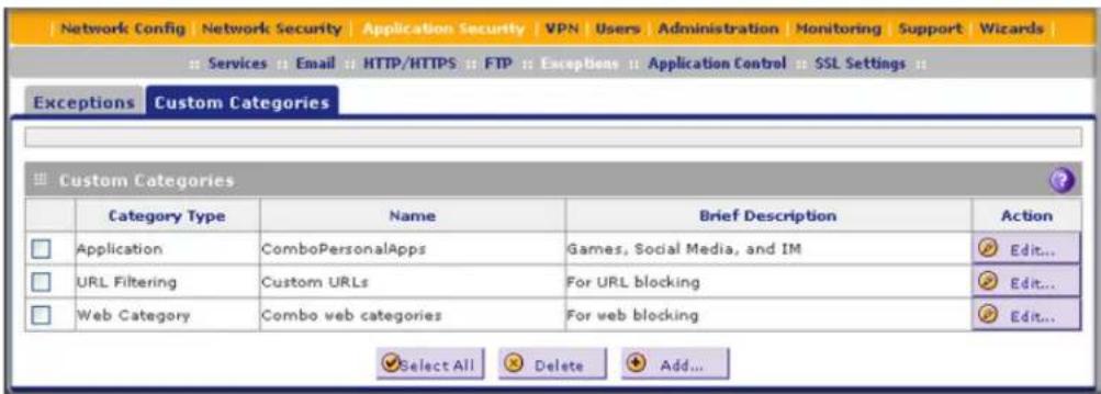
Figure 144.
- Under the Custom Categories table, click the Add table button to specify a custom category. The Add Custom Category screen displays. The content that is displayed onscreen depends on your selection from the Category Type drop-down list, which is set by default to Application.
- From the Category Type drop-down list, select the exception category. The following three screens display the different options that can be shown on screen. The content of the upper part of the screen (that is, above the Category Type drop-down list) is the same on all screens.
- Application.
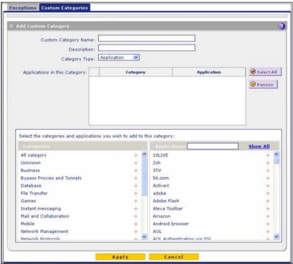
Figure 145. Custom categories: applications
- URL Filtering.

Figure 146. Custom categories: URL filtering
- Web Category.
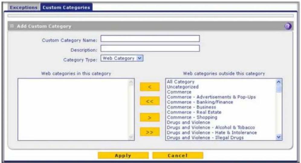
Figure 147. Custom categories: web categories
- Complete the fields and make your selections from the drop-down lists as explained in the following table:
Table 58. Custom Categories screen settings
| Setting Description | |||
| Name | A name of the custom category for identification and management purposes. | ||
| Description | A description of the category group for identification and management purposes. | ||
| Category Type | From the Category Type drop-down list, select the type of category that you want to create. Your selection determines the content that is displayed onscreen. | ||
| Application | Select the categories of applications and individual applications that you want to include in the custom category by using the following methods:To select one or more categories of applications:In the left pane, select one or more categories from the Categories list by clicking the + next to each category. The categories display in the Applications in this Category table.To select one or more individual applications:1. In the left pane, select a category from the Categories list by clicking the + next to the category.2. In the right pane, select applications by clicking the + next to each application. The applications display in the Applications in this Category table.To search for an application:1. In the right pane, click Show All.2. Type the name of the application (or the first few letters) in the search field. | ||
| Category Type (continued) | Application (continued) | To remove one or more categories or applications from the Applications in this Category table:1. Select the check boxes that are associated with the categories or applications, or select all entries in the table by clicking the Select All table button.2. Click the Remove table button. | |
| URL Filtering URL | Ls in this Category | This field contains the URLs that are added to the custom category. To add a URL to this field, use the Add URL field or the Import from File tool (see explanations later in this table). You can add a maximum of 2000 URLs.Note: Wildcards (*) are supported. For example, if you enter www.net*.com in the Add URL field and then click the Add table button, any URL that begins with www.net and ends with .com is included in the custom category.Note: To delete one or more URLs, highlight the URLs, and click the Delete table button. | |
| Add URL To add a URL:1. Type or copy a URL in the Add URL field.2. Click the Add table button to add the URL to the URLs in this Category field.Note: Start the URL with http:// or https://. If you dot not specify http:// or https://, the UTM automatically adds http://. | |||
| Import from File | To import a list with URLs into the URLs in this Category field:1. Click the Browse button and navigate to a file in .txt format that contains line-delimited URLs (that is, one URL per line).2. Click the Upload table button to add the URLs to the URLs in this Category field.Note: Any existing URLs in the URLs in this Category field are overwritten when you import a list of URLs from a file. | ||
| Web Categories | Use the move buttons to move entire web categories (for example, Commerce), individual applications (for example, Commerce - Shopping), or combinations of both from the web categories outside this category field to the web categories in this category field (or the other way around).These are the functions of the move buttons:< or > moves one or more highlighted selections from one field to the other.< or >> moves all entries from one field to the other. | ||
- Click Apply to save your settings. The new category is added to the Custom Categories table. To return to the Custom Categories screen without adding the category, click Cancel.
To change an existing custom category:
- In the Action column to the right of the custom category, click the Edit table button. The Edit Custom Category screen displays. This screen is identical to the Add Custom Category screen (see Figure 145 on page 259, Figure 146 on page 259, and Figure 147 on page 260).
- Modify the settings that you wish to change (see the previous table).
- Click Apply to save your changes. The modified custom group is displayed in the Custom Categories table.
To delete one or more custom categories:
- Select the check box to the left of each custom category that you want to delete, or click the Select All table button to select all custom categories.
- Click the Delete table button.
Set Scanning Exclusions for IP Addresses and Ports
After you have specified which IP addresses and ports the UTM scans for malware threats, you can set scanning exclusion rules for certain IP addresses and ports.
To save resources, you can configure scanning exclusions for IP addresses and ports that you know are secure. For example, if your network includes a web server that hosts web pages that are accessible by anyone on the Internet, the files that are hosted by your web server do not need to be scanned. To prevent the UTM from scanning these files, you can configure a scanning exclusion for your web server.
To configure scanning exclusion rules:
- Select Application Security > Services> Scanning Exclusions. The Scanning Exclusions screen displays. This screen shows the Scanning Exclusions table, which is empty if you have not specified any exclusions. (The following figure shows one exclusion rule in the table as an example.)
ProSecure Unified Threat Management (UTM) Appliance

Figure 148.
- In the Add Scanning Exclusions section of the screen, specify an exclusion rule as explained in the following table:
Table 59. Scanning Exclusion screen settings
| Setting Description | |
| Client IP Fill in the | client IP address and optional subnet mask that are excluded from all scanning. |
| Destination IP | Fill in the destination IP address and optional subnet mask that are excluded from all scanning. |
| Port Enter the number of the port that is excluded from all scanning. | |
| Brief Description | Enter a description of the exclusion rule for identification and management purposes. |
- In the Add column, click the Add table button to add the exclusion rule to the Scanning Exclusions table. The new exclusion rule is enabled by default.
To disable a rule, select the check box in the Enable column for the rule. (Unlike the operation of the web management interface on other screens, you do not need to click any other button to disable the rule.)
To delete an exclusion rule from the Scanning Exclusions table, click the Delete table button in the Action column to the right of the rule that you want to delete.
Virtual Private Networking Using IPSec, PPTP, or L2TP Connections
7
This chapter describes how to use the IP security (IPSec) virtual private networking (VPN) features of the UTM to provide secure, encrypted communications between your local network and a remote network or computer. This chapter contains the following sections:
- Use the IPSec VPN Wizard for Client and Gateway Configurations
- Test the Connection and View Connection and Status Information
- Manage IPSec VPN and IKE Policies
- Configure Extended Authentication (XAUTH)
- Assign IP Addresses to Remote Users (Mode Config)
- Configure Keep-Alives and Dead Peer Detection
- Configure NetBIOS Bridging with IPSec VPN
- Configure the PPTP Server
- Configure the L2TP Server
- For More IPSec VPN Information
Considerations for Dual WAN Port Systems (Multiple WAN Port Models Only)
On the multiple WAN port models only, if two WAN ports are configured, you can enable either auto-rollover mode for increased system reliability or load balancing mode for optimum bandwidth efficiency. Your WAN mode selection impacts how the VPN features need to be configured.
Note: For the UTM9S and UTM25S only, you can also use a DSL interface in combination with a WAN interface for VPN tunnel failover.
The use of fully qualified domain names (FQDNs) in VPN policies is mandatory when the WAN ports function in auto-rollover mode or load balancing mode, and is also required for VPN tunnel failover. When the WAN ports function in load balancing mode, you cannot configure VPN tunnel failover. An FQDN is optional when the WAN ports function in load
balancing mode if the IP addresses are static, but mandatory if the WAN IP addresses are dynamic. See Virtual Private Networks on page 629 for more information about the IP addressing requirements for VPNs in the dual WAN modes.
For information about how to select and configure a Dynamic DNS service for resolving FQDNs, see Configure Dynamic DNS on page 91. For information about WAN mode configuration, see Configure the WAN Mode on page 80.
The following diagrams and table show how the WAN mode selection relates to VPN configuration.
WAN auto-rollover: FQDN required for VPN

flowchart
graph LR
    A["Rest of UTM functions"] --> B["UTM WAN port functions"]
    B --> C["UTM rollover control"]
    C --> D["WAN 1 port"]
    C --> E["WAN 2 port"]
    D --> F["Internet"]
    E --> F
    style A fill:#f9f,stroke:#333
    style B fill:#f9f,stroke:#333
    style C fill:#f9f,stroke:#333
    style D fill:#ccf,stroke:#333
    style E fill:#ccf,stroke:#333
    style F fill:#cff,stroke:#333
Figure 149.
WAN load balancing: FQDN optional for VPN

flowchart
graph LR
    A["Rest of UTM functions"] --> B["UTM WAN port functions"]
    B --> C["Load balancing control"]
    C --> D["WAN 1 port"]
    C --> E["WAN 2 port"]
    D --> F["Internet"]
    E --> F
FQDN required for dynamic IP addresses FQDN optional for static IP addresses
Figure 150.
The following table summarizes the WAN addressing requirements (FQDN or IP address) for a VPN tunnel in either dual WAN mode.
Table 60. IP addressing for VPNs in dual WAN port systems
| Configuration and WAN IP address Rollover modea | Load balancing mode | |
| VPN Road Warrior(client to gateway) | Fixed FQDN required FQDN Allowed (optional) | |
| Dynamic FQDN required FQDN required | ||
| VPN Gateway-to-Gateway(gateway to gateway) | Fixed FQDN required FQDN Allowed (optional) | |
| Dynamic FQDN required FQDN required | ||
| VPN Telecommuter(client to gateway through a NAT router) | Fixed FQDN required FQDN Allowed (optional) | |
| Dynamic FQDN required FQDN required | ||
a. After a rollover, all tunnels need to be reestablished using the new WAN IP address.
Use the IPSec VPN Wizard for Client and Gateway Configurations
- Create Gateway-to-Gateway VPN Tunnels with the Wizard
- Create a Client-to-Gateway VPN Tunnel
You can use the IPSec VPN Wizard to configure multiple gateway or client VPN tunnel policies.
The following section provides wizard and NETGEAR ProSafe VPN Client software configuration procedures for the following scenarios:
- Using the wizard to configure a VPN tunnel between two VPN gateways
• Using the wizard to configure a VPN tunnel between a VPN gateway and a VPN client
Configuring a VPN tunnel connection requires that you specify all settings on both sides of the VPN tunnel to match or mirror each other precisely, which can be a daunting task. The VPN Wizard efficiently guides you through the setup procedure with a series of questions that determine the IPSec keys and VPN policies it sets up. The VPN Wizard also configures the settings for the network connection: security association (SA), traffic selectors, authentication algorithm, and encryption. The settings that are used by the VPN Wizard are based on the recommendations of the VPN Consortium (VPNC), an organization that promotes multivendor VPN interoperability.
Create Gateway-to-Gateway VPN Tunnels with the Wizard
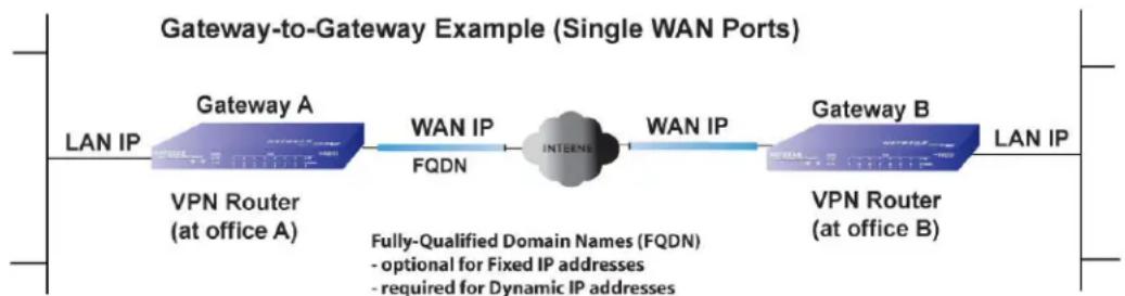
flowchart
graph LR
    A["LAN IP"] --> B["Gateway A"]
    B --> C["FWN Router (at office A)"]
    C --> D["WAN IP"]
    D --> E["FQDN"]
    E --> F["INTERNET"]
    F --> G["WAN IP"]
    G --> H["Gateway B"]
    H --> I["FWN Router (at office B)"]
    I --> J["LAN IP"]
    style F fill:#99ccff,stroke:#333
    note right of F Fully-Qualified Domain Names (FQDN)
        - optional for Fixed IP addresses
        - required for Dynamic IP addresses
Figure 151.
To set up a gateway-to-gateway VPN tunnel using the VPN Wizard:
- Select VPN > IPSec VPN > VPN Wizard. The VPN Wizard screen displays (see the following figure, which shows the VPN Wizard screen for the UTM50, and contains an example).
The About VPN Wizard section of the VPN Wizard screen shows the following minor differences for the various UTM models:
- Single WAN port models. No WAN selection drop-down lists and no Enable RollOver check box.
ProSecure Unified Threat Management (UTM) Appliance
- Multiple WAN port models. A drop-down list to select the WAN interface, a check box to enable VPN rollover, and another drop-down list to select a WAN interface for VPN rollover. If the multiple WAN port model is configured to function in WAN auto-rollover mode, you can use the VPN Wizard to configure VPN rollover and do not need to configure this manually.
![Network Config | Network Security | Application Security | VPN | Users | Administration | Monitoring | Support | Wizards IPSec VPN SSL VPN Certificates PPTP Server L2TP Server IKE Policies VPN Policies VPN Wizard Mode Config RADIUS Client VPN Wizard default values About VPN Wizard The Wizard sets most parameters to defaults as proposed by the VPN Consortium ( VPNC ), and assumes a pre-shared key, which greatly simplifies setup. After creating the policies through the VPN Wizard, you can always update the parameters through the Policies menu. This VPN tunnel will connect to the following peers: Gateway VPN Client This VPN tunnel will use following local WAN Interface: WAN1 Enable RollOver? WAN1 Connection Name and Remote IP Type What is the new Connection Name: GW1 to GW2 What is the pre-shared key? YO!28gbrot746?_IDO [Key Length 8 - 49 Char] End Point Information What is the Remote WAN's IP Address or Internet Name? 10.144.28.226 What is the Local WAN's IP Address or Internet Name? 10.34.116.22 Secure Connection Remote Accessibility What is the remote LAN IP Address? 192 172 1 0 What is the remote LAN Subnet Mask? 255 255 255 0 Apply Reset](/content/2026/06/1371942/images/2f2be81a6b66dbcfe450a3735a5047c07ab738742cd3134de1256b07e2178fca.jpg)
Figure 152.
To view the wizard default settings, click the VPN Wizard Default Values option arrow in the upper right of the screen. A pop-up screen displays (see the following figure), showing the wizard default values. After you have completed the wizard, you can modify these settings for the tunnel policy that you have set up.

Figure 153.
The VPN Wizard default values screen lists some incorrect default values. The correct values are listed in the following table.
Table 61. IPSec VPN Wizard default values for a gateway-to-gateway tunnel
| Setting Default Value | |
| IKE policy | |
| Exchange mode Main | |
| ID type IP address or FQDN | |
| Local WAN ID Local WAN IP address or FQDN | |
| Remote WAN ID Remote WAN IP address or FQDN | |
| Encryption algorithm 3DES | |
| Authentication algorithm SHA-1 | |
| Authentication method Pre-shared Key | |
| Key group DH-Group 2 (1024 bit) | |
| Life time 8 hours | |
| VPN policy | |
| Encryption algorithm 3DES | |
| Authentication algorithm SHA-1 | |
| Life time 1 hour | |
| Key group DH-Group 2 (1024 bit) | |
| NetBIOS Enabled | |
- Select the radio buttons and complete the fields and as explained in the following table:
Table 62. IPSec VPN Wizard settings for a gateway-to-gateway tunnel
| Setting Description | |
| About VPN Wizard | |
| This VPN tunnel will connect to the following peers | Select the Gateway radio button. The local WAN port's IP address or Internet name displays in the End Point Information section of the screen. |
| This VPN tunnel will use following local WAN Interface (multiple WAN port models only) | Select a WAN interface from the drop-down list to specify which local WAN interface the VPN tunnel uses as the local endpoint. |
| Select the Enable RollOver? check box to enable VPN rollover, and then select a WAN interface from the drop-down list to the right of the check box to specify the interface to which the VPN rollover should occur.Note: If the multiple WAN port model is configured to function in WAN auto-rollover mode, you can use the VPN Wizard to configure VPN rollover and do not need to configure this manually. | |
| Connection Name and Remote IP Type | |
| What is the new Connection Name? | Enter a descriptive name for the connection. This name is used to help you to manage the VPN settings; the name is not supplied to the remote VPN endpoint. |
| What is the pre-shared key? Enter a pre-shared key. The key needs to be entered both here and on the remote VPN gateway. This key needs to have a minimum length of 8 characters and should not exceed 49 characters. | |
| End Point Informationa | |
| What is the Remote WAN's IP Address or Internet Name? | Enter the IP address or Internet name (FQDN) of the WAN interface on the remote VPN tunnel endpoint. |
| What is the Local WAN's IP Address or Internet Name? | When you select the Gateway radio button in the About VPN Wizard section of the screen, the IP address of the UTM's active WAN interface is automatically entered. |
| Secure Connection Remote Accessibility | |
| What is the remote LAN IP Address? | Enter the LAN IP address of the remote gateway.Note:The remote LAN IP address needs to be in a different subnet than the local LAN IP address. For example, if the local subnet is 192.168.1.x, then the remote subnet could be 192.168.10.x. but could not be 192.168.1.x. If this information is incorrect, the tunnel fails to connect. |
| What is the remote LAN Subnet Mask? | Enter the LAN subnet mask of the remote gateway. |
a. Both local and remote endpoints should be defined as either FQDNs or IP addresses. A combination of an IP address and an FQDN is not supported.
Tip: To ensure that tunnels stay active, after completing the wizard, manually edit the VPN policy to enable keep-alives, which periodically sends ping packets to the host on the peer side of the network to keep the tunnel alive. For more information, see Configure Keep-Alives on page 328.
Tip: For DHCP WAN configurations, first set up the tunnel with IP addresses. After you have validated the connection, you can use the wizard to create new policies using the FQDN for the WAN addresses.
- Click Apply to save your settings. The IPSec VPN policy is now added to the List of VPN Policies table on the VPN Policies screen. By default, the VPN policy is enabled.

Figure 154.
-
Configure a VPN policy on the remote gateway that allows connection to the UTM.
-
Activate the IPSec VPN connection:
a. Select Monitoring > Active Users & VPNs > IPSec VPN Connection Status. The IPSec VPN Connection Status screen displays.

Figure 155.
b. Locate the policy in the table, and click the Connect table button. The IPSec VPN connection becomes active.
Note: When using FQDNs, if the Dynamic DNS service is slow to update its servers when your DHCP WAN address changes, the VPN tunnel fails because the FQDNs do not resolve to your new address. If you have the option to configure the update interval, set it to an appropriately short time.
Create a Client-to-Gateway VPN Tunnel

flowchart
graph LR
    A["LAN IP"] --> B["Gateway A"]
    B --> C["WAN IP"]
    C --> D["INTERNET"]
    D --> E["Client B"]
    style A fill:#f9f,stroke:#333
    style B fill:#bbf,stroke:#333
    style C fill:#bfb,stroke:#333
    style D fill:#ffb,stroke:#333
    style E fill:#cfc,stroke:#333
Figure 156.
To configure a VPN client tunnel, follow the steps in the following sections:
• Use the VPN Wizard to Configure the Gateway for a Client Tunnel on page 272.
• Use the NETGEAR VPN Client Wizard to Create a Secure Connection on page 276 or Manually Create a Secure Connection Using the NETGEAR VPN Client on page 280.
Use the VPN Wizard to Configure the Gateway for a Client Tunnel
To set up a client-to-gateway VPN tunnel using the VPN Wizard:
- Select VPN > IPSec VPN > VPN Wizard. The VPN Wizard screen displays (see the following figure, which shows the VPN Wizard screen for the UTM50, and contains an example).
The About VPN Wizard section of the VPN Wizard screen shows the following minor differences for the various UTM models:
- Single WAN port models. No WAN selection drop-down lists and no Enable RollOver check box.
- Multiple WAN port models. A drop-down list to select the WAN interface, a check box to enable VPN rollover, and another drop-down list to select a WAN interface for VPN rollover. If the multiple WAN port model is configured to function in WAN auto-rollover mode, you can use the VPN Wizard to configure VPN rollover and do not need to configure this manually.
![Network Config Network Security Application Security VPN Users Administration Monitoring Support Wizards IPSec VPN SSL VPN Certificates PPTP Server L2TP Server IKE Policies VPN Policies VPN Wizard Mode Config RADIUS Client VPN Wizard default values About VPN Wizard The Wizard sets most parameters to defaults as proposed by the VPN Consortium (VPNC), and assumes a pre-shared key, which greatly simplifies setup. After creating the policies through the VPN Wizard, you can always update the parameters through the Policies menu. This VPN tunnel will connect to the following peers: Gateway VPN Client This VPN tunnel will use following local WAN Interface: WAN1 Enable RollOver? WAN1 Connection Name and Remote IP Type What is the new Connection Name? Client-to-UTM What is the pre-shared key? I7!KL39dFG_8 [Key Length 8 - 49 Char] End Point Information What is the Remote Identifier Information? utm_remote.com What is the Local Identifier Information? utm_local.com Secure Connection Remote Accessibility What is the remote LAN IP Address? What is the remote LAN Subnet Mask? Apply Reset](/content/2026/06/1371942/images/c534df0472f90152e8cfbb92001e42c19827c660c5569922afc071c5f438e89c.jpg)
Figure 157.
To display the wizard default settings, click the VPN Wizard default values option arrow in the upper right of the screen. A pop-up screen displays (see Figure 153 on page 268), showing the wizard default values.
The VPN Wizard default values screen lists some incorrect default values. The correct values are listed in the following table.
Table 63. IPSec VPN Wizard default values for a client-to-gateway tunnel
| Setting Default Value | |
| IKE policy | |
| Exchange mode Aggressive | |
| ID type FQDN | |
| Local WAN ID utm_local1.com | |
| Remote WAN ID utm_remote1.com | |
| Encryption algorithm 3DES | |
| Authentication algorithm SHA-1 | |
| Authentication method Pre-shared Key | |
| Key group DH-Group 2 (1024 bit) | |
| Life time 8 hours | |
| VPN policy | |
| Encryption algorithm 3DES | |
| Authentication algorithm SHA-1 | |
| Life time 1 hour | |
| Key group DH-Group 2 (1024 bit) | |
| NetBIOS | Disabled |
- Select the radio buttons and complete the fields and as explained in the following table:
Table 64. IPSec VPN Wizard settings for a client-to-gateway tunnel
| Setting | Description |
| About VPN Wizard | |
| This VPN tunnel will connect to the following peers | Select theVPN Clientradio button. The default remote FQDN (utm_remote.com) and the default local FQDN (utm_local.com) display in the End Point Information section of the screen. |
| Setting Description | |
| This VPN tunnel will use following local WAN Interface (multiple WAN port models only) | Select a WAN interface from the drop-down list to specify which local WAN interface the VPN tunnel uses as the local endpoint. |
| Select the Enable RollOver? check box to enable VPN rollover, and then select a WAN interface from the drop-down list to the right of the check box to specify the interface to which the VPN rollover should occur.Note: If the multiple WAN port model is configured to function in WAN auto-rollover mode, you can use the VPN Wizard to configure VPN rollover and do not need to configure this manually. | |
| Connection Name and Remote IP Type | |
| What is the new Connection Name? | Enter a descriptive name for the connection. This name is used to help you to manage the VPN settings; the name is not supplied to the remote VPN endpoint. |
| What is the pre-shared key? | Enter a pre-shared key. The key needs to be entered both here and on the remote VPN gateway, or the remote VPN client. This key needs to have a minimum length of 8 characters and cannot exceed 49 characters. |
| End Point Informationa | |
| What is the Remote Identifier Information? | When you select the Client radio button in the About VPN Wizard section of the screen, the default remote FQDN (utm_remote1.com) is automatically entered. Use the default remote FQDN, or enter another FQDN. |
| What is the Local Identifier Information? | When you select the Client radio button in the About VPN Wizard section of the screen, the default local FQDN (utm_local1.com) is automatically entered. Use the default local FQDN, or enter another FQDN. |
| Secure Connection Remote Accessibility | |
| What is the remote LAN IP Address? | These fields are masked out for VPN client connections. |
| What is the remote LAN Subnet Mask? | |
a. Both local and remote endpoints should be defined as either FQDNs or IP addresses. A combination of an IP address and an FQDN is not supported.
- Click Apply to save your settings. The IPSec VPN policy is now added to the List of VPN Policies table on the VPN Policies screen. By default, the VPN policy is enabled.
ProSecure Unified Threat Management (UTM) Appliance

Figure 158.
Note: When you are using FQDNs and a Dynamic DNS (DDNS) service, if the DDNS service is slow to update its servers when your DHCP WAN address changes, the VPN tunnel fails because the FQDNs do not resolve to your new address. If you have the option to configure the update interval, set it to an appropriately short time.
- Optional step: Collect the information that you need to configure the VPN client. You can print the following table to help you keep track of this information.
Table 65. Information required to configure the VPN client
| Component Example Information to be collected | ||
| Pre-shared key I7!KL39dFG_8 | ||
| Remote identifier information utm_remote.com | ||
| Local identifier information utm_local.com | ||
| Router's LAN network IP address 192.168.1.0 | ||
| Router's LAN network mask 255.255.255.0 | ||
| Router's WAN IP address 10.34.116.22 |
Use the NETGEAR VPN Client Wizard to Create a Secure Connection
The VPN client lets you set up the VPN connection manually (see Manually Create a Secure Connection Using the NETGEAR VPN Client on page 280) or with the integrated Configuration Wizard, which is the easier and preferred method. The Configuration Wizard configures the default settings and provides basic interoperability so that the VPN client can easily communicate with the UTM (or third-party VPN devices). The Configuration Wizard does not let you enter the local and remote IDs, so you need to enter this information manually.
Note: Perform these tasks from a computer that has the NETGEAR ProSafe VPN Client installed.
To use the Configuration Wizard to set up a VPN connection between the VPN client and the UTM:
- Right-click the VPN client icon in your Windows system tray, and select Configuration Panel. The Configuration Panel screen displays.

Figure 159.
- From the main menu on the Configuration Panel screen, select Configuration > Wizard. The Choice of the remote equipment wizard screen (screen 1 of 3) displays.

Figure 160.
- Select the A router or a VPN gateway radio button, and click Next. The VPN tunnel parameters wizard screen (screen 2 of 3) displays.
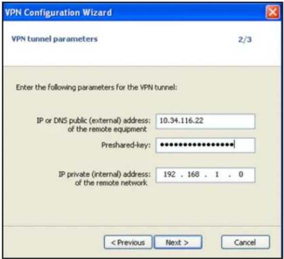
Figure 161.
-
Specify the following VPN tunnel parameters:
-
IP or DNS public (external) address of the remote equipment. Enter the remote IP address or DNS name of the UTM. For example, enter 10.34.116.22.
- Preshared key. Enter the pre-shared key that you already specified on the UTM. For example, enter I7!KL39dFG_8.
-
IP private (internal) address of the remote network. Enter the remote private IP address of the UTM. For example, enter 192.168.1.0. This IP address enables communication with the entire 192.168.1.x subnet.
-
Click Next. The Configuration Summary wizard screen (screen 3 of 3) displays.

Figure 162.
- This screen is a summary screen of the new VPN configuration. Click Finish.
- Specify the local and remote IDs:
a. In the tree list pane of the Configuration Panel screen, click Gateway (the default name given to the authentication phase). The Authentication pane displays in the Configuration Panel screen, with the Authentication tab selected by default.
b. Click the Advanced tab in the Authentication pane. The Advanced pane displays.
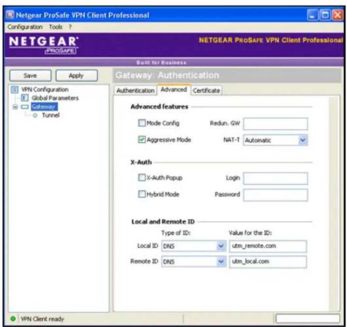
Figure 163.
c. Specify the settings that are explained in the following table.
Table 66. VPN client advanced authentication settings
| Setting Description | |
| Advanced features | |
| Aggressive Mode Select | this check box to enable aggressive mode as the mode of negotiation with the UTM. |
| NAT-T | SelectAutomaticfrom the drop-down list to enable the VPN client and UTM to negotiate NAT-T. |
| Local and Remote ID | |
| Local ID As the type of ID | , selectDNSfrom the Local ID drop-down list because you specified FQDN in the UTM configuration.As the value of the ID, enterutm_remote.comas the local ID for the VPN client.Note:The remote ID on the UTM is the local ID on the VPN client. It might be less confusing to configure an FQDN such as client.com as the remote ID on the UTM and then enter client.com as the local ID on the VPN client. |
| Remote ID | As the type of ID, selectDNSfrom the Remote ID drop-down list because you specified an FQDN in the UTM configuration.As the value of the ID, enterutm_local.comas the remote ID for the UTM.Note:The local ID on the UTM is the remote ID on the VPN client. It might be less confusing to configure an FQDN such as router.com as the local ID on the UTM and then enter router.com as the remote ID on the VPN client. |
- Configure the global parameters:
a. Click Global Parameters in the left column of the Configuration Panel screen. The Global Parameters pane displays in the Configuration Panel screen.

Figure 164.
b. Specify the default lifetimes in seconds:
- Authentication (IKE), Default. The default lifetime value is 3600 seconds. Change this setting to 28800 seconds to match the configuration of the UTM.
-
Encryption (IPSec), Default. The default lifetime value is 1200 seconds. Change this setting to 3600 seconds to match the configuration of the UTM.
-
Click Apply to use the new settings immediately, and click Save to keep the settings for future use.
The VPN client configuration is now complete.
Instead of using the wizard on the VPN client, you can also manually configure the VPN client, which is explained in the following section.
Manually Create a Secure Connection Using the NETGEAR VPN Client
Note: Perform these tasks from a computer that has the NETGEAR ProSafe VPN Client installed.
To configure a VPN connection between the VPN client and the UTM manually, create authentication settings (phase 1 settings), create an associated IPSec configuration (phase 2 settings), and then specify the global parameters.
Configure the Authentication Settings (Phase 1 Settings)
To create new authentication settings:
- Right-click the VPN client icon in your Windows system tray, and select Configuration Panel. The Configuration Panel screen displays.

Figure 165.
- In the tree list pane of the Configuration Panel screen, right-click VPN Configuration, and select New Phase 1.
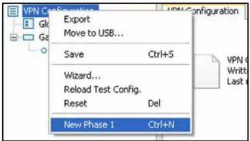
Figure 166.
- Change the name of the authentication phase (the default is Gateway):
a. Right-click the authentication phase name.
b. Select Rename.
c. Type vpn_client.
d. Click anywhere in the tree list pane.
ProSecure Unified Threat Management (UTM) Appliance
Note: This is the name for the authentication phase that is used only for the VPN client, not during IKE negotiation. You can view and change this name in the tree list pane. This name needs to be a unique name.
The Authentication pane displays in the Configuration Panel screen, with the Authentication tab selected by default.

Figure 167.
- Specify the settings that are explained in the following table.
Table 67. VPN client authentication settings
| Setting Description | ||
| Interface Select Any | from the drop-down list. | |
| Remote Gateway Enter | the remote IP address or DNS name of the UTM. For example, enter 10.34.116.22. | |
| Preshared Key | Select the Preshared Key radio button. Enter the pre-shared key that you already specified on the UTM. For example, enter I7!KL39dFG_8. Confirm the key in the Confirm field. | |
| IKE | Encryption | Select the 3DES encryption algorithm from the drop-down list. |
| Authentication | Select the SHA1 authentication algorithm from the drop-down list. | |
| Key Group | Select the DH2 (1024) key group from the drop-down list.Note: On the UTM, this key group is referred to as Diffie-Hellman Group 2 (1024 bit). | |
ProSecure Unified Threat Management (UTM) Appliance
- Click Apply to use the new settings immediately, and click Save to keep the settings for future use.
- Click the Advanced tab in the Authentication pane. The Advanced pane displays.
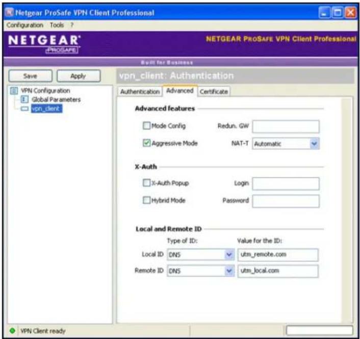
Figure 168.
- Specify the settings that are explained in the following table.
Table 68. VPN client advanced authentication settings
| Setting Description | |
| Advanced features | |
| Aggressive Mode | Select this check box to enable aggressive mode as the mode of negotiation with the UTM. |
| NAT-T | Select Automatic from the drop-down list to enable the VPN client and UTM to negotiate NAT-T. |
| Local and Remote ID | |
| Local ID | As the type of ID, selectDNSfrom the Local ID drop-down list because you specified FQDN in the UTM configuration.As the value of the ID, enterutm_remote.comas the local ID for the VPN client.Note:The remote ID on the UTM is the local ID on the VPN client. It might be less confusing to configure an FQDN such as client.com as the remote ID on the UTM and then enter client.com as the local ID on the VPN client. |
| Remote ID | As the type of ID, selectDNSfrom the Remote ID drop-down list because you specified an FQDN in the UTM configuration.As the value of the ID, enterutm_local.comas the remote ID for the UTM.Note:The local ID on the UTM is the remote ID on the VPN client. It might be less confusing to configure an FQDN such as router.com as the local ID on the UTM and then enter router.com as the remote ID on the VPN client. |
- Click Apply to use the new settings immediately, and click Save to keep the settings for future use.
Create the IPSec Configuration (Phase 2 Settings)
Note: On the UTM, the IPSec configuration (phase 2 settings) is referred to as the IKE settings.
To create an IPSec configuration:
- In the tree list pane of the Configuration Panel screen, right-click the vpn_client authentication phase name, and then select New Phase 2.
- Change the name of the IPSec configuration (the default is Tunnel):
a. Right-click the IPSec configuration name.
b. Select Rename.
c. Type netgear_platform.
d. Click anywhere in the tree list pane.
Note: This is the name for the IPSec configuration that is used only for the VPN client, not during IPSec negotiation. You can view and change this name in the tree list pane. This name needs to be a unique name.
The IPSec pane displays in the Configuration Panel screen, with the IPSec tab selected by default.

Figure 169.
- Specify the settings that are explained in the following table.
Table 69. VPN client IPSec configuration settings
| Setting Description | ||
| VPN Client address | Either enter 0.0.0.0 as the IP address, or enter a virtual IP address that is used by the VPN client in the UTM's LAN; the computer (for which the VPN client opened a tunnel) appears in the LAN with this IP address. | |
| Address Type | Select Subnet address from the drop-down list. This selection defines which addresses the VPN client can communicate with after the VPN tunnel is established. | |
| Remote LAN address | Enter 192.168.1.0 as the remote IP address (that is, LAN network address) of the gateway that opens the VPN tunnel. | |
| Subnet mask | Enter 255.255.255.0 as the remote subnet mask of the gateway that opens the VPN tunnel. | |
| ESP | Encryption | Select 3DES as the encryption algorithm from the drop-down list. |
| Authentication | Select SHA-1 as the authentication algorithm from the drop-down list. | |
| Mode | Select Tunnel as the encapsulation mode from the drop-down list. | |
| PFS and Group | Select the PFS check box, and then select the DH2 (1024) key group from the drop-down list.Note: On the UTM, this key group is referred to as Diffie-Hellman Group 2 (1024 bit). | |
- Click Apply to use the new settings immediately, and click Save to keep the settings for future use.
Configure the Global Parameters
To specify the global parameters:
- Click Global Parameters in the left column of the Configuration Panel screen. The Global Parameters pane displays in the Configuration Panel screen.

Figure 170.
-
Specify the default lifetimes in seconds:
-
Authentication (IKE), Default. The default lifetime value is 3600 seconds. Change this setting to 28800 seconds to match the configuration of the UTM.
-
Encryption (IPSec), Default. The default lifetime value is 1200 seconds. Change this setting to 3600 seconds to match the configuration of the UTM.
-
Click Apply to use the new settings immediately, and click Save to keep the settings for future use.
The UTM configuration is now complete.
Test the Connection and View Connection and Status Information
- Test the NETGEAR VPN Client Connection
• NETGEAR VPN Client Status and Log Information
• View the UTM IPSec VPN Connection Status
• View the UTM IPSec VPN Log
Both the NETGEAR ProSafe VPN Client and the UTM provide VPN connection and status information. This information is useful for verifying the status of a connection and troubleshooting problems with a connection.
Test the NETGEAR VPN Client Connection
There are many ways to establish a connection. The following procedures assume that you use the default authentication phase name Gateway and the default IPSec configuration name Tunnel. If you manually set up the connection and changed the names, use vpn_client (or any other name that you have configured as the authentication phase name) and netgear_platform (or any other name that you have configured) as the IPSec configuration name. NETGEAR recommends that you test the connection from a computer that is located off-site rather than from a computer that is located behind the UTM.
To establish a connection, use one of the following three methods:
- Use the Configuration Panel screen. In the tree list pane of the Configuration Panel screen, perform one of the following tasks:
- Click the Tunnel IPSec configuration name, and press Ctrl+O.
- Right-click the Tunnel IPSec configuration name, and select Open tunnel.
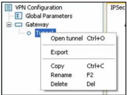
Figure 171.
- Use the Connection Panel screen. On the main menu of the Configuration Panel screen, select Tools > Connection Panel to open the Connection Panel screen.
ProSecure Unified Threat Management (UTM) Appliance
Perform one of the following tasks:
- Double-click Gateway-Tunnel.
- Right-click Gateway-Tunnel, and select Open tunnel.
- Click Gateway-Tunnel, and press Ctrl+O.

Figure 172.
- Use the system-tray icon. Right-click the system tray icon, and select Open tunnel 'Tunnel'.

Figure 173.
Whichever way you choose to open the tunnel, when the tunnel opens successfully, the Tunnel opened message displays above the system tray:
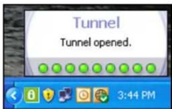
Figure 174.
Once launched, the VPN client displays an icon in the system tray that indicates whether a tunnel is opened, using a color code:


Green icon: at least one VPN tunnel opened

Purple icon: no VPN tunnel opened
Figure 175.
NETGEAR VPN Client Status and Log Information
To view detailed negotiation and error information about the NETGEAR VPN client:
Right-click the VPN client icon in the system tray, and select Console. The VPN Client Console Active screen displays.
![[VPNCONF] TGBIKE_STARTED received 2011-06-24 15:43:41 Default (SA Gateway-P1) SEND phase 1 Aggressive Mode [SA] [KEY_EXCH] [NONCE] [ID] [VID] [VID] [VID] 2011-06-24 15:43:42 Default (SA Gateway-P1) RECV phase 1 Aggressive Mode [HASH] [SA] [KEY_EXCH] [NONCE] [ID] [NAT_D] [NAT_D] [VID] [VID] 2011-06-24 15:43:42 Default (SA Gateway-P1) SEND phase 1 Aggressive Mode [HASH] [NAT_D] [NAT_D] 2011-06-24 15:43:42 Default phase 1 done: initiator id remote.com, responder id local.com 2011-06-24 15:43:42 Default (SA Gateway-Tunnel-P2) SEND phase 2 Quick Mode [HASH] [SA] [KEY_EXCH] [NONCE] [ID] [ID] 2011-06-24 15:43:42 Default (SA Gateway-P1) RECV Informational [HASH] [NOTIFY] 2011-06-24 15:43:42 Default (SA Gateway-Tunnel-P2) RECV phase 2 Quick Mode [HASH] [SA] [KEY_EXCH] [NONCE] [ID] [ID] 2011-06-24 15:43:42 Default (SA Gateway-Tunnel-P2) SEND phase 2 Quick Mode [HASH] 2011-06-24 15:43:59 Default (SA Gateway-P1) SEND Informational [HASH] [DELETE] 2011-06-24 15:43:59 Default deleted 2011-06-24 15:43:59 Default (SA Gateway-P1) SEND Informational [HASH] [DELETE] 2011-06-24 15:43:59 Default deleted 2011-06-24 15:44:08 Default (SA Gateway-P1) SEND phase 1 Aggressive Mode [SA] [KEY_EXCH] [NONCE] [ID] [VID] [VID] [VID] 2011-06-24 15:44:08 Default (SA Gateway-P1) RECV phase 1 Aggressive Mode [HASH] [SA] [KEY_EXCH] [NONCE] [ID] [NAT_D] [NAT_D] [VID] [VID] 2011-06-24 15:44:08 Default (SA Gateway-P1) SEND phase 1 Aggressive Mode [HASH] [NAT_D] [NAT_D] 2011-06-24 15:44:08 Default phase 1 done: initiator id remote.com, responder id local.com 2011-06-24 15:44:08 Default (SA Gateway-Tunnel-P2) SEND phase 2 Quick Mode [HASH] [SA] [KEY_EXCH] [NONCE] [ID] [ID] 2011-06-24 15:44:08 Default (SA Gateway-P1) RECV Informational [HASH] [NOTIFY] 2011-06-24 15:44:09 Default (SA Gateway-Tunnel-P2) RECV phase 2 Quick Mode [HASH] [SA] [KEY_EXCH] [NONCE] [ID] [ID] 2011-06-24 15:44:09 Default (SA Gateway-Tunnel-P2) SEND phase 2 Quick Mode [HASH] 2011-06-24 15:44:38 Default (SA Gateway-P1) SEND Informational [HASH] [NOTIFY] type DPD_R_U_THERE 2011-06-24 15:44:38 Default (SA Gateway-P1) RECV Informational [HASH] [NOTIFY] type DPD_R_U_THERE_ACK 2011-06-24 15:45:08 Default (SA Gateway-P1) SEND Informational [HASH] [NOTIFY] type DPD_R_U_THERE 2011-06-24 15:45:08 Default (SA Gateway-P1) RECV Informational [HASH] [NOTIFY] type DPD_R_U_THERE_ACK 2011-06-24 15:45:38 Default (SA Gateway-P1) SEND Informational [HASH] [NOTIFY] type DPD_R_U_THERE Current line: 43 Max. lines: 10000](/content/2026/06/1371942/images/a8fa7666f76722bf7db29e9a616140a9bef4ce7336b7049b0b08c75cced0794c.jpg)
Figure 176.
View the UTM IPSec VPN Connection Status
To review the status of current IPSec VPN tunnels, select Monitoring > Active Users & VPNs > IPSec VPN Connection Status. The IPSec VPN Connection Status screen displays. (The following figure shows an IPSec SA as an example.)
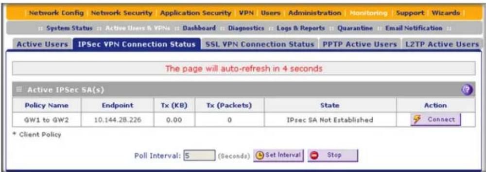
Figure 177.
The Active IPSec SA(s) table lists each active connection with the information that is described in the following table. The default poll interval is 5 seconds. To change the poll interval period, enter a new value in the Poll Interval field, and then click the Set Interval button. To stop polling, click the Stop button.
Table 70. IPSec VPN Connection Status screen information
| Setting Description | |
| Policy Name The name of the VPN policy that is associated with this SA. | |
| Endpoint The IP address on the remote VPN endpoint. | |
| Tx (KB) The amount of data that is transmitted over this SA. | |
| Tx (Packets) The number of IP packets that are transmitted over this SA. | |
| State | The status of the SA. Phase 1 is the authentication phase, and Phase 2 is key exchange phase. If there is no connection, the status is IPSec SA Not Established. |
| Action | Click the Connect table button to build the connection, or click the Disconnect table button to terminate the connection. |
View the UTM IPSec VPN Log
To query the IPSec VPN log:
- Select Monitoring > Logs & Reports > Logs Query. The Logs Query screen displays.
- From the Log Type drop-down list, select IPSEC VPN. The IPSec VPN logs display.
| Date | Content |
| 2012-09-24 20:24:29 | [UTM9S] Phase 2 negotiation failed due to time up waiting for phase1. ESP 208.87.34.15->192.1 |
| 2012-09-24 20:23:58 | [UTM9S] Setting DPD Vendor ID_ |
| 2012-09-24 20:23:58 | [UTM9S] Beginning Identity Protection mode._ |
| 2012-09-24 20:23:58 | [UTM9S] Initiating new phase 1 negotiation: 192.168.100.198[500]<=>208.87.34.15[5C |
| 2012-09-24 20:23:58 | [UTM9S] remote configuration for identifier "remote.com" found_ |
| 2012-09-24 20:23:58 | [UTM9S] Using IPsec SA configuration: 192.168.1.0/24<->192.168.50.0/30_ |
| 2012-09-24 20:23:38 | [UTM9S] Phase 2 negotiation failed due to time up waiting for phase1. ESP 74.86.197.160->192.1 |
| 2012-09-24 20:23:33 | [UTM9S] Phase 1 negotiation failed due to time up for 74.86.197.160[500]. 1f1fbbb7ab66f0fe:0000 |
| 2012-09-24 20:23:07 | [UTM9S] remote configuration for identifier "remote.com" found_ |
| 2012-09-24 20:23:07 | [UTM9S] Using IPsec SA configuration: 192.168.1.0/24<->192.168.50.0/30_ |
| 2012-09-24 20:23:04 | [UTM9S] Phase 2 negotiation failed due to time up waiting for phase1, ESP 74.86.197.160->192.1 |
| 2012-09-24 20:22:33 | [UTM9S] Setting DPD Vendor ID_ |
| 2012-09-24 20:22:33 | [UTM9S] Beginning Identity Protection mode._ |
| 2012-09-24 20:22:33 | [UTM9S] Initiating new phase 1 negotiation: 192.168.100.198[500]<=>74.86.197.160[5c |
| 2012-09-24 20:22:33 | [UTM9S] remote configuration for identifier "remote.com" found_ |
Figure 178.
Manage IPSec VPN and IKE Policies
- Manage IKE Policies
- Manage VPN Policies
After you have used the VPN Wizard to set up a VPN tunnel, a VPN policy and an IKE policy are stored in separate policy tables. The name that you selected as the VPN tunnel connection name during the VPN Wizard setup identifies both the VPN policy and IKE policy. You can edit existing policies, or manually add new VPN and IKE policies directly in the policy tables.
Manage IKE Policies
The Internet Key Exchange (IKE) protocol performs negotiations between the two VPN gateways and provides automatic management of the keys that are used for IPSec connections. It is important to remember that:
- An automatically generated VPN policy (auto policy) needs to use the IKE negotiation protocol.
- A manually generated VPN policy (manual policy) cannot use the IKE negotiation protocol.
IKE policies are activated when the following situations occur:
-
The VPN policy selector determines that some traffic matches an existing VPN policy:
-
If the VPN policy is of an auto policy type, the IKE policy that is specified in the Auto Policy Parameters section of the Add VPN Policy screen (see Figure 182 on page 303) is used to start negotiations with the remote VPN gateway.
-
If the VPN policy is of a manual policy type, the settings that are specified in the Manual Policy Parameters section of the Add VPN Policy screen (see Figure 182 on page 303) are accessed, and the first matching IKE policy is used to start negotiations with the remote VPN gateway:
-
If negotiations fail, the next matching IKE policy is used.
-
If none of the matching IKE policies are acceptable to the remote VPN gateway, then a VPN tunnel cannot be established.
-
An IKE session is established, using the security association (SA) settings that are specified in a matching IKE policy:
-
Keys and other settings are exchanged.
- An IPSec SA is established, using the settings that are specified in the VPN policy.
The VPN tunnel is then available for data transfer.
When you use the VPN Wizard to set up a VPN tunnel, an IKE policy is established and populated in the List of IKE Policies, and is given the same name as the new VPN connection name. You can also edit exiting policies or add new IKE policies from the IKE Policies screen.
IKE Policies Screen
To access the IKE Policies screen:
Select VPN > IPSec VPN. The IPSec VPN submenu tabs display with the IKE Policies screen in view. (The following figure shows some examples.)
ProSecure Unified Threat Management (UTM) Appliance

Figure 179.
Each policy contains the data that are explained in the following table. These fields are explained in more detail in Table 72 on page 296.
Table 71. List of IKE Policies table information
| Setting Description | |
| Name The name that identifies the IKE policy. When you use the VPN Wizard to set up a VPN policy, an accompanying IKE policy is automatically created with the same name that you select for the VPN policy.Note: The name is not supplied to the remote VPN endpoint. | |
| Mode The exchange mode: Main or Aggressive. | |
| Local ID | The IKE/ISAKMP identifier of the UTM. The remote endpoint needs to have this value as its remote ID. |
| Remote ID | The IKE/ISAKMP identifier of the remote endpoint, which needs to have this value as its local ID. |
| Encr | The encryption algorithm that is used for the IKE security association (SA). This setting needs to match the setting on the remote endpoint. |
| Auth | The authentication algorithm that is used for the IKE SA. This setting needs to match the setting on the remote endpoint. |
| DH | The Diffie-Hellman (DH) group that is used when keys are exchanged. This setting needs to match the setting on the remote endpoint. |
To delete one or more IKE polices:
- Select the check box to the left of each policy that you want to delete, or click the Select All table button to select all IKE policies.
- Click the Delete table button.
For information about how to add or edit an IKE policy, see Manually Add or Edit an IKE Policy on page 294.
Note: You can delete or edit an IKE policy for which the VPN policy is active without first disabling or deleting the VPN policy. In earlier firmware releases of the UTM, you first had to disable or delete the VPN policy, but this restriction has been removed.
Manually Add or Edit an IKE Policy
To add an IKE policy manually:
- Select VPN > IPSec VPN. The IPSec VPN submenu tabs display with the IKE Policies screen in view (see the previous figure).
- Under the List of IKE Policies table, click the Add table button. The Add IKE Policy screen displays (see the following figure, which shows a multiple WAN port model screen). The WAN drop-down lists (next to Select Local Gateway) are shown on the Add IKE Policy screen for the multiple WAN port models but not on the Add IKE Policy screen for the single WAN port models.
ProSecure Unified Threat Management (UTM) Appliance
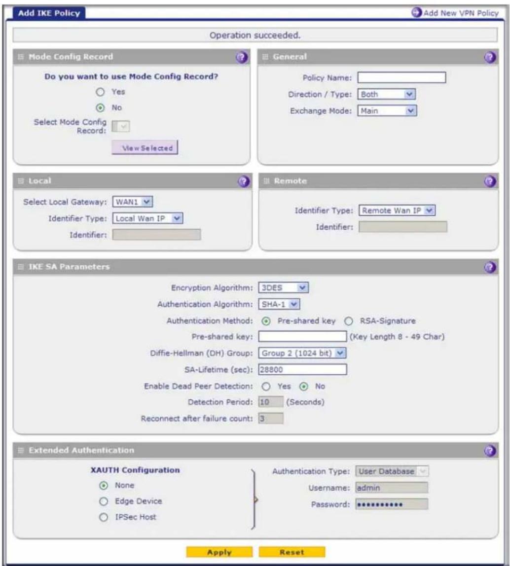
Figure 180.
- Complete the fields, select the radio buttons, and make your selections from the drop-down lists as explained in the following table:
Table 72. Add IKE Policy screen settings
| Setting Description | ||
| Mode Config Record | ||
| Do you want to use Mode Config Record? | Specify whether the IKE policy uses a Mode Config record. For information about how to define a Mode Config record, seeMode Config Operationon page 312. Select one of the following radio buttons:Yes. IP addresses are assigned to remote VPN clients. You need to select a Mode Config record from the drop-down list.Because Mode Config functions only in Aggressive mode, selecting the Yes radio button sets the tunnel exchange mode to Aggressive mode and disables the Main mode. Mode Config also requires that both the local and remote endpoints are defined by their FQDNs.No. Disables Mode Config for this IKE policy. | |
| Select Mode Config Record | From the drop-down list, select one of the Mode Config records that you defined on the Add Mode Config Record screen (seeConfigure Mode Config Operation on the UTM on page 312).Note:Click theView Selectedbutton to open the Selected Mode Config Record Details pop-up screen. | |
| General | ||
| Policy Name | A descriptive name of the IKE policy for identification and management purposes.Note:The name is not supplied to the remote VPN endpoint. | |
| Direction / Type From the | drop-down list, select the connection method for the UTM:Initiator.The UTM initiates the connection to the remote endpoint.Responder.The UTM responds only to an IKE request from the remote endpoint.Both.The UTM can both initiate a connection to the remote endpoint and respond to an IKE request from the remote endpoint. | |
| Exchange Mode | From the drop-down list, select the mode of exchange between the UTM and the remote VPN endpoint:Main.This mode is slower than the Aggressive mode but more secure.Aggressive.This mode is faster than the Main mode but less secure.Note:If you specify either an FQDN or a user FQDN name as the local ID or remote ID (see the Identifier Type sections later in this table), the Aggressive mode is automatically selected. | |
| Local | ||
| Select Local Gateway (multiple WAN port models only) | Select a WAN interface from the drop-down list to specify the WAN interface for the local gateway. | |
| Identifier Type | From the drop-down list, select one of the following ISAKMP identifiers to be used by the UTM, and then specify the identifier in the Identifier field:Local WAN IP. The WAN IP address of the UTM. When you select this option, the Identifier field automatically shows the IP address of the selected WAN interface.FQDN. The Internet address for the UTM.User FQDN. The email address for a local VPN client or the UTM.DER ASN1 DN. A distinguished name (DN) that identifies the UTM in the DER encoding and ASN.1 format. | |
| Identifier Depending on the selection of the Identifier Type drop-down list, enter the IP address, email address, FQDN, or distinguished name. | ||
| Remote | ||
| Identifier Type | From the drop-down list, select one of the following ISAKMP identifiers to be used by the remote endpoint, and then specify the identifier in the Identifier field:Remote WAN IP. The WAN IP address of the remote endpoint. When you select this option, the Identifier field automatically shows the IP address of the selected WAN interface.FQDN. The FQDN for a remote gateway.User FQDN. The email address for a remote VPN client or gateway.DER ASN1 DN. A distinguished name (DN) that identifies the remote endpoint in the DER encoding and ASN.1 format. | |
| Identifier Depending on the selection of the Identifier Type drop-down list, enter the IP address, email address, FQDN, or distinguished name. | ||
| IKE SA Parameters | ||
| Encryption Algorithm From the drop-down list, select one of the following five algorithms to negotiate the security association (SA):DES. Data Encryption Standard (DES).3DES. Triple DES. This is the default algorithm.AES-128. Advanced Encryption Standard (AES) with a 128-bit key size.AES-192. AES with a 192-bit key size.AES-256. AES with a 256-bit key size. | ||
| Authentication Algorithm | From the drop-down list, select one of the following algorithms to use in the VPN header for the authentication process:SHA-1. Hash algorithm that produces a 160-bit digest. This is the default setting.MD5. Hash algorithm that produces a 128-bit digest.AES-256. AES with a 256-bit key size.AES-512. AES with a 512-bit key size. | |
| Authentication Method | Select one of the following radio buttons to specify the authentication method:Pre-shared key.A secret that is shared between the UTM and the remote endpoint.RSA-Signature.Uses the active self-signed certificate that you uploaded on the Certificates screen (see Manage Self-Signed Certificates on page 422).The pre-shared key is masked out when you select RSA-Signature. | |
| Pre-shared key A key with a minimum length of 8 characters and no more than 49 characters. Do not use a double quote (“) in the key. | ||
| Diffie-Hellman (DH) Group | The DH Group sets the strength of the algorithm in bits. The higher the group, the more secure the exchange. From the drop-down list, select one of the following strengths:Group 1 (768 bit).Group 2 (1024 bit). This is the default setting.Group 5 (1536 bit).Group 14 (2048 bit).Group 15 (3072 bit).Group 16 (4096 bit).Note:Ensure that the DH Group is configured identically on both sides. | |
| SA-Lifetime (sec) The period in seconds for which the IKE SA is valid. When the period times out, the next rekeying occurs. The default is 28800 seconds (8 hours). | ||
| Enable Dead Peer DetectionNote:See also Configure Keep- Alives and Dead Peer Detection on page 328. | Select a radio button to specify whether Dead Peer Detection (DPD) is enabled:Yes.This feature is enabled. When the UTM detects an IKE connection failure, it deletes the IPSec and IKE SA and forces a reestablishment of the connection. You need to specify the detection period in the Detection Period field and the maximum number of times that the UTM attempts to reconnect in the Reconnect after failure count field.No.This feature is disabled. This is the default setting. | |
| Detection Period The period in seconds between consecutive DPD R-U-THERE messages, which are sent only when the IPSec traffic is idle. | ||
| Reconnect after failure count | The maximum number of DPD failures before the UTM tears down the connection and then attempts to reconnect to the peer. The default is 3 failures. | |
| Extended Authentication | ||
| XAUTH ConfigurationNote: For more information about XAUTH and its authentication modes, see Configure XAUTH for VPN Clients on page 309. | Select one of the following radio buttons to specify whether Extended Authentication (XAUTH) is enabled, and, if enabled, which device is used to verify user account information:None. XAUTH is disabled. This the default setting.Edge Device. The UTM functions as a VPN concentrator on which one or more gateway tunnels terminate. The authentication modes that are available for this configuration are User Database, RADIUS PAP, or RADIUS CHAP.IPSec Host. The UTM functions as a VPN client of the remote gateway. In this configuration, the UTM is authenticated by a remote gateway with a user name and password combination. | |
| Authentication Type | For an Edge Device configuration, from the drop-down list, select one of the following authentication types:User Database. XAUTH occurs through the UTM's user database. You can add users on the Add User screen (see User Database Configuration on page 310).Radius PAP. XAUTH occurs through RADIUS Password Authentication Protocol (PAP). The local user database is first checked. If the user account is not present in the local user database, the UTM connects to a RADIUS server. For more information, see RADIUS Client and Server Configuration on page 310.Radius CHAP. XAUTH occurs through RADIUS Challenge Handshake Authentication Protocol (CHAP). For more information, see RADIUS Client and Server Configuration on page 310. | |
| Username The user | name for XAUTH. | |
| Password The password for XAUTH. | ||
- Click Apply to save your settings. The IKE policy is added to the List of IKE Policies table.
To edit an IKE policy:
- Select VPN > IPSec VPN. The IPSec VPN submenu tabs display with the IKE Policies screen in view (see Figure 179 on page 293).
- In the List of IKE Policies table, click the Edit table button to the right of the IKE policy that you want to edit. The Edit IKE Policy screen displays. This screen shows the same fields as the Add IKE Policy screen (see Figure 180 on page 295).
- Modify the settings that you wish to change (see the previous table).
- Click Apply to save your changes. The modified IKE policy is displayed in the List of IKE Policies table.
Manage VPN Policies
You can create two types of VPN policies. When you use the VPN Wizard to create a VPN policy, only the Auto method is available.
- Manual. You manually enter all settings (including the keys) for the VPN tunnel on the UTM and on the remote VPN endpoint. No third-party server or organization is involved.
- Auto. Some settings for the VPN tunnel are generated automatically through the use of the IKE (Internet Key Exchange) Protocol to perform negotiations between the two VPN endpoints (the local ID endpoint and the remote ID endpoint). You still need to enter all settings on the remote VPN endpoint manually (unless the remote VPN endpoint also has a VPN Wizard).
In addition, a certification authority (CA) can also be used to perform authentication (see Manage Digital Certificates for VPN Connections on page 419). For gateways to use a CA, each VPN gateway needs to have a certificate from the CA. For each certificate, there is both a public key and a private key. The public key is freely distributed, and is used by any sender to encrypt data intended for the receiver (the key owner). The receiver then uses its private key to decrypt the data (without the private key, decryption is impossible). The use of certificates for authentication reduces the amount of data entry that is required on each VPN endpoint.
VPN Policies Screen
The VPN Policies screen allows you to add additional policies—either Auto or Manual—and to manage the VPN policies already created. You can edit policies, enable or disable policies, or delete them entirely. These are the rules for VPN policy use:
- Traffic covered by a policy is automatically sent through a VPN tunnel.
- When traffic is covered by two or more policies, the first matching policy is used. (In this situation, the order of the policies is important. However, if you have only one policy for each remote VPN endpoint, then the policy order is not important.)
• The VPN tunnel is created according to the settings in the security association (SA). - The remote VPN endpoint needs to have a matching SA; otherwise, it refuses the connection.
To access the VPN Policies screen, select VPN > IPSec VPN > VPN Policies. The VPN Policies screen displays. (The following figure shows some examples.)
ProSecure Unified Threat Management (UTM) Appliance

Figure 181.
Each policy contains the data that are explained in the following table. These fields are explained in more detail in Table 74 on page 304.
Table 73. List of VPN Policies table information
| Setting Description | |
| I (Status) Indicates wh | ether the policy is enabled (green circle) or disabled (gray circle). To enable or disable a policy, select the check box next to the circle, and click the Enable or Disable table button, as appropriate. |
| Name The name that | identifies the VPN policy. When you use the VPN Wizard to create a VPN policy, the name of the VPN policy (and of the automatically created accompanying IKE policy) is the connection name. |
| Type | Auto or Manual as described previously (Auto is used during VPN Wizard configuration). |
| Local IP address (either a single address, range of address, or subnet address) on your LAN. Traffic needs to be from (or to) these addresses to be covered by this policy. (The subnet address is supplied as the default IP address when you are using the VPN Wizard.) | |
| Remote | IP address or address range of the remote network. Traffic needs to be to (or from) these addresses to be covered by this policy. (The VPN Wizard default requires the remote LAN IP address and subnet mask.) |
| Auth | The authentication algorithm that is used for the VPN tunnel. This setting needs to match the setting on the remote endpoint. |
| Encr The encryption al | algorithm that is used for the VPN tunnel. This setting needs to match the setting on the remote endpoint. |
To delete one or more VPN polices:
- Select the check box to the left of each policy that you want to delete, or click the Select All table button to select all VPN policies.
- Click the Delete table button.
To enable or disable one or more VPN policies:
- Select the check box to the left of each policy that you want to enable or disable, or click the Select All table button to select all VPN policies.
- Click the Enable or Disable table button.
For information about how to add or edit a VPN policy, see Manually Add or Edit a VPN Policy on this page.
Note: You can delete or edit an IKE policy for which the VPN policy is active without first disabling or deleting the VPN policy. In earlier firmware releases of the UTM, you first had to disable or delete the VPN policy, but this restriction has been removed.
Manually Add or Edit a VPN Policy
To add a VPN policy manually:
- Select VPN > IPSec VPN > VPN Policies. The VPN Policies screen displays (see Figure 181 on page 301).
- Under the List of VPN Policies table, click the Add table button. The Add VPN Policy screen displays (see the following figure, which shows the UTM50 screen). The WAN drop-down list (next to Select Local Gateway) is shown on the Add VPN Policy screen for the multiple WAN port models but not on the Add VPN Policy screen for the single WAN port models.
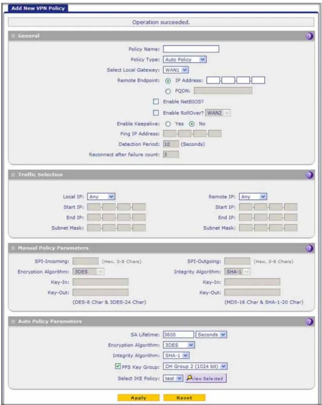
Figure 182.
- Complete the fields, select the radio buttons and check boxes, and make your selections from the drop-down lists as explained in the following table:
Table 74. Add New VPN Policy screen settings
| Setting Description | ||
| General | ||
| Policy Name A descriptive | name of the VPN policy for identification and management purposes. Note: The name is not supplied to the remote VPN endpoint. | |
| Policy Type From the drop-down list, select one of the following policy types: Auto Policy. Some settings (the ones in the Manual Policy Parameters section of the screen) for the VPN tunnel are generated automatically. Manual Policy. All settings need to be specified manually, including the ones in the Manual Policy Parameters section of the screen. | ||
| Select Local Gateway (multiple WAN port models only) | Select a WAN interface from the drop-down list to specify the WAN interface for the local gateway. | |
| Remote Endpoint Select a radio button to specify how the remote endpoint is defined: IP Address. Enter the IP address of the remote endpoint in the fields to the right of the radio button. FQDN. Enter the FQDN of the remote endpoint in the field to the right of the radio button. | ||
| Enable NetBIOS? Select this check box to allow NetBIOS broadcasts to travel over the VPN tunnel. For more information about NetBIOS, see Configure NetBIOS Bridging with IPSec VPN on page 330. This feature is disabled by default. | ||
| Enable RollOver? | Select this check box to allow the VPN tunnel to roll over to the other WAN interface when the WAN mode is set to Auto-Rollover and an actual rollover occurs. This feature is disabled by default. For the multiple WAN port models only: Select a WAN interface from the drop-down list. | |
| Enable KeepaliveNote: See also Configure Keep-ALives and Dead Peer Detection on page 328. | Select a radio button to specify if keep-alive is enabled:Yes. This feature is enabled: Periodically, the UTM sends keep-alive requests (ping packets) to the remote endpoint to keep the tunnel alive. You need to specify the ping IP address in the Ping IP Address field, the detection period in the Detection Period field, and the maximum number of keep-alive requests that the UTM sends in the Reconnect after failure count field.No. This feature is disabled. This is the default setting. | |
| Ping IP Address The IP address that the UTM pings. The address needs to be of a host that can respond to ICMP ping requests. | ||
| Detection Period The period in seconds between the keep-alive requests. The default setting is 10 seconds. | ||
| Reconnect after failure count | The maximum number of keep-alive requests before the UTM tears down the connection and then attempts to reconnect to the remote endpoint. The default setting is 3 keep-alive requests. | |
| Traffic Selection | ||
| Local IP | From the drop-down list, select the address or addresses that are part of the VPN tunnel on the UTM:Any. All computers and devices on the network.Single. A single IP address on the network. Enter the IP address in the Start IP Address field.Range. A range of IP addresses on the network. Enter the starting IP address in the Start IP Address field and the ending IP address in the End IP Address field.Subnet. A subnet on the network. Enter the starting IP address in the Start IP Address field and the subnet mask in the Subnet Mask field.Note: You cannot select Any for both the UTM and the remote endpoint. | |
| Remote IP | From the drop-down list, select the address or addresses that are part of the VPN tunnel on the remote endpoint. The selections are the same as for the Local IP drop-down list. | |
| Manual Policy ParametersNote: These fields apply only when you select Manual Policy as the policy type. When you specify the settings for the fields in this section, a security association (SA) is created. | ||
| SPI-Incoming The Security | Parameters Index (SPI) for the inbound policy. Enter a hexadecimal value between 3 and 8 characters (for example, 0x1234). | |
| Encryption Algorithm | From the drop-down list, select one of the following five algorithms to negotiate the security association (SA):DES. Data Encryption Standard (DES).3DES. Triple DES. This is the default algorithm.AES-128. Advanced Encryption Standard (AES) with a 128-bit key size.AES-192. AES with a 192-bit key size.AES-256. AES with a 256-bit key size. | |
| Key-In The encryption key | for the inbound policy. The length of the key depends on the selected encryption algorithm:DES. Enter 8 characters.3DES. Enter 24 characters.AES-128. Enter 16 characters.AES-192. Enter 24 characters.AES-256. Enter 32 characters. | |
| Key-Out The encryption key | for the outbound policy. The length of the key depends on the selected encryption algorithm:DES. Enter 8 characters.3DES. Enter 24 characters.AES-128. Enter 16 characters.AES-192. Enter 24 characters.AES-256. Enter 32 characters. | |
| SPI-Outgoing The Security | Parameters Index (SPI) for the outbound policy. Enter a hexadecimal value between 3 and 8 characters (for example, 0x1234). | |
| Integrity Algorithm | From the drop-down list, select one of the following algorithms to be used in the VPN header for the authentication process:SHA-1. Hash algorithm that produces a 160-bit digest. This is the default setting.MD5. Hash algorithm that produces a 128-bit digest.SHA-256. Hash algorithm that produces a 256-bit key size.SHA-512. Hash algorithm that produces a 512-bit key size. | |
| Key-In The integrity key for | the inbound policy. The length of the key depends on the selected integrity algorithm:MD5. Enter 16 characters.SHA-1. Enter 20 characters.SHA-256. Enter 32 characters.SHA-512. Enter 64 characters. | |
| Key-Out The integrity key | for the outbound policy. The length of the key depends on the selected integrity algorithm:MD5. Enter 16 characters.SHA-1. Enter 20 characters.SHA-256. Enter 32 characters.SHA-512. Enter 64 characters. | |
| Auto Policy ParametersNote: These fields apply only when you select Auto Policy as the policy type. | ||
| SA Lifetime The lifetime of | the security association (SA) is the period or the amount of transmitted data after which the SA becomes invalid and needs to be renegotiated. From the drop-down list, select how the SA lifetime is specified:Seconds. In the SA Lifetime field, enter a period in seconds. The minimum value is 300 seconds. The default value is 3600 seconds.KBytes. In the SA Lifetime field, enter a number of kilobytes. The minimum value is 1920000 KB. | |
| Encryption Algorithm | From the drop-down list, select one of the following five algorithms to negotiate the security association (SA):DES. Data Encryption Standard (DES).3DES. Triple DES. This is the default algorithm.AES-128. Advanced Encryption Standard (AES) with a 128-bit key size.AES-192. AES with a 192-bit key size.AES-256. AES with a 256-bit key size. | |
| Integrity Algorithm From the | the drop-down list, select one of the following algorithms to be used in the VPN header for the authentication process:SHA-1. Hash algorithm that produces a 160-bit digest. This is the default setting.MD5. Hash algorithm that produces a 128-bit digest.AES-256. Hash algorithm that produces a 256-bit digest.AES-512. Hash algorithm that produces a 512-bit digest. | |
| PFS Key Group | Select this check box to enable Perfect Forward Secrecy (PFS), and then select a Diffie-Hellman (DH) group from the drop-down list. The DH Group sets the strength of the algorithm in bits. The higher the group, the more secure the exchange. From the drop-down list, select one of the following strengths:Group 1 (768 bit).Group 2 (1024 bit). This is the default setting.Group 5 (1536 bit).Group 14 (2048 bit).Group 15 (3072 bit).Group 16 (4096 bit). | |
| Select IKE Policy | Select an existing IKE policy that defines the characteristics of the Phase-1 negotiation. To display the selected IKE policy, click theView Selectedbutton. | |
- Click Apply to save your settings. The VPN policy is added to the List of VPN Policies table.
To edit a VPN policy:
- Select VPN > IPSec VPN > VPN Policies. The VPN Policies screen displays (see Figure 181 on page 301).
- In the List of VPN Policies table, click the Edit table button to the right of the VPN policy that you want to edit. The Edit VPN Policy screen displays. This screen shows the same fields as the Add VPN Policy screen (see Figure 182 on page 303).
- Modify the settings that you wish to change (see the previous table).
- Click Apply to save your changes. The modified VPN policy is displayed in the List of VPN Policies table.
Configure Extended Authentication (XAUTH)
- Configure XAUTH for VPN Clients
- User Database Configuration
• RADIUS Client and Server Configuration
When many VPN clients connect to a UTM, you might want to use a unique user authentication method beyond relying on a single common pre-shared key for all clients. Although you could configure a unique VPN policy for each user, it is more efficient to authenticate users from a stored list of user accounts. XAUTH provides the mechanism for requesting individual authentication information from the user. A local user database or an external authentication server, such as a RADIUS server, provides a method for storing the authentication information centrally in the local network.
You can enable XAUTH when you manually add or edit an IKE policy. Two types of XAUTH are available:
- Edge Device. The UTM is used as a VPN concentrator on which one or more gateway tunnels terminate. You need to specify the authentication type that should be used during verification of the credentials of the remote VPN gateways: the user database, RADIUS-PAP, or RADIUS-CHAP.
- IPSec Host. Authentication by the remote gateway through a user name and password that are associated with the IKE policy. The user name and password that are used to authenticate the UTM need to be specified on the remote gateway.
Note: If a RADIUS-PAP server is enabled for authentication, XAUTH first checks the local user database for the user credentials. If the user account is not present, the UTM then connects to a RADIUS server.
Configure XAUTH for VPN Clients
Once the XAUTH has been enabled, you need to establish user accounts in the user database to be authenticated against XAUTH, or you need to enable a RADIUS-CHAP or RADIUS-PAP server.
Note: You cannot modify an existing IKE policy to add XAUTH while the IKE policy is in use by a VPN policy. The VPN policy needs to be disabled before you can modify the IKE policy.
To enable and configure XAUTH:
- Select VPN > IPSec VPN. The IPSec VPN submenu tabs display with the IKE Policies screen in view (see Figure 179 on page 293).
- In the List of IKE Policies table, click the Edit table button to the right of the IKE policy for which you want to enable and configure XAUTH. The Edit IKE Policy screen displays. This screen shows the same fields as the Add IKE Policy screen (see Figure 180 on page 295).
- In the Extended Authentication section onscreen, complete the fields, select the radio buttons, and make your selections from the drop-down lists as explained in the following table:
Table 75. Extended authentication settings
| Setting Description | |
| Select one of the following radio buttons to specify whether Extended Authentication (XAUTH) is enabled, and, if enabled, which device is used to verify user account information:None. XAUTH is disabled. This the default setting.Edge Device. The UTM functions as a VPN concentrator on which one or more gateway tunnels terminate. The authentication modes that are available for this configuration are User Database, RADIUS PAP, and RADIUS CHAP.IPSec Host. The UTM functions as a VPN client of the remote gateway. In this configuration the, UTM is authenticated by a remote gateway with a user name and password combination. | |
| Authentication Type | For an Edge Device configuration, from the drop-down list, select one of the following authentication types:User Database. XAUTH occurs through the UTM's user database. You can add users on the Add User screen (seeUser Database Configurationon page 310).Radius PAP. XAUTH occurs through RADIUS Password Authentication Protocol (PAP). The local user database is first checked. If the user account is not present in the local user database, the UTM connects to a RADIUS server. For more information, seeRADIUS Client and Server Configurationon page 310.Radius CHAP. XAUTH occurs through RADIUS Challenge Handshake Authentication Protocol (CHAP). For more information, seeRADIUS Client and Server Configurationon page 310. |
| Username The user name for XAUTH. | |
| Password The password for XAUTH. | |
- Click Apply to save your settings.
User Database Configuration
When XAUTH is enabled in an Edge Device configuration, users need to be authenticated either by a local user database account or by an external RADIUS server. Whether or not you use a RADIUS server, you might want some users to be authenticated locally. These users need to be added to the List of Users table on the Users screen, as described in Configure User Accounts on page 401.
RADIUS Client and Server Configuration
Remote Authentication Dial In User Service (RADIUS, RFC 2865) is a protocol for managing authentication, authorization, and accounting (AAA) of multiple users in a network. A RADIUS server stores a database of user information and can validate a user at the request of a gateway or server in the network when a user requests access to network resources. During the establishment of a VPN connection, the VPN gateway can interrupt the process with an XAUTH request. At that point, the remote user needs to provide authentication information such as a user name and password or some encrypted response using his or her user name and password information. The gateway then attempts to verify this information first against a local user database (if RADIUS-PAP is enabled) and then by relaying the information to a central authentication server such as a RADIUS server.
To configure primary and backup RADIUS servers:
- Select VPN > IPSec VPN > RADIUS Client. The RADIUS Client screen displays:

Figure 183.
- Complete the fields and select the radio buttons as explained in the following table:
Table 76. RADIUS Client screen settings
| Setting Description | |
| Primary RADIUS Server | |
| To enable and configure the primary RADIUS server, select theYesradio button, and then enter the settings for the three fields to the right. The default setting is that the No radio button is selected. | |
| Primary Server IP Address | The IP address of the primary RADIUS server. |
| Secret Phrase A shared secret phrase to authenticate the transactions between the client and the primary RADIUS server. The same secret phrase needs to be configured on both the client and the server. | |
| Primary Server NAS Identifier | The primary network access server (NAS) identifier that needs to be present in a RADIUS request.Note:The UTM functions as an NAS, allowing network access to external users after verification of their authentication information. In a RADIUS transaction, the NAS needs to provide some NAS identifier information to the RADIUS server. Depending on the configuration of the RADIUS server, the UTM's IP address might be sufficient as an identifier, or the server might require a name, which you need to enter in this field. |
| Backup RADIUS Server | |
| To enable and configure the backup RADIUS server, select theYesradio button, and then enter the settings for the three fields to the right. The default setting is that the No radio button is selected. | |
| Backup Server IP Address | The IP address of the backup RADIUS server. |
| Secret Phrase A shared secret phrase to authenticate the transactions between the client and the backup RADIUS server. The same secret phrase needs to be configured on both the client and the server. | |
| Backup Server NAS Identifier | The backup network access server (NAS) identifier that needs to be present in a RADIUS request.Note:See the note earlier in this table for the Primary Server NAS Identifier. |
| Connection Configuration | |
| Time out period The period in seconds that the UTM waits for a response from a RADIUS server. | |
| Maximum Retry Counts The maximum number of times that the UTM attempts to connect to a RADIUS server. | |
- Click Apply to save your settings.
Note: You can select the RADIUS authentication protocol (PAP or CHAP) on the Edit IKE Policy screen or Add IKE Policy screen (see Configure XAUTH for VPN Clients on page 309).
Assign IP Addresses to Remote Users (Mode Config)
- Mode Config Operation
- Configure Mode Config Operation on the UTM
- Configure the ProSafe VPN Client for Mode Config Operation
- Test the Mode Config Connection
- Modify or Delete a Mode Config Record
To simplify the process of connecting remote VPN clients to the UTM, use the Mode Config feature to assign IP addresses to remote users automatically, including a network access IP address, subnet mask, WINS server, and DNS address. Remote users are given IP addresses available in a secured network space so that remote users appear as seamless extensions of the network.
Mode Config Operation
After the IKE Phase 1 negotiation is complete, the VPN connection initiator (which is the remote user with a VPN client) requests the IP configuration settings such as the IP address, subnet mask, WINS server, and DNS address from the UTM. The Mode Config feature allocates an IP address from the configured IP address pool and activates a temporary IPSec policy, using the information that is specified in the Traffic Tunnel Security Level section of the Mode Config record (on the Add Mode Config Record screen that is shown in Figure 185 on page 314).
Note: After configuring a Mode Config record, you need to configure an IKE policy manually, and select the newly created Mode Config record from the Select Mode Config Record drop-down list (see Configure Mode Config Operation on the UTM on page 312). You do not need to change any VPN policy.
Note: An IP address that is allocated to a VPN client is released only after the VPN client has gracefully disconnected or after the SA lifetime for the connection has timed out.
Configure Mode Config Operation on the UTM
To configure Mode Config on the UTM, first create a Mode Config record, and then select the Mode Config record for an IKE policy.
To configure Mode Config on the UTM:
- Select VPN > IPSec VPN > Mode Config. The Mode Config screen displays:

Figure 184.
As an example, the screen shows two Mode Config records with the names EMEA Sales and NA Sales:
- For EMEA Sales, a first pool (172.16.100.1 through 172.16.100.99) and second pool (172.16.200.1 through 172.16.200.99) are shown.
-
For NA Sales, a first pool (172.25.100.50 through 172.25.100.99), a second pool (172.25.210.1 through 172.25.210.99), and a third pool (172.25.220.80 through 172.25.220.99) are shown.
-
Under the List of Mode Config Records table, click the Add table button. The Add Mode Config Record screen displays:
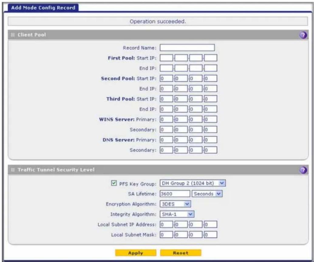
Figure 185.
- Complete the fields, select the check box, and make your selections from the drop-down lists as explained in the following table:
Table 77. Add Mode Config Record screen settings
| Setting Description | |
| Client Pool | |
| Record Name A descriptive name of the Mode Config record for identification and management purposes. | |
| First Pool | Assign at least one range of IP pool addresses in the First Pool fields to enable the UTM to allocate these to remote VPN clients. The Second Pool and Third Pool fields are optional. To specify any client pool, enter the starting IP address for the pool in the Starting IP field, and enter the ending IP address for the pool in the Ending IP field.Note: No IP pool should be within the range of the local network IP addresses. Use a different range of private IP addresses such as 172.173.xxx.xx. |
| Second Pool | |
| Third Pool | |
| WINS Server | If there is a WINS server on the local network, enter its IP address in the Primary field. You can enter the IP address of a second WINS server in the Secondary field. |
| Setting | Description |
| DNS Server | Enter the IP address of the DNS server that is used by remote VPN clients in the Primary field. You can enter the IP address of a second DNS server in the Secondary field. |
| Traffic Tunnel Security LevelNote: Generally, the default settings work well for a Mode Config configuration. | |
| PFS Key Group | Select this check box to enable Perfect Forward Secrecy (PFS), and then select a Diffie-Hellman (DH) group from the drop-down list. The DH Group sets the strength of the algorithm in bits. The higher the group, the more secure the exchange. From the drop-down list, select one of the following three strengths:Group 1 (768 bit)Group 2 (1024 bit). This is the default setting.Group 5 (1536 bit) |
| SA Lifetime The lifetime | of the security association (SA) is the period or the amount of transmitted data after which the SA becomes invalid and needs to be renegotiated. From the drop-down list, select how the SA lifetime is specified:Seconds. In the SA Lifetime field, enter a period in seconds. The minimum value is 300 seconds. The default value is 3600 seconds.KBytes. In the SA Lifetime field, enter a number of kilobytes. The minimum value is 1920000 KB. |
| Encryption Algorithm | From the drop-down list, select one of the following five algorithms to negotiate the security association (SA):DES. Data Encryption Standard (DES).3DES. Triple DES. This is the default algorithm.AES-128. Advanced Encryption Standard (AES) with a 128-bit key size.AES-192. AES with a 192-bit key size.AES-256. AES with a 256-bit key size. |
| Integrity Algorithm From | the drop-down list, select one of the following two algorithms to be used in the VPN header for the authentication process:SHA-1. Hash algorithm that produces a 160-bit digest. This is the default setting.MD5. Hash algorithm that produces a 128-bit digest. |
| Local IP Address The | local IP address to which remote VPN clients have access. If you do not specify a local IP address, the UTM's default LAN IP address is used (by default, 192.168.1.1). |
| Local Subnet Mask | The local subnet mask. Typically, this is 255.255.255.0. |
- Click Apply to save your settings. The new Mode Config record is added to the List of Mode Config Records table.
Continue the Mode Config configuration procedure by configuring an IKE policy.
-
Select VPN > IPSec VPN. The IPSec VPN submenu tabs display with the IKE Policies screen in view (see Figure 179 on page 293).
-
Under the List of IKE Policies table, click the Add table button. The Add IKE Policy screen displays. (The following figure shows the upper part only of a multiple WAN port model screen.) The WAN drop-down list (next to Select Local Gateway) is shown on the Add IKE Policy screen for the multiple WAN port models but not on the Add IKE Policy screen for the single WAN port models.

Figure 186.
- On the Add IKE Policy screen, complete the fields, select the radio buttons, and make your selections from the drop-down lists as explained in the following table.
Note: The IKE policy settings that are explained in the following table are specifically for a Mode Config configuration. Table 72 on page 296 explains the general IKE policy settings.
Table 78. IKE policy settings for a Mode Config configuration
| Setting Description | ||
| Mode Config Record | ||
| Do you want to use Mode Config Record? | Select the Yes radio button. Note: Because Mode Config functions only in Aggressive mode, selecting the Yes radio button sets the tunnel exchange mode to Aggressive mode. Mode Config also requires that both the local and remote endpoints are defined by their FQDNs. | |
| Select Mode Config Record | From the drop-down list, select the Mode Config record that you created in Step 4 on page 315. This example uses NA Sales. | |
| General | ||
| Policy Name A descriptive name of the IKE policy for identification and management purposes. This example uses ModeConfigNA_Sales. Note: The name is not supplied to the remote VPN endpoint. | ||
| Direction / Type | Responder is automatically selected when you select the Mode Config record in the Mode Config Record section of the screen. This ensures that the UTM responds to an IKE request from the remote endpoint but does not initiate one. | |
| Exchange Mode Aggressive mode is automatically selected when you select the Mode Config record in the Mode Config Record section of the screen. | ||
| Local | ||
| Select Local Gateway (multiple WAN port models only) | Select a WAN interface from the drop-down list to specify the WAN interface for the local gateway. | |
| Identifier Type From the drop-down list, select FQDN. Note: Mode Config requires that the UTM (that is, the local endpoint) is defined by an FQDN. | ||
| Identifier Enter an FQDN for the UTM. This example uses router.com. | ||
| Remote | ||
| Identifier Type From the drop-down list, select FQDN. Note: Mode Config requires that the remote endpoint is defined by an FQDN. | ||
| IKE SA ParametersNote: Generally, the default settings work well for a Mode Config configuration. | ||
| Encryption Algorithm | To negotiate the security association (SA), from the drop-down list, select the 3DES algorithm. | |
| Authentication Algorithm | From the drop-down list, select the SHA-1 algorithm to be used in the VPN header for the authentication process. | |
| Authentication Method | Select Pre-shared key as the authentication method, and enter a key in the Pre-shared key field. | |
| Pre-shared key A key with a minimum length of 8 characters and no more than 49 characters. Do not use a double quote (“) in the key. This example uses H8!spsf3#JYK2!. | ||
| Diffie-Hellman (DH) Group | The DH Group sets the strength of the algorithm in bits. From the drop-down list, select Group 2 (1024 bit). | |
| SA-Lifetime (sec) The period in seconds for which the IKE SA is valid. When the period times out, the next rekeying occurs. The default setting is 28800 seconds (8 hours). However, for a Mode Config configuration, NETGEAR recommends 3600 seconds (1 hour). | ||
| Enable Dead Peer DetectionNote: See also Configure Keep-Alives and Dead Peer Detection on page 328. | Select a radio button to specify whether Dead Peer Detection (DPD) is enabled:Yes. This feature is enabled. When the UTM detects an IKE connection failure, it deletes the IPSec and IKE SA and forces a reestablishment of the connection. You need to specify the detection period in the Detection Period field and the maximum number of times that the UTM attempts to reconnect in the Reconnect after failure count field.No. This feature is disabled. This is the default setting. | |
| Detection Period The period in seconds between consecutive DPD R-U-THERE messages, which are sent only when the IPSec traffic is idle. The default setting is 10 seconds. This example uses 30 seconds. | ||
| Reconnect after failure count | The maximum number of DPD failures before the UTM tears down the connection and then attempts to reconnect to the peer. The default setting is 3 failures. | |
| Extended Authentication | ||
| XAUTH ConfigurationNote: For more information about XAUTH and its authentication modes, see Configure XAUTH for VPN Clients on page 309. | Select one of the following radio buttons to specify whether Extended Authentication (XAUTH) is enabled, and, if enabled, which device is used to verify user account information:None. XAUTH is disabled. This the default setting.Edge Device. The UTM functions as a VPN concentrator on which one or more gateway tunnels terminate. The authentication modes that are available for this configuration are User Database, RADIUS PAP, and RADIUS CHAP.IPSec Host. The UTM functions as a VPN client of the remote gateway. In this configuration, the UTM is authenticated by a remote gateway with a user name and password combination. | |
| Authentication Type | For an Edge Device configuration, from the drop-down list, select one of the following authentication types:User Database. XAUTH occurs through the UTM's user database. You can add users on the Add User screen (see User Database Configuration on page 310).Radius PAP. XAUTH occurs through RADIUS Password Authentication Protocol (PAP). The local user database is first checked. If the user account is not present in the local user database, the UTM connects to a RADIUS server. For more information, see RADIUS Client and Server Configuration on page 310.Radius CHAP. XAUTH occurs through RADIUS Challenge Handshake Authentication Protocol (CHAP). For more information, see RADIUS Client and Server Configuration on page 310. | |
| Username The user | name for XAUTH. | |
| Password The pass | word for XAUTH. | |
- Click Apply to save your settings. The IKE policy is added to the List of IKE Policies table.
Configure the ProSafe VPN Client for Mode Config Operation
When the Mode Config feature is enabled, the following information is negotiated between the VPN client and the UTM during the authentication phase:
• Virtual IP address of the VPN client
• DNS server address (optional)
• WINS server address (optional)
The virtual IP address that is issued by the UTM is displayed in the VPN Client Address field on the VPN client's IPSec pane.
Note: Perform these tasks from a computer that has the NETGEAR ProSafe VPN Client installed.
To configure the VPN client for Mode Config operation, create authentication settings (phase 1 settings), create an associated IPSec configuration (phase 2 settings), and then specify the global parameters.
Configure the Mode Config Authentication Settings (Phase 1 Settings)
To create new authentication settings:
- Right-click the VPN client icon in your Windows system tray, and select Configuration Panel. The Configuration Panel screen displays.

Figure 187.
- In the tree list pane of the Configuration Panel screen, right-click VPN Configuration, and select New Phase 1.
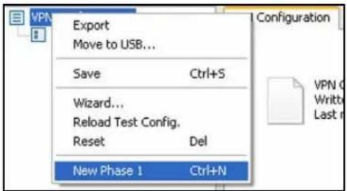
Figure 188.
- Change the name of the authentication phase (the default is Gateway):
a. Right-click the authentication phase name.
b. Select Rename.
c. Type GW_ModeConfig.
d. Click anywhere in the tree list pane.
Note: This is the name for the authentication phase that is used only for the VPN client, not during IKE negotiation. You can view and change this name in the tree list pane. This name needs to be a unique name.
The Authentication pane displays in the Configuration Panel screen, with the Authentication tab selected by default.

Figure 189.
- Specify the settings that are explained in the following table.
Table 79. VPN client authentication settings (Mode Config)
| Setting Description | ||
| Interface Select Any | from the drop-down list. | |
| Remote Gateway Enter | the remote IP address or DNS name of the UTM. For example, enter 10.34.116.22. | |
| Preshared Key | Select the Preshared Key radio button. Enter the pre-shared key that you already specified on the UTM. For example, enter H8!spsf3#JYK2!. Confirm the key in the Confirm field. | |
| IKE | Encryption | Select the 3DES encryption algorithm from the drop-down list. |
| Authentication | Select the SHA1 authentication algorithm from the drop-down list. | |
| Key Group | Select the DH2 (1024) key group from the drop-down list.Note: On the UTM, this key group is referred to as Diffie-Hellman Group 2 (1024 bit). | |
- Click Apply to use the new settings immediately, and click Save to keep the settings for future use.
- Click the Advanced tab in the Authentication pane. The Advanced pane displays.

Figure 190.
- Specify the settings that are explained in the following table.
Table 80. VPN client advanced authentication settings (Mode Config)
| Setting Description | |
| Advanced features | |
| Mode Config Select this | check box to enable Mode Config. |
| Aggressive Mode | Select this check box to enable aggressive mode as the mode of negotiation with the UTM. |
| NAT-T | Select Automatic from the drop-down list to enable the VPN client and UTM to negotiate NAT-T. |
| Local and Remote ID | |
| Local ID As the type of ID | , selectDNSfrom the Local ID drop-down list because you specified FQDN in the UTM configuration.As the value of the ID, enterclient.comas the local ID for the VPN client.Note:The remote ID on the UTM is the local ID on the VPN client. |
| Remote ID | As the type of ID, selectDNSfrom the Remote ID drop-down list because you specified an FQDN in the UTM configuration.As the value of the ID, enterrouter.comas the remote ID for the UTM.Note:The local ID on the UTM is the remote ID on the VPN client. |
- Click Apply to use the new settings immediately, and click Save to keep the settings for future use.
Create the Mode Config IPSec Configuration (Phase 2 Settings)
Note: On the UTM, the IPSec configuration (phase 2 settings) is referred to as the IKE settings.
To create an IPSec configuration:
- In the tree list pane of the Configuration Panel screen, right-click the GW_ModeConfig authentication phase name, and then select New Phase 2.
- Change the name of the IPSec configuration (the default is Tunnel):
a. Right-click the IPSec configuration name.
b. Select Rename.
c. Type Tunnel_ModeConfig.
d. Click anywhere in the tree list pane.
ProSecure Unified Threat Management (UTM) Appliance
Note: This is the name for the IPSec configuration that is used only for the VPN client, not during IPSec negotiation. You can view and change this name in the tree list pane. This name needs to be a unique name.
The IPSec pane displays in the Configuration Panel screen, with the IPSec tab selected by default.
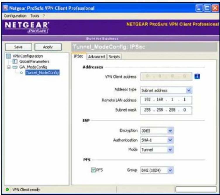
Figure 191.
- Specify the settings that are explained in the following table.
Table 81. VPN client IPSec configuration settings (Mode Config)
| Setting Description | ||
| VPN Client address This field is masked out because Mode Config is selected. After an IPSec connection is established, the IP address that is issued by the UTM displays in this field (see Figure 196 on page 328). | ||
| Address Type | Select Subnet address from the drop-down list. | |
| Remote host address | The address that you need to enter depends on whether you have specified a LAN IP network address in the Local IP Address field on the Add Mode Config Record screen of the UTM:If you left the Local IP Address field blank, enter the UTM's default LAN IP address as the remote host address that opens the VPN tunnel. For example, enter 192.168.1.1.If you specified a LAN IP network address in the Local IP Address field, enter the address that you specified as the remote host address that opens the VPN tunnel. | |
| Subnet mask | Enter 255.255.255.0 as the remote subnet mask of the UTM that opens the VPN tunnel. This is the LAN IP subnet mask that you specified in the Local Subnet Mask field on the Add Mode Config Record screen of the UTM. If you left the Local Subnet Mask field blank, enter the UTM's default IP subnet mask. | |
| ESP | Encryption | Select 3DES as the encryption algorithm from the drop-down list. |
| Authentication | Select SHA-1 as the authentication algorithm from the drop-down list. | |
| Mode | Select Tunnel as the encapsulation mode from the drop-down list. | |
| PFS and Group | Select the PFS check box, and then select the DH2 (1024) key group from the drop-down list.Note: On the UTM, this key group is referred to as Diffie-Hellman Group 2 (1024 bit). | |
- Click Apply to use the new settings immediately, and click Save to keep the settings for future use.
Configure the Mode Config Global Parameters
To specify the global parameters:
- Click Global Parameters in the left column of the Configuration Panel screen. The Global Parameters pane displays in the Configuration Panel screen.
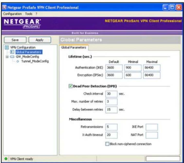
Figure 192.
- Specify the following default lifetimes in seconds to match the configuration on the UTM:
• Authentication (IKE), Default. Enter 3600 seconds.
• Encryption (IPSec), Default. Enter 3600 seconds.
- Select the Dead Peer Detection (DPD) check box, and configure the following DPD settings to match the configuration on the UTM:
• Check Interval. Enter 30 seconds.
• Max. number of entries. Enter 3 retries.
- Delay between entries. Leave the default delay setting of 15 seconds.
- Click Apply to use the new settings immediately, and click Save to keep the settings for future use.
The Mode Config configuration of the VPN client is now complete.
Test the Mode Config Connection
To test the Mode Config connection from the VPN client to the UTM:
- Right-click the system tray icon, and select Open tunnel 'Tunnel_ModeConfig'.

Figure 193.
When the tunnel opens successfully, the Tunnel opened message displays above the system tray, and the VPN client displays a green icon in the system tray.

Figure 194.
- Verify that the UTM issued an IP address to the VPN client. This IP address displays in the VPN Client address field on the IPSec pane of the VPN client. (The following figure shows the upper part of the IPSec pane only.)
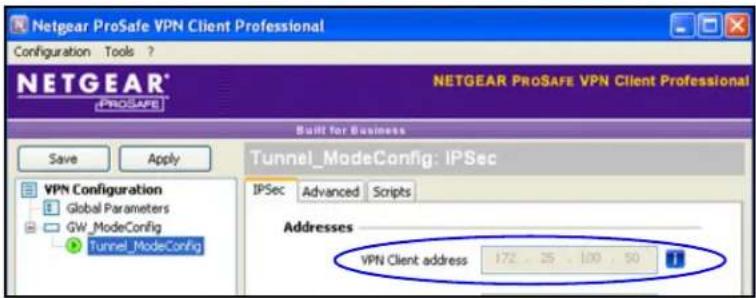
Figure 195.
- From the client computer, ping a computer on the UTM LAN.
Modify or Delete a Mode Config Record
Note: Before you modify or delete a Mode Config record, make sure that it is not used in an IKE policy.
To edit a Mode Config record:
- On the Mode Config screen (see Figure 184 on page 313), click the Edit button in the Action column for the record that you want to modify. The Edit Mode Config Record screen displays. This screen is identical to the Add Mode Config Record screen (see Figure 185 on page 314).
- Modify the settings as explained in Table 77 on page 314.
- Click Apply to save your settings.
To delete one or more Mode Config records:
- On the Mode Config screen (see Figure 184 on page 313), Select the check box to the left of each record that you want to delete, or click the Select All table button to select all records.
- Click the Delete table button.
Configure Keep-Alives and Dead Peer Detection
- Configure Keep-Alives
- Configure Dead Peer Detection
In some cases, you might not want a VPN tunnel to be disconnected when traffic is idle, for example, when client-server applications over the tunnel cannot tolerate the tunnel establishment time. If you require a VPN tunnel to remain connected, you can use the keep-alive and Dead Peer Detection (DPD) features to prevent the tunnel from being disconnected and to force a reconnection if the tunnel disconnects for any reason.
For DPD to function, the peer VPN device on the other end of the tunnel also needs to support DPD. Keep-alive, though less reliable than DPD, does not require any support from the peer device.
Configure Keep-Alives
The keep-alive feature maintains the IPSec SA by sending periodic ping requests to a host across the tunnel and monitoring the replies.
To configure the keep-alive feature on a configured VPN policy:
- Select VPN > IPSec VPN > VPN Policies. The VPN Policies screen displays (see Figure 181 on page 301).
- In the List of VPN Policies table, click the Edit table button to the right of the VPN policy that you want to edit. The Edit VPN Policy screen displays. (The following figure shows only the top part of a UTM50 screen with the General section).

Figure 196.
- Enter the settings as explained in the following table:
Table 82. Keep-alive settings
| Setting Description | ||
| General | ||
| Enable Keepalive | Select the Yes radio button to enable the keep-alive feature. Periodically, the UTM sends keep-alive requests (ping packets) to the remote endpoint to keep the tunnel alive. You need to specify the ping IP address in the Ping IP Address field, the detection period in the Detection Period field, and the maximum number of keep-alive requests that the UTM sends in the Reconnect after failure count field. | |
| Ping IP Address T | The IP address that the UTM pings. The address should be of a host that can respond to ICMP ping requests. | |
| Detection Period T | The period in seconds between the keep-alive requests. The default setting is 10 seconds. | |
| Reconnect after failure count | The maximum number of keep-alive requests before the UTM tears down the connection and then attempts to reconnect to the remote endpoint. The default setting is 3 keep-alive requests. | |
- Click Apply to save your settings.
Configure Dead Peer Detection
The Dead Peer Detection (DPD) feature lets the UTM maintain the IKE SA by exchanging periodic messages with the remote VPN peer.
To configure DPD on a configured IKE policy:
- Select VPN > IPSec VPN. The IPSec VPN submenu tabs display with the IKE Policies screen in view (see Figure 179 on page 293).
- In the List of IKE Policies table, click the Edit table button to the right of the IKE policy that you want to edit. The Edit IKE Policy screen displays. (The following figure shows only the IKE SA Parameters section of the screen).

Figure 197.
- In the IKE SA Parameters section of the screen, locate the DPD fields, and complete the fields as explained the following table:
Table 83. Dead Peer Detection settings
| Setting Description | ||
| IKE SA Parameters | ||
| Enable Dead Peer Detection | Select the Yes radio button to enable DPD. When the UTM detects an IKE connection failure, it deletes the IPSec and IKE SA and forces a reestablishment of the connection. You need to specify the detection period in the Detection Period field and the maximum number of times that the UTM attempts to reconnect in the Reconnect after failure count field. | |
| Detection Period T | The period in seconds between consecutive DPD R-U-THERE messages, which are sent only when the IPSec traffic is idle. The default setting is 10 seconds. | |
| Reconnect after failure count | The maximum number of DPD failures before the UTM tears down the connection and then attempts to reconnect to the peer. The default setting is 3 failures. | |
- Click Apply to save your settings.
Configure NetBIOS Bridging with IPSec VPN
Windows networks use the Network Basic Input/Output System (NetBIOS) for several basic network services such as naming and neighborhood device discovery. Because VPN routers do not usually pass NetBIOS traffic, these network services do not function for hosts on opposite ends of a VPN connection. To solve this problem, you can configure the UTM to bridge NetBIOS traffic over the VPN tunnel.
To enable NetBIOS bridging on a configured VPN tunnel:
- Select VPN > IPSec VPN > VPN Policies. The VPN Policies screen displays (see Figure 181 on page 301).
- In the List of VPN Policies table, click the Edit table button to the right of the VPN policy that you want to edit. The Edit VPN Policy screen displays. (The following figure shows only the top part of a UTM50 screen with the General section).

Figure 198.
- Select the Enable NetBIOS check box.
- Click Apply to save your settings.
Configure the PPTP Server
As an alternate solution to IPSec VPN and L2TP tunnels, you can configure a Point-to-Point Tunnel Protocol (PPTP) server on the UTM to allow users to access PPTP clients over PPTP tunnels. A maximum of five simultaneous PPTP user sessions are supported. (The very first IP address of the PPTP address pool is used for distribution to the UTM.)
A PPTP user typically initiates a tunnel request; the PPTP server accommodates the tunnel request and assigns an IP address to the user. After a PPTP tunnel is established, the user can connect to a PPTP client that is located behind the UTM.
You need to enable the PPTP server on the UTM, specify a PPTP server address pool, and create PPTP user accounts. For information about how to create PPTP user accounts, see Configure User Accounts on page 401.
To enable the PPTP server and configure the PPTP server pool, authentication, and encryption:
- Select VPN > PPTP Server. The PPTP Server screen displays:
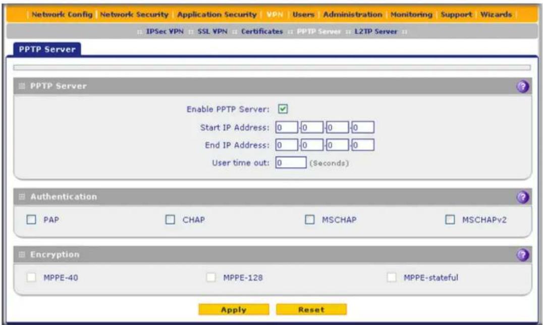
Figure 199.
- Enter the settings as explained in the following table:
Table 84. PPTP Server screen settings
| Setting Description | ||
| PPTP Server | ||
| Enable PPTP Server | To enable the PPTP server, select the Enable check box. Complete the following fields: | |
| Start IP Address Type the first IP address of the address pool. | ||
| End IP Address Type the last IP address of the address pool. A maximum of six contiguous addresses can be part of the pool. (The first address of the pool cannot be assigned to a user.) | ||
| User time out Enter the time-out period in seconds, from 300 to 1800 seconds. If there is no traffic from a user, the connection is disconnected after the specified period. | ||
| Authentication | ||
| Select one or more of the following authentication methods to authenticate PPTP users:PAP. RADIUS-Password Authentication Protocol (PAP).CHAP. RADIUS-Challenge Handshake Authentication Protocol (CHAP).MSCHAP. RADIUS-Microsoft CHAP (MSCHAP).MSCHAPv2. RADIUS-Microsoft CHAP version 2 (MSCHAPv2).Note:For each authentication method that you want to use for PPTP users, you need to have created a domain that supports the authentication method (see Configure Domains on page 388) and have added the PPTP users to the domain (see Configure User Accounts on page 401). | ||
| Encryption | ||
| If the authentication is MSCHAP or MSCHAPv2, the PPTP server can support Microsoft Point-to-Point Encryption (MPPE). Select one or more of the following types of MPPE:MPPE-40. MPPE 40-bit encryption.MPPE-128. MPPE 128-bit encryption. This is the most secure type of MPPE encryption.MPPE-stateful. Stateful MPPE encryption. This is the least secure type of MPPE encryption. | ||
3. Click Apply to save your settings.
View the Active PPTP Users
To view the active PPTP tunnel users:
Select Monitoring > Active Users & VPNs > PPTP Active Users. The PPTP Active Users screen displays:
![Network Config | Network Security | Application Security | VPN | Users | Administration | Monitoring | Support | Wizards System Status || Active Users & VPNs || Dashboard || Diagnostics || Logs & Reports || Quarantine || Email Notification || Active Users IPSec VPN Connection Status SSL VPN Connection Status PPTP Active Users L2TP Active Users The page will auto-refresh in 3 Seconds List Of PPTP Active Users Username Remote IP PPTP IP Action Poll Interval: 5 [Seconds] Set interval Stop](/content/2026/06/1371942/images/32443d71919ee342bb1a84c32ad2b83df6039520260a36a3a5d7b27a09b80bbe.jpg)
Figure 200.
The List of PPTP Active Users table lists each active connection with the information that is described in the following table.
Table 85. PPTP Active Users screen information
| Item Description | |
| Username | The name of the PPTP user that you have defined (see Configure User Accounts on page 401). |
| Remote IP The remote client's IP address. | |
| PPTP IP The IP address that is assigned by the PPTP server on the UTM. | |
| Action | Click the Disconnect table button to terminate the connection. (This button is displayed only when there an active connection.) |
The default poll interval is 5 seconds. To change the poll interval period, enter a new value in the Poll Interval field, and then click the Set Interval button. To stop polling, click the Stop button.
Configure the L2TP Server
As an alternate solution to IPSec VPN and PPTP tunnels, you can configure a Layer 2 Tunneling Protocol (L2TP) server on the UTM to allow users to access L2TP clients over L2TP tunnels. A maximum of five simultaneous L2TP user sessions are supported. (The very first IP address of the L2TP address pool is used for distribution to the UTM.)
An L2TP Access Concentrator (LAC) typically initiates a tunnel to fulfil a connection request from an L2TP user; the L2TP server accommodates the tunnel request and assigns an IP address to the user. After an L2TP tunnel is established, the user can connect to an L2TP client that is located behind the UTM.
Note: IPSec VPN and PPTP provide stronger authentication and encryption than L2TP. (Packets that traverse the L2TP tunnel are not encapsulated by IPSec or MPPE.)
You need to enable the L2TP server on the UTM, specify an L2TP server address pool, and create L2TP user accounts. For information about how to create L2TP user accounts, see Configure User Accounts on page 401.
To enable the L2TP server and configure the L2TP server pool and authentication:
- Select VPN > L2TP Server. The L2TP Server screen displays:
ProSecure Unified Threat Management (UTM) Appliance
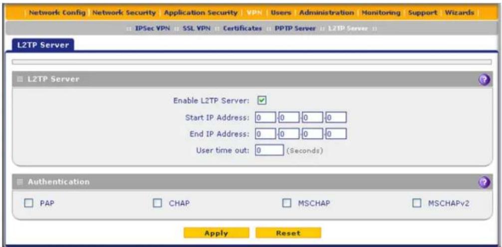
Figure 201.
- Enter the settings as explained in the following table:
Table 86. L2TP Server screen settings
| Setting Description | ||
| L2TP Server | ||
| Enable L2TP Server | To enable the L2TP server, select the Enable check box. Complete the following fields: | |
| Start IP Address Type the first IP address of the address pool. This address is used for distribution to the UTM. | ||
| End IP Address Type the last IP address of the address pool. A maximum of six contiguous addresses can be part of the pool. (The first address of the pool cannot be assigned to a user.) | ||
| User time out Enter the time-out period in seconds, from 300 to 1800 seconds. If there is no traffic from a user, the connection is disconnected after the specified period. | ||
| Authentication | ||
| Select one or more of the following authentication methods to authenticate L2TP users:PAP. RADIUS-Password Authentication Protocol (PAP).CHAP. RADIUS-Challenge Handshake Authentication Protocol (CHAP).MSCHAP. RADIUS-Microsoft CHAP (MSCHAP).MSCHAPv2. RADIUS-Microsoft CHAP version 2 (MSCHAPv2).Note: For each authentication method that you want to use for L2TP users, you need to have created a domain that supports the authentication method (see Configure Domains on page 388) and have added the L2TP users to the domain (see Configure User Accounts on page 401). | ||
- Click Apply to save your settings.
View the Active L2TP Users
To view the active L2TP tunnel users:
Select Monitoring > Active Users & VPNs > L2TP Active Users. The L2TP Active Users screen displays:
![Network Config Network Security Application Security VPN Users Administration Monitoring Support Wizards System Status Active Users & VPNs Dashboard Diagnostics Logs & Reports Quarantine Email Notification Active Users IPSec VPN Connection Status SSL VPN Connection Status PPTP Active Users L2TP Active Users The page will auto-refresh in 3 Seconds List Of L2TP Active Users Username Remote IP L2TP IP Action Poll Interval: 5 [Seconds] Set Interval Stop](/content/2026/06/1371942/images/c859929a77be3da23d2dc7224e068099bb8788c76b138b642639f027ba2a9356.jpg)
Figure 202.
The List of L2TP Active Users table lists each active connection with the information that is described in the following table.
Table 87. L2TP Active Users screen information
| Item Description | |
| Username | The name of the L2TP user that you have defined (see Configure User Accounts on page 401). |
| Remote IP The client's IP address on the remote LAC. | |
| L2TP IP The IP address that is assigned by the L2TP server on the UTM. | |
| Action | Click the Disconnect table button to terminate the connection. (This button is displayed only when there an active connection.) |
The default poll interval is 5 seconds. To change the poll interval period, enter a new value in the Poll Interval field, and then click the Set Interval button. To stop polling, click the Stop button.
For More IPSec VPN Information
Visit http://prosecure.netgear.com/community/forum.php for information about the ProSecure forum and to become part of the ProSecure community.
The forum includes a Resources section with UTM How-To's, including the following guides:
• How to Configure UTM and Apple iPhone and iPad for IPSec VPN
• How to Establish a VPN Connection Between a UTM and Cisco ASA5505
Virtual Private Networking Using SSL Connections
8
The UTM provides a hardware-based SSL VPN solution designed specifically to provide remote access for mobile users to corporate or commercial resources, bypassing the need for a preinstalled VPN client on their computers. Using the familiar Secure Sockets Layer (SSL) protocol, commonly used for e-commerce transactions, the UTM can authenticate itself to an SSL-enabled client, such as a standard web browser. Once the authentication and negotiation of encryption information are completed, the server and client can establish an encrypted connection. With support for up to 13 dedicated SSL VPN tunnels, the UTM allows users to access the remote network easily for a customizable, secure, user portal experience from virtually any available platform.
This chapter contains the following sections:
- SSL VPN Portal Options
• Build a Portal Using the SSL VPN Wizard - Manually Configure and Modify SSL Portals
- For More SSL VPN Information
SSL VPN Portal Options
The UTM's SSL VPN portal can provide two levels of SSL service to the remote user:
- SSL VPN tunnel. The UTM can provide the full network connectivity of a VPN tunnel using the remote user's browser instead of a traditional IPSec VPN client. The SSL capability of the user's browser provides authentication and encryption, establishing a secure connection to the UTM. Upon successful connection, an ActiveX-based SSL VPN client is downloaded to the remote computer to allow the remote user to join the corporate network virtually.
The SSL VPN client provides a point-to-point (PPP) connection between the client and the UTM, and a virtual network interface is created on the user's computer. The UTM assigns the computer an IP address and DNS server IP addresses, allowing the remote computer to access network resources in the same manner as if it were connected directly to the corporate network, subject to any policy restrictions that you configure.
- SSL port forwarding. Like an SSL VPN tunnel, port forwarding is a web-based client that is installed transparently and then creates a virtual, encrypted tunnel to the remote network. However, port forwarding differs from an SSL VPN tunnel in several ways:
- Port forwarding supports only TCP connections, not UDP connections or connections using other IP protocols.
- Port forwarding detects and reroutes individual data streams on the user's computer to the port-forwarding connection rather than opening up a full tunnel to the corporate network.
- Port forwarding offers more fine-grained management than an SSL VPN tunnel. You define individual applications and resources that are available to remote users.
The SSL VPN portal can present the remote user with one or both of these SSL service levels, depending on how you set up the configuration.
Build a Portal Using the SSL VPN Wizard
- SSL VPN Wizard Step 1 of 6 (Portal Settings)
- SSL VPN Wizard Step 2 of 6 (Domain Settings)
- SSL VPN Wizard Step 3 of 6 (User Settings)
- SSL VPN Wizard Step 4 of 6 (Client IP Addresses and Routes)
- SSL VPN Wizard Step 5 of 6 (Port Forwarding)
- SSL VPN Wizard Step 6 of 6 (Verify and Save Your Settings)
- Access the New SSL VPN Portal
• View the UTM SSL VPN Connection Status
• View the UTM SSL VPN Log
The SSL VPN Wizard facilitates the configuration of the SSL VPN client connections by taking you through six screens, the last of which allows you to save the SSL VPN policy. For information about how to edit policies or to configure policies manually, see Manually Configure and Modify SSL Portals on page 357.
To start the SSL VPN Wizard:
- Select Wizards from the main navigation menu. The Welcome to the Netgear Configuration Wizard screen displays:
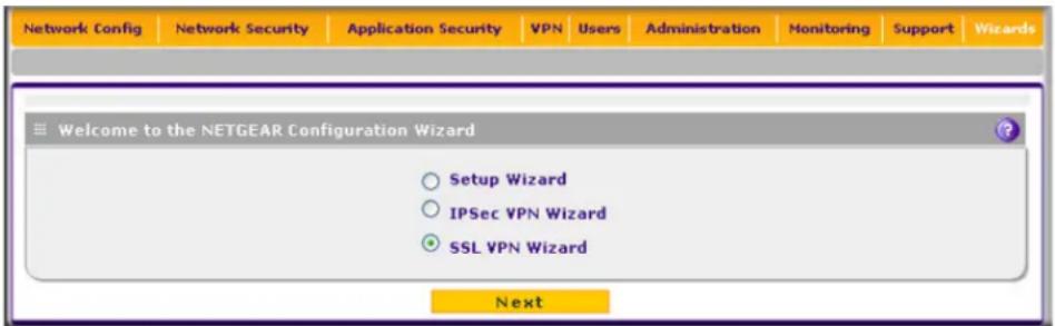
Figure 203.
- Select the SSL VPN Wizard radio button.
- Click Next. The first SSL VPN Wizard screen displays.
The following sections explain the five configuration screens of the SSL VPN Wizard. On the sixth screen, you can save your SSL VPN policy.
The tables in the following sections explain the buttons and fields of the SSL VPN Wizard screens. Additional information about the settings in the SSL VPN Wizard screens is provided in Manually Configure and Modify SSL Portals on page 357 or in other chapters. Each of the following sections provides a specific link to a section in Manually Configure and Modify SSL Portals on page 357 or to a section in another chapter.
SSL VPN Wizard Step 1 of 6 (Portal Settings)
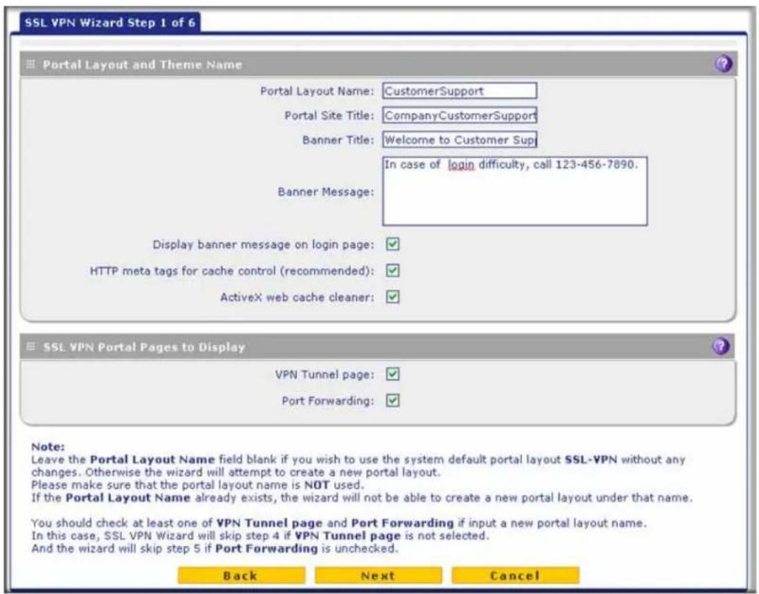
Figure 204.
Note that the previous figure contains a layout example. Enter the settings as explained in the following table, and then click Next to go the following screen.

WARNING:
Do not enter an existing portal layout name in the Portal Layout Name field; otherwise, the SSL VPN Wizard fails when you attempt to apply the settings (although the UTM does not reboot in this situation).
If you leave the Portal Layout Name field blank, the SSL VPN Wizard uses the default portal layout. (The name of the default portal is SSL-VPN). You need to enter a name other than SSL-VPN in the Portal Layout Name field to enable the SSL VPN Wizard to create a portal layout.
Table 88. SSL VPN Wizard Step 1 of 6 screen settings (portal settings)
| Setting Description | |
| Portal Layout and Theme Name | |
| Portal Layout Name | A descriptive name for the portal layout. This name is part of the path of the SSL VPN portal URL.Note:Custom portals are accessed at a different URL than the default portal. For example, if your SSL VPN portal is hosted at https://vpn.company.com, and you create a portal layout named CustomerSupport, then users access the subsite at https://vpn.company.com/portal/CustomerSupport.Note:Only alphanumeric characters, hyphens (-), and underscores (_) are accepted in the Portal Layout Name field. If you enter other types of characters or spaces, the layout name is truncated before the first nonalphanumeric character.Note:Unlike most other URLs, this name is case-sensitive. |
| Portal Site Title | The title that displays at the top of the user's web browser window, for example, Company Customer Support. |
| Banner Title The banner title of a banner message that users see before they log in to the portal, for example, Welcome to Customer Support. | |
| Banner Message | The text of a banner message that users see before they log in to the portal, for example, In case of login difficulty, call 123-456-7890. Enter a plain text message, or include HTML and JavaScript tags. The maximum length of the login screen message is 4096 characters. |
| Display banner message on login page | Select this check box to show the banner title and banner message text on the login screen as shown in Figure 211 on page 354. |
| Setting Description | |
| HTTP meta tags for cache control (recommended) | Select this check box to apply HTTP meta tag cache control directives to this portal layout. Cache control directives include:Note: NETGEAR strongly recommends enabling HTTP meta tags for security reasons and to prevent out-of-date web pages, themes, and data being stored in a user's web browser cache. |
| ActiveX web cache cleaner | Select this check box to enable ActiveX cache control to be loaded when users log in to the SSL VPN portal. The web cache cleaner prompts the user to delete all temporary Internet files, cookies, and browser history when the user logs out or closes the web browser window. The ActiveX web cache control is ignored by web browsers that do not support ActiveX. |
| SSL VPN Portal Pages to Display | |
| VPN Tunnel page | To provide full network connectivity, select this check box.Note: For information about how to assign IP addresses and routes to clients, see SSL VPN Wizard Step 4 of 6 (Client IP Addresses and Routes) on page 348. |
| Port Forwarding | To provide access to specific defined network services, select this check box.Note: For information about how to select network services, see SSL VPN Wizard Step 5 of 6 (Port Forwarding) on page 350.Note: Any services that are not selected are not visible from the SSL VPN portal; however, users can still access hidden services unless you create SSL VPN access policies to prevent access to these services. |
After you have completed the steps in the SSL VPN Wizard, you can change the portal settings by selecting VPN > SSL VPN > Portal Layout. For more information about portal settings, see Manually Create or Modify the Portal Layout on page 359.
SSL VPN Wizard Step 2 of 6 (Domain Settings)

Figure 205.
Enter the settings as explained in the following table, and then click Next to go the following screen.
Note: If you leave the Domain Name field blank, the SSL VPN Wizard uses the default domain name geardomain. You need to enter a name other than geardomain in the Domain Name field to enable the SSL VPN Wizard to create a domain.

WARNING:
Do not enter an existing domain name in the Domain Name field; otherwise, the SSL VPN Wizard fails when you attempt to apply the settings and the UTM reboots to recover its configuration.
Table 89. SSL VPN Wizard Step 2 of 6 screen settings (domain settings)
| Setting Description | ||
| Domain Name | A descriptive (alphanumeric) name of the domain for identification and management purposes. | |
| Authentication TypeNote:If you select any type of RADIUS authentication, make sure that one or more RADIUS servers are configured (seeRADIUS Client andServer Configurationon page 310). | From the drop-down list, select the authentication method that the UTM applies:Local User Database (default). Users are authenticated locally on the UTM. This is the default setting. You do not need to complete any other fields on this screen.Radius-PAP. RADIUS Password Authentication Protocol (PAP). Complete the following fields:- Authentication Server- Authentication Secret- Radius Port- Repeat- TimeoutRadius-CHAP. RADIUS Challenge Handshake Authentication Protocol (CHAP). Complete the following fields:- Authentication Server- Authentication Secret- Radius Port- Repeat- TimeoutRadius-MSCHAP. RADIUS Microsoft CHAP. Complete the following fields:- Authentication Server- Authentication SecretRadius-MSCHAPv2. RADIUS Microsoft CHAP version 2. Complete the following fields:- Authentication Server- Authentication SecretWIKID-PAP. WiKID Systems PAP. Complete the following fields:- Authentication Server- Authentication Secret- Radius Port- Repeat- Timeout | |
| Authentication Type (continued) | WIKID-CHAP. WiKID Systems CHAP. Complete the following fields:- Authentication Server- Authentication Secret- Radius Port- Repeat- TimeoutMIAS-PAP. Microsoft Internet Authentication Service (MIAS) PAP. Complete the following fields:- Authentication Server- Authentication Secret- Radius Port- Repeat- TimeoutMIAS-CHAP. Microsoft Internet Authentication Service (MIAS) CHAP. Complete the following fields:- Authentication Server- Authentication Secret- Radius Port- Repeat- TimeoutNT Domain. Microsoft Windows NT Domain. Complete the following fields:- Authentication Server- WorkgroupActive Directory. Microsoft Active Directory. Complete the following fields, and make a selection from the LDAP Encryption drop-down list:- Authentication Server- Active Directory Domain- LDAP Port- Bind DN- Bind Password- Search Base- Additional Filter (optional)LDAP. Lightweight Directory Access Protocol (LDAP). Complete the following fields, and make a selection from the LDAP Encryption drop-down list:- Authentication Server- LDAP Base DN- LDAP Port- Bind DN- Bind Password- Search Base- UID Attribute- Member Groups Attribute (optional)- Group Members Attribute (optional)- Additional Filter (optional) | |
| Setting | Description | |
| Portal The portal that you selected on the first SSL VPN Wizard screen. You cannot change the portal on this screen; the portal is displayed for information only. | ||
| Authentication Server All authentication types except the Local User Database | The server IP address or server name of the authentication server for any type of authentication other than authentication through the local user database. | |
| Authentication Secret All RADIUS, WiKID, and MIAS authentication types | The authentication secret or password that is required to access the authentication server for RADIUS, WiKID, or MIAS authentication. | |
| Workgroup NT Domain only The workgroup that is required for Microsoft NT Domain authentication. | ||
| LDAP Base DN LDAP only The LDAP base distinguished name (DN) that is required for LDAP authentication. | ||
| Active Directory Domain | Active Directory only | The Active Directory domain name that is required for Microsoft Active Directory authentication. |
| LDAP Port LDAP and Active Directory | The port number for the LDAP or Active Directory authentication server. The default port for the LDAP server is 389, which is generally the default port for TLS encryption or no encryption. When the encryption is SSL, the default port is generally 636. | |
| Bind DN The LDAP or Active Directory DN that is required to access the LDAP or Active Directory authentication server. This should be a user in the LDAP or Active Directory who has read access to all the users that you would like to import into the UTM. The Bind DN field accepts two formats:• A display name in the dn format. For example: cn=Jamie Hanson,cn=users,dc=test,dc=com.• A Windows login account name in email format. For example: jhanson@testAD.com. This last type of bind DN can be used only for a Windows Active Directory server. | ||
| Bind Password The authentication secret or password that is required to access the LDAP or Active Directory authentication server. | ||
| LDAP Encryption | ||
| Setting Description | ||
| Search Base LDAP and | Active Directory (continued) | The DN at which to start the search, specified as a sequence of relative distinguished names (RDNs), connected with commas and without any blank spaces. For most users, the search base is a variation of the domain name. For example, if your domain is yourcompany.com, your search base DN might be as follows: dc=yourcompany,dc=com. |
| UID Attribute LDAP only | The attribute in the | LDAP directory that contains the user's identifier (UID).For an Active Directory, enter sAMAccountName.For an OpenLDAP directory, enter uid. |
| Member Groups Attribute | This field is optional. The attribute that is used to identify the groups that an entry belongs to.For an Active Directory, enter memberOf.For OpenLDAP, you can enter a customized attribute to identify the groups of an entry. | |
| Group Members Attribute | This field is optional. The attribute that is used to identify the members of a group.For an Active Directory, enter member.For OpenLDAP, you can enter a customized attribute to identify the members of a group. | |
| Additional Filter LDAP | and Active Directory | This field is optional. A filter that is used when the UTM is searching the LDAP server for matching entries while excluding others. (Use the format described by RFC 2254.)The following search term examples match users only:Active Directory. objectClass=userOpen LDAP. objectClass=posixAccount |
| Radius Port All RADIUS | authentication types except MSCHAPv2 | The port number for the RADIUS server. You can enter a value between 1 and 65535. The default port number is 1812. |
| Repeat The period in second | MSCHAPv2 | waits for a response from a RADIUS server. You can enter a value between 1 and 10. The default is 3 seconds. |
| Timeout The maximum | number of times that | the UTM attempts to connect to a RADIUS server. You can enter a value between 3 and 30. The default is 5 times. |
After you have completed the steps in the SSL VPN Wizard, you can change the domain settings by selecting Users > Domains. For more information about domain settings, see Configure Domains on page 388.
SSL VPN Wizard Step 3 of 6 (User Settings)

Figure 206.
Note that the previous figure contains an example. Enter the settings as explained in the following table, and then click Next to go the following screen.

WARNING:
Do not enter an existing user name in the User Name field; otherwise, the SSL VPN Wizard fails when you attempt to apply the settings and the UTM reboots to recover its configuration.
Table 90. SSL VPN Wizard Step 3 of 6 screen settings (user settings)
| Setting Description | |
| User Name | A descriptive (alphanumeric) name of the user for identification and management purposes. |
| User Type When you | u use the SSL VPN Wizard, the user type is always SSL VPN User. You cannot change the user type on this screen; the user type is displayed for information only. |
| Group When you create a domain on the second SSL VPN Wizard screen, a group with the same name is automatically created. (A user belongs to a group, and a group belongs to a domain.) You cannot change the group on this screen; the group is displayed for information only. | |
| Password | The password that needs to be entered by the user to gain access to the UTM. The password needs to contain alphanumeric, hyphen (-), or underscore (_) characters. |
| Confirm Password | This field needs to be identical to the password that you entered in the Password field. |
| Idle Timeout | The period after which an idle user is automatically logged out of the web management interface. The default idle time-out period is 5 minutes. |
After you have completed the steps in the SSL VPN Wizard, you can change the user settings or add more users for this portal by selecting Users >Users. For more information about user settings, see Configure User Accounts on page 401.
Note: A user policy that permits access is automatically added for the user account that you define with the SSL VPN Wizard.
SSL VPN Wizard Step 4 of 6 (Client IP Addresses and Routes)
Note: This screen displays only if you have selected the VPN Tunnel page check box on the SSL VPN Wizard Step 1 of 6 screen (see Figure 204 on page 339).

Figure 207.
Note that the previous figure contains an example. Enter the settings as explained in the following table, and then click Next to go the following screen.

WARNING:
Do not enter an existing route for a VPN tunnel client in the Destination Network and Subnet Mask fields; otherwise, the SSL VPN Wizard fails when you attempt to apply the settings and the UTM reboots to recover its configuration.
Table 91. SSL VPN Wizard Step 4 of 6 screen settings (client addresses and routes)
| Setting Description | |
| Client IP Address Range | |
| Enable Full Tunnel Support | Select this check box to enable full-tunnel support. If you leave this check box cleared (which is the default setting), full-tunnel support is disabled but split-tunnel support is enabled, and you need to add a client route by completing the Destination Network and Subnet Mask fields.Note:When full-tunnel support is enabled, client routes are not operable. |
| DNS Suffix A DNS suffix to be | appended to incomplete DNS search strings. This setting is optional. |
| Primary DNS Server | The IP address of the primary DNS server that is assigned to the VPN tunnel clients. This setting is optional.Note:If you do not assign a DNS server, the DNS settings remain unchanged in the VPN client after a VPN tunnel has been established. |
| Secondary DNS Server | The IP address of the secondary DNS server that is assigned to the VPN tunnel clients. This setting is optional. |
| Client Address Range Begin | The first IP address of the IP address range that you want to assign to the VPN tunnel clients. |
| Client Address Range End | the last IP address of the IP address range that you want to assign to the VPN tunnel clients. |
| Add Routes for VPN Tunnel Clients | |
| Destination Network | Leave this field blank, or specify a destination network IP address of a local network or subnet that has not yet been used. This setting applies only when full-tunnel support is disabled. |
| Subnet Mask | Leave this field blank, or specify the address of the appropriate subnet mask. This setting applies only when full-tunnel support is disabled. |
After you have completed the steps in the SSL VPN Wizard, you can change the client IP address range and routes by selecting VPN > SSL VPN > SSL VPN Client. For more information about client IP address range and routes settings, see Configure the SSL VPN Client on page 365.
SSL VPN Wizard Step 5 of 6 (Port Forwarding)
Note: This screen displays only if you have selected the Port Forwarding check box on the SSL VPN Wizard Step 1 of 6 screen (see Figure 204 on page 339).

Figure 208.
Note that the previous figure contains an example. Enter the settings as explained in the following table, and then click Next to go the following screen.

WARNING:
Do not enter an IP address that is already in use in the upper Local Server IP Address field or a port number that is already in use in the TCP Port Number field; otherwise, the SSL VPN Wizard fails when you attempt to apply the settings and the UTM reboots to recover its configuration.
Table 92. SSL VPN Wizard Step 5 of 6 screen settings (port-forwarding settings)
| Setting Description | ||
| Add New Application for Port Forwarding | ||
| Local Server IP Address | The IP address of an internal server or host computer that remote users have access to. | |
| TCP Port Number | The TCP port number of the application that is accessed through the SSL VPN tunnel. Following are some commonly used TCP applications and port numbers. | |
| FTP Data (usually not needed) 20 | ||
| FTP Control Protocol 21 | ||
| Setting | Description | |
| TCP Port Number (continued) | SSH 22 | a |
| Telnet 23 | a | |
| SMTP (send mail) 25 | ||
| HTTP (web) 80 | ||
| POP3 (receive mail) 110 | ||
| NTP (Network Time Protocol) 123 | ||
| Citrix 1494 | ||
| Terminal Services 3389 | ||
| VNC (virtual network computing) 5900 | or 5800 | |
| Add New Host Name for Port Forwarding | ||
| Local Server IP Address | The IP address of an internal server or host computer that you want to name. Note: Both the upper and lower Local Server IP Address fields on this screen (that is, the field in the Add New Application for Port Forwarding section and the field in the Add New Host Name for Port Forwarding section) need to contain the same IP address. | |
| Fully Qualified Domain Name | The full server name, that is, the host name-to-IP address-resolution for the network server as a convenience for remote users. | |
a. Users can specify the port number together with the host name or IP address.
After you have completed the steps in the SSL VPN Wizard, you can change the client IP address range and routes by selecting VPN > SSL VPN > Port Forwarding.
For more information about port-forwarding settings, see Configure Applications for Port Forwarding on page 363.
SSL VPN Wizard Step 6 of 6 (Verify and Save Your Settings)
Verify your settings; if you need to make any changes, click the Back action button (if necessary several times) to return to the screen on which you want to make changes.

Figure 209.
Click Apply to save your settings. If the settings are accepted by the UTM, a message Operation Succeeded displays at the top of the screen, and the Welcome to the Netgear Configuration Wizard screen displays again (see Figure 203 on page 338).
Access the New SSL VPN Portal
To access the new SSL VPN portal that you created with the SSL VPN Wizard:
- Select VPN > SSL VPN > Portal Layouts. The Portal Layouts screen displays:

Figure 210.
- In the Portal URL column of the List of Layouts table, click the URL that ends with the portal layout name that you created with the help of the SSL VPN Wizard (see the blue oval in the previous screen). A login screen displays. This is the login screen for the portal that you created with the help of the SSL VPN Wizard. (The following figure shows an SSL portal login screen on the UTM10.)
IMPORTANT:
Provide a user who needs to access the portal with the corresponding URL from the Portal URL column. The user needs to paste or type this URL in the navigation toolbar of a browser. To enable a user outside the UTM's local network to access the portal, the URL needs to have a public IP address.

Figure 211.
- To verify access, enter the user name and password that you created with the SSL VPN Wizard.
Note: Any user for whom you have set up a user account that is linked to the domain for the portal and who has knowledge of the portal URL can access the portal. For information about setting up user accounts, see Configure User Accounts on page 401.
- Click Login. A portal screen displays. The format of the portal screen depends on the settings that you selected on the first screen of the SSL VPN Wizard (see SSL VPN Wizard Step 1 of 6 (Portal Settings) on page 339):
• Figure 212 shows a portal screen with both a VPN Tunnel and a Port Forwarding menu option. (If you did not change its configuration, the default portal screen for the default SSL-VPN portal looks identical.)
• Figure 213 shows a portal screen with a Port Forwarding menu option only. The VPN Tunnel menu option is not displayed. (If you disabled the VPN tunnel, the default portal screen for the default SSL-VPN portal looks identical.)
You could also disable the port forwarding option and enable the VPN tunnel, in which case the screen would display the VPN Tunnel menu option only.

Figure 212.

Figure 213.
A portal screen displays a simple menu that provides the SSL user with the following menu selections:
• VPN Tunnel. Provides full network connectivity.
- Port Forwarding. Provides access to the network services that you defined as described in SSL VPN Wizard Step 5 of 6 (Port Forwarding) on page 350.
- Change Password. Allows the user to change his or her password.
• Support. Provides access to the NETGEAR website.
Note: The first time that a user attempts to connect through the VPN tunnel, the NETGEAR SSL VPN tunnel adapter is installed; the first time that a user attempts to connect through the port-forwarding tunnel, the NETGEAR port-forwarding engine is installed.
There are other portal screens that should not be confused with a portal screen that you can create with the SSL VPN Wizard:
- All screens that you can access from the SSL VPN configuration menu of the web management interface display a user portal link in the right upper corner, above the menu bars ( )User Portal
When you click the User Portal link, the SSL-VPN default portal screen opens (see Figure 212 on page 355 and Figure 213 on page 355). SSL-VPN is the name of the default portal that is preconfigured on the UTM. Although it can look the same, this default portal screen is not the same as a portal screen that you create with the help of the SSL VPN Wizard.
- The User Portal Login screen provides access to a portal screen that lets users who are located behind the UTM email a spam report to an email address (see Users with Special Access Privileges on page 381). This portal screen too is not the same as a portal screen that you create with the help of the SSL VPN Wizard.
View the UTM SSL VPN Connection Status
To review the status of current SSL VPN tunnels, select Monitoring > Active Users & VPNs > SSL VPN Connection Status. The SSL VPN Connection Status screen displays:
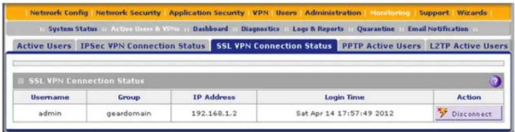
Figure 214.
The active user's user name, group, and IP address are listed in the table with a time stamp indicating the time and date that the user connected.
To disconnect an active user, click the Disconnect table button to the right of the user's table entry.
View the UTM SSL VPN Log
To query the SSL VPN log:
- Select Monitoring > Logs & Reports > Logs Query. The Logs Query screen displays.
- From the Log Type drop-down, select SSL VPN. The SSL VPN logs display.
![Network Config | Network Security | Application Security | VPN | Users | Administration | Monitoring | Support | Wizards | System Status Active Users & VPNs Dashboard Diagnostics Logs & Reports Quarantine Email Notification Email and Syslog Firewall Logs Alerts Log Query Report Application Session Monitoring SSL VPN Logs Date 2012-09-25 21:28:06 [UTM9S] Close Tunnel: Session: 8JjeC2y0ci1KOgRS25yPIQ= 2012-09-25 21:28:06 [UTM9S] [DISCONNECT] Close Tunnel: time="2012-9-25 21:28: 2012-09-25 21:28:06 [UTM9S] id=UTM9S time="2012-9-25 21:28: 6" fw=192.168.1.1 pri=6 rule=access-policy proto="S" 2012-09-25 21:28:05 [UTM9S] [CONNECT] time="2012-9-25 21:28: 5" rule=access-policy 2012-09-25 21:27:37 [UTM9S] id=UTM9S time="2012-9-25 21:27:37" fw=192.168.1.1 pri=6 rule=access-policy proto="S" 2012-09-25 21:27:37 [UTM9S] [CONNECT] time="2012-9-25 21:27:37" rule=access-policy 2012-09-25 21:27:18 [UTM9S] Lo <](/content/2026/06/1371942/images/14a5c14daf3913559b4ec569d653cd8a54687fee9f6436c7759c6f4c67a5e3e0.jpg)
Figure 215.
Manually Configure and Modify SSL Portals
- Manually Create or Modify the Portal Layout
- Configure Domains, Groups, and Users
- Configure Applications for Port Forwarding
- Configure the SSL VPN Client
- Use Network Resource Objects to Simplify Policies
- Configure User, Group, and Global Policies
To manually configure and activate SSL connections, perform the following six basic steps in the order that they are presented:
- Edit the existing SSL portal or create a new one (see Manually Create or Modify the Portal Layout on page 359).
When remote users log in to the UTM, they see a portal page that you can customize to present the resources and functions that you choose to make available.
- Create authentication domains, user groups, and user accounts (see Configure Domains, Groups, and Users on page 362)
a. Create one or more authentication domains for authentication of SSL VPN users.
When remote users log in to the UTM, they need to specify a domain to which their login account belongs. The domain determines the authentication method that is used and the portal layout that is presented, which in turn determines the network resources to which the users are granted access. Because you need to assign a portal layout when creating a domain, the domain is created after you have created the portal layout.
b. Create one or more groups for your SSL VPN users.
When you define the SSL VPN policies that determine network resource access for your SSL VPN users, you can define global policies, group policies, or individual policies. Because you need to assign an authentication domain when creating a group, the group is created after you have created the domain.
c. Create one or more SSL VPN user accounts.
Because you need to assign a group when creating an SSL VPN user account, the user account is created after you have created the group.
- For port forwarding, define the servers and services (see Configure Applications for Port Forwarding on page 363).
Create a list of servers and services that can be made available through user, group, or global policies. You can also associate fully qualified domain names (FQDNs) with these servers. The UTM resolves the names to the servers using the list you have created.
- For SSL VPN tunnel service, configure the virtual network adapter (see Configure the SSL VPN Client on page 365).
For the SSL VPN tunnel option, the UTM creates a virtual network adapter on the remote computer that then functions as if it were on the local network. Configure the portal's SSL VPN client to define a pool of local IP addresses to be issued to remote clients, as well as DNS addresses. Declare static routes or grant full access to the local network, subject to additional policies.
- To simplify policies, define network resource objects (see Use Network Resource Objects to Simplify Policies on page 369).
Network resource objects are groups of IP addresses, IP address ranges, and services. By defining resource objects, you can more quickly create and configure network policies.
- Configure the SSL VPN policies (see Configure User, Group, and Global Policies on page 371).
Policies determine access to network resources and addresses for individual users, groups, or everyone.
Manually Create or Modify the Portal Layout
The Portal Layouts screen that you can access from the SSL VPN configuration menu allows you to create a custom page that remote users see when they log in to the portal. Because the page is customizable, it provides an ideal way to communicate remote access instructions, support information, technical contact information, or VPN-related news updates to remote users. The page is also well suited as a starting page for restricted users; if mobile users or business partners are permitted to access only a few resources, the page that you create presents only the resources that are relevant to these users.
You apply portal layouts by selecting one from the available portal layouts in the configuration of a domain. When you have completed your portal layout, you can apply the portal layout to one or more authentication domains (see Configure Domains on page 388). You can also make the new portal the default portal for the SSL VPN gateway by selecting the default radio button next to the portal layout name.
Note: The UTM's default portal address is
https://
The default domain geardomain is associated with the SSL-VPN portal.
You can define individual layouts for the SSL VPN portal. The layout configuration includes the menu layout, theme, portal pages to display, and web cache control options. The default portal layout is the SSL-VPN portal. You can add additional portal layouts. You can also make any portal the default portal for the UTM by clicking the Default button in the Action column of the List of Layouts table, to the right of the desired portal layout.
To create an SSL VPN portal layout:
- Select VPN > SSL VPN > Portal Layouts. The Portal Layouts screen displays. (The following figure shows layouts in the List of Layouts table as an example. The IP addresses that are shown in this figure do not relate to other figures and examples in this manual. The portal URL normally includes the WAN IP address of the UTM.)

Figure 216.
ProSecure Unified Threat Management (UTM) Appliance
The List of Layouts table displays the following fields:
- Layout Name. The descriptive name of the portal.
• Description. The banner message that is displayed at the top of the portal (see Figure 211 on page 354).
• Use Count. The number of remote users that are currently using the portal. - Portal URL. The URL at which the portal can be accessed.
-
Action. The table buttons, which allow you to edit the portal layout or set it as the default.
-
Under the List of Layouts table, click the Add table button. The Add Portal Layout screen displays. (The following figure shows an example.)

Figure 217.
- Complete the fields and select the check boxes as explained in the following table:
Table 93. Add Portal Layout screen settings
| Setting Description | |
| Portal Layout and Theme Name | |
| Portal Layout Name | A descriptive name for the portal layout. This name is part of the path of the SSL VPN portal URL.Note:Custom portals are accessed at a different URL than the default portal. For example, if your SSL VPN portal is hosted at https://vpn.company.com, and you create a portal layout named CustomerSupport, then users access the website at https://vpn.company.com/portal/CustomerSupport.Note:Only alphanumeric characters, hyphens (-), and underscores (_) are accepted in the Portal Layout Name field. If you enter other types of characters or spaces, the layout name is truncated before the first nonalphanumeric character.Note:Unlike most other URLs, this name is case-sensitive. |
| Portal Site Title The title | that displays at the top of the user's web browser window, for example, Company Customer Support. |
| Banner Title The banner | title of a banner message that users see before they log in to the portal, for example, Welcome to Customer Support.Note:For an example, see Figure 211 on page 354. The banner title text is displayed in the orange header bar. |
| Banner Message | The text of a banner message that users see before they log in to the portal, for example, In case of login difficulty, call 123-456-7890. Enter a plain text message, or include HTML and JavaScript tags. The maximum length of the login screen message is 4096 characters.Note:For an example, see Figure 211 on page 354. The banner message text is displayed in the gray header bar. |
| Display banner message on login page | Select this check box to show the banner title and banner message text on the login screen as shown in Figure 211 on page 354. |
| HTTP meta tags for cache control (recommended) | Select this check box to apply cache control directives for the HTTP meta tags to this portal layout. Cache control directives include:Note:NETGEAR strongly recommends enabling HTTP meta tags for security reasons and to prevent out-of-date web pages, themes, and data being stored in a user's web browser cache. |
| ActiveX web cache cleaner | Select this check box to enable ActiveX cache control to be loaded when users log in to the SSL VPN portal. The web cache cleaner prompts the user to delete all temporary Internet files, cookies, and browser history when the user logs out or closes the web browser window. The ActiveX web cache control is ignored by web browsers that do not support ActiveX. |
| SSL VPN Portal Pages to Display | |
| VPN Tunnel page To provide full network connectivity, select this check box. | |
| Port Forwarding To provide access to specific defined network services, select this check box.Note:Any pages that are not selected are not visible from the SSL VPN portal; however, users can still access the hidden pages unless you create SSL VPN access policies to prevent access to these pages. | |
- Click Apply to save your settings. The new portal layout is added to the List of Layouts table. For information about how to display the new portal layout, see Access the New SSL VPN Portal on page 353.
To edit a portal layout:
- On the Portal Layouts screen (see Figure 215 on page 357), click the Edit button in the Action column for the portal layout that you want to modify. The Edit Portal Layout screen displays. This screen is identical to the Add Portal Layout screen (see the previous figure).
- Modify the settings as explained in the previous table.
- Click Apply to save your settings.
To delete one or more portal layouts:
- On the Portal Layouts screen (see Figure 215 on page 357), select the check box to the left of each portal layout that you want to delete, or click the Select All table button to select all layouts. (You cannot delete the SSL-VPN default portal layout.)
- Click the Delete table button.
Configure Domains, Groups, and Users
Remote users connecting to the UTM through an SSL VPN portal need to be authenticated before they are granted access to the network. The login screen that is presented to the user requires three items: a user name, a password, and a domain selection. The domain determines both the authentication method and the portal layout that are used.
You need to create name and password accounts for the SSL VPN users. When you create a user account, you need to specify a group. Groups are used to simplify the application of access policies. When you create a group, you need to specify a domain. Therefore, you should create any domains first, then groups, and then user accounts.
For information about how to configure domains, groups, and users, see Configure Authentication Domains, Groups, and Users on page 380.
Configure Applications for Port Forwarding
Port forwarding provides access to specific defined network services. To define these services, you need to specify the internal server addresses and port numbers for TCP applications that are intercepted by the port-forwarding client on the user's computer. This client reroutes the traffic to the UTM.
Add Servers and Port Numbers
To configure port forwarding, you need to define the IP addresses of the internal servers and the port number for TCP applications that are available to remote users.
To add a server and a port number:
- Select VPN > SSL VPN > Port Forwarding. The Port Forwarding screen displays. (The following figure shows an example.)

Figure 218.
-
In the Add New Application for Port Forwarding section of the screen, specify information in the following fields:
-
IP Address. The IP address of an internal server or host computer that a remote user has access to.
- TCP Port. The TCP port number of the application that is accessed through the SSL VPN tunnel. The following table lists some commonly used TCP applications and port numbers.
Table 94. Port-forwarding applications/TCP port numbers
| TCP application Port number | |
| FTP data (usually not needed) 20 | |
| FTP Control Protocol 21 | |
| SSH 22 | a |
| Telnet 23 | a |
| SMTP (send mail) 25 | |
| HTTP (web) 80 | |
| POP3 (receive mail) 110 | |
| NTP (Network Time Protocol) 123 | |
| Citrix | 1494 |
| Terminal Services | 3389 |
| VNC (virtual network computing) | 5900 or 5800 |
a. Users can specify the port number together with the host name or IP address.
- Click the Add table button. The new application entry is added to the List of Configured Applications for Port Forwarding table. Remote users can now securely access network applications once they have logged in to the SSL VPN portal and launched port forwarding.
To delete an application from the List of Configured Applications for Port Forwarding table:
- Select the check box to the left of the application that you want to delete.
- Click the Delete table button in the Action column.
Add a Host Name
After you have configured port forwarding by defining the IP addresses of the internal servers and the port number for TCP applications that are available to remote users, you then can also specify host-name-to-IP-address resolution for the network servers as a convenience for users. Host name resolution allows users to access TCP applications at familiar addresses such as mail.example.com or ftp.customer.com rather than by IP addresses.
To add servers and host names for client name resolution:
-
Select VPN > SSL VPN > Port Forwarding. The Port Forwarding screen displays (see Figure 218 on page 363).
-
In the Add New Host Name for Port Forwarding section of the screen, specify information in the following fields:
-
Local Server IP Address. The IP address of an internal server or host computer that you want to name.
- Fully Qualified Domain Name. The full server name.
Note: If the server or host computer that you want to name does not display in the List of Configured Applications for Port Forwarding table, you need to add it before you can rename it.
- Click the Add table button. The new application entry is added to the List of Configured Host Names for Port Forwarding table.
To delete a name from the List of Configured Host Names for Port Forwarding table:
- Select the check box to the left of the name that you want to delete.
- Click the Delete table button in the Action column.
Configure the SSL VPN Client
The SSL VPN client on the UTM assigns IP addresses to remote VPN tunnel clients. Because the VPN tunnel connection is a point-to-point connection, you can assign IP addresses from the local subnet to the remote VPN tunnel clients.
The following are some additional considerations:
- So that the virtual (PPP) interface address of a VPN tunnel client does not conflict with addresses on the local network, configure an IP address range that does not directly overlap with addresses on your local network. For example, if 192.168.1.1 through 192.168.1.100 are currently assigned to devices on the local network, then start the client address range at 192.168.1.101, or choose an entirely different subnet altogether.
- The VPN tunnel client cannot contact a server on the local network if the VPN tunnel client's Ethernet interface shares the same IP address as the server or the UTM. (For example, if your computer has a network interface IP address of 10.0.0.45, then you cannot contact a server on the remote network that also has the IP address 10.0.0.45.)
- Select whether you want to enable full-tunnel or split-tunnel support based on your bandwidth:
- A full tunnel sends all of the client's traffic across the VPN tunnel.
- A split tunnel sends only traffic that is destined for the local network based on the specified client routes. All other traffic is sent to the Internet. A split tunnel allows you to manage bandwidth by reserving the VPN tunnel for local traffic only.
- If you enable split-tunnel support and you assign an entirely different subnet to the VPN tunnel clients from the subnet that is used by the local network, you need to add a client route to ensure that a VPN tunnel client connects to the local network over the VPN tunnel.
Configure the Client IP Address Range
First determine the address range to be assigned to VPN tunnel clients, and then define the address range.
To define the client IP address range:
- Select VPN > SSL VPN > SSL VPN Client. The SSL VPN Client screen displays:
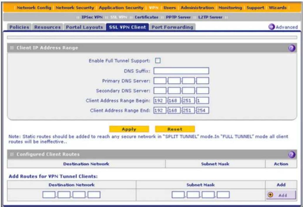
Figure 219.
- Select the check box and complete the fields as explained in the following table:
Table 95. SSL VPN Client screen settings
| Setting Description | |
| Client IP Address Range | |
| Enable Full Tunnel Support S | Select this check box to enable full-tunnel support. If you leave this check box cleared (which is the default setting), full-tunnel support is disabled but split-tunnel support is enabled, and you need to add client routes (see Add Routes for VPN Tunnel Clients on page 367).Note:When full-tunnel support is enabled, client routes are not operable. |
| DNS Suffix A DNS suffix to be | appended to incomplete DNS search strings. This setting is optional. |
| Primary DNS Server The IP address of the primary DNS server that is assigned to the VPN tunnel clients. This setting is optional.Note:If you do not assign a DNS server, the DNS settings remain unchanged in the VPN client after a VPN tunnel has been established. | |
| Secondary DNS Server The IP address of the secondary DNS server that is assigned to the VPN tunnel clients. This setting is optional. | |
| Client Address Range Begin | The first IP address of the IP address range that you want to assign to the VPN tunnel clients. |
| Client Address Range End | The last IP address of the IP address range that you want to assign to the VPN tunnel clients. |
- Click Apply to save your settings. VPN tunnel clients are now able to connect to the UTM and receive a virtual IP address in the client address range.
Add Routes for VPN Tunnel Clients
The VPN tunnel clients assume that the following networks are located across the VPN-over-SSL tunnel:
- The subnet that contains the client IP address (that is, PPP interface), as determined by the class of the address (Class A, B, or C).
- Subnets that are specified in the Configured Client Routes table on the SSL VPN Client screen.
If the assigned client IP address range is in a different subnet from the local network, or if the local network has multiple subnets, or if you select split-mode tunnel operation, you need to define client routes.
To add an SSL VPN tunnel client route:
- Select VPN > SSL VPN > SSL VPN Client. The SSL VPN Client screen displays (see Figure 219 on page 366).
- In the Add Routes for VPN Tunnel Clients section of the screen, specify information in the following fields:
- Destination Network. The destination network IP address of a local network or subnet. For example, enter 192.168.1.60.
- Subnet Mask. The address of the appropriate subnet mask.
- Click the Add table button. The new client route is added to the Configured Client Routes table.
If VPN tunnel clients are already connected, restart the UTM. Restarting forces clients to reconnect and receive new addresses and routes.
To change the specifications of an existing route and to delete an old route:
- Add a new route to the Configured Client Routes table.
- In the Configured Client Routes table, to the right of the route that is out-of-date, click the Delete table button.
If an existing route is no longer needed for any reason, you can delete it.
Configure the Advanced SSL VPN Client Settings
The advanced SSL VPN client settings let you change the link control protocol (LCP) time-out period, which determines when an SSL VPN connection is terminated after a problem has been detected on a link between the UTM and an SSL VPN client. If an LCP echo request times out three times, that is, three times the request does not receive a corresponding echo reply during the configured LCP time-out period, the SSL VPN connection is terminated.
The default LCP time-out period is 60 seconds, which means that if echo reply requests time out three times, the SSL VPN connection is terminated after 180 seconds. If the link comes back up within 180 seconds, the SSL VPN connection is automatically reestablished.
If the UTM is many hops away from SSL VPN clients, or if the intermediate connection between the UTM and SSL VPN clients is unreliable, you might want to increase the LCP time-out period to more than 60 seconds.
To change the LCP time-out:
- Select VPN > SSL VPN > SSL VPN Client. The SSL VPN Client screen displays (see Figure 219 on page 366).
- Click the Advanced option arrow in the upper right of the SSL VPN Client screen. The SSL VPN Advanced screen displays:

Figure 220.
- In the LCP Timeout field, enter a time in seconds. The default value is 60 seconds.

WARNING:
When you click Apply, all SSL VPN connections are terminated. Users need to manually reestablish the SSL VPN connections.
- Click Apply to save your settings.
Use Network Resource Objects to Simplify Policies
Network resources are groups of IP addresses, IP address ranges, and services. By defining resource objects, you can more quickly create and configure network policies. You do not need to redefine the same set of IP addresses or address ranges when you configure the same access policies for multiple users.
Defining network resources is optional; smaller organizations can choose to create access policies using individual IP addresses or IP networks rather than predefined network resources. But for most organizations, NETGEAR recommends that you use network resources. If your server or network configuration changes, you can perform an update quickly by using network resources instead of individually updating all of the user and group policies.
Add New Network Resources
To define a network resource:
- Select VPN > SSL VPN > Resources. The Resources screen displays. (The following figure shows some resources in the List of Resources table as an example.)

Figure 221.
- In the Add New Resource section of the screen, specify information in the following fields:
• Resource Name. A descriptive name of the resource for identification and management purposes.
• Service. From the Service drop-down list, select the type of service to which the resource applies:
- VPN Tunnel. The resource applies only to a VPN tunnel.
- Port Forwarding. The resource applies only to port forwarding.
-
All. The resource applies both to a VPN tunnel and to port forwarding.
-
Click the Add table button. The new resource is added to the List of Resources table.
To delete one or more network resources:
- Select the check box to the left of each network resource that you want to delete, or click the Select All table button to select all network resources.
- Click the Delete table button.
Edit Network Resources to Specify Addresses
To edit network resources:
- Select VPN > SSL VPN > Resources. The Resources screen displays (see the previous figure, which shows some examples).
- In the List of Resources table, to the right of the new resource in the Action column, click the Edit table button. A new screen displays. (The following figure shows an example.)

Figure 222.
- Complete the fields and make your selection from the drop-down list as explained in the following table:
Table 96. Resources screen settings to edit a resource
| Setting Description | |
| Add Resource Addresses | |
| Resource Name | The unique identifier for the resource. You cannot modify the resource name after you have created it on the first Resources screen. |
| Service The SSL service that is assigned to the resource. You cannot modify the service after you have assigned it to the resource on the first Resources screen. | |
Table 96. Resources screen settings to edit a resource (continued)
| Setting Description | ||
| Object Type From the drop | down list, select one of the following options:IP Address. The object is an IP address. You need to enter the IP address or the FQDN in the IP Address / Name field.IP Network. The object is an IP network. You need to enter the network IP address in the Network Address field and the network mask length in the Mask Length field. | |
| IP Address / Name Applicable only when you select IP Address as the object type. Enter the IP address or FQDN for the location that is permitted to use this resource. | ||
| Network Address Applicable only when you select IP Network as the object type. Enter the network IP address for the locations that are permitted to use this resource. | ||
| Object Type (continued) | Mask Length Applicable only when you select IP Network as the object type. As an option, enter the network mask (0–31) for the locations that are permitted to use this resource. | |
| Port Range / Port Number | A port or a range of ports (0–65535) to apply the policy to. The policy is applied to all TCP and UDP traffic that passes on those ports. Leave the fields blank to apply the policy to all traffic. | |
- Click Apply to save your settings. The new configuration is added to the Defined Resource Addresses table.
To delete a configuration from the Defined Resource Addresses table, click the Delete table button to the right of the configuration that you want to delete.
Configure User, Group, and Global Policies
You can define and apply user, group, and global policies to predefined network resource objects, IP addresses, address ranges, or all IP addresses, and to different SSL VPN services. A specific hierarchy is invoked over which policies take precedence. The UTM policy hierarchy is defined as follows:
- User policies take precedence over all group policies.
• Group policies take precedence over all global policies. - If two or more user, group, or global policies are configured, the most specific policy takes precedence.
For example, a policy that is configured for a single IP address takes precedence over a policy that is configured for a range of addresses. And a policy that applies to a range of IP addresses takes precedence over a policy that is applied to all IP addresses. If two or more IP address ranges are configured, then the smallest address range takes precedence. Host names are treated the same as individual IP addresses.
Network resources are prioritized just like other address ranges. However, the prioritization is based on the individual address or address range, not the entire network resource.
For example, assume the following global policy configuration:
- Policy 1. A Deny rule has been configured to block all services to the IP address range 10.0.0.0–10.0.0.255.
- Policy 2. A Deny rule has been configured to block FTP access to 10.0.1.2–10.0.1.10.
- Policy 3. A Permit rule has been configured to allow FTP access to the predefined network resource with the name FTP Servers. The FTP Servers network resource includes the following addresses: 10.0.0.5–10.0.0.20 and the FQDN ftp.company.com, which resolves to 10.0.1.3.
Assuming that no conflicting user or group policies have been configured, if a user attempted to access FTP servers at the following addresses, the actions listed would occur:
• 10.0.0.1. The user would be blocked by Policy 1.
• 10.0.1.5. The user would be blocked by Policy 2.
- 10.0.0.10. The user would be granted access by Policy 3. The IP address range 10.0.0.5–10.0.0.20 is more specific than the IP address range that is defined in Policy 1.
- ftp.company.com. The user would be granted access by Policy 3. A single host name is more specific than the IP address range that is configured in Policy 2.
Note: The user would not be able to access ftp.company.com using its IP address 10.0.1.3. The UTM's policy engine does not perform reverse DNS lookups.
Note: When you use the SSL VPN Wizard to build a portal, a user policy that permits access is automatically added for the user account that you define with the SSL VPN Wizard.
Global Default Policy
The global default policy with destination 0.0.0.0/[0] and permission Deny prevents traffic from any SSL VPN client to reach the LAN after an SSL VPN has been established. This is a security measure. To provide access to the LAN, you would normally create new policies for users or groups and permit restricted access to resources on the LAN.
If you want to provide global access to the LAN without restrictions, change the permission of the global default policy to Permit. Alternately, you could provide global access to the LAN but restrict access to a port or port range by specifying a port number or range of port numbers for the global default policy and by changing the permission of the global default policy to Permit.
View Policies
To view the existing policies:
- Select VPN > SSL VPN. The SSL VPN submenu tabs display, with the Policies screen in view. (The following figure shows some examples.)
![Network Config Network Security Application Security VPN Users Administration Monitoring Support Wizards IPSec VPN SSL VPN Certificates PPTP Server L2TP Server Policies Resources Portal Layouts SSL VPN Client Port Forwarding Operation succeeded. Query View List of SSL VPN Policies for: Global Group User SSLTestDomain SSL Display List of SSL VPN Policies Name Type Service Destination Permission Action RoadWarriorPolicy Group VPN Tunnel RoadWarrior Permit Edit Select All Delete Add... Related Policies Table (populated only for Group/User): Name Type Service Destination Permission RoadWarriorPolicyII Global VPN Tunnel 10.201.33.200 Deny default Global All 0.0.0.0/[0] Deny](/content/2026/06/1371942/images/bc3071aafda25f1f02f5bff002af70ee901838a9b622980f04e50461f31e37e1.jpg)
Figure 223.
- Make your selection from the following Query options:
• To view all global policies, select the Global radio button.
- To view group policies, select the Group radio button, and select the relevant group's name from the drop-down list.
- To view user policies, select the User radio button, and select the relevant user's name from the drop-down list.
- Click the Display action button. The List of SSL VPN Policies table displays the list for your selected Query option.
Add a Policy
To add an SSL VPN policy:
- Select VPN > SSL VPN. The SSL VPN submenu tabs display, with the Policies screen in view (see the previous figure).
- Under the List of SSL VPN Policies table, click the Add table button. The Add SSL VPN Policy screen displays:
![Add SSL VPN Policy Operation succeeded. Policy For Global Group User geardomain SSL Add SSL VPN Policies Apply Policy to? Network Resource IP Address IP Network All Addresses Policy Name: IP Address: Subnet Mask: Port Range / Port Number: Begin End [1-65535] Service: VPN Tunnel Defined Resources: RoadWarrior Permission: PERMIT Apply Reset](/content/2026/06/1371942/images/bb06bc2d9243b20a24098a85293eb7100c962f4efc97d63ce1399aa4c1edb458.jpg)
Figure 224.
- Select the radio buttons, complete the fields, and make your selection from the drop-down lists as explained in the following table:
Table 97. Add SSL VPN Policy screen settings
| Setting Description | |
| Policy For | |
| Select one of the following radio buttons to specify the type of SSL VPN policy:Global. The new policy is global and includes all groups and users.Group. The new policy needs to be limited to a single group. From the drop-down list, select a group name. For information about how to create groups, seeConfigure Groupson page 394.User. The new policy needs to be limited to a single user. From the drop-down list, select a user name. For information about how to create user accounts, seeConfigure User Accountson page 401. | |
| Add SSL VPN Policies | |
| Apply Policy For | Select one of the following radio buttons to specify how the policy is applied. When you select a radio button, the fields and drop-down lists that apply to your selection (see explanations later in this table) unmask onscreen.Network Resource. The policy is applied to a network resource that you have defined on the Resources screen (seeUse Network Resource Objects to Simplify Policieson page 369).IP Address. The policy is applied to a single IP address.IP Network. The policy is applied to a network address.All Addresses. The policy is applied to all addresses. |
Table 97. Add SSL VPN Policy screen settings (continued)
| Setting Description | |||
| Apply Policy For (continued) | Network Resource | Policy Name A | descriptive name of the SSL VPN policy for identification and management purposes. |
| Defined Resources | From the drop-down list, select a network resource that you have defined on the Resources screen (seeUse Network Resource Objects to Simplify Policieson page 369). | ||
| Permission | From the drop-down list, selectPERMITorDENYto specify whether the policy permits or denies access. | ||
| IP Address Policy Name A descriptive name of the SSL VPN policy for identification and management purposes. | |||
| IP Network Policy Name A descriptive name of the SSL VPN policy for identification and management purposes. | |||
| Apply Policy For (continued) | IP Network (continued) | Service From the drop-down list, select the service to which the SSL VPN policy is applied:VPN Tunnel. The policy is applied only to a VPN tunnel.Port Forwarding. The policy is applied only to port forwarding.All. The policy is applied both to a VPN tunnel and to port forwarding. | |
| Permission | From the drop-down list, select PERMIT or DENY to specify whether the policy permits or denies access. | ||
| All Addresses | Policy Name A | descriptive name of the SSL VPN policy for identification and management purposes. | |
| Port Range / Port Number | A port (fill in the Begin field) or a range of ports (fill in the Begin and End fields) to which the SSL VPN policy is applied. Ports can be 0 through 65535. The policy is applied to all TCP and UDP traffic that passes on those ports. Leave the fields blank to apply the policy to all traffic. | ||
| Service From the drop-down list, select the service to which the SSL VPN policy is applied:VPN Tunnel. The policy is applied only to a VPN tunnel.Port Forwarding. The policy is applied only to port forwarding.All. The policy is applied both to a VPN tunnel and to port forwarding. | |||
| Permission | From the drop-down list, select PERMIT or DENY to specify whether the policy permits or denies access. | ||
- Click Apply to save your settings. The policy is added to the List of SSL VPN Policies table on the Policies screen. The new policy goes into effect immediately.
Note: If you have configured SSL VPN user policies, ensure that HTTPS remote management is enabled (see Configure Remote Management Access on page 438). If HTTPS remote management is not enabled, all SSL VPN user connections are disabled.
To edit an SSL VPN policy:
- On the Policies screen (see Figure 223 on page 373), click the Edit button in the Action column for the SSL VPN policy that you want to modify. The Edit SSL VPN Policy screen displays. This screen is identical to the Add SSL VPN Policy screen (see previous screen).
- Modify the settings as explained in the previous table.
- Click Apply to save your settings.
To delete one or more SSL VPN policies:
- On the Policies screen (see Figure 223 on page 373), select the check box to the left of each SSL VPN policy that you want to delete, or click the Select All table button to select all policies.
- Click the Delete table button.
For More SSL VPN Information
Visit http://prosecure.netgear.com/community/forum.php for information about the ProSecure forum and to become part of the ProSecure community.
The forum includes a Resources section with UTM How-To's, including How to Configure Your Snow Leopard Mac for SSL VPN with the UTM.
Manage Users, Authentication, and VPN Certificates
9
This chapter describes how to manage users, authentication, and security certificates for IPSec VPN and SSL VPN. This chapter contains the following sections:
- Authentication Process and Options
- Configure Authentication Domains, Groups, and Users
- Manage Digital Certificates for VPN Connections
Authentication Process and Options
Users are assigned to a group, and a group is assigned to a domain. Therefore, you should first create any domains, then groups, then user accounts.
Note: Do not confuse the authentication groups with the LAN groups that are discussed in Manage Groups and Hosts (LAN Groups) on page 111.
You need to create name and password accounts for all users who need to be able to connect to the UTM. This includes administrators, guests, and SSL VPN clients. Accounts for IPSec VPN clients are required only if you have enabled Extended Authentication (XAUTH) in your IPSec VPN configuration.
Users connecting to the UTM need to be authenticated before being allowed to access the UTM or the VPN-protected network. The login screen that is presented to the user requires three items: a user name, a password, and a domain selection. The domain determines the authentication method that is used and, for SSL connections, the portal layout that is presented.
Note: IPSec VPN users always belong to the default domain (geardomain) and are not assigned to groups.
Except in the case of IPSec VPN users, when you create a user account, you need to specify a group. When you create a group, you need to specify a domain.
The UTM supports security policies that are based on an Active Directory with single sign-on (SSO) through the use of the DC agent and additional Lightweight Directory Access Protocol (LDAP) configuration options (see Configure Authentication Domains, Groups, and Users on page 380).
The following table summarizes the external authentication protocols and methods that the UTM supports.
Table 98. External authentication protocols and methods
| Authentication protocol or method | Description |
| PAP | Password Authentication Protocol (PAP) is a simple protocol in which the client sends a password in clear text. |
| CHAP Challenge Handshake | dshake Authentication Protocol (CHAP) executes a three-way handshake in which the client and server trade challenge messages, each responding with a hash of the other's challenge message that is calculated using a shared secret value. |
| RADIUS A network-validated | PAP, CHAP, MSCHAP, or MSCHAPv2 password-based authentication method that functions with Remote Authentication Dial In User Service (RADIUS). |
| MIAS A network-validated | PAP or CHAP password-based authentication method that functions with Microsoft Internet Authentication Service (MIAS), which is a component of Microsoft Windows 2003 Server. |
| WiKID | WiKID Systems is a PAP or CHAP key-based two-factor authentication method that functions with public key cryptography. The client sends an encrypted PIN to the WiKID server and receives a one-time passcode with a short expiration period. The client logs in with the passcode. SeeAppendix F, Two-Factor Authentication, for more on WiKID authentication. |
| NT Domain | A network-validated domain-based authentication method that functions with a Microsoft Windows NT Domain authentication server. This authentication method has been superseded by Microsoft Active Directory authentication but is supported to authenticate legacy Windows clients. |
| Active Directory | A network-validated domain-based authentication method that functions with a Microsoft Active Directory authentication server. Microsoft Active Directory authentication servers support a group and user structure. Because the Active Directory supports a multilevel hierarchy (for example, groups or organizational units), this information can be queried to provide specific group policies or bookmarks based on Active Directory attributes.The UTM supports single sign-on (SSO) through the use of the DC agent and additional LDAP configuration options.Note:A Microsoft Active Directory database uses an LDAP organization schema. |
| LDAP A network-validated | domain-based authentication method that functions with a Lightweight Directory Access Protocol (LDAP) authentication server. LDAP is a standard for querying and updating a directory. Because LDAP supports a multilevel hierarchy (for example, groups or organizational units), this information can be queried to provide specific group policies or bookmarks based on LDAP attributes.The UTM supports single sign-on (SSO) through the use of the DC agent and additional LDAP configuration options. |
Configure Authentication Domains, Groups, and Users
- Login Portals
• Active Directories and LDAP Configurations - Configure Domains
- Configure Groups
- Configure Custom Groups
- Configure User Accounts
- Set User Login Policies
- Change Passwords and Other User Settings
- DC Agent
- Configure RADIUS VLANs
- Configure Global User Settings
• View and Log Out Active Users
Login Portals
The login screen and authentication on the UTM depend on the user type. There are two basic user types on the UTM that are explained in the following sections:
- Administrative Users and Users with Guest Privileges
- Users with Special Access Privileges
- Unauthenticated or Anonymous Users
Administrative Users and Users with Guest Privileges
Users with administrative and guest privileges on the UTM need to log in through the NETGEAR Configuration Manager Login screen (see the following figure), where they are authenticated through the UTM's local user database. These users need to provide their user name and password. After they have been authenticated, they then can access the web management interface to view or change the UTM's configuration.
For information about how to configure and modify accounts for administrative users and users with guest privileges, see Configure User Accounts on page 401 and Change Passwords and Other User Settings on page 408.

Figure 225.
Users with Special Access Privileges
Users who have a computer behind the UTM and who are assigned access policies that differ from the UTM's default email and web access policies (see Set Exception Rules for Web and Application Access on page 248) need to log in through the User Portal Login screen (see the following figure).
These users need to provide their user name and password, and select the domain to which you have assigned them so they can be authenticated according to the method that you have configured for the domain.
The lower part of the NETGEAR Configuration Manager Login screen (see the previous figure) provides a User Portal Login Link, but you would typically provide users a direct link to the User Portal Login screen instead of letting them pass through the NETGEAR Configuration Manager Login screen. The following figure shows the default User Portal Login screen. (The user and domain names are just examples.) For information about how to configure SSL VPN portals, see Build a Portal Using the SSL VPN Wizard on page 338 and Manually Create or Modify the Portal Layout on page 359.

Figure 226.
The User Portal Login screen displays three links:
- Download CA certificate. The first time that a user remotely connects to a UTM with a browser through an SSL connection, he or she might get a warning message about the SSL certificate. The user can follow the directions of his or her browser to accept the SSL certificate, or import the UTM's root certificate by selecting the Download CA certificate link.
- Check you quarantined email. For information, see Spam Reports for End Users on page 519 and Configure the Quarantine Settings on page 460.
- Report a URL Misclassification. For information, see Configure Web Content Filtering on page 218.
After a user has logged in through the User Portal Login screen, a confirmation screen displays:
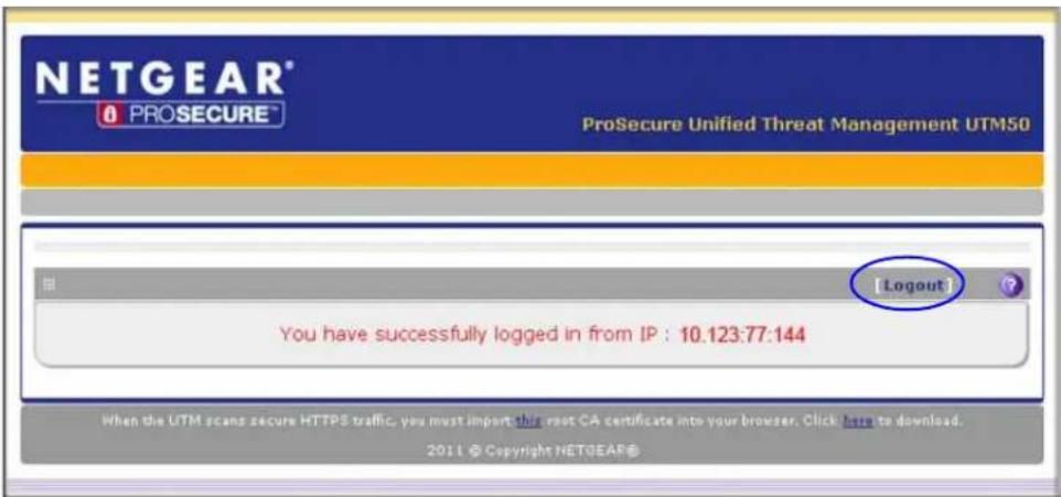
Figure 227.
If you do not use the DC agent in your configuration (see DC Agent on page 409), after completing a session, a user needs to log out manually by following these steps:
- Return to the User Portal Login screen (see Figure 226 on page 382).
Note: The user needs to know how to return to the User Portal Login screen. The administrator needs to provide the User Portal Login URL:
https://<IP_address>/~common/cgi-bin/user_login.pl or
https://<FullyQualifiedDomainName>/~common/cgi-bin/user_login.pl

Alternately, the administrator can provide the NETGEAR Configuration Manager Login screen, from which the user can access the User Portal Login screen:
https://<IP_address> or
https://<FullyQualifiedDomainName>
- Log in again.
- On the confirmation screen (see the previous figure), click the Logout link.

WARNING:
If you do not use the DC agent in your configuration, make sure that users understand that they need to log out after completing a session in order to prevent subsequent users from inheriting access privileges that were not assigned to them.
For information about how to configure and modify accounts for users with special access privileges, see the following sections:
- Configure User Accounts
- Set User Login Policies
- Change Passwords and Other User Settings
Unauthenticated or Anonymous Users
If you set up an open network, you would want to allow unauthenticated users to surf anonymously until they intend to proceed past a blocked Web activity and would need to provide credentials to the UTM. For a secure network, you would use a more restrictive access policy for unauthenticated users and a less restricted access policy for authenticated users.
The UTM has the capability to quarantine emails and spam messages. For information about how end users can send a spam report to an email address, see Spam Reports for End Users on page 519.
Active Directories and LDAP Configurations
Note: For an overview of the authentication options that the UTM supports, see Authentication Process and Options on page 378.
The UTM supports security policies that are based on an Active Directory with single sign-on (SSO) through the use of the DC agent (see DC Agent on page 409) and additional LDAP configuration options.
Note: This manual assumes that you already have some knowledge of Active Directories and LDAP servers.
How an Active Directory Works
Understanding how a typical Active Directory (AD) works might be of help when you are specifying the settings for the LDAP and Active Directory domains on the UTM.
The following applies to a typical AD:
- Organizational unit (OU), common name (CN), and domain controller (DC) can all be used to build a search base in the AD. The following applies to the OU and CN containers:
- An AD administrator can create an OU but cannot create a CN that was built in the AD server.
- An AD administrator can apply a global policy object (GPO) to an OU but not to a CN.
ProSecure Unified Threat Management (UTM) Appliance
- An OU is created in the root node (for example, dc=companyname, dc=com) of the hierarchy. In a company AD, an OU often represents a regional office or department.
- A group is created under cn=users.
- A user is created under each OU so that the user can logically show in a tree of the AD server.
- A relationship between a group and users is built using their attributes (by default: member and memberOf). These are shows in a lookup result.
The following is an example of how to set the search base:
If a company AD server has cn=users and ou=companyname defined and both are specified under dc=companyname,dc=com, the search base needs to be set as dc=companyname,dc=com in order for the UTM to search both users and groups.
If the size limit is exceeded so that dc=companyname,dc=com misses some entries during the lookup process, a user can still be correctly authenticated. However, to prevent the size limit from being exceeded, an AD administrator needs to set a larger value in the LDAP server configuration so that the entire list of users and groups is returned in the lookup result. Another workaround is to use a specific search name or a name with a wildcard in the lookup process, so that the subset of the entire list is returned in the lookup result.
How to Bind a DN in an Active Directory Configuration
Understanding how to bind a distinguished name (DN) in an Active Directory (AD) configuration might be of help when you are specifying the settings for the AD domains on the UTM.
In this example, the AD domain name is testAD.com, and the AD server has the IP address 192.168.35.115 on port 389.
To bind a user with the name Jamie Hanson with the AD server:
- On a computer that has access to the AD, open the AD for Users and Computers.
- Select the user Jamie Hanson.
- Click the General tab. The general properties for Jamie Hanson display.

Figure 228.
- To verify Jamie Hanson's user login name, click the Account tab. The account properties for Jamie Hanson display.
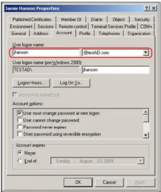
Figure 229.
-
Log in to the UTM.
-
Select Users > Domains.
- Click Add. The Add Domain screen displays.
- Enter testAD.com in the Domain Name field.
- From the Authentication Type drop-down list, select Active Directory.
- Select a previously configured portal from the Select Portal drop-down list.
- Enter 192.168.35.115 in the Authentication Server field.
- Enter the company information (for example, dc=netgear, dc=com) in the Active Directory Domain field.
- To bind the user Jamie Hanson to the AD server for authentication on the UTM, use one of the following two formats in the Bind DN field of the Add Domain screen:
- The display name in dn format: cn=Jamie Hanson,cn=users,dc=testAD,dc=com (see the following figure).

Figure 230.
- The Windows account name in email format such as jhanson@testAD.com. (The following figure shows only the Bind DN field.)
ProSecure Unified Threat Management (UTM) Appliance

Figure 231.
- Complete the remaining fields and drop-down list as needed.
- Click Apply to save your settings.
Configure Domains
The domain determines the authentication method to be used for associated users. For SSL connections, the domain also determines the portal layout that is presented, which in turn determines the network resources to which the associated users have access. The default domain of the UTM is named geardomain. You cannot delete the default domain.
Create and Delete Domains
To create a domain:
- Select Users > Domains. The Domains screen displays. (The following figure shows the UTM's default domain—geardomain—and, as an example, other domains in the List of Domains table.)

Figure 232.
ProSecure Unified Threat Management (UTM) Appliance
The List of Domains table displays the domains with the following fields:
- Check box. Allows you to select the domain in the table.
- Domain Name. The name of the domain. The default domain name (geardomain) is appended by an asterisk.
• Authentication Type. The authentication method that is assigned to the domain. -
Portal Layout Name. The SSL portal layout that is assigned to the domain.
• Action. The Edit table button, which provides access to the Edit Domain screen. -
Under the List of Domains table, click the Add table button. The Add Domain screen displays:

Figure 233.
- Enter the settings as explained in the following table:
Table 99. Add Domain screen settings
| Setting Description | ||
| Domain Name A descriptive (alphanumeric) name of the domain for identification and management purposes. | ||
| Authentication TypeNote:If you select any type of RADIUS authentication, make sure that one or more RADIUS servers are configured (seeRADIUS Client and Server Configurationon page 310). | From the drop-down list, select the authentication method that the UTM applies:Local User Database (default). Users are authenticated locally on the UTM.This is the default setting. You do not need to complete any other fields on this screen.Radius-PAP. RADIUS Password Authentication Protocol (PAP). Complete the following fields:- Authentication Server- Authentication Secret- Radius Port- Repeat- TimeoutRadius-CHAP. RADIUS Challenge Handshake Authentication Protocol (CHAP). Complete the following fields:- Authentication Server- Authentication Secret- Radius Port- Repeat- TimeoutRadius-MSCHAP. RADIUS Microsoft CHAP. Complete the following fields:- Authentication Server- Authentication SecretRadius-MSCHAPv2. RADIUS Microsoft CHAP version 2. Complete the following fields:- Authentication Server- Authentication SecretWIKID-PAP. WiKID Systems PAP. Complete the following fields:- Authentication Server- Authentication Secret- Radius Port- Repeat- TimeoutWIKID-CHAP. WiKID Systems CHAP. Complete the following fields:- Authentication Server- Authentication Secret- Radius Port- Repeat- Timeout | |
| Authentication Type (continued)Note:If you select any type of RADIUS authentication, make sure that one or more RADIUS servers are configured (seeRADIUS Client and Server Configurationon page 310). | MIAS-PAP. Microsoft Internet Authentication Service (MIAS) PAP. Complete the following fields:- Authentication Server- Authentication Secret- Radius Port- Repeat- TimeoutMIAS-CHAP. Microsoft Internet Authentication Service (MIAS) CHAP.Complete the following fields:- Authentication Server- Authentication Secret- Radius Port- Repeat- TimeoutNT Domain. Microsoft Windows NT Domain. Complete the following fields:- Authentication Server- WorkgroupActive Directory. Microsoft Active Directory. Complete the following fields, and make a selection from the LDAP Encryption drop-down list:- Authentication Server- Active Directory Domain- LDAP Port- Bind DN- Bind Password- Search Base- Additional Filter (optional)LDAP. Lightweight Directory Access Protocol (LDAP). Complete the following fields, and make a selection from the LDAP Encryption drop-down list:- Authentication Server- LDAP Base DN- LDAP Port- Bind DN- Bind Password- Search Base- UID Attribute- Member Groups Attribute (optional)- Group Members Attribute (optional)- Additional Filter (optional) | |
| Portal The portal that you selected on the first SSL VPN Wizard screen. You cannot change the portal on this screen; the portal is displayed for information only. | ||
| Authentication Server All authentication types except the Local User Database | The server IP address or server name of the authentication server for any type of authentication other than authentication through the local user database. | |
| Authentication Secret | All RADIUS, WiKID, and MIAS authentication types | The authentication secret or password that is required to access the authentication server for RADIUS, WiKID, or MIAS authentication. |
| Workgroup NT Domain | only The workgroup | that is required for Microsoft NT Domain authentication. |
| LDAP Base DN LDAP | only The LDAP base | distinguished name (DN) that is required for LDAP authentication. |
| Active Directory Domain | Active Directory only | The Active Directory domain name that is required for Microsoft Active Directory authentication. |
| LDAP Port LDAP and | Active Directory | The port number for the LDAP or Active Directory authentication server. The default port for the LDAP server is 389, which is generally the default port for TLS encryption or no encryption. When the encryption is SSL, the default port is generally 636. |
| Bind DN The LDAP or | Active Directory DN that | that is required to access the LDAP or Active Directory authentication server. This should be a user in the LDAP or Active Directory who has read access to all the users that you would like to import into the UTM. The Bind DN field accepts two formats:• A display name in the dn format. For example: cn=Jamie Hanson,cn=users,dc=test,dc=com.• A Windows login account name in email format. For example: jhanson@testAD.com. This last type of bind DN can be used only for a Windows Active Directory server. |
| Bind Password The authentication secret or the drop-down list, | password that is required to access the LDAP or Active Directory authentication server. | |
| LDAP Encryption From | select the encryption type for the connection between the UTM and the LDAP or Active Directory server:• None. The connection is not encrypted. This is the default setting.• TLS. The connection uses Transport Layer Security (TLS) encryption.• SSL. The connection uses Secure Socket Layer (SSL) encryption. | |
| Search Base The DN at which to start the se | search, specified as a sequence of relative distinguished names (RDNs), connected with commas and without any blank spaces. For most users, the search base is a variation of the domain name. For example, if your domain is yourcompany.com, your search base DN might be as follows: dc=yourcompany,dc=com. | |
| UID Attribute LDAP only | The attribute in the | LDAP directory that contains the user's identifier (UID).For an Active Directory, enter sAMAccountName.For an OpenLDAP directory, enter uid. |
| Member Groups Attribute | This field is optional. The attribute that is used to identify the groups that an entry belongs to.For an Active Directory, enter memberOf.For OpenLDAP, you can enter a customized attribute to identify the groups of an entry. | |
| Group Members Attribute | This field is optional. The attribute that is used to identify the members of a group.For an Active Directory, enter member.For OpenLDAP, you can enter a customized attribute to identify the members of a group. | |
| Additional Filter LDAP | and Active Directory | This field is optional. A filter that is used when the UTM is searching the LDAP server for matching entries while excluding others. (Use the format described by RFC 2254.)The following search term examples match users only:Active Directory. objectClass=userOpen LDAP. objectClass=posixAccount |
| Radius Port All RADIUS | authentication types except mschap at the UTM MSCHAPv2 | The port number for the RADIUS server. You can enter a value between 1 and 65535. The default port number is 1812. |
| Repeat The period in sequence | number of times that | waits for a response from a RADIUS server. You can enter a value between 1 and 10. The default is 3 seconds. |
| Timeout The maximum | the UTM attempts to connect to a RADIUS server. You can enter a value between 3 and 30. The default is 5 times. | |
- Click Apply to save your settings. The domain is added to the List of Domains table.
- If you use local authentication, make sure that it is not disabled: in the Local Authentication section of the Domain screen (see Figure 232 on page 388), select the No radio button.
Note: A combination of local and external authentication is supported.

WARNING:
If you disable local authentication, make sure that there is at least one external administrative user; otherwise, access to the UTM is blocked.
- If you change local authentication, click Apply in the Domain screen to save your settings.
To delete one or more domains:
- In the List of Domains table, select the check box to the left of each domain that you want to delete, or click the Select All table button to select all domains. You cannot delete a default domain.
- Click the Delete table button.
Edit Domains
To edit a domain:
- Select Users > Domains. The Domains screen displays (see Figure 232 on page 388).
- In the Action column of the List of Domains table, click the Edit table button for the domain that you want to edit. The Edit Domains screen displays. This screen is very similar to the Add Domains screen (see the previous figure).
- Modify the settings as explained in the previous table. (You cannot modify the Domain Name and Authentication Type fields.)
- Click Apply to save your changes. The modified domain is displayed in the List of Domains table.
Configure Groups
The use of groups simplifies the configuration of VPN policies when different sets of users have different restrictions and access controls. It also simplifies the configuration of web access exception rules. Like the default domain of the UTM, the default group is also named geardomain. The default group geardomain is assigned to the default domain geardomain. You cannot delete the default domain geardomain, nor its associated default group geardomain.
When you create a domain, for example, on the second SSL VPN Wizard screen (see SSL VPN Wizard Step 2 of 6 (Domain Settings) on page 342), a default group with the same name as the new domain is created automatically. You cannot delete this default group either. However, when you delete the domain with which it is associated, the default group is deleted automatically.
Note: IPSec VPN users always belong to the default domain (geardomain) and are not assigned to groups.
Note: Groups that are defined on the Groups screen are used for setting SSL VPN policies. These groups should not be confused with LAN groups that are defined on the LAN Groups screen and that are used to simplify firewall policies. For information about LAN groups, see Manage Groups and Hosts (LAN Groups) on page 111.
Create and Delete Groups
To create a VPN group:
- Select Users > Groups. The Groups screen displays. (The following figure shows the UTM's default group—geardomain—and, as an example, several other groups in the List of Groups table.)
The List of Groups table displays the VPN groups with the following fields:
- Check box. Allows you to select the group in the table.
- Name. The name of the group. If the group name is appended by an asterisk, the group was created by default when you created the domain with the identical name as the default group. You cannot delete a default group; you can delete only the domain with the identical name, which causes the default group to be deleted.
• Domain. The name of the domain to which the group is assigned.
• Action. The Edit table button, which provides access to the Edit Group screen.
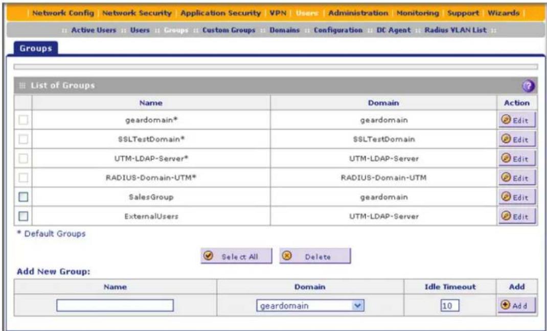
Figure 234.
- In the Add New Group section of the screen, enter the settings as explained in the following table:
Table 100. Groups screen settings
| Setting Description | |
| Name A descriptive | (alphanumeric) name of the group for identification and management purposes. |
| Domain | The drop-down list shows the domains that are listed on the Domain screen. From the drop-down list, select the domain with which the group is associated. For information about how to configure domains, see Configure Domains on page 388. |
| Idle Timeout | The period after which an idle user is automatically logged out of the UTM's web management interface. The default idle time-out period is 5 minutes. |
- Click the Add table button. The new group is added to the List of Groups table.
To delete one or more groups:
- In the List of Groups table, select the check box to the left of each group that you want to delete, or click the Select All table button to select all groups.
- Click the Delete table button.
Note: You cannot delete a default group such as one that was automatically created when you specified a new domain on the second SSL VPN Wizard screen (see SSL VPN Wizard Step 2 of 6 (Domain Settings) on page 342). You can delete only the domain with which the default group is associated and that has an identical name as the default group (see Configure Domains on page 388). Deleting the domain causes the default group to be removed.
Edit Groups
To edit a VPN group:
- Select Users > Groups. The Groups screen displays (see the previous figure).
- In the Action column of the List of Groups table, click the Edit table button for the group that you want to edit. The Edit Groups screen displays:
![Edit Group Operation succeeded. Edit Group Group Name: UTM-LDAP-Server Group's Auth Type: Idap LDAP attribute 1: LDAP attribute 2: LDAP attribute 3: LDAP attribute 4: Idle Timeout: 5 [Minutes] Apply Reset](/content/2026/06/1371942/images/3104c9570a86e006417187776a86ce74fa702a0506ab7a1021cd073ebbe97951.jpg)
Figure 235.
Except for groups that are associated with domains that use the LDAP authentication method, you can modify only the idle time-out settings. You can never modify the Group Name and Group's Auth Type fields.
- Modify the idle time-out period in minutes in the Idle Timeout field. For a group that is associated with a domain that uses the LDAP authentication method, configure the LDAP attributes (in fields 1 through 4) as needed.
- Click Apply to save your changes. The modified group is displayed in the List of Groups table.
Configure Custom Groups
After you have specified groups and users (see Configure Authentication Domains, Groups, and Users on page 380), you can create up to 200 custom groups, each of which can include a combination of local groups and local users, groups and users that are defined by their IP addresses, LDAP groups and users, and RADIUS groups and users. You use these custom groups when you define firewall rules (see Overview of Rules to Block or Allow Specific Kinds of Traffic on page 128) or when you set web access exceptions (see Set Exception Rules for Web and Application Access on page 248).
Note: You can assign custom groups to all types of firewall rules except for DMZ WAN outbound rules and LAN DMZ inbound rules.
To create and manage custom groups:
- Select Users > Custom Groups. The Custom Groups screen displays. This screen shows the Custom Groups table, which is empty if you have not specified any custom groups. (The following figure shows one custom group in the table as an example.)
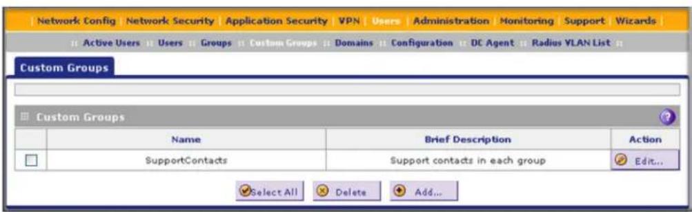
Figure 236.
- Under the Custom Groups table, click the Add table button to specify a custom group. The Add Custom Group screen displays:

Figure 237.
- Complete the fields and make your selections from the drop-down lists as explained in the following table:
Table 101. Add Custom Group screen settings
| Setting Description | ||
| Name | A name of the custom group for identification and management purposes. | |
| Brief Description | A description of the custom group for identification and management purposes. | |
| Members in this group | When you click the Add button in the Add Users/Groups to this group section of the screen, the selected member is added to this field. To remove a member, highlight the member in this field, and then click the Delete button. | |
| Add Users/Groups to this group | Local Groups Do | the following:1. From the Name drop-down list, select a local group.2. Click the Add button to add the selected local group to the custom group. Repeat this step to add more local groups to the custom group.You can specify local groups on the Groups screen (see Create and Delete Groups on page 395. |
| Group Membership by IP | Do the following:1. From the Name drop-down list, select a group that is defined by its IP address.2. Click the Add button to add the selected group to the custom group. Repeat this step to add more users or groups, or both, to the custom group.You can specify groups that are defined by their IP address on the LAN Groups screen (see Manage the Network Database on page 112). | |
| Local User Search | Do the following:1. In the Name field, enter a user name.2. Click the Lookup button. If the user is found, he or she is listed to the left of the Add button.3. Click the Add button to add the selected local user to the custom group. Repeat this step to add more local users to the custom group. | |
| Add Users/Groups to this group (continued) | LDAPUser/Group Search | Do the following:1. From the Domain drop-down list, select an LDAP domain.2. From the Type drop-down list, selectUser, Group, or User&Group.3. In the Name field, enter the name of the user, group, or user and group, or leave this field blank.4. Click theLookupbutton. If the user or group is found, it is listed to the left of the Add button. If you left the Name field blank, all users, groups, or users and groups are listed. In this case, make a selection.5. Click theAddbutton to add the selected user or group to the custom group. Repeat this step to add more users or groups, or both, to the custom group.You can specify LDAP domains, groups, and users on the Domains screen (seeConfigure Domainson page 388). |
| RADIUS User Do | the following:1. From the Domain drop-down list, select a RADIUS domain.2. From the VLAN ID/Name drop-down list, select a VLAN ID or VLAN name.3. Click theAddbutton to add the selected VLAN ID or VLAN name to the custom group. Repeat this step to add more VLAN IDs or VLAN names to the custom group.You can specify RADIUS domains on the Domains screen (seeConfigure Domainson page 388) and RADIUS VLANs on the List of VLAN screen (seeConfigure RADIUS VLANs on page 415). | |
- After you have specified all members of the custom group, click Apply to save your settings. The new custom group is added to the Custom Groups table. To return to the Custom Groups screen without adding the group, click Cancel.
To change an existing custom group:
- In the Action column to the right of the custom group, click the Edit table button. The Edit Custom Group screen displays. This screen is identical to the Add Custom Group screen (see Figure 237 on page 398).
- Modify the settings that you wish to change (see the previous table).
- Click Apply to save your changes. The modified custom group is displayed in the Custom Groups table.
To delete one or more custom groups:
- Select the check box to the left of each custom group that you want to delete, or click the Select All table button to select all custom groups.
- Click the Delete table button.
Configure User Accounts
The UTM supports both unauthenticated and authenticated users:
- Unauthenticated users. Anonymous users who do not log in to the UTM and to which the UTM's default email and web access policies apply.
- Authenticated users. Users who have a computer behind the UTM, who log in to the UTM with a user name and password, and who are assigned an access policy that usually differs from the UTM's default email and web access policies. Different users or user groups can have different access policies, so there can be multiple access policies on the UTM.
In addition to being authenticated as individual users, users can be authenticated on the UTM according to group membership or IP address:
- Group membership. A group is defined in the UTM's local database, an LDAP database, or a RADIUS database. If you use a RADIUS database for authentication, a group can also be defined in a VLAN.
- IP address. A group is defined by its IP address and subnet.
When you create a user account, you need to assign the user to a user group. When you create a group, you need to assign the group to a domain that specifies the authentication method. Therefore, you should first create any domains, then groups, and then user accounts.
You can create different types of user accounts by applying pre-defined user types:
- Administrator. A user who has full access and the capacity to change the UTM configuration (that is, read/write access).
- SSL VPN User. A user who can log in only to the SSL VPN portal.
- IPSEC VPN User. A user who can make an IPSec VPN connection only through a NETGEAR ProSafe VPN Client, and only when the XAUTH feature is enabled (see Configure Extended Authentication (XAUTH) on page 308).
- Guest user. A user who can only view the UTM configuration (that is, read-only access).
- PPTP VPN User. A user who can make a connection to the PPTP server only.
• L2TP VPN User. A user who can make a connection to the L2TP server only.
To create an individual user account:
- Select Users > Users. The Users screen displays. (The following figure shows the UTM's default users—admin and guest—and, as an example, several other users in the List of Users table.)
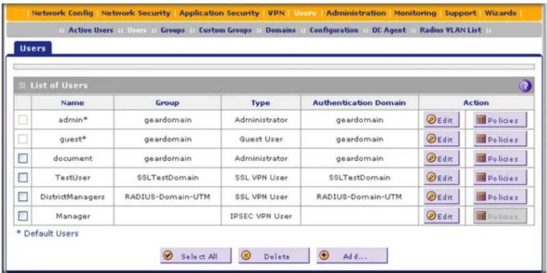
Figure 238.
The List of Users table displays the users and has the following fields:
- Check box. Allows you to select the user in the table.
- Name. The name of the user. If the user name is appended by an asterisk, the user is a default user that came preconfigured with the UTM and cannot be deleted.
- Group. The group to which the user is assigned.
• Type. The type of access credentials that are assigned to the user.
• Authentication Domain. The authentication domain to which the user is assigned. -
Action. The Edit table button, which provides access to the Edit User screen; the Policies table button, which provides access to the policy screens.
-
Click the Add table button. The Add User screen displays:

Figure 239.
- Enter the settings as explained in the following table:
Table 102. Add User screen settings
| Setting Description | |
| User Name | A descriptive (alphanumeric) name of the user for identification and management purposes. |
| User Type | From the drop-down list, select one of the predefined user types that determines the access credentials:Administrator. User who has full access and the capacity to change the UTM configuration (that is, read/write access).SSL VPN User. User who can log in only to the SSL VPN portal.IPSEC VPN User. User who can make an IPSec VPN connection only through a NETGEAR ProSafe VPN Client, and only when the XAUTH feature is enabled (see Configure Extended Authentication (XAUTH) on page 308).Guest User. User who can only view the UTM configuration (that is, read-only access).PPTP VPN User. A user who can make a connection to the PPTP server only.L2TP VPN User. A user who can make a connection to the L2TP server only. |
| Select Group | The drop-down list shows the groups that are listed on the Group screen. From the drop-down list, select the group to which the user is assigned. For information about how to configure groups, see Configure Groups on page 394.Note:The user is assigned to the domain that is associated with the selected group. |
| Password | The password that the user needs to enter to gain access to the UTM. The password needs to contain alphanumeric, hyphen (-), or underscore (_) characters. |
| Confirm Password | This field needs to be identical to the password that you entered in the Password field. |
| Idle Timeout | The period after which an idle user is automatically logged out of the web management interface. The default idle time-out period is 5 minutes.Note:The idle time-out is not applicable to PPTP and L2TP users because the user time-out is already specified on the PPTP Server screen (see Configure the PPTP Server on page 331) and L2TP Server screen (see Configure the L2TP Server on page 334). |
- Click Apply to save your settings. The user is added to the List of Users table.
To delete one or more user accounts:
- In the List of Users table, select the check box to the left of each user account that you want to delete, or click the Select All table button to select all accounts. You cannot delete a default user account.
- Click the Delete table button.
Note: You cannot delete the default admin or guest user.
Set User Login Policies
You can restrict the ability of defined users to log in to the UTM's web management interface. You can also require or prohibit logging in from certain IP addresses or from particular browsers.
Note: User logon policies are not applicable to PPTP and L2TP users.
Configure Login Policies
To configure user login policies:
- Select Users > Users. The Users screen displays (see Figure 238 on page 402).
- In the Action column of the List of Users table, click the Policies table button for the user for which you want to set login policies. The policies submenu tabs display, with the Login Policies screen in view:

Figure 240.
- In the User Login Policies section of the screen, make the following selections:
• To prohibit this user from logging in to the UTM, select the Disable Login check box.
- To prohibit this user from logging in from the WAN interface, select the Deny Login from WAN Interface check box. In this case, the user can log in only from the LAN interface.
Note: For security reasons, the Deny Login from WAN Interface check box is selected by default for guests and administrators. The Disable Login check box is disabled (masked out) for administrators.
- Click Apply to save your settings.
Configure Login Restrictions Based on IP Address
To restrict logging in based on IP address:
- Select Users > Users. The Users screen displays (see Figure 238 on page 402).
- In the Action column of the List of Users table, click the Policies table button for the user for which you want to set login policies. The policies submenu tabs display, with the Login Policies screen in view.
- Click the By Source IP Address submenu tab. The By Source IP Address screen displays. (The following figure shows an IP address in the Defined Addresses table as an example.)

Figure 241.
-
In the Defined Addresses Status section of the screen, select one of the following radio buttons:
-
Deny Login from Defined Addresses. Deny logging in from the IP addresses in the Defined Addresses table.
-
Allow Login only from Defined Addresses. Allow logging in from the IP addresses in the Defined Addresses table.
-
Click Apply to save your settings.
-
In the Add Defined Addresses section of the screen, add an address to the Defined Addresses table by entering the settings as explained in the following table:
Table 103. By Source IP Address screen settings
| Setting Description | |
| Source Address Type | Select the type of address from the drop-down list:IP Address. A single IP address.IP Network. A subnet of IP addresses. You need to enter a netmask length in the Mask Length field. |
| Network Address / IP Address | Depending on your selection from the Source Address Type drop-down list, enter the IP address or the network address. |
| Mask Length For a network | work address, enter the netmask length (0–32).Note: By default, a single IP address is assigned a netmask length of 32. |
- Click the Add table button. The address is added to the Defined Addresses table.
- Repeat Step 6 and Step 7 for any other addresses that you want to add to the Defined Addresses table.
To delete one or more addresses:
- In the Defined Addresses table, select the check box to the left of each address that you want to delete, or click the Select All table button to select all addresses.
- Click the Delete table button.
Configure Login Restrictions Based on Web Browser
To restrict logging in based on the user's browser:
- Select Users > Users. The Users screen displays (see Figure 238 on page 402).
- In the Action column of the List of Users table, click the Policies table button for the user for which you want to set login policies. The policies submenu tabs display, with the Login Policies screen in view.
- Click the By Client Browser submenu tab. The By Client Browser screen displays. (The following figure shows a browser in the Defined Browsers table as an example.)
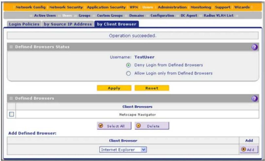
Figure 242.
-
In the Defined Browsers Status section of the screen, select one of the following radio buttons:
-
Deny Login from Defined Browsers. Deny logging in from the browsers in the Defined Browsers table.
-
Allow Login only from Defined Browsers. Allow logging in from the browsers in the Defined Browsers table.
-
Click Apply to save your settings.
-
In the Add Defined Browser section of the screen, add a browser to the Defined Browsers table by selecting one of the following browsers from the drop-down list:
-
Internet Explorer.
- Opera.
- Netscape Navigator.
- Firefox. Mozilla Firefox.
-
Mozilla. Other Mozilla browsers.
-
Click the Add table button. The browser is added to the Defined Browsers table.
- Repeat Step 6 and Step 7 for any other browsers that you want to add to the Defined Browsers table.
To delete one or more browsers:
- In the Defined Browsers table, select the check box to the left of each browser that you want to delete, or click the Select All table button to select all browsers.
- Click the Delete table button.
Change Passwords and Other User Settings
For any user, you can change the password, user type, and idle time-out settings. Only administrators have read/write access. All other users have read-only access.
Note: The default administrator and default guest passwords for the web management interface are both password. NETGEAR recommends that you change the password for the administrator account to a more secure password, and that you configure a separate secure password for the guest account.
Note: The ideal password should contain no dictionary words from any language, and should be a mixture of letters (both uppercase and lowercase), numbers, and symbols. Your password can be up to 30 characters.
Note: After a factory defaults reset, the password and time-out value are changed back to password and 5 minutes, respectively.
To modify user settings, including passwords:
- Select Users > Users. The Users screen displays (see Figure 238 on page 402).
- In the Action column of the List of Users table, click the Edit table button for the user for which you want to modify the settings. The Edit User screen displays:
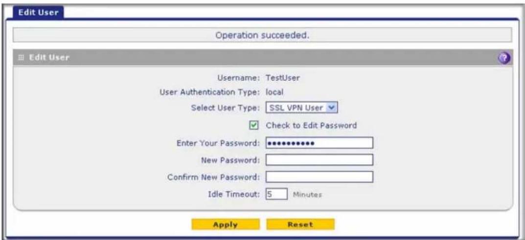
Figure 243.
- Modify the settings as explained in the following table:
Table 104. Edit User screen settings
| Setting Description | ||
| Select User Type | From the drop-down list, select one of the predefined user types that determines the access credentials:Administrator. User who has full access and the capacity to change the UTM configuration (that is, read/write access).SSL VPN User. User who can log in only to the SSL VPN portal.IPSEC VPN User. User who can make an IPSec VPN connection only through a NETGEAR ProSafe VPN Client, and only when the XAUTH feature is enabled (see Configure Extended Authentication (XAUTH) on page 308).Guest User. User who can only view the UTM configuration (that is, read-only access).PPTP VPN User. A user who can make a connection to the PPTP server only.L2TP VPN User. A user who can make a connection to the L2TP server only. | |
| Check to Edit Password | Select this check box to make the password fields accessible to modify the password. | |
| Enter Your Password Enter | the old password. | |
| New Password Enter the new password. | ||
| Confirm New Password Re | enter the new password for confirmation. | |
| Idle Timeout | The period after which an idle user is automatically logged out of the web management interface. The default idle time-out period is 5 minutes.Note:The idle time-out is not applicable to PPTP and L2TP users because the user time-out is already specified on the PPTP Server screen (see Configure the PPTP Server on page 331) and L2TP Server screen (see Configure the L2TP Server on page 334). | |
- Click Apply to save your settings.
DC Agent
If you set up an open network, you would want to allow unauthenticated users to surf anonymously. For a secure network, you would use a more restrictive access policy for unauthenticated users and a less restricted access policy for authenticated users.
Without the use of the DC agent, any Active Directory (AD) domain user surfs anonymously until providing credentials to the UTM in order to proceed past a blocked web activity. With use of the DC agent, an AD domain user is immediately known to the UTM when he or she is authenticated on a DC server on which the DC agent is installed, allowing a single sign-on (SSO).
If the AD authenticates through a domain controller (DC) server that runs Windows Server 2003 with Service Pack 1 (SP1) or Windows Server 2008, you can use the ProSecure DC Agent software to authenticate AD domain users.
Note: The DC agent does not function with LDAP domain users.
The DC agent monitors all Windows login events (that is, all AD domain user authentications) on the DC server, and provides a mapping of Windows user names and IP addresses to the UTM, enabling the UTM to apply user policies transparently. The DC agent transfers encrypted names, IP addresses, groups, and login times of the users logged in to the UTM, where this information remains securely (that is, it is not transferred out of the UTM).
Requirements for the ProSecure DC Agent Software and DC Agent Server
Note the following requirements for the ProSecure DC agent software and domain controller (DC) servers:
- If the DC server is located behind a firewall or there is a firewall on the DC server, ensure that the firewall does not block the server's listening port. The default port that is used by the DC agent is 5182.
- The DC agent needs to be able to automatically log an account login event when a domain user account is authenticated against the Active Directory on a DC server.
Verify that the DC server has the following configuration:
- The Audit Logon Events policy is defined, and the Success check box is selected.
- The Audit Account Logon Events policy is defined, and the Success check box is selected.
- The Audit Account Management policy is defined, and the Success check box is selected.
In addition, if you change the log path of the security log, restart the DC server to bring the change into effect.
- If you use the ProSecure DC Agent software on a DC server that is running Windows Server 2003, ensure that Window's Security Log settings in the Event Viewer are set to the maximum size of 16 MB and to overwrite events as needed.
Download ProSecure DC Agent Software, and Create and Delete DC Agents
When new ProSecure DC Agent software is available, the UTM automatically downloads the software from the update server and notifies administrative users in several ways:
- The UTM sends an email to administrative users.
• The UTM records a syslog entry. - The UTM generates a notification screen that is presented to administrative users upon login.
To download ProSecure DC Agent software and add a DC agent:
- Select Users > DC Agent. The DC Agent screen displays:

Figure 244.
- Under the List of DC Agents table, click the Download/Install link to download the ProSecure DC Agent software (that is, the dc_agent.mis file). Follow the instructions of your browser to save the software file to your computer.
- Install the ProSecure DC Agent software on each domain controller (DC) server through which the LDAP directory authenticates users. After installation, the ProSecure DC Agent control panel lets you configure and manage the DC agent. For more information, click the Help button on the control panel.

Figure 245.
- On the DC Agent screen (see Figure 244 on page 411), complete the fields and make your selections from the drop-down lists as explained in the following table:
Table 105. DC Agent screen settings
| Setting Description | |
| Domain | From the Domain drop-down list, select an Active Directory (AD) domain to bind with the DC agent. For information about configuring AD domains, see Configure Domains on page 388. |
| DC Agent Listening Port | Enter the listening port of the DC agent. The listening port is the port through which the DC agent transfers the list of authenticated users to the UTM. The default port is 5182. |
| Synchronization Interval | Enter the time interval (in seconds) at which the DC agent updates the list of authenticated users. The default interval is 15 seconds. |
| Expiration length Enter | time interval in hours or minutes (determined by your selection from the Expiration length drop-down list) that is allowed to elapse before a user login expires. The default setting is 0 (zero), that is, a user login does not expire. |
| Status Displays the status of the DC agent: ON indicates that the DC agent is active; OFF indicates that the DC agent is inactive. | |
- To add the newly configured DC agent to the List of DC Agent(s) table, click the Add table button in the Action column.
The Status column displays ON when a DC agent is available and OFF when a DC agent is not available.
To delete a DC agent from the table, click its Delete button in the Action column.
To edit a DC agent:
- In the Domain column, locate the DC agent that you want to edit, and make changes in the columns to the right of the Domain column as explained in the previous table.
- In the Action column, click the DC agent's Apply button to save your changes.
Example: Configure Active Directory Single Sign-On with a DC Agent
In the following example, you configure user authentication through Active Directory (AD) single sign-on (SSO) with the use of a DC agent on a UTM50:
- The domain name is Test_Domain.
- The IP address of the authentication server is 12.18.39.27.
- The AD domain is test_user.com.
• The IP address of the UTM50 is 90.49.145.18.
To configure AD SSO with a DC agent:
- Add a domain on the UTM50:
a. Select Users > Domains. The Domains screen displays.
b. Click the Add table button to add a domain. The Add Domain screen displays:

Figure 246.
c. Enter the following settings:
• In the Domain Name field, enter Test_Domain.
• From the Authentication Type drop-down list, select Active Directory.
- From the Select Portal drop-down list, select a portal. (In this example, the default portal is SSL-VPN.)
• In the Authentication Server field, enter 12.18.39.27.
• In the Active Directory Domain field, enter test_user.com.
- In the Bind DN field, enter a bind DN. (In this example, the bind DN is admin22@test_user.com.)
- In the Bind Password field, enter a password.
• In the Search Base field, enter dc=test_user,dc=com.
d. Click Apply to save your changes.
- Add a DC agent on the UTM50:
a. Select Users > DC Agent. The DC Agent screen displays:

Figure 247.
b. In the Domain field, enter Test_Domain.
c. In the Action column, click Add.
- Add the IP address of the UTM50 on the ProSecure DC Agent control panel:
a. Click Add.
b. In the Add a client pop-up screen, enter 90.49.145.18.
c. Click OK. The IP address of the UTM50 displays in the Allowed Client IPs field:

Figure 248.
- To verify that the UTM50 functions fine with the DC agent, search for active users that are logged in to the Test_Domain domain on the Active Users screen:
a. Select Users > Active Users. The Active Users screen displays.
b. Select the Search Criteria radio button.
c. In the Domain field, enter Test_Domain.
d. Click Search. If the users that are logged in to the Test_Domain domain display in the search results, the UTM50 functions fine with the DC agent. (For more information about active users, see View and Log Out Active Users on page 417.)
Configure RADIUS VLANs
You can use a RADIUS virtual LAN (VLAN) to set web access exceptions and provide an added layer of security.
To do so, follow this procedure:
- Specify a RADIUS server (see RADIUS Client and Server Configuration on page 310).
- Create a RADIUS domain (see Configure Domains on page 388).
- Add a RADIUS virtual LAN (VLAN) (see the information in this section).
Note: The VLAN ID or name should be same as the VLAN ID or name that is configured on the RADIUS server.
- Define web access exceptions for the users that are member of the RADIUS VLAN (see Set Exception Rules for Web and Application Access on page 248).
To configure a RADIUS VLAN:
- Select Users > Radius VLAN List. The List of VLAN screen displays. (The following figure contains one VLAN as an example.)
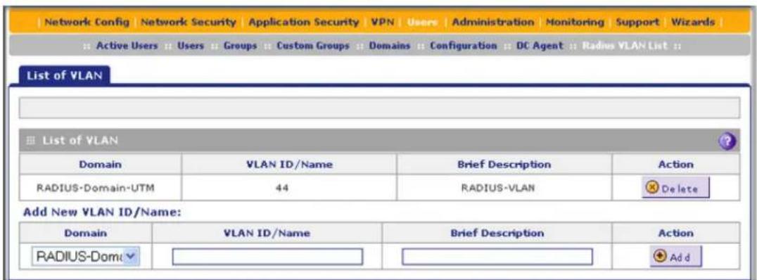
Figure 249.
The List of VLAN table displays the following fields:
- Domain. The RADIUS domain.
• VLAN ID/Name. The identifier or name for the VLAN. -
Brief Description. An optional brief description of the VLAN.
• Action. The Delete table button, which allows you to delete the VLAN. -
Add a VLAN by specifying the VLAN in the Add New VLAN ID/Name section of the screen:
a. Select a RADIUS VLAN from the Domain drop-down list.
b. In the VLAN ID/Name field, enter the identifier or the name of the VLAN.
c. In the Brief Description field, enter a description of the VLAN. This field is optional.
- Click the Add table button. The new VLAN is added to the List of VLAN table.
To delete a user from the List of VLAN table, click the Delete table button in the Action column for the VLAN that you want to delete.
Configure Global User Settings
You can globally set the user session settings for authenticated users. These settings include the session expiration period, the allowed session idle time, and the default domain that is presented to the users.
-
To specify the global user configuration settings:
-
Select Users > Configuration. The Configuration screen displays:

Figure 250.
- Locate the Session Parameters section on screen. Specify the session settings:
- Session Expiration Length. The period after which a session expires and a user needs to log in again. This setting applies to all users. From the drop-down list, select either Minutes or Hours. Then, in the field to the left of the drop-down list, enter a number for the minutes or hours. The session expiration length cannot exceed the idle time period. By default, the session expiration length is 24 hours.
Note: For information about how to set the time-out period for the web management interface, see Change Passwords and Administrator and Guest Settings on page 436.
- Idle Time. The period after which an idle connection is terminated and a user needs to log in again. This setting applies to all users. From the drop-down list, select either Minutes or Hours. Then, in the field to the left of the drop-down list, enter a number for the minutes or hours. The idle time period cannot exceed the session expiration length. By default, the idle time period is 8 hours.
- Click Apply to save the session settings.
- Locate the Users Portal Login Settings section on screen. Specify the default domain settings:
- From the Default Domain drop-down list, select a domain that you previously configured on the Domain screen (see Configure Domains on page 388). This domain is presented on the User Portal Login screen (see Figure 226 on page 382). By default, the domain that is presented is geardomain.
- Select the Authenticate User with User Selected Domain check box to limit the authentication on the User Portal Login screen to the domain that you select from the Default Domain drop-down list. If you do not select this check box, the UTM attempts to authenticate users through all the domains that are listed in the drop-down list on the User Portal Login screen. When authentication through one domain fails, the UTM attempts authentication through another domain.
- Click Apply to save the default domain settings.
View and Log Out Active Users
A user with administrative privileges can view the active users and log out selected or all active users.
To log out all active users:
- Select Users > Active Users. The Active Users screen displays:
![Network Config | Network Security | Application Security | VPN | Users | Administration | Monitoring | Support | Wizards | Active Users || Users || Groups || Custom Groups || Domains || Configuration || DC Agent || Radius VLAN List || Active Users Session Parameter: [Logout All Users] View All Search Criteria: IP Address: (Example: 192.168.32.1 , 192.168.32.0/24) Domain: User: Login Type: □ DC Agent □ User Portal □ SSL VPN Display: 15 entries per page Search](/content/2026/06/1371942/images/b12077060727c120fb2e3056f7d5906357a7779d0c6196b70acd0fb681264fff.jpg)
Figure 251.
- Click the Logout All Users button in the gray settings bar at the top of the Active Users screen.
To view all or selected users:
- On the Active Users screen (see the previous figure), select one of the following radio buttons:
• View All. This selection returns all active users after you click the Search button.
• Search Criteria. Enter one or more search criteria as explained in the following table:
Table 106. Active Users screen settings
| Setting Description | |
| IP Address Enter an | IP address or an IP address and subnet mask in Classless Inter-Domain Routing (CIDR) notation (for example, /024). |
| Domain Enter a domain | for example, geardomain). |
| User | Enter a user name (for example, JackP). If you do not enter a user name, all users of a specified domain are displayed in the search results. |
| Login Type Select one | or more of the following check boxes:DC Agent. Display only users who logged in through the DC agent.User Portal. Display only users who logged in through a user portal.SSL VPN. Display only users who logged in through an SSL VPN connection. |
- In the Display field, enter a number to specify how many entries per page the search result screen returns.
- Click Search. The search results screen displays. (The following figure contains many examples.)

Figure 252.
ProSecure Unified Threat Management (UTM) Appliance
The List of Users table displays the following fields:
• IP Address. The IP address that is associated with the user.
- Domain. The domain to which the user belongs.
- User. The user name.
- Groups. The groups to which the user belongs, if any.
- Last Seen. The most recent time that scanned traffic associated with the user (that is, IP address) passed through the UTM.
- Login Type. The method through which the user logged in (DC agent, user portal, or SSL VPN).
To log out selected active users or all active users that your search yielded:
- On the search results screen, select the check boxes to the left of the users that you want to log out, or select the check box at the upper left in the List of Users table.
- Click Logout.
- Click Return.
Manage Digital Certificates for VPN Connections
• VPN Certificates Screen
- Manage CA Certificates
- Manage Self-Signed Certificates
- Manage the Certificate Revocation List
Note: For information about digital certificates for HTTPS scans, see Manage SSL Certificates for HTTPS Scanning on page 231.
The UTM uses digital certificates (also known as X509 certificates) during the Internet Key Exchange (IKE) authentication phase to authenticate connecting IPSec VPN gateways or clients, or to be authenticated by remote entities. The same digital certificates are extended for secure web access connections over HTTPS (that is, SSL connections).
Digital certificates either can be self-signed or can be issued by certification authorities (CAs) such as an internal Windows server or an external organization such as VeriSign or Thawte.
However, if the digital certificate contains the extKeyUsage extension, the certificate needs to be used for one of the purposes defined by the extension. For example, if the digital certificate contains the extKeyUsage extension that is defined for SNMPv2, the same certificate cannot be used for secure web management. The extKeyUsage would govern the certificate acceptance criteria on the UTM when the same digital certificate is being used for secure web management.
On the UTM, the uploaded digital certificate is checked for validity and purpose. The digital certificate is accepted when it passes the validity test and the purpose matches its use. The check for the purpose needs to correspond to its use for IPSec VPN, SSL VPN, or both. If the defined purpose is for IPSec VPN and SSL VPN, the digital certificate is uploaded to both the IPSec VPN certificate repository and the SSL VPN certificate repository. However, if the defined purpose is for IPSec VPN only, the certificate is uploaded only to the IPSec VPN certificate repository.
The UTM uses digital certificates to authenticate connecting VPN gateways or clients, and to be authenticated by remote entities. A digital certificate that authenticates a server, for example, is a file that contains the following elements:
- A public encryption key to be used by clients for encrypting messages to the server.
• Information identifying the operator of the server. - A digital signature confirming the identity of the operator of the server. Ideally, the signature is from a trusted third party whose identity can be verified.
You can obtain a digital certificate from a well-known commercial certification authority (CA) such as VeriSign or Thawte, or you can generate and sign your own digital certificate. Because a commercial CA takes steps to verify the identity of an applicant, a digital certificate from a commercial CA provides a strong assurance of the server's identity. A self-signed certificate triggers a warning from most browsers because it provides no protection against identity theft of the server.
The UTM contains a self-signed certificate from NETGEAR. This certificate can be downloaded from the UTM login screen for browser import. However, NETGEAR recommends that you replace this digital certificate with a digital certificate from a well-known commercial CA before you deploy the UTM in your network.
VPN Certificates Screen
To display the Certificates screen, select VPN > Certificates. Because of the large size of this screen, and because of the way the information is presented, the Certificates screen is divided and presented in this manual in three figures (Figure 253 on page 421, Figure 255 on page 423, and Figure 257 on page 426).
The Certificates screen lets you view the currently loaded digital certificates, upload a new digital certificate, and generate a certificate signing request (CSR). The UTM typically holds two types of digital certificates:
- CA certificates. Each CA issues its own digital certificate to validate communication with the CA and to verify the validity of digital certificates that are signed by the CA.
- Self-signed certificates. The digital certificates that are issued to you by a CA to identify your device.
The Certificates screen contains four tables that are explained in detail in the following sections:
- Trusted Certificates (CA Certificate) table. Contains the trusted certificates that were issued by CAs and that you uploaded (see Manage CA Certificates on this page).
• Active Self Certificates table. Contains the self-signed certificates that were issued by CAs and that you uploaded (see Manage Self-Signed Certificates on page 422).
- Self Certificate Requests table. Contains the self-signed certificate requests that you generated. These requests might or might not have been submitted to CAs, and CAs might or might not have issued certificates for these requests. Only the self-signed certificates in the Active Self Certificates table are active on the UTM (see Manage Self-Signed Certificates on page 422).
- Certificate Revocation Lists (CRL) table. Contains the lists with certificates that have been revoked and are no longer valid, that were issued by CAs, and that you uploaded. Note, however, that the table displays only the active CAs and their critical release dates. (see Manage the Certificate Revocation List on page 426).
Manage CA Certificates
To view and upload trusted certificates:
Select VPN > Certificates. The Certificates screen displays. (The following figure shows the top section of the screen with the trusted certificate information and some example certificates in the Trusted Certificates (CA Certificate) table.)

Figure 253. Certificates, screen 1 of 3
The Trusted Certificates (CA Certificate) table lists the digital certificates of CAs and contains the following fields:
- CA Identity (Subject Name). The organization or person to whom the digital certificate is issued.
- Issuer Name. The name of the CA that issued the digital certificate.
- Expiry Time. The date after which the digital certificate becomes invalid.
To upload a digital certificate of a trusted CA on the UTM:
- Download a digital certificate file from a trusted CA and store it on your computer.
- In the Upload Trusted Certificates section of the screen, click the Browse button and navigate to the trusted digital certificate file that you downloaded on your computer.
- Click the Upload table button. If the verification process on the UTM approves the digital certificate for validity and purpose, the digital certificate is added to the Trusted Certificates (CA Certificates) table.
To delete one or more digital certificates:
- In the Trusted Certificates (CA Certificate) table, select the check box to the left of each digital certificate that you want to delete, or click the Select All table button to select all digital certificates.
- Click the Delete table button.
Manage Self-Signed Certificates
Instead of obtaining a digital certificate from a CA, you can generate and sign your own digital certificate. However, a self-signed certificate triggers a warning from most browsers because it provides no protection against identity theft of the server. (The following figure shows an image of a browser security alert.)
There can be three reasons why a security alert is generated for a security certificate:
• The security certificate was issued by a company you have not chosen to trust.
• The date of the security certificate is invalid.
• The name on the security certificate is invalid or does not match the name of the site.
When a security alert is generated, the user can decide whether to trust the host.
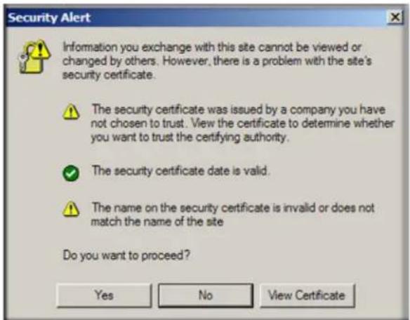
Figure 254.
Generate a CSR and Obtain a Self-Signed Certificate from a CA
To use a self-signed certificate, you first need to request the certificate from a CA, and then download and activate the certificate on the UTM. To request a self-signed certificate from a CA, you need to generate a certificate signing request (CSR) for and on the UTM. The CSR is a file that contains information about your company and about the device that holds the certificate. Refer to the CA for guidelines about the information that you need to include in your CSR.
To generate a new CSR file, obtain a digital certificate from a CA, and upload it to the UTM:
- Select VPN > Certificates. The Certificates screen displays. The following figure shows the middle section of the screen with the Active Self Certificates section, Generate Self Certificate Request section, and Self Certificate Requests section. (The Self Certificate Requests table contains some examples.)

Figure 255. Certificates, screen 2 of 3
- In the Generate Self Certificate Request section of the screen, enter the settings as explained in the following table:
Table 107. Generate self-signed certificate request settings
| Setting Description | ||
| Name A descriptive name | of the domain for identification and management purposes. | |
| Subject | The name that other organizations see as the holder (owner) of the certificate. In general, use your registered business name or official company name for this purpose.Note:Generally, all of your certificates should have the same value in the Subject field. | |
| Hash Algorithm From the | drop-down list, select one of the following hash algorithms:MD5.A 128-bit (16-byte) message digest, slightly faster than SHA-1.SHA-1.A 160-bit (20-byte) message digest, slightly stronger than MD5. | |
| Signature Algorithm | Although this seems to be a drop-down list, the only possible selection is RSA. In other words, RSA is the default to generate a CSR. | |
| Signature Key Length From | the drop-down list, select one of the following signature key lengths in bits:51210242048Note:Larger key sizes might improve security, but might also decrease performance. | |
| Optional Fields IP Address | Enter your fixed (static) IP address. If your IP address is dynamic, leave this field blank. | |
| Domain Name Enter your Internet domain name, or leave this field blank. | ||
| E-mail Address | Enter the email address of a technical contact in your company. | |
- Click the Generate table button. A new SCR is created and added to the Self Certificate Requests table.
- In the Self Certificate Requests table, click the View table button in the Action column to view the new SCR. The Certificate Request Data screen displays:

Figure 256.
- Copy the contents of the Data to supply to CA text field into a text file, including all of the data contained from “----BEGIN CERTIFICATE REQUEST----” to “----END CERTIFICATE REQUEST----.”
- Submit your SCR to a CA:
a. Connect to the website of the CA.
b. Start the SCR procedure.
c. When prompted for the requested data, copy the data from your saved text file (including “----BEGIN CERTIFICATE REQUEST----” and “----END CERTIFICATE REQUEST----”).
d. Submit the CA form. If no problems ensue, the digital certificate is issued by the CA.
- Download the digital certificate file from the CA, and store it on your computer.
- Return to the Certificates screen (see Figure 255 on page 423) and locate the Self Certificate Requests section.
- Select the check box next to the self-signed certificate request.
- Click the Browse button and navigate to the digital certificate file from the CA that you just stored on your computer.
- Click the Upload table button. If the verification process on the UTM approves the digital certificate for validity and purpose, the digital certificate is added to the Active Self Certificates table.
To delete one or more SCRs:
- In the Self Certificate Requests table, select the check box to the left of each SCR that you want to delete, or click the Select All table button to select all SCRs.
- Click the Delete table button.
View and Manage Self-Signed Certificates
The Active Self Certificates table on the Certificates screen (see Figure 255 on page 423) shows the digital certificates issued to you by a CA and available for use. For each self-signed certificate, the table lists the following information:
- Name. The name that you used to identify this certificate.
- Subject Name. The name that you used for your company and that other organizations see as the holder (owner) of the certificate.
- Serial Number. This is a serial number maintained by the CA. It is used to identify the certificate with the CA.
- Issuer Name. The name of the CA that issued the certificate.
- Expiry Time. The date on which the certificate expires. You should renew the certificate before it expires.
To delete one or more self-signed certificates:
- In the Active Self Certificates table, select the check box to the left of each self-signed certificate that you want to delete, or click the Select All table button to select all self-signed certificates.
- Click the Delete table button.
Manage the Certificate Revocation List
A Certificate Revocation List (CRL) file shows digital certificates that have been revoked and are no longer valid. Each CA issues its own CRLs. It is important that you keep your CRLs up-to-date. You should obtain the CRL for each CA regularly.
To view the currently loaded CRLs and upload a new CRL:
- Select VPN > Certificates. The Certificates screen displays. The following figure shows the bottom section of the screen with the Certificate Revocation Lists (CRL) table. (There is one example in the table.)

Figure 257. Certificates, screen 3 of 3
ProSecure Unified Threat Management (UTM) Appliance
The Certificate Revocation Lists (CRL) table lists the active CAs and their critical release dates:
• CA Identity. The official name of the CA that issued the CRL.
• Last Update. The date when the CRL was released.
- Next Update. The date when the next CRL will be released.
-
In the Upload CRL section, click the Browse button and navigate to the CLR file that you previously downloaded from a CA.
-
Click the Upload table button. If the verification process on the UTM approves the CRL, the CRL is added to the Certificate Revocation Lists (CRL) table.
Note: If the table already contains a CRL from the same CA, the old CRL is deleted when you upload the new CRL.
To delete one or more CRLs:
- In the Certificate Revocation Lists (CRL) table, select the check box to the left of each CRL that you want to delete, or click the Select All table button to select all CRLs.
- Click the Delete table button.
This chapter describes the tools for managing the network traffic to optimize its performance and the system management features of the UTM. This chapter contains the following sections:
• Performance Management
- System Management
- Connect to a ReadyNAS and Configure Quarantine Settings
Performance Management
- Bandwidth Capacity
• Features That Reduce Traffic - Features That Increase Traffic
- Use QoS and Bandwidth Assignments to Shift the Traffic Mix
• Monitoring Tools for Traffic Management
Performance management consists of controlling the traffic through the UTM so that the necessary traffic gets through when there is a bottleneck. You can either reduce unnecessary traffic or reschedule some traffic to low-peak times to prevent bottlenecks from occurring in the first place. The UTM has the necessary features and tools to help the network manager accomplish these goals.
Bandwidth Capacity
The maximum bandwidth capacity of the UTM in each direction is as follows:
- LAN side (single WAN port models and multiple WAN port models). 4000 Mbps (four LAN ports at 1000 Mbps each), except for the UTM50, which has six LAN ports and therefore supports up to 6000 Mbps.
- WAN side
- Load balancing mode (multiple WAN port models only). 2000 Mbps (two WAN ports at 1000 Mbps each), except for the UTM150, which has four WAN ports and therefore supports up to 4000 Mbps.
ProSecure Unified Threat Management (UTM) Appliance
- Auto-rollover mode (multiple WAN port models only). 1000 Mbps (one active WAN port at 1000 Mbps).
- Primary WAN mode (single WAN port models and multiple WAN port models). 1000 Mbps (one active WAN port at 1000 Mbps).
In practice, the WAN-side bandwidth capacity is much lower when DSL or cable modems are used to connect to the Internet. At 1.5 Mbps, the WAN ports support the following traffic rates:
- Load balancing mode (multiple WAN port models only). 3 Mbps (two WAN ports at 1.5 Mbps each), except for the UTM150, which has four WAN ports and therefore supports up to 6 Mbps.
- Auto-rollover mode (multiple WAN port models only). 1.5 Mbps (one active WAN port at 1.5 Mbps).
- Primary WAN mode (single WAN port models and multiple WAN port models). 1.5 Mbps (one active WAN port at 1.5 Mbps).
As a result, and depending on the traffic that is being carried, the WAN side of the UTM is the limiting factor for the data rate for most installations.
Using the WAN ports in load balancing mode increases the bandwidth capacity of the WAN side of the UTM, but there is no backup in case one of the WAN ports fails. When such a failure occurs, the traffic that would have been sent on the failed WAN port is diverted to the WAN port that is still working, thus increasing its load. However, there is one exception: Traffic that is bound by protocol to the WAN port that failed is not diverted.
Features That Reduce Traffic
You can adjust the following features of the UTM in such a way that the traffic load on the WAN side decreases:
• LAN WAN outbound rules (also referred to as service blocking)
- DMZ WAN outbound rules (also referred to as service blocking)
- Content filtering
- Source MAC filtering
LAN WAN Outbound Rules and DMZ WAN Outbound Rules (Service Blocking)
You can control specific outbound traffic (from LAN to WAN and from the DMZ to WAN). The LAN WAN Rules screen and the DMZ WAN Rules screen list all existing rules for outbound traffic. If you have not defined any rules, only the default rule is listed. The default rule allows all outgoing traffic. Any outbound rule that you create restricts outgoing traffic and therefore decreases the traffic load on the WAN side.
Each rule lets you specify the desired action for the connections that are covered by the rule:
- BLOCK always
- ALLOW always
The following section summarizes the various criteria that you can apply to outbound rules in order to reduce traffic. For more information about outbound rules, see Outbound Rules (Service Blocking) on page 129. For detailed procedures on how to configure outbound rules, see Configure LAN WAN Rules on page 139 and Configure DMZ WAN Rules on page 142.
When you define outbound firewall rules, you can further refine their application according to the following criteria:
-
Services. You can specify the services or applications, or groups of services or applications to be covered by an outbound rule. If the desired service or application does not display in the list, you need to define it using the Services screen (see Outbound Rules (Service Blocking) on page 129 and Add Customized Services on page 163).
• LAN users (or DMZ users). You can specify which computers on your network are affected by an outbound rule. There are several options: -
Any. The rule applies to all computers and devices on your LAN or DMZ
- Single address. The rule applies to the address of a particular computer.
- Address range. The rule applies to a range of addresses.
- Groups. The rule applies to a group of computers. (You can configure groups for LAN WAN outbound rules but not for DMZ WAN outbound rules.) The Known PCs and Devices table is an automatically maintained list of all known computers and network devices and is generally referred to as the network database, which is described in Manage the Network Database on page 112. Computers and network devices are entered into the network database by various methods, which are described in Manage Groups and Hosts (LAN Groups) on page 111.
- IP Groups. The rule applies to a group of individual LAN IP addresses. Use the IP Groups screen (under the Network Security main navigation menu) to assign IP addresses to groups. For more information, see Create IP Groups on page 167. (You cannot configure IP groups for DMZ WAN outbound rules.)
- WAN users. You can specify which Internet locations are covered by an outbound rule, based on their IP address:
- Any. The rule applies to all Internet IP address.
- Single address. The rule applies to a single Internet IP address.
- Address range. The rule applies to a range of Internet IP addresses.
- IP Groups. The rule applies to a group of individual WAN IP addresses. Use the IP Groups screen (under the Network Security main navigation menu) to assign IP addresses to groups. For more information, see Create IP Groups on page 167.
- Users allowed. You can specify that the rule applies to individual users in the network, groups in the network, or both. To configure users accounts, see Configure User Accounts on page 401. To configure groups, see Configure Groups on page 394 and Configure Custom Groups on page 397.
- Schedule. You can configure multiple schedules to specify when a rule is applied. Once a schedule is configured, it affects all rules that use this schedule. You specify the days of the week and time of day for each schedule. For more information, see Set a Schedule to Block or Allow Specific Traffic on page 177.
- QoS profile. You can define QoS profiles and then apply them to outbound rules to regulate the priority of traffic. For information about how to define QoS profiles, see Create Quality of Service Profiles on page 169.
- Traffic Meter profile. You can define traffic meter profiles and then apply them to outbound rules to measure traffic and to block traffic that exceeds a threshold. For information about how to define traffic meter profiles, see Create Traffic Meter Profiles on page 174.
- Bandwidth profile. You can define bandwidth profiles and then apply them to outbound rules to limit traffic. For information about how to define bandwidth profiles, see Create Bandwidth Profiles on page 171. (You cannot apply bandwidth profiles to DMZ WAN outbound rules.)
Content Filtering
If you want to reduce traffic by preventing undesired emails from reaching their destinations or by preventing access to certain sites on the Internet, you can use the UTM's content-filtering feature. By default, this feature is disabled; all requested traffic from any website is allowed except for web content categories that are mentioned in Default Email and Web Scan Settings on page 193.
- Email content filtering. To reduce incoming email traffic, you can block emails with large attachments, reject emails based on keywords, file extensions, or file names, and set spam protection rules. There are several ways you can reduce undesired email traffic:
- Setting the size of email files to be scanned. Scanning large email files requires network resources and might slow down traffic. You can specify the maximum size of the files or messages that are scanned, and if files that exceed the maximum size are skipped (which might compromise security) or blocked. For more information, see Customize Email Antivirus and Notification Settings on page 196.
- Keyword, file extension, and file name blocking. You can reject emails based on keywords in the subject line, file type of the attachment, and file name of the attachment. For more information, see Email Content Filtering on page 199.
- Protecting against spam. Set up spam protection to prevent spam from using up valuable bandwidth. For more information, see Protect Against Email Spam on page 202.
- Web content filtering. The UTM provides extensive methods to filter web content in order to reduce traffic:
- Web category blocking. You can block entire web categories because their content is undesired, offensive, or not relevant, or simply to reduce traffic. For more information, see Configure Web Content Filtering on page 218.
- Keyword and file extension blocking. You can specify words that, should they appear in the website name (URL), file extension, or newsgroup name, cause that site, file, or newsgroup to be blocked by the UTM. For more information, see Configure Web Content Filtering on page 218.
- URL blocking. You can specify up to 200 URLs that are blocked by the UTM. For more information, see Configure Web URL Filtering on page 224.
- Web services blocking. You can block web services such as instant messaging, peer-to-peer and media applications, and tools. For more information, see Customize Web Protocol Scan Settings on page 210.
- Web object blocking. You can block the following web component types: embedded objects (ActiveX, Java, Flash), proxies, and cookies; and you can disable JavaScripts. For more information, see Configure Web Content Filtering on page 218.
- Setting the size of web files to be scanned. Scanning large web files requires network resources and might slow down traffic. You can specify the maximum size of the files that are scanned, and if files that exceed the maximum size are skipped (which might compromise security) or blocked. For more information, see Configure Web Malware or Antivirus Scans on page 216.
For these features (except for web object blocking and setting the size of files to be scanned), you can set schedules to specify when web content is filtered (see Configure Web Content Filtering on page 218), and configure exceptions for groups (see Set Exception Rules for Web and Application Access on page 248).
- Application control. The UTM provides extensive methods to filter traffic for entire categories of applications, for individual applications, or for a combination of both. For more information, see Configure Application Control on page 240.
Source MAC Filtering
If you want to reduce outgoing traffic by preventing Internet access by certain computers on the LAN, you can use the source MAC filtering feature to drop the traffic received from the computers with the specified MAC addresses. By default, this feature is disabled; all traffic received from computers with any MAC address is allowed. See Enable Source MAC Filtering on page 179 for the procedure on how to use this feature.
Features That Increase Traffic
The following features of the UTM tend to increase the traffic load on the WAN side:
• LAN WAN inbound rules (also referred to as port forwarding)
- DMZ WAN inbound rules (also referred to as port forwarding)
- Port triggering
- Enabling the DMZ port
- Configuring exposed hosts
- Configuring VPN tunnels
LAN WAN Inbound Rules and DMZ WAN Inbound Rules (Port Forwarding)
The LAN WAN Rules screen and the DMZ WAN Rules screen list all existing rules for inbound traffic (from WAN to LAN and from WAN to the DMZ). If you have not defined any rules, only the default rule is listed. The default rule blocks all access from outside except responses to requests from the LAN side. Any inbound rule that you create allows additional incoming traffic and therefore increases the traffic load on the WAN side.
Each rule lets you specify the desired action for the connections covered by the rule:
- BLOCK always
- ALLOW always
The following section summarizes the various criteria that you can apply to inbound rules and that might increase traffic. For more information about inbound rules, see Inbound Rules (Port Forwarding) on page 133. For detailed procedures on how to configure inbound rules, see Configure LAN WAN Rules on page 139 and Configure DMZ WAN Rules on page 142.
When you define inbound firewall rules, you can further refine their application according to the following criteria:
- Services. You can specify the services or applications, or groups of services or applications to be covered by an inbound rule. If the desired service or application does not display in the list, you need to define it using the Services screen (see Outbound Rules (Service Blocking) on page 129 and Add Customized Services on page 163).
- WAN destination IP address. For the multiple WAN port models only, you can specify the destination IP address for incoming traffic. Traffic is directed to the specified address only when the destination IP address of the incoming packet matches the IP address of the selected WAN interface. For the single WAN port models, the WAN Destination IP Address is a fixed field.
• LAN users (or DMZ users). You can specify which computers on your network are affected by an inbound rule. There are several options:
- Any. The rule applies to all computers and devices on your LAN.
- Single address. The rule applies to the address of a particular computer.
- Address range. The rule applies to a range of addresses.
- Groups. The rule is applied to a group of computers. (You can configure groups for LAN WAN inbound rules but not for DMZ WAN inbound rules.) The Known PCs and Devices table is an automatically maintained list of all known computers and network devices and is generally referred to as the network database, which is described in Manage the Network Database on page 112. Computers and network devices are entered into the network database by various methods, which are described in Manage Groups and Hosts (LAN Groups) on page 111.
- IP Groups. The rule applies to a group of individual LAN IP addresses. Use the IP Groups screen (under the Network Security main navigation menu) to assign IP addresses to groups. For more information, see Create IP Groups on page 167. (You cannot configure IP groups for DMZ WAN inbound rules.)
- WAN users. You can specify which Internet locations are covered by an inbound rule, based on their IP address:
- Any. The rule applies to all Internet IP address.
- Single address. The rule applies to a single Internet IP address.
- Address range. The rule applies to a range of Internet IP addresses.
-
IP Groups. The rule applies to a group of individual WAN IP addresses. Use the IP Groups screen (under the Network Security main navigation menu) to assign IP addresses to groups. For more information, see Create IP Groups on page 167.
-
Users allowed. You can specify that the rule applies to individual users in the network, groups in the network, or both. To configure users accounts, see Configure User Accounts on page 401. To configure groups, see Configure Groups on page 394 and Configure Custom Groups on page 397. (You cannot narrow down DMZ WAN inbound rules to individual users or groups in the network.)
- Schedule. You can configure multiple schedules to specify when a rule is applied. Once a schedule is configured, it affects all rules that use this schedule. You specify the days of the week and time of day for each schedule. For more information, see Set a Schedule to Block or Allow Specific Traffic on page 177.
- QoS profile. You can define QoS profiles and then apply them to inbound rules to regulate the priority of traffic. For information about how to define QoS profiles, see Create Quality of Service Profiles on page 169.
- Traffic Meter profile. You can define traffic meter profiles and then apply them to inbound rules to measure traffic and to continue to allow traffic that exceeds a threshold. For information about how to define traffic meter profiles, see Create Traffic Meter Profiles on page 174.
- Bandwidth profile. You can define bandwidth profiles and then apply them to inbound rules to limit traffic. For information about how to define bandwidth profiles, see Create Bandwidth Profiles on page 171. (You cannot apply bandwidth profiles to DMZ WAN inbound rules.)
Port Triggering
Port triggering allows some applications running on a LAN network to be available to external applications that would otherwise be partially blocked by the firewall. Using the port-triggering feature requires that you know the port numbers used by the application. Without port triggering, the response from the external application would be treated as a new connection request rather than a response to a request from the LAN network. As such, it would be handled in accordance with the inbound port-forwarding rules, and most likely would be blocked.
For the procedure on how to configure port triggering, see Configure Port Triggering on page 183.
Configure the DMZ Port
The demilitarized zone (DMZ) is a network that, by default, has fewer firewall restrictions when compared to the LAN. The DMZ can be used to host servers (such as a web server, FTP server, or email server) and provide public access to them. On the UTM5, UTM10, UTM25, and UTM150, LAN port 4 can be dedicated as a hardware DMZ port to provide services safely to the Internet without compromising security on your LAN. On the UTM50, LAN port 6 can be dedicated as a hardware DMZ port. By default, the DMZ port and both inbound and outbound DMZ traffic are disabled. Enabling the DMZ port and allowing traffic to and from the DMZ increases the traffic through the WAN ports.
For information about how to enable the DMZ port, see Configure and Enable the DMZ Port on page 117. For the procedures about how to configure DMZ traffic rules, see Configure DMZ WAN Rules on page 142.
Configure Exposed Hosts
Specifying an exposed host allows you to set up a computer or server that is available to anyone on the Internet for services that you have not yet defined. For an example of how to set up an exposed host, see LAN WAN or DMZ WAN Inbound Rule: Specify an Exposed Host on page 152.
Configure VPN Tunnels
The UTM supports site-to-site IPSec VPN tunnels and dedicated SSL VPN tunnels. Each tunnel requires extensive processing for encryption and authentication, thereby increasing traffic through the WAN ports.
For information about IPSec VPN tunnels, see Chapter 7, Virtual Private Networking Using IPSec, PPTP, or L2TP Connections. For information about SSL VPN tunnels, see Chapter 8, Virtual Private Networking Using SSL Connections.
Use QoS and Bandwidth Assignments to Shift the Traffic Mix
By specifying QoS and bandwidth profiles and assigning these profiles to outbound and inbound firewall rules, you can shift the traffic mix to aim for optimum performance of the UTM.
Assign QoS Profiles
The QoS profile settings determine the priority and, in turn, the quality of service for the traffic passing through the UTM. After you have created a QoS profile, you can assign the QoS profile to firewall rules. The QoS is set individually for each service. You can change the mix of traffic through the WAN ports by granting some services a higher priority than others:
- You can accept the default priority defined by the service itself by not changing its QoS setting.
- You can change the priority to a higher or lower value than its default setting to give the service higher or lower priority than it otherwise would have.
For more information about QoS profiles, see Create Quality of Service Profiles on page 169.
Assign Bandwidth Profiles
When you apply a QoS profile, the WAN bandwidth does not change. You change the WAN bandwidth that is assigned to a service or application by applying a bandwidth profile. The purpose of bandwidth profiles is to provide a method for allocating and limiting traffic, thus allocating LAN users sufficient bandwidth while preventing them from consuming all the bandwidth on your WAN links.
For more information about bandwidth profiles, see Create Bandwidth Profiles on page 171.
Monitoring Tools for Traffic Management
The UTM includes several tools that can be used to monitor the traffic conditions of the firewall and content-filtering engine and to monitor the users' access to the Internet and the types of traffic that they are allowed to have. See Chapter 11, Monitor System Access and Performance, for a description of these tools.
System Management
- Change Passwords and Administrator and Guest Settings
- Configure Remote Management Access
• Use a Simple Network Management Protocol Manager - Manage the Configuration File
- Update the Firmware
- Update the Scan Signatures and Scan Engine Firmware
- Configure Date and Time Service
Change Passwords and Administrator and Guest Settings
The default administrator and default guest passwords for the web management interface are both password. NETGEAR recommends that you change the password for the administrator account to a more secure password, and that you configure a separate secure password for the guest account.
To modify the administrator and guest user account settings, including the password:
- Select Users > Users. The Users screen displays. (The following figure shows the UTM's default users—admin and guest—and, as an example, several other users in the List of Users table.)
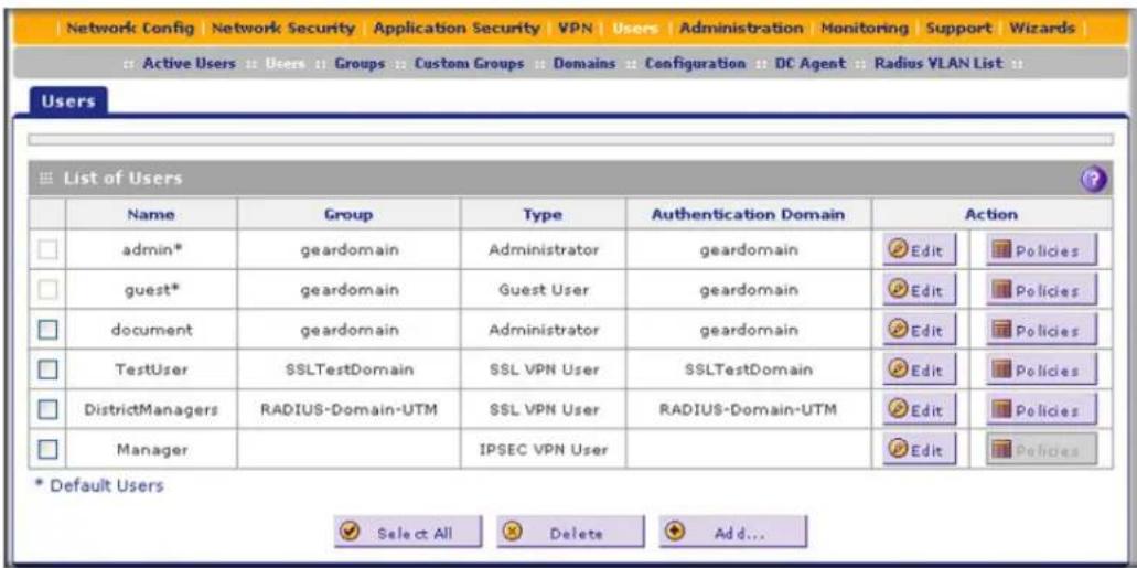
Figure 258.
- In the Action column of the List of Users table, click the Edit table button for the user with the name admin. The Edit User screen displays:

Figure 259.
- Select the Check to Edit Password check box. The password fields become available.
- Enter the old password, enter the new password, and then confirm the new password.
Note: The ideal password should contain no dictionary words from any language, and should be a mixture of letters (both uppercase and lowercase), numbers, and symbols. Your password can be up to 30 characters.
- As an option, you can change the idle time-out for an administrator login session. Enter a new number of minutes in the Idle Timeout field. (The default setting is 5 minutes.)
- Click Apply to save your settings.
- Repeat Step 1 through Step 6 for the user with the name guest.
Note: After a factory defaults reset, the password and time-out value are changed back to password and 5 minutes, respectively.
You can also change the administrator login policies:
- Deny login access from a WAN interface. By default, the administrator can log in from a WAN interface.
- Deny or allow login access from specific IP addresses. By default, the administrator can log in from any IP address.
Note: For enhanced security, restrict access to as few external IP addresses as practical.
- Deny or allow login access from specific browsers. By default, the administrator can log in from any browser.
In general, these policy settings work well for an administrator. However, if you need to change any of these policy settings, see Set User Login Policies on page 404.
Configure Remote Management Access
An administrator can configure, upgrade, and check the status of the UTM over the Internet through a Secure Sockets Layer (SSL) VPN connection.
Note: When remote management is enabled and administrative access through a WAN interface is granted (see Configure Login Policies on page 404), the UTM's web management interface is accessible to anyone who knows its IP address and default password. Because a malicious WAN user can reconfigure the UTM and misuse it in many ways, NETGEAR highly recommends that you change the admin and guest default passwords before continuing (see Change Passwords and Administrator and Guest Settings on page 436).
To configure the UTM for remote management:
- Select Administration > Remote Management. The Remote Management screen displays:

Figure 260.
- Select one of the following radio buttons:
• Yes. Enable HTTPS remote management. This is the default setting.
• No. Disable HTTPS remote management.

WARNING:
If you are remotely connected to the UTM and you select the No radio button, you and all other SSL VPN users are disconnected when you click Apply.
- As an option, you can change the default HTTPS port. The default port number is 443.
- Click Apply to save your changes.
When remote management is enabled, you need to use an SSL connection to access the UTM from the Internet. You need to enter https:// (not http://) and type the UTM's WAN IP address in your browser. For example, if the UTM's WAN IP address is 10.16.0.123, type the following in your browser: https://10.16.0.123.
The UTM's remote login URL is:
https://
Note: For enhanced security, restrict access to as few external IP addresses as practical. See Set User Login Policies on page 404 for instructions about restricting administrator access by IP address.
Note: To maintain security, the UTM rejects a login that uses http://address rather than the SSL https://address.
Note: The first time that you remotely connect to the UTM with a browser through an SSL connection, you might get a warning message regarding the SSL certificate. If you are using a Windows computer with Internet Explorer 5.5 or later, simply click Yes to accept the certificate.
Note: If you are unable to connect remotely to the UTM after enabling HTTPS remote management, check if other user policies, such as the default user policy, are preventing access. For access to the UTM's web management interface, check if administrative access through a WAN interface is granted (see Configure Login Policies on page 404).
Note: If you disable HTTPS remote management, all SSL VPN user connections are also disabled.
Tip: If you are using a Dynamic DNS service such as TZO, you can identify the WAN IP address of your UTM by running tracert from the Windows Run menu option. Trace the route to your registered FQDN. For example, enter tracert UTM.mynetgear.net, and the WAN IP address that your ISP assigned to the UTM is displayed.
Use a Simple Network Management Protocol Manager
Simple Network Management Protocol (SNMP) forms part of the Internet Protocol Suite as defined by the Internet Engineering Task Force (IETF). SNMP is used in network management systems to monitor network-attached devices for conditions that warrant administrative attention.
SNMP exposes management data in the form of variables on the managed systems, which describe the system configuration. These variables can then be queried (and sometimes set) by managing applications.
SNMP lets you monitor and manage your UTM from an SNMP manager. It provides a remote means to monitor and control network devices, and to manage configurations, statistics collection, performance, and security.
To configure the global SNMP settings and SNMPv1/v2c settings:
- Select Administration > SNMP. The SNMP screen displays:
ProSecure Unified Threat Management (UTM) Appliance

Figure 261.
- Enter the settings as explained in the following table:
Table 108. Global SNMP settings and SNMPv1/v2c settings
| Setting Description | ||
| SNMP Global Settings | ||
| Do You Want to Enable SNMP? | Select one of the following radio buttons:Yes. Enable SNMP.No. Disable SNMP. This is the default setting. | |
| Enable Access From WAN | Select the Enable Access From WAN check box to allow SNMP management over a WAN connection. This check box is cleared by default, allowing SNMP management only over a LAN connection. | |
| Contact | The SNMP system contact information that is available to the SNMP manager. This setting is optional. | |
| Location The physical location of the UTM. This setting is optional. | ||
| SNMPv1/v2c Settings | ||
| Read Community | The community string to allow an SNMP manager access to the MIB objects of the UTM for reading only. The default setting is public. | |
| Set Community | The community string to allow an SNMP manager access to the MIB objects of the UTM for reading and writing. The default setting is private. | |
| Trusted SNMP Hosts | Enter the IP addresses of the computers and devices to which you want to grant read-only (GET) or write (SET) privileges on the UTM. Separate IP addresses by a comma. To allow any trusted SNMP host access, leave the field blank, which is the default setting. | |
| SNMP Traps | Enter the IP addresses of the SNMP management stations that are allowed to receive the UTM's SNMP traps. Separate IP addresses by a comma. If you leave the field blank, which is the default setting, no SNMP management station can receive the UTM's SNMP traps. | |
| Events Select the | check boxes for the events for which SNMP traps should be sent: | |
| WAN connection failureLicenses status changedService status changedSpam detectedMalware detectedMalware outbreakIPS detectedIPS outbreakWAN failover detectedUser login failed | Traffic occurredComponent updatedSystem status changedDos attack detectedPort scan attack detectedFirewall event detectedIPSec VPN detectedSSL VPN detectedUser login detected | |
- Click Apply to save your settings.
To configure the SNMPv3 settings:
- Select Administration > SNMP. The SNMP screen displays (see Figure 261 on page 441).
- In the SNMPv3 Settings section of the screen, click the Add table button to configure a new SNMPv3 user profile. The Add/Edit User pop-up screen displays:
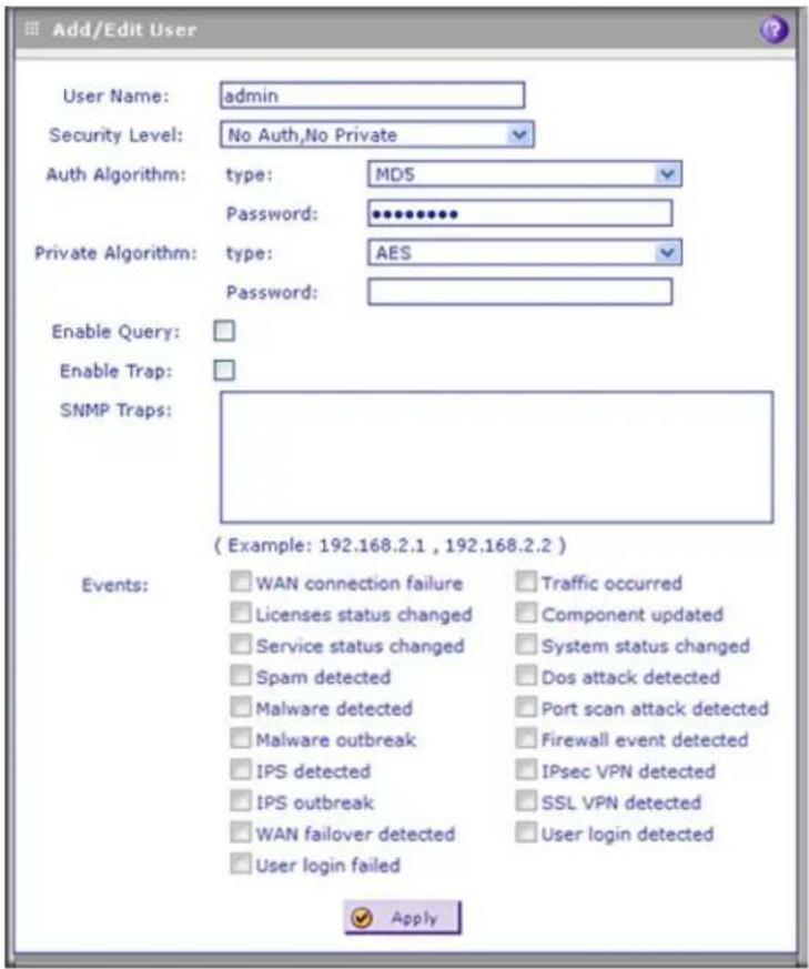
Figure 262.
- Enter the settings as explained in the following table:
Table 109. SNMPv3 settings
| Setting Description | ||||
| SNMPv3 Settings | ||||
| User Name The | SNMPv3 user name. There is no default name. | |||
| Security Level | The level of security that indicates whether authentication and encryption are enabled:NoAuth, NoPrivate. Both authentication and encryption are disabled.Auth, NoPrivate. Authentication is enabled but encryption is disabled.Auth, Private. Both authentication and encryption are enabled. | |||
| Setting Description | ||||
| Auth Algorithm Type From the drop-down list, select the protocol for authenticating the SNMPv3 user:MD5. Message Digest 5. This is a hash algorithm that produces a 128-bit digest. This is the default setting.SHA1. Secure Hash Algorithm 1. This is a hash algorithm that produces a 160-bit digest. | ||||
| Password The authentication password that the SNMPv3 user needs to enter to be granted access to the SNMP agent that collects the MIB objects from the UTM. | ||||
| Private Algorithm | Type From the drop-down list, select the encryption method for the communication between the SNMPv3 user and the SNMP agent that collects the MIB objects from the UTM:DES. Data Encryption Standard.AES. Advanced Encryption Standard. | |||
| Password The privacy password that an SNMPv3 user needs to enter to allow decryption of the MIB objects that the SNMP agent collects from the UTM. | ||||
| Enable Query | Select the check box to enable SNMP queries. By default, queries are disabled. | |||
| Enable Trap Select the check box to enable SNMP traps. By default, traps are disabled. | ||||
| SNMP Traps | Enter the IP addresses of the SNMP management stations that are allowed to receive the UTM's SNMP traps. Separate IP addresses by a comma. If you leave the field blank, which is the default setting, no SNMP management station can receive the UTM's SNMP traps. | |||
| Events Select the check boxes for the events for which SNMP traps should be sent: | ||||
| WAN connection failureLicenses status changedService status changedSpam detectedMalware detectedMalware outbreakIPS detectedIPS outbreakWAN failover detectedUser login failed | Traffic occurredComponent updatedSystem status changedDos attack detectedPort scan attack detectedFirewall event detectedIPSec VPN detectedSSL VPN detectedUser login detected | |||
- Click Apply to save your settings. The SNMPv3 user profile is added to the SNMPv3 Settings table on the SNMP screen. If the global SNMP settings are enabled, the SNMPv3 user profiles in the SNMPv3 Settings table are also enabled.
ProSecure Unified Threat Management (UTM) Appliance
The SNMPv3 Settings table shows the following columns:
- User Name. The SNMPv3 user name.
- Security Level. The level of security that indicates whether authentication and encryption are enabled:
- NoAuth, NoPrivate. Both authentication and encryption are disabled.
- Auth, NoPrivate. Authentication is enabled but encryption is disabled.
-
Auth, Private. Both authentication and encryption are enabled.
-
Notification Host. The IP addresses of the SNMP hosts.
- Queries. Indicates whether queries are enabled.
• Action. The Edit table button, which allows you to modify the SNMPv3 user profile.
To edit an SNMPv3 user profile:
- On the SNMNP screen (see Figure 261 on page 441), in the SNMPv3 Settings table, click the Edit button in the Action column for the SNMPv3 user profile that you want to modify. The Add/Edit User screen displays (Figure 262 on page 443).
- Modify the settings as explained in the Table 109 on page 443.
- Click Apply to save your settings.
To delete one or more SNMPv3 user profiles:
- On the SNMNP screen (see Figure 261 on page 441), in the SNMPv3 Settings table, select the check box to the left of each profile that you want to delete, or click the Select All table button to select all profiles.
- Click the Delete table button.
Manage the Configuration File
The configuration settings of the UTM are stored in a configuration file on the UTM. This file can be saved (backed up) to a computer, retrieved (restored) from the computer, or cleared to factory default settings.
Once the UTM is installed and works correctly, make a backup of the configuration file to a computer. If necessary, you can later restore the UTM settings from this file.
The Backup & Restore Settings screen lets you:
- Back up and save a copy of the current settings
- Restore saved settings from the backed-up file
- Revert to the factory default settings
To display the Backup & Restore Settings screen, select Administration > Backup & Restore Settings.
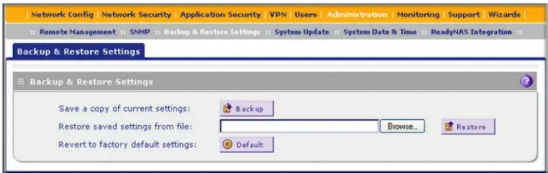
Figure 263.
Back Up Settings
The backup feature saves all UTM settings to a file. These settings include:
• Network settings. IP address, subnet mask, gateway, and so on.
- Scan settings. Services to scan, primary and secondary actions, and so on.
- Update settings. Update source, update frequency, and so on.
• Antispam settings. Whitelist, blacklist, content-filtering settings, and so on.
Back up your UTM settings periodically, and store the backup file in a safe place.
Tip: You can use a backup file to export all settings to another UTM that has the same language and management software versions. Remember to change the IP address of the second UTM before deploying it to eliminate IP address conflicts on the network.
To back up settings:
- On the Backup & Restore Settings screen (see the previous figure), next to Save a copy of current settings, click the Backup button to save a copy of your current settings. A screen displays, showing the file name of the backup file (backup.pkg).
- Select Save file, and then click OK.
- Open the folder in which you have saved the backup file, and then verify that it has been saved successfully.
Note the following:
- If your browser is not configured to save downloaded files automatically, locate the folder in which you want to save the file, specify the file name, and save the file.
- If your browser is configured to save downloaded files automatically, the file is saved to your browser's download location on the hard disk.
Restore Settings

WARNING:
Restore only settings that were backed up from the same software version. Restoring settings from a different software version can corrupt your backup file or the UTM system software.
To restore settings from a backup file:
- On the Backup & Restore Settings screen (see the previous figure), next to Restore saved settings from file, click Browse.
- Locate and select the previously saved backup file (by default, backup.pkg).
- After you have selected the file, click the Restore button. A warning message might display, and you might have to confirm that you want to restore the configuration.
The UTM reboots. During the reboot process, the Backup & Restore Settings screen remains visible. The reboot process is complete after several minutes when the Test LED on the front panel goes off.

WARNING:
Once you start restoring settings, do not interrupt the process. Do not try to go online, turn off the UTM, shut down the computer, or do anything else to the UTM until the settings have been fully restored.
Revert to Factory Default Settings
To reset the UTM to the original factory defaults settings, you can use one of the following two methods:
- Using a sharp object, press and hold the Factory Defaults reset button on the rear panel of the UTM (see Hardware Features on page 24) for about 8 seconds until the Test LED turns on and begins to blink (about 30 seconds). To restore the factory default settings when you do not know the administration password or IP address, you need to use the Factory Defaults reset button.
- On the Backup & Restore Settings screen (see the previous figure), next to Revert to factory defaults settings, click the Default button.
The UTM reboots. If you use the software Default button, the Backup & Restore Settings screen remains visible during the reboot process. The reboot process is complete after several minutes when the Test LED on the front panel goes off.

WARNING:
When you press the hardware Factory Defaults reset button or click the software Default button, the UTM settings are erased. All firewall rules, VPN policies, LAN/WAN settings, and other settings are lost. Back up your settings if you intend on using them.
Note: After rebooting with factory default settings, the UTM's password is password, and the LAN IP address is 192.168.1.1.
Update the Firmware
The UTM can automatically detect a new firmware version from a NETGEAR update server. The firmware upgrade process for the UTM consists of the following four stages:
- Querying the available firmware versions from the NETGEAR update server.
- Selecting a firmware version to download directly to the UTM (that is, not first to a computer in your network and then to the UTM).
- Installing the downloaded firmware version.
- Rebooting the UTM with the new firmware version.
These stages are explained in detail in the following sections.
View the Available Firmware Versions
To view the current version of the firmware that your UTM is running and the other available firmware versions:
- Select Administration > System Update > Firmware. The Firmware screen displays:

Figure 264. Firmware screen, available versions
The Firmware Reboot section shows the following information fields for both the active and secondary (that is, nonactive) firmware:
- Type. Active or secondary firmware.
-
Version. The firmware version.
• Status. The status of the firmware (ok or corrupted). -
To see which other firmware versions are available, click Query under the Firmware Download section to allow the UTM to connect to the NETGEAR update server. The Firmware Download section shows the available firmware versions, including any new versions, and the date when the current firmware version was downloaded to the UTM.
Upgrade the Firmware from an Update Server and Reboot the UTM
When the UTM is online, you can let the UTM connect to a remote update server to query new firmware versions. You can then decide whether you want to download new firmware, and whether you want to install new firmware.
Note: Upgrading the UTM firmware from an update server is also referred to as an online upgrade.
To upgrade the UTM's firmware directly from an update server and reboot the UTM:
- In the Firmware Download section of the Firmware screen, click Query to display the available firmware versions.
- Select the radio button that corresponds to the firmware version that you want to download onto the UTM. The following figure shows the Firmware screen after you have selected the firmware version.
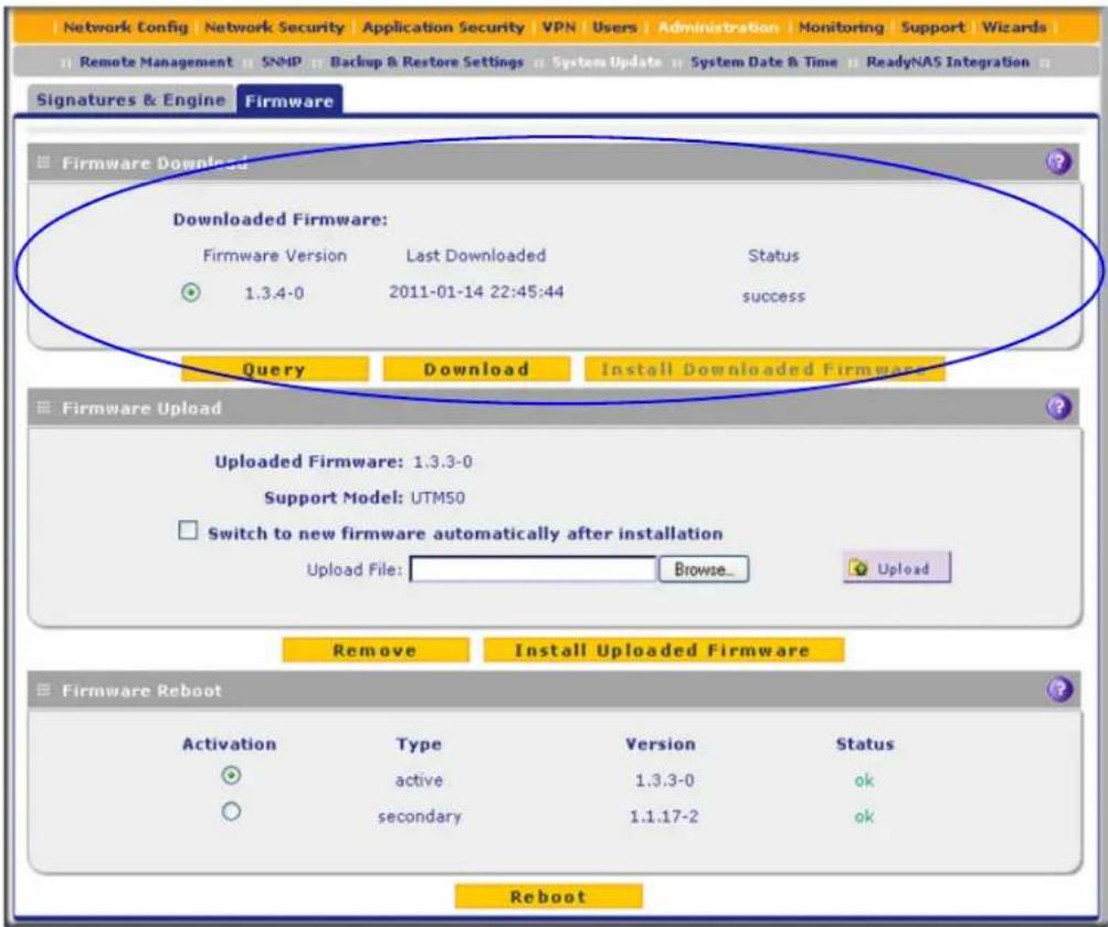
Figure 265. Firmware screen, after firmware query and selection
- Click Download. A status bar shows the progress of the download.
- Click Install Downloaded Firmware.
Note: A status bar shows the progress of the installation process, which might take up to 20 minutes.
- After the firmware installation process is complete, the newly installed firmware is the secondary firmware and not the active firmware. Ensure that the Activation radio button for the secondary firmware is selected (it should have been selected automatically).
- Click the Reboot button at the bottom of the screen to start the reboot process. A counter at the top of the screen displays the remaining time before the UTM reboots.
The UTM reboots automatically. During the reboot process, the Firmware screen remains visible. The reboot process is complete after several minutes when the Test LED on the front panel goes off and the Firmware screen disappears.

WARNING:
After you have started the firmware installation process, do not interrupt the process. Do not try to go online, turn off the UTM, or do anything else to the UTM until the UTM has fully rebooted.
- Log back in to the UTM. The System Status screen displays.
- In the System Information section of the System Status screen, verify that the newly installed firmware is the active firmware and that the old firmware is now the secondary firmware.
Note: In some cases, such as a major upgrade, it might be necessary to erase the configuration and manually reconfigure your UTM after upgrading it. Refer to the firmware release notes that NETGEAR makes available.
Upgrade the Firmware from a Downloaded File and Reboot the UTM
Instead of downloading the UTM firmware directly from a NETGEAR update server, you can download the UTM firmware from a NETGEAR website to a computer in your network and then upgrade the firmware on the UTM.
This option prevents the UTM from taking bandwidth away from end users because the download does not occur on the UTM. This option is also convenient if you have multiple UTMs in your network, because you can download the firmware just once, make it available at a central location in your network, and then upload the firmware on each UTM.
Note: Upgrading the UTM firmware from a downloaded file is also referred to as an offline upgrade.
To download the latest firmware for your UTM:
- Visit the NETGEAR Support website at http://support.netgear.com, and navigate to the product support page.
- Locate the available firmware versions.
- Follow the instructions onscreen to download the firmware to your computer.
To upgrade the UTM's firmware from a downloaded file and reboot the UTM:
- In the Firmware Upload section of the Firmware screen, click Browse to locate and select the previously saved firmware upgrade file (for example, UTM50-Firmware-V3.3.0-17.pkg).
Note: The license is verified during the firmware upload process. Make sure that the UTM is connected to the Internet while you upload the firmware.
- Click Upload. A counter at the top of the screen and a status bar in the middle of the screen show the progress of the upload.

WARNING:
Uploading firmware to the UTM stops any firmware downloading process that might be occurring and removes any downloaded and uploaded firmware files from the UTM. While the upload is occurring, do not leave or refresh the Firmware screen.
When the firmware upload process is complete, the new firmware version is displayed in the Firmware Upload section of the screen; a firmware version that previously might have been displayed in the Firmware Download section of the screen is no longer shown:
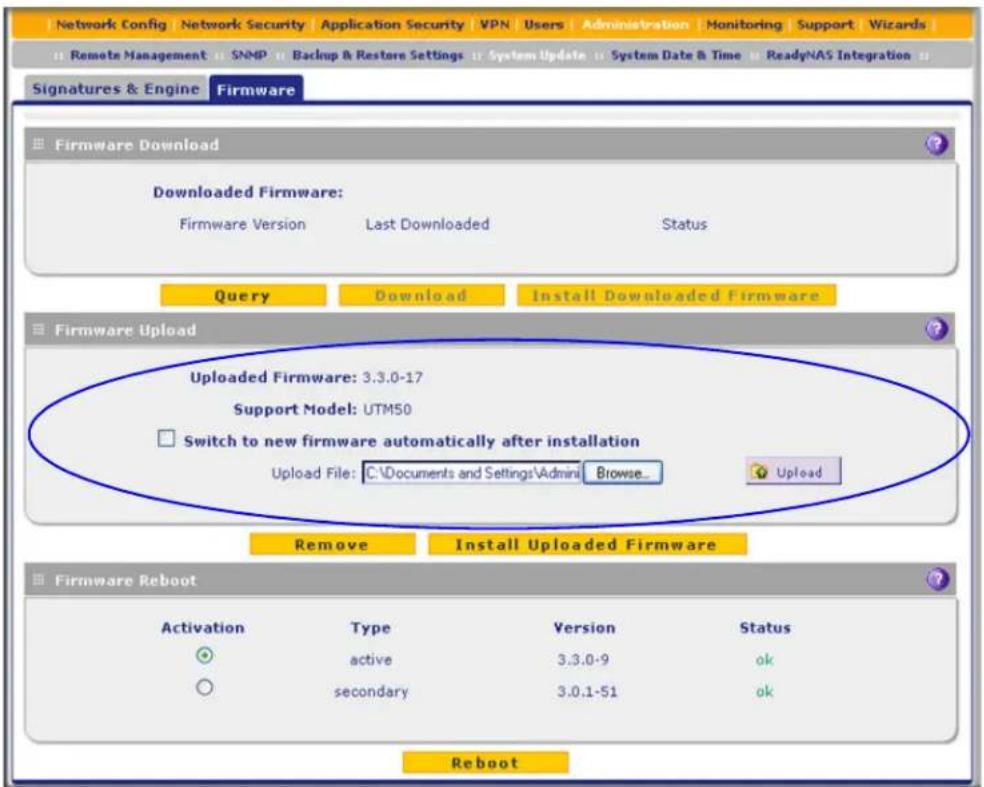
Figure 266. Firmware screen, after firmware upload
- (Optional) To install the new firmware version and reboot the UTM with the new firmware version as the active firmware, select the Switch to new firmware automatically after installation check box.
- Click Install Uploaded Firmware. (If you decide that you do not want to install the uploaded firmware, you can click Remove to remove the uploaded firmware.)

WARNING:
After you have started the firmware installation process, do not interrupt the process. Do not try to go online, turn off the UTM, or do anything else to the UTM until the UTM has fully rebooted.
Note: A status bar shows the progress of the installation process, which might take up to 20 minutes.
If you have selected the check box in Step 3: When the installation process is complete, a counter at the top of the screen displays the remaining time before the UTM reboots. The UTM reboots automatically. During the reboot process, the Firmware screen remains visible. The reboot process is complete after several minutes when the Test LED on the front panel goes off and the Firmware screen disappears.
- This step applies only if you did not select the check box in Step 3. If you did select the check box, skip to Step 6.
a. After the firmware installation process is complete, the newly installed firmware is the secondary firmware and not the active firmware. Ensure that the Activation radio button for the secondary firmware is selected (it should have been selected automatically).
b. Click the Reboot button at the bottom of the screen to start the reboot process. A counter at the top of the screen displays the remaining time before the UTM reboots. The UTM reboots automatically. During the reboot process, the Firmware screen remains visible. The reboot process is complete after several minutes when the Test LED on the front panel goes off and the Firmware screen disappears.
- A couple of minutes after the UTM has rebooted, log back in to the UTM. The System Status screen displays.
- In the System Information section of the System Status screen, verify that the newly installed firmware is the active firmware and that the old firmware is now the secondary firmware.
Reboot without Changing the Firmware
To reboot the UTM without changing the firmware:
- In the Firmware Reboot section of the Firmware screen (see the previous figure), select the active firmware version by selecting the Activation radio button for the firmware that is shown as active in the Type column.
- Click Reboot. The UTM reboots. During the reboot process, the Firmware screen remains visible. The reboot process is complete after several minutes when the Test LED on the front panel goes off and the Firmware screen disappears.
- Log back in to the UTM.
Update the Scan Signatures and Scan Engine Firmware
To scan and detect viruses, spyware, and other malware threats, the UTM's scan engine requires two components:
- A pattern file that contains the virus signature files and virus database
- Firmware that functions in conjunction with the pattern file
Because new virus threats can appear any hour of the day, it is important to keep both the pattern file and scan engine firmware current. The UTM can automatically check for updates, as often as every 15 minutes, to ensure that your network protection is current.
To view the current versions and most recent updates of the pattern file and scan engine firmware that your UTM is running, select Administration > System Update. The System Update submenu tabs display, with the Signatures & Engine screen in view:
ProSecure Unified Threat Management (UTM) Appliance

Figure 267.
The Info section onscreen shows the following information fields for the scan engine firmware and pattern file:
- Current Version. The version of the files.
- Last Updated. The date of the most recent update.
To update the scan engine firmware and pattern file immediately, click the Update Now button at the bottom of the screen.
Configure Automatic Update and Frequency Settings
To configure the update settings and frequency settings for automatic downloading of the scan engine firmware and pattern file:
- Locate the Update Settings, Frequency Settings, and HTTPS Proxy Settings sections on the Signatures & Engine screen (see the previous figure), and enter the settings as explained in the following table:
Table 110. Signatures & Engine screen settings
| Setting Description | ||
| Update Settings | ||
| Update From the drop-down list, select one of the following options:Never. The pattern and firmware files are not automatically updated.Scan engine and Signatures. The pattern and firmware files are automatically updated according to the settings in the Update Frequency section onscreen (see explanations later in this table). | ||
| Update From Set the update source server by selecting one of the following radio buttons:Default update server. Files are updated from the default NETGEAR update server.Server address. Files are updated from the server that you specify. Enter the IP address or host name of the update server in the Server address field. | ||
| Update Frequency | ||
| Specify the frequency with which the UTM checks for file updates by selecting one of the following radio buttons:Weekly. From the drop-down lists, select the weekday, hour, and minutes that the updates occur.Daily. From the drop-down lists, select the hour and minutes that the updates occur.Every. From the drop-down list, select the frequency with which the updates occur. The range is from 15 minutes to 12 hours. | ||
| HTTPS Proxy Settings | ||
| Enable | If computers on the network connect to the Internet through a proxy server, select the Enable check box to specify and enable a proxy server. Enter the following settings. | |
| Proxy Server The IP address and port number of the proxy server. | ||
| User Name The user name for proxy server authentication. | ||
| Password The password for proxy server authentication. | ||
- Click Apply to save your settings.
Configure Date and Time Service
Configure date, time, and NTP server designations on the System Date & Time screen. Network Time Protocol (NTP) is a protocol that is used to synchronize computer clock times in a network of computers. Setting the correct system time and time zone ensures that the date and time recorded in the UTM logs and reports are accurate.
To set time, date, and NTP servers:
- Select Administration > System Date & Time. The System Date & Time screen displays:

Figure 268.
The bottom of the screen displays the current weekday, date, time, time zone, and year (in the example in the previous figure: Current Time: Thu May 21 01:37:18 GMT 2009).
- Enter the settings as explained in the following table:
Table 111. System Date & Time screen settings
| Setting Description | ||
| Date/Time From the drop | -down list, select the local time zone in which the UTM operates.The correct time zone is required in order for scheduling to work correctly. The UTM includes a real-time clock (RTC), which it uses for scheduling. | |
| Automatically Adjust for Daylight Savings Time | If daylight savings time is supported in your region, select the Automatically Adjust for Daylight Savings Time check box. | |
| NTP Server (default or custom) | From the drop-down list, select an NTP server:Use Default NTP Servers. The UTM regularly updates its RTC by contacting a default NETGEAR NTP server on the Internet.Use Custom NTP Servers. The UTM regularly updates its RTC by contacting one of two custom NTP servers (primary and backup), both of which you need to specify in the fields that become available with this selection.Note: If you select the Use Custom NTP Servers option but leave either the Server 1 or Server 2 field blank, both fields are set to the default NETGEAR NTP servers.Note: A list of public NTP servers is available at http://support.ntp.org/bin/view/Servers/WebHome. | |
| NTP Server (default or custom)(continued) | Server 1 Name / IP Address Enter the IP address or host name of the primary NTP server. | |
| Server 2 Name / IP Address Enter the IP address or host name of the backup NTP server. | ||
3. Click Apply to save your settings.
Note: If you select the default NTP servers or if you enter a custom server FQDN, the UTM determines the IP address of the NTP server by performing a DNS lookup. Before the UTM can perform this lookup, you need to configure a DNS server address on the WAN ISP Settings screen of the single WAN port models or on one of the WAN ISP Settings screens of the multiple WAN port models (see Manually Configure the Internet Connection on page 75.)
Connect to a ReadyNAS and Configure Quarantine Settings
- Log Storage
- Connect to a ReadyNAS
- Configure the Quarantine Settings
The UTM can quarantine questionable emails (including spam), attachments, objects, and web files. This requires an increasing amount of storage space, which is not available on the UTM. To accommodate these storage requirements, you need to connect the UTM to a NETGEAR ReadyNAS and configure the quarantine settings. Without integration with a ReadyNAS, you cannot use the quarantine options of the UTM.
You can select to quarantine emails, attachments, objects, and web files on one or more of the following screens:
- Email Anti-Virus screen (see Customize Email Antivirus and Notification Settings on page 196)
• Distributed Spam Analysis screen (see Configure Distributed Spam Analysis on page 207)
• Malware Scan screen (see Configure Web Malware or Antivirus Scans on page 216) - FTP screen (Configure FTP Scanning on page 238)
Log Storage
After you have integrated a ReadyNAS with the UTM—whether or not you have configured the quarantine settings—all logs that are normally stored on the UTM are now stored on the ReadyNAS. That is, all logs that you can specify on the Email and Syslog screen (see Configure and Activate System, Email, and Syslog Logs on page 467) and that you can query on the Log Query screen and view onscreen (see Query and Manage the Quarantine Logs on page 514) are stored on the ReadyNAS. However, after you have integrated a ReadyNAS with the UTM, logs can no longer be sent to an email address (see the Email Logs to Administrator section on the Email and Syslog screen). If you have enabled a syslog server on the Email and Syslog screen, logs are still sent to the syslog server.

WARNING:
When you integrate a ReadyNAS with the UTM, the logs that were saved on the UTM are deleted.
Note: If the network connection to the ReadyNAS goes down, the quarantine logs are no longer saved, and all other logs are saved on the UTM. In this situation, the ReadyNAS and quarantine status fields show OFF on the System Status screen (see View the System Status Screen on page 487). When the network connection comes back up, the quarantine logs and all other logs are saved on the ReadyNAS once again, but the logs that were saved on the UTM are deleted.
Connect to a ReadyNAS
To connect to the ReadyNAS on the UTM:
- Select Administration > ReadyNAS Integration. The ReadyNAS Integration screen displays:

Figure 269.
- To connect to the ReadyNAS, select the Yes radio button.
- Enter the settings as explained in the following table:
Table 112. ReadyNAS Integration screen settings
| Setting Description | |
| ReadyNAS Server The IP | address of the ReadyNAS server. |
| ReadyNAS Username | The user name to access the ReadyNAS. By default, the user name is admin. |
| ReadyNAS Password The | password to access the ReadyNAS. By default, the password is netgear1. |
- Click Apply to save your settings.
Note: For additional information about how to set up a UTM with a ReadyNAS, see Appendix E, ReadyNAS Integration.
Configure the Quarantine Settings
You can apply the quarantine settings only after you have integrated a ReadyNAS with the UTM (see the previous section, Connect to a ReadyNAS).
To configure the quarantine settings:
- Select Administration > ReadyNAS Integration > Quarantine Settings. The Quarantine Settings screen displays:
ProSecure Unified Threat Management (UTM) Appliance

Figure 270.
- To enable the UTM to quarantine files, select the Yes radio button.
- Enter the settings as explained in the following table:
Table 113. Quarantine settings
| Setting Description | |
| Allow anonymous users to check quarantined mails | Select this check box to allow anonymous users to view their quarantined emails. Anonymous users do not log in to the UTM: the UTM's default email and web access policies apply to them. For information about how anonymous users can log in to view their quarantined emails, seeUnauthenticated or Anonymous Userson page 384.If this check box is cleared, only administrative users and users with guest privileges can view quarantined emails and spam messages. |
| Malware Quarantine Area Size | The amount of storage space that is reserved for quarantined malware.The default is 100 MB; the maximum is 512 MB. |
| Spam Quarantine Area Size | The amount of storage space that is reserved for quarantined spam. The default is 100 MB; the maximum is 1024 MB. |
| Quarantine Lifetime | The period that the quarantined files remain saved. The default period is 10 days; the maximum period is 30 days. |
| Quarantine Directory The directory | on the ReadyNAS where the quarantined files are saved. |
- Click Apply to save your settings.
Monitor System Access and Performance
11
This chapter describes the system-monitoring features of the UTM. You can be alerted to important events such as a WAN port rollover, WAN traffic limits reached, login failures, and attacks. You can also view status information about the firewall, WAN ports, LAN ports, active VPN users and tunnels, and more. In addition, the diagnostics utilities are described. This chapter contains the following sections:
- Enable the WAN Traffic Meter
- Configure Logging, Alerts, and Event Notifications
• Monitor Real-Time Traffic, Security, and Statistics
• Monitor Application Use in Real Time
• View Status Screens - Query and Manage the Logs
- Query and Manage the Quarantine Logs
• View, Schedule, and Generate Reports - Use Diagnostics Utilities
Note: All log and report functions that are part of the Logs & Reports screen and some of the functions that are part of the Diagnostics screen require that you configure the email notification server—see Configure the Email Notification Server on page 466.
Enable the WAN Traffic Meter
If your ISP charges by traffic volume over a given period, or if you want to study traffic types over a period, you can activate the traffic meter for one or more WAN ports, and for the UTM9S and UTM25S, also for the xDSL (SLOT-1 or SLOT-2) and USB ports.
To monitor traffic limits on each of the WAN ports, and for the UTM9S and UTM25S, also on the xDSL (SLOT-1 or SLOT-2) and USB ports:
- Select Network Config > WAN Metering. On the multiple WAN port models, the WAN Metering tabs display, with the WAN1 Traffic Meter screen (or, for the UTM9S and UTM25S, the WAN1 screen) in view (the following figure shows the WAN1 Traffic Meter screen of the UTM50). On the single WAN port models, the WAN Traffic Meter screen displays.
The Internet Traffic Statistics section in the lower part of the screen displays statistics on Internet traffic through the WAN port. If you have not enabled the traffic meter, these statistics are not available.
![Network Config | Network Security | Application Security | VPN | Users | Administration | Monitoring | Support | Wizards | WAN Settings || Protocol Binding || Dynamic DNS || WAN Metering || LAN Settings || DMZ Setup || Routing : WAN1 TrafficMeter WAN2 TrafficMeter Traffic by Protocol Enable Traffic Meter Do you want to enable Traffic Metering on WAN1? Yes No No Limit Download only Both Directions Monthly Limit: 0 [MB] [max. 256000 MB (~250 GB)] Increase this month limit by: 0 [MB] [max. 256000 MB (~250 GB)] This month limit: 0 [MB] Traffic Counter Restart Traffic Counter Now Restart Traffic Counter at Specific Time 12 :00 AM on the 1st day of Month. Send e-mail report before restarting counter When Limit is reached Block All Traffic Block All Traffic Except E-Mail Send e-mail alert Internet Traffic Statistics Start Date / Time: Outgoing Traffic Volume: [MB] Incoming Traffic Volume: [MB] Total Traffic Volume: [MB] Average per day: [MB] % of Standard Limit: % of this Month's Limit: Apply Reset](/content/2026/06/1371942/images/eb836a16ae54387196f881763b23a627c1a750932420a9940443598ba2d35c67.jpg)
Figure 271.
- Enter the settings as explained in the following table:
Table 114. WAN traffic meter settings
| Setting Description | ||
| Enable Traffic Meter | ||
| Do you want to enable Traffic Metering on WAN1?(multiple WAN port models)orDo you want to enable Traffic Metering on WAN?(single WAN port models) | Select one of the following radio buttons to configure traffic metering:Yes. Traffic metering is enabled, and the traffic meter records the volume of Internet traffic passing through the WAN1 interface (multiple WAN port models) or WAN interface (single WAN port models). Complete the fields that are shown on the right side of the screen (see explanations later in this table).No. Traffic metering is disabled. This is the default setting. | |
| Select one of the following radio buttons to specify if or how the UTM applies restrictions when the traffic limit is reached:No Limit. No restrictions are applied when the traffic limit is reached.Download only. Restrictions are applied to incoming traffic when the traffic limit is reached. Fill in the Monthly Limit field.Both Directions. Restrictions are applied to both incoming and outgoing traffic when the traffic limit is reached. Fill in the Monthly Limit field. | ||
| Monthly Limit Enter | the monthly traffic volume limit in MB. The default setting is 0 MB. | |
| Increase this month limit by | Select this check box to temporarily increase a previously specified monthly traffic volume limit, and enter the additional allowed volume in MB. The default setting is 0 MB.Note:When you click Apply to save these settings, this field is reset to 0 MB so that the increase is applied only once. | |
| This month limit | This is a nonconfigurable field that displays the total monthly traffic volume limit that is applicable to this month. This total is the sum of the monthly traffic volume and the increased traffic volume. | |
| Traffic Counter | ||
| Restart Traffic Counter | Select one of the following radio buttons to specify when the traffic counter restarts:Restart Traffic Counter Now. Select this option, and clickApplyat the bottom of the screen to restart the traffic counter immediately.Restart Traffic Counter at a Specific Time. Restart the traffic counter at a specific time and day of the month. Fill in the time fields, and selectAMor PMand the day of the month from the drop-down lists. | |
| Send e-mail report before restarting counter | An email report is sent immediately before the counter restarts. Ensure that emailing of logs is enabled on the Email and Syslog screen (seeConfigure Logging,Alerts, and Event Notificationson page 466). | |
Table 114. WAN traffic meter settings (continued)
| Setting Description | |
| When Limit is reached | |
| Block Traffic | Select one of the following radio buttons to specify which action the UTM performs when the traffic limit has been reached:Block All Traffic. All incoming and outgoing Internet and email traffic is blocked.Block All Traffic Except E-Mail. All incoming and outgoing Internet traffic is blocked, but incoming and outgoing email traffic is still allowed. |
| Send e-mail alert An e | email alert is sent when traffic is blocked. Ensure that emailing of logs is enabled on the Email and Syslog screen (see Configure and Activate System, Email, and Syslog Logs on page 467). |
- Click Apply to save your settings.
- For the multiple WAN port models only, click the WAN2 Traffic Meter, WAN3 Traffic Meter (UTM150 only), or WAN4 Traffic Meter (UTM150 only) submenu tab to display the corresponding WAN Traffic Meter screen. These screens are identical to the WAN1 Traffic Meter screen (see Figure 271 on page 463).
- For the multiple WAN port models only, repeat Step 2 and Step 3 for the additional WAN interface or interfaces.
To display a report of the Internet traffic by type, click the Traffic by Protocol option arrow in the upper right of the WAN Traffic Meter screen (single WAN port models) or in the upper right of one of the WAN Traffic Meter screens (multiple WAN port models). The Traffic by Protocol screen displays in a pop-up screen. The incoming and outgoing volume of traffic for each protocol and the total volume of traffic are displayed. Traffic counters are updated in MBs; the counter starts only when traffic passed is at least 1 MB. In addition, the pop-up screen displays the traffic meter's start and end dates.

Figure 272.
Configure Logging, Alerts, and Event Notifications
- Configure the Email Notification Server
- Configure and Activate System, Email, and Syslog Logs
• How to Send Syslogs over a VPN Tunnel between Sites - Configure and Activate Update Failure and Attack Alerts
- Configure and Activate Firewall Logs
Note: For more information about logs, see Query and Manage the Logs on page 507.
By default, the UTM logs security-related events such as accepted and dropped packets on different segments of your LAN, denied incoming and outgoing service requests, hacker probes and login attempts, content-filtering events such as attempts to access blocked sites and URLs, unwanted email content, spam attempts, and many other types of events. You can configure the UTM to email logs and alerts to a specified email address.

WARNING:
When you reboot the UTM, the logs are lost. If you want to save the logs, make sure that you configure the UTM to send the logs to a syslog server. For information about how to do this, see Configure and Activate System, Email, and Syslog Logs on page 467.
For you to receive the logs in an email message, the UTM's email notification server needs to be configured, and email notification needs to be enabled. If the email notification server is not configured or email notification is disabled, you can still query the logs and generate log reports that you then can view on the web management interface screen or save in CSV format.
Configure the Email Notification Server
The UTM can automatically send information such as notifications and reports to the administrator. You need to configure the necessary information for sending email, such as the administrator's email address, email server, user name, and password.
To configure the email notification server:
- Select Monitoring > Email Notification. The Email Notification screen displays. (The following figure shows an example.)
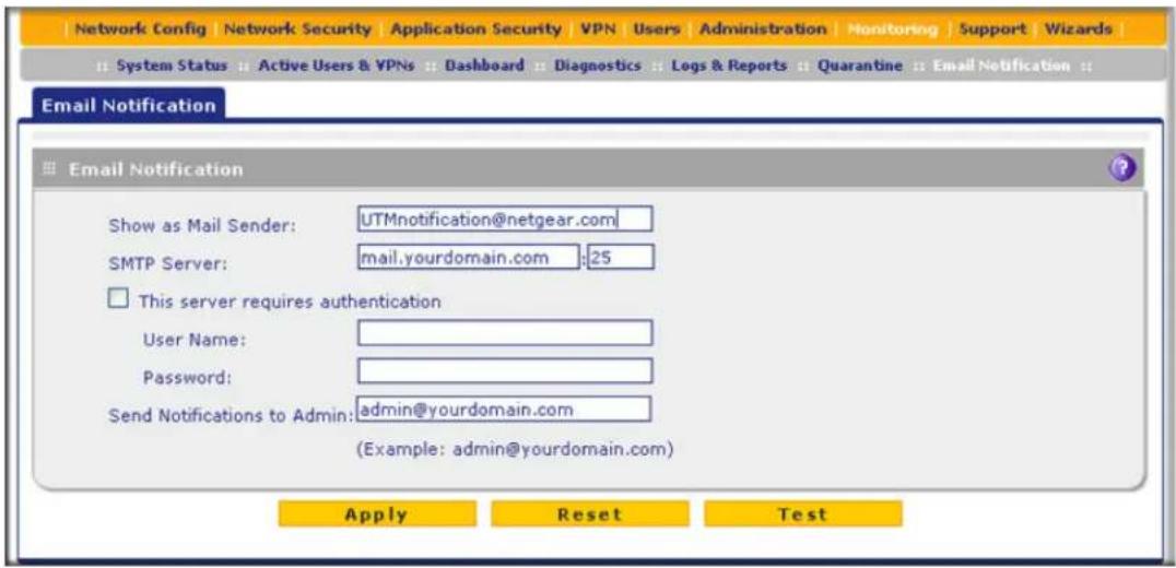
Figure 273.
- Enter the settings as explained in the following table:
Table 115. Email Notification screen settings
| Setting Description | ||
| Show as Mail Sender A descriptive name of the sender for email identification purposes. For example, enter UTMnotification@netgear.com. | ||
| SMTP Server The IP address | and port number or Internet name and port number of your ISP's outgoing email SMTP server. The default port number is 25. Note: If you leave this field blank, the UTM cannot send email notifications. | |
| This server requires authentication | If the SMTP server requires authentication, select the This server requires authentication check box, and enter the user name and password. | |
| User Name The user name for SMTP server authentication. | ||
| Password The password for SMTP server authentication. | ||
| Send Notifications to Admin The email address to which the notifications should be sent. Typically, this is the email address of the administrator. | ||
- Click Test to ensure that the connection to the server and email address succeeds.
- Click Apply to save your settings.
Configure and Activate System, Email, and Syslog Logs
You can configure the UTM to log system events such as a change of time by an NTP server, secure login attempts, reboots, and other events. You can also send logs to the administrator or schedule logs to be sent to the administrator or to a syslog server on the network. In addition, the Email and Syslog screen provides the option to selectively clear logs.
To configure and activate logs:
- Select Monitoring > Logs & Reports. The Logs & Reports submenu tabs display, with the Email and Syslog screen in view:

Figure 274.
- Enter the settings as explained in the following table:
Table 116. Email and Syslog screen settings
| Setting Description | ||
| System Logs Option | ||
| Select the check boxes to specify which system events are logged:Change of Time by NTP. Logs a message when the system time changes after a request from an NTP server.Secure Login Attempts. Logs a message when a secure login is attempted. Both successful and failed login attempts are logged.Reboots. Logs a message when the UTM has been rebooted through the web management interface. (No message is logged when the Factory Defaults reset button has been pressed.)All Unicast Traffic. All incoming unicast packets are logged.All Broadcast/Multicast Traffic. All incoming broadcast and multicast packets are logged.WAN Status. WAN link status-related events are logged.Resolved DNS Names. All resolved DNS names are logged. | ||
| Email Logs to AdministratorNote:When you have integrated a ReadyNAS with the UTM, the UTM cannot send the logs to an email address. | ||
| Enable Select | this check box to enable the UTM to send a log file to an email address. | |
| Send to The em | mail address of the recipient of the log file.Click Send Now to immediately send the logs, which you first need to specify in the Select Logs to Send subsection (see later in this table). | |
| Frequency Select | a radio button to specify how often the log file is sent:Daily. Logs are sent daily at the time that you specify from the drop-down lists (hours and minutes).Weekly. Logs are sent weekly at the day and time that you specify from the drop-down lists (weekday, hours, and minutes). | |
| Select Logs to Send | Select the check boxes to specify which logs are sent by email:System Logs. The system event logs that you have specified in the System Logs Options section at the top of the screen. However, by default, many more types of events are logged in the system logs.Traffic Logs. All scanned incoming and outgoing traffic.Anomaly Behavior Logs. All port scan and DDoS events.Application Logs. All instant messaging, peer-to-peer and media applications, and tools access violations.Email filter Logs. All emails that are blocked because of file extension and keyword violations.HTTPS Smart Block logs. All attempts to access domains that are blocked as part of an active HTTPS Smart Block profile (see Configure HTTPS Smart Block on page 212).Content Filter Logs. All attempts to access blocked websites and URLs. | |
| Enable (continued) | Select Logs to Send (continued) | Service Logs. All events that are related to the status of scanning and filtering services that you access from the Application Security main navigation menu. These events include update success messages, update failed messages, network connection errors, and so on.Firewall Logs. The firewall logs that you have specified on the Firewall Logs screen (see Configure and Activate Firewall Logs on page 476).IPS Logs. All IPS events.SSL VPN Logs. All SSL VPN events.IPSEC VPN Logs. All IPSec VPN events.Malware Logs. All intercepted viruses and malware threats.Spam Logs. All intercepted spam. |
| Format Select a | radio button to specify the format in which the log file is sent:Plain text. The log file is sent as a plain text file.CSV. The log file is sent as a comma-separated values (CSV) file. | |
| Select the Zip the logs to save space check box to enable the UTM to compress the log file. | ||
| Size | Select the Split logs size to check box to break up the log file into smaller files, and specify the maximum size of each file in MB. | |
| Send Logs via Syslog | ||
| Enable Select | this check box to enable the UTM to send a log file to a syslog server. | |
| SysLog Server | The IP address or name of the syslog server. | |
| SysLog Severity | All the logs with a severity that is equal to and above the severity that you specify are logged on the specified syslog server. For example, if you select LOG_CRITICAL as the severity, then the logs with the severities LOG_CRITICAL, LOG_ALERT, and LOG_EMERG are logged.Select one of the following syslog severities from the drop-down list:LOG EMERG. The UTM is unusable.LOG ALERT. An action has to be taken immediately.LOG CRITICAL. There are critical conditions.LOG ERROR. There are error conditions.LOG WARNING. There are warning conditions.LOG NOTICE. There are normal but significant conditions.LOG INFO. Informational messages.LOG DEBUG. Debug-level messages. | |
| Logs Select the | check boxes to specify which logs are sent through the syslog server. The Send Logs via Syslog section of the screen lists the same check boxes as the Select Logs to Send subsection in the Email Logs to Administrator section of the screen (see earlier in this table). | |
| Setting | Description | |
| Clear the Following Logs Information | ||
| Select the check boxes to specify which logs are cleared. The Clear the Following Logs Information section of the screen lists the same check boxes as the Select Logs to Send subsection in the Email Logs to Administrator section of the screen (see earlier in this table). | ||
- Click Apply to save your settings, or click Clear Log Information to clear the selected logs.
How to Send Syslogs over a VPN Tunnel between Sites
To send syslogs from one site to another over a gateway-to-gateway VPN tunnel:
- At Site 1, set up a syslog server that is connected to Gateway 1.
- Set up a VPN tunnel between Gateway 1 at Site 1 and Gateway 2 at Site 2.
- Change the remote IP address in the VPN policy on Gateway 1 to the WAN IP address of Gateway 2.
- Change the local IP address in the VPN policy on Gateway 2 to the WAN IP address of Gateway 2.
- At Site 2, specify that Gateway 2 should send the syslogs to the syslog server at Site 1.
This section describes steps 2 through 4, using the topology that is described in the following table:
| Type of address Gateway 1 at | Site 1 Gateway 2 at Site 2 | |
| WAN IP address 10.0.0.1 10.0.0.2 | ||
| LAN IP address 192.168.10.0 192.168.20.0 | ||
| LAN subnet mask 255.255.255.0 255.255.255.0 | ||
| LAN IP address syslog server | 192.168.10.2 | not applicable |
Configure Gateway 1 at Site 1
To create a gateway-to-gateway VPN tunnel to Gateway 2, using the IPSec VPN wizard:
- Select VPN > IPSec VPN > VPN Wizard. The VPN Wizard screen displays.
- Configure a gateway-to-gateway VPN tunnel using the following information:
- Connection name. Any name of your choice
- Pre-shared key. Any key of your choice
- Remote WAN IP address. 10.0.0.2
- Local WAN IP address. 10.0.0.1
- Remote LAN IP Address. 192.168.20.0
- Remote LAN subnet mask. 255.255.255.0
- Click Apply to save the settings.
To change the remote IP address in the VPN policy:
- Select VPN > IPSec VPN > VPN Policies. The VPN Policy screen displays.
- Next to the policy name for the Gateway 1-to-Gateway 2 autopolicy, click Edit. The Edit VPN Policy screen displays.
- In the General section of the screen, clear the Enable NetBIOS check box.
- In the Traffic Selector section of the screen, make the following changes:
• From the Remote IP drop-down list, select Single.
• In the Start IP fields, type 10.0.0.2, which is the WAN IP address of Gateway 2.
- Click Apply to save the settings.
Configure Gateway 2 at Site 2
To create a gateway-to-gateway VPN tunnel to Gateway 1, using the IPSec VPN wizard:
- Select VPN > IPSec VPN > VPN Wizard. The VPN Wizard screen displays.
-
Configure a gateway-to-gateway VPN tunnel using the following information:
-
Connection name. Any name of your choice
- Pre-shared key. The same key as you configured on Gateway 1
- Remote WAN IP address. 10.0.0.1
- Local WAN IP address. 10.0.0.2
- Remote LAN IP Address. 192.168.10.0
-
Remote LAN subnet mask. 255.255.255.0
-
Click Apply to save the settings.
To change the local IP address in the VPN policy:
- Select VPN > IPSec VPN > VPN Policies. The VPN Policy screen displays.
- Next to the policy name for the Gateway 2-to-Gateway 1 autopolicy, click Edit. The Edit VPN Policy screen displays.
- In the General section of the screen, clear the Enable NetBIOS check box.
- In the Traffic Selector section of the screen, make the following changes:
• From the Local IP drop-down list, select Single.
• In the Start IP fields, type 10.0.0.2, which is the WAN IP address of Gateway 2.
- Click Apply to save the settings.
To specify the syslog server that is connected to Gateway 1:
- Select Monitoring > Logs & Reports > Email and Syslog to display the Email and Syslog screen)
- Enable the syslog server and specify its IP address at Site 1. Enter 192.168.10.2 as the IP address.
- Click Apply to save the settings.
Note: The VPN tunnel should be established automatically, and the syslogs should be sent to the syslog server at Site 1. You can use the IPSec VPN Connection Status screen to verify the connection.
Configure and Activate Update Failure and Attack Alerts
You can configure the UTM to send an email alert when an update failure, malware attack, malware outbreak attack, intrusion prevention system (IPS) attack, or IPS outbreak attack occurs. Eight types of alerts are supported:
• Traffic Meter Limit Alerts. Sent when the traffic meter (for LAN usage) exceeds a limit.
- Update failure alert. Sent when an attempt to update any component such as a pattern file or scan engine firmware fails.
- License expiration alert. Sent when one or more licenses (email protection license, web protection license, combined support and maintenance license, and combined application control and IPS license) are near their expiration dates and when they expire.
• ReadyNAS failure alert. Sent when an integrated ReadyNAS is down or disconnected.
• Malware alert. Sent when the UTM detects a malware threat.
- Malware outbreak alert. Sent when the malware outbreak criteria that you have configured are reached or exceeded. Outbreak criteria are based on the number of malware threats detected within a specified period.
- IPS outbreak alert. Sent when the IPS outbreak criteria that you have configured are reached or exceeded. Outbreak criteria are based on the number of IPS attacks detected within a specified period.
- IPS alert. Sent when the UTM detects an attack.
To configure and activate the email alerts:
- Select Monitoring > Logs & Reports > Alerts. The Alerts screen displays:
ProSecure Unified Threat Management (UTM) Appliance
![Network Config | Network Security | Application Security | VPN | Users | Administration | Monitoring | Support | Wizards | System Status | Active Users & VPNs | Dashboard | Diagnostics | Logs & Reports | Quarantine | Email Notification | Email and Syslog | Firewall Logs | Alerts | Log Query | Report | Application Session Monitoring Alerts Enable Traffic Meter Limit Alerts Enable Update Failure Alerts Enable License Expiration Alerts Enable ReadyNAS Failure Alerts Enable Malware Alerts Subject: [Malware alert] Message: %VIRUSINFO% Note: Insert the following meta word(s) to automatically include the relevant malware detection information: %TIME%, %PROTOCOL%, %DOMAIN%, %USER%, %FROM%, %TO%, %SUBJECT%, %FILENAME%, %ACTION%, %VIRUSNAME%, %VIRUSINFO% Enable Malware Outbreak Alerts Outbreak Criteria: malware found within minutes (maximum 90 minutes) Protocol: SMTP POP3 IMAP HTTP FTP HTTPS Subject: [Outbreak alert] Enable IPS Outbreak Alerts Outbreak Criteria: Attacks found within minutes (maximum 90 minutes) Subject: Enable IPS Alerts Subject: [IPS alert] Apply Reset](/content/2026/06/1371942/images/fdde92fd705602312e63d3d4d85874b43fcf91d2ad27aa78415a5613b9ccd48a.jpg)
Figure 275.
- Enter the settings as explained in the following table:
Table 117. Alerts screen settings
| Setting Description | ||
| Enable Traffic Meter Limit Alerts | Select this check box to enable traffic meter limit alerts. This check box is cleared by default. | |
| Enable Update Failure Alerts | Select this check box to enable update failure alerts. This check box is cleared by default. | |
| Enable License Expiration Alerts | Select this check box to enable license expiration alerts. This check box is selected by default. | |
| Enable ReadyNAS Failure Alerts | Select this check box to enable ReadyNAS failure alerts. This check box is cleared by default. | |
| Enable Malware Alerts | Select this check box to enable malware alerts, and fill in the Subject and Message fields. This check box is cleared by default. | |
| Subject Enter the subject line for the email alert. The default text is [Malware alert]. | ||
| Message Enter the content for the email alert.Note: Make sure that you keep the %VIRUSINFO% metaword in a message to enable the UTM to insert the correct malware name. In addition to this metaword, you can insert the following metawords in your customized message:%TIME%, %PROTOCOL%, %FROM%, %TO%, %SUBJECT%, %FILENAME%, %ACTION%, %VIRUSNAME%. | ||
| Enable Malware Outbreak Alerts | Select this check box to enable malware outbreak alerts, and fill in the Outbreak Criteria, Protocol, and Subject fields. | |
| Outbreak Criteria | To define a malware outbreak, fill in the following fields:malware found within. The number of malware threats that are detected.minutes (maximum 90 minutes). The period in which the specified number of malware threats are detected.Note: When the specified number of detected malware threats is reached within the time threshold, the UTM sends a malware outbreak alert. | |
| Protocol Select the check box or check boxes to specify the protocols (SMTP, POP3, IMAP, HTTP, FTP, and HTTPS) for which malware threats are detected. | ||
| Subject Enter the subject line for the email alert. The default text is [Outbreak alert]. | ||
| Enable IPS Outbreak Alerts | Select this check box to enable malware outbreak alerts, and fill in the Outbreak Criteria and Subject fields. | |
| Outbreak Criteria | To define an IPS outbreak, fill in the following fields:Attacks found within. The number of IPS attacks that are detected.minutes (maximum 90 minutes). The period in which the specified number of IPS attacks are detected.Note: When the specified number of IPS attacks is reached within the time threshold, the UTM sends a malware outbreak alert. | |
| Subject Enter the subject line for the email alert. The default text is [Outbreak alert]. | ||
| Enable IPS Alerts | Select this check box to enable IPS alerts, and fill in the Subject field. | |
| Subject Enter the subject line for the email alert. The default text is [IPS alert]. | ||
- Click Apply to save your settings.
Configure and Activate Firewall Logs
You can configure the logging options for each network segment. For example, the UTM can log accepted packets for LAN-to-WAN traffic, dropped packets for WAN-to-DMZ traffic, and so on. You can also configure logging of packets from MAC addresses that match the source MAC address filter settings (see Enable Source MAC Filtering on page 179), and packets that are dropped because the session limit (see Set Session Limits on page 160), bandwidth limit (see Create Bandwidth Profiles on page 171), or both, have been exceeded.
Note: Enabling firewall logs might generate a significant volume of log messages. NETGEAR recommends that you enable firewall logs for debugging purposes only.
To configure and activate firewall logs:
- Select Monitoring > Logs & Reports > Firewall Logs. The Firewall Logs screen displays:
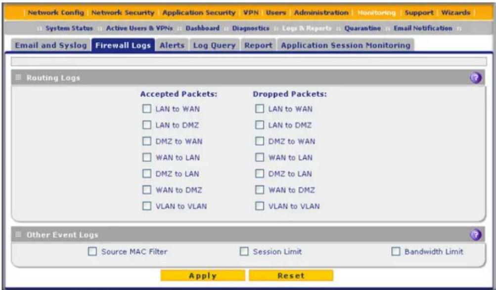
Figure 276.
- Enter the settings as explained in the following table:
Table 118. Firewall Logs screen settings
| Setting Description | |
| Routing Logs | |
| In the Accepted Packets and Dropped Packets columns, select check boxes to specify which traffic is logged:LAN to WANLAN to DMZDMZ to WANWAN to LANDMZ to LANWAN to DMZVLAN to VLAN | |
| Other Event Logs | |
| Source MAC Filter | Select this check box to log packets from MAC addresses that match the source MAC address filter settings. |
| Session Limit | Select this check box to log packets that are dropped because the session limit has been exceeded. |
| Bandwidth Limit Select this | check box to log packets that are dropped because the bandwidth limit has been exceeded. |
3. Click Apply to save your settings.
Monitor Real-Time Traffic, Security, and Statistics
The Dashboard screen lets you monitor the real-time security scanning status with detected network threats, detected network traffic, and service statistics for the six supported protocols (HTTP, HTTPS, FTP, SMTP, POP3, and IMAP). In addition, the screen displays statistics for the most recent five and top five malware threats detected, IPS signatures matched, applications blocked, web categories blocked, and spam emails blocked.
To display the Dashboard screen, select Monitoring > Dashboard. Because of the size of the Dashboard screen, it is divided and presented in this manual in three figures (the following figure, Figure 278 on page 480, and Figure 279 on page 482), each with its own table that explains the fields.
Except for setting the poll interval and clearing the statistics, you cannot configure the fields on the Dashboard screen. Any changes need to be made on other screens.
Note: Adobe Flash player 10 or later is required to display the graphics.

Figure 277. Dashboard, screen 1 of 3
To clear the statistics, click Clear Statistics.
To set the poll interval:
- Click the Stop button.
- From the Poll Interval drop-down list, select a new interval. The minimum is 5 seconds; the maximum is 5 minutes.
- Click the Set Interval button.
The following table explains the fields of the Total Threats, Threats (Counts), and Total Traffic (Bytes) sections of the Dashboard screen:
Table 119. Dashboard screen: threats and traffic information
| Item Description | |
| Total Threats | |
| Emails Displays the total number of:• Scanned emails.• Viruses (malware) detected. For information about how to configure these settings, see Customize Email Antivirus and Notification Settings on page 196.• Emails that matched filters. For information about how to configure these settings, see Email Content Filtering on page 199.• Spam. For information about how to configure these settings, see Protect Against Email Spam on page 202.• Quarantined emails, attachments, and objects. For information about how to configure these settings, see Customize Email Antivirus and Notification Settings on page 196 and Configure Distributed Spam Analysis on page 207. | |
| Web Displays the total number of:• Files scanned.• Malware detected. For information about how to configure these settings, see Configure Web Malware or Antivirus Scans on page 216.• Files blocked. For information about how to configure these settings, see Configure Web Content Filtering on page 218.• URLs blocked. For information about how to configure these settings, see Configure Web URL Filtering on page 224.• Quarantined web files and objects. For information about how to configure these settings, see Configure Web Malware or Antivirus Scans on page 216 and Configure FTP Scanning on page 238. | |
| Applications Displays the total number of:• Applications blocked.• Applications logged.For information about how to configure these settings, see Customize Web Protocol Scan Settings on page 210. | |
| Network Displays the total number of:• IPS attack signatures matched.• Anomaly behaviors detected.For information about how to configure these settings, see Enable and Configure the Intrusion Prevention System on page 187. | |
| Threats (Counts) | |
| This is a graphic that shows the relative number of threats and access violations over the last week, using different colors for the various components, most of which are self-explanatory: Email Filter, Spam, IPS Sig Match (which stands for IPS signatures matched), Web Malware, Email Virus, Application Block, Web URL Block, and Web Content Block. | |
| Total Traffic (Bytes) | |
| This is a graphic that shows the relative amount of traffic in bytes over the last week. | |

Figure 278. Dashboard, screen 2 of 3
The following table explains the fields of the Most Recent 5 and Top 5 sections of the Dashboard screen:
Table 120. Dashboard screen: most recent 5 threats and top 5 threats information
| Category | Most recent 5 threats description | Top 5 threats description |
| Threats | Malware Name. The name of the malware threat.Protocol. The protocol in which the malware threat was detected.Date and Time. The date and time that the malware threat was detected. | Malware Name. The name of the malware threat.Count. The number of times that the malware threat was detected.Percentage. The percentage that the malware threat represents in relation to the total number of detected malware threats. |
| IPS Signatures | Signature Name. The name of the attack.Category. The category in which the attack was detected, such as Web, Mail, Databases, and so on. (For more information about categories, see Enable and Configure the Intrusion Prevention System on page 187.)Date and Time. The date and time that the attack was detected. | Signature Name. The name of the attack.Count. The number of times that the attack was detected.Percentage. The percentage that the attack represents in relation to the total number of detected attacks. |
| Applications | Application. The name of the application that was blocked.Category. Instant messaging or peer-to-peer.Date and Time. The date and time that the application request was blocked. | Application. The name of the application that was blocked.Requests. The total number of user requests for the blocked application.Source IPs. The source IP address from which the request came. |
| Web Categories | Category. The web category that was blocked. (For more information about web categories, see Configure Web Content Filtering on page 218.)Date and Time. The date and time that the web request was blocked. | Category. The web category that was blocked. (For more information about web categories, see Configure Web Content Filtering on page 218.)Requests. The total number of user requests for the blocked web category.Source IPs. The source IP address from which the request came. |
| Spam | Email Subject. The email subject line in the spam message.Date and Time. The date and time that the spam message was detected. | Recipient. The intended recipient of the spam message.Email. The number of spam messages for the intended recipient. |
| Protocol | HTTP | HTTPS | FTP | SMTP | POP3 | IMAP |
| Total Scanned Traffic (MB) | 29777.34 | 0.19 | 282.99 | 0 | 0 | 0 |
| Total Emails/Files Scanned | 524616 | 1 | 10 | 0 | 0 | 0 |
| Total Malwares Found | 3 | 0 | 0 | 0 | 0 | 0 |
| Total Files Blocked | 0 | 0 | 0 | 0 | 0 | 0 |
| Total URLs Blocked | 98 | 0 | ||||
| Total Malware Quarantined | 0 | 0 | 0 | 0 | 0 | 0 |
| Total Spam Quarantined | 0 | |||||
| Total Spam Emails | 0 | 0 | ||||
| Blacklist | 0 | 0 | ||||
| RBL | 0 | |||||
| Distributed Spam Analysis | 0 | 0 |
Figure 279. Dashboard, screen 3 of 3
The following table explains the fields of the Service Statistics section of the Dashboard screen:
Table 121. Dashboard screen: service statistics information
| Item Description | ||
| For each of the six supported protocols (HTTP, HTTPS, FTP, SMTP, POP3, and IMAP), this section provides the following statistics: | ||
| Total Scanned Traffic (MB) | The total quantity of scanned traffic in MB. | |
| Total Emails/Files Scanned | The total number of scanned emails. | |
| Total Malwares Found The | total number of detected viruses and attacks. | |
| Total Files Blocked The total | number of files that were blocked from being downloaded. | |
| Total URLs Blocked | The total number of URL requests that were blocked. These statistics are applicable only to HTTP and HTTPS. | |
| Total Malware Quarantined | The total number of viruses (attachments, objects, and web files) that were quarantined. | |
| Total Spam Quarantined The | total number of spam messages that were quarantined. | |
| Total Spam Emails The total | number of spam messages that were blocked. These statistics are applicable only to SMTP and POP3. | |
| Blacklist The total | number of emails that were detected from sources on the spam blacklist (see Set Up the Whitelist and Blacklist on page 203). These statistics are applicable only to SMTP and POP3. | |
| RBL The total number | ber of emails that were detected from sources on the real-time blacklist (see Configure the Real-Time Blacklist on page 206). These statistics are applicable only to SMTP. | |
| Distributed Spam Analysis | The total number of spam messages that were detected through distributed spam analysis (see Configure Distributed Spam Analysis on page 207). These statistics are applicable only to SMTP and POP3. | |
Monitor Application Use in Real Time
If you have enabled application session monitoring (see Enable Application Session Monitoring on page 521), the Application Dashboard screen lets you monitor the use of applications and protocols in real time. To display the Application Dashboard screen, select Monitoring > Application Dashboard.
Except for setting the poll interval, changing the monitoring period, and selecting the filter, you cannot configure the fields on the Dashboard screen. Any changes need to be made on other screens.
You can sort the fields of the table below the graphics, which affects the displayed graphics, and you can display application details onscreen by clicking a View table button in the Details column. Move the cursor over the graphics to display additional information.
By default, the graphics are displayed as a pie chart. To show the graphics as a line chart, click the line chart icon below the Stop or Set Interval button. (Clicking the Stop button displays the Set Interval button; clicking the Set Interval button displays the Stop button.) To switch back to a pie chart, click the pie chart icon.
Note: Adobe Flash player 10 or later is required to display the graphics.

pie
| Category | Total Bytes | Avg Rates(KBps) | Percentage (%) | | :--- | :--- | :--- | :--- | | General TCP | 9174692 | 4.978 | 57.08 | | HTTP | 6269057 | 3.401 | | | SSL/TLS | 265310 | 0.144 | | | Google Authentication ... | 210481 | 0.114 | | | Web File Transfer | 49375 | 0.026 | | | Facebook | 29284 | 0.016 | | | General UDP | 22571 | 0.013 | | | Gmail | 17621 | 0.010 | | | World Wide Web HTTP | 17175 | 0.010 | | | Facebook Web IM | 6425 | 0.004 | | | POP3 | 5821 | 0.003 | | | Facebook Plug-in | 5000 | 0.003 | | | HTTP Protocol over TLS... | 568 | 0.001 | | | Total | 16073380 | 8.722 | 39.00% | The chart includes a legend for 'Line chart icon' and a pie chart icon, which is used to define the application dashboard click here. The 'To enable or disable the Application Dashboard click here.' is displayed in the top-left corner.Figure 280.
To set the poll interval:
- Click the Stop button.
- From the Poll Interval drop-down list, select a new interval. The minimum is 30 seconds; the maximum is 20 minutes.
- Click the Set Interval button.
To set the monitoring period:
From the Period drop-down list, select a period from 60 seconds to 4 weeks. The information onscreen adjusts.
To filter the information that is displayed onscreen:
From the Filter drop-down list, select Application, Category, User Name, or IP Address. The information onscreen adjusts.
Note: Only when the graphics are displayed as a pie chart can you set the poll interval and monitoring period and filter the information that is displayed onscreen.
The following table explains the fields of the Application Dashboard screen:
Table 122. Application Dashboard screen
| Item Description | |
| No. The item number in the table. | |
| Name The name that is displayed depends on the selection from the Filter drop-down list:Application. The field displays the name of the application or protocol. This is the default setting.Category. The field displays the name of the application category.User Name. The field displays the user name.IP Address. The field displays the IP address. | |
| Sessions The number of sessions during the monitoring period, which you can set by making a selection from the Period drop-down list. | |
| Avg Rates (Kbps) The average traffic rate in Kbps used during the monitoring period by the application, protocol, category, user, or IP address. | |
| Total Bytes | The traffic in bytes used during the monitoring period by the application, protocol, category, user, or IP address. |
| Total Packets | The number of packets used during the monitoring period by the application, protocol, category, user, or IP address. |
| Detail | Click the View table button to display the Application Dashboard Detail pop-up screen, which lets you drill down to more specific information. |
View Status Screens
• View the System Status
• View the Active VPN Users
• View the VPN Tunnel Connection Status
• View the Active PPTP and L2TP Users
• View the Port Triggering Status
• View the WAN, xDSL, or USB Port Status
• View Attached Devices and the DHCP Leases
View the System Status
When you start up the UTM, the default screen that displays is the System Status screen.
The System Status screen, Network Status screen, Router Statistics screen, Detailed Status screen, VLAN Status screen, and xDSL Statistics screen (UTM9S and UTM25S only) provide real-time information about the following important components of the UTM:
• CPU, memory, and hard disk status
- ReadyNAS and quarantine status
- Services status (indicating whether the protocols are scanned for malware) and the number of active connections per service
- Firmware versions and update information of the UTM, software versions and update information of the components, license expiration dates for each type of license, and hardware serial number
• WAN and LAN port information
- Interface statistics
• VLAN status, including port memberships
• xDSL statistics (UTM9S and UTM25S only)
These status screens are described in the following sections:
• View the System Status Screen
• View the Network Status Screen
• View the Router Statistics Screen
• View the Wireless Statistics Screen (UTM9S and UTM25S Only)
• View the Detailed Status Screen
• View the VLAN Status Screen
• View the xDSL Statistics Screen (UTM9S and UTM25S Only)
View the System Status Screen
To view the System Status screen, select Monitoring > System Status. The System Status tabs display, with the System Status screen in view:

Figure 281.
The following table explains the fields of the System Status screen:
Table 123. System Status screen fields
| Item Description | |
| Status | |
| System The current CPU, memory, and hard disk usage. When usage is within safe limits, the status bars show green. | |
| Application Control Status | The status of application control (ON or OFF). |
| Item | Description |
| Application Control Mode The application control mode (GLOBAL or PROFILE). | |
| ReadyNAS Status The status of the ReadyNAS connection:OFF. The ReadyNAS is not connected.NORMAL. The ReadyNAS is connected and functions normally.FAILED. The ReadyNAS is connected but is unreachable. | |
| Quarantine Status The status of the quarantine area:OFF. The quarantine area is disabled.NORMAL. The quarantine area is enabled and functions normally.FAILED. The quarantine area is enabled but is unreachable. | |
| Active TCP connections The number of active connections that use TCP. | |
| Active UDP connections The number of active connections that use TCP. | |
| Services The protocols for which scanning is enabled (ON or OFF is stated next to the protocol). For information about how to enable scanning for protocols, see Customize Email Protocol Scan Settings on page 194 and Customize Web Protocol Scan Settings on page 210. | |
| Active connections The number of active connections for each protocol. | |
| Anti-Virus The protocols that are being scanned for malware threats (ON or OFF is stated under the protocol). | |
| System InformationStates the system up time since last reboot. | |
| System Name The model of the UTM. | |
| Firmware Information | The versions and most recent downloads for the active and secondary firmware of the UTM, the scan engine, pattern file, and firewall.Click + More to display the versions and most recent downloads for the DC agent, SSE engine, SSE pattern, Mini engine, Mini pattern, Update client, IPS engine, IPS rules, Scand, and Urld. |
| License Expiration Date | The license expiration dates for the email protection and web protection licenses, the combined support and maintenance license, and the combined application control and IPS license.Note:When a license has expired, the license expiration date is displayed in red font. |
| Hardware Serial Number | The hardware serial number of the UTM. |
View the Network Status Screen
To view the Network Status screen, select Monitoring > System Status > Network Status. The Network Status screen displays. (The following figure shows the Network Status screen of the UTM50. The Network Status screen of the UTM9S or UTM25S also shows the
ProSecure Unified Threat Management (UTM) Appliance
available wireless access point, and has a Wireless Statistics option arrow in the upper right of the screen.)

Figure 282.
The UTM9S and UTM25S also show a table with available access points at the bottom of the Network Status screen:
| Available Access Points Table | |||||
| SSID | BSSID | Profile Name | Security | Encryption | Authentication |
| netgear-1 | e0:46:9a:ba:98:9d | UTM9S | OPEN | NONE | NONE |
| Productivity | e2:46:9a:ba:98:9e | CompanyWide | WPA WPA2 | TKIP AES | PSK |
Figure 283.
The following table explains the fields of the Network Status screen:
Table 124. Network Status screen fields
| Item Description | |
| LAN (VLAN) Information | |
| For each of the LAN ports, the screen shows the IP address and subnet mask. For more detailed information, see Table 127 on page 495. | |
| WAN Information | |
| For each of the WAN ports, the screen shows the IP address, subnet mask, and status of the port (UP or DOWN). For the UTM9s and UTM25S, the screen also shows this information for the xDSL (SLOT-1 or SLOT-2) and USB ports. For more detailed information, see Table 127 on page 495. | |
| Available Access Points TableNote: This information is displayed for the UTM9S and UTM25S only. | |
| SSID The SSID of the wireless profile. | |
| BSSID | The MAC address of the wireless radio, adjusted for each wireless profile. |
| Profile Name The name of the wireless profile. | |
| Security The security settings of the wireless profile. | |
| Encryption The encryption that is configured on the wireless profile. | |
| Authentication The authentication that is configured on the wireless profile. | |
View the Router Statistics Screen
To view the Router Statistics screen:
- Select Monitoring > System Status > Network Status. The Network Status screen displays.
- Click the Show Statistics option arrow in the upper right of the Network Status screen. The Router Statistics screen displays. (The following figure shows the Router Statistics screen of the UTM50.)
![Network Config | Network Security | Application Security | VPN | Users | Administration | Monitoring | Support | Wizards | System Status || Active Users & VPNs || Dashboard || Diagnostics || Logs & Reports || Quarantine || Email Notification || Router Statistics The page will auto-refresh in 2 Seconds System up Time: 8 Days 03:41:21 Router Statistics Port Tx Pkts Rx Pkts Collisions Tx B/s Rx B/s Up Time WAN1 3255634 759584 0 405 135 8 Days 03:39:02 WAN2 0 0 0 N/A N/A N/A LAN 2346 300509 0 0 21 8 Days 03:41:33 Poll Interval: 5 [Seconds] Set interval Stop](/content/2026/06/1371942/images/92e989a6e286360b21c288adfc945c9dab53cfe6833f6b6f9b91c4c4131f8377.jpg)
Figure 284.
The following table explains the fields of the Router Statistics screen.
ProSecure Unified Threat Management (UTM) Appliance
To change the poll interval period, enter a new value in the Poll Interval field, and then click Set interval. To stop polling, click Stop.
Table 125. Router Statistics screen fields
| Item Description | |
| System up Time. The period since the last time that the UTM was started up. | |
| Router Statistics | |
| For each of the WAN interfaces, for the xDSL and USB interfaces (UTM9S and UTM25S only, not shown on the previous figure), and for all LAN interfaces combined, the following statistics are displayed: | |
| Tx Pkts The number of packets transmitted on the port in bytes. | |
| Rx Pxts The number of packets received on the port in bytes. | |
| Collisions | The number of signal collisions that have occurred on the port. A collision occurs when the port attempts to send data at the same time as a port on the other router or computer that is connected to this port. |
| Tx B/s The number of bytes transmitted per second on the port. | |
| Rx B/s The number of bytes received per second on the port. | |
| Up Time The period that the port has been active since it was restarted. | |
View the Wireless Statistics Screen (UTM9S and UTM25S Only)
To view the Wireless Statistics screen:
- Select Monitoring > System Status > Network Status. The Network Status screen displays.
- Click the Wireless Statistics option arrow in the upper right of the Network Status screen. The Wireless Statistics screen displays:
![Network Config | Network Security | Application Security | VPN | Users | Administration | Monitoring | Support | Wizards | System Status | Active Users & VPNs | Dashboard | Diagnostics | Logs & Reports | Quarantine | Email Notification | Wireless Statistics The page will auto-refresh in 3 Seconds Radio Statistics Details Packet Bytes Errors Dropped Multicast Collisions Rx Tx Rx Tx Rx Tx 0 0 0 0 0 0 0 0 0 0 AP Statistics AP Name Packet Bytes Errors Dropped Multicast Collisions Rx Tx Rx Tx Rx Tx Rx Tx vap0 0 0 0 0 0 0 0 0 0 0 0 vap1 0 0 0 0 0 0 0 0 0 0 0 Poll Interval: S [Seconds] Set interval Stop](/content/2026/06/1371942/images/fd98e9cc839725b2b6bc169f1faa33c460eff8591329534a697e7740ec57d1bf.jpg)
Figure 285.
The following table explains the fields of the Wireless Statistics screen.
To change the poll interval period, enter a new value in the Poll Interval field, and then click Set interval. To stop polling, click Stop.
Table 126. Wireless Statistics screen fields
| Item Description | |
| Radio Statistics Details | |
| Packets The number of received (Rx) and transmitted (Tx) packets on the radio in bytes. | |
| Bytes The number of received (Rx) and transmitted (Tx) bytes on the radio. | |
| Errors The number of received (Rx) and transmitted (Tx) errors on the radio. | |
| Dropped The number of received (Rx) and transmitted (Tx) dropped packets on the radio. | |
| Multicast | The number of received (Rx) and transmitted (Tx) multicast packets on the radio. |
| Collisions | The number of signal collisions that have occurred on the radio. A collision occurs when the radio attempts to send data at the same time as a wireless station that is connected to the radio. |
| AP StatisticsNote: The default wireless profile with profile name UTM9S or UTM25S is referred to as virtual access point zero (VAP0). If you add more wireless profiles, they are referred to as VAP1, VAP2, and VAP3. | |
| AP Name The name for the virtual access point (VAP) is ap1. | |
| Packets The number of received (Rx) and transmitted (Tx) packets on the access point in bytes. | |
| Bytes The number of received (Rx) and transmitted (Tx) bytes on the access point. | |
| Errors The number of received (Rx) and transmitted (Tx) errors on the access point. | |
| Dropped | The number of received (Rx) and transmitted (Tx) dropped packets on the access point. |
| Multicast | The number of received (Rx) and transmitted (Tx) multicast packets on the access point. |
| Collisions | The number of signal collisions that have occurred on the access point. A collision occurs when the access point attempts to send data at the same time as a wireless station that is connected to the access point. |
Note: For information about clients that are connected to the access point, see View the Access Point Status and Connected Clients for a Wireless Profile on page 595.
View the Detailed Status Screen
To view the Detailed Status screen, select Monitoring > System Status > Detailed Status. The Detailed Status screen displays. (The following figure shows the Detailed Status screen of the UTM50.)

Figure 286.
The UTM9S and UTM25S also show SLOT-1 Info, SLOT-2 Info, and USB Info, and Access Points Information sections at the bottom of the Detailed Status screen:

Figure 287. Detailed Status screen sections that are specific to the UTM9S and UTM25S
The following table explains the fields of the Detailed Status screen:
Table 127. Detailed Status screen fields
| Item Description | ||
| LAN Port ConfigurationThe following fields are shown for each of the LAN ports. | ||
| VLAN Profile The name of the VLAN profile that you assigned to this port on the LAN Setup screen (see Assign and Manage VLAN Profiles on page 100). If the VLAN is not enabled on this port, the default profile (with VLAN ID 1) is assigned automatically. | ||
| VLAN ID The VLAN ID that you assigned to this port on the Add VLAN Profile screen (see Configure a VLAN Profile on page 103). If the default VLAN profile is used, the VLAN ID is 1, which means that all tagged and untagged traffic can pass on this port. | ||
| MAC Address The MAC address of this port. All LAN ports share the same MAC address if they are part of the default VLAN. However, if LAN port 4 (UTM5, UTM10, UTM25, and UTM150) or LAN port 6 (UTM50) is enabled as the DMZ port, its MAC address is changed to the MAC address of the WAN2 interface plus 1. (For example, if the MAC address of the WAN2 interface is 00:26:f2:b5:db:80, the MAC address of the DM port is 00:26:f2:b5:db:81.) For information about configuring the DMZ port, see Configure and Enable the DMZ Port on page 117. | ||
| IP Address The IP address for this port. If the VLAN is not enabled on this port, the IP address is the default LAN IP address (192.168.1.1). For information about configuring VLAN profiles, see Configure a VLAN Profile on page 103. | ||
| Subnet Mask | The subnet mask for this port. If the VLAN is not enabled on this port, the subnet mask is the default LAN IP subnet mask (255.255.255.0). For information about configuring VLAN profiles, see Configure a VLAN Profile on page 103. | |
| DHCP Status | The status can be either DHCP Enabled or DHCP Disabled. For information about enabling DHCP for this port, see Configure a VLAN Profile on page 103. | |
| WAN Info, xDSL information in SLOT-1 Info or SLOT-2 Info, and USB InfoNote: For the UTM9S and UTM25S only: DSL information is shown in the SLOT-1 Info or SLOT-2 Info section, depending on the slot in which the xDSL network module is installed. All other fields that are shown in the SLOT-1 Info or SLOT-2 Info section are also shown in the WAN Info sections.Note: The USB information in the USB Info section applies to the UTM9S and UTM25S only.The following fields are shown for each of the WAN ports and for the slot in which the xDSL network module is installed: | ||
| WAN Mode The WAN mode can be Single Port, Load Balancing, or Auto Rollover. For information about configuring the WAN mode, see Configure the WAN Mode on page 80. | ||
| Card Type (UTM9S and UTM25S only) | The configuration of the xDSL network module: VDSL or ADSL. | |
| Daughter Card (UTM9S and UTM25S only) | The type of supported annex on the xDSL network module: Annex A or Annex B (VDSL_ANNEXA, VDSL_ANNEXB, ADSL_ANNEXA, or ADSL_ANNEXB). | |
| Item | Description | |
| Firmware Version (UTM9S and UTM25S only) | The firmware on the xDSL network module. | |
| WAN State The WAN state | can be either UP or DOWN, depending on whether the port is connected to the Internet and whether the port is enabled. For information about connecting WAN ports, see Chapter 3, Manually Configure Internet and WAN Settings. | |
| NAT The NAT state can be | either Enabled or Disabled, depending on whether NAT is enabled (see Configure Network Address Translation (All Models) on page 81) or classical routing is enabled (see Configure Classical Routing (All Models) on page 82). | |
| Connection Type The connection type can be Static IP, DHCP, PPPoE, or PPTP, depending on whether the WAN address is obtained dynamically through a DHCP server or assigned statically by you. For information about connection types, see Manually Configure the Internet Connection on page 75. | ||
| Connection State | The connection state can be either Connected or Not Connected, depending on whether the WAN port is physically connected to a modem or router. For information about connecting a WAN port, see the ProSecure Unified Threat Management UTM Installation Guide. | |
| WAN Connection Type The detection type of Internet connection that is used on this port. The WAN connection type can be DSL, ADSL, CableModem, T1, or T3. | ||
| Upload Connection Speed | For the WAN port, this field displays the maximum upload speed that you have configured on the Advanced Options screen. By default, the speed is 1,000,000 Kbps. For the xDSL and USB ports, this field displays the detected upload speed. | For information about configuring the upload and download speeds for WAN interfaces, see Set the UTM's MAC Address and Configure Advanced WAN Options on page 94. |
| Download Connection Speed | For the WAN port, this field displays the maximum download speed that you have configured on the Advanced Options screen. By default, the speed is 1,000,000 Kbps. For the xDSL and USB ports, this field displays the detected download speed. | |
| IP Address The IP address of the WAN port. | These settings are either obtained dynamically from your ISP or specified by you on the WAN ISP Settings screen for this port (see Manually Configure the Internet Connection on page 75). | |
| Subnet Mask The subnet mask of the WAN port. | ||
| Gateway The IP address of the gateway. | ||
| Primary DNS Server The IP address of the primary DNS server. | ||
| Secondary DNS Server The IP address of the secondary DNS server. | ||
| Item Description | ||
| MAC Address For the WAN | or xDSL ports, this field displays the default MAC address or the MAC address that you have specified on the Advanced Options screen.For the USB port, this field displays the detected MAC address. | For information about configuring the MAC address for the WAN port, seeSet the UTM's MAC Address and Configure Advanced WAN Optionson page 94. For information about configuring the MAC address for the xDSL port, seeSet the UTM's MAC Address and Configure Advanced WAN Optionson page 574. |
| Wireless information in SLOT-1 Info or SLOT-2 InfoNote: For the UTM9S and UTM25S only: Wireless information is shown in the SLOT-1 Info or SLOT-2 Info section, depending on the slot in which the wireless network module is installed.The following fields are shown for the wireless network module: | ||
| Card Type This is a fixed field that states Wireless. | ||
| Daughter Card This is a fixed field that states Wireless. | ||
| Firmware Version | This is a fixed field that states N/A. This field might show a software version in a future release. | |
| Country The region and country that you have specified on the Radio Settings screen. | For information about configuring the basic wireless radio settings, seeConfigure the Basic Radio Settings on page 580. | |
| Operating Frequency The operating frequency that you have specified on the Radio Settings screen: 2.4 GHz or 5 GHz. | ||
| Advanced Wireless Network Mode | The wireless mode that you have specified on the Radio Settings screen. | |
| Channel The channel or automatic channel selection that you have specified on the Radio Settings screen. | ||
| Access Points InformationNote: This information applies to the UTM9S and UTM25S only. | ||
| SSID The SSID of the wireless access point that you have specified on the Add Wireless Profile screen. | For information about configuring the SSID, wireless security, and IP address, seeConfigure and Enable Wireless Profileson page 588. | |
| Security Type The type of wireless security and encryption that you have specified on the Add Wireless Profile screen. | ||
| IP Address The IP address of the VLAN that you have specified on the Add Wireless Profile screen. | ||
| MAC Address The MAC address of the wireless radio, adjusted for each wireless profile. | ||
View the VLAN Status Screen
The VLAN Status screen displays information about the VLANs (both enabled and disabled) that are configured on the UTM. For information about configuring VLAN profiles, see Configure a VLAN Profile on page 103. For information about enabling and disabling VLAN profiles, see Assign and Manage VLAN Profiles on page 100.
To view the VLAN Status screen, select Monitoring > System Status > VLAN Status. The VLAN Status screen displays. (The following figure shows the VLAN Status screen of the UTM50.)
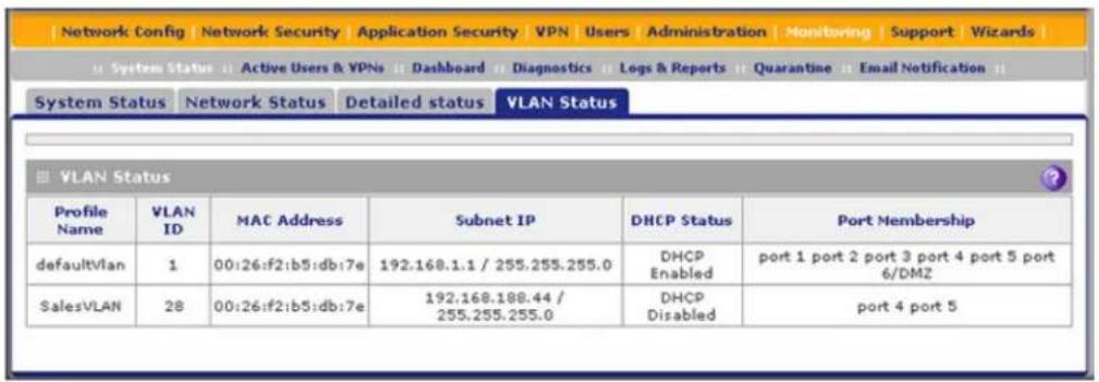
Figure 288.
The following table explains the fields of the VLAN Status screen:
Table 128. VLAN Status screen fields
| Item Description | |
| Profile Name The unique name for the VLAN that you have assigned on the Add VLAN Profile screen (see Configure a VLAN Profile on page 103). | |
| VLAN ID The identifier for the VLAN that you have assigned on the Add VLAN Profile screen (see Configure a VLAN Profile on page 103). | |
| MAC Address | VLANs can have the same MAC address as the associated LAN port or can be assigned a unique MAC address, depending on the selection that you have made on the LAN Advanced screen (see Configure VLAN MAC Addresses and Advanced LAN Settings on page 108). If a VLAN is configured but disabled, the MAC address displays as 00:00:00:00:00:00. |
| Subnet IP | The IP address and subnet mask that you have assigned on the Add VLAN Profile screen (see Configure a VLAN Profile on page 103). |
| DHCP Status | The DHCP status for the VLAN, which can be either DHCP Enabled or DHCP Disabled, depending on the DHCP configuration that you have specified on the Add VLAN Profile screen (see Configure a VLAN Profile on page 103). |
| Port Membership | The ports that you have associated with the VLAN on the Add VLAN Profile screen (see Configure a VLAN Profile on page 103). |
View the xDSL Statistics Screen (UTM9S and UTM25S Only)
To view the xDSL Statistics screen, select Monitoring > System Status > xDSL Statistics. The xDSL Statistics screen displays:

Figure 289.
View the Active VPN Users
The Active Users screen displays a list of administrators, IPSec VPN users, and SSL VPN users that are currently logged in to the UTM.
To display the list of active VPN users, select Monitoring > Active Users & VPNs. The Active Users & VPN submenu tabs display, with the Active Users screen in view:

Figure 290.
The active user's user name, group, and IP address are listed in the table with a time stamp indicating the time and date that the user logged in.
To disconnect an active user, click the Disconnect table button to the right of the user's table entry.
View the VPN Tunnel Connection Status
To review the status of current IPSec VPN tunnels, select Monitoring > Active Users & VPNs > IPSec VPN Connection Status. The IPSec VPN Connection Status screen displays:

Figure 291.
The Active IPSec SA(s) table lists each active connection with the information that is described in the following table. The default poll interval is 5 seconds. To change the poll interval period, enter a new value in the Poll Interval field, and then click Set Interval. To stop polling, click Stop.
Table 129. IPSec VPN Connection Status screen information
| Item Description | |
| Policy Name The name of the VPN policy that is associated with this SA. | |
| Endpoint The IP address on the remote VPN endpoint. | |
| Tx (KB) The amount of data that is transmitted over this SA. | |
| Tx (Packets) The number of IP packets that are transmitted over this SA. | |
| State | The status of the SA. Phase 1 is the authentication phase, and Phase 2 is key exchange phase. If there is no connection, the status is IPSec SA Not Established. |
| Action | Click the Connect table button to build the connection, or click the Disconnect table button to terminate the connection. |
To review the status of current SSL VPN tunnels, select Monitoring > Active Users & VPNs > SSL VPN Connection Status. The SSL VPN Connection Status screen displays:

Figure 292.
The active user's user name, group, and IP address are listed in the table with a time stamp indicating the time and date that the user connected.
To disconnect an active user, click the Disconnect table button to the right of the user's table entry.
View the Active PPTP and L2TP Users
To view the active PPTP tunnel users, select Monitoring > Active Users & VPNs > PPTP Active Users. The PPTP Active Users screen displays:
![Network Config | Network Security | Application Security | VPN | Users | Administration | Monitoring | Support | Wizards | System Status : Active Users & VPNs : Dashboard : Diagnostics : Logs & Reports : Quarantine : Email Notification : Active Users IPSec VPN Connection Status SSL VPN Connection Status PPTP Active Users L2TP Active Users The page will auto-refresh in 3 Seconds List Of PPTP Active Users Username Remote IP PPTP IP Action Poll Interval: 5 [Seconds] Set interval Stop](/content/2026/06/1371942/images/af41c935c67ae7a96ebf90fefaae27c23c954be7b458ab319b930991f41f9a02.jpg)
Figure 293.
The List of PPTP Active Users table lists each active connection with the information that is described in the following table.
Table 130. PPTP Active Users screen information
| Item Description | |
| Username | The name of the PPTP user that you have defined (see Configure User Accounts on page 401). |
| Remote IP The remote client's IP address. | |
| PPTP IP The IP address that is assigned by the PPTP server. | |
| Action | Click the Disconnect table button to terminate the connection. (This button is displayed only when there an active connection.) |
The default poll interval is 5 seconds. To change the poll interval period, enter a new value in the Poll Interval field, and then click the Set Interval button. To stop polling, click the Stop button.
To view the active L2TP tunnel users, select Monitoring > Active Users & VPNs > L2TP Active Users. The L2TP Active Users screen displays:
![Network Config | Network Security | Application Security | VPN | Users | Administration | Monitoring | Support | Wizards | System Status | Active Users & VPNs | Dashboard | Diagnostics | Logs & Reports | Quarantine | Email Notification | Active Users | IPSec VPN Connection Status | SSL VPN Connection Status | PPTP Active Users | L2TP Active Users The page will auto-refresh in 3 Seconds List Of L2TP Active Users Username Remote IP L2TP IP Action Poll Interval: 5 [Seconds] SetInterval Stop](/content/2026/06/1371942/images/91da0ddb4ef9d36031e7f602775de8f17c6feb2f0ca66c8907a601fe35ce25cb.jpg)
Figure 294.
The List of L2TP Active Users table lists each active connection with the information that is described in the following table.
Table 131. L2TP Active Users screen information
| Item Description | |
| Username | The name of the L2TP user that you have defined (see Configure User Accounts on page 401). |
| Remote IP The client's | IP address on the remote LAC. |
| L2TP IP The IP address | that is assigned by the L2TP server. |
| Action | Click the Disconnect table button to terminate the connection. (This button is displayed only when there an active connection.) |
The default poll interval is 5 seconds. To change the poll interval period, enter a new value in the Poll Interval field, and then click the Set Interval button. To stop polling, click the Stop button.
View the Port Triggering Status
To view the status of the port-triggering feature:
- Select Network Security > Port Triggering. The Port Triggering screen displays. (The following figure shows one rule in the Port Triggering Rules table as an example.)
ProSecure Unified Threat Management (UTM) Appliance

Figure 295.
- Select the Status option arrow in the upper right of the Port Triggering screen. The Port Triggering Status screen displays in a pop-up screen.

Figure 296.
The Port Triggering Status screen displays the information that is described in the following table:
Table 132. Port Triggering Status pop-up screen information
| Item Description | |
| # The sequence number of the rule on screen. | |
| Rule The name of the port-triggering rule that is associated with this entry. | |
| LAN IP Address | The IP address of the computer or device that is currently using this rule. |
| Open Ports The incoming ports that are associated with this rule. Incoming traffic using one of these ports is sent to the IP address that is listed in the LAN IP Address field. | |
| Time Remaining The time remaining before this rule is released and made available for other computers or devices. This timer is restarted when incoming or outgoing traffic is received. | |
View the WAN, xDSL, or USB Port Status
You can view the status of the WAN connections, the DNS servers, and the DHCP servers. For the UTM9S and UTM25S, you can also view the status of the xDSL and USB ports.
To view the status of a WAN, xDSL, or USB port:
-
Select Network Config > WAN Settings. The WAN screen displays (see Figure 37 on page 72. For the UTM9S and UTM25, see Figure 324 on page 556 for the xDSL port or see Figure 348 on page 605 for the USB port.)
-
Click the Status button in the Action column for the WAN interface for which you want to view the status. The Connection Status screen displays in a pop-up screen.

Figure 297.
The Connection Status screen displays the information that is described in the following table:
Table 133. Connection Status pop-up screen information
| Item Description | |
| Connection Time The | period that the UTM has been connected through the WAN, xDSL, or USB port. |
| Connection Type The | connection type can be DHCP, Static IP, PPPoE, or PPTP. |
| Connection Status The | connection status can be either Connected or Disconnected. |
| IP Address | The IP addresses that were automatically detected or that you manually configured. For more information, see the following sections:For WAN ports, seeAutomatically Detecting and Connecting the Internet Connectionson page 71 and Manually Configure the Internet Connectionon page 75.For the xDSL port (UTM9S and UTM25S only), seeAutomatically Detecting and Connecting the xDSL Internet Connectionon page 553 and Manually Configure the xDSL Internet Connectionon page 556.For the USB port (UTM9S and UTM25S only), seeManually Configure the USB Internet Connectionon page 604.Note:The information in the DHCP Server field displays only if your ISP does not require a login and the IP address is acquired dynamically from your ISP. |
| Subnet Mask | |
| Gateway | |
| DNS Server | |
| Lease Obtained The time when the DHCP lease was obtained. | |
| Lease Duration The period that the DHCP lease remains in effect. | |
Depending on the type of connections, any of the following buttons might display on the Connection Status screen:
- Renew. Click to renew the DHCP lease.
- Release. Click to disconnect the DHCP connection.
- Disconnect. Click to disconnect the static IP connection.
For the multiple WAN port models only, the procedure to view the status of other WAN ports is similar to the one for the WAN1 port. After you have selected Network Config > WAN Settings, click the Status button in the Action column for the selected WAN interface to display the Connection Status screen for that WAN interface.
View Attached Devices and the DHCP Leases
The LAN Groups screen shows the network database, which is the Known PCs and Devices table, which contains all IP devices that UTM has discovered on the local network. The LAN Setup screen lets you access the DHCP leases pop-up screen.
View Attached Devices
To view the attached devices in the LAN Groups screen:
- Select Network Config > LAN Settings. The LAN Settings submenu tabs display, with the LAN Setup screen in view. (The following figure shows some profiles in the VLAN Profiles table as an example.)

Figure 298.
- Select the LAN Groups submenu tab. The LAN Groups screen displays. (The following figure shows some examples in the Known PCs and Devices table.)
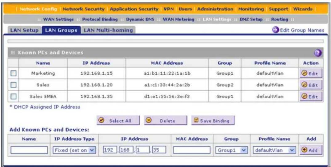
Figure 299.
The Known PCs and Devices table contains a list of all known computers and network devices that are assigned dynamic IP addresses by the UTM, or have been discovered by other means. Collectively, these entries make up the network database.
For each attached computer or device, the Known PCs and Devices table displays the following fields:
- Check box. Allows you to select the computer or device in the table.
- Name. The name of the computer or device. For computers that do not support the NetBIOS protocol, the name is displayed as Unknown (you can edit the entry
ProSecure Unified Threat Management (UTM) Appliance
manually to add a meaningful name). If the computer or device was assigned an IP address by the DHCP server, then the name is appended by an asterisk.
- IP Address. The current IP address of the computer or device. For DHCP clients of the UTM, this IP address does not change. If a computer or device is assigned a static IP address, you need to update this entry manually after the IP address on the computer or device has changed.
• MAC Address. The MAC address of the computer or device's network interface. - Group. Each computer or device can be assigned to a single LAN group. By default, a computer or device is assigned to Group 1. You can select a different LAN group from the Group drop-down list in the Add Known PCs and Devices section or on the Edit Groups and Hosts screen.
• Action. The Edit table button, which provides access to the Edit Groups and Hosts screen.
Note: If the UTM is rebooted, the data in the Known PCs and Devices table is lost until the UTM rediscovers the devices.
View the DHCP Leases
To view the DHCP leases:
- Select Network Config > LAN Settings. The LAN Settings submenu tabs display, with the LAN Setup screen in view (see Figure 298 on page 506).
- Click the DHCP Leases option arrow in the upper right of the LAN Setup screen. The DHCP Leases table displays in a pop-up screen:

Figure 300.
Query and Manage the Logs
• Overview of the Logs
• Query and Download Logs
• Example: Use the Logs to Identify Infected Clients
- Log Management
Overview of the Logs
The UTM generates logs that provide detailed information about malware threats and traffic activities on the network. You can view these logs through the web management interface or save the log records in CSV or HTML format and download them to a computer (the downloading option is not available for all logs).
Note: For information about the quarantine logs, which are stored externally, see Query and Manage the Quarantine Logs on page 514.

WARNING:
When you reboot the UTM, the logs are lost. If you want to save the logs, make sure that you configure the UTM to send the logs to a syslog server. For information about how to do this, and also about how to email logs, see Configure and Activate System, Email, and Syslog Logs on page 467.
The UTM provides 14 types of logs:
- Traffic. All scanned incoming and outgoing traffic.
- Spam. All intercepted spam.
- System. The system event logs that you have specified on the Email and Syslog screen (see Configure and Activate System, Email, and Syslog Logs on page 467). However, by default, many more types of events are logged in the system logs.
- Service. All events that are related to the status of scanning and filtering services that you access from the Application Security main navigation menu. These events include update success messages, update failed messages, network connection errors, and so on.
• Malware. All intercepted viruses, spyware, and other malware threats. - Email filters. All emails that are blocked because of file extension and keyword violations.
- Content filters. All attempts to access blocked websites and URLs.
- IPS. All IPS events.
- Anomaly Behavior. All port scan and DDoS events.
- Application. All instant messaging, peer-to-peer and media application, and tool access violations.
- Firewall. The firewall logs that you have specified on the Firewall Logs screen (see Configure and Activate Firewall Logs on page 476).
- IPSec VPN. All IPSec VPN events.
- SSL VPN. All SSL VPN events.
- HTTPS Smart Block. All attempts to access domains that are blocked as part of an active HTTPS Smart Block logs profile (see Configure HTTPS Smart Block on page 212).
ProSecure Unified Threat Management (UTM) Appliance
You can query and generate each type of log separately and filter the information based on a number of criteria. For example, you can filter the malware logs using the following criteria (other log types have similar filtering criteria):
- Start date/time and end date/time
- Protocols (HTTP, HTTPS, FTP, SMTP, POP3, and IMAP)
- Malware name
• Action - Domain
- User
- Client and server IP addresses
- Recipient email address
Query and Download Logs
To query and download logs:
- Select Monitoring > Logs & Reports > Logs Query. The Logs Query screen displays. (The following figure shows the Malware log information settings as an example.) Depending on the selection that you make from the Log Type drop-down list, the screen adjusts to display the settings for the selected type of log.

Figure 301.
- Enter the settings as explained in the following table:
Table 134. Logs Query screen settings
| Setting Description | ||
| Log Type Select one of the following log types from the drop-down list:Traffic. All scanned incoming and outgoing traffic.Spam. All intercepted spam.System. The system event logs that you have specified on the Email and Syslog screen (see Configure and Activate System, Email, and Syslog Logs on page 467). However, by default, many more types of events are logged in the system logs. Note that you cannot specify further search criteria on the Log Query screen, that is, when you select System from the drop-down list, the System Logs screen displays.Service Logs. All events that are related to the status of scanning and filtering services that you access from the Application Security main navigation menu. These events include update success messages, update failed messages, network connection errors, and so on.Malware. All intercepted viruses, spyware, and other malware threats.Email filters. All emails that are blocked because of file extension and keyword violations.Content filters. All attempts to access blocked websites and URLs.IPS. All IPS events.Anomaly Behavior. All port scan and DDoS events.Application. All instant messaging, peer-to-peer and media application, and tools access violations.Firewall. The firewall logs that you have specified on the Firewall Logs screen (see Configure and Activate Firewall Logs on page 476). Note that you cannot specify further search criteria on the Log Query screen, that is, when you select Firewall from the drop-down list, the Firewall Logs screen displays.IPSEC VPN. All IPSec VPN events. Note that you cannot specify further search criteria on the Log Query screen, that is, when you select IPSEC VPN from the drop-down list, the IPSec VPN Logs screen displays.SSL VPN. All SSL VPN events. Note that you cannot specify further search criteria on the Log Query screen, that is, when you select SSL VPN from the drop-down list, the SSL VPN Logs screen displays.HTTPS Smart Block. All attempts to access domains that are blocked as part of an active HTTPS Smart Block logs profile (see Configure HTTPS Smart Block on page 212). | ||
| View All Select one of the following radio buttons:• View All. Display or download the entire selected log.• Search Criteria. Query the selected log by configuring the search criteria that are available for the selected log. | ||
| Search Criteria | Start Date/Time From the drop-down lists, select the year, month, day, hours, and minutes for the start date and time.This field is available for the following logs:Traffic, Spam, System, Service, Malware, Email filters, Content filters, IPS, Anomaly Behavior, Application, Firewall, IPSec VPN, SSL VPN, and HTTPS Smart Block. | |
| End Date/Time From the drop-down lists, select the year, month, day, hours, and minutes for the end date and time.This field is available for the following logs:Traffic, Spam, System, Service, Malware, Email filters, Content filters, IPS, Anomaly Behavior, Application, Firewall, IPSec VPN, SSL VPN, and HTTPS Smart Block. | ||
| Protocols | Select one or more check boxes to specify the protocols that are queried.The following protocols can be selected:For Traffic and Malware logs: SMTP, POP3, IMAP, HTTP, FTP, and HTTPS.For the Spam log: SMTP and POP3.For the Email filters log: SMTP, POP3, and IMAP.For the Content filters log: HTTP, FTP, and HTTPS. | |
| Domain The domain name that is queried.This field is available for the following logs:Traffic, Spam, Malware, Email filters, Content filters, and Application. | ||
| User The user name that is queried.This field is available for the following logs:Traffic, Spam, Malware, Email filters, Content filters, and Application. | ||
| Client IP The client IP address that is queried.This field is available for the following logs:Traffic, Spam, Malware, Content filters, IPS, Anomaly Behavior, Application. | ||
| Server IP The server IP address that is queried.This field is available for the following logs:Traffic, Malware, Content filters, IPS, Anomaly Behavior, Application. | ||
| Setting | Description | |
| Search Criteria (continued) | Category or Categories | From the drop-down list, select a category that is queried. You can select the following from the drop-down list:For the IPS log: an attack.For the Application log: an instant messaging, peer-to-peer, media, or tool application. |
| Reason Select one or more check boxes to specify the reasons that are queried:You can select one or more of the following check boxes:For the Email filters log: Keyword, FileType, Filename, Password, and SizeLimit.For the Content filters log: URL, FileType, SizeLimit, Proxy, and Keyword. | ||
| Spam Found By | This field is available only for the Spam log.Select one of the following check boxes to specify the method by which spam is detected: Blacklist or Distributed Spam Analysis. | |
| Malware Name The name of the malware threat that is queried.This field is available only for the Malware log. | ||
| Action The spam or malware detection action that is queried.The following actions can be selected:For the Spam log: Select the Block or Tag check box.For the Malware log: Select the Delete, Block email, or Log check box. | ||
| Email Subject The email subject that is queried:This field is available for the following logs:Spam and Email filters. | ||
| Sender Email The sender's email address that is queried.This field is available only for the Traffic log. | ||
| Recipient Email The recipient's email address that is queried.This field is available for the following logs:Traffic, Spam, Malware, and Email filters. | ||
| Message The email message text that is queried.This field is available for the following logs:IPS, Anomaly Behavior, and Application. | ||
| Subject The email subject line that is queried.This field is available only for the Traffic log. | ||
| Size The minimum and maximum size (in bytes) of the file that is queried.This field is available only for the Traffic log. | ||
| Setting Description | ||
| Search Criteria(continued) | Event The type of | event that is queried. These events are the same events that are used to indicate the syslog server severity:EMERG, ALERT, CRITICAL, ERROR, WARNING, NOTICE, INFO, and DEBUG.This field is available only for the Service log. |
| URL The URL that is queried.This field is available only for the Content filters log. | ||
| Content The user | name, client IP address, server IP address, or domain name that is queried.This field is available only for the HTTPS Smart Block log. | |
| Display The maximum number of pages that is displayed. | ||
| Download Log (zipped)File Format | Select a radio button to specify the format to download the zipped log file:CSV. Download the log file as a comma-separated values (CSV) file.HTML. Download the log file as an HTML file. | |
- Click one of the following action buttons:
- Search. Query the log according to the search criteria that you specified, and view the log through the web management interface, that is, onscreen.
- Download. Query the log according to the search criteria that you specified, and download the log to a computer.
Example: Use the Logs to Identify Infected Clients
You can use the UTM logs to help identify potentially infected clients on the network. For example, clients that are generating abnormally high volumes of HTTP traffic might be infected with spyware or other malware threats.
To identify infected clients that are sending spyware in outbound traffic, query the UTM malware logs and see if any of your internal IP addresses are the source of spyware.
To identify infected clients:
- On the Log Query screen (see Figure 301 on page 509), select Traffic as the log type.
- Select the start date and time from the drop-down lists.
- Select the end date and time from the drop-down lists.
- Next to Protocols, select the HTTP check box.
- Click Search. After a few minutes, the log displays onscreen.
- Check if there are clients that are sending out suspicious volumes of data, especially to the same destination IP address, on a regular basis.
If you find a client exhibiting this behavior, you can run a query on that client's HTTP traffic activities to get more information. Do this by running the same HTTP traffic query and entering the client IP address in the Client IP field.
Log Management
Generated logs take up space and resources on the UTM internal disk. To ensure that there is always sufficient space to save newer logs, the UTM automatically deletes older logs whenever the total log size reaches 50 percent of the allocated file size for each log type.
Automated log purging means that you do not need to manage the size of the UTM logs constantly and ensures that the latest malware threats and traffic activities are always recorded.
Note: After the UTM reboots, traffic logs are lost. Therefore, NETGEAR recommends that you connect the UTM to a syslog server to save the traffic logs externally. Other logs (that is, nontraffic logs) are automatically backed up on the UTM every 15 minutes. However, if a power failure affects the UTM, logs that were created within this 15-minute period are lost.
For information about how to purge selected logs manually, see Configure and Activate System, Email, and Syslog Logs on page 467.
Query and Manage the Quarantine Logs
- Query the Quarantined Logs
• View and Manage the Quarantined Spam Table
• View and Manage the Quarantined Infected Files Table - Spam Reports for End Users
The UTM can quarantine spam and malware files. Before you can query the Spam and Malware logs, you need to have done the following:
- You have integrated a ReadyNAS (see Connect to a ReadyNAS on page 459).
- You have configured the quarantine settings (see Configure the Quarantine Settings on page 460).
- You have selected to quarantine emails, attachments, objects, and web files on one or more of the following screens:
- Email Anti-Virus screen (see Customize Email Antivirus and Notification Settings on page 196)
- Distributed Spam Analysis screen (see Configure Distributed Spam Analysis on page 207)
• Malware Scan screen (see Configure Web Malware or Antivirus Scans on page 216) - FTP screen (Configure FTP Scanning on page 238)
Query the Quarantined Logs
To query the quarantine logs:
- Select Monitoring > Quarantine. The Quarantine screen displays. (The following figure shows the Spam log information settings as an example.)
Depending on the selection that you make from the File Type drop-down list, the screen adjusts to display either the settings for the Spam log or the Malware log.
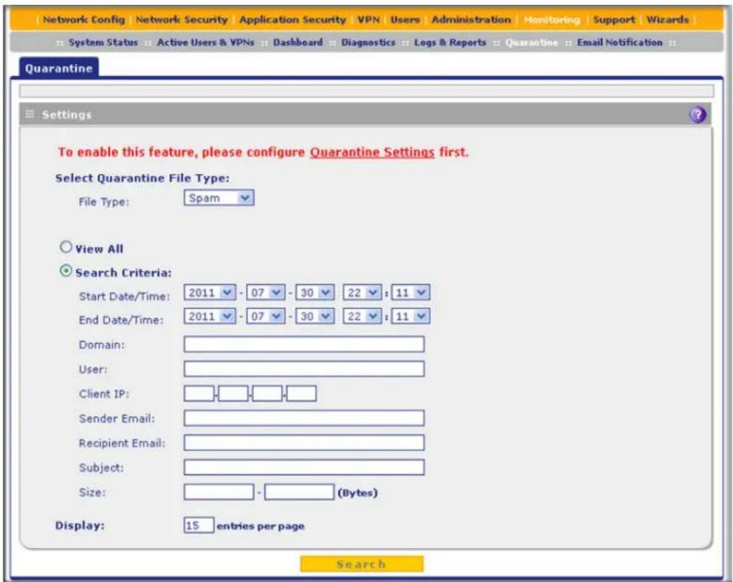
Figure 302.
- Enter the settings as explained in the following table:
Table 135. Quarantine screen settings
| Setting Description | ||
| File Type Select one of the following file types from the drop-down list:Spam. All intercepted spam.Malware. All intercepted viruses, spyware, and other malware threats. | ||
| View All Select one of the following radio buttons:View All. Display or download the entire selected log.Search Criteria. | Search Criteria. Query the selected log by configuring the search criteria that are available for the selected log. | |
| Start Date/Time From the drop-down lists, select the year, month, day, hours, and minutes for the start date and time.This field is available for both the Spam and Malware logs. | ||
| End Date/Time From the drop-down lists, select the year, month, day, hours, and minutes for the end date and time.This field is available for both the Spam and Malware logs. | ||
| Protocols For the Malware log only, select one or more check boxes to specify the protocols that are queried: SMTP, POP3, IMAP, HTTP, FTP, and HTTPS. | ||
| Domain The domain name that is queried.This field is available for both the Spam and Malware logs. | ||
| User The user name that is queried.This field is available for both the Spam and Malware logs. | ||
| Malware Name The name of the malware threat that is queried.This field is available only for the Malware log. | ||
| Client IP | The client IP address that is queried.This field is available for both the Spam and Malware logs. | |
| Sender Email | The sender's email address that is queried.This field is available only for the Spam log. | |
| Recipient Email The recipient's email address that is queried.This field is available for both the Spam and Malware logs. | ||
| Subject | The email subject line that is queried.This field is available for both the Spam and Malware logs. | |
| Size | The minimum and maximum size (in bytes) of the file that is queried.This field is available for both the Spam and Malware logs. | |
| Display | The maximum number of pages that is displayed. | |
- Click Search. The log is queried according to the search criteria that you specified, and the search results are displayed onscreen.
View and Manage the Quarantined Spam Table
When you query the spam quarantine file, the Quarantine screen with the Quarantined Spam table displays:

Figure 303.
The Quarantined Spam table has the following columns (not all columns are shown in the previous figure):
- Check box. Lets you select the table entry.
- Date. The date that the email was received.
- Protocol. The protocol (SMTP) in which the spam was found.
- Domain. The domain in which the spam was found.
- User. The user name that was used to log in to the UTM.
- Client IP. The client IP address from which the spam originated.
• From. The email address of the sender.
• To. The email address of the recipient. - Subject. The email subject line.
- Size (Bytes). The size of the email in bytes.
After you have selected one or more table entries, take one of the following actions (or click the return link to return to the previous screen):
- Send as Spam. The selected spam email files are tagged as spam for distributed spam analysis, and are sent to the intended recipients.
- Send as Ham. The selected spam email files are not tagged as spam for distributed spam analysis, are removed from quarantine, and are sent to the intended recipients.
- Delete. The selected spam email files are removed from quarantine and deleted.
View and Manage the Quarantined Infected Files Table
When you query the malware quarantine file, the Quarantine screen with the Quarantined Infected Files table displays:

Figure 304.
The Quarantined Infected Files table has the following columns (not all columns are shown in the previous figure):
- Check box. Lets you select the table entry.
- Date. The date that the file was received.
- Protocol. The protocol (SMTP, POP3, IMAP, HTTP, FTP, HTTPS) in which the spyware or virus was found.
• Domain. The domain name that was used to log in to the UTM. - User. The user name that was used to log in to the UTM.
- Malware Name. The name of the spyware or virus.
- Filename. The name of the file in which the spyware or virus was found.
ProSecure Unified Threat Management (UTM) Appliance
- Client IP. The client IP address from which the spyware or virus originated.
• Server IP. The server IP address from which the spyware or virus originated.
• From. The email address of the sender.
• To. The email address of the recipient. - URL/Subject. The URL or subject that is associated with the spyware or virus.
• Size (Bytes). The size of the virus or spyware file in bytes.
After you have selected one or more table entries, take one of the following actions (or click the return link to return to the previous screen):
- Resend to Admin. The selected malware files are removed from quarantine, zipped together as an email attachment, and then sent to the recipient that you have specified on the Email Notification Server screen (see Configure the Email Notification Server on page 466).
- Delete. The selected malware files are removed from quarantine and deleted.
Spam Reports for End Users
Any user, including unauthenticated users who have the link to the User Portal Login screen, can email a spam report to an email address.
For an end user to send a spam report:
- Open the User Portal Login screen (for information about how to access this screen, see Users with Special Access Privileges on page 381):

Figure 305.
- Click the Check your quarantined mail link. The following screen displays:

Figure 306.
- From the drop-down lists, specify the start date, start time, end date, and end time for the spam report.
- In the Send to field, enter an email address.
- Click Send Report.
Note: The spam report contains only spam messages that were sent to the email address that is specified in the Send to field.
View, Schedule, and Generate Reports
- Enable Application Session Monitoring
• Report Filtering Options - Use Report Templates and View Reports Onscreen
• Schedule, Email, and Manage Reports
The reporting functions of the UTM let you perform the following tasks that help you to monitor the protection of the network and the performance of the UTM:
- Generating, viewing, and downloading web activity, IPS and application, email activity, and system reports
- Scheduling automatic web activity, IPS and application, email activity, and system reports, and emailing these reports to specified recipients
ProSecure Unified Threat Management (UTM) Appliance
You can view the reports onscreen, download them to your computer, and configure the UTM to send them to one or more email addresses.
The UTM provides preconfigured report templates. As an option, you can apply filtering options to narrow down and specify the following options:
• The period that is covered in the report
• The categories and domains to be included in the report
- The number of entries per report (for example, how many entries—from 1 to 10—are included in reports that show the "top number.")
• The chart type of the report (horizontal bar, pie, or vertical bar)
Because of the nature of the Report screen, it is divided and presented in this manual in three figures that are explained in the following sections:
• Report Filtering Options
- Use Report Templates and View Reports Onscreen
• Schedule, Email, and Manage Reports
Enable Application Session Monitoring
Enabling application session monitoring lets you view relevant information on the Application Dashboard screen (see Monitor Application Use in Real Time on page 483) and generate application reports on the Reports screen (see Use Report Templates and View Reports Onscreen on page 524). Application monitoring does require system resources; if you do not require application monitoring, you can disable it.
IMPORTANT:
Enabling application session monitoring can affect the UTM's performance.
To enable application monitoring:
- Select Monitoring > Logs & Reports > Application Session Monitoring. The Application Session Monitoring screen displays:
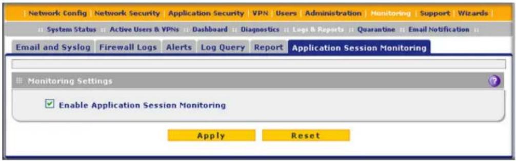
Figure 307.
- Select the Enable Application Session Monitoring check box. By default, this check box is cleared.
- Click Apply to save your changes.
Report Filtering Options
Before you generate reports to view onscreen or schedule reports to be emailed, you might want to configure filtering options. If you do not configure filtering options, the default settings apply. The report default settings are:
• Time range. The last 24 hours.
- Destination. None.
- Count. 10.
• Chart Type. Vertical bar.
To configure filtering options:
- Select Monitoring > Logs & Reports > Report. The Report screen displays. (The following figure shows only the sections with the preconfigured report templates.)

Figure 308. Report, screen 1 of 4
- Enter the settings as explained in the following table:
Table 136. Report screen: filtering options settings
| Setting Description | ||
| Time RangeNote: Even if you clickApply to save the filtering options, when you leave the Report screen and then return to it, the From and To drop-down lists are reset to their defaults. You cannot save these settings. | From From the drop-down lists, specify the start year, month, day, and hour for the report.Note: By default, the beginning time is 24 hours earlier than the ending time. The maximum time range is 31 days. | |
| To From the drop-down lists, specify the end year, month, day, and hour for the report.Note: By default, the ending time is the current hour. The maximum time range is 31 days. | ||
| Destination You can narrow down the reports to a single domain (wildcards are not applicable), a single IP address, a single category, or a selection of categories. Specifying a destination affects the following reports in the Web Activity section:Top n Domain by BandwidthTop n Category by BandwidthTop n Blocked DomainsTop n Blocked CategoriesTop n Domains By RequestTop n Categories By RequestTop n Domains by Session TimeTop n Categories by Session Time | ||
| Count Enter a number between 1 and 10 to specify how many entries are included in reports that provide a top count, such as the Top n(umber of) Blocked Domain report or the Top n(umber of) Infected Clients report.The default number is 10, which means that a maximum of 10 domains are included in the Top n Blocked Domain report and a maximum of 10 clients are included in the Top n Infected Clients report, for example. | ||
| Chart Type | Specify the type of chart that is generated in the report by making one of the following selections from the drop-down list:Horizontal Bar.Pie.Vertical Bar. This is the default selection. | |
-
The next step depends on whether you want to view the report on screen or schedule it to be emailed:
-
Viewing onscreen. To view a filtered report onscreen, select a report by clicking View next to the report. (For more information, see the following section.) To save the configured filtering options for future use, click Apply at the bottom of the Report screen.
- Scheduling to be emailed. To save the configured filtering options to use them to schedule a filtered report that can be emailed, click Apply at the bottom of the Report screen, and then follow the procedure in Schedule, Email, and Manage Reports on page 529.
Note: Even if you click Apply to save the filtering options, when you leave the Report screen and then return to it, the From and To drop-down lists are reset to their defaults. You cannot save these settings. The other filtering options are saved when you click Apply.
Use Report Templates and View Reports Onscreen
The UTM provides preconfigured report templates in four categories:
- Web Activity
- IPS & Applications
- Email Activity
- System
Note: Adobe Flash player 10 or later is required to display the reports.
Note: To generate web reports, make sure that the Log HTTP Traffic check box on the Content Filtering screen is selected (see Configure Web Content Filtering on page 218).
To display the report templates and view reports onscreen:
- Select Monitoring > Logs & Reports > Report. The Report screen displays. (The following figure shows only the sections with the preconfigured report templates.)
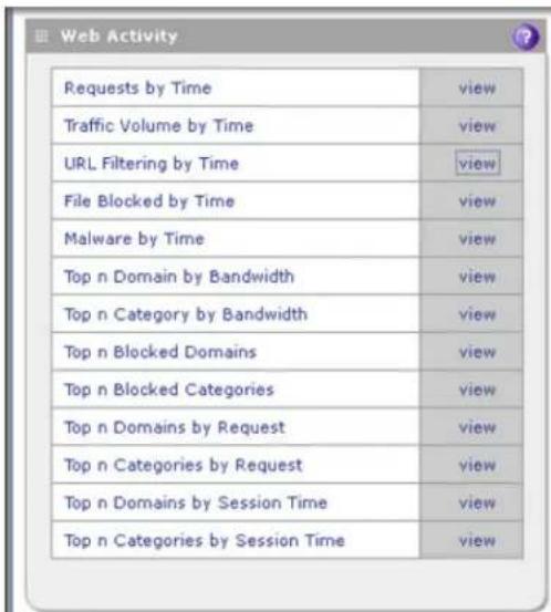
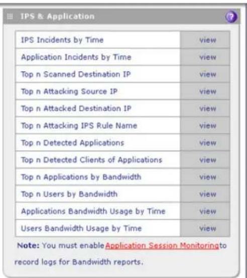
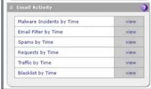

Figure 309. Report, screen 2 of 4
Note: For information about setting a time range and other filtering options for a report, see the previous section.
- Select a report by clicking View next to the report to display the selected report onscreen. The following table explains the contents of the reports.
Table 137. Report screen: report template information
| Report template | Information reported for the specified time range |
| Web ActivityNote:To generate web reports, make sure that the Log HTTP Traffic check box on the Content Filtering screen is selected (seeConfigure Web Content Filteringon page 218). | |
| Requests by Time For each of | the three web server protocols separately, a chart and a table with the number of web requests. |
| Traffic Volume by Time For each | ch of the three web server protocols separately, a chart and a table with the processed traffic, expressed in bytes. |
| Report template Information | reported for the specified time range |
| URL Filtering by Time | For the HTTPS and HTTP protocols separately, a chart and a table with the number of blocked attempts to access URLs that are on the blacklist. |
| File Blocked by Time | For each of the three web server protocols separately, a chart and a table with the number of blocked files (FTP files, HTTPS attachments, or HTTP attachments). |
| Malware by Time For each of the three web server protocols separately, a chart and a table with the number of detected malware incidents. | |
| Top n Domain by Bandwidth | For all web server protocols combined, a chart and a table with the domains for which most bandwidth was consumed and the size of the bandwidth consumed (expressed in bytes), and drill-down links to the users who accessed the domains.When you click the drill-down link for a domain, the User by Bandwidth chart and table display, showing the users who accessed the domain. For each user, the user login name (including the domain to which the user belongs) and the size of the bandwidth consumed (expressed in bytes) are shown. |
| Top n Category by Bandwidth | For all web server protocols combined, a chart and a table with the web categories for which most bandwidth was consumed and the size of the bandwidth consumed (expressed in bytes), and drill-down links to the users who accessed the web categories.When you click the drill-down link for a web category, the Users by Bandwidth chart and table display, showing the users who accessed the web category. For each user, the user login name (including the domain to which the user belongs) and the size of the bandwidth consumed (expressed in bytes) are shown. |
| Top n Blocked Domains | For all web server protocols combined, a chart and a table with the domains that were blocked most often, including the number of blocked requests, and drill-down links to the users who requested them.When you click the drill-down link for a domain, the Blocked Users by Requests chart and table display, showing the users who requested the domain. For each user, the user login name (including the domain to which the user belongs) and the number of blocked requests are shown. |
| Top n Blocked Categories | For all web server protocols combined, a chart and a table with the web categories that were blocked most often, including the number of blocked requests, and drill-down links to the users who requested them.When you click the drill-down link for a domain, the Blocked Users by Requests chart and table display, showing the users who requested the domain. For each user, the user login name (including the domain to which the user belongs) and the number of blocked requests are shown. |
| Top n Domains By Request | For all web server protocols combined, a chart and a table with the domains that were requested most often, including the number of times that they were requested, and drill-down links to the users who requested them.When you click the drill-down link for a domain, the Users by Requests chart and table display, showing the users who requested the domain. For each user, the user login name (including the domain to which the user belongs) and the number of blocked requests are shown. |
| Report template | Information reported for the specified time range |
| Top n Categories By Request | For all web server protocols combined, a chart and a table with the web categories that were requested most often, including the number of times that they were requested, and drill-down links to the users who requested them.When you click the drill-down link for a web category, the Users by Requests chart and table display, showing the users who requested the web category. For each user, the user login name (including the domain to which the user belongs) and the number of blocked requests are shown. |
| Top n Domains By Session Time | For all web server protocols combined, a chart and a table with the domains at which users spent most time, including the session time, and drill-down links to the users who spent time at the domains.When you click the drill-down link for a domain, the Users by Session Time chart and table display, showing the users who spent time at the domain. For each user, the user login name (including the domain to which the user belongs) and the session time are shown. |
| Top n Categories By Session Time | For all web server protocols combined, a chart and a table with the web categories at which users spent most time, including the session time, and drill-down links to the users who spent time at the web categories.When you click the drill-down link for a web category, the Users by Session Time chart and table display, showing the users who spent time at the web category. For each user, the user login name (including the domain to which the user belongs) and the session time are shown. |
| IPS & Application | |
| IPS Incidents by Time A chart | and a table with the number of detected attacks and scans and the number of blocked attacks and scans. |
| Application Incidents by Time | A chart and a table with the number of detected application incidents and the number of blocked applications. |
| Top n Scanned Destination IP | A chart and a table with the destination IP addresses that were scanned most often, including the number of times that they were scanned. |
| Top n Attacking Source IP | A chart and a table with the source IP addresses from which attacks were launched most often, including the number of times that the attacks were launched. |
| Top n Attacked Destination IP | A chart and a table with the destination IP addresses that were attacked most often, including the number of times that they were attacked. |
| Top n Attacking IPS Rule Name | A chart and a table with the names of the IPS attacks that occurred most often, including the number of times that they occurred. |
| Top n Detected Applications | A chart and a table with the names of the applications that were blocked most often, including the number of times that they were blocked. |
| Top n Detected Clients of Applications | A chart and a table with the client IP address for which applications were blocked most often, including the number of times that they were blocked. |
| Report template Information | reported for the specified time range |
| Top n Applications by Bandwidth | A chart and a table with the applications for which most bandwidth was consumed and the size of the bandwidth consumed (expressed in bytes), and drill-down links to the users who accessed the applications.When you click the drill-down link for a user, the Applications Bandwidth by User chart and table display, showing the users who consumed most bandwidth for the application. For each user, the user login name (including the domain to which the user belongs) and the size of the bandwidth consumed (expressed in bytes) are shown. |
| Top n Users by Bandwidth A chart and a table with the users who consumed most bandwidth and the size of the bandwidth consumed (expressed in bytes), and drill-down links to the applications for which most bandwidth was consumed.When you click the drill-down link for an application, the User Bandwidth by Applications chart and table display, showing the applications for which the user consumed most bandwidth. For each application, the size of the bandwidth consumed (expressed in bytes) is shown. | |
| Applications Bandwidth Usage by Time | A chart and a table with the bandwidth usage (expressed in bytes) and the numbers of applications for which bandwidth was consumed, and drill-down links to the applications for which bandwidth was consumed.When you click the drill-down link for the applications, the Applications Bandwidth Usage chart and table display, showing the individual applications for which most bandwidth was consumed. For each application, the size of the bandwidth consumed (expressed in bytes) is shown. |
| Users Bandwidth Usage by Time | A chart and a table with the bandwidth usage (expressed in bytes) and the numbers of users who consumed bandwidth, and drill-down links to the users who consumed bandwidth.When you click the drill-down link for the users, the User Bandwidth Usage chart and table display, showing the individual users who consumed most bandwidth. For each user, the size of the bandwidth consumed (expressed in bytes) is shown. |
| Email Activity | |
| Malware Incidents By Time For each of the three email server protocols separately, a chart and a table with the number of detected malware incidents. | |
| Email Filter By Time For each of the three email server protocols separately, a chart and a table with the number of filtered (blocked) files (attachments). | |
| Spams By Time For the POP3 and SMTP protocols separately, a chart and a table with the number of spam emails that are detected by distributed spam analysis. | |
| Requests By Time For each of the three email server protocols separately, a chart and a table with the number of processed emails. | |
| Traffic By Time For each of the three email server protocols separately, a chart and a table with the processed traffic, expressed in bytes. | |
| Report template | Information reported for the specified time range |
| Blacklist By Time For the POP | 3 and SMTP protocols separately, a chart and a table with the number of blocked emails from email addresses that are on the blacklist, and for the SMTP protocol only, a chart and a table with the number of blocked emails from email addresses that are on the real-time blacklist (RBL). |
| System | |
| Total Bandwidth Usage By Time | A chart and a table with the consumed bandwidth, expressed in bytes. |
| Top n User By Bandwidth | A chart and a table with the IP addresses that consume most bandwidth, expressed in bytes. |
| Total Malware Incidents By Time | For email and web traffic separately, a chart and a table with the number of detected malware incidents. |
| Top n Malwares For email and | web traffic separately, a chart and a table with the names of the malware that were detected most often, including the number of times that they were detected. |
| Top n Infected Clients | For email and web clients separately, a chart and a table with the IP addresses of the clients that were infected by malware most often, including the number of times that they were infected. |
| CPU & Mem Usage For the UT | TM's CPU and memory separately, a chart and a table with the usage, expressed in percentage. |
Schedule, Email, and Manage Reports
To schedule automatic generation and emailing of reports:
- Select Monitoring > Logs & Reports > Report. The Report screen displays. (The following two figures show only the Schedule Reports and Report History sections of the Report screen.)

Figure 310. Report, screen 3 of 4
- Enter the settings in the Schedule Reports section as explained in the following table:
Table 138. Report screen: schedule report settings
| Setting Description | |
| Schedule Reports | |
| Email Recipients | Specify the email addresses of the report recipients, using commas to separate the email addresses. |
| Frequency | Select one or more of the following check boxes to specify the frequency with which the reports are generated and emailed:·Hourly. The report is generated hourly at the specified minute.·Daily. The report is generated daily at the specified hour and minute.·Weekly. The report is generated weekly on Sunday at the specified hour and minute.·Monthly. The report is generated monthly on first day of the month at the specified hour and minute.Next to Occurs at, select the hours and minutes from the drop-down lists. |
| Reports Select one | or more check boxes to specify the reports that are generated:·Web Activity. All reports that are listed in the Web Activity section of the Report screen.·IPS & Application. All reports that are listed in the IPS & Application section of the Report screen.·Email Activity. All reports that are listed in the Email Activity section of the Report screen.·System. All reports that are listed in the System section of the Report screen.Note: You can select all check boxes, but you might generate a very large aggregate report.Note: Drill-down links (that is, links that provide access to additional charts and tables) are not available in emailed reports. |
| Report List | |
| Number of Reports to Keep | Enter the number of reports that the UTM saves. The maximum number is 12. |
- Optional step: To send the reports immediately to the email addresses that are specified in the Email Recipients field, click Send Now. (These emailed reports are not saved in the Reports History section of the Reports screen.)
- Click Apply to save your settings.
Managing Saved Reports
After the scheduled report has been generated and emailed, the record of the report is displayed in the Report History section of the Report screen:

Figure 311. Report, screen 4 of 4
The Report History section shows the generated and emailed reports with their report date and lets you perform the following actions.
- Specify the number of reports to keep. To manage the number of reports that you can keep, enter a number from 1 to 12 in the Number of reports to keep field. The default number is 5 reports.
- Download a report. Click Download next to a report to download the report to your computer.
- Delete a report. Click Delete next to a report to delete the report.
Use Diagnostics Utilities
• Use the Network Diagnostic Tools
- Use the Real-Time Traffic Diagnostics Tool
• Gather Important Log Information and Generate a Network Statistics Report
• Perform Maintenance on the USB Device, Reboot the UTM, or Shut Down the UTM
The UTM provides diagnostic tools that help you analyze traffic conditions and the status of the network. Two sets of tools are available:
• Network diagnostic tools. These tools include a ping utility, traceroute utility, and DNS lookup utility, and the option to display the routing table.
- Traffic diagnostic tools. These tools allow you to perform real-time, per-protocol traffic analysis between specific source and destination addresses, and let you generate reports on network usage in your network.
Note: For normal operation, diagnostic tools are not required.
The diagnostic tools are described in the following sections:
- Use the Network Diagnostic Tools
- Use the Real-Time Traffic Diagnostics Tool
• Gather Important Log Information and Generate a Network Statistics Report
To display the Diagnostics screen, select Monitoring > Diagnostics. To facilitate the explanation of the tools, the Diagnostics screen is divided and presented in this manual in three figures.
Use the Network Diagnostic Tools
This section discusses the Network Diagnostics section and the Perform a DNS Lookup section of the Diagnostics screen.
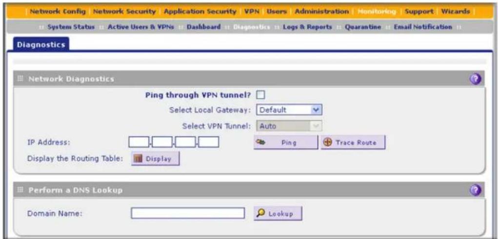
Figure 312. Diagnostics, screen 1 of 4
Send a Ping Packet
Use the ping utility to send a ping packet request in order to check the connection between the UTM and a specific IP address. If the request times out (no reply is received), it usually means that the destination is unreachable. However, some network devices can be configured not to respond to a ping. The ping results are displayed on a new screen; click Back on the browser menu bar to return to the Diagnostics screen.
To send a ping:
- Locate the Network Diagnostics section on the Diagnostics screen. In the IP Address field, enter the IP address that you want to ping.
- Do one of the following:
- Make sure that the Ping through VPN tunnel? check box is cleared, and then select a gateway from the Select Local Gateway drop-down list. (The Select VPN Tunnel drop-down list is masked out.)
- Select the Ping through VPN tunnel? check box, and then select a VPN tunnel from the Select VPN Tunnel drop-down list. (The Select Local Gateway drop-down list is masked out.)
- Click the Ping button. The results of the ping are displayed in a new screen. To return to the Diagnostics screen, click Back on the browser menu bar.
ProSecure Unified Threat Management (UTM) Appliance
Trace a Route
A traceroute lists all routers between the source (the UTM) and the destination IP address.
To send a traceroute:
- Locate the Network Diagnostics section on the Diagnostics screen. In the IP Address field, enter the IP address for which you want to trace the route.
- Click the Traceroute button. The results of the traceroute are displayed in a new screen. To return to the Diagnostics screen, click Back on the browser menu bar.
Display the Routing Table
Displaying the internal routing table can assist NETGEAR technical support in diagnosing routing problems.
To display the routing table, locate the Network Diagnostics section on the Diagnostics screen. Next to Display the Routing Table, click the Display button. The routing table is shown in the Route Display screen that displays as a pop-up screen.
Look Up a DNS Address
A Domain Name Server (DNS) converts the Internet name (for example, www.netgear.com) to an IP address. If you need the IP address of a web, FTP, mail, or other server on the Internet, request a DNS lookup to find the IP address.
To look up a DNS address:
- Locate the Perform a DNS Lookup section on the Diagnostics screen. In the Domain Name field, enter a domain name.
Click the Lookup button. The results of the lookup action are displayed in a new screen. To return to the Diagnostics screen, click Back on the browser menu bar.
Use the Real-Time Traffic Diagnostics Tool
This section discusses the Realtime Traffic Diagnostics section of the Diagnostics screen.
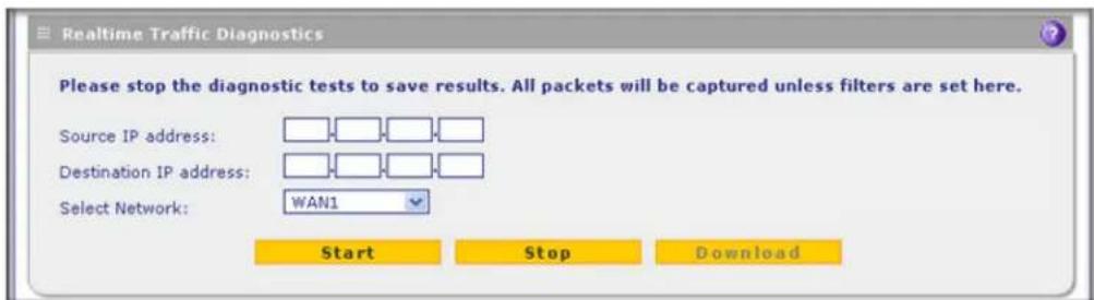
Figure 313. Diagnostics, screen 2 of 4
You can use the real-time traffic diagnostics tool to analyze traffic patterns with a network traffic analyzer tool. Depending on the network traffic analyzer tool that you use, you can find
out which applications are using the most bandwidth, which users use the most bandwidth, how long users are connected, and other information.
To use the real-time traffic diagnostics tool:
- Locate the Realtime Traffic Diagnostics section on the Diagnostics screen. In the Source IP Address field, enter the IP address of the source of the traffic stream that you want to analyze.
- In the Destination IP Address field, enter the IP address of the destination of the traffic stream that you want to analyze.
-
From the Select Network drop-down list, select one of the following components:
-
A single WAN interface
- The DMZ interface
- The slot in which the xDSL network module is installed (SLOT-1 or SLOT-2) (UTM9S and UTM25S only)
-
A single VLAN
-
Click Start.
- When you want to stop capturing the traffic flow, click Stop.
- Select a location to save the captured traffic flow.
The default file name is diagnostics.result.dat. The file is downloaded to the location that you specify.
- When the download is complete, browse to the download location that you specified, and verify that the file has been downloaded successfully.
- Optional: Send the file to NETGEAR technical support for analysis.
Gather Important Log Information and Generate a Network Statistics Report
When you request support, NETGEAR technical support might ask you to collect the debug logs and other information from your UTM.
This section discusses the Gather Important Log Information section, Network Statistics Report section, and Reboot the System section of the Diagnostics screen.

Figure 314. Diagnostics, screen 3 of 4
Gather Important Log Information
To gather log information about your UTM:
- Locate the Gather Important Log Information section on the Diagnostics screen. Click Download Now. You are prompted to save the downloaded log information file to your computer. The default file name is importantlog.gpg.
- When the download is complete, browse to the download location you specified, and verify that the file has been downloaded successfully.
Generate Network Statistics
The network statistic report provides a detailed overview of the network utilization in the UTM managed network environment. The report allows you to see what consumes the most resources on the network.
To generate the Network Statistic Report, locate the Network Statistics Report section on the Diagnostics screen. Click Generate Network Statistics. The network statistics report is sent as an email to the recipient that you specified on the Email Notification screen (see Configure the Email Notification Server on page 466).
Perform Maintenance on the USB Device, Reboot the UTM, or Shut Down the UTM
Note: The USB Device Maintenance section applies to the UTM9S and UMT25S only.
This section discusses the USB Device Maintenance section and System Maintenance section of the Diagnostics screen.

Figure 315. Diagnostics, screen 4 of 4
Perform Maintenance on the USB Device
The USB Device Maintenance section provides the following buttons:
• Power On. Click the button to switch on the power to the USB device.
• Power Off. Click the button to switch off the power to the USB device.
• Power Cycle. Click the button to switch off and then switch on the power to the USB device.
3. Download Log. Click the button to download the diagnostics information for the USB device. The default file name is usb_diagnostics.zip. The file is downloaded to the location that you specify.
Reboot and Shut Down the UTM
You can perform a remote reboot (restart), for example, when the UTM seems to have become unstable or is not operating normally.
To reboot the UTM, locate the Reboot the System section on the Diagnostics screen. Click the Reboot button. The UTM reboots. (If you can see the unit: The reboot process is complete when the Test LED on the front panel goes off.)
Note: Rebooting breaks any existing connections either to the UTM (such as your management session) or through the UTM (for example, LAN users accessing the Internet). However, when the reboot process is complete, connections to the Internet are automatically reestablished when possible.
Note: See also Reboot without Changing the Firmware on page 454.
To shut down the UTM, locate the Reboot the System section on the Diagnostics screen. Click the Shutdown button. The UTM shuts down.

WARNING:
You can shut down the UTM using the web management interface, but you cannot start up the UTM using the web management interface.
Troubleshoot and Use Online Support
12
This chapter provides troubleshooting tips and information for the UTM. After each problem description, instructions are provided to help you diagnose and solve the problem. For the common problems listed, go to the section indicated.
- Is the UTM on?
Go to Basic Functioning on page 539. - Have I connected the UTM correctly?
Go to Basic Functioning on page 539. - I cannot access the UTM's web management interface.
Go to Troubleshoot the Web Management Interface on page 540. - A time-out occurs.
Go to When You Enter a URL or IP Address, a Time-Out Error Occurs on page 541. - I cannot access the Internet or the LAN.
Troubleshoot the ISP Connection on page 541. - I have problems with the LAN connection.
Go to Troubleshoot a TCP/IP Network Using a Ping Utility on page 543. - I want to clear the configuration and start over again.
Go to Restore the Default Configuration and Password on page 545. - The date or time is not correct.
Go to Problems with Date and Time on page 546.
• I need help from NETGEAR.
Go to Use Online Support on page 546.
Note: The UTM's diagnostic tools are explained in Use Diagnostics Utilities on page 531.
Basic Functioning
- Verify the Correct Sequence of Events at Startup
- Power LED Not On
• Test LED Never Turns Off
• LAN or WAN Port LEDs Not On
Note: For descriptions of all LEDs, see LED Descriptions, UTM5, UTM10, UTM25, UTM50, and UTM150 on page 30 or LED Descriptions, UTM9S, UTM25S, and their Network Modules on page 32.
Verify the Correct Sequence of Events at Startup
After you turn on power to the UTM, verify that the following sequence of events occurs:
- When power is first applied, verify that the Power LED is on.
- After approximately 2 minutes, verify that:
a. The Test LED is no longer lit.
b. The left LAN port LEDs are lit for any local ports that are connected.
c. The left WAN port LEDs are lit for any WAN ports that are connected.
If a port's left LED is lit, a link has been established to the connected device. If a port is connected to a 1000-Mbps device, verify that the port's right LED is green. If the port functions at 100 Mbps, the right LED is amber. If the port functions at 10 Mbps, the right LED is off.
If any of these conditions do not occur, see the appropriate following section.
Power LED Not On
If the Power and other LEDs are off when your UTM is turned on, make sure that the power cord is correctly connected to your UTM and that the power supply adapter is correctly connected to a functioning power outlet.
If the error persists, you have a hardware problem and should contact NETGEAR technical support.
Test LED Never Turns Off
When the UTM is powered on, the Test LED turns on for approximately 2 minutes and then turns off when the UTM has completed its initialization. If the Test LED remains on, there is a fault within the UTM.
If all LEDs are still on more than several minutes minute after power-up, do the following:
- Turn off the power, and then turn it on again to see if the UTM recovers.
- Reset the UTM's configuration to factory default settings. Doing so sets the UTM's IP address to 192.168.1.1. This procedure is explained in Restore the Default Configuration and Password on page 545.
If the error persists, you might have a hardware problem and should contact NETGEAR technical support.
LAN or WAN Port LEDs Not On
If either the LAN LEDs or WAN LEDs do not turn on when the Ethernet connection is made, check the following:
- Make sure that the Ethernet cable connections are secure at the UTM and at the hub, router, or workstation.
- Make sure that power is turned on to the connected hub, router, or workstation.
- Be sure that you are using the correct cables:
When connecting the UTM's WAN ports to one or two devices that provide the Internet connections, use the cables that are supplied with the devices. These cables could be standard straight-through Ethernet cables or Ethernet crossover cables.
Troubleshoot the Web Management Interface
If you cannot access the UTM's web management interface from a computer on your local network, check the following:
- Check the Ethernet connection between the computer and the UTM as described in the previous section (LAN or WAN Port LEDs Not On).
- If your UTM's IP address has been changed and you do not know the current IP address, reset the UTM's configuration to factory default settings. This sets the UTM's IP address to 192.168.1.1. This procedure is explained in Restore the Default Configuration and Password on page 545.
Tip: If you do not want to revert to the factory default settings and lose your configuration settings, you can reboot the UTM and use a sniffer to capture packets sent during the reboot. Look at the ARP packets to locate the UTM's LAN interface address.
- Make sure that your browser has Java, JavaScript, or ActiveX enabled. If you are using Internet Explorer, click Refresh to be sure that the Java applet is loaded.
-
Try quitting the browser and launching it again.
-
Make sure that you are using the correct login information. The factory default login name is admin, and the password is password. Make sure that Caps Lock is off when entering this information.
- If your computer's IP address is shown as 169.254.x.x: Windows and Mac operating systems generate and assign an IP address if the computer cannot reach a DHCP server. These autogenerated addresses are in the range of 169.254.x.x. If your IP address is in this range, check the connection from the computer to the UTM and reboot your computer. If this does not resolve the access situation, reset the UTM's configuration to factory default settings. Doing so returns the UTM's IP address to 192.168.1.1. This procedure is explained in Restore the Default Configuration and Password on page 545.
If the UTM does not save changes you have made in the web management interface, check the following:
- When entering configuration settings, be sure to click the Apply button before moving to another menu or tab, or your changes are lost.
- Click the Refresh or Reload button in the web browser. The changes might have occurred, but the web browser might be caching the old configuration.
When You Enter a URL or IP Address, a Time-Out Error Occurs
A number of things could be causing this situation. Try the following troubleshooting steps:
- Check whether other computers on the LAN work correctly. If they do, ensure that your computer's TCP/IP settings are correct. If you use a fixed (static) IP address, check the subnet mask, default gateway, DNS, and IP addresses on the WAN ISP Settings screen of the single WAN port models or on one of the WAN ISP Settings screens of the multiple WAN port models. For more information, see Manually Configure the Internet Connection on page 75.
- If the computer is configured correctly, but still not working, ensure that the UTM is connected and turned on. Connect to the web management interface, and check the UTM's settings. If you cannot connect to the UTM, see the information in the previous section (Troubleshoot the Web Management Interface on page 540).
- If the UTM is configured correctly, check your Internet connection (for example, your modem or router) to make sure that it is working correctly.
Troubleshoot the ISP Connection
If your UTM is unable to access the Internet, you should first determine whether the UTM is able to obtain a WAN IP address from the ISP. Unless you have been assigned a static IP address, your UTM requests an IP address from the ISP. You can determine whether the request was successful using the web management interface.
To check the WAN IP address:
- Launch your browser and navigate to an external site such as www.netgear.com.
- Access the web management interface of the UTM's configuration at https://192.168.1.1.
- Select Network Config > WAN Settings. The WAN Settings screen displays.
- In the Action column for the interface for which you want to open the Connection Status screen, click the Status button. (For more information, see View the WAN, xDSL, or USB Port Status on page 504.)
- Check that an IP address is shown for the WAN port. If 0.0.0.0 is shown, your UTM has not obtained an IP address from your ISP.
If your UTM is unable to obtain an IP address from the ISP, you might need to force your modem or router to recognize your new UTM by performing the following procedure:
- Turn off the power to the modem or router.
- Turn off the power to your UTM.
- Wait 5 minutes, and then turn on the power to the modem or router.
- When the modem's or router's LEDs indicate that it has reacquired synchronization with the ISP, turn on the power to your UTM.
If your UTM is still unable to obtain an IP address from the ISP, the problem might be one of the following:
- Your ISP might require a login program.
Ask your ISP whether they require PPP over Ethernet (PPPoE) or some other type of login.
• If your ISP requires a login, you might have incorrectly set the login name and password. - Your ISP might check for your computer's host name.
On the WAN ISP Settings screen of the single WAN port models or on one of the WAN ISP Setting screens of the multiple WAN port models, in the Account Name field, enter the host name, system name, or account name that was assigned to you by your ISP. You might also have to enter the assigned domain name or workgroup name in the Domain Name field, and you might have to enter additional information. For more information, see Manually Configure the Internet Connection on page 75.
- Your ISP allows only one Ethernet MAC address to connect to the Internet, and might check for your computer's MAC address. In this case, do one of the following:
- Inform your ISP that you have bought a new network device, and ask them to use the UTM's MAC address.
- Configure your UTM to spoof your computer's MAC address. You can do this in the Router's MAC Address section on the WAN Advanced Options screen of the single WAN port models or on one of the WAN Advanced Options screens of the multiple WAN port models. For more information, see Set the UTM's MAC Address and Configure Advanced WAN Options on page 94.
If your UTM can obtain an IP address, but an attached computer is unable to load any web pages from the Internet:
- Your computer might not recognize any DNS server addresses.
A DNS server is a host on the Internet that translates Internet names (such as www.netgear.com) to numeric IP addresses. Typically your ISP provides the addresses of one or two DNS servers for your use. You can configure your computer manually with DNS addresses, as explained in your operating system documentation.
- Your computer might not have the UTM configured as its TCP/IP gateway.
Troubleshoot a TCP/IP Network Using a Ping Utility
• Test the LAN Path to Your UTM
- Test the Path from Your Computer to a Remote Device
Most TCP/IP terminal devices and firewalls contain a ping utility that sends an echo request packet to the designated device. The device then responds with an echo reply. You can easily troubleshoot a TCP/IP network by using the ping utility in your computer or workstation.
Test the LAN Path to Your UTM
You can ping the UTM from your computer to verify that the LAN path to the UTM is set up correctly.
To ping the UTM from a computer running Windows 95 or later:
- From the Windows toolbar, click Start and select Run.
-
In the field provided, type ping followed by the IP address of the UTM, for example: ping 192.168.1.1
-
Click OK. A message similar to the following should display:
Pinging
If the path is working, you see this message:
Reply from
If the path is not working, you see this message:
Request timed out
If the path is not functioning correctly, you could have one of the following problems:
- Wrong physical connections:
- Make sure that the LAN port LED is on. If the LED is off, follow the instructions in LAN or WAN Port LEDs Not On on page 540.
- Check that the corresponding Link LEDs are on for your network interface card and for the hub ports (if any) that are connected to your workstation and UTM.
- Wrong network configuration:
- Verify that the Ethernet card driver software and TCP/IP software are both installed and configured on your computer.
- Verify that the IP address for your UTM and your workstation are correct and that the addresses are on the same subnet.
Test the Path from Your Computer to a Remote Device
After verifying that the LAN path works correctly, test the path from your computer to a remote device. From the Windows Run dialog box, type:
ping -n 10
in which
If the path is functioning correctly, replies as in the previous section are displayed. If you do not receive replies:
- Check that your computer has the IP address of your UTM listed as the default gateway. If the IP configuration of your computer is assigned by DHCP, this information is not visible in your computer's Network Control Panel.
- Check to see that the network address of your computer (the portion of the IP address that is specified by the netmask) is different from the network address of the remote device.
- Check that the modem or router is connected and functioning.
- If your ISP assigned a host name, system name, or account name to your computer, enter that name in the Account Name field on the WAN ISP Settings screen of the single WAN port models or on one of the WAN ISP Settings screens of the multiple WAN port models. You might also have to enter the assigned domain name or workgroup name in the Domain Name field, and you might have to enter additional information. For more information, see Manually Configure the Internet Connection on page 75.
- Your ISP could be rejecting the Ethernet MAC addresses of all but one of your computers. Many broadband ISPs restrict access by allowing traffic only from the MAC address of your broadband modem, but some ISPs additionally restrict access to the MAC address of a single computer connected to that modem. If this is the case, you need to configure your UTM to clone or spoof the MAC address from the authorized computer. You can do this in the Router's MAC Address section on the WAN Advanced Options screen of the single WAN port models or on one of the WAN Advanced Options screens of the multiple WAN port models. For more information, see Set the UTM's MAC Address and Configure Advanced WAN Options on page 94.
Restore the Default Configuration and Password
To reset the UTM to the original factory default settings, you can use one of the following two methods:
- Press the Factory Defaults reset button on the rear panel of the UTM (see Rear Panel UTM5, UTM10, and UTM25 on page 33, Rear Panel UTM50 and UTM150 on page 34, or Rear Panel UTM9S and UTM25S on page 35) and hold the button for about 8 seconds until the Test LED turns on and begins to blink (about 30 seconds). To restore the factory default settings when you do not know the administration password or IP address, you need to use the Factory Defaults reset button.
- On the Backup & Restore Settings screen, next to Revert to factory defaults settings, click the Default button:
a. To display the Backup & Restore Settings screen, select Administration > Backup & Restore Settings. The Backup & Restore Settings screen displays:

Figure 316.
b. Click the Default button.
The UTM reboots. During the reboot process, the Backup & Restore Settings screen remains visible. The reboot process is complete after several minutes when the Test LED on the front panel goes off.

WARNING:
When you press the hardware Factory Defaults reset button or click the software Default button, the UTM settings are erased. All firewall rules, VPN policies, LAN/WAN settings, and other settings are lost. Back up your settings if you intend on using them.
Note: After rebooting with factory default settings, the UTM's password is password, and the LAN IP address is 192.168.1.1.
Problems with Date and Time
The System Date & Time screen displays the current date and time of day (see Configure Date and Time Service on page 456). The UTM uses the Network Time Protocol (NTP) to obtain the current time from one of several network time servers on the Internet. Each entry in the log is stamped with the date and time of day.
Problems with the date and time function can include:
- Date shown is January 1, 2000. Cause: The UTM has not yet successfully reached a network time server. Check that your Internet access settings are configured correctly. If you have just completed configuring the UTM, wait at least 5 minutes and check the date and time again.
- Time is off by 1 hour. Cause: The UTM does not automatically sense daylight savings time. Go to the System Date & Time screen, and select or clear the Automatically Adjust for Daylight Savings Time check box.
Use Online Support
The UTM includes online support tools that allow NETGEAR technical support to perform diagnostics of the UTM securely, and that let you submit suspicious files for analysis by NETGEAR. You can also access the knowledge base and documentation online.
Enable Remote Troubleshooting
One of the advanced features that the UTM provides is online support through a support tunnel. With this feature, NETGEAR technical support staff are able to analyze from a remote location any difficulty you might be experiencing with the UTM and to perform advanced diagnostics. Make sure that ports 443 and 2222 are open on your firewall, and that you have the support key that was given to you by NETGEAR.
To initiate the support tunnel:
- Select Support > Online Support. The Online Support screen displays:

Figure 317.
- In the Support Key field, enter the support key that was given to you by NETGEAR.
- Click Connect. When the tunnel is established, the tunnel status field displays ON.
To terminate the tunnel, click Disconnect. The tunnel status field displays OFF.
If NETGEAR technical support cannot access the UTM remotely, they might ask you to save a log file to your computer and then email it to NETGEAR for analysis (see Gather Important Log Information on page 535).
Send Suspicious Files to NETGEAR for Analysis
You can report any undetected malware file or malicious email to NETGEAR for analysis.
The file is compressed and password-protected before it is sent.
To submit a file to NETGEAR for analysis:
- Select Support > Malware Analysis. The Online Support screen displays:
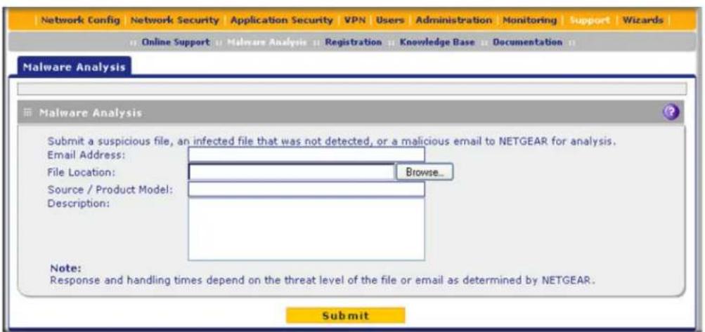
Figure 318.
- Enter the settings as explained in the following table:
Table 139. Malware Analysis screen settings
| Setting Description | |
| Email Address | The email address of the submitter to enable NETGEAR to contact the submitter if needed. |
| File Location | Click Browse to navigate to the file that you want to submit to NETGEAR. |
| Source / Product Model | Specify where the file originated (for example, an email address if received through email) and, if known, which product or scan feature (for example, the UTM or a desktop antivirus application) detected the file. |
| Description As an option, | include a description or any information that is relevant. |
- Click Submit.
Access the Knowledge Base and Documentation
To access NETGEAR's knowledge base for the UTM, select Support > Knowledge Base. To access NETGEAR's documentation library for your UTM model, select Support > Documentation.
xDSL Network Module for the UTM9S and UTM25S

This appendix describes how to configure the DSL interfaces of the NMSDSLA and NMSDSLB network modules that you can install in a UTM9S or UTM25S. This appendix includes the following sections:
- xDSL Network Module Configuration Tasks
- Configure the xDSL Settings
• Automatically Detecting and Connecting the xDSL Internet Connection - Manually Configure the xDSL Internet Connection
- Configure the WAN Mode
- Configure Secondary WAN Addresses
- Configure Dynamic DNS
- Set the UTM's MAC Address and Configure Advanced WAN Options
• Additional WAN-Related Configuration Tasks
A UTM9S or UTM25S can simultaneously support a DSL WAN interface, Ethernet WAN interfaces, and a USB WAN interface.
- For information about how to configure the Ethernet WAN interfaces, see Chapter 3, Manually Configure Internet and WAN Settings.
- For information about how to configure the USB WAN interface, see Appendix C, 3G/4G Dongles for the UTM9S and UTM25S.
Note: In previous releases for the UTM9S, these network modules were referred to as the UTM9SDSLA and UTM9SDSLB. The UTM9SDSLA is identical to the NMSDSLA, and the UTM9SDSLB is identical to the NMSDSLB.
xDSL Network Module Configuration Tasks
Generally, six steps, four of which are optional, are required to complete the DSL Internet connection of your UTM9S or UTM25S.
Complete these steps:
- Configure the xDSL settings. Before you can configure the DSL Internet connection to your ISP, you need to configure the xDSL settings. See Configure the xDSL Settings on page 550.
- Configure the Internet connection to your ISP. During this phase, you connect to your ISP. See Automatically Detecting and Connecting the xDSL Internet Connection on page 553 or Manually Configure the xDSL Internet Connection on page 556.
- Configure the WAN mode. Select either NAT or classical routing, and select dedicated (single WAN) mode, or, if you have also configured another WAN interface, auto-rollover mode or load balancing mode. For load balancing, you can also select any necessary protocol bindings. See Configure the WAN Mode on page 561.
- Configure secondary WAN addresses on the WAN port (optional). Configure aliases for the WAN port. See Configure Secondary WAN Addresses on page 570.
- Configure Dynamic DNS on the WAN port (optional). Configure your fully qualified domain names during this phase (if necessary). See Configure Dynamic DNS on page 572.
- Configure the WAN options (optional). Optionally, you can enable the WAN port to respond to a ping, and you can change the factory default MTU size and port speed. However, these are advanced features, and changing them is not usually required. See Set the UTM's MAC Address and Configure Advanced WAN Options on page 574.
Each of these tasks is detailed separately in this appendix.
Note: For information about how to configure the WAN meter for the DSL interface, see Enable the WAN Traffic Meter on page 462.
Configure the xDSL Settings
Before you can configure the DSL Internet connection to your ISP, you need to configure the ADSL or VDSL settings and, if necessary, the ATM multiplexing method. These settings are usually provided by your ISP, but you can autodetect these settings. You can either let the UTM9S or UTM25S autodetect these settings or configure them manually.
Note: Autodetecting the DSL settings takes about 25 minutes.
To configure the xDSL settings:
- Select Network Config > WAN Settings. The WAN screen displays:
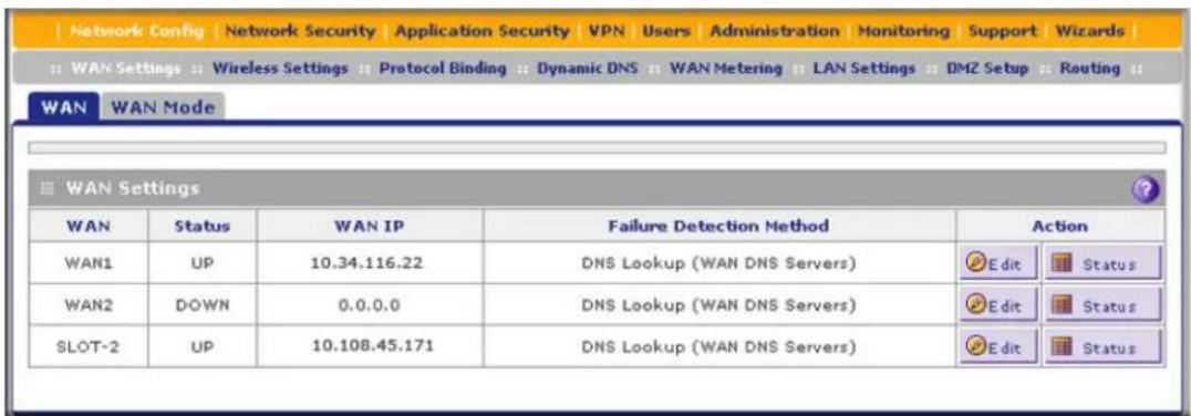
Figure 319.
Note: For more information about the WAN screen, see Automatically Detecting and Connecting the xDSL Internet Connection on page 553.
- Click the Edit button in the Action column of the SLOT-x interface. The SLOT-x ISP Settings screen displays. (The following figure shows the top part of the screen only.)

Figure 320.
Note: For more information about the SLOT-x ISP Settings screen, see Automatically Detecting and Connecting the xDSL Internet Connection on page 553.
- Click the xDSL Settings option arrow. The xDSL Settings screen displays:

Figure 321.
- Either click Auto Detect or, if you have the correct settings, enter the settings as explained in the following table:
Table 140. xDSL settings
| Setting Description | |
| xDSL Settings | |
| DSL Transfer Mode | Select one of the following DSL transfer methods:PTM. Packet Transfer Mode (PTM) has a functionality that is similar to packet-switched networking and does not use multiplexing.ATM. Asynchronous Transfer Mode (ATM) uses Asynchronous Time-Division Multiplexing (ATDM) to encode data into small, fixed-sized cells. ATM has a functionality that is similar to circuit-switched networking and small-packet-switched networking.When you select ATM, you also need to configure the multiplexing method, VPI, and VCI. |
| Multiplexing Method | Select the VDSL multiplexing method for the ATM mode:LLC-BASED. Multiplexing is based on Logical Link Control (LLC) encapsulation.VC-BASED. Multiplexing is based on use of a virtual circuit (VC). |
| VPI The virtual path identifier (VPI) that is used for the VDSL connection. | |
| VCI The virtual channel identifier (VCI) that is used for the VDSL connection. | |
5. Click Apply to save your settings.
Automatically Detecting and Connecting the xDSL Internet Connection
To set up your UTM9S or UTM25S for secure Internet connections, the web management interface provides the option to detect the network connection and configure the xDSL port automatically. You can also manually configure the Internet connection and port (see Manually Configure the xDSL Internet Connection on page 556).
To configure the WAN port automatically for connection to the Internet:
1. Select Network Config > WAN Settings. The WAN screen displays.

Figure 322.
The xDSL network module is installed in one of the two slots (SLOT-1 or SLOT-2). The WAN Settings table displays the following fields:
- WAN. The WAN or DSL interface.
• Status. The status of the WAN or DSL interface (UP or DOWN).
• WAN IP. The IP address of the WAN or DSL interface. - Failure Detection Method. The failure detection method that is active for the WAN or DSL interface. The following methods can be displayed:
- None
- WAN DNS (WAN DNS servers)
- Custom DNS (the IP address of the configured DNS server is displayed)
- Ping (the configured IP address is displayed)
You can set the failure detection method for the DSL interface on the corresponding WAN Advanced Options screen (see Configure Auto-Rollover Mode and the Failure Detection Method on page 563).
- Action. The Edit button in the Action column of the SLOT-x entry provides access to the xDSL ISP Settings screen (see step 2); the Status button provides access to the Connection Status screen (see step 6) for the DSL interface.
- Click the Edit button in the Action column of the SLOT-x entry to configure the connection to the Internet automatically. The SLOT-x ISP Settings screen displays. (The following figure shows the SLOT-2 ISP Settings screen.)
![Network Config | Network Security | Application Security | VPN | Users | Administration | Monitoring | Support | Wizards | WAN Settings | Wireless Settings | Protocol Binding | Dynamic DNS | WAN Metering | LAN Settings | DMZ Setup | Routing | SLOT-2 ISP Settings xDSL Settings Secondary Addresses Advanced Operation succeeded. SLOT-1/2 Details Card Type: VDSL Daughter Card: VDSL_ANNEXA Firmware Version: 2.1 ISP Login Does Your Internet Connection Require a Login? Yes No Login: isp-user-name Password: ************ ISP Type Which type of ISP connection do you use? PPPoE PPPoA Account Name: Domain Name: Idle Timeout: Keep Connected Idle Timeout 0 [Minutes] Internet (IP) Address (Current IP Address) Get Dynamically from ISP Use Static IP Address Use IP Over ATM (IPOA) IP Address: 0 0 0 0 Subnet Mask: 0 0 0 0 Gateway IP Address: 0 0 0 0 Domain Name Server (DNS) Servers Get Automatically from ISP Use These DNS Servers Primary DNS Server: 0 0 0 0 Secondary DNS Server: 0 0 0 0 Apply Reset Test Auto Detect](/content/2026/06/1371942/images/944c2d100f4044122b11c4e9b15f5db1f1e6d3a432eac3b8c449ecd138449027.jpg)
Figure 323.
- Click the Auto Detect button at the bottom of the screen. The autodetect process probes the WAN port for a range of connection methods and suggests one that your ISP is most likely to support.
The autodetect process returns one of the following results:
- If the autodetect process is successful, a status bar at the top of the screen displays the results (for example, DHCP service detected).
- If the autodetect process senses a connection method that requires input from you, it prompts you for the information. All methods with their required settings are explained in the following table:
Table 141. Internet connection methods
| Connection method | Manual data input required |
| DHCP (Dynamic IP) No data is required. | |
| PPPoA Login, password, account name, and domain name.Note: PPPoA is supported on the UTM9S and UTM25S only. | |
| PPPoE Login, password, account name, and domain name. | |
| Fixed (Static) IP IP address, subnet mask, and gateway IP address, and related data supplied by your ISP. | |
- If the autodetect process does not find a connection, you are prompted either to check the physical connection between the xDSL network module and the telephone line or to check the MAC address of the UTM9S or UTM25S. For more information, see Configure the xDSL Settings on page 550, Configure the WAN Mode on page 561, and Troubleshoot the ISP Connection on page 541.
- Click Apply to save your changes.
- Click Test to evaluate your entries. The UTM9S or UTM25S attempts to make a connection according to the settings that you entered.
- To verify the connection:
a. Return to the WAN screen by selecting Network Config > WAN Settings.
b. Click the Status button in the Action column of the SLOT-x entry to display the Connection Status pop-up screen.

Figure 324.
Note: The Connection Status screen should show a valid IP address and gateway. For more information about the Connection Status screen, see View the WAN, xDSL, or USB Port Status on page 504.
What to do next:
- If the automatic ISP configuration is successful:
You are connected to the Internet through the DSL interface that you just configured. You can skip ahead to Configure the WAN Mode on page 561.
- If the automatic ISP configuration fails:
You can attempt a manual configuration as described in Manually Configure the xDSL Internet Connection on page 556 or you might need to change the MAC address as described in Set the UTM's MAC Address and Configure Advanced WAN Options on page 574. For information about troubleshooting, see Troubleshoot the ISP Connection on page 541.
Manually Configure the xDSL Internet Connection
Unless your ISP automatically assigns your configuration through DHCP, you need to obtain configuration parameters from your ISP to manually establish an Internet connection over the DSL interface. The necessary parameters for various connection types are listed in Table 141 on page 555.
To configure the WAN ISP settings for the DSL interface manually:
- Select Network Config > WAN Settings. The WAN screen displays:

Figure 325.
- Click the Edit button in the Action column of the SLOT-x interface. The SLOT-x ISP Settings screen displays (see Figure 323 on page 554).
- Locate the ISP Login section onscreen:

Figure 326.
In the ISP Login section, select one of the following options:
-
If your ISP requires an initial login to establish an Internet connection, select Yes. (The default is No.)
• If a login is not required, select No, and ignore the Login and Password fields. -
If you selected Yes, enter the login name in the Login field and the password in the Password field. This information is provided by your ISP.
- In the ISP Type section of the screen, select the type of ISP connection that you use from the two listed options. By default, PPPoE is selected, as shown in the following figure:
![ISP Type Which type of ISP connection do you use? PPPoE PPPoA Account Name: Domain Name: Idle Timeout: Keep Connected Idle Timeout 0 [Minutes]](/content/2026/06/1371942/images/adad3d57d5cf8f1398aa13302ba9235d7172b6e90e6fd18abf4c4f9c43e45507.jpg)
Figure 327.
- If your connection is Point-to-Point Protocol over Ethernet (PPPoE) or Point-to-Point Protocol over ATM (PPPoA), your ISP requires an initial login. Enter the settings as explained in the following table:
Table 142. PPPoE and PPPoA settings
| Setting Description | ||
| PPPoE | If your ISP uses PPPoE for login, select this radio button, and enter the following settings: | |
| Account Name The account name for the PPPoE connection. | ||
| Domain Name The name of your ISP's domain or your domain name if your ISP has assigned you one. You can leave this field blank. | ||
| Idle Timeout | Select theKeep Connectedradio button to keep the connection always on. To log out after the connection is idle for a period:1. Select theIdle Timeoutradio button.2. In the time-out field, enter the number of minutes to wait before disconnecting.This is useful if your ISP charges you based on the period that you are logged in.Note:When you use a PPPoE connection and select the Idle Timeout radio button, you cannot configure load balancing (seeConfigure Load Balancingon page 567). To use load balancing on a PPPoE connection, select theKeep Connectedradio button. When you have configured load balancing, the Idle Timeout radio button and time-out field are masked out. | |
| PPPoA | If your ISP uses PPPoA for login, select this radio button, and enter the following settings: | |
| Account Name The account name for the PPPoA connection. | ||
| Domain Name The name of your ISP's domain or your domain name if your ISP has assigned you one. You can leave this field blank. | ||
| Idle Timeout | Select theKeep Connectedradio button to keep the connection always on. To log out after the connection is idle for a period:1. Select theIdle Timeoutradio button.2. In the time-out field, enter the number of minutes to wait before disconnecting.This is useful if Your ISP charges you based on the period that you are logged in.Note:When you use a PPPoA connection and select the Idle Timeout radio button, you cannot configure load balancing (seeConfigure Load Balancingon page 567). To use load balancing on a PPPoA connection, select theKeep Connectedradio button. When you have configured load balancing, the Idle Timeout radio button and time-out field are masked out. | |
- In the Internet (IP) Address section of the screen (see the following figure), configure the IP address settings as explained in the following table. Click the Current IP Address link to see the currently assigned IP address.
![Internet (IP) Address [Current IP Address] Get Dynamically from ISP Use Static IP Address Use IP Over ATM (IPOA) IP Address: 0 0 0 0 Subnet Mask: 0 0 0 0 Gateway IP Address: 0 0 0 0](/content/2026/06/1371942/images/3ba385954dc3f2b987e02db43f00c58b693a724fbbca68285b50ca397173f5a3.jpg)
Table 143. Internet IP address settings
| Setting Description | ||
| Get Dynamically from ISP | If your ISP has not assigned you a static IP address, select the Get Dynamically from ISP radio button. The ISP automatically assigns an IP address to the UTM9S or UTM25S using DHCP network protocol. | |
| Use Static IP Address | If your ISP has assigned you a fixed (static or permanent) IP address, select the Use Static IP Address radio button, and enter the following settings: | |
| IP Address Static IP address assigned to you. This address identifies the UTM9S or UTM25S to your ISP. | ||
| Subnet Mask The subnet mask is usually provided by your ISP. | ||
| Gateway IP Address The IP address of the ISP's gateway is usually provided by your ISP. | ||
| Use IP Over ATM (IPOA) | If your ISP uses IP over ATM (IPoA), select the Use IP Over ATM (IPOA) radio button, and enter the following settings: | |
| IP Address The IP address assigned to you. This address identifies the UTM9S or UTM25S to your ISP. | ||
| Subnet Mask The subnet mask is usually provided by your ISP. | ||
| Gateway IP Address The IP address of the ISP's gateway is usually provided by your ISP. | ||
- In the Domain Name Server (DNS) Servers section of the screen (see the following figure), specify the DNS settings as explained in the following table.

Figure 328.
Table 144. DNS server settings
| Setting Description | ||
| Get Automatically from ISP | If your ISP has not assigned any Domain Name Server (DNS) addresses, select the Get Automatically from ISP radio button. | |
| Use These DNS Servers | If your ISP has assigned DNS addresses, select the Use These DNS Servers radio button. Make sure that you fill in valid DNS server IP addresses in the fields. Incorrect DNS entries might cause connectivity issues. | |
| Primary DNS Server The IP address of the primary DNS server. | ||
| Secondary DNS Server The IP address of the secondary DNS server. | ||
- Click Apply to save any changes to the SLOT-x ISP settings. (Or click Reset to discard any changes and revert to the previous settings.)
- Click Test to evaluate your entries. The UTM9S or UTM25S attempts to make a connection according to the settings that you entered.
- To verify the connection:
a. Return to the WAN screen by selecting Network Config > WAN Settings.
b. Click the Status button in the Action column of the SLOT-x entry to display the Connection Status pop-up screen.

Figure 329.
Note: The Connection Status screen should show a valid IP address and gateway. For more information about the Connection Status screen, see View the WAN, xDSL, or USB Port Status on page 504.
ProSecure Unified Threat Management (UTM) Appliance
What to do next:
- If the manual ISP configuration is successful:
You are connected to the Internet through the DSL interface that you just configured. Continue with Configure the WAN Mode on page 561. - If the manual ISP configuration fails:
You might need to change the MAC address as described in Set the UTM's MAC Address and Configure Advanced WAN Options on page 574. For information about troubleshooting, see Troubleshoot the ISP Connection on page 541.
Configure the WAN Mode
• Overview of the WAN Modes
- Configure Network Address Translation
- Configure Classical Routing
- Configure Auto-Rollover Mode and the Failure Detection Method
- Configure Load Balancing and Optional Protocol Binding
Overview of the WAN Modes
A UTM9S or UTM25S in which an xDSL network module is installed can support a DSL WAN interface, Ethernet WAN interfaces, and a USB WAN interface.
If you have configured an Ethernet WAN interface or a USB WAN interface in addition to the DSL WAN interface, the UTM9S or UTM25S can be configured on a mutually exclusive basis for either auto-rollover (for increased system reliability) or load balancing (for maximum bandwidth efficiency). If you do not select load balancing, you need to specify one WAN interface as the primary interface.
Note: In this section and the following sections of this appendix, the DSL WAN interface is referred to as the DSL interface, the Ethernet WAN interfaces are referred to as the WAN interfaces, and the USB WAN interface is referred to as the USB interface.
- Load balancing mode. The UTM9S or UTM25S distributes the outbound traffic equally among the DSL, USB, and WAN interfaces that are functional. The UTM9S and UTM25S support weighted load balancing and round-robin load balancing (see Configure Load Balancing and Optional Protocol Binding on page 566).
Note: Scenarios could arise when load balancing needs to be bypassed for certain traffic or applications. If certain traffic needs to travel on the DSL interface or a specific WAN interface, configure protocol binding rules for that interface. The rule should match the desired traffic.
- Primary WAN mode. The DSL interface (or a WAN interface or the USB interface) is made the primary interface. The other interfaces are disabled.
- Auto-rollover mode. A DSL or WAN interface is defined as the primary link, and another interface needs to be defined as the rollover link. Because there can be four interfaces on the UTM9S and UTM25S (one DSL, one USB, and two WAN interfaces), the remaining interface are disabled. (If a 3G/4G dongle is installed, you cannot configure the USB interface as the primary link in an auto-rollover configuration, but you can configure it as the rollover link.)
As long as the primary link is up, all traffic is sent over the primary link. When the primary link goes down, the rollover link is brought up to send the traffic. When the primary link comes back up, traffic automatically rolls back to the original primary link.
If you want to use a redundant ISP link for backup purposes, select the DSL or WAN interface that needs to function as the primary link for this mode. Ensure that the backup interface has also been configured and that you configure the WAN failure detection method on the WAN Advanced Options screen to support auto-rollover (see Configure Auto-Rollover Mode and the Failure Detection Method on page 563).
Whichever WAN mode you select, you also need to select either NAT or classical routing, as explained in the following sections.

WARNING:
When you change the WAN mode, the WAN interface or interfaces restart. If you change from primary WAN mode to load balancing mode, or the other way around, the interface through which you can access the UTM9S or UTM25S might change. Take note of the IP addresses of the interfaces before you change the WAN mode.
Configure Network Address Translation
Network Address Translation (NAT) allows all computers on your LAN to share a single public Internet IP address. From the Internet, there is only a single device (the UTM9S or UTM25S) and a single IP address. Computers on your LAN can use any private IP address range, and these IP addresses are not visible from the Internet.
Note the following about NAT:
- The UTM9S or UTM25S uses NAT to select the correct computer (on your LAN) to receive any incoming data.
- If you have only a single public Internet IP address, you need to use NAT (the default setting).
- If your ISP has provided you with multiple public IP addresses, you can use one address as the primary shared address for Internet access by your computers, and you can map incoming traffic on the other public IP addresses to specific computers on your LAN. This one-to-one inbound mapping is configured using an inbound firewall rule.

WARNING:
Changing the WAN mode from classical routing to NAT causes all LAN WAN and DMZ WAN inbound rules to revert to default settings.
To configure NAT:
- Select Network Config > WAN Settings > WAN Mode. The WAN Mode screen displays (see Figure 330 on page 564).
- In the NAT (Network Address Translation) section of the screen, select the NAT radio button.
- Click Apply to save your settings.
Configure Classical Routing
In classical routing mode, the UTM9S and UTM25S perform routing, but without NAT. To gain Internet access, each computer on your LAN needs to have a valid static Internet IP address.
If your ISP has allocated a number of static IP addresses to you, and you have assigned one of these addresses to each computer, you can choose classical routing. Or, you can use classical routing for routing private IP addresses within a campus environment.
To view the status of the WAN ports, you can view the Router Status screen (see View the System Status on page 486).

WARNING:
Changing the WAN mode from NAT to classical routing causes all LAN WAN and DMZ WAN inbound rules to revert to default settings.
To configure classical routing:
- Select Network Config > WAN Settings > WAN Mode. The WAN Mode screen displays (see Figure 330 on page 564).
- In the NAT (Network Address Translation) section of the screen, select the Classical Routing radio button.
- Click Apply to save your settings.
Configure Auto-Rollover Mode and the Failure Detection Method
To use a redundant ISP link for backup purposes, ensure that the backup DSL, USB, or WAN interface has already been configured. Then select the DSL or WAN interface that should function as the primary link for this mode, and configure the WAN failure detection method on the WAN Mode screen to support auto-rollover.
When the UTM9S or UTM25S is configured in auto-rollover mode, it uses the selected WAN failure detection method to detect the status of the primary link connection at regular intervals. Link failure is detected in one of the following ways:
• DNS queries sent to a DNS server
• Ping request sent to an IP address
• None (no failure detection is performed)
From the primary interface, DNS queries or ping requests are sent to the specified IP address. If replies are not received after a specified number of retries, the primary interface is considered down, and a rollover to the backup interface occurs. When the primary interface comes back up, another rollover occurs from the backup interface back to the primary interface. The WAN failure detection method that you select applies only to the primary interface, that is, it monitors the primary link only.
Configure Auto-Rollover Mode
To configure auto-rollover mode:
- Select Network Config > WAN Settings > WAN Mode. The WAN Mode screen displays:
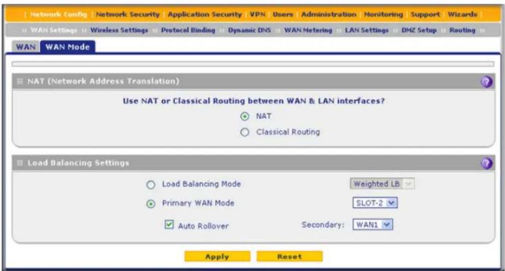
Figure 330.
- In the Load Balancing Settings section of the screen, configure the following settings:
a. Select the Primary WAN Mode radio button.
b. From the corresponding drop-down list on the right, select the DSL interface or a WAN interface to function as the primary WAN interface.
If you select the DSL interface, both WAN interfaces become disabled; if you select a WAN interface, the DSL interface and the other WAN interface become disabled.
c. Select the Auto Rollover check box.
d. From the corresponding drop-down list on the right, select a WAN interface, the USB interface, or the DSL interface to function as the backup interface.
Note: Ensure that the backup interface is configured before enabling auto-rollover mode.
- Click Apply to save your settings.
Configure the Failure Detection Method
To configure the failure detection method:
- Select Network Config > WAN Settings. The WAN screen displays (see Figure 322 on page 553).
- Click the Edit button in the Action column of the interface that you selected as the primary interface (see Figure 323 on page 554, which shows the SLOT-2 ISP Settings screen as an example).
- Click the Advanced option arrow at the upper right of the screen. The WAN Advanced Options screen displays for the interface that you selected. (For an image of the entire screen, see Figure 338 on page 575, which shows the WAN Advanced Options screen for the DSL interface.)
- Locate the Failure Detection Method section onscreen (see the following figure). Enter the settings as explained in the following table.
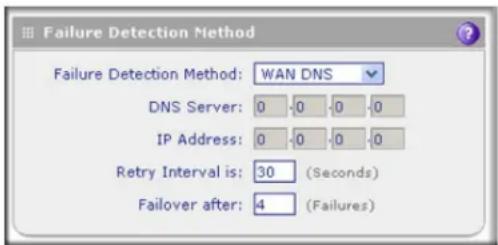
Figure 331.
Table 145. Failure detection method settings
| Setting Description | ||
| WAN Failure Detection MethodSelect a failure detection method from the drop-down list. DNS queries or pings are sent through the interface that is being monitored. The retry interval and number of failover attempts determine how quickly the UTM9S or UTM25S switches from the primary link to the backup link in case the primary link fails, or when the primary link comes back up, switches back from the backup link to the primary link. | ||
| WAN DNS DNS queries are sent to the DNS server that is configured in the Domain Name Server (DNS) Servers section of the WAN ISP screen (see Manually Configure the xDSL Internet Connection on page 556). | ||
| Custom DNS DNS queries are sent to the specified DNS server. | ||
| Ping | Pings are sent to a server with a public IP address. This server should not reject the ping request and should not consider ping traffic to be abusive. | |
| IP Address The IP address of the ping server. | ||
| Retry Interval is | The retry interval in seconds. The DNS query or ping is sent periodically after every test period. The default test period is 30 seconds. | |
| Failover after | The number of failover attempts. The primary WAN interface is considered down after the specified number of queries have failed to elicit a reply. The backup interface is brought up after this situation has occurred. The failover default is four failures. | |
Note: After the primary interface fails, the default time to roll over is 2 minutes. The minimum test period is 30 seconds, and the minimum number of tests is 4.
5. Click Apply to save your settings.
Note: You can configure the UTM to generate a WAN status log and email this log to a specified address (see Configure Logging, Alerts, and Event Notifications on page 466).
Configure Load Balancing and Optional Protocol Binding
To use multiple ISP links simultaneously, configure load balancing. In load balancing mode, the DSL interface, USB interface or any WAN interface carries any outbound protocol unless protocol binding is configured.
When a protocol is bound to a particular interface, all outgoing traffic of that protocol is directed to the bound interface. For example, if the HTTPS protocol is bound to the DSL interface and the FTP protocol is bound to the WAN1 interface, then the UTM9S or UTM25S automatically routes all outbound HTTPS traffic from the computers on the LAN through the DSL interface. All outbound FTP traffic is routed through the WAN1 interface.
Protocol binding addresses two issues:
- Segregation of traffic between links that are not of the same speed.
High-volume traffic can be routed through the DSL interface connected to a high-speed link, and low-volume traffic can be routed through a WAN interface connected to a low-speed link.
ProSecure Unified Threat Management (UTM) Appliance
- Continuity of source IP address for secure connections. Some services, particularly HTTPS, cease to respond when a client's source IP address changes shortly after a session has been established.
Configure Load Balancing
To configure load balancing:
- Select Network Config > WAN Settings > WAN Mode. The WAN Mode screen displays:
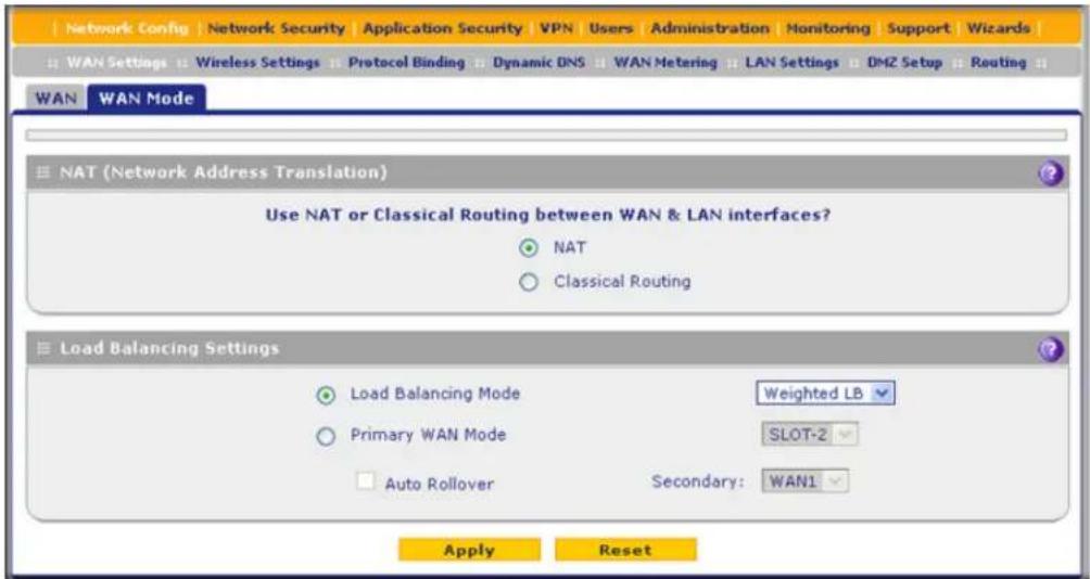
Figure 332.
Note: You cannot configure load balancing when you use a PPPoE or PPPoA connection and have selected the Idle Timeout radio button on the WAN ISP Settings screen (single WAN port models) or on one of the WAN ISP Settings screens (multiple WAN port models); to use load balancing on a PPPoE or PPPoA connection, select the Keep Connected radio button. For more information, see Figure 327 on page 557 and the accompanying PPPoE and PPPoA information in Table 142 on page 558.
- In the Load Balancing Settings section of the screen, configure the following settings:
a. Select the Load Balancing Mode radio button. b. From the corresponding drop-down list on the right, select one of the following load balancing methods:
- Weighted LB. With weighted load balancing, balance weights are calculated based on DSL, USB, or WAN link speed and available DSL, USB, or WAN bandwidth. This is the default setting and the most efficient load-balancing algorithm.
ProSecure Unified Threat Management (UTM) Appliance
- Round-robin. With round-robin load balancing, new traffic connections are sent over a DSL, USB, or WAN link in a serial method irrespective of bandwidth or link speed. For example if the DSL, WAN1, and WAN2 interfaces are active in round-robin load balancing mode, an HTTP request could first be sent over the DSL interface, then a new FTP session could start on the WAN1 interface, and then any new connection to the Internet could be made on the WAN2 interface. This load-balancing method ensures that a single interface does not carry a disproportionate distribution of sessions.
- Click Apply to save your settings.
Configure Protocol Binding (Optional)
To configure protocol binding and add protocol binding rules:
- Select Network Config > Protocol Binding. The Protocol Bindings screen displays. (The following figure shows two examples in the Protocol Bindings table.)

Figure 333.
The Protocol Bindings table displays the following fields:
- Check box. Allows you to select the protocol binding rule in the table.
• Status icon. Indicates the status of the protocol binding rule:
- Green circle. The protocol binding rule is enabled.
- Gray circle. The protocol binding rule is disabled.
• Service. The service or protocol for which the protocol binding rule is set up.
- Local Gateway. The WAN interface to which the service or protocol is bound.
- Source Network. The computers on your network that are affected by the protocol binding rule.
- Destination Network. The Internet locations (based on their IP address) that are covered by the protocol binding rule.
- Action. The Edit button provides access to the Edit Protocol Binding screen for the corresponding service.
- Click the Add table button below the Protocol Bindings table. The Add Protocol Binding screen displays:

Figure 334.
- Configure the protocol binding settings as explained in the following table:
Table 146. Add Protocol Binding screen settings
| Setting Description | ||
| Service | From the drop-down list, select a service or application to be covered by this rule. If the service or application does not appear in the list, you need to define it using the Services screen (seeOutbound Rules (Service Blocking) on page 129). | |
| Local Gateway From the drop-down list, select the DSL interface or one of the WAN interfaces. | ||
| Source Network | The source network settings determine which computers on your network are affected by this rule. Select one of the following options from the drop-down list: | |
| Any All devices on your LAN. | ||
| Single address In the Start IP field, enter the IP address to which the rule is applied. | ||
| Address Range In the Start IP field and End IP field, enter the IP addresses for the range to which the rule is applied. | ||
| Group 1-Group 8 If this option is selected, the rule is applied to the devices that are assigned to the selected group.Note: You can also assign a customized name to a group (seeChange Group Names in the Network Database on page 115). | ||
| Destination Network | The destination network settings determine which Internet locations (based on their IP address) are covered by the rule. Select one of the following options from the drop-down list: | |
| Any All Internet IP address. | ||
| Single address In the Start IP field, enter the IP address to which the rule is applied. | ||
| Address range In the Start IP field and End IP field, enter the IP addresses for the range to which the rule is applied. | ||
- Click Apply to save your settings. The protocol binding rule is added to the Protocol Bindings table. The rule is automatically enabled, which is indicated by the ! status icon, a green circle.
To edit a protocol binding:
- On the Protocol Bindings screen (see Figure 333 on page 568), in the Protocol Bindings table, click the Edit table button to the right of the binding that you want to edit. The Edit Protocol Binding screen displays. This screen shows the same fields as the Add Protocol Binding screen (see the previous figure).
- Modify the settings as explained in the previous table.
- Click Apply to save your settings.
To enable, disable, or delete one or more protocol bindings:
- On the Protocol Bindings screen (see Figure 333 on page 568), select the check box to the left of each protocol binding that you want to enable, disable, or delete, or click the Select All table button to select all bindings.
-
Click one of the following table buttons:
-
Enable. Enables the binding or bindings. The ! status icon changes from a gray circle to a green circle, indicating that the selected binding or bindings are enabled. (By default, when a binding is added to the table, it is automatically enabled.)
- Disable. Disables the binding or bindings. The ! status icon changes from a green circle to a gray circle, indicating that the selected binding or bindings are disabled.
- Delete. Deletes the binding or bindings.
Configure Secondary WAN Addresses
You can set up a single DSL or WAN interface to be accessed through multiple IP addresses by adding aliases to the interface. An alias is a secondary WAN address. One advantage is, for example, that you can assign different virtual IP addresses to a web server and an FTP server, even though both servers use the same physical IP address. You can add several secondary IP addresses to a single interface.
After you have configured secondary WAN addresses, these addresses are displayed on the following firewall rule screens:
- In the WAN Destination IP Address drop-down lists of the following inbound firewall rule screens:
- Add LAN WAN Inbound Service screen
- Add DMZ WAN Inbound Service screen
- In the NAT IP drop-down lists of the following outbound firewall rule screens:
- Add LAN WAN Outbound Service screen
- Add DMZ WAN Outbound Service screen
ProSecure Unified Threat Management (UTM) Appliance
For more information about firewall rules, see Overview of Rules to Block or Allow Specific Kinds of Traffic on page 128).
It is important that you ensure that any secondary DSL addresses are different from the primary DSL, WAN, LAN, and DMZ IP addresses that are already configured on the UTM9S or UTM25S. However, primary and secondary DSL addresses can be in the same subnet. The following is an example of correctly configured IP addresses:
• Primary DSL IP address. 10.118.0.1 with subnet 255.255.255.0
• Secondary DSL IP address. 10.118.24.1 with subnet 255.255.255.0
• Primary WAN1 IP address. 10.215.74.1 with subnet 255.255.255.0
• Secondary WAN1 IP address. 10.215.81.1 with subnet 255.255.255.0
• DMZ IP address. 192.168.10.1 with subnet 255.255.255.0
• Primary LAN IP address. 192.168.1.1 with subnet 255.255.255.0
• Secondary LAN IP address. 192.168.2.1 with subnet 255.255.255.0
To add a secondary WAN address to the DSL interface:
- Select Network Config > WAN Settings. The WAN screen displays (see Figure 322 on page 553).
- Click the Edit button in the Action column of the SLOT-x entry. The WAN ISP Settings screen displays (see Figure 323 on page 554, which shows the SLOT-2 ISP Settings screen as an example).
- Click the Secondary Addresses option arrow at the upper right of the screen. The SLOT-x Secondary Addresses screen displays (see the following figure, which shows the SLOT-2 Secondary Addresses screen as an example, and which includes one entry in the List of Secondary WAN addresses table).
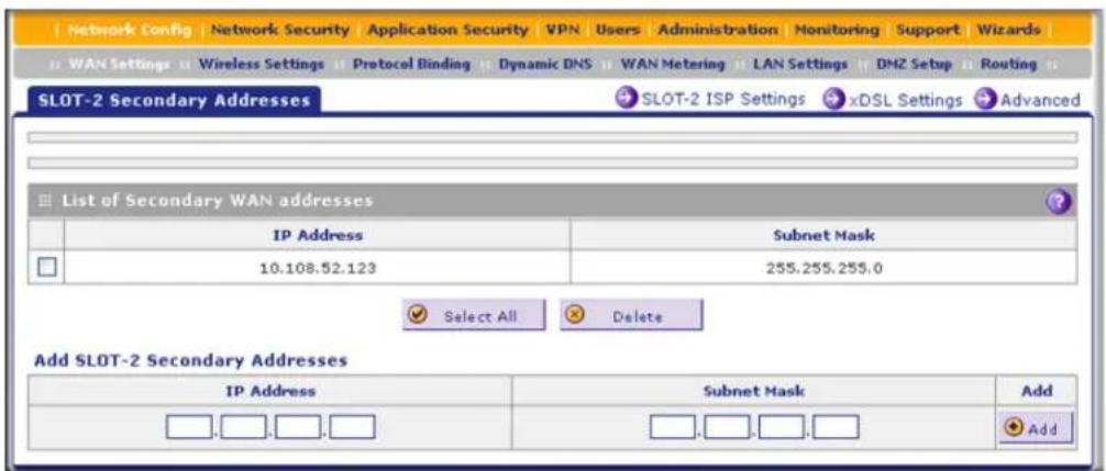
Figure 335.
The List of Secondary WAN addresses table displays the secondary LAN IP addresses added for the DSL interface.
- In the Add SLOT-x Secondary Addresses section of the screen, enter the following settings:
- IP Address. Enter the secondary address that you want to assign to the DSL interface.
- Subnet Mask. Enter the subnet mask for the secondary IP address.
- Click the Add table button in the rightmost column to add the secondary IP address to the List of Secondary WAN addresses table.
Repeat step 4 and step 5 for each secondary IP address that you want to add to the List of Secondary WAN addresses table.
To delete one or more secondary addresses:
- In the List of Secondary WAN addresses table, select the check box to the left of each address that you want to delete, or click the Select All table button to select all addresses.
- Click the Delete table button.
Configure Dynamic DNS
Dynamic DNS (DDNS) is an Internet service that allows devices with varying public IP addresses to be located using Internet domain names. To use DDNS, you need to set up an account with a DDNS provider such as DynDNS.org, TZO.com, Oray.net, or 3322.org. (Links to DynDNS, TZO, Oray, and 3322 are provided for your convenience as option arrows on the DDNS configuration screens.) The UTM9S and UTM25S firmware includes software that notifies DDNS servers of changes in the DSL IP address, so that the services running on this network can be accessed by others on the Internet.
If your network has a permanently assigned IP address, you can register a domain name and have that name linked with your IP address by public Domain Name Servers (DNS).
However, if your Internet account uses a dynamically assigned IP address, you do not know in advance what your IP address will be, and the address can change frequently—hence, the need for a commercial DDNS service, which allows you to register an extension to its domain, and forwards DNS requests for the resulting fully qualified domain name (FQDN) to your frequently changing IP address.
After you have configured your account information on the UTM9S or UTM25S, when your ISP-assigned IP address changes, your UTM9S or UTM25S automatically contacts your DDNS service provider, logs in to your account, and registers your new IP address.
Consider the following:
- For auto-rollover mode, you need an FQDN to implement features such as exposed hosts and virtual private networks regardless of whether you have a fixed or dynamic IP address.
- For load balancing mode, you might still need an FQDN either for convenience or if you have a dynamic IP address.
Note: If your ISP assigns a private WAN IP address such as 192.168.x.x or 10.x.x.x, the DDNS service does not work because private addresses are not routed on the Internet.
To configure DDNS:
- Select Network Config > Dynamic DNS. The Dynamic DNS screen displays (see the following figure).
The WAN Mode section onscreen reports the currently configured WAN mode (for example, Single Port WAN1, Load Balancing, or Auto Rollover). Only those options that match the configured WAN mode are accessible onscreen.
- Click the submenu tab for your DDNS service provider:
• Dynamic DNS for DynDNS.org (which is shown in the following figure)
• DNS TZO for TZO.com
• DNS Oray for Oray.net
• 3322 DDNS for 3322.org
![Network Config Network Security Application Security VPN Users Administration Monitoring Support Wizards WAN Settings Wireless Settings Protocol Binding Dynamic DNS WAN Metering LAN Settings DMZ Setup Routing Dynamic DNS DNS T20 DNS Oray 3322 DDNS DynDNS Information WAN Mode Current WAN Mode: Load Balancing WANI(Dynamic DNS Status: service is not enabled) Configured DDNS : none Change DNS to DynDNS.org? Yes No Host and Domain Name: [Example: yourname.dyndns.org] Username: Password: Use wildcards Update every 30 days WAN2(Dynamic DNS Status: service is not enabled) Configured DDNS : none Change DNS to DynDNS.org? Yes No Host and Domain Name: [Example: yourname.dyndns.org] Username: Password: Use wildcards Update every 30 days SLOT-2 (Dynamic DNS Status: service is not enabled) Configured DDNS : none Change DNS to DynDNS.org? Yes No Host and Domain Name: [Example: yourname.dyndns.org] Username: Password: Use wildcards Update every 30 days Apply Reset](/content/2026/06/1371942/images/cd09eaba57f9c94ccd50d7b4021e915f302c8c57506672ee7dce53c6ddf8421e.jpg)
Figure 336.
- Click the Information option arrow in the upper right of a DNS screen for registration information.

Figure 337.
-
Access the website of the DDNS service provider, and register for an account (for example, for DynDNS.org, go to http://www.dyndns.com/).
-
Configure the DDNS service settings for the DSL interface as explained in the following table:
Table 147. DNS service settings
| Setting Description | ||
| SLOT-x (Dynamic DNS Status: ...) | ||
| Change DNS to (DynDNS, TZO, Oray, or 3322) | Select the Yes radio button to enable the DDNS service. The fields that display onscreen depend on the DDNS service provider that you have selected. Enter the following settings: | |
| Host and Domain Name The host and domain name for the DDNS service. | ||
| Username or User Email Address | The user name or email address for DDNS server authentication. | |
| Password or User Key The password that is used for DDNS server authentication. | ||
| Use wildcards If your DDNS provider allows the use of wildcards in resolving your URL, you can select the Use wildcards check box to activate this feature. For example, the wildcard feature causes *.yourhost.dyndns.org to be aliased to the same IP address as yourhost.dyndns.org. | ||
| Update every 30 days If your WAN IP address does not often change, you might need to force a periodic update to the DDNS service to prevent your account from expiring. If the Update every 30 days check box displays, select it to enable a periodic update. | ||
- Click Apply to save your configuration.
Set the UTM's MAC Address and Configure Advanced WAN Options
The advanced options include configuring the maximum transmission unit (MTU) size, the port speed, and the MAC address of the UTM9S or UTM25S, and setting a rate limit on the traffic that is being forwarded by the UTM9S or UTM25S.
Note: You can also configure the failure detection method for the auto-rollover mode on the Advanced Options screen for the DSL interface. This procedure is discussed in Configure the Failure Detection Method on page 565.
IMPORTANT:
Each computer or router on your network has a unique 48-bit local Ethernet address. This is also referred to as the computer's Media Access Control (MAC) address. The default, on the WAN Advanced Options screen, is Use Default Address. If your ISP requires MAC authentication and another MAC address has been previously registered with your ISP, then you need to enter that address on the Advanced Options screen for the DSL interface.
To configure advanced WAN options:
- Select Network Config > WAN Settings.
- Click the Edit button in the Action column of the SLOT-x entry. The SLOT-x ISP Settings screen displays (see Figure 323 on page 554, which shows the SLOT-2 ISP Settings screen as an example).
- Click the Advanced option arrow in the upper right of the screen. The SLOT-x Advanced Options screen displays. (The following figure shows the SLOT-2 Advanced Options screen as an example.)
![Network Config Network Security Application Security VPN Users Administration Monitoring Support Wizards WAN Settings Wireless Settings Protocol Binding Dynamic DNS WAN Metering LAN Settings DMZ Setup Routing SLOT-2 Advanced Options SLOT-2 ISP Settings xDSL Settings Secondary Addresses MTU Size Default Custom 1492 [Bytes] Router's MAC Address Use Default Address Use this computer's MAC Address Use this MAC Address 04:3d:c7:d3:57:fa Failure Detection Method Failure Detection Method: WAN DNS DNS Server: 0 0 0 0 IP Address: 0 0 0 0 Retry Interval is: 30 (Seconds) Failover after: 4 (Failures) Apply Reset](/content/2026/06/1371942/images/4ce61486bdb8c2b3493444810d4a823b7e7005da6a3d22fb5f29192e0d9b4bd8.jpg)
Figure 338.
- Enter the settings as explained in the following table:
Table 148. Advanced DSL settings
| Setting Description | |
| MTU SizeMake one of the following selections: | |
| Default | Select the Default radio button for the normal maximum transmit unit (MTU) value. For most Ethernet networks, this value is 1500 bytes, or 1492 bytes for PPPoE connections. |
| Custom | Select the Custom radio button, and enter an MTU value in the Bytes field. For some ISPs, you might need to reduce the MTU. This is rarely required, and should not be done unless you are sure that it is necessary for your ISP connection. |
| Router's MAC AddressMake one of the following selections: | |
| Use Default Address | Each computer or router on your network has a unique 32-bit local Ethernet address. This is also referred to as the computer's Media Access Control (MAC) address. To use the MAC address of the UTM9S or UTM25S, select the Use Default Address radio button. |
| Use this computer's MAC Address | Select the Use this computer's MAC Address radio button to allow the UTM9S or UTM25S to use the MAC address of the computer you are now using to access the web management interface. This setting is useful if your ISP requires MAC authentication. |
| Use this MAC Address | Select the Use this MAC Address radio button, and manually enter the MAC address in the field next to the radio button. You would typically enter the MAC address that your ISP is requiring for MAC authentication.Note:The format for the MAC address is 01:23:45:67:89:AB (numbers 0–9 and either uppercase or lowercase letters A–F). If you enter a MAC address, the existing entry is overwritten. |
| Failure Detection MethodSee Configure the Failure Detection Method on page 565, including Table 145 on page 565. | |
- Click Apply to save your changes.

WARNING:
Depending on the changes that you made, when you click Apply, the UTM9S or UTM25S restarts, or services such as HTTP and SMTP might restart.
Additional WAN-Related Configuration Tasks
- If you have not already done so, configure the Ethernet WAN interfaces of the UTM9S or UTM25S (see Chapter 3, Manually Configure Internet and WAN Settings).
- If you want the ability to manage the UTM9S or UTM25S remotely, enable remote management (see Configure Remote Management Access on page 438). If you enable remote management, NETGEAR strongly recommend that you change your password (see Change Passwords and Administrator and Guest Settings on page 436).
- You can set up the traffic meter for the DSL interface (see Enable the WAN Traffic Meter on page 462).
Wireless Network Module for the UTM9S and UTM25S
B
This appendix describes how to configure the wireless features of the NMSWLSN wireless network module that you can install in a UTM9S or UTM25S. This appendix includes the following sections:
• Overview of the Wireless Network Module
- Configure the Basic Radio Settings
• Wireless Data Security Options
• Wireless Security Profiles
- Configure a Wireless Distribution System
- Configure Advanced Radio Settings
- Configure WMM QoS Priority Settings
• Test Basic Wireless Connectivity
- For More Information About Wireless Configurations
Before you set up the wireless features that are described in this appendix, connect the UTM9S or UTM25S and get the Internet connection working. The UTM9S or UTM25S should work with an Ethernet or DSL WAN connection, or with both. In planning your wireless network, consider the level of security required.
Note: In previous releases for the UTM9S, this network module was referred to as the UTM9SWLSN. The UTM9SWLSN is identical to the NMSWLSN.

WARNING:
If you are configuring the wireless settings from a wireless computer and you change the wireless network module's SSID, channel, or wireless security settings, you will lose your wireless connection when you click Apply. You then need to change the wireless settings of your computer to match the wireless network module's new settings.
Overview of the Wireless Network Module
- Configuration Order
- Wireless Equipment Placement and Range Guidelines
The wireless network module is a wireless access point that provides connectivity to multiple wireless network devices within a fixed range or area of coverage—interacting with a wireless network interface card (NIC) through an antenna. Typically, an individual in-building wireless access point provides a maximum connectivity area of about a 500-foot radius. The wireless network module can support a small group of wireless users—typically 5 to 20 users.
The wireless network module integrates a 2.4-GHz radio and a 5-GHz radio. One radio can be active at a time to provide wireless connectivity between wired Ethernet networks and radio-equipped wireless notebook systems, desktop systems, print servers, and other devices. The 2.4-GHz radio supports 802.11b/g/n modes and Greenfield mode; the 5-GHz radio supports 802.11a/n modes and Greenfield mode.
The wireless network module supports up to four wireless security profiles, allowing you to tailor access and security to a variety of wireless clients. Each wireless security profile can support Wi-Fi Multimedia (WMM) QoS priority and MAC address access control. The wireless network module supports WMM Power Save and Wireless Distribution System (WDS). You can insert one wireless network module only in the UTM9S or UTM25S.
Configuration Order
Configure the wireless features according to the order of the following sections:
- Configure the Basic Radio Settings
- Configure and Enable Wireless Profiles
- (Optional) Configure a Wireless Distribution System
- (Optional) Configure Advanced Radio Settings
- (Optional) Configure WMM QoS Priority Settings
Wireless Equipment Placement and Range Guidelines
The range of your wireless connection can vary significantly based on the location of the UTM9S or UTM25S. The latency, data throughput performance, and notebook power consumption of wireless adapters also vary depending on your configuration choices.
Note: Failure to follow these guidelines can result in significant performance degradation or inability to connect to the wireless network module. For complete performance specifications, see the data sheet on the ProSecure UTM series home page at http://prosecure.netgear.com/products/prosecure-utm-series/index.php.
For best results, place your UTM9S or UTM25S according to the following general guidelines:
- Near the center of the area in which your wireless devices will operate.
- In an elevated location such as a high shelf where the wirelessly connected devices have line-of-sight access (even if through walls).
- Away from sources of interference, such as computers, microwaves ovens, and 2.4-GHz cordless phones.
- Away from large metal surfaces or water.
- Placing the antennas in a vertical position provides the best side-to-side coverage. Placing the antennas in a horizontal position provides the best up-and-down coverage.
- If you are using multiple wireless access points, it is better if the wireless network module and an adjacent wireless access point use different radio frequency channels to reduce interference. The recommended channel spacing between adjacent wireless access points is five channels (for example, use channels 1 and 6, or 6 and 11, or 1 and 11).
- The time it takes to establish a wireless connection can vary depending on both your security settings and placement. WEP connections can take slightly longer to establish. Also, WEP encryption can consume more battery power on a notebook computer.
Configure the Basic Radio Settings
The default wireless mode is 802.11bg. You can change the wireless mode, country, and many other radio settings on the Radio Settings screen (described in this section) and on the Advanced Wireless screen (see Configure Advanced Radio Settings on page 598). The default radio settings should work well for most configurations.
To configure the basic radio settings:
- Select Network Config > Wireless Settings > Radio Settings. The Radio Settings screen displays:
ProSecure Unified Threat Management (UTM) Appliance

Figure 339.
- Specify the settings as explained the following table:
Table 149. Radio Settings screen settings
| Field Descriptions | |
| Region This is a preconfigured field that you cannot change. | |
| Country Specify a country by making a selection from the drop-down list. | |
| Operating Frequency Specify the radio's operating frequency by making a selection from the drop-down list:2.4GHz. The 2.4-GHz band is enabled and the 5-GHz band is disabled.5GHz. The 5-GHz-band is enabled and the 2.4-GHz-band is disabled. | |
Table 149. Radio Settings screen settings (continued)
| Field Descriptions | ||
| Mode The wireless modes | that you can select depend on the radio's operating frequency that you select. | |
| 2.4 GHz Specify the wireless mode in the 2.4-GHz band by making a selection from the drop-down list:g and b. This is the default setting. In addition to 802.11b- and 802.11g-compliant devices, 802.11n-compliant devices can connect to the wireless access point because they are backward compatible.g only. 802.11g- and 802.11n-compliant devices can connect to the wireless access point, but 802.11n-compliant devices function below their capacity in 802.11g mode. 802.11b-compliant devices cannot connect.ng. 802.11g- and 802.11n-compliant devices can connect to the wireless access point. 802.11b-compliant devices cannot connect.GreenField. Only 802.11n-compliant devices can connect to the wireless access point, and 802.1b- and 802.11g-compliant devices cannot recognize the wireless access point, which might cause interference. Therefore, use Greenfield mode only when you are sure that there are no or very few 802.1b- and 802.11g-compliant devices in the wireless coverage area. | ||
| 5 GHz Specify the wireless mode in the 5-GHz band by making a selection from the drop-down list:a only. 802.11a- and 802.11n-compliant devices can connect to the wireless access point, but 802.11n-compliant devices function below their capacity in 802.11a mode.na. This is the default setting. 802.11a- and 802.11n-compliant devices can connect to the wireless access point.GreenField. Only 802.11n-compliant devices can connect to the wireless access point, and 802.1a -compliant devices cannot recognize the wireless access point, which might cause interference. Therefore, use Greenfield mode only when you are sure that there are no or very few 802.1a-compliant devices in the wireless coverage area. | ||
| Channel SpacingNote: na, ng, and Greenfield modes only. This is a fixed field for a, b, and g modes. | For the na, ng, and Greenfield modes only, specify the channel spacing by making a selection from the drop-down list:20/40MHz. Select this option to improve the performance. Some legacy devices (that is, devices that function only in a, b, or g mode) can operate only in 20 MHz.20MHz. Select this option if your network includes legacy devices. This is the default setting.Note: The channel spacing is fixed at 20 MHz for the a, b, and g modes. | |
| Current Channel | This is a nonconfigurable field that shows the current channel if you have selected Auto from the Channel drop-down list. | |
Table 149. Radio Settings screen settings (continued)
| Field Descriptions | |
| Channel Specify the channel you wish to use on your wireless LAN by making a selection from the drop-down list. The wireless channels and frequencies depend on the country and wireless mode. The default setting is Auto.Note: It should not be necessary to change the wireless channel unless you notice interference in the network (indicated by lost connections or slow data transfers). If this happens, you might want to experiment with different channels to see which is the best. For more information, see Operating Frequency (Channel) Guidelines following this table.Note: For more information about available channels and frequencies, see Physical and Technical Specifications on page 673. | |
| Default Transmit Power From the drop-down list, select the default transmit power:Full. This is the default setting.Half.Quarter.Eighth.Minimum.Note: If the country regulation does not allow the transmit power that you select, the power is automatically adjusted to the legally allowed power, which is then displayed in the Transmit Power field. | |

WARNING:
When you have changed the country settings, the wireless network module (not the UTM9S or UTM25S) will reboot when you click Apply.
3. Click Apply to save your settings.
Operating Frequency (Channel) Guidelines
You should not need to change the operating frequency (channel) unless you notice interference problems, or are setting up the UTM9S or UTM25S near another wireless access point. Observe the following guidelines:
- Wireless access points use a fixed channel. You can select a channel that provides the least interference and best performance. In the United States and Canada, 11 channels are available in the 2.4-GHz operating frequency and 13 channels in the 5-GHz operating frequency.
- If you are using multiple wireless access points, it is better if adjacent wireless access points use different channels to reduce interference. The recommended channel spacing between adjacent wireless access points is 5 channels (for example, in 2.4-GHz operating frequency, use channels 1 and 6, or 6 and 11).
- In infrastructure mode, wireless devices normally scan all channels, looking for a wireless access point. If more than one wireless access point can be used, the one with the strongest signal is used. This can happen only when the wireless access points use the same SSID. The wireless network module functions in infrastructure mode by default.
Wireless Data Security Options
Indoors, computers can connect over 802.11n wireless networks at a maximum range of 300 feet. Typically, a UTM9S or UTM25S inside a building works best with wireless devices within a 100-foot radius. Such distances can allow for others outside your immediate area to access your network.
Unlike wired network data, your wireless data transmissions can extend beyond your walls and can be received by anyone with a compatible adapter. For this reason, use the security features of your wireless equipment. The wireless network module provides highly effective wireless security features that are covered in detail in this appendix. Deploy the security features appropriate to your needs.

flowchart
graph LR
    A["UTM9S or UTM25S"] --> B["Wireless Data Security Options"]
    B --> C["Range: Up to 500 feet RADIUS"]
    C --> D["1. No security: Easy but no security"]
    C --> E["2. MAC Access List: No data security"]
    C --> F["3. WEP: Secure but vulnerable"]
    C --> G["4. WPA or WPA-PSK: Strong security"]
    C --> H["5. WPA2 or WPA2-PSK: Very strong security"]
Figure 340.
There are several ways you can enhance the security of your wireless network:
- Restrict access based by MAC address. You can allow only trusted computers to connect so that unknown computers cannot wirelessly connect to the wireless network module. Restricting access by MAC address adds an obstacle against unwanted access to your network, but the data broadcast over the wireless link is fully exposed. For information about how to restrict access by MAC address, see Restrict Wireless Access by MAC Address on page 593.
- Turn off the broadcast of the wireless network name (SSID). If you disable broadcast of the SSID, only devices that have the correct SSID can connect. This nullifies the wireless network discovery feature of some products, such as Windows XP, but the data is still exposed. For information about how to turn of broadcast of the SSID, see Configure and Enable Wireless Profiles on page 588.
- WEP. Wired Equivalent Privacy (WEP) data encryption provides data security. WEP shared key authentication and WEP data encryption block all but the most determined eavesdropper. This data encryption mode has been superseded by WPA-PSK and WPA2-PSK.
Note: On the UTM9S or UTM25S, WEP is not supported when the radio functions in 802.11n wireless mode (802.11n, 802.11ng, 802,11na, or Greenfield).
For information about how to configure WEP, see Configure and Enable Wireless Profiles on page 588.
- WPA. Wi-Fi Protected Access (WPA) data encryption provides strong data security with Temporal Key Integrity Protocol (TKIP) or a combination of TKIP and Advanced Encryption Standard (AES) encryption. The strong authentication along with dynamic per frame rekeying of WPA make it virtually impossible to compromise. The wireless network module supports WPA with a pre-shared key (PSK), RADIUS, or a combination of PSK and RADIUS.
For more information about how to configure WPA, see Configure and Enable Wireless Profiles on page 588.
- WPA2. Wi-Fi Protected Access version 2 (WPA2) data encryption provides strong data security with AES encryption. WPA2 provides the most reliable security. Use WPA2 only if all clients in your network support WPA2. The wireless network module supports WPA2 with PSK, RADIUS, or a combination of PSK and RADIUS.
For more information about how to configure WPA2, see Configure and Enable Wireless Profiles on page 588.
- WPA+WPA2 mixed mode. This mode supports data encryption with a combination of TKIP and AES for both WPA and WPA2 clients. The strong authentication along with dynamic per frame rekeying of WPA2 make it virtually impossible to compromise. The wireless network module supports WPA+WPA2 with PSK, RADIUS, or a combination of PSK and RADIUS.
For more information about how to configure WPA+WPA2 mixed mode, see Configure and Enable Wireless Profiles on page 588.
Note: TKIP provides only legacy (slower) rates of operation. NETGEAR recommends WPA2 with AES to make use of 802.11n rates and speed.
Wireless Security Profiles
- Before You Change the SSID, WEP, and WPA Settings
- Configure and Enable Wireless Profiles
- Restrict Wireless Access by MAC Address
• View the Access Point Status and Connected Clients for a Wireless Profile
Wireless security profiles, hereafter referred to as wireless profiles, let you configure unique security settings for each SSID on the UTM9S or UTM25S. The UTM9S and UTM25S support up to four wireless profiles (BSSIDs) that you can configure from the Wireless Profiles screen (see Configure and Enable Wireless Profiles on page 588).
Each wireless profile provides the following features:
- Capability to turn off the wireless profile during scheduled vacations and office shutdowns, on evenings, or on weekends. This a green feature that allows you to save energy.
- Capability to assign the wireless profile to a VLAN.
- MAC address access control list that lets you add another level of security.
- Capability to monitor the clients that are connected to the SSID of the wireless profile.
To set up a wireless profile, specify a name for the profile and the SSID, specify the type of security with authentication and data encryption, and specify whether the SSID is broadcast.
• Network authentication
The default wireless profile is set as an open system with no authentication. When you configure network authentication, bear in mind that older wireless adapters might not support WPA or WPA2. Windows XP, Windows 2000 with Service Pack 3, and Windows Vista do include the client software that supports WPA. However, client software is required on the client. Consult the product documentation for your wireless adapter and WPA or WPA2 client software for instructions about configuring WPA2 settings.
For information about the types of network authentication that the wireless network module supports, see Configure and Enable Wireless Profiles on page 588.
- Data encryption
Select the data encryption that you want to use. The available options depend on the network authentication setting described earlier (otherwise, the default is None). The data encryption settings are explained in Configure and Enable Wireless Profiles on page 588.
Here are some concepts and guidelines regarding the SSID:
- A basic service set (BSS) is a group of wireless devices and a single wireless access point, all using the same security profile or service set identifier (BSSID). The actual identifier in the BSSID is the MAC address of the wireless radio. (A wireless radio can have multiple MAC addresses, one for each security profile.)
- An extended service set (ESS) is a group of wireless devices, all using the same identifier (ESSID).
- Different devices within an ESS can use different channels. To reduce interference, adjacent devices should use different channels.
- Roaming is the ability of wireless devices to connect wirelessly when they physically move from one BSS to another one within the same ESS. The wireless device automatically changes to the wireless access point with the least interference or best performance.
Before You Change the SSID, WEP, and WPA Settings
For a new wireless profile, print or copy the following form and fill in the settings.
Store this information in a safe place:
• SSID
The service set identifier (SSID) identifies the wireless local area network. You can customize it by using up to 32 alphanumeric characters. Write your SSID on the line.
SSID:
The SSID in the wireless profile is the SSID you configure on the wireless adapter card. All wireless nodes in the same network need to be configured with the same SSID.
- WEP key size, key format, authentication type, and passphrase
Choose the key size by circling one: 64, 128, or 256 bits. Choose the key format by circling one: ASCII or HEX. Choose the authentication type by circling one: open or shared.
Passphrase:
Note: If you select shared key, the other devices in the network cannot connect unless they are set to shared key and have the same keys in the same positions as those in the security profile on the wireless network module.
• WPA-PSK (pre-shared key) and WPA2-PSK
Record the WPA-PSK passphrase:
WPA-PSK passphrase: ____
Record the WPA2-PSK passphrase:
WPA2-PSK passphrase: ____
• WPA RADIUS settings
For WPA, record the following settings for the primary and secondary RADIUS servers:
Server name/IP address: Primary ____ Secondary ____
Port:
Shared secret:
• WPA2 RADIUS settings
For WPA2, record the following settings for the primary and secondary RADIUS servers:
Server name/IP address: Primary ____ Secondary ____
Port: ____
Shared secret:
Configure and Enable Wireless Profiles
To add a wireless profile:
- Select Network Config > Wireless Settings > Wireless Profiles. The Wireless Profiles screen displays:

Figure 341.
The following table explains the fields of the Wireless Profiles screen:
Table 150. Wireless Profiles screen settings
| Field Description | |
| Status The status of the wireless profile (Enabled or Disabled). | |
| Profile Name | The unique name of the wireless profile that makes it easy to recognize the profile. For the UTM9S, the default profile name is UTM9S. For the UTM25S, the default profile name is UTM25S. You cannot change these names. |
| SSID The wireless network | name (SSID) for the wireless profile. |
| Broadcast | Indicates whether the SSID is broadcast. A green circle indicates that the SSID is broadcast; a gray circle indicates that it is not. |
| Security The configured security method for the wireless profile. | |
| Encryption The configured encryption method for the wireless profile. | |
| Authentication The configured authentication method for the wireless profile. | |
| Schedule Indicates whether the timer for the wireless profile is activated (No or Yes). | |
| Start Time The start time for the timer. | |
| Stop Time The stop time for the timer. | |
- Click the Add table button. The Add Wireless Profile screen displays:
ProSecure Unified Threat Management (UTM) Appliance

Figure 342.
- Specify the settings as explained in the following table:
Table 151. Add Wireless Profiles screen settings
| Field Description | |
| Profile Configuration | |
| Profile Name | The name for the wireless profile. For the UTM9S, the name of the default wireless profile is UTM9S. For the UTM25S, the name of the default wireless profile UTM25S. You cannot change these names. For additional profiles, enter a unique name to make it easy to recognize the profile. You can enter a name of up to 32 alphanumeric characters. |
Table 151. Add Wireless Profiles screen settings (continued)
| Field Description | ||
| SSID The wireless network name (SSID) for the wireless profile. The default SSID name is netgear-1. You can change this name by entering up to 32 alphanumeric characters. Make sure that additional SSIDs have unique names. | ||
| Broadcast SSID Select the check box to enable the wireless profile to broadcast its SSID, allowing wireless clients that have a null (blank) SSID to adopt the wireless profile's SSID. To prevent the SSID from being broadcast, clear the check box. | ||
| Security | Note: Before you configure security, you might want to read Wireless Data Security Options on page 584.Specify the wireless security by making a selection from the drop-down list:OPEN. This is the default setting. An open system has no authentication and no encryption, and therefore no security configuration. However, you can use an open system with encryption. To do so, select WEP from the Security drop-down list. In the WEP Index and Keys section of the screen, take the following steps:- Select Open System authentication.- Select the encryption.- Enter a passphrase and generate a key, or enter a key manually.WEP. To configure WEP, take the following steps in the WEP Index and Keys section of the screen:- Select Shared Key authentication.- Select the encryption.- Enter a passphrase and generate a key, or enter a key manually.WPA. To configure WPA, select the encryption and authentication. The remaining configuration depends on the selected authentication:- For WPA-PSK, select a password.- For WPA with RADIUS, configure the RADIUS server settings.- For WPA with PSK+RADIUS, select a password and configure the RADIUS server settings.WPA2. To configure WPA2, select the encryption and authentication. The remaining configuration depends on the selected authentication:- For WPA2-PSK, select a password.- For WPA2 with RADIUS, configure the RADIUS server settings. As an option, you can enable RADIUS preauthentication.- For WPA2 with PSK+RADIUS, select a password and configure the RADIUS server settings. As an option, you can enable RADIUS preauthentication.WPA+WPA2. To configure WPA, select the encryption and authentication. The remaining configuration depends on the selected authentication:- For WPA+WPA2 with PSK, select a password.- For WPA+WPA2 with RADIUS, configure the RADIUS server settings.- For WPA+WPA2 with PSK+RADIUS, select a password and configure the RADIUS server settings. | |
| EncryptionNote:WPA, WPA2, and WPA+WPA2 only. | The encryption that you can select depends on the type of WPA security that you have selected:WPA. You can select the following types of encryption from the drop-down list:TKIP- TKIP+AESWPA2. The encryption is AES.WPA+WPA2. The encryption is TKIP+AES. | |
| AuthenticationNote:WPA, WPA2, and WPA+WPA2 only. | For WPA, WPA2, and WPA+WPA2 only, specify the authentication by making a selection from the drop-down list:PSKRADIUSPSK+RADIUS | |
| WPA PasswordNote:WPA, WPA2, and WPA+WPA2 only. | For WPA, WPA2, and WPA+WPA2 only, if you have selected PSK or PSK+RADIUS authentication, enter a pre-shared key or password. The password length needs to be between 8 and 63 characters (inclusive). | |
| Schedule | To enable the timer, select theSchedulecheck box. When the timer is enabled, the wireless profile is turned off from the start time until the stop time. To disable the timer, clear the check box. | |
| Start Time Specify the start hour in the Hour field and the start minute in the Minutes field, and then selectAMorPMfrom the drop-down list. | ||
| Stop Time Specify the stop hour in the Hour field and the stop minute in the Minutes field, and then selectAMorPMfrom the drop-down list. | ||
| VLAN From the drop-down list, select the VLAN to which the wireless profile should be allocated. The default VLAN is defaultVlan. | ||
| VLAN Profiles | To configure a VLAN profile, click theVLAN Profileslink. For information about VLAN profiles, seeConfigure a VLAN Profileon page 103. | |
| Radius Server SettingsNote:WPA, WPA2, and WPA+WPA2 only. | For WPA, WPA2, and WPA+WPA2 only, if you have selected RADIUS or PSK+RADIUS authentication, click theRadius Server Settingslink to configure the RADIUS settings (seeRADIUS Client and Server Configurationon page 310). | |
| WEP Index and Keys | ||
| Authentication | Specify the authentication by making a selection from the drop-down list:Open System. Select this option to use WEP encryption without authentication.Shared Key. Select this option to use WEP authentication and encryption with a shared key (passphrase). | |
Table 151. Add Wireless Profiles screen settings (continued)
| Field Description | |
| Encryption Select the encryption key size by making a selection from the drop-down list:64-bit WEP. Standard WEP encryption, using 40/64-bit encryption.128-bit WEP. Standard WEP encryption, using 104/128-bit encryption.256-bit WEP. Standard WEP encryption, using 232/256-bit encryption. | |
| Passphrase Enter a passphrase. The passphrase can have a maximum of 64 characters.The secret passphrase allows you to generate the keys automatically by clicking Generate. | |
| Encryption Key(Key1-Key4) | Specify the active key by selecting one of the four radio buttons. Only one key can be the active key. Either enter a key manually or generate the key automatically by clicking Generate. The length of the key depends on the selected encryption:64-bit WEP. A key length of 5 ASCII or 10 hexadecimal characters.128-bit WEP. A key length of 13 ASCII or 26 hexadecimal characters.256-bit WEP. A key length of 29 ASCII or 58 hexadecimal characters.Note: Wireless stations need to use the key to access the wireless access point. |
- Click Apply to save your settings. The profile is updated in the List Of Wireless Profiles table.

WARNING:
If you use a wireless computer to configure wireless security settings, you will be disconnected when you click Apply. Reconfigure your wireless computer to match the new settings, or access the wireless network module from a wired computer to make further changes.
To edit a wireless profile:
- On the Wireless Profiles screen (see Figure 341 on page 588), click the Edit button in the Action column for the wireless profile that you want to modify. The Edit Wireless Profile screen displays. This screen is identical to the Add Wireless Profile screen.
- Modify the settings as explained in the previous table.
- Click Apply to save your settings.
To delete one or more wireless profiles:
- On the Wireless Profiles screen (see Figure 341 on page 588), select the check box to the left of each wireless profile that you want to delete, or click the Select All table button to select all wireless profiles. (You cannot select the default wireless profile.)
- Click the Delete table button.
To enable or disable one or more wireless profiles:
- On the Wireless Profiles screen (see Figure 341 on page 588), select the check box to the left of each wireless profile that you want to enable or disable, or click the Select All table button to select all wireless profiles.
- Click one of the following table buttons:
- Enable. Enables the wireless profile or wireless profiles and allows wireless clients to make a connection.
- Disable. Disables the wireless profile or wireless profiles and prevents wireless clients from making a connection.
Restrict Wireless Access by MAC Address
For increased security, you can restrict access to an SSID by allowing access to only specific computers or wireless stations based on their MAC addresses. You can restrict access to only trusted computers so that unknown computers cannot connect to the wireless access point. MAC address filtering adds an obstacle against unwanted access to your network, but the data broadcast over the wireless link is fully exposed. You can configure MAC address access control for each wireless profile individually.
Note: For wireless adapters, you can usually find the MAC address printed on the wireless adapter.
To allow or restrict access to a wireless profile based on MAC addresses:
- On the Wireless Profiles screen (see Figure 341 on page 588), select the check box to the left of the wireless profile for which you want to set up access control.
- Click the ACL table button. The Address Control List screen displays. (The following figure shows some examples.)

Figure 343.
Note: The default wireless profile with profile name UTM9S or UTM25S is referred to as virtual access point zero (VAP0). If you add more wireless profiles, they are referred to as VAP1, VAP2, and VAP3.
- In the MAC Filter Configuration section of the screen, enter a MAC address in the MAC Address field.
- Click Add to add the MAC address to the MAC Address table.
- Repeat step 3 and step 4 for any other MAC addresses that you want to add to the MAC Address table.
-
In the Access Control List Status section of the screen, from the ACL Policy Status drop-down list, select if access control is enabled, and if so, how the MAC addresses in the MAC Address table are treated:
-
Open. Access control is disabled. All MAC addresses, including the ones in the MAC Address table, are allowed access.
- Allow. Only the MAC addresses in the MAC Address table are allowed access. All other MAC addresses are denied access.
-
Deny. The MAC addresses in the MAC Address table are denied access. All other MAC addresses are allowed access.
-
Click Apply to save your settings.

WARNING:
If you configure the wireless network module in the UTM9S or UTM25S from a wireless computer whose MAC address is not in the access control list, and if the ACL policy status is set to deny access, you lose your wireless connection when you click Apply. You then need to access the UTM9S or UTM25S from a wired computer or from a wireless computer that is on the access control list to make any further changes.
To remove one or more MAC addresses from the table:
- In the MAC Address table, select the check box to the left of each MAC address that you want to delete, or click the Select All table button to select all MAC addresses.
- Click the Delete table button.
View the Access Point Status and Connected Clients for a Wireless Profile
To view the access point status for a wireless profile and the clients that are connected to it:
- On the Wireless Profiles screen (see Figure 341 on page 588), select the check box to the left of the wireless profile for which you want to view the status.
- Click the Status table button. The Access Point Status screen displays:
![Network Config | Network Security | Application Security | VPN | Users | Administration | Monitoring | Support | Wizards | WAN Settings || Wireless Settings || Protocol Binding || Dynamic DNS || WAN Metering || LAN Settings || DMZ Setup || Routing || Access Point Status The page will auto-refresh in 3 Seconds Access Point Status AP Name Radio Packet Bytes Errors Dropped Multicast Collision rx Characteristics rx Characteristics rx Characteristics vap0 1 28 9 3138 1788 0 0 0 0 18 0 Connected Clients MAC Address Radio Security Encryption Authentication Time Connected 21:d7:06:3b:60:6d 1 OPEN NONE NONE 0 Days 00:00:07 Poll Interval: 5 [Seconds] Set interval Stop](/content/2026/06/1371942/images/3e49cb0b680bec762e6e9c178b11902c9270347e68193a16b87055f21bd5a90d.jpg)
Figure 344.
To change the poll interval period, enter a new value in the Poll Interval field, and then click Set interval. To stop polling, click Stop.
The following table explains the fields of the Access Point Status screen.
Table 152. Access Point Status screen fields
| Item Description | |
| AP Statistics | |
| AP Name | The default wireless profile with profile name UTM9S or UTM25S is referred to as virtual access point zero (VAP0). If you add more wireless profiles, they are referred to as VAP1, VAP2, and VAP3. |
| Radio | The radio to which the client is connected. By default, the radio is always 1. |
| Packets | The number of received (Rx) and transmitted (Tx) packets on the virtual access point in bytes. |
| Bytes | The number of received (Rx) and transmitted (Tx) bytes on the virtual access point. |
| Errors | The number of received (Rx) and transmitted (Tx) errors on the virtual access point. |
| Dropped | The number of received (Rx) and transmitted (Tx) dropped packets on the virtual access point. |
| Multicast | The number of received (Rx) and transmitted (Tx) multicast packets on the virtual access point. |
| Collisions | The number of signal collisions that have occurred on the virtual access point. A collision occurs when the virtual access point attempts to send data at the same time as a wireless station that is connected to the virtual access point. |
| Connected Clients | |
| MAC Address The MAC address of the client. | |
| Radio The radio to which the client is connected. By default, the radio is always 1. | |
| Security The type of security that the client is using (Open, WEP, WPA, WPA2, or WPA+WPA2). | |
| Encryption | The type of encryption that the client is using (None, TKIP, AES, or TKIP+AES). |
| Authentication | The type of authentication that the client is using (Open, PSK, RADIUS, or PSK+RADIUS). |
| Time Connected | The period in minutes since the connection was established between the virtual access point and the client. |
Configure a Wireless Distribution System
The UTM9S or UTM25S can function as a station (peer) in a Wireless Distribution System (WDS). WDS enables expansion of a wireless network through two or more access points that are interconnected and that use the same radio channel and security mode.
WDS is supported in any of the security modes (see Wireless Security Profiles on page 585). If you configure the access point for WEP, then WDS works in WEP mode; if you configure the access point for WPA2, then WDS works in WPA2 mode, and so on. If you configure
ProSecure Unified Threat Management (UTM) Appliance
mixed encryption (TKIP+AES, which is supported in WPA and WPA+WPA2 security modes), WDS uses AES because it is the stronger encryption method.
To configure WDS, you need to know the MAC addresses of the wireless peers, and you need to use a common WPA password or WEP key on all peers. (You enter the WPA password or WEP key in the WPA Password field on the WDS Configuration screen.) You can configure up to a maximum of four WDS peers.
To enable and configure WDS:
- Select Network Config > Wireless Settings > WDS Configuration. The WDS Configuration screen displays:

Figure 345.
- Select the Enable WDS check box.
- In the WPA Password field, enter a password between 8 and 63 characters.
- Click Apply to save your settings.
- In the Add WDS Peer Configuration section of the screen, enter a MAC address of a peer in the MAC Address field.
- Click Apply to add the MAC address to the WDS Peers table.
- Repeat step 5 and step 6 for any other MAC addresses that you want to add to the MAC Address table.
To configure WDS on a peer:
- Configure the same wireless security that you have configured on the UTM9S or UTM25S.
- Enter the MAC address of the UTM9S's or UTM25S's access point, which is displayed on the WDS Configuration screen of the UTM9S or UTM25S.
- Enter the same WPA password or WEP key that you have entered on the WDS Configuration screen of the UTM9S or UTM25S.
Note: Make sure that you use the same wireless security configuration on all WDS peers.
To remove one or more MAC addresses from the WDS Peers table:
- In the WDS Peers table, select the check box to the left of each MAC address that you want to delete, or click the Select All table button to select all MAC addresses.
- Click the Delete table button.
Configure Advanced Radio Settings
To configure advanced radio settings:
- Select Network Config > Wireless Settings > Radio Settings. The Radio Settings screen displays (see Figure 339 on page 581).
- Click the Advanced option arrow in the upper right of the Radio Settings screen. The Advanced Wireless screen displays:

Figure 346.
- Specify the settings as explained in the following table:
Table 153. Advanced Wireless screen settings
| Setting Description | |
| Beacon Interval Enter an interval between 20 ms and 100 ms for each beacon transmission, which allows the wireless network module to synchronize the wireless network. The default setting is 100 ms. | |
| DTIM Interval | Enter the Delivery Traffic Indication Message (DTIM) interval, also referred to as the data beacon rate, which indicates the period for the beacon DTIM in multiples of beacon intervals. This value needs to be between 1 and 255. The default setting is 2. |
| RTS Threshold Enter the Request to Send (RTS) threshold. The default setting is 2346 bytes.If the packet size is equal to or less than the RTS threshold, the wireless network module uses the Carrier Sense Multiple Access with Collision Detection (CSMA/CD) mechanism, and the data frame is transmitted immediately after the silence period.If the packet size is larger than the RTS threshold, the wireless network module uses the CSMA with Collision Avoidance (CSMA/CA) mechanism. In this situation, the transmitting station sends an RTS packet to the receiving station and waits for the receiving station to return a Clear to Send (CTS) packet before sending the actual packet data. This method improves the performance but reduces the throughput. | |
| Fragmentation Threshold | Enter the maximum packet size that is used for the fragmentation of data packets. Packets that are larger than the specified fragmentation length are broken up into smaller packets before being transmitted. The fragmentation threshold needs to be an even number. The default setting is 2346 bytes. |
| Preamble Mode | Specify the transmit preamble mode by making a selection from the drop-down list:Long Preamble.A long transmit preamble might provide a more reliable connection or a slightly longer range. This is the default mode.Short Preamble.A short transmit preamble gives better performance.Auto Preamble.An automatic preamble gives a better overall performance by providing both long and short preambles. |
| Protection Mode Specify the CTS-to-self protection mode (CTS stands for Clear to Send) by making a selection from the drop-down list:None.CTS-to-self protection mode is disabled. This is the default mode.CTS-To-Self-Protection.CTS-to-self protection mode is enabled. This mode increases the performance but reduces the throughput slightly. | |
| Power Save Enable | To enable the Wi-Fi Multimedia (WMM) Power Save feature, select the Power Save Enable check box. This feature saves power for battery-powered equipment by increasing the efficiency and flexibility of data transmission. Clear the check box to disable the feature, which is the default setting. |
- Click Apply to save your settings.
Configure WMM QoS Priority Settings
Wi-Fi Multimedia (WMM) is a subset of the 802.11e standard. WMM allows wireless traffic to have a range of priorities, depending on the type of data. Time-dependent information, such as video or audio, has a higher priority than normal traffic. For WMM to function correctly, wireless clients also need to support WMM.
By enabling WMM, you allow Quality of Service (QoS) control for upstream traffic flowing from a wireless client to the UTM9S or UTM25S and for downstream traffic flowing from the UTM9S or UTM25S to a wireless client.
WMM defines the following four queues in decreasing order of priority:
- Voice (Queue 4). The highest priority queue with minimum delay, which makes it ideal for applications like VoIP and streaming media.
- Video (Queue 3). The second highest priority queue with low delay is given to this queue. Video applications are routed to this queue.
- Best Effort (Queue 2). The medium priority queue with medium delay is given to this queue. Most standard IP applications use this queue.
- Background (Queue 1). The low priority queue with high throughput. Applications, such as FTP, that are not time-sensitive but require high throughput can use this queue.
Differentiated Services (DiffServ) QoS packet matching lets you map each Differentiated Services Code Point (DSCP) value (0 to 63) to one queue (1, 2, 3, or 4). You can map different DSCP values to the same queue. Based on the DSCP value in a packet's IP header, the packet is placed in the queue to which you mapped the DSCP value.
To enable and configure WMM QoS priority settings for a wireless profile:
- On the Wireless Profiles screen (see Figure 341 on page 588), select the check box to the left of the wireless profile for which you want to configure the WMM QoS priority settings.
- Click the WMM table button. The WMM screen displays.
Note: The default wireless profile with profile name UTM9S or UTM25S is referred to as virtual access point zero (VAP0). If you add more wireless profiles, they are referred to as VAP1, VAP2, and VAP3.

Figure 347.
- Select the Enable WMM check box.
- Click Apply to save your settings.
- In the DSCP to Queue table, from the drop-down lists, select a WMM queue for each DSCP value that you want to use in a QoS profile:
• 4. The highest priority queue with minimum delay.
• 3. The second highest priority queue with low delay.
• 2. The medium priority queue with medium delay.
• 1. The low priority queue with high throughput.
- Click Apply to save your settings.
Test Basic Wireless Connectivity
After you have configured the wireless network module as explained in the previous sections, test your wireless clients for connectivity before you place the UTM9S or UTM25S at its permanent position.
To test for wireless connectivity:
- Configure the 802.11b/g/n or 802.11a/n wireless clients so that they all have the same SSID that you have configured on the wireless access point. Make sure that the wireless mode on the wireless access point supports the wireless capacity of the wireless clients. (For example, 802.11b-compliant devices cannot connect to the wireless access point if the wireless mode is set to ng.)
- Verify that your wireless clients have a link to the wireless access point. If you have enabled the DHCP server on the UTM9S or UTM25S (see Configure a VLAN Profile on page 103) and have assigned a VLAN to the wireless access point, verify that your wireless clients are able to obtain an IP address through DHCP from the UTM9S or UTM25S.
- Verify network connectivity by using a browser such as Internet Explorer 6.0 or later or Mozilla Firefox 1.5 or later to browse the Internet, or check for file and printer access on your network.
- If you have trouble connecting to the wireless network module, try to connect without security by selecting OPEN from the Security drop-down list on the Edit Profiles screen. If that does not help you to solve the connection problem, see Chapter 12, Troubleshoot and Use Online Support.
For More Information About Wireless Configurations
Visit http://prosecure.netgear.com/community/forum.php for information about the ProSecure forum and to become part of the ProSecure community.
The forum includes a Resources section with UTM How-To's, including the following guides:
- How to Create a Dedicated Guest Wireless VLAN with UTM, Smart Switch, and Wireless AP
• How to Set Up Office Guest Wireless Access Using VLAN Trunking with UTM
3G/4G Dongles for the UTM9S and UTM25S
C
This appendix describes how to configure the wireless features of a mobile broadband USB adapter (3G/4G dongle) that you can install in a UTM9S or UTM25S. This appendix includes the following sections:
• 3G/4G Dongle Configuration Tasks
• Manually Configure the USB Internet Connection
• Configure the 3G/4G Settings
- Configure the WAN Mode
- Configure Dynamic DNS
• Additional WAN-Related Configuration Tasks
A UTM9S or UTM25S can simultaneously support a USB WAN interface, Ethernet WAN interfaces, and a DSL WAN interface:
- For information about how to configure the Ethernet WAN interfaces, see Chapter 3, Manually Configure Internet and WAN Settings.
- For information about how to configure the DSL WAN interface, see Appendix A, xDSL Network Module for the UTM9S and UTM25S.
Note: The UTM9S and UTM25S support 3G, 4G, and combined 3G/4G dongles. This appendix refers to these three types of dongles as 3G/4G dongles.
3G/4G Dongle Configuration Tasks
A 3G/4G dongle provides wireless connectivity to a UTM9S or UTM25S. You can insert a single dongle in the USB port on the front panel.
A list of supported dongles is available at http://support.netgear.com/utmhcl.
Generally, four steps, one of which is optional, are required to complete the 3G/4G Internet connection of your UTM9S or UTM25S.
Complete these steps:
- Insert the 3G/4G dongle and configure the Internet connection to your ISP. During this phase, you connect to your wireless ISP, and, only if necessary, modify the 3G/4G settings. See Manually Configure the USB Internet Connection on page 604.
- Configure the 3G/4G settings. Modifying the 3G/4G settings is required only if you cannot connect to your ISP. See Configure the 3G/4G Settings on page 608.
- Configure the WAN mode. Select either NAT or classical routing, and select dedicated (single WAN) mode, or, if you have also configured another WAN interface, auto-rollover mode or load balancing mode. The USB interface can function as a rollover interface only. For load balancing, you can also select any necessary protocol bindings. See Configure the WAN Mode on page 610.
- Configure Dynamic DNS on the WAN port (optional). Configure your fully qualified domain names during this phase (if necessary). See Configure Dynamic DNS on page 618.
Each of these tasks is detailed separately in this appendix.
Note: For information about how to configure the WAN meter for the USB interface, see Enable the WAN Traffic Meter on page 462.
Note: In this appendix, the USB WAN interface is often referred to as the USB interface.
Manually Configure the USB Internet Connection
When you insert a 3G/4G dongle in the USB port on the front panel of a UTM9S or UTM25S, the dongle is detected automatically.
Unless your ISP automatically assigns your configuration through DHCP, you need to obtain configuration parameters from your ISP to manually establish an Internet connection over the USB WAN interface. For a fixed (static) IP address configuration, you need to obtain the following information:
IP address
- Subnet mask
• Gateway IP address
• Primary DNS server IP address (if not assigned dynamically)
• Secondary DNS server IP address (if not assigned dynamically)
To configure the WAN ISP settings for the USB interface:
- Select Network Config > WAN Settings. The WAN screen displays:

Figure 348.
- Select WAN Mode
- Click the Edit button in the Action column of the USB interface. The USB ISP Settings screen displays.
![Network Config | Network Security | Application Security | VPN | Users | Administration | Monitoring | Support | Wizards | WAN Settings | Wireless Settings | Protocol Binding | Dynamic DNS | WAN Metering | LAN Settings | DMZ Setup | Routing | USB ISP Settings 3G Dongle Details Card Type: 3G/4G Enable 3G Services: Connection Settings Idle Timeout: Keep Connected Idle Timeout 0 [Minutes] Connection Reset: Disconnect Time: HH MM Delay: Sec Internet (IP) Address [Current IP Address] Get Dynamically from ISP Use Static IP Address IP Address: 0 0 0 0 Subnet Mask: 0 0 0 0 Gateway IP Address: 0 0 0 0 Domain Name Server (DNS) Servers Get Automatically from ISP Use These DNS Servers Primary DNS Server: 0 0 0 0 Secondary DNS Server: 0 0 0 0 Apply Reset](/content/2026/06/1371942/images/5e238e695b7275ec33d23a69056c7888d533ee45e1430f1e0ca48d58e1e86472.jpg)
Figure 349.
- Configure the settings as explained in the following table:
Table 154. USB ISP settings
| Setting Description | ||
| 3G Dongle Details | ||
| Card Type The card | type is a fixed field that states 3G/4G. | |
| Enable 3G Service | Select the Enable 3G Service check box to enable the 3G/4G service. | |
| Connection Settings | ||
| Idle Timeout | Select the Keep Connected radio button to keep the connection always on. To log out after the connection is idle for a period:1. Select the Idle Timeout radio button.2. In the time-out field, enter the number of minutes to wait before disconnecting.This is useful if your ISP charges you based on the period that you are logged in. | |
| Connection Reset | Select the Connection Reset check box to specify a time when the 3G/4G connection is reset, that is, the connection is disconnected momentarily and then reestablished. Then, specify the disconnect time and delay. | |
| Disconnect Time Specify the hour and minutes when the connection should be disconnected. | ||
| Delay Specify the period in seconds after which the connection should be reestablished. | ||
| Internet (IP) AddressNote: Click the Current IP Address link to see the currently assigned IP address. | ||
| Get Dynamically from ISP | If your ISP has not assigned you a static IP address, select the Get Dynamically from ISP radio button. The ISP automatically assigns an IP address to the UTM9S or UTM25S using DHCP network protocol. | |
| Use Static IP Address | If your ISP has assigned you a fixed (static or permanent) IP address, select the Use Static IP Address radio button, and enter the following settings: | |
| IP Address Static IP address assigned to you. This address identifies the UTM9S or UTM25S to your ISP. | ||
| Subnet Mask The subnet mask is usually provided by your ISP. | ||
| Gateway IP Address The IP address of the ISP's gateway is usually provided by your ISP. | ||
| Domain Name Server (DNS) Servers | ||
| Get Automatically from ISP | If your ISP has not assigned any Domain Name Server (DNS) addresses, select the Get Automatically from ISP radio button. | |
| Use These DNS Servers | If your ISP has assigned DNS addresses, select the Use These DNS Servers radio button. Make sure that you fill in valid DNS server IP addresses in the fields. Incorrect DNS entries might cause connectivity issues. | |
| Primary DNS Server The IP address of the primary DNS server. | ||
| Secondary DNS Server | The IP address of the secondary DNS server. | |
- Click Apply to save any changes to the USB ISP settings. (Or click Reset to discard any changes and revert to the previous settings.)
- To verify the connection:
a. Return to the WAN screen by selecting Network Config > WAN Settings.
b. Click the Status button in the Action column for the USB interface that you just configured to display the Connection Status pop-up screen.

bar
| Connection Status | Signal Strength (dBm) | | :--- | :--- | | Connection Type: PPP | 10.136.80.92 | | Connection State: Connected | 10.136.80.1 | | Primary DNS Server: 10.136.20.10 | 10.136.20.10 | | Secondary DNS Server: 10.136.20.20 | 10.136.20.20 | | Total Traffic (KBytes): 5900234 | 5900234 | Connect | 5900234 |Figure 350.
Note: The Connection Status screen should show a valid IP address and gateway (the example in the previous figure does not). For more information about the Connection Status screen, see View the WAN, xDSL, or USB Port Status on page 504.
Configure the 3G/4G Settings
The 3G/4G settings are automatically detected. Modifying these settings is required only if you cannot connect to your ISP. For example, if your ISP provides you information about a pay plan for the 3G/4G service, you might need to configure the 3G/4G settings.
To configure the 3G/4G settings:
- Select Network Config > WAN Settings. The WAN screen displays (see Figure 348 on page 605).
- Click the Edit button in the Action column of the USB interface. The USB ISP Settings screen displays (see Figure 349 on page 605).
- Click the 3G/4G Settings option arrow in the upper right of the screen. The 3G/4G Settings screen displays:

Figure 351.
ProSecure Unified Threat Management (UTM) Appliance
- The information in the 3G Status section and SIM Card state section of the screen is automatically detected. If necessary, configure the connection settings as explained in the following table.
Table 155. 3G/4G settings
| Setting Description | |
| 3GStatusNote: These fields are for information only. The information is detected and cannot be modified. | |
| Dongle Vendor The vendor | name that was detected. |
| Dongle Model The model that was detected. | |
| Dongle Serial No The serial number that was detected. | |
| Dongle Firmware Version The firmware version that was detected. | |
| SIM Card state | |
| The SIM Card state section of the screen displays whether the SIM card in the dongle is ready (see the example in the previous figure) or whether you need to enter a personal identification number (PIN) code or personal unblocking key (PUK) code (see the following examples). | |
| SIM Card statePin code requested.PIN:Warning: SIM card may be locked if entered incorrectly PIN code. | |
| SIM Card statePUK code requested.PIN: 1234 PUK: 12345678Warning: SIM card may be permanently locked if entered incorrectly PUK code. | |
| The following codes might be required to authenticate and activate or inactivate the SIM card in the dongle:PIN code. A PIN code required to activate or inactivate the SIM card.PIN2 code. A second PIN code that acts as a second layer of protection for certain dongle features.PUK code: If the PIN code is entered incorrectly three times, a PUK code is required.PUK2 code. If the PIN2 code is entered incorrectly three times, a second PUK code is required.Note: Contact your ISP for assistance with PIN and PUK codes.Note: If you enter the PUK code incorrectly 10 times, the SIM card might become blocked. If this situation occurs, you need to obtain a new SIM card from your ISP. | |
| Connection Setting | |
| Country The country that was detected. This field is for information only and cannot be modified. | |
| Pay Plan Select the pay plan:Default. The default pay plan should work for most conditions.Custom. If the default pay plan does not work, select the custom pay plan, and enter the custom information in the APN, Username, Password, Access Number, and PDP Type fields. | |
| APN The access point name (APN) that was detected. For a custom pay plan, enter the custom APN. | |
| Username The user name that was detected. For a custom pay plan, enter the custom user name. | |
| Password | The password that was detected. For a custom pay plan, enter the custom password. |
| ISP The ISP that was detected. This field is for information only and cannot be modified. | |
| Access Number | The access number that was detected. For a custom pay plan, enter the custom access number. |
| PDP Type The packet data protocol (PDP) that was detected. For a custom pay plan, select the PDP type from the drop-down list:IP. The 3G/4G dongle connects to the Internet over an IP connection.PPP. The 3G/4G dongle connects to the Internet over a PPP connection. | |
5. Click Apply to save your settings.
Note: If you are connected to the Internet over a PPP connection (that is, the PDP type is PPP) and you change the connection settings, the settings do not take effect until you disconnect from the Internet and then reconnect to the Internet.
Configure the WAN Mode
- Configure Network Address Translation
- Configure Classical Routing
A UTM9S or UTM25S in which a 3G/4G dongle is installed can support a USB WAN interface, Ethernet WAN interfaces, and a DSL interface.
Overview of the WAN Modes
You cannot configure failure detection settings for the USB interface, but you can configure the USB interface to participate in load balancing or function as a rollover interface in case the primary WAN interface goes down.
If you have configured an Ethernet WAN interface or a DSL WAN interface in addition to the USB WAN interface, the UTM9S or UTM25S can be configured on a mutually exclusive basis for either auto-rollover (for increased system reliability) or load balancing (for maximum bandwidth efficiency). If you do not select load balancing, you need to specify one WAN interface (the DSL interface or an Ethernet interface) as the primary interface.
Note: In this section and the following sections of this appendix, the DSL WAN interface is referred to as the DSL interface, the Ethernet WAN interfaces are referred to as the WAN interfaces, and the USB WAN interface is referred to as the USB interface.
- Load balancing mode. The UTM9S or UTM25S distributes the outbound traffic equally among the DSL, USB, and WAN interfaces that are functional. The UTM9S and UTM25S support weighted load balancing and round-robin load balancing (see Configure Load Balancing and Optional Protocol Binding on page 614).
Note: Scenarios could arise when load balancing needs to be bypassed for certain traffic or applications. If certain traffic needs to travel on the DSL interface or a specific WAN interface, configure protocol binding rules for that interface. The rule should match the desired traffic.
- Primary WAN mode. The USB interface, a WAN interface, or the DSL interface) is made the primary interface. The other interfaces are disabled.
- Auto-rollover mode. You cannot configure the USB interface as the primary link in an auto-rollover configuration, but you can configure it as the rollover link. A DSL or WAN interface is defined as the primary link, and another interface needs to be defined as the rollover link. Because there can be four interfaces on the UTM9S and UTM25S (one DSL, one USB, and two WAN interfaces), the remaining interfaces are disabled.
As long as the primary link is up, all traffic is sent over the primary link. When the primary link goes down, the rollover link is brought up to send the traffic. When the primary link comes back up, traffic automatically rolls back to the original primary link.
If you want to use a redundant ISP link for backup purposes, select the DSL or WAN interface that needs to function as the primary link for this mode. Ensure that the backup interface has also been configured and that you configure the WAN failure detection method on the WAN Advanced Options screen to support auto-rollover for the WAN or DSL interface.
For information about how to configure the USB interface as a rollover link, see the following sections:
- To configure the USB interface as the rollover link for a WAN interface, see Configure Load Balancing (Multiple WAN Port Models) on page 86.
- To configure the USB interface as the rollover link for the DSL interface, see Configure Load Balancing on page 567.
Whichever WAN mode you select, you also need to select either NAT or classical routing, as explained in the following sections.

WARNING!
When you change the WAN mode, the WAN interface or interfaces restart. If you change from primary WAN mode to load balancing mode, or the other way around, the interface through which you can access the UTM9S or UTM25S might change. Take note of the IP addresses of the interfaces before you change the WAN mode.
Configure Network Address Translation
Network Address Translation (NAT) allows all computers on your LAN to share a single public Internet IP address. From the Internet, there is only a single device (the UTM9S or UTM25S) and a single IP address. Computers on your LAN can use any private IP address range, and these IP addresses are not visible from the Internet.
Note the following about NAT:
- The UTM9S or UTM25S uses NAT to select the correct computer (on your LAN) to receive any incoming data.
- If you have only a single public Internet IP address, you need to use NAT (the default setting).
- If your ISP has provided you with multiple public IP addresses, you can use one address as the primary shared address for Internet access by your computers, and you can map incoming traffic on the other public IP addresses to specific computers on your LAN. This one-to-one inbound mapping is configured using an inbound firewall rule.

WARNING!
Changing the WAN mode from classical routing to NAT causes all LAN WAN and DMZ WAN inbound rules to revert to default settings.
To configure NAT:
- Select Network Config > WAN Settings > WAN Mode. The WAN Mode screen displays:
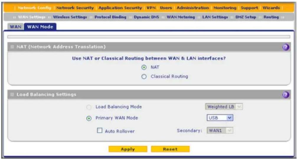
Figure 352.
- In the NAT (Network Address Translation) section of the screen, select the NAT radio button.
- Click Apply to save your settings.
Configure Classical Routing
In classical routing mode, the UTM9S and UTM25S perform routing, but without NAT. To gain Internet access, each computer on your LAN needs to have a valid static Internet IP address.
If your ISP has allocated a number of static IP addresses to you, and you have assigned one of these addresses to each computer, you can choose classical routing. Or, you can use classical routing for routing private IP addresses within a campus environment.
To view the status of the WAN ports, you can view the Router Status screen (see View the System Status on page 486).

WARNING!
Changing the WAN mode from NAT to classical routing causes all LAN WAN and DMZ WAN inbound rules to revert to default settings.
To configure classical routing:
- Select Network Config > WAN Settings > WAN Mode. The WAN Mode screen displays (see Figure 352 on page 613).
- In the NAT (Network Address Translation) section of the screen, select the Classical Routing radio button.
- Click Apply to save your settings.
Configure Load Balancing and Optional Protocol Binding
To use multiple ISP links simultaneously, configure load balancing. In load balancing mode, the USB interface, DSL interface, or any WAN interface carries any outbound protocol unless protocol binding is configured.
When a protocol is bound to a particular interface, all outgoing traffic of that protocol is directed to the bound interface. For example, if the HTTPS protocol is bound to the DSL interface and the FTP protocol is bound to the WAN1 interface, then the UTM9S or UTM25S automatically routes all outbound HTTPS traffic from the computers on the LAN through the DSL interface. All outbound FTP traffic is routed through the WAN1 interface.
Protocol binding addresses two issues:
- Segregation of traffic between links that are not of the same speed.
High-volume traffic can be routed through the DSL interface connected to a high-speed link, and low-volume traffic can be routed through a WAN interface connected to a low-speed link. - Continuity of source IP address for secure connections.
Some services, particularly HTTPS, cease to respond when a client's source IP address changes shortly after a session has been established.
Configure Load Balancing
To configure load balancing:
- Select Network Config > WAN Settings > WAN Mode. The WAN Mode screen displays:

Figure 353.
- In the Load Balancing Settings section of the screen, configure the following settings: a. Select the Load Balancing Mode radio button.
ProSecure Unified Threat Management (UTM) Appliance
b. From the corresponding drop-down list on the right, select one of the following load balancing methods:
- Weighted LB. With weighted load balancing, balance weights are calculated based on DSL, USB, or WAN link speed and available DSL, USB, or WAN bandwidth. This is the default setting and the most efficient load-balancing algorithm.
- Round-robin. With round-robin load balancing, new traffic connections are sent over a DSL, USB, or WAN link in a serial method irrespective of bandwidth or link speed. For example if the DSL, WAN1, and WAN2 interfaces are active in round-robin load balancing mode, an HTTP request could first be sent over the DSL interface, then a new FTP session could start on the WAN1 interface, and then any new connection to the Internet could be made on the WAN2 interface. This load-balancing method ensures that a single interface does not carry a disproportionate distribution of sessions.
- Click Apply to save your settings.
Configure Protocol Binding (Optional)
To configure protocol binding and add protocol binding rules:
- Select Network Config > Protocol Binding. The Protocol Bindings screen displays. (The following figure shows two examples in the Protocol Bindings table.)

Figure 354.
The Protocol Bindings table displays the following fields:
- Check box. Allows you to select the protocol binding rule in the table.
• Status icon. Indicates the status of the protocol binding rule:
- Green circle. The protocol binding rule is enabled.
- Gray circle. The protocol binding rule is disabled.
• Service. The service or protocol for which the protocol binding rule is set up.
- Local Gateway. The WAN interface to which the service or protocol is bound.
- Source Network. The computers on your network that are affected by the protocol binding rule.
ProSecure Unified Threat Management (UTM) Appliance
- Destination Network. The Internet locations (based on their IP address) that are covered by the protocol binding rule.
-
Action. The Edit button provides access to the Edit Protocol Binding screen for the corresponding service.
-
Click the Add table button below the Protocol Bindings table. The Add Protocol Binding screen displays:

Figure 355.
- Configure the protocol binding settings as explained in the following table:
Table 156. Add Protocol Binding screen settings
| Setting Description | ||
| Service From the | drop-down list, select a service or application to be covered by this rule. If the service or application does not appear in the list, you need to define it using the Services screen (seeOutbound Rules(Service Blocking)on page 129). | |
| Local Gateway | From the drop-down list, select the DSL interface or one of the WAN interfaces. | |
| Source Network | The source network settings determine which computers on your network are affected by this rule. Select one of the following options from the drop-down list: | |
| Any All devices on your LAN. | ||
| Single address In the Start IP field, enter the IP address to which the rule is applied. | ||
| Address Range In the Start IP field and End IP field, enter the IP addresses for the range to which the rule is applied. | ||
| Group 1–Group 8 If this option is selected, the rule is applied to the devices that are assigned to the selected group.Note:You can also assign a customized name to a group (seeChange Group Names in the Network Databaseon page 115). | ||
| Destination Network | The destination network settings determine which Internet locations (based on their IP address) are covered by the rule. Select one of the following options from the drop-down list: | |
| Any All Internet IP address. | ||
| Single address In the Start IP field, enter the IP address to which the rule is applied. | ||
| Address range In the Start IP field and End IP field, enter the IP addresses for the range to which the rule is applied. | ||
- Click Apply to save your settings. The protocol binding rule is added to the Protocol Bindings table. The rule is automatically enabled, which is indicated by the ! status icon, a green circle.
To edit a protocol binding:
- On the Protocol Bindings screen (see Figure 354 on page 615), in the Protocol Bindings table, click the Edit table button to the right of the binding that you want to edit. The Edit Protocol Binding screen displays. This screen shows the same fields as the Add Protocol Binding screen (see the previous figure).
- Modify the settings as explained in the previous table.
- Click Apply to save your settings.
To enable, disable, or delete one or more protocol bindings:
- On the Protocol Bindings screen (see Figure 354 on page 615), select the check box to the left of each protocol binding that you want to enable, disable, or delete, or click the Select All table button to select all bindings.
-
Click one of the following table buttons:
-
Enable. Enables the binding or bindings. The ! status icon changes from a gray circle to a green circle, indicating that the selected binding or bindings are enabled. (By default, when a binding is added to the table, it is automatically enabled.)
- Disable. Disables the binding or bindings. The ! status icon changes from a green circle to a gray circle, indicating that the selected binding or bindings are disabled.
- Delete. Deletes the binding or bindings.
Configure Dynamic DNS
Dynamic DNS (DDNS) is an Internet service that allows devices with varying public IP addresses to be located using Internet domain names. To use DDNS, you need to set up an account with a DDNS provider such as DynDNS.org, TZO.com, Oray.net, or 3322.org. (Links to DynDNS, TZO, Oray, and 3322 are provided for your convenience as option arrows on the DDNS configuration screens.) The UTM9S and UTM25S firmware includes software that notifies DDNS servers of changes in the IP address of the USB interface, so that the services running on this network can be accessed by others on the Internet.
If your network has a permanently assigned IP address, you can register a domain name and have that name linked with your IP address by public Domain Name Servers (DNS). However, if your Internet account uses a dynamically assigned IP address, you do not know in advance what your IP address will be, and the address can change frequently—hence, the need for a commercial DDNS service, which allows you to register an extension to its domain, and forwards DNS requests for the resulting fully qualified domain name (FQDN) to your frequently changing IP address.
After you have configured your account information on the UTM9S or UTM25S, when your ISP-assigned IP address changes, your UTM9S or UTM25S automatically contacts your DDNS service provider, logs in to your account, and registers your new IP address.
For load balancing mode, you might need an FQDN either for convenience or if you have a dynamic IP address.
Note: If your ISP assigns a private WAN IP address such as 192.168.x.x or 10.x.x.x, the DDNS service does not work because private addresses are not routed on the Internet.
To configure DDNS:
- Select Network Config > Dynamic DNS. The Dynamic DNS screen displays:
ProSecure Unified Threat Management (UTM) Appliance
![Network Config Network Security Application Security VPN Users Administration Monitoring Support Wizards WAN Settings Wireless Settings Protocol Binding Dynamic DNS WAN Metering LAN Settings DMZ Setup Routing Dynamic DNS DNS T20 DNS Gray 3322 DDNS DynDNS Information WAN Mode Current WAN Mode: Load Balancing WAN1(Dynamic DNS Status: service is not enabled) Configured DDNS : none Change DNS to DynDNS.org? Yes No Host and Domain Name: [Example: youname.dyndns.org] Username: Password: Use wildcards Update every 30 days WAN2(Dynamic DNS Status: service is not enabled) Configured DDNS : none Change DNS to DynDNS.org? Yes No Host and Domain Name: [Example: youname.dyndns.org] Username: Password: Use wildcards Update every 30 days SLOT-2 (Dynamic DNS Status: service is not enabled) Configured DDNS : none Change DNS to DynDNS.org? Yes No Host and Domain Name: [Example: youname.dyndns.org] Username: Password: Use wildcards Update every 30 days USB (Dynamic DNS Status: service is not enabled) Configured DDNS : none Change DNS to DynDNS.org? Yes No Host and Domain Name: [Example: youname.dyndns.org] Username: Password: Use wildcards Update every 30 days Apply Reset](/content/2026/06/1371942/images/126fc7fa486348529f070f92df782bee5547665de47d8ba24053825b2154e1d3.jpg)
Figure 356.
The WAN Mode section onscreen reports the currently configured WAN mode (for example, Single Port WAN1, Load Balancing, or Auto Rollover). Only those options that match the configured WAN mode are accessible onscreen.
- Click the submenu tab for your DDNS service provider:
• Dynamic DNS for DynDNS.org (which is shown in the following figure)
• DNS TZO for TZO.com
• DNS Oray for Oray.net
• 3322 DDNS for 3322.org
- Click the Information option arrow in the upper right of a DNS screen for registration information.

Figure 357.
-
Access the website of the DDNS service provider, and register for an account (for example, for DynDNS.org, go to http://www.dyndns.com/).
-
Locate the USB section at the bottom of the screen, and configure the DDNS service settings for the DSL interface as explained in the following table:
Table 157. DNS service settings
| Setting Description | ||
| USB (Dynamic DNS Status: ...) | ||
| Change DNS to (DynDNS, TZO, Oray, or 3322) | Select the Yes radio button to enable the DDNS service. The fields that display onscreen depend on the DDNS service provider that you have selected. Enter the following settings: | |
| Host and Domain Name The host and domain name for the DDNS service. | ||
| Username or User Email Address | The user name or email address for DDNS server authentication. | |
| Password or User Key The password that is used for DDNS server authentication. | ||
| Use wildcards If your DDNS provider allows the use of wildcards in resolving your URL, you can select the Use wildcards check box to activate this feature. For example, the wildcard feature causes *.yourhost.dyndns.org to be aliased to the same IP address as yourhost.dyndns.org. | ||
| Update every 30 days If you | our WAN IP address does not often change, you might need to force a periodic update to the DDNS service to prevent your account from expiring. If the Update every 30 days check box displays, select it to enable a periodic update. | |
- Click Apply to save your configuration.
Additional WAN-Related Configuration Tasks
- If you have not already done so, configure the Ethernet WAN interfaces of the UTM9S or UTM25S (see Chapter 3, Manually Configure Internet and WAN Settings).
- If you want the ability to manage the UTM9S or UTM25S remotely, enable remote management (see Configure Remote Management Access on page 438). If you enable remote management, NETGEAR strongly recommend that you change your password (see Change Passwords and Administrator and Guest Settings on page 436).
- You can set up the traffic meter for the USB interface (see Enable the WAN Traffic Meter on page 462).
Network Planning for Dual WAN Ports (Multiple WAN Port Models Only)
D
This appendix describes the factors to consider when planning a network using a firewall that has dual WAN ports. This appendix does not apply to single WAN port models.
This appendix contains the following sections:
• What to Consider Before You Begin
• Overview of the Planning Process
- Inbound Traffic
• Virtual Private Networks
What to Consider Before You Begin
- Plan Your Network and Network Management and Set Up Accounts
• Cabling and Computer Hardware Requirements - Computer Network Configuration Requirements
- Internet Configuration Requirements
Plan Your Network and Network Management and Set Up Accounts
The UTM is a powerful and versatile solution for your networking needs. The information in this section can help you to understand the configuration choices that are available to you, and can make the configuration process easier.
Consider the following information before you begin:
- Plan your network.
a. Determine whether you will use one or both WAN ports. For one WAN port, you might need a fully qualified domain name either for convenience or to access a dynamic WAN IP address remotely.
b. If you intend to use both WAN ports, determine whether you will use them in auto-rollover mode for increased system reliability or load balancing mode for maximum bandwidth efficiency. See the topics in this appendix for more information.
Your decision has the following implications:
• Fully qualified domain name (FQDN)
- For auto-rollover mode, you will need an FQDN to implement features such as exposed hosts and virtual private networks.
- For load balancing mode, you might still need an FQDN either for convenience or to access a dynamic WAN IP address remotely.
- Protocol binding
- For auto-rollover mode, protocol binding does not apply.
- For load balancing mode, decide which protocols should be bound to a specific WAN port.
-
You can also add your own service protocols to the list.
-
Set up your accounts.
a. Obtain active Internet services such as cable or DSL broadband accounts, and locate the Internet service provider (ISP) configuration information.
- In this manual, the WAN side of the network is presumed to be provisioned as shown in the following figure, with two ISPs connected to the UTM through separate physical facilities.
• Each WAN port needs to be configured separately, whether you are using a separate ISP for each WAN port or you are using the same ISP to route the traffic of both WAN ports. - If your ISP charges by the volume of data traffic each month, consider enabling the UTM's traffic meter to monitor or limit your traffic.

flowchart
graph LR
    A["UTM"] -->|WAN port 1| B["ISP 1"]
    A -->|WAN port 2| C["ISP 2"]
    B --> D["Internet"]
    C --> D
    style A fill:#f9f,stroke:#333
    style B fill:#ccf,stroke:#333
    style C fill:#ccf,stroke:#333
    style D fill:#dfd,stroke:#333
Figure 358.
b. Contact a Dynamic DNS service and register FQDNs for one or both WAN ports.
- Plan your network management approach.
- You can manage the UTM remotely, but you need to enable remote management locally after each factory default reset.
NETGEAR strongly advises you to change the default management password to a strong password before you enable remote management.
- You can choose a variety of WAN options if the factory default settings are not suitable for your installation. These options include enabling a WAN port to respond to a ping, and setting MTU size, port speed, and upload bandwidth.
- Prepare to connect the UTM physically to your cable or DSL modems and a computer. Instructions for connecting the UTM are in the ProSecure Unified Threat Management UTM Installation Guide.
Cabling and Computer Hardware Requirements
For you to use the UTM in your network, each computer needs to have an Ethernet network interface card (NIC) installed and needs to be equipped with an Ethernet cable. If the computer will connect to your network at 100 Mbps or higher speeds, you need to use a Category 5 (Cat 5) cable.
Computer Network Configuration Requirements
The UTM integrates a web management interface. To access the configuration screens on the UTM, you need to use a Java-enabled web browser that supports HTTP uploads such as Microsoft Internet Explorer 6 or later, Mozilla Firefox 3 or later, or Apple Safari 3 or later with JavaScript and cookies, and you need to have SSL enabled. Free browsers are readily available for Windows, Macintosh, or UNIX/Linux.
For the initial connection to the Internet and configuration of the UTM, you need to connect a computer to the UTM, and the computer needs to be configured to get its TCP/IP configuration automatically from the UTM through DHCP.
The cable or DSL modem broadband access device needs to provide a standard 10 Mbps (10BASE-T) Ethernet interface.
Internet Configuration Requirements
Depending on how your ISP set up your Internet accounts, you will need the following Internet configuration information to connect UTM to the Internet:
- Host and domain names
• One or more ISP login names and passwords - ISP Domain Name Server (DNS) addresses
• One or more fixed IP addresses (also known as static IP addresses)
Where Do I Get the Internet Configuration Information?
There are several ways you can gather the required Internet connection information.
- Your ISPs provide all the information needed to connect to the Internet. If you cannot locate this information, you can ask your ISP to provide you with it, or, if you have a computer already connected using the active Internet access account, you can gather the configuration information from that computer.
- For Windows 95/98/ME, open the Network Control Panel, select the TCP/IP entry for the Ethernet adapter, and click Properties. Record all the settings for each tab.
ProSecure Unified Threat Management (UTM) Appliance
- For Windows 2000/XP/Vista, open the Local Area Network Connection, select the TCP/IP entry for the Ethernet adapter, and click Properties. Record all the settings for each tab.
- For Macintosh computers, open the TCP/IP or Network Control Panel. Record all the settings for each section.
After you have located your Internet configuration information, you might want to record the information in the following section.
Internet Connection Information
Print these pages with the Internet connection information. Fill in the configuration settings that are provided to you by ISP.
- ISP login name: The login name and password are case-sensitive and need to be entered exactly as given by your ISP. For AOL customers, the login name is the primary screen name. Some ISPs use your full email address as the login name. The service name is not required by all ISPs. If you connect using a login name and password, then fill in the following:
Login name: ____
Password: ____
Service name: ____
- Fixed or static IP address: If you have a static IP address, record the following information. For example, 169.254.141.148 could be a valid IP address.
Fixed or static Internet IP address: ____. ____. ____.
Gateway IP address: ____. ____ ____ ____ ____
Subnet mask: ____ ____ ____ ____ ____
- ISP DNS server addresses: If you were given DNS server addresses, fill in the following:
Primary DNS server IP address: ____.____.____.____
Secondary DNS server IP address: ____.____.____.
- Host and domain names: Some ISPs use a specific host or domain name like CCA7324-A or home. If you have not been given host or domain names, you can use the following examples as a guide:
- If your main email account with your ISP is aaa@yyy.com, then use aaa as your host name. Your ISP might call this your account, user, host, computer, or system name.
- If your ISP's mail server is mail.xxx.yyy.com, then use xxx.yyy.com as the domain name.
ISP host name: ____
ISP domain name: ____
- Fully qualified domain name: Some organizations use a fully qualified domain name (FQDN) from a Dynamic DNS service provider for their IP addresses.
Dynamic DNS service provider: ____
FQDN:
Overview of the Planning Process
The areas that require planning when you use a firewall that has dual WAN ports such as the UTM include the following:
- Inbound traffic (port forwarding, port triggering)
- Outbound traffic (protocol binding)
• Virtual private networks (VPNs)
The two WAN ports can be configured on a mutually exclusive basis to either of the following:
• Auto-rollover for increased reliability
- Load balance for outgoing traffic
These various types of traffic and auto-rollover or load balancing all interact to make the planning process more challenging:
- Inbound traffic. Unrequested incoming traffic can be directed to a computer on your LAN rather than being discarded. The mechanism for making the IP address public depends on whether the dual WAN ports are configured for auto-rollover or load balancing.
- Virtual private networks. A virtual private network (VPN) tunnel provides a secure communication channel either between two gateway VPN firewalls or between a remote VPN client and gateway VPN firewall. As a result, the IP address of at least one of the tunnel endpoints needs to be known in advance in order for the other tunnel endpoint to establish (or reestablish) the VPN tunnel.
- Dual WAN ports in auto-rollover mode. Rollover for a UTM with dual WAN ports is different from a single WAN port gateway configuration when you specify the IP address. Only one WAN port is active at a time, and when it rolls over, the IP address of the active WAN port always changes. Therefore, the use of a fully qualified domain name (FQDN) is always required, even when the IP address of each WAN port is fixed.
ProSecure Unified Threat Management (UTM) Appliance
Dual WAN Ports (Before Rollover)
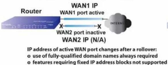
flowchart
graph LR
    A["Router"] --> B["WAN1 IP WAN1 port active"]
    B --> C["INTERNATIONAL INTERNATION"]
    D["WAN2 port inactive WAN2 IP (N/A)"] --> B
    style A fill:#f9f,stroke:#333
    style B fill:#ccf,stroke:#333
    style C fill:#cfc,stroke:#333
    note right of D: IP address of active WAN port changes after a rollover:
    o = use of fully-qualified domain names always required
    o = features requiring fixed IP address blocks not supported
Dual WAN Ports (After Rollover)
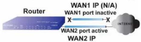
flowchart
graph LR
    A["Router"] -->|WAN1 IP (N/A)\nWAN1 port inactive\nX--> X| B["INTERNET"]
    B -->|WAN2 port active\nWAN2 IP\nX--> X
Figure 359.
Features such as multiple exposed hosts are not supported in auto-rollover mode because the IP address of each WAN port needs to be in the identical range of fixed addresses.
- Dual WAN ports in load balancing mode. Load balancing for a UTM with dual WAN ports is similar to a single WAN gateway configuration when you specify the IP address. Each IP address is either fixed or dynamic based on the ISP: You need to use FQDNs when the IP address is dynamic, but FQDNs are optional when the IP address is static.
Dual WAN Ports (Load Balancing)

flowchart
graph LR
    A["Router"] --> B["WAN1 IP\nnetgear1.dyndns.org"]
    A --> C["Internet"]
    A --> D["WAN2 IP"]
Use of fully-qualified domain names for IP addresses of WAN ports:
o required for dynamic IP addresses
o optional for fixed IP addresses
Figure 360.
Inbound Traffic
• Inbound Traffic to a Single WAN Port System
• Inbound Traffic to a Dual WAN Port System
Incoming traffic from the Internet is usually discarded by the UTM unless the traffic is a response to one of your local computers or a service for which you have configured an inbound rule. Instead of discarding this traffic, you can configure the UTM to forward it to one or more LAN hosts on your network.
The addressing of the UTM's dual WAN port depends on the configuration being implemented.
Table 158. IP addressing requirements for exposed hosts in dual WAN port systems
| Configuration and WAN IP address | Single WAN port (reference case) | Dual WAN port cases | ||
| Rollover mode Load balancing mode | ||||
| Inbound traffic• Port forwarding• Port triggering | Fixed Allowed(FQDN optional) | FQDN required Allowed(FQDN optional) | ||
| Dynamic FQDN required FQDN required | FQDN required | |||
Inbound Traffic to a Single WAN Port System
The Internet IP address of the UTM's WAN port needs to be known to the public so that the public can send incoming traffic to the exposed host when this feature is supported and enabled.
In the single WAN case, the WAN's Internet address is either fixed IP or an FQDN if the IP address is dynamic.
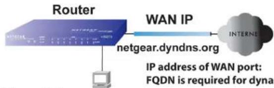
flowchart
graph LR
    A["Router"] -->|WAN IP| B["Internal Network"]
    B --> C["IP address of WAN port: FQDN is required for dynamic access"]
    A --> D["netgear.dyndns.org"]
    D --> A
Figure 361.
FQDN is required for dynamic IP address and is optional for fixed IP address
Inbound Traffic to a Dual WAN Port System
The IP address range of the UTM's WAN port needs to be both fixed and public so that the public can send incoming traffic to the multiple exposed hosts when this feature is supported and enabled.
Inbound Traffic: Dual WAN Ports for Improved Reliability
In a dual WAN port auto-rollover configuration, the WAN port's IP address will always change when a rollover occurs. You need to use an FQDN that toggles between the IP addresses of the WAN ports (that is, WAN1 or WAN2).
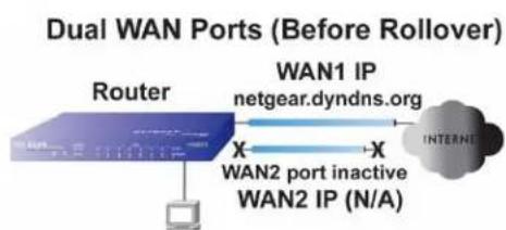
flowchart
graph LR
    A["Router"] -->|X| B["WAN2 port inactive WAN2 IP (N/A)"]
    B -->|Y| C["WAN1 IP netgear.dyndns.org"]
    C --> D["INTERNET"]

flowchart
graph LR
    A["Router"] -->|X| B["netgear.dyndns.org"]
    B -->|X| C["WAN1 IP (N/A)"]
    C --> D["WAN2 IP"]
    D --> E["INTERNET"]
IP address of active WAN port changes after a rollover (use of fully-qualified domain names always required)
Figure 362.
Inbound Traffic: Dual WAN Ports for Load Balancing
In a dual WAN port load-balancing configuration, the Internet address of each WAN port is either fixed if the IP address is fixed or an FQDN if the IP address is dynamic (see the following figure).
Note: Load balancing is implemented for outgoing traffic and not for incoming traffic. Consider making one of the WAN port Internet addresses public and keeping the other one private in order to maintain better control of WAN port traffic.
Dual WAN Ports (Load Balancing)
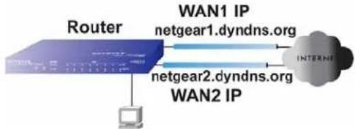
flowchart
graph LR
    A["Router"] -->|WAN1 IP netgear1.dyndns.org| B["Internet"]
    A -->|WAN2 IP netgear2.dyndns.org| B
    A --> C["Computer"]
IP addresses of WAN ports: use of fully-qualified domain names required for dynamic IP addresses and optional for fixed IP addresses
Figure 363.
Virtual Private Networks
• VPN Road Warrior (Client-to-Gateway)
• VPN Gateway-to-Gateway
• VPN Telecommuter (Client-to-Gateway through a NAT Router)
When implementing virtual private network (VPN) tunnels, you need to use a mechanism for determining the IP addresses of the tunnel endpoints. The addressing of the firewall's dual WAN port depends on the configuration being implemented.
Table 159. IP addressing requirements for VPNs in dual WAN port systems
| Configuration and WAN IP address Single WAN port configurations (reference cases) | Dual WAN port configurations | ||
| Rollover Mode1 | Load balancing mode | ||
| VPN Road Warrior (Client-to-Gateway) | Fixed Allowed (FQDN optional) | FQDN required Allowed (FQDN optional) | |
| Dynamic FQDN required FQDN required FQDN required | |||
| VPN Gateway-to-Gateway Fixed Allowed (FQDN optional) | FQDN required Allowed (FQDN optional) | ||
| VPN Telecommuter (Client-to-Gateway through a NAT Router) | Fixed Allowed (FQDN optional) | FQDN required Allowed (FQDN optional) | |
| Dynamic FQDN required FQDN required FQDN required | |||
- After a rollover, all tunnels need to be reestablished using the new WAN IP address.
For a single WAN gateway configuration, use an FQDN when the IP address is dynamic and either an FQDN or the IP address itself when the IP address is fixed. The situation is different in dual WAN port gateway configurations.
- Dual WAN ports in auto-rollover mode. A dual WAN port auto-rollover gateway configuration is different from a single WAN port gateway configuration when you specify the IP address of the VPN tunnel endpoint. Only one WAN port is active at a time, and when it rolls over, the IP address of the active WAN port always changes. Therefore, the use of an FQDN is always required, even when the IP address of each WAN port is fixed.
Note: When the UTM's WAN port rolls over, the VPN tunnel collapses and need to be reestablished using the new WAN IP address. However, you can configure automatic IPSec VPN rollover to ensure that an IPSec VPN tunnel is reestablished.

flowchart
graph LR
    A["Gateway"] -->|X| B["WAN2 port inactive WAN2 IP (N/A)"]
    B -->|X| C["Internet"]
    D["VPN Router"] -->|X| E["WAN1 IP netgear.dyndns.org"]
    E --> F["Final Network Interface"]

flowchart
graph LR
    A["Gateway"] -->|X| B["netgear.dyndns.org"]
    C["VPN Router"] -->|X| D["WAN1 IP (N/A)"]
    D -->|X| E["WAN2 IP"]
    E --> F["INTERNAT"]
IP address of active WAN port changes after a rollover (use of fully-qualified domain names always required)
Figure 364.
- Dual WAN ports in load balancing mode. A dual WAN port load balancing gateway configuration is the same as a single WAN port configuration when you specify the IP address of the VPN tunnel endpoint. Each IP address is either fixed or dynamic based on the ISP: You need to use FQDNs when the IP address is dynamic, and FQDNs are optional when the IP address is static.

flowchart
graph LR
    A["Gateway"] --> B["VPN Router"]
    B --> C["WAN1 IP\nnetgear1.dyndns.org"]
    B --> D["WAN2 IP\nnetgear2.dyndns.org"]
    C --> E["INTERNET"]
    D --> E
IP addresses of WAN ports same as single WAN port case (use of fully-qualified domain names required for dynamic IP addresses and optional for fixed IP addresses)
Figure 365.
VPN Road Warrior (Client-to-Gateway)
The following situations exemplify the requirements for a remote VPN client with no firewall to establish a VPN tunnel with a gateway VPN firewall such as an UTM:
- Single-gateway WAN port
• Redundant dual-gateway WAN ports for increased reliability (before and after rollover)
• Dual-gateway WAN ports for load balancing
VPN Road Warrior: Single-Gateway WAN Port (Reference Case)
In a single WAN port gateway configuration, the remote VPN client initiates the VPN tunnel because the IP address of the remote VPN client is not known in advance. The gateway WAN port needs to function as the responder.

flowchart
graph LR
    A["LAN IP 10.5.6.1"] --> B["Gateway A"]
    B --> C["WAN IP"]
    C --> D["FQDN bzrouter.dyndns.org"]
    D --> E["INTERNET"]
    E --> F["WAN IP 0.0.0.0"]
    G["Client B"] --> H["Remote PC (running NETGEAR ProSafe VPN Client)"]
    style A fill:#f9f,stroke:#333
    style B fill:#ccf,stroke:#333
    style C fill:#cfc,stroke:#333
    style D fill:#fcc,stroke:#333
    style E fill:#cff,stroke:#333
    style F fill:#ffc,stroke:#333
Figure 366.
The IP address of the gateway WAN port can be either fixed or dynamic. If the IP address is dynamic, an FQDN needs to be used. If the IP address is fixed, an FQDN is optional.
VPN Road Warrior: Dual-Gateway WAN Ports for Improved Reliability
In a dual WAN port auto-rollover gateway configuration, the remote VPN client initiates the VPN tunnel with the active WAN port (port WAN1 in the following figure) because the IP address of the remote VPN client is not known in advance. The gateway WAN port needs to function as a responder.

flowchart
graph LR
    A["LAN IP 10.5.6.1"] --> B["Gateway A"]
    B --> C["WAN1 IP bzrouter.dyndns.org"]
    C --> D["INTERNET"]
    D --> E["WAN IP 0.0.0.0"]
    style A fill:#4A90E2,stroke:#333
    style B fill:#4A90E2,stroke:#333
    style C fill:#4A90E2,stroke:#333
    style D fill:#4A90E2,stroke:#333
    style E fill:#4A90E2,stroke:#333
Figure 367.
The IP addresses of the WAN ports can be either fixed or dynamic, but you always need to use an FQDN because the active WAN port could be either WAN1 or WAN2 (that is, the IP address of the active WAN port is not known in advance).
After a rollover of the WAN port has occurred, the previously inactive gateway WAN port becomes the active port (port WAN2 in the following figure) and the remote VPN client needs to reestablish the VPN tunnel. The gateway WAN port needs to function as the responder.
ProSecure Unified Threat Management (UTM) Appliance

flowchart
graph LR
    A["Client B"] -->|WAN IP 0.0.0.0| B["Remote PC (running NETGEAR ProSafe VPN Client)"]
    C["Gateway A"] -->|WAN1 IP (N/A) WAN1 port inactive| D["Internet"]
    D -->|wzrouter.dyndns.org| E["VPN Router (at employer's main office)"]
    E -->|LAN IP 10.5.6.1| F["Remote PC must re-establish VPN tunnel after a rollover"]
    style A fill:#f9f,stroke:#333
    style B fill:#bbf,stroke:#333
    style C fill:#dfd,stroke:#333
    style D fill:#dfd,stroke:#333
    style E fill:#dfd,stroke:#333
    style F fill:#dfd,stroke:#333
Figure 368.
The purpose of the FQDN in this case is to toggle the domain name of the gateway firewall between the IP addresses of the active WAN port (that is, WAN1 and WAN2) so that the remote VPN client can determine the gateway IP address to establish or reestablish a VPN tunnel.
VPN Road Warrior: Dual-Gateway WAN Ports for Load Balancing
In a dual WAN port load balancing gateway configuration, the remote VPN client initiates the VPN tunnel with the appropriate gateway WAN port (that is, port WAN1 or WAN2 as necessary to balance the loads of the two gateway WAN ports) because the IP address of the active WAN port is not known in advance. The selected gateway WAN port needs to function as the responder.

flowchart
graph LR
    A["LAN IP 10.5.6.1"] --> B["Gateway A"]
    B --> C["WAN1 IP bzrouter1.dyndns.org"]
    B --> D["WAN2 IP bzrouter2.dyndns.org"]
    C --> E["INTERNET"]
    D --> E
    E --> F["WAN IP 0.0.0.0"]
    G["Client B Remote PC (running NETGEAR ProSafe VPN Client)"]
Figure 369.
The IP addresses of the gateway WAN ports can be either fixed or dynamic. If an IP address is dynamic, you need to use an FQDN. If an IP address is fixed, an FQDN is optional.
VPN Gateway-to-Gateway
The following situations exemplify the requirements for a gateway VPN firewall such as an UTM to establish a VPN tunnel with another gateway VPN firewall:
- Single-gateway WAN ports
• Redundant dual-gateway WAN ports for increased reliability (before and after rollover)
• Dual-gateway WAN ports for load balancing
VPN Gateway-to-Gateway: Single-Gateway WAN Ports (Reference Case)
In a configuration with two single WAN port gateways, either gateway WAN port can initiate the VPN tunnel with the other gateway WAN port because the IP addresses are known in advance.

flowchart
graph LR
    A["LAN IP 10.5.6.1"] --> B["Gateway A"]
    B --> C["WAN IP"]
    C --> D["FQDN netgear.dyndns.org"]
    D --> E["INTERNET"]
    E --> F["WAN IP 22.23.24.25"]
    F --> G["Gateway B"]
    G --> H["VPN Router (at office A)"]
    H --> I["Gateway B"]
    I --> J["VPN Router (at office B)"]
    style A fill:#99ccff,stroke:#333
    style G fill:#99ccff,stroke:#333
    note right of H Fully-Qualified Domain Names (FQDN)
        - optional for Fixed IP addresses
        - required for Dynamic IP addresses
    end
Figure 370.
The IP address of the gateway WAN ports can be either fixed or dynamic. If an IP address is dynamic, you need to use an FQDN. If an IP address is fixed, an FQDN is optional.
VPN Gateway-to-Gateway: Dual-Gateway WAN Ports for Improved Reliability
In a configuration with two dual WAN port VPN gateways that function in auto-rollover mode, either of the gateway WAN ports at one end can initiate the VPN tunnel with the appropriate gateway WAN port at the other end as necessary to balance the loads of the gateway WAN ports because the IP addresses of the WAN ports are known in advance. In this example (see
the following figure), port WAN_A1 is active and port WAN_A2 is inactive at Gateway A; port WAN_B1 is active and port WAN_B2 is inactive at Gateway B.

flowchart
graph LR
    A["LAN IP 10.5.6.1"] --> B["Gateway A"]
    B --> C["WAN_A1 IP netgearA.dyndns.org"]
    C --> D["Gateway B"]
    D --> E["LAN IP 172.23.9.1"]
    B --> F["VPN Router (at office A)"]
    F --> G["WAN_A2 port inactive WAN_A2 IP (N/A)"]
    G --> H["Gateway B"]
    H --> I["LAN IP 172.23.9.1"]
    style B fill:#f9f,stroke:#333
    style D fill:#f9f,stroke:#333
    style E fill:#f9f,stroke:#333
    note right of B: Fully-Qualified Domain Names (FQDN)
    note left of G: Required for Fixed IP addresses
    note right of H: Required for Dynamic IP addresses
    note right of H: Internal label
Figure 371.
The IP addresses of the gateway WAN ports can be either fixed or dynamic, but you always need to use an FQDN because the active WAN ports could be either WAN_A1, WAN_A2, WAN_B1, or WAN_B2 (that is, the IP address of the active WAN ports is not known in advance).
After a rollover of a gateway WAN port, the previously inactive gateway WAN port becomes the active port (port WAN_A2 in the following figure), and one of the gateways needs to reestablish the VPN tunnel.

flowchart
graph LR
    A["LAN IP 10.5.6.1"] --> B["Gateway A"]
    B --> C["VPN Router (at office A)"]
    C --> D["WAN_A1 IP (N/A) WAN_A1 port inactive"]
    D --> E["Internet"]
    E --> F["WAN_B1 IP"]
    F --> G["Gateway B"]
    G --> H["LAN IP 172.23.9.1"]
    I["One of the gateway routers must re-establish VPN tunnel after a rollover"] --> J["Gateway B"]
    J --> K["Gateway B"]
    style E fill:#cccccc,stroke:#333
    note right of E Fully-Qualified Domain Names (FQDN)
        - required for Fixed IP addresses
        - required for Dynamic IP addresses
    end
Figure 372.
The purpose of the FQDNs is to toggle the domain name of the rolled-over gateway between the IP addresses of the active WAN port (that is, WAN_A1 and WAN_A2 in the previous figure) so that the other end of the tunnel has a known gateway IP address to establish or reestablish a VPN tunnel.
VPN Gateway-to-Gateway: Dual-Gateway WAN Ports for Load Balancing
In a configuration with two dual WAN port VPN gateways that function in load balancing mode, either of the gateway WAN ports at one end can be programmed in advance to initiate the VPN tunnel with the appropriate gateway WAN port at the other end as necessary to manage the loads of the gateway WAN ports because the IP addresses of the WAN ports are known in advance.
ProSecure Unified Threat Management (UTM) Appliance
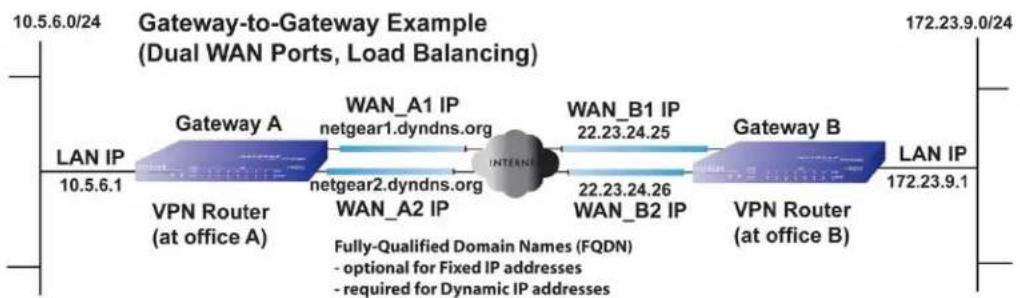
flowchart
graph LR
    A["LAN IP 10.5.6.1"] --> B["Gateway A"]
    B --> C["Gateway B"]
    C --> D["VPN Router (at office A)"]
    B --> E["WAN_A1 IP netgear1.dyndns.org"]
    B --> F["WAN_B1 IP 22.23.24.25"]
    B --> G["WAN_B2 IP 22.23.24.26"]
    C --> H["LAN IP 172.23.9.1"]
    style B fill:#f9f,stroke:#333
    style C fill:#bbf,stroke:#333
    note right of B Fully-Qualified Domain Names (FQDN)
    note left of B - optional for Fixed IP addresses
    note right of C - required for Dynamic IP addresses
Figure 373.
The IP addresses of the gateway WAN ports can be either fixed or dynamic. If an IP address is dynamic, you need to use an FQDN. If an IP address is fixed, an FQDN is optional.
VPN Telecommuter (Client-to-Gateway through a NAT Router)
Note: The telecommuter case assumes that the home office has a dynamic IP address and NAT router.
The following situations exemplify the requirements for a remote VPN client connected to the Internet with a dynamic IP address through a NAT router to establish a VPN tunnel with a gateway VPN firewall such as an UTM at the company office:
- Single-gateway WAN port
• Redundant dual-gateway WAN ports for increased reliability (before and after rollover) - Dual-gateway WAN ports for load balancing
VPN Telecommuter: Single-Gateway WAN Port (Reference Case)
In a single WAN port gateway configuration, the remote VPN client at the NAT router initiates the VPN tunnel because the IP address of the remote NAT router is not known in advance. The gateway WAN port needs to function as the responder.

flowchart
graph LR
    A["LAN IP 10.5.6.1"] --> B["Gateway A"]
    B --> C["WAN IP"]
    C --> D["FQDN"]
    D --> E["INTERNATIONAL"]
    E --> F["WAN IP 0.0.0.0"]
    F --> G["NAT Router B"]
    G --> H["Client B"]
    I["Remote PC (running NETGEAR ProSafe VPN Client)"] --> H
    style A fill:#99ccff,stroke:#333
    style H fill:#cccccc,stroke:#333
Figure 374.
The IP address of the gateway WAN port can be either fixed or dynamic. If the IP address is dynamic, you need to use an FQDN. If the IP address is fixed, an FQDN is optional.
VPN Telecommuter: Dual-Gateway WAN Ports for Improved Reliability
In a dual WAN port auto-rollover gateway configuration, the remote VPN client initiates the VPN tunnel with the active gateway WAN port (port WAN1 in the following figure) because the IP address of the remote NAT router is not known in advance. The gateway WAN port needs to function as the responder.

flowchart
graph LR
    A["LAN IP 10.5.6.1"] --> B["Gateway A"]
    B --> C["WAN1 IP bzrouter1.dyndns.org"]
    C --> D["INTENNE"]
    D --> E["WAN IP 0.0.0.0"]
    E --> F["NAT Router B"]
    F --> G["Client B"]
    H["NAT Router (at telecommuter's home office)"] --> I["Remote PC (running NETGEAR ProSafe VPN Client)"]
    J["Fully-Qualified Domain Names (FQDN) - required for Fixed IP addresses - required for Dynamic IP addresses"] --> D
Figure 375.
The IP addresses of the gateway WAN ports can be either fixed or dynamic, but you always need to use an FQDN because the active WAN port could be either WAN1 or WAN2 (that is, the IP address of the active WAN port is not known in advance).
After a rollover of the WAN port has occurred, the previously inactive gateway WAN port becomes the active port (port WAN2 in the following figure), and the remote VPN needs to reestablish the VPN tunnel. The gateway WAN port needs to function as the responder.

flowchart
graph LR
    A["LAN IP 10.5.6.1"] --> B["Gateway A"]
    B --> C["WAN1 IP (N/A) WAN1 port inactive"]
    C --> D["Internet"]
    D --> E["WAN IP 0.0.0.0"]
    E --> F["NAT Router B"]
    F --> G["Client B"]
    H["Remote PC (running NETGEAR ProSafe VPN Client)"] --> I["Remote PC must re-establish VPN tunnel after a rollover"]
    style A fill:#f9f,stroke:#333
    style B fill:#bbf,stroke:#333
    style C fill:#bfb,stroke:#333
    style D fill:#ffb,stroke:#333
    style E fill:#ffb,stroke:#333
    style F fill:#ffb,stroke:#333
    style G fill:#f9f,stroke:#333
Figure 376.
The purpose of the FQDN is to toggle the domain name of the gateway between the IP addresses of the active WAN port that is, WAN1 and WAN2) so that the remote VPN client can determine the gateway IP address to establish or reestablish a VPN tunnel.
VPN Telecommuter: Dual-Gateway WAN Ports for Load Balancing
In a dual WAN port load balancing gateway configuration, the remote VPN client initiates the VPN tunnel with the appropriate gateway WAN port (that is, port WAN1 or WAN2 as necessary to balance the loads of the two gateway WAN ports) because the IP address of the remote NAT router is not known in advance. The selected gateway WAN port needs to function as the responder.
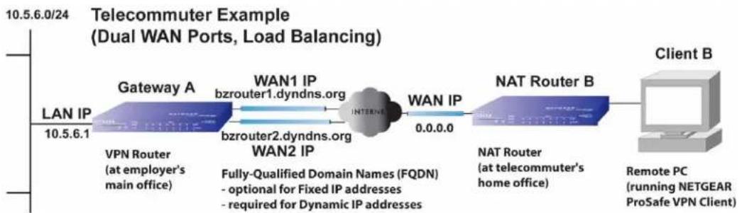
flowchart
graph LR
    A["LAN IP 10.5.6.1"] --> B["Gateway A"]
    B --> C["WAN1 IP bzrouter1.dyndns.org"]
    C --> D["INTERNET"]
    D --> E["WAN IP 0.0.0.0"]
    E --> F["NAT Router B"]
    F --> G["Client B"]
    H["NAT Router (at telecommuter's home office)"] --> I["Remote PC (running NETGEAR ProSafe VPN Client)"]
    J["FWI Fully-Qualified Domain Names (FQDN) - optional for Fixed IP addresses - required for Dynamic IP addresses"] --> D
Figure 377.
The IP addresses of the gateway WAN ports can be either fixed or dynamic. If an IP address is dynamic, you need to use an FQDN. If an IP address is fixed, an FQDN is optional.
This appendix describes how to set up a UTM with a NETGEAR ReadyNAS. This appendix includes the following sections:
• Supported ReadyNAS Models
• Install the UTM Add-On on the ReadyNAS
- Connect to the ReadyNAS on the UTM
Note: For more information about integrating a ReadyNAS with a UTM, see the UTM ReadyNAS Integration Guide that you can access from http://downloadcenter.netgear.com.
Supported ReadyNAS Models
The following ReadyNAS models are supported for integration with the UTM:
- ReadyNAS 1500
- ReadyNAS 2100
- ReadyNAS 3100
- ReadyNAS 3200
- ReadyNAS 4200
- ReadyNAS Ultra 2/Plus
- ReadyNAS Ultra 4/Plus
- ReadyNAS Ultra 6/Plus
- ReadyNAS Pro 2
- ReadyNAS Pro 4
- ReadyNAS Pro 6
• ReadyNAS Pro Business Edition
• ReadyNAS Pro Pioneer Edition - ReadyNAS NVX
• ReadyNAS NVX Pioneer Edition
Install the UTM Add-On on the ReadyNAS
To install the UTM add-on on the ReadyNAS:
- Start a web browser.
- In the address field, enter the IP address of the ReadyNAS, for example, enter https://192.168.168.168. The ReadyNAS web management interface displays.
- In the User Name field, type admin; in the Password field, type netgear1.
- Select Add-ons > Add New.

Figure 378.
- Click Browse. Navigate to and select the UTM add-on image.
- Click Upload and verify image. When the upload is finished and the image has been verified, the screen adjusts.

Figure 379.
- Click Install.
- Select Add-ons > Installed.

Figure 380.
-
Select the UTM Connector check box to enable the UTM connection.
-
Click Save. The status indicator shows green.
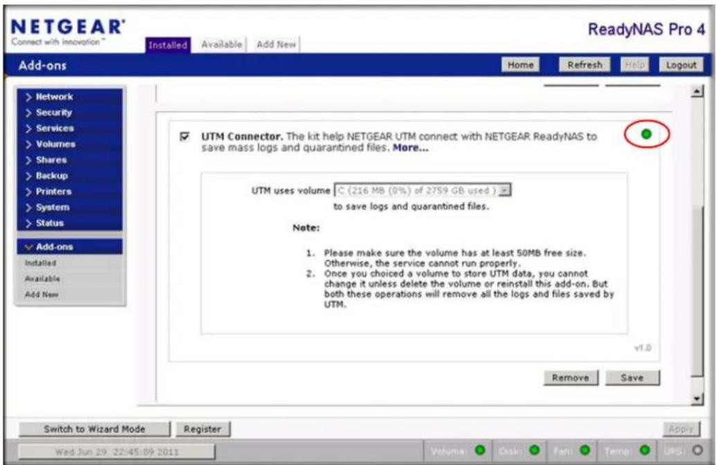
Figure 381.
Connect to the ReadyNAS on the UTM
To connect to the ReadyNAS on the UTM:
- Select Administration > ReadyNAS Integration. The ReadyNAS Integration screen displays:

Figure 382.
-
To connect to the ReadyNAS, click the Yes radio button.
-
Enter the settings as explained in the following table:
Table 160. ReadyNAS Integration screen settings
| Setting Description | |
| ReadyNAS Server The IP | address of the ReadyNAS server. |
| ReadyNAS Username | The user name to access the ReadyNAS. By default, the user name is admin. |
| ReadyNAS Password The | password to access the ReadyNAS. By default, the password is netgear1. |
- Click Apply to save your settings.
- Select Administration > Quarantine Settings. The Quarantine Settings screen displays:
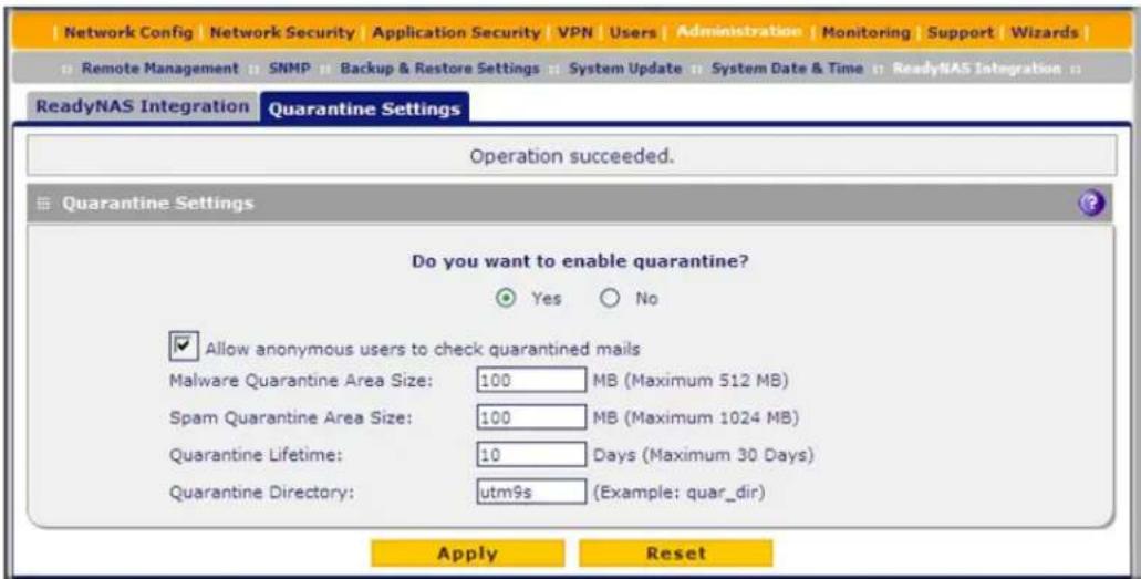
Figure 383.
- To enable quarantine files to be saved to the ReadyNAS, click the Yes radio button. (For information about how to configure the quarantine settings, see Configure the Quarantine Settings on page 460).
- Click Apply to save your settings.
- Select Monitoring > System Status. The System Status screen displays. When the UTM connects with the ReadyNAS, the ReadyNAS Status and Quarantine Status fields in the Status section of the screen show NORMAL in green font. The following figure shows the top of the System Status screen only.
ProSecure Unified Threat Management (UTM) Appliance

Figure 384.
This appendix provides an overview of two-factor authentication, and an example of how to implement the WiKID solution. This appendix contains the following sections:
• Why Do I Need Two-Factor Authentication?
• NETGEAR Two-Factor Authentication Solutions
Why Do I Need Two-Factor Authentication?
• What Are the Benefits of Two-Factor Authentication?
• What Is Two-Factor Authentication?
In today's market, online identity theft and online fraud continue to be one of the fast-growing cybercrime activities used by many unethical hackers and cybercriminals to steal digital assets for financial gains. Many companies and corporations are losing millions of dollars and running into risks of revealing their trade secrets and other proprietary information as a result of these cybercrime activities. Security threats and hackers have become more sophisticated, and user names, encrypted passwords, and the presence of firewalls are no longer enough to protect the networks from being compromised. IT professionals and security experts have recognized the need to go beyond the traditional authentication process by introducing and requiring additional factors in the authentication process. NETGEAR has also recognized the need to provide more than just a firewall to protect the networks. NETGEAR has implemented a more robust authentication system known as two-factor authentication (2FA or T-FA) to help address the fast-growing network security issues.
What Are the Benefits of Two-Factor Authentication?
- Stronger security. Passwords cannot efficiently protect the corporate networks because attackers can easily guess simple passwords or users cannot remember complex and unique passwords. One-time passcode (OTP) strengthens and replaces the need to remember complex password.
- No need to replace existing hardware. Two-factor authentication can be added to existing NETGEAR products through a firmware upgrade.
- Quick to deploy and manage. The WiKID solution integrates seamlessly with the NETGEAR SSL and VPN firewall products.
• Proven regulatory compliance. Two-factor authentication has been used as a mandatory authentication process for many corporations and enterprises worldwide.
What Is Two-Factor Authentication?
Two-factor authentication is a security solution that enhances and strengthens security by implementing multiple factors of the authentication process that challenge and confirm the users' identities before they can gain access to the network. There are several factors that are used to validate the users to make sure that you are who you say you are. These factors are:
- Something you know—for example, your password or your PIN.
- Something you have—for example, a token with generated passcode that is 6 to 8 digits in length.
- Something you are—for example, biometrics such as fingerprints or retinal prints.
This appendix focuses on and discusses only the first two factors, something you know and something you have. This security method can be viewed as a two-tiered authentication approach because it typically relies on what you know and what you have. A common example of two-factor authentication is a bank (ATM) card that has been issued by a bank institute:
• The PIN to access your account is something you know.
• The ATM card is something you have.
You need to have both of these factors to gain access to your bank account. Similar to the way ATM cards work, access to the corporate networks and data can also be strengthened using a combination of multiple factors such as a PIN and a token (hardware or software) to validate the users and reduce the incidence of online identity theft.
NETGEAR Two-Factor Authentication Solutions
NETGEAR has implemented 2 two-factor authentication solutions from WiKID. WiKID is the software-based token solution. So instead of using only Windows Active Directory or LDAP as the authentication server, administrators now can use WiKID to perform two-factor authentication on NETGEAR SSL and VPN firewall products.
The WiKID solution is based on a request-response architecture where a one-time passcode (OTP), which is time-synchronized with the authentication server, is generated and sent to the user after the validity of a user credential has been confirmed by the server.
The request-response architecture supports self-service initialization by end users, dramatically reducing implementation and maintenance costs.
To use WiKID (for end users):
- Launch the WiKID token software, enter the PIN that has been provided (something the user knows), and then click Continue to receive the OTP from the WiKID authentication server:

Figure 385.
- A one-time passcode (something the user has) is generated.

Figure 386.
Note: The one-time passcode is time-synchronized to the authentication server so that the OTP can be used only once and needs to be used before the expiration time. If a user does not use this passcode before it expires, the user needs to go through the request process again to generate a new OTP.
- Proceed to the 2 Factor Authentication login screen and enter the one-time passcode as the login password.
ProSecure Unified Threat Management (UTM) Appliance
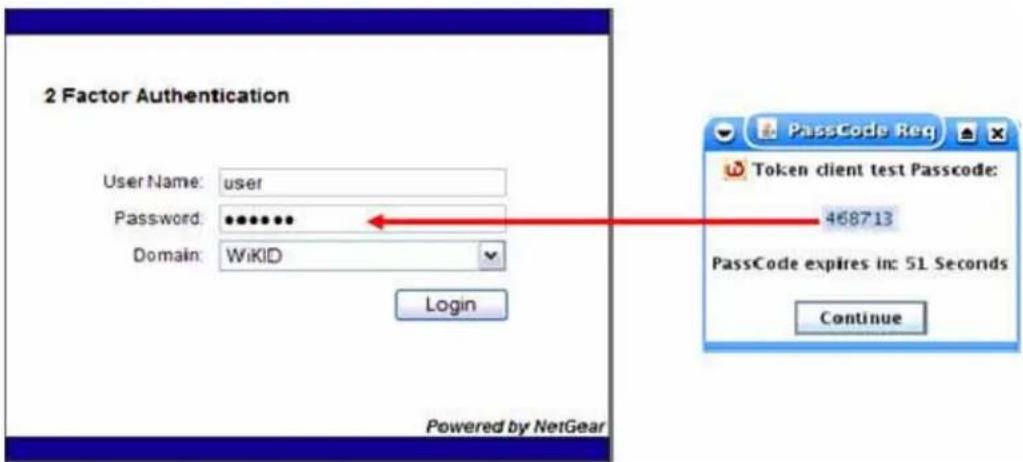
Figure 387.
This appendix provides examples and explanations of system logs and error message. When applicable, a recommended action is provided. This appendix contains the following sections:
- System Log Messages
- Service Logs
- Content-Filtering and Security Logs
- Routing Logs
This appendix uses the log message terms that are described in the following table:
Table 161. Log message terms
| Term Description | |
| [UTM] System identifier. | |
| [kernel] Message from the kernel. | |
| CODE Protocol code (for example, protocol is ICMP, type 8) and CODE=0 means successful reply. | |
| DEST Destination IP address of the machine to which the packet is destined. | |
| DPT Destination port. | |
| IN Incoming interface for packet. | |
| OUT Outgoing interface for packet. | |
| PROTO | Protocol used. |
| SELF | Packet coming from the system only. |
| SPT | Source port. |
| SRC Source IP address of machine from which the packet is coming. | |
| TYPE | Protocol type. |
System Log Messages
- System Startup
- Reboot
• NTP - Login/Logout
- Firewall Restart
- IPSec Restart
- WAN Status
- Traffic Metering Logs
- Unicast, Multicast, and Broadcast Logs
- Invalid Packet Logging
This section describes log messages that belong to one of the following categories:
- Logs that are generated by traffic that is meant for the UTM.
- Logs that are generated by traffic that is routed or forwarded through the UTM.
- Logs that are generated by system daemons: the NTP daemon, the WAN daemon, and others daemons.
System Startup
This section describes log messages generated during system startup.
Table 162. System logs: system startup
| Message Jan 1 15:22:28 [UTM] [ledTog] [SYSTEM START-UP] System Started |
| Explanation Logs that are generated when the system is started. |
| Recommended Action None. |
Reboot
This section describes log messages generated during a system reboot.
Table 163. System logs: reboot
| Message Nov 25 19:42:57 | [UTM] [reboot] Rebooting in 3 seconds |
| Explanation Logs that are generated when the system is rebooted from the web management interface. | |
| Recommended Action None. | |
NTP
This section describes log messages generated by the NTP daemon during synchronization with the NTP server. The fixed time and date before NTP synchronizes with any of the servers is Fri 1999 Dec 31 19:13:00.
Table 164. System logs: NTP
| Message 1 | Nov 28 12:31:13 [UTM] [ntpdate] Looking Up time-f.netgear.com |
| Message 2 | Nov 28 12:31:13 [UTM] [ntpdate] Requesting time from time-f.netgear.com |
| Message 3 | Nov 28 12:31:14 [UTM] [ntpdate] adjust time server 69.25.106.19 offset 0.140254 sec |
| Message 4 | Nov 28 12:31:14 [UTM] [ntpdate] Synchronized time with time-f.netgear.com |
| Message 5 | Nov 28 12:31:16 [UTM] [ntpdate] Date and Time Before Synchronization: Tue Nov 28 12:31:13 GMT+0530 2006 |
| Message 6 | Nov 28 12:31:16 [UTM] [ntpdate] Date and Time After Synchronization: Tue Nov 28 12:31:16 GMT+0530 2006 |
| Example | Nov 28 12:31:16 [UTM] [ntpdate] Next Synchronization after 2 Hours |
| Explanation Message 1: DN | S resolution for the NTP server (time-f.netgear.com).Message 2: Request for NTP update from the time server.Message 3: Adjust time by resetting system time.Message 4: Display date and time before synchronization, that is, when resynchronization started.Message 5: Display the new updated date and time.Message 6: Next synchronization will occur after the specified time.Example: In these logs the next synchronization will occur after 2 hours. |
| Recommended Action None. |
Login/Logout
This section describes logs that are generated by the administrative interfaces of the device.
Table 165. System logs: login/logout
| Message Nov 28 14:45:42 [UTM] [login] Login succeeded: user admin from 192.168.10.10 |
| Explanation Login of user admin from host with IP address 192.168.10.10. |
| Recommended Action None. |
| Message Nov 28 14:55:09 [UTM] [seclogin] Logout succeeded for user adminNov 28 14:55:13 [UTM] [seclogin] Login succeeded: user admin from 192.168.1.214 |
| Explanation Secure login/logout of user admin from host with IP address 192.168.1.214. |
| Recommended Action None. |
Firewall Restart
This section describes logs that are generated when the firewall restarts.
Table 166. System logs: firewall restart
| Message Jan 23 16:20:44 [UTM] [wand] [FW] Firewall Restarted |
| Explanation Logs that are generated when the firewall is restarted.This message is logged when the VPN firewall restarts after any changes in the configuration are applied. |
| Recommended Action None. |
IPSec Restart
This section describes logs that are generated when IPSec restarts.
Table 167. System logs: IPSec restart
| Message Jan 23 16:20:44 [UTM] [wand] [IPSEC] IPSEC Restarted |
| Explanation Logs that are generated when the IPsec is restarted.This message is logged when IPsec restarts after any changes in the configuration are applied. |
| Recommended Action None. |
WAN Status
This section describes the logs that are generated by the WAN component. If there are two ISP links for Internet connectivity, the router can be configured either in auto-rollover mode or load balancing mode.
Auto-Rollover Mode
When the WAN mode is configured for auto-rollover, the primary link is active and the secondary link acts only as a backup. When the primary link goes down, the secondary link becomes active only until the primary link comes back up.
The UTM monitors the status of the primary link using the configured WAN failure detection method.
This section describes the logs that are generated when the WAN mode is set to auto-rollover.
Table 168. System logs: WAN status, auto rollover
| Message Nov 17 09:59:09 | [UTM] [wand] [LBFO] WAN1 Test Failed 1 of 3 times_Nov 17 09:59:39 [UTM] [wand] [LBFO] WAN1 Test Failed 2 of 3 times_Nov 17 10:00:09 [UTM] [wand] [LBFO] WAN1 Test Failed 3 of 3 times_Nov 17 10:01:01 [UTM] [wand] [LBFO] WAN1 Test Failed 4 of 3 times_Nov 17 10:01:35 [UTM] [wand] [LBFO] WAN1 Test Failed 5 of 3 times_Nov 17 10:01:35 [UTM] [wand] [LBFO] WAN1(DOWN), WAN2(UP),ACTIVE(WAN2)_Nov 17 10:02:25 [UTM] [wand] [LBFO] WAN1 Test Failed 6 of 3 times_Nov 17 10:02:25 [UTM] [wand] [LBFO] Restarting WAN1_Nov 17 10:02:57 [UTM] [wand] [LBFO] WAN1 Test Failed 7 of 3 times_Nov 17 10:03:27 [UTM] [wand] [LBFO] WAN1 Test Failed 8 of 3 times_Nov 17 10:03:57 [UTM] [wand] [LBFO] WAN1 Test Failed 9 of 3 times_Nov 17 10:03:57 [UTM] [wand] [LBFO] Restarting WAN1_ |
| Explanation The logs suggest | st that the failover was detected after 5 attempts instead of3 attempts. However, the reason that these messages appear is because of theWAN state transition logic that is part of the failover algorithm. You can interpret thelogs in the following way:The primary link failure is correctly detected after the 3rd attempt. Thereafter, thealgorithm attempts to restart the WAN and checks once again if WAN1 is still down.This results in the 4th failure detection message. If WAN1 is still down, the algorithmstarts the secondary link. When the secondary link is up, it is marked as active.Meanwhile, the secondary link has failed again, and this results in the 5th failuredetection message. Note that the 5th failure detection and the message suggestingthat the secondary link is active have the same time stamp, and so they happen inthe same algorithm state-machine cycle. Although it appears that the failover didnot occur immediately after 3 failures, internally, the failover process is triggeredafter the 3rd failure, and the transition to the secondary link is completed by the 5thfailure. The primary link is also restarted every 3 failures until it is functional again.In these logs, the primary link was restarted after the 6th failure, that is, 3 failuresafter the failover process was triggered. |
| Recommended Action Check | the WAN settings and WAN failure detection method configured for theprimary link. |
Load Balancing Mode
When the WAN mode is configured for load balancing, both the WAN ports are active simultaneously and the traffic is balanced between them. If one WAN link goes down, all the traffic is diverted to the WAN link that is active.
This section describes the logs that are generated when the WAN mode is set to load balancing.
Table 169. System logs: WAN status, load balancing
| Message 1Message 2Message 3Message 4 | Dec 1 12:11:27 [UTM] [wand] [LBFO] Restarting WAN1_Dec 1 12:11:31 [UTM] [wand] [LBFO] Restarting WAN2_Dec 1 12:11:35 [UTM] [wand] [LBFO] WAN1(UP), WAN2(UP)_Dec 1 12:24:12 [UTM] [wand] [LBFO] WAN1(UP), WAN2(DOWN)_Dec 1 12:29:43 [UTM] [wand] [LBFO] Restarting WAN2_Dec 1 12:29:47 [UTM] [wand] [LBFO] WAN1(UP), WAN2(DOWN)_ |
| Explanation Message 1 and | Message 2 indicate that both the WANs are restarted.Message 3: This message shows that both the WANs are up and the traffic is balanced between the two WAN interfaces.Message 4: This message shows that one of the WAN links is down. At this point, all the traffic is directed through the WAN that is up. |
| Recommended Action None. |
PPP Logs
This section describes the WAN PPP connection logs. The PPP type can be configured through the web management interface. For more information, see Manually Configure the Internet Connection on page 75.
- PPPoE Idle Timeout logs
Table 170. System logs: WAN status, PPPoE idle timeout
| Message 1 | Nov 29 13:12:46 [UTM] [pppd] Starting connection |
| Message 2 | Nov 29 13:12:49 [UTM] [pppd] Remote message: Success |
| Message 3 | Nov 29 13:12:49 [UTM] [pppd] PAP authentication succeeded |
| Message 4 | Nov 29 13:12:49 [UTM] [pppd] local IP address 50.0.0.62 |
| Message 5 | Nov 29 13:12:49 [UTM] [pppd] remote IP address 50.0.0.1 |
| Message 6 | Nov 29 13:12:49 [UTM] [pppd] primary DNS address 202.153.32.3 |
| Message 7 | Nov 29 13:12:49 [UTM] [pppd] secondary DNS address 202.153.32.3 |
| Message 8 | Nov 29 11:29:26 [UTM] [pppd] Terminating connection due to lack of activity. |
| Message 9 | Nov 29 11:29:28 [UTM] [pppd] Connect time 8.2 minutes. |
| Message 10 | Nov 29 11:29:28 [UTM] [pppd] Sent 1408 bytes, received 0 bytes. |
| Message 11 | Nov 29 11:29:29 [UTM] [pppd] Connection terminated. |
| Explanation Message 1: | Establishment of the PPPoE connection starts.Message 2: A message from the PPPoE server indicating a correct login.Message 3: The authentication for PPP succeeds.Message 4: The local IP address that is assigned by the server.Message 5: The server's side IP address.Message 6: The primary DNS server that is configured on a WAN Settings screen.Message 7: The secondary DNS server that is configured on a WAN Settings screen.Message 8: The PPP link transitions to idle mode. This event occurs when there is no traffic from the LAN network.Message 9: The time in minutes that the link was up.Message 10: Data sent and received at the LAN side while the link was up.Message 11: The PPP connection terminates after the idle timeout. |
| Recommended Action To | reconnect during idle mode, initiate traffic from the LAN side. |
- PPTP Idle-Timeout logs
Table 171. System logs: WAN status, PPTP idle timeout
| Message 1 | Nov 29 11:19:02 [UTM] [pppd] Starting connection |
| Message 2 | Nov 29 11:19:05 [UTM] [pppd] CHAP authentication succeeded |
| Message 3 | Nov 29 11:19:05 [UTM] [pppd] local IP address 192.168.200.214 |
| Message 4 | Nov 29 11:19:05 [UTM] [pppd] remote IP address 192.168.200.1 |
| Message 5 | Nov 29 11:19:05 [UTM] [pppd] primary DNS address 202.153.32.2 |
| Message 6 | Nov 29 11:19:05 [UTM] [pppd] secondary DNS address 202.153.32.2 |
| Message 7 | Nov 29 11:20:45 [UTM] [pppd] No response to 10 echo-requests |
| Nov 29 11:20:45 [UTM] [pppd] Serial link appears to be disconnected. | |
| Nov 29 11:20:45 [UTM] [pppd] Connect time 1.7 minutes. | |
| Message 8 | Nov 29 11:20:45 [UTM] [pppd] Sent 520 bytes, received 80 bytes. |
| Message 9 | Nov 29 11:20:51 [UTM] [pppd] Connection terminated. |
| Explanation Message 1: | The PPP connection process starts. |
| Message 2: A message from the server indicating authentication success. | |
| Message 3: The local IP address that is assigned by the server. | |
| Message 4: The server's side IP address. | |
| Message 5: The primary DNS address that is configured on a WAN Settings screen. | |
| Message 6: The secondary DNS address that is configured on a WAN Settings screen. | |
| Message 7: An idle link is detected. | |
| Message 8: Data sent and received at the LAN side while the link was up. | |
| Message 9: The PPP connection terminates after the idle timeout. | |
| Recommended Action To reconnect during idle mode, initiate traffic from the LAN side. | |
- PPP Authentication logs
Table 172. System logs: WAN status, PPP authentication
| Message 1 | Nov 29 11:29:26 [UTM] [pppd] Starting link |
| Message 2 | Nov 29 11:29:29 [UTM] [pppd] Remote message: Login incorrect |
| Message 3 | Nov 29 11:29:29 [UTM] [pppd] PAP authentication failed |
| Message 4 | Nov 29 11:29:29 [UTM] [pppd] Connection terminated. WAN2(DOWN)_ |
| Explanation Message 1: | The PPPoE connection process starts.Message 2: The PPPoE server indicates that the login is incorrect.Message 3: The PPP authentication fails because of incorrect login.Message 4: The PPP connection terminates. |
| Recommended Action | If authentication fails, verify the correct login name and password, and then enter the correct information. |
Traffic Metering Logs
This section describes logs that are generated when the traffic meter has reached a limit.
Table 173. System logs: traffic metering
| Message | Jan 23 19:03:44 [TRAFFIC_METER] TRAFFIC_METER: Monthly Limit of 10 MB has reached for WAN1._ |
| Explanation | Logs that are generated when the traffic limit for WAN1 interface that was set at 10 MB has been reached. Depending on the setting that is configured in the When Limit is reached section on the WAN1 Traffic Meter screen (see Enable the WAN Traffic Meter on page 462), all the incoming and outgoing traffic might be stopped.Note: For WAN2 interface, see the settings on the WAN2 Traffic Meter screen. |
| Recommended Action To start the traffic, restart the traffic counter in the Traffic Counter section on the WAN1 Traffic Meter screen.Note: For WAN2 interface, see the settings on the WAN2 Traffic Meter screen. | |
Unicast, Multicast, and Broadcast Logs
This section describes logs that are generated when the UTM processes unicast packets.
Table 174. System logs: unicast
| Message | Nov 24 11:52:55 [UTM] [kernel] UCAST IN=SELF OUT=WAN SRC=192.168.10.1 DST=192.168.10.10 PROTO=UDP SPT=800 DPT=2049 |
| Explanation • This unicast | packet is sent to the device from the WAN network.For other settings, seeTable 161on page 648. |
| Recommended Action None. |
ICMP Redirect Logs
This section describes logs that are generated when the UTM processes ICMP redirect messages.
Table 175. System logs: unicast, redirect
| Message Feb 2007 22 14:36:07 [UTM] [kernel] [LOG_PACKET] SRC=192.168.1.49 DST=192.168.1.124 PROTO=ICMP TYPE=5 CODE=1 | |
| Explanation | This packet is an ICMP redirect message sent to the device by another device.For other settings, seeTable 161on page 648. |
| Recommended Action None. | |
Multicast/Broadcast Logs
This section describes logs that are generated when the UTM processes multicast and broadcast packets.
Table 176. System logs: multicast/broadcast
| Message Jan 1 07:24:13 [UTM] [kernel] MCAST-BCAST IN=WAN OUT=SELF SRC=192.168.1.73 DST=192.168.1.255 PROTO=UDP SPT=138 DPT=138 |
| ExplanationThe multicast or broadcast packet is sent to the device from the WAN network.For other settings, seeTable 161on page 648. |
| Recommended Action None. |
Invalid Packet Logging
This section describes logs that are generated when the UTM processes invalid packets.
Table 177. System logs: invalid packets
| Message 2007 Oct 1 00:44: | 17 [UTM] [kernel] [INVALID][NO_CONNTRACK_ENTRY] [DROP] SRC=192.168.20.10DST=192.168.20.2 PROTO=TCP SPT=23 DPT=54899 |
| Explanation No connection tracking entry exists. | |
| Recommended Action None. | |
| Message 2007 Oct 1 00:44: | 17 [UTM] [kernel][INVALID][RST_PACKET][DROP] SRC=192.168.20.10DST=192.168.20.2 PROTO=TCP SPT=23 DPT=54899 |
| Explanation Invalid RST packet. | |
| Recommended Action None. | |
| Message 2007 Oct 1 00:44: | 17 [UTM] [kernel][INVALID][ICMP_TYPE][DROP] SRC=192.168.20.10DST=192.168.20.2 PROTO=ICMP TYPE=19 CODE=0 |
| Explanation Invalid ICMP type. | |
| Recommended Action None. | |
| Message 2007 Oct 1 00:44: | 17 [UTM] [kernel][INVALID][TCP_FLAG_COMBINATION][DROP] SRC=192.168.20.10DST=192.168.20.2 PROTO=TCP SPT=23 DPT=54899 |
| Explanation Invalid TCP flag combination. | |
| Recommended Action None. | |
| Message 2007 Oct 1 00:44: | 17 [UTM] [kernel][INVALID][BAD_CHECKSUM]DROP] SRC=192.168.20.10DST=192.168.20.2 PROTO=TCP SPT=23 DPT=54899 |
| Explanation Bad checksum | |
| Recommended Action None. | |
| Message 2007 Oct 1 00:44: | 17 [UTM] [kernel][INVALID][BAD_HW_CHECKSUM][DROP] SRC=192.168.20.10DST=192.168.20.2 PROTO=ICMP TYPE=3 CODE=0 |
| Explanation Bad hardware checksum for ICMP packets. | |
| Recommended Action None. | |
| Message [INVALID][MALFORMED_PACKET][DROP] SRC=192.168.20.10DST=192.168.20.2 PROTO=TCP SPT=23 DPT=54899 | |
| Explanation Malformed packet. | |
| Recommended Action None. | |
| Message 2007 Oct 1 00:44: | 17 [UTM] [kernel][INVALID][SHORT_PACKET][DROP] SRC=192.168.20.10DST=192.168.20.2 PROTO=TCP SPT=23 DPT=54899 |
| Explanation Short packet. | |
| Recommended Action None. | |
| Message [INVALID][ INVALID_STATE][DROP] SRC=192.168.20.10DST=192.168.20.2 PROTO=TCP SPT=23 DPT=54899 | |
| Explanation Packet with invalid state. | |
| Recommended Action None. | |
| Message 2007 Oct 1 00:44: | 17 [UTM] [kernel][INVALID][REOPEN_CLOSE_CONN][DROP] SRC=192.168.20.10DST=192.168.20.2 PROTO=TCP SPT=23 DPT=54899 |
| Explanation Attempt to reopen or close a session. | |
| Recommended Action None. | |
| Message 2007 Oct 1 00:44: | 17 [UTM] [kernel][INVALID][OUT_OF_WINDOW][DROP] SRC=192.168.20.10DST=192.168.20.2 PROTO=TCP SPT=23 DPT=54899 |
| Explanation Packet not in TCP window. | |
| Recommended Action None. | |
| Message 2007 Oct 1 00:44: | 17 [UTM] [kernel][INVALID][ERR_HELPER_ROUTINE][DROP] SRC=192.168.20.10DST=192.168.20.2 PROTO=TCP SPT=23 DPT=54899 |
| Explanation Error returned from helper routine. | |
| Recommended Action None. | |
Service Logs
This section describes log messages generated during firmware updates and other service-related events.
Table 178. Service logs
| Message | 2008-12-31 23:59:48 error Firmware update failed! Either the subscription is not yet registered, or has expired. |
| Explanation Logs that are generated when a firmware update fails or succeeds. The message shows the date and time, and the event.Note:The service log includes miscellaneous service messages. | |
| Recommended Action None. | |
Content-Filtering and Security Logs
• Web Filtering and Content-Filtering Logs
- Spam Logs
- Traffic Logs
- Malware Logs
- Email Filter Logs
- IPS Logs
- Anomaly Behavior Logs
- Application Logs
This section describes the log messages that are generated by the content-filtering and security mechanisms.
Web Filtering and Content-Filtering Logs
This section describes logs that are generated when the UTM filters web content.
Table 179. Content-filtering and security logs: web filtering and content filtering
| Message 2009-08-01 00:00 | :01 HTTP ldap_domain Idap_user 192.168.1.3 192.168.35.165http://192.168.35.165/testcases/files/virus/normal/%b4%f3%d3%da2048.rarSizeLimit Block |
| Explanation Logs that are g | generated when web content is blocked because the allowed size limit is exceeded. The message shows the date and time, protocol, domain, user, client IP address, server IP address, URL, reason for the action, and the action that is taken. |
| Recommended Action None. | |
| Message 2009-08-01 00:00 | :01 HTTP Idap_domain Idap_user 192.168.1.3 192.168.35.165http://192.168.35.165/testcases/files/virus/normal/%b4%f3%d3%da2048.rarURL Block |
| Explanation Logs that are g | generated when web content is blocked because an access violation of a blocked web category occurs. The message shows the date and time, protocol, domain, user, client IP address, server IP address, URL, reason for the action, and the action that is taken. |
| Recommended Action None. | |
| Message 2009-08-01 00:00 | :01 HTTP Idap_domain Idap_user 192.168.1.3 192.168.36.165http://192.168.35.165/testcases/files/virus/normal/%b4%f3%d3%da2048.rarFileType Block |
| Explanation Logs that are g | generated when web content is blocked because an access violation of a blocked web file extension occurs. The message shows the date and time, protocol, domain, user, client IP address, server IP address, URL, reason for the action, and the action that is taken. |
| Recommended Action None. | |
| Message 2009-08-01 00:00 | :01 HTTP Idap_domain Idap_user 192.168.1.3 192.168.25.165http://192.168.35.165/testcases/files/virus/normal/%b4%f3%d3%da2048.rarProxy Block |
| Explanation | Logs that are generated when web content is blocked because of a proxy violation. The message shows the date and time, protocol, domain, user, client IP address, server IP address, URL, reason for the action, and the action that is taken. |
| Recommended Action None. | |
| Message 2009-08-01 00:00 | :01 HTTP Idap_domain Idap_user 192.168.1.3 192.168.35.165http://192.168.35.165/testcases/files/virus/normal/%b4%f3%d3%da2048.rarKeyword Block |
| Explanation Logs that are generated when web content is blocked because of a keyword violation. The message shows the date and time, protocol, domain, user, client IP address, server IP address, URL, reason for the action, and the action that is taken. | |
| Recommended Action None. | |
Spam Logs
This section describes logs that are generated when the UTM filters spam email messages.
Table 180. Content-filtering and security logs: spam
| Message 2009-02-28 23:59 | :59 SMTP radius_domain radius_user1 192.168.1.2192.168.35.165 xlzimap@test.com xlzpop3@test.com Blocked by list.dsbl.org 0 RBL Block |
| Explanation Logs that are generated when spam messages are blocked by the RBL. The message shows the date and time, protocol, domain, user, client IP address, server IP address, sender, recipient, subject line, size, mechanism that detected the spam, and the action that is taken. | |
| Recommended Action None. | |
| Message 2009-02-28 23:59 | :59 SMTP radius_domain radius_user1 192.168.1.2192.168.35.165 xlzimap@test.com xlzpop3@test.com Blocked by customized blacklist 0 Heuristic Block |
| Explanation Logs that are generated when spam messages are blocked by the blacklist. The message shows the date and time, protocol, domain, user, client IP address, server IP address, sender, recipient, subject line, size, mechanism that detected the spam, and the action that is taken. | |
| Recommended Action None. | |
| Message 2009-02-28 23:59 | :59 SMTP radius_domain radius_user1 192.168.1.2191.168.35.165 xlzimap@test.com xlzpop3@test.com Blocked by customized blacklist 58882 Distributed Spam Analysis Block |
| Explanation Logs that are generated when spam messages are blocked by distributed spam analysis. The message shows the date and time, protocol, protocol, domain, client IP address, server IP address, sender, recipient, subject line, size, mechanism that detected the spam, and the action that is taken. | |
| Recommended Action None. | |
Traffic Logs
This section describes logs that are generated when the UTM processes web and email traffic.
Table 181. Content-filtering and security logs: traffic
| Message 2009-02-28 23:59 | :59 HTTP 99 radius_domain radius_user1 192.168.1.2192.168.33.8 xlzimap@test.com xlzpop3@test.com[MALWARE INFECTED] Fw: cleanvirus |
| Explanation Web and email | traffic logs for HTTP, SMTP, POP3, IMAP, HTTPS, and FTP traffic.In this sample message, a malware threat was cleaned from the traffic. The message shows the date and time, protocol, size of the web file or email, domain, user, client IP address, server IP address, sender, recipient, and web URL or email subject line. |
| Recommended Action None. |
Malware Logs
This section describes logs that are generated when the UTM detects viruses.
Table 182. Content-filtering and security logs: virus
| Message 2008-02-29 23:59 | :00 POP3 OF97/Jerk Delete cleanvirus.zip radius_domainradius_user1 192.168.1.2 192.168.35.166 xlzimap@test.com xlzimap@test.com [MALWARE INFECTED] Fw: cleanvirus |
| Explanation Virus logs for all services. The message shows the date and time, protocol, virus name, the action that is taken, file name, domain, user, client IP address, server IP address, sender, recipient, and web URL or email subject line. | |
| Recommended Action None. | |
Email Filter Logs
This section describes logs that are generated when the UTM filters email content.
Table 183. Content-filtering and security logs: email filter
| Message 2009-04-31 23:59 | :59 SMTP radius_domain radius_user1 192.168.1.2192.168.35.165 xlzimap@test.com xlzpop3@test.com test Keyword test BlockMail |
| Explanation | Logs that are generated when emails are blocked because of a keyword violation in the subject line. The message shows the date and time, protocol, domain, user, client IP address, server IP address, sender, recipient, email subject line, reason for the action, details, and the action that is taken. |
| Recommended Action None. |
IPS Logs
This section describes logs that are generated when traffic matches IPS rules.
Table 184. Content-filtering and security logs: IPS
| Message 2008-12-31 23:59 | 37 drop TCP 192.168.1.2 3496 192.168.35.165 8081 WEB-CGITrend Micro OfficeScan CGI password decryption buffer overflow attempt |
| Explanation Logs that are generated when traffic matches IPS rules. The message shows the date and time, the action that is taken, protocol, client IP address, client port number, server IP address, server port number, IPS category, and reason for the action. | |
| Recommended Action None. | |
Anomaly Behavior Logs
This section describes logs that are generated when ports are scanned or when distributed DoS (DDoS) events occur.
Table 185. Content-filtering and security logs: anomaly behavior
| Message 2008-12-31 23:59 | 12 192.168.1.10 192.168.35.160 5 10 1 18:188 UDP Portscan |
| Explanation Logs that are generated when port scans are detected. The message shows the date and time, client IP address, server IP address, connection number, IP number, port number, port range, and details. | |
| Recommended Action None. | |
| Message 2012-09-25 14:53 | 16 allow 192.168.1.3 10.40.2.63 116 1 100 24:62078 TCP PORT SYN SCAN |
| Explanation | Logs that are generated when DDoS events are detected. The message shows the date and time, action, client IP address, server IP address, connection number, IP number, port number, port range, and details. |
| Recommended Action None. | |
Application Logs
This section describes logs that are generated when the UTM filters application traffic.
Table 186. Content-filtering and security logs: applications
| Message 2008-12-31 23:59 | 31 0 block 1 8800115 2 TCP 192.168.1.2 543 65.54.239.2101863 MSN login attempt |
| Explanation Logs that are generated when an IM/P2P traffic violation occurs. The messageshows the date and time, the action that is taken, protocol, client IP address, client port number, server IP address, server port number, IM/P2P category, and reason for the action. | |
| Recommended Action None. | |
Routing Logs
• LAN-to-WAN Logs
• LAN-to-DMZ Logs
- DMZ-to-WAN Logs
- WAN-to-LAN Logs
- DMZ-to-LAN Logs
- WAN-to-DMZ Logs
This section explains the logging messages for each network segment such as LAN-to-WAN for debugging purposes. These logs might generate a significant volume of messages.
LAN-to-WAN Logs
This section describes logs that are generated when the UTM processes LAN-to-WAN traffic.
Table 187. Routing logs: LAN to WAN
| Message Nov 29 09:19:43 | [UTM] [kernel] LAN2WAN[ACCEPT] IN=LAN OUT=WAN SRC=192.168.10.10 DST=72.14.207.99 PROTO=ICMP TYPE=8 CODE=0 |
| Explanation • This packet | from the LAN to the WAN has been allowed by the firewall.• For other settings, see Table 161 on page 648. |
| Recommended Action None. | |
LAN-to-DMZ Logs
This section describes logs that are generated when the UTM processes LAN-to-DMZ traffic.
Table 188. Routing logs: LAN to DMZ
| Message Nov 29 09:44:06 [UTM] [kernel] LAN2DMZ[ACCEPT] IN=LAN OUT=DMZ SRC=192.168.10.10 DST=192.168.20.10 PROTO=ICMP TYPE=8 CODE=0 |
| Explanation • This packet from the LAN to the DMZ has been allowed by the firewall.• For other settings, see Table 161 on page 648. |
| Recommended Action None. |
DMZ-to-WAN Logs
This section describes logs that are generated when the UTM processes DMZ-to-WAN traffic.
Table 189. Routing logs: DMZ to WAN
| Message Nov 29 09:19:43 | [UTM] [kernel] DMZ2WAN[DROP] IN=DMZ OUT=WAN SRC=192.168.20.10 DST=72.14.207.99 PROTO=ICMP TYPE=8 CODE=0 |
| Explanation • This packet | from the DMZ to the WAN has been dropped by the firewall.• For other settings, seeTable 161on page 648. |
| Recommended Action None. |
WAN-to-LAN Logs
This section describes logs that are generated when the UTM processes WAN-to-LAN traffic.
Table 190. Routing logs: WAN to LAN
| Message Nov 29 10:05:15 [UTM] [kernel] WAN2LAN[ACCEPT] IN=WAN OUT=LAN SRC=192.168.1.214 DST=192.168.10.10 PROTO=ICMP TYPE=8 CODE=0 |
| Explanation • This packet from the LAN to the WAN has been allowed by the firewall.• For other settings, seeTable 161on page 648. |
| Recommended Action None. |
DMZ-to-LAN Logs
This section describes logs that are generated when the UTM processes DMZ-to-LAN traffic.
Table 191. Routing logs: DMZ to WAN
| Message | Nov 29 09:44:06 [UTM] [kernel] DMZ2LAN[DROP] IN=DMZ OUT=LAN SRC=192.168.20.10 DST=192.168.10.10 PROTO=ICMP TYPE=8 CODE=0 |
| Explanation • This packet | from the DMZ to the LAN has been dropped by the firewall.• For other settings, seeTable 161on page 648. |
| Recommended Action None. | |
WAN-to-DMZ Logs
This section describes logs that are generated when the UTM processes WAN-to-DMZ traffic.
Table 192. Routing logs: WAN to DMZ
| Message Nov 29 09:19:43 | [UTM] [kernel] WAN2DMZ[ACCEPT] IN=WAN OUT=DMZ SRC=192.168.1.214 DST=192.168.20.10 PROTO=ICMP TYPE=8 CODE=0 |
| Explanation • This packet | from the WAN to the DMZ has been allowed by the firewall.• For other settings, seeTable 161on page 648. |
| Recommended Action None. |
Default Settings and Technical Specifications
H
This appendix provides the default settings and the physical and technical specifications of the UTM in the following sections:
- Default Settings
• Physical and Technical Specifications
Default Settings
You can use the Factory Defaults reset button on the rear panel to reset all settings to their factory defaults. This is called a hard reset (for more information, see Revert to Factory Default Settings on page 447):
- To perform a hard reset, press and hold the Factory Defaults reset button for approximately 8 seconds (until the Test LED blinks rapidly). The UTM returns to the factory configuration settings that are shown in the following table.
- Pressing the Factory Defaults reset button for a shorter period simply causes the UTM to reboot.
The following table shows the default configuration settings for the UTM:
Table 193. UTM default configuration settings
| Feature Default behavior | ||
| Login settings | ||
| User login URL https://192.168.1.1 | ||
| Administrator user name (case-sensitive) admin | ||
| Administrator login password (case-sensitive) password | ||
| Guest user name (case-sensitive) guest | ||
| Guest login password (case-sensitive) password | ||
| Feature | Default behavior | |
| WAN connections | ||
| WAN MAC address Use default address | ||
| WAN MTU size 1500 | ||
| Port speed AutoSense | ||
| Dynamic DNS Disabled | ||
| Local network (LAN) | ||
| LAN IP address 192.168.1.1 | ||
| Subnet mask 255.255.255.0 | ||
| DHCP server Enabled | ||
| DHCP starting IP address 192.168.1.2 | ||
| DHCP starting IP address 192.168.1.100 | ||
| VLAN 1 (defaultVLAN) membership All ports | ||
| DNS proxy Disabled | ||
| Inter VLAN routing Disabled | ||
| RIP direction None | ||
| RIP version Disabled | ||
| RIP authentication Disabled | ||
| Administrative and monitoring settings | ||
| Remote management | HTTPS enabled on port 443CLI disabled | |
| SNMP | Disabled | |
| WAN traffic meter | Disabled | |
| Time zone | GMT | |
| Time zone adjusted for daylight saving time | Disabled | |
| All logs | Disabled | |
| All alerts | Disabled, except license expiration alerts | |
| Application session monitoring | Disabled | |
| Firewall and network security | ||
| Inbound LAN WAN rules (communications coming in from the Internet) | All traffic is blocked, except for traffic in response to requests from the LAN. | |
| Outbound LAN WAN rules (communications from the LAN to the Internet) | All traffic is allowed. | |
| Inbound and outbound DMZ WAN rules None | ||
| Inbound and outbound LAN DMZ rules None | ||
| Respond to ping on WAN (Internet) ports Disabled | ||
| Stealth mode Enabled | ||
| Block TCP flood Disabled | ||
| Block UDP flood Disabled | ||
| Respond to ping on LAN ports Disabled | ||
| VPN pass-through for IPSec in NAT mode Enabled | ||
| VPN pass-through for PPTP in NAT mode Enabled | ||
| VPN pass-through for L2TP in NAT mode Enabled | ||
| Multicast pass-through for IGMP Disabled | ||
| Session limits Disabled | ||
| TCP time-out 1200 seconds | ||
| UDP time-out 180 seconds | ||
| ICMP time-out 8 seconds | ||
| SIP ALG | Disabled | |
| VPN scanning | Disabled | |
| Source MAC filtering | Disabled | |
| IP/MAC bindings | Disabled | |
| Port triggering rules | None | |
| UPnP | Disabled | |
| QoS profiles | None configured | |
| Bandwidth profiles | None configured | |
| LAN traffic meter profiles | None configured | |
| IPS | Disabled | |
| Application security | ||
| SMTP Enabled on port 25 | Infected email is blocked | |
| POP3 Enabled on port 110 | Infected attachment is deleted | |
| IMAP Enabled on port 143 | Infected attachment is deleted | |
| Email content filtering Disabled | ||
| Email whitelist and black list Blank | ||
| Email real-time blacklist Disabled | ||
| Email distributed spam analysis Disabled | ||
| HTTP Enabled on port 80 | File is deleted if malware threat detected | |
| HTTPS Disabled on port 443 | No action | |
| FTP Enabled on port 21 | File is deleted if malware threat detected | |
| Web content filtering Enabled | ||
| Commerce websites Allowed | ||
| Drugs and Violence websites Blocked | ||
| Education websites | Allowed except for school cheating | |
| Gaming websites | Blocked | |
| Inactive Sites websites | Allowed | |
| Internet Communication and Search websites | Allowed except for anonymizers | |
| Leisure and News websites | Allowed | |
| Malicious websites | Blocked | |
| Politics and Religion websites | Allowed | |
| Sexual Content websites | Blocked | |
| Technology websites | Allowed | |
| Blocked file extensions for web traffic | None | |
| Blocked file extensions for FTP traffic | None | |
| Blocked keywords for Web traffic None | ||
| Embedded Objects (ActiveX/Java/Flash) Allowed | ||
| Javascript Allowed | ||
| Proxy Allowed | ||
| Cookies Allowed | ||
| URL whitelist and black list None | ||
| Blocked applications None | ||
| VPN IPsec Wizard: IKE policy settings for gateway-to-gateway tunnels | ||
| Exchange mode Main | ||
| ID type IP address or FQDN | ||
| Local WAN ID Local WAN IP address or FQDN | ||
| Remote WAN ID Remote WAN IP address or FQDN | ||
| Encryption algorithm 3DES | ||
| Authentication algorithm SHA-1 | ||
| Authentication method | Pre-shared Key | |
| Key group | DH-Group 2 (1024 bit) | |
| Life time | 8 hours | |
| VPN IPsec Wizard: VPN policy settings for gateway-to-gateway tunnels | ||
| Encryption algorithm 3DES | ||
| Authentication algorithm SHA-1 | ||
| Life time | 1 hour | |
| Key group | DH-Group 2 (1024 bit) | |
| NetBIOS | Enabled | |
| VPN IPsec Wizard: IKE policy settings for client-to-gateway tunnels | ||
| Exchange mode Aggressive | ||
| ID type FQDN | ||
| Local WAN ID utm_local1.com | ||
| Remote WAN ID utm_remote1.com | ||
| Encryption algorithm 3DES | ||
| Authentication algorithm SHA-1 | ||
| Authentication method Pre-shared Key | ||
| Key group DH-Group 2 (1024 bit) | ||
| Life time 8 hours | ||
| VPN IPsec Wizard: VPN policy settings for client-to-gateway tunnels | ||
| Encryption algorithm 3DES | ||
| Authentication algorithm SHA-1 | ||
| Life time 1 hour | ||
| Key group DH-Group 2 (1024 bit) | ||
| NetBIOS Disabled | ||
| RADIUS settings | ||
| Primary RADIUS server Disabled and none configured | ||
| Secondary RADIUS server Disabled and none configured | ||
| RADIUS time-out period 30 seconds | ||
| RADIUS maximum retry count 4 | ||
| SSL VPN settings | ||
| Default portal URL | https:///portal/SSL-VPN | |
| Default client address range 192.168.251.1–192.168.251.254 | ||
| Global default policy Traffic from an SSL VPN client cannot reach the LAN | ||
| User, group, and domain settings | ||
| Default domain geardomain | ||
| Default group | geardomain | |
| Default user authentication local user database | ||
| Default users, default passwords | admin, password | |
| guest, password | ||
| Default idle time-out period | 5 minutes | |
| Login from WAN interface | Denied | |
| Wireless radio and access point settings (UTM9S and UTM25S only) | ||
| Wireless radio Enabled | ||
| Region Nonconfigurable: set for the region in | which you purchased the UTM. | |
| Country The selection is limited to the countries in | the region in which you purchased the UTM. The default settings are:• Africa. Algeria• Asia. Azerbaijan• Europe. Albania• Middle East. Bahrain• North America, Latin America, and The Caribbean. United States• Oceania. Australia | |
| Operating frequency 2.4 GHz or 5 GHz | ||
| Default security profile netgear-1 | ||
| Default network name (SSID) UTM9S or UTM25S | ||
| Broadcast SSID Enabled | ||
| Security Open | ||
| Encryption None | ||
| Authentication None | ||
| Default transmit power Full | ||
| 802.11 wireless mode g and b (for most countries) | ||
| 802.11b/g/n radio frequency channel Auto | ||
| 802.11n channel spacing 20 MHz | ||
| Beacon interval | 100 ms | |
| DTIM interval | 2 | |
| RTS threshold | 2346 bytes | |
| Fragmentation threshold | 2346 bytes | |
| Preamble mode | Long | |
| Protection mode | None | |
| Power save | Disabled | |
Physical and Technical Specifications
The following table shows the physical and technical specifications for the UTM:
Table 194. UTM physical and technical specifications
| Feature Specification | |||
| Network protocol and standards compatibility | |||
| Data and Routing Protocols TCP/IP, RIP-1, RIP-2, DHCP, PPPoA (UTM9S and UTM25S only), PPPoE, PPTP | |||
| Power adapter | |||
| UTM5, UTM10, and UTM25 100–240V, AC/50–60 Hz, Universal Input, 1.2 Amp Max | |||
| UTM9S, UTM25S, UTM50, and UTM150 100–240V, AC/50–60 Hz, Universal Input, 1.0 Amp Max | |||
| Dimensions and weight | |||
| Dimensions(W x H x D) | UTM5, UTM10, and UTM25 33 x 4.3 x 20.9 cm | ||
| UTM50 and UTM150 44 x 4.3 x 25.3 cm | |||
| UTM9S and UTM25S 33 x 4.3 x 28.6 cm | |||
| Weight UTM5 | UTM10, and UTM25 2.1 kg | ||
| 4.6 lb | |||
| UTM50 and UTM150 2.9 kg | |||
| 6.4 lb | |||
| UTM9S and UTM25S 2.56 kg | |||
| 5.65 lb | |||
| Environmental specifications | |||
| Operating temperatures 0° to 45°C | |||
| 32° to 113°F | |||
| Storage temperatures –20° to 70°C | |||
| –4° to 158°F | |||
| Operating humidity 90% maximum relative humidity, noncondensing | |||
| Storage humidity | 95% maximum relative humidity, noncondensing | ||
| Feature | Specification | ||
| Major regulatory compliance | |||
| Meets requirements of FCC Class A | |||
| CE | |||
| WEEE | |||
| RoHS | |||
| Interface specifications | |||
| LAN UTM5, U | TM9S, UTM25S, UTM10, UTM25, and UTM150 | 4 LAN autosensing 10/100/1000BASE-T, RJ-45, one of which is a configurable DMZ interface | |
| UTM50 6 LAN autosensing 10/1 | 00/1000BASE-T, RJ-45, one of which is a configurable DMZ interface | ||
| WAN Single W | WAN port models 1 WAN autosensing 10/100/1000BASE-T, RJ-45 | ||
| Multiple WAN port models | 2 or 4 WAN autosensing 10/100/1000BASE-T, RJ-45 | ||
| 1 administrative console port RS-232 | |||
| 1 USB nonfunctioning, included for future management enhancements | |||
The following table shows the IPSec VPN specifications for the UTM:
Table 195. UTM IPSec VPN specifications
| Setting Specification | |
| Network Management Web-based configuration and status monitoring | |
| Number of concurrent users supported | The number of supported site-to-site IPSec VPN tunnels depends on the model (see Table 1 on page 22). |
| IPSec encryption algorithm DES, 3DES, | AES-128, AES-192, AES-256 |
| IPSec authentication algorithm | SHA-1, MD5 |
| IPSec key exchange | IKE, manual key, pre-shared key, PKI, X.500 |
| IPSec authentication types | Local user database, RADIUS PAP, RADIUS CHAP |
| IPSec certificates supported | CA certificate, self-signed certificate |
The following table shows the SSL VPN specifications for the UTM:
Table 196. UTM SSL VPN specifications
| Setting Specification | |
| Network Management Web-based configuration and status monitoring | |
| Number of concurrent users supported | The number of supported dedicated SSL VPN tunnels depends on the model (see NETGEAR's documentation at http://prosecure.netgear.com). |
| SSL versions SSLv3, TLS1.0 | |
| SSL encryption algorithm DES, 3DES, ARC4, AES-128, AES-192, AES-256 | |
| SSL message integrity MD5, SHA-1, MAC-MD5/SHA-1, HMAC-MD5/SHA-1 | |
| SSL authentication types Local user database, RADIUS-PAP, RADIUS-CHAP, RADIUS-MSCHAP, RADIUS-MSCHAPv2, WiKID-PAP, WiKID-CHAP, MIAS-PAP, MIAS-CHAP, NT domain | |
| SSL certificates supported CA certificate, self-signed certificate | |
The following table shows the wireless specifications for the wireless network module for the UTM9S and UTM25S:
Table 197. Wireless specifications UTM9S and UTM25S wireless network module
| Feature Description | |
| 802.11b/bg/ng wireless specifications | |
| 802.11bg data rates | 1, 2, 5.5, 6, 9, 11, 12, 18, 24, 36, 48, 54 Mbps, and autorate capable |
| 802.11ng data rates (including Greenfield) | Channels with data rates for a 20-MHz channel spacing (width):0 / 7.2 Mbps, 1 / 14.4 Mbps, 2 / 21.7 Mbps, 3 / 28.9 Mbps, 4 / 43.3 Mbps,5 / 57.8 Mbps, 6 / 65 Mbps, 7 / 72.2 Mbps, 8 / 14.44 Mbps, 9 / 28.88 Mbps,10 / 43.33 Mbps, 11 / 57.77 Mbps, 12 / 86.66 Mbps, 13 / 115.56 Mbps,14 / 130 Mbps, 15 / 144.44 Mbps, and autorate capable |
| Channels with data rates for a 40-MHz channel spacing (width):0 / 15 Mbps, 1 / 30 Mbps, 2 / 45 Mbps, 3 / 60 Mbps, 4 / 90 Mbps, 5 / 120 Mbps,6 / 135 Mbps, 7 / 150 Mbps, 8 / 30 Mbps, 9 / 60 Mbps, 10 / 90 Mbps, 11 / 120 Mbps,12 / 180 Mbps, 13 / 240 Mbps, 14 / 270 Mbps, 15 / 300 Mbps, and autorate capable | |
| 802.11b/bg/ng operating frequencies | • 2.412–2.462 GHz (US)• 2.457–2.462 GHz (Spain)• 2.410–2.484 GHz (Japan 11b)• 2.410–2.472 GHz (Japan 11ng)• 2.457–2.472 GHz (France)• 2.412–2.472 GHz (Europe ETSI)• 2.412–2.472 GHz (China) |
| 802.11 b/bg/ng encryption | • 64-bit, 128-bit, and 256-bit WEP• AES• T K I P |
| 802.11a/na wireless specifications | |
| 802.11a data rates 6, 9, 12, 18, 24, 36, 48, 54 Mbps, and autorate capable | |
| 802.11na data rates (includes Greenfield) | Channels with data rates for a 20-MHz channel spacing (width):0 / 7.2 Mbps, 1 / 14.4 Mbps, 2 / 21.7 Mbps, 3 / 28.9 Mbps, 4 / 43.3 Mbps,5 / 57.8 Mbps, 6 / 65 Mbps, 7 / 72.2 Mbps, 8 / 14.44 Mbps, 9 / 28.88 Mbps,10 / 43.33 Mbps, 11 / 57.77 Mbps, 12 / 86.66 Mbps, 13 / 115.56 Mbps,14 / 130 Mbps, 15 / 144.44 Mbps, and autorate capable |
| Channels with data rates for a 40-MHz channel spacing (width):0 / 15 Mbps, 1 / 30 Mbps, 2 / 45 Mbps, 3 / 60 Mbps, 4 / 90 Mbps, 5 / 120 Mbps,6 / 135 Mbps, 7 / 150 Mbps, 8 / 30 Mbps, 9 / 60 Mbps, 10 / 90 Mbps, 11 / 120 Mbps,12 / 180 Mbps, 13 / 240 Mbps, 14 / 270 Mbps, 15 / 300 Mbps, and autorate capable | |
| 802.11a/na Operating Frequencies | • 5.180–5.240 GHz (US, lower frequencies)• 5.260–5.320 GHz (US, middle frequencies)• 5.180–5240 GHz (CE [EU], lower frequencies)• 5.260–5.320 GHz (CE [EU], middle frequencies)• 5.500–5.680 GHz (CE [EU], upper frequencies) |
| 802.11 a/na encryption • | 64-bit, 128-bit, and 256-bit WEP• AES• T K I P |
Note: For default email and web scan settings, see Table 41 on page 193.
Notification of Compliance (Wired)
NETGEAR Wired Products

Regulatory Compliance Information
This section includes user requirements for operating this product in accordance with National laws for usage of radio spectrum and operation of radio devices. Failure of the end-user to comply with the applicable requirements may result in unlawful operation and adverse action against the end-user by the applicable National regulatory authority.
This product's firmware limits operation to only the channels allowed in a particular Region or Country. Therefore, all options described in this user's guide may not be available in your version of the product.
FCC Requirements for Operation in the United States
FCC Information to User
This product does not contain any user serviceable components and is to be used with approved antennas only. Any product changes or modifications will invalidate all applicable regulatory certifications and approvals
This device complies with Part 15 of the FCC Rules. Operation is subject to the following two conditions: (1) This device may not cause harmful interference, and (2) this device must accept any interference received, including interference that may cause undesired operation.
FCC Guidelines for Human Exposure
This equipment complies with FCC radiation exposure limits set forth for an uncontrolled environment. This equipment should be installed and operated with minimum distance of 20 cm between the radiator and your body. This transmitter must not be co-located or operating in conjunction with any other antenna or transmitter.
FCC Declaration Of Conformity
We, NETGEAR, Inc., 350 East Plumeria Drive, San Jose, CA 95134, declare under our sole responsibility that the ProSecure Unified Threat Management (UTM) Appliance complies with Part 15 of FCC Rules.
Operation is subject to the following two conditions:
- This device may not cause harmful interference, and
- This device must accept any interference received, including interference that may cause undesired operation.
FCC Radio Frequency Interference Warnings & Instructions
This equipment has been tested and found to comply with the limits for a Class B digital device, pursuant to Part 15 of the FCC Rules. These limits are designed to provide reasonable protection against harmful interference in a residential installation. This equipment uses and can radiate radio frequency energy and, if not installed and used in accordance with the instructions, may cause harmful interference to radio communications. However, there is no guarantee that interference will not occur in a particular installation.
If this equipment does cause harmful interference to radio or television reception, which can be determined by turning the equipment off and on, the user is encouraged to try to correct the interference by one or more of the following methods:
- Reorient or relocate the receiving antenna.
- Increase the separation between the equipment and the receiver.
- Connect the equipment into an electrical outlet on a circuit different from that which the radio receiver is connected.
- Consult the dealer or an experienced radio/TV technician for help.
Modifications made to the product, unless expressly approved by NETGEAR, Inc., could void the user's right to operate the equipment.
Canadian Department of Communications Radio Interference Regulations
This digital apparatus, ProSecure Unified Threat Management (UTM) Appliance, does not exceed the Class B limits for radio-noise emissions from digital apparatus as set out in the Radio Interference Regulations of the Canadian Department of Communications.
This Class [B] digital apparatus complies with Canadian ICES-003.
The ProSecure Unified Threat Management (UTM) Appliance complies with essential requirements of EU EMC Directive 2004/108/EC and Low Voltage Directive 2006/95/EC as supported by applying the following test methods and standards:
• EN55022: 2006 / A1: 2007
• EN55024: 1998 / A1: 2001 / A2: 2003
• EN60950-1: 2005 2nd Edition
• EN 61000-3-2:2006
• EN 61000-3-3:1995 w/A1: 2001+A2: 2005
Additional Copyrights
| AES Copyright (c) 2001, Dr. Brian Gladman, brg@gladman.uk.net, Worcester, UK.All rights reserved.TERMSRedistribution and use in source and binary forms, with or without modification, are permitted subject to the following conditions:1. Redistributions of source code must retain the above copyright notice, this list of conditions, and the following disclaimer.2. Redistributions in binary form must reproduce the above copyright notice, this list of conditions, and the following disclaimer in the documentation and/or other materials provided with the distribution.3. The copyright holder's name must not be used to endorse or promote any products derived from this software without his specific prior written permission.This software is provided "as is" with no express or implied warranties of correctness or fitness for purpose. | |
| Open SSL Copyright (c) 1998–2000 The OpenSSL Project. All rights reserved.Redistribution and use in source and binary forms, with or without modification, are permitted provided that the following conditions are met:1. Redistributions of source code must retain the above copyright notice, this list of conditions, and the following disclaimer.2. Redistributions in binary form must reproduce the above copyright notice, this list of conditions, and the following disclaimer in the documentation and/or other materials provided with the distribution.3. All advertising materials mentioning features or use of this software must display the following acknowledgment: "This product includes software developed by the OpenSSL Project for use in the OpenSSL Toolkit (http://www.openssl.org/).4. The names "OpenSSL Toolkit" and "OpenSSL Project" must not be used to endorse or promote products derived from this software without prior written permission. For written permission, contact openssl-core@openssl.org.5. Products derived from this software may not be called "OpenSSL" nor may "OpenSSL" appear in their names without prior written permission of the OpenSSL Project.6. Redistributions of any form whatsoever must retain the following acknowledgment: "This product includes software developed by the OpenSSL Project for use in the OpenSSL Toolkit (http://www.openssl.org/).THIS SOFTWARE IS PROVIDED BY THE OpenSSL PROJECT "AS IS," AND ANY EXPRESSED OR IMPLIED WARRANTIES, INCLUDING, BUT NOT LIMITED TO, THE IMPLIED WARRANTIES OF MERCHANTABILITY AND FITNESS FOR A PARTICULAR PURPOSE ARE DISCLAIMED. IN NO EVENT SHALL THE OpenSSL PROJECT OR ITS CONTRIBUTORS BE LIABLE FOR ANY DIRECT, INDIRECT, INCIDENTAL, SPECIAL, EXEMPLARY, OR CONSEQUENTIAL DAMAGES (INCLUDING, BUT NOT LIMITED TO, PROCUREMENT OF SUBSTITUTE GOODS OR SERVICES; LOSS OF USE, DATA, OR PROFITS; OR BUSINESS INTERRUPTION) HOWEVER CAUSED AND ON ANY THEORY OF LIABILITY, WHETHER IN CONTRACT, STRICT LIABILITY, OR TORT (INCLUDING NEGLIGENCE OR OTHERWISE) ARISING IN ANY WAY OUT OF THE USE OF THIS SOFTWARE, EVEN IF ADVISED OF THE POSSIBILITY OF SUCH DAMAGE.This product includes cryptographic software written by Eric Young (eay@cryptsoft.com). This product includes software written by Tim Hudson (tjh@cryptsoft.com). | |
| MD5 Copyright (C) 1990, RSA Data Security, Inc. All rights reserved.License to copy and use this software is granted provided that it is identified as the “RSA Data Security, Inc. MD5 Message-Digest Algorithm” in all material mentioning or referencing this software or this function. License is also granted to make and use derivative works provided that such works are identified as “derived from the RSA Data Security, Inc. MD5 Message-Digest Algorithm” in all material mentioning or referencing the derived work.RSA Data Security, Inc. makes no representations concerning either the merchantability of this software or the suitability of this software for any particular purpose. It is provided “as is” without express or implied warranty of any kind.These notices must be retained in any copies of any part of this documentation and/or software. | |
| PPP Copyright (c) 1989 Carnegie Mellon University. All rights reserved.Redistribution and use in source and binary forms are permitted provided that the above copyright notice and this paragraph are duplicated in all such forms and that any documentation, advertising materials, and other materials related to such distribution and use acknowledge that the software was developed by Carnegie Mellon University. The name of the University may not be used to endorse or promote products derived from this software without specific prior written permission.THIS SOFTWARE IS PROVIDED “AS IS” AND WITHOUT ANY EXPRESS OR IMPLIED WARRANTIES, INCLUDING, WITHOUT LIMITATION, THE IMPLIED WARRANTIES OF MERCHANTABILITY AND FITNESS FOR A PARTICULAR PURPOSE. | |
| Zlib | zlib.h. Interface of the zlib general purpose compression library version 1.1.4, March 11th, 2002. Copyright (C) 1995–2002 Jean-loup Gailly and Mark Adler.This software is provided “as is,” without any express or implied warranty. In no event will the authors be held liable for any damages arising from the use of this software. Permission is granted to anyone to use this software for any purpose, including commercial applications, and to alter it and redistribute it freely, subject to the following restrictions:1. The origin of this software must not be misrepresented; you must not claim that you wrote the original software. If you use this software in a product, an acknowledgment in the product documentation would be appreciated but is not required.2. Altered source versions must be plainly marked as such, and must not be misrepresented as being the original software.3. This notice may not be removed or altered from any source distribution.Jean-loup Gailly: jloup@gzip.org; Mark Adler: madler@alumni.caltech.edu.The data format used by the zlib library is described by RFCs (Request for Comments) 1950 to 1952 in the files rfc1950.txt (zlib format), rfc1951.txt (deflate format), and rfc1952.txt (gzip format). For more information, see http://www.ietf.org/rfc/. |
Notification of Compliance (Wireless)
NETGEAR Dual Band - Wireless

Regulatory Compliance Information
This section includes user requirements for operating this product in accordance with National laws for usage of radio spectrum and operation of radio devices. Failure of the end-user to comply with the applicable requirements may result in unlawful operation and adverse action against the end-user by the applicable National regulatory authority
Note: This product's firmware limits operation to only the channels allowed in a particular Region or Country.
Therefore, all options described in this user's guide may not be available in your version of the product.
Europe - EU Declaration of Conformity

Marking by the above symbol indicates compliance with the Essential Requirements of the R&TTE Directive of the European Union (1999/5/EC). This equipment meets the following conformance standards:
EN300 328 (2.4 Ghz), EN301 489-17, EN301 893 (5 Ghz), EN60950-1
For the complete EU Declarations of Conformity, visit http://support.netgear.com/app/answers/detail/a_id/11621.
EDOC in Languages of the European Community
| Language Statement | |
| Cesky [Czech] | NETGEAR Inc. tímto prohlašuje, že tento Radiolan je ve shode se základními požadavky a dalšími príslušnými ustanoveními smernice 1999/5/ES. |
| Dansk [Danish] | Undertegnede NETGEAR Inc. erklærer herved, at følgende udstyr Radiolan overholder de væsentlige krav og øvrige relevante krav i direktiv 1999/5/EF. |
| Deutsch [German] | Hiermit erklärt NETGEAR Inc., dass sich das Gerät Radiolan in Übereinstimmung mit den grundlegenden Anforderungen und den übrigen einschlägigen Bestimmungen der Richtlinie 1999/5/EG befindet. |
| Eesti [Estonian] | Käesolevaga kinnitab NETGEAR Inc. seadme Radiolan vastavust direktiivi 1999/5/EÜ põhinõuetele ja nimetatud direktiivist tulenevatele teistele asjakohastele sätetele. |
| English | Hereby, NETGEAR Inc., declares that this Radiolan is in compliance with the essential requirements and other relevant provisions of Directive 1999/5/EC. |
| Español [Spanish] | Por medio de la presente NETGEAR Inc. declara que el Radiolan cumple con los requisitos esenciales y cualesquiera otras disposiciones aplicables o exigibles de la Directiva 1999/5/CE. |
| Ελληνική [Greek] | ΜΕ ΤΗΝ ΠΑΡΟΥΣΑ NETGEAR Inc. ΔΗΛΩΝΕΙ ΟΤΙ Radiolan ΣΥΜΜΟΡΦΩΝΕΤΑΙ ΠΡΟΣ ΤΙΣ ΟΥΣΙΩΔΕΙΣ ΑΠΑΙΤΗΣΕΙΣ ΚΑΙ ΤΙΣ ΛΟΙΠΕΣ ΣΧΕΤΙΚΕΣ ΔΙΑΤΑΞΕΙΣ ΤΗΣ ΟΔΗΓΙΑΣ 1999/5/EK. |
| Français [French] | Par la présente NETGEAR Inc. déclare que l'appareil Radiolan est conforme aux exigences essentielles et aux autres dispositions pertinentes de la directive 1999/5/CE. |
| Italiano [Italian] | Con la presente NETGEAR Inc. dichiara che questo Radiolan è conforme ai requisiti essenziali ed alle altre disposizioni pertinenti stabilite dalla direttiva 1999/5/CE. |
| Latviski [Latvian] | Ar šo NETGEAR Inc. deklarē, ka Radiolan atbilst Direktīvas 1999/5/EK būtiskajām prasībām un citiem ar to saistītajiem noteikumiem. |
| Lietuvių [Lithuanian] | Šiuo NETGEAR Inc. deklaruoja, kad šis Radiolan atitinka esminius reikalavimus ir kitas 1999/5/EB Direktyvos nuostatas. |
| Nederlands [Dutch] | Hierbij verklaart NETGEAR Inc. dat het toestel Radiolan in overeenstemming is met de essentiële eisen en de andere relevante bepalingen van richtlijn 1999/5/EG. |
| Malti [Maltese] | Hawnhekk, NETGEAR Inc., jiddikjara li dan Radiolan jikkonforma mal-htigijiet essenzjali u ma provvedimenti ohrajn relevanti li hemm fid-Dirrettiva 1999/5/EC. |
| Magyar [Hungarian] | Alulírott, NETGEAR Inc. nyilatkozom, hogy a Radiolan megfelel a vonatkozó alapvető követelményeknek és az 1999/5/EC irányelv egyéb előírásainak. |
| Polski [Polish] | Niniejszym NETGEAR Inc. oświadcza, że Radiolan jest zgodny z zasadniczymi wymogami oraz pozostałymi stosownymi postanowieniami Dyrektywy 1999/5/EC. |
| Português [Portuguese] | NETGEAR Inc. declara que este Radiolan está conforme com os requisitos essenciais e outras disposições da Directiva 1999/5/CE. |
| Slovensko [Slovenian] | NETGEAR Inc. izjavlja, da je ta Radiolan v skladu z bistvenimi zahtevami in ostalimi relevantnimi določili direktive 1999/5/ES. |
| Slovensky [Slovak] | NETGEAR Inc. týmto vyhlasuje, že Radiolan spíňa základné požiadavky a všetky príslušné ustanovenia Smernice 1999/5/ES. |
| Suomi [Finnish] | NETGEAR Inc. vakuuttaa täten että Radiolan tyyppinen laite on direktiivin 1999/5/EY oleellisten vaatimusten ja sitä koskevien direktiivin muiden ehtojen mukainen. |
| Svenska [Swedish] | Härmed intygar NETGEAR Inc. att denna Radiolan står I överensstämmelse med de väsentliga egenskapskrav och övriga relevanta bestämmelser som framgår av direktiv 1999/5/EG. |
ProSecure Unified Threat Management (UTM) Appliance
This device is a 2.4 GHz wideband transmission system (transceiver), intended for use in all EU member states and EFTA countries, except in France and Italy where restrictive use applies.
In Italy the end-user should apply for a license at the national spectrum authorities in order to obtain authorization to use the device for setting up outdoor radio links and/or for supplying public access to telecommunications and/or network services.
This device may not be used for setting up outdoor radio links in France and in some areas the RF output power may be limited to 10 mW EIRP in the frequency range of 2454 - 2483.5 MHz. For detailed information the end-user should contact the national spectrum authority in France.
FCC Requirements for Operation in the United States
FCC Information to User
This product does not contain any user serviceable components and is to be used with approved antennas only. Any product changes or modifications will invalidate all applicable regulatory certifications and approvals.
FCC Guidelines for Human Exposure
This equipment complies with FCC radiation exposure limits set forth for an uncontrolled environment. This equipment should be installed and operated with minimum distance of 20 cm between the radiator and your body. This transmitter must not be co-located or operating in conjunction with any other antenna or transmitter.
FCC Declaration of Conformity
We, NETGEAR, Inc., 350 East Plumeria Drive, San Jose, CA 95134, declare under our sole responsibility that the ProSecure Unified Threat Management (UTM) Appliance complies with Part 15 Subpart B of FCC CFR47 Rules. Operation is subject to the following two conditions:
- This device may not cause harmful interference, and
- This device must accept any interference received, including interference that may cause undesired operation.
FCC Radio Frequency Interference Warnings & Instructions
This equipment has been tested and found to comply with the limits for a Class B digital device, pursuant to Part 15 of the FCC Rules. These limits are designed to provide reasonable protection against harmful interference in a residential installation. This equipment uses and can radiate radio frequency energy and, if not installed and used in accordance with the instructions, may cause harmful interference to radio communications. However, there is no guarantee that interference will not occur in a particular installation. If this equipment does cause harmful interference to radio or television reception, which can be determined by turning the equipment off and on, the user is encouraged to try to correct the interference by one or more of the following methods:
- Reorient or relocate the receiving antenna.
- Increase the separation between the equipment and the receiver.
- Connect the equipment into an electrical outlet on a circuit different from that which the radio receiver is connected.
- Consult the dealer or an experienced radio/TV technician for help.
FCC Caution
- Any changes or modifications not expressly approved by the party responsible for compliance could void the user's authority to operate this equipment.
- This device complies with Part 15 of the FCC Rules. Operation is subject to the following two conditions: (1) This device may not cause harmful interference, and (2) this device must accept any interference received, including interference that may cause undesired operation.
ProSecure Unified Threat Management (UTM) Appliance
- For product available in the USA market, only channel 1\~11 can be operated. Selection of other channels is not possible.
- This device and its antenna(s) must not be co-located or operation in conjunction with any other antenna or transmitter.
Canadian Department of Communications Radio Interference Regulations
This digital apparatus (ProSecure Unified Threat Management (UTM) Appliance) does not exceed the Class B limits for radio-noise emissions from digital apparatus as set out in the Radio Interference Regulations of the Canadian Department of Communications.
This Class [B] digital apparatus complies with Canadian ICES-003.
This device complies with RSS-210 of the Industry Canada Rules. Operation is subject to the following two conditions: (1) This device may not cause harmful interference, and (2) this device must accept any interference received, including interference that may cause undesired operation.
IMPORTANT NOTE: Radiation Exposure Statement:
This equipment complies with IC radiation exposure limits set forth for an uncontrolled environment. This equipment should be installed and operated with minimum distance 20cm between the radiator & your body.
Caution:
The device for the band 5150-5250 MHz is only for indoor usage to reduce potential for harmful interference to co-channel mobile satellite systems.
High power radars are allocated as primary users (meaning they have priority) of 5250-5350 MHz and 5650-5850 MHz and these radars could cause interference and/or damage to LE-LAN devices.
ProSecure Unified Threat Management (UTM) Appliance
Interference Reduction Table
The following table shows the recommended minimum distance between NETGEAR equipment and household appliances to reduce interference (in feet and meters).
| Household Appliance Recommended | Minimum Distance(in feet and meters) |
| Microwave ovens 30 feet / 9 meters | |
| Baby Monitor - Analog 20 feet / 6 meters | |
| Baby Monitor - Digital 40 feet / 12 meters | |
| Cordless phone - Analog 20 feet / 6 meters | |
| Cordless phone - Digital 30 feet / 9 meters | |
| Bluetooth devices 20 feet / 6 meters | |
| ZigBee 20 feet / 6 meters |
Index
Numerics
10BASE-T, 100BASE-T, and 1000BASE-T speeds 96
2.4- and 5-GHz operating frequency, radio 581
20- and 40-MHz channel spacing, radio 582
3322.org
DSL settings 572–574
USB settings 618–620
WAN settings 91–93
3G service, enabling 606
3G/4G dongles, supported 603
64-, 128-, and 256-bit WEP 592
802.11a/b/bg/ng/n modes 582, 675
A
a and na modes, wireless 582
AAA (authentication, authorization, and accounting) 310
AC input 34–35
access
preventing inherited privileges 383
remote management 438
wireless, restricting by MAC address 593
access number, 3g/4G service 610
access point (AP)
advanced settings 598–601
configuring 580–583
default settings 672
statistics 491
access point name (APN), 3G/4G service 610
access point, default settings 672
account name
PPPoE and PPPoA (DSL settings) 558
PPTP and PPPoE (WAN settings) 76
action buttons (web management interface) 45
activating service licenses 23, 65
Active LED (multiple WAN port models only) 31, 33
ActiveX
object blocking 218, 222
web cache cleaner, SSL VPN 341, 361
AD (Active Directory)
described 379, 384–388
manual configuration 391
SSL VPN Wizard 344
address reservation 116
Address Resolution Protocol (ARP)
broadcasting, configuring 109
requests 111
administrative default settings 667
administrator
default name and password 43
receiving alerts by email 473
receiving logs by email 469
receiving reports by email 530
settings (admin) 436
user account 403
ADSL (asymmetric digital subscriber line) 18
advertisement, UPnP information 186
AES (Advanced Encryption Standard)
IKE policy settings 297
Mode Config settings 315
SNMPv3 user settings 444
VPN policy settings 306–307
wireless security 585, 591
alerts
configuring 474
email address for sending alerts 62, 467
specifying alerts to send via email 473
ALG (Application Level Gateway) 161
allowing
emails 199–210
URLs 226
web access exceptions 252
web categories 61
Annex A and Annex B, DSL 18, 29
anomaly behavior logs 469, 508–510
anonymous users 253, 401, 461
antennas, external orientation 580
antivirus settings
emails 196
FTP web traffic 238
HTTP and HTTPS web traffic 216
AP (access point)
advanced settings 598–601
configuring 580–583
default settings 672
statistics 491
APN (access point name), 3G/4G service 610
ProSecure Unified Threat Management (UTM) Appliance
Apple
iPhone and iPad IPSec VPN connections 336
Mac SSL VPN connection 377
Application Level Gateway (ALG) 161
applications
custom categories 259–260
default security settings 669
reports 527
setting access exceptions 255
ARP (Address Resolution Protocol)
broadcasting, configuring 109
requests 111
arrow (web management interface) 45
ATDM (Asynchronous Time-Division Multiplexing) 552
ATM (Asynchronous Transfer Mode), DSL settings 552
attached devices
monitoring with SNMP 440
viewing 505
attacks
alerts 473
checks 157
IPS categories 187
audio and video files
email filtering 202
FTP filtering 240
web filtering 222, 256
authenticated users 253
authentication domain 402
authentication, authorization, and accounting (AAA) 310
authentication, for
IPSec VPN
pre-shared key 269, 274, 298
RSA signature 298
L2TP server 335
PPTP server 333
SSL VPN 343, 391
wireless network 586
See also
AD (Active Directory)
LDAP
MIAS (Microsoft Internet Authentication Service)
NT Domain
RADIUS
WiKID
auto uplink, autosensing Ethernet connections 20
autodetecting
DSL settings 555
WAN settings 52, 73
auto-rollover mode
DSL interfaces
configuring 563–566
DDNS 572
described 562, 611
multiple WAN port models
bandwidth capacity 429
configuring 82–84
DDNS 91
described 80
VPN IPSec 264
autosensing port speed 96
B
b mode, wireless 582
background traffic, WMM QoS 600
backing up configuration file 446
bandwidth capacity 428–429
bandwidth limits, logging dropped packets 477
bandwidth profiles
creating 171–174
shifting traffic mix 435
basic service set (BSS) 586
basic service set identifier (BSSID) 586
beacon interval, radio 599
best effort traffic, WMM QoS 600
blacklist
emails 203
URLs 226
blocking
emails 199–210
file extensions 202, 218, 222
file names 202
instant messaging applications 153
keywords 201, 218, 222
sites to reduce traffic 431
TCP flood 157
traffic
action when reaching limit 465
scheduling 177
UDP flood 158
URLs 226
using wildcards 218, 226
web access exceptions 252
web categories 61, 218, 223
web objects 218, 222
broadcasting wireless network names (SSIDs) 584, 590
browsers
user login policies 407
web management interface 42
BSS (basic service set) 586
BSSID (basic service set identifier) 586
button, Reset 34–35
buttons (web management interface) 45
ProSecure Unified Threat Management (UTM) Appliance
C
CA (certification authority) 232, 300
cache control, SSL VPN 341, 361
card, service registration 23
Carrier Sense Multiple Access (CSMA), radio 599
categories, web content 61
Category 5 cable 624
Certificate Revocation List (CRL) 421, 426
certificate signing request (CSR) 423
certificates
authentication 228
commercial CAs 232, 420
CRL 421, 426
CSR 423
exchange 228
NETGEAR default 233
overview 419
PKCS12 format 233
self-signed 231, 420, 422
signature key length 424
third-party website 237
trusted 233, 420–421
untrusted 234
certification authority (CA) 232, 300
channel spacing, radio 582
channels and frequencies
defaults 675
selecting 583
wireless spacing, radio 580
CHAP (Challenge Handshake Authentication Protocol)
described 379
See also
MIAS-CHAP
RADIUS-CHAP
WiKID-CHAP
Cisco ASA5505 IPSec VPN connection 336
classical routing mode
DSL settings 563
USB settings 613
WAN settings 82
Clear to Send (CTS) packets and self protection, radio 599
clearing statistics 478
client identifier 53, 78
clients
infected, identifying 513
wireless, viewing 596
CN (common name), Active Directory 384
collision detection and collision avoidance, CSMA, radio 599
community strings, SNMP 442
community, ProSecure2
comparison, UTM models 22
compatibility, protocols and standards 673
compliance 681
compliance, regulatory
major requirements 674
wired products 677–680
compressed files
email filtering 202
FTP filtering 240
web filtering 222, 256
configuration
using the Setup Wizard 47
configuration file, managing 445–447
configuration manager (web management interface)
login 42, 380
menu 45
configuration settings, defaults 666–672
connection requirements 41
connection reset, WAN connection 53, 77
connection speed, WAN 97
connection status
DSL interface 504
USB interface 607
WAN interface 74, 79
console port 34–35
content filtering
executable, audio, video, and compressed files 222, 256
log messages 658
logs 469, 508, 510
scheduling 61
settings, using the Setup Wizard 60
web categories 61
cookies 218, 222
counter, WAN traffic 464
country, radio 581
CPU usage 487
CRL (Certificate Revocation List) 421, 426
crossover cable 20, 540
CSMA (Carrier Sense Multiple Access), radio 599
CSR (certificate signing request) 423
CTS (Clear to Send) packets and self protection, radio 599
custom services, firewall 163
D
Data Encryption Standard (DES) 297, 306–307, 315
data rates, wireless, specifications 675
database, local user 343, 390, 391
date
settings 55, 457
ProSecure Unified Threat Management (UTM) Appliance
troubleshooting settings 546
daylight savings time
settings 55, 457
troubleshooting settings 546
DC (domain controller) agent, configuring 409–414
DDNS (dynamic DNS), configuring
DSL settings 572
USB settings 618
WAN settings 91
DDoS (distributed denial-of-service) 188
Dead Peer Detection (DPD) 298, 329
debug logs 534
defaults
channels and frequencies 675
configuration settings 666–672
configuration, restoring 545
content filtering settings 193
domains, for authentication 417
factory 447, 545
IPSec VPN Wizard 670-671
login time-out 43
MTU 95, 576
NETGEAR certificate 233
password 43, 545
PVID 99
ReadyNAS user name and password 460
SSID 590
user name 43
UTM IP address and subnet mask 49, 105
VLAN 48, 103
wireless profile 589
demilitarized zone. See DMZ.
denial of service. See DoS.
deployment, testing 68
DES (Data Encryption Standard) and 3DES 297, 306–307, 315
SNMPv3 user settings 444
DH (Diffie-Hellman) groups 293, 298, 307, 315
DHCP
automatic configuration of devices 21
DNS servers, IP addresses 50, 106, 119
domain name 49, 106, 119
LDAP server 50, 107, 120
lease time 50, 106, 119
leases, monitoring 507
relay 50, 119
relay, VLANs 102, 106
server 49, 119
server, VLANs 102, 105
settings 49, 105, 119
WINS server 50, 106, 119
diagnostics 531
Differentiated Services Code Point (DSCP) 18, 171, 600
Diffie-Hellman (DH) groups 293, 298, 307, 315
DiffServ (differentiated services)
mapping, WMM 600
marking, QoS profiles 170
digital certificates. See certificates.
dimensions 673
direction
bandwidth profiles 173
traffic meter profiles 176
directory, quarantine on ReadyNAS 461
distributed denial-of-service (DDoS) 188
distributed spam analysis 207–208
DMZ
configuration settings 118
DHCP configuration 119–120
DNS proxy 120
firewall security 117
increasing traffic 434
IP address and subnet mask 118
port 20, 117
DN (distinguished name), Active Directory 385
DNS (Domain Name Server)
automatic configuration of computers 21
dynamic
DSL settings 572
USB settings 618
WAN settings 91
looking up an address 533
ModeConfig 315
proxy 21, 50, 120
proxy, VLANs 102, 107
queries, auto-rollover 83, 564
server IP addresses
DMZ settings 119
DSL settings 560
LAN/VLAN settings 50, 106
SSL VPN settings 349, 367
USB settings 607
WAN settings 54, 78
documentation, online 548
domain name
PPPoE and PPPoA, DSL settings 558
PPPoE and PPTP, WAN settings 52–53, 76
Domain Name Server, See DNS.
domains
default 417
for authentication 388, 402
HTTPS Smart Block 213
web access exceptions, applying to 253
dongles, supported 603
DoS (denial of service)
advanced IPS settings 191
attack check settings 157–158
default protection 19, 134
ProSecure Unified Threat Management (UTM) Appliance
downloading
DC agent software 410
firmware file 451
SSL certificate 382
DPD (Dead Peer Detection) 298, 329
DSCP (Differentiated Services Code Point) 18, 171, 600
DSL LEDs 33
DSL network modules
described 29
status, viewing 495
DSL settings
advanced settings 576
autodetecting 555
auto-rollover mode and failure detection method 563–566
classical routing mode 563
load balancing mode and protocol binding 566–570
manually configuring 556
NAT, configuring 562
PTM and ATM configuration 550
secondary IP addresses 570
status 555, 560
DSL statistics, viewing 499
DTIM (Delivery Traffic Indication Message) interval, radio 599
dual WAN ports (multiple WAN port models)
auto-rollover mode
configuring 82–84, 564–565
described 80
planning 626–630
FQDNs
configuring DDNS 91, 572, 618
configuring VPN policies 264–265
network planning 623, 629
load balancing
configuring 85, 566, 614
described 80
network planning 627–630
overview network planning 622
duplex, half and full 96
dynamic DNS (DDNS), configuring
DSL settings 572
USB settings 618
WAN settings 91
Dynamic Host Configuration Protocol. See DHCP.
dynamically assigned IP addresses
DSL settings 559
USB settings 606
WAN settings 78
DynDNS.org
DSL settings 572–574
USB settings 618–620
WAN settings 91–93
E
e-commerce 337
edge device 308, 309
EICAR test file 68
electronic licensing 67
email notification server
configuring manually 466
settings, using the Setup Wizard 62
SMTP server 62
emails
blocking, types of 199
distributed spam analysis 207–208
filter logs 469, 508–510
filtering file extensions 202
protection. See SMTP, POP3, or IMAP.
protocols 194
real-time blacklist 206
reports 528
security settings, using the Setup Wizard 57
spam protection 202
traffic statistics 479
whitelist and blacklist 203
See also spam.
embedded objects 222
encryption
WEP 592
WPA, WPA2, and mixed mode 591
environmental specifications 673
error messages and log messages, understanding 648
ESS (extended service set) 586
Ethernet ports 25–28
exceptions for web access, custom categories 258
exchange mode, IKE policies 293, 296
exclusions, scanning 262
executable files
email filtering 202
FTP filtering 240
web filtering 222, 256
exposed hosts 91, 152, 572
Extended Authentication. See XAUTH.
extended service set (ESS) 586
F
factory default settings
list of 666–672
reverting to 447
service licenses, automatic retrieval 67
failover attempts, configuring number of 85, 566
failover protection. See auto-rollover mode.
failure detection method
DSL settings 563–566
ProSecure Unified Threat Management (UTM) Appliance
WAN settings 82–85
file extensions
blocking 202, 218, 222
setting access exceptions 256
file names, blocking 202
filtering reports 522
firewall
attack checks 157
bandwidth profiles 171–174
connecting to the Internet 624
custom services 163
default settings 668
inbound rules. See inbound rules.
logs 470, 508
outbound rules. See outbound rules.
overview 19
QoS profiles 169
rules
numbers and types supported 129
order of precedence 138
See also inbound rules.
See also outbound rules.
traffic meter profiles 174–177
firmware
upgrade processes 448–454
versions 448, 487, 488
Flash objects 218, 222
forum, ProSecure 2
FQDNs
DDNS requirements 91, 572, 618
dual WAN ports, planning 264–265, 623, 629
SSL VPN, port forwarding 358
VPN tunnels 265
fragmentation length, radio 599
frequencies and channels
defaults 675
selecting 583
front panel
LEDs 30—33
ports 25–30
FTP
action, infected web file or object 59, 238
default port 56, 211
enabling scanning 56, 211
filtering files 240
traffic, WMM QoS 600
fully qualified domain names. See FQDNs.
G
g mode, wireless 582
gateway IP address, ISP
DSL settings 559
WAN settings 54, 78
generating keys, WEP 592
GPO (global policy object), Active Directory 384
Greenfield mode, wireless 582
group policies, precedence 371
groups
IP groups 167
IP membership, authentication 254, 399
LAN groups 113–115
local 254, 399
membership, user accounts 401
service groups 165
VPN policies 394
web access exceptions, applying to groups 253
guest access, wireless 602
guests, user account 401–403
GUI (graphical user interface)
described 44
troubleshooting 540
H
hard disk usage 487
hardware
bottom panel label 36–38
front panel LEDs 30–33
front panel ports 25–30
rear panel, components 33–35
requirements 624
serial number 488
Help button (web management interface) 46
hosts
exposed
increasing traffic 435
specifying 152
name resolution 364
public web server 148
security alerts 231
trusted
SNMP 442
specifying 235
HTML files, scanning 217
HTTP
action, infected web file or object 59, 217
default port 56, 211
enabling scanning 56, 211
proxy
for HTTPS scanning 228, 230
signatures and engine settings 64
trusted hosts 235
HTTPS
action, infected web file or object 59, 217
default port 56, 211
enabling scanning 56, 211
managing certificates 232
ProSecure Unified Threat Management (UTM) Appliance
scanning process 228
trusted hosts 235
HTTPS Smart Block
configuring 212–215
logs 469, 508–510
settings access exceptions 256
humidity, operating and storage 673
I
ICMP (Internet Control Message Protocol)
time-out 161
type 164
idle time-out
DSL connection 558
WAN connection 53, 77
IGP (Interior Gateway Protocol) 123
IKE policies
default settings 670–671
exchange mode 293, 296
ISAKMP identifier 293, 297
managing 292
ModeConfig 296, 315
XAUTH 299
IMAP
action, infected email 58
antivirus settings 197
content filtering and blocking 200–202
default port 56, 195
enabling scanning 56
importing certificates 233
inbound rules
default 129
DMZ-to-WAN rules 144
examples 148
increasing traffic 432
LAN-to-DMZ rules 147
LAN-to-WAN rules 141
order of precedence 138
overview 133
settings 135
inbound traffic
bandwidth 173
traffic meter 176
increasing traffic
overview 432–435
port forwarding 134
infected clients, identifying 513
infrastructure mode, wireless access point 584
initial configuration, Setup Wizard 47
initial connection 41
installation guide 41
installation, verifying 68
instant messaging applications
blocked applications, recent 5 and top 5 481
blocking applications 153
logs 469, 508–510
traffic statistics 479
inter VLAN routing 51, 107
interface specifications 674
interference, wireless 580
Interior Gateway Protocol (IGP) 123
Internet configuration requirements 624
Internet connection
autodetecting
over DSL 553
over WAN 71
default settings 667
DNS servers
DSL settings 560
USB settings 607
WAN settings 78
form, saving information 625
manually configuring
DSL settings 556
USB settings 604
WAN settings 75
Internet Control Message Protocol (ICMP)
time-out 161
type 164
Internet Key Exchange. See IKE policies.
Internet Message Access Protocol. See IMAP.
Internet Service Provider. See ISP.
intrusion prevention system. See IPS.
IP addresses
autogenerated 541
default 49, 105
DHCP, address pool 49, 106, 119
DMZ port 118
DNS servers
DMZ DHCP settings 119
DSL settings 560
USB settings 607
VLAN DHCP settings 106
WAN settings 78
DSL aliases 570
dynamically assigned
DSL settings 559
USB settings 606
WAN settings 78
gateway, ISP
DSL settings 559
WAN settings 54, 78
L2TP server 335
LAN, multihome 109–110
MAC binding 181
ProSecure Unified Threat Management (UTM) Appliance
port forwarding, SSL VPN 363
PPTP server 332
reserved 116
secondary addresses
DSL settings 570
LAN settings 109
WAN settings 89
static or permanent addresses
DSL settings 559
requirements 74, 555
USB settings 606
WAN settings 54, 78
subnet mask
default 49, 105
DMZ port 118
WAN aliases 89
IP groups 167
IP header, QoS 171
IP precedence, QoS 170
IP/MAC binding 181
iPhone and iPad IPSec VPN connections 336
IPoA (IP over ATM), DSL settings 559
IPS (intrusion prevention system)
alerts 473
attacks
categories 187
recent 5 and top 5 481
described 187
logs 470, 510
outbreak
alerts 473
defining 475
reports 527
IPSec hosts, XAUTH 308–309
IPSec VPN Wizard
client-to-gateway tunnels, setting up 272
default settings 670–671
described 21
gateway-to-gateway tunnels, setting up 266
IPSec VPN. See VPN tunnels.
ISAKMP identifier 293, 297
ISP
connection, troubleshooting 541
gateway IP address
DSL settings 559
WAN settings 54, 78
login
DSL settings 557
WAN settings 52, 75
J
Java 218, 222
K
keep-alives, VPN tunnels 305, 328
key generation, WEP 592
keywords
blocking 201, 218, 222
using wildcards 218
kit, rack-mounting 40
knowledge base 548
L
L2TP (Layer 2 Tunneling Protocol)
server settings 334
user accounts 401–403
label, bottom panel 36–38
LAC (L2TP Access Concentrator) 334
LAN
bandwidth capacity 428
configuration 98
default settings 667
groups, assigning and managing 113–115
Known PCs and Devices table 113–114
network database 111–112
port status, viewing 495
secondary IP addresses 109
security checks 158
settings, using the Setup Wizard 48
testing the LAN path 543
LAN LEDs 31–32, 540
LAN ports 16, 25–28
Layer 2 Tunneling Protocol (L2TP)
server settings 334
user accounts 401–403
LCP time-out period 368
LDAP
described 379, 384–388
domain authentication 344, 391
server, DHCP 50, 107, 120
users and groups 254, 400
VLANs 103
LEDs (front panel)
explanation of 30–33
troubleshooting 539–540
licenses
activating 65–67
automatic retrieval 67
expiration alerts 473–474
expiration dates 488
keys 23
ProSecure Unified Threat Management (UTM) Appliance
ProSafe VPN Client software 17
licensing, electronic 67
lifetime, quarantine 461
Lightweight Directory Access Protocol, See LDAP.
limit, traffic meter (or counter) 464
limits, sessions 160
listening port, DC agent 412
LLC (Logical Link Control) encapsulation 552
load balancing mode
DSL interfaces
configuring 566–568
DDNS 572
described 561
multiple WAN port models
bandwidth capacity 429
configuring 85–87
DDNS 91
described 80
VPN IPSec 264
USB interfaces
configuring 614–615
DDNS 618
described 611
local area network. See LAN.
local user database 343, 390, 391
location, placement of UTM 39, 580
lock, security 34–35
log information, diagnostics 535
log messages and error messages, understanding 648
logging
email address for sending logs 62, 467
firewall logs, configuring 476–477
querying logs 507–514
syslogs, configuring 467–471
terms in log messages 648
logging out users
all active 417
preventing inherited access privileges 383
Logical Link Control (LLC) encapsulation 552
login
default settings 666
policy
restricting by browser 406
restricting by IP address 405
time-out
changing 408, 436
default 43
logs
external storage 459
management 514
long preamble, radio 599
looking up DNS address 533
losing wireless connection 595
M
MAC addresses
blocked, adding 180
configuring 96, 576
format 96, 180, 576
IP binding 181
restricting wireless access by 584, 593
spoofing 542
VLANs, unique 108
Mac SSL VPN connection 377
main navigation menu (web management interface) 45
malware
alert 473
infected files, viewing 518
logs 470, 508–510
outbreak alert 473
outbreak, defining 475
protection
emails 196
FTP web traffic 238
HTTP and HTTPS web traffic 216
quarantine storage space 461
recent 5 and top 5 481
management default settings 667
maximum transmission unit (MTU), default 95, 576
MD5
IKE polices 297
ModeConfig 315
RIP-2 125
self-signed certificate requests 424
SNMPv3 users settings 444
VPN policies 306
Media Access Control. See MAC addresses.
media applications
blocked applications, recent 5 and top 5 481
logs 469, 508–510
traffic statistics 479
membership, ports, VLAN 498
memory usage 487
Message-Digest algorithm 5. See MD5.
metering WAN traffic 462
metric, static routes 122
MIAS (Microsoft Internet Authentication Service) described 379
MIAS-CHAP and MIAS-PAP 344, 391
Microsoft Point-to-Point Encryption (MPPE) 333
misclassification of URLs 224
ModeConfig
configuring 312–319
ProSecure Unified Threat Management (UTM) Appliance
record 296
models, UTM 22
modes, wireless 582, 675
monitoring default settings 667
MPPE (Microsoft Point-to-Point Encryption) 333
MTU (maximum transmission unit), default 95, 576
multicast pass-through 158
multihome LAN IP addresses, configuring 109–110
multiple WAN ports, auto-rollover 626–630
multiplexing method, DSL settings 552
N
NAS (network access server) 311
NAT (Network Address Translation)
configuring the mode
DSL settings 562
USB settings 612
WAN settings 81
described 21
features of 20
firewall, use with 127
mapping, one-to-one 81, 150, 562, 612
status, viewing 496
NetBIOS, VPN tunnels 304, 330
NETGEAR registration server 24
network
authentication, wireless access 586
configuration requirements 624
database 111–112, 506
diagnostic tools 531, 532
planning, dual WAN ports 622
protocols, supported 17
resources, SSL VPN 369
statistics report, diagnostics 535
traffic statistics 479
network access server (NAS) 311
Network Address Translation. See NAT.
Network Management System NMS200 17
newsgroups 218
ng modes, wireless 582
NT Domain 344, 379, 391
NTP (Network Time Protocol)
servers, settings 55, 457
troubleshooting 546
O
objects, embedded 222
offline upgrade, firmware 451
one-time passcode (OTP) 644–646
online
documentation 548
support 546
online games, DMZ port 117
online upgrade, firmware 449
open system (no wireless security) 590
operating frequencies, radio 581, 675
option arrow (web management interface) 45
Oray.net
DSL settings 572–574
USB settings 618–620
WAN settings 91–93
order of precedence, firewall rules 138
OTP (one-time passcode) 644–646
OU (organizational unit), Active Directory 384
outbound rules
default 129
DMZ-to-WAN rules 144
examples 153
LAN-to-DMZ rules 147
LAN-to-WAN rules 140
order of precedence 138
overview 129
reducing traffic 429
service blocking 129
settings 130
outbound traffic
bandwidth 173
traffic meter 176
outbreak alerts 475
outbreaks, defining IPS and defining malware 475
P
package contents, UTM 24
packet data protocol (PDP) type, 3G/4G service 610
Packet Transfer Mode (PTM), DSL settings 552
packets
accepted and dropped 477
transmitted, received, and collided 491–492
PAP (Password Authentication Protocol)
described 379
See also
MIAS-PAP
RADIUS-PAP
WiKID-PAP
passphrase, WEP, WPA, WPA2, and mixed mode591
pass-through, multicast 158
password-protected attachments 201
passwords
changing 408, 436
default 43
ReadyNAS server 460
ProSecure Unified Threat Management (UTM) Appliance
restoring 545
pattern file 454
pay plan, 3G/4G service 610
PDP (packet data protocol) type, 3G/4G service 610
peer-to-peer (P2) applications
blocked applications, recent 5 and top 5 481
logs 469, 508–510
traffic statistics 479
Perfect Forward Secrecy (PFS) 307, 315
performance management 428
permanent IP address
DSL settings 559
requirements 74, 555
USB settings 606
WAN settings 54, 78
personal identification number (PIN) 609
personal unblocking key (PUK) 609
PFS (Perfect Forward Secrecy) 307, 315
phishing 207
PIN (personal identification number) 609
pinging
auto-rollover 83, 564
checking connections 532
responding on Internet ports 157
responding on LAN ports 158
troubleshooting TCP/IP 543
using the ping utility 532
PKCS12 certificate format 233
placement, location of UTM39, 579, 580
plug and play. See UPnP.
Point-to-Point Tunneling Protocol (PPTP) requirements 74
server settings 331
user accounts 401–403
WAN settings 52, 76
policies
IKE
exchange mode 293, 296
ISAKMP identifier 293, 297
managing 292
ModeConfig 296, 315
XAUTH 299
IPSec VPN
automatically generated 300
groups, configuring 394
managing 291
manually generated 300
SSL VPN
managing 371
settings 374
policy hierarchy 371
pools, ModeConfig 314
POP3
action, infected email 57
antivirus settings 197
content filtering and blocking 200–202
default port 56, 195
distributed spam analysis 208
enabling scanning 56
port filtering
reducing traffic 429
rules 129
port forwarding
firewall rules 129, 133
increasing traffic 134
reducing traffic 432
port membership, VLANs 105
port numbers
customized services 163
port triggering 183
SSL VPN port forwarding 350, 364
port ranges
port triggering 184
SSL VPN policies 375–376
SSL VPN resources 371
port triggering
configuring 183–185
increasing traffic 434
status monitoring 185, 502
Port VLAN Identifier (PVID) 99
portals, SSL VPN 337, 353, 359
ports
console 34–35
front panel 25–30
LAN and WAN and their LEDs 25–28
listening port, DC agent 412
rear panel 33–35
speed 96
USB
functioning 28
nonfunctioning 25–27
viewing VLAN membership 498
Post Office Protocol 3. See POP3.
Power LED 30—32, 539
power receptacle 34–35
power saving, radio 599
power specifications, adapters 673
PPP connection 337
PPPoA (PPP over ATM), DSL settings 555, 558
PPPoE (PPP over Ethernet)
described 21
DSL settings 558
settings 53
settings DSL 555
settings WAN 74
WAN settings 77
ProSecure Unified Threat Management (UTM) Appliance
PPTP (Point-to-Point Tunneling Protocol)
requirements 74
server settings 331
user accounts 401–403
WAN settings 52, 76
preamble type, radio 599
pre-shared key
client-to-gateway VPN tunnel 274
gateway-to-gateway VPN tunnel 269
IKE policy settings 298
WPA, WPA2, and mixed mode 591
primary WAN mode
bandwidth capacity 429
described 80
priority queues
QoS profiles 171
WMM QoS 600
product updates 2
profiles
bandwidth 171–174
HTTPS Smart Block 213
QoS 169
traffic meter 174–177
VLANs 100–107
wireless security options described 584–587
wireless security, configuring 588–592
ProSafe VPN Client software, license 17
ProSecure DC Agent software 410
ProSecure forum and community 2
protection from common attacks 157
protection mode, radio 599
protocol binding, configuring
DSL settings 568–569
USB settings 615–617
WAN settings 87–88
protocols
compatibilities 673
emails 194
RIP 21
service numbers 163
setting access exceptions 256
supported 17
traffic volume by protocol 465
web 210
proxies for HTTPS scanning 228
proxy servers 222
PTM (Packet Transfer Mode), DSL settings 552
public web server, hosting 148
PUK (personal unblocking key) 609
PVID (Port VLAN Identifier) 99
Q
QoS (Quality of Service)
configuring 169–171
shifting traffic mix 435
WMM priority 600
quarantine
configuring settings 460—461
FTP files 59, 238
infected emails and attachments 57, 197
infected files (malware), viewing 518
logs, querying 514
malware 59, 217
spam 209
spam emails, viewing 517
spam report settings 210
question mark icon (web management interface) 46
R
rack-mounting kit 40
radio
basic settings, configuring 580
advanced settings, configuring 598
statistics 491
RADIUS
CHAP and PAP
domain authentication 343, 391
XAUTH 299, 308–309
default settings 671
described 379
MSCHAP(v2), domain authentication 343, 390
users 254, 400
RADIUS server, configuring 310–311
range guidelines, wireless equipment 579
rate-limiting, traffic 96
read-only access and read/write access 401
ReadyNAS
configuring 459
failure alerts 473–474
models supported 638
steps to integrate with UTM 638–643
real-time blacklist (RBL), emails 206
real-time traffic, diagnostics 533
rear panel, components 33–35
rebooting 454, 536
reducing traffic 429–432
refresh rate, ARP 109
region, radio 581
registering with NETGEAR 65
registration information 24
regulatory compliance
major requirements 674
ProSecure Unified Threat Management (UTM) Appliance
wired products 677–680
relay gateway 50, 106, 119
Remote Authentication Dial In User Service. See RADIUS.
remote management
access 438
troubleshooting 440
remote troubleshooting, enabling 546
remote users, assigning addresses (ModeConfig) 312
reports
administrator emailing options 530
email address for sending reports 62, 467
filtering options 522
quarantined spam 210
scheduling 529
types of 524
Request to Send (RTS) threshold, radio 599
requirements, hardware 624
reserved IP addresses
configuring 116
in LAN groups database 114
Reset button 34–35
restoring, configuration file 447
restricting wireless access by MAC address 584
retry interval, DNS lookup or ping 85, 566
RFC 1349 169
RFC 1700 163
RFC 2865 310
RIP (Routing Information Protocol), configuring 123–125
RJ-11 port, DSL module29
Road Warrior (client-to-gateway) 630
roaming 586
round-robin load balancing
DSL settings 568
USB settings 615
WAN settings 86
Routing Information Protocol (RIP), configuring 123–125
routing log messages 663
routing table
adding static routes 121
displaying 533
RSA signatures 298
RTS (Request to Send) threshold, radio 599
rules
See inbound rules.
See outbound rules.
S
SA (security association)
IKE policies 293, 297
IPSec VPN Wizard 266
ModeConfig 315
VPN connection status 290
VPN policies 305, 307
scan engine firmware 454
scan exceptions
email message size 58, 198
FTP file or object size 239
web file or object size 59, 217
scan signatures 454
scanning
exclusions 262
size exceptions 198, 217, 239
scheduling
blocking traffic 177
reports 529
web access exceptions 255
web content filtering 61
search criteria
all logs except quarantine logs 511
quarantine logs 516
Secure Hash Algorithm 1. See SHA-1.
Secure Socket Layer. See SSL.
security
log messages 658
overview 20
services settings, using the Setup Wizard 55
security alerts, trusted or untrusted hosts 231
security association. See SA.
security lock 34–35
Security Parameters Index (SPI) 305
security profiles, wireless
creating and configuring 588–592
security options described 584–587
self protection and CTS packets, radio 599
serial numbers
dongle 609
hardware 488
server
domain controller 409
ReadyNAS 460
service blocking
reducing traffic 429
rules, firewall 129
service groups, configuring 165
service licenses
activating 65–67
automatic retrieval 67
expiration alerts 473–474
expiration dates 488
keys 23
ProSafe VPN Client software 17
service logs 470, 508–510
service numbers, common protocols 163
ProSecure Unified Threat Management (UTM) Appliance
service provider, 3G/4G 608
service registration card 23
session expiration length 416
Session Initiation Protocol (SIP) 161
session limits
configuring 160
logging dropped packets 477
Setup Wizard, initial configuration 47
severities, syslog 470
SHA-1
IKE policies 297
ModeConfig 315
self-signed certificate requests 424
SNMPv3 user settings 444
VPN policies 306
shared key, WEP 591
short preamble, radio 599
shutting down 536
signature key length 424
signatures and engine, update settings 63–64, 454–456
Simple Mail Transfer Protocol. See SMTP.
Simple Network Management Protocol. See SNMP.
single sign-on (SSO) 384, 412
SIP (Session Initiation Protocol) 161
size
email messages 58, 198
FTP file or object 239
web file or object 59, 217
slots
front panels (UTM9S and UTM25S) 28
status, viewing 495–497
SMTP (Simple Mail Transfer Protocol)
action, infected email 57
antivirus settings 197
content filtering and blocking 200–202
default port 56, 195
distributed spam analysis 208
enabling scanning 56
server for email notification 62
sniffer 540
SNMP (Simple Network Management Protocol)
configuring 440–444
described 22
software
upgrade processes 448–454
versions 448, 487
source MAC filtering
configuring MAC addresses 179
logging matched packets 477
reducing traffic 432
spacing, channels, radio 582
spam
blocked messages, recent 5 and top 5 481
distributed spam analysis 207–209
logs 470, 508–510
protection 202
quarantine report 210
quarantine storage space 461
quarantined emails, viewing 517
real-time blacklist (RBL) 206
whitelist and blacklist 203
Spamhaus and Spamcop 206
specifications, physical and technical 673
speed
ISP, uploading and downloading 97
ports, connection 96
SPI (Security Parameters Index) 305
SPI (stateful packet inspection) 19, 127
split tunnel 365
spoofing MAC addresses 542
SSIDs (service set identifiers)
assigning a name and broadcasting 590
broadcasting and security 584
SSL (Secure Socket Layer)
certificate, warning and downloading 382
connection and HTTPS scanning 228, 237
disabling SSLv2 connections 237
SSLv2, SSLv3, and TLSv1 237
SSL VPN
ActiveX web cache cleaner 341, 361
ActiveX-based client 337
Apple Mac SSL VPN connection 377
authentication 343, 391
cache control 341, 361
client IP address range and routes 348, 366–367
default settings 671
domain settings, using SSL VPN Wizard 342
encryption for LDAP 345, 392
FQDNs, port forwarding 358
LCP time-out period 368
logs 357, 470, 508–510
Mac SSL VPN connection 377
manual configuration steps 357
network resources 369
overview 19
policies
managing 371
settings 374
port forwarding
configuring 363–365
described 338
port number 350
using SSL VPN Wizard 350
portal
accessing 353
ProSecure Unified Threat Management (UTM) Appliance
options 337
settings, configuring manually 359
settings, using SSL VPN Wizard 339
specifications 675
status 356
tunnel described 337
user account 401–403
user portal 354
user settings, using SSL VPN Wizard 347
SSL VPN Wizard 21, 338
SSO (single sign-on) 384, 412
stateful packet inspection 19, 127
static IP address
DSL settings 559
requirements 74, 555
USB settings 606
WAN settings 54, 78
static routes
configuring 121–126
table 121
statistics, viewing 482, 490–492
status screens 486
stealth mode 157
storing logs externally 459
Stream Scanning technology overview 19
streaming media, WMM QoS 600
streaming, HTTP and HTTPS traffic 59, 217
submenu tabs (web management interface) 45
support
online 546
technical 2
suspicious files, sending to NETGEAR 547
SYN flood 157
synchronization interval, DC agent 412
syslog server 470
system
date and time settings, using the Setup Wizard 54, 456
details, viewing 495
log messages 649
logs 469, 508–510
reports 529
updating 448
T
table buttons (web management interface) 46
tabs, submenu (web management interface) 45
TCP (Transmission Control Protocol) 184
TCP flood, blocking 157
TCP time-out 161
TCP/IP
network, troubleshooting 543
settings 49
technical specifications 673
technical support 2
temperatures, operating and storage 673
Temporal Key Integrity Protocol (TKIP) 585, 591
Test LED 30–32, 539
testing
connectivity and HTTP scanning 68
wireless connectivity 602
time
settings 55, 457
troubleshooting settings 546
time-out
error, troubleshooting 541
L2TP users 335
PPTP users 332
sessions 161
timer, wireless access point 591
tips, firewall and content filtering 128
TKIP (Temporal Key Integrity Protocol) 585, 591
TLS (Transport Layer Security) 345, 392
tools
blocked applications, recent 5 and top 5 481
logs 469, 508–510
traffic statistics 479
ToS (Type of Service)
inbound rules, QoS profile 137
outbound rules, QoS profile 132
QoS profile settings 170
tracert, using with DDNS 440
tracing a route (traceroute) 533
trademarks 2
traffic
action when reaching limit 465
bandwidth 171–174
diagnostic tools 531
inbound (dual-WAN port models, planning) 626
increasing 432–435
metering 174–177
rate-limiting 96
real-time diagnostics 533
reducing 429–432
total scanned, in MB 482
total, in bytes 480
volume by protocol 465
WMM QoS 600
traffic logs 469, 508–510
traffic management 428
traffic meter (or counter), WAN 462
traffic meter limit alerts 473–474
traffic meter profiles, creating 174–177
ProSecure Unified Threat Management (UTM) Appliance
transfer mode, DSL settings 552
Transmission Control Protocol (TCP) 184
transmit power, radio 583
Transport Layer Security (TLS) 345, 392
traps, SNMP 442
trial period, service licenses 65
troubleshooting
basic functioning 539
browsers 540
configuration settings, using sniffer 540
date and time settings 546
defaults 541
ISP connection 541
LEDs 539–540
NTP 546
remote management 440
remotely 546
testing your setup 544
time-out error 541
web management interface 540
trusted certificates 233, 420–421
trusted hosts, specifying 235–236
two-factor authentication. See WiKID.
Type of Service. See ToS.
TZO.com
DSL settings 572–574
USB settings 618–620
WAN settings 91–93
U
UDP (User Datagram Protocol) 158, 184
UDP flood, blocking 158
UDP time-out 161
unauthenticated users 253, 401, 461
understanding log messages 648
Universal Plug and Play (UPnP), configuring 186
untrusted certificates 234
update failure alerts 473–474
update frequency, signatures and engine 64, 456
update server, firmware 449
updates, product 2
upgrading firmware 448–454
UPnP (Universal Plug and Play), configuring 186
URLs
blacklisted 226
custom categories 259–261
misclassification 224
settings access exceptions 256
using wildcards 226
whitelisted 226
USB device, performing maintenance 536
USB port
functioning 28
Internet connection, configuring 604–607
LEDs 32
nonfunctioning 25–27
User Datagram Protocol (UDP) 158, 184
user name
default 43
ReadyNAS server 460
user policies, precedence 371
User Portal Login link 381
user portal, SSL-VPN 354
user types 401
users
active VPN users 499
administrative (admin)
login 380
settings 436
anonymous 253, 401, 461
assigned groups 403
authenticated 253, 401
default settings 671
logging out 383
login policies, configuring 404–407
login time-out 408
passwords, changing 408
searching
adding exception 254
adding to custom group 399
logging out 418
special privileges 381
unauthenticated 253, 401, 461
user accounts 401
user types 403, 409
web access exceptions, applying to 253
V
VAP (virtual access point) 492, 596, 600
VC (virtual circuit) 552
VCI (vendor class identifier) 53, 78
VCI (virtual channel identifier) 553
VDSL (very-high-bitrate digital subscriber line) 18
versions, firmware 448, 487
video traffic, WMM QoS 600
videoconferencing
DMZ port 117
from restricted address 149
virtual access point (VAP) 492, 596, 600
virtual channel identifier (VCI) 553
virtual circuit (VC) 552
virtual LAN. See VLAN.
virtual path identifier (VPI) 553
ProSecure Unified Threat Management (UTM) Appliance
Virtual Private Network Consortium (VPNC) 21, 266
virtual private network. See VPN tunnels.
virus
database 454
logs. See malware, logs.
protection
emails 196
FTP web traffic 238
HTTP and HTTPS web traffic 216
signature files 454
VLANs
advantages 99
default 48, 103
described 99
DHCP
address pool 106
options 101–103
inter VLAN routing 51, 107
MAC addresses 108
port membership, viewing 498
port-based 99
profiles, configuring 103–107
status, viewing 498
wireless access point 591
VoIP (voice over IP) traffic
ALG and SIP 161
WMM QoS 600
VPN (virtual path identifier) 553
VPN client
Configuration Wizard, using 276
configuring manually 280
Mode Config tunnel, opening 326
Mode Config, configuring 319
tunnel, opening 287
VPN IPSec Wizard. See IPSec VPN Wizard.
VPN SSL Wizard 21, 338
VPN tunnel examples
gateway-to-gateway
dual WAN ports, auto-rollover 633
dual WAN ports, load balancing 634
primary WAN mode 633
Road Warrior
dual WAN mode, auto-rollover 631
dual WAN mode, load balancing 632
primary WAN mode 631
VPN telecommuter
dual WAN ports, auto-rollover 636
dual WAN ports, load balancing 637
primary WAN mode 635
VPN tunnels
active users 499
Apple iPhone and iPad 336
auto-rollover mode 265
Cisco ASA5505 336
client policy, creating 276
client-to-gateway, using IPSec VPN Wizard 272
connection status 289
DPD 329
failover 304
FQDNs 265, 629
gateway-to-gateway, using IPSec VPN Wizard 266
IKE policies
exchange mode 293, 296
ISAKMP identifier 293, 297
managing 292
ModeConfig 296, 315
XAUTH 299
increasing traffic 435
iPhone and iPad 336
IPSec VPN
logs 290, 470, 508–510
specifications 674
user account 401–403
IPSec VPN policies
automatically generated 300
default settings 670–671
groups, configuring 394
managing 291
manually generated 300
keep-alives 305, 328
load balancing mode 265
NetBIOS 304, 330
pass-through (IPSec, PPTP, L2TP) 158
planning (multiple WAN port models) 626
pre-shared key
client-to-gateway tunnel 274
gateway-to-gateway tunnel 269
IKE policy settings 298
rollover See auto-rollover mode.
RSA signature 298
sending syslogs 471
testing connections 287
tunnel connection status 500
XAUTH 308
VPNC (Virtual Private Network Consortium) 21, 266
W
WAN
advanced settings 95
auto-rollover mode
configuring 82–84
DDNS 91
described 80
VPN IPSec 264
bandwidth capacity 428
classical routing mode 82
ProSecure Unified Threat Management (UTM) Appliance
connection speed 97
connection type, viewing 496
failure detection method 82–85
load balancing mode
configuring 85–87
DDNS 91
described 80
VPN IPSec 264
NAT, configuring81
primary WAN mode, described 80
secondary IP addresses 89
SNMP management 442
WAN aliases 89
WAN interfaces, primary and backup 83
WAN LEDs 31–32, 540
WAN mode status, viewing 495
WAN ports 16, 25–28
WAN settings
autodetecting 52, 73
using the Setup Wizard 51
WAN status 74, 79
WAN traffic meter (or counter) 462
warning, SSL certificate 382
WDS (Wireless Distribution System), configuring 596
web access exceptions, custom categories 258
web categories
blocked, recent 5 and top 5 481
blocking 61, 218, 223
custom, for exceptions 258
setting access exceptions 256
web filtering executable, audio, video, and compressed
files 222, 256
web management interface
described 44
troubleshooting 540
web objects, blocking 218, 222
web protection
See FTP.
See HTTP.
See HTTPS.
web reports 525
web security settings, using the Setup Wizard 58
web statistics 479
weight 673
weighted load balancing
DSL settings 567
USB settings 615
WAN settings 86
WEP (wired equivalent privacy)
configuring 590–591
types of encryption 584
whitelist
emails 203
URLs 226
width, channels, radio 582
Wi-Fi Multimedia (WMM)
power saving, radio 599
priority 600
Wi-Fi protected access (WPA), WPA2, and mixed mode
configuring 590—592
types of encryption 584
WiKID
authentication, overview 644
described 379
WiKID-PAP and WiKID-CHAP 343, 390
wildcards
keywords blocking 218
URL blocking 226
WinPoET 53
WINS server
DHCP 50, 106, 119
ModeConfig 314
wired equivalent privacy (WEP)
configuring 590—591
types of encryption 584
wireless access point
advanced settings 598–601
configuring 580–583
default settings 672
statistics 491
wireless clients, viewing 596
wireless connection, losing 595
wireless connectivity, testing 602
Wireless Distribution System (WDS), configuring 596
wireless equipment, placement and range 579
wireless guest access 602
wireless LEDs 33
wireless modes 582, 675
wireless network module
configuring 578
described 29
status, viewing 497
wireless network name (SSID)
broadcasting 590
broadcasting and security 584
wireless radio
basic settings, configuring 580
advanced settings, configuring 598
statistics 491
wireless security 584–592
wireless security profiles
creating and configuring 588–592
security options described 584–587
wireless service, 3G/4G 608
ProSecure Unified Threat Management (UTM) Appliance
wireless specifications 675
Wizards
Setup Wizard 47
IPSec VPN. See IPSec VPN Wizard.
SSL VPN. See SSL VPN Wizard.
WMM (Wi-Fi Multimedia)
power saving, radio 599
priority 600
WPA (Wi-Fi protected access), WPA2, and mixed mode
configuring 590–592
types of encryption 584
X
XAUTH
configuring 308
edge device 308, 309
IKE policies 299
IPSec host 308–309



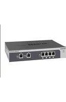
- ProSecure Unified Threat Management (UTM) Appliance
- Support
- Trademarks
- ProSecure Product Updates
- ProSecure Forum
- Contents
- Chapter 1 Introduction
- Chapter 2 Use the Setup Wizard to Provision the UTM in Your Network
- Chapter 3 Manually Configure Internet and WAN Settings
- Chapter 4 LAN Configuration
- Chapter 5 Firewall Protection
- Chapter 6 Content Filtering and Optimizing Scans
- Chapter 7 Virtual Private Networking Using IPSec, PPTP, or L2TP Connections
- Chapter 8 Virtual Private Networking Using SSL Connections
- Chapter 9 Manage Users, Authentication, and VPN Certificates
- Chapter 10 Network and System Management
- Chapter 11 Monitor System Access and Performance
- Chapter 12 Troubleshoot and Use Online Support
- Appendix A xDSL Network Module for the UTM9S and UTM25S
- Appendix B Wireless Network Module for the UTM9S and UTM25S
- Appendix C 3G/4G Dongles for the UTM9S and UTM25S
- Appendix D Network Planning for Dual WAN Ports (Multiple WAN Port Models Only)
- Appendix E ReadyNAS Integration
- Appendix F Two-Factor Authentication
- Appendix G System Logs and Error Messages
- Appendix H Default Settings and Technical Specifications
- Appendix I Notification of Compliance (Wired)
- Appendix J Notification of Compliance (Wireless)
- Index
- What Is the ProSecure Unified Threat Management (UTM) Appliance?
- Key Features and Capabilities
- Multiple WAN Port Models for Increased Reliability or Outbound Load Balancing
- Wireless Features
- DSL Features
- Advanced VPN Support for Both IPSec and SSL
- A Powerful, True Firewall
- Stream Scanning for Content Filtering
- Security Features
- Autosensing Ethernet Connections with Auto Uplink
- Extensive Protocol Support
- Easy Installation and Management
- Maintenance and Support
- Model Comparison
- Service Registration Card with License Keys
- Package Contents
- Hardware Features
- Front Panel UTM5 and UTM10
- Front Panel UTM25
- Front Panel UTM50
- Front Panel UTM150
- Front Panel UTM9S and UTM25S and Network Modules
- xDSL Network Modules
- Wireless Network Modules
- LED Descriptions, UTM5, UTM10, UTM25, UTM50, and UTM150
- LED Descriptions, UTM9S, UTM25S, and their Network Modules
- Rear Panel UTM5, UTM10, and UTM25
- Rear Panel UTM50 and UTM150
- Rear Panel UTM9S and UTM25S
- Bottom Panels with Product Labels
- NETGEAR
- ProSecure Unified Threat Management UTM150
- NETGEAR®
- ProSecure Unified Threat Management UTM9S
- DEFAULT ACCESS
- Choose a Location for the UTM
- Use the Rack-Mounting Kit
- Use the Setup Wizard to Provision the UTM in Your Network
- 2
- Steps for Initial Connection
- Qualified Web Browsers
- Requirements for Entering IP Addresses
- Log In to the UTM
- To connect and log in to the UTM:
- Web Management Interface Menu Layout
- Figure 24.
- Use the Setup Wizard to Perform the Initial Configuration
- To start the Setup Wizard:
- Setup Wizard Step 1 of 10: LAN Settings
- Setup Wizard Step 2 of 10: WAN Settings
- Setup Wizard Step 3 of 10: System Date and Time
- Setup Wizard Step 4 of 10: Services
- IMPORTANT:
- Setup Wizard Step 5 of 10: Email Security
- Setup Wizard Step 6 of 10: Web Security
- Setup Wizard Step 7 of 10: Web Categories to Be Blocked
- Setup Wizard Step 8 of 10: Email Notification
- Setup Wizard Step 9 of 10: Signatures & Engine
- Setup Wizard Step 10 of 10: Saving the Configuration
- Register the UTM with NETGEAR
- Use the Web Management Interface to Activate Licenses
- WARNING:
- Electronic Licensing
- Automatic Retrieval of Licenses after a Factory Default Reset
- Verify Correct Installation
- Test Connectivity
- Test HTTP Scanning
- What to Do Next
- Manually Configure Internet and WAN Settings
- 3
- Internet and WAN Configuration Tasks
- Complete these steps:
- Automatically Detecting and Connecting the Internet Connections
- To configure the WAN ports automatically for connection to the Internet:
- Manually Configure the Internet Connection
- Configure the WAN Mode
- Overview of the WAN Modes
- Configure Network Address Translation (All Models)
- To configure NAT:
- Configure Classical Routing (All Models)
- To configure classical routing:
- Configure Auto-Rollover Mode and the Failure Detection Method (Multiple WAN Port Models)
- Configure Auto-Rollover Mode
- To configure auto-rollover mode:
- Configure the Failure Detection Method
- To configure the failure detection method:
- Click Apply to save your settings.
- Configure Load Balancing and Optional Protocol Binding (Multiple WAN Port Models)
- Configure Load Balancing (Multiple WAN Port Models)
- To configure load balancing:
- Configure Protocol Binding (Optional)
- To configure protocol binding and add protocol binding rules:
- To edit a protocol binding:
- To enable, disable, or delete one or more protocol bindings:
- Configure Secondary WAN Addresses
- To add a secondary WAN address to a WAN interface:
- To delete one or more secondary addresses:
- Configure Dynamic DNS
- To configure DDNS:
- Set the UTM's MAC Address and Configure Advanced WAN Options
- To configure advanced WAN options:
- Click Apply to save your changes.
- Additional WAN-Related Configuration Tasks
- Manage Virtual LANs and DHCP Options
- Port-Based VLANs
- Assign and Manage VLAN Profiles
- To assign VLAN profiles to the LAN ports and manage VLAN profiles:
- VLAN DHCP Options
- DHCP Server
- DHCP Relay
- DNS Proxy
- LDAP Server
- Configure a VLAN Profile
- To add or edit a VLAN profile:
- To edit a VLAN profile:
- To enable, disable, or delete one or more VLAN profiles:
- Configure VLAN MAC Addresses and Advanced LAN Settings
- To configure a VLAN to have a unique MAC address:
- Configure Multihome LAN IP Addresses on the Default VLAN
- To add a secondary LAN IP address:
- To edit a secondary LAN IP address:
- To delete one or more secondary LAN IP addresses:
- Manage Groups and Hosts (LAN Groups)
- Manage the Network Database
- Add Computers or Devices to the Network Database
- To add computers or devices manually to the network database:
- Modify Computers or Devices in the Network Database
- To modify computers or devices manually in the network database:
- Set Up Address Reservation
- Configure and Enable the DMZ Port
- To enable and configure the DMZ port:
- Click Apply to save your settings.
- Manage Routing
- Configure Static Routes
- To add a static route to the Static Route table:
- Configure Routing Information Protocol
- Static Route Example
- About Firewall Protection
- Administrator Tips
- Overview of Rules to Block or Allow Specific Kinds of Traffic
- Outbound Rules (Service Blocking)
- Allowing inbound services opens security holes in your UTM. Enable only those ports that are necessary for your network.
- Inbound Rules (Port Forwarding)
- Order of Precedence for Rules
- Configure LAN WAN Rules
- To change the default outbound policy:
- To change an existing outbound or inbound service rule:
- To enable, disable, or delete one or more rules:
- Create LAN WAN Outbound Service Rules
- To create an outbound LAN WAN service rule:
- Create LAN WAN Inbound Service Rules
- To create an inbound LAN WAN service rule:
- Configure DMZ WAN Rules
- To delete or disable one or more rules:
- Create DMZ WAN Outbound Service Rules
- To create an outbound DMZ WAN service rule:
- Create DMZ WAN Inbound Service Rules
- To create an inbound DMZ WAN service rule:
- Configure LAN DMZ Rules
- Create LAN DMZ Outbound Service Rules
- To create an outbound LAN DMZ service rule:
- Create LAN DMZ Inbound Service Rules
- To create an inbound LAN DMZ service rule:
- Examples of Firewall Rules
- Inbound Rule Examples
- LAN WAN Inbound Rule: Host a Local Public Web Server
- LAN WAN Inbound Rule: Allow Videoconference from Restricted Addresses
- LAN WAN or DMZ WAN Inbound Rule: Set Up One-to-One NAT Mapping
- To configure the UTM for additional IP addresses:
- LAN WAN or DMZ WAN Inbound Rule: Specify an Exposed Host
- To expose one of the computers on your LAN or DMZ as this host:
- Outbound Rule Example
- LAN WAN Outbound Rule: Block Instant Messenger
- Configure Other Firewall Features
- VLAN Rules
- To create a VLAN rule:
- Attack Checks, VPN Pass-through, and Multicast Pass-through
- To enable the appropriate attack checks for your network environment:
- Configure Multicast Pass-Through
- To delete one or more multicast source addresses:
- Set Session Limits
- To enable and configure session limits:
- Click Apply to save your settings.
- Manage the Application Level Gateway for SIP Sessions and VPN Scanning
- To enable ALG for SIP and VPN scanning:
- Create Services, QoS Profiles, Bandwidth Profiles, and Traffic Meter Profiles
- Add Customized Services
- To add a customized service:
- Name Type Start Port End Port Action
- To edit a service:
- To delete one or more services:
- Create Service Groups
- To create a service group:
- Name List of Services Action
- To edit a service group:
- Create IP Groups
- To create an IP group:
- IP Group Name IP Group Type Action
- IP Address
- To delete an IP group:
- Create Quality of Service Profiles
- To create a QoS profile:
- To edit a QoS profile:
- To delete one ore more QoS profiles:
- Create Bandwidth Profiles
- To add and enable a bandwidth profile:
- To edit a bandwidth profile:
- To delete one or more bandwidth profiles:
- Create Traffic Meter Profiles
- To add a traffic meter profile:
- To edit a traffic meter profile:
- To delete one or more traffic meter profiles:
- Set a Schedule to Block or Allow Specific Traffic
- To add a schedule:
- To edit a schedule:
- To delete one or more schedules:
- Enable Source MAC Filtering
- To enable MAC filtering and add MAC addresses to be permitted or blocked:
- To remove one or more entries from the table:
- Set Up IP/MAC Bindings
- To set up IP/MAC bindings:
- To edit an IP/MAC binding:
- To remove one or more IP/MAC bindings from the table:
- Configure Port Triggering
- To add a port-triggering rule:
- Name Enable Protocol Outgoing (Trigger) Port Range Incoming (Response) Port Range Action
- To edit a port-triggering rule:
- To remove one or more port-triggering rules from the table:
- To display the status of the port-triggering rules:
- Rule LAN IP Address Open Ports Time Remaining (Sec.)
- Configure Universal Plug and Play
- Select Security > UPnP. The UPnP screen displays:
- Enable and Configure the Intrusion Prevention System
- To enable intrusion prevention:
- To configure intrusion prevention:
- IPS
- Anomaly Behavior Settings
- Security Category Settings
- Content Filtering and Optimizing Scans
- 6
- About Content Filtering and Scans
- Default Email and Web Scan Settings
- Configure Email Protection
- Customize Email Protocol Scan Settings
- To configure the email protocols and ports to scan:
- Customize Email Antivirus and Notification Settings
- To configure the antivirus settings for email traffic:
- Email Content Filtering
- To configure email content filtering:
- Protect Against Email Spam
- Set Up the Whitelist and Blacklist
- To configure the whitelist and blacklist:
- Configure the Real-Time Blacklist
- To enable the real-time blacklist:
- To add a blacklist provider to the real-time blacklist:
- To delete a blacklist provider from the real-time blacklist:
- Configure Distributed Spam Analysis
- To configure distributed spam analysis and the antispam engine settings:
- Configure Web and Services Protection
- Customize Web Protocol Scan Settings
- To configure the web protocols and ports to scan:
- Configure HTTPS Smart Block
- To change a profile:
- To delete one or more profiles from the HTTPS Smart Block Profiles table:
- To enable or disable one or more profiles on the HTTPS Smart Block List:
- To delete one or more profiles from the HTTPS Smart Block List:
- Configure Web Malware or Antivirus Scans
- To configure the antivirus settings for HTTP and HTTPS traffic:
- Configure Web Content Filtering
- To configure web content filtering:
- Configure Web URL Filtering
- To configure web URL filtering:
- Configure HTTPS Scanning and SSL Certificates
- How HTTPS Scanning Works
- Configure the HTTPS Scan Settings
- To configure the HTTPS scan settings:
- Manage SSL Certificates for HTTPS Scanning
- Manage the Active HTTPS Certificate
- To download the current certificate into your browser:
- To reload the default NETGEAR certificate:
- To import a new certificate:
- Click Apply to save your settings.
- Manage Trusted HTTPS Certificates
- To import a trusted certificate:
- To view details of a trusted certificate:
- To delete a trusted certificate:
- Manage Untrusted HTTPS Certificates
- To view details of an untrusted certificate:
- To delete an untrusted certificate:
- To move an untrusted certificate to the Trusted Certificate Authorities table:
- Specify Trusted Hosts for HTTPS Scanning
- To specify trusted hosts:
- Configure the SSL Settings for HTTPS Scanning
- To configure the SSL settings for HTTPS scanning:
- Configure FTP Scanning
- Customize FTP Antivirus Settings
- To configure the antivirus settings for FTP traffic:
- Configure FTP Content Filtering
- To configure the FTP filters:
- Configure Application Control
- To configure an application control profile and enable application control:
- To change an existing application control profile:
- To delete one or more application control profiles:
- Set Exception Rules for Web and Application Access
- To set web access exception rules:
- - Application.
- To change an existing exception rule:
- To disable, enable, or delete one or more exception rules:
- Create Custom Categories for Exceptions for Web and Application Access
- To create and manage custom categories:
- To change an existing custom category:
- To delete one or more custom categories:
- Set Scanning Exclusions for IP Addresses and Ports
- To configure scanning exclusion rules:
- Virtual Private Networking Using IPSec, PPTP, or L2TP Connections
- 7
- Considerations for Dual WAN Port Systems (Multiple WAN Port Models Only)
- Use the IPSec VPN Wizard for Client and Gateway Configurations
- Create Gateway-to-Gateway VPN Tunnels with the Wizard
- To set up a gateway-to-gateway VPN tunnel using the VPN Wizard:
- Create a Client-to-Gateway VPN Tunnel
- To set up a client-to-gateway VPN tunnel using the VPN Wizard:
- Use the NETGEAR VPN Client Wizard to Create a Secure Connection
- To use the Configuration Wizard to set up a VPN connection between the VPN client and the UTM:
- Configure the Authentication Settings (Phase 1 Settings)
- To create new authentication settings:
- Create the IPSec Configuration (Phase 2 Settings)
- To create an IPSec configuration:
- Configure the Global Parameters
- To specify the global parameters:
- Test the Connection and View Connection and Status Information
- Test the NETGEAR VPN Client Connection
- To establish a connection, use one of the following three methods:
- NETGEAR VPN Client Status and Log Information
- To view detailed negotiation and error information about the NETGEAR VPN client:
- View the UTM IPSec VPN Connection Status
- View the UTM IPSec VPN Log
- To query the IPSec VPN log:
- Manage IPSec VPN and IKE Policies
- Manage IKE Policies
- IKE Policies Screen
- To delete one or more IKE polices:
- Manually Add or Edit an IKE Policy
- To add an IKE policy manually:
- To edit an IKE policy:
- Manage VPN Policies
- VPN Policies Screen
- To delete one or more VPN polices:
- To enable or disable one or more VPN policies:
- Manually Add or Edit a VPN Policy
- To add a VPN policy manually:
- To edit a VPN policy:
- Configure Extended Authentication (XAUTH)
- Configure XAUTH for VPN Clients
- To enable and configure XAUTH:
- User Database Configuration
- RADIUS Client and Server Configuration
- To configure primary and backup RADIUS servers:
- Assign IP Addresses to Remote Users (Mode Config)
- Mode Config Operation
- Configure Mode Config Operation on the UTM
- To configure Mode Config on the UTM:
- Configure the ProSafe VPN Client for Mode Config Operation
- Configure the Mode Config Authentication Settings (Phase 1 Settings)
- Create the Mode Config IPSec Configuration (Phase 2 Settings)
- Configure the Mode Config Global Parameters
- Test the Mode Config Connection
- To test the Mode Config connection from the VPN client to the UTM:
- Modify or Delete a Mode Config Record
- Configure Keep-Alives and Dead Peer Detection
- Configure Keep-Alives
- To configure the keep-alive feature on a configured VPN policy:
- Configure Dead Peer Detection
- To configure DPD on a configured IKE policy:
- Configure NetBIOS Bridging with IPSec VPN
- Configure the PPTP Server
- View the Active PPTP Users
- To view the active PPTP tunnel users:
- Configure the L2TP Server
- View the Active L2TP Users
- To view the active L2TP tunnel users:
- For More IPSec VPN Information
- Virtual Private Networking Using SSL Connections
- 8
- SSL VPN Portal Options
- Build a Portal Using the SSL VPN Wizard
- To start the SSL VPN Wizard:
- SSL VPN Wizard Step 1 of 6 (Portal Settings)
- SSL VPN Wizard Step 2 of 6 (Domain Settings)
- SSL VPN Wizard Step 3 of 6 (User Settings)
- SSL VPN Wizard Step 4 of 6 (Client IP Addresses and Routes)
- SSL VPN Wizard Step 5 of 6 (Port Forwarding)
- SSL VPN Wizard Step 6 of 6 (Verify and Save Your Settings)
- Access the New SSL VPN Portal
- To access the new SSL VPN portal that you created with the SSL VPN Wizard:
- View the UTM SSL VPN Connection Status
- View the UTM SSL VPN Log
- To query the SSL VPN log:
- Manually Configure and Modify SSL Portals
- Manually Create or Modify the Portal Layout
- To create an SSL VPN portal layout:
- To edit a portal layout:
- To delete one or more portal layouts:
- Configure Domains, Groups, and Users
- Configure Applications for Port Forwarding
- Add Servers and Port Numbers
- To add a server and a port number:
- Add a Host Name
- Configure the SSL VPN Client
- Configure the Client IP Address Range
- To define the client IP address range:
- Add Routes for VPN Tunnel Clients
- To add an SSL VPN tunnel client route:
- Configure the Advanced SSL VPN Client Settings
- Use Network Resource Objects to Simplify Policies
- Add New Network Resources
- To define a network resource:
- To delete one or more network resources:
- To edit network resources:
- Configure User, Group, and Global Policies
- Global Default Policy
- View Policies
- To view the existing policies:
- Add a Policy
- To add an SSL VPN policy:
- To edit an SSL VPN policy:
- To delete one or more SSL VPN policies:
- For More SSL VPN Information
- Manage Users, Authentication, and VPN Certificates
- 9
- Authentication Process and Options
- Configure Authentication Domains, Groups, and Users
- Login Portals
- Administrative Users and Users with Guest Privileges
- Users with Special Access Privileges
- Unauthenticated or Anonymous Users
- Active Directories and LDAP Configurations
- How an Active Directory Works
- How to Bind a DN in an Active Directory Configuration
- To bind a user with the name Jamie Hanson with the AD server:
- Configure Domains
- Create and Delete Domains
- To create a domain:
- To delete one or more domains:
- Edit Domains
- To edit a domain:
- Configure Groups
- Create and Delete Groups
- To create a VPN group:
- To delete one or more groups:
- Edit Groups
- To edit a VPN group:
- Configure Custom Groups
- To create and manage custom groups:
- To change an existing custom group:
- To delete one or more custom groups:
- Configure User Accounts
- To create an individual user account:
- To delete one or more user accounts:
- Set User Login Policies
- Configure Login Policies
- To configure user login policies:
- Configure Login Restrictions Based on IP Address
- To restrict logging in based on IP address:
- To delete one or more browsers:
- Change Passwords and Other User Settings
- To modify user settings, including passwords:
- DC Agent
- Requirements for the ProSecure DC Agent Software and DC Agent Server
- Download ProSecure DC Agent Software, and Create and Delete DC Agents
- To download ProSecure DC Agent software and add a DC agent:
- To edit a DC agent:
- Example: Configure Active Directory Single Sign-On with a DC Agent
- To configure AD SSO with a DC agent:
- Configure RADIUS VLANs
- To do so, follow this procedure:
- To configure a RADIUS VLAN:
- Configure Global User Settings
- View and Log Out Active Users
- To log out all active users:
- To view all or selected users:
- Manage Digital Certificates for VPN Connections
- VPN Certificates Screen
- Manage CA Certificates
- To view and upload trusted certificates:
- Manage Self-Signed Certificates
- Generate a CSR and Obtain a Self-Signed Certificate from a CA
- To generate a new CSR file, obtain a digital certificate from a CA, and upload it to the UTM:
- To delete one or more SCRs:
- View and Manage Self-Signed Certificates
- To delete one or more self-signed certificates:
- Manage the Certificate Revocation List
- To view the currently loaded CRLs and upload a new CRL:
- To delete one or more CRLs:
- Performance Management
- Bandwidth Capacity
- Features That Reduce Traffic
- LAN WAN Outbound Rules and DMZ WAN Outbound Rules (Service Blocking)
- Content Filtering
- Source MAC Filtering
- Features That Increase Traffic
- LAN WAN Inbound Rules and DMZ WAN Inbound Rules (Port Forwarding)
- Port Triggering
- Configure the DMZ Port
- Configure Exposed Hosts
- Configure VPN Tunnels
- Use QoS and Bandwidth Assignments to Shift the Traffic Mix
- Assign QoS Profiles
- Assign Bandwidth Profiles
- Monitoring Tools for Traffic Management
- System Management
- Change Passwords and Administrator and Guest Settings
- To modify the administrator and guest user account settings, including the password:
- Configure Remote Management Access
- To configure the UTM for remote management:
- Use a Simple Network Management Protocol Manager
- To configure the global SNMP settings and SNMPv1/v2c settings:
- To configure the SNMPv3 settings:
- To edit an SNMPv3 user profile:
- To delete one or more SNMPv3 user profiles:
- Manage the Configuration File
- Back Up Settings
- To back up settings:
- Restore Settings
- To restore settings from a backup file:
- Revert to Factory Default Settings
- Update the Firmware
- Upgrade the Firmware from an Update Server and Reboot the UTM
- To upgrade the UTM's firmware directly from an update server and reboot the UTM:
- Upgrade the Firmware from a Downloaded File and Reboot the UTM
- To download the latest firmware for your UTM:
- Reboot without Changing the Firmware
- To reboot the UTM without changing the firmware:
- Update the Scan Signatures and Scan Engine Firmware
- Configure Automatic Update and Frequency Settings
- To configure the update settings and frequency settings for automatic downloading of the scan engine firmware and pattern file:
- Configure Date and Time Service
- To set time, date, and NTP servers:
- Connect to a ReadyNAS and Configure Quarantine Settings
- Log Storage
- Connect to a ReadyNAS
- To connect to the ReadyNAS on the UTM:
- Configure the Quarantine Settings
- Monitor System Access and Performance
- 11
- Enable the WAN Traffic Meter
- Configure Logging, Alerts, and Event Notifications
- Configure the Email Notification Server
- To configure the email notification server:
- Configure and Activate System, Email, and Syslog Logs
- To configure and activate logs:
- How to Send Syslogs over a VPN Tunnel between Sites
- Configure Gateway 1 at Site 1
- Configure Gateway 2 at Site 2
- Configure and Activate Update Failure and Attack Alerts
- Configure and Activate Firewall Logs
- To configure and activate firewall logs:
- Monitor Real-Time Traffic, Security, and Statistics
- To set the poll interval:
- Monitor Application Use in Real Time
- To set the monitoring period:
- To filter the information that is displayed onscreen:
- View Status Screens
- View the System Status
- View the System Status Screen
- View the Network Status Screen
- View the Router Statistics Screen
- To view the Router Statistics screen:
- To view the Wireless Statistics screen:
- View the Detailed Status Screen
- View the VLAN Status Screen
- View the Active VPN Users
- View the VPN Tunnel Connection Status
- View the Active PPTP and L2TP Users
- View the Port Triggering Status
- To view the status of the port-triggering feature:
- View the WAN, xDSL, or USB Port Status
- To view the status of a WAN, xDSL, or USB port:
- View Attached Devices and the DHCP Leases
- View Attached Devices
- To view the attached devices in the LAN Groups screen:
- View the DHCP Leases
- To view the DHCP leases:
- Query and Manage the Logs
- Overview of the Logs
- Query and Download Logs
- To query and download logs:
- Example: Use the Logs to Identify Infected Clients
- To identify infected clients:
- Log Management
- Query and Manage the Quarantine Logs
- Query the Quarantined Logs
- To query the quarantine logs:
- View and Manage the Quarantined Spam Table
- View and Manage the Quarantined Infected Files Table
- Spam Reports for End Users
- For an end user to send a spam report:
- View, Schedule, and Generate Reports
- Enable Application Session Monitoring
- To enable application monitoring:
- Report Filtering Options
- To configure filtering options:
- Use Report Templates and View Reports Onscreen
- Schedule, Email, and Manage Reports
- To schedule automatic generation and emailing of reports:
- Managing Saved Reports
- Use Diagnostics Utilities
- Use the Network Diagnostic Tools
- Send a Ping Packet
- To send a ping:
- Trace a Route
- To send a traceroute:
- Display the Routing Table
- Look Up a DNS Address
- To look up a DNS address:
- Use the Real-Time Traffic Diagnostics Tool
- To use the real-time traffic diagnostics tool:
- Gather Important Log Information and Generate a Network Statistics Report
- Gather Important Log Information
- To gather log information about your UTM:
- Generate Network Statistics
- Perform Maintenance on the USB Device, Reboot the UTM, or Shut Down the UTM
- Perform Maintenance on the USB Device
- Reboot and Shut Down the UTM
- Troubleshoot and Use Online Support
- 12
- Basic Functioning
- Verify the Correct Sequence of Events at Startup
- After you turn on power to the UTM, verify that the following sequence of events occurs:
- Power LED Not On
- Test LED Never Turns Off
- LAN or WAN Port LEDs Not On
- Troubleshoot the Web Management Interface
- When You Enter a URL or IP Address, a Time-Out Error Occurs
- Troubleshoot the ISP Connection
- To check the WAN IP address:
- If your UTM is unable to obtain an IP address from the ISP, you might need to force your modem or router to recognize your new UTM by performing the following procedure:
- Troubleshoot a TCP/IP Network Using a Ping Utility
- Test the LAN Path to Your UTM
- To ping the UTM from a computer running Windows 95 or later:
- Test the Path from Your Computer to a Remote Device
- Restore the Default Configuration and Password
- Problems with Date and Time
- Use Online Support
- Enable Remote Troubleshooting
- To initiate the support tunnel:
- Send Suspicious Files to NETGEAR for Analysis
- To submit a file to NETGEAR for analysis:
- Access the Knowledge Base and Documentation
- xDSL Network Module for the UTM9S and UTM25S
- xDSL Network Module Configuration Tasks
- Configure the xDSL Settings
- To configure the xDSL settings:
- Automatically Detecting and Connecting the xDSL Internet Connection
- To configure the WAN port automatically for connection to the Internet:
- Select Network Config > WAN Settings. The WAN screen displays.
- Manually Configure the xDSL Internet Connection
- Configure Network Address Translation
- Configure Classical Routing
- Configure Auto-Rollover Mode and the Failure Detection Method
- Configure Load Balancing and Optional Protocol Binding
- Configure Load Balancing
- To add a secondary WAN address to the DSL interface:
- Wireless Network Module for the UTM9S and UTM25S
- B
- Overview of the Wireless Network Module
- Configuration Order
- Wireless Equipment Placement and Range Guidelines
- Configure the Basic Radio Settings
- To configure the basic radio settings:
- Operating Frequency (Channel) Guidelines
- Wireless Data Security Options
- Wireless Security Profiles
- • Network authentication
- - Data encryption
- Before You Change the SSID, WEP, and WPA Settings
- • SSID
- - WEP key size, key format, authentication type, and passphrase
- • WPA-PSK (pre-shared key) and WPA2-PSK
- • WPA RADIUS settings
- • WPA2 RADIUS settings
- Configure and Enable Wireless Profiles
- To add a wireless profile:
- To edit a wireless profile:
- To delete one or more wireless profiles:
- To enable or disable one or more wireless profiles:
- Restrict Wireless Access by MAC Address
- To allow or restrict access to a wireless profile based on MAC addresses:
- View the Access Point Status and Connected Clients for a Wireless Profile
- Configure a Wireless Distribution System
- To enable and configure WDS:
- To configure WDS on a peer:
- To remove one or more MAC addresses from the WDS Peers table:
- Configure Advanced Radio Settings
- To configure advanced radio settings:
- Configure WMM QoS Priority Settings
- To enable and configure WMM QoS priority settings for a wireless profile:
- Test Basic Wireless Connectivity
- To test for wireless connectivity:
- For More Information About Wireless Configurations
- 3G/4G Dongles for the UTM9S and UTM25S
- C
- 3G/4G Dongle Configuration Tasks
- Manually Configure the USB Internet Connection
- To configure the WAN ISP settings for the USB interface:
- Configure the 3G/4G Settings
- To configure the 3G/4G settings:
- WARNING!
- Network Planning for Dual WAN Ports (Multiple WAN Port Models Only)
- D
- What to Consider Before You Begin
- Plan Your Network and Network Management and Set Up Accounts
- Cabling and Computer Hardware Requirements
- Computer Network Configuration Requirements
- Internet Configuration Requirements
- Where Do I Get the Internet Configuration Information?
- Internet Connection Information
- Overview of the Planning Process
- Inbound Traffic
- Inbound Traffic to a Single WAN Port System
- Inbound Traffic to a Dual WAN Port System
- Inbound Traffic: Dual WAN Ports for Improved Reliability
- Inbound Traffic: Dual WAN Ports for Load Balancing
- Virtual Private Networks
- VPN Road Warrior (Client-to-Gateway)
- VPN Road Warrior: Single-Gateway WAN Port (Reference Case)
- VPN Road Warrior: Dual-Gateway WAN Ports for Improved Reliability
- VPN Road Warrior: Dual-Gateway WAN Ports for Load Balancing
- VPN Gateway-to-Gateway
- VPN Gateway-to-Gateway: Single-Gateway WAN Ports (Reference Case)
- VPN Gateway-to-Gateway: Dual-Gateway WAN Ports for Improved Reliability
- VPN Gateway-to-Gateway: Dual-Gateway WAN Ports for Load Balancing
- VPN Telecommuter (Client-to-Gateway through a NAT Router)
- VPN Telecommuter: Single-Gateway WAN Port (Reference Case)
- VPN Telecommuter: Dual-Gateway WAN Ports for Improved Reliability
- VPN Telecommuter: Dual-Gateway WAN Ports for Load Balancing
- Supported ReadyNAS Models
- Install the UTM Add-On on the ReadyNAS
- To install the UTM add-on on the ReadyNAS:
- Connect to the ReadyNAS on the UTM
- Why Do I Need Two-Factor Authentication?
- What Are the Benefits of Two-Factor Authentication?
- What Is Two-Factor Authentication?
- NETGEAR Two-Factor Authentication Solutions
- To use WiKID (for end users):
- System Log Messages
- System Startup
- Reboot
- NTP
- Login/Logout
- Firewall Restart
- IPSec Restart
- WAN Status
- Auto-Rollover Mode
- Load Balancing Mode
- PPP Logs
- Traffic Metering Logs
- Unicast, Multicast, and Broadcast Logs
- ICMP Redirect Logs
- Multicast/Broadcast Logs
- Invalid Packet Logging
- Service Logs
- Content-Filtering and Security Logs
- Web Filtering and Content-Filtering Logs
- Spam Logs
- Traffic Logs
- Malware Logs
- Email Filter Logs
- IPS Logs
- Anomaly Behavior Logs
- Application Logs
- Routing Logs
- LAN-to-WAN Logs
- LAN-to-DMZ Logs
- DMZ-to-WAN Logs
- WAN-to-LAN Logs
- DMZ-to-LAN Logs
- WAN-to-DMZ Logs
- Default Settings and Technical Specifications
- H
- Default Settings
- Physical and Technical Specifications
- Notification of Compliance (Wired)
- Regulatory Compliance Information
- FCC Requirements for Operation in the United States
- FCC Information to User
- FCC Guidelines for Human Exposure
- FCC Declaration Of Conformity
- FCC Radio Frequency Interference Warnings & Instructions
- Canadian Department of Communications Radio Interference Regulations
- Notification of Compliance (Wireless)
- Europe - EU Declaration of Conformity
- FCC Caution
- IMPORTANT NOTE: Radiation Exposure Statement:
- Caution:
- Interference Reduction Table
- Numerics
- A
- Apple
- E
- F
- G
- I
- J
- K
- L
- M
- N
- O
- P
- Q
- R
- S
- T
- U
- V
- W
- X
Brand : NETGEAR
Model : UTM10
Category : Firewall