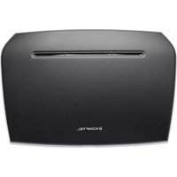
IP DECT 10 - Telephone KONFTEL - Free user manual and instructions
Find the device manual for free IP DECT 10 KONFTEL in PDF.


| Product Type | DECT Cordless Phone |
| Brand | Konftel |
| Model | IP DECT 10 |
| Connectivity | DECT, RJ-9 headset jack, USB (for programming) |
| Standby Time | Up to 100 hours |
| Talk Time | Up to 12 hours |
| Indoor Range | Up to 50 meters |
| Outdoor Range | Up to 300 meters |
| Display | Backlit LCD with icons |
| Speakerphone | Full-duplex |
| Headset Compatibility | RJ-9 connector (wired R series headsets) |
| Phonebook | Up to 100 contacts |
| Caller ID | Supported (requires network service) |
| Ringtone Options | 10 polyphonic ringtones |
| Power Source (Base) | AC adapter: 100-240V, 50/60Hz to 5V DC |
| Handset Battery Type | Rechargeable Li-Ion |
| Handset Battery Capacity | 2.8V, 2000mAh |
| Charging Time | Approximately 4 hours |
| Handset Dimensions (HxWxD) | 150 x 50 x 30 mm |
| Base Dimensions (HxWxD) | 120 x 100 x 80 mm |
| Handset Weight | 120 g (including battery) |
| Base Weight | 200 g |
| Included Accessories | Base unit, handset, charging cradle, AC adapter, belt clip, line cord |
| Operating Temperature | 0°C to 40°C |
| Maintenance | Clean with a soft, dry cloth. Do not use liquids or abrasives. |
Frequently Asked Questions - IP DECT 10 KONFTEL
User questions about IP DECT 10 KONFTEL
0 question about this device. Answer the ones you know or ask your own.
Ask a new question about this device
Download the instructions for your Telephone in PDF format for free! Find your manual IP DECT 10 - KONFTEL and take your electronic device back in hand. On this page are published all the documents necessary for the use of your device. IP DECT 10 by KONFTEL.
USER MANUAL IP DECT 10 KONFTEL
Installation & Configuration Network Deployment Operation & Management
Technical Reference Document © September-2015 Konftel AB, Sweden
Konftel IP DECT 10 User Guide Proprietary and Confidential
Trademarks
Konftel and the combinations of its logo thereof are trademarks of Konftel AB, Sweden.
Other product names used in this publication are for identification purposes and maybe the trademarks of their respective companies.
Disclaimer
The contents of this document are provided in connection with Konfel products. Konftel makes no representations with respect to completeness or accuracy of the contents of this publication and reserves the right to make changes to product descriptions, usage, etc., at any time without notice. No license, whether express, implied, to any intellectual property rights are granted by this publication
Confidentiality
This document should be regarded as confidential, unauthorized copying is not allowed
© September-2015 Konftel AB, Sweden, All rights reserved
http://www.konftel.com
KONFTEL
Contents
Konftel IP DECT 10....1
Manual....1
Contents 3
1 About This Document....6
1.1 Audience....6
1.2 When Should I Read This Guide 6
1.3 Important Assumptions....6
1.4 What's Inside This Guide 6
1.5 What's Not in This guide....7
1.6 Abbreviations....7
1.7 Document History....8
1.8 Documentation Feedback 8
2 Introduction – System Overview 9
2.1 Hardware Setup....9
2.2 Components of IP DECT 10....9
2.3 Wireless Bands 10
2.4 System Capacity (in Summary) 10
3 Installation of Base Station....11
3.1 Package – Contents/Damage Inspection.... 11
3.2 Base station Mechanics.... 12
3.3 Base Station – Reset feature 12
3.4 Installing the Base Station 13
3.5 Find IP of Base Station 13
3.6 Login to Base Configuration Interface 14
4 VoIP Administration Interface 15
4.1 Web navigation.... 15
4.2 Home/Status.... 17
4.3 Extensions.... 18
4.4 Servers 23
4.5 Network....27
4.6 Management Settings Definitions.... 31
4.7 Firmware Update Definitions 34
4.8 Time Server.... 35
KONFTEL
4.9 Country 37
4.10 Security 38
4.11 Central Directory and LDAP 40
4.12 Statistics.... 43
4.13 Settings – Configuration File Setup 46
4.14 Sys log 46
4.15 SIP Logs 47
5 Firmware Upgrade Procedure 48
5.1 Network Dimensioning....48
5.2 TFTP Configuration 48
5.3 Create Firmware Directories 49
5.4 Firmware Update Settings.... 50
5.5 Base Station Firmware Upgrade.... 51
6 Functionality Overview....53
6.1 Base Station Interfaces....53
6.2 Software Features 54
6.3 Call Features 55
Appendix....57
7 Appendix A: Basic Network Server(s) Configuration 57
7.1 Server setup....57
7.2 Requirements 57
7.3 DNS Server Installation/Setup 57
7.4 DHCP Server Setup 57
7.5 TFTP Server Setup.... 59
7.6 SIP Server Setup.... 60
8 Appendix B: Using Base with VLAN Network 63
8.1 Introduction......63
8.2 Backbone/ VLAN Aware Switches 64
8.3 How VLAN Switch Work: VLAN Tagging 65
8.4 Implementation Cases....65
8.5 Base station Setup 66
8.6 Configure Time Server 66
8.7 VLAN Setup: Base station 67
9 Appendix C: Local Central directory file handling 68
9.1 Central Directory Contact List Structure 68
9.2 Central Directory Contact List Filename Format 68
KONFTEL
9.3 Import Contact List to Central Directory 69
9.4 Central directory using server 70
9.5 Verification of Contact List Import to Central Directory 70
1 About This Document
This document describes the configuration, customization, management, operation, maintenance and troubleshooting of Konftel IP DECT 10. For customer specific modes refer to specific customer agreements, which describe the software operational deviations from this document.
1.1 Audience
Who should read this guide? First, this guide is intended for networking professionals responsible for designing and implementing Konftel IP DECT 10.
Second, network administrators and IT support personnel that need to install, configure, maintain and monitor elements in a “live” VoIP network will find this document helpful.
1.2 When Should I Read This Guide
Read this guide before you install the core network devices of VoIP System and when you are ready to setup or configure SIP server, NAT aware router, advanced VLAN settings, base stations, and multi cell setup.
This manual will enable you to set up components in your network to communicate with each other and also deploy a fully functionally VoIP System.
1.3 Important Assumptions
This document was written with the following assumptions in mind:
1) You have understanding of network deployment in general
2) You have working knowledge of basic TCP/IP/SIP protocols, Network Address Translation, etc...
3) A proper site survey has been performed, and the administrator have access to these plans
1.4 What's Inside This Guide
We summarize the contents of this document in the table below:
| Where Is It? | Content | Purpose |
| Chapter 2 | Introduction to the VoIP Network | To gain knowledge about the different elements in a typical VoIP Network |
| Chapter 3 | Installation of Base station/Repeater | Considerations to remember before unwrapping and installing base units and repeaters |
| Chapter 4 | Making Handsets Ready | To determine precautions to take in preparing handsets for use in the system |
| Chapter 5 | VoIP Administration Interface | To learn about the Configuration Interface and define full meaning of various parameters needed to be setup in the system. |
| Chapter 6 | Registration Management - Handsets | Learn how to register handset and extensions to base stations |
| Chapter 7 | Firmware Upgrade/Downgrade Management | Provides the procedure of how to upgrade firmware to base stations and/or handsets and/or repeaters |
| Chapter 8 | System Functionality Overview | To gain detail knowledge about the system features. |
| 9 Appendix A | Basic Network Servers Configuration | To learn about operating the handset and base stations including detail description of handset MMI. |
| 10 Appendix B | VLAN Setup Management | Examines how to setup VLAN in the network |
| 11 Appendix C | Local central directory file handling | Detailed description of central directory file format and upload. |
1.5 What's Not in This guide
This guide provides overview material on network deployment, how-to procedures, and configuration examples that will enable you to begin configuring your VoIP System.
It is not intended as a comprehensive reference to all detail and specific steps on how to configure other vendor specific components/devices needed to make the VoIP System functional. For such a reference to vendor specific devices, please contact the respective vendor documentation.
1.6 Abbreviations
For the purpose of this document, the following abbreviations hold:
DHCP: Dynamic Host Configuration Protocol
DNS: Domain Name Server
HTTP(S): Hyper Text Transfer Protocol (Secure)
(T)FTP: (Trivial) File Transfer Protocol
IOS: Internetworking Operating System
PCMA: A-law Pulse Code Modulation
PCMU: mu-law Pulse Code Modulation
PoE: Power over Ethernet
RTP: Real-time Transport Protocol
RPORT: Response Port (Refer to RFC3581 for details)
SIP: Session Initiation Protocol
VLAN: Virtual Local Access Network
TOS: Type of Service (policy based routing)
URL: Uniform Resource Locator
UA: User Agent
1.7 Document History
| Revision | Author | Issue Date | Comments |
| 2.4 | KMR | 9-Sep-2015 | First version |
1.8 Documentation Feedback
We always strive to produce the best and we also value your comments and suggestions about our documentation. If you have any comments about this guide, please enter them through the Feedback link on the Konftel website. We will use your feedback to improve the documentation.
2 Introduction – System Overview
In a typical telephony system, the network setup is the interconnection between Phones, "fat" routers, repeaters, portable parts, etc. The back-bone of the network depends on the deployment scenario but a ring or hub topology is used. The network has centralized monitoring, and maintenance system.
The IP DECT 10 is a single cell VoIP solution with support of up to 20 registered handsets (eg. Konftel 300Wx).
2.1 Hardware Setup
IP DECT 10 network hardware setup can be deployed as follows:
The base-stations are mounted on walls or lamp poles so that each base-station is separated from each other by up to 10m indoor.
The base-station antenna mechanism is based on space diversity feature which improves coverage. The base-stations uses complete DECT MAC protocol layer and IP media stream audio encoding feature to provide up to 6 simultaneous calls.
2.2 Components of IP DECT 10
IP DECT 10 is made up of (but not limited to) the following components:
• One IP DECT 10 is connected over an IP network and using DECT as air-core interface.
- Konftel 300Wx
- Web configuration Interface; is a management interface for IP DECT 10 Wireless Solution.
2.2.1 IP DECT 10
The Base Station converts IP protocol to DECT protocol and transmits the traffic to and from the end-nodes (i.e. wireless handsets) over a channel. It has 6 available channels.
2.2.2 VoIP Administration Server/Software
This server is referred to as VoIP Configuration Interface.
The VoIP Configuration Interface is a web based administration page used for configuration and programming of the base station and relevant network end-nodes. E.g. handsets can be registered or de-registered from the system using this interface.
The configuration interface can be used as a setup tool for software or firmware download to base stations, repeaters and handsets. Further, it is used to check relevant system logs that can be useful to administrator. These logs can be used to troubleshoot the system when the system faces unforeseen operational issues.
2.3 Wireless Bands
The bands supported in the VoIP are summarized as follows:
Frequency bands:
1880 - 1930 MHz (DECT)
1880 – 1900 MHz (10 carriers) Europe/ETSI
1910 – 1930 MHz (10 carriers) LATAM
1920 – 1930 MHz (5 carriers) US
2.4 System Capacity (in Summary)
network capacity of relevant components can be summarised as follows:
| Description | Capacity |
| Single Cell Setup | 1 |
| Max ## of Users (SIP registrations) per Base | 20 |
| Single Cell Setup: Max ## Simultaneous Calls | 6 |
3 Installation of Base Station
In the following we briefly describe the how to install the base station in this chapter.
3.1 Package - Contents/Damage Inspection
Before Package Is Opened:
Examine the shipping package for evidence of physical damage or mishandling prior to opening. If there is a proof of mishandling prior to opening, you must report it to the relevant support centre of the regional representative or operator.
Contents of Package:
Make sure all relevant components are available in the package before proceeding to the next step.
Every shipped base unit package/box contains the following items:
• 1 x Cat. 5 cable (Ethernet cable)
- Base unit
- Power supply

Back View of Base Station Unit
Damage Inspection:
The following are the recommended procedure for you to use for inspection:
- Examine all relevant components for damage.
-
Make a "defective on arrival – DOA" report or RMA to the operator. Do not move the shipping carton until it has been examined by the operator. If possible send pictures of the damage. The operator/regional representative will initiate the necessary procedure to process this RMA. They will guide the network administrator on how to return the damaged package if necessary.
-
If no damage is found then unwrap all the components and dispose of empty package/carton(s) in accordance with country specific environmental regulations.
3.2 Base station Mechanics
The base station front end shows an LED indicator that signals different functional states of the base unit and occasionally of the overall network. The indicator is off when the base unit is not powered.
The table below summarises the various LED states:
| LED State | State |
| Unlit | No power in unit |
| Unlit/Solid red | Error condition |
| Blinking green | Initialisation |
| Solid red | Factory reset warning or long press in BS reset button |
| Blinking red | Factory setting in progress |
| Solid green | Ethernet connection available (Normal operation) |
| Blinking red | Ethernet connect not available OR handset de/registration failed |
| Solid red | Critical error (can only be identified by Konftel Engineers). Symptoms include no system/SIP debug logs are logged, etc. |
| Orange | Press reset button of base station. |
| Blinking orange | No IP address received |
3.3 Base Station - Reset feature
It is possible to restart or reset the base station unit by pressing a knob at the rear side of the unit. Alternatively, it can be reset from the web configuration Interface.
3.4 Installing the Base Station
First determine the best location that will provide an optimal coverage taking account the construction of the building, architecture and choice of building materials.
Next, mount the Base Station on a wall to cover range between 50 – 300 meters (i.e. 164 to 984 feet), depending whether it's an indoor or outdoor installation.
3.4.1 Mounting the Base Stations:
We recommend the base station be mounted an angle other than vertical on both concrete/wood/plaster pillars and walls for optimal radio coverage. Avoid mounting the base units upside down as it significantly reduces radio coverage.
Mount the base unit as high as possible to clear all nearby objects (e.g. office cubicles and cabinets, etc.). Occasionally extend coverage to remote offices/halls with lower telephony users by installing Repeaters.
Make sure that when you fix the base stations with screws, the screws do not touch the PCB on the unit. Secondly, avoid all contacts with any high voltage lines.
3.5 Find IP of Base Station
To find IP of the installed base station two methods can be used; Using Konftel 300Wx status page or using a web browser.
3.5.1 Using Konftel 300Wx to find IP address
On the handset press "Menu" then go to STATUS. Scroll to the bottom of the status view to see the IP address of the base. This can only be found when the handset (Konftel 300Wx) is connected to the base.
3.5.2 Using browser
Open any standard browser and enter the address:
http://ipdect
for e.g. http://ipdect00087B00AA10. This will retrieve the HTTP Web Server page from the base station with hardware address 00087B00AA10.
This feature requires an available DNS server.
3.6 Login to Base Configuration Interface
STEP 1 Connect the Base station to a private network via standard Ethernet cable (CAT-5).
STEP 2 Use section 3.5 to find the IP address and enter that in a web browser.
STEP 3 On the Login page, enter your authenticating credentials (i.e. username and password). By default the username and password is admin. Click OK button.

STEP 4 Once you have authenticated, the browser will display front end of the Configuration Interface. The front end will show relevant information of the base station.

4 VoIP Administration Interface
The VoIP Administration Interface is the main interface through which the system is managed and debugged.
The VoIP Configuration Interface is an in-built HTTP Web Server service residing in each base station. This interface is user friendly interface and easy to handle even to a first time user.
Note: Enabling secure web is not possible. For secure configuration use secure provisioning.
This chapter seeks to define various variables/parameters available for configuration in the network.
4.1 Web navigation
We describe the left menu in the front end of the VoIP Administration Interface.

| Feature | Description |
| Home/Status | This is the front end of the Base station’s HTTP web interface. This page shows the summary of current operating condition and settings of the Base station and Handset(s). |
| Extensions | Administration of extensions and handsets in the system |
| Servers | On this page the user can define which SIP/NAT server the network should connect to. |
| Network | Typically the user configures the Network settings from here.NAT provisioning: allows configuration of features for resolving of the NAT – Network Address Translation. These features enable interoperability with most types of routers.DHCP: allows changes in protocol for getting a dynamic IP address.Virtual LAN: specifies the Virtual LAN ID and the User priority.IP Mode: specifies using dynamic (DHCP) or static IP address for your network. IP address: if using DHCP leave it empty. Only write in, when you use static IP address.Subnet mask: if using DHCP, leave it empty. Only write in, when you use static IP address.DNS server: specify if using DHCP, leave it empty. Only write in the DNS server address of your Internet service provider, when you use static IP address. (DNS = Dynamic Name Server)Default gateway: if using DHCP, leave it empty. Write in the IP address of your router, when you use static IP address. |
| Management | Defines the Configuration server address, Management transfer protocol, sizes of logs/traces that should be catalogued in the system. |
| Firmware Update | Remote firmware updates (HTTP(s)/TFTP) settings of Base stations and handsets. |
| Time | Here the user can configure the Time server. It should be used as time server in relevant country for exact time. The time servers have to deliver the time to conform to the Network Time Protocol (NTP). Handsets are synchronised to this time. Base units synchronise to the master using the Time server. |
| Country | Specifying the country/territory where the network is located ensures that your phone connection functions properly.Note: The base language and country setting are independent of each other. |
| Security | The users can administrate certificates and create account credentials with which they can log in or log out of the embedded HTTP web server. |
| Central Directory | Interface to common directory load of up to 3000 entries using *csv format or configuration of LDAP directory.Note: LDAP and central directory cannot operate at the same time. |
| Repeaters | Administration and configuration of repeaters of the system |
| Alarm | Administration and configuration of the alarm settings on the system. This controls the settings for alarms that can be sent to the handsets. This feature is only available on certain types of handsets. |
| Statistics | Overview of system and call statistics for a system. |
| Configuration | This shows detail and complete network settings for base station(s), HTTP/DNS/DHCP/TFTP server, SIP server, etc. |
| Syslog | Overall network related events or logs are displayed here (only live feed is shown). |
| SIP Log | SIP related logs can be retrieved from url link. It is also possible to clear logs from this feature. |
4.2 Home/Status
We describe the parameters found in the Welcome front end home/status of the VoIP Administration Interface.
Screenshot
Welcome
System Information:
| Phone Type: | IPDECT |
| System Type: | Generic SIP (RFC 3261) |
| RF Band: | EU |
| Current local time: | 08/Sep/2015 07:55:14 |
| Operation time: | 5 Days 20:52:21 (H:M:S) |
| RFPI Address: | 1254E27B; RPN:00 |
| MAC Address: | 000413620023 |
| IP Address: | 10.10.1.53 |
| Firmware Version: | IPDECT/03.55/B0004/19-Aug-2015 15:39 |
| Firmware URL: | Firmware update server address: |
| Firmware path: | |
| Base Station Status: | Idle |
| Flash file storage contents: | No flash file stored |
| SIP Identity Status on this Base Station: | |
| 211@10.10.1.36 (Asterisk) | Status: OK |
Press button to reboot.
| Reboot | Forced Reboot |
| Parameter | Description |
| System information | This base current multi-cell state |
| Phone Type | Always IPDECT |
| System Type | This base customer configuration |
| RF Band | This base RF band setting |
| Current local time | This base local time |
| Operation time | Time from last boot of base |
| RFPI-Address | This base RFPI address |
| MAC-Address | This base MAC address |
| IP-Address | This base IP address |
| Firmware version | This base firmware version |
| Firmware URL | Firmware update server address and firmware path on server |
| Base Station Status | “Idle”: When no calls on base“In use”: When active calls on base |
| SIP Identity Status on this Base Station | List of extensions present at this base station.Format: “extension”@“this base IP address” followed by status to the |
| right. Below is listed possible status:OK: Handset is okSIP Error: SIP registration error | |
| Reboot | Reboot after all connections is stopped on base. Connections are active call, directory access, firmware update active |
| Forced Reboot | Reboot immediately even active calls are ongoing. |
4.3 Extensions
In this section, we describe the different parameters available whenever the administrator is creating extensions for handsets. Note, it is not possible to add extensions if no servers are defined. As well the section describes the group call feature.
The system can handle maximum 20 extensions matching 20 handsets which can be divided between servers. When 20 handsets are registered it is not possible to add more extensions.
Note: Within servers or even with multi servers, extensions must always be unique. This means same extension number on server 1 cannot be re-used on server 2.
4.3.1 Group call
Call Group is a SIP extension where multiple handsets are associated. All handsets that subscribes to a given extension (and hence Call Group) can receive incoming calls and initiate outgoing calls on the given extension. It is possible for any handset to perform any call action which is possible without the Call Group feature. That is, call actions as Hold, Transfer etc. are possible if the PBX supports them.
When an incoming call arrives to a given Call Group, all Call Group subscribed handsets will alert. Thus, if a Call Group contains 20 handsets, all 20 handset will alert.
An alerting handset cannot receive another incoming call, and therefore if a handset subscribes for multiple Call Groups, and a call arrives for a 2^nd Call Group while the handset is alerting, the handset will not receive this call. If DND is enabled for a given handset, it will not receive the incoming call.
For outgoing calls, it can be selected in the handset which line (i.e. Call Group) to use for the call. The maximum number of lines is 20. For any outgoing actions, the settings for the selected line (SIP extension) will be used.
4.3.2 Add extension
Screenshot
IP DECT 10
Edit extension
| Extension: | 211 | |
| Authentication User Name: | 211 | |
| Authentication Password: | ...... | |
| Display Name: | 300Wx 210 | |
| Mailbox Name: | ||
| Mailbox Number: | ||
| Server: | Asterisk: 10.10.1.36 | |
| Call waiting feature: | Enabled | |
| BroadWorks Feature Event Package: | Disabled | |
| Forwarding Unconditional Number: | Disabled | |
| Forwarding No Answer Number: | Disabled 20 s | |
| Forwarding on Busy Number: | Disabled | |
| Save | ||
| Cancel |
Select Handset(s)
| Idx | IPEI | |
| Add Handset | N/A | |
| 1 | 0134239EC0 | |
| 2 | 0134209268 | |
| Parameter | Default Value(s) | Description |
| Extension | Empty | Handset phone number depending on the setup.Possible value(s): 8-bit string lengthExample: 1024, etc.Note: The Extension must also be configured in SIP server in order for this feature to function. |
| Authentication User Name | Empty | Username: SIP authentication usernamePermitted value(s): 8-bit string length |
| Authentication Password | Empty | Password: SIP authentication password.Permitted value(s): 8-bit string length |
| Display Name | Empty | Human readable name used for the given extensionPermitted value(s): 8-bit string length |
| Mailbox Name | Empty | Name of centralised system used to store phone voice messages that can be retrieved by recipient at a later time.Valid Input(s): 8-bit string Latin characters for the Name |
| Mailbox Number | Empty | Dialled mail box number by long key press on key 1.Valid Input(s): 0 – 9, *, #Note: Mailbox Number parameter is available only when it's enabled from SIP server. |
| Server | Server 1 IP | FQDN or IP address of SIP server.Drop down menu to select between the defined Servers of VoIP Service provider. |
| Call waiting feature | Enabled | Used to enable/disable Call Waiting feature. When disabled a second incoming call will be rejected. If enabled a second call will be presented as call waiting. |
| Forwarding Unconditional | Empty | Number to which incoming calls must be re-routed to irrespective of the current state of the handset. |
| Number | Disabled | Forwarding Unconditional must be enabled to function.Note:Feature must be enabled in the SIP server before it can function in the networkNote:Feature will be automatically disabled in case the handset or extension is part of a group |
| Forwarding No Answer Number | Empty | Number to which incoming calls must be re-routed to when there is no response from the SIP end node.Forwarding No Answer Number must be enabled to function.Note:Feature must be enabled in the SIP server before it can function in the networkSpecify delay from call to forward in seconds.Note:Feature will be automatically disabled in case the handset or extension is part of a group |
| Disabled | ||
| 90 | ||
| Forwarding On Busy Number | Empty | Number to which incoming calls must be re-routed to when SIP node is busy.Forwarding On Busy Number must be enabled to function.Note:Feature must be enabled in the SIP server before it can function in the networkNote:Feature will be automatically disabled in case the handset or extension is part of a group |
| Disabled |
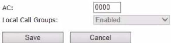
When an extension is added (or edited) it can be selected (right side check box) which handsets shall subscribe to the given extension, and hence be a part of this call group, see above figure. It is also possible to choose to add a new handset entry at this point, and if this is done, DECT registration for the new entry can be enabled afterwards on the handsets subpage
4.3.3 Extensions list
The added extensions will be shown in the extension lists.
The list can be sorted by any of the top headlines, by mouse click on the headline link.
Screenshot
Extensions and Handset
Extensions / Handset
| Idx | Extension | Display Name | Server | Server Alias | State | IPEI | |
| □ | 1 | 211 | 300Wx 210 | 10.10.1.36 | Asterisk | SIP Registered | 0134239EC0 |
| □ | 2 | 212 | 10.10.1.36 | Asterisk | 0134209268 | ||
| □ | 3 | 10.10.1.36 | Asterisk | ||||
| □ | 4 | 10.10.1.36 | Asterisk | ||||
| □ | 5 | 10.10.1.36 | Asterisk | ||||
| □ | 6 | 10.10.1.36 | Asterisk | ||||
| □ | 7 | 10.10.1.36 | Asterisk |
| Parameter | Description |
| Idx | Select / deselect for delete, register and deregister handsets |
| Extension | Given extension is displayed. |
| Display Name | Given display name is displayed. If no name given this field will be empty |
| Server | Server IP or URL |
| Server Alias | Given server alias is displayed. If no alias given this field will be empty. |
| State | SIP registration state – if empty the handset is not SIP registered. |
| IPEI | Handset IPEI. IPEI is a unique DECT identification number.Group call: One extension can be associated to up to 20 IPEI's. The IPEI's will be listed in this cell. |
4.3.4 Handset list
The added handsets will be shown in the handset lists.
The list can be sorted by any of the top headlines, by mouse click on the headline link.
Screenshot
Extensions and Handset

Extensions / Handset
Add Handset
| Idx | IPEI | Handset State | Handset Type FW Info | FWU Progress | Extension | |
| □ | 1 | 0134239ECO | Present | 3Party 00/00/00 00:00 | Off | 211 |
| □ | 2 | 0134209268 | 212 | |||
| Check All / Uncheck All | ||||||
With selected: Delete Handset(s) Register Handset(s) Deregister Handset(s)
| Parameter | Description |
| Idx | Select / deselect for delete, register and deregister handsets |
| IPEI | Handset IPEI. IPEI is unique DECT identification number. |
| Handset state | The state of the given handset:Present:The handset is DECT located at the baseDetached:The handset is detached from the system (e.g. powered off)Removed:The handset has been out of sight for a specified amount of time (~one hour). |
| Handset Type FW info | Handset type and firmware version of handset |
| FWU Progress | Possible FWU progress states:Off: Means sw version is specified to 0 = fwu is offInitializing: Means FWU is starting and progress is 0%.X% : FWU ongoingVerifying X%: FWU writing is done and now verifying before swap"Waiting for charger" (HS) / "Conn. term. wait" (Repeater): All FWU is complete and is now waiting for handset/repeater restart.Complete HS/repeater: FWU completeError: Not able to fwu e.g. file not found, file not valid etc |
| Extension | Given extension is displayed.Group call: The cell will show all the extensions associated with this handset and IPEI. |
4.3.4.1 Handset and extension list top/sub-menus
The handset extension list menu is used to control paring or deletion of handset to the system (DECT registration/de-registrations) and to control SIP registration/de-registrations to the system.
Above and below the list are found commands for making operations on handsets/and extensions. The top menu is general operations, and the sub menu is always operating on selected handsets/extensions.
Screenshots
Check All / Uncheck All
With selected: Delete Handset(s) Register Handset(s) Deregister Handset(s)
In the below table each command is described.
| Actions | Description |
| Delete Handset(s) | Deregister selected handset(s), but do not delete the extension(s). |
| Register Handset(s) | Enable registration mode for the system making it possible to register at a specific extension (selected by checkbox) |
| Deregister Handset(s) | Deregister the selected handset(s) and delete the extension(s). |
4.3.5 Edit Extension
To edit extension use the mouse to click the link of the extension.
Edit extension will open the same configuration possibilities as add extension. Refer to the above add extension section.
4.4 Servers
In this section, we describe the different parameters available in the Servers configurations menu. Maximum 10 servers can be configured.
Screenshot Servers
Asterisk: 10.10.1.06
| Add Server |
| Remove Server |
Asterisk:
| Server Alias: | Asterisk | |||
| NAT Adaption: | Enabled | |||
| Registrar: | 10 10 1 36 | |||
| Outbound Proxy: | ||||
| Conference Server: | ||||
| Call Log Server: | ||||
| Reregistration time (s): | 600 | |||
| SIP Session Timers: | Disabled | |||
| Session Timer Value (s): | 1800 | |||
| SIP Transport: | UDP | |||
| Signal TCP Source Port: | Enabled | |||
| Use One TCP Connection per SIP Extension: | Disabled | |||
| Keep Alive: | Enabled | |||
| Show Extension on Handset Idle Screen: | Enabled | |||
| Hold Behaviour: | RFC 3264 | |||
| Local Ring Back tone: | Enabled | |||
| Attended Transfer Behaviour: | Hold 2nd Call | |||
| Directed Call Pickup: | Disabled | |||
| Directed Call Pickup Code: | ||||
| Group Call Pickup: | Disabled | |||
| Group Call Pickup Code: | ||||
| Use Own Codec Priority: | Disabled | |||
| DTMF Signalling: | RFC 2833 | |||
| DTMF Payload Type: | 101 | |||
| Remote Caller ID Source Priority: | PAI - FROM | |||
| Codec Priority: | G722G711UG711AG726 | |||
| Up | Down | Reset Codecs | Remove | |
| RTP Packet Size: | 20 ms | |||
| Secure RTP: | Disabled | |||
| Secure RTP Auth: | Disabled | |||
| SRTP Crypto Suites: | AES CM 128 HMAC SHA1 32AES CM 128 HMAC SHA1 60 | |||
| Up | Down | Reset Crypto Suites | Remove | |
| Parameter | Default value | Description |
| Server Alias | Empty | Parameter for server alias |
| NATAdaption | Disabled | To ensure all SIP messages goes directly to the NAT gateway in the SIP aware router. |
| Registrar | Empty | SIP Server proxy DNS or IP addressPermitted value(s): AAA.BBB.CCC.DDD:or::Note: Specifying the Port Number is optional. |
| OutboundProxy | Empty | This is a Session Border Controller DNS or IP address (OR SIP server outbound proxy address)Set the Outbound proxy to the address and port of |
| private NAT gateway so that SIP messages sent via the NAT gateway. Permitted value(s): AAA.BBB.CCC.DDD oror:Examples: “192.168.0.1”, “192.168.0.1:5062”, “nat.company.com” and “sip:nat@company.com:5065”. | ||
| Conference Server | Empty | Broadsoft conference feature.Set the IP address of the conference server.In case an IP is specified pressing handset conference will establish a connection to the conference server.If the field is empty the original 3-party local conference of 8660 is used. |
| Call Log Server | Empty | Broadsoft call log feature.Set the IP address of the XSI call log server.In case an IP is specified pressing handset will use the call log server.If the field is empty the local call log is used |
| Re-registration time | 600 | The “expires” value 24nalyse24n in SIP REGISTER requests. This value indicates how long the current SIP registration is valid, and hence is specifies the maximum time between SIP registrations for the given SIP account. Permitted value(s): A value below 60 sec is not recommended, Maximum value 65636 |
| SIP Session Timers: | Disabled | RFC 4028. A “keep-alive” mechanism for calls. The session timer value specifies the maximum time between “keep-alive” or more correctly session refresh signals. If no session refresh is received when the timer expires the call will be terminated. Default value is 1800 s according to the RFC. Min: 90 s. Max: 65636. If disabled session timers will not be used. |
| Session Timer Values (s): | 1800 | Default value is 1800s according to the RFC. If disabled session timers will not be used. Permitted value(s): Minimum value 90, Maximum 65636 |
| SIP Transport | UDP | Select UDP, TCP, TLS 1.0 |
| Signal TCP Source Port | Disabled | When SIP Transport is set to TCP or TLS, a TCP (or TLS) connection will be established for each SIP extension. The source port of the connection will be chosen by the TCP stack, and hence the local SIP port parameter, specified within the SIP/RTP Settings (see 5.5.5) will not be used. The “Signal TCP Source Port” parameter specifies if the used source port shall be signaled explicitly in the SIP messages. |
| Use One TCP/TLS Connection per SIP Extension: | Disabled | When using TCP or TLS as SIP transport, choose if a TCL/TLS connection shall be established for each SIP extension or if the base station shall establish one connection which all SIP extensions use. Please note that if TLS is used and SIP server requires client authentication (and requests a client certificate), this setting must be set to disabled. 0: Disabled. (Use one TCP/TLS connection for all SIP |
| extensions)1: Enabled. (Use one TCP/TLS connection per SIP extensions). | ||
| Keep Alive | Enabled | This directive defines the window period (30 sec.) to keep opening the port of relevant NAT-aware router(s), etc. |
| Show Extension on Handset Idle Screen | Enabled | If enabled extension will be shown on handset idle screen. |
| Hold Behaviour | RFC 3264 | Specify the hold behaviour by handset hold feature.RFC 3264: Hold is 25nalyse25n according to RFC 3264, i.e. the connection information part of the SDP contains the IP Address of the endpoint, and the direction attribute is sendonly, revonly or inactive dependant of the contextRFC 2543: The "old" way of 25nalyse25ng HOLD. The connection information part of the SDP is set to 0.0.0.0, and the direction attribute is sendonly, revonly or inactive dependant of the context |
| Attended Transfer Behaviour | Hold 2^nd Call | When we have two calls, and one call is on hold, it is possible to perform attended transfer. When the transfer soft key is pressed in this situation, we have traditionally also put the active call on hold before the SIP REFER request is sent. However, we have experienced that some PBXes do not expect that the 2nd call is put on hold, and therefore attended transfer fails on these PBXes.The "Attended Transfer Behaviour" feature defines whether or not the 2nd call shall be put on hold before the REFER is sent.If "Hold 2nd Call" is selected, the 2nd call will be held before REFER is sent.If "Do Not Hold 2nd Call" is selected, the 2nd call will not be held before the REFER is sent |
| Use Own Codec Priority | Disabled | Default disabled.By enable the system codec priority during incoming call is used instead of the calling party priority.E.g. If base has G722 as top codec and the calling party has Alaw on top and G722 further down the list, the G722 will be chosen as codec for the call. |
| DTMF Signalling | RFC 2833 | Conversion of decimal digits (and '*' and '#') into sounds that share similar characteristics with voice to easily traverse networks designed for voiceSIP INFO: Carries application level data along SIP signalling path (e.g.: Carries DTMF digits generated during SIP session OR sending of DTMF tones via data packets in thesameinternet layer as the Voice Stream, etc.).RFC 2833: DTMF handling for gateways, end systems and RTP trunks (e.g.: Sending DTMF tones via data |
| packets in different internet layer as the voice stream) Both: Enables SIP INFO and RFC 2833 modes. | ||
| DTMF Payload Type | 101 | This feature enables the user to specify a value for the DTMF payload type / telephone event (RFC2833). |
| Codec Priority | G.722G.711UG.711AG.726 | Defines the codec priority that base stations uses for audio compression and transmission.Possible Option(s): G.711U,G.711A, G.726, G.729, G.722.Note: Modifications of the codec list must be followed by a “reset codes” and “Reboot chain” on the multipage in order to change and update handsets.Note:With G.722 as first priority the number of simultaneous calls per base station will be reduced from 10 (8) to 4 calls.With G.722 in the list the codec negotiation algorithm is active causing the handset (phone) setup time to be slightly slower than if G.722 is removed from the list.With G.729 add on DSP module for the base is required. |
| RTP Packet size | 20ms | The packet size offered as preferred RTP packet size by 8630 when RTP packet size negotiation.Selections available: 20ms, 40ms, 60ms, 80ms |
| Secure RTP | Disabled | With enable RTP will be encrypted (AES-128) using the key negotiated via the SDP protocol at call setup. |
| Secure RTP Auth | Disabled | With enable secure RTP is using authentication of the RTP packages.Note: with enabled SRTP authentication maximum 4 concurrent calls is possible per base in a single or multicell system. |
| SRTP Crypto Suites | AES_CM_128_HMAX_SHA1_32AES_CM_128_HMAX_SHA1_80 | Field list of supported SRTP Crypto Suites. The device is born with two suites. |
Note: Within servers or even with multi servers, extensions must always be unique. This means same extension number on server 1 cannot be re-used on server 2.
4.5 Network
In this section, we describe the different parameters available in the network configurations menu.
4.5.1 IP Settings
Screenshot
IP settings
| DHCP/Static IP: | DHCP |
| IP Address: | 10.10.1.53 |
| Subnet Mask: | 255.255.255.0 |
| Default Gateway: | 10.10.1.1 |
| DNS (Primary): | 10.10.1.10 |
| DNS (Secondary): | 10.10.1.18 |
| Parameter | Default Values | Description |
| DHCP/Static IP | DHCP | If DHCP is enabled, the device automatically obtains TCP/IP parameters.Possible value(s): Static, DHCPDHCP: IP addresses are allocated automatically from a pool of leased address.Static IP: IP addresses are manually assigned by the network administrator.If the user chooses DHCP option, the other IP settings or options are not available. |
| IP Address | NA | 32-bit IP address of device (e.g. base station). 64-bit IP address will be supported in the future.Permitted value(s): AAA.BBB.CCC.DDD |
| Subnet Mask | NA | Is device subnet mask.Permitted value(s): AAA.BBB.CCC.DDDThis is a 32-bit combination used to describe which portion an IP address refers to the subnet and which part refers to the host.A network mask helps users know which portion of the address identifies the network and which portion of the address identifies the node. |
| Default Gateway | NA | Device's default network router/gateway (32-bit).Permitted value(s): AAA.BBB.CCC.DDD e.g. 192.168.50.0IP address of network router that acts as entrance to other network.This device provides a default route for TCP/IP hosts to use when communicating with other hosts on hosts networks. |
| DNS (Primary) | NA | Main server to which a device directs Domain Name System (DNS) queries.Permitted value(s): AAA.BBB.CCC.DDD orThis is the IP address of server that contains mappings of DNS domain names to various data, e.g. IP address, etc.The user needs to specify this option when static IP address option is chosen. |
| DNS(Secondary) | NA | This is an alternate DNS server. |
4.5.2 VLAN Settings
Enable users to define devices (e.g. Base station, etc.) with different physical connection to communicate as if they are connected on a single network segment.
The VLAN settings can be used on a managed network with separate Virtual LANs (VLANs) for sending voice and data traffic. To work on these networks, the base stations can tag voice traffic it generates on a specific "voice VLAN" using the IEEE 802.1q specification.
Screenshot
VLAN Settings
ID:
| 0 |
| 0 |
User Priority:
| Parameter | Default Values | Description |
| VLAN id | 0 | Is a 12 bit identification of the 802.1Q VLAN.Permitted value(s): 0 to 4094 (only decimal values are accepted)A VLAN ID of 0 is used to identify priority frames and ID of 4095 (i.e. FFF) is reserved.Null means no VLAN tagging or No VLAN discovery through DHCP. |
| VLAN User Priority | 0 | This is a 3 bit value that defines the user priority.Values are from 0 (best effort) to 7 (highest); 1 represents the lowest priority. These values can be used to prioritize different classes of traffic (voice, video, data, etc).Permitted value(s): 8 priority levels (i.e. 0 to 7) |
For further help on VLAN configuration refer to Appendix.
4.5.3 DHCP Options
Screenshot
DHCP Options
Plug-n-Play:
| Enabled |
| Parameter | Default Values | Description |
| Plug-n-Play | Enabled | Enabled: DHCP option 43 to automatically provide PBX IP address to base. |
4.5.4 NAT Settings
We define some options available when NAT aware routers are enabled in the network.
Screenshot
NAT Settings
| Enable STUN: | Disabled |
| STUN Server: | |
| STUN Bindtime Determine: | Enabled |
| STUN Bindtime Guard: | 80 |
| Enable RPORT: | Disabled |
| Keep alive time: | 90 |
| Parameter | Default Values | Description |
| Enable STUN | Disabled | Enable to use STUN |
| STUN Server | NA | Permitted value(s): AAA.BBB.CCC.DDD (Currently only lpv4 are supported) or url |
| STUN Bindtime Determine | Enabled | |
| STUN Bindtime Guard | 80 | Permitted values: Positive integer default is 90, unit is in seconds |
| Enable RPORT | Disabled | Enable to use RPORT in SIP messages. |
| Keep alive time | 90 | This defines the frequency of how keep-alive are sent to maintain NAT bindings.Permitted values: Positive integer default is 90, unit is in seconds |
4.5.5 SIP/RTP Settings
These are some definitions of SIP/RTP settings:
Screenshot
SIP/RTP Settings
| Use Different SIP Ports: | Disabled |
| RTP Collision Detection: | Enabled |
| Always reboot on check-sync: | Disabled |
| Local SIP port: | 5060 |
| SIP ToS/QoS: | 0x68 |
| RTP port: | 50004 |
| RTP port range: | 40 |
| RTP ToS/QoS: | 0xB8 |
| Parameter | Default Values | Description |
| Use Different SIP Ports | Disabled | If disabled, the Local SIP port parameter specifies the source port used for SIP signalling in the system.If enabled, the Local SIP Port parameter specifies the source port used for first user agent (UA) instance. Succeeding UA's will get succeeding ports. |
| RTP Collision Detection | Enabled | |
| Local SIP port | 5060 | The source port used for SIP signallingPermitted values: Port number default 5060. |
| SIP ToS/QoS | 0x68 | Priority of call control signalling traffic based on both IP Layers of Type of Service (ToS) byte. ToS is referred to as Quality of Service (QoS) in packet based networks.Permitted values: Positive integer, default is 0x68 |
| RTP port | 50004 | The first RTP port to use for RTP audio streaming.Permitted values: Port number default 50004 (depending on the setup). |
| RTP port range | 40 | The number of ports that can be used for RTP audio streaming.Permitted values: Positive integers, default is 40 |
| RTP TOS/QoS | 0xB8 | Priority of RTP traffic based on the IP layer ToS (Type of Service) byte. ToS is referred to as Quality of Service (QoS) in packet based networks.See RFC 1349 for details. “cost bit” is not supported.o Bit 7..5 defines precedence.o Bit 4..2 defines Type of Service.o Bit 1..0 are ignored.Setting all three of bit 4..2 will be ignored.Permitted values: Positive integer, default is 0xB8 |
4.6 Management Settings Definitions
The administrator can configure base stations to perform some specific functions such as configuration of file transfers, firmware up/downgrades, password management, and SIP/debug logs.
Screenshot
Management Settings
Base Station Name:
IP DECT 10
Settings
Management Transfer Protocol:
HTTP Management upload script:
User Name:
HTTP Management password:
Enable Automatic Prefix:
Set Maximum Digits of Internal Numbers:
Set Prefix for Outgoing Calls:
HTTP
/CfgUpload
Disabled
0
Configuration
Configuration Server Address:
Configuration File Download:
Base Specific File:
DHCP Controlled Config Server:
DHCP Custom Option:
DHCP Custom Option Type:


Text Messaging
Text Messaging:
Text Messaging & Alarm Server:
Text Messaging Port:
Text Messaging Keep Alive (m):
Text Messaging Response (s):
Text Messaging TTL:

1300
30
30
0
Syslog/SIP Log
Upload of SIP Log:
SIP Log Server Address:
Syslog Level:
Syslog Server IP Address:
Syslog Server Port:


514
Save and Reboot
Save
Cancel
Default Base Station
| Parameter | Default value | Description |
| Base Station Name: | VoIP | It indicates the title that appears at the top window of the browser and is used in the multicell page. |
| Management Transfer Protocol | TFTP | The protocol assigned for configuration file and central directoryValid Input(s): TFTP, HTTP, HTTPS |
| HTTP Management upload script | Empty | The folder location or directory path that contains the configuration files of the Configuration server. The configuration upload script is a file located in e.g. TFTP server or Apache Server which is also the configuration server.Permitted value(s): /Example: /CfgUploadNote: Must begin with (/) slash character. Either / or \ can be used. |
| HTTP | Empty | Password that should be entered in order to have access to the |
| Management password | configuration server. Permitted value(s): 8-bit string length | |
| Configuration server address | Empty | Server/device that provides configuration file to base station. Type: DNS or IP address Permitted value(s): AAA.BBB.CCC.DDD or |
| Base Specific File | Empty | Base configuration file |
| Configuration File Download | Disabled | Base Specific file: Used when configuring a single cell base Multicell Specific File: Used when configuring a multicell based system Base and Multicell Specific File: Used on out of factory bases to specify VLAN and Multicell ID and settings. |
| DHCP Controlled Config Server | Disabled | Provisioning server options. DHCP Option 66: Look for provision file by TFTP boot up server. DHCP Custom Option: Look for provision file by custom option DHCP Custom Option & Option 66: Look for provision file by first custom option and then option 66. |
| DHCP Custom Option | Empty | By default option 160, but custom option can be defined. An option 160 URL defines the protocol and path information by using a fully qualified domain name for clients that can use DNS. |
| DHCP Custom Option Typr | Empty | URL: URL of server with path. Example of URL: http://myconfigs.com:5060/configs Default configuration file on server must follow the name: MAC.cfg IP Address: IP of server with path. |
| Text Messaging | Disabled | Disable/enable messaging with Mobicall server The third option is to “Enable Without Server”. With this setting handset can send messages to other handsets, which support messaging. Note: Contact Mobicall to get the proper version and setup for Mobicall server |
| Text Messaging & Alarm server | Empty | Permitted value(s): AAA.BBB.CCC.DDD or |
| Text Messaging Port | 1300 | Port number of message server. |
| Text Messaging Keep Alive (m) | 30 | This defines the frequency of how keep-alive are sent Permitted values: Positive integer, unit is in minutes |
| Text Messaging Response (s) | 30 | This defines the frequency of how response timeout Permitted values: Positive integer, unit is in seconds |
| Text Messaging TTL | 0 | This defines the text messaging time to live Permitted values: Positive integer, unit is in seconds |
| SIP Log Server Address | Empty | Permitted value(s): AAA.BBB.CCC.DDD orRequires a predefined folder named: \SIP |
| Upload of SIP Log | Disabled | Enable this option to save low level SIP debug messages to the server. The SIP logs are saved in the file format:SIP.log |
| Syslog Server IP-Address | NA | Permitted value(s): AAA.BBB.CCC.DDD or |
| Syslog Server Port | NA | Port number of syslog server. |
| Syslog Level | Off | Off: No data is saved on syslog serverNormal Operation: Normal operation events are logged, incoming call, outgoing calls, handset registration, DECT location, and call lost due to busy, critical system errors, general system information.System Analyze: Handset roaming, handset firmware updates status.The system 33nalyse level also contains the messages from normal operation.Debug: Used by IP DECT 10 for debug. Should not be enabled during normal operation. |
| Enable Automatic Prefix | Disabled | Disabled: Feature off.Enabled: The base will add the leading digit defined in “Set Prefix for Outgoing Calls”.Enabled + fall through on * and #: Will enable detection of * or # at the first digit of a dialled number. In case of detection the base will not complete the dialled number with a leading 0.Examples:1: dialed number on handset * 1234 -> dialed number to the pabx *12342: dialed number on handset #1234 -> dialed number to the pabx #12343: dialed number on handset 1234 -> dialed number to the pabx 01234 |
| Set Maximum Digits of Internal Numbers | 0 | Used to detect internal numbers. In case of internal numbers no prefix number will be added to the dialled number. |
| Set Prefix for Outgoing Calls | Empty | Prefix number for the enabled automatic prefix feature.Permitted value(s): 1 to 9999 |
There are three ways of configuring the system.
- Manual configuration by use of the Web server in the base station(s)
- By use of configuration files that are uploaded from a disk via the "Configuration" page on the Web server.
- By use of configuration files which the base station(s) download(s) from a configuration server.
For further details refer to doc reference [3].
4.7 Firmware Update Definitions
In this page, the system administrator can configure how base stations and SIP nodes upgrade/downgrade to the relevant firmware. Handset firmware update status can be found in the extensions page and repeater firmware update status in the repeater page. Base firmware update status is found in the multicell page.
Screenshot
Firmware Update Settings

| Parameter | Default Value(s) | Description |
| Firmware update server address | Empty | IP address or DNS of firmware update files sourceValid Inputs: AAA.BBB.CCC.DDD orExample: 10.10.104.41 |
| Firmware path | Empty | Location of firmware on server (or firmware update server path where firmware update files are located).Example: /East_FwuNote: Must begin with (/) slash character |
| Required Version Type | Empty | Version of firmware to be upgraded (or downgraded) on handset type or repeater.Valid Input(s): 8-bit string length. E.g. 280Note: Value version 0 will disable firmware upgrade for handsets and/or repeaterNote: Two handset types will be serial firmware upgraded. First type 8630 then type 8430. |
| Required Version Base | Empty | Version of firmware to be upgraded (or downgraded) on Base station. Base units are referred to as gateways over here.Valid Input(s): 8-bit string length. E.g. 280 |
4.8 Time Server
In this section, we describe the different parameters available in the Time Server menu.
The Time server supplies the time used for data synchronisation in a multi-cell configuration. As such it is mandatory for a multi-cell configuration. The system will not work without a time server configured.
As well the time server is used in the debug logs and for SIP traces information pages, and used to determine when to check for new configuration and firmware files.
NOTE: It is not necessary to set the time server for standalone base stations (optional).
Press the "Time PC" button to grab the current PC time and use in the time server fields.
NOTE:
When time server parameters are modified/changed synchronisation between base stations can take up to 15 minutes before all base stations are synchronised, depending on the number of base stations in the system.
Screenshot
Time Settings
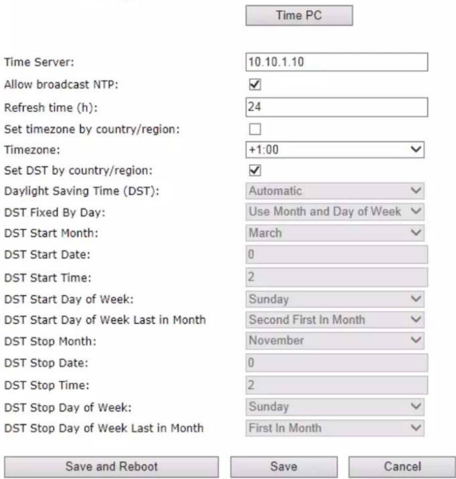
| Parameter | Default Values | Description |
| Time Server | Empty | DNS name or IP address of NTP server.Enter the IP/DNS address of the server that distributes reference clock information to its clients including Base stations, Handsets, etc.Valid Input(s): AAA.BBB.CCC.DDD or URL (e.g. time.server.com)Currently only lpv4 address (32-bit) nomenclature is supported. |
| Allow broadcast NTP | Checked | |
| Refresh time (h) | Empty | The window time in seconds within which time server refreshes.Valid Inputs: positive integer |
| Set timezone by country/region | Checked | By checked country setting is used (refer to country web page). |
| Time Zone | 0 | Refers to local time in GMT or UTC format.Min:-12:00Max:+13:00 |
| Set DST by country/region | Checked | By checked country setting is used (refer to country web page). |
| Daylight Saving Time (DST) | Disabled | The system administrator can Enable or Disable DST manually.Automatic: Enter the start and stop dates if you selectAutomatic. |
| DST Fixed By Day | Use Month and Date | You determine when DST actually changes. Choose the relevant date or day of the week, etc. from the drop down menu. |
| DST Start Month | March | Month that DST beginsValid Input(s): Gregorian months (e.g. January, February, etc.) |
| DST Start Date | 25 | Numerical day of month DST comes to effect when DST is fixed to a specific dateValid Inputs: positive integer |
| DST Start Time | 3 | DST start time in the dayValid Inputs: positive integer |
| DST Start Day of Week | Monday | Day within the week DST begins |
| DST Start Day of Week, Last in Month | Last in Month | Specify the week that DST will actually start. |
| DST Stop Month | October | The month that DST actually stops. |
| DST Stop Date | 1 | The numerical day of month that DST turns off.Valid Inputs: positive integer (1 to 12) |
| DST Stop Time | 2 | The time of day DST stopsValid Inputs: positive integer (1 to 12) |
| DST Stop Day of Week | Sunday | The day of week DST stops |
| DST Stop Day of Week Last in Month | First in Month | The week within the month that DST will turn off. |
4.9 Country
The country setting controls the in-band tones used by the system. To select web interface language go to the management page.
Screenshot
Country
| Select country: | US / Canada |
| State / Region: | Alabama |
| Select Language: | English |
| Set timezone by country/region: | |
| Set DST by country/region: | |
| Notes: | Time zone is CST, not fitting the unofficial use of EST |
Save and Reboot
Save
Cancel
| Parameter | Default Values | Description |
| Select Country | Germany | Supported countries: Australia, Belgium, Brasil, Denmark, Germany, Spain, France, Ireland, Italia, Luxembourg, Nederland, New Zealand, Norway, Portugal, Swiss, Finland, Sweden, Tyrkey, United Kingdom, US/Canada, Austria |
| State / Region | NA | Only shown by country selection US/Canada, Australia, Brasil |
| Select Language | English | Web interface language. Number of available languages: English, Dansk, Italiano, Tyrkie, Deutsch, Portuguese, Hrvatski, Srpski, Slovenian, Nederlands, Francaise, Espanol, Russian, Polski. |
| Set timezone by country/region | checked | When checked timezone will follow country/region |
| Set DST by country/region | checked | When checked DST will follow country/region |
| Notes | Empty | Only showing notes to time setting for countries: US/Canada, Brasil |
NOTE: By checked timezone and DST the parameters in web page Time will be discarded.
The following types of in-band tones are supported:
- Dial tone
- Busy tone
- Ring Back tone
- Call Waiting tone
- Re-order tone
4.10 Security
The security section is used for loading of certificates and for selecting if only trusted certificates are used. Furthermore, web password can be configured.
The Security web is divided into three sections: Certificates (trusted), SIP Client Certificates (and keys) and Password administration.
To setup secure fwu and configuration file download select HTTPS for the Management Transfer Protocol (refer to management web).
SIP and RTP security is server dependent and in order to configure user must use the web option Servers (refer to servers web).
4.10.1 Certificates
The certificates list contains the list of loaded certificates for the system. Using the left column check mark it is possible to check and delete certificates. To import a new certificate use the mouse "select file" and browse to the selected file. When file is selected, use the "Load" bottom to load the certificate.
The certificate format supported is DER encoded binary X.509 (.cer).
Screenshot
Security
Certificates:
| Idx | Issued To | Issued To | Valid Until | |
| □ | 0 | |||
| ■ | 1 | |||
| □ | 2 | |||
| ■ | 3 |
Check All /Uncheck All
With selected: Delete Certificate(s)
Import Trusted Certificates:
Filename:

Certificates list
| Parameter | Default Values | Description |
| Idx | Fixed indexes | Index number |
| Issued To | Empty | IP address – which is part of the certificate file |
| Issued To | Empty | Organisation, Company – which is part of the certificate file |
| Valid Until | Empty | Date Time Year – which is part of the certificate file |
Screenshot
Use Only Trusted Certificates: Disabled

By enabling Use Only Trusted Certificates, the certificates the base will receive from the server must be valid and loaded into the system. If no valid matching certificate is found during the TLS connection establishment, the connection will fail. When Use Only Trusted Certificates is disabled, all certificates received from the server will be accepted.
Note: It is important to use correct date and time of the system when using trusted certificates. In case of time/date not defined the certificate validation can fail
4.10.2 SIP Client Certificates
To be able to establish a TLS connection in scenarios, where the server requests a client certificate, a certificate/key pair must be loaded into the base. This is currently supported only for SIP.
To load a client certificate/key pair, both files must be selected at the same time, and it is done by pressing "select files" under "Import SIP Client Certificate and Key Pair" and then select the certificate file as well as the key file at the same time. Afterwards, press load.
The certificate must be provided as a DER encoded binary X.509 (.cer) file, and the key must be provided as a binary PKCS#8 file.
Note: Use Chrome for loading SIP Client Certificates
Screenshot
SIP Client Certificates:
| Idx | Issued To | Issued To | Valid Until | |
| 0 | ||||
| 1 |
Check All /Uncheck All
With selected: Delete Certificate(s)
Import SIP Client Certificate and Key Pair:
Filename:

4.10.3 Password
In the below the password parameters are defined.
Screenshot
Password:
| Username: | admin |
| Current Password: | |
| New Password: | |
| Confirm Password: |

| Parameter | Default Values | Description |
| Username | Admin | Can be modified to any supported character and number |
| Current Password | Admin | Can be modified to any supported character and number |
| New Password | Empty | Change to new password |
| Confirm Password | Empty | Confirm password to reduce accidentally wrong changes of passwords |
Password valid special signs: @/|<>-_:!?*+#
Password valid numbers: 0-9
Password valid letters: a-z and A-Z
4.11 Central Directory and LDAP
The VOIP system support two types of central directories, a local central directory or LDAP directory.
For both directories caller id look up is made with match for 6 digits of the phone number.
4.11.1 Local Central Directory
Select local and save for local central directory.
Screenshot
Central Directory

Save
Import Central Directory:
Filename: Bläddra...
Load
| Parameter | Default Values | Description |
| Local | Local | Drop down menu to select between local central directory and LDAP based central directory |
| Server | Empty | The parameter is used if directory file is located on server. Valid Inputs: AAA.BBB.CCC.DDD orRefer to appendix for further details. |
| Filename | Empty | The parameter is used if directory file is located on server. Refer to appendix for further details |
| Phonebook reload interval (s) | 0 | The parameter is controlling the reload interface of phonebook in seconds. The feature is for automatic reload the base phonebook file from the server with intervals. It is recommended to specify a conservative value to avoid overload of the base station. With default value setting 0 the reload feature is disabled. |
4.11.1.1 Import Central Directory
The import central directory feature is using a browse file approach. After file selection press the load button to load the file. The system support only the original *.csv format. Please note that some excel csv formats are not the original csv format. The central directory feature can handle up to 3000 contacts. For further details of the central directory feature refer to appendix.
4.11.2 LDAP
Select LDAP Server and save for LDAP server configuration.
Screenshot
LDAP Central Directory

Handset Identity:
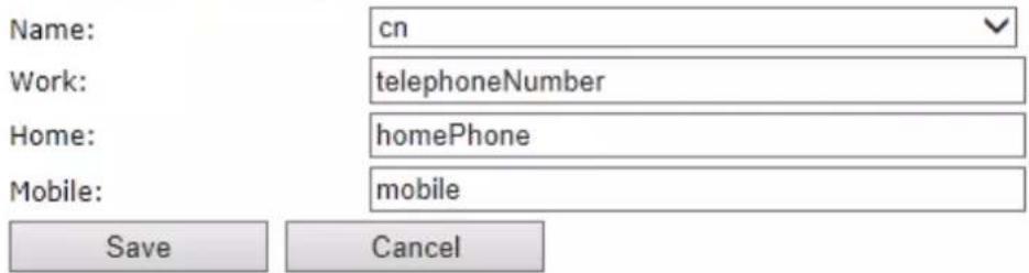
| Parameter | Default Values | Description |
| LDAP Server | LDAP Server | Drop down menu to select between local central directory and LDAP based central directory. LDAP Server is displayed when LDAP server is selected. |
| Server | Empty | IP address of the LDAP server. Valid Inputs: AAA.BBB.CCC.DDD or |
| Port | Empty | The server port number that is open for LDAP connections. |
| Sbase | Empty | Search Base. The criteria depends on the configuration of the LDAP server. Example of the setting is CN=Users, DC=umber, DC=loc |
| LDAP filter | Empty | LDAP Filter is used to as a search filter, e.g. setting LDAP filter to (|(givenName=%*)(sn=%*)) the IP-DECT will use this filter |
| when requesting entries from the LDAP server. % will be replaced with the entered prefix e.g searching on J will give the filter (I(givenName=J*)(sn=J*)) resulting in a search for given name starting with a J or surname starting with J. | ||
| Bind | Empty | Bind is the username that will be used when the IP-DECT phone connects to the server |
| Password | Empty | Password is the password for the LDAP Server |
| Name | Empty | The name can be used to specify if sn+givenName or cn (common name) is return in the LDAP search results |
| Work Number | Empty | Work number is used to specify that LDAP attribute that will be mapped to the handset work number |
| Home Number | Empty | Home number is used to specify that LDAP attribute that will be mapped to the handset home number |
| Mobile Number | Empty | Mobile number is used to specify that LDAP attribute that will be mapped to the handset mobile number |
4.12 Statistics
The statistic feature is divided into four administrative web pages, which can be access from any base.
- System
- Calls
- Repeater
- DECT data
All four views have an embedded export function, which export all data to comma separated file.
By pressing the clear button all data in the full system is cleared.
4.12.1 System data
The system data web is access by http://ip/SystemStatistics.html and data is organised in a table as shown in below example.
Screenshot
Statistics
Export
Clear
System / Calls / Repeater / DECT
| Base Station Name | Operation/ Duration D-H:M:S | Busy | Busy Duration D-H:M:S | SIP Failed | Handset Removed | Searching | Free Running | DECT Source Changed |
| Sum | 0-00:31:12/5-21:27:59 | 0 | 127 | 1 | 0 | 0 | 0 |
The table is organised with headline row, data pr. base rows and with last row containing the sum of all base parameters.
| Parameters | Description |
| Base Station Name | Base IP address and base station name from management settings |
| Operation time | Total operation time for the base |
| Busy Count | Busy Count is the number of times the base has been busy. |
| Busy Duration | Busy duration is the total time a base has been busy for speech (8 or more calls active). |
| SIP Failed | Failed SIP registrations count the number of times a SIP registration has failed |
| Handset Removed | Handset removed count is the number of times a handset has been marked as removed |
| Searching | Base searching is the number of times a base has been searching for it's sync source |
| Free Running | Base free running is the number of times a base has been free running |
| DECT Source Changed | Number of time a base has changed sync source |
4.12.2 Call data
The call data web is access by http://ip/CallStatistics.html and data are organised in a table as shown in below example.
Screenshot
System / Calls / Repeater / DECT
| Base Station Name | Operation/ Duration D-H:M:S | Count | Dropped | No Response | Duration D-H:M:S | Active | Max Active | Codec G711U: G711A: G729: G722: G726: | Handover Success | Handover Failed | Audio Not Detected |
| Sum | 0-00:31:45/ 5-21:28:32 | 106 | 1 | 0 | 0-00:26:32 | 0 | 3 | 10:41:0:36:0 | 0 | 0 | 46 |
The table is organised with headline row, data pr. base rows and with last row containing the sum of all base parameters.
| Parameters | Description |
| Base Station Name | Base IP address and base station name from management settings |
| Operation time/Duration | Total operation time for the base since last reboot or reset Duration is the time from data was cleared or system has been firmware upgraded. |
| Count | Counts number of calls on a base. |
| Dropped | Dropped calls are the number of active calls that was dropped.E.g. if a user has an active call and walks out of range, the calls will be counted as a dropped call. An entry is stored in the syslog when a call is dropped. |
| No response | No response calls is the number of calls that have no response, e.g. if a external user tries to make a call to a handset that is out of range the call is counted as no response. An entry is stored in the syslog when a call is no response. |
| Duration | Call duration is total time that calls are active on the base. |
| Active | Active call shows how many active calls that are active on the base (Not active DECT calls, but active calls). On one base there can be up to 30 active calls. |
| Max Active | Maximum active calls are the maximum number of calls that has been active at the same time. |
| Codecs | Logging and count of used codec types on each call. |
| Handover Success | Counts the number of successful handovers. |
| Handover Failed | Counts the number of failed handovers. |
4.12.3 DECT data
The DECT data web is access by http://ip/DectStatistics.html and data is organised in a table as shown in below example.
Screenshot
System / Calls / Repeater / DECT
| Slot0 | Slot1 | Slot2 | Slot3 | Slot4 | Slot5 | Slot6 | Slot7 | Slot8 | Slot9 | Slot10 | Slot11 | |
| Frequency0 | 11 | 0 | 6 | 0 | 16 | 0 | 11 | 0 | 7 | 0 | 7 | 0 |
| Frequency1 | 11 | 0 | 16 | 0 | 16 | 0 | 13 | 0 | 16 | 0 | 12 | 0 |
| Frequency2 | 13 | 0 | 15 | 0 | 15 | 0 | 15 | 0 | 10 | 0 | 10 | 0 |
| Frequency3 | 15 | 0 | 16 | 0 | 12 | 0 | 17 | 0 | 12 | 0 | 9 | 0 |
| Frequency4 | 9 | 0 | 22 | 0 | 11 | 0 | 16 | 0 | 10 | 0 | 15 | 0 |
| Frequency5 | 21 | 0 | 19 | 0 | 16 | 0 | 14 | 0 | 22 | 0 | 17 | 0 |
| Frequency6 | 8 | 0 | 5 | 0 | 10 | 0 | 3 | 0 | 4 | 0 | 4 | 0 |
| Frequency7 | 13 | 0 | 16 | 0 | 19 | 0 | 10 | 0 | 14 | 0 | 8 | 0 |
| Frequency8 | 22 | 0 | 16 | 0 | 18 | 0 | 12 | 0 | 11 | 0 | 16 | 0 |
| Frequency9 | 19 | 0 | 15 | 0 | 14 | 0 | 22 | 0 | 24 | 0 | 24 | 0 |
Please note 3 frequencies are manually removed in the example system.
4.13 Settings – Configuration File Setup
This page provides non editable information showing the native format of entire VoIP Configuration parameter settings. The settings format is exactly what is used in the configuration file. The configuration file is found in the TFTP server.
The filename for the configuration server is
There are three ways to edit the configuration file or make changes to the settings page:
1) Using the VoIP Configuration interface to make changes. Each page of the HTTP web interface is a template for which the user can customise settings in the configuration file.
2) Retrieving the relevant configuration file from the TFTP and modify and enter new changes. This should be done with an expert network administrator.
3) Navigate to the settings page of the VoIP Configuration interface > copy the contents of settings > save them to any standard text editor e.g. notepad > modify the relevant contents, make sure you keep the formatting intact > Save the file as
For details refer to [3].
An example of contents of settings is as follows:
~RELEASE=UMBER_FP_V0054
%GMT_TIME_ZONE%:16
%COUNTRY_VARIANT_ID%:18
%FWU_POLLING_ENABLE%:0
%FWU_POLLING_MODE%:0
%FWU_POLLING_PERIOD%:86400
%FWU_POLLING_TIME_HH%:3
%FWU_POLLING_TIME_MM%:0
%DST_ENABLE%:2
%DST_FIXED_DAY_ENABLE%:0
%DST_START_MONTH%:3
%DST_START_DATE%:1
...
4.14 Sys log
This page shows live feed of system level messages of the current base station. The messages the administrator see here depends on what is configured at the Management settings. The Debug logs can show only Boot Log or Everything that is all system logs including boot logs.
The Debug log is saved in the file format
A sample of debug logs is as follows:
0101000013 [N](01):DHCP Enabled
0101000013 [N](01):IP Address: 192.168.10.101
0101000013 [N](01):Gateway Address: 192.168.10.254
0101000013 [N](01):Subnet Mask: 255.255.255.0
0101000013 [N](01):TFTP boot server not set by DHCP. Using Static.
0101000013 [N](01):DHCP Discover completed
0101000013 [N](01):Time Server: 192.168.10.11
0101000013 [N](01):Boot server: 10.10.104.63 path: Config/ Type: TFTP
0101000013 [N](01):RemCfg: Download request of Config/00087b077cd9.cfg from 10.10.104.63 using TFTP
0101000014 [N](01):accept called from task 7
0101000014 [N](01):TrelAccept success [4]. Listening on port 10010
0101000019 [N](01):RemCfg: Download request of Config/00087b077cd9.cfg from 10.10.104.63 using TFTP
0101000019 [W](01):Load of Config/00087b077cd9.cfg from 10.10.104.63 failed
To dump the log simply copy and page the full contents.
4.15 SIP Logs
This page shows SIP server related messages that are logged during the operation of the system. The full native format of SIP logs is saved in the TFTP server as
.....
Sent to udp:192.168.10.10:5080 at 12/11/2010 11:56:42 (791 bytes)
REGISTER sip:192.168.10.10:5080 SIP/2.0
Via: SIP/2.0/UDP 192.168.10.101:5063;branch=z9hG4bKrlga4nkuhimpnj4.qx
Max-Forwards: 70
From: <sip:Ext003@192.168.10.10:5080>;tag=3o51314
To: <sip:Ext003@192.168.10.10:5080>
Call-ID: p9st.zzrfff66.ah8
CSeq: 6562 REGISTER
Contact: <sip:Ext003@192.168.10.101:5063>
Allow: INVITE, CANCEL, BYE, ACK, REGISTER, OPTIONS, REFER, SUBSCRIBE, NOTIFY,
MESSAGE, INFO, PRACK
Expires: 120
User-Agent: Generic-DPV-001-A-XX (Generic_SIPEXT2MLUA_v1)
Content-Type: application/X-Generic_SIPEXT2MLv1
Content-Length: 251
.....
To dump the log simply copy and page the full contents.
5 Firmware Upgrade Procedure
This step-by-step chapter describes how to upgrade or downgrade base station(s) and/or handset(s) / repeater (s) to the relevant firmware provided by Konftel.
5.1 Network Dimensioning
In principle, a number of hardware and software components should be available or be satisfied before base station/handset update can be possible.
The minimum hardware and software components that are required to be able update via TFTP include the following (but not limited to):
- Handsets
- Base stations
• TFTP Server (Several Windows and Linux applications are available)
• DHCP Server (Several Windows and Linux applications are available)
• Workstation (e.g. Normal terminal or PC)
• Any standard browser (e.g. Firefox)
• Public/Private Network
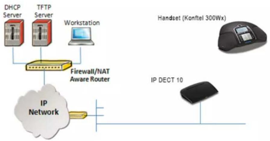
flowchart
graph TD
    A["DHCP Server"] --> D["Firewall/NAT Aware Router"]
    B["TFTP Server"] --> D
    C["Workstation"] --> D
    D --> E["IP Network"]
    F["Handset (Konftel 300Wx)"] --> G["IP DECT 10"]
    G --> E
5.2 TFTP Configuration
This section illustrates TFTP Server configuration using "SolarWinds" vendor TFTP Server. Create the following relevant folders as shown in the snap shots and choose defaults settings for the remaining options and save.

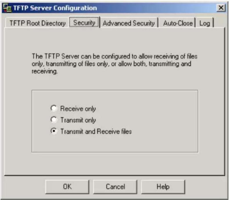
NOTE: If TFTP server timeout settings are too short firmware upgrade might not complete. Recommended time out setting is more than 3 seconds.
5.3 Create Firmware Directories
The admin from the service provider's side must create the relevant firmware directory in the server where both old and new firmware(s) can be placed in it. (See the STEP above)
5.3.1 Base:
On the TFTP server root, create directory "9430".

Copy Base station firmware to the named directory.

IMPORTANT:
The 9430 directory name cannot be changed.
5.4 Firmware Update Settings
Scroll down and Click on Firmware Update url link in the VoIP Configuration Interface to view the Firmware Update Settings page.
Firmware Update Settings
Firmware update server address:
Firmware path:
Image path:
Type
8630
Required version
Required branch
Startup image


Update Base Stations
Required version
Required branch


Save/Start Update
Type IP address and firmware path followed by save.
For Http download the firmware update server settings must be entered as follows:

5.5 Base Station Firmware Upgrade
On the Firmware Update Settings page > scroll down to the Update Gateways section > Enter the relevant firmware version of the base station to upgrade or to downgrade. Enter 202 for base version V0202.
Update Base Stations

Save/Start Update
After entering required version choose Start update button > select OK button from the dialog window to start the update/downgrade procedure.
The base station will automatically reboot and retrieve the firmware specified from the server and update itself accordingly.
The base firmware update behaviour is: Base will fetch the fwu file for approximately 3 minutes, then reboot and start flashing the LED - indicated by LED fast flashing for approximately 3 minutes and reboots in new version.
Note: All on-going voice calls are dropped from the base station immediately the firmware update procedure starts.
5.5.1 Base firmware confirmation
Base station firmware version status can be seen on the web Welcome page.
Welcome
| System Information: | |
| Phone Type: | IPDECT |
| System Type: | Generic SIP (RFC 3261) |
| RF Band: | EU |
| Current local time: | 08/Sep/2015 08:58:53 |
| Operation time: | 00:59:12 (H:M:S) |
| RFPI Address: | 1254E27B; RPN:00 |
| MAC Address: | 000413620023 |
| IP Address: | 10.10.1.53 |
| Firmware Version: | IPDECT/03.55/B0004/19-Aug-2015 15:39 |
| Firmware URL: | Firmware update server address: http://10.10.1.30 |
| Firmware path: FwuTest | |
| Base Station Status: | Idle |
5.5.2 Verification of Firmware Upgrade
Syslog information when Management Syslog level is set to "Debug"
[ FWU Downloading File tftp://10.1.24.101/FwuPath/Beatus/BeatusSw_4181_v0202.fwu]
[ Base FWU started]
[ Base FWU ended with exit code 2101 (NE_FILE_TRANSFER_EOF): End of file]
The log window of the TFTP server:

6 Functionality Overview
So far we have setup our VoIP system. Next, in this chapter we list what features and functionalities are available in the system. The VOIP system supports all traditional and advanced features of most telephony networks. In addition, 3 ^rd party components handle features like voice mail, call forward, conference calls, etc. A brief description of VOIP network functionalities are:
- Outgoing/incoming voice call management: The VOIP system can provide multiple priority user classes. Further, up to 3 repeaters can be linked to a Base-station.
- Internal handover: User locations are reported to SIP Server in order to provide differentiated services and tariff management. Within a DECT traffic area, established calls can seamlessly be handover between Base-station and repeaters using connection handover procedures.
- Security: The IP DECT 10 system also supports robust security functionalities for Base-station. Most security ^1 functionality is intrinsically woven into the VOIP network structure so that network connections can be encrypted and terminal authentication can be performed.
6.1 Base Station Interfaces
| Interfaces | |
| Power | Input: 100-240 VAC 50-60Hz (90 – 265 VAC)Output Nom: 5VDC 1000mAType: Switch mode single or multi-plug solutionPlugs: UK, EU, US and AUS |
| LAN Interface | Standard : 10BASE-T(IEEE 802.3 100Mbps)Connector: RJ45 8/8 |
| Keys | |
| 1: Reset key, Page and Default | |
| LED indicator | |
| One Status LED (multicolour, red, green, orange) | |
| RF | |
| Frequency Bands | 1880 – 1900 MHz (EMEA)1910 – 1930 MHz (Latam)1920 – 1930 MHz (USA)Factory setting which can’t be modified after production |
| Output Power | 250 mW or 140mW depending on country version |
| Antenna | Two antennas for diversity |
| Software upgrade | |
| Downloadable | Remote firmware update using HTTP, HTTPS or TFTP |
| Temperatures | |
| Operation | 0°C to 40°C |
6.2 Software Features
| CODEC's | |
| G.711 PCM A-law & U-law | Yes |
| G.722 | Yes |
| G.726 | Yes |
| G.729 | A/AB (including VAD), max 4 codersG729 licence not included |
| SIP | |
| RFC2327 | SDP: Session Description Protocol |
| RFC2396 | Uniform Resource Identifiers (URI): Generic Syntax |
| RFC2833 | In-Band DTMF/Out of band DTMF support |
| RFC2976 | The SIP INFO method |
| RFC3261 | SIP 2.0 |
| RFC3262 | Reliability of Provisional Responses in the Session Initiation Protocol (PRACK) |
| RFC3263 | Locating SIP Servers (DNS SRV, redundant server support) |
| RFC3264 | Offer/Answer Model with SDP |
| RFC3265 | Specific Event Notification |
| RFC3326 | The Reason Header Field for the Session Initiation Protocol |
| RFC3311 | The Session Initiation Protocol UPDATE Method |
| RFC3325 | P-Asserted Identity |
| RFC3326 | The Reason Header Field for the Session Initiation Protocol (SIP) |
| RFC3489 | STUN |
| RFC3515 | REFER: Call Transfer |
| RFC3550 | RTP: A Transport Protocol for Real-Time Application |
| RFC3581 | Rport |
| RFC3842 | Message Waiting Indication |
| RFC3891 | Replace header support |
| RFC3892 | The Session Initiation Protocol (SIP) Referred-By Mechanism |
| RFC3960 | Early Media and Ringing Tone Generation in the Session Initiation Protocol (SIP) |
| RFC4475 | Session Initiation Protocol (SIP) Torture Test Messages |
| SIPS | Secure SIP |
| In-band DTMF | No |
| SRTP | Yes, packet authentication will limit the number of calls to 4 |
| SIP registrations | max 20 |
| RTP streams | max 10 |
| SIP transport | UDP, TCP or TLS |
| Web server | |
| Embedded web server, accessed using HTTP | |
| Other features | |
| IP quality | Warning – Network outage, VoIP service outage |
| Jitter buffer | Yes, adaptive |
| Automatic DST | Yes |
| Tone Scheme | Country Depend Tone Scheme |
| Provisioning | Yes |
| Re-direct server | Yes |
| SIP configuration | Yes, from web page or configuration file |
| Call groups | Yes |
| IP features | |
| IPv4 | Yes |
| IPv6 | Hardware ready, software not included |
| TCP/IP/UDP | Yes |
| DHCP Support | Yes |
| DHCP option | 66, 120 |
| Static IP | Yes |
| DNS srv | Yes |
| VLAN | Yes, 802.1p/q |
| Quality of service | Type of Service (ToS) including DiffServ Tagging, and QoS per IEEE 802.1p/q |
| TLS | Yes, 1.0 |
| Certificates | Yes, X.509 (certificate not included) |
| TFTP | Yes, for firmware and configuration file download |
| HTTP server | Yes |
| HTTP client | Yes, for firmware and configuration file download |
| HTTPS | Yes, for firmware and configuration file download |
| SNTP | Yes, For internet clock synchronization |
| DECT | |
| DECT handover | Yes, inter-cell handover for repeater support |
| CAT-IQ v1.0 | HD audio or NB audio support |
| Repeater support | Yes |
| Intercom | No |
| DECT encryption | Yes |
| DECT Authentication | Yes |
| Group TPUI support | Yes, for call groups |
| GAP compliant | No |
| CAT-IQ compliant | No |
| Handset registrations | 20 |
6.3 Call Features
| Call supported | 5 simultaneous call supported |
| Simultaneous calls/base | 5 Wideband calls (g.722). 5 narrowband calls (PCMA, PCMU, G.726) or 4 when using G729 |
| Simultaneous calls/handset | 2 |
| Call features | Codec Negotiation |
| Codec Switching | |
| Missed call notification | |
| Voice message waiting notification | |
| Date and Time synchronization | |
| Parallel calls | |
| Call Hold | |
| Call Retrieve | |
| Call transfer unannounced | |
| Call transfer announced | |
| Conference (3PTY) | |
| Conference, Network | |
| Call Waiting Indication | |
| Calling line identity | |
| Outgoing call | |
| Call Toggle/Swap | |
| Incoming call | |
| Line identification | |
| Multiple Lines | |
| Multiple calls | |
| Call identification | |
| Calling Name Identification Presentation (CNIP) | |
| Calling Line Identification Presentation (CLIP) | |
| Call Completed Elsewhere | |
| Distinctive Ringing | |
| Central Phone Book: | |
| - LDAP | Yes |
| - XML | Yes, remote or file load from web interface |
| - CSV | Yes, file load through web interface |
| DND: | Yes |
| Call Forward: | Configurable from base or handset (Not with Call Group active)) |
| - CFU | Yes |
| - CFNA | Yes |
| - CFB | Yes |
| Call groups: | Yes, 1-20 handsets/SIP account |
7 Appendix A: Basic Network Server(s) Configuration
In this chapter we describe how to setup the various server elements in the system.
7.1 Server setup
In the network, the server environment is installed as a centralized system.
The main server types hosted on the network include SIP, DNS/DHCP and HTTP/TFTP Servers. These servers can be hosted both in one or multiple windows and/or Linux Server environment.
Management servers are normally installed to monitor and manage the network in detail. Each Base-station status can be checked. Each Repeater and each Subscriber Terminal can be monitored over the air from a centralized location.
Further, new software can be uploaded to all system elements from the centralized location (typically a TFTP server) on an individual basis. This includes Subscriber Handsets where the latest software is downloaded over the air.
7.2 Requirements
Regardless of whether or not you will be installing a centrally provisioned system, you must perform basic TCP/IP network setup, such as IP address and subnet mask configuration, to get your organization's phones up and running.
7.3 DNS Server Installation/Setup
Name server is a name server service installed in a server for mapping or resolution of humanly memorable domain names and hostnames into the corresponding numeric Internet Protocol (IP) addresses.
The customer should refer to the platform vendor either windows or Linux vendor for detail step-by-step guide on how to install and configure Domain Name System for internet access. In this section, we briefly describe hints on how to setup DNS behind NAT or Firewall.
7.3.1.1 Hints on how to Configure DNS behind a Firewall/NAT
Proxy and Network Address Translation (NAT) devices can restrict access to ports. Set the DNS to use UDP port 53 and TCP port 53. For windows Servers, set the RCP option on the DNS Service Management console and configure the RCP to use port 135.
These settings should be enough to resolve some of potential issues that may occur when you configure DNS and firewalls/NAT.
7.4 DHCP Server Setup
A DHCP Server allows diskless clients to connect to a network and automatically obtain an IP address. This server is capable of supplying each network client with an IP address, subnet mask, default gateway, an IP address for a WINS server, and an IP address for a DNS server. This is very often used in enterprise networks to reduce configuration efforts. All IP addresses of all computers/routers/bases are stored in a database that resides on a server machine.

flowchart
graph TD
    A["Base station 1"] --> B["NAT/VLAN Aware Router"]
    C["Base station 2"] --> B
    D["Base station n"] --> E["Ethernet"]
    F["Other Server(s)"] --> B
    G["DNS/DHCP Server"] --> B
    H["Workstation"] --> E
The network administrator should contact the relevant vendors for detail information or step-by-step procedure on how to install and setup DHCP process or service on windows/Linux servers. In this section, we will provide some hints of how to resolve potential problems to be encountered you setup DHCP Servers.
7.4.1 Hint: Getting DHCP Server to Work
Windows Server:
1) Clients are unable to obtain an IP address
If a DHCP client does not have a configured IP address; it generally means that the client has not been able to contact a DHCP server. This is either because of a network problem or because the DHCP server is unavailable. If the DHCP server has started and other clients have been able to obtain a valid address, verify that the client has a valid network connection and that all related client hardware devices (including cables and network adapters) are working properly.
2) The DHCP server is unavailable
When a DHCP server does not provide leased addresses to clients, it is often because the DHCP service has failed to start. If this is the case, the server may not have been authorized to operate on the network. If you were previously able to start the DHCP service, but it has since stopped, use Event Viewer to check the system log for any entries that may explain the cause.
Next, restart the DHCP service, click Start, click Run, type cmd, and then press ENTER. Type net start dhcpserver, and then press ENTER.
Linux Platform:
Troubleshooting DHCP, check the following:
1) Incorrect settings in the /etc/dhcpd.conf file such as not defining the networks for which the DHCP server is responsible;
2) NAT/Firewall rules that block the DHCP bootp protocol on UDP ports 67 and 68;
3) Routers failing to forward the bootp packets to the DHCP server when the clients reside on a separate network. Always check your /var/logs/messages file for dhcp errors.
4) Finally restart the dhcp service daemon
7.5 TFTP Server Setup
There are several TFTP servers in the market place; in this section we describe how to setup a commonly used TFTP Server.
7.5.1 TFTP Server Settings
The administrator must configure basic parameters of the TFTP application:
- Specify UDP 69 port – for TFTP incoming requests and TCP 12000 – for remote management of the server. For file transmission the server opens UDP ports with random numbers. In case the option Enable NAT or firewall support is activated on the server, the server uses the same port for files transmission and listening to the TFTP incoming requests (UDP 69 port on default).
- Specify the interface bindings, TFTP root directory, port which the TFTP Server will listen, timeout and number of retries, and TFTP options supported by the server.

- Configure the relevant TFTP virtual folder in the server. The TFTP virtual folder is the file folder, visible for TFTP clients under a certain name. You can set security settings separately for every virtual TFTP folder. Next, set rights to access TFTP folders according to the relevant clients.

7.6 SIP Server Setup
SIP server is one of the main components of a network, dealing with the setup of all SIP calls in the network. A SIP server is also referred to as a SIP Proxy or a Registrar.
Although the SIP server is the most important part of the SIP based phone system, some servers only handles call setup and call tear down. It does not actually transmit or receive any audio. This is done by the media server in RTP.
The IP DECT 10 is fully interoperable with the most of SIP Server applications. There are many off-the-shelf vendor and open source SIP servers. In this section, we will briefly explain settings required to take full advantage of FreePBX SIP Server feature set. The settings are similar for other SIP servers.
7.6.1 FreePBX SIP Server
FreePBX is an easy to use GUI (graphical user interface) that controls and manages Asterisk, which the most popular open source telephony engine software.
The administrator should refer to the relevant detail step-by-step procedure of how to install FreePBX SIP server. This section briefly describes SIP Server setup parameters.
1) SIP Server Setup
| Settings | Description |
| NAT | This option determines the settings for users connecting to an asterisk server.Possible values: Yes, No, Never, RouteNAT=routeAsterisk will send the audio to the port and IP where it's receiving the audio from. Instead of relying on the addresses in the SIP and SDP messages.This will only work if the phone behind NAT send and receive audio on the same port and if they send and receive the signalling on the same port. (The signalling port does not have to be the same as the RTP audio port).NAT=NoAsterisk will add an RPORT to the via header of the SIP messagesNAT=neverThis will cause asterisk not to add an RPORT in the VIA line of the sip invite header |
| Other NAT Settings | Choose the relevant option or enter the settings in IP configuration, External IP, Local Network. |
| Codecs | Some SIP Servers supports dynamic codec support. Codecs are algorithm used to compress or decompress speech or audio signals. The user should select the relevant Codecs and other speech compression techniques whose traffic will be routed to the network. |
| Video Codecs | The user should enable this option if network supports video telephony. |
| Media & RTP Settings | This option should be enabled to provide for deliver media streams (e.g., audio and video) or out-of-band events signalling (DTMF in separate payload type). |

2) Extensions
This feature allows administrators create handset profiles in the network. In other words, Extensions describes the Dial plan for the PBX SIP system. Enter the relevant parameters
8 Appendix B: Using Base with VLAN Network
In this chapter we describe how to setup a typical VLAN in the network.
8.1 Introduction
In this chapter, we describe how to setup VLAN to typical network. There are three main stages involved in this procedure:
1) Configure a VLAN Aware Switch to a specific (un)tagged VLAN ID, so the system can process untagged frames forwarded to it.
2) Setup the Time Server (NTP Server) and other relevant network servers.
3) Configure the HTTP server in the Base station to access the features in the PBX or system.
VLAN allows administrators to separate logical network connectivity from physical connectivity analogous to traditional LAN which is limited by its physical connectivity. Normally, users in a LAN belong to a single broadcast domain and communicate with each other at the Data Link Layer or "Layer 2". LANs are segmented into smaller units for each IP subnets and here communication between subnets is possible at the Network Layer or "Layer 3", using IP routers.
A VLAN can be described as a single physical network that can be logically divided into discrete LANs that can operate independently of each other.
An Illustration of using VLANs to create independent broadcast domains across switches is shown below:

flowchart
graph TD
    subgraph Blue VLAN
        A1["Computer"] --> B1["VLAN-aware Switch"]
        A2["Computer"] --> B1
        A3["Computer"] --> B1
        A4["Computer"] --> B1
        A5["Computer"] --> B1
    end
    subgraph Red VLAN
        B1 --> C1["VLAN-aware Switch"]
        B2["Computer"] --> C1
        B3["Computer"] --> C1
        B4["Computer"] --> C1
        B5["Computer"] --> C1
    end
    subgraph Green VLAN
        C1 --> D1["Computer"]
    end
The figure above highlights several key differences between traditional LANs and VLANs.
- All switches are interconnected to each other. However, there are three different VLANs on broadcast domains on the network. Physical isolation is not required to define broadcast domains. If the figure was a traditional LAN without VLAN-aware switches, all stations would belong to one broadcast domain.
- All switch ports can communicate with one another at the Data Link Layer, if they become members of the same VLAN.
KONFTEL
• The physical location of an end station does not define its LAN boundary.
-
An end station can be physically moved from one switch port to another without losing its "view of the network". That is, the set of stations it can communicate with at the Data Link Layer remains the same, provided that its VLAN membership is also migrated from port to port.
-
By reconfiguring the VLAN membership of the switch port an end station is attached to, you can change the network view of the end station easily, without requiring a physical move from port to port.
8.2 Backbone/ VLAN Aware Switches
To implement a VLAN in your network, you must use VLAN-aware switches.
Before we continue, let consider two rules to remember regarding the functioning of a regular LAN switch:
- When the switch receives a broadcast or multicast frame from a port, it floods (or broadcasts) the frame to all other ports on the switch.
- When the switch receives a unicast frame, it forwards it only to the port to which it is addressed.
A VLAN-aware switch changes the above two rules as follows:
- When the switch receives a broadcast or multicast frame from a port, it floods the frame to only those ports that belong to the same VLAN as the frame.
- When a switch receives a unicast frame, it forwards it to the port to which it is addressed, only if the port belongs to the same VLAN as the frame.
- A unique number called the VLAN ID identifies each VLAN.
Which VLAN Does a Frame Belong To?
The previous section notes that a frame can belong to a VLAN. The next question is—how is this association made?
- A VLAN-aware switch can make the association based on various attributes of the type of frame, destination of MAC address, IP address, TCP port, Network Layer protocol, and so on.
An illustration of IEEE 802.1Q VLAN tag in Ethernet frame is as follows:

flowchart
graph TD
    A["Destination Address"] --> B["Source Address"]
    B --> C["802.1Q VLAN Tag"]
    C --> D["Type/Len"]
    D --> E["Data"]
    E --> F["Frame Check"]
    G["Tag Protocol ID 0x8100"] --> H["User Priority (3 Bits)"]
    H --> I["Canonical Format Indicator (1 Bit)"]
    I --> J["VLAN ID (12 Bits)"]
    style A fill:#cce5ff,stroke:#333
    style G fill:#cce5ff,stroke:#333
    style B fill:#cce5ff,stroke:#333
    style C fill:#cce5ff,stroke:#333
    style D fill:#cce5ff,stroke:#333
    style E fill:#cce5ff,stroke:#333
    style F fill:#cce5ff,stroke:#333
    style H fill:#cce5ff,stroke:#333
    style I fill:#cce5ff,stroke:#333
    style J fill:#cce5ff,stroke:#333
8.3 How VLAN Switch Work: VLAN Tagging
VLAN functionality can be implemented via explicit frame tagging by switches and end stations. Network switches and end stations that know about VLANs are said to be VLAN aware. Network switches and end stations that can interpret VLAN tags are said to be VLAN tag aware. VLAN-tag-aware switches and end stations add VLAN tags to standard Ethernet frames—a process called explicit tagging. In explicit tagging, the end station or switch determines the VLAN membership of a frame and inserts a VLAN tag in the frame header (see figure above for VLAN tagging), so that downstream link partners can examine just the tag to determine the VLAN membership.
8.4 Implementation Cases
Common types of usage scenarios for VLANs on typical VLAN switches: port-based VLANs, protocol-based VLANs, and IP subnet-based VLANs. Before figuring out which usage scenario suits your needs, you must understand what each type of usage scenario implies.
- Port-based VLAN: All frames transmitted by a NIC are tagged using only one VLAN ID. The NIC does not transmit or receive any untagged frames.
All protocols and applications use this virtual interface's virtual PPA to transmit data traffic. Therefore all frames transmitted by that NIC port are tagged with the VLAN ID of that Virtual Interface. - Protocol-based VLAN: The NIC assigns a unique VLAN ID for each Layer 3 protocol (such as IPv4, IPv6, IPX, and so on). Therefore, the VLAN ID of outbound frames is different for each protocol. An inbound frame is dropped if the protocol and VLAN ID do not match.
- IP subnet-based VLAN: The NIC assigns a unique VLAN ID for each IP subnet it belongs to. Therefore, the VLAN ID of outbound frames is different for different destination subnets. An inbound frame is dropped if the IP subnet and VLAN ID do not match.
KONFTEL

flowchart
graph LR
    A["VoIP"] --> B["Time Server (NTP)"]
    C["IP Network"] --> D["Other Servers"]
    D --> E["Untagged VLAN"]
    E --> F["Backbone VLAN Aware Switch"]
    F --> G["VLAN Tagged in Private Network"]
    G --> H["Base station"]
    G --> I["Base station"]
    G --> J["VLAN Aware Switch"]
    J --> K["Untagged VLAN"]
    K --> L["PBX"]
8.5 Base station Setup
After the admin have setup the Backbone switch, next is to configure the Base station via HTTP interface.
STEP 1 Connect the Base station to a private network via standard Ethernet cable (CAT-5).
STEP 2 Use one of the two methods to find the base IP
STEP 3 On the Login page, enter your authenticating credentials (the username and password is admin by default unless it is changed). Click OK button.
STEP 4 Once you have authenticated, the browser will display front end of the Configuration Interface. The front end will show relevant information of the base station.
STEP 5 Create the relevant SIP server information in the system. Each service provider/customer should refer SIP server vendor on how to setup SIP servers.
8.6 Configure Time Server
STEP 6 Navigate to the Time settings and configure it. Scroll on the left column and click on Time url link to Open the Time Settings Page. Enter the relevant parameters on this page and press the Save button.
Time Settings
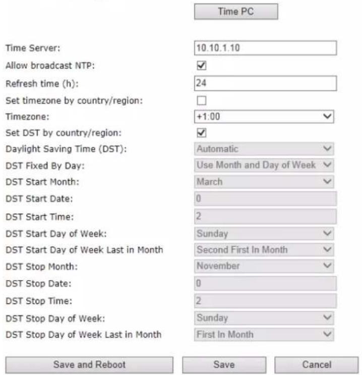
8.7 VLAN Setup: Base station
STEP 7 Navigate to the Network url > On the network page enter the relevant settings in the VLAN section > VLAN Id should be the same as those configured into the backbone.
Network Settings
IP settings
DHCP/Static IP:
IP Address:
Subnet Mask:
Default Gateway:
DNS (Primary):
DNS (Secondary):
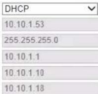
NAT Settings
Enable STUN:
STUN Server:
STUN Bindtime Determine:
STUN Bindtime Guard:
Enable RPORT:
Keep alive time:

VLAN Settings
ID:
User Priority:

SIP/RTP Settings
Use Different SIP Ports:
RTP Collision Detection:
Always reboot on check-sync:
Local SIP port:
SIP ToS/QoS:
RTP port:
RTP port range:
RTP ToS/QoS:

DHCP Options
Plug-n-Play:

Save and Reboot
Save
Cancel
9 Appendix C: Local Central directory file handling
In this appendix the Local Central Directory file format, import and configuration is described.
9.1 Central Directory Contact List Structure
The structure of Contact List is simple. The figure below shows an example of structure of Contact List in Text format and in Xml format. Contact name must not contain more than 23 characters and contact number must not contain more than 21 digits.
.csv or .txt
File Edit Format View Help
Dennis Iversen,+4596322382
Torsten Krogh Elgaard,2381
Rune Thor Jensen,2445
Maija-Liisa Knudsen,2377
Jesper Jensen,2346
Kristian Kjaer,2447
Gitte Dyhr Petersen,2470
Sukesh Reddy,2749
Morten Fredegod,4726
Annemarie Dahl,2861
Hans Back,2721
Henrik Olsen,2733
Jens Martin Jensen,2782
Kenneth Skiveren,2363
Lars Christensen (RTX),2433
.xml
File Edit Format View Help
<IPPhoneDirectory>
<DirectoryEntry>
<Name>Mark Ross</Name>
<Telephone>100</Telephone>
<office>+450123456789</office>
<Mobile>+451123456789</Mobile>
<Fax>+452123456789</Fax>
</DirectoryEntry>
</IPPhoneDirectory>
Txt file limitations:
- Contact name must NOT be longer than 23 characters (name will be truncated)
- Contact name must NOT contain “,”
- Contact number must be limited to 21 digits (entry will be discarded, no warning)
■ Contact number digits must be: +0123456789 - Contact number does not support SIP-URI
- Spaces between name section “,” and number section is not supported
9.2 Central Directory Contact List Filename Format
The Contact list is saved as file format: .txt .csv or .xml
9.3 Import Contact List to Central Directory
On the Central Directory page, the admin should click on Browse button and the Choose File to Load dialog window will be shown.
On the Choose File to Upload dialog window, navigate to the directory or folder that contains the right file to be imported to the base station > Click on Open button.

Next, click on the Load button. This will import the contents of contacts in the selected file into the relevant Base station.
Import Central Directory:
Filename: C:\work\IP DECT 10\Contacts. Bläddra...
Load
The figure below shows the import procedure is in process.
The parameters are successfully saved
You will be redirected after 3 seconds
9.4 Central directory using server
Alternative way to import a Contact List is to get it from a server. First click on Management url to get Management Settings page, then select the protocol of your server (TFTP/HTTP) in Management Transfer Protocol, then save the setting by clicking Save.
Settings
Management Transfer Protocol:
HTTP Management upload script:

Go back to Central Directory page and enter Server IP address (inclusive the path in the end of the address) and Filename of the contact list, then save the setting by clicking Save. (See example below).
XML Central Directory

Then reboot the Base station to ensure that the changes take effect.
9.5 Verification of Contact List Import to Central Directory
On the Handset, navigate to Central Directory where the correct contact list should populate to the contacts uploaded to the Base station.


- Trademarks
- Disclaimer
- Confidentiality
- KONFTEL
- Contents
- Konftel IP DECT 10....1
- Manual....1
- Contents 3
- About This Document....6
- Introduction – System Overview 9
- Installation of Base Station....11
- VoIP Administration Interface 15
- Firmware Upgrade Procedure 48
- Functionality Overview....53
- Appendix....57
- Appendix A: Basic Network Server(s) Configuration 57
- Appendix B: Using Base with VLAN Network 63
- Appendix C: Local Central directory file handling 68
- About This Document
- Audience
- When Should I Read This Guide
- Important Assumptions
- What's Inside This Guide
- What's Not in This guide
- Abbreviations
- Document History
- Documentation Feedback
- Introduction – System Overview
- Hardware Setup
- Components of IP DECT 10
- IP DECT 10
- VoIP Administration Server/Software
- Wireless Bands
- System Capacity (in Summary)
- Installation of Base Station
- Package - Contents/Damage Inspection
- Before Package Is Opened:
- Contents of Package:
- Damage Inspection:
- Base station Mechanics
- Base Station - Reset feature
- Installing the Base Station
- Mounting the Base Stations:
- Find IP of Base Station
- Using Konftel 300Wx to find IP address
- Using browser
- Login to Base Configuration Interface
- VoIP Administration Interface
- Web navigation
- Home/Status
- Screenshot
- Welcome
- Extensions
- Group call
- Add extension
- Extensions list
- Extensions and Handset
- Handset list
- Extensions / Handset
- Handset and extension list top/sub-menus
- Screenshots
- Edit Extension
- Servers
- Screenshot Servers
- Network
- IP Settings
- VLAN Settings
- VLAN Settings
- DHCP Options
- DHCP Options
- NAT Settings
- SIP/RTP Settings
- Management Settings Definitions
- Management Settings
- Settings
- Configuration
- Text Messaging
- Syslog/SIP Log
- Firmware Update Definitions
- Time Server
- NOTE:
- Time Settings
- Country
- Security
- Certificates
- Security
- SIP Client Certificates
- Password
- Central Directory and LDAP
- Local Central Directory
- Central Directory
- Import Central Directory:
- Import Central Directory
- LDAP
- LDAP Central Directory
- Handset Identity:
- Statistics
- System data
- Statistics
- Call data
- DECT data
- Settings – Configuration File Setup
- Sys log
- SIP Logs
- Firmware Upgrade Procedure
- Network Dimensioning
- TFTP Configuration
- Create Firmware Directories
- Base:
- IMPORTANT:
- Firmware Update Settings
- Firmware Update Settings
- Update Base Stations
- Base Station Firmware Upgrade
- Base firmware confirmation
- Verification of Firmware Upgrade
- Functionality Overview
- Base Station Interfaces
- Call Features
- Appendix A: Basic Network Server(s) Configuration
- Server setup
- Requirements
- DNS Server Installation/Setup
- Hints on how to Configure DNS behind a Firewall/NAT
- DHCP Server Setup
- Hint: Getting DHCP Server to Work
- Windows Server:
- 1) Clients are unable to obtain an IP address
- 2) The DHCP server is unavailable
- Linux Platform:
- TFTP Server Setup
- TFTP Server Settings
- SIP Server Setup
- FreePBX SIP Server
- 1) SIP Server Setup
- 2) Extensions
- Appendix B: Using Base with VLAN Network
- Introduction
- Backbone/ VLAN Aware Switches
- Which VLAN Does a Frame Belong To?
- How VLAN Switch Work: VLAN Tagging
- Implementation Cases
- Base station Setup
- Configure Time Server
- VLAN Setup: Base station
- Network Settings
- IP settings
- NAT Settings
- SIP/RTP Settings
- Appendix C: Local Central directory file handling
- Central Directory Contact List Structure
- Txt file limitations:
- Central Directory Contact List Filename Format
- Import Contact List to Central Directory
- The parameters are successfully saved
- Central directory using server
- XML Central Directory
- Verification of Contact List Import to Central Directory
Brand : KONFTEL
Model : IP DECT 10
Category : Telephone