DCX3600 - Digital decoder Arris - Free user manual and instructions
Find the device manual for free DCX3600 Arris in PDF.


| Product Type | Digital Set-Top Box / Decoder |
| Brand | Arris |
| Model | DCX3600 |
| Dimensions (W x D x H) | 200 x 150 x 40 mm |
| Weight | 0.5 kg |
| Power Supply | 12V DC, 1A (external adapter) |
| Video Output | HDMI, Composite (RCA) |
| Audio Output | HDMI, Optical (S/PDIF), Analog Stereo |
| Supported Video Resolutions | 480i, 480p, 720p, 1080i, 1080p |
| Tuner Type | Digital Cable (QAM) or Satellite (DVB-S/S2) depending on region |
| Recording Capability | DVR-enabled (requires external USB storage or built-in HDD, model-dependent) |
| Connectivity | Ethernet (10/100), USB 2.0 (front panel), eSATA (optional) |
| Remote Control | Infrared, included |
| Operating Temperature | 0°C to 40°C |
| Power Consumption | Typical 15W, Standby <1W |
| Compliance | CE, FCC, RoHS |
| Maintenance | Clean with dry, soft cloth. Do not use liquids or aerosol cleaners. |
| Safety Precautions | Place in well-ventilated area; do not expose to moisture or extreme temperatures. |
| Spare Parts / Repairability | Remote control and power adapter available separately. Unauthorized repair voids warranty. |
Frequently Asked Questions - DCX3600 Arris
User questions about DCX3600 Arris
0 question about this device. Answer the ones you know or ask your own.
Ask a new question about this device
Download the instructions for your Digital decoder in PDF format for free! Find your manual DCX3600 - Arris and take your electronic device back in hand. On this page are published all the documents necessary for the use of your device. DCX3600 by Arris.
USER MANUAL DCX3600 Arris
©ARRIS Enterprises, Inc. 2014 All rights reserved. No part of this publication may be reproduced in any form or by any means or used to make any derivative work (such as translation, transformation, or adaptation) without written permission from ARRIS Enterprises, Inc. ("ARRIS"). ARRIS reserves the right to revise this publication and to make changes in content from time to time without obligation on the part of ARRIS to provide notification of such revision or change.
ARRIS and the ARRIS logo are all trademarks of ARRIS Enterprises, Inc. MoCA is a registered trademark of Multimedia over Coax Alliance. HDMI is a trademark of HDMI Licensing LLC. Dolby and the double-D symbol are registered trademarks of Dolby Laboratories. This product incorporates copy protection technology that is protected by U.S. patents and other intellectual property rights. Use of this copy protection technology must be authorized by Rovi Corporation, and is intended for home and other limited viewing uses only unless otherwise authorized by Rovi Corporation. Reverse engineering or disassembly is prohibited. Other trademarks and trade names may be used in this document to refer to either the entities claiming the marks and the names of their products. ARRIS disclaims proprietary interest in the marks and names of others.
ARRIS provides this guide without warranty of any kind, implied or expressed, including, but not limited to, the implied warranties of merchantability and fitness for a particular purpose. ARRIS may make improvements or changes in the product(s) described in this manual at any time.
The capabilities, system requirements and/or compatibility with third-party products described herein are subject to change without notice.
i
Safety and Regulatory
IMPORTANT SAFETY INSTRUCTIONS
- Read these instructions.
- Keep these instructions.
- Heed all warnings.
- Follow all instructions.
• Do not use this apparatus near water.
- Clean only with dry cloth.
- Do not block any ventilation openings. Install in accordance with the manufacturer's instructions.
- Do not install near any heat sources such as radiators, heat registers, stoves, or other apparatus (including amplifiers) that produce heat.
- Do not defeat the safety purpose of the polarized or grounding type plug. A polarized plug has two blades with one wider than the other. A grounding type plug has two blades and a third grounding prong. The wide blade or the third prong is provided for your safety. If the provided plug does not fit into your outlet, consult an electrician for replacement of the obsolete outlet.
- Protect the power cord from being walked on or pinched particularly at plugs, convenience receptacles, and the point where they exit from the apparatus.
• Only use attachments/accessories specified by the manufacturer.
• Unplug this apparatus during lightning storms or when unused for long periods of time.
- Refer all servicing to qualified service personnel. Servicing is required when the apparatus has been damaged in any way, such as the power supply cord or plug is damaged, liquid has been spilled or objects have fallen into the apparatus, the apparatus has been exposed to rain or moisture, does not operate normally, or has been dropped.
IMPORTANT SAFETY CONSIDERATIONS FOR ALL SET-TOPS
• The mains plug is the main disconnect device. It shall remain readily accessible and operable.
- The apparatus shall not be exposed to dripping or splashing and no objects filled with liquids, such as vases, shall be placed on the apparatus.
- WARNING: To reduce the risk of fire or electric shock, do not expose this apparatus to rain or moisture.
- WARNING: Batteries shall not be exposed to excessive heat such as sunshine, fire or the like.
• See label on bottom of unit for additional markings.
During Installation
- Do not place the terminal in an enclosed area where the cooling vents are blocked or impede the flow of air through the ventilation openings.
-
Install the terminal so that its position does not interfere with its proper ventilation. For example, do not place the terminal on a bed, sofa, rug, or similar surface that could block the ventilation openings.
-
Install the terminal so that there is a minimum of two inches of space between surrounding surfaces and the top, left, and right sides of the terminal to ensure proper ventilation.
- Install the terminal away from heat sources such as radiators, heat registers and stoves. Installation of the terminal near consumer electronics devices, such as stereo receiver/amplifiers and televisions, is permitted as long as the air surrounding the terminal does not exceed 40 °C (104 °F).
- Place the terminal on a flat surface not prone to vibration or impact.
• Do not place the terminal on top of another electronic device. - Do not install the terminal in an area where condensation occurs.
- To prevent the temporary loss of guide data and cause a temporarily non-responding terminal, do not plug the AC power cord into a switched power outlet.
ADDITIONAL SAFETY CONSIDERATIONS FOR DVR MODELS
• To avoid shock and vibration damage to the internal hard drive, do not move the terminal while it is plugged in.
- To allow the hard drive to spin down and park its heads, wait at least 10 seconds after disconnecting power before moving the terminal.
- Install the terminal so that there is a minimum of 3 inches of space between surrounding surfaces and the back of the terminal to ensure proper ventilation.
FCC COMPLIANCE
This device complies with part 15 of the FCC Rules. Operation is subject to the following two conditions: (1) This device may not cause harmful interference, and (2) this device must accept any interference received, including interference that may cause undesired operation.
Note: This equipment has been tested and found to comply with the limits for a Class B digital device, pursuant to part 15 of the FCC Rules. These limits are designed to provide reasonable protection against harmful interference in a residential installation. This equipment uses and can radiate radio frequency energy and, if not installed and used in accordance with the instructions, may cause harmful interference to radio communications. However, there is no guarantee that interference will not occur in a particular installation. If this equipment does cause harmful interference to radio or television reception, which can be determined by turning the equipment off and on, the user is encouraged to try to correct the interference by one or more of the following measures:
• Reorient or relocate the receiving antenna.
- Increase the separation between the equipment and set-top.
- Connect the equipment into an outlet on a circuit different from that to which the set-top is connected.
Consult the dealer or an experienced radio/TV technician for help.
Caution: Changes or modifications not expressly approved by ARRIS for compliance could void the user's authority to operate the equipment.
FCC DECLARATION OF CONFORMITY
ARRIS Enterprises, Inc., 101 Tournament Drive, Horsham, PA 19044, 1-215-323-1000, declares that this Class B digital device complies with 47 CFR Parts 2 and 15 of the FCC rules.
INDUSTRY CANADA (IC)
This Class B digital device complies with Canadian ICES-003.
 | The exclamation point, within an equilateral triangle, is intended to alert the user to the presence of important installation, servicing, and operating instructions in the documents accompanying the equipment. |
 | This symbol indicates that dangerous voltage levels are present within the equipment. These voltages are not insulated and may be of sufficient strength to cause serious bodily injury when touched. The symbol may also appear on schematics. |
CARING FOR THE ENVIRONMENT BY RECYCLING

When you see this symbol on an ARRIS product, do not dispose of the product with residential or commercial waste.
Recycling your ARRIS Equipment
Please do not dispose of this product with your residential or commercial waste. Some countries or regions, such as the European Union, have set up systems to collect and recycle electrical and electronic waste items. Contact your local authorities for information about practices established for your region. If collection systems are not available, call ARRIS Customer Service for assistance.
Contents
Safety and Regulatory ....i
Tables......v
Figures......v
Introduction 1
Overview 1
Support 3
Getting Help....3
Product Overview....4
Front Panel 4
Rear Panel....5
Standard Features 6
Whole Home DVR Functionality....6
M-Card™ 7
Networking Overview....8
Ethernet Networking Connection....8
MoCA Networking Connection....9
Wi-Fi Networking Connection....10
Transcoding....14
The Basics of Transcoding....14
DCX3600-M Authorization....15
DCX3600-M Software 15
Connection to the Home Wireless Network....15
Handheld Device Software....16
Installation....17
Video Connection Options....17
Audio Connection Options....17
Connecting a High-Definition TV (HDTV) for Video....18
Connecting a High-Definition TV (HDTV) for Audio....19
Connecting a High-Definition TV (HDTV) and an A/V Receiver for Video....20
Connecting a High-Definition TV (HDTV) and an A/V Receiver for Audio 21
Connecting a Standard-Definition TV 22
RF4CE....23
Operational Check for the Remote Control....24
Configuring the User Settings....25
Troubleshooting....28
Common Bootloader OSS Attribution Text....30
Common Bootloader Open Source Software Attribution Text....30
Tables
Table 1 – Top & Front Panel Controls....4
Table 2 – Rear Panel Ports & Connectors....5
Table 3 - Approximate DVR Recording Capacities ....7
Table 4 - DCX3600-M Video Outputs ....17
Table 5 - DCX3600-M Audio Outputs....17
Table 6 - Remote Control Test ....24
Table 7 - User Settings Menu Fields....26
Table 8 – Troubleshooting Guidelines ....28
Figures
Figure 1 - DCX3600-M Networking Overview ...... 2
Figure 2 - DCX3600-M Front View ....4
Figure 3 - DCX3600-M Rear View....5
Figure 4 - A Typical Mixed Ethernet/WiFi Home Network....9
Figure 5 - A Typical Mixed MoCA/WiFi Home Network....10
Figure 6 - A Typical IEEE 802.11g WiFi Home Network ....12
Figure 7 - A Typical Dual Band IEEE 802.11n WiFi Home Network....13
Figure 8 – High-Definition TV (HDTV) for Video Connection....18
Figure 9 – High-Definition TV (HDTV) for Audio Connection....19
Figure 10 – High-Definition TV (HDTV) and an A/V Receiver for Video Connection....20
Figure 11 – High-Definition TV (HDTV) and an A/V Receiver for Audio Connection ....21
Figure 12 - Standard-Definition TV Connection ....22
Figure 13 - Settings Menu....25
Figure 14 - Power ON Timer Menu....26
Figure 15 - Power OFF Timer Menu....26
1
Introduction
Overview
The DCX3600-M is an advanced Video Gateway that provides access to live television, Video-On-Demand, and recorded content throughout the entire home.
The DCX3600-M connects directly to a high definition television through the audio/video connectors on the rear panel. It includes multiple tuners for recording up to six high definition programs to the internal hard drive simultaneously. The high-end processor, expanded memory, and accelerated graphics performance enhance the user's experience by supporting advanced interactive applications.
The networking capabilities of the DCX3600-M allow content to be streamed to other devices that are connected on the home network, including IP set-tops, computers, and DLNA media players ^1 . The DCX3600-M can also convert the incoming video from your cable provider to a format that can be watched on a mobile device. This transcoded content is streamed from the DCX3600-M to your smartphone or tablet over the home Wi-Fi network.
This manual provides an overview of the DCX3600-M features, operation instructions, and troubleshooting tools. This manual also provides instructions for connecting devices to the DCX3600-M over the home network.

flowchart
graph TD
    subgraph DCX3600-M & Accessories
        A["External Hard Drive (eSATA)"]
        B["IR / RF4CE Remote Control"]
        C["Bluetooth Devices"]
        D["HDTV (HDMI)"]
    end

    subgraph Whole Home DVR Services
        E["Computer"]
        F["Computer"]
        G["Computer"]
        H["Computer"]
        I["Computer"]
        J["Computer"]
        K["Computer"]
        L["Computer"]
        M["IP STB"]
    end

    DCX3600-M -->|MoCA| IP_STB's
    DCX3600-M -->|Ethernet 802.11n| DataRouter
    DataRouter -->|MoCA| Video Gateway Services
    Video Gateway Services --> Computers
    Video Gateway Services --> IP STB
    Video Gateway Services --> DataRouter
    DataRouter -->|Ethernet 802.11n| Mobile Devices
    DataRouter --> DLNA Media Players
    DataRouter --> Mobile Devices
Figure 1 - DCX3600-M Networking Overview
Support
Getting Help
Please contact your service provider if you require assistance with your set-top box. If directed to contact ARRIS use the numbers below.
The Technical Assistance Center (TAC) provides assistance 24 hours a day, 7 days a week. To open a case, use one of these contact methods:
- Customers in North American should call the TAC at 888-944-HELP (888-944-4357).
- Customers outside North America should call the TAC at 215-323-2345.
• For Spanish language support, call 215-323-2346.
Contact the TAC by e-mail at Tac.Helpdesk@arrisi.com
2
Product Overview
Front Panel
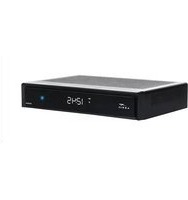
The DCX3600-M includes a backlit, mechanical Power/Standby button and a Clock/Channel display with integrated status LEDs.
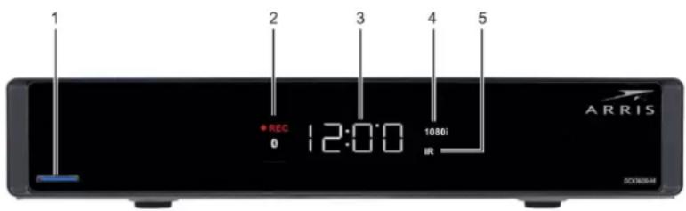
Figure 2 - DCX3600-M Front View
Table 1 – Top & Front Panel Controls
| Feature Description | ||
| 1 | Power Button | Turns ON/OFF power to the DCX3600-M. |
| 2 | Display LEDs | Record, Home LAN, Bluetooth*, Message |
| 3 | Display Shows the time or channel number | |
| 4 | Video Format Indicators | Shows the current video output resolution that is displayed on the television connected to the DCX3600-M. |
| 5 | Remote Activity LED | Blinks to indicate that the DCX3600-M has received a command from the remote control. |
* Bluetooth not available on all models.
Rear Panel
The DCX3600-M rear panel contains ports and connectors for video, audio, RF cabling, data output, and data interface. Some connectors are not enabled and require application software support.

Figure 3 - DCX3600-M Rear View
Table 2 – Rear Panel Ports & Connectors
| Port/Connector Description | |
| 1 Cable In(RF Coaxial Input) | Connects to a coaxial cable that delivers the cable television signal from your service provider |
| 2 YPbPr (optional feature)(Component Video) | Connects to the color-coded component video input on a high-definition TV (HDTV) |
| 3 Audio L/R(Baseband Analog Audio) | Connects to the analog audio left/right stereo inputs on a TV |
| 4 Video(Composite Video) | Connects to the standard definition video output on a SDTV |
| 5 HDMI | Connects to a high-definition TV (HDTV). Provides both audio and video to the HDTV. |
| 6 Digital Audio(Optical S/PDIF) | Connects to the Dolby® Digital 5.1 audio or PCM output on a digital audio device |
| 7 USB 2.0* | Connects to a high-speed peripheral device. Two USB 2.0 ports are provided. |
| 8 Ethernet* | Connects to an Ethernet device. 10/100/1000 |
| 9 eSATA* Connects to an external Serial ATA hard disk drive | |
| 10 M-Card Device Only | Cable card access panel. The M-Card is required to view television programs, previously recorded programs on the video gateway, or interactive on-demand programs. The M-Card should not be removed. |
| 11 IR Remote Input | Connects to a remote control set-top accessory cable |
| 12 Power | Connects the external power supply cord to the DCX3600-M |
* Feature may not be supported by your service provider.
Standard Features
- Local video decode up to 1080p60, MPEG-2, MPEG-4 AVC, SVC, MVC
- Dual transcode up to 720p30 each, or single transcode up to 1080i60
• 1GHz Full-band capture front end with 8x QAM demodulators
• DOCSIS 3.0 channel bonding (8x4)
• MoCA 2.0 home networking
• 1.2 Gp/s OpenGL 2.0, scalable video-in-graphics - Dolby Digital Plus 7.1 (HDMI) and ATSC standard Dolby® Digital (Optical S/PDIF)
- Front panel 4 digit, 7 segment display with integrated status LED indicators
- Backlit power button
• Video outputs: HDMI, composite video
• Audio outputs: L/R audio with volume control, optical S/PDIF
Standard Data Features
- 500GB 3.5" internal hard drive
• 128MB flash memory (upgradeable to 256MB and 512MB)
• 1GB DRAM (upgradeable to 1.5GB and 2GB) - Two Universal Serial Bus (USB) 2.0 ports on the rear panel
• 10/100/1000 Mbps Ethernet port (RJ-45)
• eSATA Gen2 (3.0 Gbps) connector - IR remote control interface plus rear panel extender input
Optional Features
- Component Video Output
• RF4CE remote control interface
• 4-digit, 14 segment front panel display
• 802.11n, 2x2, dual band, switched Wi-Fi - Bluetooth 4.0 remote device interface
• 1TB 3.5" internal hard drive
Whole Home DVR Functionality
- Integrated MoCA 2.0 supports content streaming and two-way connectivity to multiple IP clients
- DVR functionality integrated with the interactive guide application enables connected clients to do the following:
o Pause, rewind, fast-forward, or record live TV
o Initiate program recordings and access the recordings library
o Record multiple programs in the background while viewing another live program
o Playback, pause, rewind, fast-forward recorded programs
Table 3 - Approximate DVR Recording Capacities
| Estimated Recording Hours for: | ||
| Internal Hard Disk Size | Standard Digital Channels | HDTV Channels |
| 500GB | 200 to 350 | 45 to 90 |
| 1 TB | 350 to 600 | 90 to 150 |
Note: ARRIS cannot guarantee the exact amount of programming that each subscriber will be able to record. The approximate time depends on the programming type and the encoding format used.
M-Card™
The M-Card is required to view television programs, previously recorded programs on the DVR, or interactive on-demand programs. The M-Card should not be removed.
Networking Overview
The DCX3600-M is equipped with standard Ethernet and MoCA home networking interfaces. It may also be equipped with an optional 802.11n wireless home networking interface. These networking interfaces allow the DCX3600-M to connect to a variety of home networks and share programming content with other devices ^2 within the home. The following sections of the document will discuss the various methods available to connect the DCX3600-M to the home network in order to enable the sharing of programming content with other devices on the network.
Ethernet Networking Connection
The DCX3600-M is equipped with a standard 1000BASE-T Ethernet connection that can support gigabit (1 Gbps) transfer speeds. Category 5 (or better) twisted pair cabling must be used between the DCX3600-M and another gigabit capable device (such as a wireless router or network switch) in order to achieve gigabit transfer speeds. The DCX3600-M Ethernet connection also supports 10BASE-T (10 Mbps) and 100BASE-TX (100 Mbps) data transfer speeds depending on the connected device.
A typical mixed Ethernet/WiFi home network is shown in Figure 4. Modern wireless routers combine the functionality of a data router, network switch, and wireless access point into a single device and therefore form the backbone of most Ethernet/WiFi home networks. If the DCX3600-M is co-located with the wireless router, or if the home is already wired for Ethernet connections between the rooms, the DCX3600-M may be easily connected to the wireless router using a Category 5 (or better) Ethernet cable.
Ethernet Router Connection

flowchart
graph TD
    A["DCX3600-M"] --> B["Ethernet Connections"]
    B --> C["IP Client"]
    C --> D["PC"]
    D --> E["Game Console"]
    E --> F["Router 802.11 b/g/n"]
    F --> G["2.4 GHz b/g/n"]
    F --> H["5 GHz n"]
    I["Tablets Smartphones"] --> J["Wireless IP Client"]
Figure 4 - A Typical Mixed Ethernet/WiFi Home Network
MoCA Networking Connection
The DCX3600-M is equipped with a standard MoCA 2.0 home networking interface that can support gigabit (1 Gbps) transfer speeds when connected to other devices that are also equipped with MoCA 2.0 functionality. The MoCA home networking interface allows devices to transfer data to each other over pre-existing coaxial cable within the home as long as the cables are electrically connected to each other within the home (typically through a network of RF splitters).
The DCX3600-M is most easily connected to the home network when the wireless router itself is equipped with MoCA functionality. In this case, the DCX3600-M is automatically connected to the MoCA-equipped wireless router via the network of interconnected coaxial cables within the home. At the time of the initial launch of the DCX3600-M, however, a limited number of MoCA-enabled wireless routers are available for installation within the home.
A typical MoCA home network featuring a MoCA-equipped wireless router is shown in Figure 5. In this type of home network, the MoCA devices will automatically discover each other and make the provisions to form and manage the MoCA network. The DCX3600-M can then make programming content available to MoCA-equipped IP set-top boxes and other devices (with the required software support) via the wireless router.

flowchart
graph TD
    A["DCX3600-M"] --> B["MoCA 1.x/MoCA 2.0 Network"]
    B --> C["Router 802.11 b/g/n"]
    B --> D["MoCA Enabled Router"]
    C --> E["IP Client"]
    C --> F["IP Client"]
    D --> G["MoCA Enabled Router"]
    D --> H["5 GHz n"]
    E --> I["Tablets Smartphones"]
    F --> I
    G --> J["Wireless IP Client"]
Figure 5 - A Typical Mixed MoCA/WiFi Home Network
Wi-Fi Networking Connection
The DCX3600-M is available with an optional integrated 802.11n wireless home networking interface that can interoperate with either 2.4 GHz wireless networks or 5 GHz wireless networks. With its dual internal antennas the DCX3600-M can achieve data transfer speeds up to 300 Mbps ^3 depending upon the capabilities of the wireless router.
Since the performance of home wireless networks are highly susceptible to degradation by a number of factors including RF interference, device proximity, and wall/floor construction materials, it is always recommended to use a wired connection such as Ethernet or MoCA between the DCX3600-M and the wireless router whenever possible. Recognizing that such a wired connection is not always feasible, the DCX3600-M is available with an optional 802.11n Wi
Fi interface that allows it to be connected to the wireless home network. However, it is important to note that the ability to share content with other devices ^4 in the home depends directly on the capabilities of the wireless router itself. This will be discussed further below.
2.4 GHz Wireless Routers
There are a number of wireless networking standards in use today for both commercial and residential applications. The majority of these wireless networks operate within the 2.4 GHz frequency band, the 5 GHz frequency band, or both. The first widely-available wireless networking devices available to the public were designed to meet the IEEE 802.11b wireless standard. The 802.11b standard works entirely within the 2.4 GHz frequency band, but since its maximum data transfer rate is only 11 MBps, its available bandwidth is unable to support any of the advanced content sharing capabilities of the DCX3600-M. If the home is equipped with an 802.11b wireless router, it must be upgraded to an 802.11g (or better) wireless router in order to make full use of the content sharing capabilities of the DCX3600-M.
The IEEE 802.11g wireless standard defined the next generation of wireless networking following the 802.11b standard. While 802.11g also operates entirely within the 2.4 GHz frequency band, it introduced new modulation schemes that allowed the maximum data transfer rate to be increased to 54 Mbps (or roughly 5 times that of 802.11b). Due to its higher data rate, 802.11g is adequate to support the ability of the DCX to make programming content available to portable wireless devices in the home ^5 .
The IEEE 802.11n wireless standard defined the next generation of wireless networking following the 802.11g standard. 802.11n can operate in either the 2.4 GHz frequency band or the 5 GHz frequency band, although the standard only requires support for operation within the 2.4 GHz frequency band (support for 5 GHz operation is optional). The 802.11n also introduced a number of other improvements (the majority of which are optional) which can help increase the data transfer rate to as high as 600 Mbps. However, to achieve the maximum data transfer rate, the wireless devices must include support for most of the optional features within the 802.11n standard. In practical home networking applications, data transfer rates of up to 300 Mbps are achievable with currently available 802.11n wireless routers.
A typical 802.11g wireless network is shown in Figure 6. In this type of home network, the DCX will automatically configure itself to operate within the 2.4 GHz frequency band and at 802.11g data transfer speeds once the wireless network information is provided via its WiFi setup screens. When operating with an 802.11g wireless router, the DCX can support sharing transcoded programming with other wireless video devices in the home such as smartphones and tablets. The transcoded programming content provided has a data rate such that it can be easily streamed across an 802.11g wireless network.

flowchart
graph LR
    A["Broadcast Content"] --> B["DCX3600-M"]
    B --> C["Transcoded Content Only"]
    B --> D["2.4 GHz Router"]
    D --> E["Transcoded Content"]
    D --> F["2.4 GHz Router"]
    F --> G["Tablets Smartphones"]
    style B fill:#f9f,stroke:#333
    style D fill:#ccf,stroke:#333
    style E fill:#cfc,stroke:#333
    style F fill:#fcc,stroke:#333
    style G fill:#ffc,stroke:#333
Figure 6 - A Typical IEEE 802.11g WiFi Home Network
A typical 802.11n wireless network that supports only the 2.4 GHz frequency band is shown in Figure 6. In this type of home network, the DCX will automatically configure itself to operate within the 2.4 GHz frequency band and at 802.11n data transfer speeds once the wireless network information is provided via its WiFi setup screens. When operating with an 802.11n (2.4 GHz only) wireless router, the DCX can support sharing transcoded programming with other wireless video devices in the home such as smartphones and tablets. The transcoded programming content provided has a data rate such that it can be easily streamed across an 802.11n (2.4 GHz only) wireless network.
5 GHz Wireless Routers
As mentioned in the previous section, the IEEE 802.11n wireless standard introduced support for operation within the 5 GHz frequency band. Whereas the 2.4 GHz frequency band is very congested since it is heavily used by a number of devices (microwave ovens, Bluetooth devices, cordless phones, baby monitors, etc.) that can interfere with and degrade the performance of 2.4 GHz wireless networks, the 5 GHz frequency is much larger and has far fewer sources of interference. As a result, wireless networks operating in the 5 GHz frequency band are capable of much higher data transfer rates (up to 600 Mbps) and can in general work more reliably at greater distances than 2.4 GHz networks.
While 5 GHz operation is not required by the 802.11n standard, most of the available 802.11n wireless routers available today will support dual band operation, i.e., they can operate simultaneously in both the 2.4 GHz and 5 GHz frequency bands. Dual band operation allows the wireless router to support older devices (such as 802.11b or 802.11b devices) that can only operate in the 2.4 GHz frequency band, newer 802.11n devices that can only operate in the 2.4 GHz frequency band, and newer 802.11n devices that can operate in the 5 GHz band. Therefore a dual band 802.11n wireless router enables newer devices that support 5 GHz operation to operate at faster speeds while still maintaining backward compatibility with legacy devices.
A typical dual band 802.11n wireless network which supports both the 2.4 GHz and 5 GHz frequency bands simultaneously is shown in Figure 7. When the wireless router supports 5 GHz frequency band operation, the DCX is able to a full rate high definition program ^6 for a wireless IP client in addition to transcoded programming content for other wireless video devices in the home such as tablets and smartphones. This increased capability to share programming content is due to the fact that the 5 GHz frequency band supports much greater data transfer rates and is much less susceptible to degradation from other wireless devices in the home.

flowchart
graph LR
    A["Broadcast Content"] --> B["DCX3600-M"]
    B --> C["Transcoded Content + Full-Rate HD Content"]
    C --> D["2.4 / 5 GHz Dual Band Router"]
    D --> E["Router 802.11 n"]
    E --> F["Transcoded Content"]
    F --> G["Tablets Smartphones"]
    D --> H["5 GHz"]
    H --> I["Full-Rate HD Content"]
    I --> J["5 GHz"]
    J --> K["Wireless IP Client"]
    style A fill:#f9f,stroke:#333
    style G fill:#ccf,stroke:#333
    style K fill:#cfc,stroke:#333
Figure 7 - A Typical Dual Band IEEE 802.11n WiFi Home Network
Transcoding
With the rising popularity of handheld video playback devices such as smartphones, tablets, and portable game consoles, consumers are no longer required to sit down in front of their televisions to enjoy their favorite broadcast programs. However, traditional television programming is not broadcast in formats that are ideally suited for playback on these types of handheld devices.
The DCX3600-M is equipped with an integrated dual session transcoder that allows it to convert broadcast television content into audio and video formats that are more ideally suited for playback on handheld video devices such as tablets and smartphones. The DCX3600-M can transcode up to two broadcast television programs simultaneously, converting them from formats intended to be viewed on a television (with a cable set-top box such as the DCX3600-M) into formats that can be easily streamed across the in-home wireless (WiFi) network for playback on two handheld devices in or around the home ^7 .
The Basics of Transcoding
The majority of digital television programs broadcast on the cable system make use of two primary digital encoding formats: MPEG-2 for video and Dolby Digital for audio. The DCX3600-M, like all cable set-top box units, is specifically designed to receive and decode video and audio transmitted in these formats. However, many of today's handheld video devices have limited capability to decode MPEG-2 video or Dolby Digital audio. In addition, MPEG-2 video (especially High Definition video) requires a great deal of bandwidth to transmit within the home. Wireless networks, particularly those using 2.4 GHz 802.11b/g/n connections, can have difficulty streaming MPEG-2 high definition video services reliably due to their high sustained bandwidth requirements.
The integrated transcoder in the DCX3600-M converts broadcast television services into formats that are more likely to be supported by modern handheld playback devices and also require much less bandwidth to stream across the in-home wireless network. The transcoder decodes the MPEG-2 video of broadcast television services and re-encodes using the much more efficient MPEG-4 (Advanced Video Coding) format. Video which is encoded using the AVC format requires approximately half the transmission bandwidth of video encoded using the MPEG-2 format for roughly the same picture quality. This 50% (or greater) reduction in bandwidth means that the in-home wireless network can more easily stream the video service to handheld playback devices with much fewer interruptions and rebuffering attempts.
The transcoder also converts the broadcast television audio soundtrack from the Dolby Digital format to the AAC (Advanced Audio Coding) format. While the bandwidth savings can also be as high as 50% in performing this conversion, it is fairly inconsequential since the bandwidth to
transmit audio is just a fraction of that required to stream video. The audio format conversion is done more for compatibility purposes than for bandwidth reduction.
In order to make use of the transcoding capabilities of the DCX3600-M, the following prerequisites must be satisfied:
- The DCX3600-M must be authorized by the cable service provider to stream broadcast services to handheld devices within the home
- The DCX3600-M must have software pushed to it by the cable service provider which enables the integrated transcoding functionality
- The DCX3600-M must be connected via Ethernet, MoCA, or WiFi to the in-home wireless router (see the Networking Overview section)
- The handheld playback device must be connected via WiFi to the in-home wireless router
- The handheld playback device must have the appropriate software installed (this may include a minimum version number of the device OS software, a specific video application as required by the cable service provider, or both)
These prerequisites are discussed in further detail below.
DCX3600-M Authorization
Although the DCX3600-M is equipped with an integrated dual session transcoder that can support the streaming of transcoded broadcast television services to up to two handheld playback devices at the same time, the cable service provider must first authorize the DCX3600-M to provide these services for the subscriber.
DCX3600-M Software
To enable the integrated transcoder and stream broadcast television services to handheld video devices within the home, the DCX3600-M must have software which can turn on the transcoding functionality and stream transcoded broadcast television content to the in-home wireless router so that it can be viewed on handheld video devices. The cable service provider may need to push a software upgrade to the DCX3600-M in order to enable transcoding functionality and streaming television service within the subscriber's home.
Connection to the Home Wireless Network
In order to get the transcoded broadcast television content from the DCX3600-M to the wireless handheld devices in the home, the DCX3600-M must be connected to the in-home wireless router using an Ethernet connection, a MoCA connection, or a WiFi connection (an optional feature). Please consult the Networking Overview section for more details on connecting the DCX3600-M to the in-home wireless router.
In addition, the wireless video device must also be connected to the same in-home wireless router. The router acts as the bridge between the DCX3600-M and the wireless video device.
Broadcast television programming can then be received and transcoded on the DCX3600-M and streamed via the in-home wireless network to the handheld device where it can be viewed by the subscriber. The handheld devices must be connected to the in-home WiFi network; a cellular data connection (such as 3G/4G/LTE) will not allow the subscriber to browse and watch content available from the DCX3600-M.
Handheld Device Software
The wireless video device(s) must have the appropriate software to discover the DCX3600-M on the home network and request broadcast television content from it. The device may require an upgrade to an appropriate OS (such as Android or iOS) version. In addition, it will also likely require the download and installation of a specific application as required by the cable service provider from the appropriate application marketplace for the device.
- DCX3600-M provisioned with transcoding/streaming compatible software (platform code + 3rd party application)
- Handheld wireless (802.11 b/g/n/ac) device capable of decoding AVC video content and AAC audio content (either hardware or software decoding, depending on processor and the streaming application)
- Active WiFi network in the home (802.11g/n/ac) with throughput adequate for streaming transcoded content (at least 4Mbps per stream, preferably more for margin) to the handheld devices
- Data networking connection between the DCX3600-M and the WiFi router (either WiFi connection, Ethernet connection, or MoCA connection depending on DCX3600-M and router hardware capability)
- A resident application on the handheld wireless device that enables content discovery on the DCX3600-M, can initiate a streaming session, and provides the necessary content and device security
- Authorization from the MSO for in-home streaming (either through download of the software/application to the DCX3600-M/handheld or some other mechanism to be defined)
3
Installation
Video Connection Options
Use the following guidelines to determine the best video connection for the subscriber's home entertainment system. To determine the available video inputs on the TV, check the manual supplied with the TV or the TV itself.
The DCX3600-M series offers the following video outputs:
Table 4 – DCX3600-M Video Outputs
| Connection type | TV type | Description |
| HDMI | HDTV | Connects to a high-definition TV (HDTV). Provides both audio and video to the HDTV. |
| YPbPr(optional feature) | HDTV and SDTV | (Component Video) Connects to the color-coded component video Input on a high-definition TV (HDTV). |
| Video (composite) | SDTV only | (Composite Video) Connects to the standard definition video output on a SDTV. |
Audio Connection Options
When connecting to a home theater receiver, depending on its inputs, you can use the following DCX3600-M series audio outputs:
Table 5 - DCX3600-M Audio Outputs
| Connection type | Description |
| HDMI | Connects to a high-definition TV (HDTV) or an audio/video receiver (AVR). Provides high fidelity digital audio to the HDTV or AVR. |
| Digital audio | (Optical S/PDIF) Connects to the Dolby® Digital 5.1 audio or PCM output on a digital audio device. |
| Audio L/R | (Baseband Analog Audio) Connects to the analog audio left/right stereo Inputs on a TV. |
Connecting a High-Definition TV (HDTV) for Video
Do the following for the best possible HDTV video quality:
- If the TV has an HDMI input, connect it to the HDMI output on the DCX3600-M.
- If the TV has a DVI input, connect it to the HDMI output on the DCX3600-M using an HDMI-to-DVI converter cable or adapter.
- Otherwise, use the component video (YPbPr) connectors. L/R audio connection or digital audio S/PDIF connection is required for sound with component video.
Note: Make sure to match up each signal to the same connection on the TV or the colors will not appear correctly on the TV.
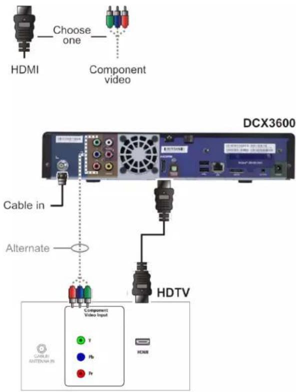
Figure 8 – High-Definition TV (HDTV) for Video Connection
Note: Because HDMI provides both video and audio, no additional audio connections to the TV are required.
Connecting a High-Definition TV (HDTV) for Audio

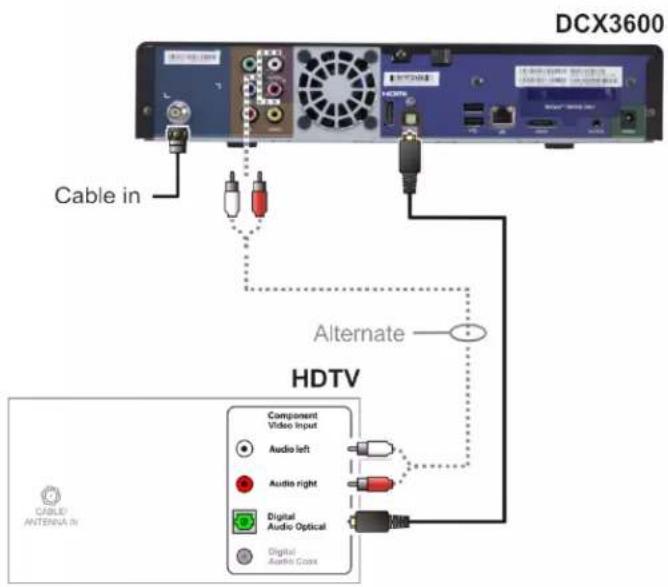
Figure 9 – High-Definition TV (HDTV) for Audio Connection
Connecting a High-Definition TV (HDTV) and an A/V Receiver for Video
Note: If the A/V receiver includes an HDMI input and output, the DCX3600-M's HDMI output can be connected directly to the A/V receiver's input and the A/V receiver's HDMI output directly to the TV. Because HDMI provides both video and audio output, no additional audio connections to the A/V Receiver and TV are required.
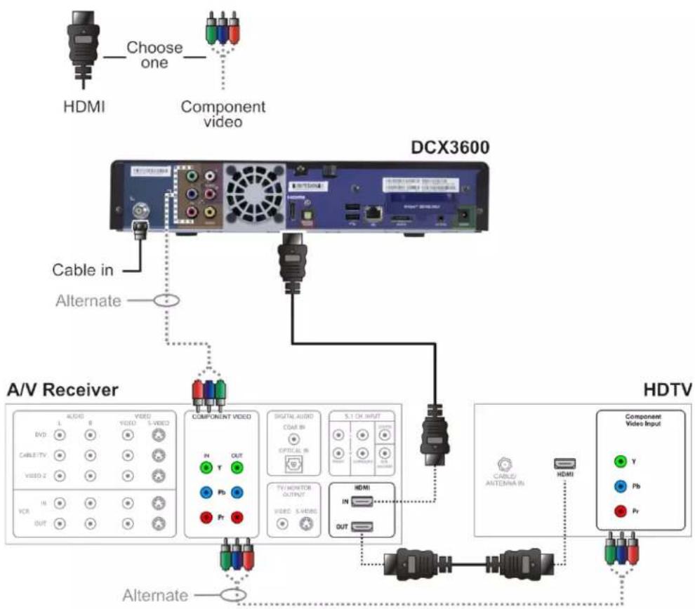
flowchart
graph TD
    A["HDMI"] -->|Choose one| B["Component video"]
    B --> C["DCX3600"]
    C --> D["A/V Receiver"]
    D --> E["COMPONENT VIDEO"]
    E --> F["S.1 ON INPUT"]
    F --> G["HDTV"]
    G --> H["Component Video Input"]
    H --> I["CABLE/ Antenna IN"]
    H --> J["HDMI"]
    style A fill:#f9f,stroke:#333
    style B fill:#ccf,stroke:#333
    style C fill:#cfc,stroke:#333
    style D fill:#fcc,stroke:#333
    style E fill:#cff,stroke:#333
    style F fill:#ffc,stroke:#333
    style G fill:#fcc,stroke:#333
    style H fill:#cfc,stroke:#333
    style I fill:#fcc,stroke:#333
Figure 10 – High-Definition TV (HDTV) and an A/V Receiver for Video Connection
Connecting a High-Definition TV (HDTV) and an A/V Receiver for Audio
Note: If the A/V receiver includes an HDMI input and output, the DCX3600-M's HDMI output can be connected directly to the A/V receiver's input and the A/V receiver's HDMI output directly to the TV. Because HDMI provides both video and audio output, no additional audio connections to the A/V Receiver and TV are required.
Note: If the receiver can check the baseband and digital audio (S/PDIF) ports for appropriate channels, connect both the baseband and digital audio connections. Otherwise, do not connect both the baseband left/right composite connections and the digital audio connection. The baseband connections are not necessary because the digital audio port provides a single audio interface for digital and analog channels.
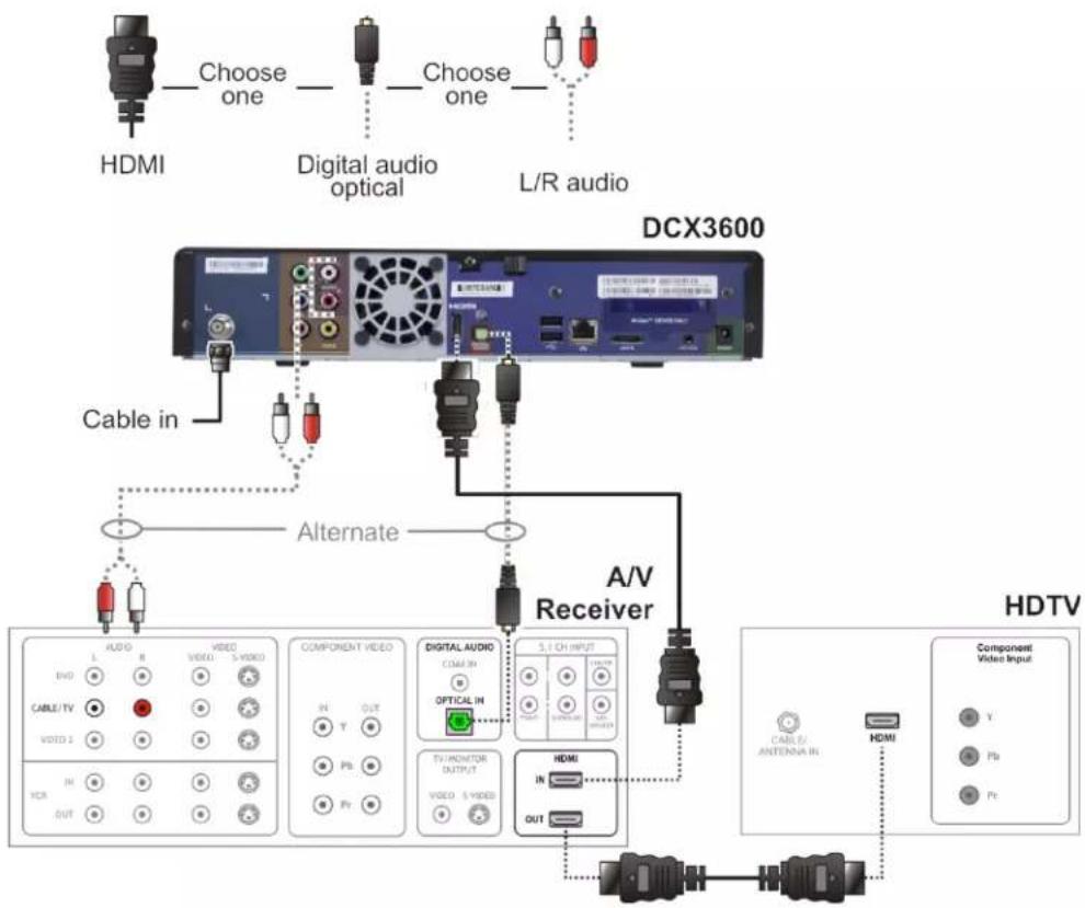
Figure 11 – High-Definition TV (HDTV) and an A/V Receiver for Audio Connection
Connecting a Standard-Definition TV
- Connect the stereo audio cable to the audio L or R connector on the DCX3600-M and the audio left and audio right connectors on the SDTV.
- Make the video connection between the DCX3600-M and the television using the composite video output on the DCX3600-M.

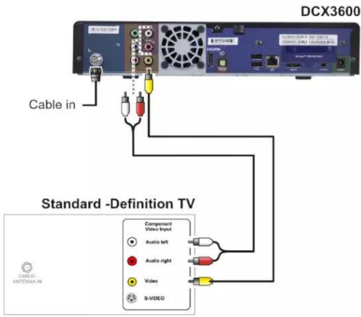
Figure 12 – Standard-Definition TV Connection
RF4CE
The DCX3600-M can be operated by either a traditional infrared (IR) remote control or an advanced radio frequency (RF) remote control. While an infrared remote control unit (RCU) requires a clear line of sight between the RCU and the front panel of the DCX3600-M, an RF RCU can transmit commands to the DCX3600-M even if there are obstacles (such as a wall or furniture) between it and the DCX3600-M. Using a standard wireless technology known as RF4CE (Radio Frequency For Consumer Electronics) the DCX3600-M can be operated by an RF RCU if one has been provided by your MSO.
In order to use an RF RCU with the DCX3600-M, you must first pair the RCU with the DCX3600-M. The pairing process enables the DCX3600-M and the RCU to discover each other so that the RCU may transmit commands to the paired DCX3600-M. In order to avoid unexpected actions being triggered by another RF RCU in the home, the DCX3600-M will only acknowledge and act upon commands transmitted by a paired RF RCU, while ignoring all other commands transmitted by any other RF RCU in the home. Please note that a traditional IR remote control does not require any such pairing process.
If you need to manually pair or unpair your RF remote control with your DCX3600-M, please use the procedures detailed below.
RF4CE Remote Paring and Un-Pairing Instruction:
Pairing:
- Entering pairing mode with the pairing keycode sequence (IR command): the POWER key is pressed and released and then INFO key is pressed within two seconds and released.
- "PAIr" will be displayed on the front panel display during the pairing process.
- Display "X Pr" on the LED display for five (5) seconds after completing the pairing process. (Note: the left most digit "X" of the display is the number of the just-paired remote control stored in the pairing table of the product. The digit "X" can range from 1 to 9. For example, for the second remote control being paired with the product, the "X" will be 2 and the LED display shall be "2 Pr").
- The pairing mode will terminate if no RF4CE pairing request is received during the first thirty (30) seconds after entering pairing mode.
- If the pairing process fails (described in #4), "FAIL" will be displayed on the front panel display for five (5) seconds after the pairing process terminated.
Un-Pairing:
-
Entering Un-Pairing mode with unpairing keycode sequence: the POWER key is pressed and released and then EXIT key is pressed within two seconds and released.
-
"UnPr" will be displayed on the front panel display during the un-pairing process.
- "FAIL" will be displayed on the front panel display for five (5) seconds if the un-pairing process failed.
Operational Check for the Remote Control
The operational check will test the remote control.
Table 6 – Remote Control Test
| Feature Testing Procedure | |
| Power ON Press | Power on the remote control to turn ON the DCX3600-M. |
| Channel Selection Scan through the channels using the Channel Up or Down keys.Tune to several channels by entering the channel number using the numeric keys. | |
| Volume Control Press | Volume Up or Down to increase or decrease the volume.Press Mute to turn the sound off. Press Mute again to restore the sound. |
If the DCX3600-M does not operate properly, refer to Troubleshooting for more information.
Configuring the User Settings
The following describes how to configure the audio (for HDMI connections) and SD and HD video settings for the DCX3600-M.
Note: Additional user settings are configured through the Interactive Program Guide and not directly through the Settings Menu.
Before you adjust the output settings:
- Connect the DCX3600-M to other home entertainment devices.
• Plug the DCX3600-M into an AC power outlet. - Turn the TV on.
When using an HDMI connection between the DCX3600-M and the television, be sure to have the cable connected and the TV powered on before adjusting the video settings.
To optimize the output settings:
- Ensure the DCX3600-M is installed properly.
- With the set-top in stand-by mode, press the MENU key on the remote control.
- If the TV is on, the on-screen User Settings menu lists the DCX3600-M settings that can be adjusted.
- Use the remote control to navigate the on-screen menus:
- Press the ▲ and ▼ keys to highlight the setting you wish to change.
- Press the ▶ key to select an option.
• To exit the setting and move to another setting, press the ▲ or ▼ key.
• To exit the menu and save your settings, press the B key on the remote control.
Settings Menu
| Audio Coding Format | ◀ | HDMI | ▶ |
| Audio Output Range | ◀ | Narrow | ▶ |
| Audio Output | Fixed | ||
| 3D Mode | ◀ | Enabled | ▶ |
| Video Sharpness | ◀ | 3 | ▶ |
| RF Output Channel | ◀ | Channel 3 | ▶ |
| Power On Timer | |||
| Power Off Timer | |||
| Sleep Timer | ◀ | Off | ▶ |
Figure 13 - Settings Menu
Power ON Timer
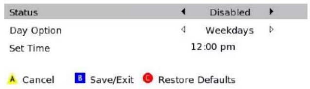
Figure 14 - Power ON Timer Menu
Power OFF Timer
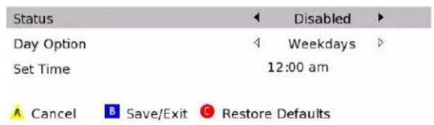
Figure 15 - Power OFF Timer Menu
Table 7 - User Settings Menu Fields
| Setting Description | |
| Audio Coding Format | Selects the audio coding format on the digital output (HDMI and SPDIF) when tuned to a channel carrying compressed audio. The following formats are supported:PCM/Stereo – Send decoded audio in PCM format over the digital outputs.Dolby Digital – Send Dolby Digital audio over the digital outputs.HDMI – Send appropriate audio format, as per auto negotiation between STB and TV, when connected over HDMI. If the negotiation indicates:PCM – send decoded audio in PCM format over the digital outputsDolby Digital – send Dolby Digital audio over the digital outputsDolby Digital Plus – send Dolby Digital Plus over HDMI and Dolby Digital over SPDIF. |
| Audio Output Range | Sets the preferred audio dynamic range when the input audio is decoded by the STB. Three options are allowedNarrow (default) – Enables minimum dynamic range and is most appropriate when the TV is connected to the STB over the RF output. |
Setting Description
| Normal – Enables moderate dynamic range which is most appropriate when a receiver is connected to the STB over baseband or digital outputs.Wide – Enables the complete dynamic range to be reproduced on all outputs, which is most suitable for advanced users who have high quality speakers and audio equipment. | |
| Audio Output | Sets the audio output to a fixed or variable setting. The fixed setting produces a constant output level from the set-top (recommended when connected to an external receiver). This setting does not apply to the Audio Out (Fixed) connector. |
| 3D Mode | Selections are Enabled or Disabled.Enabled – The "D" key on the remote toggles 3D graphics display modes through the settings, 2D, 3DTB, and 3DSS. Disabled – The "D" key on the remote is disabled. The 3D graphics display mode is set by the signal of the selected program. |
| Video Sharpness | Adjusts the picture sharpness when viewing a standard-definition (SD) program. The Video Sharpness setting affects all of the video outputs. By default, the sharpness level of 3 is selected. The DCX3600-M supports five distinct levels of video picture sharpness. A value of 1 corresponds to a "softer" picture while a value of 5 corresponds to a "sharper" picture. The best sharpness setting depends upon the video connection being used, the display quality of the TV, and personal preference. |
| RF Output Channel | The default selection is channel 3. |
| Power ON Timer | The designated time for the set-top to power on. |
| Status | This selection disables or enables the Power ON Timer. |
| Day Option | When enabled, this selection indicates when the Power ON Timer is active. Choices are Weekends, Weekdays, Every Sunday, Every Monday, Every Tuesday, Every Wednesday, Every Thursday, Every Friday, or Every Saturday. |
| Set Time | 12-hour clockAM/PM |
| Power OFF Timer | The designated time for the set-top to power off. |
| Status | This selection disables or enables the Power OFF Timer. |
| Day Option | When enabled, this selection indicates when the Power OFF Timer is active. Choices are Weekends, Weekdays, Every Sunday, Every Monday, Every Tuesday, Every Wednesday, Every Thursday, Every Friday, or Every Saturday. |
| Set Time | 12 hour clockAM/PM |
| Sleep Timer Off/On | |
4
Troubleshooting
See the troubleshooting guidelines listed below for a possible solution to the problem you are experiencing with the installation. If the problem is not resolved after performing the diagnostics, contact the TAC for assistance (see Getting Help for more information).
Table 8 – Troubleshooting Guidelines
| Problem Possible solution | |
| The DCX3600-M will not power ON | The DCX3600-M may have received a software update and may not power ON while the new software is being installed. Try again in a few minutes.Verify that the AC power cord is connected to the DCX3600-M set-top and an AC outlet. Unplug the DCX3600-M set-top from the AC outlet, plug it back in, and then press the POWER button.If the DCX3600-M set-top is connected to a switched outlet on another unit, verify that that unit is powered on. Unplug the power cord from the DCX3600-M AC outlet, plug it back it in, and then press the POWER button. It is recommended that you use an unswitched outlet, if possible.Press the POWER button on the DCX3600-M front panel instead of the remote control. The batteries in the remote control may be depleted.If you are attempting to use an RF remote control to power on the DCX3600-M, the DCX3600-M will not respond if the remote control has not been properly paired with the DCX3600-M. Consult the RF4CE section of this manual for the procedures to pair and un-pair an RF remote control with the DCX3600-M. |
| The remote control does not work | Verify that the remote control is in “Cable” mode.Verify that there are no obstructions between the remote control and the DCX3600-M. Aim the remote control directly at the DCX3600-M front panel, not the TV or VCR.The angle between the remote control and the DCX3600-M may be too large. Stand in front of the DCX3600-M and not too far to either side.Press and release operation keys one at a time, firmly and deliberately.Check the batteries in the remote control. Install new batteries if needed.If you are using an RF remote control with your DCX3600-M, please ensure that the remote control has been properly paired with the DCX3600-M. Unlike an infrared (IR) remote control, an RF remote control must be paired with the device it is intended to control. Consult the RF4CE section of this manual for the procedures to pair and un-pair an RF remote control with the DCX3600-M. |
Problem Possible solution
| There is no audio when viewing cable channels | Verify that the mute button on the DCX3600-M or the remote control has not been pressed. Press MUTE on the remote control to restore sound.If the DCX3600-M audio output is connected to the TV, verify that the mute button on the TV has not been pressed.If the DCX3600-M audio output is connected to a home theater receiver, verify that the receiver is set to the appropriate input source and the mute button on the receiver has not been pressed.Verify that you have the correct cables for the audio connections.Verify that the audio cables are firmly connected between the DCX3600-M and the audio playback device (TV, receiver, DVD player, etc.). |
| There is no audio from the center and/or surround speakers of a home theater receiver connected to the DCX3600-M | Not all Dolby® Digital programs feature full 5.1 surround sound. In some cases, the programs may only contain left and right stereo audio.Verify that the S/PDIF cable is firmly connected to the DCX3600-M and the home theater receiver.Verify that the home theater receiver is set to a surround sound audio mode (Dolby Digital, Dolby Pro Logic II®, Dolby Pro Logic®).Verify that the receiver is properly configured to work with all connected speakers. |
| There is no video on the TV screen | Verify that the TV is powered on and set to the appropriate input source for the DCX3600-M.Verify that the DCX3600-M is powered on and tuned to an authorized cable channel.Verify that all video cables between the DCX3600-M and the TV are firmly connected.Verify that the coaxial cable feed is firmly connected to the DCX3600-M and the wall jack.If the DCX3600-M video output is connected to a home theater unit, verify that the home theater unit is powered on and set to the appropriate input source.If the DCX3600-M video output is connected to a TV through an HDMI connection, power OFF the TV and then power OFF the DCX3600-M set-top. Wait one second and then power ON the devices. |
| No closed captions display | Verify in the guide application settings menu that closed captions are enabled on the DCX3600-M.Note: Closed captioning may not be available on the current program. |
| Colors do not appear correctly | Be sure to match up each signal to the same YPbPr connection on the TV. Otherwise, colors will not appear correctly on your TV. |
| The DCX3600-M set-top is making a humming noise | The DCX3600-M includes an integrated hard drive and a fan for cooling. During normal operation, the DCX3600-M emits a low humming noise, similar to a personal computer. The noise varies in volume occasionally when the speed of the internal fan adjusts to changes in the temperature around the DCX3600-M set-top. Please note that the cooling fan may remain active for a short period of time after turning off the DCX3600-M. |
5
Common Bootloader OSS Attribution Text
Common Bootloader Open Source Software Attribution Text
### Summary Listing of OSS Component Licenses, by Family ###
openssl_license
openssl-0.9.8l
BSD_license
parseX509Cert
ZLIB license
Zlib-1.1.3
Broadcom CFE license
Broadcom CFE
### License Text, Copyright Notices, Etc. ###
openssl-0.9.81
Copyright (c) 1998-2002 The OpenSSL Project. All rights reserved.
Redistribution and use in source and binary forms, with or without modification, are permitted provided that the following conditions are met:
- Redistributions of source code must retain the above copyright notice, this list of conditions and the following disclaimer.
- Redistributions in binary form must reproduce the above copyright notice, this list of conditions and the following disclaimer in the documentation and/or other materials provided with the distribution.
- All advertising materials mentioning features or use of this software must display the following acknowledgment: "This product includes software developed by the OpenSSL Project for use in the OpenSSL Toolkit. (http://www.openssl.org/)"
- The names "OpenSSL Toolkit" and "OpenSSL Project" must not be used to endorse or promote products derived from this software without prior written permission. For written permission, please contact openssl-core@openssl.org.
- Products derived from this software may not be called "OpenSSL" nor may "OpenSSL" appear in their names without prior written permission of the OpenSSL Project.
- Redistributions of any form whatsoever must retain the following acknowledgment:
"This product includes software developed by the OpenSSL Project for use in the OpenSSL Toolkit (http://www.openssl.org/)"
THIS SOFTWARE IS PROVIDED BY THE OpenSSL PROJECT ``AS IS" AND ANY EXPRESSED OR IMPLIED WARRANTIES, INCLUDING, BUT NOT LIMITED TO, THE IMPLIED WARRANTIES OF MERCHANTABILITY AND FITNESS FOR A PARTICULAR PURPOSE ARE DISCLAIMED. IN NO EVENT SHALL THE OpenSSL PROJECT OR ITS CONTRIBUTORS BE LIABLE FOR ANY DIRECT, INDIRECT, INCIDENTAL, SPECIAL, EXEMPLARY, OR CONSEQUENTIAL DAMAGES (INCLUDING, BUT NOT LIMITED TO, PROCUREMENT OF SUBSTITUTE GOODS OR SERVICES; LOSS OF USE, DATA, OR PROFITS; OR BUSINESS INTERRUPTION) HOWEVER CAUSED AND ON ANY THEORY OF LIABILITY, WHETHER IN CONTRACT, STRICT LIABILITY, OR TORT (INCLUDING NEGLIGENCE OR OTHERWISE) ARISING IN ANY WAY OUT OF THE USE OF THIS SOFTWARE, EVEN IF ADVISED OF THE POSSIBILITY OF SUCH DAMAGE.
BSD\_license
Copyright (c) 1987, 1989 Regents of the University of California. All rights reserved.
This code is derived from software contributed to Berkeley by Arthur David Olson of the National Cancer Institute.
Redistribution and use in source and binary forms, with or without modification, are permitted provided that the following conditions are met:
- Redistributions of source code must retain the above copyright notice, this list of conditions and the following disclaimer.
- Redistributions in binary form must reproduce the above copyright notice, this list of conditions and the following disclaimer in the documentation and/or other materials provided with the distribution.
- All advertising materials mentioning features or use of this software must display the following acknowledgement:
This product includes software developed by the University of California, Berkeley and its contributors. - Neither the name of the University nor the names of its contributors may be used to endorse or promote products derived from this software without specific prior written permission.
THIS SOFTWARE IS PROVIDED BY THE REGENTS AND CONTRIBUTORS ``AS IS" AND ANY EXPRESS OR IMPLIED WARRANTIES, INCLUDING, BUT NOT LIMITED TO, THE IMPLIED WARRANTIES OF MERCHANTABILITY AND FITNESS FOR A PARTICULAR PURPOSE ARE DISCLAIMED. IN NO EVENT SHALL THE REGENTS OR CONTRIBUTORS BE LIABLE FOR ANY DIRECT, INDIRECT, INCIDENTAL, SPECIAL, EXEMPLARY, OR CONSEQUENTIAL DAMAGES (INCLUDING, BUT NOT LIMITED TO, PROCUREMENT OF SUBSTITUTE GOODS OR SERVICES; LOSS OF USE, DATA, OR PROFITS; OR BUSINESS INTERRUPTION) HOWEVER CAUSED AND ON ANY THEORY OF LIABILITY, WHETHER IN CONTRACT, STRICT LIABILITY, OR TORT (INCLUDING NEGLIGENCE OR OTHERWISE) ARISING IN ANY WAY OUT OF THE USE OF THIS SOFTWARE, EVEN IF ADVISED OF THE POSSIBILITY OF SUCH DAMAGE.
ZLIB\_license (v1.1.3)
Copyright (C) 1995-1998 Jean-loup Gailly and Mark Adler
This software is provided 'as-is', without any express or implied warranty. In no event will the authors be held liable for any damages arising from the use of this software.
Permission is granted to anyone to use this software for any purpose, including commercial applications, and to alter it and redistribute it freely, subject to the following restrictions:
- The origin of this software must not be misrepresented; you must not claim that you wrote the original software. If you use this software in a product, an acknowledgment in the product documentation would be appreciated but is not required.
- Altered source versions must be plainly marked as such, and must not be misrepresented as being the original software.
- This notice may not be removed or altered from any source distribution.
Jean-loup Gailly Mark Adler
jloup@gzip.org madler@alumni.caltech.edu
The data format used by the zlib library is described by RFCs (Request for Comments) 1950 to 1952 in the files ftp://ds.internic.net/rfc/rfc1950.txt (zlib format), rfc1951.txt (deflate format) and rfc1952.txt (gzip format).
Broadcom CFE license
Broadcom Common Firmware Environment (CFE) Copyright 2000,2001 Broadcom Corporation. All rights reserved.
This software is furnished under license and may be used and copied only in accordance with the following terms and conditions. Subject to these conditions, you may download, copy, install, use, modify and distribute modified or unmodified copies of this software in source and/or binary form. No title or ownership is transferred hereby.
1) Any source code used, modified or distributed must reproduce and retain this copyright notice and list of conditions as they appear in the source file.
2) No right is granted to use any trade name, trademark, or logo of Broadcom Corporation. Neither the "Broadcom Corporation" name nor any trademark or logo of Broadcom Corporation may be used to endorse or promote products derived from this software without the prior written permission of Broadcom Corporation.
3) THIS SOFTWARE IS PROVIDED "AS-IS" AND ANY EXPRESS OR IMPLIED WARRANTIES, INCLUDING BUT NOT LIMITED TO, ANY IMPLIED WARRANTIES OF MERCHANTABILITY, FITNESS FOR A PARTICULAR PURPOSE, OR NON-INFRINGEMENT ARE DISCLAIMED. IN NO EVENT SHALL BROADCOM BE LIABLE FOR ANY DAMAGES WHATSOEVER, AND IN PARTICULAR, BROADCOM SHALL NOT BE LIABLE FOR DIRECT, INDIRECT, INCIDENTAL, SPECIAL, EXEMPLARY, OR CONSEQUENTIAL DAMAGES (INCLUDING, BUT NOT LIMITED TO, PROCUREMENT OF SUBSTITUTE GOODS OR SERVICES; LOSS OF USE, DATA, OR PROFITS; OR BUSINESS INTERRUPTION) HOWEVER CAUSED AND ON ANY THEORY OF LIABILITY, WHETHER IN CONTRACT, STRICT LIABILITY, OR TORT (INCLUDING NEGLIGENCE OR OTHERWISE), EVEN IF ADVISED OF THE POSSIBILITY OF SUCH DAMAGE.

ARRIS Enterprises, Inc.
3871 Lakefield Drive, Suwanee, GA 30024 www.arrisi.com
365-095-25659 x.1 04/14

- i
- Safety and Regulatory
- IMPORTANT SAFETY INSTRUCTIONS
- IMPORTANT SAFETY CONSIDERATIONS FOR ALL SET-TOPS
- During Installation
- ADDITIONAL SAFETY CONSIDERATIONS FOR DVR MODELS
- FCC COMPLIANCE
- FCC DECLARATION OF CONFORMITY
- INDUSTRY CANADA (IC)
- CARING FOR THE ENVIRONMENT BY RECYCLING
- Contents
- Safety and Regulatory ....i
- Tables......v
- Figures......v
- Introduction 1
- Overview 1
- Support 3
- Getting Help....3
- Product Overview....4
- Front Panel 4
- Rear Panel....5
- Standard Features 6
- M-Card™ 7
- Networking Overview....8
- Transcoding....14
- Installation....17
- RF4CE....23
- Operational Check for the Remote Control....24
- Tables
- Figures
- 1
- Introduction
- Overview
- Support
- Getting Help
- 2
- Product Overview
- Front Panel
- Rear Panel
- Standard Features
- Standard Data Features
- Optional Features
- Whole Home DVR Functionality
- M-Card™
- Networking Overview
- Ethernet Networking Connection
- MoCA Networking Connection
- Wi-Fi Networking Connection
- GHz Wireless Routers
- GHz Wireless Routers
- Transcoding
- The Basics of Transcoding
- DCX3600-M Authorization
- DCX3600-M Software
- Connection to the Home Wireless Network
- Handheld Device Software
- 3
- Installation
- Video Connection Options
- Audio Connection Options
- Connecting a High-Definition TV (HDTV) for Video
- Connecting a High-Definition TV (HDTV) for Audio
- Connecting a High-Definition TV (HDTV) and an A/V Receiver for Video
- Connecting a High-Definition TV (HDTV) and an A/V Receiver for Audio
- Connecting a Standard-Definition TV
- RF4CE
- Pairing:
- Un-Pairing:
- Operational Check for the Remote Control
- Configuring the User Settings
- 4
- Troubleshooting
- 5
- Common Bootloader OSS Attribution Text
- Common Bootloader Open Source Software Attribution Text
- BSD\_license
- ZLIB\_license (v1.1.3)
- Broadcom CFE license
Brand : Arris
Model : DCX3600
Category : Digital decoder