RG-12T - Power regulator ENTES - Free user manual and instructions
Find the device manual for free RG-12T ENTES in PDF.


| Product Type | Voltage monitoring relay |
| Model | RG-12T |
| Brand | ENTES |
| Dimensions (HxWxD) | 90 x 72 x 58 mm |
| Weight | 0.2 kg |
| Power Supply | 230 V AC, 50/60 Hz |
| Operating Voltage Range | 184-276 V AC |
| Protection Functions | Overvoltage, undervoltage, phase failure, phase sequence |
| Response Time | 0.1-10 s (adjustable) |
| Output Contacts | 1 x SPDT relay, 8 A / 250 V AC |
| Mounting | DIN rail EN 60715 |
| Degree of Protection | IP20 (front panel) |
| Ambient Temperature | -20°C to +55°C |
| Certification | CE, EAC |
| Maintenance | Clean with dry lint-free cloth; avoid solvents |
| Safety Precautions | Disconnect power before installation or servicing |
| Spare Parts Available | Replacement fuses, terminal covers |
| Typical Applications | Motor protection, generator monitoring, industrial control |
Frequently Asked Questions - RG-12T ENTES
User questions about RG-12T ENTES
0 question about this device. Answer the ones you know or ask your own.
Ask a new question about this device
Download the instructions for your Power regulator in PDF format for free! Find your manual RG-12T - ENTES and take your electronic device back in hand. On this page are published all the documents necessary for the use of your device. RG-12T by ENTES.
USER MANUAL RG-12T ENTES
This User Manual is designed to help you for quick installation of RG-T. Before installation and operation, please read this section very carefully.
1.2 Precautions for Safe Use and Installation
- Failure to follow those instructions will result in death or serious injury.
- Disconnect all power before working on equipment.
- When the device is connected to the network, do not remove the back panel.
- Do not try to clean the device with solvent or the like. Only clean the device with dried cloth.
- Verify correct terminal connections when wiring.
- Electrical equipment should be serviced only by your component seller.
- Only for rack panel mounting.
- An F type fuse must be used and its current limit value must be 6A.
- No responsibility is assured by ENTES A.S or any of its subsidiaries
for any consequences arising out of the use of this material.
2. GENERAL
Power Factor Controllers are used for measurement and control of power factor control units for central reactive power compensation. The Power Factor measured by RG-T is compared with the set point values and in order to provide necessary compensation, Power Factor Controller switches capacitor banks ON and OFF automatically. RG-T is a microcontroller relay, designed for above application in 144x144 case for flush mounting with rear plug-in connectors. In addition to displaying the system's Cosj in Automatic Operating Mode, RG-T displays the RMS values of Voltage(V) and Current (I), Active Power (W), Reactive Power (VAr) and Apparent Power (VA) of measuring phase.
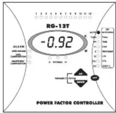
- FRONT PANEL SPECIFICATIONS

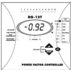
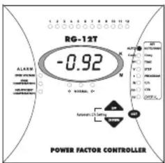
On the front panel of RG-T, there are warning lights, display and 3 buttons for settings.
3.1 Buttons and Lights
-
1,2,......,12 : Shows the status of each capacitor steps.
-
SET Menu : Shows the Menu options that correspond to the lights.
-
AUTO/MAN Light : If this light is continuously ON, RG-T is in Automatic Mode. If it is blinking, RG-T is in Manual Mode. By pressing SET button 3 seconds, you enter to Menu and change operating Mode.
(Refer to: 5.1)
- Cosj Light : By pressing SET button 3 seconds ; Cosj Adjustment can be made by selecting this light. (Refer to: 5.3).
In Automatic Mode, when Cosj light is selected by pressing UP and
DOWN buttons, system's Cosj and ind/cap state is displayed.
(Refer to: 5.10)
- TIME/PF Light : By pressing SET button 3 seconds; you enter to Menu and Step Time adjustment is made by selecting this light. (Refer to: 5.4)
In Automatic Mode, when this light is selected by pressing UP and
DOWN buttons, system's Power Factor is displayed. (Refer to: 5.11)
- STEP/V Light : By pressing SET button 3 seconds; you enter to Menu and Step Number adjustment is made by selecting this light. (Refer to:5.5)
In Automatic Mode, when this light is selected by pressing UP and
DOWN buttons phase voltage (V) is displayed. (Refer to:5.12)
- PROGRAM/I Light : By pressing SET button 3 seconds; you enter to Menu and Power Sequence adjustment is made by selecting this light. (Refer to:5.6)
In Automatic Mode, when this light is selected by pressing UP and
DOWN buttons phase current (I) is displayed (Refer to:5.12)
- C/k - W Light : By pressing SET button 3 seconds; you enter to Menu and Manual C/k adjustment is made by selecting this light.(Refer to:5.7)
In Automatic Mode when this light is selected by pressing UP and
DOWN buttons, system's Active Power (W) is displayed.
(Refer to: 5.13)
- CTR - VAr Light : By pressing SET button 3 seconds; you enter to Menu and Current Transformer Primary Value is made by selecting this light.
(Refer to:5.8)
In Automatic Mode when this light is selected by pressing UP and DOWN buttons, system's Reactive Power (VAr) is displayed.
(Refer to: 5.14)
- Over V./VA Light : By pressing SET button 3 seconds; you enter to Menu and Protection of Capacitor Steps Against Over Voltage function is made by selecting this light. (Refer to:5.9)
In Automatic Mode when this light is selected by pressing UP and
DOWN buttons, system's Apparent Power (VA) is displayed. (Refer to: 5.15)
-
UP Button : To move up in the Menu.
-
SET Button : Enter button for different settings and values.
-
DOWN Button : To move down in the Menu.
-
Automatic
C/k Setting : Automatical C/k adjustment is started by pressing UP and DOWN buttons together at the same time. (Refer to:5.2)
-
C+ Light : This light is ON when RG-T switches capacitor steps on.
-
NORMAL Light : This light is ON when the targeted compensation is achieved.
-
C- Light : This light is ON when RG-T switches capacitor steps off.
-
Insufficient
Compensation
Light
(Refer to:6.1.2)
- Over
Compensation
Light
(Refer to:6.1.3)
: This warning light is ON when insufficient compensation occurs.
: This warning light is ON when over compensation occurs.
- Over Voltage
Light : This warning light is ON when over voltage occurs. (Refer to:6.1.1)
-
K (Kilo) Light : When this light is ON displayed value must be multiplied by 1000.
-
M (Mega) Light : When this light is ON displayed value must be multiplied by 106.
-
CONNECTION DIAGRAM

flowchart
graph TD
    subgraph Phase_Phase_Conding
        A["15"] --> B["C1"]
        B --> C["20"]
        C --> D["C6"]
        D --> E["27"]
        E --> F["C7"]
        F --> G["C12"]
    end

    subgraph Phase_Phase_Lates
        H["L3"] --> I["L1"]
        J["L2"] --> K["L"]
        L["Alarm Relay"] --> M["11"]
        N["3A"] --> O["10"]
    end

    style Phase_Phase_Conding fill:#f9f,stroke:#333
    style Phase_Lates fill:#ccf,stroke:#333
    style Alarm_Relay fill:#cfc,stroke:#333
Warnings:
a) Connection of a circuit breaker between the network and the power supply input of the device is highly recommended.
b) Circuit breaker must be in close proximity to the device.
c) Circuit breaker must be marked as the disconnecting device for the equipment.
d) All used fuses must be FF type and the current values of the fuses must be 2A, 3A and 6A.
All settings are made by Menu. The set values except operating mode are kept in memory even if the device is switched off. When it is switched on, it starts compensation with the values stored in the memory in Automatic Operating Mode. After entering Menu by pressing SET button for 3 seconds and if you don't make any adjustments during 20 seconds, RG-T operates with the previously stored values.
To quit Menu without any storing operation, UP or DOWN buttons are pressed until the ESC symbol is displayed and then SET button is pressed.
The details of controls and adjustments are explained in the following sections.
5.1 Selection of Operating Mode(Automatic / Manual Mode)
Two Operating Modes are available for switching on/off the capacitor steps.
1) Automatic Operating Mode: The capacitor steps are controlled by RG-T, automatically.
2) Manual Operating Mode: The capacitor steps are switched on/off, manually.
Mode selection is done as followed.

flowchart
graph TD
    A["SET"] --> B{UP}
    B --> C["DOWN"]
    C --> D["SET"]
    D --> E{UP}
    E --> F["DOWN"]
    F --> G["SET"]
By pressing SET button 3 seconds SET Menu is started.

AUTO/MAN light is selected by using UP-DOWN buttons. AUTO symbol is displayed.
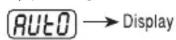
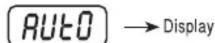
AUTO/MAN setting is selected by pressing SET button. If the device is in Manual Mode, R OF symbol is displayed. If the device is in Automatic Mode, R On symbol is displayed.
Automatic Mode (A) or Manual Mode (A OF) is selected by using UP-DOWN buttons.
When targeted operating mode is displayed, it is selected by pressing SET button. If Manual Mode is selected, AUTO/MAN light starts blinking and blinks during this mode. If Automatic Mode is selected, AUTO/MAN light is continuously ON during this mode.

5.1.1 Switching of the Capacitor Steps Manually
When RG-T is in Manual Mode, capacitor steps are connected by pressing UP button.
Each time UP button is pressed, C+ light turns ON and one step is connected accordingly; NORMAL light will be ON after the connection of the step. This operation must be repeated to connect more steps.
Capacitor steps are disconnected by pressing DOWN button. Each time UP button is pressed, C- light turns ON and one step is disconnected after a delay time; NORMAL light will be ON after the disconnection of the step. This operation must be repeated to disconnect more steps.
5.2 Automatic C/k Adjustment

C/k adjustment is started by pressing UP-DOWN buttons together.
5.3 Cosj Adjustment

flowchart
graph TD
    A["SET"] --> B{UP}
    B --> C["SET"]
    C --> D{UP}
    D --> E["SET"]
    B --> F["DOWN"]
    C --> G["DOWN"]
    E --> H["SET"]
By pressing SET button 3 seconds, SET Menu is started.
Cosj light is selected by using UP DOWN buttons. COS symbol is displayed
Cosj adjustment is selected by pressing SET button. Previously adjusted value is shown at the display.
A value between 0.85-1.00 adjusted by using UP-DOWN buttons.

When targeted value is displayed, it is stored by pressing SET button and RG-T
returns to its normal operating mode.
5.4 Step Time Adjustment

flowchart
graph TD
    A["SET"] --> B{UP}
    B --> C["SET"]
    C --> D{UP}
    D --> E["SET"]
    B --> F["DOWN"]
    F --> C
    D --> G["DOWN"]
By pressing SET button 3 seconds, SET Menu is started.
TIME light is selected by means of UP-DOWN buttons.
While TIME light is ON, t 0n symbol is displayed by means of UP-DOWN buttons and time delay adjustment for connection of capacitor steps to system is selected by pressing SET button.
While TIME light is ON, t 0F symbol is displayed by means of UP-DOWN buttons and time delay adjustment for disconnection of capacitor steps to system is selected by pressing SET button.
A value between 2-1800 sec. is adjusted by using UP-DOWN buttons.
When targeted value is displayed, it is stored by pressing SET button and RG-T returns to its normal operating mode.

5.5 Step Number Selection

flowchart
graph TD
    A["SET"] --> B{UP}
    B --> C["SET"]
    C --> D{UP}
    D --> E["SET"]
    B --> F["DOWN"]
    C --> G["DOWN"]
By pressing SET button 3 seconds, SET Menu is started.

STEP light is selected by means of UP-DOWN buttons. StEP symbol is displayed.
STEP number adjustment is selected by pressing SET button. Previously selected value is shown on the display
A preferred step number is selected by means of UP-DOWN buttons.

When targeted value is displayed, it is red by pressing SET button and RG-T returns to its normal operating mode.
5.6 Switching Program Selection

flowchart
graph TD
    A["SET"] --> B{UP}
    B --> C{DOWN}
    C --> D["SET"]
    D --> E{UP}
    E --> F{DOWN}
    F --> G["SET"]
By pressing SET button 3 seconds, SET Menu is started.

PROGRAM light is selected by means of UP-DOWN buttons. Symbol is displayed.
Switching Program is selected by pressing SETbutton. Previously selected value is shown on the display.
A value between PS1-PS5 is selected by using UP-DOWN buttons.
When targeted program is displayed, it is stored by pressing SET button and RG-T returns to its normal operating mode.
5.7 Selection of C/k Value by the User
By pressing SET button 3 seconds, SET Menu is started.

flowchart
graph TD
    A["Start"] --> B{UP}
    B -->|DOWN| C["SET"]
    B -->|UP| D{DOWN}
    D -->|UP| E["SET"]
    D -->|DOWN| F["End"]

C/ k light is selected by means of UP-DOWN buttons. Symbol is displayed.
Manual C/ k adjustment is selected by pressing SET button. Previously manually selected or automatically calculated C/ k value is shown on the display
A value between 0.02-1 is selected by using UP-DOWN buttons.
When targeted value is displayed, it is stored by pressing SET button and RG-T returns to its normal operating mode.
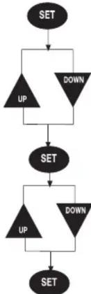
5.8 Selection of Current Transformer Primary Value
flowchart
graph TD
    A["SET"] --> B{UP}
    B --> C["DOWN"]
    C --> D["SET"]
    D --> E{UP}
    E --> F["DOWN"]
    F --> G["SET"]
By pressing SET button 3 seconds, SET Menu is started.

CTR light is selected by means of UP-DOWN buttons. Ct symbol is displayed.
Current Transformer Primary Value is selected by pressing SET button. Previously selected CTR value is shown on the display.
A value between 5--1 0 0 00 is adjusted by using UP-DOWN buttons.

When targeted value is displayed, it is red by pressing SET button and RG-T returns to its normal operating mode.
5.9 Protection of Capacitor Steps Against Over Voltage
This is a selectable function, either O OF (Over Voltage Protection Off) or an Over Voltage value between 410-480V can be selected. If "Over Voltage" occurs when Over Voltage Value is selected (between 410-480V), then all the capacitor steps switch off, OVER VOLTAGE LED turns on and alarm relay activates. And if RG-T is on Manual Mode, it switches to Automatic Mode. If 0 OF is selected; Then over voltage protection is disabled.
Setting can be made as followed.

flowchart
graph TD
    A["SET"] --> B{UP}
    B --> C["DOWN"]
    C --> D["SET"]
    D --> E{UP}
    E --> F["DOWN"]
    F --> G["SET"]
Push SET button 3 seconds and enter SET Menu.

Scroll to "OVER V." by UP/DOWN buttons. OV is displayed.
Push SET button for Over Voltage Protection setting. Either O OF or preset over voltage value is displayed.
Select either O OF to cancel Over Voltage Protection Function or select a voltage value by UP/DOWN buttons.
Push SET button to store the selected value. RG-T returns to normal operating mode.
5.10 Display of Cosj Value
When RG-T is in Manual Operating Mode, Cosj value and inductive/capacitive state is always displayed. When Cosj value is negative, the system is capacitive and if Cosj value is positive, the system is inductive. In Automatic Operating Mode, system's present Cosj value and ind./cap. state may be displayed by selecting the Cosj light, by means of UP-DOWN buttons.
5.11 Display of Power Factor (PF) Value
When RG-T is in Automatic Operating Mode (AUTO/MAN light is continuously ON), PF light is selected by means of UP-DOWN buttons and sytem's Power Factor value is displayed. This option is disabled in Manual Operating Mode.
Important Definition: Cosj is defined as Displacement Power Factor and is relative to the fundamental harmonic only. PF is defined Total Power Factor and is relative to the all harmonics including fundamental harmonic. In a system without harmonics, PF and Cosj are equal to each other.
Attention: The difference between cosj and PF values does not mean that voltage harmonics, which leads to problems in systems, are high on the network.
5.12 Displaying RMS Values of Voltage and Current
When RG-T is in Automatic Operating Mode (AUTO/MAN light is ON) and V light is selected, RMS value of Voltage (V) is displayed.
If I light is selected, RMS value of Current (I) is displayed. Displayed current and voltage values are of the phase where CT is connected. These options are disabled in Manual Operating Mode.
5.13 Display of Active Power (W) Value
When RG-T is in Automatic Operating Mode (AUTO/MAN light is continuously ON) and W light is selected by means of UP-DOWN buttons, system's Active Power value is displayed. This option is disabled in Manual Operating Mode.
5.14 Display of Reactive Power (VAr) Value
When RG-T is in Automatic Operating Mode (AUTO/MAN light is continuously ON) and VAr light is selected by means of UP-DOWN buttons, system's Reactive Power value is displayed. This option is disabled in Manual Operating Mode.
5.15 Display of Apparent Power (VA) Value
When RG-T is in Automatic Operating Mode (AUTO/MAN light is continuously ON) and VA light is selected by means of UP-DOWN buttons, system's Apparent Power value is displayed. This option is disable in Manual Operating Mode.
6. DESCRIPTION
6.1 Errors and Warnings
The Alarm Relay is activated if the following "errors" occur.
6.1.1 Over Voltage
If the phase to phase voltage of the L1 phase exceeds or equals to preset Over Voltage Value (between 410-480V), then RG-T waits for 3 seconds. At the end of 3 seconds if there is still over voltage, then OVER VOLTAGE LED turns on. Depending on selection of Over Voltage Protection Function (Pls. refer to 5.9), RG-T switches off all the capacitor steps or continues to compensation.
Over Voltage error disappears, if set Over Voltage value decreases by 4VAC. In this case, OVER VOLTAGE LED turns off and RG-T continues to compensation.

line
| Condition | Voltage Level | | --------- | ------------- | | A: Selected Over Voltage | ΔU | | B: Selected Over Voltage - 4 V AC | Normal Voltage |6.1.2 Insufficient Compensation
When target power factor is not reached although all the capacitor steps have been connected, INSUFFICIENT COMPENSATION's light is ON and the Alarm Relay is activated.
6.1.3 Over Compensation
If the system is still capacitive although all the capacitor steps are disconnected, OVER COMPENSATION light is ON and Alarm Relay is activated.
6.2 Target Cosj
The target Cosj value can be adjusted between 0.85-1.00 inductive. RG-T connects capacitors in order to bring system's power factor to the adjusted value. The adjusted value is defined as 1.25xQC1 value. Switching operation occurs out of this region.

6.3 Adjustable Step Switching Time
Step switching on/off delay time can be adjusted between 2 sec.-1800 sec.
Warning: Shorter time than above range can lead to damage in capacitors and conductors.
If capacitor banks do not have discharge coils, the delay time must be selected over 14 seconds. The selected delay time must not be shorter than the manufacturer's instruction.
6.4 Switching Program Selection
RG-T has 5 different program modes which determines the power ratio sequence of the capacitor steps:
PS1 selection ==> 1: 1: 1:......: 1
PS2 selection ===> 1: 2: 2:.....: 2
PS3 selection ==> 1:2:4:.....:4
PS4 selection ==> 1:2:4:8:...:8
PS5 selection ==> may be all of the above
6.4.1 RG-T Capacitor Sequence Examples
The power ratio selection between capacitor steps is very important. When choosing the ratio between the power of capacitor steps, the rating of each capacitor step value may exceed that of the first by a maximum amount equal to the total of the preceding capacitor steps value. So the first step value will be the smallest one and the following steps must be the multiplies of the first step.
Example: If the first capacitor power is 5 kVAr, the capacitor power sequence of the following capacitors are as followed:
PS1 selection ==> 5.5:5:.....:5
PS2 selection ==> 5:10:10:......:10
PS3 selection ==> 5:10:20:.....:20
PS4 selection ===> 5:10:20:40.....:40
PS5selection ===> may be all of the above
Two different switching programs exist in RG-T :
a) Rotational Switching : This switching program is rotational between equal steps in the clockwise direction. This ensures that the capacitor
switching cycles are uniformly distributed over all steps and to provide minimum switching steps for maximum service life time of the system.
There are 4 different rotational switching program options. (PS1, PS2, PS3, PS4)
b) Linear Operation : The switching program begins always from the first step
to the last one in both switching on and off mode. The advantage of this switching program is the possibility of a large selection of capacitor steps conform to the step function ratio rule as explained above. The maximum possible ratio is "x:2x:4x:8x:16x...".
This switching program is selected by PS5 option.
6.5 Step Number Selection
By selecting the step number, the extra time is spent connecting on/off the unused capacitor steps is eliminated. As a result, compensation system is used more effectively and efficiently. If step number is not selected, RG-T makes the compensation according to the factory set step number which is max. available output as defined on the front panel.
6.6 C/k Setting
The C/k value is a threshold value for switching on/off the capacitor steps. C/k is the value obtained by dividing first step capacitor power "C" to the Current Transformer Ratio "k". This value is measured and calculated by RG-T automatically, or can be entered manually. After pressing the UP and DOWN buttons together, the C/k value is calculated and stored in one step switching on/off time interval. The further compensation controls are made with this stored value. In case of instantaneous change of the system's load, measuring process will be renewed. RG-T will stop the measuring after 10 attempt. It means that the C/k value couldn't be measured due to the instability of the system's load. In this case, compensation control will continue with the previously stored value in the memory.
The formula to calculate the C/k value is :
c / K = QK Q: Power of the first step capacitor (kVar) k: Current Transformer Ratio.(CTR)
Example :
Let the power (C) of the first step capacitor is 5 kVAr and the Current Transformer Ratio (k) is 100/5. Then the C/k value is:
C / k = 5 / (1 0 0 / 5) = 0. 2 5
C/k value for the different C and k values are as followed :
6.7 Sensing the Energy Flow Direction
RG-T has four quadrant measuring and operation feature. So, it is able to sense the energy flow direction and to correct itself for right compensation.
6.8 Current Transformer (CT) Selection
A separate CT must be always used for the Power Factor Controller. The wires connecting CT to Power Factor Controller must be as short as possible and the diameter of wire not less than 1.5 mm. Since the current information is supplied by CT, the right selection of CT is very important. The secondary current of the selected CT must comply with the following current limits for correct measuring.
Minimum=0.05 mA, Maximum=5.5 A (Minimum C/k Ratio must be 0.02)
7. ERROR DESCRIPTIONS
7.1 Wrong Cosj
Current and Voltage phase connections are not correct.
7.2 Insufficient Compensation
The power value of the capacitor steps may be decreased by time. The fuses which are connected to the capacitors may be out of order. The power of the capacitor steps may be insufficient to compensate the system.(In this case, user must increase the capacitor power.)
7.3 Over Compensation
This occurs (especially at weekends, nights etc.) due to capacitive load current drawn by devices like ballasts, constant steps, etc. The contactor's contacts switching the capacitor steps may have stuck to each other due to the instantaneous over current. Unnecessary capacitor steps may have switched on manually.
7.4 Over Voltage
The phase-neutral voltage of L1 has exceeded the preset Over Voltage Value.
8. EASY INSTALLATION RECOMMENDATION (IMPORTANT NOTICE)
When the load is unstable and varies very quickly, the C/k calculation process may take long time or in some cases it can not be calculated properly or can be miscalculated which may cause improper compensation. A practical way to prevent this situation is as followed:
1- Turn on the compensation board without connecting the load current. Only the capacitors will be in operation in this situation (You can do this by switching off the load current temporarily). 2- Start the C/k calculation process by pressing the UP and DOWN buttons at the same time. Now, depending on the power of the first step, C/k value is calculated very accurately by RG-T. The calculated C/k value will automatically be stored in the memory. You can switch the load on. This C/k value will be kept in the memory until it is recalculated or changed manually.
- TECHNICAL SPECIFICATIONS
| Rated Voltage (Un) | :415 VAC |
| Operating Voltage Range(DU) | :(0.9-1.1)xUn |
| Operating Current Range(DI) | :50 mA-5.5A |
| Rated Frequency | :50 Hz / 60 Hz |
| Measuring Class | :1% ±1digit (V,I,cosj), 2% ±1digit(W,VAr,VA) |
| Power Consumption | :Current: <2 VAVoltage: 3 VA- 10 VA |
| Output Contact | :3 A ,750 VA (NO Contact) |
| No-Volt Feature | :In case of power failure longer than 200 msec.all capacitor steps are disconnected automatically. |
| Setting Range | :Manual C/k Setting:0.02-1.0Cosj Setting:0.85 (ind.)-1.00CT Value:5-10000CT Seconder 5A |
| Time Delay | :Between 2 sec.-1800 sec. |
| Over Voltage Values | :410-480 V (Selectable) (Un= 230 V AC ) |
| Factory Set Values | :Cosj=1.00(ind.), Step Time=7 sn.Program=PS5 , C/k=0.05CT Ratio =5 |
| Number of Steps | :RG12T(max 12) ; RG8T(max 8)RG6T(max 6) ; RG5T(max 5) |
| Ambient Temperature | :-5°C - 55°C |
| Display | :4 Digit ,Red Display |
| Equipment Protection Class | :Double Insulation-Class II ( [IMAGE] |
| Wire Section (For Terminal Block) | :2.5 mm2 |
| Terminal Block Protection Class : IP 00 | |
| Protection Class | :IP 40 |
| Connections | :Socket terminals with screw |
| Dimension | :Type PR16 |
| Switchboard cut-out | :139x139 mm |
| Weight | :0.8 kg. |
- DIMENSIONS

ENTES Elektronik Cihazlar Imalat ve Ticaret A.S.
Dudullu OSB; 1. Cadde; No:23 34776 Umraniye - ISTANBUL / TURKEY
Tel: +90 216 313 01 10 Fax: +90 216 314 16 15
E-mail: iletisim@entes.com.tr - contact@entes.eu
Web: www.entes.com.tr - www.entes.eu

A8573 / Rev.1
01.12.2019
- Precautions for Safe Use and Installation
- GENERAL
- Buttons and Lights
- (Refer to: 5.1)
- (Refer to: 5.10)
- (Refer to: 5.13)
- Warnings:
- Selection of Operating Mode(Automatic / Manual Mode)
- Switching of the Capacitor Steps Manually
- Automatic C/k Adjustment
- Cosj Adjustment
- Step Time Adjustment
- Step Number Selection
- Switching Program Selection
- Selection of C/k Value by the User
- Selection of Current Transformer Primary Value
- Protection of Capacitor Steps Against Over Voltage
- Setting can be made as followed.
- Display of Cosj Value
- Display of Power Factor (PF) Value
- Displaying RMS Values of Voltage and Current
- Display of Active Power (W) Value
- Display of Reactive Power (VAr) Value
- Display of Apparent Power (VA) Value
- DESCRIPTION
- Errors and Warnings
- Over Voltage
- Insufficient Compensation
- Over Compensation
- Target Cosj
- Adjustable Step Switching Time
- Switching Program Selection
- RG-T Capacitor Sequence Examples
- Two different switching programs exist in RG-T :
- Step Number Selection
- C/k Setting
- The formula to calculate the C/k value is :
- Example :
- Sensing the Energy Flow Direction
- Current Transformer (CT) Selection
- ERROR DESCRIPTIONS
- Wrong Cosj
- Insufficient Compensation
- Over Compensation
- Over Voltage
- EASY INSTALLATION RECOMMENDATION (IMPORTANT NOTICE)
Brand : ENTES
Model : RG-12T
Category : Power regulator