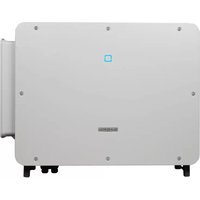
SG125HX - Solar panel Sungrow - Free user manual and instructions
Find the device manual for free SG125HX Sungrow in PDF.


| Product Type | Three-Phase Grid-Tied Solar Inverter |
| Model Number | SG125HX |
| Maximum DC Input Power | 187.5 kW |
| Maximum DC Input Voltage | 1500 V |
| MPPT Range | 500 V – 1500 V |
| Number of MPPT Trackers | 12 |
| Rated AC Output Power | 125 kVA @ 50°C |
| Maximum AC Output Current | 152.5 A |
| Nominal AC Voltage | 800 V / 480 V (selectable) |
| Maximum Efficiency | 99.0% |
| European Efficiency | 98.7% |
| Dimensions (W × H × D) | 1050 × 700 × 360 mm |
| Weight | 96 kg |
| Cooling Method | Smart forced air cooling with speed-controlled fans |
| Display | LCD graphical display with touch buttons |
| Communication Interfaces | RS485, Wi-Fi (optional), Ethernet (optional) |
| Protection Class | IP66 |
| Operating Temperature Range | -25°C to +60°C (derating above 45°C) |
| Warranty | Standard 5 years, extendable up to 20 years |
| Safety Certifications | IEC 62109, IEC 61727, VDE-AR-N 4105, AS/NZS 4777 |
Frequently Asked Questions - SG125HX Sungrow
User questions about SG125HX Sungrow
0 question about this device. Answer the ones you know or ask your own.
Ask a new question about this device
Download the instructions for your Solar panel in PDF format for free! Find your manual SG125HX - Sungrow and take your electronic device back in hand. On this page are published all the documents necessary for the use of your device. SG125HX by Sungrow.
USER MANUAL SG125HX Sungrow
PV Grid-Connected Inverter
SG125CX-P2
All Rights Reserved
All Rights Reserved
No part of this document can be reproduced in any form or by any means without the prior written permission of Sungrow Power Supply Co., Ltd (hereinafter "SUNGROW").
Trademarks
SUNGROW and other Sungrow trademarks used in this manual are owned by SUNGROW.
All other trademarks or registered trademarks mentioned in this manual are owned by their respective owners.
Software Licenses
- It is prohibited to use data contained in firmware or software developed by SUNGROW, in part or in full, for commercial purposes by any means.
- It is prohibited to perform reverse engineering, cracking, or any other operations that compromise the original program design of the software developed by SUNGROW.
About This Manual
The manual mainly contains the product information, as well as guidelines for installation, operation, and maintenance. The manual does not include complete information about the photovoltaic (PV) system. Readers can get additional information at www.sungrowpower.
com or on the webpage of the respective component manufacturer.
Validity
This manual is valid for the following model of low-power grid-connected PV string inverters:
- SG125CX-P2
It will be referred to as "inverter" hereinafter unless otherwise specified.
Target Group
This manual is intended for professional technicians who are responsible for installation, operation, and maintenance of inverters, and users who need to check inverter parameters.
The inverter must only be installed by professional technicians. The professional technician is required to meet the following requirements:
- Know electronic, electrical wiring and mechanical expertise, and be familiar with electrical and mechanical schematics.
- Have received professional training related to the installation and commissioning of electrical equipment.
- Be able to quickly respond to hazards or emergencies that occur during installation and commissioning.
- Be familiar with local standards and relevant safety regulations of electrical systems.
- Read this manual thoroughly and understand the safety instructions related to operations.
How to Use This Manual
Please read this manual carefully before using the product and keep it properly at a place for easy access.
All contents, pictures, marks, and symbols in this manual are owned by SUNGROW. No part of this document may be reprinted by the non-internal staff of SUNGROW without written authorization.
Contents of this manual may be periodically updated or revised, and the actual product purchased shall prevail. Users can obtain the latest manual from support.sungrowpower.com or sales channels.
Symbols
This manual contains important safety instructions, which are highlighted with the following symbols, to ensure personal and property safety during usage, or to help optimize the product performance in an efficient way.
Please carefully understand the meaning of these warning symbols to better use the manual.
! DANGER
Indicates high-risk potential hazards that, if not avoided, may lead to death or serious injury.
WARNING
Indicates moderate-risk potential hazards that, if not avoided, may lead to death or serious injury.
CAUTION
Indicates low-risk potential hazards that, if not avoided, may lead to minor or moderate injury.
NOTICE
Indicates potential risks that, if not avoided, may lead to device malfunctions or financial losses.
i
"NOTE" indicates additional information, emphasized contents or tips that may be helpful, e.g., to help you solve problems or save time.
Contents
All Rights Reserved ....I
About This Manual....II
1 Safety Instructions ....1
1.1 Unpacking and Inspection ....1
1.2 Installation Safety ....1
1.3 Electrical Connection Safety....2
1.4 Operation Safety ....3
1.5 Maintenance Safety....4
1.6 Disposal Safety ....4
2 Product Description ....5
2.1 System Introduction....5
2.2 Product Introduction....6
2.3 Symbols on the Product ....8
2.4 LED Indicator 9
2.5 Circuit Diagram 10
2.6 Function Description ......10
3 Unpacking and Storage 13
3.1 Unpacking and Inspection ....13
3.2 Inverter Storage 13
4 Mechanical Mounting 15
4.1 Safety during Mounting 15
4.2 Location Requirements ....15
4.2.1 Environment Requirements....16
4.2.2 Carrier Requirements ....16
4.2.3 Angle Requirements....17
4.2.4 Clearance Requirements ....18
4.3 Installation Tools....19
4.4 Moving the Inverter....20
4.5 Installing the mounting-bracket ....21
4.5.1 PV Bracket-Mounted Installation 22
4.5.2 Wall-Mounted Installation....23
4.5.3 Pole-Mounting 25
4.6 Installing the Inverter....27
5 Electrical Connection ....29
5.1 Safety Instructions ......29
5.2 Terminal Description ....30
5.3 Electrical Connection Overview 32
5.4 Crimp OT / DT terminal 34
5.5 External Grounding Connection....35
5.5.1 External Grounding Requirements....36
5.5.2 Connection Procedure....36
5.6 AC Cable Connection ....37
5.6.1 AC Side Requirements ....37
5.6.2 Requirements for OT/DT Terminal 39
5.6.3 Connection Procedure (For a multi-core cable)....39
5.6.4 Connection Procedure (For a single-core cable) .....44
5.7 DC Cable Connection ....48
5.7.1 PV Input Configuration 49
5.7.2 Assembling the PV Connectors ....50
5.7.3 Installing the PV Connector....52
5.8 Wiring of Tracking System Power Cable (optional) 52
5.9 Wireless Communication Module Connection(optional) ....54
5.10 WiNet-S Connection (optional)....55
5.10.1 Ethernet Communication ....55
5.10.2 WLAN Communication ....57
5.11 Communication Junction Box....57
5.12 Communication Wiring Board ....58
5.13 RS485 Connection....59
5.13.1 Interface Description ....59
5.13.2 RS485 Communication System....60
5.13.3 Connection Procedure(Terminal Block) 61
5.13.4 Connection Procedure (RJ45 Interface) 63
5.14 Dry Contact Connection ....64
5.14.1 Dry Contact Function....64
5.14.2 Wiring Procedure 67
5.15 DRM Connection ( For Countries "AU" and "NZ") 67
5.15.1 DRM Function....67
5.15.2 Connection Procedure 68
6 Commissioning ....71
6.1 Inspection before Commissioning ....71
6.2 Commissioning Procedure 71
7 iSolarCloud App ....73
7.1 Brief Introduction ......73
7.2 Installing the App....73
7.3 Login 74
7.3.1 Requirements 74
7.3.2 Login Procedure 74
7.4 Function Overview....78
7.5 Home page 78
7.6 Run Information....81
7.7 Records....81
7.8 More....84
7.8.1 System Parameters....84
7.8.2 Operation Parameters 84
7.8.3 Power Regulation Parameters....86
7.8.4 Communication Parameters....92
7.8.5 Firmware Update 92
7.8.6 Password Changing 93
8 System Decommissioning 95
8.1 Disconnecting the Inverter....95
8.2 Dismantling the Inverter 95
8.3 Disposal of the Inverter 96
9 Troubleshooting and Maintenance 97
9.1 Troubleshooting 97
9.2 Maintenance ....105
9.2.1 Maintenance Notices.... 105
9.2.2 Routine Maintenance 106
9.2.3 Cleaning Air Inlet and Outlet.... 106
9.2.4 Fan Maintenance ....106
10 Appendix 109
10.1 Technical Data.... 109
10.2 Wring Distance of DI Dry Contact.... 110
10.3 Quality Assurance 112
10.4 Contact Information 112
1 Safety Instructions
When installing, commissioning, operating, and maintaining the product, strictly observe the labels on the product and the safety requirements in the manual. Incorrect operation or work may cause:
- Injury or death to the operator or a third party;
- Damage to the product and other properties.

- The safety instructions in this manual are only supplements and cannot cover all the precautions that should be followed. Perform operations considering actual onsite conditions.
- SUNGROW shall not be held liable for any damage caused by violation of general safety operation requirements, general safety standards, or any safety instruction in this manual.
- When installing, operating, and maintaining the product, comply with local laws and regulations. The safety precautions in this manual are only supplements to local laws and regulations.
1.1 Unpacking and Inspection
WARNING
Check all safety signs, warning labels and nameplates on devices.
Ensure that the safety signs, warning labels and nameplates must be clearly visible and cannot be removed or covered before the device is decommissioned.
NOTICE
After receiving the product, check whether the appearance and structural parts of the device are damaged, and check whether the packing list is consistent with the actual ordered product. If there are problems with the above inspection items, do not install the device and contact SUNGROW in time.
1.2 Installation Safety
! DANGER
Make sure there is no electrical connection before installation.
Before drilling, avoid the water and electricity wiring in the wall.
CAUTION
Improper installation may cause personal injury!
- If the product supports hoisting transport and is hoisted by hoisting tools, no one is allowed to stay under the product.
- When moving the product, be aware of the product weight and keep the balance to prevent it from tilting or falling.
NOTICE
Before operating the product, must check and ensure that tools to be used have been maintained regularly.
1.3 Electrical Connection Safety
! DANGER
Before electrical connections, please make sure that the inverter is not damaged, otherwise it may cause danger!
Before electrical connections, please make sure that the inverter switch and all switches connected to the inverter are set to "OFF", otherwise electric shock may occur!
! DANGER
The PV string will generate lethal high voltage when exposed to sunlight.
- Operators must wear proper personal protective equipment during electrical connections.
- Must ensure that cables are voltage-free with a measuring instrument before touching DC cables.
- Respect all safety instructions listed in relevant documents about PV strings.
- The inverter must not be connected to a PV string that requires positive or negative grounding.
! DANGER
Danger to life due to a high voltage inside the inverter!
- Be sure to use special insulation tools during cable connections.
- Note and observe the warning labels on the product, and perform operations strictly following the safety instructions.
- Respect all safety instructions listed in this manual and other pertinent documents.
! WARNING
Damage to the product caused by incorrect wiring is not covered by the warranty.
- Electrical connection must be performed by professionals.
- All cables used in the PV generation system must be firmly attached, properly insulated, and adequately dimensioned.
WARNING
Check the positive and negative polarity of the PV strings, and connect the PV connectors to corresponding terminals only after ensuring polarity correctness.
During the installation and operation of the inverter, please ensure that the positive or negative poles of PV strings do not short-circuit to the ground. Otherwise, an AC or DC short-circuit may occur, resulting in equipment damage. The damage caused by this is not covered by the warranty.
NOTICE
Comply with the safety instructions related to PV strings and the regulations related to the local grid.
1.4 Operation Safety
! DANGER
- When the inverter is running, do not touch its enclosure.
- When the inverter is running, it is strictly forbidden to plug and unplug any connector on the inverter.
- When the inverter is running, do not touch any wiring terminal of the inverter. Otherwise, electric shock may occur.
- When the inverter is running, do not disassemble any parts of the inverter. Otherwise, electric shock may occur.
- When the inverter is running, it is strictly forbidden to touch any hot parts of the inverter (such as the heat sink). Otherwise, it may cause burns.
- If the inverter is equipped with a DC switch, do not operate it when the inverter is running. Otherwise, device damage or personal injury may occur.
1.5 Maintenance Safety
! DANGER
Risk of inverter damage or personal injury due to incorrect service!
- Before any service work, first disconnect the grid-side AC circuit breaker and check the inverter status. If the inverter indicator is off, please wait until night to disconnect the DC switch. If the inverter indicator is on, directly disconnect the DC switch.
- After the inverter is powered off for 5 minutes, measure the voltage and current with professional instrument. Only when there is no voltage nor current can operators who wear protective equipment operate and maintain the inverter.
- Even if the inverter is shut down, it may still be hot and cause burns. Wear protective gloves before operating the inverter after it cools down.
! DANGER
Touching the power grid or the contact points and terminals on the inverter connected to the power grid may lead to electric shock!
- The power grid side may generate voltage. Always use a standard voltmeter to ensure that there is no voltage before touching.
CAUTION
To prevent misuse or accidents caused by unrelated personnel: Post prominent warning signs or demarcate safety warning areas around the inverter to prevent accidents caused by misuse.
NOTICE
To avoid the risk of electric shock, do not perform any other maintenance operations beyond this manual. If necessary, contact SUNGROW for maintenance. Otherwise, the losses caused is not covered by the warranty.
1.6 Disposal Safety
WARNING
Please scrap the inverter in accordance with relevant local regulations and standards to avoid property losses or casualties.
2 Product Description
2.1 System Introduction
The inverter is a transformerless 3-phase PV grid-connected inverter. As an integral component in the PV power system, the inverter is designed to convert the direct current power generated from the PV modules into grid-compatible AC current and to feed the AC current into the utility grid.
The intended usage of the inverter is illustrated in the following figure.
![graph LR A[" Solar Panel A "] --> B[" Panel B "] B --> C[" Panel C "] C --> D[" Grid Panel D "] D --> E[" Grid Panel E S321-G001 "]](/content/2026/06/1367933/images/1ce39e6b768002a151f96ff364e64b6f686509c7ee4e6d87b25f9d2f6c749ad9.jpg)
figure 2-1 Inverter Application in PV Power System
WARNING
The inverter must not be connected to a PV string that requires positive or negative grounding.
Do not connect any local load between the inverter and the AC circuit breaker.
NOTICE
The inverter applies only to the scenarios described in this manual.
| Item | Description | Note |
| A | PV strings | Monocrystalline silicon, polycrystalline silicon and thin-film without grounding. |
| B | Inverter SG125CX-P2 | |
| C | Grid connection cabinet | Includes devices such as AC circuit breaker, SPD, metering device. |
| D | Transformer | Boost the low voltage from the inverter to grid-compatible medium voltage. (Optional) |
| E | Utility grid | The grid forms supported by the inverter are shown in the figure below. |
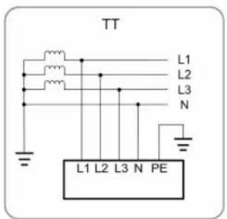


S000-G003

Make sure the inverter is applied to an IT system before enabling the PID recovery function.
2.2 Product Introduction
Model Description
The model description is as follows :
![graph TD A["SG"] --> B["125"] B --> C["CX"] C --> D["P2"] D --> E["Code of Product Series"] D --> F["Commercial and industrial models"] D --> G["Code of Power Level"] D --> H["Photovoltaic Grid-connected Inverter"]](/content/2026/06/1367933/images/dddf85bb6b7a2b2bd7955f4199978eecbf8b3e9969b1d0af8f1a6ad8d318b493.jpg)
S321-G002
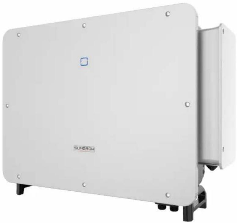
Appearance

figure 2-2 Inverter Appearance
* The image shown here is for reference only. The actual product received may differ.
| No. | Name | Description |
| 1 | LED indicator panel | HMI interface to indicate the present working state of the inverter. |
| 2 | AC junction box | Used to connect AC cables and the power cable for tracking system. |
| 3 | Additional ground-ing terminals | 2, use at least one of them to ground the inverter. |
| 4 | Bottom handles | 2, used to move the inverter. |
| 5 | Mounting ears 4, used to hang the inverter onto the mounting-bracket. | |
| 6 | Wiring area | DC switches, DC terminals, and communication terminals.For details, refer to"5.2 Terminal Description" |
| 7 | Labels | Warning symbols, nameplate, and QR code. |
Dimensions
The following figure shows the dimensions of the inverter.

figure 2-3 Dimensions of the Inverter(in mm)
Weight
| Model Weight |
| SG125CX-P2 87 kg |
2.3 Symbols on the Product
| Symbol Explanation | |
 | Do not dispose of the inverter together with household waste. |
 | TÜV mark of conformity. |
 | CE mark of conformity.EU/EEA Importer. |
 | Regulatory compliance mark. |
 | CGC-SOLAR mark of conformity. |
 | UKCA mark of conformity. |
 | Disconnect the inverter from all the external power sources before maintenance! |
 | Burn danger due to the hot surface that may exceed 60°C. |
Symbol Explanation

Danger to life due to high voltages!
Do not touch live parts for 5 minutes after disconnection from the power sources.
Only qualified personnel can open and maintain the inverter.


Additional grounding point.
Read the user manual before maintenance!
* The table shown here is for reference only. The actual product received may differ.
2.4 LED Indicator
The LED indicator on the front of the inverter indicates the working state of the inverter.
table 2-1 State description of the LED indicator
| LED color State Definition | ||
 Blue Blue | On | The device is connected to the grid and operating normally. |
| Fast blink (Period: 0.2s) | The Bluetooth communication is connected and there is data communication.No system fault occurs. | |
| Slow blink (Period: 2s) | The device is in standby or startup state (not feeding power into the grid). | |
| Slow blink once, fast blink three times | The inverter is performing PID recovery. | |
 Red Red | On | A fault occurs and the device cannot connect to the grid. |
| Twinkling | The Bluetooth connection is established, data communication in process, and a system fault occurs. | |
 Gray Gray | OFF | Both the AC and DC sides are powered down. |
WARNING
Voltage may still be present in AC side circuits after the indicator is off. Pay attention to the electricity safety during operating.
2.5 Circuit Diagram
The following figure shows the main circuit of the inverter.
![graph LR DC1["DC1"] -->|+| A["Current Monitoring"] DC2["DC2"] -->|-| B["Switch"] A --> C["DC Switch"] B --> D["DC SPD"] C --> E["DC EMI Filter"] D --> E E --> F["MPPT (Boost 1)"] E --> G["MPPT (Boost 12)"] F --> H["DC BUS"] G --> H H --> I["Inverter Circuit (DC/AC)"] I --> J["AC Filter"] I --> K["AC…](/content/2026/06/1367933/images/4ba04dc44fb758db03f923ea2efdfebf6855dc85a5e4ea66c19d92746becff3d.jpg)
figure 2-4 Circuit Diagram
- DC switches can safely disconnect the PV input when necessary to ensure the safe operation of the inverter and the safety of personnel.
- The DC SPD provides a discharge circuit for the DC side over-voltage power to prevent it from damaging the internal circuits of the inverter.
- EMI filters can filter out the electromagnetic interference inside the inverter to ensure that the inverter meets the requirements of electromagnetic compatibility standards.
- The MPPT is utilized for DC input to ensure the maximum power from the PV array at different PV input conditions.
- The inverter circuit converts the DC power into grid-compliant AC power and feeds it into the grid.
- The AC filter filters the output AC component of high frequency to ensure that the output current meets the grid requirements.
- The AC relay isolates the AC output of the inverter from the grid, making the inverter safe from the grid in case of inverter failure or grid failure.
- The AC SPD provides a discharge circuit for the AC side over-voltage power to prevent it from damaging the internal circuits of the inverter.
2.6 Function Description
The inverter is equipped with the following functions:
Conversion Function
The inverter converts the DC into grid-compatible AC and feeds the AC into the grid.
Data Storage and Display
The inverter logs system information like running information, error records, etc.
Parameter Configuration
The inverter provides various parameter configurations. Users can set parameters via the App to meet different needs and optimize the inverter performance.
Communication Interface
The inverter is designed with standard RS485 communication interfaces and communication accessory port.
- The standard RS485 communication interfaces are used to establish communication with monitoring devices and to upload monitoring data to a monitoring background through communication cables.
- The communication accessory port is used to connect communication module manufactured by SUNGROW, and upload monitoring data by means of wireless communication.
The inverter can be connected to communication devices via either of the two interfaces. When communication is established between the inverter and the communication devices, users can view inverter information or set inverter parameters, such as running parameter and protection parameter, through the iSolarCloud.

It is recommended to use the communication module from SUNGROW. Using a device from other companies may lead to communication failure or other unexpected damage.
Protection Function
The inverter is equipped with anti-island protection, LVRT/HVRT, DC reversed polarity protection, AC short circuit protection, leakage current protection, DC over-voltage/over-current protection, etc.
PID Recovery
The PID effect (Potential Induced Degradation) of PV modules will cause serious damage to generated output and yield, which can be avoided or recovered by PID recovery function.
- For positive voltage scheme, after the PID is enabled, the voltage to ground of all PV strings is greater than 0, and therefore the PV string-to-ground voltage is a positive value.
![graph LR A["PV Module"] -->|+| B["Inverter"] A -->|-| B B --> C["Transformer"] C --> D["Grid"] note1["Raise the potential between the negative pole of PV strings and earth"]](/content/2026/06/1367933/images/4c54c894758783213f94ea9fa97ffaf95562741dba650570166d88ad4ec81cdd.jpg)
- For negative voltage scheme, after the PID is enabled, the voltage to ground of all PV strings is lower than 0, and therefore the PV string-to-ground voltage is a negative value.
![graph LR A["PV Module"] -->|+| B["Inverter"] A -->|-| B B --> C["Transformer"] C --> D["Grid"] style A fill:#f9f,stroke:#333 style B fill:#ccf,stroke:#333 style C fill:#cfc,stroke:#333 style D fill:#fcc,stroke:#333 note1["Reduce the potential between the negative pole of PV strings and earth"]](/content/2026/06/1367933/images/124a9968eb2b9f041f8d8ad90b69b30726aef7b385a26221aa3494f4ebac0434.jpg)
NOTICE
- Before enabling the PID recovery function, make sure the voltage polarity of the PV modules to ground meets requirement. If there are any questions, contact the PV module manufacturer or read the corresponding user manual.
- If the voltage scheme for the PID protection / recovery function does not meet the requirement of corresponding PV modules, the PID will not work as expected or even damage the PV modules.
- PID recovery function and reactive power generation at night cannot be enabled at the same time.
- If the PID recovery function is enabled, it only works at night.
- PID recovery function and reactive power generation at night cannot be enabled at the same time.
- After the PID recovery function is enabled, the voltage of the PV string to ground is 500Vdc by default.
- When the inverter is in the PID recovery state (the indicator blinks blue once at long intervals and blinks at short intervals for three times), disable the PID recovery in the iSolarCloud App before manually powering on and maintaining the inverter.
AFCI Function
- AFCI activation
This function can be enabled to detect whether arc occurs in the DC circuit of the inverter.
- AFCI self-test
This function is intended to detect whether the AFCI function of the inverter is normal.
3 Unpacking and Storage
3.1 Unpacking and Inspection
The product is thoroughly tested and strictly inspected before delivery. Nonetheless, damage may still occur during shipping. For this reason, please conduct a thorough inspection after receiving the product.
- Check the packing case for any visible damage.
- Check the scope of delivery for completeness according to the packing list.
- Check the inner contents for damage after unpacking.
Contact SUNGROW or the transport company in case of any damage or incompleteness, and provide photos to facilitate services.
Do not dispose of the original packing case. It is recommended to store the device in the original packing case when the product is decommissioned.
NOTICE
After receiving the product, check whether the appearance and structural parts of the product are damaged, and check whether the packing list is consistent with the actual ordered product. If there are problems with the above inspection items, do not install the device and contact SUNGROW in time.
If any tool is used for unpacking, be careful not to damage the product.
3.2 Inverter Storage
Proper storage is required if the inverter is not installed immediately.
- Store the inverter in the original packing case with the desiccant inside.
- The storage temperature must be always between -40°C and +70°C , and the storage relative humidity must be always between 0 and 95% , non-condensing.
- In case of stacking storage, the number of stacking layers should never exceed the limit marked on the outer side of the packing case.
- The packing case should be upright.
- If the inverter needs to be transported again, pack it strictly before loading and transporting it.
-
Do not store the inverter in places susceptible to direct sunlight, rain, and strong electric field.
-
Do not place the inverter in places with items that may affect or damage the inverter.
- Store the inverter in a clean and dry place to prevent dust and water vapor from eroding.
- Do not store the inverter in places with corrosive substances or susceptible to rodents and insects.
- Carry out periodic inspections. Inspection shall be conducted at least once every six months. If any insect or rodent bites are found, replace the packaging materials in time.
- If the inverter has been stored for more than a year, inspection and testing by professionals are required before it can be put into operation.
NOTICE
Please store the inverter according to the storage requirements. Product damage caused by failure to meet the storage requirements is not covered by the warranty.
4 Mechanical Mounting
WARNING
Respect all local standards and requirements during mechanical installation.
4.1 Safety during Mounting
! DANGER
Make sure there is no electrical connection before installation. Before drilling, avoid the water and electricity wiring in the wall.
WARNING
Poor installation environment will affect system performance!
• Install the inverter in a well-ventilated place.
- Ensure that the heat dissipation system or vent is not blocked.
- Do not install the inverter in an environment with flammable and explosive objects or smoke.
CAUTION
Improper handling may cause personal injury!
- When moving the inverter, be aware of its weight and keep the balance to prevent it from tilting or falling.
- Wear proper protective equipment before performing operations on the inverter.
- The bottom terminals and interfaces of the inverter cannot directly contact the ground or other supports. The inverter cannot be directly placed on the ground.
4.2 Location Requirements
Select an optimal mounting location for safe operation, long service life and expected performance.
- The inverter with protection rating IP66 can be installed both indoors and outdoors.
• Install the inverter at a place convenient for electrical connection, operation, and maintenance.

4.2.1 Environment Requirements
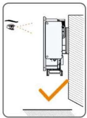
- The installation environment must be free of inflammable or explosive materials.
- The location should be not accessible to children.
- The ambient temperature and relative humidity must meet the following requirements.


- Please consult SUNGROW before installing inverters outdoors in salt stress areas. Salt stress areas mainly refer to coastal areas that are within 500 meters from the coast. The deposition of salt fog varies largely with nearby seawater characteristics, sea wind, precipitation, relative humidity, terrain, and forest coverage.
- Inverters free from direct sunlight, direct rain and snow have longer service life. Consider sheltered places as the installation location.
- The inverter should be well ventilated. Ensure air circulation.
- The inverter generates noise during operation and is not recommended to be installed in living areas.
4.2.2 Carrier Requirements
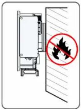
The installation carrier should be capable of withstanding a force of four times the weight of the inverter and be suitable for the dimensions of the inverter.
The surface of the installation carrier must be fire resistant.
4.2.3 Angle Requirements
Install the inverter vertically or at the maximum allowable rear tilt angle. Do not install the inverter horizontally, forward, excessively backward, sideways, or upside down.
Please consult SUNGROW before tilting backwards the inverter and install it in floating power plants.
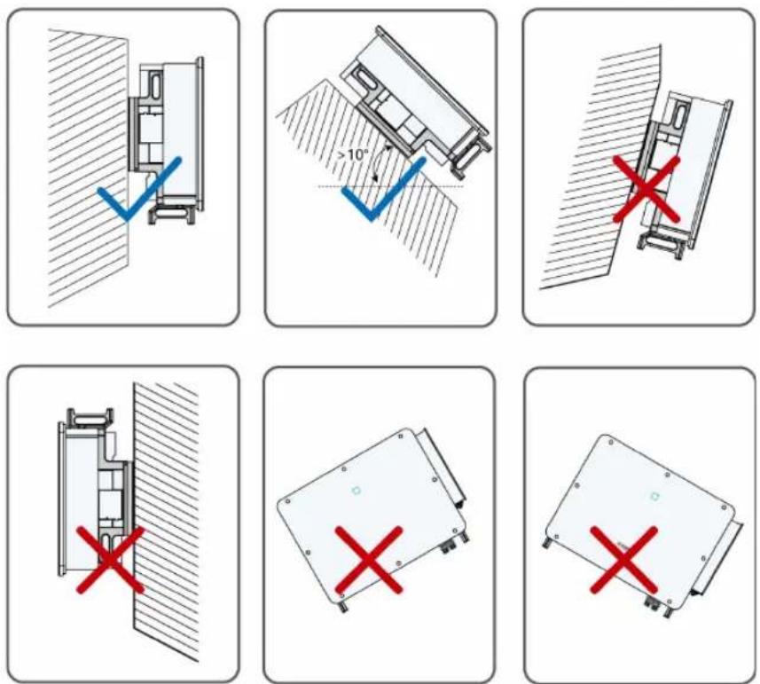
tilting backwards installation requirements
In case the installation site is a level surface, mount the inverter to the horizontal-mounting bracket to meet the mounting angle requirements, as shown in the figure below.

Take the following items into account when designing the bracket scheme:
- Consider onsite climate conditions and take anti-snow and anti-rain measures if necessary.
-
Ensure that the waterproof connectors are at least 300mm higher than the ground surface.
-
Bind the cables at the positions 300\~350mm away from the DC connector and communication waterproof terminal.
- The various waterproof terminals should be tightened in accordance with the torque requirements in this manual to ensure that they are tight and sealed.
Contact SUNGORW if you have any question.
4.2.4 Clearance Requirements
Spacing for installing an inverter
Reserve enough clearance around the inverter to ensure sufficient space for heat dissipation.

* In case this distance is less than the distance in the diagram, move the inverter from the mounting-bracket or wall before maintaining fans.
Spacing for installing multiple inverters
In case of multiple inverters, reserve specific clearance between the inverters. For other installation scenarios, please refer to the relevant technical documents on http://support.sun-growpower.com/.
![graph LR A["Step 1: >600mm"] --> B["Step 2: >600mm"] B --> C["Step 3: >600mm"] C --> D["End: S322-1005"]](/content/2026/06/1367933/images/4389dfc8868e601abd21656b886f5eb51afbf9b395c3658a84b6e6918f366208.jpg)
Back to Back Installation
When installing inverters back-to-back, the distance between every two inverters should be at least 600 mm.
Add a baffle between the two inverters to form a heat dissipation channel. The baffle plate should be placed horizontally between two inverters and should not block the air outlet of inverters.

4.3 Installation Tools
Installation tools include but are not limited to the following recommended ones. If necessary, use other auxiliary tools on site.
table 4-1 Tool specification


4.4 Moving the Inverter
Before installation, remove the inverter from the packing case and move it to the installation site.
It is recommended to use the four screw-in handles and the Bottom handles to move the inverter. Attach the four screw-in handles to the inverter lugs and base. Lift and move the inverter to its destination by means of the bottom handles and the four installed handles.

CAUTION
Improper handling may cause personal injury!
- Arrange an appropriate number of personnel to carry the inverter according to its weight, and installation personnel should wear protective equipment such as anti-impact shoes and gloves.
- Attention must be paid to the center of gravity of the inverter to avoid tilting during handling.
- Placing the inverter directly on a hard ground may cause damage to its metal enclosure. Protective materials such as sponge pad or foam cushion should be placed underneath the inverter.
- Move the inverter by holding the handles on it. Do not move the inverter by holding the terminals.
4.5 Installing the mounting-bracket
Inverter is installed on the wall and bracket by means of mounting bracket. The expansion plug set shown below is recommended for the installation.
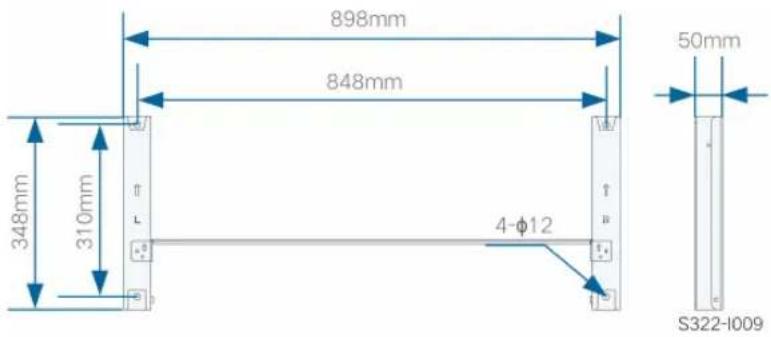
figure 4-1 Dimensions of mounting-bracket
4.5.1 PV Bracket-Mounted Installation
Tools
| Item Specification | |
| Phillips screwdriver / electric screw driver | M4 |
| Marker | - |
| Level | - |
| Electric drill Drill bit: φ12 | |
| Wrench Opening: 16 mm | |
| Spare parts | |
| Item Quantity Specification Source | |
| Grub screw 2 M4×10 Delivery scope | |
| Bolt assembly 4 M10 Delivery scope | |
step 1 Assemble the mounting-bracket by using the connecting bar.

step 2 Level the assembled mounting-bracket by using the level, and mark the positions for drilling holes on the PV bracket. Drill the holes by using a electric drill.

step 3 Secure the mounting-bracket with bolts.

S322-I012
(A) Mounting-bracket (B) Full threaded bolt (C) Metal bracket
(D) Flat washer (E) Spring washer (F) Hex nuts
-- End
4.5.2 Wall-Mounted Installation
Tools
Item Specification
| Phillips screwdriver / electric screw driver | M4 |
| Marker | - |
| Level | - |
| Hammer drill Drill bit: φ12 | |
| wrench Opening: 16mm | |
Spare parts
| Item Quantity Specification Source | |
| Grub screw 2 M4×10 Delivery scope | |
| Bolt assembly 4 M10×95 | Self-prepared |
| (Recommended) | |
step 1 Assemble the mounting-bracket by using the connecting bar.

step 2 Level the assembled mounting-bracket by using the level, and mark the positions for drilling holes on the installation site.

step 3 Insert the expansion bolts into the holes and secure them with a rubber hammer. Fasten the nut with a wrench to expand the bolt. Remove the nut, spring washer, and flat washer, and store them properly.
![graph LR A["Tool: 90°"] --> B["Reaction Step ①"] B --> C["Cut to a workpiece"] C --> D["Step ②"] D --> E["Cut to a workpiece"] E --> F["Step ③"] F --> G["Cut to a workpiece"]](/content/2026/06/1367933/images/e0db264efcace9404ef38a1dfe88a94d50b91563a0cdc7982fd776299284e44c.jpg)
step 4 Fix the mounting-bracket with the expansion bolts.

S322-1014
(A) Wall (B) Expansion bolt (C) Mounting-bracket
-- End
4.5.3 Pole-Mounting
Tools
| Item Specification | |
| Phillips screwdriver / electric screw driver | M4 |
| Marker | — |
| Level | — |
| Electric drill * Drill bit: φ12 | |
| wrench Opening: 16 mm | |
* Confirm the need for other sizes of tools based on the bolts of the matching clamps.
Spare parts
| Item | Quantity | Specification | Source |
| Grub screw 2 | M4×10 | Delivery scope | |
| Bolt assembly | 4 M10 | Delivery scope | |
| Nut assembly | 4 M10 | Self-prepared | |
| U-shaped steel | 2 | — | Self-prepared |
| Clamp | 3 | Determined by column specifications | Self-prepared |
step 1 Bury the column into the installation site.

Please skip this step if you need to install the inverter on a concrete post, PV bracket, etc. by holding the post.
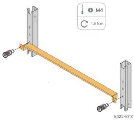
step 2 Assemble the mounting-bracket by using the connecting bar.
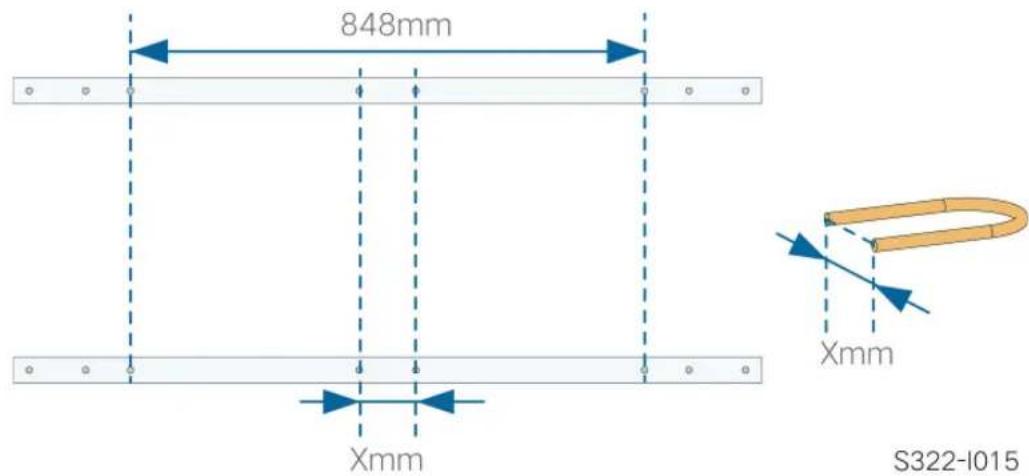
step 3 Mark and punch holes in the U-beam according to the dimensions shown below.
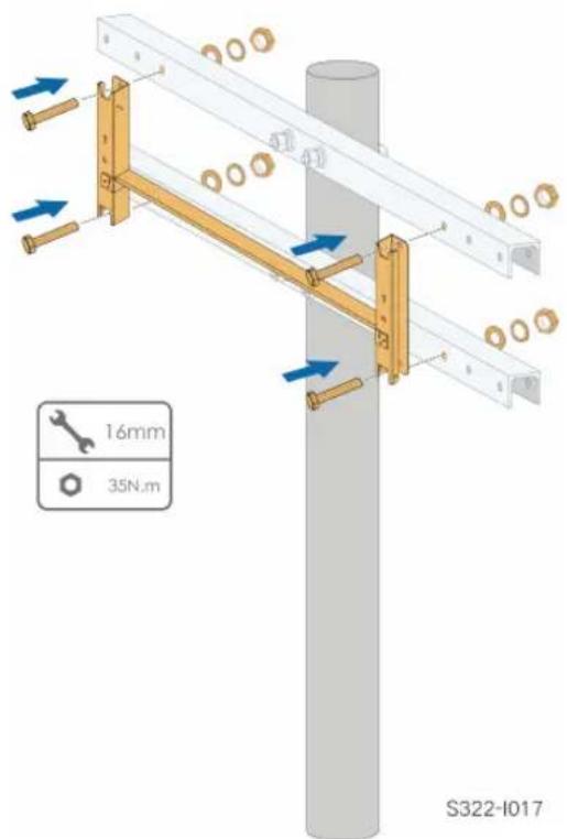
step 4 Use bolts and clamps to fix the U-beam to the column.

step 5 Use bolts to secure the pegboard to the U-beam.
-- End
4.6 Installing the Inverter
Tools
| Item Specification | |
| Phillips screwdriver / electric | M6 |
| screw driver | |
Spare parts
| Item | Quantity Specification | Source |
| Grub screw 2 M6×65 | Delivery scope | |
step 1 Take out the inverter from the packing case.
step 2 Hang the inverter to the mounting-bracket and ensure that the mounting ears perfectly engage with the mounting-bracket.

step 3 Fix the inverter with screws.

NOTICE
It is necessary to fix the left and right sides of the inverter with screws. Otherwise, the inverter may be unstable.
-- End
5 Electrical Connection
5.1 Safety Instructions
! DANGER
The PV string will generate lethal high voltage when exposed to sunlight.
- Operators must wear proper personal protective equipment during electrical connections.
- Must ensure that cables are voltage-free with a measuring instrument before touching DC cables.
- Respect all safety instructions listed in relevant documents about PV strings.
! DANGER
- Before electrical connections, please make sure that the inverter switch and all switches connected to the inverter are set to "OFF", otherwise electric shock may occur!
- Ensure that the inverter is undamaged and all cables are voltage free before performing electrical work.
- Do not close the AC circuit breaker until the electrical connection is complete.
WARNING
Damage to the product caused by incorrect wiring is not covered by the warranty.
- Electrical connection must be performed by professionals.
- Operators must wear proper personal protective equipment during electrical connections.
- All cables used in the PV generation system must be firmly attached, properly insulated, and adequately dimensioned.
NOTICE
All electrical connections must comply with local and national / regional electrical standards.
- Cables used by the user shall comply with the requirements of local laws and regulations.
- Only with the permission of the national / regional grid department, the inverter can be connected to the grid.
NOTICE
- All vacant terminals must be covered with waterproof covers to prevent affecting the protection rating.
- When the wiring is completed, seal the gap of cable inlet and outlet holes with fireproof / waterproof materials such as fireproof mud to prevent foreign matter or moisture from entering and affecting the long-term normal operation of the inverter.
- Comply with the safety instructions related to PV strings and the regulations related to the utility grid.

The cable colors in figures in this manual are for reference only. Please select cables according to local cable standards.
5.2 Terminal Description
All electrical terminals are located at the side and bottom of the inverter.

figure 5-1 Terminal Description(For a multi-core cable)
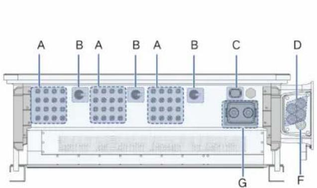

figure 5-2 Terminal Description(For four single-core cables)
* The image shown here is for reference only. The actual product received may differ.
| Item Terminal Mark Note | |||
| A PV terminals + / - PV connector | |||
| B DC Switch DC SWITCH | Used to switch on and off the DC input. | ||
| C | Communication terminal | COM3 For communication module connection. | |
| D | AC wiring terminal | — | Used for AC output cable connection. |
| E | Standby grounding terminal* | — | Used for internal grounding. |
| F PE terminal | — | Used for internal grounding. | |
| Item | Terminal Mark Note | ||
| G | Communication terminal | COM1,COM2 | RS485 communication, digital input/output DI/DO, etc. |
| H | Additional grounding terminal |  | use at least one of them to ground the inverter. |
*If the PE cable is an independent single-core cable, it should be inserted into the AC junction box through the standby grounding terminal.
5.3 Electrical Connection Overview
The electrical connection should be realized as follows:
![graph TD A[" Solar Panel "] -->|1| B[" Network "] B -->|2| C[" Cloud "] B -->|3| D[" Grid "] B -->|4| E[" Power Tower "] B -->|5| F[" Smartphone & Computer"]](/content/2026/06/1367933/images/f176e9385524520e296766293fc53fd6e4c17ab78f29efb67768ddf2834aa922.jpg)
(A) PV string
( B ) Inverter
( C ) Tracking Control Box
( D ) Grid
( E ) Monitoring device
( F ) AC circuit breaker
table 5-1 Cable Requirements
| No. Cable | Type | Specification | ||
| Cable Diameter(mm) | Cross-sectional Area (mm2) | |||
| 1 DC cable | PV cable complying with 1,100V standard | 4.7 ~ 6.4 4 ~ 6 | ||
| 2 | Power cable for tracking system | Outdoor two-core copper wire cable | 8 ~ 18 | 0.5 ~ 10 (recommended range: 4 ~ 6 ) |
| 3 | Additional grounding cable | Outdoor single-core copper wire cable | The same as that of the PE wire in the AC cable | |
| 4 AC cable | Outdoor five-core copper wire cable | 30 ~ 60 | L1, L2, L3, N wire: 70 ~ 120PE wire: refer to "table 5-2PE Wire Requirements" | |
| Outdoor four-core wire copper cable | L1, L2, L3, N wire: 30 ~ 60PE wire: 14 ~ 32 | |||
| Outdoor PE cable | ||||
| Outdoor five-core aluminum wire ca-ble(1) | 30 ~ 60 | L1, L2, L3, N wire: 70 ~ 240PE wire: refer to "table 5-2PE Wire Requirements" | ||
| Outdoor four-core aluminum wire ca-ble(1) | L1, L2, L3, N wire: 30 ~ 60PE wire: 14 ~ 32 | |||
| Outdoor PE cable | ||||
| Five single-core outdoor copper cables | 14 ~ 32 | L1, L2, L3, N wire: 70 ~ 120PE wire: refer to "table 5-2PE Wire Requirements" | ||
| Four single-core outdoor aluminum cables(1)(2) | 14 ~ 32 | L1, L2, L3, N wire: 120 ~ 240PE wire: refer to "table 5-2PE Wire Requirements" | ||
| Outdoor PE cable | ||||
| 5 | Communi-cation cable | Shielded twisted pair (terminal block) | 4.5 ~ 18 | 0.2 ~ 1.5 |
| CAT-5 Ethernet ca-ble (RJ45) | / | |||
(1) A copper to aluminum adapter terminal is required when an aluminum cable is used. For details, refer to "Aluminium Cable Requirements".
(2) In the case of five single-core cables, a spare AC sealing plate accessory is required as shown in the following figure. To purchase the AC sealing plate accessory, contact SUNGROW.

figure 5-3 Spare AC Sealing Plate

Inverter for Australia and New Zealand are equipped with the five-core sealing plate by default.
table 5-2 PE Wire Requirements
| PE Wire | |
| Cross Section | Note |
| S/2 | The specifications are valid only when the phase wire and PE wire use the same material. If otherwise, ensure that the cross section of the PE wire produces a conductance equivalent to that of the wire specified in the table. |
| S: Phase wire cross-section | |
5.4 Crimp OT / DT terminal
Crimp OT / DT terminal
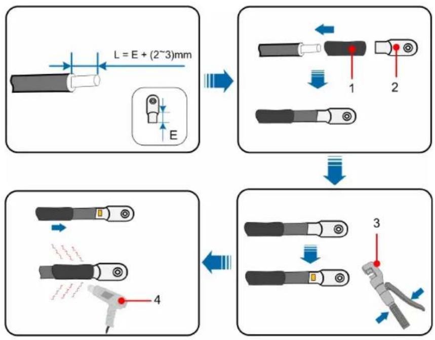
- Heat shrink tubing 2. OT DT terminal
- Hydraulic pliers 4. Heat gun
Aluminium Cable Requirements
If an aluminium cable is selected, use a copper to aluminium adapter terminal to avoid direct contact between the copper bar and the aluminium cable.

figure 5-4 Aluminium cable terminal connection sequence
- Copper to Aluminium adapter terminal 2. Flange nut 3. Aluminium cable
NOTICE
Ensure that the selected terminal can directly contact with the copper bar. If there are any problems, contact the terminal manufacturer.
Ensure that the copper bar is not in direct contact with the aluminum wire. Otherwise, electrochemical corrosion may occur, impairing the reliability of electrical connection.
5.5 External Grounding Connection
! DANGER
Electric shock!
- Make sure that the ground cable is connected reliably. Otherwise, it may cause electric shock.
WARNING
- Since the inverter is not equipped with a transformer, neither the negative electrode nor the positive electrode of the PV string can be grounded. Otherwise, the inverter will not operate normally.
- Connect the grounding terminal to the protective grounding point before AC cable connection, PV string connection, and communication cable connection.
WARNING
The external protective grounding terminal must meet at least one of the following requirements.
- The cross-sectional area of the AC side grounding cable is not less than 10 mm 2 for copper wire or 16 mm for aluminum wire. It is recommended that both the external protective grounding terminal and the AC side grounding terminal be reliably grounded.
- If the cross-sectional area of the AC side grounding cable is less than 10 mm for copper wire or 16 mm for aluminum wire, ensure that both the external protective grounding terminal and the AC side grounding terminal are reliably grounded.
The grounding connection can be made by other means if they are in accordance with the local standards and regulations, and SUNGROW shall not be held liable for the possible consequences.
5.5.1 External Grounding Requirements
All non-current carrying metal parts and device enclosures in the PV power system should be grounded, for example, brackets of PV modules and inverter enclosure.
When there is only one inverter in the PV system, connect the external grounding cable to a nearby grounding point.
When there are multiple inverters in the PV system, connect grounding points of all inverters and the PV array frames to the equipotential cable (according to the onsite conditions) to implement an equipotential connection.
5.5.2 Connection Procedure
step 1 Prepare the cable and OT / DT terminal, refer to "Crimp OT / DT terminal".
step 2 Remove the screw on the grounding terminal and fasten the cable with a screwdriver.

step 3 Apply paint to the grounding terminal to ensure corrosion resistance.

The grounding screws have been anchored to the side of the inverter before delivery, and do not need to be prepared.
There are two grounding terminals. Use one of them to ground the inverter.
-- End
5.6 AC Cable Connection
5.6.1 AC Side Requirements

Only with the permission of the local grid department, the inverter can be connected to the grid.
Before connecting the inverter to the grid, ensure the grid voltage and frequency comply with requirements, for which, refer to "Technical Date". Otherwise, contact the electric power company for help.
AC Circuit Breaker
An independent circuit breaker or fuse should be installed on the output side of the inverter to ensure safe disconnection from the grid.
Inverter Model Recommended rated voltage Recommended rated current
SG125CX-P2 400V 250A

WARNING
AC circuit breakers should be installed on the output side of the inverter and the grid side to ensure safe disconnection from the grid.
- Determine whether an AC circuit breaker with greater overcurrent capacity is required based on actual conditions.
- Do not connect any local load between the inverter and the AC circuit breaker except for the tracking axis.
- Multiple inverters cannot share one AC circuit breaker.
Residual Current Monitoring Device
With an integrated universal current-sensitive residual current monitoring unit included, the inverter will disconnect immediately from the mains power once a fault current with a value exceeding the limit is detected.
However if an external residual current device (RCD) (type A is recommended) is mandatory, the switch must be triggered at the residual current. RCD of other specifications can also be used according to local standard. The recommended residual current is as follows.
Inverter Recommended residual current
SG125CX-P2 1250 mA
Multiple Inverters in Parallel Connection
If multiple inverters are connected in parallel to the grid, ensure that the total number of parallel inverters does not exceed 25. Otherwise, please contact SUNGROW for technical scheme.
MV Transformer
The MV transformer used together with the inverter should meet the following requirements:
- The transformer may be a distribution transformer, and it must be designed for the typical cyclical loads of a PV system (load in the day and no load at night).
- The transformer may be of the liquid-immersed type or dry type, and shield winding is not necessary.
- The line-to-line voltage on the LV side of the transformer should endure the output voltage of inverter. When the transformer is connected to the IT grid, to-ground withstanding voltage of the LV winding of the transformer, the LV side AC cables, and the LV side secondary equipment (including the relay protection device, detection & measuring device, and other related auxiliary devices) should not be lower than 1,100V.
- The line-to-line voltage on the HV side of the transformer should comply with the local power grid voltage.
- A transformer with a tap changer on the HV side is recommended in order to keep consistent with the grid voltage.
- The voltage drop of system cable is no more than 3% .
- The DC component that the transformer can withstand is 1% of the fundamental current at rated power.
- For thermal rating, the load curve of the transformer and environment conditions should be taken into account.
- The apparent power of the inverter should never exceed the power of the transformer. The maximum AC current of all inverters connected in parallel must be taken into account. If more than 25 inverters are connected to the grid, contact SUNGROW.
- The transformer must be protected against overloading and short circuit.
- The transformer is an important part of grid-connected PV generation system. The fault tolerance capacity of the transformer should be taken into account at all times. The fault include: system short circuit, grounding fault, voltage drop, etc.
• Take ambient temperature, relative humidity, altitude, air quality, and other environmental conditions into account when selecting and installing the transformer.
- When the anti-PID function is enabled, observe the following items:
- If the LV side winding is in Y shape, neutral point grounding is prohibited.
- Surge protective devices (SPD) for the AC combiner box and on the LV side of the transformer are recommended to be connected in the "3+1" manner, as shown in the figure below. The Min. continuous operating voltages of M1-M4 are 690VAC.
- The LV side winding of the transformer, AC cables, and secondary devices (including protective relay, detection and measurement instruments, and related auxiliary devices) must withstand the voltage to ground of at least 906 V.

5.6.2 Requirements for OT/DT Terminal
OT/DT terminals (not included in the delivery scope) are required for fixing AC cables to the terminal block. Purchase the OT/DT terminals according to the following requirements.
OT/DT Terminals of Phase Wire
- Specification: M12
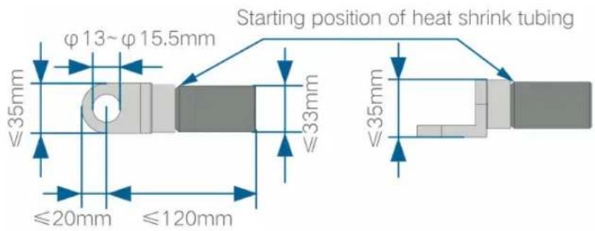
figure 5-5 Specifications of the Crimped OT/DT Terminal
OT/DT Terminal of PE Wire
- Specification: M12
5.6.3 Connection Procedure (For a multi-core cable)

In this manual, description is given by using five-core cable as an example. The wiring of the four-core cable is the same.
step 1 Disconnect the AC-side circuit breaker and prevent it from inadvertent reconnection.
step 2 Loosen two screws on the front cover of the junction box using the supplied hexagon socket wrench, and open the junction box. Keep the cover of the junction box open during wiring with a limit rod attached to the cover.


The screws on the front cover are captive screws. When the front cover is opened, the screws remain on it.
step 3 Loosen screws on the bottom sealing plate using the supplied hexagon socket wrench, and remove the sealing plate.


The screws on the sealing plate are captive screws. When the sealing plate is removed, the screws remain on it.
step 4 Cut off the excess part of sealing ring according to cable diameter.

step 5 Lead the cable with the protective layer stripped through the sealing ring and secure screws on the bottom sealing plate.

step 6 Open the protective cover.

step 7 Connect cables with crimped OT/DT terminals to corresponding terminals and secure them.

NOTICE
Note the terminal positions of PE wire and N wire. If a phase wire is connected to the PE terminal or N terminal, unrecoverable damage may be caused to the inverter.
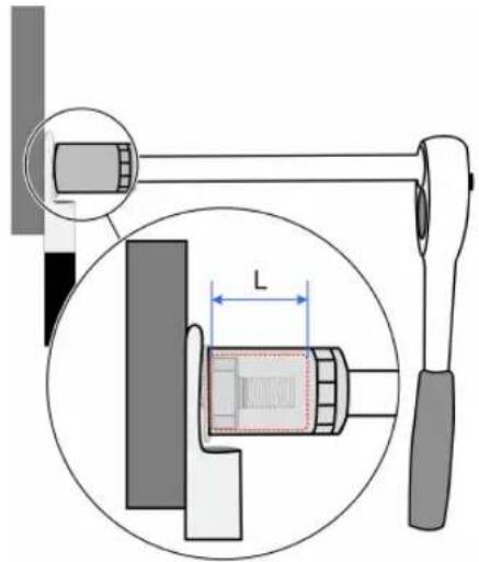
Ensure that the depth L of the socket used is not less than 28mm.

i
step 8 Close the protective cover.

step 9 Remove the limit rod and put it back. Close the junction box and tighten the two screws on the front cover using the supplied hexagon socket wrench.
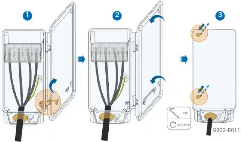
-- End
*If the PE cable is an independent single-core cable, it is inserted into the cabinet through the standby grounding terminal.

5.6.4 Connection Procedure (For a single-core cable)
step 1 Disconnect the AC-side circuit breaker and prevent it from inadvertent reconnection.
step 2 Loosen two screws on the front cover of the junction box using the supplied hexagon socket wrench, and open the junction box. Keep the cover of the junction box open during wiring with a limit rod attached to the cover.
![graph LR A["1: Battery with switch and valve"] --> B["2: Panel with internal components"] B --> C["3: Panel with switch and valve"] style A fill:#f9f,stroke:#333 style B fill:#ccf,stroke:#333 style C fill:#cfc,stroke:#333](/content/2026/06/1367933/images/54a4f4519022d01a57828474048909202dcb0bd1ce1d1ecaa31210d92a14877f.jpg)

The screws on the front cover are captive screws. When the front cover is opened, the screws remain on it.
step 3 Loosen screws on the bottom sealing plate using the supplied hexagon socket wrench, and remove the sealing plate.


The screws on the sealing plate are captive screws. When the sealing plate is removed, the screws remain on it.
step 4 Cut off the excess part of sealing ring according to cable diameter.

step 5 Lead the cable through the sealing ring and secure the screws on the bottom sealing plate.

step 6 Open the protective cover.

step 7 Connect cables with crimped OT/DT terminals to corresponding terminals and secure them.

NOTICE
Note the terminal positions of PE wire and N wire. If a phase wire is connected to the PE terminal or N terminal, unrecoverable damage may be caused to the inverter.
Ensure that the depth L of the socket used is not less than 28 mm.
i
step 8 Close the protective cover.

step 9 Remove the limit rod and put it back. Close the junction box and tighten the two screws on the front cover using the supplied hexagon socket wrench.
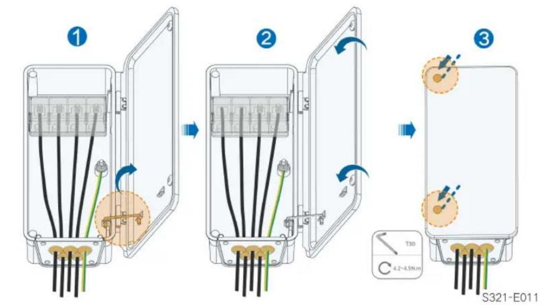
-- End
5.7 DC Cable Connection
! DANGER
The PV string will generate lethal high voltage when exposed to sunlight.
- Respect all safety instructions listed in relevant documents about PV strings.
! WARNING
- Make sure the PV array is well insulated to ground before connecting it to the inverter.
- Make sure the maximum DC voltage and the maximum short circuit current of any string never exceed inverter permitted values specified in "Technical Data".
- Check the positive and negative polarity of the PV strings, and connect the PV connectors to corresponding terminals only after ensuring polarity correctness.
- During the installation and operation of the inverter, please ensure that the positive or negative electrodes of PV strings do not short-circuit to the ground. Otherwise, an AC or DC short-circuit may occur, resulting in equipment damage. The damage caused by this is not covered by the warranty.
- Electric arc or contactor over-temperature may occur if the PV connectors are not firmly in place, and SUNGROW shall not be held liable for any damage caused.
- If the DC input cables are reversely connected or the positive and negative terminals of different MPPT are shorted to ground at the same time, while the DC switch is in the "ON" position, do not operate immediately. Otherwise, the inverter may be damaged. Please turn the DC switch to "OFF" and remove the DC connector to adjust the polarity of the strings when the string current is lower than 0.5 A.
NOTICE
The following requirements about PV string connection must be met. Otherwise, it may cause irreversible damage to the inverter, which is not covered by the warranty.
- Mixed use of different brand or model of PV modules in one MPPT circuit, or PV modules of different orientation or angles in a string may not damage inverter but will cause system bad performance!
- The inverter enters standby state when the input voltage ranges between 1,000 V and 1,100 V. The inverter returns to running state once the voltage returns to the MPPT operating voltage range, namely, 180 V to 1,000 V.
5.7.1 PV Input Configuration
As shown in the figure below, the inverter is provided with multiple PV inputs, and each PV input is designed with an MPP tracker.
Each PV input operates independently and has its own MPPT. In this way, string structures of each PV input may differ from each other, including PV module type, number of PV modules in each string, angle of tilt, and installation orientation.
A maximum of two PV strings can be connected to an MPPT controller. For the best use of PV power, the type, quantity, tilt, and orientation of PV modules connected to the same MPPT shall be the same.
![graph TD A["DC 1"] --> B["MPPT1"] C["DC 2"] --> D["MPPT1"] E["DC 3"] --> F["MPPT2"] G["DC 4"] --> H["..."] I["DC 2n-1"] --> J["MPPTn"] K["DC 2n"] --> L["MPPTn"] B --> M["n=12"] D --> M F --> M H --> M J --> M L --> M](/content/2026/06/1367933/images/2c0ced9fda9118dd5e48483ecbd07d2b97d355ab7a8dc324dd07279e576bde94.jpg)
Prior to connecting the inverter to PV inputs, the specifications in the following table should be met:
Open Circuit Voltage Limit Max. Current for Input Connector
1100 V 30 A
5.7.2 Assembling the PV Connectors
! DANGER
High voltage may be present in the inverter!
- Ensure all cables are voltage-free before performing electrical operations.
- Do not connect the AC circuit breaker before finishing electrical connection.

SUNGROW provides corresponding PV connectors in the scope of delivery for quick connection of PV inputs. To ensure IP66 protection, use only the supplied connector or the connector with the same ingress of protection.
step 1 Strip the insulation from each DC cable by 8 mm \~ 10 mm.

step 2 Assemble the cable ends with the crimping pliers.

1: Positive crimp contact 2: Negative crimp contact
step 3 Lead the cable through cable gland, and insert the crimp contact into the insulator until it snaps into place. Gently pull the cable backward to ensure firm connection.

step 4 Tighten the cable gland and the insulator.
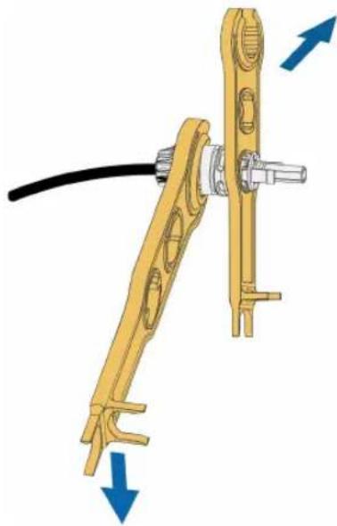
step 5 Check for polarity correctness.
NOTICE
If the PV polarity is reversed, the inverter will be in a fault or alarm state and will not operate normally.
-- End
5.7.3 Installing the PV Connector
step 1 Ensure that the DC switch is in "OFF" position. Otherwise, manually turn it to "OFF".

step 2 Check the cable connection of the PV string for polarity correctness and ensure that the open circuit voltage in any case does not exceed the inverter input limit of 1,100V .
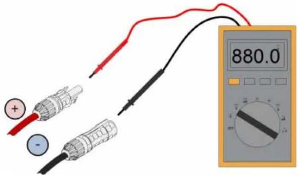
step 3 Connect the PV connectors to corresponding terminals until there is an audible click.
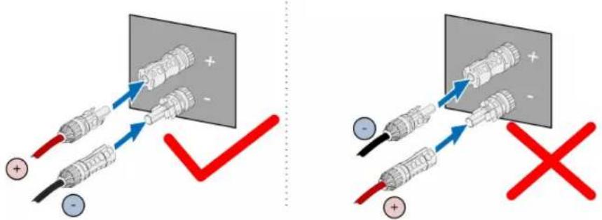
step 4 Follow the foregoing steps to connect PV connectors of other PV strings.
step 5 Seal any unused PV terminal with a terminal cap.
-- End
5.8 Wiring of Tracking System Power Cable (optional)
step 1 Please refer to step 1 and step 2 in "5.6.3 Connection Procedure (For a multi-core cable)".
step 2 Cut off the excess part of sealing ring according to cable diameter.
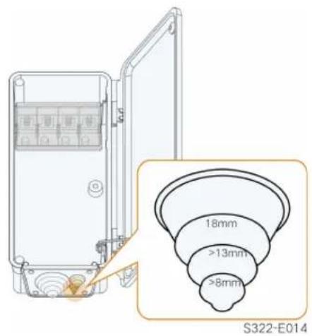
step 3 Lead the cable through the seal ring. The length of unstripped cable in the AC junction box is 50mm.

step 4 Place the OT terminals of power cable for tracking system on the OT/DT terminals of the AC cable, and secure them.
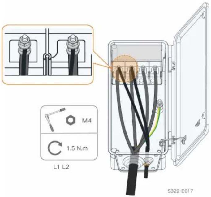
The power cables for tracking system can be connected to any two phases among L1, L2, and L3.
step 5 Close the protective cover. Close the junction box and tighten the two screws on the front cover using the supplied hexagon socket wrench.
-- End
the inverter and tracking system control box for protection. The length of the cable between the internal connection terminals of the inverter and the fuse is no more than 2.5 m .
5.9 Wireless Communication Module Connection(optional)
Install the wireless communication module to the communication interface with a silk screen of COM3 at the bottom of the inverter.

*The image shown here is for reference only. The actual product you receive may differ.
NOTICE
Once the communication module is in use, do not connect the inverter to a 3rd party data logger at the same time via RS485.

For details on module installation and configuration, refer to the manual delivered together with the module.
5.10 WiNet-S Connection (optional)
The WiNet-S module supports Ethernet communication and WLAN communication. It is not recommended to use both communication methods at the same time.
For details, see the quick guide for the WiNet-S module. Scan the following QR code for the quick guide.

5.10.1 Ethernet Communication
step 1 (Optional) Strip the insulation layer of the communication cable with an Ethernet wire stripper, and lead the corresponding signal cables out. Insert the stripped communication cable into the RJ45 plug in the correct order, and crimp it with a crimper.

1: RJ45 plug 2 : Protective cap

Skip this step if a standard network cable with RJ45 plug is prepared.
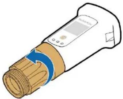
step 2 Unscrew the swivel nut from the communication module and take out the inner sealing ring.

step 3 Unscrew the housing from the communication module.
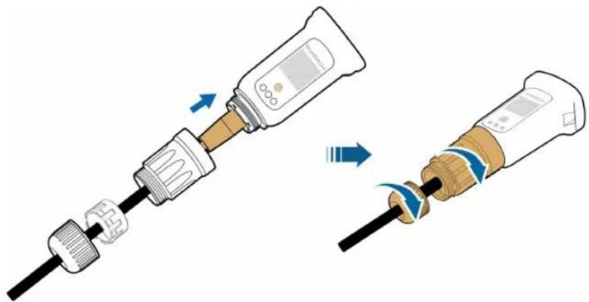
step 4 Thread the network cable through the swivel nut and gasket. Afterwards, route the cable into the opening of the sealing. Finally, insert the cable through the housing.

step 5 Insert the RJ45 plug into the front plug connector until there is an audible click and tighten the housing. Install the gasket and fasten the swivel nut.
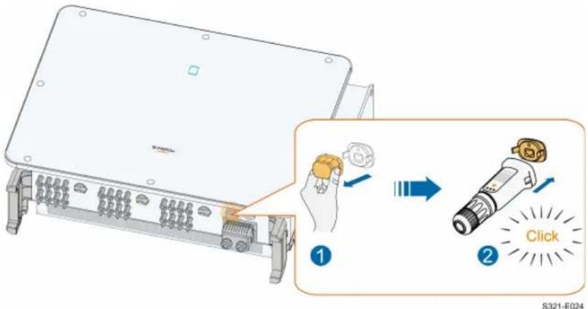
step 6 Remove the waterproof lid from the COM1 terminal and install WiNet-S.

step 7 Slightly shake it by hand to determine whether it is installed firmly.
-- End
5.10.2 WLAN Communication
step 1 Remove the waterproof lid from the COM1 terminal.
step 2 Install the module. Slightly shake it by hand to determine whether it is installed firmly, as shown below.
step 3 Refer to the guide delivered with the module for the set-up.
-- End
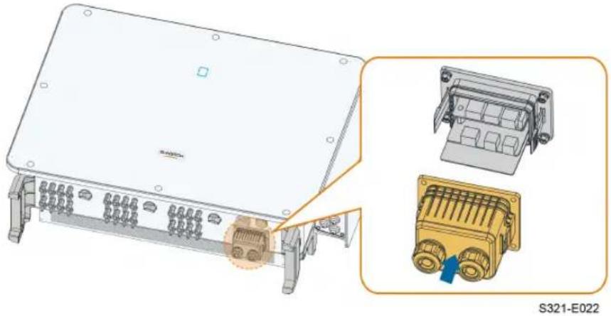
5.11 Communication Junction Box
Remove the Communication Junction Box
Squeeze both sides of the communication junction box with force, and pluck it out.

Install the Communication Junction Box
Put the junction box back and ensure a firm connection.
5.12 Communication Wiring Board
The inverter communication board consists of two layers, RS485 communication interface on the upper layer, and DI/DO interface on the lower layer.

table 5-3 Port description
| No. | Silk Screen | Description |
| 1 | RS485_3 | Used to connect the external meter |
| 2 | RS485_1 | Used to connect the external COM100E to realize data interaction with host computer or other monitoring devicesUsed for multiple inverters in the daisy chain to communicate |
| 3 | RSD STOP Reserved | |
| 4 | LOCAL STOP | Emergency stop |
| 5 | DRM | For external Demand Response Enabling Device ("AU"/ "NZ") |
| 6 | ALARM | Used to connect LED indicators or other devices to indicate whether the inverter is in the faulty state |
5.13 RS485 Connection
5.13.1 Interface Description
The RS485 communication wiring board of the inverter is shown below.

The following is the description of terminals.
table 5-4 RS485_1 interface (terminal block) description
| No. | Description |
| A1 | RS485A OUT, RS485A differential signal+ |
| A1 | RS485A IN, RS485A differential signal+ |
| B1 | RS485B OUT, RS485B differential signal- |
| B1 | RS485B IN, RS485B differential signal- |
table 5-5 RS485_1 interface (RJ45) description
| No. | Description |
| PIN 1 ~ 2 N/A | |
| PIN 3 | RS485B differential signal- |
| PIN 4 ~ 5 N/A | |
| PIN 6 | RS485A differential signal+ |
| PIN 7 ~ 8 N/A | |
table 5-6 RS485_3 terminal description
| No. | Description |
| A3 | RS485A differential signal+ |
| B3 | RS485B differential signal- |
NOTICE
RJ45 and terminal block are two types of RS485_1 interface with same functions and different wiring methods. Choose one of the interfaces for wiring.
5.13.2 RS485 Communication System
Single-inverter Communication System
In case of a single inverter, communication connection requires only one RS485 communication cable.

Multi-inverter Communication System
In case of multiple inverters, all the inverters in the daisy chain can be connected via RS485 cables for communication.
![graph TD subgraph Top_Layer A1_1["A1"] --> B1_1["B1"] A1_1 --> B1_B1["B1"] B1_1 --> OUT1["OUT"] B1_1 --> IN1["IN"] end subgraph Middle_Layer A2_1["A1"] --> B1_B1["B1"] A2_1 --> B1_B1_B1["B1"] B1_1 --> OUT2["OUT"] B1_1 --> IN2["IN"] end subgraph Bottom_Layer N["N"] --> OUT_N["OUT"] end A3["Switch"] -…](/content/2026/06/1367933/images/ac38875310d042f35a2a66fbdf99e599b3a81e0775dc508fecdae34f081761b4.jpg)
figure 5-6 Multi-inverter Communication System 【RS485_1 interface (terminal block)】
![graph TD A["Module 1"] -->|OUT| B["Tracker"] A -->|IN| C["Tracker"] D["Module 2~(N-1)"] -->|OUT| E["Tracker"] D -->|IN| F["Tracker"] G["Module N"] -->|OUT| H["Tracker"] I["Solar Panel"] --> J["Controller"] J --> K["Output"] style A fill:#f9f,stroke:#333 style D fill:#ccf,stroke:#333 style G fill:#cf…](/content/2026/06/1367933/images/9406ce0068b71eace5606422edede58eb842826e317a467e8fa10f87fa0ae128.jpg)
figure 5-7 Multi-inverter Communication System 【RS485_1 interface (RJ45)】
The length of an RS485 cable cannot exceed 1200m.
If multiple inverters communicate via the smart communication box, the number of permissible daisy chains and the number of devices allowed to be connected should meet the requirements (refer to the user manual of the smart communication box).
5.13.3 Connection Procedure(Terminal Block)
step 1 Remove the communication junction box, referring to" Remove the Communication Junction Box".
step 2 Unscrew the swivel nut of the junction box and select the sealing ring according to the cable diameter.
step 3 Strip off the protective layer and insulation layer of proper length.

step 4 Lead the cable through the swivel nut, the sealing ring and the junction box in sequence.

| Outer Diameter D(mm) Sealing Rings | |
| 4.5 ~ 6 | c |
| 6 ~12 a + b | |
| 12 ~ 18 b | |
step 5 Connect cables to the terminal socket.

step 6 Insert the terminal socket into the corresponding terminal block.
table 5-7 Terminal description
| No. | Description |
| 1 | RS485 A+ |
| 2 | RS485 A+ |
| 3 | RS485 B- |
| 4 | RS485 B- |
step 7 If other cables should be connected to the communication circuit board, skip the subsequent steps and continue wiring. Otherwise, perform as follows.
step 8 Install the communication junction box, referring to" Install the Communication Junction Box".
step 9 Pull slightly the cable backward and screw the swivel nut clockwise.

-- End
5.13.4 Connection Procedure (RJ45 Interface)
step 1 Remove the communication junction box, referring to" Remove the Communication Junction Box".
step 2 Unscrew the swivel nut of the junction box and select the sealing ring according to the cable diameter. Lead the cable through the swivel nut, the sealing ring and the junction box in sequence.

| Outer Diameter D(mm) Sealing Rings | |
| 4.5 ~ 6 | c |
| 6 ~ 12 a + b | |
| 12 ~ 18 b | |
step 3 Strip the insulation layer of the Ethernet cable with a stripper, lead out the signal wire, and insert it into the RJ45 connector (pins 3 and 6 are used for communication). Use the RJ45 crimping tool to crimp the RJ45 connector.


Pins 1 and 2 supply power to the SUNGROW communication module. Do not connect or use these two pins when making an RS485 communication cable. Otherwise, the inverter or other devices connected through the communication cable may be damaged.
step 4 Insert the RJ45 connector into the RJ45 jack.

step 5 If other cables should be connected to the communication circuit board, skip the subsequent steps and continue wiring. Otherwise, perform as follows.
step 6 Install the communication junction box, referring to" Install the Communication Junction Box".
step 7 Pull slightly the cable backward and screw the swivel nut clockwise.

-- End
5.14 Dry Contact Connection
5.14.1 Dry Contact Function
The configuration circuit board is provided with fault output dry contact and emergency stop dry contact, as shown in the figure below.

DO terminal (fault output dry contact)
The relay can be set to output fault alarms, and user can configure it to be a normally open contact (COM&NO) or a normally closed contact (COM&NC).
The relay is initially at the NC terminal, and it will trip to another contact when a fault occurs. When alarm occurs, signal status change will not be triggered.
Use LED indicators or other equipment to indicate whether the inverter is in the faulty state. The following Figures show the typical applications of normally open contact and normally closed contact:

figure 5-8 Normal open contact

figure 5-9 Normal close contact
Devices connected to the relay should comply with related requirements:
AC-Side Requirements DC-Side Requirements
| Max. voltage: 230 Vac | Max. voltage: 24 Vdc |
| Max. current: 3 A | Max. current: 3 A |
DI terminal (emergency stop dry contact)
The dry contact can be configured to be an emergency stop contact.
When the DI contact and PGND contact are shorted by external controlled switch (The external switch can be configured as normally open contact or normally closed contact), the inverter will immediately shutdown.
NS Protection
NS Protection is used for German market currently. For a plant with an installed power over 30kW, an external NS Protection Relay is connected to inverters that are connected to each other with NS Protection terminals. When the grid runs abnormally, the status of the relay's dry contact changes, and the inverters are emergently shut down.
NS Protection(including Passive Valid) can be set. When NS Protection is enabled on the iSolarCloud, the inverters will operate normally when DI contact and PGND contact are shorted by external controlled switch, and the inverters will emergently stop when DI contact and PGND contact are disconnected.

The dry contacts only support passive switch signal input.
The following figure shows the typical application of local stop dry contact.
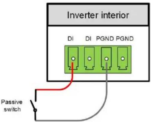
figure 5-10 Local stop contact
![graph LR subgraph Inverter_1 A["Di DI PGND PGND"] --> B["Controlled switch"] end subgraph Inverter_2 C["Di DI PGND PGND"] --> D["Inverter"] end subgraph Inverter_N E["Di DI PGND PGND"] --> F["..."] end A --> G["Red line"] C --> H["Red line"] E --> I["Red line"] G --> J["Gray line"] H --> K["Gray lin…](/content/2026/06/1367933/images/c65ab57fb07718d529f49fbc93485adaf8be68ae15e4ec0facc803441d8f9e54.jpg)
figure 5-11 Daisy chain topology
When wiring DI dry contacts, ensure that the maximum wiring distance meet the requirements in "10.2 Wring Distance of DI Dry Contact".
5.14.2 Wiring Procedure

Connection method of the dry contacts is similar to that of the RS485 terminal block.
Refer to the wiring of terminal block described in chapter "5.13.3 Connection Procedure(Terminal Block)"to implement fault output, emergency shutdown and NS protection.
For NS protection (including passive valid), enable the function on iSolarCloud, refer to "7.8.2 Operation Parameters".
5.15 DRM Connection ( For Countries "AU" and "NZ")
5.15.1 DRM Function
The inverter supports the demand response modes as specified in the standard AS/NZS 4777. The inverter has integrated a terminal for connecting to a DRED. After the connection, the method of asserting DRMs as specified in the follow table.

The mode DRM0 is supported by the inverter.
table 5-8 Method of Asserting DRMs
| Mode | Method of Asserting |
| DRM0 | Asserted by shorting pins 5 and 6 |
| Asserted when the impedance between pins 5 and 6 is detected to be above 20 kΩ |

Enable the DRM function through the iSolarCloud App. If there are any problems, contact SUNGROW. The DRM function is only applicable to devices for Australia and New Zealand.
5.15.2 Connection Procedure
step 1 Remove the communication junction box, referring to" Remove the Communication Junction Box".
step 2 Unscrew the swivel nut of the junction box and select the sealing ring according to the cable diameter. Lead the cable through the swivel nut, the sealing ring and the junction box in sequence.

| Outer Diameter D(mm) Sealing Rings | |
| 4.5 ~ 6 | c |
| 6 ~ 12 a + b | |
| 12 ~ 18 b | |
step 3 Strip the insulation layer of the Ethernet cable with a wire stripper, and insert the signal wires to the RJ45 connector. Crimp the RJ45 connector with a crimping tool.
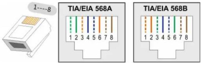
| Pin | Assignment for inverters capable of both charging and discharging |
| 1 DRM 1/5 | |
| 2 DRM 2/6 | |
| 3 DRM 3/7 | |
| 4 DRM 4/8 | |
| 5 RefGen | |
| 6 Com/DRM0 | |
| 7 | V+ |
| 8 | V- |
step 4 Insert the RJ45 connector to the RJ45 jack.

step 5 Install the communication junction box, referring to" Install the Communication Junction Box".
step 6 Pull slightly the cable backward and screw the swivel nut clockwise.

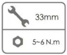
-- End
6 Commissioning
6.1 Inspection before Commissioning
Check the following items before starting the inverter:
- All equipment has been reliably installed.
- DC switch(es) and AC circuit breaker are in the "OFF" position.
- The ground cable is properly and reliably connected.
- The AC cable is properly and reliably connected.
- The DC cable is properly and reliably connected.
- The communication cable is properly and reliably connected.
- The vacant terminals are sealed.
- No foreign items, such as tools, are left on the top of the machine or in the junction box (if there is).
- The AC circuit breaker is selected in accordance with the requirements of this manual and local standards.
- All warning signs & labels are intact and legible.
6.2 Commissioning Procedure
If all of the items mentioned above meet the requirements, proceed as follows to start up the inverter for the first time.
step 1 Rotate one DC switch of the inverter to the "ON" position. When the indicator blinks blue slowly, turn the other DC switches to the "ON" position.
NOTICE
The indicator is red if there is no power supply from the grid. Report the grid power failure (the fault information can be viewed on the iSolarCloud App, see "Records" for details). The fault is automatically cleared when the AC circuit breaker between the inverter and the grid is closed.
step 2 Close the AC circuit breaker between the inverter and the grid.
step 3 Install the iSolarCloud App, see "7.2 Installing the App" for details.
step 4 Set initial protection parameters via the iSolarCloud App when the inverter is connected to the grid for the first time (see Step 4 in "7.3.2 Login Procedure" for details). If the irradiation and grid conditions meet requirements, the inverter normally operates.
step 5 The home page is automatically displayed when the initialization is completed. The indicator is steady blue, and the inverter is in grid-connected operation.
-- End
7 iSolarCloud App
7.1 Brief Introduction
The iSolarCloud App can establish communication connection to the inverter via the Bluetooth, thereby achieving near-end maintenance on the inverter. Users can use the App to view basic information, alarms, and events, set parameters, or download logs, etc.
*In case the communication module Eye, WiFi or WiNet-S is available, the iSolarCloud App can also establish communication connection to the inverter via the mobile data or WiFi, thereby achieving remote maintenance on the inverter.

- This manual describes only how to achieve near-end maintenance via the Bluetooth connection. For remote maintenance through the Eye, WiFi or WiNet-S, refer to the related manuals in the delivery scope.
- Screenshots in this manual are based on the Android system V2.1.6, and the actual interfaces may differ.
7.2 Installing the App
Method 1
Download and install the App through the following application stores:
• MyApp (Android, mainland China users)
- Google Play (Android, users other than mainland China ones)
- App Store (iOS)
Method 2
Scan the following QR code to download and install the App according to the prompt information.

The App icon appears on the home screen after installation.

7.3 Login
7.3.1 Requirements
The following requirements should be met:
• The AC or DC side of the inverter is powered-on.
- The mobile phone is within 5 meters away from the inverter and there are no obstructions in between.
• The Bluetooth function of the mobile phone is enabled.

The inverter can only pair with one phone at a time through Bluetooth.
7.3.2 Login Procedure
step 1 Open the App to enter the login page, tap Local Access at the bottom of the page to go to the next page.
step 2 Scan the QR code on the side of the inverter for Bluetooth connection. Or tap MANUAL CONNECTION at the bottom of the interface and select Others, the Bluetooth search interface will automatically appear. Select the inverter to be connected according to the serial number on the nameplate on the side of the inverter, or tap scan the QR code on the side of the inverter for Bluetooth connection. The connection is successfully established if the LED indicator blinks blue.
![graph TD A["Login Account"] --> B["Password LOGIN"] B --> C["REGISTER"] C --> D["Forgot Password"] D --> E["Others"] E --> F["Search Device SEARCH"] G["SCAN TO CONNECT"] --> H["QR code not found MANUAL CONNECTION"] I["PLEASE SELECT DEVICE TYPE"] --> J["WLAN"] J --> K["WiNet-5"] J --> L["WiFi"] J -->…](/content/2026/06/1367933/images/3b71f8d132d2b0715952afb3c218a3668e9e9f4e3df5f48ddd11aa3793b533f3.jpg)
figure 7-1 Bluetooth Connection
step 3 Enter the identity verification screen after the Bluetooth connection is established.
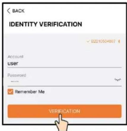
figure 7-2 Login

The Account is "user", and the initial password is "pw1111" or "111111" which should be changed for the consideration of account security.
To set inverter parameters related to grid protection and grid support, contact SUNGROW to obtain the advanced account and corresponding password.
step 4 If the inverter is not initialized, you will enter the quick setting screen of initializing protection parameter.
![graph LR A["< BACK TURN ON DEVICE<br>INITIALIZE PROTECTION PARAM...<br>Country/Region<br>Not Configual"] --> B["→"] B --> C["< BACK TURN ON DEVICE<br>INITIALIZE PROTECTION PARAMETER<br>Country/Region<br>Brazil<br>Device Address"] C --> D["→"]](/content/2026/06/1367933/images/3fa1719e90552e1dfff9c52432b9bcd48c82339a09692f3f78b1c0b4431d3d7c.jpg)
figure 7-3 Initialization Protection Parameter
NOTICE
The Country/Region must be set to the country where the inverter is installed at. Otherwise, the inverter may report errors.
step 5 When the country is set to Australia, additionally set the applicable network service provider and then the grid type. Tap Power Company to select the correct power company.
![graph LR A["<<BACK TURN ON DEVICE\nINITIALIZE PROTECTION PARAM...\nCountry/Region\nAustralia\nPower Company\nNet Configured\nDevice Address\n!)"] --> B["<<BACK TURN ON DEVICE\nPower Company\nAS/NZS 4777.2:2015\nAS/NZS 4777.2:2020 Australia A\nAS/NZS 4777.2:2021 Australia B\nAS/NZS 4777.2:2022 Austra…](/content/2026/06/1367933/images/c74999fdb198780cd933d9d5bd0532102abbd93a086f7abee8e65e9ca4a26cd8.jpg)
figure 7-4 Initialization Power Company
The image shown here is for reference only. Refer to the actual interface for the supported network service providers.
table 7-1 Power Company Information
| Network Service Provider | Grid Type |
| AS/NZS 4777.2:2015 / | |
| AS/NZS 4777.2:2020 Australia A / | |
| AS/NZS 4777.2:2020 Australia B / | |
| AS/NZS 4777.2:2020 Australia C / | |
| ENERGEX & Ergon Energy | • STNW1170: single phase < 10 kVA & three phase < 30 kVA• STNW1174 :30 kVA < PN ≤ 1500 kVA |
| Endeavour Energy MDI 0043 | |
| Ausgrid NS194 | |
| Jemena | • ≤ 10kVA per phase (or 30 kVA per thre phase)• ELE GU 0014: 30-200kVA |
| CitiPower & Powercor | • ≤ 5 kVA for single-phase & 30 kVA for three-phase• > 30 kVA three-phase |
| United Energy | • UE-ST-2008.1: ≤ 10 kW for single-phase & 30 kW for three-phase• UE-ST-2008.2: > 30 kVA three-phase |
| PowerWater | Embedded Generation Notice Photovoltaic Systems:2020 |
| SA Power Networks | TS129-2019: < 10 kW for single-phase & 30 kW for three-phaseTS130-2017: > 30 kW & ≤ 200 kWTS131-2018: > 200 kW |
| Horizon Power | HPC-9DJ-13-0001-2019: ≤ 10 kVA for single-phase & 30 kVA for three-phaseHPC-9DJ-13-0002-2019: > 30 kVA & ≤1 MVA |
| westernpower | EDM # 33612889-2019 |
| AusNet Services Basic Micro Embedded Generation:2020 | |
For compliance with AS/NZS 4777.2:2020, please select from Australia A/B/C. Please contact your electricity grid operator for which region to use.
step 6 After finishing the settings, tap TUNR ON DEVICE at the upper right corner and the device will be initialized. The App will send start instructions and the device will start and operate.
step 7 If the inverter is initialized, the App automatically turns to its home page.
-- End
7.4 Function Overview
The App provides parameter viewing and setting functions, as shown in the following figure.
![graph TD A["iSolarCloud"] --> B["Home"] A --> C["Running information"] A --> D["History record"] A --> E["More"] C --> F["Fault and Record"] C --> G["Yield Record"] C --> H["Event Record"] E --> I["Settings"] E --> J["Modify Password"] I --> K["System Parameters"] I --> L["Operation Parameter"] I --…](/content/2026/06/1367933/images/0a958e0cdd3b082474d0bc2d02f47cbc606919545e577446d9ec4a2839913c2d.jpg)
figure 7-5 App function tree map
7.5 Home page
After login, the home page is as follows:
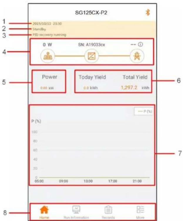
figure 7-6 Home Page
table 7-2 Home Page Description
| No. | Designation Description | |
| 1 | Date and time | System date and time of the inverter. |
| 2 | Inverter state | Present operation state of the inverter. For details, refer to "table 7-3 Description of Inverter State". |
| 3 | PID state | Present state of the PID. For details, refer to "table 7-4 Description of PID State". |
| 4 | Power flow chart | Displays the PV power generation power, feed-in power, etc. The line with an arrow indicates energy flow between connected devices, and the arrow pointing indicates energy flow direction. |
| 5 | Power generation | Today power yield and accumulative power yield of the inverter. |
| 6 | Real-time power | Output power of the inverter. |
| 7 | Power curve | Shows the change of power between 5 am and 23 pm every day(Each point on the curve represents the percentage of present inverter power to rated power). |
| 8 | Navigation bar | Including Home, Run Information, Records, and More. |
table 7-3 Description of Inverter State
| State | Description |
| Run | After being energized, the inverter tracks the PV arrays' maximum power point (MPP) and converts the DC power into AC power. This is the normal operation mode. |
| Stop The inverter is stopped. | |
| Press to Shut Down | The inverter will stop operation by manually “stop” via App. In this way, inverter internal DSP stops. To restart the inverter, manually start via App. |
| Standby | Inverter enters standby mode when DC side input is insufficient. In this mode the inverter will wait within the standby duration. |
| Initial standby | The inverter is in the initial power-on standby state. |
| Starting Up | The inverter is initializing and synchronizing with the grid. |
| Warn Run | Warning information is detected. |
| Derating running | The inverter derates actively due to environmental factors such as temperature or altitude |
| Dispatch Running | The inverter runs according to the scheduling instructions received from the monitoring background |
| Fault | If a fault occurs, the inverter will automatically stop operation, and disconnect the AC relay. The fault information will be displayed in the app. Once the fault is removed in recovery time, the inverter will automatically resume running. When the country setup is German HV, which is complied with VDE-AR-4120, the inverter will not be automatically connected to the grid after the fault is cleared, and needs to wait for an external signal to trigger reconnection. |
table 7-4 Description of PID State
| State | Description |
| PID recovery running | The inverters perform PID recovery actively. |
| PID abnormality | It is detected that the ISO impedance is abnormal or the PID cannot work normally after the PID being enabled. |
If the inverter is running abnormally, the alarm or fault icowill be displayed in the lower right corner of the inverter icon in power flow chart. The user can tap this icon to enter the alarm or fault screen to view detailed information and corrective measures.
7.6 Run Information
Tap Run Information on the navigation bar to enter the screen showing running information, slide the screen upwards to view all detailed information.
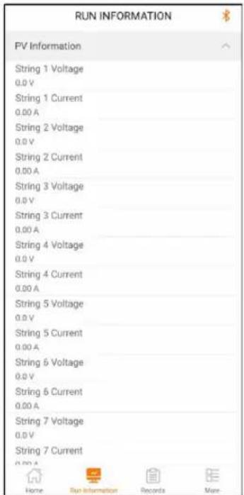
The run information includes the PV information, inverter information, input information, and output information.
7.7 Records
Tap Records on the navigation bar to enter the screen showing event records, as shown in the following figure.

figure 7-7 Records
Fault Alarm Record
Tap Fault Alarm Record to enter the screen, as shown in the following figure.

figure 7-8 Fault Alarm Record
i
Click to select a time segment and view corresponding records. The inverter can record up to 400 latest entries.
Select one of the records in the list and click the record, to view the detailed fault info as shown in following figure.

figure 7-9 Detailed Fault Alarm Information
Yield Record
Tap Yield Record to enter the screen showing daily power generation, as shown in the following figure.
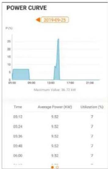
figure 7-10 Power Curve
The App displays power generation records in a variety of forms, including daily power generation graph, monthly power generation histogram, annual power generation histogram and total power generation histogram.
table 7-5 Explanation of Power Yields Records
| Parameter | Description |
| Power curve | Shows the power output from 5 am to 11 pm in a single day. point on the curve is the percentage of present power to rated power. |
| Daily energy histogram | Shows the power output every day in the present month. |
| Monthly energy histogram | Shows the power output every month in a year. |
| Annual energy histogram | Shows the power output every year. |
Tap the time bar on the top of the screen to select a time segment and view the corresponding power curve.
Swipe left to check the power yields histogram.
Event Record
Tap Event Record to view event record list.

Click ☐ to select a time segment and view corresponding records.
The inverter can at most record the latest 400 events.
7.8 More
Tap More on the navigation bar to enter the corresponding screen, as shown in the following figure.

figure 7-11 More
7.8.1 System Parameters
Tap Settings→System Parameters to enter the corresponding screen, as shown in the following figure.

figure 7-12 System Parameters
* The image shown here is for reference only.
Boot/Shutdown
Tap Boot/Shutdown to send the boot/shutdown instruction to the inverter.
For Australia and New Zealand, when the DRM state is DRM0, the "Boot" option will be prohibited.
Date Setting/Time Setting
The correct system time is very important. Wrong system time will directly affect the data logging and power generation value. The clock is in 24-hour format.
Software Version
Version information of the current firmware.
7.8.2 Operation Parameters
Running Time
Tap Settings→Operation Parameters→Running Time to enter the corresponding screen, on which you can set "Running Time".
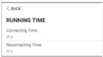
figure 7-13 Running Time
PID Parameters
Tap Settings→Operation Parameters→PID Parameters to enter the corresponding screen, on which you can set "PID Parameters".
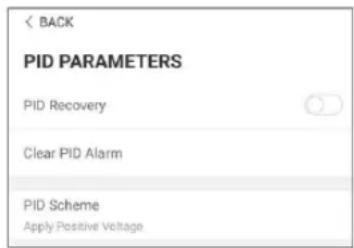
figure 7-14 PID Setting
table 7-6 PID Parameter Description
| Parameter | Description |
| PID Recovery | Set enabling/disabling of the PID night recovery function. PID night recovery function operates between 22:00 pm and 5:00 am by default. |
| Clear PID alarm | If ISO impedance abnormality or PID function exception is detected during running of the PID function, the inverter reports a PID false alarm and reminds the user to take corresponding measures. After processing, clear the alarm via this parameter. |
| PID Scheme | Apply negative or positive voltage. |

After the PID night recovery function is enabled, the fault indicator on the inverter front panel turns green.
AFCI Parameters
Tap Settings→Operation Parameters→AFCI Parameters to enter the corresponding screen, on which you can set AFCI Parameters.
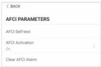
figure 7-15 AFCI Setting
NS Protection (Passive Valid)
Tap Settings→Operation Parameters→Regular Parameters to enter the corresponding screen, on which you can set the NS Protection(Passive Valid).

figure 7-16 NS Protection(Passive Valid)
7.8.3 Power Regulation Parameters
Active Power Regulation
Tap Settings→Power Regulation Parameters→Active Power Regulation to enter the screen, as shown in the following figure.
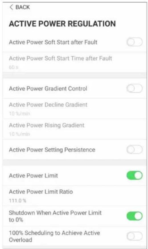
figure 7-17 Active Power Regulation
table 7-7 Active Power Regulation
| Parameter | Definition/Setting Description | Range |
| Active power soft start after fault | The switch for enabling/disabling the soft start function after a fault occurs. | Enable/Disable |
| Active power soft start time after fault | Time that the soft start takes to raise the power from 0 to 100% rated power. | 1s~1200s |
| Active power gradient control | Switch for enabling/disabling the active power rate settable function. | Enable/Disable |
| Active power decline gradient | The decline rate of inverter active power per minute. | 3%/min~6000%/min |
| Active power rising gradient | The rise rate of inverter active power per minute. | 3%/min~6000%/min |
| Active power setting persistence | Switch for enabling/disabling the function of saving output limited power. | Enable/Disable |
| Active power limit | The switch for limiting output power. | Enable/Disable |
| Active power limit ratio | The ratio of limiting output power to rated power in percentage. | 0%~110% |
| Shutdown when active power limit to 0% | Switch used to determine whether the inverter is in stop state when the limited power reaches 0. | Enable/Disable |
| 100% Scheduling to achieve active overload | Switch used to ensure that the inverter operates at the maximum active power when PV power limit ratio is set over 100%. | Enable/Disable |
Reactive Power Regulation
Tap Settings→Power Regulation Parameters→Reactive Power Regulation to enter the screen, as shown in the following figure.
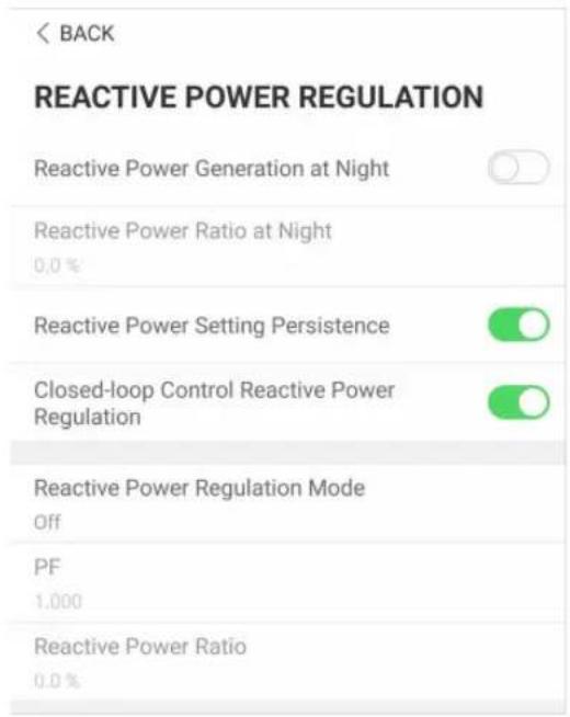
figure 7-18 Reactive Power Regulation
table 7-8 Reactive Power Regulation
| Parameter | Definition/Setting Description | Range |
| Reactive power generation at night | Switch for enabling/disabling Q at night function. | Enable/Disable |
| Reactive power ratio at night | Reactive power ratio set for the Q at night function. | -100%~0%/0%~100% |
| Reactive power setting persistence | Switch for enabling/disabling the power-off function during reactive power | Enable/Disable |
| Closed-loop control reactive power regulation | Switch for closed-loop control during reactive power | Enable/Disable |
| Reactive power regulation mode | Reactive power regulation mode selection | Off/PF/Qt/Q(P)/Q(U) |
The inverter provides the reactive power regulation function. Enable this function under Re-active Power Regulation Mode and select the appropriate mode.
table 7-9 Descriptions of reactive power regulation mode:
| Mode | Descriptions |
| Off The PF is fixed at +1.000. | |
| PF | The reactive power can be regulated by the parameter PF (Power Factor). |
| Qt | The reactive power can be regulated by the parameter Q-Var limits (in %). |
| Q(P) | The PF changes with the output power of the inverter. |
| Q(U) | The reactive power changes with the grid voltage. |
"Off" Mode
The reactive power regulation function is disabled. The PF is limited to +1.000.
"PF" Mode
The power factor is fixed and reactive power setpoint is calculated according to the current power. The PF ranges from 0.8 leading to 0.8 lagging.
Leading: the inverter is sourcing reactive power to the grid.
Lagging: the inverter is injecting reactive power into the grid.
"Qt" Mode
In the Qt mode, system rated reactive power is fixed, and the system injects reactive power according to the delivered reactive power ratio. The Reactive Power Ratio is set through the App.
The setting range of the reactive power ratio is 0\~100% or 0\~-100%, corresponding to the ranges of inductive and capacitive reactive power regulation respectively.
"Q(P)" Mode
The PF of the inverter output varies in response to the output power of the inverter.
table 7-10 "Q(P)" Mode Parameter Descriptions:
| Parameter | Explanation Range | |
| Reactive response | Switch for enabling/disabling reactive response | Enable/Disable |
| Reactive re-sponse time | Completion time of reactive response | 0.1s~600.0s |
| Q(P) Curve | Select corresponding curve according to local regulations | A, B, C |
| QP_P1 | Output power at P1 on the Q(P) mode curve (in percentage) | 10% ~ 100% |
| QP_P2 | Output power at P2 on the Q(P) mode curve (in percentage) | 20% ~ 100% |
| QP_P3 | Output power at P3 on the Q(P) mode curve (in percentage) | 20% ~ 100% |
| QP_K1 | Power factor at P1 on the Q(P) mode curve | Curve A/C: 0.8 ~ 1Curve B: - 0.6 ~ 0.6 |
| QP_K2 | Power factor at P2 on the Q(P) mode curve | |
| QP_K3 | Power factor at P3 on the Q(P) mode curve | |
| QP_EnterVoltage | Voltage percentage for Q(P) function activation | 100% ~ 110% |
| QP_ExitVoltage | Voltage percentage for Q(P) function deactivation | 90% ~ 100% |
| QP_ExitPower | Power percentage for Q(P) function deactivation | 1% ~ 100% |
| QP_EnableMode | Unconditional activation/deactivation of Q (P) function | Yes / No |
* Curve C is reserved and consistent with Curve A currently.


figure 7-19 Q(P) Curve
table 7-11 "Q(U)" Mode Parameter Descriptions:
| Parameter | Explanation Range | |
| Reactive response | Switch for enabling/disabling reactive response | Enable/Disable |
| Reactive response time | Completion time of reactive response | 0.1s~600.0s |
| Q(U) curve | Select corresponding curve according to local regulations | A, B, C |
| Hysteresis Ratio | Voltage hysteresis ratio on the Q(U) mode curve | 0 ~ 5% |
| QU_V1 | Grid voltage limit at P1 on the Q(U) mode curve | 80% ~ 100% |
| QU_Q1 | Value of Q/Sn at P1 on the Q(U) mode curve | -60% ~ 0 |
| QU_V2 | Grid voltage limit at P2 on the Q(U) mode curve | 80% ~ 100% |
| QU_Q2 | Value of Q/Sn at P2 on the Q(U) mode curve | -60% ~ 60% |
| QU_V3 | Grid voltage limit at P3 on the Q(U) mode curve | 100% ~ 120% |
| QU_Q3 | Value of Q/Sn at P3 on the Q(U) mode curve | -60% ~ 60% |
| QU_V4 | Grid voltage limit at P4 on the Q(U) mode curve | 100% ~ 120% |
| QU_Q4 | Value of Q/Sn at P4 on the Q(U) mode curve | 0 ~ 60% |
| QU_EnterPower Active power for Q(U) function activation | 20% ~ 100% | |
| QU_ExitPower Active power for Q(U) function deactivation | 1% ~ 20% | |
| QU_EnableMode | Unconditional activation/deactivation of Q (U) function | Yes / No / Yes, Limited by PF |
| QU_Limited PF Value | PF value for Q(U) function activation | 0~0.95 |
* Curve C is reserved and consistent with Curve A currently.
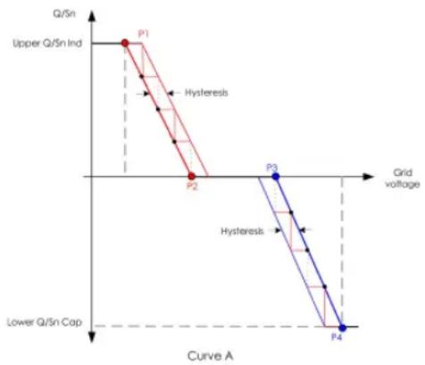

figure 7-20 Q(U) Curve
7.8.4 Communication Parameters
Serial Port Parameters
Tap Settings→Communication Parameters→Serial Port Parameters to enter the corresponding screen, as shown in the following figure. The device address ranges from 1 to 246.

figure 7-21 Serial Port Parameters
7.8.5 Firmware Update
To avoid download failure due to poor on-site network signal, it is recommended to download the firmware package to the mobile device in advance.
Perform firmware update only during high irradiance conditions in order to prevent equipment failure.
step 1 Enable the "Mobile data" of the mobile device.
step 2 Open the App, enter the account and password on the login screen. Tap Login to enter the home screen.
step 3 Tap More→Firmware Download to enter corresponding screen on which you can view the device list.
step 4 Select the device model before downloading the firmware. Tap the device name in the device list to enter the firmware upgrade package detail interface, and tap behind the firmware upgrade package to download it.

step 5 Return to the Firmware Download screen, tap in the upper right corner of the screen to view the downloaded firmware upgrade package.
step 6 Login the App via local access mode. Refer to "7.3 Login".
step 7 Tap More on the App home screen and then tap Firmware Update.
step 8 Tap the upgrade package file, a prompt box will pop up asking you to upgrade the firmware with the file, tap CONFIRM to perform the firmware upgrade.

step 9 Wait for the file to be uploaded. When the upgrade is finished, the interface will inform you of the upgrade completion. Tap Complete to end the upgrade.

-- End
7.8.6 Password Changing
Tap Modify Password to enter the modify password screen, as shown in the following figure.
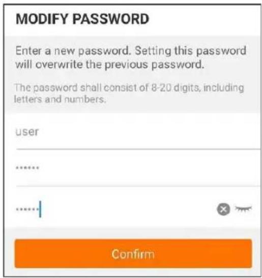
figure 7-22 Change Password
The password shall consist of 8–20 digits, including letters and numbers.
8 System Decommissioning
8.1 Disconnecting the Inverter
CAUTION
Danger of burns!
Even if the inverter is shut down, it may still be hot and cause burns. Wear protective gloves before operating the inverter after it cools down.
For maintenance or other service work, the inverter must be switched off.
Proceed as follows to disconnect the inverter from the AC and DC power sources. Lethal voltages or damage to the inverter will follow if otherwise.
step 1 Disconnect the external AC circuit breaker and secure it against reconnection.
step 2 Rotate the DC switch to the "OFF" position for disconnecting all of the PV string inputs.
step 3 Wait about 5 minutes until the capacitors inside the inverter completely discharge.
step 4 Ensure that the DC cable is current-free via a current clamp.
-- End
8.2 Dismantling the Inverter
CAUTION
Risk of burn injuries and electric shock!
After the inverter is powered off for 5 minutes, measure the voltage and current with professional instrument. Only when there is no voltage nor current can operators who wear protective equipment operate and maintain the inverter.

Before dismantling the inverter, disconnect both AC and DC connections.
If there are more than two layers of inverter DC terminals, dismantle the outer DC connectors before dismantling the inner ones.
step 1 Refer to "5 Electrical Connection", for the inverter disconnection of all cables in reverse steps. In particular, when removing the DC connector, use an MC4-Evo2 wrench to loosen the locking parts and install waterproof plugs.

step 2 Refer to "4 Mechanical Mounting", to dismantle the inverter in reverse steps.
step 3 If necessary, remove the wall-mounting bracket from the wall.
step 4 If the inverter will be used again in the future, please refer to "3.2 Inverter Storage" for a proper conservation.
-- End
8.3 Disposal of the Inverter
Users take the responsibility for the disposal of the inverter.
WARNING
Please scrap the inverter in accordance with relevant local regulations and standards to avoid property losses or casualties.
NOTICE
Some parts of the inverter may cause environmental pollution. Please dispose of them in accordance with the disposal regulations for electronic waste applicable at the installation site.
9 Troubleshooting and Maintenance
9.1 Troubleshooting
Once the inverter fails, the fault information can be displayed on the App interface. If the inverter is equipped with an LCD screen, the fault information can be viewed on it.
The fault codes and troubleshooting methods of all PV inverters are detailed in the table below. The device you purchase may only contain some of the fault information, and when the inverter fails, you can check the corresponding information through the fault codes from the mobile app.
| Fault code | Fault name | Corrective measures |
| 2, 3, 14, 15 | Grid Overvoltage | Generally, the inverter will be reconnected to the grid after the grid returns to normal. If the fault occurs repeatedly:1. Measure the actual grid voltage, and contact the local electric power company for solutions if the grid voltage is higher than the set value.2. Check whether the protection parameters are appropriately set via the App or the LCD. Modify the overvoltage protection values with the consent of the local electric power operator.3. Contact Sungrow Customer Service if the preceding causes are ruled out and the fault persists. |
| 4, 5 | Grid Undervoltage | Generally, the inverter will be reconnected to the grid after the grid returns to normal. If the fault occurs repeatedly:1. Measure the actual grid voltage, and contact the local electric power company for solutions if the grid voltage is lower than the set value.2. Check whether the protection parameters are appropriately set via the App or the LCD.3. Check whether the AC cable is firmly in place.4. Contact Sungrow Customer Service if the preceding causes are ruled out and the fault persists. |
| 8 | Grid Overfrequency | Generally, the inverter will be reconnected to the grid after the grid returns to normal. If the fault occurs repeatedly:1. Measure the actual grid frequency, and contact the local electric power company for solutions if the grid frequency is beyond the set range.2. Check whether the protection parameters are appropriately set via the App or the LCD.3. Contact Sungrow Customer Service if the preceding causes are ruled out and the fault persists. |
| 9 | Grid Underfrequency | |
| 10 | Grid Power Outage | Generally, the inverter will be reconnected to the grid after the grid returns to normal. If the fault occurs repeatedly:1. Check whether the grid supplies power reliably.2. Check whether the AC cable is firmly in place.3. Check whether the AC cable is connected to the correct terminal (whether the live wire and the N wire are correctly in place).4. Check whether the AC circuit breaker is connected.5. Contact Sungrow Customer Service if the preceding causes are ruled out and the fault persists. |
| 12 | Excess Leakage Current | 1. The fault can be caused by poor sunlight or damp environment, and generally the inverter will be reconnected to the grid after the environment is improved.2. If the environment is normal, check whether the AC and DC cables are well insulated.3. Contact Sungrow Customer Service if the preceding causes are ruled out and the fault persists. |
| 13 | Grid Abnormal | Generally, the inverter will be reconnected to the grid after the grid returns to normal. If the fault occurs repeatedly:1. Measure the actual grid, and contact the local electric power company for solutions if the grid parameter exceeds the set range.2. Contact Sungrow Customer Service if the preceding causes are ruled out and the fault persists. |
| Fault code Fault name Corrective measures | ||
| 17 | Grid Voltage Imbalance | Generally, the inverter will be reconnected to the grid after the grid returns to normal. If the fault occurs repeatedly:1. Measure the actual grid voltage. If grid phase voltages differ greatly, contact the electric power company for solutions.2. If the voltage difference between phases is within the permissible range of the local power company, modify the grid voltage imbalance parameter through the App or the LCD.3. Contact Sungrow Customer Service if the preceding causes are ruled out and the fault persists. |
| 28, 29, 208, 212, 448-479 | PV Reserve Connection Fault | 1. Check whether the corresponding string is of reverse polarity. If so, disconnect the DC switch and adjust the polarity when the string current drops below 0.5 A.2. Contact Sungrow Customer Service if the preceding causes are ruled out and the fault persists.*The code 28 to code 29 are corresponding to PV1 to PV2 respectively.*The code 448 to code 479 are corresponding to string 1 to string 32 respectively. |
| 532-547, 564-579 | PV Reverse Connection Alarm | 1. Check whether the corresponding string is of reverse polarity. If so, disconnect the DC switch and adjust the polarity when the string current drops below 0.5 A.2. Contact Sungrow Customer Service if the preceding causes are ruled out and the alarm persists.*The code 532 to code 547 are corresponding to string 1 to string 16 respectively.*The code 564 to code 579 are corresponding to string 17 to string 32 respectively. |
| Fault code | Fault name | Corrective measures |
| Check whether the voltage and current of the inverter is abnormal to determine the cause of the alarm.1. Check whether the corresponding module is sheltered. If so, remove the shelter and ensure module cleanness.2. Check whether the battery board wiring is loose, if so, make it reliably connected.3. Check if the DC fuse is damaged. If so, replace the fuse.4. Contact Sungrow Customer Service if the preceding causes are ruled out and the alarm persists.*The code 548 to code 563 are corresponding to string 1 to string 16 respectively.*The code 580 to code 595 are corresponding to string 17 to string 32 respectively. | ||
| 548-563, 580-595 | PV Abnormal Alarm | |
| 37 | Excessively High Ambient Temperature | Generally, the inverter will resume operation when the internal or module temperature returns to normal. If the fault persists:1. Check whether the ambient temperature of the inverter is too high;2. Check whether the inverter is in a well-ventilated place;3. Check whether the inverter is exposed to direct sunlight. Shield it if so;4. Check whether the fan is running properly. Replace the fan if not;5. Contact Sungrow Power Customer Service if the fault is due to other causes and the fault persists. |
| 43 | Excessively Low Ambient Temperature | Stop and disconnect the inverter. Restart the inverter when the ambient temperature rises within the operation temperature range. |
| 39 | Low System Insulation Resistance | Wait for the inverter to return to normal. If the fault occurs repeatedly:1. Check whether the ISO resistance protection value is excessively high via the app or the LCD, and ensure that it complies with the local regulations.2. Check the resistance to ground of the string and DC cable. Take corrective measures in case of short circuit or damaged insulation layer.3. If the cable is normal and the fault occurs on rainy days, check it again when the weather turns fine.4. Contact Sungrow Customer Service if the preceding causes are ruled out and the fault persists. |
| 106 | Grounding Cable Fault | 1. Check whether the AC cable is correctly connected.2. Check whether the insulation between the ground cable and the live wire is normal.3. Contact Sungrow Customer Service if the preceding causes are ruled out and the fault persists. |
| 88 Electric Arc Fault | 1. Disconnect the DC power supply, and check whether any DC cable is damaged, the connection terminal or fuse is loose or there is a weak contact. If so, replace the damaged cable, fasten the terminal or fuse, and replace the burnt component.2. After performing step 1, reconnect the DC power supply, and clear the electric arc fault via the App or the LCD, after that the inverter will return to normal.3. Contact Sungrow Customer Service if the fault persists. | |
| 84 | Reverse Connection Alarm of the Meter/CT | 1. Check if the meter is wrongly connected.2. Check if the input and output wiring of the meter is reversed.3. If the existing system is enabled, please check if the rated power setting of the existing inverter is correct. |
| 514 | Meter Communication Abnormal Alarm | 1. Check whether the communication cable and the terminals are abnormal. If so, correct them to ensure reliable connection.2. Reconnect the communication cable of the meter.3. Contact Sungrow Customer Service if the preceding causes are ruled out and the alarm persists. |
| 323 Grid Confrontation | 1. Check whether the output port is connected to actual grid. Disconnect it from the grid if so.2. Contact Sungrow Customer Service if the preceding causes are ruled out and the fault persists. | |
| 75 | Inverter Parallel Communication Alarm | 1. Check whether the communication cable and the terminals are abnormal. If so, correct them to ensure reliable connection.2. Reconnect the communication cable of the meter.3. Contact Sungrow Customer Service if the preceding causes are ruled out and the alarm persists. |
| 7, 11, 16, 19–25, 30–34, 36,38, 40–42, 44–50, 52–58, 60–69, 85, 87, 92,93, 100–105,107–114, 116–124, 200–211,248–255, 300–322, 324–328,401–412, 600–603, 605, 608,612, 616, 620,622–624, 800,802, 804, 807,1096–1122 | System Fault | Wait for the inverter to return to normal.Disconnect the AC and DC switches, and reconnect the AC and DC switches 15 minutes later to restart the inverter. If the fault still exists, contact Sungrow Customer Service. |
| Fault code Fault name Corrective measures | ||
| 59, 70–74, 76,82, 83, 89, 77–81, 216–218,220–232, 432–434, 500–513,515–518, 635–638, 900, 901,910, 911, 996 | System Alarm | 1. The inverter can continue running.2. Check whether the related wiring and terminal are abnormal, check whether there are any foreign materials or other environmental abnormalities, and take corresponding corrective measures when necessary.If the fault persists, please contact Sungrow Power Customer Service. |
| 264-283 | MPPT Reverse Connection | 1. Check whether the corresponding string is of reverse polarity. If so, disconnect the DC switch and adjust the polarity when the string current drops below 0.5 A.2. Contact Sungrow Customer Service if the preceding causes are ruled out and the fault persists.*The code 264 to code 279 are corresponding to string 1 to string 20 respectively. |
| 332-363 | Boost Capacitor Overvoltage Alarm | 1. The inverter can continue running.2. Check whether the related wiring and terminals are abnormal, check whether there are any foreign materials or other environmental abnormalities, and take corresponding corrective measures when necessary.If the fault persists, please contact Sungrow Power Customer Service. |
| 364-395 | Boost Capacitor Overvoltage Fault | Disconnect the AC and DC switches, and reconnect the AC and DC switches 15 minutes later to restart the inverter. If the fault still exists, contact Sungrow Customer Service. |
| Fault code | Fault name | Corrective measures |
| 1548-1579 | String Current Reflux | 1. Check whether the number of PV modules of the corresponding string is less than other strings. If so, disconnect the DC switch and adjust the PV module configuration when the string current drops below 0.5 A.2. Check whether the PV module is shaded;3. Disconnect the DC switch to check whether the open circuit voltage is normal when the string current drops below 0.5 A. If so, check the wiring and configuration of the PV module,4. Check whether the orientation of the PV module is abnormal. |
| 1600 - 1615, 1632 - 1655 | PV Grounding Fault | 1. When the fault occurs, it is forbidden to directly disconnect the DC switch and unplug PV terminals when the direct current is greater than 0.5 A;2. Wait until the direct current of the inverter falls below 0.5 A, then disconnect the DC switch and unplug the faulty strings;3. Do not reinsert the faulty strings before the grounding fault is cleared;4. If the fault is not caused by the foregoing reasons and still exists, contact Sungrow Customer Service. |
| 1616 | System Hardware Fault | 1. It is prohibited to disconnect the DC switch when the DC current is greater than 0.5 A when the fault occurs.2. Disconnect the DC switch only when the inverter DC side current drops below 0.5 A.3. It is prohibited to power up the inverter again. Please contact Sungrow Customer Service. |
9.2 Maintenance
9.2.1 Maintenance Notices
! DANGER
Risk of inverter damage or personal injury due to incorrect service!
- Be sure to use special insulation tools when perform high-voltage operations.
- Before any service work, first disconnect the grid-side AC circuit breaker and check the inverter status. If the inverter indicator is off, please wait until night to disconnect the DC switch. If the inverter indicator is on, directly disconnect the DC switch.
- After the inverter is powered off for 5 minutes, measure the voltage and current with professional instrument. Only when there is no voltage nor current can operators who wear protective equipment operate and maintain the inverter
- Even if the inverter is shut down, it may still be hot and cause burns. Wear protective gloves before operating the inverter after it cools down.
CAUTION
To prevent misuse or accidents caused by unrelated personnel: Post prominent warning signs or demarcate safety warning areas around the inverter to prevent accidents caused by misuse.
NOTICE
Restart the inverter only after removing the fault that impairs safety performance. As the inverter contains no component parts that can be maintained, never open the enclosure, or replace any internal components.
To avoid the risk of electric shock, do not perform any other maintenance operations beyond this manual. If necessary, contact SUNGROW for maintenance. Otherwise, the losses caused is not covered by the warranty.
NOTICE
Touching the PCB or other static sensitive components may cause damage to the device.
- Do not touch the circuit board unnecessarily.
- Observe the regulations to protect against electrostatic and wear an anti-static wrist strap.
9.2.2 Routine Maintenance
| Item Method Period | |
| System clean | Check the temperature and dust of the inverter. Clean the inverter enclosure if necessary.Check if the air inlet and outlet are normal. Clean the air inlet and outlet, if necessary. |
| Fans | Check whether there is fan warning using App.Check whether there is any abnormal noise when the fan is turning.Clean or replace the fans if necessary (see the following section). |
| Cable entry | Check whether the cable entry is insufficiently sealed or the gap is excessively large, and reseal the entry when necessary. |
| Electrical Connection | Check whether all cable are firmly connected in place.Check whether a cable is damaged, Six months to a year especially the part contacting the metal enclosure. |
9.2.3 Cleaning Air Inlet and Outlet
A significant amount of heat is generated when the inverter is working.
In order to maintain good ventilation, please check to make sure the air inlet and outlet are not blocked.
Clean the air inlet and outlet with soft brush or vacuum cleaner if necessary.
9.2.4 Fan Maintenance
WARNING
- Power off the inverter and disconnect it from all power supplies before maintaining fans.
- After the inverter is powered off for 10 minutes, measure the voltage and current with professional instrument. Only when there is no voltage nor current can operators who wear protective equipment operate and maintain the inverter.
- Fan maintenance must be performed by professionals.
Fans inside the inverter are used to cool the inverter during operation. If the fans do not operate normally, the inverter may not be cooled down and inverter efficiency may decrease.
Therefore, it is necessary to clean dirty fans and replace the broken fans in a timely manner. The operation procedure is as follows:
step 1 Stop the inverter (see"8.1 Disconnecting the Inverter").
step 2 Loosen the screw on the sealing plate of the fan module.

step 3 Press the tab of the latch hook, unplug the cable connection joint outwards, and loosen the screw on the fan holder.

step 4 Loosen screws on the side of the fan module.

step 5 Pull out the fans. Clean them with a soft brush or vacuum cleaner, and replace them when necessary.

-- End
10 Appendix
10.1 Technical Data
| Parameters | SG125CX-P2 |
| Input (DC) | |
| Recommended max. PV input power | 175 kW |
| Max. PV input voltage 1100 V | |
| Min. operating PV voltage / Start-up input voltage | 180 V / 200 V |
| Rated PV input voltage 600 V | |
| MPP voltage range 180 ~ 1000 V | |
| No. of independent MPP inputs | 12 |
| No. of PV strings per MPPT 2 | |
| Max. PV input current | 360 A (30 A / 30 A / 30 A / 30 A / 30 A / 30 A / 30 A / 30 A) |
| 30 A / 30 A / 30 A / 30 A / 30 A / 30 A) | |
| Max.DC Short-circuit current | 480 A (40 A / 40 A / 40 A / 40 A / 40 A / 40 A / 40 A / 40 A) |
| 40 A / 40 A / 40 A / 40 A / 40 A / 40 A) | |
| Output (AC) | |
| Max. AC Output power | 125 kVA |
| Rated AC output apparent power | 125 kVA |
| Max. AC output current | 181.1 A |
| Rated AC voltage | 3 / N / PE, 230 / 400 V |
| AC voltage range | 320 - 480V |
| Rated grid frequency / Grid frequency range | 50 Hz / 45 - 55 Hz |
| 60 Hz / 55 - 65 Hz | |
| Harmonic (THD) | < 3 % (at rated power) |
| Power factor at nominal power / Adjustable power factor | > 0.99 / 0.8 leading - 0.8 lagging |
| Feed-in phases / connection phases | 3 / 3-PE |
| Efficiency | |
| Max. efficiency | 98.5% |
| European efficiency | 98.3% |
| Protection | |
| Parameters | SG125CX-P2 |
| DC reverse polarity protection | Yes |
| AC short circuit protection | Yes |
| Leakage current protection Yes | |
| Grid monitoring | Yes |
| Ground fault monitoring | Yes |
| DC switch | Yes |
| PV string monitoring Yes | |
| Q at night function | Yes |
| PID recovery function | Yes |
| Arc fault circuit interrupter (AFCI) | Yes |
| Surge protection | DC Type I+II / AC Type II |
| General Data | |
| Dimensions (W*H*D) 1020 * 795* 360 mm | |
| Weight | 87 kg |
| Topology Transformerless | |
| Degree of protection | IP66 |
| Night power consumption < 4 W | |
| Operating ambient temperature range | -30 to 60 °C (> 45°C derating) |
| Allowable relative humidity range | 0 ~ 100% |
| Cooling method | Smart forced air cooling |
| Max. operating altitude | 4000 m (>3000 m derating) |
| Display | LED, Bluetooth + APP |
| Communication | RS485 / Optional: WLAN, Ethernet |
| DC connection type | Evo2 (Max. 6 mm2) |
| AC connection type | OT / DT terminal (Max. 240 mm2) |
| Grid Support | Q at night function, LVRT, HVRT, active & reactive power control and power ramp rate control |
10.2 Wring Distance of DI Dry Contact
The maximum wiring distance of DC dry contact must meet the requirements in the Table below. The wiring distance L is the total length of all DI signal cables.
L = 2 _ k = 1 ^ n L _ k
LK refers to the cable length in one direction between the DI dry contact terminal of the kverter and the corresponding terminal of the γkin1 verter.
table 10-1 Correspondence between number of inverters and maximum wiring distance
| Number of inverter | Maximum wiring distance(unit:m) | |
| 16AWG / 1.31mm | 17AWG / 1.026mm | |
| 1 13030 10552 | ||
| 2 6515 5276 | ||
| 3 4343 3517 | ||
| 4 3258 2638 | ||
| 5 2606 2110 | ||
| 6 2172 1759 | ||
| 7 1861 1507 | ||
| 8 1629 1319 | ||
| 9 1448 1172 | ||
| 10 1303 1055 | ||
| 11 1185 959 | ||
| 12 1086 879 | ||
| 13 1002 812 | ||
| 14 931 754 | ||
| 15 869 703 | ||
| 16 814 660 | ||
| 17 766 621 | ||
| 18 724 586 | ||
| 19 686 555 | ||
| 20 652 528 | ||
| 21 620 502 | ||
| 22 592 480 | ||
| 23 567 459 | ||
| 24 543 440 | ||
| 25 521 422 | ||
NOTICE
In case the specification of the cable used is not included in the Table above, when there is only one inverter, ensure that the line impedance of the input node is less than 300Ω ; and when there are multiple inverters connected in the daisy chain, ensure that the impedance is less than 300Ω /number of inverter.
10.3 Quality Assurance
When product faults occur during the warranty period, SUNGROW will provide free service or replace the product with a new one.
Evidence
During the warranty period, the customer shall provide the product purchase invoice and date. In addition, the trademark on the product shall be undamaged and legible. Otherwise, SUNGROW has the right to refuse to honor the quality guarantee.
Conditions
• After replacement, unqualified products shall be processed by SUNGROW.
- The customer shall give SUNGROW a reasonable period to repair the faulty device.
Exclusion of Liability
In the following circumstances, SUNGROW has the right to refuse to honor the quality guarantee:
- The free warranty period for the whole machine/components has expired.
- The device is damaged during transport.
- The device is incorrectly installed, refitted, or used.
- The device operates in harsh conditions beyond those described in this manual.
- The fault or damage is caused by installation, repairs, modification, or disassembly performed by a service provider or personnel not from SUNGROW.
- The fault or damage is caused by the use of non-standard or non-SUNGROW components or software.
- The installation and use range are beyond stipulations of relevant international standards.
- The damage is caused by unexpected natural factors.
For faulty products in any of above cases, if the customer requests maintenance, paid maintenance service may be provided based on the judgment of SUNGROW.
10.4 Contact Information
In case of questions about this product, please contact us.
We need the following information to provide you the best assistance:
- Model of the device
- Serial number of the device
- Fault code/name
- Brief description of the problem
For detailed contact information, please visit: https://en.sungrowpower.com/contactUS.

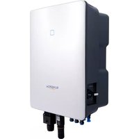
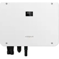

- ALL RIGHTS RESERVED
- TRADEMARKS
- SOFTWARE LICENSES
- ABOUT THIS MANUAL
- VALIDITY
- TARGET GROUP
- HOW TO USE THIS MANUAL
- SYMBOLS
- DANGER
- WARNING
- CAUTION
- NOTICE
- I
- CONTENTS
- ALL RIGHTS RESERVED ....I
- ABOUT THIS MANUAL....II
- 1 SAFETY INSTRUCTIONS ....1
- 2 PRODUCT DESCRIPTION ....5
- 3 UNPACKING AND STORAGE 13
- 4 MECHANICAL MOUNTING 15
- 5 ELECTRICAL CONNECTION ....29
- 6 COMMISSIONING ....71
- 7 ISOLARCLOUD APP ....73
- 8 SYSTEM DECOMMISSIONING 95
- 9 TROUBLESHOOTING AND MAINTENANCE 97
- 10 APPENDIX 109
- 1 SAFETY INSTRUCTIONS
- 1.1 UNPACKING AND INSPECTION
- 1.2 INSTALLATION SAFETY
- 1.3 ELECTRICAL CONNECTION SAFETY
- 1.4 OPERATION SAFETY
- 1.5 MAINTENANCE SAFETY
- 1.6 DISPOSAL SAFETY
- 2 PRODUCT DESCRIPTION
- 2.1 SYSTEM INTRODUCTION
- 2.2 PRODUCT INTRODUCTION
- MODEL DESCRIPTION
- DIMENSIONS
- 2.3 SYMBOLS ON THE PRODUCT
- SYMBOL EXPLANATION
- 2.4 LED INDICATOR
- 2.5 CIRCUIT DIAGRAM
- 2.6 FUNCTION DESCRIPTION
- CONVERSION FUNCTION
- DATA STORAGE AND DISPLAY
- PARAMETER CONFIGURATION
- COMMUNICATION INTERFACE
- PROTECTION FUNCTION
- PID RECOVERY
- AFCI FUNCTION
- 3 UNPACKING AND STORAGE
- 3.1 UNPACKING AND INSPECTION
- 3.2 INVERTER STORAGE
- 4 MECHANICAL MOUNTING
- 4.1 SAFETY DURING MOUNTING
- 4.2 LOCATION REQUIREMENTS
- 4.2.1 ENVIRONMENT REQUIREMENTS
- 4.2.2 CARRIER REQUIREMENTS
- 4.2.3 ANGLE REQUIREMENTS
- TILTING BACKWARDS INSTALLATION REQUIREMENTS
- 4.2.4 CLEARANCE REQUIREMENTS
- SPACING FOR INSTALLING AN INVERTER
- SPACING FOR INSTALLING MULTIPLE INVERTERS
- BACK TO BACK INSTALLATION
- 4.3 INSTALLATION TOOLS
- 4.4 MOVING THE INVERTER
- 4.5 INSTALLING THE MOUNTING-BRACKET
- 4.5.1 PV BRACKET-MOUNTED INSTALLATION
- 4.5.2 WALL-MOUNTED INSTALLATION
- 4.5.3 POLE-MOUNTING
- 4.6 INSTALLING THE INVERTER
- 5 ELECTRICAL CONNECTION
- 5.1 SAFETY INSTRUCTIONS
- 5.2 TERMINAL DESCRIPTION
- 5.3 ELECTRICAL CONNECTION OVERVIEW
- 5.4 CRIMP OT / DT TERMINAL
- ALUMINIUM CABLE REQUIREMENTS
- 5.5 EXTERNAL GROUNDING CONNECTION
- ELECTRIC SHOCK
- 5.5.1 EXTERNAL GROUNDING REQUIREMENTS
- 5.5.2 CONNECTION PROCEDURE
- 5.6 AC CABLE CONNECTION
- 5.6.1 AC SIDE REQUIREMENTS
- AC CIRCUIT BREAKER
- RESIDUAL CURRENT MONITORING DEVICE
- MULTIPLE INVERTERS IN PARALLEL CONNECTION
- MV TRANSFORMER
- 5.6.2 REQUIREMENTS FOR OT/DT TERMINAL
- OT/DT TERMINALS OF PHASE WIRE
- OT/DT TERMINAL OF PE WIRE
- 5.6.3 CONNECTION PROCEDURE (FOR A MULTI-CORE CABLE)
- END
- 5.6.4 CONNECTION PROCEDURE (FOR A SINGLE-CORE CABLE)
- 5.7 DC CABLE CONNECTION
- 5.7.1 PV INPUT CONFIGURATION
- 5.7.2 ASSEMBLING THE PV CONNECTORS
- 5.7.3 INSTALLING THE PV CONNECTOR
- 5.8 WIRING OF TRACKING SYSTEM POWER CABLE (OPTIONAL)
- 5.9 WIRELESS COMMUNICATION MODULE CONNECTION(OPTIONAL)
- 5.10 WINET-S CONNECTION (OPTIONAL)
- 5.10.1 ETHERNET COMMUNICATION
- 5.10.2 WLAN COMMUNICATION
- 5.11 COMMUNICATION JUNCTION BOX
- 5.12 COMMUNICATION WIRING BOARD
- 5.13 RS485 CONNECTION
- 5.13.1 INTERFACE DESCRIPTION
- 5.13.2 RS485 COMMUNICATION SYSTEM
- SINGLE-INVERTER COMMUNICATION SYSTEM
- MULTI-INVERTER COMMUNICATION SYSTEM
- 5.13.3 CONNECTION PROCEDURE(TERMINAL BLOCK)
- 5.13.4 CONNECTION PROCEDURE (RJ45 INTERFACE)
- 5.14 DRY CONTACT CONNECTION
- 5.14.1 DRY CONTACT FUNCTION
- DO TERMINAL (FAULT OUTPUT DRY CONTACT)
- DI TERMINAL (EMERGENCY STOP DRY CONTACT)
- NS PROTECTION
- 5.14.2 WIRING PROCEDURE
- 5.15 DRM CONNECTION ( FOR COUNTRIES "AU" AND "NZ")
- 5.15.1 DRM FUNCTION
- 5.15.2 CONNECTION PROCEDURE
- 6 COMMISSIONING
- 6.1 INSPECTION BEFORE COMMISSIONING
- 6.2 COMMISSIONING PROCEDURE
- 7 ISOLARCLOUD APP
- 7.1 BRIEF INTRODUCTION
- 7.2 INSTALLING THE APP
- METHOD 1
- METHOD 2
- 7.3 LOGIN
- 7.3.1 REQUIREMENTS
- 7.3.2 LOGIN PROCEDURE
- 7.4 FUNCTION OVERVIEW
- 7.5 HOME PAGE
- 7.6 RUN INFORMATION
- 7.7 RECORDS
- YIELD RECORD
- EVENT RECORD
- 7.8 MORE
- 7.8.1 SYSTEM PARAMETERS
- BOOT/SHUTDOWN
- DATE SETTING/TIME SETTING
- SOFTWARE VERSION
- 7.8.2 OPERATION PARAMETERS
- RUNNING TIME
- PID PARAMETERS
- AFCI PARAMETERS
- NS PROTECTION (PASSIVE VALID)
- 7.8.3 POWER REGULATION PARAMETERS
- ACTIVE POWER REGULATION
- REACTIVE POWER REGULATION
- OFF" MODE
- PF" MODE
- QT" MODE
- Q(P)" MODE
- 7.8.4 COMMUNICATION PARAMETERS
- SERIAL PORT PARAMETERS
- 7.8.5 FIRMWARE UPDATE
- 7.8.6 PASSWORD CHANGING
- 8 SYSTEM DECOMMISSIONING
- 8.1 DISCONNECTING THE INVERTER
- 8.2 DISMANTLING THE INVERTER
- 8.3 DISPOSAL OF THE INVERTER
- 9 TROUBLESHOOTING AND MAINTENANCE
- 9.1 TROUBLESHOOTING
- 9.2 MAINTENANCE
- 9.2.1 MAINTENANCE NOTICES
- 9.2.2 ROUTINE MAINTENANCE
- 9.2.3 CLEANING AIR INLET AND OUTLET
- 9.2.4 FAN MAINTENANCE
- 10 APPENDIX
- 10.2 WRING DISTANCE OF DI DRY CONTACT
- 10.3 QUALITY ASSURANCE
- EVIDENCE
- CONDITIONS
- EXCLUSION OF LIABILITY
- 10.4 CONTACT INFORMATION
Brand : Sungrow
Model : SG125HX
Category : Solar panel