
SH3.6RS - Solar panel Sungrow - Free user manual and instructions
Find the device manual for free SH3.6RS Sungrow in PDF.


| Product Type | Hybrid Solar Inverter |
| Model | SH3.6RS |
| Brand | Sungrow |
| Rated Output Power | 3.6 kW |
| Max. PV Input Power | 5.4 kWp |
| Max. PV Input Voltage | 600 V |
| MPPT Voltage Range | 125 V – 500 V |
| Max. Continuous AC Output Current | 16 A |
| Dimensions (W x H x D) | 490 x 580 x 220 mm |
| Weight | 24 kg |
| Operating Temperature Range | -25 °C to +60 °C |
| Protection Class | IP65 |
| Cooling Method | Natural Convection |
| Topology | Transformerless |
| Communication Interfaces | RS485, Wi-Fi (optional), Ethernet (optional) |
| Display | Graphic LCD |
| Warranty | 5 years (standard), extendable to 10 or 15 years |
| Maintenance | Clean dust from heatsink periodically; check connections |
| Safety Certifications | IEC 62109, AS/NZS 4777, VDE 4105 |
Frequently Asked Questions - SH3.6RS Sungrow
User questions about SH3.6RS Sungrow
0 question about this device. Answer the ones you know or ask your own.
Ask a new question about this device
Download the instructions for your Solar panel in PDF format for free! Find your manual SH3.6RS - Sungrow and take your electronic device back in hand. On this page are published all the documents necessary for the use of your device. SH3.6RS by Sungrow.
USER MANUAL SH3.6RS Sungrow
1-Phase PV Grid-Connected Inverter
User Manual
SG2.0RS-S / SG2.5RS-S / SG3.0RS-S /
SG3.0RS / SG3.6RS / SG4.0RS /
SG5.0RS / SG6.0RS

All Rights Reserved
AAIII RRIigghhttss RReesseerrvveedd
No part of this document can be reproduced in any form or by any means without the prior written permission of Sungrow Power Supply Co., Ltd (hereinafter "SUNGROW").
SUNGROW and other Sungrow trademarks used in this manual are owned by SUNGROW.
All other trademarks or registered trademarks mentioned in this manual are owned by their respective owners.
SSooffttwaarree LLiicceennsseess
- It is prohibited to use data contained in firmware or software developed by SUNGROW, in part or in full, for commercial purposes by any means.
- It is prohibited to perform reverse engineering, cracking, or any other operations that compromise the original program design of the software developed by SUNGROW.
About This Manual
The manual mainly contains the product information, as well as guidelines for installation, operation and maintenance. The manual does not include complete information about the photovoltaic (PV) system. The reader can get additional information about other devices at www.sungrowpower.com or on the webpage of the respective component manufacturer.
VVaalliiddiittyy
This manual is valid for the following inverter models:
- SG2.0RS-S
- SG2.5RS-S
- SG3.0RS-S
- SG3.0RS
- SG3.6RS
- SG4.0RS
- SG5.0RS
- SG6.0RS
They will be referred to as "inverter" hereinafter unless otherwise specified.
TTaarrggeett GGrroouupp
This manual is intended for inverter owners who will have the ability to interact with the inverter and qualified personnel who are responsible for the installation and commissioning of the inverter. Qualified personnel should have the following skills:
- Training for installation and commissioning of electrical system, as well as dealing with hazards
- Knowledge of the manual and other related documents
- Knowledge of the local regulations and directives
How to Use This Manual
Read the manual and other related documents before performing any work on the inverter. Documents must be stored carefully and be available at all times.
Contents may be periodically updated or revised due to the product development. The manual content of subsequent versions of the inverter may be subject to change. The latest manual can be found at support.sungrowpower.com.
Syymmboollss
Important instructions contained in this manual should be followed during installation, operation and maintenance of the inverter. They will be highlighted by the following symbols.
! DANGER
Indicates a hazard with a high level of risk that, if not avoided, will result or serious injury.
! WARNING
Indicates a hazard with a medium level of risk that, if not avoided, could death or serious injury.
CAUTION
Indicates a hazard with a low level of risk that, if not avoided, could result minor or moderate injury.
NOTICE
Indicates a situation that, if not avoided, could result in equipment or proper damage.
i
Indicates additional information, emphasized contents or tips that may be helpful, e.g. to help you solve problems or save time.
CCoonntteenn
All Rights Reserved....I
About This Manual....II
1 Safety 1
1.1 PV Panels.... 1
1.2 Utility Grid 1
1.3 Inverter 2
2 Product Description 4
2.1 System Introduction 4
2.2 Product Introduction...... 5
2.3 Symbols on the Product 7
2.4 LED Panel 8
2.5 Circuit Diagram 9
2.6 Function Description 10
3 Unpacking and Storage 12
3.1 Unpacking and Inspection 12
3.2 Inverter Storage 12
4 Mechanical Mounting 13
4.1 Safety during Mounting 13
4.2 Location Requirements 13
4.2.1 Environment Requirements.... 13
4.2.2 Carrier Requirements.... 14
4.2.3 Angle Requirements 14
4.2.4 Clearance Requirements 15
4.3 Installation Tools.... 15
4.4 Moving the Inverter 17
4.5 Installing the Inverter 17
5 Electrical Connection 19
5.1 Safety Instructions.... 19
5.2 Terminal Description.... 19
5.3 Electrical Connection Overview 21
5.4 Additional Grounding Connection 22
5.4.1 Additional Grounding Requirements.... 22
5.4.2 Connection Procedure.... 22
5.5 AC Cable Connection 23
5.5.1 AC Side Requirements.... 23
5.5.2 Assembling the AC Connector 24
5.5.3 Installing the AC Connector.... 26
5.6 DC Cable Connection 27
5.6.1 PV Input Configuration 27
5.6.2 Assembling the PV Connectors 28
5.6.3 Installing the PV Connectors 29
5.7 WiNet-S Connection 31
5.7.1 Ethernet Communication 31
5.7.2 WLAN Communication 33
5.8 Meter Connection 33
5.9 DRM Connection.... 35
6 Commissioning 39
6.1 Inspection before Commissioning.... 39
6.2 Powering on the System.... 39
6.3 App Preparation 39
6.4 Creating a Plant.... 40
6.5 Initializing the Device 42
6.6 Configuring the Plant.... 45
7 iSolarCloud App .... 50
7.1 Brief Introduction.... 50
7.2 Installing the App.... 50
7.3 Account Registration 51
7.4 Login.... 52
7.4.1 Requirements 52
7.4.2 Login Procedure 52
7.5 Initial Settings.... 54
7.6 Function Overview 54
7.7 Home.... 55
7.8 Run Information 56
7.9 Records 57
7.10 More.... 60
7.10.1 System Parameters 60
7.10.2 Operation Parameters 61
7.10.3 Power Regulation Parameters.... 61
7.10.4 Communication Parameters 66
7.10.5 Firmware Update.... 66
8 System Decommissioning 68
8.1 Disconnecting the Inverter.... 68
8.2 Dismantling the Inverter.... 68
8.3 Disposal of the Inverter.... 69
9 Troubleshooting and Maintenance 70
9.1 Troubleshooting 70
9.2 Maintenance.... 74
9.2.1 Maintenance Notices.... 74
9.2.2 Routine Maintenance.... 75
10 Appendix 76
10.1 Technical Data 76
10.2 Quality Assurance 82
10.3 Contact Information 83
1 Safety
The device has been designed and tested strictly according to international safety regulations. Read all safety instructions carefully prior to any work and observe them at all times when working on or with the device.
Incorrect operation or work may cause:
- Injury or death to the operator or a third party;
- Damage to the device and other properties.
All detailed work-related safety warnings and notes are specified at critical points in this manual.

The safety instructions in this manual cannot cover all the precautions that should be followed. Perform operations considering actual onsite conditions.
SUNGROW shall not be held liable for any damage caused by violation of the safety instructions in this manual.
1.1 PV Panels
! DANGER
PV strings will produce electrical power when exposed to sunlight and can cause a lethal voltage and an electric shock.
- Always keep in mind that the inverter is dual power supplied. E operators must wear proper personal protective equipment: helmet, insulated footwear, gloves, etc.
- Before touching the DC cables, operator must use a measuring device to ensure that the cable is voltage-free.
- The operator must follow all warnings on the PV strings and in its manual
1.2 Utility Grid
Follow the regulations related to the utility grid.
NOTICE
All electrical connections must be in accordance with local and national standards.
Only with the permission of the local utility grid company, the inverter can be connected to the utility grid.
1.3 Inverter
! DANGER
Danger to life from electric shocks due to live voltage
Do not open the enclosure at any time. Unauthorized opening will void warranty and warranty claims and in most cases terminate the operating license.
WARNING
Risk of inverter damage or personal injury
- Do not connect or disconnect the PV and AC connectors when the inverter running.
- Wait at least 10 minutes for the internal capacitors to discharge after all electric devices are removed and the inverter is powered off.
- Ensure that there is no voltage or current before connecting or disconnecting the PV and AC connectors.
WARNING
All safety instructions, warning labels, and nameplate on the inverter:
- Must be clearly legible.
- Should not be removed or covered.
CAUTION
Risk of burns due to hot components!
Do not touch any hot parts (such as the heat sink) during operation. Only the switch and the LED panel can safely be touched at any time.
NOTICE
Only qualified personnel can perform the country setting. Unauthorized alteration may cause a breach of the type-certificate marking.
Risk of inverter damage due to electrostatic discharge (ESD)!
By touching the electronic components, you may damage the inverter. For inverter handling, be sure to:
- avoid any unnecessary touching;
- wear a grounding wristband before touching any connectors.
2 Product Description
2.1 System Introduction
The inverter is a transformerless 1-phase PV grid-connected inverter. As an integral component in the PV power system, the inverter is designed to convert the direct current power generated from the PV modules into grid-compatible AC current and feeds the AC current to the utility grid.
WARNING
- The inverter must only be operated with PV strings with class II protection in accordance with IEC 61730, application class A. It is not allowed for the positive pole or the negative pole of the PV strings to be grounded. This cause damage to the inverter.
- Damages to the product due to a faulty or damaged PV installation are not covered by warranty.
- Any use other than the one described in this document is not permitted.
The intended usage of the inverter is illustrated in the following figure.
![graph LR A[" Solar Panel A "] --> B[" Electronic Device B "] B --> C[" Home with Power Source E "] C --> D[" Power Transmission Tower D "]](/content/2026/07/1408664/images/f8e6bf228902f9e575532742de33fb8c90b576935f8f72db42dbdd2e0ed1e075.jpg)
FFiigguurree 22--11 Inverter Application in PV Power System
| Itteem Description | Noottee | |
| A | PV strings | Compatible with monocrystalline silicon, polycrystalline silicon, and thin-film modules without grounding. |
| B | Inverter | SG2.0RS-S, SG2.5RS-S, SG3.0RS-S, SG3.0RS, SG3.6RS, SG4.0RS, SG5.0RS, SG6.0RS. |
| C | Metering device | Meter cupboard with power distribution system. |
lltteemDeessccrriippttiNnontee
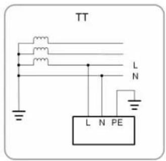
D Utility grid TT, TN-C, TN-S, TN-C-S.
E Loads House loads that consume electricity.
The following figure shows the common grid configurations.


S005-G002
2.2 Product Introduction
MMooddeell DDeessccrriippttiioonn
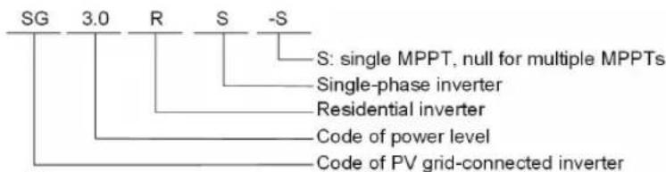
The model description is as follows (take SG3.0RS-S as an example):
S005-G003
Apppeeaaraannccee
The following figure shows the dimensions of the inverter. The image shown here is for reference only. The actual product received may differ.

S005-G004
FFiigguurree 22--22 Inverter Appearance
| NNoo.. NNaammee | DDeessccrriippttiioonn | |
| 1 Label | Information about COM2 pin definition, supported DRM modes, etc. | |
| 2 | Hanger | Complement to the included wall mounting bracket for hanging the inverter. |
| 3 | LED pannel | The LED screen indicates the running information and the LED indicator indicates the working state of the inverter. |
| 4 | Nameplate | To clearly identify the product, including device model, S/N, important specifications, marks of certification institutions, etc. |
| 5 | Electrical connection area | DC terminals (SG6.0RS for example), AC terminal, additional grounding terminal and communication terminals. |
| 6 DC switch | To safely disconnect the DC circuit whenever necessary. | |
DDiimmeennssiioonns
The following figure shows the dimensions of the inverter.

FFiigguurree 22--33 Dimensions of the Inverter
| Inverter Model | W (mm) | H (mm) | D (mm) |
| SG2.0RS-S, SG2.5RS-S, SG3.0RS-S | 320 | 225 | 123 |
| SG3.0RS, SG3.6RS, SG4.0RS, SG5.0RS, SG6.0RS | 410 | 270 | 149 |
2.3 Symbols on the Product
| Symbol | Explanation |
 | Parameters on the DC side. |
 | Parameters on the AC on-grid side. |
 | Regulatory compliance mark. |
 | TÜV mark of conformity. |
 | CE mark of conformity. |
 | Do not dispose of the inverter together with household waste. |
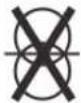 | The inverter does not have a transformer. |
 | Disconnect the inverter from all the external power sources before maintenance! |
 | Read the user manual before maintenance! |
Burn danger due to the hot surface that may exceed 60° C.

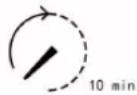
Danger to life due to high voltages!
Do not touch live parts for 10 minutes after disconnection from the power sources.
Only qualified personnel can open and maintain the inverter.

Additional grounding point.
* The table shown here is for reference only. The actual product received may differ.
2.4 LED Panel
The LED panel with a display screen and an indicator is on the front of the inverter.
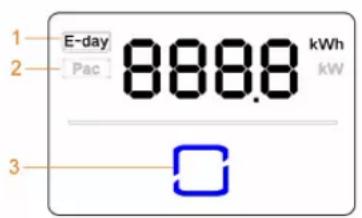
(a)
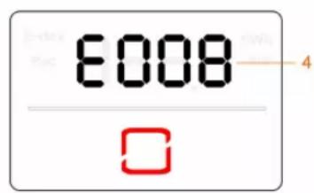
(b)
FFiigguurree 22--44 LED Panel
(a) Normal state
(b) Error state
| Noo.. | NaammeeDeessccrriippttiioonn | |
| 1 | E-day | Today's energy yield. |
| 2 | Pac | Current AC power. |
| 3 | LED indicator | To indicate the working state of the inverter.Touch it to switch the information in normal state or view multiple error codes in error state. |
| 4 | Error code | The error code in the figure is just an example. |
- In normal state, the E-day and Pac information will be displayed alternately. Also you can touch the LED indicator to switch the information.
• In error state, touch the LED indicator to view multiple error codes. - If there is no operation for 5 minutes, the display screen will be off. Touch the LED indicator to activate it.
Table 2-1 State description of the LED indicator
| LLEEDD ccoolloorr SStaattee DDeeffiinniittioonn | ||
 | On | The inverter is operating normally. |
| Flashing | The inverter is at standby or startup state (not feeding power into the grid). | |
| Blue | ||
 | On | A system fault has occurred. |
| Red | ||
 | Off | Both the AC and DC sides are powered down. |
| Gray | ||
2.5 Circuit Diagram
The following figure shows the main circuit of the inverter.
![graph LR DC1["DC Switch"] --> DCSPD["DC SPD"] DC2["DC2"] --> DCSPD DCSwitch["DC Switch"] --> DCEMIFilter["DC EMI Filter"] DCSwitch --> MPPT1["MPPT1 (Boost1)"] DCSwitch --> MPPT2["MPPT2 (Boost2)"] MPPT1 --> DCBus["DC Bus"] MPPT2 --> DCBus DCBus --> InverterCircuit["Inverter Circuit (DC/AC)"] Inverter…](/content/2026/07/1408664/images/0579d2df02fd465f0d829f9d0e9b010550bd497c1e15fdf26881ca95432e3195.jpg)
Figure 2-5 Circuit Diagram (SG6.0RS for example)
- The DC switch is used to safely disconnect the DC circuit.
- The MPPT is utilized for DC input to ensure the maximum power from the PV array at different PV input conditions.
- The inverter circuit converts the DC power into AC power and generates AC power to loads or utility grid through the AC terminal.
• The protection circuit ensures the safe operation of the device and personal safety.
2.6 Function Description
The inverter converts the DC power from the PV array to the AC power, in conformity with the grid requirements.
- Data storage
The inverter logs running information, error records, etc.
• Parameter configuration
The inverter provides various parameter configurations for optimal operation.
Parameters can be set via the iSolarCloud App or the cloud server. For further configurations, which exceeds the usual parameters configuration, please contact Sungrow.
- Communication interface
The inverter is equipped with two communication interfaces. The communication device can be connected to the inverter via both interfaces.
After communication connection is established, users can view inverter information, operational data and can set inverter parameters through the iSolarCloud.

It is recommended to use the communication module from SUNGROW. Using a device from other companies may lead to communication failure or other unexpected damage.
- Protection Function
Several protective functions are integrated in the inverter, including short circuit protection, grounding insulation resistance monitoring, residual current protection, grid monitoring, DC overvoltage/overcurrent protection, etc.
DRM ("AU"/"NZ")
The DRM function is only applicable to a single inverter.
The inverter provides terminals for connecting to a Demand Response Enabling Device (DRED). After the connection, the DRED asserts demand response modes (DRMs). The inverter detects and initiates a response to all supported demand response modes listed in the following table.
Table 2-2 Demand Response Mode Explanation
| Mooddee | EExxppllaannaattiioonn |
| DRMO | The inverter is in the state of standby. |
EExxppoorrtt PPoowweerr LLiimmiitt
Set the export power limit value via iSolarCloud App. When the smart energy meter detects that the export power is greater than the limit value, the inverter will reduce the output power within the specified range.
PPIID RReeccovveerryy
The inverter is equipped with PID phenomenon recovery function to improve the PV power generation. During the power generation process, the inverter could carry out a main Anti-PID function without any influence to the grid side thanks to a particular technology.
The PID recovery function is disabled by default. Enable the function via iSolarCloud App when there is PV power in the daytime. During the inverter standby process with no irradiance, an additional PID recovery function could apply inverse voltage to PV modules, to restore the degraded modules.
![graph LR A["PV Strings"] --> B["Inverter"] B --> C["Grid"] D["Raise the potential between the negative pole of PV array and earth"] --> B](/content/2026/07/1408664/images/278b535c2fade1c86d349ec2954ac374b117afafec91793d91b92135c95cd2cc.jpg)
Figure 2-6 PID Recovery Scheme
! DANGER
Keep the DC switch "ON" in the PID recovery process. During the process, this is voltage hazard between inverter/PV module live conductors and ground. Do not touch any of them.
3 Unpacking and Storage
3.1 Unpacking and Inspection
The device is thoroughly tested and strictly inspected before delivery. Nonetheless, damage may still occur during shipping. For this reason, please conduct a thorough inspection after receiving the device.
- Check the packing case for any visible damage.
- Check the scope of delivery for completeness according to the packing list.
- Check the inner contents for damage after unpacking.
Contact SUNGROW or the transport company in case of any damage or incompleteness, and provide photos to facilitate services.
Do not dispose of the original packing case. It is recommended to store the device in the original packing case when the device is decommissioned.
3.2 Inverter Storage
Proper storage is required if the inverter is not installed immediately.
- Store the inverter in the original packing case with the desiccant inside.
- The storage temperature must be always between -30°C and +70°C , and the storage relative humidity must be always between 0 and 95% , non-condensing.
- In case of stacking storage, the number of stacking layers should never exceed the limit marked on the outer side of the packing case.
- The packing case should be upright.
- If the inverter has been stored more than half a year, the qualified personnel should thoroughly check and test it before installation.
4 Mechanical Mounting
4.1 Safety during Mounting
! DANGER
Make sure there is no electrical connection before installation.
In order to avoid electric shock or other injury, make sure that holes will not be drilled over any electricity or plumbing installations.
CAUTION
Risk of injury due to improper handling
• Always follow the instructions when moving and positioning the inverter.
- Improper operation may cause injuries or serious wounds.
In the case of poor ventilation, the system performance may compromise.
- Keep the heat sinks uncovered to ensure heat dissipation performance.
4.2 Location Requirements
Select an optimal mounting location for safe operation, long service life and expected performance.
- The inverter with protection rating IP65 can be installed both indoors and outdoors.
• Install the inverter at a place convenient for electrical connection, operation, and maintenance.


S005-1001
4.2.1 Environment Requirements
- The installation environment must be free of inflammable or explosive materials.
• The location should be not accessible to children.
- The ambient temperature and relative humidity must meet the following requirements.

- Avoid direct exposure to sun, rain and snow.
• The inverter should be well ventilated. Ensure air circulation.
- Never install the inverter in living areas. The inverter will generate noise during operation, affecting daily life.
4.2.2 Carrier Requirements
The concrete wall should be capable of withstanding a force of four times the weight of the inverter and be suitable for the dimensions of the inverter.
The installation carrier should meet the following requirements:
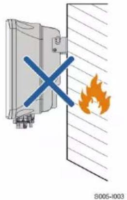
4.2.3 Angle Requirements
Install the inverter vertically. Never install the inverter horizontally, or at forward/backward tilted, side tilted, or upside down.
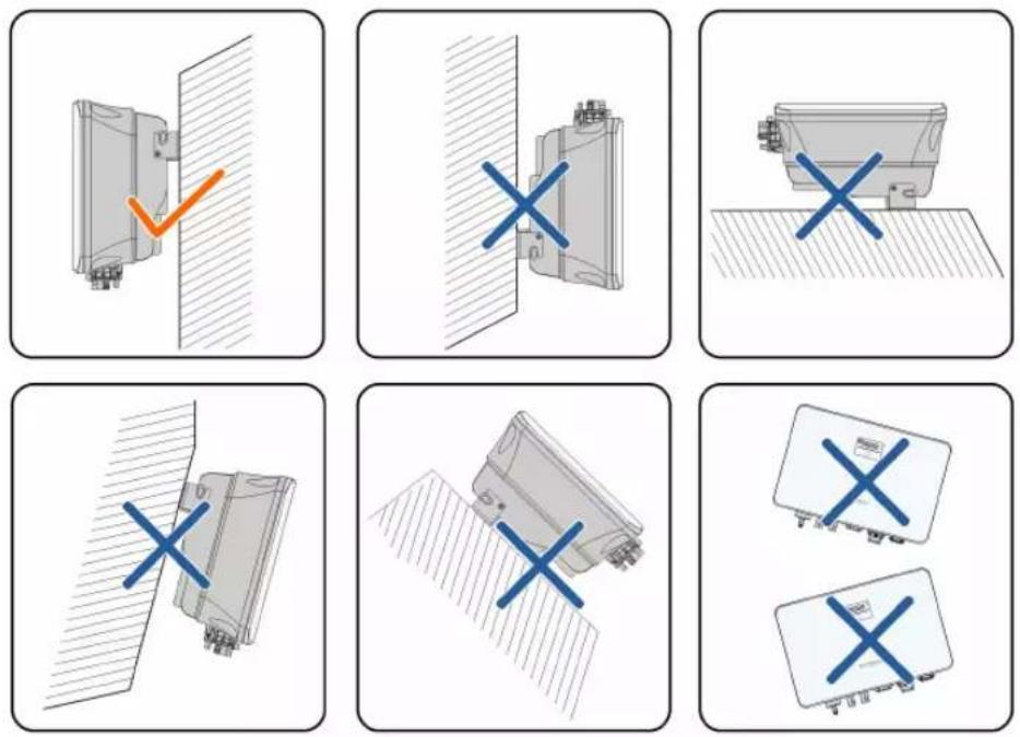
S005-1004
4.2.4 Clearance Requirements
Reserve enough clearance around the inverter to ensure sufficient space for heat dissipation.

Install the inverter at an appropriate height for ease of viewing the screen and LED indicator and operating switch(es).
4.3 Installation Tools
Installation tools include but are not limited to the following recommended ones. If necessary, use other auxiliary tools on site.
Table 4-1 Tool specification

Multimeter ( 600
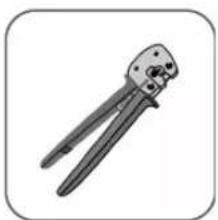
MC4 terminal crimping tool (4 mm² - 6 mm²)
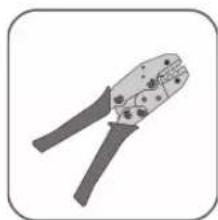
Tube terminal crimping tool (0.5 mm 2 -1.0 mm 2 )
4.4 Moving the Inverter
Before installation, remove the inverter from the packing case and move it to the installation site. Follow the instructions below as you move the inverter:
• Always be aware of the weight of the inverter.
- Lift the inverter using the handles positioned on both sides of the inverter.
- Move the inverter by one or two people or by using a proper transport tool.
- Do not release the equipment unless it has been firmly secured.
4.5 Installing the Inverter
Inverter is installed on the wall by means of wall-mounting bracket and the expansion plug sets.
The expansion plug set shown below is recommended for the installation.

(1) Self-tapping screw M6
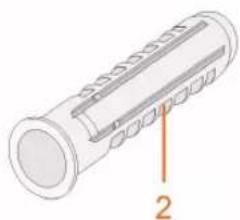
(2) Expansion tube

(3) Fender washer

(4) Spring washer
Step 1 Place the wall-mounting bracket to a proper position on the wall. Mark the positions and drill the holes.
NOTICE
Observe the level on the bracket and adjust until the bubble is in the midd position.
The depth of the holes should be about 70 mm.

Step 2 Place the expansion tubes into the holes. Then secure the wall-mounting bracket to the wall firmly with the expansion bolt sets.

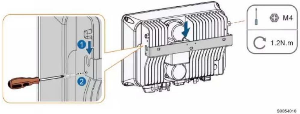
Step 3 Lift the inverter and slide it down along the wall-mounting bracket to make sure they match perfectly. Use two screw sets to lock both left and right sides.
-- -- EEnndd
5 Electrical Connection
5.1 Safety Instructions
Prior to any electrical connections, keep in mind that the inverter has dual power supplies. It is mandatory for the qualified personnel to wear personal protective equipments (PPE) during the electrical work.
! DANGER
Danger to life due to a high voltage inside the inverter!
- The PV string will generate lethal high voltage when exposed to sunlight.
- Before starting electrical connections, disconnect the DC and AC circuit breakers and prevent them from inadvertent reconnection.
- Ensure that all cables are voltage free before performing cable connection.
WARNING
- Any improper operations during cable connection can cause device damage or personal injury.
- Only qualified personnel can perform cable connection.
- All cables must be undamaged, firmly attached, properly insulated and adequately dimensioned.
NOTICE
Comply with the safety instructions related to the PV strings and the regulati related to the utility grid.
- All electrical connections must be in accordance with local and national standards.
- Only with the permission of the local utility grid company, the inverter can connected to the utility grid.
5.2 Terminal Description
All electrical terminals are located at the bottom side of the inverter.

FFiigguurree 55--11 Terminals (SG3.0RS for example)
* The image shown here is for reference only. The actual product received may differ.
Table 5-1 Terminal Description
| NNoo.. NNaammee | DDeessccrriippttiioonn | DDeecciisiivveeVoollttaaggeeCCllaassssiifficcaattiioonn | |
| 1 | PV1+, PV1-, PV2+, PV2- | MC4 terminals for PV input.The terminal number depends on inverter model. | DVC-C |
| 2 | COM1 | Communication accessory port to be connected to WiNet-S communication module. | DVC-A |
| 3 | COM2 | Communication connection for RS485, DRM and smart energy meter. | DVC-A |
| 4 | GRID | AC terminal to connect to the grid | DVC-C |
| 5 | Additional grounding terminal. | Not applicable | |
The pin definition of COM2 terminal is shown in the following label.
| RS485 | Meter | DRM | RSD |
| A1 | A2 | R | RSD-1 |
| B1 | B2 | C | RSD-2 |
FFiigguurre 55--22 Label of COM2 Terminal
Table 5-2 Label Description of COM2 Terminal
| LLaabbeell | Description | |
| RS485 | A1, B1 | Reserved |
| Meter | A2, B2 | For the smart energy meter |
| LLaabbeell | DDeessccrriippttiioonn | |
| DRM | R, C | For external Demand Response Enabling Device ("AU"/"NZ") |
| RSD | RSD-1, RSD-2 | Reserved |
5.3 Electrical Connection Overview
The electrical connection should be realized as follows:
![graph TD A["Solar Panel"] -->|1| B["Home"] B -->|2| C["Grid"] B -->|3| D["Power Supply Unit"] B -->|4| E["Grid"] B -->|5| F["Grid"] C --> G["Computer"] D --> H["Grid"] E --> I["Grid"] F --> J["Grid"] G --> K["Power Supply Unit"] H --> L["Grid"] I --> M["Grid"] N["Grid"] --> O["Power Supply Unit"] P[…](/content/2026/07/1408664/images/c831fa36858d6b0c6f17e6f05ff9ec3381baf40ff588a92568b6eca0d8dec61e.jpg)
(A) PV string (B) Inverter (C) Loads
(D) Grid (E) Smart energy meter (optional)
(F) AC circuit breaker (G) External device
Table 5-3 Cable Requirements
| NNoo. | CCaabbllee | TTyyppee | CCAabbllee | DDiiaametteer | Wiirree CCoonndduucctoorrCCrroossss-sseecctioonn |
| 1 | DC cable | Single or multi-core copper wire complying with 600 V and 20 A standard | 6 mm-9 mm | 4 m 2 mm 6 mm 2 | |
| 2 | Ethernet cable | CAT 5E outdoor shielded network cable | 5.3 mm-7 mm | 8 * 0.2 mm | |
| 3 | Meter RS485 cable (1) | Shielded twisted pair | 5.0 mm-6.0 mm | 2 * (0.5-1.0) mm 2 | |
| NNoo.. | CCaabblee | TTyyppee | CCaabblee | DDiiaammeetteerr | WWiirree CCoonndduuccttoorrCCrroossss--sseeccttiioonn |
| 4 | AC cable (2) | Outdoor 3-core copper wire cable | 12 mm - 25 mm | 4 mm 2 - 6 mm 2 | |
| 5 | Additional Grounding cable | Outdoor single-core copper wire cable | The same as that of the PE wire in the AC cable | ||
(1) The cable requirements for COM2 terminal connection are the same.
(2) All the AC wires should be equipped with correctly colored cables for distinguishing.
Please refer to related standards about the wiring color.
5.4 Additional Grounding Connection
! WARNING
- Since the inverter is transformerless, neither the negative pole nor the positive pole of the PV string must be grounded. Otherwise, the inverter will not operate normally.
- Connect the additional grounding terminal to the protective grounding point before AC cable connection, PV cable connection, and communication cable connection.
- The ground connection of this additional grounding terminal cannot replace the connection of the PE terminal of the AC cable. Make sure those terminals are both grounded reliably. SUNGROW shall not be held liable for any damage caused by the violation.
5.4.1 Additional Grounding Requirements
All non-current carrying metal parts and device enclosures in the PV power system should be grounded, for example, mounts of PV modules and the inverter enclosure.
When there is only one inverter in the PV system, connect the additional grounding cable to a nearby grounding point.
When there are multiple inverters in the PV system, connect grounding points of all inverters and the PV array frames to the equipotential cable (according to the onsite conditions) to implement an equipotential connection.
5.4.2 Connection Procedure
Additional grounding cable and OT/DT terminal are prepared by customers.
Step 1 Prepare the cable and OT/DT terminal.

(1) Heat shrink tubing
(2) OT/DT terminal
Step 2 Remove the screw on the grounding terminal and fasten the cable with a screwdriver.

Step 3 Apply paint to the grounding terminal to ensure corrosion resistance.
-- -- EEnndd
5.5 AC Cable Connection
5.5.1 AC Side Requirements

Connect the inverter to the grid only after getting an approval from the local electric power company.
Before connecting the inverter to the grid, ensure the grid voltage and frequency comply with requirements, for which, refer to "Technical Date". Otherwise, contact the electric power company for help.
An independent two-pole circuit breaker must be installed on the output side of the inverter to ensure safe disconnection from the grid. The recommended specifications are as follows.
| llnnvveerrtteerr Mooddeell | Recommended Specification |
| SG2.0RS-S/SG2.5RS-S/SG3.0RS-S | 25 A |
| SG3.0RS/SG3.6RS/SG4.0RS/SG5.0RS | 32 A |
| SG6.0RS | 40 A |
NOTICE
- Determine whether an AC circuit breaker with greater overcurrent capacity is required based on actual conditions.
- Multiple inverters cannot share one circuit breaker.
- Never connect a load between the inverter and the circuit breaker.
With an integrated universal current-sensitive residual current monitoring unit included, the inverter will disconnect immediately from the mains power once a fault current with a value exceeding the limit is detected.
However if an external residual current device (RCD) is mandatory, the switch must be triggered at a residual current of 300 mA (recommended), or it can be set to other values according to local regulations. For example in Australia, the inverter can use an additional 30 mA (type A) RCD in installations.
5.5.2 Assembling the AC Connector
Step 1 Unscrew the swivel nut of the AC connector.
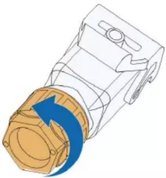
S000-E047
Step 2 Thread the AC cable of appropriate length through the swivel nut, the sealing ring and the housing.

S000-E049
Step 3 Remove the cable jacket by less than 45 mm, and strip the wire insulation by 12 mm-16 mm.

S000-E050
Step 4 Open the clamp on the spring-loaded terminal and fully insert the wires into the corresponding holes. Then close the clamp and push the terminal plug into the housing until there is an audible click.
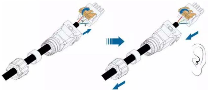
S000-E051
NOTICE
Observe the plug assignment.
- Do not connect the L line to the "PE" terminal or the PE wire to the "N" terminal. Otherwise, unrecoverable damage to the inverter may follow.
- Do not connect the L line and the N line in reverse, otherwise the inverter may not operate normally.
Step 5 Ensure that the wires are securely in place by slightly pulling them. Tighten the swivel nut to the housing.

-- -- EEnndd
5.5.3 Installing the AC Connector
! DANGER
High voltage may be present in inverter!
Ensure all cables are voltage-free before electrical connection.
Do not connect the AC circuit breaker until all inverter electrical connections are completed.
Step 1 Disconnect the AC circuit breaker and secure it against reconnection.
Step 2 Lift the locking part upwards and insert the AC connector into the GRID terminal on the bottom side of the inverter. Then press the locking part and lock it with the screw.

S005-E006
Step 3 Connect the PE wire to ground and the phase lines and the “N” line to AC circuit breaker. Then Connect the AC circuit breaker to electric board.
Step 4 Make sure all wires are firmly installed via the right torque tool or dragging the cables slightly.
-- -- EEnndd
5.6 DC Cable Connection
! DANGER
Danger of electric shock!
The PV array will generate lethal high voltage once exposed to sunlight.
WARNING
Make sure the PV array is well insulated to ground before connecting it to inverter.
NOTICE
Risk of inverter damage! Observe the following requirements. Failure to do so will void guarantee and warranty claims.
- Make sure the maximum DC voltage and the maximum short circuit current of any string never exceed inverter permitted values specified in "Technical Data".
- Mixed use of different brand or model of PV modules in a PV string or compromised PV string design composed with PV modules from rooftops of different orientation may not damage inverter but will cause system bad performance!
- The inverter enters standby state when the input voltage ranges between 560 V and 600 V. The inverter returns to running state once the voltage returns to the MPPT operating voltage range, namely, 40 V to 560 V.
5.6.1 PV Input Configuration
- The inverters SG2.0RS-S / SG2.5RS-S / SG3.0RS-S have one PV input with one MPP tracker.
- The inverters SG3.0RS / SG3.6RS / SG4.0RS / SG5.0RS / SG6.0RS have two PV inputs, each with independent MPP tracker. Each DC input area can operate independently.
- The PV strings to the same DC input area should have the same type, the same number of PV panels, identical tilt and identical orientation for maximum power.
- The PV strings to two DC input areas may differ from each other, including PV module type, number of PV modules in each string, angle of tilt, and installation orientation.
![graph LR A["Top Unit 1"] --> B["Top Unit 2"] B --> C["Top Unit 3"] C --> D["Output Module MDP-1"] D --> E["Output Module MDP-2"] F["Bottom Unit 1"] --> G["Bottom Unit 2"] G --> H["Bottom Unit 3"] H --> I["Output Module MDP-2"] I --> J["Output Module MDP-1"]](/content/2026/07/1408664/images/3e15df76b9ee0fdbbf19cfbf6bf426cdcc80de81e56f0e851fa42626c764ce88.jpg)
FFiigguurree 55--33 PV Input Configuration (SG6.0RS for example)
Prior to connecting the inverter to PV inputs, the specifications in the following table should be met:
| Innveerrtteerr | Open deiquit Voltage Limit | Max. current for input connector |
| All models | 600 V | 20 A |
5.6.2 Assembling the PV Connectors
! DANGER
High voltage may be present in the inverter!
- Ensure all cables are voltage-free before performing electrical operations.
- Do not connect the AC circuit breaker before finishing electrical connection.

SUNGROW provides corresponding PV connectors in the scope of delivery for quick connection of PV inputs. To ensure IP65 protection, use only the supplied connector or the connector with the same ingress of protection.
Step 1 Strip the insulation from each DC cable by 7 mm - 8 mm.

Step 2 Assemble the cable ends with the crimping pliers.

1: Positive crimp contact 2: Negative crimp contact
Step 3 Lead the cable through cable gland, and insert the crimp contact into the insulator until it snaps into place. Gently pull the cable backward to ensure firm connection. Tighten the cable gland and the insulator (torque 2.5 N.m to 3 N.m).

Step 4 Check for polarity correctness.
NOTICE
If the PV polarity is reversed, the inverter will be in a fault or alarm state not operate normally.
-- -- EEnndd
5.6.3 Installing the PV Connectors
Step 1 Rotate the DC switch to "OFF" position.

S005-E032
Step 2 Check the cable connection of the PV string for polarity correctness and ensure that the open circuit voltage in any case does not exceed the inverter input limit of 600 V.

Step 3 Connect the PV connectors to corresponding terminals until there is an audible click.

NOTICE
- Check the positive and negative polarity of the PV strings, and connect the PV connectors to corresponding terminals only after ensuring polarity correctness.
- Electric arc or contactor overtemperature may occur if the PV connectors are not firmly in place, and SUNGROW shall not be held liable for any damage caused due to this operation.
Step 4 Seal the unused PV terminals with the terminal caps.
-- -- EEnndd
5.7 WiNet-S Connection
The WiNet-S module supports Ethernet communication and WLAN communication. It is not recommended to use both communication methods at the same time.
For details, see the quick guide for the WiNet-S module. Scan the following QR code for the quick guide.

5.7.1 Ethernet Communication
Step 1 (Optional) Strip the insulation layer of the communication cable with an Ethernet wire stripper, and lead the corresponding signal cables out. Insert the stripped communication cable into the RJ45 plug in the correct order, and crimp it with a crimper.

1: RJ45 plug

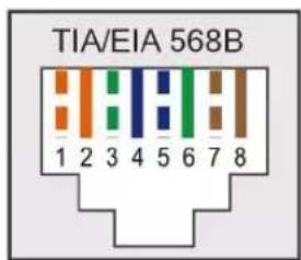
2: Protective cap

Skip this step if a standard network cable with RJ45 plug is prepared.
Step 2 Unscrew the swivel nut from the communication module and take out the inner sealing ring.

Step 3 Unscrew the housing from the communication module.

Step 4 Thread the network cable through the swivel nut and gasket. Afterwards, route the cable into the opening of the sealing. Finally, insert the cable through the housing.
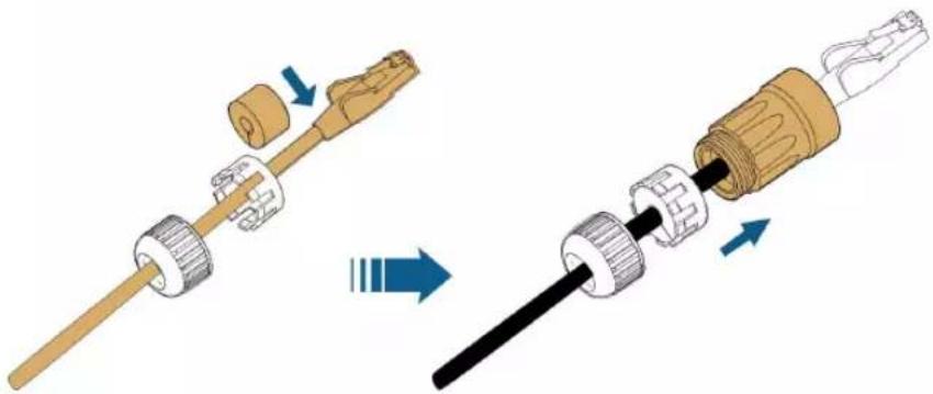
Step 5 Insert the RJ45 plug into the front plug connector until there is an audible click and tighten the housing. Install the gasket and fasten the swivel nut.

Step 6 Remove the waterproof lid from the COM1 terminal and install WiNet-S.

Step 7 Slightly shake it by hand to determine whether it is installed firmly.
-- -- EEnndd
5.7.2 WLAN Communication
Step 1 Remove the waterproof lid from the COM1 terminal.
Step 2 Install the module. Slightly shake it by hand to determine whether it is installed firmly, as shown below.

Step 3 Refer to the guide delivered with the module for the set-up.
-- -- EEnndd
5.8 Meter Connection
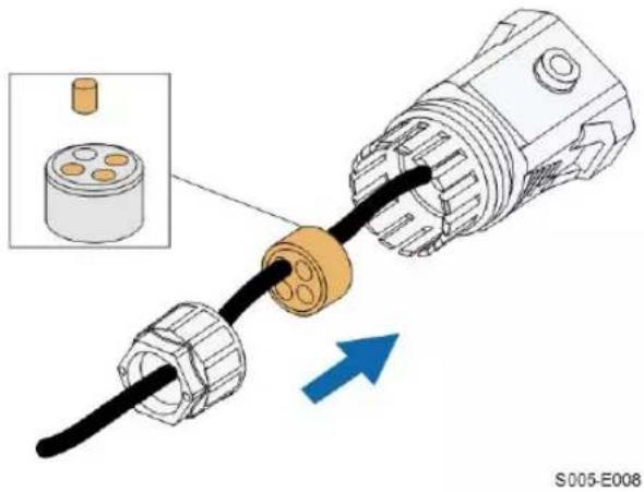
Step 1 Unscrew the swivel nut from the communication connector.

S005-E007
Step 2 Remove the seal and lead the cable through the cable gland.
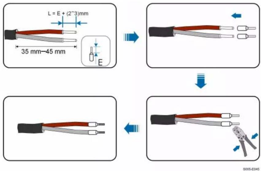
Step 3 Remove the cable jacket and strip the wire insulation.

Step 4 (Optional) When using a multi-core multi-strand wire cable, connect the wire head to the cord end terminal. In case of single-strand copper wire, skip this step.
Step 5 Plug the wires into the corresponding terminals as shown in the following figure. Ensure that the wires are securely in place by slightly pulling them.

Step 6 Insert the terminal plug into the COM2 terminal at the bottom side of the inverter and then install the housing.

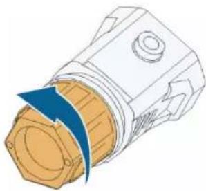
Step 7 Slightly pull out the cable and then fasten the swivel nut. Lock the connector with the screw.

-- -- EEnndd
5.9 DRM Connection
In Australia and New Zealand, the inverter supports DRM0 as specified in the standard AS/NZS 4777.
The DRM0 mode is asserted by shorting terminals R and C on the inverter.
Step 1 Unscrew the swivel nut from the communication connector.
S005-E007
Step 2 Remove the seal and lead the cable through the cable gland.

Step 3 Remove the cable jacket and strip the wire insulation.

C = 0. 5 mm ^ 2: D 2. 6 mm
C = 1. 0 mm ^ 2: D 2. 8 mm
S005-E044
Step 4 (Optional) When using a multi-core multi-strand wire cable, connect the wire head to the cord end terminal. In case of single-strand copper wire, skip this step.

Step 5 Plug the wires into the corresponding terminals as shown in the following figure. Ensure that the wires are securely in place by slightly pulling them.

Step 6 Insert the terminal plug into the COM2 terminal at the bottom side of the inverter and then install the housing.
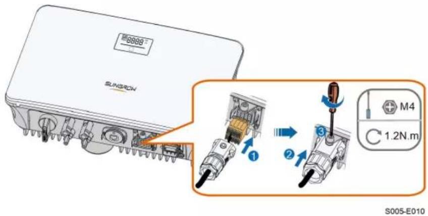
Step 7 Slightly pull out the cable and then fasten the swivel nut. Lock the connector with the screw.

-- -- EEnndd
6 Commissioning
6.1 Inspection before Commissioning
Check the following items before starting the inverter:
- All the installation sites are convenient for operation, maintenance and service.
- All devices are firmly installed.
• Space for ventilation is sufficient for one inverter or multiple inverters. - Nothing is left on the top of the inverter.
- The inverter and accessories are correctly connected.
- Cables are routed safely and protected against mechanical damage.
- The selection of the AC circuit breaker is in accordance with this manual and all applicable local standards.
- All unused terminals at the bottom of the inverter are properly sealed.
- Warning signs & labels are intact and legible.
6.2 Powering on the System
If all of the items mentioned above meet the requirements, proceed as follows to start up the inverter for the first time.
Step 1 Turn on the AC circuit breaker between the inverter and the grid.
Step 2 Rotate the DC switch of the inverter to "ON" position.
Step 3 Turn on the external DC switch (if applicable) between the inverter and the PV string.
Step 4 If the irradiation and grid conditions meet requirements, the inverter will operate normally. Observe the LED indicator to ensure that the inverter operates normally. Refer to "2.4 LED Panel" for LED screen introduction and LED indicator definition.
Step 5 Refer to the quick guide for WiNet-S for its indicator definition.
-- -- EEnndd
6.3 App Preparation
Step 1 Install the iSolarCloud App with latest version. Refer to "7.2 Installing the App".
Step 2 Register an account. Refer to "7.3 Account Registration". If you have got the account and password from the distributor/installer or SUNGROW, skip this step.
Step 3 Download the firmware package to the mobile device in advance. Refer to "7.10.5 Firmware Update". This is to avoid download failure due to poor on-site network signal.
-- -- EEnndd
6.4 Creating a Plant
Screenshots of creating a plant are for reference only. For details, refer to the actual screen.
Step 1 Open the App, tap at the upper right corner and tap Select Server. Choose the same server as when registering.

FFiigguurree 66--11 Selecting the Server
Step 2 Enter the account and password on the login screen and tap Login to enter the App home screen.
Step 3 Tap the icorat the upper right corner to enter the creating screen.

FFigguurree 6--22 Creating Power Plant
Step 4 Select plant type to RESIDENTIAL and inverter type to PV.


FFiigguurree 66--33 Selecting Plant/Inverter Type
Step 5 Scan the QR code on the communication device or manually enter the serial number of the communication device. Tap Next after the QR code is identified or the serial number entered is correct and then tap CONFIRM. Your mobile device is thus connected to the WiNet-S successfully.
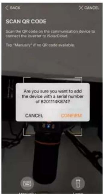
FFiigguurree 66--44 Connecting Mobile Device to WiNet-S
Step 6 Select the Internet access mode to WLAN(CONNECTED) or ETHERNET according to actual connection. The following description is for WLAN access mode.

Figure 6-5 Selecting Internet Access Mode
Step 7 The EASYCONNECT INSTRUCTION screen will prompt. Press the multi-function button on the WiNet-S module once to turn on EasyConnect mode. The WLAN indicator
on WiNet-S blinks quickly when this mode is turned on. Return to the App and the screen displays successful connection to the inverter WLAN. Tap NEXT.

FFiigguurree 66--66 Turn on EasyConnect Mode
NOTICE
The EasyConnect mode can be used only when the router is 2.4 GHz. If the EasyConnect mode fails, refer to the WiNet-S quick guide for the instructions of other modes.
Step 8 Connect the inverter to router network. Enter network name and password. Tap NNEEXXTT and the screen display prompt information of successful connection to the router network.

FFiigguurree 66--77 Connecting Inverter to Router Network
-- - EEnndd
6.5 Initializing the Device
The inverter is successfully connected to the router.
If there is no latest equipment upgrade package, skip steps 1 and 2.
The actual initializing procedure may differ due to different countries. Please follow the actual App guidance.
Step 1 If a latest equipment upgrade package is available, the following prompt window pops up. Tap UPDATE NOW to download the latest update package.

FFiigguurree 66--88 Upgrade Reminder
Step 2 After download, it would take around 15 minutes to update. After successful upgrade, the screen will show the version numbers before and after the upgrade as well as the upgrade time. Tap NNEEXXTT.

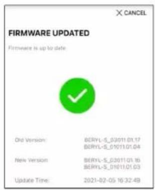
FFiigguurree 66--99 Upgrading Inverter
NOTICE
If the communication equipment is upgraded, after successful upgrade, check and confirm that the phone is connected to the inverter WLAN.
Step 3 Tap Country/Region and select the country where the inverter is installed at. The supported countries and corresponding settings are as follows.
| Country/Region | Setting |
| Belgium ("BE") | Belgium |
| Netherlands ("NL") | Netherlands |
| Portugal / Turkey / Hungary | EN50549-1 |
| Australia ("AU") | Australia |
| New Zealand ("NZ") | New Zealand |
| Countries not listed above | Other 50Hz or Other 60Hz |
NOTICE
The parameter Country/Region must be set to the country (region) where the inverter is installed at. Otherwise, the inverter may report errors.
Step 4 When the country is set to Australia, additionally set the applicable network service provider and then the grid type.

The image shown here is for reference only. Refer to the actual interface for the supported network service providers.
Table 6-1 Description of Network Service Provider and Grid Type
| Network Service Provider | Grid Type |
| AS/NZS 4777.2:2015 | / |
| ENERGEX & Ergon Energy | • STNW1170: single-phase < 10 kVA & three-phase < 30 kVA• STNW1174: 30 kVA < Pn ≤ 1500 kVA |
| Jemena | • ≤ 10 kVA per phase (or 30 kVA per three phase)• ELE GU 0014: 30 kVA-200 kVA |
| Endeavour Energy | MDI 0043 |
| Ausgrid | NS194 |
| CitiPower & Powercor | • ≤ 5 kVA for single-phase & 30 kVA for three-phase• > 30 kVA three-phase |
| NNeettwwoorkk SSeerrvviiccee PPrroovviiddeerr GGrriidd TTyyppee | |
| United Energy | • UE-ST-2008.1: ≤ 10 kVA for single-phase & 30 kVA for three-phase• UE-ST-2008.2: > 30 kVA three-phase |
| PowerWater | AS/NZS 4777.2:2015 |
| SA Power Networks | • TS129-2019: < 10 kW for single-phase & 30 kW for three-phase• TS130-2017: > 30 kW & ≤ 200 kW• TS131-2018: > 200 kW |
Step 5 Initialize parameters according to local grid requirements, including grid type, reactive power regulation mode, etc. The screen displays that the inverter is successfully configured.

Figure 6-10 Initializing Parameters
-- EEnndd
6.6 Configuring the Plant
The inverter is successfully added to the plant and initialized. Refer to the guidance in previous sections.
The distributor/installer who creates a plant for the end user needs to get the end user's e-mail address. In configuring a plant, the e-mail address is required, and each e-mail address can be registered only once.
Step 1 The App screen will display the added inverter. Tap NEXT to configure the plant.

FFiigguurree 66--1111 Display the Added Inverter
Step 2 Fill in the plant information. The fields marked with * must be filled in.
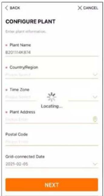
FFiigguurree 66--1122 Entering Plant Information
Step 3 (Optional) Fill in the tariff information. The electricity price can be set to a specific value or Time-of-Use tariff.

FFiigguurree 66--1133 Entering Tariff Information
Step 4 Fill in the end user's e-mail address. The first time you fill in the end user's e-mail address, the system will create an account for the end user and send an email to the end user. The end user can activate the account via the email.

The Distributor/installer creates plants for the end user and can manage the plants by default.
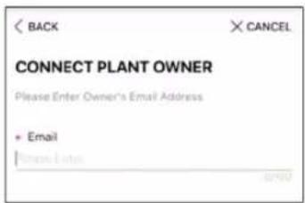
FFiigguurree 66--1144 Entering Owener's e-mail
Step 5 Tap NEXT to wait for the inverter to connect to the iSolarCloud.

FFiigguurree 66--1155 Configuration Completed
Step 6 (Optional) Tab View live data for the device, tick Inverter or Total Plant Devices and tab ALL PLANTS OPEN. The clock symble indicates that the live data view function is successfully enabled. Tab the inverter to view the live data about voltage, current, power or curve.


FFiigguurre 66--1166 Live Data View Function Setting

Consult Sungrow service for the devices that support live data function.
Step 7 Tab BACK to the COMPLETED screen. Tab PDF REPORT to export the plant configuration report.
Step 8 Tab BACK to the COMPLETED screen. Tab DASHBOARD to return and manually refresh the page until the newly created plant is displayed with status commissioned.
-- -- EEnndd
7 iSolarCloud App
7.1 Brief Introduction
The iSolarCloud App can establish communication connection to the inverter via the WLAN, providing remote monitoring, data logging and near-end maintenance on the inverter. Users can also view inverter information and set parameters through the App.
* To achieve direct login via WLAN, the wireless communication module developed and manufactured by SUNGROW is required. The iSolarCloud App can also establish communication connection to the inverter via Ethernet connection.

- This manual describes only how to achieve near-end maintenance via WLAN direct connection.
- Screenshots in this manual are based on the V2.1.6 App for Android system, and the actual interfaces may differ.
7.2 Installing the App
MMeetthhoodd 11
Download and install the App through the following application stores:
- MyApp (Android, mainland China users)
- Google Play (Android, users other than mainland China ones)
- App Store (iOS)
MMeetthhoodd 22
Scan the following QR code to download and install the App according to the prompt information.

The App icon appears on the home screen after installation.

7.3 Account Registration
The account distinguishes two user groups, end user and distributor/installer.
- The end user can view plant information, create plants, set parameters, share plants, etc.
- The distributor/installer can help the end user to create plants, manage, install, or maintain plants, and manage users and organizations.
Step 1 Tap REGISTER to enter the registration screen.
Step 2 Select End user or Distributor/Installer to enter the corresponding screen.

Figure 7-1 Selecting User Group
Step 3 Fill in the registration information, including server selection, email, verification code, password and affirmance, country (region) and time zone. The distributor/installer has the permission to fill in the company name and the code of upper level distributor/installer.

The code of upper level distributor/installer can be obtained from the upper level distributor/installer. Only when your organization belongs to the upper level distributor/installer organization, can you fill in the corresponding code.
Step 4 Tick Accept privacy protocol and tap Register to finish the registration operation.
-- -- EEnndd
7.4 Login
7.4.1 Requirements
The following requirements should be met:
- The AC and DC sides or the AC side of the inverter is powered-on.
- The WLAN function of the mobile phone is enabled.
- The mobile phone is within the coverage of the wireless network produced by the communication module.
7.4.2 Login Procedure
Step 1 For the WiNet-S module, press the multi-function button 3 times to enable the WLAN hotspot. No password is required and the valid time is 30 minutes.

Figure 7-2 Enabling the WLAN Hotspot
Step 2 Connect the mobile phone to the WLAN network named as "SG-xxxxxxxxxxx" (-xxxxxxxxxx is the serial number indicated on the side of the communication module).
Step 3 Open the App to enter the login screen. Tap Local Access to enter the next screen.
Step 4 Select WLAN and select the device (SN), then enter the password and tap LOGIN.

The default account is "user" and the initial password is "pw1111" which should be changed for the consideration of account security. Tap "More" at the lower right corner on home page and choose "Change Password".
![graph TD A["Login Account"] --> B["LOCAL ACCESS WLAN"] B --> C["SELECT DEVICE A1503112556 User"] C --> D["BEGIN SEARCHING"] subgraph Login E["Password"] --> F["LOGIN"] G["REGISTER"] --> H["REGISTER"] I["Others"] --> J["Others"] K["Visitor Login"] --> L["Local Access"] end subgraph LOCAL ACCESS M["WL…](/content/2026/07/1408664/images/e1f36deeee1c93d59f4af19916be86d0b65ccf386037b3c5b4da8ca4c5405d49.jpg)
FFiigguurree 77--33 WLAN Local Access
Step 5 If the inverter is not initialized, navigate to the quick setting screen to initialize the protection parameters. For details, please refer to "Initial Settings".
NOTICE
The "Country/Region" must be set to the country where the inverter is install at. Otherwise, the inverter may report errors.

Figure 7-4 WLAN Local Access
Step 6 After finishing the settings, tap TUNR ON DEVICE at the upper right corner and the device will be initialized. The App will send start instructions and the device will start and operate.
Step 7 After initialization settings, the App will return automatically to the home page.
-- -- EEnndd
7.5 Initial Settings
Tap Country/Region and select the country where the inverter is installed. For countries except Australia and Germany, the initialization is completed.


The actual initializing procedure may differ due to different countries. Please follow the actual App guidance.
For some countries, you should initialize parameters according to local grid requirements. For details, see 6.5 Initializing the Device.
7.6 Function Overview
The App provides parameter viewing and setting functions, as shown in the following figure.
![graph TD A["iSolarCloud"] --> B["Home"] A --> C["Running Information"] A --> D["Records"] D --> E["Chart"] D --> F["Fault Alarm Record"] D --> G["Event Record"] A --> H["More"] H --> I["WLAN Configuration"] I --> J["Settings"] J --> K["System Parameters"] K --> L["Date"] K --> M["Time"] I --> N["Ope…](/content/2026/07/1408664/images/c0df85aeb18181ca628ec9f22664e02aee2bf75bd97fbec0df09d0edc77aa560.jpg)
FFiigguurree 77--55 App Key Function Menu
7.7 Home
Home page of the App is shown in the following figure.

FFiigguurree 77--66 Home
Table 7-1 Home Page Description
| NNoo.. | NNaammee | DDeessccrriippttiioonn |
| 1 | Inverter state | Present operation state of the inverter |
| 2 | Energy flow chart | Shows the PV power generation power, feed-in power, etc. The line with an arrow indicates energy flow between connected devices, and the arrow pointing indicates energy flow direction. |
| 3 | Real-time power | Shows the present output power of the inverter. |
| 4 | Nominal power | Shows the installed power of the inverter. |
| 5 | Today yield | Shows today power generation of the inverter |
| 6 | Total yield | Shows accumulative power generation of the inverter |
| 7 | Navigation bar | Includes menus of "Home", "Run Infomation", "Records" and "MMorree". |
If the inverter runs abnormally, the fault icon ⚠️ will appear on the upper left corner of the screen. Users can tap the icon to view detailed fault information and corrective measures.
7.8 Run Information
Tap Run Information on the navigation bar to enter the screen showing running information, slide the screen upwards to view all detailed information.
Table 7-2 Description of Run Information
| Iltteemm | DDeessccrriippttiioonn |
| PV information | Shows voltage and current of every PV string. |
| Inverter information | Shows basic information such as running state, on-grid running time, negative voltage to grid, bus voltage, internal air temperature, inverter efficiency, etc. |
| Input | Shows total DC power, voltage and current of MPPT1 and MPPT2. |
| Output | Shows daily/monthly/annual/total yield, total active/reactive/apparent power, total power factor, grid frequency, phase voltage and current. |
| Meter information | Shows active power and phase active power of the meter. |
7.9 Records
Tap Records on the navigation bar to enter the screen showing event records, as shown in the following figure.

Figure 7-7 Records
CChhaarrtt
Tap Chart to enter the screen showing daily power generation, as shown in the following figure.

FFiigguurree 77--88 Chart
The App displays power generation records in a variety of forms, including daily power generation graph, monthly power generation histogram, annual power generation histogram and total power generation histogram.
Table 7-3 Description of Power Curve
| Iltteemm | DDeessccrriippttiioonn |
| Daily | Daily curve that indicates the real-time power. |
| Month | Monthly curve that indicates daily yield and equivalent hours in a month. |
| Year | Annual curve that indicates monthly yield and equivalent hours in a year. |
| Total | A curve that indicates annual yield and equivalent hours since installation. |
Fault Alarm Record
Tap Fault Alarm Record to enter the screen, as shown in the following figure.

FFiigguurree 77--99 Fault Alarm Record

Click to select a time segment and view corresponding records.
Select one of the records in the list and click the record, to view the detailed fault info as shown in following figure.
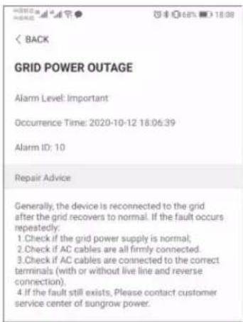
FFiigguurree 77--1100 Detailed Fault Alarm Information
EEvveenntt RReeccoorrdd
Tap Event Record to enter the screen, as shown in the following figure.

FFiigguurree 77--1111 Event Record

Click to select a time segment and view corresponding records.
7.10 More
Tap More on the navigation bar to enter the corresponding screen, as shown in the following figure.

FFiigguurree 77--1122 More
In addition to viewing the WLAN configuration and App software version, the More screen supports the following operations:
- Set parameters including inverter system parameters, operation parameters, power regulation parameters and communication parameters.
- Upgrade inverter firmware.
7.10.1 System Parameters
Tap Settings→System Parameters to enter the corresponding screen, as shown in the following figure.
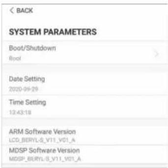
FFiigguurree 77--1133 System Parameters
Tap Boot/Shutdown to send the boot/shutdown instruction to the inverter.
For Australia and New Zealand, when the DRM state is DRM0, the "Boot" option will be prohibited.
DDaattee//TTiimmee
The correct system time is very important. Wrong system time will directly affect the data logging and power generation value. The clock is in 24-hour format.
7.10.2 Operation Parameters
Tap Settings→Operation Parameters→Running Time to enter the corresponding screen, on which you can set "Connecting Time" and "Reconnecting Time".
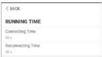
FFiigguurree 77--1144 Running Time
7.10.3 Power Regulation Parameters
Tap Settings→Power Regulation Parameters→Active Power Regulation to enter the screen, as shown in the following figure.

FFiigguurree 77--1155 Active Power Regulation
Table 7-4 Description of Active Power Regulation Parameters
| PPaarraammeetteerr | DDeessccrriippttiioonn | RRaannggee |
| Accttiivee PPooweerr SSttaarrtt aafftteerr FF | Switch for activating/deactivating the SSoofftt function of active power soft start after a On/Off aauulltt fault occurs | |
| Accttiivee PPooweerr SSttaarrtt TTiimmee aafftteerr FF | The soft start time required for raising active SSoofftt power from 0 to rated value after a fault occurs | 1 s - 1200 s |
| Active Power Gradient CCoonnttrrooll | Set whether to enable active power gradient control | On/Off |
| Accttiivee PPooweerr Grraaddiieennt | Decileal gradient of inverter active power per minute | 3 %/min - 6000 %/min |
| Active Power Rising Grraaddiieennt | Rising gradient of inverter active power per minute | |
| Accttiivee PPooweerr PPeerrsisstteennccee | SWeettifiongactivating/deactivating the function of active power setting persistence | On/Off |
| Active Power Limit | Switch for limiting active power | On/Off |
| Active Power Limit Raattlioo | The ratio of active power limit to rated power in percentage | 0 % - 110.0 % |
| DDRRMM | Switch for activating/deactivating the DRM function | On/Off |
Reactive Power Regulation
Tap Settings→Power Regulation Parameters→Reactive Power Regulation to enter the screen, as shown in the following figure.
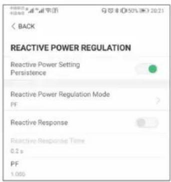
FFiigguurree 77--1166 Reactive Power Regulation
Table 7-5 Description of Reactive Power Regulation Parameters
| PPaarraammeetteerr | DDeessccrriippttioonn | RRaannggee | |
| RReeaaccttivvee PPooweerr | Switch for activating/deactivating the function of reactive power setting persistence | On/Off | |
| SSeetttiinngg PPeerrssiisstteenncee | |||
| RReeaaccttivvee PPooweerr | Off/PF/Qt/Q(P)/Q(U) | (P)/Q(U) | |
| RReegguullaattioonn MMooddee | |||
| RReeaaccttivvee RReessppoonnssee function of reactive response | Switch for activating/deactivating the function of reactive response | On/Off | |
| RReeaaccttivvee RReessppoonnssee Time for reactive response | 0.2 s | ||
| TTimmee | |||
""OOffff"" MMooddee
The reactive power regulation function is disabled. The PF is fixed at +1.000.
""PPFF"" MMooddee
The power factor (PF) is fixed and the reactive power is regulated by the parameter PF. The PF ranges from 0.8 leading to 0.8 lagging.
- Leading: the inverter is sourcing reactive power to the grid.
- Lagging: the inverter is injecting reactive power into the grid.
""QQtt"" MMooddee
In the Qt mode, the reactive power can be regulated by the parameter Q-Var limits (in %). The system rated reactive power is fixed, the system injects reactive power according to the delivered reactive power ratio. The "Reactive Power Ratio" is set through the App.
The setting range of the reactive power ratio is from -100 % to 100 %, corresponding to the ranges of inductive and capacitive reactive power regulation respectively.
""QQ((PP))"" MMooddee
The PF of the inverter output varies in response to the output power of the inverter.
Table 7-6 "Q(P)" Mode Parameters Explanation
| PPaarraammeetteerr EExxppllaannaattiioonn RRaannggee | ||
| Q(P) Curve Select corresponding curve according to local regulations | A, B, °C | |
| QP_P1 Output power at point P1 on the Q(P) mode curve (in %) | 20.0 %-100.0% | |
| QP_P2 Output power at point P2 on the Q(P) mode curve (in %) | 20.0 %-100.0% | |
| QP_P3 Output power at point P3 on the Q(P) mode curve (in %) | 20.0 %-100.0% | |
| QP_K1 Power factor at point P1 on the Q(P) mode curve | Curve A/C: 0.800 to 1.000 | |
| QP_K2 Power factor at point P2 on the Q(P) mode curve | ||
| QP_K3 Power factor at point P3 on the Q(P) mode curve | Curve B: -0.600 to 0.600 | |
| QP_EnterVoltage | Voltage for Q(P) function activation (in %) | 100.0 %-110.0% |
| QP_ExitVoltage | Voltage for Q(P) function deactivation (in %) | 90.0 %-100.0% |
| QP_ExitPower | Power for Q(P) function deactivation (in %) | 1.0 %-20.0% |
| QP_EnableMode | Unconditional activation/deactivation of Q(P) function | Yes, No |
* Curve C is reserved and consistent with Curve A currently.

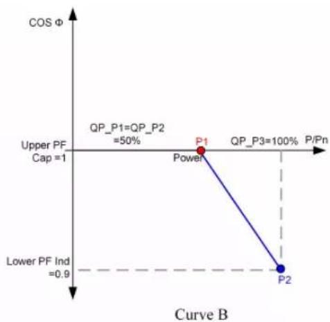
Figure 7-17 Reactive Power Regulation Curve in Q(P) Mode
"Q(U)" Mode
The reactive power output of the inverter varies in response to the grid voltage.
Table 7-7 "Q(U)" Mode Parameter Explanation
| PPaarraamme Epppllaannaattiioonn RRaannggee | ||
| Q(U) curve | Select corresponding curve according to local regulations | A, B, C |
| Hysteresis Ratio | Voltage hysteresis ratio on the Q(U) mode curve 0.0 % - 5.0 % | |
| QU_V1 | Grid voltage limit at point P1 on the Q(U) mode 80.0 % - 100.0 curve (in %) | % |
| QU_V2 | Grid voltage limit at point P2 on the Q(U) mode 80.0 % - 110.0 curve (in %) | % |
| QU_V3 | Grid voltage limit at point P3 on the Q(U) mode 100.0 % - curve (in %) | 120.0 % |
| QU_V4 | Grid voltage limit at point P4 on the Q(U) mode 100.0 % - curve (in %) | 120.0 % |
| QU_Q1 | Value of Q/Sn at point P1 on the Q(U) mode 60.0 % to 0.0 (in %) | % |
| QU_Q2 | Value of Q/Sn at point P2 on the Q(U) mode 60.0 % to 60.0 (in %) | % |
| QU_Q3 | Value of Q/Sn at point P3 on the Q(U) mode curve -60.0 % to 60 % (in %) | |
| QU_Q4 | Value of Q/Sn at point P4 on the Q(U) mode curve 0.0 % to 60.0 % (in %) | |
| QU_EnterPower | Active power for Q(U) function activation (in %) | 20.0 % - 100.0 % |
| QU_ExitPower | Active power for Q(U) function deactivation (in %) | 1.0 % - 20.0 % |
| QU_EnableMode | Unconditional activation/deactivation of Q(U) function | Yes, No, Yes (-Limited by PF) |
| QU_Limited PF Value | Preset PF value 0 - 0.95 | |
* Curve C is reserved and consistent with Curve A currently.

Curve A
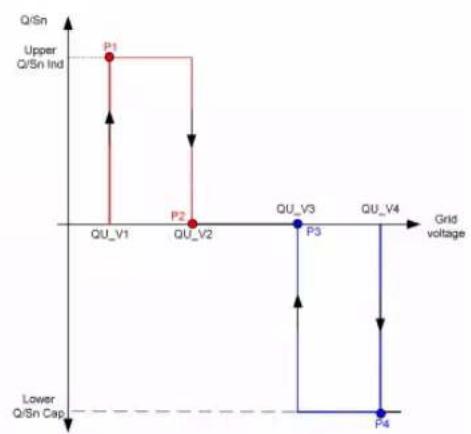
Curve B
FFiigguurree 77--1188 Reactive Power Regulation Curve in Q(U) Curve
7.10.4 Communication Parameters
Tap Settings→Communication Parameters to enter the corresponding screen, as shown in the following figure. The device address ranges from 1 to 246.

FFiigguurree 77--1199 Communication Parameters
To avoid download failure due to poor on-site network signal, it is recommended to download the firmware package to the mobile device in advance.
Step 1 Enable the "Mobile data" of the mobile device.
Step 2 Open the App, tap the upper right corner and select Firmware Download.

FFiigguurree 77--2200 Firmware Download
Step 3 Select the firmware from the file list and download. Tap Downloaded to view successfully downloaded firmware package.


FFiigguurree 77--2211 Downloading Firmware Package
Step 4 Login the App via local access mode. Refer to "7.4 Login".
Step 5 Tab More on the App home screen and then tab Firmware Upgrade. Select the desired upgrade package to upgrade the firmware.

FFiigguurree 77--2222 Updating Firmware
-- Enndd
8 System Decommissioning
8.1 Disconnecting the Inverter
For maintenance or other service work, the inverter must be switched off.
Proceed as follows to disconnect the inverter from the AC and DC power sources.
Lethal voltages or damage to the inverter will follow if otherwise.
Step 1 Disconnect the external AC circuit breaker and secure it against reconnection.
Step 2 Rotate the DC switch to the "OFF" position for disconnecting all of the PV string inputs.
Step 3 Wait about 10 minutes until the capacitors inside the inverter completely discharge.
Step 4 Ensure that the DC cable is current-free via a current clamp.
Step 5 Insert a MC4 wrench into the notch and press the wrench with an appropriate force to remove the DC connector.

Step 6 Lay the tool in the location of snap and press the tool down to remove the AC connector. Ensure that the AC wiring terminals are voltage-free via a multimeter, and remove the AC wires and communication wires.
Step 7 Install the MC4 waterproof plugs.

For further disconnection and reconnection instructions, please visit the webpage of respective component manufacturer.
-- -- EEnndd
8.2 Dismantling the Inverter
CAUTION
Risk of burn injuries and electric shock!
Do not touch any inner live parts until for at least 10 minutes after disconnect the inverter from the utility grid and the PV input.
Step 1 Refer to "5 Electrical Connection" for the inverter disconnection of all cables in reverse steps.
Step 2 Dismantle the inverter referring to "4 Mechanical Mounting" in reverse steps.
Step 3 If necessary, remove the wall-mounting bracket from the wall.
Step 4 If the inverter will be reinstalled in the future, please refer to "3.2 Inverter Storage" for a proper conservation.
-- -- EEnndd
8.3 Disposal of the Inverter
Users take the responsibility for the disposal of the inverter.
NOTICE
Some parts and devices of the inverter, such as the capacitors, may cause environmental pollution.
Do not dispose of the product together with household waste but in accorda with the disposal regulations for electronic waste applicable at the installation site.
9 Troubleshooting and Maintenance
9.1 Troubleshooting
When an alarm occurs, the alarm information can be viewed through the App. Alarm ID and corrective measures are as follows:
| Alarm ID | Alarm Name | Corrective Measures |
| 001 | Grid overvoltage | Generally, the inverter will be reconnected to the grid after the grid recovers. If the alarm occurs frequently:1. Measure the grid voltage, and contact the local utility grid company for solutions if the grid voltage exceeds the specified value.2. Check, through the App, whether the protection parameters are appropriately set.3. Check whether the cross-sectional area of the AC cable meets the requirement.4. If the alarm persists, contact SUNGROW. |
| 002 | Grid undervoltage | Generally, the inverter will be reconnected to the grid after the grid recovers. If the alarm occurs frequently:1. Measure the grid voltage, and contact the local utility grid company for solutions if the grid voltage is below the specified value.2. Check, through the App, whether the protection parameters are appropriately set.3. Check whether the AC cable is firmly in place.4. If the alarm persists, contact SUNGROW. |
| AAllaarrmm | IIDD AAllaarrmm | NNaammee CCoorrreeccttiivvee MMeeaassuurreess |
| 003 | Grid overfrequency | Generally, the inverter will be reconnected to the grid after the grid recovers. If the alarm occurs frequently:1. Measure the grid frequency, and contact the local utility grid company for solutions if the grid frequency is beyond the specified range.2. Check, through the App, whether the protection parameters are appropriately set.3. If the alarm persists, contact SUNGROW. |
| 004 | Grid underfrequency | |
| 005 | No Grid | Generally, the inverter will be reconnected to the grid after the grid recovers. If the alarm occurs frequently:1. Check whether the grid supplies power reliably.2. Check whether the AC cable is firmly in place.3. Check whether the AC cable is correctly connected (whether the live wire and the N wire are in correct place).4. Check whether the AC switch or circuit breaker is disconnected.5. If the alarm persists, contact SUNGROW. |
| 006 | Overhigh leakage current | 1. The alarm can be caused by poor sunlight or damp environment, and the inverter will be reconnected to the grid after the environment is improved.2. If the environment is normal, check whether the AC and DC cables are well insulated.3. If the alarm persists, contact SUNGROW. |
| 007 | Grid abnormal | Generally, the inverter will be reconnected to the grid after the grid recovers. If the alarm occurs frequently:1. Measure the grid frequency, and contact the local utility grid company for solutions if the grid frequency exceeds the specified value.2. If the alarm persists, contact SUNGROW. |
| 008 | Grid voltage unbalance | Generally, the inverter will be reconnected to the grid after the grid recovers. If the alarm occurs frequently:1. Measure the grid voltage. If the grid phase voltage differs greatly, contact the utility grid company for solutions.2. If the voltage difference between the three phases is within the permissible range of the local utility grid company, modify the parameter setting through the App.3. If the alarm persists, contact SUNGROW. |
| 009 | PV reverse connection fault | 1. Check whether the corresponding string is of reverse polarity. If so, disconnect the DC switch and adjust the polarity when the solar radiation is low and the string current drops below 0.5 A.2. Check whether PV strings connected to the same MPPT have the same number of PV modules. If not, take corrective measures.3. If the alarm persists, contact SUNGROW. |
| 012 | High ambient temperature | 1. Check whether the inverter is directly exposed to sunlight. If so, take some shading measures.2. Check and clean the air ducts.3. Check whether the sub-alarm ID 070 (fan alarm) occurs through the App. If so, replace the faulty fan.4. If the alarm persists, contact SUNGROW. |
| 013 | Low ambient temperature | 1. Stop and disconnect the inverter.2. Restart the inverter when the ambient temperature is within the permissible range. |
| AAllaarrmm | IIDD | AAllaarrmm | NNaammee CCoorrreeccttiivvee MMeeaassuurreess |
| 014 | Low ISO resistance | Wait for the inverter to recover. If the fault occurs frequently:1. Check whether the insulation resistance protection value is extremely large through the App, and ensure that it complies with the local regulations.2. Check the resistance to ground from the PV module/cable. Take corrective measures in case of leading to short circuit or damaged insulation layer.3. If the cable is normal and the alarm occurs on rainy days, check it again when the weather turns fine.4. If the fault occurs on a cloudy day without rain but there is stagnant water or vegetation on site, clear the water and vegetation. If the fault persists, check it again when the weather turns fine.5. If the alarm persists, contact SUNGROW. | |
| 015 | Grounding cable fault | 1. Check whether the AC cable is correctly connected.2. Check whether the grounding cable and wire cores are wrongly insulated.3. If the alarm persists, contact SUNGROW. | |
| 016 | Arc fault | 1. Disconnect the DC inputs and check whether the DC cables are damaged, whether the wiring terminals or fuses, if necessary, are loose or in poor contact, and whether there is a PV module burnt. If so, take corresponding corrective measures.2. After taking corresponding measures in step 1, reconnect the DC inputs. Remove the arc fault through the App, and therefore the inverter will recover.3. If the alarm persists, contact SUNGROW. | |
| AAllaarrmm | IIDD AAllaarrmm | NNaammee CCoorrreeccttiivvee MMeeaassuurreess | |
| 019 | Smart Energy Meter communication error | 1. Check whether the Smart Energy Meter communication cable and terminal are abnormal. If so, remove the corresponding abnormality.2. Reconnect the Smart Energy Meter communication cable.3. If the alarm persists, contact SUNGROW. | |
| 063 | System alarm | The inverter can operate normally.1. Check whether the related cable connection and terminals are abnormal, and check whether the ambient environment is abnormal. If so, take corrective measures.2. If the alarm persists, contact SUNGROW. | |
| 064 | System fault | 1. Wait for the inverter to recover.2. Disconnect the AC and DC switches or circuit breakers, and connect them again after 15 minutes.3. If the alarm persists, contact SUNGROW. | |
9.2 Maintenance
9.2.1 Maintenance Notices
The DC switch can be secured with a lock in the OFF position or a certain angle beyond the OFF position.
! DANGER
Risk of inverter damage or personal injury due to incorrect service
- Always keep in mind that the inverter is powered by dual sources: PV strings and utility grid.
Before any service work, observe the following procedure. - Disconnect the AC circuit breaker and then set the DC load-break switch of the inverter to OFF;
- Wait at least 10 minutes for inner capacitors to discharge completely;
- Verify that there is no voltage or current before pulling any connector.
CAUTION
Keep non-related persons away!
A temporary warning sign or barrier must be posted to keep non-related persons away while performing electrical connection and service work.
NOTICE
- Restart the inverter only after removing the fault that impairs safety performance.
- As the inverter contains no component parts that can be maintained, never arbitrarily replace any internal components.
- For any maintenance need, please contact SUNGROW. Otherwise, SUNGROW shall not be held liable for any damage caused.

Servicing of the device in accordance with the manual should never be undertaken in the absence of proper tools, test equipments or the latest revision of the manual which has been clearly and thoroughly understood.
9.2.2 Routine Maintenance
| Itteemm MMeetthhoodd PPeerioodd | ||
| System clean | Check the temperature and dust of six months to a yearthe inverter. Clean the inverter (depending on the dustenclosure if necessary. contents in air) | |
| Electricalconnection | Check whether all cable are firmlyconnected in place. 6 months afterCheck whether there is damage to commissioning and thenthe cables, especially the surface in once or twice a year.contact with metal. | |
| General statusof the system | Visual check for any damage ordeformation of the inverter.Check any abnormal noise duringthe operation.Every 6 monthsCheck each operation parameter.Be sure that nothing covers theheat sink of the inverter. | |
10 Appendix
10.1 Technical Data
| PPaarraammeetteerr | SSGG22..00RRSS--SS | SSGG22..55RRSS--SS | SSGG33..00RRSS--SS |
| Innppuutt ((DC)) | |||
| Recommended max. PV input power | 3.0 kWp | 3.75 kWp | 4.5 kWp |
| Max. PV input voltage | 600 V* | ||
| Startup voltage | 50 V | ||
| Nominal input voltage | 360 V | ||
| MPP voltage range | 40 V - 560 V | ||
| No. of MPPTs | 1 | ||
| Default No. of PV strings per MPPT | 1 | ||
| Max. PV input current | 16 A | ||
| Max. current for input connector | 20 A | ||
| Max. DC short-circuit current | 20 A | ||
| Max. inverter backfeed current to strings | 0 A | ||
| OOuutppuutt ((AAC) | |||
| Nominal AC output power | 2000 W | 2500 W | 3000 W |
| Max. AC output apparent power | 2000 VA | 2500 VA | 3000 VA |
| Max. AC output current | 9.1 A | 11.4 A | 13.7 A |
| Max. inrush current (peak/ duration) | 8 A / 12 ms | ||
| Max. output fault current (peak/duration) | 80 A / 3.2 us | ||
| Nominal AC voltage | 220 V / 230 V / 240 V | ||
| AC voltage range | 154 V AC - 286 V AC | ||
| Nominal grid frequency / Grid frequency range | 50 Hz / 45 Hz - 55 Hz, 60 Hz / 55 Hz - 65 Hz | ||
| Harmonic (THD) | < 3 % (of nominal power) | ||
| PPaarraammeetteerr | SSGG22..00RRSS--SS | SSGG22..55RRSS--SS | SSGG33..00RRSS |
| Power factor at nominal power / Adjustable power factor | > 0.99 at default value at nominal power (adj. 0.8 overexcited/leading - 0.8 underexcited/lagging) | ||
| Feed-in phases / connection phases | 1 / 1 | ||
| PPrrootteeccttiioonn | |||
| Grid monitoring | Yes | ||
| DC reverse polarity protection | Yes | ||
| AC short circuit protection | Yes | ||
| Leakage current protection | Yes | ||
| DC switch | Yes | ||
| PV string current monitoring | Yes | ||
| PID recovery Yes | |||
| Arc fault circuit interrupter Yes (AFCI) | |||
| Surge protection | DC Type II, AC Type II | ||
| Overvoltage category | III [AC], II [PV] | ||
| SSyysstteemm Daattaa | |||
| Max. efficiency | 98.0 % | ||
| European efficiency | 97.3 % | 97.5 % | 97.5 % |
| Isolation protection | Transformerless | ||
| Topology | IP65 | ||
| Degree of protection | -25°C to +60°C | ||
| Allowable relative humidity range (non-condensing) | 0 - 100 % | ||
| Max. operating altitude | 4000 m | ||
| Cooling method | Natural cooling | ||
| Display | LED digital display, LED indicator | ||
| Communication | WLAN, Ethernet, RS485 * 2, Ripple control, DRM | ||
| DC connection type | MC4 (Max. 6 fm) | ||
| AC connection type | Plug and play (Max. 6 fm) | ||
| Grid support | Active/reactive power control and power ramp rate control | ||
| MMeechhaanniccaall Daattaa | |||
| Dimensions (W x H x D) | 320 mm x 225 mm x 120 mm | ||
| PPaarraammeetteerr | SSGG22..00RRSS--SS | SSGG22..55RRSS--SS | SSGG33..00RRSS--S |
| Mounting method Wall-mounting bracket | |||
| Weight 6 kg | |||
* The inverter enters standby state when the input voltage ranges between 560 V and 600 V.
| PPaarraammeetteerr | SSGG33..00RRSS | SSGG33..66RRSS | SSGG44..00RF |
| Innppuutt ((DC)) | |||
| Recommended max. PV input power | 4.5 kWp | 5.4 kWp | 6.0 kWp |
| Max. PV input voltage | 600* V | ||
| Startup voltage | 50 V | ||
| Nominal input voltage | 360 V | ||
| MPP voltage range | 40 V-560 V | ||
| No. of MPPTs | 2 | ||
| Default No. of PV strings per MPPT | 1 | ||
| Max. PV input current | 32 A (16 A / 16 A) | ||
| Max. current for input connector | 20 A | ||
| Max. DC short-circuit current | 40 A (20 A / 20 A) | ||
| Max. inverter backfeed current to strings | 0 A | ||
| OOuutppuutt ((AAC) | |||
| Nominal AC output power | 3000 W | 3680 W | 4000 W |
| Max. AC output apparent power | 3000 VA | 3680 VA | 4000 VA |
| Max. AC output current | 13.7 A | 16.0 A | 18.2 A |
| Max. inrush current (peak/10 A / 12 ms duration) | |||
| Max. output fault current (peak/duration) | 100 A / 3.2 us | ||
| Nominal AC voltage | 220 V / 230 V / 240 V | ||
| AC voltage range | 154 V AC-286 V AC | ||
| Nominal grid frequency / Grid frequency range | 50 Hz / 45 Hz-55 Hz, 60 Hz / 55 Hz-65 Hz | ||
| Harmonic (THD) | < 3 % (of nominal power) | ||
| PPaarraammeetteerr | SSGG33..00RRSS | SSGG33..66RRSS | SSGG44..00RRSS |
| Power factor at nominal power / Adjustable power factor | > 0.99 at default value at nominal power (adj. 0.8 overexcited/leading - 0.8 underexcited/lagging) | ||
| Feed-in phases / connection phases | 1 / 1 | ||
| PPrrootteeccttiioonn | |||
| Grid monitoring | Yes | ||
| DC reverse polarity protection | Yes | ||
| AC short circuit protection | Yes | ||
| Leakage current protection | Yes | ||
| DC switch | Yes | ||
| PV string current monitoring | Yes | ||
| PID recovery function Yes | |||
| Arc fault circuit interrupter Yes (AFCI) | |||
| Surge protection DC Type II, AC Type II | |||
| Overvoltage category III [AC], II [PV] | |||
| SSyysstteemm Daattaa | |||
| Max. efficiency | 98.1 % | ||
| European efficiency | 97.0 % | 97.1 % | 97.4 % |
| Topology | Transformerless | ||
| Degree of protection | IP65 | ||
| Operating ambient temperature range | -25°C to +60°C | ||
| Allowable relative humidity range (non-condensing) | 0 - 100 % | ||
| Max. operating altitude | 4000 m | ||
| Cooling method | Natural cooling | ||
| Display | LED digital display, LED indicator | ||
| Communication | WLAN, Ethernet, RS485 * 2, Ripple control, DRM | ||
| DC connection type | MC4 (Max. 6 mm) | ||
| AC connection type | Plug and play (Max. 6 mm) | ||
| Grid support | Active/reactive power control and power ramp rate control | ||
| MMeechhaanniiccaall | DDaattaa | ||
| Dimensions (W x H x D) | 410 mm x 270 mm x 150 mm | ||
| Mounting method | Wall-mounting bracket | ||
| Weight | 10 kg | ||
* The inverter enters standby state when the input voltage ranges between 560 V and 600 V.
| PPaarraammeetteerr | SSGG55..00RRSS | SSGG66..00RRSS |
| IInnppuutt ((DDCC)) | ||
| Recommended max. PV input power | 7.5 kWp | 9.0 kWp |
| Max. PV input voltage | 600 V* | |
| Startup voltage | 50 V | |
| Nominal input voltage | 360 V | |
| MPP voltage range | 40 V - 560 V | |
| No. of MPPTs | 2 | |
| Default No. of PV strings per MPPT | 1 | |
| Max. PV input current | 32 A (16 A / 16 A) | |
| Max. current for input connector | 20 A | |
| Max. DC short-circuit current | 40 A (20 A / 20 A) | |
| Max. inverter backfeed current to strings | 0 A | |
| OOuutppuutt ((AACC)) | ||
| Nominal AC output power | 4999 W for "AU", 5000 W for others | 6000 W |
| Max. AC output apparent power | 4999 VA for "AU", 5000 VA for others | 6000 VA |
| Max. AC output current | 21.7 A for "AU", 22.8 A for others | 27.3 A |
| Max. inrush current (peak/ duration) | 10 A / 12 ms | |
| Max. output fault current (peak/duration) | 100 A / 3.2 us | |
| Nominal AC voltage | 220 V / 230 V / 240 V | |
| AC voltage range | 154 V AC - 286 V AC | |
| Nominal grid frequency / Grid frequency range | 50 Hz / 45 Hz-55 Hz, 60 Hz / 55 Hz-65 Hz | |
| Harmonic (THD) < 3 % (of nominal power) | ||
| Power factor at nominal power / Adjustable power factor | >0.99 at default value at nominal power (adj. 0.8 overexcited/leading-0.8 underexcited/lagging) | |
| Feed-in phases / connection phases | 1 / 1 | |
| PPrrootteeccttiioonn | ||
| Grid monitoring Yes | ||
| DC reverse polarity protection | Yes | |
| AC short circuit protection | Yes | |
| Leakage current protection | Yes | |
| DC switch | Yes | |
| PV string current monitoring | Yes | |
| PID recovery function | Yes | |
| Arc fault circuit interrupter (AFCI) | Yes | |
| Surge protection | DC Type II, AC Type II | |
| Overvoltage category | III [AC], II [PV] | |
| SSyysstteemm Daattaa | ||
| Max. efficiency | 98.1 % | |
| European efficiency | 97.5 % | 97.8 % |
| Topology | Transformerless | |
| Degree of protection | IP65 | |
| Operating ambient temperature range | -25°C to +60°C | |
| Allowable relative humidity range (non-condensing) | 0-100 % | |
| Max. operating altitude | 4000 m | |
| Cooling method | Natural cooling | |
| Display | LED digital display, LED indicator | |
| Communication | WLAN, Ethernet, RS485 * 2, Ripple control, DRM | |
| DC connection type | MC4 (Max. 6 m) | |
| PPaarraammeetteerr | SSGG55..00RRSS SSGG66..00RRSS | |
| AC connection type | Plug and play (Max. 6 mm) | |
| Grid support | Active/reactive power control and power ramp rate control | |
| MMeechhaanniiccaall DDaattaa | ||
| Dimensions (W x H x D) | 410 mm x 270 mm x 150 mm | |
| Mounting method | Wall-mounting bracket | |
| Weight | 10 kg | |
* The inverter enters standby state when the input voltage ranges between 560 V and 600 V.
10.2 Quality Assurance
When product faults occur during the warranty period, SUNGROW will provide free service or replace the product with a new one.
EEvviiddeennccee
During the warranty period, the customer shall provide the product purchase invoice and date. In addition, the trademark on the product shall be undamaged and legible.
Otherwise, SUNGROW has the right to refuse to honor the quality guarantee.
CCoonnddiittiionns
• After replacement, unqualified products shall be processed by SUNGROW.
• The customer shall give SUNGROW a reasonable period to repair the faulty device.
In the following circumstances, SUNGROW has the right to refuse to honor the quality guarantee:
- The free warranty period for the whole machine/components has expired.
• The device is damaged during transport. - The device is incorrectly installed, refitted, or used.
- The device operates in harsh conditions beyond those described in this manual.
- The fault or damage is caused by installation, repairs, modification, or disassembly performed by a service provider or personnel not from SUNGROW.
- The fault or damage is caused by the use of non-standard or non-SUNGROW components or software.
- The installation and use range are beyond stipulations of relevant international standards.
- The damage is caused by unexpected natural factors.
For faulty products in any of above cases, if the customer requests maintenance, paid maintenance service may be provided based on the judgment of SUNGROW.
10.3 Contact Information
Should you have any question about this product, please contact us. We need the following information to provide you the best assistance:
- Model of the device
- Serial number of the device
- Fault code/name
- Brief description of the problem
| CChhiinnaa ((HHQQ)) | AAuussttraalliiaa |
| Sungrow Power Supply Co., Ltd | Sungrow Australia Group Pty. Ltd. |
| Hefei | Sydney |
| +86 551 65327834 | +61 2 9922 1522 |
| service@sungrowpower.com | service@sungrowpower.com.au |
| BBrraazziill | FFrraanncee |
| Sungrow Do Brasil | Sungrow France |
| Sao Paulo | Lyon |
| +55 0800 677 6000 | +33420102107 |
| latam.service@sungrowamericas.com | service@sungrow-emea.com |
| Germany, Austria, Switzerland | Grreeeeecee |
| Sungrow Deutschland GmbH | Service Partner - Survey Digital |
| Munich | +30 2391052757 |
| +49 0800 4327 9289 | service@sungrow-emea.com |
| service@sungrow-emea.com |
| Innddiiaa | Ittaallyy |
| Sungrow (India) Private Limited | Sungrow Italy |
| Gurgaon | Verona |
| +91 080 41201350 | +39 0800 974739 (Residential) |
| service@in.sungrowpower.com | +39 045 4752117 (Others) |
| service@sungrow-emea.com |
| Jaappaann | KKorreeaa |
| Sungrow Japan K.K. | Sungrow Power Korea Limited |
| Tokyo | Seoul |
| + 81 3 6262 9917 | +82 70 7719 1889 |
| service@jp.sungrowpower.com | service@kr.sungrowpower.com |
| MMaallaayyssiiaa | PPhhilliippppiinneess |
| Sungrow SEA | Sungrow Power Supply Co., Ltd |
| Selangor Darul Ehsan | Mandaluyong City |
| +60 19 897 3360 | +63 9173022769 |
| service@my.sungrowpower.com | service@ph.sungrowpower.com |
| TThhaaiillaanndd | SSppaaiinn |
| Sungrow Thailand Co., Ltd. | Sungrow Ibérica S.A.U. |
| Bangkok | Mutilva |
| +66 891246053 | +34 948 05 22 04 |
| service@th.sungrowpower.com | service@sungrow-emea.com |
| RRoommaanniiaa | TTuurrkkeeyy |
| Service Partner - Elerex | Sungrow Deutschland GmbH Turkey |
| service@sungrow-emea.com | Istanbul |
| +90 216 663 61 80 | |
| service@sungrow-emea.com | |
| UK | UU..SS..AA,, MMeexxiiccoo |
| Sungrow Power UK Ltd. | Sungrow USA Corporation |
| Milton Keynes | Phoenix |
| +44 (0) 01908 414127 | +1 833 747 6937 |
| service@sungrow-emea.com | techsupport@sungrow-na.com |
| VViieettnnaamm | BBeellggiiuumm,, NNeetthheerrllaannddss aanndd |
| Sungrow Vietnam | LLuuxxeemmbboouurrgg ((Beenneelluuss) |
| Hanoi | +31 08000227012 (only for Netherlands) |
| +84 918 402 140 | |
| service@vn.sungrowpower.com | service@sungrow-emea.com |
| PPoollaanndd | |
| +48 221530484 | - |
| service@sungrow-emea.com |

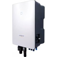
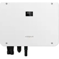
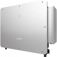
- 1-PHASE PV GRID-CONNECTED INVERTER
- USER MANUAL
- ALL RIGHTS RESERVED
- ABOUT THIS MANUAL
- HOW TO USE THIS MANUAL
- SYYMMBOOLLSS
- DANGER
- WARNING
- CAUTION
- NOTICE
- I
- CCOONNTTEENN
- 1 SAFETY 1
- 2 PRODUCT DESCRIPTION 4
- 3 UNPACKING AND STORAGE 12
- 4 MECHANICAL MOUNTING 13
- 5 ELECTRICAL CONNECTION 19
- 6 COMMISSIONING 39
- 7 ISOLARCLOUD APP .... 50
- 8 SYSTEM DECOMMISSIONING 68
- 9 TROUBLESHOOTING AND MAINTENANCE 70
- 10 APPENDIX 76
- 1 SAFETY
- 1.1 PV PANELS
- 1.2 UTILITY GRID
- 1.3 INVERTER
- 2 PRODUCT DESCRIPTION
- 2.1 SYSTEM INTRODUCTION
- 2.2 PRODUCT INTRODUCTION
- 2.3 SYMBOLS ON THE PRODUCT
- 2.4 LED PANEL
- 2.5 CIRCUIT DIAGRAM
- 2.6 FUNCTION DESCRIPTION
- DRM ("AU"/"NZ")
- 3 UNPACKING AND STORAGE
- 3.1 UNPACKING AND INSPECTION
- 3.2 INVERTER STORAGE
- 4 MECHANICAL MOUNTING
- 4.1 SAFETY DURING MOUNTING
- 4.2 LOCATION REQUIREMENTS
- 4.2.1 ENVIRONMENT REQUIREMENTS
- 4.2.2 CARRIER REQUIREMENTS
- 4.2.3 ANGLE REQUIREMENTS
- 4.2.4 CLEARANCE REQUIREMENTS
- 4.3 INSTALLATION TOOLS
- 4.4 MOVING THE INVERTER
- 4.5 INSTALLING THE INVERTER
- 5 ELECTRICAL CONNECTION
- 5.1 SAFETY INSTRUCTIONS
- 5.2 TERMINAL DESCRIPTION
- 5.3 ELECTRICAL CONNECTION OVERVIEW
- 5.4 ADDITIONAL GROUNDING CONNECTION
- 5.4.1 ADDITIONAL GROUNDING REQUIREMENTS
- 5.4.2 CONNECTION PROCEDURE
- 5.5 AC CABLE CONNECTION
- 5.5.1 AC SIDE REQUIREMENTS
- 5.5.2 ASSEMBLING THE AC CONNECTOR
- 5.5.3 INSTALLING THE AC CONNECTOR
- 5.6 DC CABLE CONNECTION
- 5.6.1 PV INPUT CONFIGURATION
- 5.6.2 ASSEMBLING THE PV CONNECTORS
- 5.6.3 INSTALLING THE PV CONNECTORS
- 5.7 WINET-S CONNECTION
- 5.7.1 ETHERNET COMMUNICATION
- 5.7.2 WLAN COMMUNICATION
- 5.8 METER CONNECTION
- 5.9 DRM CONNECTION
- 6 COMMISSIONING
- 6.1 INSPECTION BEFORE COMMISSIONING
- 6.2 POWERING ON THE SYSTEM
- 6.3 APP PREPARATION
- 6.4 CREATING A PLANT
- 6.5 INITIALIZING THE DEVICE
- 6.6 CONFIGURING THE PLANT
- 7 ISOLARCLOUD APP
- 7.1 BRIEF INTRODUCTION
- 7.2 INSTALLING THE APP
- 7.3 ACCOUNT REGISTRATION
- 7.4 LOGIN
- 7.4.1 REQUIREMENTS
- 7.4.2 LOGIN PROCEDURE
- 7.5 INITIAL SETTINGS
- 7.6 FUNCTION OVERVIEW
- 7.7 HOME
- 7.8 RUN INFORMATION
- 7.9 RECORDS
- FAULT ALARM RECORD
- 7.10 MORE
- 7.10.1 SYSTEM PARAMETERS
- 7.10.2 OPERATION PARAMETERS
- 7.10.3 POWER REGULATION PARAMETERS
- REACTIVE POWER REGULATION
- 7.10.4 COMMUNICATION PARAMETERS
- 8 SYSTEM DECOMMISSIONING
- 8.1 DISCONNECTING THE INVERTER
- 8.2 DISMANTLING THE INVERTER
- 8.3 DISPOSAL OF THE INVERTER
- 9 TROUBLESHOOTING AND MAINTENANCE
- 9.1 TROUBLESHOOTING
- 9.2 MAINTENANCE
- 9.2.1 MAINTENANCE NOTICES
- 9.2.2 ROUTINE MAINTENANCE
- 10 APPENDIX
- 10.2 QUALITY ASSURANCE
- EEVVIIDDEENNCCEE
- CCOONNDDIITTIIONNS
- 10.3 CONTACT INFORMATION
Brand : Sungrow
Model : SH3.6RS
Category : Solar panel