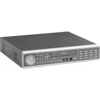
Digimaster DR16HD - Surveillance Camera Ganz - Free user manual and instructions
Find the device manual for free Digimaster DR16HD Ganz in PDF.


| Product Type | Surveillance DVR (Digital Video Recorder) |
| Model | Digimaster DR16HD |
| Brand | Ganz |
| Video Channels | 16 channels |
| Recording Resolution | Up to 1080p (Full HD) |
| Compression Format | H.264 / H.265 |
| Storage | Internal SATA HDD (up to 10TB) |
| Network Interface | Ethernet RJ45 10/100 Mbps |
| Video Output | HDMI, VGA |
| Audio Support | Yes (audio input/output) |
| Remote Access | Via web browser or mobile app |
| Power Supply | DC 12V, 2A (adapter included) |
| Dimensions (W x D x H) | 300 x 250 x 50 mm |
| Weight | 2.0 kg |
| Operating Temperature | 0°C to 40°C |
| Maintenance | Clean with a dry, soft cloth; avoid liquids |
| Safety | Use in dry, ventilated area; do not cover vents |
| Reparability | Spare parts available through authorized service centers |
| General Information | Designed for 24/7 continuous recording |
Frequently Asked Questions - Digimaster DR16HD Ganz
User questions about Digimaster DR16HD Ganz
0 question about this device. Answer the ones you know or ask your own.
Ask a new question about this device
Download the instructions for your Surveillance Camera in PDF format for free! Find your manual Digimaster DR16HD - Ganz and take your electronic device back in hand. On this page are published all the documents necessary for the use of your device. Digimaster DR16HD by Ganz.
USER MANUAL Digimaster DR16HD Ganz
Before connecting, operating or adjusting this product, read this instruction booklet carefully and completely

Specification & Organization 12
Specifications 12
Product Contents List 14
System Organization 15
Product Description 16
Front Panel Description (8 & 16ch) 16
Rear Panel Description (8 & 16ch) 17
Front Panel Description (4ch) 18
Rear Panel Description (4ch) 19
Remote Controller Description 20
Connect & Power On 21
Live Display 22
Menu Control 22
Screen Division 22
Sequence 22
PTZ Camera Control 23
Digital Zoom 23
Event Log Search 24
Panic Recording 24
Quick Menu 25
SYSTEM SETUP 26
Camera 27
Camera Setup 27
Color Setup 27
PTZ Setup 28
Motion Sensor 30
Display 31
OSD 31
Monitor 32
Sequence 33
Spot Out 35
Sound 36
Audio 36
Buzzer 36
System 37
Date / Time 37
System Management 38
Control Device 39
User 40
User Management 40
User Authority 41
Log Out 41
Network 42
IP Setup 42
DDNS 43
E-mail 43
Event / Sensor 44
HDD Event 44
Alarm Input 44
Alarm Out 45
Buzzer Out 46
E-mail Notification 47
Disk Manage 48
RECORD SETUP 49
Recording Operations 49
Continuous / Motion Recording Setup 50
Alarm Recording Setup 54
Panic Recording Setup 54
SEARCH 55
Search By Time 55
Search By Event 59
ARCHIVING 61
Create a New Archive 61
Reserved Data Management 62
WEB CONNECTION SETUP 63
Preliminary Before Connection 63
How to Connect 63
Live Mode 65
Search By Time 67
Search By Event 68
Remote Setup 69
Camera 69
Display 70
Sound 71
System 71
Recording 71
User 72
Network 72
Sensor 73
Information 73
WATERMARK PROCESS 74
SMARTPHONE CONNECTION 76
Introduction
Thank you for purchasing the GANZ DIGIMASTER Digital Video Recorder (DVR).
This DVR is produced using the most advanced GANZ digital recording technology and its quality is guaranteed by strict reliability and compatibility testing.
This manual provides necessary information for the correct use of this product and also contains some useful tips and step-by-step procedures for common DVR operations.
Please read this manual thoroughly before using your DVR in order to prevent possible malfunction due to operator error.
Notice
This manual applies to the following DIGIMASTER Series DVR models: DR4H / DR8H / DR16H.
This manual describes the external features of GANZ DIGIMASTER, part names, correct connection methods for supported domes or pan/tilt receivers, control devices, peripheral devices and the system setup instructions. It is important to note here that some features, figures, pictures and references can only be applied to just one model.
- GANZ cannot be held responsible if the DVR is damaged due to the use of non-compatible devices with this product. If you have any doubts, please check.
- GANZ cannot be held responsible if the DVR is damaged due to the product being disassembled or modified by the user.
• This product is qualified for both domestic and industrial use.
• This product has acquired international certifications, including CE (Europe) and FCC (USA).
This manual is written based on the 16 Channel DVR. The contents may change according to the number of channels and the types of exterior equipment.
Copyrights
All copyrights of this manual are reserved by CBC (America) Corp., CBC Group, and CBC Co., Ltd.
Copyright © 2010
Any reproduction or republishing of this manual for commercial purposes is prohibited.
It is prohibited to transfer this manual via online media such as, but not limited to, the Internet.
It is also prohibited to post, distribute or translate this manual without permission from CBC.
CBC will not be held responsible if the DVR has been damaged as a result of improper handling by any user who is unaware of how to operate this product and did not consult this manual before attempting to operate the product.
CBC reserves the right to change the contents of this manual without notice.
CBC reserves all copyrights of registered trademarks contained within this manual.
Caution
Please be aware of the following precautions before installing the DVR:
- Avoid positioning the DVR in any place where the unit may come into contact with moisture, dust, or soot.
- Avoid placing in direct sunlight, or near heating appliances.
- Keep the product away from electric shock or magnetic substances.
- Avoid temperature extremes (recommended operation temperature is between 0^ and 40^ ).
• Do not place any conductive material through the ventilation grills.
- Keep the system turned off before installation.
- Ensure that enough space is left for cable connections.
- Place the system on a solid surface with sufficient air ventilation. Avoid any surface that vibrates.
- Placing the system near electronic devices such as radio or TV may cause the product to malfunction.
• Do not disassemble the product without seeking assistance from the supplier.
- Do not place any heavy object on the system.
- Please keep cleaning the fan filter of front panel.
CALIFORNIA USA ONLY
This Perchlorate warning applies only to primary CR (Manganese Dioxide) Lithium coin cells in the product sold or distributed ONLY in California USA.
"Perchlorate Material – special handing may apply. See www.dtsc.ca.gov/hazardouswaste/perchlorate."
Safety Warnings and Cautions
The following are warnings and precautions to ensure user safety and prevention of property damage.
Please read the information below thoroughly.
Warning and caution signs

Warning
If you are not aware of this warning, you may be seriously injured or be killed

Caution
If you are not aware of this caution, you may be injured or cause property loss.

Warning
Turn off the system before installing the system. Do not plug in several electric devices to the same outlet.
• This may cause heating, fire or electric shock.

natural_image
Illustration of a white electronic device next to a red explosion effect emitting smoke (no text or symbols)Do not place any liquid container on the system, such as water, coffee or any other beverage.
- If liquid is poured onto the system, it can cause a system malfunction or fire.

natural_image
Illustration of a device with a warning symbol (no text or labels)Prevent the power cable from being severely bent or pressed by a heavy object.
- This may cause fire.

natural_image
Illustration of a white electronic device with a starburst symbol and power plug, no text or symbols presentClean the dust around the system on a regular basis. When cleaning the system, always use dry cloth. Do not use wet cloth or other organic solvents.
- This may damage the surface of the system and can cause system malfunction or electric shock.

Avoid any place with moisture, dust, or soot.
• This can cause fire or electric shock.

natural_image
Illustration of a microwave oven and a refrigerator on a light blue background (no text or symbols)When pulling the power cable from the plug, do so gently. Do not touch the plug with wet hands and avoid using the plug if the holes on the outlet are too loose.
- This may cause fire or electric shock.

natural_image
Illustration of a power outlet with lightning bolts and a tool emitting sparks (no text or symbols)
Warning
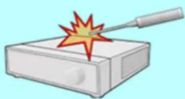
Do not attempt to disassemble, repair or modify the system on your own. It is extremely dangerous due to high voltage running through the system.
- This may cause fire, electric shock or serious injuries.
natural_image
Illustration of a test device with a probe emitting a test mark (no text or symbols)Install the system in a cool place without direct sunlight and always maintain room temperature. Avoid candlelight and heat-generating devices such as a heater. Keep the system away from high-traffic areas.
• This may cause fire.

natural_image
Illustration of a solar heating system with a warning triangle and server rack (no text or symbols)Check for any danger signs such as a moist floor, loosened or damaged power cable or unstable surface. If you encounter any problems, ask your dealer for assistance.
• This may cause fire or electric shock.

natural_image
Illustration of a white electronic device with a fuse and explosion effect (no text or symbols)Install the system on a flat surface with sufficient air ventilation. Do not place the system on elevated surface.
- This may cause system malfunction or serious injuries.

natural_image
Illustration of a white electronic device with a lid and base, placed on a pink surface (no text or symbols)Keep at least 15cm between the back of the system and the wall for the cables connected into the system. Otherwise, the cables may be bent, damaged or cut.
• This may cause fire, electric shock, or injuries.

natural_image
Illustration of a white electronic device with two red measurement arrows indicating width (5cm and 15cm), no text or symbols present.The power outlet must be placed on a ground, and the voltage range must be within 10% of the voltage rate. Do not use the same outlet with a hair dryer, iron, refrigerator or any heating appliances.
- This may cause fire, heating and electric shock.

natural_image
Illustration of a white electronic device with a red explosion effect (no text or symbols)When the system's battery is depleted, you must replace it with the same or equivalent type of battery specified by the manufacturer. Depleted batteries should be discarded according to manufacturer's instructions.
• This may cause an explosion.
If the system's HDD has exceeded its life span, you may not be able to recover any data stored inside the HDD. If the video on the system screen appears 'damaged' while playing a recording stored inside the system's HDD, it must be replaced with a new one. Ask for an engineer's assistance for HDD replacement from your dealer.
- CBC is not responsible for deleted data caused by user mishandling.

Warning
Power setup
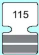
Connect with AC115V if the AC selector appears as shown here.
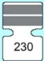
Connect with AC230V if the AC selector appears as shown here.

Caution
Do not install the system in an area featuring high magnetic, electric wave or wireless devices such as radio or TV.
• Install the system in a place without magnetic objects, electric frequencies or vibration.

Install the system in a place with appropriate moisture and temperature levels.
- Avoid installing the system at high (over 40°C) or low (under 0°C) temperatures.

Prevent any substances from entering into the system.
• This may cause system malfunction.

natural_image
Illustration of a device with a warning symbol (no text or labels)Do not place any heavy objects on the system.
• This may cause system malfunction.
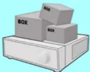
natural_image
Illustration of three boxes placed on a drawer (no text or symbols)Install the system in a place with sufficient air ventilation.
- Keep at least 15cm distance between the back of the system and the wall, and at least 5cm distance between the side of the system and any walls.
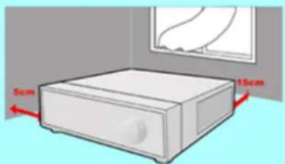
natural_image
Illustration of a white electronic device with a 5cm and 15cm measurement annotations, placed in a room with a window on top (no text or symbols on the device itself)Install the system on a stable and level surface.
• The system may not operate properly.
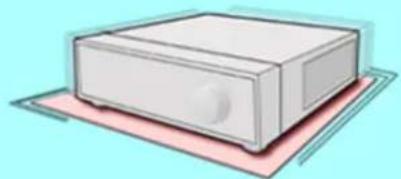
natural_image
Illustration of a white electronic device with a lid, placed on a pink surface against a light blue background (no text or symbols)
Caution
The system can be damaged as a result of strong impact or vibration. Avoid throwing objects within the vicinity of the system.

natural_image
Illustration of a computer with a box and a red starburst on top (no text or symbols)The outlet must be placed on the ground.
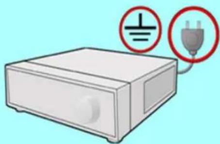
natural_image
Illustration of a power switch device with two electrical plug symbols (no text or labels)Avoid direct sunlight or any heating appliances.

natural_image
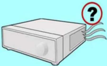
Illustration of a sun heating next to a device with a warning triangle (no text or symbols)If there is strange sound or smell, unplug the power cable immediately and contact the service center.
• This may cause fire or electric shock.
natural_image
Illustration of a white electronic device with a red question mark and swirling lines, no text or symbols present.Ventilate the air inside the system operation room and tighten the system cover firmly.
- System malfunction may be caused by inappropriate environment.
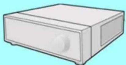
Do not overturn the product when in use.
natural_image
Illustration of a white rectangular electronic device with a knob and side slots (no text or symbols)It is recommended to use AVR (automatic voltage regulator) for stable power supply.
It is recommended to coil the core-ferrite around the connector of the system to avoid electromagnetic interference.
In order to maintain stable system performance, have your system checked regularly by the service center.
- CBC is not held responsible for system breakdown caused by user mishandling.
Important Safety Instructions
1) Read all instructions contained in this manual.
2) Keep a copy of these instructions for future reference.
3) Read all warnings.
4) Follow all instructions.
5) Do not use this apparatus near water.
6) Clean only with a dry cloth.
7) Do not block any of the ventilation openings. Install in accordance with the manufacturer's instructions.
8) Do not install near any heat sources such as radiators, space heaters, stoves, or other devices that produce heat.
9) Do not defeat the safety purpose of the polarized or grounding type plug.
- a polarized plug has two blades with one wider than the other.
- a grounding type plug has two blades and a third grounding prong.
- the wide blade and third prong are safety features provided for your safety.
[NOTE: If the provided plug does not fit into the outlet, consult an electrician for replacement of the obsolete outlet.]
10) Protect the power cord from being walked on or pinched particularly at plugs, convenience receptacles, and the point where they exit from the apparatus.
11) Only use attachments or accessories that are specified by the manufacturer.
12) Use only with a cart, stand, tripod, bracket, or table specified by the manufacturer, or sold with the apparatus. When a cart is used, use caution when moving the cart/apparatus combination to avoid injury from tip-over.
13) Unplug this apparatus (if outlet is unprotected) during a lightning storm, or when unused for long periods of time.
14) Refer all servicing to qualified service personnel. Servicing is required when the apparatus has been damaged in any way, such as power supply cord or plug is damaged, liquid has been spilled or objects have fallen into the apparatus, the apparatus has been exposed to rain or moisture, does not operate normally, or has been dropped.
15) This equipment is intended for indoor use and all input/output wiring is limited to the inside of a building.
16) The power socket or outlet shall be installed near the equipment and should be easily accessible.
17) CAUTION: RISK OF EXPLOSION IF BATTERY IS REPLACED BY AN INCORRECT TYPE. ONLY DISPOSE OF USED BATTERIES ACCORDING TO THE INSTRUCTIONS.
NOTE: Maximum Operating Temperature: 40°C
USB Power Output: 5V DC (Maximum 500mA)
Specifications & Organization
- Device Specifications
| Video Standard | NTSC/PAL |
| Audio | Bi-Directional Audio |
| Monitor Display | Real Time: 30ips (NTSC) or 25ips (PAL), per camera |
| Covert Camera Operation | Programmable |
| Event/Log Search | Up to 1,000,000 event log entries for user login/out, configuration changes, remote access, connects/disconnects. |
| Record Scheduling | Daily or Weekly; adjustable by specific hour of the day, per channel |
| Remote Access | Live View, Search, Playback, Configuration; via web browser or client software |
| Playback | Up to 16-channel simultaneous playback |
| Pre/Post Alarm Buffers | Up to 5 seconds (Pre), 3 minutes (Post), programmable per camera |
| VGA | 1280x1024 (60Hz) (monitors with Multi Sync function only) |
| High-Definition Video Output | HDMI (1920x1080) |
| Activity Detection | 20x12 grid (DR8/16H); Sensitivity Levels: 10 (1 lowest, 10 highest) |
| Multitasking | Pentaplex |
| Video Inputs | 4, 8, 16 x 1Vp-p, CVBS, 75 ohms, BNC, looping outputs |
| Monitor Outputs | 1 x CVBS/S-VHS, VGA |
| Spot Output | 4 (DR16H) x 1Vp-p, CVBS, 75 ohms, BNC |
| Audio Inputs | 4 x line-in, mono, line level, unbalanced, RCA jack |
| Audio Output | 1 x line-out, mono, line level, unbalanced, RCA jack |
| Resolution | 352x240, 704x240, 704x480 (NTSC), 352x288, 704x288, 704x576 (PAL) |
| Compression Standard | H.264 |
| Recording Speed | DR16H: 480/400fps @CIF, DR8H: 240/200fps @CIF, DR4H:120/100fps @CIF |
| Image Size | 3-5 Kbyte (352x240, 352x288), 5-10 Kbyte (704x240, 704x288)6-16 Kbyte (704x480, 704x576) |
| Hard Disk Drive Capacity | 4 x HDD; no limit on HDD capacity |
| Secondary Storage | USB default (USB memory stick, USB HDD, ODD), DVD/CD-RW (optional) |
| Alarm Inputs | 4, 8, 16 x TTL, programmable as NC/NO |
| Alarm Outputs | 4-channel: relay output; 8 and 16-channel: 8 / 16 x TTL + 4 relay outputs |
| Archive/Snapshot File Formats | AVI, JPG, BMP |
| Network Speed Control | 8 levels (adjustable from 56Kbps ~ 8Mbps) |
Specifications & Organization
- Device Specifications (cont'd)
| Pre-Alarm Recording | Up to 5 seconds, programmable per camera |
| OSD Languages | English, Spanish, Portuguese, French, Russian, Polish, German, Italian |
| Ethernet/LAN Network Interface | 10/100-Base-TX, RJ-45 |
| Remote Function | Live View, Search, Playback, Configuration, ArchivingSupport for CMS Software, Web R/A and Smart Phone |
| Digital Watermark | Watermarked Video & Audio (for verification of data integrity & continuity) |
| PTZ Control | RS-485 Serial interface (full duplex) (two wires, +/-) |
| Supply Voltage | 4-channel: 12VDC, 5A; 8 and 16-channel: 100VAC-240VAC, 60/50Hz |
| Operating Temperature Range | 5°C to 50°C |
| Housing Materials | Case Cover: Steel metal; Front Panel: Molded Plastic |
| Dimensions (HxWxD) | 4-channel : 36cm x 39cm x 7cm; 8 and 16-channel : 43cm x 46cm x 9cm |
| Weight | 4-channel : 3.8kgs; 8 and 16-channel : 7.3kgs |

The CE Marking is a Directive Conformity mark of the European Union (EU).
Disposal of your old appliance
- When this crossed-out wheeled bin symbol is attached to a product it means the product is covered by the European Directive 2002/96/EC.
- All electrical and electronic products should be disposed or separately from the municipal waste stream via designated collection facilities appointed by the government or the local authorities.
- The correct disposal of your old appliance will help prevent potential negative consequences for the environment and human health.
- For more detailed information about disposal of your old appliance, please contact your city office, waste disposal service or the shop where you purchased the product.
This device complies with Part 15 of the FCC Rules. Operation is subject to following two conditions:
(1) This device may not cause harmful interference.
(2) This device must accept any interference received, including interference that may cause undesired operation.
Specifications & Organization
2. Product Contents List
Please check to make sure that all of the product contents are present after opening the product packaging.
① Basic Contents

natural_image
Front view of a black electronic device with control panel and speaker (no visible text or symbols)DR4H Unit

natural_image
Electric electrical adapter with attached cable and power plug (no visible text or symbols)12V DC Adapter (DR4H only)

natural_image
Front view of a silver audio recording device with control panel and buttons (no visible text or labels)DR8H or DR16H Unit

natural_image
Close-up of a black cable with a small plug at the end (no text or symbols visible)AC Power Cable

Instruction Manual
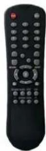
Remote Controller

Installation CD

AAA Battery x 2
② Optional Contents

Internal Hard Disk Drive
natural_image
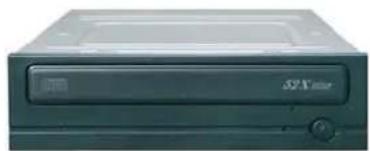
Exterior view of a beige Sony internal drive (no visible text or symbols on body)Internal DVD-RW Drive

natural_image
White and red USB device labeled 'Data Traveler' (no additional text or symbols visible)USB Thumb Drive
Specifications & Organization
- System Organization

flowchart
graph TD
    A["Cameras"] --> B["Video In"]
    C["Camera"] --> B
    D["Video Out"] --> B
    E["Archiving"] --> B
    F["Remote Controller"] --> G["Remote Client PC"]
    H["Network"] --> I["TCP/IP"]
    I --> J["Image Printer"]
    I --> K["AVI Backup"]
    I --> L["Web Client"]
    I --> M["USB Drive"]
    N["VCR"] --> O["Video In"]
    P["VGA Monitor"] --> O
    Q["A/V Monitor"] --> O
    R["CD or DVD-RW"] --> O
    S["Remote Controller"] --> T["Remote Controller"]
Product Description
1. Front Panel (8 and 16-channel models)

① POWER : System Power On / Shutdown
② DISPLAY : Switch Screen Division Modes (and Screen Rotation Mode)
③ SEQUENCE : Toggle Sequence Mode
④ PANIC : Trigger Panic Recording Mode and Panic Relay Output
⑤ ZOOM : Digital Zoom on Live View or Playback
⑥ LOCK : Toggle Front Panel Lock
⑦ ARCHIVE : Go to Archiving Menu
⑧ PTZ : Go to Camera PTZ Control Menu
⑨ SETUP : Go to Main Setup Menu
⑩ SEARCH : Go to Search Menu
⑪ USB PORT: USB Port(s) for either USB Mouse, USB Memory Stick, or USB HDD archiving devices.
⑫ RETURN : Cancel / Deselect / Return to Previous Screen
⑬ ENTER : Confirm / Select / Next Screen
⑭ LED Indicator : Indicates Present System Status. (POWER, REC, NETWORK)
⑮ Channel Selection Buttons (1 \~ 8 / 16) : Select Channel or Input Password Digits
- Directional / Navigation Buttons (UP, DOWN, LEFT, RIGHT, ENTER)
- Remote Controller Input Sensor (IR)
- EJECT : Eject CD-ROM (Optional)
- ◀ ◀ / ◀ : Focus Adjust (Near / Far) or Reverse Play / Fast Rewind
- II: Pause Playback
- ▶ / ▶ ▶ : Iris Adjust (Open / Close) or Forward Play / Fast Forward
- JOG / SHUTTLE : Outer wheel – variable REW or FF; Inner wheel – scroll frame-by frame while PAUSED.
- HOLD : Hold Current JOG / SHUTTLE Position
Tip
- If the Remote Control IR Sensor is blocked, the Remote Controller will NOT function properly.
- When a button is pressed on the Front Panel or on the Remote Controller, the DVR will beep, unless this feature is disabled from the main menu: System Setup → Audio → Buzzer.
Product Description
2. Rear Panel (8 and 16-channel models)
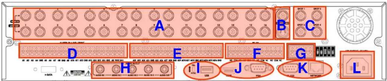
A. CAMERA INPUTS and LOOP OUTPUTS :
Connect up to 16 BNC camera inputs. 16 Hi-Z Loop outputs can be used for connection to other equipment.
B. COMPOSITE AND S-VIDEO MAIN MONITOR CONNECTIONS :
All main monitor outputs can be used at the same time, if more than one main monitor is required.
C. SPOT MONITOR OUTPUTS: Up to 4 spot monitors can be connected and individually configured as necessary.
D. ALARM INPUTS: Up to 16 alarm inputs can be connected and configured as high or low inputs with common ground.
E. ALARM OUTPUTS: Up to 16 alarm inputs can be connected and configured as high or low outputs with common ground.
F. RELAY OUTPUTS: Up to 4 Relay outputs can be connected and configured as high or low outputs with common ground.
G. RS-485 : Can connect to PTZ camera and controller by two RS-485 connectors.
H. AUDIO INPUTS & OUTPUTS: Up to 4 audio inputs and one audio output can be connected as necessary.
I. VIDEO SIGNAL SWITCH : Can change video input signal type between NTSC and PAL formats.
USB PORT : Can connect a USB mouse or other USB device for archiving.
J. HDMI : Can output high-definition video to any HDMI-capable monitor.
VGA : Can output to any type of VGA monitor.
K. RS-232 : Serial port (used for initial factory programming only).
LAN : Connect to a hub, switch, or router with access to a Local Area Network (LAN) or the Internet.
L. POWER : AC power inlet, to be used with provided AC power cable.
Tip
- During installation, please install unit while System Power is disconnected.
- When connecting one or more microphones to the audio input jack(s), please use with a microphone system or some other kind of amplification.
• Without amplification, a line-level input from a microphone is too low to use.
Product Description
3. Front Panel (4-channel model)

① CD/DVD-RW : CD/DVD-RW Device for Archiving.
② Channel Selection Button : Select Channel (1 \~ 4) or Input Password Digits.
③ LED Indicator: Indicate Present System Status Information.
( PWR: System Power On/Off, REC: Record On/Off, ALARM: Alarm Sensor Status, NET: Network Client Connection Status,)
④ Search Controller : Searching Recorded Data or Control Menu & PTZ / FOCUS.
⑤ HOLD : Hold current position of Jog / Shuttle wheel.
⑥ JOG : Navigate through video frame-by-frame, while in Pause.
⑦ Eject : Eject CD / DVD.
⑧ DISPLAY : Switch Screen Division Mode (and Screen Rotation Mode).
⑨ SEARCH : Go to Search Menu.
⑩ SETUP : Go to System Menu.
⑪ PTZ / FOCUS : Go to Camera PTZ Control.
⑫ RETURN : Cancel / Deselect / Return to Previous Screen.
⑬ ENTER : Confirm / Select / Go to Next Screen.
⑭ Remote Controller IR Sensor
⑮ USB Port: USB port for either USB Mouse, USB Memory Stick, or USB HDD archiving devices.
Tip
- Power Button uses "Soft-Off" with Password to prevent accidental shutdown.
• Channel Selection Buttons can be used in most Screen Division modes. - If the IR Sensor is blocked, the Remote Controller will NOT work properly.
- When any Front Panel Button is pressed, it is accompanied by a system beep.
- Depending on the model of CD/DVD-RW installed, the actual appearance of the DVR system may look different from what is pictured above.
Product Description
4. Rear Panel (4-channel model)

A. Video Inputs: Connect up to 4 BNC camera inputs.
Loop Outs : 4 Hi-Z loop outs can be used for connection to other equipment.
B. Main Monitor Out : BNC Main Monitor Output to A/V Monitor.
Spot Monitor Out : BNC Spot Monitor Output to A/V Monitor.
C. NTSC / PAL : Select NTSC or PAL Video Format.
D. Audio Out : Mono, Line Level, Unbalanced, RCA Audio Output Jack.
Audio In : Mono, Line Level, Unbalanced, RCA Audio Input Jacks.
E. DVI OUT : DVI Video Main Monitor Output to Computer Monitor.
F. Alarm / Relay / RS-485 : Connection interface for Alarm Sensor Inputs, Relay Outputs, & RS-485 PTZ.
G. USB Port: use either USB Mouse, USB Memory Stick, or USB HDD archiving devices.
Ethernet (TCP/IP) : RJ-45 10/100 Base Ethernet / LAN connector.
DC Power Input : Connect to provided DC 12V Power Adapter.
Tip
- During installation, please install unit while System Power is disconnected.
- When connecting one or more microphones to the audio input jack(s), please use with a microphone system or some other kind of amplification.
- Without amplification, a line-level input from a microphone is too low to use.
SYSTEM CONFIGURATION – Remote Controller
- Handheld IR Remote Controller

※ If there are multiple DVRs stacked or mounted in a rack, each DVR must be assigned a unique ID number, so that each DVR can be controlled with a single remote controller, referencing each DVR by its own ID.
How to choose which ID to use on the remote controller:
- Press the ID button. The system will display 'INPUT ID'.
- Enter the digits of the unit ID, and then press the ENTER button. (The default unit ID is '01').
- To return back to normal control of the DVR, now press the RETURN button.
- Factory Default Setting: Input unit ID '255' and then press ENTER and RETURN.
CONNECT & POWER ON
- Connect up to 16 CAMERA INPUTS as necessary. The DVR also has LOOP OUTPUTS, so that your video signals can be looped to other equipment, if required. BNC Termination is automatically set by the DVR, depending on the connection type.
- Connect one or more monitors to the DVR using the COMPOSITE, VGA, S-VIDEO or HDMI connections.
- Connect power to the DVR, using the provided AC power cord or DC 12V Power Adapter (depending on model). The DVR will check for proper power connection and emits two beeps if system power test is OK.
- Press the POWER BUTTON on the front panel of the DVR to begin operation.

- The DVR startup screen detects and checks the status of all internal hard drives, and the CD/DVD-RW drive.
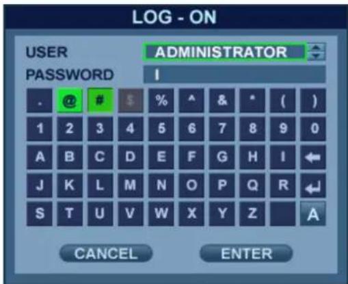
- After startup diagnostics are complete, the operator must login to the system. The default user name is 'ADMIN'.
- Using the CHANNEL SELECTION buttons, key in the digits of the default password ('1234') and then press the ENTER button.
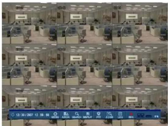
- After DVR startup, the system will show the default display of all 16 channels in a standard 4x4 Screen Division mode.
- The status bar at the bottom of the screen shows the current Date/Time and the percentage of Hard Drive capacity used.
- The title for each channel is shown.
- A red recording icon and the letter 'T' in the top right of each channel shows that the channel is recording in 'Timer' (Scheduled / Continuous) recording mode.
LIVE DISPLAY
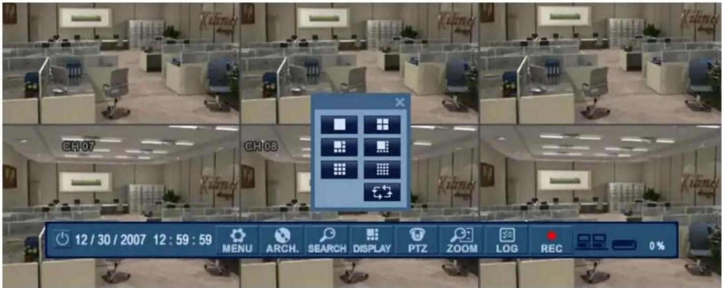
MENU CONTROL

All menus can be controlled from this 'Status Bar' with either the USB mouse or Front Panel buttons.
SCREEN DIVISION

Select the 'DISPLAY' button and the screen division menu will appear.
Select the screen type (1, 4, 6, 7, 8, 9, 13, 16-channel or sequence).
SEQUENCE MODE

(User can select a sequence as one of the options within the screen division menu.)
Press the 'SEQ' button. Each channel is shown full screen for an adjustable duration, before switching to the next channel.
To stop the sequence on a particular channel, press the 'SEQ' button again.
More complex sequences can be programmed through the 'DISPLAY' section of the setup menu.
LIVE DISPLAY
PTZ
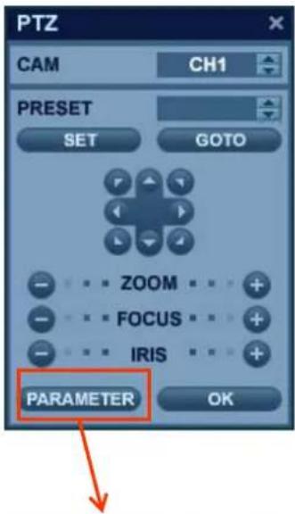

1) CAM: Select the Channel of the PTZ device which you are controlling.
2) Preset: Select the number of the preset you are working with (1 \~ 254).
3) Set: Sets the current PTZ position as the selected Preset number.
4) Goto: Tells the PTZ device to move to the position of the selected Preset.
5) Directional Arrows: moves the PTZ device in the direction specified.
6) Zoom / Focus / Iris: User can control each item with + or - button.
7) Parameter: Press this button and another window will appear.
User can select an item from the PTZ parameter menu, and edit the settings in order to fine-tune the speed of pan-tilt-zoom motions, or to enable advanced features, such as Auto Focus and Auto Iris (only on supported PTZ devices).
DIGITAL ZOOM
Right-Click within Live View mode, and choose 'ZOOM'.
Or select the 'ZOOM' function from the status bar.
natural_image
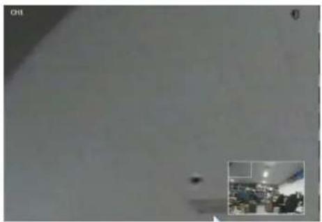
Interior view of a room with a small dark object and an inset photo of a group of people in a meeting room (no visible text or symbols)While viewing a channel in full screen, the user can digitally zoom into a particular area of that channel by up to 8X. The small PIP window at the bottom-right shows the full image and the main display area shows the zoomed portion.
LIVE DISPLAY
LOG SEARCH

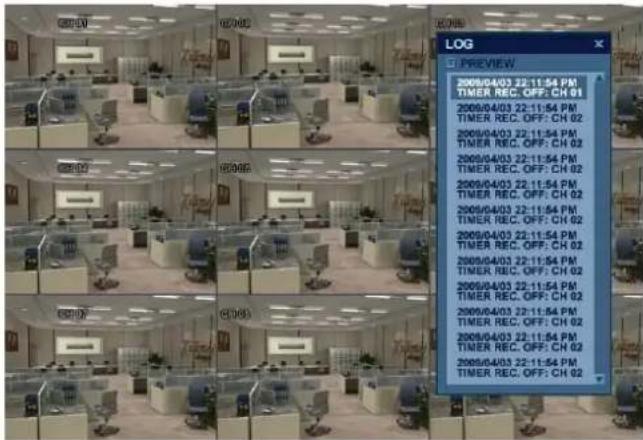
User can see a live event log window, which shows each new event as it occurs.
Click on an event within the live event log window to begin playback from the selected event.
(This will only happen when the 'PREVIEW' option is selected from the live event log window.)
PANIC RECORDING

- This function button is used to toggle the Panic Recording mode On/Off.
- When Panic Recording mode is enabled, you will see a red recording icon with "P" for Panic.
- When Panic Recording mode is enabled, the system will record all channels, as per the Panic Recording settings.
- All resolution and image rate settings related to Panic Recording are configured within the Record menu.
LIVE DISPLAY
QUICK MENU

You may access the 'Quick Menu' by right-clicking on any channel which you would like to control.
-
Freeze On/Off: User can freeze the live display of any channel. While the other channels will continue to show live view video, the frozen channel display is stopped. Click once more to return to live view video.
-
PTZ
User can instantly playback video from a selected time (10, 20, 30 seconds or 1 minute) ago.

In the case of selecting the "go to" option, another menu will appear.
After entering the desired Date / Time, press "OK" to begin playback from there.

- Record Start (Stop)
Please refer to "Panic Record" menu of Page 23.
LIVE DISPLAY

Click the 'MENU' button and choose the 'SYSTEM SETUP' menu.

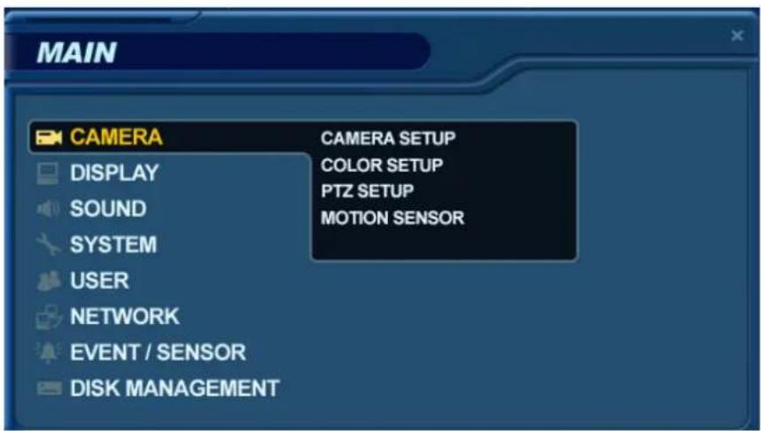
- To navigate around any items in the setup menu, use the CURSOR KEYS and the 'ENTER' and 'RETURN' buttons.
- In general, the 'ENTER' button is used to select a particular field to edit, and then is pressed again to confirm changes.
- The 'RETURN' button is used to cancel or deselect, or to step back one screen while navigating the menu system.
- To configure all system settings, highlight 'SYSTEM SETUP' and press 'ENTER'.
SYSTEM SETUP
CAMERA
From the 'System Setup' menu, click on the 'CAMERA' submenu.
Double-click on the 'TITLE' field to change the camera name.
Click the 'COVERT' or 'AUDIO' fields for the desired channel.
Then, use the button to modify each value.
TITLE: For each camera, a title of up to 11 characters can be set, using the virtual keyboard.
COVERT: When it is set to ON, the camera image is not displayed in live display but continues to be recorded.
AUDIO: Determines the audio recording channel which will be paired with each video channel.
CAMERA : COLOR SETUP
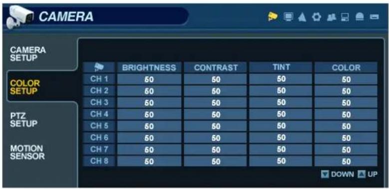

Click on any field to adjust its value.
Modify each value using the button.
While modifying any value within the color setup, the selected channel will be displayed full screen.
BRIGHTNESS, CONTRAST, TINT and COLOR can be modified as necessary.
To modify a different channel, highlight the CAMERA field, and choose the desired channel.
Press RETURN when all changes are completed.
NOTE: These settings will not change the properties of the recorded image, only what is being displayed on screen.
SYSTEM SETUP


Modify each value using the

button.
The selected channel is displayed in full screen mode.
BRIGHTNESS, CONTRAST, TINT and COLOR can be changed as necessary.
To modify a different channel, highlight the CAMERA field, and choose the desired channel.
Press RETURN when all changes are completed.
CAMERA : PTZ SETUP


Click the PTZ SETUP menu.
Click on any field to modify its value.
Change the value by the

button.
ADDRESS: The unique ID of the PTZ device.
PROTOCOL: The protocol of the PTZ device.
BAUD RATE: The baud rate of the PTZ device.
DETAIL : Detail setting for PTZ device. (Refer to the next page.)
PRESET : Tour setting for PTZ device. (Refer to the next page.)
SYSTEM SETUP

Advanced PTZ properties can be adjusted for each channel using the 'DETAIL' button.
Some settings, such as Auto Focus, may not be compatible with all PTZ devices. If this is the case, changing this value will have no effect on PTZ control.

Click the 'PRESET' button and set the MODE to 'AUTO' in order to use the TOUR function.
First, you must choose the channel of the PTZ device which you are configuring the tour for.
Select a valid PRESET number for each step of the tour.
Select the DWELL TIME, which is the amount of time that the PTZ will wait before moving to the next preset.
SYSTEM SETUP
CAMERA : MOTION SENSOR


Click on the MOTION SENSOR menu.
Click on a SENSITIVITY value for the desired channel.
Then use the button to increase or decrease the sensitivity.
SENSITIVITY : Determines the degree of motion required before recording is activated.
(1: Least Sensitive to Motion - 10: Most Sensitive to Motion)
Click the
AREA SETUP
button to edit the motion detection area.
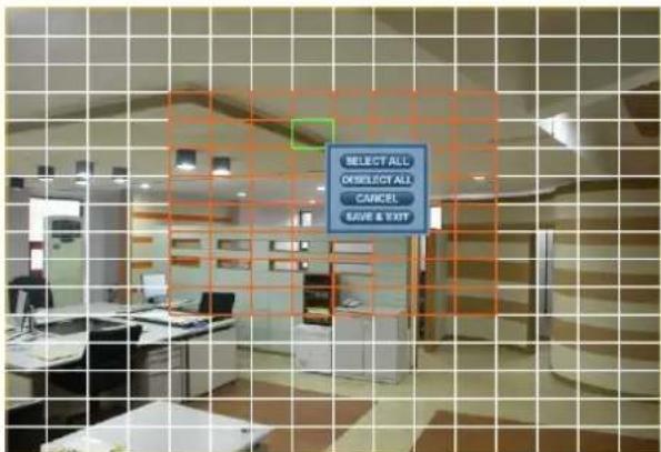
AREA SETUP : Choose this option to define which areas of the image are sensitive to motion.
Click on individual squares to select or deselect each square.
Click-and-drag to select or deselect entire areas of the grid.
To quickly select or deselect the entire grid at once, right-click and choose either 'SELECT ALL' or 'DESELECT ALL'.
- Red outlined grid area: Selected area.
- White outlined grid area: Unselected area.
- Green outlined grid square: Current position of mouse cursor.
SYSTEM SETUP
DISPLAY
From the 'System Setup' menu, click on the 'DISPLAY' submenu.
DISPLAY - OSD


Click on the 'OSD' submenu and then click on any field.
Then, click on the button to modify the value.
STATUS BAR : Toggles the status bar at the bottom of screen in Live View mode ON / OFF.
CAMERA TITLE : Determines whether the camera title is displayed for each channel.
RECORDING MODE ICON : Toggles the DVR recording status icons shown at the top right of each channel window.
BORDER : Determines whether there is a border grid shown around each channel in each Screen Division mode.
BORDER COLOR : If the border grid is set to ON, the user can choose the color of the grid.
MENU TRANSPARENCY : During setup, Live View video can be seen through a partially-transparent menu screen.
Changing this value determines whether the live view is more (higher value) or less (lower value) visible.
MOTION SENSOR DISPLAY : This feature can be used to determine which areas within a channel are detecting motion in real-time. The motion sensor display can be used to troubleshoot false motion activations.
OFF – normal display mode.
ON – areas where motion is detected are highlighted with colored blocks.
MOTION COLOR: The color of the blocks displayed when MOTION SENSOR DISPLAY is set to ON.
LANGUAGE : Determines the DVR Operating System language.
To change any of these settings, highlight 'OSD' and press 'ENTER' to select.
Use the CURSOR KEYS to navigate to the desired option.
Press 'ENTER' to select the option, and use the CURSOR KEYS to change the setting.
Press 'ENTER' to confirm the setting or 'RETURN' to cancel.
SYSTEM SETUP
DISPLAY - MONITOR
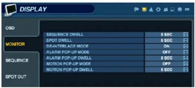

Click the MONITOR menu, then click on any field.
Use the button to modify the value.
SEQUENCE DWELL: The amount of time that each screen is displayed in a sequence.
SPOT-OUT DWELL: The amount of time that each screen is displayed on each of the spot monitor outputs.
DE-INTERLACE MODE : When recording any channels in D1 resolution (704 x 480), this may be set to ON, to prevent interlaced motion distortion during playback.
ALARM POP-UP MODE : When enabled, an alarm input will cause the associated channel to display full screen.
ALARM POP-UP DWELL : Determines the amount of time a full screen popup is displayed after an alarm input. If the alarm condition continues, the pop-up screen will be displayed constantly.
MOTION POP-UP MODE : When enabled, motion detection will cause the associated channel to display full screen.
MOTION POP-UP DWELL: Determines how long the full screen popup is displayed after motion detection. If motion continues, the popup screen is displayed constantly.
To change any of these settings, highlight 'MONITOR' and press 'ENTER' to select.
Use the CURSOR KEYS to navigate to the option required.
Press ENTER to select the option (the cursor changes to orange) and use the CURSOR KEYS to change the setting.
Press ENTER to save the setting, or press RETURN to cancel.
NOTE: When display modes are changed, the DVR must be rebooted in order for changes to take effect.
SYSTEM SETUP
DISPLAY - SEQUENCE


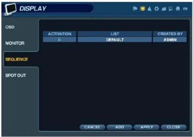
Click the 'SEQUENCE' menu.
- When the 'SEQ' button is pressed, the default sequence will cycle through all 16 channels, one by one, in full screen.
- Sequence setup allows the user to define a custom sequence pattern, using either full screen or mixed multi-screen views, which can be comprised of any number of channels in any order.
- To add a new sequence, highlight 'ADD' and press 'ENTER'.


Click the 'ADD' button to add a new sequence.
- Sequence Title is highlighted. Press 'ENTER' to bring up the virtual keyboard, and key in a name for the new sequence.
Click on the 'ACTIVATION' field, and click the button to turn the sequence activation ON.
Select 'SAVE'. Then, the menu pictured will appear.

SYSTEM SETUP


Click 'ADD'. The "Sequence Setup" submenu appears.
- Determine the Screen Division mode under the "VIEW TYPE" section.
- Assign the desired channel under the "CONFIGURE" section.
- When all sequence settings have been entered correctly, click 'CONFIRM'.
- To add an additional mode, click 'ADD' continuously. After finishing the setup, click 'CLOSE'.
- To modify the current pattern, double click it. The 'Sequence Setup' window will appear again.
- The new sequence has now been saved, and can be started by pressing the 'SEQ' button while in Live View mode.
SYSTEM SETUP
DISPLAY - SPOT OUT


Click on the 'SPOT-OUT' menu.
Each DVR has up to 4 SPOT MONITOR OUTPUTS (depending on model).
Each spot monitor displays a full screen sequence of particular channels, depending on the settings within this menu.
For each spot monitor, the operator can decide which channels are to be displayed in the sequence.
By default, each Spot Monitor output is set to run a sequence of all 16 channels.
SPOT TITLE: Input the title of each spot monitor.
ACTIVATION: Toggle each spot monitor ON/OFF.

- Click 'MODIFY'. (Below is default setup)
- To modify the current display, double-click the display. Then 'Spot Sequence Setup' window will appear.
Setup method is similar to the Sequence setup performed earlier (can only use single or quad mode for spot output).
- To add an additional display, click 'ADD'.
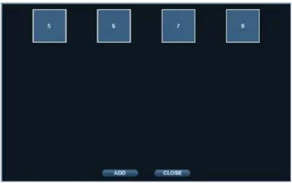
SYSTEM SETUP
SOUND
From the 'System Setup' menu, click on the 'SOUND' menu.
SOUND - AUDIO
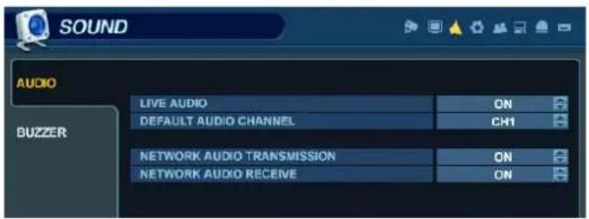

Click on the 'AUDIO' menu, and click on any field.
Use the

button to modify each value.
LIVE AUDIO : When enabled, the selected audio channel can be monitored from the AUDIO OUTPUT.
AUDIO MONITORING CHANNEL : Specify which one of the 4 AUDIO INPUTS is routed to the AUDIO OUTPUT.
NETWORK AUDIO TX : When enabled, live and playback audio is transmitted to a remote PC connection.
NETWORK AUDIO RX : When enabled, allows a remote PC connection to send audio back to the DVR.
SOUND - BUZZER

Click on the BUZZER menu, and click on any field.
Use the

button to modify each value.
KEYPAD: When enabled, each front panel button keypress is confirmed by a system beep.
REMOCON: When enabled, each button pressed on the handheld IR remote is confirmed by a system beep.
SYSTEM SETUP
SYSTEM
From the 'System Setup' menu, click the SYSTEM menu.
SYSTEM - DATE / TIME


Click the DATE / TIME menu, and click on any field.
Use the button to modify any value.
DATE TIME : Allows the operator to set or modify the current system date & time.
DATE FORMAT : Determines the format in which the date is displayed. (MM / DD / YYYY)
TIME FORMAT : Determines how the time is displayed. (AM/PM or 24-hour)
NETWORK TIME SERVER SETUP : If the DVR is connected to the Internet, the time and date can be accurately set by selecting SYNC and pressing ENTER.
TIME ZONE SETUP : should be set according to the region that the DVR is used in.
D.S.T.: When enabled, the DVR will automatically adjust for daylight savings time changes in the spring and autumn.
SYSTEM SETUP
SYSTEM-SYSTEM MANAGEMENT
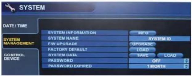

Click on the 'SYSTEM MANAGEMENT' menu.

F/W version: Shows the current firmware version of the DVR.
H/W version: Shows the hardware version of the DVR.
VIDEO SIGNAL TYPE: The DVR automatically switches between PAL and NTSC depending on the video format of the Channel 1 input signal at the time of power on.
DISK CAPACITY: The first value shows the amount of hard drive capacity used by recorded footage. The second value shows the total hard drive capacity installed.
IP ADDRESS: Shows either the manual IP address entered in the 'NETWORK' menu, or the automatic IP address assigned by a DHCP server, if enabled.
MAC ADDRESS: Shows the MAC (Media Access Control) address of the DVR. It is a unique identifier – no other network device has the same MAC address.
DDNS DOMAIN NAME: If DDNS is enabled, the host DDNS server is specified here.
NET CLIENT PORT : The port number that the DVR uses to support remote connection from the client software.
WEB SERVER PORT : The port number that the DVR uses to support remote connection from Internet Explorer or other web browsers.
SYSTEM NAME : This field is used so that notification e-mails can be identified by system name.
SYSTEM SETUP
F/W UPDATE : Firmware updates may be released periodically to enhance system performance and add extra features. The user can upgrade the DVR firmware locally, using a USB memory stick.

Select the Device where the Firmware Update files are located. After selecting the F/W version from F/W list, press 'UPGRADE'. This will start the Firmware Update process.
FACTORY DEFAULT : If settings have been changed which cause erratic behavior, the factory default configuration can be reloaded.
SYSTEM DATA : The system configuration can be saved to a USB memory stick. At any time, it can be reloaded in case of accidental factory reset, or can be transferred to another DVR if multiple units need to be installed with the same settings. All information is saved apart from network settings and system name.
PASSWORD: Determines whether the system must be used every time when entering the menu system.
PASSWORD EXPIRED: Determines the amount of time before the system password expires.
SYSTEM - CONTROL DEVICE


Click on the 'CONTROL DEVICE' menu.
This will allow up to 254 DVRs to be controlled from the same keyboard controller.
SYSTEM ID: If more than one DVR is connected on the same RS-485 bus, each one must have a unique ID.
Note: If more than one DVR is being used, each DVR must have a unique ID to use the Handheld IR Remote Controller.
PROTOCOL: Must be set to match the Protocol of the Control Device.
BAUD RATE: Must be set to match the Baud Rate of the Control Device.
SYSTEM SETUP
USER
From the 'System Setup' menu, click on the 'USER' menu.
USER - USER MANAGEMENT

By default, the DVR is configured with a user ID of 'ADMIN', belonging to the ADMIN group, with a password of '1234'.
Within this menu, you have the ability to add new users, or modify the details for existing users. To modify user details, click or highlight the user with the green cursor square, and press 'ENTER'. The maximum number of users that can be created is 8.
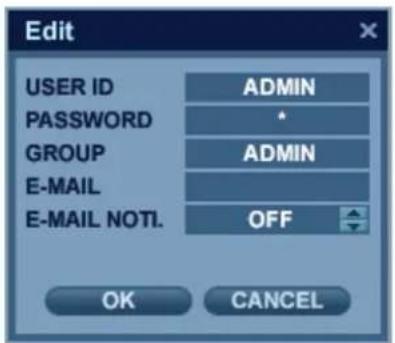

To edit a user account, double-click on the user name. After changing, click 'OK' to confirm changes.
USER ID : Edit the User ID using the virtual keyboard. (maximum of 10 characters)
PASSWORD: Change the password using the virtual keyboard. (maximum of 4 characters)
GROUP : Users can be assigned to one of three groups - ADMIN, MANAGER or USER (see User Authority setup).
E-MAIL : Enter the user's e-mail address if e-mail notification is required. (maximum of 64 characters)
E-MAIL NOTIFICATION : Enable or disable e-mail notification for the specified user.
NOTE: For security reasons, it is recommended that the ADMIN user password be changed after installing the DVR.
SYSTEM SETUP
User can configure the specific authority and permissions for the MANAGER and USER groups.
To confirm changes, click the 'APPLY' button after selecting each of the desired items.
NOTE: Any user can be deleted except the default 'ADMIN' user account.
USER - LOG OUT

AUTO LOGOUT: Determines whether a logged-in user is automatically logged-out of the menu.
DURATION: Determines the amount of time before a logged-in user is automatically logged-out of the menu.
SYSTEM SETUP
NETWORK
From the 'System Setup' menu, click on the 'NETWORK' menu.
NETWORK- IP SETUP


Click on the 'IP SETUP' menu.
DHCP : When enabled, the DVR will obtain an IP address automatically from a router or DHCP server, upon reboot.
WEB SERVICE : When enabled, allows remote connections using Internet Explorer or other compatible web browsers.
IP ADDRESS : If DHCP is not being used, the IP address can be manually set by the user.
GATEWAY : If DHCP is not being used, the gateway IP address can be manually set by the user.
SUBNET MASK: If DHCP is not being used, the subnet mask can be manually set by the user.
1ST DNS SERVER : If DHCP is not being used, the first DNS server can be manually set by the user.
2ND DNS SERVER : If DHCP is not being used, the second DNS server can be manually set by the user.
RTSP SERVICE PORT : If the connected Router supports UPnP (Universal Plug and Play) functionality, when you click
'AUTO PORT', the port forwarding is automatically configured.
WEB SERVER PORT : The port number that the DVR uses to support remote connection from Internet Explorer or other compatible web browsers.
ALIAS : When you enter the DDNS HOST NAME within DDNS setup (see next page), you can see the DDNS Information, for example: http://1234.dvrlink.net:8080
MAX TX SPEED : Specifies the maximum bandwidth that the DVR can use during a remote connection.
SYSTEM SETUP
NETWORK-DDNS

DDNS : When enabled, the DVR can be accessed through a Dynamic DNS server.
(This is commonly used if a particular broadband connection does not have a Static IP address.)
CAUTION:
To use the DDNS function, the user must configure port forwarding.
a. Default WEB SERVICE PORT : 8080
b. Default RTSP SERVICE PORT : 554
The Default DDNS Host Name is the Mac Address of the DVR, so the user can connect through two different ways: (Mac Address or Custom DDNS Host Name)
a. 00115ff00213.dvrlink.net
b. 1234.dvrlink.neet (user can choose any DDNS Host Name)
NETWORK - E-MAIL
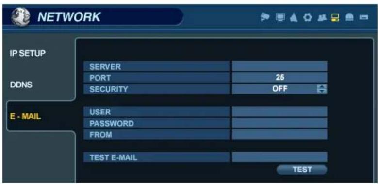
Click on the 'E-MAIL' submenu.
SERVER : The SMTP outgoing e-mail server that will be used to send e-mail notifications.
PORT : The outbound e-mail service port number.
SECURITY : Turn OFF if the SERVER does not require a username and password for SMTP authorization.
USER : Enter the user name for the account which will be sending e-mail messages from the SMTP server.
PASSWORD : If SECURITY is set to ON, enter the password here.
TEST E-MAIL : Test the configuration of the outgoing SMTP mail server.
SYSTEM SETUP
EVENT / SENSOR
From the 'System Setup' menu, click on the 'EVENT / SENSOR' menu.
EVENT / SENSOR - HDD EVENT
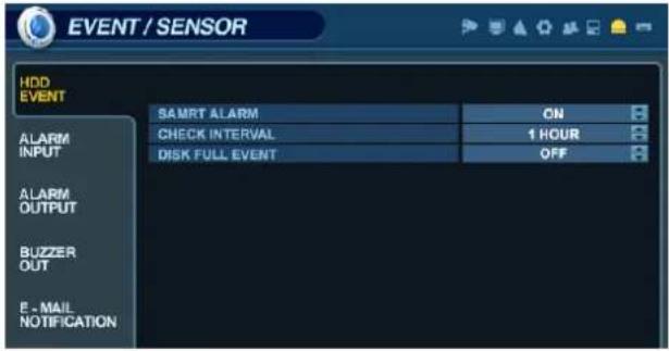

Click on the 'HDD EVENT' menu, and choose any field.
. Use the button to modify the value.
The DVR will continually monitor the health of the hard drives in the system and detect problems that may be developing.
SMART ALARM: Enables S.M.A.R.T. (Self-Monitoring, Analysis, and Reporting Technology) hard disk monitoring.
CHECK INTERVAL: Frequency of testing.
DISK FULL EVENT: Determines whether a 'Disk Full' condition would result in a HDD event.
EVENT / SENSOR - ALARM INPUT


Click on the 'ALARM INPUT' menu, and choose any field.
Use the 📄 button to modify the value.
The menu will determine the behavior of each of the 16 alarm inputs.
OPERATION: Alarm inputs can be enabled or disabled.
TYPE: Alarm inputs can be set as normally open (N/O) or normally closed (N/C).
SYSTEM SETUP
EVENT / SENSOR - ALARM OUTPUT
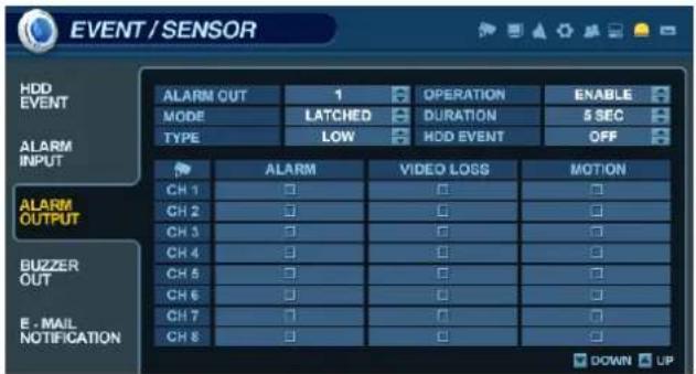

Click on the ALARM OUTPUT menu, and click on a field.
Use the button to modify the value.
This menu will determine the behavior and actions that will trigger each of the 16 alarm outputs.
Behavior settings
ALARM OUT : Choose which alarm output to configure. (1\~16 and R1\~R4)
OPERATION : The selected alarm output can be enabled or disabled.
MODE : Can be either set as 'TRANSPARENT' (the output is active only when the trigger criteria is present) or 'LATCHED' (the output is active for a set period of time after the trigger).
DURATION : In 'LATCHED' mode, the amount of time that the alarm output remains active after it has been triggered.
TYPE : Can be set to high (0V to +5V when activated) or low (+5V to 0V when activated).
HDD EVENT : Determines whether a hard drive event will trigger an alarm output.
Action settings
ALARM : Determines whether the specific channel alarm input would trigger the alarm output.
VIDEO LOSS : Determines whether video loss on any of the selected channels will trigger the alarm output.
MOTION : Determines whether motion detection on any of the selected channels will trigger the alarm output.
NOTE: Remember to select 'APPLY' and press 'ENTER' to save all settings before exiting these menus.
SYSTEM SETUP
EVENT / SENSOR - BUZZER OUT
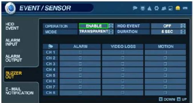
Click on the BUZZER OUTPUT menu, and click on a field.
Use the button to modify the value.
This menu will determine the behavior and actions that will trigger the internal buzzer.
Behavior settings
OPERATION : The internal buzzer can be enabled or disabled.
HDD EVENT : Determines whether a hard drive event will activate the internal buzzer.
MODE : Can be set as either 'TRANSPARENT' (the buzzer sounds only when the trigger criteria is present) or 'LATCHED' (the buzzer sounds for a set period of time after the trigger).
DURATION : In 'LATCHED' mode, the time that the buzzer will continue to sound after it has been triggered.
Action settings
ALARM : Determines whether alarm inputs will activate the internal buzzer.
VIDEO LOSS : Determines whether video loss on any of the selected channels will sound the internal buzzer.
MOTION : Determines whether motion detection on any of the selected channels will sound the internal buzzer.
NOTE: Remember to select 'APPLY' and press 'ENTER' to save all settings before exiting these menus.
SYSTEM SETUP
EVENT / SENSOR - E-MAIL NOTIFICATION

This menu will determine the behavior and actions that will send an e-mail notification to a remote user.
Behavior settings
NOTIFICATION : E-mail notification can be enabled or disabled.
SETUP CHANGE: Determines whether a change to the system configuration would cause an e-mail to be sent.
HDD EVENT : Determine whether a hard drive event would cause an e-mail to be sent.
BOOTING EVENT: Determines whether a booting event would cause an e-mail to be sent.
Action settings
ALARM : Determine whether alarm inputs will cause an e-mail to be sent.
VIDEO LOSS : Determine whether video loss on any of the selected channels will cause an e-mail to be sent.
MOTION : Determine whether motion detection on any of the selected channels will cause an e-mail to be sent.
FREQUENCY : Minimum period of time between sending e-mail notifications (max. 60 minutes).
NOTE: E-mail Notification settings must also be configured within the 'MAIL' and 'USER MANAGEMENT' menus.
SYSTEM SETUP
DISK MANAGEMENT
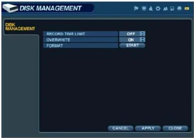

Click on the DISK MANAGEMENT menu.
To manage the internal hard drives, from the 'System Setup' menu, highlight 'DISK MANAGE' and press ENTER.
RECORD TIME LIMIT: In certain circumstances, it may be necessary to limit the amount of footage stored. on the DVR (to comply with data protection laws, for example).
Recording can be limited to the following time periods: 12 hours, 1, 2, 3, 4, 5, 6 days, 1, 2, 3 weeks or 1, 2 months. Once the DVR has reached the recording time limit, the system will start to overwrite the earliest recorded footage.
OVERWRITE: When enabled, the DVR will start overwriting the earliest recorded footage once the hard drive is full. In this case, the percentage of hard drive used shown in live display will always be 99%. When disabled, the DVR will stop recording when the disk becomes full.
FORMAT: If necessary, all recorded footage can be erased from the DVR using this option.
NOTE: When the RECORD TIME LIMIT is set, the percentage of HDD used shown in live display mode may never reach 99%. For example, if the total HDD capacity of the DVR allows for a recording time of 4 days under normal operation, if the RECORD TIME LIMIT is set to only 2 days, the percentage of HDD used would never exceed 50%.
NOTE: When a RECORD TIME LIMIT is set, the OVERWRITE option cannot be changed.
RECORD SETUP


From the Main Menu, click on the 'RECORD' menu.
To configure the recording behavior of the DVR, highlight 'RECORD MENU' and press 'ENTER'.
Click on any field, and use the button to modify the value.
SCHEDULE MODE : Either DAILY (one schedule will apply to every day of the week) or WEEKLY (each day of the week has its own schedule).
PRE-EVENT RECORDING TIME : When the DVR is not in continuous recording mode, this setting determines the amount of footage that is always recorded before an event occurs. (motion detection, alarm input, etc.)
POST-EVENT RECORDING TIME : When the DVR is not in continuous recording mode, this setting determines the amount of footage that is always recorded after an event occurs. (motion detection, alarm input, etc.)
RECORD SETUP
CONTINUOUS / MOTION RECORDING SETUP
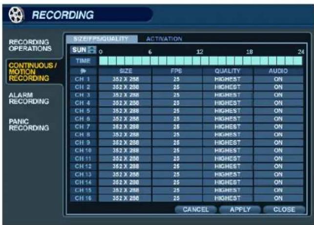

Click on the 'CONTINUOUS / MOTION RECORDING' menu.
This menu allows the operator to configure continuous and motion-activated recording, based on a schedule.
There are 2 sections to this menu:
SIZE / IPS / QUALITY:: Recording settings for each channel can be defined across a 24-hour period, in blocks (for example between 09:00 and 18:00) or by each individual hour. Note that when SCHEDULE MODE is set to WEEKLY, each day of the week can be individually configured.
SCHEDULE: This section determines at what times the DVR will record and whether it is set to continuous or motion.
SIZE / IPS / QUALITY
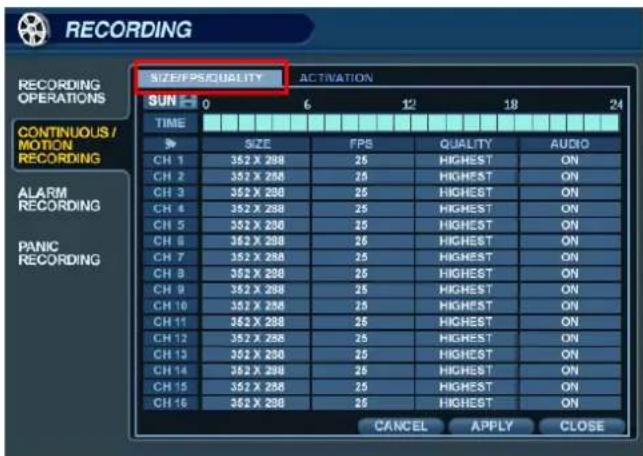

Click on the 'SIZE / IPS / QUALITY' tab.
To change 'SIZE / IPS / QUALITY' settings, highlight 'CONTINUOUS / MOTION SETUP' and press 'ENTER'.
Ensure that 'SIZE / IPS / QUALITY' is highlighted in yellow, and press 'ENTER' again.
The 24 hour time bar is highlighted in green.
RECORD SETUP
SIZE / IPS / QUALITY (continued)

Press 'ENTER' to display the green cursor.
The green cursor square shown represents one hour. (In this case between 00:00 and 01:00).
The table below the time bar shows the recording settings for this time period.

Example: To change the recording settings between 09:00 and 18:00.
Use the CURSOR KEYS to move the green cursor to the 09:00 position and press 'ENTER'.
The cursor changes to orange to show the start position.
Use the CURSOR KEYS to stretch the orange cursor across to the 18:00 position.

Click on the TIMELINE to select a block of time.

Click and drag on the TIMELINE to select a block of time.
RECORD SETUP
SIZE / IPS / QUALITY (continued)


Click on the SIZE, IPS, QUALITY or AUDIO fields.
Use the button to modify the value.
Press ENTER. Recording settings for the selected time period are displayed.
SIZE : Recording resolutions of CIF (352x240), 2CIF (704x240) or D1 (704x480) can be selected for each channel.
IPS : Image rates between 1 and 30ips can be set for each channel.
QUALITY : Four different recording quality levels can be set for each channel.
AUDIO : If audio devices are connected to the DVR, any audio channel can be assigned to any of the video channels.
During playback, when a channel is viewed in full screen, the assigned audio channel will play back at the same time.
Adjust the values as desired and select OK to finish and return to the parameter menu.
Other time periods can be configured in the same manner.
NOTE: Remember that if the SCHEDULE MODE is set to WEEKLY, recording settings need to be changed for each day as well as for each particular time.
NOTE: DR16H supports a maximum recording rate across all channels of 480/400 images per second at CIF (352x240) resolution. (DR8H: 240/200ips, DR4H:120/100ips)
As settings are adjusted, the 'frames available' at bottom left displays the number of available images still remaining and must always be zero or higher.
If, while changing recording settings, this figure becomes negative, recording resolutions and/or image rates must be lowered to increase the 'frames available' value to zero or above.
RECORD SETUP
SCHEDULE
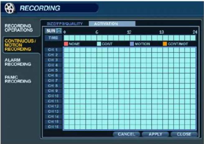

Click on the 'SCHEDULE' menu.
To change 'SCHEDULE' settings, highlight 'CONTINUOUS / MOTION RECORDING' and press 'ENTER'.
Use the CURSOR KEYS to highlight 'SCHEDULE' and press 'ENTER'.
The schedule box is highlighted in green.
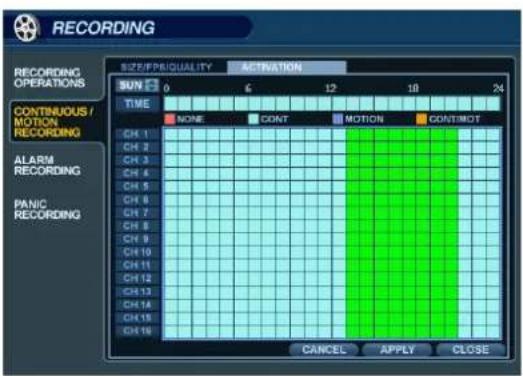

Press 'ENTER' to display the green cursor square.
Example: To set all channels to motion detection recording only between 18:00 and 00:00.
Use the CURSOR KEYS to move the green cursor to the 18:00 position and press 'ENTER'.
The cursor changes to orange to show the start position.
The schedule grid uses differently-colored blocks to denote the different recording modes:
- NO COLOR blocks: No recording.
- LIGHT BLUE blocks: The DVR will record continuously.
- DARK BLUE blocks: The DVR will only record while motion is detected.
- PINK blocks: The DVR will record continuously and with motion event.
RECORD SETUP
ALARM RECORDING


Click on the 'ALARM RECORDING' submenu.
The layout of this menu is very similar to the 'CONTINUOUS / MOTION RECORDING' menu.
This menu screen allows the user to configure alarm-activated recording.
There are 2 sections to this menu:
SIZE / IPS / QUALITY:: Recording settings for each channel can be defined across a 24-hour period, in blocks SCHEDULE: This section determines at what times the DVR will record and whether it is set to continuous or motion.
NOTE: Please refer to the instructions for the 'CONTINUOUS / MOTION RECORDING' menu for details on setting up the 'SIZE / IPS / QUALITY' and 'SCHEDULE' tabs within the 'ALARM RECORDING' menu.
Alarm-activated recording can be used in conjunction with the 'CONTINUOUS / MOTION RECORDING' menu. The DVR can be configured to record continuously at a low image rate ('CONTINUOUS / MOTION RECORDING' menu), and then increase to a higher image rate during an alarm condition. ('ALARM RECORDING' menu)
PANIC RECORDING


Click on the 'PANIC SETUP' submenu. Click on the SIZE, IPS, QUALITY and AUDIO.
During a Panic Recording condition, the DVR will override all other recording settings and record continuously on all channels as per the settings configured here.
SEARCH

To search for a particular section of recorded footage, click or press the 'SEARCH' button.
To protect unauthorized viewing of footage, only ADMIN and MANAGER user groups can playback footage (by default).
To login as ADMIN, enter the default password of '1234' and press 'ENTER'.
SEARCH – SEARCH BY TIME
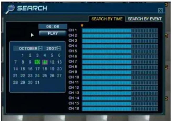

Click on the desired search date from the calendar.
The DVR uses a calendar and timeline search method for quick access to recorded footage.
The calendar displayed on the left side of the screen shows the current month.
Days which have any recorded footage will be highlighted in green.
The timeline on the right side of the screen shows a 24-hour status of all channels for the selected day.
Each block represents 15 minutes of time. Light blue areas indicate the presence of recorded video.
SEARCH


Click and drag the time bar across the timeline.
Press ENTER to select the calendar and use the CURSOR KEYS to move the purple square to the desired day. As different days are selected, the timeline display also changes to show the timeline of recorded footage for that day. Press ENTER to choose the date and move to the timeline.
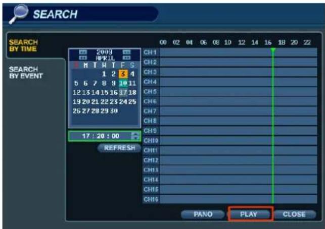

Click the PLAY button on the bottom of the screen.
Use the CURSOR KEYS to move the timeline cursor left or right to select the desired time segment.
Each movement of the timeline cursor increases or decreases the time by 15 minutes.
The currently selected time is displayed above the calendar.
Press ENTER to begin playback from the selected time.
SEARCH
SEARCH MODE : PANO

SEARCH MODE : Multi-Playback
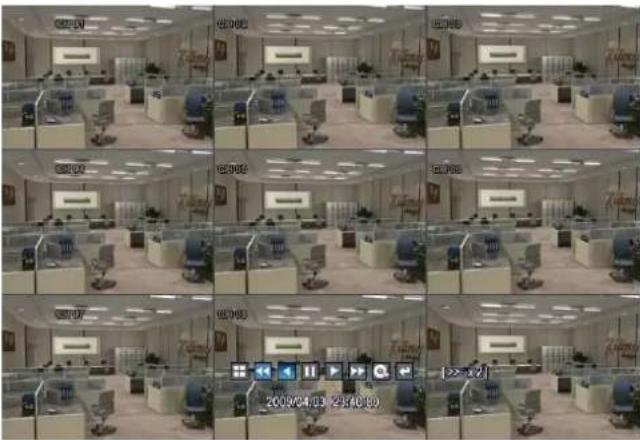


PANO (Panoramic or Time-of-Day Search) :
Each display pane shows 3 hour of data.
CH1:0\~3 o'clock
CH2:3\~6 o'clock
...
CH8: 21\~24 o'clock
User can select different channels and play back using variable play speeds - up to 64x.
The default playback mode is 16-channel view.
By pressing DISPLAY or using the CHANNEL SELECTION buttons, it is possible to display a single screen or other screen display modes similar to the standard live screen display modes.
During playback, turning the SHUTTLE WHEEL steadily clockwise increases the playback speed by up to 64x.
Turning counter-clockwise will reverse play up to 64x. If the SHUTTLE WHEEL is released, playback is paused. If the HOLD button is pressed and released during SHUTTLE WHEEL operation, the last shuttle position is held, even when the wheel is released.
When playback is paused, the JOG DIAL can be used to accurately move the footage forward or backwards, frame by frame. Playback speed and direction can also be controlled using the five playback control buttons located below the jog wheel.
SEARCH
During playback, user can put a bookmark on the recorded data that needs to be archived later.
Click the 📷 button at the time the archive is to be started. Then playback will halt and menu below will appear.

After inputting the "TAG" name, press START. Then the system will return to playback mode.
Click the 📷 button again at the end point of the archive. The menu below will appear once again.

RESERVE : Press this button to reserve the currently selected data.
CONTINUE : Press this button to go back and reserve more data. The system will return to playback mode.
START : Press this button to start the reservation.
STOP : Make sure to press this button to reserve the current data first. Then user can select RESERVE.
CLOSE : Close the reservation menu and finish archiving.
NOTE: Reserved data will be kept on the HDD.
The user can view all of the reserved clips listed in 'RESERVED DATA MANAGEMENT' within the ARCHIVING menu.
SEARCH
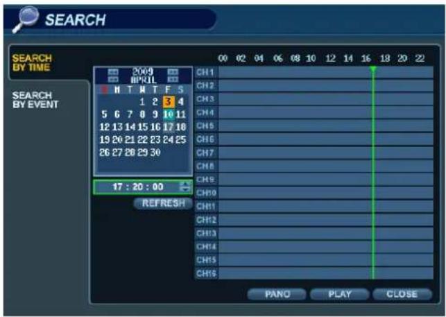
To exit playback mode and return to the search screen in order to choose another time and date, press 'RETURN'.
To exit the search screen and return to Live View mode, repeatedly press the 'RETURN' button.
SEARCH – SEARCH BY EVENT
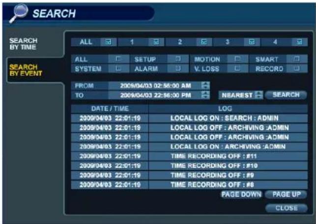
The DVR event log stores events such as motion and alarm activated recording, video loss etc.
To search for an event and playback the recorded footage, press the SEARCH button and log in as ADMIN with the default password of 1234.


Click the 'SEARCH BY EVENT' menu.
Check all desired options. Use the 📁 buttons to select the desired date and time range to search for events.
SEARCH


Click the 'SEARCH' button to search for events.
Highlight 'SEARCH' and press 'ENTER' to display the event log for the criteria selected.
To playback footage for a particular event, select the event from the list using the CURSOR KEYS and press 'ENTER'.

Playback resumes from the moment the selected event occurred and continues until stopped by the user.
During event-based playback, the SHUTTLE WHEEL, JOG RING and playback buttons can be used as normal.
To stop playback and return to live view mode, repeatedly press the 'RETURN' button.
The event log search contains the following selectable entries:
ALARM: When this option is checked, all alarm input events are displayed for the chosen date range.
TIMER: When this option is checked, scheduled recording operations are displayed for the chosen date range.
MOTION: When this option is checked, all motion detection events are displayed for the chosen date range.
ETC: When this option is checked, all other events (video loss, remote logins, etc.) are displayed for date range.
ARCHIVING
To archive recorded footage to a USB Memory Stick or a CD/DVD disc, press the ARCHIVE button.
To protect unauthorized viewing and distribution of footage, only the ADMIN user level can archive footage (by default).
To login as ADMIN, enter the default password of '1234' and press 'ENTER'.
CREATE A NEW ARCHIVE
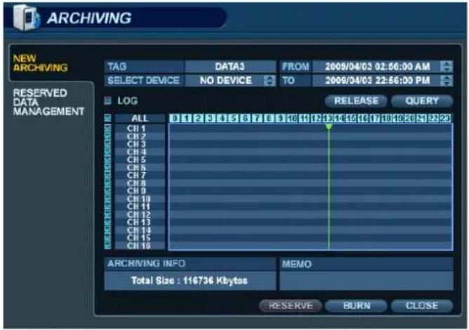

Click on a field to configure each of the archive settings.
Use the button to modify each value.
Click QUERY to view the data size of the selected clip.
It is useful to use 'QUERY' first before selecting 'BURN' or 'RESERVE'.
Press the 'RELEASE' button to reset the results from any previous 'QUERY'.
RESERVE : Press this after inputting the "TAG" name to reserve the selected clip.
BURN : Press this after inputting the "TAG" name. Then press 'START' after viewing the confirmation window.

NOTE: To use a USB Memory Stick, it must be inserted into the DVR before entering the archiving menu.
ARCHIVING
RESERVED DATA MANAGEMENT
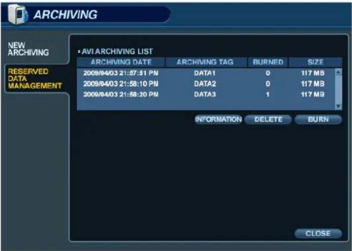
AVI ARCHIVING LIST: User can see the list of data that has been reserved from the 'Create New Archive' menu
INFORMATION : The detailed information of each clip that has been reserved.
DELETE : Delete the selected clip from the list of reserved data.
BURN : Perform an archiving operation using the selected clip.
Once all the desired archive options have been selected, highlight the 'START' button and press 'ENTER'.
The DVR displays a list showing the exact information to be archived and the total archive size.
If the ORIGINAL SIZE of the archive is larger than the amount of available space on the backup media, the END TIME of the archive is adjusted accordingly. The MODIFIED SIZE is the final file size of the archive.
Select "OK" and press 'ENTER' to begin the archiving process.
Once extracted, the footage is copied to CD/DVD or USB.
Depending on the amount of footage selected for archive, the extracting and burning process may take some time, during which the operating system of the DVR cannot be used. Normal recording is unaffected by the archive process.
NOTE: In case the selected data size for archiving exceeds the size of the CD / DVD / USB media being used, the user may choose to continue the archive on additional pieces of media until complete. Insert a new disc or drive after the first archive has completed, and click or press 'CONTINUE'.
WEB CONNECTION SETUP
PRELIMINARY BEFORE CONNECTING
When configuring for a web or remote connection to the DVR, Ports 554 and 8080 should be forwarded within the router.
Refer to the user's manual of your specific model of router for information on port forwarding configuration.
| WEB / REMOTE CLIENT - MINIMUM PC REQUIREMENTS | |
| CPU | P4 (3.0GHz or higher) |
| RAM 512MB (or higher) | |
| Video Card | GeForce MS 400, ATI Radeon 7500 (or higher) |
| GeForce 8 Series (or higher) | |
| Video RAM | 64MB (or higher) |
| Monitor 1280x1024 | |
| Operating System | Windows XP Service Pack 2 (or higher) |
| Web Browser | IE 6.0 (or higher) |
| Network / LAN | at least 100Mbps |
| DirectX Version 7.0 (or higher) | |
HOW TO CONNECT
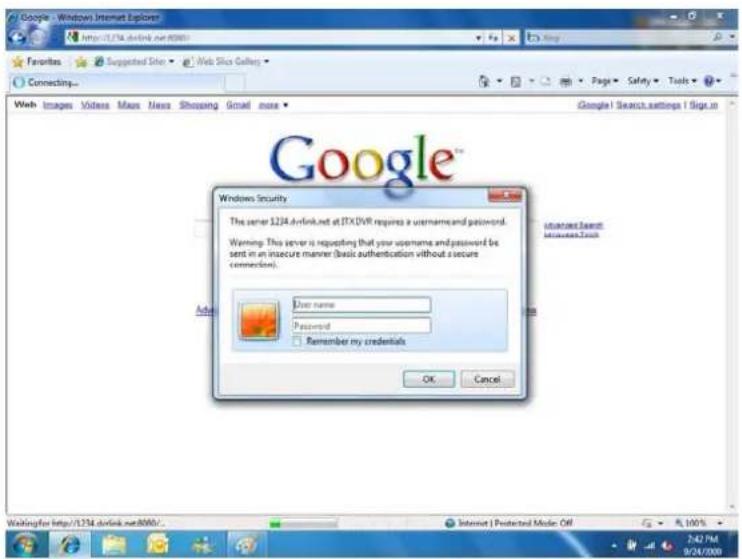
Input the IP address or URL of the DVR into the Address Bar of your web browser.
If using a DDNS service, you may input the URL as shown below:
http://1234.dvrlink.net:8080(webport :8080) or
http://1234.dvrlink.net (webport :80)
WEB CONNECTION SETUP
The default User ID and Password are 'ADMIN' & '1234', respectively.

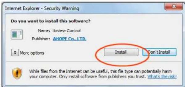
User will need to install the ActiveX control, click Run Add-on.
In case of not being able to install ActiveX, the user needs to enable ActiveX within the IE security menu.

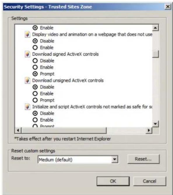
Select 'Enable' for all ActiveX-related options:
("Download signed ActiveX controls", "Download unsigned ActiveX controls", etc.)
WEB CONNECTION SETUP
LIVE MODE

Icons and corresponding functions within LIVE mode:

natural_image
Five simple geometric shapes arranged horizontally: two squares, three grids, and four grids (no text or symbols)


- Select Live View Screen Division (1, 4, 8, 9, 16-channel modes)
- Sequence Mode
- Move to Next Camera
- Full Screen
- Select Live View Channel Manually.
- Activate Microphone to send audio to the DVR audio out jack.
- Toggle Network Audio Receive (from DVR).
- Save the current live image.
- Print the current live image.
- Take a Snapshot of the current live image.
WEB CONNECTION SETUP
- Status : Shows active status indicators of all channels on the DVR.
- Alarm - indicator will be marked when system detects Alarm Input.
- Motion - indicator will be marked when system detects Motion.
- Video Loss - indicator will be marked when system detects Video Loss.
- Recording - Display current recording mode. (T: Timer or Continuous, M: Motion, A: Alarm Recording)
- Alarm Out - indicator will be marked when system detects Alarm Output.
- Refresh Time – interval for the information on the status panel to refresh.

- Log : Display the system event log in real time.

- PTZ : Control any connected PTZ camera remotely.

WEB CONNECTION SETUP
- Pattern – move a camera to a sequence of several preset camera positions in order.
- Preset – set a position of the camera to be recalled later.
- Swing - move a camera between two or more preset points.
SEARCH BY TIME
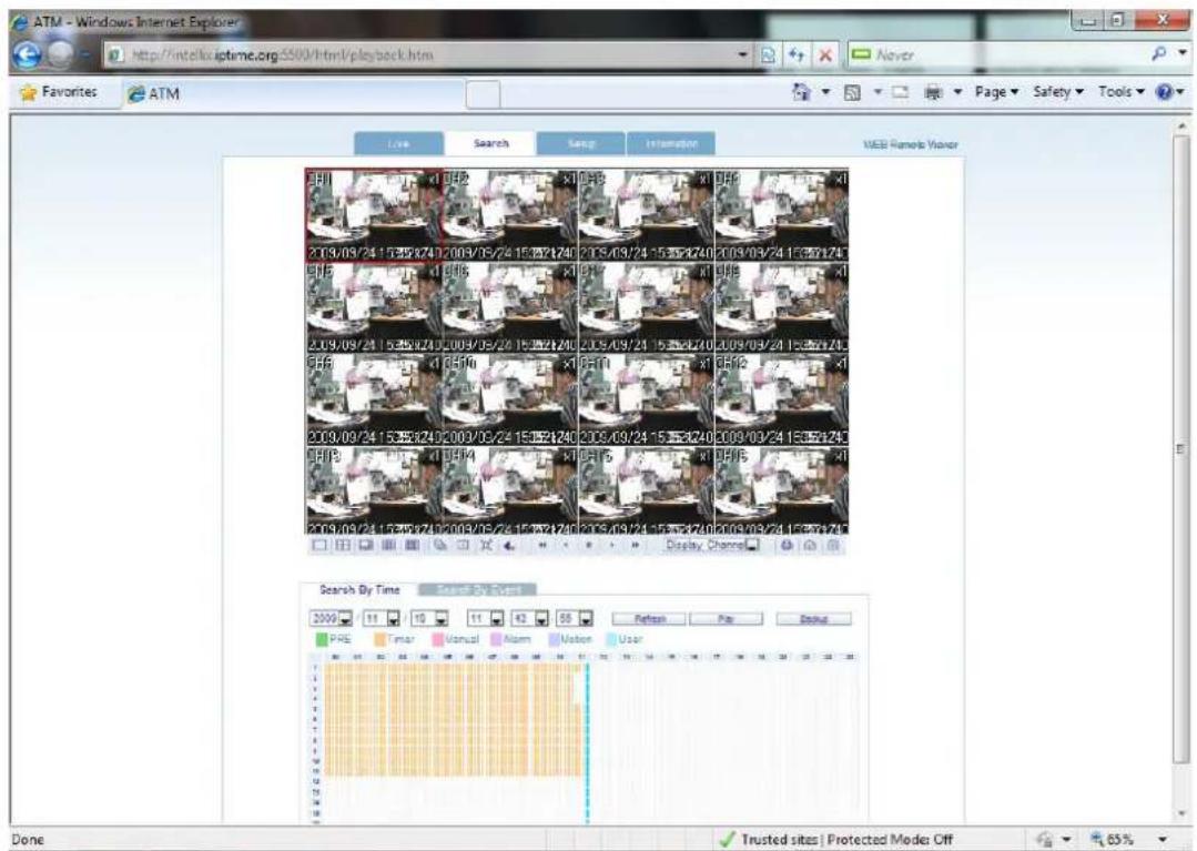
- Select a position on the timeline or set an exact time.
- Press the 'Play' button to begin playback from the selected position.

- Refresh : Refresh all data indicators on the recording table.
- Play : Initiate playback of recorded data from the current position on the timeline.
- Backup : User can archive recorded data remotely from the DVR to the local PC.
WEB CONNECTION SETUP

SEARCH BY EVENT

- Event : Select the types of events to search for within the recorded data.
- Period : Set the date/time range to search for events within the recorded data.
- Search : Begin query, and list all events found within selected range and type.

- Double-click an event from the list to initiate playback, with the specific channel shown in full screen mode.
WEB CONNECTION SETUP
REMOTE SETUP
- CAMERA : User can configure all camera attributes, such as title, covert channel, PTZ, or motion.

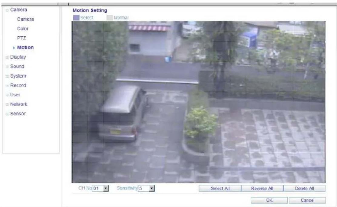
- Motion Area Setup for individually configuring motion areas and sensitivity.
WEB CONNECTION SETUP
1. CAMERA (continued)
1) Select the 'Motion' submenu.
2) Select a channel and the motion sensitivity level.
3) Click and drag the mouse across the image grid to select motion areas.
4) Click OK.
2. DISPLAY
1) OSD - Configure properties for the on-screen display (OSD) of the DVR.

2) Monitor - Set dwell time for sequence, spot monitor output, and pop-up functions.
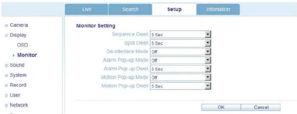
WEB CONNECTION SETUP
3. Sound
1) Audio Setting - Enable live audio, and select a live audio channel.
2) Buzzer Setting - Activate DVR internal buzzer, based on keypress.
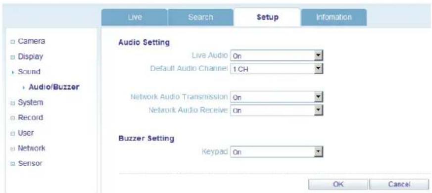
4. System
Configure Date and Time Formats, NTP Time Server, Time Zone and DST properties.
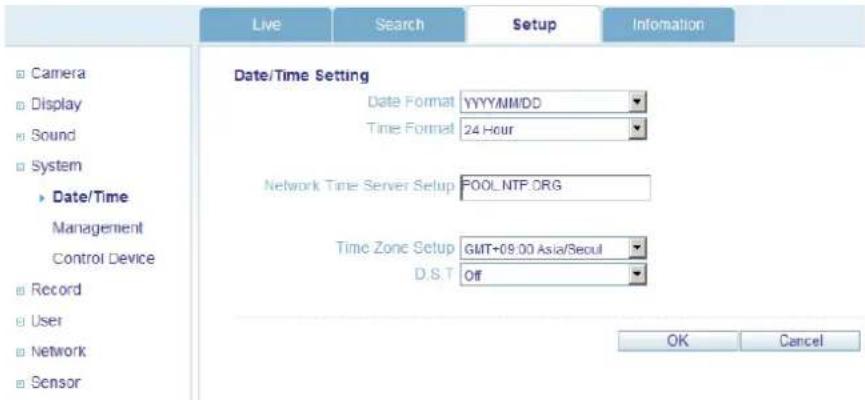
5. Recording
User can configure all of the recording parameters and schedules.
(This is similar to the procedure for configuring these properties on the DVR system.)

other
Continuous / Motion Recording Setting | Time | Resolution | Frame Rate | Quality | Audio | FPS | |---|---|---|---|---|---| | CH1 | 352 * 240 | 15 | Highest | Off | 14 Remain | | CH2 | 352 * 240 | 15 | Highest | Off | 14 Remain | | CH3 | 352 * 240 | 15 | Highest | Off | 14 Remain | | CH4 | 352 * 240 | 15 | Highest | Off | 14 Remain | | CH5 | 352 * 240 | 15 | Highest | Off | 14 Remain | | CH6 | 352 * 240 | 15 | Highest | Off | 14 Remain | | CH7 | 352 * 240 | 15 | Highest | Off | 14 Remain | | CH8 | 352 * 240 | 15 | Highest | Off | 14 Remain | | CH9 | 352 * 240 | 15 | Highest | Off | 14 Remain | | CH10 | 352 * 240 | 15 | Highest | Off | 14 Remain | | CH11 | 352 * 240 | 15 | Highest | Off | 14 Remain | | CH12 | 352 * 240 | 15 | Highest | Off | 14 Remain | | CH13 | 352 * 240 | 15 | Highest | Off | 14 Remain | The chart displays a table with three columns: 'Time' (rows) and 'Resolution' (columns). The values for each cell represent the time in seconds. The 'Continuous / Motion Recording Setting' is highlighted in the top left corner. The 'Size / FPS / Quality' column contains the absolute values of the rows and columns. The 'Activation' column contains the corresponding values of the columns. The 'Frequency' column contains the same columns. The 'Audio' column contains the right-side color bar. The 'FPS' column contains the bottom-right color bar.WEB CONNECTION SETUP
6. User
Add new users, configure existing users, authority level and log out time.

7. Network
User can check the DVR network information and adjust the network bandwidth throttle.
All other IP settings are not allowed to be changed remotely. These settings can only be changed locally.
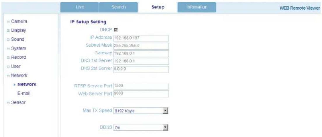
For setting up e-mail notification, user can configure the SMTP server details remotely.

WEB CONNECTION SETUP
8. Sensor
Configure all options for Alarm Input, Alarm Output, Buzzer Out, and E-Mail Notification. The menu structure is very similar to the local DVR system setup for Event / Sensor.

INFORMATION
- Displays the DVR Model and WEB Remote Software Version.

WATERMARK PROCESS
- Open the archive data, and Run the file [bplayer.exe], which is included within the backup folder.

- Click the [Open File] button and choose the backup file you wish to open and verify.


WATERMARK PROCESS
- After selecting the file, you will be asked to confirm whether or not you would like to check the watermark.
- Click the [Yes] button to verify the embedded watermark.
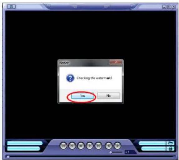


- If the archived AVI file has been modified, a [Verification Failed] message will appear.
SMARTPHONE CONNECTION
- iPhone
- Select the Safari browser.

- Enter the IP address or URL to connect. Click the [GO] button.

- Enter the User ID and Password.
(Default: ADMIN / 1234)

SMARTPHONE CONNECTION
- BlackBerry
- Select the Web browser.

- Enter the IP address or URL to connect, and press the Enter button.

- Enter the User ID and Password.
(Default: ADMIN / 1234)
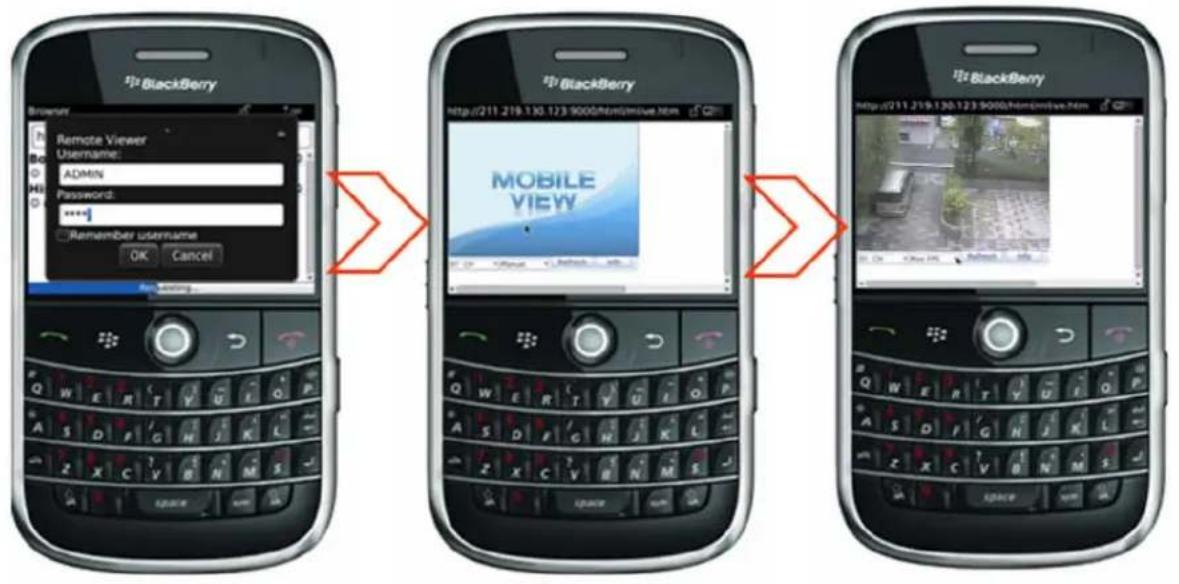

natural_image
Symbol of a trash bin crossed with two diagonal lines, no text or labels present
English
Disposal of your old appliance
- When this crossed-out wheeled bin symbol is attached to a product it means the product is covered by the European Directive 2002/96/EC.
- All electrical and electronic products should be disposed of separately from the municipal waste stream via designated collection facilities appointed by the government or the local authorities.
- The correct disposal of your old appliance will help prevent potential negative consequences for the environment and human health.
- For more detailed information about disposal of your old appliance, please contact your city office, waste disposal service or the shop where you purchased the product.
Français/French
CBC (POLAND) Sp.zo.o
Warszawa
http://www.cbcpoland.pl
CBC Co., Ltd. MOSCOW REP OFFICE
Moscow
http://www.cbc.ru
CHINA
CBC(Beijing) Trading CO.,LTD.
Beijing
http://www.cbc-china.cn/10/
CBC (SHANGHAI) TRADING CO., LTD.
Shanghai
http://www.cbc-china.cn/10/
CBC SHANGHAI CO., LTD. GUANGZHOU OFFICE
Guangzhou
http://www.cbc-china.cn/10/
CBC (H.K.) CO., LTD.
Hong Kong
http://www.cbc-china.cn/10/
ASIA
CBC. S PTE LTD.
Singapore
CBC(THAILAND) CO., LTD.
Bangkok
CBC Corporation (India) Private Limited
Mumbai
CBC Co. Middle East Branch Office
Dubai
http://www.cbceurope.com
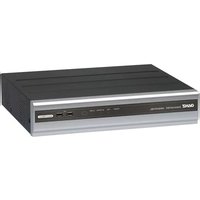
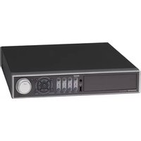
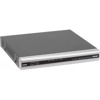

- Specification & Organization 12
- Product Description 16
- Connect & Power On 21
- Live Display 22
- SYSTEM SETUP 26
- Camera 27
- Display 31
- Sound 36
- System 37
- User 40
- Network 42
- Event / Sensor 44
- Disk Manage 48
- RECORD SETUP 49
- SEARCH 55
- ARCHIVING 61
- WEB CONNECTION SETUP 63
- Remote Setup 69
- Introduction
- Notice
- Copyrights
- Caution
- CALIFORNIA USA ONLY
- Safety Warnings and Cautions
- Warning and caution signs
- Warning
- Important Safety Instructions
- Specifications & Organization
- Disposal of your old appliance
- Product Contents List
- Product Description
- Front Panel (8 and 16-channel models)
- Tip
- Rear Panel (8 and 16-channel models)
- Front Panel (4-channel model)
- Rear Panel (4-channel model)
- SYSTEM CONFIGURATION – Remote Controller
- How to choose which ID to use on the remote controller:
- CONNECT & POWER ON
- LIVE DISPLAY
- MENU CONTROL
- SCREEN DIVISION
- SEQUENCE MODE
- PTZ
- DIGITAL ZOOM
- LOG SEARCH
- PANIC RECORDING
- QUICK MENU
- SYSTEM SETUP
- CAMERA
- CAMERA : PTZ SETUP
- CAMERA : MOTION SENSOR
- DISPLAY
- DISPLAY - OSD
- DISPLAY - MONITOR
- DISPLAY - SEQUENCE
- DISPLAY - SPOT OUT
- SOUND
- SOUND - AUDIO
- SOUND - BUZZER
- SYSTEM
- SYSTEM-SYSTEM MANAGEMENT
- SYSTEM - CONTROL DEVICE
- USER
- USER - USER MANAGEMENT
- USER - LOG OUT
- NETWORK
- NETWORK- IP SETUP
- NETWORK-DDNS
- CAUTION:
- NETWORK - E-MAIL
- EVENT / SENSOR
- EVENT / SENSOR - ALARM OUTPUT
- Behavior settings
- Action settings
- EVENT / SENSOR - BUZZER OUT
- EVENT / SENSOR - E-MAIL NOTIFICATION
- DISK MANAGEMENT
- RECORD SETUP
- CONTINUOUS / MOTION RECORDING SETUP
- SIZE / IPS / QUALITY
- ALARM RECORDING
- SEARCH
- SEARCH – SEARCH BY TIME
- PANO (Panoramic or Time-of-Day Search) :
- SEARCH – SEARCH BY EVENT
- ARCHIVING
- RESERVED DATA MANAGEMENT
- WEB CONNECTION SETUP
- PRELIMINARY BEFORE CONNECTING
- HOW TO CONNECT
- SEARCH BY EVENT
- REMOTE SETUP
- CAMERA (continued)
- DISPLAY
- Sound
- System
- Recording
- User
- Network
- Sensor
- INFORMATION
- WATERMARK PROCESS
- SMARTPHONE CONNECTION
- - BlackBerry
- English
- Français/French
- CHINA
- ASIA
Brand : Ganz
Model : Digimaster DR16HD
Category : Surveillance Camera