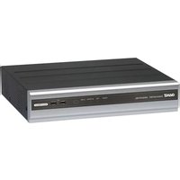
Digimaster DR-16M55-RA - Surveillance Camera Ganz - Free user manual and instructions
Find the device manual for free Digimaster DR-16M55-RA Ganz in PDF.


| Product Type | Outdoor Surveillance Camera |
| Brand | Ganz |
| Model | Digimaster DR-16M55-RA |
| Image Sensor | 1/2.8" Progressive Scan CMOS |
| Resolution | 1920 x 1080 (Full HD) |
| Frame Rate | 30 fps @ 1080p |
| Lens | 2.8 mm fixed lens (90° FOV) |
| IR Range | Up to 30 meters (Smart IR) |
| Day/Night Mode | Auto switching with IR cut filter |
| Weather Rating | IP67 (dust and water resistant) |
| Power Supply | 12V DC / PoE (IEEE 802.3af) |
| Power Consumption | ≤ 5W (typical) |
| Dimensions (W x H x D) | 70 x 180 x 70 mm |
| Weight | 0.5 kg (approx.) |
| Mounting Type | Wall or ceiling mount with bracket |
| Main Functions | Motion detection, alarm I/O, ONVIF support, remote viewing via web or app |
| Maintenance | Clean lens with soft dry cloth; check cables periodically; keep firmware updated |
| Safety | Overvoltage protection, short circuit protection, operating temperature -30°C to 60°C |
| Spare Parts & Repairability | Contact Ganz support for replacement parts; user-replaceable only for mount and power adapter |
Frequently Asked Questions - Digimaster DR-16M55-RA Ganz
User questions about Digimaster DR-16M55-RA Ganz
0 question about this device. Answer the ones you know or ask your own.
Ask a new question about this device
Download the instructions for your Surveillance Camera in PDF format for free! Find your manual Digimaster DR-16M55-RA - Ganz and take your electronic device back in hand. On this page are published all the documents necessary for the use of your device. Digimaster DR-16M55-RA by Ganz.
USER MANUAL Digimaster DR-16M55-RA Ganz
This manual without the manufacturer's approved copy and reprinted partially or in full, or translated into another language is prohibited.
Limitation of Liability
This product is designed to prevent fire and theft is not the main means. We shall not be liable for accidents or damage by using this product can result in liability for accidents or damage
In order to improve the performance of the product without prior notice to the product may be a firmware upgrade.
Content
OVERVIEW
4
4 Safety Instruction
5 Key Features
6 What's included
7 Rear Panel
9 Remote Control At a Glance
PLAY
90
90 If you want to play
INSTALLATION
10
10 Replacing HDD
15 Basic Layout
16 Connecting to an external device
ARCHIVING
93
93 To start the Archive menu
MONITORING
22
24 Live Screen At a Glance
WEB VIEWER
96
96 What is the Web Viewer?
98 Live
102 Search
105 Setup
SYSTEM SETTING
34
34 To move to the System Setup menu
35 Camera Setting
41 Display Setting
49 Audio Setup
50 User Setting
52 Network Setup
58 System Setting
65 Storage
69 Event Setup
78 To start the Record Setup menu
79 Record Setup
MOBILE VIEWER
126
126 nViewer
ARCHIVE VIEWER
141
141 Getting started with the Backup Player
143 Backup Player At a Glance
SEARCH
85
85 To move to the Search menu while in monitoring
85 To move to the Search menu while in playback mode
86 Search Settings
APPENDIX
146
146 Compatible HDD Specifications
147 Troubleshooting (FAQ)
Safety Instruction
This product was tested with a UPS to satisfy EN 61000-4-11 test conditions (voltage dips and short interruptions test) under the EN 50130-4: 2011 standard.
The Company shall not have any responsibility for any accident or damage that may incur during the use of the product. For your safety, we provide a few instructions about installation, manipulation, cleaning, assembly/disassembly of the product as below. So please read carefully and comply with the instructions.
Before installation
Comply with the following instructions to prevent a fire, explosion, system failure or electric shock.
- Remove the power supply module before proceeding.
- Check the input voltage (AC100V–AC240V) to the power supply module before connecting it.
- Keep the product away from humidity.
- Ensure that all devices connected to the product should be properly earth-grounded.
In operation mode
Comply with the following instructions to prevent a fire, explosion, system failure or electric shock.
- If you need to open the cover, consult with a service person who could help you do what you want to do.
- Do not connect multiple devices to a single power socket.
- Keep the product away from dust or too much combustible substances (ex: propane gas).
- Do not touch it with wet hand.
- Do not insert a conductor in the vent of the ventilation system.
- Do not apply excessive force to unplug the power cord.
Disassembly & Cleaning
- When cleaning on the surface, use a dry cloth.
- Do not wipe the product using water, paint thinner or organic solvents.
- Do never dismantle, repair or modify the product by your own.
During installation
To prevent an accident or physical injury and to operate DVR properly, please comply with the followings:
- Secure at least 18 centimeter of distance between cooling fan and wall for a proper ventilation.
•Install the product on a flat surface. - Keep it away from direct sunlight or excessive temperature.
While in use
- Do not apply force to or shake it while using it.
- Do not move, throw away or put excessive force to it.
- Using any unrecommended HDD may cause a system failure. Check the compatibility list and use only compatible HDDs.
{A system failure or data loss caused by an incompatible HDD will void your warranty.}
CAUTION
Replaceable batteries
Risk of Explosion if Battery is replaced by an Incorrect Type. Dispose of Used Batteries According to the Instructions.
Warning to service personnel
Double pole/neutral fusing
Ethernet Instruction
This equipment is indoor use and all the communication wiring are limited to inside of the building or similar word.
Key Features
This product is capable of receiving inputs from up to 16 channels of 5MP camera inputs of video and audio and recording onto a hard disk drive in real-time, as well as providing monitoring, playback and backup footages in excellent quality of 5MP resolution.
It also provides transferring video and audio data to the networked external devices, which allows remote monitoring environment for computers and mobile devices including cell phones.
- Up to 16 channels of 5MP camera video can be displayed at 480 fps in real time.
- Up to 16 channels of 5MP camera videos can be saved at maximum 160 fps.
- Simultaneous recording and playback of maximum 16 channels (at 480fps @ CIF)
•Supports H.264 HP (High Profile) CODEC - Auto alarm feature with self-diagnostics on the system (HDD S.M.A.R.T, system temperature, network error, FAN error, etc.)
•Supports dual streaming for remote access service
•Supports HDD extension (eSATA) - Various search methods (time, event, bookmark, thumbnail and text-in)
•Mass storage backup via USB port or FTP server
•Supports remote access and search using web browser
•Dedicated smart phone applications that can be used with iPhone and iPad or on Android OS
•1080p Full HD GUI
Overview
What's included


natural_image
Exterior view of a remote control with two batteries (no text or symbols visible)
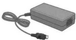
Mouse x1 Remote Control x1 & Batteries (AAA x2) Power Cable x1
natural_image
Exterior view of a gray rectangular electronic device with a black connector and coiled cable (no text or symbols visible)

natural_image
Illustration of a closed book with a series of small mechanical components on its cover (no text or symbols visible)DC 12V Adaptor x1 (90W) Adapter cable retainer clip x1 Screws (For fixing HDD / ODD)


Terminal Block (7P/for 8CH) x2 Terminal Block (9P for 16CH) x2 Terminal Block 10P (for 16CH x4 / for 8CH x2)

Quick Guide
Rear Panel
8 channels
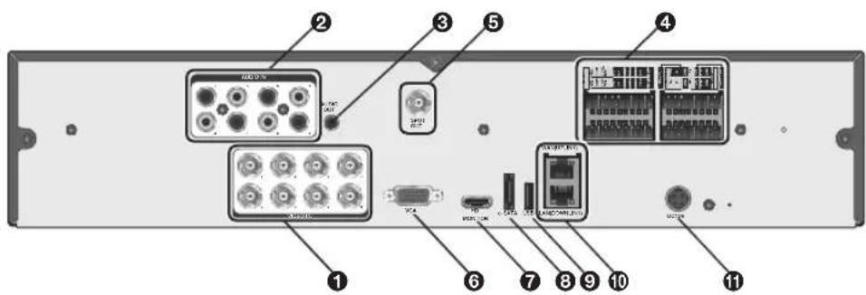
16 channels
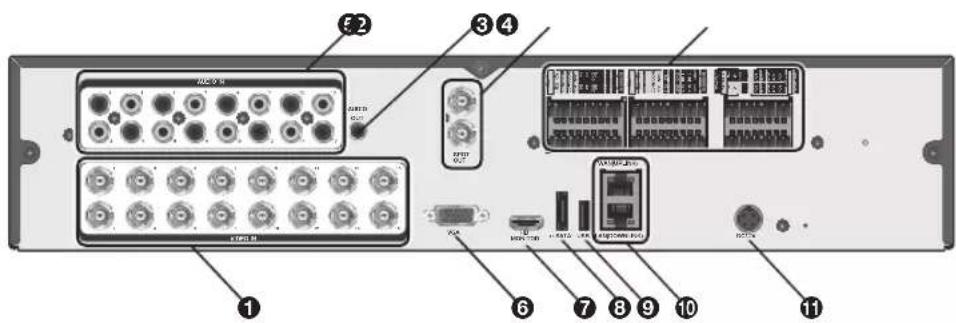
No. Name Description
| 1 | VIDEO IN Video input terminal for cameras. | |
| 2 | AUDIO IN Port for audio input. | |
| 3 | AUDIO OUT Port for speaker connection. | |
| ALARM IN Alarm input signal port. | ||
| ALARM OUT Alarm out signal port. O.C. (Pulled up to 5V via 10KOhm) | ||
| 4 | RELAY Relay Terminal output port. | |
| RS485 Ports for communication with external devices such as PTZ camera and system keyboard. | ||
| RS232 | Connection ports for signal cables to external devices such as PTZ camera, POS and ATM devices. | |
| 5 | SPOT OUT Exclusive port for SPOT output only. (Connect to a TV monitor.) | |
| 6 | VGA VGA monitor video output port. | |
| No. | Name Description | |
| 7 | HD-MONITOR HD monitor video output port. | |
| 8 | e-SATA Connection port for external eSATA storage. | |
| 9 | USB Used for connecting USB storage or mouse. | |
| 10 | WAN(UPLINK) Network port for connection to the Internet, router or hub. | |
| LAN(DOWN LINK) | Port for connecting the dedicated network device.√ Do not share it with other device. | |
| 11 | DC12V Power input port. | |
Remote Control At a Glance

: Installation
Replacing HDD
When an HDD is full or problematic, you can replace it with a new one by yourself.
8 / 16Ch Model
√ Below illustrations are based on the 8/16-channel model.
- Remove 2 screws on both ends of DVR.
- Pull the front side of the unit forward to separate it.

natural_image
Exploded view diagram of a device showing internal components and labeled parts (no text or symbols present)- Hold the middle of HDD bracket's handle with index finger and pull it forward while sustaining the bracket handle with your thumb and middle finger as shown in the illustration.

natural_image
Illustration of a computer drive with a hand inserting a slot into the case (no text or symbols visible)
natural_image
Hand inserting a device into a computer case, showing internal components and a downward arrow (no text or symbols)-
Once the HDD bracket is separated from the main unit, remove 4 screws on both ends of HDD bracket to separate the HDD from the bracket.
-
Install a new HDD and fasten 4 screws back to both ends of the bracket to fix it.
√ When installing HDD, make sure to install in the correct direction.

- Push the bracket installed with new HDD back into the main unit until it is completely inserted.
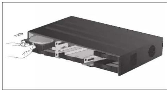
natural_image
Diagram of a computer case with internal components and a hand inserting a cable (no text or symbols visible)- Hold center of the ODD bracket's holder by your index finger and pull it.
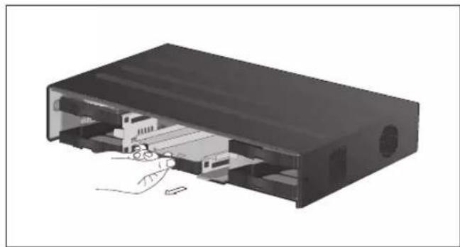
natural_image
3D diagram of an open electronic device showing internal components and wiring (no text or symbols)
Installation
- Install the ODD on the ODD bracket and fix it by fastening 4 screws on the bottom of it.

natural_image
3D diagram of a computer drive chassis showing internal components and mounting points (no text or labels)- Insert the bracket with ODD into the main unit, push it until it's fully inserted.

natural_image
3D rendering of a black electronic device casing with internal components and wiring (no text or symbols visible)- Assemble the front panel back to the unit.
When assembling the front panel to the main unit, make sure the marked part is tightly attached.
- Fasten 2 screws on both ends of the main unit.

natural_image
3D diagram of an electronic device showing internal components and external casing (no text or symbols)If installed 5 HDD drives
√ Below illustrations are based on the 8/16-channel model.
7 Remove 2 screws on both ends of DVR.
2. Pull the front side of the unit forward to separate it.
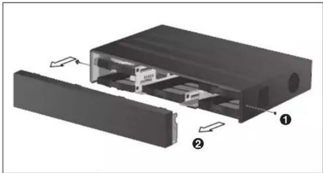
natural_image
Exploded view diagram of a computer case showing internal components and casing (no text or labels)- Hold the middle of HDD bracket's handle with index finger and pull it forward while sustaining the bracket handle with your thumb and middle finger as shown in the illustration.

natural_image
Illustration of a computer drive with a hand inserting a component into the case (no text or symbols visible)
natural_image
Hand inserting a CD into a drive into a memory compartment (no text or symbols visible)
Installation
- Once the HDD bracket is separated from the main unit, remove 4 screws on both ends of HDD bracket to separate the HDD from the bracket.
- Install a new HDD and fasten 4 screws back to both ends of the bracket to fix it.
√ When installing HDD, make sure to install in the correct direction.

- Push the bracket installed with new HDD back into the main unit until it is completely inserted.

natural_image
Diagram of a computer drive showing internal components and a hand inserting a cable (no text or symbols)- Assemble the front panel back to the unit.
When assembling the front panel to the main unit, make sure the marked part is tightly attached.
- Fasten 2 screws on both ends of the main unit.

natural_image
3D rendering of an open black electronic device with internal compartments and external casing (no text or symbols visible)Basic Layout
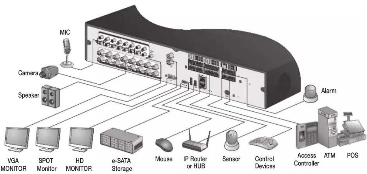
flowchart
graph TD
    A["MIC"] --> B["Speaker"]
    C["Camera"] --> B
    D["VGA MONITOR"] --> E["SPOT Monitor"]
    F["HD MONITOR"] --> G["e-SATA Storage"]
    H["Mouse"] --> I["IP Router or HUB"]
    J["Sensor"] --> K["Control Devices"]
    L["Alarm"] --> M["Access Controller"]
    N["ATM"] --> O["POS"]
! Since the cable quality may affect directly to the video quality depending on the distance between the camera and DVR, it is recommended to consult an authorized installer when installing the DVR.
Connecting to an external device
Connecting to the monitor
This product supports 1080p 60 Hz HDMI monitors and regular monitors that support DVI and VGA inputs. Use the switch on the product's rear side to set it for HDMI or VGA monitor. Connect an HDMI cable to the port on the product's rear bottom, or connect an HDMI-DVI converter cable to connect a DVI monitor. Or, use VGA cable to connect the product with a VGA monitor.
- Once the product is set for NTSC or PAL output, connect cameras of the corresponding video standard for proper operations.
! Make sure to connect the product to a monitor that supports 1920x1080 at 60Hz. (HDMI, DVI, VGA)
Power Connection
Connect the power cable supplied with the product into the power socket on the main unit's rear side.

For stable operation of the product, it is recommended to use the adapter provided. (12V, 10A)
Make connection when the power is not applied yet.
! Arrange up the cables and be careful not to peel off the cable coating.
Do not place the power cord under the carpet or rug. The power cord is usually earth-grounded. However, even if it's not earth-grounded, do never modify it on your own for earth-grounding.
Do not insert multiple devices in a single power socket. Otherwise, it may cause a power overload.
For stable power supply, this product provides two separate adaptors and two corresponding AC cords by factory default. Make sure all cables are connected properly.
Alarm I/O Connection
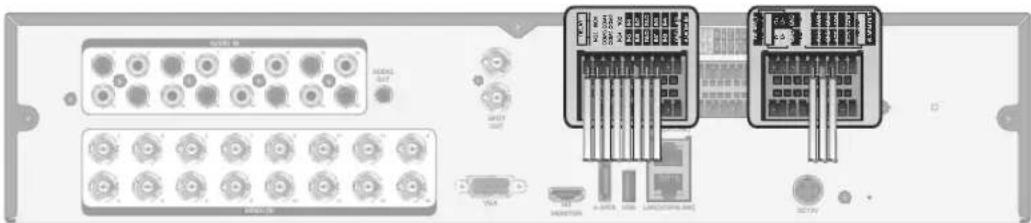
natural_image
Front view of an electronic device chassis showing ports, connectors, and memory drives (no readable text or symbols)To connect the alarm input signal
Connect the signal line of an alarm input device such as sensor to the rear [ALARM IN] port.
7 Loosen the screws on both the alarm input port and [GND] port of the provided terminal block plug.
2. Insert one end of alarm signal cable through the [AO1] or [AO8] terminal hole below the screw hole, and then fasten the screw.
3 Insert the ground signal wire into the hole of the [GND] port (shown also below the screw), and tighten the screw.
4. To check proper insertion of cable, stop pushing and gently pull the cable and test whether it disconnects. To disconnect a cable, push the bottom side of the terminal and pull out the cable.
To connect the alarm output signal
Connect the signal line of an alarm output device to the rear [REL AY] port.
7 Loosen the screws on the [NO] and [NC] ports and the [COM] port of the provided terminal block plug.
2. Insert the alarm signal wire into the hole of the [NO] or [NC] input port (shown below the screw), and tighten the screw.
Check the relay output type of Normal Open or Normal Close before selecting a proper type (NO or NC).
NO(Normal Open) : Normally Open but switching to Close if an alarm out occurs.
COM : Insert the grounding wire.
NC(Normal Close) : Normally Close but switching to Open if an alarm out occurs.
- Insert the ground signal wire into the hole of the [COM] port (shown also below the screw), and tighten the screw.
Or, you can connect the signal cable of the alarm output device to the [ALARM OUT] port on the rear side.
7 Loosen the screws on the [AO1] and [AO8] ports and the [GND] port of the provided terminal block plug.
2. Insert the alarm signal wire into the hole of the [A01] or [A08] input port (shown below the screw), and tighten the screw.
Check the relay output type of Normal Open or Normal Close before selecting a proper type (NO or NC).
3 Insert the ground signal wire into the hole of the [GND] port (shown also below the screw), and tighten the screw.
4. To check proper insertion of cable, stop pushing and gently pull the cable and test whether it disconnects. To disconnect a cable, push the bottom side of the terminal and pull out the cable.
5. Install the wire-connected terminal block in the rear port.
: Installation
Communication Port

RS-485 Connection
Connect a PTZ Camera or Keyboard Controller.
After connecting the control device, be sure to match the connection settings between DVR and device.
Make communication settings in
- Use a signal cable to connect the [D+] port of the terminal block plug and the [D+] port of the keyboard controller.
- Connect the [D+] port of the terminal block plug and the [D+] port of the keyboard controller.
- Connect the [GND] port of the terminal block plug and the [GND] port of the keyboard controller.
√ For RS-485 communication configuration, refer to the user's manual of the applicable PTZ camera or keyboard controller.
RS-232 Connection
You can connect PTZ cameras, POS or ATM devices.
For connection of the text-in device, refer to the user manual of the text-in device.
Audio Device Connection
You can connect an audio output device such as speaker amplifier.
Connect the audio input device such as microphone to the rear Audio In port, connect the audio output device such as speaker amplifier to the Audio Out port.
Storage and Mouse Connection
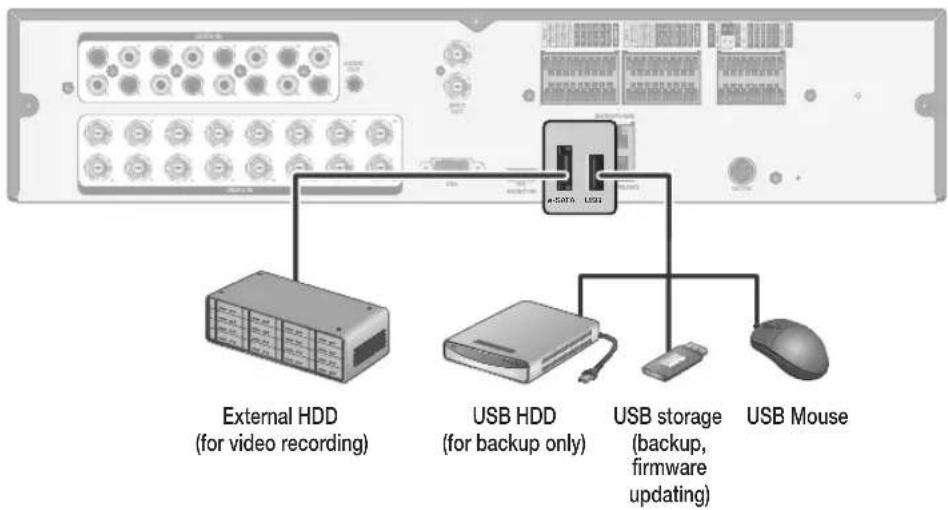
flowchart
graph TD
    A["External HDD (for video recording)"] --> B["USB HDD (for backup only)"]
    B --> C["USB storage (backup, firmware updating)"]
    C --> D["USB Mouse"]
eSATA Storage
If the internal storage space is insufficient, you can extend your storage capacity by adding an eSATA storage device to the rear eSATA port.
Using devices other than recommended eSATA products may cause serious problem.
USB Device
You can connect and use USB storage devices for backup of recorded video, saving snapshots, firmware updating, importing/exporting user configurations. Also, USB mouse can be connected for DVR manipulations.
! If you need to connect a USB HDD with a high power consumption, it is recommended to use a separate power source for that HDD.
: Installation
Network Connection
PC connection in the local network
You can connect DVR to a PC in the same network and control or manipulate it on the PC monitor.

7 Connect the [ETHERNET] port in the rear panel to the router or hub.
2. Connect the local PC to the router or hub.

flowchart
graph TD
    A["Wi Rwanda 2000"] --> B["Broadband router or hub"]
    B --> C["Local PC"]
    B --> D["Local PC"]
    style A fill:#f9f,stroke:#333
    style B fill:#ccf,stroke:#333
    style C fill:#cfc,stroke:#333
    style D fill:#fcc,stroke:#333
- Enter the address in the Web browser of your PC in the format of: "http://IP address:Web service port" (Ex : http://192.168.0.23:8080) The web service port is set to 8080 by default. From the Network Setup screen, you can change the port number.
√ If using the dedicated PC S/W, refer to the user manual of the program.
- Provide the ID and password before logging in. Then, you can view the monitoring screen. The initial administrator ID is "ADMIN" and the password should be set when logging in for the first time.
For security purpose, change the password before you use the product for the first time after purchasing it.
PC connection from a remote network
You can connect DVR to a PC or mobile device in the same remote network and control or manipulate it on the monitor of the PC or mobile device.

flowchart
graph TD
    A["Server"] --> B["Remote PC"]
    A --> C["Smart Phone"]
    A --> D["ADSL modem"]
    A --> E["Broadband router"]
    A --> F["Local PC"]
    A --> G["Local PC"]
    A --> H["Internet Direct Connection"]
    B --> I["Internet"]
    C --> J["Internet"]
    D --> K["Internet"]
    E --> L["Internet"]
    F --> M["Internet"]
    G --> N["Internet"]
- Connect the [ETHERNET] port in the rear panel to the router.
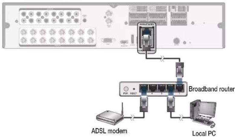
flowchart
graph TD
    A["ADSL modem"] --> B["Broadband router"]
    B --> C["Local PC"]
    D["Local PC"] --> E["Adm/PLM"]
    E --> F["Switch"]
    F --> G["Switch"]
    G --> H["Switch"]
    H --> I["Switch"]
    I --> J["Switch"]
    J --> K["Switch"]
    K --> L["Switch"]
    L --> M["Switch"]
    M --> N["Switch"]
    N --> O["Switch"]
    O --> P["Switch"]
    P --> Q["Switch"]
    Q --> R["Switch"]
    R --> S["Switch"]
    S --> T["Switch"]
    T --> U["Switch"]
    U --> V["Switch"]
    V --> W["Switch"]
    W --> X["Switch"]
    X --> Y["Switch"]
    Y --> Z["Switch"]
- Connect the [ETHERNET] port of the router directly to the fixed IP LAN cable, or connect it to the ADSL modem.
- If using the router, set the port forwarding and enter the DDNS address in the address bar (web browser) of the remote PC, or of the dedicated software program or mobile phone.
For the IP and DDNS address settings, refer to "Network Setup". (page 52) - If the MAC address of the DVR is 00-11-5F-12-34-56 and the web port number is 8080, enter "http://00115f123456.dvrlink.net:8080" in the address bar of the web browser.
If you have renamed DDNS as "mydvr", you can make network connection at http://mydvr.dvrlink.net:8080.
START
- Connect the adaptor to the power input port on the DVR's rear side.
! Make connection when the power is not applied yet. - Turn on the power switch in the rear panel of DVR. With a beep, the logo screen appears several seconds after the front LED turns on.
- When the booting process is completed, the live screen then the login screen appears.

User Information Setup
SET PASSWORD
For enhanced security of DVR, enter a new password on DVR boot.
- Enter a new password in the
field. - Enter exactly the same password in the
field. - Click
. The password changes to the set password.
AUTHENTICATION INFORMATION SETUP
In case you forgot your PASSWORD, you can reset it through email verification.

- Enter your E-MAIL in
for verification. - Click
. E-MAIL ADDRESS is registered.
In case you forgot your password, you can click
Log In
To manipulate or access the menus of DVR, you should have logged in.
- When the system starts, the login screen appears.
- Select a user and provide the password. The initial administrator ID is "ADMIN" and the password should be set when logging in for the first time.
- Click
. If the login information is correct and valid, you will see the live screen.
For security purpose, change the password before you use the product for the first time after purchasing it.

Forgot Password?
In case you forgot your password, you can click
- Click
- Enter the email address you registered on the initial DVR boot, and then click
. - Click
to proceed with the email verification. - Reset the password.

Log Out
To prevent unauthorized access, it is recommended to log out when you leave the screen.
√ Hover the cursor near the bottom of the screen to display the menu.
- In the monitoring screen, click
- While logged out, Search / Backup / System Settings / Record Settings / Exit menus are restricted to use.

System Shutdown
- In the monitoring screen, click
- Use the virtual keyboard to enter the password.
- Be sure to turn off the power switch in the rear panel.
If you turn off the system in an abnormal manner such as removing the power cord while the system is in operation, the disk will have or increase the bad sectors, causing data loss and shortened life cycle of the disk.

Live Screen At a Glance
The live screen largely consists of three components: video window, status bar and timeline zone.

Video Window
Icons used in the video window.
| Item Description | ||
| Camera ID | CAM1 | Show the camera ID. |
| Record Mode Icons | Displayed if an event recording is reserved. | |
| C | Display the status of the continuous recording. | |
| A | Display the recording status when an alarm occurs. | |
| M | Display the recording status when a motion event occurs. | |
| P | Display the status of the emergency recording. | |
| Audio I/O Icons | The audio signal of the connected camera is outputting. | |
| Motion Detection Icon | A motion is detected by the connected camera. | |
Status Bar
Press the [▼] button on the remote control, or place the mouse in the lower area of the screen to display the status bar.
| Item Description | ||
| Menu Button | Select one of the system setup, search and backup menu items before accessing it. | |
| User ID | Show the ID of the user who has currently logged in. | |
| Screen Control Buttons | Edit the screen layout to show the status bar and timeline at all times or only when the mouse cursor hovers on the status bar/timeline. | |
| Select a split mode. | ||
| Select Auto Sequence Mode.When a user arranges channels on desired tiles of split screen, such setting is listed for later access. Selecting a screen setup directly switches the screen mode as configured. | ||
| Display or hide the OSD menu on the screen. | ||
| PTZ | Move to the PTZ screen. You can control the PTZ operations of a PTZ-compliant camera on the PTZ screen. | |
| Zoom | Move to the Digital Zoom. | |
| Quick Log | Display the log list of the recent recording events. | |
| Audio Channel Selection Button | You can use the camera supporting the audio input to listen to the audio. | |
| Panic Record | Start the panic recording. | |
| Alarm Indicator | Turns on if an event occurs. It does not turn on if no reaction to the event is yet defined. Click this to check the information of the event that occurred. | |
| Network Connection Status | Check if network connection is made via an external PC or mobile device. Click this to view the details of the concurrent users and to check the network connection status. For more information, refer to "Network Setup". (page 52) | |
| Disk Space | Show the disk space information. If you have set the disk overwrite mode, it will be displayed "OW" (Over Write) from the start point of the overwriting. Click this to view the details of the disk status. For more information, refer to "Record Setup". (page 79) | |
| Date & Time | 01-01-201513:38:21 | Display the current time and date. |
Timeline
Press the [▶] button on the remote control or move the cursor to the right of the screen to display the timeline. Double-click the timeline to move to the video screen. Drag and drop it to make backup or event search for the specified area.
| Item Description | ||
| Timeline Date |  | Display the date of the current timeline.Click this to select a desired date of the timeline. |
| Expand/Collapse the timeline |  | Expand or collapse the timeline. |
| Navigation through Timeline | [AXZ] | Navigate through the timeline.You can also use the mouse wheel to do the navigation. |
| Timeline Bar |  | Display the recording data with time. The color of each bar indicates the following:•Green : Continuous Recording•Red : Alarm Recording•Blue : Motion Recording•Yellow: Panic Recording |
Quick Menu
Right click on a channel to display a quick menu popup window.
| Item Description | |
| Channel No Display the number of the current channel. | |
| PLAYBACK Start playing the video of the selected channel from the specified time. | |
| ZOOM Operates (digital) zooming on the selected channel. | |
| SNAPSHOT | Capture the current live video and save it in the .jpeg format.√ Then, you can save the captured video in the HDD or export it to an external USB memory device. |
| CAM CHANGE You can assign the selected screen to another channel. | |
| CALIBRATION You can calibrates the camera image. | |
Using the status bar in the live mode
Changing Channel
You can change channel in LIVE/PLAYBACK screen. Right-click your mouse at the selected channel, and then click the [CAMCHANGE] to select your desired [CAMXX]. Or you can drag & drop your desired channel into the screen to assign.(ex: Changing the channels of CAM1 and CAM2)

Using the status bar in the live mode
Selecting a split mode
Click a desired split mode from 1, 4, 9 and 16 split screen. Or press the [DISPLAY] button on the remote control until a desired split mode is displayed.

natural_image
Row of five blue square icons with grid and circular arrows, no text or symbols presentAllocating Live Screen Channel
Move a channel to your desired location by dragging & dropping with your mouse. This enables you to modify the allocation of your views depending on your taste. However, you cannot change the recording channel. These settings are not saved and initialized when restarting your system.
Auto sequence
Click the Sequence button in the status bar, or press the [SEQ] button on the remote control to perform the specified sequence mode.
You can configure the sequence settings in


Monitoring
Controlling PTZ
You can control PTZ cameras connected to each channel. Use the mouse to click PTZ button on the status bar, or press the [PTZ] button of the remote control to initiate the predefined sequence.
In PTZ mode, use buttons on the screen to control
PTZ or use [ZOOM], [FOCUS] and [PRESET] buttons of the remote control.


Pan/Tilt Control
Use mouse to rotate the PTZ camera in the direction of up/down/left/right and diagonal directions.
You can control Pan/Tilt with [▲▼◀▶] buttons of the remote control.
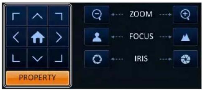
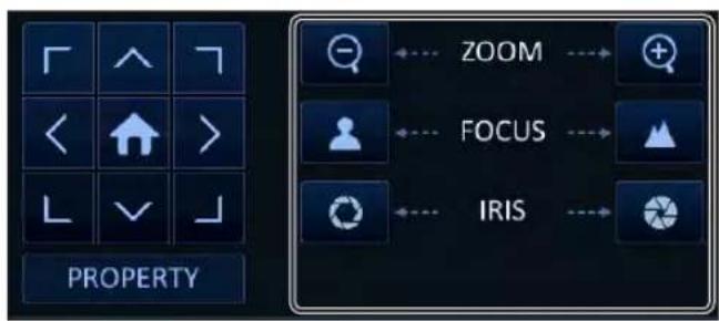
Zoom / Focus Control
You can control the PTZ camera for zooming and focus adjustment.
Click
If the connected camera supports manual iris adjustment, you can adjust the iris setting.
You can control by using ZOOM] and [FOCUS] buttons of the remote control.
- Click
and change to a desired setting of the PTZ camera (for auto focus, auto IRIS, pan/tilt speed, zoom speed, focusing speed, iris speed).
√ Depending on the PTZ camera manufacturer and model, some of the PTZ properties may not be applicable.

CH : Selects the PTZ camera connected to the DVR.
PRESET (No. / Name) : You can select the preset number and name.
√ Up to 255 presets can be selected for a PTZ camera, while up to 16 presets can be registered to one DVR.


Monitoring
- Control the Camera's PTZ while watching the video. Press the
button to append the preset.
: Click the shortcut icon to move to the corresponding PTZ (preset) position.
✗ : Click Delete icon to delete the corresponding preset.
√ PRESET: Memorizes the PTZ camera's framing for direct access at a later time.
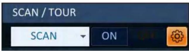
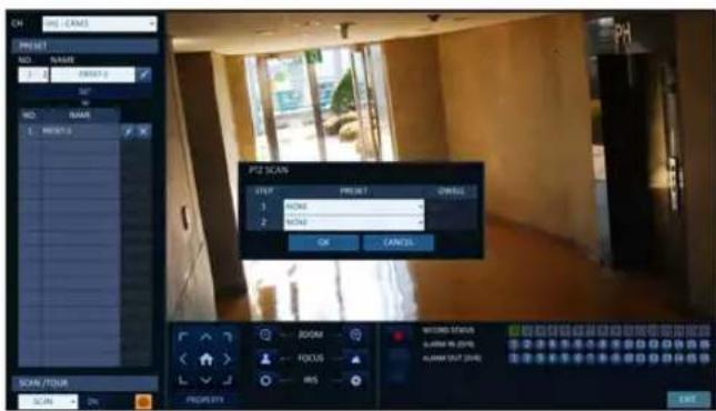
SCAN/TOUR
- Select
and click the button. -
Click the < icon.
-
Select a user-defined preset and register it.
DWELL : Sets the dwell time of 00 seconds before moving to the next preset location.
√function patrols two preset positions at the specified speed and interval for back-and-forth monitoring.
- Select
and click the button. -
Click the < icon.
-
Select a user-defined preset and register it.
DWELL : Sets the dwell time of 00 seconds before moving to the next preset location.
√function patrols multiple presets in order (PRESET 1 → PRESET 2 → PRESET 3 →...) for automated patrolling monitoring.

Digital Zooming
You can enlarge the monitoring screen for better view.
Zooming will enlarge the video of the selected channel. If no channel is selected, channel 1 will be zoomed.
- Click Zoom in the status bar or move the cursor to a desired channel and right-click it to display the context menu. Select
. You can also press the [ZOOM] button on the remote control. - Move to the zoom control screen. When the menu bar appears in the right bottom, use the buttons to control the zooming.
CH1-CAM1 : Select a channel to zoom in/out.
: Zoom out the current (enlarged) image step by step.
: Enlarge the current image step by step.
Zoom Box : Use the yellow box to move to or select a desired zooming area.
EXIT : Exit the zooming screen and return to the live screen.
√ Digital zooming magnifies the video image digitally and produces enlarged images that may not be sharp and clear. For sharper and clearer magnification, it is recommended to use cameras supporting optical zooming.
To check the event log
You can check the log of the events that occurred.
- Click Log to display the "EVENT LOG" window. The log list is sorted with the latest one on top.
- Double-click a desired log to display the event video. You will move to the play screen of the selected log.

natural_image
Interior view of a modern building with large windows and exposed flooring, showing interior space and signage (no readable text or symbols)
Monitoring
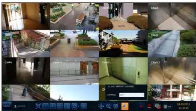
To select an audio input channel
Select a channel from which the audio signal will be received.
CHANNEL : Produces the selected channel's audio, regardless of the split screen mode.
LINK TO FULL SCREEN : When switching the DVR display mode to view one channel (Single Split), it produces the selected channel's audio.
√ A camera supports audio input should be used, and the DVR is connected to a speaker.
To check the alarm status
You can check alarms and events from each camera and the system.
Click

To check the network status
Shows connection status of cameras and network devices. Click to display detailed information on current users and network connections.
Click
√ For more information, refer to "Network Status". (page 55).

flowchart
graph TD
    A["INFO"] --> B["CARTAN"]
    B --> C["Network Node 1"]
    B --> D["Network Node 2"]
    B --> E["Network Node 3"]
    B --> F["Network Node 4"]
    B --> G["Network Node 5"]
    B --> H["Network Node 6"]
    B --> I["Network Node 7"]
    B --> J["Network Node 8"]
    B --> K["Network Node 9"]
    B --> L["Network Node 10"]
    B --> M["Network Node 11"]
    B --> N["Network Node 12"]
    B --> O["Network Node 13"]
    B --> P["Network Node 14"]
    B --> Q["Network Node 15"]
    B --> R["Network Node 16"]
    B --> S["Network Node 17"]
    B --> T["Network Node 18"]
    B --> U["Network Node 19"]
    B --> V["Network Node 20"]
    B --> W["Network Node 21"]
    B --> X["Network Node 22"]
    B --> Y["Network Node 23"]
    B --> Z["Network Node 24"]
    B --> AA["Network Node 25"]
    B --> AB["Network Node 26"]
    B --> AC["Network Node 27"]
    B --> AD["Network Node 28"]
    B --> AE["Network Node 29"]
    B --> AF["Network Node 30"]
    B --> AG["Network Node 31"]
    B --> AH["Network Node 32"]
    B --> AI["Network Node 33"]
    B --> AJ["Network Node 34"]
    B --> AK["Network Node 35"]
    B --> AL["Network Node 36"]
    B --> AM["Network Node 37"]
    B --> AN["Network Node 38"]
    B --> AO["Network Node 39"]
    B --> AP["Network Node 40"]
    B --> AQ["Network Node 41"]
    B --> AR["Network Node 42"]
    B --> AS["Network Node 43"]
    B --> AT["Network Node 44"]
    B --> AU["Network Node 45"]
    B --> AV["Network Node 46"]
    B --> AW["Network Node 47"]
    B --> AX["Network Node 48"]
    B --> AY["Network Node 49"]
    B --> AZ["Network Node 50"]
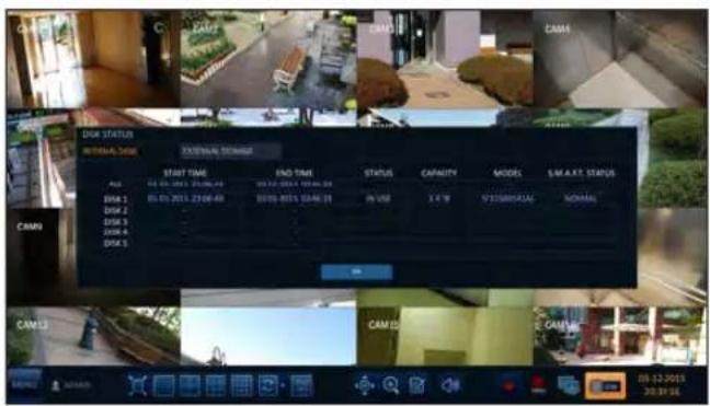
To check the disk status
You can check status and information on storage devices currently connected to the system.
Click
√ For more information, refer to "Disk Information". (page 65).
Saving captured snapshots
You can capture the current video screen and save or export to a connected storage device.
- Select a channel first, and right click to open popup menu, and select
menu item, or press the [SNAPSHOT] button of the remote control.
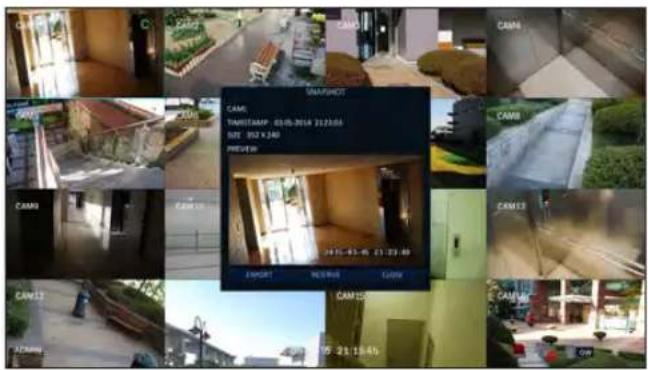
- Connect a storage device, and click
button. To save the captured image onto the built-in HDD, press the button.
√ Saved image can be found in the "Archive > Reserved data management" and can be backed up. (Page 74)
- Enter the
and and press or button.
A progress bar appears and indicates the progress of exporting to storage device.
BURN: Snapshot is stored in the connected USB storage device.
ERASE & BURN : Deletes all files in the connected USB storage and then saves the snapshot.
Note that

System Setting
To move to the System Setup menu
How to use the mouse


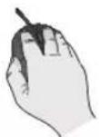


How to use the remote control 1

flowchart
graph TD
    A["ENTER"] --> B["Arrow 1"]
    A --> C["Arrow 2"]
    A --> D["Arrow 3"]
    A --> E["Arrow 4"]


How to use the remote control 2

Camera Setting
You can configure the display settings of: camera title, hidden option, motion and camera type.
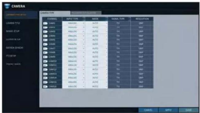
Camera Type Setup
This is used to set up the type of signal for each camera channel.
- From
- , select . - Use the [▲▼◄►/ENTER] buttons on the remote controller or the mouse to set the type appropriate for the camera connected.
√ Not all types are compatible therefore check before connecting the camera.
- To apply the change, click
in the bottom of the screen. - When done, press the [EXIT] button on the remote control or click
in the lower screen. The confirmation message appears and you will return to the previous menu.
√ TVI, AHD are all for analogue cameras, and IPCAM is for network cameras.
√ If the type of IPCAM signal is selected or deselected, the configured signal type will be applied after restarting the system.
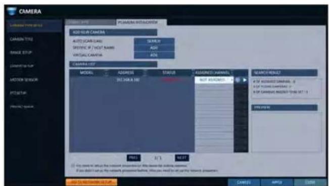
IPcamera Installation
- Cameras connected to the network will be added through
, and can also be added manually by entering an access address with . In addition, it is possible to use it like a camera input by receiving RTSP streaming from equipment which provides a streaming service. - The added IP camera can be allocated to the desired channel. (This applies only to the channel designated as IPCAM from the camera type set-up page.)
- Assign a channel number to the camera searched, and press < 📋 > to add the camera.
- When done, press the [EXIT] button on the remote control or click
in the lower screen to return to the previous menu.
√ Recording may be stopped during additional camera work.
! The HTTP/RTSP port forwarding should be set same as the port of the camera when connecting the camera through the router from an external network.
System Setting
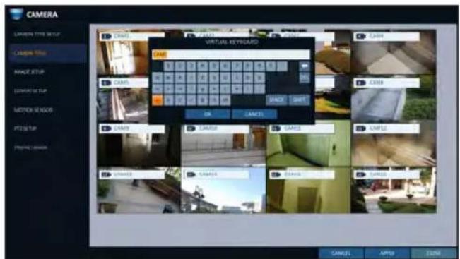
Camera Title
You can change the camera ID that is displayed on the screen.
- From
- , select . - Use the [▲▼◄►/ENTER] buttons on the remote control or use the mouse to select a channel that you want to rename. Alternatively, simply double-click the camera to rename from the top left corner.
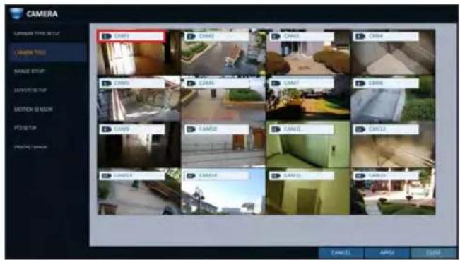
- Once the virtual keyboard appeared, select desired alphanumeric characters to complete your input, and press the
button.
√ The
-
To apply the change, click
in the bottom of the screen. -
When done, press the [EXIT] button on the remote control or click
in the lower screen. The confirmation message appears and you will return to the previous menu.
√ Camera name allows up to 8 letters, combining numbers and upper/lower case alphabets.
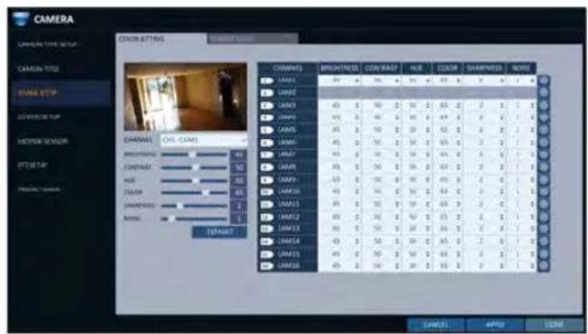
You can edit image settings for video from each camera.
You can adjust brightness, contrast, color and quality setting of each channel's camera. (Not available for HD-SDI cameras.)
- From
- , select . - Use [▲▼◄►/ENTER] buttons of the remote control or mouse to edit settings.
COLOR SETTING : Configures detailed image capturing setup for the camera.
STREAM SETUP : You can specify the camera's codec, resolution and other properties.
- To apply your changes, click
button. - Once completed with setup, press [EXIT] button of the remote control or click
button on the bottom of the screen. A confirmation dialog appears and returns to the previous menu.
√ Press < button for adjusting with preview image.
You can set to hide the camera video so that a specific user or user group can not view. Set a channel(s) that you want to hide from a specific user or user group.
- From
- , select . - Use the [▲▼◀▶/ENTER] buttons on the remote control or use the mouse to select a covert channel(s) from a specific user group.
ADMIN, MANAGER, USER : Set them to
LOG OUT : Set it to
. When the user logs out, the current channel will be set to a covert channel.
SHOWN AS : Sets how achannel will be displayed on the monitor.
- No Video : Nothing is displayed on the monitor for the
channel as if it is not connected to a camera. - COVERT : Hides only the live monitoring.
√ If
3 To apply the change, click
4. When done, press the [EXIT] button on the remote control or click
System Setting
Motion Sensor
Set the motion sensor of the camera so that it can detect a motion event.
- From
- , select . - Use the [▲▼◄►/ENTER] buttons on the remote control or use the mouse to specify the use of each option item.
ACTIVATION : turn on or off the motion sensor.
MARK : Set toto display the motion detection indicator on each video tile where applicable.
SENSITIVITY : Set the sensitivity level of the motion sensor to either Daytime or Nighttime.
EDIT AREA : Specify the motion detection area.

3 To apply the change, click
- When done, press the [EXIT] button on the remote control or click
in the lower screen. The confirmation message appears and you will return to the previous menu.
! The motion detection sensitivity may differ depending on the characteristics of the connected camera or the installation environment.
Motion Area Setup
From the motion setup window, click
- Click
to move to the motion area setup screen. - If using the remote control, press the [ENTER] button to mark the current position.
- Use the arrow buttons to move to a desired block and press [ENTER]. The area setup will begin.
Then, use the arrow buttons to specify the area.
Alternatively, you can use the drag-and-drop method to specify or release the area as using mouse. - If you select the specified area again, it will be released.
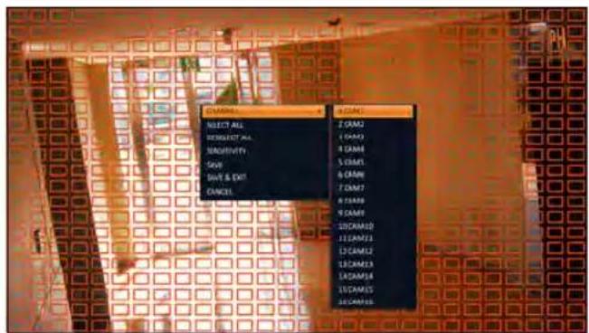
- Press the [EXIT] button on the remote control or right-click any area to display the popup window as in the right picture.
- While the popup window is displayed, select
to set the motion detection sensitivity of the channel currently selected.
Channel: Select the channel to set the motion sensitivity.
- SENSITIVITY: 1(Low) \~ 30(High) - The higher the number is, the more higher the sensitivity level becomes.
DAYTIME : specify the time period that will be considered as daytime.
- DAYTIME : specify the
for the daytime. - NIGHTTIME : specify the
for the nighttime.
√ Images recorded in a low contrast scene such as at night cause severe noise, triggering the motion event too often.
√ If unwanted events occur frequently at night, you may want to reduce the motion sensitivity for the night duty.

PTZ Setup
You can configure PTZ cameras connected to each channel. Set the camera ID, protocol, baud rate and PTZ control speed for each channel.
- From
- , select . - Use [▲▼◄►/ENTER] buttons of the remote control or mouse to set protocol and bitrate of each channel.
RS-485 : You can manually configure RS-485 communication connection to the pan/tilt base (PT driver) of IP Box type camera or motorized zoom lens. Check to enable editing
,and submenu items.
√ Refer to user's manual of the camera or consult camera installation service provider for further details on setting the PTZ camera, such as camera address, protocol and baud rate.

- To apply your changes, click
button. - Once the setup completed, press the [EXIT] button of the remote control or click
button on the bottom to display a confirmation dialog.
Click
System Setting
Privacy Mask
You can edit privacy mask settings and privacy masking areas for video from each camera.
Enabling Privacy Mask
For privacy purposes, you can specify masking area for a selected camera's video.
- From
- , select . -
Use [▲▼◄►/ENTER] buttons of the remote or the mouse to set channels enabled, mask color and its area.
ACTIVATION : Turns on or off the motion detection sensor in the specified privacy area.
MASK COLOR : Select the color of the masked area, which will be displayed on the monitor. -
To apply the change, click
in the bottom of the screen. -
When done, press the [EXIT] button on the remote control or click
in the lower screen to return to the previous menu.
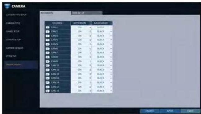
Setting the Privacy Masking Area
You can specify the privacy masking area.
- Click on the tab on the right side to display the area setup page.
- When using the remote, press the [Select] button to show the selector first.
- Use direction keys to move to the desired channel, and press the [Select] button to begin area setup. Use direction keys to set the masking area. When using the mouse, hold the mouse left button and drag to set or cancel the masking area.
- Selecting masked area again will exclude the corresponding block from the masking area.

Display Setting
You can configure screen display setup for On-screen Display, monitor, dual monitor, sequence, spot out, and POS/ATM.
OSD
You can set Camera Name, Icon, Status Bar, Timeline, Borderline, User Name and Language.
- From
- , select . - Use the [▲▼◄►/ENTER] buttons on the remote control or use the mouse to set each option of the OSD item.
CAMERA TITLE : specify the display of the camera title on the screen.
RECORDING MODE ICON : specify the display of the record mode icon on the screen.
STATUS BAR ON FULL SCREEN MODE : select to show or hide the status bar in full screen mode.
- AUTO HIDE : place the cursor in the lower area of the screen to display the status bar. If moving the cursor up, the status bar will disappear.
- ALWAYS ON : The status bar will be displayed at all times.
- 5 SEC \~1 MIN : If no mouse movement is detected for from 5 seconds to 1 minute, the status bar will disappear.
TIMELINE ON FULL SCREEN MODE : select to show or hide the timeline in full screen mode.
- AUTO HIDE : place the cursor in the right corner to display the timeline. If moving the cursor to the left, the timeline will disappear.
- ALWAYS ON : The timeline will be displayed at all times.
- ALWAYS OFF : The timeline will not be displayed.
ZOOM PIP : You can select the
, <1\~5 sec>, etc. to turn ON/OFF the PIP menu displayed in ZOOM screen.
BORDER LINE : specify the display of the cross-border between channels in a split mode
BORDER COLOR : select a color for the border.
USER NAME : specify the display of the currently logged-in users on the status bar.
LANGUAGE : select a menu display language.
- To apply the change, click
in the bottom of the screen. - When done, press the [EXIT] button on the remote control or click
in the lower screen. The confirmation message appears and you will return to the previous menu.
System Setting
Monitor
If you change from monitoring mode to sequence, you will have to set the interval of the sequence.
- From
- , select . - Use the [▲▼◄►/ENTER] button of the remote control or mouse to set the dwell for Sequence mode and SPOT Out dwell.
SEQUENCE DWELL: Sets the time interval to the next screen mode for Live monitoring, which defines individual screen mode's dwell time in the Sequence.
SPOT DWELL: Sets the time interval to the next view type, which defines individual view type's dwell time for SPOT OUT.

-
To apply the change, click
in the bottom of the screen. -
When done, press the [EXIT] button on the remote control or click
in the lower screen. The confirmation message appears and you will return to the previous menu.
DUAL MONITOR
When using the Dual Monitor during surveillance, you can also set the screen mode, type, resolution, and other settings.
- From
- , select . - Use the [▲▼◄►/ENTER] buttons on the remote controller or the mouse to set each item of the Dual Monitor.
DISPLAY MODE : When connecting two monitors, you can set the monitor management type.
- DUPLICATE THESE DISPLAYS : The same screen will be displayed on each monitor at the same time.
- MAIN MONITOR+SPOT : You can use one monitor as the main monitor while using the other as a SPOT output monitor.
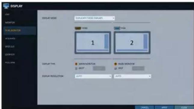
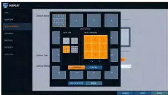
DISPLAY TYPE : Select which monitor to use as the main surveillance and the SPOT output. If you selected the SPOT output monitor, click
to add the view type.
DISPLAY RESOLUTION : Set the resolution for each monitor.
-
To apply the change, click
in the bottom of the screen. -
When done, press the [EXIT] button on the remote control or click
in the lower screen. The confirmation message appears and you will return to the previous menu.
Sequence
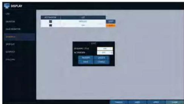
Select a split mode for the sequence, and also select a list of active items when the sequence is performed.
- From
- , select . - Use the [▲▼◄►/ENTER] buttons on the remote control or use the mouse to add a sequence or change the settings of the existing sequence.
ACTIVATION : Select a list that you want to activate the sequence for. Only one list will become active.
ADD : add a sequence.
- To apply the change, click
in the bottom of the screen.

- When done, press the [EXIT] button on the remote control or click
in the lower screen. The confirmation message appears and you will return to the previous menu.
System Setting
To add a sequence
- Click
in the bottom of the screen. - When the "ADD" dialog appears, enter a title using the virtual keyboard.
- Enter the name of the sequence and click
. - When the
dialog appears, click . - When the "SEQUENCE SETUP" dialog appears, select a split mode that you want to add from
.

-
If the selected split mode is displayed on
, select a channel you want to display in each split screen. -
Click
. The set sequence mode is confirmed and will be added to the Add Sequence list in order -
When done, click
in the bottom of the screen. After the sequence type is saved, you will return to the previous screen.

- Place your mouse cursor over a desired tile of added Sequence, right click on it or press the [ENTER] button of the remote control to edit or delete it.
To edit a sequence
- Select a sequence that you want to edit in the list.
- The "EDIT" dialog appears.
- Use the [▲▼◄►/ENTER] buttons on the remote control or use the mouse to edit the selected sequence.
SEQUENCE TITLE : enter a new sequence name.
ACTIVATION : specify the use of the sequence.
MODIFY : change the settings of the sequence mode.
DELETE : delete the selected sequence list.
CANCEL : cancel the changes.
- Pressing the
button will display the Edit Sequence window. - To change the existing settings, select a screen mode that you want to edit and right-click to display the context menu. Then, select
. - When done, click
to close the window. - To apply your changes, click
.

System Setting
SPOT OUT
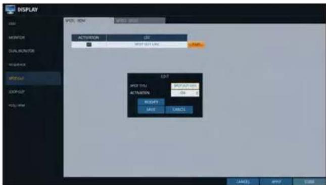
Apart from the main screen display, you can configure the Spot Out to display a Live channel as needed in various live view types.
You can set the live view type of display output through the [SPOT] terminal and activate / deactivate it.
- From
- , select . - Use [▲▼◄►/ENTER] button of the remote control or mouse to edit Spot Out properties.
SPOT TITLE : Name the Spot Out setup.
ACTIVATION : Set whether to activate / deactivate the spot out setup.
MODIFY : Edit the view type of the spot output.
SAVE : Save the changes of spot output settings.
-
To apply your changes, click
button. -
Once completed with setup, press [EXIT] button of the remote control or click
button on the bottom of the screen. A confirmation dialog appears and returns to the previous menu.
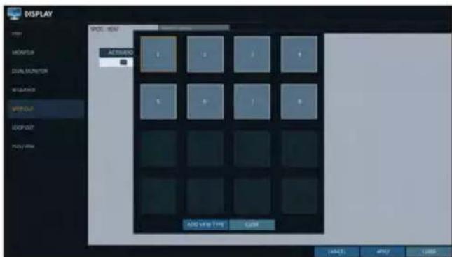
To add a View Type to a Spot Out
- Select an item from the SPOT Output list to be changed.
- The "MODIFY" window appears, click
button. - When the View Type selection window appears, click
button. - Select the desired View Type and configuration, and click
button. - Complete adding and click
to close the edit window

To edit or delete View Type of the SPOT Output
- Select an item from the SPOT Output list to be changed.
- The "MODIFY" window appears, click
button. - When the View Type selection window appears, select the desired View Type to be edited or deleted, and press [ENTER] button of the remote control or right click on it.
MODIFY : Displays "SPOT SETUP" window for editing View Type and other properties.
DELETE : Deletes the selected View Type.
- Complete editing and click
to close the edit window.

LOOP OUT
Video signal can be sent to other devices.
- From
- , select . - Press the [▲▼◄►/ENTER] button on the remote or use mouse to set whether to send out a camera's video or not. Hardware type video LOOP OUT is not supported in some models. If you want to use the Y-shape cable to configure the video loop, change the
to . - To apply your changes, click
button. - Complete editing and click
to close the edit window.

System Setting
POS/ATM
You can change the settings required to interlock the POS/ATM device connected to DVR.
- From
- , select . - Use the [▲▼◄►/ENTER] on your remote control or use the mouse to change the POS/ATM settings.
DISPLAY MODE : You can select the screen where the data entered from POS/ATM are displayed.
- OFF: Nothing is displayed on screen.
- BOTH : Both LIVE and PLAYBACK screens are displayed.
- LIVE : The POS/ATM data are displayed on the LIVE screen.
- PLAYBACK : The POS/ATM data are displayed on the PLAYBACK screen.
POSITION : Select LEFT or RIGHT for the screen position.
FONT SIZE : Select SMALL, MEDIUM or LARGE for your desired font size.
√ The font size is applied to a single split screen only.
FONT COLOR : Select WHITE, GRAY, YELLOW, BLUE, GREEN or RED for your desired font color.
DWELL TIME : You can set how long the data is displayed on screen.
- UNTIL NEXT : Keep the data displayed on screen until the next data are input.
- 1\~60SEC : The data are displayed for the specified time.
SCROLL TYPE : Set the scroll type for screen.
- CLEAR : Display the screen without scrolling.
- ROLL UP : Display the screen with roll-up type scrolling.
HIGHLIGHT TEXT : Select whether to activate the highlighted text or not before entering the text and specifying its color.
EXCLUDE TEXT : Select whether to activate the excluded text or not before entering the text.
√ The POS data are displayed only in 1-, 4-, 6-, and 8- split screen.
- To apply the change, click
in the bottom of the screen. - When done, press the [EXIT] button on the remote control or click
in the lower screen. The confirmation message appears and you will return to the previous menu.

Audio Setup
You can configure audio related settings (channel and network transfer) and signal beep for remote control operations.
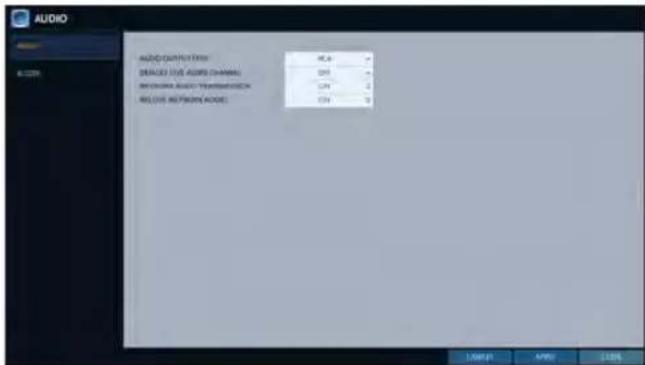
Audio
Choose whether to receive the live sound source and select an audio channel.
- From
- - Use the [▲▼◄►/ENTER] buttons on the remote control or use the mouse to select an item that you want to edit.
AUDIO OUTPUT TYPE : You can select and use the conventional RCA audio output or the HDMI audio output.
DEFAULT LIVE AUDIO CHANNEL : select an audio channel to monitor on the live screen.
NETWORK AUDIO TRANSMISSION : decide if DVR transfers the audio signal to the remote client. DVR → PC (Remote Client)
RECEIVE NETWORK AUDIO : decide if DVR receives the audio signal from the remote client. PC (Remote Client) → DVR
- To apply the change, click
in the bottom of the screen. - When done, press the [EXIT] button on the remote control or click
in the lower screen. The confirmation message appears and you will return to the previous menu.
Buzzer
You can set to output the buzzer if you manipulate the remote control.
- From
- - Use the [▲▼◄►/ENTER] buttons on the remote control or use the mouse to select an item that you want to edit.
REMOTE CONTROLLER BEEP : specify the output of a beep when you press a button on the remote control.
KEYPAD : Select whether to output the buzzer when pressing keypad or not.
-
To apply the change, click
in the bottom of the screen. -
When done, press the [EXIT] button on the remote control or click
in the lower screen. The confirmation message appears and you will return to the previous menu.

System Setting
User Setting
You can configure the settings regarding user management and user and group permissions.
Management
You can add a user account(s) that can be edited at a later time.
- From
- , select . - Use the [▲▼◄►/ENTER] buttons on the remote control or use the mouse to add a user account or select an item that you want to edit.
- To apply the change, click
in the bottom of the screen. - When done, press the [EXIT] button on the remote control or click
in the lower screen. The confirmation message appears and you will return to the previous menu.

To add a user account
- Click
in the bottom of the screen. - Use the [▲▼▲▶] buttons on the remote control and move to a desired item. Then, press [ENTER] to select the item.
USER ID : enter the user ID using the virtual keyboard.
PASSWORD : With the virtual keyboard, enter the password.
GROUP : From, And , select a group that the user belongs to.
EMAIL : Type in the e-mail address to which you will receive notification of an event if it occurs.
EMAIL NOTIFY : Choose whether you will receive notification of an event if it occurs.
√ To use
COVERT CHANNEL : You can set the channel to hide from a specific user.
√option hides the video of the selected channel from being displayed on the screen.

3 When done, click
The added user account will be listed.
To edit the user account information
- From the list of users, select a user account to edit and click
next to it. - From the Edit window, make necessary changes and click
. - To delete the user account, click
.
√ Theaccount can not be changed or edited.

Group Authority
You can grant different user groups different permissions to a specific menu.
- From
- , select . - Use the [▲▼◄►/ENTER] buttons or use the mouse to set the permissions for both
and groups.
SEARCH : Set the permissions for the Search menu.
ARCHIVING : Set the permissions for the Backup menu.
SYSTEM SETUP : Set the permissions for the System Setup menu.
RECORD SETUP : Set the Access Permissions for the Record Setup menu.
EVENT ACTION CONTROL : Set the permissions to output the alarm or control the buzzer if an event such as alarm occurs.
LISTEN TO AUDIO : Set the permission to listen to the audio.
REMOTE LOG IN : Set the permission to access remotely.
SHUTDOWN : Set the permission to shut down DVR from the System menu.
√ Theaccount is the master account allowed for all permissions, which is not edited for individual permissions.
- To apply the change, click
in the bottom of the screen. - When done, press the [EXIT] button on the remote control or click
in the lower screen. The confirmation message appears and you will return to the previous menu.
System Setting
Network Setup
You can set IP address, DDNS and E-mail settings, check network status and RTP.
IP Setup
Specify the IP address as well as the remote service port.
- From
- , select . - Use the [▲▼◄►/ENTER] buttons on the remote control or use the mouse to select one between
and . - When done, press the [EXIT] button on the remote control or click
in the lower screen to return to the previous menu.
IPv4
DHCP : If it is checked, set the IP address of the DVR to Dynamic IP. - If the
item is checked, the sub items of IP address, gateway, subnet mask, primary DNS server, secondary DNS server will be filled in automatically.
! If you select to obtain an IP address from the
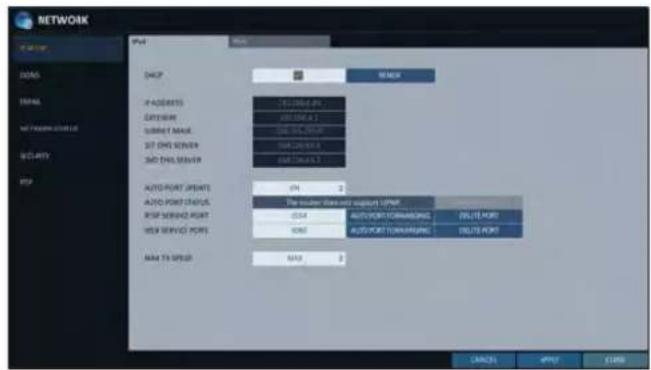
RENEW : The network server restarts and re-allocates dynamic IP address.
IP ADDRESS : Provide the IP address.
GATEWAY : provide the gateway address.
SUBNET MASK : provide the subnet mask address.
1ST DNS SERVER : Enter the address of the primary DNS server.
2ST DNS SERVER : Enter the address of the secondary DNS server.
AUTO PORT UPDATE : Regularly updates the selected WEB and RTSP ports of the router through UPNP function.
AUTO PORT STATUS : You can check AUTO PORT FORWARDING setup is properly configured.
RTSP SERVICE PORT : port number that the remote client receives the DVR video from.
WEB SERVICE PORT : port number used for connecting to the DVR with the web browser.
PORT FORWARDING : If you are using a router, you can set the port forwarding so that external access to the DVR is enabled. If the router does not support the uPnP protocol, you must set the port forwarding manually. For more information, contact your network administrator.
DELETE PORT : release the port forwarding settings for the router.
MAX TX SPEED : Limit the network transfer rate to access a remote client. The video signal may be transferred at a less rate than specified, which depends on the status of your network connection.
IPv6
IPv6 : You can select OFF or ON for IPv6.
- OFF
- ON (MANUAL)
- ON (AUTO)
RENEW : The network server restarts and reallocates IPv6 IP address.
IP ADDRESS : Provide the IP address.
GATEWAY : provide the gateway address.
1ST DNS SERVER : enter the address of the primary DNS server.
2ND DNS SERVER : enter the address of the primary DNS server.

You can configure the DDNS settings so that remote users who are connected to the network can access remotely.
√ DDNS is an IP redirection service in a dynamic IP environment that redirects (maps) the new IP address to a registered domain name each time the IP address is changed.
- From
- , select . - Use the [▲▼◄►/ENTER] buttons on the remote control or use the mouse to specify the use of DDNS and select a server.
DDNS : Specify the use of DDNS connection.
DDNS SERVER : Select a server to connect to.
DVR NAME : Enter the name of the DVR that you want to use as DDNS.
DDNS REGISTRATION TEST : Check if thecan be set as DDNS. If there is a duplicate name in the server, the registration will
fail. If this is the case, rename the
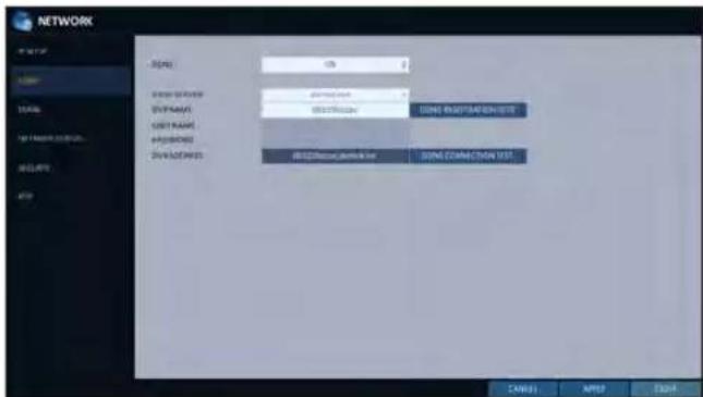
USER NAME : Use this field only if you set DDNS server to dyndns.org.
PASSWORD : Use this field only if you set DDNS server to dyndns.org.
DVR ADDRESS : Provide theand press the button. The name will be added automatically.
DDNS CONNECTION TEST : Perform the connection test to check if DDNS is normally registered.
-
To apply the change, click
in the bottom of the screen. -
When done, press the [EXIT] button on the remote control or click
in the lower screen. The confirmation message appears and you will return to the previous menu.
System Setting
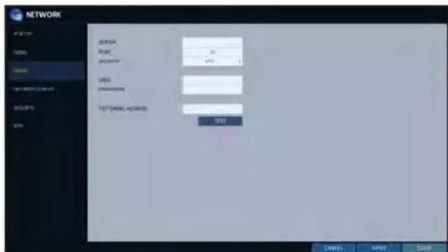
You can register and test an email address so that an email notification is delivered at a specific interval or if an event occurs.
- From
- , select . - Use the [▲▼◄►/ENTER] buttons on the remote control or use the mouse to specify the use of email and select a server.
SERVER : Set up the mail server. Set the mail server that will be used for notification to the DVR. Use the virtual keyboard to enter your mail server.
PORT : Enter the mail server port.
SECURITY : If it is set to, the email will be transferred in secure mode. If it is set to , the email will be transferred to a server that does not support SSL.
USER : Provide the email account (ID) of the sender.
PASSWORD : Provide the password of the sender.
TEST EMAIL ADDRESS : Enter an email address for the test purpose.
TEST : Send a test email and check if the test email is delivered normally.
-
To apply the change, click
in the bottom of the screen. -
When done, press the [EXIT] button on the remote control or click
in the lower screen. The confirmation message appears and you will return to the previous menu.
Network Status
From the network map screen, you can check the internet connection status and camera connection status, and check also the details of the connection status for each camera.
7 From
2. Use the [▲▼◄►/ENTER] buttons on the remote control or use the mouse to select one between
3. When done, press the [EXIT] button on the remote control or click
Network Map
IP ADDRESS : Indicates the internal IP address of the DVR.
IPv6 ADDRESS : Indicates theIPv6 IP address of the DVR.
MAC ADDRESS : Indicates the internal MAC address of the DVR.
DDNS ADDRESS : Indicates the internal DDNS address of the DVR.
RTSP SERVICE PORT : Indicates the network port of the video service. For remote service, the router must have set up the port forwarding.

flowchart
graph TD
    A["Router"] --> B["Server"]
    B --> C["Connector"]
    C --> D["TCP-HTTP-HTTP"]
    C --> E["TCP-HTTP"]
    C --> F["TCP-HTTP-HTTP"]
    style A fill:#f9f,stroke:#333
    style B fill:#ccf,stroke:#333
    style C fill:#cfc,stroke:#333
    style D fill:#fcc,stroke:#333
    style E fill:#cff,stroke:#333
    style F fill:#ffc,stroke:#333
WEB SERVICE PORT : Indicates the web service network port. For the remote service to be enabled, the corresponding port of the router should have set up the port forwarding.
UPDATE DDNS STATUS : Shows if the DDNS address was registered to the DDNS server normally. Press < 6 to try to register the DDNS address forcibly.EXTERNAL IP ADDRESS : Indicate the IP address for the Internet, accessible from the DVR. The DVR can be granted access with the web browser at "http://
: . The IP address can vary in a dynamic IP environment. CONNECTED CLIENTS : Shows the list of clients that are currently connected. Press < ■ to terminate the connection of an unwanted client forcibly.
√ Termination is limited to only users in a lower group than the current user.
System Setting
Security
For security purpose, you can set whether to use encryption and its method, and configure IP filtering.
- From
- , select . - Use the [▲▼◄►/ENTER] buttons on the remote control or use the mouse to select one between
and . - When done, press the [EXIT] button on the remote control or click
in the lower screen to return to the previous menu.

ENCRYPTION
RTSP ENCRYPTION ENABLE : Set whether to apply RTSP encryption or not.
RTSP ENCRYPTION METHOD : Select the encryption method.
HTTPS ENABLE : Set whether to use HTTPS encryption or not.
HTTP AUTHENTICATION METHOD : Select the authentication method for encrypted communication.
RTP
- From
- , select . - Use the [▲▼◄►/ENTER] buttons on the remote control or use the mouse to select one between
and . - When done, press the [EXIT] button on the remote control or click
in the lower screen. The confirmation message appears and you will return to the previous menu.
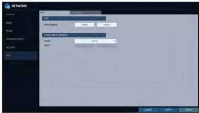
RTP
PORT RANGE : Set the range of port number for RTP UDP transfer, which will be dynamically allocated.
MODE : Set the port allocation method for "RTP Audio back channel".
Set tofor automatic allocation, or to to use specified port in the PORT attribute.
√ RTP (Real-time Transport Protocol) is a protocol designed to transport real-time data such as sound, video, etc. under unicast or multicast condition.
MULTICAST
Multicast allows efficient network bandwidth utilization if multiple clients are receiving monitoring video on a local area network.
Set the Multicast Address, Video/Audio Ports and TTL for each channel's Main/Second Stream.
√ Note that the network must support multicast communication.
√ In general, multicast in WAN environment is not supported.
√ Multicast is a method to send the same data to multiple specific receivers simultaneously in a network. This
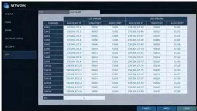
method cuts down on network waste, gets rid of unnecessary burden, and is generally used in unrestricted network (intranet).
System Setting
System Setting
You can configure the settings of date/time, system management, system information, control device, POS/ATM and Security.
Date/Time
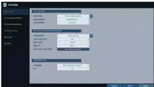
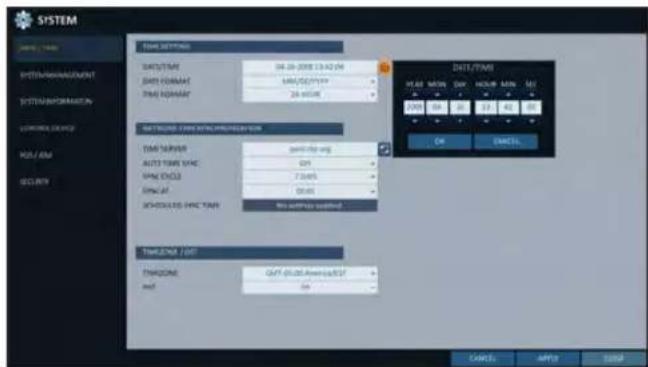
Specify the current date and time.
- From
- , select . - Use the [▲▼◄►/ENTER] buttons on the remote control or use the mouse to change the time or set the options as necessary.
DATE/TIME : Set the current time and date. Click< to adjust the time manually.
DATE FORMAT : specify the date format.
TIME FORMAT : specify the time format.
TIME SERVER : obtain the current time from the time server. Click < 📄 > to get the current time.
AUTO TIME SYNC : automatically synchronize the time with the time server at a specific time.
SYNC CYCLE : Set up the cycle, which will be synchronized with the time server.
SYNC AT : Set the time to sync with the time server.
SCHEDULED SYNC TIME : This shows the predicted time for sync, which was set up as described above.
TIMEZONE : specify the GMT standard time for your local area.
DST : You can set up or release the DST (Daylight Saving Time).
√ Both
- To apply the change, click
in the bottom of the screen. - When done, press the [EXIT] button on the remote control or click
in the lower screen. The confirmation message appears and you will return to the previous menu.
System Management
You can check, update or reset the system information.
- From
- , select . - Use the [▲▼◄►/ENTER] buttons on the remote control or use the mouse to set each option of the system management.

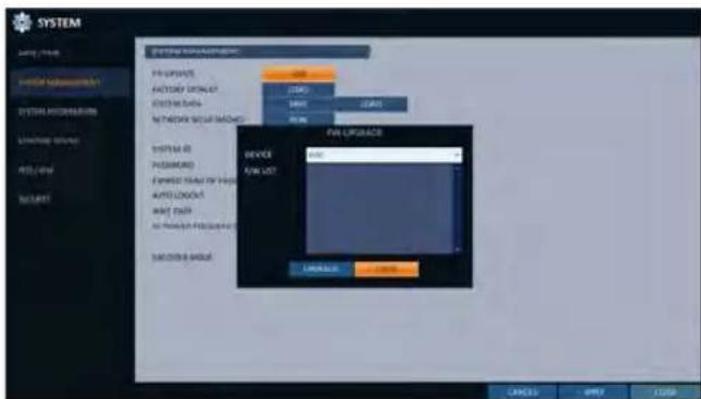
FW UPDATE : you can update the current software with the latest version.
FACTORY DEFAULT : Return the DVR settings to the factory default.
! If you proceed with the firmware upgrade or select to reset to the factory default, all current settings of the DVR will be erased. In such a case, you must configure the network, time, password and recording settings again.
SYSTEM DATA : Save the system settings or get the system information from other device.
- SAVE : Store the DVR settings to a storage device. Connect the storage device to the USB port of DVR.
System Setting
- LOAD : Apply the settings of the storage device to the DVR. Connect the storage device to the USB port of DVR.
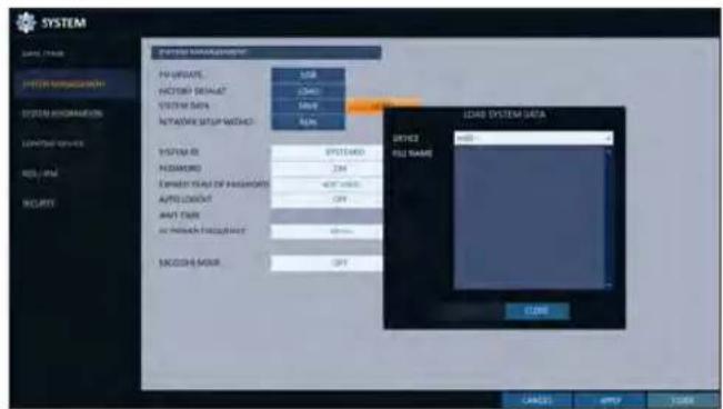
NETWORK SETUP WIZARD : Triggered when the corresponding button is pressed or upon factory initialization. The wizard guides through network configuration such as setting the DHCP or static IP address, WEB and RTSP service ports.

SYSTEM ID : Assign an ID to the DVR to distinguish it out from others when there are multiple DVR used.
√ The default value is "SYSTEM ID".
PASSWORD : Open or close the dialog box for settings of the menus: quit, system settings, record settings, backup, and search.
! If it is set to
EXPIRED TERM OF PASSWORD : You will be prompted to change the current password after a certain period of time.

AUTO LOGOUT : If there is no user input for a certain period of time, you can set to log out automatically.
WAIT TIME : Specify the waiting time for Auto Logout.
AC POWER FREQUENCY : Set to the actual AC power's frequency (50Hz / 60Hz) applied to DVR to avoid flickering.
ENCODER MODE: This sets up whether the encoder mode is used or not.
- When done, press the [EXIT] button on the remote control or click
in the lower screen to return to the previous menu.
To perform the upgrade
- Connect the USB storage device that contains the updatable files.
- Click
. - Select one(s) from the updatable files listed in
.

-
Click
. -
When the confirmation message appears, click
.

-
The progress bar displays the progress of the firmware upgrade process.
-
When the upgrade is complete, reboot the system.
√ If the DVR is forcibly turned off while the firmware upgrade is in progress, this can cause a serious damage to the DVR.
√ The USB memory device must have free space of 10MB or more and be enabled for writing.
√ Once started firmware upgrading, the USB memory device must not be separated until the completion message appears after a restarting.

- The progress of the upgrade is terminated after completion of the boot.
System Setting
System Information
You can check the current system version and system-related settings.
- From
- , select . - Check the status of the current system.
- When done, press the [EXIT] button on the remote control or click
in the lower screen. The confirmation message appears and you will return to the previous menu.

Control Device
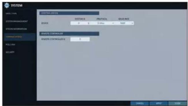
Configure the settings of the remote control and keyboard controller.
√ This function is provided for controlling individual DVR separately using a control device or remote control, in case the site has multiple DVRs of the same model.
- From
- , select . - Use the [▲▼◄►/ENTER] buttons on the remote control or use the mouse to set the connection options for the control device.
SYSTEM ID : Set the ID of the DVR so that the keyboard controller can identify.
PROTOCOL : Set up the protocol of the keyboard controller.
BAUD RATE : Specify the RS485 communication speed.
REMOTE CONTROLLER ID : Set the ID of the remote control.
- To apply the change, click
in the bottom of the screen. - When done, press the [EXIT] button on the remote control or click
in the lower screen. The confirmation message appears and you will return to the previous menu.
POS/ATM
You can check the configuration of the POS/ATM device connected to DVR.
- From
- , select . - Use the [▲▼◄►/ENTER] on your remote control or use the mouse to check the POS/ATM settings.
ACTION : Specify whether to activate the POS/ATM device or not.
TYPE : Display the type for each channel.
PORT : Display the port for each channel.
- Change the data for each required item, and then press the
button.

- To apply the change, click
in the bottom of the screen. - When done, press the [EXIT] button on the remote control or click
in the lower screen. The confirmation message appears and you will return to the previous menu.
To set the POS
- Press the
button to change in each channel.
PORT : You can change the linked port by pressing the
button on the right.
√ The USB to serial device is required to add a port.
PROTOCOL : GENERAL is designated for PROTOCOL by default.
BAUDRATE : Select the BAUD RATE between 2400\~115200.
DATA BIT: You can select between 5 and 8 for DATA BIT.
CHARACTER SET : The ASCII CHARACTER SET is designated by default.
PARITY : You can select NONE, ODD or EVEN for PARITY BIT.
STOP BIT: You can select 1 or 2 for STOP BIT.
TRANSACTION START : Enter the value for TRANSACTION START by using the virtual keyboard.
TRANSACTION END : Enter the value for TRANSACTION END by using the virtual keyboard.
LINE DELIMITER : Enter the value for LINE DELIMITER by using the virtual keyboard.
IGNORE STRING : Enter the string to ignore by using the virtual keyboard.
COPY SETTINGS TO : You can copy the settings to each channel.
TEST: You can test the settings through the POS.
- Complete editing and click
to close the edit window.
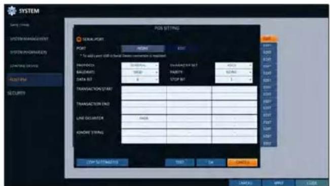
System Setting
Security
For security, you can set to apply reinforced password policy (to system, search/backup) and control accessing snapshot.
- From
- , select . - Use the [▲▼◄►/ENTER] buttons on the remote control or use the mouse to set each option of security.
AUDIO SUPPORT : Allows audio function. If set to
, all audio functions are disabled. Live and playback screen do not produce audio, and no audio recording is allowed.
Note that changing the setting fromto initializes audio related settings. Hence, reconfiguration is required after enabling.
SNAPSHOT SUPPORT : Allows snapshot function. If set to, all capturing functions are disabled. User cannot take a snapshot on the Live screen, playback screen, and backup player screen. Event notification with e-mail will not include event snapshot too.
Note that changing the setting fromto initializes snapshot related settings. Hence, reconfiguration is required after enabling.
ID INPUT METHOD : Set an ID input method upon log-in. By selecting "SELECTION METHOD", you can select an ID by clicking the arrow button on the input screen. By selecting "DIRECT INPUT METHOD", you can log in by typing in your ID directly.
ENHANCED USER ID RULE : Set whether to use Enhanced User ID Policy or not. When this is set to, the following rules will be applied.
! ID must be between 5 and 10 characters. IDs created with only one character (e.g. aaaaa, 11111, te.) cannot be used.
ENHANCED PASSWORD RULE: Sets whether to apply strong password policy, which prevents using too easy password. When this is set to, the following rules will be applied.
! Password must be between 8 and 16 characters. It must contain uppercase / lowercase letters, special characters, and numbers. The same character cannot be used 3 consecutive times. Sequential strings (e.g. abcde, 12345) are not allowed. The password cannot contain the same string as the ID.
- When done, press the [EXIT] button on the remote control or click
in the lower screen to return to the previous menu.

Storage
You can configure the settings of and view information of the disk and external storage device.
Disk Information
It will show information about the connected disk.
- From
- , select . - Use the [▲▼◄►/ENTER] buttons on the remote control or use the mouse to select either
or . Please check the status for each connected device.
START / END TIME : show the start time and end time of data stored in each disk.
STATUS : check if the connected disk is being used by the DVR. If you encounter a problem with the disk, the DVR will terminate the connection to the disk and mark it as 'Not In Use'.
CAPACITY : show the capacity of the disk.
MODEL : indicate the disk model.
S.M.A.R.T STATUS : Read the S.M.A.R.T information of the disk and check to display if the current disk is in normal operation.
- NORMAL : The disk is in a normal state.
- CHECK: The disk has an error so that you need to check the disk or the connection cables of the disk.
If you leave the problem unresolved, no recording may be enabled. So it is recommended that you replace the disk immediately.

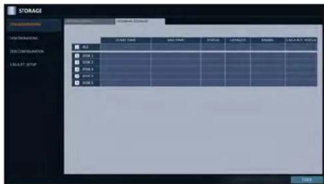
- ERROR : The disk fails or is unable to use due to an error of the disk or the cable. The disk should be replaced immediately. Contact the retailer or the customer service to replace the disk.
- When done, press the [EXIT] button on the remote control or click
in the lower screen to return to the previous menu.
System Setting
Disk Operations
You can set to delete the recording automatically and set the overwrite options, and you can also format the HDD recording data.
- From
- , select . - Use the [▲▼◄►/ENTER] buttons on the remote control or use the mouse to set the operation conditions of the disk.
DISK WRITE MODE
- If it is set to
, the existing data will be overwritten by new recording data if the recording data size exceeds the free space of the HDD. - If the option is set to
and the HDD is full, the DVR will stop recording and output the beep or alarm that is pre-defined at .
RECORDING TIME LIMIT: The recorded data is stored for the designated period by selecting the
, , , etc., and then deleted after the specified period. If it is set to , this function will be disabled. (You can save the recorded data for a maximum of 3 months.)

Ex) Record Time Limit : 1 day Even if there is sufficient free space in the HDD, it records / keeps videos of the most recent 1 day only.
DISK FORMAT : format the hard disk.
Note that formatting the HDD will delete all video data and logs.
- To apply the change, click
in the bottom of the screen. - When done, press the [EXIT] button on the remote control or click
in the lower screen. The confirmation message appears and you will return to the previous menu.
Disk Configuration
You can generate and configure a RAID array in your internal disks.
What is RAID?
RAID is a back-up storage technology which allows you to use multiple independent disks as if they were just a single one.
RAID 1 : The same duplicated data are also recorded in a different drive. That is, the data are equally stored in a pair of drives.
RAID 5 : This mode is the best known RAID array. It distributes and stores data and parity across at least 3 drives.
- From
- , select . - Use the [▲▼◄►/ENTER] on your remote control or use the mouse to change your DISK CONFIGURATION.
MODEL : Display the model of each disk.
CAPACITY : Display the capacity of each disk.
STATUS : If any problem occurs in the disk where a RAID array has been configured, the disk is displayed as Degrade.
REBUILD : Display whether to rebuild each disk or not.
REFRESH : Reload the status of the RAID array.
CREATE RAID : Press the button to create a RAID array.
- To apply the change, click
in the bottom of the screen. - When done, press the [EXIT] button on the remote control or click
in the lower screen. The confirmation message appears and you will return to the previous menu.
To configure a RAID array
- Press the
button on screen.
√ To configure RAID 1, at least 2 disks are required.
√ To configure RAID 5, at least 3 disks are required.
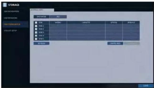
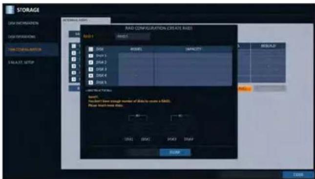
- Check the model and capacity of each disk, configure your desired RAID array, and then press the
button.
! If you modify the RAID configuration, all the data will be formatted.
! To apply the modified RAID configuration, reboot the system.

System Setting
S.M.A.R.T settings
You can check the S.M.A.R.T information of the disk and specify the check frequency.
√ What is S.M.A.R.T information?
S.M.A.R.T (Self-Monitoring, Analysis and Report Technology) is to detect a HDD that is likely to cause a problem in the future with a warning message.
- From
- , select . - Use the [▲▼◄►/ENTER] buttons on the remote control or use the mouse to check the S.M.A.R.T operation and specify the check interval.
S.M.A.R.T STATUS : Read the S.M.A.R.T information of the disk and check to display if the current disk is in normal operation. Click
to view the details.
- NORMAL : The disk is in a normal state.
- CHECK : The disk has an error so that you need to check the disk or the connection cables of the disk.
If you leave the problem unresolved, no recording may be enabled. So it is recommended that you replace the disk immediately.
- ERROR : The disk fails or is unable to use due to an error of the disk or the cable. The disk should be replaced immediately.
Contact the retailer or the customer service to replace the disk.
S.M.A.R.T CHECK INTERVAL : Specify the S.M.A.R.T check interval. Click
to start checking.
- To apply the change, click
in the bottom of the screen. - When done, press the [EXIT] button on the remote control or click
in the lower screen. The confirmation message appears and you will return to the previous menu.

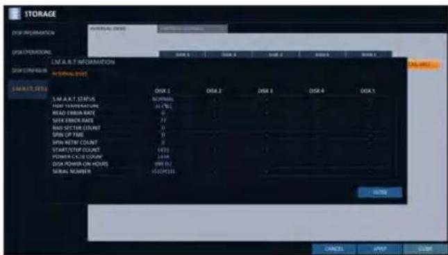
Event Setup
Define various events, and specify the conditions to notify the user in various ways.
Alarm Out
Specify the alarm output conditions with the work schedule.
Alarm Out
- From
- , select . - Use the [▲▼◀▶/ENTER] buttons on the remote control or use the mouse to select
and configure the related settings.
NAME: You can rename the alarm.
OPERATION : Set the alarm output mode.
- N/O (Normal Open) : It normally stays Open. However, if an event occurs, it will switch to Close.
- N/C (Normal Close) : It normally stays Close. However, if an event occurs, it will switch to Open.
DURATION : Specify the duration of the alarm output.

- TRANSPARENT: Keep the alarm out for as much time as the event lasts.
- UNTIL KEY : Keep the alarm out until a mouse or remote control button is pressed.
- 5 \~ 300 SEC : Keep the alarm out for as long as specified.
TEST : Forcibly output the alarm for the test purpose.
- To apply the change, click
in the bottom of the screen. - When done, press the [EXIT] button on the remote control or click
in the lower screen. The confirmation message appears and you will return to the previous menu.
System Setting
ON/OFF Schedule
You can activate or turn off the alarm output as scheduled.
- Use the [▲▼◄►/ENTER] buttons on the remote control or use the mouse to select a
for the schedule. - Drag the mouse to resize the cell or use the on the [▲▼◄►] buttons to move to the cell, then press [ENTER].
- Select a desired alarm output mode.
ON : The alarm output is always turned on.
OFF : The alarm output is always turned off.
EVENT : Trigger the alarm output in sync with the event.
- Click
to check the checkbox of the date that you want to copy the schedule at.
5 When done, clickto apply the settings. - To apply the change, click
in the bottom of the screen. - When done, press the [EXIT] button on the remote control or click
in the lower screen. The confirmation message appears and you will return to the previous menu.
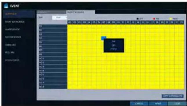

Event Notification
Specify the methods of notification such as buzzer, video popup or email if an event occurs.
- From
- , select . - Use the [▲▼◀▶] buttons on the remote control or use the mouse to select one from
, and . - Use the [▲▼◄►/ENTER] buttons on the remote control or use the mouse to set the output method and duration.
4 To apply the change, clickin the bottom of the screen. - When done, press the [EXIT] button on the remote control or click
in the lower screen. The confirmation message appears and you will return to the previous menu.
Buzzer output
You can notify the user of the event using the buzzer.
> DURATION
- TRANSPARENT : Keep the buzzer out for as much time as the event lasts.
- UNTIL KEY : Keep the buzzer out until a mouse or remote control button is pressed.
- 5 \~ 300 SEC : Keep the buzzer out for as long as specified.
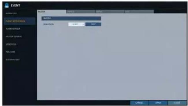
Display
If an event occurs, you can display the video screen or a popup message to notify the user of the event.
VIDEO POPUP : Display the video channel that is synchronized with the event on a single split screen. Set the DURATION of the single split screen.
- TRANSPARENT : Keep the video popup displayed for as much time as the event lasts.
- UNTIL KEY : Keep the video popup displayed until a mouse or remote control button is pressed.
- 5 \~ 300 SEC : Keep the video popup displayed for as long as specified.
√ If multiple events occur at the same time, or if multiple event-related video channels exist, the video popup will be displayed in the maximum split screen mode rather than the single split screen mode.

OSD POPUP: This will notify the user of the event with a popup message if an OSD popup event occurs. You can adjust the duration of the popup message.
- UNTIL KEY : Keep the OSD popup displayed until a mouse or remote control button is pressed.
- 5 \~ 300 SEC : Keep the OSD popup displayed for as long as specified.
System Setting
If an event occurs, this will notify registered users of the event by email. If you do not want to receive the email, uncheck the
ADD NEW EMAIL If you want to add a new mail recipient beside the existing ones, click this to add the recipient.
MINIMUM EMAIL FREQUENCY Adjust the minimum frequency of sending the email. For example, even if you have set the minimum frequency to one minute and another event occurs in less than one minute after the last email sending, the email for the new event will be sent one minute after.
√ Some email servers can block the email sending if the email delivery cycle is too short, and classify it as spam.
Contact your email service provider to adjust the minimum delivery cycle so that the server does not classify the email as spam.
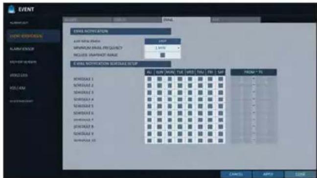
INCLUDE SNAPSHOT IMAGE : Set whether to include snapshot image of the event with the notification.
E-MAIL NOTIFICATION SCHEDULE SETUP : You can set your email to be sent at a specified time. You can select a specific time and day.
FTP
Upon events, uploads event notification onto the added FTP server.
FTP SERVER : Enter the FTP server address for event transfer.
DIRECTORY : Select or manually enter the destination folder of the FTP for event transfer.
FILE NAME : Select the uploading event file's format or manually set the file name.
MINIMUM FREQUENCY : Sets the minimum recurrence delay for uploading event notification onto the FTP server. For example, when the minimum recurrence is set to 1 minute, the next FTP event notification will be uploaded after 1 minute from the last event, even if another event is detected within 1 minute from the last one.INCLUDE WEBRA LINK : Select whether to include WEBRA link address of the event generating DVR, which can be accessed with web browser (Internet Explorer).
√ Check to play back the event footage.
INCLUDE SNAPSHOT IMAGE : Set whether to include snapshot (still image) or not.
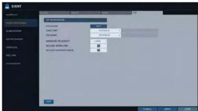
Alarm Sensor
You can configure the settings of the alarm sensor and specify the operation of the sensor if an event occurs.
- From
- , select . - Use the [▲▼▲▶] buttons on the remote control or use the mouse to specify the sensor input method and operation.
NAME : You can specify the name of the alarm sensor.
OPERATION : You can specify the type of the alarm sensor.
- N/O (Normal Open) : Normally the sensor is left Open. If the sensor switches to Close, an event will be triggered.
- N/C (Normal Close) : Normally the sensor is left Close. If the sensor switches to Open, an event will be triggered.

LINKED CAMERA : Set the camera to sync with the alarm sensor if it is triggered. If you have set the alarm recording and the sensor detects the recording, all synchronized cameras will start alarm recording.
ALARM OUTPUT : Specify the alarm output channel if it is detected by the alarm sensor. The alarm will be output to the specified channel.
☐: Specify the output of the buzzer if an alarm is detected by the alarm sensor.
☐: Select to display the video popup if an alarm is detected by the alarm sensor. If there exist multiple, the video popup will be displayed in the maximum split mode.
: Select to display the OSD popup message if it is detected by the alarm sensor.
: Select to send an email if detected by the alarm sensor.
: Select whether to upload event notification onto the FTP upon detected alarm event.
-
To apply the change, click
in the bottom of the screen. -
When done, press the [EXIT] button on the remote control or click
in the lower screen. The confirmation message appears and you will return to the previous menu.
System Setting
Motion Sensor
You can set an action to execute when a motion is detected. For the settings of the motion sensor, move to
-
From
- , select . -
Use the [▲▼◀▶] buttons on the remote control or use the mouse to specify the ignorance interval and operation.
IGNORING INTERVAL : Specify the minimum interval of the motion event occurrence. For example, even if you have set the minimum frequency to 5 seconds and another motion event occurs in less than 5 seconds after the last motion event occurred, the new event will be ignored. If too many motion events occur, adjust to shorten the interval.

√ Motion recording will be triggered immediately after the motion occurred regardless of the above settings.
ALARM OUTPUT : Specify the alarm output channel if a motion is detected by the motion sensor.
: Specify the output of the buzzer if a motion is detected by the motion sensor.
☐: Select to display the video popup if a motion is detected by the motion sensor.
: Select to send an email if a motion is detected by the motion sensor.
: Select whether to upload event notification onto the FTP upon detected motion event.
-
To apply the change, click
in the bottom of the screen. -
When done, press the [EXIT] button on the remote control or click
in the lower screen. The confirmation message appears and you will return to the previous menu.
Video Loss
You can specify a reaction to the case where no video is received from the camera.
- From
- , select . - Use the [▲▼▲▶] buttons on the remote control or use the mouse to specify the reaction to a video loss
ALARM OUT : Specify the alarm output channel if a video loss occurs.
: Specify the output of the buzzer if a video loss occurs.
: Select to send an email if a video loss occurs.
: Select whether to upload event notification onto the FTP upon detected video loss event.
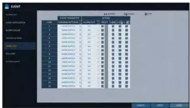
-
To apply the change, click
in the bottom of the screen. -
When done, press the [EXIT] button on the remote control or click
in the lower screen. The confirmation message appears and you will return to the previous menu.
POS / ATM
-
From
- , select . -
Use the [▲▼◀▶] buttons on the remote control or use the mouse to specify the sensor input method and operation.
TEXT : Specify the text to detect POS / ATM event.
LINKED CAMERA : Select which camera(s) to interlock when detecting POS / ATM events.
ALARM OUTPUT : Specify in which channel to output the alarm when detecting POS / ATM
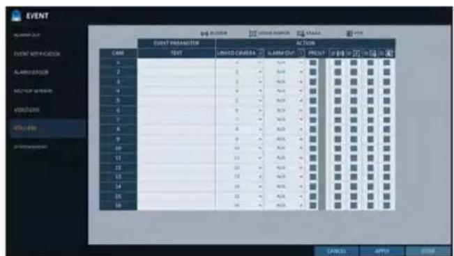
events. Corresponding output is displayed on the specified alarm output channel when detecting an event.
PRESET : Move camera based on the preset criteria when detecting POS / ATM events.
BUZZER : Select whether to sound the buzzer when detecting POS / ATM events.
VIDEO POPUP : Select whether to pop up corresponding video when detecting POS / ATM events. If there are multiple
, the video screen pops up with maximum split views. EMAIL : Select whether to send an email when detecting POS / ATM events.
FTP : Select whether to send the event to FTP server when detecting POS / ATM events.
-
To apply the change, click
in the bottom of the screen. -
When done, press the [EXIT] button on the remote control or click
in the lower screen to return to the previous menu.
System Setting
System Event
You can set any action to an event related to the disk, recording, network or system. Like the other events, you may notify the event to the user using the alarm/buzzer output, OSD pop-up or email.
- From
- , select . - Use the [▲▼◀▶] buttons on the remote control or use the mouse to specify the reaction to each event.
- To apply the change, click
in the bottom of the screen. - When done, press the [EXIT] button on the remote control or click
in the lower screen. The confirmation message appears and you will return to the previous menu.
Disk
OVERWRITE START EVENT : if you set the disk write mode to
, this event occurs when the disk is full and the overwriting begins accordingly.
DISK FULL EVENT : if you set the disk write mode to, this event occurs when the disk is full (100%).
DISK SPACE EXHAUSTED EVENT : Event that is triggered if the disk is almost full. Click < → to specify the threshold percentage of usage to trigger the event.
S.M.A.R.T EVENT : Occurs if the disk causes the S.M.A.R.T error.NO DISK EVENT : Occurs if no disk is recognized after the booting due to a disk failure or cable problem.
To detect the disk error, it is recommended not to change the settings of the S.M.A.R.T event, no disk event and buzzer output.

PANIC RECORD START EVENT : Specify the action to perform when the panic recording begins.

System
BOOTING EVENT: This event occurs when the DVR is booting.
LOGIN FAIL EVENT: This event occurs when the DVR fails to log in.
You can specify the times of clicking < ■> to trigger the event.
FAN FAIL EVENT : This event occurs if the CPU cooling fan or unit's cooling fan does not work at all.
√ If the fan fails, no recording will proceed by the DVR. If you encounter a fan failure, contact the retailer or the service center for technical assistance.
TEMPERATURE FAIL EVENT : This event occurs if
the internal temperature of the DVR exceeds the effective range. Then, the DVR will not operate normally. If this is the case, check the followings and take a necessary measure.
- Check if the ventilation of the DVR is clogged with foreign substances. If so, remove them.
- Keep the DVR away from a heat source such as heater. Install it in a flat, lower area with good ventilation.
- If the problem persists, contact the retailer or service center.
To monitor the normal operation of the DVR, it is recommended not to change the buzzer output settings of the fan failure event and the temperature fail event.

Network
TROUBLE IN INTERNET CONNECTION : Occurs if the Internet connection to the DVR fails. If you do not want to connect the DVR to the network, leave the
item blank.
FAIL IN REMOTE LOGIN : This event occurs if a remote client fails to log in due to an invalid ID or password.
You can specify the times of clicking < ■> to trigger the event.
FAIL IN DDNS UPDATE : This event occurs if the DVR tried to update the DDNS address but failed.
√ If the DDNS address fails to be updated, the DVR may not connect to a remote client. If this is the case, enter the IP
address from the client side to allow access from the DVR. This is just a temporary measure.
For the IP address, move to and check
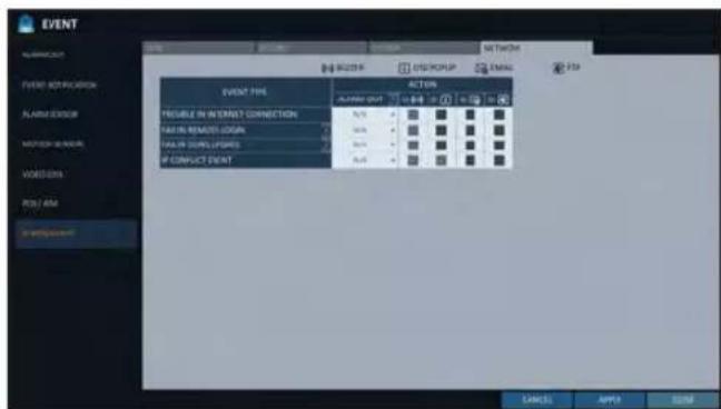
IP CONFLICT EVENT : An event occurs when network IP conflicts.
Note that thecan change at any time in a dynamic IP environment.

Record Setting
You can configure the record settings for the DVR.
Only authorized users can access the Record Setup menu.
To start the Record Setup menu

How to use the mouse


SEARCH

ARCHIVING

SYSTEM SETUP

RECORD SETUP

LOG OUT

SHUTDOWN
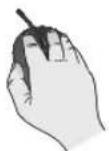

How to use the remote control


natural_image
Circular diagram with four directional arrows pointing inward toward a central 'ENTER' button (no text or symbols beyond the label)
SEARCH

ARCHIVING

SYSTEM SETUP

RECORD SETUP

LOG OUT

SHUTDOWN

Record Setup
Operation Mode
You can set the recording options for Auto or Manual mode.
- From
menu, select . - Use the [▲▼▶] buttons or use the mouse to set
to or . - Set the recording options for each selected Record mode.
- To apply the change, click
in the bottom of the screen. - When done, press the [EXIT] button on the remote control or click
in the lower screen. The confirmation message appears and you will return to the previous menu.
Auto Configuration
If you choose your preferred record mode, the DVR will recommend you the optimized settings for the selected record mode.
CONTINUOUS RECORD : Recording will proceed in the best quality regardless of the event at all times. As this option will always make recording in the best quality, the recording period is the shortest compared to the other record modes.
- MOTION RECORD : Recording will proceed only if a motion is detected. - ALARM RECORD : Recording will proceed only if an alarm event occurs. - MOTION/ALARM RECORD : Recording will proceed only if a motion is detected or an alarm event occurs.
INTENSIVE MOTION RECORD : Normally recording will be performed in a normal quality. However, the quality will switch to high if a motion is detected.
INTENSIVE ALARM RECORD : Normally recording will be performed in normal quality. However, the quality will switch to high if an alarm event occurs.
INTENSIVE MOTION/ALARM RECORD : Normally recording will be performed in normal quality. However, the quality will switch to high if an alarm event occurs or a motion is detected.
√ Motion : Normally, it means the movement of an object. However, it implies a change to the illumination in the context of the DVR. Ex) Vehicle lights (headlights), illumination change, etc.
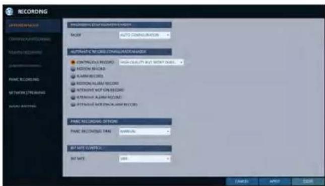
Record Setting
Manual Configuration
If you set the record mode to
MANUAL CONFIGURATION OPTIONS : You can configure the recording settings by the time, date, and channel.
- SCHEDULE MODE : Set the recording schedule for a day (daily) or for a week (weekly).
- PRE RECORDING TIME : Set the pre-recording time.
- POST RECORDING TIME : Set the post-recording time.
PANIC RECORDING OPTIONS: Set the panic recording duration. If it is set to
, recording will continue until you turn it off manually. BIT RATE CONTROL : Set the bitrate to either one of CBR or VBR.

Continuous Recording
You can configure the settings of: continuous recording time, recording size, frame rate per second and quality.
- From the
menu, select .
√ From
- Use the [▲▼◀▶] buttons on the remote control or use the mouse to select either
or .
Size/FPS/Quality Setting
-
Please select the day of the week to perform the continuous recording. From
, you must set the of the to before you can specify the . -
Click a time cell from which you want to edit the SIZE/FPS/Quality and drag it to a desired cell. Or use the [▲▼◀▶] buttons on the remote control to move to the cell and press [ENTER]. Then, use the [▲▼◀▶] buttons to move to a desired cell and press [ENTER] again.
-
When the cell selection is complete, the "SIZE/FPS/QUALITY" table appears.
Specify the
RESOLUTION : set the size of the video recording.
FPS : set the frame rate per second.
QUALITY : set the recording quality.
AUDIO : specify the use of the audio recording.
- When done, click
. You can check the recording size in the size table under the time selection bar.
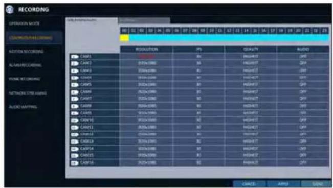
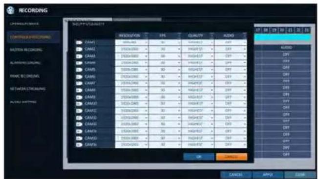
The video resolution and the FPS option may differ depending on the specification of the camera.
Record Setting
Schedule Setting
- Select a start day of the week on the schedule.
- Click a time cell from which you want to make the schedule and drag it to a desired cell. Or use the [▲▼◀▶] buttons on the remote control to move to the cell and press [ENTER]. Then, use the [▲▼◀▶] buttons to move to a desired cell and press [ENTER] again.
-
When the time selection is complete, you will be prompted to specify the use of recording in the Record Setup window.
-
To apply the change, click
in the bottom of the screen. -
When done, press the [EXIT] button on the remote control or click
in the lower screen. The confirmation message appears and you will return to the previous menu.

Motion Recording
Specify the recording size of the motion event if it occurs and make schedule for that recording.
- From the
menu, select . - Use the [▲▼◀▶] buttons on the remote control or use the mouse to select either
or . -
Set each item of
, , and use of the -
To apply the change, click
in the bottom of the screen. -
When done, press the [EXIT] button on the remote control or click
in the lower screen. The confirmation message appears and you will return to the previous menu.
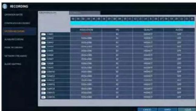
Alarm Recording
Specify the recording size of the alarm event if it occurs and make schedule for that recording.
- From the
menu, select - Use the [▲▼◀▶] buttons on the remote control or use the mouse to select either
or . - Set each item of
, , and use of the
√ For more information, see the "Continuous Recording" (page 81)
-
To apply the change, click
in the bottom of the screen. -
When done, press the [EXIT] button on the remote control or click
in the lower screen. The confirmation message appears and you will return to the previous menu.
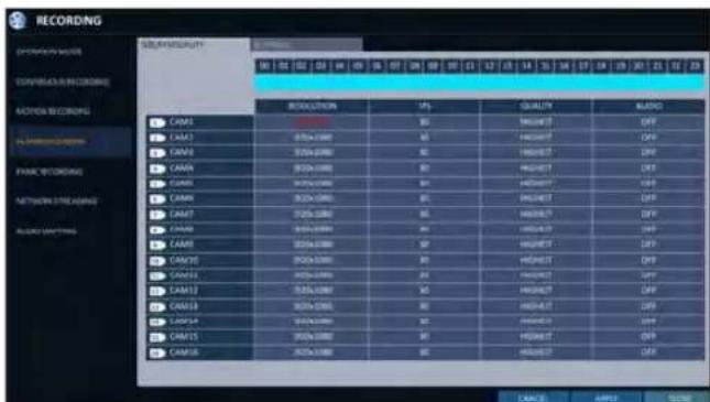
Panic Recording
In panic recording mode, you can specify the recording size and quality of the video.
- From the
menu, select . - Set each item of
, , and use of the -
To apply the change, click
in the bottom of the screen. -
When done, press the [EXIT] button on the remote control or click
in the lower screen. The confirmation message appears and you will return to the previous menu.

Record Setting
Network Streaming
You can specify the maximum size of network streaming for remote users and set the FPS.
√ Even if you set the resolution and FPS to high for the network streaming, the DVR will reduce the size or FPS according to the network status (speed) before transferring the recording video.
- From the
menu, select . - Use the [▲▼◀▶/ENTER] buttons on the remote control or use the mouse to select an item that you want to edit.
- Set the
for each channel. - When done, click
. -
To apply the change, click
in the bottom of the screen. -
When done, press the [EXIT] button on the remote control or click
in the lower screen. The confirmation message appears and you will return to the previous menu.

AUDIO MAPPING
- From the
menu, select - Set the
- To apply the change, click
in the bottom of the screen. - When done, press the [EXIT] button on the remote control or click
in the lower screen. The confirmation message appears and you will return to the previous menu.

You can search for the recording data in the HDD by the criteria of time, thumbnail, event, text-in, etc.
To move to the Search menu while in monitoring

How to use the mouse

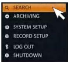
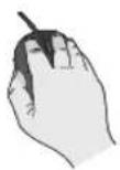

How to use the remote control 1


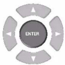

How to use the remote control 2
SEARCH

To move to the Search menu while in playback mode

How to use the mouse



How to use the remote control
SEARCH

Search Settings
Time Search
With the calendar, you can search for the recording data by the recorded date.
- From the
menu, select - Use the [▲▼▲▶] buttons or use the mouse to specify the search date and time from the calendar in the left corner of the screen.
FIRST : The first date of recording is automatically selected.
LAST : The last date of recording is automatically selected.
: Press this to display the time selection menu where you can specify the time and date.

- You can identify the type of the recording data by the color in the bar.
Yellow green (Pre recording): The pre-recording is performed on the recording data after you set the
from.
Green (Continuous) : The continuous recording is performed on the recording data.
Red (Alarm) : The alarm event recording is performed on the recording data.
Blue (Motion) : The motion event recording is performed on the recording data.
Yellow (Panic) : The panic manual recording is performed on the recording data.
4 Click to move to a desired start time in the time bar, or use the buttons at the bottom of the status bar to make search.
: Recall the recording data.
: Expand the timeline of the time bar to a greater unit of time.
: Collapse the timeline of the time bar to a smaller unit of time..
: Use this to move to a previous time that is hidden in the time bar as it is expanded to a greater time unit.
: Use this to move to a next time that is hidden in the time bar as it is expanded to a greater time unit.
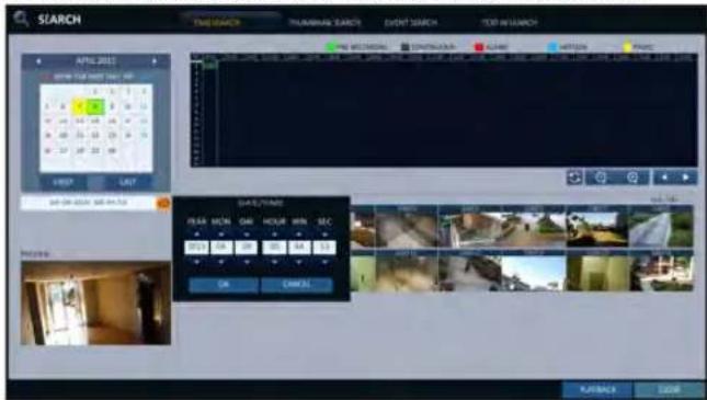
- Click a thumbnail channel or use the [▲▼▲▶] buttons on the remote control to move to a desired channel and press [ENTER]. You can check the video in
.
! Click to move to a desired time, or simply double-click a desired time in the time bar to play the video data on that time.
- Press the [ENTER] button again on the remote control with the mouse, or simply double-click on the channel. You will move to the playback screen.
- If you want to stop playing and return to the search screen, press [EXIT] or [SEARCH] on the remote control. You can also click
Thumbnail Search
To improve your search, you will be provided with a list of thumbnails. Select Day, Hour or Minute to narrow down the search results.
- From the
menu, select . - Use the [▲▼◀▶] buttons or use the mouse to specify the search date and time from the calendar in the left corner of the thumbnail search screen.
FIRST : The first date of recording is automatically selected.
LAST : The last date of recording is automatically selected.
CHANNEL : Select a channel to search for.
DATE/TIME : Specify the search date and time.
√ The menus available differ depending on the selected interval mode.
INTERVAL: Select a time interval of the thumbnail view.
- Double-click a desired play time in the recording data bar, or double-click a desired time image from the thumbnail list.
You will move to the playback screen.
- If you want to stop playing and return to the search screen, press [EXIT] or [SEARCH] on the remote control. You can also click
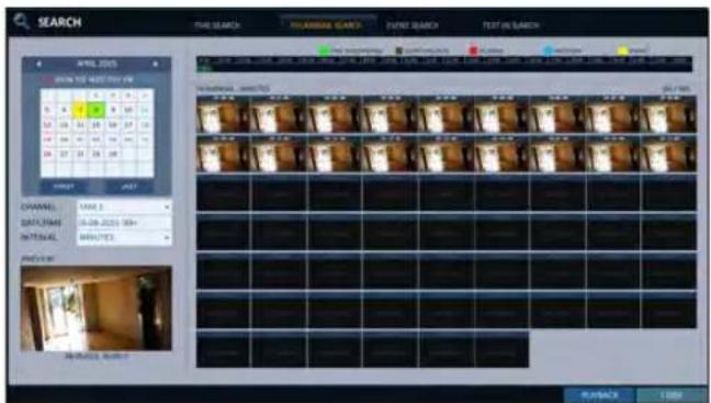
< "Minute" selection screen >

< "Hour" selection screen >
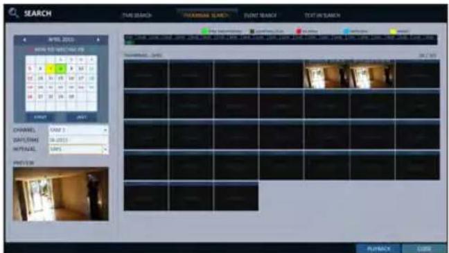
< "Day" selection screen >
: Search
Event Search
Search for events that occurred at the specified time and select an event to play from the list.
- From the
menu, select . - Use the [▲▼▲▶] buttons or use the mouse to specify the
and times in the left of the event search list. - Select a channel to search.
- Mark the checkbox of the event to search from the
list. - Press the
button. The search results will be listed as shown.
TYPE : displays the event type.
TIME : displays the recording start time.
CONTENTS : shows the details of the event found.
ORDER BY : If you select, the list will be sorted with the earliest one on top.
-
Double-click a desired event or click
in the lower right corner to move to the play screen. -
If you want to stop playing and return to the search screen, press [EXIT] or [SEARCH] on the remote control. You can also click

Text-in Search
You can search for the text generated at a predefined time and select the text from the list to playback.
- From the
menu, select . - Use the [▲▼▲▶] on your remote control or use the mouse to specify the
and times on the left of the EVENT SEARCH list. - Select the check box(es) for the channel(s) to search.
- Enter the keyword in
- to search for.
MATCH CASE : Perform a case-sensitive search for the keyword entered.
MATCH WHOLE WORD ONLY : Perform an exact word search for the keyword entered.
- Press the
button. The searched keywords are displayed in the list.
TIME : Recording Start Time is displayed.
CHANNEL : Selected channel is displayed.
ITEM : Detail keywords are displayed.
ODER BY : Select theto display the keywords in sequence from the beginning in the list.
-
Double-click a desired event or click
in the lower right corner to move to the play screen. -
If you want to stop playing and return to the search screen, press [EXIT] or [SEARCH] on the remote control. You can also click

If you want to play
- To play the searched data
- You can search for and play a searched data.
- To play with the live viewer
- Simply double-click a desired time point in the right corner of the play screen.
√ If you move the cursor to the rightmost, the "Timeline" bar will be displayed.
- Select a desired channel in the live screen and right-click to select
Playback screen configuration
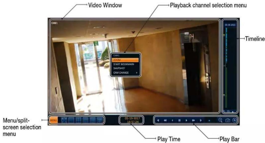
Video Window
Display the current video.
Timeline
Display the type of recording data.
The vertical bar in the timeline indicates the current point of playback. Double-click a desired point in the timeline to start playing the video from that point.
Once you drag to specify an area, you can perform the backup or event search for that area.
Menu / split-screen selection menu
For more information about how to use each button, refer to "Using the status bar in the live mode". (page 27)
Play Bar
You can start playing, stop playing or change the play speed of the current video.
Playback channel selection menu
| Item Description | |
| CAM1 Display the title of the selected channel. | |
| ZOOM | Zoom the video of the selected channel. (The zooming function is active only in '1' split screen.) |
| START BOOKMARK | The "Set bookmark" popup appears, and you can bookmark a play point for the backup purpose. |
| SNAPSHOT Capture the current live video and save it in the .jpeg format. | |
| CAM CHANGE You can assign the selected screen to another channel. | |
Using the play bar
| Item Description | ||
| Jump | Move forward or backward. | |
| Reverse Fast Play | The video will be reversely played at the speed of x64 > 32> 16 > 8 > 4 > 2 in this order. | |
| Reverse Play | Play the video in the reverse direction. | |
| Pause | Stop playing forward or playback temporarily. | |
| Play | Play the video forward. | |
| Fast Forward | The video will be played forward at the speed of x2 < 4 < 8 < 16 < 32 < 64 in this order. | |
| Zoom In | Move to the zoom in/out screen of the selected channel. | |
| Snapshot | Capture the current live video and save it in the .jpeg format.Then, you can save the captured video in the HDD or export it to an external USB memory device.While you perform the snapshot, the current video will be stopped playing. | |
| Start/end bookmark | Add a bookmark for the current playback screen.Press this to display the "SET BOOKMARK" window. Provide each entry and click Start. The arrow in the bookmark button blinks to indicates that the bookmarking is in process. If you press the Bookmark button again, the bookmarking stops and the current settings will be reserved.Then, the reserved data can be backed up in Archive menu or can be played in the "RESERVED DATA MANAGEMENT" menu. | |
Bookmarking
During playback, you can add a bookmark for reserving the video data.
You can view the bookmarked data in the Archive menu, which can be saved to a connected device for the backup purpose.
- Provide a tag in the
item for data reservation. - Provide the details of the reserved data in the
input box.
3 Click.
You will return to the play screen with the backup progress. - To stop the bookmarking, click <BOOKMARK( ).
- To quit the bookmarking, click
. To continue with bookmarking, just click .

You can export the reserved data to a connected storage device using the
√ What is the

To start the Archive menu
Using the Archive menu during playback
- During the playback, click
- The "ARCHIVING SETUP" window appears where you can reserve the data.
- Click
menu. - Press the [ARCHIVE] button on the remote control.
Using the Archive menu during monitoring
- Click
menu. - Press the [ARCHIVE] button on the remote control.
Archive
You can archive the searched data or reserve it.
- From the
menu, select . - Select a date for the archive from the calendar in the left.
√ The date containing recording data will be marked in a colored box. - FIRST : The first date of recording is automatically selected.
-
LAST : The last date of recording is automatically selected.
-
Check the
and times.
√ Drag the timeline to specify the start and end time.
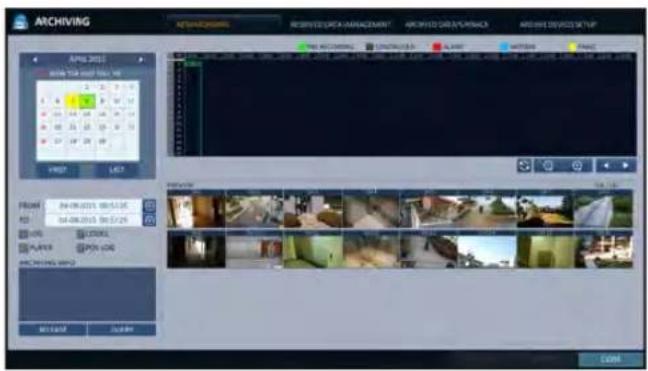
-
Mark the
, , and checkboxes and select to include the archiving. -
Click
. The results will be listed in .
√ The maximum backup capacity for one time is 20GB.
√ If the archiving request exceeds 20GB, the end time will be adjusted to within 20GB.
-
If you want to import to a storage device, connect it to the DVR and click
. -
If you just want to reserve the data, click
. If the dialog appears, enter the name and click .
Click

√ Using
- To exit the Archive menu, click
.
Archiving
Reserved data management
You can search for the reserved data and delete or import it to a storage device.
- From the
menu, select . The reserved data will be listed. - Select a data type from
and .
AVI : Searches AVI video files stored in the DVR.
SNAPSHOT CAPTURE : Searches captured snapshots stored in the DVR.
- If you want to play the data, double-click a desired data item or click it and select
.
√ If selecting

4 If you want to import to a storage device, connect it to the DVR and click
5. If you want to delete the reserved data, click <×> next to the list. Click
6. To exit the Archive menu, click
Playing the archived data
You can search the storage device for the archived data and check the details of or play it.
- Connect the storage device containing the archived data.
- When the storage device is recognized, click
.
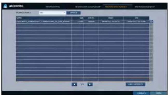
- To view the details, click next to the list.
√ Clickto check if the data is corrupt or incomplete. - Select an item to play from the list and click
. - To exit the Archive menu, click
.

Archive Devices Setup
Provide the FTP server information for archiving data in the HDD before testing the transfer.
- From the
menu, select . - Move to the FTP information box.
- Fill in each item using a virtual keyboard.
HOST NAME : enter the address at which you can access the server.
PORT : enter the port number to which you can access the server.
USER NAME : enter the user ID with which you can access the server.
PASSWORD : enter the connection password.
DIRECTORY : specify the archiving path.
4 When all information is filled, click
5. To apply the change, click
6. When done, press the [EXIT] button on the remote control or click

What is the Web Viewer?
Web RA is a user-friendly software application that enables you to control the video data in connection with a remote DVR.
System Requirements
The following is the minimum hardware and operating system requirements to run Web RA.
| Operating System | Windows XP ProfessionalWindows Vista Home Baisc / PremiumWindow 7 |
| Web browsers: | Internet Explorer 7.0 or later/Mozilla Firefox 3.6/Google Chrome 4.1/Opera 10Some web browsers other than Internet Explorer may not fully function. |
| CPU Intel Pentium 4 / 2.0GHz or higher | |
| Memory 512 MB | |
| Display 16-bit 1024 x 768 High Color | |
| Hard Disk Drive | 50 MB (space required for installing the web viewer)* Additional HDD space is required for saving your recording data.The file size of your recording may differ depending on the specified quality. |
Connection
Open a browser and enter the IP address of DVR, or type the URL in the address bar.
To connect to the DVR from inside
- Check the "Network Status" and verify the
and of the DVR. (page 55) - Enter the IP address and web service port in the address bar of the browser. Ex) http://192.168.1.200:8080

To connect to the DVR from outside
• Using the IP address
- Check the "Network Status" and verify the
- If using a fixed (external) IP, enter the external IP that is specified in the DVR in the address bar of the web browser. Ex) If the internal IP address is set to "http://222.112.4.48:8080" (192.xxx.xxx.xxx), no access from outside is allowed.
- Using the URL
- Check the "Network Status" and verify the
- Enter the DDNS address and web service port in the address bar of the browser. Ex) http://00115f123456.DVRLINK.NET:8080
√ In a router network, you have to set the "Port Forwarding" and "DMZ Setting" to allow access from outside.
√ For the necessary settings of the router, refer to the user manual of the router or contact the manufacturer of the router.
- Provide the user ID and password.
√ The initial administrator ID is "ADMIN" and the password should be set when logging in for the first time.

- Click the lower warning bar to install the ActiveX.

√ If you fail to download the ActiveX control, move to Tools
→ Internet Options → Security → Custom Level → Download unsigned ActiveX control, and change its setting from "Disable (recommended)" to "Enable", and then click OK.
-
Click
. -
When the installation is complete, you will see the live screen.
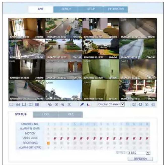
Web Viewer
Live
Live Screen At a Glance

| No. Item Description | |
| 1 | View selection tab You can switch to the live, playback and setup screen and check the provided information. |
| 2 | Live Display the live screen of the currently connected DVR. |
| 3 | Split Mode Select and switch to a desired split-screen mode. |
| 4 | Sequence, Zoom Set the sequence mode, switch to the next camera, zoom the screen or select the full screen mode. |
| 5 | Status Show the connection status of each channel. |
| Log Show the log. | |
| Refresh Time Set the interval at which the DVR Status is refreshed. | |
| Reload Load the DVR Status immediately. | |
| 6 | Voice transmission You can turn on or off the output of the voice signal. |
| 7 | Channel Select a channel listed in the screen. |
| Save Save the live video on the screen. | |
| Print Print out the current screen. | |
| 8 | Capture Capture the selected image. |
| ActiveX Settings Configure the ActiveX settings or specify the saving path of the captured image. | |
Switching the split mode
Click the Switch button to switch the mode as follows:
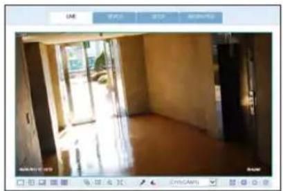
natural_image
Interior view of a dimly lit room with large windows and a wooden floor (no visible text or symbols)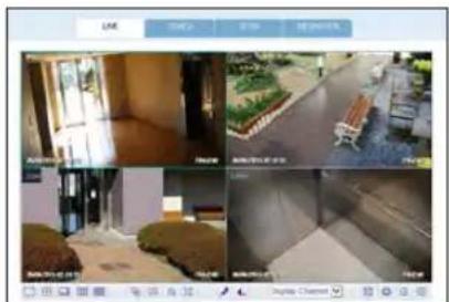
natural_image
Four-panel collage showing outdoor scenes with furniture, buildings, and a bench, all without visible text or symbols.<4-split Mode><1-split Mode>
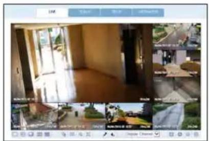
natural_image
Interior view of a modern building with large windows and interior features, no visible text or symbols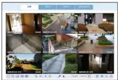

<9-split Mode> <16-split Mode><8-split Mode>
Web Viewer
To save the video
-
Click < > to start saving.
-
The video from the selected channel will be saved to the PC in the AVI format. (Default path: C:\SaveFolder) Click <图标> again to stop saving. Click
to display the context menu where you can change the saving path.
-
Click <
-
The current screen will be printed with the printer connected to the PC.
Screen capture
-
Click <
-
The current screen of the selected channel will be saved to the path specified in the PC. (Default path: C:\SaveFolder) Click
to display the context menu where you can change the saving path.
ActiveX Settings
- Click <>.
- When the setup screen appears, you can change the settings of the audio, capture and saving path as well as the video streaming.
- If you want to change the saving path, click < ▶ (Save Folder) and specify a new path. The Windows Vista user cannot change the saving path.
- Change the streaming settings according to the PC specification and network environment. Auto mode is recommended.
Sync : If this option is set, the audio signal will be synchronized with the video signal. However, you may encounter a delay due to buffering for the synchronization.
Live : Set the audio signal to use in live monitoring mode.
I Frame only : Only the I frames (key frames) will be transferred.
Type
- Auto : The DVR will optimize the quality and FPS to the network status and specification of the connected PC before transferring the data.
- Main: The video will be transferred in high definition (HD).
-
Second : The video will be transferred in a medium definition (SD).
-
When done, click
to save your settings.

Status tab
Click
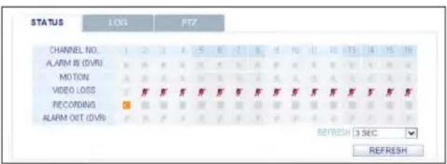
Log tab
Click

PTZ tab
Click
PRESET : Move the camera in a predefined direction.

Web Viewer
Search
Click
Search Viewer at a Glance

No. Item Description
| 1 | View selection tab You can switch to the live, playback and setup screen and check the provided information. | |
| 2 | Playback Screen Play the recording data. | |
| 3 | Split Mode Select and switch to a desired split-screen mode. | |
| 4 | Sequence, zoom, voice transfer | Set the sequence mode, switch to the next camera, zoom the screen or select the full screen mode.You can turn on/off the voice signal. |
| 5 | Play button bar You can control the playback screen. | |
| 6 | Time Selection Specify the start time of playback. | |
| 7 | Time Line Indicates the status of the recorded data. | |
| No. Item Description | |
| 8 | REFRESH Reload the time line. |
| PLAY Play the video that satisfies your search criteria. | |
| EXPORT Archive the video that satisfies your search criteria. | |
| 9 | Channel Selection Select a channel listed in the screen. |
| 10 | Screen Print out the current screen. |
| Image Capture Capture the selected image. | |
| ActiveX Settings Configure the ActiveX settings or specify the saving path of the captured image. | |
Search by time
Use the timeline to search for the data recorded in the DVR.
7 Select a date that you want to search.
2. Click
3. Check the existence of recording data in the bottom time line and specify the time range for your search. You can specify the start time by moving the time bar.
4. Click
REFRESH : If your changes are not applied to the current screen, reload the changes.
PLAY : Play the searched video.
Backup : Archive the recorded video.

Web Viewer
Search by event
You can sort the recording data items by event to facilitate your search.
- Mark the checkbox of the event that you want to search for.
- Specify the start and end dates and times for your log search.
- Set the display order of the items found.
LATEST : The most recent event will be listed on top.
OLDEST : The earliest event will be listed on top.
4 Click
You can check the log for your search at the bottom of the screen.
- Select a log to play the recording data.
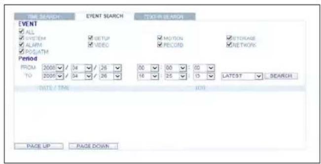
Text-in Search
You can search for the recorded data in DVR by text.
- Enter your desired text to search for in ITEM KEYWORD, and then click the check boxes such as MATCH CASE, MATCH WHOLE WORD ONLY, etc.
- Select the check box(es) of channel(s) to search for.
- Select your desired Start/End date and time to perform the log search.
- Specify the displaying order for the searched items.
√ Refer to the "Search by event" for displaying order of searched items.
-
Press the
button. You can check the log resulted from the search near the bottom. -
When selecting the log, you can watch the recorded video for corresponding event.
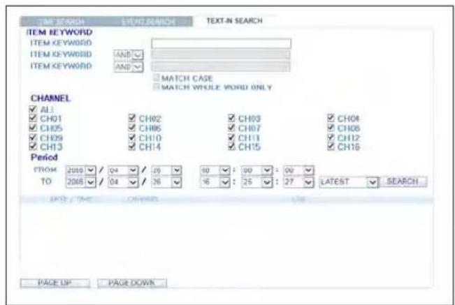
Setup
Click
When done, click
√ If the DVR is in process of system or record setting, the remote control will be disabled.
! If you change the settings remotely at will, the major 'Record Settings' of the DVR may be changed, which is not recommended at all.
Setup Viewer at a Glance

Camera
To name the camera title
You can name the camera title that is displayed on each channel screen. Select a channel to name and provide a new title. Then, click
√ You can enter up to 9 alphanumeric characters for the camera title.
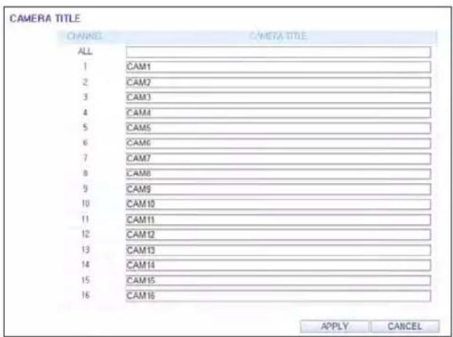
Web Viewer
Image Setting
You can set the image of each channel.
When done, click
√ The default color value is <50>. (Brightness, Contrast, Hue, Color)
√ If you change the default settings, the video from the DVR or the video color may not be displayed properly.

Covert Setting
You can set to hide the video of a specific camera from a specific user. Set to hide the camera video so that a specific user or user group can not view. To change the covert settings from user group to user, move to the

You can set each camera's motion detection, day/night time and others.
Select a channel. Set the mask area and activation and specify the daytime range.
When done, click
√ For information about how to set the motion area, refer to "Motion Area Setup". (page 38)
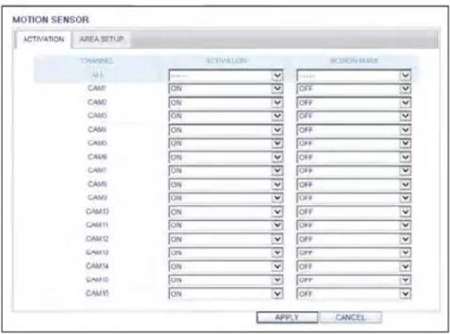

Web Viewer
PTZ setting
To make DVR utilize camera's PTZ functions, match the protocol and baud rate of connected cameras and DVR.
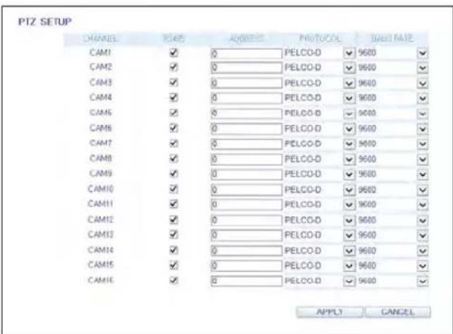
Privacy Mask
You can enable a camera channel's privacy masking area and its mask color.
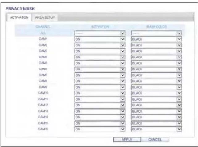

Web Viewer
Display
OSD Setting
Configure the settings for the time, title, boundary, icon and language that will be displayed on the screen. Make changes to each item of the OSD menu and click
√ For details about each displayed item, refer to "OSD". (page 41)
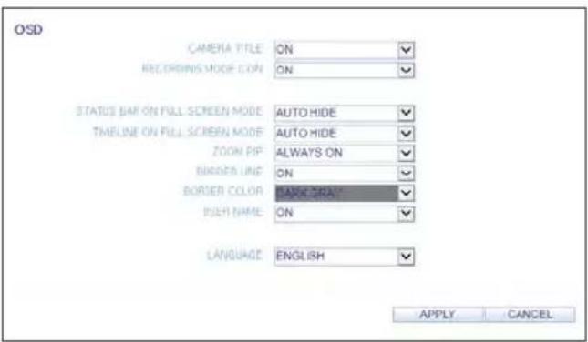
Audio
Audio/Buzzer
You can configure the settings of the voice and audio signal.
√ For details about each displayed item, refer to "Audio Setup". (page 49)

User
User Management
You can add a user account and change the password.
√ For details about each displayed item, refer to "User Setting". (page 50)
To add a user, click
If you want to delete the user click next to it. When done, click

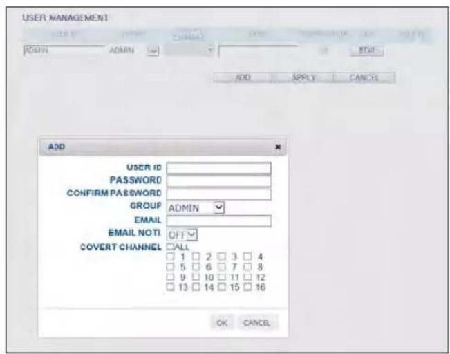
Group Permission Setting
You can grant different user groups different permissions to a specific menu.
Mark the checkboxes of the menu items accessible by the user group.
When done, click
√ For more information about the accessible menu items, refer to "Group Authority". (page 51)

Web Viewer
Network
Network Setting
You can check the network connection status and change the baud rate.
Change the maximum transfer rate and click
√ For more information about each network entry, refer to "IP Setup". (page 52)

DDNS Setting
You can configure the DDNS settings so that remote users who are connected to the network can access remotely.
Change the DDNS settings and click

Email Setting
You can register and test an email address so that an email notification is delivered at a specific interval or if an event occurs.
Provide the necessary information and click
√ For more information, refer to "Email". (page 54)

Security Setting
For security purpose, you can set whether to use encryption and its method.
Change the system network settings and click
√ For more information, refer to "Security". (page 56)
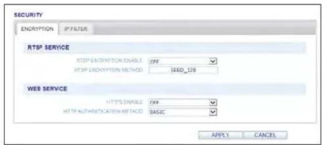

RTP
For more information, refer to "RTP". (page 57)
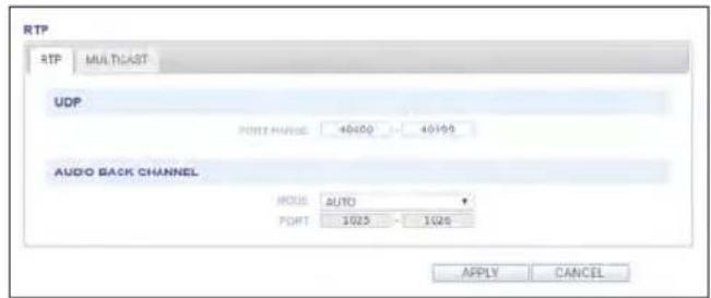

Web Viewer
System
Date/Time Setting
Specify the current date and time.
When done, click
√ For more information about each of the time and date settings, refer to "Date/Time". (page 58)
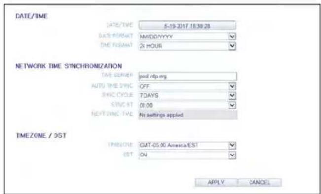
System Management
You can configure the access settings of: log in, log out, and auto logout.
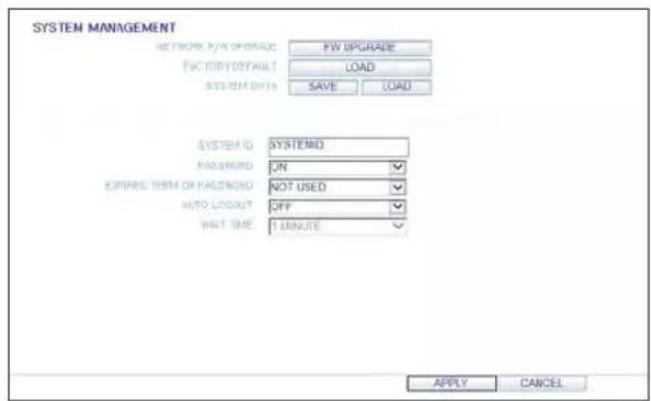
System Information
You can check information of system firmware version, disk space, and network settings, as well as the status information of network connection and alarm I/O.
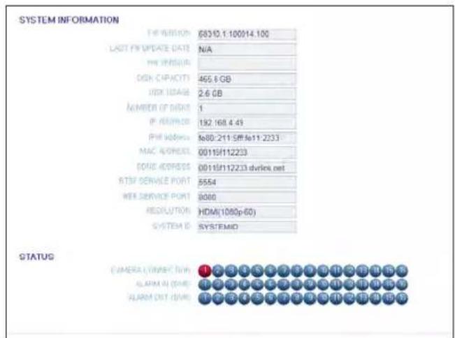
Control Device Setting
Set the connection of both the remote control and the keyboard control.
Change the communication settings and click
√ For more information about each communication item, refer to "Control Device". (page 62)
Security Setting
For security, you can set to apply reinforced password policy (to system, search/backup) and control accessing audio and snapshot.
Change the system security settings and click
√ For more information, refer to "Security". (page 64)
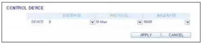

Storage
Device Information
You can check a list of internal/external storage devices connected to the DVR as well as the recording time information of each device.

DISK Operations
You can set the overwrite mode and recording period of a storage device, or format the disk.

Web Viewer
S.M.A.R.T Status
You can check the S.M.A.R.T status for each of the internal and external devices.
√ What is S.M.A.R.T?
This is a sort of HDD self-diagnosis tool that detects any error on the system and alerts the user if an error occurs.

Event
Alarm Output
Specify the alarm output conditions with the work schedule.
When done, click
√ For more information about the alarm output and ON/OFF schedule, refer to "Alarm Out". (page 69)


Event Notification
You can set desired event actions triggered by an event, such as
Set the dwell time for buzzer or pop-up display, or set the email or FTP destination settings and then click
√ For more information about the event notification, refer to "Event Notification". (page 71)
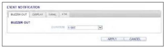


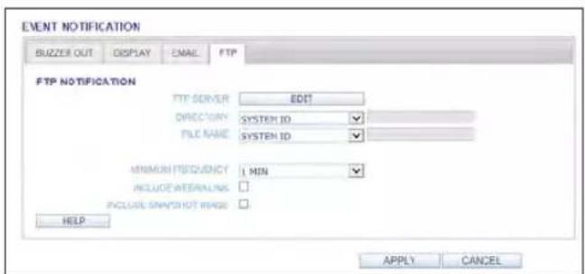
Web Viewer
Alarm Sensor
You can configure the settings of the alarm sensor and specify the operation of the sensor if an event occurs. When done, click
√ For more information about each of the alarm sensor actions, refer to "Alarm Sensor". (page 73)

Motion Sensor
You can set an action to execute when a motion is detected.
When done, click
√ For more information about how to set the motion sensor, refer to "Motion Sensor". (page 74)
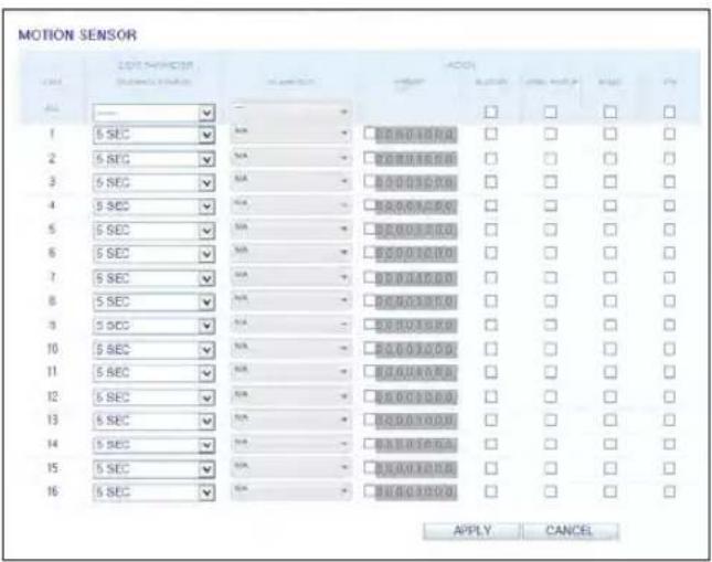
You can set to trigger alarm output or other actions when there is no video transfer from a camera.
When done, click
√ For more information about how to set the video loss, refer to "Video Loss". (page 75)

System Event
You can set event actions for disk, recording, network and system events. As same to setting event actions for normal events, you can set to trigger alarm output, buzzer, display on-screen pop-up, or send event notification via email and FTP.
When done, click
√ For more information about how to set the system event, refer to "System Event". (page 76)
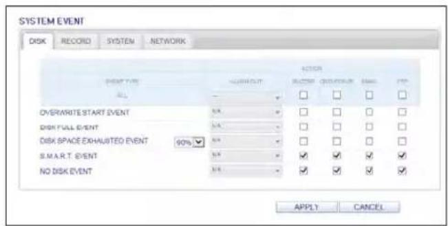


Web Viewer
Record Setup
Operation mode
You can set the recording options for AUTO CONFIGURATION or MANUAL CONFIGURATION mode.

When done, click
√ For more information about how to set each mode, refer to "Operation Mode". (page 79)

Continuous Recording
You can configure the settings of: continuous recording time, recording size, frame rate per second and quality. Click < ➕ next to each item to display the list of values available.
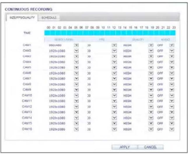
When you complete the recording size and schedule settings, click
√ For more information about the continuous recording size and schedule, refer to "Continuous Recording". (page 81)

Web Viewer
Motion Recording
Set the

Complete setting the
√ For more information about the motion recording size and schedule, refer to "Motion Recording". (page 82)

Alarm Recording
Set the
Click < ➕ next to each item to display the list of values available.

Complete setting the
√ For more information about the alarm recording size and schedule, refer to "Alarm Recording". (page 83)

Web Viewer
Panic Recording
From the
Click < ➕ next to each item to display the list of values available.
When you have completed the manual record settings, click
√ For more information about the manual record settings, refer to "Panic Recording". (page 83)

Network Streaming
You can specify the maximum size of network streaming and video resolution for remote users and change the FPS.
Click < next to each item to display the list of values available.
When done, click

Audio Mapping
You can activate audio of a channel to communicate to the remote user.
Click < ▶ on the right side of each item to display audio channels available to select.
Click

About
Click the
Web Viewer Information
DVR Model : 16CH / 480FPS
WEB Version : WEB_v2.7.3_1.0.2.19_140627
nViewer
You can use the smart viewer to monitor the network on a remote site and play the monitoring video anytime anywhere.
nViewer specification
Minimum / recommended specification
| OS Minimum specification Recommended specification | ||
| Android Phone | Processor : 800 MHz or higher | Processor : 2 GHz or higher |
| Flash : 512 MB | Flash : 512 MB | |
| RAM : 512 MB | RAM : 1 GB | |
| OS : Phone : 4.0, Pad : 3.0 | OS : 4.0 or higher | |
| iPhone | iPhone 3GS | |
| iPod touch 3rd Generation | iPhone 5s / iPhone OS 8.0 higher | |
| iPhone OS 6.1 or higher | ||
Using the nViewer on iPhone
How to download the iPhone-dedicated application
From your iPhone, access the App Store.
Enter "nViewer" in the search bar to find it before downloading. Install the application on your iPhone.
√ The nViewer supports the Multi split screen mode.
The nViewer Lite is a free application, and does not provide search, log view, PTZ control and system configuration functions.
To connect to DVR with nViewer
7 Select and run the nViewer.
2. Click < + in the top right corner of the DVR List to select and add a site to the list.
- Please enter a Name.
- Provide the IP address, HTTP port number and RTSP port number.


Mobile Viewer
- Provide the access ID of the DVR as well as the password.
- Specify the use of the Auto Login.
-
Click
. -
Select the site that you added in the DVR List.
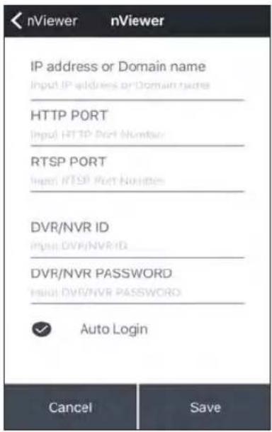
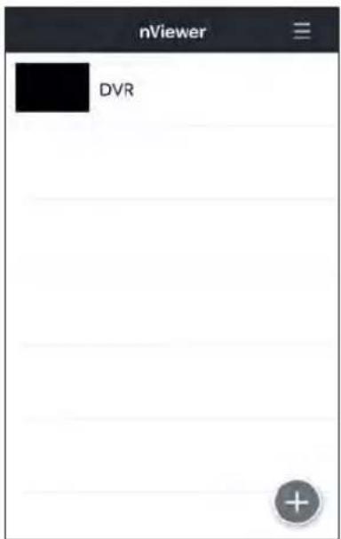
- Try to access the DVR. If connected successfully, you will see the screen as shown.

Split Mode
- Click any area on the screen. The main menu appears at the bottom of the screen.
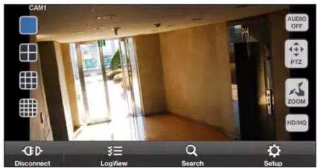
- Click < ■ > in the top left corner to switch to 1-split mode; click < ■ ■ ■ > to switch to Multi-split mode.
√ Use the finger to scroll the screen to the left or right to move to the next camera video screen.
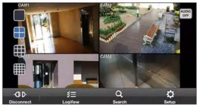
To use AUDIO
Select the desired audio channel or set to OFF. Audio can be played back from the selected channel in Multi-split mode.

Mobile Viewer
To use PTZ control
You can use 2 methods for PTZ control.
To switch between PTZ control methods, use the "Fine Control" button.
- For continuous PTZ control while viewing the monitoring window, use the joystick control as shown in the right figure.
- For stepped PTZ control at a certain position step, use STEP control as shown in the right figure.
√ : Use the Focus button to adjust the focus
√ - + : Use the Zoom button to zoom in or out.
Position Step - 5 + : Set the Position Step value to adjust the amount of camera movement for each PTZ control.
√ : Use to Pan/Tilt control in the selected direction.
√ : Use to capture the real-time monitoring screen and save it as an image file into the image folder of the device.


To use Zoom function
- Click < 20%> in the top right corner.
- Click <⊕> button to zoom in, or click <⊖> to zoom out.
√ Touch the screen with two fingers and pinch open to zoom in, or pinch close to zoom out.

To view HQ (High Quality) video
- Click < 📞 > in the top right corner.
- It switches to the HQ video.

Using the Log View
- From the main menu, click < 狼 You can check the log of the data stored.
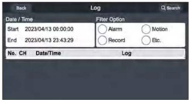
- Select one from Alarm, Motion, Record, Etc. and click < Search >. You will view the log of related items.


Mobile Viewer
Using the Search function
- From the main menu, click <Q You can view the history of the data stored.
- Select a desired time and date. You can use the vertical time bar to specify the start time.

- Click < play the video recorded at the specified time.
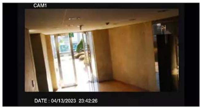
natural_image
Interior view of a modern building with large windows and doors, captured in a black-and-white photo frame (no visible text or symbols)- Click any area to display the play bar with which you can control the playing direction and speed of the video.

Using the Setup function
From the main menu, click <
You will be connected to the web viewer site.
√ For details about each displayed item, refer to "Setup". (page 105)
| Back | Setup | |
| CAMERA | CAMERA TITLE | |
| ANALOG TYPE SETUP | CHANNEL | |
| CAMERA TITLE | ALL | |
| IMAGE SETUP | 1 | CAM1 |
| COVERT SETUP | 2 | CAM2 |
| MOTION SENSOR | 3 | CAM3 |
| PTZ SETUP | 4 | CAM4 |
| PRIVACY MASK | 5 | CAM5 |
| DISPLAY | 6 | CAM6 |
| 7 | CAM7 | |

Mobile Viewer
Using nViewer with Android
How to download the Android-dedicated application
From your smart phone, access the Market.
Enter "nViewer" in the search bar to find it before downloading. Install the application on your Smart Phone.
√ The nViewer supports the 1/4 split screen mode.
The nViewer Lite is a free application, and does not provide search, log view, PTZ control and system configuration functions.
To connect to DVR with nViewer
- Select and run the nViewer.
- Use the Add button to select and add a site to the list.

- Please enter a Name.
- Provide the IP address, HTTP port number and RTSP port number.
- Provide the access ID of the DVR as well as the password.
- Select whether or not to save the ID and PW.
- Click
.
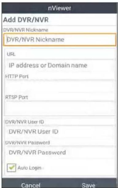
- Select the site that you added in the DVR List. Press and hold the mouse button to display the pop-up window.

- Select
and try to access. If connected successfully, you will see the screen as shown.
natural_image
Interior view of a modern building with large windows and exposed flooring (no visible text or symbols)
Mobile Viewer
Split Mode
- Click any area on the screen. The main menu appears at the bottom of the screen.

- Click < ■ > in the top left corner to switch to 1-split mode; click < ■ ■ ■ > to switch to Multi-split mode. √ Use the finger to scroll the screen to the left or right to move to the next camera video screen.
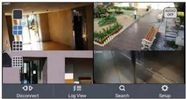
To use AUDIO
Select the desired audio channel or set to OFF. Audio can be played back from the selected channel in Multi-split mode.
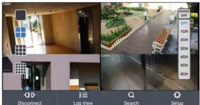
To use PTZ control
You can use 2 methods for PTZ control.
To switch between PTZ control methods, use the "Fine Control" button.
- For continuous PTZ control while viewing the monitoring window, use the joystick control as shown in the right figure.
- For stepped PTZ control at a certain position step, use STEP control as shown in the right figure.
√ : Use the Focus button to adjust the focus
√ - + : Use the Zoom button to zoom in or out.
Position Step - 5 + : Set the Position Step value to adjust the amount of camera movement for each PTZ control.
√ : Use to Pan/Tilt control in the selected direction.
√: Use to capture the real-time monitoring screen and save it as an image file into the image folder of the device.

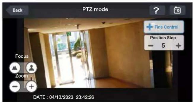
To use Zoom function
- Click < 📄> in the top right corner.
- Click < + > button to zoom in, or click < - > to zoom out.
√ Touch the screen with two fingers and pinch open to zoom in, or pinch close to zoom out.

To view HQ (High Quality) video
- Click < 📄> in the top right corner.
- It switches to the HQ video.

Mobile Viewer
Using the Log View
- From the main menu, click < is You can check the log of the data stored.
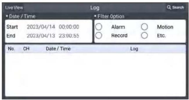
- Select one from Alarm, Motion, Record, Etc. and click < Search >. You will view the log of related items.

Using the Search function
- From the main menu, click <Q You can view the video of the recording data.
- Select a desired time and date. You can use the vertical time bar to specify the start time.

- Click < play the video recorded at the specified time.

natural_image
Interior view of a modern building hallway with large windows and exposed flooring (no visible text or symbols)- Click any area to display the play bar with which you can control the playing direction and speed of the video.

Mobile Viewer
Using the Setup function
From the main menu, click <
You will be connected to the web viewer site.
√ For details about each displayed item, refer to "Setup". (page 105)

Archive Viewer
You can play the data archived in the DVR.
You can play the HDD data recorded by the DVR.
Getting started with the Backup Player
- Connect the DVR to the backup USB storage device.
- Open the folder saving the archived images.
- Run the Backup Player.


- Click < in the bottom left corner to display the file browser. Select the archived file to play.

Archive Viewer
- Check the integrity of the archived file.
- When done, the archived file will be played on the screen.


Backup Player At a Glance
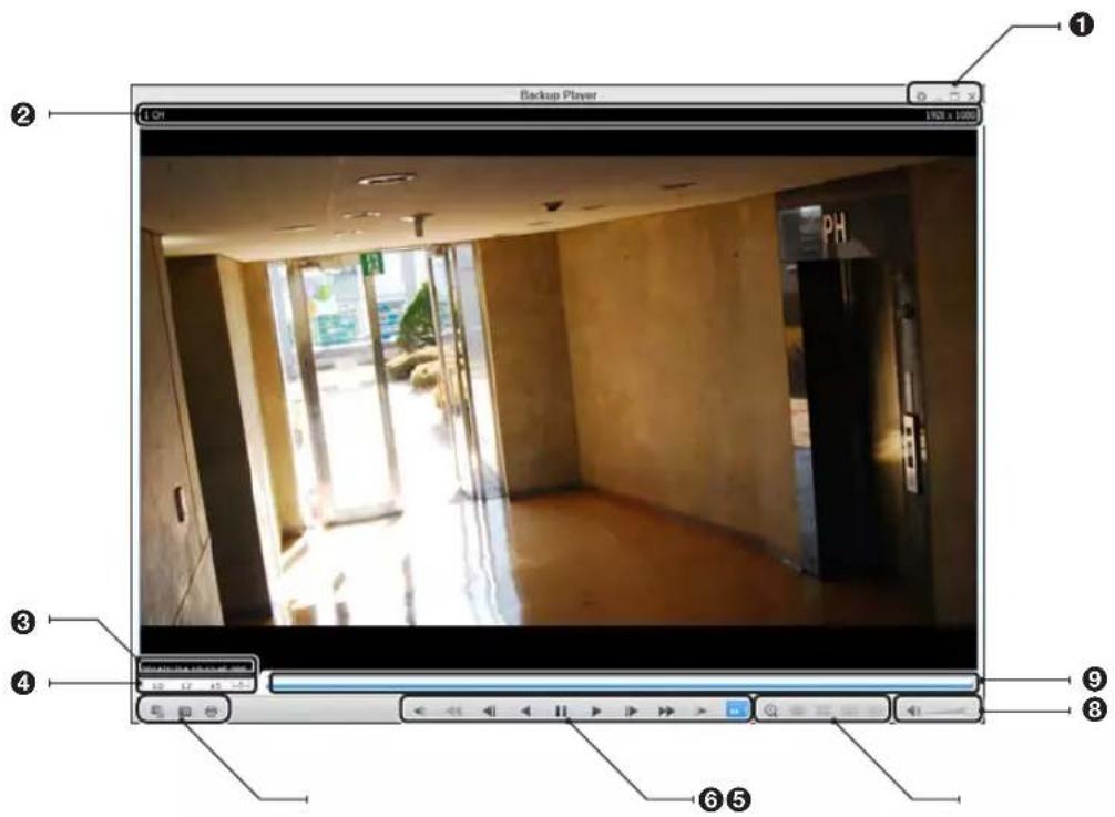
No. Item Description
| 1 | Setup Configure the environment settings. | |
| Minimize, Close Minimize or close the Backup Player. | ||
| 2 | Channel Information Show the channel information and the video resolution. | |
| 3 | Play Time Display the time of the current video image. | |
| 4 | Play Time Display the current playback time. | |
| 5 | File Search Open the file that you backed up. | |
| Capture Capture the current screen. | ||
| Print Print out the current screen. | ||
| 6 | Playback Control | Control the playback direction and speed of the current video.For more information about how to use the playback control buttons, refer to "Using the play bar". (page 91) |
| 7 | Zoom, Split Mode Switch to Zoom, 1-/4-/9-/16-split screen mode. | |
| 8 | Audio Setting Show the sound signal status and volume level. | |
| 9 | Play Bar Display the current playback position in the video. | |
Archive Viewer
Video Capture
Click < to capture the current video image.
Selected Video : Capture the actual frame of the current video.
Screen : Capture the visible portion of the current video.
Format : Select a saving format.(BMP, JPG, PNG)
Path : Specify the saving path.
- Default location : My Documents\My Pictures
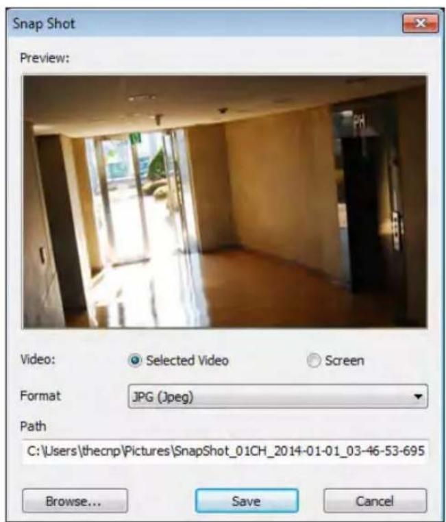
Print Out
Click < Button to print out the image.
When the "Print" window appears, check the preview and click

Settings
Click < ☐ to configure the Backup Player settings. You can check the version of the Backup Player.
Maintain image aspect ratio : Preserve the aspect ratio of the image. If you do not mark this option, the image will be adjusted to fit the screen.
I-frame Play : Only the I frames (key frames) will be playback.
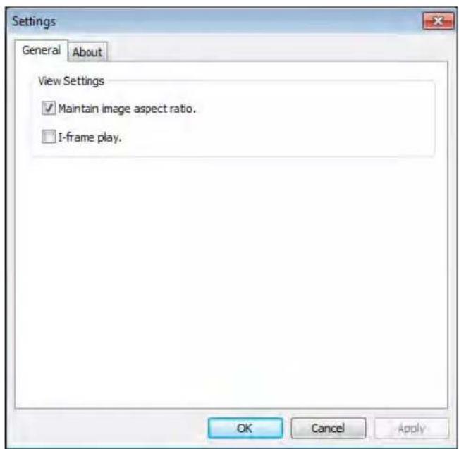
About : You can check the program information including the current version.

Appendix
Compatible HDD Specifications
| Maximum SATA Speed | •SATA1(1.5G) : Can be used•SATA2(3.0G) : Can be used•SATA3(6.0G) : Devices of backward compatibility to SATA2 (3.0G) can be used. |
| Maximum Start-up Current 12V, 2A (or lower) | |
| Maximum Average Operation Power Consumption | 7W (or lower) |
| Maximum R/W Latency Latency (Read: 13ms / Write: 13ms) or smaller | |
√ Use 3.5" HDD disks.
√ Using HDD devices other than recommended specifications may cause serious problem.
√ For further information of HDD specifications, refer to the applicable data sheet of the HDD manufacturer.
Troubleshooting (FAQ)
| Problem Action | |
| The system does not operate at all with no active LED in the front panel. | Make sure that the rear switch is turned on.Make sure that the system gets supplied with power properly.Check the input voltage. |
| The unit continuously reboots. | Check if the system fan in a side panel of the unit or the CPU fan inside the unit works properly.If it fails, contact the retailer or the service center.Disconnect the HDD cable and try to boot the system again. If the system reboots successfully, install a new HDD and check if the system make recording normally. |
| The front LED is lit, but nothing is displayed on the screen yet. | Check if your monitor supports the 1080p 60Hz HDMI, VGA input.Ensure that the input source settings of the monitor match with the output source settings of the DVR.If using the HDMI-to-DVI cable for the connection, ensure that the input source is set to DVI.Make sure that the system gets supplied with power properly.Check the input voltage. |
| The sides of the video image are displayed incomplete. | If the monitor is over-scanning the video, the sides can be hidden. If this is the case, switch the display mode of the monitor to the 1:1 pixel matching mode. Then, you will view the video in full screen.The 1:1 pixel matching is referred to differently depending on the monitor manufacturer (for example, "JUST SCAN" for Samsung, "ZERO OVERSCAN" for LG). For details, refer to the user manual of the monitor. |
| The camera is connected but no image is displayed. | Make sure that the camera is compatible with the DVR. For the compatibility of the cameras, contact the retailer.Ensure that the output settings of the camera match with the camera type settings of the DVR. |
| It fails to connect to the web or mobile application. | Check if the network cable is properly connected to the ETHERNET port of the unit.You must have set the port forwarding if using a router.If you cannot get access with the DDNS address, use the IP address of the DVR instead.If the DVR is connected to the router, use the IP address of the DVR.You can check the IP address of the router in- |
| I can access the web or mobile application but still no video image is displayed. | You must have set the port forwarding if using a router.This may happen when the communications provider or network administrator has blocked the service port of the DVR.Change the RTSP port and HTTP port numbers to different ones and set the port forwarding again.Try to access the web or mobile application using the new port numbers. |

natural_image
Abstract wave pattern with flowing blue and white gradients, no text or symbols present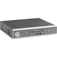
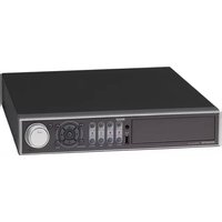

- Limitation of Liability
- Content
- OVERVIEW
- PLAY
- INSTALLATION
- ARCHIVING
- MONITORING
- WEB VIEWER
- SYSTEM SETTING
- MOBILE VIEWER
- ARCHIVE VIEWER
- SEARCH
- APPENDIX
- Safety Instruction
- Before installation
- In operation mode
- Disassembly & Cleaning
- During installation
- While in use
- CAUTION
- Replaceable batteries
- Warning to service personnel
- Ethernet Instruction
- Key Features
- What's included
- Rear Panel
- Remote Control At a Glance
- : Installation
- Replacing HDD
- / 16Ch Model
- If installed 5 HDD drives
- Basic Layout
- Connecting to an external device
- Connecting to the monitor
- Power Connection
- Alarm I/O Connection
- To connect the alarm input signal
- To connect the alarm output signal
- Communication Port
- RS-485 Connection
- RS-232 Connection
- Audio Device Connection
- Storage and Mouse Connection
- eSATA Storage
- USB Device
- Network Connection
- PC connection in the local network
- PC connection from a remote network
- START
- User Information Setup
- SET PASSWORD
- AUTHENTICATION INFORMATION SETUP
- Log In
- Forgot Password?
- Log Out
- System Shutdown
- Live Screen At a Glance
- Video Window
- Status Bar
- Timeline
- Quick Menu
- Using the status bar in the live mode
- Changing Channel
- Selecting a split mode
- Allocating Live Screen Channel
- Auto sequence
- Controlling PTZ
- Pan/Tilt Control
- Zoom / Focus Control
- SCAN/TOUR
- Digital Zooming
- To check the event log
- To select an audio input channel
- To check the alarm status
- To check the network status
- To check the disk status
- Saving captured snapshots
- To move to the System Setup menu
- Camera Setting
- Camera Type Setup
- IPcamera Installation
- OF MOUNTED CAMERA: 0
- OF CREAM CAMERA: 2
- OF CAMERA ANGENT NAME SET 14
- The screen is set up the network architecture. We do not use any other options.
- Camera Title
- Motion Sensor
- Motion Area Setup
- PTZ Setup
- Privacy Mask
- Enabling Privacy Mask
- Setting the Privacy Masking Area
- Display Setting
- OSD
- Monitor
- DUAL MONITOR
- Sequence
- To add a sequence
- To edit a sequence
- SPOT OUT
- To add a View Type to a Spot Out
- To edit or delete View Type of the SPOT Output
- LOOP OUT
- POS/ATM
- Audio Setup
- Audio
- Buzzer
- User Setting
- Management
- To add a user account
- To edit the user account information
- Group Authority
- Network Setup
- IP Setup
- IPv4
- IPv6
- Network Status
- Network Map
- Security
- ENCRYPTION
- RTP
- MULTICAST
- Date/Time
- System Management
- To perform the upgrade
- System Information
- NUMBERS
- Control Device
- To set the POS
- Storage
- Disk Information
- Disk Operations
- Disk Configuration
- To configure a RAID array
- S.M.A.R.T settings
- Event Setup
- Alarm Out
- ON/OFF Schedule
- Event Notification
- Buzzer output
- > DURATION
- Display
- FTP
- Alarm Sensor
- Video Loss
- POS / ATM
- System Event
- Disk
- System
- Network
- Record Setting
- To start the Record Setup menu
- Record Setup
- Operation Mode
- Auto Configuration
- Manual Configuration
- Continuous Recording
- Size/FPS/Quality Setting
- Schedule Setting
- Motion Recording
- Alarm Recording
- Panic Recording
- Network Streaming
- AUDIO MAPPING
- To move to the Search menu while in monitoring
- To move to the Search menu while in playback mode
- Search Settings
- Time Search
- Thumbnail Search
- : Search
- Event Search
- Text-in Search
- If you want to play
- Playback screen configuration
- Menu / split-screen selection menu
- Play Bar
- Bookmarking
- To start the Archive menu
- Using the Archive menu during playback
- Using the Archive menu during monitoring
- Archive
- Reserved data management
- Playing the archived data
- Archive Devices Setup
- What is the Web Viewer?
- System Requirements
- Connection
- To connect to the DVR from inside
- To connect to the DVR from outside
- Live
- Switching the split mode
- To save the video
- Screen capture
- ActiveX Settings
- Status tab
- Log tab
- PTZ tab
- Search by time
- Search by event
- Setup
- Setup Viewer at a Glance
- Camera
- To name the camera title
- Image Setting
- Covert Setting
- PTZ setting
- OSD Setting
- Audio/Buzzer
- User
- User Management
- Group Permission Setting
- Network Setting
- DDNS Setting
- Email Setting
- Security Setting
- Date/Time Setting
- Control Device Setting
- Device Information
- S.M.A.R.T Status
- Event
- Alarm Output
- About
- Web Viewer Information
- nViewer
- nViewer specification
- Using the nViewer on iPhone
- How to download the iPhone-dedicated application
- To connect to DVR with nViewer
- Split Mode
- To use AUDIO
- To use PTZ control
- To use Zoom function
- To view HQ (High Quality) video
- Using the Log View
- Using the Search function
- Using the Setup function
- Using nViewer with Android
- How to download the Android-dedicated application
- Getting started with the Backup Player
- Video Capture
- Print Out
- Settings
- Troubleshooting (FAQ)
Brand : Ganz
Model : Digimaster DR-16M55-RA
Category : Surveillance Camera