
Spirit Powerstation 350 - Power Supply SOUNDCRAFT - Free user manual and instructions
Find the device manual for free Spirit Powerstation 350 SOUNDCRAFT in PDF.


| Product Type | Powered Mixer / PA System |
| Model | Spirit Powerstation 350 |
| Brand | Soundcraft |
| Power Output | 2 x 350W (stereo) at 4 ohms |
| Input Channels | 12 channels (8 mono + 2 stereo) |
| Frequency Response | 20 Hz – 20 kHz ±1 dB |
| Built-in Effects | 24-bit digital effects processor with 16 presets |
| Graphic Equalizer | 9-band stereo graphic EQ |
| Amplifier Type | Class H |
| Cooling | Variable speed fan |
| Dimensions (W x D x H) | 19" x 15.7" x 6.3" (rack mountable 4U) |
| Weight | Approximately 18.5 kg (40.8 lbs) |
| Power Supply | AC 100-240 V, 50/60 Hz |
| Power Consumption | 850 W max |
| Input Impedance | 10 kΩ (mic), 20 kΩ (line) |
| Phantom Power | +48 V switchable per channel |
| Speaker Outputs | 2 x speakON compatible |
| Line Outputs | 2 x XLR balanced |
| Headphone Output | 1/4" stereo jack |
| Cleaning | Wipe with a dry, soft cloth. Do not use solvents. |
| Safety | Operate in well-ventilated area. Disconnect power before cleaning. |
| Spare Parts | Contact authorized Soundcraft service centers for replacement parts. |
| Repairability | Modular internal design; repair by qualified technician recommended. |
Frequently Asked Questions - Spirit Powerstation 350 SOUNDCRAFT
User questions about Spirit Powerstation 350 SOUNDCRAFT
0 question about this device. Answer the ones you know or ask your own.
Ask a new question about this device
Download the instructions for your Power Supply in PDF format for free! Find your manual Spirit Powerstation 350 - SOUNDCRAFT and take your electronic device back in hand. On this page are published all the documents necessary for the use of your device. Spirit Powerstation 350 by SOUNDCRAFT.
USER MANUAL Spirit Powerstation 350 SOUNDCRAFT
Using the Powerstation ..... 4
Setting Up & Troubleshooting ..... 10
Applications ..... 11
System Block Diagram .....17
Connecting Leads .....19
Dimensions 20
Typical Specifications .....20
INTRODUCTION
Thank you for purchasing a Powerstation mixer, brought to you with pride by the SPIRIT team of Andy, Colin, Chris, James, Simon, Mukesh, Graham, Martin, Paul, Tony, Adam, Peter, our friends in Boston and with the support of many others - we hope you will have as much fun using it as we did building it!
For your own safety and to avoid invalidation of the warranty please read this section carefully.

SAFETY PRECAUTIONS
WARNING: THIS UNIT MUST BE EARTHED
Under no circumstances should the mains earth be disconnected from the mains lead.
The wires in the mains lead are coloured in accordance with the following code:
Earth: Green and Yellow (Green/Yellow - US)
Neutral: Blue (White - US)
Live: Brown (Black - US)
As the colours of the wires in the mains lead may not correspond with the coloured markings identifying the terminals in your plug, proceed as follows:
● The wire which is coloured Green and Yellow must be connected to the terminal in the plug which is marked with the letter E or by the earth symbol.
● The wire which is coloured Blue must be connected to the terminal in the plug which is marked with the letter N.
● The wire which is coloured Brown must be connected to the terminal in the plug which is marked with the letter L.
Ensure that these colour codings are followed carefully in the event of the plug being changed.
This unit is capable of operating over a range of mains voltages by means of a 4-position mains input fuse carrier. It is important to ensure that the correct voltage setting is selected for the level of local mains voltage supply, for safe, uninterrupted operation. Use a small screwdriver to prise the fuse carrier from its location in the connector.
To avoid the risk of fire, replace the mains fuse only with the correct value fuse, as marked on the rear panel.
The internal power supply unit contains no user serviceable parts. Refer all servicing to a qualified service engineer, through the appropriate Spirit dealer.
Do not obstruct air vents.
![graph TD A["Connecting Up"] --> B["MO Box"] A --> C["MO Box"] A --> D["MO Box"] A --> E["MO Box"] A --> F["MO Box"] A --> G["MO Box"] A --> H["MO Box"] A --> I["MO Box"] A --> J["MO Box"] A --> K["MO Box"] A --> L["MO Box"] A --> M["MO Box"] A --> N["MO Box"] A --> O["MO Box"] A --> P["MO Box"] A --…](/content/2026/06/1365821/images/b5853b8891cff7e0e9f136bb91abfe98cfb61547a784d3e0fdad1180abc35e76.jpg)
Page 3

Using the POWERSTATION
MONO INPUT CHANNEL

MICROPHONE INPUT

The mic input accepts XLR-type connectors and is designed to suit a wide range of BALANCED or UNBALANCED signals. Professional dynamic, condenser or ribbon mics are best because these will be LOW IMPEDANCE. You can use low-cost HIGH IMPEDANCE mics, but the level of background noise will be higher. If you press the MIC +48V switch down (on the Master section) the socket provides a suitable powering voltage for professional condenser mics (this is also known as Phantom Power).
ONLY connect condenser microphones with the +48V powering OFF (switch UP), and ONLY turn the +48V powering on or off with all output faders DOWN, to prevent damage to the mixer or external devices.
TAKE CARE when using unbalanced sources, which may be damaged by the phantom power voltage on pins 2 & 3 of the XLR connector.
Unplug any mics if you want to use the LINE Input. The input level is set using the GAIN knob.

LINE INPUT
Accepts 3-pole 'A' gauge (TRS) jacks. Use this high impedance input for sources other than mics, such as keyboards, drum machines, synths, tape machines or guitars. The input is BALANCED for low noise and top quality from professional equipment, but you can use UNBALANCED sources by wiring up the jacks as shown, although you should then keep cable lengths as short as possible. Unplug anything in the MIC input if you want to use this socket. Set the input level using the GAIN knob.

INSERT
The unbalanced, pre-EQ insert point is a break in the channel signal path, allowing limiters, compressors, special EQ or other signal processing units to be added in the signal path. The Insert is a 3-pole 'A' gauge jack socket which is normally bypassed. When a jack is inserted, the signal path is broken just after the High-Pass Filter and before the EQ section. The Send may be tapped off as an alternative pre-fade, pre-EQ direct output if required, using a lead with tip and ring shorted together so that the signal path is not interrupted.

GAIN CONTROL
This knob sets how much of the source signal is sent to the rest of the mixer. Too high, and the signal will distort as it overloads the channel. Too low, and the level of any background hiss will be more noticeable and you may not be able to get enough signal level to the output of the mixer. Setting the knob to the 10dB mark gives unity gain for the LINE input. Note that some sound equipment, particularly that intended for domestic use,
operates at a lower level (-10dBV) than professional equipment and will therefore need a higher gain setting to give the same output level. See 'Setting Up & Troubleshooting' on page 10 to learn how to set GAIN correctly.

100Hz HI-PASS FILTER
Pressing this switch activates a steep 18dB per octave filter which reduces the level of bass frequencies only. Use this in live PA situations to clean up the mix, reducing stage rumble or 'popping' from microphones.

EQUALISER
The Equaliser (EQ) allows fine manipulation of the frequency bands, and is particularly useful for improving the sound in live PA applications where the original signal is often far from ideal and where slight boosting or cutting of particular voice frequencies can really make a difference to clarity.
HF EQ
Turn clockwise to boost high (treble) frequencies (12kHz and above) by up to 15dB, adding crispness to cymbals, vocals and electronic instruments. Turn anticlockwise to cut by up to 15dB, reducing hiss or excessive sibilance which can occur with certain types of microphone. Set the knob in the centre-detented position when not required.
MID EQ
This pair of knobs work together to form a MID frequency EQ section. The lower knob provides 15dB of boost and cur, just like the HF EQ knob, but the frequency at which this occurs can be set by the upper knob over a range of 250Hz to 6kHz. This allows some truly creative improvement of the signal in live situations, because the mid band covers the range of most vocals. Listen carefully as you use these controls together to find how particular characteristics of, for instance, a vocal signal can be enhanced or reduced. Set the gain (lower) knob to the centre-detented position when not required. Note: Q is set at 1.5.
LF EQ
Turn clockwise to boost low (bass) frequencies (60Hz and below) by up to 15dB, adding warmth to vocals or extra punch to synths, guitars and drums. Turn anticlockwise to cut low frequencies by up to 15dB for reducing hum, stage rumble or to improve a mushy sound. Set the knob to the centre-detented position when not required.

AUXILIARY SENDS
These are used to set up separate mixes for FOLDBACK, EFFECTS or recording, and the combination of each Aux Send is mixed to the respective Aux Output at the rear of the mixer. For Effects it is useful for the signal to fade up and down with the fader (this is called POST-FADE), but for Foldback or Monitor feeds it is important for the send to be independent of the fader (this is called PRE-FADE).
Aux 1 is always PRE-FADE, POST-EQ, for typical use as a monitor or fold-back feed. Aux 2 is normally POST-FADE, POST-EQ for use as an effects send. By pressing the AUX 2 PRE switch on the Master section the Aux 2 send is set PRE-FADE, POST-EQ. Both knobs should be turned down when not in use.

8 LEX FX
This control routes the post-fade, post-EQ channel signal to the Lexicon FX bus, which feeds the internal LEXICON Digital Effects Processor. The knob should be turned down when not in use. The output of the LEXICON unit feeds the Stereo Mix directly or may be mixed to the Aux I output (see Master section, no. 4).
9 PAN
This control sets the amount of the channel signal feeding the Left and Right MIX buses, allowing you to move the source smoothly across the stereo image. When the control is turned fully right or left you are able to route the signal at unity gain to either left or right outputs individually.
10 PFL
When the latching PFL switch is pressed, the pre-fade, post-EQ signal is fed to the headphones and meters, where it replaces the Stereo Mix as the normal monitor source. The PFL ACTIVE LED on the Master section illuminates to warn that the headphones and meters are now carrying a PFL signal. This is a useful way of listening to any required input signal without interrupting the main mix, for making adjustments or tracing problems. The monitors and meters revert to stereo Mix when the PFL switch is released.
II CHANNEL FADER
The 60mm FADER allows precise balancing of the various source signals being mixed to the Master Section. You get most control when the input Sensitivity is set up correctly, giving full travel on the fader. See the 'Setting Up & Troubleshooting' section on page 10 for help in setting a suitable signal level.


STEREO INPUT CHANNEL

STEREO INPUTS
Each Stereo Input section comprises a pair of similar inputs. The inputs are electronically balanced and separate 3-pole 'A' gauge (TRS) jacks are provided for the Left and Right source signals. A mono signal may be plugged into the upper (left) socket only and will be fed equally to both paths.

GAIN
This knob allows you to match the input level to suit a wide variety of professional, semi-professional and hi-fi sources.
Start with a low setting, especially for professional equipment, and increase it if you cannot reach an adequate signal level with the fader at the nominal '0' mark. See 'Setting Up & Troubleshooting' on page 10 to learn how to set GAIN correctly.

EQUALISER
The Equaliser(EQ) comprises three sections.
HF EQ
The upper control provides H.F. (treble) boost and cut of 15dB at 12kHz. Turning to the right provides boost, adding crispness to drum machines, synths and electronic instruments. Turning to the left cuts the same frequencies, reducing hiss or excessive brilliance.
MID EQ
The MID control provides cut and boost of 15dB, at a 1kHz.
LF EQ
The lowest knob is an LF (bass) section providing boost and cut of 15dB at 80Hz. Turning to the right provides boost, adding extra punch to synths, guitars or drums. Turning to the left can be helpful to reduce hum or boominess or to improve a mushy sound.
Set the controls to the centre-detented position when not required.

AUXILIARY SENDS
These are used to set up separate mono mixes for FOLDBACK, EFFECTS or recording, and the combination of each Aux Send is mixed to the respective Aux Output at the rear of the mixer. For Effects it is useful for the signal to fade up and down with the fader (this is called POST-FADE), but for Foldback or Monitor feeds it is important for the send to be independent of the fader (this is called PRE-FADE).
Aux 1 is always PRE-FADE, POST-EQ, for typical use as a monitor or fold-back feed. Aux 2 is normally POST-FADE, POST-EQ for use as an effects send.. By pressing the AUX 2 PRE switch on the Master section the Aux 2 send is set PRE-FADE, POST-EQ. Both knobs should be turned down when not in use.

LEX FX
This control routes the post-fade, post-EQ channel signal to the Lexicon FX bus, which feeds the internal LEXICON Digital Effects Processor. The knob should be turned down when not in use. The output of the LEXICON unit feeds the Stereo Mix directly or may be mixed to the Aux I output (see Master section, no. 4).

BALANCE
The BAL (Balance) control determines the position of the signal within the stereo mix image. Rotation fully anticlockwise feeds the signal solely to the Left mix bus, while rotation clockwise sweeps the image to the Right bus.

PFL
When the latching PFL switch is pressed, a mono sum of the pre-fade, post-EQ signal is fed to the headphones and meters, where it replaces the Stereo Mix as the normal monitor source. The PFL ACTIVE LED on the Master section illuminates to warn that the headphones and meters are now carrying a PFL signal. This is a useful way of listening to any required input signal without interrupting the main mix, for making adjustments or tracing problems. The monitors and meters revert to stereo Mix when the PFL switch is released.

CHANNEL FADER
The 60mm FADER allows precise balancing of the various source signals being mixed to the Master Section. You get most control when the input Sensitivity is set up correctly, giving full travel on the fader. See the 'Setting Up & Troubleshooting' section on page 10 for help in setting a suitable signal level.
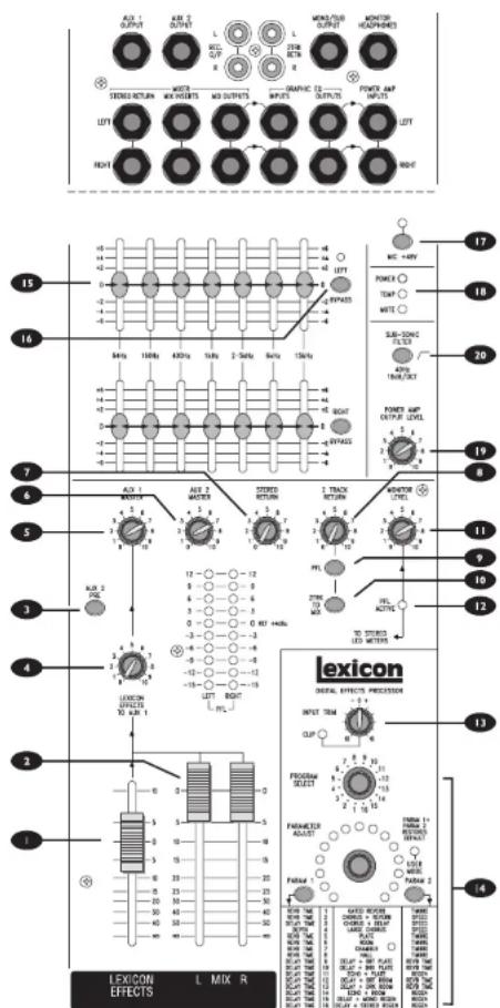
MASTER SECTION
I LEXICON EFFECTS MASTER FADER
The EFFECTS fader controls the volume of the effect which is added directly to the Left/Right mix, and is subject to the control of the Main L/R Master Faders (see 2 below).
The MAIN L & R MASTER FADERS control the final output level of the signal to the Main impedance balanced Mix outputs (after the Insert Point).
3 AUX 2 PRE
Aux Send 2 is normally post-fade, Post EQ, but for flexibility it may be switched to PRE-FADE, POST EQ by pressing the AUX 2 PRE switch. This simultaneously affects all Aux 2 sends across the mixer.
4 LEXICON EFFECTS TO AUX 1
This control allows the output of the Lexicon Digital Effects Processor to be mixed in mono with the Aux I Sends if required to provide a 'wet' foldback feed or alternative output.
5 AUX 1 MASTER
The AUX I MASTER control sets the final level of the Aux I mix sent to the impedance balanced Aux I output.
6 AUX 2 MASTER
The AUX 2 MASTER control sets the final level of the Aux 2 mix sent to the impedance balanced Aux 2 output.
7 STEREO RETURN
A balanced Stereo Return is available for the output of effects units and this is mixed directly to the Mix L/R busses at a level set by the STEREO RETURN control. If a mono source is used, plugging into the Left jack only automatically feeds the signal to both Left and Right.
8 2 TRACK RETURN
The unbalanced 2Track Return, at a nominal -10dBV on RCA phono sockets, feeds via the 2TRK TO MIX switch and the 2 TRACK RETURN control to Mix L/R, before the Mix L/R Master faders. This input is ideal for pre-show or interval music from an external source, or as an additional effects return.
9 PFL
When the PFL switch is pressed, the pre-fade 2 Track Return signal is fed in mono to the headphones and meters, where it replaces the Mix as the monitor source. This is a useful way of listening to the Return for making adjustments or tracing problems.
10 2TRK TO MIX
This switch routes the 2 Track Return to Mix L/R, and provides a very simple method of feeding an external source (e.g. interval music) to the Mix outputs.
2TRK TO MIX should not be used when recording from the REC O/P sockets, as there is the possibility of serious feedback.
II MONITOR LEVEL
The MONITOR LEVEL control sets the level of signal to the Monitor Headphones jack.
12 PFL ACTIVE
This LED illuminates when any PFL switch is pressed to warn that the headphones and meters are now monitoring the PFL signal instead of the Mix.
lexicon
DIGITAL EFFECTS PROCESSOR
The controller provides a wide range of echo, reverb and acoustic treatments to add fullness to the sound, complement room acoustics or for specific effects.
13 INPUT TRIM
The input level to the integral Effects Controller from the mixer is set by the INPUT TRIM control, with an associated LED to warn of levels high enough to cause clipping at the input of the Effects. The control should where possible be kept in the centre detent position to minimise noise, and if a setting over '0' is required this would indicate that the input is not being driven hard enough from the LEX FX channel sends.
14 PROGRAM SELECT/PARAMETER ADJUST
PROGRAM SELECT
This rotary switch allows any one of 16 factory-programmed effect combinations to be selected, as listed on the panel legend below the controls. These factory presets have been carefully selected and should be suitable for most applications.
PARAMETER ADJUST
Two effects Parameters may be adjusted and saved in the onboard RAM for each of the pre-programmed effects, using the encoder knob and the two PARAMeter switches. The best setting for a particular application will be found by experimentation and careful listening to the final sound.
Adjustments are made with the encoder knob while pressing and holding the required PARAM switch, listening to the result. As soon as the PARAM switch is released the setting will be held in internal flash RAM memory. Any alterations to the pre-programmed settings are retained, even if the mixer is turned off, and will be recalled the next time that the particular program is selected. If these settings differ from the original default settings the USER MODE LED illuminates. Factory default settings may be restored by pressing and holding both PARAM switches until the USER MODE LED goes out.

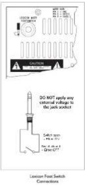
LEXICON MUTE FOOT SWITCH
The Effects may be turned ON or OFF remotely by connecting a standard latching or non-latching guitar foot-switch, or similar unit providing an isolated switch closure, to the rear panel Lexicon Foot Switch jack socket as shown. The Effect is muted when the switch is closed.
GRAPHIC EQUALISER

GRAPHIC EQUALISER
The stereo GRAHIC EQUALISER is normalled to the Mix L/R outputs. Seven frequency bands, with cut or boost of 6dB, allow very precise global control over subtle tonal changes to the PA rig in a particular room. (This is in contrast to the much more dangerous +/-12 or +/-15dB offered on sly small movement of the faders can re effects.)
The built-in graphic equaliser is intended to trim the overall sound to suit the room, and is not designed to null out frequencies to prevent feedback. A full 31-band EQ is recommended for that purpose.

LEFT/RIGHT BYPASS
Each channel of the Graphic Equaliser may be bypassed by pressing the LEFT BYPASS or RIGHT BYPASS switches. This allows a direct comparison to made of the treated signal (with EQ) and untreated signal, to judge the effect of the Graphic EQ settings.

+48V
Many professional condenser microphones need Phantom Power, and this can be supplied to all of the Mic input connectors by pressing the +48V switch.
ONLY connect condenser microphones with the +48V powering OFF (switch UP), and ONLY turn the +48V powering on or off with all output faders DOWN, to prevent damage to the mixer or external devices.
TAKE CARE when using unbalanced sources, which may be damaged by the phantom power voltage on pins 2 & 3 of the XLR connector.

STATUS INDICATORS
Three LEDs provide visual indication of the status of the mixer.
POWER
The POWER (green) lights to show that power is switched on, and senses the power amplifier voltage rails.
THERMAL
The THERMAL (yellow) indicates that power amplifier over-temperature has been detected.
MUTE
The MUTE (red) lights when the power amplifier output relays are open. This happens momentarily on power-up to isolate surges as the power rails stabilise, or will happen if the protection circuits detect a d.c. fault situation or overheating, in which case the relays will open as protection for the loudspeakers.
If a d.c. offset or overheating is suspected, check that the air vents at the front and rear of the mixer have not been inadvertently covered.
POWER AMPLIFIER
The Power Amplifier contains no user-serviceable parts. Refer all servicing to a qualified service engineer, through the appropriate Spirit dealer
The POWERSTATION contains an integral power amplifier, the inputs to which are normalled to the Graphic Equaliser outputs, or may be accessed directly via the Power Amp Input jacks. The amplifier incorporates a sophisticated protection system which guards against overheating, to protect the output transistors, and isolates the speaker outputs via relays if a damaging fault condition is detected in the output stage. The amplifier is cooled by a variable speed "music-sensing" fan which senses the output signal level and delivers greater airflow as the signal level, and corresponding heat dissipation in the output devices, increases. When there is no signal or a very low level signal, the fan will be running very slowly and quietly.
Air is drawn in along the front of the unit and expelled through vents at the left-hand side at the rear. It is important that sufficient clearance is allowed at the front and rear of the mixer to ensure unrestricted airflow, especially in rack-mounted or flight case installation.
WARNING
Do not obstruct air vents.

The signals from the balanced Power Amp Inputs jacks (normally the output from the Graphic Equaliser) are fed via the POWER AMP LEVEL control to the integral stereo power amplifier. Use this control to set the level to your speakers, as with any amplifier level control.

20 SUB-SONIC FILTER
An 18dB/octave 40Hz SUB-SONIC FILTER may be switched into the feed to the amplifier, and for most applications it is recommended that this filter be switched in. Using the filter avoids potential loss of control in PA cabinets with reflex ports when driven below their frequency range, and offers some protection against damage from heavy ultra-bass signals.
Switching the filter into circuit is almost always a good idea, but may unnecessarily restrict the dynamic range of a system with particularly wide-range PA cabinets, and should be switched out if very low frequency rumbles are specifically required and the speaker system has the capability. The filter also allows you to use your LF boost to warm up the bottom end of your mix without the usual problems of bass distortion.
RECORD OUTPUT
The RECORD OUTPUT, on RCA phone sockets, provides a -10dBV premix-fader (post insert feed), for recording. Since the signal is derived after the insert, a compressor can be included in the signal path if required.
LOUDSPEAKER OUTPUT TERMINALS
The power amplifier output is available on standard dual banana terminals and 'speakon' connectors on the rear of the mixer.
Minimum recommended load impedance is 4Ω but the amplifier guards itself against damaging overload, switching in the protection systems when necessary. While this will maintain safe operating limits, the result will be serious distortion and a very unmusical sound. Always follow the load recommendations where possible.

To avoid damage to the amplifiers DO NOT GROUND any of the Loudspeaker output terminals, or connect any terminal to any other terminal.
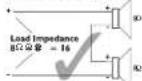
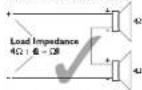
Multiple speaker configurations may be used, but load impedance should be maintained above 4Ω. It is therefore important to understand the difference between SERIES connection (impedances ADD) and PARALLEL connection (impedances are divided) as shown in the illustrations.

MULTIPLE & OHM SPEAKERS
MULTIPLE 4 OHM SPEAKERS


PATCHBAY
The line level mixer outputs, inserts and returns are arranged together on the top right of the mixer. For maximum flexibility the inputs to the Mixer, Graphic Equaliser and the Power Amplifier are available separately to allow replugging for particular purposes. The three sections are 'normalled' together by the internal switch contacts on the jacks, as shown in the diagram.
The normaling is broken as soon as a jack is inserted, allowing the signal to be re-routed as required. Note that separate left and right jacks are provided for all signals shown in the diagram above. Only one side is shown for clarity.
PATCHBAY APPLICATIONS
The flexibility of the POWERSTATION Patchbay is illustrated with three examples:
Example 1
Feeding an external amplifier, either pre- or post-Graphic Equaliser. Normaling is unaffected. The output acts as a "Y" splitter, one feed to the internal amplifier, the other to the external amplifier.
Example 2
Feeding the amplifier from an external mixer, for a secondary band perhaps, plugging directly into the power amplifier jacks. Alternatively the external feeds could plug into the Graphic EQ Inputs jacks, providing some signal correction if required. Alternatively you can add the external signal/mixer to the Powerstation's MIX using the Stereo Return or any line level input.
Example 3
If only a mono PA output is required, one channel of the power amplifier can be fed from the Mono Output by overplugging as shown, and the second channel may be used to drive, for example, foldback from Aux I. In both cases the Graphic EQ is left in the signal path.
Setting Up & Troubleshooting
INITIAL SET UP
Once you have connected up your system, you are ready to set initial positions for the controls on your mixer.
The front panel drawing on page 18 shows typical initial control positions which may serve as a useful guide to setting up the mixer for the first time.
Set up individual input channels as follows:
- Connect the source required (microphone, keyboard etc.) to the appropriate inputs.
Note: Phantom powered mics should be connected before the +48V is switched on
● Set Mix faders at 0, input faders at 0, and set the Power Amp Output level to the required level. - Set all EQ controls to the centre 'flat' position.
● Press the PFL button on the particular channel, monitoring the level on the meters. - Adjust the input gain until the meter is just reaching the amber section (0dB) at a typical maximum source level. This allows sufficient headroom to accommodate peaks and establishes the maximum level for normal operation (but see note below).
● Release the PFL button - Repeat this procedure on other channels as required. As more channels are added to the mix, the meters may move into the red section
- Listen carefully for the characteristic sound of 'feedback'. If you cannot achieve satisfactory input level setting without feedback, check microphone and speaker placement and repeat the exercise.
Having set the correct input Gain settings for each channel, you are now ready to start building the mix and this should be done progressively, listening carefully for each component in the mix and watching the meters for any hint of overload. If this occurs, back off
the appropriate Channel Fader slightly until the level is out of the red segments, or adjust the Mix Faders.
Note: The level of any source signal in the final output is affected by many factors, principally the Gain control, Channel Fader, Mix Faders and Power Amp level. You should try to use only as much microphone gain as required to achieve a good balance between signals, with the faders set as described above.
If the input gain is set too high, the channel fader will need to be pulled down too far in compensation to leave enough travel for successful mixing and there is a greater risk of feedback because small fader movements will have a very significant effect on output level. If the gain is set too low, you will not find enough gain on the faders to bring the signal up to an adequate level.
Boosting or cutting EQ also affects gain. It is often necessary to readjust input gain using the PFL switch after changing a channel's EQ settings
Microphone Placement
Careful microphone placement and the choice of a suitable type of microphone for the job is one of the essentials of successful sound reinforcement. The aim should be to place the microphone as close as physically possible to the source, to cut out unwanted surrounding sounds, allow a lower gain setting on the mixer and avoid feedback. Also a well-chosen and well-placed microphone should not need any appreciable equalisation.
TROUBLESHOOTING
No Power
● Is the mains supply present? Check that mains voltage selection is correct for your country.
● Is the mains lead firmly connected?
- Check the mains fusing
Condenser Mic Not Working
● Is the +48V turned on?
● Is the mic plugged into the Mic input?
● Is the mic cable a balanced 3-wire type?
Meters not showing any signal
● Has the input gain been set correctly? (see above.)
● Is the source connected to the appropriate input socket for the level of signal?
- Do you have something connected on the Inserts, and is that external device switched on?
● Are the Master faders set at max., and are input faders set high enough?
● Is there a PFL/AFL pressed on another channel?
No Mix output
- Check that the Mix Master Fader is up?
- Do you have something connected on the Mix Inserts, and is that external device switched on?
Headphones Distorting
● Are the headphones less than 200Ω impedance?
● Is the Monitor level set too high?
No Loudspeaker output
● Is the power amp level control set high enough?
● Is the power input bypassed by a jack inserted in the power amp input jack?
Thermal LED On
● This is a warning that you should allow the amplifier to cool down. The internal temperature has reached safe limits and the amplifier may shut down if no action is taken.
Thermal LED On and Mute LED On with no output to Speakers
● The amplifier has shut down due to overheating and the output relays have opened. Switch off and allow the unit to cool down! Check that the unit has adequate ventilation, that operating levels are set correctly and that the speaker load is 4Ω or greater.
APPLICATIONS
Large Live Setup
![graph TD A["Live Setup"] --> B["VOCAI MIC"] B --> C["VOCAI MIC"] C --> D["GUITAR VIA DI BOX"] D --> E["ACTIVE DI BOX"] E --> F["EFFECTS PROCESSOR"] F --> G["EFFECTS"] G --> H["GRAPHIC EQ"] H --> I["EFFECTS"] I --> J["SPIRIT POWERSTATION 350"] J --> K["DATA RECORDER"] K --> L["CD PLAYER"] L --> M["SU…](/content/2026/06/1365821/images/dbeb90ab07c1f81045f6aa3fa723c4850988df90d355ec49c4007ace6d82faef.jpg)
Recording

Live Setup with maximum foldback
![graph TD A["VOH SPEAKER"] --> B["FOH Speaker"] C["FOH Speaker"] --> D["POWERED MONITORS 1 & 2"] E["STAGE MONITORS"] --> F["Engineers HEADPHONES"] G["LEXICON MUTE SWITCH"] --> H["CD PLAYER"] I["EFFECTS PROCESSOR"] --> J["DAT RECORDER"] K["VARIOUS AUDIO SIGNALS"] --> L["SPIRIT POWERSTATION 350"] style…](/content/2026/06/1365821/images/b337b739feb412f42a775c9de3d73e4d38cc1fa59c25a222f0564a27f001391a.jpg)
![graph TD A["External Mixer"] --> B["Mix L"] A --> C["Mix R"] B --> D["FOH SPEAKER"] C --> E["FOH SPEAKER"] D --> F["SPIRIT POWERSTATION 350"] E --> F F --> G["LEXICON MUTE SWITCH"] F --> H["ROH SPEAKERS"] style A fill:#f9f,stroke:#333 style B fill:#ccf,stroke:#333 style C fill:#ccf,stroke:#333 style…](/content/2026/06/1365821/images/5d3b5657db8f4abe41f96900686874ebc928ecead31afb76d03853df7900bfbf.jpg)
Splitting FOH and On-Stage Monitor

Powerstation as a Submixer
(Amplifier still used for on-stage Monitors)
![graph TD A["FOH PA SYSTEM"] --> B["AMP"] C["VARIOUS MUSIC SOURCES -DRUMS TYPICAL"] --> D["LARGE FOH CONSOLE"] D --> E["MIXER MONITOR OUTPUT"] E --> F["SPIRIT POWERSTATION 350"] F --> G["TO MIXER INPUT"] G --> H["MIXED SOUND SOURCES"] H --> I["LEFT OUTPUT MONITOR"] H --> J["RIGHT OUTPUT MONITOR"]](/content/2026/06/1365821/images/4dd2bee9bf626084c45e4c306488dde65c58c31bba46302c90f3e01cc77593c9.jpg)
System Block Diagram
![graph TD subgraph MONO_INPUT_CHANNEL A["MONO INPUT"] --> B["INJ PPT"] B --> C["INSERT"] D["MINI ON"] --> E["SMC NLT"] F["SMC NLT"] --> G["SMC NLT"] H["SMC NLT"] --> I["SMC NLT"] J["SMC NLT"] --> K["SMC NLT"] L["SMC NLT"] --> M["SMC NLT"] N["SMC NLT"] --> O["SMC NLT"] P["SMC NLT"] --> Q["SMC NLT"] R[…](/content/2026/06/1365821/images/fc06152f4f45c3675beabbe48138bd75a4d8e33c91b7bc51c3e7d161b3956de9.jpg)
Powerstation Console
Typical Starting Out Control Positions

Connecting Leads

Dimensions
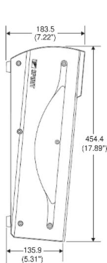
Free Standing

| Dimension "X" Dimension "Y" | ||
| Powerstation 350 | 456.0 (17.95") | 390.0 (15.35") |
| Powerstation 600 | 504.0 (19.84") | 436.0 (17.24") |
| Powerstation 1200 | 736.0 (28.98") | 670.0 (26.38") |

Rack Mounting (350 & 600 only)
Typical Specifications
T.H.D.
Mic, Line or stereo input to Main Outputs, +20dB at outputs, any input gain <0.009%
Crosstalk
Fader Attenuation 100dB @1kHz Aux Send Attenuation 80dB @1kHz Stereo Separation 70dB @1kHz
Noise
Measured RMS, 22Hz to 22kHz bandwidth Aux Outputs -83dBu Main Outputs -80dBu
E.I.N.
Microphone Input, Maximum Gain, terminated 150R 129dBu
Max. Gain to Main Outputs
Mic Input 74dB Line Input 54dB Stereo Input 32dB Stereo Return & 2Track Return 12dB
Maximum Input Levels
Mic Input +21dBu Line Input >30dBu Stereo Input +26dBu Stereo Return & 2Track Return >30dBu
Maximum Output Levels
Any Output
+22dBu
Power Amplifier Power Output
Powerstation 350 175W + 175W RMS into 4Ω Powerstation 600 300W + 300W RMS into 4Ω Powerstation 1200 600W + 600W RMS into 4Ω
Amplifier will deliver rated power output with +4dBu at power amp input sockets, power amp level control at maximum. (+15dBU for 350) THD @ 1kHz with both channels driven just below clipping: Into 4Ω <0.025%
- INTRODUCTION
- SAFETY PRECAUTIONS
- WARNING: THIS UNIT MUST BE EARTHED
- UNDER NO CIRCUMSTANCES SHOULD THE MAINS EARTH BE DISCONNECTED FROM THE MAINS LEAD
- USING THE POWERSTATION
- MONO INPUT CHANNEL
- MICROPHONE INPUT
- LINE INPUT
- INSERT
- GAIN CONTROL
- 100HZ HI-PASS FILTER
- EQUALISER
- HF EQ
- MID EQ
- LF EQ
- AUXILIARY SENDS
- 8 LEX FX
- 9 PAN
- 10 PFL
- II CHANNEL FADER
- STEREO INPUT CHANNEL
- STEREO INPUTS
- GAIN
- LEX FX
- BALANCE
- PFL
- CHANNEL FADER
- MASTER SECTION
- I LEXICON EFFECTS MASTER FADER
- 3 AUX 2 PRE
- 4 LEXICON EFFECTS TO AUX 1
- 5 AUX 1 MASTER
- 6 AUX 2 MASTER
- 7 STEREO RETURN
- 8 2 TRACK RETURN
- 9 PFL
- 10 2TRK TO MIX
- 2TRK TO MIX SHOULD NOT BE USED WHEN RECORDING FROM THE REC O/P SOCKETS, AS THERE IS THE POSSIBILITY OF SERIOUS FEEDBACK
- II MONITOR LEVEL
- 12 PFL ACTIVE
- LEXICON
- DIGITAL EFFECTS PROCESSOR
- 13 INPUT TRIM
- 14 PROGRAM SELECT/PARAMETER ADJUST
- PROGRAM SELECT
- PARAMETER ADJUST
- LEXICON MUTE FOOT SWITCH
- GRAPHIC EQUALISER
- LEFT/RIGHT BYPASS
- 48V
- STATUS INDICATORS
- POWER
- THERMAL
- MUTE
- POWER AMPLIFIER
- THE POWER AMPLIFIER CONTAINS NO USER-SERVICEABLE PARTS. REFER ALL SERVICING TO A QUALIFIED SERVICE ENGINEER, THROUGH THE APPROPRIATE SPIRIT DEALER
- WARNING
- DO NOT OBSTRUCT AIR VENTS
- 20 SUB-SONIC FILTER
- RECORD OUTPUT
- LOUDSPEAKER OUTPUT TERMINALS
- TO AVOID DAMAGE TO THE AMPLIFIERS DO NOT GROUND ANY OF THE LOUDSPEAKER OUTPUT TERMINALS, OR CONNECT ANY TERMINAL TO ANY OTHER TERMINAL
- PATCHBAY
- PATCHBAY APPLICATIONS
- EXAMPLE 1
- EXAMPLE 2
- EXAMPLE 3
- SETTING UP & TROUBLESHOOTING
- INITIAL SET UP
- MICROPHONE PLACEMENT
- TROUBLESHOOTING
- APPLICATIONS
- SPLITTING FOH AND ON-STAGE MONITOR
- POWERSTATION CONSOLE
- TYPICAL SPECIFICATIONS
- T.H.D
- CROSSTALK
- NOISE
- E.I.N
- MAX. GAIN TO MAIN OUTPUTS
- MAXIMUM INPUT LEVELS
- MAXIMUM OUTPUT LEVELS
- POWER AMPLIFIER POWER OUTPUT
Brand : SOUNDCRAFT
Model : Spirit Powerstation 350
Category : Power Supply