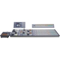
MVS-7000X - Video Conferencing System SONY - Free user manual and instructions
Find the device manual for free MVS-7000X SONY in PDF.


| Product Type | Video Conferencing System |
| Brand | Sony |
| Model | MVS-7000X |
| Dimensions (W x H x D) | 430 x 88 x 350 mm |
| Weight | 7.5 kg |
| Power Supply | AC 100-240 V, 50/60 Hz |
| Power Consumption | 150 W (max) |
| Video Input | HDMI, SDI, Composite |
| Video Output | HDMI, SDI, Composite |
| Audio Input | XLR, RCA, 3.5mm |
| Audio Output | XLR, RCA, 3.5mm |
| Network Interface | Ethernet 10/100/1000, Wi-Fi |
| Supported Protocols | H.323, SIP, WebRTC |
| Maximum Resolution | 1080p 60fps |
| Camera | Integrated PTZ camera, 12x optical zoom |
| Microphone | Built-in array microphone |
| Display | Not included (external display required) |
| Maintenance | Clean with soft dry cloth; avoid liquids |
| Safety | Operate in dry environment; do not block vents |
| Spare Parts & Reparability | Contact authorized service center; spare parts available |
| Included Accessories | Remote control, power cable, HDMI cable |
Frequently Asked Questions - MVS-7000X SONY
User questions about MVS-7000X SONY
0 question about this device. Answer the ones you know or ask your own.
Ask a new question about this device
Download the instructions for your Video Conferencing System in PDF format for free! Find your manual MVS-7000X - SONY and take your electronic device back in hand. On this page are published all the documents necessary for the use of your device. MVS-7000X by SONY.
USER MANUAL MVS-7000X SONY
Multi Format Switcher System
MVS-8000X System MVS-7000X System
(With CCP-8000 Series Center Control Panel)
User's Guide Volume 1 English
Software Version 11.10 or Later 1st Edition (Revised 1)
NOTICE TO USERS
© 2011 Sony Corporation. All rights reserved. This manual or the software described herein, in whole or in part, may not be reproduced, translated or reduced to any machine readable form without prior written approval from Sony Corporation.
SONY CORPORATION PROVIDES NO WARRANTY WITH REGARD TO THIS MANUAL, THE SOFTWARE OR OTHER INFORMATION CONTAINED HEREIN AND HEREBY EXPRESSLY DISCLAIMS ANY IMPLIED WARRANTIES OF MERCHANTABILITY OR FITNESS FOR ANY PARTICULAR PURPOSE WITH REGARD TO THIS MANUAL, THE SOFTWARE OR SUCH OTHER INFORMATION. IN NO EVENT SHALL SONY CORPORATION BE LIABLE FOR ANY INCIDENTAL, CONSEQUENTIAL OR SPECIAL DAMAGES, WHETHER BASED ON TORT, CONTRACT, OR OTHERWISE, ARISING OUT OF OR IN CONNECTION WITH THIS MANUAL, THE SOFTWARE OR OTHER INFORMATION CONTAINED HEREIN OR THE USE THEREOF.
Sony Corporation reserves the right to make any modification to this manual or the information contained herein at any time without notice. The software described herein may also be governed by the terms of a separate user license agreement.
Functions Newly Supported in Version 11.10
The functions newly supported in the MVS-8000X/7000X system version 11.10 are as follows.
Functions relating to the switcher
| Classification | Functions supported | Menu No. | See page | |
| Vol. 1 | Vol. 2 | |||
| Signal inputs and outputs | Combination setting of format converter signal formats in units of 4 inputs | 7313.4 - 540 | ||
| Frame delay mode in the format converter | 7332 - 541, | 601 | ||
| Key Key rotation by the resizer | 1115 154 - | |||
| Frame memory | Ancillary data 73 | 16.8 215 550 | ||
| System 3D support 7331.13 | 7331.97331.107331.12 | 255 - | ||
| Signal outputs Multi Viewer | 7333.9 - 606 | |||
a) In MVS-7000X only
Functions relating to the setup
| Classification | Functions supported | Menu No. | See page | |
| Vol. 1 | Vol. 2 | |||
| User setup | Source patch 72 | 11 | -645 | |
| 7212 | ||||
| 7212.1 | ||||
Functions relating to the DME
| Classification | Functions supported | Menu No. | See page | |
| Vol. 1 | Vol. 2 | |||
| Switcher connection | Connection by SDI interface | 7337.7 - 619 | ||
| Applying special effects (edge effects) | Flex shadow | 4115 290 | ||
| Classification | Functions supported | Menu No. | See page | |
| Vol. 1 | Vol. 2 | |||
| Applying special effects (effects on the overall video signal) | Masking the glow effect | 4174 304 - | ||
| System Support | for SD format by MKS-7470X/7471X | - | 264 | - |
Functions Not Supported in Version 11.10
The following functions are not supported in the MVS-7000X system version 11.10.
| Classification | Functions supported | Menu No. | See page | |
| Vol. 1 | Vol. 2 | |||
| System Support | for 1080P format by MKS-7470X/7471X | - | - | - |
| Key assignment for 3M/E mode or 4M/E mode | 7331.13 | -- | ||
Table of Contents
Volume 1
Chapter 1 MVS-8000X/7000X Functions
Introduction ......18
Features of the MVS-8000X/7000X Multi Format Switcher System....19
Basic Video Processing....20
Transitions 20
Keys 22
Wipes 22
DME Wipes 23
Frame Memory 23
Color Backgrounds 23
Copy and Swap.... 23
Video Process 23
Color Corrector.... 23
Side Flags.... 23
Multi Program 2.... 24
3D Support.... 25
Creation of Special Effects and Management of Data and Operations 25
Digital Multi Effects (DME) 25
External Devices.... 26
Keyframes.... 26
Snapshots 26
Utility.... 26
Shotbox....26
Macros 26
Files.... 27
Setup 27
Chapter 2 Menus and Control Panel
Names and Functions of Parts of the Control Panel ....28
Control Panel: Example Configuration 1 (With Standard Transition Modules). 28
Control Panel: Example Configuration 2 (With Simple Transition Modules) ... 28
Control Panel: Example Configuration 3 (With Compact Transition Modules) 29
Cross-Point Control Block.... 29
Cross-Point Control Block in Key/AUX Bus Delegation Mode 33
Transition Control Block (Standard Type) . 34
Flexi Pad Control Block (Standard Type) .. 37
Key Control Block.... 39
Device Control Block (Trackball) 42
Device Control Block (Joystick) 45
Device Control Block (Search Dial)...... 46
Keyframe Control Block.... 48
Numeric Keypad Control Block 51
Fade to Black Control Block 53
Auxiliary Bus Control Block (for AUX Buses) 53
Auxiliary Bus Control Block (for Router Control) 55
Menu Control Block 56
Memory Card/USB Adaptor Block 57
"Memory Stick"/USB Connections Block . 57
Utility/Shotbox Control Block.... 58
Transition Control Block and Flexi Pad Control Block (Simple Type)...... 59
Independent Key Transition Control Block (Simple Type).... 61
Downstream Key Control Block 63
Downstream Key/Fade-to-Black Control Block 64
Transition Control Block (Compact Type). 65
CCP-6224 2M/E Control Panel 68
CCP-6324 3M/E Control Panel 68
Cross-Point Control Block (CCP-6224/6324) in the AUX Operating Mode...... 69
Multifunction Flexi Pad Control Block ..... 70
Basic Menu Operations ....72
Overview....72
About the Top Menu List.... 72
Accessing Menus 73
Example of Displaying a Menu 74
Interpreting the Menu Screen.... 74
Names and Functions of Parts of the Top Menu Window.... 77
Names and Functions of Parts of the Numeric Keypad Window.... 78
Names and Functions of Parts of the Keyboard Window 78
Names and Functions of Parts of the Color Pallet Window 79
Menu Operations.... 81
Selecting an Item.... 81
Selecting a Function.... 81
Setting Parameters 81
Switching Between the Main Menu Site and Subsidiary Menu Site .... 81
Going Back to the Previous Menu 82
Returning to Default State in Function Groupings 82
Returning Knob Parameters to Default State 82
Operation With a Mouse.... 82
Shortcut Menu.... 83
Registering a Menu To the Shortcut Menu. 83
Recalling a Menu Using the Shortcut Menu 83
Customizing the Shortcut Menu 83
Chapter 3 Signal Selection and Transitions
Video Processing Flow.... 85
Signal Selection 86
Basics of Signal Selection.... 86
Bus Selection 86
AUX Panel-less Function 89
Signal Assignment and Selection.... 89
Signal Name Display 91
Transitions.... 92
Selecting the Next Transition.... 92
Transition Types 92
Procedure for Basic Transition Operation 93
Key Priority Setting.... 95
Setting the Key Priority in the Transition Control Block 95
Setting the Key Priority by a Menu Operation 96
Display of the Key Output Status and Key Priority.... 97
Selecting the Transition Type by a Menu Operation 98
Super Mix Settings.... 99
Color Matte Settings 99
Executing a Transition 101
Transition Indicator Function...... 101
Setting the Transition Rate.... 101
Pattern Limit 104
Executing an Auto Transition 105
Executing a Transition With the Fader Lever (Manual Transition).... 106
Combinations of Auto and Manual Transitions 106
Non-Sync State 106
Fader Lever Operation in Bus Fixed Mode 107
Transition Preview 108
Independent Key Transitions.... 109
Basic Independent Key Transition Operations 112
Setting the Independent Key Transition Type by a Menu Operation .... 113
Setting the Independent Key Transition Rate 113
Fade to Black.... 115
Fade to Black Operation 115
Setting the Fade to Black Transition Rate 115
Simple Transition.... 116
Basic Operations for Simple Transitions .. 116
Display of the Key Output Status and Key Priority.... 117
Split Fader.... 117
Independent Key Transitions With a Simple Transition Module .... 117
Chapter 4 Keys
Overview ....119
Key Types.... 119
Key Modifiers.... 120
Key Memory.... 121
Key Default.... 122
Key Setting Operations Using Menus ...122
Key Setting Menus 122
Key Type Setting 123
Selecting Key Fill and Key Source...... 124
Chroma Key Composition and Basic Settings 126
Key Adjustments (Menus) ......127
Chroma Key Adjustments.... 127
Key Edge Modifications.... 130
Masks.... 133
Applying a DME Effect to a Key 134
Specifying the Key Output Destination.... 136
Key Modify Clear.... 137
Blink Function 137
Video Processing 137
Key Setting Operations with the Key Control Block ....138
Selecting the Bank and Keyer...... 138
Selecting the Key Type.... 138
Parameter Adjustment with the Knobs..... 138
Selecting Key Fill 139
Selecting Key Source.... 139
Key Adjustments (Key Control Block) ..140
Key Edge Modifications.... 140
Masks.... 141
Applying a DME Effect to a Key 142
Other Key Setting Operations.... 144
Key Adjustments (Multifunction Flexi Pad Control Block)....145
Resizer....148
Two-Dimensional Transformations and Rotation of Keys .... 148
Resizer Interpolation Settings.... 150
Resizer Crop/Border Settings 151
Applying Resizer Effects.... 152
Setting rotation of the resizer.... 154
Key Snapshots ....155
Key Snapshot Operations 155
Key Snapshot Operations Using a Simple Transition Module .... 157
Chapter 5 Wipes
Overview 159
Types of Wipe Pattern 159
Basic Procedure for Wipe Settings .....159
Wipe Settings Menu 159
Wipe Pattern Selection 159
Pattern Mix 160
Setting Wipe Modifiers.... 162
Wipe Modify Clear 170
Wipe Settings for Independent Key Transitions ....171
Basic Procedure for Independent Key Transition Wipe Settings.... 171
Setting Independent Key Transition Wipe Modifiers 171
Wipe Snapshots 173
Wipe Snapshot Operations With the Flexi Pad 173
Wipe Snapshot Operations With the Menus 175
Wipe Pattern Operations in the Multifunction Flexi Pad Control Block 176
Recalling a Wipe Snapshot.... 176
Selecting the Wipe Pattern.... 176
Editing the Wipe Pattern.... 176
Saving, Canceling, and Deleting Edited Wipe Patterns .... 178
Chapter 6 DME Wipes
Overview 179
Types of DME Wipe Pattern 179
DME Wipe Pattern Variation and Modifiers 181
Relation Between DME Wipes and Other Effects.... 182
Basic Procedure for DME Wipe Settings 183
DME Wipe Settings Menu.... 183
DME Wipe Pattern Selection.... 183
Setting DME Wipe Modifiers.... 185
DME Wipe Modify Clear 188
DME Wipe Settings for Independent Key Transitions.... 189
Basic Procedure for Independent Key Transition DME Wipe Settings ..... 189
Setting Independent Key Transition DME Wipe Modifiers.... 189
Resizer DME Wipe Setting 191
DME Wipe Snapshots 192
DME Wipe Snapshot Operations With the Flexi Pad.... 192
DME Snapshot Operations With the Menus 192
Creating User Programmable DME Patterns.... 193
User Programmable DME Transition Mode 193
DME Wipe Pattern Operations in the Multifunction Flexi Pad Control Block 195
Recalling a DME Wipe Snapshot ...... 195
Selecting the DME Wipe Pattern.... 195
Editing the DME Wipe Pattern 195
Saving, Canceling, and Deleting DME Wipe Snapshots.... 197
Chapter 7 Frame Memory
Overview 198
Still Image Operations 200
Preparations.... 200
Interpreting the Frame Memory Menu ..... 200
Selecting an Input Image 202
Selecting Outputs and Target Frame Memory 203
Capturing and Saving an Input Image ..... 203
Recalling Still Images.... 205
Image Output...... 206
Continuously Capturing Still Images (Record) 207
Recalling a Continuous Sequence of Still Images (Animation).... 207
Frame Memory Clip Function ...... 209
Frame Memory Clip Operations...... 210
Preparations for Operation 210
Recalling Clips.... 210
Clip Playback 211
Clip Creation.... 213
Creating and Handling Frame Memory Folders 213
Clip Output.... 214
Recording and Playback of Ancillary Data 214
Clip Transition Operations.... 215
Image Data Management.... 217
Pair File Processing.... 217
Moving Files 217
Deleting Files 218
Renaming Files 218
External Hard Disk Drive Access ...... 219
Hard Disk Formatting 219
Saving Files.... 219
Recalling Files.... 220
Managing Images Using a DDR/VTR..... 221
Using a DDR/VTR for High-speed Backup and Restoring.... 221
Extracting Images from Video Tape...... 222
Chapter 8 Color Backgrounds, Copy and Swap, and Other Settings
Color Background.... 224
Color Background Settings Menu...... 224
Basic Color Background Setting Operations 224
Copy and Swap 226
Overview of Copy and Swap 226
Copy and Swap Operations.... 227
Misc Menu Operations.... 229
Port Settings for Control From an External Device.... 229
Editing Keyboard Settings...... 229
Safe Title Settings.... 230
Displaying a List of Transition Rates and Changing the Settings 230
AUX Menu Operations ......231
AUX Bus Settings.... 231
Status Menu....232
Router Control Menu Operations......232
Checking the List of Inputs for Each Destination 232
Switching the Source for Each Destination 232
Video Process....233
Video Process Adjustments for Each Input Signal.... 233
Video Process Adjustments on a Particular Bus.... 233
Video Process Memory...... 234
Video Process Settings 234
Chapter 9 Color Corrector
Preparations ......235
Overall Color Corrector Operations .....236
Enabling Color Corrector 236
Copy and Swap Operations 236
Color Corrector Functions ......237
Input Video Processing Operations ...... 237
Primary Color Correction Operations...... 237
Secondary Color Correction Operations... 240
Luminance Processing Operations ...... 240
Spot Color Adjustment 241
Output Video Processing Operations...... 242
YUV Clip Operations 243
RGB Clip Operations.... 243
Chapter 10 Special Functions
Side Flags 245
Overview.... 245
Side Flag Settings 245
Wipe Action on Images with Side Flags .. 246
DME Wipe Action for an Image with Side Flags 246
Multi Program 2 ....248
Overview.... 248
Sequence of Operations in Multi Program 2 ...... 248
Basic Operations (Required)...... 249
Examples of Operations in the Multi Program 2 Mode (When Sharing a Switcher Bank) .... 251
Optional Operations.... 251
Functions Added in Multi Program 2 Mode 253
Differences between Multi Program 2 Mode and Standard Mode.... 253
Restrictions on Using Multi Program 2 Mode 254
3D Support....255
Overview.... 255
Preparations 255
Restrictions in 3D Mode.... 260
Video Creation in 3D Mode 260
M/E Configuration Switching .....261
Chapter 11 DME Operations
DME 263
Three-Dimensional Transformations...... 263
Transformation Operation Modes...... 265
Graphics Display 267
Three-Dimensional Parameter Display..... 268
Special Effects 268
Global Effects 276
Devices for DME Support 276
Three-Dimensional Transformation Operations ....277
Basic Operations.... 277
Three-Dimensional Parameter Display..... 279
Entering Three-Dimensional Parameter Values.... 280
Graphics Display Operation.... 281
Canceling Virtual Images 281
Applying Special Effects (Operations Common to Special Effects).... 282
Applying Special Effects (Edge Effects) 283
Border Settings.... 283
Crop Settings.... 284
Wipe Crop Settings.... 294
Color Mix Settings.... 296
Applying Special Effects (Effects on the Overall Video Signal) 297
Defocus Settings 297
Blur Settings.... 298
Multi Move Settings 299
Sepia Settings.... 300
Mono Settings 300
Posterization and Solarization Settings..... 300
Nega Settings 301
Contrast Settings 301
Mosaic Settings.... 301
Sketch Settings.... 301
Metal Settings 303
Dim and Fade Settings.... 303
Glow Settings.... 304
Mask Settings.... 304
Freeze Settings 306
Applying Special Effects (Nonlinear Effect Settings).... 307
Wave Settings 307
Mosaic Glass Settings.... 309
Flag Settings.... 309
Twist Settings.... 309
Ripple Settings.... 310
Rings Settings 313
Broken Glass Settings.... 313
Flying Bar Settings 314
Blind Settings.... 314
Split Settings 315
Split Slide Settings.... 315
Mirror Settings 316
Multi Mirror Settings 316
Kaleidoscope Settings.... 317
Lens Settings.... 317
Circle Settings.... 318
Panorama Settings.... 318
Page Turn Settings 318
Roll Settings.... 319
Cylinder Settings.... 319
Sphere Settings.... 320
Explosion Settings.... 320
Swirl Settings 320
Melt Settings 321
Character Trail Settings 322
Applying Special Effects (Lighting and Recursive Effects).... 323
Lighting Settings.... 323
Trail Settings.... 325
Motion Decay Settings.... 327
Keyframe Strobe Settings 328
Wind Settings.... 329
Spotlighting Settings.... 330
Applying Special Effects (Other Effects) 338
Background Settings 338
Separate Sides Settings 338
Shaped Video Settings 338
Invert Settings 339
Key Density Settings.... 340
Key Source Selection.... 340
Interpolation Settings 340
Corner Pinning Settings 341
Global Effect Operations.... 343
Overview.... 343
Operations Common to All Global Effects 343
Combiner Settings.... 344
Brick Settings.... 347
Shadow Settings.... 349
Appendix (Volume 1)
Wipe Pattern List ....351
Standard Wipes.... 351
Enhanced Wipes 352
Rotary Wipes 352
Mosaic Wipes 353
Random/Diamond Dust Wipes.... 354
DME Wipe Pattern List ....355
DME Wipe Patterns Available in One-Channel Mode 355
DME Wipe Patterns Available in Two-Channel Mode 360
DME Wipe Patterns Available in Three-Channel Mode 363
Resizer DME Wipe Pattern List ....365
Menu Tree ....366
Recalling Menus 366
M/E-1 to M/E-4 Menus 366
PGM/PST Menu 369
Frame Memory Menu.... 371
Color Bkgd Menu 371
AUX Menu 372
CCR Menu.... 372
Copy/Swap Menu 373
Misc Menu.... 373
Status Menu 373
DME Menu 374
Global Effect Menu 375
Device Menu.... 375
Macro Menu.... 376
Key Frame Menu 376
Effect Menu 377
Snapshot Menu 378
Shotbox Menu.... 379
File Menu.... 380
Engineering Setup Menu 381
User Setup Menu 386
Diagnostic Menu.... 386
Using the M/E-4 Bank....387
Assigning a Button for M/E-4 Selection in the Setup Menu 387
Using Keys 5 to 8 ....388
Assigning Buttons for Selection of Keys 5 to 8 in the Setup Menu .... 388
Selecting Keys 5 to 8 for Next Transition 389
Selecting Input Signals for Keys 5 to 8 in the Cross-Point Control Block .... 389
Menus accessed by pressing a button twice ....390
Menus allowing a return to default settings 396
SpotLighting 400
Texture Patterns 400
Shape Patterns.... 400
Functional Differences With Models of DME 401
Volume 2
Chapter 12 External Devices
Control of External Devices ....407
Shared Functions for External Device Control 407
Control of P-Bus Devices ....408
Creating and Editing the P-Bus Timeline. 408
P-Bus Trigger.... 410
Control of GPI Devices 411
GPI Timeline Creation and Editing ..... 411
Control of VTRs, Extended VTRs, and Disk Recorders....412
Manual Operation 412
Controlling the Tape/Disk Transport...... 413
Checking VTR/Disk Recorder/Extended VTR Information.... 415
Cueup & Play.... 416
VTR/Disk Recorder/Extended VTR Timeline 419
Disk Recorder/Extended VTR File Operations 423
Chapter 13 Keyframe Effects
Regions...... 425
Registers...... 426
Keyframes...... 427
Effects 427
Saving and Recalling Effects 427
Effect Attributes.... 427
Effect Editing 427
Time Settings 428
Paths.... 429
Effect Execution.... 431
Master Timelines 432
Sequence of Keyframe Operations ...... 432
Displaying the Timeline Menu 433
Interpreting the Timeline Menu 433
Settings in the Timeline Menu.... 434
Recalling a Register.... 435
Specifying the Region and Edit Points . 439
Selecting the Region in Which Editing Applies.... 439
Setting the Edit Points.... 440
Creating and Editing Keyframes...... 441
Creation.... 441
Insertion 441
Modification.... 441
Deletion.... 443
Movement 443
Copying.... 443
Pause 444
Keyframe Loop (Repeated Execution of a Specified Range) 444
Undoing an Edit Operation 445
Duration Mode Setting...... 445
Transition Mode Settings for User Programmable DME.... 445
Keyframe Creation and Editing in the Multifunction Flexi Pad Control Block 448
Time Settings 449
Setting the Keyframe Duration 449
Setting the Effect Duration 450
Setting the Delay.... 450
Path Setting 451
Basic Procedure for Path Settings...... 451
Executing Effects...... 452
Executing Effects in the Keyframe Control Block.... 452
Setting the Run Mode 453
Executing an Effect in the Flexi Pad Control Block.... 453
Executing an Effect in the Multifunction Flexi Pad Control Block .... 454
Saving Effects 454
Creating and Saving a Master Timeline 455
Creating and Saving a Master Timeline Using the Buttons in the Numeric Keypad Control Block 455
Creating and Saving a Master Timeline Using the Buttons in the Multifunction Flexi Pad Control Block .... 456
Creating and Saving a Master Timeline With the Menu.... 457
Register Operations in the Menus...... 459
Effect Attribute Settings.... 459
Effect Status Display.... 459
Effect Register Editing...... 459
Displaying a List of Effect Registers for Editing 462
Chapter 14 Snapshots
Overview 463
Snapshot Types 463
Snapshot Attributes.... 463
Snapshot Operations From the Numeric Keypad Control Block.... 465
Saving and Recalling Snapshots ...... 465
Snapshot Operations in the Flexi Pad Control Block.... 467
Banks and Registers...... 467
Saving and Recalling Snapshots .... 468
Snapshot Operations in the Multifunction Flexi Pad Control Block.... 470
Saving and Recalling Snapshots 470
Snapshot Operations in the Menus..... 473
Selecting a Region or Reference Region in a Menu.... 473
Setting Snapshot Attributes 473
Snapshot Status Display 475
Setting Key Snapshot Attributes...... 475
Creating and Saving a Master Snapshot ... 476
Snapshot Register Editing 476
Displaying a List of Snapshot Registers for Editing 476
Operations in the Misc >Snapshot Menu . 476
Chapter 15 Utility/Shotbox
Utility Execution 478
Executing a Utility With the User Preference Buttons (Menu Control Block)...... 478
Executing a Utility in the Utility/Shotbox Control Block 478
Executing Utilities With the Cross-Point Buttons in the Key 2 Row .... 479
Shotbox 480
Shotbox Register Creation......480
Creating a Shotbox Register in the Numeric Keypad Control Block.... 480
Creating a Shotbox Register in the Multifunction Flexi Pad Control Block 481
Creating a Shotbox Register Using the Menus 482
Shotbox Execution....484
Shotbox Execution From the Numeric Keypad Control Block 484
Shotbox Execution in the Multifunction Flexi Pad Control Block or the Flexi Pad Control Block .... 484
Shotbox Execution in the Utility/Shotbox Control Block 485
Executing a Shotbox Function With the Key 2 Row Cross-Point Buttons.... 485
Shotbox Register Editing ....486
Chapter 16 Macros
Macros....487
Overview.... 487
Macro Creation and Editing.... 488
Macro Execution.... 489
Macro Operations in the Numeric Keypad Control Block and the Keyframe Control Block....490
Recalling a Macro Register and Executing a Macro 491
Creating and Editing a Macro.... 491
Saving a Macro 494
Macro Operations in the Standard Type Flexi Pad Control Block ....495
Recalling a Macro Register and Executing a Macro 496
Creating and Saving a Macro 497
Macro Operations in the Simple Type Flexi Pad Control Block ....498
Recalling a Macro Register and Executing a Macro 498
Creating and Editing a Macro.... 499
Saving a Macro 500
Macro Operations in the Multifunction Flexi Pad Control Block ....501
Recalling a Macro Register and Executing a Macro 501
Creating and Editing a Macro.... 502
Macro Editing Using Menus ....502
Macro Register Editing.... 502
Online Editing of Macro Events 502
Offline Editing of Macro Events 505
Macro Attachment Assigning ....507
Setting and Canceling a Macro Attachment 509
Displaying the Macro Attachment List..... 510
Executing a Macro by Macro Attachment 511
Menu Macros ....512
Recalling a Menu Macro Register and Executing a Menu Macro .... 513
Menu Macro Creation and Editing ..... 514
Menu Macro Register Editing 516
Macro Timeline ....517
Creating and Editing a Macro Timeline ... 518
Chapter 17 Files
Overview of File Operations .... 519
Operations on Individual Files...... 522
Displaying the Individual File Operation Menus .... 522
Viewing Detailed File Information...... 522
Selecting Regions.... 523
Selecting a Device for Operations ..... 523
Saving Files.... 523
Loading Files 524
Copying Files.... 525
Renaming Files 526
Deleting Files.... 527
Converting Between Frame Memory Clips and Extended Clips.... 527
Saving the list of frame memory files to hard disk or memory card.... 528
File Batch Operations.... 529
Displaying the Batch Operation Menu ..... 529
Batch Saving Files 529
Batch Loading Files 529
Batch Copying Files.... 529
Importing and Exporting Files 530
Displaying the Import/Export Menu...... 530
Importing Frame Memory Data 530
Exporting Frame Memory Data 531
Directory Operations 532
Displaying the Directory Menu 532
Creating a New Directory 532
Renaming a Directory 532
Deleting a Directory.... 532
Copying Files Between Different Unit IDs 533
Saving Files Recalled by Autoload ..... 534
Chapter 18 System Setup (System)
Setup for the Whole System .... 535
Network Settings (Network Config Menu) 536
Making the Network Settings 536
System Settings (System Config Menu)537
Specifying the Switcher Controlled by the Control Panel 537
Specifying the DME Connected to the Switcher.... 537
Enabling the FM Data Port of the Switcher 538
Setting the Signal Format (Format Menu) 539
Setting the Signal Format.... 539
Switching the Input Reference Signal for HD System 539
Setting Conversion Formats.... 540
Setting the Screen Aspect Ratio (Format Menu)....541
Selecting the State After Powering On (Start Up Menu) 542
Saving and Recalling Setup Data.... 542
Selecting the State at Start-up 543
Saving User-Defined Settings.... 543
Setting Automatic Loading of Register Data at Power On (Autoload Function) ..... 543
Reset and Initialization (Initialize Menu)544
Installation and Device Setup (Install/Unit Config Menu) 544
Installing Software 544
Making Settings Required to Use the Software 545
Adding User Texture Patterns.... 547
Saving a Frame Memory Clip With Ancillary Data.... 550
Setting the DME Input/Output Signal Format 550
System Maintenance (Maintenance Menu) 551
Setting the Date and Time.... 551
Using a Memory Card.... 551
Carrying Out the Primary Setting 551
Reloading a USB Driver 552
Initializing the Hard Disk.... 552
Locking the Setup Menu Settings 552
Locking File Loading Operations 553
Chapter 19 Control Panel Setup (Panel)
Overall Control Panel Settings (Config Menu)....555
Panel Setup 555
Interchanging the Bank Order or Disabling Operation.... 555
Assigning Two M/E Banks to One M/E Bank 556
Assigning the Key Delegation in the Downstream Key Control Block..... 556
Linking Switcher Bus and Router Destination 557
Linking Transitions Between Keyers ..... 558
Linking the Next Transition Selection Buttons 559
Selecting the Module to Be the Reference for Device Control Block.... 559
Assigning a Region to the Region Selection Buttons in the Numeric Keypad Control Block or Multifunction Flexi Pad Control Block .... 559
Setting Transition Control Block Button Assignments 560
Setting the Assignment of Macro Operation Buttons 561
Assigning the Dual Background Bus Mode Switching Function 561
Assigning the Utility/Shotbox Mode Switching Function 561
Assigning the Function to Disable Cross-Point Button Operations to a Button...... 562
Assigning the AUX Bus Control Mode Switching Function 562
Assigning Keys to the DSK1 and DSK2 Buttons in the Downstream Key/Fade-to-Black Control Block .... 562
Assigning Keys to the Independent Key Transition Control Block (Simple Type) 563
Assigning Functions to Key Control Block Buttons 564
Assigning Preview Output to Preview Selection Buttons .... 564
Assigning Functions to the Device Control Block 565
Inhibiting Utility 2 Bus and Key Operations 565
Inhibiting DME Channel Selection Operations 566
Assigning Functions to the Menu Control Block Top Menu and User Preference Buttons .... 566
Assigning Functions to the Buttons in the Multifunction Flexi Pad Control Block 567
Assigning a Function to the Independent Key Transition Control Block (Simple Type) 568
Cross-Point Settings (Xpt Assign Menu) 569
Creating Cross-Point Assign Tables...... 569
Copying Cross-Point Assign Tables...... 572
Selecting Cross-Point Assign Tables...... 572
Exporting Source Names and Destination Names.... 573
Making Settings for Audio Mixer...... 573
Assigning a Cross-Point Button to Enable/Disable Side Flags.... 573
Auxiliary Bus Control Block Settings (Aux Assign Menu)....574
Assigning a Bus to an AUX Delegation Button 574
Using the Auxiliary Bus Control Block for Router Control.... 575
Setting Button Assignments (Prefs/Utility Menu)....577
Assigning Functions to User Preference Buttons 577
Assigning a Function to a Memory Recall Button in the Utility/Shotbox Control Block 581
Assigning a Function to the Key 2 Row Cross-Point Buttons....584
Interfacing With External Devices (Device Interface Menu)....585
Making Control Panel GPI Input Settings 585
Making Control Panel GPI Output Settings 586
Setting the Control Mode for P-Bus Devices 587
Setting the SCU Editor Panel Port...... 587
Making DCU Serial Port Settings...... 587
Sharing Disk Recorder/Extended VTR File Lists 588
Setting the AUX Bus Override Operating Mode.... 588
Operation Settings (Operation Menu) ... 589
Setting the On-Air Tally 590
Assigning a Key or AUX Bus to a Button in the Key 1 or Key 2 Row....590
Setting the Transition Rate Display Mode 590
Making Settings Relating to Effects ..... 590
Setting the First Keyframe When a Rewind is Executed 591
Setting the Source and Destination Names591
Settings for the Flexi Pad and Wipe Snapshot Menu.... 591
Setting the Button Operation Mode ...... 592
Setting the Operation Mode of the [ALL] Button in the Transition Control Block 593
Setting Trackball, Joystick, Search Dial, and Double-Click Sensitivity .... 593
Specifying Main Split Fader 593
Setting the Macro Execution Mode ..... 593
Screen Saver and Other Settings (Maintenance Menu).... 594
Screen Saver Settings.... 594
Adjusting the Brightness.... 594
Setting Whether or not to Sound a Beep when a Touch Operation is Carried Out ... 595
Calibrating the Touch Panel.... 595
Setting the Menu to be Shown When the Menus Are Started.... 595
Setting the Mouse Wheel Scrolling Direction for Parameter Setting.... 595
Selecting the Mouse Button Used for Adjusting the Knob Parameters..... 595
Chapter 20 Switcher Setup (Switcher)
Settings for Switcher Configuration (Config Menu) 596
Adjusting the Reference Phase .... 596
Specifying the Video Switching Timing... 596
Setting the Operation Mode 597
Setting User Regions.... 598
Assigning PGM/PST Logically to an M/E598
Setting the Assignments of DME Channels to Use on the Individual M/E Banks.... 598
Setting the Side Flag Video Material and Operation 599
Signal Input Settings (Input Menu)...... 600
Making Through Mode Settings 600
Making Video Process Settings .... 600
Enabling the Illegal Color Limiter...... 600
Selecting the Primary Input to be Used in the Format Converter.... 601
Selecting the Input to Which the Frame Delay Function Applies.... 601
Selecting the Format Converter Conversion 601
Signal Output Settings (Output Menu).. 604
Assigning Output Signals.... 604
Setting the Output Signal 605
Settings Relating to Video Switching (Transition Menu) 608
Selecting the Bank to Make the Settings .. 608
Settings Relating to Keys, Wipes, Frame Memory and Color Correction (Key/Wipe/FM/CCR Menu) 609
Switching Video Process Memory On or Off 609
Settings for the Show Key Function ...... 610
Settings for Key Auto Drop Function...... 610
Automatically Naming and Saving to Frame Memory 610
Selecting the Bank to Make the Settings .. 610
Settings Relating to Function Links (Link Menu)....612
Setting a Cross-Point Button Link ...... 612
Making Link Table Settings.... 612
Linking Cross-Point Buttons and GPI Output Ports.... 613
Making a Setting for Linking Two M/E Banks 614
Making a Link Setting for Key Transition 615
Interfacing With External Devices (Device Interface Menu) 616
Making 9-Pin Port Device Interface Settings 616
Making Switcher Processor GPI Input Settings.... 616
Making Switcher Processor GPI Output Settings.... 618
Enabling or Disabling AUX Bus Control. 618
Setting the Interface Between the DME and the Switcher.... 619
Setting the AUX Bus Output and Reentry Input 619
Selecting the Mode for Turning Off Keys Upon Receiving the Editor Command 620
Chapter 21 DME Setup (DME)
Settings Relating to Signal Inputs (Input Menu)....621
Setting the Initial Crop.... 621
Setting an Illegal Color Limit for Matte Signals 621
Making DME System Phase Adjustment . 621
Setting the TBC Window Center Position 622
Settings Relating to Signal Outputs (Output Menu)....622
Adjusting the DME1 and DME2 Output Video Clip Levels 622
Setting the Monitor Output.... 622
Interfacing With External Devices (Device Interface Menu) 623
Making DME GPI Input Settings 624
Making DME GPI Output Settings...... 625
Chapter 22 DCU Setup (DCU)
Setup Relating to DCU....626
Settings Relating to Parallel Inputs (Input Config Menu) ......626
Assigning a GPI Input Port...... 626
Releasing the Assignment of a GPI Input Port 627
GPI Input Setting (GPI Input Assign Menu) 627
Making DCU GPI Input Settings...... 627
Parallel Output Settings (Output Config Menu)....629
Assigning a GPI Output Port 629
Releasing the Assignment of a GPI Output Port 630
GPI Output Setting (GPI Output Assign Menu)....630
Making DCU GPI Output Settings...... 630
Serial Port Settings (Serial Port Assign Menu)....631
Making Serial Port Settings.... 631
Making Detailed Settings on the External Device Connected to the Serial Port 632
Chapter 23 Setup Relating to Router Interface and Tally (Router/Tally)
Router Interface Settings (Router Menu) 637
Assigning Switcher Inputs and Outputs to S-Bus Space 637
Making an External Box Setting...... 638
Tally Group Settings (Group Tally Menu) 639
Wiring Settings (Wiring Menu)......639
Making New Wiring Settings 639
Changing the Wiring Settings.... 640
Deleting Wiring Settings 640
Sorting Wiring Settings 640
Tally Generation Settings (Tally Enable Menu)....640
Making New Tally Generation Settings ... 640
Modifying Tally Generation 641
Deleting Tally Generation Settings...... 641
Tally Copy Settings (Tally Copy Menu). 641
Making New Tally Copy Settings...... 641
Modifying Tally Copy Settings 641
Deleting Tally Copy Settings.... 642
Parallel Tally Settings (Parallel Tally Menu) 642
Making or Modifying Parallel Tally Settings 642
Deleting Parallel Tally Settings 643
Serial Tally Settings (Serial Tally Menu)643
Setting or Changing the Serial Tally Settings 643
Making the Serial Tally Source Address Settings 643
Clearing a Source Address Setting ...... 644
Chapter 24 User Setup
Source Patch 645
Sequence of Source Patch Operations ..... 645
Exporting a User Source Name File to the Memory Card.... 645
Creating a Patch Table (Conversion Table) 646
Replacing Signal Pairs Using the Patch Table 647
Chapter 25 DIAGNOSIS
Checking the Communications Status. 648
Communications Status Display.... 648
Appendix (Volume 2)
Simple Connection of the MKS-8080/8082 AUX Bus Remote Panel 649
Procedure for Simple Connection...... 649
Setting Status of the MKS-8080/8082 in Simple Connection 649
Macro File Editing Rules 650
Macro File Syntax.... 650
Syntax of Event and Continue Statements 651
File Name.... 651
Saving and Recalling a File 651
Errors.... 651
Correspondence Between Events and Symbols 652
Symbols and Parameters 653
Example of File Contents.... 656
About the Macro Attachment List Display 658
M/E and PGM/PST Banks 658
Auxiliary Bus Control Block 659
Other Blocks 660
Menu Operations Not Recorded in a Menu Macro.... 661
Data Saved by [Setup Define] and [Initial Status Define] 662
Data Saved by [Setup Define]...... 662
Data Saved by [Initial Status Define] ..... 666
Error Messages 669
Error Messages Displayed in the Error Status/Error Log Menu 669
Error Messages Appearing in a Message Box 670
Error Messages Shown in the Error Information Menu.... 682
Index 684
MVS-8000X/7000X Functions
Chapter
1
Introduction
This manual is the User's Guide for the MVS-8000X/7000X Multi Format Switcher system. This manual describes principally the operation of the system using the CCP-8000 of center control panels. The User's Guide for this system comprises two volumes. For the contents of each volume, see the section "Organization of This User's Guide" at the front of this volume.
Devices and system nomenclature
In this manual, when discussing the principal components of the MVS-8000X/7000X system, in place of the formal product names, abbreviated names characterizing the functions and features are sometimes used. When distinctions between system configurations must be drawn, the terms in the following table are used.
Principal components and naming
The formal product names of the principal components of the MVS-8000X/7000X system, and the terms used in this manual are as follows.
| Formal product name Term | used in this manual |
| MVS-8000X/7000X Multi Format Switcher Processor | Switcher or switcher processor |
| DME Board Set MKS-7470X | DME or DME Board set or MKS-7470X/7471X |
| Additional DME Board MKS-7471X | |
| MVE-8000A Multi Format DME Processor | DME or DME processor or MVE-8000A |
| MVE-9000 Multi Format DME Processor | DME or DME processor or MVE-9000 |
| CCP-8000, CCP-6224, CCP-6324 Center Control Panel | Control panel or center control panel |
| DCU-8000 (MKS-8700) Device Control Unit | DCU or MKS-8700 |
| DCU-2000 (MKS-2700) Device Control Unit | DCU or MKS-2700 |
System nomenclature
The following terms are used for systems, depending on the combination of installed options, and the signal format.
| System configuration and features Term for system | |
| System with installed option boards and settings to support HDTV format | HD system |
| System with installed option boards and settings to support SDTV format | SD system |
| A system in which the center control panel has five M/E banks | 5M/E system |
| A system in which the center control panel has four M/E banks | 4M/E system |
| A system in which the center control panel has three M/E banks | 3M/E system |
| A system in which the center control panel has two M/E banks | 2M/E system |
Related manuals
MVS-8000X-C/7000X-C Switcher Processor Pack
• MVS-8000X-C/7000X-C Operation Manual
• MVS-8000X-C/7000X-C Installation Manual
MVE-8000A DME Processor Pack
• MVE-8000A Operation Manual
• MVE-8000A Installation Manual
MVE-9000-C DME Processor Pack
• MVE-9000-C Operation Manual
• MVE-9000-C Installation Manual
CCP-6000/8000 Center Control Panel Pack
• CCP-6000/8000 Operation Manual
• CCP-6000/8000 Installation Manual
DCU-8000 Device Control Unit Pack
• DCU-8000 Operation Manual
• DCU-8000 Installation Manual
DCU-2000 Device Control Unit Pack
• DCU-2000-C Operation Manual
• DCU-2000-C Installation Manual
Features of the MVS-8000X/7000X Multi Format Switcher System
The MVS-8000X/7000X Multi Format Switcher system boasts extensible high performance and multifunctionality. The following are some of the principal features of this system.
System configuration flexibility
Multiformat support
This system supports both HDTV and SDTV signal formats. The format selection can be switched by a simple control panel operation.
Extensible system configuration
By suitable combination of options, the switcher can be configured with various inputs and outputs, and different numbers of M/E banks. The system offers the flexibility to change and expand as required.
You can connect up to two MVE-8000A or MVE-9000 extensible DME processor, which provides any number from one to eight channels, for a maximum of eight channels of DME functionality.
When the signal format is 1080P, you can also connect up to four MVE-8000A units, which provides a maximum of eight channels of DME functionality.
For the MVS-7000X, by installing the optional MKS-7470X/7471X DME board set, you can use a maximum of four channels of DME functionality.
You can use a maximum of eight channels of DME functionality in the whole switcher system.
Powerful external device interfaces
By connecting to a Sony routing switcher or similar, a large system can be built. From the control panel, it is also possible to operate other equipment, including VTRs and disk recorders.
Powerful tally system
The complete system including routing switcher provides an all-inclusive tally system. The system can be adapted to different applications and settings, using multiple tally outputs, including both on-air and recording tallies.
Comprehensive video manipulation
M/E banks
Each mix/effects bank (M/E bank) is equipped with eight keyers, and each keyer is capable not only of chroma keying, but also independent key transitions separate from the background transitions. The eight keys can be freely combined, to carry out four different program outputs.
Powerful frame memory functions
The frame memory can hold approximately 1000 frames in an HDTV system (approximately 2000 frames in 720P/59.94 format), or approximately 5000 frames in an SDTV system in 480i/59.94 format, or approximately 4000 frames in 576i/50 format, and allows eight frames (four frames in 1080P format) to be recalled simultaneously.
Link operation with DME
You can use a wide range of DME functions, including DME wipes and processed key functions as though they were part of the standard switcher functions.
Designed for use in a live broadcasting environment
Flexible control panel layout
Because of its modular design, the various sections of the control panel can be laid out as required. This allows a flexible layout appropriate to the system operation.
High-performance user interface
The menu control block provides a large color LCD panel, with rapid touch-panel menu selection.
The source name displays and buttons in the Flexi Pad™ and shotbox control blocks have color backlit LCD displays. The signal names, and graphical representations of the patterns associated with buttons provide intuitive feedback, and allow the immediate decisions that are required in a live operating environment.
Basic Video Processing
This section introduces basic functions used for video processing on the switcher.
Transitions
In the M/E banks and PGM/PST bank, the switch from the current video stream (appearing on the corresponding program monitor) to a new video stream is referred to as a transition.
In the M/E banks and PGM/PST bank, you can change one of the images, the background, and keys 1 to 8 (downstream keys 1 to 8 in the PGM/PST bank), and also vary combinations of these simultaneously.
Notes
When the signal format is 1080P, four keyers can be used (keys 1 to 4).
The following are examples of transition.
Changing the background
A background transition switches from the video currently selected on the background A bus (the current video) to the video selected on the background B bus (the new video).
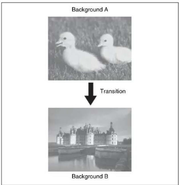
In the default selection of flip-flop mode (see page 107), the background always switches in the direction from the A bus to the B bus. When the transition completes, the
cross-point selections on the A and B buses are interchanged.
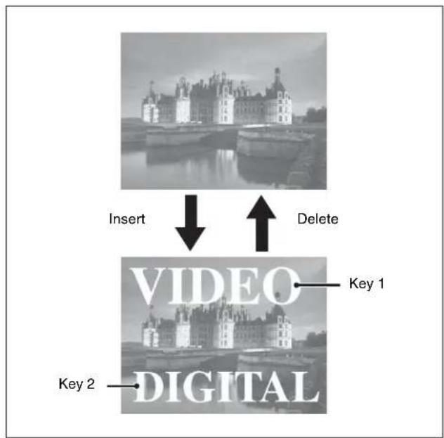
Inserting and deleting a key
You can insert one or more of the eight keys (downstream keys on the PGM/PST bank).
If you select a key which is already inserted, the transition will delete the key.
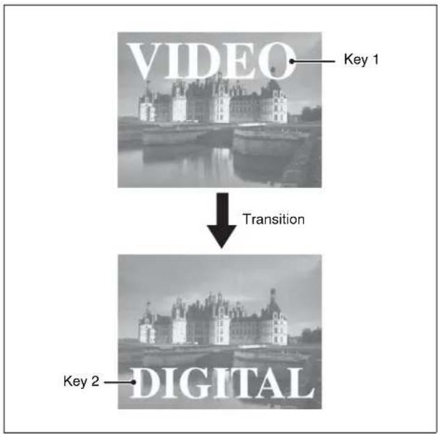
A simultaneous combination of deleting and inserting keys is also possible.
flowchart
graph TD
    A["Insert"] --> B["VIDEO"]
    B --> C["Key 1"]
    B --> D["Key 2"]
    B --> E["DIGITAL"]
    F["Delete"] --> B
Inserting or deleting key 1 and key 2
flowchart
graph TD
    A["VIDEO"] -->|Transition| B["DIGITAL"]
    A -->|Key 1| C["Top: Top: Great Wall"]
    B -->|Key 2| D["Bottom: Bottom: Grand Palace"]
Deleting key 1 and inserting key 2
Simultaneously changing the background and keys
You can change any of the eight keys (downstream keys on the PGM/PST bank) and the background at the same time.
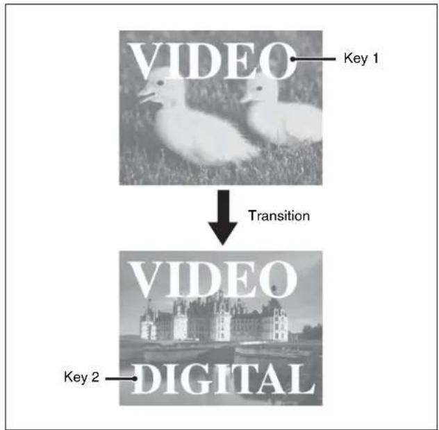
flowchart
graph TD
    A["VIDEO"] -->|TRANSITION| B["VIDEO"]
    B --> C["KEY 2"]
Changing the background and key 2 simultaneously
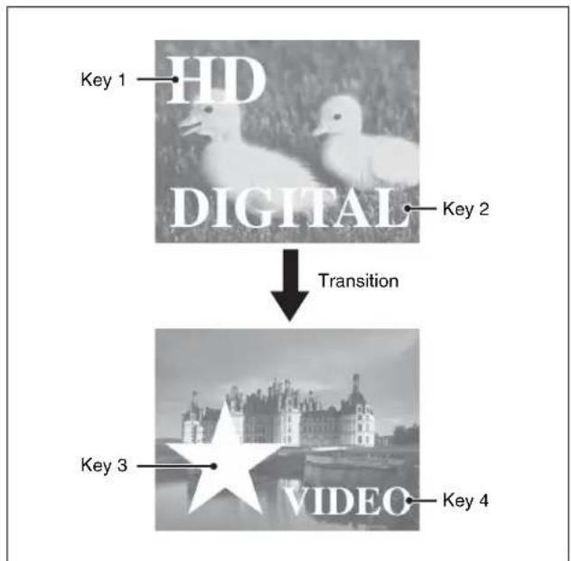
flowchart
graph TD
    A["HD"] --> B["DIGITAL"]
    B --> C["Transition"]
    C --> D["VIDEO"]
    style A fill:#f9f,stroke:#333
    style B fill:#ccf,stroke:#333
    style C fill:#cfc,stroke:#333
    style D fill:#fcc,stroke:#333
Changing the background and keys 1 to 4 simultaneously
Selecting the transition type determines the way in which the transition occurs. The following are the transition type.
- Mix
• NAM (non-additive mix) - Super mix
- Preset color mix (color matte)
-
W i p c
• DME wipe -
Clip transition
- Cut
There are two modes for carrying out a transition: auto transitions are carried out by a button operation, and manual transitions are carried out using the fader lever. It is also possible to combine these two modes.
Independent Key Transitions
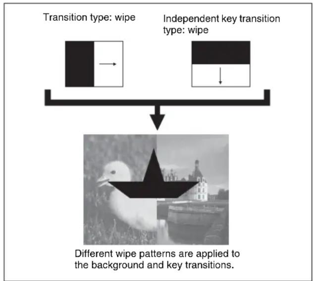
In addition to common transitions, it is possible to carry out independent transitions on the keyers of the M/E banks and PGM/PST bank. These are called “independent key transitions.”
By carrying out an independent key transition in combination with a common transition, different transition types can be used for the background and keys.
The following description compares the independent key transition with a common transition, taking a simultaneous change of the background and key as an example.
Video used in the transition
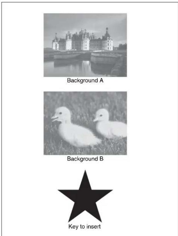
Effect of a common transition
In the case shown in the previous illustration, carrying out a common transition produces the following change in the image.
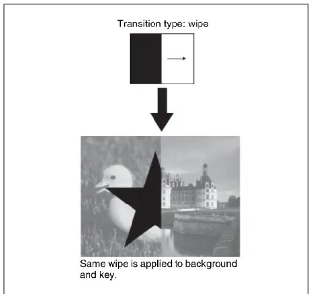
Effect of a common transition
Effect of use with an independent key transition
The key is inserted with an independent key transition as the background changes with a common transition, providing the following result.
flowchart
graph TD
    A["Transition type: wipe"] --> B["Input: wipe"]
    C["Independent key transition type: wipe"] --> D["Output: wipe"]
    E["Different wipe patterns are applied to the background and key transitions."] --> F["Image of birds in Moscow"]
Effect of a background transition and independent key transition
For details, see Chapter 3 “Signal Selection and Transitions” (page 85).
Keys
A key is an effect in which a part of the background image is replaced by an image or superimposed text. The signal determining how the background is cut out is termed “key source,” and the signal that replaces the cut-out part is
termed “key fill.” The system component responsible for processing a key is referred to as a keyer.
Each switcher bank has eight keyers, each providing the same functionality.
On each switcher bank, you can use the following key types (methods of processing the key source).
- Luminance key
- Linear key
- Color vector key
- Chroma key
- Wipe pattern key
• Key wipe pattern key
Key modifiers
You can apply borders and other modifiers to the edge of the key image.
Masks
A mask allows a part of the image to be replaced by the background or a key. To prevent unwanted holes in the background, or if a key is not the desired shape, you can correct this with a mask.
Resizer
This function allows you to apply effects, similar to a DME, such as zoom, movement, or aspect ratio change to a part of a created key. You can use the following operations.
- Two-dimensional transform of a key
- Rotation of keys
- Resizer interpolation settings
- Resizer crop/border settings
- Resizer effect settings (wide key border, drop shadow, edge enhancement, mosaic, defocus, mask)
For details, see "Keys" (page 119).
Wipes
A wipe is a transition from the current video stream to a new video stream, using a wipe pattern.
Changing the background by means of a wipe is referred to as a “background wipe,” and inserting or deleting a key with a wipe is termed a “key wipe.”
There are two types of wipe: those that can be selected in a common transition, and those that can be selected in an independent key transition.
The patterns that can be used for a wipe are as follows.
- Standard wipe patterns
- Enhanced wipes
- Rotary wipes
- Mosaic wipe pattern
- Random and diamond dust wipe patterns
You can combine two selected patterns (referred to as “main” and “sub”) to create a new pattern (pattern mix). You can also specify the wipe direction, or set the pattern position, applying various changes and modifiers to the selected wipe pattern.
For details, see "Wipes" (page 159).
DME Wipes
A DME wipe is a wipe transition that uses a DME effect to change from one video image to the next.
There are two types of DME wipe: those which can be selected for a normal transition, and those which can be selected for an independent key transition.
The patterns that can be used for a DME wipe are as follows.
Slide, Squeeze, Split, Door, Flip tumble, Mirror, Sphere, Character trail, Wave, Ripple, Page turn, Page roll, Frame in-out, Picture-in-picture, 2D trans, 3D trans, Sparkle, Split slide, Mosaic, Defocus, Brick, and User programmable DME
You can also specify the wipe direction, or set the pattern position, applying various changes and modifiers to the selected DME wipe pattern.
Resizer DME wipes
Using the resizer, you can carry out key DME wipes.
For details, see "DME Wipes" (page 179).
Frame Memory
Frame memory is a function for using a still image or video (frame memory clip) as material for editing.
You can create a still image by capturing a frame of input video or a clip by specifying a range of input video. The created images and clips can be written to memory for playback, editing, and output.
For details, see "Frame Memory" (page 198).
Color Backgrounds
This function can be used to obtain color background video.
Two color signals generated from the dedicated generators can be switched or mixed, and then output.
For details, see "Color Background" (page 224).
Copy and Swap
This function can be used to copy and swap the settings among the M/E-1 to M/E-3, and PGM/PST banks or between keyers.
The following settings can be copied or swapped.
- Overall settings for the M/E and PGM/PST banks
- Keyer settings
- Wipe settings in a transition control block
- Wipe settings in an independent key transition control block
• DME wipe settings in a transition control block - DME wipe settings in an independent key transition control block
- Matte color settings (color 1, color 2, and how to compose them)
- Color settings
• DME channel settings - Format converter input settings (copy only)
- Format converter output settings (copy only)
For details, see "Copy and Swap" (page 226).
Video Process
The term “video process” is applied to adjustments to the gain, hue, black level of the input video signal. There are two types of adjustment; adjustment of an individual input signal and adjustment as image effects on a particular bus.
For details, see "Video Process" (page 233).
Color Corrector
The color corrector enables video signal color correction (black balance/white balance adjustment, gamma correction, knee correction, etc.).
The color corrector includes the following adjustments.
- Input video processing
• Primary color correction
• Secondary color correction
• Luminance processing - Spot color adjustment
• Output video processing - YUV/RGB clip
For details, see "Color Corrector" (page 235).
Side Flags
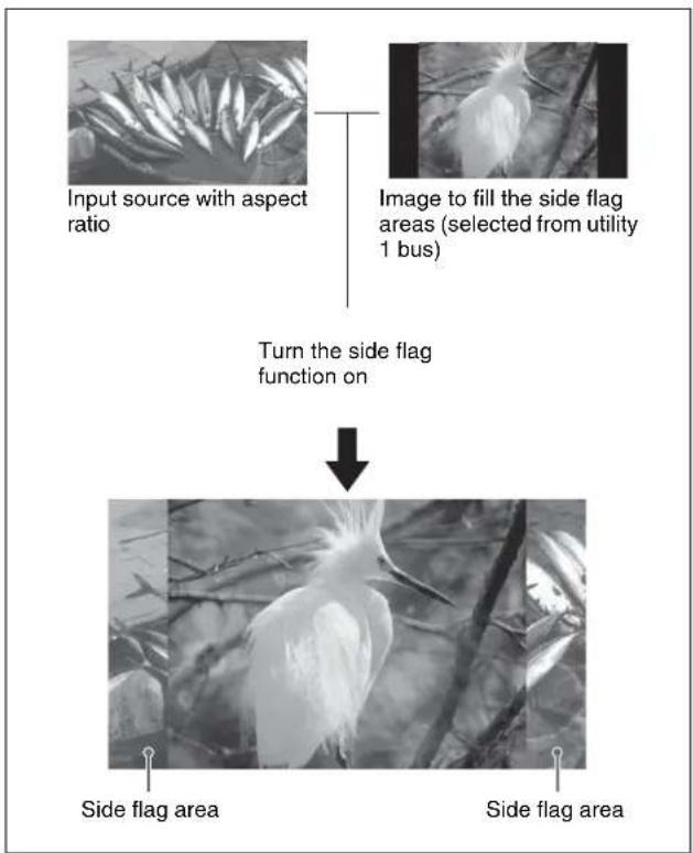
The term “side flags” refers to the areas to left and right of an image with aspect ratio 4:3 embedded within a 16:9
frame, when these areas are filled with a separate image selected from the utility 1 bus.
flowchart
graph TD
    A["Input source with aspect ratio"] --> B["Image to fill the side flag areas (selected from utility 1 bus)"]
    B --> C["Turn the side flag function on"]
    C --> D["Side flag area"]
    C --> E["Side flag area"]
For details, see "Side Flags" (page 245).
Multi Program 2
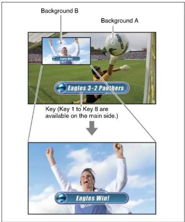
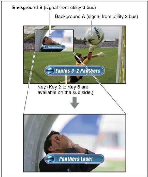
By operating the switcher in Multi Program 2 mode, a single switcher mix/effects bank can be used to create two separate video outputs, referred to as “main” and “sub.” You can set backgrounds, keys, and transitions for each of main and sub. For example, during broadcast of sports events, two versions of the scene can be provided as shown below, and switched simultaneously.
Program output for "Main"
Program output for "Sub"
For details, see "Multi Program 2" (page 248).
3D Support
Installing the BZS-8560 switcher upgrade software in an MVS-8000X/7000X, and the BZDM-8560 DME upgrade software in an MVE-8000A/MVE-9000, enables the processing of video in 3D mode.
For details, see "3D Support" (page 255).
Creation of Special Effects and Management of Data and Operations
This section introduces functions used for creation of special effects, control of external devices or switcher operations, and data management.
Digital Multi Effects (DME)
When used with the switcher, DME allows you to add three-dimensional effects such as image movement, rotation, magnification and shrinking, as well as a wide variety of special effects.
Each channel can be used on its own or in combination with other channels, which allows you to create advanced effects with more complexity.
The following types of DME special effects are available.
- Edge effects: Border, Crop, Beveled Edge, Key Border, Art Edge, Flex Shadow
• Effects for entire image: Defocus, Blur, Multi Move - Effects for video image: Sepia, Mono, Posterization, Solarization, Nega, Contrast, Mosaic, Mask, Sketch, Metal, Dim and Fade, Glow
- Freeze effects
- Nonlinear effects: Wave, Mosaic Glass, Flag, Twist, Ripple, Rings, Broken Glass, Flying Bar, Blind, Split, Split Slide, Mirror, Multi Mirror, Kaleidoscope, Lens, Circle, Panorama, Page Turn, Roll, Cylinder, Sphere, Explosion, Swirl, Melt, Character Trail
• Lighting effects: Lighting, Spotlighting - Recursive effects: Trail, Motion Decay, Keyframe Strobe
- Background color
- Separate Sides (effects for front and back sides)
• Signal inversion (Invert effect)
• Key density adjustment
• Key source selection
Global effects
Global effects are special effects created by combining the images of successive channels. The following types of global effects are available.
- Combiner
- Brick
- Shadow
For details, see "DME Operations" (page 263).
External Devices
In this system, you can operate while controlling the following types of external device:
• Devices supporting P-Bus (Peripheral II protocol)
• Devices supporting GPI
• V TR s
- Disk recorder (Sony disk 9-pin protocol and video disk communications protocol)
- Extended VTR (Abekas A53 protocol)
For details on the devices that can be connected, consult your Sony representative.
You can control an external device by previously registering timeline keyframes.
For details, see Chapter 12 “External Devices” (Volume 2).
Keyframes
A keyframe represents an instantaneous state of an image; it can be saved in a register and recalled for reuse.
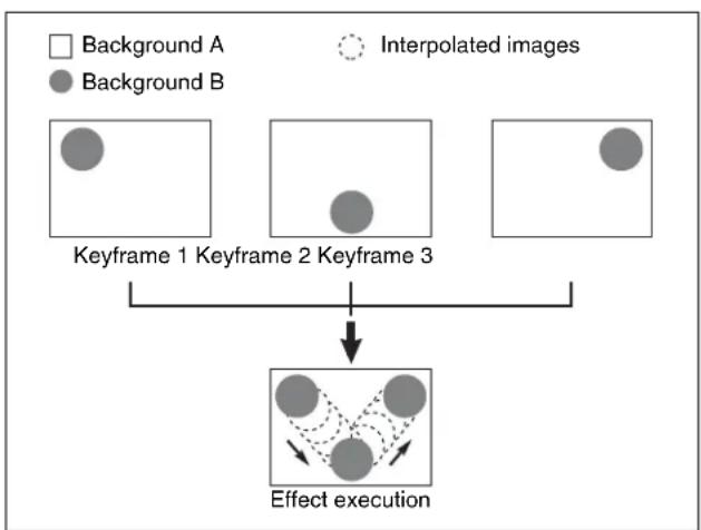
By arranging a number of keyframes on the time axis, and interpolating between successive keyframes, you can create a “keyframe effect” in which there is a continuous change from each keyframe to the next.
The following figure shows three keyframes created with a wipe pattern (the circle) in different positions. This is interpolated to create the effect shown.
flowchart
graph TD
    A["Keyframe 1 Keyframe 2 Keyframe 3"] --> B["Effect execution"]
    C["Background A"] --> B
    D["Background B"] --> B
    E["Interpolated images"] -.-> B
Example of keyframes and effect execution
You can save the sequence of keyframes representing a single effect in a register. Then by recalling this register, you can replay the same effect.
For details, see Chapter 13 "Keyframe Effects" (Volume 2).
Snapshots
The term “snapshot” refers to a function whereby the various settings required to apply a particular effect to an image are saved in a register as a set of data, for recall as required, to recover the original state.
Snapshots are divided as follows.
- Snapshots applying to a particular region (functional block of the switcher or DME)
- Master snapshot
• Key snapshot - Wipe snapshot
• DME wipe snapshot
An individual snapshot may also have attached special conditions relating to switcher or DME operation when the snapshot is recalled.
These conditions are called “attributes” of the snapshot, and can be added when the snapshot is saved or recalled.
For details, see Chapter 14 "Snapshots" (Volume 2).
Utility
The utility function refers to a function whereby you can assign an arbitrary action or a shortcut for frequently used menu to a particular button, then instantly recall the action or menu by pressing the button.
For details, see "Utility Execution" in Chapter 15 (Volume 2).
Shotbox
The term “shotbox” refers to a function whereby for each specified region (see “Regions” in Chapter 13 (Volume 2)) any snapshot or keyframe effect can be recalled simultaneously.
For details, see "Shotbox" in Chapter 15 (Volume 2).
Macros
The term “macro” refers to the function whereby a sequence of signal selections and other operations on the control panel is saved as data in memory (macro register), so that it can be recalled as required to automatically execute the same sequence of operations.
The individual control panel operations constituting a macro are termed “events.”
Macros also provide the following functions.
Menu macros
The term “menu macro” refers to the function whereby a sequence of menu operations is saved as data in memory, so that it can be recalled as required to automatically execute the same sequence of operations.
Macro timeline
By recording macro recall and execute action on a timeline, in the same way as for keyframes in an effect, you can automatically execute them in a sequence.
Macro attachment
Macro attachment is a function whereby a macro register is assigned to a control panel button or a particular position of a fader lever, linking the execution of the button function or a fader lever operation with a macro execution.
For details, see Chapter 16 "Macros" (Volume 2).
Files
You can save register data, including setup information and snapshot information, as a file on a hard disk or memory card, and recall it as required.
You can operate on individual files or registers, or together in a batch.
Regarding frame memory, it is possible to capture image data stored in an external device into frame memory.
The following files can be saved and recalled.
- Operation mode setup data for system as a whole and individual devices
• Device status data for system startup
• Key memory setting data
• Video process memory setting data
• Keyframe effect setting data - Snapshot setting data
- Wipe snapshot setting data
• DME wipe snapshot setting data
• Key snapshot setting data - Shotbox setting data
- Macro setting data
- Macro attachment data
- Menu macro setting data
• Frame memory image data
For details, see Chapter 17 "Files" (Volume 2).
Setup
Various settings are required, in order to operate the switcher, control panel, DME, external devices, and so on, connected together in a single system. This is referred to as “setup,” and you can carry out the setup operations from the Engineering Setup menu.
The settings in the Engineering Setup menu are grouped under the following headings.
System setup (System)
For details, see Chapter 18 "System Setup" (Volume 2).
Panel setup (Panel)
For details, see Chapter 19 "Control Panel Setup (Panel)" (Volume 2).
Switcher setup (Switcher)
For details, see Chapter 20 "Switcher Setup (Switcher)" (Volume 2).
DME setup (DME)
For details, see Chapter 21 "DME Setup (DME)" (Volume 2).
DCU setup (DCU)
For details, see Chapter 22 “DCU Setup (DCU)” (Volume 2).
Router/tally setup (Router/Tally)
For details, see Chapter 23 "Setup Relating to Router Interface and Tally (Router/Tally)" (Volume 2).
User setup (User Setup)
For details, see Chapter 24 "User Setup (User Setup)" (Volume 2).
Menus and Control Panel
Chapter
2
Names and Functions of Parts of the Control Panel
Control Panel: Example Configuration 1 (With Standard Transition Modules)
The MVS-8000X/7000X system control panel comprises a number of modules.
The following illustration shows a typical 32-button, 4-M/E configuration, with standard transition modules used in the transition control block.
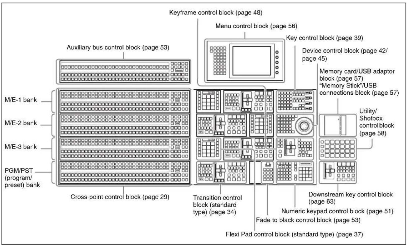
Control panel configuration 1 (with standard transition modules)
Control Panel: Example Configuration 2 (With Simple Transition Modules)
The following illustration shows a typical configuration, with simple transition modules used in the transition
control block.
Except for the simple modules, this is the same configuration as in example configuration 1.
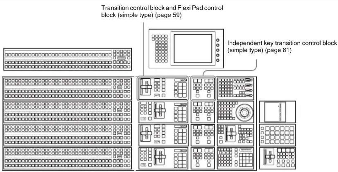
Control panel configuration 2 (with simple transition modules)
Control Panel: Example Configuration 3 (With Compact Transition Modules)
The following illustration shows a typical configuration, with compact transition modules used in the transition control block.
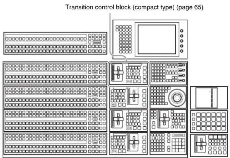
Control panel configuration 3 (with compact transition modules)
Cross-Point Control Block
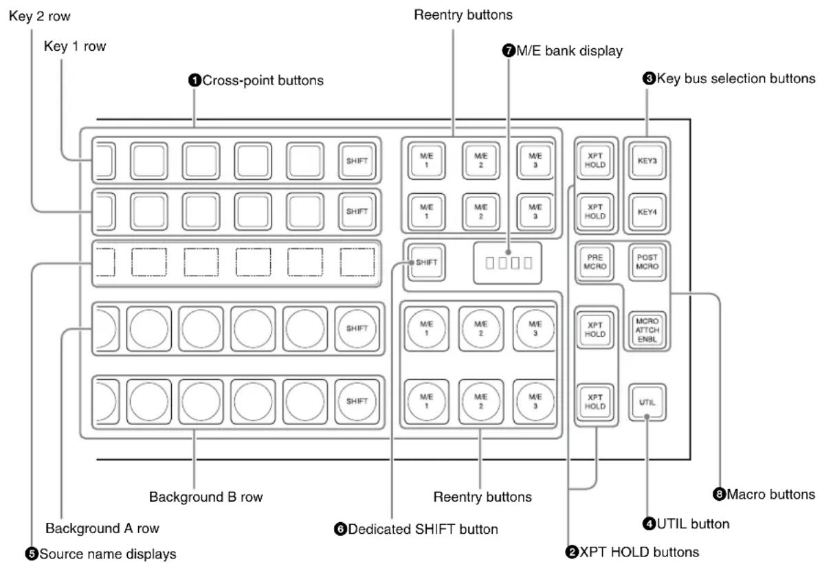
In the cross-point control block, you can select the signals to be used in this M/E bank or PGM/PST bank.
There are also modules without the source name displays shown in the following figure.
All operations except those of the [SHIFT] button are the same as for a module with source name displays.
Notes
In the case of the MVS-8000X, only the premium inputs (inputs to the switcher PREMIUM INPUTS connectors 1 to 20) can be selected as key signals on the M/E-4 bank.

flowchart
graph TD
    A["Key 2 row"] --> B["Cross-point buttons"]
    C["Key 1 row"] --> B
    B --> D["SHIFT"]
    D --> E["M/E 1"]
    D --> F["M/E 2"]
    D --> G["M/E 3"]
    H["Reentry buttons"] --> I["M/E bank display"]
    J["Key bus selection buttons"] --> K["XPT HOLD"]
    J --> L["KEY3"]
    J --> M["XPT HOLD"]
    J --> N["KEY4"]
    O["Background A row"] --> P["SHIFT"]
    Q["Background B row"] --> R["SHIFT"]
    S["Background B row"] --> T["SHIFT"]
    U["Source name displays"] --> V["Dedicated SHIFT button"]
    W["XPT HOLD"] --> X["PRE MCRO"]
    W --> Y["POST MCRO"]
    W --> Z["XPT HOLD"]
    W --> AA["XPT HOLD"]
    W --> AB["UTIL"]
    AC["Macro buttons"] --> AD["UTIL button"]
    AE["XPT HOLD buttons"] --> AF["RE-entry buttons"]
① Cross-point buttons
These buttons select the signals used for video creation on this M/E bank or PGM/PST bank. Each row of buttons corresponds to one or more signal buses within the switcher.
For details of assignment and selection of keys 5 to 8, see the following sections in Appendix: "Assigning Buttons for Selection of Keys 5 to 8 in the Setup Menu" (page 388) and "Selecting Input Signals for Keys 5 to 8 in the Cross-Point Control Block" (page 389).
flowchart
graph TD
    A["Key 2 row"] --> B["Key 1 row Reentry buttons"]
    B --> C["ME1"]
    B --> D["ME2"]
    B --> E["ME3"]
    B --> F["SHFT"]
    B --> G["SHFT"]
    B --> H["SHFT"]
    B --> I["SHFT"]
    J["Background A row"] --> K["Background B row Reentry buttons"]
    K --> L["ME1"]
    K --> M["ME2"]
    K --> N["ME3"]
    K --> O["ME1"]
    K --> P["ME2"]
    K --> Q["ME3"]
| Name Description | |
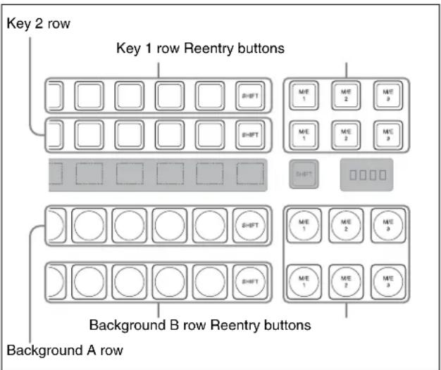
| Key 1 row • The buttons in this row select the key 1 or key 3 signals to be inserted into the video on this M/E bank or PGM/PST bank.To select the key 1 fill signal, check that the right-hand [KEY3] button in the M/E bank (or the [DSK3] button in the PGM/PST bank) is off, then press the button assigned to the desired signal.To select the key 3 fill signal, press the [KEY3] button, turning it on.While the [UTIL] button on the right hand side is held down, these buttons are assigned to the DME external video bus allowing you to select the signal on that bus. | |
| Key 2 row • The buttons in this row select the key 2 or key 4 signals to be inserted into the video on this M/E bank or PGM/PST bank.To select the key 2 fill signal, check that the right-hand [KEY4] button in the M/E bank (or the [DSK4] button in the PGM/PST bank) is off, then press the button assigned to the desired signal.To select the key 4 fill signal, press the [KEY4] button, turning it on.While the [UTIL] button on the right hand side is held down, these buttons are assigned to the DME utility 1 or 2 bus as follows.When the [KEY 4] button is off: DME utility 1 busWhen the [KEY 4] button is on: DME utility 2 bus | |
| Background A row | • To select the signal as the current background video on this M/E bank or PGM/PST bank.While the [UTIL] button on the right hand side is held down in Hold mode, these buttons are assigned to the utility 1 bus, and can be used to select the signal on that bus. |
| Background B row | • To select the signal as the background video after the transition on this M/E bank or PGM/PST bank.While the [UTIL] button on the right hand side is held down in Hold mode, these buttons are assigned to the utility 2 bus, and can be used to select the signal on that bus. |
| Reentry buttons | • These allow you to select the video created on another bank as background A or B or one of the keys 1 to 8.For example, to use the video created on the M/E-1 bank as background B on the M/E-2 bank, press the reentry button [M/E 1] in the background B row of buttons on the M/E-2 bank. |
Cross-point button numbers
Cross-point button and reentry buttons are respectively numbered (see page 89).
Assigning signals to button
You can assign a signal to each button using the Setup menu.
For details, see "Cross-Point Settings (Xpt Assign Menu)" in Chapter 19 (Volume 2).
Visual indications on cross-point buttons
For details, see “Colors of lit cross-point buttons” (page 91).
Assigning a Delegation Function to the Key 1 Row
You can assign the key/AUX bus delegation function to the key 1 row so that signals can be selected in the key 2 row.
For details, see "Assigning a Key or AUX Bus to a Button in the Key 1 or Key 2 Row" in Chapter 19 (Volume 2).
②XPT (cross-point) HOLD buttons
Turning one of these buttons on enables you to recall a keyframe or snapshot while keeping the current cross-point selection unchanged. Function of this button varies depending on the operation mode selected in the Setup menu.
For details, see “Selecting the Bank to Make the Settings” in Chapter 20 (Volume 2).
③Key bus selection buttons
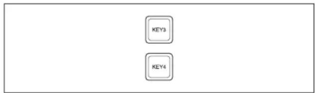
With the following buttons you can assign the key 1 or key 2 cross-point buttons to the key 3 or key 4 fill bus.
| Name Description | |
| KEY3 button | Press this button, turning it on, to assign the key 1 cross-point buttons to the key 3 fill bus. |
| KEY4 button | Press this button, turning it on, to assign the key 2 cross-point buttons to the key 4 fill bus. |
Pressing one of the key delegation buttons [KEY1] to [KEY4] in the transition control block (standard type) twice in rapid succession changes the state of the corresponding one of these buttons, so that you can make cross-point selections on the key bus (see page 37). Using these buttons and the dedicated SHIFT button, you can assign keys 5 to 8 to cross-point buttons (see page 389).
④UTIL (utility) button
While this button is held down, the cross-point buttons are assigned to the following buses, respectively.
Background A row: utility 1 bus
Background B row: utility 2 bus
Key 1 row: DME external video bus
Key 2 row: DME utility 1 bus when the [KEY4] button is off, or DME utility 2 bus when the [KEY4] button is lit.
In a Setup menu, you can select either of the following two modes for these buttons.
- The button takes effect while being held down.
- Every time the button is pressed, it toggles between the on and off states for key 1 and key 2 rows. For background A and background B rows, utility buses remain disabled.
⑤Source name displays
These show the names of the signals which can be selected on the cross-point buttons, in two or four characters, or in auto mode.
While the [SHIFT] button on the right hand side or the [SHIFT] button assigned to the column of cross-point buttons is enabled, the source name of the signal assigned to the column of cross-point buttons in shift mode appears. You can select green, orange, or yellow for the background color of the source name display, for each source separately. You can set the source name display mode and background color in a Setup menu.
⑥ Dedicated SHIFT button
This button has the following three functions.
Selection buttons for key 5 to 8 signals: When this button is enabled, you can select key 5 and 7 signals in the key 1 row, and key 6 and 8 signals in the key 2 row. Each time you press the button toggles between enabled and disabled.
Source name display shift button: When this button is enabled, the source name display shows the shifted signal name. Each time you press the button toggles between enabled and disabled. In a module with no source name display, this button is disabled.
Bus shift button: When this button is enabled, it acts as a shift button for all buses on this M/E (PGM/PST) bank. Each time you press the button toggles between enabled and disabled.
You can select the mode in a Setup menu.
⑦M/E bank display
This indicates the notional mix/effect bank name to which the particular M/E bank is assigned, as a four-character identifier.
⑧Macro buttons
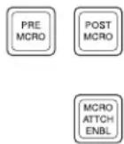
With the following buttons you can enable macro attachments, and select the mode for using macro attachments.
| Name Description | |
| PRE MCRO(pre macro) | Use this button to set a macro attachment in pre macro mode.For setting in macro only mode, use this in combination with a macro only set button assigned to the utility/shotbox control block or a user preference button. Alternatively, without using the button, you can make the selection simply, by pressing simultaneously with the [POST MCRO] button.Function of this button varies as follows depending on the operation mode selected in the Setup menu.- Switching dual background bus mode- Switching utility/shotbox mode- Disabling cross-point button operationsFor details, see “Setting the Assignment of Macro Operation Buttons” in Chapter 19 (Volume 2).NotesFor the CCP-6224/6324, [AUX CTRL] is assigned to this button (see page 70). |
| POSTMCRO (post macro) | Use this button to set a macro attachment in post macro mode.For setting in macro only mode, use this in combination with a macro only set button assigned to the utility/shotbox control block or a user preference button. Alternatively, without using the button, you can make the selection simply, by pressing simultaneously with the [PRE MCRO] button.For details, see “Setting the Assignment of Macro Operation Buttons” in Chapter 19 (Volume 2).NotesFor the CCP-6224/6324, [AUX DSPLY] is assigned to this button (see page 70). |
| MCROATTCHENBL(macro attachment enable) | When this button is on, the macro attachments set for the buttons of the M/E bank are enabled. You can make a setup setting such that enabled buttons light. |
Cross-Point Control Block in Key/AUX Bus Delegation Mode
You can assign key and AUX buses to the key 1 row buttons in the cross-point control block for use as delegation buttons so that signal selection can be made in the key 2 row.
In this case, the buttons in the cross-point control block operate as follows.
For details of assignment, see “Assigning a Key or AUX Bus to a Button in the Key 1 or Key 2 Row” in Chapter 19 (Volume 2).
![④DSPLY [display] button ①Key/AUX delegation button row ②Cross-point button row ③Source name/bus name display (for key/AUX buses) A/B bus control block ⑤DEST button ⑥KEY button](/content/2026/06/1364863/images/3bffa9b4392f130b2ad949031415ca3f51758cb72181bc8b2cd2a4aea5342b2f.jpg)
①Key/AUX delegation button row
These buttons select a key bus or AUX bus. In setup you can assign the following buses. KEY1 to KEY8, DSK1 to DSK8, UTILITY 1, UTILITY 2, EXT DME, DME UTIL 1, DME UTIL 2, EDIT PVW AUX 1 to 48, FMS 1, FMS 2, DME 1 V/K to DME 8 V/K, CCR 1, CCR2
②Cross-point button row
These buttons select a cross-point on the bus selected with the key/AUX delegation buttons.
Notes
- When you press a button in the cross-point button row while holding down the button to which any of KEY1 to KEY8 and DSK1 to DSK8 buses is assigned in the Key/AUX delegation button row, you can select the cross-point of the key source bus.
- When you select a cross-point while holding down the button to which any of DME 1 V.K to DME 4 V.K buses is assigned in the Key/AUX delegation button row, you can select the image on the reverse side of the currently viewed DME image.
③Source name / bus name display (for key/AUX buses)
When the DSPLY button is on, these show the names of the signals corresponding to the current bus delegation.
The following displays may also appear, depending on the state of other buttons.
| Button name Display | |||
| [DSPLY] | [DEST] | [KEY] | |
| Off Off - A/B bus signal names | |||
| On Off Off | Key/AUX bus | video | signal name or key signal names^a) |
| On On - Key/AUX bus | names | ||
| On Off On | Key/AUX bus | video | signal name or key signal names^b) |
a) When you are holding down the button to which any of KEI to KEY8 and DSK1 to DSK8 buses is assigned in the key/AUX delegation button row, the video signal name is displayed. To display the key signal names when other bus is selected, keep the KEY button held down.
b) When you are holding down the button to which any of KEY1 to KEY8 and DSK1 to DSK8 buses is assigned in the key/AUX delegation button row, the key signal names are displayed. To display the key signal names when other bus is selected, keep the KEY button held down.
④DSPLY [display] button
Press to light this button, in order that the source name / bus name displays show the signal names or bus names corresponding to the current bus delegation.
⑤DEST button
When both the DSPLY button and this button are on, the key bus names or AUX bus names are displayed.
6KEY button
When you press a cross-point button while holding down this button, the key signal is selected.
Transition Control Block (Standard Type)
In the transition control block, you can modify the output of the M/E bank or PGM/PST bank, and perform
transitions. Both common transition and independent key transition operations are possible.

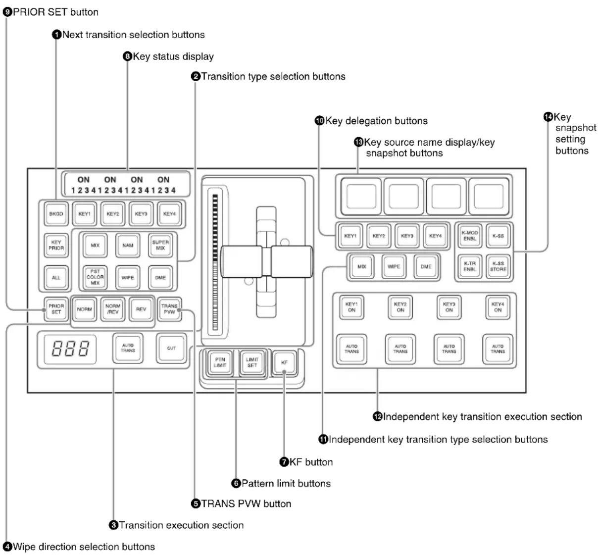
①Next transition selection buttons
Press these buttons, turning them on, to determine what the next transition will apply to.
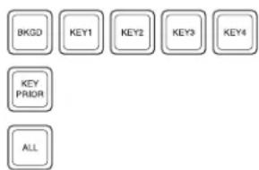
flowchart
graph TD
    A["BKG0"] --> B["KEY1"]
    B --> C["KEY2"]
    C --> D["KEY3"]
    D --> E["KEY4"]
    F["KEY PRIOR"] --> G["ALL"]
| Name Description | |
| BKGD Next transition changes the background. | |
| KEY1 to KEY8 (DSK1 to DSK8 in the PGM/PST bank) | Press this button, turning it on, to make the next transition insert or remove the corresponding key (keys 1 to 8).If a key is currently inserted it will be removed, and vice versa.In the PGM/PST bank, this inserts or removes downstream keys 1 to 8.For details of assignment and selection of keys 5 to 8, see the following sections in Appendix: “Assigning Buttons for Selection of Keys 5 to 8 in the Setup Menu” (page 388) and “Selecting Keys 5 to 8 for Next Transition” (page 389). |
| KEY PRIOR (priority) | When this button is lit, the setting of the key priority after the next transition is enabled.The key priority after the next transition appears in the key status display. |
| ALL Pressing | this button turns on a preselected set of the [BKGD], [KEY1] to [KEY8], and [KEY PRIOR] buttons. Make this setting in a Setup menu. |
② Transition type selection buttons
Press one of these buttons, turning it on, to determine the type of the next transition (see page 92).
For the method of assigning transition types, see "Transition Control Block Button Assignments" in Chapter 19 (Volume 2).
When multi-program mode is selected in the Setup menu, two or more of the following buttons may light.
For details of multi-program mode, see “Setting Transition Control Block Button Assignments” in Chapter 19 (Volume 2).
You can also assign a function to these buttons to select whether or not the fader levers are used as keyframe faders.

| Name Description | |
| MIX In a background transition, the new video fades in as the current video fades out. | |
| NAM (non-additive mix) | The current and new video signals are compared, and the signal with the higher luminance level is given priority in the output. |
| SUPER MIX | The current video is maintained at 100% output for the first half of the transition as the new video is mixed while increasing progressively to 100%. |
| PST (preset) COLOR MIX | The color matte (unpatterned display) is inserted during transition, replacing the current video by the color matte, and then replacing the color matte by the new video. |
| WIPE The current video is replaced by the new video, using the wipe pattern selected in the Wipe menu. | |
| DME (DME wipe) | A wipe type of transition is carried out, using the DME effect selected in the DME Wipe menu. |
| FM1&2CLIP, FM3&4CLIP, FM5&6CLIP, FM7&8CLIP | A recorded clip is played back together with the transition. At this point, you can also carry out a transition (wipe or mix (dissolve)) simultaneously together with the clip. |
| KF (keyframe) | Press this button, turning it on, to enable using the fader lever as a keyframe fader. |
③ Transition execution section
This section is used to carry out a transition and check the progress of the transition.
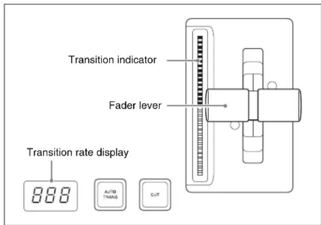
| Name Description | |
| Transition indicator | This comprises multiple LEDs, which show the progress of the transition. |
| Fader lever • | Move up or down to carry out the transition.• When the [KF] button or a transition type selection button to which the KF button function has been assigned is lit, you can use this as a keyframe fader. |
| Transition rate display | This shows the “transition rate” (the time from the beginning of a transition to its completion) set for an auto transition, in frames.You can set the transition rate using the numeric keypad control block, Flexi Pad control block, or menu. |
| AUTO TRANS (transition) button | Pressing this button carries out an auto transition of the set transition rate (duration). The transition starts immediately, and the button lights amber.When the transition completes, the button goes off. |
| CUT button P | Pressing this button carries out the transition as a cut (i.e. instantaneously). |
④ Wipe direction selection buttons
When a wipe or DME wipe is selected as the transition type, you can press to light these buttons to select the wipe direction.
| Name Description | |
| NORM (normal) | The wipe proceeds in the direction from black to white as shown on the pattern in the lists of patterns see “Wipe Pattern List” (page 351) and “DME Wipe Pattern List” (page 355), or in the direction of the arrow. |
| REV (reverse) | The wipe proceeds in the opposite direction to that when the [NORM] button is pressed. |
| NORM/REV (normal/reverse) | The wipe direction alternates between normal and reverse every time a transition is executed. |
⑤TRANS PVW (transition preview) button
When this button is lit, you can check in advance the video changes during the transition, on the preview output from the M/E or PGM/PST bank.
During the preview, you can use the fader lever, [AUTO TRANS] button, and [CUT] button. One of the following functions of this button can be selected in a Setup mode.
- When the transition completes, the system returns to the normal mode.
- The transition preview mode is maintained while this button is pressed.
- Switching is made between the transition preview mode and normal mode every time this button is pressed.
⑥Pattern limit buttons
The following buttons are used to set a pattern limit.

| Name Description | |
| PTN (pattern) LIMIT | Pressing this button, turning it on, enables the pattern limit function. |
| LIMIT SET • | Use this button to set a pattern limit when the [PTN LIMIT] button is off.• Move the fader lever to the position of a particular pattern size, and stop it there, then press this button to set the pattern limit range. |
⑦KF (keyframe) button
Pressing this button to turn it on allows you to use the fader lever as a keyframe fader.
⑧Key status display
For each of the next transition selection buttons, [KEY1] to [KEY4], the corresponding ON indicator lights when the key is inserted. It also shows the priority (1 to 4) of each key.
⑨PRIOR (priority) SET button
While this button is held down, you can set the key priority.
The setting mode when this button is pressed depends on whether or not the [KEY PRIOR] button is lit, as follows.
- When the [KEY PRIOR] button is off, the current key priority is set.
- When the [KEY PRIOR] button is lit, the key priority after the next transition is set.
Press the [KEY PRIOR] button as required, to switch between these two modes.
In either mode, hold down the [PRIOR SET] button, and press the button ([KEY1] to [KEY8]) corresponding to the key you want to bring to the front.
Notes
The key priority establishes a separate priority order within each of the groups of keys 1 to 4 and keys 5 to 8. You can make any setting within the groups of keys 1 to 4 or keys 5 to 8, but not for combinations of keys from different groups. For example, it is not possible to set a priority sequence of keys 1, 5, and 2.
For details, see “Setting the Key Priority in the Transition Control Block” (page 95).
The following controls are used as the independent key transition control block.
⑩Key delegation buttons
These buttons delegate this independent key transition control block to a desired keyer. Press one of the [KEY1] to [KEY8] buttons ([DSK1] to [DSK8] in the PGM/PST bank), turning it on.
You can press more than one button to select two or more keyers.
While these buttons are held down, you can select a key source with the cross-point buttons for the key bus.
Pressing one of these buttons twice in rapid succession changes its state so that you can make cross-point selections on the corresponding key bus.
For details of assignment of keys 5 to 8, see “Assigning Buttons for Selection of Keys 5 to 8 in the Setup Menu” (page 388) in Appendix.
⑪Independent key transition type selection buttons
Press one of the following buttons, turning it on, to select the independent key transition type.
You can assign any transition types to these buttons in setup
For details, see “Setting Transition Control Block Button Assignments” in Chapter 19 (Volume2).
| Name Description | |
| MIX Faded in or out. | |
| WIPE Inserted or deleted with a wipe. | |
| DME (DME wipe) | Inserted or deleted with a DME wipe. |
| CUT Instantaneously insert or remove the key selected with the delegation buttons. | |
⑫Independent key transition execution section
The following buttons are used to insert or delete a key, and carry out an auto transition.
For details of assignment of keys 5 to 8, see “Assigning Buttons for Selection of Keys 5 to 8 in the Setup Menu” (page 388) in Appendix.
| Name Description | |
| KEY1 ON to KEY8 ON (DSK1 ON to DSK8 ON in the PGM/PST bank) | Press the corresponding one of these buttons to cut key 1 to key 4 in or out instantaneously.When the key corresponding to the button appears in the final program output, the button lights red, and otherwise lights amber. |
| AUTO TRANS (transition) | These correspond to keys 1 to 4 from left to right; press one to carry out an auto transition.The transition rate for an independent key transition can be set in the numeric keypad control block, in the Flexi Pad control block, or in a menu. |
⑬Key source name display/key snapshot buttons
These display the source name selected on the corresponding keyer. In key snapshot mode, press these buttons, corresponding to registers 1 to 8 for the selected keyer, to save or recall a key snapshot.
⑭Key snapshot setting buttons
The following buttons are used to operate a key snapshot.
| Name Description | |
| K-SS (key snapshot) | This enables key snapshot mode. |
| K-SS STORE (key snapshot store) | To save a key snapshot, hold down this button, and press the key source name display/key snapshot button corresponding to the register you want to save. |
| K-MOD ENBL (key modifier enable) | To recall key adjustment values and key modifier settings when recalling a key snapshot, press this button, turning it on. |
| K-TR ENBL (key transition enable) | To recall independent key transition settings when recalling a key snapshot, press this button, turning it on. |
Flexi Pad Control Block (Standard Type)
The Flexi Pad control block is used for saving and recalling wipe snapshots, DME wipe snapshots, and snapshots, for recalling effects, and shotbox content, and for entering the transition rate.
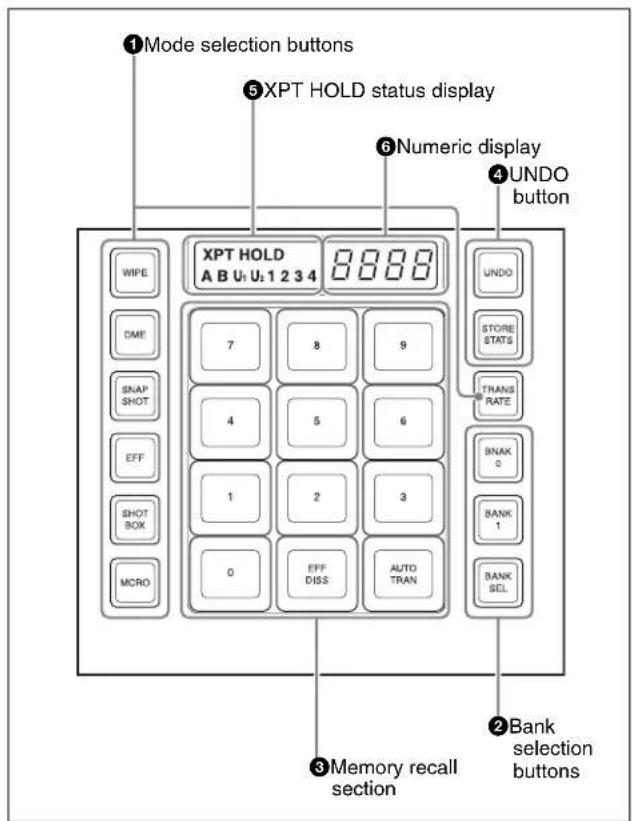
① Mode selection buttons
Pressing the following buttons selects the operation mode.
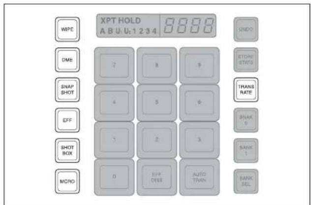
| Name Description | |
| WIPE To save | or recall a wipe snapshot, or recall the pattern number of a wipe pattern, use this in combination with the buttons of the memory recall section. |
| DME To save | or recall a DME wipe snapshot, or recall the pattern number of a DME wipe pattern, use this in combination with the buttons of the memory recall section. |
| SNAPSHOT | To save or recall a snapshot, use this in combination with the buttons of the memory recall section. |
| Name Description | |
| EFF (effect) | To recall the master timeline or run an effect, use this in combination with the buttons in the memory recall section. |
| SHOTBOX To | recall or execute a shotbox, use this in combination with the buttons of the memory recall section. |
| MCRO (macro) | To save, recall or edit a macro, use this in combination with the buttons of the memory recall section. |
| TRANS RATE (transition rate) | • To enter the transition rate, press this button, turning it on.• To enter the independent key transition rate, hold down this button, and press the key delegation button in the independent key transition control block.• To select whether the value is entered in frames or as a timecode value, switch the [TC] button in the memory recall section on or off. |
② Bank selection buttons
The following buttons are used to select a bank, and assign the memory recall section to the registers of the selected bank.
flowchart
graph TD
    A["BNAK 0"] --> B["BANK 1"]
    B --> C["BANK SEL"]
| Name Description | |
| BANK0 (bank 0) | Assigns the memory recall section to bank 0, of registers 1 to 10. |
| BANK1 (bank 1) | Assigns the memory recall section to bank 1, of registers 11 to 20. |
| BANK SEL (bank selection) | After pressing this button, press a button in the memory recall section to select banks 0 to 9. |
③ Memory recall section
This consists of 12 buttons with LCDs. These display changes, according to various operation modes.
④ UNDO button
The following buttons are used to return a register to its state before the register recall operation.
| Name Description | |
| UNDO • After | recalling a register, press this button to return to the state before recalling the register.When contents have been saved to a register, hold down the [STORE STATS] button and press this button to return the register to its state before the save operation. |
| STORE STATS (store status) | When a save or delete operation has been carried out on a register, this button lights amber.After saving to a register, hold down this button and press the relevant register button to delete the data in the register.Again, after a save operation on a register, hold down this button and press the [UNDO] button to restore the register to its state before the save operation. |
⑤XPT HOLD (cross-point hold) status display
A bus for which cross-point hold is set appears as a green light.
6Numeric display
Depending on the operation mode, this shows the pattern number of a wipe or DME wipe, a bank number, a register number, a transition rate, and so on in up to four digits.
Key Control Block
Each of the M/E banks and the PGM/PST bank includes eight keyers (for keys 1 to 8), and you can delegate this
control block to any desired keyer. In this control block, you can adjust and modify keys.
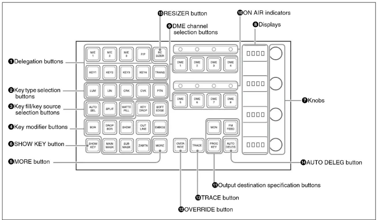
①Delegation buttons
Pressing the following buttons selects a keyer and an M/E or PGM/PST bank to which the key control block is delegated.
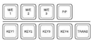
| Name Description | |
| M/E delegation | Press one of the [M/E 1] to [M/E 4], and [P/P] buttons to select the bank (an M/E bank or the PGM/PST bank) to which the key control block is delegated.For details of [M/E 4] button assignment, see “Assigning a Button for M/E-4 Selection in the Setup Menu” (page 387) in Appendix. |
| Key delegation | Press one of the [KEY1] to [KEY8] buttons to delegate the key control block to the corresponding keyer.For details of assignment of keys 5 to 8, see “Assigning Buttons for Selection of Keys 5 to 8 in the Setup Menu” (page 388) in Appendix. |
| TRANS • By | pressing this button, you can check the DME channel used for DME wipes on the M/E or PGM/PST bank.By pressing this button, then pressing one of the DME channel selection buttons, you can preset the DME channel to be used when a DME wipe is selected as the transition type for the transition.When presetting the DME channel for an independent key transition, hold down this button, then press one of the [KEY1] to [KEY8] buttons, turning the two buttons on, beforehand. |
②Key type selection buttons
Press one of these buttons, turning it on, to select the desired key type.
Depending on the selected key type, various parameters are displayed, and you can set the values with the knobs. The following key types can be selected.
LUM: luminance key
LIN: linear key
CRK: chroma key
CVK: color vector key
PTN: key wipe pattern key
For details, see "Key Types" (page 119).
③Key fill/key source selection buttons
Pressing the following buttons selects key fill and key source.

| Name Description | |
| AUTO SEL (selection) | Use the signal selected on the key fill bus, and the paired key source signal. The setting of key fill and key source pairs is carried out in a Setup menu.To use the signal selected on the key fill bus as key source (self keying), press the [AUTO SEL] button and [SPLIT] button at the same time, so that both are off. |
| SPLIT • To use the signal selected on the key fill bus as key fill, and a signal separate from the signal assigned in a pair with key fill for key source, press this button, turning it on.To select the signal on the key source bus, hold down this button, and press a button in the key 1 or key 2 row in the cross-point control block.To use the signal selected on the key fill bus as key source (self keying), press the [AUTO SEL] button and [SPLIT] button at the same time, so that both are off. | |
| MATTE FILL | To use a color matte from the internal generator as key fill, press this button, turning it on. You can adjust the color matte using the knobs.When this button is off, the signal selected on the key fill bus is used as key fill. |
④Key modifier buttons
To add an edge modifier to the key, press one of these buttons, turning it on.
Depending on the button pressed, parameters appear in the displays, and you can set the values with the knobs.
To select a normal edge as the edge type, turn the BDR (border), DRP BDR (drop border), SHDW (shadow), EMBOS [emboss] and OUTLINE buttons off.
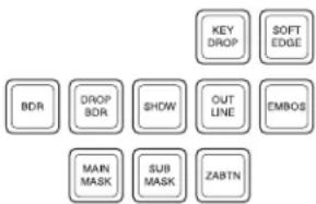
| Name Description | |
| KEY DROP | When the selected edge type is “normal” and soft edge is off or when drop border or shadow is selected, turning this button on lowers the key fill and key source position by four or eight scan lines as set in the key menu. To select 4H or 8H, use the Key menu.When the selected edge type is “normal” and soft edge is selected or when border, outline, or emboss is selected, this button lights automatically. |
| BDR (border)a) | Apply a border of a uniform thickness to the whole key. |
| DROP BDR (drop border)a) | Apply a border to two sides of the key (for example, below and to the right, or below and to the left). |
| SHDW (shadow)a) | Apply a shadow to two sides of the key (for example, below and to the right, or below and to the left). |
| OUTLINE • Use the outline of the key.Use the key fill signal selected for the key in the edge portions. | |
| EMBOS (emboss) | • Apply an embossing effect to the periphery of the key.When emboss is selected, you can use the dedicated color matte signal for the emboss function. |
| MAIN MASK | Press this button, turning it on, to enable the key mask using the main pattern. |
| SUB MASK P | Press this button, turning it on, to enable the key mask using the sub pattern. |
| ZABTN (zabton) | Press this button, turning it on, a translucent pattern is inserted behind the key. |
| SOFT EDGE | Press this button, turning it on, to soften the key edge portions. |
a) When one of these buttons is selected, you can use a special color matte or a signal selected on the utility 1 bus for the edge.
⑤MORE button
When there are more than four parameters, this button lights amber. When it is pressed, it changes from amber to green and the fifth and subsequent parameters are assigned to the knobs, allowing them to be adjusted.
⑥SHOW KEY button
While this button is held down, a key processed key source signal is output from the specified output port. You can make the output specification independently for each of edit preview and the preview of each M/E or PGM/PST bank in a Setup menu.
⑦Knobs
Turn the knobs to adjust the parameter values.
⑧Displays
Each display shows the initial letters of the parameter name and the parameter value (maximum three digits including a minus sign for a negative value).
⑨DME channel selection buttons
Press one of these buttons, turning it on, to delegate a DME channel to the keyer.
The number of valid DME channel selection buttons depends on the number of channels installed in the DME processor.
A maximum of four consecutively numbered DME channels from the two sets, DME 1 to 4 and DME 5 to 8, can be assigned to one keyer.
On the MVS-8000X, when the signal format is 1080P only, the consecutive channel combinations that can be selected are any of DME1 and DME2, DME3 and DME4, DME5 and DME6, or DME7 and DME8.
On the MVS-7000X, when the signal format is 1080P, the above restriction also applies if using the MVE-8000A. There is no such restriction for the MKS-7470X/7471X. DME channel assigned to a keyer cannot be selected on another keyer.
However, using the override function it is possible to allocate a channel already allocated to another keyer to the currently selected keyer. If DME channel allocations have been made in a Setup menu, these buttons cannot be used to make DME channel allocations. Using the trace function, it is possible to check which keyer a DME channel is allocated to.
⑩ON AIR indicators
These light red when the corresponding DME channels are included in the final program output.
⑪ Output destination specification buttons
Pressing the following buttons selects and checks the output signal.
| Name Description | |
| MON (DME monitor) | Hold down this button and press the selection button for the DME channel you want to assign to the monitor output; you can then monitor the output signal on the DME monitor output.While this button is held down, the DME channel selection buttons light as follows, allowing you to check the monitor assignment.Lit amber: DME channel that can currently be monitoredLit green: DME channel currently assigned to the monitor output |
| FM FEED(frame memory feed) | When you press this button, it lights momentarily amber, then for the currently selected keyer, the key processed signals are selected for frame memory sources 1 and 2.If a DME is selected on the currently selected keyer, the key fill and key source signals to which a DME effect is applied are assigned; otherwise the key fill and key source are assigned.Carrying out a frame memory feed causes the [PROC KEY] button to light amber. |
| PROC KEY(processed key) | When this button is on, the key fill/source signal subjected to key processing or signal subjected to a DME effect on the currently selected keyer can be selected as a reentry signal (PROC V or PROC K) for the M/E or PGM/PST bank, on the auxiliary bus or the like.If a DME is selected on the currently selected keyer, the key fill and key source signals to which a DME effect is applied are assigned; otherwise the key fill and key source are assigned. |
12 OVERRIDE button
To select a DME channel already allocated to another keyer or transition to the currently selected keyer (or
transition), hold down this button, and press the DME channel selection button.
13TRACE button
When a DME channel is already allocated to another keyer or transition, hold down this button, and press the corresponding DME channel selection button, to switch to the state in which the keyer (or transition) to which the DME channel is allocated is currently selected.
14 AUTO DELEG (auto delegation) button
When this button is on, the key delegation selection state of the key control block is linked to the key delegation selection state of the independent key transition control block.
15RESIZER button
Enables or disables resizer.
When this is set to On, you can turn the knob to shrink, magnify, or move a key.
You can also rotate the key by pressing the following buttons assigned in the Setup menu in advance.
ROT X button: Rotate the key in the horizontal direction. ROT Y button: Rotate the key in the vertical direction.
For details on resizer, see page 148.
Device Control Block (Trackball)
The device control block is used for three-dimensional transform operations using a DME, for wipe pattern
position setting, and for VTR/disk recorder/frame memory clip operation.
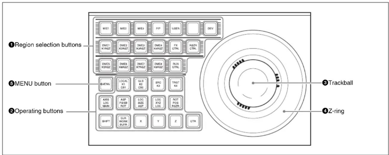
①Region selection buttons
The operation mode allocated to the device control block depends on the selection state of the region selection buttons.
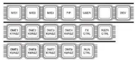
flowchart
graph TD
    subgraph Top
        M01["ME1"] --> DMES1["DMES1 KIN5Z"]
        M02["ME2"] --> DMES2["DMES2 KIN5Z"]
        M03["ME3"] --> DMES3["DMES3 KIN5Z"]
        PIP["PIP"] --> DMES4["DMES4 KIN5Z"]
        USER["USER"] --> FX["FX CTRL"]
        DEV["DEV"] --> RS7R["RS7R CTRL"]
    end
    subgraph Bottom
        DMES1 --> DMES5["DMES5 KIN5Z"]
        DMES2 --> DMES6["DMES6 KIN5Z"]
        DMES3 --> DMES7["DMES7 KIN5Z"]
        DMES4 --> DMES8["DMES8 KIN5Z"]
        FX --> RUN["RUN CTRL"]
        RS7R --> RUN
    end
| Selected buttons | Overview of assigned operation |
| [M/E 1] to [M/E 4], [P/P] | This enables the wipe pattern position setting (positioner) operation mode in the device control block.You can select multiple buttonssimultaneously.For details of [M/E 4] button assignment, see “Assigning a Button for M/E-4 Selection in the Setup Menu” (page 387) in Appendix. |
| [USER] This | enables pattern position setting used for color backgrounds. |
| [DME1] to [DME8] | This enables the three-dimensional transform operation mode in the device control block.Press a button, turning it on, to select a DME channel.You can select multiple buttonssimultaneously.The number of valid buttons depends on the number of DME processor channels installed. |
| [DEV] • This | enables the VTR/disk recorder/frame memory operation mode in the device control block.Each button functions as follows.(From upper left to right in the above figure)- [M/E1] to [M/E3]: DEV1 (device 1) to DEV3 (device 3)- [P/P]: DEV4 (device 4)- [USER]: FM1CLIP (frame memory clip 1)- [Unused]: FM2CLIP (frame memory clip 2)- [DME1] to [DME4]: DEV5 (device 5) to DEV8 (device 8)- [FX CTRL]: FM LOOP (frame memory loop)- [DME5] to [DME8]: DEV9 (device 9) to DEV12 (device 12)To exit from this mode, press the [DEV] button again, turning it off. |
| [RUN CTRL] | This enables the effect run control mode in the device control block. |
| [RSZR CTRL] | This enables the resizer control mode in the device control block.In resizer control mode, select the key with the region selection button [K1RSZ] to [K8RSZ]. |
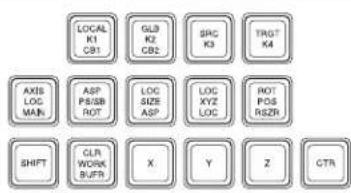
| Selected buttons | Overview of assigned operation |
| [FX CTRL] | Leave this button off for operation. |
| Alternatively, for details of operation of this button, refer to the help information for the MPES-FX01 Programmable Effector software. |
②Operation buttons
The following buttons are used to carry out the corresponding operations. Function of each button varies with the operation mode.
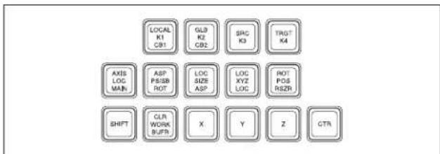
When the positioner operation mode is enabled
For details of assignment of keys 5 to 8, see "Assigning Buttons for Selection of Keys 5 to 8 in the Setup Menu" (page 388) in Appendix.
| Name Description | |
| K1 CB1 a) b) | Press this button to enable wipe pattern position setting for key 1 (DSK1).When the [USER] button is selected, pattern position setting for color background 1 is enabled. |
| K2 CB2 a) b) | Press this button to enable wipe pattern position setting for key 2 (DSK2).When the [USER] button is selected, pattern position setting is enabled for color background 2. |
| K3 a) b) | Press this button to enable wipe pattern position setting for key 3 (DSK3). |
| K4 a) b) | Press this button to enable wipe pattern position setting for key 4 (DSK4). |
| MAIN a) | Press this button to enable main wipe pattern position setting for normal transitions. |
| SB a) | Press this button to enable sub wipe pattern position setting for normal transitions. |
| POS • Press | this button to enable pattern movement in the x-axis and y-axis directions with the trackball.When the [USER] button is selected, this enables the trackball to move the pattern in the x-axis and y-axis directions, and the Z-ring to adjust the size of the pattern. |
| X, Y, Z These | restrict the axes affected by the trackball and Z-ring to the x-, y- or z-axis. |
| CTR(center) | When this button is pressed, the pattern position returns to the center.When the [USER] button is selected, the pattern size also returns to 50.00. |
| CLR WORKBUFR | Press this button twice in rapid succession to reset all parameters on the target M/E or PGM/PST to their initial values. |
a) Among these buttons, you can select multiple buttons.
b) By setting the operation mode in setup, you can select keys 5 to 8 with these buttons. In this case, it is not possible to select more than one of keys 1 to 8.
When the three-dimensional transform operation mode is enabled
The buttons are used for three-dimensional DME transformations.
For details, see “Three-Dimensional Transformation Operations” (page 277).
When the VTR/disk recorder/frame memory operation mode is enabled
The buttons are used for VTR control or playback of frame memory clips.
For details, see “Controlling the Tape/Disk Transport” in Chapter 12 (Volume 2).
When the resizer control mode is enabled
| Name Description | |
| LOC SIZE(ASP: aspect) | Pressing this button and operating the trackball or Z-ring changes the aspect ratio of a key to which the resizer function is applied to.When this button is held down, the trackball or Z-ring operation is switched to a finer control. (fine mode) |
| LOC XYZ(LOC: location) | Pressing this button and operating the trackball or Z-ring moves, shrinks, or magnifies a key to which the resizer function is applied.When this button is held down, the trackball or Z-ring operation is switched to a finer control. (fine mode) |
| ROT(RSZR: resizer) | Press this button, turning it on, to enable the resizer. |
| ASP PS(ROT: Rotation) | Pressing this button and operating the trackball or Z-ring rotates the key to which the resizer function is applied or adjusts perspective.When this button is held down, the trackball or Z-ring operation is switched to a finer control. (fine mode) |
| Name Description | |
| SHIFT/CLR WORK BUFR (clear work buffer) | Pressing this button once returns the two-dimensional transformation settings to the defaults.Pressing the [CLR WORK BUFR] button twice, or holding down [SHIFT] and pressing the [CLR WORK BUFR] button returns all resizer parameter values to the defaults. |
| X, Y, Z These | restrict the axes affected by the trackball and Z-ring to the x-, y- or z-axis. |
| SHIFT/CTR (center) | Pressing this button once changes the two-dimensional transformation settings to the closest detent values.Pressing the [CTR] button twice, or holding down [SHIFT] and pressing the [CTR] button returns the two-dimensional transformation values to the defaults. |
③Trackball
The effect of operation depends on the operating mode as follows.
When the positioner operation mode is enabled
By moving this, you can move the pattern in the x-axis and y-axis directions.
When the three-dimensional transform operation mode is enabled
Move the trackball to control the x- and y-axes in a three-dimensional transform.
When the [SRC] or [TRGT] button is held down, the trackball operation is switched to a finer control. (fine mode)
When the resizer control mode is enabled
By turning the trackball, you can move in the x and y directions of the key to which the resize is applied, change the aspect ratio, and rotate around the x-axis and y-axis. When the [LOC SIZE], [LOC XYZ], or [ASP PS] button is held down, the trackball operation is switched to a finer control. (fine mode)
④Z-ring
The effect of operation depends on the operating mode as follows.
When the positioner operation mode is enabled
When the [USER] button is selected, by turning the ring you can adjust the size of the pattern.
When the three-dimensional transform operation mode is enabled
Turn this ring to control the z-axis in a three-dimensional transform.
When the [SRC] or [TRGT] button is held down, the Z-ring operation is switched to a finer control. (fine mode)
When the effect run control mode is enabled
By turning the Z-ring, you can run the keyframe effect, independent of the STOP NEXT KF, EFF LOOP, and similar settings in the keyframe control block. Turn clockwise to run the effect in the normal direction, and counterclockwise for the reverse direction.
When the VTR/disk recorder/frame memory operation mode is enabled
Turning the Z-ring controls the tape transport/disk drive/frame memory clip operations, at a speed determined by the operating buttons. Turn clockwise for the normal direction, and counterclockwise for the reverse direction. When the [LOC SIZE] or [LOC XYZ] button is held down, the Z-ring operation is switched to a finer control. (fine mode)
When the resizer control mode is enabled
By turning the ring, you can zoom the key to which the resizer is applied, and change the aspect ratio and perspective.
When the [LOC SIZE], [LOC XYZ], or [ASP PS] button is held down, the trackball operation is switched to a finer control. (fine mode)
⑤ MENU button
Press this button, turning it on, to enable adjusting the parameters allocated to the knobs in the menu using the trackball and Z-ring.
In the case of the DME menu, the operation applies to the selected DME channel.
In VTR/disk recorder/frame memory operation mode, press this button, setting it to On. This makes it possible to carry out timeline start/stop point setting operation for the device selected with the device selection buttons (timeline setting mode).
Device Control Block (Joystick)
All functions of the joystick type device control block are equivalent to the functions of the trackball type, except that
the trackball and Z-ring operations are carried out with the joystick.
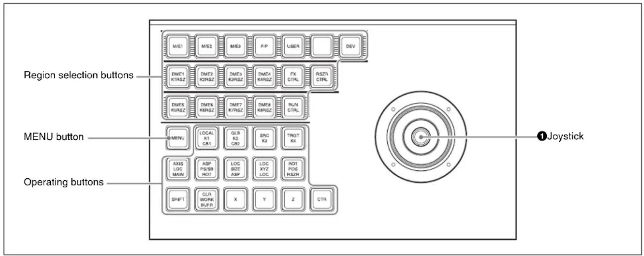
①Joystick
When the positioner operation mode is enabled
By moving this, you can move the pattern in the x-axis and y-axis directions.
When the [USER] button is selected, by turning the end of the joystick you can adjust the size of pattern.
When the three-dimensional transform operation mode is enabled
By moving this, you can carry out operations in the x-, y-, and z-axes.
When the following buttons are held down, the joystick operation is switched to a finer control. (fine mode)
• The button on the end of the joystick
- [SRC] button
- [TRGT] button
When the effect run control mode is enabled
By moving the joystick sideways, you can run the keyframe effect, independent of the STOP NEXT KF, EFF LOOP and similar settings in the keyframe control block. Move to the right to run the effect in the normal direction, and to the left for the reverse direction.
When the VTR/disk recorder/frame memory operation mode is enabled
Moving the joystick sideways controls the tape transport/disk drive/frame memory clip operation, at a speed determined by the operating buttons.
When the resizer control mode is enabled
Move for operations in the x-, y-, and z-axes.
When the following buttons are held down, the joystick operation is switched to a finer control. (fine mode)
• The button on the end of the joystick
- [LOC SIZE] button
- [LOC XYZ] button
• [ASP PS] button
Device Control Block (Search Dial)
Using the device control block (search dial), you can directly operate an XDCAM, disk recorder, VTR, other external device, frame memory clip, or shotbox. The
device control block (trackball) and device control block (joystick) can be used together.
①Timecode display
This shows the current time (CURRENT) and the start and stop point timecode values for the current reference device (START TC, STOP TC). When you press a device selection button, the button lights, selecting the assigned device as the reference device, and displaying its setting value.
In the case of the [SBOX] buttons, the display does not change. When the operation applies to a VTR/disk recorder, the displayed setting value depends on whether the [TIMELINE] button is on or off, as follows.
When the [TIMELINE] button is on: Displays the start and stop points of the last set keyframe on the timeline. When the keyframe number is changed and the last register and keyframe change, the display also changes. (timeline setting mode)
When the [TIMELINE] button is off: Displays the Cueup & Play (rewind action) start and stop points.
②Device selection buttons
These buttons are used for selecting assigned external devices or frame memory clips.
Each button can only be assigned to a single device. Carry out the assignment in the Setup menu.
For details, see “Assigning Functions to the Device Control Block” in Chapter 19 (Volume 2).
To select an assigned device, press the corresponding button, which lights green. To select more than one device simultaneously, hold down the button for the first selection, while pressing the buttons for the other selections in turn. The second and subsequent selected buttons light amber. If you press another button without holding down the first selected button, the second button will be the reference device and light green.
| Name Description | |
| DEV1 to DEV6 | Assign external devices DEV1 to DEV12. |
| FM1 CLIP, FM2 CLIP | Assign frame memory clips FM1 to FM8.Device selection buttons can be set as SBOX buttons or DELAY button in the Setup menu. |
③SBOX (shotbox) buttons
Assign a shotbox saved in registers 1 to 99. When you press a button, the assigned shotbox is selected, and executed. Carry out the assignment in the Setup menu.
For details, see “Assigning Functions to the Device Control Block” in Chapter 19 (Volume 2).
You can freely assign the portions for device selection, SBOX, and DELAY buttons in setup.
④ DELAY button
When pressed, this button lights green, the numeric keypad control block display changes to DELAY_: , and you can set the start delay time for the selected device. The setting range is from 00:00 to 59:29 (depends on the video format). This button goes off when another timecode setting button ([START TC], [STOP TC], [SET START TC], [SET STOP TC], or [SET DUR]) is pressed. The DELAY button can be set as a device selection button or an SBOX button in the Setup menu. Carry out the assignment in the Setup menu.
For details, see “Assigning Functions to the Device Control Block” in Chapter 19 (Volume 2).
⑤ Editing buttons
These buttons set start and stop points. These operations are only valid while a device is selected with the device selection buttons.
| Name Description | |
| START TC Press this button to set the timecode of the start point at that time. The timecode of the start point is updated to the current time each time this button is pressed. When the device the operation applies to is a VTR/disk recorder, the start point updated by the setting of the [TIMELINE] button is as follows.When the [TIMELINE] button is On: start point of the timelineWhen the [TIMELINE] button is Off: start point of Cueup & Play | |
| STOP TC Press this button to set the timecode of the stop point at that time. The timecode of the stop point is updated to the current time each time this button is pressed. When the device the operation applies to is a VTR/disk recorder, the stop point updated by the setting of the [TIMELINE] button is as follows.When the [TIMELINE] button is On: stop point of the timelineWhen the [TIMELINE] button is Off: stop point of Cueup & Play | |
| SET START TC, SET STOP TC, SET DUR | ·When pressed, these buttons light green, “START TC”, “STOP TC” or “DUR” appears in the numeric keypad control block display, and you can enter a timecode from the numeric keypad. If you enter a numeric value and press the [ENTER] button, the button goes off, whereas if you press the [ENTER] button without entering a numeric value the numeric keypad control block display shows “--:--:--:--”. If the timecode has been set correctly, the entered numeric value appears in the timecode display.·To exit the numeric value entry mode, either repeat pressing the same button, or press a different numeric keypad control block linked button, or a mode selection button such as the [EFF] and [SNAPSHOT] buttons in the numeric keypad control block. |
| STB (standby) OFF | ·When pressed, this button flashes amber, and the device selected with the device selection buttons exits from the standby mode.·This button cannot be used for frame memory clip operations. |
| CUE · When pressed, this button flashes amber together with the [ALL STOP] button, and the device selected with the device selection button is cued up to the start point of the material.·When more than one device is selected, the amber flashing continues until the reference device is cued up, and when the cueing up is finished, this button lights green. | |
| REW When pressed, this button lights amber, and material of the device selected with the device selection buttons is rewound. | |
| PLAY • When | pressed, this button lights amber, and the device selected with the device selection buttons plays. The playback stops not only if the [STOP] button is pressed, but also if any of the [STB OFF], [SHTL], [JOG], [CUE], [REW], [PLAY], [FF], and [ALL STOP] buttons is pressed.When the [VAR] button is pressed while the device is playing back, the device plays at one times normal speed in variable mode. |
| FF When pressed, this button lights amber, and the material of the device selected with the device selection buttons is fast forwarded. | |
| ALL STOP • When pressed, all device material playback stops.During cueing up of any of the devices, this button flashes amber, and when all cueing up operations are completed, it lights green. | |
| REC • When | pressed simultaneously with the [PLAY] button, this button lights red (the [PLAY] button lights amber), and the image from the selected device is recorded.This button cannot be used for frame memory clip operations. |
⑥ External device operation buttons
Pressing the following buttons selects the search dial mode.
| Name Description | |
| ENBL (enable) | When this is pressed, turning it on, the search dial [VAR], [JOG], and [SHTL] button operations are enabled. |
| VAR (variable) | Sets the search dial to variable mode. |
| JOG Sets the search dial to jog mode. | |
| SHTL (shuttle) | Sets the search dial to shuttle mode. |
⑦ TIMELINE button
Press to switch the device selected with the device selection buttons to timeline setting mode.
⑧ STOP button
When pressed, this lights amber, and operation of the device selected with the device selection buttons stops.
⑨Search dial
Use this for search and other operations on the material of an external device.
For details, see “Controlling Tape/Disk Transport” in Chapter 12 (Volume 2).
Keyframe Control Block
In the keyframe control block, you can carry out effect editing and execution.
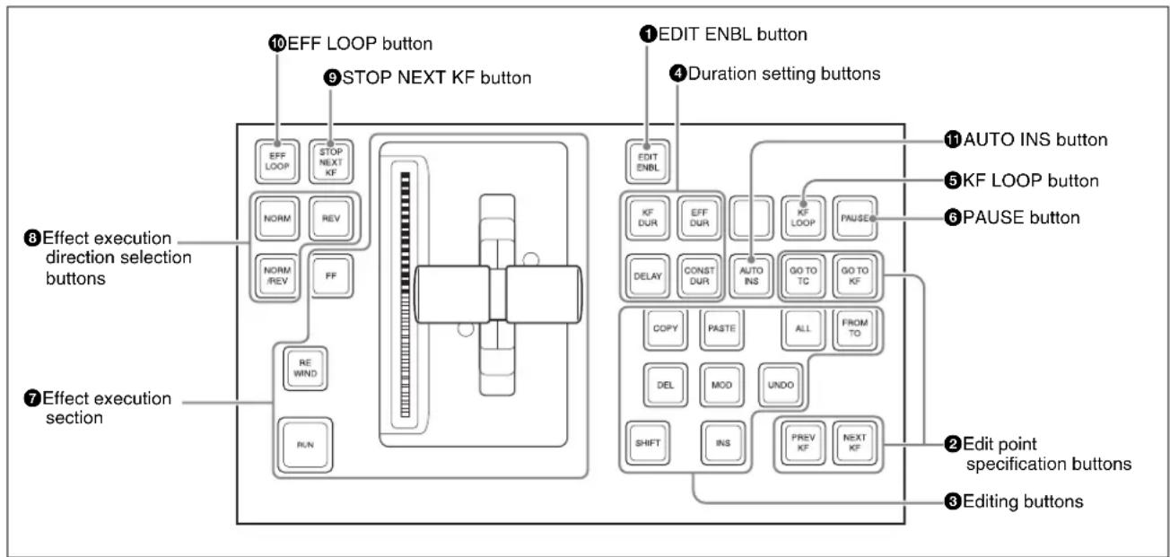
flowchart
graph TD
    A["10 EFF LOOP button"] --> B["9 STOP NEXT KF button"]
    B --> C["11 AUTO INS button"]
    B --> D["5 KF LOOP button"]
    B --> E["6 PAUSE button"]
    F["7 Effect execution section"] --> G["8 Effect execution direction selection buttons"]
    G --> H["9 Effect loop button"]
    H --> I["10 EFF LOOP button"]
    I --> J["11 ADDIT ENBL button"]
    J --> K["12 EDIT ENBL button"]
    K --> L["13 ADDIT ENBL button"]
    M["14 Duration setting buttons"] --> N["15 AUTO INS button"]
    N --> O["16 KF LOOP button"]
    O --> P["17 PAUSE button"]
    Q["18 EDIT point specification buttons"] --> R["19 Edit point specification buttons"]
    S["20 Editing buttons"] --> T["21 Editing buttons"]
①EDIT ENBL (edit enable) button
Press this button, turning it on, to enable effect editing operations with the keyframe control block.
When macro editing is carried out, this button lights red.
②Edit point specification buttons
The following buttons are used to set an edit point.
| Name Description | |
| GO TO TC (Go to timecode) | Press this button, turning it on, to enter a numeric value from the numeric keypad control block, and move the edit point to the specified timecode position. |
| GO TO KF (Go to keyframe) | • Press this button, turning it on, to enter a numeric value from the numeric keypad control block, and move the edit point to the specified keyframe.• During macro editing, pressing this button moves the edit point to the event number specified by numeric entry with the numeric keypad control block. |
| PREV KF (previous keyframe) | • When this button is pressed, the edit point moves to the keyframe immediately before the current time (the position where the effect is currently stopped).• During macro editing, pressing this button moves the edit point to the event immediately before the current event. |
| NEXT KF (next keyframe) | • When this button is pressed, the edit point moves to the keyframe immediately after the current time.• During macro editing, pressing this button moves the edit point to the event immediately after the current event. |
③ Editing buttons
The following buttons are used to edit keyframes.
| Name Description | |
| ALL Press this button, turning it on, to select all keyframes (during macro editing, all events) in the effect. | |
| FROM TO Press this button, turning it on, to enter numeric values from the numeric keypad control block, and select a specified range of keyframes (during macro editing, the specified range of events). | |
| INS (insert) | When this button is pressed, a new keyframe is inserted after the current keyframe.Pressing this button while holding down the [SHIFT] button inserts a new keyframe before the current keyframe.During macro editing, pressing this button registers an event after the current event.During macro editing, holding down the [SHIFT] button and pressing this button inserts a new event before the current event. |
| MOD (modify) | When this button is pressed, the selected keyframe is modified with the values of the current keyframe.When the edit point is between two keyframes, the immediately preceding keyframe is modified.You can also select multiple keyframes, and modify them in a single operation. At this time, pressing this button while holding down the [SHIFT] button modifies all selected keyframes with the changed values taken as relative values.During macro editing, pressing this button amends the selected event.You can also select multiple events, and edit them in a single operation. |
| DEL (delete) | When this button is pressed, the selected keyframe is deleted.When the edit point is between two keyframes, the immediately preceding keyframe is deleted.During macro editing, pressing this button deletes the selected event.You can also select multiple keyframes or macro events, and delete them in a single operation. |
| COPY • When this button is pressed, the selected keyframe (during macro editing, macro event) is copied.You can also select multiple keyframes or macro events, and copy them in a single operation. | |
| PASTE • When this button is pressed, the deleted or copied keyframe (during macro editing, macro event) is inserted after the current keyframe (during macro editing, macro event).Pressing this button while holding down the [SHIFT] button inserts the deleted or copied keyframe (during macro editing, macro event) before the current keyframe (during macro editing, macro event). | |
| SHIFT Hold down this button, and press the [INS] button, [MOD] button, or [PASTE] button, to obtain the shifted function for the button. | |
| UNDO When this button is pressed, the last executed keyframe (during macro editing, macro event) insertion, modification, or deletion, or paste operation is canceled. | |
④Duration setting buttons
The following buttons are used to set the duration of a keyframe.
flowchart
graph TD
    A["KF DUR"] --> B["DELAY"]
    C["EFF DUR"] --> B
    D["CONST DUR"] --> B
| Name Description | |
| KF DUR (keyframe duration) | Press this button, turning it on, to set the keyframe duration of the selected keyframe, by numeric value entry from the numeric keypad control block. |
| EFF DUR (effect duration) | Press this button, turning it on, to set the effect duration from the numeric keypad control block. |
| DELAY Press | this button, turning it on, to enter a delay value from the numeric keypad control block. |
| CONST DUR (constant duration) | Select the duration mode.When this is lit, the mode is constant duration mode, and when off, variable duration mode. |
⑤KF LOOP (keyframe loop) button
Press this button, turning it on, to execute the effect the specified number of times through the keyframes in the specified range.
6 PAUSE button
When this button is pressed, a pause is applied to the selected keyframe.
When editing a macro, press this button, turning it on, to include a pause event in the macro. The pause length can be set in the numeric keypad control block.
⑦ Effect execution section
This section is used to execute an effect, and check the progress of the effect execution.
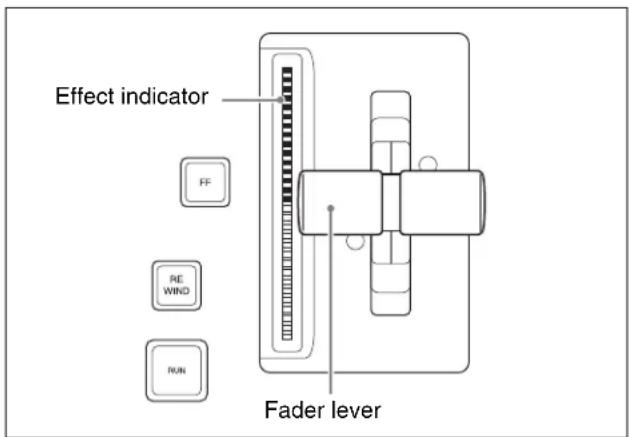
| Name Description | |
| RUN button | When this button is pressed, the effect is run from the first keyframe to the last keyframe. However, if a pause is set on a keyframe, the effect stops at that point.Press this button again to resume execution, and continue to the next pause point or the end of the effect. |
| Effect indicator | This comprises multiple LEDs, which show the progress of the effect. |
| Fader lever | Moving this up or down manually runs the effect. |
| REWIND button | When this button is pressed, the currently recalled effect is rewound to the first keyframe. |
| FF (fast forward) button | When this button is pressed, the currently recalled effect is advanced to the last keyframe. |
⑧ Effect execution direction selection buttons
The following buttons are used to set the direction of effect execution.
flowchart
graph TD
    A["NORM"] --> B["REV"]
    C["NORM/REV"] --> B["REV"]
| Name Description | |
| NORM (normal) | When this button is lit, effect execution runs from the first keyframe to the last keyframe.This button automatically goes off when the [REV] button is pressed, turning it on. |
| REV (reverse) | When this button is lit, effect execution runs from the last keyframe to the first keyframe.This button automatically goes off when the [NORM] button is pressed, turning it on. |
| NORM/REV (normal/reverse) | Press this button, turning it on, to reverse the direction of the effect when it reaches the last keyframe or first keyframe. |
⑨ STOP NEXT KF (stop next keyframe) button
When this button is pressed, turning it on, the effect execution range is from the current time to the next keyframe.
⑩EFF LOOP (effect loop) button
When the effect reaches the last keyframe with this button on, it returns to the first keyframe and repeats.
11 AUTO INS (auto insert) button
When editing a macro, press this button, turning it on, to enable the auto insert function, so that every control panel operation you carry out is added to the macro as an event.
Numeric Keypad Control Block
The numeric keypad control block is used for region selection, for saving and recalling snapshots, effects and shotboxes, for entering numeric values for trackball
operation and keyframe operation, and for transition rate entry.
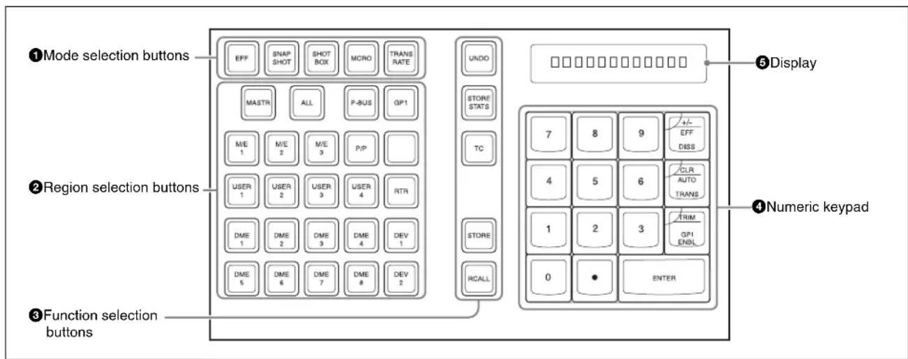
① Mode selection buttons
Pressing the following buttons changes the mode.
 |
| Name Description | |
| EFF (effect) | Press to save or recall an effect. |
| SNAPSHOT | Press to save or recall a snapshot. |
| SHOTBOX | Press to save or recall a shotbox. |
| MCRO (macro) | Press to save, recall or edit a macro. |
| TRANS RATE (transition rate) | Press to set the transition rate.Hold down this button, and press one of the key delegation buttons [KEY1] to [KEY8] in the transition control block to set an independent key transition rate. |
②Region selection buttons
These select the functional block (“region”) of the control panel to which operations apply.
You can select more than one region at the same time.
The first button you press is taken as the reference region, and lights green, while the next pressed button lights amber.
With the exception of the [MASTR] and [ALL] buttons, you can change the region assignment to the buttons as desired in the Setup menu.
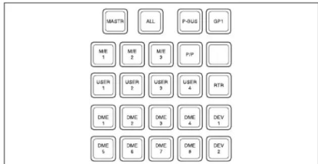

| Name Description | |
| MASTR (master) | Press this, turning it on, to save region information in a master snapshot register or master timeline register, or to recall such region information. |
| ALL • Select all regions. • When any region is already selected, pressing this button makes all regions unselected. | |
| M/E 1 to M/E 4, P/P | Select the corresponding regions, M/E-1, M/E-2, M/E-3, M/E-4, and PGM/PST.For details of [M/E 4] button assignment, see “Assigning a Button for M/E-4 Selection in the Setup Menu” (page 387) in Appendix. |
| USER 1 to USER 8 | Select a User region. |
| DME1 to DME8 | Select a DME channel. |
| P-Bus Select | the P-Bus region. |
| GPI Select the GPI region. | |
| RTR Select the router region. | |
| DEV1 to DEV12 | Select the Device 1 to Device 12 regions respectively. |
| MCRO Select the macro region. | |
③Function selection buttons
The following buttons are used to switch the function.
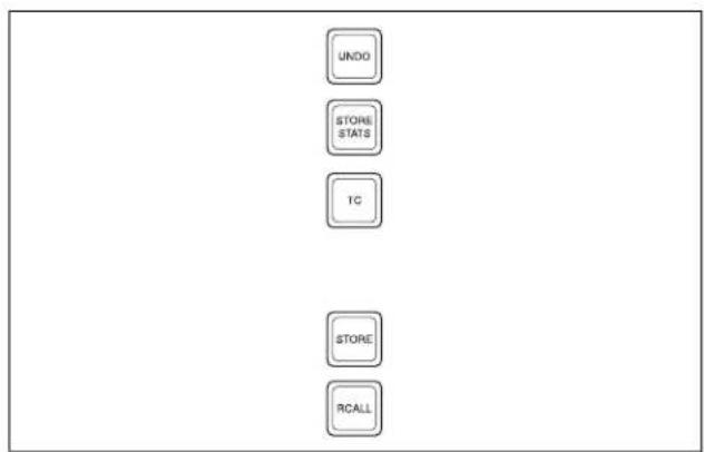
flowchart
graph TD
    A["UNDO"] --> B["STORE STATS"]
    B --> C["TC"]
    C --> D["STORE"]
    D --> E["RCALL"]
| Name Description | |
| UNDO After | recalling a register, press this button to return to the state before recalling the register. |
| STORE STATS (store status) | This lights amber when data is stored in a register.After saving data to a register, hold down this button and press the [UNDO] button to return the register to the state before the data was saved. |
| TC (timecode) | Press this button, turning it on, to switch transition rate entry to the timecode entry mode. |
| Name Description | |
| STORE^a) | Press this button to switch to the mode for saving a snapshot, effect, shotbox or macro in a register. |
| RCALL (recall)^a) | Press this button to switch to the mode for recalling a snapshot, effect, shotbox or macro from a register. |
a) [STORE] button or [RCALL] button flashes amber when one or more of the regions assigned to the Region selection buttons are not selected by the Region Select menu.
④Numeric keypad
In addition to the buttons for numeric input, this includes buttons for adding attributes to snapshots.
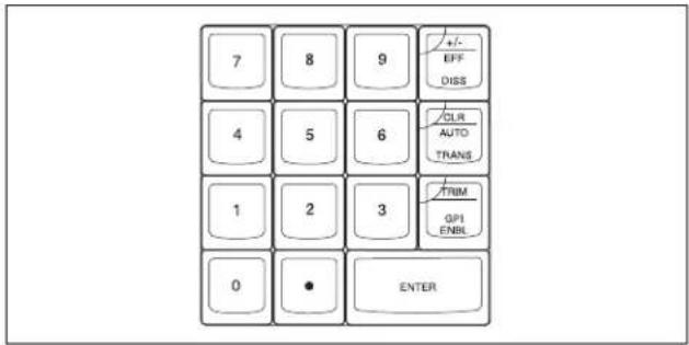
| Name Description | |
| 0 to 9 Used to input numeric digits. | |
| .(period) • Enters the decimal point.When the [TC] button is lit, enters “00.”When the [EFF] button, [SNAPSHOT] button or [SHOTBOX] button is lit, this is used to find an empty register. | |
| +/-/EFF DISS (effect dissolve) | • Invert the sign, negative or positive.When the [SNAPSHOT] button is lit, applies the effect dissolve attribute to a snapshot. |
| CLR/AUTO TRANS (clear/auto transition) | • Clear an input value, returning to the previous state.When the [SNAPSHOT] button is lit, applies the auto transition attribute to a snapshot. |
| TRIM/GPI ENBL (enable) | • After entering a difference value to be added to an existing setting, press this button to confirm the change.When the [SNAPSHOT] button is lit, adds a GPI output attribute to the snapshot. |
| ENTER Confirm an entered value. | |
⑤Display
This shows the selected region name, register number and entered numeric values.
Fade to Black Control Block
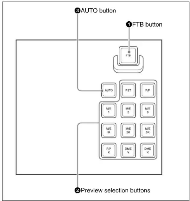
flowchart
graph TD
    A["3 AUTO button"] --> B["FTB button"]
    B --> C["AUTO"]
    C --> D["PST"]
    C --> E["P/P"]
    D --> F["M/E 1"]
    D --> G["M/E 2"]
    D --> H["M/E 3"]
    D --> I["M/E IK"]
    D --> J["M/E 2K"]
    D --> K["M/E 3K"]
    D --> L["P/P K"]
    D --> M["DME V"]
    D --> N["DME K"]
    O["2 Preview selection buttons"] --> P["3 AUTO button"]
    style O fill:#f9f,stroke:#333,stroke-width:2px
①FTB (fade to black) button
Press this button to fade to black the program output of the PGM/PST bank, at the set transition rate. You can set the fade to black transition rate in the menu.
②Preview selection buttons
Each of these buttons can be assigned to any preview output in setup.
Each button can be assigned to any preview output in setup.
For details, see “Assigning Preview Output to Preview Selection Buttons” in Chapter 19 (Volume 2).
| Name Description | |
| PST(preset) | When this button is pressed, the signal selected on the background B row of the PGM/PST bank is selected on the edit preview bus. |
| M/E 1 to M/E 4, P/P (M/E1 to M/E 4, P/P preview) | The preview signal (M/E-1 PVW, M/E-2 PVW, M/E-3 PVW, M/E-4 PVW, P/P PVW) of the M/E or PGM/PST bank corresponding to the pressed button is selected on the edit preview bus.For details of [M/E 4] button assignment, see “Assigning a Button for M/E-4 Selection in the Setup Menu” (page 387) in Appendix. |
| M/E1 K to M/E4 K, P/P K (M/E1 to M/E 4, P/P key preview) | The key preview signal (M/E-1 K-PVW, M/E-2 K-PVW, M/E-3 K-PVW, M/E-4 K-PVW, P/P K-PVW) of the M/E or PGM/PST bank corresponding to the pressed button is selected on the edit preview bus.For details of [M/E 4] button assignment, see “Assigning a Button for M/E-4 Selection in the Setup Menu” (page 387) in Appendix. |
| DME V (DME monitor video) | When this button is pressed, the DME monitor output video signal (DME MON V) is selected on the edit preview bus. |
| DME K (DME monitor key) | When this button is pressed, the DME monitor output key signal (DME MON K) is selected on the edit preview bus. |
③ AUTO button
When this button is pressed, the M/E or PGM/PST bank preview signal selected on the edit preview bus is automatically switched to the program signal depending on the on-air status.
Auxiliary Bus Control Block (for AUX Buses)
There are also models without the selected source name displays and source name displays shown in the following figure.
All operations except those of the [DEST] button and [SHIFT] button are the same as for a model with selected source name displays and source name displays.
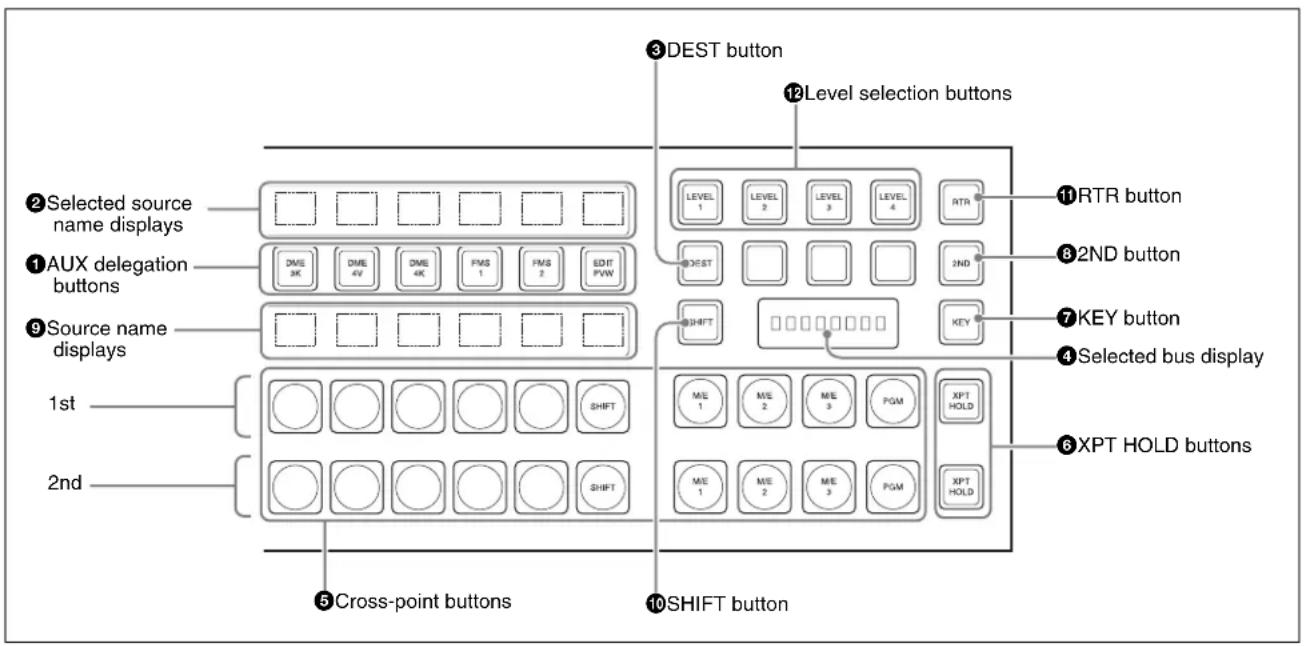
①AUX delegation buttons
Press one of these buttons, turning it on, to select the bus to which to assign the cross-point buttons in the auxiliary bus control block.
For buses that can be selected, see “Bus Selection” (page 86).
②Selected source name displays
These show the name of the currently selected signal (source) on the bus corresponding to the delegation button.
③DEST (destination) button
Press this button, turning it on, to display the names of buses allocated to the delegation buttons in the selection source name displays.
In the case of a module without selected source name displays, this button is invalid.
④ Selected bus display
This shows the name of the bus selected by the auxiliary bus delegation buttons.
⑤ Cross-point buttons
The cross-points in the auxiliary bus control block are arranged in two rows: an upper row (1st row) and a lower row (2nd row), and are allocated to the buses selected with the AUX delegation buttons. The 1st row contains the cross-point buttons for unshifted buses, and the 2nd row contains the cross-point buttons for shifted buses.
When the DME 1V/K to 8V/K buses are selected with the AUX delegation buttons, the 1st row cross-point buttons are for the currently showing side of DME, and the 2nd row are for the reverse side.
By holding down the [2ND] button and making an AUX delegation selection, you can allocate the 2nd row to a different bus from the 1st row.
In this case, if the 32nd button is set to be a [SHIFT] button (in a 32-button system), you can select the shifted cross-point buttons in the 1st and 2nd rows.
⑥XPT HOLD (cross-point hold) buttons
Press one of these buttons, turning it on, to enable cross-point hold.
⑦ KEY button
While this button is held down, you can use the cross-point row of buttons to select key signals.
82ND button
After selecting a bus with an AUX delegation button, hold down this button, and select another AUX delegation, thus allocating a different bus in the 2nd row from the 1st row.
⑨Source name displays
These show the names of the source signals which can be selected by the cross-point buttons. While the [SHIFT] button is enabled, the shifted signal name is displayed. If a different bus is allocated to the 2nd row, while the [2ND] button is held down, the 2nd row signal name is displayed. While the [KEY] button is held down, the source name of the key signal assigned to the cross-point buttons appears.
10SHIFT button
While this button is enabled, the shifted signal names appear in the source name display. Pressing this buttons toggles the source name display between the shifted signal names and unshifted signal names.
In the case of a module without source name displays, this button is invalid.
⑪RTR (router) button
Press this button, turning it on, to assign the auxiliary bus control block to router control.
For details of the names and functions of parts for router control, see the next section.
12Level selection buttons
Used when the auxiliary bus control block is carrying out router control.
Auxiliary Bus Control Block (for Router Control)
Press the [RTR] button, turning it on, to assign the auxiliary bus control block to router control.
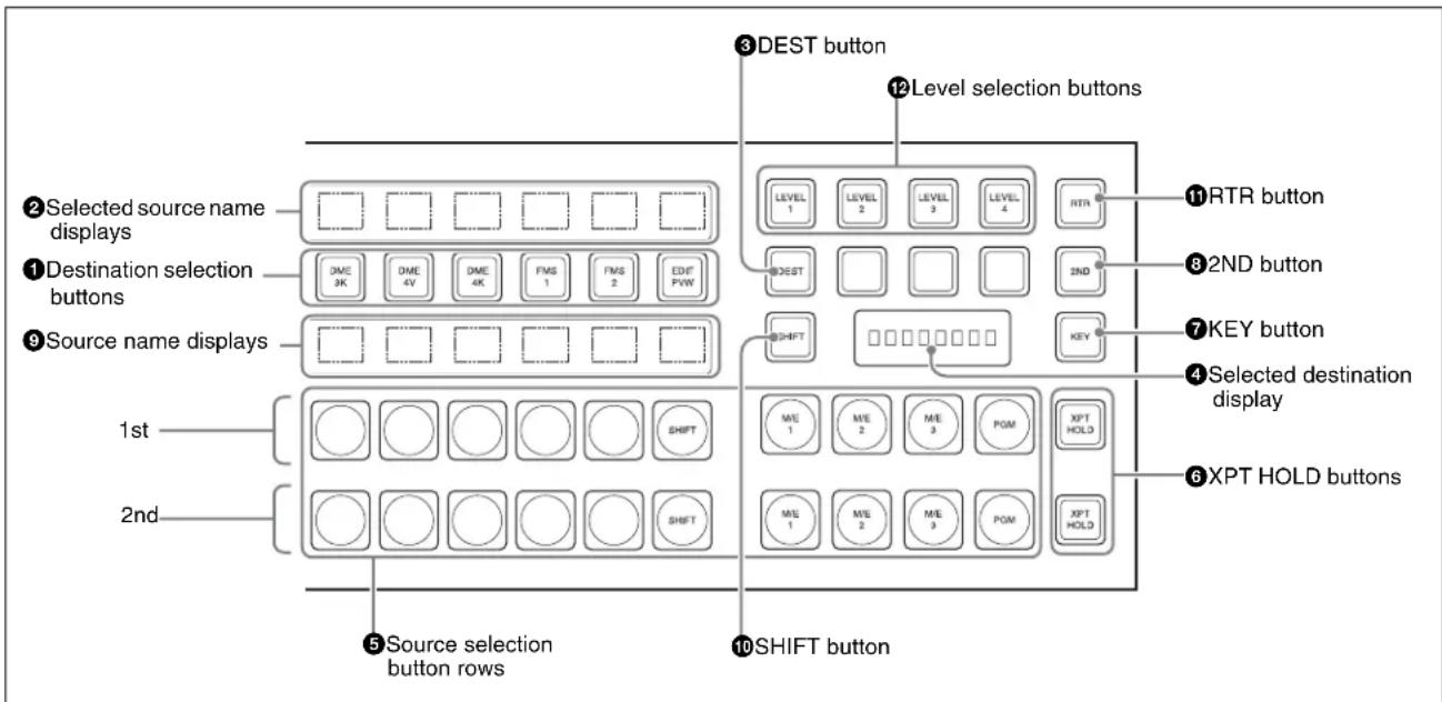
①Destination selection buttons
Press a button, turning it on, to select the destination to which the router source is assigned.
The button pressed to assign a destination to a source selection button in the 1st row lights amber. When another button is pressed to assign a different destination to a source selection button in the 2nd row, it lights green.
②Selected source name displays
These show the source name selected for the destination. If the source names and destination names are set in the Setup menu to "SW'er Local" mode, then the description names appear here.
③DEST (destination) button
Press this button, turning it on, to display the names of the destinations assigned to the destination selection buttons in the selected source name displays.
④Selected destination display
This shows the name of the destination selected by the destination selection buttons. If a protected destination is selected, the indication “PROTECT” appears.
⑤Source selection button rows
The destination selected with a destination selection button is assigned to a source selection button. Press a source selection button to select a source. The 1st row of buttons are source selection buttons for the unshifted destinations, and the 2nd row are shifted source selection buttons. By holding down the [2ND] button, and selecting a destination, you can assign a different destination from the 1st row to the 2nd row. In the 1st row, the button to which a destination is assigned lights amber. If a different destination is assigned to a button in the 2nd row, the button lights green.
When the 32nd button is set as a [SHIFT] button (in a 32-button system), you can select the shifted sources in the 1st and 2nd rows. Also, by using the [KEY] button, you can expand the source selection as follows.
| Source selection | [SHIFT] [KEY] Selection operation | |
| 1 to 31 Off Off | Press the source | selection button. |
| 32 to 62 On Off Press the [SHIFT] | button, then press the source selection button. | |
| 63 to 93 Off On Hold down the [KEY] | button, and press the source selection button. | |
| 94 to 124 On On Hold down the [KEY] | button, and press the [SHIFT] button, turning it on (the [SHIFT] button locks here, even when in Hold mode), then press the source selection button. | |
⑥XPT HOLD (cross-point hold) buttons
Not used in router control mode.
⑦KEY button
When this button is enabled by a setting in the Setup menu, by holding it down during a source selection you can expand the function of the [SHIFT] button.
See "Using the Auxiliary Bus Control Block for Router Control Setting Button" in Chapter 19 (Volume 2).
⑧2ND button
After selecting a destination with the destination selection buttons, hold down this button and make another destination selection to assign a different destination from the 1st row to the 2nd row.
⑨Source name displays
These display the names of signals (sources) that can be selected with the cross-point buttons. While the [SHIFT] button is active, the shifted signal names appear. While the [KEY] button is held down, the expanded signal names appear.
When a different destination is assigned to the 2nd row, the 2nd row signal names appear only while the [2ND] button is held down.
10SHIFT button
While this button is active, the source name displays show the shifted signal names. Press this button to toggle between the shifted and unshifted states.
⑪RTR (router) button
Press this button, turning it on, to assign the auxiliary bus control block to router control.
12Level selection buttons
To each of the four buttons, plural S-Bus levels are assigned in the Setup menu. Press a button, turning it on, to make operations apply to those S-Bus levels.
Menu Control Block
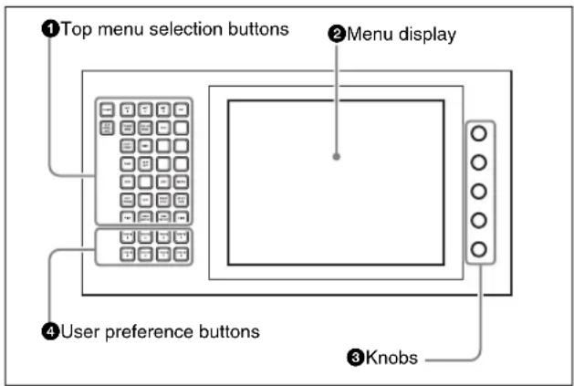
① Top menu selection buttons
These select the menu appearing in the menu display. It is also possible to change the assignment of these buttons in setup.
For details, see “Assigning Functions to the Menu Control Block Top Menu and User Preference Buttons” in Chapter 19 (Volume 2).
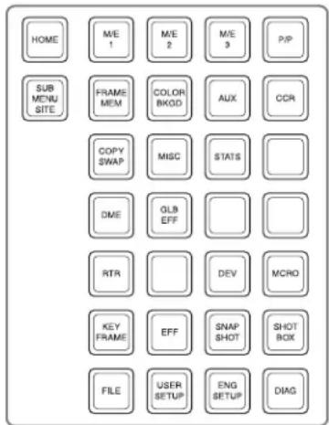
②Menu display
This shows the menu currently in use.
③Knobs
These adjust the parameter values appearing in the menu.
④User preference buttons
These recall the functions or menus assigned to them in the Setup menu.
In the default setup, nothing is assigned to the [PREFS 1] to [PREFS 7] buttons.
It is also possible to change the assignment of these buttons in setup.
For details, see “Assigning Functions to User Preference Buttons” in Chapter 19 (Volume 2).
PREFS 8 button: When this button is on, control of an editor from the Remote1 port on the rear panel of the switcher is possible. However, even when it is off, control of the Edit PVW bus is always possible.
Memory Card/USB Adaptor Block
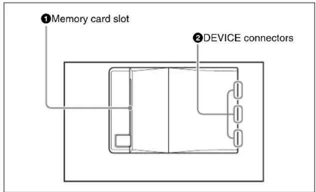
①Memory card slot
This slot accepts a PCMCIA Type II compliant memory card. You can use it in software installation, and for saving and reading in data, such as snapshot, keyframe, effect, and setup data.
②DEVICE connectors
There are three USB connectors.
You can connect a device such as a mouse, keyboard, USB storage, and so on, that is equipped with a USB interface to any of these connectors.
For details on the devices that can be connected, consult your Sony representative.
"Memory Stick"/USB Connections Block
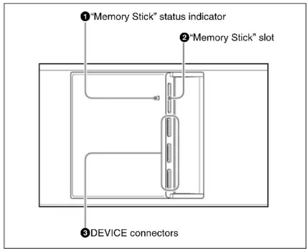
①"Memory Stick" status indicator
Lights in red during access to a "Memory Stick."
Notes
Do not power the unit off or remove a “Memory Stick” when the “Memory Stick” status indicator is lit.
②"Memory Stick" slot
Insert “Memory Sticks.” You can use it in software installation, and for saving and reading data, such as snapshot, keyframe, effect, and setup data.
See the next item, “About “Memory Sticks”” for more information about the usable “Memory Sticks” and their handling.
③DEVICE connectors
There are three USB connectors.
You can connect a device such as a mouse, keyboard, USB storage, and so on, that is equipped with a USB interface to any of these connectors.
For details on the devices that can be connected, consult your Sony representative.
About "Memory Sticks"
Usable "Memory Sticks"
This unit has been confirmed to operate with those of the following “Memory Sticks” that have a capacity of 8 GB (gigabytes) or less. However, operation with all “Memory Sticks” is not guaranteed.
• “Memory Stick”
- "Memory Stick PRO"
• “Memory Stick Duo”
• "Memory Stick PRO Duo"
Notes
- When using a “Memory Stick PRO,” high-rate data transfer using parallel interface is not supported.
- A "MagicGate Memory Stick" can also be used, but this system does not support the MagicGate function.
- When using a “Memory Stick Duo,” be sure to use it with a “Memory Stick Duo Adaptor” (MSAC-M2 or equivalent). If you insert a “Memory Stick Duo” without using the adaptor, there is the possibility that the stick cannot be removed, resulting in a serious accident.
Handling "Memory Sticks"
When using “Memory Sticks,” pay attention to the following points.
- Do not touch the connector of the “Memory Stick” with anything, including your finger or metallic objects.
- Do not attach anything other than the supplied label to the "Memory Stick" labeling position.
- Attach the label so that it does not stick out beyond the labeling position.
- Carry and store the "Memory Stick" in its case.
- Do not strike, bend, or drop the "Memory Stick."
- Do not disassemble or modify the "Memory Stick."
- Do not allow the "Memory Stick" to get wet.
- Do not use or store the “Memory Stick” in a location that is:
- Extremely hot, such as in a car parked in the sun
- Under direct sunlight
- Very humid or subject to corrosive substances
Utility/Shotbox Control Block
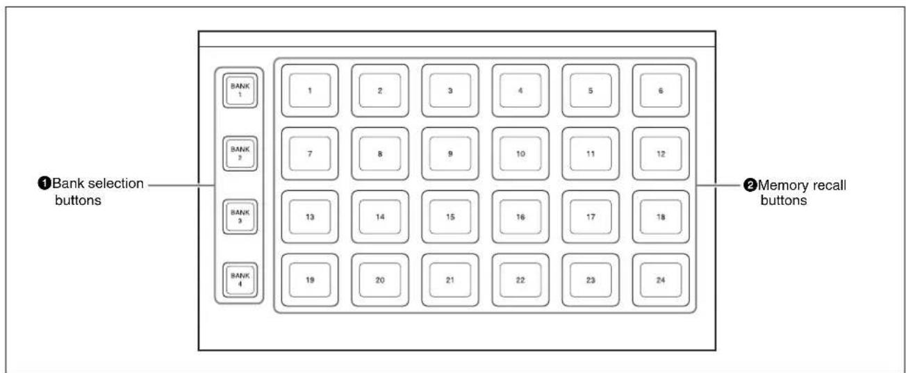
①Bank selection buttons
Press any of the [BANK1] to [BANK4] buttons to select a bank of 24 memory recall buttons. The selected button lights amber.
②Memory recall buttons
You can use these buttons to recall frequently used menus, utility functions, shotbox registers, or macro registers that you have assigned.
When a utility function is allocated to a button, the button lights orange (or green depending on the status), and the allocated function name appears.
Pressing the button executes the allocated function. When the function constitutes a switching on/off operation, the button lights green; otherwise, it only momentarily lights green.
When a shotbox register or macro register recall is assigned to a button, the button lights orange, and the
assigned register name appears. (If the register is empty, the button goes off.) In the case of a shotbox function, pressing the button executes the assigned shotbox function, and the button lights yellow. In the case of a macro register, pressing the button executes the assigned macro, and the button flashes yellow.
You can also assign enabling and disabling of macro attachment to use as the MCRO ATTCH ENBL button. You can make a setup setting such that when MCRO ATTCH ENBL is On, the buttons for which a macro attachment is set light.
For details, see "Assigning a Function to a Memory Recall Button in the Utility/Shotbox Control Block" in Chapter 19 (Volume 2).
Transition Control Block and Flexi Pad Control Block (Simple Type)
The simple versions of the transition control block and Flexi Pad control block shown in the following figure is designed to allow simplified operations than with the
standard type. The transitions carried out using these simple-type control blocks are also referred to as “simple transitions” in this User’s guide.
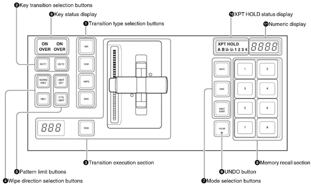
Shown above is the right-hand type transition control block (with the right-hand fader lever).
Transition Control Block and Flexi Pad Control Block (with INH button)
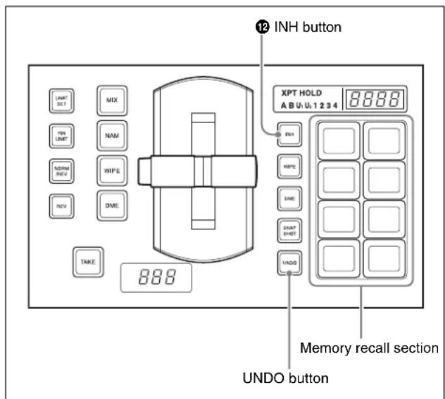
① Transition type selection buttons
You can assign these buttons in setup to any transition type.
For details, see “Overall Control Panel Settings (Config Menu)” in Chapter 19 (Volume 2).
Press any of the following buttons, turning it on, to select the transition type.
Press one of these buttons, turning it on, to determine the type of the next transition for a background.
To select the key transition type (see page 92), hold down the [KEY1] or [KEY2] button, and press one of the following buttons, turning it on.
When multi-program mode is selected in the Setup menu, two or more of the following buttons may light.
For details, see “Setting the Operation Mode” in Chapter 20 (Volume 2).
You can also assign a function to these buttons to select whether or not the fader levers are used as key frame faders.
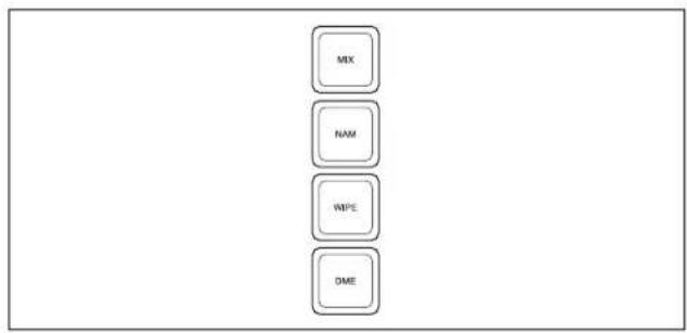
flowchart
graph TD
    A["MIX"] --> B["NAM"]
    B --> C["WIPE"]
    C --> D["DME"]
| Name Description | |
| MIX In a background transition, the new video fades in as the current video fades out. | |
| NAM (non-additive mix) | The current and new video signals are compared, and the signal with the higher luminance level is given priority in the output. |
| WIPE (DME wipe) | The current video is replaced by the new video, using the wipe pattern selected in the Wipe menu. |
| DME A wipe type of transition is carried out, using the DME effect selected in the DME Wipe menu. | |
| FM1&2CLIP, FM3&4CLIP, FM5&6CLIP, FM7&8CLIP | A recorded clip is played back together with the transition. At this point, you can also carry out a transition (wipe or mix (dissolve)) simultaneously together with the clip. |
| KF (keyframe) | Press this button, turning it on, to enable using the fader lever as a keyframe fader. |
②Key transition selection buttons
To insert or delete key 1 on the next transition, hold down the [KEY1] button, and select the type of transition using the transition type selection buttons. If the key is currently not inserted, the transition will insert it, and if the key is currently inserted, the transition will delete it. You can use the [KEY2] button in a similar way.
While these buttons are held down, you can select a key source with the cross-point buttons on the key bus.
Pressing one of these buttons twice in rapid succession changes the state of the corresponding key bus so that a cross-point can be selected.
③ Transition execution section
This section is used to execute a transition, and check the progress of the transition.
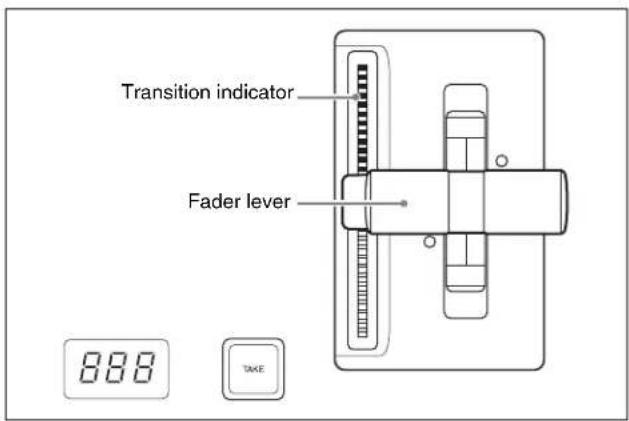
| Name Description | |
| Fader lever | Move this vertically to carry out a transition.When the [KF] button or a transition type selection button to which the KF button function has been assigned is lit, you can use this as a key frame fader.When the split fader function is enabled, by pressing the projection on the left side of the grip you can release the lock and separate the two halves of the fader lever. With the split fader lever, in a background mix transition, you can control the background A and B buses independently. |
| Transition indicator | This comprises multiple LEDs, which show the progress of the transition. |
| Transition rate display | This displays the transition rate (the time from the beginning of the transition to its completion) set for an auto transition, in frames.You can set the transition rate using the numeric keypad control block or menu. |
| TAKE button | Pressing this button carries out an auto transition of the set transition rate. The transition starts immediately, and the button lights amber.When the transition completes, the button goes off. |
④ Wipe direction selection buttons
For details, see "Wipe direction selection buttons" (page 36).
⑤Pattern limit buttons
The following buttons are used to set a pattern limit.

flowchart
graph TD
    A["LIMIT SET"] --> B["PTN LIMIT"]
| Name Description | |
| LIMIT SET | Move the fader lever to the position of a particular pattern size, and stop it there, then press this button to set the pattern limit range.This button is enabled when the [PTN LIMIT] button is off. |
| PTN (pattern) LIMIT | When a wipe or DME wipe is selected, pressing this button, turning it on, enables the pattern limit function. |
⑥Key status display
For each of keys 1 and 2, when the key is inserted, the corresponding ON indicator lights. The OVER indicators show the priority between keys 1 and 2, by lighting when the corresponding key is on top. For example, when key 1 appears over key 2 on the program monitor, the OVER indicator for key 1 lights.
The following is the Flexi Pad control block.
⑦ Mode selection buttons
The following buttons are used to save and recall a snapshot, wipe snapshot, and DME wipe snapshot.

flowchart
graph TD
    A["WIPE"] --> B["DME"]
    B --> C["SNAP BHOIT"]
| Name Description | |
| WIPE When | saving or recalling a wipe snapshot, use this in combination with the buttons of the memory recall section. |
| DME When | saving or recalling a DME wipe snapshot, use this in combination with the buttons of the memory recall section. |
| SNAPSHOT | When saving or recalling a snapshot, use this in combination with the buttons of the memory recall section. |
⑧ Memory recall section
This consists of eight buttons with LCDs, whose display changes according to the operation mode. Use these in combination with the mode selection buttons to save or recall wipe snapshots, DME wipe snapshots, or snapshots.
⑨ UNDO button
After recalling a register, press this button to return to the state before recalling the register.
With a setup setting, this can be switched to a mode selection button for macro setting, and used in combination with the buttons in the memory recall section for recalling and executing a macro.
10XPT HOLD (cross-point hold) status display
A bus for which cross-point hold is set appears as a green light.
⑪Numeric display
Depending on the operation mode, this shows a wipe or DME wipe pattern number, or a register number in up to four digits.
In macro mode, this provides indications for macro editing.
⑫INH (inhibit) button
Pressing this button, turning it on, disables the buttons in the memory recall section and the [UNDO] button.
Independent Key Transition Control Block (Simple Type)
The left side of this control block controls key 3, and the right side controls key 4.
The control block for key 3 only is described as an example, but the operations on the key 4 control block are the same.
In setup you can assign any key to either side of this control block.
You can also assign the key selection function (key delegation) for keys 1 to 8 to any buttons in this control block.
For details, see “Assigning Keys to the Independent Key Transition Control Block (Simple Type)” in Chapter 19 (Volume 2).
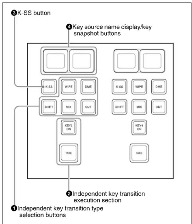
flowchart
graph TD
    A["① Independent key transition type selection buttons"] --> B["② Independent key transition execution section"]
    B --> C["③ K-SS button"]
    B --> D["④ Key source name display/key snapshot buttons"]
    C --> E["KEY3 ON"]
    C --> F["TAKE"]
    D --> G["K-SS"]
    D --> H["WIPCE"]
    D --> I["DME"]
    D --> J["SHIFT"]
    D --> K["MIX"]
    D --> L["CUT"]
    D --> M["KEY4 ON"]
    D --> N["TAKE"]
①Independent key transition type selection buttons
Press one of the following buttons, turning it on, to select the independent key transition type.

| Name Description | |
| MIX Faded in or out. | |
| WIPE Inserted or deleted with a wipe. | |
| DME Switches the key with a DME wipe. | |
| CUT Inserted or deleted instantaneously. | |
| SHIFT • When setting is made in the Setup menu to allow a different transition type for inserting or deleting a key, it is possible to display and set the transition type after the next transition while this button is held down.While this button is held down, you can select a key source with the cross-point buttons for the key bus.If you press this button twice in rapid succession, the key bus selection button [KEY3] in the cross-point control block lights, and a key 3 key bus cross-point can be selected.If you press this button, while holding down [TRANS RATE] button in the numeric keypad control block, you can set the independent key transition rate on the control block. |
②Independent key transition execution section
The following buttons are used to carry out independent key transition operations.
flowchart
graph TD
    A["KEY3 ON"] --> B["TAKE"]
| Name Description | |
| KEY3 ON • This inserts or deletes key 3 instantaneously. - When key 3 is present in the final program output from the switcher, this lights red, and otherwise lights amber. | |
| TAKE This carries out an auto transition on key 3. |
③K-SS (key snapshot) button
This enables key snapshot mode. In key snapshot mode, it is possible to save and recall key snapshots.
④ Key source name display/key snapshot buttons
These show the signal name of the key fill selected for key 3 and the transition rate on two buttons. In key snapshot mode, these correspond to registers 1 and 2 for key 3; press to save or recall a key snapshot.
To save a key snapshot, with the [K-SS] button lit amber, hold down [SHIFT] button and press one of the key snapshot buttons.
This saves a key snapshot in the button you pressed, which lights yellow.
By assigning [K-SS 3/4] to a key in the Setup menu, you can press the button to switch between key snapshot registers 1/2 and 3/4.
For details, see the section “Assigning a Function to the Independent Key Transition Control Block (Simple Type)” in Chapter 19 (Volume 2).
Downstream Key Control Block
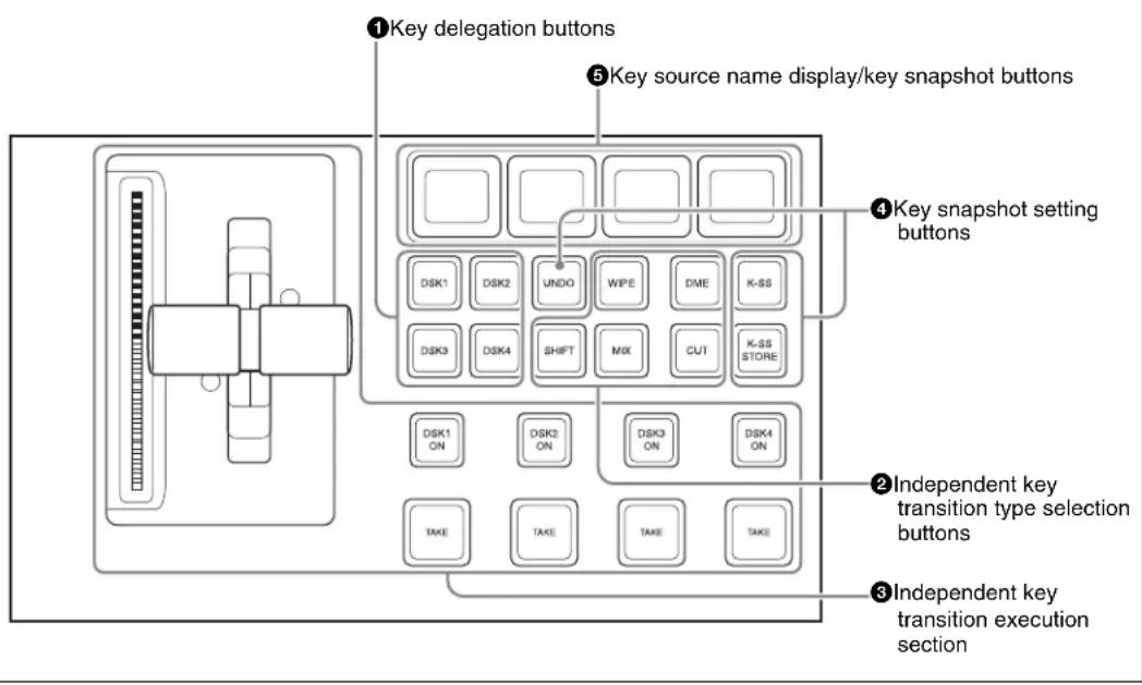
①Key delegation buttons
Press one of the [DSK1] to [DSK4] buttons to delegate this control block to the corresponding keyer.
Using the Setup menu, it is possible to assign these to DSK5 to DSK8 or M/E keys 1 to 8.
While these buttons are held down, you can select a key source with the cross-point buttons for the key bus.
Pressing one of these buttons twice in rapid succession changes its state so that you can make cross-point selections on the corresponding key bus.
②Independent key transition type selection buttons
Press one of these buttons, turning it on, to select the downstream key transition type.
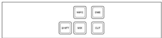
| Name Description | |
| MIX Carry out | a dissolve with the key selected with the key delegation buttons. |
| WIPE Carry out | a wipe with the key selected with the key delegation buttons. |
| DME This switches the key selected with the key delegation buttons, using a DME wipe. | |
| CUT Instantaneously insert or delete the key selected with the key delegation buttons. | |
| Name Description | |
| SHIFT When | setting is made in the Setup menu to allow a different transition type for inserting or deleting a key, it is possible to display and set the transition after the next transition while this button is held down. |
③Independent key transition execution section
This section is used to carry out an independent key transition, and check the progress of the transition.
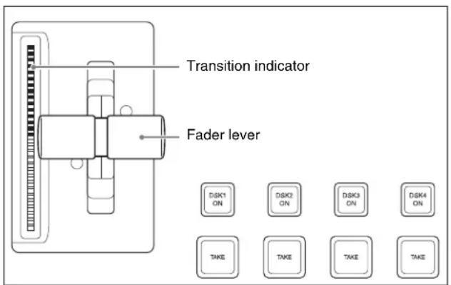
| Name Description | |
| DSK1(downstream key 1)ON to DSK4ON buttons | Press these to instantaneously cut the downstream keys 1, 2, 3, and 4 in or, when the downstream keys are already inserted, cut them out.When the key corresponding to the button appears in the final program output, the button lights red, and otherwise lights amber. |
| TAKEbuttons | These correspond to downstream keys 1, 2, 3, and 4 from left to right; press to execute an auto transition. The transition starts immediately, and the button lights amber.When the transition completes, the button goes off. |
| Fader lever | Move this vertically to carry out a manual downstream key transition. |
| Transition indicator | This comprises multiple LEDs, which show the progress of the downstream key transition. |
④Key snapshot setting buttons
Pressing the following buttons carries out key snapshot operations.
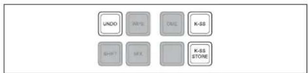
| Name Description | |
| K-SS (key snapshot) | This enables key snapshot mode. |
| K-SS STORE (key snapshot store) | To save a key snapshot, hold down this button, and press the key source name display/key snapshot button for the register you want to save. |
| UNDO (key snapshot recall undo) | This undoes the last key snapshot recall. |
⑤Key source name display/key snapshot buttons
These display the selected source name for each corresponding keyer. In snapshot mode, they correspond to registers 1 to 4 of the selected keyer, and pressing the button saves or recalls a key snapshot.
Downstream Key/Fade-to-Black Control Block
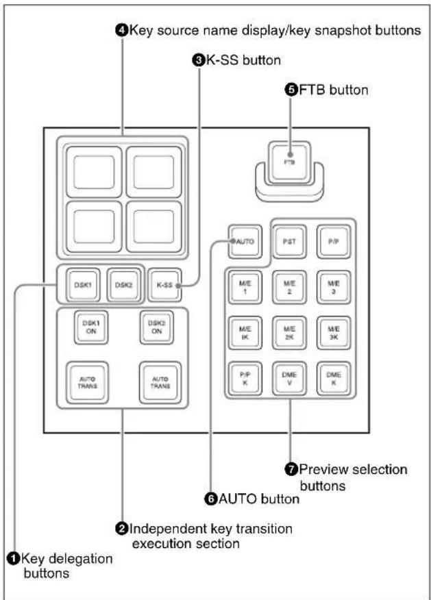
flowchart
graph TD
    A["Key source name display/key snapshot buttons"] --> B["Key delegation buttons"]
    C["K-SS button"] --> D["Key source name display/key snapshot buttons"]
    E["FTB button"] --> F["Key source name display/key snapshot buttons"]
    G["Auto"] --> H["Preview selection buttons"]
    I["AUTO"] --> J["AUTO button"]
    K["Independent key transition execution section"] --> L["Key delegation buttons"]
    M["DSK1 ON"] --> N["DSK2 ON"]
    O["DSK1"] --> P["DSK2"]
    Q["AUTO TRANS"] --> R["AUTO TRANS"]
    S["ME 1"] --> T["M/E 2"]
    U["ME 3"] --> V["M/E 3"]
    W["ME IK"] --> X["M/E 2K"]
    Y["P/P K"] --> Z["DME V"]
    AA["DTB"] --> AB["PST"]
    AC["Auto"] --> AD["P/P"]
①Key delegation buttons
Press DSK1 or DSK2, to select the keyer. Each button can be assigned to any key in setup.
For details, see "Assigning Keys to the DSK1 and DSK2 Buttons in the Downstream Key/Fade-to-Black Control Block" in Chapter 19 (Volume 2).
While these buttons are held down, you can select a key source with the cross-point buttons on the key bus. Pressing one of these buttons twice in rapid succession changes its state so that you can make cross-point selections on the corresponding key bus in the PGM/PST bank.
②Independent key transition execution section
Pressing the following buttons carries out transition operations of the corresponding downstream key.

flowchart
graph TD
    A["DSK1 ON"] --> B["AUTO TRANS"]
    C["DSK2 ON"] --> D["AUTO TRANS"]
| Name Description | |
| DSK1 ON, DSK2 ON | Press these to cut in the corresponding downstream key 1 or 2.When the key is already inserted, pressing the button cuts it out.Each button lights red when the corresponding key is inserted in the program output (final output from the switcher), and lights amber at other times. |
| AUTO TRANS | The left button applies to DSK1 and the right button to DSK2; press these buttons to carry out an auto transition.The transition immediately starts, and the button lights amber.When the transition completes, the button goes off. |
③K-SS (key snapshot) button
Pressing this button, turning it on, enables the key snapshot mode. In this mode, you can save and recall key snapshots.
④Key source name display/key snapshot buttons
Each column of two buttons relates to the corresponding downstream key 1 or 2. The upper button displays the name of the key fill signal selected for the key, and the lower button shows the transition rate. In key snapshot mode, these buttons correspond to registers 1 to 4 of the keyer selected with the key delegation buttons, and pressing a button recalls the key snapshot. To save a key snapshot, hold down the [STORE] button in the numeric keypad control block, and press the button for the desired register.
⑤FTB (fade to black) button
Press this button to fade to black the program output of the PGM/PST bank, at the set transition rate. You can set the fade to black transition rate in the menu.
6 AUTO button
When this button is pressed, the M/E or PGM/PST bank preview signal selected on the edit preview bus is automatically switched to the program signal depending on the on-air status.
⑦Preview selection buttons
Press one of these buttons to select a signal on the edit preview bus. Each of these buttons can be assigned to any key in setup.
For details, see “Assigning Preview Output to Preview Selection Buttons” in Chapter 19 (Volume 2).
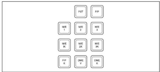
| Name Description | |
| PST(preset) | When this button is pressed, the signal selected on the background B row of the PGM/PST bank is selected on the edit preview bus. |
| M/E 1 to M/E 4, P/P(M/E1 to M/E 4, P/P preview) | The preview signal (M/E-1 PVW, M/E-2 PVW, M/E-3 PVW, M/E-4 PVW, P/P PVW) of the M/E or PGM/PST bank corresponding to the pressed button is selected on the edit preview bus.For details of [M/E 4] button assignment, see “Assigning a Button for M/E-4 Selection in the Setup Menu” (page 387) in Appendix. |
| M/E1 K to M/E4 K, P/P K (M/E1 to M/E 4, P/P key preview) | The key preview signal (M/E-1 K-PVW, M/E-2 K-PVW, M/E-3 K-PVW, M/E-4 K-PVW, P/P K-PVW) of the M/E or PGM/PST bank corresponding to the pressed button is selected on the edit preview bus.For details of [M/E 4] button assignment, see ““Assigning a Button for M/E-4 Selection in the Setup Menu” (page 387) in Appendix. |
| DME V(DME monitor video) | When this button is pressed, the DME monitor output video signal (DME MON V) is selected on the edit preview bus. |
| DME K(DME monitor key) | When this button is pressed, the DME monitor output key signal (DME MON K) is selected on the edit preview bus. |
Transition Control Block (Compact Type)
The compact version of the transition control block shown in the following figure has fewer buttons than the standard type. Independent key transition operations can also be controlled with the compact transition control block.
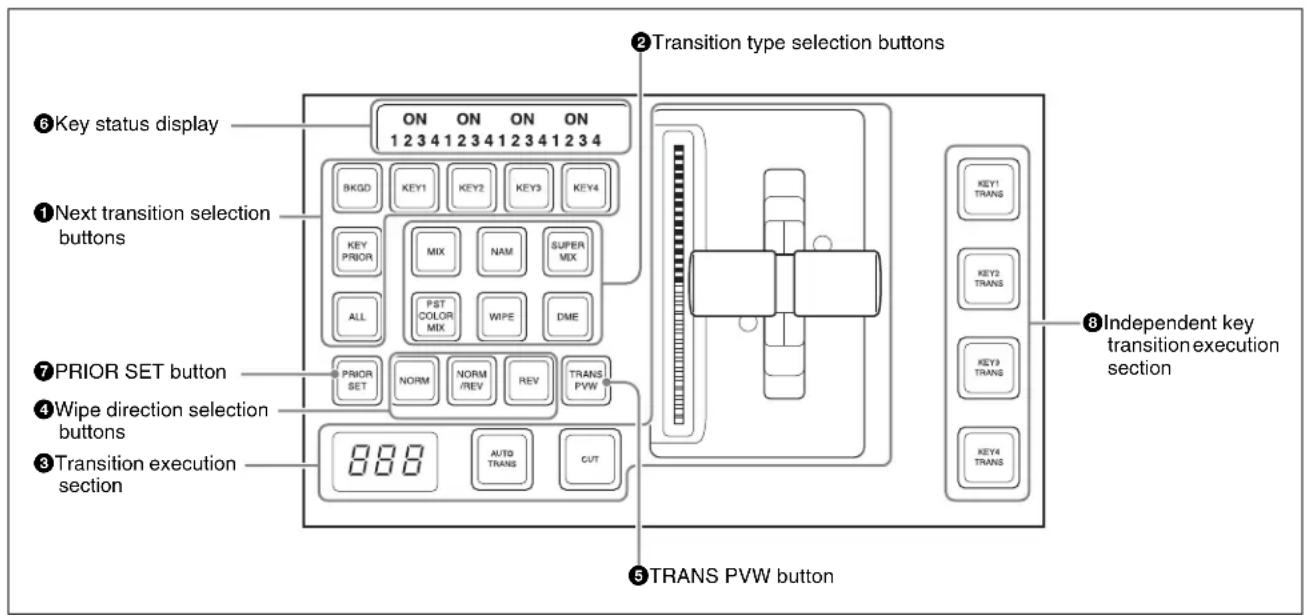
①Next transition selection buttons
Press these buttons, turning them on, to determine what the next transition will apply to.
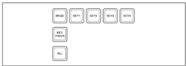
flowchart
graph TD
    A["BKG"] --> B["KEY1"]
    B --> C["KEY2"]
    C --> D["KEY3"]
    D --> E["KEY4"]
    F["KEY PRIOR"] --> G["ALL"]
| Name Description | |
| BKGD Next transition changes the background. | |
| KEY1 to KEY8 (DSK1 to DSK8 in the PGM/PST bank) | Press this button, turning it on, to make the next transition insert or remove the corresponding key (keys 1 to 8).If a key is currently inserted it will be removed, and if it is not currently inserted, it will be inserted.In the PGM/PST bank, this inserts or removes downstream keys 1 to 8.For details of assignment and selection of keys 5 to 8, see the “Assigning Buttons for Selection of Keys 5 to 8 in the Setup Menu” (page 388) and “‘Selecting Keys 5 to 8 for Next Transition” (page 389). |
| KEY PRIOR (priority) | When this button is lit, the setting of the key priority after the next transition is enabled.The key priority after the next transition appears in the key status display. |
| ALL • Pressing | this button turns on a preselected set of the [BKGD], [KEY1] to [KEY8], and [KEY PRIOR] buttons.Make this setting in a Setup menu. |
② Transition type selection buttons
You can assign these buttons in setup to any transition type.
For details, see “Setting Transition Control Block Button Assignments” in Chapter 19 (Volume 2).
Press one of these buttons, turning it on, to determine the type of the next transition (see page 92).
When multi-program mode is selected in the Setup menu, two or more of the following buttons may light.
For details, see “Settings for Switcher Configuration (Config Menu)” in Chapter 20 (Volume 2).
You can also assign a function to these buttons to select whether or not the fader levers are used as keyframe faders.
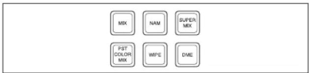
| Name Description | |
| MIX In a background transition, the new video fades in as the current video fades out. | |
| NAM (non-additive mix) | The current and new video signals are compared, and the signal with the higher luminance level is given priority in the output. |
| SUPER MIX | The current video is maintained at 100% output for the first half of the transition as the new video is mixed while increasing progressively to 100%. |
| PST (preset) COLOR MIX | The color matte (unpatterned display) is inserted during transition, replacing the current video by the color matte, and then replacing the color matte by the new video. |
| WIPE (DME wipe) | The current video is replaced by the new video, using the wipe pattern selected in the Wipe menu. |
| DME A wipe type of transition is carried out, using the DME effect selected in the DME Wipe menu. | |
| FM1&2CLIP, FM3&4CLIP, FM5&6CLIP, FM7&8CLIP | A recorded clip is played back together with the transition. At this point, you can also carry out a transition (wipe or mix (dissolve)) simultaneously together with the clip. |
| KF (keyframe) | Press this button, turning it on, to enable using the fader lever as a keyframe fader. |
③ Transition execution section
This section is used to carry out a transition, and check the signal status during the transition.
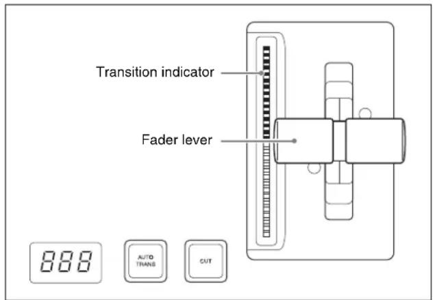
| Name Description | |
| Transition indicator | This comprises multiple LEDs, which show the progress of the transition. |
| Fader lever | Move this vertically to carry out a manual transition.When the [KF] button or a transition type selection button to which the KF button function has been assigned is lit, you can use this as a keyframe fader. |
| Transition rate display | This shows the “transition rate” (the time from the beginning of a transition to its completion) set for an auto transition, in frames.You can set the transition rate using the numeric keypad control block, Flexi Pad control block, or menu. |


| Name Description | |
| AUTO TRANS (transition) button | Pressing this button carries out an auto transition of the set transition rate (duration). The transition starts immediately, and the button lights amber.When the transition completes, the button goes off. |
| CUT button | Pressing this button carries out the transition as a cut (i.e. instantaneously). |
④ Wipe direction selection buttons
For details, see “Wipe direction selection buttons” (page 36).
⑤TRANS PVW (transition preview) button
When this button is lit, you can check in advance the video changes during the transition, on the preview output from the M/E or PGM/PST bank.
During the preview, you can use the fader lever, [AUTO TRANS] button, and [CUT] button. One of the following functions of this button can be selected in a Setup menu.
- When the transition completes, the system returns to the normal mode.
- The transition preview mode is maintained while this button is pressed.
- Switching is made between the transition preview mode and normal mode every time this button is pressed.
⑥Key status display
For each of keys 1 to 4, the corresponding ON indicator lights when the key is inserted. It also shows the priority (1 to 4) of each key.
⑦PRIOR (priority) SET button
While this button is held down, you can set the key priority.
The setting mode when this button is pressed depends on whether or not the [KEY PRIOR] button is lit, as follows.
- When the [KEY PRIOR] button is off, the current key priority is set.
- When the [KEY PRIOR] button is lit, the key priority after the next transition is set.
Press the [KEY PRIOR] button as required, to switch between these two modes.
In either mode, hold down the [PRIOR SET] button, and press the button ([KEY1] to [KEY8]) corresponding to the key you want to bring to the front.
Notes
The key priority establishes a separate priority order within each of the groups of keys 1 to 4 and keys 5 to 8. You can make any setting within the groups of keys 1 to 4 or keys 5 to 8, but not for combinations of keys from different groups. For example, it is not possible to set a priority sequence of keys 1, 5, and 2.
For details, see “Setting the Key Priority in the Transition Control Block” (page 95).
⑧Independent key transition execution section KEY1 TRANS (transition) to KEY8 TRANS (DSK1 TRANS to DSK8 TRANS in the PGM/PST block)
buttons: Press the corresponding one of these buttons to cut key 1 to key 8 in or out automatically at the set transition rate. When the key corresponding to the button appears in the final program output, the button lights red, and otherwise lights amber. During a transition, the button lights green.
CCP-6224 2M/E Control Panel
In this system, you can use the built-in CCP-6224 2M/E Control Panel. This panel has two cross-point control blocks, two transition control blocks (compact type), one
device control block (track ball), and one Multifunction Flexi Pad control block.
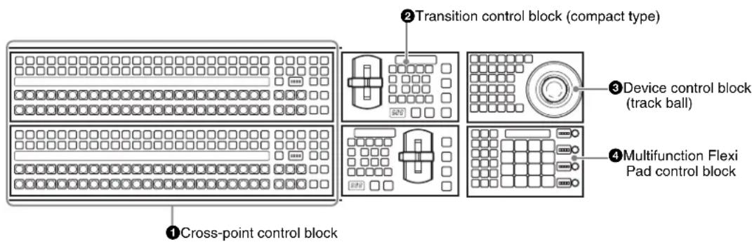
①Cross-point control block
For details of cross-point control block operation, see "Cross-Point Control Block" (page 29).
For operations in AUX control mode, see “Auxiliary Bus Control Block (for AUX Buses)” (page 53) and “Cross-Point Control Block (CCP-6224/6324) in the AUX Operating Mode” (page 69).
② Transition control block (compact type)
For details of operations, see “Transition Control Block (Compact Type)” (page 65).
③Device control block (track ball)
For details of operations, see “Device Control Block (Trackball)” (page 42).
④ Multifunction Flexi Pad control block
For details of operations, see “Multifunction Flexi Pad Control Block” (page 70).
CCP-6324 3M/E Control Panel
In this system, you can use the built-in CCP-6324 3M/E Control Panel. This panel has three cross-point control blocks, three transition control blocks (compact type), one device control block (trackball), and one Multifunction Flexi Pad control block.
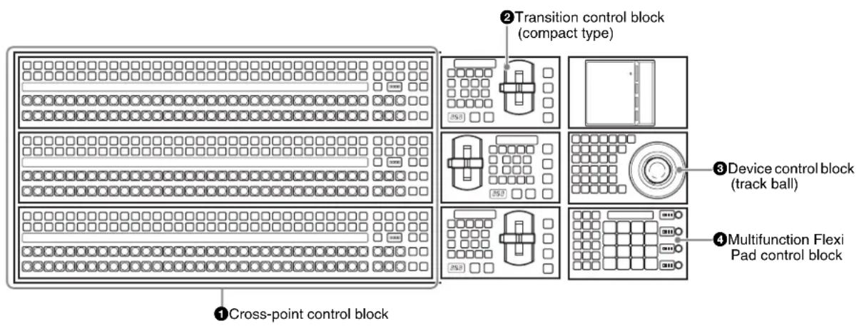
① Cross-point control block
For details of operations, see “Cross-Point Control Block” (page 29) and “CCP-6224 2M/E Control Panel” (page 68).
② Transition control block (compact type)
For details of operations, see “Transition Control Block (Compact Type)” (page 65).
③Device control block (track ball)
For details of operations, see “Device Control Block (Trackball)” (page 42).
④Multifunction Flexi Pad control block
For details of operations, see “Multifunction Flexi Pad Control Block” (page 70).
Cross-Point Control Block (CCP-6224/6324) in the AUX Operating Mode
On the CCP-6224/6324, when using a [24-column] cross-point control block, if the [PRE MCRO] button is assigned to switch to AUX operating mode, by pressing this button
you can switch the control block button functions as follows, and select the AUX bus and its source signals (AUX panel-less function).
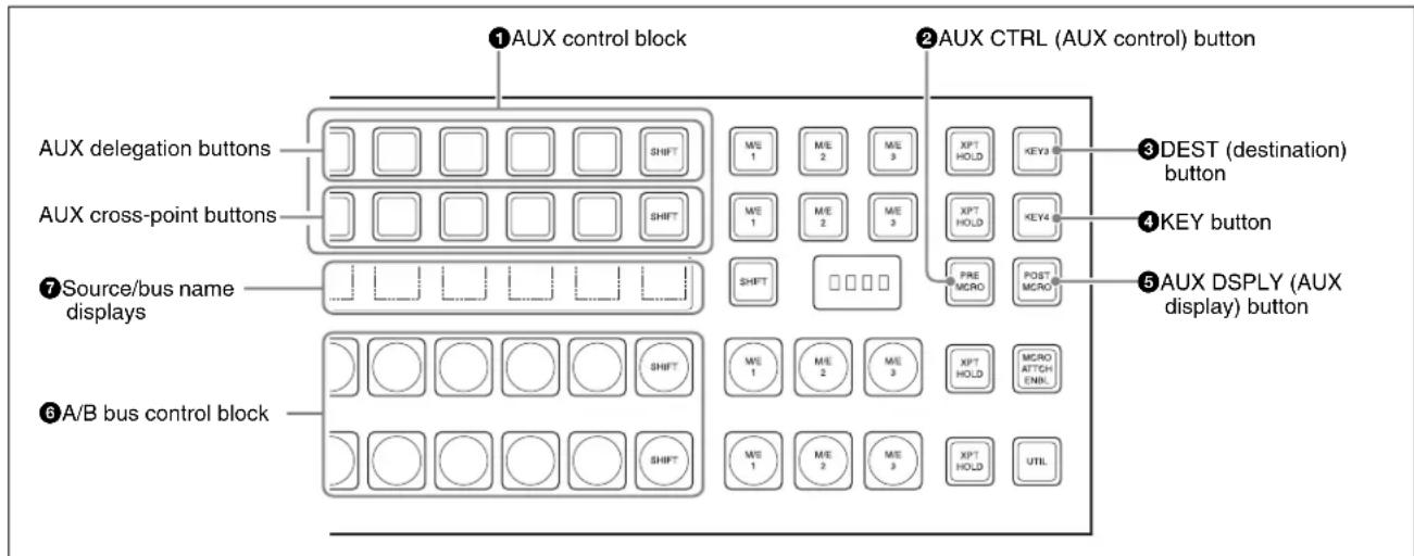
① AUX control block
This selects the AUX bus and the assigned source signals. This cross-point control block can be switched to AUX control mode with the [AUX CTRL] button, and the key 1
row used as AUX delegation buttons, and the key 2 row used as AUX bus cross-point selection buttons, with the source name display showing the source names or the bus names (AUX panel-less function). To use this function, the
function for switching to AUX control mode must first be assigned to the [PRE MCRO] and [POST MCRO] buttons.
For the method of making this assignment, see Chapter 19 "Assigning the AUX Bus Control Mode Switching Function" (Volume 2).
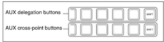
| Name Description | |
| AUX delegation buttons | These select the AUX bus.When you press a button, turning it on, this selects the assigned bus as the AUX bus.You can make the rightmost button a [SHIFT] button, in which case each button can be used to select two buses.For details of the buses that can be selected, see “Bus Selection” (page 86). |
| AUX cross-point buttons | These select the source signal to be assigned to the AUX bus.When you press a button, turning it on, this selects the assigned video/key source signal and assigns it to the bus selected with the AUX delegation buttons.To select a key, hold down the [KEY] button and press the AUX cross-point button to which the desired key signal is assigned.You can make the rightmost button a [SHIFT] button, in which case each button can be used to select two video/key source signals.When one of the DME 1V/K to 4V/K buses is selected with the AUX delegation buttons, this selects the video side currently visible on the DME, and if you hold down the AUX delegation button, you can also select the reverse side of the video. |
Multifunction Flexi Pad Control Block
You can use the Multifunction Flexi Pad control block for creating, saving, and recalling snapshots, wipe snapshots, and DME wipe snapshot key snapshots, effects, shotbox recall, macro execution, transition rate settings, and key adjustments.
② AUX CTRL (AUX control) button
This switches the cross-point control block to the AUX operating mode. However, using this function requires an assignment to have been made in the Setup menu.
For details of assigning the function for switching to AUX operating mode, see “Assigning the AUX Bus Control Mode Switching Function” in Chapter 19 (Volume 2).
③DEST (destination) button
When you press this button, turning it on, the source name displays show the names of the buses assigned to the AUX delegation buttons.
④ KEY button
When you press this button, turning it on, the source name displays show the names of the key source signals assigned to the AUX cross-point buttons, and they are now selectable.
⑤ AUX DSPLY (AUX display) button
This switches the source name displays to the AUX operating mode (by default showing the video source signal names).
⑥A/B bus control block
Select the source signals for the background A/B buses.
⑦ Source/bus name displays
In the AUX operating mode, these show the information in the following table, according to the states of the [AUX DSPLY], [DEST], and [KEY] buttons.
| [AUX DSPLY] | [DEST] | [KEY] Indication |
| Off Off Off Background A/B bus source signal names | ||
| On Off Off Video source signal names for AUX bus | ||
| On On Off Bus names for AUX bus | ||
| On Off On Key source signal names for AUX bus | ||
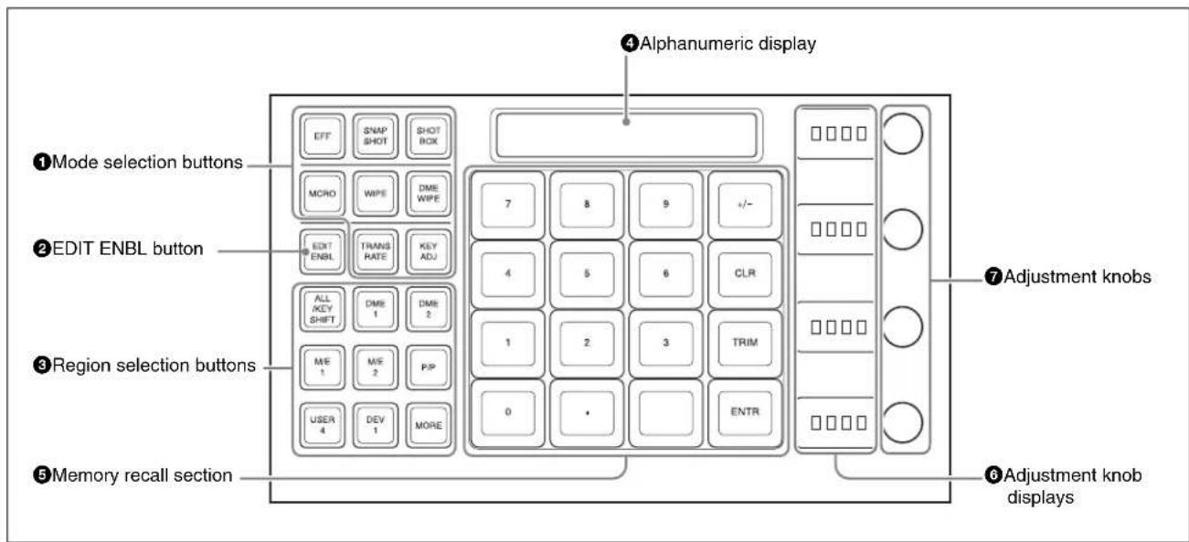
① Mode selection buttons
Pressing the following buttons selects the mode.
flowchart
graph TD
    A["EFF"] --> B["MCRO"]
    C["SNAP SHOT"] --> D["WIPE"]
    E["SHOT BOX"] --> F["DME WIPE"]
    G["TRANS RATE"] --> H["KEY ADJ"]
| Name Description | |
| EFF (effect) | Press this to carry out effect creation/recall/editing/execution/deletion. |
| SNAPSHOT | Press this to carry out snapshot creation/recall/editing/deletion. |
| SHOTBOX | Press this to carry out shotbox creation/recall/editing/execution/deletion. |
| MCRO (macro) | Press this to carry out macro creation/editing/execution/deletion. |
| WIPE (wipe snapshot) | Press this to carry out wipe snapshot creation/recall/deletion and wipe adjustments. |
| DME WIPE (DME wipe snapshot) | Press this to carry out DME wipe snapshot creation/recall/deletion and DME wipe adjustments. |
| TRANS RATE (transition rate) | Press this to set the transition rate. |
| KEY ADJ (key adjust) | Press this to carry out key adjustments and set modifiers. |
| KEY SS (key snapshot) | Press this to carry out key snapshot creation/recall/deletion.By default, this is not assigned to a mode selection button, so before use it is necessary to assign to a mode selection button in the Setup menu. |
②EDIT ENBL (edit enable) button
By pressing this, turning it on, you can carry out the following operations.
• Effect creation/editing
- Snapshot attribute setting
- Shotbox creation/editing
- Macro creation/editing
- Wipe adjustments
• DME wipe adjustments
③Region selection buttons
These select the function block to which operations apply. When the mode selection button selection is EFF/SNAPSHOT/SHOT BOX/MCRO, you can select multiple region selection buttons simultaneously. In this case, the first button pressed lights green as the reference region, and the other buttons pressed light amber (the buttons for the regions shown in the memory recall section are yellow).

| Name Description | |
| ALL/KEY SHIFT | Selects all regions.When any region is selected, press this button to unset the selection of all regions.When KEY ADJ (key adjust) or KEY SS (key snapshot) is selected as the function mode, these buttons are for KEY5 to KEY8 selection. |
| DME1 to DME2 | Select DME channels. |
| M/E1, M/E2, P/P | Select the M/E-1, M/E-2, and PGM/PST regions respectively. |
| USER4 Selects the USER4 region. | |
| DEV1 Selects the device 1 region. | |
| MORE • Displays buttons in the memory recall section for regions not assigned to a region selection button, so that they can be selected.By default the following regions are shown on the memory recall section buttons.MSTR (master snapshot, master timeline registers), USER1 to 3, USER5 to 8, MCRO (macro), DEV2 (device 2), PBUS, GPI, RTR (router)If there is a region selected in the memory recall section, this is indicated by the MORE button lighting green.To revert the button displays in the memory recall section, press the [MORE] button once more, or press the [EXIT] button that appears in the memory recall section.Note that except for the [ALL], [EXIT], and [MORE] buttons, you can freely change the assignment to regions in the Setup menu. | |
④ Alphanumeric display
This shows the selected region name or register number, and entered numeric values.
⑤Memory recall section
This comprises 16 LCD buttons, each with a display that changes according to the operating mode.
⑥ Adjustment knob displays
Each of these shows the initial letter of the parameter that can be adjusted with the knob to the right, and the setting value (three digit places, including the minus sign).
⑦ Adjustment knobs
Use these to adjust the parameters selected with the memory recall section buttons.
Basic Menu Operations
Overview
In the MVS system, all detailed settings for basic operations such as transitions, keys, wipes, and DME are made in menus.
You can also display menus on an external monitor, and use a mouse. The menu operations using a mouse are basically the same as the menu control block operations described here, with mouse clicks in place of button presses. However, since the monitor has no knobs for adjusting the parameters in the menu control block.
For details of operations corresponding to these knob operations, see “Operation With a Mouse” (page 82).
About the Top Menu List
When the control panel is powered on, the top menu list appears as shown below.
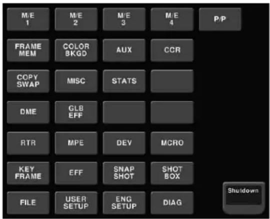
You can also display this by selecting VF1 'Top Menu List' after pressing the [HOME] button at the upper left in the top menu selection button area of the menu control block.
To display the top menu from the top menu list
In the same way as for the top menu selection buttons in the menu control block, press each button to display the particular top menu in the menu display.
Notes
- The arrangement of buttons in the top menu list and the default arrangement of the top menu selection buttons may be different.
- Changing the top menu selection button assignment in setup has no effect on the top menu list.
To shut down the menus
Press the [Shutdown] button at the lower right. This operation is the same as the shut down operation in the top menu window (see page 77).
Accessing Menus
You can use any of the following methods to access a menu, and the initially displayed menu page depends on the method used.
Pressing a top menu selection button in the menu control block
This displays the page you last accessed in the particular menu. After initially powering on the system, however, the page of VF1 - HF1 of the particular menu is always selected.
For details of the menus which can be recalled, see "Menus accessed from a top menu selection button" (page 73).
For details of the VF buttons and HF buttons, see "Interpreting the Menu Screen" (page 74).
Pressing a button other than a top menu button twice in rapid succession
Depending on the button, this may display a fixed page or the page selected last time you accessed the menu.
For details of the menus which can be recalled, see "Menus accessed by pressing a button twice" (page 390).
Press the menu page selection button at the top left of the menu display
The top menu window appears; press the top menu selection button for the particular menu, or enter the menu number with the numeric keypad, and press the Enter button.
Menus accessed from a top menu selection button
| Buttons Menus Function See | |||
| HOME Home Recalling menus using the top menu list or shortcut menu | Top menu list: page 72 Shortcut menu: page 83 | ||
| M/E 1 M/E-1 Transition, keys, and wipe settings for the M/E-1 bank | page 98 (transitions), page 120 (keys), page 159 (wipes) | ||
| M/E 2 M/E-2 Transition, keys, and wipe settings for the M/E-2 bank | |||
| M/E 3 M/E-3 Transition, keys, and wipe settings for the M/E-3 bank | |||
| M/E 4 M/E 4 Transition, keys, and wipe settings for the M/E-4 bank | |||
| P/P PGM/PST Transition, downstream key, and wipe settings for the PGM/PST bank | |||
| FRAME MEM | Frame Memory | Frame memory settings | page 200 |
| COLOR BKGD | Color Bkgd | Color background settings | page 224 |
| AUX | Aux | AUX bus settings | page 231 |
| CCR | CCR | Color corrector settings | page 235 |
| COPY SWAP | Copy/Swap | Copy and swap settings | page 226 |
| MISC | Misc | Settings for side flag, safe title, transition settings, and connection to external devices | page 230 |
| STATS | Status | Status display | page 232 |
| DME | DME | DME special effect settings | page 282 |
| GLB EFF | Global Effect | Global effect settings | page 343 |
| RTR | Router | Router settings | page 232 |
| DEV | Device | Settings for external device operation | Chapter 12 (Volume 2) |
| Buttons | Menus | Function | See |
| MCRO Macro Macro | register and macro tim | eline settings | Chapter 16 (Volume 2) |
| KEY FRAME Key Frame | keyframe settings | Chapter 13 (Volume 2) | |
| EFF Effect Keyframe | effect register settings | Chapter 13 (Volume 2) | |
| SNAP SHOT Snapshot | Snapshot register settings | Chapter 14 (Volume 2) | |
| SHOTBOX Shotbox | Shotbox | register settings Chapter 15 (Volume 2) | |
| FILE | File | File settings | Chapter 17 (Volume 2) |
| USER SETUP | User setup | User setup settings | Chapter 24 (Volume 2) |
| ENG SETUP | Engineering Setup | Setup functions | Chapter 18 to Chapter 23 (Volume 2) |
| DIAG | Diagnosis | Status information display | Chapter 25 (Volume 2) |
Example of Displaying a Menu
To display, for example, the M/E-1 >Key1 >Type menu, use either of the following operations.
- Press the top menu selection button [M/E 1], then press the VF1 'Key1' button and the HF1 'Type' button in that order.
- Press the menu page number button in the upper left corner of the menu screen to display the top menu window, then enter the page number of the M/E-1>Key1>Type menu, which is 1111, and press the [Enter] button.
For details of the menu page numbers, see "Menu Tree" (page 366).
The M/E-1 >Key1 >Type menu appears in the menu display as follows.
![Page 1111 M/E-1 > Key1 > Type KEY1-4 KEY3-8 1110 Black: 0 (----) M/E-1 KF# 0/0 01:00:00:00 Free KF: 0 Type LUM C = 15.97 G = -31.47 D = 97.96 Edge Matte Bit Mode Main Mask Sub Mask Video Proe Key Print Blue Fill BLAC Source Whit Off On Trans Off Trans Priority 1 KB 5 KB 2 KB 6 KB 3 KB 8 KB 4 KB 8 KB Key Bus Auto Select [30] 1 KB 5 KB 2 KB 6 KB 3 KB 8 KB 4 KB 8 KB Key Type Luminance Linear Chroma Color Vialer Wipe Pattern Key Wipe Pattern Wipe Clean Mode Key Invert Key Position Chrome Pulse Key Probability Signal Select DME Wipe Key Fill Key Source Key Bus Mate Signal Select Self Auto Select Split Mio Default Recall Type Edge Main Mask Sub Mask Processed Key Transition Video Process Prex 1116](/content/2026/06/1364863/images/71f9e003da1e76a771c8b10c6f1438834195f12aa369a810b6916e9b9ad48732.jpg)
Interpreting the Menu Screen
The menu screen consists of the following principal parts. When buttons on the screen are lit or represented in a depressed state, this indicates that the corresponding item or function is selected (set on).
The following describes the M/E-1 >Key1 >Type menu screen as an example.
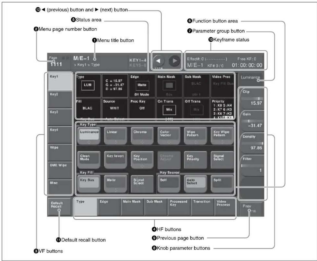
M/E-1 >Key1 >Type menu
①Menu title button
This shows the title of the menu screen.
You can set different colors for the main menu site and subsidiary menu site (see page 81).
Switching the VF buttons between the Key1 to Key4 and Key5 to Key8 button displays
Switch the displays with the [KEY1-4] and [KEY5-8] menu title buttons.
When [KEY1-4] is lit, Key1 to Key4 buttons appear in VF1 to VF4.
When [KEY5-8] is lit, Key5 to Key8 buttons appear in VF1 to VF4.
②Menu page number button
This shows the menu screen page number.
When you press this button, the top menu window (see page 77) appears. You can enter the page number for the desired menu, or press one of the top menu selection buttons in the window, to display that menu.
While the system is accessing the hard disk, the indicator lights red.
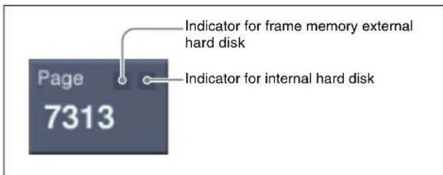
Notes
When the indicator is lit, do not power off the switcher, or disconnect the USB cable ^1) .
1) When an external hard disk drive is connected
③ VF buttons
These indicate the larger subdivisions of this menu. Depending on the selected item, the menu screen contents including the HF button indications change.
④HF buttons
These indicate the items within the menu. Depending on the selected item, the menu indications change. Depending on the function, if any one is on, the status is shown by an orange bar, as in the following figure.
⑤Status area
This shows the status of the settings items controlled by the selected menu.
An orange frame appears around the parameter area relating to the displayed menu. For each of the twelve areas, pressing the display jumps to the related menu.
⑥Function button area
This shows the functions which can be operated in the currently selected menu by means of buttons. Each function button corresponds to a function which can be set in the currently selected menu. Press it to enable the function, to display a parameter group and adjust the parameters with the knobs, or to execute the function. These buttons are in groups by function. In the screen example shown on the previous page, the [Key Bus] and [Matte] function buttons constitute the
⑦Parameter group button
This displays parameter group names for which the knobs can make adjustments, the current parameter setting page number, and the total number of the parameter setting pages. (Example: Color Vector 1/2) When there are more than five parameters within the same parameter group, press this button to display the sixth and subsequent parameters, which can then be controlled by the knobs.
⑧Knob parameter buttons
These show the parameters currently controlled by the knobs and their values. Pressing one of these buttons displays the numeric keypad window (see page 78), and you can then enter a new value for the corresponding parameter with the numeric keypad.
⑨Previous page button
This shows the page number of the previously displayed menu screen. Press it to go back to that page. When the indication [Parent] appears, this displays the parent directory.
⑩Keyframe status
This shows the keyframe status of the reference region. Pressing this button switches the menu screen as follows.
When a menu other than the Key Frame menu is currently shown: The menu screen switches to the Key Frame menu.
When the Key Frame menu is currently shown: The menu screen switches to the menu that was on the screen immediately before the Key Frame menu.
In some parts of menus such as the File menu, this functions as a “Region selection area,” for selecting the region to which operations apply.
⑪Default recall button
This only appears in those menus for which the default recall function is available.
For details of the menus which can be initialized, see "Menus allowing a return to default settings" (page 396) in Appendix.
Press this button, turning it on, then press a VF button or knob parameter button to return the settings to their default values, in the following groupings.
- Function grouping: the functions within an HF menu under the VF button
- Knob parameters (parameters currently controlled by the knobs)
12 ◀ (previous) button and ▶ (next) button
The ◀ button returns to the previous menu. Press the ▶ button to continue to the next menu.
Names and Functions of Parts of the Top Menu Window
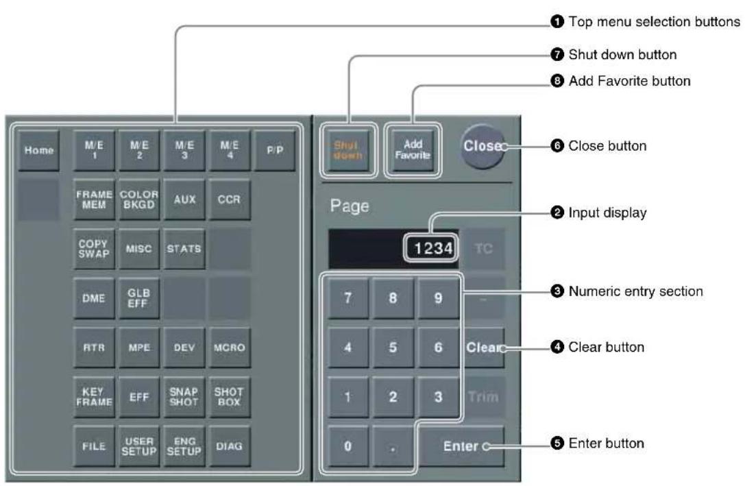
① Top menu selection buttons
These are the same as the top menu selection buttons in the menu control block. Pressing one of these buttons closes the top menu window and displays the selected menu in the menu display.
②Input display
This shows the page number entered with the numeric entry section.
③Numeric entry section
Enter a page number.
④ Clear button
Press this to clear the input display.
⑤Enter button
Pressing this button without entering a page number closes the top menu window with the current menu remaining in the menu display.
If you enter a page number then press this button, this confirms the value in the input display. If it is a correct page number, the top menu window closes, and the menu display shows the new menu. If it is not correctly set, the input display changes color.
6 Close button
Press this to close the top menu window.
⑦Shut down button
Shuts down the menus.
Notes
Be sure to shut down the menus before powering off the control panel.
Shutting down the menus
1 In the menu screen, press the menu page number button to open the top menu window.
2 Press [Shut down].
A confirmation message appears.
3 Press [Yes].
This shuts down the menu system after a while, and the menu display changes to black. Now power off the system.
To restart menu operations
Power on the control panel once more.
④ Add Favorite button
Pressing this button allows the currently displayed menu to be registered to the Shortcut menu (see page 83).

Names and Functions of Parts of the Numeric Keypad Window
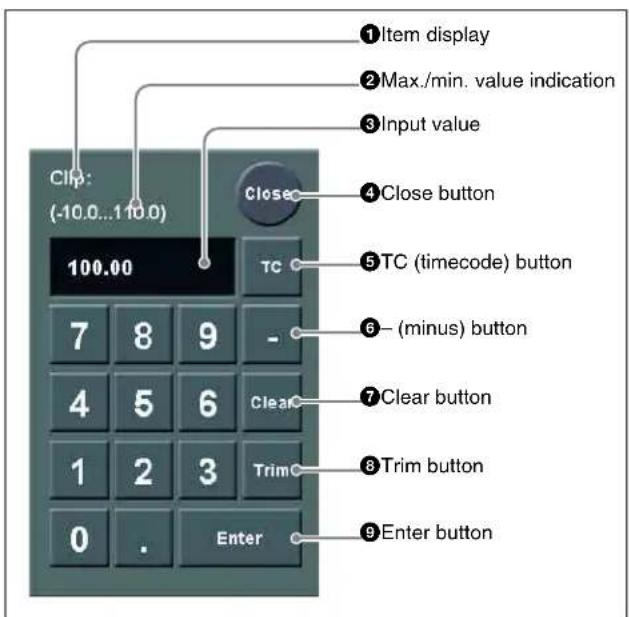
①Item display
This is the name of the parameter being set in the numeric keypad window.
②Max./min. (maximum/minimum) value indication
This shows the maximum and minimum settings of the parameter.
③Input value
This is the value being input into the numeric keypad window.
④ Close button
This closes the numeric keypad window.
⑤TC (timecode) button
When the numeric keypad window is opened for a setting requiring a timecode value to be entered, this button appears in a depressed state.
You can enter a timecode value in the range that depends on the signal format.
00:00:00:00 to 23:59:59:nn,
where nn = (number of frames per second) - 1.
6 - (minus) button
This toggles the sign of the entered value. When it is pressed, the value is negative.
⑦ Clear button
This clears the input. It does not change the parameter setting.
8 Trim button
After entering the difference from the current value, press this button to confirm the numeric input.
⑨ Enter button
This confirms the entered value.
If correctly set, the numeric keypad window closes.
If not correctly set, the input display changes color.
Names and Functions of Parts of the Keyboard Window
Notes
Except when changing source names, the following characters cannot be used.
space, \, /, :, :, (comma), . (dot), <, >, *, ?, ", |
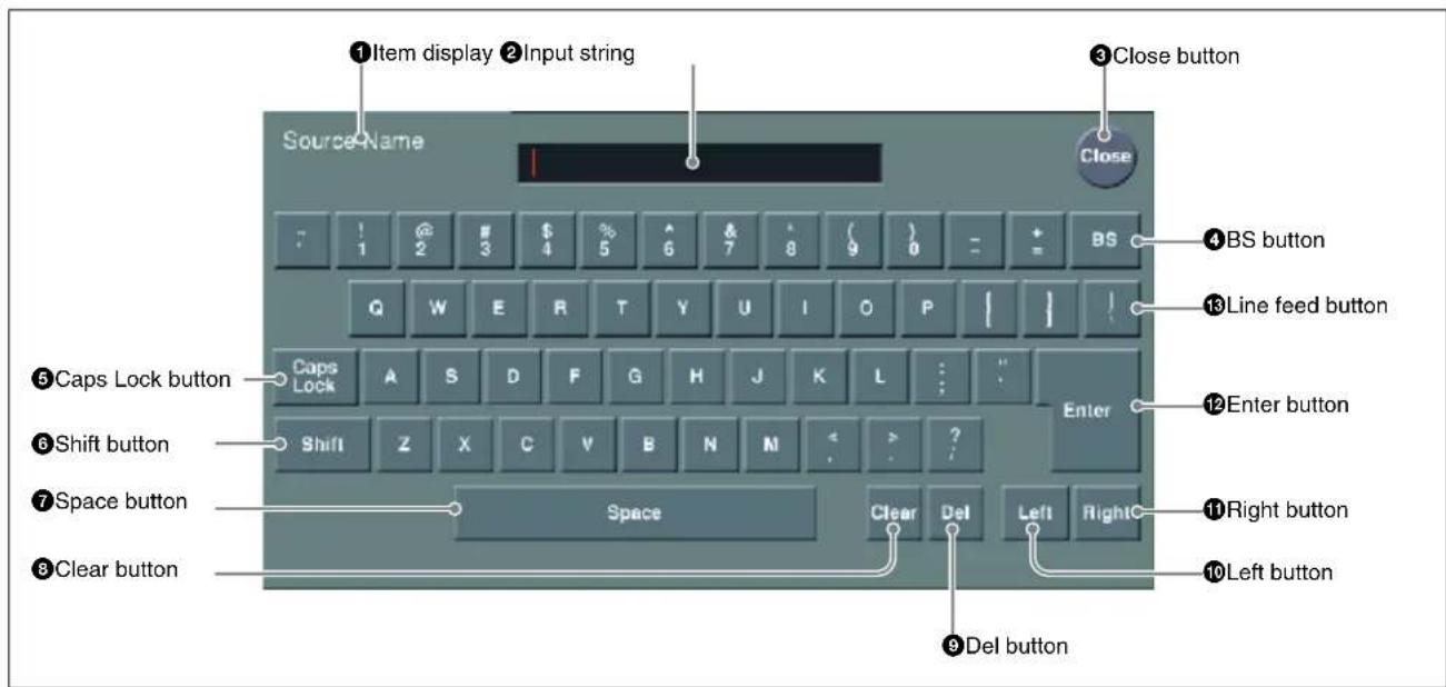
①Item display
This is the name of the parameter being set in the keyboard window.
②Input string
This is the character string being input in the keyboard window.
③ Close button
This closes the keyboard window.
④BS button
This clears the character immediately before the cursor in the input string.
⑤ Caps Lock button
This enables input of capital letters only.
Notes
You can enter items to be displayed on the control panel LCD using lowercase letters, but these will be converted to capitals for display.
MS-DOS does not distinguish case in filenames, and therefore you are recommended to enter filenames in capital letters.
⑥Shift button
This selects the characters on the shift side of the keys. The shift is released when you enter a character.
⑦Space button
This enters a space character.
8 Clear button
This clears all of the characters in the input string.
⑨Del button
This clears the character immediately after the cursor in the input string.
10 Left button
This moves the cursor one character to the left in the input string.
⑪Right button
This moves the cursor one character to the right in the input string.
12Enter button
This sets the input string as a parameter value, and closes the keyboard window if the value has been entered correctly. If the value has not been entered correctly, the display color changes.
13 Line feed button
After pressing the Shift button, press this button to feed a line. The input string shows “|”.
Names and Functions of Parts of the Color Pallet Window
When a parameter is assigned to the knobs as a combination of luminance, saturation, and hue, pressing a
knob parameter button displays a color palette window.
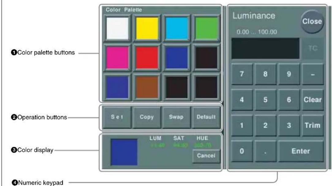
①Color palette buttons
Press one of these to enter the corresponding color in the display.
By default the following settings are available.
First row: white, yellow, cyan, green
Second row: magenta, red, blue, black
Third row: all black
②Operation buttons
Set: If you press any color palette button with this button held down, the color shown in the color display is assigned to the color palette button.
Copy: If you press a color palette button with this button held down, the color is used as the source for copying. Next press a different color palette button to copy to that button.
Swap: If you press two color palette buttons in sequence with this button held down, the two colors are swapped.
Default: If you press any color palette button with this button held down, the color palette button is set to the default color.
③Color display
This shows the setting color, and the parameters (LUM, SAT, and HUE).
By adjusting the parameters with the knobs, you can create any color.
If a parameter value is outside the permitted range for RGB (0 to 255), the indication “Illegal Color” appears, and this is adjusted to a value in range.
Cancel: Pressing this button returns to the state when the color palette window was opened.
4Numeric keypad
Use this to enter numeric values for parameters.
For details of use, see page 78.
Menu Operations
The method of menu operation is basically the same when using a mouse with an external monitor, but with mouse clicks in place of button presses. There is no difference in the menu control block operation described here. However, the monitor has no knobs for adjusting the parameters in the menu control block.
For details of operations corresponding to these knob operations, see the section below, "Operation With a Mouse" (page 82).
Selecting an Item
1 Press the VF button (1 to 7) for the desired group of items.
The HF button (1 to 7) indications change to show the items within the selected group.
2 Press the HF button for the desired item.
The indications in the status area and function button area change, and you can now make various changes to the selected item.
Selecting a Function
Press the appropriate function button within the function button area.
Shape and color of the button
Pressing the button turns it on, and it lights, showing the state.
Lit pale blue: The function is enabled, and the parameters can currently be adjusted with the knobs.
Lit orange: The function is enabled.
Lit purple: Execution button. Pressing the button immediately executes the function. (Example: [Auto Start] button in the Chroma Adjust menu)
Pressing a button of this type displays a further menu, allowing more detailed settings. (Example: [Chroma Adjust] button in the Type menu)
Setting Parameters
This marking on a function button indicates that there are parameters which can be adjusted with the knobs.
Pressing this function button assigns parameters to the knobs.
You can set the parameter values by either of the following methods.
- Turn the knob (1 to 5) corresponding to the parameter, to adjust the value.
- Press the knob parameter buttons (1 to 5) corresponding to the parameter. This displays the numeric keypad window allowing you to enter the desired value.
In the description of specific setting procedures, the knob adjustment is described, as follows.
Example: When wipe pattern key is selected
| Knob | Parameter | Adjustment | Setting values |
| 1 Size Pattern size 0.00 to 100.00 | |||
| 2 Soft Edge softness 0.00 to 100.00 | |||
| 3 Density Key density 0.00 to 100.00 | |||
When the [MENU] button in the device control block is lit, you can use the trackball and Z-ring to control the parameters.
- Move the trackball on the x-axis to control the parameter for knob 1 or on the y-axis to control the parameter for knob 2. Moving up or to the right increases the parameter value, and moving down or to the left decreases the parameter value.
- Use the Z-ring to adjust the parameter for knob 3. Turning clockwise increases the parameter value, and turning counterclockwise decreases the parameter value.
Switching Between the Main Menu Site and Subsidiary Menu Site
For menu transitions, you can store two separate versions in the main and subsidiary menu sites.
By switching sites, and pressing the ◀ button and the ▶ button you can trace the history in each menu.
To switch the subsidiary menu site on and off
Assign [SUB MENU SITE] to a menu control block top menu selection button or user preference button.
To switch to the subsidiary menu site, press this button, turning it on.
For details, see “Assigning Functions to the Menu Control Block Top Menu and User Preference buttons” in Chapter 19 (Volume 2).
Going Back to the Previous Menu
To return to the last displayed menu, press the previous page button.
Returning to Default State in Function Groupings
1 Press the [Default Recall] button, turning it on.
This enters the menu default recall mode.
2 Press the VF button you want to return to the default state.
This returns the settings within the function grouping to the default state, and the [Default Recall] button goes off.
Notes
The default state of the settings depends on the setting of the initial status mode, set in the Setup menu of system setup, as follows.
User: The state when [Initial Status Define] is executed.
Factory: Factory default settings
Returning Knob Parameters to Default State
1 Press the [Default Recall] button, turning it on.
This enters the menu default recall mode.
2 Press the knob parameter button you want to return to the default state.
This returns the knob parameter value to the default state, and the [Default Recall] button goes off.
For details, see the table, “Knob parameters subject to restriction on default recall” on page 398.
Notes
The default recall function does not return the horizontal (H) and vertical (V) position settings to their default state individually. Returning the horizontal (H) position to its default state also returns the vertical (V) position to its default state automatically, and vice versa.
Operation With a Mouse
If you display the menus in an external monitor, operated with a mouse, then you click the mouse instead of pressing a button as described in the previous section, "Menu Operations."
However, in the following cases there are special operations with a mouse.
To set a parameter with the mouse
To adjust the value of a knob setting parameter button with the mouse, you can use either of the following three methods.
- Position the cursor over the knob setting parameter button for which you want to adjust the value, and turn the mouse wheel.
- Position the cursor over the knob setting parameter button for which you want to adjust the value, then hold down the right mouse button, and drag the bar showing the setting to the desired value.
- Position the cursor over the knob setting parameter button for which you want to adjust the value, then click the left mouse button to open the numeric keypad window by which you can input the desired value.
To scroll a list with the mouse
Position the cursor over the list you want to scroll, and turn the mouse wheel.
In the setup menus you can select the direction of mouse wheel rotation that increases the setting value. And you can also switch the functions of the right and left mouse buttons.
For details, see Chapter 19 "Setting the Mouse Wheel Scrolling Direction for Parameter Setting" (Volume 2).
Shortcut Menu
Registering a Menu To the Shortcut Menu
1 In the Home >Favorites >Shortcut menu, select the desired group.
2 Display the menu you want to register, and then press the [Add Favorite] button.
The currently displayed menu is automatically registered to a blank button.
Recalling a Menu Using the Shortcut Menu
1 In the Home menu, select VF2 'Favorites' and HF1 'Shortcut.'
The following menu appears.
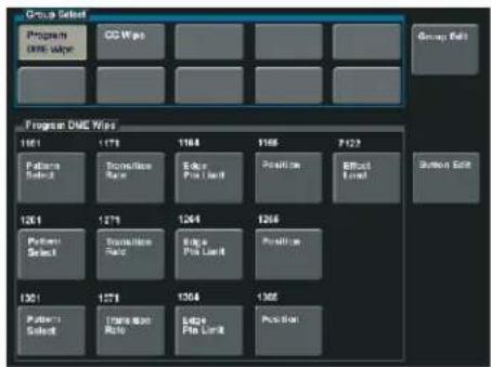
flowchart
graph TD
    A["Program Start"] --> B["Program Phase"]
    B --> C["Position"]
    C --> D["Effort Level"]
    D --> E["Session Exit"]

    subgraph Timeframe
        F["101"] --> G["111"]
        G --> H["114"]
        H --> I["118"]
        I --> J["7/22"]
        J --> K["126"]
        K --> L["127"]
        L --> M["129"]
        M --> N["126"]
        N --> O["130"]
        O --> P["131"]
        P --> Q["133"]
        Q --> R["134"]
        R --> S["135"]
        S --> T["136"]
        T --> U["137"]
        U --> V["138"]
        V --> W["139"]
        W --> X["140"]
        X --> Y["141"]
        Y --> Z["142"]
        Z --> AA["143"]
        AA --> AB["144"]
        AB --> AC["145"]
        AC --> AD["146"]
        AD --> AE["147"]
        AE --> AF["148"]
        AF --> AG["149"]
        AG --> AH["150"]
        AH --> AI["151"]
        AI --> AJ["152"]
        AJ --> AK["153"]
        AK --> AL["154"]
        AL --> AM["155"]
        AM --> AN["156"]
        AN --> AO["157"]
        AO --> AP["158"]
        AP --> AQ["159"]
        AQ --> AR["160"]
        AR --> AS["161"]
        AS --> AT["162"]
        AT --> AU["163"]
        AU --> AV["164"]
        AV --> AW["165"]
        AW --> AX["166"]
        AX --> AY["167"]
        AY --> AZ["168"]
        AZ --> BA["169"]
        BA --> BB["170"]
        BB --> BC["171"]
        BC --> BD["172"]
        BD --> BE["173"]
        BE --> BF["174"]
        BF --> BG["175"]
        BG --> BH["176"]
        BH --> BI["177"]
        BI --> BJ["178"]
        BJ --> BK["179"]
        BK --> BL["180"]
        BL --> BM["181"]
        BM --> BN["182"]
        BN --> BO["183"]
        BO --> BP["184"]
        BP --> BQ["185"]
        BQ --> BR["186"]
        BR --> BS["187"]
        BS --> BT["188"]
        BT --> BU["189"]
        BU --> BV["190"]
        BV --> BW["191"]
        BW --> BX["192"]
        BX --> BY["193"]
        BY --> ZQ["194"]
        ZQ --> AY
    end
2 In the [Group Select] box, select the group.
The group buttons appear.
3 Press the button for the desired menu.
Customizing the Shortcut Menu
Assign frequently used menus to buttons, to create a "Favorites" menu.
To create a menu group
1 In the Home menu, select VF2 'Favorites' and HF1 'Shortcut.'
The following menu appears.
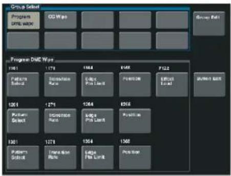
flowchart
graph TD
    A["Group School"] --> B["Program DAC Wipe"]
    B --> C["GG Wipe"]
    C --> D["..."]
    D --> E["..."]
    E --> F["..."]
    F --> G["..."]
    G --> H["..."]
    H --> I["..."]
    I --> J["..."]
    J --> K["..."]
    K --> L["..."]
    L --> M["..."]
    M --> N["..."]
    N --> O["..."]
    O --> P["..."]
    P --> Q["..."]
    Q --> R["..."]
    R --> S["..."]
    S --> T["..."]
    T --> U["..."]
    U --> V["..."]
    V --> W["..."]
    W --> X["..."]
    X --> Y["..."]
    Y --> Z["..."]
    Z --> AA["..."]
    AA --> AB["..."]
    AB --> AC["..."]
    AC --> AD["..."]
    AD --> AE["..."]
    AE --> AF["..."]
    AF --> AG["..."]
    AG --> AH["..."]
    AH --> AI["..."]
    AI --> AJ["..."]
    AJ --> AK["..."]
    AK --> AL["..."]
    AL --> AM["..."]
    AM --> AN["..."]
    AN --> AO["..."]
    AO --> AP["..."]
    AP --> AQ["..."]
    AQ --> AR["..."]
    AR --> AS["..."]
    AS --> AT["..."]
    AT --> AU["..."]
    AU --> AV["..."]
    AV --> AW["..."]
    AW --> AX["..."]
    AX --> AY["..."]
2 Press [Group Edit].
The following menu appears.
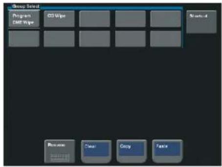
3 With the cursor, select the group name (in this case a blank button) for the operation.
4 Press [Rename].
A keyboard window appears.
5 Enter a group name (maximum 24 characters), and press Enter.
This confirms the group name.
To copy a menu group
1 In the Home >Favorites >Group Edit menu, press the button for the copy source group.
2 Press [Copy].
3 Press the button for the copy destination group.
4 Press [Paste].
This copies the menu group settings.
To delete menu group settings
1 In the Home >Favorites >Group Edit menu, select the group to be deleted.
2 Press [Clear].
A confirmation message appears.
3 Press [Yes].
This deletes the settings.
To register a menu on a button
You can register 15 buttons in one group.
1 In the Home >Favorites >Shortcut menu, press [Button Edit].
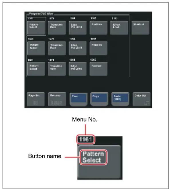
2 Move the cursor to the position where you want to display the button. To change the content of an already displayed button, press the button to select it.
3 Press [Page Set].
A page number input window appears.
4 Enter the page number for the menu you want to register.
5 Press [Rename].
A keyboard window appears.
6 Enter the button name (maximum 24 characters).
7 To change the button color, press [Color Set].
Button color samples appear.
8 Press the desired color.
This completes the assignment of the menu to the button.
9 Repeat steps 2 to 8 to complete the "Favorites" menu.
To copy button settings
1 In the Home >Favorites >Button Edit menu, press the copy source button to select it.
2 Press [Copy].
3 Press the copy destination button to select it.
4 Press [Paste].
This copies the button settings.
To delete button settings
In the Home >Favorites >Button Edit menu, press [Clear]. This deletes the button settings.
Notes
The shortcut menu settings are handled as part of the control panel setup. You can recall and save them in the same way as setup data.
To register a menu macro on a button
See “Recalling a Menu Macro Register and Executing a Menu Macro” in Chapter 16 (Volume 2).
To execute a menu macro with a button
See “Recalling a Menu Macro Register and Executing a Menu Macro” in Chapter 16 (Volume 2).
Signal Selection and Transitions
Chapter
3
Video Processing Flow
The switch from the current video stream (appearing on the corresponding program monitor) to a new video stream is referred to as a transition.
The following illustration shows the flow of operations for carrying out a transition on an M/E bank or the PGM/PST bank.
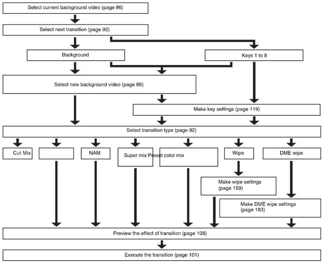
flowchart
graph TD
    A["Select current background video (page 86)"] --> B["Select next transition (page 92)"]
    B --> C["Background"]
    B --> D["Keys 1 to 8"]
    C --> E["Select new background video (page 86)"]
    D --> F["Make key settings (page 119)"]
    E --> G["Select transition type (page 92)"]
    F --> G
    G --> H["Cut Mix"]
    G --> I["NAM"]
    G --> J["Super mix Preset color mix"]
    G --> K["Wipe"]
    G --> L["DME wipe"]
    H --> M["Preview the effect of transition (page 108)"]
    I --> M
    J --> M
    K --> M
    L --> N["Make DME wipe settings (page 183)"]
    M --> O["Execute the transition (page 101)"]
Signal Selection
You carry out signal selection with the cross-point buttons in the cross-point control block of each M/E bank or the PGM/PST bank, and the buttons in the auxiliary bus control block.
The number of buttons in each cross-point row may be 16, 24, or 32, but here the description is of the 32-button case as an example.
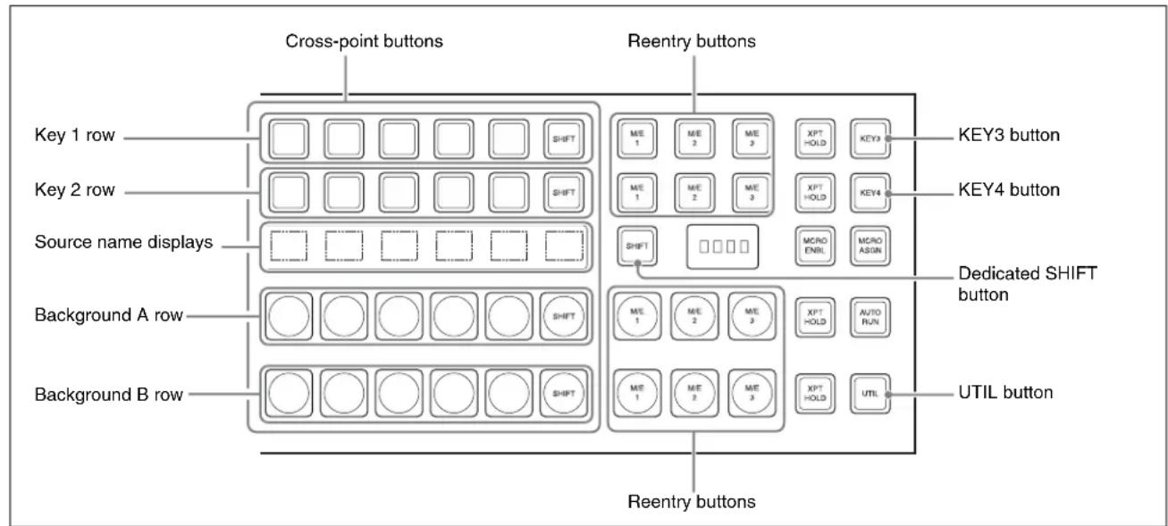
Cross-point control block
Basics of Signal Selection
Each of the M/E banks, PGM/PST bank and auxiliary bus control block has 32 cross-point buttons and three reentry buttons (four in the case of the auxiliary bus control block). These buttons are identified by numbers common to all of the banks and block, and a signal is assigned to each number.
The basis of signal selection is to select, in a cross-point button row, the cross-point button to which is assigned the desired signal.
Reentry buttons
To use the output of one M/E bank as background input to another bank, use the reentry buttons [M/E1], [M/E2], and
[M/E3] (on the auxiliary bus control block, [M/E1], [M/E2], [M/E3], and [PGM]) in the cross-point control block of the destination bank.
For example, to feed the output from the M/E-1 bank as the background B input to M/E-2, in the M/E-2 cross-point control block, press the [M/E1] button in the background B row.
Notes
- To select M/E 4, it is necessary to assign M/E 4 to a button (see page 387).
- For a 5M/E system, a maximum of four re-entry stages are possible. For other restrictions on re-entry, see page 235.
Bus Selection
Each row of 32 cross-point buttons is shared by multiple buses.
To assign a bus to the cross-point buttons in the auxiliary bus control block, press one of the AUX delegation buttons to select the bus.
Notes
- When using the CCP-6224/6324, buses may be assigned with the cross-point button rows for keys 1 and 2 as the auxiliary bus control block.

- You can enable assigning a key and AUX bus to the key 1 row of cross-point buttons, and selecting the signal in the key 2 row.
The following table illustrates the correspondence between buses and cross-point button rows, and the delegation operations.
For details, see "Assigning a Key or AUX Bus to a Button in the Key 1 or Key 2 Row" in Chapter 19 (Volume 2).
| Bank | Bus name | Cross-point button row | Delegation operation | |
| M/E-1, M/E-2,M/E-3, M/E-4a) | Background A busb) | Background A row – | ||
| Background B busb) | Background B row – | |||
| Key 1 bus Key 1 row Turn off the | dedicated [SHIFT] button, | then turn off the [KEY3] button.c) | ||
| Key 2 bus Key 2 row Turn off the | dedicated [SHIFT] button, | then turn off the [KEY4] button.c) | ||
| Key 3 bus Key 1 row Turn off the | dedicated [SHIFT] button, | then turn on the [KEY3] button.c) | ||
| Key 4 bus Key 2 row Turn off the | dedicated [SHIFT] button, | then turn on the [KEY4] button.c) | ||
| Key 5 busd) | Key 1 row Turn on the dedicated | [SHIFT] button,then turn off the [KEY3] button. | ||
| Key 6 busd) | Key 2 row Turn on the dedicated | [SHIFT] button,then turn off the [KEY4] button. | ||
| Key 7 busd) | Key 1 row Turn on the dedicated | [SHIFT] button,then turn on the [KEY3] button. | ||
| Key 8 busd) | Key 2 row Turn on the dedicated | [SHIFT] button,then turn on the [KEY4] button. | ||
| PGM/PST Program bus b) | Program row – | |||
| Preset busb) | Preset row – | |||
| DSK 1 bus DSK 1 row Turn off the | dedicated [SHIFT] button,then turn off the [DSK3] button.c) | |||
| DSK 2 bus DSK 2 row Turn off the | dedicated [SHIFT] button,then turn off the [DSK 4] button.c) | |||
| DSK 3 bus DSK 1 row Turn off the | dedicated [SHIFT] button,then turn on the [DSK 3] button.c) | |||
| DSK 4 bus DSK 2 row Turn off the | dedicated [SHIFT] button,then turn on the [DSK 4] button.c) | |||
| DSK 5 busd) | DSK 1 row Turn on the dedicated | [SHIFT] button,then turn off the [DSK 3] button. | ||
| DSK 6 busd) | DSK 2 row Turn on the dedicated | [SHIFT] button,then turn off the [DSK 4] button. | ||
| DSK 7 busd) | DSK 1 row Turn on the dedicated | [SHIFT] button,then turn on the [DSK 3] button. | ||
| DSK 8 busd) | DSK 2 row Turn on the dedicated | [SHIFT] button,then turn on the [DSK 4] button. | ||
| M/E-1, M/E-2,M/E-3, M/E-4a),PGM/PST | Utility 1 bus Background A row W | When [UTIL] button mode is Hold, hold | holddown the [UTIL] button. | |
| Utility 2 bus Background B row | ||||
| DME external video bus | Key 1 row Hold down the [UTIL] | button. | ||
| DME utility 1 bus | Key 2 row Hold down the [UTIL] | button, and pressthe [KEY4] button, turning it off. | ||
| DME utility 2 bus | Hold down the [UTIL] button, and pressthe [KEY4] button, turning it on. | |||

| Bank | Bus name | Cross-point button row | Delegation operation |
| Auxiliary bus control block^e) | AUX1 to AUX48 buses 1st row, 2nd row Turn on the appropriate buttons | accordance with the signal assignment made in the Setup menu. | |
| Frame memory source 1 and frame memory source 2 buses | |||
| DME 1 to DME 8 video buses | |||
| DME 1 to DME 8 key buses | |||
| Edit preview bus | |||
| M/E-1 UTILITY 1 and M/E-1 UTILITY 2 buses | |||
| M/E-2 UTILITY 1 and M/E-2 UTILITY 2 buses | |||
| M/E-3 UTILITY 1 and M/E-3 UTILITY 2 buses | |||
| M/E-4 UTILITY 1 and M/E-4 UTILITY 2 buses | |||
| P/P UTILITY 1 and P/P UTILITY 2 buses | |||
| M/E-1 Key 1 fill to M/E-1 Key 8 fill buses | |||
| M/E-1 Key 1 source to M/E-1 Key 8 source buses | |||
| M/E-2 Key 1 fill to M/E-2 Key 8 fill buses | |||
| M/E-2 Key 1 source to M/E-2 Key 8 source buses | |||
| M/E-3 Key 1 fill to M/E-3 Key 8 fill buses | |||
| M/E-3 Key 1 source to M/E-3 Key 8 source buses | |||
| M/E-4 Key 1 fill to M/E-4 Key 8 fill buses | |||
| M/E-4 Key 1 source to M/E-4 Key 8 source buses | |||
| DSK 1 source to DSK 8 source buses | |||
| DSK 1 fill to DSK 8 fill buses | |||
| M/E-1 external DME bus | |||
| M/E-2 external DME bus | |||
| M/E-3 external DME bus | |||
| M/E-4 external DME bus | |||
| P/P external DME bus | |||
| DME UTILITY 1 and DME UTILITY 2 buses | |||
a) M/E-4 requires assignment.
b) Dual background bus mode (see below) can be selected.
c) A dedicated [SHIFT] button operation is required when the dedicated [SHIFT] button operation mode is set in setup to "Key5-8 Select." For other settings, a dedicated [SHIFT] button operation is not required.
d) Only valid when the dedicated [SHIFT] button operation mode is set in setup to "Key5-8 Select." For other settings, assignment is not possible.
e) An assignment to the delegation buttons is required in setup, to assign the bus for operations.
Dual background bus mode
In this mode, the shifted signal on the background A row can be selected on the key 1 row, and the shifted signal on the background B row can be selected on the key 2 row.
To switch this mode on and off, it is necessary to assign this function to the [PRE MCRO] button in the cross-point control block.
For details of the assignment operation, see “Assigning the Dual Background Bus Mode Switching Function” in Chapter 19 (Volume 2).
Notes
For the following switcher banks, dual background bus mode is not available.
- When set to "Dual M/E Assign"
- When M/E Config is set to "DSK"
AUX Panel-less Function
When using 24-column cross-point control blocks for the CCP-6224/CCP-6324 Control Panel, you can use the key 1 and key 2 rows as the auxiliary bus control block. This is called the panel-less function.
Preparations
Assign the function for switching to the AUX control mode to the [PRE MCRO] and [POST MCRO] buttons. Hereafter this button is called the [AUX CTRL] button. In the source name display you can display either the source name or the bus name.
For details of how to make the assignment, see “Assigning the AUX Bus Control Mode Switching Function” in Chapter 19 (Volume 2).
Selecting the AUX bus
1 Switch the operation mode with the [AUX CTRL] button.
2 In the key 1 row, select the AUX bus for the operation.
3 In the key 2 row, select the desired signal.
Signal Assignment and Selection
Assigning signals to buttons
Each of the 32 cross-point buttons and reentry buttons has a corresponding button number, to which you assign a signal.
In addition to the signals input to the following connectors, you can also select signals generated within the switcher.
- The PRIMARY INPUTS connectors on the rear panel of the switcher (1 to 144 in MVS-8000X, 1 to 80 in MVS-7000X)
- The PREMIUM INPUTS 1 to 20 connectors (only in MVS-8000X)
- The FC INPUTS 1 to 16 connectors (only in MVS-8000X)
Each button has assigned to it a video signal and a key signal, forming a pair. You can set these video and key combinations in a Setup menu.
For details of Setup menu operations, see “Creating Cross-Point Assign Tables” in Chapter 19 (Volume 2).
Cross-point button control block button numbers
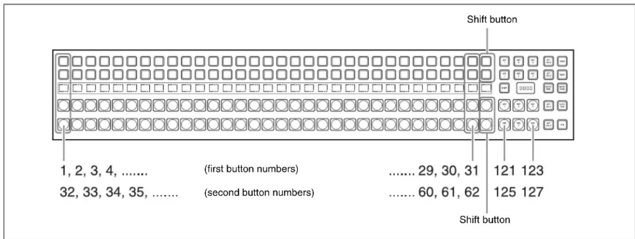
On each M/E bank and the PGM/PST bank, each cross-point button and reentry button has two button numbers, and you use the shift button to switch between these numbers.
In the case of a 32-button layout, the button numbers are as follows.
Cross-point control block button numbers
| Button Number when the shift button is not pressed | Number when the shift button is pressed | |
| From the left end to the 31st button | 1 to 31 32 to 62 | |
| Reentry buttons 121 to 123 125 to 127 |
Notes
You can use the rightmost button (number 32) as a [SIDE FLAG] button. In this case, the shift button moves one to the left, to number 31, and the button numbers are offset by one.
For details of the [SIDE FLAG] button, see "Assigning a Cross-Point Button to Enable/Disable Side Flags" in Chapter 19 (Volume 2).
Switching button numbers
The rightmost (32nd) button functions as a shift button. (The shift button function can be disabled in a Setup menu.)
When selecting the signals of button numbers 1 to 31, press the cross-point button for the desired signal.
To select button numbers 32 to 62, hold down the shift button, and press the cross-point button for the desired signal.
Button numbers in the auxiliary bus control block
![1, 2, 3, 4, ...... (1st row) ...... 29, 30, 31 121 124 [2ND] button 32, 33, 34, 35, ...... (2nd row) ...... 60, 61, 62 125 128](/content/2026/06/1364863/images/a37f16c3ff1b62fa8548b91a7ce7307ab3df9a0d89d7e0b16354b74f704c63ef.jpg)
When the [2ND] button is unlit
The cross-point buttons and reentry buttons in the auxiliary bus control block have separate upper (1st row) and lower (2nd row) numbers.
In the case of a 32-button layout, the button numbers are as follows.
Auxiliary bus control block button numbers ([2ND] button unlit)
| Button Button numbers | ||
| 1st row From the left end to the 31st button | 1 to 31 | |
| 2nd row From the left end to the 31st button | 32 to 62 | |
When the [2ND] button is lit
Different buses can be assigned to the 1st-row buttons and 2nd-row buttons. When the 32nd button is set as a shift button, the 1st-row buttons and 2nd-row buttons both have the following button numbers.
Auxiliary bus control block button numbers ([2ND] button lit)
| Button Number when the shift button is not pressed | Number when the shift button is pressed | |
| From the left end to the 31st button | 1 to 31 32 to 62 | |
| Reentry buttons 12 | 1 to 124 125 to 128 |
Inhibiting cross-point button operations
For each cross-point button, you can temporarily inhibit operations.
Notes
This setting is cleared when you reset the control panel.
Assigning a button to the function of disabling cross-point button operation
You can assign the button to be used for the operation to the [PRE MCRO] button, in setup.
For details, see "Overall Control Panel Settings (Config Menu)" in Chapter 19 (Volume 2).
You can also use the [Inhibit Set] and [Inhibit All Clear] functions, assigned to user preference buttons.
For details, see "Assigning Functions to User Preference Buttons" in Chapter 19 (Volume 2).
Buses for which operations can be inhibited
This setting applies to the auxiliary bus control block (when using the CCP-8000) and the cross-point buttons in each switcher bank. However, when using the CCP-6224/6324, buses may be assigned with the cross-point button rows for keys 1 and 2 as the auxiliary bus control block. For example, if you make the setting for one cross-point button in a switcher bank, this inhibits operation of all cross-point buttons with the same number in the following buses.
The corresponding name also disappears from the source name display.
• Background A, background B
- Keys 1 to 8
• Utility 1, Utility 2
• DME utility 1, DME utility 2
- External DME
To inhibit operation of a cross-point button
Hold down the button which “Inhibit Set” is assigned, and press the cross-point button whose operation you want to inhibit.
The button you pressed flashes amber, and this makes the operation inhibited.
Notes
Even when you inhibit operation of a cross-point button, macro attachment settings are still possible.
For details, see “Setting and Canceling a Macro Attachment” in Chapter 16 (Volume 2).
To clear a cross-point button operation inhibit setting
Hold down the button to which “Inhibit Set” is assigned, and press the button whose operation is inhibited (flashing amber).
This clears the operation inhibit setting for the button you pressed.
To clear all operation inhibit settings
Press the button to which “Inhibit Set” is assigned and the button to which “Inhibit All Clear” is assigned simultaneously.
Selection of signals linked with the audio mixer
When you select a signal in a switcher bank background A, key 1 or key 2 row (of the CCP-6224/6324 control panel in AUX control mode) or AUX bus control block (of the CCP-8000), and the bank and signal are set to be linked to the audio mixer, then the program output of the audio mixer follows the signal selection.
For details of the setting, see “Making Settings for Audio Mixer” in Chapter 19 (Volume 2).
Notes
- For details of audio mixers that can be connected, contact your Sony service or sales representative.
- When the signal is switched with a snapshot, keyframe, and so on, the audio mixer is not linked.
- When bus fixed mode is selected in setup (see page 107), the audio mixer program output is linked to the bus output as the background.
Signal Name Display
You can attach a name (source name) to each signal assigned to a cross-point button, with a maximum of 16 characters.
- The source name displays in the cross-point control block and auxiliary bus control block show the source names of the video signals assigned to numbers 1 to 31.
- To display the source names for numbers 32 to 62, press the [SHIFT] button to the right of the source name displays.
- To display the source names of the key signals assigned to buttons, hold down the [SPLIT] button in the key control block or the [KEY] button in the auxiliary bus control block.
When using the AUX panel-less function (see page 89) with the CCP-6224/6324 Control Panel, you can use the cross-point control block as an AUX bus control block with the [AUX CTRL] button.
In this case, use the key 1 row as AUX delegation buttons, and the key 2 row as AUX bus cross-point selection buttons; the source name displays show the bus names and source names.
Colors of lit cross-point buttons
In a particular row of cross-point buttons, only the last pressed button is effective, and lights amber or red. The amber indicates the “low tally” state, and the red indicates the “high tally” state, to indicate whether or not the selected signal appears in the final output video.
Significance of colors of lit cross-point buttons
| Color State Significance | ||
| Amber Low tally | Does not appear | in final output video |
| Red High tally | Appears in final out | put video |
Transitions
Selecting the Next Transition
To execute a transition, it is first necessary to decide how the image will be changed as a result of the transition. This selection is carried out using the next transition selection buttons (see page 34) in the transition control block of each M/E or PGM/PST bank.
For details of operations, see “Procedure for Basic Transition Operation” (page 93).
Transition Types
Selecting the transition type determines the way in which the transition occurs.
Carry out the type selection with the transition type selection buttons in the transition control block of each M/E or PGM/PST bank.
For details of this operation, see “Procedure for Basic Transition Operation” (page 93).
The following are the transition types.
Mix
This is a dissolve, in which the new video progressively fades in over the current video, with the sum of the two video outputs maintained constant. At the mid-point of the transition (when the fader lever is in the center position), the output of each is 50%.
This transition type can also be selected for an independent key transition. In this case, the key either dissolves in or dissolves out similarly, with the progress of the transition.
NAM (non-additive mix)
In this dissolve, the current video and new video signals are compared, and the signal with the higher luminance level is given priority in the output. The current video is maintained at 100% output for the first half of the transition as the new video increases progressively to 100%, then the current video is progressively reduced from 100% to zero in the second half with the new video maintained at 100% output.
Notes
This transition type is not available for an independent key transition.
Super mix
In this dissolve, the current video is maintained at 100% output for the first half of the transition as the new video is mixed while increasing progressively to 100%, then the current video is progressively reduced from 100% to zero in the second half with the new video maintained at 100% output.
Notes
This transition type is not available for an independent key transition.
For details on super mix settings, see page 99.
Preset color mix
This is a two-stage dissolve, comprising two transitions, the first a dissolve to a color matte, and the second from the color matte to the new video.
In the first transition, the current video is replaced by the color matte in a mix (dissolve), then in the second transition the color matte is replaced by the new video also in a mix (dissolve).
Notes
This transition type is not available for an independent key transition.
For details on color matte settings, see page 99.
Wipe
A wipe replaces the current video by the new video according to a predetermined pattern. This transition type can also be selected for an independent key transition.
For details, see Chapter 5 "Wipes" (page 159).
DME wipe
Using a DME effect, it is possible to obtain a transition to a new image from the current image, as in a wipe. You can also use this transition type as an independent key transition.
For details, see Chapter 6 "DME Wipes" (page 179).
Clip transitions
Linked to a mix (dissolve) or wipe transition, a frame memory clip (movie) is played back.
Cut
A cut switches instantaneously from the current video to the new video. When the next transition is a key transition, the key cuts in or out instantaneously.
Procedure for Basic Transition Operation
The positions of the principal buttons used for basic transition operation are as follows.
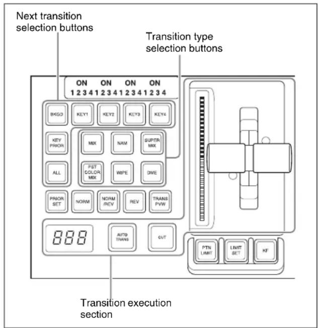
Transition control block (for standard transitions)
1 In the cross-point control block, select the background video with the background A row of cross-point buttons.
2 Select the way in which the transition will affect the image, using the next transition selection buttons in the transition control block.
For an overview, see “Selecting the Next Transition” (page 92).
To change the background: Press the [BKGD] button, turning it on.
To insert or delete a key: Press one of the [KEY1] to [KEY4] buttons (or [DSK1] to [DSK4] buttons in the PGM/PST bank), turning it on.
For details of the operation to select [Key5] to [Key8], see “Assigning Buttons for Selection of Keys 5 to 8 in the Setup Menu” (page 388) in Appendix.
To enable the key priority setting, which determines the key overlay order after the transition: Press the [KEY PRIOR] button, turning it on.
You can press more than one button at the same time.
To change the keys and background presets in Setup menus simultaneously: Press the [ALL] button.
To allocate a particular next transition button to the [ALL] button function, see “Setting the Operation Mode of the [ALL] Button in the Transition Control Block” in Chapter 19 (Volume 2).
3 For the transition to change the key priority, set the priority for after the transition.
When using keys 1 to 8, see “Priority Setting for Keys 1 to 8” (page 97). For details of the key priority setting operation, see “Key Priority Setting” (page 95).
4 Select the new video used for the transition.
- In the background B row of cross-point buttons, select the new background video.
- When inserting a key, select the key signal, and make any required settings.
For details of key settings, see Chapter 4 "Keys" (page 119).
To carry out a cut transition, skip to step 7; otherwise continue to step 5.
5 Select one of the transition type selection buttons in the transition control block.
To carry out a dissolve to the new video: Press one of the [MIX], [NAM], [SUPER MIX], and [PST COLOR MIX] buttons, turning it on.
To carry out a wipe: Press the [WIPE] or [DME] button, turning it on.
To carry out a transition while playing back a frame memory clip: Press one of the buttons corresponding to the clip to be used (FM1&2CLIP, FM3&4CLIP, FM5&6CLIP, and FM7&8CLIP).
You can also use the Misc >Transition menu to select a desired transition type for the M/E or PGM/PST bank. (See “Selecting the Transition Type by a Menu Operation” (page 98).)
For an overview, see "Transition Types" (page 92).
Notes
The transition type selection buttons in the transition control block can be interchanged in the setup menu.
For details, see "Overall Control Panel Settings (Config Menu)" in Chapter 19 (Volume 2).
6 Make the required settings, according to the selected transition type.
For details of the settings, see the relevant section.
Super mix: "Super Mix Settings" (page 99)
Preset color mix: "Color Matte Settings" (page 99)
Wipe: “Basic Procedure for Wipe Settings” (page 159)
DME wipe: "Basic Procedure for DME Wipe Settings" (page 183)
Clip transition: “Clip Transition Operations” (page 215)
Using the transition preview function (see page 108), you can check the transition on the preview monitor.
7 Carry out the transition in the transition execution section.
For a gradual transition such as a mix (dissolve) or wipe: Press the [AUTO TRANS] button, or operate the fader lever.
To execute a transition by pressing the [AUTO TRANS] button, first set the transition rate (specified as the duration of the transition).
(See "Setting the Transition Rate" (page 101).)
When you have selected a wipe or DME wipe as the transition type, you can also set the transition range. (See "Pattern Limit" (page 104).)
For an instantaneous transition: Press the [CUT] button.
For details, see "Executing a Transition" (page 101).
Transition linked to the audio mixer
If the video signal selected in the background B row is linked to the audio mixer in setup, then the audio mixer sound changes with the transition. That is, pressing the [AUTO TRANS] button gives a cross fade, and pressing the [CUT] button gives an instantaneous sound switch.
For details of setup, see “Making Settings for Audio Mixer” in Chapter 19 (Volume 2).
Notes
- The audio mixer is not linked to a snapshot or key frame transition.
- The audio mixer is not linked to a transition using the fader lever.
- If the bus-fixed mode (see page 107) is selected in the setup menu, and the fader lever is in the lowest position, there is a cross fade from the audio selected on the B row to the audio selected on the A row.
- The audio mixer is not linked to a key transition.
- In the following cases, the audio and video may be out of sync.
- When carrying out a cross fade in some DME wipes (for example, “picture in picture”)
- When executing a preset color mix in two-stroke mode
- For details of audio mixers that can be used, contact your Sony service or sales representative.
Key Priority Setting
If a number of keys are already inserted in the current video, you can check or change the key priority, that is to say, the order in which the keys are overlaid.
When a key priority ([KEY PRIOR]) is selected as the next transition, you can also change the key priority in the new video.
The key priority values go from 1 to 4, with a higher priority key being “in front” as seen on the screen.
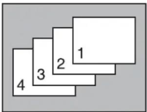
Priority sequence on the screen
There are two ways of setting the priority: either using the [PRIOR SET] button in the transition control block, or using the Misc menu to access the Key Priority menu for the M/E or PGM/PST bank.
Notes
When the operating mode is set to multi program, the key priority setting cannot be made.
Setting the Key Priority in the Transition Control Block
The positions of the buttons used for the operation are as follows.
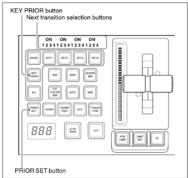
Transition control block (standard type)
Changing the currently inserted key priority
1 If the next transition selection button [KEY PRIOR] is on, press another next transition selection button to turn the [KEY PRIOR] button off.
(When the [KEY PRIOR] button is on, the transition control block switches to the mode for changing the key priority for after the transition.)
2 Holding down the [PRIOR SET] button, press the one of the next transition selection buttons [KEY1] to [KEY4] ([DSK1] to [DSK4] buttons in the PGM/PST bank) for the key to appear on top.
Notes
- To select [Key5] to [Key8], or [DSK5] to [DSK8] requires an assignment (see page 388).
- The key priority establishes a separate priority order within each of the groups of keys 1 to 4 and keys 5 to 8. You can make any setting within the groups of keys 1 to 4 or keys 5 to 8, but not for combinations of keys from different groups.
For example, it is not possible to set a priority sequence of keys 1, 5, and 2.
The selected key now appears on top, on the program monitor.
The priority of keys other than the selected one does not change.
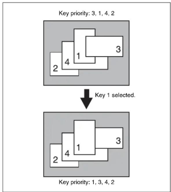
flowchart
graph TD
    A["Key priority: 3, 1, 4, 2"] --> B["Key 1 selected."]
    B --> C["Key priority: 1, 3, 4, 2"]
To change the priority of more than one key, repeat this operation as required.
Changing the key priority for after the transition
When executing a transition, turning on the next transition selection button [KEY PRIOR] causes the keys to be rearranged based on the set priority.
To set the key priority for after the transition, use the following procedure.
1 In the transition control block, hold down the [PRIOR SET] button and press the [KEY PRIOR] button to turn it on. Do not release the [PRIOR SET] button before advancing to step 2.
The [KEY PRIOR] button lights green, and it becomes possible to change the key priority setting for after the transition.
2 Hold down the [PRIOR SET] button, and press the one of the next transition selection buttons [KEY1] to [KEY4] ([DSK1] to [DSK4] buttons in the PGM/PST bank) for the key you want to bring to the front after the transition.
To set the priority to be the same as before the transition, press the [BKGD] button.
Notes
- The [BKGD] button is only effective when in the mode for changing the key priority for after the transition.
- To select [Key5] to [Key8], or [DSK5] to [DSK8] requires an assignment (see page 388). - The key priority establishes a separate priority order within each of the groups of keys 1 to 4 and keys 5 to 8. You can make any setting within the groups of keys 1 to 4 or keys 5 to 8, but not for combinations of keys from different groups. For example, it is not possible to set a priority sequence of keys 1, 5, and 2.
When the next transition selection button [KEY PRIOR] is on, the selected key appears on top on the preview monitor. The priority of keys other than the selected one does not change.
3 To change the priority of more than one key, repeat the previous operation as required.
4 Execute the transition.
The keys are rearranged based on the set priority.
Setting the Key Priority by a Menu Operation
When using keys 1 to 8, set the priority separately for the two groups (see page 97).
Changing the priority of the currently inserted keys
1 In the M/E or PGM/PST menu, select first VF7 'Misc,' then HF3 'Key Priority.'
The Key Priority menu appears.
2 For each of
The keys are inserted in the key priority sequence with priority 1 at the front.
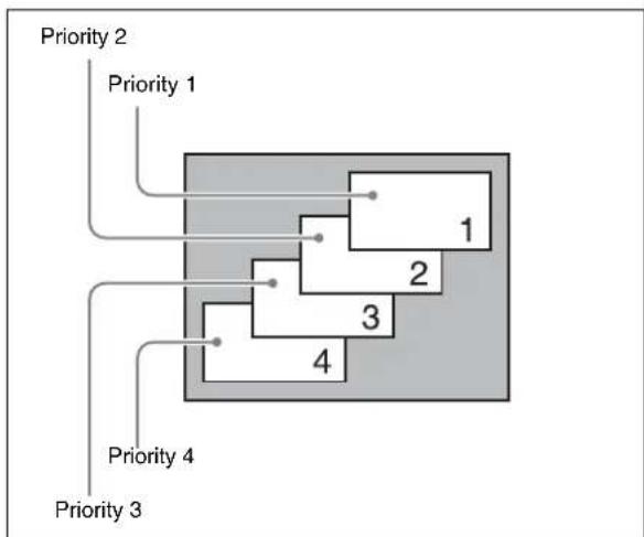
flowchart
graph TD
    A["Priority 2"] --> B["Priority 1"]
    B --> C["1"]
    B --> D["2"]
    D --> E["3"]
    D --> F["4"]
    G["Priority 3"] --> H["Priority 4"]
    H --> I["4"]
Notes
It is not possible to select the same key for two or more priority numbers.
The keys appear in the set order on the program monitor.
Changing the key priority for after the transition
1 In the M/E or PGM/PST menu, select first VF7 'Misc,' then HF4 'Next Key Priority.'
The Next Key Priority menu appears.
2 For each of
For details of the key priority sequence, see the figure shown for step 2 in the previous item (see page 96).
The keys appear in the set order on the preview monitor.
3 Execute the transition.
The keys are rearranged in the set order on the program monitor.
Display of the Key Output Status and Key Priority
You can check whether keys are currently output, and the key priority setting, using the key status display in the transition control block of the M/E or PGM/PST bank. The display is above the next transition selection buttons [KEY1] to [KEY4] ([DSK1] to [DSK4] buttons in the PGM/PST bank).
Notes
You can change the assignment of the next transition selection buttons [KEY1] to [KEY4]. If this is changed, the output status and priority is shown for the assigned key.
Display of the key output status
When a key is included in the output from the M/E or PGM/PST bank, the corresponding ON indicator lights.
Key priority display
The key priority is indicated by numerals 1 to 4 lighting. The topmost key as seen on the program monitor is priority 1, and the keys underneath are numbered 2, 3, 4 away from the viewer (see page 96).
To display the key priority for after the transition, press the [KEY PRIOR] button in the transition control block, turning it on. For keys for which the priority after the transition is different from the current priority, the corresponding numerals 1 to 4 flash. For a key with the same priority, the indication remains on.
Example key status display given when the [KEY PRIOR] button is pressed:
Current key priority: 1, 2, 3, 4
Key priority after the transition: 3, 2, 1, 4
Indicators: 1, 3 (flashing), 2, 1 (flashing), 3, 4
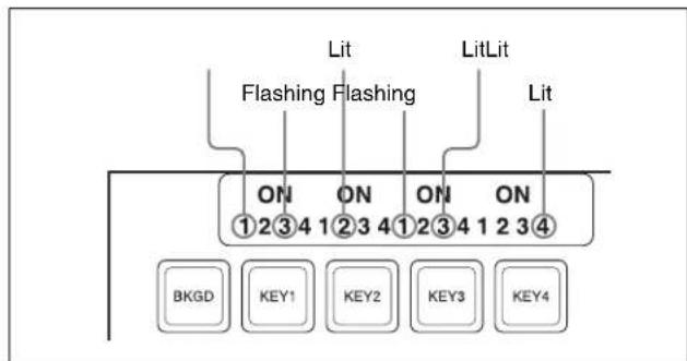
Example key status display (showing the key priority after the transition)
Priority Setting for Keys 1 to 8
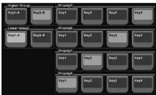
Set the priority for each of the groups consisting of keys 1 to 4 and keys 5 to 8.
1 In the VF7 'Misc' menu, select HF3 'Key Priority,' to display the Key Priority menu.
2 In
The button you pressed lights green, and this becomes the reference group.
3 Set the reference group priority.
4 In
5 Set the priority for the other group.
Selecting the Transition Type by a Menu Operation
You can also select the required transition type by a menu operation.
1 In the M/E or PGM/PST menu, select first VF7 'Misc,' then HF1 'Transition.'
The Transition menu appears.
2 Select the required transition type in the
The parameter settings can now be adjusted with the knobs according to the selected transition type.
For details, see the following.
- "Super Mix Settings" (page 99)
• "Color Matte Settings" (page 99)
- "Setting the Transition Rate" (page 101)
- “Color Matte Settings” (page 99) - “Setting the Transition Rate” (page 101)
Notes
When multi-program mode is selected in the Setup menu, there may be cases in which two or more transition types have been selected.
For details, see “Setting the Operation Mode” in Chapter 20 (Volume 2).
Super Mix Settings
You can set the output levels of the current and new video signals at the mid-point of the transition, in the range 0 to 100%.
Notes
This transition type is not available for an independent key transition.
1 In the M/E or PGM/PST menu, select first VF7 'Misc,' then HF1 'Transition.'
The Transition menu appears.
2 Select [Super Mix] in the
3 Turn the knobs to adjust the output levels.
| Knob | Parameter | Adjustment | Setting values |
| 2 A Gain | Background | A output level | 0.00 to 100.00% |
| 3 B Gain | Background | B output level | 0.00 to 100.00% |
Color Matte Settings
You can specify the color matte by luminance, saturation, and hue values.
Also, in place of a color matte you can use an image selected on the utility 2 bus.
Notes
- This transition type is not available for an independent key transition.
- In the multi-program mode, you can use a preset color mix only when selecting the background for the next transition.
One-stroke mode and one-time mode
- You can make a setting such that a preset color mix is carried out in a single transition. This is called “one-stroke mode.”
When the bus fixed mode is selected with a Setup menu setting, a preset color mix is always carried out in the one-stroke mode. - You can also make a setting such that when a preset color mix is completed, the next transition switches to the previous transition type automatically. This is called “one-time mode.”

Chapter 3 Signal Selection and Transitions
When only the background is changed
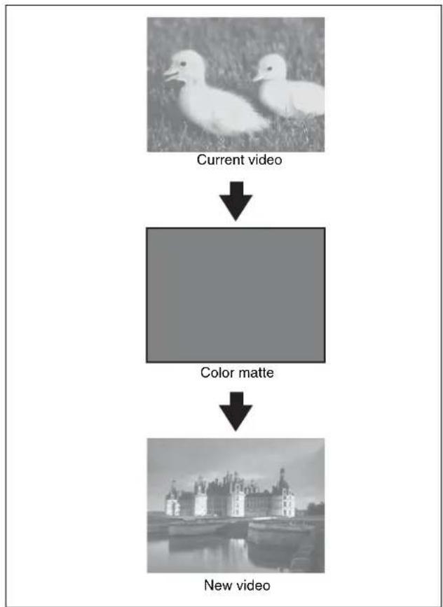
flowchart
graph TD
    A["Current video"] --> B["Color matte"]
    B --> C["New video"]
Preset color mix (changing background only)
When a key is inserted
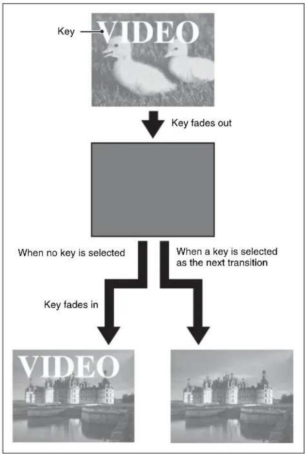
flowchart
graph TD
    A["VIDEO"] -->|Key fades out| B[" "]
    B -->|When no key is selected| C["VIDEO"]
    B -->|When a key is selected as the next transition| D["VIDEO"]
    C --> E["VIDEO"]
    D --> F["VIDEO"]
Preset color mix (transition including key)
By means of a Setup menu setting, it is possible to preserve the key state while carrying out the color matte mix.
When, with a key inserted, a key is selected in the next transition
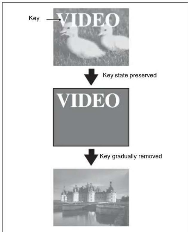
flowchart
graph TD
    A["VIDEO"] -->|Key state preserved| B["VIDEO"]
    B -->|Key gradually removed| C["Image of castle"]
Preset color mix (when set to preserve key state)
Setting the color matte
1 In the M/E or PGM/PST menu, select first VF7 'Misc,' then HF1 'Transition.'
The Transition menu appears.
2 Select [Preset Color Mix] in the
3 In the
Flat Color: monochrome color matte
Utility 2 Bus: signal selected on the utility 2 bus
4 When "Flat Color" is selected, turn the knobs to adjust the color matte.
| Knob | Parameter | Adjustment | Setting values |
| 2 Luminance | Luminance | 0.00 to 100.00 | |
| 3 Saturation | Saturation | 0.00 to 100.00 | |
| 4 Hue | Hue 359.99 to | 0.00 |
Executing a Transition
There are two modes of executing a transition: an auto transition by button operation or a manual transition using the fader lever.
It is also possible to combine both methods, taking control with the fader lever of an auto transition which has partly completed, or complete a transition started with the fader lever as an auto transition.
By combining common transitions with independent key transitions, different transition types can be applied to the background and keys, for example allowing a key wipe combined with a background dissolve.
When the audio mixer is linked in setup, you can carry out an auto transition, and also switch the sound with the audio mixer (see page 94).
Transition Indicator Function
In each of the M/E banks and PGM/PST bank, to the left of the fader lever is a transition indicator composed of multiple LEDs. This indicator shows the state of the transition, whether auto or manual, by which LEDs are lit.
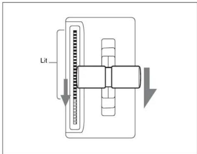
Transition indicator
For example, in the previous illustration, it can be seen that the transition is more than half completed. When the transition is completed, all of the LEDs go off.
Setting the Transition Rate
There are two ways of setting the transition rate: using the Flexi Pad control block, Multifunction Flexi Pad control block or numeric keypad control block to enter a numeric value, or using the Misc menu to access the Transition menu for the M/E or PGM/PST bank.
You can also display the transition rate, independent key transition rate, and fade-to-black transition rate for each of the M/E and PGM/PST banks, and change the settings (see page 230).
Notes
When a clip transition is selected as the transition type, it is not possible to set the transition rate.
Frame input mode and timecode input mode
For numeric input of the transition rate value, there are two modes: frame input mode and timecode input mode. You select one of these modes using either the Flexi Pad control block (page 102), Multifunction Flexi Pad control block or the numeric keypad control block (page 103).
Frame input mode: The entered value is a number of frames.
Example: Entering 123 constitutes an entry of 123 frames
Timecode input mode: The entered value is a timecode value.
Example: Entering 123 constitutes an entry of 1 second 23 frames.
Notes
Whereas you can enter a value of up to 999 in frame input mode, a value not smaller than 10 seconds cannot be entered in timecode input mode.
Frame display mode and timecode display mode
For the transition rate display in the transition control block, there are two modes: frame display mode and timecode display mode. You can select one of these modes in setup.
For details, see “Setting the Transition Rate Display Mode” in Chapter 19 (Volume 2).
Notes
The setting is common to all banks of the switcher.
Frame display mode: Values are shown as from 0 to 999 frames. In this display mode, a value entered in timecode input mode is converted for display as a number of frames.
Timecode display mode: Values are shown as timecode values, consisting of seconds and frames. In this display mode, a value entered in frame input mode is converted for display as a timecode value. If the value consists of four or more digits, the last digit is not shown.
Example: A value of 9 seconds 23 frames appears as "9.23" and a value of 10 seconds 1 frame appears as "10.0."
Setting the transition rate in the Flexi Pad control block
Notes
When using a simple-type transition control block, you cannot use the Flexi Pad control block to set the transition rate.
1 In the M/E bank Flexi Pad control block, press the [TRANS RATE] button.
The memory recall section display is now ready to accept the entered transition rate.
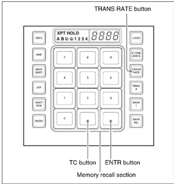
Flexi Pad control block (standard type)
2 Enter the desired transition rate with the numeric keypad.
If required, press the [TC] button to toggle the input mode (frame input or timecode input).
- Enter a value of up to three digits.
- To cancel the entry, press any of the six buttons in the leftmost column ([WIPE], [DME], ...) or the [TRANS RATE] button.
3 Press the [ENTR] button.
This confirms the entry, and the new setting appears in the transition control block display.
Setting the transition rate in the numeric keypad control block
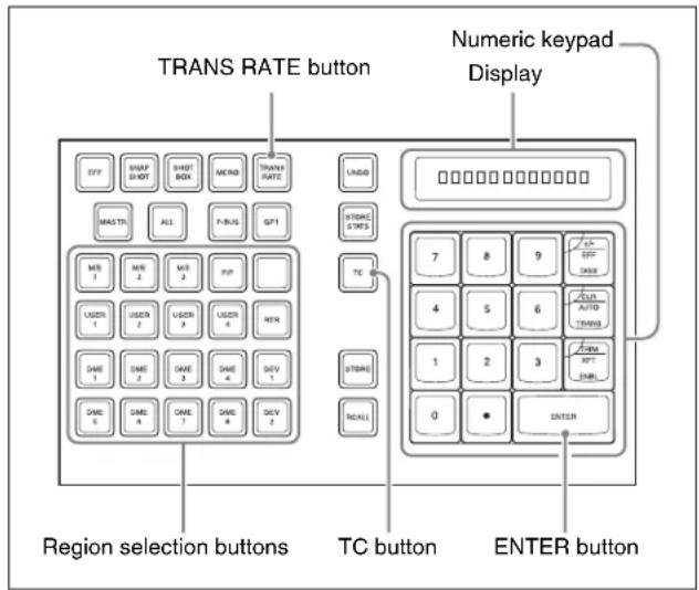
Numeric keypad control block
1 In the numeric keypad control block, press the [TRANS RATE] button.
2 Press the region selection button for the M/E or PGM/PST bank for which you want to set the transition rate, turning it on.
The numeric keypad control block display now shows the selected region name and the current transition rate setting for the region.
3 With the numeric keypad, enter the transition rate.
If required, press the [TC] button to toggle the input mode (frame input or timecode input).
- Enter a value of up to three digits.
- To clear the entry, press the [CLR] button.
4 Press the [ENTER] button.
This confirms the entry, and the selected region name and the set transition rate appear in the numeric keypad control block display.
The transition control block display of the same bank (M/E or PGM/PST) also shows the setting.
To enter a difference from the current value
After pressing the [+/-] button, enter the difference and press the [TRIM] button.
To change the sign (+ or -), press the [+/-] button.
Setting the transition rate in the Multifunction Flexi Pad control block
1 In the Multifunction Flexi Pad control block, press the [TRANS RATE] button.
The button displays in the memory recall section change as shown in the following illustration, and the Multifunction Flexi Pad control block switches to the transition rate setting mode.
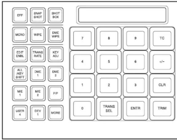
2 In the region selection buttons, select the switcher bank.
3 Press the [TRANS SEL] button in the memory recall section.
The button displays in the memory recall section change as shown in the following illustration, and you can select the type of transition for which to set the rate.
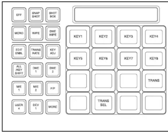
4 Press the [TRANS] button.
You can now set the M/E-1 block background transition rate.
5 Watching the alphanumeric display, enter the transition rate you want to set with the memory recall section button.
If required, press the [TC] button to switch the input mode (frame count input or timecode input).
- Enter a value of up to three digits.
- To cancel the input, press any of the mode selection buttons.
6 Press the [ENTR] button.
Setting the transition rate by a menu operation
1 In the switcher bank, select first VF7 'Misc,' then HF1 'Transition.'
The Transition menu appears.
2 Select any transition type in the
3 Turn the knob to set the transition rate.
| Knob | Parameter | Adjustment | Setting values |
| 1 Transition Rate | Transition Rate 0 | to 999 (frame count) | |
Displaying the transition rates in a menu and changing the settings
For each of the M/E and PGM/PST banks, you can display the transition rate, independent key transition rate and fade-to-black transition rate, and change the settings (see page 230).
Pattern Limit
When a wipe or DME wipe pattern is selected for the transition, you can specify the range of movement of the wipe pattern through the course of the transition, for each bank independently.
When the pattern limit function is enabled, carrying out a transition results in the following effect for example settings.
- When the limit value is set to 50% , the effect at the end of the transition is the same as when the fader lever is at the center position in the normal case (with the pattern limit function disabled); the wipe pattern does not complete.
- When the limit value is set to 0% , the wipe effect is completely disabled, and carrying out the transition produces no change in the image.
- When the limit value is set to the maximum 100% , the image changes in exactly the same way as when the pattern limit function is off, but when the transition is completed, the cross-point selections on the background A and B buses do not interchange.
There are two ways of setting a pattern limit: either by operating the fader lever to save the fader position, or by using the Wipe menu or DME Wipe menu to access the Edge/Direction menu for the M/E or PGM/PST bank.
Notes
- A pattern limit only applies when a wipe or DME wipe is selected as the transition type.
- A pattern limit cannot be applied to an independent key transition (see page 109).
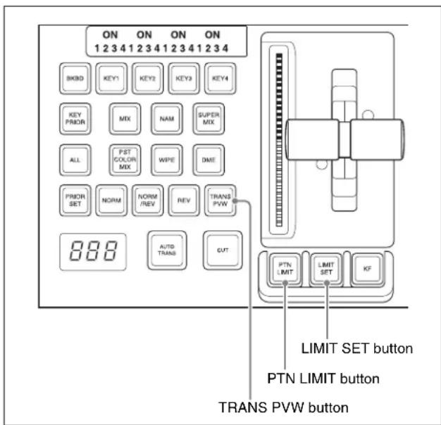
Transition control block (standard type)
Setting the pattern limit with the fader lever
1 Move the fader lever to the position corresponding to a particular pattern size.
- First make sure that the [PTN LIMIT] button is off.
- To check the pattern size on the preview monitor, first press the [TRANS PVW] button, to select the transition preview mode (see page 108).
2 Press the [LIMIT SET] button.
This sets the current fader lever position as the pattern limit.
Setting the pattern limit by a menu operation
1 When a wipe is selected as the transition type, in the M/E or PGM/PST menu, select first VF5 'Wipe,' then HF4 'Edge/Direction.'
When a DME wipe is selected as the transition type, in the M/E or PGM/PST menu, select first VF6 'DME Wipe,' then HF4 'Edge/Direction.'
The Edge/Direction menu appears.
2 Press the [Pattern Limit] button, turning it on.
3 Turn the knobs to adjust the following parameters.
| Knob | Parameter | Adjustment Setting | values |
| 1 | Pattern Limit | Pattern limit 0.00 | ^a) to 100.00^b) % |
a) 0.00%: Executing the transition does not change the video output at all.
b) 100.00%: The transition is the same as when no pattern limit is set, but the cross-point button selections of the background A and B buses do not interchange when the transition completes.
Executing a pattern limit transition
1 Press the [PTN LIMIT] button, turning it on.
The button you pressed lights amber.
2 Carry out the transition.
The transition progresses as far as the set pattern limit. Even if the transition completes, the cross-point button assignments of the background A and B buses do not interchange.
3 Carry out the transition once again.
The status before the previous transition is restored.
To cancel the pattern limit
To cancel the pattern limit after completion of step 3 in the previous procedure, press the [PTN LIMIT] button, turning it off.
If after carrying out step 2 in the previous procedure, the pattern limit has been reached, carry out the following procedure.
1 Press the [PTN LIMIT] button.
The button you pressed lights green.
2 Carry out the transition.
The [PTN LIMIT] button goes off, and the pattern limit state is released.
Depending on the way in which the transition was executed, the action will be as follows.
- When you press the [CUT] button, the pattern limit is immediately released, and the image switches instantaneously.
- When you press the [AUTO TRANS] button, until the state of the next transition, the transition is carried out over the duration given by the transition rate.
- When you move the fader lever, the transition is carried out from the pattern limit state to the state
before the pattern limit transition was carried out. Moving the fader lever even a little synchronizes the fader lever position with the transition state, and you can move the fader lever either in the forward direction or in the reverse direction.
Depending on the Setup settings, the transition may be executed at the instant you press the [PTN LIMIT] button, and the button goes off. In this case, execution continues for the time specified by the dedicated transition rate in the menu setting, as far as the state of the next transition.
For details of the setting, see “Selecting the Bank to Make the Settings” in Chapter 20 (Volume 2).
To set the transition rate when the pattern limit is released
1 In the
Auto Trans Rate: Use the transition rate set in the transition rate control block
Independ Trans Rate: Independent transition rate
2 If you selected "Independ Trans Rate" in step 1, adjust the following parameter.
| Knob | Parameter Adjustment Setting | values | |
| 1 | Transition Rate | Independent transition rate | 0 to 999 (frames) |
Executing an Auto Transition
The following two modes can be used for auto transition.
Cut
A cut switches instantaneously from the current video to the new video. When the next transition is a key transition, the key cuts in or out instantaneously.
Auto transition
The transition from the current video to the new video is carried out automatically at a constant rate, using the transition effect selected as the transition type.
You can set the transition rate in advance (see page 101).
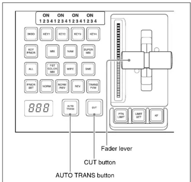
Transition control block (standard type)
To execute a transition on the M/E or PGM/PST bank by a button operation, use the following procedure in the transition control block.
To carry out an instantaneous cut transition: Press the [CUT] button.
To carry out a gradual transition: Press the [AUTO TRANS] button.
This executes the transition at the preset transition rate (see page 101).
While the transition is executing, the [AUTO TRANS] button lights amber. When it completes the button goes off.
To complete a partially executed transition instantaneously: Press the [CUT] button. The [AUTO TRANS] button goes off.
Executing a Transition With the Fader Lever (Manual Transition)
Using the fader lever, you can manually control the progress of the transition. Moving the fader lever from one end of its travel to the other completes the transition.
To execute a manual transition with the transition control block fader lever, use the following procedure.
To carry out the transition completely: Move the lever over the full range of its travel.
To pause a partly executed transition: Stop moving the fader lever.
To resume a paused transition: Resume moving the fader lever.
Combinations of Auto and Manual Transitions
Using the [AUTO TRANS] button, the [CUT] button, and the fader lever, use the following procedures.
Moving the fader lever during an auto transition
During an auto transition started by pressing the [AUTO TRANS] button, operating the fader lever immediately enables the fader lever, and the [AUTO TRANS] button goes off. Thereafter, the fader lever controls the progress of the transition.
Executing an auto transition after partly moving the fader lever
- Press the [CUT] button to instantaneously complete the transition.
- Press the [AUTO TRANS] button to complete the rest of the transition at the preset transition rate.
If the transition rate is set to 100 frames, and the fader lever has moved through 14 of the transition, then the remaining 34 of the transition is carried out in 100 frames.
Non-Sync State
If the fader lever is in an intermediate position when a transition is completed as an auto transition, then the lever position no longer agrees with the transition state. This is termed a non-sync state.
In a non-sync state, two lit LEDs indicate the position from which a normal transition can be carried out. This is either at one end position or both end positions of the fader lever travel.
Moving the fader lever toward the position of the lit LEDs does not carry out a transition, but when the fader lever reaches the end position the non-sync state is released, and it is now possible to carry out the next transition.
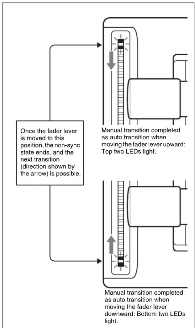
flowchart
graph TD
    A["Once the fader lever is moved to this position, the non-sync state ends, and the next transition (direction shown by the arrow) is possible."] --> B["Manual transition completed as auto transition when moving the fader lever upward: Top two LEDs light."]
    A --> C["Manual transition completed as auto transition when moving the fader lever downward: Bottom two LEDs light."]
- If the fader lever is moved in the direction away from the lit LEDs, this carries out the next transition, over the remaining part of the fader lever travel.
- Even in a non-sync state, you can carry out an auto transition by pressing the [AUTO TRANS] button. During the auto transition, the indicators show the transition progress in the usual way, but when the transition completes, they once again indicate the non-sync state.
Fader Lever Operation in Bus Fixed Mode
Flip-flop mode and bus fixed mode
The following describes the difference between flip-flop mode and bus fixed mode, taking an M/E bank as an example; the functionality is the same, however, on the PGM/PST bank.
Normally, when a background transition is carried out on an M/E bank, the signals selected on the A and B rows of cross-point buttons are interchanged at the end of the transition. That is to say, except during a transition, the background output is always from the background A bus. This is called “flip-flop mode.”
The alternative is known as “bus fixed mode,” in which there is no bus interchange. In this mode, when the fader lever is at the top of its travel the output from the A bus is always 100%, and when the fader lever is at the bottom of its travel the output from the B bus is 100%.
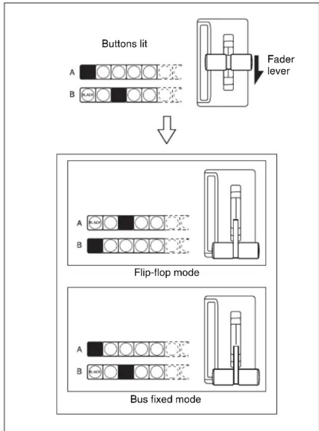
flowchart
graph TD
    A["Buttons lit"] --> B["Fader lever"]
    B --> C["Flip-flop mode"]
    C --> D["Bus fixed mode"]
Flip-flop mode and bus fixed mode
In the bus fixed mode there is a fixed relationship between the position of the fader lever and the signal output on each bus. Depending on the direction of the transition, the fader lever must therefore always be moved in a particular direction, as shown in the following table. This does not affect an auto transition, which is executed regardless of the fader lever direction.
| Next transition | Transition direction | Fader lever movement |
| Background A → | B Downward | |
| B → A Upward | ||
| Keys 1, 2, 3, 4, 5, 6, 7, and 8 | On → Off (deletion) | Downward |
| Off → On (insertion) | Upward |
- When a transition applies to a combination of more than one of the background and keys 1, 2, 3, 4, 5, 6, 7, and 8, then the transition for all of these must be in the same direction complying with the above table.
- If as a result of an auto transition, for example, the fader lever position does not agree with the signal output, this is a non-sync state (see page 106) and LEDs light at both end positions of the fader lever travel. Moving the fader lever does not carry out a transition, but when the fader lever reaches the end position the non-sync state is released, and it is now possible to carry out the next transition. If the fader lever is moved in the direction away from the lit LEDs, this carries out the next transition, over the remaining part of the fader lever travel.
Transition Preview
With the preview output of the M/E banks and PGM/PST bank, you can check the effect of a transition in advance. To carry out a transition preview, press the [TRANS PVW] button in the transition control block.
Notes
In multi-program mode, DSK mode or bus fixed mode (page 107), it is not possible to carry out a transition preview.
Carrying out a transition preview
1 In the M/E or PGM/PST bank transition control block, press the [TRANS PVW] button.
The [TRANS PVW] button lights green, and the switcher is now in the transition preview mode. At this point, the preview output is the same as the program output before the [TRANS PVW] button was pressed.
2 Operate the fader lever, or press the [AUTO TRANS] button or [CUT] button.
On the preview monitor, you can check the effect of the transition.
To terminate a transition preview
There are three modes for a transition preview. To terminate a transition preview, carry out the operation which depends on the mode, and press the [TRANS PVW] button, turning it off.
Lock: Toggling the [TRANS PVW] button on and off switches between the transition preview mode and the normal mode.
Hold: The preview mode obtains only while the [TRANS PVW] button is held down.
One Time: Each time a transition ends, it reverts to the normal mode.
Set the transition preview mode in the following combinations.
For details, see “Setting the Button Operation Mode” in Chapter 19 and “Settings Relating to Video Switching (Transition Menu)” in Chapter 20 (Volume 2).
| TransitionPreview mode | Switcher setup(Transition menu)group | Panel setup(Operation>Custom Button menu)group |
| Lock Normal Lock | ||
| Hold Normal Hold | ||
| One Time One | Time – | |
Notes
- During a transition, whether executed with the [AUTO TRANS] button or the fader lever, it is not possible to press the [TRANS PVW] button.
- In bus fixed mode (see page 107), transition previews are not available.
- When using the simple-type transition control block (see page 116), transition previews are not available.
Independent Key Transitions
What is an independent key transition?
In addition to common transitions, it is possible to carry out independent transitions on the keyers of the M/E banks and PGM/PST bank. These are called “independent key transitions.”
By carrying out an independent key transition in combination with a common transition, different transition types can be used for the background and keys. It is also possible to use different transition types for key insertion and key deletion by means of a Setup menu setting (see page 112).
Combining other transitions with independent key transitions
When you set a common transition and a key independent transition for the same key, you can apply two different effects such as a wipe and mix (dissolve) (see page 92) to the key simultaneously.
When carrying out such a combination of transitions simultaneously on a key as auto transitions (see page 105), the result depends on the timing of pressing the respective [AUTO TRANS] buttons.
Simultaneous execution
If the [AUTO TRANS] buttons for the two transitions are pressed simultaneously, the following is the result. Note that in both cases the common transition is a wipe and the independent key transition is a mix (dissolve).
Deleting a key with simultaneous transitions: With the key inserted, it is deleted simultaneously with the two transitions.
When the common transition completes, even if the independent key transition is still not completed, the two end simultaneously.
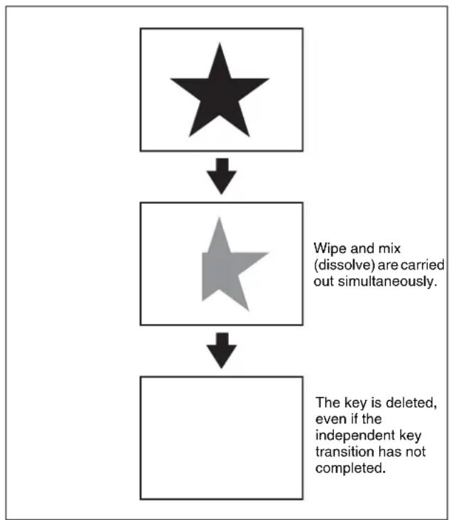
flowchart
graph TD
    A["★"] --> B["★"]
    B --> C["The key is deleted, even if the independent key transition has not completed."]
    style A fill:#000,stroke:#fff,color:#fff
    style B fill:#000,stroke:#fff,color:#fff
    style C fill:#000,stroke:#fff,color:#fff
Deleting a key with simultaneous transitions
Inserting a key with simultaneous transitions: With the key not inserted, it is inserted simultaneously with the two transitions. If the common transition or independent key transition ends first, the other continues to completion.
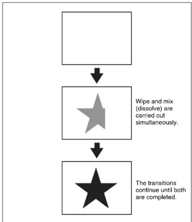
flowchart
graph TD
    A[" "] --> B["★"]
    B --> C["★"]
    style B fill:#99ccff,stroke:#333
    note1["Wipe and mix (dissolve) are carried out simultaneously"]
    note2["The transitions continue until both are completed."]
Inserting a key with simultaneous transitions
Time offset execution
If the [AUTO TRANS] buttons for the two transitions are pressed with a time offset, the following is the result. Note that in both cases the common transition is a wipe and the independent key transition is a mix (dissolve).
Time offset execution with the key inserted: With the key inserted, it is deleted with the two transitions acting with a time offset.
Whichever button is pressed first, when the common transition completes, even if the independent key transition is still not completed, the two end simultaneously.
Example: When the independent key transition [AUTO TRANS] button is pressed later
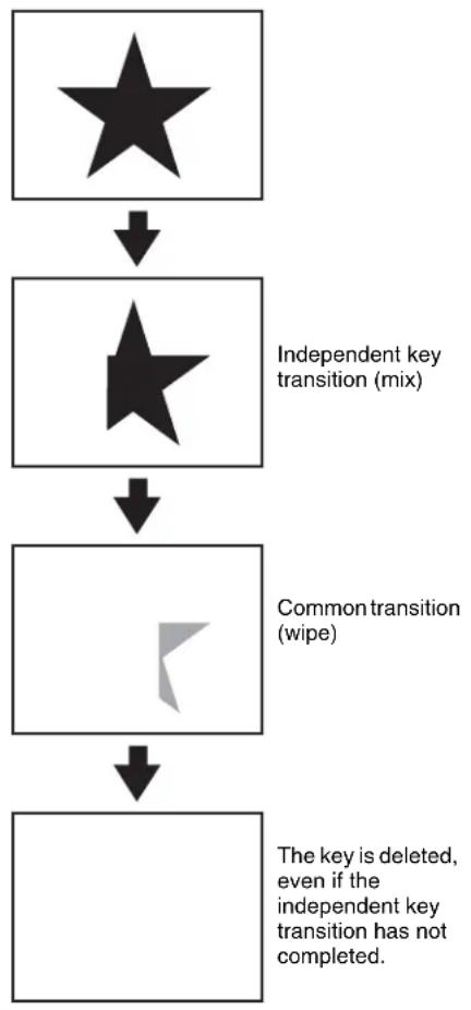
flowchart
graph TD
    A["★"] --> B["★"]
    B --> C["Common transition (wipe)"]
    C --> D["The key is deleted, even if the independent key transition has not completed."]
    style A fill:#000,stroke:#fff,color:#fff
    style B fill:#000,stroke:#fff,color:#fff
    style C fill:#000,stroke:#fff,color:#fff
    style D fill:#000,stroke:#fff,color:#fff
Time offset execution with the key inserted
Time offset execution with the key not inserted: With the key not inserted, it is inserted with the transition whose [AUTO TRANS] button is pressed first. Since the key is then in the inserted state, with the transition whose [AUTO TRANS] button is pressed later, the key is deleted. When the key is completely deleted, both transitions complete.
Example 1: When the independent key transition [AUTO TRANS] button is pressed later
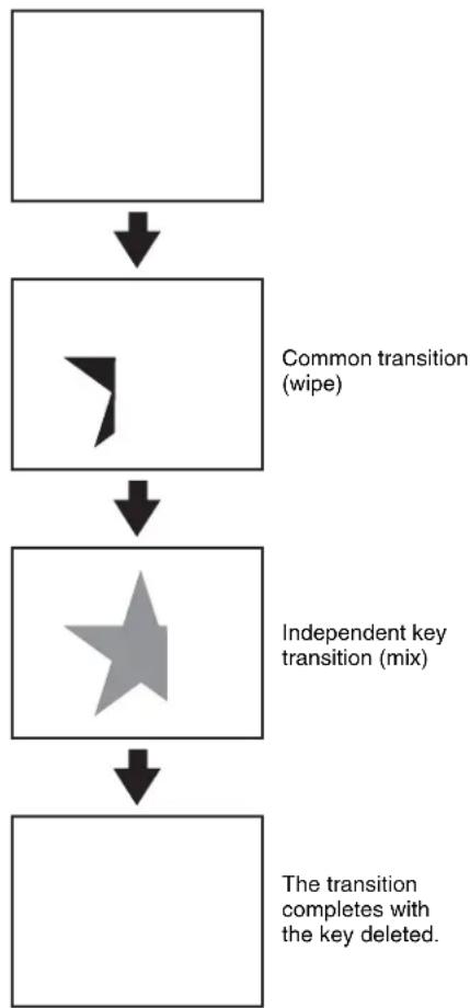
flowchart
graph TD
    A[" "] --> B[" Common transition (wipe) "]
    B --> C[" Independent key transition (mix) "]
    C --> D[" The transition completes with the key deleted. "]
Time offset execution with the key not inserted
Example 2: When the common transition [AUTO TRANS] button is pressed later
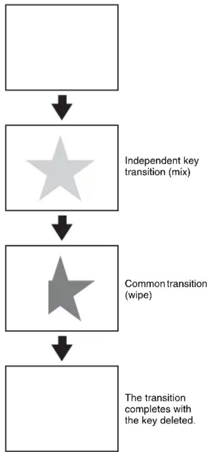
flowchart
graph TD
    A[" "] --> B["Independent key transition (mix)"]
    B --> C["Common transition (wipe)"]
    C --> D["The transition completes with the key deleted."]
Time offset execution with the key not inserted

Basic Independent Key Transition Operations
Key delegation buttons
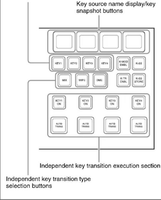
flowchart
graph TD
    A["Key source name display/key snapshot buttons"] --> B["KEY1"]
    A --> C["KEY2"]
    A --> D["KEY3"]
    A --> E["KEY4"]
    A --> F["K-MOD EMBL"]
    A --> G["K-SS"]
    A --> H["MIX"]
    A --> I["WIP5"]
    A --> J["OME"]
    A --> K["K-TR ENBL"]
    A --> L["K-SS STORE"]
    M["Independent key transition execution section"] --> N["KEY1 ON"]
    M --> O["KEY2 ON"]
    M --> P["KEY3 ON"]
    M --> Q["KEY4 ON"]
    M --> R["AUTO TRANS"]
    M --> S["AUTO TRANS"]
    M --> T["AUTO TRANS"]
    M --> U["AUTO TRANS"]
Independent key transition control block (standard type)
To set independent transitions for the keyers on the M/E or PGM/PST bank, use the independent key transition control block.
1 Select one or more of the delegation buttons [KEY1] to [KEY4] ([DSK1] to [DSK4] in the PGM/PST bank), turning them on.
You can press more than one button at the same time.
Notes
The buttons for [Key5] to [Key8] and [DSK5] to [DSK8] require previous assignment in the Setup menu (see page 388).
2 Select the transition type.
To fade a key in or out: Press the [MIX] button, turning it on.
To insert or delete a key using a dedicated wipe pattern: Press the [WIPE] button, turning it on.
To insert or delete a key using a dedicated DME wipe pattern: Press the [DME] button, turning it on.
To instantaneously insert or remove the key: press the [CUT] button, turning it on.
If, in the Setup menus, you set insertion and deletion as independent modes, make the settings for the next transition in the independent key transition control block.
Separate settings are required both when inserting a key and when deleting it. For example, with the key not inserted, if you select the transition type and carry out a transition, this will be the setting when inserting a key.
You can also use the Transition menu to select a desired independent key transition type for each key (see the next section).
For details of the wipe settings, see “Wipe Settings for Independent Key Transitions” (page 171). For details of DME wipe settings, see “DME Wipe Settings for Independent Key Transitions” (page 189).
3 Execute the transition.
To insert or delete the key gradually with a mix or wipe transition: Press the [AUTO TRANS] button.
For details of the transition rate, see “Setting the Independent Key Transition Rate” (page 113). For details of operation together with a common transition, see “Combining other transitions with independent key transitions” (page 109).
To cut the key in or out instantaneously: Press the [KEY ON] button on the keyer.
Notes
- In an independent key transition, the pattern limit function is not available.
-
When the following DME effects are set, the effects may be applied during wipe transitions. If the effects are not necessary, cancel the settings.
-
Trail
- Motion Decay
- Wind
When the Keyframe Strobe effect is set, operating keyframes do the same effect. Cancel the unnecessary settings.
Independent key transition operations when using the CCP-6224/6324 Control Panel
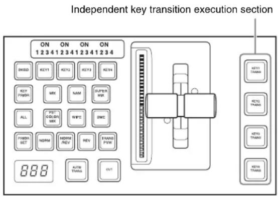
Transition control block (compact type)
To carry out an independent key transition, press the corresponding button in the independent key transition execution section of the transition control block.
The color of the button shows the status as follows.
Lit green: transition in progress.
Lit amber: key inserted.
Lit red: key inserted into final program output.
Off: no key inserted.
For details of setting the transition rate, see “Setting the transition rate in the Flexi Pad control block” (page 102).
Notes
The buttons for [Key5] to [Key8] and [DSK5] to [DSK8] require previous assignment in the Setup menu (see page 388).
Setting the Independent Key Transition Type by a Menu Operation
You can also select the required independent key transition type by a menu operation.
1 In the M/E or PGM/PST menu, select first the desired one from VF1 'Key1' to VF4 'Key4,' then HF6 'Transition.'
The Transition menu for the selected appears.
2 Select the required transition type in the
If, in the Setup menus, you set insertion/deletion as independent modes, make the settings for insertion in the
Setting the Independent Key Transition Rate
There are two ways of setting the transition rate: using the Flexi Pad control block, Multifunction Flexi Pad control block or numeric keypad control block to enter a numeric value, or using the Key menu to access the Transition menu for the M/E or PGM/PST bank.
You can also display the transition rate, independent key transition rate, and fade-to-black transition rate for each of the M/E and PGM/PST banks, and change the settings (see page 230).
When the setup selection is for separate transition rates for inserting or deleting a key, you can set both rates independently. For example, with the system in the state with the key not inserted, the transition rate setting applies to key insertion.
Setting the independent key transition rate in the Flexi Pad control block
Notes
In the PGM/PST bank or when using a simple-type transition control block, you cannot use the Flexi Pad control block to set the transition rate.
1 In the Flexi Pad control block of the M/E bank, hold down the [TRANS RATE] button, and in the independent key transition control block, press the delegation button [KEY1] to [KEY8] for the key for which you want to set the transition rate.
The memory recall section display is now ready to accept the entered independent key transition rate.
2 Enter the desired transition rate with the numeric keypad.
- Enter a value of up to three digits.
- To cancel the entry, press any of the six buttons in the leftmost column ([WIPE], [DME], ...) or the [TRANS RATE] button.
For details of frame input mode and timecode input mode, see page 102.
3 Press the [ENTR] button.
Setting the independent key transition rate in the numeric keypad control block
Notes
You cannot use the numeric keypad control block to set the transition rate for a simple transition.
1 In the numeric keypad control block, hold down the [TRANS RATE] button, and in the independent key transition control block, press the delegation button [KEY1] to [KEY8] ([DSK1] to [DSK8] in the PGM/PST bank) for the key for which you want to set the transition rate.
The numeric keypad control block changes to the mode for inputting the independent key transition rate, and its display now shows the corresponding region name and the current transition rate set for the region.
2 With the numeric keypad, enter the transition rate.
- Enter a value of up to three digits.
• To clear the entry value, press the [CLR] button.
For details of frame input mode and timecode input mode, see page 102.
3 Press the [ENTER] button.
This confirms the entry, and the selected region name and the set transition rate appear in the numeric keypad control block display.
To enter a difference from the current value
After pressing the [+/-] button, enter the difference and press the [TRIM] button.
To change the sign (+ or -), press the [+/-] button.
Setting the independent key transition rate in the Multifunction Flexi Pad control block
For example, to set the independent key transition rate for M/E-1 key1, carry out the following procedures.
1 In the Multifunction Flexi Pad control block, press the [TRANS RATE] button.
The Multifunction Flexi Pad control block switches to the transition rate setting mode.
2 In the region selection buttons, select the switcher bank.
3 Press the [TRANS SEL] button in the memory recall section.
You can select the type of transition for which to set the rate.
4 Press the [KEY1] button.
This enables setting of the independent key transition rate for M/E-1 key1.
5 Watching the alphanumeric display, enter the transition rate you want to set with the memory recall section button.
If required, press the [TC] button to switch the input mode (frame count input or timecode input).
- Enter a value of up to three digits.
- To cancel the input, press any of the mode selection buttons.
6 Press the [ENTR] button.
Setting the independent key transition rate by a menu operation
1 In the M/E or PGM/PST menu, select first the desired one from VF1 'Key1' to VF4 'Key4,' then HF6 'Transition.'
The Transition menu for the selected key appears.
2 Select any transition type in the
If, in the Setup menus, you set insertion/deletion as independent modes, make the settings for insertion in the
3 Turn the knob to set the transition rate.
| Knob | Parameter | Adjustment | Setting values |
| 1 Transition Rate | Transition rate 0 to 999 (frame count) | ||
Independent key transition rate display
To check the set independent key transition rate, press the key source name display/key snapshot button above the corresponding delegation button when the [K-SS] button is off.
Displaying the independent key transition rates in a menu and changing the settings
For each of the M/E and PGM/PST banks, you can also display the transition rate, independent key transition rate and fade-to-black transition rate, and change the settings (see page 230).
Fade to Black
The PGM/PST bank provides a fade-to-black function, controlled with the [FTB] button in the fade to black control block.
Notes
In multi-program mode or DSK mode, it is possible to carry out a fade-to-black on a number of programs simultaneously.
You can also make a Setup menu setting such that a fade-to-black does not apply to particular programs.
For details of the setting, see “Settings Relating to Video Switching (Transition Menu)” in Chapter 20 (Volume 2).
Fade to Black Operation
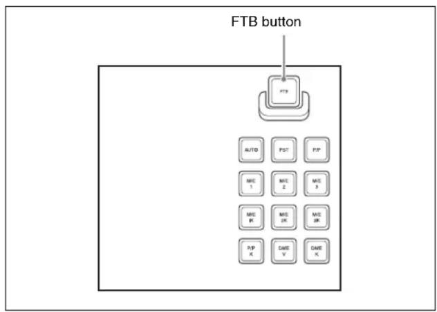
Fade to black control block
Carrying out a fade to black
Press the [FTB] button in the fade to black control block. The fade to black is carried out with the transition rate set for the program output of the PGM/PST bank. During the transition, the [FTB] button lights amber. When the transition completes (the video is completely black), the button lit color changes to red.
Setting the Fade to Black Transition Rate
Setting the fade to black transition rate
1 In the PGM/PST menu, select first VF7 'Misc,' then HF1 'Transition.'
The Transition menu appears.
2 Select [FTB].
3 Turn the knob to set the fade to black transition rate.
| Knob | Parameter | Adjustment | Setting values |
| 1 Transition Rate | Transition rate 0 to 999 (frame count) | ||
Displaying the transition rates in a menu and changing the settings
You can also display the transition rate, independent key transition rate, and fade-to-black transition rate for each of the M/E and PGM/PST banks, and change the settings (see page 230).
Simple Transition
Basic Operations for Simple Transitions
A simple-type transition control block is used to carry out a transition.
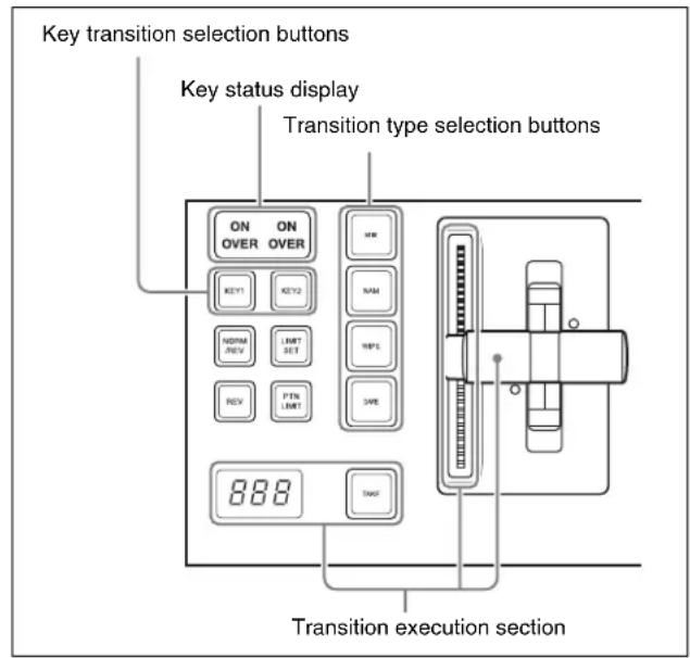
Transition control block (simple right-hand type)
Notes
The simple transition control block cannot be installed in the CCP-6224/6324 Control Panel.
Carrying out a transition using a simple-type transition control block
1 With the background A row of cross-point buttons in the cross-point control block, select the background video.
2 Using one of the following methods, select the way in which the transition will affect the image.
Use a combination of the transition type selection buttons ([MIX], [NAM], [WIPE] and [DME]) and the next transition selection buttons ([KEY1] and [KEY2]).
For an overview of the mix, NAM, wipe, and DME wipe transition types, see “Transition Types” (page 92).
To change the background only: Press one of the [MIX], [NAM], [WIPE], and [DME] buttons. The [KEY1] and [KEY2] buttons go off, and the system changes to the background transition mode.
To insert or delete key 1: Hold down the [KEY1] button and press one of the [MIX], [NAM], [WIPE], and [DME] buttons.
To insert or delete key 2: Hold down the [KEY2] button and press one of the [MIX], [NAM], [WIPE], and [DME] buttons.
To insert or delete key 1 and key 2 simultaneously: Hold down the [KEY1] and [KEY2] buttons, and press one of the [MIX], [NAM], [WIPE], and [DME] buttons.
To use a super mix or preset color mix: Select [Super Mix] or [Preset Color Mix] in the Misc >Transition menu for the M/E or PGM/PST bank.
To set the key priority, use the Misc >Key Priority menu for the M/E or PGM/PST bank (see page 96).
Notes
The transition type selection buttons ([MIX], [NAM], [WIPE], and [DME]) can be assigned to other transition types in setup.
For details, see “Setting Transition Control Block Button Assignments” in Chapter 19 (Volume 2).
3 Select the new background for after the transition.
- Select the background video with the background B row of cross-point buttons.
- To insert a key, select the key signal, and make various settings as required.
For details of key settings, see Chapter 4 "Keys" (page 119).
4 Depending on the transition type selected in step 2, make the required settings.
For details of the settings, see the following sections:
Super mix: "Super Mix Settings" (page 99)
Preset color mix: "Color Matte Settings" (page 99)
Wipe: "Basic Procedure for Wipe Settings" (page 159)
DME Wipe: "Basic Procedure for DME Wipe Settings" (page 183)
Clip transition: “Clip Transition Operations” (page 215)
5 Carry out the transition in the transition execution section.
For a gradual transition such as a mix or wipe: Press the [TAKE] button, or operate the fader lever.

See “Setting the Transition Rate” (page 101) and “Pattern Limit” (page 104) as required.
Display of the Key Output Status and Key Priority
You can check the output status of keys 1 and 2 and the key priority setting, in the key status display in the transition control block.
The key status display includes two ON indicators corresponding to keys 1 and 2.
Display of the key output status
When the key is inserted in the output from the M/E or PGM/PST bank, the indication "ON" lights, and when it is not inserted, the indication goes off.
Key priority display
The key lying in front on the program monitor has an indication "OVER" lit.
To set the key priority, use the Misc >Key Priority menu for the M/E or PGM/PST bank (see page 96).
Split Fader
What does "split fader" mean?
The term “split fader” refers to the function of carrying out a transition with the fader lever split into left and right halves, so that the background A and background B buses can be manipulated separately.
To use the split fader, the following conditions must be met.
• The fader lever is in bus fixed mode.
For details, see "Selecting the Bank to Make the Settings" in Chapter 20 (Volume 2).
- The necessary settings have been made in a Setup menu to enable the split fader.
For details, see "Selecting the Bank to Make the Settings" in Chapter 20 (Volume 2).
- A background is selected for the next transition.
- For the transition type, [MIX] or [NAM] is selected.
Split fader operation
The two halves of the split fader lever correspond to the buses as follows.
Right fader lever: Background A bus
Left fader lever: Background B bus
The relationship between the positions of the two fader levers and the image output in a mix is as follows.
| Left lever position | Right lever position | A bus output | B bus output |
| Top Top 100% | 0% | ||
| Bottom Top 100% | 100% | ||
| Top Bottom 0% | 0% |
| Left lever position | Right lever position | A bus output | B bus output |
| Bottom Bottom | 0% 100% | ||
| Center Center | 50% 50% |
- When the transition type is NAM, the outputs of the A bus and B bus in the above table are the outputs subjected to NAM.
• The transition indicators always show the progress of the background A bus.
• The operation of the left lever and that of the right lever can be swapped.
For details, see "Specifying Main Split Fader" in Chapter 19 (Volume 2).
Independent Key Transitions With a Simple Transition Module
You carry out independent key transition operations using the independent key transition control block (simple type). This controls only keys 3 and 4. However, each key button can be assigned to any key in setup.
For details, see "Assigning a Function to the Independent Key Transition Control Block (Simple Type)" in Chapter 19 (Volume 2).
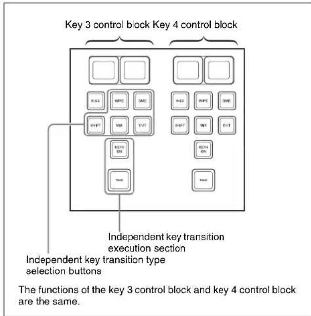
Independent key transition control block (simple type)
Carrying out a transition using a simple-type independent key transition control block
1 Select the transition type for key 3 or key 4 using the independent key transition type selection buttons.
To fade a key in or out: Press the [MIX] button, turning it on.
To insert or delete a key using a dedicated wipe pattern: Press the [WIPE] button, turning it on.
To insert or delete a key using a dedicated DME wipe pattern: Press the [DME] button, turning it on.
For details of wipe settings, see “Wipe Settings for Independent Key Transitions” (page 171). For details of DME wipe settings, see “DME Wipe Settings for Independent Key Transitions” (page 189).
To cut the key instantaneously in or out: Press the [CUT] button, turning it on.
If, in the Setup menus, you set insertion and deletion as independent modes, make the settings for the next transition in the independent key transition control block.
Separate settings are required both when inserting a key and when deleting it. For example, with the key not inserted, if you select the transition type and carry out a transition, this will be the setting when inserting a key.
2 Carry out the transition in the independent key transition execution section.
To insert or delete the key gradually with a mix or wipe transition: Press the [TAKE] button.
To set the independent key transition rate using a simple-type transition control block, use the key 3 and key 4 Transition menus (see page 113).
To cut the key in or out instantaneously: Press the [KEY 3 ON] button or [KEY 4 ON] button.
Notes
In an independent key transition, the pattern limit function is not available.
Overview
A key is an effect in which a part of the background image is replaced by an image or superimposed text. The signal determining how the background is cut out is termed “key source,” and the signal that replaces the cut-out part is termed “key fill.”
The system component responsible for processing a key is referred to as a keyer.
Each M/E bank and the PGM/PST bank has eight keyers, and all of these keyers provide the same functions.
Notes
When the signal format is 1080P, four keyers can be used (keys 1 to 4).
Key Types
The key type indicates the manner in which the key source signal is used to cut out the background. In each bank, you can use the following key types. You can select the key type using the key type selection buttons in the key control block or Multi function Flexi Pad control block, or by a setting in the Type menu for the keyer (see page 123).
Luminance key
The background is cut out according to the luminance (Y) of the key source signal, and at the same time the key fill signal is cut out and then added to the background signal.
Linear key
This is a type of luminance key, but there is a reduced variability in gain, allowing more precise adjustment.
Color vector key
The key signal is created from a combination of the luminance and chrominance components of the key source signal. When perfect keying is not possible with a luminance key, this allows a key signal to be created even if the luminance level is low, provided that the colors have high saturation.
Clean mode
In a luminance key, linear key or color vector key, you can enable the clean mode. When the clean mode is on, the key source does not affect the key fill, which is added unchanged to the background. This improves the keyed image quality, but means that the part of the key fill signal which is not to be inserted must be completely black, or it will color the background. You set the clean mode with the Type menu of the respective keyer.
For details, see “Setting the key type in a menu” (page 123).
Note that in the following situations, the clean mode goes off, and cannot be turned on.
- When the key type is a pattern key
- When key inversion is on
- When the key fill is a matte
- When the key edge is an outline
- When the key edge is normal with soft edge being on
- When fine key is on
- When the key positioner is on

Chroma key
A key signal based on a particular color is used to cut out the background, and the key fill is then inserted. The inserted signal is also referred to as the foreground, and the composite image is called a chroma key image.
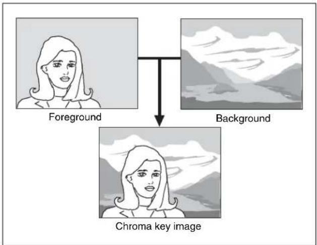
flowchart
graph TD
    A["Foreground"] --> C["Chroma key image"]
    B["Background"] --> C["Chroma key image"]
For details of chroma key, see (page 126) and (page 127).
Wipe pattern key
This uses the wipe pattern selected for a transition as the key source.
Key wipe pattern key
This uses the wipe pattern selected for an independent key transition as the key source.
Note on wipe pattern modifiers
In a wipe pattern key or key wipe pattern key, you can apply various modifications, depending on the pattern used, and the modifiers in common with a wipe. However, modifiers which relate to the wipe direction and edge are not reflected.
Key Modifiers
Edge modifiers
You can apply borders and other effects to the edge of the key (see pages 130 and 140).
| Name Effect Image | ||
| Normal T | This is the state with no key edge modifiers applied. |  |
| Name Effect Image | ||
| Border T | This applies a uniform width border to the edge of the key. You can adjust the border width and density. You can also enable the separate edge function, and adjust the top, bottom, left, and right border widths separately. |  |
| Drop border | This applies a border below and to the right for example, of the key. You can adjust the border width, position, and density. |  |
| Shadow | This applies a shadow below and to the right for example, of the key. You can adjust the shadow width, position, and density. |  |
| Outline T | This uses the outline of the original key as the key. You can adjust the width and density of the outline. You can also enable the separate edge function, and adjust the top, bottom, left, and right outline widths separately. |  |
| Emboss | This applies an embossing effect to the outline of the key. You can adjust the width and position of the embossing and the density. You can adjust the density separately for key fill and key edge. When embossing is on, the Fine Key and zabton functions go off. | - |
| Soft edge | This softens the edge of the key. | - |
| Zabton T | This inserts a translucent pattern behind a key. You can adjust the pattern size, softness, density and color. | - |
Edge type and key fill/key source position
The key edge modification function has two modes: a mode (“key drop ON mode”) in which the key fill/key source position moves downward, and a mode (“key drop OFF mode”) in which it does not move downward.
Key drop ON mode: The key fill/key source position moves downward by eight scan lines or four scan lines. When a drop border or shadow is selected, it is possible to apply a border to the top edge of the key.
Key drop OFF mode: The key fill/key source position does not move. When a drop border or shadow is selected, it is not possible to apply a border to the top edge of the key.
In the key drop ON mode, a menu setting selects between the mode (“4H mode”) in which the key fill/key source position is lowered by four scan lines, and the mode (“8H mode”) in which the key fill/key source position is lowered by eight scan lines.
When Fine Key is on, the edge width is forced to the range 0.00 to 4.00.
Note that in the following situations, the key drop mode is forcibly turned on.
- When the edge type is border, outline, or emboss
- When the edge type is normal with soft edge being on
- When Fine Key is on
To fix key fill / key source in key drop off mode
Switch frame delay mode on.
Regardless of the fine key and edge type settings, key fill and key source are fixed in key drop off mode. In this mode key image has a one-frame delay.
Notes
This function uses the resizer, and therefore the normal effect of the setting is not obtained while using DME wipe or other effect that uses the resizer.
Edge fill
When a border, drop border, or shadow modifier is selected, you can select a signal to fill these edge effects. The edge fill may be either the signal from the dedicated color matte generator, or the signal currently selected on the utility 1 bus.
In the case of an outline, there is no edge fill signal selection, because the key fill signal fills the outline, and the rest of the image remains as the background. For the emboss effect, in place of the edge fill signal, the emboss fill matte 1 and emboss fill matte 2 signals are used.
Masks
A mask is used to inhibit the effect of a key over a part of the image. This allows parts of the background which would otherwise be keyed to be protected, or to correct the key if it is not of the desired shape.
For details of masking operations, see “Masks” (pages 133 and 141).
Key mask and background mask
There are two types of mask: a key mask and a background mask.
Key mask: This masks out a part of the key, which will result in the background appearing.
Background mask: This masks out a part of the background, which will result in the key fill appearing.
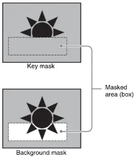
Main mask and subsidiary ("sub") mask
Each keyer allows two masks to be used simultaneously, and these are referred to as the main mask and the sub mask. The signal that determines the mask shape and size is termed the mask source, and different sources are used for the main mask and sub mask.
Main mask: This uses the signal from the dedicated box generator provided on each keyer, or the signal from the dedicated pattern generator as the mask source. When the box generator is selected, a rectangular mask is formed. You can adjust the positions of the four sides of the box separately. When the pattern generator is selected, you can select the pattern and apply modifiers.
Sub mask: This uses the wipe generator signal or the signal selected on the utility 1 bus, as the mask source. When the wipe generator is selected, the patterns and the pattern modifiers are the same as in a wipe transition.
Key Memory
The key memory function allows the keyer settings on each cross-point button to be automatically stored, so that
the next time the same cross-point button is selected these settings are recalled automatically.
There are two modes for key memory: simple mode and full mode.
The parameters stored in each mode are as follows.
Simple mode: key type, clean mode (including the plane setting for chroma keying), key position, key inversion, and adjustment values for the particular key type (Clip, Gain, Density, Filter, etc. This includes color vector key, wipe pattern key, key wipe pattern key, and chroma key. However, in the case of a chroma key, it excludes color cancel, Y balance, foreground CCR, window, and shadow.)
Full mode: All settings except transition (the same parameters as simple mode, Fine Key, key modifiers, main and sub mask settings, chroma key detailed settings, and so on)
For the settings for these modes, see “Selecting the Bank to Make the Settings” in Chapter 20 (Volume 2).
Key Default
With a simple operation you can return the key adjustment values to their defaults.
The adjustment values which can be returned to their default values are as follows.
- Adjustment values for the particular key type (Clip, Gain, Density, Filter, etc.)
In the case of chroma keying, all adjustment values return to their default values.
• Key position
• Key inversion - Clean mode
For details, see “Returning the key adjustment values to their defaults” (page 144).
For the menu operation to return the key adjustment values to their defaults, see “Returning to Default State in Function Groupings” (page 82).
Key Setting Operations Using Menus
There are two ways of making key settings: either using menus, or using the key control block or the Multifunction Flexi Pad control block.
This section describes basic procedures for making key settings using the menus, taking the M/E-1 >Key1 menu as an example.
Operations in the Key menus are the same for all banks (M/E-1 to M/E-3 and PGM/PST).
For details of the method of using the key control block, see “Key Setting Operations with the Key Control Block” (page 138).
Key Setting Menus
The key setting menus for each bank (M/E-1 to M/E-3 and PGM/PST) are as follows.
| Bank Keys set Menus | ||
| M/E-1 Keys 1 to 8 M/E-1 >Key1 to 8 | ||
| M/E-2 Keys 1 to 8 M/E-2 >Key1 to 8 | ||
| M/E-3 Keys 1 to 8 M/E-3 >Key1 to 8 | ||
| M/E-4 Keys 1 to 8 M/E-4 >Key1 to 8 | ||
| PGM/PST Downstream keys1 to 8 | PGM/PST >DSK1to 8 |
Notes
When the signal format is 1080P, only keys 1 to 4 can be used.
Accessing a key setting menu
For example, to access the M/E-1 >Key1 menu, carry out any of the following procedures.
- In the menu control block, select the top menu selection button [M/E 1], then press VF1 'Key1.'
If VF1 'Key5' is shown, press the [KEY1-4] switching button at the top of the menu, turning it on, then press VF1 'Key1.'
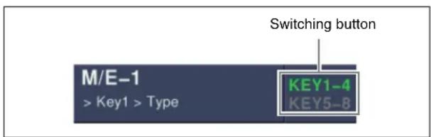
- In the M/E-1 bank transition control block, press the KEY1 next transition selection button twice in rapid succession.
- In the M/E-1 bank independent key transition control block, press the key delegation button [KEY1] twice in rapid succession.
- In the key control block, press the M/E delegation button [M/E1], then press the key delegation button [KEY1] twice in rapid succession.
Note that you can access the DSK menus by pressing the button for the corresponding key in the downstream key control block twice in rapid succession.
Notes
- To select [M/E 4] with the top menu selection buttons, it is first necessary to assign a button in the Setup menu (see page 387).
- To select [Key5] to [Key8], and [DSK5] to [DSK8] in the key control block, a previous assignment in the Setup menu is required (see page 388).
Key Type Setting
Setting the key type in a menu
1 In the M/E-1 >Key1 menu, select HF1 'Type.'
The Type menu appears.
2 In the
Luminance: luminance key
Linear: linear key
Chroma: chroma key
Color Vector: color vector key
Wipe Pattern: wipe pattern key
Key Wipe Pattern: key wipe pattern key
3 Carry out the following settings as required, depending on the key type selected in step 2.
To enable clean mode (see page 119) for a luminance key, linear key or color vector key: Select [Clean Mode] so that it is set on. When clean mode is enabled, key fill is added to the background without cutting out with key source.
When chroma key is selected: Select [Chroma Adjust] to access the Chroma Adjust menu (see page 127), and make the required settings.
When a wipe pattern key is selected: In the M/E-1 >Wipe menu (see page 159), select the pattern and set any modifiers, then return to the M/E-1 >Key1 menu.
When a key wipe pattern key is selected: In the M/E-1>Key1>
Transition >Wipe Adjust menu (see page 171), carry out pattern selection and modifier setting, then return to the M/E-1 >Key1 >Type menu.
Notes
For a wipe pattern selected for a wipe pattern key or key wipe pattern key, the [Edge] and [Direction] modifier settings are not available.
4 Set the parameters.
When a luminance key or linear key is selected
| Knob | Parameter | Adjustment | Setting values |
| 1 Clip | Reference level for generating the key signal | +109.59 to -7.31 | |
| 2 Gain | Key sensitivity | -100.00 to | +100.00 |
| 3 Density | Key density | 0.00 to 100.00 | |
| 4 Filter | Filter coefficient | 1 to 9 | a) |
a) Setting this value to 1, produces the "through" state in which no filter is applied. The larger the value, the more strongly the filter applies.
When a chroma key is selected
| Knob | Parameter | Adjustment | Setting values |
| 3 | Density Key | density 0.00 | to 100.00 |
When a color vector key is selected
Parameter group [1/2]
| Knob | Parameter | Adjustment | Setting values |
| 1 | Y Clip Reference level for creating luminance signal | +109.59 to -7.31 | |
| 2 | Y Gain | Luminance signal sensitivity | -100.00 to +100.00 |
| 3 | C Clip | Reference level for creating chrominance signal | 100.00 to 0.00 |
| 4 | C Gain | Chrominance signal sensitivity | -100.00 to +100.00 |
| 5 | Density Key density | 0.00 to 100.00 | |
Parameter group [2/2]
| Knob | Parameter | Adjustment | Setting values |
| 1 | Y Filter | Luminance signal filter coefficient | 1 to 9 |
| 2 | C Filter | Chrominance signal filter coefficient | 1 to 9 |
When a wipe pattern key or key wipe pattern key is selected
| Knob | Parameter | Adjustment Setting | values |
| 1 Size | Pattern size | 0.00 to 100.00 | |
| 2 Soft | Degree of edge softness | 0.00 to 100.00 | |
| 3 Density | Key density | 0.00 to 100.00 | |
5 Make the following settings as required.
To invert the black and white sense of the key source: Press [Key Invert], turning it on.
To adjust the horizontal position or key source width for a luminance key, linear key, or chroma key: Press [Key Position], turning it on, and set the parameters.
| Knob | Parameter | Adjustment Setting | values |
| 1 H | Phase Key horizontal position | -4.00 to +4.00 | |
| 2 Left | Key left edge | position | -4.00 to +4.00 |
| 3 Right | Key right edge position | -4.00 to +4.00 | |
To set the key priority: Press [Key Priority] or select VF7 'Misc' and HF3 'Key Priority' to access the Key Priority menu.
For details, see “Setting the Key Priority by a Menu Operation” (page 96).
Selecting Key Fill and Key Source
Notes
In the case of the MVS-8000X, only the premium inputs (inputs to the switcher PREMIUM INPUTS connectors 1 to 20) can be selected as key signals on the M/E-4 bank.
Selecting key fill and key source
To select key fill and key source for key 1 on the M/E-1 bank, use the following procedure.
1 In the M/E-1 >Key1 menu, select HF1 'Type.'
The Type menu appears.
2 In the
Key Bus: signal selected on the key 1 fill bus Matte: signal from the dedicated color matte generator
3 If you selected [Key Bus] in step 2, select the key fill signal on the key 1 row in the cross-point control block.
For the CCP-6224/6324 Control Panel, it is necessary to set the [AUX CTRL] button to Off in order to exit the AUX panel-less function (see page 89).
4 If you selected [Matte] in step 2, in the same Type menu, press the [Matte Adjust] button to display the Matte Adjust menu, then adjust the single-color or two-color combination color matte. Select whether to use a single-color matte or a two-color combination in the
Flat Color: Adjust color 1 with the following parameters.
| Knob | Parameter | Adjustment | Setting values |
| 1 Luminance | Luminance | 0.00 to 100.00 | |
| 2 Saturation | Saturation | 0.00 to 100.00 | |
| 3 Hue | Hue | 359.99 to 0.00 |
Mix Color: Carry out a color mix. Adjust color 1 and color 2, and select a mix pattern (see the next section).
5 In the
Self: The key fill bus signal is automatically selected as the key source. When the key type is selected as chroma key, select [Self].
Auto Select: The signal allocated, being paired with the key fill bus signal, to a cross-point button is automatically selected as the key source. The setting of key fill and key source pairs is carried out in the Setup menu.
For details, see “Cross-Point Settings (Xpt Assign Menu)” in Chapter 19 (Volume 2).
Split: You can select a key source signal independently of the key source automatically selected in Auto Select mode.
6 When [Split] was selected in step 5, hold down the [SPLIT] button in the key control block or the Multifunction Flexi Pad Control block, then in the cross-point control block key 1 row, select the key source signal. Alternatively, hold down the key delegation button in the transition control block and press a cross-point button in the key 1 row to select the key source signal.
Notes
- In the above-stated key 1 row operation, you can only select a key signal assigned to a cross-point
button. For the method of selecting a video signal, see "To select a video signal assigned to a cross-point button" below.
- When [Split] is selected, the key memory function (see page 121) is disabled.
To select a video signal assigned to a cross-point button
By selecting the key source bus with an auxiliary bus control block AUX delegation button, and pressing the cross-point button, it is possible to select the video signal assigned to the cross-point button.
(If you press the cross-point button with holding down [KEY], the key signal assigned to the cross-point button.)
Notes
In the above operation, the following settings must have been made.
- Assigning the key source bus to an AUX delegation button For details, see “Auxiliary Bus Control Block Settings (Aux Assign Menu)” in Chapter 19 (Volume 2).
- Setting the [KEY] button operating mode For details, see “Setting the Button Operation Mode” in Chapter 19 (Volume 2).
Selecting key source and key fill in the menu
Selecting key source
For example, to select the key source for M/E-1 key 1, use the following procedure.
1 In the
2 Press [Signal Select].
The Signal Select menu appears.
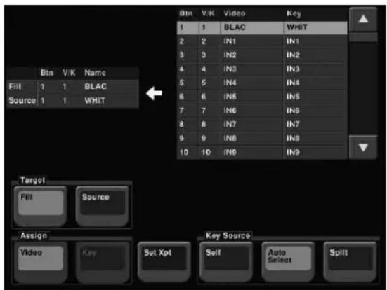
3 In the
4 In the
See step 5 in "Selecting Key Fill and Key Source" (page 124).
5 If you selected [Split], using any of the following methods, select the key source signal.
- Press directly on the list on the right.
- Press the arrow keys to scroll the reverse video cursor.
- Turn the knob.
| Knob | Parameter | Setting Values | |
| 1 No | Button number | 1 to 300 |
6 In the
7 Press [Set Xpt].
This selects the key source signal.
Selecting key fill
For example, to select the key fill for M/E-1 key 1, use the following procedure.
1 In the M/E-1 >Key1 >Type menu status area, press "Fill."
The Signal Select menu appears.
2 In the
3 Select the fill signal from the list on the right.
4 Press [Set Xpt].
This selects the key fill signal.
Carrying out a color mix for key fill
When [Matte] is selected for key fill, you can combine color 1 and color 2. For the combination, you can use not only a key wipe generator pattern, but also the dedicated pattern for key edge color mix.
1 In the
The Matte Adjust menu appears.
2 Select [Mix Color] in the
3 Adjust the following parameters.
| Knob | Parameter | Adjustment Setting | values |
| 1 Size | Pattern size | 0.00 to 100.00 | |
| Knob Parameter Adjustment Setting values | |||
| 2 Soft Softness of the edge of the pattern | 0.00 to 100.00 | ||
4 Select the combining pattern in the
Key Wipe: The wipe pattern selected for an independent key transition is used for combination. You can change this pattern by pressing [Pattern Select] to open the menu for key wipe pattern selection (Pattern Select menu), and make adjustments by pressing [Pattern Adjust] to open the menu for pattern adjustment (Wipe Adjust menu).
Key Edge Pattern: Combine using the dedicated pattern selected for the color mix in the key edge fill. You can change this pattern by pressing [Pattern Select] to open the menu for edge color mix dedicated wipe pattern selection (Mix Pattern Select menu), and make adjustments by pressing [Pattern Adjust] to open the menu for pattern adjustment (Matte Adjust menu).
For details, see “Carrying out a color mix for the key edge fill matte” (page 131).
5 In the Type menu, adjust color 1 and color 2.
To adjust color 1, select [Color1], and to adjust color 2, select [Color2], then adjust the following parameters.
| Knob | Parameter | Adjustment Setting | values |
| 1 | Luminance | Luminance 0.00 to 100.00 | |
| 2 | Saturation | Saturation 0.00 to 100.00 | |
| 3 | Hue | Hue 359.99 to 0.00 |
6 To interchange color 1 and color 2, press the [Color Invert] button, turning it on.
Chroma Key Composition and Basic Settings
In creating a chroma key image, either a normal mix or an additive mix can be used. To select which, use the Type >Chroma Adjust menu for the keyer.
Normal mix: The foreground is cut out with the key signal, and then combined with the background, which has also been cut out with the key signal.
Additive mix: The background, which has been cut out with the key signal, is combined with the unshaped foreground. This is effective for a natural-looking composite when the scene includes glass or other translucent objects.
Plane function
In an additive mix, the foreground is not shaped by the key signal, and variations in the (blue) background appear in the composite image. To prevent this, it is possible to set a particular luminance level for the background, and any parts below this level are cut forcibly.
Composing an image by chroma keying
1 In the M/E-1 >Key1 menu, select HF1 'Type.'
2 Select [Chroma] in the
It becomes possible to adjust the key density (see page 123).
3 Select [Chroma Adjust].
The Chroma Adjust menu appears.
4 Carry out auto chroma key adjustments.
Also carry out manual adjustments if necessary to obtain an optimum chroma key image.
5 In the
When using an additive mix for chroma keying, the (typically blue) background parts of the foreground video must be converted to black. For this, use the color cancel function (see page 128).
Using the plane function
In an additive mix, since no key is applied to the foreground, any variations in the (typically blue) background may appear in the composite image. To avoid this, a particular luminance level can be set for the (blue) background, and regions of lower luminance forcibly cut.
1 In the Chroma Adjust menu, set [Plane] on.
2 Adjust the following parameter.
| Knob | Parameter | Adjustment | Setting values |
| 1 Luminance | Luminance level 0.00 to | 100.00 | |
Key Adjustments (Menus)
This section describes key adjustments made by a menu operation.
You can adjust the following functions by a menu operation.
• Chroma Key Adjustment (page 127)
• Key Edge Modifications (page 130)
- Masks (page 133)
- Applying a DME effect to a key (page 134)
- Specifying the Key Output Destination (page 136)
• Key Modify Clear (page 137)
- Blink Function (page 137)
• Video Processing (page 137)
Chroma Key Adjustments
Methods of adjusting the composite obtained from chroma keying include automatic adjustment with the auto chroma key function, and manual adjustment carrying out the necessary processing separately. The optimum results will be obtained by first carrying out adjustments with the auto chroma key function, then making any fine adjustments as required.
The following manual adjustments are possible.
Key active
When this function is off, only the foreground is output and you can make adjustments of color cancel (see the next paragraph).
Color cancel
If the foreground image includes shades of the background color, turn this function on to remove the color from the foreground image.
Chroma key window
You can adjust the range over which the key signal is determined as matching the specified hue. When this adjustment is off the default ranges are used.
Chroma keying generates a key signal based on a particular color (reference color) in the foreground (typically a plain blue background), and the “window” refers to the range of colors which are regarded as matching this specified reference color to create the key signal.
As seen on a vectorscope (that is, in the hue-saturation color space), the range for this matching corresponds to a truncated sector. This range is specified by two parameters: the “Angle” parameter, which determines the range of the hue parameter, and the “Crop” parameter, which determines the degree of truncation (see the following figure).
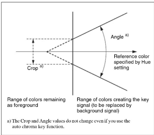
Window adjustment
Y balance
In normal chroma keying, the key signal is based on the chrominance component only, and all elements of the foreground with the same hue are replaced by the background. Using the Y balance function, you can specify a luminance level range within which the key is active, and replace the specified part by the background.
You can use the Y balance function independently on the key signal for the composition and the key signal for the color cancel function. When applied to the key signal for the composition, this produces the foreground with the color cancel effect applied. This can therefore be used to provide an impression of smoke, for example.
When the Y balance function is applied to the color cancel key, the relevant part is output in its original color without canceling, and therefore it is possible to combine colors which are the same color as the background (i.e. typically blue) in the foreground.
Chroma key shadow
This function provides a more realistic treatment when the shadow of an object in the field of view falls on the blue background. Since parts of the blue background darker than a specified intensity are treated as shadows, there is no effect on cutting out of the foreground.
Video signal adjustment
You can vary the foreground signal gain, or change the hue. There are separate adjustments for the gain of the overall video signal, and Y and C components.
Making auto chroma key adjustments
Auto chroma key is an automatic adjustment function which allows you to specify a part of the foreground video (for example, the blue background color) and use it as a reference for creating the chroma key image.
1 In the M/E-1 >Key1 menu, select HF1 'Type,' then select [Chroma] in the
2 Select [Chroma Adjust].
The Chroma Adjust menu appears.
3 Select [Sample Mark] in the
The foreground video only appears on the monitor, with a white box-shaped sample selector.
4 Adjust the position and size of the sample selector, to specify the color to be used as the basis of chroma keying (typically a blue background).
| Knob | Parameter | Adjustment Setting | values |
| 1 | Position | on H Horizontal position | -100.00 to +100.00^a) |
| 2 | Position | on V Vertical position | -100.00 to +100.00^a) |
| 3 | Size | Size 1.00 to 100.00 |
a) The setting ranges depend on the signal format, screen aspect ratio, and size settings.
5 Select [Auto Start] in the
This executes an auto chroma key based on the color specified by the sample selector, and displays the composite image on the monitor.
Making key active adjustments
When the key active function is on, the composite image is output to the monitor, and you can watch the monitor while manually adjusting the keying.
When the key active function is off, only the foreground image appears. Set this off when manually adjusting color cancel (see the next section).
1 In the Chroma Adjust menu, set [Key Active] on.
2 Adjust the following parameters.
| Knob | Parameter | Adjustment Setting | values |
| 1 Clip | Chroma key | reference level | 0.00 to 100.00 |
| 2 Gain | Key gain -1 | 00.00 to | +100.00 |
| 3 Hue | Hue | 359.99 to 0.00 | |
| 4 Density | Density | 0.00 | to 100.00 |
| 5 Filter | Filter | coefficient 1 to 9 |
Making color cancel adjustments
If the background color is leaking into the foreground video, turning the color cancel function on allows you to eliminate this leakage.
1 In the Chroma Adjust menu, turn [Key Active] off.
Only the foreground image appears on the monitor.
2 In the
3 Adjust the following parameters.
| Knob | Parameter | Adjustment | Setting values |
| 1 Luminance | Luminance | 0.00 to 100.00 | |
| 2 Saturation | Saturation | 0.00 to 100.00 | |
| 3 Hue | Hue | 359.99 to 0.00 | |
| 5 Filter | Filter | coefficient 1 to 9 |
4 Set [Key Active] on.
The chroma key composite image now appears in the monitor.
Making key signal adjustments for color cancel
When the color cancel function is set on, you can adjust the key signal for color cancel.
1 In the
2 In the
The cancel key is now on, and you can now adjust the key signal for color cancel.
| Knob | Parameter | Adjustment | Setting values |
| 1 Clip | Color | cancel key reference level | 0.00 to 100.00 |
| 2 Gain | Color cancel | key gain | -100.00 to +100.00 |
3 Make the following settings, as required, in the
When setting [Key Position] on and adjusting the color cancel key edge position
| Knob | Parameter | Adjustment | Setting values |
| 1 H Phase | Move | left and right edges of the color cancel key simultaneously | Left edge position value shown |

| Knob | Parameter Adjustment Setting | values |
| 2 Left | Move left edgeof the colorcancel key | -3.00 to +3.00 |
| 3 Right | Move right edgeof the colorcancel key | -3.00 to +3.00 |
When setting [Window] on and adjusting the detection range of the color cancel key
| Knob | Parameter Adjustment Setting | values |
| 1 Crop | Crop value 100.00 to 0.00 | |
| 2 Angle | Angle value 180.00 to 0.00 |
For details of the crop and angle parameters, see "Chroma key window" (page 127).
When setting [Y Balance] on and adjusting the ratio in which Y balance is added to the color cancel key
| Knob | Parameter | Adjustment Setting | values |
| 1 Mixture Ratio of Y | balance key | 0.00 to 100.00 | |
Adjusting the window
Setting the window (see page 127) function on allows you to adjust the detection range used to determine the key signal. When this function is off, the default range is used for the key.
After making sure that the values of Clip, Gain, and Hue are adjusted appropriately, use the following procedure to make the window adjustment.
1 In the Chroma Adjust menu, set [Window] on.
2 Adjust the following parameters.
| Knob | Parameter Adjustment Setting | values |
| 1 Crop | Crop value 100.00 to 0.00 | |
| 2 Angle | Angle value 180.00 to 0.00 |
Adjusting the Y balance
Setting the Y balance (see page 127) on allows you to specify that, even if the hue is the same, only portions of a particular luminance will be replaced by the background.
1 In the Chroma Adjust menu, set [Y Balance] on.
2 Adjust the following parameters.
| Knob | Parameter | Adjustment Setting | values |
| 1 Clip | Luminance | range | 0.00 to 100.00 |
| Knob | Parameter | Adjustment | Setting | values |
| 2 Gain | Key gain | -100.00 to | +100.00 | |
| 3 Luminance | Luminance | 0.00 to 100.00 | ||
Adjusting the chroma key shadow
This function allows a shadow falling on the (typically blue) background color to be rendered more realistically. Since portions of the (blue) background of less than a certain luminance are treated as shadows, there is no effect on cutting out of the foreground.
1 In the Chroma Adjust menu, set [Shadow] on.
2 Adjust the following parameters.
| Knob | Parameter | Adjustment Setting | values |
| 1 | Luminance | Reference luminance for shadows | 0.00 to 100.00 |
| 2 | Gain | Shadow key gain | -100.00 to +100.00 |
| 3 | Density | Shadow opacity | 0.00 to 100.00 |
| 4 | Soft | Shadow softness | 0.00 to 100.00 |
Notes
When chroma key shadow is on, key edge is changed to normal, and soft edge is switched off.
Adjusting the video signal
You can change the gain of the foreground signal, or vary the Hue. There are separate adjustments for the gain of the whole video signal, or Y and C individually.
1 In the Chroma Adjust menu, set [FRGD CCR] on.
2 Adjust the following parameters.
| Knob | Parameter | Adjustment Setting | values |
| 1 Video Gain | Overall gain of video signal | -100.00 to +100.00 | |
| 2 Y Gain | Y signal gain | -100.00 to +100.00 | |
| 3 C Gain | C signal gain | -100.00 to +100.00 | |
| 4 Hue | Hue offset amount | -180.00 to +180.00 | |

To modify the key edge of key 1 on the M/E-1 bank, use the following procedure.
1 In the M/E-1 >Key1 menu, select HF2 'Edge.'
The Edge menu appears.
2 Select the edge type (see page 120) in the
Normal: unadorned edge
Border: edge with border applied
Drop Border: edge with drop border applied
Shadow: edge with shadow applied
Outline: edge used as outline
Emboss: embossing effect applied to edge
If you select [Normal], skip to step 7.
3 Set the border width and other parameters.
When border or outline is selected: The setting parameters depend on the key type and whether the separate edge function is enabled or not. To enable the separate edge function, press [Separate Edge], setting it on.
- Separate edge off
| Knob | Parameter | Adjustment Setting | values |
| 1 Width | Width 0.00 | to 8.00 | a) (0.00 to 100.00) b) |
| 3 Density | Density 0 | 00 to 100.00 |
a) In the "4H mode" and when [Fine Key] (page 131) is on, the setting value range is 0.00 to 4.00.
b) When a wipe pattern key or key wipe pattern key is selected as the key type
- Separate edge on
The left, right, top, and bottom border or outline widths can be adjusted independently. The separate edge function is only valid when a luminance key, linear key, or chroma key is selected as the key type.
| Knob | Parameter | Adjustment Setting | values |
| 1 Top | Top edge width | 0.00 to 8.00 | a) |
| 2 Left | Left edge width | 0.00 to 8.00 | a) |
| 3 Right | Right edge width | 0.00 to 8.00 | a) |
| 4 Bottom | Bottom edge width | 0.00 to 8.00 a) | |
| 5 Density | Density 0.00 to 100.00 |
a) In the "4H mode" and when [Fine Key] (page 131) is on, the setting value range is 0.00 to 4.00.
When drop border or shadow is selected: The setting parameter values depend on the on/off setting of key drop and the selection of 4H mode/8H mode (see page 121).
- “Key drop off” mode
| Knob | Parameter | Adjustment | Setting values |
| 1 Width | Width 0.00 | to 8.00 | a) |
| 2 | Position | Position | 359.99 to 180.00 |
| 3 Density | Density | 0.00 to 100.00 |
- “Key drop on” mode
| Knob | Parameter | Adjustment | Setting values |
| 1 Width | Width 0.00 | to 8.00 | a) |
| 2 | Position | Position | 359.99 to 0.00 |
| 3 Density | Density | 0.00 to 100.00 |
a) In the “4H mode” and when [Fine Key] (page 131) is on, the setting value range is 0.00 to 4.00.
When emboss is selected:
| Knob | Parameter | Adjustment | Setting values |
| 1 Width | Width 0.00 | to 4.00 | |
| 2 | Position | Position | 359.99 to 0.00 |
| 3 | Density^a) | Density 0.00 to 100.00 |
a) The Density adjustment only affects the key edge. This can be adjusted separately from Key Density, and if Key Density is set to 0.00, the embossed edge effect only can be applied.
To make edge fill adjustments, carry out the settings in step 6.
4 Select the edge fill signal in the
Utility 1 Bus: signal selected on the utility 1 bus Matte: signal from dedicated color matte generator. It becomes possible to adjust color 1.
| Knob | Parameter | Adjustment | Setting values |
| 1 | Luminance | Luminance | 0.00 to 100.00 |
| 2 | Saturation | Saturation | 0.00 to 100.00 |
| 3 Hue | Hue | 359.99 to 0.00 | |
When the edge type is outline, in place of the edge fill signal, the selected key fill signal fills the outline, and elsewhere remains as the background.
5 Carry out the following operation, depending on the selection in step 4.
When [Utility 1 Bus] is selected: Hold down the [UTIL] button in the cross-point control block, and select the signal in the background A bus row. While the [UTIL] button is held down, the background A bus changes to the utility 1 bus.
Notes
To enable the [UTIL] button, its operation mode must be set to [Hold] beforehand.
For details, see “Setting the Button Operation Mode” in Chapter 19 (Volume 2).
When [Matte] is selected: Press [Matte Adjust] in the same EDGE menu, to display the Matte Adjust menu, and adjust a single color or two-color combination color matte.
You can select whether to use a single color matte or a two-color combination color matte in the
For the color mix operation, see “Carrying out a color mix for the key edge fill matte” (page 131).
6 When emboss is selected for the edge type, adjust the color in the
To adjust matte 1 press [Matte1], and to adjust matte 2 press [Matte2], then adjust the following parameters.
| Knob | Parameter | Adjustment Setting | values |
| 1 | Luminance | Luminance 0.00 to 100.00 | |
| 2 | Saturation | Saturation 0.00 to 100.00 | |
| 3 | Hue | Hue 359.99 to 0.00 |
7 To make the edge soft, press [Soft Edge] to set it on, and adjust the softness.
| Knob | Parameter | Adjustment Setting | values |
| 1 Soft | Edge softness | 0.00 to 100.00 |
For a normal edge, when [Soft Edge] is enabled, [Key Drop] is kept on.
8 To make separate fine adjustments to the positions of the left, right, top, and bottom of the source edge, press [Fine Key], to set it on, and adjust the following parameters.
Parameter group [1/2]
| Knob | Parameter | Adjustment Setting | values |
| 1 Top | Key | top edge position | -2.00 to +2.00 |
| 2 Left | Key | left edge position | -2.00 to +2.00 |
| 3 Right | Key right edge position | -2.00 to +2.00 | |
| 4 Bottom | Key bottom edge position | -2.00 to +2.00 | |
Parameter group [2/2]
| Knob | Parameter | Adjustment Setting | values |
| 1 H Phase | Key horizontal position | Left edge position value shown | |
| 2 V Phase | Key vertical position | Top edge position value shown | |
Notes
In the emboss function it is not possible to set [Fine Key] on.
- When the edge type is normal, drop border or shadow, enabling the [Fine Key] function keeps [Key Drop] on.
- When applying a border to the key edge, enabling the [Fine Key] function halves the border width setting range.
To fix key fill and key source in key drop off mode
1 In the Edge menu, press [Key Delay Mode].
The Key Delay Mode menu appears.
2 Press [Frame Delay], setting it to On.
Notes
This function uses the resizer, and therefore the expected result of the setting may not be obtained if conditions do not allow the resizer to be used.
Carrying out a color mix for the key edge fill matte
When you select 'Matte' for the edge fill of a border, drop border, or shadow, you can create a combination of color 1 and color 2 using a wipe pattern generated by the dedicated pattern generator.
1 In the
The edge fill Matte Adjust menu appears.
2 In the
3 Adjust the following parameters.
| Knob | Parameter | Adjustment | Setting | values |
| 1 Size | Pattern | size 0.00 | to 100.00 | |
| 2 Soft | Softness of pattern edge | 0.00 to 100.00 | ||
| 3 Pattern | Pattern number | 1 to 24 | a) | |
a) The patterns are the same as standard wipes. (For details, see "Wipe Pattern List" in (page 351).)
To select the pattern, display the Mix Pattern Select menu by pressing [Mix Pattern] in the edge fill Matte Adjust menu.
After selecting one of the patterns (standard wipe patterns 1 to 24) displayed in the Mix Pattern Select menu, you can adjust the following parameters.
| Knob | Parameter | Adjustment Setting | values |
| 1 Size | Pattern size | 0.00 to 100.00 | |
| 2 Soft | Softness of | pattern edge | 0.00 to 100.00 |
4 Adjust color 1 and color 2.
To adjust color 1 press [Color 1], and to adjust color 2 press [Color 2], turning it on respectively, and adjust the following parameters.
| Knob | Parameter | Adjustment Setting | values |
| 1 | Luminance | Luminance 0.00 to 100.00 | |
| 2 | Saturation | Saturation 0.00 to 100.00 | |
| 3 | Hue | Hue | 359.99 to 0.00 |
5 If required, set the pattern modifiers.
When turning [Position] on and setting the pattern position
| Knob | Parameter | Adjustment Setting | values |
| 1 | Position H | Horizontal position | -200.00 to +200.00^a) |
| 2 | Position V | Vertical position | -200.00 to +200.00^a) |
a) See page 165.
When turning [Multi] on and replicating the pattern
| Knob | Parameter | Adjustment | Setting values |
| 1 H Multi | Number of repetitions of pattern horizontally | 1 to 63 | |
| 2 V Multi | Number of repetitions of pattern vertically | 1 to 63 | |
| 3 Invert | Type Replication layout | 1 to 4a) |
a) See page 167.
When turning [Aspect] on and setting the aspect ratio of the pattern
| Knob | Parameter | Adjustment | Setting values |
| 1 Aspect | Aspect | ct ratio -100.00 to | +100.00^a) |
a) See page 167.
When turning [Angle] on in the
| Knob | Parameter | Adjustment | Setting values |
| 1 Angle | Angle of pattern rotation | -100.00 to +100.00^a) | |
a) See page 166.
When turning [Speed] on in the
| Knob | Parameter | Adjustment | Setting values |
| 1 Speed | Rotation rate of pattern | -100.00 to +100.00a) | |
a) See page 166.
6 To interchange color 1 and color 2, press [Color Invert], turning it on.
Applying the zabton effects
1 In the Edge menu, press [Zabton], turning it on.
2 Adjust the following parameters.
| Knob | Parameter | Adjustment | Setting values |
| 1 Size | Pattern size | 0.00 to 100.00 | |
| 2 Soft | Pattern edge | softness | 0.00 to 100.00 |
| 3 | Density | Density | 0.00 to 100.00 |
Notes
If in the pattern selection described below you select "Mask Pattern," and "Box" for the main mask, the "Size" parameter here cannot be adjusted. Set "Size" in the Main Mask menu.
3 To adjust the pattern and color, press [Zabton Adjust].
The Zabton Adjust menu appears.
4 In the
Key Wipe: Use a key wipe.
You can change this pattern by pressing [Pattern Select] to open the menu for key wipe pattern selection (Pattern Select menu), and make adjustments by
pressing [Pattern Adjust] to open the menu for pattern adjustment (Wipe Adjust menu).
Key Edge Pattern: Use a color mixing pattern for key edge.
You can change this pattern by pressing [Pattern Select] to open the menu for edge color mix dedicated wipe pattern selection (Mix Pattern Select menu), and make adjustments by pressing [Pattern Adjust] to open the menu for pattern adjustment (Matte Adjust menu).
Mask Pattern: Use the main mask Box or Pattern.
You can also press [Pattern Select], and in the corresponding pattern adjustment menu, change the pattern.
5 To adjust the color, press [Zabton Color] and adjust the following parameters.
| Knob | Parameter | Adjustment Setting | values |
| 1 | Luminance | Luminance 0.00 to 100.00 | |
| 2 | Saturation | Saturation 0.00 to 100.00 | |
| 3 | Hue | Hue 359.99 to 0.00 | |
| 4 | Density | Density 0.00 to 100.00 |
Masks
There are two masks, which can be used to mask off unneeded parts of a key or background, or to remove defects, and these are known as the main mask and subsidiary mask.
You can either use the main mask and subsidiary mask independently, or at the same time.
Using the main mask
For example, to use the main mask for key 1 on the M/E-1 bank, use the following procedure.
1 In the M/E-1 >Key1 menu, select HF3 'Main Mask.' The Main Mask menu appears.
2 In the
Key Mask: Masks a part of a key. Bkgd Mask: Masks a part of a background.
3 In the
Box: signal from the dedicated box generator Pattern: signal from the dedicated pattern generator
4 Set the mask source parameters.
When a box is selected
| Knob | Parameter | Adjustment | Setting | values |
| 1 Top | Top position | -100.00 to +100.00 | ||
| 2 Left | Left position | -100.00 to +100.00 | ||
| 3 Right | Right position | -100.00 to +100.00 | ||
| 4 Bottom | Bottom position | -100.00 to +100.00 | ||
| 5 Soft | Box softness | 0.00 to 100.00 | ||
When a pattern is selected
| Knob | Parameter | Adjustment | Setting | values |
| 1 Size | Pattern size | 0.00 | to 100.00 | |
| 2 Soft | Edge softness | 0.00 | to 100.00 | |
| 5 Pattern | Pattern number | 1 to 24 | a) |
a) The pattern is the same as a standard wipe. (See "Wipe Pattern List" in Appendix (Volume 1) (page 351).)
To select the pattern, display the Mask Ptn Select menu by pressing the [Mask Ptn Select] button in the Main Mask menu.
After selecting one of the patterns (standard wipe patterns 1 to 24) displayed in the Mask Ptn Select menu, you can adjust the following parameters.
| Knob | Parameter | Adjustment | Setting | values |
| 1 Size | Pattern size | 0.00 | to 100.00 | |
| 2 Soft | Edge | softness | 0.00 | to 100.00 |
5 To invert the black and white sense of the mask source, press the [Mask Invert] button, turning it on.
6 When a pattern is selected as the mask source, set the pattern modifiers as required.
When turning [Position] on and setting the pattern position
| Knob | Parameter | Adjustment Setting | values |
| 1 | Position H | Horizontal position | -200.00 to +200.00^a) |
| 2 | Position V | Vertical position | -200.00 to +200.00^a) |
a) See page 165.
When turning [Multi] on and replicating the pattern
| Knob | Parameter | Adjustment Setting | values |
| 1 H Multi | Number of repetitions of pattern horizontally | 1 to 63 | |
| 2 V | Multi Number of repetitions of pattern vertically | 1 to 63 | |
| 3 Invert | Type Replication layout | 1 to 4a) | |
a) See page 167.
When turning [Aspect] on and setting the aspect ratio of the pattern
| Knob | Parameter | Adjustment Setting | values |
| 1 | Aspect | Aspect ratio -100.00 to | +100.00a) |
a) See page 167.
When turning [Angle] on in the
| Knob | Parameter | Adjustment Setting | values |
| 1 Angle | Pattern angle | -100.00 to | + 100.00^a) |
a) See page 166.
When turning [Speed] on in the
| Knob | Parameter | Adjustment Setting | values |
| 1 Speed | Rate of pattern rotation | -100.00 to +100.00a) | |
a) See page 166.
Using the subsidiary mask
For example, to use the subsidiary mask for key 1 on the M/E-1 bank, use the following procedure.
1 In the M/E-1 >Key1 menu, select HF4 'Sub Mask.'
The Sub Mask menu appears.
2 In the
Key Mask: Masks a part of a key.
Bkgd Mask: Masks a part of a background.
3 In the
Wipe: wipe pattern selected for a transition If you select [Wipe], select the pattern and make modifier settings in the M/E-1 >Wipe menu (see page 159), then return to this M/E-1 >Key1 menu. In the case of a wipe pattern selected for a mask, the modifier [Edge] and [Direction] settings are not available.
Utility 1 Bus: signal selected on the utility 1 bus When you selected [Utility 1 Bus], hold down the [UTIL] button in the M/E-1 bank cross-point
control block, and select the signal with the background A bus buttons. While the [UTIL] button is pressed, the background A bus switches to the utility 1 bus.
Notes
To enable the [UTIL] button, its operation mode must be set to [Hold] beforehand.
For details, see "Assigning a Bus to an AUX Delegation Button" in Chapter 19 (Volume 2).
4 Set the mask source parameters.
When wipe is selected
| Knob | Parameter | Adjustment | Setting values |
| 1 Size | Pattern size | 0.00 to 100.00 | |
| 2 Soft | Edge softness | 0.00 to 100.00 |
When utility 1 bus is selected
| Knob | Parameter | Adjustment | Setting values |
| 1 Clip | Reference level for creating mask signal | +109.59 to -7.31 | |
| 2 Gain | Gain | -100 | 00 to +100.00 |
5 To invert the black and white sense of the mask source, press the [Mask Invert] button, turning it on.
Applying a DME Effect to a Key
Notes
- When the SDI interface is used to connect the DME, DME effects (including DME wipes) can be used in only one place for one M/E bank.
- When the dedicated interface is used to connect the DME, the number of keys to which DME effects (including DME wipes) can be applied simultaneously for one M/E bank varies as follows depending on the execution mode of the DME wipe pattern selected for the background.
- MVS-8000X
| Applicable block | Key to which DME effects are applied | DME wipe pattern for background | Number of keys to which DME effects can be applied simultaneously |
| Other than M/E-4 | Keys 1 to 4 | No DME wipe used | 2 |
| One-channel mode | 1 | ||
| Two- or three-channel mode | 0 | ||
| Keys 5 to 8 | - | 2^a) | |
| M/E-4 Keys | 1 to 4 | No DME wipe used | 2^b) |
| One-channel mode | 1^c) | ||
| Two- or three-channel mode | 0 | ||
| Keys 5 to 8 | - | 0 |
- MVS-7000X
| Key to which DME effects are applied | DME wipe pattern for background | Number of keys to which DME effects can be applied simultaneously |
| Keys 1 to 4 | No DME wipe used 2 | |
| One-channel mode 1 | ||
| Two- or three-channel mode | 0 | |
| Keys 5 to 8 | - | 2^a) |
a) 0 when the system signal format is 1080P.
b) 1 when the system signal format is 1080P and the DME input/output signal format is set to dual link mode.
c) 0 when the system signal format is 1080P and the DME input/output signal format is set to dual link mode.
- When combining DMEs connected via the dedicated interface and the SDI interface, you can increase the number of keys to which DME effects are applied simultaneously. (Requires a setting in setup.)
For details, see "Setting DME and Switcher Interfaces" in Chapter 20 (Volume 2).
Assigning a DME to a key
1 In the M/E-1 >Key1 menu, select HF5 'Processed Key.'
The Processed Key menu appears.
2 In the
The lit colors of [DME1] to [DME8] indicate the DME assignment.
Lit green: Shows the DME assigned to the currently selected key.
Lit amber: Shows the DME assigned to a key other than the currently selected key.
Off: DME is not assigned.
To select a DME being used by another keyer
Press [Override], turning it on, then select the DME channel.
The later selection is valid, and the button lights green.
Using two or three DME channels on one keyer
When using the DME dedicated interface, proceed as follows.
Notes
- On the MVS-8000X, when the signal format is 1080P, the combination of two consecutively numbered DME channels that can be selected is DME1 and DME2, DME3 and DME4, DME5 and DME6, or DME7 and DME8. It is not possible to combine three or more DME channels.
- On the MVS-7000X, when the signal format is 1080P, the above restriction also applies if using the MVE-8000A. There is no such restriction for the MKS-7470X/7471X.
1 Select the DME for the first channel (see the previous item, "Assigning a DME to a key"), then select the successive channel for the second channel. For the third channel select the channel after that.
2 To select the video signal for the second channel, hold down the [UTIL] button in the cross-point control block, and select the signal in the Key1 row (DME external video bus).
3 To select the video signal for the third channel, hold down the [UTIL] button in the cross-point control block, and carry out the following operation.
- If the selected DME is channel 3 or channel 4, turn off the [KEY4] button in the key 2 row, then select the signal in the key 2 row (DME utility 1 bus).
- If the selected DME is channel 7 or channel 8, turn on the [KEY4] button in the key 2 row, then select the signal in the key 4 row (DME utility 2 bus).
Using four DME channels on one keyer
When using the DME dedicated interface, proceed as follows.
Notes
- On the MVS-8000X, when the signal format is 1080P, this operation cannot be carried out.
- On the MVS-7000X, when the signal format is 1080P, the above restriction also applies if using the MVE-8000A. There is no such restriction for the MKS-7470X/7471X.
1 Select the DME channel 1 (or channel 5) for the first channel (see "Assigning a DME to a key" (page 135)). In the same way, select the DME channel 2 (channel 6) for the second channel, the DME channel 3 (channel 7) for the third channel, and the DME channel 4 (channel 8) for the fourth channel.
2 To select the video signal for the second channel, hold down the [UTIL] button in the cross-point control block, and select the signal in the Key1 row (DME external video bus).
3 To select the video signal for the third channel, hold down the [UTIL] button in the cross-point control block, and carry out the following operation.
- If the selected DME is channel 3, turn off the [KEY4] button in the key 2 row, then select the signal in the key 2 row (DME utility 1 bus).
- If the selected DME is channel 7, turn on the [KEY4] button in the key 2 row, then select the signal in the key 4 row (DME utility 2 bus).
4 To select the video signal for the fourth channel, hold down the [UTIL] button in the cross-point control block, and carry out the following operation.
- If the selected DME is channel 4, turn on the [KEY4] button in the key 2 row, then select the signal in the key 4 row (DME utility 2 bus).
- If the selected DME is channel 8, turn off the [KEY4] button in the key 2 row, then select the signal in the key 2 row (DME utility 1 bus).
When using the SDI interface
The operations to select the video signals for the third and fourth channels differ from those in the previous procedure: select the video signals on the AUX bus allocated in a Setup menu (Engineering Setup >Switcher >Device Interface >DME Type Setting >DME SDI Interface menu).
Notes
In setup (Engineering Setup >Switcher >Device Interface menu), if “Dual DME units” is selected, the second channel video signal is also selected on the AUX bus.
For details, see “Setting the Interface Between the DME and the Switcher” in Chapter 19 (Volume 2).
You can check the DME operating status in the Status menu (see page 232).
Assigning a DME output signal as a monitor signal
1 In the Processed Key menu, press [Monitor].
The Monitor menu appears.
2 Press [Monitor Set], turning it on.
3 In the
This assigns the selected DME output to DME MON V and DME MON K. The colors with which [DME1] to [DME8] are lit show the key assignment status.
Lit green: DME currently being monitored
Lit amber: DME that can be monitored
Off: Unassigned DME
Specifying the Key Output Destination
Using the key processed keyer signals (external processed key)
To select the key processed keyer key fill and key source signals on the AUX bus or edit preview bus, press [Ext Proc Key] turning it on, in the Processed Key menu. This assigns the key fill and key source signals for M/E-1 key 1 to reentry signals PROC V and PROC K. When a DME is selected on the keyer, the key fill and key source signals to which a DME effect is applied are assigned.
Notes
You cannot select the PROC V and PROC K signals using the cross-point selection buttons of the M/E or PGM/PST bank.

Using the key processed keyer signals or signals to which a DME effect is applied in frame memory (frame memory feed)
To use the key processed keyer key fill and key source signals on the frame memory source buses, in the Processed Key menu, press [FM Feed]. [Ext Proc Key] turns on, and the key fill and key source signals processed on the currently selected keyer are automatically assigned to frame memory source buses 1 and 2. When a DME is selected on the keyer, the key fill and key source signals to which a DME effect is applied are assigned.
Key Modify Clear
A simple button operation or a menu operation returns the key settings to the initial status settings.
Press [Default Recall] at the lower left of the menu display, turning it on, then press the corresponding VF button (VF1 to VF4) to return the key settings to their initial status.
For details of the initial status, see “Saving User-Defined Settings” in Chapter 18 (Volume 2).
For the menu operation to return the key state to that set in initial status, see “Returning to Default State in Function Groupings” (page 82).
Blink Function
With the blink function, you can obtain the following effects.
Key blink: The key is alternately inserted and deleted at regular intervals. You can set the period of blinking, and the proportion of each cycle for which the key is inserted.
Edge blink: The key fill and key edge fill signals are interchanged at regular intervals. You can set the period of blinking, and the proportion of each cycle for which the original state holds.
The blink settings are in the Transition menu for each key.
Using the blink function
For example, to make the required settings for key 1 on the M/E-1 bank, use the following procedure.
1 In the M/E-1 >Key1 menu, select HF6 'Transition.' The Transition menu appears.
2 In the
3 Set the blink parameters.
When key blink is selected
| Knob | Parameter Adjustment Setting values | ||
| 1 Blink | Rate Length of blink cycle | 1 to 100 | |
| 2 Duty | Proportion of cycle for which key inserted | 0.00 to 100.00 | |
When edge blink is selected
| Knob | Parameter | Adjustment Setting | values |
| 1 Blink | Rate Length | of blinkcycle | 1 to 100 |
| 2 Duty | Proportion of | cycle for whichoriginal stateholds | 0.00 to 100.00 |
Video Processing
You can adjust the luminance and hue of the selected key fill signal.
For example, to apply video processing to the signal selected on the M/E-1 bank key 1 fill bus, use the following procedure.
1 In the M/E-1 >Key1 menu, select HF7 'Video Process.'
The Video Process menu appears.
2 Press [Video Process], turning it on.
3 Adjust the following parameters.
| Knob | Parameter | Adjustment Setting | values |
| 1 Video Gain | Video gain -200.00 to +200.00 | ||
| 2 Y Gain | Luminance | gain -200.00 to | +200.00 |
| 3 C Gain | Chrominance | gain | -200.00 to +200.00 |
| 4 Hue | Delay Hue delay | -180.00 to | +180.00 |
| 5 | B I Level | Luminancedblack level | +7.31 to +109.59 |
To return adjustment values to their defaults Press [Unity].

Key Setting Operations with the Key Control Block
This section describes the basic procedures for key settings using the key control block.
Key type selection buttons
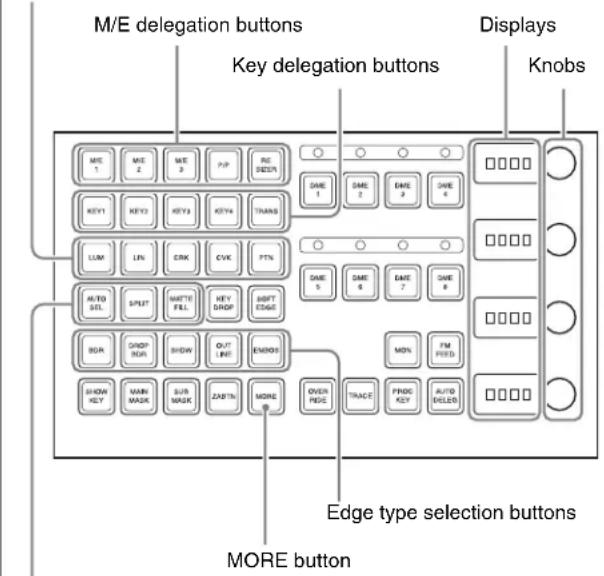
Key fill/key source selection buttons
Notes
To select [M/E 4], [Key5] to [Key8], and [DSK5] to [DSK8] in the key control block, a previous assignment in the Setup menu is required (see page 388).
Selecting the Bank and Keyer
To make key settings, first select the bank (from M/E-1 to M/E-3 and PGM/PST) and keyer, then assign them to the key control block.
For example, to set key 1 on M/E-1 with the key control block, use the following procedure.
1 Using the M/E delegation buttons in the key control block, press the [M/E1] button, setting it on.
2 Using the key delegation buttons in the key control block, press the [KEY1] button, setting it on.
This assigns the key control block to M/E-1 key 1.
Selecting the Key Type
To select the key type, press one of the key type (see page 119) selection buttons in the key control block.
[LUM] button: luminance key
[LIN] button: linear key
[CRK] button: chroma key
[CVK] button: color vector key
[PTN] button: key wipe pattern key
When using a wipe pattern key as the key type, in the
The button you pressed lights green, and you can now adjust the parameters with the knobs. The display beside each knob shows the first letter of the parameter name and the three-digit setting value.
Parameter Adjustment with the Knobs
When the button for a function requiring parameter settings is pressed (that is, on), you can set the parameters with the four knobs. If there are more than four values to be assigned to the knobs, the [MORE] button lights amber. At this point, press the [MORE] button, which turns green, to assign the fifth and subsequent parameters to the knobs, so that the parameter settings can be made.
When the [LUM] or [LIN] button is lit green
| Knob | Parameter | Adjustment Setting values | |
| 1 | Clip | Reference level for generating the key signal | +109 to -7 |
| 2 | Gain | Key sensitivity -100 (shown as | -00) to +100 |
| 3 | Density | Key density 0 to 100 | |
| 4 | Filter | Filter coefficient 1 to 9 | |
When the [CRK] button is lit green
| Knob | Parameter | Adjustment Setting values | |
| 1 Clip | Chroma key | reference level | 0 to 100 |
| 2 Gain | Key sensitivity | -100 (shown as -00) to +100 | |
| 3 Hue | Hue | 0 to 359 | |
| 4 Density | Key density | 0 to 100 | |
- When [Key Active] is off, only the parameters Hue and Density are displayed.
- When both [Key Active] and [Color Cancel] are off, only the parameter Density is displayed.
When the [CVK] button is lit green
Parameter group [1/2]
| Knob | Parameter | Adjustment Setting values | |
| 1 Y Clip | Reference | level for Y signal | +109 to -7 |
| 2 Y Gain | Y signal | sensitivity -100 (shown as -00) to +100 | |
| 3 C Clip | Reference | level for chrominance signal | 100 to 0 |
| 4 C Gain | Chrominance | signal sensitivity | -100 (shown as -00) to +100 |
Parameter group [2/2]
| Knob | Parameter | Adjustment Setting values | |
| 1 Y Filter | Y signal filter | coefficient | 1 to 9 |
| 2 C Filter | Chrominance | signal filter coefficient | 1 to 9 |
| 4 Density | Key density | 0 to 100 | |
When the [PTN] button is lit green
| Knob | Parameter | Adjustment | Setting values |
| 1 Size | Pattern size | 0 to 100 | |
| 2 Soft | Edge | softness | 0 to 100 |
| 3 Density | Key density | 0 to 100 | |
Selecting Key Fill
Select whether to use a color matte as key fill, or the signal on the key fill bus.
When using a color matte: Press the [MATTE FILL]
button, setting it on. The button lights green, and you can now set the parameters with the knobs.
| Knob | Parameter | Adjustment | Setting values |
| 1 Luminance | Color | 1 luminance | 0 to 100 |
| 2 Saturation | Color | 1 saturation | 0 to 100 |
| 3 Hue | Color | 1 hue 359 to 0 | |
When [Mix Color] is selected in the key fill Matte Adjust menu, you can further adjust color 2.
When [Mix Color] is on, and the [MORE] button is lit amber
| Knob | Parameter | Adjustment | Setting values |
| 1 | Luminance | Color 1 luminance | 0 to 100 |
| 2 | Saturation | Color 1 saturation | 0 to 100 |
| 3 | Hue | Color 1 hue | 359 to 0 |
| 4 | Size | Pattern size 0 to 100 | |
When [Mix Color] is on, and the [MORE] button is lit green
| Knob | Parameter | Adjustment | Setting values |
| 1 Luminance | Color | 2 luminance | 0 to 100 |
| 2 | Saturation | Color 2 saturation | 0 to 100 |
| 3 | Hue | Color 2 hue 359 to 0 | |
| 4 | Soft | Edge softness | 0 to 100 |
When using the key fill bus signal: Press the [MATTE FILL] button, turning it off.
To select the key fill signal, use the key 1 or key 2 bus buttons in the cross-point control block.
For the CCP-6224/6324 Control Panel, it is necessary to set the [AUX CTRL] button to Off in order to exit the AUX panel-less function (see page 89).
Selecting Key Source
- To use the key source paired with the key fill signal selected on the key fill bus, press the [AUTO SEL] button, turning it on. The pairing of the cross-point buttons for key fill and key source is carried out in the Setup menu.
For details, see "Cross-Point Settings (Xpt Assign Menu)" in Chapter 19 (Volume 2).
- To select key source independently of the key fill signal selected on the key fill bus and paired with key source, hold down the [SPLIT] button, turning it on, then press the desired Key 1 or Key 2 button in the cross-point control block.
- To use as key source the same signal as the key fill signal selected on the key fill bus, select the SELF mode by pressing the [AUTO SEL] button and [SPLIT] button simultaneously so that both are off. When chroma key is selected as the key type, select the SELF mode.
Key Adjustments (Key Control Block)
This section describes the various key adjustments provided by the control panel key control block.
To apply a modification to the key edge (see page 120), press one of the edge type selection buttons in the key control block.
[BDR] button: border
[DROP BDR] button: drop border
[SHDW] button: shadow
[OUTLINE] button: outline
[EMBOS] button: emboss
The pressed button lights green, and you can now adjust the parameters with the knobs. The display beside each knob shows the first letter of the parameter name and the three-digit setting value.
Setting the border parameters
When the [BDR] button is lit green, the parameter settings depend on the key type and whether the separate edge function is active. To activate the separate edge function, press [Separate Edge], setting it on, in the Edge menu for the key.
Separate edge off
| Knob | Parameter | Adjustment Setting values | |
| 1 Width | Border width | 0 to 8 | a) (0 to 100) ^b) |
| 4 Density | Border density | 0 to 100 | |
a) In the "4H mode" and when [Fine Key] (page 131) is on, the setting value range is 0 to 4.
b) When a wipe pattern key or key wipe pattern key is selected as the key type
Separate edge on
The border width settings can be made independently for left, right, top, and bottom sides. The separate edge function is only available when luminance key, linear key, or chroma key is selected as the key type.
| Knob Parameter Adjustment Setting values | ||
| 1 Top Top edge width 0 to 8 | a) | |
| 2 Left Left edge width 0 to 8 | a) | |
| 3 Right Right edge width 0 to 8 | a) | |
| 4 Bottom Bottom edge width 0 to 8 | a) | |
a) In the "4H mode" and when [Fine Key] (page 131) is on, the setting value range is 0 to 4.
To adjust the edge fill color
When [BDR] is selected, the [MORE] button lights amber. Pressing the [MORE] button to turn it green then allows you to adjust the edge fill color parameters with the knobs.
| Knob | Parameter | Adjustment | Setting values |
| 1 | Luminance | Luminance | 0 to 100 |
| 2 | Saturation | Saturation | 0 to 100 |
| 3 | Hue Hue | 359 to 0 | |
| 4 | Density | Density | 0 to 100 |
Setting the drop border or shadow parameters
When the [DROP BDR] or [SHDW] button is lit green, the parameter settings differ between the "key drop OFF" and "key drop ON" modes (see page 121) as shown below. Switching between these two modes is made by turning the [KEY DROP] button on or off.
"Key drop OFF" mode
| Knob | Parameter | Adjustment | Setting values |
| 1 Width | Width | 0 to 8 | a) |
| 2 Position | Position | 359 to 180 | |
| 4 Density | Density | 0 to 100 |
a) In the "4H mode" and when [Fine Key] (page 131) is on, the setting value range is 0 to 4.
"Key drop ON" mode
| Knob | Parameter | Adjustment | Setting values |
| 1 Width | Width | 0 to 8 | a) |
| 2 Position | Position | 359 to 0 | |
| 4 Density | Density | 0 to 100 |
a) In the "4H mode" and when |Fine Key| (page 131) is on, the setting value range is 0 to 4.
To adjust the edge fill color
When [DROP BDR] or [SHDW] is selected, the [MORE] button lights amber. Pressing the [MORE] button to turn it green then allows you to adjust the edge fill color parameters with the knobs.
| Knob | Parameter | Adjustment | Setting values |
| 1 | Luminance | Luminance | 0 to 100 |
| 2 | Saturation | Saturation | 0 to 100 |
| 3 | Hue Hue | 359 to 0 | |
| 4 | Density | Density | 0 to 100 |
Setting the outline parameters
When the [OUTLINE] button is lit green, the parameter settings depend on the key type and whether the separate
edge function is active. To activate the separate edge function, press [Separate Edge], setting it on, in the Edge menu for the key.
Separate edge off
| Knob | Parameter | Adjustment | Setting values |
| 1 Width | Outline width | 0 to 8 | a) (0 to 100)^b) |
| 4 Density | Outline density | 0 to 100 |
a) In the "4H mode" and when [Fine Key] (page 131) is on, the setting value range is 0 to 4.
b) When a wipe pattern key or key wipe pattern key is selected as the key type
Separate edge on
The outline width settings can be made independently for left, right, top, and bottom sides. The separate edge function is only available when luminance key, linear key, or chroma key is selected as the key type.
| Knob | Parameter | Adjustment | Setting values |
| 1 Top Top edge width 0 to 8 | a) | ||
| 2 Left | Left edge width | 0 to 8 | a) |
| 3 Right | Right edge width | 0 to 8 | a) |
| 4 Bottom | Bottom edge width | 0 to 8 | a) |
a) In the “4H mode” and when [Fine Key] (page 131) is on, the setting value range is 0 to 4.
When [Outline] is selected with separate edge on, the [MORE] button lights amber. Pressing the [MORE] button to turn it green then allows you to adjust the key fill density parameter with a knob.
| Knob | Parameter | Adjustment | Setting values |
| 4 | Density | Outline density | 0 to 100 |
Setting the embossing parameters
When the [EMBOS] button is lit green, adjust the following parameters.
| Knob | Parameter | Setting values |
| 1 | Width | 0 to 4 |
| 2 | Position | 359 to 0 |
| 4 | Density | 0 to 100 |
Selecting a normal edge
When all five edge type selection buttons are off, a normal edge is selected. If one of the buttons is lit, press it, turning it off.
Softening the edge
Press the [SOFT EDGE] button, turning it on. The button lights green, and you can now adjust the softness with the knob.
| Knob | Parameter | Adjustment | Setting values |
| 1 | Soft | Edge softness 0 to 100 | 0 |
- For a normal edge, when [SOFT EDGE] is enabled, "Key Drop" mode turns on.
- When a luminance key or linear key is selected as the key type, and clean mode is enabled, enabling [SOFT EDGE] ends the clean mode.
Applying the zabton effects
When the [ZABTN] button is lit green, adjust the following parameters.
| Knob | Parameter | Adjustment | Setting values |
| 1 | Size Pattern | size 0 to 100 | |
| 2 | Soft | Pattern edge softness | 0 to 100 |
Press the [MORE] button lit amber, changing it to green, then adjust the following parameters.
| Knob | Parameter | Adjustment | Setting values |
| 1 | Luminance | Luminance | 0 to 100 |
| 2 | Saturation | Saturation | 0 to 100 |
| 3 | Hue | Hue | 359 to 0 |
| 4 | Density | Density | 0 to 100 |
Masks
Using the main mask
In the key control block, press the [MAIN MASK] button, turning it on.
The parameter settings depend on the mask source selected as [Box] or [Pattern] in the
When box is selected
| Knob | Parameter | Adjustment | Setting values |
| 1 Top | Top position | -100 (shown as -00) to +100 | |
| 2 Left | Left position | -100 | (shown as -00) to +100 |
| 3 Right | Right position | -100 | (shown as -00) to +100 |
| 4 Bottom | Bottom position | -100 | (shown as -00) to +100 |
When box is selected and the [MORE] button is lit amber, there are more settings. Press the [MORE] button, so that it changes from amber to green to make the extra setting.
| Knob | Parameter | Adjustment | Setting values |
| 1 Soft | Box softness | 0 to 100 | |
When pattern is selected
| Knob | Parameter | Adjustment | Setting values |
| 1 | Size | Pattern size 0 to 100 | |
| 2 | Soft Edge softness | 0 to 100 | |
| 3 | Pattern | Pattern number 1 to 24 | a) |
a) The pattern is the same as a standard wipe. (See "Wipe Pattern List" (page 351).)
Using the subsidiary mask
In the key control block, press the [SUB MASK] button, turning it on. The parameter settings depend on the mask source selected as [Wipe] or [Utility 1 Bus] in the
When wipe is selected
| Knob Parameter Adjustment Setting values | ||
| 1 Size Pattern size 0 to 100 | ||
| 2 Soft Edge softness 0 to 100 | ||
When utility 1 bus is selected
| Knob Parameter Adjustment Setting values | |||
| 1 Clip Reference level for creating mask signal | +109 to -7 | ||
| 2 Gain | Gain | -100 | (shown as -00) to +100 |
Applying a DME Effect to a Key
Notes
- When the SDI interface is used to connect the DME, DME effects (including DME wipes) can be used in only one place for one M/E bank.
-
When the dedicated interface is used to connect the DME, the number of keys to which DME effects (including DME wipes) can be applied simultaneously for one M/E bank varies as follows depending on the execution mode of the DME wipe pattern selected for the background.
-
MVS-8000X
| Applicable block | Key to which DME effects are applied | DME wipe pattern for background | Number of keys to which DME effects can be applied simultaneously |
| Other than M/E-4 | Keys 1 to 4 | No DME wipe used | 2 |
| One-channel mode | 1 | ||
| Two- or three-channel mode | 0 | ||
| Keys 5 to 8 | - | 2^a) | |
| M/E-4 | Keys 1 to 4 | No DME wipe used | 2^b) |
| One-channel mode | 1^c) | ||
| Two- or three-channel mode | 0 | ||
| Keys 5 to 8 | - | 0 |
- MVS-7000X
| Key to which DME effects are applied | DME wipe pattern for background | Number of keys to which DME effects can be applied simultaneously |
| Keys 1 to 4 | No DME wipe used | 2 |
| One-channel mode | 1 | |
| Two- or three-channel mode | 0 | |
| Keys 5 to 8 | - | 2^a) |
a) 0 when the system signal format is 1080P.
b) 1 when the system signal format is 1080P and the DME input/output signal format is set to dual link mode.
c) 0 when the system signal format is 1080P and the DME input/output signal format is set to dual link mode.
- When combining DMEs connected via the dedicated interface and the SDI interface, you can increase the number of keys to which DME effects are applied simultaneously. (Requires a setting in setup.) For details, see “Setting DME and Switcher Interfaces” in Chapter 20 (Volume 2).
Assigning a DME to a key
1 In the key control block, press the delegation buttons [M/E1] and [KEY1].

2 Using the DME channel selection buttons, select the DME channel (DME1 to DME8) for applying the effect.
The lit colors of the [DME1] to [DME8] buttons indicate the DME assignment.
Lit green: Shows the DME assigned to the currently selected key.
Lit amber: Shows the DME assigned to a key other than the currently selected key.
Off: DME is not assigned.
To select a DME being used by another keyer Press [Override], turning it on, then select the DME channel.
The later selection is valid, and the button lights green.
Using two or three DME channels on one keyer
When using the DME dedicated interface, proceed as follows.
Notes
On the MVS-800X, when the signal format is 1080P, the combination of two consecutively numbered DME channels that can be selected is DME1 and DME2, DME3 and DME4, DME5 and DME6, or DME7 and DME8. It is not possible to combine three or more DME channels. On the MVS-7000X, when the signal format is 1080P, the above restriction also applies if using the MVE-8000A. There is no such restriction for the MKS-7470X.
1 Select the DME for the first channel (see the previous item, "Assigning a DME to a key"), then select the successive channel for the second channel. For the third channel select the channel after that.
2 To select the second channel video signal, hold down the [UTIL] button in the cross-point control block, and select the signal in the Key1 row (DME external video bus).
3 To select the third channel video signal, when the selected DME is Ch3 or Ch4, select the signal on the DME utility 1 bus. When the selected DME is Ch7 or Ch8, select the signal on the DME utility 2 bus.
For details of the method of signal selection, see “Bus Selection” (page 86).
Using four DME channels on one keyer
When using the DME dedicated interface, proceed as follows.
Notes
- When the signal format is 1080P, this operation cannot be carried out.
- On the MVS-7000X, when the signal format is 1080P, the above restriction also applies if using the MVE-8000A. There is no such restriction for the MKS-7470X/7471X.
1 Select the DME channel 1 (or channel 5) for the first channel (see “Assigning a DME to a key” (page 142)). In the same way, select the DME channel 2 (channel 6) for the second channel, the DME channel 3 (channel 7) for the third channel, and the DME channel 4 (channel 8) for the fourth channel.
2 For the second channel video signal, select the signal on the DME external video bus.
3 To select the third channel video signal, when the selected DME is Ch3, select the signal on the DME utility 1 bus. When the selected DME is Ch7, select the signal on the DME utility 2 bus.
4 To select the fourth channel video signal, when the selected DME is Ch4, select the signal on the DME utility 2 bus. When the selected DME is Ch8, select the signal on the DME utility 1 bus.
For details of the method of signal selection, see “Bus Selection” (page 86).
When using the SDI interface
The operations to select the video signals for the third and fourth channels differ from those in the previous procedure: select the video signals on the AUX bus allocated in a Setup menu (Engineering Setup >Switcher >Device Interface >DME Setting >DME SDI Interface menu).
Notes
When using a second key in combination with a dedicated interface, select the signal to be used on the AUX bus. You can check the DME operating status in the Status menu (see page 232).
Assigning the DME output signal to a monitor signal
1 Holding down the output destination specification button [MON] in the key control block, use the DME channel selection buttons to select the DME channel (DME1 to DME8) you want to use.
The selected DME output is assigned to DME MON V and DME MON K.
2 To check the DME assignment status, hold down just the [MON] button.
While it is held down, the lit color of the [DME1] to [DME8] buttons shows the key assignment status.
Lit green: Shows the DME currently being monitored.
Lit amber: Shows a DME which can be monitored.
Off: DME is not assigned.
Other Key Setting Operations
Using an external processed key
You can select and use the key processed keyer key fill and key source signals on the AUX buses.
1 Select the keyer to be allocated.
2 In the key control block, press [PROC KEY], turning it on.
The button lights amber, and on the currently selected keyer, the key fill and key source are assigned to reentry signals PROC V and PROC K.
When a DME is selected on the currently selected keyer, the key fill and key source signals to which the DME effect is applied are assigned to PROC V and PROC K.
Notes
You cannot select the PROC V and PROC K signals using the cross-point selection buttons of the M/E or PGM/PST bank.
Using a frame memory feed
When you press the [FM FEED] button in the key control block, it lights momentarily amber, then the key fill and key source signals processed in the currently selected keyer are assigned to frame memory sources 1 and 2. If a DME is selected on the currently selected keyer, then the key fill and key source signals to which a DME effect is applied are assigned to frame memory sources 1 and 2. Carrying out a frame memory feed causes the [PROC KEY] button to light amber.
Using the show key function
While the [SHOW KEY] button is held down, the key-processed key source signal appears on the specified output. (Show key mode)
Even when the [SHOW KEY] button is released, for a preset time the show key mode is maintained. You can specify the output to which the show key function is
applied and set the time for which the show key mode is maintained after releasing the button in a Setup menu.
For details see “Settings for the Show Key Function” in Chapter 20 (Volume 2).
Using the auto delegation function
To couple the selection in the key delegation buttons of the independent key transition control block so that the key control block delegation selection is automatically switched, in the key control block press the [AUTO DELEG] button, turning it on.
Returning the key adjustment values to their defaults
Holding down a key type button ([LUM], [LIN], [CRK], [CVK], or [PTN]) recalls the key default values (page 122).
Key modify clear
When an M/E delegation button is held down, holding down a key delegation button together returns the key settings to the initial status settings.
For details of the initial status, see “Saving User-Defined Settings” in Chapter 18 (Volume 2).
Key Adjustments (Multifunction Flexi Pad Control Block)
This section describes basic key adjustment operations when using the Multifunction Flexi Pad control block.
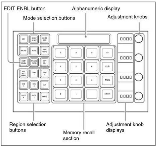
Notes
To select [M/E 4], a previous assignment in the Setup menu is required (see page 387).
Selecting the switcher bank and keyer
Before carrying out key adjustment, first select the key adjust mode, then select the switcher bank and keyer. For example, to adjust key 1 on M/E-1, proceed as follows.
1 In the Multifunction Flexi Pad control block mode selection buttons, press [KEYADJ].
2 Press the [M/E1] region selection button.
3 Press the [KEY SHIFT] button, turning it off.
4 In the memory recall section, press the [KEY1] button.
Notes
To select keys 5 to 8, in step 3 press [KEY SHIFT], turning it on, then press one of buttons [KEY5] to [KEY8] in the memory recall section to select the key.
The button displays in the memory recall section now appear as shown in the following illustration.
Pressing the [PAGE 1/4] > [PAGE 2/4] > [PAGE 3/4] buttons further changes the display as follows, then pressing [PAGE 4/4] returns to the original display shown in the illustration.
[PAGE 1/4]
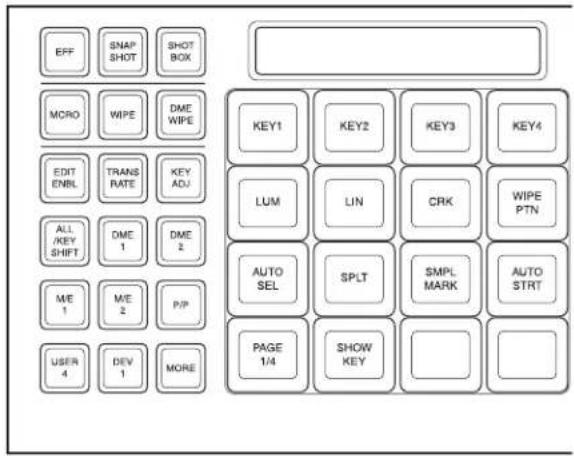
[PAGE 2/4]
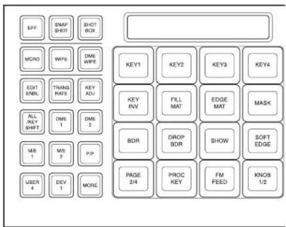
[PAGE 3/4]
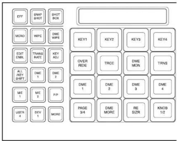

[PAGE 4/4]
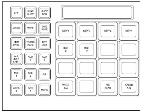
With these buttons in the memory recall section, you can carry out the following key adjustment.
Selecting the key type
[LUM] button: Selects a luminance key.
[LIN] button: Selects a linear key.
[CRK] button: Selects a chroma key.
[WIPE PTN] button: Selects a key wipe pattern key.
Adjust the parameters for each type with the adjustment knobs. For details of the parameters, see the following sections.
Luminance key: “When the [LUM] or [LIN] button is lit green” (page 138)
Linear key: “When the [LUM] or [LIN] button is lit green” (page 138)
Chroma key: “When the [CRK] button is lit green” (page 138)
Key wipe pattern key: “When the [PTN] button is lit green” (page 139)
Selecting the key source
[AUTO SEL] button: The signal assigned as a pair with the key fill bus signal for the key row button in the cross-point control block is automatically selected.
[SPLT] button: Select a different signal manually. To make the selection, hold down this button, and press the button assigned to the signal you want as key source in the cross-point control block.
You can also use the same signal as the key fill selected on the key fill bus as key source (SELF). Press the [AUTO SEL] button and [SPLT] button simultaneously so that both are off, to select the SELF mode.
Setting auto chroma key
[SMPL MARK] button: Toggles the sample mark display on and off. When on, the monitor screen shows the foreground video and a white box sample mark.
[AUTO STRT] button: Automatically adjusts the chroma key. When the [SMPL MARK] button is off, pressing this does not carry out automatic chroma key adjustment.
You can adjust the display position and size of the sample mark with the adjustment knobs.
For details of these parameters, see “Making auto chroma key adjustments” (page 127).
Setting the show key function
[SHOW KEY] button: When this is pressed, the key source signal to which key processing has been applied is output from the specified output port (show key mode).
For details, see "Using the show key function" (page 144).
Setting the resizer function
[RE SIZR] button: Enables and disables the resizer function.
The parameters that can be adjusted with the adjustment knobs are on three pages; to access the second page or third page, press the [KNOB 1/3] or [KNOB 2/3] button.
For details of the parameters, see “Menu operations for key shrinking, magnification, rotation and movement” (page 148).
If you press this button at the same time as any of the [KEY1] to [KEY4] buttons, you can switch the trackball and joystick to the resizer setting mode.
[ROT X] button: When this is set to On, you can rotate the key around on the x-axis.
[ROT Y] button: When this is set to On, you can rotate the key around on the y-axis.
For the parameters adjustable with the adjustment knobs, see step 4 in “Setting rotation of the resizer” (page 154).
Inverting the sense of the key source
[KEY INV] button: When this is set to On, the sense of the key source is inverted.
Selecting the key fill signal
[FILL MAT] button: When this is On, the signal generated by the dedicated color matte generator is selected, and when it is Off, the signal selected on the key 1 fill bus is selected.
For parameters that can be adjusted with the adjustment knobs, see “Selecting key fill and key source” (page 124).
Selecting the key edge signal
[EDGE MAT] button: When this is On, the signal generated by the dedicated color matte generator is selected, and when it is Off, the signal selected on the utility bus is selected.
For parameters that can be adjusted with the adjustment knobs, see step 4 in “Key Edge Modifications” (page 130).
Selecting the mask source
[MASK] button: Selects the mask source (box generated by dedicated generator or pattern) to be selected in the Main Mask menu for each M/E bank.
The parameters that can be adjusted with the adjustment knobs are different for a box or a pattern.
The box parameters are on two pages; to access the second page, press the [KNOB1/2] button.
For details, see step 4 in “Using the main mask” (page 133).
Applying modifiers to the key edge
[BDR] button: Applies a border to the edge.
[DROP BDR] button: Applies a drop border to the edge.
[SHDW] button: Applies a shadow to the edge.
For parameters that can be adjusted with the adjustment knobs, see “Key Edge Modifications” (page 130).
Setting the degree of edge softening
[SOFT EDGE] button: Softens the key edge.
For parameters that can be adjusted with the adjustment knobs, see step 7 in "Key Edge Modifications" (page 131).
Enabling the set key to be used on the AUX bus
[PROC KEY] button: This enables the keyer key fill/key source signal to be subjected to key processing, then used as a reentry signal by selection on the AUX bus.
For details, see “Using an external processed key” (page 144).
Sending a signal subjected to key processing to frame memory
[FM FEED] button: Press this to assign the key fill/key source signal processed on the currently selected keyer to frame memory source 1 or 2.
For details, see "Using a frame memory feed" (page 144).
Using a DME currently used on another keyer
[OVER RIDE] button: When one DME channel is in use, holding down this button and pressing a DME channel button ([DME1] to [DME8]) allows you to forcibly select this channel. The button for the selected DME channel lights green.
Recalling the keyer using the DME channel
[TRCE] button: Holding down this button, press the selection button for the DME channel already assigned to another keyer or transition, to switch the keyer or transition to which the DME channel is assigned to the currently selected state.
Monitoring DME output
[DME MON] button: Holding down this button and pressing the selection button for a DME channel ([DME1] to [DME8]) allows you to monitor the signal for this channel as a reentry signal to DME MON V/K. However, it is first necessary to assign this channel on the DME to the delegation (keyer or transition) to be monitored.
Selecting the DME channel
[DME1] to [DME8] buttons: Press one of these to select the corresponding DME channel. The number of valid buttons depends on the number of DME channels in use.
[DME MORE] button: If there are more than four DME channels in use, use this to change the DME channel selection buttons displayed.
Returning the key adjustment values to their defaults
Holding down a key type button ([LUM], [LIN], [CRK], or [WIPE PTN])
recalls the key default values.
Key modify clear
When the [KEY ADJ] button is held down, holding down the region selection button for the selected region together returns all the key settings of the region to the initial status settings.
When the [KEY ADJ] button is held down, holding down the button for the selected key together returns the key settings to the initial status settings.
For details of the initial status, see "Saving User-Defined Settings" in Chapter 18 (Volume 2).

Resizer
Resizer allows you to apply DME-like effects such as image shrinking, magnification and movement, rotation as well as change of the aspect ratio, to the processed key. The following functions are available.
- Two-dimensional transformations of keys (page 148)
• Key rotation around on the x- or y-axis - Resizer interpolation settings (page 150)
- Resizer crop/border settings (page 151)
- Resizer effect settings (page 152) (wide key border, drop shadow, edge enhance, mosaic, defocus, mask)
Notes
- The image of the key manipulated by resizer has a one-frame delay.
- Some effects of resizer are different from what you would expect of DME effects.
Restrictions on the use of effects
There are restrictions on combined use of resizer effects themselves and that with DME wipes.
For details, see “Impossibility of simultaneous use within the same keyer” (page 154).
Relation between resizer and other effects
You cannot apply DME effects to a key for which the resizer function is enabled. When one of the three functions – resizer, DME wipe and DME effects – is enabled, the other two are disabled.
Two-Dimensional Transformations and Rotation of Keys
Notes
When the screen aspect ratio is 4:3 in HD format, when the resizer is used to shrink a video image, this is applied to the 16:9 screen including the added video on the left and right sides. Use the crop function as required to extract the 4:3 image.
Menu operations for key shrinking, magnification, rotation and movement
For example, to shrink, magnify, rotate or move key 1 of the M/E-1 bank, use the following procedure.
1 In the M/E-1 >Key1 >Processed Key menu, press [Resizer], turning it on.
2 Adjust the following parameters with the knobs.
Parameter group [1/2]
| Knob | Parameter | Adjustment | Setting values | |
| 1 Location X Move key horizontally | HD -9 | 9.9999 to +99.9999 | ||
| SD 4:3 | -33.3333 to +33.3333 | |||
| SD 16:9 | -24.9999 to +24.9999 | |||
| 2 Location Y Move key vertically | HD -9 | 9.9999 to +99.9999 | ||
| SD 4:3 | -33.3333 to +33.3333 | |||
| SD 16:9 | -24.9999 to +24.9999 | |||
| 3 Size Magnify or shrink key | 0.0000 to 99.9999 | |||
| 4^a) | Rotation X R | Rotate key horizontally | -99.9999 to +99.9999 | |
| 4^b) | Rotation Y R | Rotate key vertically | -99.9999 + 99.9999 | |
| 5 Perspective Change perspective | 0.0000 to 1.0000 | |||
a) [X] is turned on in the
b) [Y] is turned on in the
Parameter group [2/2]
| Knob | Parameter Adjustment Setting values | ||
| 1 Aspect X Change | aspect ratio horizontally | 0.0000 to 99.9999 | |
| 2 Aspect Y Change | aspect ratio vertically | 0.0000 to 99.9999 | |
| 3 Aspect Ratio | Change aspect ratio horizontally and vertically at a time | 0.0000 to 2.0000 | |
Key control block operations for key shrinking, magnification, rotation and movement
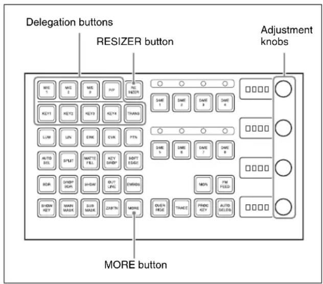
1 Use the delegation buttons to select the key to which you want to apply a resizer function.
2 Press the [RESIZER] button, turning it on.
3 Adjust the following parameters with the knobs. (To switch between displaying parameter group 1/2 and 2/2, press the [MORE] button.)
Parameter group [1/2]
| Knob | Parameter | Adjustment | Setting values | |
| 1 X Move key | horizontally | HD -99 to | +99 | |
| SD 4:3 -33 | to +33 | |||
| SD 16:9 -24 | to +24 | |||
| 2 Y Move key | vertically | HD -99 to | +99 | |
| SD 4:3 -33 | to +33 | |||
| SD 16:9 -24 | to +24 | |||
| 3 S Magnify or | shrink key | 0.0 to 99 | ||
Parameter group [2/2]
| Knob | Parameter | Adjustment | Setting values |
| 1 X Change | aspect ratio horizontally | 0.0 to 99 | |
Parameter group [2/2]
| Knob | Parameter | Adjustment | Setting values |
| 2 Y Change | aspect ratio vertically | 0.0 to 99 | |
| 3 R Change | aspect ratio horizontally and vertically at a time | 0.0 to 2.0 | |
4 To specify the direction of rotation, press the [ROT X] or [ROT Y] button, turning it on.
Notes
To enable the [ROT X] and [ROT Y] buttons, it is necessary to assign functions in advance.
For details, see Chapter 19 "Assigning Functions to Key Control Block Buttons" (Volume2).
5 Turn the knobs to adjust the following parameters.
- When [ROT X] is lit
| Knob | Parameter | Adjustment | Setting values |
| 1 Rotation X | Rotate | key horizontally | -99 to +99 |
| 4 | Perspective | Change perspective | 0 to 99 |
- When [ROT Y] is lit
| Knob | Parameter | Adjustment | Setting values |
| 2 | Rotation Y | Rotate key vertically | -99 to +99 |
| 4 | Perspective | Change perspective | 0 to 99 |

Device control block operations for key shrinking, magnification, rotation and movement
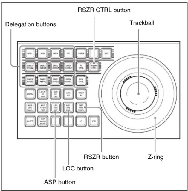
1 Press the [RSZR CTRL] button, turning it on.
2 Press the delegation button to select the key.
3 Press the [RSZR] button, turning it on.
4 • To change the aspect ratio, turn on the [LOC SIZE(ASP)].
- To shrink, magnify, or move the key, turn on the [LOC XYZ(LOC)].
- To rotate the key, turn on the [ASP PS (ROT)] button. To specify the direction of rotation, press [X] or [Y]. To adjust perspective, press [Z].
Hold these buttons down while carrying out the operation of step 5 to enable fine adjustment (fine mode).
5 Use the trackball and joystick for the operation.
For details of parameters, see steps 3 and 5 of “Key control block operations for key shrinking, magnification, rotation and movement” (page 149).
Entering parameters
This operation is the same as DME three-dimensional parameter input.
For details, see “Entering Three-Dimensional Parameter Values” (page 280).
Resetting parameters
This operation is the same as DME three-dimensional parameter resetting.
For details, see “Entering Three-Dimensional Parameter Values” (page 280).
Clearing resizer effects
To clear two-dimensional transform and rotation parameters only and set the initial state
In the device control block, press the [CLR WORK BUFR] button in the operation buttons.
To clear all resizer parameters, and set the initial state
In the device control block, press the [CLR WORK BUFR] button in the operation buttons, twice in rapid succession.
For the initial state, you can select either the factory default settings or user settings.
For details of how to make this selection, see “Selecting the State After Powering On (Start Up Menu)” in Chapter 18 (Volume 2).
Resizer Interpolation Settings
For example, to make the interpolation settings for key 1 of the M/E-1 bank, use the following procedure.
1 In the M/E-1 >Key1 >Processed Key menu, press [Resizer], turning it on.
2 Press [Resizer Process].
The Resizer Process menu appears.
3 In the
This operation is the same as when making the DME interpolation settings for MVS-8000A.
For details, see Chapter 11 ““Interpolation Settings” (page 340).
However, the following points are different from the operation for MVE-8000A.
- [Interpolation Mode] can be set for any type of signal formats.
- The anti-moire filter cannot be set.
Resizer Crop/Border Settings
Making a crop setting for a key for which resizer is on
For example, to make the crop settings for key 1 of the M/E-1 bank, use the following procedure.
1 In the M/E-1 >Key1 >Processed Key menu, press [Resizer], turning it on.
2 Press [Border/Crop].
The Border/Crop menu appears.
3 Press [Crop], turning it on.
4 Set the parameters.
These settings are the same as those for crop of DME. For details, see “Crop Settings” (page 284).
Notes
If mosaic or defocus is enabled, and in the
Applying a border to a key for which resizer is on
For example, to add the border for key 1 of the M/E-1 bank, use the following procedure.
1 In the M/E-1 >Key1 >Processed Key menu, press [Resizer], turning it on.
2 Press [Border/Crop].
The Border/Crop menu appears.
3 Press [Border], turning it on.
4 Set the parameters.
The valid ranges of the parameter values depend on the combination of signal format (SD/HD) and aspect ratio (4:3/16:9) selected in the system, as follows.
SD format
| Knob Parameter Adjustment Setting values | ||
| 1 H Simultaneously | adjust width of left and right borders | 0.00 to 4.00 |
| Knob | Parameter | Adjustment | Setting values |
| 2 V | Simultaneously | adjust width of top and bottom borders | 0.00 to 3.00 (4:3)0.00 to 2.25 (16:9) |
| 3 All | Simultaneously | adjust width of all four borders | Value of H shown |
| 5 Density | Density of | the borders | 0.00 to 100.00 |
HD format
| Knob | Parameter | Adjustment | Setting values |
| 1 H | Simultaneously | adjust width of left and right borders | 0.00 to 12.00 (4:3)0.00 to 16.00 (16:9) |
| 2 V | Simultaneously | adjust width of top and bottom borders | 0.00 to 9.00 |
| 3 All | Simultaneously | adjust width of all four borders | Value of H shown |
| 5 Density | Density of | the borders | 0.00 to 100.00 |
To apply color to a border
1 In the
2 Adjust the following parameters.
| Knob | Parameter | Adjustment | Setting values |
| 1 | Luminance | Luminance | 0.00 to 100.00 |
| 2 | Saturation | Saturation | 0.00 to 100.00 |
| 3 | Hue | Hue | 359.99 to 0.00 |
To soften the inner edge of a border
1 In the Border/Crop menu, press [Border Soft].
2 Adjust the following parameters.
| Knob | Parameter | Adjustment | Setting values |
| 1 Inner | Soft | Border inner softness | 0.00 to 100.00 |
To apply a beveled light edge
1 In the
2 Adjust the following parameters.

| Knob | Parameter | Adjustment | Setting values |
| 1 | Top | top edge -100.00 to | +100.00 |
| 2 | Left | left edge -100.00 to | +100.00 |
| 3 | Right | right edge -100.00 to | +100.00 |
| 4 | Bottom | bottom edge -100.00 to | +100.00 |
| 5 | All | Four edges Value of Left | shown |
3 Press [Border Soft].
4 Adjust the following parameters.
| Knob | Parameter | Adjustment | Setting values |
| 1 Inner | Soft | Border inner softness | 0.00 to 100.00 |
| 2 Bound | Soft | 0.00 to 100.00 |
To apply a beveled color edge
1 In the
2 In the
3 Set the color parameters.
For details, see “To apply color to a border” (page 151)
4 Press [Border Soft].
5 Adjust the following parameters.
| Knob | Parameter | Adjustment | Setting values |
| 1 Inner | Soft | Border inner softness | 0.00 to 100.00 |
| 2 Bound | Soft | 0.00 to 100.00 |
Applying Resizer Effects
For example, to apply effects to key 1 of the M/E-1 bank, use the following procedure.
1 In the M/E-1 >Key1 >Processed Key menu, press [Resizer], turning it on.
2 Press [Enhanced Effect].
The Enhanced Effect menu appears.
![Type LUM C = 0.00 G = 0.00 D = 100.00 Edge Matio BH Mode Main Mask Sub Mask BLAC Video Proc Key Diff Opt Fill Source WRIT Proc Key Resizer On Trans Mix Oil Trans Priority 1: K8 3: K4 2: K7 6: K3 3: K6 7: K2 4: K5 0: K1 Key Bus Auto Select [30] Resizer Dual Rear Effect Wide Key Border Outlines Border Color Crop Shadow Resizer Effect Rotation Edge Enhance Mosaic Fasket Border Crop Resizer Process Rotation Mosaic Defocus Mode Defocus Clean Defocus Video Key Video Mask Mask Menu](/content/2026/06/1364863/images/44be6b103f00261be3e71a3b9f896bcf0853d8a3a43ea2012407a14612db7623.jpg)
Applying a wide key border
1 In the M/E-1 >Key1 >Processed Key >Enhanced Effect menu, press [Dual Rszr Effect], turning it on.
2 Press [Wide Key Border], turning it on.
3 Adjust the following parameters.
| Knob | Parameter | Adjustment | Setting values |
| 1 H | Simultaneouslyadjust border width of left and right edges | 0.00 to 100.00 | |
| 2 V | Simultaneouslyadjust border width of upper and lower edges | 0.00 to 100.00 | |
| 3 All Simultaneously | adjust border width of all four edges | Value of H shown | |
| 4 | Softa) | Softness of border | 0.00 to 100.00 |
| 5 Density | Density of border | 0.00 to 100.00 | |
a) Shared with the drop shadow "Soft" value.
4 To add an outline, press [Outline], turning it on.
5 To adjust the border color, press [Border Color].
6 Set the color parameters.
For details, see "To apply color to a border" (page 151).
Applying a drop shadow
1 In the M/E-1 >Key1 >Processed Key >Enhanced Effect menu, press [Dual Rszr Effect], turning it on.
2 Press [Drop Shadow], turning it on.
3 Set the parameters.
The valid ranges of the parameter values depend on the combination of signal format (SD/HD) and aspect ratio (4:3/16:9) selected in the system, as follows.
SD format
| Knob | Parameter | Adjustment Setting | values |
| 1 | H | H o position of shadow | -8.00 toi+8.00 z |
| 2 V Vertical position | of shadow | -6.00 to +6.00 (4:3) -4.50 to +4.50 (16:9) | |
| 3 Size | Shadow size | 0.00 to 2.00 | |
| 4 | S a) o | Soffness of shadow | 0.00 to 100.00 |
| 5 Density | Density of | shadow | 0.00 to 100.00 |
a) Shared with the wide key border "Soft" value.
HD format
| Knob | Parameter | Adjustment Setting | values |
| 1 | H | H o position of shadow | -24.00 to z +24.00 (4:3) -32.00 to +32.00 (16:9) |
| 2 V Vertical position | of shadow | -18.00 to +18.00 | |
| 3 Size | Shadow size | 0.00 to 2.00 | |
| 4 | S a) o | Soffness of shadow | 0.00 to 100.00 |
| 5 Density | Density of | shadow | 0.00 to 100.00 |
a) Shared with the wide key border "Soft" value.
Edge enhancement
Adjusting the gain sharpens the image.
1 In the M/E-1 >Key1 >Processed Key >Enhanced Effect menu, press [Edge Enhance], turning it on.
2 Adjust the following parameters.
| Knob | Parameter Adjustment Setting | values |
| 1 H | Horizontal gain adjustment | 0.00 to 100.00 |
| 2 V Vertical gain | 0.00 to 100.00 | |
| 3 All | Both horizontal and vertical adjustment | H value is displayed |
Applying a mosaic
1 In the M/E-1 >Key1 >Processed Key >Enhanced Effect menu, press [Mosaic], turning it on.
2 Set the parameters.
This operation is the same as the DME mosaic setting.
For more details, see “Mosaic Settings” (page 301).
3 In the < Mosaic/Defocus Mode > group, select the signal to which to apply the mosaic effect.
Video/Key: Video signal and key signal Video: Video signal only
Notes
If mosaic is enabled, and in the
4 Set the parameters.
0
| Knob | Parameter | Adjustment Setting | values |
| 1 H | Horizontal defocusing | 0.00 to 100.00 | |
| 2 | V | Ve r t defocusing | 0.00 to 100.00 |
| 3 All | Horizontal and vertical defocusing | H value shown | |
To make the mosaic like a relief pattern
1 With [Mosaic] on, press [Relief], turning it on.
2 In addition to the mosaic parameters, set the following parameters.
| Knob | Parameter | Adjustment Setting | values |
| 3 Gain | Relief | depth of mosaic cells | 0.00 to 100.00 |
| 4 Angle | Light | source direction | -8.00 to +8.00 |
Defocusing
1 In the M/E-1 >Key1 >Processed Key >Enhanced Effect menu, press [Defocus], turning it on.
2 Set the parameters.
This operation is the same as the defocusing setting when using the DME with the DME dedicated interface (see page 297).
However,
Notes
If defocus is enabled, and in the
Applying a mask to mosaic or defocus
1 In the M/E-1 >Key1 >Processed Key >Enhanced Effect menu, press [Dual Rszr Effect], turning it on.
2 Press [Mask], turning it on.
This enables the mask function.
To make the mask settings, continue with steps 3 and following.
3 Press [Mask Menu].
The Mask menu appears.
4 In the
Box: Use a box pattern as the mask signal.
Circle: Use a circle pattern as the mask signal.
5 Set the parameters.
The valid ranges of the parameter values depend on the combination of signal format (SD/HD) and aspect ratio (4:3/16:9) selected in the system, as follows. The parameters are the same as for drop shadow.
For more details, see “Applying a drop shadow” (page 153), except that knobs 3 and 5 are as follows.
| Knob | Parameter | Adjustment Setting | values |
| 3 Size | Size 0.00 to | 100.00 | |
| 5 Aspect | Aspect ratio | -100.00 to | +100.00 |
The rotation and inversion operations are the same as for a DME mask setting.
For more details, see "Mask Settings" (page 304).
Notes
- When a mask effect is applied to a border, the boundary becomes discontinuous, giving an unnatural effect. Avoid applying a mask to a border.
- If mosaic or defocus is enabled, and in the
group you select Video/Key, then the mask is disabled.
Restrictions on resizer effects
Restrictions on the use of effects
Of the resizer effects, using mask, drop shadow, or wide key border requires two units of hardware for the resizer function.
These are called "dual resizer effects".
In a dual resizer effect, predetermined combinations, key 1 and key 2, key 3 and key 4, key 5 and key 6, key 7 and key 8 are used.
For example, if either of key 1 and key 2 has resizer set to On, the other key cannot be used for a dual resizer effect. The same restriction applies when using a resizer DME wipe in place of resizer.
Impossibility of simultaneous use within the same keyer
The following combinations of resizer effects cannot be simultaneously on.
- Mosaic and edge enhance
• Defocus and wide key border - Mask and drop shadow
- Mask and wide key border
Setting rotation of the resizer
Notes
Either X or Y direction must be specified for rotation. You cannot make rotation by combining both directions.
When rotating key 1 of the M/E-1 bank, for example, use the following procedure.
1 Select M/E-1 >Key1 >Processed Key menu, press [Resizer], turning it on.
2 Press [Rotation], turning it on.
The Rotation menu appears.
3 Press [X] or [Y] in the
4 Turn the knobs to adjust the following parameters.
- When [X] is on
| Knob | Parameter | Adjustment | Setting values |
| 1 Rotation X Rotate key horizontally | -99.0000 to +99.0000 | ||
| 4 Perspective Change perspective | 0.0000 to 99.9999 | ||
- When [Y] is on
| Knob | Parameter | Adjustment | Setting values |
| 2 Rotation Y Rotate key | -99.0000 to +99.0000 | ||
| 4 Perspective Change | 0.0000 to 99.9999 | ||
Canceling Virtual Images
If an extreme degree of perspective is set for an image, the part of the image which is beyond the imaginary view point of view is wrapped around to show the other side of the image on the monitor screen. You can press [Wrap Around], turning it on, to make a setting not to show the virtual images.
Key Snapshots
Key settings other than the key on/off status and the key priority can all be instantaneously saved in a dedicated register, for recall when required. A key snapshot comprises three values: a cross-point button number, key memory full mode, and independent key transition, and can be called in any combination.
There are four key snapshot registers for each keyer.
Key Snapshot Operations
Key snapshot operations are carried out in the independent key transition control block, downstream key control block or Multifunction Flexi Pad control block. Each keyer is provided with four dedicated key snapshot registers.
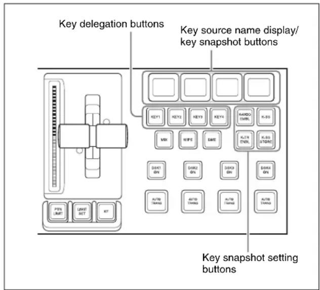
Independent key transition control block (standard type)
Notes
To select [Key5] to [Key8] or [DSK5] to [DSK8] in the independent key transition control block or downstream key control block, a previous assignment in the Setup menu is required (see page 388).
Saving a key snapshot
For example, the following procedure saves the state of the M/E-1 key 1 settings.
1 In the M/E-1 independent key transition control block, press the key delegation button [KEY1], turning it on.
2 Press the [K-SS] button, turning it on.
The system switches to key snapshot mode, and the key source name display/key snapshot buttons show the status of registers 1 to 4 for key 1.
Off: Nothing is saved in the register.
Lit orange: Settings are saved in the register.
For a register holding a snapshot, the register name is shown as up to eight characters.
3 Hold down the [K-SS STORE] button, and press the key source name display/key snapshot button corresponding to the register in which you want to save the snapshot.
The key source name display/key snapshot button which you pressed lights yellow.
Notes
If you save a key snapshot in a register for which the button is lit orange or yellow, the existing contents of the register are overwritten.
Recalling a key snapshot
For example, the following procedure recalls the state of the M/E-1 key 1 settings.
1 In the M/E-1 independent key transition control block, press the key delegation button [KEY1], turning it on.
2 Press the [K-SS] button, turning it on.
3 Set the following buttons on or off, depending on the information you want to recall.
(These buttons are not provided in the downstream key control block.)
[K-MOD ENBL] button: When this is on, the key settings and key modifiers are recalled. When this is off, they are not recalled.
[K-TR ENBL] button: When this is on, the independent key transition settings are recalled. When this is off, they are not recalled.
If both buttons are off, the key memory function is enabled and only the saved selection of key fill and key source signals is recalled.
4 Press the key source name display/key snapshot button corresponding to the register you want to recall.
The button you pressed lights yellow, and this recalls the key snapshot.
To cancel a recall carried out in the downstream key control block, press the [UNDO] button in the downstream key control block.
Key snapshot operation on the Multifunction Flexi Pad control block
By default, the [KEY SS] key snapshot mode selection button does not appear in the Multifunction Flexi Pad control block. To carry out key snapshot saving and recall in this control block, it is first necessary in the Engineering Setup >Panel >Config >Link/Program Button >Multi Function >Mode Sel Assign menu to assign the Key Snapshot mode to a mode selection button.
To save a key snapshot
For example, to save a key snapshot for key 1 of M/E-1, select M/E1 and key1, then use the following procedure.
1 Press the [K SS] button.
The button displays in the memory recall section change as shown in the following illustration.
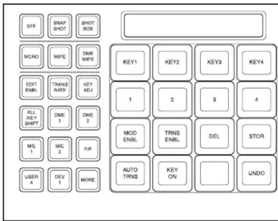
2 In the memory recall section, hold down the [STOR] button, and press the button (any of [1] to [4]) for the register in which you want to save the key snapshot.
To recall a key snapshot
For example, to recall a key snapshot for M/E-1 key 1 saved in register 1, with the M/E1 region and key 1 selected, proceed as follows.
1 Press the [KEY SS] button.
2 According to the information you want to recall, set the following buttons On/Off.
[MOD ENBL] button: Recall the key adjustment values and key modifier settings.
[TRNS ENBL] button: Recall independent key transition settings.
If both are Off, then key memory is enabled, and just the saved key fill and key source signal selections are recalled.
3 Press button [1] for the register you want to recall.
The [1] button lights yellow, and the key snapshot is recalled.
To cancel the recall operation, press the [UNDO] button.
To delete a key snapshot
For example, to delete a key snapshot for M/E1 key 1 saved in register 1, with the M/E1 and key 1 region selected, proceed as follows.
1 Press the [KEY SS] button.
2 Holding down the [DEL] button, press the button [1] for the register in which is saved the key snapshot you want to delete.
To carry out an auto transition execution during key snapshot operation
Press the [AUTO TRNS] button.
Instant key insertion/removal
Press the [KEY ON] button.
To remove the key, while the key is inserted press the [KEY ON] button.
Key Snapshot Operations Using a Simple Transition Module
When using a simple transition module, the key snapshots hold the settings for key 3 and key 4. However, each key control block can be assigned to any key in setup.
For details, see “Assigning a Function to the Independent Key Transition Control Block (Simple Type)” in Chapter 19 (Volume 2).
You can carry out key snapshot operations in the independent key transition control block (simple type) and Flexi Pad control block (simple type).
There are four dedicated key snapshot registers for each of keys 3 and 4.
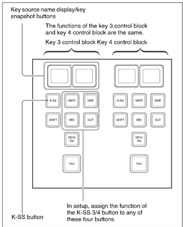
flowchart
graph TD
    A["Key source name display/key snapshot buttons"] --> B["Key 3 control block Key 4 control block"]
    B --> C["K-SS"]
    B --> D["K-SS ON"]
    B --> E["WEIPE"]
    B --> F["DME"]
    B --> G["MIX"]
    B --> H["CUT"]
    B --> I["THYF"]
    B --> J["THYF"]
    B --> K["THYF"]
    B --> L["THYF"]
    B --> M["THYF"]
    B --> N["THYF"]
    B --> O["THYF"]
    B --> P["THYF"]
    B --> Q["THYF"]
    B --> R["THYF"]
    B --> S["THYF"]
    B --> T["THYF"]
    style A fill:#f9f,stroke:#333
    style B fill:#ccf,stroke:#333
    note right of A: The functions of the key 3 control block and key 4 control block are the same.
    note right of B: Key 3 control block Key 4 control block
    note right of C: In setup, assign the function of the K-SS 3/4 button to any of these four buttons.
    note right of D: In setup, assign the function of the K-SS 3/4 button to any of these four buttons.
    note right of E: In setup, assign the function of the K-SS 3/4 button to any of these four buttons.
    note right of F: In setup, assign the function of the K-SS 3/4 button to any of these four buttons.
    note right of G: In setup, assign the function of the K-SS 3/4 button to any of these four buttons.
    note right of H: In setup, assign the function of the K-SS 3/4 button to any of these four buttons.
    note right of I: In setup, assign the function of the K-SS 3/4 button to any of these four buttons.
    note right of J: In setup, assign the function of the K-SS 3/4 button to any of these four buttons.
    note right of K: In setup, assign the function of the K-SS 3/4 button to any of these four buttons.
Independent key transition control block (simple type)
Saving a key snapshot
For example, to save the settings of M/E-1 key 3, use the following procedure.
1 In the M/E-1 independent key transition control block, press the [K-SS] button in the key 3 control block, turning it on.
This switches to key snapshot mode, and the key source name display/key snapshot button shows the state of registers 1 and 2 for key 3.
Pressing the [K-SS 3/4] button shows the state of registers 3 and 4 for key 3.
Off: Nothing is saved in the register.
Lit orange: Settings are saved in the register.
For a register holding a snapshot, the register name is shown as up to eight characters.
2 In the Flexi Pad control block, hold down the [SNAPSHOT] button and press the key source name display/key snapshot button corresponding to the register in which you want to save the snapshot.
The key source name display/key snapshot button which you pressed lights yellow.

Notes
If you save a key snapshot in a register for which the button is lit orange or yellow, the existing contents of the register are overwritten.
Recalling a key snapshot
For example, the following procedure recalls the state of the M/E-1 key 3 settings.
1 In the M/E-1 independent key transition control block, press the [K-SS] button in the key 3 control block, turning it on.
2 Press the key source name display/key snapshot button corresponding to the register you want to recall.
Press the [K-SS 3/4] button as required, to switch between displaying the key 3 registers 1 and 2 or registers 3 and 4.
The button you pressed lights yellow, and this recalls the key settings (excluding the key insertion state (on/off) and key priority).
Overview
A wipe is a transition from the current video stream to a new video stream, using a wipe pattern.
Changing the background by means of a wipe is referred to as a “background wipe,” and inserting or deleting a key with a wipe is termed a “key wipe.”
There are two types of wipe: those that can be selected in a common transition, and those that can be selected in an independent key transition (see page 171).
Types of Wipe Pattern
The patterns that can be used for a wipe are divided into a number of groups, as follows. Note that only the standard wipe patterns can be used for an independent key transition.
For wipe patterns, see “Wipe Pattern List” in Appendix (Volume 1) (page 351).
Standard wipe patterns
Patterns consisting of straight lines vertically, horizontally, or diagonally, and circular patterns.
Enhanced wipes
More complex shapes such as hearts, stars, and round corners.
Rotary wipes
These patterns involve rotation of the image about a point.
Mosaic wipe pattern
This divides the image into small tiles.
Random and diamond dust wipe patterns
These patterns consist of small random tiles, or fine particles.
Basic Procedure for Wipe Settings
You carry out wipe setting operations principally using the Wipe menu for each of the M/E-1 to M/E-3 and PGM/PST banks.
This section describes the basic procedures for wipe settings, taking the M/E-1 >Wipe menu as an example.
Wipe Settings Menu
Accessing the wipe settings menu
To access the M/E-1 >Wipe menu, use either of the following operations.
- In the menu control block, select the top menu selection button [M/E 1], and press VF5 'Wipe.'
Notes
To select [M/E-4], a previous assignment in the Setup menu is required.
- In the transition control block of the M/E-1 bank, press the transition type selection button [WIPE] twice in rapid succession.
Wipe Pattern Selection
Selecting a wipe pattern by a menu operation
1 In the M/E-1 >Wipe menu, select HF1 'Main Pattern.' The Main Pattern menu appears.
2 Select the wipe pattern group with the pattern group selection button.
Standard: standard wipes
Enhanced: enhanced wipes
Rotary: rotary wipes
Mosaic1 to Mosaic3: mosaic wipes
Random/Dust: random/diamond dust wipes
The patterns from the selected pattern group appear on the screen.
For details of wipe patterns, see “Types of Wipe Pattern” (page 159) and “Wipe Pattern List” (page 351).
3 Press the button to select the desired pattern.
4 3The parameters change according to the selected pattern, and you can adjust the pattern.
When a polygon wipe is selected (pattern number 49)
| Knob | Parameter | Adjustment | Setting values |
| 1 No Number of points | 3 to 64 | ||
| 2 Star Rate Angularity of star | -100.00 to +100.00^a) | ||
a) A value of -100.00 completely removes the star "rays," leaving a circle; at +100.00 the "rays" are at their sharpest.
When a mosaic wipe is selected (pattern numbers 200 to 203, 206 to 213, 224 to 247, 250 to 257, 260 to 269)
| Knob | Parameter | Adjustment | Setting values |
| 1 H Tile | No Number | of tiles horizontally | 2 to 36 |
| 2 V Tile | No Number | of tiles vertically | 2 to 18 |
When a karaoke wipe is selected (pattern numbers 220 to 223)
| Knob | Parameter | Adjustment | Setting values |
| 1 Start | Position of start tile | -100.00 to +100.00^a) | |
| 2 Row | No Number of rows of tiles | 1 to 36 | |
| 3 Phase | Delay for next row | -100.00 to +100.00^b) | |
a) At -100.00 tiles appear from the top (or left edge) of the screen; at +100.00 from the bottom (or right edge) of the screen.
b) At -100.00 all rows appear simultaneously; at +100.00 until one row of tiles is completely displayed, the next row does not start to appear.
When a random wipe is selected (pattern number 273)
| Knob | Parameter | Adjustment | Setting values |
| 1 H Size | Tile width 0.00 to 100.00 | ||
| 2 V Size | Tile height 0.00 to 100.00 | ||
| 3 Volatility | Rate of tile generation | 0.00 to 100.00 | |
When a diamond dust wipe is selected (pattern number 274)
| Knob | Parameter | Adjustment | Setting values |
| 1 H Size | Particle width | 0.00 to 100.00 | |
| 2 V Size | Particle height | 0.00 to 100.00 | |
| 3 Flash | Rate Rate of generation of particles | 0.00 to 100.00 |
Notes
When Flash Rate is set to 0.00, you cannot change the pattern. In this state, adjusting H Size or V Size has no effect on the pattern.
For details of a pattern mix, see the next section.
For details of applying pattern modifiers, see “Setting Wipe Modifiers” (page 162).
Pattern Mix
You can create a new pattern by combining two selected patterns (main and "sub").
Notes
It is not possible to apply a pattern mix to an independent key transition.
Types of pattern mix
There are four ways in which patterns can be combined in a pattern mix, as follows.
Mix: The effect of the sub pattern is applied to the main pattern, modifying the outline or nature of the main pattern.
Positive NAM (+Nam): Creates a pattern with an outline which contains all points within the outlines of either of the main pattern and the sub pattern.
Negative NAM (–Nam): Creates a pattern with an outline which contains all points within the outlines of both of the main pattern and the sub pattern.

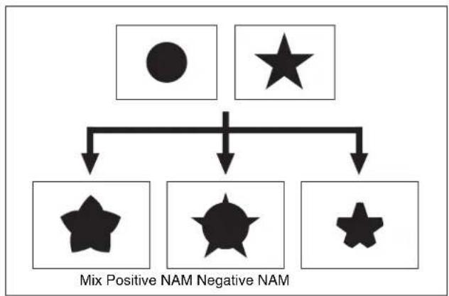
flowchart
graph TD
    A["●"] --> C["★"]
    B["○"] --> C["★"]
    C["★"] --> D["Mix Positive NAM"]
    C["★"] --> E["Negative NAM"]
    D["★"] --> F["★"]
    E["★"] --> G["★"]
Morphing: As the transition progresses, the pattern morphs from the main pattern, through the “mix” combination, to the sub pattern.
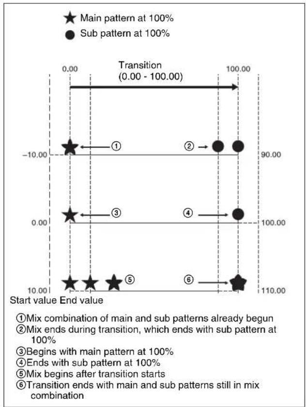
scatter
| Start value End value | Main pattern at 100% | Sub pattern at 100% | | --------------------- | -------------------- | ------------------- | | 0.00 | -10.00 | 90.00 | | 10.00 | -10.00 | 90.00 | | 10.00 | 0.00 | 100.00 | | 10.00 | 10.00 | 110.00 |- Parameter settings
Start: Point in the course of the transition at which the main pattern is at 100%
End: Point in the course of the transition at which the sub pattern is at 100% - A value of 0.00 corresponds to the beginning of the transition, and a value of 100.00 to the end of the transition.
-
A negative Start value signifies that the main and sub patterns are already combined when the transition starts.
-
An End value of 100.00 or more signifies that the main and sub patterns are still combined when the transition complete.
- If the Start and End values are the same, the main and sub patterns are interchanged instantaneously at the corresponding point in the transition.
- If End is less than Start, as the transition proceeds, it changes from the sub pattern to the main pattern.
Dust mix
You can apply the effect of a diamond dust wipe to a selected pattern. You can also apply the diamond dust wipe effect to the pattern resulting from a pattern mix (see page 162).
When the pattern mix function is off, turning dust mix on results in the main pattern and the diamond dust pattern being mixed. This state is the same as a pattern mix when the diamond dust pattern is selected for the sub pattern.
Main and sub modifier link function
When carrying out a pattern mix, it is possible to link the modifier settings for the main pattern and sub pattern. There are two modes for this function.
FULL LINK (fully linked) mode
In this mode, all modifier settings are the same for the main pattern and sub pattern.
Changing the modifier settings for one pattern automatically changes the settings for the other.
SEMI LINK (semi-linked) mode
Only the parameter settings of the modifiers are linked. The modifier on/off settings are not linked. When the parameter values for the modifiers of the main pattern and sub pattern are different, then after this link mode is selected, changing the value of a parameter for one pattern changes the value of the parameter for the other pattern to maintain the same difference between the two.
Notes
When carrying out a wipe transition using a pattern mix, it is recommended that you set the modifier link function to FULL LINK mode.
If the link function is off, or SEMI LINK mode is selected, the desired effect may not be obtained at the start or end of the transition.
Combining two patterns
Select a main pattern in the Main Pattern menu, then use the following procedure.
1 In the M/E-1 >Wipe menu, select HF3 'Sub Pattern.' The Sub Pattern menu appears.
2 In the same way as for the main pattern, select the sub pattern.
The patterns that can be selected for the sub pattern depend on the pattern selected for the main pattern (see the following table).
Yes: Combination possible No: Combination not possible
| Main pattern | Sub pattern | ||||
| Standard | Enhanced | Rotary Mosaic | Random/diamond dust | ||
| Standard | Yes Yes No Yes Yes | ||||
| Enhanced | Yes Yes No Yes Yes | ||||
| Rotary No No No No | |||||
| Mosaic Yes Yes No No Yes | |||||
| Random/diamond dust | Yes | Yes | No | Yes | No |
3 Select HF2 'Pattern Mix.'
The Pattern Mix menu appears.
4 In the
Mix: mix
+Nam: positive Nam
-Nam: negative Nam
Morphing: morphing
5 Depending on the selection in step 4, set the following parameters.
When mix, positive Nam, or negative Nam is selected
| Knob | Parameter | Adjustment | Setting values |
| 1 Mix Ratio | Proportion of sub pattern to the main pattern | 0.00 to 100.00 | |
When morphing (see page 161) is selected
| Knob | Parameter | Adjustment | Setting values |
| 2 Start | Point | in transition at which main pattern is at 100% | -50.00 to +150.00 |
| 3 End | Point | in transition at which sub pattern is at 100% | -50.00 to +150.00 |
6 In the
Full: fully linked mode
Semi: semi-linked mode
Applying the effect of a diamond dust wipe to the selected pattern (Dust mix)
1 In the Pattern Mix menu, press [Dust Mix], turning it on.
2 Set the following parameters as required.
| Knob | Parameter | Adjustment | Setting values |
| 1 Mix Ratio | Proportion of diamond dust pattern in mix | 0.00 to 100.00 | |
| 2 H Size | Particle width | 0.00 to 100.00 | |
| 3 V Size | Particle height | 0.00 to 100.00 | |
| 4 Flash | Rate Rate of generation of particles | 0.00 to 100.00 | |
You can also apply the dust mix function to the pattern generated by a pattern mix.
Notes
When a random/diamond dust wipe (pattern numbers 270-274) is selected, the dust mix function is not available.
Setting Wipe Modifiers
You can apply various modifiers to the wipe pattern: setting the wipe direction, pattern position, and so on. Note that the available modifiers may depend on the pattern you are using (see page 170).
Main pattern and sub pattern modifiers
You can make independent settings of the modifiers for the main pattern and sub pattern.
- To set the modifiers for the main pattern, in the M/E-1 >Wipe menu, select HF5 'Main Modify,' and make the settings in the Main Modify menu.
- To set the modifiers for the sub pattern, select HF6 'Sub Modify,' and make the settings in the Sub Modify menu. Operations in the Main Modify menu and Sub Modify menu are the same.
Independently set modifiers for the main pattern and sub pattern
- Positioner
- Rotation
- Aspect ratio
- Pattern replication (MULTI)
-
Pairing
-
Modulation
- Spring
• Spiral
The following sections show examples of modifying the main pattern.
Specifying the wipe direction (Direction)
You can specify the direction of the wipe: the regular direction is referred to as “normal,” and the other direction as “reverse.” You can also select alternating directions each time the transition is completed (normal/reverse mode).
natural_image
Simple black square with four arrows pointing outward from its center (no text or symbols)Normal
natural_image
Simple black square with four arrows pointing outward from its center (no text or symbols)Reverse
To specify the wipe direction in a menu
1 In the M/E-1 >Wipe menu, select HF4 'Edge/Direction.'
The Edge/Direction menu appears.
2 In the
Normal: regular direction
Normal/Reverse: alternate between regular and reverse for each transition
Reverse: reverse direction to normal
To specify the wipe direction with a button in the transition control block
In the transition control block of each of the M/E-1 to M/E-3 and PGM/PST banks, press the following direction selection buttons.
NORM: Normal
NORM/REV: Normal/reverse
REV: Reverse
Splitting the wipe pattern (Split)
This splits the pattern, making the parts of the wipe move in opposite directions.
flowchart
graph LR
    A["Black Square"] --> B["White Square"]
Split OnSplit Off
The parameter Split No specifies the number of splits. The parameter Spacing specifies the spacing between adjacent patterns.
1 In the M/E-1 >Wipe menu, select HF4 'Edge/Direction.'
The Edge/Direction menu appears.
2 Press [Split], turning it on.
3 Set the following parameters.
| Knob | Parameter | Adjustment | Setting values |
| 1 Split | No Number of | splits 1 to 4 (integer) | |
| 2 Spacing | Spacing | betweenadjacentpatterns | 0.00 to 100.00 |
Modifying the wipe pattern edge (Edge)
You can apply a border to the pattern, soften the edges, or soften the applied border.
natural_image
Black-and-white photo of a lion's face within a dark frame (no text or symbols visible)Border
natural_image
Black and white photo of a person lying down (no visible text or symbols)Soft
natural_image
Black-and-white photo of a lion's face in profile, no visible text or symbolsSoft border
Border: You can adjust the border width.
Soft: You can adjust the edge softness.
Soft border: You can adjust the border width, and the softness of the inner and outer edges of the border.
When a border or soft border is selected, the signal filling the border is called edge fill. For the edge fill, you can use a matte generated by the dedicated color matte generator, or the signal selected on the utility 2 bus. A matte can include color 1 and color 2, and a combination of the two colors (a “color mix”).
1 In the M/E-1 >Wipe menu, select HF4 'Edge/Direction.'
The Edge/Direction menu appears.
2 In the
Border: border
Soft: soft edge
Soft Border: soft border
3 Set the parameters according to the selection in step 2.
When border is selected
| Knob | Parameter | Adjustment | Setting values |
| 1 Width | Border width | 0.00 to 100.00 |
When soft edge is selected
| Knob | Parameter | Adjustment | Setting values |
| 1 Soft Edge softness | 0.00 to 100.00 | ||
When soft border is selected
| Knob | Parameter | Adjustment | Setting values |
| 1 Width | Border width | 0.00 to 100.00 | |
| 2 Inner | Soft Border inner softness | 0.00 to 100.00 | |
| 3 Outer | Soft Border outer softness | 0.00 to 100.00 | |
4 When you selected border or soft border, select the edge fill signal in the group.
Utility 2 Bus: signal selected on the utility 2 bus
Matte: signal from the dedicated color matte generator
5 Depending on the operation in step 4, carry out the following operation.
When ‘Utility 2 Bus’ is selected: Hold down the [UTIL] button in the cross-point control block, and select the signal on the background B bus. While the [UTIL] button is held down, the background B bus changes to the utility 2 bus.
Notes
To enable the [UTIL] button, its operation mode must be set to [Hold] beforehand.
For details, see "Setting the Button Operation Mode" in Chapter 19 (Volume 2).
When ‘Matte’ is selected: In the same Edge/Direction menu, press [Matte Adjust] to display the Matte Adjust menu, then adjust the single-color or two-color combination color matte. Select whether to use a single-color matte or a two-color combination in the
Flat Color: Adjust color 1 with the following parameters.
| Knob | Parameter | Adjustment | Setting values |
| 1 Luminance | Luminance | 0.00 to 100.00 |
| Knob | Parameter | Adjustment | Setting values |
| 2 Saturation | Saturat | on 0.00 to 100.00 | |
| 3 Hue | Hue | 359.9 | 9 to 0.00 |
When you select [Mix Color] for a two-color combination, see the next paragraph.
Carrying out a color mix for the edge fill matte
When you selected [Matte] for the border or soft border edge fill, you can combine color 1 and color 2. For the combination, you can use not only a normal wipe generator pattern, but also the dedicated color mix pattern.
1 In the
The Matte Adjust menu appears.
2 In the
3 In the
Wipe: Use the wipe pattern selected for the transition. Pattern: Use the dedicated pattern.
4 Depending on the selection in step 3, set the following parameters.
When Wipe is selected
| Knob | Parameter | Adjustment | Setting values |
| 1 Size | Pattern size | 0.00 to 100.00 | |
| 2 Soft | Edge | softness 0.00 to 100.00 |
When Pattern is selected
| Knob | Parameter | Adjustment | Setting values |
| 1 Size | Pattern size | 0.00 to 100.00 | |
| 2 Soft | Edge | softness 0.00 to 100.00 | |
| 3 Pattern | Pattern number 1 to 24 | a) | |
a) The patterns are the same as for a standard wipe. See “Wipe Pattern List” (page 351).
If you selected Pattern, you can also carry out the pattern selection by pressing the [Mix Ptn Select] button in the Matte Adjust menu, to display the Mix Ptn Select menu. Select any pattern appearing in the Mix Ptn Select menu (wipe patterns 1 to 24) by pressing the appropriate button, and you can then adjust the following parameters.
| Knob | Parameter | Adjustment | Setting values |
| 1 | Size | Pattern size | 0.00 to 100.00 |
| Knob | Parameter | Adjustment Setting | values |
| 2 Soft Edge softness | 0.00 to 100.00 | ||
5 If you selected Pattern in step 4, if required, the following modifiers can be added. After selecting a wipe mix, skip to step 6.
When turning [Position] on and setting the pattern position
| Knob | Parameter | Adjustment Setting | values |
| 1 | Position H Horizontal position | -200.00 to +200.00^a) | |
| 2 | Position V Vertical | position -200.00 | to +200.00^a) |
a) See page 165.
When turning [Multi] on and using replications of the same pattern
| Knob Parameter Adjustment Setting values | |||
| 1 H Multi Number of repetitions of pattern horizontally | 1 to 63 | ||
| 2 V Multi Number of repetitions of pattern vertically | 1 to 63 | ||
| 3 Invent Type Replication layout | 1 to 4a) | ||
a) See page 167.
When turning [Aspect] on and setting the aspect ratio of the pattern
| Knob | Parameter | Adjustment | Setting | values |
| 1 Aspect | Aspect ratio | -100 | 00 to +100.00a) | |
a) See page 167.
When turning [Angle] on in the
| Knob Parameter Adjustment Setting values | |||
| 1 Angle | Angle | of pattern rotation | -100.00 to +100.00^a) |
a) See page 166.
When turning [Speed] on in the
| Knob Parameter Adjustment Setting values | ||
| 1 Speed | Rotation rate of pattern | -100.00 to +100.00^a) |
a) See page 166.
6 To adjust color 1, set [Color 1] on, and to adjust color 2 set [Color 2] on, then adjust the parameters.
| Knob | Parameter | Adjustment | Setting values |
| 1 Luminance | Luminance | 0.00 to 100.00 | |
| 2 Saturation | Saturation | 0.00 to 100.00 | |
| 3 Hue | Hue | 359.99 to 0.00 |
7 To interchange color 1 and color 2, press the [Color Invert] button, turning it on.
Setting the wipe position (Positioner)
When you turn on this function, you can move the wipe pattern to any position.
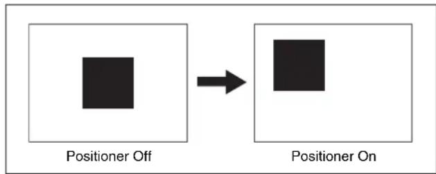
flowchart
graph LR
    A["Positioner Off"] --> B["Positioner On"]
- The parameter H Position controls the horizontal position of the pattern.
A negative value moves the pattern to the left, and a positive value moves the pattern to the right.
- The parameter V Position controls the vertical position of the pattern.
A negative value moves the pattern down, and a positive value moves the pattern up.
You can set the position independently for the main pattern and sub pattern.
1 In the M/E-1 >Wipe menu, select HF5 'Main Modify.'
The Main Modify menu appears.
2 In the
| Knob | Parameter | Adjustment | Setting values |
| 1 Position H Horizontal position | -200.00 to +200.00 | ||
| 2 Position V Vertical position -200.00 to +200.00 | |||
To return the pattern position to the center of the screen
In the < Position> group, press [Center].
To move the pattern from its current position to the center through the course of a transition
In the
To set the wipe position using the trackball or joystick
You can also set the wipe position using the trackball or joystick in the device control block.
1 In the device control block, press the [M/E1], [M/E2], [M/E3], [M/E4], or [P/P] button, turning it on.
Notes
The [M/E4] button requires a previous assignment in the Setup menu.
The buttons in the device control block are assigned to the wipe position setting as follows.
Table 1: Buttons and assigned settings
| Button name Setting | |
| MAIN Wipe position | for common transition(main pattern) |
| SUB Wipe position | for common transition(sub pattern) |
Table 2: Buttons assigned to functions
| Button name Function | |
| POS Toggle Position on or off. | |
| X, Y Fix the operating direction. | |
| CTR Return the pattern position to the center of the screen. |
2 Press the [MAIN] button or [SUB] button, turning it on.
3 Press the [POS] button, turning Position on.
4 Move the trackball or joystick, to set the wipe position. By pressing the [X] button, turning it on, you can restrict movement to the horizontal direction, and by pressing the [Y] button, turning it on, you can restrict movement to the vertical direction.
Rotating the wipe pattern (Rotation)
You can rotate the pattern. There are three rotation modes, as follows.
Angle
This carries out a wipe with the pattern in a fixed angle.
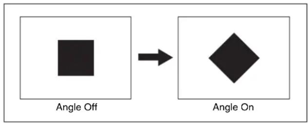
flowchart
graph LR
    A["Square"] --> B["Diamond"]
The parameter Angle determines the angle of pattern rotation.
- A value of -100.00 of the parameter Angle corresponds to one whole turn counterclockwise.
- A value of +100.00 corresponds to one whole turn clockwise.
- With a value of 0.00 there is no rotation.
Speed
Through the course of the transition the wipe pattern rotates at a fixed specified speed.

natural_image
Simple circular diagram with a black diamond shape at center, surrounded by three arrows in clockwise direction (no text or symbols)The parameter Speed determines the speed of pattern rotation.
- A value of -100.00 of the parameter Speed corresponds to one turn per second counterclockwise.
- A value of +100.00 corresponds to one turn per second clockwise.
- With a value of 0.00 the pattern is stationary.
Magnitude
Through the course of the transition the wipe pattern rotates through the specified angle.
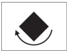
natural_image
Simple black diamond shape with a curved arrow indicating rotation or cycle (no text or symbols)The parameter Angle determines an angle of pattern inclination at the beginning of the transition.
- A value of -100.00 corresponds to the angle rotated one whole turn counterclockwise.
- A value of +100.00 corresponds to the angle rotated one whole turn clockwise.
- With a value of 0.00 the pattern is stationary.
The parameter Magnitude determines an angle of pattern rotation through the course of the transition. - A value of -200.00 corresponds to a rotation of two turns counterclockwise.
- A value of +200.00 corresponds to a rotation of two turns clockwise.
- With a value of 0.00 the pattern is stationary.
You can apply rotation independently to the main pattern and sub pattern.
1 In the M/E-1 >Wipe menu, select HF5 'Main Modify.' The Main Modify menu appears.
2 In the
Angle: Incline the pattern through a fixed angle.
Speed: Rotate at a fixed rate.
Magnitude: Rotate through a particular angle during the course of the transition.
3 According to the selection in step 2, set the following parameters.
When Angle is selected
| Knob Parameter Adjustment Setting values | |||
| 1 Angle | Angle of pattern rotation | -100.00 to +100.00 | |
When Speed is selected
| Knob | Parameter | Adjustment Setting | values |
| 1 Speed | Rotation rate | of pattern | -100.00 to +100.00 |
When Magnitude is selected
| Knob | Parameter | Adjustment Setting | values |
| 1 Angle | Angle of pattern | -100.00 to +100.00 | |
| 2 Magnitude | Angle of rotation through course of transition | -200.00 to +200.00 | |
Setting the wipe pattern aspect ratio (Aspect ratio)
You can freely change the aspect ratio of the pattern.
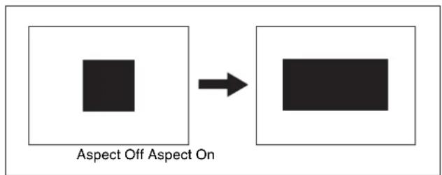
A negative value of the parameter Aspect stretches the pattern vertically; a positive value stretches the pattern horizontally.
You can set the aspect ratio independently for the main pattern and sub pattern.
1 In the M/E-1 >Wipe menu, select HF5 'Main Modify.'
The Main Modify menu appears.
2 Press [Aspect], turning it on.
3 Set the following parameter.
| Knob | Parameter | Adjustment | Setting values |
| 1 Aspect | Aspect ratio | -100.00 to | +100.00 |
Setting the wipe pattern replication (Multi)
The same pattern can be repeated horizontally and vertically or both, up to 63 times. You can also change the orientation of alternate copies, or change the position.
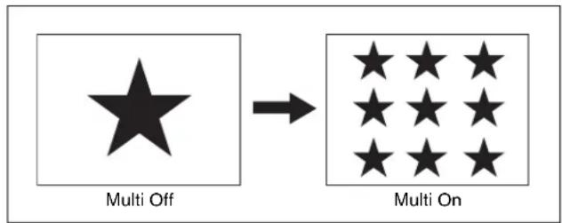
flowchart
graph LR
    A["Star"] --> B["Grid of 9 stars"]
    style A fill:#fff,stroke:#000
    style B fill:#fff,stroke:#000
- The parameter H Multi determines the number of pattern replications horizontally, and the parameter V Multi determines the number of pattern replications vertically.
- The parameter Shift determines the manner of replication.
At a value of -100.00, the pattern of the adjacent odd-numbered column on the left lines up with the central coordinate horizontally.
At a value of +100.00, the pattern of the adjacent odd-numbered column on the right lines up with the central coordinate horizontally.
For an independent key transition wipe, you can use the “Invert Type” parameter to select from the following four types of replication pattern.
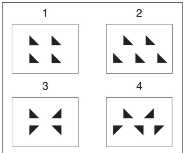
1: All replications in the same orientation
2: Even-numbered rows staggered
3: Even-numbered columns and rows inverted
4: Even-numbered columns and rows inverted, and even-numbered rows staggered
You can set pattern replication independently for the main pattern and sub pattern.
1 In the M/E-1 >Wipe menu, select HF5 'Main Modify.'
The Main Modify menu appears.
2 Press the [Multi] button, turning it on.
3 Set the following parameters.
| Knob | Parameter | Adjustment | Setting values |
| 1 H Multi Number of | repetitions of pattern horizontally | 1 to 63 | |
| 2 V Multi Number of | repetitions of pattern vertically | 1 to 63 | |
| 3 Shift | Replication | layout | -100.00 to +100.00 |
4 To make more adjustments, press the [Multi Adjust] button.
The Multi Adjust menu appears.
5 Make the following settings, as required.
H Invert: When this is on, alternate tiles are inverted left-to-right.
V Invert: When this is on, alternate tiles are inverted top-to-bottom.
Non-Mask: When this is on, even if the positioner function is used to move the pattern position, the pattern is always present on the screen.
Position: By adjusting the following parameters, move the pattern position within the divisions determined in step 3.
| Knob | Parameter | Adjustment | Setting values |
| 1 Position H Horizontal position of pattern | -200.00 to +200.00 a) | ||
| 2 Position V Vertical position of pattern | -200.00 to +200.00 a) | ||
a) See page 165.
Making a wipe pattern like a Venetian blind (Pairing)
This slits the pattern into multiple strips in the horizontal or vertical direction, making it like a venetian blind.
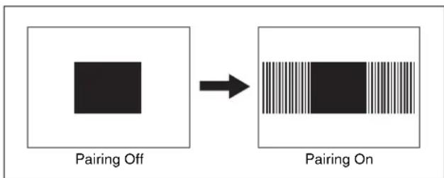
flowchart
graph LR
    A["Square with diagonal stripes"] --> B["Patterned Pattern with striped bar"]
    style A fill:#fff,stroke:#000
    style B fill:#fff,stroke:#000
- The parameter Width determines the width of the slits.
- The parameter H Offset determines the spacing in the horizontal direction.
If a negative value is set, the even-numbered pairs of strip and slit move to the left, and the odd-numbered pairs move to the right. (The value -100.00 represents the maximum movement.)
If a positive value is set, the even-numbered pairs of strip and slit move to the right, and the odd-numbered pairs move to the left. (The value +100.00 represents the maximum movement.)
- The parameter V Offset determines the spacing in the vertical direction.
If a negative value is set, the even-numbered pairs of strip and slit move upward, and the odd-numbered pairs move downward. (The value -100.00 represents the maximum movement.)
If a positive value is set, the even-numbered pairs of strip and slit move downward, and the odd-numbered pairs move upward. (The value +100.00 represents the maximum movement.)
1 In the M/E-1 >Wipe menu, select HF5 'Main Modify.' The Main Modify menu appears.
2 In the
H: Create slits in the horizontal direction.
V: Create slits in the vertical direction.
3 Set the following parameters.
| Knob | Parameter | Adjustment | Setting values |
| 1 Width | Width of the slits | slits | 1 to 128 (integer) |
| 2 H Offset | Spacing in the horizontal direction | horizontal direction | -100.00 to +100.00 |
| 3 V Offset | Spacing in the vertical direction | vertical direction | -100.00 to +100.00 |
Applying modulation to the wipe pattern (Modulation)
The pattern signal can be modulated, giving waves on the horizontal or vertical edges, or radially.
The parameter Shape determines the form of the modulation.
1: sine wave, 2: triangular wave, 3: rectangular wave
Notes
When using 1080PsF mode in an HD system, the modulation function is not available.
Horizontal modulation
This modulates the pattern, applying waviness in the horizontal direction to edges.
natural_image
Abstract black wavy shape on white background (no text or symbols)The parameter Speed determines the speed of waves.
A value of -100.00 generates the maximum downward speed of waves, and a value of +100.00 the maximum upward speed.
Vertical modulation
This modulates the pattern, applying waviness in the vertical direction to edges.
natural_image
Abstract black zigzag pattern on white background (no text or symbols)The parameter Speed determines the speed of waves.
A value of -100.00 generates the maximum leftward speed of waves, and a value of +100.00 the maximum rightward speed.
Fringe
This modulates the pattern, applying waviness in the radial direction to edges.
natural_image
Abstract black irregular shape on white background (no text or symbols)The parameter Speed determines the speed of waves.
A value of -100.00 generates the maximum counterclockwise speed of waves, and a value of +100.00 the maximum clockwise speed.
You can apply modulation independently to the main pattern and sub pattern.
1 In the M/E-1 >Wipe menu, select HF5 'Main Modify.'
The Main Modify menu appears.
2 Depending on the desired effect, in the
H (Horizontal modulation): Modulate the pattern, applying waviness in the horizontal direction to edges.
V (Vertical modulation): Modulate the pattern, applying waviness in the vertical direction to edges.
Fringe (Radial modulation): Modulate the pattern, applying waviness in the radial direction to edges.
3 Set the following parameters.
| Knob | Parameter | Adjustment | Setting values |
| 1 Amplitude | Amplitude of modulation | 0.00 to 100.00 | |
| 2 Frequency | Frequency of modulation | 0.00 to 100.00 | |
| 3 Speed | Speed of waves –100.00 to +100.00 | ||
| 4 Shape | Form of the modulation | 1 to 3 |
Applying barrel or pincushion distortion to the edge of the wipe pattern (Spring)
As the transition progresses, the edge of the pattern is subjected to barrel or pincushion distortion.
flowchart
graph LR
    A["Square"] --> B[" rounded Square"]
    style A fill:#fff,stroke:#000
    style B fill:#fff,stroke:#000
A negative parameter value produces pincushion distortion, and a positive value produces barrel distortion. You can set the spring function independently for the main and sub patterns.
1 In the M/E-1 >Wipe menu, select HF5 'Main Modify.'
The Main Modify menu appears.
2 Press [Spring], turning it on.
3 Set the following parameters.
| Knob | Parameter | Adjustment | Setting values |
| 1 Gain | Degree of barrel distortion | -100.00 to +100.00 |
Applying a spiral effect to the wipe pattern (Spiral)
This deforms the pattern spirally.
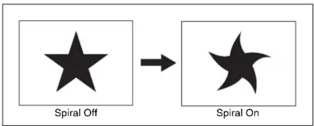
- The parameter Magnitude determines the size and direction of the spiral.
A value of -100.00 represents the maximum movement in the counterclockwise direction, and a value of +100.00 represents the maximum movement in the clockwise direction.
- The parameter Wave Speed determines the speed of the lateral waves.
A value of -100.00 represents the maximum speed to the left, and a value of +100.00 represents the maximum speed to the right.
You can set the spiral function independently for the main and sub patterns.
1 In the M/E-1 >Wipe menu, select HF5 'Main Modify.' The Main Modify menu appears.
2 Press [Spiral], turning it on.
3 Set the following parameters.
| Knob | Parameter | Adjustment | Setting values |
| 1 Magnitude Size and direction of the spiral | -100.00 to +100.00 | ||
| 2 | W a Speed | Speed of the lateral waves | -100.00 to +100.00 |
Possible combinations of wipe patterns and modifiers
Yes: Can be used No: Cannot be used
| Modifiers | Type of wipe | ||||
| Standard | Enhanced | Rotary Mosaic | Random/diamond dust | ||
| Direction | Yes | Yes | Yes | Yes | Yes |
| Split | Yes | Yes | No | Yes | No |
| Edge | Yes | Yes | Yes | Yes | Yes |
| Positioner | Yes a) | Yes b) | Yes c) | No | No |
| Rotation | Yes | Yes | Yes c) | No | No |
| Modifiers | Type of wipe | ||||
| Standard | Enhanced | Rotary M | Mosaic | Random/diamond dust | |
| Aspect ratio | Yes d) | Yes | No | No | No |
| Pattern replication | Yes | Yes | Yes | Yes e) | No |
| Pairing | Yes f) | Yes | No | No | No |
| Modulation (H/V) | Yes | Yes | Yes | No | No |
| Modulation (Fringe) | No g) | Yes | No | No | No |
| Spring | No g) | Yes | No | No | No |
| Spiral No | h) | Yes | No | No | No |
a) Not patterns 1 to 16, 19, and 20
b) Not patterns 300 to 303
c) Not patterns 100 to 103, 150, 151, 516, 518, 604, and 606
d) Not patterns 1 to 8, 17, and 18
e) Not patterns 220 to 223
f) Not patterns 19 and 20
g) But patterns 21, 23 and 24 are possible
h) But patterns 21 and 23 are possible
Wipe Modify Clear
Press [Default Recall] at the lower left of the menu display, turning it on, then press VF5 'Wipe' to return the wipe settings to their initial status.
For details of the menu operation to return the wipe state to that set in initial status, see “Returning to Default State in Function Groupings” (page 82).

Wipe Settings for Independent Key Transitions
You carry out independent key transition wipe setting operations using the Wipe Adjust menu for each keyer. This section describes the independent key transition wipe settings, taking the M/E-1 >Key1 >Transition >Wipe Adjust menu as an example.
For details, see “Independent Key Transitions” (page 109).
Basic Procedure for Independent Key Transition Wipe Settings
Accessing the independent key transition wipe settings menu
As an example, to access the M/E-1 >Key1 >Transition >Wipe Adjust menu, carry out the following operations.
- In the menu control block, select the top menu selection button [M/E 1] and select VF1 'Key1' and HF6 'Transition' to display the Transition menu for key 1, then press [Wipe Adjust].
- If VF1 [Key5] is shown, press the switching button at the top of the menu, so that [Key1-4] appears, and press VF1 [Key1].
Notes
To select [M/E-4], a previous assignment in the Setup menu is required.
- In the independent key transition control block of the M/E-1 bank, press the key delegation button [KEY1], then press the independent key transition type selection button [WIPE] twice in rapid succession.
Carrying out the above operation displays the M/E-1>Key1>Transition >Wipe Adjust menu (which will be referred to below as simply the Key1 Wipe Adjust menu).
Selecting the independent key transition wipe pattern
You select the independent key wipe pattern from the list of patterns displayed in the menu.
Notes
In an independent key transition, you can only use the standard wipe patterns (pattern numbers 1 to 24).
To select a wipe pattern for independent key1 on the M/E-1 bank, use the following procedure.
1 In the Key1 Wipe Adjust menu, select [Pattern Select]. The Pattern Select menu appears.
2 Press the button for the desired pattern.
Setting Independent Key Transition Wipe Modifiers
Available modifiers
You can use the following modifiers with an independent key transition wipe.
Note that the available modifiers may depend on the pattern you are using.
- Direction
- Edge
- Positioner
- Rotation
- Aspect ratio
- Pattern replication
Setting the wipe direction (Direction)
In the
Normal: regular direction
Normal/Reverse: alternate between regular and reverse for each transition
Reverse: reverse direction to normal
Softening the wipe pattern edge (Soft edge)
1 Press [Soft] in the Key1 Wipe Adjust menu, turning it on.
2 Set the following parameter.
| Knob | Parameter | Adjustment | Setting values |
| 1 Soft Edge softness | 0.00 to 100.00 | ||
Setting the wipe position (Positioner)
There are two methods of setting the wipe position: using the device control block, or in a menu.
To set the wipe position using the trackball or joystick
You can also set the wipe position using the trackball or joystick in the device control block.
1 In the device control block, press the [M/E1], [M/E2], [M/E3], [M/E4], or [P/P] button, turning it on.
Notes
The [M/E4] button requires a previous assignment in the Setup menu.
The buttons in the device control block are assigned to the wipe position setting as follows.
Table 1: Buttons and assigned settings
| Button name Setting | |
| K1 CB1 Wipe position for independent key 1 transition | |
| K2 CB2 Wipe position for independent key 2 transition | |
| K3 Wipe position for independent key 3 transition | |
| K4 Wipe position for independent key 4 transition |
Table 2: Buttons assigned to functions
| Button name | Function |
| POS Toggle Position on or off. | |
| X, Y Fix the operating direction. | |
| CTR Return the pattern position to the center of the screen. | |
2 Press one of the buttons in Table 1 above, to select the wipe position to which the operation applies. Multiple selection is possible.
Notes
By setting the operation mode in setup, you can also use [K1 CB1], [K2 CB2], [K3], and [K4] to select keys 5 to 8. In this case, press [SHIFT], turning it on, then press [K1 CB1], [K2 CB2], [K3], or [K4] to select one of keys 5 to 8. However, it is not possible to select more than one key.
For details of assignment for keys 5 to 8, see "Assigning Buttons for Selection of Keys 5 to 8 in the Setup Menu" in the Appendix (page 388).
3 Press the [POS] button, turning Position on.
4 Move the trackball or joystick, to set the wipe position. By pressing the [X] button, turning it on, you can restrict movement to the horizontal direction, and by pressing the [Y] button, turning it on, you can restrict movement to the vertical direction.
To set the wipe position by a menu operation
1 Press [Position] in the Key1 Wipe Adjust menu, turning it on.
2 Set the following parameters.
| Knob | Parameter | Adjustment | Setting values |
| 1 Position H Horizontal position | -200.00 to +200.00a) | ||
| 2 Position V Vertical position -200.00 to +200.00a) | |||
a) See page 165.
To move the pattern from its current position to the center through the course of a transition
Press [Auto Center] in the
Rotating the wipe pattern (Rotation)
1 In the
Angle: Incline the pattern through a fixed angle.
Speed: Rotate at a speed rate.
Magnitude: Rotate the pattern through a fixed angle during the course of the transition.
2 According to the selection in step 1, set the following parameters.
When Angle is selected
| Knob | Parameter | Adjustment | Setting values |
| 1 Angle | Angle | of pattern rotation | -100.00 to +100.00^a) |
a) See page 166.
When Speed is selected
| Knob | Parameter | Adjustment | Setting values |
| 1 Speed | Rotation rate of pattern | -100.00 to +100.00a) | |
a) See page 166.
When Magnitude is selected
| Knob | Parameter | Adjustment | Setting values |
| 1 Angle | Angle | of pattern rotation at start of transition | -100.00 to +100.00^a) |
| 2 Magnitude | Angle | of rotation through course of transition | -200.00 to +200.00^a) |
a) See page 166.
Setting the wipe pattern aspect ratio (Aspect ratio)
1 Press [Aspect] in the Key1 Wipe Adjust menu, turning it on.
2 Set the following parameter.
| Knob Parameter Adjustment Setting values | ||
| 1 Aspect Aspect ratio | -100.00 to | +100.00^a) |
a) See page 167.
Replicating the wipe pattern (Multi)
1 Press [Multi] in the Key1 Wipe Adjust menu, turning it on.
2 Set the following parameters.
| Knob | Parameter | Adjustment Setting | values |
| 1 H Multi Number of repetitions of pattern horizontally | 1 to 63 | ||
| 2 V Multi Number of repetitions of pattern vertically | 1 to 63 | ||
| 3 Invert Type Replication layout | 1 to 4^a) | ||
a) See page 167.
Wipe Snapshots
You can snapshot and save a wipe pattern together with the current settings of its modifiers and pattern limit in a dedicated register for recall when required. There are 10 wipe snapshot registers on each M/E bank and the PGM/PST bank.
Use the Flexi Pad control block, the Multifunction Flexi Pad block in each switcher bank or the Menu control block to save and recall wipe snapshots.
For simple transitions (see page 116), there are eight wipe snapshot registers on each M/E bank and the PGM/PST bank.
Wipe Snapshot Operations With the Flexi Pad
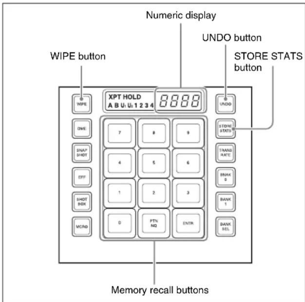
Flexi Pad control block (standard type)
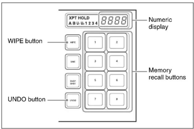
Flexi Pad control block (simple type)
Selecting a wipe pattern in the Flexi Pad control block
To select a pattern with a standard type Flexi Pad control block, use the following procedure. (It is not possible to select a wipe pattern with a simple type Flexi Pad control block.)
1 In the M/E-1 Flexi Pad control block, press the [WIPE] button.
This switches the Flexi Pad control block to wipe snapshot mode.
2 In the memory recall section, press the [PTN NO] button.
This switches the Flexi Pad control block to wipe pattern number recall mode.
3 Use the buttons in the memory recall section to enter the pattern number consisting of up to three digits, and press the [ENTR] button.
The entry is confirmed, and now the numeric display shows the pattern number (see page 351).
Saving a wipe snapshot
1 Make the wipe settings that you want to save.
Make any modifier settings required (see page 162).
2 In the Flexi Pad control block, hold down the [WIPE] button, and press the memory recall button corresponding to the register in which you want to save.
Notes
- If you press a button which is lit orange or yellow, the existing contents of the register are overwritten.
- If you carry out a pattern mix, and both the main pattern and sub pattern are selected, then the memory recall button shows the main pattern.
The pattern appears on the button you pressed, which lights yellow.
The numeric display shows the number of the corresponding pattern.
It is also possible to display the register name using a Setup menu.
For details, see “Operation Settings (Operation Menu)” in Chapter 19 (Volume 2).
Meaning of the state of buttons
Off: Nothing is saved in the register.
Lit orange: Settings are saved in the register.
Lit yellow: The most recently recalled register.
Canceling the saving of a wipe snapshot
To cancel the saving of a wipe snapshot immediately after performing it, hold down the [STORE STATS] button, and press the [UNDO] button.
The [STORE STATS] button changes from amber to green.
Notes
On a simple type Flexi Pad control block, it is not possible to cancel the saving of a wipe snapshot.
Recalling a wipe snapshot
1 In the Flexi Pad control block, press the [WIPE] button.
This switches the Flexi Pad control block to the wipe snapshot mode.
2 Press the memory recall button for the register from which you want to recall the wipe snapshot.
The button lights, and the saved wipe snapshot is recalled. At this point, the numeric display shows the pattern number or register name.
Canceling the recall of a wipe snapshot
To cancel the recall of a wipe snapshot, press the [UNDO] button.
Deleting a wipe snapshot
When the [WIPE] button is lit in the Flexi Pad control block, hold down the [STORE STATS] button and press the memory recall button for the register in which you want to delete the wipe snapshot.
The indication of the memory recall button reverts from the wipe pattern or register name to the register number.
Notes
In a simple type Flexi Pad control block, it is not possible to delete a wipe snapshot.
Wipe Snapshot Operations With the Menus
Menus used
As an example, when operating on M/E-1, select M/E-1 >Wipe >Wipe Snapshot.
The Wipe Snapshot menu appears.
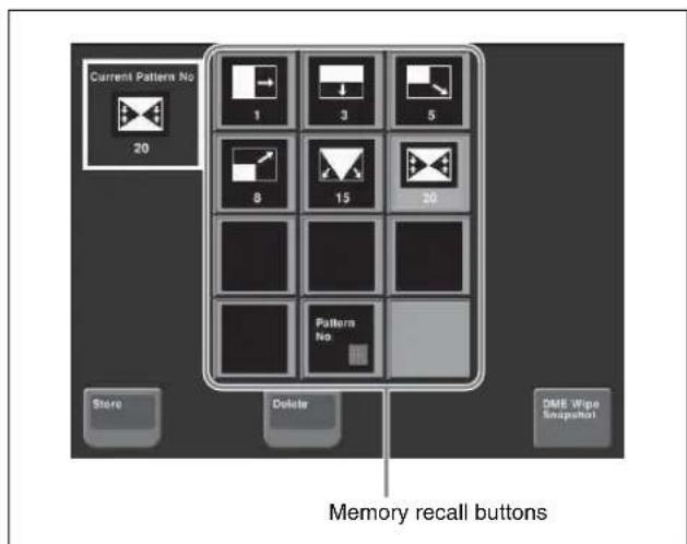
Button displays
In setup you can select whether the memory recall buttons show the pattern number or register name.
For details, see "Operation Settings (Operation Menu)" in Chapter 19 (Volume 2).
Saving a wipe snapshot from the menu
1 Set up the wipe you want to save.
2 In the Wipe Snapshot menu, press [Store], lighting it amber.
3 Press the memory recall button for the register in which you want to save.
Notes
- If you press a button which is already lit, this overwrites the contents of the register.
- When both the main pattern and sub pattern are selected for a pattern mix, the button in the memory recall section shows only the main pattern.
Recalling a wipe snapshot from the menu
In the Wipe Snapshot menu, press the memory recall button for the wipe snapshot you want to recall.
This recalls the wipe snapshot, and the button you pressed lights amber.
In the upper left is shown the currently recalled register name or number.
Notes
The Flexi Pad and menu settings are linked.
A setting in setup determines whether register names or pattern numbers appear.
Deleting a wipe snapshot from the menu
1 In the Wipe Snapshot menu, press [Delete].
2 Press the memory recall button for the wipe snapshot you want to delete.
Wipe Pattern Operations in the Multifunction Flexi Pad Control Block
Recalling a Wipe Snapshot
You can recall a wipe snapshot in the Multifunction Flexi Pad control block. To recall a wipe snapshot, use the operations shown in the following illustration.
1 In the Multifunction Flexi Pad control block, press the [WIPE] button.
This sets the Multifunction Flexi Pad control block to wipe snapshot mode, and the button indications appear as follows.
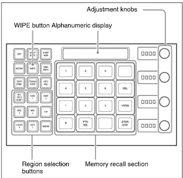
You can change the indications for buttons [0] to [9] in the memory recall section to pattern images, using the Engineering Setup >Panel >Operation >Flexi Pad Mode menu.
2 Select the region for the wipe snapshot to be recalled with the region selection buttons.
3 Press the numeric button (lit orange) in the memory recall section corresponding to the register in which the desired wipe snapshot is stored.
The button you pressed lights yellow, and this recalls the saved wipe snapshot.
At this point the numeric display shows the register name or pattern number for the pattern.
Selecting the Wipe Pattern
1 Press the [WIPE] button, and select the region with the region selection buttons.
Notes
The [M/E4] button requires a previous assignment in the Setup menu (see page 387).
2 Press the [PTN NO.] button in the memory recall section.
The [PTN No.] button lights green.
3 With the buttons in the memory recall section, enter the pattern number of up to three digits, and press the [ENTR] button.
This confirms the input, and the pattern number (see page 351) appears in the alphanumeric display.
The [PTN NO.] button lights orange, and the system returns to wipe snapshot mode.
Editing the Wipe Pattern
By pressing the [EDIT ENBL] button to switch the memory recall section to editing mode as shown in the following illustration, you can edit the selected wipe pattern with the following buttons.
To exit from the editing mode, press the [EDIT ENBL] button once more, or press the [EXIT] button.
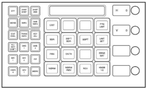
Wipe pattern edge setting buttons
BDR (border): Applies a border to the wipe pattern. SOFT BDR (soft border): Softens the applied border. SOFT (soft edge): Softens the edge.
EDGE MAT (edge matte): Selects whether to fill the edge with a color matte, or insert an image from the utility bus. By default a color matte is selected.
You can adjust the parameters selected with these buttons using the control knobs, when the button is lit green.
When border is selected
Parameter group [1/2]
| Knob Parameter Adjustment Setting values | ||
| 1 W Border width 0 to 100 | ||
Parameter group [2/2]
| Knob Parameter Adjustment Setting values | ||
| 1 L Luminance 0 to 100 | ||
| 2 S Saturation 0 to 100 | ||
| 3 H Hue 359 to 0 | ||
When soft border is selected
Parameter group [1/2]
| Knob Parameter Adjustment Setting values | ||
| 1 W Border width 0 to 100 | ||
| 2 I Degree of softening of inside of border | 0 to 100 | |
| 3 O Degree of softening of outside of border | 0 to100 | |
Parameter group [2/2]
| Knob Parameter Adjustment Setting values | ||
| 1 L Luminance 0 to 100 | ||
| 2 S Saturation 0 to 100 | ||
| 3 H Hue 359 to 0 | ||
When soft edge is selected
| Knob Parameter Adjustment Setting values | ||
| 1 S Degree of | softening of edge | 0 to 100 |
When edge matte is selected
| Knob Parameter Adjustment Setting values | ||
| 1 L Luminance 0 to 100 | ||
| 2 S Saturation 0 to 100 | ||
| 3 H Hue 359 to 0 | ||
Buttons for positioning the wipe pattern
POS (position): Adjusts the position of the wipe pattern.
CNTR (center): Returns the wipe pattern position to the center.
When you press the [POS] button, the alphanumeric display first shows the name of the parameter, "H" or "V," and then the value of the parameter.
When the [POS] button is lit green, you can adjust the position of the wipe pattern with the control knobs.
| Knob Parameter Adjustment Setting values | |||
| 1 | H | Horizontal position | -200 to +200 |
| 2 V Vertical position | -200 to +200 | ||
Buttons for setting the wipe direction
NORM (normal): Sets wipe to normal (forward) direction.
NORM/REV (normal/reverse): Sets the wipe direction to alternate between normal and reverse for each transition.
REV (reverse): Sets wipe to reverse direction to normal.
Buttons for setting the wipe pattern limit
PTN LIMIT (pattern limit): Enables the following settings for the pattern limit using the control knobs.
LIMIT SET (limit set): If you change the pattern size with the fader lever then press this button, this sets the current size as the pattern limit.
| Knob Parameter Adjustment Setting values | |||
| 1 P Pattern limit | range | 0^a) to +100^b) (%) | |
a) At 0%, executing the transition has no effect at all.
b) At 100%, the transition can be executed with the same effect as with no pattern limit set, but when the transition completes, background buses A and B are not interchanged.
Other buttons
EXIT: Exits the editing mode, and returns the memory recall section to wipe snapshot mode.
KNOB 1/2: When the control knob adjustments are on two pages, this switches between parameter group [1/2] and parameter group [2/2].
Wipe modify clear
When the [WIPE] button is held down, holding down the region selection button for the selected region together returns all the wipe settings of the region to the initial status settings.
For details of the initial status, see “Saving User-Defined Settings” in Chapter 18 (Volume 2).
Saving, Canceling, and Deleting Edited Wipe Patterns
Saving the edited wipe pattern as a snapshot
Holding down the [WIPE] button, press the button in the memory recall section for the register in which you want to save.
The button you pressed lights yellow.
Buttons for registers in which wipe snapshots are already saved light orange.
Canceling a saved wipe snapshot
Immediately after saving, hold down the [STOR STAT] button and press the [UNDO] button.
At other times, hold down the [STOR STAT] button, and press the button for the register in which the wipe snapshot you want to cancel is saved.
Buttons for registers in which wipe snapshots are already saved light orange.
Canceling recall of a wipe snapshot
To cancel the operation of recalling a wipe snapshot, press the [UNDO] button.
Deleting the data of a saved wipe snapshot
Holding down the [DEL] button, press the button for the register in which the wipe snapshot you want to delete is saved.
The register button you pressed goes off.
Overview
A DME wipe is a wipe transition that uses a DME effect to change from one video image to the next.
There are two types of DME wipe: those which can be selected for a normal transition, and those which can be selected for an independent key transition (see page 195).
Notes
It is also possible to carry out a DME wipe on a key using the resizer (see page 191).
Types of DME Wipe Pattern
The patterns used for a DME wipe fall into two broad classes.
Preset patterns: predetermined fixed patterns
User programmable DME patterns: patterns which you can create using keyframe effects
DME wipe execution mode and pattern numbers that can be used
There are three DME wipe execution modes, depending on the number of DME channels available: one-channel mode, two-channel mode and three-channel mode. The pattern numbers that can be used in these modes are as follows.
| Execution mode Preset pattern numbers that can be used | User programmable DME pattern numbers that can be used |
| One-channel mode 1000 series 1901 | to 1999 |
| Two-channel mode 2000 series 2901 | to 2999 |
| Three-channel mode 3000 series 3901 | to 3999 |
Notes
- On the MVS-8000X, when the signal format is 1080P, the three-channel mode is not available.
- On the MVS-7000X, when the signal format is 1080P, the above restriction also applies if using the MVE-
8000A. There is no such restriction for the MKS-7470X/7471X.
DME wipe pattern groups
The patterns used in DME wipes fall into the following groups.
For each group (excluding user programmable DMEs), for schematic patterns and numbers, see “DME Wipe Pattern List” in Appendix (page 355).

| Pattern groups | Effects Pattern numbers | |||
| One-channel mode | Two-channel mode | Three-channel mode | ||
| Slide The new video slides in over the old video. 1001 to 1008 2601 to 2608 | — | |||
| Squeeze The new video appears squeezed over the old video, and progressively expands to cover it. | 1021 to 1031 2621 to 2628 — | |||
| Split The old video splits, and the new video appears in the gap. 1011 to 1013 — — | ||||
| Door The new video moves like a door closing, and progressively covers the old video. | 10411048 — | |||
| Flip tumble The old video rotates about an axis and is replaced by the new video. During the transition, the signal from the utility 2 bus of the M/E bank appears as the background. | 1101 to 1104, 1109, 1110, 1121, 1122, 1124, 1131 to 1133, 1135 | — | — | |
| Mirror The new video appears over the old video as a mirror effect slides in all four directions. | 1355 to 1358 — | — | ||
| Sphere | The new video appears wrapped around a sphere over the old video, then returns to the original video while unwrapping. | 1365 | — — | |
| Character trail | The new video appears with a trail over the old video. Next this gradually returns to the original from the periphery. | 1371, 1372 | — — | |
| Wave | The new video appears with a wave-like effect over the old video. Next this returns to the original video as the effect reduces. | 1378, 1379 | — — | |
| Ripple | The new video appears over the old video like outwardly moving ripples. | 1381 | — — | |
| Page turn | The old video moves like a page turning, and the new video appears behind it. | 1301 to 1313, 1315 to 1318, 1341 to 1345 | 2701 to 2713, 2715 to 2718, 2741 to 2745 | — |
| Page roll The new video unrolls like a scroll over the old video. This is a type of page turn. | 1321 to 1333, 1335 to 1338, 1346 to 1350 | 2721 to 2733, 2735 to 2738, 2746 to 2750 | — | |
| Frame in-out | Completed in two transitions. In the first transition, the new video appears, then on the second transition the new video goes out and the old video returns. | 1201 to 1208, 1221 to 1224 | 2851 to 2854, 2861 to 2864 | — |
| Picture-in-picture | In one-channel mode, this completes in two transitions.- In the first transition, the old video shrinks, and the new video appears behind it.- In the second transition, the old video expands again until it is its original size.In two-channel mode, in the first half of the transition, the old video shrinks, and the new video appears.- In the second half of the transition, the new video expands, and the old video disappears.- You can move the pattern from the current position by a relative amount.- During the transition, the signal from the utility 2 bus of the M/E bank appears as the background. | 1251 | 2651 to 2652 — | |
| 2D trans | The new video appears over the old video, while undergoing expansion, two-dimensional rotation and translation. | 1051 to 1058, 1061 to 1064, 1068 | — | — |
| 3D trans | In one-channel mode, the new video appears over the old video, while undergoing expansion, three-dimensional rotation and translation.In two-channel mode, the old video changes to the new video while both undergo expansion, three-dimensional rotation and translation. | 1071, 1072, 1074, 1076, 1077, 1088, 1091 to 1094 | 2631 to 2634, 2642, 2644 | — |
| Sparkle The new | video appears over the old video with a nonlinear effect applied, such as broken glass, explosion, or melt. Next this returns to the original video as the effect gradually reduces. | 1391, 1393, 1394, 1396, 1398, 1399 | — | — |
| Split slide The new | new video appears in strip form while sliding interleaved in the opposite direction over the old video. | 1384 to 1389 — | — | |
| Mosaic In the first | half of the transition, a mosaic is gradually applied to the old video, then at the 50% point the inner image changes to the new video. In the second half, the mosaic effect on the new video is gradually reduced, returning to the original image at 100%. | 1701 — — | ||
| Defocus In the first | half of the transition, the old video is gradually defocused, then at the 50% point the inner image changes to the new video. In the second half, the defocusing effect on the new video is gradually reduced, returning to the original image at 100%. | 1702 — — | ||
| Brick • In two-channel mode, a brick such that the side surface is visible slides in over the old video, then rotates so that the new video can be seen.• In three-channel mode, a brick appears over the old video as the image is expanding and rotating, and switches to the new video. | — 2801 to 2804, 2811 to 2814 | 3601 | ||
| User programmable DME | Using a DME keyframe effect created with a keyframe operation, this executes a DME wipe.For details of creating keyframe effects, see “Creating User Programmable DME Patterns” (page 193). | 1901 to 1999 2901 to 2999 3901 to 3999 | ||
Notes
In an independent key transition, the following patterns can be used.
| Execution mode | DME wipe patterns that can be used |
| One-channel mode | Slide, split, squeeze, door, 2D trans, 3D trans, frame in-out, page turn, page roll, mirror, sphere, character trail, wave, ripple, split slide, sparkle, user programmable DME |
| Two-channel mode | Page turn, page roll |
DME Wipe Pattern Variation and Modifiers
You can modify the selected DME wipe pattern in the same way as an ordinary wipe pattern, as follows.
For the setting operations, see “Setting DME Wipe Modifiers” (page 185).
Direction: You can set the DME wipe direction to normal, reverse, or alternating normal/reverse (see page 185), except for a key transition, which is always in normal/ reverse mode. However, a key transition can only be specified when the following patterns are selected, and
when other patterns are selected, this is fixed, as normal/reverse.
Patterns: 1204, 1207, 1221 to 1224
Edge: You can apply a border or soft border (see page 185).
In the case of those user programmable DME patterns for keys in which an edge has already been applied to the effect, the behavior is as follows.
- When the DME wipe edge setting is on, only part of the edge applied in the effect is enabled, and that portion can be adjusted (see page 185).
- When the DME wipe edge setting is off, the edge applied in the effect is enabled as is.
Positioner: You can move the DME wipe pattern or center of the effect to an arbitrary position. Using the position select function, you can also instantaneously move the pattern.
• 1031
When this pattern number is selected, with the progress of the transition the pattern center automatically moves initially from the set position toward the center of the screen (see page 185). In other words, the effect obtained is the same as in a normal wipe with the positioner set to “AUTO CENTER”.
• 1201 to 1208, 1221 to 1224, 1251
When these pattern numbers are selected, you can
set the pattern position when the first transition completes.
- 1381, 1391, 1393, 1394, 1396 When these pattern numbers are selected, you can set the center of the transition effect.
- 2651, 2652 When these pattern numbers are selected, you can move the pattern for each channel, or with values relative to the current position the two channels simultaneously.
- 2801 to 2804, 2811 to 2814 When the these pattern numbers are selected, you can set the vertical position as the brick slides in.
- 2851 to 2854, 2861 to 2864 When these pattern numbers are selected, you can set the pattern position for each channel setting when the first transition completes.
Pattern limit: You can restrict the range of the transition as desired. However, this is not available for a DME wipe in the independent key transition control block.
For more details, see "Pattern Limit" (page 104).
Size: This can only be used when one of the following pattern numbers is selected.
• 1201 to 1208, 1221 to 1224, 1251
• 2651, 2652, 2851 to 2854, 2861 to 2864
You can set the size of the image.
Crop: You can crop the image. It is also possible in 16:9 mode to crop both sides, to convert the image to a 4:3 aspect ratio. For the execution of a DME wipe crop transition, you can select from the following three possibilities.
- Cut
- Last 5 %
- Linear
When [Last 5%] is selected, you can set the [Release Transition] as follows.
- Last 30%
- Last 5 %
- Off
Notes
When pattern numbers 1701 and 1702 are selected, crop cannot be used.
Relation Between DME Wipes and Other Effects
The relations between DME wipes and other effects are as follows.
Relation to ordinary wipes
- DME wipes do not use the wipe generator built into the switcher. Therefore, during the execution of a DME
wipe, you can still use a pattern produced by the wipe generator as the source for a pattern key or mask.
- A DME wipe pattern cannot be used as the source for a pattern key or mask.
Relation to processed keys
When using the DME for a processed key, if you select a DME wipe, an available DME is automatically allocated to the DME wipe. If all of the DME channels are in use, then it is not possible to select a DME wipe.
If in a Setup menu a setting has been made for DME allocation, that Setup menu setting takes precedence.
For details, see “Setting the assignments of DME channels to use on the individual M/E banks” in Chapter 20 (Volume 2).
Relation to resizer
When resizer is enabled, it is not possible to select a DME wipe.
For the key 1 and key 2, key 3 and key 4, key 5 and key 6, or key 7 and key 8 combinations, if one is used for a dual resizer effect, the other key cannot be used for a DME wipe.
Number of DME wipes that can be used simultaneously on a single M/E bank
DME wipes can be used in nine places, including the eight independent key transitions.
Notes
- When the signal format is 1080P, DME wipes can be used in five places, including the four independent key transitions.
- In the case of the MVS-8000X, DME effects cannot be applied on keys 5 to 8 of the M/E-4 bank. There is no such restriction for the MVS-7000X.
- When the SDI interface is used to connect the DME, DME effects (including DME wipes) can be used in only one place for one M/E bank.
-
When the dedicated interface is used to connect the DME, the number of keys to which DME effects (including DME wipes) can be applied simultaneously for one M/E bank varies as follows depending on the execution mode of the DME wipe pattern selected for the background.
-
MVS-8000X
| Applicable block | Key to which DME effects are applied | DME wipe pattern for background | Number of keys to which DME effects can be applied simultaneously |
| Other than M/E-4 | Keys 1 to 4 | No DME wipe used | 2 |
| One-channel mode | 1 | ||
| Two- or three-channel mode | 0 | ||
| Keys 5 to 8 | - | 2^a) | |
| M/E-4 Keys | 1 to 4 | No DME wipe used | 2^b) |
| One-channel mode | 1^c) | ||
| Two- or three-channel mode | 0 | ||
| Keys 5 to 8 | - | 0 |
- MVS-7000X
| Key to which DME effects are applied | DME wipe pattern for background | Number of keys to which DME effects can be applied simultaneously |
| Keys 1 to 4 | No DME wipe used 2 | |
| One-channel mode 1 | ||
| Two- or three-channel mode | 0 | |
| Keys 5 to 8 | - | 2^a) |
a) 0 when the system signal format is 1080P.
b) 1 when the system signal format is 1080P and the DME input/output signal format is set to dual link mode.
c) 0 when the system signal format is 1080P and the DME input/output signal format is set to dual link mode.
Basic Procedure for DME Wipe Settings
You carry out DME wipe setting operations principally using the DME Wipe menu for each bank.
This section describes the basic procedures for DME wipe settings, taking the M/E-1 >DME Wipe menu as an example.
For details of independent key transition DME wipe settings, see “DME Wipe Settings for Independent Key Transitions” (page 189).
For details of resizer DME wipe, see “Resizer DME Wipe Setting” (page 191).
DME Wipe Settings Menu
Accessing the DME Wipe menu
To access the M/E-1 >DME Wipe menu, use either of the following operations.
- In the menu control block, select the top menu selection button [M/E 1], and press VF6 'DME Wipe.'
Notes
To select [M/E-4], a previous assignment in the Setup menu is required.
- In the transition control block of the M/E-1 bank, press the transition type selection button [DME] twice in rapid succession.
DME Wipe Pattern Selection
Selecting a DME wipe pattern by a menu operation
1 In the M/E-1 >DME Wipe menu, select HF1 '1ch' for one-channel mode, HF2 '2ch' for two-channel mode or HF3 '3ch' for three-channel mode.
2 Select the desired DME wipe pattern group with one of the following buttons.
- Slide/Squeeze: slide and squeeze
- Split/Door: split and door
- Flip Tumble: flip tumble
- Mirror/Sphere: mirror and sphere
• Character Trail: character trail
• Wave/Ripple: wave and ripple
• Page Turn/Roll: page turn and page roll
- Frame I/O/P in P: frame in/out and picture-in-picture
• 2D Trans/3D Trans: 2D trans and 3D trans
- Sparkle/Split Slide: sparkle and split slide
• Mosaic/Defocus: mosaic and defocus
- Brick: brick
- User Program: user programmable DME
Selectable DME wipe pattern groups in one-channel mode: All of the above groups except for Brick.
Selectable DME wipe pattern groups in two-channel mode: Slide/Squeeze, Page Turn/Roll, Frame I/O, PinP, 3D Trans, Brick and User Program.
Selectable DME wipe pattern groups in three-channel mode: User Program and Brick.
For details of DME wipe patterns, see “Types of DME Wipe Pattern” (page 179) and “DME Wipe Pattern List” (page 355).
The patterns from the selected pattern group appear on the screen.
3 Press the button to select the desired pattern.
Notes
For a key transition, the page turn, page roll and picture-in-picture cannot be used.
Adjusting DME wipe pattern parameters
Of the DME wipe patterns, the following have parameters that can be adjusted.
When Brick (for two channels) is selected (pattern numbers 2801 to 2804, 2811 to 2814)
| Knob Parameter Adjustment Setting values | |||
| 1 Side V | Size X Horizontal | magnification | 0.01 to 8.00 |
| 2 Side V | Size Y Vertical | magnification | 0.01 to 8.00 |
| 3 Height | Height of brick 0.01 to 100.00 | ||
| 4 Center | X Horizontal | center position | -100.00 to +100.00a) |
| 5 Center | Y Vertical center | position | -100.00 to +100.00b) |
a) The horizontal center position of the video pasted on Side V. At -100.00 the center is at the left edge of the screen, and at +100.00 the center is at the right edge of the screen.
b) The vertical center position of the video pasted on Side V. At -100.00 the center is at the bottom edge of the screen, and at +100.00 the center is at the top edge of the screen.
When Frame in-out (for two channels) is selected • Pattern numbers 2851 to 2854
| Knob Parameter Adjustment Setting values | ||
| 5 Delay Timing for | video selected on a utility bus to appear on the screen | -100.00 to +100.00 |
• Pattern numbers 2861 to 2864
| Knob Parameter Adjustment Setting values | |||
| 1 Rot X | Rotation about | the Y axis (horizontal direction) | -100.00 to +100.00 |
| 2 Rot Y | Rotation about | the X axis (vertical direction) | -100.00 to +100.00 |
| 3 Rot Z | Rotation about | the Z axis | -100.00 to +100.00 |
| 5 Delay | Timing for | video selected on a utility bus to appear on the screen | -100.00 to +100.00 |
When Brick (for three channels) is selected (pattern number 3601)
Parameter group [1/2]
| Knob Parameter Adjustment Setting values | |||
| 1 Side V | Size X Side V | horizontal magnification | 0.01 to 8.00 |
| 2 Side V | Size Y Side V vertical magnification | 0.01 to 8.00 | |
| 3 Height | Height of brick 0.01 to | 100.00^a) | |
| 4 Side V | Center X | Side V horizontal center position | -100.00 to +100.00b) |
| 5 Side V | Center Y | Side V vertical center position | -100.00 to +100.00c) |
a) Shared with knob 3 for parameter group 2
b) The horizontal center position of the video pasted on Side V. At -100.00 the center is at the left edge of the screen, and at +100.00 the center is at the right edge of the screen.
c) The vertical center position of the video pasted on Side V. At -100.00 the center is at the bottom edge of the screen, and at +100.00 the center is at the top edge of the screen.
Parameter group [2/2]
| Knob Parameter Adjustment Setting values | ||||
| 1 Side H | Size X | Side H | horizontal magnification | 0.01 to 8.00 |
| 2 Side H | Size Y | Side H | vertical magnification | 0.01 to 8.00 |
Parameter group [2/2]
| Knob Parameter Adjustment Setting values | |||
| 3 Height | Height of brick 0.01 to 100.00 | a) | |
| 4 Side H | Center X | Side H horizontal center position | -100.00 to +100.00b) |
| 5 Side H | Center Y | Side H vertical center position | -100.00 to +100.00c) |
a) Shared with knob 3 for parameter group 1
b) The horizontal center position of the video pasted on Side H. At -100.00 the center is at the left edge of the screen, and at +100.00 the center is at the right edge of the screen.
c) The vertical center position of the video pasted on Side H. At -100.00 the center is at the bottom edge of the screen, and at +100.00 the center is at the top edge of the screen.
Setting DME Wipe Modifiers
You can apply various modifiers to the DME wipe pattern: setting the DME wipe direction, pattern position, and so on.
For an overview of the DME wipe modifiers, see “DME Wipe Pattern Variation and Modifiers” (page 181).
Specifying the DME wipe direction (Direction)
You can specify the DME wipe direction (normal/reverse).
To specify the DME wipe direction in a menu
1 In the M/E-1 >DME Wipe menu, select HF4 'Edge/Direction.'
The Edge/Direction menu appears.
2 In the
Normal: regular direction
Normal/Reverse: alternate between regular and reverse for each transition
Reverse: reverse direction to normal
To specify the DME wipe direction with a button in the transition control block
In the transition control block of each of the M/E-1 to M/E-3 and PGM/PST banks, press the following direction selection buttons.
NORM: Normal
NORM/REV: Normal/Reverse
REV: Reverse
Modifying the DME wipe pattern edge
1 In the M/E-1 >DME Wipe menu, select HF4 'Edge/Direction.'
The Edge/Direction menu appears.
2 Depending on whether the selected pattern is in one-channel mode or two-channel mode, proceed as follows.
For a pattern in one-channel mode: press [1st Ch], turning it on.
For a pattern in two-channel mode: from the
3 In the
Border: border
Soft Border: soft border
4 Set the parameters according to the selection in step 3.
When border is selected
| Knob | Parameter | Adjustment | Setting values |
| 1 Width | Border width | 0.00 to 100.00 | |
| 3 Luminance | Luminance | 0.00 to 100.00 | |
| 4 Saturation | Saturation | 0.00 to 100.00 | |
| 5 Hue | Hue | 359.99 to 0.00 |
When soft border is selected
| Knob | Parameter | Adjustment | Setting values |
| 1 Width | Border width | 0.00 to 100.00 | |
| 2 Inner | Soft Border inner softness | 0.00 to 100.00 | |
| 3 Luminance | Luminance | 0.00 to 100.00 | |
| 4 Saturation | Saturation | 0.00 to 100.00 | |
| 5 Hue | Hue | 359.99 to 0.00 | |
Display indications when multiple channels are selected at the same time
The indications on the knobs show the settings of the lowest-numbered channel. When you turn the knobs to adjust the settings, this changes the settings on the other channels by the same amount.
Setting the DME wipe position (Positioner)
1 In the M/E-1 >DME Wipe menu, select HF5 'Modify.'
The Modify menu appears.
2 Depending on whether the DME wipe pattern is in one-channel mode or two-channel mode, proceed as follows.
For a pattern in one-channel mode: press [1st Ch], turning it on.
For a pattern in two-channel mode: from the
3 In the
4 Set the following parameters.
| Knob | Parameter | Adjustment | Setting values |
| 1 | H | H o position | -200.00 to +200.00 z |
| 2 | V | V e position | -200.00 to +200.00 i |
Display indications when multiple channels are selected at the same time
The indications on the knobs show the settings of the lowest-numbered channel. When you turn the knobs to adjust the settings, this changes the settings on the other channels by the same amount.
To return the DME wipe pattern position to the center of the screen
In the
Displaying and moving the position of the DME wipe pattern (position select)
1 In the M/E-1 >DME Wipe menu, select HF5 'Modify.'
The Modify menu appears.
In the
2 In the
3 Depending on whether the DME wipe pattern is in one-channel mode or two-channel mode, proceed as follows.
In one-channel mode: press [1st Ch], turning it on.
In two-channel mode: from the
4 To move the position of the DME wipe pattern, press the button where you want to move to, turning it on.
The DME wipe pattern displayed on the screen moves to the position of the specified button.
Setting relative positions to move the DME wipe pattern
In two-channel mode, use the following procedure.
1 In the M/E-1 >DME Wipe menu, select HF5 'Modify.' The Modify menu appears.
2 In the
3 Press [Position] in the
4 Set the following parameters.
| Knob a | Parameter | Adjustment Setting | values |
| 4 Relative H Relative | movement in the horizontal direction | -400.00 to +400.00 | |
| 5 Relative V Relative | movement in the vertical direction | -400.00 to +400.00 | |
For details of the method of DME wipe pattern selection, see “DME Wipe Pattern Selection” (page 183)).
Setting the DME wipe pattern size (Size)
1 In the M/E-1 >DME Wipe menu, select HF5 'Modify.' The Modify menu appears.
2 Depending on whether the selected pattern is in one-channel mode or two-channel mode, proceed as follows.
For a pattern in one-channel mode: press [1st Ch], turning it on.
For a pattern in two-channel mode: from the
3 Press [Size], turning it on.
4 Set the following parameters.
| Knob | Parameter | Adjustment Setting | values |
| 1 Size | Set size of effect | 0.00 to 200.00a) | |
a) The effect size when [Size] is off is taken as 100.00%.
Display indications when multiple channels are selected at the same time
The indications on the knobs show the settings of the lowest-numbered channel. When you turn the knobs to adjust the settings, this changes the settings on the other channels by the same amount.
Adjusting the DME wipe pattern cropping
Notes
When pattern numbers 1701 and 1702 are selected, crop cannot be used.
1 In the M/E-1 >DME Wipe menu, select HF5 'Modify.'
The Modify menu appears.
2 Depending on whether the selected pattern is in one-channel mode or two-channel mode, proceed as follows.
For a pattern in one-channel mode: press [1st Ch], turning it on.
For a pattern in two-channel mode: from the
3 In the
4 Set the following parameters.
Parameter group [1/2]
| Knob | Parameter | Adjustment | Setting values |
| 1 H Crop the left | and right of the image | Left value shown | |
| 2 V Crop the top | and bottom of the image | Top value shown | |
| 3 All Crop the top, | bottom, left, and right of the image | Left value shown | |
Parameter group [2/2]
| Knob | Parameter | Adjustment | Setting values |
| 1 Top Crop the top of the image | -100.00 to +100.00 | ||
| 2 Left Crop the left of the image | -100.00 to +100.00 | ||
| 3 Right Crop the right of the image | -100.00 to +100.00 | ||
Parameter group [2/2]
| Knob | Parameter | Adjustment | Setting values |
| 4 Bottom Crop the | bottom of the image | -100.00 to +100.00 | |
Display indications when multiple channels are selected at the same time
The indications on the knobs show the settings of the lowest-numbered channel. When you turn the knobs to adjust the settings, this changes the settings on the other channels by the same amount.
In 16:9 mode, to crop to 4:3 aspect ratio
In the
To set the action when a DME wipe crop transition is executed
1 In the M/E-1 >DME Wipe menu, select HF5 'Modify.'
The Modify menu appears.
2 Depending on whether the selected pattern is in one-channel mode or two-channel mode, proceed as follows.
For a pattern in one-channel mode: in the
For a pattern in two-channel mode: from the
3 In the
4 In the
The Remove From Begin menu appears.
5 In the
Cut: Cut mode. The cropping does not change during the transition, but at the end point of the transition the cropping is removed (enlarges).
Last 5%: The cropping is maintained for the first 95% of the transition, and is progressively removed during the last 5% of the transition (enlarges).
Linear: The cropping is removed linearly through the whole course of the transition (enlarges).
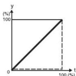
line
| t (%) | y (%) | |---|---| | 0 | 0 | | 100 | 100 |[Cut]
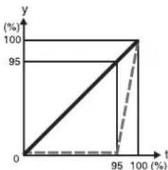
line
| t (%) | y (%) | |---|---| | 0 | 0 | | 95 | 100 | | 100 | 100 |[Last 5%]
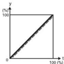
line
| t (%) | y (%) | |---|---| | 0 | 0 | | 100 | 100 |[Linear]
Transition Cropping
t: transition execution time
y: change in transition and
cropping amount
Setting the timing of transition completion
When the execution mode for a DME wipe crop transition is set to [Last 5%], you can select the timing of transition completion from 70% ([Last 30%]), 95% ([Last 5%]), and 100% ([Off]).
1 In the M/E 1 >DME Wipe menu, select HF5 'Modify.'
The Modify menu appears.
2 In the
The Remove From Begin menu appears.
3 In the
Last 30%: The transition completes at the end of 70% of the transition execution time. The transition has a dead zone from 70% to 95% of the transition time.
Last 5%: The transition completes at the end of 95% of the transition execution time. When the transition completes, the cropping is removed during the last 5% (enlarges).
Off: The transition completes at the end of the transition execution time. During the last 5% of the transition, the transition and cropping removal proceed together.
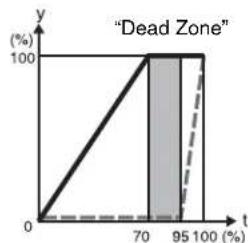
line
| t | y | | --- | --- | | 0 | 0 | | 70 | 100 | | 95 | 100 | | 100 | 0 |[Last 30%]
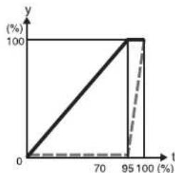
line
| t (%) | y (%) | |---|---| | 0 | 0 | | 95 | 100 | | 95 | 100 |[Last 5%]
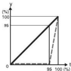
line
| t (%) | y (%) | |---|---| | 0 | 0 | | 95 | 95 | | 100 | 100 |[Off]
— Transition
--- Cropping
t: transition execution time
y: change in transition and cropping amount
DME Wipe Modify Clear
Press [Default Recall] at the lower left of the menu display, turning it on, then press VF6 'DME Wipe' to return the DME wipe settings to their initial status.
For details of the menu operation to return the DME wipe state to that set in initial status, see "Returning to Default State in Function Groupings" (page 82).
DME Wipe Settings for Independent Key Transitions
You carry out independent key transition DME wipe setting operations using the DME Wipe Adjust menu for each keyer.
For an overview of independent key transitions, see page 109.
This section describes the independent key transition DME wipe settings, taking the M/E-1>Key1>Transition>DME Wipe Adjust menu as an example.
Basic Procedure for Independent Key Transition DME Wipe Settings
Accessing the independent key transition DME wipe settings menu
As an example, to access the M/E-1 >Key1 >Transition >DME Wipe Adjust menu, carry out the following operation.
- In the menu control block, select the top menu selection button [M/E 1], and select VF1 'Key1' and HF6 'Transition' to display the Transition menu for key 1. Next, press [DME Wipe Adjust]. If VF1 [Key5] is shown, press the switching button at the top of the menu, so that [Key1-4] appears, and press VF1 [Key1].
Notes
To select [M/E-4], a previous assignment in the Setup menu is required.
- Press the key delegation button [Key1] in the independent key transition control block of the M/E-1 bank, then press the independent key transition type [DME] twice in quick succession.
Carrying out the above operation displays the M/E-1>Key1>Transition>DME Wipe Adjust menu (which will be referred to below as simply the Key1 DME Wipe Adjust menu).
Selecting the independent key transition DME wipe pattern
You select the independent key DME wipe pattern from the list of patterns displayed in the menu. To select a DME wipe pattern for independent key1 on the M/E-1 bank, use the following procedure.
1 In the
The Pattern Select menu appears.
2 Select the desired DME wipe pattern group with one of the following buttons.
(In two-channel mode, only Page Turn and Page Roll are selectable.)
- Slide/Squeeze: slide and squeeze
- Split/Door: split and door
- Mirror/Sphere: mirror and sphere
• Character Trail: character trail
• Wave/Ripple: wave and ripple
• Page Turn/Roll: page turn and page roll
• Frame I/O: frame in/out
• 2D Trans/3D Trans: 2D Trans and 3D Trans - Sparkle/Split Slide: sparkle and split slide
- User Program: user programmable DME
For details of DME wipe patterns, see “Types of DME Wipe Pattern” (page 179) and “DME Wipe Pattern List” (page 355).
3 Press the button to select the desired pattern.
Setting Independent Key Transition DME Wipe Modifiers
You can add modifiers such as pattern position and size for an independent key transition DME wipe.
For introductory information, see “Setting the DME wipe position (Positioner)” (page 185) and “Setting the DME wipe pattern size (Size)” (page 186).
Setting the DME wipe position (Positioner)
For applicable pattern numbers, see page 181.
1 In the
2 Set the following parameters.
| Knob | Parameter | Adjustment | Setting values |
| 1 | H | H o position | -200.00 to z +200.00 |
| 2 | V | V e position | -200.00 to i +200.00 |
To return the DME wipe pattern position to the center of the screen
In the
Setting the DME wipe pattern size (Size)
For applicable pattern numbers, see page 182.
1 In the Key 1 DME Wipe Adjust menu, press [Size], turning it on.
2 Set the following parameter.
| Knob | Parameter | Adjustment | Setting values |
| 1 Size | Set size of effect | 0.00 to 200.00a) | |
a) The effect size when [Size] is off is taken as 100.00%.
Cropping a key DME wipe
1 In the
2 Set the following parameters.
Parameter group [1/2]
| Knob | Parameter | Adjustment | Setting values |
| 1 H Crop the left | and right of the image | Left value shown | |
| 2 V Crop the top | and bottom of the image | Top value shown | |
| 3 All Crop the top, | bottom, left, and right of the image | Left value shown | |
Parameter group [2/2]
| Knob | Parameter | Adjustment Setting | values |
| 1 | Top Cropping of the top of the image | -100.00 to +100.00 | |
| 2 | Left Cropping of the left of the image | -100.00 to +100.00 | |
| 3 | Right Cropping of the right of the image | -100.00 to +100.00 | |
| 4 | Bottom Cropping of the bottom of the image | -100.00 to +100.00 | |
To crop to 4:3 in 16:9 mode
In the
To set the operation for DME wipe crop transition execution
1 In the
2 In the
3 In the
The Remove From Begin menu appears.
For subsequent operations, see step 5 of “To set the action when a DME wipe crop transition is executed” (page 187).
To set the timing of transition completion
1 In the
2 In the
For subsequent operations, see “Setting the timing of transition completion” (page 188).
Applying a border to a key DME wipe
In the
For subsequent operations, use the same process as in step 4 of “Modifying the DME wipe pattern edge” (page 185).
Resizer DME Wipe Setting
You can carry out a DME wipe on a key using the resizer.
Notes
When the screen aspect ratio is 4:3 in HD format, when the resizer DME wipe is used to shrink a video image, this is applied to the 16:9 screen including the added video on the left and right sides. Use the crop function as required to extract the 4:3 image.
DME wipe patterns available for resizer DME wipe
You can use the following patterns of the DME wipe pattern one-channel mode that can be used in a resizer DME wipe. (7000-series numbers)
- Slide (pattern numbers: 7001 to 7008)
- Squeeze (pattern numbers: 7021 to 7031)
- Frame in-out (pattern numbers: 7201 to 7208, 7221 to 7224)
Relation between resizer DME wipes and other effects
The following relations hold between a resizer DME wipe and other effects.
Relation to processed keys
It is not possible to select a resizer DME wipe for a key with processed key enabled.
Relation to resizer
It is not possible to use a resizer DME wipe for a key with resizer enabled.
It is not possible to use a resizer DME wipe for a key forming a pair with a key with the dual resizer effect enabled. The key combinations forming pairs are keys 1 and 2, keys 3 and 4, key 5 and key 6, and key 7 and key 8. For example, when a dual resizer effect is enabled for key 1, it is not possible to use a resizer DME wipe on key 2.
Making resizer DME wipe settings
1 In the
The 1ch Pattern Select menu appears.
2 Select [Resizer Slide/Squeeze] or [Resizer Frame I/O].
The patterns of the selected group appear.
The wipe patterns that can be used for a resizer DME wipe are as follows.
- Slide (pattern numbers: 7001 to 7008)
- Squeeze (pattern numbers: 7021 to 7031)
- Frame in-out (pattern numbers: 7201 to 7208, 7221 to 7224)
3 Press the desired pattern to select it.
For more about resizer DME wipe modifiers, see "Setting Independent Key Transition DME Wipe Modifiers" (page 189).
DME Wipe Snapshots
You can snapshot and save a DME wipe pattern together with the current settings of its modifiers and pattern limit in a dedicated register for recall when required.
There are 10 DME wipe snapshot registers for each of the M/E and P/P banks.
To save and recall these registers, use the Flexi Pad control block, the Multifunction Flexi Pad block in each switcher bank or the Menu control block.
In the case of a simple transition system, there are eight DME wipe snapshot registers for each switcher bank.
DME Wipe Snapshot Operations With the Flexi Pad
You can save, recall and delete DME wipe snapshots using the procedures similar to the procedures for wipe snapshot operations. In DME wipe snapshot operations, use the [DME] button instead of the [WIPE] button used in wipe snapshot operations.
Selecting a DME wipe pattern in the Flexi Pad control block
In the standard type Flexi Pad control block, enter a four-digit pattern number, using the [DME] button (see page 174).
Notes
- You cannot select a DME wipe pattern in the simple type Flexi Pad control block.
- A button in the memory recall section in which a DME wipe snapshot is saved shows the pattern, and lights yellow.
For a user-programmable DME, the register number (see page 193) appears.
Depending on the setting of the Setup menu, you can also display a register name.
For details, see "Operation Settings (Operation Menu)" in Chapter 19 (Volume 2). - In a simple type Flexi Pad control block, it is not possible to delete a DME wipe snapshot.
For details of the operating procedures, see “Wipe Snapshots” (page 173).
DME Snapshot Operations With the Menus
In the same way as for wipe snapshots, you can save, recall, and delete DME snapshots.
For details of the operating procedures, see “Wipe Snapshot Operations With the Menus” (page 175).
Creating User Programmable DME Patterns
With a user programmable DME, you can use DME effects created through the use of keyframes for a transition on the switcher system.
Note the following points when creating a keyframe effect for use as a user programmable DME pattern.
Register numbers and pattern numbers
When saving a keyframe effect as a user programmable DME pattern, specify the register number that corresponds to the pattern number as shown in the following table.
| Execution mode | Register number | Pattern number |
| One-channel mode | 101 to 199 | 1999 |
| Two-channel mode | 201 to 299 | 2999 |
| Three-channel mode | 301 to 399 | 3999 |
For details of registers and keyframe effects, see Chapter 13 "Keyframe Effects" (Volume 2), respectively.
Notes
When the signal format is 1080P, three-channel mode cannot be used.
Keyframe effects in the global channel
When the effect with the same number as the reference channel is present on the DME global (GLBL) channel, executing the user programmable DME will also execute the effect on the global channel simultaneously.
When executing a user programmable DME, take note of whether the effect is present on the global channel.
User Programmable DME Transition Mode
To create a user programmable DME, it is necessary to set the transition mode (the way in which the effect moves). To set the transition mode, use the Key Frame >DME User PGM menu.
For details of the operating procedures, see “Transition Mode Settings for User Programmable DME” in Chapter 13 (Volume 2).
The following transition modes are available.
| Channels Transition | mode Effect group | |
| One-channel mode | Single transition mode | Slide, Split, Door, Page turn, Page roll, Squeeze, Mirror, Sphere, Character Trail, Wave, Ripple, 2D Trans, 3D Trans, Sparkle, Split Slide |
| Flip Tumble Flip Tumble, Mosaic, Defocus | ||
| Frame in-out Frame | in-out | |
| Frame in-out H^a) | Frame in-out | |
| Frame in-out V | Frame in-out | |
| Picture-in-picture ^b) | Picture-in-picture | |
| Compress ^c) | Picture-in-picture | |
| Two-channel mode | Dual transition mode | Slide, Squeeze, 3D Trans |
| Two-channel picture-in-picture | Picture-in-picture | |
a) Transition according to DME wipe patterns 1202, 1203, or 1204
b) Transition according to DME wipe pattern 1201
c) Transition according to DME wipe pattern 1251
For details, see "Overview" (page 179).
Notes
For the following group of effects available in two-channel mode, no user programmable DME wipe patterns can be created.
Page turn, Page roll, Frame in-out, Brick
Notes on creating keyframe effects
When creating a keyframe effect to be used as a user programmable DME pattern, note the following, depending on the transition mode used.
Notes on single transition mode (one-channel mode)
- Either create the first keyframe image outside the screen area, or set the image size to zero so that it cannot be seen within the screen.
- Create the last keyframe to be a full-size image.
- In the
group of the Key Frame >DME User PGM menu, select [Single].
Notes on flip tumble (one-channel mode)
- Create the first keyframe image at full size. In the
- Create the last keyframe with the image inverted so the back side is visible, and with the size at full size.
- In the
group of the Key Frame >DME User PGM menu, select [Flip Tumble].
Notes on frame in-out (one-channel mode)
Create a minimum of three keyframes.
- Either create the first keyframe image outside the screen area, or set the image size to zero so that it cannot be seen within the screen.
- Create the first transition to end such that the image can be seen within the screen. At this point, press the [PAUSE] button in the keyframe control block, turning it on, to set a pause for the keyframe.
- Either create the last keyframe image outside the screen area, or set the image size to zero so that it cannot be seen within the screen.
- In the
group of the Key Frame >DME User PGM menu, select [FRAME I/O].
Notes on Frame in-out H (one-channel mode)
Create a minimum of three keyframe points.
- Either create the first keyframe image outside the screen area, or set the image size to zero so that it cannot be seen within the screen.
- As the state after completion of the first transition, move the image horizontally to make it visible within the screen. At this time, press the [PAUSE] button in the keyframe control block, turning it on, to set a pause for the keyframe.
- For the last keyframe move the image horizontally to place it outside the screen area or set the image size to zero, so that the image is not visible within the screen.
- In the
group of the Key Frame >DME User PGM menu, select [FRAME I/O H].
Notes on frame in-out V (one-channel mode)
Create a minimum of three keyframe points.
- Either create the first keyframe image outside the screen area, or set the image size to zero so that it cannot be seen within the screen.
- As the state after completion of the first transition, move the image vertically to make it visible within the screen. At this time, press the [PAUSE] button in the keyframe control block, turning it on, to set a pause for the keyframe.
- For the last keyframe move the image vertically to place it outside the screen area or set the image size to zero, so that the image is not visible within the screen.
- In the
group of the Key Frame >DME User PGM menu, select [FRAME I/O V].
Notes on picture-in-picture (one-channel mode)
Create a minimum of three keyframes.
- Either create the first keyframe image outside the screen area, or set the image size to zero so that it cannot be seen within the screen.
- Create the first transition to end such that the image can be seen within the screen. At this point, press the
[PAUSE] button in the keyframe control block, turning it on, to set a pause for the keyframe.
- Either create the last keyframe image outside the screen area, or set the image size to zero so that it cannot be seen within the screen.
- In the
group of the Key Frame >DME User PGM menu, select [P In P].
Notes on compress (one-channel mode)
Create a minimum of three keyframe points.
- Create the first keyframe with the image at full size.
- In the state at completion of the first transition, create the image to be visible within the screen. At this time, press the [PAUSE] button in the keyframe control block, turning it on, to set a pause for the keyframe.
- For the last keyframe, once again set the image size to full size.
- In the
group of the Key Frame >DME User PGM menu, select [Compress].
Notes on dual transition mode (two-channel mode)
- Create the first keyframe for each channel as follows.
- Channel 1: create the image full-size.
- Channel 2: either create the image outside the screen area, or set the image size to zero so that it cannot be seen within the screen.
- Create the last keyframe for each channel as follows.
- Channel 1: either create the image outside the screen area, or set the image size to zero so that it cannot be seen within the screen.
- Channel 2: create the image full-size.
- In the
group of the Key Frame >DME User PGM menu, select [Dual].
Notes on picture-in-picture (two-channel mode)
Create a minimum of three keyframes.
- Create the first keyframe for each channel as follows.
- Channel 1: create the image full-size.
- Channel 2: since the priority is low, it will not be visible on the screen, so no particular restrictions apply.
In the Global Effect >Ch1 to Ch4 >Combiner menu, when setting the priority of channel 1 and channel 2, set the channel 1 priority higher.
- In the intermediate part of the transition, create the two images so that both are visible within the screen. In the Global Effect >Ch1 to Ch4 >Combiner menu, when setting the priority of channel 1 and channel 2, set the channel 2 priority higher.
It is recommended to make the priority settings at a keyframe point at which the two images are not overlapping.
- During the course of a transition, there is a “dead zone” corresponding to the intermediate point of the whole effect (see following figure), during which the image does not change. Therefore, it is necessary to create the effect so that the image in the intermediate part of the
transition is the keyframe for the mid-point of the whole effect. The range of this “dead zone” corresponds to the central one-third of the range of the transition indicator. This also applies to an auto transition.
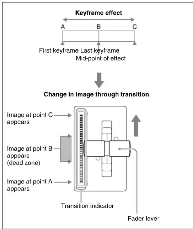
flowchart
graph TD
    A["First keyframe Last keyframe Mid-point of effect"] --> B{Change in image through transition}
    B --> C["Image at point A appears"]
    B --> D["Image at point B appears (dead zone)"]
    B --> E["Image at point C appears"]
    B --> F["Transition indicator"]
    F --> G["Fader lever"]
- Create the last keyframe for each channel as follows.
- Channel 1: since the priority is low, it will not be visible on the screen, so no particular restrictions apply.
- Channel 2: create the image full-size.
- In the
DME Wipe Pattern Operations in the Multifunction Flexi Pad Control Block
Recalling a DME Wipe Snapshot
The operation of recalling a DME wipe snapshot in the Multifunction Flexi Pad control block is the same as the operation of recalling a wipe snapshot, except for pressing the [DME WIPE] button to select DME wipe snapshot mode (see page 176).
You can change the indications for buttons [0] to [9] in the memory recall section to pattern images, using the Engineering Setup >Panel >Operation >Flexi Pad Mode menu.
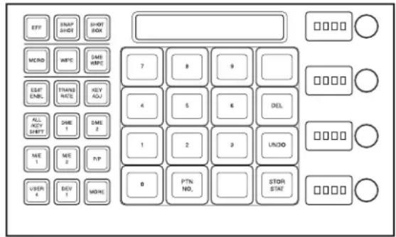
Selecting the DME Wipe Pattern
The operation of selecting the DME wipe pattern in the Multifunction Flexi Pad control block is the same as the operation of selecting a wipe pattern, except for pressing the [DME WIPE] button to select DME wipe snapshot mode (see page 176).
Note, however, that the pattern numbers for DME wipe patterns have four digits (see page 355).
Editing the DME Wipe Pattern
By pressing the [EDIT ENBL] button to switch the memory recall section to editing mode as shown in the following illustration, you can edit the selected DME wipe pattern with the following buttons.
To exit from the editing mode, press the [EDIT ENBL] button once more, or press the [EXIT] button.
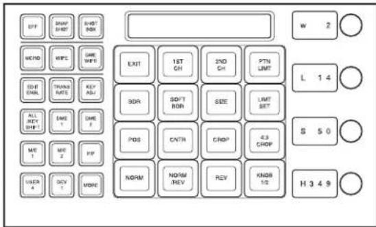
Note that the operation of the following buttons is the same as when editing a wipe pattern.
- [EXIT] button
• [PTN LIMIT], [LIMIT SET] buttons
• [NORM], [NORM/REV], [REV] buttons
• [KNOB 1/2] button
For the method of operation of these buttons, see “Editing the Wipe Pattern” (page 176).
Channel selection buttons
1ST CH (channel 1): Selects channel 1.
2ND CH (channel 2): Selects channel 2.
You can also select two channels by pressing the buttons simultaneously.
DME wipe pattern edge setting buttons
BDR (border): Applies a border to the DME wipe pattern. SOFT BDR (soft border): Softens the applied border.
You can adjust the parameters selected with these buttons using the control knobs, when the button is lit green.
- When border is selected
| Knob Parameter Adjustment Setting values | ||
| 1 W Border width 0 to 100 | ||
| 2 L Luminance 0 to 100 | ||
| 3 S Saturation 0 to 100 | ||
| 4 H Hue 0 to 359 | ||
- When soft border is selected
Parameter group [1/2]
| Knob Parameter Adjustment Setting values | ||
| 1 W Border width 0 to 100 | ||
| 2 I Degree of | softening of inside of border | 0 to 100 |
Parameter group [2/2]
| Knob Parameter Adjustment Setting values | |||
| 1 L Luminance 0 to 100 | |||
| 2 S Saturation 0 to 100 | |||
| 3 | H | Hue | 0 to 359 |
Buttons for positioning the DME wipe pattern
POS (position): Adjusts the position of the DME wipe pattern.
CNTR (center): Returns the DME wipe pattern position to the center.
When you press the [POS] button, the alphanumeric display first shows the name of the parameter, "H" or "V," and then the value of the parameter.
When the [POS] button is lit green, you can adjust the position of the pattern with the control knobs.
| Knob Parameter Adjustment Setting values | |||
| 1 H Horizontal | position | -200 to +200 | |
| 2 | V | Vertical position | -200 to +200 |
| 3 H (R) | Relative horizontal movement | -400 to +400 | |
| 4 V (R) | Relative vertical movement | -400 to +400 | |
Buttons for setting DME wipe pattern cropping
CROP: Adjusts the DME wipe pattern cropping.
4:3 CROP: Crops a 16:9 image to 4:3.
When the [CROP] button is lit green, you can set the cropping ratio of the DME wipe pattern, with the control knobs.
Parameter group [1/2]
| Knob Parameter Adjustment Setting values | ||
| 1 H Cropping ratio | of the image from left and right sides | -100 to +100 |
| 2 V Cropping ratio | of the image from top and bottom sides | -100 to +100 |
| 3 A Cropping ratio | of the image from all four sides | -100 to +100 |
Parameter group [2/2]
| Knob Parameter Adjustment Setting values | ||
| 1 T Cropping ratio | of the image from the top | -100 to +100 |
| 2 L Cropping ratio | of the image from the left | -100 to +100 |
| 3 R Cropping ratio | of the image from the right | -100 to +100 |
| 4 B Cropping ratio | of the image from the bottom | -100 to +100 |
Button for specifying effect size
SIZE: Specifies the effect size. When the [SIZE] button is lit green, you can specify the effect size, with the control knobs.
| Knob Parameter Adjustment Setting values | ||
| 1 S Effect sizes 0 to 200 | a) | |
a) The effect size when [Size] is off is taken as 100.00.
DME wipe modify clear
With the [DME WIPE] button held down, pressing and holding down the region selection button for the selected region returns the DME wipe settings to their initial status.
For details of the initial status, see “Saving User-Defined Settings” in Chapter 18 (Volume 2).
Saving, Canceling, and Deleting DME Wipe Snapshots
The operations of saving, canceling, and deleting a DME wipe pattern snapshot you have created are the same as the operations of saving, canceling, and deleting a wipe snapshot (see page 178).
Frame Memory
Chapter
7
Overview
Frame memory is a function whereby a frame of input video can be frozen and written to memory, for further use as material for editing.
You can also play recorded frame memory clips (movies).
Frame capacity
The frame memory board has two blocks of memory, and the following table shows the maximum number of images that can be written to each block. (Of the two, one is reserved for storing frame memory clips.)
HD system:
(Without ancillary data)
| Video format Memory capacity | |
| 1080i/50 Approx. 1000 frames | |
| 1080i/59.94 | |
| 1080PsF/23.976 | |
| 1080PsF/24 | |
| 1080PsF/25 | |
| 1080PsF/29.97 | |
| 1080PsF/50 Approx. 2300 frames | |
| 1080P/30 | |
| 720P/50 Approx. 2300 frames | |
| 720P/59.94 | |
(With ancillary data)
| Video format Memory capacity | |
| 1080i/50 Approx. 700 frames | |
| 1080i/59.94 Approx. 800 frames | |
| 1080i/60 | |
| 1080PsF/23.976 Approx. 600 frames | |
| 1080PsF/24 | |
| 1080PsF/25 Approx. 700 frames | |
| Video format Memory capacity | |
| 1080PsF/29.97 Approx. 800 frames | |
| 1080PsF/30 | |
| 720P/50 Approx. 1400 frames | |
| 720P/59.94 Approx. 1700 frames | |
SD system:
(Without ancillary data)
| Video format Memory capacity |
| 480i/59.94 Approx. 5600 frames |
| 576i/50 Approx. 4800 frames |
(With ancillary data)
| Video format Memory capacity |
| 480i/59.94 Approx. 4700 frames |
| 576i/50 Approx. 3900 frames |
For details of operating procedures, see "Still Image Operations" (page 200).
Types of image and terminology used
The following types of image are handled in frame memory.
Freeze image: An input image that has been frozen, but not saved to memory.
Still image: A freeze frame that has been saved to memory as a file. Each file (still file) holds just one still image.
Frame memory clip: A clip consists of a sequence of still images, which appears as a movie on playback. In this manual this is also referred to simply as a "clip." The files (still files) constituting clips are referred to as a "clip file."
When the above distinctions are not being made, an image is simply referred to as an “image.”
About extended clips
Of the two memory blocks for saving a clip, the clip saved in the one which is not combined with a still image is called an “extended clip.”
However, when the signal format is 1080P, since both a still image and a clip are saved in both memory blocks, there is no extended clip.
Use of frame memory
There are eight frame memory channels, FM1 to FM8, and each channel independently allows a freeze image to be saved or recalled.
By allocating FM1 to FM8 to cross-point buttons you can use the still image output or clip output from each channel as input material.
Notes
However, when the signal format is 1080P, only the four options of FM1 to FM4 can be used.
Correspondence between input and output
There are two buses for capturing frame memory material: the frame memory source bus 1 and the frame memory source bus 2.
These input buses are used by allocation to one of the pairs of output, FM1&2, FM3&4, FM5&6, and FM7&8. You can freeze a frame in each channel separately, or freeze in the two channels simultaneously.
The source buses allocated to FM1 to FM8 are as follows.
| Input Frame source bus 1 | Frame memory source bus 2 |
| Output FM1 FM2 | |
| FM3 FM4 | |
| FM5 FM6 | |
| FM7 FM8 |
Pair mode
By enabling the pair mode, you can link FM1 and FM2, FM3 and FM4, FM5 and FM6, and FM7 and FM8. For example, when a freeze or image processing is carried out on FM1, the same operation is carried out on FM2. The same applies to the other pairs. When a pair of images are captured in pair mode, the image frozen in FM1 (3, 5, or 7) is referred to as the main file and the other frozen in FM2 (4, 6, or 8) is referred to as the sub file.
Pair files and single files
A file that can be recalled in pair mode is termed a “pair file.” A pair file can be created by setting pair mode and capturing an image, or by using the coupling function (see page 217) to combine two single files.
A file other than a pair file is termed a “single file.” A single file can be created by switching off pair mode and capturing an image, or by using the separation function (see page 217) to split a pair file.
Operation modes
The frame memory has the following operation mode.
V/K mode: When the pair mode is active, the key signal is automatically selected on frame memory source bus 2. This is convenient for handling the video and key signals together in frame memory. For example, when you select a video signal on frame memory source bus 1, the key signal assigned to it is automatically selected on frame memory source bus 2. You can also use the signal automatically selected on frame memory source bus 2 as a key signal when processing keyframe memory 1.
To change the pair mode or operation mode, use the Frame Memory menu.
Frame memory folders
Still images and clips can be managed in a maximum of twelve groups.
Such a group is called a “frame memory folder.” Folders can be added or deleted, and can be given a name of up to 8 characters.
Notes
- When the system is powered off, the folder names are deleted. The folder names need to be saved on media.
- The following names cannot be used for folders.
Flash1, Flash2
CON, PRN, AUX, CLOCK\$, NUL, COM0, COM1,
COM2, COM3, COM4, COM5, COM6, COM7, COM8, COM9
LPT0, LPT1, LPT2, LPT3, LPT4, LPT5, LPT6, LPT7, LPT8, LPT9
A folder named “Default” is provided, and this folder cannot be renamed or deleted.
- Still images and clips in different frame memory folders cannot have the same name.
Still Image Operations
The frame memory functions provides the following still image file functions.
- Capturing and Saving an Input Image (page 203)
- Recalling Still Images (page 205)
• Image Output (page 206) - Continuously Capturing Still Images (Record) (page 207)
- Recalling a Continuous Sequence of Still Images (Animation) (page 207)
Notes
During playback of a frame memory clip of the pair assigned to either of the target FM selection buttons (see page 211), frame memory operations may not be performed properly. Carry out frame memory operations after stopping clip playback.
Preparations
Allocating the frame memory outputs (FM1 to FM8) to cross-point buttons
To output a frame memory image to a monitor, for example, the output signal from the frame memory (FM1 to FM8) must be allocated to a cross-point button. Carry out this allocation in the Setup menu.
Notes
When the signal format is 1080P, only the four options of FM1 to FM4 can be used.
Accessing the Frame Memory menu
Most frame memory operations are carried out using the Frame Memory menu.
To access the Frame Memory menu, use either of the following procedures.
- In the menu control block, select the top menu selection button [FRAME MEM].
- Press the cross-point button to which the frame memory output is allocated twice in rapid succession.
Interpreting the Frame Memory Menu
The menu screen consists of the following principal parts. The frame memory selection area display is the same for all except the Pattern Adjust/Pattern Select/Field Invert/File (excluding Pair Recombination menu)/Folder/External Device menus.
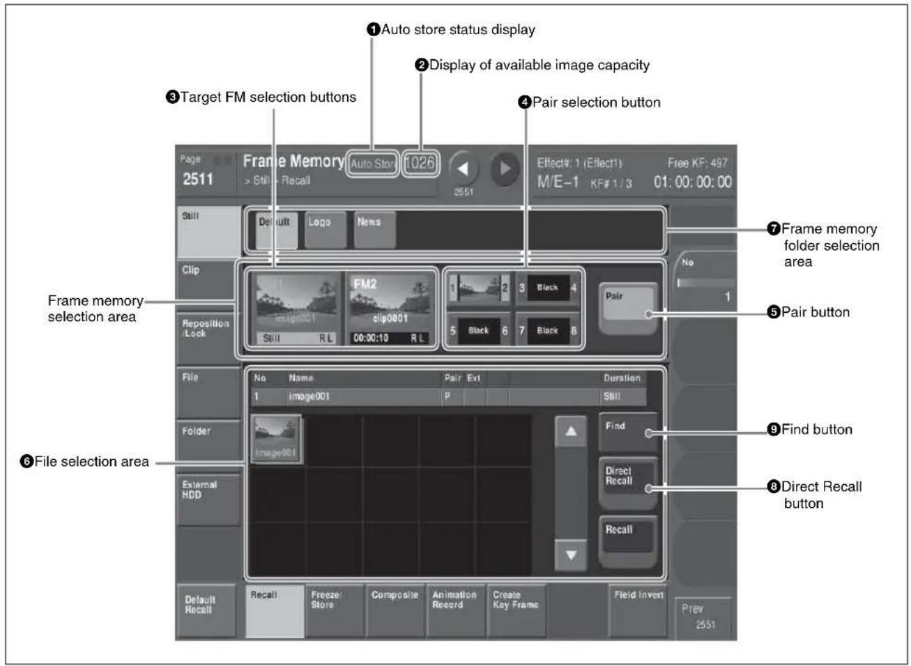
Frame Memory menu
①Auto store status display
Depending on the setup settings, this appears when the auto store function is enabled.
② Display of available image capacity
This shows the remaining number of frames. When no more frames can be stored, in pair mode "1" or "0" appears in red, and in single mode "0" appears in red. The lower figure shows the remaining number of frames that can be used as extended clips.
Notes
When the signal format is 1080P, each time a still image is saved the remaining space is reduced by two frames.
③Target FM selection buttons
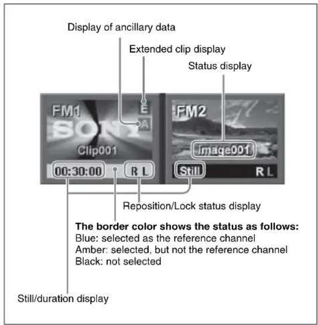
Press one of these to select which of the selected outputs (FM1 and FM2 in the example shown) the operation applies to.
The following information appears on the button.
Status display
File name (e.g. image001) and thumbnail: when a file is output
Black: when a black signal is output
Through: when the input image is output
Freeze: when a freeze is output
Record: when continuously capturing images (record)
Still/duration display
When a still image is selected, "Still" is shown. When a clip is selected, a duration indication such as "00:00:10" is shown.
Reposition/Lock status display
This shows “R” when the reposition function (see page 206) is on, and shows “L” when the lock function (see page 206) is on.
Extended clip display
For an extended clip, an "E" appears.
Ancillary data-attached clip display
For an ancillary data attached clip, an "A" appears.
④ Pair selection button
Select the pair to be displayed in the target FM selection buttons.
(in the following figure, the pair of FM1 and FM2 is selected.)
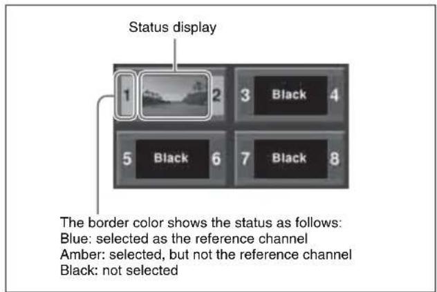
The following information appears on the button.
Status display
For a pair, shows the status for the reference.
Thumbnail: when a file is output
Black: when a black signal is output
Through: when the input image is output
Freeze: when a freeze is output
Record: when continuously capturing images (record)
⑤Pair button
Press this button, turning it on, to enable pair mode.
⑥File selection area
You can select from the displayed still image files or clip files.
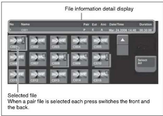
Thumbnail indications
Still image files and clip files: Still image files are displayed as gray buttons and clip files are displayed as yellow buttons.
Single files and pair files: Single files are displayed with shadow and pair files are displayed with no shadow.
Selected file: Pale blue border. When more than one file is selected, only the first is pale blue, and the remainders are amber. If the pair file was selected, each press switches the front and the back.
File information detail display
For the selected file, this shows the file name, "P" if a pair file, "E" if an extended clip, "A" if an ancillary data attached clip, and the duration.
⑦Frame memory folder selection area
Select the frame memory folder to be displayed.
⑧Direct Recall button
Toggle on and off the direct recall mode in which pressing a thumbnail immediately recalls the file.
⑨ Find button
Pressing this button displays a popup window, in which you can enter a file name to carry out a search.
Selecting an Input Image
For the input image to frame memory, you can use either the signal selected on one of the two frame memory source buses or a dedicated color matte signal.
When using the signal on frame memory source bus 1 or 2 for the input image, select the signal as described below.
Selecting the signal on a frame memory source bus
As an example, to select a signal on frame memory source bus 1, use the following procedure.
1 In the auxiliary bus control block, press the AUX delegation button to which frame memory source bus 1 is allocated, turning it on.
For allocation of buses to the AUX delegation buttons, see “Assigning a Bus to an AUX Delegation Button” in Chapter 19 (Volume 2).
On a CCP-6224/6324 control panel, you switch the cross-point control block for use as an AUX bus control block.
2 In the auxiliary bus control block cross-point buttons, select the signal to be used for the input image.
To select a signal with a key or DME effect applied on the frame memory source bus
In the key control block, press the [FM FEED] button, turning it on.
This automatically assigns the key fill and key source signals being keyed by the currently selected keyer to frame memory source buses 1 and 2.
When DME is selected on the keyer, the key fill and key source signals to which a DME effect is applied are assigned.
Selecting Outputs and Target Frame Memory
Selecting outputs (FM) and target frame memory
The following description applies to the case of settings for FM1&2, but the procedures are similar for the other cases.
1 In the Frame Memory menu, press one of VF1 to VF4, and select the required HF menu.
The current status of frame memory appears. (See page 200.)
2 From the pair selection buttons, press the buttons corresponding to FM1 and FM2.
This assigns the signals to FM1 and FM2. To the right of the target FM selection buttons, the FM1 and FM2 output status appears (see page 201).
3 If required, press [Pair], to select the FM operation mode (pair mode).
On: Operate on FM1 (3, 5, 7) and FM2 (4, 6, 8) as a pair.
Off: Operate on FM1 (3, 5, 7) and FM2 (4, 6, 8) individually.
For more details, see "Pair mode" (page 199).
Notes
In the Pair Recombination menu, the [Pair] operation is not possible.
4 Press the target FM selection button [FM1] or [FM2] (see page 201) to select the FM operations apply to.
When [Pair] is On: Whichever of FM1 and FM2 you press, the pair is selected.
When [Pair] is Off: One of the targets must be selected. However, in the Clip >Play menu you can also select both FM1 and FM2.
Selecting a frame memory folder
Press a button in the frame memory folder selection area (see page 202).
By pressing [More] to switch the display, you can select from a maximum of 12 folders.
Thumbnails of the files within the selected folder appear.
Capturing and Saving an Input Image
As the input material for the frame memory, you can use the signal selected on the frame memory source bus. For this signal you can use video processing (video levels or hue value adjustment) or masking.
Allocating a frame memory source bus signal to one of FM1 to FM8, then carrying out a freeze captures a still image in the corresponding frame memory output image, and saves it in temporary memory.
For a freeze, an image can be captured either as video frame (a “frame freeze”) or a video field (“field freeze”).
Notes
When the system is powered off, any freeze images written to temporary memory are lost.
Freezing an image and writing it to memory
To freeze the signal selected as input material, and write it to memory, use the following procedure.
1 In the Frame Memory menu, select VF1 'Still' and HF2 'Freeze/Store.'
The Freeze/Store menu appears.
2 Select the target frame memory.
For the procedure, see “Selecting outputs (FM) and target frame memory” (page 203).
3 To enable V/K mode, press [V/K Mode] turning it on.
4 Press a button in the frame memory folder selection area, to select the folder to hold the freeze image (see page 203).
Notes
The folder selected here is the destination folder for writing the freeze image.
It is not possible to change the selection of this folder after the following step 5.
An orange bar appears on the selection button for the destination folder.
5 Press [Freeze Enable], turning it on.
The signals of frame memory source buses 1 and 2 are assigned to the pair of FMs selected in step 2, a freeze is now possible.
6 If necessary, make the video process settings (see page 204) or mask settings (see page 205) for application to the selected signal.
7 In the state in which you want to freeze, press one of the following in the
Frame: Freeze one frame.
Field: Freeze one field.
Off: Release the freeze, and delete the recorded freeze image.
After carrying out the freeze, to return to the state immediately before the freeze, press [Undo] in the
Notes
- All freeze images written to temporary memory are lost when the system is powered off.
- If you change the frame memory to use as in step 2 before saving the freeze images written to temporary memory, all the freeze images in temporary memory are lost, unless the auto store function has been enabled in setup. With the auto store function enabled, the freeze images written to temporary memory are saved automatically when the frame memory selection is changed.
- For the following signal formats, a field freeze is not possible.
1080P/50, 1080P/59.94, 1080PsF/23.976, 1080PsF/24, 1080PsF/25, 1080PsF/29.97, 720P/ 50, 720P/59.94
Saving a freeze image (Store)
You can save an image in temporary memory which has been placed with the freeze function as a file in memory. You can save a single image in a single file and apply a name of up to eight characters to the file.
Notes
- When the system is powered off, all the files saved in memory are lost.
- When the signal format is 1080P, the file name is limited to seven characters.
Each time a still image is saved, the remaining space is reduced by two frames.
To save a captured still image in a file, use the following procedure in the Still >Freeze/Store menu.
1 Press [Store].
The keyboard window (see page 79) appears.
2 In the keyboard window, enter the file name.
Notes
The following names cannot be used:
CON, PRN, AUX, CLOCK\$, NUL, COM0, COM1, COM2, COM3, COM4, COM5, COM6, COM7, COM8, COM9
LPT0, LPT1, LPT2, LPT3, LPT4, LPT5, LPT6, LPT7, LPT8, LPT9
3 In the keyboard window, press the [Enter] button.
This saves the still image file in memory.
The destination folder is the folder selected in step 4 of "Freezing an image and writing it to memory."
If the entered folder name already exists, a message to confirm overwriting appears.
When the system is powered off, the file saved in memory is erased.
To carry out a freeze and store simultaneously (Freeze and Store)
Press [Freeze & Store], turning it on.
In this state, if you press [Frame] or [Field], this carries out a freeze, and simultaneously stores in a still image file.
Setting video processing
To set video processing for the signal selected on a frame memory source bus, use the following procedure in the Still >Freeze/Store menu.
1 In the
2 Use the knobs to adjust the following parameters.
| Knob | Parameter | Adjustment | Setting values |
| 1 Video | Gain Overall gain of the video signal | -200.00 to +200.00 | |
| 2 Y Gain | Y signal gain -200.00 to | +200.00 | |
| 3 C Gain | Chrominance signal gain | -200.00 to +200.00 | |
| 4 Hue | Delay Hue delay -180.00 to | +180.00 | |
| 5 | B I Level | Y signal c black level | -7.81 to +109.59 |
To return the settings to the default values, press [Unity] in the
Notes
When a pair setting is active, it is coupled to the video process on/off setting, but the above parameter settings are only valid for frame memory source bus 1. The pair setting cannot be used to set the frame memory source bus 2. If you want to set video process for frame memory source bus 1 only with the pair setting when old settings for frame memory source bus 2 remain, return the frame memory source bus 2 settings to their default values. When setting video process for the frame memory source bus 2, disable the pair setting.
Setting a mask
Masks can be set separately for frame memory source buses 1 and 2. To apply a mask to the signal selected on frame memory source bus 1, for example, use the following procedure in the Still >Freeze/Store menu.
1 Press [Box Mask], turning it on.
2 Use the knobs to adjust the following parameters.
| Knob | Parameter | Adjustment | Setting values |
| 1 | Top | Top position | -100.00 to +100.00 |
| 2 Left | Left position | -100.00 to +100.00 | |
| 3 Right | Right position | -100.00 to +100.00 | |
| 4 Bottom | Bottom position | -100.00 to +100.00 |
3 To link the masks on frame memory source buses 1 and 2, press [Mask Link], turning it on.
Recalling Still Images
You can recall an image file saved in memory, and allocate to any of the FM1 to FM8 outputs.
Recalling a still image
To recall a still image file saved in memory using the thumbnails, and assign it to an FM output, use the following procedure.
1 In the Frame Memory menu, select VF1 'Still' and HF1 'Recall.'
The Recall menu appears.
- When [Pair] is on, only pair files (pairs of main file and sub file) are displayed.
- When [Pair] is off, both single files and pair files appear (see following figure).
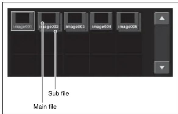
2 In the frame memory selection area, select the FM to be assigned. (See page 203).
3 If [Direct Recall] is on, press and turn it off.
4 Select the desired folder in the folder selection area. By pressing [More] to switch the display, you can select from a maximum of 12 folders.
Thumbnails of the files within the selected folder appear.
5 Using the arrow keys or turning the knob, scroll the file thumbnail display.
| Knob | Parameter | Adjustment | Setting values |
| 1 Scroll | Thumbnaildisplayscrolling | 1 and upwards |
6 Press the thumbnail of the still image you want to recall.
7 Press [Recall].
This recalls the still image file, which is assigned to the FM you selected in step 2.
To recall in direct recall mode
Direct recall means that pressing a thumbnail immediately recalls the file.
In this mode, only the front thumbnail file is recalled.
1 In step 7 above, instead of pressing [Recall], press [Direct Recall].
2 Press the thumbnail for the file you want to recall.
To display the subsidiary file in front
With the direct recall mode on, press [Sub Display], turning it on.
To search by file name
1 Press the [Find] button.
The Find window appears.
2 Press [Find].
A keyboard window appears.
3 Enter the string you want to search for, and press [Enter].
This starts the search, and the indicator lights. When the search ends, the files found are selected.
4 To move through the selected files, press the [
5 Press outside the Find window on the menu screen.
Image Output
There are two functions related to image output: the reposition function for moving the output image, and the lock function for fixing the output image.
Moving the output image (reposition function)
For up to two channels of FM1 to FM8 (one from FM1, FM3, FM5 and FM7 and the other from FM2, FM4, FM6 and FM8), you can move the output image with respect to the screen. The area of the screen around the image that has
been moved is filled with black. There are two ways of carrying out this repositioning.
Normal mode: Movement in the horizontal direction is in two-pixel increments.
Black and white mode: Movement in the horizontal direction is in one-pixel increments, and for each pixel moved the color is inverted.
Notes
It is not possible to save an image moved with the reposition function directly to frame memory.
1 In the Frame Memory menu, select VF3 'Reposition/Lock' and HF1 'Reposition.'
The Reposition menu appears. In this menu, you can also enable the V/K mode (see page 204).
2 In the frame memory selection area, select the FM output (see page 203).
3 In the
Normal: Move in normal mode.
Black&White: Move in black & white mode.
4 With the knobs, adjust the parameters to move the image.
| Knob | Parameter | Adjustment | Setting values |
| 1 | Position H Move | in horizontal direction | -200.00 to +200.00^a) |
| 2 | Position V Move | in vertical direction | -200.00 to +200.00^a) |
a) See page 165.
The surroundings of the moved image on the screen are filled with black.
5 To return the image moved by the reposition function to the center position, in the
Fixing the output image selection (lock function)
For the output of each of FM1 to FM8, this fixes the image at the current output. When this lock is enabled, even if the output is recalled in a snapshot or keyframe, the images output to FM1 to FM8 are preserved.
Notes
When the signal format is 1080P, this function cannot be used.
1 In the Frame Memory menu, select VF3 'Reposition/Lock' and HF2 'Lock.'
The Lock menu appears.
2 In the frame memory selection area, select the FM output. (See page 203.)
3 Press [Lock], turning it on.
This fixes the currently selected frame memory output image.
To release the lock, set [Lock] to off.
Continuously Capturing Still Images (Record)
You can continuously capture (freeze) a sequence of input video frames and store the sequence of the still images over a specified time interval.
The name of each image recorded in this way consists of a first character string followed by a second string.
First character string: A common part of name assigned to all the still images captured in one record operation. This string includes a maximum of four characters, which can be specified using a menu before carrying out the capture. The first string is automatically used as the clip name when the images are treated as a frame memory clip.
Second character string: A four-digit number (0000 or greater), which is incremented each time a still image is captured.
Notes
When using the record function to continuously capture frames, it is not possible to use the mask function.
Continuously freezing input images and writing to memory
1 In the Frame Memory menu, select VF1 'Still' and HF4 'Animation Record.'
The Animation Record menu appears.
2 Select the desired frame memory (see page 203).
3 To use V/K mode, press [V/K Mode], turning it on.
4 Press a button in the frame memory folder selection area, to select the folder to hold the freeze image (see page 203).
Notes
The folder selected here is the destination folder for writing the freeze image.
It is not possible to change the selection of this folder after the following step 5.
An orange bar appears on the selection button for the destination folder.
5 Press [Record Enable], turning it on.
The signals of frame memory source buses 1 and 2 are assigned to the pair of FMs selected in step 2, the recording function is now possible.
6 Input the file name if required.
Pressing [File Name] displays the keyboard window and you can enter the first character string (up to four characters) of the file name.
7 Set the recording time if required.
Pressing [Duration] displays the numeric keypad window, in which you can enter the recording time in the form of timecode.
If you set the recording time to zero, this uses all frame memory in which storing is possible for recording.
8 If required, set video processing for the selected signal (see page 204).
9 Press [Record], to start recording.
When the recording time is set, recording stops once the time has elapsed.
10 Press [Stop] to stop recording.
Even if the recording time is set, you can still stop recording before the set time has elapsed.
Recalling a Continuous Sequence of Still Images (Animation)
You can use a continuous sequence of images captured with the record function as keyframes to create an effect. By executing this effect you can recall the continuous sequence (animation).
Notes
- For example, to create an effect using FM1, FM1 must be assigned to a user region.
- To execute the effect, you must assign the user region to which FM1 is assigned to a region selection button in the numeric keypad control block and the Multifunction Flexi Pad control block.
For details of assigning to region selection buttons, see Chapter 19 “Control Panel Setup (Panel)” (Volume 2).
In the Frame Memory menu, effect creation follows the image file names. Of the eight characters in the file names, if files have the same characters except for the last three characters they are treated as an image file group, and the effect is created with the last three (numeric) characters in sequence.
Notes
When creating the effect in pair mode (see page 199), the files used must be main files and sub files with the same last three (numeric) characters in the file name.
To recall a continuous sequence of still images, create an effect in the user region with the still image files as a keyframe, and run the created effect.
Notes
With the 720P format or 1080P format, you can continuously recall images using the frame memory in units of two frames only.
Creating an effect with still image files as a keyframe
1 In the Frame Memory menu, select VF1 'Still' and HF5 'Create Key Frame.'
The Create Key Frame menu appears.
- A thumbnail appears for each group of files having the same characters, except for the last three characters, in the file name.
- When [Pair] is on, only pair files (each pair comprising a main file and a sub file) appear.
- When [Pair] is off, both single files and pair files all appear.
2 In the frame memory selection area, select the frame memory to be assigned (see page 203).
3 Select the desired folder in the folder selection area. By pressing [More] to switch the display, you can select from a maximum of 12 folders.
Thumbnails of the files within the selected folder appear.
4 Turn the knob to select the register number in the user region.
| Knob | Parameter | Adjustment | Setting values |
| 5 | Register Effect | 1 to 99 | |
| register number |
Notes
To search for an empty register in the user region, use the numeric keypad control block or the Multifunction Flexi Pad control block.
For details, see step 3 of “Recalling a Register” in Chapter 13 (Volume 2).
5 Use the arrow keys or turn the knobs to scroll the thumbnail display of the files.
| Knob | Parameter Adjustment Setting values | ||
| 1 | Scroll | Thumbnail | display scrolling |
6 Select the thumbnail of the files to be used for the keyframe.
7 If necessary, turn the knob to check the animation effect in the thumbnail display.
| Knob | Parameter | Adjustment | Setting values |
| 3 | V | i | e w thumbnail display of files00:00:00 and A upwardsA |
8 Using the region selection buttons in the numeric keypad control block or the Multifunction Flexi Pad control block, select one of the regions (User1 to User8) to which the frame memory output signals have been assigned.
9 Carry out either of the following.
- To clear the effect register selected in step 4, and create a new effect: press [Create Key Frame].
- To add to the end of the effect register selected in step 4, press [Append Key Frame].
A confirmation message for creating the effect appears.
If there is an inappropriate condition for creating the effect, an error message appears.
For details of error messages, see “Error Messages” in the Appendix (Volume 2).
10 Press [OK].
This creates the effect in the selected user region register.
To cancel creating the effect
Press [Cancel].
Notes
- The effect is built with the selected files, in increasing order of the last three characters of the file name. If you do not want to include some of these files in the effect, first delete or rename them.
- A maximum of 99 keyframes can be included in a single effect.
Recalling a sequence of still images
Run the effect created by the foregoing procedure. The procedure for doing this is the same as for any other effect.
For details, see “Executing Effects” in Chapter 13 (Volume 2).
Frame Memory Clip Function
What is a "frame memory clip"?
Movies can be read into frame memory, and recalled and played back. A movie held in frame memory is called a "frame memory clip."
A frame memory clip can be named using up to four characters (see page 207).
Ancillary data
In a frame memory clip, in addition to the video image, you can also record and play back ancillary data which can be used as embedded audio.
To record the ancillary data, in the Setup menu the frame memory saving mode must be set to “save with ancillary data”.
For details, see “Saving a Frame Memory Clip With Ancillary Data” in Chapter 18 (Volume 2).
Notes
- With this setting, the saving mode for still images also changes to “save with ancillary data,” but when playing back a still image the ancillary data is never played.
- When you change the saving mode, the frame memory is initialized, and any existing recorded frame memory data is lost.
- When the signal format is 1080P, ancillary data is not supported.
Note on transferring ancillary data
Ancillary data is recorded when the frame memory saving mode is set to “save with ancillary data,” and can be saved to an external storage device such as a hard disk or memory card, and recalled. However, the ancillary data can only be saved or recalled;
- When the frame memory saving mode is set to “save with ancillary data.
- When ancillary data is present in the saved or recalled frame memory file.
- When the system signal format is the same as the signal format in the file.
When the frame memory saving mode is set to “save with ancillary data,” the following ancillary data status information is added to a frame memory clip.
- Disable(d):
In this state the ancillary data is not played. This is the status when the [Ancillary Enable] button in the Frame Memory >Clip menu is set to Off.
- Enable(d):
In this state, ancillary data is present, and can be played
back. This is the status when the [Ancillary Enable] button in the Frame Memory >Clip menu is set to On.
This is the status after a clip recording operation.
This status information is saved in a file, and is followed when the file is recalled.
Frame memory clip settings
For frame memory clips, you can make the following settings using a menu or device control block (trackball/search dial/joystick).
- Start point
- Stop point
- Loop On/Off
The above settings can be saved in a snapshot register as snapshot attributes, and recalled.
Frame Memory Clip Operations
Notes
During playback of a frame memory clip of the pair assigned to either of the target FM selection buttons (see page 211), frame memory operations may not be performed properly.
Carry out frame memory operations after stopping clip playback.
Preparations for Operation
The preparations for using a frame memory clip (hereafter, a “clip”) are the same as for a still image operation.
For details, see “Preparations” (page 200) and “Selecting Outputs and Target Frame Memory” (page 203).
Recalling Clips
Recalling a clip
You can recall a clip from each of frame memories 1 to 8.
1 In the Frame Memory menu, select VF2 'Clip' and HF1 'Recall.'
The Recall menu appears. (See following figure)
- When [Pair] is set to On, only pair files (sets of main file and sub file) are shown.
- When [Pair] is set to Off, both of single files and pair files are shown.
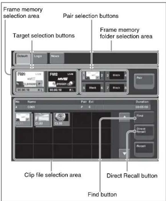
2 In the frame memory selection area, select an assigned target FM. (See page 203).
3 If [Direct Recall] is on, press the button, turning it off.
4 In the frame memory folder selection area, select the desired folder.
By pressing [More] to switch the displays, you can select from a maximum of 12 folders.
5 Using the arrow keys or turning the knob, scroll the file thumbnail display.
| Knob | Parameter | Adjustment | Setting values |
| 1 Scroll | Thumbnail | display scrolling | 1 and upwards |
6 Press the thumbnail of the clip you want to recall.
7 Press [Recall].
This recalls the clip file, which is assigned to the FM you selected in step 2.
In pair mode, if a clip is selected, the main file is output to FM1, and the sub file to FM2. In single mode, when only one of FM1 and FM2 is selected, the front file on the thumbnail is output.
To recall in direct recall mode
Direct recall means that pressing a thumbnail immediately recalls the file.
In this mode, only the front thumbnail file is recalled.
1 In step 7 above, instead of pressing [Recall], press [Direct Recall].
2 Press the thumbnail for the file you want to recall.
To display the subsidiary file in front
With the direct recall mode on, press [Sub Display], turning it on.
To search the clip file by file name
Press the [Find] button (see page 206).
Clip Playback
You can play a recalled clip by a menu operation or by using the device control block.
Notes
With a pair file recalled, it is possible to set [Pair] to Off and carry out a single file operation, but if you then set [Pair] to On again, the output of frame memory may be black. In such cases it is necessary to recall the pair file once more.
Playing a clip using the menu
1 In the Frame Memory menu, select VF2 'Clip' and HF2 'Play.'
The Play menu appears. The status of the clip shown in the current target FM selection buttons appears here.
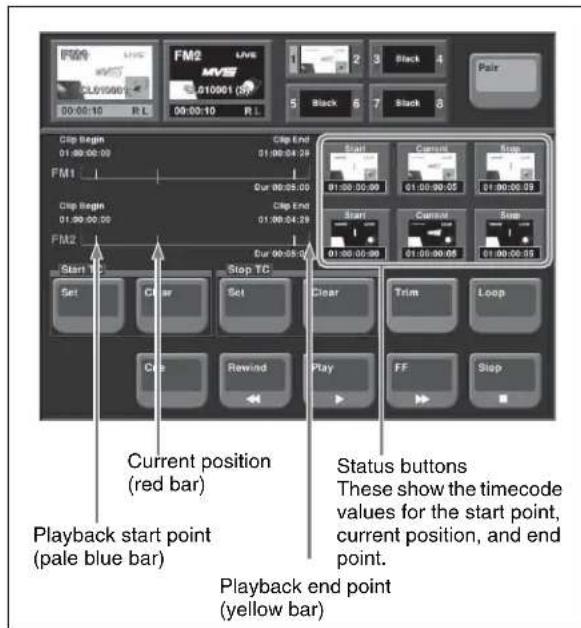
2 When [Pair] is Off, press a target FM selection button to select the target.
3 To set loop playback, press [Loop], turning it on.
4 To start playback, press [Play]. During playback, to stop, press [Stop].
To cue up
Press [Cue].
To play the image at the beginning of the clip (Clip Begin)
Press [Rewind].
To play the image at the end of the clip (Clip End) Press [FF].
To specify the playback start point
To set the current position as the playback start point, in the
To specify the playback stop point
Start playback, and at the desired position press the [STOP] button to stop playback, then in the
To change the current position
To change the current position, press the [Current] status button, and enter a timecode value from the numeric keypad window.
To delete the parts of a clip file other than the playback part (trimming)
1 Set the playback start point and stop point.
2 Press [Trim].
A confirmation message appears.
3 Press [Yes].
Using the device control block (search dial) to play back clips
Notes
A frame memory clip must first be recalled with a menu operation.
1 With the device selection buttons, select the frame memory clip to be played (FM1 CLIP to FM8 CLIP). If the pair mode is on, both main and subsidiary FMs light.
2 Press the [PLAY] button, turning it on.
To stop playback, press [STOP] or any of the [SHTL], [JOG], [CUE], [REW], [FF], and [ALL STOP] buttons.
For details of the buttons in the device control block (search dial), see “Device Control Block (Search Dial)” (page 46).
To specify the playback start point
To make the current position the playback start point, press the [START TC] button. To set a different position, press the [SET START TC] button, then enter the timecode from the numeric keypad control block.
To specify the duration
Press the [SET DUR] button, and enter a timecode from the numeric keypad control block. If the playback start point is already set, this automatically sets the playback stop point. If the playback stop point is already set, this automatically sets the playback start point. (The duration setting is not displayed in the device control block.)
To specify the playback stop point
Start playback, and at the desired position press the [STOP] button to stop playback, then press the [STOP TC] button. To set to any position, press the [SET STOP TC] button, and enter a timecode from the numeric keypad control block.
To carry out the variable speed playback
Use the search dial.
For details on using the search dial, see “Controlling the Tape/Disk Transport” in Chapter 12 (Volume 2).
To apply a loop to a frame memory clip
Press the [LOOP] button.
Using the device control block (trackball) or device control block (joystick) to play back clips
Notes
A frame memory clip must first be recalled with a menu operation.
1 Press the [DEV] button in the region selection buttons, and select the frame memory clip for playback (FM1 CLIP to FM8 CLIP).
If the pair mode is on, both main and subsidiary FMs light.
2 Press the [PLAY] button, turning it on.
To stop playback, press [STOP] or any of the [SHTL], [JOG], [CUE], [REW], [FF], and [ALL STOP] buttons.
For details of the buttons in the device control block (trackball) or device control block (joystick), see “Device Control Block (Trackball)” (page 42).
For details of the playback start point, stop point, and duration settings, see the previous item, "Using the device control block (search dial) to play back clips" (page 212).
To carry out the variable speed playback
Press any of the [SHTL], [JOG], and [VAR] buttons, then turn the Z-ring or move the joystick. The image changes in the forward direction when you turn the Z-ring clockwise, and in the reverse direction when you turn it counterclockwise. Move the joystick to the right for the forward direction and to the left for the reverse direction.
When you pressed the [JOG] button: Playback is at a speed corresponding to the turning speed of the Z-ring or the movement speed of the joystick.
When you pressed the [SHTL] button: Playback is at a speed corresponding to the rotation angle of the Z-ring or amount of movement of the joystick.
When you pressed the [VAR] button: Playback is at a speed corresponding to the rotation angle of the Z-ring or amount of movement of the joystick, in the range -1 to +3 times normal speed.
Clip Creation
You save a movie as a clip.
Notes
If the number of frame memory clips exceed 100 single files (50 pair files), an error appears.
Using the menu to record clips
1 In the Frame Memory menu, select VF2 'Clip' and HF3 'Record.'
The Record menu appears.
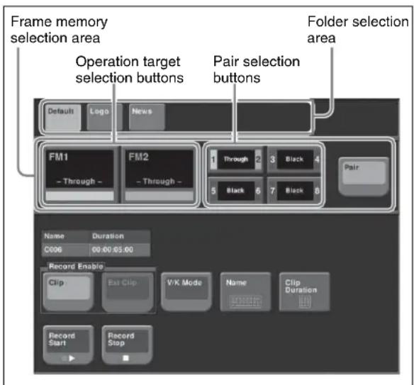
2 With [Pair] off, press the operation target selection button, to select the operation target.
3 In the folder selection area, select the folder containing the clip to be recorded.
4 In the
• To record a normal clip, press [Clip].
- To record an extended clip, press [Ext Clip].
5 To set the clip name, press [Name].
A keyboard window appears.
6 Enter the clip name, and press Enter.
7 To start recording, press [Record Start].
8 To end recording, press [Record Stop].
To set the clip duration
1 Press [Clip Duration].
A numeric keypad window appears.
2 Enter a timecode value or number of frames, and press Enter.
Creating and Handling Frame Memory Folders
You can create, rename, and delete frame memory folders.
Creating a new folder
1 In the Frame Memory menu, select VF5 'Folder.'
The Folder menu appears. The status area shows a list of the current folder settings.
2 Select [New].
A keyboard window appears.
3 Enter the folder name, and press Enter.
Changing the folder name
1 In the Frame Memory >Folder menu, select the folder with the arrow keys or by turning the knobs.
| Knob | Parameter | Adjustment | Setting values |
| 1 No. | Folder select | on 1 to 12 | |
| 2 Num | Number of files | to select consecutively from selected file | 1 to 12 |
2 Press [Rename].
A keyboard window appears.
3 Enter the new folder name, and press Enter.
Notes
The following names cannot be used for folders:
Default, Flash1, Flash2
CON, PRN, AUX, CLOCK\$, NUL, COM0,
COM1, COM2, COM3, COM4, COM5, COM6,
COM7, COM8, COM9
LPT0, LPT1, LPT2, LPT3, LPT4, LPT5, LPT6,
LPT7, LPT8, LPT9
This changes the folder name.
Deleting a folder
1 In the Frame Memory >Folder menu, select the folder with the arrow keys or by turning the knobs.
| Knob | Parameter | Adjustment | Setting values |
| 1 No. | Folder selecti | on 1 to 12 | |
| 2 Num | Number of f | les to select consecutively from selected file | 1 to 12 |
To select all folders, select [All].
2 Press [Delete].
A confirmation message appears.
3 To carry out the deletion select [Yes], and to cancel the deletion select [No].
Notes
It is not possible to delete the default folder (named "Default").
Clip Output
As for still image operation, you can use the reposition and lock functions.
For details of the operation, see “Image Output” (page 206).
Recording and Playback of Ancillary Data
Preparations
To record ancillary data, it is first necessary in the Setup menu to select “save with ancillary data” as the frame memory saving mode.
For details, see “Saving a Frame Memory Clip With Ancillary Data” in Chapter 18 (Volume 2).
Recording ancillary data
To record ancillary data in a frame memory clip, use the Frame Memory >Clip >Record menu.
For details of the operating sequence, see “Clip Creation” (page 213).
To check ancillary data during recording
If the ancillary data to be recorded is embedded audio, by first setting the signal output to through mode, you can listen while recording.
For the method of setting the signal output to through mode, see “Signal Output Settings (Output Menu)” in Chapter 20 (Volume 2).
Notes
For [Freeze Enable] or [Record Enable], in the
Playing back ancillary data
You can play ancillary data recorded in a frame memory clip by normal playback or an auto transition of the clip transition.
To play the ancillary data, you must use the following procedure to enable playback of the ancillary data.
For the subsequent playback operation, see “Clip Playback” (page 211).
Notes
• After recording a frame memory clip, the ancillary data state is enabled for playback.
- To play back the clip, set the signal output to through mode.
For the method of setting through mode, see “Signal Output Settings (Output Menu)” in Chapter 20 (Volume 2).
- When the reposition function is on, ancillary data cannot be played back.
- Switching reposition function between on and off may cause noise.
- Only the AUX bus and edit preview bus can output ancillary data.
- For loop playback of clips in the following video formats, the loop playback range must be at least 5 frames, and set to a multiple of 5 frames.
- 480i/59.94
-720P/59.94
- 1080i/59.94
1080PsF/29.97
- Recalling operations of still images or clips can cause noise.
- Carrying out file operations on a frame memory clip may result in the ancillary data being discontinuous, or in noise occurring. However, if the first or last frame of the clip is deleted, noise will not occur.
• The audio sampling frequency is always 48 kHz.
- In the case of 480i or 59.94, noise may occur at the beginning of playing back a clip. This can be avoided by making the first nine or more frames of the clip soundless.
- When you play back the recorded embedded audio, depending on the device to be used, noises are produced at the playback start point and end point. For details of devices that are used for playback, contact your Sony service or sales representative.
1 In the Frame Memory menu, select VF2 "Clip", HF5 "Ancillary Enable."
2 Select the frame memory folder and file to be played back.
3 Set the [Ancillary Enable] button to On.
Clip Transition Operations
A frame memory clip (movie) is played back, linked to a transition using a mix (dissolve) or wipe.
The following restrictions apply to the use of a clip transition.
• Key frame capture is not possible.
- It is not possible to apply a pattern limit.
• Transitions executed in two strokes, such as a preset color mix with the stroke mode set to Normal, or a DME wipe with a picture-in-picture pattern, will not execute correctly.
- It is not possible to vary the transition rate of a clip transition.
• Transition preview cannot be used.
- No instantaneous state of a clip transition can be saved as a snapshot.
- When recalling a snapshot including a clip transition during executing another clip transition, the follow-on transition does not operate properly. Be sure to complete the transition before recalling a snapshot.
Notes
When a clip transition is selected as the transition type, if one of the wipe direction selection buttons in the transition control block is lit, it indicates the direction of clip playback.
Setting a clip transition
The following example describes the case of a clip transition using FM 1&2 Clip on the M/E-1 bank.
Notes
To use a clip transition effectively, the image from the frame memory clip being played back during the clip transition should be seen in the M/E-1 program output. For example, inserting a key using frame memory output 1 and frame memory output 2.
1 Display the M/E-1 >Misc >Transition menu, and in the
2 Press [Clip Transition].
The Clip Transition menu appears.
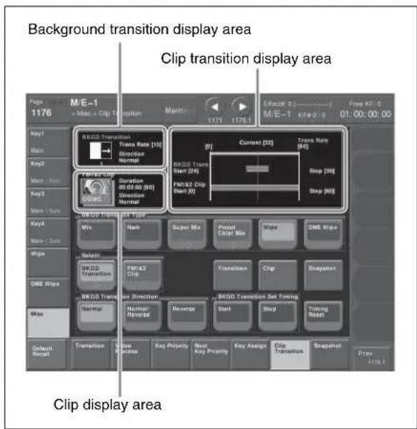
3 Press the [Clip] button.
The status area shows a list of clips.
4 Select the clip to use in the clip transition.
5 Return to the Clip Transition menu, and in the
Notes
For details of the background transition selected here, see the various adjustments in the M/E-1 >Misc >Transition menu.
6 In the
- Move the fader lever to the desired position, and in the
group press [Start]. - Turn knob 1 to set the number of frames. (The left end of the reference axis (see following figure) is the position of frame 0.)
![Position of frame 0 Reference axis Current [32] Trans Rate [50] BkgD Trans Start [24] Stop [39] FM1&2 Clip Start [0] Stop [60]](/content/2026/06/1364863/images/b6e2ec44a06e4e51d5d584eb5186a993293bbe4e875a6c5bbc6ab7c102e29dbc.jpg)
8 Using either of the following methods, set the end point of the background transition.
- Move the fader lever to the desired position, and in the
group press [Stop]. - Turn knob 2 to set the number of frames.
9 If Wipe or DME Wipe is selected in the
10 In the
- Move the fader lever to the desired start point, and in the
group press [Start]. - Turn knob 1 to set the number of frames. (The left end of the reference axis (see previous figure) is the position of frame 0.)
Notes
It is not possible to set the end point.
12 In the
To reset the start point and end point
Press [Timing Reset].
The background transition start point and end point, and the clip start point are all reset.
Image Data Management
You can carry out the following operations on the files in which images are saved.
• Pair File Processing (page 217)
- Moving Files (page 217)
- Deleting Files (page 218)
- Renaming Files (page 218)
Notes
During playback of a frame memory clip of the pair assigned to either of the target FM selection buttons (see page 211), frame memory operations may not be performed properly. Carry out frame memory operations after stopping clip playback.
Pair File Processing
You can create a pair file from two single files. In the reverse direction, you can split a pair file into two single files.
Couple: You can create a pair file from two single still image files or clip files.
Separate: You can also separate a pair file into two single still image files or clip files.
Creating a pair file from two single files
Notes
Carrying out the following operation automatically switches [Pair] to On.
The following description applies to the case of FM1&2, but the procedures are similar for the other cases.
1 In the Frame Memory >Still >Recall menu or Frame Memory >Clip >Recall menu, recall the two single files you want to convert to a pair file, to FM1 and FM2.
2 In the Frame Memory menu, select VF4 'File' and HF1 'Pair Recombination.'
The Pair Recombination menu appears.
3 Press [Couple].
Splitting a pair file into two single files
Notes
Carrying out the following operation automatically switches [Pair] to Off.
The following description applies to the case of FM1 and FM2, but the procedures are similar for the other cases.
1 In the Frame Memory >Still >Recall menu or Frame Memory >Clip >Recall menu, recall the pair file.
2 Select the folder in which the file to be moved is stored.
3 In the Frame Memory menu, select VF4 'File' and HF1 'Pair Recombination.'
The Pair Recombination menu appears.
4 Press [Separate].
Moving Files
1 In the Frame Memory menu, select VF4 'File' and HF4 'Move.'
The Move menu appears. The status area shows files to be moved in the upper area, and destination files in the lower area.
2 Select the folder which contains the file to be moved.
3 Using any of the following methods, select the file to be moved.
- Press the arrow keys to scroll the display.
- Press directly on the thumbnail in the status area.
- Turn the knobs.
- Press the arrow keys to scroll the display.
- Press directly on the thumbnail in the status area.
- Turn the knobs.
| Knob | Parameter | Adjustment | Setting values |
| 1 No File selection | 1 and upwards | ||
| 2 Num | Selection of | number of files in sequence | 1 and upwards |
4 Select the destination folder and file.
5 Press [Move].
6 To confirm the move press [Yes], and to cancel press [No].
Deleting Files
1 In the Frame Memory menu, select VF4 'File' and HF5 'Delete.'
The Delete menu appears. In the status area, whether pair mode is on or off, all of the saved files appear as thumbnails.
2 Select the folder which contains the file to be deleted.
3 Using either of the following methods, select the file to be deleted. If necessary, press the arrow keys to scroll the display.
- Press directly on the thumbnail in the status area.
- Turn the knobs.
| Knob | Parameter Adjustment Setting values | ||
| 1 No F | le selection | 1 and upwards | |
| 2 Num | Selection of | number of files in sequence | 1 and upwards |
- To delete all files, press [Select All], turning it on.
- When a clip thumbnail is selected, the still image files making up the clip are also selected for deletion.
4 If necessary, turn the knob to check the contents of the frame memory clip through the thumbnail display.
| Knob | Parameter Adjustment Setting values | ||
| 3 Viewer | For a movie, the current frame position. For a still image, no effect. | 00:00:00 and upwards | |
5 Press [Delete].
A message for confirming the deletion appears.
6 To confirm the deletion press [Yes], and to cancel press [No].
Renaming Files
1 In the Frame Memory menu, select VF4 'File' and HF6 'Rename'
The Rename menu appears. In the status area, whether pair mode is on or off, all of the saved files appear as thumbnails.
2 Using either of the following methods, select the file to be renamed. If necessary, press the arrow keys to scroll the display.
- Press directly on the thumbnail in the status area.
- Turn the knobs.
| Knob | Parameter | Adjustment | Setting values |
| 1 | No File selection | 1 and upwards |
3 If necessary, turn the knob check the contents of the frame memory clip through the thumbnail display.
| Knob | Parameter Adjustment Setting values | |
| 3 Viewer | For a movie, the current frame position. For a still image, no effect. | 00:00:00 and upwards |
4 Press [Rename].
A keyboard window appears.
5 Enter the new name, then press [Enter] in the keyboard window.
Notes
The following names cannot be used: CON, PRN, AUX, CLOCK\$, NUL, COM0, COM1, COM2, COM3, COM4, COM5, COM6, COM7, COM8, COM9 LPT0, LPT1, LPT2, LPT3, LPT4, LPT5, LPT6, LPT7, LPT8, LPT9
External Hard Disk Drive Access
You can connect a hard disk drive to the USB port of the switcher processor, to carry out the following operations.
Format: Format the hard disk.
Backup: Batch saving of files from frame memory to the hard disk.
Restore: Restoring frame memory from files saved on the hard disk.
Since image data saved in memory is lost when the system is powered off, using an external hard disk drive allows required data to be preserved.
Notes
- Only one hard disk drive can be connected to a single switcher processor.
- While the hard disk is being accessed, frame memory operations are not possible. This applies to all operations for frame memory including frame memory recall by a snapshot operation.
- During playback of a frame memory clip of the pair assigned to either of the target FM selection buttons (see page 211), frame memory operations may not be performed properly. Carry out frame memory operations after stopping clip playback.
- When the signal format is 1080P, this function cannot be used.
Consult your Sony service representative or sales representative about the hard disk drives that can be connected.
Hard Disk Formatting
When you connect a hard disk drive for the first time, it is necessary to format the hard disk. This partitions the disk, creating 15 logical areas (FMHDD1 to FMHDD15).
1 In the Frame Memory menu, select VF6 'External Device' and HF1 'Ext HDD Format.'
The Ext HDD Format menu appears.
To get the hard disk drive information
In the button area press [Refresh Status].
The Device item shows the product information for the hard disk drive.
2 Press [Format].
A popup window for confirming formatting appears.
Notes
Carrying out formatting erases any existing data on the hard disk.
3 Press [Yes].
This starts the hard disk formatting. A progress bar and numerical indication appear to show the progress of the operation.
When the operation is completed, a popup window reading “Success!!” appears.
4 Press [OK].
Saving Files
You can save all of the files from frame memory to the external hard disk drive.
Notes
Before carrying out this operation for the first time, it is necessary to format the hard disk (see previous item, "Hard Disk Formatting").
1 In the Frame Memory menu, select VF6 'External Device' and HF2 'Ext HDD Backup/Restore.'
The Ext HDD Backup/Restore menu appears. For each partition, a list of the directory names and number of files appears.
To get the hard disk drive information
Press [Refresh Status].
The Device item shows the product information for the hard disk drive, and the names of directories.
2 Using any of the following methods, select a logical drive (FMHDD1 to FMHDD15).
- Press directly on the list to select.
- Turn the knob.
| Knob | Parameter | Adjustment | Setting values |
| 1 Partition Partition | selection | 1 to 15 | |
3 In the
- To replace the existing data, press [Replace].
- To save in addition to the existing data, press [Append].
A popup window for confirming file saving appears.
Notes
When you execute [Replace], all of the saved files in the logical drive is erased immediately before the saving operations.
4 Press [Yes].
This starts the file saving operation. If there is no directory, a directory is automatically created, and the files are saved within it. A progress bar and numerical indication appear to show the progress of the operation. When the operation is completed, a popup window reading “Completed.” appears.
5 Press [OK].
To rename a directory
Select a directory in the list, and in the button area press [Rename].
In the keyboard window that appears, enter the new directory name, and press [Enter]. The name of a directory is limited to eight characters.
Notes
The following names cannot be used:
CON, PRN, AUX, CLOCK\$, NUL, COM0, COM1, COM2, COM3, COM4, COM5, COM6, COM7, COM8, COM9
LPT0, LPT1, LPT2, LPT3, LPT4, LPT5, LPT6, LPT7, LPT8, LPT9
Recalling Files
You can recall all of the saved files on the hard disk drive into frame memory.
1 Carry out steps 1 and 2 of the procedure “Saving Files” (page 219).
Notes
It is not possible to select a partition (FMHDD1 to FMHDD15) of a hard disk in which no file is saved.
2 In the group, do either of the following.
- To replace the existing data with the recalled data, press [Replace].
- To add the recalled data to the existing data, press [Append].
A popup window for confirming file recall appears.
Notes
When you execute [Replace], any existing data in frame memory is lost immediately before the recalling operations.
3 Press [Yes].
This starts the file recall operation. A progress bar and numerical indication appear to show the progress of the operation.
When the operation is completed, a popup window reading “Completed.” appears.
4 Press [OK].
Managing Images Using a DDR/VTR
Using a DDR/VTR for High-speed Backup and Restoring
You can save all files currently held in frame memory as a backup data set, by high-speed recording on video tape or other medium.
To restore the folder structure, it is necessary to save the automatically generated file list (of file name, length of clip, and so on) in memory.
Notes
At the beginning of this backup data a red or blue image is automatically inserted when the data is created. Do not delete this image, as it is required for restoring the data.
High-speed recording of backup data to DDR or VTR
Notes
Before starting the backup, it is necessary to select the FM output to record on an AUX bus, for example, and input the AUX output to the DDR/VTR.
1 In the Frame Memory menu, select VF6 'External Device,' and HF4 'Backup to DDR/VTR.'
The Backup to DDR/VTR menu appears.
2 To save with ancillary data, output the frame memory output signal to the AUX bus.
3 In the
Clip/Still: Data from the first board (still images and clips)
Ext Clip: Data from the second board (extended clips)
4 Press [Backup Start].
The message “Preparing now...” is displayed in a popup window, and it changes to a confirmation message when the preparation is complete.
5 Start recording at the external device, and immediately after that press [Yes].
This starts the backup, and when completed a message appears.
6 Stop the recording at the external device, and press the [OK] button.
7 To save the file list in memory, press [File >File Name Data].
The File >File Name Data menu appears.
The name of the file that is saved is fixed (FM_Bkup).
For details, see “Overview of File Operations” in Chapter 17 (Volume 2).
Restoring backup data from DDR or VTR
Notes
Before starting the restore operation, it is necessary to select the DDR/VTR output on the FM input bus.
1 In the Frame Memory menu, select VF6 'External Device' and HF5 'Restore from DDR/VTR.'
The Restore from DDR/VTR menu appears.
2 Press [File >File Name Data], to read the file list from the File Name Data menu.
For details, see “Overview of File Operations” in Chapter 17 (Volume 2).
3 To restore the ancillary data, select any of FM1, FM3, and FM5.
4 In the
Clip/Still: Data from the first board (still images and clips)
Ext Clip: Data from the second board (extended clips)
5 In the
Replace: Replace the existing frame memory data with the recalled data.
Append: Add to the existing frame memory data.
Notes
If you selected "Ext Clip" in step 4, "Append" is selected automatically.
A confirmation popup window appears.
7 Start playback at the external device, and immediately after that press [Yes].
Notes
Make sure to include that the red or blue image inserted at the beginning when the backup was made. If this image is not found, the clip or still image will not be played back correctly.
This starts the restore operation, and when completed a message appears.
8 Stop the playback at the external device, and press the [OK] button.
Extracting Images from Video Tape
By recording a clip or still image stored on a video tape as a single clip (single file) under certain rules, you can automatically extract an image from the clip, and save as a separate frame memory file.
Notes
When the signal format is 1080P, this function cannot be used.
Relation between recorded state of video tape and files after extraction
The extraction is carried out according to the following rules.
Example 1: When only video signal clips and a still image are recorded (single files)
V: video
Red: red marker frame a)
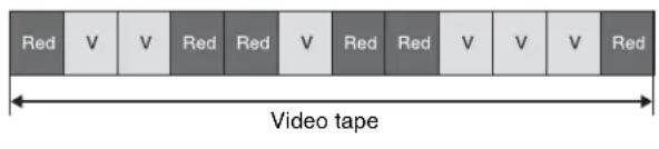
Result of extraction:
Each section surrounded by red marker frames is extracted as a clip (main file). If the red markers surround a single frame, then it is extracted as a still image. In the case above two clip files (main files) are extracted, and one still image file.
Example 2: When a video signal clip is followed by a key signal clip with the same number of frames (pair file)
V: video
K: key
Red: red marker frame a)
Blue: blue marker frame b)
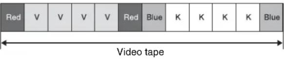
Result of extraction:
The section surrounded by red marker frames is extracted as the main file, and the section surrounded by blue marker frames is extracted as the sub file.
In the case above, one clip file (pair file) is extracted.
a) A red marker frame is a monochrome frame with the RGB signal levels respectively 100%, 0%, 0%.
b) A blue marker frame is a monochrome frame with the RGB signal levels respectively 0%, 0%, 100%.
Notes
- For extraction as a pair file, the main file and sub file must have the same number of frames.
- For image extraction as an extended clip, [Ext Clip] must be selected in the Record menu
group when the video tape content is recorded as a clip. - For image extraction as still images, [Clip] must be selected in the Record menu
group when the video tape content is recorded as a clip.
1 In the Frame Memory >Clip >Record menu, record the tape image as a clip (see page 213).
2 In the Frame Memory menu, select VF4 'File' and HF2 'Auto Extraction.'
The Auto Extraction menu appears.
3 Select a clip (single file) recorded from the tape.
4 Press [Extraction Start].
A confirmation popup window appears.
5 Press [Yes].
This starts the extraction, analyzes the currently selected single clip, and automatically extracts a movie (Clip) or still image (Still). When there is key data, a pair file is created.
To check the details of the images (still image/clip)
Use the following knob operations.
| Knob | Parameter | Adjustment Setting | values |
| 1 No. | File number 1 | to maximum | |
| 3 Viewer | Timecode | forselected image | 00:00:00 tomaximum |
Color Backgrounds, Copy and Swap, and Other Settings
Chapter
8
Color Background
The dedicated generators generate color signals, and these can be used as color backgrounds in video effects.
Color background selection
There are two color backgrounds, color background 1 and color background 2, which you use by assigning to cross-point buttons.
Color combinations ("color mix")
The color generators can output the result of combining two colors, which are color 1 and color 2.
Using a pattern from a dedicated pattern generator, color 1 and color 2 can be combined in the boundary region, forming a color gradation. This is referred to in the menu system as “color mix.”
You can also apply modifiers to the selected pattern.
When the “color mix” function is not used, the result is a flat color, and color 1 is always output.
You carry out color background settings in the Color Bkgd menu. This section describes the settings menu for color background 1 as an example.
Color Background Settings Menu
Accessing the Color Bkgd1 menu
Use either of the following operations.
- In the menu control block, select the top menu selection button [COLOR BKGD], and press VF1 'Color Bkgd1.'
- Press a cross-point button assigned to color background 1 twice in rapid succession.
Basic Color Background Setting Operations
Making a single-color matte (Flat Color)
If you are not using the “color mix” function to combine two colors, use the following procedure.
1 In the
2 Set the following parameters.
| Knob | Parameter | Adjustment | Setting values |
| 1 | Luminance | Luminance | 0.00 to 100.00 |
| 2 | Saturation | Saturation | 0.00 to 100.00 |
| 3 | Hue | Hue | 359.99 to 0.00 |
Making a color combination (color mix)
To combine color 1 and color 2, use the following procedure.
1 In the
2 Set the following parameters as required.
| Knob | Parameter | Adjustment | Setting values |
| 1 | Size | Pattern size | 0.00 to 100.00 |
| 2 | Soft | Degree of softening of edge | 0.00 to 100.00 |
| 5 | Pattern | Pattern number | 1 to 24a) |
a) The patterns are the same as for a standard wipe. See "Wipe Pattern List" (page 351).
You can also carry out the pattern selection by pressing the [Mix Ptn Select] button, to display the Mix Ptn Select menu. Select any pattern appearing in
the Mix Ptn Select menu (standard wipe patterns 1 to 24), and you can then adjust the following parameters.
| Knob | Parameter | Adjustment Setting | values |
| 1 Size | Pattern size | 0.00 to 100.00 | |
| 2 Soft | Edge softness | 0.00 to 100.00 |
3 To adjust color 1, set [Color 1] on, and to adjust color 2 set [Color 2] on, then adjust the parameters.
| Knob | Parameter | Adjustment Setting | values |
| 1 | Luminance | Luminance 0.00 to 100.00 | |
| 2 | Saturation | Saturation 0.00 to 100.00 | |
| 3 | Hue | Hue | 359.99 to 0.00 |
4 If required, set the pattern modifiers.
When turning [Position] on and setting the pattern position
| Knob | Parameter | Adjustment Setting | values |
| 1 | Position H | Horizontal position | -200.00 to +200.00^a) |
| 2 | Position V | Vertical position | -200.00 to +200.00^a) |
a) See page 165.
When turning [Multi] on and using replications of the same pattern
| Knob | Parameter | Adjustment Setting | values |
| 1 H Multi | Number of repetitions of pattern horizontally | 1 to 63 | |
| 2 V Multi | Number of repetitions of pattern vertically | 1 to 63 | |
| 3 Invert | Type Replication layout | 1 to 4a) | |
a) See page 167.
When turning [Aspect] on and setting the aspect ratio of the pattern
| Knob | Parameter | Adjustment | Setting | values |
| 1 Aspect | Aspect ratio | -100.00 to +100.00a) | ||
a) See page 167.
When turning [Pairing] on and making a wipe pattern like a Venetian blind
| Knob | Parameter | Adjustment Setting | values |
| 1 Width | Width | of the slits 1 to 128 (integer) |
When turning [Angle] on in the
| Knob | Parameter | Adjustment Setting | values |
| 1 Angle | Angle | of pattern rotation | -100.00 to +100.00^a) |
a) See page 166.
When turning [Speed] on in the
| Knob | Parameter | Adjustment Setting | values |
| 1 Speed | Rotation rate of pattern | -100.00 to +100.00a) | |
a) See page 166.
When selecting H (horizontal) or V (vertical) in the
(The modulation is always a sine wave.)
Notes
When using 1080PsF mode in an HD system, the modulation function is not available.
| Knob | Parameter | Adjustment Setting | values |
| 1 | Amplitude | Amplitude of modulation | 0.00 to 100.00 |
| 2 | Frequency | Frequency of modulation | 0.00 to 100.00 |
| 3 | Speed | Speed of waves -100.00 | 0 to +100.00a) |
a) See “Applying modulation to the wipe pattern (Modulation)” (page 168).
5 To interchange color 1 and color 2, press the [Color Invert] button, turning it on.
Copy and Swap
Overview of Copy and Swap
You can copy or swap the settings among the switcher banks or between keyers.
The following settings can be copied or swapped.
- Overall settings for the M/E-1 to M/E-4, and PGM/PST banks
- Keyer settings
- Wipe settings in a transition control block
- Wipe settings in an independent key transition control block
- DME wipe settings in a transition control block
- DME wipe settings in an independent key transition control block
- Matte data (color 1, color 2, and how to compose them)
- Color settings
• DME channel settings - Format converter input settings (copy only)
- Format converter output settings (copy only)
You can carry out copy operations with a simple button operation. Swap operations, and copy operations on DME data can only be done with a menu operation.
M/E copy and M/E swap
You can copy and swap the overall bank settings among the M/E-1 to M/E-4, and PGM/PST banks.
| Target bank | Target data |
| M/E-1M/E-2M/E-3M/E-4PGM/PST | Bank settings excluding the following data items:Setup dataFlexi Pad settingsSnapshotsKeyframe effectsKey snapshotsKey memory |
Notes
If a DME is being used on the source M/E bank, then if for example there are insufficient DME channels, it may not be possible to select the DME.
There are no such restrictions on a swap.
Keyer copy and keyer swap
You can carry out copy and swap operations among the keyers listed in the following table.
| Target bank | Target keyer Target data | |
| M/E-1M/E-2M/E-3M/E-4 | Keys 1 to 8 Key settings | excluding the following data items:• Setup data• Key snapshots• Key memory |
| PGM/PST | Downstream keys 1 to 8 |
Notes
If a DME is being used on the source keyer for a copy or either keyer for a swap, then if for example there are insufficient DME channels, or the limit on using DME channels within an M/E bank is exceeded, it may not be possible to select the DME.
Wipe copy and wipe swap
You can copy and swap the wipe settings among the banks listed in the following table.
| Target bank | Target data |
| M/E-1 | Wipe settings. |
| M/E-2 | It is not, however, possible to carry out copy or swap involving independent key transition wipe settings. |
| M/E-3 | |
| M/E-4 | |
| PGM/ | |
| PST |
Wipe copy and wipe swap in the independent key transition control block
You can copy and swap the wipe settings among the keyers listed in the following table.
| Target bank | Target keyer Target data | |
| M/E-1M/E-2M/E-3M/E-4 | Keys 1 to 8 Wipe settings | in the independent key transition control block. |
| PGM/PST | Downstream keys 1 to 8 |
DME wipe copy and DME wipe swap
You can copy and swap the DME wipe settings among the banks listed in the following table.
| Target bank | Target data |
| M/E-1 | DME wipe settings. |
| M/E-2 | It is not, however, possible to carry out copy or swap involving independent key transition DME wipe settings. |
| M/E-3 | |
| M/E-4 | |
| PGM/ | |
| PST |
DME wipe copy and DME wipe swap in the independent key transition control block
You can copy and swap the DME wipe settings among the keyers listed in the following table.
| Target bank | Target keyer Target data | |
| M/E-1 | Keys 1 to 8 | DME wipe settings in the independent key transition control block. |
| M/E-2 | But excluding keys 5 to 8 | |
| M/E-3 | on M/E-4 In the MVS-8000X | |
| M/E-4 | ||
| PGM/PST | Downstream keys 1 to 8 |
Matte data copy and swap
You can copy or swap the matte data among the color generators listed in the following table.
| Target bank | Target keyer and data | |
| M/E-1M/E-2M/E-3M/E-4PGM/PST | • K e y s 1 to• Downstream keys 1 to 8 | • Matte data for key fill• Matte data for key edge fill |
| Matte data for wipe border edge | ||
| Color background | • Matte data for color background 1• Matte data for color background 2 | |
Color data copy and swap
You can copy or swap the color data among the color generators listed in the following table.
| Target bank | Target keyer and data | |
| M/E-1M/E-2M/E-3M/E-4PGM/PST | • K e y s 1 to• Downstream keys 1 to 8 | • Colors 1 and 2 for key fill• Colors 1 and 2 for key edge fill• “Zabton” color data |
| Colors 1 and 2 for wipe border | ||
| Color data for preset color mix | ||
| Color background | • Colors 1 and 2 for color background 1• Colors 1 and 2 for color background 2 | |
| Frame memory | • F M 1 c o l or• F M 2 c o l or | |
| DME ch1 to ch8 | • B a c k g r o u n d• Border• Sepia• L i g h t• Shade• Drop shadow (other than DME ch4 and DME ch8)• T r a i l | |
DME channel copy and swap
You can copy and swap the channel data among DME channels 1 to 4 or DME channels 5 to 8. It is not possible to copy or swap the channel data between DME channels 1 to 4 and DME channels 5 to 8.
Notes
On the MVS-8000X, when the signal format is 1080P, the combinations for a copy or swap are restricted as follows.
- Channels 1 and 2
- Channels 3 and 4
- Channels 5 and 6
- Channels 7 and 8
On the MVS-7000X, when the signal format is 1080P, the above restriction also applies if using the MVE-8000A. There is no such restriction for the MKS-7470X/7471X.
Copying format converter data
You can copy data from one format converter input to another or from one output to another.
Notes
The copy source and destination data must be in the same signal format.
Copy and Swap Operations
Copy and Swap Menu Operations
In the menu operation section top menu selection buttons, press the [Copy/Swap] button, then press VF1 'Copy/Swap.' The Copy/Swap menu appears.
Here a copy/swap operation on wipe data is described by way of example, using the Copy/Swap >Wipe menu, but the same general procedure applies to all of the following menus.
• M/E: Copying and swapping M/E data
• Key: Copying and swapping key data
- Wipe: Copying and swapping wipe data
• DME Wipe: Copying and swapping DME wipe data
- Matte: Copying and swapping matte data
• Color: Copying and swapping color data
• DME: Copying and swapping data by DME channels
- Format Converter: Copying format converter data For an overview of the concepts involved, see “Copy and Swap” (page 226). For details of color corrector copy and swap, see “Copy and Swap Operations” (page 236).
Examples of Copy and Swap Operations by a Menu Operation
As an example, to copy or swap wipe data, use the following procedure.
1 In the Copy/Swap menu, select HF3 'Wipe.'
The Copy/Swap >Wipe menu appears.
The status area shows lists for the copy/swap source on the left, and the copy/swap destination on the right.
2 In the group, select either of the following.
Wipe: The operation applies to wipes in the transition control block.
Key Wipe: The operation applies to wipes in the independent key transition control block.
3 Using any of the following methods, select the data to be copied or swapped.
- Press directly on the list in the status area.
- Press the arrow keys to scroll the reverse video cursor.
- Turn the knobs to make the setting.
| Knob | Parameter | Adjustment Setting | values |
| 1 Left | No Select data for copy/swap source | 1 to 5 a)1 to 40 b) | |
| 2 Right | No Select data for copy/swap destination | 1 to 5 a)1 to 40 b) | |
a) Transition control block wipe data
b) Independent key transition control block wipe data
For details of the data affected, see “Copy and Swap” (page 226).
4 To copy, press [Copy], and to swap, press [Swap].
To undo a copy or swap
Press [Undo], to return to the state before the copy or swap was carried out.
Copy by Button Operation
You can carry out the following copy operations by a simple button operation.
• M/E copy
- Keyer copy
- Wipe copy
- DME wipe copy
Notes
On the CCP-6224/6324, it is not possible to carry out a copy by button operation.
Basic button operation
The basic button operation is to hold down the copy source button, then press the destination button.
You can undo the last operation using [Undo] in the menu (see page 228).
M/E copy button operation
In the Flexi Pad control block of each M/E bank, use the [SNAPSHOT] button.
To copy from M/E-1 to M/E-2
In the M/E-1 Flexi Pad control block, hold down the [SNAPSHOT] button, then press the [SNAPSHOT] button in the M/E-2 Flexi Pad control block.
Keyer copy button operation
To specify the copy source, use the key delegation buttons in the key control block, and to specify the copy destination, use the key delegation buttons in the independent key transition control block.
To copy from M/E-1 key 1 to M/E-2 key 2
In the key control block M/E delegation buttons, press [M/E1], turning it on, then hold down the [KEY1] button, and in the M/E-2 independent key transition control block, press the [KEY2] button.
Wipe copy button operation
Use the [WIPE] button in the Flexi Pad control block of each M/E bank.
To copy the M/E-1 wipe to the M/E-2 wipe
In the M/E-1 Flexi Pad control block, hold down the [WIPE] button, then press the [WIPE] button in the M/E-2 Flexi Pad control block.
DME wipe copy button operation
Use the [DME] button in the Flexi Pad control block of each M/E bank.
To copy the M/E-1 DME wipe to the M/E-2 DME wipe
In the M/E-1 Flexi Pad control block, hold down the [DME] button, then press the [DME] button in the M/E-2 Flexi Pad control block.
Misc Menu Operations
In the Misc menu, you can carry out the following operations.
- Enabling and disabling operation from an external device, System Manager, or an editing keyboard.
- Enabling and disabling side flags on the background bus of each of the M/E-1 to M/E-4 and PGM/PST banks. For the side flag function, see “Side Flags” (page 245).
- Switching the safe title function on or off for each switcher output.
- Displaying the transition rate, independent key transition rate, and fade-to-black transition rate for each of the M/E and PGM/PST banks, and changing the settings.
Port Settings for Control From an External Device
Enabling or disabling control from an external device
1 In the menu control block, press the top menu selection button [MISC], then select VF1 'Enable' and HF1 'Port Enable.'
The Misc >Enable >Port Enable menu appears with the status area showing the settings of the following ports.
- Switcher Remote1 to Remote4 ports (RS-422A, D-sub 9-pin)
- Switcher GPI port (parallel, 25-pin)
• DME1/DME2 Editor ports (RS-422A, D-sub 9-pin)
• DME1/DME2 GPI ports (parallel, 25-pin)
When the signal format is 1080P, you can also make settings for DME3/DME4.
2 In the
To re-enable control for the port, press on its name once more.
Notes
For the AUX bus operation from the Remote 1 to Remote 4 ports of the switcher, the setting (Enable/Disable/Manual) in the Setup menu takes precedence. Only when the setting is “Manual,” the settings made in the Port Enable menu apply.
For details, see “Interfacing With External Devices (Device Interface Menu)” in Chapter 19 (Volume 2).
DME override
1 In the menu control block, press the top menu selection button [MISC], then select VF1 'Enable' and HF1 'Port Enable.'
The Misc >Enable >Port Enable menu appears.
2 In the
DME Override: When a switcher snapshot or effect using a DME is recalled, forcibly select the DME that was used when saving.
On Air Protect: The operation is the same as the DME override function, except that a DME being used by an M/E bank or P/P bank that is on air will not be forcibly selected.
Notes
If effects using the same DME channel are selected simultaneously in two or more regions, the DME is selected with the order of precedence P/P >M/E1 >M/E2 >M/E3 >M/E4.
Enabling or disabling control from System Manager
By installing the BZPS-8000 System Management Software (System Manager), you can use a computer connected on a network for management of some switcher data and control operations.
To enable or disable this function, use the following procedure.
1 In the menu control block, press the top menu selection button [MISC], then select VF1 'Enable' and HF1 'Port Enable.'
The Misc >Enable >Port Enable menu appears.
2 Press [System Manager].
Each time you press the button toggles between enable and disable.
Editing Keyboard Settings
Notes
The following operations are only possible when a license for the BZS-8050 Editing Control Software is activated.
For details of license registration, see “Installation and Device Setup (Install/Unit Config Menu)” in Chapter 18 (Volume 2).
Enabling or disabling control from the editing keyboard
1 In the menu control block, press the top menu selection button [MISC], then select VF1 'Enable' and HF2 'Plug-In Editor.'
The Misc >Enable >Plug-In Editor menu appears.
2 In the
Each time you press the button toggles between enable and disable.
To enable control of the preview bus only
When control from the editing keyboard is disabled (when [Editor Enable] is set to Disable), to enable control of the preview bus only, press [PVW Bus Enable] in the
Safe Title Settings
Switching the safe title function on or off
1 In the menu control block, press the top menu selection button [MISC] and select VF2 'Safe Title.'
The Misc >Safe Title menu appears.
2 Using any of the following methods, select the signal to which the settings apply.
- Directly press the list in the status area.
- Press the arrow keys to scroll the reverse video cursor.
- Turn the knob to make the setting.
| Knob | Parameter | Adjustment Setting | values |
| 1 | Output Signal to which the settings apply | 1 to 48 | |
Notes
- It is not possible to change the setting for the output for which the safe title is set off in a Setup menu.
- The safe title function cannot be used for output signals for which through mode is set to Enable in a Setup menu.
For more information about the Setup menu settings referred to above, see “Signal Input Settings (Input Menu)” and “Signal Output Settings (Output Menu)” in Chapter 20 (Volume 2).
3 Press [Safe Title] to set it on or off.
Displaying a List of Transition Rates and Changing the Settings
In the Transition menu, for each bank you can display a list of the M/E (or PGM/PST) transition rates and independent key (or DSK) transition rates, and change the settings.
These settings are linked to the other transition rate setting operations.
You can also display and set the fade-to-black transition rate.
Displaying the Transition menu
In the menu control block, press the top menu selection button [MISC], then select VF3 'Transition.'
The Misc >Transition menu appears.
About the Transition menu display
The display of the independent key transition rate in the Misc >Transition menu depends on the selection in the
When [Same] (On direction and Off direction settings the same) is selected in the
When [Independ] (On direction and Off direction settings independent) is selected in the
For details, see “Settings Relating to Video Switching (Transition Menu)” in Chapter 20 (Volume 2).
Setting the transition rate in the Transition menu
To set the M/E transition rate
For example, to make the settings for the M/E-1 bank, use the following procedure.
1 Press in the list in the status area of the Misc >Transition menu, to select M/E-1.
2 In the
3 Turn the knob to set the number of frames.
| Knob | Parameter | Adjustment | Setting values |
| 1 | T r Rate | Transition rate 0 tos999 i t (frames) |
Notes
When a clip transition is selected as the transition type, it is not possible to change the transition rate in this menu.
To set the independent key transition rate
By way of example, the following is the procedure for settings of keys 1 to 4 in the M/E-1 block.
1 Press in the list in the status area of the Misc >Transition menu, to select M/E-1.
2 In the
3 Turn the knobs to set the number of frames.
| Knob | Parameter | Adjustment Setting | values |
| 1 Key1 | Trans Rate | Key 1 transition rate | 0 to 999 (frames) |
| 2 Key2 | Trans Rate | Key 2 transition rate | 0 to 999 (frames) |
| 3 Key3 | Trans Rate | Key 3 transition rate | 0 to 999 (frames) |
| 4 Key4 | Trans Rate | Key 4 transition rate | 0 to 999 (frames) |
To set the fade-to-black transition rate in the Transition menu
1 In the Misc >Transition menu, press [FTB].
2 Turn the knob to set the number of frames.
| Knob | Parameter | Adjustment Setting | values |
| 1 Transition Rate | Transition rate 0 | to 999 (frames) | |
AUX Menu Operations
AUX Bus Settings
Making video process settings for an AUX bus
1 In the Aux >Aux Bus menu, using any of the following methods, select the AUX bus to which the settings apply.
- Directly press the list in the status area.
- Press the arrow keys to scroll the reverse video cursor.
- Turn the knob to make the setting.
| Knob | Parameter Adjustment Setting values | ||
| 1 AUX | Bus AUX bus selection | 1 to 48 | |
2 Press [Video Process], turning it on.
3 Adjust the following parameters.
| Knob | Parameter | Adjustment Setting | values |
| 1 Video Gain | Video signal gain | -200.00 to +200.00 | |
| 2 Y Gain | Luminance | signal gain | -200.00 to +200.00 |
| 3 C Gain | Chrominance | signal gain | -200.00 to +200.00 |
| 4 Hue | Delay Hue delay | -180.00 to | +180.00 |
| 5 | B I Level | Black level e-7.31 | tk +109.59 |
To return adjustment values to their defaults, press [Unity].
Status Menu
The Status menu shows the following information.
- Operating status of the DME
Viewing the DME operating status
To view the DME operating status, press the top menu selection button [STATS] in the menu control block. This selects VF1 'DME Status' and the Status menu appears.
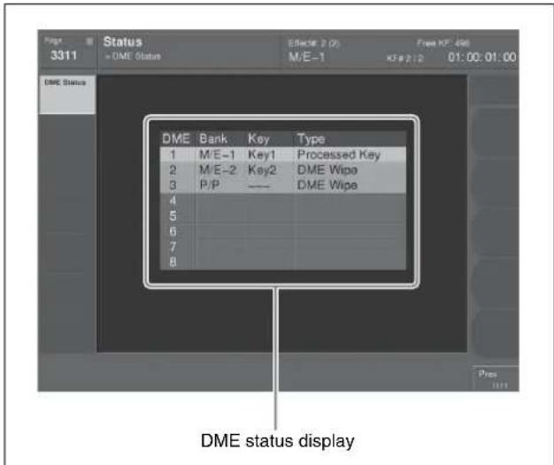
For each DME channel, you can see how the DME is being used in the corresponding operation block.
The display background color also indicates the following differences in the way in which a DME is being used.
Blue: The DME is currently being used in other than the final program output.
Red: The DME is currently being used in the final program output.
Router Control Menu Operations
Using the Router >Router Control >Router Control menu, you can carry out router switching operations.
Checking the List of Inputs for Each Destination
You can check the list of signals currently input for each destination.
In the menu control block, press the top menu selection button [RTR], then select VFI 'Router Control' and HFI 'Router Control.'
The following menu appears, and the left side of the status area shows a list for destination assignments.
![Dest Btn # Protect Dest Name Src Name 10 OUT[0010] 11 OUT[0011] 12 OUT[0012] 13 OUT[0013] 14 OUT[0014] 15 OUT[0015] 16 OUT[0016] 17 OUT[0017] 18 OUT[0018] 19 OUT[0019] 20 OUT[0020] 21 OUT[0021] 22 OUT[0022] 23 OUT[0023] 24 OUT[0024] Level Btn # Level Assign 1 1---- 2 -2---- 3 --3---- 4 --4---- Level Button No Change Xpl Level 1 Level 2 Level 3 Level 4](/content/2026/06/1364863/images/23b9fedd6b05649be08205b7ca1ba6838ba125034f3a169bd48b986570911c13.jpg)
If in the Assign >RTR Mode Setting menu, [Inhibit] is set to On for a destination, the corresponding line appears in gray. Also, if [PROT] (protect) is set to ON for a source, using a BKSR3xxx or R1xxx series Router remote control, a padlock icon appears.
The right side of the status area shows the level assignment status to the Level 1 to Level 4 buttons.
Selecting the level
In the
Switching the Source for Each Destination
You can switch the source for each destination with a menu operation.
For the assignment of destinations and sources to buttons, use the Setup >Panel >Aux Assign >RTR Mode Setting menu.
For details, see “Using the Auxiliary Bus Control Block for Router Control” in Chapter 19 (Volume 2).
1 Press [Change Xpt].
The Router >Router Control >Router Control >Change Xpt menu appears.
Destination Select buttons appear in groups of 16. Source Select buttons appear by group (maximum 24 buttons).
2 Press one of the Destination Select buttons, to select the destination for which you want to switch the source.
To change the group
Press one of the [1-16], [17-32], [33-48], and [49-64] buttons.
3 Press one of the Source Select buttons, to select the source you want to switch.
To change the group
Press one of the [1-24], [25-48], ... [97-120], and [121-128] buttons.
Video Process
The term “video process” is applied to adjustments to the luminance and hue of the input video signal.
There are two types of adjustment, depending on the application:
- Adjustment of an individual input signal
• Image effects on a particular bus
Notes
These types of adjustment may be carried out independently. However, since they are implemented by the same hardware, if the same signal is subjected to processing twice, there may be limitations on the range of effects obtained in the final result.
Video Process Adjustments for Each Input Signal
For each signal input to the switcher, you can set video process on or off and set the parameters (Video Gain, Y Gain, C Gain, Hue Delay, and Black Level) in the Setup menu.
For details of the settings, see “Signal Input Settings” in Chapter 20 (Volume 2).
Video Process Adjustments on a Particular Bus
Buses to which the adjustments apply
For each of the following buses, you can switch video process adjustments on or off, and adjust the parameters.
- Following buses in the M/E-1 to M/E-4, and PGM/PST banks
- Key fill buses for keys 1 to 8
- Background A and background B buses
- Utility 1 and utility 2 buses
• Frame memory source 1 and frame memory source 2 buses
- Aux 1 to 48 buses
These settings also apply to keyframes and snapshots.
Making the adjustments
Adjust VIDEO GAIN, Y GAIN, BLACK LEVEL, C GAIN, and HUE DELAY in the following menus.
| Applicable bus Menu used for operation | See page | |
| M/E-1 to M/E-4 banks | Key fill buses for keys 1 to 8 | M/E-1 to M/E-4 menus |
| Background A and B buses | Video Process menu | |
| Utility 1 and 2 buses | ||
| PGM/PST bank | Key fill buses for DSK1 to DSK8 | PGM/PST menu page 137 |
| Background A and B buses | Video Process menu | |
| Utility 1 and 2 buses | ||
| Frame memory source 1 and 2 buses | Frame Memory menu | |
| Aux 1 to 48 buses AUX menu page | 231 | |
Video Process Memory
When using video process adjustments for an image effect on a bus, this function saves the final values for each pair number for the signals. The video process on/off setting is not saved.
When you change the adjustments the values are automatically saved, and these last values are recalled when the pair number is selected.
In other words, by switching video process memory on, regardless of the video process information for each bus, you can carry out video process adjustments for each input signal.
The parameters saved are as follows. VIDEO GAIN, Y GAIN, BLACK LEVEL, C GAIN, HUE DELAY
Switch the video process memory on or off in the Setup menu.
For details of setting operations, see “Settings Relating to Keys, Wipes, Frame Memory and Color Correction (Key/Wipe/FM/CCR Menu)” in Chapter 20 (Volume 2).
Video Process Settings
This section describes operations on the M/E-1 to M/E-4, and PGM/PST background A and B buses, and utility buses 1 and 2.
For these operations, use the Misc >Video Process menu in the respective operating bank.
For video process settings on other buses, see the following.
- Settings for a particular input signal: "Signal input settings" in Chapter 20 (Volume 2)
• Key fill bus settings: "Video Processing" (page 137) - Settings for frame memory source buses 1 and 2: "Setting video processing" (page 204)
- Settings for Aux 1 to 48 buses: "Making video process settings for an AUX bus" (page 231)
- Overview of video process: "Video Process" (page 233)
This section describes an example on the background A bus of the M/E-1 bank.
For the background B bus or utility bus 1 or 2, make the adjustment with a similar procedure.
Making video process settings for each bus
1 In the menu control block, press the top menu selection button [M/E1] and select VF7 'Misc' and HF2 'Video Process.'
2 In the
3 Adjust the following parameters.
| Knob | Parameter | Adjustment | Setting values |
| 1 Video Gain | Video signal gain | -200.00 to +200.00 | |
| 2 Y Gain Luminance | signal gain | -200.00 to +200.00 | |
| 3 C Gain Chrominance | signal gain | -200.00 to +200.00 | |
| 4 Hue Delay Hue delay -180.00 to | +180.00 | ||
| 5 | B | Level | Black level c | +7.31 to +109.59 |
To return the parameter settings to the defaults, press [Unity] in the
Color Corrector
Chapter
9
Preparations
The color corrector enables video signal color correction (black balance/white balance adjustment, gamma correction, knee correction, etc.).
Notes
To use the color corrector, the BZS-8420X (for MVS-8000X) or the BZS-7420X (for the MVS-7000X) Color Corrector Software. To use the software, you are required to input an install key.
For the method of inputting an install key, see "Installation and Device Setup (Install/Unit Config Menu)" in Chapter 18 (Volume 2).
Restrictions on color corrector and M/E combination
| Signal format | When the color corrector output is selected | When the color corrector output is not selected | |
| 3M/E system 4M | M/E system/5M/E system | 4M/E system/5M/E system | |
| Other than 720P | - Re-entry signal selection on a key bus or the utility 1 bus cannot be performed over a cascade of two or more M/E blocks. (Restriction 2) | - | |
| 720P Re-entry signal selection on a key bus or the utility 1 bus cannot be performed over a cascade of two or more M/E blocks. (Restriction 2) | Re-entry signal selection on a key bus or the utility 1 bus cannot be performed. (Restriction 1) | Re-entry signal selection on a key bus or the utility 1 bus cannot be performed over a cascade of three or more M/E blocks. (Restriction 2) | |
Example of restriction 2: When M/E-1 is selected on the M/E-2 background A bus (or background B bus, key bus, or utility 1 or 2 bus), then M/E-2 cannot be selected on the M/E-3 key bus or the utility 1 bus.
Assigning the color corrector input buses to AUX delegation buttons
There are two inputs for capturing material to the color corrector: the CCR1 bus and the CCR2 bus.
For details of the input assignment operation, see "Auxiliary Bus Control Block Settings (Aux Assign Menu)" in Chapter 19 (Volume 2).
Selecting the color correction input signal
After assigning CCR1 and CCR2 to AUX buses, use the following procedure.
1 Press the AUX delegation buttons assigned to CCR1 (or CCR2).
2 In the cross-point button row, select the signal to which you want to apply color correction.
Notes
The signals that can be selected on the CCR1 and CCR2 buses are primary inputs, premium inputs, format converter inputs and frame memory outputs (FM1 to FM8) only.
However you can make all the internal signals of the switcher selectable by a setting in the Setup menu.
For details, see “Selecting the Bank to Make the Settings” in Chapter 20 (Volume 2).
Selecting the color corrector output signal
By assigning the signal output from the color corrector to a cross-point button, you can make that signal available on that button.
For details of the assignment process, see “Cross-Point Settings (Xpt Assign Menu)” in Chapter 19 (Volume 2).
Accessing the CCR menu
For color correction operations, use the CCR menu. To access the CCR menu, in the menu control block, press the top menu selection button [CCR]. The following description uses CCR1 as an example. To apply color correction to CCR2, replace VF1 'CCR1' by VF2 'CCR2,' and follow the same procedure.
Overall Color Corrector Operations
Enabling Color Corrector
To enable the functions of color corrector 1, for example, use the following procedure.
1 In the CCR menu, press VF1 'CCR1' and any HF.
2 In the
Returning all color corrector settings to their defaults
1 In the
A confirmation message appears.
2 Press [Yes].
This returns all color corrector settings to their defaults, whether [CCR] is on or off.
Copy and Swap Operations
Copying color corrector data
1 In the CCR menu, press VF5 'Copy/Swap.'
The Copy/Swap menu appears. The status area shows a copy source list on the left and a copy destination list on the right.
2 Using any of the following methods, select the copy source data and copy destination data.
- Press directly on the list in the status area.
- Press the arrow keys to scroll the reverse video cursor.
- Turn the knobs.
| Knob | Parameter Adjustment Setting values | ||
| 1 | Left | No Select copy source data | 1 or 2 |
| 2 | Right | No Select copy destination data | 1 or 2 |
3 Press [Copy].
This carries out the copy.
Swapping color corrector data
Refer to the procedure described in the previous item "Copying color corrector data." In step 3, press [Swap] instead of [Copy].
To undo copy or swap
In the Copy/Swap menu, press [Undo].
The state before carrying out the copy or swap is restored.
Color Corrector Functions
This section describes the color corrector functions.
For each of the following operations, it is possible to copy or swap data between two color correctors (CCR1 and CCR2).
Input Video Processing Operations
Carry out the following corrections to a YUV signal before conversion to an RGB signal.
- Overall gain adjustment of the video signal
• Gain adjustment of the Y signal
• Gain adjustment of the C signal - Hue delay
- Black level adjustment
To apply input video processing effects, use the following procedure.
1 In the CCR menu, press VF1 'CCR1' and HF1 'Input Process.'
The Input Process menu appears.
2 In the group, press [Input Process], turning it on.
3 Adjust the following parameters.
| Knob | Parameter | Adjustment | Setting values |
| 1 Video | Gain Video | signal gain | -200.00 to +200.00 |
| 2 Y Gain | Y signal gain | -200.00 to +200.00 | |
| 3 C Gain | Chrominance | signal gain | -200.00 to +200.00 |
| 4 Hue | Delay Hue delay | -180.00 to +180.00 | |
| 5 | B I Level | Black levelo-116.90 | Q to +116.90 |
To return the parameters to their default settings Press [Unity] in the group.
Primary Color Correction Operations
Carry out the following corrections to each of the R, G, and B signals.
Black balance adjustment: setting the output level for a 0% level input signal.
White balance adjustment: setting the output level for a 100% level input signal.
Gamma correction: adjusting the curvature of the gamma curve.
Knee correction: adjusting the position of the maximum point of the gamma curve.
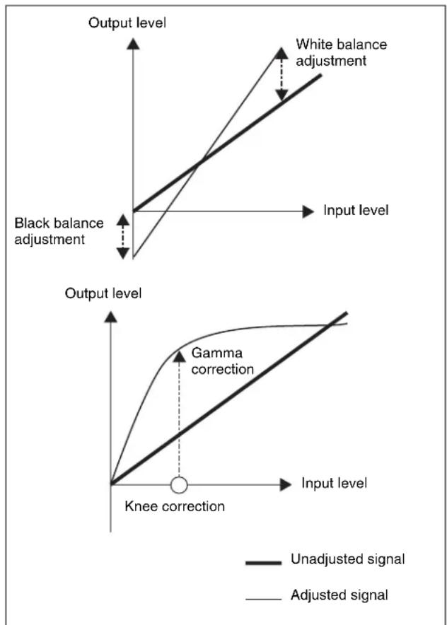
It is also possible to mask part of the region to be corrected.
Applying primary color correction
1 In the CCR menu, press VF1 'CCR1' and HF2 'Primary CCR.'
The Primary CCR menu appears.
2 In the
3 In the
Black: black balance adjustment
White: white balance adjustment
Gamma: gamma correction
Knee: knee correction
4 Depending on the selection in step 3, adjust the following parameters.
When Black or Gamma is selected
| Knob | Parameter | Adjustment | Setting values |
| 1 Red | Red signal | adjustment | -100.00 to +100.00 |
| 2 Green | Green signal | adjustment | -100.00 to +100.00 |
| 3 Blue | Blue signal | adjustment | -100.00 to +100.00 |
| 4 All Simultaneous | RGB adjustment | Red value is shown | |
When White is selected
| Knob | Parameter | Adjustment | Setting values |
| 1 Red | Red signal | adjustment | 0.00 to 200.00 |
| 2 Green | Green signal | adjustment | 0.00 to 200.00 |
| 3 Blue | Blue signal | adjustment | 0.00 to 200.00 |
| 4 All Simultaneous | RGB adjustment | Red value is shown | |
When Knee is selected
| Knob | Parameter | Adjustment | Setting values |
| 1 Red | Red signal | adjustment | 20.00 to 75.00 |
| 2 Green | Green signal gain | 20.00 to 75.00 | |
| 3 Blue | Blue signal gain | 20.00 to 75.00 | |
| 4 All Simultaneous | RGB adjustment | Red value is shown | |
To return the parameters to their default settings
In the
Masking a part of the primary color correction
Here the procedure for mask 1 operation is described by way of example. You can carry out mask 2 operation in a similar way.
1 In the Primary CCR menu, press [Mask1].
2 In the < Primary/Secondary Mask > group, press [Mask1], turning it on.
Notes
When [Mask 2] is selected in the Secondary CCR menu, linked to this setting it automatically changes from [Mask 2] to [Mask 1].
3 Press [Mask1 Adjust].
The Mask1 Adjust menu appears.
4 In the
Box: signal from dedicated box generator Pattern: signal from dedicated pattern generator
5 Depending on the selection in step 3, adjust the following parameters.
When Box is selected
| Knob | Parameter | Adjustment | Setting values |
| 1 Top | Top position | -100.00 to +10 | 0.00 |
| 2 Left | Left position | -100.00 to +10 | 0.00 |
| 3 Right | Right | position | -100.00 to +100.00 |
| 4 Bottom | Bottom | position | -100.00 to +100.00 |
| 5 Soft | Degree of | softness of box | 0.00 to 100.00 |
When Pattern is selected
| Knob | Parameter | Adjustment | Setting values |
| 1 Size | Pattern size 0.00 | to 100.00 | |
| 2 Soft | Degree of softness of pattern edge | 0.00 to 100.00 | |
| 5 Pattern | Pattern number | 1 to 24 | |
For the pattern selection, you can also press [Mask Ptn Select] in the Mask1 Adjust menu, then use the Mask Ptn Select menu.
Press any of the displayed patterns (standard wipe patterns 1 to 24) to select it, then you can adjust the following parameters.
| Knob | Parameter | Adjustment | Setting values |
| 1 Size | Pattern size 0.00 | to 100.00 | |
| 2 Soft | Degree of softness of pattern edge | 0.00 to 100.00 | |
6 When selecting the pattern as a mask source, set the pattern modifiers as required.
When turning [Position] on and setting the pattern position
| Knob | Parameter | Adjustment | Setting values |
| 1 Position | on H Horizontal position | -200.00 to +200.00^a) | |
| 2 | Position V | Vertical position | -200.00 to +200.00^a) |
a) See "Setting the wipe position (Positioner)" (page 165).
When turning [Multi] on and replicating the same pattern
| Knob | Parameter | Adjustment | Setting values |
| 1 H Multi | Number of repetitions of pattern horizontally | 1 to 63 | |
| 2 V Multi | Number of repetitions of pattern vertically | 1 to 63 | |
| 3 Invert Type | Replication layout | 1 to 4^a) |
a) See "Setting the wipe pattern replication (Multi)" (page 167).
When turning [Aspect] on and setting the aspect ratio of the pattern
| Knob | Parameter | Adjustment | Setting values |
| 1 Aspect | aspect ratio | -100.00 to +100.00a) | |
a) See "Setting the wipe pattern aspect ratio (Aspect ratio)" (page 167).
When turning the [Angle] on in the
| Knob | Parameter | Adjustment | Setting values |
| 1 Angle | Angle of pattern rotation | of | -100.00 to +100.00^a) |
a) See "Angle" (page 166).
When turning [Speed] on in the
| Knob | Parameter | Adjustment | Setting values |
| 1 Speed | Rotation rate of pattern | -100.00 to +100.00^a) |
a) See "Speed" (page 166).
7 To invert the mask source, return to the Primary CCR menu and press [Pri/Sec Mask Invrt], turning it on.
Notes
The mask function is common to the primary color correction, secondary color correction, and spot color adjustment functions.
Secondary Color Correction Operations
For the six colors R (red), G (green), B (blue), Y (yellow), C (cyan), and M (magenta), adjust the luminance and saturation, and also the hue within a range of ±30 degrees of the center value for each color. You can mask a part of the region to be corrected.
Applying secondary color correction
1 In the CCR menu, press VF1 'CCR1' and HF3 'Secondary CCR.'
The Secondary CCR menu appears.
2 In the
3 In the
4 Adjust the following parameters.
| Knob | Parameter | Adjustment | Setting values |
| 1 | Luminance | Luminance -100.00 | to +100.00 |
| 2 | Saturation | Saturation 0.00 to 200.00 | |
| 3 | Hue | Delay Hue delay -180.00 to | +180.00 |
To return the parameter settings to their default values
In the
Masking a part of the secondary color correction
Set [Mask] to On in the Secondary CCR menu, then carry out the same operation as described under "Masking a part of the primary color correction" (page 238).
Luminance Processing Operations
After converting a signal to which RGB color correction has been applied to a YUV signal, divide the luminance levels into three regions, referred to as Dark, Middle, and Bright, and apply video signal adjustments to these regions.
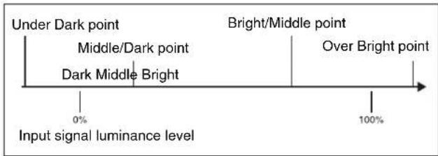
There are three modes for luminance processing, as follows.
Tint mode: adding a specified color to the original video signal.
Color Modify mode: adjusting the original video signal. Y Modify mode: adjusting the output levels of the input luminance signal.
- White balance adjustment: setting the output level for an input luminance signal at the 100% level.
- Black balance adjustment: setting the output level for an input luminance signal at the 0% level.
- Y lift correction: adjusting the curvature of the curve.
- Y dark correction: adjusting the position of the maximum point of the curve.
Output signal luminance level
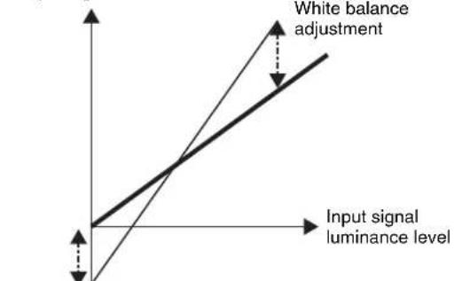
Black balance adjustment
Output signal luminance level
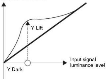
— Unadjusted signal
— Adjusted signal
It is also possible to mask part of the region to be corrected.
Applying luminance processing
1 In the CCR menu, press VF1 'CCR1' and HF5 'Luminance Process.'
The Luminance Process menu appears.
2 In the
3 In the
Tint: add a specified color to the original video signal. Color Modify: adjust the original video signal.
Y Modify: adjust the output levels of the input luminance signal.
When tint mode or color modify mode is selected, skip to step 4.
When Y modify mode is selected, adjust the following parameters.
| Knob | Parameter | Adjustment | Setting values |
| 1 | W h | i t balance adjustment | 0.06 to 200.00 W |
| 2 | B l | a c balance adjustment | -100.00 to +100.08 |
| 3 Y Lift | Curvature of curve | -100.00 to +100.00 | |
| 4 Y Dark Position of | maximum point of curve | -7.31 to +109.59 | |
4 In the
[Level] parameters: set the boundaries of the three regions.
| Knob | Parameter | Adjustment | Setting values |
| 1 | O v Level | Luminancer level of the Over Bright point | 50.0B to 150.00 |
| 2 | M i Level | LuminanceB level of the Bright/Middle point | 10.00 to 120.00 |
| 3 Dark | Mid Level | Luminance level of the Middle/Dark point | -20.00 to +90.00 |
| 4 Under D Level | Luminance level of the Under Dark point | -50.00 to +50.00 | |
[Soft] parameters: set the degree of boundary softness of the three regions.
| Knob | Parameter | Adjustment | Setting values |
| 1 | O v Soft | Degree of r softness at Over Bright point | 15.0B to 70.00 |
| 2 Mid B | Soft Degree | of softness at Bright/Middle point | 15.00 to 42.50 |
| 3 Dark | Mid Soft | Degree of softness at Middle/Dark point | 15.00 to 42.50 |
| 4 Under D Soft | Degree of softness at Under Dark point | 15.00 to 70.00 | |
5 In the
h In tint mode e
| Knob | Parameter | Adjustment | Setting values |
| 1 Luminance | Luminance | -100.00 to +100.00 | |
| 2 Saturation | Saturation | 0.00 to 100.00 | |
| 3 Hue | Hue | 359.99 to 0.00 |
In color modify mode
| Knob | Parameter | Adjustment | Setting values |
| 1 Luminance | Luminance | -100.00 to +100.00 | |
| 2 C Gain | Chrominance signal gain | 0.00 to 200.00 | |
| 3 Hue | Delay | Huedelay -180.00 to +180.00 | |
To return the parameters to their default settings
In the
Spot Color Adjustment
You can change the color of a specified color region to a different color, without affecting other regions. You can also mask part of such a region.
Then for the region other than the region whose color you have changed, you can make the following corrections.
• Video signal overall gain adjustment
• Y signal gain adjustment
• Y signal offset adjustment
• C signal gain adjustment
• C signal hue adjustment
Adjusting the color of the specified region (key)
1 In the CCR menu, press VF1 'CCR1' and HF6 'Spot CCR/Output.'
The Spot CCR/Output menu appears.
2 In the
3 In the
Notes
When [Sample Mark] is on, the effects of color adjustment outside the region of spot color adjustment (see page 242) and output video processing (see page 243) are temporarily disabled. Turning [Sample Mark] off restores the former state.
4 Adjust the parameters so that the color you want to change is included within the sample mark.
| Knob | Parameter | Adjustment | Setting values |
| 1 Position | on H Horizontal position | -100.00 to +100.00 | |
| 2 Position | on V Vertical position | -100.00 to +100.00 | |
| 3 Size | Size 1.00 to | 100.00 |
5 In the
Notes
This automatic adjustment does not carry out key gain adjustment. If required, adjust the key gain as shown in step 6.
6 Press [Key Adjust], and adjust the following parameters.
| Knob | Parameter | Adjustment | Setting values |
| 1 Luminance | Luminance | -7.31 to +109.59 | |
| 2 Saturation | Saturation | 0.00 to 100.00 | |
| 3 Hue | Hue | 359.99 to 0.00 | |
| 4 Gain | Key gain | -100.00 to +100.00 |
7 Press [Window], turning it on, to adjust the key detection range for spot color adjustment.
| Knob | Parameter | Adjustment | Setting values |
| 1 Luminance | Luminance | 0.00 to 10 | 0.00 |
| Knob | Parameter | Adjustment | Setting values |
| 2 Saturation | Saturation | 0.00 to 100.00 | |
| 3 Hue | Hue | 0.00 to 100.00 |
8 In the
| Knob | Parameter | Adjustment | Setting values |
| 1 | Luminance Luminance 0.00 to 100.00 | ||
| 2 | Saturation Saturation 0.00 to 100.00 | ||
| 3 | Hue | 359.99 to 0.00 | |
To return the parameters to their default settings
In the
Masking a part of the spot color adjustment
Set [Mask] to On in the Spot CCR/Output menu, then carry out the same procedure as in “Masking a part of the primary color correction” (page 238).
Adjusting the color outside the spot color adjustment region
1 In the Spot CCR/Output menu, press [Outer Out Proc] in the
2 Adjust the following parameters.
| Knob | Parameter | Adjustment | Setting values |
| 1 Video | Gain Video | signal gain | -200.00 to +200.00 |
| 2 Y Gain | Y signal gain | -200.00 to +200.00 | |
| 3 C Gain | Chrominance signal gain | -200.00 to +200.00 | |
| 4 Hue | Delay Hue | delay -180.00 to +180.00 | |
| 5 | Black Level | Black level | -116.90 to +116.90 |
To return the parameters to their default settings
In the
Output Video Processing Operations
Carry out the following corrections are available on the YUV signal.
• Video signal overall gain adjustment
• Y signal gain adjustment
• Y signal offset adjustment
• C signal gain adjustment
• C signal hue adjustment
Applying output video processing effects
1 In the CCR menu, press VF1 'CCR1' and HF6 'Spot CCR/Output.'
The Spot CCR/Output menu appears.
2 In the
3 Adjust the following parameters.
| Knob | Parameter Adjustment Setting values | ||
| 1 Video | Gain Video | signal gain | -200.00 to +200.00 |
| 2 Y Gain | Y signal gain | -200.00 to +200.00 | |
| 3 C Gain | Chrominance signal gain | -200.00 to +200.00 | |
| 4 Hue | Delay Hue delay | -180.00 to +180.00 | |
| 5 | B I Level | Black level-1 | 6.90 to +116.90 |
To return the parameters to their default settings In the
YUV Clip Operations
For each of the luminance and color difference signals, the following processing is available.
White clip: setting the maximum level of the luminance signal.
Dark clip: setting the minimum level of the luminance signal.
Positive clip: setting the maximum amplitude in the positive direction of the color difference signal.
Negative clip: setting the maximum amplitude in the negative direction of the color difference signal.
Applying YUV clip processing
1 In the CCR menu, press VF1 'CCR1' and HF7 'YUV Clip/RGB Clip.'
The YUV Clip/RGB Clip menu appears.
2 In the
3 In the
Luminance: settings for the luminance signal.
Chroma: settings for the color difference signal.
4 Depending on the selection in step 3, adjust the following parameters.
When Luminance is selected
| Knob | Parameter Adjustment Setting values | ||
| 1 White | Clip White | clip adjustment | -6.85 to +109.13 |
| 2 Dark | Clip Dark | clip adjustment | -6.85 to +109.13 |
When Chroma is selected
| Knob | Parameter Adjustment Setting values | ||
| 1 | U Posi Clip | Positive clip adjustment for U signal | -113.39 to +113.39 |
| 2 U Nega Clip | Negative clip adjustment for U signal | -113.39 to +113.39 | |
| 3 | V Posi Clip | Positive clip adjustment for V signal | -113.39 to +113.39 |
| 4 V Nega Clip | Negative clip adjustment for V signal | -113.39 to +113.39 | |
To return the parameters to their default settings
In the
RGB Clip Operations
For each of the R, G, and B signals, you can make dark clip and white clip adjustments.
Making RGB clip adjustments
1 In the CCR menu, press VF1 'CCR1' and HF7 'YUV Clip/RGB Clip.'
The YUV Clip/RGB Clip menu appears.
2 In the
3 In the
Dark: dark clip adjustment
White: white clip adjustment
4 Adjust the following parameters.
| Knob | Parameter | Adjustment | Setting values |
| 1 Red | Red signal adjustment | -50.00 to +149.99^a) -49.99 to +150.00^b) | |
| 2 Green | Green signal adjustment | -50.00 to +149.99^a) -49.99 to +150.00^b) | |
| 3 Blue | Blue signal adjustment | -50.00 to +149.99^a) -49.99 to +150.00^b) | |
| Knob | Parameter Adjustment Setting values | ||
| 4 All Simultaneous | RGB adjustment | Red value is shown | |
a) When Dark is selected
b) When White is selected
To return the parameters to their default settings
In the
Special Functions
Chapter
10
Side Flags
Overview
The term “side flags” refers to the areas to left and right of an image with aspect ratio 4:3 embedded within a 16:9 frame, when these areas are filled with a separate image selected from the utility 1 bus.
You can adjust the width of the side flag area.
Side Flag Settings
Input source aspect ratio, auto side flags, and auto crop settings
Aspect ratio 4:3 setting
Set the input signal to aspect ratio 4:3. If set to 16:9, the side flags are disabled.
Auto side flag setting
This function automatically applies side flags when a 4:3 signal is selected in the cross-point control block.
Auto crop setting
When carrying out a DME wipe, this function automatically crops the image during transition to 4:3.
Adjusting the width of the side flag area
You can set the left and right sides separately.
For the operation for the above setting, see “Settings for Switcher Configuration (Config Menu)” in Chapter 20 (Volume 2).
Enabling and disabling side flags with a menu operation
You can enable or disable side flags for the backgrounds (A and B) of each of the M/E and PGM/PST banks.
As an example, to enable side flags for background B row on the M/E-1 bank, use the following procedure.
1 In the menu control block, press the top menu selection button [MISC], then select VF1 'Enable' and HF3 'Side Flags.'
The Misc >Enable >Side Flags menu appears. The status area shows the buttons for Bkgd A and Bkgd B for each of the M/E-1 to M/E-4, and PGM/PST (P/P) banks.
2 In the
Each time you press the button toggles between Enable and Disable.
To display a menu for the aspect ratio 4:3, auto side flags, and auto crop settings
In the Misc >Enable >Side Flags menu, press [Setup >SWER >Side Flags].
To display a menu for assigning the side flags on/off function to a cross-point button
In the Misc >Enable >Side Flags menu, press [Side Flags Button Assign].
Enabling and disabling side flags with a button operation
For example, to enable side flags for the background B row of the M/E-1 bank, use the following procedure.
1 First, in the Setup menu assign the rightmost cross-point button to the [SIDE FLAG] button.
For details of the assignment operation, see "Assigning a Cross-Point Button to Enable/Disable Side Flags" in Chapter 19 (Volume 2).
2 Press the [SIDE FLAG] button at the right end of the background B row of the M/E-1 bank.
The button you pressed lights amber, and this enables the side flags.
Notes
- The operations of enabling or disabling the side flags by menu operation and by control panel button operation are linked.
- When the auto side flags are on, selecting a 4:3 video material automatically lights the [SIDE FLAG] button, but if you press this button, turning it off, the side flags are temporarily disabled.
However, when you select a different 4:3 video material, the [SIDE FLAG] button automatically lights once again, enabling the side flags.
Creating an image with side flags
For example, to create an image with side flags in the background B row of the M/E-1 bank, use the following procedure.
1 In the M/E-1 bank cross-point control block, hold down the [UTIL] button, and in the background A row select the signal (utility bus 1 signal) you want to insert in the side flag areas.
2 In the background B row, press the cross-point button corresponding to the 4:3 video material.
At this point, if auto side flags are on, this automatically adds side flags to the 4:3 video material.
For details, see "Settings for Switcher Configuration (Config Menu)" in Chapter 20 (Volume 2).
3 Use either of the following methods to turn the side flags on.
- Use the Misc >Enable >Side Flags menu. (See page 245).
- Use a cross-point button operation. (See previous item.)
This adds side flags to the 4:3 video material.
Wipe Action on Images with Side Flags
When a wipe is carried out on an image with side flags, all wipe patterns can be used.
The following illustration shows the action in a wipe.
Wipe from a 4:3 image to a 16:9 image
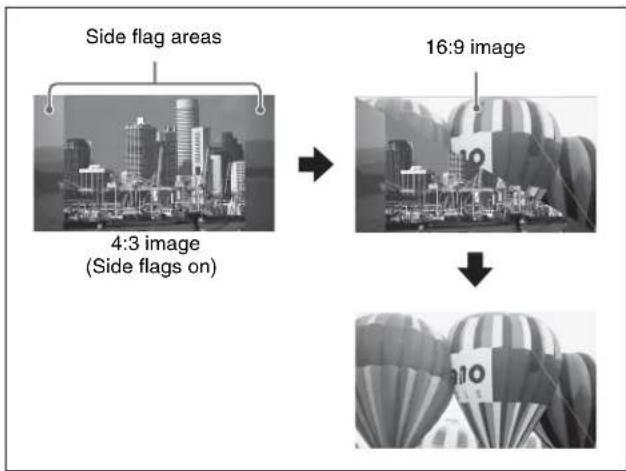
Wipe from a 4:3 image to another 4:3 image (when side flags are on for both images)
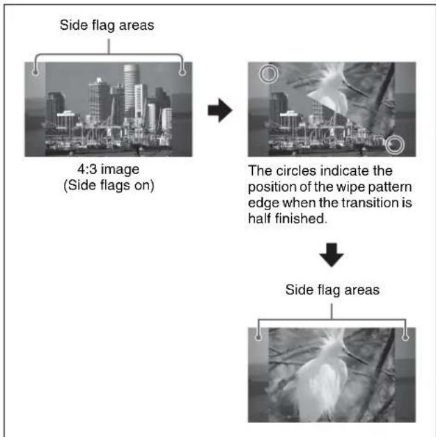
flowchart
graph TD
    A["Side flag areas"] --> B["4:3 image (Side flags on)"]
    B --> C["The circles indicate the position of the wipe pattern edge when the transition is half finished."]
    C --> D["Side flag areas"]
DME Wipe Action for an Image with Side Flags
When a DME wipe is carried out on an image with side flags, all wipe patterns can be used. Depending on the setting (On/Off) of [Auto Crop] in the Engineering Setup >Switcher >Config menu, the appearance of the 4:3 image changes.
Notes
- When using the DME through SDI interface with [Auto Crop] being off, side flags are not added to the new image during DME wipe.
- For signals with the following DME wipe pattern selected on the DME external video bus (gray part shown in the pattern illustration), side flags are not applied when auto side flags are set to Off.
- Two-channel page turn
- Two-channel page roll
- Two-channel frame in-out
- Two-channel brick
- Three-channel brick
The following illustration shows the action in a DME wipe.
DME wipe from a 4:3 image to a 16:9 image
Wipe action using slide (No. 1001)
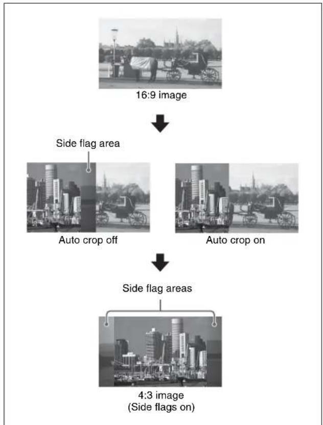
flowchart
graph TD
    A["16:9 image"] --> B["Side flag area"]
    B --> C["Auto crop off"]
    B --> D["Auto crop on"]
    C --> E["Side flag areas"]
    D --> E
    E --> F["4:3 image\n(Side flags on)"]
DME wipe from a 4:3 image to another 4:3 image (when side flags are on for both images)
Wipe action using squeeze (No. 1031)
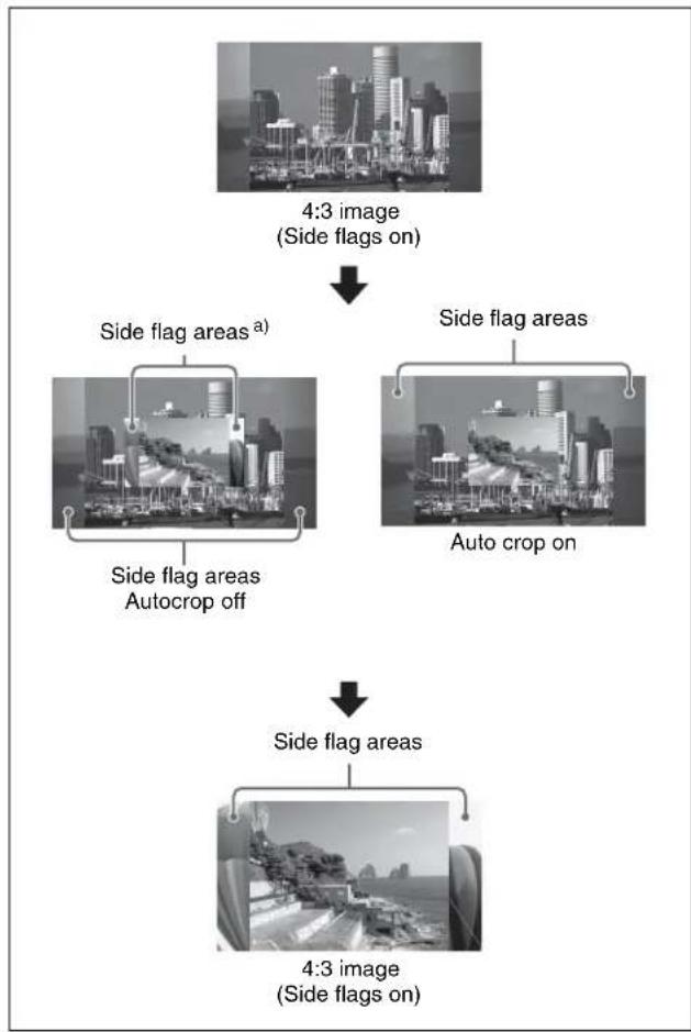
flowchart
graph TD
    A["4:3 image (Side flags on)"] --> B["Side flag areas a)"]
    A --> C["Side flag areas"]
    A --> D["Auto crop on"]
    B --> E["Side flag areas Autocrop off"]
    C --> F["Side flag areas"]
    D --> G["Side flag areas"]
    G --> H["4:3 image (Side flags on)"]
a) When using the DME through SDI interface, side flags are not added during a DME wipe.
Multi Program 2
Overview
What is Multi Program 2?
By operating the switcher in Multi Program 2 mode, a single switcher mix/effects bank can be used to create two separate video outputs, referred to as "main" and "sub." You can set backgrounds, keys, and transitions for each of main and sub. Keys 2 to 8, however, are common to main and sub.
Notes
To enable this function requires the BZS-8200X (for the MVS-8000X) or BZS-7200X (for the MVS-7000X) Multi Program 2 software.
Using the software
To use the Multi Program 2 software, you are required to enter an install key which validates the software. (If the software has been factory installed, the install key is not required.) For the method of obtaining an install key, contact your Sony representative. To obtain a key, you may be required to submit the unique device ID of the switcher you are using. You can check the unique device ID in the Install menu of the switcher.
For details of the operation, see “Installation and Device Setup (Install/Unit Config Menu)” in Chapter 18 (Volume 2).
Assigning main and/or sub to switcher banks
For Multi Program 2 operations, a single switcher bank may be shared, and switched between main and sub, or two separate switcher banks may be used, each dedicated to main or sub.
Example 1: Assigning M/E-1 main and sub to a single switcher bank, and switching between them
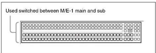
Example 2: Assigning separate switcher banks as “M/E-1 main dedicated” and “M/E-1 sub dedicated”
Used for M/E-1 main operations
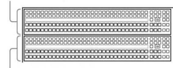
natural_image
Pure electrical circuit lines without any symbolsUsed for M/E-1 sub operations
Video creation operations in Multi Program 2 mode
For each of main and sub, there are differences from the operations in standard mode.
For details, see "Differences between Multi Program 2 Mode and Standard Mode" (page 253).
Sequence of Operations in Multi Program 2
Basic operation sequence
Enter the BZS-8200X or BZS-7200X install key (first time only) ↓ Set Multi Program 2 operating mode for each switcher bank ↓ Assign output signals, and set the background configuration, key configuration, and key preview configuration ↓ For each switcher bank, make a main/sub assignment (one of main dedicated, sub dedicated, and main and sub shared) ↓ For a switcher bank assigned to main and sub shared, assign the [MAIN] and [SUB] delegation buttons ↓ Create the main and sub images ↓ Execute the transition
Optional operations
- Making cross-point settings
- Enabling DME wipe operations for sub
• Inhibiting utility 2 bus signal selection - Including Multi Program 2 data in keyframes and snapshots
-
Changing the key assignment for each output
-
Assigning sub preview output to preview selection buttons in the fade-to-black control block
- Changing the matrix size to Standard
- Making settings for keyframe timeline operation
Basic Operations (Required)
Entering the install key of the software (first time only)
After installing the BZS-8200X or the BZS-7200X Multi Program 2 software in the switcher, carry out the following procedure.
1 In the status area of the Engineering Setup >System >Install/Unit Config menu, select the switcher (SWRx), and press [License].
The License menu appears.
2 In the License menu, enter the install key.
For details of the operation, see “Installation and Device Setup (Install/Unit Config Menu)” in Chapter 18 (Volume 2).
3 Shut down the menus (see page 77).
4 Power the switcher and SCU off and on again.
Setting the operating mode for each switcher bank
To set a desired switcher bank to Multi Program 2 mode, use the following procedure.
1 Display the Engineering Setup >Switcher >Config menu.
2 Select the switcher bank from M/E-1 to M/E-4, and P/P.
3 In the
4 Repeat steps 2 and 3 as required, to set the operating mode for all desired switcher banks.
Assigning output signals for Multi Program 2 mode
To assign signals to outputs
Use the Engineering Setup >Switcher >Config >M/E Output Assign menu.
The difference from standard mode is that OUT1 is fixed, set to PGM1 (main program), and OUT6 is fixed, set to PGM2 (sub program), and that for the OUT2 to OUT5
signals you can assign any signal selected from the following. PGM1, PGM2, PGM3, PGM4, PVW1, PVW2, K-PVW1, K-PVW2, CLEAN, SUB CLEAN
Notes
Each of main and sub can use a maximum of four of the six outputs (OUT1 to OUT6). The outputs can be used within the following limits.
• OUT1, OUT2: main only
- OUT3, OUT4: can be used for either main or sub
• OUT5, OUT6: sub only
For details, see “Selecting the System Operation Mode” in Chapter 18 (Volume 2).
To set the background and key configuration
Use the Engineering Setup >Switcher >Config >PGM Config menu.
The following are the differences from standard mode.
Background configuration: Consists of the following combinations.
- For main: Clean, Bkgd A, Bkgd B
- For sub: Sub Clean, Utility 2, Utility 3
Key configuration: Key1 can be set to "Enable" only when the background is Clean, Bkgd A, or Bkgd B.
For details, see “Setting the Operation Mode” in Chapter 20 (Volume 2).
To set the key preview configuration
Use the Engineering Setup >Switcher >Config >K-PVW Config menu.
The following are the differences from standard mode.
Background configuration: Clean or Sub Clean
Key configuration: Key1 can be set to "On" or "Link" only when the background is Clean.
For details, see "Setting the Operation Mode" in Chapter 20 (Volume 2).
To assign sub outputs to output ports
Use the Engineering Setup >Switcher >Output >Output Assign menu.
You can assign a sub output signal to a switcher output port number.
For details, see “Assigning Output Signals” in Chapter 20 (Volume 2).
Assigning main and/or sub to switcher banks
For each switcher bank for which Multi Program 2 mode is selected, set whether this is main dedicated, sub dedicated, or main and sub shared.
To assign main and sub to a single switcher bank
1 In the Engineering Setup >Panel >Config >MP2 Main/Sub Assign menu, select the switcher bank.
2 In the
Main: use for main operations.
Sub: use for sub operations.
Main&Sub: use for both main and sub operations.
When “Main&Sub” is selected, it is necessary to assign [MAIN] and [SUB] delegation buttons to the control panel buttons.
To assign main and sub to two consecutive switcher banks
For example, to assign the first row (first switcher bank) to M/E-1 main, and the second row (second switcher bank) to M/E-1 sub, use the following procedure.
1 In the status area of the Engineering Setup >Panel >Config >MP2 Main/Sub Assign menu, select 1st Row (M/E-1), then press [Main] in the
2 Press [Dual M/E Assign] to assign M/E to two banks.
In this state, both 1st Row and 2nd Row are set to main.
3 Set 2nd Row to [Sub].
This cancels the shift/non-shift assignment for dual M/E in standard mode.
Notes
It is not possible to assign the combinations of Main with Main&Sub, or Sub with Main&Sub.
Assigning the [MAIN] and [SUB] delegation buttons to buttons on the control panel
To assign the Main/Sub switching function to buttons in the transition control block
This applies to the standard type and compact type transition control block, and the CCP-6224/6324 control panel.
For details of the CCP-6224 2M/E control panel, see page 125, and for the details of the CCP-6324 3M/E control panel, see page 68.
For details of the transition control block, .
1 In the Engineering Setup >Panel >Config menu, press [Program Button].
The Program Button menu appears.
2 Press [Transition Module1].
The Transition Module1 menu appears.
3 Select the switcher bank in the
The buttons in the transition control block on the left appear in the currently assigned state.
4 Press the button whose assignment you wish to change.
The button you press appears in reverse video.
5 From the list on the right, select [MAIN], and press [Set].
The indication on the button changes according to the selection.
6 Repeat Step 4 and 5 to assign [SUB].
To assign to macro buttons in the cross-point control block
For details of the cross-point control block, see page 29.
1 In the Engineering Setup >Panel >Config menu, press [Program Button].
The Program Button menu appears.
2 Press [Xpt Module].
The Xpt Module menu appears.
3 Select the switcher bank, then in the
group, press [Main Sub].You can now use the [PRE MCRO] button as [MAIN], and the [POST MCRO] button as [SUB].
To assign macro operations to different buttons
If in the above operation you assigned a Multi Program 2 function to the macro buttons, you can assign the PRE MCRO and POST MCRO functions to different buttons.
For details, see “Assigning Functions to User Preference Buttons” or “Assigning a Function to a Memory Recall Button in the Utility/Shotbox Control Block” in Chapter 19 (Volume 2).
Examples of Operations in the Multi Program 2 Mode (When Sharing a Switcher Bank)
To create video on the M/E or PGM/PST bank assigned to both main and sub operations, use the following procedure.
1 Press the [MAIN] button, turning it on, and turning off the [SUB] button.
2 With the normal operations, create the main video.
3 Press the [SUB] button, turning it on, and turning off the [MAIN] button.
Now you can create the sub video.
4 Create the sub video.
The basic method of operation is the same as for the main video, except that the utility 2 bus signal is assigned to background A, and the utility 3 bus signal is assigned to background B.
For sub, only keys 2 to 8 can be used, and for wipes, standard wipe patterns only. There are also other differences in operation from standard mode.
For details, see “Differences between Multi Program 2 Mode and Standard Mode” (page 253) and “Restrictions on Using Multi Program 2 Mode” (page 254).
5 Press the [MAIN] and [SUB] buttons simultaneously, turning them on.
If both buttons are lit, the control panel shows the status of main.
6 Carry out the transition.
Both main and sub video images are switched.
Optional Operations
Making cross-point settings
Cross-point assign tables can be set not only for main output but also for sub output.
You can set cross-point assign tables for the following banks.
M/E-1 SUB to M/E-4 SUB P/P SUB
The table actually used is that for which the control panel delegation button is lit.
For details, see “Cross-Point Settings (Xpt Assign Menu)” in Chapter 19 (Volume 2).
Enabling DME wipe operations for sub
By factory default, DME wipe operations are inhibited for sub background. To enable them, in the Engineering Setup >Switcher >Config menu, set [DME Wipe Sub Enable] to On.
This setting applies to the whole control panel (all M/E banks and PGM/PST bank).
Notes
If a DME wipe for sub is recalled in a snapshot or keyframe, the image will not be handled correctly.
Inhibiting utility 2 bus signal selection
In Multi Program 2 mode, you can inhibit other uses of the utility 2 bus signal in order to use the signal as the background for sub.
This setting applies to the whole control panel (all M/E banks and PGM/PST bank).
In the Engineering Setup >Panel >Config >MP2 Main/Sub Assign menu, set [Util2 Inhibit] to On.
This inhibits operations of selecting from the background B row while holding down the [UTIL] button in the cross-point control block.
Inhibiting key operations for main or sub keyer
In the Engineering Setup >Panel >Config >Operation Inhibit >M/E Operation Inhibit menu, you can make settings to inhibit key operations on each of the main and sub keyers independently.
For details, see “Inhibiting Utility 2 Bus and Key Operations” in Chapter 19 (Volume 2).
Including Multi Program 2 data in recall operations of keyframes and snapshots
In the Engineering Setup >Switcher >Config menu, set [Recall M/E Config] to On.
When a keyframe or snapshot is stored or recalled, the following data is included.
M/E Config, PGM Config, M/E Output Assign, and Key PVW Config
For details of the above data, see “Setting the operating mode for each switcher bank” (page 249) and “Assigning output signals for Multi Program 2 mode” (page 249).
This setting applies to the whole control panel (all M/E banks and PGM/PST bank).
Notes
M/E Config data is saved, even when this setting is Off.
Changing the key assignment for each output (Misc menu)
In Multi Program 2 mode you can change the key assignments independently.
The following describes an example using M/E-1, but the operation is the same for other banks.
Notes
- This setting is linked to the setting in the Engineering Setup >Switcher >Config >PGM Config menu.
- It is not possible to make this setting while the above PGM Config menu is locked, or [Recall M/E Config] (see previous item) is set to Off.
1 In the M/E-1 menu, select first VF7 'Misc,' then HF5 'Key Assign.'
The Key Assign menu appears, and the current key assignment is shown in the status area.
2 Change the setting in "Key Enable" as required.
Keys recalled in a snapshot recall
If a snapshot is recalled independently on main or sub, this only retrieves the settings for the key assigned to the recalled side. For example, if key 1 and key 2 are assigned on main, and key 3 and key 4 are assigned on sub, then if you recall a snapshot on main, this only retrieves the settings for key 1 and key 2, and the state of key 3 and key 4 assigned on sub is not affected.
Assigning sub preview output to preview selection buttons
You can assign the sub preview output to a preview selection button in the fade-to-black control block or downstream key/fade-to-black control block.
For details, see "Overall Control Panel Settings (Config Menu)" in Chapter 19 (Volume 2).
When the Multi Program 2 license is valid, by assigning the "Shift" function to a button, you can assign two preview outputs, "Shift" and "Unshift" to a single button. To use the shift output, always assign "Shift" to some button.
Changing the matrix size to Standard
When using a router, if the matrix size is set to [128 × 128] , it is not possible to control the utility 3 bus on the S-Bus. When using Multi Program 2, in the
For details, see "Assigning Switcher Inputs and Outputs to S-Bus Space" in Chapter 23 (Volume 2).
As for the bus number of the utility 3 bus, a DME Key bus number is used as follows.
| No. Bus (Standard) Bus (MP2) | |
| 70 M/E-1 DME Key M/E-1 Utility3 | |
| 85 M/E-2 DME Key M/E-2 Utility3 | |
| 100 M/E-3 DME Key M/E-3 Utility3 | |
| 115 P/P DME Key P/P Utility3 |
Making settings for timeline-related keyframe operations
To assign sub regions to the region selection buttons in the numeric keypad control block
In the Engineering Setup >Panel >Config >10 Key Region Assign menu, assign regions to the region selection buttons in the numeric keypad control block.
For details, see "Overall Control Panel Settings (Config Menu)" in Chapter 19 (Volume 2).
To make region and reference region selections using a menu
During snapshot or keyframe operations, you can select a region (including sub) in the Key Frame >Region Select menu. This is convenient for selecting some of the regions assigned to the numeric keypad control block or changing the reference region.
For details, see "Specifying the Region and Edit Points" in Chapter 13 (Volume 2).
To assign regions shown in the Timeline menu
You can select how regions assigned to region selection buttons appear in the Key Frame >Timeline menu.
For details, see "Settings in the Timeline Menu" in Chapter 13 (Volume 2).
Enabling re-entry between the main and sub sides of the same M/E bank
In the Engineering Setup >Switcher >Config menu, set [MP2 Free Re-Entry] to On.
Notes
- Re-entry adds a 1H delay to the video. Nested re-entry may lead to problems in the video.
- A maximum of ten re-entry stages are possible, with the final output having a delay of 5H.
- The selection order of re-entry signals affects the number of lines by which the output signal is lowered.
- If a delay occurs in the image, even when the through mode is set, the ancillary data does not pass through.
- For example, it is possible to select the re-entry of M/E-1 main on M/E-1 main.
Restrictions on mutual re-entry when using Multi Program 2
The snapshot function is affected by this re-entry function. When the [MP2 Free Re-Entry] button is On, and any of the switcher banks are in Multi Program 2 mode, then the following restrictions apply.
If you save and recall snapshots simultaneously with more than one region specified, the recorded state is played back in the order of precedence of regions (M/E-1 >M/E-2 >M/E-3 >P/P). Therefore, if you save and recall snapshots with more than one region specified, the cross-point settings may not be recalled correctly.
To recall the snapshots correctly, press the cross-point button before recalling the snapshots, to select a signal other than the re-entry signal, then recall the snapshots.
Functions Added in Multi Program 2 Mode
- You can set video processing for the utility 3 bus signal.
-
In the control panel and DCU GPI input settings and switcher GPI link settings, the actions that can be selected now also include “Sub Cut” and “Sub Auto Trans.”
-
A switcher GPI link can now be set also for the utility 3 bus.
- To the macro event configuration parameters and macro attachment settings, “Main & Sub” and “Sub” have been added.
- For cross-point button link settings, M/E-1 to M/E-4, and P/P “Sub Program,” “Sub Preset,” and “Sub Trans PGM” have been added to the link source bus.
- Snapshot attributes can now be set independently for main and sub.
- There are additional menus for sub which can be recalled by pressing a button twice.
- You can set [MP2 Auto Correct] to On or Off in the Effect menu or Snapshot menu. When this is set to On, for example, copy destination and source data is automatically recognized as main or sub, and the data interchanged.
- When the key adjustment mode is selected on the Multifunction Flexi Pad (or when the KEY ADJ button is lit), if you select the region selection button to which [M/E-x Sub] is assigned, the [TRNS] button operates as a button for the sub region.
- You can assign [SUB TRANS] to the key control block. This button functions as a [TRNS] button for the sub region.
Differences between Multi Program 2 Mode and Standard Mode
The differences from operation in standard mode are as follows.
| Item Main Sub | |||
| Keys a) | Keys 1 to 8 can be used Keys 2 to 8 only can be used | ||
| Wipes (background) | Patterns Same as standard mode • Only standard patterns can be used• Pattern mix is not possible | ||
| Modifiers Same as standard mode • Pairing, modulation, spring, spiral,and split cannot be used• Edge fill mattes are single-color only• Replication can be selected from four patterns | |||
| Wipes (key) Same as wipes (background) for sub | |||
| DME wipes Use Can be | used Cannot be used (Can be used, with a setting change) | ||
| Patterns for 1 channel For a dedicated interface, each of main and sub can be used.For the SDI interface, only one of main and sub can be used. | |||
| Patterns for 2 channels | Only one of main and sub can be used(For each M/E, the number of DMEs that can be used is the same as in standard mode.) | ||
| Patterns for 3 channels | |||
| Backgrounds | Wipe edge fill matte (including color mix and other settings in the Matte Adjust menu) | Wipe edge fill matte (single-color only) | |
| Modifiers Same as standard mode Wipe border colors are single-color only | |||
| Item | Main | Sub | |
| Transitions Key priority | Cannot be used | ||
| Transition preview Cannot be used | |||
| Preset color mix Color m | atte or video signal selected on the utility 2 bus | Color matte only | |
| Snapshots Cross-point h | old Utility 2 cannot be set | Utility 3 is added. BKGD A/B and | Key1 cannot be set. |
| Control from an editor Same as standard mode C | Cannot be used | ||
| Operation setting for switcher GPI inputs and outputs | Same as standard mode Cannot be used | ||
a) Keys 2 to 8 are common to main and sub.
Notes
- Allow a transition to complete before carrying out main and sub delegation switching.
- The sub background A bus (utility 2 bus) is shared with wipe edge border fill. Making a change to one affects the other.
- Even if the wipe border width is set to the same numeric value for main and sub, the same image is not obtained.
Restrictions on Using Multi Program 2 Mode
- The following functions are not available for sub:
- Data copy and swap
- Default recall (except for parametric recall)
- [AUTO] button function (see page 65)
- Re-entry is limited to five levels. Re-entry is not possible for main and sub of the same M/E.
However, this restriction can be removed.
For details, see “Enabling re-entry between the main and sub sides of the same M/E bank” (page 252). - In the following cases, a transition using the fader lever may not be performed correctly:
- When the main and sub bus toggle modes are set differently
- For a pattern mix, preset color mix, and so on
- For an Internal bus link, GPI link, or External bus link, the “Utility 2” bus cannot be selected.
- Screen aspect, show key, and [MCRO ATTCH ENBL] button settings are common to main and sub.
- If a snapshot is recalled simultaneously for main and sub, or a keyframe is executed simultaneously for main and sub, then for the following common to main and sub the main settings are reflected.
- Key
- M/E Config
- DME external video bus and utility 1 bus
-
When a macro attachment is set on the DME utility 1 bus or DME utility 2 bus, it is not possible to make separate main and sub settings.
-
When snapshots with different M/E Config settings are recalled:
- If M/E Config data is not to be included in the snapshot data, the current system settings are used for snapshot reproduction.
- If M/E Config data is to be included in the snapshot data first M/E Config data is set, and then other snapshot data is recalled.
- The bus override function is only available on the following buses:
- M/E-1 to M/E-4 Main BKGD A/B buses
- M/E-1 to M/E-4 Sub BKGD A/B buses (UTIL-2, UTIL-3 buses)
- P/P Main PGM/PST bus
- P/P Sub PGM/PST buses (UTIL-2, UTIL-3 buses)
- When a master snapshot or master timeline is executed with a key being assigned to both main and sub, it is uncertain which data will be reflected.
- When recalling a master snapshot with different register numbers for main and sub, the recall timing may differ by one field or more between main and sub.
- The link state is maintained even when M/E Config is changed. Set the link setting again, as required.
- Since keys 2 to 4 are shared between main and sub, when the main and sub fader lever positions are different, if you move the fader lever, the video changes instantaneously to the value of the most recently moved fader lever.
- When the transition type for main or sub is set to preset color mix, it is not possible to carry out independent key transition operation (common to main and sub).
- When the signal format is 1080P, snapshots, wipe snapshots, and effects created using a wipe for sub, do not function correctly with a signal format other than 1080P. Similarly, those created with other than the 1080 signal format, do not function correctly with a signal format of 1080P.
3D Support
Overview
Installing the following software enables video creation in 3D mode.
- BZS-8560X (for MVS-8000X) or BZS-7560X (for MVS-7000X) as the switcher upgrade software
- BZDM-8560 (for MVE-8000A/MVE-9000) or BZS-7561X (for MKS-7470X/7471X) as the DME upgrade software
Notes
- On the MVS-8000X, the M/E-4 bank is not used for 3D mode.
- On the MVS-7000X, the M/E configuration in 3D mode will be the same as that in 2M/E mode (see page 261).
• The following signal formats support 3D. 1080i/50, 1080i/59.94, 720P/50, 720P/59.94 - For details of the board configurations required for 3D mode, consult your Sony representative.
Using the software
To use the switcher upgrade software and DME upgrade software, you need to enter an install key to enable the software. (It is not necessary to enter an install key if the software was factory-installed.)
Ask your Sony representative about entering the install key.
At this time, the unique device ID may be required. You can check the unique device ID in the Install menu of the switcher and DME.
For details of this operation, see "Installation and Device Setup (Install/Unit Config menu)" in Chapter 18 (Volume 2).
How the 3D display works
In 3D mode, two different images, for the left eye and the right eye, are displayed simultaneously, to be combined by the brain into a stereoscopic image.
Therefore, switcher and DME hardware is duplicated, with input signals for the left eye and right eye. (See the following figure.)
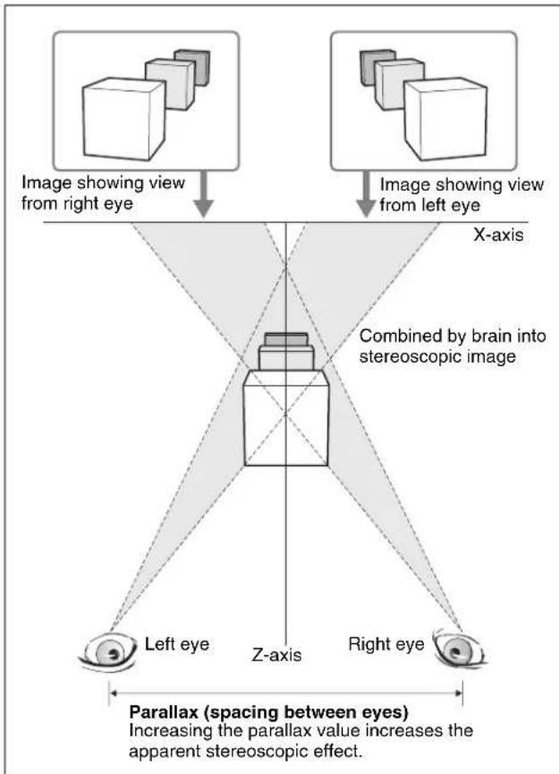
flowchart
graph TD
    A["Image showing view from right eye"] --> B["Combined by brain into stereoscopic image"]
    C["Image showing view from left eye"] --> B
    B --> D["Left eye"]
    B --> E["Z-axis"]
    B --> F["Right eye"]
    D --> G["Parallax (spacing between eyes)"]
    E --> G
    F --> G
    style A fill:#f9f,stroke:#333
    style C fill:#f9f,stroke:#333
    style B fill:#ccf,stroke:#333
    style D fill:#cfc,stroke:#333
    style E fill:#cfc,stroke:#333
    style F fill:#cfc,stroke:#333
    style G fill:#ffc,stroke:#333
Preparations
Switching the system to 3D mode
Notes
It is only possible to switch to 3D mode when the system signal format is set to one of the following. 1080i/50, 1080i/59.94, 720P/50, 720P/59.94
1 Display the Engineering Setup >System >Format menu.
2 Press [3D Mode], turning it on.
A popup window appears, with a message.
3 Check the message, and select [Yes].
Input primary numbers for left and right signals
For the signals used in 3D mode for the left eye view and right eye view (referred to simply as left and right signals), select a combination of primary input numbers from two types (signals in the same slot and signals in different slots).
For some signals, such as titles, the same signal is used for both left and right.
Specify whether to use a combination of left and right signals in the same slot or different slots
1 Display the Engineering Setup >System >Install/Unit Config >Unit Config menu.
2 In <3D Connector Pair> group, select either of the following.
1-2 Mode: Specify a pair of left and right signals in the same slot.
1-21Mode: Specify a pair of left and right signals in different slots.
3 Press [Execute].
Combinations of left and right signals (Input terminals)
The following combinations of left and right signals are available depending on whether to use the signals in the same slot or different slots.
If [1-2 Mode] is selected on MVS-8000X
| Right signals Left signals | |
| Slot 5 | |
| PRIMARY INPUTS 1 PRIMARY INPUTS 2 | |
| PRIMARY INPUTS 3 PRIMARY INPUTS 4 | |
| : | : |
| PRIMARY INPUTS 19 PRIMARY INPUTS 20 | |
| Slot 6 | |
| PRIMARY INPUTS 21 PRIMARY INPUTS 22 | |
| PRIMARY INPUTS 23 PRIMARY INPUTS 24 | |
| : | : |
| PRIMARY INPUTS 39 PRIMARY INPUTS 40 | |
| Slot 7 | |
| PRIMARY INPUTS 41 PRIMARY INPUTS 42 | |
| PRIMARY INPUTS 43 PRIMARY INPUTS 44 | |
| : | : |
| PRIMARY INPUTS 59 PRIMARY INPUTS 60 | |
| Slot 8 | |
| PRIMARY INPUTS 61 PRIMARY INPUTS 62 | |
| PRIMARY INPUTS 63 PRIMARY INPUTS 64 | |
| : | : |
| PRIMARY INPUTS 79 PRIMARY INPUTS 80 | |
| Slot 9 | |
| PRIMARY INPUTS 81 PRIMARY INPUTS 82 | |
| PRIMARY INPUTS 83 PRIMARY INPUTS 84 | |
| : | : |
| Right signals Left signals | |
| PRIMARY INPUTS 99 PRIMARY INPUTS 100 | |
| Slot 10 | |
| PRIMARY INPUTS 101 PRIMARY INPUTS 102 | |
| PRIMARY INPUTS 103 PRIMARY INPUTS 104 | |
| : | : |
| PRIMARY INPUTS 119 PRIMARY INPUTS 120 | |
| Slot 11 | |
| PRIMARY INPUTS 121 PRIMARY INPUTS 122 | |
| PRIMARY INPUTS 123 PRIMARY INPUTS 124 | |
| : | : |
| PRIMARY INPUTS 139 PRIMARY INPUTS 140 | |
| Slot 12 | |
| PRIMARY INPUTS 141 PRIMARY INPUTS 142 | |
| PRIMARY INPUTS 143 PRIMARY INPUTS 144 | |
| Slot 13 | |
| PREMIUM INPUTS 1 PREMIUM INPUTS 2 | |
| PREMIUM INPUTS 3 PREMIUM INPUTS 4 | |
| : | : |
| PREMIUM INPUTS 19 PREMIUM INPUTS 20 | |
If [1-21 Mode] is selected on MVS-8000X
| Right signals Left signals | |
| Slot 5 Slot 6 | |
| PRIMARY INPUTS 1 PRIMARY INPUTS 21 | |
| PRIMARY INPUTS 2 PRIMARY INPUTS 22 | |
| : | : |
| PRIMARY INPUTS 20 PRIMARY INPUTS 40 | |
| Slot 7 Slot 8 | |
| PRIMARY INPUTS 41 PRIMARY INPUTS 61 | |
| PRIMARY INPUTS 42 PRIMARY INPUTS 62 | |
| : | : |
| PRIMARY INPUTS 60 PRIMARY INPUTS 80 | |
| Slot 9 Slot 10 | |
| PRIMARY INPUTS 81 PRIMARY INPUTS 101 | |
| PRIMARY INPUTS 82 PRIMARY INPUTS 102 | |
| : | : |
| PRIMARY INPUTS 100 PRIMARY INPUTS 120 | |
| Slot 11 | |
| PRIMARY INPUTS 121 PRIMARY INPUTS 122 | |
| PRIMARY INPUTS 123 PRIMARY INPUTS 124 | |
| : | : |
| PRIMARY INPUTS 139 PRIMARY INPUTS 140 | |
| Slot 12 | |
| PRIMARY INPUTS 141 PRIMARY INPUTS 142 | |
| PRIMARY INPUTS 143 PRIMARY INPUTS 144 | |
| Slot 13 | |
| PREMIUM INPUTS 1 PREMIUM INPUTS 2 | |
| PREMIUM INPUTS 3 PREMIUM INPUTS 4 | |
| : | : |
| PREMIUM INPUTS 19 PREMIUM INPUTS 20 | |
If [1-2 Mode] is selected on MVS-7000X
| Right signals Left signals | |
| Slot 5 | |
| PRIMARY INPUTS 1 PRIMARY | Y INPUTS 2 |
| PRIMARY INPUTS 3 PRIMARY | Y INPUTS 4 |
| : | : |
| PRIMARY INPUTS 19 PRIMARY | Y INPUTS 20 |
| Slot 6 | |
| PRIMARY INPUTS 21 PRIMARY | Y INPUTS 22 |
| PRIMARY INPUTS 23 PRIMARY | Y INPUTS 24 |
| : | : |
| PRIMARY INPUTS 39 PRIMARY | Y INPUTS 40 |
| Slot 7 | |
| PRIMARY INPUTS 41 PRIMARY | Y INPUTS 42 |
| PRIMARY INPUTS 43 PRIMARY | Y INPUTS 44 |
| : | : |
| PRIMARY INPUTS 59 PRIMARY | Y INPUTS 60 |
| Slot 8 | |
| PRIMARY INPUTS 61 PRIMARY | Y INPUTS 62 |
| PRIMARY INPUTS 63 PRIMARY | Y INPUTS 64 |
| : | : |
| PRIMARY INPUTS 79 PRIMARY | Y INPUTS 80 |
If [1-21 Mode] is selected on MVS-7000X
| Right signals Left signals | |
| Slot 5 Slot 6 | |
| PRIMARY INPUTS 1 PRIMARY INPUTS 21 | |
| PRIMARY INPUTS 2 PRIMARY INPUTS 22 | |
| : | : |
| PRIMARY INPUTS 20 PRIMARY INPUTS 40 | |
| Slot 7 Slot 8 | |
| PRIMARY INPUTS 41 PRIMARY INPUTS 61 | |
| PRIMARY INPUTS 42 PRIMARY INPUTS 62 | |
| : | : |
| PRIMARY INPUTS 60 PRIMARY INPUTS 80 | |
Setting input signals for 3D mode
For each primary input, to select whether separate left and right signals are used, or the same signal is shared between left and right, use the following procedure.
1 Display the Engineering Setup >Switcher >Config >3D Config menu.
2 Press [Input Link].
The Input Link menu appears.
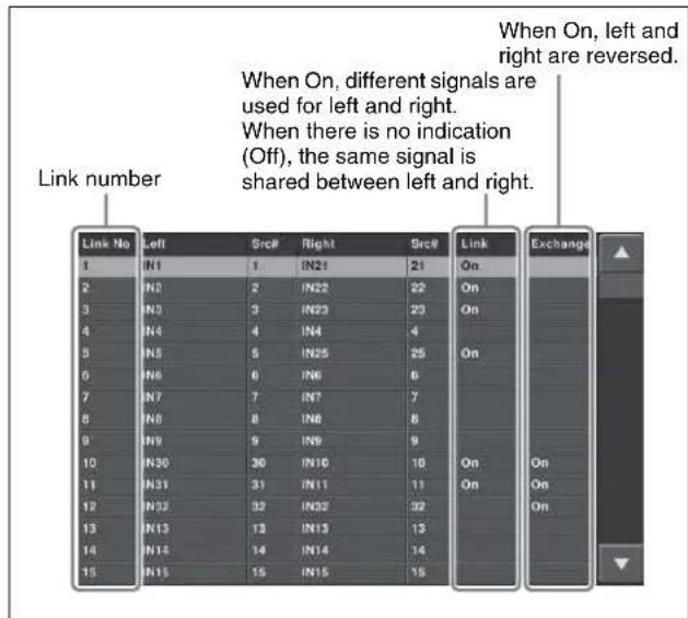
3 Using any of the following methods, select the link number to operate on.
- Press directly on the list.
- Press the arrow keys to scroll the reverse video cursor.
- Turn the knobs.
| Knob | Parameter Adjustment Setting values | |
| 1 Link | No Link number 1 to upwards | |
| 3 Num | Select the number of consecutive numbers from the selected link number | 1 to upwards |
4 Press [3D Input Link], and set the link to either of the following.
• To use separate left and right signals, set to On.
- To use the same signal shared between left and right, set to Off (no indication).
Notes
When this is set to "Off," one signal of the predetermined pair cannot be used.
For example, for IN1 and IN21, IN21 cannot be used, and is grayed out in the list.
5 Repeat steps 3 and 4, to set all of the primary inputs in 3D mode.
Using pairs of primary input numbers reversed right-to-left
Press [L/R Input Exchange], setting it to On, to swap the left and right signals, and reverse the indications in the list. For example, when the left signal is IN1, and the right signal is IN21, this assigns IN21 to the left signal and IN1 to the right signal.
Notes
When [3D Input Link] is off and [L/R Input Exchange] is set to On, then the other input of the pair can be used. For example, when using IN1 shared between left and right, you can also use IN21 shared between left and right, and IN21 also appears in the list.
To assign inputs with the primary input numbers reversed left-to-right to cross-points
1 In the Input Link menu, set [L/R Input Exchange] to On, then display the Engineering Setup >Panel >Xpt Assign >Main, V/K Pair Assign menu.
In the Source field, "3D Exchange=xx" appears ("xx" is the input number linked to the input number at the position of the cursor). In the example of the following figure, for IN11 "3D Exchange=31" appears.
2 Press [Set].
This sets IN31 in place of IN11.
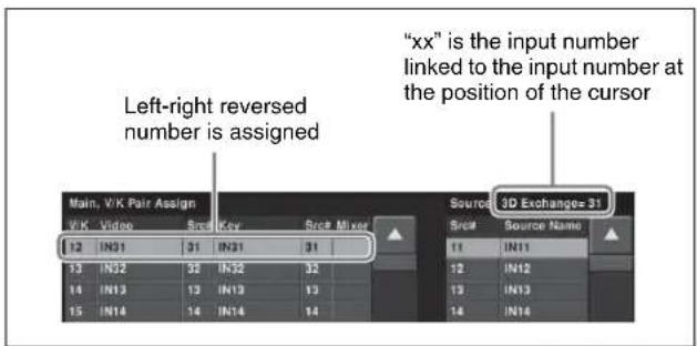
Combinations of left and right signals (output connectors)
The left and right signals are combined for the slots as follows.
If [1-2 Mode] is selected on MVS-8000X
| Right signals Left signals | |
| Slot 13 | |
| OUTPUTS 1 OUTPUTS 2 | |
| OUTPUTS 3 OUTPUTS 4 | |
| : | : |
| OUTPUTS 19 OUTPUTS 20 | |
| Right signals Left signals | |
| Slot 14 | |
| OUTPUTS 25 OUTPUTS 26 | |
| OUTPUTS 27 OUTPUTS 28 | |
| : | : |
| OUTPUTS 43 OUTPUTS 44 | |
| Slot 15 | |
| MSD1 MSD2 | |
| OUTPUTS 21 OUTPUTS 22 | |
| OUTPUTS 23 OUTPUTS 24 | |
| OUTPUTS 45 OUTPUTS 46 | |
| OUTPUTS 47 OUTPUTS 48 | |
If [1-21 Mode] is selected on MVS-8000X
| Right signals Left signals | |
| Slot 13 Slot 14 | |
| OUTPUTS 1 OUTPUTS 25 | |
| OUTPUTS 2 OUTPUTS 26 | |
| : | : |
| OUTPUTS 20 OUTPUTS 44 | |
| Slot 15 | |
| MSD1 MSD2 | |
| OUTPUTS 21 OUTPUTS 22 | |
| OUTPUTS 23 OUTPUTS 24 | |
| OUTPUTS 45 OUTPUTS 46 | |
| OUTPUTS 47 OUTPUTS 48 | |
If [1-2 Mode] is selected on MVS-7000X
| Right signals Left signals | |
| Slot 9 | |
| OUTPUTS 1 OUTPUTS 2 | |
| OUTPUTS 3 OUTPUTS 4 | |
| : | : |
| OUTPUTS 19 OUTPUTS 20 | |
| Slot 10 | |
| OUTPUTS 25 OUTPUTS 26 | |
| OUTPUTS 27 OUTPUTS 28 | |
| : | : |
| OUTPUTS 43 OUTPUTS 44 | |
| Slot 11 | |
| MSD1 MSD2 | |
| OUTPUTS 21 OUTPUTS 22 | |
| OUTPUTS 23 OUTPUTS 24 | |
| OUTPUTS 45 OUTPUTS 46 | |
| OUTPUTS 47 OUTPUTS 48 | |
If [1-21 Mode] is selected on MVS-7000X
| Right signals Left signals | |
| Slot 9 Slot 10 | |
| OUTPUTS 1 OUTPUTS 25 | |
| OUTPUTS 2 OUTPUTS 26 | |
| : | : |
| OUTPUTS 20 OUTPUTS 44 | |
| Slot 11 | |
| MSD1 MSD2 | |
| OUTPUTS 21 OUTPUTS 22 | |
| OUTPUTS 23 OUTPUTS 24 | |
| OUTPUTS 45 OUTPUTS 46 | |
| OUTPUTS 47 OUTPUTS 48 | |
Setting frame memory outputs for 3D mode
Select whether to use frame memory outputs 1 to 8 in combinations of left and right signals for 3D mode. The left and right combinations are fixed, as 1 and 5, 2 and 6, 3 and 7, and 4 and 8.
1 Display the Engineering Setup >Switcher >Config >3D Config menu.
2 Press [FM Output Link].
The FM Output Link menu appears.
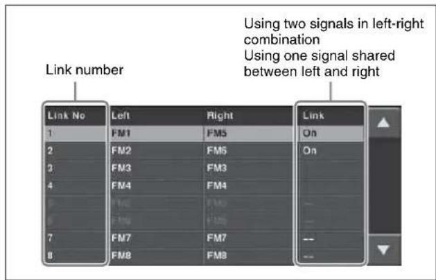
3 Using any of the following methods, select the link number.
- Press directly on the list.
- Press the arrow keys to scroll the reverse video cursor.
- Turn the knobs.
| Knob | Parameter | Adjustment | Setting values |
| 1 Link | No Link number | 1 to 8 |
| Knob | Parameter | Adjustment | Setting values |
| 3 Num | Select the | number of consecutive numbers from the selected link number | 1 to 8 |
4 Press [FM Link], and set the link to either of the following.
• To use the frame memory outputs in left and right combinations, set to On.
- To use the same frame memory output for left and right, set to Off (no indication).
Notes
When [FM Link] is On, frame memory output does not include ancillary data for the right image.
5 Repeat steps 3 and 4, to set all of the frame memory outputs for 3D mode.
Functions for which left and right frame memory outputs are coupled when [FM Link] is On
Pair mode On/Off, clip playback, clip transition ^1) , clip transition snapshot
Carry out operations other than the above separately for left and right.
1) When [FM Link] is On, a clip for the right frame memory to be used in the clip transition cannot be selected in the following menus.
• M/E-1 >Misc >Transition >Clip Transition >Clip menu
- M/E-2 >Misc >Transition >Clip Transition >Clip menu
- P/P >Misc >Transition > Clip Transition > Clip menu
- The selection must be made in the Frame Memory >Clip >Recall menu
Switching the type of DME output signal (video/key) assigned to a monitor signal
The function for switching the signal type of the monitor output (one channel) to video or key is assigned to one of the Prefs buttons of the Menu control block or one of the buttons of the Utility/Shotbox control block (DME MON KEY command).
For details of the assignment, see "Settings Button Assignment (Prefs/Utility Menu)" in Chapter 19 (Volume 2).
To switch the signal type of DME output (video/key) assigned to a monitor signal
Press the DME MON KEY command assigned button and turn it on to assign DME key output to a monitor signal. Then press the button and turn it off to assign DME video output to a monitor signal. For selection of the DME channels to be assigned to a monitor signal.
For details, see "Assigning a DME output signal as a monitor signal" (page 136).
Selecting the signal output from a DME monitor output connector
1 Display the Engineering Setup >DME >Output >Monitor Output menu.
2 Press [DME1] or [DME2] to select the DME to operate on.
3 On the left, select MONI OUT#1 or MONI OUT#2.
4 On the right, select the signal.
You can select any of Ch1 Video, Ch1 Key, Ch2 Video, and Ch2 Key.
5 Press [Set].
This assigns the signal.
Restrictions in 3D Mode
In 3D mode, the following restrictions apply, because the switcher and DME hardware is operating in tandem (link A and link B).
| Restrictions Details | |
| Functions that cannot be used in the switcher | 73 or more signal inputs (MVS-8000X) or 41 or more signal inputs (MVS-7000X)11 or more premium input signals (MVS-8000X only)25 or more signal outputsMonitor buses 2/4/6/8M/E-2 banka)M/E-3 bankKey 5 to Key 8b)DME utility buses 1, 2Color corrector 2Format converterFunctions of the “Logical M/E Assign” in the Engineering Setup >Switcher>Config menu. |
| Functions that cannot be used on the DME | DME channels 3, 4, 7, 8DME monitor output numbers 3 and 4Editor ports 3 and 4 when the editor port operation mode is set to “Independent” |
| Other restrictions | Auto chroma keying is carried out on the left image.Tallies are generated based on the left signal in the PGM/PST bank. |
a) In MVS-8000X
b) In MVS-7000X
Video Creation in 3D Mode
Adjusting the parallax using the DME
By adjusting the parallax (see page 255), you can control the degree of depth perception.
1 Display the Global Effect >Ch1 to Ch4 >3D Mode menu.
2 To adjust the parallax, press [Parallax].
3 Turn the knobs to adjust the following parameters.
| Knob | Parameter Adjustment Setting values | ||
| 1 | 1 c Parallax | Adjust the parallax for channel 1 | 0.00 to 8.00 |
| 2 | 2 c Parallax | Adjust the parallax for channel 2 | 0.00 to 8.00 |
Notes
If the position of an image in three-dimensional space is in the plane of the monitor screen, adjusting the parallax does not change the 3D effect. In this case, adjust the parameters in the local coordinate space so that the image is either in front of or behind the plane of the screen before adjusting the parallax.
4 To adjust the perspective without changing a size or shape, press [Disparity].
5 Turn the knobs to adjust the following parameters.
| Knob | Parameter | Adjustment | Setting values |
| 1 | 1 c Disparity | Adjust the degree of depth perception for channel 1 | -8.00 to 8.00 |
| 2 | 2 c Disparity | Adjust the degree of depth perception for channel 2 | -8.00 to 8.00 |
M/E Configuration Switching
On the MVS-7000X, a single mix/effect board MKS-7210X can be shared among a number of M/E banks. Using this function, you can select the M/E configuration of the whole switcher from the following.
| Board Num | Number of assigned M/Es | Number of keys available on a single M/E | |
| Board 1 1 | 8 | ||
| 2 | 4 | ||
| 3 M/E-1, M/E-2 Select from | 0 to 4 | ||
| PGM/PST 4 | |||
| 4 Select from 0 to 4 | |||
| Board 2 1 | 8 | ||
| 2 | 4 | ||
| Board 3 1 | 8 | ||
| 2 | 4 | ||
In this manual, using a single MKS-7210X board is referred to as 1M/E mode, 2M/E mode, 3M/E mode, or 4M/E mode depending on the maximum number of M/Es on which the board is used.
Notes
- A maximum of five M/Es can be used on a single switcher.
- When the signal format is 1080P, each MKS-7210X board can only be used on a single 1M/E and the number of available keys is 4.
- In 2M/E mode, DME selection on a single M/E is as follows.
- Two places when the dedicated interface is used.
- One place when the SDI interface is used.
Setting the number of M/Es for each board
Use the following procedure.
1 Display the Engineering Setup >System > Install/Unit Config >M/E Split menu.
2 In
3 In each of the
4 Press [Execute].
Assigning Keys for 3M/E Mode or 4M/E Mode
You can assign keys for 3M/E mode or 4M/E mode selected in the M/E Split menu.
1 Display the Engineering Setup >Switcher >Config >Key Config menu.
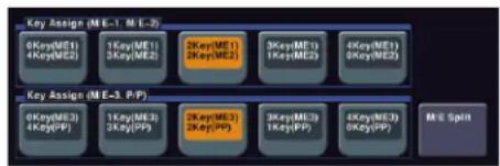
flowchart
graph TD
    A["0Key(ME1)\( 4Key(ME2) \)"] --> B["1Key(ME1)\( 3Key(ME2) \)"]
    B --> C["2Key(ME1)\( 2Key(ME2) \)"]
    C --> D["3Key(ME1)\( 1Key(ME2) \)"]
    D --> E["4Key(ME1)\( 8Key(ME2) \)"]
    F["0Key(ME3)\( 4Key(PF) \)"] --> G["1Key(ME3)\( 3Key(PF) \)"]
    G --> H["2Key(ME3)\( 2Key(PF) \)"]
    H --> I["3Key(ME3)\( 1Key(PF) \)"]
    I --> J["4Key(ME3)\( 8Key(PF) \)"]
    K["M E Split"] --> L["End"]
2 Assign keys to M/E-1 and M/E-2.
Select any of the following in the
0Key (ME1) 4Key(ME2): Assign no key to M/E-1 and four keys to M/E-2.
1Key(ME1) 3Key(ME2): Assign one key to M/E-1 and three keys to M/E-2.
2Key(ME1) 2Key(ME2): Assign two keys each to M/E-1 and M/E-2.
3Key(ME1) 1Key(ME2): Assign three keys to M/E-1 and one key to M/E-2.
4Key(ME1) 0Key(ME2): Assign four keys to M/E-1 and no key to M/E-2.
3 Assign keys to M/E-3 and P/P.
Select the key assignment method in the
Restrictions in 3M/E Mode and 4M/E Mode
In 3M/E mode and 4M/E mode, the following restrictions apply.
| Classification 3M/E mode 4M/E mode | ||||
| Operation mode All M/Es and P/P | DSK mode and multi-program 2 mode cannot be set. | All M/Es and P/P | • DSK mode and multi-program 2 mode cannot be set. • [Utility 2] cannot be selected for the background in multi-program mode. | |
| M/E-1, M/E-2 [Utility 2] cannot be selected for the background in multi-program mode. | ||||
| M/E assignment All M/Es and P/P | Logical M/E Assign cannot be used. | All M/Es and P/P | Logical M/E Assign cannot be used. | |
| Wipes All M/Es and P/P | • Pattern mix cannot be used. • Pattern number 162 wipes cannot be used. | All M/Es and P/P | • Pattern mix cannot be used. • Pattern number 162 wipes cannot be used. | |
| M/E-2 • Random/diamond dust wipes can be used. • Dust mix cannot be used. | M/E-2, M/E-3 • | Random/diamond dust wipes can be used. • Dust mix cannot be used. | ||
| Wipe border M/E-2 Wipe border colors are single-color only. | M/E-2, M/E-3 Wipe border colors are single-color only. | |||
| M/E outputs M/E-1, M/E-2 Out5 and Out6 cannot be used. All M/Es and P/P | Out5 and Out6 cannot be used. | |||
| Signal selection M/E-1, M/E-2 PROC V and PROC K signals cannot be selected with any cross-point button. | All M/Es and P/P | PROC V and PROC K signals cannot be selected with any cross-point button. | ||
| Utility bus | M/E-1 Since only one utility bus is available, utility 1 bus is used instead of utility 2 bus in the following functions.a) • Wipe border • Preset color mix • Backgrounds of DME wipes | M/E-1, P/P | Since only one utility bus is available, utility 1 bus is used instead of utility 2 bus in the following functions. • Wipe border • Preset color mix • Backgrounds of DME wipes | |
| M/E-2 Since only one utility bus is available, you cannot select the following functions. • Key border • Sub mask • Preset color mix • Wipe border | M/E-2, M/E-3 S | Since only one utility bus is available, you cannot select the following functions. • Key border • Sub mask • Preset color mix • Wipe border | ||
| M/E-2 If you select a DME wipe which uses a utility bus for a background image, a color matte signal is used instead of a utility bus signal. | M/E-2, M/E-3 If | you select a DME wipe which uses a utility bus for a background image, a color matte signal is used instead of a utility bus signal. | ||
| Side flags | M/E-2 | Side flags cannot be used. | M/E-2, M/E-3 | Side flags cannot be used. |
| DME | All M/Es and P/P | For PGM/PST, the same restrictions as those for 2M/E apply. For M/E1 and M/E-2, the same restrictions as those for 4M/E mode apply. | All M/Es and P/P | • For the dedicated interface, DME can be used in only one place for each M/E. • For the SDI interface, DME wipes and processed keys cannot be used. • Only one-channel mode patterns can be selected for DME wipes. |
a) No restriction is applied to P/P. Thus, both utility buses 1 and 2 can be used for P/P.
DME Operations
11
Chapter
DME
DME (Digital Multi Effects) allows you to add three-dimensional effects such as image movement, rotation, magnification and shrinking, as well as a wide variety of special effects. DME is the general name for all of these effects.
You can use up to eight channels as dedicated DME channels.
Each channel can be used on its own or in combination with other channels, which allows you to create advanced effects with more complexity.
Functions that can be used differ with the models of DME.
For details, see "Functional Differences With Models of DME" (page 401).
Three-Dimensional Transformations
Transformation is the process of placing a video image in a three-dimensional DME coordinate space and subjecting it to manipulations such as movement, rotation, magnification or shrinking.
Three-dimensional coordinate space
Source coordinate space and target coordinate space
Images are placed in one of two types of coordinate space: source coordinate space and target coordinate space.
- The source coordinate space is a three-dimensional coordinate space with reference to the image itself. The x- and y-axes are defined parallel to the plane of the image, and the z-axis is defined perpendicular to the plane of the image. When you move the image, the coordinate axes also move.
- The target coordinate space is a three-dimensional coordinate space with reference to the output monitor screen. The x- and y-axes are defined parallel to the
plane of the monitor screen, and the z-axis is defined perpendicular to the plane of the monitor screen. The coordinates do not move even if the image moves.
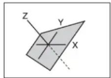
Source coordinate space
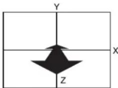
Target coordinate space
Source coordinate space and target coordinate space
For example, as shown in the following figure, the image moves in a different direction when you move it along the x-axis of the source coordinate space and along the x-axis of the target coordinate space.
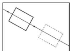
Source coordinate space
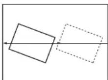
Target coordinate space
Movement along the x-axes of the source coordinate space and target coordinate space
Local coordinate space and global coordinate space
The coordinates of an individual DME channel are called its local coordinate space. The coordinates common to all channels are called the global coordinate space.
By switching from local to global coordinate space, you can add new movement to the movement of images in individual channels, and also apply transformation effects to multiple channels that have been combined by Global effects (see page 343).
Rotation around y-axis in local coordinate space
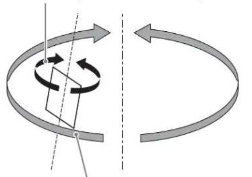
natural_image
Diagram showing a rotating cube with directional arrows, no text or symbols presentRotation around y-axis in global coordinate space
Local coordinate space and global coordinate space
Three-dimensional parameters
Three-dimensional parameters are x, y, and z values which define the position of an image, its axis of rotation, the position of an imaginary point of view on the image, and so on.
The standard values of parameters are as follows, depending on the aspect ratio of your monitor (4:3 or 16:9).
Values for 4:3 mode
- Origin at center of image (source coordinate space) or center of monitor (target coordinate space) x = 0.00, y = 0.00, z = 0.00
- Upper right corner of image or monitor When using SD format signals: x = 4.00, y = 3.00, z = 0.00 When using HD format signals: x = 12.00, y = 9.00, z = 0.00
- Lower left corner of image or monitor When using SD format signals: x = -4.00, y = -3.00, z = 0.00 When using HD format signals: x = -12.00, y = -9.00, z = 0.00
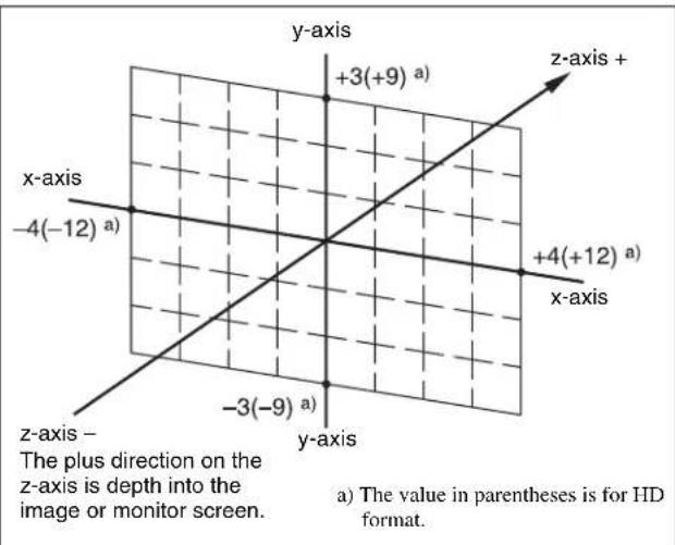
Values for x-, y-, and z-axes (4:3 mode)
Values for 16:9 mode
- Origin at center of image (source coordinate space) or center of monitor (target coordinate space) x = 0.00, y = 0.00, z = 0.00
- Upper right corner of image or monitor When using SD format signals: x = 4.00, y = 2.25, z = 0.00 When using HD format signals: x = 16.00, y = 9.00, z = 0.00
- Lower left corner of image or monitor When using SD format signals: x = -4.00, y = -2.25, z = 0.00 When using HD format signals: x = -16.00, y = -9.00, z = 0.00
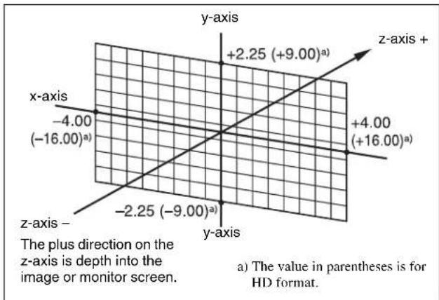
Values for x-, y- and z-axes (16:9 mode)
Limits of three-dimensional parameters
The following table shows the limits of three-dimensional transformation parameters.
The three-dimensional parameters of an image change when you use the trackball or Z-ring to execute a transformation. You can also execute a transformation by entering parameter values from the numeric keypad control block.
| Operation mode | Limits of three-dimensional transformation parameters | ||
| Location XYZ HD | format: -999.9999 to +999.9999 | ||
| SD format: | 4:3-333.3333 to +333.3333 | ||
| 16:9-250.0000 to +250.0000 | |||
| Rotation, Spin -999.9999 to +999.9999 | |||
| Axis Location HD | format: -999.9999 to +999.9999 | ||
| SD format: | 4:3-333.3333 to +333.3333 | ||
| 16:9-250.0000 to +250.0000 | |||
| Location Size 0.000 to +999.9999 | |||
| Aspect 0.0000 to +2.0000 | |||
| Perspective (x, y) | HD format: -999.9999 to +999.9999 | ||
| SD format: | 4:3-333.3333 to +333.3333 | ||
| 16:9-250.0000 to +250.0000 | |||
| Perspective (z) 0.0000 to 999.9999 | |||
| Skew -9.9999 to +9.9999 | |||
Detents
The system defines points called detents at regular intervals on the three-dimensional space. Pressing the [CTR] button (see page 278) in the device control block sets the current three-dimensional parameter values to the closest detent points.
The following table shows the interval between successive detents for each transformation operation mode (see page 265).
| Operation mode Detent interval | |
| Location XYZ | 1.0000 |
| Rotation, Spin | 0.2500 |
| Axis Location | 1.0000 |
| Location Size | 0.2500 |
| Aspect | 1.0000^a) |
| Perspective (x, y) | 1.0000 |
| Perspective (z) | 1.0000^a) |
| Skew | 0.1000 |
a) When a value is smaller than 1, 1/Aspect or 1/Perspective (z) is adjusted to an integral value.
Three-dimensional parameter default values
Each of the transformation operation modes has default values for three-dimensional parameters. If required, you can return the current value to the defaults by pressing the [CTR] (see page 278) button in the device control block twice in rapid succession.
The following table shows the default parameter values for each transformation operation mode.
| Operation mode Default value | |
| Location XYZ | 0.0000 |
| Rotation, Spin | 0.0000 |
| Axis Location | 0.0000 |
| Location Size | 1.0000 |
| Aspect | 1.0000 |
| Perspective (x, y) | 0.0000 |
| Perspective (z) | 1.0000 |
| Skew | 0.0000 |
Resetting of parameter values set in the source coordinate space
In some transformation operation modes, if you switch to the target coordinate space after setting up a three-dimensional transformation in the source coordinate space, the setting values in the source coordinate space (three-dimensional parameter values) are converted to values in the target coordinate space (source/target conversion).
Once a conversion has taken place, the original source coordinate space parameters do not return to their original values when you switch back to the source coordinate space. They are reset to zeros.
Source/target conversion occurs in the following operation modes:
- Location XYZ
- Rotation
Transformation Operation Modes
The following operation modes are available for three-dimensional DME transformations. These operations are carried out in the device control block (trackball or joystick). (For details, see “Three-Dimensional Transformation Operations” (page 277).)
Location XYZ
Moves the image on the x-axis, y-axis, or z-axis. The direction of movement differs depending on whether you are manipulating the image in the source coordinate space or the target coordinate space.
Image movement in the source coordinate space
Movement on the x-axis Movement on the y-axis
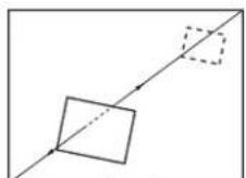
Movement on the z-axis
Image movement in the target coordinate space
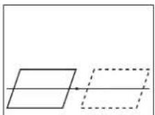
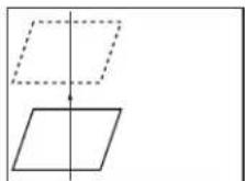
Movement on the x-axis Movement on the y-axis
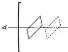
Movement on the z-axis
Rotation
Rotates the image on the x-axis, y-axis, or z-axis. The type of rotation differs depending on whether you are manipulating the image in the source coordinate space or the target coordinate space.
Image rotation in the source coordinate space
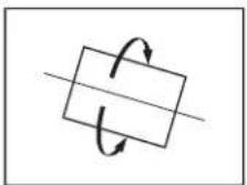
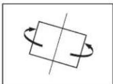
Rotation around the y-axisRotation around the x-axis
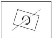
Rotation around the z-axis
Image rotation in the target coordinate space
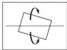
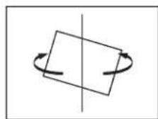
Rotation around the y-axisRotation around the x-
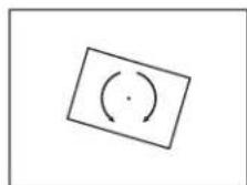
Rotation around the z-axis
Spin
When rotating the image in Rotation mode, it may not always be possible to achieve the kind of rotation around an axis that you want. Combining Rotation mode with Spin mode creates an effect that rotates the image around a specified axis. The type of rotation differs depending on whether you are manipulating the image in the source coordinate space or the target coordinate space. (The way the image rotates around an axis is the same as in Rotation mode.)
Axis Location
Moves an axis of rotation in the source coordinate space.
Axis movement
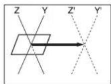
Movement on the x-axis
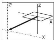
Movement on the y-axis
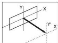
Movement on the z-axis
Location Size
Changes the size of the whole image.
- Because shrinking and magnification of the image in the source coordinate space is done in three-dimensional space, magnifying the image emphasizes the sense of perspective.
- Because shrinking and magnification of the image in the target coordinate space is a conversion of the two-dimensional image displayed on the monitor, shrinking and magnification does not change the shape of the image.
Magnification and shrinking in the source coordinate space
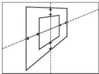
natural_image
Pure geometric diagram showing nested rectangles with arrows, no text or symbols presentMagnification and shrinking in the target coordinate space
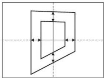
natural_image
Pure geometric diagram showing nested rectangles with arrows indicating direction, no text or symbols presentAspect
In the source coordinate space, changes the aspect ratio in the x-axis direction and y-axis direction, either independently or simultaneously.
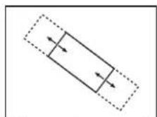
Change of aspect ratio in x-axis direction
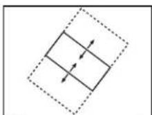
Change of aspect ratio in y-axis direction
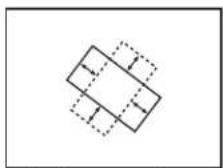
Simultaneous change aspect ratio in x-axis direction and y-axis direction
Perspective
In the target coordinate space, changes the perspective on the image by changing an imaginary view point, without changing the position of the image.
The x-axis and y-axis values define the position of the view point. The z-axis value defines its distance from the image.
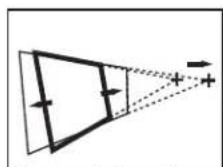
Change of view point on x-axis
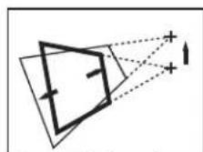
Change of view point on y-axis
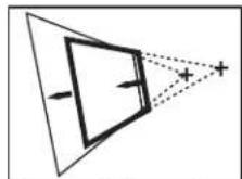
Change of distance from view point to image
Skew
In the source coordinate space, change the skew of the image on the x-axis or y-axis.
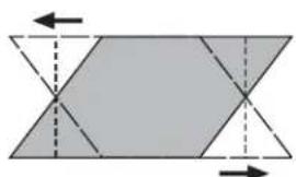
natural_image
Geometric diagram showing a parallelogram divided into two triangles with dashed internal lines and arrows indicating direction (no text or symbols)Change of skew on x-axis
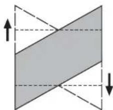
natural_image
Geometric diagram showing a shaded parallelogram with dashed and solid lines indicating dimensions (no text or symbols)Change of skew on y-axis
Graphics Display
Graphics display is a function that allows you to display wire frames, coordinate axes and a grid over the current DME image, to make it easier to create effects in three-dimensional coordinate space.
Graphics displayed by this function can also be output to the monitor output connector.
To make graphics display settings, use the DME menu. (For details, see "Graphics Display Operation" (page 281).)
You can display the following kinds of graphics.
Wire frames
A wire frame displays an image enclosed in a frames, so that you can check the position and size of the image. If there is a shadow (see page 349), a frame is shown for the shadow as well.
Coordinate axes
This is a three-dimensional display of coordinates in local or global coordinate space. You can check the origin of the axes and the directions of the x-, y-, and z-axes.
Channel ID
This displays the channel number so that you can check which channel you are using, a useful feature when you are working with multiple channels.
Channel IDs are displayed differently in local and global coordinate space.
- In local coordinate space, the channel number is displayed along with “F” or “B” to indicate whether you are looking at the front (F) or back (B) of the current wire frame. For example, “1F” means the front of the wire frame on channel 1 in local coordinate space.
- In global coordinate space, the channel number is displayed along with “G” to indicate global. For example, “G2” means channel 2 in global coordinate space.
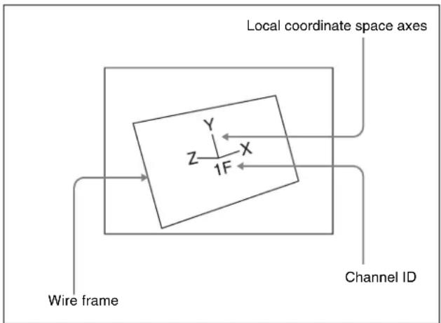
Wire frame, local coordinate space axes, and channel ID
Grid
This is a grid pattern representing the whole of the monitor screen. The grid makes it easy to set the position of an image in two-dimensional coordinates.
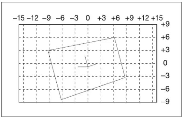
radar
| Angle (degrees) | X | Y | | :--- | --- | --- | | 0 | -15 | -9 | | 0 | -12 | -6 | | 0 | -9 | -3 | | 0 | -6 | 0 | | 0 | -3 | 3 | | 0 | 0 | 6 | | 0 | +3 | 9 | | 0 | +6 | 12 | | 0 | +9 | 15 | | 0 | +12 | 18 | | 0 | +15 | 21 | | 30° | -15 | -9 | | 30° | -12 | -6 | | 30° | -9 | -3 | | 30° | -6 | 0 | | 30° | -3 | 3 | | 30° | 0 | 6 | | 30° | +3 | 9 | | 30° | +6 | 12 | | 30° | +9 | 15 | | 30° | +12 | 18 | | 60° | -15 | -9 | | 60° | -12 | -6 | | 60° | -9 | -3 | | 60° | -6 | 0 | | 60° | -3 | 3 | | 60° | 0 | 6 | | 60° | +3 | 9 | | 60° | +6 | 12 | | 60° | +9 | 15 | | 60° | +12 | 18 | | 90° | -15 | -9 | | 90° | -12 | -6 | | 90° | -9 | -3 | | 90° | -6 | 0 | | 90° | -3 | 3 | | 90° | 0 | 6 | | 90° | +3 | 9 | | 90° | +6 | 12 | | 90° | +9 | 15 | | 90° | +12 | 18 | | ∞ | -15 | -9 | | ∞ | -12 | -6 | | ∞ | -9 | -3 | | ∞ | -6 | 0 | | ∞ | -3 | 3 | | ∞ | 0 | 6 | | ∞ | +3 | 9 | | ∞ | +6 | 12 | | ∞ | +9 | 15 | | ∞ | +12 | 18 | The chart displays a polygonal shape with vertices at integer multiples of π/2. The x-axis is labeled 'x', and the y-axis is labeled 'y'. The legend is not explicitly labeled in the image.Grid (16:9 mode)
Shrinking the graphics display
You can shrink the graphics display so that you can see beyond the range displayed on the normal monitor screen. This makes it possible to visually set the location of images in a larger space. The range displayed on a normal monitor screen is indicated by a frame.
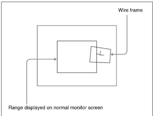
flowchart
graph TD
    A["Range displayed on normal monitor screen"] --> B["Wire frame"]
    B --> C["Component"]
    C --> D["Output"]
To automatically erase the graphic display
Turn Auto Erase on. The graphic display is erased automatically whenever a keyframe is executed. It is displayed again after the keyframe ends, after the time set in Recovery Time.
Flex Shadow center axis
When using the Flex Shadow function (see page 290), turn Flex Shadow Axis on to display the Flex Shadow center axis. This is an effective aid in making settings for this function.
Notes
The Flex Shadow center axis function is not supported on the MVE-8000A.
Three-Dimensional Parameter Display
You can display a three-dimensional parameter list for the currently controlled image. When more than one DME channel is selected, the status of the reference channel is displayed.
For the method of displaying a parameter list and an example display, see “Viewing the three-dimensional parameter details” (page 280).
Special Effects
You can use DME to add a variety of special effects. The special effects shown below can be applied.

Functions that can be used differ with the models of DME. For details, see “Functional Differences With Models of DME” (page 401).
Edge effects
| Name Effect/Image | |
| Border(See page 283.) | Adds a border to the image frame. You can adjust the width (or thickness) of the border, its color, and the softness of the border edges.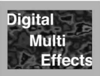 |
| Crop(See page 284.) | Crops away the edges of the image. You can crop the top, bottom, left, and right sides individually or all together. You can also soften the cropped edges.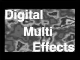 |
| Beveled Edge(See page 285.) | Gives an image a beveled edge. You can set the edge width and color. The inner edge softness and edge boundary softness can also be set. Color Color Lights Lights |
| Name Effect/Image | |
| Key Border(See page 286.) | Adds borders to keys or gives a key consisting of an outline only. |
| Art Edge(See page 286.) | Adds edges to the inner and outer side of the input image.The following items can be set.• Art edge width and position• Separate softening of the art edge inner and outer sides• Color of art edgesExamples of Art Edge source Gradation Matte Gradation Matte Rainbow Matte Rainbow Matte Radial Gradation Radial Gradation |

| Name Effect/Image | |
| Art Edge(See page 286.) |  Radial RainbowExamples of Art Edge source [Rainbow Matte] Radial RainbowExamples of Art Edge source [Rainbow Matte] |
| Flex Shadow(See page 290.) | Allows a shadow to be added to the image using only one DME channel.The following settings can be made for the shadow.The signal to use for the shadow- External: Generate shadow using input key signal.- Internal: Generate shadow using an internally generated, full-size DME key signal.Shadow shrinking and magnificationShadow positionShadow color and densityCenter axis of deformationShadow slant and perspective Flex Shadow Source = External Flex Shadow Source = External Flex Shadow Source = Internal Flex Shadow Source = Internal |
| Name Effect/Image | |
| Wipe Crop(See page 294.) | Crops the video image to be visible inside or outside a wipe pattern. |
| Background | |
 | |
 | |
| When Invert is On | |
| Video image | |
Effects for entire image
| Name Effect/Image | |
| Defocus(See page 297.) | Defocuses the whole image. The degree of defocusing can be set simultaneously or separately for video and key signals.(However, when the DME dedicated interface is used, the degree of defocusing can be set for video signals only.) You can also cancel the black level leaking that occurs at the edge of the screen when the Defocus effect is used. |
| Blur(See page 298.) | Applies a rounded blurring to the whole image. |
| Multi Move(See page 299.) | Shrinks the image and lines up a number of copies vertically and horizontally. You can specify the center point of the shrinking, the shrinking ratio, and the aspect ratio of the image screen. |
Effects for video image
| Name Effect/Image | |
| Sepia(See page 300.) | Overlays a specified color onto the image. You can adjust the sepia color that is overlaid, and specify the degree of mixing between the original image and the sepia image. |
| Mono(See page 300.) | Converts the image into a monochrome image. |
| Posterization(See page 300.) | Coarsens the luminance gradations of the image, for a paintinglike effect. |
| Solarization(See page 300.) | Coarsens the chroma gradations of the image, for a paintinglike effect. |
| Nega(See page 301.) | Reverses the luminance or chroma of the image.  |
| Contrast(See page 301.) | Changes the contrast of the luminance and chroma of the image. |
| Name Effect/Image | |
| Mosaic(See page 301.) | Divides the image into small tiles so that it looks like a mosaic. You can specify the size and aspect ratio of the tiles.  |
| Mask(See page 304.) | Masks part of the picture, so that special effects are applied only inside a selected pattern. Mask (normal)Effect video image(Mosaic) Video image Mask (normal)Effect video image(Mosaic) Video image Mask (invert) Mask (invert) |
| Sketch(See page 301.) | Provides a sketch-like effect based on the outlines of the image, using different touches such as sketch, edge color, drawing, relief, and sharp. Sketch Sketch |
| Metal(See page 303.) | Provides a metallic gloss like that from gold, silver, or a rainbow colored surface. A metallic gloss can also be given to a freely selected color. |
| Dim and Fade(See page 303.) | The Dim effect makes the image darker as it recedes into the distance. The Fade effect makes the image fade into the background as it recedes into the distance. Fade Fade |
| Glow(See page 304.) | Softens the edges of highlights, giving an effect like being struck by a soft light. |
Nonlinear effects
| Name Effect/Image | ||
| Wave(See page 307.) | Produces a wave-like effect in the image. |  |
| Mosaic Glass(See page 309.) | Makes the image rougher and finer at a specified interval. |  |
| Flag(See page 309.) | Applies an effect like a flag waving in the wind. |  |
| Twist(See page 309.) | Twists the image. |  |
| Ripple(See page 310.) | Applies an effect like ripples moving across the image. |  |
| Rings(See page 313.) | Partitions the image into rings that rotate while moving in the same direction. | 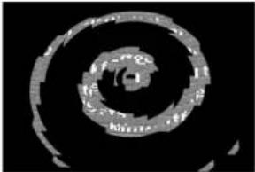 |
Freeze effects
Freezes the input video. The video can also be frozen at a specified interval (see page 306).
| Name Effect/Image | ||
| Broken Glass(See page 313.) | Partitions the image like broken glass, with shards flying outward. | 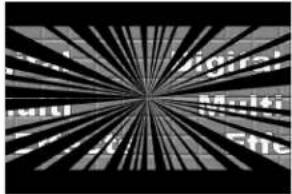 |
| Flying Bar(See page 314.) | Divides the image into bars which peel off in two blocks as they move. | 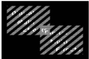 |
| Blind(See page 314.) | Divides the image into bars or wedges, with blocks rotating like the slats of venetian blinds. | 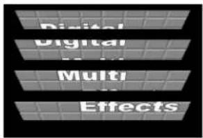 |
| Split(See page 315.) | Splits the image upper and lower, left and right. | 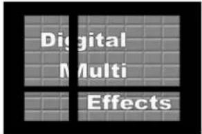 |
| Split Slide(See page 315.) | Divides the image into bars which slide alternately in reverse directions. | 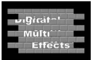 |
| Mirror(See page 316.) | Partitions the image vertically and horizontally, creating an image like a reflection in a mirror. | 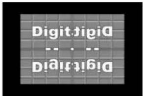 |
| Multi Mirror(See page 316.) | Divides the image into originals and reflections, lining them up vertically and horizontally. | 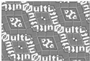 |
| Name Effect/Image | ||
| Kaleidoscope(See page 317.) | Creates an image like a view into a kaleido-scope. | 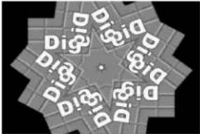 |
| Lens(See page 317.) | Creates an image like a view through a lens. |  |
| Circle(See page 318.) | Makes a circle with the image. |  |
| Panorama(See page 318.) | Curves the upper and lower edges of the image to emphasize the sense of perspective. |  |
| Page Tum(See page 318.) | Turns the image like a turning page. | 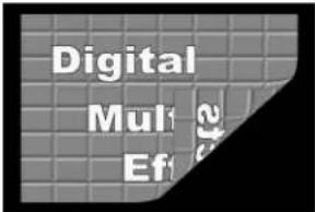 |
| Roll(See page 319.) | Rolls the image up. |  |
| Cylinder(See page 319.) | Winds the whole image onto a cylinder. | 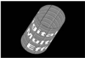 |


| Name Effect/Image | ||
| Sphere(See page 320.) | Winds the whole image onto a sphere. |  |
| Explosion(See page 320.) | Divides the image into fragments which expand as they fly out. |  |
| Swirl(See page 320.) | Swirls the image. | 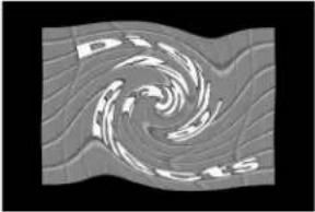 |
| Melt(See page 321.) | Melts the image away from a specified part. |  |
| Character Trail(See page 322.) | Extends the edge of the image like a trail. |  |
Corner Pinning effect
| Name Effect/Image | |
| Corner Pinning(See page 341.) | Provides the effect of inserting theforeground in the background, allowingthe four corners to be positioned freely, sothat the image fills the quadrilateraloutlined by the corners. Background Background Foreground (in cropped state) Foreground (in cropped state) Corner Pinning (when Crop Link is on) Corner Pinning (when Crop Link is on) |
Lighting effects
| Name Effect/Image | |
| Lighting(See page 323.) | Provides the effect of light striking the image. |
 Normal Normal | |
 Specular Specular | |
 Mat Mat | |
| Spotlighting(See page 330.) | Creates the effect of a spotlight striking the surface of the image. |
Recursive effects
| Name Effect/Image | ||
| Trail(See page 325.) | Recursively freezes the input video at regular intervals so that a trail of afterimages is created. You can make the afterimages stardust trails. |  |
| Name Effect/Image | ||
| Motion Decay(See page 327.) | Blurs the motion of a moving video by creating afterimages of the moving video. You can make the afterimages stardust trails. |  |
| Keyframe Strobe(See page 328.) | Freezes the video each time the effect passes a keyframe. You can make the afterimages stardust trails. | |
| Wind(See page 329.) | Strobes the image at regular intervals, and moves the frozen image in a fixed direction, leaving an afterimage. | |
Background color
Adds a color or inputs an external signal to the background of the image (see page 338).
Separate sides (effects for front and back sides)
Applies separate video signals and key signals to the front and back of the image (see page 338).
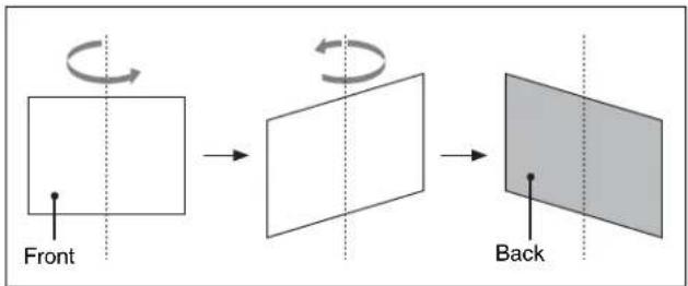
flowchart
graph LR
    A["Front"] --> B["Rotate"]
    B --> C["Back"]
Front and back sides
Signal inversion (Invert effect)
Inverts the input video signal and/or key signal horizontally or vertically. You can make separate settings for the front and back (see page 339).
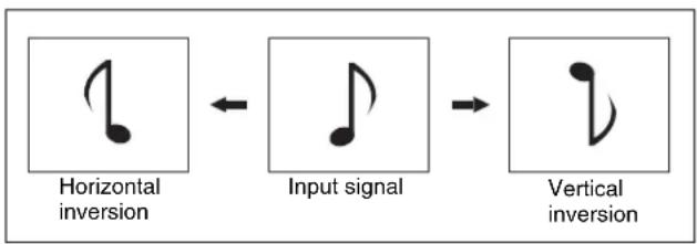
flowchart
graph LR
    A["Horizontal inversion"] <--> B["Input signal"]
    B --> C["Vertical inversion"]
Inversion of input signal
Key density adjustment
Adjusts the key density for the key signal input to the DME (see page 340).
Key source selection
Selects either the key signals received from the switcher or the key signals generated in the DME for application to the front and back of the image (see page 275 or page 340).
Color mix setting
This is a combination of two colors with a pattern generator. This color mix signal can be used to fill parts such as a background or border (see page 296).
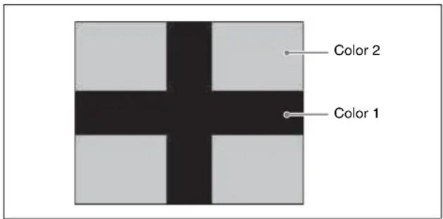
Global Effects
Global effects are special effects created by combining the images of successive channels. The following types of global effects are available.
- Combiner
- Brick
- Shadow
Devices for DME Support
The following boards and processors provide DME support.
The available functions depend on the type of DME being used. For details, see “Functional Differences With Models of DME” in Appendix (page 401).
MKS-7470X/7471X DME board set (MVS-7000X only)
Installing this in the MVS-7000X allows DME to be operated as though part of the switcher.
Each board supports two channels, and a maximum of two boards (four channels) can be used.
There are two types of interfaces available for connecting DMEs to the switcher: the dedicated interface and the SDI interface.
For details, see “Setting the Interface Between the DME and the Switcher” in Chapter 20 (Volume 2).
The use of the SDI interface requires an MKS-8110X 20-input board and an MKS-7171X DME output connector board. When using the SDI interface, the following operations are different from using the dedicated interface.
- Setting the input signals from the switcher to the MKS-7470X/7471X (AUX bus outputs), and signals returned to the switcher (reentry inputs). For details, see “Setting the AUX Bus Output and Reentry Input” in Chapter 20 (Volume 2).
- Selecting the combiner channels not in the key control block, but in the Global Effect menu.
For details, see “Procedure for combine operation when using an SDI interface” (page 345)
MVE-8000A Multi Format DME Processor
The MVE-8000A is a “Digital Multi Effects” with multi-format support.
For the MVE-8000A, an optional MKE-8021A Input/Output Board is available as a dedicated interface for integrated use with the switcher.
There are two types of interfaces available for connecting DMEs to the switcher: the dedicated interface and the SDI interface.
Notes
When using the SDI interface, the following operations are different from using the dedicated interface.
For details, see “Setting the Interface Between the DME and the Switcher” in Chapter 20 (Volume 2).
- Setting the input signals from the switcher to the MVE-8000A (AUX bus outputs), and signals returned to the switcher (reentry inputs). However, "Ext In" cannot be set for the DME channel.
For details, see "Setting the AUX Bus Output and Reentry Input" in Chapter 20 (Volume 2). - Selecting the combiner channels not in the key control block, but in the Global Effect menu (see page 344).
MVE-9000 Multi Format DME Processor
The MVE-9000 is a “Digital Multi Effects” with multi-format support.
For the MVE-9000, an optional MKE-9021A Input/Output Board is available as a dedicated interface for integrated use with the switcher.
There are two types of interfaces available for connecting DMEs to the switcher: the dedicated interface and the SDI interface.
For details, see “Setting the Interface Between the DME and the Switcher” in Chapter 20 (Volume 2).
Notes
When using the SDI interface, the following operations are different from when using the dedicated interface.
- Setting the input signals from the switcher to the MVE-9000 (AUX bus outputs), and signals returned to the switcher (reentry inputs).
For details, see “Setting the AUX Bus Output and Reentry Input” in Chapter 20 (Volume 2). - Selecting the combiner channels not in the key control block, but in the Global Effect menu (see page 344).
Three-Dimensional Transformation Operations
Use the device control block to carry out three-dimensional DME transformations.
For details of three-dimensional DME coordinate space, see “Three-Dimensional Transformations” (page 263).
Basic Operations
This section explains how to use the device control block (trackball) to carry out three-dimensional transformations.
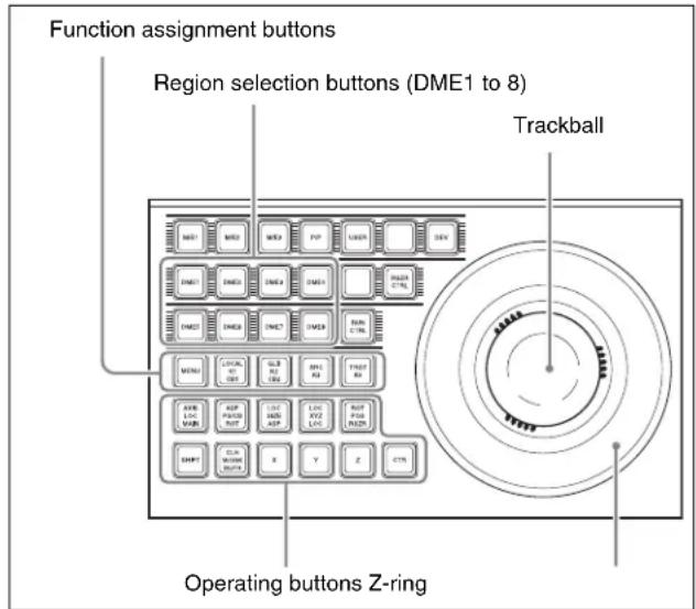
Device control block (trackball)
Buttons used when the three-dimensional transform operation mode is enabled
LOCAL: Enable operations in the DME local coordinate space.
GLB (global): Enable operations in the DME global coordinate space. The [LOCAL] and [GLB] buttons can be selected at the same time.
SRC (source): Enable operations in the DME source coordinate space.
TRGT (target): Enable operations in the DME target coordinate space.
The [SRC] and [TRGT] buttons cannot be selected at the same time. When these buttons are held down, trackball and Z-ring operation is switched to a finer control. (fine mode)
AXIS LOC (location): When this button is lit, the trackball moves the rotational axis of the image in the x-axis and y-axis directions, and the Z-ring moves the axis in the z-axis direction.
ASP PERS (aspect/perspective): When the [SRC] button is lit, pressing this button enables the trackball to control the x-axis and y-axis directions independently, and the Z-ring controls the x-axis and y-axis directions together, to vary the aspect ratio. When the [SHIFT] button is held down and this button is pressed, the trackball controls the skew of the image in the x-axis and y-axis directions.
When the [TRGT] button is lit, pressing this button enables the trackball to control the perspective of the image in the x-axis and y-axis directions.
The Z-ring controls the distance to the viewpoint.
LOC (location) SIZE: When this button is lit, the Z-ring controls the image size.
The trackball moves the image in the x-axis and y-axis directions.
LOC (location) XYZ: When this button is lit, the trackball moves the image in the x-axis and y-axis directions, and the Z-ring moves the image in the z-axis direction.
SHIFT: While holding down this button, pressing the [ASP PERS] button or [ROT] button switches to the shifted version of the corresponding function.
CLR WORK BUFR (clear work buffer): Press this button once to clear only the three-dimensional transform parameters of the information held in the work buffer. Press twice in rapid succession to clear all of the parameters, and return to the default state.
ROT (rotation): When this button is lit, the trackball rotates the image about the x- and y-axes, and the Z-ring rotates the image about the z-axis.
Pressing this while holding down the [SHIFT] button enables rotation of the image in the "Spin" mode. The trackball and Z-ring operate in the same manner.
X, Y, Z: These restrict which axes the trackball and Z-ring can control. You can select more than one.
When one of these buttons is selected, you can enter the parameter value for the corresponding axis using the numeric keypad control block.
CTR (center): Pressing this button changes the values of the three-dimensional parameters currently controlled by the trackball and Z-ring to the closest detent values. Pressing twice in rapid succession returns the parameter values to their defaults.
Transforming an image in three-dimensional coordinate space
1 With the region selection buttons, select the target channel of the operation.
You can press several of the buttons simultaneously to select several channels. In this case, the button that you
pressed first lights in green, while buttons pressed subsequently light in amber.
2 With the function assignment buttons, select the three-dimensional coordinate space in which to perform the transformation.
LOCAL button: Selects local coordinate space.
GLB button: Selects global coordinate space. You can select this button and the [LOCAL] button simultaneously.
SRC button: Selects the source coordinate space.
TRGT button: Selects the target coordinate space. ([SRC] and [TRGT] cannot be selected at the same time.)
3 Press the button for the operation you want to do, turning it on, to select the transformation mode.
The trackball and Z-ring are assigned to the selected three-dimensional coordinate space transformation mode.
To move the image: Press the [LOC XYZ] button, turning it on.
You can move the image on the x- and y-axes with the trackball and move it on the z-axis with the Z-ring. Pressing the [LOC SIZE] button instead of the [LOC XYZ] button, turning it on, makes it possible to move the image on the x- and y-axes.
To rotate the image: Press the [ROT] button, turning it on.
You can rotate the image on the x- and y-axes with the trackball and rotate it on the z-axis with the Z-ring.
To rotate the image in Spin mode, press the [ROT] button, turning it on, while holding down the [SHIFT] button. You can operate in the same way with the trackball and Z-ring.
To move an axis of rotation: With the [SRC] button selected in step 2, press the [AXIS LOC] button, turning it on.
You can move the axis of rotation of the image on the x- and y-axes of the image with the trackball, and on the z-axis with the Z-ring.
To magnify or shrink the image: Press the [LOC SIZE] button, turning it on.
You can magnify and shrink the image with the Z-ring. Rotate counterclockwise to shrink, and clockwise to magnify.
To change the aspect ratio of the image: With the [SRC] button selected in step 2, press the [ASP PERS] button, turning it on.
You can change the aspect ratio independently on the x- and y-axes with the trackball, and change it simultaneously on both the x- and y-axes with the Z-ring.
To change the perspective on the image: With the [TRGT] button selected in step 2, press the [ASP
PERS] button, turning it on.
You can change the perspective of the image on the x- and y-axes with the trackball, and change the distance to the view point with the Z-ring.
To change the skew of the image: With the [SRC] button selected in step 2, press the [ASP PERS] button, turning it on, while holding down the [SHIFT] button.
You can change the skew of the image along the x- and y-axes with the trackball.
4 Depending on the axis of the change, operate the trackball and Z-ring as follows.
- To change on the x-axis, rotate the trackball horizontally.
Parameter values increase as you rotate to the right, and decrease as you rotate to the left.

natural_image
Abstract diagram with concentric circles and two opposing arrows, no text or symbols present- To change on the y-axis, rotate the trackball vertically.
Parameter values increase as you rotate upward, and decrease as you rotate downward.

natural_image
Abstract circular diagram with concentric rings and a central arrow, no text or symbols present.• To change on the z-axis, rotate the Z-ring.
Parameter values increase as you rotate clockwise, and decrease as you rotate counterclockwise. However, when you have pressed the [LOC XYZ] button to move the image, z-axis parameters increase as you rotate counterclockwise, and decrease as you rotate clockwise.
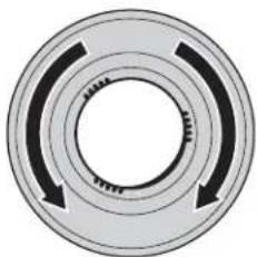
natural_image
Circular mechanical component with three curved arrows indicating rotational direction (no text or symbols)To reduce the rate of change of the parameters (fine mode)
Carry out the trackball or Z-ring operations while holding down the [SRC] or [TRGT] button.
5 To restrict the change in the transformation to a specific axis, press the [X], [Y], or [Z] button, tuning it on.
This enables the trackball and Z-ring operations on the selected axis only.
Functions assignable to trackball and Z-ring operations
| Button Usable coordinate space | Trackball x-direction | Trackball y-direction | Z-ring | |
| LOC XYZ | Source, target | Move image on x-axis | Move image on y-axis | Move image on z-axis |
| ROT Source, target | Rotate image on y-axis | Rotate image on x-axis | Rotate image on z-axis | |
| SHIFT+ ROT | Source, target | Rotate image on y-axis (Spin mode) | Rotate image on x-axis (Spin mode) | Rotate image on z-axis (Spin mode) |
| AXIS LOC | Source Move | x-axis of rotation | Move y-axis of rotation | Move z-axis of rotation |
| LOC SIZE | Source, target | Move image on x-axis | Move image on y-axis | Magnify and shrink image |
| ASPPERS | Source Change aspect ratio on x-axis | Change aspect ratio on y-axis | Change aspect ratio on x- and y- axes simultaneously | |
| Target Shift view point on x-axis | Shift view point on y-axis | Change distance from view point to image | ||
| SHIFT+ ASP PERS | Source Change skew on x-axis | Change skew on y-axis | Change aspect ratio on x- and y- axes simultaneously | |
Three-Dimensional Parameter Display
You can check the values of the three-dimensional parameters in the DME menu.
Displaying the three-dimensional parameters in the DME menu
In the menu control block, select the top menu selection button [DME].
The DME menu appears. The status area shows the three-dimensional parameters currently controlled by the device control block.
- When multiple DME channels are selected, this shows the parameters for the reference channel.
- When both Global and Local are selected, the three-dimensional parameters are shown for the channel (the reference channel) for which the button is lit green.
![Global Target] Loc XYZ] X=200.1500] Y=100.0000] Z=-150.9999] Type of three-dimensional space a) Operation mode for three-dimensional transforms b) Value of X Value of Y Value of Z](/content/2026/06/1364863/images/6e6e74c3a57593ab49d2c2d527ef175b008ef096e323bb8b52b66074003c5ac6.jpg)
a) This shows one of Local Target, Local Source, Global Target, and Global Source.
b) This shows one of Loc XYZ, Loc Size, Rot, Spin, Axis Loc, Skew, Asp, and Pers.
Example three-dimensional parameter display (DME menu)
Viewing the three-dimensional parameter details
In the DME menu, press the menu title button (the [DME] in the upper left part of the screen).
The Status menu appears. This menu shows the three-dimensional parameters for the DME reference channel currently selected in the device control block.
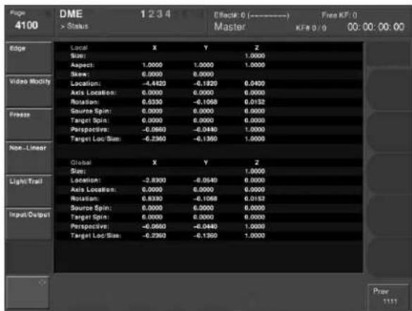
Example three-dimensional parameter details
Entering Three-Dimensional Parameter Values
In addition to setting three-dimensional parameter values with the trackball and Z-ring, you can enter them directly from the numeric keypad control block.
Entering three-dimensional parameter values
1 In the device control block, press the [X], [Y], or [Z] button, turning it on.
The numeric keypad control block enters a mode in which you can enter parameters for the selected axis.
2 Enter a parameter value with the numeric keypad.
The number of significant digits after a decimal point is 4.
3 Press the [ENTER] button.
The parameter value is changed, and the image changes.
To enter difference values
You can enter difference values by pressing the [+/-] button, entering the difference from the current value, and pressing the [TRIM] button to confirm. The [+/-] button toggles between “+” (plus) and “-” (minus) each time it is pressed.
Resetting three-dimensional parameter values
Pressing the [CTR] button in the device control block sets the current three-dimensional parameter values to the closest detent points (page 265).
To reset three-dimensional parameter values to the defaults (page 265) for the current transformation operation mode, press the [CTR] button twice in rapid succession.
Clearing the working buffer
The working buffer is memory that holds the instantaneous state of an effect. To clear (initialize) only the three-dimensional transform parameters in the working buffer, press the [CLR WORK BUFR] button in the device control block.
To clear all of the parameters in the working buffer and initialize the DME system, press the [CLR WORK BUFR] button twice in rapid succession. It is necessary to do this for both the local coordinate space and global coordinate space.
As the initial DME state, you can specify whether to use the factory default settings or user settings in the Setup menu.
For details see “Selecting the State After Powering On (Start Up Menu)” in Chapter 18 (Volume 2).
Graphics Display Operation
Use the DME menu to make graphics display settings. You can make separate settings for separate channels. To select a target DME channel, use the device control block.
For the types of graphics displayed, see “Graphics Display” (page 267).
Displaying graphics
1 In the menu control block, select the top menu selection button [DME].
The DME menu appears.
2 Select VF6 'Input/Output' and HF4 'Graphic.'
The Graphic menu appears.
3 Turn [Graphic] on.
The system enters graphics display mode, enabling graphics to be displayed in the monitor screen.
4 Turn on the buttons of the graphics you want to show.
To show axes: Turn [Axis] on.
To show axis names: Turn [Axis Name] on.
To show the channel ID: Turn [Ch ID] on.
To show a wire frame: Turn [Wire Frame] on.
To show the grid: Turn [Grid] on.
To show the flex shadow axis: Turn [Flex Shadow Axis] on.
The selected graphics appear in the monitor screen.
Notes
The flex shadow axis function is not supported on the MVE-8000A.
5 If you want to shrink the graphics display to show the range not displayed on a normal monitor, turn [Scale] on and set the following parameters.
| Knob | Parameter | Adjustment | Setting values |
| 1 Scale | Degree to | which the graphics display is shrunk | 0.00 to 100.00 |
As the value of the setting grows, the monitor shrinks further toward the center point.
6 To automatically erase the graphic display while the keyframes are executing, press [Auto Erase], turning it on, and then set the following parameter.
| Knob | Parameter | Adjustment | Setting values |
| 1 | R e Time | Time until o graphic display appears again after keyframe execution | 0 to 800 (frames) r |
Outputting graphics to the monitor output connector
In the Graphic menu, press [Monitor Out] to turn it on. Graphics are displayed on the device connected to the monitor output connector.
Canceling Virtual Images
When a transformation is executed with an extreme degree of perspective, the part of the image which is beyond the imaginary view point can wrap around and show on the other side. The wrapped-around portion is referred to as a virtual image.
Using the DME menu, you can make a setting not to show the virtual images.
Canceling virtual images
1 In the DME menu, select VF6 'Input/Output' and HF2 'Video/Key.'
The Video/Key menu appears.
2 Press [Wrap Around], turning it on.

![Virtual image [Wrap Around] on](/content/2026/06/1364863/images/e233262cf59a4bf25efe0e8085e865e27d3b4cfb4ad98a1e2f5b038bbc469711.jpg)
Applying Special Effects (Operations Common to Special Effects)
In this section, explanations of the operating procedures for individual special effects begin with selections from the DME menu. The following are common operations that you must do prior to selecting from the DME menu.
1 In the device control block, select the target DME channel.
2 In the menu control block, select the top menu selection button [DME].
The DME menu appears.
Applying Special Effects (Edge Effects)
Border Settings
Adding a border
1 In the DME menu, select VF1 'Edge' and HF1 'Border/Crop.'
The Border/Crop menu appears.
2 Press [Border], turning it on.
3 Set the parameters.
The valid ranges of the parameter values depend on the combination of signal format (SD/HD) and aspect ratio (4:3/16:9) selected in the system, as follows.
4:3 mode
Parameter group [1/2]
| Knob | Parameter | Adjustment | Setting values |
| 1 H Border width | on left and right sides | Left value shown | |
| 2 V Border width | on top and bottom sides | Top value shown | |
| 3 All Border width | on all sides | Left value shown | |
| 5 | D e | n s density | 0.00 to 100.00 y |
Parameter group [2/2]
| Knob | Parameter | Adjustment | Setting values |
| 1 Top | Border width | on top side | -6.00 to +6.00 (SD)-18.00 to +18.00 (HD) |
| 2 Left | Border width | on left side | -8.00 to +8.00 (SD)-24.00 to +24.00 (HD) |
| 3 Right | Border width | on right side | -8.00 to +8.00 (SD)-24.00 to +24.00 (HD) |
| 4 Bottom | Border width on bottom side | -6.00 to +6.00 (SD)-18.00 to +18.00 (HD) | |
| 5 | D e | n s density | 0.00 to 100.00 y |
16:9 mode
Parameter group [1/2]
| Knob | Parameter | Adjustment | Setting values |
| 1 H Border width | on left and right sides | Left value shown | |
| 2 V Border width | on top and bottom sides | Top value shown | |
| 3 All Border width | on all sides | Left value shown | |
| 5 | D e | n s density | 0.00 to 100.00 y |
Parameter group [2/2]
| Knob | Parameter | Adjustment | Setting values |
| 1 Top | Border width | on top side | -4.50 to +4.50 (SD)-18.00 to +18.00 (HD) |
| 2 Left | Border width | on left side | -8.00 to +8.00 (SD)-32.00 to +32.00 (HD) |
| 3 Right | Border width | on right side | -8.00 to +8.00 (SD)-32.00 to +32.00 (HD) |
| 4 Bottom | Border width on bottom side | -4.50 to +4.50 (SD)-18.00 to +18.00 (HD) | |
| 5 | D e | n s density | 0.00 to 100t00 y |
Setting the border color
The operation differs depending on the DME used (MVE-8000A, MVE-9000 or MKS-7470X/7471X).
When the MVE-8000A is used
Press [Border Color], turning it on, and set the following parameters.
| Knob | Parameter | Adjustment | Setting values |
| 1 Luminance | Luminance | 0.00 to 100.00 | |
| 2 Saturation | Saturation | 0.00 to 100.00 | |
| 3 Hue | Hue | 359.99 to 0.00 |
When the MVE-9000 or MKS-7470X/7471X is used
Use the buttons in the
Flat Color: single color
Mix Color: mix color signal set in the Color Mix menu (see page 296)
Ext Video: an external video signal input to the Ext IN connector
If Flat Color is selected, adjust the following parameters.
| Knob | Parameter | Adjustment | Setting values |
| 1 Luminance | Luminance | 0.00 | to 100.00 |

| Knob | Parameter | Adjustment Setting | values |
| 2 | Saturation | Saturation 0.00 to 100.00 | |
| 3 | Hue | Hue 359.99 to 0.00 |
If Mix Color or Ext Video selected, the border color changes according to the mix color signal or external video signal.
Softening the border edges
Press [Border Soft], turning it on, and set the following parameters.
| Knob | Parameter | Adjustment Setting values | |
| 1 | Soft | Softness of inner side of border | 0.00 to 100.00 |
Crop Settings
Cropping the image
1 In the DME menu, select VF1 'Edge' and HF1 'Border/Crop.'
The Border/Crop menu appears.
2 Press [Crop], turning it on.
3 Set the parameters.
The valid ranges of the parameter values depend on the combination of signal format (SD/HD) and aspect ratio (4:3/16:9) selected in the system, as follows.
4:3 mode
Parameter group [1/2]
| Knob | Parameter | Adjustment | Setting values |
| 1 | H | C r positions on left and right sides | Left value shown |
| 2 | V | C r positions on top and bottom sides | Top value shown |
| 3 | A I | I C positions on all sides | Left value shown |
Parameter group [2/2]
| Knob | Parameter Adjustment Setting values | ||
| 1 Top | Crop position on top side | -3.00 to +3.00 (SD) -9.00 to +9.00 (HD) | |
Parameter group [2/2]
| Knob | Parameter | Adjustment | Setting values |
| 2 Left | Crop position on left side | -4.00 to +4.00 (SD) -12.00 to +12.00 (HD) | |
| 3 Right | Crop position on right side | -4.00 to +4.00 (SD) -12.00 to +12.00 (HD) | |
| 4 Bottom | Crop position on bottom side | -3.00 to +3.00 (SD) -9.00 to +9.00 (HD) | |
16:9 mode
Parameter group [1/2]
| Knob | Parameter | Adjustment | Setting values |
| 1 | H | C r positions on left and right sides | Leftvalue spown |
| 2 | V | C r positions on top and bottom sides | Topvalue spown |
| 3 | A I | I positions on all sides | C Left value shown |
Parameter group [2/2]
| Knob | Parameter | Adjustment | Setting values |
| 1 Top | Crop | position on top side | -2.25 to +2.25 (SD) -9.00 to +9.00 (HD) |
| 2 Left | Crop | position on left side | -4.00 to +4.00 (SD) -16.00 to +16.00 (HD) |
| 3 Right | Crop | position on right side | -4.00 to +4.00 (SD) -16.00 to +16.00 (HD) |
| 4 Bottom | Crop | position on bottom side | -2.25 to +2.25 (SD) -9.00 to +9.00 (HD) |
Signs of numeric settings
For H, V, and All settings, the sign (+/-) of the setting need not be considered. For example, in the case of an H setting, the value for Left is automatically regarded as a negative value, and the value for Right as a positive value, to display the image.
The following is an example of these settings.
| Parameter | Entered value | Setting |
| H | 1.5 | Left=-1.50 |
| Right=1.50 | ||
| -1.5 | Left=-1.50 | |
| Right=1.50 |
4 To soften the edges of the image, press [Edge Soft], turning it on, and set the following parameter.
| Knob | Parameter | Adjustment | Setting values |
| 1 Soft | Softness of edges | 0.00 to 100.00 | |
Notes
Edges cannot be softened when the Crop effect is disabled.
To specify whether to invert the crop area when inverting the video image
In the
Crop -> Invert: Set an axis of symmetry at the center of the input video, and invert both the desired area of video and the crop area horizontally and vertically around that axis of symmetry. The order of effect application is Crop > Invert.
Invert -> Crop: Set an axis of symmetry at the center of the input video, and invert only the desired area of video horizontally and vertically around that axis of symmetry. The order of effect application is Invert > Crop.
2 Press [Beveled Edge], turning it on.
3 Set the parameters.
The valid ranges of the parameter values depend on the combination of signal format (SD/HD) and aspect ratio (4:3/16:9) selected in the system, as follows.
4:3 mode
| Knob | Parameter | Adjustment | Setting values |
| 1 H Simultaneous | sly adjust width of left and right edges | 0.00 to 4.00 (SD)0.00 to 12.00 (HD) | |
| 2 V Simultaneous | sly adjust width of top and bottom edges | 0.00 to 3.00 (SD)0.00 to 9.00 (HD) | |
| Knob | Parameter | Adjustment | Setting values |
| 3 All Simultane- | ously adjust width of all four edges | Value of H shown | |
16:9 mode
| Knob | Parameter | Adjustment | Setting values |
| 1 H Simultane- | ously adjust width of left and right edges | 0.00 to 4.00 (SD)0.00 to 16.00 (HD) | |
| 2 V Simultane- | ously adjust width of top and bottom edges | 0.00 to 2.25 (SD)0.00 to 9.00 (HD) | |
| 3 All Simultane- | ously adjust width of all four edges | Value of H shown | |
4 In the
Light: effect of light striking the edge
| Knob | Parameter | Adjustment | Setting values |
| 1 | T o | pA–100.00 to +100.00luminance of top edge | |
| 2 Left | Adjust | luminance of left edge | -100.00 to +100.00 |
| 3 Right | Adjust | luminance of right edge | -100.00 to +100.00 |
| 4 Bottom | Adjust | luminance of bottom edge | -100.00 to +100.00 |
| 5 All | Simultaneously adjust luminance of all four edges | Value of Left shown |
Color: colored edges. When this is selected, set the following parameters in the
- To set the density
| Knob | Parameter | Adjustment | Setting values |
| 1 Density | Adjust the color density | 0.00 to 100.00 | |
- To set the colors for each edge (Top, Left, Right, Bottom, All)
| Knob | Parameter | Adjustment | Setting values |
| 1 Luminance | Luminance | 0.00 to 100.00 | a) |
| Knob Parameter Adjustment Setting values | ||
| 2 Saturation Saturation 0.00 to 100.00 | a) | |
| 3 Hue Hue 359.99 to 0.00 | a) | |
a) For the All adjustment, the value for Left is shown.
5 To soften the inside of the edges and the boundaries between adjacent edges, turn on [Edge Soft], and adjust the following parameters.
| Knob | Parameter Adjustment Setting values | |
| 1 Inner | Soft Softness of the inside of edges | 0.00 to 100.00 |
| 2 Bound | Soft Softness of the edge boundaries | 0.00 to 100.00 |
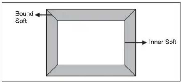
Key Border Settings
Notes
The Key Border function is not supported on the MVE-8000A.
Applying key borders
1 In the DME menu, select VF1 'Edge' and HF3 'Key Border.'
The Key Border menu appears.
2 Press [Key Border], turning it on.
Notes
The key border function and Glow function (see page 304) cannot be turned on at the same time. Only the one most recently turned on is effective.
3 Set the following parameters.
| Knob | Parameter Adjustment Setting values | ||
| 1 H Simultane- | ously adjust width of left and right key borders | 0.00 to 100.00 | |
| 2 V Simultane- | ously adjust width of top and bottom key borders | 0.00 to 100.00 | |
| 3 All Simultane- | ously adjust width of all four key borders | Value of H shown | |
| 4 Soft Softness of | the key borders | 0.00 to 100.00 | |
| 5 Density Density of the key borders | 0.00 to 100.00 | ||
4 To set the key border color, press [Flat Color] and adjust the following parameters.
| Knob | Parameter | Adjustment | Setting values |
| 1 Luminance | Luminance | 0.00 to 100.00 | |
| 2 Saturation | Saturation | 0.00 to 100.00 | |
| 3 Hue | Hue | 359.99 to 0.00 |
To select an outline only key Press [Outline], turning it on.
Art Edge Settings
Notes
The Art Edge function is not supported on the MVE-8000A.
Applying art edges
1 In the DME menu, select VF1 'Edge' and HF4 'Art Edge.'
The Art Edge menu appears.
2 Press [Art Edge], turning it on.
Notes
The Defocus, Blur, Key Border, and Glow effects cannot be applied to the Art Edge sections.
3 Set the parameters.
The valid ranges of the parameter values depend on the combination of signal format (SD/HD) and aspect ratio (4:3/16:9) selected in the system, as follows.
4:3 mode
Parameter group [1/2]
| Knob | Parameter | Adjustment | Setting values |
| 1 H Simultane- | ously adjust width of left and right edges | Value of Left shown | |
| 2 V Simultane- | ously adjust width of top and bottom edges | Value of Top shown | |
| 3 All Simultane- | ously adjust width of all four edges | Value of Left shown | |
| 5 Density Density of | edges | 0.00 to 100.00 | |
Parameter group [2/2]
| Knob | Parameter | Adjustment | Setting values |
| 1 Top | Width of top | edge | 0.00 to 6.00 (SD)0.00 to 18.00 (HD) |
| 2 Left | Width of left | edge | 0.00 to 8.00 (SD)0.00 to 24.00 (HD) |
| 3 Right | Width of right | edge | 0.00 to 8.00 (SD)0.00 to 24.00 (HD) |
| 4 Bottom | Width of bottom edge | of | 0.00 to 6.00 (SD)0.00 to 18.00 (HD) |
| 5 Density | Density of edges | edges | 0.00 to 100.00 |
16:9 mode
Parameter group [1/2]
| Knob | Parameter | Adjustment | Setting values |
| 1 H Simultane- | ously adjust width of left and right edges | Value of Left shown | |
| 2 V Simultane- | ously adjust width of top and bottom edges | Value of Top shown | |
| 3 All Simultane- | ously adjust width of all four edges | Value of Left shown | |
| 5 Density Density of edges | 0.00 to 100.00 | ||
Parameter group [2/2]
| Knob | Parameter | Adjustment | Setting values |
| 1 Top | Width of top | edge | 0.00 to 4.50 (SD)0.00 to 18.00 (HD) |
| 2 Left | Width of left | edge | 0.00 to 8.00 (SD)0.00 to 32.00 (HD) |
| 3 Right | Width of right | edge | 0.00 to 8.00 (SD)0.00 to 32.00 (HD) |
| 4 Bottom | Width of bottom edge | of edge | 0.00 to 6.00 (SD)0.00 to 18.00 (HD) |
| 5 Density | Density of edges | edges | 0.00 to 100.00 |
Adjusting the position of art edges
1 In the Art Edge menu, press [Edge Position], turning it on.
2 Adjust the following parameters.
The valid ranges of the parameter values depend on the combination of signal format (SD/HD) and aspect ratio (4:3/16:9) selected in the system, as follows.
4:3 mode
| Knob | Parameter | Adjustment | Setting values |
| 1 Top | Position of | top edge | -3.00 to +3.00 (SD)-9.00 to +9.00 (HD) |
| 2 Left | Position of | left edge | -4.00 to +4.00 (SD)-12.00 to +12.00 (HD) |
| 3 Right | Position of | right edge | -4.00 to +4.00 (SD)-12.00 to +12.00 (HD) |
| 4 Bottom | Position of | bottom edge | -3.00 to +3.00 (SD)-9.00 to +9.00 (HD) |
| 5 All | Adjust the position of all four edges | Value of H shown | |
16:9 mode
| Knob | Parameter | Adjustment | Setting values |
| 1 Top | Position of | top edge | -2.25 to +2.25 (SD) -9.00 to +9.00 (HD) |
| 2 Left | Position of | left edge | -4.00 to +4.00 (SD) -16.00 to +16.00 (HD) |
| 3 Right | Position of | right edge | -4.00 to +4.00 (SD) -16.00 to +16.00 (HD) |
| 4 Bottom | Position of bottom edge | -2.25 to +2.25 (SD) -9.00 to +9.00 (HD) | |
| 5 All | Adjust the position of all four edges | Value of H shown | |

Softening the inner and outer sides of art edges
1 In the Art Edge menu, press [Soft], turning it on.
2 Adjust the following parameters.
| Knob | Parameter Adjustment Setting values | |
| 1 Inner | H Simultane-ously adjust softness of left and right inner edges | 0.00 to 100.00 |
| 2 Inner | V Simultane-ously adjust softness of top and bottom inner edges | 0.00 to 100.00 |
| 3 Outer | H Simultane-ously adjust softness of left and right outer edges | 0.00 to 100.00 |
| 4 Outer | V Simultane-ously adjust softness of top and bottom outer edges | 0.00 to 100.00 |
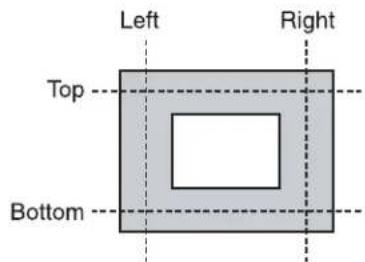
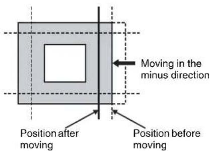
| Knob | Parameter Adjustment Setting values | ||
| 5 All Simultane- | ously adjust softness of all inner and outer edges. | Value of Outer H shown | |
Setting the way in which art edge colors change
1 In the
Flat Color: Uses Color 1 (see page 290) as a flat color.
Gradation Matte: Color 1 changes to Color 2 (see page 290) at the border lines (see step 2 (page 288)).
Rainbow Matte: The color set as Color 1 changes hue into color on the border lines.
Radial Gradation: Color 1 on the inner side is mixed into Color 2 on the outer side, according to the shape of the art edge.
Radial Rainbow: The hue of Color 1 on the inner side changes into Color 2 on the outer side, according to the shape of the art edge.
Rainbow Gradation: Color 3 (see "Color 3 settings" (page 290)) overwrites Radial Rainbow, giving a gradation effect.
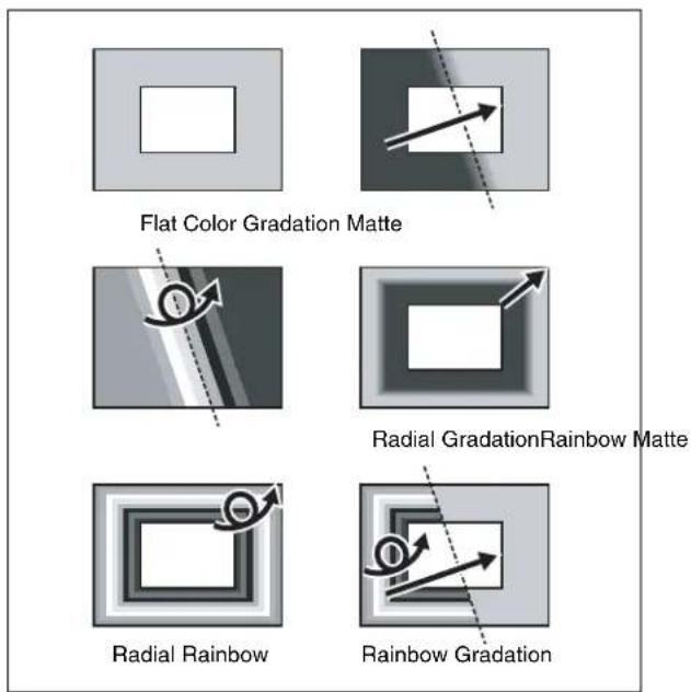
2 When you select other than [Flat Color], set the gradation border lines for the selected pattern.
Border line parameters for Gradation Matte and Rainbow Matte
The valid ranges of the parameter values depend on the combination of signal format (SD/HD) and aspect ratio (4:3/16:9) selected in the system, as follows.
4:3 mode
| Knob | Parameter | Adjustment | Setting values |
| 1 H | Position of | gradationborder inhorizontaldirection | -8.00 to +8.00 (SD)-24.00 to +24.00 (HD) |
| 2 V | Position of | gradationborder inverticaldirection | -6.00 to +6.00 (SD)-18.00 to +18.00 (HD) |
| 3 Soft | Softness of | gradationborderregion | 0.00 to 100.00 |
16:9 mode
| Knob | Parameter | Adjustment | Setting values |
| 1 H P | Position of | gradationborder inhorizontaldirection | -8.00 to +8.00 (SD)-32.00 to +32.00 (HD) |
| 2 V Position of | gradationborder inverticaldirection | -4.50 to +4.50 (SD)-18.00 to +18.00 (HD) | |
| 3 Soft Softness of | gradationborderregion | 0.00 to 100.00 | |
Radial Gradation and Radial Rainbow parameters
| Knob | Parameter | Adjustment | Setting values |
| 3 Soft | Softness of | gradationborderregion | 0.00 to 100.00 |
Rainbow Gradation parameters
The valid ranges of the parameter values depend on the combination of signal format (SD/HD) and aspect ratio (4:3/16:9) selected in the system, as follows.
• 4 : 3 mode
| Knob | Parameter | Adjustment | Setting values |
| 1 H | Position of | gradationborder inhorizontaldirection | -8.00 to +8.00 (SD)-24.00 to +24.00 (HD) |
| 2 V | Position of | gradationborder inverticaldirection | -6.00 to +6.00 (SD)-18.00 to +18.00 (HD) |
| Knob | Parameter Adjustment Setting values | |
| 3 RBW | Soft Softness of rainbow border region | 0.00 to 100.00 |
| 4 GRD | Soft Softness of gradation border region | 0.00 to 100.00 |
• 16:9 mode
| Knob | Parameter | Adjustment | Setting values |
| 1 H | Position of | gradation border in horizontal direction | -8.00 to +8.00 (SD)-32.00 to +32.00 (HD) |
| 2 V | Position of | gradation border in vertical direction | -4.50 to +4.50 (SD)-18.00 to +18.00 (HD) |
| 3 RBW | Soft Softness | of rainbow border region | 0.00 to 100.00 |
| 4 GRD | Soft Softness | of gradation border region | 0.00 to 100.00 |
3 When Gradation Matte or Rainbow Matte is selected, set modifiers as required.
When turning [Angle] on in the
| Knob | Parameter | Adjustment | Setting values |
| 1 Angle | Rotation angle of pattern | -8.00 to +8.00^a) | |
a) -1.00 is one rotation in counterclockwise direction. +1.00 is one rotation in clockwise direction. 0.00 is no rotation.
When turning [Speed] on in the
| Knob | Parameter | Adjustment | Setting values |
| 1 Speed | Rotation speed of pattern | -100.00 to +100.00 a) | |
a) -100.00 is four rotations per second in counterclockwise direction. +100.00 is four rotations per second in clockwise direction. 0.00 is no rotation.
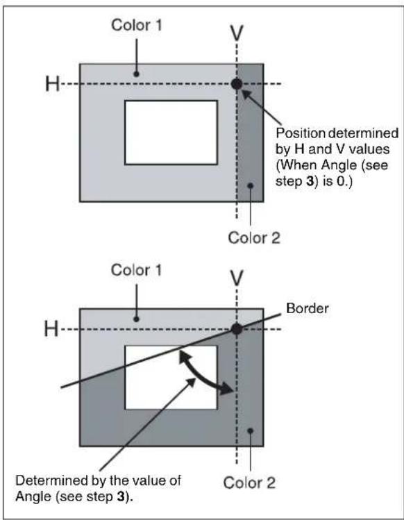
Setting art edge colors
1 In the Art Edge menu, turn on the button (Color 1 to Color 3) for the color for which you want to make settings in the
2 Adjust the following parameters.
Color 1 settings
| Knob | Parameter Adjustment Setting values |
| 1 | Luminance Luminance 0.00 to 100.00 |
| 2 | Saturation Saturation 0.00 to 100.00 |
| 3 | Hue 359.99 to 0.00 |
Color 2 settings
Notes
Color 2 cannot be set when [Flat Color] is selected in the
| Knob | Parameter | Adjustment | Setting values |
| 1 | Luminance | Luminance | 0.00 to 100.00 |
| 2 | Saturation | Saturation | 0.00 to 100.00 |
| 3 | Hue | Offset Hue range | -540.0 to +540.0 |
Color 3 settings
Notes
Color 3 can be set only when [Rainbow Gradation] is selected in the
| Knob | Parameter | Adjustment | Setting values |
| 1 | Luminance | Luminance | 0.00 to 100.00 |
| 2 | Saturation | Saturation | 0.00 to 100.00 |
| 3 | Hue | Offset Hue range | -540.0 to +540.0 |
Relationship between Hue and Hue Offset
For example, when the Hue value of Color 1 is 180.00, and the Hue Offset value of Color 2 is -540.00, the relationship is as shown below, with the hue changing within the Hue Offset range of Color 1 and Color 2.
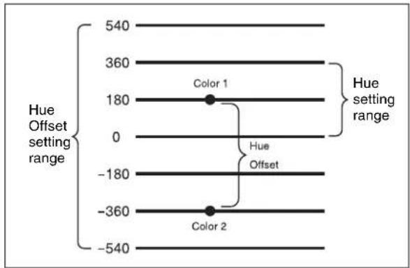
Rounding art edge corners
Press [Round Corner], turning it on.
The art edge corners on the inner and outer sides are rounded.
Notes
This function is available only when [Soft] is on.
Flex Shadow Settings
Notes
- The Flex Shadow function is not supported on the MVE-8000A.
- On the MKS-7470X/7471X, the Flex Shadow function can be used except for the following.
- [External] in the Flex Shadow Source group - [Ext Video] in the Flex Shadow Fill group
- "Mix Color" or "Ext Video" can only be applied to one of the background (see page 338), flex shadow, trail (see page 325), and wind (see page 329) effects.
If you select "Mix Color" or "Ext Video" in one of these settings, a selection of "Mix Color" or "Ext Video" in any of the other effects is disabled, and "Flat Color" is selected in its place.
- When executing combining four channels of DME images, "Mix Color" and "Ext Video" in the flex shadow and background effects cannot be selected.
Applying a flex shadow
1 In the DME menu, select VF1 'Edge' and HF5 'Flex Shadow.'
The Flex Shadow menu appears.
2 Press [Flex Shadow], turning it on.
Notes
The Flex shadow function cannot be enabled when the following functions are enabled.
• Any nonlinear effect
- Brick
- Shadow
3 Adjust the following parameters.
The valid ranges of the parameter values depend on the combination of signal format (SD/HD) and aspect ratio (4:3/16:9) selected in the system, as follows.
4:3 mode
| Knob | Parameter | Adjustment | Setting values |
| 1 | H | M o shadow horizontally | -8.00 to +8.00 (SD) -24.00 to +24.00 (HD) |
| 2 | V | M o shadow vertically | -6.00 to +6.00 (SD) -18.00 to +18.00 (HD) |
| 3 Size | All Enlarge or shrink horizontally and vertically | Value of Size H (see page 291) shown | |
| 4 Soft | a) | Softness of shadow | 0.00 to 100.00 |
| 5 Density | Density of shadow | 0.00 to 100.00 | |
a) The Soft parameter is valid only when [Internal] is selected in the
16:9 mode
| Knob | Parameter | Adjustment | Setting values |
| 1 | H | M o shadow horizontally | -8.00 to +8.60 (SD) -32.00 to +32.00 (HD) |
| 2 | V | M o shadow vertically | -4.50 to +4.50 (SD) -18.00 to +18.00 (HD) |
| 3 Size | All Enlarge or shrink horizontally and vertically | Value of Size H (see page 291) shown | |
| 4 Soft | a) | Softness of shadow | 0.00 to 100.00 |
| 5 Density | Density of shadow | 0.00 to 100.00 | |
a) The Soft parameter is valid only when [Internal] is selected in the
4 In the
External: Generate the shadow using an input signal.
Internal: Generate the shadow using a full-size key signal.
5 In the
Flat Color: single color
Mix Color: mix color signal set in the Color Mix menu (see page 296)
Ext Video: an external video signal input to the Ext IN connector
6 Only if Flat Color is selected in step 5, adjust the following parameters.
| Knob | Parameter | Adjustment | Setting values |
| 1 Luminance | Luminance | 0.00 to 100.00 | |
| 2 Saturation | Saturation | 0.00 to 100.00 | |
| 3 Hue | Hue | 359.99 to 0.00 |
Adjusting the size of the flex shadow
1 In the Flex Shadow menu, press [Size], turning it on.
2 Set the following parameters.
| Knob | Parameter | Adjustment | Setting values |
| 1 Size | H Enlarge | ge or shrink horizontally | 0.00 to 2.00 |
| 2 Size | V Enlarge | ge or shrink vertically | 0.00 to 2.00 |
| 3 Size | All Enlarge or | shrink horizontally and vertically | Value of Size H shown |
| 4 Soft | a) | Softness of shadow | 0.00 to 100.00 |
| 5 Density | Density of | shadow | 0.00 to 100.00 |
a) The Soft parameter is valid only when [Internal] is selected in the
Setting the center point of the flex shadow
1 In the Flex Shadow menu, press [Axis Loc], turning it on.
2 Adjust the following parameters.
The valid ranges of the parameter values depend on the combination of signal format (SD/HD) and aspect ratio (4:3/16:9) selected in the system, as follows.
4:3 mode
| Knob | Parameter | Adjustment Setting values | |
| 1 Axis | Loc H Move | the shadow center axis horizontally | -8.00 to +8.00 (SD) -24.00 to +24.00 (HD) |
| 2 Axis | Loc V Move | the shadow center axis vertically | -6.00 to +6.00 (SD) -18.00 to +18.00 (HD) |
16:9 mode
| Knob | Parameter Adjustment Setting values | ||
| 1 Axis | Loc H Move | the shadow center axis horizontally | -8.00 to +8.00 (SD) -32.00 to +32.00 (HD) |
| 2 Axis | Loc V Move | the shadow center axis vertically | -4.50 to +4.50 (SD) -18.00 to +18.00 (HD) |
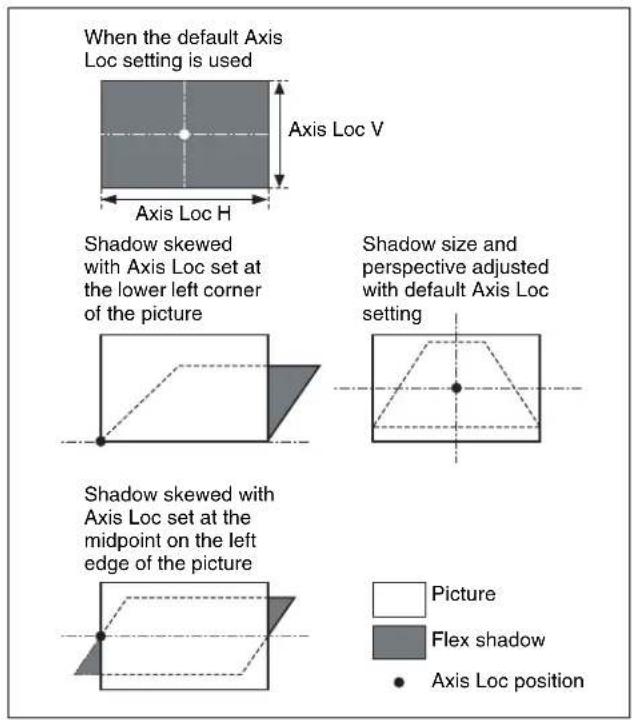
The flex shadow central axis appears when the [Flex Shadow Axis] function is enabled in the Graphic menu.
For details, see "Graphics Display Operation" (page 281).
Skewing the flex shadow
1 In the Flex Shadow menu, press [Skew], turning it on.
2 Adjust the following parameters.
| Knob | Parameter Adjustment Setting values | ||
| 1 Skew | H Skew | horizontally | -100.00 to +100.00 |
| 2 Skew | V Skew | vertically | -100.00 to +100.00 |
Adding perspective to the flex shadow
1 In the Flex Shadow menu, press [Perspective], turning it on.
2 Adjust the following parameters.
| Knob | Parameter Adjustment Setting values | |
| 1 | PH e | Add s horizontal perspective-100.00 to €100.00c |
| 2 | PV e | Add vertical perspective-100.00 to €100.00c |
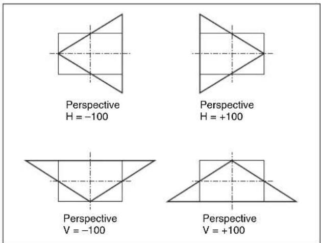
Inverting the flex shadow
In the
H: Invert the shadow in the horizontal direction. The inversion is applied around the axis of the knob 2 parameter Axis Loc V set with [Axis Loc].
V: Invert the shadow in the vertical direction. The inversion is applied around the axis of the knob 1 parameter Axis Loc H set with [Axis Loc].
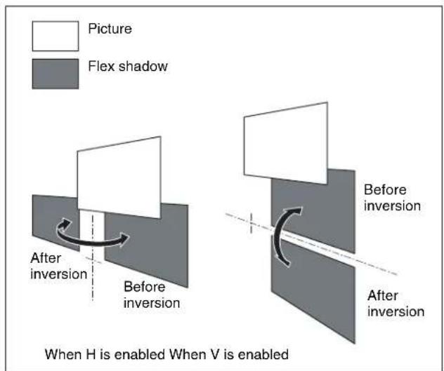
Setting a combine shadow
When there are several images, adds a flex shadow in the depth of an image or overlays multiple flex shadows.
Example 1: When Flex Shadow is enabled on both of two channels.
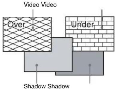
No combine shadow is set.
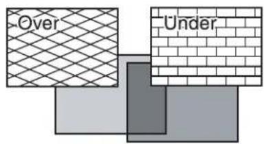
Combine shadow is enabled. Density is set to 100.00.
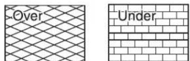
Combine shadow is enabled. Density is set to 0.00.
Example 2: Flex Shadow is enabled on one channel only.
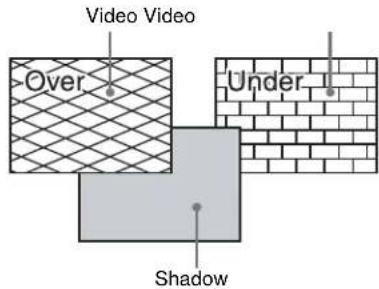
No combine shadow is set.
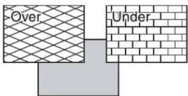
Combine shadow is enabled. Density is set to 100.00.
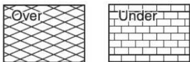
Combine shadow is enabled. Density is set to 0.00.
1 In the Flex Shadow menu, press [Combine Shadow], turning it on.
2 Adjust the following parameter.
| Knob | Parameter | Adjustment | Setting values |
| 1 Density | Density of combine shadow | 0.00 to 100.00 |
Notes
- The Combine Shadow effect is applied to all shadows, not only the sections where shadows overlap.
- Combine Shadow is enabled when the Flex Shadow effect and the global effect Combiner are enabled. In this state, Combine Shadow remains enabled even if the global effect is disabled.
- In Combine Shadow, the settings for the channel with the lowest number among the channels being combined are enabled.
Flex shadow creation example
The flow of flex pattern creation will be explained using the following pattern as an example.

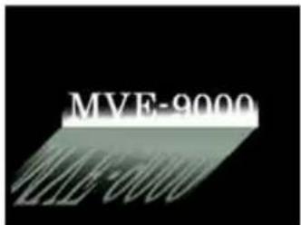
1 Press [Flex Shadow], turning it on.
2 In the
3 Turn [Axis Loc] on and use knob 2 to set the Axis Loc V parameter so that the center of the flex shadow deformation is at the bottom of the picture.
(For HD format and 16:9 mode: Axis Loc V = -9.00)
The following steps will be easier if you display the flex shadow axis graphic by pressing [Flex Shadow Axis] in the Graphic menu.
4 Press [V] in the
5 Turn [Size] on and use knob 2 to set the Size V parameter so that the shadow extends vertically. (For HD format and 16:9 mode: Size V = 1.50)
6 Press [Skew], turning it on, and use knob 1 to set the Skew H parameter so that the parallel lines appear to emerge from the depth at the right. (For HD format and 16:9 mode: Skew H = -50.00)
Wipe Crop Settings
Notes
- The wipe crop function is not supported on the MVE-8000A.
- When wipe crop is on, any mask that was on is turned off.
- When brick is on, wipe crop cannot be turned on. To turn wipe crop on, it is first necessary to turn brick off.
- In the
group of the Video/Key menu, when [Output] is off, unless you set [Bkgd] in the HF1 'Bkgd' menu to on, the wipe crop effect will not function.
Applying the wipe crop effect
To select the pattern
1 In the DME menu, select VF1 'Edge' and HF6 'Wipe Crop.'
The Wipe Crop menu appears.
2 Press [Wipe Crop], turning it on.
3 Press [Pattern Select].
The Pattern Select menu appears.
4 From the displayed patterns (standard wipe patterns 1 to 24 and 304), press any pattern to select it.
In this state, you can use the knobs to adjust the size of the pattern. (For details of parameters, see the next item.)
To set the pattern size and position
1 In the Wipe Crop menu, press [Position/Size].
2 Set the following parameters.
The setting range for the parameters depends on the signal format (SD/HD) and aspect ratio (4:3/16:9) selected in the system, as follows.
For SD format
| Knob | Parameter Adjustment Setting values | ||
| 1 | H | H o position | -8.00 to +8i00 z |
| 2 | V | V e position | -6.00 to +6t00a) i -4.50 to +4.50b) |
| 3 Size | Pattern size | 0.00 to 100.00 | |
| 5 Pattern | Pattern number | 1 to 24, 304 | |
a) For 4:3 mode
b) For 16:9 mode
a) For 4:3 mode b) For 16:9 mode
Notes
When pattern number 304 is selected, the effect of settings in the
For HD format
| Knob | Parameter Adjustment Setting values | ||
| 1 | H | H o position | -24.00 to +24.00 ^a) z -32.00 to +32.00 ^b) |
| 2 | V | V e position | -18r00 to +t18.00 i |
| 3 Size | Pattern size | 0.00 to 100.00 | |
| 5 Pattern | Pattern number | 1 to 24, 304 | |
a) For 4:3 mode
b) For 16:9 mode
a) For 4:3 mode b) For 16:9 mode
Notes
When pattern number 304 is selected, the effect of settings in the
To invert the regions of the cropping
In the Wipe Crop menu, press [Invert], turning it on.
Setting the aspect ratio of the wipe crop pattern (Aspect)
1 In the Wipe Crop menu, press [Aspect], turning it on.
2 Set the following parameter.
| Knob | Parameter | Adjustment | Setting values |
| 1 Aspect | Aspect ratio | -100.00 to +100.00 a) |
a) When set to a negative value, the image is stretched vertically, to become taller. When set to a positive value, the image is stretched horizontally, to become wider.
Rotating the wipe crop pattern (Rotation)
1 In the
Angle: Incline the pattern through a fixed angle.
Speed: Rotate the pattern at a fixed speed.
2 Depending on the selection in step 1, set the following parameter.
When Angle is selected
| Knob | Parameter | Adjustment | Setting values |
| 1 Angle | Angle of | pattern rotation | -8.00 to +8.00^a) |
a) -1.00 represents a whole turn counterclockwise, and +1.00 represents a whole turn clockwise. 0.00 is the original state.
When Speed is selected
| Knob | Parameter | Adjustment | Setting values |
| 1 Speed | Rotation rate of pattern | -100.00 to +100.00 a) | |
a) -100.00 represents a speed of four whole turns counterclockwise per second, and +100.00 represents a speed of four whole turns clockwise per second. 0.00 is the stationary state.
Applying modulation to the wipe crop pattern (Modulation)
1 In the
H (horizontal modulation): Modulate the pattern to apply waving in the horizontal direction.
V (vertical modulation): Modulate the pattern to apply waving in the vertical direction.
2 Set the following parameters.
| Knob | Parameter | Adjustment | Setting values |
| 1 Amplitude | Amplitude of modulation | 0.00 to 100.00 | |
| 2 Frequency | Frequency of modulation | 0.00 to 100.00 | |
| 3 Speed | Speed of waves | -100.00 to +100.00 | |
Replicating the wipe crop pattern (Multiplication)
1 In the Wipe Crop menu, press [Multi], turning it on.
2 Set the following parameters.
| Knob | Parameter | Adjustment | Setting values |
| 1 H Multi Number of repetitions of pattern horizontally | 1 to 63 | ||
| 2 V Multi Number of repetitions of pattern vertically | 1 to 63 | ||
| 3 Invert Type Replication layout | 1 to 4^a) | ||
a) See the replication patterns (page 167).
Modifying the wipe crop pattern edge
You can apply a border to the wipe crop pattern, or soften the boundary.
1 In the
Border: border
Soft: soft edge
Soft Border: soft border
2 Depending on the selection in step 1, set the following parameters.
When Border is selected
| Knob | Parameter | Adjustment | Setting values |
| 1 Width | Border width 0.00 to | 100.00 | |
When Soft is selected
| Knob | Parameter Adjustment Setting values | ||
| 1 Soft | Edge | softness | 0.00 to 100.00 |
When Soft Border is selected
| Knob | Parameter | Adjustment | Setting values |
| 1 | Width | Border width | 0.00 to 100.00 |
| 2 | Inner | Soft Border | inner softness |
| 3 | Outer | Soft Border | outer softness |
Selecting the signal or color to be inserted in the wipe crop border
When you are applying a border or soft border to the wipe crop, you can select the signal or color to be inserted in the border.
1 In the
Flat Color: flat color
Mix Color: a mix color signal combining color 1 and color 2 (see the next section, "Color Mix Settings")
Ext Video: an external video signal input to the Ext IN connector
2 When Flat Color is selected in step 1 only, adjust the following parameters.
| Knob | Parameter Adjustment Setting values | |
| 1 | Luminance | Luminance 0.00 to 100.00 |
| 2 | Saturation | Saturation 0.00 to 100.00 |
| 3 | Hue | Hue 359.99 to 0.00 |
Color Mix Settings
Notes
The color mix function is not supported on the MVE-8000A.
Creating a color combination pattern
To select the pattern
1 In the DME menu, select VF1 'Edge' and HF7 'Color Mix.'
The Color Mix menu appears.
2 Press [Mix Pattern Select].
The Mix Pattern Select menu appears.
3 Press any of the displayed patterns (standard wipe patterns 1 to 24) to select it.
In this state, you can adjust the pattern size and border softness with the knobs.
(For details of the parameters, see the next item.)
To set the pattern size and position
1 In the Color Mix menu, press [Position/Size].
2 Set the following parameters.
The setting range for the parameters depends on the system selected signal format (SD/HD) and aspect ratio (4:3/16:9), as follows.
For SD format
| Knob | Parameter | Adjustment | Setting values |
| 1 | H | Horizontal position | -8.00 to +8.00 |
| 2 | V | Vertical position | -6.00 to +6.00^a) -4.50 to +4.50^b) |
| 3 Size | Pattern size 0.00 | to 100.00 | |
| 4 Soft | Softness of the pattern | 0.00 to 100.00 | |
| 5 Pattern | Pattern number | 1 to 24 | |
a) For 4:3 mode
b) For 16:9 mode
For HD format
| Knob | Parameter | Adjustment | Setting values |
| 1 | H | Horizontal position | -24.00 to +24.00^a) -32.00 to +32.00^b) |
| 2 | V | Vertical position | -18.00 to +18.00 |
| 3 Size | Pattern size 0.00 | to 100.00 | |
| 4 Soft Softness of the pattern | 0.00 to 100.00 | ||
| 5 Pattern Pattern number | 1 to 24 | ||
a) For 4:3 mode
b) For 16:9 mode
To invert the regions of the two colors
In the Color Mix menu, press [Color Invert], turning it on.
Adjusting the color 1 and color 2
1 In the Color Mix menu, to adjust color 1 press [Color1], and to adjust color 2 press [Color2].
2 Set the following parameters.
| Knob | Parameter | Adjustment | Setting values |
| 1 Luminance | Luminance | 0.00 to 100.00 | |
| 2 Saturation | Saturation | 0.00 to 100.00 | |
| 3 Hue | Hue | 359.99 to 0.00 |
Modifying the color combination pattern
See the following pages.
- “Setting the aspect ratio of the wipe crop pattern (Aspect)” (page 295)
- “Replicating the wipe crop pattern (Multiplication)” (page 295)
- “Rotating the wipe crop pattern (Rotation)” (page 295)
- “Applying modulation to the wipe crop pattern (Modulation)” (page 295)
Applying Special Effects (Effects on the Overall Video Signal)
Defocus Settings
Applying the Defocus effect
1 In the DME menu, select VF2 'Video Modify' and HF1 'Defocus/Blur.'
The Defocus/Blur menu appears.
2 Press [Defocus], turning it on.
Notes
On the MVE-8000A, the Defocus and Glow effects cannot be enabled at the same time. The effect which was turned on most recently is enabled.
3 In the
Video/Key: Video signal and key signal
Video: Video signal only
Key: Key signal only
Notes
“Key” can be selected only when the DME is connected through an SDI interface.
4 Set the parameters.
When Video/Key is selected (with DME dedicated interface)
| Knob | Parameter | Adjustment | Setting values |
| 1 | H | H o defocusing of video and key signals | 0.00 to 100i00 z |
| 2 | V | Ve r defocusing of video and key signals | 0.00 to 100i00 c |
| 3 | A I | I and vertical defocusing of video and key signals | HH value shownr |
When Video/Key is selected (with SDI-interfaced DME)
Parameter group [1/2]
| Knob | Parameter Adjustment | Setting values | |
| 1 V/K | H Horizontal | defocusing of video and key signals | Video H value shown |
| 2 V/K | V Vertical | defocusing of video and key signals | Video V value shown |
| 3 V/K | All Horizontal | and vertical defocusing of video and key signals | Video H value shown |
| 4 Video | All Horizontal | and vertical defocusing of video signal | Video H value shown |
| 5 Key | All Horizontal | and vertical defocusing of key signal | Key H value shown |
Parameter group [2/2]
| Knob | Parameter | Adjustment | Settings values |
| 1 Video | H Horizontal | defocusing of video signal | 0.00 to 100.00 |
| 2 Video | V Vertical | defocusing of video signal | 0.00 to 100.00 |
| 3 Key | H Horizontal | defocusing of key signal | 0.00 to 100.00 |
| 4 Key | V Vertical | defocusing of key signal | 0.00 to 100.00 |
When Video is selected
| Knob | Parameter Adjustment Setting values | ||
| 1 | H | Horizontal defocusing of video signal | 0.00 to 100.00 |
| 2 | V | Vertical defocusing of video signal | 0.00 to 100.00 |
| 3 | All | Horizontal and vertical defocusing of video signal | H value shown |
When Key is selected (with SDI-interfaced DME)
| Knob | Parameter | Adjustment | Settings values |
| 1 | H | Horizontal defocusing of key signal | 0.00 to 100.00 |
| 2 | V | Vertical defocusing of key signal | 0.00 to 100.00 |
| 3 | All | Horizontal and vertical defocusing of key signal | H value shown |
5 To cancel black level leaking that can occur at the edge of the screen when the Defocus effect is enabled, press [Clean Defocus], turning it on.
Masking the Defocus effect with a selected pattern
Press [Mask] to display the Mask menu, and set the pattern type and modifiers (see page 304).
Blur Settings
Applying the Blur effect
1 In the DME menu, select VF2 'Video Modify' and HF1 'Defocus/Blur.'
The Defocus/Blur menu appears.
2 Press [Blur], turning it on.
Notes
On the MVE-8000A, the Glow and Blur effects cannot be enabled at the same time. The effect which was turned on most recently is enabled.
3 When the DME is connected through an SDI interface, in the
Video/Key: Video signal and key signal
Video: Video signal only
Key: Key signal only
4 Set the parameters.
When the DME dedicated interface is used
| Knob | Parameter | Adjustment | Setting values |
| 1 | H | Horizontal defocusing of video and key signals | 0.00 to 100.00 |
| 2 | V | V e defocusing of video and key signals | 0.00 to 100.00 i |
| 3 All Horizontal | and vertical defocusing of video and key signals | H value shown | |
When Video/Key is selected (with SDI-interfaced DME)
Parameter group [1/2]
| Knob | Parameter | Adjustment | Settings values |
| 1 V/K H | Horizontal | defocusing of video and key signals | Video H value shown |
| 2 V/K V | Vertical | defocusing of video and key signals | Video V value shown |
| 3 V/K All | Horizontal | and vertical defocusing of video and key signals | Video H value shown |
| 4 Video All | Horizontal | and vertical defocusing of video signal | Video H value shown |
| 5 Key All | Horizontal | and vertical defocusing of key signal | Key H value shown |
Parameter group [2/2]
| Knob | Parameter | Adjustment | Settings values |
| 1 Video H | Horizontal defocusing of video signal | 0.00 to 100.00 | |
| 2 Video V | Vertical defocusing of video signal | 0.00 to 100.00 | |
| 3 Key H | Horizontal defocusing of key signal | 0.00 to 100.00 | |
| 4 | Key V | Vertical defocusing of key signal | 0.00 to 100.00 |
When video is selected (with SDI-interfaced DME)
| Knob | Parameter | Adjustment | Settings values |
| 1 H | Horizontal defocusing of video signal | 0.00 to 100.00 | |
C
| Knob | Parameter | Adjustment | Settings values |
| 2 a | VI | V e defocusing of video signal | 0.00 to 100.00 i |
| 3 | All | Horizontal and vertical defocusing of video signal | H value shown |
When Key is selected (with SDI-interfaced DME)
| Knob | Parameter | Adjustment | Setting values |
| 1 | H | H o defocusing of key signal | 0r00 to 1i00.00 zo |
| 2 | V | V e defocusing of key signal | 0.00 to 100.00 i |
| 3 | All | Horizontal and vertical defocusing of key signal | H value shown |
Masking the Blur effect with a selected pattern
Press [Mask] to display the Mask menu, and set the pattern type and modifiers (see page 304).
Multi Move Settings
Applying the Multi Move effect
1 In the DME menu, select VF2 'Video Modify' and HF2 'Multi Move.'
The Multi Move menu appears.
2 Press [Multi Move], turning it on.
3 Set the parameters.
The valid ranges of the parameter values depend on the combination of signal format (SD/HD) and aspect ratio (4:3/16:9) selected in the system, as follows.
4:3 mode
| Knob | Parameter | Adjustment | Setting values |
| 1 Center X | x-value of shrinking center point | -4.00 to +4.00 (SD) -12.00 to +12.00 (HD) | |
| 2 Center Y | y-value of shrinking center point | -3.00 to +3.00 (SD) -9.00 to +9.00 (HD) | |
| 3 Size | Shrinking ratio | 0.00 to 100.00 | |
| Knob | Parameter | Adjustment Setting values | |
| 4 Aspect | Aspect ratio | of shrunken images | -100.00 to +100.00 a) |
a) Specify minus values to stretch the image in the vertical direction, and plus values to stretch the image in the horizontal direction.
16:9 mode
| Knob | Parameter | Adjustment Setting values | |
| 1 | Center | X x-value of shrinking center point | -4.00 to +4.00 (SD) -16.00 to +16.00 (HD) |
| 2 | Center | Y y-value of shrinking center point | -2.25 to +2.25(SD) -9.00 to +9.00 (HD) |
| 3 | Size | Shrinking ratio | 0.00 to 100.00 |
| 4 | Aspect | Aspect ratio of shrunken images | -100.00 to +100.00 a) |
a) Specify minus values to stretch the image in the vertical direction, and plus values to stretch the image in the horizontal direction.
Sepia Settings
Applying the Sepia effect
1 In the DME menu, select VF2 'Video Modify' and HF3 'Color Modify.'
The Color Modify menu appears.
2 Press [Sepia], turning it on.
3 Set the following parameters.
| Knob | Parameter Adjustment Setting values | ||
| 1 Mix Y | Y signal mix amount | 0.00 to 100.00 | |
| 2 Mix C | Chroma | signal mix amount | 0.00 to 100.00 |
| 3 Mix All Y signal and chroma signal mix amount | Mix Y value shown | ||
4 To set the color of the sepia image, press [Sepia Color], turning it on, and adjust the parameters.
| Knob | Parameter | Adjustment | Setting values |
| 1 | Luminance | Luminance | 0.00 to 100.00 |
| 2 | Saturation | Saturation | 0.00 to 100.00 |
| 3 | Hue | Hue | 359.99 to 0.00 |
Masking the Sepia effect with a selected pattern
Press [Mask] to display the Mask menu, and set the pattern type and modifiers (see page 304).
Mono Settings
Applying the Mono effect
1 In the DME menu, select VF2 'Video Modify' and HF3 'Color Modify.'
The Color Modify menu appears.
2 Press [Mono], turning it on.
Masking the Mono effect with a selected pattern
Press [Mask] to display the Mask menu, and set the pattern type and modifiers (see page 304).
Posterization and Solarization Settings
You can specify the degree of luminance coarsening. You can specify the degree of chroma coarsening.
Applying the Posterization or Solarization effect
1 In the DME menu, select VF2 'Video Modify' and HF3 'Color Modify.'
The Color Modify menu appears.
2 Press [Poster/Solar], turning it on.
3 Set the parameters.
| Knob | Parameter | Adjustment | Setting values |
| 1 Poster | Coarseness of luminance gradations (Posterization parameter) | 0.00 to 100.00 | |
| 2 Solar | Coarseness of chroma gradations (Solarization parameter) | 0.00 to 100.00 | |
Masking the Posterization or Solarization effect with a selected pattern
Press [Mask] to display the Mask menu, and set the pattern type and modifiers (see page 304).
Nega Settings
Applying the Nega effect
1 In the DME menu, select VF2 'Video Modify' and HF3 'Color Modify.'
The Color Modify menu appears.
2 Press [Nega Y] or [Nega C], turning it on, or press both buttons, turning them on.
Nega Y: Reverse the luminance.
Nega C: Reverse the chroma.
Masking the Nega effect with a selected pattern
Press [Mask] to display the Mask menu, and set the pattern type and modifiers (see page 304).
Contrast Settings
Applying the Contrast effect
1 In the DME menu, select VF2 'Video Modify' and HF3 'Color Modify.'
The Color Modify menu appears.
2 Press [Contrast], turning it on.
3 Set the parameters.
| Knob | Parameter | Adjustment Setting values | |
| 1 Y Clip | Luminance | clip level | +109.59 to -7.31 |
| 2 Y Gain | Luminance | contrast gradient | -100.00 to +100.00 |
| 3 Y Offset | Luminance | offset level increment | -100.00 to +100.00 |
| 4 | C G | a i contrast gradient | -100.00 to €100.00 |
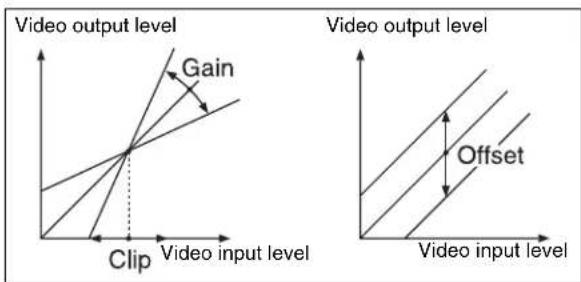
Clip, Gain, Offset
Masking the Contrast effect with a selected pattern
Press [Mask] to display the Mask menu, and set the pattern type and modifiers (see page 304).
Mosaic Settings
Applying the Mosaic effect
1 In the DME menu, select VF2 'Video Modify' and HF4 'Mosaic.'
The Mosaic menu appears.
2 Press [Mosaic], turning it on.
3 Set the following parameters.
| Knob | Parameter | Adjustment | Setting values |
| 1 Size | Size of tiles | 0.00 to 100.00 | |
| 2 Aspect | Aspect ratio | of tiles | -100.00 to +100.00^a) |
a) Specify minus values to stretch the tiles in the vertical direction, and plus values to stretch the tiles in the horizontal direction.
Masking the Mosaic effect with a selected pattern
Press [Mask] to display the Mask menu, and set the pattern type and modifiers (see page 304).
Sketch Settings
Applying the Sketch effect
1 r In the DME menu, select VF7 'Enhanced Video Modify' and HF1 'Sketch.'
The Sketch menu appears.
2 Press [Sketch], turning it on.
3 Select the method for applying outlines in the
Sketch: Apply an effect like a sketch.
Edge Color: Enhance the outlines.
Draw: Apply an effect like a line drawing.
Relief: Apply a bas-relief effect.
Sharp: Increase the apparent sharpness.
4 Set the following parameters, according to the method selected in step 3.
When Sketch is selected
| Knob | Parameter Adjustment Setting values | ||
| 1 Mix | Mix amount | for Sketch video and input video | 0.00 to 100.00a) |
| 2 Clip | Reference | level for outline extraction | -100.00 to +100.00b) |
| 3 Gain | Image gain | for outline extraction | -100.00 to +100.00 |
| 4 C Gain | Chroma gain of input video | -100.00 to +100.00 | |
a) 100.00 gives an image completely transformed by the Sketch effect. 0.00 is the original input image.
b) The larger the Clip value, the narrower the outline width.
When Edge Color is selected
| Knob | Parameter Adjustment Setting values | ||
| 1 Mix | Mix amount | for Edge Color video and input video | 0.00 to 100.00a) |
| 2 Clip | Reference | level for outline extraction | -100.00 to +100.00b) |
a) 100.00 gives an image completely transformed by the Sketch effect. 0.00 is the original input image.
b) The larger the Clip value, the narrower the outline width.
When Draw is selected
| Knob | Parameter Adjustment Setting values | ||
| 1 Mix | Mix amount | for Draw video and input video | 0.00 to 100.00a) |
| 2 Clip | Reference | level for outline extraction | -100.00 to +100.00b) |
| 3 Gain | Image gain | for outline extraction | -100.00 to +100.00 |
a) 100.00 gives an image completely transformed by the Sketch effect. 0.00 is the original input image.
b) The larger the Clip value, the narrower the outline width.
When Relief is selected
| Knob | Parameter Adjustment Setting values | ||
| 1 Mix | Mix amount | for Relief video and input video | 0.00 to 100.00a) |
| 2 Offset | Relief | luminance level | -100.00 to +100.00 |
| 3 Gain | Image gain | for outline extraction | -100.00 to +100.00 |
| 4 Angle | Direction of | relief image light source | -8.00 to +8.00 |
a) 100.00 gives an image completely transformed by the Sketch effect. 0.00 is the original input image.
When Sharp is selected
| Knob | Parameter Adjustment Setting values | ||
| 1 H Simultane- | ously adjust the left and right resolution | 0.00 to 100.00 | |
| 2 V | Simultaneously adjust the top and bottom resolution | 0.00 to 100.00 | |
| 3 All | Simultaneously adjust the resolution of all four sides | 0.00 to 100.00 | |
| 5 Coring | Minimum value of edge to emphasize | 0.00 to 100.00 | |
5 If you selected other than Sharp in step 3, depending on the necessity, proceed as follows.
To adjust the outline color for Edge Color or Draw Turn [Edge Matte] on and set the following parameters to set the outline color.
| Knob | Parameter | Adjustment | Setting values |
| 1 | Luminance | Luminance | 0.00 to 100.00 |
| 2 | Saturation | Saturation | 0.00 to 100.00 |
| 3 | Hue | Hue | 359.99 to 0.00 |
To set the color of the sections other than the outlines for Draw
Press [Matte], turning it on, and adjust the following parameters to set the color of the sections other than the outlines.
| Knob | Parameter | Adjustment | Setting values |
| 1 Luminance | Luminance | 0.00 to 100.00 | |
| 2 Saturation | Saturation | 0.00 to 100.00 | |
| 3 Hue | Hue | 359.99 to 0.00 |
To select the signal to mix with the relief pattern for Relief
In the
Matte: Select a single color. The following parameters can be adjusted.
| Knob | Parameter | Adjustment | Setting values |
| 2 Saturation | Saturation | 0.00 to 100.00 | |
| 3 Hue | Hue | 359.99 to 0.00 |
Video: Select the input video signal.
6 To invert white and black in the extracted video, or to invert the outlines and the sections other than the outlines, press [Nega], turning it on.
Masking the Sketch effect with a selected pattern
Press [Mask] to display the Mask menu and set the type of pattern and modifiers (see page 304).
Metal Settings
Applying the Metal effect
1 In the DME menu, select VF7 'Enhanced Video Modify' and HF2 'Metal.'
The Metal menu appears.
2 Press [Metal], turning it on.
3 Set the parameters.
| Knob | Parameter | Adjustment | Setting values |
| 1 Mix Ratio Mix amount for Metal video and input video | 0.00 to 100.00 | ||
| 2 Y Clip Clip level of | input signal Y level | 0.00 to 100.00 | |
| Knob | Parameter | Adjustment | Setting values |
| 3 Y Gain | Amount of | gain for clip adjusted input signal Y level | -100.00 to +100.00 |
| 4 Y Offset | Offset offset added | to clip and gain adjusted input Y signal | 0.00 to 100.00 |
4 In the
Gold: Give a gold gloss to the input video.
Silver: Give a silver gloss to the input video.
Rainbow: Give a rainbow color gloss to the input video.
Variable: Give a metallic gloss to the input video in any color by adjusting the following parameters.
| Knob | Parameter | Adjustment | Setting values |
| 2 Saturation | Saturation | 0.00 to 100 | 0.00 |
| 3 Hue | Hue | 359.99 to 0.00 | |
Masking the Metal effect with a selected pattern
Press [Mask] to display the Mask menu and set the type of pattern and modifiers (see page 304).
Dim and Fade Settings
Notes
The Dim and Fade functions are not supported on the MVE-8000A.
Applying the Dim effect
1 In the DME menu, select VF7 'Enhanced Video Modify' and HF3 'Dim & Fade.'
The Dim & Fade menu appears.
2 Press [Dim], turning it on.
3 Set the following parameters.
| Knob | Parameter | Adjustment | Setting values |
| 1 Start | Point | where dimming starts (dim start point) | -100.00 to +100.00 |
| Knob | Parameter Adjustment Setting values | ||
| 2 Gain | Degree of | dimming | 0.00 to 100.00 |
4 Press [Flat Color] and set the parameters for the color of the depths of the picture.
| Knob | Parameter Adjustment Setting values |
| 1 | Luminance Luminance 0.00 to 100.00 |
| 2 | Saturation Saturation 0.00 to 100.00 |
| 3 | Hue 359.99 to 0.00 |
Applying the Fade effect
1 In the DME menu, select VF7 'Enhanced Video Modify' and HF3 'Dim & Fade.'
The Dim & Fade menu appears.
2 Press [Fade], turning it on.
3 Set the parameters.
| Knob | Parameter Adjustment Setting values | ||
| 1 Start | Point where | fading starts (fade start point) | -100.00 to +100.00 |
| 2 Gain | Degree of | fading | 0.00 to 100.00 |
Glow Settings
Applying the Glow effect
1 In the DME menu, select VF7 'Enhanced Video Modify' and HF4 'Glow.'
The Glow menu appears.
2 Press [Glow], turning it on.
Notes
- On the MVE-9000 and MVS-7470X/7471X, the key border function and Glow function cannot be turned on at the same time. The function most recently turned on is effective.
- On the MVE-8000A, the Defocus and Glow effects or the Blur and Glow effects cannot be turned on at the same time. The effect most recently turned on is effective.
3 Set the parameters.
| Knob | Parameter Adjustment Setting values | ||
| 1 Clip | Reference | level for highlight detection | 0.00 to 100.00 |
| 2 Gain | Amount of | gain for highlights | -100.00 to +100.00 |
| 3 Soft | Softness 0.00 to 100.00 | ||
4 Press [Matte] and set the glow color.
| Knob | Parameter | Adjustment | Setting values |
| 1 | Luminance | Luminance | 0.00 to 100.00 |
| 2 | Saturation | Saturation | 0.00 to 100.00 |
| 3 | Hue | Hue | 359.99 to 0.00 |
Inverting the highlight areas
Press [Glow Invert], turning it on. The highlight and non-highlight areas are inverted.
Masking the Glow effect with a selected pattern
Press [Mask] to display the Mask menu and set the type of pattern and modifiers (see page 304).
Notes
When the signal format is 1080P (3G) on the MKS-7470X/7471X, masking will cause the edges to get blurred.
Mask Settings
Applying masks
1 In the DME menu, select VF2 'Video Modify' and HF7 'Mask.'
The Mask menu appears.
2 In the
Effect Gp 1: Posterization, Solarization, Nega, Sepia, Mono, Contrast, Mosaic, Sketch, Metal Effect Gp 2: Defocus, Blur, Glow
Notes
On the MVE-8000A, Effect Gp 1 and Effect Gp 2 cannot be turned on at the same time.
3 Press [Position/Size].
4 Set the mask source parameters.
The valid ranges of the parameter values depend on the combination of signal format (SD/HD) and aspect ratio (4:3/16:9) selected in the system, as follows.
4:3 mode
| Knob | Parameter | Adjustment | Setting values |
| 1 H Horizontal | position | -8.00 to +8.00 (SD)-24.00 to +24.00 (HD) | |
| 2 | V | V e position | -6.00 to +6.00 (SD)-18.00 to +18.00 (HD) |
| 3 Size | Size of mask | 0.00 to 100.00 | |
| 4 Soft Softness of | mask | 0.00 to 100.00 | |
| 5 Pattern | Pattern | number | 21, 24, 304a) |
a) This setting value is not supported on the MVE-8000A.
16:9 mode
| Knob | Parameter | Adjustment | Setting values |
| 1 H Horizontal | position | -8.00 to +8.00 (SD)-32.00 to +32.00 (HD) | |
| 2 | V | V e position | -4.50 to +4.50 (SD)-18.00 to +18.00 (HD) |
| 3 Size | Size of mask | 0.00 to 100.00 | |
| 4 Soft Softness of | mask | 0.00 to 100.00 | |
| 5 Pattern | Pattern | number | 21, 24, 304a) |
a) This setting value is not supported on the MVE-8000A.
5 To invert the mask source, press [Invert], turning it on.
6 As required, set the modifiers for the mask pattern.
When turning [Aspect] on and adjusting the pattern aspect ratio
| Knob | Parameter | Adjustment | Setting values |
| 1 Aspect | Aspect ratio | -100.00 to +100.00^a) | |
a) When a minus value is specified, the picture is extended in the vertical direction. When a plus value is specified, the picture is extended in the horizontal direction.
When turning [Angle] on in the
| Knob | Parameter | Adjustment | Setting values |
| 1 Angle | Rotation angle of pattern | -8.00 to +8.00^a) | |
a) -1.00 is one rotation in counterclockwise direction. +1.00 is one rotation in clockwise direction. 0.00 is no rotation.
When turning [Speed] on in the group and rotating the pattern at a specified speed
| Knob | Parameter | Adjustment | Setting values |
| 1 Speed | I Rotation | speed of pattern | -100.00 to +100.00^a) |
a) -100.00 is four rotations per second in counterclockwise direction. +100.00 is four rotations per second in clockwise direction. 0.00 is no rotation.
Notes on applying a mask effect with a DME (only when using the MKS-7470X/7471X or MVE-9000) In the
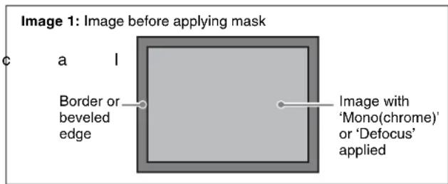
![SONY MVS-7000X - When turning [Speed] on in the group and rotating the pattern at a specified speed - 2](/content/2026/06/1364863/images/75b9d9f1abc0d15600373889d7326a129b13078bb526b7d4ad4d48388dcb9c50.jpg)
![Image 2: State with [Effect Gp1] only set to On Portion ② has ‘Mono’ masked, and ‘Defocus’ only applied. ① ② Portion ① has both ‘Mono’ and ‘Defocus’ applied.](/content/2026/06/1364863/images/55cc829aedf15030b075364dc8f5b05f6994d076e75e060c3ddbfbaa9c222081.jpg)
![SONY MVS-7000X - When turning [Speed] on in the group and rotating the pattern at a specified speed - 4](/content/2026/06/1364863/images/95bad6ffe8fa2e5b81e85cdf825ae14a9d646584702a00a070ba868b7e668c6a.jpg)
In the state corresponding to image 2, if you switch [Effect Gp2] to On, then the mask should be applied to portion ② only, but in fact the border or beveled edge is also masked.
Image 3: State with [Effect Gp1] and [Effect Gp2] set to On
The border or beveled edge effect is also masked.
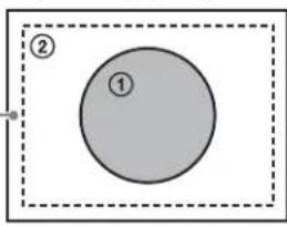
Freeze Settings
Freezes the input video. The following types are available:
Hard Freeze: Freezes the input video at an arbitrary timing.
Time Strobe: Freezes the input video at specified intervals for a specified length.
Film: Slows the apparent frame rate, for an effect like film. You can specify the ratio of advancement.
For Hard Freeze and Time Strobe, you can select the first field or the frame as the freeze timing.
Notes
When 720P or 1080P signal format is used, the Film mode cannot be selected.
To apply a Freeze effect, start by displaying the Freeze menu. In the DME menu, select VF3 'Freeze' and HF1 'Freeze.'
Applying the Hard Freeze effect
1 In the
Frame: Freeze one frame of signal.
Field 1: Freeze the first field of signal.
2 In the
Applying the Time Strobe effect
1 In the
Frame: Freeze one frame of signal.
Field 1: Freeze the first field of signal.
Notes
The freeze timing setting is not required when the following signal formats are being used. 1080P/50, 1080P/59.94, 1080PsF/23.976, 1080PsF/24, 1080PsF/25, 1080PsF/29.97, 720P/ 50, 720P/59.94
2 In the
3 Set the parameters.
| Knob | Parameter Adjustment Setting values | ||
| 1 Duration Freeze | interval | 1 to 255 (frames) | |
| 2 Live | Ratio of live | video inserted between freeze images | 0.00 to 100.00 |
Applying the Film effect
Notes
When 720P or 1080P signal format is used, the Film mode cannot be selected.
1 In the
2 Set the parameter.
| Knob | Parameter Adjustment Setting values | ||
| 1 Film | Ratio of | frame advance | 0.00 to 100.00 |
Applying Special Effects (Nonlinear Effect Settings)
You can add a variety of effects, including effects that change the shape of the image as a whole.
1 In the DME menu, select VF4 'Non Linear/Corner Pin' and HF1 'Non Linear.'
A menu for selecting the various effects appears.
2 Display the menu for the effect that you want to apply by pressing its button.
3 Make the settings for the selected effect.
Notes
- It is not possible to apply two or more nonlinear effects at the same time. Turning any nonlinear effect on automatically turns all other nonlinear effects off.
- The Flex Shadow function cannot be enabled when any of the nonlinear effects Page Turn, Roll, Cylinder, and Sphere is enabled.
- However, the Flex Shadow function is not supported on the MVE-8000A.
To turn an effect off
In the setting menu, press the button for the effect name, turning it off, or in the Type menu press [OFF] in the lower right part of the window.
Wave Settings
There are two modes: H&V and Size. You can set the size and frequency of the waves, the wave form, the amount of wave movement, and the range. In H&V mode, you can also set the wave angle.
To apply the Wave effect
With the Wave menu displayed, use the following procedure.
1 In the
H&V: Modulate vertically and horizontally without changing the size of the image. This mode allows waves to be created in both the vertical and horizontal directions at the same time.
Size: Create waves by reducing and expanding the image. This mode allows waves to be created in one direction only.
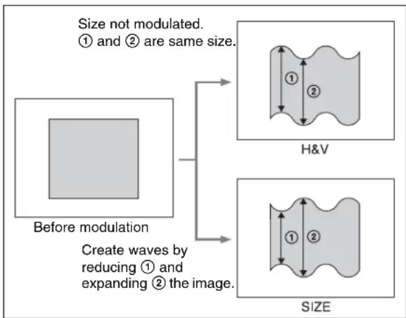
flowchart
graph TD
    A["Before modulation"] --> B["Size not modulated. ① and ② are same size."]
    A --> C["Create waves by reducing ① and expanding ② the image."]
    D["H&V"] --> E["Image with two dimensions labeled ① and ②"]
    F["SIZE"] --> G["Image with two dimensions labeled ① and ②"]
2 Set the following parameters, according to the selected mode.
When H&V is selected
Parameter group [1/2]
| Knob | Parameter | Adjustment | Setting values |
| 1 Amp | H Amplitude | of waves in horizontal direction | 0.00 to 100.00 |
| 2 Freq | H Frequency | of waves in horizontal direction | 0.00 to 100.00 |
| 3 Offset H a) | Horizontal direction in which to offset wave phase and amount of movement | -16.00 to +16.00c)-64.00 to +64.00d) | |
| 4 Speed H b) | Horizontal direction and speed of waves | -100.00 to +100.00 | |
| 5 Slant | Slant of | waves | -8.000 to +8.000 |
Parameter group [2/2]
| Knob | Parameter | Adjustment | Setting values |
| 1 Amp | V Amplitude | of waves in vertical direction | 0.00 to 100.00 |
| 2 Freq | V Frequency | of waves in vertical direction | 0.00 to 100.00 |
Parameter group [2/2]
| Knob | Parameter Adjustment Setting values | |
| 3 Offset V a) | Vertical direction in which to offset wave phase and amount of movement | -16.00 to +16.00c)-64.00 to +64.00d) |
| 4 Speed V b) | Vertical direction and speed of waves | -100.00 to +100.00 |
| 5 Slant | Slant of waves | -8.000 to +8.000 |
a) Set when Lock is on.
b) Set when Lock is off.
c) Setting for SD 4:3, SD 16:9
d) Setting for HD 4:3, HD 16:9
When Size is selected
| Knob | Parameter Adjustment Setting values | ||
| 1 Amp | H Amplitude of waves | 0.00 to 100.00 | |
| 2 Freq | H Frequency of waves | 0.00 to 100.00 | |
| 3 Offset Ha) | Direction in which to offset wave phase and amount of movement | -16.00 to +16.00c)-64.00 to +64.00d) | |
| 4 Speed Hb) | Direction and speed of waves | -100.00 to +100.00 | |
| 5 Slant | Slant of waves | -8.000 to +8.000 | |
a) Set when Lock is on.
b) Set when Lock is off.
c) Setting for SD 4:3, SD 16:9
d) Setting for HD 4:3, HD 16:9

To stop the waves
Press [Lock], turning it on.
With each press, the waves alternately stop and start moving again.
To select the waveform
Press [Form] and set the following parameters.
When H&V mode is selected
| Knob | Parameter Adjustment Setting values | ||
| 1 Form | H Waveform | in horizontal direction | 1 to 6a) |
| 2 Form | V Waveform | in vertical direction | 1 to 6a) |
When Size mode is selected
| Knob | Parameter Adjustment Setting values | ||
| 1 Form | H Waveform | 1 to 6 | a) |
a) 1 (SINE): Sine wave
2 (PARABOLA): Parabola wave
3 (TRIANGLE): Triangular wave
4 (RECTANGLE): Rectangular wave
5 (CIRCLE): Circular wave
6 (CUBIC): Cubic wave
To randomize the modulated waveform
1 Press [Random], turning it on.
2 Set the following parameters.
When H&V mode is selected
| Knob | Parameter Adjustment Setting values | ||
| 1 | Random H Degree | of randomness in horizontal waveform modulation | 0.00 to 100.00 |
| 2 | Random V Degree | of randomness in vertical waveform modulation | 0.00 to 100.00 |
| 3 | Random All | Degree of randomness in both vertical and horizontal directions | Random H value shown |
When Size mode is selected
| Knob | Parameter Adjustment Setting values | ||
| 1 | Random H Degree | of randomness in waveform modulation | 0.00 to 100.00 |
To limit the wave range
1 Press [Range], turning it on.
2 Set the following parameters.
When H&V mode is selected
| Knob | Parameter | Adjustment | Setting values |
| 1 Size | H Amount of | horizontal wave modulation | 0.00 to 100.00 |
| 2 Offset | H Center point | of horizontal modulation range | -8.000 to +8.000^a) -32.000 to +32.000^b) |
| 3 Size | V Amount of | vertical wave modulation | 0.00 to 100.00 |
| 4 Offset | V Center point | of vertical modulation range | -8.000 to +8.000^a) -32.000 to +32.000^b) |
a) Setting for SD 4:3, SD 16:9
b) Setting for HD 4:3, HD 16:9
When Size mode is selected
| Knob | Parameter | Adjustment | Setting values |
| 1 Size | H Amount of | wave modulation | 0.00 to 100.00 |
| 2 Offset | H Center point | of modulation range | -8.000 to +8.000^a) -32.000 to +32.000^b) |
a) Setting for SD 4:3, SD 16:9
b) Setting for HD 4:3, HD 16:9
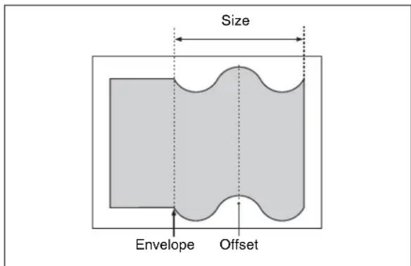
To smooth the range envelope when the wave range is limited
1 Press [Range Envelope], turning it on.
2 Set the following parameters.
When H&V mode is selected
| Knob | Parameter | Adjustment | Setting values |
| 1 Envelope H | Smoothness of envelope in horizontal direction | 0.00 to 100.00 | |
| Knob | Parameter | Adjustment | Setting values |
| 2 Envelope V | Smoothness of envelope in vertical direction | 0.00 to 100.00 | |
When Size mode is selected
| Knob | Parameter | Adjustment | Setting values |
| 1 EnvelopeH | Smoothness of envelope | 0.00 to 100.00 | |
To reverse the wave range
To reverse the horizontal wave range set with [Range]:
Press [Range Rev H], turning it on.
To reverse the vertical wave range set with [Range]:
Press [Range Rev V], turning it on.
Mosaic Glass Settings
There are two modes: H&V and Size. You can set the size and frequency of waves in the image, the wave form, the amount of wave movement, and the range. In H&V mode, you can also set the wave angle.
To apply the Mosaic Glass effect
Display the Mosaic Glass menu.
The items displayed in the Mosaic Glass menu and the functions of the knobs are the same as for the Wave menu (see page 307).
Flag Settings
There are two modes: H&V and Size. You can set the size and frequency of waves in the image, the wave form, the amount of wave movement, and the range. In H&V mode, you can also set the wave angle.
To apply the Flag effect
Display the Flag menu.
The items displayed in the Flag menu and the functions of the knobs are the same as for the Wave menu (see page 307).
Twist Settings
You can twist the image in the horizontal or vertical direction.
You can set the size and frequency of waves in the image, the wave form, the amount of wave movement, and other parameters.
To apply the Twist effect
With the Twist menu displayed, set the following parameters.
Parameter group [1/2]
| Knob | Parameter | Adjustment | Setting values |
| 1 Amp V | Amplitude of | twist in vertical direction | 0.00 to 100.00 |
| 2 Freq V | Frequency of | twist in vertical direction | 0.00 to 100.00 |
| 3 Offset V | a) | Amount of movement in twist phase in the vertical direction | -16.00 to +16.00c)-64.00 to +64.00d) |
| 4 Speed V | b) | Speed and direction of twist movement in vertical direction | -100.00 to +100.00 |
| 5 Slant S | lant of twist -8.000 to | +8.000 | |
Parameter group [2/2]
| Knob | Parameter | Adjustment | Setting values |
| 1 Amp H | Amplitude of | twist in horizontal direction | 0.00 to 100.00 |
| 3 Offset H | a) | Amount of movement in twist phase in the horizontal direction | -100.00 to +100.00 |
| 5 Slant S | lant of twist -8.000 to | +8.000 | |
a) Set when Lock is on.
b) Set when Lock is off.
c) Setting for SD 4:3, SD 16:9
d) Setting for HD 4:3, HD 16:9
To stop the waves
Press [Lock], turning it on.
With each press, the waves alternately stop and start moving again.
To select the waveform
Press [Form] and set the following parameters.
| Knob | Parameter | Adjustment | Setting values |
| 1 Form H | Waveform in | horizontal direction | 1 to 6^a) |
| 2 Form V | Waveform in | vertical direction | 1 to 6^a) |
a) 1 (SINE): Sine wave
2 (PARABOLA): Parabola wave
3 (TRIANGLE): Triangular wave
4 (RECTANGLE): Rectangular wave
5 (CIRCLE): Circular wave
6 (CUBIC): Cubic wave
Ripple Settings
There are four modes: Radial, Angular, Both, and Shape. The direction of modulation differs depending on the mode. You can set the size and frequency of the ripples, their direction and speed, their center point, and other parameters. In Shape mode, you can select ripple shapes other than circles (stars, etc.).
To apply the Ripple effect
With the Ripple menu displayed, use the following procedure.
1 In the
Radial: Points on radii of the same length from the center of the ripples behave in the same way.
Angular: Points at the same angle from the center of the ripples behave in the same way.
Both: Both Radial and Angular ripples are applied.
Shape: The ripples can have shapes such as stars or hearts in addition to circles.
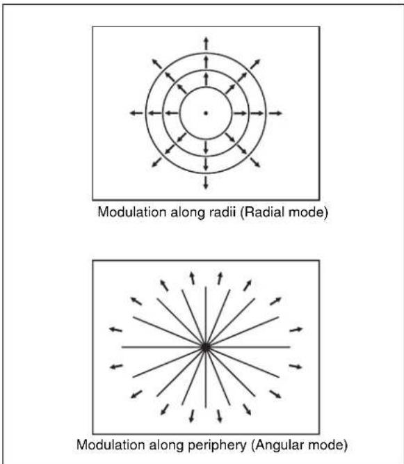
Modulation modes and directions
2 Set the following parameters, depending on the selected modulation mode.
When Radial mode is selected
| Knob | Parameter | Adjustment Setting values | |
| 1 | A m | p R amplitude along radius | 0.00 tR 100.00 p |
| 2 Freq | R Ripple | frequency along radius | 0.00 to 100.00 |
| 3 Offset R a) | Direction along radius in which to offset ripple phase and amount of movement | -8.000 to +8.000 c)-32.000 to +32.000 d) | |
| 4 Speed R b) | Ripple direction along radius and speed | -100.00 to +100.00 | |
| 5 | A m | p A amplitude along periphery | 0.00 tR 100.00 p |
a) Set when Lock is on.
b) Set when Lock is off.
c) Setting for SD 4:3, SD 16:9
d) Setting for HD 4:3, HD 16:9
When Angular mode is selected
| Knob | Parameter | Adjustment Setting values | |
| 1 | A m | p amplitude along periphery | 0.00 tR 100.00 p |
| 2 Freq | A Ripple | frequency along periphery | 0.00 to 100.00 |
| 3 Offset A a) | Direction along periphery in which to offset ripple phase and amount of movement | -8.000 to +8.000 | |
| 4 Speed A b) | Ripple direction along periphery and speed | -100.00 to +100.00 | |
| 5 | A m | p amplitude along radius | 0.00 tR 100.00 p |
a) Set when Lock is on.
b) Set when Lock is off.
When Both mode is selected
Parameter group [1/2]
| p | Knobl | Parameter | Adjustment | Setting values |
| 1 | A m | p R amplitude along radius | 0.00 tB 100.00 | |
| 2 Freq | R Ripple | frequency along radius | 0.00 to 100.00 | |
| 3 Offset R a) | Direction along radius in which to offset ripple phase and amount of movement | -8.000 to +8.000c)-32.000 to +32.000d) | ||
| 4 Speed I b) | Ripple direction along radius and speed | -100.00 to +100.00 | ||
[Non-Text]
p
p
Parameter group [2/2]
| Knob | Parameter | Adjustment | Setting values |
| 1 | A m | p amplitude along periphery | 0.00 to 100.00 |
| 2 Freq l | A Ripple e | frequency along periphery | 0.00 to 100.00 |
| 3 Offset A a) | Direction along periphery in which to offset ripple phase and amount of movement | -8.000 to +8.000 | |
| 4 Speed A b) | Ripple direction along periphery and speed | -100.00 to +100.00 | |
a) Set when Lock is on.
b) Set when Lock is off
c) Setting for SD 4:3, SD 16:9
d) Setting for HD 4:3, HD 16:9
When Shape mode is selected
| Parameter group [1/2] | |||
| Knob | Parameter | Adjustment | Setting values |
| 1 | A m | p R amplitude | 0.00 tR 100.00 |
| 2 Freq | R Ripple | frequency | 0.00 to 100.00 |
p
Parameter group [1/2]
| Knob | Parameter | Adjustment Setting values | |
| 3 Offset R | a) | Direction in which to offset ripple phase and amount of movement | -8.000 to +8.000c)-32.000 to +32.000d) |
| 4 Speed R | b) | Ripple direction and speed | -100.00 to +100.00 |
| 5 Shape | Ripple shape | 1 to 4 | e) |
Parameter group [2/2]
| Knob | Parameter Adjustment Setting values | ||
| 1 | Aspect | Ripple | aspect ratio-100.00 to +100.00 |
| 2 | Angle | Ripple angle | -8.000 to +8.000 |
a) Set when Lock is on.
b) Set when Lock is off.
c) Setting for SD 4:3, SD 16:9
d) Setting for HD 4:3, HD 16:9
e) 1 (Circle): Circle
2 (Rectangle): Rectangle
3 (Star): Star
4 (Heart): Heart
To limit the direction in which modulation is applied
By pressing [Plus Only], turning it on, you can limit the direction in which modulation is applied (the direction in which the image expands) to the plus direction only.
To set the ripple center point
1 Press [Position], turning it on.
2 Set the following parameters, depending on the selected modulation mode.
When Shape is selected
| Knob | Parameter Adjustment Setting values | ||
| 1 | H | Ripple point in horizontal direction | -5.000 dents 5.000^a) -20.000 to +20.000^b) |
| 2 | V | Ripple point in vertical direction | -3.000 dents 8.000^a) -12.000 to +12.000^b) |
a) Setting for SD 4:3, SD 16:9
b) Setting for HD 4:3, HD 16:9
When other than Shape is selected
| Knob | Parameter | Adjustment Setting values | |
| 1 | H | Ripple point in horizontal direction | -8.000 dcm (8r000^a) -32.000 to +32.000^b) |
| 2 | V | Ripple point in vertical direction | -6.000 dcm (8r000^a) -18.000 to +18.000^b) |
a) Setting for SD 4:3, SD 16:9
b) Setting for HD 4:3, HD 16:9
To limit the ripple range
1 Press [Range], turning it on.
2 Set the following parameters.
When Radial or Shape mode is selected
| Knob | Parameter | Adjustment Setting values | |
| 1 Size | R | Amount of ripple modulation along radius | 0.00 to 100.00 |
| 2 Offset | R | Center of modulation range along radius | -8.000 to +8.000^a) -32.000 to +32.000^b) |
a) Setting for SD 4:3, SD 16:9
b) Setting for HD 4:3, HD 16:9
When Angular mode is selected
| Knob | Parameter | Adjustment | Setting values |
| 1 Size | A Amount of | ripplemodulationalongperiphery | 0.00 to 100.00 |
| 2 Offset A | Center ofmodulationrange alongperiphery | -8.000 to +8.000 |
When Both mode is selected
| Knob | Parameter | Adjustment | Setting values |
| 1 Size | R Amount of ripple modulation along radius | 0.00 to 100.00 | |
| 2 Offset | R Center of modulation range along radius | -8.000 to +8.000a)-32.000 to +32.000b) | |
| Knob | Parameter Adjustment Setting values | ||
| 3 Size | A Amount of | ripple modulation along periphery | 0.00 to 100.00 |
| 4 Offset | A Center of | modulation range along periphery | -8.000 to +8.000 |
a) Setting for SD 4:3, SD 16:9
b) Setting for HD 4:3, HD 16:9
To reverse the ripple range
When modulation mode is Radial, Both, or Shape: Press [Range Rev R], turning it on.
When modulation mode is Both or Angular: Press [Range Rev A], turning it on.
Other settings
You can turn [Lock], [Form], [Random], and [Range Envelope] on to do the following.
- Stop the waves
- Select the wave shape
- Randomize the waveform
- Smooth the range envelope when the wave range is limited
For Lock, Form, Random, and Range Envelope functions, see “Wave Settings” (page 307).
Rings Settings
You can set the degree of transition, the degree of randomness in the distance moved by each block, the amount of movement, the width of the partitions, the degree of randomness in partition width, the center point, the starting angle, and other parameters.
To apply the Rings effect
With the Rings menu displayed, use the following procedure.
1 To make transition settings, press [Transition] and set the following parameters.
| Knob | Parameter Adjustment Setting values | |
| 1 Transition Degree of transition | 0.000 to 100.000 | |
| 2 Random Degree of randomness in distance moved by each block | 0.000 to 100.000 | |
| Knob | Parameter Adjustment Setting values | |
| 3 Spiral | Amount of movement toward periphery accompanying transition | -1.000 to +1.000 |
2 To set the partition method, press [Partition] and set the following parameters.
| Knob | Parameter Adjustment Setting values | |
| 1 Width | Width of partition | 0.000 to 100.000 |
| 2 Random Degree of randomness in partition width | 0.000 to 100.000 | |
| 3 Angle | Starting angle of effect | -8.000 to +8.000 |
3 To set the ring center position, press [Position] and set the following parameters.
| Knob | Parameter Adjustment Setting values | |
| 1 H | Horizontal center position | -5.000 to +5.000a)-20.000 to +20.000b) |
| 2 V | Vertical center position | -4.000 to +4.000a)-16.000 to +16.000b) |
a) Setting for SD 4:3, SD 16:9
b) Setting for HD 4:3, HD 16:9
4 To partition into pixels, press [Pixel], turning it on, and set the following parameters.
| Knob | Parameter | Adjustment Setting | values |
| 1 | Density | Degree to which image disappears around periphery | 0.00 to 100.00 |
| 2 | Random | Degree of jaggies at block edges | 0.00 to 100.00 |
Broken Glass Settings
You can set the degree of transition, the degree of randomness in the distance moved by each block, the amount of movement, the width of the partitions, the degree of randomness in partition width, the center point, the starting angle, and other parameters.
You can also fix the direction in which shards scatter.
To apply the Broken Glass effect
Display the Broken Glass menu.
The functions of the knobs in the Broken Glass menu are the same as those of the Rings menu (see page 313), with the exception of [Direction].
To fix the direction in which shards scatter
Press [Direction], turning it on.
Flying Bar Settings
You can set the degree of transition, the degree of randomness in the distance moved by each block, the direction of movement, the width of the partitions, the degree of randomness in partition width, the partition angle, and other parameters.
To apply the Flying Bar effect
With the Flying Bars menu displayed, use the following procedure.
1 To make transition settings, press [Transition] and set the following parameters.
| Knob | Parameter Adjustment Setting values | ||
| 1 | Transition Degree of transition | 0.000 to 100.000 | |
| 2 | Random Degree of randomness in distance moved by each block | -100.000 to +100.000 | |
| 3 | Angle Direction of movement | -8.000 to +8.000 | |
2 To set the partition method, press [Partition] and set the following parameters.
| Knob | Parameter Adjustment Setting values | |
| 1 Width | Width of partition | 0.000 to 100.000 |
| 2 Random Degree of randomness in partition width | 0.000 to 100.000 | |
| 3 Angle | Partition angle -8.000 to +8.000 | |
Blind Settings
There are two modes: Bar and Wedge. You can set the number of rotations by blocks, the perspective, the width and position of blocks, the direction, the center position, and other parameters.
To apply the Blind effect
With the Blind menu displayed, use the following procedure.
1 In the
2 To make transition settings, press [Transition] and set the following parameters.
| Knob | Parameter Adjustment Setting values | |
| 1 | Rotation Number of rotations of the blocks | -8.000 to +8.000 |
| 2 | Perspective Degree of randomness in distance moved by each block | 0.000 to 100.000 |
3 To set the partition method, press [Partition] and set the following parameters.
When Bar was selected in step 1
| Knob | Parameter Adjustment Setting values | ||
| 1 Width | Width of | partition | 0.000 to 100.000 |
| 2 Offset | Degree of | randomness in partition width | -5.000 to +5.000a)-20.000 to 20.000b) |
| 3 Angle | Starting angle | of effect | -8.000 to +8.000 |
a) Setting for SD 4:3, SD 16:9
b) Setting for HD 4:3, HD 16:9
When Wedge was selected in step 1
| Knob | Parameter Adjustment Setting values | |
| 4 No Width of blocks | 0.000 to 100.000 | |
| 5 Phase | Partition position | -8.000 to +8.000 |
To set the wedge center position
When Wedge is selected in the
1 Press [Position].
2 Set the following parameters.
| Knob | Parameter | Adjustment | Setting values |
| 1 | H | Horizontal center position | -8.000 to +8.000 a) -32.000 to +32.000 b) |
| 2 | V | Vertical center position | -6.000 to +6.000 a) -18.000 to +18.000 b) |
a) Setting for SD 4:3, SD 16:9
b) Setting for HD 4:3, HD 16:9
Split Settings
You can set the degree to which the image is split, the split positions, and other parameters.
To apply the Split effect
With the Split menu displayed, use the following procedure.
1 In the
Single: Leave gaps between splits.
Double: Fill gaps between splits with the same image.
2 Set the following parameters.
Parameter group [1/2]
| Knob | Parameter | Adjustment | Setting values |
| 1 Transition H | Degree of left and right separation | -100.00 to +100.000 | |
| 2 Transition V | Degree of top and bottom separation | -100.00 to +100.000 | |
Parameter group [2/2]
| Knob | Parameter | Adjustment | Setting values |
| 1 Top Amount of | movement of top | -100.00 to +100.000 | |
| 2 Left Amount of | movement of left | -100.00 to +100.000 | |
| 3 Right Amount of | movement of right | -100.00 to +100.000 | |
| 4 Bottom Amount of | movement of bottom | -100.00 to +100.000 | |
To set the split position
1 Press [Position].
2 Set the following parameters.
| Knob | Parameter | Adjustment | Setting values |
| 1 H Degree of | left and right separation | -4.000 to +4.000^a) -16.000 to +16.000^b) | |
| Knob | Parameter | Adjustment | Setting values |
| 2 V Degree of | top andbottomseparation | -3.000 to +3.000a)-12.000 to+12.000b) | |
a) Setting for SD 4:3, SD 16:9
b) Setting for HD 4:3, HD 16:9
Split Slide Settings
You can set the degree of transition, the degree of randomness in the distance moved by each block, the degree of sliding, block width, block angle, and other parameters.
To apply the Split Slide effect
With the Split Slide menu displayed, set the following parameters.
Parameter group [1/2]
| Knob | Parameter | Adjustment | Setting values |
| 1 | Transition H | Degree of transition in horizontal direction | -100.00 to +100.000 |
| 2 | Random H | Degree of randomness in distance moved by blocks in horizontal direction | 0.00 to 100.00 |
| 3 | Skew H | Degree of skew in horizontal direction | 0.00 to 100.00 |
| 4 | Width H | Horizontal width of partition | 0.00 to 100.00 |
| 5 | Angle | Angle of partition line | -8.000 to +8.000 |
Parameter group [2/2]
| Knob | Parameter | Adjustment | Setting values |
| 1 | Transition V | Degree of transition in vertical direction | -100.00 to +100.000 |
| 2 | Random V | Degree of randomness in distance moved by blocks in vertical direction | 0.00 to 100.00 |
| 3 | Skew V | Degree of skew in vertical direction | 0.00 to 100.00 |
Parameter group [2/2]
| Knob | Parameter | Adjustment | Setting values |
| 4 Width V | Vertical width | of partition | 0.00 to 100.00 |
| 5 Angle | Angle of | partition line | -8.000 to +8.000 |
To set the partition position
1 Press [Position], turning it on.
2 Set the following parameters.
| Knob | Parameter Adjustment Setting values | ||
| 1 | H | Hpartitionposition | e5.000 to +5.000a)-20.000 to+20.000b) |
| 2 | V | Vpartitionposition | e5.000 to +5.000a)-20.000 to+20.000b) |
a) Setting for SD 4:3, SD 16:9
b) Setting for HD 4:3, HD 16:9
Mirror Settings
You can choose to reflect in the directions left to right, right to left, bottom to top, top to bottom, or any combination of directions. You can also set the position of the border between original and reflections.
To apply the Mirror effect
With the Mirror menu displayed, press [Left to Right], [Right to Left], [Top to Bottom], or [Bottom to Top] to set the reflection method (multiple selections possible).
Left to Right: Reflect left side on right.
Right to Left: Reflect right side on left.
Top to Bottom: Reflect top side on bottom.
Bottom to Top: Reflect bottom side on top.
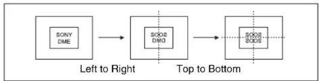
flowchart
graph LR
    A["SONY DME"] --> B["SOO2 DM0"]
    B --> C["SOO2 2OD5"]
    style A fill:#f9f,stroke:#333
    style B fill:#ccf,stroke:#333
    style C fill:#cfc,stroke:#333
To set the position of the border between original and reflection
1 Press [Position].
2 Set the following parameters.
| Knob | Parameter Adjustment Setting values | ||
| 1 | H | H o border position | -8.000 to +8.000a) -32.000 to +32.000b) |
| 2 | V | V e border position | -6.000 to +6.000a) -24.000 to +24.000b) |
a) Setting for SD 4:3, SD 16:9
b) Setting for HD 4:3, HD 16:9
Multi Mirror Settings
z
You can set the width of the original, the center position of the original, the offset of the image with fixed mirrors, the direction of the mirrors, and other parameters.
i
To apply the Multi Mirror effect
With the Multi Mirror menu displayed, set the following parameters.
| Knob | Parameter | Adjustment | Setting values |
| 1 Interval | H Horizontal | distance between mirrors(original width) | 0.000 to 10.000a)0.000 to 40.000b) |
| 2 Offset H | Amount of horizontal offset of image with mirrors fixed | -4.000 to +4.000a)-16.000 to +16.000b) | |
| 3 Interval V | Vertical | distance between mirrors(original width) | 0.000 to 10.000a)0.000 to 40.000b) |
| 4 Offset V | Amount of vertical offset of image with mirrors fixed | -4.000 to +4.000a)-16.000 to +16.000b) | |
| 5 Angle | Mirror angle | -8.000 | to +8.000 |
a) Setting for SD 4:3, SD 16:9
b) Setting for HD 4:3, HD 16:9
To set the center position of original image
1 Press [Position], turning it on.
2 Set the following parameters.
| Knob | Parameter | Adjustment | Setting values |
| 1 | H | Horizontal original image center position | -4.000 to +4.000a)-16.000 to +16.000b) |
| 2 | V | Voriginalimagecenterposition | e-4.000rto +4.000a) i-16.000 to+16.000b) |
a) Setting for SD 4:3, SD 16:9
b) Setting for HD 4:3, HD 16:9
Kaleidoscope Settings
You can set the number of blocks, the partition reference point and angle, horizontal and vertical offsets, a reflection position, and other parameters.
To apply the Kaleidoscope effect
With the Kaleidoscope menu displayed, set the following parameters.
| Knob | Parameter | Adjustment | Setting values |
| 1 Number | Number of blocks | 0.00 to 100.00 | |
| 2 Phase | Angle of partition reference point | -8.000 to +8.000 | |
| 3 Offset | H Amount of horizontal offset | -4.000 to +4.000^a) -16.000 to +16.000^b) | |
| 4 Offset | V Amount of vertical offset | -3.000 to +3.000^a) -12.000 to +12.000^b) |
a) Setting for SD 4:3, SD 16:9
b) Setting for HD 4:3, HD 16:9
To reflect the kaleidoscope image as if in a mirror
1 To reflect in the horizontal direction, press [Mirror H], turning it on.
2 To reflect in the vertical direction, press [Mirror V], turning it on.
To set the reflection position
1 Press [Position], turning it on.
2 Set the following parameters.
| Knob | Parameter | Adjustment | Setting values |
| 1 | H | Horizontal reflection position | 0.000 to 4.000^a) 0.000 to 16.000^b) |
| 2 | V | Vertical reflection position | 0.000 to 3.000^a) 0.000 to 12.000^b) |
a) Setting for SD 4:3, SD 16:9
b) Setting for HD 4:3, HD 16:9
To cyclically repeat part of the original and its reflection
Press [Cyclic], turning it on.
Lens Settings
You can set the shape and aspect ratio of the lens, the angle, the magnification ratio, the curve ratio, the size, the center position, and other parameters.
You can also choose to display only the portion of the image that is seen through the lens.
To apply the Lens effect
With the Lens menu displayed, use the following procedure.
1 In the
- Circle
- Rectangle
• Star
• Heart
• Bar
• Cross
2 Depending on the selected lens shape, set the following parameters.
When Circle, Rectangle, Star, or Heart is selected
| Knob | Parameter | Adjustment | Setting values |
| 1 Magnify H | Magnification ratio | -100.00 to +100.00 | |
| 2 Curve H | Curve ratio | -100.00 to +100.00 | |
| 3 Size H | Size | 0.00 to 100.00 | |
| 4 Angle | Slant angle | -8.00 to +8.000 | |
| 5 Aspect | Aspect ratio | -100.00 to +100.00 |
When Bar is selected
| Knob | Parameter | Adjustment | Setting values |
| 1 Magnify H | Magnification ratio | -100.00 to +100.00 | |
| 2 Curve H | Curve ratio | -100.00 to +100.00 | |
| 3 Size H | Size | 0.00 to 100.00 | |
| 4 Angle | Slant angle | -8.00 to +8.000 |
When Cross is selected
Parameter group [1/2]
| Knob | Parameter | Adjustment | Setting values |
| 1 Magnify H | Horizontal magnification ratio | -100.00 to +100.00 | |
| 2 Curve H | Horizontal curve ratio | -100.00 to +100.00 |
Parameter group [1/2]
| Knob | Parameter Adjustment Setting values | ||
| 3 Size | H Horizontal size | 0.00 to 100.00 | |
Parameter group [2/2]
| Knob | Parameter Adjustment Setting values | ||
| 1 | Magnify V Vertical | magnification ratio | -100.00 to +100.00 |
| 2 | Curve V Vertical | curve ratio | -100.00 to +100.00 |
| 3 | Size V Vertical size | 0.00 to 100.00 | |
To make only the lens part visible
Press [Lens Only], turning it on.
The parts of the image outside the lens are removed.
To set the lens center position
1 Press [Position], turning it on.
2 Set the following parameters.
| Knob | Parameter | Adjustment | Setting values |
| 1 | H | H lens center position | e5.000 to +5.000^a) -20.000 to +20.000^b) |
| 2 | V | Vertical lens center position | -4.000 to +4.000^a) -16.000 to +16.000^b) |
a) Setting for SD 4:3, SD 16:9
b) Setting for HD 4:3, HD 16:9
Circle Settings
You can set the size of the circle, and make the axis of modulation vertical.
To apply the Circle effect
With the Circle menu displayed, set the following parameters.
| Knob | Parameter | Adjustment | Setting values |
| 1 | Radius | Size of circle | 0.00 to 100.00 |
To make the axis of modulation vertical
Press [Mod V], turning it on.
The axis of modulation when converting to the circle becomes vertical.
Panorama Settings
You can set the horizontal and vertical curve ratio, and the curve center position.
To apply the Panorama effect
With the Panorama menu displayed, set the following parameters.
| Knob | Parameter | Adjustment Setting | values |
| 1 Curve | H | Horizontal curve ratio | -100.00 to +100.00 |
| 2 Curve | V | Curve ratio | -100.00 to +100.00 |
| 3 Position | H | Horizontal curve center position | -4.000 to +4.000^a) -16.000 to +16.000^b) |
| 4 Position | V | Curve center position | -3.000 to +3.000^a) -12.000 to +12.000^b) |
a) Setting for SD 4:3, SD 16:9
b) Setting for HD 4:3, HD 16:9
Page Turn Settings
n t a l
There are four modes: H&V, H, V, and Off. You can select the turn position, the radius of the turned portion, the amount and angle of turning, and the input video for the front and back pages.
To apply the Page Turn effect
With the Page Turn menu displayed, use the following procedure.
1 In the
H&V: The image turns as it is split from the center into 4 parts: left, right, upper, lower.
H: The image turns as it is split from the center into 2 parts: left, right.
V: The image turns as it is split from the center into 2 parts: upper, lower.
When nothing is selected (Off): There are no splits and the image turns from the edge.
2 Press [Page Turn], then set the following parameters.
| Knob | Parameter | Adjustment Setting values | |
| 1 | Radius | Radius of turn part | 0.00 to 100.00 |
| 2 | Offset Amount of | turn | -100.00 to +100.00 |
| Knob | Parameter | Adjustment | Setting values |
| 3 Angle | Angle of turn | -0.250 to +0 | 000 a) -0.250 to +0.250 b) -0.500 to +0.000 c) -8.000 to +8.000 d) |
a) When split mode is H&V
b) When split mode is H
c) When split mode is V
d) When split mode is off
To set the input signal of the back page
1 In the
Self: Use the same signal as the front page.
Flat: Use a flat color.
Hue Rotation: Gradually vary the hue.
2nd Ch: Use the 2nd channel video signal. To select “2nd Ch,” it is first necessary to select the second DME on the keyer using DME.
2 Adjust the following parameters, according to the selected input signal.
When Flat is selected
| Knob | Parameter | Adjustment | Setting values |
| 1 Luminance | Luminance | 0.00 to 1 | 00.00 |
| 2 Saturation | Saturation | 0.00 to 100 | 0.00 |
| 3 Hue | Hue | 359.99 to 0.00 |
When Hue Rotation is selected
| Knob | Parameter | Adjustment | Setting values |
| 1 Luminance | Luminance | 0.00 to 100.00 | |
| 2 Saturation | Saturation | 0.00 to 100.00 | |
| 3 Speed | Speed | at which hue changes | -12.00 to +12.00 |
Notes
When using a page turn effect with one channel, the following restrictions apply.
- In an MVE-8000A HD system, when the input is for example a title, parts of the back page other than the title appear as black.
- For the MKS-7470X/7471X, the same restrictions as above apply to all signal formats.
Roll Settings
There are four modes: H&V, H, V, and Off. You can select the turn position, the radius of the turned portion, the amount and angle of turning, and the input video for the front and back pages.
To apply the Roll effect
Display the Roll menu.
The knobs in the Roll menu have the same functions as those in the Page Turn menu (see page 318).
Notes
When using a roll effect with one channel, the following restrictions apply.
- In an MVE-8000A HD system, when the input is for example a title, parts of the back page other than the title appear as black.
- For the MKS-7470X/7471X, the same restrictions as above apply to all signal formats.
Cylinder Settings
You can set the degree of winding onto the cylinder, the radius, the horizontal position of the wound image, and front and back side output for the image.
To apply the Cylinder effect
With the Cylinder menu displayed, set the following parameters.
| Knob | Parameter | Adjustment | Setting values |
| 1 | Radius | Degree to which image is wound onto the cylinder | 0.00 to 100.00 |
| 2 | Min R | Radius of the cylinder | 0.00 to 100.00 |
| 3 | Offset | Horizontal position of the image wound onto cylinder | -100.00 to +100.00 |
The procedure for selecting the input signal in the
Notes
When using a cylinder effect with one channel, the following restrictions apply.
- In an MVE-8000A HD system, when the input is for example a title, parts of the inner surface other than the title appear as black.
- For the MKS-7470X/7471X, the same restrictions as above apply to all signal formats.
Sphere Settings
You can set the degree of winding onto the sphere, the radius, the horizontal position of the wound image, and front and back side output for the image.
Notes
You cannot monitor the part of a rotating sphere that corresponds to its axis on the monitor screen.
To apply the Sphere effect
Display the Sphere menu.
The knobs in the Sphere menu have the same functions as those in the Cylinder menu “Cylinder Settings” (page 319).
Notes
When using a sphere effect with one channel, the following restrictions apply.
- In an MVE-8000A HD system, when the input is for example a title, parts of the inner surface other than the title appear as black.
- For the MKS-7470X/7471X, the same restrictions as above apply to all signal formats.
Explosion Settings
You can set the pattern shape and aspect ratio, the center position, the amount of movement by fragments, the curvature of the transition path, and other parameters.
To apply the Explosion effect
With the Explosion menu displayed, use the following procedure.
1 In the
- Circle
- Rectangle
• Star
• Heart - Ellipse
2 Set the following parameters.
When Circle was selected in step 1
| Knob | Parameter | Adjustment Setting values | |
| 1 | Transition Degree | of transition | 0.00 to 100.00 |
| 2 | Curve Degree to | which image periphery expands | 0.00 to 100.00 |
| Knob | Parameter | Adjustment Setting values | |
| 3 Spiral | Degree of | curvature of transition path | -100.00 to +100.00 |
When Rectangle, Star, Heart, or Ellipse was selected in step 1
| Knob | Parameter | Adjustment Setting values | |
| 1 | Transition Degree | of transition | 0.00 to 100.00 |
| 2 | Curve Degree to | which image periphery expands | 0.00 to 100.00 |
| 3 | Aspect Aspect | ct ratio of waveform | -100.00 to +100.00 |
| 4 | Angle Slant of | waveform | -8.000 to +8.000 |
To make the fragments stardust
1 Press [Pixel], turning it on.
2 Set the following parameters.
| Knob | Parameter | Adjustment Setting values | |
| 1 | Density | Degree to which image disappears | 0.00 to 100.00 |
| 2 | Random | Degree of randomness in flying out fragment positions | 0.00 to 100.00 |
To set the explosion center point
1 Press [Position], turning it on.
2 Set the following parameters.
| Knob | Parameter | Adjustment | Setting values |
| 1 | H | Center point in horizontal direction | -5.000 to +5.000a)-20.000 to +20.000b) |
| 2 | V | Center point in vertical direction | -4.000 to +4.000a)-16.000 to +16.000b) |
a) Setting for SD 4:3, SD 16:9
b) Setting for HD 4:3, HD 16:9
Swirl Settings
You can set the amount of swirl, the swirl region, the amount of rotation, and the swirl center position.
To apply the Swirl effect
With the Swirl menu displayed, set the following parameters.
| Knob | Parameter | Adjustment | Setting values |
| 1 Transition | Swirl amount | 0.00 to 100.00 | |
| 2 Center | Amount of | rotation in center of swirl | -8.000 to +8.000 |
| 3 Outer Amount of | rotation outside of Area | -8.000 to +8.000 | |
| 4 Area Region of swirl 0.00 to 100.00 | |||
To make the tip of the swirl stardust
1 Press [Pixel], turning it on.
2 Set the following parameters.
| Knob | Parameter | Adjustment | Setting values |
| 1 | Density | Degree to which image disappears | 0.00 to 100.00 |
| 2 | Random Trail type and amount of stardust | 0.00 to 100.00 | |
To set the center position of the swirl
1 Press [Position], turning it on.
2 Set the following parameters.
| Knob | Parameter | Adjustment | Setting values |
| 1 | H | Horizontal center position of swirl | -8.000 to +8.000^a) -32.000 to +32.000^b) |
| 2 | V | Vertical center position of swirl | -6.000 to +6.000^a) -18.000 to +18.000^b) |
a) Setting for SD 4:3, SD 16:9
b) Setting for HD 4:3, HD 16:9
Melt Settings
You can set the degree of transition, the degree of extension in the image, the jaggedness of the melting sections, and the amplitude, frequency, amount of movement, and speed of the melting sections. You can also set the slant of the borders, the shape of the sections that begin to melt, and other parameters.
To apply the Melt effect
With the Melt menu displayed, use the following procedure.
1 In the
Up: Melting occurs upward.
Down: Melting occurs downward.
2 To make transition settings, press [Transition] and set the following parameters.
| Knob | Parameter | Adjustment | Setting values |
| 1 | Transition | Degree of transition | 0.00 to 100.00 |
| 2 | Curve | Degree to which image stretches | 0.00 to 100.00 |
| 3 | Random Degree of jaggies at melted part | 0.00 to 100.00 | |
3 To make wave settings for melting part, press [Border] and set the following parameters.
| Knob | Parameter | Adjustment | Setting values |
| 1 | Amp | Amplitude of waves | 0.00 to 100.00 |
| 2 | Freq | Frequency of waves | 0.00 to 100.00 |
| 3 | Offset^a) | Amount of wave phase offset | -16.000 to +16.000 ^c) -64.000 to +64.000 ^d) |
| 4 | Speed^b) | Direction and speed of waves | -100.00 to +100.00 |
| 5 | Slant | Slant of border | -100.00 to +100.00 |
a) Set when Lock is on.
b) Set when Lock is off.
c) Setting for SD 4:3, SD 16:9
d) Setting for HD 4:3, HD 16:9
To stop the waves in the melting part
Press [Lock], turning it on.
With each press, the waves alternately stop and start moving again.
To select the shape of the part beginning to melt
Press [Form] and set the following parameter.
| Knob | Parameter | Adjustment | Setting values |
| 1 Form | Waveform | 1 to 8 | a) |
a) 1 (SINE): Sine wave
2 (PARABOLA): Parabola wave
3 (TRIANGLE): Triangular wave
4 (RECTANGLE): Rectangular wave
5 (CIRCLE): Circular wave
6 (CUBIC): Cubic wave
7 (MELT1): Melting wave 1
8 (MELT2): Melting wave 2
To make the melting part stardust
1 Press [Pixel], turning it on.
2 Set the following parameters.
| Knob | Parameter | Adjustment Setting values | |
| 1 | Density Degree to | which image disappears | 0.00 to 100.00 |
| 2 | Random Degree to | which pixel positions become more randomized further from the center | 0.00 to 100.00 |
Character Trail Settings
You can set the effect starting position, the degree of expansion, the slant angle of the effect region, and trail direction, the degree to which the image disappears, the trail type and amount of stardust, and other parameters.
To apply the Character Trail effect
With the Character Trail menu displayed, set the following parameters.
| Knob | Parameter | Adjustment | Setting values |
| 1 Transition Position where effect starts | -8.000 to +8.000a)-32.000 to +32.000b) | ||
| 2 Expand Degree of expansion | 0.00 to 100.00 | ||
| 3 Trans Angle Angle of slanting in effect region | -8.000 to +8.000 | ||
| 4 Trail Angle Direction of trail -100.00 to | +100.00 | ||
a) Setting for SD 4:3, SD 16:9
b) Setting for HD 4:3, HD 16:9
To make the tip of the swirl stardust
1 Press [Pixel], turning it on.
2 Set the following parameters.
| Knob | Parameter | Adjustment Setting values | |
| 1 | Density | Degree to which image disappears | 0.00 to 100.00 |
| 2 | Random | Trail type and amount of stardust | 0.00 to 100.00 |
Applying Special Effects (Lighting and Recursive Effects)
Lighting Settings
You can specify the intensity and color of the light and the lighting pattern. The following lighting patterns are available:
Plane: Illumination of the entire screen.
Bar: Bar illumination. You can specify the width and angle of the bar, and its softness.
Preset: Lighting pattern suitable for nonlinear effects.
When Bar is selected, the following modes can be selected.
Normal: Emphasizes the bar highlight area.
Specular: An effect like light striking a surface with metallic reflections.
Mat: An effect like light striking paper, cloth, or another diffusively reflective surface.
Notes
The function for setting the bar mode of the lighting area is not supported on the MVE-8000A.
Applying the Lighting effect
1 In the DME menu, select VF5 'Light/Trail' and HF1 'Lighting.'
The Lighting menu appears.
2 Press [Lighting], turning it on.
3 In the
4 Set the parameters.
The parameters differ as follows, depending on the selected lighting pattern.
When Plane is selected
| Knob | Parameter | Adjustment | Setting values |
| 1 Light | Intensity of | light in highlight area | 0.00 to 100.00 |
| 5 Total | Ambient | Brightness of whole image | 0.00 to 100.00a) |
a) You can make the Lighting effect more effective by adjusting [Total Ambient] to lower the brightness of the entire image. This setting is used both by this effect and by the Spotlighting effect.
Notes
The Total Ambient parameter is not supported on the MVE-8000A.
When Bar is selected
| Knob | Parameter | Adjustment | Setting values |
| 1 Light | Intensity of | light in highlight area | 0.00 to 100.00 |
| 2 Ambient | Intensity of light in ambient area | 0.00 to 100.00 | |
| 5 Total | Ambient | Brightness of whole image | 0.00 to 100.00^a) |
a) You can make the Lighting effect more effective by adjusting [Total Ambient] to lower the brightness of the entire image. This setting is used both by this effect and by the Spotlighting effect.
Notes
The Total Ambient parameter is not supported on the MVE-8000A.
When Preset is selected
| Knob | Parameter | Adjustment | Setting values |
| 1 Light | Intensity of | light in highlight area | 0.00 to 100.00 |
| 2 Ambient | Intensity of | light in ambient area | 0.00 to 100.00 |
| 3 Shade | Intensity of | light in shade area | 0.00 to 100.00^a) |
| 5 Total | Ambient | Brightness of whole image | 0.00 to 100.00^b) |
a) Setting is available when nonlinear effect page turn, roll, cylinder, or sphere is selected.
b) You can make the Lighting effect more effective by adjusting [Total Ambient] to lower the brightness of the entire image. This setting is used both by this effect and by the Spotlighting effect.
Notes
The Total Ambient parameter is not supported on the MVE-8000A.
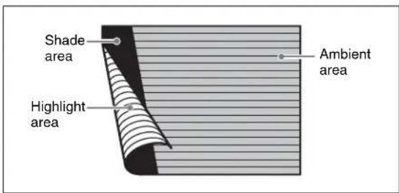
The three regions for which the light intensity can be set
Setting the bar shape of the highlight area
When you select [Bar] or [Preset] in step 3 of “Applying the Lighting effect” (page 323), use the following procedure to set the shape of the bar.
1 Turn [Light Modify] on.
2 Adjust the following parameters.
| Knob Parameter Adjustment Setting values | |||
| 1 | X X | - vbar centerpoint | -8.00 to +8.00^a) b) u -24.00 to +24.00^c) -32.00 to +32.00^d) |
| 2 | Y Y | - vbar centerpoint | -6.00 to +6.00^a) u -4.50 to +4.50^b) -18.00 to +18.00^c) d) |
| 3 | A e)n | Angle of bar | -8.00 eto +8.00 |
| 4 Width Width of bar 0.00 to 100.00 | |||
| 5 Soft Softness of edges | 0.00 to 100.00 | ||
a) For SD 4:3
b) For SD 16:9
c) For HD 4:3
d) For HD 16:9
e) There are some nonlinear effects for which Angle cannot be used.
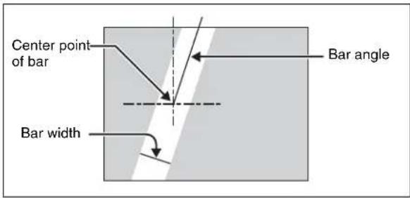
Bar shape parameters
Setting the color of the light in the highlight area
1 Turn [Light Color] on.
2 Adjust the following parameters.
| Knob | Parameter | Adjustment | Setting values |
| 1 | Luminance | Luminance | 0.00 to 100.00 |
| 2 | Saturation | Saturation | 0.00 to 100.00 |
| 3 | Hue | Hue | 359.99 to 0.00 |
Setting the bar shape of the shade area
When you select [Preset] in step 3 of “Applying the Lighting effect” (see page 323), use the following procedure to set the bar shape of the shade area.
1 Turn [Shade Modify] on.
2 Adjust the following parameters.
| Knob | Parameter Adjustment Setting values | ||
| 1 | X | X | - vbar centerpoint -8.00 to +8.00^a) u -24.00 to +24.00^b) -32.00 to +32.00^c) |
| 4 Width | Width of bar | 0.00 to 100.00 | |
| 5 Softo | Softness off | edges0.00 to 100.00 | |
a) For SD 4:3 and SD 16:9
b) For HD 4:3
c) For HD 16:9
e c) For HD 16.9 f
Setting the color of the shade in the shade area
1 Turn [Shade Color] on.
2 Adjust the following parameters.
| Knob | Parameter Adjustment Setting values | ||
| 1 | Luminance Luminance 0.00 to 100.00 | ||
| 2 | Saturation Saturation | 0.00 to 100.00 | |
| 3 | Hue | 359.99 to 0.00 | |
Setting the bar mode of the highlight area
When you select [Bar] in step 3 of “Applying the Lighting effect” (page 323), use the following procedure to set the bar mode of the highlight area.
Notes
The bar mode of the highlight area is not supported on the MVE-8000A.
1 Select the mode in the
Normal: Emphasizes the bar highlight area.
Specular: An effect like light striking a surface with metallic reflections.
Mat: An effect like light striking paper, cloth, or another diffusively reflective surface.
2 Set the following parameters.
| Knob | Parameter | Adjustment | Setting values |
| 1 Intensity | Intensity | of diffuse light area | 0.00 to 100.00 |
| 2 Offset | Offset of | center of diffuse light area | -4.00 to +4.00^a) -12.00 to +12.00^b) -16.00 to +16.00^c) |
| 3 Width | Width of | diffuse light area | 0.00 to 100.00 |
| 4 Soft | Softness of | diffuse light area | 0.00 to 100.00 |
a) For SD 4:3 and SD 16:9
b) For HD 4:3
c) For HD 16:9
3 When you select Normal or Mat in step 1, press [Bar Diffuse Color], turning it on, and adjust the following parameters to set the color of the diffuse light area.
| Knob | Parameter | Adjustment | Setting values |
| 1 Luminance | Luminance | 0.00 to 100.00 | |
| 2 Saturation | Saturation | 0.00 to 100.00 | |
| 3 Hue | Hue | 359.99 to 0.00 |
With no selection made in the
With a selection made in the
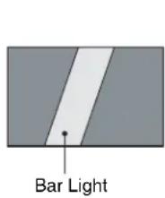
Trail Settings
Notes
- Of the three effects of trail, motion decay and keyframe strobe, only one can be on at a time. When one of them is on, turning another of them on automatically turns off the one that has been on.
- Turning Trail on when Motion Decay (see page 327), Keyframe Strobe (see page 328) or Wind (see page 329) is on turns it off automatically.
Applying the Trail effect
1 In the DME menu, select VF5 'Light/Trail' and HF2 'Trail.'
The Trail menu appears.
2 Press [Trail], turning it on.
3 Set the parameters.
| Knob | Parameter | Adjustment | Setting values |
| 1 Decay | Degree to which the trail is left | 0.00 to 100.00a) | |
| 2 Interval | Freeze interval | 1 to 255 (frames) | |
| 3 Live Proportion of | the interval between two successive freeze images for which the video is run | 0.00 to 100.00 | |
a) 0.00 is no trail. At 100.00, the trail does not disappear.
4 To erase the trail, press [Trail Eraser], turning it on.
Switching the priority between the current image and trail superimposed
In the
Over: Current image is on top.
Under: Trail is on top.
Selecting the source to create a trail
In the
Notes
- “Rainbow,” “Mix Color,” and “Ext Video” are not supported on the MVE-8000A.
- “Mix Color” or “Ext Video” can only be applied to one of the background (see page 338), flex shadow (see page 290), trail, and wind (see page 329) effects.
If you select “Mix Color” or “Ext Video” in one of these settings, a selection of “Mix Color” or “Ext Video” in any of the other effects is disabled, and “Flat Color” is selected in its place. - When executing combining four channels of DME images, “Mix Color” and “Ext Video” in the flex shadow and background effects cannot be selected.
Freeze Video: Use freeze images of the input video as source of the trail.
Flat Color: Use a flat color matte as source of the trail. You can set the following parameters with the knobs.
| Knob | Parameter | Adjustment | Setting values |
| 1 | Luminance | Luminance | 0.00 to 100.00 |
| 2 | Saturation | Saturation | 0.00 to 100.00 |
| 3 | Hue | Hue | 359.99 to 0.00 |
Hue Rotate: Use a color matte whose hue varies slightly with each frame for the trail of the afterimages. You can set the following parameters with the knobs.
| Knob | Parameter | Adjustment Setting values | |
| 1 | Luminance | Luminance 0.00 to 100.00 | |
| 2 | Saturation | Saturation 0.00 to 100.00 | |
| 3 | H u Speed | Speed at which the hue changes | -12.00 to +12.00 |
Mix Color: Insert a mix color signal set in the Color Mix menu (see page 296) in the afterimage portion.
Ext Video: Insert the external video signal input to the Ext IN connector in the afterimage portion.
Rainbow: Use a freeze image with the hue changing every frame in the afterimage portion. The difference from “Hue Rotate” is that many colors appear simultaneously.
For details of the Rainbow parameters, see the “Hue Rotate” item above.
Erasing the afterimages that remain in memory whenever a keyframe is passed
Press [Trail Eraser], turning it on.
When the effect passes a keyframe, the afterimage is erased before writing a new afterimage.
Selecting the freeze timing
In the
Frame: freeze in frame units.
Field: freeze in field units.
Notes
The freeze timing setting is not required when the following signal formats are being used.
Signal formats: 1080P/50, 1080P/59.94, 1080PsF/23.976, 1080PsF/24, 1080PsF/25, 1080PsF/29.97, 720P/50, 720P/59.94
Defocusing the afterimage portion (Defocus)
Notes
The function to defocus the trail afterimage portion is not supported on the MVE-8000A.
1 Press [Defocus], turning it on.
2 Set the following parameters.
| Knob | Parameter Adjustment Setting values | ||
| 1 | Defocus V | Defocusing of the video signal | 0.00 to 100.00 |
| 2 | Defocus K | Defocusing of the key signal | 0.00 to 100.00 |
Applying stardust to the afterimage portion
The afterimage portion becomes stardust, and gradually disappears.
1 Press the [DUST] button, turning it on.
2 Set the following parameters.
| Knob | Parameter Adjustment Setting values | |||
| 1 Trail | Dust | Amount of the afterimage disappearing as stardust a) | 0.00 to 100.00 | |
| 2 Dust | Soft | Timing with which stardust disappears | 0.00 to 100.00 | |
| 3 Dust | Size | Size of stardust | 0.00 to 100.00 | |
| Knob | Parameter | Adjustment | Setting values | |
| 4 | D u Aspect | Aspect ratio of stardust | -100.00 to +100.00 | |
a) The way in which the afterimage disappears is affected by both Decay and Trail Dust parameter adjustments.
Setting a combine process
Select whether to add the Trail effect before or after the combine.
Notes
- The combine process function is not supported on the MVE-8000A.
- When you change the selection in the
group, the afterimages which had been added up to then disappear. - When you do not combine images, the Trail effect only is applied, regardless of the selection in the
group.
Select one of the following in the
Combine -> Trail: Add the Trail effect after the combine. As the trail parameters, the data for the channel with the lowest number among the channels being combined is enabled.
Trail -> Combine: Add the Trail effect before the combine. Trails parameters can be set independently for each channel.
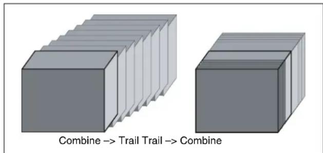
Motion Decay Settings
Notes
When you turn on motion decay, if the Trail, Keyframe Strobe or Wind effect is on, it automatically goes off.
Blurring image motion
1 In the DME menu, select VF5 'Light/Trail' and HF3 'Motion Decay.'
The Motion Decay menu appears.
2 Press [Motion Decay], turning it on.
3 Set the following parameter.
| Knob | Parameter | Adjustment | Setting values |
| 1 Video | Decay | Degree of blurring of the video signal | 0.00 to 100.00a) |
a) At the setting 0.00, there is no afterimage. At a setting of 100.00, the afterimage does not decay.
4 In the
Soft: mix the live image and the afterimage.
Hard: show the lighter of the live image and afterimage.
5 To erase the afterimage, press [Decay Eraser], turning it on.
Erasing the afterimages that remain in memory whenever a keyframe is passed
Press [Decay Eraser], turning it on. When the effect passes a keyframe, the afterimage is erased before writing a new afterimage.
Selecting the freeze timing
In the
Frame: freeze in frame units.
Field: freeze in field units.
Notes
The freeze timing setting is not required when the following signal formats are being used. 1080P/50, 1080P/59.94, 1080PsF/23.976, 1080PsF/24, 1080PsF/25, 1080PsF/29.97, 720P/ 50, 720P/59.94
Applying stardust to the afterimage portion
The afterimage portion becomes stardust, and gradually disappears.
1 Press the [DUST] button, turning it on.
2 Set the following parameters.
| Knob | Parameter | Adjustment | Setting values |
| 1 | D e Dust | Amount of the afterimage disappearing as stardust^a) | 0.00 to 100.00 |
| 2 Dust | Soft Timing with which stardust disappears | 0.00 to 100.00 | |
| 3 Dust | Size Size of | stardust 0.00 to 1 | 00.00 |
| 4 | D u Aspect | Aspect ratio of stardust | -100.00 to +100.00 |
a) The way in which the afterimage disappears is affected by both the Video Decay and Decay Dust parameter adjustments for the motion decay.
Keyframe Strobe Settings
Notes
When you turn on keyframe strobe, if the Trail, Motion Decay or Wind effect is on, it automatically goes off.
For details, see "Note" in the section "Trail."
Leaving a trail of afterimages of the image
1 In the DME menu, select VF5 'Light/Trail' and HF4 'KF Strobe.'
The KF Strobe menu appears.
2 Press [KF Strobe], turning it on.
3 Set the following parameter.
| Knob | Parameter | Adjustment | Setting values |
| 1 Decay Degree of | blurring of the video signal | 0.00 to 100.00a) | |
a) At the setting 0.00, there is no afterimage. At a setting of 100.00, the afterimage does not decay.
4 To erase the afterimage, press [KF Strobe Eraser], turning it on.
Selecting the overlay priority for movie and still images (video freeze image)
In the
Over: the movie is on top, and the still image is underneath.
Under: the movie is underneath, and the still image is on top.
Mix: the movie and still images are mixed; adjust the following parameter with the knob.
| Knob | Parameter | Adjustment | Setting values |
| 1 Mix | Mix amount of the still image with respect to the movie | 0.00 to 100.00a) |
a) The 0.00 setting is the same as Over, and the 100.00 is the same as Under.
Selecting the freeze timing
In the
Frame: freeze in frame units.
Field: freeze in field units.
Notes
The freeze timing setting is not required when the following signal formats are being used.
1080P/50, 1080P/59.94, 1080PsF/23.976, 1080PsF/24, 1080PsF/25, 1080PsF/29.97, 720P/ 50, 720P/59.94
Erasing the afterimages that remain in memory whenever a keyframe is passed
Press [KF Strobe Eraser], turning it on. When the effect passes a keyframe, the afterimage is erased before writing a new afterimage.
Applying stardust to the afterimage portion
The afterimage portion becomes stardust, and gradually disappears.
1 Press the [DUST] button, turning it on.
2 Set the following parameters.
| Knob | Parameter | Adjustment | Setting values |
| 1 KF Strobe Dust | Amount of the afterimage disappearing as stardust^a) | 0.00 to 100.00 | |
| 2 Dust | Soft Timing with which stardust disappears | 0.00 to 100.00 | |
| 3 Dust | Size Size of | stardust 0.00 to 1 | 100.00 |
| 4 | D u Aspect | Aspect ratio of stardust | -100.00 to +100.00 |
a) The way in which the afterimage disappears is affected by both the Decay and KF Strobe Dust parameter adjustments for the keyframe strobe.
Disabling the keyframe strobe afterimage
Press [KF Strobe Disable], turning it on.
If you turn this function on when creating a keyframe, even as the effect passes a keyframe, no afterimage remains.
Setting a combine process
Select whether to add the Keyframe Strobe effect before or after the combine.
Notes
- The combine process function is not supported on the MVE-8000A.
- When you change the selection in the
group, the afterimages which had been added up to then disappear. - When you do not combine images, the Keyframe Strobe effect only is applied, regardless of the selection in the
group.
Select one of the following in the
Combine -> KF STRB: Add the Keyframe Strobe effect after the combine.
As parameters, the data for the channel with the lowest number among the channels being combined is enabled.
KF STRB -> Combine: Add the Keyframe Strobe effect before the combine.
Parameters can be set independently for each channel.
Wind Settings
Notes
- The wind function is not supported on the MVE-8000A.
- When wind is turned on, any of the following effects that are on are turned off.
- Trail
- Motion decay
- Keyframe strobe
Applying the wind effect
1 In the DME menu, select VF5 'Light/Trail' and HF5 'Wind.'
The Wind menu appears.
2 Press [Wind], turning it on.
3 Set the following parameters.
| Knob | Parameter | Adjustment | Setting values |
| 1 Decay | Amount of | afterimage displayed | 0.00 to 100.00a) |
| 2 Shift | H Extension in the horizontal direction | -100.00 to +100.00 | |
| 3 Shift | V Extension in the vertical direction | -100.00 to +100.00 | |
a) 0.00 represents no afterimage, and 100.00 represents no decay in the afterimage.
4 To erase the afterimages, press [Wind Eraser], turning it on.
Selecting the signal for the afterimage portion
In the
Notes
- “Mix Color” or “Ext Video” can only be applied to one of the background (see page 338), flex shadow (see page 290), trail (see page 325), and wind effects.
If you select “Mix Color” or “Ext Video” in the wind settings, a selection of “Mix Color” or “Ext Video” in any of the other effects is disabled, and “Flat Color” is selected in its place. - When executing combining four channels of DME images, “Mix Color” and “Ext Video” cannot be selected.
Freeze Video: Freeze the input image to use as the afterimage.
Flat Color: Use a single color matte for the afterimage; you can set the following parameters with the knobs.
| Knob | Parameter | Adjustment | Setting values |
| 1 Luminance | Luminance | 0.00 to 100.00 | |
| 2 Saturation | Saturation | 0.00 to 100.00 | |
| 3 Hue | Hue | 359.99 to 0.00 |
Hue Rotate: Use a single color matte with the hue changing for each frame as the afterimage; you can set the following parameters with the knobs.
| Knob | Parameter | Adjustment | Setting values |
| 1 Luminance | Luminance | 0.00 to 100.00 | |
| 2 Saturation | Saturation | 0.00 to 100.00 | |
| 3 | Hue Speed | Rate at which hue changes | -12.00 to +12.00 |
Mix Color: Insert a mix color signal (see page 296) in the afterimage portion.
Ext Video: Insert the external video signal input to the Ext IN connector in the afterimage portion.
Rainbow: Use a freeze image with the hue changing every frame in the afterimage portion. The difference from "Hue Rotate" is that many colors appear simultaneously.
For details of the Rainbow parameters, see the "Hue Rotate" item above.
Applying modulation to the afterimage portion (Modulation)
1 In the Wind menu, press [Modulation], turning it on.
2 Set the following parameters.
| Knob | Parameter | Adjustment | Setting values |
| 1 | A m | p H amplitude of the wave | 0.08 to 100.00 |
| 2 Freq | H Horizontal | frequency of the wave | -100.00 to +100.00 |
| 3 | A m | p V amplitude of the wave | 0.00 to 100.00 |
| 4 | F r | e q frequency of the wave | -100.00 to +100.00 |
For details of Priority, Wind Freeze Timing, Wind Eraser, Defocus, Dust, and Combine Process in the Wind menu, see "Trail Settings" (page 325).
Spotlighting Settings
You can set up to three light sources (lights 1 to 3).
Notes
- The Spotlighting effect is not supported on the MVE-8000A.
- The BZDM-9050 Texture Lighting Software (for MVE-9000) is required to set lights 2 and 3.
- When the global effect Combiner is enabled, the settings of the smallest-numbered channel selected for the Combiner are used.
Adjustments to the image surface
The following adjustments can be made to the image surface struck by the light.
- Adjusting the brightness of the whole image
- Selecting the image surface effect
- Test sphere function
- Adjusting the bumpiness of the image surface
• Coordinate axis on surface of image
- Texture deformations
Selecting the image surface effect
Flat: The image surface is unchanged, causing the selected light source to appear as the effect.
Texture: A texture appears on the surface of the image. Textures can be selected from among 30 patterns (see page 400).
Non Linear: Spotlighting effect is applied to an area to which a DME nonlinear effect is applied.
Notes
The BZDM-9050 is required to enable Texture and Non Linear settings on the MVE-9000.
Test sphere function
A test sphere is a translucent sphere virtually embedded in the center of the input picture to provide an intuitive way for you to check the position and direction of the spotlight. When you change the position or direction of a light source, the side of the sphere closest to the light source grows brighter. You can easily check the position and direction of the light source by viewing the test sphere (see page 332).
Coordinate axis on surface of image
Specify where to apply the texture or test sphere on the image surface. i c a l
Move: The texture moves together with the DME image.
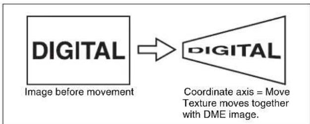
flowchart
graph LR
    A["IMAGE before movement"] --> B["DIGITAL"]
    B --> C["Coordinate axis = Move Texture moves together with DME image."]
Fix: The texture does not move, even if the DME image moves.
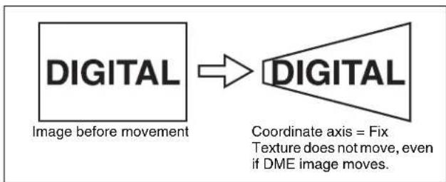
flowchart
graph LR
    A["Image before movement"] --> B["DIGITAL"]
    B --> C["Coordinate axis = Fix Texture does not move, even if DME image moves."]
Texture deformations
You can change the texture pattern, position, and size, and use the repetition function.
The following figure shows examples of a texture pattern repeated in the X and Y directions.
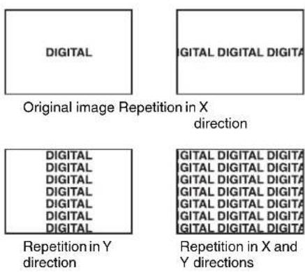
Setting lights
Light source types
The following type of light sources are available (see figure).
Parallel: Parallel light source
Point: Point light source. As the light source is placed further away, the illuminated range becomes wider and the light become weaker.
Line: Line light source
Whole: Non-directional light source which illuminates the whole image.
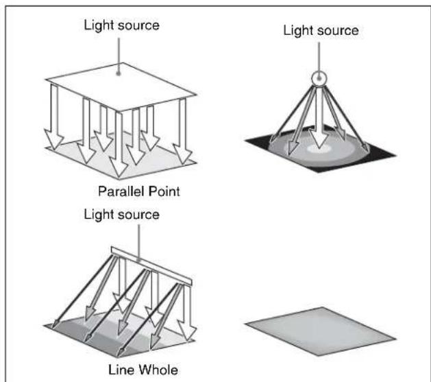
Linking and unlinking image and spotlight
The spotlight can move together with a DME image, or be fixed in place.
Source: Place the light source in source coordinate space. The spotlight is linked and moves when the image moves.
Target: Place the light source in target coordinate space. The spotlight does not move, even when the image moves.
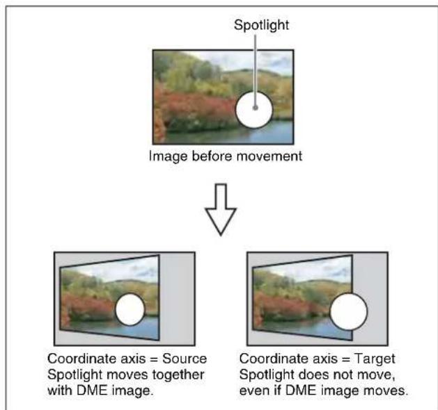
flowchart
graph TD
    A["Image before movement"] --> B["Coordinate axis = Source Spotlight moves together with DME image."]
    A --> C["Coordinate axis = Target Spotlight does not move, even if DME image moves."]
Selecting the lighted area
You can select the area lit by the spotlight.
FRGD: The light strikes the image foreground.
BKGD: The light strikes the image background.
Both: The light strikes both foreground and background.
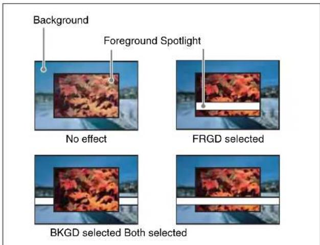
Surface Flat
For the currently selected light source only, you can forcibly make the image surface effect flat.
This is effective when you have selected texture as image surface effect and want a flat effect for one light source only.
Light shape
Creates the light shape.
- Select the shape pattern
For shape patterns, see "Shape Patterns" (page 400). - Set the size, degree of deformation, softness, and rotation.

Ring settings
Shines the light with a hole in the middle, like a doughnut. Adjust the following parameters.
Offset: Distance to move the center of the ring from the initial position (the position set when selecting the light source in the
Radius: Inner side radius of the ring.
Angle: When an Offset is set, the rotation angle of the ring around the initial center position.
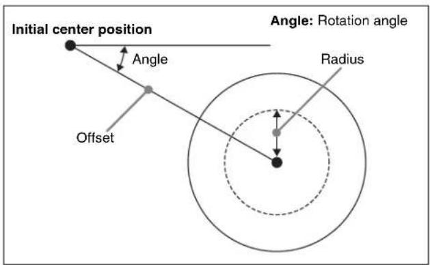
Fill blending modes
Specifies the way in which the light is blended with the image.
Mix: Light as if reflected from a mirror. The light can be given a color.
Multiply: Light as if reflected from a dull surface (diffuse reflection).
Relation between test spheres and parallel rays
The following figure shows an example of the effect of parallel rays on a test sphere.
The direction of a ray is defined by longitude and latitude.
- Longitude: A direction (angle), expressed as a plus value for clockwise rotation in the plus direction with respect to the X axis of the input picture.
- Latitude: Latitude
The following figure shows the relationships between the longitude and latitude of parallel rays, input picture, and test sphere.
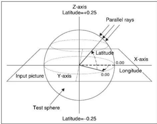
The unit of these direction parameters is the number of rotations, with 360^ (1 rotation) expressed as 1.00, in the same way as 3D rotation parameters.
The following relationships apply in the example shown in the figure.
| Parameter Setting | Angle | |
| Longitude 0.12 45° | ||
| Latitude 0.12 45° | ||
The fractional part of the setting after the decimal point corresponds to an angle 0 to 360^ . If the fractional parts of two setting values are the same, the effect is the same even if the integral parts are different.
The integral part of a setting value is used when moving a light source with keyframes.
For example, when the longitude of a light source rotates in the clockwise direction from 0.88 (315°) to 0.12 (45°), it rotates in the counterclockwise direction (the angle grows smaller) if the above values are used. In this case, the value of the second keyframe can be set to 1.12 (360° + 45°).
Keyframe trajectory
Setting the surface where light strikes the image
1 In the DME menu, select VF5 'Light/Trail' and HF6 'Spot Lighting.'
The Spot Lighting menu appears.
2 Press [Spot Lighting], turning it on.
3 Set the following parameter.
| Knob | Parameter | Adjustment | Setting values |
| 1 Total | Ambient | Brightness of whole image | 0.00 to 100.00 |
- Lowering the brightness of the image makes Spotlighting more effective.
- The Total Ambient setting is shared with the Lighting function.
4 In the
Flat: The image surface is unchanged, causing the selected light source to appear as the effect.
Texture: A texture appears on the surface of the image.
Non Linear: The Spotlighting effect is applied to an area to which a DME nonlinear effect is applied.
Notes
- The BZDM-9050 Texture Lighting Software (for MVE-9000) is required to enable Texture or Non Linear.
An install key must be entered to use the software. For details, see “Installation and Device Setup (Install/Unit Config Menu)” in Chapter 18 (Volume 2). - The Spotlighting Non Linear setting is effective for the following nonlinear effects. For any other nonlinear effect, the result of selecting the Non Linear setting is the same as selecting Flat. Wave, Mosaic Glass, Flag, Ripple, Lens, Panorama, Page Turn, Roll.
5 If you selected Texture or Non Linear in step 4, set the following parameters.
Parameters when you selected Texture
- S D format
| Knob | Parameter | Adjustment | Setting values |
| 1 | X M | o v X-axis direction | -00 to -.00^a) |
| 2 | Y M | o v Y-axis direction | -.00 to -.00^b) |
| Knob | Parameter | Adjustment | Setting values |
| 3 Size | X Image size | in X-axis direction | 0.50 to 16.00 |
| 4 Size | Y Image size | in Y-axis direction | 0.50 to 16.00 |
| 5 Amp | Emphasize | bumps and depressions | -100.00 to +100.00c) |
a) Minus moves left, plus moves right.
b) Minus moves down, plus moves up.
c) Plus emphasizes bumps in texture, minus emphasizes depressions. 0.00 is a flat surface.
• HD format
| Knob | Parameter | Adjustment | Setting values |
| 1 | X M | o ve X-axis direction | -32 00 to e +32.00^a) |
| 2 | Y M | ov e Y-axis direction | -24 00 to e +24.00^b) |
| 3 Size | X Image size | in X-axis direction | 0.50 to 16.00 |
| 4 Size | Y Image size | in Y-axis direction | 0.50 to 16.00 |
| 5 Amp | Emphasize | bumps and depressions | -100.00 to +100.00^c) |
a) Minus moves left, plus moves right.
b) Minus moves down, plus moves up.
c) Plus emphasizes bumps in texture, minus emphasizes depressions. 0.00 is a flat surface.
Parameters when you selected Non Linear
| Knob | Parameter | Adjustment | Setting values |
| 5 Amp | Distance of light | -100.00 to +100.00a) |
a) Light appears from Z direction. At -100.00 the light goes deepest, at +100.00 the whole image is lit like a flat effect.
6 If you selected Texture in step 4, select the pattern as explained in the next section "To select a texture pattern."
7 If you selected Texture in step 4, select the way it is applied in the
Move: The texture moves together with the DME image.
Fix: The texture does not move, even if the DME image moves.
For the difference between these application methods, see “Coordinate axis on surface of image” (page 330).
r Notes i n
If Non Linear is selected in the
To select a texture pattern
1 In the Spot Lighting menu, press [Texture Ptn Select].
The Texture Ptn Select menu appears.
Two lists appear in the status area. The list on the left displays the number and name of the currently selected texture. The list on the right is for selecting a texture.
2 In the
[User]: List of texture patterns created by the user. See "Adding User Texture Patterns" in Chapter 18 (Volume 2).
[Factory]: List of texture patterns stored in the system when shipped from the factory.
3 Do one of the following to select a texture.
- Press directly on the list on the right of the status area.
- Press the arrow keys to scroll the reverse video cursor.
- Turn the knob.
| Knob | Parameter | Adjustment Setting values | |
| 1 | Texture | No Texture | 1 to 30 |
a) When Factory is selected
b) When User is selected. The setting value range depends on the number of texture patterns installed.
4 Press [Set].
The texture selected in step 2 appears in the list on the left of the status area.
To set a test sphere
1 In the Spot Lighting menu, press [Test Sphere], turning it on.
A test sphere effect appears on the image surface.
2 Adjust the following parameter.
| Knob | Parameter Adjustment Setting | values |
| 5 Amp | Distance of light -100.00 to | +100.00^a) |
a) Light appears from Z direction. At -100.00 the light goes deepest, at +100.00 the whole image is lit like a flat effect.
For details of the relationship of test spheres and light sources, see “Relation between test spheres and parallel rays” (page 332).
Setting light sources
Up to three light sources (Light 1 to Light 3) for Spotlighting can be set by menus.
Light source menu
The following three light source menus are available.
| Light source Menu | |
| Light 1 DME >Light/Trail | >Spot Lighting>Light 1 |
| Light 2 DME >Light/Trail | >Spot Lighting>Light 2 |
| Light 3 DME >Light/Trail | >Spot Lighting>Light 3 |
Notes
The BZDM-9050 Texture Lighting Software (for MVE-9000) is required to enable Light 2 and Light 3. An install key must be entered to use the software.
For details, see "Installation and Device Setup (Install/Unit Config Menu)" in Chapter 18 (Volume 2).
To set light source data
The following example shows how to set light source data with the Light 1 menu.
If you use multiple light sources, use the same procedure for all light sources.
1 In the
The Light 1 menu appears.
2 Press [Light 1], turning it on.
3 Set the following parameters.
| Knob | Parameter | Adjustment | Setting values |
| 1 | Total Ambient | Brightness of whole image | 0.00 to 100.00 |
| 2 Intensity | Intensity | (brightness) of the light source | 0.00 to 100.00 |
| 3 Soft | Softness of the lighted area | 0.00 to 100.00 | |
- Lowering the brightness of the image makes Spotlighting more effective.
- The Total Ambient setting is shared with the Lighting function.
4 In the
Parallel: Parallel light source. The direction can be set.
Point: Point light source. The position can be set.
Line: Line light source. The position and angle can be set.
Whole: Non-directional light source which illuminates the whole image (no settings).
5 According to the selected light source type, set the following parameters.
When you selected Parallel
| Knob | Parameter | Adjustment | Setting values |
| 1 Longitude | Longitudede | -8.00 to +8.00 | a) |
| 2 Latitude | de Latitude | -8.00 to +8.00 |
a) Minus moves counterclockwise, plus moves clockwise.
When you selected Point
- S D format
| Knob | Parameter | Adjustment | Setting values |
| 1 | X | Movement in X-axis direction | -6.00 to +6.00^a) |
| 2 | Y | Movement in Y-axis direction | -6.00 to +6.00^b) |
| 3 | Z | Movement in Z-axis direction | -6.00 to +6.00^c) |
a) Minus moves left, plus moves right.
b) Minus moves down, plus moves up.
c) Minus moves forward, plus moves deeper.
• H D format
| Knob | Parameter | Adjustment | Setting values |
| 1 | X | Movement in X-axis direction | -24.00 to +24.00a) |
| 2 | Y | Movement in Y-axis direction | -24.00 to +24.00b) |
| 3 | Z | Movement in Z-axis direction | -24.00 to +24.00c) |
a) Minus moves left, plus moves right.
b) Minus moves down, plus moves up.
c) Minus moves forward, plus moves deeper.
When you selected Line
- S D format
| Knob | Parameter | Adjustment | Setting values |
| 1 | X | Movement in X-axis direction | -6.00 to +6.00^a) |
| 2 | Y | Movement in Y-axis direction | -6.00 to +6.00^b) |
| 3 | Z | Movement in Z-axis direction | -6.00 to +6.00^c) |
| 4 Longitude | Longitude | de -8.00 to +8.00 | d) |
a) Minus moves left, plus moves right.
b) Minus moves down, plus moves up.
c) Minus moves forward, plus moves deeper.
d) Minus moves counterclockwise, plus moves clockwise.
- HD format
| Knob | Parameter | Adjustment | Setting values |
| 1 | X | Movement in X-axis direction | -24.00 to +24.00a) |
| 2 | Y | Movement in Y-axis direction | -24.00 to +24.00b) |
| 3 | Z | Movement in Z-axis direction | -24.00 to +24.00c) |
| 4 Longitude | Longitude | de -8.00 to +8.00 | d) |
a) Minus moves left, plus moves right.
b) Minus moves down, plus moves up.
c) Minus moves forward, plus moves deeper.
d) Minus moves counterclockwise, plus moves clockwise.
6 In the
Source: Place the light source in the source coordinate space. The spotlight moves when the image moves.
Target: Place the light source in the target coordinate space. The spotlight does not move, even when the image moves.
For details of the coordinate space in which to place the light source, see “Linking and unlinking image and spotlight” (page 331).
To set a test sphere
1 In the Light 1 menu, press [Test Sphere], turning it on.
A test sphere effect appears on the surface of the image.
2 Adjust the following parameter.
| Knob | Parameter | Adjustment | Setting values |
| 5 | Amp | Distance of light | -100.00 to +100.00^a) |
a) Light appears from Z direction. At -100.00 the light goes deepest, at +100.00 the whole image is lit like a flat effect.
To select the lighted area
In the group, select one of the following.
FRGD: The light strikes the image foreground.
BKGD: The light strikes the image background.
Both: The light strikes both foreground and background.
For more information about the lighted area, see "Selecting the lighted area" (page 331).
Notes
- If you select [Multiply] in the

the light effect is not applied to the background, even if you select BKGD or Both.
- If the setting of [Brilliancy] in the
group of the Light Color Adjust menu (see page 337) is 100.00, the light effect is not applied to the background, even if you select BKGD or Both. - When the global effect Combiner is set to Mix or Depth, the light effect is not applied to the background, even if you select BKGD or Both.
To select Surface Flat
Press [Surface Flat], turning it on.
If you have selected anything other than Flat in the
To set the shape of the light
1 Press [Shape], turning it on.
2 Set the following parameters.
SD format
| Knob | Parameter | Adjustment Setting | values |
| 1 Shape | Ptn Shape | pattern 1 to 2 | a) |
| 2 Size | Shape size | 0.00 to 6.00 | |
| 3 Deform Amount of shape deformation | 0.00 to 100.00b) | ||
| 4 Soft Softness of shape pattern | 0.00 to 100.00 | ||
| 5 Angle | Angle of shape pattern rotation | -8.00 to +8.00c) | |
a) For more information about the shape patterns, see "Shape Patterns" (page 400) in the Appendix.
b) 0 is a round shape, and 100 is the shape itself. Smaller values make the pattern more rounded.
c) -1.00 is one rotation in the counterclockwise direction. +1.00 is one rotation in the clockwise direction.
HD format
| Knob | Parameter Adjustment Setting | values | |
| 1 Shape | Ptn Shape | pattern 1 to 2 | a) |
| 2 Size | Shape size 0.00 to 24.00 | ||
| 3 Deform Amount of shape deformation | 0.00 to 100.00b) | ||
| 4 Soft Softness of shape pattern | 0.00 to 100.00 | ||
| 5 Angle | Angle of shape pattern rotation | -8.00 to +8.00c) | |
a) For more information about the shape patterns, see “Shape Patterns” (page 400) in the Appendix.
b) 0 is a round shape, and 100 is the shape itself. Smaller values make the pattern more rounded.
c) -1.00 is one rotation in the counterclockwise direction. +1.00 is one rotation in the clockwise direction.
To rotate the shape pattern
1 Press [Shape Speed], turning it on.
The display on knob 5 that was visible when [Shape] was selected changes.
2 Set the following parameter.
| Knob | Parameter | Adjustment | Setting values |
| 5 | Speed | Rotation direction and speed | -100.00 to +100.00a) |
a) -100.00 is four rotations per second in the counterclockwise direction, and +100.00 is four rotations per second in the clockwise direction. 0.00 stops the rotation.
To change the light to a ring shape
Notes
If you select Parallel or Whole (see page 334) in the
1 Press [Ring], turning it on.
2 Set the following parameter.
SD format
| Knob | Parameter | Adjustment | Setting values |
| 1 Offset | Offset from | center position (radius) | -6.00 to +6.00 |
| 2 Radius | Radius of ring | 0.00 to 6.00 | |
| 3 Angle | Rotation | angle of ring | -8.00 to +8.00^a) |
a) -1.00 is one rotation in the counterclockwise direction and +1.00 is one rotation in the clockwise direction.
Notes
There is no Radius setting when Line is selected in the
HD format
| Knob | Parameter | Adjustment Setting | values |
| 1 Offset | Offset from | center position (radius) | -24.00 to +24.00 |
| 2 Radius | Radius of ring | 0.00 to 6.00 | |
| 3 Angle | Rotation angle of ring | -8.00 to +8.00a) | |
a) -1.00 is one rotation in the counterclockwise direction and +1.00 is one rotation in the clockwise direction.
Notes
There is no Radius setting when Line is selected in the
To rotate the ring
1 Press [Ring Speed], turning it on.
The display on knob 3 that was visible when [Ring] was selected changes.
2 Set the following parameter.
| Knob | Parameter | Adjustment | Setting values |
| 3 Speed | Rotation speed and direction | -100.00 to +100.00a) | |
a) -100.00 is four rotations per second in the counterclockwise direction, and +100.00 is four rotations per second in the clockwise direction. 0.00 stops the rotation.
To invert the lighted area
Press [Light Invert], turning it on.
To add color to the light source
1 In the Light 1 menu, press [Light Color Adjust]. The Light Color Adjust menu appears.
2 In the
Mix: Light as if reflected from a mirror. Multiply: Light as if reflected from a dull surface (diffuse reflection).
3 If you selected Mix, select the fill color in the
Flat Color: A monochrome matte. Hue Rotation: Color matte with a color that gradually varies.
4 According to the selection, set the following parameters.
When you selected Flat Color
| Knob | Parameter | Adjustment | Setting values |
| 1 Luminance | Luminance | 0.00 to 100.00 | |
| 2 Saturation | Saturation | 0.00 to 100.00 | |
| 3 Hue | Hue 359.99 to 0.00 | ||
| 4 Brilliancy | Brilliance of surface struck by light | 0.00 to 100.00^a) | |
a) 100.00: The image beneath the light shines through.
When you selected Hue Rotation
| Knob | Parameter | Adjustment | Setting values |
| 1 Luminance | Luminance | 0.00 to 100.00 | |
| 2 Saturation | Saturation | 0.00 to 100.00 | |
| 3 Speed | Speed at which hue changes | -12.00 to +12.00a) | |
| 4 Brilliancy | Brilliance of surface struck by light | 0.00 to 100.00b) | |
a) -12.00 is a 360-degree rotation every second in the counterclockwise direction. +12.00 is a 360-degree rotation every second in the clockwise direction.
b) 100.00: The image beneath the light shines through.
Copying or swapping light source settings
You can copy or swap the setting from one light source (Light 1 to Light 3) to another light source.
1 In the Spot Lighting menu, press [Copy/Swap].
The Copy/Swap menu appears.
Two lists appear in the status area. The list on the left shows the copy or swap sources, and the list on the right shows the copy or swap destinations.
2 Do one of the following to select the target data.
- Press directly on the list in the status area.
- Press the arrow keys to scroll the reverse video cursor.
- Turn the knobs.
| Knob | Parameter | Adjustment | Setting values |
| 1 Left No | Copy | or swap source data | 1 to 3 |
| 2 Right No | Copy | or swap destination data | 1 to 3 |
3 Press [Copy] to copy, or [Swap] to swap.
To undo a copy or swap
Press [Undo]. Settings are returned to their values before the copy or swap.
Applying Special Effects (Other Effects)
Background Settings
Adds a color or inputs an external signal to the background of the image.
Notes
Signal selection for this purpose is not supported on the MVE-8000A.
Applying the Background effect
1 In the DME menu, select VF6 'Input/Output' and HF1 'Bkgd.'
The Bkgd menu appears.
2 Press [Bkgd], turning it on.
The Background effect is enabled. Only if Flat Color is selected in the
3 Set the following parameters.
| Knob | Parameter | Adjustment | Setting values |
| 1 | Luminance | Luminance 0.00 to 100.00 | |
| 2 | Saturation | Saturation 0.00 to 100.00 | |
| 3 | Hue | Hue 359.99 to 0.00 | |
Selecting the signal to insert in the background
When using the MVE-9000, you can select the signal to insert in the background.
With [Bkgd] set on, use the following procedure.
1 In the
Flat Color: single color
Mix Color: mix color signal set in the Color Mix menu (see page 296)
Ext Video: an external video signal input to the Ext IN connector
Notes
- “Mix Color” or “Ext Video” can only be applied to one of the background, flex shadow (see page 290), trail (see page 325), and wind (see page 329) effects. If you select “Mix Color” or “Ext Video” in one of
these settings, a selection of "Mix Color" or "Ext Video" in any of the other effects is disabled, and "Flat Color" is selected in its place.
- When executing combining four channels of DME images, "Mix Color" and "Ext Video" cannot be selected.
2 Only if Flat Color is selected in step 1, adjust the following parameters.
| Knob | Parameter | Adjustment Setting | values |
| 1 | Luminance | Luminance 0.00 to 100.00 | |
| 2 | Saturation | Saturation 0.00 to 100.00 | |
| 3 | Hue | Hue | 359.99 to 0.00 |
Separate Sides Settings
Applies separate video signals and key signals to the front and back of the image.
Applying the Separate Sides effect
1 In the DME menu, select VF6 'Input/Output' and HF2 'Video/Key.'
The Video/Key menu appears.
2 Press [Separate Side], turning it on.
The Separate Sides effect is enabled. If the video and key signals currently being output to the monitor are the front side, you can select the front signals. If they are the back side, you can select the back signals. Video and key signals are selected with the cross-point control blocks of each M/E bank or the PGM/PST bank.
Shaped Video Settings
For each of the front and back sides of the image, specifies whether to handle input video from the switcher as shaped video (key processed signals).
You can also make these settings for the output video.
Notes
- When using an SDI interface, with the [PROC KEY] not selected in the output destination buttons, then the shaped video function is enabled.
- When using the dedicated interface or SDI interface, with [PROC KEY] selected in the output destination buttons, since the input video signal to the first channel is always set to the key processed signal on the switcher, the shaped video setting is always on. For the second and
third channel signals, this will be turned off. For the output video, this is always on.
Switching shaped video on or off
1 In the DME menu, select VF6 'Input/Output' and HF2 'Video/Key.'
The Video/Key menu appears.
2 In the
Front Input: When this is on, the front image of the input video signal is treated as shaped video.
Back Input: When this is on, the back image of the input video signal is treated as shaped video.
Output: When this is on, the output video signal is treated as shaped video.
About on and off for shaped video input (Front Input/Back Input)
Switch shaped video on and off according to the input video signals.
For example, switch the shaped video input on when the input signal is a key processed image such as computer graphics.
Switch the shaped video input off when the input signal is not key processed, for example when a video signal taken with a camera is cut out with a title or other key signal.
About on and off for shaped video output
Switch the shaped video output on and off to match the on and off state of the switcher clean video mode.
Also, when the shaped video output is on, it is recommended that the switcher key type be set to linear key.
About the relationship between shaped video output and effects
When the shaped video output is off, the video signal before key processing is output. According to the selected effect, the following states may result.
(a) The output video signal is affected by the key signal.
(b) When key processing is done, a different image may appear in the parts which are removed.
(c) There is no change in the output video signal for effects which are applied to key signals only.
When multiple effects are applied, the order of priority is (a) > (b) > (c).
The following explains the relationship between effects and states (a), (b), and (c).
(a) The output video signal is affected by the key signal
The output video signal is affected by the key signal when the following effects are selected. To prevent the signal from being affected, set the DME key source to Int Key, or choose an appropriate input key signal.
Page Turn, Roll, Cylinder, Sphere, Spotlighting, global effects (Combiner, Brick, Shadow)
(b) When key processing is done, a different image may appear in the parts which are removed
The following states result, depending on the selected effect.
Removal with the key can be checked by turning the background on.
Border, Beveled Edge: Added also to the outer side of the cropped video signal.
Trail, Keyframe Strobe: The key signal level of the afterimage portion varies with adjustments of the knob (Decay), but the afterimage portion of the video signal does not disappear until Trail Eraser (KF Strobe Eraser) is turned on or the effect is turned off.
Lighting: The Lighting effect is applied to the whole picture.
Spotlighting: If BKGD or Both is selected in the group, light strikes the entire background.
(c) No change in the output video signal for effects which are applied to key signals only
The following states result, depending on the selected effect.
Removal with the key can be checked by turning the background on.
Crop: The Copy effect is applied to the key signal only. The video signal does not change.
Edge Soft: The Edge Soft effect is applied to the key signal only. The video signal does not change.
Shadow, Flex Shadow, Combine Shadow: The key signal density changes. The video signal does not change.
Fade: The key signal density changes according to depth data. The video signal does not change.
Key Density: The key signal density changes. The video signal does not change.
Invert Settings
Inverts the input video signal and/or key signal horizontally or vertically. You can make separate settings for the front and back.
Applying the Invert effect
1 In the DME menu, select VF6 'Input/Output' and HF2 'Video/Key.'
The Video/Key menu appears.
2 In the
H Invert: Invert video and key signals horizontally.
V Invert: Invert video and key signals vertically.
Key Density Settings
You can adjust the key density for the key signal input to the DME.
Setting the key density
1 In the DME menu, select VF6 'Input/Output' and HF2 'Video/Key.'
The Video/Key menu appears.
2 Press [Key Density], turning it on.
3 Set the following parameter.
| Knob | Parameter | Adjustment | Setting values |
| 1 | K e Density | Key density 0 | 00 to 100.00 |
Key Source Selection
You can select either the key signals received from the switcher or the key signals generated in the DME for application to the front and back of the image.
Selecting the key source signals
Notes
When the shaped video setting (see page 338) is on, it is not possible to select the key source. It is fixed as "Ext Key" as listed in the following.
1 In the DME menu, select VF6 'Input/Output' and HF2 'Video/Key.'
The Video/Key menu appears.
2 In the
Ext Key: Use the key signal sent from the switcher as the key source.
Int Key: Use the full-size DME internal key signal as the key source.
Lum Key: Use the input video luminance signal as the key source.
3 When Ext Key or Lum Key is selected in step 2, set the following parameters.
| Knob | Parameter Adjustment Setting | values |
| 1 Clip | Reference levelfor key signal generation | -7.31 to +109.59 |
| 2 Gain | Key sensitivity -100.00 to | +100.00 |
Notes
- The Ext Key and Lum Key in the
- The Ext Key parameter setting is only enabled when the shaped video setting is off.
Interpolation Settings
Specifies the methods used for interpolation processing of input video signals and input key signals.
For input video signals, you can select from the following four methods.
- Detect changes in the luminance and chrominance signals separately, and switch automatically between fields and frames. You can select the degree of change detection.
- Detect changes in the luminance signal separately, and switch automatically between fields and frames. You can select the degree of change detection.
- Do interpolation in field units.
- Do interpolation in frame units.
For input key signals, you can select from the following three methods.
- Detect changes in the luminance signal separately, and switch automatically between fields and frames. You can select the degree of change detection.
- Do interpolation in field units.
- Do interpolation in frame units.
You can also select the number of pixels used in interpolation processing, and select the method used to show the picture reduced or expanded.
Further, you can apply an anti-moire filter to reduce the moire patterns created by interpolation.
Notes
- Interpolation processing is possible for the following signal formats and DME systems.
- MVE-8000A: 480i/59.94, 576i/50
- MVE-9000 and MKS-7470X/7471X: 480i/59.94, 576i/50, 1080i/59.94, 1080i/50
- The anti-moire filter is only effective when the MVE-8000A is used in an HD system.
Selecting an interpolation method for input video signals
1 In the DME menu, select VF6 'Input/Output' and HF3 'Process.'
2 In the
Adaptive Y/C: Detect changes in the luminance and chrominance components of the video signal separately, and switch automatically between fields and frames.
Adaptive Y: Detect changes in the luminance component of the video signal separately, and switch automatically between fields and frames.
Field: Do interpolation in field units. This gives natural movement, suitable for moving video.
Frame: Do interpolation in frame units. This gives higher image precision, suitable for still pictures.
3 When you select Adaptive Y/C or Adaptive Y in step 2, set the following parameter.
| Knob | Parameter | Adjustment | Setting values |
| 1 Mode | Degree of | motion detection | 1 to 4 |
4 In the
Adaptive: Detect changes in the luminance component of the key signal separately, and switch automatically between fields and frames.
Field: Do interpolation in field units. This gives natural movement, suitable for moving video.
Frame: Do interpolation in frame units. This gives higher image precision, suitable for still pictures.
5 When you select Adaptive in step 4, set the following parameter.
| Knob | Parameter | Adjustment | Setting values |
| 1 Mode | Degree of | motion detection | 1 to 4 |
6 In the
Multi: Use multi-point interpolation. This gives higher picture quality.
Linear: Use two-point interpolation.
7 In the
Mode1 (standard): Even when the picture is reduced, add compensation so that it can be seen clearly.
Mode2 (soft): Suppress aliasing when expanding or reducing the picture.
Mode3 (sharp): Do not suppress aliasing when expanding or reducing the picture.
Applying the anti-moire filter
You can reduce the moire patterns created by interpolation when an image is enlarged, compressed, or rotated.
Notes
This function is effective only when the HD signal format is used on the MVE-8000A.
1 In the DME menu, select VF6 'Input/Output' and HF3 'Process.'
The Process menu appears.
2 Press [Anti Moire Filter], turning it on.
3 Set the following parameter.
| Knob | Parameter | Adjustment | Setting values |
| 1 | A n Filter | Ambunt of moire reduction | Mto 8 o i |
Corner Pinning Settings
Notes
When the Brick effect is enabled, the Corner Pinning function cannot be used.
Setting the Foreground Corner Pinning positions
1 In the DME menu, select VF4 'Non Linear/Corner Pin', HF2 'Corner Pinning.'
The Corner Pinning menu appears.
2 Set [Corner Pinning] to On.
3 Set [Corner Marker] to On.
A marker appears for each corner. The marker for the selected corner is distinguished from the other markers.

Marker for selected corner Other markers
4 In the
Top Left: Top left
Top Right: Top right
Bottom Left: Bottom left
Bottom Right: Bottom right
All: All four corners
5 Turn the knobs to adjust the position of the corner selected in step 4.
The parameter setting ranges depend on the system's selected signal format (SD/HD) and aspect ratio (4:3/16:9) combination, as follows.
4:3 mode
| Knob | Parameter Adjustment Setting values | ||
| 1 Pos | X Movement in x-axis direction | -8.00 to +8.00 (SD)a)-24.00 to +24.00 (HD)a) | |
| 2 Pos | Y Movement in y-axis direction | -6.00 to +6.00 (SD)a)-18.00 to +18.00 (HD)a) | |
a) When the selection for operation is "All," the Top Left value appears, and the knobs move all four corners correspondingly.
16:9 mode
| Knob | Parameter | Adjustment Setting | values |
| 1 Pos | X Movement | in x-axis direction | -8.00 to +8.00 (SD)a)-32.00 to +32.00 (HD)a) |
| 2 Pos | Y Movement | in y-axis direction | -4.50 to +4.50 (SD)a)-18.00 to +18.00 (HD)a) |
a) When the selection for operation is "All," the Top Left value appears, and the knobs move all four corners correspondingly.
Resetting the corner positions
In the Corner Pinning menu, press [Reset Corner].
Selecting the area used for pinning
When the foreground is cropped, press [Crop Link] to select either of the following.
On: Use the area of the cropped image for positioning
Off: Use the area of the entire image, including the part hidden by cropping (shaded in the diagram below) for positioning
Area positioned by pinning when Crop Link is On
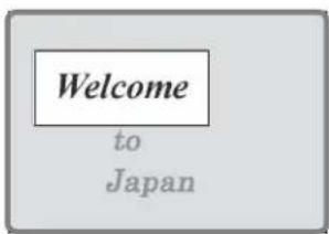
Area positioned by pinning when Crop Link is Off (The bold frame shows the area used for positioning.)
Adjusting the density of the foreground
You can adjust the density of the foreground image to be translucent so that the background shows through, making it easier to position the corners.
Notes
This setting is not saved in a key frame or snapshot.
1 In the Corner Pinning menu, set [Video Through] to On.
2 Turn the knob to adjust the following parameter.
| Knob | Parameter | Adjustment Setting | values |
| 4 | Density | Image density 0.00 to 100.00 |
Adjusting the zoom
You can enlarge the image around the corner being adjusted, to allow fine positioning of the corner.
Notes
- This setting is not saved in a key frame or snapshot.
- This function is only enabled when combine is set.
- When all four corners are being positioned, this function cannot be used.
1 In the Corner Pinning menu, press [Zoom Enable], turning it On.
2 Turn the knob to adjust the following parameter.
| Knob | Parameter | Adjustment | Setting values |
| 5 Zoom | Degree of | zooming in on the corners | 1.00 to 16.00 |

Zoom Off

Zoom On
Global Effect Operations
Overview
Global effects are special effects created by combining the images of successive channels. The Global Effect menu is used to add these effects. The following types of global effects are available.
Notes
On the MVE-8000A, when the signal format is 1080P, of the following effects, three or more channel combiner and brick effects cannot be used.
| Name Effect/Image | |
| Combiner Automatically combines the selected images when multiple channels are selected on one keyer or for one transition. | |
Brick Creates a rectangular parallelepiped from 3 successive channels.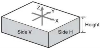 | |
Shadow Gives the image a shadow.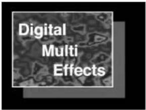 |
Operations Common to All Global Effects
In this section, explanations of the operating procedures for individual global effects begin with selections from VF1 'Ch1 - Ch4' in the Global Effect menu. The following are common operations that you must do prior to selecting from this menu.
1 In the device control block, select the target DME channel.
2 In the menu control block, press the top menu selection button [GLB EFF], then select VF1 'Ch1 - Ch4.'
The Global Effect >Ch1 - Ch4 menu appears.
Combiner Settings
When multiple channels are selected on one keyer or for one transition, the Combiner automatically combines the selected images. Up to four channels can be combined.
You can also control the way in which the combination is carried out, as a mix or an overlap with priority set automatically. For a mix, you can control the relative amounts of each channel.
Images can also be crossed in three dimensions.
Notes
Three-dimensional image crossing is not supported on the MVE-8000A.
Combination of channel 1 (Ch1) and channel 2 (Ch2)
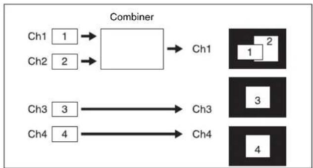
flowchart
graph LR
    A["Ch1 1"] --> B["Box"]
    C["Ch2 2"] --> B
    B --> D["Ch1"]
    E["Ch3 3"] --> F["Ch3"]
    G["Ch4 4"] --> H["Ch4"]
    I["1 2"] --> J["Box 1"]
    K["3"] --> L["Box 3"]
    M["4"] --> N["Box 4"]
Combination of Ch1, Ch2, and Ch3
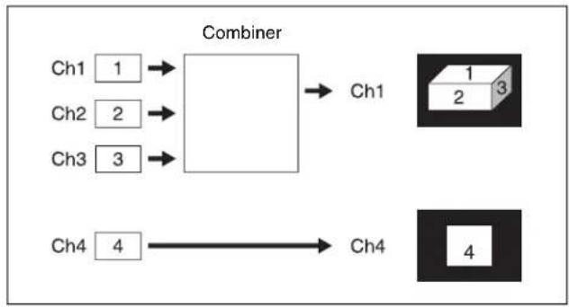
flowchart
graph LR
    A["Ch1"] --> B["Combiner"]
    C["Ch2"] --> B
    D["Ch3"] --> B
    E["Ch4"] --> F["Ch4"]
    B --> G["Ch1"]
    F --> H["Ch4"]
Combination of Ch1 and Ch2 / combination of Ch3 and Ch4
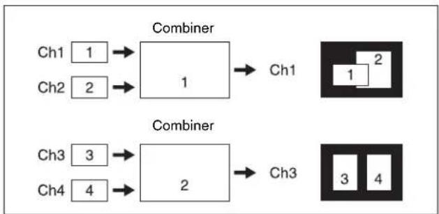
flowchart
graph TD
    A["Ch1 1"] --> B["Combiner 1"]
    C["Ch2 2"] --> B
    B --> D["Ch1"]
    E["Ch3 3"] --> F["Combiner 2"]
    G["Ch4 4"] --> F
    F --> H["Ch3"]
Combination of Ch1, Ch2, Ch3, and Ch4
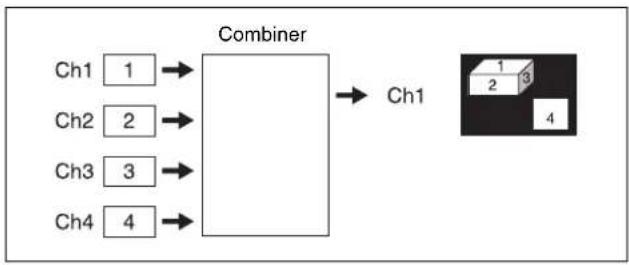
flowchart
graph LR
    A["Ch1"] --> B["Combiner"]
    C["Ch2"] --> B
    D["Ch3"] --> B
    E["Ch4"] --> B
    B --> F["Ch1"]
    G["1"] --> H["4"]
    I["2"] --> H
    J["3"] --> H
Mixing Ch1 and Ch2
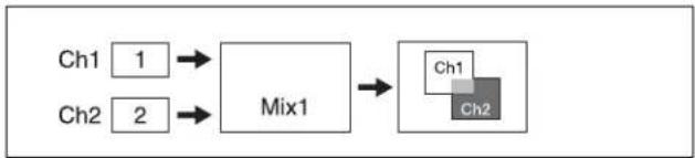
flowchart
graph LR
    A["Ch1 1"] --> C["Mix1"]
    B["Ch2 2"] --> C
    C --> D["Ch1"]
    C --> E["Ch2"]
If the Mix1 setting is 70, the proportion of the channels in the mixed portion in the previous illustration is as shown in the following table.
| Combination | Indication in figure | Ch1 Ch2 | |
| Ch1 and Ch2 | 30% 70% |
Mixing Ch1, Ch2, and Ch3
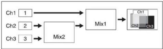
flowchart
graph LR
    Ch1["Ch1"] --> Mix1["Mix1"]
    Ch2["Ch2"] --> Mix2["Mix2"]
    Ch3["Ch3"] --> Mix2
    Mix1 --> Ch1["Ch1"]
    Mix1 --> Ch2["Ch2"]
    Mix1 --> Ch3["Ch3"]
If the Mix1 setting is 70 and the Mix2 setting is 40, the proportions of the channels in the mixed portions in the previous illustration are as shown in the following table.
| Combination | Indication in figure | Ch1 Ch2 | Ch3 | |
| Ch1 and Ch2 | 30% 70% – | |||
| Ch2 and Ch3 | -60% 40% | |||
| Ch1 and Ch3 | 30% – 70% | |||
| Ch1, Ch2, and Ch3 | 30% 42% | 28% |
Pairwise mixing of Ch1 and Ch2, and Ch3 and Ch4
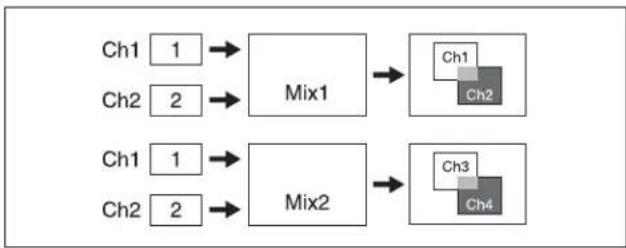
flowchart
graph LR
    A["Ch1 1"] --> B["Mix1"]
    C["Ch2 2"] --> B
    D["Ch1 1"] --> E["Mix2"]
    F["Ch2 2"] --> E
    B --> G["Ch1"]
    E --> H["Ch3"]
    G --> I["Ch2"]
    H --> J["Ch4"]
If the Mix1 setting is 70 and the Mix2 setting is 40, the proportions of the channels in the mixed portions in the previous illustration are as shown in the following table.
| Combination | Indication in figure | Ch1 | Ch2 | Ch3 | Ch4 | |
| Ch1 and Ch2 | 30% 70% -- | |||||
| Ch3 and Ch4 | -60% 40% |
Ch1 crossed with Ch2
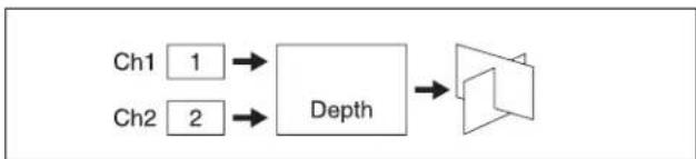
flowchart
graph LR
    A["Ch1 1"] --> C["Depth"]
    B["Ch2 2"] --> C["Depth"]
    C --> D["Speaker"]
Setting the combiners
The setting menu differs according to the combiner usage status.
This section shows the cases of “Ch1+Ch2+Ch3” and “Ch1+Ch2, Ch3+Ch4” as examples.
For details of operating procedures when using an SDI interface, see “Procedure for combine operation when using an SDI interface” (page 345).
1 In the Global Effect >Ch1- Ch4 menu, select HF1 'Combiner Priority.'
The Combiner Priority menu appears.
2 If [Mix], [Auto] or [Depth] is on, turn it off.
3 Set the overlap priority for "Ch1+Ch2+Ch3" or "Ch1+Ch2, Ch3+Ch4" as follows.
For case "Ch1+Ch2+Ch3"
Under
Priority1: Select the channel with the highest priority.
Priority2: Select the channel with the second highest priority.
Priority3: Select the channel with the lowest priority.
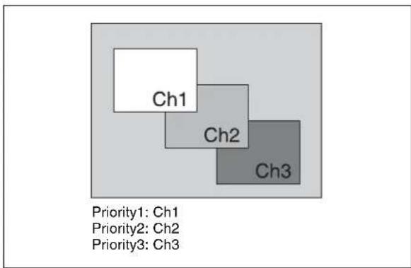
flowchart
graph TD
    A["Ch1"] --> B["Ch2"]
    B --> C["Ch3"]
    style A fill:#fff,stroke:#000
    style B fill:#ccc,stroke:#000
    style C fill:#d4e6f1,stroke:#000
For case "Ch1+Ch2, Ch3+Ch4"
Under
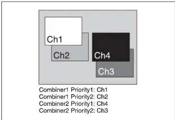
Procedure for combine operation when using an SDI interface
Use the following procedure only when the DME with an SDI interface.
Notes
It is not possible to select channels with buttons in the key control block.
In the following, the example given is that channels 2 and 3 are combined, then channels 1+2 and channels 3+4 are combined, but other combinations are also possible.
1 In the Global Effect menu, select VF1 'Ch1-Ch4' and HF7 'Combine Gp Select.'
The Combine Gp Select menu appears.
2 In the
• To combine channels 2 and 3, press [Ch2+Ch3], turning it on.
• To combine the previously combined combinations of channels 1 and 2, and channels 3 and 4, press [Ch1+Ch2] and [Ch3+Ch4], turning them on.
Notes
The only two buttons that can be selected simultaneously are the combination of [Ch1+Ch2] and [Ch3+Ch4] .
The selected channels are combined.
To cancel a combine
When for example [Ch2+Ch3] is on, pressing [Ch2+Ch3] once more turns it off. Alternatively, pressing a different combination button to select it cancels the combine selection for the current combination.
Mixing the images of up to four consecutive channels
1 In the Combiner Priority menu, press [Mix], turning it on.
2 Adjust the following parameters.
For case "Ch1+Ch2"
| Knob | Parameter | Adjustment Setting | values |
| 1 Mix | Mix degree 0. | 00 to 100.00 | a) |
a) See "Mixing Ch1 and Ch2" (page 344).
For case "Ch1+Ch2+Ch3"
| Knob | Parameter Adjustment Setting | values |
| 1 Mix1 | Mix degree for mix of channel 1 with result of Mix2 | 0.00 to 100.00a) |
| 2 Mix2 | Mix degree for channels 2 and 3 | 0.00 to 100.00a) |
a) See "Mixing Ch1, Ch2, and Ch3" (page 344).
For case "Ch1+Ch2+Ch3+Ch4"
Knobs 1 and 2 set the same parameters as “For case ‘Ch1+Ch2+Ch3’,” respectively. Knob 3 is additionally effective, which sets the parameter Mix3 (in the same setting value range as with knobs 1 and 2).
Mixing pairwise the images of channels 1 and 2, and channels 3 and 4
1 In the Combiner Priority menu, press [Combiner1 Mix], turning it on.
2 Adjust the following parameter.
| Knob | Parameter | Adjustment | Setting values |
| 1 Mix1 | Mix degree for channels 1 and 2 | 0.00 to 100.00a) |
a) See "Pairwise mixing of Ch1 and Ch2, and Ch3 and Ch4" (page 345).
3 Press [Combiner2 Mix], turning it on.
4 Adjust the following parameter.
| Knob | Parameter | Adjustment | Setting values |
| 1 Mix2 | Mix degree for channels 2 and 3 | 0.00 to 100.00a) |
a) See "Pairwise mixing of Ch1 and Ch2, and Ch3 and Ch4" (page 345).
Automatically setting the priority of overlapping images
To set the system so that the priority of overlapping images is automatically determined by their position on the z-axis, in the Combiner Priority menu, press [Auto], turning it on.
Notes
It is not possible to cross images. If an image is rotated, the priority is determined by the position on the z-axis of the center of the image.
Crossing images from up to four consecutive channels in three dimensions
Notes
The three-dimensional crossing function is not supported on the MVE-8000A.
1 In the Combiner Priority menu, press [Depth], turning it on.
2 Set the following parameters.
For case "Ch1+Ch2"
| Knob | Parameter | Adjustment | Setting values |
| 1 Soft | Softness of | edges ofcrossed section | 0.00 to 100.00 |
For case "Ch1+Ch2+Ch3"
| Knob | Parameter Adjustment Setting values | ||
| 1 | Soft1 | Softness edges of channel 1 and channel 2 crossed section | 0.00 to 100.00 |
| 2 | Soft2 | Softness edges of channel 2 and channel 3 crossed section | 0.00 to 100.00 |
For case "Ch1+Ch2+Ch3+Ch4"
Knobs 1 and 2 set the same parameters as “For case ‘Ch1+Ch2+Ch3’,” respectively. Knob 3 is additionally effective, which sets the parameter Soft3 (in the same setting value range as with knobs 1 and 2).
Crossing images from channels 1 and 2, and channels 3 and 4 in three dimensions
Notes
The three-dimensional crossing function is not supported on the MVE-8000A.
1 In the Combiner Priority menu, press [Combiner1 Depth], turning it on.
2 Set the following parameter.
| Knob | Parameter Adjustment Setting | values |
| 1 Soft1 | Softness of edges of channel 1 and channel 2 crossed section | 0.00 to 100.00 |
3 Press [Combiner2 Depth], turning it on.
4 Set the following parameter.
| Knob | Parameter Adjustment Setting | values |
| 1 Soft2 | Softness of edges of channel 3 and channel 4 crossed section | 0.00 to 100.00 |
Brick Settings
Brick allows you to create a rectangular parallelepiped by using images of three consecutive channels. The Brick effect can combine Ch1, Ch2, and Ch3, or combine Ch2, Ch3, and Ch4. The three images are displayed as shown in the following figure.
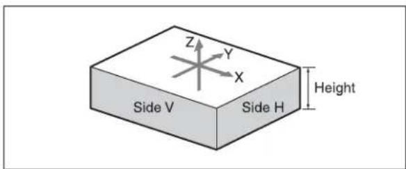
Combinations of Ch1, Ch2, and Ch3
Upper side: Ch1 image
Side V: Ch2 image
Side H: Ch3 image
Combinations of Ch2, Ch3, and Ch4
Upper side: Ch2 image
Side V: Ch3 image
Side H: Ch4 image
You can adjust the height of the brick, the overlap between the three images and the way to insert the side images.
Applying the Brick effect
1 In the Global Effect >Ch1 - Ch4 menu, select HF2 'Brick.'
The Brick menu appears.
2 Press [Brick], turning it on.
The Brick effect is enabled, and a rectangular parallelepiped (brick) showing the images of three channels appears. You can use the knobs to adjust parameters for the height of the brick and the overlap between the three images.
Notes
- When the Brick effect is enabled, the z-axis position of the front image in the source coordinate frame is shifted by the amount of half the height. Therefore, the image is somewhat magnified.
- The flex shadow function cannot be enabled when Brick is enabled.
However, the flex shadow function is not supported on the MVE-8000A.
3 Set the parameters.
| Knob | Parameter | Adjustment | Setting values |
| 1 Height | Height of | brick | 0.00 to 8.00^a) 0.00 to 32.00^b) |
| 2 | F r Overlap | Front overlap | -100.00 to +100.00 |
| 3 Side | H Overlap | Side H overlap | -100.00 to +100.00 |
| 4 Side | V Overlap | Side V overlap | -100.00 to +100.00 |
a) Setting for SD 4:3, SD 16:9
b) Setting for HD 4:3, HD 16:9
4 Specify the way to insert the side images when the height is changed by pressing one of the following buttons in the
Crop: Crop the parts that do not fit into the side without shrinking the picture. You can set the following parameters.
The valid ranges of the parameter values depend on the combination of signal format (SD/HD) and aspect ratio (4:3/16:9) selected in the system, as follows.
• 4 : 3 mode
| Knob | Parameter | Adjustment Setting values | |
| 1 H | Position of | left crop -4.00 to +4.00 (SD) -12.00 to +12.00 (HD) | |
| 2 V | Position of | top crop -3.00 to +3.00 (SD) -9.00 to +9.00 (HD) | |
| 3 Rotation Angle of | rotation,when rotatedaround theZ-axis of thesourcespace 0/90/180/270^ | ||
• 16:9 mode
| Knob | Parameter | Adjustment Setting values | |
| 1 H | Position of | left crop -4.00 to +4.00 (SD) -16.00 to +16.00 (HD) | |
| 2 V | Position of | top crop -2.25 to +2.25 (SD) -9.00 to +9.00 (HD) | |
| 3 Rotation Angle of | rotation,when rotatedaround theZ-axis of thesourcespace 0/90/180/270^ | ||
The set position becomes the upper left corner of Side V or Side H. The right and bottom sides of the inserted image are set automatically.
Compress: Images are inserted after being compressed. You can set the following parameters.
The valid ranges of the parameter values depend on the combination of signal format (SD/HD) and aspect ratio (4:3/16:9) selected in the system, as follows.
• 4 : 3 mode
| Knob | Parameter | Adjustment Setting values | |
| 1 Top | Position of | -2.83 to +3.00 (SD) -8.50 to +9.00 (HD) | |
| top crop | |||
| 2 Left | Position of | -4.00 to +3.83 (SD) -12.00 to +11.50 (HD) | |
| left crop | |||
| 3 Right | Position of right crop | -3.83 to +4.00 (SD) -11.50 to +12.00 (HD) | |
| 4 Bottom | Position of bottom crop | -3.00 to +2.83 (SD) -9.00 to +8.50 (HD) | |
| 5 Rotation Angle of | 0/90/180/270° | ||
| rotation, when rotated around the Z-axis of the source space | |||
• 16:9 mode
| Knob | Parameter | Adjustment Setting values | |
| 1 Top | Position of | -2.12 to +2.25 (SD) -8.50 to +9.00 (HD) | |
| 2 Left | Position of | top crop | -4.00 to +3.87 (SD) -16.00 to +15.50 (HD) |
| left crop | |||
| 3 Right | Position ofright crop | -3.87 to +4.00 (SD) -15.50 to +16.00 (HD) | |
| 4 Bottom | Position ofbottom crop | -2.25 to +2.12 (SD) -9.00 to +8.50 (HD) | |
| 5 Rotation Angle of | 0/90/180/270^ | ||
The part of the image defined by Top, Left, Right, and Bottom is magnified or shrunk to fit into Side V or Side H.
To invert the image in a side face
For example, to invert the image on the front of Side H in the
Invert H: To invert horizontally.
Invert V: To invert vertically.
For the images on the other faces, use a similar operation in the following
groups:
- Back image of Side H:
group - Front image of Side V:
group - Back image of Side V:
group
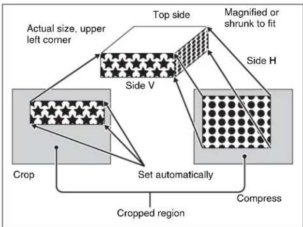
flowchart
graph TD
    A["Actual size, upper left corner"] --> B["Top side"]
    B --> C["Side V"]
    B --> D["Side H"]
    C --> E["Crop"]
    D --> F["Set automatically"]
    F --> G["Cropped region"]
    F --> H["Compress"]
    style A fill:#f9f,stroke:#333
    style B fill:#ccf,stroke:#333
    style C fill:#cfc,stroke:#333
    style D fill:#fcc,stroke:#333
    style E fill:#ffc,stroke:#333
    style F fill:#cfc,stroke:#333
    style G fill:#fcc,stroke:#333
    style H fill:#ffc,stroke:#333
Shadow Settings
The effect uses two successive channels. You can adjust the position and density of the shadow with respect to the image, and the color of the shadow. The channel with the largest number (for example, Ch2 in the case of Ch1 and Ch2) becomes the shadow.
Notes
When the Combiner function is off, the shadow effect cannot be used.
Applying the Drop Shadow effect
The Shadow menu allows you to apply the Drop Shadow effect. To access the Shadow menu, in the Global Effect >Ch1 - Ch4 menu select HF3 'Shadow.'
Depending on the selected combiner channels, the valid buttons differ as follows.
| Combiner channel selection | Button | ||||
| Ch1 Shadow | Ch2 Shadow | Ch3 Shadow | Ch1+ Ch2 Shadow | Ch2+ Ch3 Shadow | |
| Ch1+Ch2 Valid | |||||
| Ch2+Ch3 Valid | |||||
| Ch3+Ch4 Valid | |||||
| Ch1+Ch2 +Ch3 | Valid Valid | ||||
| Ch2+Ch3 +Ch4 | Valid Valid | Valid | |||
| Ch1+Ch2 +Ch3+Ch 4 | Valid Valid | Valid Valid | |||
Taking Ch1 Shadow as an example, the following explains the procedure for applying the Drop Shadow effect.
1 Press [Ch1 Shadow], turning it on.
The Drop Shadow effect is enabled, and channel 2 becomes the channel for the shadow to the image. You can adjust the position and density of the shadow with the knobs.
Notes
The flex shadow function cannot be enabled when Drop Shadow is enabled.
However, the flex shadow function is not supported on the MVE-8000A.
2 Set the parameters.
| Knob | Parameter | Adjustment | Setting values |
| 1 Position H | Horizontal shadow position | -8.00 to +8.000^a) -32.00 to +32.000^b) | |
| 2 Position V | Vertical shadow position | -8.00 to +8.000^a) -32.00 to +32.000^b) | |
| 3 Density of | Shadow | 0.00 to 100.00 |
a) Setting for SD 4:3, SD 16:9
b) Setting for HD 4:3, HD 16:9
3 In the
Video: Select Ch2 video input as the shadow.
Flat Color: Select a matte color as the shadow.
4 When you select Flat Color in step 3, adjust the parameters.
| Knob | Parameter | Adjustment | Setting values |
| 1 Luminance | Luminance | 0.00 to 100.00 | |
| 2 Saturation | Saturation | 0.00 to 100.00 | |
| 3 Hue | Hue | 359.99 to 0.00 |
To combine the video images after applying a shadow
Use the Combiner function to select channel 1 + channel 2 and channel 3 + channel 4, then turn [Ch 1 Shadow] and [Ch 3 Shadow] on.
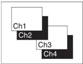
To apply a shadow after combining the video images
Use the Combiner function to select channel 1 + channel 2 + channel 3 + channel 4, then turn [Ch 1 + Ch 2 Shadow] on.
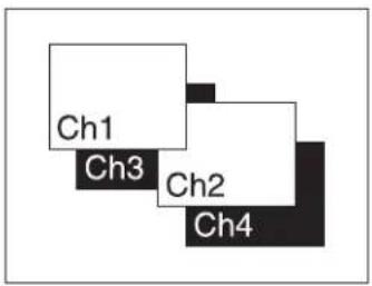
Appendix (Volume 1)
Wipe Pattern List
Interpreting the illustrations for patterns
The black part of the pattern represents the old video, and the white part the new video, with the wipe taking place in the direction of the arrow.
Standard Wipes
| 1 |  | 2 |  | 3 |  | 4 |  | 5 |  | 6 |  |
| 7 |  | 8 |  | 9 |  | 10 |  | 11 |  | 12 |  |
| 13 |  | 14 |  | 15 |  | 16 |  | 17 |  | 18 |  |
| 19 |  | 20 |  | 21 |  | 22 |  | 23 |  | 24 |  |
Enhanced Wipes
| 26 |  | 27 |  | 29 |  | 49 |  | 300 |  | 301 |  |
| 302 | 303 | 304 | |||||||||
Rotary Wipes
| 100 |  | 101 |  | 102 | 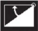 | 103 |  | 104 |  | 105 |  |
| 106 |  | 107 |  | 150 |  | 151 |  | 156 |  | 158 | 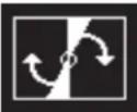 |
| 160 |  | 162 |  | 516 |  | 518 |  | 604 | 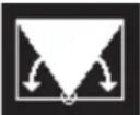 | 606 |  |


Mosaic Wipes
| 200 |  | 201 |  | 202 |  | 203 |  | 206 |  | 207 |  |
| 208 |  | 209 |  | 210 |  | 211 |  | 212 |  | 213 |  |
| 220 |  | 221 |  | 222 |  | 223 |  | 224 | 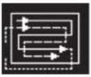 | 225 |  |
| 226 |  | 227 |  | 228 |  | 229 |  | 230 |  | 231 |  |
| 232 |  | 233 |  | 234 |  | 235 |  | 236 |  | 237 |  |
| 238 |  | 239 |  | 240 |  | 241 | 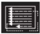 | 242 | 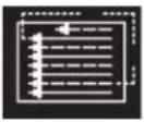 | 243 | 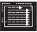 |
| 244 | 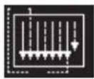 | 245 |  | 246 |  | 247 |  | 250 |  | 251 |  |
| 252 |  | 253 |  | 254 |  | 255 |  | 256 |  | 257 |  |
| 260 |  | 261 | 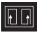 | 262 | 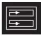 | 263 | 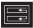 | 264 | 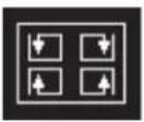 | 265 |  |
| 266 |  | 267 |  | 268 |  | 269 |  | ||||
Random/Diamond Dust Wipes
| 270 |  | 271 |  | 272 |  | 273 |  | 274 |  |
DME Wipe Pattern List
Notes
When 3M/E mode or 4M/E mode is selected on the MVS-7000X, there are cases in which utility bus 1 (U1) appears
instead of utility bus 2 (U2) and utility bus 2 (U2) does not appear.
DME Wipe Patterns Available in One-Channel Mode
Slide
| 1001 |  | 1002 |  | 1003 |  | 1004 |  | 1005 |  | 1006 |  |
| 1007 |  | 1008 |  | ||||||||
Split
| 1011 |  | 1012 |  | 1013 |  |
Squeeze
| 1021 |  | 1022 |  | 1023 |  | 1024 |  | 1025 |  | 1026 |  |
| 1027 |  | 1028 |  | 1029 |  | 1030 |  | 1031 |  | ||

Door
| 1041 |  | 1042 |  | 1043 |  | 1044 |  | 1045 |  | 1046 |  |
| 1047 | 1048 | ||||||||||
2D trans
| 1051 |  | 1052 |  | 1053 |  | 1054 |  | 1055 |  | 1056 |  |
| 1057 |  | 1058 |  | 1061 | 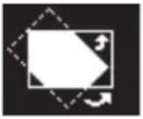 | 1062 |  | 1063 | 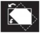 | 1064 | 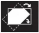 |
| 1068 | |||||||||||
3D trans
| 1071 |  | 1072 | 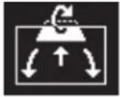 | 1074 |  | 1076 |  | 1077 |  | 1088 |  |
| 1091 |  | 1092 |  | 1093 |  | 1094 | 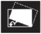 | ||||

Flip tumble
| 1101 | 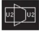 | 1102 | 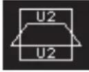 | 1103 | 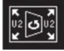 | 1104 | 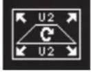 | 1109 |  | 1110 | 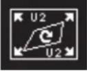 |
| 1121 | 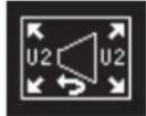 | 1122 | 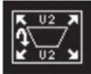 | 1124 | 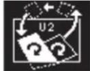 | 1131 | 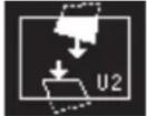 | 1132 | 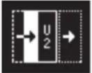 | 1133 | 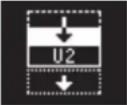 |
| 1135 |  | ||||||||||
Frame in-out
| 1201 |  | 1202 |  | 1203 |  | 1204 |  | 1205 |  | 1206 |  |
| 1207 |  | 1208 |  | 1221 |  | 1222 |  | 1223 |  | 1224 |  |
Picture-in-picture
| 1251 |  |
Page turn
| 1301 |  | 1302 |  | 1303 |  | 1304 |  | 1305 |  | 1306 |  |
| 1307 |  | 1308 |  | 1309 |  | 1310 |  | 1311 |  | 1312 |  |
| 1313 |  | 1315 |  | 1316 |  | 1317 |  | 1318 |  | 1341 | 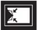 |
| 1342 |  | 1343 | 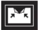 | 1344 | 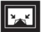 | 1345 |  | ||||
Page roll
| 1321 | 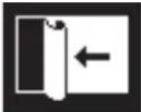 | 1322 |  | 1323 |  | 1324 |  | 1325 |  | 1326 |  |
| 1327 |  | 1328 |  | 1329 |  | 1330 |  | 1331 |  | 1332 |  |
| 1333 |  | 1335 |  | 1336 |  | 1337 |  | 1338 |  | 1346 |  |
| 1347 |  | 1348 |  | 1349 |  | 1350 |  | ||||

Mirror
| 1355 |  | 1356 |  | 1357 |  | 1358 |  |
Sphere
| 1365 | 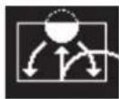 |
Character trail
| 1371 |  | 1372 |  |
Wave
| 1378 |  | 1379 |  |
Ripple
| 1381 |  |
Split slide
| 1384 | 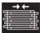 | 1385 | 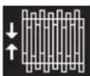 | 1386 |  | 1387 |  | 1388 |  | 1389 |  |

Sparkle
| 1391 |  | 1393 |  | 1394 |  | 1396 |  | 1398 |  | 1399 |  |
Mosaic
| 1701 |  |
Defocus
| 1702 |  |
User programmable DME
The illustrations for patterns 1901 to 1999 show an effect register number or register name.
| 1901 | 101 | ··· | 1999 | 199 |
DME Wipe Patterns Available in Two-Channel Mode
Slide
| 2601 |  | 2602 |  | 2603 |  | 2604 |  | 2605 |  | 2606 |  |
| 2607 | 2608 | ||||||||||
Squeeze
| 2621 |  | 2622 |  | 2623 |  | 2624 |  | 2625 |  | 2626 |  |
| 2627 | 2628 | ||||||||||
3D trans
| 2801 |  | 2802 |  | 2803 |  | 2804 |  | 2811 |  | 2812 |  |
| 2813 | 2814 | ||||||||||
Picture-in-picture
| 2651 |  | 2652 |  |

Page turn
| 2701 |  | 2702 |  | 2703 |  | 2704 |  | 2705 |  | 2706 |  |
| 2707 | 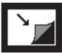 | 2708 | 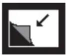 | 2709 | 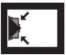 | 2710 | 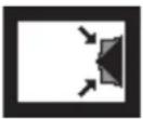 | 2711 | 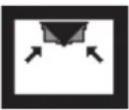 | 2712 | 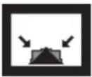 |
| 2713 | 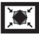 | 2715 |  | 2716 |  | 2717 |  | 2718 | 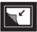 | 2741 | 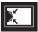 |
| 2742 | 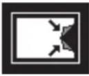 | 2743 |  | 2744 | 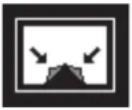 | 2745 |  | ||||
Page roll
| 2721 | 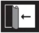 | 2722 | 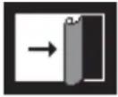 | 2723 | 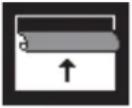 | 2724 | 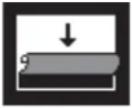 | 2725 | 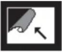 | 2726 | 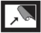 |
| 2727 | 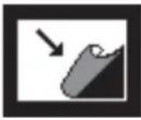 | 2728 |  | 2729 | 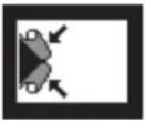 | 2730 | 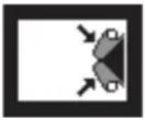 | 2731 | 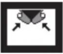 | 2732 | 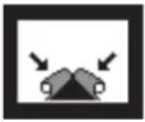 |
| 2733 | 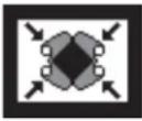 | 2735 | 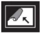 | 2736 |  | 2737 |  | 2738 |  | 2746 |  |
| 2747 |  | 2748 |  | 2749 |  | 2750 |  | ||||
Brick
| 2801 |  | 2802 |  | 2803 |  | 2804 |  | 2811 |  | 2812 | 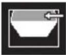 |
| 2813 | 2814 | ||||||||||
Frame in-out
| 2851 | 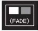 | 2852 | 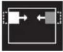 | 2853 | 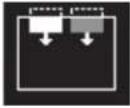 | 2854 |  | 2861 |  | 2862 |  |
| 2863 | 2864 | ||||||||||
User programmable DME
The illustrations for patterns 2901 to 2999 show an effect register number or register name.
| 2901 |  | • • |  |  |
DME Wipe Patterns Available in Three-Channel Mode
Brick
| 3601 |  |
User programmable DME
The illustrations for patterns 3901 to 3999 show an effect register number or register name.
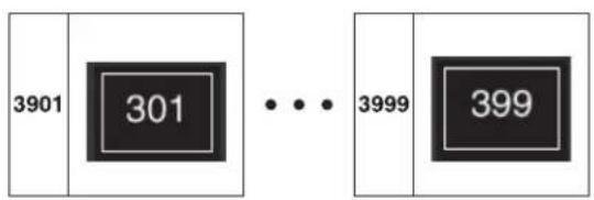
Resizer DME Wipe Pattern List
Slide
| 7001 |  | 7002 |  | 7003 |  | 7004 |  | 7005 |  | 7006 |  |
| 7007 | 7008 | ||||||||||
Squeeze
| 7021 |  | 7022 |  | 7023 |  | 7024 |  | 7025 |  | 7026 |  |
| 7027 |  | 7028 |  | 7029 |  | 7030 |  | 7031 |  | ||
Frame in-out
| 7201 |  | 7202 |  | 7203 |  | 7204 |  | 7205 |  | 7206 |  |
| 7207 |  | 7208 |  | 7221 |  | 7222 |  | 7223 |  | 7224 |  |
Menu Tree
Recalling Menus
This section details the menu structure, and shows the top menu selection buttons in the menu control block which are used to access the menus.
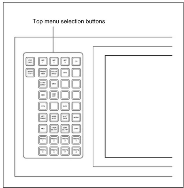
Menu control block
Some menus can also be accessed by pressing other buttons twice in rapid succession.
For more details, see "Overview" (page 72).
Notes
Some menus may not appear, depending on the model.
M/E-1 to M/E-4 Menus
The functions in the M/E-1, M/E-2, M/E-3, and M/E-4 menus are the same, but the menu page numbers are distinguished as follows.
M/E-1 menus: 11xx, M/E-2 menus: 12xx,
M/E-3 menus: 13xx, M/E-4 menus: 81xx
In this section, the numbers for the M/E-1 menus are given as examples.
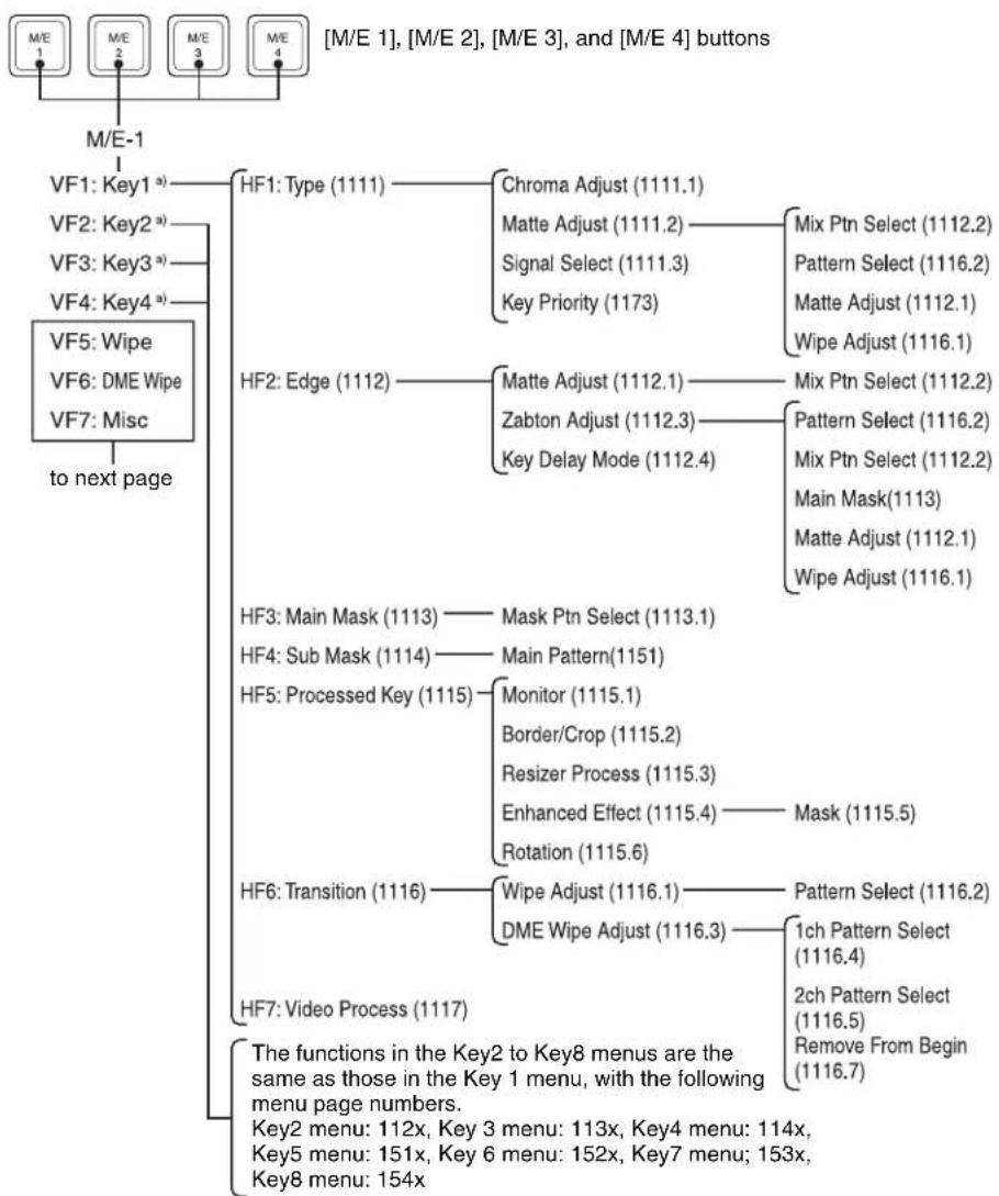
flowchart
graph TD
    A["M/E 1"] --> B["M/E-1"]
    C["M/E 2"] --> B
    D["M/E 3"] --> B
    E["M/E 4"] --> B
    B --> F["VF1: Key1 a)"]
    F --> G["HF1: Type (1111)"]
    G --> H["Chroma Adjust (1111.1)"]
    G --> I["Matte Adjust (1111.2)"]
    I --> J["Mix Ptn Select (1112.2)"]
    G --> K["Signal Select (1111.3)"]
    K --> L["Pattern Select (1116.2)"]
    G --> M["Key Priority (1173)"]
    M --> N["Matte Adjust (1112.1)"]
    M --> O["Wipe Adjust (1116.1)"]
    F --> P["VF2: Key2 a)"]
    P --> Q["HF2: Edge (1112)"]
    Q --> R["Matte Adjust (1112.1)"]
    R --> S["Mix Ptn Select (1112.2)"]
    Q --> T["Zabton Adjust (1112.3)"]
    T --> U["Pattern Select (1116.2)"]
    Q --> V["Key Delay Mode (1112.4)"]
    V --> W["Mix Ptn Select (1112.2)"]
    V --> X["Main Mask(1113)"]
    V --> Y["Matte Adjust (1112.1)"]
    V --> Z["Wipe Adjust (1116.1)"]
    F --> AA["VF3: Main Mask (1113)"]
    AA --> AB["Mask Ptn Select (1113.1)"]
    AA --> AC["Main Pattern(1151)"]
    F --> AD["HF4: Sub Mask (1114)"]
    AD --> AE["Main Pattern(1151)"]
    F --> AF["HF5: Processed Key (1115)"]
    AF --> AG["Monitor (1115.1)"]
    AG --> AH["Border/Crop (1115.2)"]
    AG --> AI["Resizer Process (1115.3)"]
    AG --> AJ["Enhanced Effect (1115.4)"]
    AJ --> AK["Mask (1115.5)"]
    AG --> AL["Rotation (1115.6)"]
    F --> AM["HF6: Transition (1116)"]
    AM --> AN["Wipe Adjust (1116.1)"]
    AM --> AO["DME Wipe Adjust (1116.3)"]
    AN --> AP["Pattern Select (1116.2)"]
    AO --> AQ["1ch Pattern Select (1116.4)"]
    AO --> AR["2ch Pattern Select (1116.5)"]
    AO --> AS["Remove From Begin (1116.7)"]
    F --> AT["HF7: Video Process (1117)"]
    AT --> AU["The functions in the Key2 to Key8 menus are the same as those in the Key 1 menu, with the following menu page numbers.<br>Key2 menu: 112x, Key 3 menu: 113x, Key4 menu: 114x,<br>Key5 menu: 151x, Key 6 menu: 152x, Key7 menu: 153x,<br>Key8 menu: 154x"]
a) For VF1 to VF4, either of the groups Key1 to Key4 and Key5 to Key8 appears.

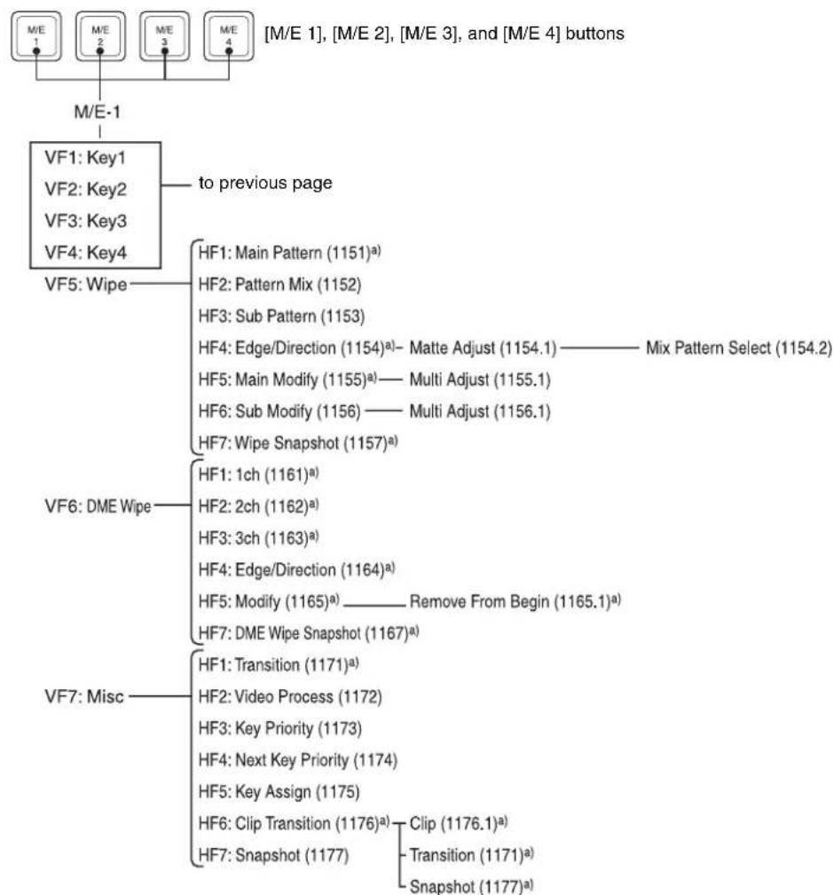
flowchart
graph TD
    A["M/E 1"] --> B["M/E-1"]
    C["M/E 2"] --> D["VF1: Key1"]
    E["M/E 3"] --> F["VF2: Key2"]
    G["M/E 4"] --> H["VF3: Key3"]
    I["VF4: Key4"] --> J["VF5: Wipe"]
    K["HF1: Main Pattern (1151)²"] --> L["HF2: Pattern Mix (1152)"]
    M["HF3: Sub Pattern (1153)"] --> N["HF4: Edge/Direction (1154)²— Matte Adjust (1154.1) —— Mix Pattern Select (1154.2)"]
    O["HF5: Main Modify (1155)²— Multi Adjust (1155.1)"] --> P["HF6: Sub Modify (1156) —— Multi Adjust (1156.1)"]
    Q["HF7: Wipe Snapshot (1157)²"] --> R["VF6: DME Wipe"]
    S["HF1: 1ch (1161)²"] --> T["HF2: 2ch (1162)²"]
    U["HF3: 3ch (1163)²"] --> V["HF4: Edge/Direction (1164)²"]
    W["HF5: Modify (1165)² —— Remove From Begin (1165.1)²"] --> X["HF7: DME Wipe Snapshot (1167)²"]
    Y["VF7: Misc"] --> Z["HF1: Transition (1171)²"]
    AA["HF2: Video Process (1172)"] --> AB["HF3: Key Priority (1173)"]
    AC["HF4: Next Key Priority (1174)"] --> AD["HF5: Key Assign (1175)"]
    AE["HF6: Clip Transition (1176)²"] --> AF["HF7: Snapshot (1177)"]
    AG["Clip (1176.1)²"] --> AH["Transition (1171)²"]
    AI["Snapshot (1177)²"] --> AJ["->"]
a) In Multi Program 2 mode, the menus for sub are displayed with 400 higher numbers than the above for main.
PGM/PST Menu
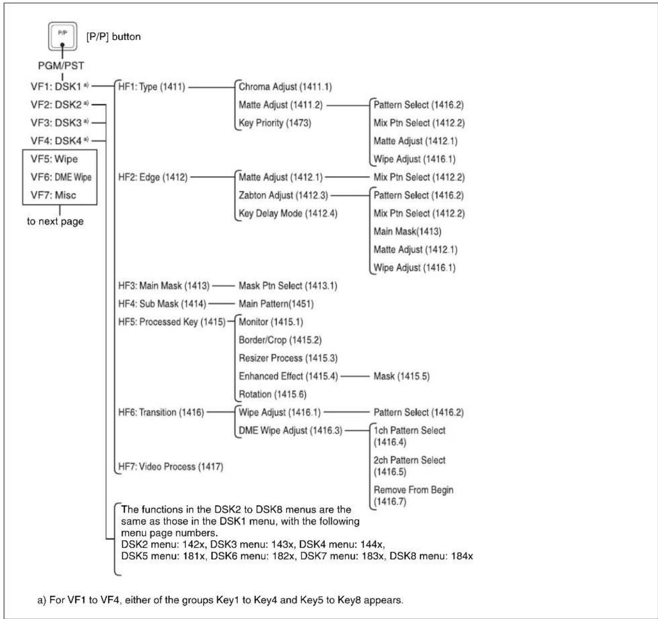
flowchart
graph TD
    A["[P/P"] button] --> B["PGM/PST"]
    B --> C["VF1: DSK1 a) HF1: Type (1411)"]
    C --> D["Chroma Adjust (1411.1)"]
    C --> E["Matte Adjust (1411.2)"]
    E --> F["Pattern Select (1416.2)"]
    C --> G["Key Priority (1473)"]
    G --> H["Mix Ptn Select (1412.2)"]
    C --> I["Matte Adjust (1412.1)"]
    I --> J["Wipe Adjust (1416.1)"]
    B --> K["VF2: DSK2 a) VF2: Type (1411)"]
    K --> L["Key Priority (1473)"]
    L --> M["Pattern Select (1416.2)"]
    C --> N["VF3: DSK3 a) VF3: Type (1411)"]
    N --> O["Key Priority (1473)"]
    O --> P["Mix Ptn Select (1412.2)"]
    C --> Q["VF4: DSK4 a) VF4: Type (1411)"]
    Q --> R["Key Priority (1473)"]
    R --> S["Mix Ptn Select (1412.2)"]
    C --> T["VF5: Wipe VF5: Type (1411)"]
    T --> U["Key Priority (1473)"]
    U --> V["Wipe Adjust (1416.1)"]
    C --> W["VF6: DME Wipe VF6: Type (1411)"]
    W --> X["Key Priority (1473)"]
    X --> Y["Mix Ptn Select (1412.2)"]
    C --> Z["VF7: Misc to next page"]
    Z --> AA["Key Priority (1473)"]
    AA --> AB["Mix Ptn Select (1412.2)"]
    C --> AC["HF2: Edge (1412)"]
    AC --> AD["Matte Adjust (1412.1)"]
    AD --> AE["Mix Ptn Select (1412.2)"]
    AC --> AF["Zabton Adjust (1412.3)"]
    AF --> AG["Key Delay Mode (1412.4)"]
    AG --> AH["Mix Ptn Select (1412.2)"]
    AG --> AI["Main Mask(1413)"]
    AG --> AJ["Matte Adjust (1412.1)"]
    AG --> AK["Wipe Adjust (1416.1)"]
    C --> AL["HF3: Main Mask (1413)"]
    AL --> AM["Mask Ptn Select (1413.1)"]
    C --> AN["HF4: Sub Mask (1414)"]
    AN --> AO["Main Pattern(1451)"]
    C --> AP["HF5: Processed Key (1415)"]
    AP --> AQ["Monitor (1415.1)"]
    AQ --> AR["Border/Crop (1415.2)"]
    AP --> AS["Resizer Process (1415.3)"]
    AS --> AT["Enhanced Effect (1415.4)"]
    AT --> AU["Mask (1415.5)"]
    AP --> AV["Rotation (1415.6)"]
    C --> AW["HF6: Transition (1416)"]
    AW --> AX["Wipe Adjust (1416.1)"]
    AX --> AY["DME Wipe Adjust (1416.3)"]
    AX --> AZ["Pattern Select (1416.2)"]
    AW --> BA["HF7: Video Process (1417)"]
    BA --> BB["Main Pattern Select (1416.4)"]
    BA --> BC["2ch Pattern Select (1416.5)"]
    BA --> BD["Remove From Begin (1416.7)"]
    B --> BE["The functions in the DSK2 to DSK8 menus are the same as those in the DSK1 menu, with the following menu page numbers.<br>DSK2 menu: 142x, DSK3 menu: 143x, DSK4 menu: 144x,<br>DSK5 menu: 181x, DSK6 menu: 182x, DSK7 menu: 183x, DSK8 menu: 184x"]

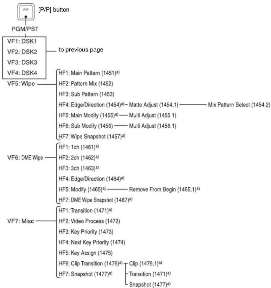
flowchart
graph TD
    A["P/P"] --> B["PGM/PST"]
    B --> C["VF1: DSK1"]
    B --> D["VF2: DSK2"]
    B --> E["VF3: DSK3"]
    B --> F["VF4: DSK4"]
    C --> G["to previous page"]
    G --> H["VF5: Wipe"]
    H --> I["HF1: Main Pattern (1451)²"]
    H --> J["HF2: Pattern Mix (1452)"]
    H --> K["HF3: Sub Pattern (1453)"]
    H --> L["HF4: Edge/Direction (1454)²— Matte Adjust (1454.1)—Mix Pattern Select (1454.2)"]
    H --> M["HF5: Main Modify (1455)²— Multi Adjust (1455.1)"]
    H --> N["HF6: Sub Modify (1456)— Multi Adjust (1456.1)"]
    H --> O["HF7: Wipe Snapshot (1457)²"]
    G --> P["MF"]
    P --> Q["VF6: DME Wipe"]
    Q --> R["HF1: 1ch (1461)²"]
    Q --> S["HF2: 2ch (1462)²"]
    Q --> T["HF3: 3ch (1463)²"]
    Q --> U["HF4: Edge/Direction (1464)²"]
    Q --> V["HF5: Modify (1465)²— Remove From Begin (1465.1)²"]
    Q --> W["HF7: DME Wipe Snapshot (1467)²"]
    G --> X["MF"]
    X --> Y["VF7: Misc"]
    Y --> Z["HF1: Transition (1471)²"]
    Y --> AA["HF2: Video Process (1472)"]
    Y --> AB["HF3: Key Priority (1473)"]
    Y --> AC["HF4: Next Key Priority (1474)"]
    Y --> AD["HF5: Key Assign (1475)"]
    Y --> AE["HF6: Clip Transition (1476)²— Clip (1476.1)²"]
    Y --> AF["HF7: Snapshot (1477)²— Transition (1471)²"]
    Y --> AG["SNAPSHOT (1477)²"]
a) In Multi Program 2 mode, the menus for sub are displayed with 400 higher numbers than the aboves for main.
Frame Memory Menu
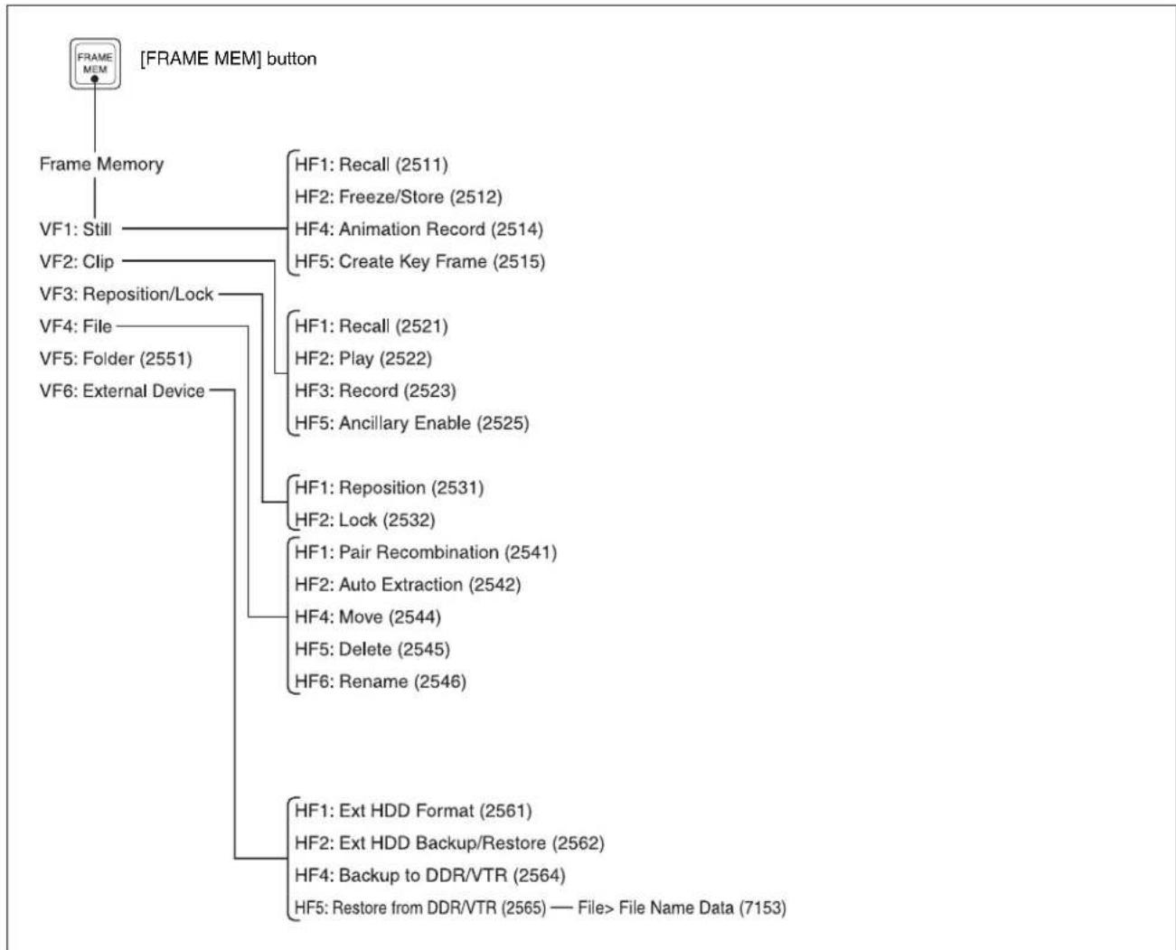
flowchart
graph TD
    A["FRAME MEM"] --> B["Frame Memory"]
    B --> C["VF1: Still"]
    B --> D["VF2: Clip"]
    B --> E["VF3: Reposition/Lock"]
    B --> F["VF4: File"]
    B --> G["VF5: Folder (2551)"]
    B --> H["VF6: External Device"]
    C --> I["HF1: Recall (2511)"]
    C --> J["HF2: Freeze/Store (2512)"]
    C --> K["HF4: Animation Record (2514)"]
    C --> L["HF5: Create Key Frame (2515)"]
    D --> M["HF1: Recall (2521)"]
    D --> N["HF2: Play (2522)"]
    D --> O["HF3: Record (2523)"]
    D --> P["HF5: Ancillary Enable (2525)"]
    E --> Q["HF1: Reposition (2531)"]
    E --> R["HF2: Lock (2532)"]
    F --> S["HF1: Pair Recombination (2541)"]
    F --> T["HF2: Auto Extraction (2542)"]
    F --> U["HF4: Move (2544)"]
    F --> V["HF5: Delete (2545)"]
    F --> W["HF6: Rename (2546)"]
    H --> X["HF1: Ext HDD Format (2561)"]
    H --> Y["HF2: Ext HDD Backup/Restore (2562)"]
    H --> Z["HF4: Backup to DDR/VTR (2564)"]
    H --> AA["HF5: Restore from DDR/VTR (2565) — File> File Name Data (7153)"]
Color Bkgd Menu
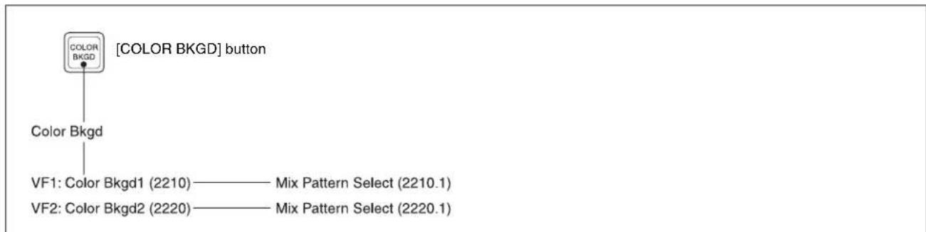
flowchart
graph TD
    A["COLOR Bkgd"] --> B["Color Bkgd"]
    B --> C["VF1: Color Bkgd1 (2210) —— Mix Pattern Select (2210.1)"]
    B --> D["VF2: Color Bkgd2 (2220) —— Mix Pattern Select (2220.1)"]

AUX Menu
![[AUX] button Aux VF1: Aux Bus (2311)](/content/2026/06/1364863/images/409b3d04698cb75be66e30de8a8d4fe5e5843667b3133bd9362d1397651ed595.jpg)
CCR Menu
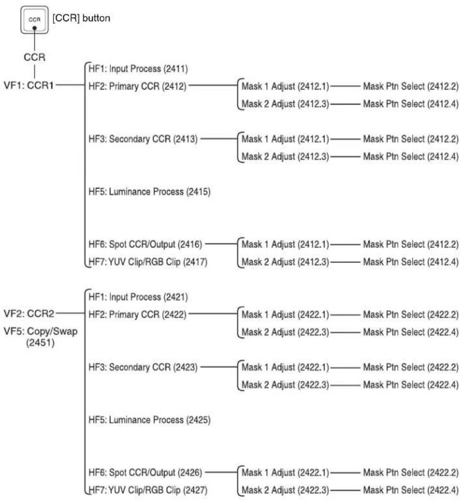
flowchart
graph TD
    A["CCR"] --> B["CCR1"]
    B --> C["VF1: CCR1"]
    C --> D["HF1: Input Process (2411)"]
    C --> E["HF2: Primary CCR (2412)"]
    E --> F["Mask 1 Adjust (2412.1) — Mask Ptn Select (2412.2)"]
    E --> G["Mask 2 Adjust (2412.3) — Mask Ptn Select (2412.4)"]
    C --> H["HF3: Secondary CCR (2413)"]
    H --> I["Mask 1 Adjust (2412.1) — Mask Ptn Select (2412.2)"]
    H --> J["Mask 2 Adjust (2412.3) — Mask Ptn Select (2412.4)"]
    C --> K["HF5: Luminance Process (2415)"]
    K --> L["HF6: Spot CCR/Output (2416) — Mask 1 Adjust (2412.1) — Mask Ptn Select (2412.2)"]
    K --> M["HF7: YUV Clip/RGB Clip (2417) — Mask 2 Adjust (2412.3) — Mask Ptn Select (2412.4)"]
    N["VF2: CCR2"] --> O["VF5: Copy/Swap (2451)"]
    O --> P["HF1: Input Process (2421)"]
    O --> Q["HF2: Primary CCR (2422)"]
    Q --> R["Mask 1 Adjust (2422.1) — Mask Ptn Select (2422.2)"]
    Q --> S["Mask 2 Adjust (2422.3) — Mask Ptn Select (2422.4)"]
    O --> T["HF3: Secondary CCR (2423)"]
    T --> U["Mask 1 Adjust (2422.1) — Mask Ptn Select (2422.2)"]
    T --> V["Mask 2 Adjust (2422.3) — Mask Ptn Select (2422.4)"]
    O --> W["HF5: Luminance Process (2425)"]
    W --> X["HF6: Spot CCR/Output (2426) — Mask 1 Adjust (2422.1) — Mask Ptn Select (2422.2)"]
    W --> Y["HF7: YUV Clip/RGB Clip (2427) — Mask 2 Adjust (2422.3) — Mask Ptn Select (2422.4)"]
Copy/Swap Menu
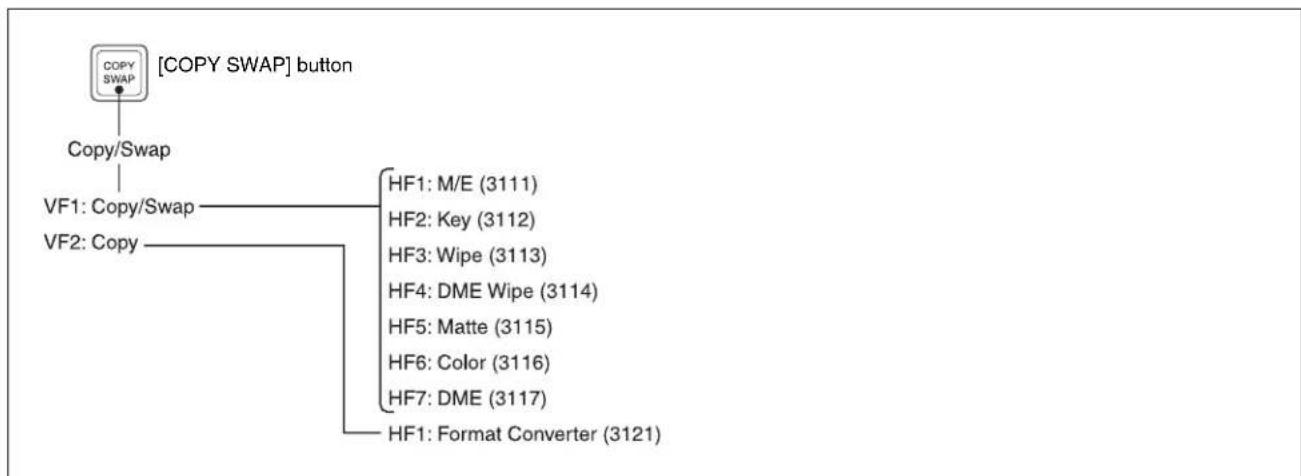
flowchart
graph TD
    A["COPY SWAP"] --> B["Copy/Swap"]
    B --> C["VF1: Copy/Swap"]
    B --> D["VF2: Copy"]
    C --> E["HF1: M/E (3111)"]
    C --> F["HF2: Key (3112)"]
    C --> G["HF3: Wipe (3113)"]
    C --> H["HF4: DME Wipe (3114)"]
    C --> I["HF5: Matte (3115)"]
    C --> J["HF6: Color (3116)"]
    C --> K["HF7: DME (3117)"]
    C --> L["HF1: Format Converter (3121)"]
Misc Menu
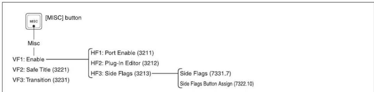
flowchart
graph TD
    A["MISC"] --> B["Misc"]
    B --> C["VF1: Enable"]
    C --> D["HF1: Port Enable (3211)"]
    C --> E["HF2: Plug-In Editor (3212)"]
    C --> F["HF3: Side Flags (3213)"]
    F --> G["Side Flags (7331.7)"]
    F --> H["Side Flags Button Assign (7322.10)"]
    A --> I["VMF"]
Status Menu
![STATS [STATS] button Status VF1: DME Status (3311)](/content/2026/06/1364863/images/a689acf6eaa9ea1c54a3d8531da646be97d40d3adcf8145fc0df5061df6b97f4.jpg)
DME Menu

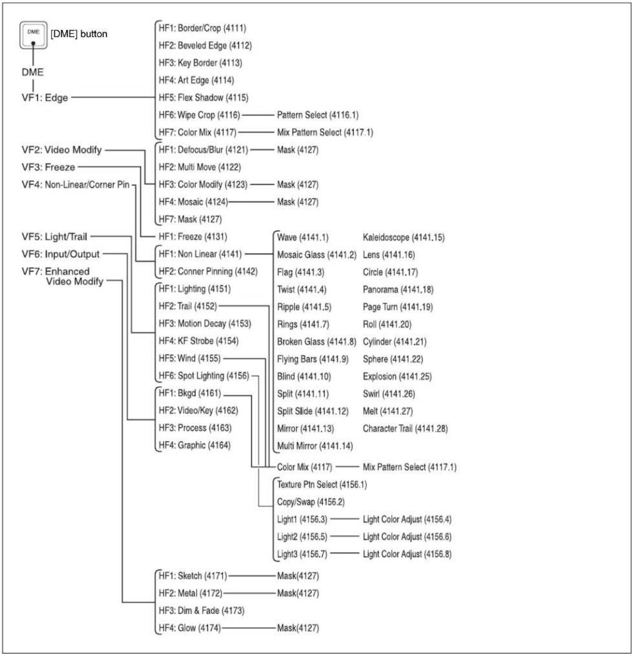
flowchart
graph TD
    A["[DME"] button] --> B["DFM"]
    B --> C["DFM: Edge"]
    C --> D["VF1: Edge"]
    D --> E["VF2: Video Modify"]
    E --> F["VF3: Freeze"]
    F --> G["VF4: Non-Linear/Corner Pin"]
    G --> H["VF5: Light/Trail"]
    H --> I["VF6: Input/Output"]
    I --> J["VF7: Enhanced Video Modify"]

    B --> K["HF1: Border/Crop (4111)"]
    B --> L["HF2: Beveled Edge (4112)"]
    B --> M["HF3: Key Border (4113)"]
    B --> N["HF4: Art Edge (4114)"]
    B --> O["HF5: Flex Shadow (4115)"]
    B --> P["HF6: Wipe Crop (4116) — Pattern Select (4116.1)"]
    B --> Q["HF7: Color Mix (4117) — Mix Pattern Select (4117.1)"]

    E --> R["HF1: Defocus/Blur (4121) — Mask (4127)"]
    E --> S["HF2: Multi Move (4122)"]
    E --> T["HF3: Color Modify (4123) — Mask (4127)"]
    E --> U["HF4: Mosaic (4124) — Mask (4127)"]
    E --> V["HF7: Mask (4127)"]

    G --> W["HF1: Freeze (4131)"]
    G --> X["HF1: Non Linear (4141) —"]
    G --> Y["HF2: Conner Pinning (4142)"]

    W --> Z["Wave (4141.1) — Kaleidoscope (4141.15)"]
    W --> AA["Mosaic Glass (4141.2) — Lens (4141.16)"]
    W --> AB["Flag (4141.3) — Circle (4141.17)"]

    X --> AC["Twist (4141.4) — Panorama (4141.18)"]
    X --> AD["Ripple (4141.5) — Page Turn (4141.19)"]

    Y --> AE["Rings (4141.7) — Roll (4141.20)"]

    W --> AF["Broken Glass (4141.8) — Cylinder (4141.21)"]
    W --> AG["Flying Bars (4141.9) — Sphere (4141.22)"]

    X --> AH["Blind (4141.10) — Explosion (4141.25)"]

    W --> AI["Split (4141.11) — Swirl (4141.26)"]

    W --> AJ["Split Slide (4141.12) — Melt (4141.27)"]

    W --> AK["Mirror (4141.13) — Character Trail (4141.28)"]

    W --> AL["Multi Mirror (4141.14)"]

    W --> AM["Color Mix (4117) — Mix Pattern Select (4117.1)"]

    W --> AN["Texture Ptn Select (4156.1)"]

    W --> AO["Copy/Swap (4156.2)"]

    W --> AP["Light1 (4156.3) — Light Color Adjust (4156.4)"]

    W --> AQ["Light2 (4156.5) — Light Color Adjust (4156.6)"]

    W --> AR["Light3 (4156.7) — Light Color Adjust (4156.8)"]

    W --> AS["HF1: Sketch (4171) — Mask(4127)"]

    W --> AT["HF2: Metal (4172) — Mask(4127)"]

    W --> AU["HF3: Dim & Fade (4173)"]

    W --> AV["HF4: Glow (4174) — Mask(4127)"]
Global Effect Menu
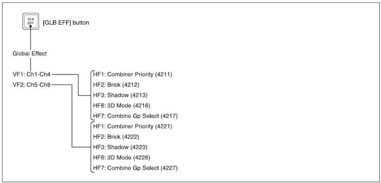
flowchart
graph TD
    A["GLB EFF"] --> B["Global Effect"]
    B --> C["VF1: Ch1-Ch4"]
    B --> D["VF2: Ch5-Ch8"]
    C --> E["HF1: Combiner Priority (4211)"]
    C --> F["HF2: Brick (4212)"]
    C --> G["HF3: Shadow (4213)"]
    C --> H["HF6: 3D Mode (4216)"]
    C --> I["HF7: Combine Gp Select (4217)"]
    D --> J["HF1: Combiner Priority (4221)"]
    D --> K["HF2: Brick (4222)"]
    D --> L["HF3: Shadow (4223)"]
    D --> M["HF6: 3D Mode (4226)"]
    D --> N["HF7: Combine Gp Select (4227)"]
Device Menu
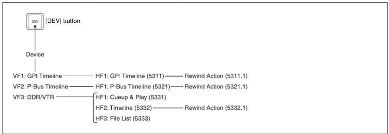
flowchart
graph TD
    A["DEV [DEV"] button] --> B["Device"]
    B --> C["VF1: GPI Timeline —— HF1: GPI Timeline (5311) —— Rewind Action (5311.1)"]
    B --> D["VF2: P-Bus Timeline —— HF1: P-Bus Timeline (5321) —— Rewind Action (5321.1)"]
    B --> E["VF3: DDR/VTR —— HF1: Cueup & Play (5331)"]
    E --> F["HF2: Timeline (5332) —— Rewind Action (5332.1)"]
    E --> G["HF3: File List (5333)"]

Macro Menu

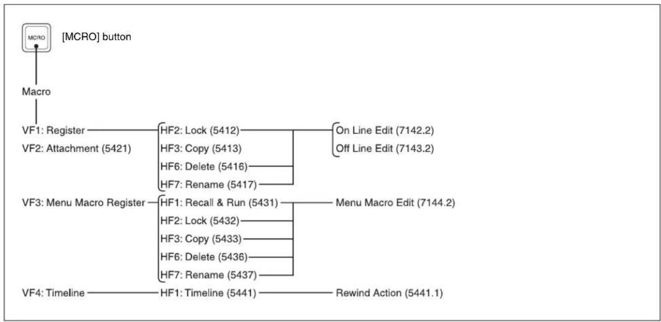
flowchart
graph TD
    A["MCRO"] --> B["Macro"]
    B --> C["VF1: Register"]
    B --> D["VF2: Attachment (5421)"]
    C --> E["HF2: Lock (5412)"]
    C --> F["HF3: Copy (5413)"]
    C --> G["HF6: Delete (5416)"]
    C --> H["HF7: Rename (5417)"]
    D --> I["On Line Edit (7142.2)"]
    D --> J["Off Line Edit (7143.2)"]
    K["VF3: Menu Macro Register"] --> L["HF1: Recall & Run (5431)"]
    K --> M["HF2: Lock (5432)"]
    K --> N["HF3: Copy (5433)"]
    K --> O["HF6: Delete (5436)"]
    K --> P["HF7: Rename (5437)"]
    L --> Q["Menu Macro Edit (7144.2)"]
    M --> Q
    N --> Q
    O --> Q
    P --> Q
    R["VF4: Timeline"] --> S["HF1: Timeline (5441)"]
    R --> T["Rewind Action (5441.1)"]
Key Frame Menu
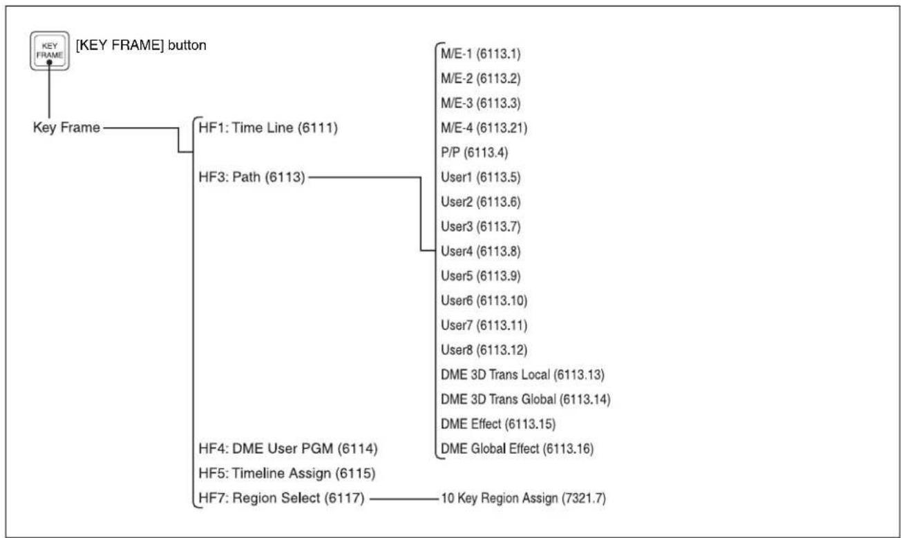
flowchart
graph TD
    A["KEY FRAME"] --> B["Key Frame"]
    B --> C["HF1: Time Line (6111)"]
    B --> D["HF3: Path (6113)"]
    D --> E["HF4: DME User PGM (6114)"]
    D --> F["HF5: Timeline Assign (6115)"]
    D --> G["HF7: Region Select (6117)"]
    E --> H["M/E-1 (6113.1)"]
    E --> I["M/E-2 (6113.2)"]
    E --> J["M/E-3 (6113.3)"]
    E --> K["M/E-4 (6113.21)"]
    E --> L["P/P (6113.4)"]
    E --> M["User1 (6113.5)"]
    E --> N["User2 (6113.6)"]
    E --> O["User3 (6113.7)"]
    E --> P["User4 (6113.8)"]
    E --> Q["User5 (6113.9)"]
    E --> R["User6 (6113.10)"]
    E --> S["User7 (6113.11)"]
    E --> T["User8 (6113.12)"]
    E --> U["DME 3D Trans Local (6113.13)"]
    E --> V["DME 3D Trans Global (6113.14)"]
    E --> W["DME Effect (6113.15)"]
    E --> X["DME Global Effect (6113.16)"]
Effect Menu
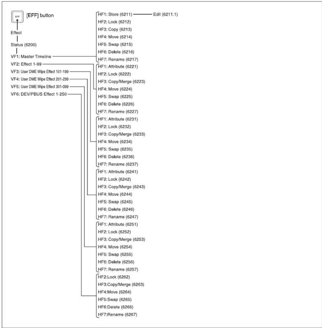
flowchart
graph TD
    A["Effect"] --> B["Status (6200)"]
    B --> C["VF1: Master Timeline"]
    C --> D["VF2: Effect 1-99"]
    C --> E["VF3: User DME Wipe Effect 101-199"]
    C --> F["VF4: User DME Wipe Effect 201-299"]
    C --> G["VF5: User DME Wipe Effect 301-399"]
    C --> H["VF6: DEV/PBUS Effect 1-250"]
    D --> I["HF1: Store (6211) —— Edit (6211.1)"]
    D --> J["HF2: Lock (6212)"]
    D --> K["HF3: Copy (6213)"]
    D --> L["HF4: Move (6214)"]
    D --> M["HF5: Swap (6215)"]
    D --> N["HF6: Delete (6216)"]
    D --> O["HF7: Rename (6217)"]
    E --> P["HF1: Attribute (6221)"]
    E --> Q["HF2: Lock (6222)"]
    E --> R["HF3: Copy/Merge (6223)"]
    E --> S["HF4: Move (6224)"]
    E --> T["HF5: Swap (6225)"]
    E --> U["HF6: Delete (6226)"]
    E --> V["HF7: Rename (6227)"]
    P --> W["HF1: Attribute (6231)"]
    P --> X["HF2: Lock (6232)"]
    P --> Y["HF3: Copy/Merge (6233)"]
    P --> Z["HF4: Move (6234)"]
    P --> AA["HF5: Swap (6235)"]
    P --> AB["HF6: Delete (6236)"]
    P --> AC["HF7: Rename (6237)"]
    W --> AD["HF1: Attribute (6241)"]
    W --> AE["HF2: Lock (6242)"]
    W --> AF["HF3: Copy/Merge (6243)"]
    W --> AG["HF4: Move (6244)"]
    W --> AH["HF5: Swap (6245)"]
    W --> AI["HF6: Delete (6246)"]
    W --> AJ["HF7: Rename (6247)"]
    A --> AK["HF1: Store (6211) —— Edit (6211.1)"]
    AK --> AL["HF2: Lock (6212)"]
    AK --> AM["HF3: Copy (6213)"]
    AK --> AN["HF4: Move (6214)"]
    AK --> AO["HF5: Swap (6215)"]
    AK --> AP["HF6: Delete (6216)"]
    AK --> AQ["HF7: Rename (6217)"]
    AQ --> AR["HF1: Attribute (6251)"]
    AQ --> AS["HF2: Lock (6252)"]
    AQ --> AT["HF3: Copy/Merge (6253)"]
    AQ --> AU["HF4: Move (6254)"]
    AQ --> AV["HF5: Swap (6255)"]
    AQ --> AW["HF6: Delete (6256)"]
    AQ --> AX["HF7: Rename (6257)"]
    AX --> AY["HF2:Lock (6262)"]
    AX --> AZ["HF3:Copy/Merge (6263)"]
    AX --> BA["HF4:Move (6264)"]
    AX --> BB["HF5:Swap (6265)"]
    AX --> BC["HF6:Delete (6266)"]
    AX --> BD["HF7:Rename (6267)"]

Snapshot Menu

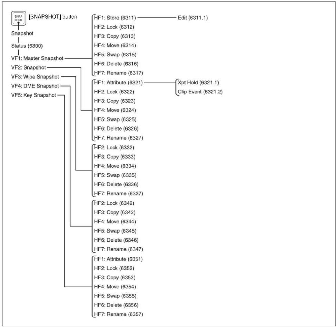
flowchart
graph TD
    A["SNAPSHOT"] --> B["Snapshot"]
    B --> C["Status (6300)"]
    C --> D["VF1: Master Snapshot"]
    D --> E["VF2: Snapshot"]
    D --> F["VF3: Wipe Snapshot"]
    F --> G["VF4: DME Snapshot"]
    G --> H["VF5: Key Snapshot"]

    I["HF1: Store (6311)"] --> J["Edit (6311.1)"]
    I --> K["HF2: Lock (6312)"]
    I --> L["HF3: Copy (6313)"]
    I --> M["HF4: Move (6314)"]
    I --> N["HF5: Swap (6315)"]
    I --> O["HF6: Delete (6316)"]
    I --> P["HF7: Rename (6317)"]

    Q["HF1: Attribute (6321)"] --> R["Xpt Hold (6321.1)"]
    Q --> S["Clip Event (6321.2)"]

    T["HF2: Lock (6332)"] --> U["HF3: Copy (6333)"]
    T --> V["HF4: Move (6334)"]
    T --> W["HF5: Swap (6335)"]
    T --> X["HF6: Delete (6336)"]
    T --> Y["HF7: Rename (6337)"]

    Z["HF2: Lock (6342)"] --> AA["HF3: Copy (6343)"]
    Z --> AB["HF4: Move (6344)"]
    Z --> AC["HF5: Swap (6345)"]
    Z --> AD["HF6: Delete (6346)"]
    Z --> AE["HF7: Rename (6347)"]

    AF["HF1: Attribute (6351)"] --> AG["HF2: Lock (6352)"]
    AF --> AH["HF3: Copy (6353)"]
    AF --> AI["HF4: Move (6354)"]
    AF --> AJ["HF5: Swap (6355)"]
    AF --> AK["HF6: Delete (6356)"]
    AF --> AL["HF7: Rename (6357)"]
Shotbox Menu
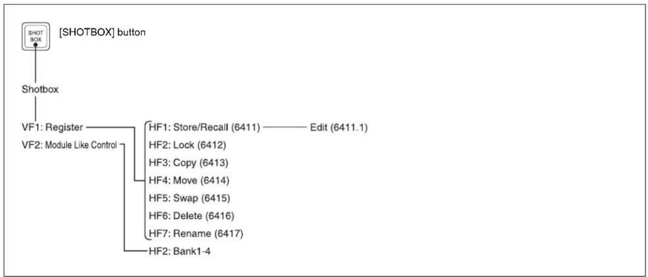
flowchart
graph TD
    A["SHOTBOX"] --> B["Shotbox"]
    B --> C["VF1: Register"]
    B --> D["VF2: Module Like Control"]
    C --> E["HF1: Store/Recall (6411) —— Edit (6411.1)"]
    C --> F["HF2: Lock (6412)"]
    C --> G["HF3: Copy (6413)"]
    C --> H["HF4: Move (6414)"]
    C --> I["HF5: Swap (6415)"]
    C --> J["HF6: Delete (6416)"]
    C --> K["HF7: Rename (6417)"]
    C --> L["HF2: Bank1-4"]
File Menu

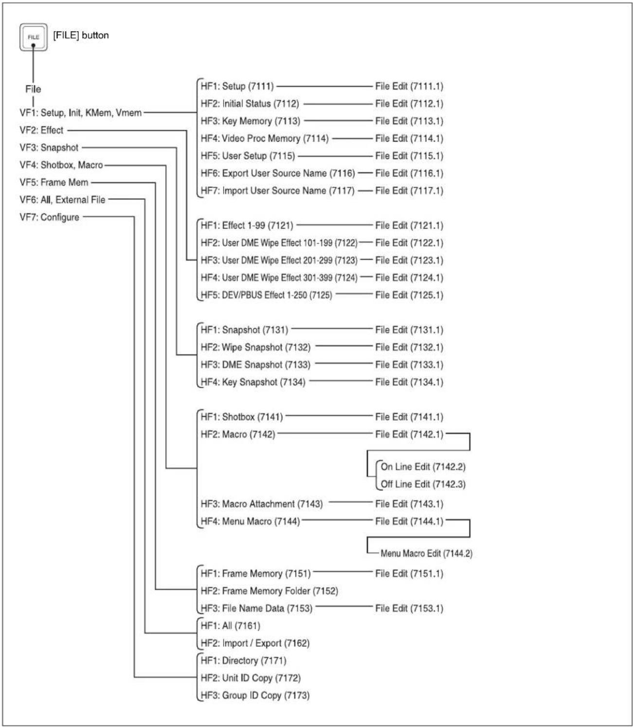
flowchart
graph TD
    A["FILE"] --> B["File"]
    B --> C["VF1: Setup, Init, KMem, Vmem"]
    B --> D["VF2: Effect"]
    B --> E["VF3: Snapshot"]
    B --> F["VF4: Shotbox, Macro"]
    B --> G["VF5: Frame Mem"]
    B --> H["VF6: All, External File"]
    B --> I["VF7: Configure"]

    C --> J["HF1: Setup (7111) — File Edit (7111.1)"]
    C --> K["HF2: Initial Status (7112) — File Edit (7112.1)"]
    C --> L["HF3: Key Memory (7113) — File Edit (7113.1)"]
    C --> M["HF4: Video Proc Memory (7114) — File Edit (7114.1)"]
    C --> N["HF5: User Setup (7115) — File Edit (7115.1)"]
    C --> O["HF6: Export User Source Name (7116) — File Edit (7116.1)"]
    C --> P["HF7: Import User Source Name (7117) — File Edit (7117.1)"]

    D --> Q["HF1: Effect 1-99 (7121) — File Edit (7121.1)"]
    D --> R["HF2: User DME Wipe Effect 101-199 (7122) — File Edit (7122.1)"]
    D --> S["HF3: User DME Wipe Effect 201-299 (7123) — File Edit (7123.1)"]
    D --> T["HF4: User DME Wipe Effect 301-399 (7124) — File Edit (7124.1)"]
    D --> U["HF5: DEV/PBUS Effect 1-250 (7125) — File Edit (7125.1)"]

    E --> V["HF1: Snapshot (7131) — File Edit (7131.1)"]
    E --> W["HF2: Wipe Snapshot (7132) — File Edit (7132.1)"]
    E --> X["HF3: DME Snapshot (7133) — File Edit (7133.1)"]
    E --> Y["HF4: Key Snapshot (7134) — File Edit (7134.1)"]

    V --> Z["HF1: Shotbox (7141) — File Edit (7141.1)"]
    V --> AA["HF2: Macro (7142) — File Edit (7142.1)"]

    Z --> AB["On Line Edit (7142.2)"]
    Z --> AC["Off Line Edit (7142.3)"]

    AA --> AD["Macro Attachment (7143) — File Edit (7143.1)"]
    AA --> AE["Menu Macro Edit (7144.2)"]

    AB --> AF["Frame Memory (7151) — File Edit (7151.1)"]
    AB --> AG["Frame Memory Folder (7152)"]
    AB --> AH["File Name Data (7153) — File Edit (7153.1)"]

    AC --> AI["All (7161)"]
    AC --> AJ["Import / Export (7162)"]

    AD --> AK["Directory (7171)"]
    AD --> AL["Unit ID Copy (7172)"]
    AD --> AM["Group ID Copy (7173)"]
Engineering Setup Menu
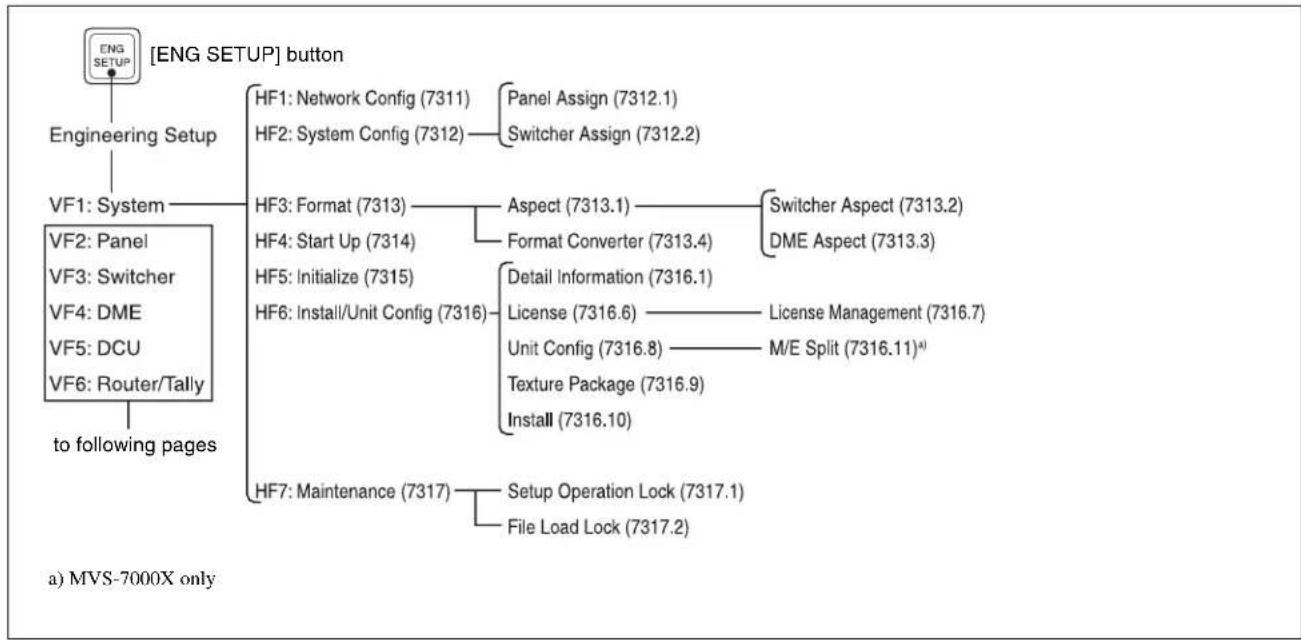
flowchart
graph TD
    A["[ENG SETUP"] button] --> B["Engineering Setup"]
    B --> C["VF1: System"]
    C --> D["HF1: Network Config (7311)"]
    C --> E["HF2: System Config (7312)"]
    C --> F["HF3: Format (7313)"]
    C --> G["HF4: Start Up (7314)"]
    C --> H["HF5: Initialize (7315)"]
    C --> I["HF6: Install/Unit Config (7316)"]
    C --> J["HF7: Maintenance (7317)"]
    D --> K["Panel Assign (7312.1)"]
    D --> L["Switcher Assign (7312.2)"]
    E --> M["Aspect (7313.1)"]
    E --> N["Format Converter (7313.4)"]
    M --> O["Switcher Aspect (7313.2)"]
    M --> P["DME Aspect (7313.3)"]
    N --> Q["Detail Information (7316.1)"]
    N --> R["License (7316.6) —— License Management (7316.7)"]
    N --> S["Unit Config (7316.8) —— M/E Split (7316.11)\( ^{a)} \)"]
    N --> T["Texture Package (7316.9)"]
    N --> U["Install (7316.10)"]
    I --> V["Setup Operation Lock (7317.1)"]
    I --> W["File Load Lock (7317.2)"]

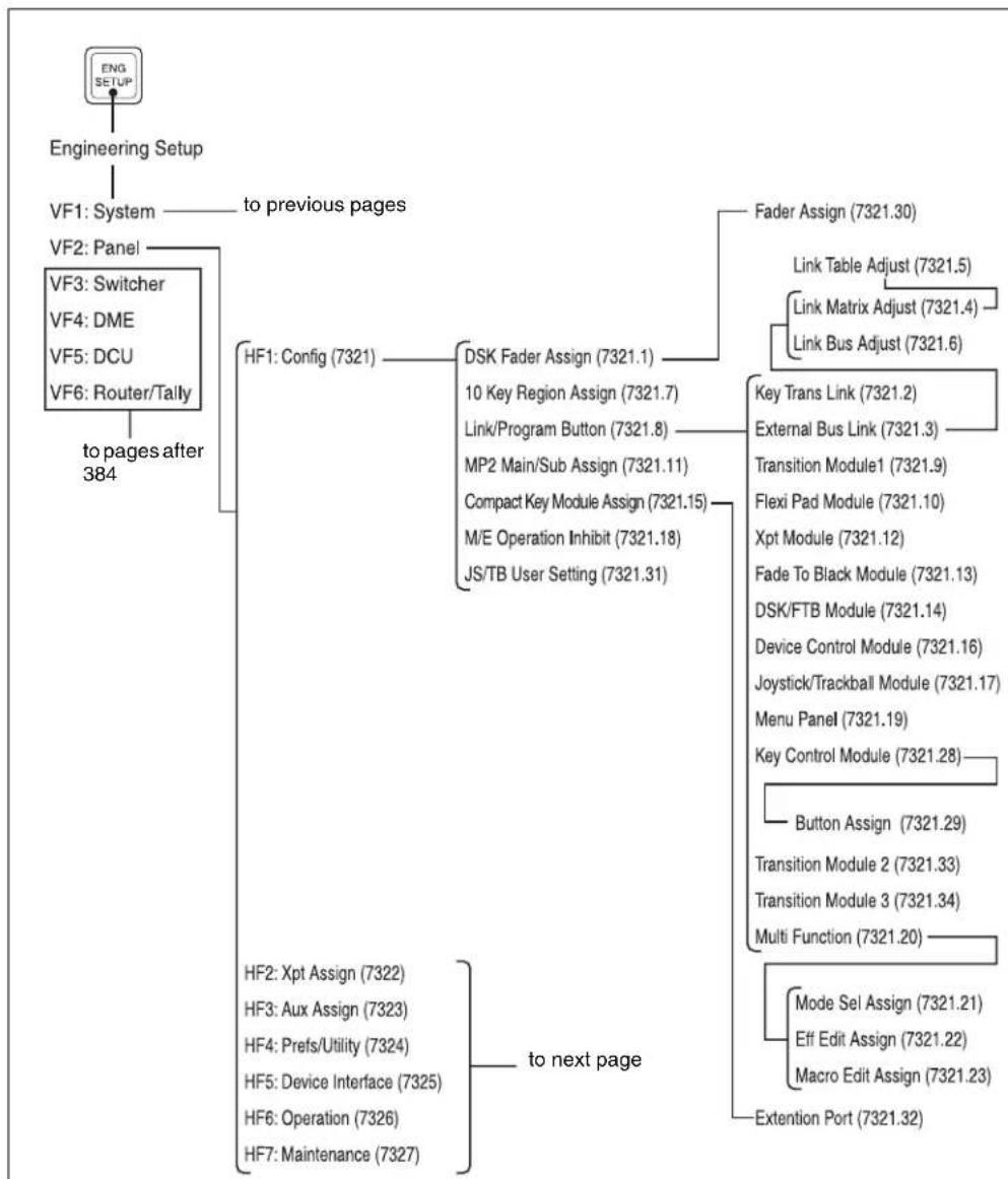
flowchart
graph TD
    A["ENGINEERING SETUP"] --> B["VF1: System"]
    B --> C["to previous pages"]
    B --> D["VF2: Panel"]
    D --> E["VF3: Switcher"]
    D --> F["VF4: DME"]
    D --> G["VF5: DCU"]
    D --> H["VF6: Router/Tally"]
    H --> I["to pages after 384"]
    I --> J["HF1: Config (7321)"]
    J --> K["DSK Fader Assign (7321.1)"]
    K --> L["10 Key Region Assign (7321.7)"]
    K --> M["Link/Program Button (7321.8)"]
    K --> N["MP2 Main/Sub Assign (7321.11)"]
    K --> O["Compact Key Module Assign (7321.15)"]
    K --> P["M/E Operation Inhibit (7321.18)"]
    K --> Q["JS/TB User Setting (7321.31)"]
    J --> R["Key Trans Link (7321.2)"]
    R --> S["External Bus Link (7321.3)"]
    R --> T["Transition Module1 (7321.9)"]
    R --> U["Flexi Pad Module (7321.10)"]
    R --> V["Xpt Module (7321.12)"]
    R --> W["Fade To Black Module (7321.13)"]
    R --> X["DSK/FTB Module (7321.14)"]
    R --> Y["Device Control Module (7321.16)"]
    R --> Z["Joystick/Trackball Module (7321.17)"]
    R --> AA["Menu Panel (7321.19)"]
    R --> AB["Key Control Module (7321.28)"]
    R --> AC["Button Assign (7321.29)"]
    R --> AD["Transition Module 2 (7321.33)"]
    R --> AE["Transition Module 3 (7321.34)"]
    R --> AF["Multi Function (7321.20)"]
    J --> AG["HF2: Xpt Assign (7322)"]
    J --> AH["HF3: Aux Assign (7323)"]
    J --> AI["HF4: Prefs/Utility (7324)"]
    J --> AJ["HF5: Device Interface (7325)"]
    J --> AK["HF6: Operation (7326)"]
    J --> AL["HF7: Maintenance (7327)"]
    AG --> AM["to next page"]
    AH --> AM
    AI --> AM
    AJ --> AM
    AK --> AM
    AL --> AM
    AM --> AN["Extention Port (7321.32)"]
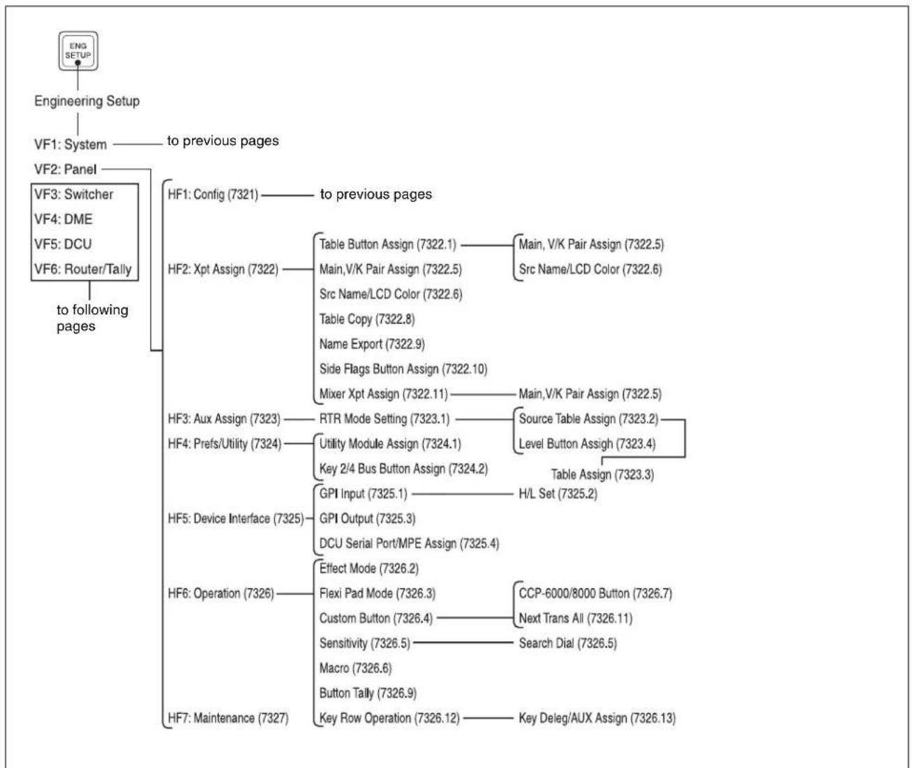
flowchart
graph TD
    A["ENGINEERING SETUP"] --> B["VF1: System"]
    B --> C["to previous pages"]
    B --> D["VF2: Panel"]
    D --> E["VF3: Switcher"]
    D --> F["VF4: DME"]
    D --> G["VF5: DCU"]
    D --> H["VF6: Router/Tally"]
    H --> I["to following pages"]
    I --> J["HF1: Config (7321)"]
    J --> K["to previous pages"]
    J --> L["HF2: Xpt Assign (7322)"]
    L --> M["Table Button Assign (7322.1)"]
    L --> N["Main, V/K Pair Assign (7322.5)"]
    L --> O["Src Name/LCD Color (7322.6)"]
    L --> P["Table Copy (7322.8)"]
    L --> Q["Name Export (7322.9)"]
    L --> R["Side Flags Button Assign (7322.10)"]
    L --> S["Mixer Xpt Assign (7322.11)"]
    S --> T["Main, V/K Pair Assign (7322.5)"]
    J --> U["HF3: Aux Assign (7323)"]
    U --> V["RTR Mode Setting (7323.1)"]
    V --> W["Source Table Assign (7323.2)"]
    V --> X["Utility Module Assign (7324.1)"]
    X --> Y["Level Button Assign (7323.4)"]
    X --> Z["Key 2/4 Bus Button Assign (7324.2)"]
    Z --> AA["Table Assign (7323.3)"]
    J --> AB["HF4: Prefs/Utility (7324)"]
    AB --> AC["Utility Module Assign (7324.1)"]
    AC --> AD["Key Output (7325.3)"]
    AD --> AE["DCU Serial Port/MPE Assign (7325.4)"]
    J --> AF["HF5: Device Interface (7325)"]
    AF --> AG["GPI Input (7325.1)"]
    AG --> AH["H/L Set (7325.2)"]
    AF --> AI["HF6: Operation (7326)"]
    AI --> AJ["Effect Mode (7326.2)"]
    AI --> AK["Flexi Pad Mode (7326.3)"]
    AK --> AL["CCP-6000/8000 Button (7326.7)"]
    AK --> AM["Next Trans All (7326.11)"]
    AI --> AN["Custom Button (7326.4)"]
    AN --> AO["Sensitivity (7326.5)"]
    AO --> AP["Search Dial (7326.5)"]
    AI --> AQ["Macro (7326.6)"]
    AQ --> AR["Button Tally (7326.9)"]
    AI --> AS["HF7: Maintenance (7327)"]
    AS --> AT["Key Row Operation (7326.12)"]
    AS --> AU["Key Deleg/AUX Assign (7326.13)"]


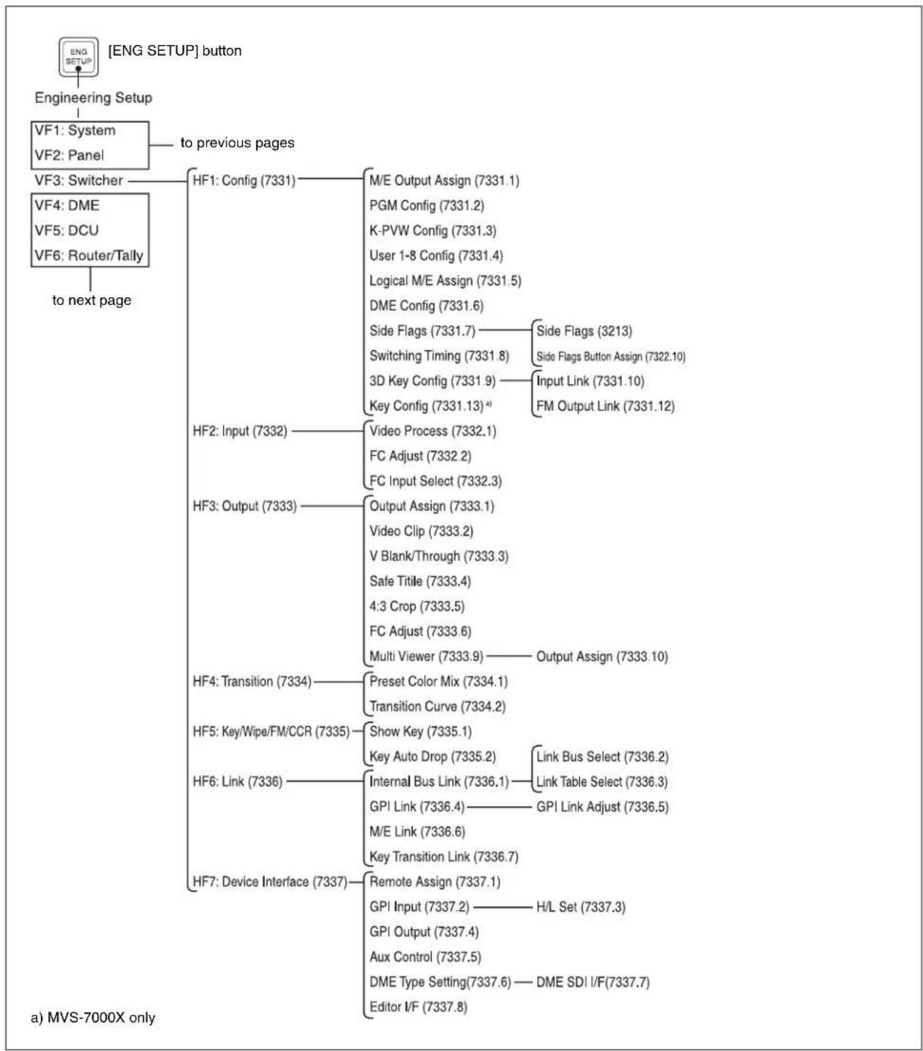
flowchart
graph TD
    A["ENG SETUP"] --> B["Engineering Setup"]
    B --> C["VF1: System"]
    C --> D["to previous pages"]
    C --> E["VF2: Panel"]
    E --> F["VF3: Switcher"]
    F --> G["HF1: Config (7331)"]
    G --> H["M/E Output Assign (7331.1)"]
    G --> I["PGM Config (7331.2)"]
    G --> J["K-PVW Config (7331.3)"]
    G --> K["User 1-8 Config (7331.4)"]
    G --> L["Logical M/E Assign (7331.5)"]
    G --> M["DME Config (7331.6)"]
    M --> N["Side Flags (7331.7) — Side Flags (3213)"]
    M --> O["Switching Timing (7331.8) — Side Flags Button Assign (7322.10)"]
    M --> P["3D Key Config (7331.9) — Input Link (7331.10)"]
    M --> Q["Key Config (7331.13) a) — FM Output Link (7331.12)"]
    F --> R["HF4: DME"]
    F --> S["VF5: DCU"]
    F --> T["VF6: Router/Tally"]
    T --> U["to next page"]
    U --> V["HF2: Input (7332) — Video Process (7332.1)"]
    U --> W["FC Adjust (7332.2)"]
    U --> X["FC Input Select (7332.3)"]
    V --> Y["HF3: Output (7333) — Output Assign (7333.1)"]
    V --> Z["Video Clip (7333.2)"]
    V --> AA["V Blank/Through (7333.3)"]
    V --> AB["Safe Title (7333.4)"]
    V --> AC["4:3 Crop (7333.5)"]
    V --> AD["FC Adjust (7333.6)"]
    V --> AE["Multi Viewer (7333.9) — Output Assign (7333.10)"]
    V --> AF["HF4: Transition (7334) — Preset Color Mix (7334.1)"]
    V --> AG["Transition Curve (7334.2)"]
    V --> AH["HF5: Key/Wipe/FM/CCR (7335) — Show Key (7335.1)"]
    V --> AI["HF6: Link (7336) — Key Auto Drop (7335.2) — Link Bus Select (7336.2)"]
    V --> AJ["Internal Bus Link (7336.1) — Link Table Select (7336.3)"]
    V --> AK["GPI Link (7336.4) — GPI Link Adjust (7336.5)"]
    V --> AL["M/E Link (7336.6)"]
    V --> AM["Key Transition Link (7336.7)"]
    V --> AN["HF7: Device Interface (7337) — Remote Assign (7337.1)"]
    AN --> AO["GPI Input (7337.2) — H/L Set (7337.3)"]
    AN --> AP["GPI Output (7337.4)"]
    AN --> AQ["Aux Control (7337.5)"]
    AN --> AR["DME Type Setting(7337.6) — DME SDI I/F(7337.7)"]
    AN --> AS["Editor I/F (7337.8)"]
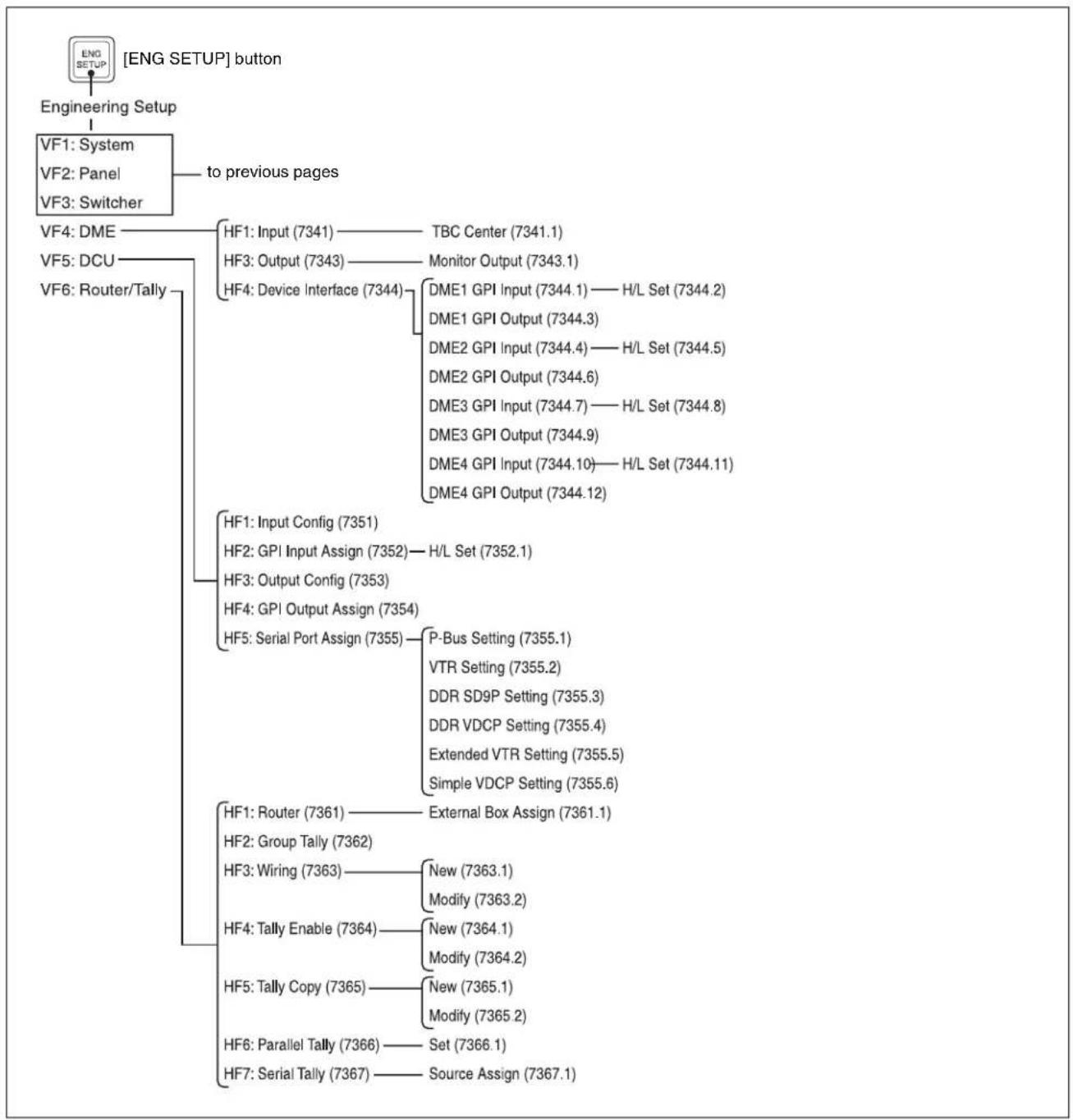
flowchart
graph TD
    A["ENGINEING SETUP"] --> B["VF1: System"]
    B --> C["to previous pages"]
    C --> D["VF4: DME"]
    C --> E["VF5: DCU"]
    C --> F["VF6: Router/Tally"]
    D --> G["HF1: Input (7341)"]
    D --> H["HF3: Output (7343)"]
    D --> I["HF4: Device Interface (7344)"]
    I --> J["DME1 GPI Input (7344.1) — H/L Set (7344.2)"]
    I --> K["DME1 GPI Output (7344.3)"]
    I --> L["DME2 GPI Input (7344.4) — H/L Set (7344.5)"]
    I --> M["DME2 GPI Output (7344.6)"]
    I --> N["DME3 GPI Input (7344.7) — H/L Set (7344.8)"]
    I --> O["DME3 GPI Output (7344.9)"]
    I --> P["DME4 GPI Input (7344.10) — H/L Set (7344.11)"]
    I --> Q["DME4 GPI Output (7344.12)"]
    E --> R["HF1: Input Config (7351)"]
    E --> S["HF2: GPI Input Assign (7352) — H/L Set (7352.1)"]
    E --> T["HF3: Output Config (7353)"]
    E --> U["HF4: GPI Output Assign (7354)"]
    E --> V["HF5: Serial Port Assign (7355) — P-Bus Setting (7355.1)"]
    V --> W["VTR Setting (7355.2)"]
    V --> X["DDR SD9P Setting (7355.3)"]
    V --> Y["DDR VDCP Setting (7355.4)"]
    V --> Z["Extended VTR Setting (7355.5)"]
    V --> AA["Simple VDCP Setting (7355.6)"]
    R --> AB["HF1: Router (7361) — External Box Assign (7361.1)"]
    R --> AC["HF2: Group Tally (7362)"]
    R --> AD["HF3: Wiring (7363) — New (7363.1)"]
    AD --> AE["Modify (7363.2)"]
    R --> AF["HF4: Tally Enable (7364) — New (7364.1)"]
    AF --> AG["Modify (7364.2)"]
    R --> AH["HF5: Tally Copy (7365) — New (7365.1)"]
    AH --> AI["Modify (7365.2)"]
    R --> AJ["HF6: Parallel Tally (7366) — Set (7366.1)"]
    R --> AK["HF7: Serial Tally (7367) — Source Assign (7367.1)"]
User Setup Menu
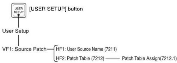
flowchart
graph TD
    A["USER SETUP"] --> B["User Setup"]
    B --> C["VF1: Source Patch"]
    C --> D["HF1: User Source Name (7211)"]
    C --> E["HF2: Patch Table (7212) —— Patch Table Assign(7212.1)"]
Diagnostic Menu
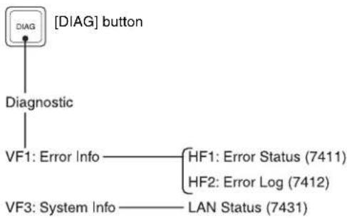
flowchart
graph TD
    A["DIAG"] --> B["Diagnostic"]
    B --> C["VF1: Error Info"]
    C --> D["HF1: Error Status (7411)"]
    C --> E["HF2: Error Log (7412)"]
    B --> F["VF3: System Info"]
    F --> G["LAN Status (7431)"]
Using the M/E-4 Bank
Assigning a Button for M/E-4 Selection in the Setup Menu
- In the factory defaults for this system, M/E-4 is not assigned to buttons on the control panel.
- To select M/E-4, assign buttons in the Setup menu according to the following table.
| Control block | Button | Menu number | Reference in User Guide“Control Panel Setup (Panel)” and “Cross-Point Settings (Xpt Assign Menu)” in Chapter 19 (Volume 2) |
| Cross-point control block | Reentry buttons 7322 | 2.17322.5 | “Creating Cross-Point Assign Tables”Engineering Setup >Panel >Xpt Assign >Table Button Assign menuEngineering Setup >Panel >Xpt Assign >Main,V/K Pair Assign menu |
| Entire switcher bank | - 7321 “Interchanging | the Bank Order or | Disabling Operation”Engineering Setup >Panel >Config menu |
| Key control block Delegation buttons 7321 | 29 “Assigning Functions to Key Control Block Buttons”Engineering Setup >Panel >Config >Link/Program Button >Key Control Module >Button Assign menu | ||
| Device control block | Region selection buttons | 7321.17 “Assigning Functions to the Device Control Block”Engineering Setup >Panel >Config >Link/Program Button >Joystick/Trackball Module menu | |
| Numeric keypad control block | Region selection buttons | 7321.7 | “Assigning a Region to the Region Selection Buttons in the Numeric Keypad Control Block or Multifunction Flexi Pad Control Block”Engineering Setup >Panel >Config >10 Key Region Assign menu |
| Fade to black control block | Preview selection buttons | 7321.13 “Assigning Preview Output to Preview Selection Buttons”Engineering Setup >Panel >Config >Link/Program Button >Fade To Black Module menu | |
| Menu control block | Top menu selection buttons | 7321.19 “Assigning Functions to the Menu Control Block Top Menu and User Preference Buttons”Engineering Setup >Panel >Config >Link/Program Button >Menu Panel menu | |
| Multifunction Flexi Pad control block | Region selection buttons | 7321.7 | “Assigning a Region to the Region Selection Buttons in the Numeric Keypad Control Block or Multifunction Flexi Pad Control Block”Engineering Setup >Panel >Config >10 Key Region Assign menu |

Using Keys 5 to 8
Notes
Keys 5 to 8 cannot be used when the signal format is 1080P.
Assigning Buttons for Selection of Keys 5 to 8 in the Setup Menu
In the factory defaults for this system, keys 5 to 8 are not assigned to buttons on the control panel.
To select keys 5 to 8, assign buttons in the Setup menu according to the following table.
| Control block | Button | Menu number | Reference in User Guide“Control Panel Setup (Panel)” and “Cross-Point Settings (Xpt Assign Menu)” in Chapter 19 (Volume 2) |
| Transition control block | Next transition selection buttons | 7321.9 “Setting Transition Control Block Button Assignments”Engineering Setup >Panel >Config >Link/Program Button >Transition Module1 menu | |
| Cross-point control block | SHIFT button 7322.1 | “Creating Cross-Point Assign Tables” “Setting the action of the [SHIFT] button in the cross-point control block”Engineering Setup >Panel >Xpt Assign >Table Button Assign menu | |
| Key Control Block Delegation button 7321 | 29 “Assigning Functions to Key Control Block Buttons”Engineering Setup >Panel >Config >Link/Program Button >Key Control Module >Button Assign menu | ||
| Transition control block (standard type) | Key delegation buttons | 7321.33 “Setting Transition Control Block Button Assignments”Engineering Setup >Panel >Config >Link/Program Button >Transition Module2 menu | |
| Independent key transition execution section | 7321.34 “Setting Transition Control Block Button Assignments”Engineering Setup >Panel >Config >Link/Program Button >Transition Module3 menu | ||
| Independent key transition control block | Entire block 7321.15 | “Assigning Keys to the Independent Key Transition Control Block (Simple Type)”Engineering Setup >Panel >Config >Compact Key Module Assign menu | |
| Downstream key control block | Key delegation buttons | 7321.1 “Assigning the Key Delegation in the Downstream Key Control Block”Engineering Setup >Panel >Config >DSK Fader Assign menu | |
| Downstream key/fade-to-black control block | Key delegation buttons | 7321.14 “Assigning Keys to the DSK1 and DSK2 Buttons in the Downstream Key/Fade-to-Black Control Block”Engineering Setup >Panel >Config >Link/Program Button >DSK/FTB Module menu | |
| Device control block (joystick) | Operating buttons 7321.31 “Selecting the Module to be the Reference for Device Control Block”Menu Engineering Setup >Panel >Config >JS/TB User Setting menu | ||
| Device control block (trackball) | |||
| Cross-point control block | Key 1 row 7326.13 | “Assigning the key/AUX bus delegation function to the key 1 row”Engineering Setup >Panel >Operation >Key Row Operation >Key Deleg/AUX Assign menu |
Selecting Keys 5 to 8 for Next Transition
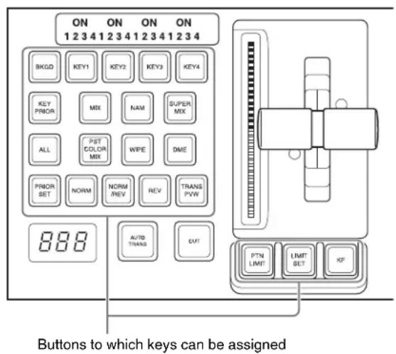
To select keys 5 to 8 for the next transition, in addition to assigning [KEY5] to [KEY8] for the operation, it is also possible to make the selection with [KEY1/5], [KEY2/6], [KEY3/7], [KEY4/8], [SHIFT], and [ADD].
The following describes this method of operation.
First in the Setup menu, assign the following to any buttons:
[KEY1/5], [KEY2/6], [KEY3/7], [KEY4/8], [SHIFT], and [ADD]
By way of example, this is the procedure for [KEY1/5].
To select key 5
Press [SHIFT], turning it on, then press the [KEY1/5] button.
To select keys 1 and 5 simultaneously
1 Press the [KEY1/5] button alone.
This selects key 1.
2 Press [SHIFT], turning it on.
3 Holding down [ADD], press the [KEY1/5] button.
This selects keys 1 and 5 simultaneously.
Selecting Input Signals for Keys 5 to 8 in the Cross-Point Control Block
Buttons used for selection of keys 5 to 8
For the positions of the following buttons in the cross-point control block, see page 30.
| Key Key row Dedicated SHIFT button a) | [KEY3]/[KEY4] button | ||
| 5 | K e row | Lit [KEY3] button off | |
| 6 | K e row | y 2 | [KEY4] button off |
| 7 | K e row | y 1 | [KEY3] button lit |
| 8 | K e row | y 2 | [KEY4] button lit |
a) Button previously assigned in the Setup menu to selection of keys 5 to 8
To select the key 5 fill signal
1 Turn on the dedicated SHIFT button.
2 Turn off the [KEY3] button.
3 Select the signal in the key 1 row.
When a key delegation function is assigned to the key 1 row
1 In the key 1 row, press the button assigned to the desired key 5.
2 In the key 2 row, select the signal.
For details, see “Cross-Point Control Block in Key/AUX Bus Delegation Mode” (page 33).
Menus accessed by pressing a button twice
For relevant buttons other than the top menu selection buttons, pressing twice in rapid succession directly recalls
a related menu page. The following table lists these buttons of each control block, together with the menus they recall. (XX represents the HF menu recalled last in the VF menu.)
Cross-point control block
| Buttons Menus See | ||
| FM1 to 8 signals assigned buttons Frame Memory >$till >Recall page 205 | ||
| Color Bkgd1 signal assigned button Color Bkgd >Color Bkgd1 page 224 | ||
| Color Bkgd2 signal assigned button Color Bkgd >Color Bkgd2 | ||
| CCR1 signal assigned button CCR >CCR1 >XX Chapter 19 | (Volume 2) | |
| CCR2 signal assigned button CCR >CCR2 >XX | ||
| FMS1 Frame Memory >Still >Recall | ||
| FMS2 Frame Memory >Still >Recall | ||
Transition control block (standard type, compact type)
| Buttons Menus See | ||
| KEY1 (DSK1)a) | • M/E-1, 2, 3, 4 >Key1 >XX• PGM/PST >DSK1 >XX | page 122 |
| KEY2 (DSK2)a) | • M/E-1, 2, 3, 4 >Key2 >XX• PGM/PST >DSK2 >XX | |
| KEY3 (DSK3)a) | • M/E-1, 2, 3, 4 >Key3 >XX• PGM/PST >DSK3 >XX | |
| KEY4 (DSK4)a) | • M/E-1, 2, 3, 4 >Key4 >XX• PGM/PST >DSK4 >XX | |
| KEY5 (DSK5)a) | • M/E-1, 2, 3, 4 >Key5 >XX• PGM/PST >DSK5 >XX | |
| KEY6 (DSK6)a) | • M/E-1, 2, 3, 4 >Key6 >XX• PGM/PST >DSK6 >XX | |
| KEY7 (DSK7)a) | • M/E-1, 2, 3, 4 >Key7 >XX• PGM/PST >DSK7 >XX | |
| KEY8 (DSK8)a) | • M/E-1, 2, 3, 4 >Key8 >XX• PGM/PST >DSK8 >XX | |
| WIPE M/E-1, 2, 3, 4, PGM/PST >Wipe >Main Pattern | page 159 | |
| DME | M/E-1, 2, 3, 4, PGM/PST >DME Wipe >XX | page 183 |
| SUPER MIX | M/E-1, 2, 3, 4, PGM/PST >Misc >Transition | page 99 |
| PST COLOR MIX | M/E-1, 2, 3, 4, PGM/PST >Misc >Transition | page 99 |
| FM1&2 CLIP, FM3&4 CLIP, FM5&6 CLIP, FM7&8 CLIP | M/E-1, 2, 3, 4, PGM/PST >Misc >Clip Transition | page 215 |
| PRIOR SET | M/E-1, 2, 3, 4, PGM/PST >Misc >Key Priority | page 96 |
| KEY PRIOR | M/E-1, 2, 3, 4, PGM/PST >Misc >Next Key Priority | page 97 |
| WIPE (Independent key transition type selection button (standard type)) | • M/E-1, 2, 3, 4 >Key1, 2, 3, 4, 5, 6, 7, 8 >Transition >Wipe Adjust >Pattern Select• PGM/PST >DSK1, 2, 3, 4, 5, 6, 7, 8 >Transition >Wipe Adjust >Pattern Select | page 171 |
| DME (Independent key transition type selection button (standard type)) | • M/E-1, 2, 3, 4 >Key1, 2, 3, 4, 5, 6, 7, 8 >Transition >DME Wipe Adjust >1ch Pattern Select• PGM/PST >DSK1, 2, 3, 4, 5, 6, 7, 8 >Transition >DME Wipe Adjust >1ch Pattern Select | page 189 |
Transition control block (standard type, compact type)
| Buttons Menus See | ||
| K-SS STORE Snapshot >Key Snapshot >XX Chapter | 14 | (Volume 2) |
a) Including the key delegation buttons of the transition control block (standard type).
Independent key transition control block (simple type) ^a)
| Buttons Menus See | ||
| WIPE • M/E-1, 2, 3, 4 >Key1, 2, 3, 4, 5, 6, 7, 8 >Transition | Wipe Adjust >Pattern SelectPGM/PST >DSK1, 2, 3, 4, 5, 6, 7, 8 >TransitionWipe Adjust >Pattern Select | page 171 |
| DME • M/E-1, 2, 3, 4 >Key1, 2, 3, 4, 5, 6, 7, 8 >Transition | DME Wipe Adjust >1ch Pattern SelectPGM/PST >DSK1, 2, 3, 4, 5, 6, 7, 8 >TransitionDME Wipe Adjust >1ch Pattern Select | page 189 |
| SHIFT • M/E-1, 2, 3, 4 >Key1, 2, 3, 4, 5, 6, 7, 8 >XX | PGM/PST >DSK1, 2, 3, 4, 5, 6, 7, 8 >XX | page 122 |
a) The menu to be recalled depends on the setup of the key assignment.
Flexi Pad control block (standard type)
| Buttons Menus See | ||
| WIPE M/E-1, 2, 3, 4, PGM/PST >Wipe >Main Pattern | page 159 | |
| DME M/E-1, 2, 3, 4, PGM/PST >DME Wipe >XX page | 183 | |
| SNAPSHOT Snapshot >Snapshot >XX | Chapter 14 | (Volume 2) |
| EFF | Effect >Effect 1-99 >XX | Chapter 13 (Volume 2) |
| SHOTBOX | Shotbox >Register >Store/Recall | Chapter 15 (Volume 2) |
| MCRO | Macro >Register >XX | Chapter 16 (Volume 2) |
Key control block ^a)
| Buttons Menus See | ||
| KEY1 • M/E-1, 2, 3, 4 >Key1 >XX | • PGM/PST >DSK1 >XX | page 122 |
| KEY2 • M/E-1, 2, 3, 4 >Key2 >XX | • PGM/PST >DSK2 >XX | |
| KEY3 • M/E-1, 2, 3, 4 >Key3 >XX | • PGM/PST >DSK3 >XX | |
| KEY4 • M/E-1, 2, 3, 4 >Key4 >XX | • PGM/PST >DSK4 >XX | |
| KEY5 • M/E-1, 2, 3, 4 >Key5 >XX | • PGM/PST >DSK5 >XX | |
| KEY6 • M/E-1, 2, 3, 4 >Key6 >XX | • PGM/PST >DSK6 >XX | |
| KEY7 • M/E-1, 2, 3, 4 >Key7 >XX | • PGM/PST >DSK7 >XX | |
| KEY8 • M/E-1, 2, 3, 4 >Key8 >XX | • PGM/PST >DSK8 >XX |


Key control block ^a)
| Buttons Menus See | ||
| LUM • M/E-1, 2, 3, 4 >Key1, 2, 3, 4, 5, 6, 7, 8 >Type | • PGM/PST >DSK1, 2, 3, 4, 5, 6, 7, 8 >Type | page 123 |
| LIN | ||
| CVK | ||
| PTN | ||
| CRK • M/E-1, 2, 3, 4 >Key1, 2, 3, 4, 5, 6, 7, 8 >Type | >Chroma Adjust• PGM/PST >DSK1, 2, 3, 4, 5, 6, 7, 8 >Type>Chroma Adjust | page 127 |
a) The menu recalled depends on which of the M/E delegation buttons and key delegation buttons are selected in the key control block.
Numeric keypad control block
| Buttons Menus See | ||
| EFF • Effect >Effect 1-99 >XX | b)• Effect >Master Timeline >Store c) | Chapter 13 (Volume 2) |
| SNAPSHOT • Snapshot >Snapshot >XX | b)• Snapshot >Master Snapshot >Store c) | Chapter 14 (Volume 2) |
| SHOTBOX Shotbox >Register >Store/Recall Chapter | 15 | (Volume 2) |
| MCRO Macro >Register >XX Chapter 16 | (Volume 2) | |
| TRANS RATEa) | Misc >Transition | page 104 |
| STORE RCALL | Key Frame >Region Selectd) | Chapter 13 (Volume 2) |
a) The menu recalled depends on which of the M/E-1 to M/E-4 banks and PGM/PST bank the numeric control block is delegated to.
b) When other than [MASTR] is selected with the region selection buttons.
c) When [MASTR] is selected with the region selection buttons.
d) When the [SNAPSHOT] button or [EFF] button is set to On, or lit green.
Downstream key control block a)
| Buttons Menus See | ||
| DSK1 | • M/E-1, 2, 3, 4 >Key1 >XX• PGM/PST >DSK1 >XX | page 122 |
| DSK2 | • M/E-1, 2, 3, 4 >Key2 >XX• PGM/PST >DSK2 >XX | |
| DSK3 | • M/E-1, 2, 3, 4 >Key3 >XX• PGM/PST >DSK3 >XX | |
| DSK4 | • M/E-1, 2, 3, 4 >Key4 >XX• PGM/PST >DSK4 >XX | |
| WIPE | • M/E-1, 2, 3, 4 >Key1, 2, 3, 4, 5, 6, 7, 8 >Transition >Wipe Adjust >Pattern Select• PGM/PST >DSK1, 2, 3, 4, 5, 6, 7, 8 >Transition >Wipe Adjust >Pattern Select | page 171 |
| DME | • M/E-1, 2, 3, 4 >Key1, 2, 3, 4, 5, 6, 7, 8 >Transition >Wipe Adjust >Pattern Select• PGM/PST >DSK1, 2, 3, 4, 5, 6, 7, 8 >Transition >DME Wipe Adjust >Pattern Select | page 189 |
| K-SS STOREb) | Snapshot >Key Snapshot >XX | Chapter 14 (Volume 2) |
a) The menu recalled depends on which of keyers 1 to 8 the downstream key control block is delegated to.
b) Recalling is possible only when the [K-SS] button is On.
Auxiliary bus control block
| Buttons Menus See | ||
| FMS1, FMS2 Frame Memory >Still >Freeze/Store page 203 | ||
| FM1 to 8 signals assigned buttons Frame Memory >Still >Recall page 205 | ||
| Color Bkgd1 signal assigned button Color Bkgd >Color Bkgd1 page 224 | ||
| Color Bkgd2 signal assigned button Color Bkgd >Color Bkgd2 | ||
| CCR1 signal assigned button CCR >CCR1 >XX page 236 | ||
| CCR2 signal assigned button CCR >CCR2 >XX |
Device control block (trackball or joystick)
| Buttons Menus See | ||
| DME1 to DME8a) | DME >XX page 282 | |
| DEV1 to DEV12 assigned buttons | Device >DDR/VTR >Cueup & Playb)Device >DDR/VTR >Timelinec) | Chapter 12(Volume 2) |
| FM1CLIP to FM8CLIP assigned buttons | Frame Memory >Clip >Recall | page 210 |
| K1RSZ to K8RSZd) | M/E-1, 2, 3, 4>Key1, 2, 3, 4, 5, 6, 7, 8>Processed KeyPGM/PST >DSK1, 2, 3, 4, 5, 6, 7, 8>Processed Key | page 148 |
a) When the three-dimensional transformation operation mode is enabled.
c) When the [MENU] button is On.
b) When the [MENU] button is Off.
d) When the resizer control mode is enabled.
Device control block (search dial)
| Buttons Menus See | ||
| DEV1 to DEV12 | Device >DDR/VTR >Cueup & Playa)Device >DDR/VTR >Timelineb) | Chapter 12(Volume 2) |
| FM1CLIP to FM8CLIP assigned buttons | Frame Memory >Clip >Recall | - |
a) When the [TIMELINE] button is Off. b) When the [TIMELINE] button is On.
Downstream key/fade-to-black control block
| Buttons Menus See | ||
| DSK1, DSK2 | PGM/PST >DSK1, 2 >XXa) | page 122 |
a) When a key other than DSK1 or DSK2 is assigned, the menu for the corresponding key appears.
Transition control block and Flexi Pad control block (simple type)
| Buttons Menus See | ||
| KEY1 (DSK1) | M/E-1, 2, 3, 4 >Key1 >XXPGM/PST >DSK1 >XX | page 122 |
| KEY2 (DSK2) | M/E-1, 2, 3, 4 >Key2 >XXPGM/PST >DSK2 >XX | |
| WIPE | M/E-1, 2, 3, 4 >Wipe >Main PatternPGM/PST >Wipe >Main Pattern | page 159 |
| DME | M/E-1, 2, 3, 4 >DME Wipe >XXPGM/PST >DME Wipe >XX | page 183 |
| FM1CLIP to FM8CLIP assigned buttons | M/E1, 2, 3, 4 >Misc >Clip TransitionPGM/PST >Misc >Clip Transition | - |
| SNAPSHOT | Snapshot >Snapshot >XX | Chapter 14(Volume 2) |

Transition control block and Flexi Pad control block (simple type)
| Buttons Menus See | ||
| MCRO^a) | Macro >Register >XX Chapter 16 | (Volume 2) |
a) When the button is assigned to macro function in the Setup menu.
Multifunction Flexi Pad control block
| Buttons Menus See | |||
| WIPE M/E-1, 2, 3, 4, PGM/PST >Wipe >Main Pattern page | 159 | ||
| DME WIPE M/E-1, 2, 3, 4, PGM/PST >DME Wipe >xxx | a) | page 183 | |
| SNAPSHOT When the [MSTR] button is On. | Snapshot >Master Snapshot >Store | Chapter 14 (Volume 2) | |
| When the [MSTR] button is Off Snapshot >Snapshot >xxx a) | |||
| EFF When the [MSTR] button is On | Effect >Master Timeline >Store | Chapter 13 (Volume 2) | |
| When the [MSTR] button is Off Effect >Effect 1-99 >xxx a) | |||
| SHOTBOX Shotbox >Register >Store/Recall | Chapter 15 | (Volume 2) | |
| MCRO | Macro >Register >xxx a) | Chapter 16 (Volume 2) | |
| TRANS RATE | Misc >Transition | page 230 | |
| KEY SS | Snapshot >Key Snapshot >xxx a) | Chapter 14 (Volume 2) | |
| KEY ADJ > | KEY1 | • M/E1, 2, 3, 4 >Key1 >xxx a) • PGM/PST >DSK1 >xxx a) | page 122 |
| KEY2 | • M/E1, 2, 3, 4 >Key2 >xxx a) • PGM/PST >DSK2 >xxx a) | ||
| KEY3 | • M/E1, 2, 3, 4 >Key3 >xxx a) • PGM/PST >DSK3 >xxx a) | ||
| KEY4 | • M/E1, 2, 3, 4 >Key4 >xxx a) • PGM/PST >DSK4 >xxx a) | ||
| KEY5 | • M/E1, 2, 3, 4 >Key5 >xxx a) • PGM/PST >DSK5 >xxx a) | ||
| KEY6 | • M/E1, 2, 3, 4 >Key6 >xxx a) • PGM/PST >DSK6 >xxx a) | ||
| KEY7 | • M/E1, 2, 3, 4 >Key7 >xxx a) • PGM/PST >DSK7 >xxx a) | ||
| KEY8 | • M/E1, 2, 3, 4 >Key8 >xxx a) • PGM/PST >DSK8 >xxx a) | ||
| LUM LIN WIPE PTN | M/E-1 >Key1, 2, 3, 4, 5, 6, 7, 8 >Type | page 123 | |
| M/E-2 >Key1, 2, 3, 4, 5, 6, 7, 8 >Type | |||
| M/E-3 >Key1, 2, 3, 4, 5, 6, 7, 8 >Type | |||
| M/E-4 >Key1, 2, 3, 4, 5, 6, 7, 8 >Type | |||
| PGM/PST >DSK1, 2, 3, 4, 5, 6, 7, 8 >Type | |||
| CRK | M/E-1 >Key1, 2, 3, 4, 5, 6, 7, 8 >Type >Chroma Adjust | page 126 | |
| M/E-2 >Key1, 2, 3, 4, 5, 6, 7, 8 >Type >Chroma Adjust | |||
| M/E-3 >Key1, 2, 3, 4, 5, 6, 7, 8 >Type >Chroma Adjust | |||
| M/E-4 >Key1, 2, 3, 4, 5, 6, 7, 8 >Type >Chroma Adjust | |||
| PGM/PST >DSK1, 2, 3, 4, 5, 6, 7, 8 >Type >Chroma Adjust | |||
Multifunction Flexi Pad control block
| Buttons Menus See | |||
| KEY SS KEY1 • M/E1, 2, 3, 4 >Key1 | >xxx | a)PGM/PST >DSK1 >xxx a) | page 122 |
| KEY2 • M/E1, 2, 3, 4 | >Key2 >xxx a)PGM/PST >DSK2 >xxx a) | ||
| KEY3 • M/E1, 2, 3, | 4 >Key3 >xxx a)PGM/PST >DSK3 >xxx a) | ||
| KEY4 • M/E1, 2, 3, | 4 >Key4 >xxx a)PGM/PST >DSK4 >xxx a) | ||
| KEY5 • M/E1, 2, 3, 4 | >Key5 >xxx a)PGM/PST >DSK5 >xxx a) | ||
| KEY6 • M/E1, 2, 3, 4 | >Key6 >xxx a)PGM/PST >DSK6 >xxx a) | ||
| KEY7 • M/E1, 2, 3, 4 | >Key7 >xxx a)PGM/PST >DSK7 >xxx a) | ||
| KEY8 • M/E1, 2, 3, 4 | >Key8 >xxx a)PGM/PST >DSK8 >xxx a) | ||
a) "xxx" represents the last accessed page of the relevant menu.

Menus allowing a return to default settings
| Top menu selection button name | VF number (HF number) | Menu number Menu name | |
| M/E1 VF1 | a) | 1110-series/1510-series Key1/Key5 | b) |
| VF2 a) | 1120-series/1520-series Key2/Key6 | b) | |
| VF3 a) | 1130-series/1530-series Key3/Key7 | b) | |
| VF4 a) | 1140-series/1540-series Key4/Key8 | b) | |
| VF5 1150-series Wipe | b) | ||
| VF6 1160-series DME Wipe | b) | ||
| VF7 1170-series Misc | b) | ||
| M/E2 VF1 | a) | 1210-series/1610-series Key1/Key5 | b) |
| VF2 a) | 1220-series/1620-series Key2/Key6 | b) | |
| VF3 a) | 1230-series/1630-series Key3/Key7 | b) | |
| VF4 a) | 1240-series/1640-series Key4/Key8 | b) | |
| VF5 1250-series Wipe | b) | ||
| VF6 1260-series DME Wipe | b) | ||
| VF7 1270-series Misc | b) | ||
| M/E3 VF1 | a) | 1310-series/1710-series Key1/Key5 | b) |
| VF2 a) | 1320-series/1720-series Key2/Key6 | b) | |
| VF3 a) | 1330-series/1730-series Key3/Key7 | b) | |
| VF4 a) | 1340-series/1740-series Key4/Key8 | b) | |
| VF5 1350-series Wipe | b) | ||
| VF6 1360-series DME Wipe | b) | ||
| VF7 1370-series Misc | b) | ||
| M/E4 VF1 | a) | 8110-series/8510-series Key1/Key5 | b) |
| VF2 a) | 8120-series/8520-series Key2/Key6 | b) | |
| VF3 a) | 8130-series/8530-series Key3/Key7 | b) | |
| VF4 a) | 8140-series/8540-series Key4/Key8 | b) | |
| VF5 8150-series Wipe | b) | ||
| VF6 8160-series DME Wipe | b) | ||
| VF7 8170-series Misc | b) | ||
| P/P VF1 | a) | 1410-series/1810-series DSK1/DSK5 | b) |
| VF2 a) | 1420-series/1820-series DSK2/DSK6 | b) | |
| VF3 a) | 1430-series/1830-series DSK3/DSK7 | b) | |
| VF4 a) | 1440-series/1840-series DSK4/DSK8 | b) | |
| VF5 1450-series Wipe | b) | ||
| VF6 1460-series DME Wipe | b) | ||
| VF7 1470-series Misc | b) | ||
| COLOR BKGD VF1 2210 Color Bkgd 1 | b) | ||
| CCR VF1 2410-series CCR1 | b) | ||
| FRAME MEM VF1 2510-series | Still | c) | |
| VF2 2520-series Clip | c) | ||
| VF3 2530-series Reposition/Lock | c) | ||
| VF4 2540-series File | c) | ||
| VF5 2550-series Folder | c) | ||
| AUX VF1 2311 Aux Bus | c) | ||
| DME VF1 4110-series Edge | c) | ||
| VF2 4120-series Video | Modify | c) | |
| VF3 4131 Freeze | c) | ||
| VF4 4141 Non-Linear | c) | ||
| VF5 4150-series Light/Trail | c) | ||
| VF6 4160-series Input/Output | c) | ||
| VF7 4170-series Enhanced Video Modify | b) | ||
| GLB EFF VF1 4210-series Ch1-Ch4 | c) | ||
| KEY FRAME (HF3) 6113 Path | c) | ||
a) VF1 to VF4 are shared between Key1 (DSK1) to Key4 (DSK4) and Key5 (DSK5) to Key8 (DSK8).
b) Menu to return to the default settings for particular functions or for particular knob parameters (for the relevant knob parameters, see page 397)
c) Menu to return to the default settings for particular knob parameters (for the relevant knob parameters, see page 397)
Knob parameters to which default recall does not apply
| Menu number a) | Menu name | Button name | Knob | Parameter |
| 1111 | Type [Luminance] and | [Linear] in <Key Type> group | 4 | Filter |
| [Color Vector] in <Key Type> group | 12 (Parameter group [2/2]) | Y Filter, C Filter | ||
| 1111.1 | Type >CRK Adjust | [Key Active] | 5 | Filter |
| [Color Cancel] in <Color Cancel> group | 5 | Filter | ||
| 1112.1 | Edge >Matte | [Mix Color] in <Edge Matte> group | 5 | Pattern |
| [Multi] | 3 | Invert Type | ||
| 1113 | Main Mask | [Pattern] | 5 | Pattern |
| [Multi] | 3 | Invert Type | ||
| 1116 | Transition | [Wipe] in <ON Transition Type> group | 15 | Transition Rate Pattern |
| [Wipe] in <OFF Transition Type> group | 15 | Transition Rate Pattern | ||
| [Key Blink] and [Edge Blink] in <Blink> group | 1 | Blink Rate | ||
| [Mix] in <Transition Type> group | 1 | Transition Type | ||
| [Wipe] in <Transition Type> group | 15 | Transition Rate Pattern |
Knob parameters to which default recall does not apply
| Menu number a) | Menu name | Button name | Knob | Parameter |
| 1116.1 Transition | > Wipe Adjust | [Multi] 3 | Invert | |
| [H] and [V] in <Pairing> group 1 | Width | |||
| [H], [V], and [Fringe] in <Modulation> group | 4 | Shape | ||
| 1154 Edge/Direction | on [Split] in <Edge> group 1 Split No | |||
| 1154.1 Edge/Direction | > Matte Adjust | [Mix Color] in <Edge Matte> group | 3 | Pattern |
| [Multi] 3 | Invert | |||
| 1155 Main Modify | [H] and [V] in <Pairing> group 1 Width | |||
| [H], [V], and [Fringe] in <Modulation> group | 4 Shape | |||
| 1164 Edge/Direction | on [Independent Trans | Rate] in <Pattern Limit Release> group | 1 | Transition |
| 1171 Transition [Mix], [Nam], [Super Mix], [Preset Color Mix], [Wipe], [DME Wipe], and [FTB] in <Transition Type> group | 1 | Transition | ||
a) The menu numbers shown by way of example are those for M/E-1: the same applies for M/E-2, M/E-3, M/E-4, and P/P. Also, content applying to Key1 applies equally to Key2 to Key8.
Knob parameters subject to restriction on default recall
| Menu number | Menu name | Button name | Knob | Parameter |
| 1111.1 ^a) | Type >CRK Adjust | [Sample Mark] in the <Auto> group | 12 | Position H Position V |
| 1112.1 ^a) | Edge >Matte Adjust | [Position] | ||
| 1113 ^a) | Main Mask | [Position] | ||
| 1116.1 ^a) | Transition >Wipe Adjust | [Position] | ||
| 1116.3 ^a) | Transition >DME Wipe Adjust | [Position] | 12 | H V |
| 1154.1 ^a) | Edge Direction >Matte Adjust | [Position] | 12 | Position H Position V |
| 1155 ^a) | Main Modify | [Position] in the <Position> group | ||
| 1155.1 ^a) | Main Modify >Multi Adjust | [Position] | ||
| 1156 ^a) | Sub Modify | [Position] in the <Position> group | ||
| 1156.1 ^a) | Sub Modify >Multi Adjust | [Position] | ||
| 2122.2 | Composite >Pattern Adjust | [Position] | 12 | Position H Position V |
| 2131 | Reposition | [Normal] | ||
| [Black&White] | ||||
| 2210 | Color Bkgd1 ^b) | [Position] | ||
| 2412.1 ^c) | Primary CCR >Mask1 Adjust ^d) | [Position] | ||
| 4116 | DME >Edge >Wipe Crop | [Position/Size] | 5 Pattern | |
| 4127 | DME >Video Modify >Mask | [Position/Size] |
a) The menu numbers shown by way of example are those for M/E-1: the same applies to M/E-2, M/E-3, M/E-4, and P/P. Equally, content applying to Key1 applies equally to Key2 to Key8.
b) The same applies to Color Bkgd2.
c) The menu numbers shown by way of example are those for CCR1: the same applies to CCR2.
d) The sample applies to Mask2 Adjust.
SpotLighting
Texture Patterns
| 1 |  | 2 |  | 3 |  | 4 |  | 5 |  | 6 |  |
| 7 |  | 8 |  | 9 |  | 10 |  | 11 |  | 12 |  |
| 13 |  | 14 |  | 15 |  | 16 |  | 17 |  | 18 |  |
| 19 |  | 20 |  | 21 |  | 22 |  | 23 |  | 24 |  |
| 25 |  | 26 |  | 27 |  | 28 |  | 29 |  | 30 |  |
Material provided by Digital Archive Japan, INC.
Shape Patterns
| 1 |  _ _ | 2 |  _ _ |
Functional Differences With Models of DME
| Function | Menu number | MVE-8000A | MVE-9000 | MKS-7470X/7471X | See |
| Selection of signal to insert in the border | 4111 Flat Color | only Flat Color | Ext VideoMix Color | Flat ColorExt VideoMix Color | page 283 |
| Key Border 4113 No Cannot be turned on | when Glow is on. | Cannot be turned on when Glow is on. | page 286 | ||
| Art Edge 4114 No Yes Yes page 286 | |||||
| Flex Shadow 4115 No Yes Yes | a) | page 290 | |||
| Wipe Crop | 4116 No Yes Yes | page 294 | |||
| Color Mix | 4117 | No | Yes | Yes | page 296 |
| Defocus/Blur | 4121 Cannot be | turned on when Glow is on. | Yes | Yes | page 297 |
| Mask | 4127 Yes | b) | Yes | Yes | page 304 |
| Adjustment of entire image brightness in Lighting/Spotlighting (parameter [Total Ambient]) | 41514156 | No | Yes | Yes | page 323page 333 |
| Setting the bar mode of the highlight area | 4151 No | Yes Yes | page | 324 | |
| Adjustment of color of the diffuse light area (parameter [Bar Diffuse Color]) | 4151 No | Yes Yes | page | 325 | |
| Selection of signal to insert in the trail afterimage portion | 4152 Freeze Video | Flat ColorHue Rotate | Without limitation | Without limitation | page 325 |
| Combine process for Trail | 4152 | No | Yes | Yes | page 327 |
| Defocus function for Trail | 4152 | No | Yes | Yes | page 326 |
| Combine process for Keyframe Strobe | 4154 No | Yes Yes | page | 329 | |
| Wind | 4155 | No | Yes | Yes | page 329 |
| Spotlighting | 4156 | No | Yes | Yes | page 330 |
| Selection of signal to insert in the background | 4161 Flat Color | only Flat Color | Ext VideoMix Color | Flat ColorExt VideoMix Color | page 338 |
| Interpolation settings | 4163 | Yes (SD only) | Yes (both SD/HD) | Yes (both SD/HD) | page 340 |
| Anti-moire filter | 4163 | Yes (HD only) | No | No | page 341 |
| Flex shadow axis settings | 4164 | No | Yes | Yes | page 281 |
| Dim and Fade | 4173 | No | Yes | Yes | page 303 |
| Glow | 4174 Cannot be | turned on when Defocus/Blur is on. | Cannot be turned on when Key Border is on. | Cannot be turned on when Key Border is on. | page 304 |
| Combiner depth settings (three-dimensional crossing function)(parameter [Depth]) | 4211 No | Yes Yes | page | 346 |


| Function | Menu number | MVE-8000A | MVE-9000 | MKS-7470X/7471X | See |
| Adding user texture patterns (for Spotlighting) | 7316.9 No Yes No “Adding User | Texture Patterns” in Chapter 18 (Volume 2) | |||
| Setting AUX bus output/reentry input | 7337.7 It is not possible to make settings for DME 1 to 8 Ext In. | It is not possible to make settings for DME 1 to 8 Ext In. | It is not possible to make settings for DME 1 to 8 Ext In. | It is not possible to make settings for DME 1 to 8 Ext In. | “Setting the AUX Bus Output and Reentry Input” in Chapter 20 (Volume 2) |
| TBC window center position (Video/Key) | 7341.1 Yes only when SDI interface is used. | Yes only when SDI interface is used. | No “Setting the | TBC Window Center Position” in Chapter 21 (Volume 2) | |
| TBC window center position (Ext.In) | No Yes Yes “Setting the | TBC Window Center Position” in Chapter 21 (Volume 2) | |||
| Adjustment of monitor output video clip level | 7343 Yes only when SDI interface is used. | Yes only when SDI interface is used. | No “Adjusting the | Monitor Output” in Chapter 21 (Volume 2) | |
| Settings relating to usage of editor port | 7344 Yes Yes No “Interfacing | With External Devices (Device Interface Menu)” in Chapter 19 (Volume 2) | |||
| 1080P supported 7313.1 Yes No Yes “Setting the | Signal Format (Format Menu)” in Chapter 18 (Volume 2) |
a) [External] cannot be selected in the
Video] cannot be selected in the
b) Effect groups 1 and 2 cannot be selected at the same time. Pattern 304
(Round Corner) is not supported.
The material contained in this manual consists of information that is the property of Sony Corporation and is intended solely for use by the purchasers of the equipment described in this manual.
Sony Corporation expressly prohibits the duplication of any portion of this manual or the use thereof for any purpose other than the operation or maintenance of the equipment described in this manual without the express written permission of Sony Corporation.
MVS-8000X System
MVS-7000X System
(SY)
4-287-524-01 (1)
SONY®
Multi Format Switcher System
MVS-8000X System MVS-7000X System
(With CCP-8000 Series Center Control Panel)
User's Guide Volume 2 English
Software Version 11.10 or Later 1st Edition (Revised 1)
NOTICE TO USERS
© 2011 Sony Corporation. All rights reserved. This manual or the software described herein, in whole or in part, may not be reproduced, translated or reduced to any machine readable form without prior written approval from Sony Corporation.
SONY CORPORATION PROVIDES NO WARRANTY WITH REGARD TO THIS MANUAL, THE SOFTWARE OR OTHER INFORMATION CONTAINED HEREIN AND HEREBY EXPRESSLY DISCLAIMS ANY IMPLIED WARRANTIES OF MERCHANTABILITY OR FITNESS FOR ANY PARTICULAR PURPOSE WITH REGARD TO THIS MANUAL, THE SOFTWARE OR SUCH OTHER INFORMATION. IN NO EVENT SHALL SONY CORPORATION BE LIABLE FOR ANY INCIDENTAL, CONSEQUENTIAL OR SPECIAL DAMAGES, WHETHER BASED ON TORT, CONTRACT, OR OTHERWISE, ARISING OUT OF OR IN CONNECTION WITH THIS MANUAL, THE SOFTWARE OR OTHER INFORMATION CONTAINED HEREIN OR THE USE THEREOF.
Sony Corporation reserves the right to make any modification to this manual or the information contained herein at any time without notice. The software described herein may also be governed by the terms of a separate user license agreement.
External Devices
Chapter
12
Control of External Devices
In this system, you can operate while controlling the following types of external device:
- Devices supporting P-Bus (Peripheral II protocol) (referred to as “P-Bus devices” in the manual)
• Devices supporting GPI
• V TR s - Disk recorder (Sony disk 9-pin protocol and video disk communications protocol)
• Extended VTR (Abekas A53 protocol)
For details on the devices that can be connected, consult your Sony representative.
Use the Device menu to carry out operations for controlling above external devices.
To access the Device menu
In the menu control block, press the top menu selection button [DEV].
For VTRs, Extended VTRs, and disk recorders, you can also carry out operations using the device control block.
Notes
- To operate P-Bus devices, VTRs, Extended VTRs, and disk recorders in the this system, the following settings are required on the DCU 9-pin serial port.
- Device type setting
- Device name
- Setting of control panel (SCU) to be used For details of the settings, see “Making Serial Port Settings” (page 631).
- When using a disk recorder or Extended VTR, be sure to go to the Device >DDR/VTR >File List menu, and recall the file (see page 424).
Shared Functions for External Device Control
Keyframe functions
There are 250 registers, numbered 1 to 250, holding external device control data as keyframe data (see page 427) (only 99 registers for the GPI timeline).
The following are the keyframe functions that can be used.
- RECALL (1-250), STORE (1-250), RECALL UNDO, STORE UNDO, empty register search, AUTO SAVE, RECALL MODE (RECALL, RECALL & REWIND)
• EDIT ENABLE, EDIT UNDO - CONST DUR, EFF DUR, KF DUR, DELAY, PAUSE, INSERT BEFORE, INSERT AFTER, MODIFY, DELETE, COPY, PASTE BEFORE, PASTE AFTER, FROM TO, ALL
- PREV KF, NEXT KF, GOTO TC, GOTO KF, RUN, REWIND, FF, STOP NEXT KF, NORMAL, JOG, KF FADER
Notes
- Actions set in a keyframe are executed only when the keyframe effect is executed in the normal direction. Take care when executing simultaneously with a switcher or DME keyframe effect, since the actions are not executed in the reverse direction.
- The following keyframe functions cannot be used.
- KF LOOP, EFFECT LOOP, REVERSE, NORMAL/REVERSE
- PATH
Saving to registers
Set the data for controlling external devices in the Device menu. You can save the set data in keyframe, snapshot, or shotbox registers (see page 426). You can recall the register in which the data is saved, and carry out operations on it with the keyframe control block.
Editing registers
You can carry out the following operations on the registers in which the data for controlling external devices is saved.
• Copy
- Move
- Swap
- Merge (this cannot be carried out for registers holding VTR, disk recorder, or Extended VTR control data.)
- Lock
- Name
File related functions
As effect data, you can save and recall, using the File menu.
Control of P-Bus Devices
You can control P-Bus devices from this system through the 9-pin serial port of a DCU.
P-Bus device control modes
There are two modes of P-Bus device control, as follows.
Trigger: Operating a previously specified button outputs the command for an action assigned to that button.
Timeline: Carrying out a keyframe effect under the control of the center control panel controls external devices.
In the setup, select which of Trigger mode and Timeline mode to use.
You can set the following actions (set what action command is output to which device) in both modes.
- Store
- Recall
- Trigger
Creating and Editing the P-Bus Timeline
At a keyframe point on the P-Bus timeline, you can set an action. At any single keyframe point you can set actions for a maximum of 24 devices.
For details of keyframe creation and editing operations, see “Creating and Editing Keyframes” (page 441).
For the action setting (or P-Bus timeline editing), use the Device menu.
You can save the data set in the Device menu in keyframe effect registers. Recalling the register starts execution of the keyframe effect, and when this reaches the keyframe point at which actions are set, action commands are output to external devices through the 9-pin serial port assigned to P-Bus.
Notes
Using the P-Bus timeline function requires the P-Bus control mode to be set to [Timeline]. Carry out this setting in the Engineering Setup >Panel >Device Interface menu (see page 587).
Setting an action
1 In the Device menu, press VF2 'P-Bus Timeline.'
The Device >P-Bus Timeline menu appears. The status area shows two lists. The left list is for setting combinations of devices and actions. The
settings in this list will be saved as keyframe point data. The right list is for selecting the action.
2 Select the P-Bus device for which you want to set an action, by using any of the following methods to specify the device ID.
- Press directly on the list on the left of the status area.
- Press the arrow keys to scroll the reverse video cursor.
- Turn the knob.
| Knob | Parameter | Adjustment | Setting values |
| 1 ID Device number | 0 to 23 | ||
3 Using either of the following methods, select the action.
- Press directly on the list on the right of the status area.
- Turn the knob.
| Knob | Parameter | Adjustment | Setting values |
| 2 Action | No Action | 1 to 4 | a) |
a) 1: Off (no specification)
2: Store
3: Recall
4: Trigger
4 If in step 3 you selected 2 (Store), 3 (Recall), or 4 (Trigger), turn knob 3 to select the register number or trigger number.
The indication for knob 3 changes to reflect the selection of Store, Recall, or Trigger.
| Knob | Parameter | Adjustment | Setting values |
| 3 Store | No Register | number for Store | 1 to 250 |
| 3 Recall | No Register | number for Recall | 1 to 250 |
| 3 Trigger | No Trigger | number 0 to 15 | |
The setting is reflected in the list on the right of the status area.
5 Press [Set].
For the device selected in the list on the left of the status area, this sets the action specified in step 4.
Repeat steps 2 to 5 as required for other devices.
Testing an action command
To produce a test output of the action command, press [Test Fire].
The action command is output from the 9-pin serial port of the DCU according to the setting in the list on the left of the status area.
Clearing an action setting
To clear the setting for separate devices
1 In the list on the left of the status area, select the device for which you want to clear the action setting.
2 In the list on the right, select "Off."
3 Press [Set].
To clear the action settings for all devices in a single operation
Press [All Off].
Setting the action for a rewind operation
On the P-Bus timeline, when the [REWIND] button in the keyframe control block is pressed the action set for the first keyframe is not executed; when the [RUN] button is pressed, then the first keyframe action is executed. To execute an action when the [REWIND] button is pressed, it is necessary to set this action (Rewind Action). To carry out this setting, in the Device >P-Bus Timeline menu, press [Rewind Action] to recall the Rewind Action menu. In this setting screen, use the same setting method as in the screen for setting an action on the P-Bus timeline. Alternatively, you can select the reverse arrangement, whereby when the [REWIND] button is pressed, this executes the action set for the first keyframe, and when the [RUN] button is pressed the first keyframe action is not executed. In this case, the Rewind Action setting is still valid.
For details, see “Setting the First Keyframe When a Rewind is Executed” (page 591).
Carrying out a Direct Store
You can carry out a Learn with the register number specified for the device selected in the menu.
1 Using any of the following methods, select the device.
- Press directly on the list on the left of the status area.
- Press the arrow keys to scroll the reverse video cursor.
- Turn the knob.
| Knob | Parameter | Setting | Setting values |
| 1 | ID | Device ID | 0 to 23 |
2 In the Device >P-Bus Timeline menu, press [Direct Store].
The numeric keypad window appears.
3 Enter the register number for which you want to carry out the Learn.
The setting range is from 1 to 250.
4 Press [Enter].
This carries out a Learn with the specified register number.
P-Bus Trigger
“P-Bus trigger” is a function whereby a button operation in the numeric keypad control block or keyframe control block outputs an action command to a P-Bus device.
Notes
To use the P-Bus trigger function, the P-Bus control mode must be set to [Trigger]. Make this setting in the Engineering Setup >Panel >Device Interface menu.
For details, see “Setting the Control Mode for P-Bus Devices” (page 587).
The relation between the operation in each of the control blocks and the action command output is as follows.
Action command for an operation in the numeric keypad control block or Multifunction Flexi Pad control block
- RECALL: Recall
- STORE: Store
This recalls the register specified in the numeric keypad control block, and a Recall or Store is carried out, according to the setting.
Action command for an operation in the keyframe control block or Multifunction Flexi Pad control block
- RUN: Trigger 1
- REWIND: Trigger 4
- NEXT KF: Trigger 7
- PREV KF: Trigger 8
Outputting an action command
As an example, to output a Recall, use the following procedure.
1 In the numeric keypad control block, press the [EFF] button, turning it on.
The [RCALL] button in the numeric keypad control block lights.
2 Press the [P-BUS] button in the numeric keypad control block, turning it on, to select the P-Bus region.
3 Enter the number of the register (1 to 250) to be recalled with the numeric keypad buttons.
4 Press the [ENTER] button in the numeric keypad control block.
Control of GPI Devices
You can control GPI devices from the control panel of this system, or through the GPI output port of a DCU.
GPI timeline
For a keyframe effect controlled from the center control panel, the GPI timeline allows you to set an action (setting a trigger output from a particular GPI output port) at a keyframe point on the GPI timeline. At any keyframe point, you can make a maximum of eight GPI output port settings.
GPI timeline actions
The actions that can be used on the GPI timeline are as follows.
• Control panel GPI output port
- DCU GPI output port
For the GPI output settings (keyframe editing), use the Device menu.
The data set in the Device menu are saved in a keyframe effect register. When you recall this register and start execution of the keyframe effect, and advance the effect to the keyframe point for which the GPI output is set, a trigger pulse is output to the external device from the specified GPI output port.
GPI Timeline Creation and Editing
This section describes how to set GPI output ports to be registered at a keyframe point, and how to carry out creation and editing of the GPI timeline.
For details of keyframe creation and editing operations, see “Creating and Editing Keyframes” (page 441).
GPI output port settings
Set the GPI output port number of the control panel or DCU which outputs GPI pulses at a keyframe point on the GPI timeline.
Use the following procedure. (Use the same procedure to subsequently change the settings.)
1 In the Device menu, press VF1 'GPI Timeline.'
The Device >GPI Timeline menu appears.
The status area shows the “GPI Output” list on the left and the “GPI Port” list on the right.
The “GPI Output” list (on the left) shows the relation between ports 1 to 8 for the GPI timeline and the trigger pulse output destination ports. The content of this list is saved as keyframe data.
The “GPI Port” list (on the right) is for selecting the GPI trigger pulse output destination.
2 Using either of the following methods, select the GPI timeline port you want to set on the GPI Timeline.
- Press directly on the list on the left of the status area.
- Turn the knob.
| Knob | Parameter Setting | Setting | Setting values | |
| 1 | G No | P | GPI timeline@port number | uto 8 t |
3 Using either of the following methods, trigger output destination.
- Press directly on the list on the right of the status area.
- Turn the knob.
| Knob | Parameter Setting | Setting values | |
| 2 | G No | P | SCU/DCU GPI port to be the trigger output destination |
a) 1: Off (no specification)
2: Control panel (SCU) GPI port
3: DCU GPI port
4 If in step 3 you selected 2 (SCU) or 3 (DCU), then use the knob to select the port number.
The indication for knob 3 depends on whether SCU or DCU is selected.
| Knob | Parameter Setting | Setting values | |
| 3 SCU | Port No | SCU GPI port number | 1 to 8 |
| 3 DCU | Port No | DCU GPI port number | 1 to 50a) |
a) The number of DCU GPI ports depends on the settings in Engineering Setup.
The setting is reflected in the list on the right of the status area.
Notes
For the output port you have set here, be sure to set the trigger type to “Rising Edge,” “Falling Edge” or “Any Edge.”
For details of the trigger type settings, see “Making Control Panel GPI Output Settings” (page 586) and “Making DCU GPI Output Settings” (page 630).
5 Press [Set].
This specifies the SCU/DCU GPI port whose number you specified in step 4 as the pulse output destination
for the GPI output port selected in the list on the left of the status area.
Repeat steps 1 to 5 for other GPI output ports as required.
Testing trigger output
To test the trigger output, press [Test Fire]. According to the list settings on the left of the status area, a pulse is output from the selected output port.
Clearing output port settings
To clear the settings for each device (GPI output port)
1 In the list on the left of the status area, select the GPI output port whose settings you want to clear.
2 In the list on the right, select "Off."
3 Press [Set].
To clear the settings for all devices (GPI output ports) in a single operation Press [All Off].
Setting the action for a rewind operation
On the GPI timeline, when the [REWIND] button in the keyframe control block (or Flexi Pad control block, or Multifunction Flexi Pad control block) is pressed the action set for the first keyframe is not executed; when the [RUN] button is pressed, then the first keyframe action is executed.
To execute an action when the [REWIND] button is pressed, it is necessary to set this action (Rewind Action). To carry out this setting, in the Device >GPI Timeline menu, press [Rewind Action] to recall the Rewind Action menu. In this setting screen, use the same setting method as in the screen for setting an action on the GPI timeline. Alternatively, you can select the reverse arrangement, whereby when the [REWIND] button is pressed, this executes the action set for the first keyframe, and when the [RUN] button is pressed the first keyframe action is not executed. In this case, the Rewind Action setting is still valid.
For details of the setting, see “Setting the First Keyframe When a Rewind is Executed” (page 591).
Control of VTRs, Extended VTRs, and Disk Recorders
In this system, for up to 12 VTRs, disk recorders or Extended VTRs connected to a DCU, you can carry out the following manual operations and timeline settings.
- Controlling manually from the device control block (trackball or search dial)
- Saving a start point, stop point, start delay time, variable speed and so on in a data register, then recalling the register to control automatically from the keyframe control block. (Cucup & Play and VTR/disk recorder/Extended VTR timeline)
- In the Device menu, you can check the following VTR, disk recorder and Extended VTR information:
- Device name
- Register number
- VTR/disk recorder/Extended VTR status
- Current time
- Start point
- Stop point
- Variable speed
- Start delay time
- Loop setting
Recue setting
To control a VTR, Extended VTR, or disk recorder in this system, the following settings are required.
- Button assignment: For a VTR, Extended VTR, or disk recorder connected to the DCU 9-pin serial port, assign a device selection button in the device control block.
- Timecode source: When using a VTR, specify a reference signal used for determining the tape position.
For details, see “Making DCU Serial Port Settings” (page 587) and “Making Detailed Settings on the External Device Connected to the Serial Port” (page 632).
Manual Operation
In the device control block, you can carry out the following operations manually.
• VTR, disk recorder or Extended VTR selection
- Tape transport and disk drive control: You can use the following tape transport and disk drive control buttons:
REC, REW, PLAY, FF, CUE UP, VAR PLAY, SHTL, JOG, STANDBY OFF, STOP, and ALL STOP.
Depending on the settings made in the Setup menu, the CUE UP, PLAY and STOP operations can be carried out from the transition control block.
For details of the operation of the buttons, see "Transition Control Block" in Chapter 2 "Menus and Control Panel" (Volume 1).
- Setting a start point: For each selected VTR/disk recorder/Extended VTR you can set the start point timecode value as keyframe data.
- Setting a stop point: For each selected VTR/disk recorder/Extended VTR you can set the stop point timecode value as keyframe data.
- Setting a start delay time: For each selected VTR/disk recorder/Extended VTR you can set the start delay as key frame data.
- Recording to VTR or disk recorder: Record video to the selected VTR/disk recorder.
- Loop/recue setting: You can select loop or recue as the playback mode. These operate as follows.
- When loop is selected: Playback repeats from the start to the end of the currently recalled file.
- When recue is selected: When playback reaches the stop point, automatically cue up to the start point.
To use the loop or recue function, it is necessary to enable the function in setup.
For details, see “Making Detailed Settings on the External Device Connected to the Serial Port” (page 632).
Controlling the Tape/Disk Transport
To switch to VTR/disk recorder operation mode
To control a VTR/Extended VTR/disk recorder with the device control block (trackball) or device control block (joystick), press the [DEV] button in the device control block, turning it on, to switch the device control block to the VTR/disk recorder operation mode. The button assignment changes as follows (the [SHIFT] button is disabled in VTR/disk recorder operation mode).
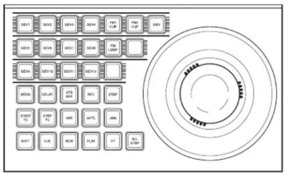
Device control block in the VTR/disk recorder operation mode (trackball module)
In the device control block (search dial module), there is no such a mode selection button and you can directly select a device.
Buttons used when the VTR/disk recorder/frame memory operation mode is enabled
DELAY: Press this button, turning it on, to enter a delay value from the numeric keypad control block.
STB OFF (standby off): Press this button to switch to standby off mode. This button cannot be used for frame memory clip operations.
REC (record): Press this button at the same time as the [Y] button to start recording. This button cannot be used for frame memory clip operations.
STOP: Press this button to stop the tape, disk or frame memory clip.
START TC (start timecode): Press this button to set the timecode of the start point at that time. The timecode of the start point is updated to the current time each time this button is pressed.
When the device the operation applies to is a VTR/disk recorder, the start point updated by the setting of the [MENU] button is as follows.
- When the [MENU] button is On: start point of the timeline
- When the [MENU] button is Off: start point of Cueup & Play
STOP TC (stop timecode): Press this button to set the timecode of the stop point at that time. The timecode of the stop point is updated to the current time each time this button is pressed.
When the device the operation applies to is a VTR/disk recorder, the stop point updated by the setting of the [MENU] button is as follows.
- When the [MENU] button is On: stop point of the timeline
- When the [MENU] button is Off: stop point of Cueup & Play
VAR (variable speed playback): Pressing this button and turning the Z-ring plays back the tape, disk or frame memory clip at a variable speed and direction proportional to the rotation angle of the Z-ring. The variable speed range is -1 to +3 times normal playback speed.
SHTL (shuttle): Pressing this button and turning the Z-ring plays back the tape, disk or frame memory clip at a speed and direction proportional to the rotation angle of the Z-ring.
JOG: Pressing this button and turning the Z-ring plays back the tape, disk or frame memory clip at a speed and direction proportional to the rotation of the Z-ring. You can set the Z-ring operation sensitivity to any of six levels, in the setup menus.
You can also change the sensitivity by holding down this button during an operation. You can select the sensitivity in this case from six levels.
For details of the settings, see “Setting Trackball, Joystick, Search Dial, and Double-Click Sensitivity” (page 593).
CUE: Pressing this button cues the tape, disk or frame memory clip automatically to the start point.
REW (rewind): Press this button to rewind the tape, disk or frame memory clip.
PLAY: Press this button to play the tape, disk or frame memory clip.
FF: Press this button to fast forward the tape, disk or frame memory clip.
ALL STOP: Press this button to stop all tape transport/disk drive/frame memory operations.
Selecting a VTR/Extended VTR/disk recorder
To select the VTR/Extended VTR/disk recorder to be controlled, in the device selection buttons of the device control block, press a selection of those buttons turning them on.
For details on frame memory clip operations, see "Frame Memory Clip Operations" in Chapter 7 (Volume 1).
Controlling the tape/disk transport
Using the buttons in the device control block, you can control the tape transport or the disk transport.
For more details of the effect of buttons in VTR/disk recorder operation mode, see “Device Control Block (Trackball),” “Device Control Block (Joystick)” and “Device Control Block (Search Dial)” in Chapter 2 “Menus and Control Panel” (Volume 1).
If an appropriate setup setting has been made, VTR, Extended VTR, or disk recorder can also be operated with the transition control block (standard type or compact type).
For more details of the effect of buttons in VTR/disk recorder operation mode, see “Transition Control Block (Standard Type)” and “Transition Control Block (Compact Type)” in Chapter 2 “Menus and Control Panel” (Volume 1).
For details of settings in setup, see “Setting Transition Control Block Button Assignments” (page 560).
Controlling the tape/disk transport with the search dial
With the device control block, you can play back the material on an external device in variable speed. This section describes the three playback modes, taking the device control block (search dial) as an example. If you turn this dial during video playback, the direction and speed of playback depend on the direction and angle of rotation. To use this dial, press the [ENBL] button to the upper right of the dial, lighting it amber. This dial has three operation modes: jog, shuttle, and variable.
To prevent overheating, if the search dial is on continuously for 10 seconds, it is automatically turned off. However, in this state, if a movement of the dial is detected, it switches on again.
Jog mode
Press the [JOG] button, lighting the button amber, to switch the dial to jog mode. In this mode, you can advance material frame by frame at a speed proportional to the rotation angle of the dial. To show a still image, stop turning the search dial.
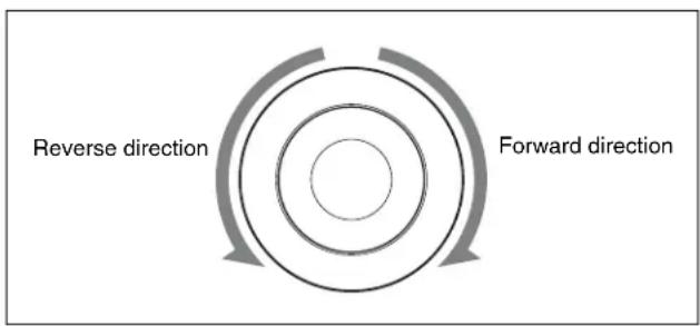
flowchart
graph TD
    A["Reverse direction"] --> B["Concentric Circle"]
    C["Forward direction"] --> B
    B --> D["Arrow Up"]
    B --> E["Arrow Down"]
Shuttle mode
Press the [SHTL] button, lighting the button amber, to switch the dial to shuttle mode. In this mode, the playback speed varies in steps according to the rotation angle of the dial, to a maximum of 50 times normal. If the valid angle is exceeded, the dial makes a clicking sound. To show a still image, return the dial to the home position, where it stops with a clicking sound.
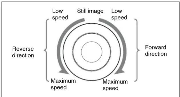
Variable mode
Press the [VAR] button, lighting the button amber, to switch the dial to variable mode. In this mode, the playback speed varies according to the rotation angle of the dial from -1 to +3 times normal speed. The dial indicates the positions where the playback speed is -1 times normal speed, +1 times normal speed, and +3 times normal speed by making a clicking sound at those positions. To show a still image (playback speed 0%), return the dial to its home position, where it stops with a clicking sound.
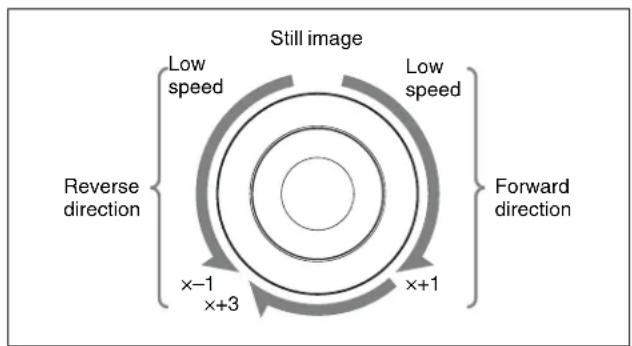
flowchart
graph TD
    A["Reverse direction"] --> B["x-1 x+3"]
    B --> C["Forward direction"]
    C --> D["x+1"]
    D --> E["Low speed"]
    E --> F["Still image"]
    style A fill:#f9f,stroke:#333
    style C fill:#f9f,stroke:#333
    style D fill:#f9f,stroke:#333
    style E fill:#f9f,stroke:#333
    style F fill:#f9f,stroke:#333
×-1: -1 times normal speed
×+3: +3 times normal speed
×+1: +1 times normal speed
To disable the search dial and end variable mode, press the [STOP] button. Additionally, pressing any of the [REW], [PLAY], [FF], [STB OFF], and [ALL STOP] editing buttons ends the variable mode. For shuttle mode and variable mode, you can set the valid range of the operating angle in the Engineering Setup >Panel >Operation
Sensitivity >Search Dial menu to either of the following.
Narrow operating angle
- Shuttle mode: approx. -150 to +150^
- Variable mode: approx. -120 to +210^ (+1 times normal speed is +120^ )
Wide operating angle
- Shuttle mode: approx. -180 to +180^
- Variable mode: approx. -200 to +348^ (+1 times normal speed is +200^ )
Recording to VTRs and disk recorders
You can record to the VTR or disk recorder selected in the device control block. Proceed as follows.
Notes
- Recording is not possible if the VTR or disk recorder is not set to Recorder.
- The disk recorder type must be specified to use the video disk communications protocol (see page 632).
- When using a disk recorder, recording is not possible unless a new file name is specified.
For details, see "Creating new files" (page 424).
1 Using the buttons of the device control block, select the VTR or disk recorder to which you want to record. You can select more than one button.
The first button pressed lights green to indicate the reference device, and the subsequent buttons light amber.
2 While holding down the [REC] button in the device control block, press the [PLAY] button.
Recording starts. During recording, the [REC] button lights red and the [PLAY] button lights amber.
Notes
Note the following points about recording to a disk recorder.
- The maximum length of time that can be recorded in one operation is 30 minutes.
- If you want to record to a different file than the file used in the previous recording, use the Device >DDR/VTR >File List menu to create a new file.
- If you resume recording without executing [Unload] from the Device >DDR/VTR >File List menu, recording starts at the position in the same file where recording was interrupted.
To stop recording
Press the [STOP] button or the [ALL STOP] button in the device control block.
Checking VTR/Disk Recorder/Extended VTR Information
You can check the VTR/disk recorder/Extended VTR information (timecode information and operating status) set in the device control block, in the Device menu display. To check the VTR/disk recorder/Extended VTR information, press VF3 'VTR' and HF1 'Cueup & Play' or HF2 'Timeline' in the Device menu.
The Device >DDR/VTR >Cueup & Play menu or Device >DDR/VTR >Timeline menu appears, and a list shows the timecode information and operating status for each device. The columns of the list show the following information.
DEV (device name): DEV1 to DEV12 represent respectively device 1 to device 12.
Reg (register): Number of the register to which settings apply.
Status: Status of each device. The meaning of the indications is as follows.
| Operating status display | When VTR, Extended VTR, or Sony disk 9-pin protocol is used | When video disk communications protocol is used |
| XXXX Communications with the device are being carried out normally, but status information is not received. | Not communicating, or communicating but the device type cannot be read. | |
| Local The Remote/LOCAL switch of the device is set to LOCAL. | Port is not open. | |
| Tape Out No tape is loaded (VTR).No file loaded.(Sony disk 9-pin protocol or Extended VTR) | No file loaded. | |
| Rec | Recording. | Recording. |
| Cue>Cueing up in the forward direction. | — | |
| Cue<Cueing up in the reverse direction. | — | |
| Eject Ejecting cassette. — | ||
| Stb Off Stopped in standby off mode. | — | |
| Stop Stopped in standby on mode. | Stopped. | |
| Play Playing. Playing. | ||
| FF Fast forwarding. — | ||
| Rewind | Rewinding. | — |
| Shtl> | Playing in the forward direction in shuttle mode. | — |
| Shtl< | Playing in the reverse direction in shuttle mode. | — |
| Var> Playing in the forward direction in “variable” mode. | Playing in the forward direction in “variable” mode. | |
| Var< Playing in the reverse direction in “variable” mode. | Playing in the reverse direction in “variable” mode. | |
| Jog> Playing in the forward direction in jog mode. | Playing in the forward direction in jog mode. | |
| Jog< Playing in the reverse direction in jog mode. | Playing in the reverse direction in jog mode. | |
| Still | Playing still image. | — |
Current: Shows timecode for current device position.
Start TC: Shows timecode for start point set on device.
Stop TC: Shows timecode for stop point set on device.
Variable: Shows the variable speed set for each device.
Delay: Shows start delay time set on device.
Mode: Shows operation mode (Loop or Recue) set for the device (only when the EVS XT server is operated with video disk communications protocol).
Cueup & Play
You can use the device control block or Device menu to save Cueup & Play settings (start point timecode, stop
point timecode, start delay time, and so on) for a VTR, disk recorder or Extended VTR in an effect register. By recalling this register, you can operate the following buttons in the keyframe control block to automatically control the VTR, disk recorder or Extended VTR.
[REWIND] button: Cue up to the start point timecode [RUN] button: Play
With this function you can also stop the VTR, disk recorder or Extended VTR used for playback at the stop point timecode recalled from the same register.
Disk recorder (video disk communications protocol) operation when loop /recue is set
When loop is set: playback repeatedly between the start point and stop point.
When recue is set: when playback reaches the stop point, automatically cue up to the start point.
Notes
- In an effect register set on the VTR/disk recorder timeline, Cueup & Play settings are not possible. To add Cueup & Play settings to such a register, first clear the VTR/disk recorder timeline setting before carrying out the operation.
-
When using a disk recorder with Cueup & Play, if you carry out the following sequence of operations, the system may freeze on the frame of the start point.
-
Press the [RUN] button to play to a point close to the end of a file.
-
Stop playback.
- Press the [RUN] button once more.
In such cases, first recall a different register, then carry out the following sequence:
- Recall the original register again.
- Press the [REWIND] button.
- Press the [RUN] button.
Making and saving settings relating to Cueup & Play
1 Press the [EFF] button in the numeric keypad control block, turning it on.
This assigns the numeric keypad control block to keyframe operations, and the [RCALL] button lights.
2 Press the region selection button for the region for which you want to make the setting, turning it on.
You can select more than one button.
3 Enter the number of the register to be recalled with the numeric keypad buttons.
To search for an empty register, instead of entering a number, press the [.] (period) button.
The display shows the register number. A letter “e” or “E” after the number indicates the register status, as follows:
e: This register is empty in the selected region.
E: This register is empty in all selectable regions.
4 Press the [ENTER] button.
This recalls the register you selected in step 3.
5 When using the device control block (trackball) or device control block (joystick), press the [DEV] button in the device control block, turning it on.
Notes
Check that the [MENU] button is not lit. If it is lit, press to turn it off.
6 With the device selection buttons in the device control block, select the VTR, Extended VTR, or disk recorder for which you want to make the setting.
You can select more than one button.
The first button pressed lights green to indicate the reference region, and the subsequent buttons light amber.
7 Set the start point.
- Using the [START TC] button: Play the VTR, Extended VTR or disk recorder by control from the device control block. Find the desired start point, and press the [START TC] button at that position. If using the [START TC] button, each time you press the button the start point timecode is overwritten.
- Using the [SET START TC]: Press the [SET START TC] button in the device control block (search dial).
The display in the numeric keypad control block shows “START TC.” Enter the desired timecode from the numeric keypad control block, and press [ENTER].
For details of timecode entry, see “Setting the start point and stop point with the [SET XX] buttons” (page 418).
- Setting with the Cueup & Play menu: Set the start point, stop point, and start delay duration (see page 418).
8 Set the stop point or duration.
When two of the start point, stop point and duration are set, the remaining one is automatically determined. For example, if you set the stop point in the following procedure, you do not need to enter the value of the duration.
- Using the [STOP TC] button: Play the VTR, Extended VTR or disk recorder by control from the device control block. Find the desired stop point, and press the [STOP TC] button at that point. If using the [STOP TC] button, each time you press the button the stop point timecode is overwritten.
- Using the [SET STOP TC] button of the device control block (search dial): Press the [SET STOP TC] button in the device control block (search dial). The display in the numeric keypad control block shows “STOP TC.” Enter the desired timecode from the numeric keypad control block, and press [ENTER].
- Using the [SET DUR] button of the device control block (search dial): Press the [SET DUR] button in the device control block (search dial). The display in the numeric keypad control block shows “DUR” and the current setting. Enter the desired duration from the numeric keypad control block, and press [ENTER]. For details of timecode entry, see “Setting the start point and stop point with the [SET XX] buttons” (page 418).
- Setting with the Cueup & Play menu: Set the start point, stop point, and start delay duration (see page 418).
9 To set a start delay time, press the [DELAY] button in the device control block, and enter a value in the numeric keypad control block. Alternatively, make the setting in the Device >DDR/VTR >Cueup & Play menu. If no setting is required, continue to step 10.
10 Press the [STORE] button, turning it on, in the numeric keypad control block.
11 Enter the number of the register in which to save the settings.
When overwriting the settings in the register recalled in step 3, continue to step 12 without changing the displayed register number.
12 Press the [ENTER] button.
Automatically cueing up and playing VTR/Extended VTR/disk recorder
By recalling a register in which you have saved setting data for Cueup & Play, you can control the VTR/Extended VTR/disk recorder automatically in the same way as when automatically executing a keyframe effect.
1 In the numeric keypad control block, press the [EFF] button, turning it on.
The [RCALL] button in the numeric keypad control block lights.
2 With the region selection buttons in the numeric keypad control block, select the region. You can select more than one button.
3 Enter the number of the register to be recalled with the numeric keypad buttons.
4 Press the [REWIND] button in the keyframe control block.
The VTR/Extended VTR/disk recorder automatically advances to the timecode value set as the start point. While the VTR/Extended VTR/disk recorder is operating, the [ALL STOP] button in the device control block flashes amber, and when the start point is reached lights green.
If the operating VTR/Extended VTR/disk recorder is selected as the reference region in the device control block, the [CUE] button also flashes and lights in the same way as the [ALL STOP] button. Also, when the start point is reached, the [STOP] button lights amber.
5 Press the [RUN] button in the keyframe control block. The VTR/Extended VTR/disk recorder is now controlled according to the keyframe data.
Setting the start point and stop point with the [SET XX] buttons
When you enter a timecode and make a setting with the [SET START TC], [SET STOP TC], or [SET DUR] button in the device control block (search dial), the timecode display changes as follows. With these buttons you can set the start point and stop point timecodes, and the duration (the duration is not displayed). When two of these values are set, the remaining one is automatically determined.
Example 1
1 Press the [SET START TC] button, and enter "00000000" from the numeric keypad control block.
| START TC | 00:00:00:00 |
| STOP TC | --:--:--:-- |
| (DUR (notdisplayed) | ) |
2 Press the [SET STOP TC] button, and enter "200" from the numeric keypad control block. This automatically sets DUR.
| START TC | 00:00:00:00 |
| STOP TC | 00:00:02:00 |
| (DUR | 0:02:00) |
3 Press the [SET DUR] button, and enter “-100” from the numeric keypad control block. START TC remains the same, and STOP TC changes. ^a)
| START TC | 00:00:00:00 |
| STOP TC | 00:00:01:00 |
| (DUR | 0:01:00) |
Example 2
1 Press the [SET DUR] button, and enter "200" from the numeric keypad control block.
2 Press the [SET STOP TC] button, and enter "01000000" from the numeric keypad control block. This automatically sets START TC.
| START TC | 00:59:58:00 |
| STOP TC | 01:00:00:00 |
| (DUR | 0:02:00) |
3 Press the [SET STOP TC] button, and without entering anything from the numeric keypad control block, press [ENTER].
The STOP TC display, and the START TC display automatically calculated in step 2 disappear, and the setting of the DUR does not change.
a) If after pressing the [SET XX] button you press the [+/-] button in the numeric keypad control block, you can enter offsets from the existing setting values. Each time you press this button, the sign of the offset cycles through the settings “ ”(absolute value) → “+” → “-”…, and the sign appears in the numeric keypad control block display. If there is no existing setting value, then it is only possible to enter an absolute value, and not an offset value.
Setting the start point, stop point, and start delay time in a menu
In the Device menu, you can set the start point, stop point, and start delay time.
1 In the Device menu, press VF3 'DDR/VTR' and HF1 'Cueup & Play.'
The Device >DDR/VTR >Cueup & Play menu appears.
The status area shows the device number, register number, status information, current time, start point, stop point, and start delay time.
2 Using any of the following methods, select the device.
- Press directly on the list in the status area.
- Press the arrow keys to scroll the reverse video cursor.
- Turn the knob.
| Knob | Parameter Adjustment Setting values | |
| 1 Dev | Device number 1 to 12 | |
3 Carry out any of the following operations as required.
- To set the start point, press [Set] in the
group. - To set the stop point, press [Set] in the
group. - To set the start delay time, press [Set] in the
group.
A timecode window appears.
4 Set the timecode value for the start point, stop point, or start delay time.
Notes
You can enter a start delay time in the range that depends on the signal format as follows: 00:00 to 59:nn, where nn = (number of frames per second) - 1 frame.
5 Press [Enter].
Clearing the start point, stop point, and start delay time settings in a menu
In the Device menu, use the following procedure.
1 Press VF3 'DDR/VTR' and HF1 'Cueup & Play.'
2 Using any of the following methods, select the device for which you want to clear the settings.
- Press directly on the list in the status area.
- Press the arrow keys to scroll the reverse video cursor.
- Turn the knob.
| Knob | Parameter Setting | Setting | Setting values |
| 1 Dev | Device number | 1 to 12 |
3 Carry out any of the following operations as required.
- To clear the start point, press [Clear] in the
group. - To clear the stop point, press [Clear] in the
group. - To clear the start delay time, press [Clear] in the
group.
This clears the setting of the start point, stop point, or start delay time.
Selecting Loop or Recue as the playback mode
You can set the device operation mode to loop or recue.
Loop: Carry out playback from the start point of a file to the stop point, then indefinitely repeat playback from the start point.
Recue: Carry out playback from the start point of a file to the stop point, then return to the start point and stop.
Notes
Loop and recue functions are only available when the EVS XT server is operated with the video disk communications protocol.
In the Device menu, use the following procedure.
1 Press VF3 'DDR/VTR' and HF1 'Cueup & Play.'
The Device >DDR/VTR >Cueup & Play menu appears. The status area shows the device number, register number, status information, current time, start point, stop point, start delay time, and playback mode.
2 Using any of the following methods, select the device.
Press directly on the list in the status area. Press the arrow keys to scroll the reverse video cursor. Turn the knob.
| Knob | Parameter Adjustment Setting values | ||
| 1 Dev | Device number 1 to 12 | ||
3 In the
VTR/Disk Recorder/Extended VTR Timeline
For a keyframe effect controlled from the center control panel, the timeline allows you to set a VTR, disk recorder or Extended VTR action at a keyframe point on the timeline.
Timeline actions
The actions that can be used on the timeline are as follows.
- Start
- Stop
• C u e u p - Variable speed
Notes
• The timeline does not support loop and recue.
- For a disk recorder, the maximum number of files for a single register is eight.
For the action settings (VTR/disk recorder/Extended VTR timeline editing), use the Device menu.
The data set in the Device menu are saved in a keyframe effect register. When you recall this register and start execution of the keyframe effect, and advance the effect to the keyframe point for which the action is set, an action command is output to the external device through the 9-pin serial port assigned to the VTR, disk recorder or Extended VTR.
Notes
When executing a timeline using a disk recorder or Extended VTR, note the following points.
- It is not possible to use loop and recue on the timeline.
- When carrying out keyframe settings, be sure to recall the file for operation first.
- If the duration of the recorded video clip is less than the keyframe duration, after playback to the end of the clip, the remainder of the keyframe duration is filled with a still of the last frame of the clip (see figure below).
Example: When the recorded clip for keyframe 1 has a duration of 15 frames
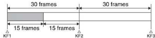
: Interval for which clip is recorded
: Interval in which still frame is displayed
In this example, when keyframe 1 is executed, the first 15 frames consist of clip playback and the remaining 15 frames show the 15th frame as a still image.
When executing the timeline using a disk recorder, also take note of the following points.
- Set the keyframe duration to at least 30 frames.
- From pressing the [RUN] button to the time when the effect actually starts execution may take around one second.
In order that pressing the [RUN] button after [REWIND] make the effect start execution as soon as possible, set cueing up of the file for operation as rewind operation ^1) . In the first keyframe ^2) to be executed with [RUN], for the cued-up file, do not set the start point, but set only the start command.
1) If the setting when the [REWIND] button is pressed is for the first keyframe to be executed, then the first keyframe is executed, and otherwise the setting for the Rewind Action is carried out.
2) If the setting when the [REWIND] button is pressed is for the first keyframe to be executed, then the second keyframe is executed, and otherwise the first keyframe is executed.
- To execute an effect, be sure to carry out a Rewind. For example, when the start command only is set for a keyframe, playback starts from the current position, in the same way as with a VTR (no automatic cue-up).
- During file playback, to play the next keyframe at variable speed, for the next keyframe set variable speed only, and do not set the start point (see figure below).
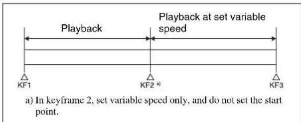
- When using a disk recorder with the VTR/disk recorder timeline, if you carry out the following sequence of operations, the system may freeze on the frame of the start point.
- Press the [RUN] button to play to a point close to the end of a file.
- Stop playback.
- Press the [RUN] button once more.
In such cases, first recall a different register, then carry out the following sequence:
- Recall the original register again.
- Press the [REWIND] button.
- Press the [RUN] button.
- Some operating limitations apply when the video disk communications protocol is used. These are explained with reference to the following figure, which illustrates creation of a timeline that plays from the video of file A to the video of file B.

- Operation with no problems:
| KF1 action setting | Operating status of file A | KF2 action setting |
| Start Playing Start |
- Black video or still image appears momentarily when play switches from file A to file B:
| KF1 action setting | Operating status of file A | KF2 action setting |
| Start Playing Cueup | ||
| Variable Speed set | Playing at variable speed | Cueup |
| Cueup Cueup Cueup | ||
- Partial operating limitation:
| KF1 action setting | Operating status of file A | KF2 action setting |
| Start Playing Variable Speed | set a) | |
| Variable Speed set | Playing at variable speed | Variable Speed set a) |
| Cueup Cueup Variable Speed | set a) | |
a) Failure to operate when variable speed is set to minus value. However, operates when the file B action is set to Start, and then variable speed is set to minus after file B starts playing.
- Play does not switch from file A to file B:
| KF1 action setting | Operating status of file A | KF2 action setting |
| Variable Speed set | Playing at variable speed | Start |
| Cueup Cueup Start | ||
If play continues to show video of file A without switching to file B, a Stop action is required in file A in order to switch to file B.
VTR/disk recorder/Extended VTR timeline editing
This section describes how to set an action at a keyframe point, and how to edit the timeline.
For details of the operations for keyframe creation and editing, see “Creating and Editing Keyframes” (page 441).
To set an action in the menu
1 In the Device menu, press VF3 'DDR/VTR' and HF2 'Timeline.'
The Device >DDR/VTR >Timeline menu appears. The status area shows two lists.
The upper list shows the device number, register number, keyframe number, and action type (start point, stop point, and variable speed) set for the keyframe.
The lower list is used for setting the action for the device selected above, and shows the port name, current file, current time, status information, start point, stop point, variable speed, and file name (for a disk recorder or Extended VTR).
2 Using any of the following methods, select the device for which you want to set the action.
- Press directly on the list in the status area.
- Press the arrow keys to scroll the reverse video cursor.
- Turn the knob.
| Knob | Parameter Setting | Setting | Setting values |
| 1 Dev | Device number | 1 to 12 |
3 To set the name of a file when using an Extended VTR or disk recorder, recall the file using the Device >DDR/VTR >File List menu.
Notes
- There is a limit of eight disk recorder files that can set on a single timeline.
- If you have not set the file name when using an Extended VTR, the file recalled in the Extended VTR when the keyframe point is passed is the subject of the action.
For details of settings required to recall a file, see "Sharing Disk Recorder/Extended VTR File Lists" (page 588).
When not using an Extended VTR or disk recorder, or when the file name has not been set for an Extended VTR, skip to step 4.
4 In the
Cueup: Output a command to cue up to the currently displayed start point.
Start: Output a Play command.
Notes
When the stop point and variable speed are both set, the variable speed setting takes priority.
Stop: Output a Stop command.
Notes
Before executing the Stop command, if the timecode for the set stop point has been reached, or on an Extended VTR or disk recorder if the end of the file has been reached, then at that point the device stops.
5 To set a start point, in the
A timecode window appears. If you do not want to set the start point, skip to step 8.
Notes
For a disk recorder on which the start point is not set, the file recalled in the disk recorder when the keyframe point is passed is the subject of the action.
6 Set the start point as a timecode value.
7 Press [Enter].
The new start point setting is reflected in the status area.
8 To set the stop point, in the
A timecode window appears.
If you do not want to set the stop point, skip to step 11.
9 Set the stop point as a timecode value.
10 Press [Enter].
The new stop point setting is reflected in the status area.
11 To set the variable speed, in the
- Press [Fit].
Without setting a speed value, this automatically carries out playback according to automatically calculated values for the duration and keyframe duration to fit the set start point and stop point.
- Press the [Set] button, and adjust the parameter with the knob.
| Knob | Parameter Setting | Setting values | a) |
| 2 Variable | Variable | speed -100 to +200 |
a) The setting range of the variable speed depends on the type of connected device.
The new variable speed setting is reflected in the status area.
Repeat steps 2 to 11 as required for other devices.
To carry out start point and stop point settings and cueing up operations in the device control block
With the following buttons in the device control block, you can set the start point or stop point of a keyframe point on the timeline, or carry out a cueing up operation.
Notes
- When using the device control block (trackball or joystick), check that the [MENU] button in the block is lit amber. If it is not lit, press it, turning it on.
- When using the device control block (search dial), check that the [TIMELINE] is lit amber.
[START TC] button: Set the start point of the keyframe point to the current time.
[STOP TC] button: Set the stop point of the keyframe point to the current time.
[SET START TC] button (of the device control block (search dial)): Enable to input the timecode of the
start point of the keyframe point with the numeric keypad control block.
[SET STOP TC] button (of the device control block (search dial)): Enable to input the timecode of the stop point of the keyframe point with the numeric keypad control block.
[SET DUR] button (of the device control block (search dial)): Enable to input the duration between the start point and stop point of a keyframe point with the numeric keypad control block.
[CUE] button: Cue up to the start point set for the keyframe point.
To display or check the settings, use the Device >DDR/VTR >Timeline menu.
To test an action command output
To test an action command output, select the desired device from the upper list in the status area, and press [Test Fire].
An action command is output from the DCU 9-pin serial port, according to the settings in the list.
To clear the start point, stop point, and variable speed settings
1 In the upper list in the status area, select the device for which you want to clear the settings.
2 Carry out any of the following operations as required.
- To clear the start point setting, press [Clear] in the
group. - To clear the stop point setting, press [Clear] in the
group. - To clear the variable speed setting, press [Clear] in the
group.
To set the action for a rewind operation
On the VTR/disk recorder/Extended VTR timeline, when the [REWIND] button in the keyframe control block is pressed the action set for the first keyframe is not executed; when the [RUN] button is pressed, then the first keyframe action is executed.
To execute an action when the [REWIND] button is pressed, it is necessary to set this action (Rewind Action).
To carry out this setting, in the Device >DDR/VTR >Timeline menu, press [Rewind Action] to recall the Rewind Action menu. In this setting screen, use the same setting method as in the screen for setting an action on the VTR/disk recorder timeline.
Alternatively, you can select the reverse arrangement, whereby when the [REWIND] button is pressed, this executes the action set for the first keyframe, and when the [RUN] button is pressed the first keyframe action is not executed. In this case, the Rewind Action setting is still valid.
For details of the setting, see "Setting the First Keyframe When a Rewind is Executed" (page 591).
Disk Recorder/Extended VTR File Operations
Material held on a disk recorder/Extended VTR is managed in units of files. You can recall a file to play it back. (In the case of an Extended VTR, the register number is recalled.)
To carry out disk recorder/Extended VTR file operations, use the Device menu.
Accessing the file list
Before playback and suchlike operations on a disk recorder/Extended VTR, it is first necessary to display a list of the disk recorder files on the DCU. The file list includes the following information.
- File name
- Date of last update 1)
• Duration of recorded material ^1)
To recall the file list, use the Device menu.
1) Not displayed in the case of an Extended VTR
Recalling a file
In the recalled list of files, select the file you want to play back, and open the file.
File list sharing
You can connect multiple DCU serial ports to a single disk recorder/Extended VTR.
You can share the recalled list of files between serial ports connected to the same disk recorder/Extended VTR.
For settings relating to file list sharing, see "Sharing Disk Recorder/Extended VTR File Lists" (page 588).
File creation
To record a new file on the disk recorder, use the Device menu to create a new file.
Notes
In the case of an Extended VTR, it is not possible to record a new file.
Refreshing (recalling) the disk recorder/Extended VTR file list
1 In the Device menu, press VF3 'DDR/VTR' and HF3 'File List.'
The Device >DDR/VTR > File List menu appears.
In the status area, two lists appear.
The upper list shows the selected device name, and the currently selected file name (register number), and set file name.
The lower list shows a list of files for the selected device (the device appearing in the upper list). In this list is shown the file name (register number) set when
the material was recorded, the length of the file data (timecode value), and the file update information.
Notes
- File update information is not shown when using the video disk communications protocol.
- When using an Extended VTR, the length of file data and file update information are not shown, and the register number is shown in place of the file name.
2 Select the device for which you want to recall the file list, using the knob.
| Knob | Parameter Setting | Setting values |
| 1 Dev | Device number 1 to 12 |
3 Press the [File List Update] button.
This starts the process of recalling the file list, and a message box appears.
When the file list recall is completed, the message box disappears.
To cancel recalling the file list
During the recall, press the [Cancel] button in the message box.
File list sharing
You can share the recalled file list across serial ports connected to the same disk recorder (see page 588).
Sorting files in the list
You can sort the files in the list by name, number, or update date.
1 In the Device menu, press VF3 'DDR/VTR' and HF3 'File List.'
The Device >DDR/VTR >File List menu appears.
2 Select the device for which you want to recall the file list, using the knob.
| Knob | Parameter Setting | Setting values |
| 1 Dev | Device number 1 to 12 |
3 In the
File Name: Sort in alphabetical order of file name.
File No: Sort in ascending file number order.
Update: Sort in file update date order, newest first.
Notes
- Files cannot be sorted by the file update date and time when using the video disk communications protocol.
- When using an Extended VTR, it is not possible to sort files.
This sorts the files in the selected order.
Recalling a file
To recall a file from the file list, use the following procedure.
Notes
Files cannot be recalled when the disk recorder is set to Recorder.
1 In the Device menu, press VF3 'DDR/VTR' and HF3 'File List.'
The Device >DDR/VTR >File List menu appears.
2 Select the device from which you want to recall a file, using the knob.
| Knob | Parameter Setting | Setting values | |
| 1 Dev | Device number | 1 to 12 |
3 Using any of the following methods, select the file you want to recall.
- Press directly on the lower list in the status area.
- Press the arrow keys to scroll the reverse video cursor.
- Turn the knob.
| Knob | Parameter Setting | Setting values | |
| 2 No File selection | 1 to 5000 | a)0 to 99 b) | |
a) For disk recorders. The range of setting values depends on the total number of files.
b) For Extended VTRs. The range of setting values depends on the total number of files.
4 Press [Load].
This recalls the selected file, and the file name appears at the top of the status area.
Creating new files
A file name must be specified to record to a new file on a disk recorder.
Notes
- New files cannot be created when the disk recorder is set to Player or Recorder/Player.
- In the case of Extended VTRs, new files cannot be created.
1 In the Device menu, press VF3 'DDR/VTR' and HF3 'File List.'
The Device >DDR/VTR >File List menu appears.
2 Press [New File].
The keyboard window appears.
3 Enter a file name and press [Enter].
When using the Sony disk recorder 9-pin protocol: Up to 23 characters.
When using the video disk communications protocol: Up to 8 characters (in Fixed 8 Character mode) or 23 characters (in Variable Length mode)
For details of how to select the file name character count mode in the video disk communications protocol, see “Making Detailed Settings on the External Device Connected to the Serial Port” (page 632).
The name appears as the current file name at the top of the status area.
When the loaded file is not a target for recording
When a file that is not a target for recording is loaded in the disk recorder, proceed as follows.
1 In the Device menu, press VF3 'DDR/VTR' and HF3 'File List.'
The Device >DDR/VTR >File List menu appears.
2 Press [Unload].
The current file name at the top of the status area is cleared.
Keyframe Effects
Chapter
13
Regions
The term “region” refers to some sort of functional block of the system.
When saving or recalling snapshot registers and effect registers, or creating or editing effects, you first select the region to which the operation applies. You can also select multiple regions simultaneously.
Classification of the regions
The regions are classified as follows.
-
Master region
• The following 36 regions -
Switcher: M/E1 to M/E4, PGM/PST, User1 to User8
- DME: DME ch1 to DME ch8 (inclusive of Global)
- External devices: P-Bus, Router, Device 1 to Device 12, GPI, Macro
Only the regions assigned to the region selection buttons of the numeric keypad control block or Multifunction Flexi Pad control block can be used simultaneously (see page 559).
Regions applicable to keyframe operations
All the regions less the Router region.
Regions applicable to snapshot operations
Twenty-two regions, that is, the above regions less the external devices' regions (P-Bus, Device 1 to Device 12, and GPI) and the Macro region.
"User" regions
You can optionally assign the following regions to the regions User1 to User8 (see page 598). The User regions shown in parenthesis are the default assignments.
• Color backgrounds 1 and 2 (User1)
- AUX1 to AUX48 (User2)
• Frame Memory 1 to 8 (User4)
• Color correctors 1 and 2
Notes on saving or recalling a frame memory still image for or by a snapshot/keyframe
- The saving and recalling of frame memory images for snapshots and keyframes is restricted to the still images
or clips on the eight frame memory outputs. The settings made for frame memory images in the Freeze menu or other menus do not apply to snapshots or keyframes.
- To reproduce a frame memory still image or a clip of them by recalling a snapshot or keyframe, you must have the same images that were present in the frame memory when you saved the snapshot or keyframe. Therefore, when saving a snapshot or keyframe using frame memory, you must also save the images to a storage media such as the hard disk.
Reference region
When multiple regions are selected, only one region appears in the displays for menu and numeric keypad operations. This is called the “reference region.”
The reference region is determined according to the following precedence.
M/E1 > M/E2 > M/E3 > M/E4 > P/P > User1 > User2
User3 >User4 >User5 >User6 >User7 >User8
DME ch1>DME ch2>DME ch3>DME ch4>DME
ch5 >DME ch6 >DME ch7 >DME ch8 >Device1
Device2 >Device3 >Device4 >Device5 >Device6
Device7 >Device8 >Device9 >Device10 >Device11
Device12 >P-Bus >GPI >Router >Macro
Master region
The regions saved in a master snapshot register or master timeline register and the register numbers saved in such regions can be recalled at a time as the master region.
The master region can be saved or recalled using the numeric keypad control block or Multifunction Flexi Pad control block.
Registers
A register is an area of memory in a device which holds a snapshot (see chapter 16), keyframe, macro (see chapter 13), and so on.
Keyframe effect registers
Dedicated effect registers
There are 99 dedicated registers for keyframe effects in each region, numbered 1 to 99.
Shared user-programmable DME registers
In addition to the 99 DME registers for each region (i.e. each channel), there are also shared registers for each processor as shown in the following table. These are used for user-programmable DME.
| Register number | Register allocation |
| 101 to 199 Sh | shared register for one-channel effects |
| 201 to 299 Sh | shared register for two-channel effects |
| 301 to 399 Sh | shared register for three-channel effects |
Notes
When operating with these shared registers, be sure to select the appropriate regions depending on the number of channels.
When recalling registers in the 200 range, select two consecutive channels for the regions, as for example [DME1] and [DME2]. Similarly, for registers in the 300 range, select three consecutive registers.
Registers for P-Bus Device regions
There are 250 registers for P-Bus and Device1 to Device12 in each region, numbered 1 to 250.
Work register
This is a temporary register used when editing keyframes. When you recall an effect, it is read from the effect register into the work register, and when you save, the contents of the work register are written to the effect register.
Master timeline registers
There are 99 master timeline registers, numbered 1 to 99, for each control panel. They store keyframe effect regions and the register numbers saved in the regions.
Snapshot registers
These are registers for snapshots, and there are 99, numbered 1 to 99 for each region.
Master snapshot registers
There are 99 master snapshot registers, numbered 1 to 99, for each control panel. They store snapshot regions and the register numbers saved in the regions.
Keyframes
A keyframe represents an instantaneous state of an image; it can be saved and recalled for reuse.
Effects
By arranging a number of keyframes on the time axis, and interpolating between successive keyframes, you can create an effect in which there is a continuous change from each keyframe to the next.
You can save the sequence of keyframes representing a single effect in a register. Then by recalling this register, you can replay the same effect (see page 425 and 426).
Saving and Recalling Effects
To create a new effect, first recall an empty register, then create the keyframes one at a time in this register. To run an effect, it is also necessary to set the time and the path. To edit an existing effect, recall the register holding the effect, then make the changes.
When you have finished creating or editing the effect, save it in the recalled register or another specified register.
Auto save function
When you recall an effect, the currently recalled effect is automatically saved in a register. This is called the auto save function. You can disable this function in a Setup menu.
Effect Attributes
An individual effect may also have attached special conditions relating to switcher or DME operation when the effect is recalled.
These conditions are called “attributes” of the effect, and can be added when the keyframe effect is saved or recalled.
Type of attribute
The attribute that can be attached to an effect is as follows.
Effect dissolve: The transition from the state before the effect recall to the state at the effect start point is carried out smoothly, by a dissolve. The dissolve duration can be set in the Effect menu.
Temporary attributes
When a keyframe is recalled, independently of the attributes held in the register, you can also enable or disable temporary attributes. These temporary attributes are set when the keyframe effect is recalled.
Effect Editing
For editing operations such as to insert, delete, or modify a keyframe, it is necessary to stop the effect at the corresponding point on the time axis. This is termed an “edit point.”
You can edit either on a keyframe within the effect, or at any point between keyframes.
Insert: Insert the current image as a keyframe. Inserting a keyframe in an existing effect may change the duration of the effect (see page 428).
Modify: Modify a keyframe. You can modify a single keyframe or a range of keyframes in the effect together.
Delete: Delete a keyframe. You can delete a single keyframe or a range of keyframes in the effect together. Deleting keyframes from an effect reduces the duration of the effect (see page 428). After deleting a keyframe, you can reinsert the keyframe with a paste operation.
Copy: Copy a keyframe. You can copy a single keyframe or a range of keyframes in the effect together.
Paste: Paste the keyframe last copied or deleted anywhere within the effect.
Pause: You can set a pause on a particular keyframe, so that when the effect is run it pauses on this keyframe. You can make this setting on any number of keyframes. To restart the paused effect, repeat the operation to run the effect.
KF Loop: Execute the effect the specified number of times through the keyframes in the specified range.
Undo an edit operation: Undo the effect of the last operation to insert, modify, delete, or paste a keyframe.
Duration modes
In keyframe editing, there are two duration modes; switch between them in the keyframe operation section (see page 441).
Variable duration mode: In this mode, inserting or deleting a keyframe increases or reduces the duration.
Constant duration mode: In this mode, inserting or deleting a keyframe does not change the duration. This is useful for keyframe editing of an effect with a fixed duration.
In the variable and constant duration modes, the keyframes to which a modify operation applies, and the effect of a paste operation are different.
Difference in keyframes to which a modify operation applies
| Effect position | Variable duration mode | Constant duration mode |
| On a keyframe | Applies to currently selected keyframe | Applies to currently selected keyframe |
| Between two keyframes | Applies to previous keyframe | Modify operation not possiblea) |
a) A new keyframe is inserted at the effect position.
Difference in the effect of a paste operation
Variable duration mode: The copied keyframe is inserted at the specified position.
Constant duration mode: The copied keyframe is written over the specified position.
Transition mode
You can use an effect created with keyframes as a DME wipe pattern on the switcher. In this case, it is necessary to set the transition mode (the way in which the effect behaves) (see page 445).
Time Settings
Keyframe duration and effect duration
You can determine the execution time of an effect by setting either the keyframe durations or the effect duration.
Keyframe duration: This is the time from the keyframe to the next keyframe. You can set this time in the keyframe control block (see page 449). In constant duration mode (see page 427), it is not possible to change the keyframe duration setting.
Effect duration: This is the total execution time of the effect, from the first keyframe to the last. You can set this time in the keyframe control block (see page 450). When you change the effect duration, the keyframe duration for each keyframe in the effect is automatically recalculated proportionally.
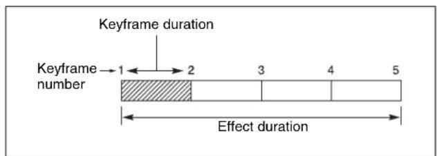
Keyframe duration and effect duration
The effect duration may also be changed by inserting or deleting keyframes.
Changes in the effect duration caused by inserting a keyframe
- When the effect is stopped on a keyframe, inserting a keyframe increases the effect duration by the duration of the inserted keyframe.
- When the effect is stopped between two keyframes, inserting a keyframe does not change the effect duration.
Notes
In constant duration mode (see page 427), the duration of the current keyframe is reduced to zero, and the new keyframe is inserted with the previous duration of the current keyframe. Thus the effect duration does not change.
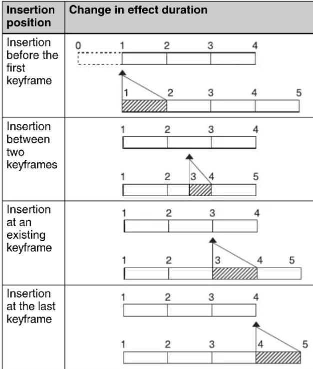 |
Keyframe insertion position and the change in effect duration
Changes in the effect duration caused by deleting a keyframe
- When the effect is stopped on a keyframe, a delete operation deletes the keyframe, and reduces the effect duration by the duration of the deleted keyframe.
- When the effect is stopped between two keyframes, a delete operation deletes the preceding keyframe, and reduces the effect duration by the duration of the deleted keyframe.
Notes
In constant duration mode (see page 427), the duration of the keyframe before the deleted keyframe is increased by
the duration of the deleted keyframe. Thus the effect duration does not change.
| Deletion position | Change in effect duration |
| Deletion of the first keyframe | 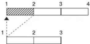 |
| Deletion of an intermediate keyframe | 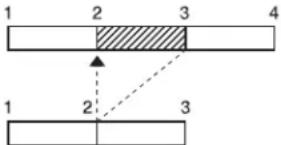 |
| Deletion between two keyframes | 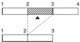 |
| Deletion of the last keyframe | 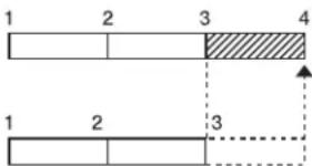 |
Keyframe deletion position and the change in effect duration
Delay setting
You can set the delay from the time of executing an operation to run the effect, and the effect actually starting (that is, the delay until the first keyframe). You can make this setting in the keyframe control block.
Note that changing the delay does not alter the duration of the effect.
Paths
The term “path” refers to the specification of how interpolation is carried out from one keyframe to the next. Images are interpolated from an edit point to the next one according to the path setting.
For details of the path setting procedure, see “Path Setting” (page 451).
Switcher path settings
Carry out path settings in the Key Frame menu. For each menu, the following settings are available.
M/E-1 to M/E-4, and P/P menus
| Item Paths that can | be set | |
| M/E1 to M/E4, P/P All | For each M/E and PGM/PST, path settings for the following items are made simultaneously. | |
| Key1 to Key8 Overall | path settings for items relating to keys 1 to 8 are made simultaneously. | |
| Key1 All to Key8 All | ||
| Source Key source path for keys 1 to 8 | ||
| Fill Key fill path for keys 1 to 8 | ||
| Proc Proc path for keys 1 to 8 | ||
| Trans Transition path for keys 1 to 8 | ||
| Bkgd/Util Overall path | settings for items relating to the background and utility buses are made simultaneously. | |
| Bkgd/Util All | ||
| Bkgd A Path for background A | ||
| Bkgd B Path for background B | ||
| Util 1 Path for utility 1 | ||
| Util 2 Path for utility 2 | ||
| DME 2nd Video | Path for video to be used for second DME channel | |
| Wipe/DME Wipe Over | all path settings for items relating to wipes and DME wipes are made simultaneously. | |
| Wipe/DME Wipe All | ||
| Wipe Path for wipes | ||
| DME Wipe | Path for DME wipes | |
| Trans | - | Transition path for each M/E and P/P bank |
User1 to User8 menus
The items that can be adjusted depend on the settings in the Setup menu.
For details, see "Setting User Regions" (page 598).
| Item | Paths that can be set | |
| User1 All to User8 All | Overall path settings for the following items for each “User” are made simultaneously. | |
| FM All | Overall path settings for frame memory items are made simultaneously. | |
| FM Still Store | Overall path settings for frame memory freeze image output are made simultaneously. | |
| FM Still Store All | ||
| FM Still Store 1 to 8 | Paths for frame memory freeze image outputs 1 to 8 | |
| Aux | Overall path settings for AUX buses are made simultaneously. | |
| Aux All | ||
| Aux 1 to 48 | Paths for Aux 1 to 48 | |

| Item | Paths that can be set | |
| Color Bkgd Overall path settings for color backgrounds are made simultaneously. | ||
| Color Bkgd All | ||
| Color Bkgd 1 P | Paths for color background 1 | |
| Color Bkgd 2 P | Paths for color background 2 | |
| CCR Overall path settings for color corrector | ||
| CCR All | ||
| CCR 1 Path for color corrector 1 | ||
| CCR 2 Path for color corrector 2 | ||
Paths relating to DME
DME 3D Trans Local menu
| Item Paths that can be set | ||
| 3D Trans Local All Over | overall path settings for local channel three-dimensional transform items are made simultaneously. | |
| Loc Size Overall path settings for items relating to image size changes and movement are made simultaneously. | ||
| Loc Size All | ||
| Size Path for image size | ||
| Post Loc X, Post Loc Y | Paths for movement in the x- and y- axes | |
| Post Size Path | for size | |
| Loc XYZ Overall path settings for items relating to image movement are made simultaneously. | ||
| Loc XYZ All | ||
| Loc X, Loc Y, Loc Z | Paths for the x-, y- and z-axes | |
| Rot Overall path settings for items relating to image rotation are made simultaneously. | ||
| Rot All | ||
| Rot X, Rot Y, Rot Z | Paths for the x-, y- and z-axes | |
| Spin Overall path settings for items relating to spin are made simultaneously. | ||
| Spin All | ||
| Spin Src X, Spin Src Y, Spin Src Z | Paths for the x-, y- and z-axes | |
| Spin X, Spin Y, Spin Z | Paths for the x-, y- and z-axes | |
| Asp | Overall path settings for items relating to aspect ratio are made simultaneously. | |
| Asp All | ||
| Rate X, Rate Y | Paths for the x- and y-axes | |
| Item Paths that can be set | ||
| Skew | Overall path settings for items relating to skew are made simultaneously. | |
| Skew All | ||
| Skew X, Skew Y | Paths for the x- and y-axes | |
| Aspect Path for aspect ratio | ||
| Pers Overall path settings for items relating to perspective are made simultaneously. | ||
| Pers All | ||
| Pers X, Pers Y, Pers Z | Paths for the x-, y- and z-axes | |
| Axis Loc | Overall path settings for items relating to image rotation axis are made simultaneously. | |
| Axis All | ||
| Axis X, Axis Y, Axis Z | Paths for the x-, y- and z-axes | |
DME 3D Trans Global menu
| Item | Paths that can be set | |
| 3D Trans Global All | Overall path settings for three-dimensional transform items in the global channel are made simultaneously. | |
| Loc Size Overall path settings for items relating to image size changes and movement are made simultaneously. | ||
| Loc Size All | ||
| Size | Path for image size | |
| Post Loc X, Post Loc Y | Paths for movement in the x- and y- axes | |
| Post Size | Path for size | |
| Loc XYZ | Overall path settings for items relating to image movement are made simultaneously. | |
| Loc XYZ All | ||
| Loc X, Loc Y, Loc Z | Paths for the x-, y- and z-axes | |
| Rot | Overall path settings for items relating to image rotation are made simultaneously. | |
| Rot All | ||
| Rot X, Rot Y, Rot Z | Paths for the x-, y- and z-axes | |
| Spin Overall path settings for items relating to spin are made simultaneously. | ||
| Spin All | ||
| Spin Src X, Spin Src Y, Spin Src Z | Paths for the x-, y- and z-axes | |
| Spin X, Spin Y, Spin Z | Paths for the x-, y- and z-axes | |
| Pers Overall path settings for items relating to perspective are made simultaneously. | ||
| Pers All | ||
| Pers X, Pers Y, Pers Z | Paths for the x-, y- and z-axes | |
| Item Paths that can be set | ||
| Axis Loc Overall path settings for items relating to image rotation axis are made simultaneously. | ||
| Axis All | ||
| Axis X, Axis Y, Axis Z | ||
DME Effect menu
| Item Paths that can be set | ||
| Effect All Overall path settings for DME effect items are made simultaneously. | ||
| Edge Overall path settings for edge items are made simultaneously. | ||
| Edge All | ||
| Border Path for border | ||
| Crop/Edge Soft | Path for crop/edge softness | |
| Beveled Edge | Path for beveled edge | |
| Key Border Path for key border a) | ||
| Art Edge Path for art edge a) | ||
| Flex Shadow Path for flex shadow a) | ||
| Wipe Crop Path for wipe crop a) | ||
| Color Mix | Path for color mixa) | |
| Video Modify | Overall path settings for video modify items are made simultaneously. | |
| Video Modify All | ||
| Defocus/Blur | Path for defocus/blur | |
| Multi Move | Path for “multi-move” | |
| Color Modify | Path for color modify | |
| Mosaic | Path for mosaic | |
| Mask | Path for mask | |
| Sketch Path for sketch | ||
| Metal | Path for metal | |
| Dim/Fade | Path for dim/fadea) | |
| Glow | Path for glow | |
| Freeze | Path for freeze | |
| Non-Linear | Path for nonlinear effects | |
| Corner Pin | Path for corner pinning | |
| Light | Overall path settings for lighting items are made simultaneously. | |
| Light All | ||
| Lighting | Path for lighting | |
| Spot Lighting | Path for spotlightinga) | |
| Trail | Path for trails | |
| In/Out | Overall path settings for items relating to input/output are made simultaneously. | |
| In/Out All | ||
| Bkgd | Path for background | |
| Video/Key | Path for video/key | |
a) This cannot be used on the MVE-8000A.
DME Global Effect menu
| Item | Paths that can be set |
| Global Effect All | Overall path settings for DME global effect items are made simultaneously. |
| Combine | Path for combiner |
| Shadow | Path for shadow |
| Brick | Path for brick |
Types of path
Path types for Curve
There are five types, as follows.

OFF: Executing the effect causes no change.

Step: There is no interpolation between keyframes, so that the effect parameters are updated each time a keyframe is passed.

Linear: Linear interpolation between keyframes, resulting in constant speed movement.

S-Curve: The rate of change accelerates and ecelerates before and after a keyframe, so that the rate of change is maximum midway between two eyframes.

Spline: The effect follows a smooth curved path from each keyframe to the next.
Path types for Hue
There are four types, as follows.

CW: The hue changes in a clockwise direction as seen on a Vectorscope.

CCW: The hue changes in a counterclockwise direction as seen on a Vectorscope.

Short: The hue changes in whichever of the lockwise and counterclockwise directions is shorter.

Long: The hue changes in whichever of the lockwise and counterclockwise directions is longer.
Path types for Xpt
There are two types, as follows.

Xpt Hold off: When replaying a keyframe, change the inputs to the settings saved in memory.

Xpt Hold on: When replaying a keyframe, do not change the inputs.
Effect Execution
By using the [RUN] button in the keyframe control block, you can replay the effect as a continuous sequence of images. This is referred to as effect execution.
Range of execution
Each time the [RUN] button is pressed, the range of execution of the effect is from timecode 01:00:00:00 or the current time (the position at which the current effect is stopped) to the end point of the effect. However, if there is a pause set on a keyframe, the execution range is up to that point. Pressing the [RUN] button again resumes the effect, which then runs to the next pause point or the end of the effect.
Run mode setting
You can select from the following run modes for when the effect is executed.
DIRECTION: Specify the effect execution direction.
STOP NEXT KF: Run the effect, and stop at the next keyframe.
EFFECT LOOP: Repeat the effect in an endless loop. Make these settings in the keyframe control block.
For details, see "Run mode setting" (page 432).
Master Timelines
You can save the regions selected for a keyframe effect and the register numbers saved in the regions in a master timeline register so that operation can be applied to two or more regions at a time.
To save master timeline registers, use the numeric keypad control block, Multifunction Flexi Pad control block or menu; to recall them you can use the numeric keypad control block, menu, the Flexi Pad control block or the Multifunction Flexi Pad control block.
For details, see “Creating and Saving a Master Timeline” (page 455).
Sequence of Keyframe Operations
The following table shows the principal operations involved in the sequence from creating keyframes to executing an effect. For details of each operation, see the page number in parenthesis.
For the overview of keyframes, see "Keyframes" in Chapter 1 (Volume 1).
Recalling a register (see page 435)
To create a new effect, recall an empty register; to edit an effect, open the register containing it.
Specifying the region and edit points (see page 439)
Select the region in which editing applies, and set the edit points.

Creating and editing keyframes (see page 441)
Create the keyframes that make up the effect, using operations to create, insert, modify, or delete

Time settings (see page 449)
Set the overall duration of the effect or the duration of each keyframe.

Path setting (see page 451)
Set the type of interpolation used between successive keyframes.

Executing effects (see page 452)
This provides a smooth effect, based on the time and path settings.

Saving effects (see page 454)
Save a completed effect in a register.
Displaying the Timeline Menu
By displaying the Timeline menu, you can view keyframe effects on the timeline for each region, and the associated information.
Recalling the Timeline menu
1 In the menu control block, press the top menu selection button [KEY FRAME].
2 Select HF1 'Time Line.' The Time Line menu appears.
Interpreting the Timeline Menu
The following are the main parts of the menu display.
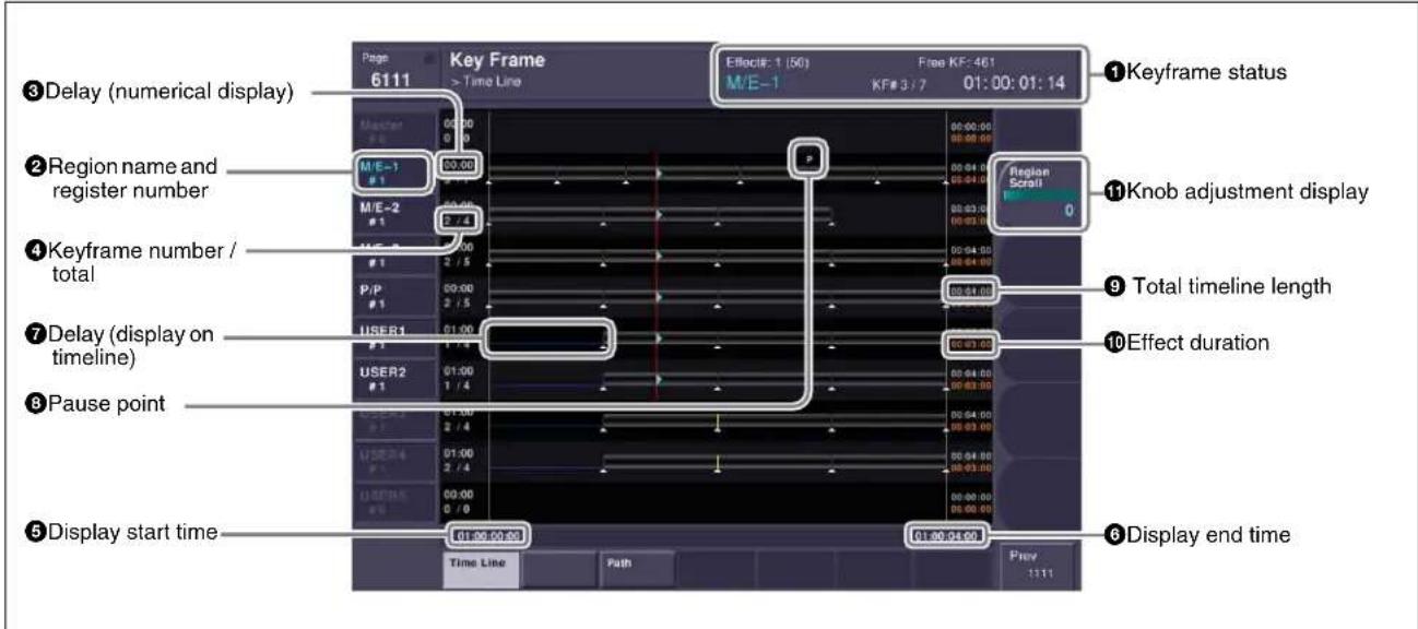
Key Frame >Timeline menu
①Keyframe status
This shows the region name, register number, register name, number of remaining keyframes, current position and timecode with regard to the reference region.
②Region name and register number
This shows the region name and the number of the register recalled in this region.
The display color indicates the region selection as follows.
Blue: reference region
White: selected region
Gray: not selected region
③Delay (numerical display)
This shows the delay between carrying out an effect operation, and the start of the actual effect.
④Keyframe number / total
This shows the number of the keyframe at the cursor position, and the total number of keyframes in the register.
⑤Display start time
This shows the timecode value for the timeline display start point.
⑥ Display end time
This shows the timecode value for the timeline display end point.
⑦Delay (display on timeline)
When a delay is set, the interval is shown by a blue line.
⑧ Pause point
A "P" appears where a pause is set.
⑨ Total timeline length
The total time of delays and effect duration appears in white.
10 Effect duration
The total duration of the effect appears in orange.
⑪Knob adjustment display
Turning the corresponding knob scrolls the timeline display, allowing you to see the timeline for regions that were previously hidden.
Settings in the Timeline Menu
Selecting the region to be displayed
The Timeline menu shows a timeline for each region, but you can also restrict the regions to be shown.
Recalling the Timeline Assign menu
1 In the menu control block, press the top menu selection button [KEY FRAME].
2 Select HF5 'Timeline Assign.'
The Key Frame >Timeline Assign menu appears. The right of the status area shows a list of the regions (including the global region) assigned to the region selection buttons in the numeric keypad control block. The left shows the regions in order of precedence, and whether each region is shown on the Timeline menu.
Deciding which regions appear on the timeline
In the Timeline Assign menu, press [Active Region], toggling it on or off.
On: The regions for which the region selection buttons in the numeric keypad control block are lit are shown in the precedence order (see next item) set in this menu, followed by the regions for which the buttons are off, in the same order.
Off: The regions appear according to the precedence order (see next item) and display on/off setting (see page 434) set in this menu.
Deciding the precedence order for timeline display
To change the precedence order, insert and delete regions in the list, in the desired order.
1 In the Timeline Assign menu, use any of the following methods to select the desired precedence order position and the region you want to insert.
- Press directly on the precedence order position in the list on the left and the region you want to insert in the list on the right.
- Press the arrow keys to scroll the reverse video cursor.
- Turn the knobs to make the setting.
| Knob | Parameter | Adjustment | Setting values |
| 1 Priority Precedence | order of insertion position | 1 to upwards | |
| 2 Region | Region to be inserted | be inserted | 1 to upwards |
2 In the group, press [Insert].
This inserts the selected region before the specified precedence order.
If the inserted region is already present in a different precedence order, it is deleted from that precedence order.
3 To delete a region from a precedence order, use any of the following methods to select the region.
- Press directly on the list on the left of the status area.
- Press the arrow keys to scroll the reverse video cursor.
- Turn the knob.
| Knob | Parameter Adjustment Setting values | ||
| 1 | Priority Precedence | order assigned to the region to be deleted | 1 to upwards |
4 To carry out the deletion, press [Delete] in the group.
This deletes the selected region from the precedence order list.
Setting the display of regions in the Timeline menu on or off
When [Active Region] is off, to select which regions are displayed in the Timeline menu, use the following procedure.
1 In the Timeline Assign menu, use any of the following methods to select the region.
- Press directly on the list on the left of the status area.
- Press the arrow keys to scroll the reverse video cursor.
- Turn the knob.
| Knob | Parameter | Adjustment Setting | values |
| 1 | Priority Region selection 1 to upwards | ||
2 For no display, press [Display], turning it off. To display, press once more, turning it on.
When [Active Region] is off, regions with the "Display Off" setting are not displayed in the Timeline menu.
To return to the default precedence order and timeline menu display settings
Press [Default] in the
Recalling a Register
Use the numeric keypad control block or Multifunction Flexi Pad control block to recall a register. For each region there are 99 registers dedicated to keyframes, numbered from 1 to 99.
When creating an effect as a user programmable DME, use a 3-digit register number which is commonly used for all DME regions (channels).
For a description of the concept of regions and registers, see “Regions” (page 425) and “Registers” (page 426).
The master timeline can also be recalled from the standard-type Flexi Pad control block.
Recalling a register from the numeric keypad control block
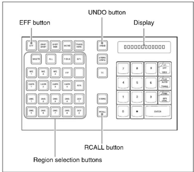
Numeric keypad control block
1 Press the [EFF] button, turning it on.
This allocates the numeric keypad control block to keyframe operations, and the [RCALL] button lights.
2 Press the button corresponding to the region you want to select, turning it on.
You can also press more than one button.
[M/E 1], [M/E 2], [M/E 3], [M/E 4], [P/P]: These select the corresponding M/E-1, M/E-2, M/E-3, M/E-4, and PGM/PST regions.
Notes
To select M/E 4, it is necessary to assign M/E 4 to a button (see page 559).
[USER 1] to [USER 8]: These select the User regions.
[DME 1] to [DME 8]: These select the DME channels.
[DEV 1] to [DEV 12]: These select the regions Device 1 to Device 12, respectively.
[P-BUS]: This selects P-Bus.
[GPI]: This selects GPI.
[MCRO]: This selects Macro.
[ALL]: This selects all valid regions.
[MASTR]: This selects the master timeline (see page 455)
Notes
The regions that can be selected simultaneously are those assigned to the region selection buttons in the numeric keypad control block (see page 559).
It is not possible to select [MASTR] and other regions simultaneously. If selected simultaneously, the master timeline takes precedence.
The first button pressed lights green as the reference region, and any subsequently pressed buttons light amber.
Pressing one of the amber-lit buttons, while holding down [EFF], turns the button green to indicate its corresponding region as the new reference region.
For details of the precedence order for becoming the reference region, see “Reference region” (page 425).
The display shows the name of the reference region, and the number of the last register recalled for this region.
3 Enter the number of the register you want to recall, using the numeric keypad.
To find an empty register, instead of entering a number, press the [.] (period) button. To search for an empty register common to all currently selectable regions, press the [.] button again.
To search for an empty register in the 100 range, press [1], [0], [0], [. ] (period) in this order. Similarly, to search for an empty register in the 200 range, press [2], [0], [0], [. ] (period), and to search for an empty register in the 300 range, press [3], [0], [0], [. ] (period).
The register number appears in the display. If the number is followed by a letter ‘e’ or ‘E,’ this indicates the following.
e: The selected register is empty for the regions selected in step 2.
E: The selected register is empty for all currently selectable regions.
4 To apply a temporary attribute (effect dissolve), press the [+/-/EFF DISS] button.
Notes
It is not possible to apply temporary attributes to the master timeline.
5 Press the [ENTER] button.
This recalls the specified register.
When the master timeline is recalled, the region selection buttons light according to the saved region information.
To undo the recall of a register
Immediately after recalling the register, press the [UNDO] button to undo the operation.
Notes
After recalling the master timeline, you cannot undo the recall.
Recalling the master timeline in the Flexi Pad control block
Whichever block you recall the master timeline from, the region set when it was saved is recalled.
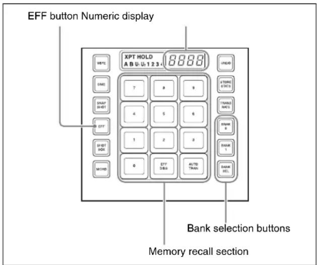
Flexi Pad control block (standard type)
1 In the Flexi Pad control block, press the [EFF] button.
This assigns the Flexi Pad control block to master timeline operation.
The previously selected bank number and last recalled register number appear in the numeric display.
2 Using any of the following methods, select the bank to be recalled.
To select bank 0: press the [BANK 0] button.
To select bank 1: press the [BANK 1] button.
To select any of banks 0 to 9: press the [BANK SEL] button; the memory recall section display changes as shown in the following figure; press one of 0 to 9.
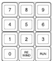
The selected bank number appears in the numeric display.
The memory recall section buttons show the register names corresponding to the selected bank, and the register status.
Note that by a setting in the Setup menu, you can select either register names or register numbers to be displayed.
Lit orange: register holding the master timeline
Lit yellow: last recalled register
Off: empty register
3 Press the button in the memory recall section which shows the desired register name.
The button you pressed lights yellow, and the master timeline is recalled. The numeric display shows the bank number, followed by the selected register number.
Recalling a register from the Multifunction Flexi Pad control block
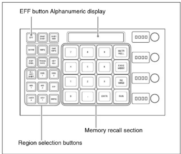
1 Press the [EFF] button, turning it on.
2 Press the button corresponding to the region you want to select, turning it on.
You can also press more than one button.
[M/E 1], [M/E 2], [M/E 3], [M/E 4], [P/P]: These select the corresponding M/E-1, M/E-2, M/E-3, M/E-4, and PGM/PST regions.
Notes
To select M/E 4, it is necessary to assign M/E 4 to a button (see page 649).
[USER 1] to [USER 8]: These select the User regions.
[DME 1] to [DME 8]: These select the DME channels.
[PBUS]: This selects P-Bus.
[GPI]: This selects GPI.
[MCRO]: This selects Macro.
[DEV 1] to [DEV 12]: This selects device.
[ALL]: This selects all valid regions.
[MSTR]: This selects the master timeline.
For details, see “Creating and Saving a Master Timeline Using the Buttons in the Multifunction Flexi Pad Control Block” (page 456).
Notes
The regions that can be selected simultaneously are those assigned to the region selection buttons in the Multifunction Flexi Pad control block, and those displayed on the memory recall section buttons when the [MORE] button is pressed (see page 559).
When [MSTR] and other regions are selected simultaneously, the master timeline takes precedence. The first button pressed lights green as the reference region, and any subsequently pressed buttons light amber.
Pressing one of the amber-lit buttons, while holding down [EFF], turns the button green to indicate its corresponding region as the new reference region.
For details of the precedence order for becoming the reference region, see “Reference region” (page 425).
The display shows the name of the reference region, and the number of the last register recalled for this region.
3 Enter the number of the register you want to recall, using the numeric keypad.
To find an empty register, instead of entering a number, press the [.] (period) button. To search for an empty register common to all currently selectable regions, press the [.] button again.
To search for an empty register in the 100 range, press [1], [0], [0], [.] (period) in this order. Similarly, to search for an empty register in the 200 range, press [2],

[0], [0], [.] (period), and to search for an empty register in the 300 range, press [3], [0], [0], [.] (period).
The register number appears in the display. If the number is followed by a letter ‘e’ or ‘E,’ this indicates the following.
e: The selected register is empty for the regions selected in step 2.
E: The selected register is empty for all currently selectable regions.
4 Press the [ENTER] button.
This recalls the specified register.
When the master timeline is recalled, the region selection buttons light according to the saved region information.
To recall the master timeline
1 In the Multifunction Flexi Pad control block, press the [EFF] button.
This switches the Multifunction Flexi Pad control block to the effect operation mode.
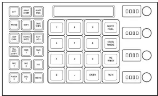
2 Press the [MSTR RCLL] button.
This switches the memory recall section to the master timeline recall mode.
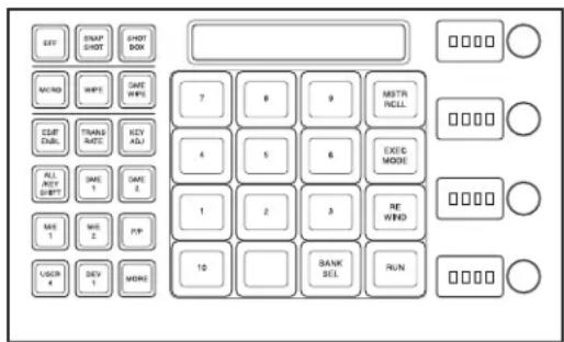
3 Press the [BANK SEL] button.
This switches the memory recall section to the bank selection mode.
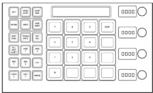
4 Press the number of the desired bank.
This selects the bank, and the buttons in the memory recall section show the register states as follows.
Lit yellow: Last recalled register
Lit orange: Register holding data
Off: Empty register
5 Press the number of the desired register.
The button you pressed lights yellow, and this recalls the master timeline.
The alphanumeric display shows the selected bank and register numbers.
Specifying the Region and Edit Points
Selecting the Region in Which Editing Applies
Selecting by control panel
Select the region in which the editing is applied by the effect consisting of keyframes, using the region selection buttons in the numeric keypad control block or Multifunction Flexi Pad control block.
See step 2 of "Recalling a register from the numeric keypad control block" (page 435).
Selecting by menus
This is convenient for selecting some of the regions assigned to the numeric keypad control block or changing the reference region.
Notes
The function of region selection buttons in the numeric keypad control block or Multifunction Flexi Pad control block is linked to the menu. If you carry out region selection by pressing a region selection button, then all the regions assigned to that button are selected.
1 In the Key Frame menu, press HF7 'Region Select.'
The Key Frame >Region Select menu appears.
On the left of the status area, region selection buttons appear.
Depending on the region selection state, the following indications appear.
Green text: the assigned regions include the reference region.
Orange text: one of the assigned regions is selected.
White text: no assigned region is selected.
When any one or more of the regions assigned to the region selection buttons is not selected, a red bar appears within the button indication. The [STORE] and [RCALL] buttons in the numeric keypad control block flash amber.
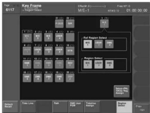
flowchart
graph TD
    A["Key Frame"] --> B["Ret Region Select"]
    A --> C["Region Select"]
    B --> D["M/E-1"]
    B --> E["M/E"]
    B --> F["M/E"]
    B --> G["M/E"]
    C --> H["M/E"]
    C --> I["M/E"]
    C --> J["M/E"]
    D --> K["1 (3)"]
    D --> L["2 (3)"]
    D --> M["3 (2)"]
    D --> N["4 (1)"]
    D --> O["5 (0)"]
    E --> P["1 (3)"]
    E --> Q["M/E 1"]
    E --> R["M/E 2"]
    E --> S["M/E 3"]
    E --> T["USER 4"]
    E --> U["USER 5"]
    E --> V["USER 6"]
    E --> W["USER 7"]
    E --> X["USER 8"]
    E --> Y["USER 9"]
    E --> Z["USER 10"]
    E --> AA["USER 11"]
    E --> AB["USER 12"]
    E --> AC["USER 13"]
    E --> AD["USER 14"]
    E --> AE["USER 15"]
    E --> AF["USER 16"]
    E --> AG["USER 17"]
    E --> AH["USER 18"]
    E --> AI["USER 19"]
    E --> AJ["USER 20"]
    E --> AK["USER 21"]
    E --> AL["USER 22"]
    E --> AM["USER 23"]
    E --> AN["USER 24"]
    E --> AO["USER 25"]
    E --> AP["USER 26"]
    E --> AQ["USER 27"]
    E --> AR["USER 28"]
    E --> AS["USER 29"]
    E --> AT["USER 30"]
    E --> AU["USER 31"]
    E --> AV["User 32"]
    E --> AW["User 33"]
    E --> AX["User 34"]
    E --> AY["User 35"]
    E --> AZ["User 36"]
    E --> BA["User 37"]
    E --> BB["User 38"]
    E --> BC["User 39"]
    E --> BD["User 40"]
    E --> BE["User 41"]
    E --> BF["User 42"]
    E --> BG["User 43"]
    E --> BH["User 44"]
    E --> BI["User 45"]
    E --> BJ["User 46"]
    E --> BK["User 47"]
    E --> BL["User 48"]
    E --> BM["User 49"]
    E --> BN["User 50"]
When using the CCP-6224/6324 Control Panel, the buttons in the
Selection screen for regions assigned to region selection buttons
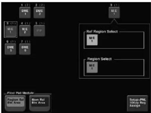
flowchart
graph TD
    A["1 (2)"] --> B["DME 1"]
    C["2 (2)"] --> D["DME 2"]
    B --> E["3 (1)"]
    D --> F["4 (1)"]
    E --> G["M.E 1"]
    F --> H["M.E 2"]
    G --> I["0 (1)"]
    H --> J["7 (1)"]
    I --> K["DME 5"]
    J --> L["DME 6"]
    K --> M["3 (1)"]
    L --> N["3 (1)"]
    M --> O["M.E 1"]
    N --> P["Ref Region Select"]
    P --> Q["M.E 1"]
    Q --> R["Region Select"]
    R --> S["M.E 1"]
    S --> T["Setup-PNL 10Key Reg Assign"]
    U["Filet Pad Module"] --> V["Region Set Bit Area"]
    U --> W["Mom Rel Bit Area"]
Selection screen for regions assigned to buttons in the memory recall section

flowchart
graph TD
    A["1 (0)"] --> B["4 (1)"]
    C["2 (0)"] --> D["5 (1)"]
    E["3 (1)"] --> F["6 (1)"]
    G["4 (1)"] --> H["7 (1)"]
    I["USER 1"] --> J["8 (1)"]
    K["USER 2"] --> L["9 (1)"]
    M["USER 3"] --> N["10 (1)"]
    O["USER 5"] --> P["11 (1)"]
    Q["USER 6"] --> R["12 (1)"]
    S["USER 7"] --> T["13 (1)"]
    U["USER 8"] --> V["14 (1)"]
    W["MCRO"] --> X["15 (1)"]
    Y["DEV 2"] --> Z["P-BUS"]
    AA["GPI"] --> AB["RTR"]
    AC["Flow Pad Module"] --> AD["Region Sel Bin Area"]
    AE["Menu Ret Bin Area"] --> AF["Setup-PML 10Key Reg Assign"]
2 Press a button indication on the left of the status area, to select the button you want to assign.
The regions currently assigned to the button you pressed appear on the right side of the status area.
3 In the
4 In the group, press the button indication you want to make the reference region.
The button you pressed lights green.
Notes
You can also specify edit points in the Multifunction Flexi Pad control block (see page 448).
Setting the Edit Points
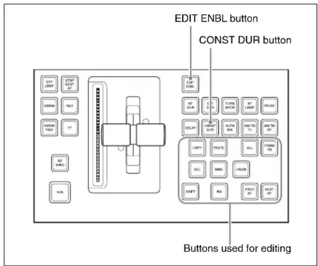
Keyframe control block
To set the edit points, use any of the following operations in the keyframe control block.
- To move the edit point to the keyframe immediately after the current time (the position at which the effect is currently stopped), press the [NEXT KF] button.
- To move the edit point to the keyframe immediately before the current time, press the [PREV KF] button.
- To move the edit point to a keyframe specified by number, press the [GO TO KF] button, then enter the keyframe number with the numeric keypad in the numeric keypad control block or Multifunction Flexi Pad control block, and press the [ENTER] button to confirm.
- To move the edit point to a specified timecode, press the [GO TO TC] button, then enter the timecode value with the numeric keypad in the numeric keypad control block, or Multifunction Flexi Pad control block and press the [ENTER] button to confirm.
To enter a difference value
When moving to a point specified with the [GO TO KF] button or [GO TO TC] button, you can also enter the difference from the current keyframe number or timecode value.
Press the numeric keypad [+/-] button, and enter the difference, then press the [TRIM] button. Each time you press the [+/-] button, it toggles between plus (+) and minus (-).

Creating and Editing Keyframes
For this operation you can use the numeric keypad control block and keyframe control block, or the Multifunction Flexi Pad control block. In the following, the case of using the numeric keypad control block and keyframe control block is described as an example.
For details of Multifunction Flexi Pad control block, see "Keyframe Creation and Editing in the Multifunction Flexi Pad Control Block" (page 448).
Creation
Creating new keyframes
To create new keyframes, after recalling an empty register, use the following procedure to create and insert each new keyframe. Use the keyframe control block for carrying out the operation.
1 Press the [EDIT ENBL] button, turning it on.
This enables effect editing in the keyframe control block.
2 Create the image you want to be the first keyframe.
3 Press the [INS] button.
This takes the current image as the first keyframe.
You can make a setting in the Setup menu so that when you recall an empty register, the system state at that point is automatically captured as the first keyframe.
4 Create the image you want to be the next keyframe.
5 Press the [INS] button.
This inserts the current image as the second keyframe after the first keyframe.
Repeat steps 4 and 5 to create the required number of keyframes.
To insert a new keyframe before an existing keyframe
Hold down the [SHIFT] button and press the [INS] button, to insert a new keyframe before the current keyframe.
Insertion
Inserting keyframes
To insert a keyframe in an existing effect, use the following procedure in the keyframe control block.
1 Press the [EDIT ENBL] button, turning it on.
2 Stop the effect at the desired edit point.
3 Create the image for the keyframe you want to insert.
4 Press the [INS] button.
When the edit point is on a keyframe, to insert the new keyframe before the existing keyframe, hold down the [SHIFT] button and press the [INS] button.
This inserts the current image as the new keyframe. Inserting a keyframe may change the total duration of the effect.
For details, see "Time Settings" (page 428).
Modification
Modifying keyframes
Use the following procedure in the keyframe control block.
1 Press the [EDIT ENBL] button, turning it on.
2 Stop the effect at the desired edit point.
When the edit point is on a keyframe, this is what you modify. If the edit point is between two keyframes, the previous keyframe is what you modify.
Notes
In constant duration mode (see page 427) modification is only possible when the edit point is on a keyframe.
3 Using image transformations or adding special effects, modify the keyframe.
4 Press the [MOD] button.
Modifying more than one keyframe simultaneously
You can modify a number of keyframes simultaneously. There are three different cases for this operation.
- Modifying from the edit point to a particular keyframe
- Modifying all keyframes in the effect
- Modifying the keyframes in a specified range
The different procedures for these cases are now described.
To modify from the edit point to a particular keyframe
1 Press the [EDIT ENBL] button, turning it on.
2 Stop the effect at the first keyframe of the range to be modified.
3 Carry out the necessary modifications.
4 Press the [FROM TO] button, turning it on.
The display in the numeric keypad control block shows the current keyframe number, followed by "TO."
5 Enter the number of the last keyframe to be modified from the numeric keypad control block and press the [ENTER] button to confirm.
6 Press the [MOD] button. Alternatively, hold down the [SHIFT] button and press the [MOD] button.
For the difference in the result, see “Differences in the changes when a number of keyframes are modified” (page 442).
To modify all keyframes in the effect
1 Press the [EDIT ENBL] button, turning it on.
2 Carry out the necessary modifications on any keyframe.
3 Press the [ALL] button, turning it on.
4 Press the [MOD] button. Alternatively, hold down the [SHIFT] button and press the [MOD] button.
For the difference in the result, see “Differences in the changes when a number of keyframes are modified” (page 442).
To modify the keyframes in a specified range
1 Press the [EDIT ENBL] button, turning it on.
2 Stop the effect at any keyframe within the range to be modified.
3 Carry out the necessary modifications.
4 Press the [FROM TO] button, turning it on.
The display in the numeric keypad control block shows the current keyframe number, followed by "TO."
5 Using the numeric keypad in the numeric keypad control block, carry out the following operations.
- To set the first keyframe in the range to be modified, press the [CLR] button, then enter the keyframe number, and press the [ENTER] button to confirm.
- To set the last keyframe in the range to be modified, enter the keyframe number from the numeric keypad, and press the [ENTER] button to confirm.
6 Press the [MOD] button. Alternatively, hold down the [SHIFT] button and press the [MOD] button.
For the difference in the result, see “Differences in the changes when a number of keyframes are modified” (page 442).
Differences in the changes when a number of keyframes are modified
When you select a number of keyframes to modify, and press the [MOD] button alone or in combination with the [SHIFT] button, the result of the operation differs as shown below.
Modifying the keyframes by pressing the [MOD] button alone
The modified parameter values are taken as absolute values, and applied to all of the selected keyframes.
![SONY MVS-7000X - Modifying the keyframes by pressing the [MOD] button alone - 1](/content/2026/06/1364863/images/9c3ce1743f319521451b471edab89398f6b8969b72613c26c70529b6ca383be3.jpg)
flowchart
graph TD
    A["Keyframe 1: Background A"] --> D["Modify keyframe 2. (Changing the position of background B in the horizontal direction)"]
    B["Keyframe 2: Background B"] --> D
    C["Keyframe 3: Background B"] --> D
    D --> E["Effect execution"]
    F["Keyframe 1: Background A"] --> G["Select keyframes 1 to 3 and modify simultaneously."]
    H["Keyframe 2: Background B"] --> G
    I["Keyframe 3: Background B"] --> G
    J["Keyframe 3: Background B"] --> G
    K["Keyframe 1: Background A"] --> L["Execution"]
    M["Keyframe 2: Background B"] --> L
    N["Keyframe 3: Background B"] --> L
    O["Keyframe 3: Background B"] --> L
Result:
The horizontal position of background B in keyframes 1 and 3 is now the same as that in keyframe 2. In all keyframes, the vertical position remains unchanged as the parameter is not changed.
Modifying the keyframes by holding down the [SHIFT] button and pressing the [MOD] button
The modified parameter values are taken as relative values, which modify all of the selected keyframes.
![SONY MVS-7000X - Modifying the keyframes by holding down the [SHIFT] button and pressing the [MOD] button - 1](/content/2026/06/1364863/images/c9741930d39f115290ab4e0f6eeddf9a5244c639e9eb5c877ffc237339b66871.jpg)
flowchart
graph TD
    A["Keyframe 1 Keyframe 2 Keyframe 3 Effect"] --> B["Modify keyframe 2. (Changing the position of background B in the horizontal direction)"]
    B --> C["Select keyframes 1 to 3 and modify simultaneously."]
Result:
Background B of keyframes 1 and 3 is moved in the horizontal direction by the same amount as in keyframe 2.
Deletion
Deleting keyframes
1 Press the [EDIT ENBL] button, turning it on.
2 Stop the effect at the desired edit point.
When the edit point is on a keyframe, this is what you delete. If the edit point is between two keyframes, the previous keyframe is what you delete.
3 To delete a number of keyframes in a single operation, press the [FROM TO] button or the [ALL] button, turning it on.
For how to specify a range of keyframes, see "Modifying more than one keyframe simultaneously" (page 441).
4 Press the [DEL] button.
This deletes the keyframe. Deleting a keyframe reduces the total duration of the effect. In constant duration mode (see page 445), however, the duration does not change.
For details, see “Changes in the effect duration caused by deleting a keyframe” (page 428).
Movement
Moving keyframes
1 Press the [EDIT ENBL] button, turning it on.
2 Stop the effect at the edit point you want to move.
3 To move a number of keyframes in a single operation, press the [FROM TO] button, turning it on, to specify the keyframes.
For how to specify a range of keyframes, see "Modifying more than one keyframe simultaneously" (page 441).
4 Press the [DEL] button.
This deletes the keyframe, and saves it in the paste buffer.
5 Move the edit point to the position to which you want to move the keyframe.
6 Press the [PASTE] button.
This inserts the keyframe you have moved after the current keyframe. In constant duration mode, the moved keyframe overwrites the edit point.
To insert the moved keyframe before a keyframe Hold down the [SHIFT] button, and press the [PASTE] button to insert the moved keyframe before the current keyframe.
Copying
Copying keyframes
1 Press the [EDIT ENBL] button, turning it on.
2 Stop the effect at the edit point you want to copy.
3 To copy a number of keyframes in a single operation, press the [FROM TO] button or the [ALL] button, turning it on.
For how to specify a range of keyframes, see "Modifying more than one keyframe simultaneously" (page 441).
4 Press the [COPY] button.
This copies the specified keyframe, and saves it to the paste buffer.
5 Move the edit point to the position where you want to insert the copied keyframe.
6 Press the [PASTE] button.
This inserts the keyframe you have copied after the current keyframe. In constant duration mode, the copied keyframe overwrites the edit point.
To insert the copied keyframe before a keyframe Hold down the [SHIFT] button, and press the [PASTE] button to insert the copied keyframe before the current keyframe.
Pause
To apply a pause to a keyframe, use the following procedure.
1 Press the [EDIT ENBL] button, turning it on.
2 Stop the effect on the keyframe to which you want to apply a pause.
3 Press the [PAUSE] button.
Keyframe Loop (Repeated Execution of a Specified Range)
By setting the range of the loop within the effect, and the number of loop executions, you can execute the loop range repeatedly.
Notes
It is only possible to set one keyframe loop for each region.
Creating a new keyframe loop
To specify the loop range and loop count, carry out the following procedure.
1 Press the [EDIT ENBL] button, turning it on.
2 Stop the effect on the keyframe you want to make the first of the loop range (start point). (Here, by way of example, keyframe 2 is taken as the start point.)
3 Press the [KF LOOP] button in the keyframe control block, turning it on.
The numeric keypad control block display shows the start point keyframe number as follows.
FM 2 TO
The example shown means “from (keyframe) 2 to...,” where the end keyframe is to follow.
4 With the numeric keypad buttons of the numeric keypad control block, enter the number of the last keyframe in the loop range (end point). (Here, by way of example, keyframe 5 is the end point.)
FM 2 TO 5
5 Press the [ENTER] button to confirm the entry.
The display changes as follows, prompting you to enter the loop count.
COUNT
6 Enter the loop count. (Here, by way of example, "15" is entered.)
- To specify a loop count, enter a number in the range 1 to 99.
- To specify an endless loop, enter "0" (zero).
COUNT 15
7 Press the [ENTER] button to confirm the entry.
The start point, end point, and loop count that you have set are reflected in the Timeline menu.
If you enter the loop count as “0” (endless loop), the count is shown as “inf” (infinity).
The numeric keypad control block display changes back to the state shown in step 4.
Changing the keyframe loop settings
To change the loop range or count for the currently recalled effect, carry out the following procedure.
1 When the [KF LOOP] button in the keyframe control block is lit amber, press it, turning it green.
The numeric keypad control block display shows the current loop range.
If, for example, the start point is keyframe 2 and the end point is keyframe 5, this appears as follows.
FM 2 TO 5
2 To change the loop range, press the [CLEAR] button in the numeric keypad control block.
To change the loop count only, press the [ENTER] button, then skip to step 6.
When you press the [CLEAR] button, this appears as follows.
FM TO
3 Enter the keyframe number for the new start point, and press the [ENTER] button.
4 Enter the keyframe number for the new end point, and press the [ENTER] button.
The display shows the currently set loop count.
5 To change the setting, press the [CLEAR] button. This clears the set loop count.
COUNT
6 Enter the new loop count, and press the [ENTER] button.
Executing a keyframe loop
In the keyframe control block, press the [RUN] button. The set loop range is executed repeatedly for the set loop count number of times.
The screen shows the total loop count and the number of loops remaining. (If the loop count is infinite (inf), the remaining number is not shown.)
If the [REV] button is lit, the loop is played in the reverse order.
Canceling keyframe loop execution
Press the [REWIND] button in the keyframe control block.
Changes to the loop range caused by keyframe insertion/deletion
When a keyframe is inserted or deleted within the loop range, the loop range also changes. The following are examples.
Example 1: If keyframe 3 is deleted, the loop end point moves forward as follows.
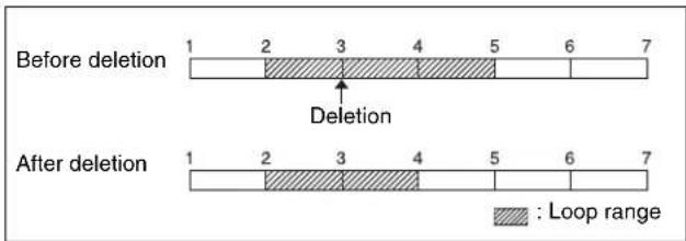
Example 2: If keyframe 3 is added, the end point keyframe number moves back.
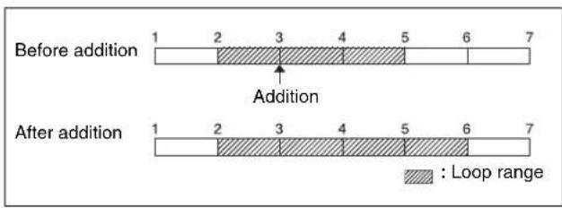
Example 3: If the keyframe at the end of the loop range (the end point) is deleted, the keyframe loop settings are all cleared, as follows, and the [KF LOOP] button goes off. The same occurs if the first keyframe in the loop range (the start point) is deleted.
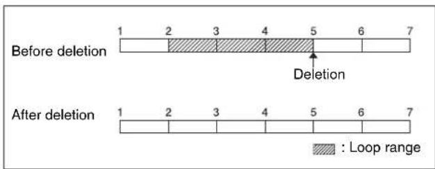
Undoing an Edit Operation
To undo a keyframe insert, modify, delete, or paste operation immediately after execution, press the [UNDO] button.
Duration Mode Setting
There are two keyframe duration modes: variable duration mode, and constant duration mode in which the effect duration is fixed (see page 427).
- To select variable duration mode, turn the [CONST DUR] button off.
- To select constant duration mode, press the [CONST DUR] button, turning it on.
Transition Mode Settings for User Programmable DME
To create an effect for user programmable DME, it is necessary to set the transition mode.
User programmable DME in transition mode
For the transition mode set when creating a keyframe effect for a user programmable DME pattern, the following can be used.
Single: single transition mode
Flip tumble (Flip Tumble): flip tumble transition mode
Dual: dual transition mode

Picture-in-picture (PinP): one-channel and two-channel picture-in-picture transition mode
Compress: a type of picture-in-picture, in which the new image is the background, and the currently visible image shrinks, and then expands to its original size. (See example in the next item.)
Frame in-out (Frame I/O): frame in-out transition mode. When the first transition completes, if you move the position of the image, you can move it both horizontally and vertically.
Frame in-out H (Frame I/O H): a type of frame in-out mode, which is specified when creating a transition effect in the horizontal direction.
The image movement is reflected at both the transition start point and end point. (See page 446.)
The operation is carried out according to DME wipe patterns 1202, 1203, or 1204.
Frame in-out V (Frame I/O V): a type of frame in-out mode, which is specified when creating a transition effect in the vertical direction.
The image movement is reflected at both the transition start point and end point. (See page 447.)
Transition mode "Compress"
The change in the image when the transition mode is set to “Compress” is as follows, in comparison to the case of “Picture-in-picture.”
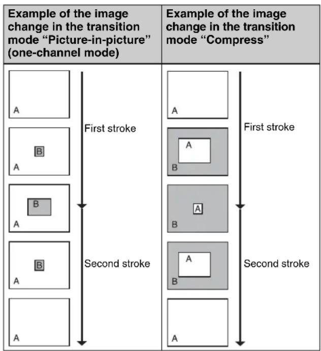
flowchart
graph TD
    A1["Image A"] -->|First stroke| B1["Image A B"]
    A2["Image A"] -->|Second stroke| B2["Image A B"]
    A3["Image A"] -->|First stroke| B3["Image A B"]
    A4["Image A"] -->|Second stroke| B4["Image A B"]
    style A1 fill:#f9f,stroke:#333
    style A2 fill:#f9f,stroke:#333
    style A3 fill:#f9f,stroke:#333
    style A4 fill:#f9f,stroke:#333
    style B1 fill:#ccf,stroke:#333
    style B2 fill:#ccf,stroke:#333
    style B3 fill:#ccf,stroke:#333
    style B4 fill:#ccf,stroke:#333
Transition mode "frame in-out"
In this mode, when the first transition has completed, you can move the image with the positioner in both horizontal and vertical directions, but the image position at the transition start point and end point does not change. The description is of an example of creating an effect such as the following.
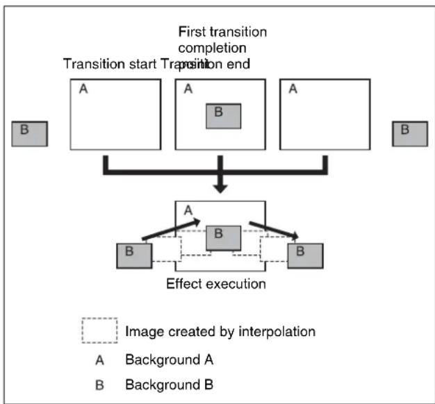
flowchart
graph TD
    A["Transition start"] --> B["First transition completion"]
    B --> C{Transition end}
    C --> D["Effect execution"]
    D --> E["Image created by interpolation"]
    style A fill:#f9f,stroke:#333
    style B fill:#ccf,stroke:#333
    style D fill:#cfc,stroke:#333
    note1["Image created by interpolation"]
    note2["A Background A\nB Background B"]
At the first transition completion point, if you move the image with the positioner, the transition appears as in the following figure.
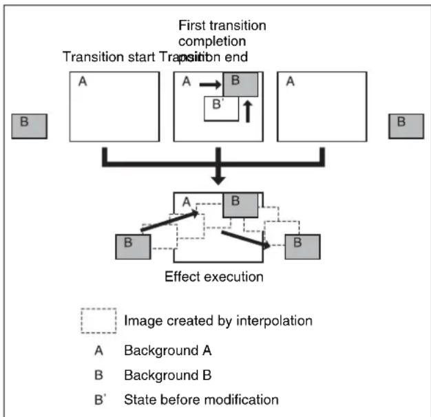
flowchart
graph TD
    A["Transition start"] --> B["First transition completion"]
    B --> C["Transition end"]
    C --> D["Effect execution"]
    D --> E["Image created by interpolation"]
    style A fill:#f9f,stroke:#333
    style B fill:#ccf,stroke:#333
    style C fill:#cfc,stroke:#333
    style D fill:#fcc,stroke:#333
    note right of D: Image created by interpolation
    note left of D: A Background A
    note right of D: B Background B
    note right of D: B State before modification
Transition mode "frame in-out H"
This mode is specified when creating a transition effect in the horizontal direction.
In this mode, when the first transition has completed, you can move the image with the positioner in both horizontal and vertical directions. The image at the transition start point and end point also moves.
The description is of an example of creating an effect such as the following.
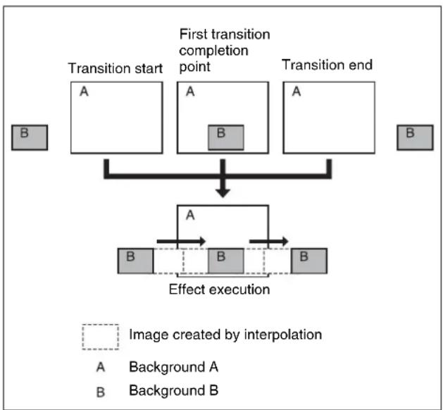
flowchart
graph TD
    A["Transition start"] --> B["First transition completion point"]
    B --> C["Transition end"]
    D["Image created by interpolation"] --> E["Effect execution"]
    F["Background A"] --> E
    G["Background B"] --> E
    H["A"] --> I["B"]
    J["A"] --> K["B"]
    L["A"] --> M["B"]
At the first transition completion point, if you move the image with the positioner, the transition appears as in the following figure.
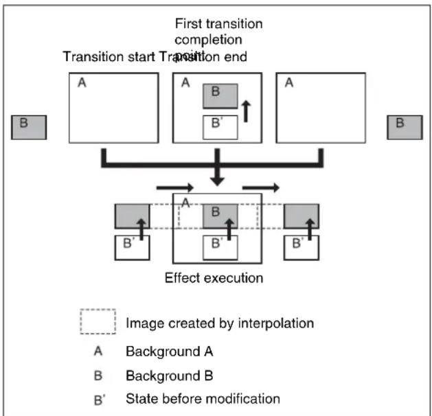
flowchart
graph TD
    A["Transition start"] --> B["Transition end"]
    B --> C["Effect execution"]
    C --> D["Image created by interpolation"]
    style A fill:#f9f,stroke:#333
    style B fill:#ccf,stroke:#333
    style C fill:#cfc,stroke:#333
    style D fill:#fcc,stroke:#333
Transition mode "frame in-out V"
This mode is specified when creating a transition effect in the vertical direction.
In this mode, in the state at completion of the first transition, you can move the image with the positioner in both horizontal and vertical directions. The image at the transition start point and end point also moves.
The description is of an example of creating an effect such as the following.
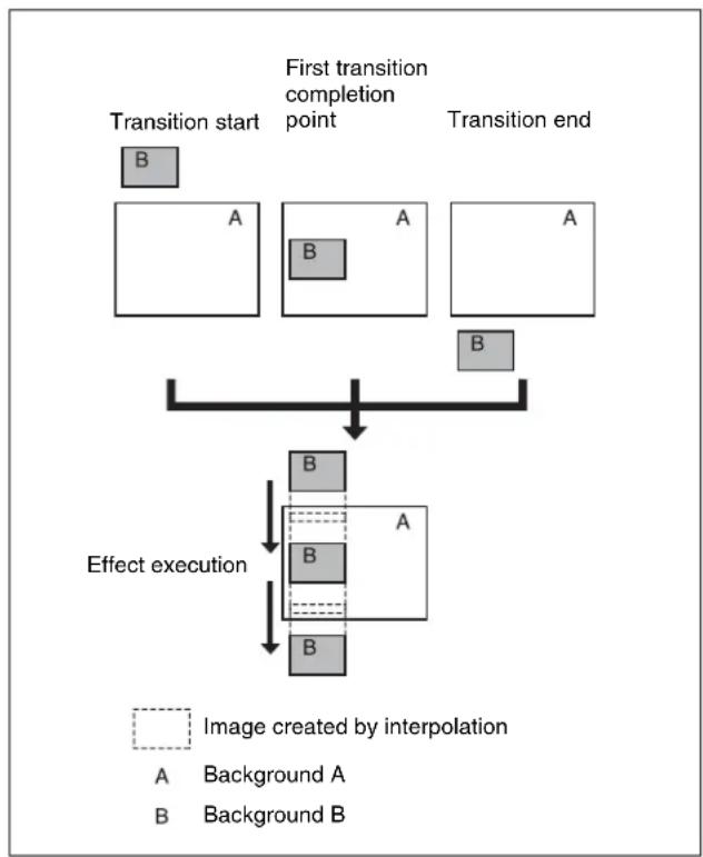
flowchart
graph TD
    A["Transition start"] --> B1["B"]
    B1 --> C["A"]
    C --> D["A"]
    D --> E["A"]
    E --> F["B"]
    F --> G["Effect execution"]
    G --> H["B"]
    H --> I["A"]
    I --> J["B"]
    J --> K["B"]
    style A fill:#ccc,stroke:#333
    style B fill:#ccc,stroke:#333
    style C fill:#ccc,stroke:#333
    style D fill:#ccc,stroke:#333
    style E fill:#ccc,stroke:#333
    style F fill:#ccc,stroke:#333
    style G fill:#ccc,stroke:#333
    style H fill:#ccc,stroke:#333
    style I fill:#ccc,stroke:#333
    style J fill:#ccc,stroke:#333
    style K fill:#ccc,stroke:#333
At the first transition completion point, if you move the image with the positioner, the transition appears as in the following figure.
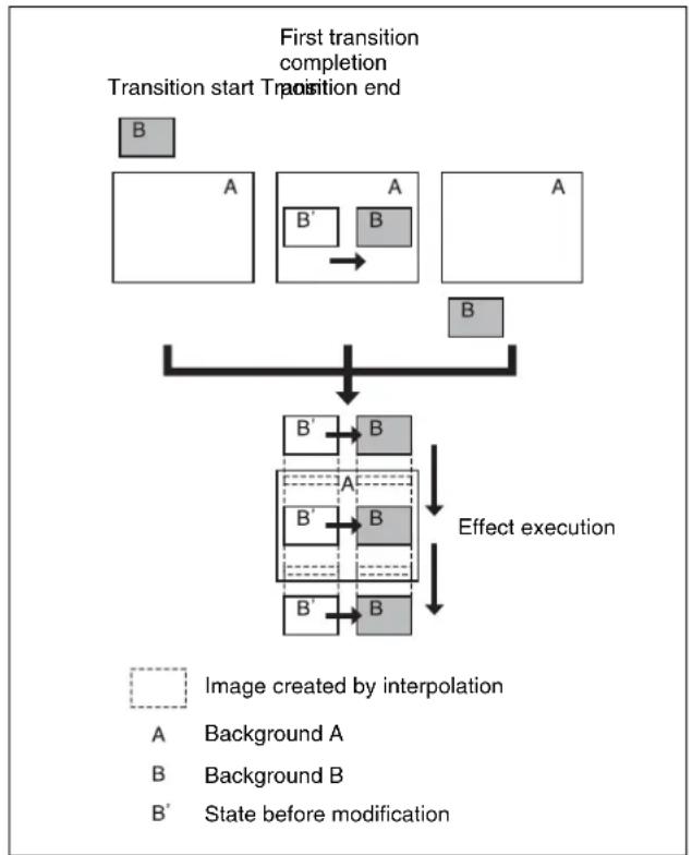
flowchart
graph TD
    A["Transition start"] --> B1["First transition completion"]
    B1 --> C1["Transition start Transition end"]
    C1 --> D1["Effect execution"]
    D1 --> E1["Image created by interpolation"]
    style A fill:#f9f,stroke:#333
    style B fill:#ccf,stroke:#333
    style C1 fill:#cfc,stroke:#333
    style D1 fill:#fcc,stroke:#333
    style E1 fill:#ffc,stroke:#333
Signals forming part of the background for a DME wipe
For a two-channel mode page turn, page roll, brick, frame in-out, and so on, the part of the pattern shown in gray is filled with the signal selected on the DME external video bus.
For three-channel mode brick, the part of the pattern shown in dark gray is filled with the DME external video signal, and the light gray portion with the signal selected as follows.
For details on the pattern, see “DME Wipe Pattern List” in Appendix (Volume 1).
For a DME dedicated interface
- When the DME channel used is 3 or 4, the signal selected on the DME utility 1 bus.
- For channel 7 or 8, the signal selected on the DME utility 2 bus.
For a DME SDI interface
Signal selected on the AUX bus assigned in the Engineering Setup >Switcher >Device Interface >DME Type Setting >DME SDI interface menu. (The AUX bus is determined by which DME channel is being used.)
Notes
For the SDI interface on the DME, in some cases the AUX bus is used in place of the DME external bus (see page 619).
Setting the transition mode
1 In the Key Frame menu, select HF4 'DME User PGM.'
The DME User PGM menu appears.
2 In the
Single: select single transition mode.
Flip/Tumble: select the flip/tumble transition mode.
Dual: select dual transition mode.
P in P: select picture-in-picture mode.
Compress: select compress mode.
Frame I/O: select frame in-out transition mode.
Frame I/O H: select frame in-out transition mode in the horizontal direction.
Frame I/O V: select frame in-out transition mode in the vertical direction.
For details of creating an effect for user programmable DME, see “Creating User Programmable DME Patterns” in Chapter 6 (Volume 1).
Notes
Which DME channel is selected as the reference region (lit green) in the numeric keypad control block is reflected in the
Keyframe Creation and Editing in the Multifunction Flexi Pad Control Block
To create and edit a keyframe in the Multifunction Flexi Pad control block, press the [EFF] button to switch to effect operation mode, then press the [EDIT ENBL] button.
The [EDIT ENBL] button lights red, and the memory recall section switches to the effect editing mode as shown in the following illustration.
- Buttons in the memory recall section in effect editing mode (first page) Press the [PAGE 1/2] button to switch to the next button display.
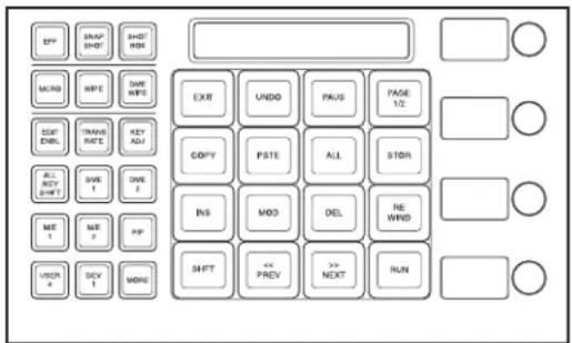
- Buttons in the memory recall section in effect editing mode (second page)
Press the [PAGE 2/2] button to switch to the previous button display.
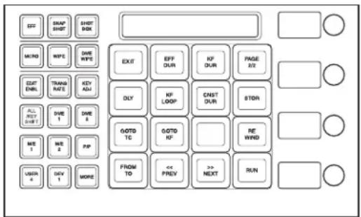
In this mode, you can carry out keyframe creation and editing, using the following buttons.
[EXIT] button: Forcibly exit editing mode.
[UNDO] button: Undo the last keyframe insertion, modification, deletion, paste or other operation.
[PAUS] button: Add a pause setting to a keyframe (see page 444).
[COPY] button: Copy a keyframe (see page 443).
[PSTE] button: Paste a keyframe (see page 443).
[ALL] button: Select all keyframes in an effect (see page 441).
[STOR] button: Save the effect (see page 455).
[INS] button: Insert a keyframe (see page 441)
[MOD] button: Modify a keyframe (see page 441).
[DEL] button: Delete a keyframe (see page 443).
[REWIND] button: Move to the first keyframe in the effect (see page 453).
[SHFT] button: Enable the shift function of the button pressed together with this one.
[<< PREV] button: Move the edit point to the previous keyframe (see page 440).
[>> NEXT] button: Move the edit point to the next keyframe (see page 440).
[RUN] button: Run the effect (see page 453).
[EFF DUR] button: Set the effect duration (see page 450).
[KF DUR] button: Set the keyframe duration (see page 449).
[ DLY ] button: Set a delay (see page 450).
[KF LOOP] button: Set a keyframe loop (see page 444).
[CNST DUR] button: Switch the duration mode (see page 445).
[GOTO TC] button: Move the edit point to the specified timecode position (see page 440).
[GOTO KF] button: Move the edit point to the specified keyframe position (see page 440).
[FROM TO] button: Switch to the mode for inputting ranges with the numeric keypad (see page 441).
Time Settings
You can determine the execution time of an effect by setting either the keyframe durations or the effect duration (see page 428).
Setting the Keyframe Duration
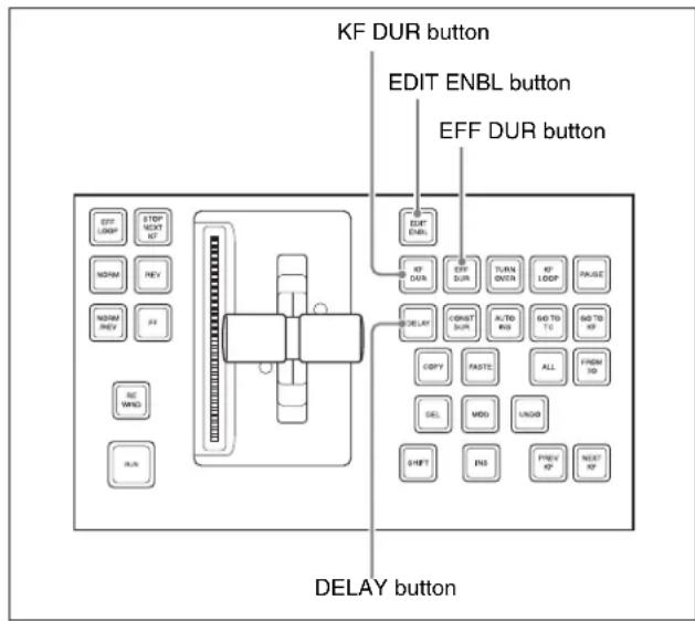
Keyframe control block
Setting the keyframe duration
You can set the value of the keyframe duration independently for each keyframe, by the following method.
1 Press the [EDIT ENBL] button, turning it on.
2 Stop the effect on the keyframe for which you want to set the duration.
The time from this keyframe to the following keyframe is what you set.
3 Press the [KF DUR] button, turning it on.
The display in the numeric keypad control block shows “KF DUR” followed by the duration of the current keyframe (seconds:frames).
4 Using the numeric keypad in the numeric keypad control block, enter the timecode value for the keyframe duration, as a maximum of four digits.
For example, to set 9 seconds and 20 frames, enter 920. You can also use the [TRIM] button to enter a difference value (see page 440).
5 Press the [ENTER] button to confirm the entry.
This changes the keyframe duration to the new setting.
Notes
In addition to the above operation, the keyframe duration may also be automatically changed as a result of changing the effect duration. (See the next section.)
Setting the Effect Duration
To set the effect duration, use the following procedure.
1 Press the [EDIT ENBL] button, turning it on.
2 Press the [EFF DUR] button, turning it on.
The display in the numeric keypad control block shows “DUR” followed by the effect duration (minutes:seconds:frames).
3 Using the numeric keypad in the numeric keypad control block, enter the timecode value for the effect duration, as a maximum of six digits.
For example, to set 3 minutes 7 seconds and 15 frames, enter 30715. You can also use the [TRIM] button to enter a difference value (see page 440).
4 Press the [ENTER] button.
Notes
In addition to the above operation, the effect duration may also be changed as a result of inserting or deleting keyframes.
For details, see "Time Settings" (page 428).
Setting the Delay
To set the delay (see “Delay setting” (page 429)), use the following procedure.
1 Press the [EDIT ENBL] button, turning it on.
2 Press the [DELAY] button, turning it on.
The display in the numeric keypad control block shows “DELAY” followed by the delay time (seconds:frames).
3 Using the numeric keypad in the numeric keypad control block, enter the timecode value for the delay, as a maximum of four digits.
You can also use the [TRIM] button to enter a difference value (see page 440).
4 Press the [ENTER] button to confirm the entry.
Path Setting
The term “path” (see page 429) refers to the specification of how interpolation is carried out from one keyframe to the next.
Set keyframe paths in the Key Frame >Path menu.
To access the Key Frame >Path menu
In the menu control block, press the top menu selection button [KEY FRAME], then select HF3 'Path.'
Basic Procedure for Path Settings
Selecting the category
From the 16 buttons in the function button area, select the category for which you want to make the setting.
First row: path settings for the switcher M/E1 to M/E4, and PGM/PST banks
Second and third rows: path settings for User1 to User8
Fourth row: path settings for DME local channel and global channel 3D transforms and effects
Making switcher path settings
This section describes settings for M/E-1 Key1 as an example.
The area for the VF buttons shows the names of items.
A ▶ sign by a button indicates that pressing it opens a more detailed setting menu.
The status area shows the settings for Xpt, Hue, and Curve. However, depending on the item, these parameters may or may not be present.
Notes
Whenever you set a path or modify its setting, be sure to press the [MOD] button in the keyframe control block. The setting does not become effective unless the [MOD] button is pressed.
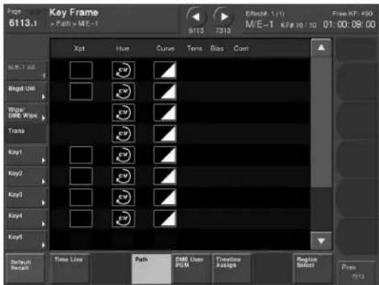
Changing the path type for Curve
1 In the Path menu, press [M/E-1].
The M/E-1 menu appears.
2 Press the Curve path type indication for the Key1 item that you want to change.
A path selection window appears.
3 Press the indication for the desired path type, to select it.

OFF: Executing the effect causes no change.

Step: There is no interpolation between eyframes, so that the effect parameters are updated each time a keyframe is passed.

Linear: Linear interpolation between eyframes, resulting in constant speed movement.

S-Curve: The rate of change accelerates and accelerates before and after a keyframe, so that the rate of change is maximum midway between two keyframes.

Spline: The effect follows a smooth curved path from each keyframe to the next.
The status area reflects the selected path type.
At this point, depending on the setting for Curve, the effect for Hue and Xpt is also affected as shown in the following table. In the menu, the Hue and Xpt settings do not change, but the path type indication is dimmed out.
| Curve setting | Hue change Xpt change | |
| OFF Does not change Hold | ||
| Step Changes as with the Step setting | Is not affected | |
4 If you selected Spline as the path type, set the following parameters, using the knobs.
| Knob | Parameter | Adjustment Setting | values |
| 1 Tens | Spline interpolation tension | -4.00 to +4.00 | |
| 2 Bias | Spline interpolation bias | -4.00 to +4.00 | |
| 3 Cont | Spline interpolation continuity | -4.00 to +4.00 | |
Changing the path type for Hue
1 Press the Hue path type indication for the item that you want to change.
2 Turn knob 1 to change the Hue path type.
The path type indications shown in the menu represent the change in hue as seen on a Vectorscope.

CW: Rotate clockwise.

CCW: Rotate counterclockwise.

Short: The hue changes in whichever of the lockwise and counterclockwise directions is shorter.

Long: The hue changes in whichever of the clockwise and counterclockwise directions is longer.
Changing the path type for Xpt
1 Press the Xpt path type indication for the item that you want to change.
A path selection window appears.
2 Press the indication for the desired path type, to select it.

Xpt Hold off: When replaying a keyframe, change the inputs to the settings saved in memory.

Xpt Hold on: When replaying a keyframe, do not change the inputs.
Executing Effects
By means of the [RUN] button in the keyframe control block, you can play an effect as a continuously varying image. This is referred to as effect execution (see page 431).
It is also possible to execute an effect from the device control block, the standard type Flexi Pad control block or the Multifunction Flexi Pad control block.
For details, see "Menus and Control Panel" in Chapter 2 (Volume 1).
Executing Effects in the Keyframe Control Block
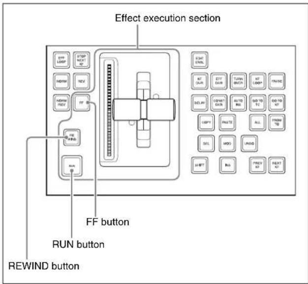
Keyframe control block
Executing an effect automatically
1 Select the region in which you want to execute the effect, using the region selection buttons in the numeric keypad control block (see page 435).
2 With the numeric keypad, enter the number of the register in which the effect you want to execute is saved, and press the [ENTER] button to confirm.
This recalls the effect saved in the register.
3 In the keyframe control block, press the [RUN] button.
The [RUN] button lights amber and the effect is executed automatically.
Executing an effect manually
In step 3 above, operate the fader lever.
To use the transition control block fader lever as a keyframe fader
Press the [KF] button in the transition control block, turning it on, to execute a keyframe effect with the fader lever in the same control block.
You can also assign the [KF] button to a transition type selection button in the transition control block (see page 560).
Notes
- It is not possible for the [KF] button to be on for multiple banks (M/E or PGM/PST) at the same time. If you press the [KF] button in more than one bank, only the last button pressed remains on.
- If a macro is assigned to the transition control block fader lever, then while in use as a keyframe fader the macro is not executed.
Moving to the first keyframe of the effect
To move to the first keyframe of the effect, press the [REWIND] button.
Moving to the last keyframe of the effect
To move to the last keyframe of the effect, press the [FF] button.
Setting the Run Mode
You can set the run mode in which an effect is executed when you press the [RUN] button.
Specifying the effect execution direction
To specify the effect execution direction, press the [NORM] button or the [REV] button, turning it on. When you press one, turning it on, the other automatically goes off.
To execute the effect so as to obtain the effects of the [NORM] and [REV] buttons alternately, press the [NORM/REV] button, turning it on.
When the [NORM] button is lit: The effect is executed in the direction from the first keyframe to the last keyframe.
When the [REV] button is lit: The effect is executed in the direction from the last keyframe to the first keyframe.
When the [NORM/REV] button is lit: Each time the effect is executed, the direction reverses.
Executing an effect up to the next keyframe
1 Press the [STOP NEXT KF] button, turning it on.
2 Press the [RUN] button.
This executes the effect as far as the next keyframe. When the [REV] button is lit, it is executed as far as the previous keyframe.
Repeating an effect
1 Press the [EFF LOOP] button, turning it on.
2 Press the [RUN] button.
This executes the effect repeatedly, from the first keyframe to the last keyframe.
When the [REV] button is lit, the effect is executed in the reverse direction.
3 To stop the repeating effect, press the [EFF LOOP] button, turning it off, or press the [REWIND] button.
Executing an Effect in the Flexi Pad Control Block
Executing an effect
To execute an effect recalled from the numeric keypad control block in the Flexi Pad control block, use the following procedure.
1 In the Flexi Pad control block, press the [EFF] button.
This assigns the Flexi Pad control block to effect operation, and the [REWIND] button and [RUN] button appear in the memory recall section. The previously selected bank number and last recalled register number appear in the numeric display.
2 Press the following buttons to execute the effect.
REWIND: Press this button to move to the first keyframe of the currently recalled effect. RUN: Press this button to run the currently recalled effect.
Executing an Effect in the Multifunction Flexi Pad Control Block
1 In the Multifunction Flexi Pad control block, press the [EFF] button.
This changes the Multifunction Flexi Pad control block to effect operation, and the [REWIND] button and [RUN] button appear in the memory recall section. The previously selected bank number and last recalled register number appear in the numeric display.
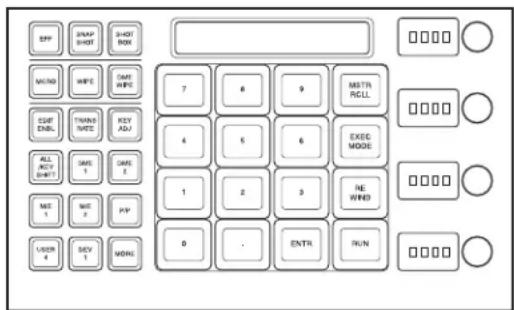
2 Press the following buttons to execute the effect.
[REWIND] button: Press this button to move to the first keyframe of the currently recalled effect.
[RUN] button: Press this button to run the currently recalled effect.
Setting the execution mode
Press the [EXEC MODE] button to switch the memory recall section to the execution mode setting mode, and set the execution mode with the following buttons, then execute the effect.
[EFF LOOP] button: Execute the effect repeatedly.
[STOP NEXT] button: Execute the effect and stop at the next keyframe.
[NORM] button: Execute the effect from the first keyframe to the last keyframe.
[NORM/REV] button: Execute the effect as far as the first or last keyframe, then reverse direction.
[REV] button: Execute the effect from the last keyframe to the first keyframe.
Saving Effects
When you recall an effect, the currently recalled effect is automatically saved in a register. This is referred to as the auto save function.
You can disable the auto save function in a Setup menu. By means of the following operation, you can also specify a register and save an effect in it.
Saving an effect in a specified register
Specify the register using the numeric keypad control block.
1 Press the [EFF] button, turning it on.
This assigns the numeric keypad control block to keyframe operations.
2 Press the region selection button corresponding to the region for which you want to save the register, turning it on (see page 435).
3 Press the [STORE] button, turning it on.
4 With the numeric keypad, enter the number of the register in which you want to save the effect.
To find an empty register, instead of entering a number, press the [.] (period) button. To search for an empty register common to all currently selectable regions, press the [.] button again.
To search for an empty register in the 100 range, press [1], [0], [0], [.] (period) in this order. Similarly, to search for an empty register in the 200 range, press [2], [0], [0], [.] (period), and to search for an empty register in the 300 range, press [3], [0], [0], [.] (period).
The register number appears in the display. If the number is followed by a letter ‘e’ or ‘E,’ this indicates the following.
e: The selected register is empty for the regions selected in step 2.
E: The selected register is empty for all selectable regions.
5 To add an attribute (effect dissolve) (see page 427), press the [+/-/EFF DISS] button, turning it on.
6 Press the [ENTER] button.
This saves the current effect in the specified register, and turns off the [STORE] button. The [RCALL] button and [STORE STATS] button both light.
To undo the saving of an effect
Hold down the [STORE STATS] button and press the [UNDO] button.
Saving an effect with the Multifunction Flexi Pad control block
1 Press the [EFF] button, turning it on.
This assigns the memory recall section to effect operations.
2 Press the region selection button corresponding to the region for which you want to save the register, turning it on (see page 435).
3 Press the [EDIT ENBL] button.
This assigns the memory recall section to effect editing operations.
4 Press the [STOR] button, turning it on.
5 With the numeric keypad, enter the number of the register in which you want to save the effect.
To find an empty register, instead of entering a number, press the [.] (period) button. To search for an empty register common to all currently selectable regions, press the [.] button again.
To search for an empty register in the 100 range, press [1], [0], [0], [.] (period) in this order. Similarly, to search for an empty register in the 200 range, press [2], [0], [0], [.] (period), and to search for an empty register in the 300 range, press [3], [0], [0], [.] (period).
The register number appears in the display. If the number is followed by a letter ‘e’ or ‘E,’ this indicates the following.
e: The selected register is empty for the regions selected in step 2.
E: The selected register is empty for all selectable regions.
6 Press the [ENTR] button.
This saves the current effect in the specified register, and turns off the [EDIT ENBL] button.
Creating and Saving a Master Timeline
Creating and Saving a Master Timeline Using the Buttons in the Numeric Keypad Control Block
Creating and saving a master timeline
You can save region information (information on any regions, including the register numbers associated with the regions) referred to as a master timeline in a dedicated register. By recalling that register, you can manipulate the regions and registers together.
1 Press the [EFF] button, turning it on.
This assigns the numeric keypad control block to keyframe effect operations.
2 Recall the register number of the effect you want to save on the master timeline for each region (see page 435).
3 Of the region selection buttons, press those buttons for the regions you want to save on the master timeline, turning them on.
4 Press the region selection button [MASTR], turning it on.
The display shows the number of the register last used for master timeline register operation.
5 Press the [STORE] button, turning it on.
6 With the numeric keypad buttons, enter the number of the register in which you want to save the master timeline.
To find an empty register, instead of entering a number, press the [.] (period) button.
The display shows the register number. If the number is followed by a letter “E,” the register is empty.
7 Press the [ENTER] button.
The regions selected in step 3 and the register numbers recalled in those regions are saved in the master timeline register, and the [STORE] button goes off. At the same time, the [RCALL] button lights.
Notes
- It is not possible to undo a master timeline save.
- Saving the master timeline does not carry out a save of effects. Save the effects for each region first, then carry out the master timeline save.
Changing a master timeline
You can change information already saved in a master timeline.
As an example, to change the M/E-1 register from Effect 5 to Effect 10, use the following procedure.
Information in master timeline register 1 before change
| Region Register | |
| M/E-1 Effect 5 | |
| P/P Effect 5 |

Information in master timeline register 1 after change
| Region Register | |
| M/E-1 Effect 10 | |
| P/P Effect 5 |
1 Recall the master timeline register you want to change (see page 435).
This simultaneously recalls M/E-1 register 5 and P/P register 5, and the [M/E-1] and [P/P] region selection buttons light.
2 Press the region selection button [MASTR], turning it off.
3 Turn on only the button for the region you want to change (here, [M/E-1]), and recall the desired register (here, Effect 10).
This recalls M/E-1 register 10, while on P/P register 5 remains selected.
4 Press the buttons for the regions you want to save on the master timeline (here, [M/E-1] and [P/P]), turning them on.
5 Press the region selection button [MASTR], turning it on.
The display shows the register number last used for master timeline operation.
6 Press the [STORE] button, turning it on.
7 With the numeric keypad buttons, enter the number of the register (here "1") in which you want to save the master timeline, and press the [ENTER] button.
This saves M/E-1 register 10 and P/P register 5 in master timeline register 1, and the [STORE] button goes off. At the same time, the [RCALL] button lights.
Checking the regions saved on a master timeline
For example in the course of changing a master timeline, you can check which regions are saved in the register. With the [MASTR] button in the numeric keypad control block lit, hold down the [STORE] button. While it is held down, the buttons for the saved regions light. When the button is released, the state before it was held down is restored.
Creating and Saving a Master Timeline Using the Buttons in the Multifunction Flexi Pad Control Block
Creating and saving a master timeline
1 Press the [EFF] button, turning it on.
This assigns the memory recall section to keyframe effect operations.
2 Recall the register number of the effect you want to save on the master timeline for each region (see page 435).
3 Of the region selection buttons, press those buttons for the regions you want to save on the master timeline, turning them on.
4 Press the region selection button [MSTR], turning it on.
The display shows the number of the register last used for master timeline register operation.
5 Press the [EDIT ENBL] button.
This assigns the memory recall section to keyframe effect editing operations.
6 Press the [STOR] button, turning it on.
7 With the numeric keypad buttons, enter the number of the register in which you want to save the master timeline.
To find an empty register, instead of entering a number, press the [.] (period) button.
The display shows the register number. If the number is followed by a letter “E,” the register is empty.
8 Press the [ENTER] button.
The regions selected in step 3 and the register numbers recalled in those regions are saved in the master timeline register.
Notes
- It is not possible to undo a master timeline save.
- Saving the master timeline does not carry out a save of effects. Save the effects for each region first, then carry out the master timeline save.
Changing a master timeline
You can change information already saved in a master timeline.
As an example, to change the M/E-2 register from Effect 11 to Effect 15, use the following procedure.
1 Recall the master timeline register you want to change (see page 435).
This simultaneously recalls M/E-2 register 11 and P/P register 11, and the [M/E-2] and [P/P] region selection buttons light.
2 Press the region selection button [MSTR], turning it off.
3 Turn on only the button for the region you want to change (here, [M/E-2]), and recall the desired register (here, Effect 15).
This recalls M/E-2 register 15, while on P/P register 11 remains selected.
4 Press the buttons for the regions you want to save on the master timeline (here, [M/E-2] and [P/P]), turning them on.
5 Press the region selection button [MSTR], turning it on.
The display shows the register number last used for master timeline operation.
6 Press the [EDIT ENBL] button.
This assigns the memory recall section to keyframe effect editing operations.
7 Press the [STOR] button, turning it on.
8 With the numeric keypad buttons, enter the number of the register (here "1") in which you want to save the master timeline, and press the [ENTR] button.
This saves M/E-2 register 15 and P/P register 11 in master timeline register 1. At the same time, the [MSTR RCLL] button lights green.
Creating and Saving a Master Timeline With the Menu
You can save a master timeline using the Effect >Master Timeline >Store menu.
Recalling the Store menu
1 Do either of the following.
- In the menu control block, press the top menu selection button [EFF].
- In the numeric keypad control block, press the [EFF] button twice in rapid succession.
The Effect menu appears.
2 Press VF1 'Master Timeline' and HF1 'Store.'
The Master Timeline >Store menu appears. The status area shows the master timeline register names, register lock status, register number for each region, and so on.
3 If required, press the following buttons in the status area to change the region display.
M/E, P/P: indicate assignment of M/E-1 (“M/E1”), M/E-2 (“M/E2”), M/E-3 (“M/E3”), M/E-4 (“M/E4”), and P/P (“P/P”).
User: indicate assignment of User1 (“USR1”), User2 (“USR2”), User3 (“USR3”), User4 (“USR4”), User5 (“USR5”), User6 (“USR6”), User7 (“USR7”), and User8 (“USR8”).
DME: indicate assignment of DME ch1 (“DME1”), ch2 (“DME2”), ch3 (“DME3”), ch4 (“DME4”), ch5 (“DME5”), ch6 (“DME6”), ch7 (“DME7”), and ch8 (“DME8”).
DEV1-8: indicate assignment of Device1 (“DEV1”), Device2 (“DEV2”), Device3 (“DEV3”), Device4 (“DEV4”), Device5 (“DEV5”), Device6 (“DEV6”), Device7 (“DEV7”), and Device8 (“DEV8”).
DEV9-12: indicate assignment of Device9 (“DEV9”), Device10 (“DEV10”), Device11 (“DEV11”), and Device12 (“DEV12”).
Misc: indicate assignment of P-Bus (“PBUS”), GPI (“GPI”), and Macro (“MCRO”).
Creating and saving a master timeline
To save a master timeline register with the menu, use the following procedure.
1 In the Store menu, using any of the following methods, select the register in which you want to save the master timeline.
- Press directly on the list in the status area.
- Press the arrow keys to scroll the reverse video cursor.
- Turn the knob.
| Knob | Parameter Adjustment Setting | values | |
| 1 | M a Reg | Master timeline e register number | 1 to 99a) |
a) For P-Bus and Device1 to Device12, register numbers 1 to 250 can be set.
2 Press [Edit].
The Edit menu appears, and you can now save the master timeline in the specified register. In this menu again, you can turn the knob to select the master timeline register.
The status area shows the status of each region in this master timeline.
3 Using any of the following methods, select the region. Multiple selections are also possible.
- Press directly on the display in the status area.
- To cancel the selection, press once more to return to the normal display.
- To select all regions, press [ALL].
To select all switcher-related regions (M/E, P/P, User), press [SWR ALL].
4 Press [Assign], turning it on.
- If the selected register is locked, a confirmation message appears asking whether or not to cancel the operation. Press [OK] to return to the previous menu display without carrying out the registration.
- If the operation is carried out, the region selected in step 3 is registered on the master timeline, and the parameters are now valid.
5 Turn the knob to select the number of the effect register.
| Knob | Parameter | Adjustment Setting | values |
| 3 Effect | Reg Effect | register number | 1 to 399 |
6 Repeat steps 3 to 5 as required to set all regions and register numbers to be saved on the master timeline.
7 In the
To return to the state before saving the master timeline content
In the
Register Operations in the Menus
Using the Effect menu, you can carry out the following effect register operations.
• Effect Attribute Settings (page 459)
• Effect Status Display (page 459)
• Effect Register Editing (page 459)
To display the Effect menu
Press the top menu selection button [EFF] in the menu control block.
The menus for editing registers are divided up by registers. Here the menu for registers 1 to 99 is described as an example, but you can carry out operations in the same way on registers 101 to 199, 201 to 299, and 301 to 399, using VF3 to VF5.
Also for registers for P-Bus and Device1 to Device12, carry out similar operations using VF6 'DEV/PBUS Effect 1-250.'
Effect Attribute Settings
Applying effect dissolve
To apply the “effect dissolve” attribute to a keyframe effect, use the following procedure.
1 In the Effect menu, press VF2 'Effect 1-99' and HF1 'Attribute.'
The Attribute menu appears. The status area shows the region names, register numbers and status, and attribute settings.
2 Press the region display in the upper part of the list, and in the selection window select the region. Selecting multiple regions is also possible. To select all regions, press [ALL].
3 Press [OK].
The selected region name appears in the upper part of the list.
4 Using any of the following methods, select the register.
- Press directly on the list in the status area.
- Press the arrow keys to scroll the reverse video cursor.
- Turn the knobs.
| Knob | Parameter | Adjustment | Setting values |
| 1 Register | Register | number 1 to 99 | |
| 3 Num | Select number | er of registers | 1 to 99 |
• To select all registers, press [ALL].
5 Press [Effect Dissolve], turning it on.
6 Turn the knob to set the duration.
| Knob | Parameter | Adjustment | Setting values |
| 4 | E f Duration | Dissolve duration in | to 99s (frames) |
Setting the duration for a temporary attribute
To set the duration for a temporary attribute set in the numeric keypad control block, turn knob 5.
| Knob | Parameter | Adjustment | Setting values |
| 5 | Temp Dur | Temporary attribute dissolve duration | 0 to 999 (frames) |
Effect Status Display
The Effect >Effect 1-99 menu displays the following information.
Region name: The selected region name appears in the upper part of the list.
Register number
Register name
Write-protected status: When the register is write-protected, a letter “L” appears.
Empty status: When the register is empty, a letter “E” appears.
Effect Register Editing
You can carry out the following editing on effect registers and master timeline registers.
- Lock: Write-protect the contents of the register.
- Copy: Copy the contents of one register to another register.
- Merge: Merge the data of two registers. It is not possible to merge master timeline registers.
- Move: Move the contents of one register to another register.
- Swap: Swap the contents of two registers.
- Delete: Delete the contents of a register.
- Name: Attach a name to a register.
Write-protecting the contents of the effect register
Notes
It is not possible to write-protect an empty register.
1 In the Effect menu, press VF2 'Effect 1-99' and HF2 'Lock.'
The Lock menu appears.
2 Press the region display in the upper part of the list to display a selection window, then select the region in the selection window. Selecting multiple regions is also possible.
To select all regions, press [ALL].
3 Press [OK].
The selected region name appears in the upper part of the list.
4 Using any of the following methods, select the register.
- Press directly on the list in the status area.
- Press the arrow keys to scroll the reverse video cursor.
- Turn the knobs.
| Knob | Parameter | Adjustment | Setting values |
| 1 Register | Register number 1 to 99 | ||
| 3 Num | Select number of registers | 1 to 99 | |
• To select all registers, press [ALL].
5 Press [Lock], turning it on.
To unlock the register
Select the register you want to unlock, and press [Lock], turning it off.
Copying, moving, and swapping effect register data
This section describes the procedure for copying. You can move or swap registers using a similar procedure.
1 In the Effect menu, press VF2 'Effect 1-99' and HF3 'Copy/Merge.'
• The Copy/Merge menu appears.
- The left side of the status area shows the register number of the copy source, and the right side shows the register number of the copy destination.
2 Press the region display in the upper part of the list to display a selection window, then select the region in the selection window. Selecting multiple regions is also possible.
To select all regions, press [ALL].
Operation between regions
Operation between regions is possible in the following cases.
- Two of the M/E-1, M/E-2, M/E-3, M/E-4, and P/P regions
- Two of the User1 to 8 regions of the same configuration
- Two of the DME ch1 to 8 (including Global) regions
3 Press [OK].
The selected region name appears in the upper part of the list.
4 Using any of the following methods, select the desired registers.
- Press directly on the list in the status area.
- Press the arrow keys to scroll the reverse video cursor.
- Turn the knobs.
| Knob | Parameter | Adjustment | Setting values |
| 1 From | Reg Copy source register number | 1 to 99 | |
| 2 To | Reg Copy destination register number | 1 to 99 | |
| 3 Num | Select number of registers | 1 to 99 | |
• To select all registers, press [ALL].
5 To copy without transferring the name, in the
6 In the
This carries out the copy.
If, for example, the copy destination register is write-protected or the same register is specified both as the copy source and destination registers, a confirmation message appears. Press [OK] to cancel the copy.
Merging effect registers
1 In the Effect menu, select VF2 'Effect 1-99' and HF3 'Copy/Merge.'
• The Copy/Merge menu appears.
- The left side of the status area shows a list for the register coming afterward when merged. The right side shows a list for the register coming before when merged.
2 Press the region display in the upper part of the list, and in the selection window select the region.
Selecting multiple regions is also possible.
To select all regions, press [ALL].
3 Press [OK].
The selected region name appears in the upper part of the list.
4 Using any of the following methods, select the register.
- Press directly on the list in the status area.
- Press the arrow keys to scroll the reverse video cursor.
- Turn the knobs.
| Knob | Parameter | Adjustment | Setting values |
| 1 From | Reg The register | coming afterwards when merged | 1 to 99 |
| 2 To Reg | The register | coming before when merged | 1 to 99 |
5 Press [Merge].
Deleting data from effect registers
1 In the Effect menu, press VF2 'Effect 1-99' and HF6 'Delete.'
The Delete menu appears.
2 Press the region display in the upper part of the list to display a selection window, then select the region in the selection window. Selecting multiple regions is also possible.
To select all regions, press [ALL].
3 Press [OK].
The selected region name appears in the upper part of the list.
4 Using any of the following methods, select the desired registers.
- Press directly on the list in the status area.
- Press the arrow keys to scroll the reverse video cursor.
- Turn the knobs.
| Knob | Parameter | Adjustment | Setting values |
| 1 Register | Register | number 1 to 99 | |
| 3 Num | Select number | er of registers | 1 to 99 |
• To select all registers, press [ALL].
5 Press [Delete].
Attaching a name to an effect register
1 In the Effect menu, press VF2 'Effect 1-99' and HF7 'Rename.'
The Rename menu appears.
2 Press the region display in the upper part of the list to display a selection window, then select the region in the selection window. Selecting multiple regions is also possible.
To select all regions, press [ALL].
3 Press [OK].
The selected region name appears in the upper part of the list.
4 Using any of the following methods, select the register you want to name.
- Press directly on the list in status area.
- Press the arrow keys to scroll the reverse video cursor.
- Turn the knob.
| Knob | Parameter | Adjustment | Setting values |
| 1 | Register Register number | 1 to 99 |
The selected register appears in reverse video.
5 Press [Rename].
A keyboard window appears.
6 Enter the name, of not more than eight characters, and press [Enter].
The set name is reflected in the status area.
Notes
The following names cannot be used.
CON, PRN, AUX, CLOCK\$, NUL, COM0, COM1, COM2, COM3, COM4, COM5, COM6, COM7,
COM8, COM9
LPT0, LPT1, LPT2, LPT3, LPT4, LPT5, LPT6, LPT7, LPT8, LPT9
Displaying a List of Effect Registers for Editing
You can display a list of effect registers including status information (whether data is present and so on), then carry out lock, copy, delete, and rename operations.
Displaying the list of effect registers with status information
Press the menu title button at the top left of the Effect menu.
The Effect >Status menu appears. The status area shows a list of effect registers (1 to 99).
Register name displays
For the same number, the register name for the M/E-1 region takes precedence.
If there is no data for the M/E-1 region, then the register name appears in the sequence M/E-2 >M/E-3 >M/E-4 >P/P>User1 to User8 >DME ch1 to DME ch8 >Device1 to Device12 >P-Bus >GPI >Macro.
Indication colors
Each register has a color-coded border, indicating its status.
Selected register: pale blue border
Register containing data: shown amber within the border. If, however, there are one or more locked regions, the display is in red.
Write-protecting the contents of the register (lock function)
(This applies to all regions.)
In the Effect >Status menu, use the following procedure.
1 Using any of the following methods, select the register you want to lock.
- Press directly on the corresponding register indication in the status area.
- Turn the knob.
| Knob | Parameter | Adjustment | Setting values |
| 1 Register Register | selection 1 to 99 | ||
2 Press [Lock].
The register is locked, and the background of the register indication appears in red.
To release the lock
Press [Lock] once more, turning the contents of the frame to amber.
Copying the contents of a register
(This applies to all regions.)
In the Effect >Status menu, use the following procedure.
1 Using any of the following methods, select the copy source register.
- Press directly on the corresponding register indication in the status area.
- Turn the knob.
| Knob | Parameter Adjustment Setting values | ||
| 1 Register Register selection 1 to 99 | |||
2 In the
3 Select the copy destination register.
4 In the
Deleting the contents of a register
(This applies to all regions.)
In the Effect >Status menu, use the following procedure.
1 Using any of the following methods, select the register you want to delete.
- Press directly on the corresponding register indication in the status area.
- Turn the knob.
| Knob | Parameter | Adjustment | Setting values |
| 1 Register | Register selection | 1 to | 99 |
2 Press [Delete].
Renaming a register
(This applies to all regions.)
In the Effect >Status menu, use the following procedure.
1 Using any of the following methods, select the register you want to rename.
- Press directly on the corresponding register indication in the status area.
- Turn the knob.
| Knob | Parameter | Adjustment Setting | values |
| 1 Register | Register selection 1 to 9 | 9 | |
2 Press [Rename].
A keyboard window appears.
3 Enter a name of up to eight characters, and press [Enter].
Snapshots
14
Chapter
Overview
The term “snapshot” refers to a function whereby the various settings required to apply a particular effect to an image are saved in memory as a set of data, for recall as required, to recover the original state.
Use the following to operate the snapshot.
- Numeric keypad block (see page 465)
• Flexi Pad control block (see page 467) - Multifunction Flexi Pad control block (see page 470)
- Snapshot menu (see page 473)
Notes
If the M/E bank has the Inhibit setting (see page 555), it is not possible to recall a snapshot on that M/E bank.
Snapshot Types
Snapshots are divided as follows.
Snapshots applying to a particular region (functional block of the switcher or DME)
The term “snapshot” alone usually refers to this type of snapshot. This only applies to regions assigned to region selection buttons in the numeric keypad control block and Multifunction Flexi Pad control block.
For details about a region, see "Regions" (page 425).
Master snapshot: This applies to the selected regions and the register numbers saved in the regions.
A master snapshot can be saved and recalled using the numeric keypad control block and the Multifunction Flexi Pad control block.
Snapshots applying only to particular functions
This type of snapshot includes the following.
Key snapshot: This includes the key on/off state and all key settings other than key priority for each keyer.
For details, see "Key Snapshots" in Chapter 4 (Volume 1).
Wipe snapshot: This includes the wipe settings of each of the M/E-1 to M/E-4 and PGM/PST banks.
For details, see “Wipe Snapshots” in Chapter 5 (Volume 1).
DME wipe snapshot: This includes the DME wipe settings of each of the M/E-1 to M/E-4 and PGM/PST banks.
The rest of this section describes the snapshots that apply to a particular region or regions.
Snapshot Attributes
An individual snapshot may also have attached special conditions relating to switcher or DME operation when the snapshot is recalled.
These conditions are called “attributes” of the snapshot, and can be added when the snapshot is saved or recalled.
Types of attribute
There are seven snapshot attributes, as follows.
Cross-point hold: When the snapshot is recalled, the cross-point button selection remains unchanged. This can be set independently for each bus.
Key disable: When the snapshot is recalled, the key settings remain unchanged. This can be set independently for each keyer. A Setup menu allows you to select whether or not the key on/off state should also remain unchanged.
For details of the setting operation, see “Setting the operation mode of the key bus [XPT HOLD] button” (page 610).
Effect dissolve: The transition from the state before the snapshot recall to the snapshot settings is carried out smoothly, by a dissolve. The dissolve duration can be set in the Snapshot menu.

Auto transition: An auto transition starts the instant the snapshot is recalled. The auto transition setting is valid only for M/E-1, M/E-2, M/E-3, M/E-4, and PGM/PST.
Notes
If both effect dissolve and auto transition are selected as attributes, the auto transition takes precedence.
GPI output: A GPI output is sent to the allocated GPI port the instant the snapshot is recalled. The trigger type depends on the switcher GPI output settings made in the Setup menu.
For details, see “Interfacing With External Devices (Device Interface Menu)” (page 616).
Clip event: Recall a frame memory clip immediately after the snapshot is recalled.
Auto play: Play a frame memory clip immediately after the snapshot is recalled.
Table of available attributes
The attributes that can be used depend on the region, as follows.
Yes: Can be used No: Cannot be used
| Attribute Region | |||
| M/E-1, M/E-2, M/E-3, M/E-4, and PGM/PST | User 1 to User 8 | DME ch 1 to DME ch 8 | |
| Cross-point hold | Yes Yes Yes | ||
| Key disable Yes | No No | ||
| Effect dissolve | Yes Yes Yes | ||
| Auto transition | Yes No No | ||
| GPI outputs | Yes Yes No | ||
| Clip event | No | Yes No | |
| Auto play | No | Yes No | |
Attribute display
You can view the attributes of a snapshot in the Snapshot menu (see page 473).
Temporary attributes
When recalling a snapshot, you can temporarily apply attributes distinct from the attributes set for each register. These are called “temporary attributes.”
You can set temporary attributes when recalling a snapshot.
Bus override
If you recall a snapshot while holding down an A or B bus button, the selection of the signal on the A or B bus does not change when the snapshot is recalled. This function is called “bus override.”
This function is effective when cross-point hold is off, and you want to temporarily maintain the cross-point setting. When cross-point hold is on, the above operation is not necessary.
Snapshot Operations From the Numeric Keypad Control Block
Saving and Recalling Snapshots
Snapshot operations with the numeric keypad control block use the following buttons.
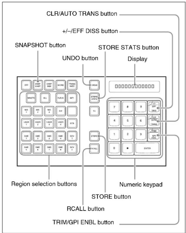
Numeric keypad control block
Saving a snapshot from the numeric keypad control block
1 Make the settings for the state you want to save as a snapshot.
2 In the numeric keypad control block, press the [SNAPSHOT] button, turning it on.
This allocates the numeric keypad control block to snapshot operations, and the [RCALL] button lights.
3 Press the region selection button corresponding to the region for which you want to save, turning it on. You can select more than one region.
[M/E 1], [M/E 2], [M/E 3], [M/E 4], [P/P]: These select the corresponding M/E-1, M/E-2, M/E-3, M/E-4, and PGM/PST regions.
Notes
To select M/E 4, it is necessary to assign M/E 4 to a button (see page 559).
[USER 1] to [USER 8]: These select the User regions. [DME 1] to [DME 8]: These select the DME channels.
[RTR]: This selects the Router region.
[ALL]: This selects all regions.
Notes
The regions that can be selected simultaneously are those assigned to the region selection buttons in the numeric keypad control block (see page 559).
The first button pressed lights green as the reference region, and any subsequently pressed buttons light amber.
Pressing one of the amber-lit buttons, while holding down [SNAPSHOT], turns the button green to indicate its corresponding region as the new reference region.
For details of the precedence order for becoming the reference region, see “Reference region” (page 425).
The display shows the name of the reference region and the number of the register previously recalled for that region.
4 Press the [STORE] button, turning it on.
5 Enter the desired register number from the numeric keypad.
To find an empty register, instead of entering a number, press the [.] (period) button. To search for an empty register common to all currently selectable regions, press the period button again.
Notes
If you choose a register which already contains a snapshot, and save a snapshot, then the existing register contents are overwritten.
The register number appears in the display. If the number is followed by a letter ‘e’ or ‘E,’ this indicates the following.
e: The selected register is empty for the regions selected in step 3.
E: The selected register is empty for all currently selectable regions.
6 To apply attributes (see page 463), press the following buttons, turning them on.
| Attribute to apply | Button |
| Effect dissolve [+/-/EFF DISS] button | |
| Auto transition [CLR/AUTO TRANS] button | |
| GPI output^a) | [TRIM/GPI ENBL] button |
a) The GPI port that can be set is 1 (fixed).
Notes
In the numeric keypad control block, it is not possible to apply the cross-point hold.
For details, see “Applying snapshot attributes” (page 473).
7 Press the [ENTER] button.
This saves the snapshot, and the [STORE] button goes off. The [RCALL] and [STORE STATS] buttons light.
To cancel a snapshot save operation
Hold down the [STORE STATS] button and press the [UNDO] button.
Recalling a snapshot from the numeric keypad control block
1 In the numeric keypad control block, press the [SNAPSHOT] button, turning it on.
This allocates the numeric keypad control block to snapshot operations, and the [RCALL] button lights.
2 Press the region selection button corresponding to the region you want to recall, turning it on. Multiple selections are also possible.
[M/E 1], [M/E 2], [M/E 3], [M/E 4], [P/P]: These select the corresponding M/E-1, M/E-2, M/E-3, M/E-4, and PGM/PST regions.
[USER 1] to [USER 8]: These select the User regions.
[DME 1] to [DME 8]: These select the DME channels.
[ALL]: This selects all regions.
[RTR]: This selects the Router region.
[MASTR]: This selects a master snapshot.
Notes
The regions that can be selected simultaneously are those assigned to the region selection buttons in the numeric keypad control block (see page 559). It is not possible to select [MASTR] and other regions simultaneously. If selected simultaneously, the master snapshot takes precedence.
The first pressed button lights green as the reference region, and subsequently pressed buttons light amber. Pressing one of the amber-lit buttons, while holding down [SNAPSHOT], turns the button green to indicate its corresponding region as the new reference region.
For details of the precedence order for becoming the reference region, see “Reference region” (page 425).
The display shows the name of the reference region and the number of the register previously recalled for that region.
3 Enter the desired register number from the numeric keypad.
The entered register number appears in the display.
4 To apply temporary attributes (see page 465), press the following buttons, turning them on.
| Control block | Temporary attribute to apply | Button |
| Cross-point control block | A/B bus cross-point hold | [XPT HOLD] button in the background A/B bus |
| Key cross-point hold | [XPT HOLD] button in the key bus a) | |
| Key disable [XPT HOLD] button in the key bus b) | ||
| Numeric keypad control block | Effect dissolve [+/-] | EFF DISS] button |
| Auto transition [CLR/AUTO TRANS] button | ||
a) When Xpt Hold mode is selected in setup.
b) When Key Disable mode is selected in setup.
For the setup setting, see "Setting the operation mode of the key bus [XPT HOLD] button" (page 610).
Notes
- The cross-point hold and key disable settings are maintained until you next press the [XPT HOLD] button.
- Applying temporary attributes does not affect the contents of the register.
- It is not possible to apply temporary attributes to a master snapshot.
5 Press the [ENTER] button.
This recalls the specified snapshot, and the reference region name and recalled register number appear in the display.
If you applied the effect dissolve or auto transition temporary attributes in step 4, the corresponding buttons go off.
When a master snapshot is recalled, the region selection buttons light according to the saved region information.
To cancel a snapshot recall operation
To cancel the recall, press the [UNDO] button.
Notes
It is not possible to cancel recalling a master snapshot.
Creating and saving a master snapshot with the numeric keypad control block
To create and save a master snapshot with the numeric keypad control block, refer to the operations in “Creating and Saving a Master Timeline Using the Buttons in the Numeric Keypad Control Block” (page 455). Note, however, that in place of the [EFF] button in the numeric keypad control block, the [SNAPSHOT] button is used.
Snapshot Operations in the Flexi Pad Control Block
In the Flexi Pad control block (standard type or simple type) on each M/E bank and PGM/PST banks, you can only carry out operations on snapshots for that bank. It is therefore not necessary to select a region.
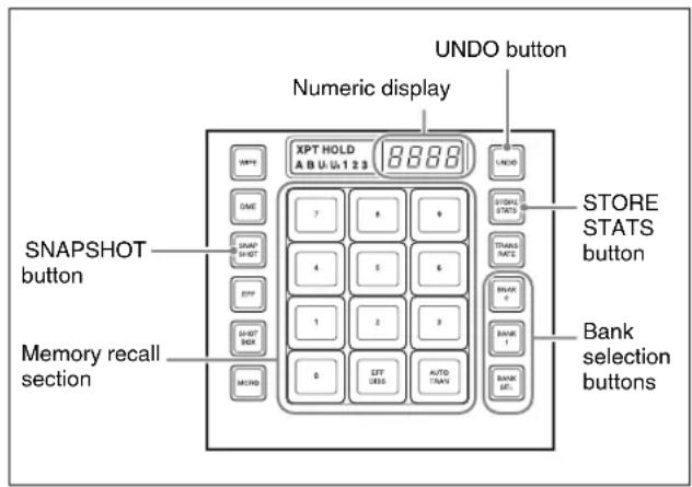
Flexi Pad control block (standard type)
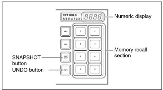
Flexi Pad control block (simple type)
Banks and Registers
In a standard type Flexi Pad control block or Multifunction Flexi Pad control block, in order to handle the 99 registers, they are considered in groups. These groups are called “banks,” and there are ten banks, numbered from 0 to 9. The correspondence between banks and registers is shown in the following table.
| Bank number Register numbers | |
| Bank 0 1 to 10 | |
| Bank 1 11 to 20 | |
| Bank 2 21 to 30 | |

| Bank number Register numbers | |
| Bank 3 31 to 40 | |
| Bank 4 41 to 50 | |
| Bank 5 51 to 60 | |
| Bank 6 61 to 70 | |
| Bank 7 71 to 80 | |
| Bank 8 81 to 90 | |
| Bank 9 91 to 99 | |
Example: When you select bank 3, the register numbers allocated to the memory recall section are as follows.
Operations with a simple type Flexi Pad control block
With a simple type Flexi Pad control block, the registers that can be handled are numbers 1 to 8. Bank operations are therefore not possible. It is also not possible to apply attributes, or to cancel a snapshot save or recall operation once carried out.
To use registers 9 to 99, or to cancel a snapshot save operation, use the numeric keypad control block.
Saving and Recalling Snapshots
Saving a snapshot in the Multifunction Flexi Pad control block
As an example, to save a snapshot on the M/E-1 bank, use the following procedure.
1 In the M/E-1 bank, make the settings for the state you want to save as a snapshot.
2 In the M/E-1 bank Flexi Pad control block, press the [SNAPSHOT] button.
This assigns the Flexi Pad control block to snapshot operations. The numeric display shows the last selected bank number and the register number last recalled on the bank.
3 Use any of the following methods to select the bank for saving the snapshot.
(On a simple type Flexi Pad control block, there are no banks, and this operation is not necessary.)
To select bank 0: Press the [BANK 0] button.
To select bank 1: Press the [BANK 1] button.
To select any bank from 0 to 9: Press the [BANK SEL] button, changing the memory recall section display as in the following figure; select a number from 0 to 9.
The selected bank number appears in the numeric display.
The buttons in the memory recall section change to show the names of the registers in the selected bank, together with the register status.
Using the Setup menu, it is possible to specify which to display, the register name or register number.
Lit orange: register containing a snapshot
Lit yellow: last recalled register
Not lit: register not containing anything
4 To apply an attribute (see page 463), hold down the [SNAPSHOT] button, and in the memory recall section, press a button as follows, turning it on.
| Attribute to apply Button | |
| Effect dissolve [EFF DISS] | button |
| Auto transition [AUTO TRANS] | button |
Notes
In the Flexi Pad control block, it is not possible to apply the cross-point hold or GPI output attributes. In a simple type Flexi Pad control block, it is not possible to apply any attributes. To add these attributes, use a menu operation. (See page 473.)
5 Still holding down the [SNAPSHOT] button from step 4, press the memory recall button corresponding to the register in which you want to save.
Recalling a snapshot in the Flexi Pad control block (standard type or simple type)
Notes
When an M/E bank is not assigned to any region selection button in the numeric keypad control block in a setup setting, it is not possible to recall a snapshot with the Flexi Pad control block of that M/E bank.
For details, see “Assigning a Region to the Region Selection Buttons in the Numeric Keypad Control Block or Multifunction Flexi Pad Control Block” (page 559).
As an example, to recall a snapshot on the M/E-1 bank, use the following procedure.
1 In the M/E-1 bank Flexi Pad control block, press the [SNAPSHOT] button.
This assigns the Flexi Pad control block to snapshot operations. The numeric display shows the last selected bank number and the register number last recalled on the bank.
2 Select the bank for recall.
See step 3 (page 468) in “Saving a snapshot in the Multifunction Flexi Pad control block.”
3 To apply temporary attributes (see page 463), press the following buttons, turning them on.
| Control block | Temporary attribute to apply | Button |
| Cross-point control block | A/B bus cross-point hold | [XPT HOLD] button in the background A/B bus |
| Key cross-point hold | [XPT HOLD] button in the key busa) | |
| Key disable [XPT HOLD] button in the key busb) | ||
| Flexi Pad control block | Effect dissolve | [EFF DISS] button |
| Auto transition | [AUTO TRANS] button | |
a) When Xpt Hold mode is selected in setup.
b) When Key Disable mode is selected in setup.
For details of the operation mode of the [XPT HOLD] button, see “Setting the operation mode of the key bus [XPT HOLD] button” (page 610).
Notes
- The cross-point hold and key disable settings are maintained until you next press the [XPT HOLD] button.
- Applying temporary attributes does not affect the contents of the register.
4 Press the button in the memory recall section which shows the desired register name.
The button you pressed lights yellow, and this recalls the snapshot.
The numeric display shows the selected register number after the bank number.
Deleting a snapshot in the Flexi Pad control block (standard type or simple type)
As an example, to delete a snapshot on the M/E-1 bank, use the following procedure.
1 In the M/E-1 bank Flexi Pad control block, press the [SNAPSHOT] button.
This assigns the Flexi Pad control block to snapshot operations. The numeric display shows the last selected bank number and the last recalled register number on the corresponding bank.
2 Select the bank for the register containing the snapshot you want to delete.
See step 3 (page 468) in “Saving a snapshot in the Multifunction Flexi Pad control block.”
3 Hold down the [STORE STATS] button, then hold down the button in the memory recall section displaying the number of the corresponding register.
The button you pressed goes off, and this deletes the snapshot. The [STORE STATS] button lights amber.
Notes
On a simple type Flexi Pad control block, it is not possible to delete a snapshot.
Snapshot Operations in the Multifunction Flexi Pad Control Block
![[SNAPSHOT] button Alphanumeric display Region selection buttons Memory recall section](/content/2026/06/1364863/images/1f1068ac65d866abcf3cb796ebc12031990770e7a2dc4bc4c22ec8b215f6a74b.jpg)
Carry out snapshot operations on the Multifunction Flexi Pad control block of the CCP-6224 or CCP-6324 Control Panel as follows.
Saving and Recalling Snapshots
Saving a snapshot in the Multifunction Flexi Pad control block
As an example, to save a snapshot on the M/E-1 bank, use the following procedure.
1 In the M/E-1 bank, make the settings for the state you want to save as a snapshot.
2 In the Multifunction Flexi Pad control block, press the [SNAPSHOT] button.
This assigns the Multifunction Flexi Pad control block to snapshot operations. The numeric display shows the last selected bank number and the register number last recalled on the bank.
3 Press the region selection button corresponding to the region for which you want to save, turning it on. You can select more than one region.
Notes
To select M/E 4, it is necessary to assign M/E 4 to a button.
For details of [M/E 4] button assignment, see "Assigning a Button for M/E-4 Selection in the Setup Menu" in Appendix (Volume 1).
[M/E 1], [M/E 2], [M/E 3], [M/E 4], [P/P]: These select the corresponding M/E-1, M/E-2, M/E-3, M/E-4, and PGM/PST regions.
[USER 1] to [USER 8]: These select the User regions.
[DME 1] to [DME 8]: These select the DME channels.
[RTR]: This selects the Router region.
[ALL]: This selects all regions.
Notes
The regions that can be selected simultaneously are those assigned to the region selection buttons in the memory recall section (see page 559).
The first pressed button lights green as the reference region, and any subsequently pressed buttons light amber.
Pressing one of the amber-lit buttons, while holding down [SNAPSHOT], turns the button green to indicate its corresponding region as the new reference region.
For details of the precedence order for becoming the reference region, see “Reference region” (page 425).
The display shows the name of the reference region and the number of the register previously recalled for that region.
4 Press the [BANK SEL] button, and select the desired bank with the numeric keypad buttons in the memory recall section.
5 Hold down the [SNAPSHOT] button, and press the button in the memory recall section corresponding to the register in which you want to save.
Notes
If you press a button which is lit orange or yellow, this overwrites the contents of the corresponding register. The button you pressed lights yellow, and this completes saving. The [STORESTATS] button lights amber, and the numeric display shows the bank number followed by the number of the selected register.
To enter the number of the desired snapshot save destination register using the numeric keypad
After step 2 above, press the [10 KEY] button in the memory recall section. This switches the memory recall

section to the numeric keypad input mode, and after pressing the [STOR] button, lighting it yellow, you can enter the desired register number from the numeric keypad. The number you entered appears in the alphanumeric display.
To find an empty register, press the [ . ] button without entering a number, and the number of an empty register appears in the alphanumeric display.
Confirm the displayed number by pressing the [ENTR] button. This saves the data in the specified register.
To cancel a snapshot save operation
Hold down the [STORE STATS] button and press the [UNDO] button.
The light of [STORE STATS] button changes from amber to green.
Notes
With a simple type Flexi Pad control block, it is not possible to cancel saving a snapshot.
Adding attributes in the Multifunction Flexi Pad control block
1 Press the [EDIT ENBL] button.
The button indications in the memory recall section change as shown in the following illustration. To cancel adding attributes, press the [EDIT ENBL] button once more, or press the [EXIT] button.
- When the reference region is M/E-x (x is a number) or P/P
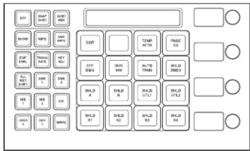
- When the [PAGE 1/2] button is pressed to display the second page
![SONY MVS-7000X - Press the [EDIT ENBL] button. - 2](/content/2026/06/1364863/images/5cb5fa56b384082ff80245d0233902aa4cf540c6fd08ef65673ed8ee10e585aa.jpg)
- When the reference region is other than M/E-x or P/P, and effect dissolve settings are possible
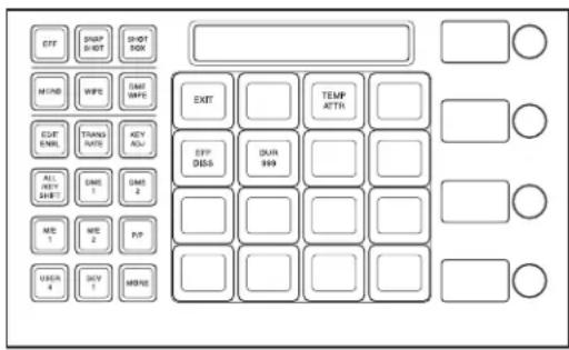
2 Add attributes (see page 463) with the following buttons.
[TEMP ATTR] button: Set a temporary attribute. Set this to Off to add an attribute.
[EFF DISS] button: Add the effect dissolve attribute.
[DUR xxx] button: Set the effect dissolve duration. The current setting is shown by "xxx." When you press this button, the memory recall section switches to numeric keypad input mode, and you can enter the setting value.
[AUTO TRNS] button: Add the auto transition attribute.
[XHLD xxx] button: Add the bus cross-point hold attribute. The affected bus is shown by “xxx.”
Recalling a snapshot in the Multifunction Flexi Pad control block
As an example, to recall a snapshot on the M/E-1 bank, use the following procedure.
1 In the Multifunction bank Flexi Pad control block, press the [SNAPSHOT] button.
This assigns the Multifunction Flexi Pad control block to snapshot operations. The numeric display shows the last selected bank number and the register number last recalled on the bank.
2 Press the region selection button corresponding to the region you want to recall, turning it on. Multiple selections are also possible.
[M/E 1], [M/E 2], [M/E 3], [M/E 4], [P/P]: These select the corresponding M/E-1, M/E-2, M/E-3, M/E-4, and PGM/PST regions.
[USER 1] to [USER 8]: These select the User regions.
[DME 1] to [DME 8]: These select the DME channels.
[ALL]: This selects all regions.
[RTR]: This selects the Router region.
[MASTR]: This selects a master snapshot.
Notes
The regions that can be selected simultaneously are those assigned to the region selection buttons in the memory recall section.
For details, see “Assigning a Region to the Region Selection Buttons in the Numeric Keypad Control Block or Multifunction Flexi Pad Control Block” (page 559).
It is not possible to select [MASTR] and other regions simultaneously. If selected simultaneously, the master snapshot takes precedence.
The first pressed button lights green as the reference region, and subsequently pressed buttons light yellow. Pressing one of the amber-lit buttons, while holding down [SNAPSHOT], turns the button green to indicate its corresponding region as the new reference region.
For details of the precedence order for becoming the reference region, see “Reference region” (page 425).
The display shows the name of the reference region and the number of the register previously recalled for that region.
3 Select the bank for recall.
See step 3 (page 470) in "Saving a snapshot in the Multifunction Flexi Pad control block."
4 To add a temporary attribute (see page 464), press the [EDIT ENBL] button to switch to editing mode, then press the [TEMP ATTR] button; you can now select the temporary attribute with the following buttons.
[EFF DISS] button: Effect dissolve.
[DUR xxx] button: Effect dissolve duration. The current setting is shown by "xxx."
[AUTO TRNS] button: Auto transition.
[XHLD xxx] button: Bus cross-point hold. The affected bus is shown by "xxx."
For details of the operation of mode of the [XPT HOLD] buttons, see "Selecting the Bank to Make the Settings" (page 608).
Notes
Adding a temporary attribute does not affect the attribute settings saved in registers. To add a temporary attribute with the cross-point control block buttons, press the following buttons, turning them on.
| Temporary attribute to be added | Button to press |
| A/B bus cross-point hold [XPT HOLD] button in background A/B bus | |
| Temporary attribute to be added | Button to press |
| Key cross-point hold Key bus [XPT HOLD]button a) | |
| Key disable Key bus [XPT HOLD]button b) |
a) When setup setting is Xpt Hold mode
b) When setup setting is Key Disable mode
Notes
This setting is maintained until the next time the [XPT HOLD] button is pressed.
5 Press the button in the memory recall section which shows the desired register name.
The button you pressed lights yellow, and this recalls the snapshot.
The numeric display shows the selected register number after the bank number.
To cancel a snapshot recall operation
Press the [UNDO] button.
To enter the number of the register to be recalled using the numeric keypad
After step 1 above, press the [10 KEY] button in the memory recall section. This switches the memory recall section to the numeric keypad input mode, and after pressing the [RCLL] button, lighting it yellow, you can enter the desired register number from the numeric keypad. Confirm the displayed number by pressing the [ENTR] button.
Deleting a snapshot in the Multifunction Flexi Pad control block
As an example, to delete a snapshot on the M/E-1 bank, use the following procedure.
1 In the Multifunction Flexi Pad control block, press the [SNAPSHOT] button, press region selection button to select [M/E1] only.
This assigns the Multifunction Flexi Pad control block to snapshot operations. The numeric display shows the last selected bank number and the last recalled register number on the corresponding bank.
2 Select the bank for the register containing the snapshot you want to delete.
See step 3 (page 470) in "Saving a snapshot in the Multifunction Flexi Pad control block."
3 Hold down the [DEL] button, then hold down the button in the memory recall section displaying the number of the corresponding register.
The button you pressed goes off, and this deletes the snapshot.
Snapshot Operations in the Menus
Operations in the Snapshot menu
You can also set snapshot or key snapshot attributes in the Snapshot menu, which also displays the status of the registers.
To access the Snapshot menu, press the top menu selection button [SNAPSHOT] in the menu control block.
In the Snapshot menu, as well as setting snapshot attributes, you can carry out editing operations on snapshots, including copy and delete. (See page 476.)
Operations in the Misc >Snapshot menu
For M/E and PGM/PST snapshots only, you can carry out saving, recalling, applying attributes, and so on using the same menu (see page 476).
Selecting a Region or Reference Region in a Menu
During snapshot operations, you can select a region in the menu. This is convenient for selecting some of the regions assigned to the numeric keypad control block or changing the reference region.
For details of the operations, see “Selecting by menus” (page 439).
Setting Snapshot Attributes
Applying snapshot attributes
1 In the Snapshot menu, press VF2 'Snapshot' and HF1 'Attribute.'
The Snapshot >Attribute menu appears. The status area shows the region names, register numbers, and the status and attributes set.
2 Press the region display in the upper part of the list to display a selection window, then select the region in the selection window. Selecting multiple regions is also possible. To select all regions, press [ALL].
3 Press [OK].
The selected region name appears in the upper part of the list.

4 Using any of the following methods, select the register.
- Press directly on the list in the status area.
- Press the arrow keys to scroll the reverse video cursor.
- Turn the knobs.
| Knob | Parameter | Adjustment Setting | values |
| 1 | Register Register | number 1 to 99 | |
| 2 | Num | Select number of registers | 1 to 99 |
• To select all registers, press [ALL].
5 In the
Carry out the following procedures for each of the attributes.
For details of attributes and available attributes, see "Snapshot Attributes" (page 463).
To apply the cross-point hold attributes
Notes
Applying the key disable attribute (so the key state is not reflected) to cross-point hold requires a setting in setup.
For details, see "Snapshot Attributes" (page 463).
1 Press [XPT Hold].
The Snapshot >Attribute >Xpt Hold menu appears. The status area shows a list of the currently selected regions and bus names.
2 Using any of the following methods, select the register.
- Press directly on the list in the status area. To select one or more buses, press [Plural] and then select buses.
- Press the arrow keys to scroll the reverse video cursor.
- Turn the knobs.
| Knob | Parameter Adjustment Setting values | |
| 2 Destination a) | Destination selection | 1 to 128 |
| 3 | Bus b) | Bus name selection |
a) Appears when the region is RTR.
b) Appears when the region is other than RTR.
• To select all registers, press [ALL].
3 When the region is set to RTR (Router) only, press [RTR Level].
A window appears for selecting the router level.
4 Press the level for which you want to set the cross-point hold, turning it on, and press [OK]. To select all levels, press [ALL].
5 Press [On].
This enables cross-point hold on the selected bus or buses. To switch cross-point hold off, press [Off].
To apply the effect dissolve attribute
1 Press [Effect Dissolve], turning it on.
2 Turn the knob to set the effect dissolve duration.
| Knob | Parameter | Adjustment | Setting values |
| 3 Eff Duration | Dissolve duration | 0 to 999 (frames) | |
To set the duration for a dissolve set as a temporary attribute effect
To set the duration for a dissolve set as a temporary attribute effect in the numeric keypad or Flexi Pad control block, turn the knob.
| Knob | Parameter | Adjustment | Setting values |
| 5 Temp | Dur Temporary attribute dissolve duration | 0 to 999 (frames) |
To apply the auto transition attribute
Press [Auto Transition], turning it on.
To apply the GPI output attribute
1 Press [GPI Output], turning it on.
2 Turn the knob to set the port number.
| Knob | Parameter | Adjustment | Setting values |
| 4 GPI | Out Port | GPI output port number | 1 to 8 |
To apply the clip event attribute
Notes
The following operating procedure can be used only for the frame memory channels assigned to a user region.
For details of frame memory assignment, see “Setting User Regions” (page 598).
1 Press [Clip Event].
The Snapshot >Attribute >Clip Event menu appears.
2 In the group, press the desired button.
On the left of the status area, the name and content of the selected region (for example, USER1) are shown. On the right, the content of the clip of the current frame memory is shown.
3 Press [Clip Event], turning it on.
The clip event attribute is applied.
4 To select the clip of the current frame memory, press [Set].
5 To play the clip as soon as it is recalled, press [Auto Play], turning it on.
Snapshot Status Display
The Snapshot >Attribute menu displays the following information.
Region name: The selected region name appears in the upper part of the list.
Register number
Register name
Write-protected status: When the register is write-protected, an “L” (for “lock”) appears.
Empty status: When the register is empty, an “E” (for “empty”) appears.
Attribute settings: The attributes set for a register are shown by the following character codes.
- When the cross-point hold is set
| Displayed character codes | Attributes set |
| A, B Cross-point hold | Id is set for the A or B background bus. |
| 1, 2, 3, 4, 5, 6, 7, 8 | Cross-point hold is set for key bus 1, 2, 3, 4, 5, 6, 7 or 8. |
| U1, U2 Cross-point hold | hold is set for the utility 1 or utility 2 bus. |
| D2 Cross-point hold | is set for video bus selected for 2nd DME channel. |
| FvFkBvBk Cross-point hold | is set for all of the DME front video bus, DME front key bus, DME back video bus, and DME back key bus. |
| Aux Cross-point hold | id is set for one of the AUX buses. |
| Fm1, Fm2 Cross-point hold | is set for one of the frame memory 1 and 2 buses. |
| Displayed character codes | Attributes set |
| Ccr1, Ccr2 Cross-point hold is set for one of the CCR 1 and 2 buses. | |
| RTR Cross-point hold is set for the Router region. | |
- When an effect dissolve is set
| Displayed character codes | Attributes set |
| Duration value The | effect dissolve attribute is set, with the displayed duration. |
- When an auto transition is set
| Displayed character codes | Attributes set |
| T Auto transition is set. | |
- When a GPI output is set
| Displayed character codes | Attributes set |
| Port number GPI output is set for the port of the displayed number. | |
- When a clip event is set
| Displayed character codes | Attributes set |
| On | Clip event is set. |
Setting Key Snapshot Attributes
Applying key snapshot attributes
1 In the Snapshot menu, press VF5 'Key Snapshot' and HF1 'Attribute.'
The Snapshot >Key Snapshot >Attribute menu appears.
The status area shows the region names, register numbers, and whether the registers are locked or not.
2 Press the region display in the upper part of the list to display a selection window, then select the region in the selection window. Selecting multiple regions is also possible.
3 Press [OK].
The selected region name appears in the upper part of the list.
4 Using any of the following methods, select the register.
- Press directly on the list in the status area.
- Press the arrow keys to scroll the reverse video cursor.
- Turn the knobs.
| Knob | Parameter | Adjustment | Setting values |
| 1 Register Register | number 1 to 4 | ||
5 In the
XPT: Only the key material selection data is saved or recalled.
Modifier: Only the key modifier settings are saved or recalled.
Transition: Only the independent key transition settings are saved or recalled.
Creating and Saving a Master Snapshot
To save a master snapshot in the Snapshot menu, after recalling the Snapshot >Master Snapshot >Store menu, refer to the operations in “Creating and Saving a Master Timeline With the Menu” (page 457).
Recalling the Store menu
1 Do either of the following.
- In the menu control block, press the top menu selection button [SNAPSHOT].
- In the numeric keypad control block, press the [SNAPSHOT] button twice in rapid succession. The Snapshot menu appears.
2 Press VF1 'Master Snapshot' and HF1 'Store.'
The Master Snapshot >Store menu appears. The status area shows the master snapshot register names, register lock status, register number for each region, and so on.
3 If required, press the following buttons in the status area to change the region display.
M/E, P/P: indicate assignment of M/E-1 (“M/E1”), M/E-2 (“M/E2”), M/E-3 (“M/E3”), M/E-4 (“M/E4”), and P/P (“P/P”).
User: User1 ("USR1") to User8 ("USR8")
DME: indicate assignment of DME ch1 (“DME1”), ch2 (“DME2”), ch3 (“DME3”), ch4 (“DME4”), ch5 (“DME5”), ch6 (“DME6”), ch7 (“DME7”), and ch8 (“DME8”).
Misc: RTR ("Router")
Snapshot Register Editing
You can carry out the following editing on snapshot registers.
(You can use similar procedures also on master snapshot, wipe snapshot, DME wipe snapshot and key snapshot registers.)
- Lock: Write-protect the contents of the register.
- Copy: Copy the contents of one register to another register.
- Move: Move the contents of one register to another register.
- Swap: Swap the contents of two registers.
- Delete: Delete the contents of a register.
- Name: Attach a name to a register.
For details of snapshot register operations, see “Effect Register Editing” (page 459).
Displaying a List of Snapshot Registers for Editing
You can display a list of snapshot registers including status information (whether data is present and so on), then carry out lock, copy, delete, and rename operations.
Displaying the list of snapshot registers with status information
Press the menu title button at the top left of the Snapshot menu.
The Snapshot >Status menu appears. The status area shows a list of snapshot registers (1 to 99).
For details of lock, copy, delete, and rename operations, see “Displaying a List of Effect Registers for Editing” (page 462).
Register name displays
For the same number, the register name for the M/E-1 region takes precedence.
If there is no data for the M/E-1 region, then the register name appears in the sequence M/E-2 >P/P >User1 to User8 >DME ch1 to DME ch8 >RTR.
Operations in the Misc >Snapshot Menu
Recalling a snapshot
1 In the Misc menu, press [Snapshot].
The Snapshot menu appears.
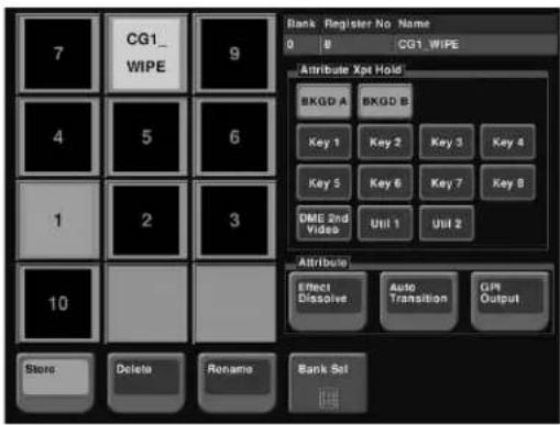
2 As required, change the bank (see page 477).
3 Press the button for the number or name you want to recall.
This recalls the snapshot, and the button you pressed lights green.
Saving a snapshot
1 Display the Misc >Snapshot menu.
2 Set the state you want to save as a snapshot.
3 Press [Store].
The button lights amber.
4 As required, change the bank (see page 477).
5 Press the button for the number or name you want to save.
This saves the snapshot, and the button goes off.
Changing the bank
Change the combination shown on the memory recall buttons (the bank).
1 Press [Bank Sel].
2 Select the bank in the numeric keypad window. For example, to show the numbers or names corresponding to registers 11 to 20, select "1" in the numeric keypad window.
Applying attributes
To apply an attribute to the snapshot represented by a lit-green memory recall button, use the following procedure.
1 To apply the cross-point hold attribute, in the
Notes
A setting in the Setup menu determines whether key disable is applied to cross-point hold or not.
For details, see "Selecting the Bank to Make the Settings" (page 608).
2 Select the following attributes in the
Effect Dissolve: Apply effect dissolve.
Auto Transition: Apply auto transition.
GPI Output: Apply GPI output. When this is selected, select the GPI number with the knob.
Deleting a snapshot
1 In the Misc >Snapshot menu, press [Delete]. The button lights amber.
2 As required, change the bank.
3 Press the button for the number or name you want to delete.
This deletes the snapshot, and the button you pressed goes off.
Renaming a snapshot register
1 In the Misc >Snapshot menu, press [Rename]. The button lights amber.
2 As required, change the bank.
3 Press the button for the number you want to rename.
A keyboard window appears.
4 Enter the register name, and press [Enter]. The new name appears on the memory recall button.
Utility Execution
The utility function refers to a function whereby you can assign an arbitrary action or a shortcut for frequently used menu to a particular button, then instantly recall the action or menu by pressing the button.
The functions you can assign include menu shortcuts, enabling/disabling functions (recalling utility commands), and recalling (shotbox registers or macro registers).
Carry out the button assignment in the Setup menu.
For details of the operation, see "Setting Button Assignments (Prefs/Utility Menu)" (page 577).
You can execute the utility functions from the following blocks.
• Utility/shotbox control block (page 478)
• Cross-point control block (page 479)
- User preference buttons in the menu control block (page 478)
For details of the settings for assigning functions to buttons, see “Setting Button Assignments (Prefs/Utility Menu)” (page 577).
Executing a Utility With the User Preference Buttons (Menu Control Block)
In the setup menu, you can assign any 16 actions to the user preference buttons in the menu control block.
To execute an assigned action
Press the corresponding user preference button ([PREFS 1] to [PREFS 16]).
- In the case of a function on/off action, the button you pressed lights amber, and this enables the function.
To disable the function, press the button once more.
- For other actions, the button you pressed momentarily lights amber, and then the function is executed.
Executing a Utility in the Utility/Shotbox Control Block
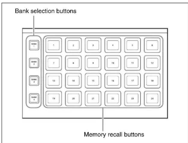
Utility/shotbox control block
By default, the memory recall buttons in the utility/shotbox control block are assigned to shotbox registers 1 to 96, in banks 1 to 4 (see page 485), but in the setup menu, you can assign these to any 96 actions.
To execute an assigned action
When the action is to execute a shotbox register, follow the procedure in “Shotbox Execution in the Utility/Shotbox Control Block” (page 485).
1 Press one of the bank selection buttons [BANK1] to [BANK4] to select a bank.
- The bank selection button you pressed lights amber.
- For the selected bank, the memory recall buttons show the button numbers and corresponding button states. If a button has been given a name in the setup menu, this name appears.
Not lighted: buttons with nothing saved
Lit orange: buttons saving a utility command or menu shortcut
2 Press the memory recall button for which the action you want to execute has been registered.
- In the case of a function on/off action, the button you pressed lights green, and this enables the function. To disable the function, press the button once more.
- For other actions, the button you pressed momentarily lights green, and then the function is executed.
Executing Utilities With the Cross-Point Buttons in the Key 2 Row
You can use the key 2 row of each of the M/E-1 to M/E-4, and PGM/PST banks in the same way as the buttons in the utility/shotbox control block.
Notes
To use this function, it is first necessary to assign the utility/shotbox mode switching function to the control panel [PRE MCRO] button.
For details of the assignment operation, see “Assigning the Utility/Shotbox Mode Switching Function” (page 561).
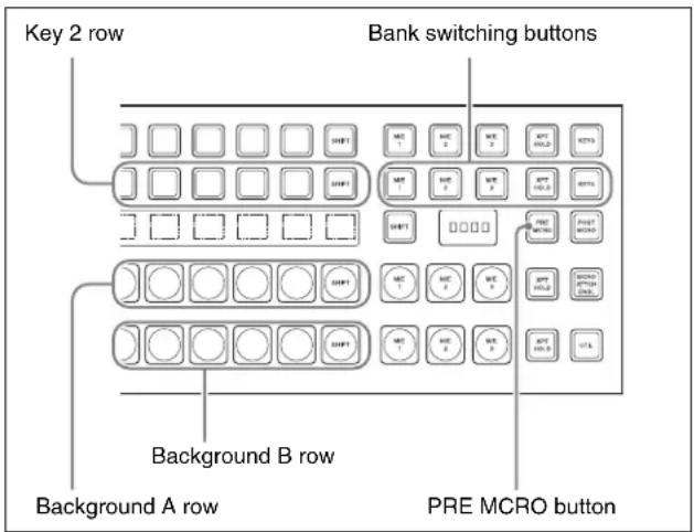
Cross-point control block in the PGM/PST block
You can assign any action to the cross-point buttons (see page 584).
To execute the assigned action
When the action is executing a shotbox register, follow the procedure “Executing a Shotbox Function With the Key 2 Row Cross-Point Buttons” (page 485).
1 Press the [PRE MCRO] button, turning it on.
2 Press one of the bank switching buttons (see previous figure), to select the bank.
These buttons correspond to banks 1 to 5 in sequence from the left.
3 Press the cross-point button to which the desired action is assigned.
Shotbox
The term “shotbox” refers to a function whereby for each specified region any snapshot or keyframe effect can be recalled simultaneously.
The simultaneous recall setting data such as region names, snapshot numbers and keyframe effect numbers are stored in “registers.” There are 99 registers for each control panel.
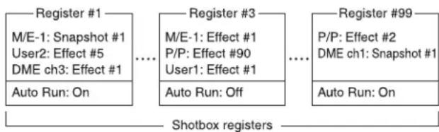
flowchart
graph LR
    A["Register #1\nM/E-1: Snapshot #1\nUser2: Effect #5\nDME ch3: Effect #1"] --> B["..."]
    C["Register #3\nM/E-1: Effect #1\nP/P: Effect #90\nUser1: Effect #1"] --> D["..."]
    E["Register #99\nP/P: Effect #2\nDME ch1: Snapshot #1"] --> F["Auto Run: On"]
    G["Auto Run: On"] --> H["Shotbox registers"]
The previous figure shows schematically the settings in the 99 shotbox registers.
Each register may contain any combination of the regions to which the register applies, with the snapshots or effects to be recalled.
The Auto Run function is an attribute which can be set for each register. When this is set to On, an effect recalled by a shotbox operation is automatically run.
- When register 1 is executed, this recalls M/E-1 snapshot 1, User2 effect 5, and DME ch3 effect 1. For register 1, auto run is On, and therefore the User2 and DME ch3 effects are run as soon as they have been recalled.
- When register 3 is executed, M/E-1 effect 1, P/P effect 90, and User1 effect 1 are recalled. For register 3, auto run is off, and therefore to run the recalled effects, press the [RUN] button in the keyframe control block.
Shotbox Register Creation
You can create (save) shotbox registers in the following control blocks.
- Numeric keypad control block (See "Numeric Keypad Control Block" in Chapter 2 (Volume 1).)
- Menu control block (See “Menu Control Block” in Chapter 2 (Volume 1).)
- Multifunction Flexi Pad control block (See "Multifunction Flexi Pad Control Block" in Chapter 2 (Volume 1).)
Creating a Shotbox Register in the Numeric Keypad Control Block
When you create a shotbox register in the numeric keypad control block, you carry out separate operations in respect of the snapshot setting data and the effect setting data, and save in the register. The procedure described here makes the snapshot settings first, followed by the effect settings.
Creating a shotbox register
1 In the numeric keypad control block, press the [SNAPSHOT] button, turning it on.
This assigns the numeric keypad control block to snapshot operations.
2 Specify the register number of the snapshot you want to save in a shotbox register, and then recall it for each region.
For details of the procedure for recalling a register, see “Recalling a snapshot from the numeric keypad control block” (page 466).
3 Press the [SHOTBOX] button, turning it on.
This assigns the numeric keypad control block to shotbox operations.
4 Press the [STORE] button, turning it on.
The [SNAPSHOT] button lights green. If not lighted, press the [SNAPSHOT] button to turn it on.
Notes
Only in [SHOTBOX] operation mode with the [STORE] button lit, the [SNAPSHOT] button or
[EFF] button lights green to indicate that a setting operation is in progress for the purpose of saving snapshot data or effect data in a shotbox register.
5 Press the region button for the snapshot you want to save, turning it on.
6 Enter the desired shotbox register number with the numeric keypad buttons.
To find an empty register, instead of entering a number, press the [.] (period) button.
The display shows the relevant register numbers. When a register number is postfixed with an “E,” the register is empty.
7 Press [ENTER].
This saves the region you turned on in step 5, and the register number you recalled for that region as a snapshot setting in a shotbox register, and the [STORE] button goes off. At the same time, the [RCALL] button lights.
8 In the numeric keypad control block, press the [EFF] button, turning it on.
9 Specify the register number of the keyframe effect you want to save in a shotbox register, and then recall it for each region.
For details of the procedure for recalling a register, see “Recalling a Register” (page 435).
10 Referring to steps 3 to 5, carry out the setting operation for effect register saving. In step 4, however, press the [EFF] button, lighting it green.
11 Enter the shotbox register number specified in step 6 using the numeric keypad buttons.
12 Press the [ENTER] button.
This saves the effect setting in a shotbox register, and the [STORE] button goes off. At the same time, the [RCALL] button lights.
To change the contents of a shotbox register
After recalling the shotbox register you want to change, referring to the previous item “Creating a shotbox register,” change the contents of the shotbox register, and save.
To check the region saved in a shotbox register
During operations to change the contents of a shotbox register, to check which region is saved in the register, use the following procedure.
1 With the [SHOTBOX] button lit, press the [STORE] button, turning it on.
2 Press the required button, as follows, turning it on.
To check the snapshot region: [SNAPSHOT] button To check the effect region: [EFF] button
3 Hold down the [STORE] button.
While this button is held down, the button for the saved region lights.
Releasing the button returns you to the state before holding down the [STORE] button.
Notes
While the [STORE] button is lit, the mode selection buttons ([TRANS RATE] button and so on) in the numeric keypad control block do not operate. To change the mode, press the [RCALL] button or [SHOTBOX] button so that the [STORE] button goes off.
Creating a Shotbox Register in the Multifunction Flexi Pad Control Block
1 In the Multifunction Flexi Pad control block, press the [SNAPSHOT] button, turning it on.
This changes the Multifunction Flexi Pad control block to snapshot operation mode.
2 Specify the register number of the snapshot you want to save in a shotbox register, and then recall it for each region.
For details of the procedure for recalling a snapshot, see “Recalling a snapshot in the Multifunction Flexi Pad control block” (page 471).
3 Press the [SHOTBOX] button, turning it on.
This changes the Multifunction Flexi Pad control block to shotbox operations.
4 Press the [EDIT ENBL] button.
This changes the Multifunction Flexi Pad control block to shotbox editing mode.
5 Press the [STOR] button, turning it on.
The [SNAPSHOT] button lights green. If not lighted, press the [SNAPSHOT] button to turn it on.
Notes
In shotbox editing mode, when you press the [STOR] button, the [SNAPSHOT] button or [EFF] button lights, to indicate that snapshot data will be saved in the shotbox register, or that effect data will be saved.
6 Specify the region for the snapshot to be saved, with the region selection buttons.
7 Enter the number of the shotbox register where you want to save with the memory recall section numeric keypad buttons.
To select an empty register, press the [ . ] button without entering a number.
The number of the selected register appears in the alphanumeric display. An “E” after the number indicates an empty register.
8 Press [ENTR].
This saves the region you turned on in step 6, and the register number you recalled for that region as a snapshot setting in a shotbox register, and the [STORE] button goes off. At the same time, the [RCALL] button lights.
9 Press the [EFF] button, turning it on.
10 Specify the register numbers to recall the keyframe effects for each region that you want to save in the shotbox register.
For the procedure for recalling keyframe effects, see "Recalling a register from the Multifunction Flexi Pad control block" (page 437).
11 Referring to steps 3 to 6, carry out the procedure to save the recalled keyframe effect data.
In step 5, however, press the [EFF] button instead of [SNAPSHOT] button, lighting it on.
12 Enter the shotbox register number specified in step 7 using the numeric keypad buttons in the memory recall section.
13 Press the [ENTR] button.
This saves the snapshot data, followed by the keyframe effect data, in the specified shotbox register, and the [STOR] button goes off and then the [RCLL] button lights up.
To change the contents of a shotbox register
After recalling the shotbox register you want to change, referring to the previous item “Creating a shotbox register in the Multifunction Flexi Pad control block,” change the contents of the shotbox register, and save.
To check the region saved in a shotbox register When changing the contents or so for a shotbox register, to check the region saved in the register press and hold the following buttons.
To check the snapshot region: [SNAPSHOT] button To check the keyframe effect region: [EFF] button The memory recall section buttons change as shown in the following illustration, and the region for the saved data lights.
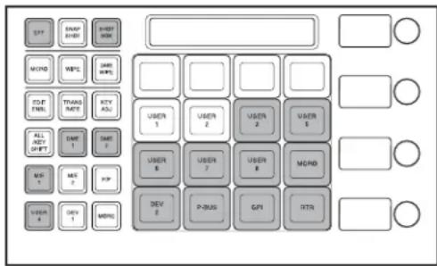
To recall an assigned effect and simultaneously execute it
Press the [AUTO RUN] button, lighting it green, then save the region data in the register.
Creating a Shotbox Register Using the Menus
Accessing the Shotbox menu
Carry out creation and editing of shotbox registers in the Shotbox menu.
To access the Shotbox menu, use either of the following methods.
- In the menu control block, press the top menu selection button [SHOTBOX].
- In the numeric keypad control block, press the [SHOTBOX] button twice in rapid succession.
Creating a shotbox register
1 In the Shotbox menu, press VF1 'Register' and HF1 'Store/Recall.'
The Store/Recall menu appears.
In the status area, the settings for each register appear as follows.
Region settings: Appear as “Sxxx” when a snapshot is allocated, and as “Exxx” when an effect is allocated. (xxx is the register number.) The register name also appears. If nothing is allocated, nothing appears in the display.
Register lock setting: When the register is write-protected, an “L” (for “lock”) appears.
Empty status: When the register is empty, an “E” (for “empty”) appears.
Auto run setting: When this is enabled, so that an effect is executed simultaneously with recall, "AR" appears.
Shotbox register name: This shows the shotbox register name.
2 If necessary, switch the region display by pressing one of the following buttons in the status area.
M/E, P/P: Shows the allocations for M/E-1 (“M/E1”), M/E-2 (“M/E2”), M/E-3 (“M/E3”), M/E-4 (“M/E4”), and P/P (“P/P”).
User: Shows the allocations for User1 (“USR1”) to User8 (“USR8”).
DME: Shows the allocations for DME ch1 (“DME1”), ch2 (“DME2”), ch3 (“DME3”), ch4 (“DME4”), ch5 (“DME5”), ch6 (“DME6”), ch7 (“DME7”), and ch8 (“DME8”).
DEV1-8: Shows the allocations for Device1 ("DEV1") to Device8 ("DEV8").
DEV9-12: Shows the allocations for Device9 (“DEV9”) to Device12 (“DEV12”).
Misc: Shows the allocations for P-Bus (“PBUS”), GPI (“GPI”), Router (“RTR”), and Macro (“MCRO”).
3 Using any of the following methods, select the register you want to create (or edit).
- Press directly on the list in the status area.
- Press the arrow keys to scroll the reverse video cursor.
- Turn the knob.
| Knob | Parameter | Adjustment | Setting values |
| 1 ShotboxReg | Shotbox register number | 1 to 99 | |
4 Press [Edit].
The Edit menu appears, and it is now possible to make the settings for the specified register.
You can also use knob 1 to select the register in this menu.
In the status area, the shotbox register status for each region appears.
5 Using any of the following methods, select the desired region. You may select more than one region.
- Press directly on the region display in the status area, turning it to reverse video.
- Press [ALL] to select all regions.
- To select all switcher-related regions (M/E, P/P, User), press [SWR ALL].
- To cancel a selection, press once more to return to the normal display.
6 In the
Snapshot: Allocate a snapshot register.
Effect: Allocate a keyframe effect.
- If the selected register is locked, a confirmation message appears asking whether or not to cancel the operation. Press [OK] to return to the previous menu display without carrying out the registration.
- If the operation is carried out, the region selected in step 5 is registered on the master timeline, and the parameters are now valid.
7 Depending on the selection in step 6, set the parameters as follows.
When a snapshot is selected
| Knob | Parameter Adjustment Setting | values |
| 3 Snapshot | Snapshot register number | 1 to 99 |
When an effect is selected
| Knob | Parameter Adjustment Setting | values |
| 3 Effect | Keyframe effect number | 1 to 99a) |
a) For the DME region, you can also set register numbers 101 to 199, 201 to 299, and 301 to 399.
For P-Bus and Device1 to Device12, you can also set register numbers 1 to 250.
8 To run the allocated effect as soon as it is recalled, press [Auto Run], turning it on.
9 Repeat steps 5 to 8 as required.
10 In the
To return to the state before saving the setting In the
To execute the settings to check them
Press [Recall] to execute the shotbox.
Shotbox Execution
You can recall (and run) shotbox registers from the following control blocks.
This section describes the various methods of operation.
- Numeric keypad control block (see page 484)
• Flexi Pad control block (see page 484) - Multifunction Flexi Pad control block (see page 484)
• Cross-point control block (see page 485)
• Utility/shotbox control block (see page 485)
Shotbox Execution From the Numeric Keypad Control Block
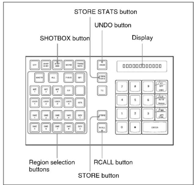
Numeric keypad control block
1 In the numeric keypad control block, press the [SHOTBOX] button, turning it on.
- This allocates the numeric keypad control block to shotbox operations.
- The [RCALL] button lights amber.
- The display shows the last recalled register number.
2 With the numeric keypad buttons, enter the desired register number.
- The display now shows the entered register number.
- If the specified register is empty, an “E” automatically appears after the register number.
3 Press the [ENTER] button.
- This runs the specified shotbox register.
- The number of the recalled register appears in the display.
- The region selection buttons corresponding to the regions for which the effect is set light.
- If auto run is set for the specified shotbox register, on recall the effect is immediately executed.
- If you recall an empty register, then shotbox execution has no effect.
When auto run is not set for the recalled register Simply recalling the register does not run the effect. To do this, in the keyframe control block, press the [RUN] button.
Shotbox Execution in the Multifunction Flexi Pad Control Block or the Flexi Pad Control Block
Notes
In the simple type of Flexi Pad control block, shotbox operations are not possible. You can carry out shotbox operations with a standard type or multifunction type Flexi Pad control block.
1 In the Flexi Pad control block, press the [SHOTBOX] button, lighting the [SHOTBOX] button amber.
- This allocates the Flexi Pad control block to shotbox operations.
- The previously selected bank number and the last recalled register number appear in the numeric display.
2 Using any of the following methods, select the bank.
- To select a register in bank 0, press the [BANK 0] button.
- To select a register in bank 1, press the [BANK 1] button.
- Press the [BANK SEL] button, and when the memory recall section display changes as follows, press the button from 0 to 9 corresponding to the bank you want to select.
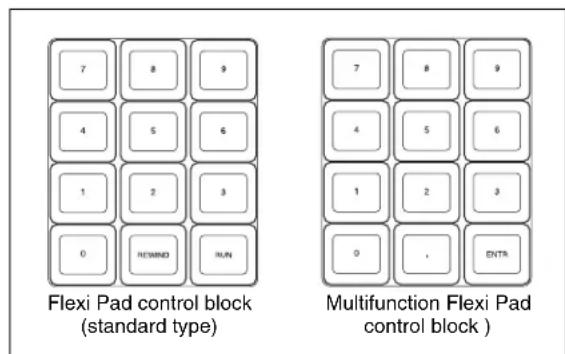

- The numeric display shows the selected bank number.
- The buttons in the memory recall section show the names and states of the registers corresponding to the selected bank.
- Off: register in which nothing is saved
- Lit orange: register holding shotbox settings
- Lit yellow: last executed register
3 Press the button in the memory recall section corresponding to the register you want to run.
- The selected shotbox register is executed.
- The pressed button lights yellow.
- The numeric display shows the bank number followed by the selected register number.
- If the selected shotbox register has auto run set, on recall the effect is immediately executed.
When auto run is not set for the recalled register
Simply recalling the register does not run the effect. To do this, press the [RUN] button.
Shotbox Execution in the Utility/ Shotbox Control Block
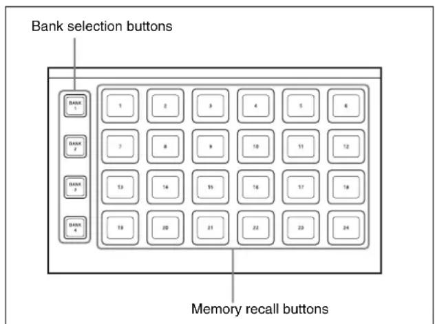
Utility/shotbox control block
In the utility/shotbox control block, as the default setting the memory recall buttons have registers 1 to 96 allocated to banks 1 to 4.
| Bank | Register allocation to memory recall buttons | |||||
| 1 | 1 | t | o | 2 | 4 | |
| 2 | 2 | 5 | t | o | 4 | 8 |
| 3 | 4 | 9 | t | o | 7 | 2 |
| 4 | 7 | 3 | t | o | 9 | 6 |
1 Press one of the bank selection buttons [BANK1] to [BANK4] to select the bank.
- The pressed bank selection button lights amber.
- The memory recall buttons show the names and states of the registers corresponding to the selected bank.
- Off: register in which nothing is saved
- Lit orange: register holding shotbox settings
- Lit yellow: last recalled register
2 Press the memory recall button to which the shotbox register you want to run is allocated.
- The shotbox execution is carried out.
- The pressed button lights yellow.
- The numeric keypad control block [SHOTBOX] button lights, and the region selection button corresponding to the region for which the effect is set also lights.
- If the selected shotbox register has auto run set, on recall the effect is immediately executed.
When auto run is not set for the recalled register Simply recalling the register does not run the effect. To do this, press the [RUN] button in the keyframe control block.
Executing a Shotbox Function With the Key 2 Row Cross-Point Buttons
You can use the key 2 row of each of the M/E-1 to M/E-4, and PGM/PST banks in the same way as the buttons in the utility/shotbox control block.
Notes
To use this function, it is first necessary to assign the utility shotbox mode switching function to the control panel [PRE MCRO] button.
For details of the assignment operation, see “Assigning the Utility/Shotbox Mode Switching Function” (page 561).
You can assign any shotbox register to the cross-point buttons.
For details of the assignment operation, see “Assigning a Function to the Key 2 Row Cross-Point Buttons” (page 584).
1 Press the [PRE MCRO] button, turning it on.
2 Press one of the bank switching buttons (see the figure on page 479), to select the bank.
3 Press the cross-point button to which the desired shotbox is assigned.
Shotbox Register Editing
You can carry out the following editing on shotbox registers.
- Lock: Write-protect the contents of the register.
- Copy: Copy data from one register to another.
- Move: Move data from one register to another.
- Swap: Swap the contents of two registers.
- Delete: Delete the contents of a register.
- Name: Attach a name to a register.
The procedures for shotbox register editing are similar to the procedures described in “Effect Register Editing” (page 459).
Unlike in effect register editing, however, it is not necessary to specify a region in shotbox register editing.
Macros
Overview
The term “macro” refers to the function whereby a sequence of signal selections and other operations on the control panel is saved as data in memory, so that it can be recalled as required to automatically execute the same sequence of operations.
To record menu operations in memory, use a menu macro (see page 512).
Macro registers
The area of memory that holds a macro is termed a “macro register.” For each control panel there are 250 macro registers, numbered 1 to 250.
Events
The individual control panel operations constituting a macro are termed “events.” One macro can contain a maximum of 99 events.
The following table shows the operations for each control block of the control panel that can be saved as events in a macro.
| Control block Event | |
| Auxiliary bus control block | Cross-point selection |
| Cross-point selection in router control mode | |
| Cross-point control block (including when the AUX panel-less function is set) | Cross-point selectionRecalling a function assigned to a key 2 row button |
| Control block Event | |
| Transition control block (standard type) | ·Auto transition and cut for the transition execution section·Auto transition and key on/off for the independent key transition execution section^a) ·Next transition setting·Transition type selection·Pattern limit on/off·Key snapshot recall·VTR/disk recorder/Extended VTR / frame memory clips playback^b) ·VTR/disk recorder/Extended VTR / frame memory clips stop^b) ·VTR/disk recorder/Extended VTR / frame memory clips cue-up^b) |
| Transition control block (simple type) | ·Transition execution section take·Transition type selection·Pattern limit on/off |
| Transition control block (compact type) | ·Transition execution section auto transition and cut·Independent key transition execution section auto transition^a) ·Next transition setting·Transition type selection·Pattern limit on/off·VTR/disk recorder/Extended VTR / frame memory clips playback^b) ·VTR/disk recorder/Extended VTR / frame memory clips stop^b) ·VTR/disk recorder/Extended VTR / frame memory clips cue-up^b) |
| Independent key transition control block (simple type) | ·Independent key transition execution section take and key on/off ^a) ·Key snapshot recall·Selection of independent key transition type |
| Flexi Pad control block (standard type) | Recalling the following data·Snapshots·Wipe snapshots·DME wipe snapshots |

| Control block Event | |
| Flexi Pad control block (simple type) | Recalling the following data• Snapshots• Wipe snapshots• DME wipe snapshots |
| Flexi Pad control block (multifunction type) | • E f f e c t• Snapshots• Shotbox• Wipe snapshots• DME wipe snapshots• Key snapshotsFollowing operations• Effect rewind• Effect execution• Effect fast forward• Selection of effect execution direction• Independent key transition execution section auto transition and cut a)• Pattern limit on/off |
| Numeric keypad control block | Recalling the following data• Effects• Snapshots• Shotbox• Master snapshots• Master timeline |
| Keyframe control block | • Effect rewind• Effect execution• Effect fast forward• Selection of effect execution direction |
| Device control block (trackball)(joystick)(search dial)c) | • VTR/disk recorder/Extended VTR/frame memory clips start point setting• VTR/disk recorder/Extended VTR/frame memory clips playback• VTR/disk recorder/Extended VTR/frame memory clips stop• VTR/disk recorder/Extended VTR/frame memory clips cue-up• VTR/disk recorder/Extended VTR/frame memory clips fast forward• VTR/disk recorder/Extended VTR/frame memory clips rewind• VTR/disk recorder record• Frame memory clip loop setting |
| Downstream key control block | • Independent key transition execution section auto transition and cut a)• Key snapshot recall |
| Fade to black control block | Execution of fade to black transition |
| Menu control block • | Disk recorder/Extended VTR file recalling• Recalling the functions assigned to [PREFS 1] to [PREFS 16] buttons• Execution of a menu macro• Recalling frame memory clips |
| Control block Event | |
| Utility/Shotbox control block | Recalling the functions assigned to memory recall buttons |
a) In the case of an event that inserts or deletes a key, the key state at the time of event registration (inserted or not inserted) is also saved in the macro. When the macro is executed, the event is only replayed if the key state matches the saved state. (Example: For a macro with an event that deletes a key, when the macro is executed, if the key is inserted it is deleted, but otherwise nothing occurs as concerns keying.)
b) Function valid only when |PLAY|, |STOP|, and |CUEUP| have been set in the Setup menu.
c) When using the device control block (search dial), this operates as a reference module. When not used, this operates on the module selected in the Panel >Config menu. For details of reference module selection, see “Overall Control Panel Settings (Config Menu)” (page 555).
Macro Creation and Editing
You can create or edit a macro by recalling a macro register.
To create a new macro, recall an empty macro register, and create the desired sequence of events (by executing the sequence of operations on the control panel that you want to save as events in the macro).
To add an event to an existing macro, recall the register holding the macro, and create the event you want to add.
Notes
While editing a macro, it is not possible to execute another macro.
Creating a macro
To include all information associated with an operation when registering a macro event
When registering an auto transition operation as an event, you can register the auto transition event to include the transition rate and background A/B bus selection status.
When registering an effect execution, rewind, or fast forward as an event, you can also save the region to which this applies.
To use this capability, assign the following functions to user preference buttons in the menu control block or buttons in the utility/shotbox control block (see page 577), and turn the relevant button on before you start an event to register.
Macro AT with Rate (Macro Auto Trans Event with/without Rate): When registering an auto transition macro event in one of the M/E banks or the PGM/PST bank, include the transition rate.
Macro AT with A/B Bus (Macro Auto Trans Event with/without A/B Bus): When registering an auto transition macro event in the transition control block, include the background A/B bus cross-point.
Macro TL with Region (Macro Timeline with Region): When registering an effect execution, rewind, or fast
forward as a macro event, save the affected region together in the macro.
Events requiring adjustment when creating a macro
The following events require time for execution to complete, and therefore when executed within a macro sequence, a pause event must be inserted to adjust the timing.
- Rewinding effects involving external device control
• VTR/disk recorder/Extended VTR cue-up
For example, create a macro to cue up a VTR and then play back as follows.
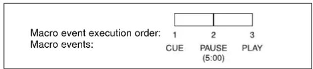
Auto insert mode on/off setting
You can switch on or off the mode (auto insert mode) in which at the same time that a control panel operation is carried out, the event is automatically saved in a macro.
Editing a macro
You can carry out the following macro editing operations.
Event insertion
Insert the control panel operation as an event in a macro.
Event modification
Modify any event. You can modify all events within a macro, or events within a specified range in a single operation.
Event deletion
Delete any one event. You can delete all events within a macro, or events within a specified range in a single operation. You can then paste the deleted event using the paste function.
Event copy
Copy any one event. You can copy all events within a macro, or events within a specified range in a single operation.
Event paste
Paste a copied or deleted event at a desired position within a macro.
Undoing an editing operation
You can undo the last event insertion, modification, deletion, or paste operation.
Macro merging
During macro editing, you can recall and copy another register to merge it with the macro being edited. For example, while editing macro register 2 you can recall and copy register 1 to merge it as shown in the following figure.
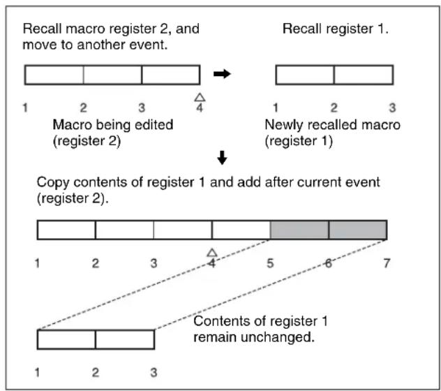
flowchart
graph TD
    A["Recall macro register 2, and move to another event."] --> B["Macro being edited (register 2)"]
    B --> C["Newly recalled macro (register 1)"]
    C --> D["Copy contents of register 1 and add after current event (register 2)."]
    D --> E["Contents of register 1 remain unchanged."]
Macro Execution
To execute a macro, recall the register in which the macro is held. Simultaneous with the register recall, all events stored in the macro are played back (executed) in sequence without pause.
Pausing and restarting macro execution
It is also possible to execute a macro in the following ways.
Pause event
To adjust the execution timing of a particular event (to delay the start of execution of the event by a particular time interval), you can store a special event which pauses macro execution. This event is called a “pause event.” When you store a pause event, you can set the interval for which the macro is paused (the pause length) to any value in the range 1 to 999 frames. When the set time has elapsed, the macro is automatically executed.
Pause zero event
By including a pause event with the time set to zero, you can make macro execution pause at the pause event.
Step execution (requires a Setup menu setting)
By selecting step execution mode in the Setup menu, you can make macro execution pause every time an event is executed.
Take operation
When a paused macro is restarted, this is referred to as a “Take” operation.
Macro take operation using a GPI input
You can carry out a macro take operation using a GPI input on the control panel and DCU.
For GPI input settings, see "Making Control Panel GPI Input Settings" (page 585) and "Making DCU GPI Input Settings" (page 627).
Macro Operations in the Numeric Keypad Control Block and the Keyframe Control Block
This section describes macro operations carried out in the numeric keypad control block and the keyframe control block.
Notes
For a macro take operation (see "Macro Execution" (page 489)), the numeric keypad control block and keyframe control block are not used. Use the [Take] button in the Flexi Pad control block or the Multifunction Flexi Pad control block.
For an overview of macros, see "Macros" (page 487).
For macro operations in the numeric keypad control block, use the following buttons. (See the following figure.)
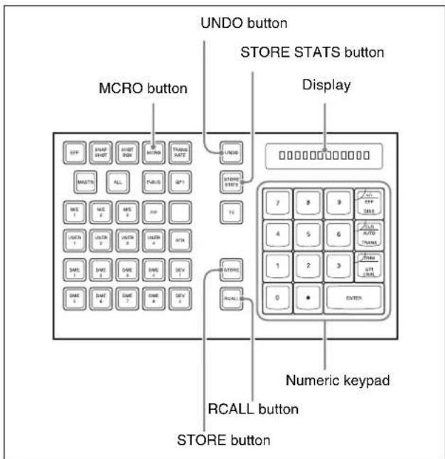
For macro operations in the keyframe control block, use the following buttons. (See the following figure.)
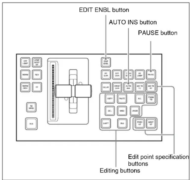
Recalling a Macro Register and Executing a Macro
To carry out a macro operation, recall a macro register. Recalling an empty register allows you to carry out macro editing operations. Recalling a register holding a macro executes the macro immediately.
To recall a macro register, use the following procedure.
1 In the numeric keypad control block, press the [MCRO] button, turning it on.
This assigns the numeric keypad control block to macro operations, and the [RCALL] button lights.
2 Enter the number of the register (1 to 250) to be recalled with the numeric keypad buttons. To search for an empty register, instead of entering a number, press the [.] (period) button.
The display shows the corresponding register number. A letter “E” after the number indicates that the corresponding register is empty.
3 Press the [ENTER] button.
When you recall an empty register
This assigns the numeric keypad control block and keyframe control block to macro editing.
For details of macro editing, see “Creating and Editing a Macro” (see below).
When you recall a register holding a macro
This immediately executes the macro. While the macro is executed, the [RCALL] button flashes.
Notes
- It is not possible to execute more than one macro at a time.
- If the same register is recalled again during macro execution or when the macro is paused, the following operation depends on a setting in setup.
For details of the settings, see “Setting the Macro Execution Mode” (page 593).
- Individual events stored in a macro are executed according to the settings in setup. If you change the settings in setup, a saved macro may not have the expected effect.
- During macro execution, if you switch the control panel to macro editing mode, the macro being executed stops.
- During macro editing it is not possible to execute a macro.
- While executing a macro with the Flexi Pad control block, or with a button with a macro attachment set, if you recall another macro with the numeric keypad control block, the following operation depends on a setting in setup.
For details of the settings, see “Setting the Macro Execution Mode” (page 593).
Creating and Editing a Macro
Use the numeric keypad control block and keyframe control block to create and edit a macro.
After carrying out creation and editing, be sure to carry out a save operation (see page 494), using the numeric keypad control block.
Switching auto insert mode on or off for macro creation/editing
In the auto insert mode, when creating or editing a macro, an operation carried out on the control panel is automatically registered as an event.
When this mode is off, it is necessary to press the [INS] button in the keyframe control block for each operation to register the event.
To switch auto insert mode on or off, press the [AUTO INS] button in the keyframe control block.
Notes
When you start macro editing using the numeric keypad control block with the macro execution mode set to "Normal" (page 593), the auto insert mode is automatically on. When "Step" is selected as the macro execution mode, the auto insert mode is automatically off.
Creating a new macro
1 Recall an empty register (1 to 250) (see page 491).
This assigns the numeric keypad control block and keyframe control block to macro editing, and the [MCRO] button in the numeric keypad control block and the [EDIT ENBL] button in the keyframe control block light red. The [STORE] button in the numeric keypad control block flashes red.
2 If required, press the [AUTO INS] button in the keyframe control block to toggle the auto insert mode on or off.
3 Create the events (carry out the control panel operations to be registered as events in the macro).
You can include pause events (see page 494).
For details of events that can be registered, see "Events" (page 487).
- When auto insert mode (see page 491) is on, execution of a control panel operation automatically registers an event in the macro.
- When auto insert mode is off, proceed to step 4.
Notes
- During macro editing, if you press any of the mode selection buttons in the numeric keypad control block other than the [MCRO] button ([TRANSRATE] button, and so on), the executed operation is also registered as an event. In this case, the [MCRO] button stays lit red.
- Even during macro editing, you can carry out keyframe operations using the fader lever in the keyframe control block and the following buttons: [EFF LOOP], [STOP NEXT KF], [NORM], [REV], [NORM / REV], [FF], [REWIND], [RUN]
- During macro editing, if you press a button for which a macro attachment is set, the outcome is as described in the next item.
4 When auto insert mode is off, press the [INS] button in the keyframe control block to register the event.
5 Repeat steps 2 and 3 to register the required events in the macro.
This registers the events in the macro, in the order the operations were carried out on the control panel.
6 Press the [STORE] button.
Macro editing finishes, and the [MCRO] button and [STORE] button in the numeric keypad control block light amber. The keyframe control block returns to the state before starting macro editing.
Notes
While carrying out macro editing in the numeric keypad control block and keyframe control block, no macro operation other than macro recalling is possible in the Flexi Pad control block.
Merging a macro for which a macro attachment is set
While creating/editing a macro, if you press a button for which a macro attachment is set, the macro in the register assigned to the button is recalled, and the following occurs.
- When auto insert mode is on, it is merged with the macro being edited. However, the macro assigned to the button is not executed.
- When auto insert mode is off, it is copied to the paste buffer. Pressing the [PASTE] button in the keyframe control block merges it with the macro being edited.
Specifying an edit point
To specify an edit point with the numeric keypad control block and keyframe control block, use the following procedure.
1 Recall the register of the macro (1 to 250) you want to edit (see page 491).
2 In the numeric keypad control block, hold down the [MCRO] button, and press the [STORE] button.
This assigns the numeric keypad control block and keyframe control block to macro editing, and the [MCRO] button in the numeric keypad control block and the [EDIT ENBL] button in the keyframe control block light red. The [STORE] button in the numeric keypad control block flashes red.
3 Using any of the following methods, specify the edit point.
- To move the edit point to the event immediately following the current macro event, press the [NEXT KF] button in the keyframe control block.
- To move the edit point to the event immediately preceding the current macro event, press the [PREV KF] button in the keyframe control block.
- To move to an edit point by specifying an event number (the number showing the position of the event in the macro execution sequence), press the [GO TO KF] button in the keyframe control block, then in the numeric keypad control block, enter the target number and confirm with the [ENTER] button.
Inserting an event
1 Specify the edit point. (See page 492.)
2 If required, press the [AUTO INS] button in the keyframe control block to toggle the auto insert mode on or off.
3 Create the event.
- When auto insert mode (see page 491) is on, the event is automatically added to the macro.
- When auto insert mode is off, proceed to step 4.
4 When auto insert mode is off, press the [INS] button in the keyframe control block.
5 Repeat steps 2 and 3 to insert the required events in the macro.
Modifying a single event
1 Specify the edit point. (See page 492.)
2 If the [AUTO INS] button is lit, press it to turn off the insert mode.
3 Create the event.
4 Press the [MOD] button in the keyframe control block.
Modifying a particular range of events
1 Carry out steps 1 to 3 of the procedure in “Modifying a single event” (the previous item).
2 Press the [FROM TO] button in the keyframe control block, turning it on.
The numeric display in the numeric keypad control block shows the current event number and the indication “TO.”
3 To set the start of the range to other than the current event number, press the [CLR/AUTO TRANS] button in the numeric keypad control block, then enter the desired event number with the numeric keypad and press the [ENTER] button. (This operation is not required when using the current event number.)
4 Enter the event number for the end of the range and press the [ENTER] button.
5 Press the [MOD] button in the keyframe control block.
Modifying all events at the same time
1 Carry out steps 1 to 3 of the procedure in “Modifying a single event” (page 493).
2 Press the [ALL] button in the keyframe control block, turning it on.
3 Press the [MOD] button.
Deleting an event
1 Specify the edit point. (See page 492.)
2 To delete multiple events simultaneously, carry out either of the following operations. (This operation is not required to delete the event at the edit point only.)
- To specify a range to be deleted, press the [FROM TO] button in the keyframe control block, then enter the event numbers from the numeric keypad control block.
- To delete all events within this macro, press the [ALL] button, turning it on.
3 Press the [DEL] button.
Moving events
1 Specify the edit point for the start of the range to be moved. (See page 492.)
2 To move multiple events simultaneously, press the [FROM TO] button in the keyframe control block, then specify the range in the numeric keypad control block.
3 Press the [DEL] button.
This temporarily deletes the specified events from the macro, and copies them to the paste buffer.
4 Move to the edit point which is the destination within the macro to which you want to move the events.
5 To paste the contents of the paste buffer after the edit point, press the [PASTE] button in the keyframe control block.
To paste before the edit point, hold down the [SHIFT] button in the keyframe control block and press the [PASTE] button.
This pastes the events from the paste buffer.
Copying events
1 Specify the edit point for the start of the range to be copied.
2 To copy multiple events simultaneously, press the [FROM TO] button or [ALL] button in the keyframe
control block, then specify the range in the numeric keypad control block.
3 Press the [COPY] button.
This copies the specified events into the paste buffer.
4 Move to the edit point which is the destination within the macro to which you want to copy the events.
5 To paste the contents of the paste buffer after the edit point, press the [PASTE] button in the keyframe control block.
To paste before the edit point, hold down the [SHIFT] button in the keyframe control block and press the [PASTE] button.
This copies the events from the paste buffer.
Inserting a pause event
1 Press the [PAUSE] button in the keyframe control block, lighting it green.
The indication “PAUSE” appears in the numeric keypad control block display.
2 If required, press the [AUTO INS] button in the keyframe control block to toggle the auto insert mode on or off.
3 Enter the pause duration with the numeric keypad control block (0 or 1 to 999 (frames)).
4 Press the [ENTER] button.
- If auto insert mode is on, this sets the pause duration, and inserts the pause event.
- When auto insert mode is off, continue to step 5.
5 When auto insert mode is off, press the [INS] button in the keyframe control block to insert the pause event.
Merging macro register data
1 Specify the edit point. (See page 492.)
2 Press the [RCALL] button in the numeric keypad control block, lighting it amber.
3 Enter the number of the macro register you want to copy using the numeric keypad buttons.
The display shows the register number.
4 Press the [ENTER] button.
The [RCALL] button goes off, and the specified register data is copied to the paste buffer.
- When auto insert mode is on, the data from the specified register is included after the edit point.
- When auto insert mode is off, continue to step 5.
5 When auto insert mode is off, to include after the edit point, press the [PASTE] button in the keyframe control block.
To include before the edit point, hold down the [SHIFT] button in the keyframe control block, and press the [PASTE] button.
In place of steps 2 to 4, you can specify the register with the Flexi Pad control block.
For details, see “Recalling a Macro Register and Executing a Macro” (page 496).
The same effect is obtained if you use a button which has a macro attachment set. In this case, the data from the assigned macro register is copied into the paste buffer.
Undoing a macro editing operation with the numeric keypad control block
Immediately after inserting, modifying, deleting, or pasting an event, you can undo the operation by pressing the [UNDO] button in the numeric keypad control block.
Saving a Macro
Use the following procedure to save the register after creating or editing/modifying a macro.
1 In the numeric keypad control block, press the [MCRO] button, turning it on.
This assigns the numeric keypad control block to macro operations.
2 Press the [STORE] button, turning it on.
3 Enter the number of the register (1 to 250) in which you want to save the macro with the numeric keypad buttons.
To search for an empty register, instead of entering a number, press the [.] (period) button.
The display shows the corresponding register number. A letter “E” after the number indicates that the corresponding register is empty.
4 Press the [ENTER] button.
This saves the macro data in the specified register, and the [STORE] button goes off.
The [RCALL] and [STORE STATS] buttons light.
To cancel the saving of a macro
To cancel the saving of a macro immediately after performing it, hold down the [STORE STATS] button and press the [UNDO] button.
Macro Operations in the Standard Type Flexi Pad Control Block
This section describes how to carry out macro operations in a standard type Flexi Pad control block.
Using the
The display of the standard type Flexi Pad control block changes as follows, depending on the selected mode of macro execution.
When entering macro editing mode with "Pause Only" selected
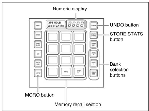
When entering macro editing mode with "Full Editing" selected
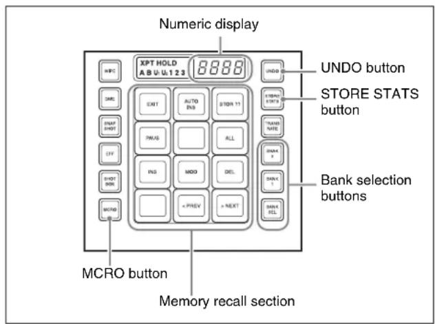
About operations in Full Editing mode, see “Setting the Macro Execution Mode” (page 593).
Banks and registers
To allow operations on the 99 registers, the standard type Flexi Pad control block treats the registers in groups. These groups are called banks, and there are 10 banks, numbered from 0 to 9.
For details of the correspondence between banks and registers, see “Banks and Registers” (page 467).
Recalling a Macro Register and Executing a Macro
Carrying out a macro operation in the normal mode
Use the following procedure to recall a macro register.
1 In the Flexi Pad control block, press the [MCRO] button, turning it on.
This assigns the Flexi Pad control block to macro operations.
The numeric display shows the previously selected bank number and the last recalled register number.
2 Use any of the following operations to select the bank for recall.
To select bank 0: Press the [BANK0] button.
To select bank 1: Press the [BANK1] button.
To select any of banks 0 to 9: Press the [BANK SEL] button, changing the memory recall section display as in the following figure; select a number from 0 to 9.
Example:
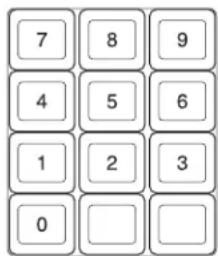
The selected bank number appears in the numeric display.
Each button in the memory recall section shows the corresponding register name and register status for the selected bank.
Note that in the Setup menu, you can select whether to display register names or register numbers.
- Lit orange: Register holding macro data
- Lit yellow: Last recalled register
- Off: Empty register
3 Press the button in the memory recall section showing the name of the register to be recalled.
The button you pressed lights yellow, the macro register is recalled, and the macro is executed.
During macro execution, the button you pressed remains yellow, but flashes. When macro execution completes, it returns to permanently on.
The numeric display shows the bank name followed by the selected register number.
Notes
- It is not possible to execute more than one macro at a time.
- If the same register is recalled again during macro execution or when the macro is paused, the following operation depends on a setting in setup. For details of the settings, see “Setting the Macro Execution Mode” (page 593).
- Individual events stored in a macro are executed according to the settings in setup. If you change the settings in setup, a saved macro may not have the expected effect.
- During macro execution, if you switch the control panel to macro editing mode, the macro being executed stops.
- During macro editing it is not possible to execute a macro.
- While executing a macro with the numeric keypad control block, Multifunction Flexi Pad control block, Flexi Pad control block for another switcher bank, or with a button with a macro attachment set, if you recall another macro with the Flexi Pad control block, the following operation depends on a setting in setup (see page 593).
Executing a macro in normal execution mode (with pause events set)
When execution of a macro is paused, the [Take] button is assigned to the memory recall section.
To restart the macro execution, press the [Take] button.
You can switch the normal execution mode and step execution mode in the Setup menu (see page 593).
Executing a macro in step execution mode
To recall a macro register and execute the macro in step execution mode, use the following procedure.
1 In the Flexi Pad control block, recall the macro register (see page 496).
The Flexi Pad control block memory recall section is assigned to the display of the [Take] button and macro execution status, as in the following figure.
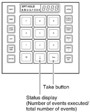
2 Press the [Take] button.
This executes one event within the macro, then stops. The number of events executed, as shown in the memory recall section status display, is incremented by one.
3 Repeat step 2, executing the macro event by event.
When all events in the macro have been executed, the [Take] button goes off.
Creating and Saving a Macro
1 In the Flexi Pad control block, press the [MCRO] button, turning it on.
This assigns the Flexi Pad control block to macro operations.
2 Select the bank of the register in which you want to save the macro.
For details of the method of operation, see step 2 in the previous item “Recalling a Macro Register and Executing a Macro” (page 496).
3 Hold down the [MCRO] button in the Flexi Pad control block, and press the button in the memory recall section showing the desired register name.
This assigns the Flexi Pad control block to macro editing, and the auto insert function is enabled. The [MCRO] button lights red.
As an example, when register 12 is specified, the buttons in the memory recall section appear as in the following figure.
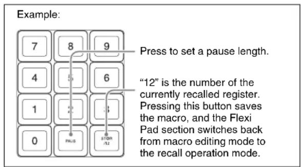
4 In the same way as in the numeric keypad control block, create the events you want to save in the macro.
For details, see step 2 (page 491) of “Creating a new macro.”
5 Repeat step 4 to save the desired events in the macro.
The operations you carry out on the control panel are saved as a sequence of events in the macro. The numeric display appears as follows.
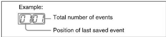
6 Press the [STORE XX] button in the memory recall section (where XX is the register number).
The [STORE STATS] button lights amber. This saves the created macro in the register, and macro editing ends. The Flexi Pad control block returns to the state before macro editing began. The [MCRO] button lights amber.
Notes
- During macro editing, you can press a mode selection button in the Flexi Pad control block other than the [MCRO] button (for example, the [WIPE] button or [DME] button) to record the executed operation as an event. In this case, the [MCRO] button remains lit red.
- During macro editing, if you press a button for which a macro attachment is set, the macro within the register assigned to the button is merged into the macro being edited. However, the macro assigned to the button is not executed.
- While carrying out macro editing in the Flexi Pad control block, absolutely no macro operations are possible in the Flexi Pad control blocks for other M/E and PGM/PST banks. Macro operations from the numeric keypad control block or Multifunction Flexi Pad control block are also not possible.
To cancel the saving of a macro
To cancel the saving of a macro immediately after performing it, hold down the [STORE STATS] button and press the [UNDO] button.
Inserting a pause event
1 Press the [PAUS] button in the memory recall section.
The buttons in the memory recall section change as follows.
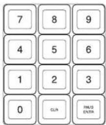
2 Enter the length of pause you want to set (0 to 999 frames).
3 Press the [PAUS ENTR] button.
This sets the pause length, and inserts the pause event. The memory recall section displays returns to its former state.
Deleting a macro
1 In the Flexi Pad control block, press the [MCRO] button.
This assigns the Flexi Pad control block to macro operations.
The numeric display shows the previously selected bank number and the number of the last recalled register.
2 Select the bank of the register holding the macro you want to delete.
For details of the method of operation, see step 2 (page 496) of "Recalling a Macro Register and Executing a Macro."
3 Hold down the [STORE STATS] button, and then press the button in the memory recall section showing the corresponding register number.
The button you pressed in the memory recall section goes off, and this deletes the macro. The [STORE STATS] button lights amber.
Macro Operations in the Simple Type Flexi Pad Control Block
This section describes the macro operations carried out in the simple type Flexi Pad control block.
Use the following buttons.
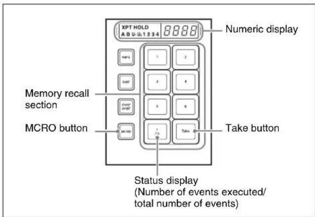
To use the MCRO button
To enable the [MCRO] button for use as in the above figure, it is necessary in the Setup menu to switch the [UNDO] button to the [MCRO] button (see page 561).
Notes
In a simple type Flexi Pad control block, only registers 1 to 6 can be used for operations. There are no “bank” operations.
For registers 7 to 250, use the numeric keypad control block.
Recalling a Macro Register and Executing a Macro
Executing a macro in normal execution mode
1 In the simple type Flexi Pad control block, press the [MCRO] button, turning it on.
This assigns the Flexi Pad control block to macro operation.
The numeric display shows the number of the last recalled register.
The buttons of the memory recall section show the selected register status.
Lit orange: register holding macro data
Lit yellow: last recalled register
Off: empty register
2 Press the button in the memory recall section showing the register to be recalled.
The button you pressed lights yellow, the macro register is recalled, and the macro is executed. During the macro execution, the button pressed remains yellow, but flashes, and when the macro execution completes it changes to permanently lit. The numeric display shows the selected register number.
Notes
- Only one macro can be executed at a time.
- If the same register is recalled again during macro execution or when the macro is paused, the following operation depends on a setting in setup. For details of the settings, see “Setting the Macro Execution Mode” (page 593)
- Individual events registered in a macro are executed according to the setup settings. If you change the setup settings, the content of the macro may not be played back.
- During macro execution, if you switch the control panel to macro editing mode, the macro currently being executed stops.
- It is not possible to execute a macro during macro editing.
Executing a macro in normal execution mode (with pause events set)
When the macro execution is paused, the [Take] button is assigned to the simple type Flexi Pad memory recall section. Press the button to restart macro execution.
Executing a macro in step execution mode
After recalling the macro register, to execute a macro in step execution mode (see page 561), use the following procedure.
1 In the simple type Flexi Pad control block, press the [MCRO] button, turning it on.
This assigns the Flexi Pad control block to macro operation.
2 Press the button in the memory recall section showing the register to be recalled.
3 Press the [Take] button.
This executes one event within the macro, then stops.
The number of events executed, as shown in the memory recall section status display, is incremented by one.
4 Repeat step 3, executing the macro event by event.
When all events in the macro have been executed, the [Take] button goes off.
Creating and Editing a Macro
Creating a macro
1 In the simple type Flexi Pad control block, press the [MCRO] button, turning it on.
This assigns the Flexi Pad control block to macro operation.
2 While holding down the [MCRO] button in the Flexi Pad control block, press the button in the memory recall section showing the desired register name.
This assigns the Flexi Pad control block to macro editing.
As an example, when register 1 is specified, the memory recall section buttons appear as in the following figure.
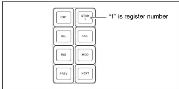
3 Carry out the control panel operation to be registered as an event in the macro.
For details of the events that can be registered, see "Events" (page 487).
Notes
In the Flexi Pad control block, it is not possible to set a pause event. To set a pause event, use the numeric keypad control block.
4 Press the [INS] button.
This registers the operation carried out in step 3 as an event within the macro.
5 Repeat steps 3 and 4 to register the required events in the macro.
The numeric display shows the last registered event position, and the total number of events.
6 Press the [STOR 1] button in the memory recall section.
This saves the created macro in the register and ends the macro editing mode; the [MCRO] button lights amber.
Notes
- During macro editing, if you press any of the mode selection buttons in the Flexi Pad control block other than [MCRO] button (the [WIPE] button, [DME] button, and so on), the executed operation is also registered as an event. In this case, the [MCRO] button stays lit red.
- While carrying out macro editing in the Flexi Pad control block, pressing a button to which a macro attachment is set does not execute the macro.
- In the simple type Flexi Pad control block, it is not possible to undo a macro save.
Specifying an edit point
1 In the Flexi Pad control block, press the [MCRO] button, turning it on.
This assigns the Flexi Pad control block to macro operation.
2 While holding down the [MCRO] button in the Flexi Pad control block, press the button in the memory recall section showing the desired register name.
3 Specify the edit point by the following operation.
- To move the edit point to the event immediately following the current macro event (the macro event specified as the current edit point), press the [NEXT] button.
- To move the edit point to the event immediately preceding the current macro event, press the [PREV] button.
Inserting an event
To add an event to an already created macro, use the following procedure.
1 Specify the edit point. (See page 500.)
2 Carry out the event to be added on the control panel.
For details of events that can be registered, see "Events" (page 487).
3 In the memory recall section, press the [INS] button. This adds the new event after the event specified in step 1.
Modifying an event
1 Specify the edit point. (See page 500.)
2 Carry out the event you want to modify on the control panel.
3 Press the [MOD] button.
This modifies the event at the specified edit point as carried out in step 2.
Deleting an event
1 Specify the edit point. (See page 500.)
2 Press the [DEL] button.
This deletes the event specified in step 1.
Deleting all events within a macro register
1 Specify the edit point. (See page 500.)
2 Press the [ALL] button, lighting it green.
3 Press the [DEL] button.
Saving a Macro
In the memory recall section, press the [STOR X] (X=register number) button to save the edited macro in a register.
To return to the state before editing, without saving the macro editing results
Press the [EXIT] button to recall the same register again. This returns to the state before editing, without saving the macro editing results.
Macro Operations in the Multifunction Flexi Pad Control Block
This section describes macro operations carried out in the Multifunction Flexi Pad control block. Use the following buttons.
![[MCRO] button Numeric keypad buttons [DRCT MODE] button](/content/2026/06/1364863/images/6917c0c9f1ff394ca328cb235cdacae87474407503b9f8fe8631d9f5583eed77.jpg)
Recalling a Macro Register and Executing a Macro
1 Press the [MCRO] mode selection button, turning it on.
This switches the Multifunction Flexi Pad control block to macro operation mode.
2 Enter the register number with the numeric keypad buttons, and press the [ENTR] button to recall the register.
3 Press the [DRCT MODE] button, to switch to the direct recall mode in which a macro can be recalled with the buttons in the memory recall section.
The button indications in the memory recall section change as shown in the following illustration.
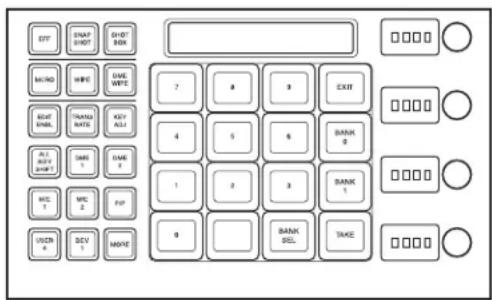
4 Use one of the following operations to select the bank.
To select bank 0: Press the [BANK0] button.
To select bank 1: Press the [BANK1] button.
To select any of banks 0 to 9: Press the [BANK SEL] button, then press the desired bank button (any of [0] to [9]).
This selects the bank, and the buttons in the memory recall section show the macro register state as follows.
Lit yellow: Last recalled register
Lit orange: Register holding macro data
Off: Empty register
5 Press the button for the number of the register to be recalled.
The button you pressed lights yellow, and the macro held in the corresponding register is recalled and executed.
The button you pressed flashes yellow as the macro execution starts, and returns to constantly lit yellow when the execution ends.
The alphanumeric display shows the numbers of the selected bank and register.
Notes
- You can only execute one macro at a time.
- If the same register is recalled again during macro execution or when the macro is paused, the following operation depends on a setting in setup.
For details of the settings, see “Setting the Macro Execution Mode” (page 593).
- The individual events registered in the macro are executed according to the setup settings. If you change the settings in setup, the registered content may not be reproduced.
- During macro execution, if you switch the control panel to macro editing mode, this stops the executing macro.
- It is not possible to execute a macro during macro editing.
- While executing a macro with the Flexi Pad control block, or with a button with a macro attachment set if you recall another macro with the Multifunction Flexi Pad control block, the following operation depends on a setting in setup (see page 593).
Macro execution modes
You can execute a macro in normal execution mode or step execution mode.
Normal execution mode: In this mode the macro events are automatically executed in sequence. However, if there is a pause event set at some point, execution pauses at that point. Then pressing the [TAKE] button in the memory recall section resumes execution.
Step execution mode: The macro events are executed one at a time with pauses in between. Execute the events in sequence by repeatedly pressing the [TAKE] button.
You can select normal execution mode or step execution mode by a selection in the Setup menus (see page 593).
Creating and Editing a Macro
To create or edit a macro, first recall the register in which the created macro will be saved, or the register holding the macro to be edited, then press the [EDIT ENBL] button. The [MCRO] button and [EDIT ENBL] button light red, and the memory recall section switches to the macro editing mode as shown in the following illustration.
For the method of recalling an empty register, see "Recalling a Macro Register and Executing a Macro" (page 496).
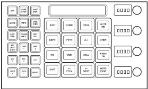
In this mode, you can use the following buttons for macro creation, editing, saving, and deletion.
[EXIT] button: Forcibly exit editing mode.
[UNDO] button: Undo the last macro event insertion, modification, deletion, paste, or other operation.
[PAUS] button: Insert a pause event (see page 494).
[AUTO INS] button: Toggle auto insert mode on or off (see page 491).
[COPY] button: Copy a macro event (see page 493).
[PSTE] button: Paste a macro event (see page 494).
[ALL] button: Select all macro events (see page 493).
[STOR] button: Save the macro (see page 494).
[INS] button: Insert a macro event (see page 492).
[MOD] button: Modify a macro event (see page 493).
[DEL] button: Delete a macro event (see page 493).
[FROM TO] button: Switch to the mode for entering a value range with the numeric keypad (see page 493).
[SHFT] button: Move a macro event (see page 493).
[<< PREV] button: Move the edit point to the previous event (see page 500).
[>> NEXT] button: Move the edit point to the next event (see page 500).
[GOTO EVNT] button: Switch to the mode for specifying an event to move to with the numeric keypad (see page 492).
Macro Editing Using Menus
Using any of the menus in the following table, you can edit macro registers and macro events.
| Menu Function | Operations | |
| Register menu (macro register editing) | Carry out macro register editing. | Locking a registerCopying a registerDeleting a registerNaming a register |
| On Line Edit menu (online editing of macro events) | Edit events in a macro register, using the control panel and menus. | Inserting an eventDeleting an eventModifying an event |
| Off Line Edit menu (offline editing of macro events) | Edit events in a macro register, on the hard disk, or on a memory card, using the menus. | Inserting an eventAdding an eventDeleting an eventCreating a new macro |
Macro Register Editing
You can display the current state of a macro register using the Macro >Register menu.
The items displayed are the same as under “Effect Status Display” (page 459), with the exception that the region name is not displayed and that the total number of macro events saved in the register is displayed.
In the Macro >Register menu, you can do the following editing operations on macro registers.
- Lock: Write-protect the contents of the register.
- Copy: Copy the contents of one register to another register.
- Delete: Delete the contents of a register.
- Name: Attach a name to a register.
The operations for macro register editing are the same as those for effect register editing (see page 459) except the region selection operation, which is not necessary for macro register editing.
Online Editing of Macro Events
Using the On Line Edit menu, you carry out online editing of macro events.
In the On Line Edit menu, you can check the control panel operating sequence in the menu. You can also carry out editing using the control panel and menu.
To display the On Line Edit menu
1 Recall the macro register (1 to 250) you want to edit with the control panel, and select the macro editing mode ^1) .
1) With the numeric keypad control block, keyframe control block, Flexi Pad control block, or Multifunction Flexi Pad control block assigned to macro editing (see step 2 in "Specifying an edit point" (page 492), step 3 in "Creating and Saving a Macro" (page 497), step 2 in "Creating a macro" (page 499), and step 1 in "Recalling a Macro Register and Executing a Macro" (page 498)).
2 In any of the following menus, select the same register as the register recalled in step 1, and press [On Line Edit] in the button area.
- Macro >Register >Lock menu
- Macro >Register >Delete menu
- Macro >Register >Rename menu
- File >Shotbox, Macro >Macro >File Edit menu
The On Line Edit menu appears, and you can now carry out online editing of the events held in the recalled register. Meanwhile, the control block of the control panel operated in step 1 is assigned to control editing operations.
Notes
In the following cases, [On Line Edit] is disabled, and it is not possible to display the On Line Edit menu.
- When the recalled register and the register selected in the menu are different.
- When a device other than [Register] is selected ([HDD] or [Memory Card]) in the File >Shotbox, Macro >Macro >File Edit menu.
- If the recalled register is locked.
On Line Edit menu
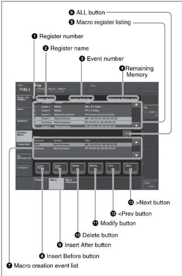
①Register number
Shows the number of the register (1 to 250) being edited.
②Register name
Shows the name of the register being edited.
③Event number
Shows the current event number. When the [FROM TO] button in the keyframe control block is pressed to select a range of events, this appears as a range, "From X To Y." The event number reflects the position of the cursor in the macro register listing.
④ Remaining Memory
Shows the percentage of memory still available for recording events.
⑤ Macro register listing
When a macro is stored in the register, this shows a list of the macro events. Each macro event consists of the following components, which you can check in the list.
- Contents: Identifies this as an Event statement, Continue statement, or event number
- Symbol: Type of event (ASCII character string)
• Data: Event details in the form of parameters and data
For details of the event components, see “Macro File Editing Rules” (page 650).
The cursor shows the current event in the list, in reverse video. You can turn knob 1 to scroll the list, but this does not change the cursor position. Depending on the switcher status, the cursor color changes as follows.
- Yellow: in macro editing mode
- Gray: when the editing mode is exited by a control panel operation
• Blue: during macro execution
6ALL button
Selects all events in the macro register listing.
⑦Macro creation event list
Shows the event being created or executed in the control panel.
⑧Insert Before button
Inserts a created event immediately before the selected event in the macro register listing.
⑨Insert After button
Inserts a created event immediately after the selected event in the macro register listing.
⑩ Delete button
Deletes the selected event in the macro register listing.
⑪Modify button
Replaces the selected event in the macro register listing with a created event.
12<Prev button
Moves the cursor to the event immediately before the selected event in the macro register listing.
13>Next button
Moves the cursor to the event immediately after the selected event in the macro register listing.
Carrying out online editing of macro events
In the On Line Edit menu, you can carry out the following editing operations on the events in the macro register.
- Insert: Insert a macro event.
- Delete: Delete a macro event.
- Modify: Modify a macro event.
Notes
It is not possible to save editing results using this menu alone. Carry out the necessary control panel operations to save the edited register.
To insert an event
1 On the control panel, if auto insert mode is on, switch it off.
2 On the control panel, create a macro event.
The created event appears in the macro creation event list.
For more details of the display, see “Macro File Editing Rules” (page 650).
3 In the macro register listing, press [
4 Carry out either of the following.
To insert before the event selected in the list: Press [Insert Before].
To insert after the event selected in the list: Press [Insert After].
This inserts the created event either before or after the specified event.
Notes
In the following cases, [Insert Before] and [Insert After] are disabled, and it is not possible to insert the event.
- If the memory or register is full.
- The size of the created macro event is larger than the memory or register space available.
- When multiple events are selected.
- When the number of events has reached 99.
- When not in macro editing mode. ^1)
1) While a macro is being executed on the control panel, when macro saving has been executed, or when the [EXIT] button in the Flexi Pad control block or Multifunction Flexi Pad control block has been pressed
5 Operate the control panel to save the editing result.
To delete an event
1 In the macro register listing, press [
To select all events in the register, press [All].
2 Press [Delete].
Notes
If not in macro editing mode ^1) , [Delete] is disabled, and it is not possible to delete the selected event.
1) While a macro is being executed on the control panel, when macro saving has been executed, or when the [EXIT] button in the Flexi Pad control block or Multifunction Flexi Pad control block has been pressed
3 Operate the control panel to save the editing result.
To modify an event
1 On the control panel, if auto insert mode is on, switch it off.
2 In the macro register listing, press [
3 On the control panel, modify the macro event.
The modified event appears in the macro creation event list.
For more details of the display, see "Macro File Editing Rules" (page 650).
4 Press [Modify].
This modifies the event selected in the list.
Notes
If not in macro editing mode ^1) , [Modify] is disabled, and it is not possible to modify the event.
1) While a macro is being executed on the control panel, when macro saving has been executed, or when the [EXIT] button in the Flexi Pad control block or Multifunction Flexi Pad control block has been pressed
5 Operate the control panel to save the editing result.
Offline Editing of Macro Events
Using the Off Line Edit menu, you carry out offline editing of macro events.
In the Off Line Edit menu, you can carry out editing in the menu only, unrelated to operation of the control panel.
To display the Off Line Edit menu
In any of the following menus, select the register or device holding the macro you want to edit, and press [Off Line Edit] in the button area.
- Macro >Register >Lock menu
- Macro >Register >Delete menu
- Macro >Register >Rename menu
- File >Shotbox, Macro >Macro >File Edit menu This recalls the selected macro register or macro file, and offline editing is now possible.
Notes
If the selected register is locked, [Off Line Edit] is disabled, and it is not possible to display the Off Line Edit menu.
Off Line Edit menu
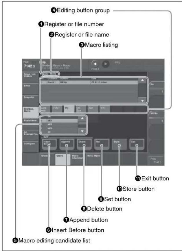
①Register or file number
Shows the number of the register or file being edited.
②Register or file name
Shows the name of the register or file being edited.
③Macro listing
Lists the macro events that are saved in the register or file. The cursor moves to the selected event. Each macro event consists of the following components, which you can check in the list.
- Contents: Event statement, Continue statement, comment (#), or event number, as selected in the editing button group [Contents]
- Symbol: Event type (ASCII character string), as selected in the editing button group [EVNT]
- Data: Parameters and data as set in the editing button group
For more details of the event components, see "Macro File Editing Rules" (page 650).
④Editing button group
This row of buttons shows the components of an event. To carry out event editing: (1) press an editing button, then (2) select an item from the list of macro editing candidates, and repeat this process as required.
⑤Macro editing candidate list
Shows the list of editing candidates for the selection from the editing button group.
6 Insert Before button
Inserts immediately before the event selected in the macro listing.
⑦ Append button
Adds an empty row at the end of the macro listing.
⑧ Delete button
Deletes the event selected in the macro listing.
⑨ Set button
Reflects the item selected in the macro editing candidate list, in the macro listing and editing buttons.
⑩Store button
Saves the results of the macro register or macro file editing.
⑪Exit button
Closes the Off Line Edit menu without saving the results of the macro register or macro file editing, and returns to the File Edit menu.
Carrying out offline editing of macro events
In the Off Line Edit menu, you can carry out the following editing operations on the events in the macro register or macro file.
- Insert: Insert a macro event.
- Add: Add a macro event.
- Delete: Delete a macro event.
You can also create a new macro.
To insert an event
1 In the macro listing, select the event immediately after the position where you want to insert an event.
2 Press [Insert Before].
This inserts a blank row before the event selected in step 1.
3 Press [Contents] in the editing button group.
The following event types appear in the macro editing candidate list.
- Event: Event
- Continue: Event continuation
-
: Comment
For details of the items, see “Macro File Editing Rules” (page 650).
4 Select the desired item from the macro editing candidate list, and press [Set].
The selected item appears at the event insertion position in the macro listing, as an event component. Additionally, in the leftmost blank position of the editing button group (to the right of [Contents]), a button appears, corresponding to the item in the macro editing candidate list. For example, if “Event” is selected, an [EVNT] button appears.

5 In the editing button group, press the button that has just appeared.
The item corresponding to the button appears in the macro editing candidate list.
If you press the [EVNT] button, the symbol indicating the event contents appears (see page 652).
6 Select the desired item from the macro editing candidate list, and press [Set].
At the event insertion position of the macro listing, the selected item is added as an event component. Additionally, in the next blank position of the editing button group, a button appears, corresponding to the item in the macro editing candidate list. For example, if “MEAutoTransition” is selected, a button for the parameters and data for the MEAutoTransition appears.

Notes
If you select an item from the macro editing candidate list, be sure to press [Set]. If [Set] is not pressed, the selection is not confirmed.
7 Repeat steps 5 and 6, to edit the event components.
At the event insertion position of the macro listing, the confirmed item is added as an event component. To further add an event, repeat steps 1 to 7.
To close the Off Line Edit menu without saving the editing results
Press [Exit] to return to the menu that was on the screen immediately before the offline editing.
8 Press [Store].
The numeric keypad window appears.
9 Enter the register number as required, and press [Enter].
The current macro is stored in the register.
The menu screen switches to the menu that was on the screen immediately before the offline editing.
To append an event
This adds an event at the end of the macro.
1 Press [Append].
A blank row is added at the end of the macro listing.
2 Carry out steps 3 to 8 of the previous item, "To insert an event," to edit an event.
To delete an event
1 In the macro listing, select the event you want to delete.
2 Press [Delete].
This deletes the selected event.
If a deleted Event statement is followed by a Continue statement, the Continue statement is converted to an Event statement.
To close the Off Line Edit menu without saving the editing results
Press [Exit] to return to the File Edit menu.
3 Press [Store].
This saves the results of the macro register or macro file editing, and returns to the File Edit menu.
To create a new macro
1 From the list in any of the following menus, select an empty register or file, and press [Off Line Edit] in the button area.
- Macro >Register >Lock menu
- Macro >Register >Delete menu
- Macro >Register >Rename menu
- File >Shotbox, Macro >Macro >File Edit menu The Off Line Edit menu appears.
2 Carry out steps 3 to 8 of the procedure “To insert an event” (page 506), to create an the event.
Macro Attachment Assigning
Macro attachment is a function whereby a macro register is assigned to a control panel button or a particular position of a fader lever, linking the execution of the button function or a fader lever operation with a macro execution.
Setting a macro attachment to a button
Select one of the following three linking modes to make the macro attachment.
Pre-macro: Mode in which the button function is executed after macro execution has completed
Post-macro: Mode in which the macro is executed after carrying out the button function
Macro only: Mode in which the button function is not executed, and the macro only is executed
The selection of pre- or post-macro mode is carried out in the cross-point control block of the PGM/PST bank or the M/E banks. For the macro-only mode, assign the selection function to a utility/shotbox control block button or user preference button, and make the selection by pressing the button. Alternatively, without pressing the button, you can make the selection simply, by simultaneously pressing the pre-macro and post-macro selection buttons in the cross-point control block.
You can assign any one of the 250 macro registers to a button.
For a button whose function is switched by delegation, you can make a separate macro attachment for each function. For each control panel, you can make up to 1000 macro attachment settings.
The macro attachment setting is possible for the following bus buttons.

| Block Button | |
| Cross-point control block | Background A row cross-point buttonsBackground B row cross-point buttonsKey 1 bus cross-point buttonsKey 2 bus cross-point buttonsKey 3 bus cross-point buttonsKey 4 bus cross-point buttonsKey 5 bus cross-point buttons a)Key 6 bus cross-point buttons a)Key 7 bus cross-point buttons a)Key 8 bus cross-point buttons a)Utility 1 bus cross-point buttonsUtility 2 bus cross-point buttonsDME external video bus cross-point buttonsDME utility 1 bus cross-point buttonsDME utility 2 bus cross-point buttonsMemory recall buttons b)Buttons set to “Inhibit”Auxiliary bus cross-point row c) |
| Auxiliary bus control block | Cross-point button1st row d)Cross-point button 2nd row d) |
| Keyframe control block | [RUN], [REWIND] and [FF] buttons[NORM], [REV], and [NORM/REV] buttons |
| Device control block (trackball, joystick) | The buttons to which the same functions as those of VTR/disk recorder/Extended VTR/frame memory clips play, cue, stop, and start tc buttons |
| Device control block (search dial) | [PLAY], [CUE], [STOP] and [START TC] buttons |
| Downstream key control block | [DSK1 ON] to [DSK8 ON] buttons e) g)[KEY1 ON] to [KEY8 ON] buttons a) c)[TAKE] button e)[MIX], [WIPE], [DME], and [CUT] buttons |
| Transition control block | All buttons except [PRIOR SET], [TRANS PVW], [SHIFT], [ADD], [KF], [MAIN], [SUB], [LIMIT SET], [K-SS], [K-SS STORE], and key snapshot setting buttons |
| Fade to black control block | [FTB] button |
| Downstream key/fade to black control block | [DSK1 ON] and [DSK2 ON] buttons c)[DSK3 ON] to [DSK8 ON] buttons a) c)[KEY1 ON] to [KEY8 ON] buttons a) c)[AUTO TRANS] button c)[FTB] button |
| Block Button | |
| Utility/shotbox control block | Memory recall buttons |
| Menu control block [PREFS 1] to [PREFS 16] buttons | |
| Independent key transition control block (simple type) ^f | • [KEY1 ON] to [KEY8 ON] buttons ^e g)• [DSK1 ON] to [DSK8 ON] buttons ^e g)• [TAKE] button ^e • [MIX], [WIPE], [DME], and [CUT] buttons |
| Multifunction Flexi Pad control block | [AUTO TRANS] ^e , [KEY ON] ^e , [RUN], [REWIND], [NORM], [REV] and [NORM/REV] buttons |
a) Assignment is required
b) Only when key row is operated in the utility/shotbox mode
c) When the auxiliary control mode or Key/AUX delegation mode is on.
d) Cross-point buttons of the bus assigned by AUX delegation setting.
c) In the case of an event that inserts or deletes a key by an independent key transition, the key state at the time of event registration (inserted or not inserted) is also saved in the macro. When the macro is executed, the event is only replayed if the key state matches the saved state. (Example: For a macro with an event that deletes a key, when the macro is executed, if the key is inserted it is deleted, but otherwise nothing occurs as concerns keying.)
f) When there are a number of control blocks on the control panel, and the keys assigned to them in setup are the same, then the macro attachment settings for the above buttons are the same.
The keys being the same includes cases such as “Key1,2” assigned to PGM/PST being the same as “DSK1,2”, “Key1,2” assigned to M/E-1 being the same as “M/E-1 Key1,2”, and so on.
g) KEY5 to KEY8 and DSK5 to DSK8 require an assignment.
Notes
- After setting a macro attachment to a cross-point button in the auxiliary bus control block, if in the Setup menu you change the assignment of buses to the AUX delegation buttons, the macro attachment setting disappears.
- After setting a macro attachment to a button for which you can perform function replacement or function assignment, if you change the function assignment to the button, the macro attachment setting disappears.
- After setting a macro attachment to a cross-point button in the cross-point control block, if you change the function assignment to the button, the macro attachment setting disappears.
Enabling and disabling macro attachment
You can temporarily disable the macro attachment settings. When a macro attachment is disabled, pressing the button does not cause execution of the assigned macro. You can enable and disable macro attachments for the PGM/PST bank and M/E banks individually.
Setting a macro attachment to a fader lever
You can set a macro attachment to any particular position of a fader lever in the transition control block.
Notes
- In macro-only mode it is not possible to set a macro attachment.
- It is not possible to set a macro attachment to a fader lever in the keyframe control block or downstream key control block.
- For a split fader, you can set a macro attachment to the main split fader.
Clearing the macro attachments
You can clear all of the macro attachments in a single operation.
Displaying the macro attachment list
You can display the macro attachment settings in the form of a list in the menu display to check them.
Setting and Canceling a Macro Attachment
Setting a macro attachment to a button
This section describes the example of setting a macro attachment for the background A row cross-points.
For details, see “Setting a macro attachment to a button” (page 507) for the buttons for which a macro attachment can be set.
1 Recall the macro register (1 to 250) that you want to assign to the button (see page 491).
2 To set in pre macro mode, hold down the [PRE MCRO] button in the cross-point control block, and to set in post macro mode, hold down the [POST MCRO] button, and then press the desired button in the background A row.
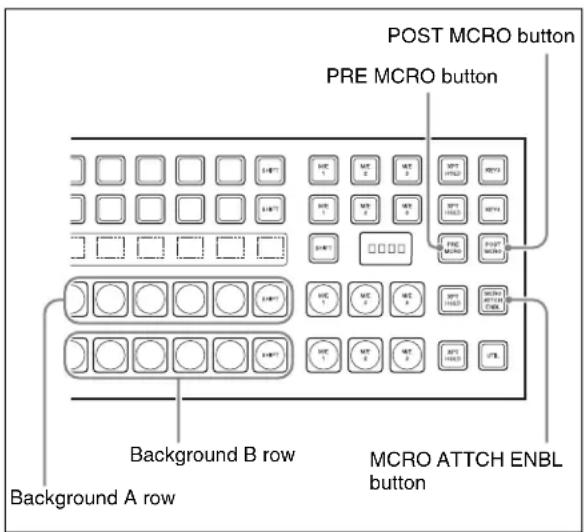
The cross-point button you pressed flashes amber, and the register you recalled in step 1 is assigned to the button.
If you make both pre macro and post macro settings for the same button
The later setting is valid.
To set a macro attachment without changing cross-points
When you set a macro attachment to a cross-point button, you can make the setting without changing the bus cross-points. Carry out this selection in the Engineering Setup >Panel >Operation menu (see page 593).
To make a macro attachment setting in macro only mode
Notes
To carry out this operation, it is first necessary to assign the "Macro Only Set" function to the user preference buttons in the menu control block or the utility/shotbox control operation. Carry out this assignment in the Eng Setup >Panel >Prefs/Utility menu (see page 577).
To make a macro attachment in macro only mode, use the following procedure.
1 Recall the macro register (1 to 250) that you want to assign to the button (see page 491).
2 Press the button to which [MCRO ONLY SET] is assigned, turning it on.
3 Hold down the cross-point control block [PRE MCRO] button or [POST MCRO] button, and press the desired button in the background A row.
The cross-point button you pressed flashes green, and the register you recalled in step 1 is assigned to the button. The [MCRO ONLY SET] button goes off. Without switching to macro only mode in step 2, if you hold down the [PRE MCRO] and [POST MCRO] buttons together and press the desired button, it is possible to set a macro attachment in macro only mode for that button.
To check macro attachment settings
Hold down the [PRE MCRO] button or [POST MCRO] button. While it is held down, buttons for which macro attachments are set flash as follows.
While the [PRE MCRO] button is held down:
- Buttons set in pre macro mode: flash amber
- Buttons set in macro only mode: flash green
- Buttons set in post macro mode: flash amber
- Buttons set in macro only mode: flash green
While the [POST MCRO] button is held down:
Setting a macro attachment to a fader lever
You can set a macro attachment to any particular position of a fader lever in the transition control block.
Notes
- In macro only mode it is not possible to set a macro attachment.
- It is not possible to set a macro attachment to a fader lever in the keyframe control block or downstream key control block.
- For a split fader, you can set a macro attachment to the main split fader.
1 Recall the macro register (1 to 250) that you want to assign to the fader lever (see page 491).
2 Move the fader lever to the position where you want to set the macro attachment.
3 Hold down the [PRE MCRO] or [POST MCRO] button ^1) in the cross-point control block, and press the [LIMIT SET] or [PRIOR SET] button in the control block containing the fader lever operated in step 2.
1) Only when setting a macro attachment to the start point or end point of fader lever operation, use [PRE MCRO] and [POST MCRO] in distinction, as follows.
To set the operation start point (0%): hold down [PRE MCRO] for the operation.
To set the operation end point (100%): hold down [POST MCRO] for the operation.
This assigns the register recalled in step 1 to the fader lever position selected in step 2.
To check a macro attachment setting
Hold down the [PRE MCRO] or [POST MCRO] button in the cross-point control block. While it is held down, the fader lever position where the macro attachment is set appears in the following places.
- Transition indicator in the transition execution section: The indicator lights at the position where the macro attachment is set.
- Transition rate indication in the transition execution section: This shows the fader lever position where the macro attachment is set, as a percentage value. (Fader lever start position as 0% , end position 100% )
Removing macro attachment settings
To cancel a macro attachment to a button
Hold down the [PRE MCRO] button or [POST MCRO] button, and press a button that is flashing in the background A row. The button for which the macro attachment is set stops flashing and goes off, and this removes the setting.
To cancel a macro attachment to a fader lever Hold down the [PRE MCRO] or [POST MCRO] button in the cross-point control block, and press the [LIMIT SET] or [PRIOR SET] button in the control block containing the fader lever having the macro attachment set.
To remove all macro attachment settings in a single operation
1 In the Macro menu, select VF2 'Attachment.'
2 Press [All Clear].
A confirmation message appears.
3 Select [Yes].
Displaying the Macro Attachment List
In the Macro >Attachment menu, you can display the macro attachment list to check the macro attachment settings.
The macro attachment list includes the following columns.
- Block: Shows the names of control panel blocks.
- Button: Shows the names of macro attachment assigned buttons (of up to 30 characters).
- Reg: Shows the names of assigned registers.
- Name: Shows the names of macro registers.
- Mode: Shows the names of macro modes (Pre/Post/Only/--- ^1) ).
Above the list is shown the names of the block and macro attachment assigned button currently selected in the list.
1) When no macro mode is set
For details of the macro modes, see “Setting a macro attachment to a button” (page 507).
For details of the macro attachment list display, see "About the Macro Attachment List Display" (page 658) in the Appendix.
Moving quickly within the macro attachment list from one block to another
When you are viewing the macro attachment settings for a block in the macro attachment list, you can move quickly from the current block to another block to check the settings for that block by pressing the following buttons in the
- P/P: Move to a block in the PGM/PST bank.
- M/E-1: Move to a block in the M/E-1 bank.
- M/E-2: Move to a block in the M/E-2 bank.
- M/E-3: Move to a block in the M/E-3 bank.
- M/E-4: Move to a block in the M/E-4 bank.
- Aux: Move to a section in the auxiliary bus control block.
- Others: Move to a block/section in a location other than the PGM/PST bank, M/E-1 to M/E-4 banks, and the auxiliary bus control block.
Scrolling the list
To scroll the macro attachment list, do one of the following.
- Press the arrow keys to scroll the reverse video cursor.
- Turn the knob.
| Knob | Parameter Adjustment Setting values | ||
| 1 No | Macro attachment settings scrolling | 1 and upwards | |
Executing a Macro by Macro Attachment
Notes
For execution on any of the M/E and PGM/PST banks, use the [MCRO ATTCH ENBL] button in the cross-point control block. To execute a macro according to a macro attachment set elsewhere, assign "MCRO ATTCH ENBL" to a utility/shotbox control block or user preference button, then use that button.
Executing a macro assigned to a button
1 Depending on the location of the button you want to use, press the [MCRO ATTCH ENBL] button, turning it on.
2 Press the desired button for which a macro attachment has been set.
This recalls the macro register assigned to the button, and the macro is executed as follows, according to the operation mode. Pre macro mode: The macro is executed first, and then the button function is executed. Post macro mode: The button function is executed first, and then the macro is executed. Macro only mode: The button function is not executed, and the macro only is executed. During macro execution, the button you pressed flashes.
Notes
- It is not possible to execute more than one macro at a time. Therefore, even if you simultaneously press multiple buttons for which macro attachments are set, only one macro is executed.
- If a button is pressed twice during macro execution or when the macro is stopped, or if another macro is recalled, the following operation (stop or continue) depends on a setting in setup.
For details of the settings, see “Setting the Macro Execution Mode” (page 593). - Individual events stored in a macro are executed according to the settings in setup. If you change the settings in setup, a saved macro may not have the expected effect.
- During macro execution, if you switch the control panel to macro editing mode, the macro being executed stops.
- During macro editing, pressing a button for which a macro attachment is set does not execute the macro.
To disable macro attachment settings
Depending on the location of the button you want to disable, press the [MCRO ATTCH ENBL] button, turning it off.
In this state, pressing a button for which a macro attachment is set does not execute the macro.
Executing a macro assigned to a fader lever
1 In the cross-point control block for the fader lever on which you want to execute the macro, press the [MCRO ATTCH ENBL] button, turning it on.
2 Move the fader lever from the start position to the end position.
When the fader lever passes the position at which the macro attachment is set, the macro register is recalled, and the macro is executed.
Notes
- Unless you move the fader lever to the end position (completing the travel), it is not possible to execute the macro again.
- When the preset color mix stroke mode is Normal, the first lever operation executes the macro, but the second lever operation does not. For details, see “Setting a preset color mix” (page 609).
- If a button is pressed twice during macro execution or when the macro is stopped, or if another macro is recalled, the following operation (stop or continue) depends on a setting in setup (see page 593).
- Individual events stored in a macro are executed according to the settings in setup. If you change the settings in setup, a saved macro may not have the expected effect.
- During macro execution, if you switch the control panel to macro editing mode, the macro being executed stops.
- During macro editing, even if you operate a fader lever with a macro attachment set, the macro is not executed.
To disable a macro attachment setting
In the cross-point control block for the fader lever on which you want to disable the macro, press the [MCRO ATTCH ENBL] button, turning it off.
In this state, operating a fader lever with a macro attachment set does not execute the macro.
Menu Macros
The term “menu macro” refers to the function whereby a sequence of menu operations is saved as data in memory, so that it can be recalled as required to automatically execute the same sequence of operations.
Using any of the menus in the following table, you can edit menu macro registers and menu macro events.
| Menu Function | Operations | |
| Menu Macro Register menu (menu macro register editing) | Carry out menu macro register editing.Recall a menu macro register and execute a menu macro. | Recalling a register and executing a menu macroLocking a registerCopying a registerDeleting a registerNaming a register |
| Menu Macro Edit menu (editing of menu macro events) | Edit events in a menu macro register. | Inserting an eventDeleting an eventModifying an event |
Menu macro registers
The area of memory that holds a menu macro is termed a “menu macro register.” For each control panel there are 99 menu macro registers, numbered 1 to 99. You can manipulate these in the menu macro register menu.
Menu macro events
The events that can be recorded in a menu macro are operations carried out in a menu.
For menu operations which are not recorded in menu macros, see “Menu Operations Not Recorded in a Menu Macro” (page 661).
Menu macro creation and editing
Carry out menu macro creation and editing in the menu.
Executing menu macros
You execute a menu macro after recalling a menu macro register.
You can recall and execute simultaneously. You can also recall and execute a menu macro from a macro recalled on the control panel.
Recalling a Menu Macro Register and Executing a Menu Macro
Menu macro operation is carried out by recalling a menu macro register.
Notes
- Menu macros and macros recalled with a control panel button operate independently. Therefore, to synchronize these, adjustment of the execution timing is required.
- Events saved in a menu macro are executed according to the settings in setup, and therefore if you change the setup settings, it may not be possible to replay an event.
- When two menu macros are recalled successively, the later coming macro is ignored as far as the first macro is being executed.
Recalling a Menu Macro Register
1 In the Macro menu, select VF3 'Menu Macro Register' and HF1 'Recall & Run.'
The Recall & Run menu appears.
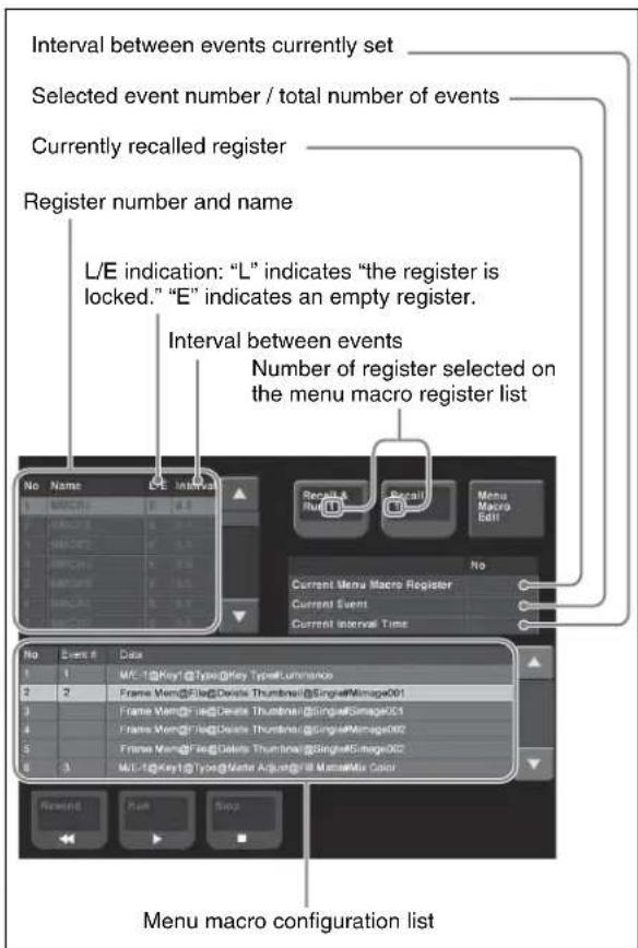
2 Using any of the following methods, select the register to be recalled.
- Press directly on the menu macro register list.
- Press the arrow keys on the right list to scroll the reverse video cursor.
- Turn the knob.
| Knob | Parameter | Adjustment | Setting values |
| 1 Menu | Macro Register | Register selection | 1 to 99 |
3 Press [Recall & Run x] or [Recall x] (x is the number of the register selected in the menu macro register list).
• To execute the menu macro at the same time as recalling the register, press [Recall & Run x].
• To recall the register only, press [Recall x].
Executing a menu macro
In the Macro >Menu Macro Register >Recall & Run menu, check that you are not in macro editing mode, then use the following procedure.
1 Using any of the following methods, specify the event from which you want to execute.
- Press directly on the menu macro register configuration list.
- Press the arrow keys on the right list to scroll the reverse video cursor.
- Turn the knob.
| Knob | Parameter Adjustment Setting | values |
| 3 No Select start | 1 and upwards | |
| event | ||
2 Press [Run].
To stop execution of a macro
Press [Stop].
To move to the start of a menu macro event Press [Rewind].
Recalling a menu macro register from a macro register
Menu macro recall and execution operations can be saved as events in a control panel macro, and then recalled. If with the control panel in macro editing mode you execute a menu macro, then this operation is recorded as an event.
For details of recalling operations, use the following references, depending on the control panel or menu used.
- Using the numeric keypad control block and the keyframe control block: page 491
• Using the standard type Flexi Pad control block: page 496
• Using the simple type Flexi Pad control block: page 498
• Using the Multifunction Flexi Pad control block: page 501
• Using menus: page 505
Executing by assigning a menu macro register to a button in the menu
1 In the Home >Favorites >Button Edit menu, select a button to register.
2 Press [Menu Macro Set].
The Menu Macro Set menu appears.
The "L/E" indications have the following meanings.
L: The register is locked.
E: The register is empty.
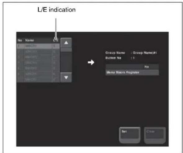
3 In the list on the left, select the button number to be assigned.
4 Press [Set].
Executing a menu macro with a menu button
1 Select the Home >Favorites >Shortcut menu.
The following screen appears.
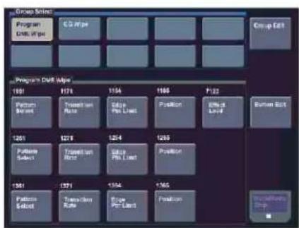
flowchart
graph TD
    A["Program Edit Type"] --> B["Group Edit"]
    A --> C["Program Edit Type"]
    C --> D["Button Exit"]
    A --> E["Program Edit Type"]
    E --> F["Group Edit"]
    A --> G["Program Edit Type"]
    G --> H["Button Exit"]
    A --> I["Program Edit Type"]
    I --> J["Group Edit"]
    A --> K["Program Edit Type"]
    K --> L["Group Edit"]
    A --> M["Program Edit Type"]
    M --> N["Group Edit"]
    A --> O["Program Edit Type"]
    O --> P["Group Edit"]
    A --> Q["Program Edit Type"]
    Q --> R["Group Edit"]
    A --> S["Program Edit Type"]
    S --> T["Group Edit"]
    A --> U["Program Edit Type"]
    U --> V["Group Edit"]
    A --> W["Program Edit Type"]
    W --> X["Group Edit"]
    A --> Y["Program Edit Type"]
    Y --> Z["Group Edit"]
2 Press the group name button.
3 Press the button to which the menu macro is assigned.
To stop a menu macro during execution Press [MenuMacro Stop].
Menu Macro Creation and Editing
Create or edit menu macro registers.
Notes
It is not possible to execute a menu macro during editing. To run the macro, first press the [Store] button to end editing.
Creating a new menu macro
1 In the Macro >Menu Macro Register >Recall & Run menu, select an empty register in the menu macro register list.
For details of the method of operation, see “Recalling a Menu Macro Register” (page 513).
2 Press [Menu Macro Edit].
The menu macro register is recalled, and the system is now in menu macro editing mode. The Menu Macro Edit menu appears.
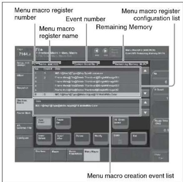
3 If required, press [Auto Insert] to switch the auto insert mode on or off.
In the auto insert mode, when you carry out a menu operation, this is automatically recorded as an event in the menu macro.
4 Create an event (carry out the menu operation you want to record as an event in the menu macro).
For details of menus that can be recorded, see page 512.
- When auto insert mode (see page 491) is on, carrying out a menu operation automatically saves the event in a menu macro.
- When auto insert mode is off, skip to step 5.
5 When auto insert mode is off, press [Insert Before] or [Insert After] to save the event.
6 Repeat steps 4 and 5, to record the required events in the menu macro.
7 Turn the knob to input the event execution interval.
| Knob | Parameter | Adjustment Setting | values |
| 5 | 1 n Time | Event interval 0.0 to 0.5(sec) a | |
This value can be set for each menu macro register.
8 Press the [Store] button.
The numeric keypad window appears.
9 Enter the menu macro register number as required, and press [Enter].
The menu macro is saved with the specified number. The menu returns to the state in step 1.
To set a pause duration
During menu macro editing, use the following procedure.
1 Enter the pause duration by turning the knob.
| Knob | Parameter Adjustment Setting values | |
| 4 | P a Time (Sec) | Pause duration 0.4 to 99.9 (sec) |
2 Press [Pause Set].
- When auto insert mode (see page 491) is on, this sets the pause duration, and inserts the pause event.
- When auto insert mode is off, use the same operations as in step 5 of “Creating a new menu macro” (page 514) to save the event.
Editing a menu macro
To edit the content of a menu macro, use the following procedure.
1 In the Macro >Menu Macro Register >Recall & Run menu, select the desired register on the menu macro register list (see page 513).
2 Press [Menu Macro Edit].
The Menu Macro Edit menu (see previous figure) appears. The menu macro register is recalled, and the system is now in menu macro editing mode.
3 Select the event you want to edit.
- Press directly on the menu macro register configuration list.
- Press the arrow keys on the right list to scroll the reverse video cursor.
- Turn the knob.
| Knob | Parameter | Adjustment | Setting values |
| 1 | No | Event number | 1 and upwards |
• To select all events, press [All Event Select].
4 If required, press [Auto Insert] to switch the auto insert mode on or off.
- When auto insert mode (see page 491) is on, a new menu is automatically inserted after the event selected in step 3.
- When auto insert mode is off, skip to step 5.
5 Carry out the editing, using any of the following methods.
- To delete the selected event, press the [Delete] button.
- To overwrite the selected event, carry out the new menu operation, then press the [Modify] button.
- To insert an event before the selected event, carry out the new menu operation, then press the [Insert Before].
- To insert an event after the selected event, carry out the new menu operation, then press the [Insert After].
6 With the same operation as step 7 of “Creating a new menu macro” (page 514), change the event execution interval.
7 With the same operation as steps 8 and 9 of “Creating a new menu macro” (page 514) save the register.
Exiting the Menu Macro Edit menu without saving the results of editing
In the Menu Macro Edit menu, press [Exit].
Scrolling event display using the menu macro listing
1 Move the cursor to the event you want to display.
2 Turn the knob.
| Knob | Parameter | Adjustment | Setting values |
| 2 H Scroll | Scroll the | characters in the “Data” field. | 1 and upwards |
About the menu macro editing mode display
If while in menu macro editing mode you switch to another menu, the display is as shown in the following figure.
Screen when the keyframe status is displayed
The keyframe status section appears as follows.
- Menu macro register number
- Menu macro register name
- Current event number / total number of events
- Remaining memory
Menu shortcut button to Menu Macro Edit menu
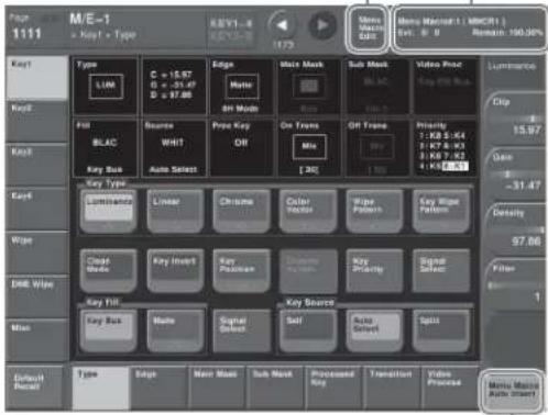
The Previous page button shows one of the following:
- When [Auto Insert] is on, "Menu Macro Auto Insert" appears.
- When [Auto Insert] is off, "Menu Macro Insert After" appears, but operates as [Insert After].
Screen when the keyframe status is not displayed
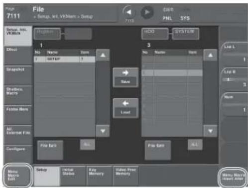
The Default Recall button shows the following. Menu shortcut button to Menu Macro Edit menu
The Previous page button shows one of the following:
- When [Auto Insert] is on, "Menu Macro Auto Insert" appears.
- When [Auto Insert] is off, "Menu Macro Insert After" appears, but operates as [Insert After].
Menu Macro Register Editing
You can display the current state of a menu macro register using the Menu Macro menu.
The items displayed are the same as under “Effect Status Display” (page 459), with the exception that the region name is not displayed.
In the Menu Macro menu, you can do the following editing operations on menu macro registers.
- Lock: Write-protect the contents of the menu macro register.
- Copy: Copy the contents of one menu macro register to another menu macro register.
- Delete: Delete the contents of a menu macro register.
- Name: Attach a name to a menu macro register.
The operations for menu macro register editing are the same as those for effect register editing (see page 459) except the region selection operation, which is not necessary for menu macro register editing.
Macro Timeline
By recording macro recall and execute action on a timeline, in the same way as for key frames in an effect, you can automatically execute them in a sequence. This timeline is called a “macro timeline,” and one macro timeline can have up to 99 macros being executed simultaneously in parallel.
There are 99 registers in the Macro region that can be recorded on the macro timeline, numbered 1 to 99. These registers are distinct from the registers where individual macros are stored.
Notes
If you use a macro timeline to superimpose more than one macro, the macros may not be executed according to the timing information registered in the timeline.
Available key frame functions
The following lists the key frame functions that can be used on the macro timeline.
- RECALL(1 to 99), STORE(1 to 99), RECALL UNDO, STORE UNDO, search for empty register, AUTO SAVE, RECALL MODE (RECALL, RECALL & REWIND)
• EDIT ENABLE, EDIT UNDO - CONST DUR, EFF DUR, KF DUR, DELAY, PAUSE, INSERT BEFORE, INSERT AFTER, MODIFY, DELETE, COPY, PASTE BEFORE, PASTE AFTER, FROM TO, ALL
- PREV KF, NEXT KF, GOTO TC, GOTO KF, RUN, REWIND, FF, STOP NEXT KF, NORMAL, JOG, KF FADER
The following key frame functions cannot be used - KF LOOP, EFFECT LOOP, REVERSE, NORMAL/REVERSE
• PATH
Saving to a register
Set the recall and execute actions for the macros to be registered in the timeline, using the Macro Timeline menu (see page 513). The setting data can be saved in a register as key frame data. You can manipulate this data by recalling the register in which it is saved, and using the key frame control block.
Notes
An action set for a key frame is only executed when the key frame effect is executed in the forward direction. It is important to remember that the action is not executed in the reverse direction when executing simultaneously with switcher and DME key frame effects.
Forcibly ending a macro timeline
- If the timeline has completed but a macro is still executing, press the [REWIND] or [RUN] button in the key frame control block to forcibly end the macro timeline.
- In a macro timeline, since a take operation is not possible, if a macro included in the timeline has a pause event with a pause time of zero, the remainder of the timeline after the pause is ignored, and the macro timeline ends at that point.
Register editing functions
You can use the following editing functions on a register in which a macro timeline is stored.
• Copy
- Move
- Swap
- Merge
- Lock
- Name
- Delete
File-related functions
You can save and recall a created macro timeline as effect data, in the File menu.
Timeline operations are carried out on a macro timeline in the same way as for normal effects.
For details of timeline operations, see “Keyframe Effects” (page 425).
Notes
When using a macro timeline, note the following.
- To use a macro timeline, the Macro region must be assigned to a region selection button in the numeric keypad control block.
For details of region assignment operations, see "Assigning a Region to the Region Selection Buttons in the Numeric Keypad Control Block or Multifunction Flexi Pad Control Block" (page 559). - On a macro timeline, only macro recall and execution actions are stored. The data for a macro to be recalled on the macro timeline is not held on the timeline. It is necessary to create the macro data first.
- A macro timeline can be saved and recalled on the master timeline or a shotbox register, but cannot be saved as a snapshot.
Creating and Editing a Macro Timeline
This section describes how to set actions, and add keyframe points. Note that path settings are not needed on the macro timeline.
For details of keyframe operations, see "Creating and Editing Keyframes" (page 441).
Saving a keyframe
For the operations, use the Macro Timeline menu and the [INS] button in the keyframe control block.
1 Press the [EDIT ENBL] button, turning it on.
This enables timeline editing in the keyframe control block.
2 In the Macro menu, select VF4 'Timeline' and HF1 'Timeline.'
The Macro Timeline menu appears.
3 Select one of the actions (Recall, Take, Take All, No Action) that appear on the right.
When you have selected Recall or Take, turn the knob to select the number of the macro register.
| Knob | Parameter Adjustment Setting | values | |
| 3 Reg | No Selection | of macro register | 1 to 250 |
4 Press the [Set] button.
The selected action appears in the Action column on the left.
5 Press the [INS] button in the keyframe control block.
This creates the keyframe 1 on the macro timeline.
To set the action for a rewind operation
On the macro timeline, when the [REWIND] button in the keyframe control block is pressed the action set for the first keyframe is not executed; when the [RUN] button is pressed, then the first keyframe action is executed. To execute an action when the [REWIND] button is pressed, it is necessary to set this action (Rewind Action). To carry out this setting, in the Macro >Timeline >Timeline menu, press [Rewind Action] to recall the Rewind Action menu. In this setting screen, use the same setting method as in the screen for setting an action on the macro timeline.
Alternatively, you can select the reverse arrangement, whereby when the [REWIND] button is pressed, this executes the action set for the first keyframe, and when the [RUN] button is
pressed the first keyframe action is not executed. In this case, the Rewind Action setting is still valid.
For details of the setting, see "Setting the First Keyframe When a Rewind is Executed" (page 591).
Overview of File Operations
You can save register data, including setup information and snapshot information, as a file on a hard disk or memory card, and recall it as required.
You can operate on individual files or registers, or together in a batch.
Regarding frame memory, it is possible to capture image data stored in an external device into frame memory. You can also convert the format of image data in frame memory into a different format and save it in an external device.
Files that can be manipulated
The following files can be saved and recalled.
- Operation mode setup data for system as a whole and individual devices
• Device status data for system startup
• Key memory setting data
• Video process memory setting data
• Keyframe effect setting data - Snapshot setting data
- Wipe snapshot setting data
• DME wipe snapshot setting data
• Key snapshot setting data - Shotbox setting data
- Macro setting data
- Macro attachment data
- Menu macro setting data
• Frame memory image data - List of files automatically created in a frame memory file backup to DDR/VTR (single data set)
- User setup setting data
- User source name setting data
File operations
You can carry out the following file operations.
When operating on individual files or registers
Save: Save the data in a register to the hard disk or memory card.
Load: Load a file from the hard disk or memory card.
Copy: Copy a file within a directory or from one directory to another. When a remote panel is used, this function applies to it, too.
Rename: Rename a file on the hard disk or memory card.
Delete: Delete a file from the hard disk or memory card.
When operating on files or registers in a batch
The Save, Load, Copy and Delete operations are performable.
Notes on transferring multiple frame memory files together to a memory card
- Transferring all of the files within frame memory together fails if the capacity of the memory card is too small to hold all of the images. In this case, replace with a larger capacity memory card, or delete files until saving is possible.
The following table roughly shows the relation between memory card capacity and number of files that can be saved.
| Memory card capacity | Number of files that can be saved | |
| SD system HD system(except 720P) | ||
| 256 MB 214 46 | ||
Note that when transferring to the hard disk, there is ample capacity, so that problems such as this do not occur.
- If you cancel the operation during a data transfer between frame memory and hard disk or memory card, then an image which was not completely transferred will not be reproducible. Avoid canceling such operations.
- When loading a file from hard disk or memory card, if [Freeze Enable] in the Freeze menu is on, the loaded file may sometimes be overwritten by the frame memory input image.
To avoid this when loading a file, ensure that [Freeze Enable] is turned off.
Importing or exporting files to or from frame memory
Import: Import a file in a different format from hard disk or memory card into frame memory after changing its format.
Export: Export a file in a register to hard disk or memory card after changing its format.
You can import TIFF, BMP, and TARGA files as follows into frame memory.
| File type | Format File name | Notes | |
| TIFF file | RGB uncompressed format | Maximum eight characters, plus extension.tif required | • Layers cannot be used.• If an alpha channel is present, two files are created as a pair. |
| BMP file | Windows a)24-bit format | Maximum eight characters, plus extension.bmp required | - |
| TARGA file | RGB uncompressed/compressed format | Maximum eight characters, plus extension.tga required | • Layers cannot be used.• If an alpha channel is present, two files are created as a pair. |
| PNG file | RGB compressed format | Maximum eight characters, plus extension.png required | • Layers cannot be used.• If an alpha channel is present, two files are created as a pair. |
a) Windows is a registered trademark or trademark of Microsoft Corporation in the United States and/or other countries.
Notes
This functionality has been tested and confirmed to work with TIFF files created by Photoshop, but it may not be possible to use TIFF files created with some other software. (Photoshop is a trademark of Adobe Systems Incorporated.)
About import image size
Pay attention to the following, depending on the signal format which you use.
SDTV (480i)
Images 720 × 487 pixels in size are exactly the size which fills the full screen.
The following figure shows how an import image is processed when the 480i/59.94 format is used.
Images are placed with the upper left of the screen as the origin.
When an image is smaller than the screen, the remainder of the screen is filled with black. When it is larger, parts which extend beyond the screen are discarded.
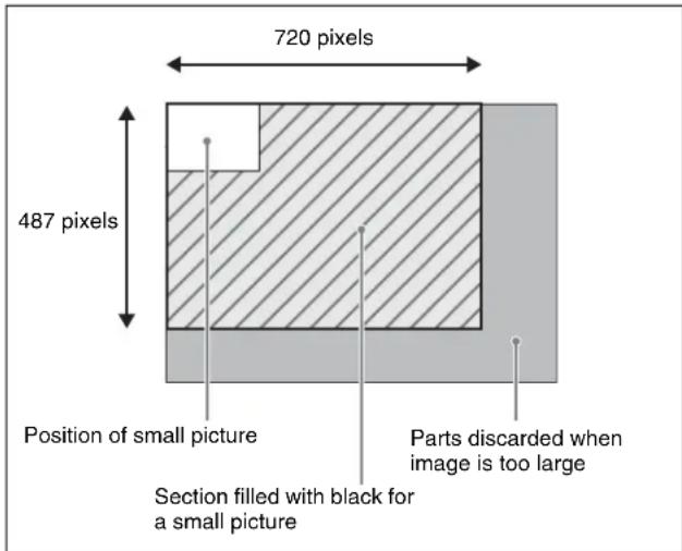
No pixel ratio conversion is performed when images are imported for the SDTV format.
When the signal format is 480i/59.94, if you create an image with a size of 720 × 540 on a computer and then import it just as it is, the image will be too tall. To maintain the shape of the image, first create it as a 720 × 540 image and then use computer software tools to compress the vertical dimension to 487 pixels before importing it.
HDTV (1080i)
Images of 1920 × 1080 pixels in size are exactly the size which fills the full screen.
Like SDTV, images are placed with the upper left of the screen as the origin.
When an image is smaller or larger than the screen, processing is the same as for SDTV.
Since the pixel ratio of the HDTV format is 1:1, files created on computers are imported in their original shapes. The following table shows the image sizes which exactly fill the full screen for the various signal formats.
| Signal format | Image size (H × V) |
| 480i/59.94 720 | × 487 |
| 576i/50 720 | × 576 |
| 1080i/50 1920 | × 1080 |
| 1080i/59.94 | |
| 1080PsF/23.976 | |
| 1080PsF/24 | |
| 1080PsF/25 | |
| 1080PsF/29.97 | |
| 1080P/50, 1080P/59.94 | |
| 720P/50 1280 × 720 | |
| 720P/59.94 |
Importing 720P and 1080P movie material
- To import movie material in 720P or 1080P format, it is necessary to treat each frame as a separate image file.
- For 1080P format, the individual files must have numbers which start from an even number. (E.g.: consecutive numbers from 0000)
Directory operations
You can create a new directory within a hard disk or memory card, and carry out other operations, such as renaming and deleting (see page 532).
File copying between different unit IDs
Switcher and DME files within the hard disk or memory card are managed by unit ID.
To copy files between different unit IDs, use the Unit ID Copy menu (see page 533).
Saving data recalled by autoload
At power on, you can automatically recall data previously stored on the hard disk. (Autoload function) The following data can be loaded by the autoload function.
• Keyframe effect setting data
- Snapshot setting data
- Wipe snapshot setting data
• DME wipe snapshot setting data
• Key snapshot setting data
- Shotbox setting data
- Macro setting data
- Macro attachment data
• Frame memory image data
To use the autoload function, the data required must first be saved (see page 542).
For details of saving operations, see “Setting Automatic Loading of Register Data at Power On (Autoload Function)” (page 543).
Locking file recall operations
For each of the following categories, in setup you can apply a lock on recalling files (see page 552).
Setup, Initial Status, Key Memory, Video Proc Memory, Effect, Snapshot, Wipe Snapshot, DME Snapshot, Key Snapshot, Shotbox, Macro, Macro Attachment, Menu Macro, User Setup
A locked file cannot be downloaded from the File menu.
Operations on Individual Files
You can save or load the contents of an individual file or register. Carry out these operations in the File menu.
Displaying the Individual File Operation Menus
1 In the menu control block, press the top menu selection button [FILE].
2 Depending on the type of file to be manipulated, select the following 'VF' and 'HF' combination.
| Button | HF1 HF2 HF3 HF4 HF5 HF6 HF7 | ||||||
| VF1 Setup Initial Status Key Memory Video | Proc | Memory | User Setup Export Source Name | Import User Source Name | |||
| VF2 Effect 1-99 User DME | Wipe Effect 101-199 | User DME Wipe Effect 201-299 | User DME Wipe Effect 301-399 | DEV/PBUS Effect 1-250 | - | - | |
| VF3 | Snapshot | Wipe Snapshot | DME Snapshot | Key Snapshot | Menu Macro | - | - |
| VF4 | Shotbox | Macro | Macro Attachment | - | - | - | - |
| VF5 Frame Memory Frame | Image Memory Folder | File Name Data | - | - | - | - | |
| VF6 | All | Import/Export | - | - | - | - | - |
| VF7 | Directory | Unit ID Copy | Group ID Copy | - | - | - | - |
The following description refers to the example of carrying out operations on snapshot files, but the procedure is similar in the other menus.
Viewing Detailed File Information
As an example, to view detailed snapshot file information, carry out the following procedure.
1 In the File menu, select VF3 'Snapshot' and HF1 'Snapshot.'
The Snapshot menu appears. The status area shows the device status, and a list of files present on the device.
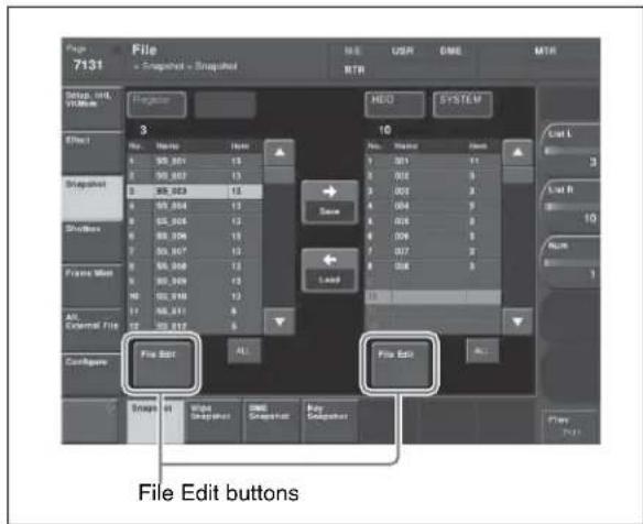
2 Press [File Edit].
The file details appear (reference region file name, creation date, regions including data) in table form.

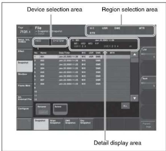
Selecting a particular file displays more detailed information about that file in the detail display area at the top right of the file list.
In the Frame Memory menu, the following items are also shown.
Pair: In the case of a pair file, "P" is shown.
Ext: In the case of an extended clip file, "Ext" is shown.
Selecting Regions
You can carry out a file operation on a number of regions simultaneously. However, a region selection is not required for the following files.
• Key memory
• Video process memory
- Shotbox
- Macro
- Macro attachment
- Frame memory
- Setup
- Initial status
- User Setup
- User source name
In the above list, for setup and initial status, you can similarly separate the files to be operated on by device in a way similar to the region selection.
To make a region selection
1 Press the region selection area at the top right of the screen (see page 523).
The region selection window appears.
2 Press the region names you do not want to select, turning them off.
3 Press [OK].
Selecting a Device for Operations
To carry out file operations, you need to specify the device holding the data (or file), as one of the following: register, hard disk, memory card, and so on. You can then further select a directory.
If you have enabled NFS (Network File System) in setup, you can add "Network" to the device for operations.
If you specify "Network," you can access System Manager through the network for file saving and loading.
For details of the NFS settings, see “Making the Network Settings” (page 536).
Notes
- Files saved on the hard disk may be lost if the hard disk fails. Always keep separate backup copies of important files on a memory card.
- Format a memory card before using it for the first time (see page 551).
As an example, to select a memory card, use the following procedure.
1 In the File menu, press the device selection indication above the file list (default is [HDD] (hard disk)). (If [Memory Card] appears, then since the memory card is already selected, steps 1 and 2 are not necessary.)
A pull-down menu appears.
2 Press [Memory Card].
A list of directories on the memory card appears. (Maximum 40 per page)
The maximum number of directories is 120 on a memory card and NFS, or 200 on an internal hard disk.
3 As required, press the ◀ or ▶ button, to switch directory pages.
4 Press the name of the directory you want to use.
This selects the specified directory on the memory card to be manipulated.
Saving Files
As an example, to save snapshot register data to hard disk or memory card, use the following procedure.
Notes
For key snapshots, snapshots, and effects, you cannot perform the following operation when [Src Patch Link] is lit on the menu screen (see page 647).
1 In the File menu, select VF3 'Snapshot' and HF1 'Snapshot.'
2 In the device selection area on the left, select [Register].
3 In the device selection area on the right, select [HDD] or [Memory Card], then select a directory.
See "Selecting a Device for Operations" (page 523).
4 Using either of the following methods, select the data to be saved, and the file in which to save it.
• To select all files within the list, press [ALL] below the list.
• To select multiple files, turn the knobs to select in the following ranges.
| Knob | Parameter | Adjustment | Setting values |
| 1 List L | Select the first register whose data is to be saved | first file to which data is to be saved | 1 to 99 |
| 2 List R | Select the first file to which data is to be saved | 1 to 99 | |
| 3 Num | Number of registers to be selected | numbers to be selected | 1 to 99 |
- To select a single file, press the arrow keys to scroll the reverse video cursor, or press directly on the list in the status area.
5 Press [→ Save].
This saves the selected register data in the specified location.
If there is already data in the specified location, a confirmation message appears.
- Select "Yes" to overwrite the data.
- Select "No" to cancel saving all of the data.
Saving frame memory files
Notes
When the signal format is 1080P, saving a still image file creates two still image files for each frame. An 'A' is automatically appended to the first file name, and a 'B' is appended to the second file name. If either of these files is missing, it is not possible to recreate the image, and
therefore for correct operation the two files must always be handled together.
Between steps 3 and 4 of the procedure above, “Saving Files,” do as follows.
1 To select the frame memory folder, press [Default] in the device selection in the list on the left.
A pull-down menu appears.
2 Press the required folder name.
3 Carry out the same operations as in steps 1 and 2 on the list on the right.
4 Select the type of data to be displayed.
• To display still image files, press [Still].
• To display clip files, press [Clip].
- To display extended clip files, press [Ext Clip].
• To display all types of file, press [All].
Loading Files
As an example, to load a snapshot file from hard disk or memory card to a register, use the following procedure.
1 In the File menu, select VF3 'Snapshot' and HFI 'Snapshot.'
2 In the device selection area on the left, select [Register].
3 In the device selection area on the right, select where the file is held ([HDD] or [Memory Card]), and then specify a directory.
See "Selecting a Device for Operations" (page 523).
4 Using any of the following methods, select the register to which you want to load, and the file to be loaded.
• To select all files within the list, press [ALL] below the list.
• To select multiple files, turn the knobs to select in the following ranges.
| Knob | Parameter | Adjustment | Setting values |
| 1 List L | Select the first register into which the data is to be loaded | 1 to 99 | |
| 2 List R | Select the first file in which data is held | 1 to 99 | |
| 3 Num | Number to be selected | 1 to 99 | |
- To select a single file, press the arrow keys to scroll the reverse video cursor, or press directly on the list in the status area.
5 Press [← Load].
This loads the contents of the selected file from the specified location. (Setup data is first loaded.)
Loading frame memory files
Between steps 3 and 4 of the procedure above, “Loading Files,” do as follows.
Notes
- When the signal format is 1080P, extended clip files cannot be recalled.
- In a still image file saved in the 1080P signal format, there are two still image files for each frame. If either of these two files is missing, it is not possible to recreate the image, and therefore for correct operation the two files must always be recalled together.
1 To select the frame memory folder, press [Default] in the device selection in the list on the left.
A pull-down menu appears.
2 Press the required folder name.
3 Carry out the same operations as in steps 1 and 2 on the list on the right.
4 Select the type of data to be displayed.
- To display still image files, press [Still].
- To display clip files, press [Clip].
- To display extended clip files, press [Ext Clip].
- To display all types of file, press [All].
Copying Files
You can copy files either within a directory or between directories, on the hard disk, or memory card.
As an example, to copy a snapshot file from memory card to hard disk, use the following procedure.
1 In the File menu, select VF3 'Snapshot' and HF1 'Snapshot.'
2 In the device selection area on the left, specify the location of the file to be copied (in this case [Memory Card] and a directory). (See page 523.)
3 In the device selection area on the right, select the destination of the copied file (in this case [HDD] and a directory).
4 Using any of the following methods, select the source and destination files.
- To select all files within the list, press [ALL] below the list.
- To select multiple files, turn the knobs to select in the following ranges.
| Knob | Parameter | Adjustment Setting | values |
| 1 List L | Select the first copy source file | 1 to 99 | |
| 2 List R | Select the first destination file | 1 to 99 | |
| 3 Num | Number to be selected | 1 to 99 | |
- To select a single file, press the arrow keys to scroll the reverse video cursor, or press directly on the list in the status area.
5 Press [→ Copy].
This copies the selected file or files to the specified destination.
If there is already data in the specified location, a confirmation message appears.
- Select "Yes" to overwrite the data.
- Select "No" to cancel copying all of the files.
- Select "Yes" to overwrite the data. - Select "No" to cancel copying all of the files.
Copying frame memory files
Between steps 3 and 4 of the procedure above, “Copying Files,” do as follows.
Notes
In a still image file saved in the 1080P signal format, there are two still image files for each frame. If either of these two files is missing, it is not possible to recreate the image, and therefore for correct operation the two files must always be copied together.
1 To select the frame memory folder, press [Default] in the device selection in the list on the left.
A pull-down menu appears.
2 Press the required folder name.
3 Carry out the same operations as in steps 1 and 2 on the list on the right.
4 Select the type of data to be displayed.
- To display still image files, press [Still].
- To display clip files, press [Clip].
- To display extended clip files, press [Ext Clip].
- To display all types of file, press [All].
Renaming Files
You can rename a file on the hard disk or memory card and a register. As an example, to rename a snapshot file, use the following procedure.
1 In the File menu, select VF3 'Snapshot' and HFI 'Snapshot.'
The Snapshot menu appears. The status area shows the device status, and a list of files present on the device.
2 Press [File Edit].
A detailed list appears. Here too, you can select a device or specify a directory. (See page 523.)
3 Using any of the following methods, select the file you want to rename.
- Press directly on the list in the status area.
- Press the arrow keys to scroll the reverse video cursor.
- Turn the knob.
| Knob | Parameter Adjustment Setting values | ||
| 1 List | File selection | 1 to 99 | |
4 Press [Rename].
The keyboard window appears.
5 Enter a name of not more than eight characters, and press [Enter].
The name you have entered is reflected in the status area.
Notes
- Within the switcher, the names for Initial Status and Setup data are fixed.
You can change the file names on the hard disk or memory card, but the next time they are reloaded they will revert to the default names. - The following names cannot be used. CON, PRN, AUX, CLOCK\$, NUL, COM0, COM1, COM2, COM3, COM4, COM5, COM6, COM7, COM8, COM9, LPT0, LPT1, LPT2, LPT3, LPT4, LPT5, LPT6, LPT7, LPT8, LPT9
Renaming frame memory files
Notes
- In a still image file saved in the 1080P signal format, there are two still image files for each frame. When a register is selected for the operation, if you change one
of the file names, the other file name of the pair also changes automatically.
- When a device other than a register is selected for the operation, if you change one file name, the other file name of the pair does not automatically change. Except for the final 'A' or 'B' in the file name, you must manually keep the names matching.
E.g.: img111A and img111B (file names must have the underscored parts the same)
1 In the File menu, select VF5 'Frame Mem' and HF1 'Frame Memory.'
The Frame Memory menu appears. The status area shows the device status, and a list of files present on the device.
2 Press [File Edit].
3 Select the type of data to be displayed.
• To display still image files, press [Still].
• To display clip files, press [Clip].
• To display extended clip files, press [Ext Clip].
• To display all types of file, press [All].
4 Using any of the following methods, select the file you want to rename.
(When you selected [Clip] or [Ext Clip] in step 3, you cannot select multiple files.)
- Press directly on the list in the status area.
- Press the arrow keys to scroll the reverse video cursor.
- Turn the knobs.
| Knob | Parameter | Adjustment Setting | values |
| 1 List | L File selection | in the left list | 1 and upwards |
| 2 List | R File selection | in the right list | 1 and upwards |
| 3 Num | Number to be selected | 1 and upwards | |
5 Press [Rename].
The keyboard window appears.
6 Depending on the selections of steps 3 and 4, enter a name as follows and press [Enter].
- When you selected a single file with [Still] or [All]: Enter a name of not more than eight characters.
- When you selected more than one file with [Still] or [All]: Enter a name of not more than four characters.
- When you selected a clip file or an extended clip file: Enter a name of not more than four characters.
The name you have entered is reflected in the status area.
Notes
- If you select [Register] in the operation device selection block, then with [Still] or [All] select multiple files and change a file name, these still images are converted to a clip.
- It is not possible to simultaneously select a file for which the Ext field in the status area is empty and a file for which the Ext field shows “Ext” to change the name.
- When the signal format is 1080P, a still image file name must be a maximum of seven characters.
Deleting Files
You can delete data from the hard disk or memory card and snapshot or effect data from a register. As an example, to delete a snapshot file, use the following procedure.
1 In the File menu, select VF3 'Snapshot' and HF1 'Snapshot.'
The Snapshot menu appears. The status area shows the device status, and a list of files present on the device.
2 Press [File Edit].
A detailed list appears. Here too, you can select a device or specify a directory. (See page 523.)
3 Using any of the following methods, select the file you want to delete.
- To select all files within the list, press [All] below the list.
- To select multiple files, turn the knobs to select in the following ranges.
| Knob | Parameter | Adjustment | Setting values |
| 1 List | Select the first file 1 to 99 | ||
| 3 Num | Number to be selected | 1 to 99 | |
- To select a single file, press the arrow keys to scroll the reverse video cursor, or press directly on the list in the status area.
4 Press [Delete].
A confirmation message appears.
- Select "Yes" to delete.
- Select "No" to cancel the deletion.
- Select "Yes" to delete. - Select "No" to cancel the deletion.
Deleting frame memory files
Between steps 2 and 3 of the procedure above, “Deleting Files,” do as follows.
Notes
- In a still image file saved in the 1080P signal format, there are two still image files for each frame. When a register is selected for the operation, if you delete one still image file, the other file of the pair is automatically deleted.
- When a device other than a register is selected for the operation, if you delete one still image file, the other file of the pair is not automatically deleted. You must manually delete both files.
1 To select the frame memory folder, press [Default] in the device selection in the list.
A pull-down menu appears.
2 Press the required folder name.
3 Select the type of data to be displayed.
- To display still image files, press [Still].
• To display clip files, press [Clip].
- To display extended clip files, press [Ext Clip].
- To display all types of file, press [All].
Converting Between Frame Memory Clips and Extended Clips
Notes
When the signal format is 1080P, this operation is not possible.
1 In the File menu, select VF5 'Frame Mem' and HF1 'Frame Memory.'
The Frame Memory menu appears. The status area shows the device status and a list of files on the device.
2 Press [File Edit].
3 In the device selection section of the list, select where the file is held ([HDD] or [Memory Card]), and specify the directory, and frame memory folder.
4 Press either of the following at the top of the list, to select the type of data displayed.
• To display clip files, press [Clip].
- To display extended clip files, press [Ext Clip].
5 Using any of the following methods, select the files you want to convert.
- Press directly on the list in the status area.
- Press the arrow keys to scroll the reverse video cursor.
- Turn the knobs.
| Knob | Parameter | Adjustment Setting | values |
| 1 List L | File selection | in the left list | 1 and upwards |
| 2 List R | File selection | in the right list | 1 and upwards |
| 3 Num | Number of files selected | 1 and upwards |
6 Carry out either of the following.
- To convert clips to extended clips, press [Clip -> Ext Clip].
- To convert extended clips to clips, press [Ext Clip - >Clip].
Creating a frame memory folder on the device (HDD or Memory Card)
1 In the File menu, press VF5 'Frame Mem' and HF2 'Frame Memory Folder.'
The Frame Memory Folder menu appears. The status area shows the device status, and a list of files present on the device.
2 In the pull-down menu of the device selection section, select [HDD] or [Memory Card], and then specify the directory.
3 Press [New].
A keyboard window appears.
4 Enter a name of up to eight characters, and press [Enter].
The name entered appears in the status area as a frame memory folder.
Notes
• The following names cannot be used.
Default, Flash1, Flash2
CON, PRN, AUX, CLOCK\$, NUL, COM0, COM1, COM2, COM3, COM4, COM5, COM6, COM7, COM8, COM9, LPT0, LPT1, LPT2, LPT3, LPT4, LPT5, LPT6, LPT7, LPT8, LPT9
- It is not possible to create 12 or more directories in the frame memory folder.
To rename a frame memory folder
1 Using any of the following methods, select the folder.
- Press directly on the list in the status area.
- Press the arrow keys to scroll the reverse video cursor.
- Turn the knobs.
| Knob | Parameter | Adjustment | Setting values |
| 1 List | L Folder selection | 1 and upwards |
2 Press [Rename].
A keyboard window appears.
3 Enter a name of up to eight characters, and press [Enter].
The name entered appears in the status area as a frame memory folder.
To delete a frame memory folder
1 With the same operations as in step 1 of the procedure "To rename a frame memory folder," select the folder.
2 Press [Delete].
A confirmation message appears; select "Yes" to carry out the deletion.
Saving the list of frame memory files to hard disk or memory card
If you save all files currently held in frame memory as a single backup data set, by high-speed recording on video tape or other medium, is created a file of file list data that is needed for successful frame memory file restore operation. It is necessary to save this file in a hard disk or memory card.
1 In the File menu, select VF5 'Frame Memory' and HF3 'File Name Data.'
2 In the operating device selection section on the left or right, select [Register].
The register name “FM_Bkup” appears. In the device selection section on the opposite side, the destination for saving automatically appears.
3 As the destination for saving select [HDD] or [Memory Card], then specify the directory.
4 Select the destination file for saving.
5 • To save to disk, press 'Save.'
• To load from disk, press 'Load.'
To view details of files
Press 'File Edit.'
A list of the saved file names appears. You can manipulate these files like any other files.
File Batch Operations
You can batch process all files or registers. Carry out these operations using the File >All, External File >All menu.
Displaying the Batch Operation Menu
1 Press the top menu selection button [FILE].
2 Select VF6 'All, External File' and HF1 'All.' The All menu appears.
Batch Saving Files
To save the data of all registers to hard disk or memory card, use the following procedure.
Notes
- Files saved on the hard disk may be lost if the hard disk fails. Always keep separate backup copies of important files on a memory card.
- Format a memory card before using it for the first time (see page 551).
- You cannot perform the following operation when [Src Patch Link] is lit on the menu screen (see page 647).
1 In the device selection area of the All menu, select the destination for saving the files ([HDD] or [Memory Card] and directory). (See page 523.)
2 If there are registers you do not want to save, in the
For details of the data to which operations apply, see "Files that can be manipulated" (page 519).
Notes
The frame memory is not selected when you press [All Select]. To apply the setting to frame memory, press [Frame Memory], turning it on. When frame memory is selected, it is not possible to apply settings to the
3 Press [→ Save].
A confirmation message appears.
- Select "Yes" to carry out the batch save.
- Select "No" to cancel the batch save.
Batch Loading Files
To load files from hard disk or memory card, use the following procedure.
Notes
It is not possible to recall a file from a category for which recall operations are locked (see page 552).
1 In the device selection area of the All menu, select where the files are held ([HDD] or [Memory Card] and directory). (See page 523.)
2 If there are files you do not want to load, in the
For details of the data to which operations apply, see "Files that can be manipulated" (page 519).
Notes
- The frame memory is not selected when you press [All Select]. To apply the setting to frame memory, press [Frame Memory], turning it on. When frame memory is selected, it is not possible to apply settings to the
group data. - You cannot select [User Setup] when [Src Patch Link] is lit on the menu screen (see page 647).
3 Press [← Load].
A confirmation message appears.
- Select "Yes" to carry out the batch load. (Setup data is first loaded.)
- Select "No" to cancel the batch load.
To execute the load after clearing the data in the destination regions
Before pressing [← Load], press [CLR Before Load], turning it on.
The following categories of data can be cleared before execution of the load.
Effect, Snapshot, Wipe Snapshot, DME Wipe Snapshot, Key Snapshot, Shotbox, and Macro
Notes
When frame memory is selected for the setting, the data is always deleted before recalling.
Batch Copying Files
To copy files between the hard disk and a memory card, use the following procedure.
1 In the operating device selection section to the left of the All menu, select the storage location ([HDD] or [Memory Card] and directory) of the source files (see page 523).
2 In the operating device selection section to the right of the All menu, select the destination storage location ([HDD] or [Memory Card] and directory) (see page 523).
3 If there are files you do not want to copy, remove them from the selection in the
For details of the data to which the operation applies, see “Files that can be manipulated” (page 519).
Notes
The frame memory is not selected when you press [All Select]. To apply the setting to frame memory, press [Frame Memory], turning it on. When frame memory is selected, it is not possible to apply settings to the
4 Press [→ Copy].
This copies the selected files to the specified destination.
If there is already data present in the destination location, a confirmation message appears.
- Select "Yes" to overwrite.
- Select "No" to cancel copying all of the files.
Importing and Exporting Files
You can import or export frame memory image data from or to external media.
Import: to transfer a file in a different format from hard disk or memory card to frame memory as image data.
Export: to change the file format of register data and save the data on hard disk or memory card.
To carry out these operations, use the File >All, External File >Import/Export menu.
For details of the formats supported for import and export, see “Importing or exporting files to or from frame memory” (page 520).
Notes
When the signal format is 1080P, exporting is not possible.
Displaying the Import/Export Menu
In the File menu, select VF6 'All, External File' and HF2 'Import/Export.'
The list on the left shows the frame memory registers, and the list on the right shows the content of the external recording media.
Importing Frame Memory Data
As an example, to import data in a bitmap format from a memory card to a frame memory register, use the following procedure.
Notes
When the signal format is 1080P, importing as an extended clip file is not possible.
About the points you should take note of when importing data, see “About import image size” (page 520).
1 In the Import/Export menu, press the file format selection area at the top of the screen to select [Frame Memory (.BMP)].
Files of the selected type are shown in the list on the right.
2 Press one of the buttons at the top left to select the type of data to display.
- To display still image files, press [Still].
- To display clip files, press [Clip].
- To display extended clip files, press [Ext Clip]
All of the selected type of frame memory data appears in the list on the left.
3 In the folder selection area on the left, select the frame memory folder to which you want to import the file.
4 Press the device selection area on the right to select [Memory Card].
5 Select the directory to hold the imported files.
Notes
Files on a memory card to be imported must always be in a directory immediately below root.
6 Using any of the following methods, select the file you want to import.
- Press directly on the list in the status area.
- Press the arrow keys to scroll the reverse video cursor.
- Turn the knob.
| Knob | Parameter | Adjustment Setting | values |
| 4 List | R File selection | 1 and upwards |
7 Press [← Import].
Exporting Frame Memory Data
As an example, to save image data from frame memory in a bitmap format on a memory card, use the following procedure.
1 In the Import/Export menu, press the file format selection area at the top of the screen to select [Frame Memory (.BMP)].
Files of the selected type are shown in the list on the right.
2 Press one of the buttons at the top left to select the type of data to display.
- To display still image files, press [Still].
- To display clip files, press [Clip].
- To display extended clip files, press [Ext Clip]
All of the selected type of frame memory data appears in the list on the left.
3 Press the device selection area on the right to select [Memory Card].
4 Select the directory to which to export the files.
Notes
The displayed directories are only those directories immediately below root.
5 In the folder selection area on the left, select the frame memory folder that contains the file you want to export.
6 Using any of the following methods, select the file you want to export from the list on the left.
- Press directly on the list in the status area.
- Press the arrow keys to scroll the reverse video cursor.
- Turn the knobs.
| Knob | Parameter Adjustment Setting values | ||
| 1 List L | Register selection 1 and upwards | ||
| 2 Num | Number of files to be selected | 1 and upwards | |
7 Press [→ Export].
This adds the image data from the frame memory in a bitmap format on the memory card.
If the specified destination file name already exists, an overwriting confirmation message appears.
- Select "Yes" to overwrite the data.
- Select “No” to cancel the whole file export operation.

Directory Operations
You can create a new directory on hard disk or memory card, rename, or delete a directory.
To carry out these operations, use the File >Configure >Directory menu.
Displaying the Directory Menu
In the File menu, select VF7 'Configure' and HF1 'Directory.'
The Directory menu appears.
Creating a New Directory
You can create a maximum of 120 directories on a memory card and NFS, or 200 on an internal hard disk.
1 In the device selection pull-down menu, select [HDD] or [Memory Card]. (See page 523.)
2 Press [New].
The keyboard window appears.
3 Enter a name of not more than eight characters, and press [Enter].
A new directory with the name you have entered appears in the status area.
Notes
The following names cannot be used for directories: CON, PRN, AUX, CLOCKS, and NUL COM0, COM1, COM2, COM3, COM4, COM5, COM6, COM7, COM8, and COM9 LPT0, LPT1, LPT2, LPT3, LPT4, LPT5, LPT6, LPT7, LPT8, and LPT9
Renaming a Directory
1 In the device selection pull-down menu, select [HDD] or [Memory Card]. (See page 523.)
2 Using any of the following methods, select the directory.
- Press directly on the list in the status area.
- Press the arrow keys to scroll the reverse video cursor.
- Turn the knob.
| Knob | Parameter | Adjustment | Setting values |
| 1 | L i | s t selection | 1 and upwards |
3 Press [Rename].
The keyboard window appears.
4 Enter a new name of not more than eight characters, and press [Enter].
The new name appears in the status area.
Deleting a Directory
1 In the device selection pull-down menu, select [HDD] or [Memory Card] (see page 523).
2 Using any of the following methods, select the directory.
- Press directly on the list in the status area.
- Press the arrow keys to scroll the reverse video cursor.
- Turn the knob.
| Knob | Parameter Adjustment Setting values | ||
| 1 List | Directory | selection | 1 and upwards |
3 Press [Delete].
A confirmation message appears.
- Select "Yes" to delete the directory.
- Select "No" to cancel the deletion.
Copying Files Between Different Unit IDs
Switcher and DME files on the hard disk or a memory card are handled separately for each unit ID (see page 535). With the normal file copy operation, it is not possible to copy files between different unit IDs. To copy files between different unit IDs, use the following procedure.
Displaying the Unit ID Copy menu
In the File menu, select VF7 'Configure' and HF2 'Unit ID Copy.'
The Unit ID Copy menu appears.
Copying files between different unit IDs
To copy files between different unit IDs, grouped by category, use the following procedure.
1 In the Unit ID Copy menu, press the category selection section at the top right of the screen.
2 Press the categories you do not want to select, turning them off.
3 Press [OK].
4 In the operating device selection section on the left list, select the storage location of the source files, and in the operating device selection section on the right list, specify the destination storage location.
For details, see "Selecting a Device for Operations" (page 523).
5 Using either of the following methods, select the copy source and copy destination unit IDs.
- Press directly on the list for the copy source on the left of the status area, and on the right for the copy destination.
- Press the arrow keys to scroll the reverse video cursor.
- Turn the knobs.
| Knob | Parameter | Adjustment | Setting values |
| 1 List L | Selection of | copy source unit ID | 1 to 4 |
| 2 List R | Selection of | copy destination unit ID | 1 to 4 |
6 Press [→Copy].
A confirmation message appears.
- Select "Yes" to carry out the copy to the specified destination of the selected file categories.
- Select "No" to cancel the copy.
Notes
If there is already data present in the copy destination, note that this will overwrite all of the data.
Saving Files Recalled by Autoload
If you save effect setting data, frame memory image files and so on in the PWON_LD directory on the hard disk, then when the system is powered on this data is recalled automatically. This is known as the autoload function. To save the data to be recalled by the autoload function, use the menu for operations on individual files.
For the data recalled by the autoload function, see "Saving data recalled by autoload" (page 521).
For the setting enabling or disabling the autoload function, see “Setting Automatic Loading of Register Data at Power On (Autoload Function)” (page 543).
For example, to save snapshot data, use the following procedure.
1 In the File menu, select VF3 'Snapshot' and HF1 'Snapshot.'
The Snapshot menu appears.
2 In the device selection area on the left, select [Register].
3 In the device selection area on the right, select [HDD]. Be sure to select [HDD] as the saving destination.
4 Select the PWON_LD directory.
The PWON_LD directory is automatically created when [Power On File Load] is set to On in the System >Start Up menu. If set to Off, the directory does not appear.
5 Using any of the following methods, select the data to be saved, and the file in which to save it.
- To select all files within the list, press [ALL] below the list.
- To select multiple files, turn the knobs to select in the following ranges.
| Knob | Parameter A | Adjustment Setting values | |
| 1 List L | Select the first register whose data is to be saved | 1 to 99 | |
| 2 List R | Select the first file to which data is to be saved | 1 to 99 | |
| Knob | Parameter | Adjustment | Setting values |
| 3 Num | Number of | registers to be selected | 1 to 99 |
- To select a single file, press the arrow keys to scroll the reverse video cursor, or directly press on the list in the status area.
6 Press [→Save].
The data from the selected registers is saved in the specified destination.
If the specified destination already contains data, a confirmation message appears.
- Select "Yes" to overwrite the existing data.
- Select "No" to cancel the entire saving operation.
![SONY MVS-7000X - Press [→Save]. - 1](/content/2026/06/1364863/images/4df0758595689e62c792bfc173967a9e17ad7006668f9350fbe67420559f91b1.jpg)
System Setup (System)
Chapter
18
Setup for the Whole System
Carry out operations relating to setup for the whole system in the Engineering Setup menu.
To access the Engineering Setup menu, press the top menu selection button [ENG SETUP].
Here the “whole system” refers to all devices connected on the Control LAN.
The DCU is connected through the control panel, but is also included in the “whole system.”
Setting the unit ID
When there are two switchers and connected DME units on the same network, it is necessary to set the unit ID on each device, as follows.
| Switcher ID | |
| 1st switcher 1 | |
| 2nd switcher 2 |
| DME ID | |
| DME1 for 1st switcher (channels 1 to 4) 1 | |
| DME2 for 1st switcher (channels 5 to 8) 2 | |
| DME1 for 2nd switcher (channels 1 to 4) 3 | |
| DME2 for 2nd switcher (channels 5 to 8) 4 |
Notes
The unit ID for the MKS-7470X/7471X is DME1 or DME3.
- DME1 (unit ID: 1) when connected to the 1st switcher (unit ID: 1).
- DME3 (unit ID: 2) when connected to the 2nd switcher (unit ID: 3).
When the signal format is 1080P
You can connect up to four MVE-8000A units to the first switcher. The unit IDs for these DMEs are assigned as follows.
| DME ID | |
| DME1 for 1st switcher (Ch1/2) 1 | |
| DME2 for 1st switcher (Ch3/4) 2 | |
| DME3 for 1st switcher (Ch5/6) 3 | |
| DME4 for 1st switcher (Ch7/8) 4 |
Notes
- When the signal format is 1080P, the MKS-7470X is always assigned DME1 (unit ID: 1), supporting four channels. An external DME unit (MVE-8000A) is assigned DME3 (unit ID: 3) or DME4 (unit ID: 4).
- The signal format for the second switcher cannot be changed to 1080P.
For more details of how to make the unit ID settings, refer to the installation manual for the particular device.
Network Settings (Network Config Menu)
This provides automatic configuration of all devices connected to the Data LAN (excluding the DCU), and displays a list of them.
To make the network settings, use System >Network Config menu.
To display the Network Config menu
In the Engineering Setup menu, select VF1 'System' and HF1 'Network Config.'
The status area shows the device ID, and Control LAN and Data LAN IP addresses for each device excluding the DCU.
Making the Network Settings
Checking IP address automatically
1 In the System >Network Config menu, press [Auto Config].
This automatically checks all devices (excluding the DCU) connected to the Data LAN.
2 Once switch to another menu, then display the Network Config menu again.
Now the status area of the System >Network Config menu shows the results of the automatic check.
Notes
Be sure to carry out this operation after reconfiguring the system, or after a software upgrade.
Using the NFS server
The address of the currently selected NFS server appears in the [NFS Server Address] box in the lower status area.
Notes
When the control panel is reset, no NFS server can be used via the Network Config menu. In this case, to use an NFS server, make sure to carry out the following procedure.
1 In the System >Network Config menu, press [NFS Server].
A keyboard window appears.
2 Enter the address of the server you want to use.
3 Press [NFS Mount].
System Settings (System Config Menu)
To make the system settings, use the System >System Config menu.
Specify the hierarchical relationship of the devices.
To display the System Config menu
In the Engineering Setup menu, select VF1 'System' and HF2 'System Config.'
Notes
After changing the following settings, be sure to press [Execute] to save the new values. If you want to cancel the setting changes without saving them, press [Clear].
Device hierarchical relationship setting
- Panel Assign: Specify the switcher controlled by a control panel.
- Switcher Assign: Specify the DME connected to a switcher.
Specifying the Switcher Controlled by the Control Panel
The number of control panels that can be connected to a single switcher depends on the signal format setting. 1080P: 2
Other than 1080P: 4
1 In the System >System Config menu, press the [Panel Assign] button.
The Panel Assign menu appears.
2 Select the switcher to be controlled by the selected control panel, as follows.
In the <1st Switcher> group, set either [SWR1] or [SWR2] to On to select the switcher to be operated. In the <2nd Switcher> group, set both [SWR1] and [SWR2] to Off.
3 To set the selected control panel as tally control master panel, press [Tally Master], turning it on.
If there are multiple panels and processors, the control panel for which [Tally Master] is set to On carries out tally control for the whole system.
Notes
- When there are multiple control panels, make sure that one of them has [Tally Master] set to On. When
you change the master panel, be sure to copy and save the setup tally (TLY) and router (RTR) data in the File menu, and make the same settings for other panels.
- If you load the master panel tally data into a panel with a different unit ID, then [Tally Master] changes to Off.
To select the lighting mode of the switcher bus selection buttons on the remote panel
When switching buses with the MKS-8080/8082 AUX Bus Remote Panel or other remote panel connected via S-Bus data link, you can select the lighting mode of the bus selection buttons.
In the System >System Config >Panel Assign menu, select either of the following in the
Mode 1: The inhibited buttons do not light even when pressed, and the other buttons light after a longer delay time than in Mode 2.
Mode 2: The delay time for button lighting is reduced, but even the inhibited buttons may light for a moment when pressed.
Notes
- Make sure that [Tally Master] is set to On.
- When simple connection is used between the center control panel and remote panel (see page 649), this setting is disabled.
Specifying the DME Connected to the Switcher
1 In the System >System Config menu, press [Switcher Assign].
The Switcher Assign menu appears.
2 Using either of the following methods, select the switcher to which the settings apply.
- Press directly on the list in the status area.
- Press the arrow keys to scroll the reverse video cursor.
The selected switcher appears in reverse video.
3 Make the DME settings as follows.
- When making DME settings for SWR1, for the first DME, select [DME1] in the <1st DME> group. For the second DME, select [DME2] in the <2nd DME> group. When a second DME is not connected, turn all buttons in the <2nd DME> group off.
- When making DME settings for SWR2, for the first DME, select [DME3] in the <1st DME> group. For the second DME, select [DME4] in the <2nd DME> group. When a second DME is not connected, turn all buttons in the <2nd DME> group off.
Notes
If you use the MKS-7470X/7471X, select either DME1 or DME3.
When the signal format is 1080P
You can connect up to four MVE-8000A units to SWR1. For SWR1, you can select a DME combination as follows, depending on the number of DMEs connected.
Only one DME connected: DME1
Two DMEs connected: DME1 and DME2
Three DMEs connected: DME1, DME2, and DME3
Four DMEs connected: DME1, DME2, DME3, and DME4
When you use both the MKS-7470X/7471X and MVE-8000A to the MVS-7000X, DME1 is assigned to the MKS-7470X/7471X and the selectable DME combinations are as follows.
Only one MVE-8000A unit connected: DME1 and DME3
Two MVE-8000A units connected: DME3 and DME4
Depending on the selected DME combination, press [DME1] (first DME), [DME2] (second DME), [DME3] (third DME), or [DME4] (fourth DME), turning them on. For SWR2, the signal format cannot be changed to 1080P.
Enabling the FM Data Port of the Switcher
With the FM data port enabled, frame memory data can be transferred in a short time between the switcher and the control panels.
Notes
If multiple control panels are in use, [FM Data Port Enbl] can be turned on for only one control panel per switcher.
1 In the System >System Config menu, press [Switcher Assign].
The Switcher Assign menu appears.
2 Using any of the following methods, select the switcher to be set.
- Press directly on the list in the status area.
- Press the arrow keys to scroll the reverse video cursor.
The selected switcher is displayed in reverse video. If there is only one switcher on the network, make the setting only for SWR1 (the first switcher).
3 Press [FM Data Port Enbl], turning it on.
Setting the Signal Format (Format Menu)
To set the format, that is, the frame frequency and number of scan lines handled by each device, use the System >Format menu.
To display the Format menu
In the Engineering Setup menu, select VF1 'System' and HF3 'Format.'
Notes
After changing any of the following settings, be sure to press [Execute] (or [FC Format Execute] for changing the format converter signal format) to save the new values. If you want to cancel the settings and return to the original state, press [Clear] without pressing [Execute] or [FC Format Execute]. When you press [Execute], some data is lost (such as frame memory images). If you press [FC Format Execute], memory is not initialized, and this data is not lost.
Restrictions on signal formats and re-entry
Re-entry restrictions for an M/E on which a selected signal format can be used depend on whether or not the color corrector is used.
For details, see "Preparations" in Chapter 9 (Volume 1).
Setting the Signal Format
Specify the signal format to be handled by the devices. The combinations of signal formats that can be selected are as follows.
| System Field frequency Effective number of scan lines | ||
| HD system | 50 1080i | |
| 59.94 | ||
| 50 1080P | ||
| 59.94 | ||
| 23.976 1080PsF | ||
| 24 | ||
| 25 | ||
| 29.97 | ||
| 50 720P | ||
| 59.94 | ||
| SD system | 59.94 480i | |
| 50 576i | ||
Notes
When the MVS-8000X is used with the 1080P signal format or the MVS-7000X is used with multiple signal formats, you need to install software options (see page 545).
1 In the System >Format menu, select the device for operations.
- Press directly on the list in the status area.
- Press the arrow keys to scroll the reverse video cursor.
- Turn the knob.
| Knob | Parameter | Adjustment | Setting values |
| 1 Device Selection | of device for operations | 1 and upwards | |
2 Press [Signal Format].
A pop-up window appears.
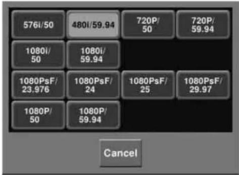
3 Press the button for the desired signal format.
Switching the Input Reference Signal for HD System
Notes
The input reference signal for the MKS-7470X/7471X is used in common with the switchers.
This changes the input reference signal.
• Tri Sync: tri-level sync for an HD system
• BB (Black Burst): black burst or sync
The following table shows the relation between signal format and the frequency of a signal that can be used as the input reference signal.
| Signal format Input reference signal | |||
| Tri Sync Black burst | |||
| 1080PsF/29.971080P/59.94,1080i/59.94 | 59.94 Black Burst | 59.94 | Sync 59.94 |
| 1080PsF/251080P/50,1080i/50 | 50 Black Burst | 50 | Sync 50 |
| 1080PsF/24 48 – | |||
| 1080PsF/23.976 | 47.952 Black Burst | 59.94a) | Sync59.94a) |
| 720P/59.94 59.94 | Black Burst | 59.94 | Sync 59.94 |
| 720P/50 – Black Burst | 50 | Sync 50 | |
a) Interlock mode
Setting Conversion Formats
Installing the MKS-8450X Format Converter Board in the MVS-8000X/7000X enables signal video format conversions.
This operation is valid only when BB is selected in the group.
In the MVS-7000X, format conversion is assigned to primary inputs in advance. For details about the primary input assignment, see “Selecting the Primary Input to be Used in the Format Converter” (page 601).
Format converter
Installing the Format Converter Board in the switcher enables the following signal video format conversions.
• Up-conversion: from SD (4:3) to HD (16:9)
- Down-conversion: from HD (16:9) to SD (4:3)
• Cross-conversion: from HD (720P) to HD (1080i), or from HD (1080i) to HD (720P)
In the MVS-8000X, the maximum number of input signals for which format conversion is possible is 16 (or 8 when only one MKS-8450X board is installed), and the maximum number of output signals is 4 (two outputs when the MKS-8160X is not installed).
In the MVS-7000X, the maximum number of primary input signals for which format conversion is possible is 8, and the maximum number of output signals is 4 (two outputs when the MKS-8160X is not installed).
Notes
- After format conversion, input and output signals have one-frame delays with respect to the reference signals. To synchronize converted input signals and unconverted input signals, it is possible to delay the unconverted input signal.
For details, see “To delay unconverted input signals (frame delay function)” (page 541).
- When the input reference signal for HD system is set to Tri Sync, the format converter function is not available. For details, see “Switching the Input Reference Signal for HD System” (page 539).
Format combinations allowing conversion
The supported combinations of switcher signal format and format converter (inputs 1 to 4, 5 to 8, 9 to 12 and 13 to 16) are as follows.
(Inputs 9 to 12 and 13 to 16 are available only in the MVS-8000X.)
Notes
The format converter cannot be used when the signal format is 1080PsF/23.976 or 1080PsF/24.
| Switcher signal format setting | Format converter signal format setting | |
| FC Input 1 to 4, 5 to 8 / 9 to 12a) / 13 to 16a) | FC Output 1, 2 / 3, 4 | |
| 480i/59.94 720P | /59.94 | 720P/59.94 |
| 1080i/59.94 | 1080i/59.94 | |
| 1080PsF/29.97 | 1080PsF/29.97 | |
| 576i/50 720P/50 | 1080i/50 | 720P/50 |
| 1080i/50 | 1080i/50 | |
| 1080PsF/25 | 1080PsF/25 | |
| 720P/50 576i/50 | 1080i/50 | 576i/50b) |
| 1080i/50 | 1080i/50b) | |
| 720P/59.94 480i | /59.94 | 480i/59.94b) |
| 1080i/59.94 | 1080i/59.94b) | |
| 1080i/50 | 576i/50 | 576i/50 |
| 720P/50 | 720P/50 | |
| 1080i/59.94 | 480i/59.94 | 480i/59.94 |
| 720P/59.94 | 720P/59.94 | |
| 1080PsF/25 | 576i/50 | 576i/50 |
| 1080PsF/29.97 | 480i/59.94 | 480i/59.94 |
a) Only on MVS-8000X
b) Output signals converted from 720P format are not synchronized to the switcher input reference signal.
On the destination device, do not use an external reference signal, but use an operation mode that can sync to the format converter output signal.
Setting the conversion format
1 Display the System >Format menu.
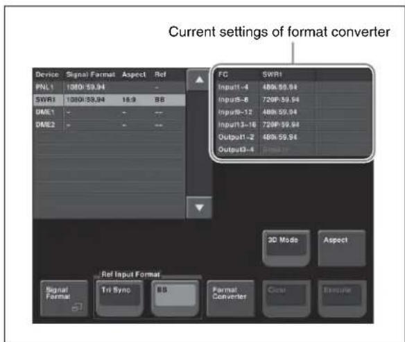
2 Click [Format Converter].
The Format Converter menu appears.
3 To select the conversion format for SWR1 format converter inputs 1 to 4, press [Input 1-4 Format] in the
A pop-up window appears.
4 Press the button for the desired signal format.
5 For "Input 5-8 Format" in MVS-7000X and "Input 9-12 Format" and "Input 13-16 Format" in the MVS-8000X, set the desired signal format in the same way as in steps 3 and 4.
6 To set the output format for format converters 1 and 2, in the
7 For "Output 3-4 Format," set the desired signal format in the same way as in step 6.
8 With reference to steps 3 to 7, make the settings for SWR2.
To delay unconverted input signals (frame delay function)
When the signal format is 1080i/59.94 or 1080i/50, you can press [Frame Delay] in the pop-up window shown in step 3 and step 5 to delay input signals.
For the format of the format converter input signal, the same format as the signal format is shown.
Notes
You can set the delay amount up to eight frames in units of frames.
For details, see "Selecting the Input to Which the Frame Delay Function Applies" (page 601).
Setting the Screen Aspect Ratio (Format Menu)
Switch the screen aspect ratio to 16:9 or 4:3. To set the screen aspect ratio, use the System >Format menu.
Setting the screen aspect ratio
1 In the System >Format menu, press [Aspect].
The Aspect menu appears.
2 In the
• 16:9
• 4:3
- Independ: Set the screen aspect ratio separately for M/E, P/P, and USER on the switcher, and for each channel independently on the DME.
3 If you selected [Independ] in step 2, select from the following.
Switcher Aspect: Make the setting for the switcher. DME Aspect: Make the setting for the DME. A menu appears according to the selection.
4 Carry out either of the following, depending on the selection you made in step 3.
When you selected [Switcher Aspect]: In each of the , and When you selected [DME Aspect]: For each of the 5 To confirm the above setting, press [Aspect Execute]. To cancel the setting and return to the original state, press [Clear] without pressing [Aspect Execute]. When you press [Aspect Execute], a confirmation message appears. 6 Press [Yes]. Set the initial state of the devices when the system is powered on. For each device, you can select Resume mode or Custom mode. This resumes the setting state at the previous power-off operation. This setting is only available for the switcher processor and control panel. This uses the settings saved in non-volatile memory or ROM within the device. In this mode, there are Setup and Initial Status settings which can be set separately. - Setup mode: Select the setup state to be used after powering on from the following.
User: Start up using the user data previously saved with [Setup Define]. Factory: Start up with the factory default settings. - Initial status mode: Select the state of each device after powering on (excluding the settings to which “setup” applies). User: Start up using the user data previously saved with [Initial Status Define]. For the control panel, this applies to the key bus delegation buttons only. Factory: Start up with the factory default settings. For details of saving and recalling setup data, see “Saving and Recalling Setup Data” (page 542) and the appendix “Data Saved by [Setup Define] and [Initial Status Define]” (page 662). Switch on or off the function to automatically load predetermined register data or frame memory image data at power on. Set the data to be read in the File menu. Saving and Recalling Setup Data Concept of saving and recalling setup data Updating the switcher or control panel setup data saves the updated setup data in RAM in each device. - In Resume mode (see page 542), even if devices are reset or powered off, the data is preserved in RAM, and recalled when the power is turned back on. The Resume mode cannot be used for DMEs and DCUs. - In Custom mode (see page 542), the user-defined settings (user setup data) saved in non-volatile memory or factory default setup data held in ROM in each device is recalled when a reset is made or the power is turned back on (see page 543). Note that the setup data in RAM can also be saved to the control panel hard disk or memory card. To set the initial state at start-up, use the System >Start Up menu. It is not possible to set the DCU state at start-up, but its settings can be saved in the control panel. In the Engineering Setup menu, select VF1 'System' and HF4 'Start Up.' The status area shows the current start-up mode settings of each device. 1 In the status area of the System >Start Up menu, select the device to which the settings are to apply. 2 In the Resume: When this is on, Resume mode is enabled. Custom: When this is on, Custom mode is enabled. The Resume mode is only valid when a switcher or control panel is selected for the setting. 3 When Custom mode is selected, in each of the User: When this is on, user-defined settings are used for the Setup or Initial Status settings. For the method of saving the user-defined settings, see the next item. Factory: When this is on, factory default settings are used for the Setup or Initial Status settings. 4 To confirm the settings, press [Execute]. If you want to cancel the setting changes without saving them, press [Clear]. When [Execute] is pressed, a confirmation message appears. 5 Select [Yes]. 1 After selecting the devices to which the settings apply to, in the System >Start Up menu, press [Setup Define]. A confirmation message appears. 2 Press [Yes]. This saves the setup settings for the selected devices in non-volatile memory within the respective devices. For details about the settings which will be saved, see "Data Saved by [Setup Define] and [Initial Status Define]" (page 662). 1 After selecting the devices to which the settings apply to, in the System >Start Up menu, press [Init Status Define]. A confirmation message appears. 2 Press [Yes]. This saves the initial status settings other than the “setup” settings for the selected devices in non-volatile memory within the respective devices. For details about the settings which will be saved, see "Data Saved by [Setup Define] and [Initial Status Define]" (page 662). To have specified data read in at power on, in the System >Start Up menu, press [Power On File Load], turning it on. This enables the autoload function. When the autoload function is enabled, a directory "PWON_LD" appears in the corresponding File menu. About saving data which can be loaded by the autoload function, see “Saving Files Recalled by Autoload” (page 534). To carry out a reset or memory initialization for a device, use the System >Initialize menu. For more details, see “Saving and Recalling Setup Data” (page 542). In the Engineering Setup menu, select VF1 'System' and HF5 'Initialize.' The status area shows the current start-up mode settings. When the MVS-7000X is reset, the MKS-7470X/7471X is also reset at the same time. 1 In the status area of the System > Initialize menu, select the device to which the settings are to apply. Reset: Reset the device. All Clear: Initialize memory. 3 Press [Execute]. A confirmation message appears. 4 Select [Yes]. Depending on the selection in step 2, the following is the result. To install software or firmware in a device, use the System >Install/Unit Config menu. This installs the software and firmware in all devices (including the DCU) connected to the Data LAN. The MKS-7470X/7471X software is included in the MVS-7000X software. In the Engineering Setup menu, select VF1 'System' and HF6 'Install/Unit Config.' The status area shows the version of the software and the firmware installed in each device. The following functions are available here. Install: Automatically detects the software that can be installed on each device, and installs the selected software. Detail Information: Gives details of the software and firmware installed in each device. Unit Config: Makes switcher processor settings and changes the DME input/output signal format. License: Makes the license valid or invalid. In the System >Install/Unit Config menu, press [Detail Information]. This accesses the Detail Information menu, and displays the detailed information on the software and firmware installed in the currently selected device. When the MKS-7470X/7471X is selected, the Detail Information menu cannot be opened. 1 Insert the memory card holding the software into the memory card slot. The Install menu appears; the status area shows the following information. Upper list: For each connected device, this shows the device name, current software version (Current), and the latest version that can be installed (Install, Title). Lower list: For the device selected in the upper list, this shows an automatically detected list of software that can be installed on the particular device. Also, software selected as a candidate for installation in the upper list is marked in the lower list with an bullet. 3 If you are satisfied with the currently installed version of all items in the upper list, skip to step 6. To change the items to be installed, use any of the following methods to select the relevant device. The display of the lower list changes according to the selected device. When the MKS-7470X/7471X is selected, no software is displayed in the lower list. Press [Display All Software], turning it on.
Not just the automatically detected software, but the names of all related software for the selected device appear. 4 In the lower list, select the software you want to install. 5 Press [Set]. The selection is reflected under “Install” and “Title” in the upper list. 6 Press [Install]. The “Install” box shows “On,” confirming that this is to be installed. To cancel this installation setting, press “Install” once more, making the box blank. 7 Repeat steps 3 to 6, to confirm all software to be installed. A confirmation message appears. 9 Press [Yes]. This carries out the installation, and when it completes normally, the “Install” box shows “OK.” To use the software listed below, you are required to enter an install key which validates the software. (If the software has been factory installed, the install key is not required.) For the method of obtaining an install key, contact your Sony representative. To obtain a key, you may be required to submit the unique device ID of the switcher you are using. You can check the unique device ID in the Install/Unit Config menu of the switcher, using the following procedure. When using the MVS-8000X a) This can be used only on MVE-8000A. When using the MVS-7000X a) This is used for license registration common to the MVS-7000 and the MKS-7470X/7471X. 1 In the System >Install/Unit Config menu, use either of the following methods to select the device for which you want to register the license. 2 Press [License]. The License menu appears as follows. When you have the install key, carry out the following procedure. 1 In the System >Install/Unit Config menu, use either of the following methods to select the device for which you want to register the license. 2 Press [License]. 5 Press [Activate License]. A keyboard window appears. 6 Enter the 16-character install key you have been given, and press [Enter]. A license registration completed message appears. 7 Press [OK]. The status area Condition box shows "Active." 8 Using either of the following methods, restart the device. (In case it becomes necessary to cancel the license registration, you can use the following procedure.) 1 In the System >Install/Unit Config menu, use either of the following methods to select the device for which you want to cancel the license registration. 2 Press [License]. The License menu appears. 3 Press directly on the name of the software for which you want to cancel the license registration (the Condition box shows "Active"). 4 Press [License Management]. The License Management menu appears. 5 Press [Deactivate License]. A confirmation message appears. 6 Press [Yes]. A license registration canceled message appears. 7 Press [OK]. The status area Condition box showing "Active" changes to blank. 8 Using either of the following methods, restart the device. After restarting, the software for which the license registration has been canceled is no longer available. You can add user created texture patterns to the repertory of texture patterns with which the spotlighting function enables the light falls on the image surface. This function is not supported on the MVE-8000A and MKS-7470X/7471X. For details of spotlighting and texture patterns, see "Spotlighting Settings" in Chapter 11 (Volume 1). The procedure for adding a texture pattern is as follows. Create a texture file meeting the following conditions, and save it on a memory card. File format: Windows bmp ("bitmap") (extension: bmp, 24-bit RGB) File name: alphanumeric (maximum 8 characters) + extension (bmp) Example: wood_01.bmp Image size (horizontal × vertical): 128 × 128 to 1024 × 1024 pixels The maximum number of texture files that can be handled by the system is related to the image size of the texture files, as shown in the following table (when all images are the same size). Example: a 300 × 200 pixel texture file is treated as 512 × 256 pixels. To create user texture patterns, use the Texture Package menu. This shows an available memory space in units of 128 × 128 pixels (a maximum of 64 units of memory space is available). This shows the texture numbers (101 to 164) registered in the texture package. The list Capacity shows the file size in units of 128 × 128 pixels (a total maximum of 64 units of texture files can be registered). By pressing this button to display the popup window, you can select a directory on the memory card. This shows the texture files stored on the memory card. If a texture file is stored in a directory, press the directory selection button and select the directory in the popup window, to show a list of files. The list Capacity shows the file size in units of 128×128 pixels. This shows how the texture files are stored in memory (an 8 × 8 grid, of 64 squares, each equivalent to 128 × 128 pixels). And this shows the location where the texture files are stored in memory by bold frames. The grid for the texture file selected in the texture number list is shown in amber. Pressing this button assigns the texture file selected in the texture file list to the number selected in the texture number list. Pressing this button deletes the texture file assigned to the number in the texture number list. Pressing this button creates the texture package. To use a user-provided texture pattern with the spotlighting function, it is necessary to convert the texture files to vector files for bump mapping. This operation is referred to as “creating a texture package.” 1 Insert the memory card holding the texture file into the memory card slot. 2 In the Engineering Setup menu, select VF1 'System' and HF6 'Install/Unit Config.' The Install/Unit Config menu appears; the status area shows the version information for the software installed on the various devices. 3 Using any of the following methods, select a DME for which the spotlighting license is valid. The MKS-7470X/7471X does not require license registration. 4 Press [Texture Package]. If you select a device for which the spotlighting license is not enabled, then [Texture Package] is not enabled. 5 In the texture number list, select the number for which you want to register the texture package, by any of the following methods. 6 In the texture file list, select the texture file by any of the following methods. a) The range of the setting values depends on the number of saved files on a memory card. 7 In the This assigns the texture file selected in step 6 to the number selected in step 5, and updates the texture number list. The grid display of memory capacity shows the location where the texture files are stored in memory by bold frames. The grid portion for the texture file selected in the texture number list is shown in amber. 8 Repeat steps 5 to 7, to assign all of the texture files to texture packages. Select the texture file (multiple selections are not possible) you want to delete in the texture number list, and in the 9 To create the texture package, press [Make Package]. A confirmation message appears. 10 Select [OK]. The texture package is created in the same location that the texture file is stored on the memory card (extension: zsp, file name generated automatically). 1 Insert the memory card holding the texture package into the memory card slot. The Install/Unit Config menu appears; the status area shows the version information for the software installed on the various devices. 3 Press [Install]. The System >Install/Unit Config >Install menu appears; the status area shows the following information. Upper list: For each connected device, this shows the device name, current software version (Current), and the information about the texture package that can be installed (Install, Title). Lower list: For the device selected in the upper list, this shows an automatically detected list of software that can be installed on the particular device. Also, software selected as a candidate for installation in the upper list is marked in the lower list with an asterisk. 4 Using any of the following methods, select in the upper list a DME for which the spotlighting license is valid. - Press directly on the list in the status area. 5 Press [Display All Software], turning it on. The lower list shows the texture packages. 6 Using any of the following methods, select the texture package you want to install from the lower list. 7 Press [Set]. The selection is reflected under “Install” and “Title” in the upper list. 8 Press [Install]. The “Install” box shows “On,” confirming that this is to be installed. To cancel this installation setting, press “Install” once more, making the box blank. 9 To carry out the installation, press [Execute]. A confirmation message appears. 10 Select [Yes]. This carries out the installation, and when it completes normally, the “Install” box shows “OK.” When the signal format is 1080P, this operation is not possible. 1 In the System >Install/Unit Config menu, select [SWRx], and press [Unit Config]. The Unit Config menu appears. 2 Press [FM Ancillary], turning it on. On: Save with ancillary data. Off: Save without ancillary data. Enabling this selection by pressing [Execute] in the following step reinitializes all frame memory data. Make backups of required data beforehand. 3 Press [Execute]. A popup window appears, displaying a message. 4 Check the message, and select [Yes]. This setting is only valid when the system signal format is set to 1080P. 1 In the System >Install/Unit Config menu, select [SWRx], and press [Unit Config]. The Unit Config menu appears. 2 In the 3G Mode: Use 3G mode (single 3G SDI signal) for DME input/output. ^1) Dual Link Mode: Use dual link mode (two 1.5G SDI signals) for DME input/output. ^2) 1) 3G SDI: Standard defined by SMPTE 424M 2) Dual link: Standard defined by SMPTE 372M 3 Press [Execute]. A popup window appears, showing a message. 4 Check the message, and select [Yes]. - For each VF button group, selecting a set of candidate menus to be locked, then locking all of the candidates using a password. Except for list scrolling, moving menus, and similar operations, menu operations for all settings can be locked. - Changing the password - Locking file recall operations - Locking file recall operations by category - Locking and removing the lock using the password (You can change the password.) In the Engineering Setup menu, select VF1 'System' and HF7 'Maintenance.' In the status area, the current date and time, and details of the memory card appear. 1 In the System >Maintenance menu, turn the knobs to set the following parameters. Parameter group [1/2] Parameter group [2/2] The set date and time appears in the “Set” box in the status area. 2 Press the [Set Date/Time] button. This sets the current time to the date and time set in step 1, and the setting in the “Current” box of the status area changes accordingly. 1 Insert the memory card into the memory card slot. Format a memory card before using it for the first time. 1 Insert the memory card in the memory card slot. To specify a USB device with a storage device connected as a primary device, use the following procedure. Without this setting, you cannot use the "Memory Card" item in the File menu to access a memory card on a storage device connected to the USB device. 1 In the System >Maintenance menu, using any of the following methods, select the USB device you want to set as primary. 2 In the In the To reload a USB driver, in the System >Maintenance menu, press [Reload USB Driver]. If even after this operation the memory card is not recognized, remove the memory card and reinsert it, then try again. If a file system corruption error has occurred on the hard disk, you should initialize the hard disk. 1 In the When the hard disk is operating normally, pressing [HDD Format] has no effect. An initialization confirmation message appears. 2 To execute the initialization operation, press [Yes]. To cancel, press [No]. If you have pressed [Yes], the hard disk initialization operation is executed, and a finished message appears. If you have pressed [No], the initialization operation is canceled, and the System >Maintenance menu appears again. 3 Press [OK]. To protect the data, you can inhibit operations in selected setup menus. Use the following procedure. (It is not possible to lock the Setup Operation Lock menu.) 1 In the System >Maintenance menu, press [Setup Operation Lock]. The Setup Operation Lock menu appears. 2 In the The status area shows a list of menu numbers and menu names in the selected group. Subsequent lock operations apply within the group selected here. 3 Using any of the following methods, select the menu or the set of menus as candidates for the locking operation. - To select all setup menus within the selected group, press [ALL]. You can also select a menu while it is open (see page 553). 4 Press [Lock Item Select]. This makes the selected menus candidates for locking, and a padlock icon appears in the "Lock" box (in the unlocked state) If there are already one or more locked menus, selection of lock candidates is not possible. After selecting a menu, press [Lock Item Select] once more, to clear the Lock box. Press [Lock Item All Clear]. 5 Repeat steps 2 to 4, to select all of the lock candidates. A keyboard window appears. 7 Enter the password with a maximum of 16 characters, and press [Enter]. If the password is correct, the menus selected in the list of candidates are all locked. The padlock icon changes to the locked state When a lock is already applied, use the following procedure. 1 In the System >Maintenance >Setup Operation Lock menu, press [Lock]. A keyboard window appears. 2 Enter the password. If the password is correct, the lock is released, and the padlock icon disappears. 1 In the System >Maintenance >Setup Operation Lock menu, press [Change Password]. A confirmation message appears. 2 Press [Yes]. A keyboard window labeled "Old Password" appears. 3 Enter the old password, and press [Enter]. If the password is correct, a keyboard window labeled "New Password" appears. 4 Enter the new password, and press [Enter]. A keyboard window labeled "New Password(Confirm)" appears. 5 Enter the new password once more for confirmation, and press [Enter]. If the password is correct, the password change completed message appears. 6 Press [OK]. With the menu you want to lock open, press [Lock Item Select] button at the lower left. The [Lock Item Select] button turns red, and a padlock icon appears. This selection is reflected in the lock candidate list in the Setup Operation Lock menu. If there are already one or more locked menus, selection of lock candidates is not possible. In this case, the indication of the [Lock Item Select] button changes as follows. If you want to select lock candidates, first remove the lock in the Setup Operation Lock menu. You can inhibit load operations for a specified file category. 1 In the System >Maintenance menu, press [File Load Lock]. The File Load Lock menu appears. The status area shows a list of file category numbers, category names, and the lock status. Subsequent lock operations apply to the category selected here. 2 Using any of the following methods, select the category or the set of categories as candidates for the locking operation. • To select all categories, press [ALL]. 3 Press [Lock]. This makes the selected categories candidates for locking. The category name display color changes to yellow, and the indication “Lock” is displayed in yellow in the Lock box. After selecting a category, press [Clear] to clear the indication "Lock" in the Lock box. 4 Repeat steps 2 and 3, to select all of the lock candidates. A keyboard window appears. 6 Enter the password with a maximum of 16 characters, and press [Enter]. If the password is correct, the categories selected in the list of candidates are all locked. The category name display color and the "Lock" indication color in the Lock box both change to white. When a lock is already applied, use the following procedure. 1 In the System >Maintenance >File Load Lock menu, press [Lock]. A keyboard window appears. 2 Enter the password. If the password is correct, the lock is released, and the indication "Lock" in the Lock box disappears. In the System >Maintenance >File Load Lock menu, press [Change Password], and carry out step 2 and following of “Changing the lock password” (page 553). Chapter To carry out the overall control panel settings, use the Panel >Config menu. In the Engineering Setup menu, select VF2 'Panel' and HF1 'Config.' The status area shows the “Bank numbers 1 to 4” (physical locations) of the M/E and PGM/PST banks, the allocated bank names, and whether or not operation is enabled. In panel setup, you carry out settings particular to the control panel. You can make the following settings. to. You can set the links between keyers for each M/E bank separately. 1 In the Panel >Config menu, select the Bank you want to set, using any of the following methods. The Bank selection here indicates the physical position on the control panel, numbering from the top as the 1st Row, 2nd Row, 3rd Row, and 4th Row. This is followed by the system control unit extension interface ports 1, 2, and 3. 2 Select the bank that you want to assign to the selected Bank number in the The status area shows the interchanged state of the banks. 3 For the selected Bank number, in the <M/E Operation> group, select one of the following. Enable: Enable panel display and operation of the bank. Disable: Enable only panel display, and disable operation of the bank. Inhibit: Disable both the panel display and operation of the bank. When this is set to Inhibit, snapshots of the bank are not recalled. 1 In the Panel >Config menu, select the M/E bank for which you want to make the setting. a) Depends on the center control panel configuration. When 7 (Ext 3) is selected, or a switcher bank is selected which is immediately above a switcher bank to which nothing is assigned, then [Dual M/E Assign] is invalid. For example, if the furthest bank from you is assigned to M/E-1, and you want no shift button operation for the bank, select 1 (1st Row) for Bank. 2 Press [Dual M/E Assign]. This assigns the furthest M/E bank from you to the unshifted (shifted) cross-points and the M/E bank in front of it to the shifted (unshifted) cross-points. For fader lever operations, only the M/E bank closer to you is enabled. The shift/non-shift assignment is set by [Dual M/E Xpt Swap]. For more details, see the next section, “Interchanging shifted and non-shifted operations for a dual M/E.” Interchange the bank order (see page 555). 1 In the Panel >Config menu, select the M/E bank for which the dual M/E setting is made. 2 Press [Dual M/E Xpt Swap], toggling it on or off. On: The lower M/E bank is non-shifted, and the higher M/E bank is shifted. Off: The lower M/E bank is shifted, and the higher M/E bank is non-shifted. As an example, to assign key 4 of the M/E-1 bank to key delegation button 1 of the downstream key control block 1, use the following procedure. 1 In the Panel >Config menu, press the [DSK Fader Assign]. The DSK Fader Assign menu appears. 2 Directly press on the indications in the status area, to select the downstream key control block for which you want to make the setting, and select the key delegation. Here, press on the intersection of the “1st Module” column and “Key1 Assign” row. 3 In the Here, select [M/E-1] as an example. 4 In the Here, select [Key4] as an example. 5 Press [Fader Assign] in the DSK Fader Assign menu. The Fader Assign menu appears. 6 To disable the fader lever of the selected downstream key control block, select [Disable] in the To enable the fader lever, select one of the following in the All: Key selected with one of the key delegation buttons Key1 to Key4: Key assigned to key delegation buttons 1 to 4 ([DSK1] to [DSK4] buttons) To provide links between the switcher bus and router destination, make the following settings as required. Matrix selection: Select the target of link setting from the eight matrices (1 to 8). Matrix position definition: Set the start address and level for the source and destination on the S-Bus. Link table setting: Link a switcher cross-point button and matrix source. Link bus setting: Link a switcher bus address and router destination. 1 In the Panel >Config menu, press [Link/Program Button]. The Link/Program Button menu appears. 2 In the group, press [External Bus Link]. The External Bus Link menu appears. The status area shows the current link status. 3 Turn the knobs to select the matrix. In the status area, the color of the selected part changes. 4 Press [Link Matrix Set]. This confirms the matrix selection and the selected part in the status area returns to the previous color. With the link selected, press [Clear]. Specify where in the 1024 × 1024 S-Bus space the link matrix is to be provided, by setting the source and destination start address. For the matrix selected in the External Bus Link menu, use the following procedure. 1 In the Panel >Config>Link/Program Button >External Bus Link menu, press [Link Matrix Adjust]. The Link Matrix Adjust menu appears. The status area shows the status of the currently selected matrix, and a list of the source and destination start addresses that can be selected. In this menu too, you can use the knobs to select the link for the setting. 2 Using any of the following methods, define the position of the matrix to be linked. 3 To confirm a source address selected in step 2, press [Source Set], to confirm a destination address press [Destination Set], and to confirm a level press [Level Set]. This confirms the selection, which is reflected in the status area. For the link selected in the External Bus Link menu, make the settings as follows. 1 In the Panel >Config>Link/Program Button >External Bus Link >Link Matrix Adjust menu, press [Link Table Adjust]. The Link Table Adjust menu appears. The status area lists the status of the currently selected link, combinations of video signals and sources, and the sources that can be selected. 2 Using any of the following methods, select the switcher cross-point button and the matrix source to be linked to the button. 3 To confirm the matrix source selection made in step 2, press [Link Source Set]. This confirms the selection, which is reflected in the status area. 4 As required, repeat steps 2 and 3 to select the matrix sources to be linked to other cross-point buttons. In the Panel >Config >Link/Program Button >External Bus Link >Link Matrix Adjust menu, press [Init Link Table]. A confirmation message appears. Press [Yes]. The links set using the above procedure are initialized to the default settings, and this is reflected in the status area. For the link number selected in the External Bus Link menu, use the following procedure. 1 In the Panel >Config>Link/Program Button>External Bus Link menu, press [Link Bus Adjust]. The Link Bus Adjust menu appears. The status area lists the current link status, and the switcher buses and router destinations that can be selected. In this menu too, you can use knob 1 to select the link to be set. 2 Using any of the following methods, select the switcher bus and the router destination to be linked to the switcher bus. 3 To confirm the bus selected in step 2, press [Master Bus Set], and to confirm the destination press [Linked Dest Set]. This confirms the selection, which is reflected in the status area. 1 In the Panel >Config menu, press [Link/Program Button]. The Link/Program Button menu appears. 2 In the group, press [Key Trans Link]. The Key Trans Link menu appears.
The status area shows the keyers for each M/E bank and the linked keyers. 3 Using any of the following methods, select the keyer to be the master. The selected keyer appears in reverse video. 4 In the Linking does not apply to a transition carried out with the downstream key control block. To the transition links between keyers, you can add a link for the next transition selection buttons in the transition control block. The effect of this additional link is such that if for example, two keyers (Key 2 and Key 3) are linked with the master keyer (Key 1), pressing the [KEY1] next transition selection button also selects the [KEY2] and [KEY3] buttons. 1 Set the transition links between keyers. For details of the operation, see the previous section "Linking Transitions Between Keyers." 2 Press [Next Trans Link], turning it on. The [KEY1] to [KEY8] next transition selection buttons in the transition control block are now selected coupled to the settings in the Key Trans Link menu for transition links between keyers. These settings apply to the whole Key Trans Link menu. It is not possible to make separate settings for each master keyer. When both trackball and joystick device control blocks are connected, select which is to be the reference. Also select the range to which key wipe positioning applies. 1 In the Panel >Config menu, press [JS/TB User Setting]. The JS/TB User Setting menu appears. 2 In the Trackball: Trackball device control block
Joystick: Joystick device control block In the Panel >Config menu KEY1-4: Applies to keys 1 to 4. KEY1-8: Applies to keys 1 to 8. When "KEY1-8" is selected, after selecting more than one key it is not possible to carry out key wipe positioning. There is no such restriction when "KEY1-4" is selected. You can set a maximum of four regions to each of the region selection buttons in the numeric keypad control block or Multifunction Flexi Pad control block. In the Multifunction Flexi Pad control block, pressing the region selection button [MORE] displays the regions not assigned to the region selection buttons on the memory recall section numeric keypad buttons, so that you can select them, and set the assignment of regions to the numeric keypad buttons. However, in the Multifunction Flexi Pad control block, it is not possible to assign a region to the [EXIT] button. 1 In the Panel >Config menu, press [10 Key Region Assign]. The 10 Key Region Assign menu appears. When a CCP-6224 or CCP-6324 control panel including a Multifunction Flexi Pad control block is connected, the display in the button area at the lower part of the status area changes as follows. The left side of the status area shows region selection buttons; the upper part of the right side shows a list of regions assigned to region selection buttons, and the lower part shows a list of assignable regions. 2 To assign regions to the region selection buttons in the Multifunction Flexi Pad control block or the numeric keypad buttons in the memory recall section, press either of the following buttons in the [Region Sel Btn Area] button: When assigning a region to the region selection buttons [Mem Rcl Btn Area] button: When assigning a region to the numeric keypad buttons in the memory recall section 3 Press the indication of the button for the assignment. The button you pressed appears in reverse video. 4 Using any of the following methods, select one of the four regions for the setting. 5 Using any of the following methods, select the region to be assigned. 6 Press [Set], to confirm the selection. This assigns the region to the region selection button in the numeric keypad control block. Only regions assigned here can be used for keyframe or snapshot recall. If an M/E bank is not assigned to a region selection button in the numeric keypad control block or Multifunction Flexi Pad control block, the M/E Flexi Pad control block or Multifunction Flexi Pad control block cannot be used to recall a snapshot. In the Panel >Config >10 Key Region Assign menu, press [Default]. This returns the assignment of region selection buttons in the numeric keypad control block to the factory default state. In step 3 of the procedure “Assigning a Region to the Region Selection Buttons in the Numeric Keypad Control Block or Multifunction Flexi Pad Control Block” (page 559), make the selection to which the operation applies, then press [Clear]. This clears the assignment of the selected region. 1 In the Panel >Config >10 Key Region Assign menu, press [All Select] in the button area, or the [All Select] button indication in the status area, setting it to On. The [All Select] button indication in the status area changes to orange, and the system switches to a mode for assigning region selection buttons to the [ALL] button. In the factory default state, all buttons appear in reverse video, and are assigned to the [ALL] button. 2 If you do not want to assign any region selection button to the [ALL] button, press the corresponding button indication, setting it to Off. The button you pressed returns to normal display. Assignment to the [ALL] button is region by region. Changing the assignment of a region selection button does not change the regions assigned to the [ALL] button. There are three separate menus for these settings, for the left part of the transition control block (Transition Module1), upper right part (Transition Module2), and lower right part (Transition Module3). The following example describes the operation for the left part (Transition Module1 menu), but operations in the Transition Module2 and Transition Module3 menus are similar. 1 In the Panel >Config menu, press [Link/Program Button]. The Link/Program Button menu appears. 2 Press [Transition Module1]. The Transition Module1 menu appears. 3 Select the bank of the transition control block you want to set in the The current assignment of the buttons appears at the left. 4 Press the transition type selection button for which you want to change the assignment. The button you pressed appears in reverse video. 5 Using any of the following methods, select the function to be assigned, from the list on the right. 6 Press [Set]. The texts on the button illustrations change to reflect the selection. Press [Clear]. Press [Default]. This setting applies to all simple type Flexi Pad control blocks on the control panel. To switch the [UNDO] button on a simple type Flexi Pad control block to a [MCRO] button for macro operation, use the following procedure. 1 In the Panel >Config >Link/Program Button menu, press [Flexi Pad Module]. The Flexi Pad Module menu appears. 2 Select the assignment of the [UNDO] button in the simple type Flexi Pad control block from the UNDO: use as an [UNDO] button. MACRO: use as a [MCRO] button. The dual background bus mode is a mode in which the background A row shifted signal can be selected with the key 1 row, and the background B row shifted signal can be selected with the key 2 row. To switch this mode on and off, it is necessary to assign this function to the cross-point control block [PRE MCRO] button. For details of the dual background bus, see “Signal Selection” in Chapter 3 (Volume 1). 1 In the Panel >Config menu, press [Link/Program Button]. 2 Press [Xpt Module]. The Xpt Module menu appears. 3 Using any of the following methods, select the bank. 4 In the Selecting the State After Powering On (Start Up Menu)
Resume mode
Custom mode
Autoload function
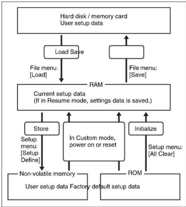
flowchart
graph TD
    A["Hard disk / memory card\nUser setup data"] --> B["Load Save"]
    B --> C["File menu: [Load"]]
    C --> D["RAM"]
    D --> E["Current setup data\n(If in Resume mode, settings data is saved.)"]
    E --> F["Store"]
    E --> G["In Custom mode,\npower on or reset"]
    E --> H["Initialize"]
    F --> I["Non-volatile memory"]
    G --> J["ROM"]
    H --> K["Setup menu: [All Clear"]]
    I --> L["User setup data Factory default setup data"]
    J --> L
    K --> L
Notes
Notes
To display the Start Up menu
Selecting the State at Start-up
Notes
Saving User-Defined Settings
Saving the Setup settings
Saving the Initial Status settings
Setting Automatic Loading of Register Data at Power On (Autoload Function)
Reset and Initialization (Initialize Menu)
To display the Initialize menu
Resetting the device and initializing memory
Notes
2 In the
Installation and Device Setup (Install/Unit Config Menu)
Notes
To display the Install/Unit Config menu
Displaying installation details
Notes
Installing Software
2 In the System >Install/Unit Config menu, press [Install].
Knob Parameter Adjustment Setting values 1 Device Device selection 1 and upwards Notes
To display all related software
Knob Parameter Adjustment Setting values 3 No S software selection 1 and upwards
8 Press [Execute].Making Settings Required to Use the Software
BZDM-9050 Texture Lighting Software (for MVE-9000) BZS-8050 Editing Control Software BZS-8200X Multi Program 2 Software BZS-8420X Color Corrector Software BZS-8560X Switcher Upgrade Software BZDM-8560 DME Upgrade Software a) BZS-7500X a) Switcher Upgrade Software BZS-7510X BZS-7520X b) BZS-7530X c) BZS-7540X d) DME Upgrade Software BZS-7541X e) BZS-7561X BZDM-8560 f) BZDM-9050 g) Texture Lighting Software BZS-8050 Editing Control Software BZS-7200X Multi Program 2 Software BZS-7420X Color Corrector Software BZS-7560X Switcher Upgrade Software
b) This is used for license registration required to support multiple signal formats when two MKS-7210X boards are used.
c) This is used for license registration required to support multiple signal formats when three MKS-7210X boards are used.
d) This is used for license registration required to support multiple signal formats on the MKS-7470X.
e) This is used for license registration required to support multiple signal formats on the MKS-7471X.
f) This can be used only on MVE-8000A.
g) This can be used only on MVE-9000.To display the unique device ID
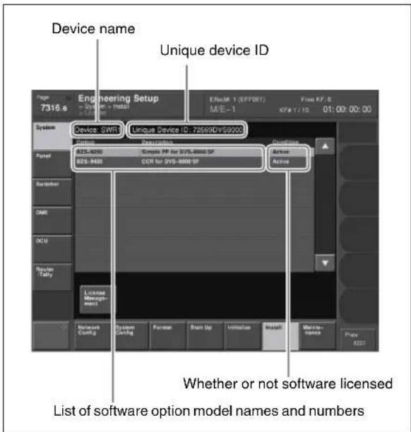
Entering the install key
The License menu appears.
3 Press directly on the name of the software you want to license (the Condition box is blank).
4 Press [License Management].
The License Management menu appears.
• Power off and on again.
After restarting, the licensed software is now available for use.To cancel the license registration
• Power off and on again.Adding User Texture Patterns
Notes
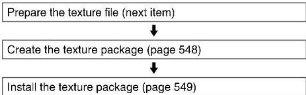
flowchart
graph TD
    A["Prepare the texture file (next item)"] --> B["Create the texture package (page 548)"]
    B --> C["Install the texture package (page 549)"]
To prepare a texture file
Maximum number of texture files handled Dimension (horizontal) Dimension (vertical) 128 pixels 256 pixels 512 pixels 1024 pixels 128 pixels 64 32 16 8 256 pixels 32 16 8 4 512 pixels 16 8 4 2 1024 pixels 8 4 2 1 Notes
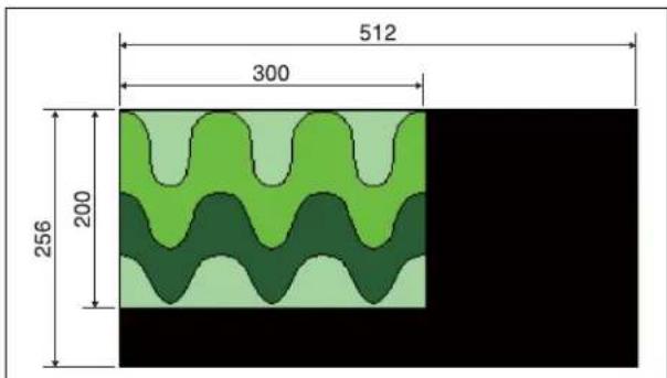
geo
| Dimension | Value |
| :--- | :--- |
| Top Section | 512 |
| Middle Section | 300 |
| Bottom Section | 256 |
| Bottom Layer | 200 |
Texture Package menu
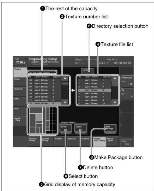
①The rest of the capacity (available memory space)
② Texture number list
③Directory selection button
④ Texture file list
⑤Grid display of memory capacity
⑥Select button
⑦ Delete button
⑧ Make Package button
Creating a texture package
Notes
Notes
Knob Parameter A Adjustment Setting values 1 Texture No Texture number selection 101 to 164
Knob Parameter Adjustment Setting values 2 No T texture file selection 1 and upwards a) Notes
To delete a texture file assignment
Notes
Installing the texture package
2 In the Engineering Setup menu, select VF1 'System' and HF6 'Install/Unit Config.'
- OK: Installation already completed.
- On: For installation, but not completed.
- Error: An error occurred during installation.
- Cancel: Installation canceled.
Knob Parameter Adjustment Setting values 1 Device Device selection 1 and upwards
Knob Parameter Adjustment Setting values 3 No P package selec ction 1 and upwards Saving a Frame Memory Clip With Ancillary Data
Notes
Notes
Setting the DME Input/Output Signal Format
Notes
Notes
System Maintenance (Maintenance Menu)
• Primary settings for USB external storage device To display the Maintenance menu
Setting the Date and Time
Knob Parameter Adjustment Setting values 1 Hour Hour 0 to 23 2 Min Minute 0 to 59 3 Sec Second 0 to 59 Knob Parameter Adjustment Setting values 1 Month Month 1 to 12 2 Day Day 1 to 31 3 Year Year 2000 to 2037 Using a Memory Card
Displaying memory card information
2 In the Formatting a memory card
Notes
2 In the System >Maintenance menu, using either of the following methods, select the USB device.
- Press directly on the list in the status area.
- Press the arrow keys to scroll the reverse video cursor.
3 In the
A confirmation message appears.
4 To carry out the formatting, press [YES].Carrying Out the Primary Setting
Notes
Knob Parameter Adjustment Setting values 5 Mount Point USB device selection 1 to 18 Making the primary setting automatic
Reloading a USB Driver
Notes
Initializing the Hard Disk
Notes
Locking the Setup Menu Settings
Knob Parameter Adjustment Setting values 1 No Selection of a menu by its number in the list 1 and upwards 3 Num Selection of number of menus in the list 1 and upwards Notes
To deselect a lock candidate
To deselect all lock candidates in the selected VF group
6 Press [Lock].Releasing the lock
Changing the lock password
Selecting an opened setup menu for locking
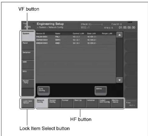

Notes
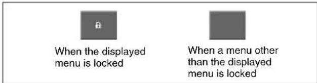
Locking File Loading Operations
Knob Parameter Adjustment Setting values 1 No S Selection of a category by its number in the list 1 to 14 3 Num Selection of number of categories in the list 1 to 14 To deselect a lock candidate
5 Press [Execute].To release the lock
To change the lock password
Control Panel Setup (Panel)
19
Overall Control Panel Settings (Config Menu)
To display the Config menu
Panel Setup
Panel settings (Config)
• Key Trans Link: Select whether or not to link transitions between keyers, and if so which keyer to link
Interchanging the Bank Order or Disabling Operation
Knob Parameter Adjustment Setting values 1 Bank Select the position of the bank you want to set 1 to 7 Notes
Notes
Assigning Two M/E Banks to One M/E Bank
Knob Parameter Adjustment Setting values 1 Bank Selection of position of bank for which you want to make the setting 1 to 7a) To return to the original assignment
Interchanging shifted and non-shifted operations for a dual M/E
Knob Parameter Adjustment Setting values 1 Bank Bank to be selected for dual M/E setting 1 to 7 Assigning the Key Delegation in the Downstream Key Control Block
Linking Switcher Bus and Router Destination
Selecting a matrix number
Knob Parameter Adjustment Setting values 1 Link No Link number 1 to 64 2 Link Matrix Matrix number 1 to 8 To delete a link
Defining the position of a matrix
Knob Parameter Adjustment Setting values 2 Source Source start address 1 to 897 3 Destination Destination start address 1 to 897 4 Level Level 1 to 8 Setting a link table
Knob Parameter Adjustment Setting values 1 Main No Switcher cross-point button 1 to 300 2 Source No Matrix source selection 1 to 128 To initialize the set links
Making link bus settings
Knob Parameter Adjustment Setting values 2 Internal Bus Switcher bus selection 1 to 128 3 Destination Router destination selection 1 to 128 Linking Transitions Between Keyers
Knob Parameter Adjustment Setting values 1 Master Key Select keyer to be master 1 to 40 Notes
Linking the Next Transition Selection Buttons
Notes
Selecting the Module to Be the Reference for Device Control Block
To select the reference module
To select the range to which key wipe positioning applies
Notes
Assigning a Region to the Region Selection Buttons in the Numeric Keypad Control Block or Multifunction Flexi Pad Control Block
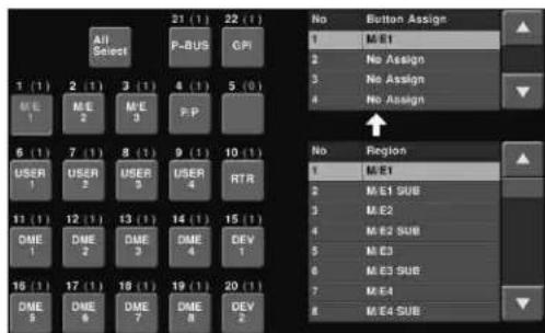

Knob Parameter Adjustment Setting values 1 Button Assign Selection to which setting applies 1 to 4
Knob Parameter Adjustment Setting values 2 Region Region selection 1 and upwards Notes
To return the region assignment to the factory default state
To delete a region assignment
Setting the region selection buttons selected when the [ALL] button is pressed
Notes
Setting Transition Control Block Button Assignments
Knob Parameter Adjustment Setting values 1 Button Assign Selection of function 1 and upwards To cancel the assignment
To make the assignment the default
Setting the Assignment of Macro Operation Buttons
Notes
Assigning the Dual Background Bus Mode Switching Function
The Link/Program Button menu appears.
Knob Parameter Adjustment Setting values 1 Bank Bank selection 1 to 5 group, select [Dual Bkgd Bus].
This assigns the dual background mode to the [PRE MCRO] button, and disables the [POST MCRO] button.
Assigning the Utility/Shotbox Mode Switching Function
You can first assign functions to the key 2 row cross-point buttons, and then use them in the same way as the buttons in the utility/shotbox control block.
To switch this mode on and off, it is necessary to assign this function to the cross-point control block [PRE MCRO] button (see page 584).
1 In the Panel >Config menu, press [Link/Program Button].
The Link/Program Button menu appears.
2 Press [Xpt Module].
The Xpt Module menu appears.
3 Using any of the following methods, select the bank.
- Press directly on the list in the status area.
- Press the arrow keys to scroll the reverse video cursor.
- Turn the knob.
| Knob | Parameter Adjustment Setting values | ||
| 1 Bank | Bank selection 1 to 5 | ||
4 Select [Utility/Shotbox] in the
group.This assigns the utility/shotbox mode to the [PRE MCRO] button, and disables the [POST MCRO] button.
Assigning the Function to Disable Cross-Point Button Operations to a Button
1 In the Panel >Config menu, press [Link/Program Button].
The Link/Program Button menu appears.
2 Press [Xpt Module].
The Xpt Module menu appears.
3 Using any of the following methods, select the bank.
- Press directly on the list in the status area.
- Press the arrow keys to scroll the reverse video cursor.
- Turn the knob.
| Knob | Parameter | Adjustment | Setting values |
| 1 Bank | Bank selection | 1 to 5 |
4 Press [Inhibit Set] in the
group.This assigns the function to disable cross-point button operations to the [PRE MCRO] button.
Assigning the AUX Bus Control Mode Switching Function
You can switch the cross-point control block of the CCP-6224/6324 control panel to AUX bus control mode (AUX panel-less function). You can display the names of the sources or buses for the AUX buses in the source name displays.
The function for switching to AUX control (AUX Ctrl) mode is assigned to the [PRE MCRO] button. And the
function for switching the source name displays to the names of the sources or buses for the AUX buses is assigned to the [POST MCRO] button.
1 In the Panel >Config menu, press [Link/Program Button].
The Link/Program Button menu appears.2 Press [Xpt Module].
The Xpt Module menu appears.
3 Using any of the following methods, select the bank.
- Press directly on the list in the status area.
- Press the arrow keys to scroll the reverse video cursor.
- Turn the knob.
| Knob | Parameter | Adjustment | Setting values |
| 1 Bank | Bank selection 1 to 5 | ||
4 Select [Aux Ctrl/Aux Disply] in the
group.This assigns the Aux Ctrl function to the [PRE MCRO] button, and the Aux Display function to the [POST MCRO] button.
Assigning Keys to the DSK1 and DSK2 Buttons in the Downstream Key/Fade-to-Black Control Block
It is possible to select the key used for downstream key/fade-to-black control block operations.
1 In the Panel >Config >Link/Program Button menu, press [DSK/FTB Module].
The DSK/FTB Module menu appears. The left side of the status area shows the DSK1 and DSK2 buttons, and the right side shows a list of keys to be assigned.
2 Press the indication (DSK1, DSK2) of the button for the assignment.
The button you pressed changes to reverse video.
3 Using any of the following methods, select the key to be assigned.
- Press directly on the list.
- Press the arrow keys to scroll the reverse video cursor.
- Turn the knob.
| Knob | Parameter | Adjustment Setting | values |
| 1 | K e | y N assigned to button | bto 40 S e |
4 Press [Set], to confirm the selection.
This assigns the selected key to the key delegation button.
To return the key delegation button assignment to the factory default state
In the DSK/FTB Module menu, press [Default].
This returns the key delegation assignment to the factory default state.
Assigning Keys to the Independent Key Transition Control Block (Simple Type)
It is possible to select the keys that can be used in an independent key transition control block (simple type) operation.
The control panel comprises a main base for installing the principal switcher bank control blocks, and an extension section for extended control blocks. The independent key transition control block (simple type) can be installed in either, but the assignable keys differ as follows.
When the independent key transition control block (simple type) is installed in the main base
Select the keys to be assigned from the following.
• Key1, 2 (keys 1 and 2) ^1)
• Key3, 4 (keys 3 and 4) ^1)
• Key5, 6 (keys 5 and 6) ^1)
• Key7, 8 (keys 7 and 8) ^1)
• N/A (no assignment)
- DSK1, 2 (downstream keys 1 and 2)
- DSK3, 4 (downstream keys 3 and 4)
- DSK5, 6 (downstream keys 5 and 6)
- DSK7, 8 (downstream keys 7 and 8)
1) The M/E bank depends on the settings in the M/E Assign menu where the independent key transition control block is installed.
When the independent key transition control block (simple type) is installed in the extension section
Select the keys to be assigned from the following.
• M/E-1 Key1, 2
• M/E-1 Key3, 4
• M/E-1 Key5, 6
• M/E-1 Key7, 8
• M/E-2 Key1, 2
• M/E-2 Key3, 4
• M/E-2 Key3, 4
• M/E-2 Key5, 6
• M/E-2 Key7, 8
• M/E-3 Key1, 2
• M/E-3 Key3, 4
• M/E-3 Key5, 6
• M/E-3 Key7, 8
• M/E-4 Key1, 2
• M/E-4 Key3, 4
• M/E-4 Key5, 6
• M/E-4 Key7, 8
• D S K 1, 2
• D S K 3, 4
• D S K 5, 6
• D S K 7, 8
• K e y 1 ^1) , 2
• K e y 3 ^1) , 4
• K e y 5 ^1) , 6
• K e y 7 ^1) , 8
• N/A (no assignment)
1) These keys are the keys of the M/E-1, M/E-2, M/E-3, M/E-4 or PGM/PST bank depending on the settings of the M/E Assign menu of the interface port for the extension section in which the independent key transition control block is installed.
To assign a key to the main base
To assign a key to the independent key transition control block (simple type), use the following procedure. Here the example shown is the case in which keys 3 and 4 (“Key3, 4”) are assigned to the second row switcher bank of the main base.
1 In the Panel >Config menu, press [Compact Key Module Assign].
The Compact Key Module Assign menu appears. The left side of the status area shows data for the main base (physical layout and switcher bank names and key assignment).
2 Press directly on the display on the left, to select the control block for the assignment.
Here, press on the intersection of the “2nd Row” column and “Module” row.
3 Select the key from the table on the right.
4 Press [Set].
To return the key assignment to the default
In the Compact Key Module Assign menu, press [Default]. This returns all key assignments for the main base to their factory default state.
To assign a key to an extension
Press [Extension Port], to display the Extension Port menu, then continue as for the main base.
To return the extension assignments to their original values, press [Default].
Assigning Functions to Key Control Block Buttons
Select one of the four key control blocks installed in the main base and extension, then assign functions to the 30 buttons.
1 In the Panel >Config menu, press [Link/Program Button].
The Link/Program Button menu appears.
2 Press [Key Control Module].
The Key Control Module menu appears.
3 Press one of [1st], [2nd], [3rd], and [4th], to select the key control block.
4 Press [Button Assign].
The assignment status of the control block you selected in step 3 above appears.
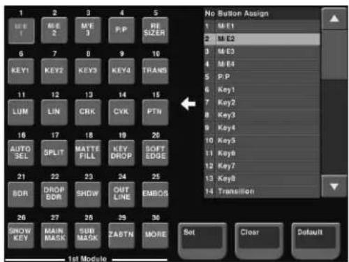
5 Press the button to which you want to assign a function, displaying it in reverse video.
6 Using any of the following methods, select the function you want to assign from the Button Assign list.
- Press directly on the list.
- Press the arrow keys to scroll the reverse video cursor.
- Turn the knob.
| Knob | Parameter Adjustment Setting values | ||
| 1 Button | Assign | Select function to be assigned to button | 1 to maximum value |
7 When you have completed the required assignments, press [Set].
Assigning Preview Output to Preview Selection Buttons
It is possible to assign any preview output to a preview selection button.
This applies to the preview selection buttons in the fade-to-black control block and the downstream key/fade-to-black control block.
1 In the Panel >Config menu, press [Link/Program Button].
The Link/Program Button menu appears.
2 Press [Fade To Black Module].
The Fade To Black Module menu appears. On the left of the status area, preview selection buttons (1 to 11) appear. On the right side a list of signals to be assigned appears.
3 In the button indications on the left, press the button for the assignment.
4 Using any of the following methods, select the signal to be assigned.
- Press directly on the list on the right.
- In the list on the right, press the arrow keys to scroll the reverse video cursor.
- Turn the knob.
| Knob | Parameter | Adjustment | Setting values |
| 1 Button | Button selec | ection 1 and upwards |
5 Press [Set].
This assigns the signal selected in the list to the button.
To cancel an assignment
Select the button, then press [Clear].
This leaves nothing assigned.
To return all preview selection button assignments to the factory default state
In the Fade To Black Module menu, press [Default].
Assigning Functions to the Device Control Block
Assigning devices or functions to the device selection buttons and other buttons of the device control block (search dial)
You can assign devices and functions to the device selection buttons, SBOX buttons and [DELAY] button of the device control block (search dial).
1 In the Panel >Config menu, press [Link/Program Button].
The Link/Program Button menu appears.
2 Press [Device Control Module].
The Device Control Module menu appears. The left of the status area shows the device selection buttons, SBOX buttons and [DELAY] button of the device control block (search dial). The list on the right shows the devices and functions that can be assigned.
3 In the button displays on the left, press the button for the assignment.
4 Using any of the following methods, select the device or function to be assigned.
- Press directly on the list on the right.
- In the list on the right, press the arrow keys to scroll the reverse video cursor.
- Turn the knob.
| Knob | Parameter | Adjustment Setting | values |
| 1 | D e Function | Selection of c device or function to be assigned | 1 and upwards |
5 Press [Set].
To cancel an assignment
Select the button, then press [Clear].
This removes the assignment to that button.
To return all device selection button assignments to the factory default state
In the Device Control Module menu, press [Default].
Assigning devices and functions to the region selection buttons of the device control block (trackball)/device control block (joystick)
You can assign devices and functions to the region selection buttons of the device control block (trackball)/device control block (joystick).
1 In the Panel >Config menu, press [Link/Program Button].
The Link/Program Button menu appears.
2 Press [Joystick/Trackball Module].
The Joystick/Trackball Module menu appears.
3 In the lower right
Device/Clip: Assignment while the device control block DEV button is lit
Wipe/RSZR: Assignment while no button is lit on the device control block or the RSZR button is lit. According to the selection, the left of the status area shows the region selection buttons of the device control block. The list on the right shows the devices and functions that can be assigned.
4 In the button displays on the left, press the button for the assignment.
5 Using any of the following methods, select the device or function to be assigned.
- Press directly on the list on the right.
- In the list on the right, press the arrow keys to scroll the reverse video cursor.
- Turn the knob.
| Knob | Parameter | Adjustment | Setting values |
| 1 | Function | Selection device or function to be assigned | of and upwards |
6 Press [Set].
To cancel an assignment
Select the button, then press [Clear].
This removes the assignment to that button.
To return all device selection button assignments to the factory default state
In the Joystick/Trackball Module menu, press [Default].
Inhibiting Utility 2 Bus and Key Operations
You can inhibit operations on the utility 2 bus and keys 1 to 8 of the M/E and PGM/PST banks by menu operations. This inhibitions apply for the following control blocks.
• Cross-point control block
• Transition control block
- Independent key transition control block ^1)
Notes
In the auxiliary bus control block and other control blocks which are excluded from M/E and PGM/PST banks, the operations on the utility 2 bus and keys 1 to 8 are not inhibited.
1 In the Panel >Config menu, press [Operation Inhibit]. Operation Inhibit menu appears.
2 Press [M/E Operation Inhibit].
The M/E Operation Inhibit menu appears.
3 In the list in the status area, using any of the following methods, select the switcher bank for which operations are to be inhibited.
- Press directly on the desired switcher bank in the list.
- Press the arrow keys to scroll the reverse video cursor.
- Turn the knob.
| Knob | Parameter | Adjustment | Setting values |
| 1 Bank | Switcher bank | selection for inhibiting operations | 1 and upwards |
4 In the
Inhibiting DME Channel Selection Operations
You can inhibit DME channel selection operations from the device control block (trackball) or device control block (joystick).
1 In the Panel >Config menu, press [Operation Inhibit]. The Operation Inhibit menu appears.
2 Press [Joystick/Trackball Module]. The Joystick/Trackball Module menu appears.
3 In the list in the status area, using any of the following methods, select the DME channel for which operations are to be inhibited.
- Press directly on the desired DME channel in the list.
- Press the arrow keys to scroll the reverse video cursor.
- Turn the knob.
| Knob | Parameter | Adjustment Setting | values |
| 1 DME | Ch DME channel selection for inhibiting operations | 1 to 8 | |
4 Press [Inhibit].
Assigning Functions to the Menu Control Block Top Menu and User Preference Buttons
To these 41 buttons, you can freely assign a menu recall or user preference button function.
1 In the Panel >Config menu, press [Link/Program Button].
The Link/Program Button menu appears.
2 Press [Menu Panel].
The Menu Panel menu appears.
The left side of the status area shows the Top menu selection buttons and user preference buttons, and the right side shows a list of menus and actions to be assigned.
3 Using any of the following methods, scroll the display.
- Press the arrow keys.
- Turn the knob.
| Knob | Parameter Adjustment Setting values | ||
| 1 Scroll | Scroll 1 to 5 | ||
4 In the button indications on the left, press the button for the assignment.
5 Using any of the following methods, select the menu or action to be assigned.
- Press directly on the right list.
- Press the arrow keys on the right list to scroll the reverse video cursor.
- Turn the knob.
| Knob | Parameter | Adjustment | Setting values |
| 3 Menu/Action | Select the menu or action | 1 to 43 | |
6 Press [Set] you confirm the setting.
This assigns the menu or action selected in the list to the button.
To cancel an assignment, select the button, then press [Clear].
To return all button assignments to the factory default state, in the Menu Panel menu, press [Default].
Assigning Functions to the Buttons in the Multifunction Flexi Pad Control Block
You can assign functions to the buttons in the various parts of the Multifunction Flexi Pad control block in the following menus.
Mode selection buttons: Multi Function Module menu Region selection buttons: 10 Key Region Assign menu Memory recall buttons: Multi Function Module menu
For details of assignment of regions to the region selection buttons, see “Assigning a Region to the Region Selection Buttons in the Numeric Keypad Control Block or Multifunction Flexi Pad Control Block” (page 559).
1 In the Panel >Config menu, press [Link/Program Button].
The Link/Program Button menu appears.
2 Press [Multi Function Module].
The Multi Function Module menu appears.
3 Press one of the following three buttons displayed in the button area.
[Mode Sel Assign] button: To assign a function to the mode selection buttons
[Eff Edit Assign] button: To assign a function to a button in the memory recall section for effect editing (when the [EFF] and [EDIT ENBL] buttons are pressed)
[Macro Edit Assign] button: To assign a function to a button in the memory recall section for macro editing (when the [MCRO] and [EDIT ENBL] buttons are pressed)
The left side of the status area shows an image of each button, and the right side shows a list of menus and actions to be assigned.
4 In the button indications on the left, press the button for the assignment.
5 Using any of the following methods, select the mode or action to be assigned.
- Press directly on the right list.
- Press the arrow keys on the right list to scroll the reverse video cursor.
- Turn the knob.
| Knob | Parameter | Adjustment Setting | values |
| 3 Button Assign | Select the mode or action | 1 and upwards a) | |
a) The following modes and functions can be selected.
Mode selection buttons
| Mode Button indication | |
| Effect EFF | |
| Snapshot SNAP SHOT | |
| Shotbox SHOT BOX | |
| Macro MCRO | |
| Wipe snapshot WIPE | |
| DME wipe snapshot | DME WIPE |
| Transition rate | TRANS RATE |
| Key adjust | KEY ADJ |
| Key snapshot | KEY SS |
Buttons in the memory recall section during effect editing
| Function Button indication | |
| Undo | UNDO |
| Pause setting | PAUS |
| Copy | COPY |
| Paste | PSTE |
| Select all | ALL |
| Insert INS | |
| Modify | MOD |
| Delete | DEL |
| Keyframe loop count setting | KF LOOP |
| Effect duration setting | EFF DUR |
| Keyframe duration setting | KF DUR |
| Delay setting | DLY |
| Constant duration mode on or off | CNST DUR |
| Go to specified timecode | GOTO TC |
| Go to specified keyframe | GOTO KF |
| Set range | FROM TO |
| Return the button display to that before effect was executed | EXIT |
| Switch to numeric keypad input mode | STOR |
| Go to first keyframe | REWIND |
| Switch to shifted functions | SHFT |
| Go to previous keyframe | <<PREV |
| Go to next keyframe | >>NEXT |
| Execute effect | RUN |
The functions of the buttons in the memory recall section during effect editing are on two pages; to set the functions of buttons on the second page, press the [2] button in the
Buttons in the memory recall section during macro editing
| Function Button indication | |
| Undo UNDO | |
| Pause setting PAUS | |
| Auto insert mode on or off AUTO INS | |
| Copy COPY | |
| Paste PSTE | |
| Select all ALL | |
| Insert INS | |
| Modify MOD | |
| Delete DEL | |
| Set range | FROM TO |
| Go to specified event | GOTO EVNT |
6 Press [Set] to confirm the setting.
This assigns the menu or action selected in the list to the button.
To cancel an assignment
Select the button, then press [Clear].
To return all button assignments to the factory default state, press [Default].
Assigning a Function to the Independent Key Transition Control Block (Simple Type)
You can assign a function to the buttons in the independent key transition control block (simple type).
The assignment may be to the independent key transition type selection buttons and buttons in the independent key transition execution section.
1 In the Panel >Config menu, press [Link/Program Button].
The Link/Program Button menu appears.
2 Press [Compact Key Trans Module].
The Compact Key Transition Mode menu appears.
3 In the
4 According to the selected bank, select the control block to be assigned, in the
The currently assigned function is displayed in the area that displays the buttons in the selected control block.
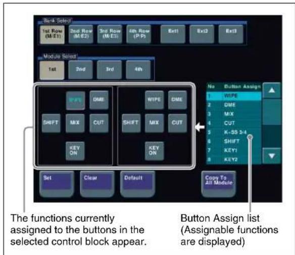
5 Press a button to which to assign a function so that the button is displayed in reverse video.
6 Using any of the following methods, select a desired function to be assigned in the Button Assign list.
- Press directly on the desired list.
- Press the arrow keys to scroll the reverse video cursor.
- Turn the knob.
| Knob | Parameter | Adjustment | Setting values |
| 1 | Button Assign No | Selection of a function to assign to the selected button | 1 to 15 |
7 Press [Set].
The function selected in step 6 is assigned to the selected button.
To remove a function assignment
In step 5, select the button whose function assignment you want to remove, and press [Clear].
To return the function assignments to the factory default state
Press [Default].
To make the same assignment for all control blocks on all banks
Press [Copy To All Module].
Cross-Point Settings (Xpt Assign Menu)
To carry out the cross-point settings, use the Panel >Xpt Assign menu.
To display the Xpt Assign menu
In the Engineering Setup menu, select VF2 'Panel' and HF2 'Xpt Assign.'
The status area shows a list of “cross-point assign tables” to use for the M/E banks, PGM/PST bank, and various buses.
The following functions are available here.
- Xpt Assign: For each control block or bus, display and set the assignments to the main table and tables 1 to 14. You can also carry out settings to link switcher signal selection to the audio mixer.
-
Main, V/K Pair Assign: Make cross-point settings for the main table.
-
Assign video/key sources for button numbers 1 to 300.
- For each table, specify whether the rightmost cross-point button in each row is used as a shift button, and the operation mode when it is used as a shift button.
- For the [SHIFT] button in the cross-point control block and for each table, select the mode in which this is a shift button dedicated to the source name displays, or the mode in which it is a shift button for all buses.
-
Disable cross-point buttons to work.
-
Mixer Xpt Assign: Assign audio mixer cross-points to cross-point buttons in the main table.
- Table Button Assign: Create tables 1 to 14 in the same way as the main table.
- Src Name: Set source names of up to 16 characters.
- LCD Color: Set the LCD color for source name display.
- Table Copy: Copy table contents from the main table to tables 1 to 14 or between tables 1 to 14 (it is not possible to copy tables 1 to 14 to the main table).
- Name Export: This function sends the source name and destination name to the S-Bus.
- Side Flags Button Assign: Assign the rightmost button in the background A/B row to the side flag function (inserting a selected image on both sides of a 4:3 image).
Creating Cross-Point Assign Tables
As cross-point assign tables, you can create a “main” table and up to 14 other tables (table 1 to table 14). However, you can only carry out assignment of the video and key combinations in the main table.
Creating the main table
In the main table, a pair consisting of a video signal and a key signal is assigned to each button number. You can also assign the same signal to another button number at the same time. Further, you can delete currently assigned signals from the main table.
1 In the Panel >Xpt Assign menu or Panel >Xpt Assign >Table1 (Table2, Table3, or Table4) menu, press [Main, V/K Pair Assign].
The Main, V/K Pair Assign menu appears.
The left of the status area shows the video and key signal names, source number, and audio mixer cross-points (machine numbers) currently assigned in the main table. On the right is a list of the source numbers and signals that can be assigned. When the shift button is pressed, the number column is distinguished by color.
For details of audio mixer cross-point assignment operations, see “Setting the audio mixer cross-points” (page 573).
2 Using any of the following methods, select the button number.
- Press an auxiliary bus control block cross-point button.
(The auxiliary bus control block is in selection mode, only when the menu for cross-point button selection is showing.)
- Press the arrow keys to scroll the reverse video cursor.
- Turn the knob.
| Knob | Parameter | Adjustment | Setting values |
| 1 V/K | Pair No | Selection of video and key pair number | 1 to 300 |
3 When assigning a video signal, press [Video] in the
Notes
[Video] and [Key] in the
4 Use any of the following methods to select the signal to assign.
- Press directly on the list in the status area.
- Press the arrow keys to scroll the reverse video cursor.
- Turn the knob.
| Knob | Parameter | Adjustment Setting | values |
| 3 Source | No Selection | on of source to be assigned | 1 to 236 (MVS-8000X)1 to 162 (MVS-7000X) |
5 Using the buttons in the
Set: Delete the signal currently assigned to the selected button number and make a new assignment.
Insert: Move down one line the signal currently assigned to the selected button number and following signals, and make a new assignment.
Notes
When a button number upper than 121 is selected, execution of “Insert” is impossible. The signal assignments to button numbers upper than 121 cannot be changed. When “Insert” is executed for any other number, moving down of signals ends at number 120, and the signals assigned to numbers upper than 121 are maintained in their original lines.
To disable a button
In the Panel >Xpt Assign >Main, V/K Pair Assign menu, select the button you want to disable, and press [Inhibit].
To delete any currently assigned signal
In the Panel >Xpt Assign >Main, V/K Pair Assign menu, select the button corresponding to the signal you want to delete, and press [Delete] in the
Notes
When a button number upper than 121 is selected, execution of “Delete” is impossible. The signal assignments to button numbers upper than 121 cannot be changed. When a signal assigned to any other button number is deleted, moving up of signals ends when the signal assigned to number 120 has moved to number 119, and the signals assigned to numbers upper than 121 are maintained in their original lines.
Creating tables 1 to 14
When creating tables 1 to 14, in the same way as when creating the main table, you can assign the same signal to more than one button number, or delete currently assigned signals. However, assignment of video and key combinations is impossible.
1 In the Panel >Xpt Assign menu, press [Table Button Assign].
The Table Button Assign menu appears.
The table number appears on the upper left part of the status area.
The left part of the status area shows the cross-point button numbers, video and key pair numbers, video signal source names and source numbers, and key signal source names and source numbers. When the shift button is pressed, the number column is distinguished by color.
The right part shows the video and key pair numbers, and the names of video signals and key signals set in the main table.
The Table Button Assign menu also allows you to access the Main, V/K Pair Assign menu and the Src Name/LCD Color menu.
2 Using the knob, select the table number.
| Knob | Parameter Adjustment Setting values | ||
| 1 Table | No Selection of the table to be set | 1 to 14 | |
3 Using any of the following methods, select the button number.
- Press an auxiliary bus control block cross-point button.
(The auxiliary bus control block is in selection mode, only when the menu for cross-point button selection is showing.) - Press the arrow keys to scroll the reverse video cursor.
- Turn the knob.
| Knob | Parameter | Adjustment Setting | values |
| 2 Button | No Cross | point button selection | 1 to 300 |
4 Using any of the following methods, select the pair number.
- Press directly on the list in the status area.
- Press the arrow keys to scroll the reverse video cursor.
- Turn the knob.
| Knob | Parameter | Adjustment | Setting values |
| 3 | V/K Pair No | Selection of video and key pair number to be assigned | 1 to 300 |
5 Using the buttons in the
Set: Delete the signal currently assigned to the selected button number and make a new assignment.
Insert: Move down one line the signal currently assigned to the selected button number and following signals, and make a new assignment.
Notes
When a button number upper than 121 is selected, execution of “Insert” is impossible. The signal assignments to button numbers upper than 121 cannot be changed. When “Insert” is executed for any other number, moving down of signals ends at number 120, and the signals assigned to numbers upper than 121 are maintained in their original lines.
To disable a button
In the Panel >Xpt Assign >Table Button Assign menu, select the button you want to disable, and press [Inhibit].
To delete any currently assigned signal
In the Panel >Xpt Assign >Table Button Assign menu, select the button corresponding to the signal you want to delete, and press [Delete] in the
Notes
When a button number upper than 121 is selected, execution of “Delete” is impossible. The signal assignments to button numbers upper than 121 cannot be changed. When a signal assigned to any other button number is deleted, moving up of signals ends when the signal assigned to number 120 has moved to number 119, and the signals assigned to numbers upper than 121 are maintained in their original lines.
Returning the table to its default state
1 In the Panel >Xpt Assign >Main, V/K Pair Assign menu or Panel >Xpt Assign >Table Button Assign menu, press [Default Recall].
A confirmation message appears, asking whether or not to return to the default state.
2 To return to the default state, press [Yes], and to cancel the operation, press [No].
Setting the cross-point button shift operation
You can set the operation of the rightmost button in each row of cross-point buttons excluding the reentry buttons.
In the
Hold: Acts as a shift button, and the shifted version of the cross-point buttons is enabled while the button is held down.
Lock: Acts as a shift button, and pressing the button toggles between the shifted version and the unshifted version.
Off: Acts as a cross-point button, in a 16-button system as button number 16, in a 24-button system as button number 24, and in a 32-button system as button number 32.
Setting the action of the [SHIFT] button in the cross-point control block
In the
Shift All Bus: When this is On, it functions as a shift button for all buses.
Key5-8 Select: This functions as a shift button dedicated to the key 1 and key 2 rows. When On, keys 5 to 8 are selected, and when Off, keys 1 to 4 are selected.
Notes
- It is not possible to make this setting separately for each of the M/E and PGM/PST banks.
- “Shift All Bus” is only valid when the cross-point button shift operation (see previous item) is set to “Lock” or “Off.”
- If both Shift All Bus and Key5-8 Select are off, this button functions as a shift button for the source name display. It is not possible to set both Shift All Bus and Key5-8 Select to On.
Setting the source signal name
1 In the Panel >Xpt Assign menu or Panel >Xpt Assign >Table Button Assign menu, press [Src Name/LCD Color].
The Src Name/LCD Color menu appears.
2 Turn the knob to select the signal to be set.
| Knob | Parameter | Adjustment | Setting values |
| 1 Source | No Source | signal selection | 1 to 236 (MVS-8000X)1 to 162 (MVS-7000X) |
| 2 Num | Number of | source signals to be selected |
3 Press [Source Name].
A keyboard window appears.
4 Enter any name of not more than 16 characters, then press [Enter].
Sequential names for multiple signals
When you specify a number at the end of a signal name, all of the signals in the range selected by knobs 1 and 2 are automatically assigned names ending with sequential numbers.
Example:
To assign sequential names to source signal 2 through source signal 4
-
In step 2 above, set knob 1 to "2," and set knob 2 to "3."
-
Set the name of source signal 2 to "CAM2."
The name “CAM3” is assigned automatically to source signal 3, and the name “CAM4” is assigned automatically to source signal 4.
Setting the source name display color
1 In the Panel >Xpt Assign >Table Button Assign >Src Name/LCD Color menu, turn the knobs to select the setting target.
| Knob | Parameter Adjustment Setting values | ||
| 1 Source | No Source | signal selection | 1 to 236 (MVS-8000X)1 to 162 (MVS-7000X) |
| 2 Num | Number of | source signals to be selected | |
2 In the
Copying Cross-Point Assign Tables
The contents of a cross-point assign table can be copied to another cross-point assign table, and vice versa.
Notes
The contents of a sub table cannot be copied to the main table.
1 In the Panel >Xpt Assign menu, press [Table Copy].
The Table Copy menu appears.
The status area shows a list of copy sources and a list of copy destinations.
2 Using any of the following methods, select the number of the table to use as the copy source and the number of the table you want to be the copy destination.
- Press directly on the list of copy sources (left-side list) or the list of copy destinations (right-side list) in the status area.
- Press the arrow keys to scroll the reverse video cursor.
- Turn the knob.
| Knob | Parameter | Adjustment | Setting values |
| 1 Left No Selection of copy source | 1 to 15 | ||
| 2 Right No Selection of copy destination | 1 to 14 | ||
3 Press [Copy].
A confirmation message appears, asking whether or not to execute the copy.
4 To execute the copy, press [Yes], and to cancel the operation, press [No].
Selecting Cross-Point Assign Tables
You can select the cross-point assign table to be used for each of the following banks or buses.
• M/E-1 to M/E-4 banks and PGM/PST bank
- Buses assignable to AUX delegation buttons
Notes
It is not possible to assign cross-point tables 5 to 14 to a bus of a switcher operated by an MKS-8080/8082 AUX Bus Remote Panel.
1 In the Panel >Xpt Assign menu, using any of the following methods, select the switcher bank or bus.
- Press directly on the list on the left of the status area.
- Press the arrow keys on the list on the left to scroll the reverse video cursor.
- Turn the knobs.
| Knob | Parameter | Adjustment | Setting values |
| 1 | Bank/Bus No | Switcher bank or bus selection | 1 and upwards |
| 2 | Num | Number of selected switcher banks or buses | 1 and upwards |
2 Using any of the following methods, select the table.
- Press directly on the list on the right of the status area.
- Press the arrow keys on the list on the right to scroll the reverse video cursor.
- Turn the knob.
| Knob | Parameter Adjustment Values | |
| 3 Table | No Selection of table to be assigned | 1 to 15 |
3 Press [Table Assign Set].
This sets the table for the selected switcher bank or bus.
Exporting Source Names and Destination Names
To send the source names and destination names to the S-Bus, use the following procedure.
1 In the Panel >XPT Assign menu, press [Name Export].
The Name Export menu appears.
2 Turn the knob to set the station ID.
| Knob | Parameter | Adjustment | Setting | values |
| 1 | Station ID | Station ID setting | 1 to 255 | a) |
a) If set to 255, the information is sent to all stations (with display of "All").
3 Press [Src Name Export].
This exports the source names to the station selected in step 2.
4 Press [Dest Name Export].
This exports the destination names to the station selected in step 2.
Notes
Since destination names cannot be selected freely, fixed names are used.
Making Settings for Audio Mixer
Enabling the function to link the audio mixer
Notes
For audio mixer operations in this system, it is necessary to set Mixer ESAM-II for the DCU 9-pin serial port.
For details, see “Serial Port Settings (Serial Port Assign Menu)” (page 631).
1 In the Panel >Xpt Assign menu, using any of the following methods, select the M/E bank or bus.
- Press directly on the list on the left of the status area.
- Press the arrow keys in the list on the left, to scroll the reverse video cursor.
- Turn the knob.
2 Press [Audio Follow].
“Enable” appears in the “Audio Follow” column.
Setting the audio mixer cross-points
To assign an audio mixer cross-point to a switcher cross-point pair (video/key), carry out the following procedure.
1 In the Panel >Xpt Assign menu, press [Mixer Xpt Assign].
The Mixer Xpt Assign menu appears.
2 In the list on the left, select the number for the setting.
3 In the list on the right, select the audio mixer cross-point (machine number).
4 Press [Set].
The audio mixer number appears in the “Mixer Xpt” column.
Assigning a Cross-Point Button to Enable/Disable Side Flags
By assigning the side flag function to the rightmost button in a cross-point button row, you can use this button to enable/disable side flags for each of the M/E and PGM/PST banks.
This setting applies to all of the M/E and PGM/PST banks. When you make this assignment, the SHIFT button (the button assigned to the shift function) is moved one to the left.
Notes
If a macro attachment is set, when you assign the button to the side flag function, the button numbers are offset, and therefore when you press the button this does not execute the macro. The settings, however, are maintained, so that when you cancel the side flag assignment, the macro can be accessed once more.
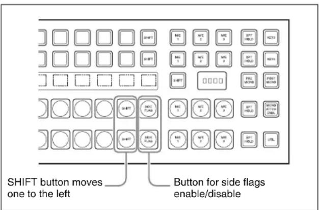
For details of side flag operations, see “Side Flag Settings” in Chapter 10 (Volume 1).
1 In the Panel >XPT Assign menu, press [Side Flags Button Assign].
The Side Flags Button Assign menu appears.
2 Press [Side Flags Btn Assign], turning it on.
Auxiliary Bus Control Block Settings (Aux Assign Menu)
To carry out the settings of the AUX delegation buttons in the auxiliary bus control block, use the Panel >Aux Assign menu.
When using the AUX panel-less function with the CCP-6224/6324, use this menu to assign the AUX delegation buttons.
To display the Aux Assign menu
In the Engineering Setup menu, select VF2 'Panel' and HF3 'Aux Assign.'
The left side of the status area shows the delegation numbers, and the list of buses set; the right side shows a list of buses that can be assigned.
The following functions are available here.
- Aux Assign: Assign the AUX delegation buttons in the auxiliary bus control block to any bus.
- Shift Mode: Specify whether the rightmost button of the AUX delegation buttons is used as a shift button, and when it is used as a shift button, the operation mode.
- RTR Mode Setting: Carry out the following settings for using the auxiliary bus control block for router control.
- Assigning destinations
- Setting the shift operation in the destination selection button rows
- Source table settings
- Setting the shift operation in the source selection button rows
- Assigning levels to the level selection buttons
- Setting destination selection buttons to be used for snapshots
Notes
When using the AUX panel-less function with the CCP-6224/6324, these settings are invalid.
Assigning a Bus to an AUX Delegation Button
1 In the Panel >Aux Assign menu, using any of the following methods, select the delegation button and the bus to be assigned.
- Press directly on the list in the status area.
- Press the arrow keys to scroll the reverse video cursor.
- Turn the knobs.
| Knob | Parameter Adjustment Setting values | ||
| 1 Deleg | No Selection of AUX delegation button | 1 to 128a) | |
| 2 Bus | No Selection of bus to be assigned | 1 to 166b) | |
a) The setting can be from 1 to 62. The valid settings, however, depend on the number of buttons and the delegation button shift mode.
| Number of buttons | Shift mode Valid settings | |
| 16 OFF 1 to 16 | ||
| ON 1 to 30 | ||
| 24 OFF 1 to 24 | ||
| ON 1 to 46 | ||
| 32 OFF 1 to 32 | ||
| ON 1 to 62 | ||
b) The buses that can be assigned are as follows.
(In M/E-x, the x is the M/E bank number (1 to 4); in DSKx the x is the DSK number (1 to 8); in Keyx the x is the key number (1 to 8).) Edit Preview, Aux1 to Aux48, Frame Memory Source1 and Frame Memory Source2, DME1V to DME8V, DME1K to DME8K, P/P Utility1 and P/P Utility2, M/E-x Utility1 to M/E-x Utility2, DSKx Fill/Source, M/E-x Keyx Fill/Source, PP EXT DME, M/Ex EXT DME, DME Utility1 and DME Utility2, CCR1 and CCR2
- For a button for which you want to disable operation, press [Inhibit].
2 Press [Set] to confirm the selection.
To set the AUX delegation button shift operation
To set the operation mode of the rightmost button in the row of AUX delegation buttons, select one of the following in the
Hold: Acts as a shift button, and the shifted version of the AUX delegation buttons is enabled while the button is held down.
Lock: Acts as a shift button, and pressing the button toggles between the shifted version and the unshifted version of the AUX delegation buttons.
Off: Acts as an AUX delegation button. In a 16-button system it acts as button number 16, in a 24-button system as button number 24, and in a 32-button system as button number 32.
Using the Auxiliary Bus Control Block for Router Control
To make router control settings, display the Setup >Panel >Aux Assign >RTR Mode Setting menu.
To display the RTR Mode Setting menu
1 In the Engineering Setup menu, select VF2 'Panel' and HF3 'Aux Assign.'
The Aux Assign menu appears.
2 Press [RTR Mode Setting].
The RTR Mode Setting menu appears. The left of the status area shows the destination number assignment status and source table, and the right side lists the destinations that can be assigned.
Assigning a destination to a destination selection button
In the Panel >Aux Assign >RTR Mode Setting menu, use the following procedure.
1 Using any of the following methods, select a destination selection button and the destination to be assigned to the button.
- Press directly on the list in the status area.
- Press the arrow keys to scroll the reverse video cursor.
- Turn the knobs.
| Knob | Parameter | Adjustment | Setting values |
| 1 | Dest No | Destination selection button selection | 1 to 128 |
| 2 | No | Destination selection in S-Bus space | 1 to 1024 |
For a button whose operation you want to disable, press [Inhibit].
Notes
When a destination selection button having a number in the range 65 to 128 is selected, source table selection automatically becomes invalid, and therefore the Inhibit function also becomes invalid.
2 Press [Dest Set] to confirm the selection.
3 If in step 1 you selected a value in the range 1 to 64, turn the knob to select the source table.
| Knob | Parameter | Adjustment | Setting values |
| 3 | Source Table | Source table selection | 1 to 5 |
4 Press [Source Table Set] to confirm the selection.
5 Repeat steps 1 to 4 as required.
To set the shift operation of the destination selection buttons
To set the operation mode of the rightmost button in the destination selection button row, select one of the
following in the
Hold: Acts as a shift button, and the shifted destination selection buttons are enabled while the button is held down.
Lock: Acts as a shift button, and pressing the button toggles between the shifted and unshifted states of the destination selection buttons.
Off: Acts as a destination selection button, that is, button number 16 on a 16-button system, button number 24 on a 24-button system, and button number 32 on a 32-button system.
Setting the source table
1 In the Panel >Aux Assign >RTR Mode Setting menu, press [Source Table Assign].
The Source Table Assign menu appears.
2 In the
3 Press [Table Assign].
The Table Assign menu appears.
The left of the status area lists the button numbers and set sources, and the right side lists the source that can be assigned.
4 Using any of the following methods, select a source selection button and the source you want to assign.
- Press directly on the list in the status area.
- Press the arrow keys to scroll the reverse video cursor.
- Turn the knobs.
| Knob | Parameter | Adjustment Setting | values |
| 1 | Source | No Source selection button selection | 1 to 128 |
| 2 | No Source selection in S-Bus space | 1 to 1024 | |
For a button whose operation you want to disable, press [Inhibit].
5 Press [Source Set] to confirm the selection.
To set the shift operation of the source selection buttons
To set the operation mode of the rightmost button in the source selection button row with different destinations assigned to the 1st and 2nd rows, select the source table in the Source Table Assign menu, then in the
Hold: Acts as a shift button, and the shifted source selection buttons are enabled while the button is held down.
Lock: Acts as a shift button, and pressing the button toggles between the shifted and unshifted states of the source selection buttons.
Off: Acts as a cross-point button, that is, button number 16 on a 16-button system, button number 24 on a 24-button system, and button number 32 on a 32-button system.
To expand the shift function
To set the [KEY] button as a shift operation expansion button, in the Source Table Assign menu select the source table, then in the
In order not to expand the shift operation, press [No Assign] in the
Assigning levels to a level selection button
To assign levels to the [LEVEL1] to [LEVEL4] buttons in the auxiliary bus control block, use the following procedure.
1 In the Panel >Aux Assign >RTR Mode Setting menu, press [Level Button Assign].
The Level Button Assign menu appears. The status area shows a list of the assignment status of levels to each button.
2 In the
3 In the
You can select plural of levels. You can also make a selection that overlaps that of another button.
Selecting a destination selection button for a snapshot
To set whether snapshots are recalled for each destination selection button individually, use the Panel >Aux Assign >RTR Mode Setting menu as follows.
1 Use any of the following methods to select the destination selection button to which the setting applies.
- Press directly on the list on the left of the status area.
- Press the arrow keys to scroll the reverse video cursor.
- Turn the knob.
| Knob | Parameter Adjustment Setting values | ||
| 1 Dest | No Selection | ofdestinationselection button | 1 to 128 |
2 Press [SS Enable], turning it on or off.
On: When a snapshot applying to the router is recalled, the recall also applies to the selected destination selection button.
Off: When a snapshot applying to the router is recalled, the recall does not apply to the selected destination selection button.
Notes
When a destination selection button is set to Inhibit, then even if SS Enable is on, the snapshot for that destination is not recalled.
Setting Button Assignments (Prefs/ Utility Menu)
Assign the [PREFS 1] to [PREFS 16] buttons in the menu control block, the utility/shotbox control block buttons, and the cross-Point control block.
This assigns recalling frequently used menus (menu shortcuts), enabling/disabling functions (recalling utility commands) and recalling shotbox registers or macro registers.
- User Preference: Make the settings for the user preference buttons in the menu control block.
- Utility Module Assign: Make the utility/shotbox control block settings.
- KEY 2/4 Bus Button Assign: Make the settings for the key 2 row buttons in the cross-point control block.
To display the Prefs/Utility menu
In the Engineering Setup menu, select VF2 'Panel' and HF4 'Prefs/Utility.'
The status area shows the settings of the user preference buttons.
Assigning Functions to User Preference Buttons
1 In the Panel >Prefs/Utility menu, using any of the following methods, select the button to be assigned.
- Press directly on the list in the status area.
- Press the arrow keys to scroll the reverse video cursor.
- Turn the knob.
| Knob | Parameter | Adjustment | Setting values |
| 1 No User preference | button selection | 1 to 16 | |
2 In the
Menu Shortcut: Assign a frequently used menu to be recalled (menu shortcut).
Utility Command: Assign a function enable/disable or similar operation (utility command).
Macro Recall: Assign a macro register recall.
Shotbox Recall: Assign a shotbox register recall.
3 Depending on the selection in step 2, make the following settings.
When Menu Shortcut is selected: For the subsequent operations, see the next item "Assigning a menu shortcut to a user preference button" (page 580).
When Utility Command is selected: A list of commands appears on the right of the status area; using any of the following methods, select the command you want to assign.
- Press directly on the list.
- Press the arrow keys to scroll the reverse video cursor.
- Turn the knob.
| Knob | Parameter | Adjustment | Setting values |
| 3 Command Utility | command selection | 1 and upwards | |
| 4^a) | GPI No GP | port number 1 and | upwards |
a) When the Command parameter is set to Sw'er GPI Test Fire, Panel GPI Test Fire, DCU GPI, or Test Fire
When Macro Recall is selected: Turn the knob to select the macro register you want to assign.
| Knob | Parameter | Adjustment | Setting values |
| 3 Macro | Macro register selection | 1 to 250 |
When Shotbox Recall is selected: Turn the knob to select the shotbox register you want to assign.
| Knob | Parameter | Adjustment | Setting values |
| 3 Shotbox | Shotbox | register selection | 1 to 99 |
4 Press [Action Set].
This assigns the selected action, which is reflected in the status area.
To cancel an assignment
After selecting the relevant button, press [Clear].
To display register names in the Utility Command column
If in step 2 you select [Macro Recall] or [Shotbox Recall], press the [Reg Name Display] button to select whether or not register names appear in the Utility Command column.
Using the [PREFS 9] to [PREFS 16] settings
There are sixteen user preference buttons that can be set, [PREFS 1] to [PREFS 16], but there are only eight user preference buttons present in the menu control block. By default these buttons are assigned to the [PREFS 1] to [PREFS 8] settings. Therefore, to use the settings of [PREFS 9] to [PREFS 16], it is necessary to access the Engineering Setup >Panel >Config >Link/Program Button >Menu Panel menu, and assign these settings to buttons in the menu control block.
List of utility commands and user preference button status
The following table shows the utility commands that can be assigned to user preference buttons.
| Command namea) | Function Button status | ||
| Lit amber Off | |||
| SWR Remote1 Enbl | SWR Remote4 Enbl | Switcher Remote 1 enabled/disabled | Switcher Remote 4 enabled/disabled | Enabled Disabled | |
| DME1 Editor Port Enbl | DME1 editor port enabled/disabled | Enabled | Disabled |
| DME2 Editor Port Enbl | DME2 editor port enabled/disabled | Enabled | Disabled |
| DME3 Editor Port Enbl | DME3 editor port enabled/disabled | Enabled | Disabled |
| DME4 Editor Port Enbl | DME4 editor port enabled/disabled | Enabled | Disabled |
| ME1 PGM1 ST | ME1 PGM4 ST | M/E-1 PGM1 output safe title on/off | M/E-1 PGM4 output safe title on/off | On | Off |
| ME1 PVW ST | M/E-1 preview output safe title on/off | On | Off |
| ME1 Clean ST | M/E-1 clean output safe title on/off | On | Off |
| ME1 K-PVW ST | M/E-1 key preview output safe title on/off | On | Off |
| ME2 PGM1 ST | ME2 PGM4 ST | M/E-2 PGM1 output safe title on/off | M/E-2 PGM4 output safe title on/off | On | Off |
| ME2 PVW ST | M/E-2 preview output safe title on/off | On | Off |
| ME2 Clean ST | M/E-2 clean output safe title on/off | On | Off |
| Command namea) | Function | Button status | |
| Lit amber | Off | ||
| ME2 K-PVW ST M/E-2 key preview output safe title on/off On Off | |||
| ME3 PGM1 ST | ME3 PGM4 ST | M/E-3 PGM1 output safe title on/off | M/E-3 PGM4 output safe title on/off | On Off | |
| ME3 PVW ST M/E-3 preview output safe title on/off On Off | |||
| ME3 Clean ST M/E-3 clean output safe title on/off On Off | |||
| ME3 K-PVW ST ME-3 key preview output safe title on/off On Off | |||
| ME4 PGM1 ST | ME4 PGM4 ST | M/E-4 PGM1 output safe title On/Off | M/E-4 PGM4 output safe title On/Off | On Off | |
| ME4 PVW ST M/E-4 preview output safe title On/Off On Off | |||
| ME4 Clean ST M/E-4 clean output safe title On/Off On Off | |||
| ME4 K-PVW ST ME-4 key preview output safe title On/Off On Off | |||
| PP PGM1 ST | PP PGM4 ST | P/P PGM1 output safe title on/off | P/P PGM4 output safe title on/off | On Off | |
| PP PVW ST P/P preview output safe title on/off On Off | |||
| PP Clean ST | P/P clean output safe title on/off | On Off | |
| PP K-PVW ST | P/P key preview output safe title on/off | On Off | |
| DME MON1 ST | DME Monitor 1 output safe title on/off | On Off | |
| DME MON2 ST | DME Monitor 2 output safe title on/off | On Off | |
| Edit PVW ST | Edit preview output safe title on/off | On Off | |
| Preset ST | Preset output safe title on/off On Off | ||
| AUX1 ST | AUX48 ST | AUX1 output safe title on/off | AUX48 output safe title on/off | On Off | |
| FM Src1 Frame Freeze | Frame freeze of frame memory source 1 | During frame freeze | Either of the other two states |
| FM Src1 Filed Freeze | Field freeze of frame memory source 1 | During field freeze | Either of the other two states |
| FM Src1 Freeze Off | Release freeze of frame memory source 1 | While freeze being released | Either of the other two states |
| FM Src2 Frame Freeze | Frame freeze of frame memory source 2 | During frame freeze | Either of the other two states |
| FM Src2 Field Freeze | Field freeze of frame memory source 2 | During field freeze | Either of the other two states |
| FM Src2 Freeze Off | Release freeze of frame memory source 2 | While freeze being released | Either of the other two states |
| SWR GPI Enbl | Enable/disable switcher GPI | Enabled | Disabled |
| DME1 GPI Enbl | Enable/disable DME1 GPI | Enabled | Disabled |
| DME2 GPI Enbl | Enable/disable DME2 GPI | Enabled | Disabled |
| DME3 GPI Enbl | Enable/disable DME3 GPI | Enabled | Disabled |
| DME4 GPI Enbl | Enable/disable DME4 GPI | Enabled | Disabled |
| Panel GPI Enbl | Enable/disable panel GPI | Enabled | Disabled |
| SWR GPI1 Test Fire | SWR GPI8 Test Fire | Output test trigger from switcher GPI1 | Output test trigger from switcher GPI8 | Output (lights only at the instant the button is pressed) | When the output is assigned |
| Panel GPI1 Test Fire | Panel GPI8 Test Fire | Output test trigger from panel GPI1 | Output test trigger from panel GPI8 | Output (lights only at the instant the button is pressed) | When the output is assigned |
| DCU GPI1 Test Fire|DCU GPI50 Test Fire | Output test trigger from port assigned to DCU GPI1|Output test trigger from port assigned to DCU GPI50 | Output (lights only at the instant the button is pressed) | When the output is assigned |
| Macro Attachment Enbl Enable | disable macro attachment Enabled Disabled | ||
| Macro Only Set Macro only mode | on/off On Off | ||
| Pre Macro Set macro attachment | in pre macro mode Can be set only while | pressed (lit) | When the function is assigned |
| Post Macro Set macro attachment | in post macro mode Can be set only while | pressed (lit) | When the function is assigned |
| Macro Take | Macro execution | During execution | When the function is assigned |
| Macro Auto Ins | Macro auto insert mode on/off | On | Off |
| Macro AT with Rate | When registering an auto transition macro event, on/off setting of mode to save transition rate | On Off | |
| Macro AT with A/B Bus | When registering an auto transition macro event for the transition control block, on/off setting of mode to save A/B Bus cross-point settings | On Off | |
| Macro TL with Region | When registering a timeline macro event, on/off setting of mode to save applicable region | On Off | |
| DME Override | DME override on/off | On | Off |
| DME Graphic | DME graphics on/off (Applies to graphics for channel selected in device control block) | On | Off |
| System Manager Enbl | Enable/disable operation from System Manager | Enabled | Disabled |
| Plug-In Editor Enbl | Enable/disable operation from an editing keyboard | Enabled | Disabled |
| Inhibit Set | Inhibit cross-point button | Can be set only while pressed (lit) | When the function is assigned |
| Inhibit All Clear | Clear all cross-point button inhibit settings | Can be set only while pressed (lit) | When the function is assigned |
| K-SS Store | Enable/disable key snapshot savingb) | Enabled | Disabled |
a) For the safe title on/off commands (from ME1 PGM1 ST-ME1 PGM4 ST to AUX1 ST-AUX48 ST), the name of the assigned output signal is shown.
b) Pressing this button to turn it on enables key snapshot operations for all control blocks.
Assigning a menu shortcut to a user preference button
1 Referring to the procedure up to step 2 of "Assigning Functions to User Preference Buttons" (page 577), select [Menu Shortcut].
The user preference buttons [PREFS 1] to [PREFS 16] flash amber.
2 Using any of the following methods, display the menu to which you want to make a shortcut.
- In the menu control block, press the relevant top menu selection button, then select VF and HF.
- Press the menu page number button in the upper left corner of the menu screen, then enter a menu number from the numeric keypad window.
- Press a particular control panel button twice in rapid succession.
3 Press the user preference button to which you want to assign the shortcut.
The menu screen goes back to the Prefs/Utility menu, and the selection is reflected in the status area. The user preference buttons [PREFS 1] to [PREFS 16] flash amber.
4 Repeat steps 2 and 3 as required, to assign all desired menu shortcuts to the user preference buttons.
To abandon the process of menu shortcut assignment
In the Prefs/Utility menu, press [Menu Shortcut] once more.
This exits the menu shortcut assignment mode.
Assigning a Function to a Memory Recall Button in the Utility/Shotbox Control Block
1 In the Prefs/Utility menu, press [Utility Module Assign].
The Prefs/Utility >Utility Module Assign menu appears. The status area shows the settings in the utility/shotbox control block.
2 Using any of the following methods, select the button to be assigned.
- Press directly on the list.
- Press the arrow keys to scroll the reverse video cursor.
- Turn the knobs.
| Knob | Parameter Adjustment Setting values | ||
| 1 Bank | Bank selection 1 to 4 | ||
| 2 Button | No Control | block button selection | 1 to 24 |
3 In the
Menu Shortcut: Assign a frequently used menu to be recalled (menu shortcut).
Utility Command: Assign a function on/off or similar operation (utility command).
Macro Recall: Assign a macro register recall.
Shotbox Recall: Assign a shotbox register recall.
4 Depending on the selection in step 3, make the following settings.
When Menu Shortcut is selected: For the subsequent operations, see the next item "Assigning a menu shortcut to a memory recall button" (page 584).
When Utility Command is selected: A list of commands appears on the right of the status area; using any of the following methods, select the command you want to assign.
- Press directly on the list.
- Press the arrow keys to scroll the reverse video cursor.
- Turn the knob.
| Knob | Parameter | Adjustment | Setting values |
| 3 Command Utility | mand Utility | command selection | 1 and upwards |
| 4a) | GPI No GPI | port number 1 and upwards | |
a) When the Command parameter is set to Sw'er GPI Test Fire, Panel GPI Test Fire, DCU GPI, or Test Fire
When Macro Recall is selected: Turn the knob to select the macro register you want to assign.
| Knob | Parameter | Adjustment | Setting values |
| 3 Macro | Macro | register selection | 1 to 250 |
When Shotbox Recall is selected: Turn the knob to select the shotbox register you want to assign.
| Knob | Parameter | Adjustment | Setting values |
| 3 Shotbox | Shotbox | register selection | 1 to 99 |
5 Press [Action Set].
This assigns the selected action, which is reflected in the status area.
In the utility/shotbox control block, the assigned button lights orange.
If a shotbox register was assigned, the register name appears.
To cancel an assignment
After selecting the relevant button, press [Clear].
To display register names in the Utility Command column
If in step 3 you select [Macro Recall] or [Shotbox Recall], press the [Reg Name Display] button to select whether or not register names appear in the Utility Command column.
List of utility commands and memory recall button status
The following table shows the utility commands that can be assigned to memory recall buttons.
| Command namea) | Function | Button status | |
| Lit green | Lit orange | ||
| SWR Remote1 Enbl | SWR Remote4 Enbl | Switcher Remote 1 enabled/disabled | Switcher Remote 4 enabled/disabled | Enabled | Disabled |
| DME1 Editor Port Enbl DME1 editor port enabled/disabled Enabled Disabled | |||
| DME2 Editor Port Enbl DME2 editor port enabled/disabled Enabled Disabled | |||
| DME3 Editor Port Enbl DME3 editor port enabled/disabled Enabled Disabled | |||
| DME4 Editor Port Enbl DME4 editor port enabled/disabled Enabled Disabled | |||
| ME1 PGM1 ST | ME1 PGM4 ST | M/E-1 PGM1 output safe title on/off | M/E-1 PGM4 output safe title on/off | On Off | |
| ME1 PVW ST M/E-1 preview output safe title on/off On Off | |||
| ME1 Clean ST M/E-1 clean output safe title on/off On Off | |||
| ME1 K-PVW ST M/E-1 key preview output safe title on/off On Off | |||
| ME2 PGM1 ST | ME2 PGM4 ST | M/E-2 PGM1 output safe title on/off | M/E-2 PGM4 output safe title on/off | On Off | |
| ME2 PVW ST M/E-2 preview output safe title on/off On Off | |||
| ME2 Clean ST M/E-2 clean output safe title on/off On Off | |||
| ME2 K-PVW ST M/E-2 key preview output safe title on/off On Off | |||
| ME3 PGM1 ST | ME3 PGM4 ST | M/E-3 PGM1 output safe title on/off | M/E-3 PGM4 output safe title on/off | On Off | |
| ME3 PVW ST M/E-3 preview output safe title on/off On Off | |||
| ME3 Clean ST M/E-3 clean output safe title on/off On Off | |||
| ME3 K-PVW ST ME-3 key preview output safe title on/off On Off | |||
| ME4 PGM1 ST | ME4 PGM4 ST | M/E-4 PGM1 output safe title On/Off | M/E-4 PGM4 output safe title On/Off | On Off | |
| ME4 PVW ST M/E-4 preview output safe title On/Off On Off | |||
| ME4 Clean ST M/E-4 clean output safe title On/Off On Off | |||
| ME4 K-PVW ST ME-4 key preview output safe title On/Off On Off | |||
| PP PGM1 ST | PP PGM4 ST | PP PGM1 output safe title on/off | PP PGM4 output safe title on/off | On Off | |
| PP PVW ST | P/P preview output safe title on/off On Off | ||
| PP Clean ST | P/P clean output safe title on/off On | Off | |
| PP K-PVW ST | P/P key preview output safe title on/off | On | Off |
| DME MON1 ST | DME Monitor 1 output safe title on/off | On | Off |
| DME MON2 ST | DME Monitor 2 output safe title on/off | On | Off |
| Edit PVW ST | Edit preview output safe title on/off | On | Off |
| Preset ST | Preset output safe title on/off On | Off | |
| AUX1 ST | AUX48 ST | AUX1 output safe title on/off | AUX48 output safe title on/off | On Off | |
| FM Src1 Frame Freeze | Frame freeze of frame memory source 1 | During frame freeze | Either of the other two states |
| FM Src1 Filed Freeze | Field freeze of frame memory source 1 | During field freeze | Either of the other two states |
| FM Src1 Freeze Off | Release freeze of frame memory source 1 | While freeze being released | Either of the other two states |
| FM Src2 Frame Freeze | Frame freeze of frame memory source 2 | During frame freeze | Either of the other two states |
| FM Src2 Field Freeze Field freeze | eze of frame memory source 2 During field freeze | Either of the other two states | |
| FM Src2 Freeze Off Release freeze | eze of frame memory source 2 While freeze being released | Either of the other two states | |
| SWR GPI Enbl Enable/disable switcher GPI Enabled Disabled | |||
| DME1 GPI Enbl Enable/disable DME1 GPI Enabled Disabled | |||
| DME2 GPI Enbl Enable/disable DME2 GPI Enabled Disabled | |||
| DME3 GPI Enbl Enable/disable DME3 GPI Enabled Disabled | |||
| DME4 GPI Enbl Enable/disable DME4 GPI Enabled Disabled | |||
| Panel GPI Enbl Enable/disable panel GPI Enabled Disabled | |||
| SWR GPI1 Test Fire SWR GPI8 Test Fire | Output test trigger from switcher GPI1 Output test trigger from switcher GPI8 | Output (lights only at the instant the button is pressed) | When the output is assigned |
| Panel GPI1 Test Fire Panel GPI8 Test Fire | Output test trigger from panel GPI1 Output test trigger from panel GPI8 | Output (lights only at the instant the button is pressed) | When the output is assigned |
| DCU GPI1 Test Fire DCU GPI50 Test Fire | Output test trigger from port assigned to DCU GPI1 Output test trigger from port assigned to DCU GPI50 | Output (lights only at the instant the button is pressed) | When the output is assigned |
| Macro Attachment Enbl | Enable/disable macro attachment | Enabled | Disabled |
| Macro Only Set | Macro only mode on/off | On | Off |
| Pre Macro | Set macro attachment in pre macro mode | Can be set only while pressed (lit) | When the function is assigned |
| Post Macro Set macro attachment in post macro mode Can be set only while pressed (lit) | When the function is assigned | ||
| Macro Take | Macro execution | During execution | When the function is assigned |
| Macro Auto Ins | Macro auto insert mode on/off | On | Off |
| Macro AT with Rate | When registering an auto transition macro event, on/off setting of mode to save transition rate | On | Off |
| Macro AT with A/B Bus | When registering an auto transition macro event for the transition control block, on/off setting of mode to save A/B Bus cross-point settings | On | Off |
| Macro TL with Region | When registering a timeline macro event, on/off setting of mode to save applicable region | On | Off |
| DME Override | DME override on/off | On | Off |
| DME Graphic | DME graphics on/off (Applies to graphics for channel selected in device control block) | On | Off |
| Plug-In Editor Enbl | Enable/disable operation from an editing keyboard | Enabled Disabled | |
| Inhibit Set | Inhibit cross-point button | Can be set only while pressed (lit) | When the function is assigned |
| Inhibit All Clear Clear all cross-point button inhibit settings Can be set only while pressed (lit) | When the function is assigned | ||
| K-SS Storeb) | Enable/disable key snapshot saving | Enabled Disabled | |
a) For the safe title on/off commands (from ME1 PGM1 ST-ME1 PGM4 ST to AUX1 ST-AUX48 ST), the name of the assigned output signal is shown.
b) Pressing this button to turn it on enables key snapshot operations for all control blocks.
Assigning a menu shortcut to a memory recall button
1 Referring to the procedure up to step 3 on “Assigning a Function to a Memory Recall Button in the Utility/Shotbox Control Block” (page 581), select [Menu Shortcut].
The memory recall buttons in the utility/shotbox control block flash orange.
2 Using any of the following methods, display the menu to which you want to make a shortcut.
- In the menu control block, press the relevant top menu selection button, then select VF and HF.
- Press the menu page number button in the upper left corner of the menu screen, then enter a menu number from the numeric keypad window.
- Press a particular control panel button twice in rapid succession.
3 In the utility/shotbox control block, select the bank, and press the button to which you want to assign the shortcut.
The menu screen goes back to the Prefs/Utility >Utility Module Assign menu, and the selection is reflected in the status area. The buttons in the utility/shotbox control block flash.
4 Repeat steps 2 and 3 as required, to assign all desired menu shortcuts to the buttons in the utility/shotbox control block.
To abandon the process of menu shortcut assignment
In the Prefs/Utility >Utility Module Assign menu, press [Menu Shortcut].
This exits the menu shortcut assignment mode.
Setting names to be displayed in memory recall buttons
Notes
The name you set using the following procedure is displayed only when “Menu Shortcut” or “Utility Command” has been assigned to the selected memory recall button. To set a name for display in a memory recall button to which “Shotbox Recall” or “Macro Recall” has been assigned, use the Shotbox menu or Macro menu.
1 In the Prefs/Utility >Utility Module Assign menu, select the button using any of the following methods.
- Press directly on the list.
- Press the arrow keys to scroll the reverse video cursor.
- Turn the knobs.
| Knob | Parameter | Adjustment | Setting values |
| 1 Bank | Bank selection | 1 to 4 | |
| 2 Button | No Control | block button selection | 1 to 24 |
2 Press [Name].
A keyboard window appears.
3 Enter a name of not more than eight characters, and press [Enter].
The name you have set is reflected in the status area and on the memory recall button in the utility/shotbox control block.
Assigning a Function to the Key 2 Row Cross-Point Buttons
You can assign a function to the key 2 row cross-point buttons of each of the M/E-1 to M/E-4, or PGM/PST banks, and use them in the same way as the buttons in the utility/shotbox control block.
1 In the Prefs/Utility menu, press [Key2/4 Bus Button Assign].
The Key2/4 Bus Button Assign menu appears. The cross-point settings for the key 2 row appear.
2 Refer to "Assigning a Function to a Memory Recall Button in the Utility/Shotbox Control Block" (page 581) to make the assignment. Note, however, the following differences.
- The bank setting of knob 1 is from 1 to 5.
- The adjustment range of knob 2 is from 1 to the number of cross-point buttons.
- The character string for a button name is a maximum of four characters.
For details of executing a utility/shotbox function with the key 2 row, see “Executing a Shotbox Function With the Key 2 Row Cross-Point Buttons” (page 485) and “Executing Utilities With the Cross-Point Buttons in the Key 2 Row” (page 479).
Interfacing With External Devices (Device Interface Menu)
To carry out setup relating to connections with external devices, display the Panel >Device Interface menu.
To display the Device Interface menu
In the Engineering Setup menu, select VF2 'Panel' and HF5 'Device Interface.'
The following functions are available here.
- GPI Input: Set the GPI input ports and trigger type, and make the action settings.
• GPI Output: Set the GPI output ports and trigger type, and make the action settings. - P-Bus Control: Set the control mode for P-Bus devices.
- DCU Serial Port Assign: Assign the devices (disk recorder/VTR/Extended VTR) connected to a DCU and accessible from the control panel to the [DEV1] to [DEV12] buttons which become operative when you press the [DEV] button on the device control block. For a disk recorder or Extended VTR, you can also make settings relating to sharing of file lists. Further, you can make settings for devices (disk recorder/VTR/Extended VTR) operable from an editing keyboard.
- Editor Port Assign: When the BZS-8050 license is valid, make settings for the SCU editor panel port.
- Aux Bus Override Mode: Set the operating mode when “Aux ? O’ride Src ???” is selected as the GPI input action.
Making Control Panel GPI Input Settings
1 In the Panel >Device Interface menu, press [GPI Input].
The GPI Input menu appears.
2 Using any of the following methods, select the settings.
- Press directly on the list in the status area.
- Press the arrow keys to scroll the reverse video cursor.
- Turn the knob.
| Knob | Parameter | Adjustment | Setting values |
| 1 Port | Port selection | 1 to 8 |
3 In the
☐ (Rising Edge): Apply the trigger on a rising edge of an input pulse.
(Falling Edge): Apply the trigger on a falling edge of an input pulse.
(X) (Any Edge): Apply the trigger on a change in the polarity of the input signal.
(Level): Carry out the specified operation when the input is low or high.
No Operation: Apply no trigger on an input pulse.
4 In the
M/E-1, M/E-2, M/E-3, M/E-4, P/P: Set the action for one of the banks.
Common/Setup: Set an action for something other than the above, or a setup action.
5 Using any of the following methods, select the action to be set.
- Press directly on the list in the status area.
- Press the arrow keys to scroll the reverse video cursor.
- Turn the knobs.
| Knob | Parameter | Adjustment | Setting values |
| 2 Action | Action selection | 1 and | upwards a) |
| 4 | Aux Bus No | AUX bus selection | 1 to 48 b) |
| 5 Reg | No Register number | 1 to 4 | c)1 to 99 d)1 to 250 e)1 to 399 f) |
| 5 Src No | Source selection | 1 and upwards b) h) i) | |
| 5 No | User | preference button selection | 1 to 16 g) |
a) As for the setting values, see "Selectable actions for various trigger types" (page 585).
b) When knob 2 selection is "Aux ? O'ride Src ???"
c) When knob 2 selection is "Key Snapshot"
d) When knob 2 selection is "Snapshot" or "Shotbox"
e) When knob 2 selection is "Macro"
f) When knob 2 selection is "Effect"
g) When knob 2 selection is "Prefs Button?"
h) The following values apply to the MVS-8000X. For primary inputs: 1 to 144
For premium inputs: 145 to 164 ((PREM1) to (PREM20) indicated after the number)
For format converter dedicated inputs: 165 to 180 ((FC1) to (FC16) indicated after the number)
i) The values from 1 to 80 apply to the MVS-7000X.
6 Press [Action Set] to confirm the action selection.
The selected setting appears in the status area.
Selectable actions for various trigger types
- When the trigger type is other than "Level"
(In M/E-x, the x is the M/E bank number (1 to 4); in DSKx the x is the DSK number (1 to 8); in Keyx the x is the key number (1 to 8)).
When Target is M/E-x: Cut, Auto Trans, Keyx Cut, Keyx Auto Trans, Keyx SS ? Recall
When Target is P/P: Cut, Auto Trans, DSKx Cut, DSKx Auto Trans, DSKx SS ? Recall, FTB Auto Trans, FTB Cut
When Target is Common/Setup: Master SS ? Recall, Master Effect ? Recall, SS ? Recall, Effect ? Recall, Effect ? Recall & Run, KF Run, KF Stop, KF Rewind, FM Src1 Frame Freeze, FM Src1 Field Freeze, FM Src1 Freeze Off, FM Src2 Frame Freeze, FM Src2 Field Freeze, FM Src2 Freeze Off, FM Src1 Clip Record, FM Src1 Clip Stop, FM Src2 Clip Record, FM Src2 Clip Stop, FM1 to FM8 Clip Cueup, FM1 to FM8 Clip Play, FM1 to FM8 Clip Stop, Shotbox ? Recall, Macro Take, Prefs Button?, Macro ? Recall, No Action
- When the trigger type is only “Rising Edge” or “Falling Edge”
Aux? O'ride Src??
- When the trigger type is "Level"
When Target is M/E-1, M/E-2, M/E-3, M/E-4 or P/P: No Action
When Target is Common/Setup: System Format Aspect (overall system settings), Level Enable, No Action
Notes
- “Level Enable” is a function that determines whether GPI inputs are enabled (“Enable”) or disabled (“Disable”) for the “Aspect” and “System Format” actions that can be used when the trigger type is Level. When Level Enable is used, if the input is “Disable” then it is not possible to switch “Aspect” or “System Format” by GPI input. If a GPI to switch “Aspect” or “System Format” occurs when powering the system off, the action triggered by the GPI may start immediately before the power goes off and the power may go off before the action is completed. This may corrupt the setup settings. It is therefore recommended to use Level Enable to avoid such a situation.
- As for “Aux ? O’ride Src ??,” when “Rising Edge” is selected, on a rising edge the set AUX bus input is used. On a falling edge, the original state of the cross-point is restored. If the GPI trigger is applied repeatedly at short intervals (0.5 second or less), the cross-point switching may not be carried out correctly. In this case, apply the GPI trigger again.
- If “System Format” is selected for “Action” when the format converter is used on the switcher, you can set the conversion format of the format converter for “FC Input 1-4,” “FC Input 5-8,” “FC Input 9-12” (MVS-8000X only), “FC Input 13-16” (MVS-8000X only), “FC Output 1-2,” and “FC Output 3-4.”
Carrying out level settings
To set the low level and high level, first set the trigger type to “Level,” then use the following procedure.
1 In the Panel >Device Interface menu, select the action to be set, and press [H/L Set].
The H/L Set menu appears.
2 Using any of the following methods, select the settings.
- Press directly on the list in the status area.
- Press the arrow keys to scroll the reverse video cursor.
- Turn the knob.
| Knob | Parameter | Adjustment Setting | values |
| 1 No S | gnal format/ | screen aspect ratio selection | 1 and upwards |
3 To apply the selection made in step 2 when the input is the GPI high level, press [H Set]. To apply the selection made in step 2 when the input is low, press [L Set].
This confirms the setting, which appears in the status area.
To Set the Level for the Format Converter
1 Set "System Format" for "Action" using the same operation in Step 5 of "Making Control Panel GPI Input Settings" (page 585).
The format converter list appears.
2 Select the format converter that you want to set from the list.
3 In the
Making Control Panel GPI Output Settings
1 In the Panel >Device Interface menu, press [GPI Output].
The GPI Output menu appears.
2 Using any of the following methods, select the settings.
- Press directly on the list in the status area.
- Press the arrow keys to scroll the reverse video cursor.
- Turn the knob.
| Knob | Parameter | Adjustment Setting | values |
| 1 Port | Port selection | 1 to 8 |
3 In the
(Rising Edge): The trigger causes the relay contacts to be open-circuit or drives the output high, and holds this state for the specified pulse width.
(Falling Edge): The trigger causes the relay contacts to be shorted or drives the output low, and holds this state for the specified pulse width.
(X) (Any Edge): Each time the trigger occurs, the relay contacts are alternately closed or opened, or the output is switched between high and low.
Status: Depending on the status, the relay contacts are closed or opened, or the output is switched between high and low.
No Operation: The trigger has no effect on the relay state or output level.
4 Turning the knobs, select the pulse width and timing to be set.
| Knob | Parameter | Adjustment Setting | values |
| 3 | P u Width | Pulse width$ 1 to 6 | 0e(fields) |
| 4 Timing | Output timing | 1 to 3 | a) |
a) 1: Field 1, 2: Field 2, 3: Any
When “” is selected as the trigger polarity, there is no Pulse Width setting. When “Status” is selected, there is no Pulse Width or Timing setting.
5 In the
M/E-1 to M/E-4 and P/P: Set an action for the M/E or PGM/PST bank.
Common: Set an action for error status.
6 Using any of the following methods, select the action to be set.
- Press directly on the list in the status area.
- Press the arrow keys to scroll the reverse video cursor.
- Turn the knobs.
| Knob | Parameter | Adjustment | Setting | values |
| 2 | Action | Action | selection 1 and | upwards a) |
| 5 | Reg | No Register | number 1 to 4 | b) |
a) Action list when the trigger type is other than "Status" (In M/E-x, the x is the M/E bank number (1 to 4); in DSKx the x is the DSK number (1 to 8); in Keyx the x is the key number (1 to 8)).
When Source is M/E-x: Keyx SS ? Recall, No Action When Source is P/P: DSKx SS ? Recall, No Action When Source is Common: KF Run, No Action Action list when the trigger type is "Status" (In M/E-x, the x is the M/E bank number (1 to 4); in DSKx the x is the DSK number (1 to 8); in Keyx the x is the key number (1 to 8)). When Source is M/E-x: Keyx SS ? Recall, Keyx On, No Action When Source is P/P: DSKx SS ? Recall, DSKx On, No Action When Source is Common: Error Make, Error Break, Keep Break, Keep Make, PREFS1, PREFS2, PREFS3, PREFS4, PREFS5, PREFS6, PREFS7, PREFS8, PREFS9, PREFS10, PREFS11, PREFS12, PREFS13, PREFS14, PREFS15, PREFS16, Device Recording, No Action
b) When knob 2 selection is "Key Snapshot"
7 Press [Action Set] to confirm the action selection.
The selected setting appears in the status area.
Test firing the trigger
To test fire the trigger, press [Test Fire].
This outputs a trigger from the selected output port. This is not output when the trigger type is "Status."
Setting the Control Mode for P-Bus Devices
In the
Trigger: When a predetermined button is pressed, the action command assigned to that button is output, to control an external device.
Timeline: The external device is controlled as a keyframe effect controlled by the center control panel.
Setting the SCU Editor Panel Port
When an editing keyboard is used, this port setting is for the editing keyboard if the license for the BZS-8050 is valid (see page 545), and for the serial tally if the license for the BZS-8050 is invalid.
If you want to use the port setting for the serial tally when the license for the BZS-8050 is valid, select [Serial Tally] from the
Serial Tally: Use the SCU editor panel port for the serial tally.
Editor Keyboard: Use the SCU editor panel port for the editing keyboard.
Making DCU Serial Port Settings
You can assign buttons in the device control block (DEV1 to DEV12) to DCU serial ports, to operate the devices (disk recorder/VTR/Extended VTR) connected to these
ports. For a disk recorder/Extended VTR, you can also set the sharing of file lists.
For details of DCU serial port settings, see “Serial Port Settings (Serial Port Assign Menu)” (page 631).
Associating a serial port with a device selection button
1 In the Panel >Device Interface menu, press [DCU Serial Port/MPE Assign].
The DCU Serial Port/MPE Assign menu appears.
2 Using any of the following methods, select the DCU serial port.
- Press directly on the list in the status area.
- Press the arrow keys to scroll the reverse video cursor.
- Turn the knob.
| Knob | Parameter | Adjustment | Setting values |
| 1 No S | Serial port | selection | 1 and upwards a) |
a) The range of the setting value depends on the DCU port settings.
The DCU number, slot number, and serial port number appear.
3 Select the device selection button to be assigned from the
Notes
- It is not possible to assign more than one device selection button to the same port. The later assigned device selection button takes priority, and the previous selection is invalidated.
- If P-Bus/Mixer ESAM-II is assigned to a serial port, it is not possible to assign a device selection button to that port.
4 Repeat steps 2 and 3 as required to make assignments to other ports.
To select whether to use an editing keyboard
If you want to use an editing keyboard for the selected device, select a port using the same operation as in step 2, then press [Plug-In Editor Enbl] to display “Enbl” in the Editor column. If you do not want to use an editing keyboard, press [Plug-In Editor Enbl] to make the “Enbl” display disappear.
Notes
- This selection is possible when the BZS-8050 license is valid (see page 545).
- A port to which Mixer ESAM-II is assigned is automatically set to Enbl, and you cannot change this setting.
Sharing Disk Recorder/Extended VTR File Lists
To share files between devices connected to the same disk recorder/Extended VTR, use the following procedure.
Notes
The following operation can only be carried out for the ports to which a disk recorder or Extended VTR is assigned.
1 In the Panel >Device Interface >DCU Serial Port/MPE Assign menu, select the target disk recorder/Extended VTR.
- Press directly on the list in the status area.
- Press the arrow keys to scroll the reverse video cursor.
- Turn the knob.
| Knob | Parameter | Adjustment | Setting values |
| 1 No Serial port | selection | 1 and upwards a) | |
a) The range of the setting value depends on the DCU port settings.
2 Turn the knob to select the device selection button (DEV1 to DEV12) for sharing the file list.
| Knob | Parameter | Adjustment | Setting values |
| 2 File List Device selection button for sharing the file list | 1 to 12 | ||
3 Press [Same File List Set].
This is reflected in the file list in the status area.
4 Repeat steps 1 to 3 as required to select other devices for sharing the file list.
Setting the AUX Bus Override Operating Mode
Set the operating mode when the trigger type is “Rising Edge” or “Falling Edge,” and “Aux ? O’ride Src ??” is selected as the GPI input action.
In the
Momentary: On an input pulse rising (falling) edge, the input of the selected AUX bus is used, and on a falling (rising) edge this returns to the original cross-point.
Latch: On an input pulse rising (falling) edge, the input of the selected AUX bus is used, and this does not return to the original cross-point change even on a falling (rising) edge.
This setting is also valid when AUX bus override is selected as the DCU GPI input (see page 627).
Operation Settings (Operation Menu)
To make settings relating to panel operation, use the Panel >Operation menu.
To display the Operation menu
In the Engineering Setup menu, select VF2 'Panel' and HF6 'Operation.'
The status area shows the items that can be set and a list of the settings.
The following functions are available here.
- Button Tally: Set whether or not the system tally generation results are reflected in the panel tally.
- Key Row Operation: Set the operation mode for cross-point control block key 1 and key 2 rows.
- Trans Rate Display: Select whether the transition rate display mode is in frames or timecode units.
- S-Bus Name Link: Copy the S-Bus description name to the source name.
- Effect: For keyframe effects, you can make the following settings.
- Recall mode
- Automatically turning off the [EDIT ENBL] button when an effect is recalled
- Automatic insertion of a first keyframe when an empty register is recalled
- Effect Auto Save
- Default KF Duration
-
Setting whether or not to replay the first keyframe after rewinding a GPI/P-Bus/disk recorder/VTR/Extended VTR/Macro effect
-
Source/Dest Name: For the Source/Dest (source/destination) names used by the system, select one of the following:
- Source name set by cross-point assignment or fixed bus name
- Description name set on routing switcher
- "Type + Num" name set on routing switcher
Names assigned with Xpt Assign can be replaced later with description names.
- Name Display: Specify the number of characters for display of the names selected in Source/Dest Name above, as two characters, four characters, or Auto.
- Flexi Pad Mode: Carry out Flexi Pad settings. Specify the delegation selection coupling, and display mode for the LCD buttons. You can also make menu settings for wipe snapshots.
- Custom Button: Set the following button operation modes.
- [ALL] button for next transition selection
- [AUTO TRANS], [TAKE] or [FTB] button during auto transition execution
- [RUN] button during keyframe execution
-
[AUTO TRANS] and [CUT] button replacement
-
[TRANS PVW] button
- [UTIL] button
- [XPT HOLD] button in key rows
- Selection of signal assigned to the auxiliary bus control block key source bus (either key signal only, or either video signal or key signal selectable)
- Sensitivity: Adjust trackball, joystick and double-click sensitivity, or set the relationship between the angle of the search dial and the playback speed or the sensitivity for the search dial in jog mode.
- Main Split Fader: When the split fader is active, specify whether the fader to control other than mix is the left side or the right side.
- Macro: Set the macro execution mode and the mode in which to edit macros using the standard type Flexi Pad control block.
Setting the On-Air Tally
To set the high tally state reflected on the control panel, use the following procedure.
1 In the Panel >Operation menu, press [Button Tally].
The Button Tally menu appears.
2 In the
[R1] to [R8]: Reflect any of tally groups 1 to 8 as the tally state.
Independent: Reflect only the switcher tally state.
3 Press [Execute].
A popup window appears and shows the progress of the operation.
Assigning a Key or AUX Bus to a Button in the Key 1 or Key 2 Row
These settings enable keys 1 to 8 and AUX bus selection in the key 1 and key 2 rows of the cross-point control block.
1 In the Panel >Operation menu, press [Key Row Operation].
The Key Row Operation menu appears.
2 In the
Key Bus: Use the key 1 and key 2 rows as cross-point button rows for the keyers.
Key Deleg/AUX: Use the key 1 row as a key and AUX delegation button row, and the key 2 row as a delegation cross-point button row.
Setting key 1 row delegation
1 In the Key Row Operation menu, press [Key Deleg/AUX Assign].
The Key Deleg/AUX Assign menu appears.
2 Select the button you want to assign from the list on the right.
3 Using any of the following methods, select the key to be assigned from the list on the right.
- Press directly on the list.
- Press the arrow keys to scroll the reverse video cursor.
- Turn the knob.
| Knob | Parameter Adjustment Setting values | ||
| 1 | Deleg | No Select button 1 and upwards | |
| 2 | Bus No | Select function to be assigned to button | 1 to 82 |
Setting the Transition Rate Display Mode
To determine whether to display transition rate values in menus and on the control panel in frames or as timecode values, select either of the following in the
Frame: display in frames.
Timecode: display as timecode (SS:FF).
Making Settings Relating to Effects
To make settings relating to the functions used when carrying out keyframe effect operations, use the following procedure.
1 In the Panel >Operation menu, press [Effect Mode].
The Effect Mode menu appears.
The status area shows a list of the items with their settings.
2 Make the following settings as required.
Effect recall mode: To select the state of the first keyframe when an effect is recalled, select [Recall] (the first keyframe is not recalled) or [Recall&Rewind] (the first keyframe is recalled) in the
Automatically turning [EDIT ENBL] off: When an effect is recalled with the [EDIT ENBL] button on, to automatically turn this button off, disabling keyframe editing, turn [Edit Enable Auto Off] on.
Automatic first keyframe insertion: When an empty register is recalled, to automatically insert a first keyframe of the state at that point, turn [1st KF Auto Insert] on.
Automatic effect saving: To automatically save an effected when it is recalled after being edited, turn [Effect Auto Save] on.
Keyframe duration default value: Press [Default KF Duration], then enter the default value from the numeric keypad window.
Setting the First Keyframe When a Rewind is Executed
For P-Bus, GPI, and DDR/VTR timeline operations, to execute the first keyframe when a rewind is carried out, set each external device on in the
Notes
When an effect is executed by pressing the [RUN] button with this setting on, the first keyframe action is not executed.
GPI: setting for the GPI timeline
P-Bus: setting for the P-Bus timeline
DDR/VTR: setting for the VTR/disk recorder/Extended VTR timeline
Macro: setting for the macro timeline
Setting the Source and Destination Names
To set the Source and Destination names used in the control panel, use the following procedure.
Notes
Before carrying out these settings, it is necessary to set the number of the S-Bus description name (see page 638).
1 In the
Sw'er Local: Source names set in the Xpt Assign menu, and fixed bus names
S-Bus Descript: Description names set in the router
S-Bus Type + Num: Type + Num set in the router (In this case always eight characters.)
2 In the
Auto: Optimize display according to number of characters. A name of up to two characters appears as two characters in one line. A name of up to four characters appears as four characters in one line. Otherwise, up to the first eight characters are shown in two lines.
2 Character: The first two characters appear.
4 Character: The first four characters appear.
To replace a name set in the Xpt Assign menu with an S-Bus description name
Turn [S-Bus Name Link] on.
This has such effect that each time a description name is changed on the router, the corresponding source name is automatically changed. Thus, the same description name can always be used both on the router and the switcher. Even when [Sw'er Local] is selected, the same name as when [S-Bus Descript] is selected can be displayed. The S-Bus description name can also be displayed in the Xpt Assign menu.
Settings for the Flexi Pad and Wipe Snapshot Menu
You can select the pattern numbers or register names as the button indications for Flexi Pad control block and the following menus.
• M/E-1 > Wipe > Wipe Snapshot menu
- M/E-1 > DME Wipe >DME Wipe Snapshot menu
- Misc >Snapshot menu
This setting is also valid in the Multifunction Flexi Pad control block.
1 In the Panel >Operation menu, press [Flexi Pad Mode].
The Flexi Pad Mode menu appears.
The status area shows a list of the items with their settings.
2 Make the following settings as required.
Coupling the transition type selection with the Flexi Pad control block mode selection: To make the Flexi Pad mode selection change automatically when [WIPE] or [DME] is selected in the transition control block, press [Wipe/DME Auto Deleg], turning it on.
Button indications in the memory recall section: When the Flexi Pad control block mode is [WIPE] or [DME], for the button indications in the memory recall section, select [Pattern] or [Register Name] in the
[MCRO], select [Register No] or [Register Name] in the
Setting the Button Operation Mode
1 In the Panel >Operation menu, press [Custom Button].
The Custom Button menu appears. The status area shows a list of the items with their settings.
2 Make the following settings as required.
Operation mode during an auto transition: For the operation mode when the [AUTO TRANS] or [TAKE] button is pressed once more during an auto transition, select [Continue] or [Cancel] in the
- Continue: Continue the auto transition.
- Cancel: Cancel the auto transition and return to the state before starting the auto transition.
Operation mode during keyframe execution: For the operation mode when the [RUN] button is pressed once more during effect execution, select [Continue] or [Cancel] in the
- Continue: Continue the execution.
- Cancel: Cancel the execution and return to the state before starting the execution.
Status display for auto transition execution button: When the [AUTO TRANS] or [TAKE] button is pressed to carry out an auto transition, select how the button is lit or off in the
- Disable: Lights amber during the transition, and goes off at the end of the transition.
- Enable: Lights green during the transition, and at the end of the transition lights red if on air and amber if not on air.
Notes
This setting is only valid in the independent key transition execution section of the following control block.
• Transition control block (standard)
- Downstream key control block (DSK Fader Module)
- Independent key transition control block (simple type)
- Downstream key/fade-to-black control block
Interchanging the [AUTO TRANS] and [CUT] buttons: To interchange the [AUTO TRANS] and [CUT] buttons in the transition control block, press the [Auto Trans/Cut Swap] button, turning it on.
Transition preview operation mode: For the operation mode of the [TRANS PVW] button, select [Lock] or [Hold] in the
[KEY] button operation mode for key source bus operations: When the key source bus is selected with the delegation buttons in the auxiliary bus control block, specify the [KEY] button operation mode in the
- Key: If you select this, the [KEY] button is always lit, and this mode allows only key signals to be selected with the cross-point buttons.
- Video & Key: The [KEY] button is enabled, and either video or key signals can be selected.
CCP-6000/8000-specific button settings: Press [CCP-6000/8000 Button], and skip to step 3. (This setting is enabled when the CCP-6224/6324 is used.)
3 If required, make the following settings.
Operation mode during a fade-to-black: To set the operation mode if the [FTB] button is pressed once more during a fade-to-black, select either of the following in the
- Continue: Continue the fade-to-black.
- Cancel: Cancel the fade-to-black, and return to the state before executing the fade-to-black.
Operation mode of the [XPT HOLD] buttons in the key rows: Set the operation mode of the [XPT HOLD] buttons in the key rows in the
- Normal: The
in the Switcher >Key/Wipe/FM/CCR menu is enabled. - Protect: In this mode, pressing a panel button cannot change the cross-point settings.
Notes
The button On/Off state is preserved in each of the “Normal” and “Protect” modes. For example, if the [XPT HOLD] buttons are “On” in the Normal mode, and you switch to Protect mode, then if the [XPT HOLD] buttons were “Off” in this mode the previous time, the [XPT HOLD] buttons go off, and if they were “On” they light.
[UTIL] button operation mode: To set the operation mode of the [UTIL] button in the cross-point control block, press either of the following in the
- Hold: Acts as a utility button while held down, changing the assignment of the cross-point button rows.
- Lock: For the key rows, each time the button is pressed the cross-point button assignment toggles between the utility assignment and the normal assignment. The background A and B rows are fixedly assigned to the A and B rows, even if the [UTIL] button is pressed.
Setting the Operation Mode of the [ALL] Button in the Transition Control Block
Specify the next transition selected by pressing the [ALL] button in the transition control block.
Notes
If everything here is set to Off, then pressing the [ALL] button does not change the specification of the next transition.
1 In the Panel >Operation >Custom Button menu, press [Next Trans All].
The Next Trans All menu appears.
2 Press the button for the next transition you want to select with the [ALL] button, turning it On.
Setting Trackball, Joystick, Search Dial, and Double-Click Sensitivity
You can set the operational sensitivity for trackball, joystick and the buttons which recall the relevant menus when pressed twice, and the relation of the rotation angle of search dial with the playback speed.
1 In the Panel >Operation menu, press the [Sensitivity].
The Sensitivity menu appears. The status area shows a list of the items with their settings.
2 Make the following settings as required.
Trackball and Z-ring sensitivity in normal mode: In the
Trackball and Z-ring sensitivity in fine mode: In the
Joystick sensitivity in normal mode: In the
Joystick sensitivity in fine mode: In the
Touch sensitivity for recalling menus by double-clicking buttons: In the
Making advanced settings for the search dial
1 In the Panel >Operation >Sensitivity menu, press [Search Dial].
The Search Dial menu appears. The status area shows a list of the settings and their content.
2 Set the sensitivity for the search dial in jog mode.
When operated with the [JOG] button pressed to be lit amber: In the
When operated with the [JOG] button held down: In the
3 In the
Narrow: The search speed varies in a relatively narrow range.
Wide: The search speed varies in a relatively wide range.
For details of search dial operations, see “Controlling the Tape/Disk Transport” (page 413).
Specifying Main Split Fader
In the
Setting the Macro Execution Mode
1 Press [Macro] in the Panel >Operation menu.
The Macro menu appears.
2 In the
Normal: normal execution mode Step: step execution mode
3 In the
This enables the standard type Flexi Pad control block to be used for macro editing. Depending on the macro editing mode setting, functions are assigned to the memory recall buttons as shown in the following figure.
![When the setting is [Pause Only] When the setting is [Full Editing] EXIT AUTO INS STOR ?? PAUS ALL INS MOD DEL NEXT](/content/2026/06/1364863/images/216d290dd5053570aafeb1e320af3f2f441d9a1f87db3555b2a3679a73b04307.jpg)
4 When making a macro attachment setting, select whether or not to enable cross-point button operations in the
With Btn Function: enable cross-point button operations
W/o Btn Function: disable cross-point button operations
5 Using the
Continue: Execution of a macro that has been stopped is resumed, and an executing macro continues.
Cancel: A stopped macro, or a macro during execution is terminated.
6 Using the
Disable: Ignore the other macro recall.
Enable: Execute the other macro.
To have a cross-point button with a macro attachment set lit continuously
Press [Atchd Btn Indication], turning it on.
When the [MCRO ATTCH ENBL] button in the cross-point control block is on, the cross-point button with a macro attachment is constantly lit green.
Screen Saver and Other Settings (Maintenance Menu)
To make settings relating to the screen saver, etc., use the Panel >Maintenance menu.
- Screen Saver: Make the menu display saver settings.
- LCD Brightness: Adjust the LCD brightness.
- LED Brightness: Adjust the LED brightness.
- Switch Brightness: Adjust the switch brightness.
- Touch Beep: Select whether or not to sound a beep when a menu operation is carried out.
- Touch Panel Calibration: Calibrate the touch panel.
- Initial Menu Set: Specify the menu to be displayed at menu startup.
- Scrl Down = Clockwise/ Scrl Up = Clockwise: Set the mouse wheel scrolling direction for parameter setting.
- Mouse Slider Control: Select the mouse button used for adjusting the bar positions of the knob parameters.
To display the Maintenance menu
In the Engineering Setup menu, select VF2 'Panel' and HF7 'Maintenance.'
The status area shows a list of the items with their settings.
Screen Saver Settings
To enable the menu display saver, use the following procedure.
1 In the Panel >Maintenance menu, press [Screen Saver], turning it on.
2 Adjust the following parameter.
| Knob | Parameter | Adjustment | Setting values |
| 1 Sleep | Time | Time until screen saver starts operation | 1 to 300 (minutes) |
Adjusting the Brightness
You can adjust the brightness of the following hardware parts.
LCD: Adjust the brightness of the source name displays and the LCD buttons in the Flexi Pad control block.
LED: Adjust the brightness of the LED displays in the numeric keypad control block and so forth.
Switch: Adjust the brightness of the panel switches.
The following description takes the LCD brightness as an example. Use a similar process for the other adjustments.
1 In the Panel >Maintenance menu, press [LCD Brightness].
2 Adjust the following parameter.
| Knob | Parameter | Adjustment Setting | values |
| 1 | Brightness Menu | screen brightness | 1 to 5a) |
a) The larger the value, the brighter the screen.
Setting Whether or not to Sound a Beep when a Touch Operation is Carried Out
In the Panel >Maintenance menu, press [Touch Beep]. Each time you press this button, it toggles the beep setting on and off.
Calibrating the Touch Panel
1 In the Panel >Maintenance menu, press [Touch Panel Calibration].
The following message appears.
"To Perform Calibration, please touch the center of each plus sign."
2 Press [Yes].
3 Press the center of the plus sign displayed on the screen.
When you press on the plus sign, it disappears and a diagonally opposite plus sign appears.
4 Press the center of the plus sign.
A confirmation message appears.
- Select "Yes" to restart the panel reflecting the new setting.
- Select "No" to cancel the setting and return to the Maintenance menu.
Setting the Menu to be Shown When the Menus Are Started
1 In the Panel >Maintenance menu, press [Initial Menu Set].
A popup window appears.
2 Enter the page number of the desired menu.
The next time the menus are started, the menu specified by this number appears.
Notes
To enable this setting, the initial state of the control panel when powered on must be set to one of the following.
- Set to Resume mode
- Set to Custom mode, with “User” selected in the
group.
For details of these settings, see “Selecting the State After Powering On (Start Up Menu)” (page 542).
Setting the Mouse Wheel Scrolling Direction for Parameter Setting
In the
Scrl Down = Clockwise: Turning the mouse wheel in the direction to scroll down is the same as turning the parameter setting knob clockwise.
Scrl Up = Clockwise: Turning the mouse wheel in the direction to scroll up is the same as turning the parameter setting knob clockwise.
Selecting the Mouse Button Used for Adjusting the Knob Parameters
In the Panel >Maintenance menu, press either of the following buttons in the
Left Button: Dragging the bar while holding down the left mouse button adjusts the parameter assigned to the knob.
Right Button: Dragging the bar while holding down the right mouse button adjusts the parameter assigned to the knob.
Notes
When Left Button selected, even pressing one of the knob parameter buttons in the menu control block does not display a numeric keypad window.
Switcher Setup (Switcher)
Chapter
20
Settings for Switcher Configuration (Config Menu)
To make settings for the switcher processor configuration, use the Switcher >Config menu.
To display the Config menu
In the Engineering Setup menu, select VF3 'Switcher' and HF1 'Config.'
The status area shows the output signal assignment for each of the M/E and PGM/PST banks.
The following functions are available here.
- System Phase: Adjust the switcher internal reference phase.
- Switching Timing: Specify the timing of video switching.
- M/E Config: Set the configuration for the M/E and PGM/PST outputs.
- Standard mode: Fix the output configuration for the maximum of four outputs (Out1 to 4) as follows.
Out1: Program output
Out2: Preview output
Out3: Clean output
Out4: Key preview output
The program output is: clean output + key1 to key8 For the key preview output, you can select either video mode (background and key) or key mode (key only), and select the background and key (K-PVW Config).
- Multi-program mode: Increase the number of M/E or PGM/PST programs, and assign any of the following to the maximum of six outputs (Out1 to 6). (M/E Output Assign)
Program outputs 1 to 4, preview output, key preview outputs 1 and 2, clean output.
Further, you can select the program background from Clean or Utility2, and change the combination of signals from which the program output is configured. (PGM Config)
- DSK mode: Treat P/P as four DSKs, with no background transitions. From among backgrounds 1 to 4, select one for which to make settings for program output configuration. (PGM Config) The signals which can be selected as the background are limited to Out1 to 6 from M/E-1 to M/E-4.
- User 1 to 8 Config: Assign the User regions, being color backgrounds 1 and 2, AUX1 to 48, frame memory 1 to 8, and color correctors 1 and 2, to any of User1 to User8.
- Logical M/E Assign: Make settings for handling PGM/PST hardware logically as an M/E.
- DME Config: Set the DME channel assignments used on the individual M/E and PGM/PST banks.
- Side Flags: Make settings relating to the side flag function (inserting a selected image on both sides of a 4:3 image).
Adjusting the Reference Phase
To adjust the switcher internal reference phase, in the Switcher >Config menu, set the following parameter.
| Knob Parameter Adjustment Setting values | ||
| 3 Phase | Switcher internal reference phase | -32.00 to +96.00 |
Specifying the Video Switching Timing
1 In the Switcher >Config menu, press [Switching Timing].
The Switching Timing menu appears.
2 Select any of the following.
Any: Not specified
Field 1: Field 1 (odd fields)
Field 2: Field 2 (even fields)
Notes
When the signal format is set to 720P, 1080PsF or 1080P, this selection is not possible.
Setting the Operation Mode
In the
- Standard mode
- Multi Program mode
- DSK mode (PGM/PST only)
For details of the modes, see the explanation of the M/E Config function (page 596).
Notes
When Multi Program mode is selected, two or more transition type indication may light. It is also possible that more than one “Transition Type” has been selected in the Misc >Transition menu for each M/E.
Assigning the output of each bank in Multi Program mode
When you selected [Multi Program] as the operation mode, use the following procedure.
1 In the Switcher >Config menu, press [M/E Output Assign].
The M/E Output Assign menu appears.
2 On the list in the status area, select the bank output to be assigned.
The selected output appears in reverse video.
3 In the
Setting the output configuration for each bank
When you selected [Multi Program] or [DSK] as the operation mode, use the following procedure.
1 In the Switcher >Config menu, press [PGM Config].
The PGM Config menu appears. The status area shows the background and key configuration assigned to the output of each bank.
2 Using either of the following methods, select the output for which you want to make the setting.
- Press directly on the list in the status area.
- Press the arrow keys to scroll the reverse video cursor.
- Turn the knob.
| Knob | Parameter Adjustment Setting values | ||
| 1 No (PGM) Output | to which setting applies | 1 to 20 | |
The selected output appears in reverse video.
3 In the
In Multi Program mode, select [Clean] or [Utility2], then skip to step 5.
In DSK mode, select one of [Bkgd1] to [Bkgd4].
4 In DSK mode, turn the knobs to select the background signal.
| Knob | Parameter Adjustment Setting values | ||
| 2 to 5 | Bkgd1 to 4 B | Background signal selection | 1 to 24a) |
a) 1 to 6: M/E1 OUT1 to 6
7 to 12: M/E2 OUT1 to 6
13 to 18: M/E3 OUT1 to 6
19 to 24: M/E4 OUT1 to 6
5 In each of the
Setting the key preview configuration
You can make this setting at any time, regardless of the operation mode.
1 In the Switcher >Config menu, press [K-PVW Config].
The K-PVW Config menu appears.
The status area shows the key preview configuration for each bank.
2 Using either of the following methods, select the key preview to which the settings apply.
- Press directly on the list in the status area to make the selection.
- Press the arrow keys to scroll the reverse video cursor.
- Turn the knob.
| Knob | Parameter Adjustment Setting values | ||
| 1 | N o PVW) | Key(previewKto which setting applies | -1 to 10 |
The selected key preview appears in reverse video.
3 In the
If you select Key mode, skip to step 6.
4 In the
In standard mode or Multi Program mode, select [Clean] or [Utility2], then skip to step 6. In DSK mode, select any of [Bkgd1] to [Bkgd4].
5 In DSK mode, turn the knobs to select the background signal.
| Knob | Parameter | Adjustment | Setting values |
| 2 to 5 | Bkgd1 to 4 | Background signal selection | 1 to 24a) |
a) 1 to 6: M/E1 OUT1 to 6
7 to 12: M/E2 OUT1 to 6
13 to 18: M/E3 OUT1 to
19 to 24: M/E4 OUT1 to 66
6 In the
- Link: Follow the key on/off setting.
- On: Key is always on.
- Off: Key is always off.
Setting User Regions
Notes
If you change the user region settings, the previously stored snapshot data and keyframe effect data can no longer be used.
1 In the Switcher >Config menu, press [User1-8 Config].
The User1-8 Config menu appears. The status area shows the region names and assigned user region numbers.
2 Using any of the following methods, select the region you want to set.
- Press directly on the list in the status area.
- Press the arrow keys to scroll the reverse video cursor.
- Turn the knob.
Knob Parameter Adjustment Setting values
1 Region Region selection 1 and upwards
3 In the
4 Repeat steps 2 and 3 as required to make the settings for other regions.
5 To confirm the setting, press [Execute]. To cancel the setting and return to the original state, press [Clear] before pressing [Execute].
When you press [Execute], a confirmation message appears.
6 Press [Yes].
Assigning PGM/PST Logically to an M/E
1 In the Switcher >Config menu, press [Logical M/E Assign].
The Logical M/E Assign menu appears. The status area shows the physical M/E and logical M/E organization.
2 Select the M/E you want to logically set to the PGM/PST from the
P/P: Assign the physical PGM/PST as logical PGM/PST.
M/E-1: Assign the physical PGM/PST as logical M/E-1.
M/E-2: Assign the physical PGM/PST as logical M/E-2.
M/E-3: Assign the physical PGM/PST as logical M/E-3.
M/E-4: Assign the physical PGM/PST as logical M/E-4.
Setting the Assignments of DME Channels to Use on the Individual M/E Banks
The Switcher >Config >DME Config menu allows you to select the DME channels to use on the M/E and PGM/PST banks for processed keys or DME wipes.
1 In the Switcher >Config menu, press [DME Config].
The DME Config menu appears.
2 Using either of the following methods, select the M/E or PGM/PST bank for which you want to set a DME channel assignment.
- Press directly on the list in the status area.
- Press the arrow keys to scroll the reverse video cursor.
3 In the
4 Repeat steps 2 and 3 to assign DME channels to other banks.
Setting the Side Flag Video Material and Operation
Make settings relating to the video material (4:3 aspect ratio) for applying side flags.
For details of side flag operations, see “Side Flag Settings” in Chapter 10 (Volume 1).
Setting the aspect ratio (4:3/16:9)
1 In the Switcher >Config menu, press [Side Flags].
The Side Flags menu appears.
The status area lists the video/key pair numbers, video signal source names, and aspect ratio settings (16:9/4:3).
2 Using any of the following methods, select the pair number for which you want to make the setting.
- Press directly on the list in the status area.
- Use the arrow keys to scroll the reverse video cursor.
- Turn the knobs.
| Knob | Parameter Adjustment Setting values | |
| 1 V/K | Pair No Selection of a V/K pair by its number in the list | 1 to 300 |
| 2 Num | Selection of number of V/K pairs in the list | 1 to 300 |
- To select all of the pair numbers, press [ALL].
3 In the
If you select [16:9], no side flags are applied.
To set 4:3 video material to have side flags applied automatically
You can make a setting so that when a signal with aspect ratio set to 4:3 is selected in the cross-point control block, side flags are automatically applied.
To do so, in the Switcher >Config >Side Flags menu press [Auto Side Flags]. Pressing this button toggles the setting on and off.
This setting applies to all of the M/E and PGM/PST banks.
To set to crop to 4:3 when a DME wipe is executed. When side flags are enabled, you can automatically crop an image as set to be a 4:3 image when executing a DME wipe.
To do so, in the Switcher >Config >Side Flags menu press [Auto Crop]. Pressing this button toggles the setting on and off.
This setting applies to all of the M/E and PGM/PST banks.
Adjusting the width of the side flags
You can adjust the width of the side flags.
1 In the Switcher >Config >Side Flags menu, press [Width].
2 Adjust the following parameters.
| Knob | Parameter | Adjustment | Setting values |
| 3 Left | Width of left side flag | -100.00 to +100.00 | |
| 4 Right | Width of right side flag | -100.00 to +100.00 | |
| 5 All | Width of both side flags | Left value shown |
Displaying the menu for enabling/disabling the side flags
In the Switcher >Config >Side Flags menu, press [Misc >Enbl >Setup Flags].
Displaying the menu for assigning the side flags on/off function to a cross-point button
In the Switcher >Config >Side Flags menu, press [Side Flags Button Assign].
Signal Input Settings (Input Menu)
For setup relating to signal inputs, use the Switcher >Input menu.
To display the Input menu
In the Engineering Setup menu, select VF3 'Switcher' and HF2 'Input.'
The status area shows source numbers and source names and through mode on/off setting.
The following functions are available here.
- Through Mode: Set the through mode for input. You can set this independently for each primary input or premium input.
- Video Process: Switch video processing on or off for each input signal, and adjust the brightness, hue and so forth.
- Matte Illeg. Color Limit: Switch the illegal limiter on or off for the signal generated by the switcher internal matte generator.
- FC Input Select: Select the primary input to be used in the format converter. (MVS-7000X only)
- FC Adjust: Select the conversion (up-conversion, cross-conversion, or down-conversion) when the format converter is applied to an input.
Making Through Mode Settings
Notes
For the format converter dedicated inputs in the MVS-8000X, you cannot set through mode.
For the MVS-7000X, through mode is enabled for the input signals which have been converted in the format converter.
1 In the Switcher >Input menu, select the input signal to which the settings apply.
- Press directly on the list in the status area.
- Press the arrow keys to scroll the reverse video cursor.
- Turn the knob.
| Knob | Parameter Adjustment Setting values | ||
| 1 Src | No Input signal selection | 1 and upwards a) b) | |
a) The following values apply to the MVS-8000X.
For primary inputs: 1 to 144
For premium inputs: 145 to 164 ((PREM1) to (PREM20) indicated after the number)
b) The values from 1 to 80 apply to the MVS-7000X.
The selected input signal appears in reverse video.
2 To enable through mode, press [Through Mode], turning it on.
Making Video Process Settings
1 In the Switcher >Input menu, press [Video Process].
The Video Process menu appears.
The status area shows the source number, source name, and video process adjustment settings.
2 Using any of the following methods, select the input signal to which the settings apply.
- Press directly on the list in the status area.
- Press the arrow keys to scroll the reverse video cursor.
- Turn the knob.
| Knob | Parameter | Adjustment | Setting values |
| 1 Src | No Input signal selection | 1 and upwards a) b) |
a) The following values apply to the MVS-8000X.
For primary inputs: 1 to 144
For premium inputs: 145 to 164 ((PREM1) to (PREM20) indicated after the number)
For format converter dedicated inputs: 165 to 180 ((FC1) to (FC16) indicated after the number)
b) The values from 1 to 80 apply to the MVS-7000X.
For primary inputs: 1 to 80
Input signals which have been converted in the format converter: 81 to 88
3 Press [Video Process], turning it on.
4 Adjust the following parameters.
| Knob | Parameter | Adjustment Setting | values |
| 1 | Video | Gain Video signal gain -200.00 | to +200.00 |
| 2 | Y Gain | Y signal gain -200.00 to | +200.00 |
| 3 | C Gain | Chrominance signal gain | -200.00 to +200.00 |
| 4 | Hue | Delay Hue delay -180 | 00 to +180.00 |
| 5 | Black Level Black level | -7.31 to +109.59 |
To set the parameter settings to their defaults, press [Unity].
Enabling the Illegal Color Limiter
To enable the illegal color limiter for the signals generated by the switcher internal matte generator, press [Matte Illeg Col Limit] in the Switcher > Input menu, turning it on.
Selecting the Primary Input to be Used in the Format Converter
1 In the Switcher >Input menu, press [FC Input Select].
The FC Input Select menu appears.
The status area shows the format converter list (left) and the primary input number list (right).
2 Using any of the following methods, select the number of the FC (format converter) that you want to set from the table on the left.
- Press directly on the list in the status area.
- Turn the knob.
| Knob | Parameter | Adjustment Setting | values |
| 1 FC Format converter | 1 to 8 | ||
3 Using any of the following methods, select the primary number.
- Press directly on the list in the status area.
- Press the arrow keys to scroll the reverse video cursor.
- Turn the knob.
| Knob | Parameter | Adjustment Setting | values |
| 2 Primary | Input signal | to be converted | 1 to 80 |
4 To input the name of the input signal which has been converted in the format converter, press [FC Name]. A keyboard window appears. You can enter a name of not more than 16 characters.
5 Press [Set].
Selecting the Input to Which the Frame Delay Function Applies
1 In the Switcher >Input menu, select the input signal for which you want to make the setting.
You can select the input signals for which the frame delay function is enabled in advance.
2 Adjust the following parameter.
| Knob | Parameter Adjustment Setting values |
| 2 Frame Delay Delay | amount 1 to 8 |
Selecting the Format Converter Conversion
Selecting the Format Converter Inputs to be Set
For four groups of FC1 to FC4, FC5 to FC8, FC9 to FC12, and FC13 to FC16, the same setting is applied in units of groups.
Notes
The two groups of FC9 to 12 and FC13 to FC16 can be used only on the MVS-8000X.
1 Display the Switcher >Input >FC Adjust menu.
The following figure illustrates the case when FC Input 1-4 are set to up-conversion, and FC Input 5-8 are set to cross-conversion.
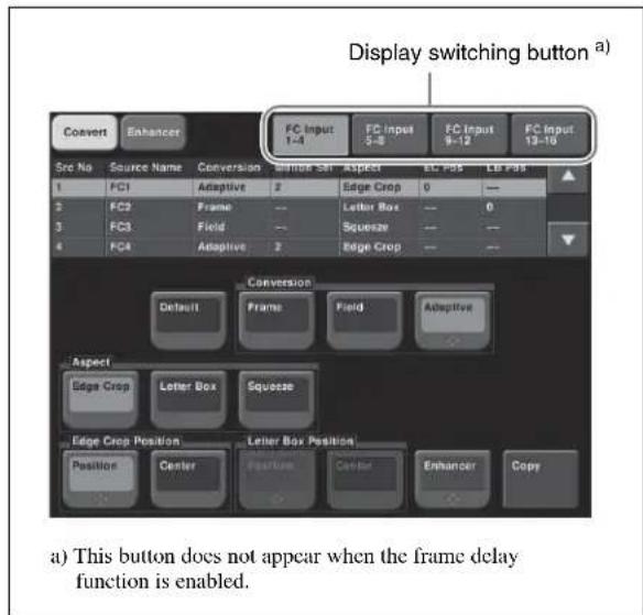
2 Press [FC Input 1-4], [FC Input 5-8], [FC Input 9-12], or [FC Input 13-16] as required.
The list corresponding to the pressed button appears.
3 Using any of the following methods, select what the setting applies to.
- Press directly on the list in the status area.
- Press the arrow keys to scroll the reverse video cursor.
- Turn the knob.
| Knob | Parameter | Adjustment | Setting values |
| 1 Source | No Input selection | 1 and upwards | a) |
a) The setting values vary with the button pressed in step 2.
Making detailed settings for up-conversion
1 In the Switcher >Input >FC Adjust menu, select the input to which the setting applies.
2 In the
Frame: Conversion in frame units
Field: Conversion in field units
Adaptive: Automatically switching between the above two modes
When Adaptive is selected, adjust the following parameter.
| Knob | Parameter Adjustment Setting values | ||
| 2 Motion Select | Motion detection sensitivity | 1 to 3a) | |
a) 1: Still priority mode, 2: Standard mode, 3: Motion priority mode
3 In the
Edge Crop: Add black bars on the left and right sides of a 4:3 aspect ratio image to convert it to a 16:9 image.
Letter Box: Crop the top and bottom of a 4:3 aspect ratio image to convert it to a 16:9 image.
Squeeze: Stretch a 4:3 image horizontally to covert it to a 16:9 image.
(For details of the image transformations, see the following figure.)
| Original image (4:3) Up-converted image (16:9) | |
| Edge Crop | |
| Letter Box | |
| Squeeze | |
Setting the image position in edge crop up-conversion mode
1 In the
2 Adjust the following parameter.
| Knob | Parameter Adjustment Setting | Setting values | ||
| 2 | EC Position | Image position a) | 1080 - 120 | to +120 |
| 720 - 80 | to +80 | |||
a) For down-conversion, the value is from -30 to +30 inclusive.
To return the edge crop image to the center
In the
Setting the image position in letter box up-conversion mode
1 In the
2 Adjust the following parameter.
| Knob | Parameter | Adjustment Setting | setting format | Setting values |
| 2 LB | Position | Image position | 1080i/59.94 | -31 to +32 |
| 1080i/50 | -36 to +36 | |||
| 720P/59.94, 720P/50 | -30 to +30 |
To return the letterbox image to the center
In the
Making enhancer settings
1 In the Switcher >Input >FC Adjust menu, press [Enhancer], turning it on.
2 Set the following parameters.
Parameter group [1/2]
| Knob | Parameter | Adjustment | Setting values |
| 2 | Detail Gain | Adjust the edge enhancement sharpness | 0 to 127 |
| 3 | Limiter | Adjust the maximum signal level to be added to the original signal | 0 to 63 |
Parameter group [1/2]
| Knob | Parameter | Adjustment | Setting values |
| 4 Crisp | Set the | amplitude value for which a low-amplitude signal is not emphasized | 0 to 15 |
| 5 | L e Depend | Set the e luminance range for edge enhancement | 0 to 15 |
Parameter group [2/2]
| Knob | Parameter | Adjustment | Setting values |
| 2 Frequency Set the central frequency for edge enhancement | 0 to 3 | ||
| 3 H/V Ratio Set the horizontal/ vertical ratio for edge enhancement | 0 to 7 | ||
Making detailed settings for down-conversion
1 In the Switcher >Input >FC Adjust menu, select the input to which the setting applies.
2 In the
Edge Crop: Crop the left and right sides of a 16:9 image to convert it to a 4:3 image.
Letter Box 13:9: Crop the left and right sides of a 16:9 image to make a 13:9 image and add black bars at the top and bottom of the 13:9 image to make a 4:3 image.
Letter Box 14:9: Crop the left and right sides of a 16:9 image to make a 14:9 image and add black bars on the top and bottom of the 14:9 image to make a 4:3 image.
Letter Box 16:9: Add black bars on the top and bottom of a 16:9 image to convert it to a 4:3 image.
Squeeze: Compress a 16:9 image horizontally to convert it to a 4:3 image.
(For details of the image transformations, see the following figure.)
| Original image (16:9) Down-converted image (4:3) | |
| Edge Crop | |
| Letter Box 13:9 | |
| Letter Box 14:9 | |
| Letter Box 16:9 | |
| Squeeze | |
For down-conversion, the image position setting in edge crop mode is the same as for up-conversion. The value is from -30 to +30 inclusive.
For details, see "Setting the image position in edge crop up-conversion mode" (page 602).
For down-conversion, the enhancer settings are the same as for up-conversion.
For details, see "Making enhancer settings" (page 602).
Making cross-conversion settings
To make the cross-conversion settings, carry out steps 1 and 2 described in “Making detailed settings for up-conversion” (page 602). No other settings are required.
Copying format converter input data
1 In the Switcher >Input >FC Adjust menu, press [Copy].
The Copy/Swap >Copy >Format Converter menu appears.
The status area shows lists of the copy source on the left, and the copy destination on the right.
2 Select [Input] in the group.
3 Using any of the following methods, select the data.
- Press directly on the list.
- Press the arrow keys to scroll the reverse video cursor.
- Turn the knob.
| Knob | Parameter | Adjustment | Setting values |
| 1 Left | No Select the | copy source data | 1 and upwards |
| 2 Right | No Select the | copy destination data | 1 and upwards |
| 3 Num | Select the | number of items | 1 and upwards |
4 Press [Copy].
Signal Output Settings (Output Menu)
For setup relating to signal outputs, use the Switcher >Output menu.
To display the Output menu
In the Engineering Setup menu, select VF3 'Switcher' and HF3 'Output.'
The status area shows the output signal numbers and names, and output signal phase for the signals output from Output 1 to 48.
The following functions are available here.
Notes
For a format converter dedicated output, Video Clip, V Blank, Through, Safe Title, and 4:3 Crop settings are not possible.
- Output Assign: Assign the signals output from the Output1 to 48 ports.
- Video Clip: Adjust the clip levels (White Clip, Dark Clip, and Chroma Clip) for the output signals from each of the Output1 to 48 ports.
- V Blank: Adjust the vertical blanking width for the output signals from each of the Output1 to 48 ports. The setting is the number of scan lines from the reference blanking position of field 1 for the particular format which should be masked.
- Through: Enable or disable through mode. Through mode can be enabled for AUX1 to 48 outputs, M/E and PGM/PST program outputs, and clean output.
- Safe Title: Enable or disable safe title, and carry out settings for box 1 and 2, cross and grid.
- 4:3 Crop: Set the actual video image to be cropped to a 4:3 aspect ratio when an HD system has a screen aspect ratio of 4:3.
- FC Adjust: Set the format converter outputs.
- Multi Viewer: Make settings for the two-channel multi viewer.
Assigning Output Signals
To assign a signal to output from an output port, use the following procedure.
1 In the Switcher >Output menu, press [Output Assign].
The Output Assign menu appears.
The status area shows the output ports and assigned signals on the left, and a list of signals that can be assigned on the right.
2 In the
[Re-Entry Source]: It is possible to make duplicate assignments.
M/E-1 Output 1 to 6 ^a)
M/E-2 Output 1 to 6^a
M/E-3 Output 1 to 6^a
M/E-4 Output 1 to 6^a
PGM/PST 1 to 6 a)
M/E-1 to 4 Proc Video
P/P Proc Video
M/E-1 to 4 Proc Key
P/P Proc Key
DME Monitor Video
DME Monitor Key
Color Corrector 1 and 2
Undefined
Color Bkgd 2
[Aux Bus]: It is not possible to make duplicate assignments.
Preset
Edit Preview
AUX 1 to 48
a) M/E output signals selected in the M/E Output Assign menu.
3 Using any of the following methods, select the output port number and signal to be assigned.
- Press directly on the list in the status area to make the selection.
- Press the arrow keys to scroll the reverse video cursor.
- Turn the knobs.
| Knob | Parameter | Adjustment Setting | values |
| 1 | Output | No Output | port number |
| 2 | Source | No Selection | on of signal to be assigned |
- For output ports not to be assigned, press [Inhibit].
The selected signal appears in reverse video.
4 Press [Set] to confirm the assignment.
Setting the Output Signal
In the following adjustment/setting operations, use any of the following methods to select the output signal before making the setting.
- Press directly on the list in the status area.
- Press the arrow keys to scroll the reverse video cursor.
- Turn the knob.
| Knob | Parameter | Adjustment Setting values | |
| 1 | Output | No Output | port number selection |
The selected output signal appears in reverse video.
Adjusting the video clip
To adjust the clip value for each of the output signals from the Output 1 to 48 ports, use the following procedure.
1 In the Switcher >Output menu, press [Video Clip].
The Video Clip menu appears.
The status area shows the output ports and assigned signals, and the white clip, dark clip, and chrominance clip values.
2 Adjust the following parameters.
| Knob | Parameter | Adjustment | Setting values |
| 2 White | Clip Luminance signal white clip value | 90.00 to 109.02 | |
| 3 Dark | Clip Luminance signal dark clip value | -6.85 to +10.00 | |
| 4 Chroma Clip | Chrominance signal clip value | 90.00 to 113.17 | |
To set the values to the default values, press [Default].
Making vertical blanking interval adjustment and through mode settings
1 In the Switcher >Output menu, press [V Blank/Through].
The V Blank/Through menu appears.
The status area shows the output ports and the assigned signals, the vertical blanking interval, and the through mode Enable/Disable status.
2 Press [V Blank Mask].
3 Adjust the parameter.
| Knob | Parameter | Adjustment | Setting values |
| 2 | Mask End | Final value for vertical blanking interval | See note a) below |
a) Depending on the signal format, the adjustment range varies as follows.
480i: 10 to 19
576i: 6 to 22
1080i/1080PsF: 7 to 20
720P: 7 to 25
1080P: 15 to 41
To return the values to their defaults, press [Default].
4 To enable the through mode, press [Through Mode], setting it to Enable.
The through mode can be applied to the following outputs.
- Aux 1 to 48 outputs
- Program outputs of the M/E and PGM/PST rows
- Clean outputs of the M/E and PGM/PST rows
Making safe title settings
1 In the Switcher >Output menu, press [Safe Title].
The Safe Title menu appears.
The status area shows the output ports and the assigned signals, with the box 1, box 2, cross, and grid states.
2 To enable the safe title on/off setting made in the Misc menu, press [Safe Title], turning it on.
3 Carry out either of the following operations.
To display a box: Press [Box1] or [Box2], turning it on.
In this case, carry out the following steps 4 and 5.
To display a cross: Press [Cross], turning it on.
To display a grid: Press [Grid], turning it on.
In this case, carry out the following steps 4 and 5.
4 When you selected [Box1] or [Box2] in step 3, adjust the following parameters.
| Knob | Parameter | Adjustment Setting | values |
| 2 Box | ize Box size | 50.00 to 100.00 | |
| 3 Luminance Display | brightness | 0.00 to100.00^{a)}$ | |
a) Adjustable for Box2
When in step 3 you selected [Grid], in the
80.00%: Set the grid size to 80% of the screen frame 85.00%: Set the grid size to 85% of the screen frame
90.00%: Set the grid size to 90% of the screen frame 100.00%: Set the grid size to the full-screen size (100% of the screen frame)
5 When in step 3 you selected [Box1] or [Box2], in the
When in step 3 you selected [Grid], in the
Cropping the image to a 4:3 aspect ratio in an HD system
In an HD system, to crop an image having a screen aspect ratio of 4:3 to an aspect ratio of 4:3, use the following procedure.
1 In the Switcher >Output menu, press [4:3 Crop].
The 4:3 Crop menu appears.
The status area shows the output ports and respective 4:3 Crop mode settings.
2 Press [4:3 Crop], turning it on.
This enables the crop setting, and this is reflected in the status area.
Notes
When the screen aspect ratio of 16:9 is selected for all M/E banks in the System >Format >Active Line/Aspect menu, the setting of 4:3 Crop is disabled.
Setting the format converter outputs
To set the format converter
Display the Switcher >Output >FC Adjust menu. The subsequent operations are the same as for the format converter input settings.
For details of the operations, see “Selecting the Format Converter Conversion” (page 601).
To copy format converter output data
1 In the Switcher >Output >FC Adjust menu, press [Copy].
The Copy/Swap >Copy >Format Converter menu appears.
2 In the group, press [Output].
3 Use the same operations as in steps 3 and 4 of "Copying format converter input data" (page 604) to copy the data.
Making settings for the multi viewer
The multi viewer is a function for splitting the screen into some windows and simultaneously displaying multiple images in those windows.
The screen can be split into 4 or 10 windows, which can be individually set for each of 2-channel multi viewers.
Example of 4-split screen:
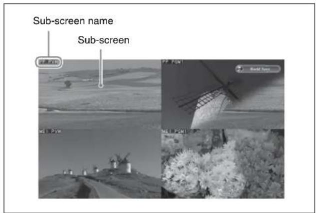
Example of 10-split screen:
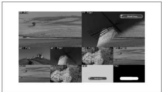
In the following description, a split window is referred to as a “sub-screen.”
1 In the Switcher >Output menu, press [Multi Viewer]. The Multi Viewer menu appears.
2 In the
The status area shows a list of outputs assigned to the sub-screens.
In the
Split 4: Split the screen into 4 windows.
Split 10: Split the screen into 10 windows.
3 To border the sub-screens, press [Border Enable] to turn it on.
To specify whether to show or hide the sub-screen names
1 In the Multi Viewer menu, use any of the following methods to select the target sub-screens.
- Press directly on the list in the status area.
- Press the arrow keys to scroll the reverse video cursor.
- Turn the knob.
| Knob | Parameter | Adjustment | Setting values |
| 1 Window | No Sub-screen selection | 1 to 10 |
2 Press [Name Enable] to select either of the following.
Enable: Show the subs-screen name.
Disable: Hide the sub-screen name.
To make the setting for all of 10 sub-screens in a single operation, turn [All Name Enable] on or off.
3 To set the name display position, adjust the following parameters.
Notes
If you change any of the following parameter values, the name display position will change on all subscreens. You cannot adjust the name display position for each sub-screen.
| Knob | Parameter | Adjustment | Setting values |
| 2 Name | Position H | Horizontal position | 0 to 100 |
| 3 Name | Position V | Vertical position | 0 to 100 |
To assign outputs to the sub-screens
1 In the Multi Viewer menu, press [Output Assign]. The Output Assign menu appears.
2 Use any of the following methods to select the target sub-screens in the list on the left.
- Press directly on the list in the status area.
- Press the arrow keys to scroll the reverse video cursor.
- Turn the knob.
| Knob | Parameter | Adjustment | Setting values |
| 1 Window | No Sub-screen selection | 1 to 10 |
3 Use any of the following methods to select the target outputs in the list on the left.
- Press directly on the list in the status area.
- Press the arrow keys to scroll the reverse video cursor.
- Turn the knob.
| Knob | Parameter | Adjustment | Setting values |
| 2 Output | No Output | selection | 1 to 10 |
4 Press [Set].
Settings Relating to Video Switching (Transition Menu)
For settings relating to video switching, use the Switcher >Transition menu.
To display the Transition menu
In the Engineering Setup menu, select VF3 'Switcher' and HF4 'Transition.'
The status area shows the transition preview, key transition, bus toggle, and split fader settings for each M/E and PGM/PST bank.
The following functions are available here.
- Transition Preview: Specify the operation mode for transition preview for each of the M/E and PGM/PST banks.
• Key Transition: Specify the operation mode for independent key transitions. - Bus Toggle: Switch the bus toggle for each of the M/E and PGM/PST banks on or off.
- Split Fader: When the bus toggle is off, the split fader settings are enabled. For each of the M/E and PGM/PST banks, select enable or disable.
- Fade To Black: Enable or disable fade-to-black for each final program output.
- Preset Color Mix: Set the stroke mode for a preset color mix, the key status for a transition including a key, and the mode in which the transition type after a transition ends returns to the previous setting.
- Transition Curve: Set the relationship when carrying out a transition, between the fader lever position and the advancement state of the transition.
Selecting the Bank to Make the Settings
In the Transition menu, using any of the following methods, select the bank to which the settings apply, then make the settings.
- Press directly on the list in the status area.
- Press the arrow keys to scroll the reverse video cursor.
- Turn the knob.
| Knob | Parameter | Adjustment | Setting values |
| 1 Bank | M/E or P/P | selection to which settings apply | 1 to 5 |
The selected bank appears in reverse video.
Setting the transition preview mode
To select the transition preview mode, in the
One Time: The transition preview ends after a single transition.
Normal: Switching the [TRANS PVW] button on or off switches between the transition preview mode and the normal mode.
Selecting the transition mode of the independent key transition control block
To select the key transition mode, select either of the following in the
Same: The transition settings for the On and Off directions are the same.
Independ: The transition settings for the On and Off directions can be set separately.
Selecting the background transition flip-flop mode
In the Transition menu, press [Bus Toggle], to switch between on and off.
On: Flip-flop mode
Off: Bus fixed mode
For details, see “Fader Lever Operation in Bus Fixed Mode” in Chapter 3 (Volume 1).
Setting the split fader to be enabled or disabled
In the Transition menu, press [Split Fader] to switch between Enable and Disable. This setting is only valid when using a simple transition module with Bus Toggle set to Off.
Enable: When the fader lever is split, the split fader effect is enabled.
Disable: Even when the fader lever is split, the normal fader lever effect is obtained.
Enabling or disabling the fade-to-black function
In the
On: When the [FTB] button is pressed, a fade-to-black is carried out.
Off: Even when the [FTB] button is pressed, no fade-to-black is carried out.
Notes
The PGM2 to PGM4 settings are only valid in Multi Program mode or DSK mode.
Setting a preset color mix
1 In the Switcher >Transition menu, press [Preset Color Mix].
The Preset Color Mix menu appears.
The status area shows the stroke mode setting for each M/E bank, the setting for whether or not the key status is maintained, and the one-time mode setting.
2 In the
Normal: Carry out a preset color mix with two transition operations.
Single: Carry out a preset color mix with a single transition operation.
Notes
In bus fixed mode (see page 608), the setting is fixed to “Single.”
3 In the
To carry out the transition with the key state maintained, press [Key1] to [Key8], turning them on.
4 If each time a transition ends the transition type is to return to the previous setting, press [One Time Enable].
Settings relating to fader lever operations
To select the way in which the fader lever position and the transition progress are related, use the following procedure.
1 In the Switcher >Transition menu, press [Transition Curve].
The Transition Curve menu appears.
2 In the
Normal: The transition progress is linear, according to the fader lever position. (Factory default setting)
Adv Tally Mode: When the fader lever is moved from the end of its travel, the tally is output slightly before the transition starts.
Settings Relating to Keys, Wipes, Frame Memory and Color Correction (Key/Wipe/FM/CCR Menu)
For settings relating to keys, wipes, frame memory and Color Correction, use the Switcher >Key/Wipe/FM/CCR menu.
To display the Key/Wipe/FM/CCR menu
In the Engineering Setup menu, select VF3 'Switcher' and HF5 'Key/Wipe/FM/CCR.'
The status area shows the key memory settings, mask and border processing order, key priority, cross-point hold, pattern limit transition, and wipe edge settings for each of the M/E and PGM/PST banks.
The following functions are available here.
- Key Memory: Set the key memory operation mode for each of the M/E and PGM/PST banks.
- Video Proc Memory: Enable or disable video process memory.
- Show Key: Enable or disable show key for edit preview, M/E and Pvw/K-Pvw of P/P.
- Key Auto Drop: For each switcher bank (M/E-1 to M/E-4, PGM/PST), specify a key to be turned off automatically when you press a cross-point button for the bus to be output as the background.
- Mask/Border Process: Set the processing order of masks and borders for each M/E or PGM/PST bank.
- Key Priority: Set the key priority operation mode for each of the M/E and PGM/PST banks. In DSK mode, the key priority is fixed.
- Xpt Hold mode: Set the operation mode for the cross-point hold button provided on the key bus for each of the M/E and PGM/PST banks.
- Pattern Limit Transition: Set the operation mode when the pattern limit is released for each of the M/E and PGM/PST banks.
- Wipe Edge Default: Adjust the wipe edge softness for each of the M/E and PGM/PST banks.
- CCR Internal Signal Enable: Select whether signals generated internally to the switcher can be selected as input material to the color corrector.
- FM Auto Store: Switch on or off the function to automatically attach a name and save in frame memory.
Switching Video Process Memory On or Off
In the Switcher >Key/Wipe/FM/CCR menu, press [Video Proc Memory], turning it on.
Settings for the Show Key Function
1 In the Switcher >Key/Wipe/FM/CCR menu, press [Show Key].
The Show Key menu appears.
2 In the
3 To set the time for which "show key" is held, press [Hold Time].
4 Adjust the following parameter.
| Knob | Parameter | Adjustment Setting | values |
| 1 Hold | Time Show | key hold time | 0 to 999 (frames) |
Settings for Key Auto Drop Function
The "key auto drop" function automatically switches off a particular key when you press a cross-point button in a bus that outputs the background on the particular switcher bank (PGM/PST, or M/E-1 to M/E-4).
When the background output bus is in flip-flop mode, this is always the A bus. In bus-fixed mode, it is either the A bus or the B bus depending on the fader lever position.
For details of bus-fixed mode, see "Executing a Transition" in Chapter 3 (Volume 1).
1 In the Switcher >Key/Wipe/FM/CCR menu, press [Key Auto Drop].
The Key Auto Drop menu appears.
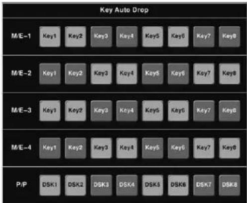
2 In the
Automatically Naming and Saving to Frame Memory
In the Switcher >Key/Wipe/FM/CCR menu, press [FM Auto Store], turning it on.
Selecting the Bank to Make the Settings
In the following procedures, select the bank to which the settings apply using any of the following methods, then make the settings.
- Press directly on the list in the status area.
- Press the arrow keys to scroll the reverse video cursor.
- Turn the knob.
| Knob | Parameter | Adjustment | Setting values |
| 1 Bank | M/E or P/P | selection to which settings apply | 1 to 5 |
The selected bank appears in reverse video.
Selecting the key memory mode
In the
For more details, see "Key Memory" in Chapter 4 (Volume 1).
Selecting the processing order of masks and borders
In the
Mask >Border: Apply the Mask effect, then apply the Border effect.
Border >Mask: Apply the Border effect, then apply the Mask effect.
Selecting the key priority operation mode
In the
Normal: The key priority sequence can be varied freely.
Fix: Fixed at currently set priority sequence.
Setting the operation mode of the key bus [XPT HOLD] button
In the
Key Disable: The [XPT HOLD] button of the key bus functions not only as a cross-point hold button but also as a key disable button. When the [XPT HOLD] button is on, recalling a snapshot or keyframe effect does not reflect the key settings, including the cross-point selection information.
Key Disable with Status: Same as [Key Disable], and further disables the reflection of the key on/off status.
Xpt Hold: The [XPT HOLD] button of the key bus functions as a cross-point hold button. When the [XPT HOLD] is on, recalling a snapshot or keyframe effect does not reflect the cross-point selection information.
To change the cross-point hold attribute of a snapshot
If you select “Key Disable” above, this also applies key disable to the cross-point hold attribute. If you select “Key Disable With Status,” the key disable function is applied, including the key on/off status.
Setting the operation mode when the pattern limit is released
In the
Auto: When the pattern limit is released, the remainder of the transition is carried out automatically at a special-purpose transition rate.
Manual: After the pattern limit is released, the transition waits for the next operation, then executes. Until you move the fader lever or press [AUTO TRANS], the transition is not executed.
Setting the default wipe edge softness
1 In the Switcher >Key/Wipe/FM/CCR menu, press [Wipe Edge Default], turning it on.
2 Set the following parameter.
| Knob | Parameter | Adjustment Setting | values |
| 3 Soft | Default value | of wipe edge softness | -50.00 to +50.00 |
Setting the mode in which all signals can be selected for input to the color corrector
Press [CCR Intrnl Signl Enbl] in the Switcher > Key/Wipe/FM/CCR menu, turning it on.
You can select signals generated internally to the switcher as material for input to the color corrector.
Notes
When you select an M/E reentry signal as material for input to the color corrector, 1H delay occurs to the output signal of M/E.
Settings Relating to Function Links (Link Menu)
Carry out setup relating to links by displaying the Switcher >Link menu.
To display the Link menu
In the Engineering Setup menu, select VF3 'Switcher' and HF6 'Link.'
The status area shows the current link information.
The following functions are available here.
- Internal Bus Link: Make a setting of the bus link function that links together two buses internal to the switcher.
- GPI Link: Make settings for linking any cross-point buttons or [CUT] and [AUTO TRANS] buttons in the cross-point control block and GPI output ports.
- M/E Link: Make settings to link together two M/E banks.
• Key Trans Link: Make settings to link key transitions.
Setting a Cross-Point Button Link
To link together two buses internal to the switcher, use the following procedure.
1 In the Switcher >Link menu, press [Internal Bus Link].
The Internal Bus Link menu appears. The status area shows the link source and link destination buses, and link table information.
2 Using any of the following methods, select what setting applies to.
- Press directly on the list in the status area.
- Press the arrow keys to scroll the reverse video cursor.
- Turn the knob.
| Knob | Parameter Adjustment Setting | values |
| 1 Link | No Link number 1 to 64 |
3 Press [Link Bus Select].
The Link Bus Select menu appears. The status area lists the current setting status of the selected link and the buses that can be selected.
4 In the
5 Using any of the following methods, select the bus to be the link source, and press [Bus Set].
- Press directly on the list appearing in the status area.
- Press the arrow keys to scroll the reverse video cursor.
- Turn the knob.
| Knob | Parameter | Adjustment | Setting values |
| 2 No Bus selection 1 | and | upwards a) | |
a) Only when [Master Bus] is selected, M/E-1 to M/E-4 Trans PGM, and P/P Trans PGM are available. Only when [Linked Bus] is selected, AUX 1 to AUX 48 as Key are available.
Notes
With one of M/E-1 to M/E-4 Trans PGM and P/P Trans PGM selected for [Master Bus], the link setting become effective as soon as you start moving the fader lever.
6 In the
7 Referring to step 5, select the bus to be the link destination, and press [Bus Set].
8 Turn the knob to select the link table, and press [Link Table Set].
| Knob | Parameter | Adjustment | Setting values |
| 3 | Link Table No | Link table selection | 1 to 8 |
For more information about link tables, see the following item.
The selected link table number is confirmed, and this is reflected in the status area.
To delete a link
Select the link you want to delete, then press [Clear] in the Switcher >Link >Internal Bus Link menu.
Making Link Table Settings
1 In the Switcher >Link >Internal Bus Link menu, press [Link Table Select].
The Link Table Select menu appears.
2 Using any of the following methods, select the link source and link destination signals.
- Press directly on the list in the status area.
- Press the arrow keys to scroll the reverse video cursor.
- Turn the knobs.
| Knob | Parameter Adjustment Setting | values |
| 4 Main | No Video/key signal for link source | 1 to 300 |
| 5 No V | deo/key signal for link destination | 1 to 300 |
3 To confirm the selection, press [Link Src Set].
This links the link destination signal to the signal selected as Main No.
To initialize the set source address
In the Switcher>Link>Link Table Select menu, press [Init Link Table].
A confirmation message appears; press [Yes].
The source addresses are reassigned, and this is reflected in the status area.
To change the link number and link table number
In this menu too, you can change the link number and link table number. To do this, turn the knobs as follows to make the setting, then press [Link Table Set].
| Knob Parameter Adjustment Setting values | |||
| 1 Link No Link to which setting applies | 1 to 64 | ||
| 3 | L i No | Link table selection Ta | 1 to 8 b le |
Linking Cross-Point Buttons and GPI Output Ports
To link cross-point buttons or the [CUT] and [AUTO TRANS] buttons in the cross-point control block, and GPI output ports, use the following procedure.
1 In the Switcher >Link menu, press [GPI Link], to display the Switcher >Link >GPI Link menu.
The status area shows the output ports and the link status, and delay value information.
2 Using any of the following methods, select the GPI output port.
- Press directly on the list in the status area.
- Press the arrow keys to scroll the reverse video cursor.
- Turn the knob.
| Knob | Parameter | Adjustment | Setting values |
| 1 | GPI Port | GPI output port selection | 1 to 8 |
3 Press [GPI Link Adjust].
The GPI Link Adjust menu appears.
The status area shows the current setting state of the selected link, and a list of the selectable video names or button names, together with the GPI link Enable/Disable setting for each bus.
4 Using any of the following methods, select what the setting applies to. For each GPI port there can be up to eight links.
- Press directly on the list in the status area.
- Press the arrow keys to scroll the reverse video cursor.
- Turn the knobs.
| Knob | Parameter | Adjustment | Setting values |
| 1 | GPI Port | GPI output port selection | 1 to 8 |
| 2 | Link No | Link number selection | 1 to 8 |
| 3 | Video/Button No | Selection of video or button name to be linked | 1 and upwards a) |
a) These include main pair numbers 1 to 300, and "Cut" and "Auto Trans" on each bank.
5 In the
The selected video or button name is reflected in the status area.
To clear a video/button name link
Make the selection to which the setting applies, then in the
6 To select for each bus whether the GPI link setting is enabled or disabled, use any of the following methods to select the bus to which the setting applies.
- Press directly on the list in the status area.
- Press the arrow keys to scroll the reverse video cursor.
- Turn the knob.
| Knob | Parameter | Adjustment | Setting values |
| 4 Bus | Bus | selection 1 and upwards | |
7 In the
Enable: Enable the GPI link setting for the selected bus.
Disable: Disable the GPI link setting for the selected bus.
All Enable: Enable the GPI link setting for all buses.
Setting the delay value
1 In the Switcher >Link >GPI Link Adjust menu, turn the knobs to select the output port for which you want to set the delay value, and the corresponding delay value.
| Knob | Parameter | Adjustment | Setting values |
| 1 GPI | Port GPI output | put port for the setting | 1 to 8 |
| 5 | D e | I a y the output port | 0 to $00 (fields) |
2 Press [Delay Set].
This confirms the delay value, which is reflected in the status area.
Setting the Re-entry Button Operation Mode
When you select a re-entry button in the cross-point control block of an M/E block (downstream M/E block), the output of the upstream M/E block is read in. You can set the system so that when a GPI link is set for the cross-point selected on the A ^a) bus of the upstream M/E block this triggers the GPI output.
In the Switcher >Link >GPI Link menu, set [Re-Entry Enable] to On or Off.
When this is On, the GPI is executed upstream.
a) When the bus toggle is set to Off, the applicable bus depends on the position of the fader lever.
Notes
- For re-entry, “upstream” applies to a single stage only.
- This setting is common to all GPI output ports.
- GPI output execution on the upstream M/E block is only possible on buses for which GPI Link is set to “Enable” in the GPI Link Adjust menu.
- GPI output occurs when you press a re-entry button, the re-entry button is selected by a macro execution, or you press the re-entry button on the AUX bus remote panel.
Making a Setting for Linking Two M/E Banks
You can link any two M/E banks for some operations by using the Switcher >Link >M/E Link menu.
The operations for which you can link two M/E banks are as follows.
- Transition execution (auto transition, cut, and fader lever operation)
- Next transition selection
• Transition type selection
1 In the Switcher >Link menu, press [M/E Link].
The M/E Link menu appears.
The status area displays a link list showing link source banks (M/E and PGM/PST) and link destination banks, and a selection list.
2 Using any of the following methods, select the link number you want to set.
- Press directly on the list in the status area.
- Press the arrow keys to scroll the reverse video a cursor. v a l u e f
- Turn the knob.
| Knob | Parameter | Adjustment Setting | values |
| 1 Link | No | Link number selection | 1 to 8 |
3 In the
4 Using any of the following methods, select the M/E or PGM/PST bank you want to be the link source, then press [M/E Set].
- Press directly on the list in the status area.
- Press the arrow keys to scroll the reverse video cursor.
- Turn the knob.
| Knob | Parameter | Adjustment | Setting values |
| 2 No | Bank | selection 1 to 5 | a) |
a) 1: M/E-1
2: M/E-2
3: M/E-3
4: M/E-4
5: PGM/PST
5 In the
6 In the same way as in step 4, select the M/E or PGM/PST bank you want to be the link destination, then press [M/E Set].
To link the banks not only for transition execution but also for the other operations
Press [Transition Only] and turn it off.
To release the link setting
Use the same operation as in step 2 to select the link number for which you want to release the link setting, then press [Clear].
Making a Link Setting for Key Transition
You can make a link setting for key transition by using the Switcher >Link >Key Transition Link menu.
The operations for which you can link two banks are the following independent key transition operations.
- Auto transition
- Turning the key on or off
- Fader lever operation (on the downstream key control block)
1 In the Switcher >Link menu, press [Key Trans Link].
The Key Transition Link menu appears. The status area displays a link list showing link sources and link destinations, and a key selection list.
2 Using any of the following methods, select the link number you want to set.
- Press directly on the list in the status area.
- Press the arrow keys to scroll the reverse video cursor.
- Turn the knob.
| Knob | Parameter | Adjustment | Setting values |
| 1 Link | No Link number | selection | 1 to 32 |
3 In the
4 Using any of the following, select the key you want to be the link source, then press [Key Set].
- Press directly on the list in the status area.
- Press the arrow keys to scroll the reverse video cursor.
- Turn the knob.
| Knob | Parameter | Adjustment Setting | values |
| 2 No Key number | selection | 1 and upwards a) | |
a) The keys and their numbers selectable as link source/link destination are as follows.
M/E-x Keyx?DSKx
(In M/E-x, the x is the M/E bank number (1 to 4); in DSKx the x is the DSK number (1 to 8); in Keyx the x is the key number (1 to 8)).
5 In the
6 In the same way as in step 4, select the key you want to be the link destination, then press [Key Set].
To release the link setting
Use the same operation as in step 2 to select the link number for which you want to release the link setting, then press [Clear].
Interfacing With External Devices (Device Interface Menu)
To carry out setup relating to connections with external devices, display the Switcher >Device Interface menu.
To display the Device Interface menu
In the Engineering Setup menu, select VF3 'Switcher' and HF7 'Device Interface.'
The following functions are available here.
- Remote Assign: Set the use of the four 9-pin ports.
- GPI Input: Set the GPI input ports and trigger polarities, and make the action settings.
- GPI Output: Set the GPI output ports and trigger polarities, and make the action settings.
- Aux Control: Set whether operations on the AUX buses from the four 9-pin ports are inhibited.
- DME Type Setting: When the DME is an MVE-9000 or MVE-8000A, carry out interface settings, and for an SDI interface set the AUX bus outputs and reentry inputs.
- DME SDI Interface: Make AUX bus output and re-entry input settings.
- Editor I/F: Set the key off mode for control from an editor.
Making 9-Pin Port Device Interface Settings
The description in this section takes the REMOTE1 port as an example. For other REMOTE ports, carry out the same process as required.
1 In the Switcher >Device Interface menu, press [Remote Assign].
The Remote Assign menu appears.
2 Select the device interface you want to set for the REMOTE1 port from the
Editor A: assign Editor A to the REMOTE1 port. Editor B: assign Editor B to the REMOTE1 port. AUX: assign AUX to the REMOTE1 port. The device interfaces which can be selected for REMOTE2 are the same as for REMOTE1. For REMOTE3 you can also select DME1, and for REMOTE4 you can also select DME2.
Notes
When REMOTE3 and REMOTE4 are respectively assigned to DME1 and DME2, you can switch the AUX
bus from the DME (DME-3000/7000) connected to these ports.
At this time, connect the DME input video signals and key signals as follows.
• DME1 video input: AUX1 output
• DME1 key input: AUX2 output
• DME2 video input: AUX4 output
• DME2 key input: AUX5 output
Note that for a DME external video signal, you can select any of AUX1 to AUX14 on the DME. Connect to the selected AUX bus.
Making Switcher Processor GPI Input Settings
1 In the Switcher >Device Interface menu, press [GPI Input].
The GPI Input menu appears.
2 Using any of the following methods, select the settings.
- Press directly on the list in the status area.
- Press the arrow keys to scroll the reverse video cursor.
- Turn the knobs.
| Knob | Parameter Adjustment Setting values | |
| 1 Port | Port selection 1 to 8 | |
| 2 No Selection of number for action to be assigned | 1 to 8 | |
3 In the
☐ (Rising Edge): Apply the trigger on a rising edge of an input pulse.
(Falling Edge): Apply the trigger on a falling edge of an input pulse.
(X) (Any Edge): Apply the trigger on a change in the polarity of the input signal.
(Level): Carry out the specified operation when the input is low or high.
No Operation: Apply no trigger on an input pulse.
4 In the
M/E-1, M/E-2, M/E-3, M/E-4, P/P: Set the action for one of the banks.
Common/Setup: Set an action for something other than the above, or a setup action.
5 Using any of the following methods, select the action to be set.
- Press directly on the list in the status area.
- Press the arrow keys to scroll the reverse video cursor.
- Turn the knobs.
| Knob | Parameter | Adjustment | Setting values |
| 3 Action | Action selection 1 and | upwardsa) | |
| 4 Reg | No Register number 1 to 4 | b)1 to 99c) |
a) As for the setting values, see “Selectable actions for various trigger types” (page 617).
b) When knob 3 selection is "Key Snapshot"
c) When knob 3 selection is "Snapshot" or "Effect"
6 Press [Action Set] to confirm the action selection.
The selected setting appears in the status area.
Selectable actions for various trigger types
- When the trigger type is other than "Level"
(In M/E-x, the x is the M/E bank number (1 to 4); in DSKx the x is the DSK number (1 to 8); in Keyx the x is the key number (1 to 8)).
- When Target is M/E-x: Cut, Auto Trans, Keyx Cut, Keyx Auto Trans, SS ? Recall, Keyx SS ? Recall, Effect ? Recall, Effect ? Recall & Run, KF Run, KF Stop, KF Rewind, KF Rev Run, No Action
- When Target is P/P: Cut, Auto Trans, DSKx Cut, DSKx Auto Trans, FTB Cut, FTB Auto Trans, SS ? Recall, DSKx SS ? Recall, Effect ? Recall, Effect ? Recall & Run, KF Run, KF Stop, KF Rewind, KF Rev Run, No Action
- When Target is Common/Setup: FM Src1 Field Freeze, FM Src1 Frame Freeze, FM Src2 Field Freeze, FM Src2 Frame Freeze FM Src1 Freeze Off, FM Src2 Freeze Off, FM Src1 Clip Record, FM Src1 Clip Stop, FM Src2 Clip Record, FM Src2 Clip Stop, FM1 to FM8 Clip Cueup, FM1 to FM8 Clip Play, FM1 to FM8 Clip Stop, User1 to 8 SS ? Recall, User1 to 8 EFF ? Recall, User1 to 8 EFF ? Recall & Run, User1 to 8 KF Run, User1 to 8 KF Stop, User1 to 8 KF Rewind, User1 to 8 KF Reverse Run, No Action
- When the trigger type is "Level"
(In M/E-x, the x is the M/E bank number (1 to 4)).
- When Target is M/E-x or P/P: Aspect, Bkgd A Side Flags, Bkgd B Side Flags, No Action
- When Target is Common/Setup: Format, Aspect, Level Enable, No Action
Notes
- “Level Enable” is a function that determines whether GPI inputs are enabled (“Enable”) or disabled (“Disable”) for the “Aspect” and “Format” actions that can be used when the trigger type is Level. When Level Enable is used, if the input is “Disable” then it is not possible to switch “Aspect” or “Format” by GPI input. If a GPI to switch “Aspect” or “Format” occurs when
powering the system off, the action triggered by the GPI may start immediately before the power goes off and the power may go off before the action is completed. This may corrupt the setup settings. It is therefore recommended to use Level Enable to avoid such a situation.
- If “Format” is selected for “Action” when the format converter is used on the switcher, you can set the conversion format of the format converter for “FC Input 1-4,” “FC Input 5-8,” “FC Input 9-12” (MVS-8000X only), “FC Input 13-16” (MVS-8000X only), “FC Output 1-2,” and “FC Output 3-4.”
Carrying out level settings
To set the low level and high level, first set the trigger type to “Level,” then use the following procedure.
1 In the Switcher >Device Interface menu, select the action to be set, and press [H/L Set].
The H/L Set menu appears.
2 Using any of the following methods, select the settings.
- Press directly on the list in the status area.
- Press the arrow keys to scroll the reverse video cursor.
- Turn the knob.
| Knob | Parameter Adjustment Setting values | ||
| 1 No S | Selection of setting for action | 1 and upwards | |
3 To apply the selection made in step 2 when the input is high, press [H Set]. To apply the selection made in step 2 when the input is low, press [L Set].
This confirms the setting, which appears in the status area.
Notes
- When the action is “Format,” these settings conflict with the current settings, but after making the settings, agreement is restored after a pulse change or power off/on.
- When the Action is “Bkgd A Side Flags” or “Bkgd B Side Flags,” the levels are fixed, as follows. High level: Off Low level: On
To Set the Level for the Format Converter
1 Set “Action” to “Format” in step 5 of the procedure in “Making Switcher Processor GPI Input Settings” (page 616).
The format converter list appears.
2 Select the format converter that you want to set from the list.
3 In the
Making Switcher Processor GPI Output Settings
1 In the Switcher >Device Interface menu, press [GPI Output].
The GPI Output menu appears.
2 Using any of the following methods, select the settings.
- Press directly on the list in the status area.
- Press the arrow keys to scroll the reverse video cursor.
- Turn the knob.
| Knob | Parameter Adjustment Setting values | ||
| 1 Port | Port selection | 1 to 8 | |
3 In the
(Rising Edge): The trigger causes the relay contacts to be open-circuit or drives the output high, and holds this state for the specified pulse width.
(Falling Edge): The trigger causes the relay contacts to be shorted or drives the output low, and holds this state for the specified pulse width.
(Any Edge): Each time the trigger occurs, the relay contacts are alternately closed or opened, or the output is switched between high and low.
Status: Depending on the status, the relay contacts are closed or opened, or the output is switched between high and low.
No Operation: The trigger has no effect on the output.
4 Turn the knobs to select the pulse width and timing to be set.
| Knob | Parameter Adjustment Setting values | ||
| 3 | Pulse Width | Pulse width | 1 to 60 (fields) |
| 4 | Timing | Output timing | 1 to 3a) |
a) 1: Field 1, 2: Field 2, 3: Any
When “×” is selected as the trigger polarity, there is no Pulse Width setting. When “Status” is selected, there is no Pulse Width or Timing setting.
5 In the
M/E-1 to M/E-4 and P/P: Set an action for the M/E or PGM/PST bank.
Common: Set an action for error status.
6 Using any of the following methods, select the action to be set.
- Press directly on the list appearing in the status area.
- Press the arrow keys to scroll the reverse video cursor.
- Turn the knobs.
| Knob | Parameter | Adjustment | Setting values | |
| 2 Action | Action | selection | 1 and upwards a) | |
| 5 Reg | No | Register number | 1 to 4 b)1 to 99 c) | |
a) Action list when the trigger type is other than "Status"
(In M/E-x, the x is the M/E bank number (1 to 4); in DSKx the x is the DSK number (1 to 8); in Keyx the x is the key number (1 to 8)).
- When Source is M/E-x: Cut, Auto Trans, Keyx Cut, Keyx Auto Trans, Keyx SS ? Recall, Effect ? Recall, Effect ? Recall & Run, KF Run, KF Stop, KF Rewind, No Action
- When Source is P/P: Cut, Auto Trans, DSKx Cut, DSKx Auto Trans, FTB Cut, FTB Auto Trans, DSKx SS ? Recall, Effect ? Recall, Effect ? Recall & Run, KF Run, KF Stop, KF Rewind, No Action
- When Source is Common: No Action
Action list when the trigger type is "Status"
(In M/E-x, the x is the M/E bank number (1 to 4); in DSKx the x is the DSK number (1 to 8); in Keyx the x is the key number (1 to 8)).
- When Source is M/E-x: Keyx On, No Action
- When Source is P/P: DSKx On, No Action
- When Source is Common: Error Make, Error Break, No Action
b) When knob 2 selection is "Key Snapshot"
c) When knob 2 selection is "Snapshot" or "Effect"
7 Press [Action Set] to confirm the action selection.
The selected setting appears in the status area.
Test firing the trigger
To test fire the trigger, press [Test Fire].
This outputs a trigger from the selected output port. This is not output when the trigger type is "Status."
Enabling or Disabling AUX Bus Control
1 In the Switcher >Device Interface menu, press [Aux Control].
The Aux Control menu appears.
2 Select the 9-pin port for the setting, from the
Remote1: Make the settings for the REMOTE1 port.
Remote2: Make the settings for the REMOTE2 port.
Remote3: Make the settings for the REMOTE3 port.
Remote4: Make the settings for the REMOTE4 port.
3 Using any of the following methods, select the AUX bus.
- Press directly on the list in the status area.
- Press the arrow keys to scroll the reverse video cursor.
- Turn the knob.
| Knob | Parameter | Adjustment | Setting | values |
| 1 | N | o | A U selection | 0xto 48 a) b |
a) 0: EDIT PVW
1 to 48: AUX1 to AUX48
4 Select whether to enable or disable AUX bus control from the
Enable: enable control of the port selected in step 2.
Disable: disable control of the port selected in step 2.
Manual: make whether control of the port selected in step 2 is possible or not depend on the setting in the Misc menu.
5 Repeat steps 2 to 4 as required to make the settings for other ports.
Setting the Interface Between the DME and the Switcher
To set the interface between the DME and the switcher, proceed as follows.
1 In the Switcher >Device Interface menu, press [DME Type Setting].
The DME Type Setting menu appears.
2 In the
Dedicated: The DME has an dedicated interface.
SDI: The DME has an SDI interface.
Notes
If the system signal format is set to 1080P and the DME input/output signal format is set to Dual Link Mode, the SDI interface cannot be selected.
For details of the connection of DME units and the switcher, see “MVS-8000X-/7000X-C Installation Manual.”
3 To select the number of keys that use DME on an M/E bank, make one of the following selections in the
Single DME unit: Mode in which a processed key operation is carried out only with the dedicated interface DME or the SDI interface DME.
Dual DME units: Mode in which two processed key operations with the dedicated interface DME and the SDI interface DME are both possible simultaneously on the same M/E. When this mode is selected, when combined by a processed key with the SDI interface DME, select the material
s for the second channel not on the DME external video bus, but on the AUX bus.
Setting the AUX Bus Output and Reentry Input
Select the signal input to the DME (AUX bus output) and the signal returned as the switcher primary input (reentry input) as follows.
1 In the Switcher >Device Interface menu, press [DME Type Setting].
The DME Type Setting menu appears.
2 Press [DME SDI Interface].
3 Using any of the following methods, select the DME channel to which operations apply.
- Press directly on the list on the left of the status area.
- Press the arrow keys to scroll the reverse video cursor.
- Turn the knob.
| Knob | Parameter | Adjustment | Setting values |
| 1 | D M No | DME chann€ selection | ħto 24 |
Notes
When using the MVE-8000A, it is not possible to select any of DME 1 Ext In to DME 8 Ext In.
4 In the
Aux Bus: Set AUX bus.
Re-Entry: Set reentry.
5 Depending on the selection in step 4, use any of the following methods to make the setting.
- Press directly on the list on the right of the status area.
- Press the arrow keys to scroll the reverse video cursor.
- Turn the knob.
When Aux Bus is selected
| Knob | Parameter | Adjustment Setting | values |
| 2 Src | No AUX bus | number 0 to 48 |
When Re-Entry is selected
| Knob | Parameter | Adjustment | Setting values |
| 2 Src No | Reentry number 0 to upwards | ||
6 Press [Set].
In the list on the right of the status area, the selected content is reflected in the specified DME channel.
Repeat steps 3 to 6 as required.
Selecting the Mode for Turning Off Keys Upon Receiving the Editor Command
Selects the mode for turning off keys when an “All Stop” command is received from the editor.
1 In the Switcher >Device Interface menu, press [Editor I/F].
The Editor I/F menu appears.
2 Select one of the following modes.
All: When an “All Stop” command is received, all keys for the selected regions are turned off.
Specified: When an “All Stop” command is received, among all the keys for the selected regions, only the keys specified by the editor are turned off.
Notes
When an “All Stop” command is received in the process of a transition, the keys selected for the next transition are also turned off.
DME Setup (DME)
Chapter
21
Settings Relating to Signal Inputs (Input Menu)
To make settings relating to DME input signals, display the DME >Input menu.
To display the Input menu
In the Engineering Setup menu, select VF4 'DME' and HF1 'Input.'
The status area shows the initial crop information and the DME system phase.
The following functions are available here.
- Initial Crop: Make the initial crop setting.
- Matte Illeg. Color Limit: Switch the illegal limiter for the signal generated by the DME internal matte generator on or off.
- System Phase: Adjust the operation timing of the whole system with respect to the reference signal.
• TBC Center: Set the TBC window center position.
When the signal format is 1080P, up to four DMEs can be operated (DME1 to DME4).
In the following description, the settings for DME1 are given by way of example, but the settings for DME2 to DME4 are carried out in a similar way.
Setting the Initial Crop
1 In the DME1
2 In the DME1
If you selected 4:3 in step 1
| Knob | Parameter | Adjustment | Setting values |
| 1 Top | Position of top | side | -3.00 to +3.00 |
| 2 Left | Position of left | side | -4.00 to +4.00 |
| 3 Right | Position of right | side | -4.00 to +4.00 |
| 4 Bottom | Position of bottom side | side | -3.00 to +3.00 |
If you selected 16:9 in step 1
| Knob | Parameter | Adjustment | Setting values |
| 1 Top Position of top side | -9.00 to +9.00 | ||
| 2 Left Position of left side | -16.00 to +16.00 | ||
| 3 Right Position of right side | -16.00 to +16.00 | ||
| 4 Bottom Position of bottom side | -9.00 to +9.00 | ||
To return the parameter values to their default values Press [Unity] in the
Setting an Illegal Color Limit for Matte Signals
To enable the illegal color limiter for the signals generated by the DME internal matte generator, press [Matte Illeg Col Limit] for DME1 in the DME >Input menu, turning it on.
Making DME System Phase Adjustment
To adjust the DME reference phase, use the following procedure.
1 In the DME >Input menu, press [System Phase].
2 Set the following parameters.
| Knob | Parameter | Adjustment | Setting values |
| 1 | D M Phase | DME1 system phase adjustment | -32.00 to +96.00 |
| 2 | D M Phase | DME2 system phase adjustment | -32.00 to +96.00 |
Setting the TBC Window Center Position
1 In the DME >Input menu, press [TBC Center].
The TBC Center menu appears. The status area shows the TBC center position values for DME1, DME2, and external input signals.
Notes
The TBC center position values for external input signals are shown only when an MVE-9000 or MKS-7470X/7471X is used.
2 Using any of the following methods, select the input number for which you want to set the TBC center position.
- Press directly on the list in the status area.
- Press the arrow keys to scroll the reverse video cursor.
- Turn the knob.
| Knob | Parameter | Adjustment | Setting values |
| 1 No Input number | selection | 1 to 8 | |
3 In the
Settings Relating to Signal Outputs (Output Menu)
To make settings relating to DME output signals, display the DME >Output menu.
You can select the signals output from the four monitor output connectors.
To display the Output menu
In the Engineering Setup menu, select VF4 'DME' and HF3 'Output.'
The following functions are available here.
- Clip Adjust: Adjust the video clip levels of DME1 and DME2 outputs. (These settings are possible only when the DME is an MVE-9000 or SDI-interfaced MVE-8000A.)
- Monitor Output: Set the signals output from the four monitor output connectors.
Adjusting the DME1 and DME2 Output Video Clip Levels
When the MVE-8000A/MVE-9000 is connected through SDI interface, you can adjust both DME1 and DME2 output video clip levels.
Use the following procedure. (DME 1 is taken by way of example.)
1 In the
2 Set the following parameters.
| Knob | Parameter Adjustment Setting values | ||
| 1 White | Clip White clip adjustment | 90.00 to 109.02 | |
| 2 Dark | Clip Dark clip adjustment | -6.85 to +10.00 | |
| 3 Chroma Clip | Chroma clip adjustment | 90.00 to 113.17 | |
To return the setting to the default value
In the DME >Output menu, press [Default].
Setting the Monitor Output
To set the signals output from the four monitor output connectors, use the following procedure.
1 In the DME >Output menu, press [Monitor Output].
The Monitor Output menu appears.
2 In the
DME1: Select DME1.
DME2: Select DME2.
When the signal format is 1080P, you can also select DME3 or DME4 similarly.
3 In the list on the left of the status area, press directly on the monitor output for which you want to make setting.
Notes
On the MVE-8000A, when the signal format is 1080P, you cannot select MONI OUT#2 and MONI OUT#4.
4 In the list on the right of the status area, press directly on the signal you want to output.
5 Press [Set].
The selection is reflected in the monitor output.
Interfacing With External Devices (Device Interface Menu)
To carry out setup relating to DME connections with external devices, display the DME >Device Interface menu.
To display the Device Interface menu
In the Engineering Setup menu, select VF4 'DME' and HF4 'Device Interface.'
The following functions are available here.
- Editor Protocol: Set the protocol to be used on the Editor port.
- Editor Port Setting: Make settings relating to the control of the four editor ports installed in the DME.
- GPI Input: Set the GPI input ports and trigger polarities, and make the action settings.
- GPI Output: Set the GPI output ports and trigger polarities, and make the action settings.
When the signal format is 1080P, up to four DMEs can be operated (DME1 to DME4).
In the following description, the settings for DME1 are given by way of example, but the settings for DME2 to DME4 are carried out in a similar way.
Notes
On the MVE-8000A, when GPI Input and GPI Output are set, the settings apply to Ch1/Ch2 for DME1/DME3, and Ch3/Ch4 for DME2/DME4.
Setting the editor protocol
In the
Device Interface menu, press the following buttons to make the setting.
DME: Control by DME protocol through the editor port.
VTR: Control by VTR protocol through the editor port.
Notes
This setting is disabled for the MKS-7470X/7471X.
Making editor port settings
In the
Common: Control all of channels 1 to 4 through editor ports 1 to 4.
Independ: Control channels 1 to 4 individually through Editor ports 1 to 4.
Notes
This setting is disabled for the MKS-7470X/7471X.
Making DME GPI Input Settings
1 In the DME >Device Interface menu, press [DME1 GPI Input].
The DME1 GPI Input menu appears.
2 Using any of the following methods, select the settings.
- Press directly on the list in the status area.
- Press the arrow keys to scroll the reverse video cursor.
- Turn the knobs.
| Knob | Parameter | Adjustment Setting | values |
| 1 Port | Input port | selection | 1 to 8 |
| 2 No | Selection of | number foraction to beassigned | 1 to 8 |
3 In the
☐ (Rising Edge): Apply the trigger on a rising edge of an input pulse.
(Falling Edge): Apply the trigger on a falling edge of an input pulse.
(Any Edge): Apply the trigger on a change in the polarity of the input signal.
(Level): Carry out the specified operation when the input is low or high.
No Operation: Apply no trigger on an input pulse.
4 In the
5 Using any of the following methods, select the action to be set.
- Press directly on the list in the status area.
- Press the arrow keys to scroll the reverse video cursor.
- Turn the knobs.
| Knob | Parameter | Adjustment Setting | values |
| 3 Action | Action selection | 1 and | upwardsa) |
| 4 Reg | No | Register number 1 to 99 | b)1 to 399c) |
a) As for the setting values, see "Selectable actions for various trigger types" (page 624).
b) When knob 3 selection is "Snapshot"
c) When knob 3 selection is "Effect"
6 Press [Action Set] to confirm the action selection.
The selected setting appears in the status area.
Selectable actions for various trigger types
- When the trigger type is other than "Level" When Target is Ch1, Ch2, Ch3, or Ch4: Freeze, SS ? Recall Effect ? Recall, Effect ? Recall & Run, KF Run, KF Stop, KF Rewind, KF Reverse Run, No Action When Target is Proc: No Action
- When the trigger type is "Level" When Target is Ch1, Ch2, Ch3, or Ch4: Aspect, No Action When Target is Proc: Format Aspect, Level Enable, No Action
Notes
- “Level Enable” is a function that determines whether GPI inputs are enabled (“Enable”) or disabled (“Disable”) for the “Aspect” and “Format” actions that can be used when the trigger type is Level. When Level Enable is used, if the input is “Disable” then it is not possible to switch “Aspect” or “Format” by GPI input. If a GPI to switch “Aspect” or “Format” occurs when powering the system off, the action triggered by the GPI may start immediately before the power goes off and the power may go off before the action is completed. This may corrupt the setup settings. It is therefore recommended to use Level Enable to avoid such a situation.
- When the DME is an MKS-7470X/7471X, "Format" is disabled.
Carrying out level settings
To set the low level and high level, first set the trigger type to "Level," then use the following procedure.
1 In the DME >Device Interface menu, select the action to be set, and press [H/L Set].
The H/L Set menu appears.
2 Using any of the following methods, select the settings.
- Press directly on the list in the status area.
- Press the arrow keys to scroll the reverse video cursor.
- Turn the knob.
| Knob | Parameter Adjustment Setting values | ||
| 1 No | Signal format/screen aspect ratio selection | 1 and upwards | |
3 To apply the selection made in step 2 when the input is high, press [H Set]. To apply the selection made in step 2 when the input is low, press [L Set].
This confirms the setting, which appears in the status area.
Making DME GPI Output Settings
1 In the DME >Device Interface menu, press [DME1 GPI Output].
The DME1 GPI Output menu appears. The output port selection is fixed at 1.
2 In the
Status: Depending on the status, the relay contacts are closed or opened, or the output is switched between high and low.
No Operation: The trigger has no effect on the relay state or output level.
3 Using any of the following methods, select the action you want to set.
- Press directly on the list in the status area.
- Press the arrow keys to scroll the reverse video cursor.
- Turn the knob.
| Knob | Parameter | Adjustment | Setting values |
| 2 Action | Action selection | 1 to 3 | a) |
a) Error Make, Error Break, No Action
4 Press [Action Set] to confirm the action selection.
The selected setting appears in the status area.
DCU Setup (DCU)
Chapter
22
Setup Relating to DCU
In DCU setup, carry out settings particular to the DCU. You can make the following settings.
- Input Config: Assign GPI inputs to Parallel input ports.
• GPI Input Assign: Make GPI input settings. - Output Config: Assign GPI outputs to parallel output ports inserted in an option slot.
- GPI Output Assign: Make GPI output settings.
- Serial Port Assign: Set the protocol to match the devices connected to a 9-pin serial port. You can also select the control panel used to control each device.
Notes
For setup relating to DCU, it is necessary to make the same settings on multiple control panels (maximum three units) that are sharing the DCU. After carrying out the DCU setup on one control panel, make the same settings on the other control panels.
Settings Relating to Parallel Inputs (Input Config Menu)
To assign GPI inputs to DCU parallel input ports, display the DCU >Input Config menu.
The DCU parallel input ports are assigned with the following priority sequence.
- When external boxes are set in the Router/Tally >Router>External Box Assign menu, the parallel inputs are assigned to the external box inputs in order.
- When tally settings are carried out in the Router/Tally >Tally Enable menu, tally inputs are assigned automatically.
In this menu, you set only the input ports which are unused after making the above assignments.
To display the Input Config menu
In the Engineering Setup menu, select VF5 'DCU' and HF1 'Input Config.'
The status area shows input port information.
Assigning a GPI Input Port
1 In the DCU >Input Config menu, select what the setting applies to (DCU1 or DCU2) from the
2 In the
3 Using any of the following methods, assign the number of the GPI input to the input port.
- Press directly on the list in the status area.
- Press the arrow keys to scroll the reverse video cursor.
- Turn the knobs.
| Knob | Parameter | Adjustment Setting | values |
| 1 | ParallelInput | Input port 1 to 102 | a) |
| 3 | GPI Input GPI input | 1 to 50 |
a) When the MKS-2700 is connected, select a value in the range 1 to 34.
4 To confirm the assignment in step 3, press [GPI Input Set].
This assigns the GPI input, and this is reflected in the status area.
Releasing the Assignment of a GPI Input Port
1 In the DCU >Input Config menu, select what the setting applies to (DCU1 or DCU2) from the
2 In the
3 Turn the knobs to adjust the following parameters.
| Knob | Parameter | Adjustment | Setting values |
| 1 From | No First port | number 1 to To No | |
| 2 To No | Last port number | From No to 102 |
4 In the
GPI Input Setting (GPI Input Assign Menu)
To set the trigger type and so on for each GPI input, display the DCU >GPI Input Assign menu.
To display the GPI Input Assign menu
In the Engineering Setup menu, select VF5 'DCU' and HF2 'GPI Input Assign.'
The GPI input port setting status appears in the status area.
Making DCU GPI Input Settings
1 In the DCU >GPI Input Assign menu, using any of the following methods select what the setting applies to.
- Press directly on the list in the status area.
- Press the arrow keys to scroll the reverse video cursor.
- Turn the knob.
| Knob | Parameter | Adjustment | Setting values |
| 1 No | GPI input 1 to 50 | ||
2 In the
(Rising Edge): Apply the trigger on a rising edge of an input pulse.
(Falling Edge): Apply the trigger on a falling edge of an input pulse.
(X) (Any Edge): Apply the trigger on a change in the polarity of the input signal.
(Level): Carry out the specified operation when the input is low or high.
No Operation: Apply no trigger on an input pulse.
3 In the
SCU1: ID1 control panel (PNL1)
SCU2: ID2 control panel (PNL2)
SCU3: ID3 control panel (PNL3)
The action set in the following step 4 is executed for the switcher and DME controlled by the selected control panel.
4 Using any of the following methods, select the action you want to set.
- Press directly on the list in the status area.
- Press the arrow keys to scroll the reverse video cursor.
- Turn the knobs.
| Knob | Parameter | Adjustment Setting | values |
| 2 Action | Action selection | 1 and | upwards a) |
| 4 | A u No | AUX bus B selection | 1uto 48 b)s |
| 5 Reg | No Register number | 1 to 4 | c)1 to 99 d)1 to 250 e)1 to 399 f) |
| 5 Src | No Source signal selection | 1 and upwards b) g) h) | |
a) As for the setting values, see “Selectable actions for various trigger types” (page 628)
b) When knob 2 selection is "Aux ? O'ride Src ??"
c) When knob 2 selection is "Key Snapshot"
d) When knob 2 selection is "Snapshot" or "Shotbox"
e) When knob 2 selection is "Macro"
f) When knob 2 selection is "Effect"
g) The following values apply to the MVS-8000X.
For primary inputs: 1 to 144
For premium inputs: 145 to 164 ((PREM1) to (PREM20) indicated after the number)
For format converter dedicated inputs: 165 to 180 ((FC1) to (FC16) indicated after the number)
h) The values from 1 to 80 apply to the MVS-7000X.
5 To confirm the setting in step 4, press [Action Set].
This confirms the setting, which appears in the status area.
Selectable actions for various trigger types
- When the trigger type is other than “Level”
(In M/E-x, the x is the M/E bank number (1 to 4); in DSKx the x is the DSK number (1 to 8); in Keyx the x is the key number (1 to 8)).
M/E-x Cut, M/E-x Auto Trans, P/P Cut, PP Auto Trans, M/E-x Keyx Cut, M/E-x Keyx Auto Trans, P/P DSKx Cut, P/P DSKx Auto Trans
FTB Auto Trans, FTB Cut, Master SS ? Recall, SS ? Recall, M/E-x Keyx SS ? Recall, P/P DSKx SS ? Recall, Master Effect ? Recall, Effect ? Recall, Effect ? Recall & Run, KF Run, KF Stop, KF Rewind, FM Src1 Field Freeze, FM Src1 Frame Freeze, FM Src1 Freeze Off, FM Src2 Field Freeze, FM Src2 Frame Freeze, FM Src2 Freeze Off, FM Src1 Clip Record, FM Src1 Clip Stop, FM Src2 Clip Record, FM Src2 Clip Stop, FM1 to FM8 Clip Cueup, FM1 to FM8 Clip Play, FM1 to FM8 Clip Stop, Shotbox ? Recall, Macro Take, Macro ? Recall, No Action
- When the trigger type is only “Rising Edge” or “Falling Edge”
Aux? O'ride Src??
- When the trigger type is "Level"
(In M/E-x, the x is the M/E bank number (1 to 4)). System Format, System Aspect, M/E-x Aspect, P/P Aspect, DME Ch1 Aspect, DME Ch2 Aspect, DME Ch3 Aspect, DME Ch4 Aspect, DME Ch5 Aspect, DME Ch6
Aspect, DME Ch7 Aspect, DME Ch8 Aspect, Level Enable, No Action
Notes
- “Level Enable” is a function that determines whether GPI inputs are enabled (“Enable”) or disabled (“Disable”) for the “Aspect” and “System Format” actions that can be used when the trigger type is Level. When Level Enable is used, if the input is “Disable” then it is not possible to switch “Aspect” or “System Format” by GPI input.
If a GPI to switch “Aspect” or “System Format” occurs when powering the system off, the action triggered by the GPI may start immediately before the power goes off and the power may go off before the action is completed. This may corrupt the setup settings. It is therefore recommended to use Level Enable to avoid such a situation.
- As for “Aux ? O’ride Src ??,” when “Rising Edge” is selected, on a rising edge the set AUX bus input is used. On a falling edge, the original state of the cross-point is restored. If the GPI trigger is applied repeatedly at short intervals (0.5 second or less), the cross-point switching may not be carried out correctly. In this case, apply the GPI trigger again.
- If “System Format” is selected for “Action” when the format converter is used on the switcher, you can set the conversion format of the format converter for “FC Input 1-4,” “FC Input 5-8,” “FC Input 9-12” (MVS-8000X only), “FC Input 13-16” (MVS-8000X only), “FC Output 1-2,” and “FC Output 3-4.”
Carrying out level settings
To set the low level and high level, first set the trigger type to “Level,” then use the following procedure.
1 In the DCU >GPI Input Assign menu, select the action to be set, and press [H/L Set].
The H/L Set menu appears.
2 Using any of the following methods, select the settings.
- Press directly on the list in the status area.
- Press the arrow keys to scroll the reverse video cursor.
- Turn the knob.
| Knob | Parameter | Adjustment | Setting values |
| 1 | No | Signal format/screen aspect ratio selection | 1 and upwards |
3 To apply the selection made in step 2 when the input is the GPI high level, press [H Set]. To apply the
selection made in step 2 when the input is low, press [L Set].
This confirms the setting, which appears in the status area.
To Set the Level for the Format Converter
1 Set “System Format” for “Action” using the same operation in Step 4 of “Making DCU GPI Input Settings” (page 627).
The format converter list appears.
2 Select the format converter that you want to set from the list.
3 In the
Parallel Output Settings (Output Config Menu)
For the DCU parallel output ports, after carrying out tally settings in the Router/Tally >Tally Enable menu, you can assign GPI outputs to output ports that are still unused. To assign DCU outputs to DCU parallel output ports, display the DCU >Output Config menu.
To display the Output Config menu
In the Engineering Setup menu, select VF5 'DCU' and HF3 'Output Config.'
The status area shows output port information.
Assigning a GPI Output Port
1 In the DCU >Output Config menu, select what the setting applies to (DCU1 or DCU2) from the
2 In the
3 Using any of the following methods, select the output port and GPI output number.
- Press directly on the list in the status area.
- Press the arrow keys to scroll the reverse video cursor.
- Turn the knobs.
| Knob | Parameter | Adjustment | Setting values |
| 1 Parallel Output Slot | Output port slot 2 to 6a) | ||
| 2 Parallel Output Port | Output port 1 to 54b) | ||
| 5 GPI Output GPI output 1 to 50 | |||
a) When the MKS-2700 is connected, select 2.
b) When the MKS-2700 is connected, select a value in the range 1 to 36.
4 To confirm the selected setting, press [GPI Output Set].
This confirms the selection, which is reflected in the status area.
Releasing the Assignment of a GPI Output Port
1 In the DCU >Output Config menu, select what the setting applies to (DCU1 or DCU2) from the
2 In the
3 Turn the knobs to select the slot and port to which the setting applies.
| Knob | Parameter | Adjustment | Setting values |
| 1 From | Slot First port slot 2 to 6 | ||
| 2 From | Port First port number 1 to 54 | ||
| 3 To Slot Last port slot 2 to 6 | |||
| 4 To Port Last port number 1 to 54 | |||
4 In the
GPI Output Setting (GPI Output Assign Menu)
To set the trigger type and so on for each GPI output, display the DCU >GPI Output Assign menu.
To display the GPI Output Assign menu
In the Engineering Setup menu, select VF5 'DCU' and HF4 'GPI Output Assign.'
The GPI output port setting status appears in the status area.
Making DCU GPI Output Settings
1 In the DCU >GPI Output Assign menu, using any of the following methods select what the setting applies to.
- Press directly on the list in the status area.
- Press the arrow keys to scroll the reverse video cursor.
- Turn the knob.
| Knob | Parameter | Adjustment | Setting values |
| 1 No | GPI output 1 to 50 | ||
2 In the
(Rising Edge): The trigger causes the relay contacts to be open-circuit or drives the output high, and holds this state for the specified pulse width.
(Falling Edge): The trigger causes the relay contacts to be shorted or drives the output low, and holds this state for the specified pulse width.
(X) (Any Edge): Each time the trigger occurs, the relay contacts are alternately closed or opened, or the output is switched between high and low.
Status: Depending on the status, the relay contacts are closed or opened, or the output is switched between high and low.
No Operation: The trigger has no effect on the relay state or output level.
3 Turning the knobs, select the pulse width and timing to be set.
| Knob | Parameter | Adjustment | Setting values |
| 3 | Pulse Width | Pulse width | 1 to 60 (fields) |
| 4 | Timing | Output timing | 1 to 3^a) |
a) 1: Field 1, 2: Field 2, 3: Any
When “×” is selected as the trigger polarity, there is no Pulse Width setting. When “Status” is selected, there is no Pulse Width or Timing setting.
4 In the
SCU1: ID1 control panel (PNL1)
SCU2: ID2 control panel (PNL2)
SCU3: ID3 control panel (PNL3)
DCU1: ID1 DCU
DCU2: ID2 DCU
When the action set in the following step 5 is carried out on the control panel selected here, this causes a GPI output. It is also possible to output error information. When the DCU is selected, you can output error information by means of the action set in step 5.
5 Using any of the following methods, select the action you want to set.
- Press directly on the list in the status area.
- Press the arrow keys to scroll the reverse video cursor.
- Turn the knobs.
| Knob | Parameter | Adjustment | Setting values |
| 2 Action | Action selection | 1 and upwardsa) | |
| 5 Reg | No Snapshot | register number | 1 to 4b) |
| 5 GPI | No GPI number | selection | 1 to 32c) |
a) Action list when the trigger type is other than "Status"
(In M/E-x, the x is the M/E bank number (1 to 4); in Keyx the x is the key number (1 to 8); in DSKx the x is the DSK number (1 to 8)). When Source Device is SCU: M/E-x Keyx SS ? Recall, P/P DSKx SS ? Recall, Editor GPI-?? (only when BZS-8050 license is valid), No Action
When Source Device is DCU: No Action
Action list when the trigger type is "Status"
(In M/E-x, the x is the M/E bank number (1 to 4); in Keyx the x is the key number (1 to 8); in DSKx the x is the DSK number (1 to 8)).
When Source Device is SCU: M/E-x Keyx SS ? Recall, P/P DSKx SS ? Recall, M/E-x Keyx On, P/P DSKx On, Error Make, Error Break, Keep Make, Keep Break, Device Recording, No Action
When Source Device is DCU: Error Make, Error Break, No Action b) When knob 2 selection is "Key Snapshot"
c) When knob 2 selection is "GPI"
6 To confirm the selection, press [Action Set].
This confirms the selection, which appears in the status area.
Test firing the trigger
In the DCU >GPI Output menu press [Test Fire].
This outputs a trigger from the selected output port. This is not output when the trigger type is “Status.”
Serial Port Settings (Serial Port Assign Menu)
To set the protocol to match a device connected to a 9-pin serial port, display the DCU >Serial Port Assign menu.
To display the Serial Port Assign menu
In the Engineering Setup menu, select VF5 'DCU' and HF5 'Serial Port Assign.'
The serial port setting status appears in the status area.
Making Serial Port Settings
1 In the DCU >Serial Port Assign menu, select the target for the setting (DCU1 or DCU2) from the
2 Using any of the following methods, select the serial port.
- Press directly on the list on the left of the status area.
- Press the arrow keys to scroll the reverse video cursor.
- Turn the knob.
| Knob | Parameter | Adjustment | Setting values |
| 1 | Port No | Serial port | 1 and upwards a) |
a) The setting value range depends on the DCU port setting. (When the MKS-2700 is connected, select 2 for the slot and a value in the range 1 to 6 for the port.)
3 Using any of the following methods, select the protocol for the connected device.
- Press directly on the list on the right of the status area.
- Press the arrow keys to scroll the reverse video cursor.
- Turn the knob.
| Knob | Parameter | Adjustment | Setting values |
| 2 | Device Type | Protocol selection | 1 to 9a) |
a) 1. No Assign: nothing is connected to the serial port.
2. P-Bus: P-Bus device.
3. VTR: VTR
4. DDR SD9P: disk recorder (Sony disk 9-pin protocol)
5. DDR VDCP: disk recorder (video disk communication protocol)
6. Simple VDCP: disk recorder with low-performance communications (video disk communications protocol)
7. Extended VTR (Abekas A53 protocol)
8. Mixer ESAM-II
9. AS ES-BUS: device supporting the AS ES bus protocol
Notes
Mixer ESAM-II cannot be operated from this system. It can only be operated from an editing keyboard.
4 Press [Device Type Set].
The selected protocol is reflected on the left of the status area.
5 To enter the name of the serial port, press [Set] in the
A keyboard window appears. You can enter a name of not more than 16 characters. If no name is set for the serial port, it is displayed as "DCUd_PORTs-p."
d: 1 or 2 (DCU No.)
s: 2 to 6 (Slot No.)
p: 1 to 6 (Port No.)
6 Press [Enter].
To return the set name to the default name Press [Clear] in the
7 From the
Deleting the serial port assignment
1 In the DCU >Serial Port Assign menu, select the target for the setting (DCU1 or DCU2) from the
2 Using any of the following methods, specify the serial port.
- Press directly on the list in the status area.
- Press the arrow keys to scroll the reverse video cursor.
- Turn the knob.
| Knob | Parameter Adjustment Setting values | ||
| 1 Port | No Serial port | 1 and | upwards a) |
a) The range of setting values depends on the DCU port setting. (When the MKS-2700 is connected, select 2 for the slot and a value in the range 1 to 6 for the port.)
3 Press [Clear].
Making Detailed Settings on the External Device Connected to the Serial Port
After setting the external device for each serial port, it is necessary to make further detailed settings for operation of the external device.
Making detailed settings for a P-Bus device
1 In the DCU >Serial Port Assign menu, select the setting target (DCU1 or DCU2) from the
2 Using any of the following methods, select the serial port connected to the P-Bus device for which you want to make the settings.
- Press directly on the list in the status area.
- Press the arrow keys to scroll the reverse video cursor.
- Turn the knob.
| Knob | Parameter Adjustment Setting values | ||
| 1 Port | No Serial port number | 1 and upwards a) | |
a) The range of setting values depends on the DCU port setting. (When the MKS-2700 is connected, select 2 for the slot and a value in the range 1 to 6 for the port.)
3 Press [Port Setting].
The DCU >Serial Port Assign >P-Bus Setting menu appears.
At the top of the status area, the relevant serial port, slot number, protocol, serial port name, and SCU number appear. In the lower part of the status area, the device name and response speed settings appear.
4 Using any of the following methods, select the ID for which you want to make a device name setting.
- Press directly on the device name list in the status area.
- Press the arrow keys to scroll the reverse video cursor.
- Turn the knob.
| Knob | Parameter | Adjustment | Setting values |
| 1 ID | ID selection | 0 to 23 |
5 In the
6 Input the desired name, and press [Enter].
The input device name appears in the device name list.
To return the device name for the selected ID to the default name
Press [Clear] in the
7 Using any of the following methods, specify the command to which the response speed setting applies.
- Press directly on the delay list in the status area.
- Press the arrow keys to scroll the reverse video cursor.
- Turn the knob.
| Knob | Parameter | Adjustment | Setting values |
| 2 | N o | C number selection | 1oto 18 m m |
8 Turn the knob to set the response speed (in field units) of the device.
| Knob | Parameter | Adjustment | Setting values |
| 3 Delay | Response speed setting | 0 to 60 |
9 Press [Delay Set].
10 Repeat steps 4 to 9 as required to make the settings for other commands.
Making detailed settings for a VTR
1 In the
2 Using any of the following methods, select the serial port connected to the VTR for which you want to make the settings.
- Press directly on the list in the status area.
- Press the arrow keys to scroll the reverse video cursor.
- Turn the knob.
| Knob | Parameter Adjustment Setting values | |||
| 1 Port | No | Serial port | 1 and upwardsa) | |
a) The range of setting values depends on the DCU port setting. (When the MKS-2700 is connected, select 2 for the slot and a value in the range 1 to 6 for the port.)
3 Press [Port Setting].
The DCU >Serial Port Assign >VTR Setting menu appears.
At the top of the status area, the relevant serial port, slot number, protocol, serial port name, SCU number,
and timecode source appear. In the lower part of the status area, the VTR constants appear.
4 In the
LTC (Longitudinal Time Code): Use LTC. When interpolation data is returned from a VTR, use that interpolation data.
LTC: VITC (Vertical Interval Time Code): Normally use LTC, but when the tape is moving at speeds at which LTC cannot be read, use VITC. When interpolation data is returned from a VTR, use that interpolation data.
VITC: Use VIFC.
CTL (Control): CTL pulses or timer counter pulses are used. Use this only for a tape on which no timecode is recorded.
The displayed tape position is based on the reference signal specified here.
5 Using any of the following methods, specify the VTR constants.
- Press directly on the list in the status area.
- Press the arrow keys to scroll the reverse video cursor.
- Turn the knob.
| Knob | Parameter | Adjustment | Setting values |
| 1 Item | Item | selection 1 to 16 | |
6 Press [Set].
A numeric keypad window for hexadecimal input appears.
7 Set the VTR constants using values in the range 00 to FF.
| Block | Byte Setting item | |
| BLOCK 1 | 1 | HI-BYTE (DEVICE TYPE) |
| 2 | LO-BYTE (DEVICE TYPE) | |
| 3 | HI-BYTE (FRAME) (PREROLL TIME) | |
| 4 | LO-BYTE (FRAME) (PREROLL TIME) | |
| 5 | EDIT DELAY (FRAME) | |
| 6 | EE DELAY (FRAME) | |
| 7 | OVER RUN (FRAME) | |
| 8 | TRAJECTORY | |
| Block Byte Setting item | ||
| BLOCK 2 1 | TC READ DELAY (FRAME) | |
| 2 START DELAY (FRAME) | ||
| 3 AFTER SYNC DELAY- | ||
| 4 AFTER SYNC DELAY+ | ||
| 5 M O D E 1 | ||
| 6 M O D E 2 | ||
| 7 MAX PRRL SPEED | ||
| 8 QUICK PVW PRRL TIME (FRAME) | ||
8 Press [Enter].
9 Repeat steps 5 to 8 as required to set the constants for other VTRs.
Making detailed settings for a disk recorder (Sony disk 9-pin protocol)
1 In the
2 Using any of the following methods, select the serial port connected to the disk recorder for which you want to make the settings.
- Press directly on the list in the status area.
- Press the arrow keys to scroll the reverse video cursor.
- Turn the knob.
| Knob | Parameter Adjustment Setting values | ||
| 1 Port | No Serial port | 1 and | upwardsa) |
a) The range of setting values depends on the DCU port setting. (When the MKS-2700 is connected, select 2 for the slot and a value in the range 1 to 6 for the port.)
3 Press [Port Setting].
The DCU >Serial Port Assign >DDR SD9P Setting menu appears.
At the top of the status area, the relevant serial port, slot number, protocol, serial port name, SCU number, and disk recorder type appear. In the lower part of the status area, the response speed settings appear.
4 Using any of the following methods, specify the item to which the response speed setting applies.
- Press directly on the list in the status area.
- Press the arrow keys to scroll the reverse video cursor.
- Turn the knob.
| Knob | Parameter | Adjustment | Setting values |
| 1 | Item No | Item selection | 1 to 4a) |
a) 1. Maximum Open Delay: maximum time required to open a file
2. Maximum Cueup Delay: maximum time required to cue up a file
-
Play After Cueup Delay: delay time from the cued-up state to begin playback
-
Play After Open Next Delay: delay time from the Open Next state to begin playback
5 Turn the knob to set the disk recorder response speed.
| Knob | Parameter | Adjustment Setting | values |
| 2 Setting | Response setting | 0 to 255 | |
6 Press [Set].
7 Repeat steps 4 to 6 as required to make the settings for other items.
Making detailed settings for a disk recorder (video disk communications protocol)
1 In the
2 Using any of the following methods, select the serial port connected to the disk recorder for which you want to make settings.
- Press directly on the list in the status area.
- Press the arrow keys to scroll the reverse video cursor.
- Turn the knob.
| Knob | Parameter | Adjustment | Setting values |
| 1 Port | No Serial | port 1 and | upwards a) |
a) The range of setting values depends on the DCU port setting. (When the MKS-2700 is connected, select 2 for the slot and a value in the range 1 to 6 for the port.)
3 Press [Port Setting].
When “DDR VDCP” is selected as the protocol, the DCU >Serial Port Assign >DDR VDCP Setting menu appears.
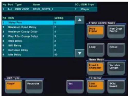
When “Simple VDCP” is selected as the protocol, the Simple VDCP Setting menu appears.
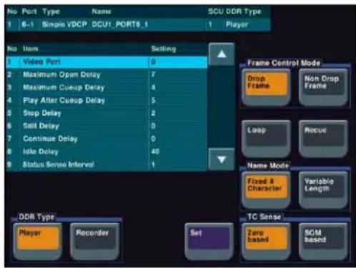
4 In the
Player: Functioning as a player.
Recorder: Functioning as a recorder.
5 In the
Fixed 8 Character: Use 8-character file names.
Variable Length: Use variable-length file names. (The file name is limited to 23 characters.)
6 In the
Zero based: Mode in which timecode is detected taking the first frame of the recalled file as 00:00:00:00
SOM based: Mode in which timecode saved in the recalled file is detected
Notes
The details of the above operation modes depend on the connected device. For more information, consult the documentation for the connected device.
7 When using a disk recorder that does not support the timecode drop frame bit, in the <Frame Control
Mode> group, select the drop frame mode or non-drop frame mode.
Drop Frame: Drop frame mode.
Non Drop Frame: Non-drop frame mode.
Notes
This setting is only valid when the system field frequency is one of the following values. 29.97, 30, 59.94, 60
8 Using any of the following methods, specify the item to which the video port number or response speed setting applies.
- Press directly on the list in the status area.
- Press the arrow keys to scroll the reverse video cursor.
- Turn the knob.
| Knob | Parameter Adjustment Setting values | ||
| 1 Item | No Item | selection | DDR VDCPSetting menu:1 to 8a)Simple VDCPSetting menu:1 to 9a) |
a) 1. Video Port: Number of the video port associated with the serial port to which the setting applies For a player, the output port setting For a recorder, the input port setting
- Maximum Open Delay: maximum time required to open a file
- Maximum Cueup Delay: maximum time required to cue up a file
- Play After Cueup Delay: delay time from the cued-up state to begin playback
- Stop Delay: delay time from issuing the stop command until actually stopping
- Still Delay: delay time from issuing the still command until actually stopping
- Continue Delay: delay time from issuing the continue command until actually stopping
- Idle Delay: delay time from unloading a file until entering the idle state (The idle state is a state wherein a file has been unloaded but a new file has not been loaded yet, that is, a state wherein no file is loaded.)
- Status Sense Interval: time until the next Status Sense command is issued (Simple VDCP Setting menu only)
9 Turn the knob to set the disk recorder video port number or response speed.
When setting the video port number
| Knob | Parameter | Adjustment | Setting values |
| 2 Setting | Video port | number | 0 to 127a) |
a) 0: No assignment
When setting the response speed
| Knob | Parameter | Adjustment | Setting values |
| 2 Setting | g Response | speed 0 to 255 |
10 Press [Set].
11 If required, repeat steps 4 to 10, to set other items.
To enable or disable the loop and recue functions
Press the [Loop] and [Recue] buttons, respectively.
Loop: Replay the recalled file in a continuous loop.
Recue: After playing the recalled file, recue to the beginning and then stop.
Making detailed settings for an Extended VTR
1 In the DCU >Serial Port Assign menu, select the setting target (DCU1 or DCU2) from the
2 Using any of the following methods, select the serial port connected to the Extended VTR for which you want to make the settings.
- Press directly on the list in the status area.
- Press the arrow keys to scroll the reverse video cursor.
- Turn the knob.
| Knob | Parameter Adjustment Setting | values |
| 1 Port | No Serial portnumber | 1 and upwards a) |
a) The range of setting values depends on the DCU port setting. (When the MKS-2700 is connected, select 2 for the slot and a value in the range 1 to 6 for the port.)
3 Press [Port Setting].
The DCU >Serial Port Assign >Extended VTR Setting menu appears.
At the top of the status area, the relevant serial port, slot number, protocol, serial port name, and SCU number appear. In the lower part of the status area, the response speed settings appear.
4 Using any of the following methods, specify the command to which the response speed setting applies.
- Press directly on the list in the status area.
- Press the arrow keys to scroll the reverse video cursor.
- Turn the knob.
| Knob | Parameter Adjustment Setting | values |
| 1 Item | No Item selection 1 to 4 | a) |
a) 1. Maximum Open Delay: maximum time required to open a file
-
Maximum Cueup Delay: maximum time required to cue up a file
-
Play After Cueup Delay: maximum delay time from the cued-up state to begin playback
-
Stop Delay: delay time from issuing the stop command until actually stopping
5 Turn the knob to set the response speed of the Extended VTR.
| Knob | Parameter | Adjustment Setting | values |
| 2 Setting | Response | speed setting | 0 to 255 |
6 Press [Set].
7 Repeat steps 4 to 6 as required to make the settings for other items.
Setup Relating to Router Interface and Tally (Router/Tally)
Chapter
23
Router Interface Settings (Router Menu)
In this system, the interface with a router (routing switcher) uses the S-Bus protocol. It is therefore necessary to assign inputs and outputs of the switcher and so on to an S-Bus space.
To carry out this assignment, use the Router/Tally >Router menu. The assignment is common to the parallel and serial tallies.
To display the Router menu
In the Engineering Setup menu, select VF6 'Router/Tally' and HF1 'Router.'
The status area shows the device names to be assigned to the S-Bus space, the matrix size, source address, destination address, and level.
The following functions are available here.
- Matrix Size: Assign the switcher matrix of each switcher processor to S-Bus space, and select the matrix size and positioning level, source address settings, and so on.
- External Box: To obtain the signal selection status of external devices with a parallel input, assign a matrix as an external selector in the S-Bus space. Make the matrix size, assignment level, source address, and other settings.
- Alias Name Gp: Set the group number for an S-Bus description name to be displayed in the source name displays for a cross-point operation.
Assigning Switcher Inputs and Outputs to S-Bus Space
1 In the
SWR1: Settings apply to switcher 1.
SWR2: Settings apply to switcher 2.
Notes
When there are two switchers on the same network, the SWR2 (second switcher) settings are required. If there is only one switcher, the settings are not required.
2 In the
320 × 348 (Standard): Assign to S-Bus space with the switcher input/output at 320×348 size.
272 × 274: Assign to S-Bus space with the switcher input/output at 272×274 size.
182 × 256: Assign to S-Bus space with the switcher input/output at 182×256 size.
136 × 138: Assign to S-Bus space with the switcher input/output at 136×138 size.
128 × 128: Assign to S-Bus space with the switcher input/output at 128×128 size.
3 Turn the knobs to set the parameters for the following items.
Source: Specify the start address of the matrix source.
Destination: Specify the start address of the matrix destination.
Level: Specify the level in the S-Bus space.
| Knob | Parameter | Adjustment Setting | values |
| 1 | Source | Start address | 1 and upwardsa) |
| 2 | Destination | Nation start address | 1 and upwardsb) |
| 3 | Level | Level 1 to 8 |
a) The maximum setting values for each matrix size: 705 for [320x348 (Standard)], 753 for [272x274], 843 for [182x256], 889 for [136x138], 897 for [128x128]
b) The maximum setting values for each matrix size:
677 for [320x348 (Standard)], 751 for [272x274], 769 for [182x256], 887 for [136x138], 897 for [128x128]
Making an External Box Setting
1 In the Router/Tally >Router menu, press [External Box Assign].
The External Box Assign menu appears.
The status area shows the external box size, address, and other settings.
2 In the
3 In the
No Assign: Do not use.
8×1: Select an external box with 8 inputs and 1 output.
16×1: Select an external box with 16 inputs and 1 output.
32×1: Select an external box with 32 inputs and 1 output.
4 Turn the knobs to make adjustments.
| Knob | Parameter | Adjustment Setting | values |
| 1 Source | Source start | address | 1 to 1017a)1 to 1009b)1 to 993c) |
| 2 Destination | Destination | start address | 1 to 1024 |
| 3 Level | Level 1 to 8 |
a) When Matrix Size is 8×1
b) When Matrix Size is 16×1
c) When Matrix Size is 32 × 1
Coupling external boxes
By coupling a number of external boxes, the number of inputs can be increased.
Here the example of coupling External Box1 and External Box2 is described.
1 In the Router/Tally >Router >External Box Assign menu, select [External Box1] from the
2 In the
3 Turn the knobs to make adjustments.
| Knob | Parameter | Adjustment Setting | values |
| 1 | Source | Start address | 1 to 1017 |
| 2 | Destination | Nation start address | 1 to 1024 |
| 3 | Level | Level 1 to 8 |
4 In the
5 In the
6 Turn the knobs to make adjustments.
At this point make the settings of Destination and Level the same as in step 3.
This automatically couples External Box1 and External Box2, forming an external box with 40 (8+32) inputs.
Setting the group number of an S-Bus description name
1 In the
2 Turn the knob to set the following parameter.
| Knob | Parameter | Adjustment | Setting values |
| 1 | Gp No | Group number of S-Bus description name | 0 to 7a) |
a) When setting values 1 to 7 are selected: If the name is not set, the description name for "0" appears. If the description name for "0" is not registered either, the Type and No values appear.
3 In the
This confirms the setting, which is reflected in the status area.
Notes
Transmit the description name selected here from the router.
Tally Group Settings (Group Tally Menu)
With the S-Bus protocol, tally control is possible for groups 1 to 8, but in this system you can use either groups 1 to 4 or groups 5 to 8.
You can also select whether or not to transfer the tally information over the S-Bus.
To select the tally groups, use the Router/Tally >Group Tally menu.
To display the Group Tally menu
In the Engineering Setup menu, select VF6 ‘Router/Tally’ and HF2 ‘Group Tally.’
The following functions are available here.
- Tally Group: Select the group tally (Gp1 to 4 or Gp5 to 8) which can be used. (For the parallel tally, all groups can be used regardless of this setting.)
- SBus Tally Enable: Specify S-Bus tally enabled or disabled.
Setting the tally groups
1 To select a consecutive sequence of groups from each of groups 1 to 4 and groups 5 to 8, set [All Group Enable] to On in the Group Tally menu.
2 In the
Wiring Settings (Wiring Menu)
When configuring a system in which the switcher inputs and outputs are connected to a router, setting this connection configuration (referred to as "wiring") in the S-Bus space, or inputting the information which specifies the physical wiring, is necessary.
To make the wiring settings, use the Router/Tally >Wiring menu. The settings are common to the parallel and serial tallies.
To display the Wiring menu
In the Engineering Setup menu, select VF6 'Router/Tally' and HF3 'Wiring.'
The status area shows the wiring settings.
Making New Wiring Settings
1 In the Router/Tally >Wiring menu, press [New].
The New menu appears.
2 With a knob or menu operation, set the destination.
When switcher inputs and outputs are connected to the router in a group, you can specify the start and end destination addresses.
Destination From: Specify the start destination address for the wiring configuration.
Destination To: When the wiring configuration is multiple, specify the end destination address. For a single wiring connection, this setting is not required.
Destination Level: Specify the destination level of the wiring configuration.
| Knob | Parameter | Adjustment Setting | values |
| 1 | Destination(From) | Destination start address | 1 to 1024 |
| 2 | Destination(To) | Destination end address | From start address to 1024 |
| 3 | Destination(Level) | Destination level | 1 to 8 |
3 Set the source.
Source From: Specify the source start address for the wiring configuration.
Source Level: Specify the source level for the wiring configuration.
| Knob | Parameter | Adjustment Setting | values |
| 4 Source (From) | Source start address | 1 to 1024 | |
| 5 Source (Level) | Source level 1 to 8 | ||
4 Press [Execute].
This makes the wiring setting according to the specifications in steps 2 and 3.
Changing the Wiring Settings
1 In the Router/Tally >Wiring menu, press [Modify].
The Modify menu appears.
2 Referring to steps 2 and 3 in the preceding section "Making new wiring settings," change the parameters as required. In this case, however, it is not possible to specify multiple destinations in a single operation, and a single "Destination Address" must be specified.
3 Press [Execute].
Deleting Wiring Settings
1 In the Router/Tally >Wiring menu, using either of the following methods, select the wiring whose settings you want to delete.
- Press directly on the list in the status area.
- Press the arrow keys to scroll the reverse video cursor.
2 Press [Delete].
Sorting Wiring Settings
In the Router/Tally >Wiring menu, press [Sort].
The sorting of wiring settings are executed in the following order.
Destination level order (ascending)→Destination address order (ascending)→Source level order (ascending)
Tally Generation Settings (Tally Enable Menu)
For settings relating to tally generation, use the Router/Tally >Tally Enable menu.
Specify the destination to be the reference for tally generation, and make various settings.
The settings are common to the parallel and serial tallies.
To display the Tally Enable menu
In the Engineering Setup menu, select VF6 ‘Router/Tally’ and HF4 ‘Tally Enable.’
The status area shows the tally generation settings.
The following functions are available here.
• Tally Type: Specify the tally type.
- Destination: Specify the address and level.
- Tally Enable: Specify the timing at which a tally is enabled.
- Enable: Always enabled.
- Disable: Always disabled.
- Tally Input: Follow the tally input status.
Making New Tally Generation Settings
1 In the Router/Tally >Tally Enable menu, press [New]. The New menu appears.
2 Turn the knobs to set the following parameters.
| Knob | Parameter | Adjustment Setting | values |
| 1 | Destination Address | Destination address | 1 to 1024 |
| 2 | Destination Level | Destination level | 1 to 8 |
| 3 | Tally Type Tally type | type 1 to | 16 a) |
a) 1:R1, 2:G1, 3:R2, 4:G2, 5:R3, 6:G3, 7:R4, 8:G4, 9:R5, 10:G5, 11:R6, 12:G6, 13:R7, 14:G7, 15:R8, and 16:G8. (R is an abbreviation of "Red Tally," and G of "Green Tally.")
3 In the
Enable: Always generate a tally.
Disable: Never generate a tally.
Tally Input: Generate a tally from the tally input state.
4 When you selected Tally Input as the tally generation mode in step 3, select either of the following in the
DCU1: Generate tally with reference to signal input to DCU1 port. Set the port number with the knob.
DCU2: Generate tally with reference to signal input to DCU2 port. Set the port number with the knob.
5 Turn the knob to select the tally input port number.
| Knob | Parameter | Adjustment | Setting values |
| 5 Input | No Tally input | put port number | 1 to 102 |
6 Press [Execute].
This sets the settings made in steps 2 to 5 as the settings for tally generation.
Modifying Tally Generation
1 In the Router/Tally >Tally Enable menu, press [Modify].
The Modify menu appears.
2 With reference to steps 2 to 5 in the preceding section "Making new tally generation settings," change the parameters as required.
3 Press [Execute].
Deleting Tally Generation Settings
1 Using either of the following methods in the Router/Tally >Tally Enable menu, select the tally generation entry you want to delete.
- Press directly on the list in the status area.
- Press the arrow keys to scroll the reverse video cursor.
2 Press [Delete].
Tally Copy Settings (Tally Copy Menu)
You can copy the tally information pertaining to a particular source to a different source.
For settings relating to the tally copy function, use the Router/Tally >Tally Copy menu. The settings are common to the parallel and serial tallies.
To display the Tally Copy menu
In the Engineering Setup menu, select VF6 'Router/Tally' and HF5 'Tally Copy.'
The status area shows the tally copy status.
Making New Tally Copy Settings
1 In the Router/Tally >Tally Copy menu, select [New]. The New menu appears.
2 Turn the knob to select the copy-from source. When setting more than one tally copy, you can specify the copy-from source start and end addresses.
| Knob | Parameter Adjustment Setting values | ||
| 1 Copy | From (From) | Copy-from source start address | 1 to 1024 |
| 2 Copy | From (To) | Copy-from source end address | 1 to 1024 |
3 Specify the copy-to source address.
| Knob | Parameter Adjustment Setting values | ||
| 3 | Copy To (From) | Copy-to source (start) address | 1 to 1024 |
| 4 | Copy To (To) | Copy-to source (end) address | 1 to 1024 |
4 Press [Execute].
This makes the tally copy setting according to the specifications in steps 2 and 3.
Modifying Tally Copy Settings
1 In the Router/Tally >Tally Copy menu, press [Modify].
The Modify menu appears.
2 Use the knobs to select the copy source and copy destination.
| Knob | Parameter | Adjustment | Setting values |
| 1 Copy | From Copy- | from source 1 to 1024 | |
| 2 Copy | To Copy-to | source 1 to 1024 |
3 Press [Execute].
Deleting Tally Copy Settings
1 In the Router/Tally >Tally Copy menu, using any of the following methods, select the tally copy whose settings you want to delete.
- Press directly on the list in the status area.
- Press the arrow keys to scroll the reverse video cursor.
- Turn the knob.
| Knob | Parameter | Adjustment | Setting values |
| 1 Copy | No Tally | copy setting selection for deletion | 1 and upwards |
2 Press [Delete].
Parallel Tally Settings (Parallel Tally Menu)
For settings relating to parallel tally, use the Router/Tally >Parallel Tally menu.
Make the parallel port settings for output of tally information pertaining to sources and destinations.
For each of the tally output terminal numbers, specify the tally type, and source address or destination level and address.
To display the Parallel Tally menu
In the Engineering Setup menu, select VF6 ‘Router/Tally’ and HF6 ‘Parallel Tally.’
The status area shows the parallel tally settings.
Making or Modifying Parallel Tally Settings
1 In the
2 Using any of the following methods, select the slot number and port number.
- Press directly on the list in the status area.
- Press the arrow keys to scroll the reverse video cursor.
- Turn the knobs.
| Knob | Parameter | Adjustment | Setting values |
| 1 | Slot No | Parallel tally slot number | 2 to 6a) |
| 2 | Port No | Parallel tally port number | 1 to 54b) |
a) When the MKS-2700 is connected, select 2 for the slot and a value in the range 1 to 36 for the port.
b) When the MKS-2700 is connected, select a value in the range 1 to 36.
3 Press [Set].
The Set menu appears.
4 In the
Src: Return a tally to all sources output to the destination.
Dest: Return a tally to the destination outputting the source to which a source tally is returned.
5 Set the destination address and level.
The level setting is only required when in step 4 you selected Destination.
| Knob | Parameter Adjustment Setting values | |
| 1 Address | Destination address | 1 to 1024 |
| 2 Leve | Destination level 1 to 8 | |
6 When setting the tally type, set the following parameter.
| Knob | Parameter Adjustment Setting values | ||
| 3 Type | Tally type | 1 to | 16 a) |
a) 1:R1, 2:G1, 3:R2, 4:G2, 5:R3, 6:G3, 7:R4, 8:G4, 9:R5, 10:G5, 11:R6, 12:G6, 13:R7, 14:G7, 15:R8, and 16:G8. (R is an abbreviation of “Red Tally,” and G of “Green Tally.”)
7 Press [Execute].
This makes the parallel tally settings, in accordance with the settings in steps 1 to 6.
Deleting Parallel Tally Settings
1 In the Router/Tally >Parallel Tally menu, using any of the following methods, select the parallel tally whose settings you want to delete.
- Press directly on the list in the status area.
- Press the arrow keys to scroll the reverse video cursor.
- Turn the knobs.
| Knob | Parameter | Adjustment | Setting values |
| 1 | Slot No | Parallel tally slot number | 2 to 6 |
| 2 | Port No | Parallel tally port number | 1 to 54 |
2 Press [Clear].
Serial Tally Settings (Serial Tally Menu)
To make serial tally settings, display the Router/Tally >Serial Tally menu.
Make the serial tally settings, including tally type and source address for each serial tally port.
To display the Serial Tally menu
In the Engineering Setup menu, select VF6 ‘Router/Tally’ and HF7 ‘Serial Tally.’
The serial tally settings appear in the status area.
Setting or Changing the Serial Tally Settings
1 In the
2 In the
3 In the
Notes
The selectable tally types depend on the settings in step 2.
4 In the
128 Bit: 128 bits 256 Bit: 256 bits
Making the Serial Tally Source Address Settings
To set the serial tally source address for each port, use the following procedure.
1 In the Router/Tally >Serial Tally menu, press [Source Assign].
The Source Assign menu appears. In the status area, the tally types and source address set for the serial tally port appear.
2 In the
3 Using any of the following methods, select the port bit number.
- Press directly on the list on the left of the status area.
- Press the arrow keys to scroll the reverse video cursor.
- Turn the knob.
| Knob | Parameter | Adjustment | Setting values |
| 1 Bit No | Bit selection | 1 and upwards |
4 Turn the knob to select the source address.
| Knob | Parameter | Adjustment | Setting values |
| 2 | S o Addr | Source address c selection | 1 to 1024 |
5 Press [Source Address Set].
Clearing a Source Address Setting
To clear a source address setting for a particular bit
In the Router/Tally >Serial Tally >Source Assign menu, select the serial tally port and bit number (see steps 2 and 3 in the previous item), then press [Clear].
This clears the source address setting for the selected bit.
To clear all source address settings
In the Router/Tally >Serial Tally >Source Assign menu, select the serial tally port, then press [All Clear].
A confirmation message appears.
- If you select "Yes," this clears all source address settings for the selected serial tally port.
- If you select "No," the clear operation is canceled.
User Setup
Chapter
24
Source Patch
The source patch is a function whereby signal pairs recorded in applicable data are automatically converted to use key snapshots, snapshots, and keyframes in different switcher systems as is.
Sequence of Source Patch Operations
In the following description, two different switcher systems are referred to as Switcher A and Switcher B.
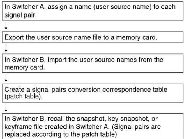
flowchart
graph TD
    A["In Switcher A, assign a name (user source name) to each signal pair."] --> B["Export the user source name file to a memory card."]
    B --> C["In Switcher B, import the user source names from the memory card."]
    C --> D["Create a signal pairs conversion correspondence table (patch table)."]
    D --> E["In Switcher B, recall the snapshot, key snapshot, or keyframe file created in Switcher A. (Signal pairs are replaced according to the patch table)."]
Exporting a User Source Name File to the Memory Card
In Switcher A, use the following procedure.
1 In the User Setup menu, select VF1 [Source Patch] and HF1 [User Source Name].
The User Source Name menu appears.
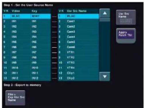
2 Use either of the following methods to select the target pair in the list on the left.
- Press directly on the list in the status area.
- Press the arrow keys to scroll the reverse video cursor.
- Turn the knob.
| Knob | Parameter Adjustment | Setting | values |
| 1 V/K P | Pair No Signal pair selection | selection | 1 to upwards |
3 Press [Usr Src Name] outside the list.
The keyboard window appears.
4 Enter a name of not more than 16 characters, and press [Enter].
The name you have entered is reflected in the Usr Src Name area.
5 Repeat steps 2 to 4, to set all of the necessary names.
6 Press [File >Exp Usr Src Name].
The Export Usr Src Name menu appears.
7 Select Memory Card as the destination, and press [→Export].
The user source name file is exported to the memory card.
To apply the signal pairs in the patch table to this menu
Press [Apply Patch Tbl].
For more information about the patch table, see the following item.
Creating a Patch Table (Conversion Table)
Load the memory card created in Switcher A to Switcher B, and use the following procedure in Switcher B.
1 In the User Setup menu, select VF1 [Source Patch] and HF2 [Patch Table].
The Patch Table menu appears.
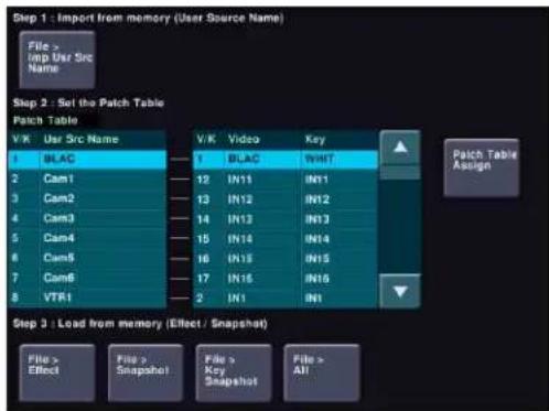
2 Press [File >Imp Usr Src Name].
The Import Usr Src Name menu appears.
3 Select Memory Card as the import source, and press [→Import].
The user source name file is loaded from the memory card.
4 Press [Patch Table Assign].
The Patch Table Assign menu appears.
The user source names in Switcher A imported by step 3 are listed on the left and the pairs of videos and keys set in Switcher B are listed on the right.
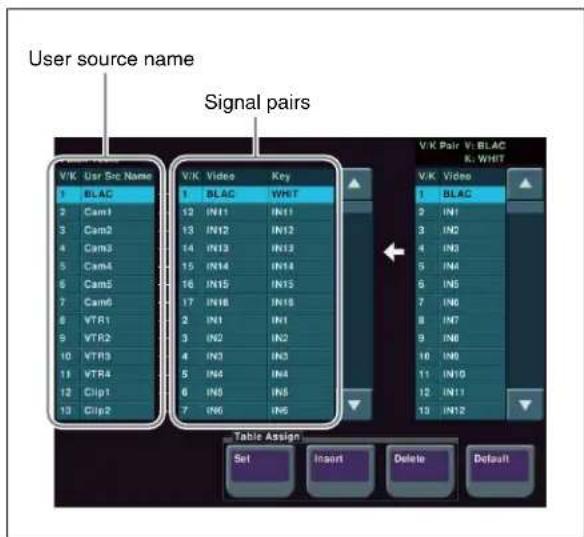
5 Using either of the following methods, select the target user source name from the list on the left.
- Press directly on the list in the status area.
- Press the arrow keys to scroll the reverse video cursor.
- Turn the knob.
| Knob | Parameter Adjustment Setting | values |
| 1 User | Source User source name selection | 1 to upwards |
6 Using either of the following methods, select the video signal that you want to assign from the list on the right.
- Press directly on the list in the status area.
- Press the arrow keys to scroll the reverse video cursor.
- Turn the knob.
| Knob | Parameter Adjustment Setting | values |
| 2 V/K | Pair No Signal pair selection | 1 to upwards |
7 In the
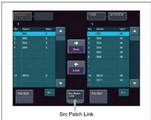
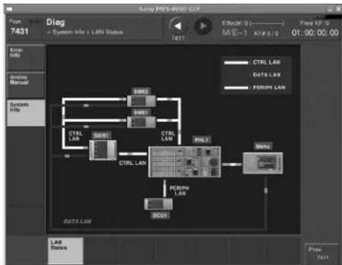
| System control unit | Board STATION ID switches | |
| MKS-8010A FP-141 S | 108 | |
| MKS-8010B CA-76 S | 108 | |
4 In the Engineering Setup >System >Initialize menu, select PNL, and carry out a reset.
This carries out a restart, and when the restart is completed connection to the MKS-8080/8082 is possible.
5 In the Engineering Setup >Router/Tally >Router menu, set the position of the MVS-8000X system in S-Bus space.
Select the setting from SWR1 and SWR2, and set each of Source, Destination, and Level to 1.
Setting Status of the MKS-8080/8082 in Simple Connection
As a result of making the simple connection, the MKS-8080/8082 operates in AUX bus mode, and the settings are the following factory defaults.
With regard to the meaning of the following settings, see the section “Menu Operations” in the Operation Manual for the MKS-8080/8082.
C: SET SWITCHER ID (for AUX mode)
This is set to 001, which is the station number of the center control panel.
D: SET AUX DESTINATION/SOURCE (for AUX mode)
The source is set to IN001 and following, and destination is set to OUT001 and following.
H: SET PHANTOM TABLE (for Router mode)
This is unset, since the unit does not operate in router mode.
N: SET PANEL TABLE (for Router mode)
The source is set to IN001 and following, and destination is set to OUT001 and following. However, since the unit does not operate in router mode, these settings are not used.
R: SET ROUTE
Since when using the simple connection the switcher and router cannot be connected in cascade, no route setting is required, and this is unset.
O: SET AVAILABLE SOURCE/DESTINATION
Set the source and destination ranges so that the MVS-8000X inputs and outputs can be selected.
Y: SET DISPLAY MODES
The DISPLAY MODES/PANEL FUNCTION setting is set to NORMAL.
The TALLY GROUP setting is set to be the same as the setting in Engineering Setup >Router/Tally >Tally Group on the MVS-8000X.
Z: SET PANEL STATUS
The various settings are the same as the factory default settings.
Macro File Editing Rules
When editing a macro file, follow the rules described below.
Macro File Syntax
The macro file syntax is as follows.
File format
The file is in CSV (comma-separated value) format.
Newline code
CR (ASCII code 0D), LF (ASCII code 0A), or CRLF may be used.
Statement syntax
There are four types of statement, each terminated by a newline code.
File header: This must always appear as the first line of the file. It comprises 28 characters, as follows. Example: PNL (space) 0001PNL_rrrr.PMRnnnnnnnnn rrrr: macro register number (0001 to 0099) nnnnnnnnn: In a file created on the switcher, this is a register name automatically set by the switcher. When creating a new file, it is recommended to set this to be the same as the file name (see page 651). The name is limited to eight characters. The following characters may not be used. space, \, /, :, :, (comma), . (dot), <, >, *, ?, “”
Comment: Begins with “#”. The content of the line following the “#” up to the next newline has no effect on macro execution, and can be used as a comment.
Notes
You can only use comments in files saved to the hard disk or a memory card. When you load a macro file into a register, the comments are discarded.
Event statement: Begins with “Event?”, and defines the macro event.
For details, see next item, "Syntax of Event and Continue Statements."
Continue statement: Begins with “Continue?”, and defines the macro event.
For details, see next item, "Syntax of Event and Continue Statements."
Some events cannot be used (see page 652).
Syntax of Event and Continue Statements
An event can be written with an Event statement only, or with an Event statement followed by any number of Continue statements. The Event statements and Continue statements have the following syntax.
Word separator character
Use “,” (comma).
Ignored
Spaces and tabs are ignored. There is no distinction between lowercase and uppercase. If two or more separator characters appear consecutively, later ones are ignored. Separator characters at the beginning of a line are also ignored.
Content of line
Must begin with “Event?” or “Continue?”, followed by symbols and parameters.
Event?, [symbol], [parameter], [parameter], ...
Continue?, [symbol], [parameter], [parameter], ...
symbol: ASCII character string showing the type of event (see page 652).
parameter: Shows details of an event. Consists of parameter names and arguments, and these must appear in pairs. The number and type of parameters depends on the event (see page 653).
If the same parameter appears twice or more, the last occurrence is valid.
How to use Continue statements
When a single parameter has more than one argument, use a Continue statement. The following example is of a snapshot event.
An event to recall a snapshot in region M/E-1 is written as: Event?, Snapshot, Region?, ME1, Register?, 1, Attribute?, Off, Time?, Current
In the Event statement, only one region can be specified.
To specify both regions M/E-1 and DME1, use a Continue statement, thus:
Event?,Snapshot,Region?,ME1,Register?,1,Attribute?,Off,Time?,Current
Continue?,Snapshot,Region?,DME1,Register?,1,Attribute?,Off,Time?,Current
To specify more than one argument for a region parameter, follow the Event statement by a Continue statement on the next line.
File Name
Set the file name as follows.
Example: nnnnnnnn.PNL_rrrr.PMR
nnnnnnnn: In a file created on the switcher, this is a register name automatically set by the switcher.
The name is limited to eight characters.
The following characters may not be used.
space, \, /, :, :, (comma), . (dot), <, >, *, ?, “”
rrrr: macro register number (0001 - 0099)
Saving and Recalling a File
For a newly created file, if you create a directory on the memory card (see figure below), and move the file to the prescribed location, you can then recall it in the File >All, External File menu.
Notes
When amending a file saved on the switcher, be sure to save it in the original directory.
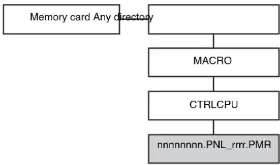
flowchart
graph TD
    A["Memory card Any directory"] --> B["MACRO"]
    B --> C["CTRLCPU"]
    C --> D["nnnnnnnn.PNL_rrrr.PMR"]
Path example: Memory Card\Sample\MACRO\CTRLCPU\nnnnnnnn.PNL_rrrr.PMR
Errors
If any of the following problems occur, it is not possible to recall the file. Attempting to recall the file will produce an error message (see page 669).
- If there is a syntax error.
- If a required parameter is not present.
Correspondence Between Events and Symbols
For details of events, see “Events” (page 487).
| Event Symbol Using Continue | ||
| Cross-point selection in the auxiliary bus control block AuxXpt No | ||
| Cross-point selection in the auxiliary bus control block in router control mode | RouterXpt Yes | |
| Cross-point selection in the cross-point control block MEXpt Yes | ||
| Auto transition and take in the transition execution section MEAutoTransition | Yes | |
| Cut in the transition execution section MECut No | ||
| Transition type selection | TransitionType | No |
| Next transition setting | NextTransition | No |
| Pattern limit on/off | PatternLimit | No |
| Fade-to-black execution | FadeToBlack | No |
| Auto transition and take in the independent key transition execution section | KeyAutoTransition | Yes |
| Key insertion and deletion in the independent key transition execution section | KeyCut | Yes |
| Independent key transition type selection | KeyTransitionType | No |
| VTR/DDR/clip start point setting | StartTc | Yes |
| VTR/DDR/clip playback | Play | Yes |
| VTR/DDR/clip stop | Stop | Yes |
| VTR/DDR/clip cue-up | Cue | Yes |
| VTR/DDR/clip fast forward | FF | Yes |
| VTR/DDR/clip rewind | Rewind | Yes |
| Disk recorder/Extended VTR file recall | DiskFileLoad | No |
| Recall snapshot | Snapshot | Yes |
| Recall key snapshot | KeySnapshot | Yes |
| Recall wipe snapshot | WipeSnapshot | Yes |
| Recall DME wipe snapshot | DMEWipeSnapshot | Yes |
| Recall shotbox | Shotbox No | |
| Recall master snapshot | MasterSnapshot | No |
| Recall master timeline | MasterTimelineRecall | No |
| Recall effect | TimelineRecall | Yes |
| Execute effect | TimelineRun | Yes |
| Rewind keyframe | TimelineRewind | Yes |
| Fast forward effect | TimelineFF | Yes |
| Effect execution direction selection (normal) | TimelineDirectionNormal | Yes |
| Effect execution direction selection (reverse) | TimelineDirectionReverse | Yes |
| Effect execution direction selection (normal/reverse on) | TimelineNormalReverseOn | Yes |
| Effect execution direction selection (normal/reverse off) | TimelineNormalReverseOff | Yes |
| Pause^a) | Pause | No |
| Recall of function assigned to memory recall button/user preference button | UtilityButton | No |
| Recall of function assigned to the key 2 row cross-point buttons | Key Bus Utility Button | No |
| Frame memory clip loop on/off | FMLoop | Yes |
| Menu macro recall and execution | MenuMacroRun | No |
| Recall of frame memory clip | ClipRecall No | |
| Record with device DeviceRecord Yes |
a) For details of pause events, see "Macro Execution" (page 489).
Symbols and Parameters
n: indicates a numeral 0 to 9. x: indicates an alphanumeric character.
| Symbol Parameter name Arguments Description | |||
| MEXpt ME? ME1 to ME4, PP Control blocks on the applicable bank | |||
| MEBus? A, B, Key1 to Key8, Key1Source to Key8Source, Utility1, Utility2, DMEExternalVideo | Applicable bus | ||
| Xpt? 1 to 300 | Main table cross-point button number set in the Xpt Assign menu | ||
| VideoKey? | Video, Key | ||
| AuxXpt | AuxBus? EditPreview, AUX1 to AUX48, FrameMemory1, FrameMemory2, DME1Video to DME8Video, DME1Key to DME8Key, DME1Video2nd to DME8Video2nd (a), DME1Key2nd to DME8Key2nd (b), DMEUtility1, DMEUtility2, CCR1, CCR2 | Aux1 to AUX48, FrameMemory1, FrameMemory2, DME1Video to DME8Video, DME1Key to DME8Key, DME1Video2nd to DME8Video2nd (a), DME1Key2nd to DME8Key2nd (b), DMEUtility1, DMEUtility2, CCR1, CCR2 | Applicable AUX bus (a): DMEnVideo2nd= Bus for selecting back video signal of DMEn channel (n=1 to 8), (b): DMEnKey2nd= Bus for selecting back key signal of DMEn channel (n=1 to 8) |
| Xpt? | 1 to 300 | Cross-point button number in the main table set in the Xpt Assign menu | |
| VideoKey? | Video, Key | Type of signal (video signal or key signal) to be selected on the applicable bus | |
| MEAutoTransition | ME? ME1 to ME4, PP Control blocks on the applicable bank | ||
| Time? | Current (a), 0 to 999 | Transition rate (number of frames) (a): Mode in which the current value set on the transition control block is used | |
| ABusXpt? | Current (a), 1 to 300 | A bus or B bus cross-point button number. Use the button number of the main table set in the Xpt Assign menu. (a): Mode in which the cross-point number set for the current A bus or B bus is used | |
| BBusXpt? | Current (a), 1 to 300 | ||
| MECut | ME? ME1 to ME4, PP Control blocks on the applicable bank | ||
| KeyAutoTransition | ME? ME1 to ME4, PP Control blocks on the applicable bank | ||
| Key? | Key1 to Key8 | Key of the applicable independent key transition control block | |
| Time? | Current (a), 0 to 999 | Transition rate (number of frames) (a): Mode in which the current value set on the independent key transition control block is used | |
| Direction? | ToOn (a), ToOff (b), Any (c) | Transition execution mode (a): Key is inserted (b): Key is deleted (c): Transition is always executed | |

| Symbol | Parameter name | Arguments | Description | ||
| KeyCut ME? ME1 to ME4, PP | Control blocks on the applicable bank | ||||
| Key? Key1 to Key8 Key of the applicable independent transition control block | key | ||||
| Direction? ToOn (a), | ToOff (b),Any (c) | Transition execution mode(a): Key is inserted(b): Key is deleted(c): Transition is always executed | |||
| Play Device? 1 to 12, | FrameMemory1Clip to FrameMemory8Clip | Applicable device | |||
| Mode? Normal (a), | Recue (b),Loop (c) | Playback mode(a): Normal modeAs for Frame Memory 1 Clip to Frame Memory 8 Clip, settings are ignored and operation mode is fixed to “Normal.”(b): Recue mode(c): Loop mode | |||
| Cue Device? 1 to 12, | FrameMemory1Clip to FrameMemory8Clip | Applicable device | |||
| Timecode? Current (a), hh:mm:ss:ff Start point timecode | hh=hours (00 to 23)As for Frame Memory 1 Clip to Frame Memory 8 Clip, hh is fixed to “01.”mm=minutes (00 to 59)ss=seconds (00 to 59)ff=frames (00 to 29)(a): Mode in which the currently set timecode is used | ||||
| Stop Device? 1 to 12, | FrameMemory1Clip to FrameMemory8Clip | Applicable device | |||
| FF | Device? 1 to 12, | FrameMemory1Clip to FrameMemory8Clip | Applicable device | ||
| Rewind | Device? 1 to 12, | FrameMemory1Clip to FrameMemory8Clip | Applicable device | ||
| DiskFileLoad | Device? 1 to 12 | Applicable device | |||
| FileName? | File Name | Name of file being set (max. 23 characters) | |||
| Snapshot | Region? | ME1 to ME4, PP, User1 to User8, DME1 to DME8, Router | Applicable region | ||
| Register? | 1 to 99 | Applicable register number | |||
| Attribute? | Off, Dissolve, AutoTransition, Dissolve&AutoTransition | Applicable snapshot attributes | |||
| Time? | Current (a), 0 to 999 | Duration of effect dissolve (number of frames)(a): Mode in which the currently set value is used | |||
| KeySnapshot | ME? ME1 to ME4, PP Control blocks on the applicable bank | ||||
| Key? | Key1 to Key8 | Applicable key | |||
| Register? | 1 to 4 | Applicable register number | |||
| WipeSnapshot ME? ME1 to ME4, PP Control blocks on the applicable bank | |||||
| Register? 1 to 10 Applicable register number | |||||
| DMEWipeSnapshot ME? ME1 to ME4, PP Control blocks on the applicable bank | |||||
| Register? 1 to 10 Applicable register number | |||||
| TimelineRecall Region? ME1 to ME4, PP, User1 to | User8, DME1 to DME8, PBus, Device1 to Device12, GPI | Applicable region | |||
| Register? 1 to 399 Applicable register number | |||||
| TimelineRun Region? ME1 to ME4, PP, User1 to | User8, DME1 to DME8, PBus, Device1 to Device12, GPI, Current (a) | Applicable region(a): Mode in which operation takes place in the region currently specified in the numeric keypad control block | |||
| TimelineRewind Region? ME1 to ME4, PP, User1 to | User8, DME1 to DME8, PBus, Device1 to Device12, GPI, Current (a) | Applicable region(a): Mode in which operation takes place in the region currently specified in the numeric keypad control block | |||
| TimelineFF | Region? ME1 to ME4, PP, User1 to | Applicable region(a): Mode in which operation takes place in the region currently specified in the numeric keypad control block | |||
| Region? 1 to 99 | Applicable register number | ||||
| Shotbox | Register? 1 to 99 | Applicable register number | |||
| Pause | Time? | 0 to 999 Time for which macro is paused(number of frames) | |||
| StartTc | Device? | 1 to 12,FrameMemory1Clip toFrameMemory8Clip | Applicable device | ||
| MasterSnapshot | Register? 1 to 99 | Applicable register number | |||
| MasterTimelineRecall | Register? 1 to 99 | Applicable register number | |||
| RouterXpt | DestinationButton? | 1 to 128 | Router cross-point button | ||
| Source? 1 to 1024 | Router source number | ||||
| Level? | 1 to 8 | Router level selection | |||
| PatternLimit | ME? ME1 to ME4, PP Control blocks on the applicable bank | ||||
| Status? | ToOn (a),ToOff (b),Any (c) | Pattern limit status(a): Pattern limit applies(b): Pattern limit does not apply(c): The pattern limit status always changes | |||
| TransitionType | ME? | ME1 to ME4, PP | Control blocks on the applicable bank | ||
| TransitionType? | Mix, NAM, SuperMix,PresetColorMix, Wipe,DMEWipe, FM1&2Clip,FM3&4Clip, FM5&6Clip,FM7&8Clip | Transition type | |||
| KeyTransitionType | ME? | ME1 to ME4, PP | Control blocks on the applicable bank | ||
| Key? | Key1 to Key8 Key of the applicable independent key transition control block | ||||
| Direction? On (a), | Off (b),Any (c) | Independent key transition execution mode(a): Key is inserted(b): Key is deleted(c): Transition is always executed | |||
| KeyTransitionType? | Mix, Wipe, DMEWipe, Cut | Transition type of the independent key transition control block | |||

| Symbol | Parameter name | Arguments | Description |
| NextTransition ME? ME1 to ME4, PP Control blocks on the applicable bank | |||
| All? On, Off Applicable next transition | |||
| KeyPriority? On, Off Applicable next transition | |||
| BKGD? On, Off Applicable next transition | |||
| Key1? to Key8? On, Off Applicable next transition | |||
| FadeToBlack Time? Current (a), 1 to 999 Transition rate (number of frames) | (a): Mode in which the current value set on the fade to black control block is used | ||
| TimelineDirectionNormal Region? | ME1 to ME4, PP, User1 to User8, DME1 to DME8, PBus, Device1 to Device12, GPI, Current (a) | Applicable region(a): Mode in which operation takes place in the region currently specified in the numeric keypad control block | |
| TimelineDirectionReverse | Region? | ME1 to ME4, PP, User1 to User8, DME1 to DME8, PBus, Device1 to Device12, GPI, Current (a) | Applicable region(a): Mode in which operation takes place in the region currently specified in the numeric keypad control block |
| TimelineNormalReverseOn | Region? | ME1 to ME4, PP, User1 to User8, DME1 to DME8, PBus, Device1 to Device12, GPI, Current (a) | Applicable region(a): Mode in which operation takes place in the region currently specified in the numeric keypad control block |
| TimelineNormalReverseOff | Region? | ME1 to ME4, PP, User1 to User8, DME1 to DME8, PBus, Device1 to Device12, GPI, Current (a) | Applicable region(a): Mode in which operation takes place in the region currently specified in the numeric keypad control block |
| UtilityButton | UtilityModule? | UserPrefs, UtilityBox | Applicable control block |
| Button? | 1 to 96 | Applicable button | |
| UtilityStatus? | On, Off, Current (a) | Status of function assigned to button (a): Operates according to currently assigned function | |
| FMLoop | Device? | FrameMemory1Clip to FrameMemory8Clip | Applicable clip |
| FMLoopMode? | On (a), Off (b) | Frame memory clip loop on/off(a): Loop is enabled(b): Loop is disabled | |
| MenuMacroRun | Register? | 1 to 99 | Applicable register number |
| KeyBusUtilityButton | ME? ME1 to ME4, PP Control blocks on the applicable bank | ||
| BANK? | Bank1 to Bank5 | Applicable bank | |
| KeyBusUtilityButton? | 1 to 32 | Applicable button | |
| UtilityStatus? | On, Off, Current (a) | Status of function assigned to button (a): Operates according to currently assigned function | |
| ClipRecall Device? | FrameMemory1Clip to FrameMemory8Clip | Applicable clip | |
| ClipType? | Pair, Single File type of clip (pair/single) | ||
| Clip? | Clip Name Name of clip (up to four characters) | ||
| Device Record | Device? | 1 to 12 | Applicable device |
Example of File Contents
| Line | Content | Description |
| 1 | PNL 0001PNL_0000.PMRMACROREG | File header |
| Line Content Description | |
| 2 #,Sample, Comment | |
| 3 Event?,Snapshot,Region?,ME1,Register?,1,Attribute?,Off,Time?,Current Simultaneous | usly recall snapshots from register number 1 in the M/E-1 and DME1 regions. |
| 4 Continue?,Snapshot,Region?,DME1,Register?,1,Attribute?,Off,Time?,Current | |
| 5 Event?,MEXpt,ME?,ME2,MEBus?,A,Xpt?,121,VideoKey?,Video Select button number | 121 on the M/E-2 A bus. |

About the Macro Attachment List Display
The Button column in the macro attachment list displayed in the status area of the Macro >Attachment menu screen shows character strings which identify macro attachment assigned buttons. Each of these character strings is in fact a combination of characters shown in the Button(1), Button(2), and Button(3) columns in the following tables. For example, if Block and Button(1) to Button(3) are combined as:
Block: P/P XPT
Button(1): UTILI Bus
Button(2): V
Button(3): XPT2
The Button column in the macro attachment list in the Macro >Attachment menu screen shows “UTIL1 Bus V XPT2,” which means “utility 1 bus, video signal, cross-point number 2.”
M/E and PGM/PST Banks
The following table shows only the macro attachment assignable buttons in the PGM/PST bank.
For the M/E-1 (M/E-2 to M/E-4) bank, "P/P" in the Block Select and Block columns changes to "M/E-1" ("M/E-2" to "M/E-4") and "DSK" in the Button(1) and Button(2) columns changes to "KEY." The contents of the Button(3) column do not change.
Block Select:P/P, Block:P/P XPT
| Button (1) Button (2) Button (3) | ||
| A BusB BusDSK1 Bus:DSK8 Bus | (nnothing)Shift | XPT 1:XPT 128M/E 1M/E 2M/E 3P/P |
| DSK1 Src Bus:DSK8 Src Bus | VKV ShiftK Shift | |
| Sub A BusSub B BusSub DSK1 Bus:Sub DSK8 BusMain&Sub A BusMain&Sub B BusMain&Sub DSK1 Bus:Main&Sub DSK8 Bus | (nnothing)Shift | |
| Button (1) Button (2) Button (3) | ||
| Sub DSK1 Src Bus:Sub DSK8 Src BusMain&Sub DSK1 Src Bus:Main&Sub DSK8 Src Bus | VKV ShiftK Shift | XPT 1:XPT 128M/E 1M/E 2M/E 3P/P |
| UTIL1 BusUTIL2 BusEXT DME BusDMEUtility1DMEUtility2Sub UTIL1 BusSub UTIL2 BusSub EXT DME BusMain&Sub UTIL1 BusMain&Sub UTIL2 BusMain&Sub EXT DME Bus | VKV ShiftK Shift | |
| Dual A BusDual B BusSub Dual A BusSub Dual B BusMain&Sub Dual A BusMain&Sub Dual B Bus | V Shift | |
| Utility/ShotboxSub Utility/ShotboxMain&Sub Utility/Shotbox | Bank 1-1:Bank 1-32Bank 2-1:Bank 2-32Bank 3-1:Bank 3-32Bank 4-1:Bank 4-32Bank 5-1:Bank 5-32 | (nnothing) |
Block Select:P/P, Block:P/P Trans
| Button (1) Button (2) Button (3) | ||
| (blank) | MIXa) | (nnothing) |
| DSK1 | NAMa) | |
| : | SUPER MIXa) | |
| DSK8 | PST COLOR MIXa)WIPEa) | |
| Sub | DMEa)TAKEb) | |
| Sub DSK1 | DSK_ONc)AUTO TRANsd) | |
| : | CUTd) | |
| Sub DSK8 | ALLa)d) | |
| Main&Sub | KEY PRIORa)d)BKGDa)d) | |
| Main&Sub DSK1 | DSK1a)d): | |
| : | DSK4a)d)NORMa)d)NORM/REVa)d)REVa)d)PTN LIMITa)c)LIMIT SETa)c)KFa)c)PTN LIMITb)FaderPRIOR SETa)c)TRANS PVWa)c)K-SSc)e)K-SS STOREc)e)K-MOD ENBLc)e)K-TR ENBLc)e)DSK1c)e): | |
| Main&Sub DSK8 | DSK4c)e) |
a) These buttons can be assigned with their functions in the setup menu. They can be assigned with any of the following functions: transition type selection (MIX, NAM, SUPER MIX, PST COLOR MIX, WIPE, DME, FM1&2, FM3&4, FM5&6, FM7&8), next transition selection (BKGD, DSK1 to DSK8, PRIOR, ALL), wipe direction selection (NORM, NORM/REV, REV), PLAY, CUEUP, STOP, and PTN LIMIT.
b) For the simple type transition control block.
c) For the standard type transition control block.
d) For the standard type or compact type transition control block.
e) These buttons can be assigned with their functions in the setup menu. Thy can be assigned with any of: MIX, WIPE, and DME.
Block Select:P/P, Block:P/P Key Trans
| Button (1) Button (2) Button (3) | ||
| DSK1:DSK8Sub DSK1:Sub DSK8Main&Sub DSK1:Main&Sub DSK8 | MIXWIPEDMECUTTAKEDSK_ON | (nnothing) |
Auxiliary Bus Control Block
Block Select:Aux, Block:AUX-1, AUX-2
| Button (1) Button (2) Button (3) | ||
| EDIT PVW | V | XPT 1 |
| AUX 1 | K | : |
| : | V Shift | XPT 128 |
| AUX 48 | K Shift | M/E 1 |
| FM1 | V 2nd Row | M/E 2 |
| FM2 | K 2nd Row | M/E 3 |
| V 2nd Row Shift | P/P | |
| K 2nd Row Shift | ||
| DME1V | (nnothing) | |
| : | Shift | |
| DME8V | 2nd Row | |
| DME1K | 2nd Row Shift | |
| : | ||
| DME8K | ||
| DMEUtility1 | V | |
| DMEUtility2 | K | |
| V Shift | ||
| K Shift | ||
| V 2nd Row | ||
| K 2nd Row | ||
| V 2nd Row Shift | ||
| K 2nd Row Shift | ||
| DME1V2nd | (nnothing) | |
| : | Shift | |
| DME8V2nd | 2nd Row | |
| DME1K2nd | 2nd Row Shift | |
| : | ||
| DME8K2nd | ||
| CCR1 | V | |
| CCR2 | K | |
| P/P UTIL1 | V Shift | |
| P/P UTIL2 | K Shift | |
| M/E-1 UTIL1 | V 2nd Row | |
| M/E-1 UTIL2 | K 2nd Row | |
| M/E-2 UTIL1 | V 2nd Row Shift | |
| M/E-2 UTIL2 | K 2nd Row Shift | |
| M/E-3 UTIL1 | ||
| M/E-3 UTIL2 | ||
| M/E-4 UTIL1 | ||
| M/E-4 UTIL2 | ||
| DSK1 | (nnothing) | |
| : | Shift | |
| DSK8 | 2nd Row | |
| 2nd Row Shift | ||
| M/E-1 KEY1 | ||
| : | ||
| M/E-1 KEY8 | ||
| M/E-2 KEY1 | ||
| : | ||
| M/E-2 KEY8 | ||
| M/E-3 KEY1 | ||
| : | ||
| M/E-3 KEY8 | ||
| M/E-4 KEY1 | ||
| : | ||
| M/E-4 KEY8 | ||

| Button (1) Button (2) Button (3) | ||
| DSK1 Src | V | XPT 1 |
| : | K | : |
| DSK8 Src | V Shift | XPT 128 |
| K Shift | M/E 1 | |
| M/E-1 KEY1 Src | V 2nd Row | M/E 2 |
| : | K 2nd Row | M/E 3 |
| M/E-1 KEY8 Src | V 2nd Row Shift | P/P |
| M/E-2 KEY1 Src | K 2nd Row Shift | |
| : | ||
| M/E-2 KEY8 Src | ||
| M/E-3 KEY1 Src | ||
| : | ||
| M/E-3 KEY8 Src | ||
| M/E-4 KEY1 Src | ||
| : | ||
| M/E-4 KEY8 Src | ||
| P/P EXT DME | ||
| M/E-1 EXT DME | ||
| M/E-2 EXT DME | ||
| M/E-3 EXT DME | ||
| M/E-4 EXT DME | ||
Other Blocks
Block Select: Others, Block:Keyframe
| Button (1) Button (2) Button (3) | |
| RUN | (nnothing) (nothing) |
| REWIND | |
| FF | |
| NORM | |
| REV | |
| NORM/REV |
Block Select: Others, Block:Multi Function Flexi Pad a)
| Button (1) Button (2) Button (3) | ||
| DSK1:DSK8M/E-1 KEY1:M/E-1 KEY8M/E-2 KEY1:M/E-2 KEY8M/E-3 KEY1:M/E-3 KEY8M/E-4 KEY1:M/E-4 KEY8Sub DSK1:Sub DSK8M/E-1 Sub KEY1:M/E-1 Sub KEY8M/E-2 Sub KEY1:M/E-2 Sub KEY8M/E-3 Sub KEY1:M/E-3 Sub KEY8M/E-4 Sub KEY1:M/E-4 Sub KEY8 | AUTO TRANSKEY_ON | (nnothing) |
| EFF RUN | REWINDNORMREVNORM/REV | |
a) The Multifunction Flexi Pad control block appears as "10KeyPad."
Block Select: Others, Block: Joystick, Trackball
| Button (1) Button (2) Button (3) | ||
| DEV CLR WORK BUFR | (CUEUP)Y (PLAY)TRGT (STOP)AXIS LOC (START TC) | (nnothing) |
Block Select: Others, Block:Device Control
| Button (1) Button (2) Button (3) | ||
| (nnothing) CUEUP | PLAYSTOPSTART TC | (nnothing) |
Block Select: Others, Block: Utility Box 1, Utility Box 2, Menu
| Button (1) Button (2) Button (3) | ||
| Utility 1: Utility 96 | (nnothing) (nothing) |
Block Select: Others, Block:DSK/FTB
| Button (1) Button (2) Button (3) | ||
| Key1 | AUTO TRANS | (nnothing) |
| Key2 | KEY_ON | |
| FTB | ||
Block Select: Others, Block:FTB
| Button (1) Button (2) Button (3) | ||
| (blank) FTB (nothing) |
Block Select: Others, Block:DSK Fader 1 to DSK Fader 4
| Button (1) Button (2) Button (3) | ||
| P/P | KEY1 | MIX |
| M/E1 | : | WIPE |
| M/E2 | KEY8 | DME |
| M/E3 | CUT | |
| M/E3 | TAKE | |
| KEY_ON | ||
Menu Operations Not Recorded in a Menu Macro
The menu operations not recorded in a menu macro comprise some operations common to all menus and some operations inhibited in individual menus.
Operations not recorded in menu macros, common to all menus
- Recalling a menu
- Delegation operations: region selection, channel delegation, operations assigning a parameter to a knob, and so forth
- Parameter setting operations using the knobs, trackball, or joystick (value input operations from the numeric keypad are recorded)
Operations not recorded in menu macros, in individual menus
| Menu number | Menu including operations not recorded |
| 0011 to 0023 | All menus under Home |
| 2544 | FrameMemory >File >Move |
| 2545 | FrameMemory >File >Delete |
| 2546 | FrameMemory >File >Rename |
| 2551 | FrameMemory >File >Folder |
| 2561 | FrameMemory >External Device >Format |
| 2562 | FrameMemory >External Device >Backup/Restore |
| 5333 | Device >DDR/VTR >File List |
| 5412 to 5437 | All menus under Macro |
| 7111 to 7172 | All menus under File |
| 7311 to 7317.1 | All menus under Engineering Setup >System |
| 7327 | Engineering Setup >Panel >Maintenance |
Data Saved by [Setup Define] and [Initial Status Define]
This section lists the data saved in the Engineering Setup >System >Start Up menu, by each of [Setup Define] and [Initial Status Define].
Data Saved by [Setup Define]
Included in Panel Setup
| Menu number Menu path Saved data | ||
| 0022 Home>Favorites>Group Edit All data relating to Group Edit menu | ||
| 0023 Home>Favorites>Button Edit All data relating to Button Edit menu | ||
| 7321 Engineering Setup>Panel>Config All data relating to Config menu | ||
| 7321.1 Engineering Setup>Panel>Config>DSK Fader Assign | All data relating to DSK Fader Assign menu | |
| 7321.2 Engineering Setup>Panel>Config>Link/Program Button>Key Trans Link | All data relating to Key Trans Link menu | |
| 7321.3 Engineering Setup>Panel>Config>Link/Program Button>External Bus Link | All data relating to External Bus Link menu | |
| 7321.7 Engineering Setup>Panel>Config>10 Key Region Assign | All data relating to 10 Key Region Assign menu | |
| 7321.8 Engineering Setup>Panel>Config>Link/Program Button | All data relating to Link/Program Button menu | |
| 7321.11 Engineering Setup>Panel>Config>MP2 Main/Sub Assign | All data relating to MP2 Main/Sub Assign menu | |
| 7321.15 Engineering Setup>Panel>Config>Compact Key Module Assign | All data relating to Compact Key Module Assign menu | |
| 7321.26 Engineering Setup>Panel>Config>M/E Operation Inhibit | All data relating to M/E Operation Inhibit menu | |
| 7321.31 Engineering Setup>Panel>Config>JS/TB User Setting | All data relating to JS/TB User Setting menu | |
| 7322 Engineering Setup>Panel>Xpt Assign Data relating to Table assignments for each bus [Audio Follow] setting | ||
| 7322.1 Engineering Setup>Panel>Xpt Assign/Table Button Assign | All data relating to Table Button Assign menu | |
| 7322.5 Engineering Setup>Panel>Xpt Assign>Main,V/K Pair Assign | AndGroup Data | |
| 7322.10 Engineering Setup>Panel>Side Flags Button Assign | All data relating to Side Flags Button Assign menu | |
| 7322.11 Engineering Setup>Panel>Xpt Assign>Mixer Xpt Assign | All data relating to Mixer Xpt Assign menu | |
| 7323 | Engineering Setup>Panel>Aux Assign | Data relating to bus assignment to AUX delegation buttons |
| 7323.1 | Engineering Setup>Panel>Aux Assign>RTR Mode Setting | All data relating to RTR Mode Setting menu |
| 7324 | Engineering Setup>Panel>Prefs/Utility | All data relating to function assignment to user preference buttons |
| Menu number | Menu path | Saved data |
| 7324.1 Engineering | Setup >Panel >Prefs/Utility >Utility Module Assign | All data relating to function assignment to utility/shotbox control block |
| 7324.2 Engineering | Setup >Panel >Prefs/Utility >Key 2/4 Bus Button Assign | All data relating to utility/shotbox assignment to cross-point buttons in the key 2 row |
| 7325 Engineering Setup >Panel >Device Interface All data relating to Device Interface menu | ||
| 7325.1 Engineering | Setup >Panel >Device Interface >GPI Input | All data relating to GPI Input menu |
| 7325.3 Engineering | Setup >Panel >Device Interface >GPI Output | All data relating to GPI Output menu |
| 7325.4 Engineering | Setup >Panel >Device Interface >DCU Serial Port/MPE Assign | All data relating to DCU Serial Port/MPE Assign menu |
| 7326 Engineering Setup >Panel >Operation All data relating to Operation menu | ||
| 7326.2 Engineering | Setup >Panel >Operation >Effect Mode All data relating to Effect Mode menu (excluding [Default KF Duration] setting values) | |
| 7326.3 Engineering | Setup >Panel >Operation >Flexi Pad Mode | All data relating to Flexi Pad Mode menu |
| 7326.4 Engineering | Setup >Panel >Operation >Custom Button | All data relating to Custom Button menu |
| 7326.5 Engineering | Setup >Panel >Operation >Sensitivity All data relating to Sensitivity menu | |
| 7326.6 Engineering | Setup >Panel >Operation >Macro All data relating to Macro menu | |
| 7326.9 Engineering | Setup >Panel >Operation >ButtonTally All data relating to ButtonTally menu | |
| 7326.12 Engineering Setup >Panel >Operation >Key Row Operation | All data relating to Key Row Operation menu | |
| 7327 Engineering Setup >Panel >Maintenance • Setting data for the following buttons:- [Screen Saver]- [LCD Brightness]- [LED Brightness]- [Switch Brightness]- [Touch Beep]• Setting data for Initial Menu | ||
| 7351 to 7355 | Engineering Setup >DCU | All data relating to DCU |
| 7361 to 7367 | Engineering Setup >Router/Tally | All data relating to router interface and tally interface |
| 7371 to 7373 | Engineering Setup >MPE | All data relating to MPE |
| — | — | Data of Color Palette window |
Included in Switcher Setup
| Menu number | Menu path | Saved data |
| 3221 Misc >Safe Title | All data relating to Safe Title menu | |
| 7322.5 Engineering | Setup >Panel >Xpt Assign >Main,V/K Pair Assign | Cross-point assignment settings (excludingandgroups) |
| 7322.6 Engineering | Setup >Panel >Xpt Assign >Src Name/LCD Color | Names of source signalsColor of source name display for each source signal |
| 7326.2 Engineering | Setup >Panel >Operation >Effect Mode Setting of [Default KF Duration] for switcher keyframes | |
| 73317331.17331.27331.3 | Engineering Setup >Switcher >ConfigEngineering Setup >Switcher >Config >M/E Output AssignEngineering Setup >Switcher >Config >PGM ConfigEngineering Setup >Switcher >Config >K-PVW Config | All data relating to Config menuAll data relating to M/E Output Assign menuAll data relating to PGM Config menuAll data relating to K-PVW Config menu |
![SONY MVS-7000X - Data Saved by [Setup Define] - 1](/content/2026/06/1364863/images/a6ab7bd5fd9b5bab73a79e9003f14a56ed6e5ee9a1eb507a6d7745307a73dcdd.jpg)
| Menu number | Menu path | Saved data |
| 7331.4 Engineering | Setup >Switcher >Config >User1-8 Config | All data relating to User1-8 Config menu |
| 7331.5 Engineering | Setup >Switcher >Config >Logical M/E Assign | All data relating to Logical M/E Assign menu |
| 7331.6 Engineering | Setup >Switcher >Config >DME Config All data relating to DME Config menu | |
| 7331.7 Engineering | Setup >Switcher >Config >Side Flags All data relating to Side Flags menu | |
| 7331.8 Engineering | Setup >Switcher >Config >Switch Timing | All data relating to Switch Timing menu |
| 7331.9 Engineering | Setup >Switcher >Config >3D Config All data relating to 3D Config menu | |
| 7332 Engineering | Setup >Switcher >Input All data relating to Input menu | |
| 7332.1 Engineering | Setup >Switcher >Input >Video Process | All data relating to Video Process menu |
| 7332.2 Engineering | Setup >Switcher >Input >FC Adjust All data relating to FC Adjust menu | |
| 7332.3 Engineering | Setup >Switcher >Input >FC Input Select | All data relating to FC Input Select menu |
| 7333.1 Engineering | Setup >Switcher >Output >Output Assign | All data relating to Output Assign menu |
| 7333.2 Engineering | Setup >Switcher >Output >Video Clip All data relating to Video Clip menu | |
| 7333.3 Engineering | Setup >Switcher >Output >V Blank/ Through | Setting of [V Blank Mask], and [Through Mode] setting data for each output |
| 7333.4 Engineering | Setup >Switcher >Output >Safe Title All data relating to Safe Title menu | |
| 7333.5 Engineering | Setup >Switcher >Output >4:3 Crop All data relating to 4:3 Crop menu | |
| 7333.6 Engineering | Setup >Switcher >Output >FC Adjust All data relating to FC Adjust menu | |
| 7333.9 Engineering | Setup >Switcher >Output >Multi Viewer All data relating to Multi Viewer menu | |
| 7334 | Engineering Setup >Switcher >Transition | All data relating to Transition menu |
| 7334.1 Engineering | Setup >Switcher >Transition >Preset Color Mix | All data relating to Preset Color Mix menu |
| 7334.2 Engineering | Setup >Switcher >Transition >Transition Curve | Setting data for <Fader Curve> group |
| 7335 | Engineering Setup >Switcher >Key/Wipe/FM/CCR | All data relating to Key/Wipe/FM/CCR menu |
| 7335.1 Engineering | Setup >Switcher >Key/Wipe/FM/CCR >Show Key | All data relating to Show Key menu |
| 7335.2 Engineering | Setup >Switcher >Key/Wipe/FM/CCR >Key Auto Drop | All data relating to Key Auto Drop menu |
| 7336.1 Engineering | Setup >Switcher >Link >Internal Bus Link | All data relating to Internal Bus Link menu |
| 7336.4 | Engineering Setup >Switcher >Link >GPI Link | All data relating to GPI Link menu |
| 7336.6 | Engineering Setup >Switcher >Link >M/E Link | All data relating to M/E Link menu |
| 7336.7 | Engineering Setup >Switcher >Link >Key Transition Link | All data relating to Key Transition Link menu |
| 7337.1 Engineering | Setup >Switcher >Device Interface >Remote Assign | All data relating to Remote Assign menu |
| 7337.2 Engineering | Setup >Switcher >Device Interface >GPI Input | All data relating to GPI Input menu |
| 7337.4 Engineering | Setup >Switcher >Device Interface >GPI Output | All data relating to GPI Output menu |
| 7337.5 Engineering | Setup >Switcher >Device Interface >AUX Control | All data relating to AUX Control menu |
| 7337.7 Engineering | Setup >Switcher >Device Interface >DME Type Setting | All data relating to DME Type Setting menu |
| Menu number Menu path Saved data | ||
| 7337.8 Engineering | Setup >Switcher >Device Interface>Editor I/F | All data relating to Editor I/F menu |
Inclued in DME Setup
| Menu number Menu path Saved data | ||
| 7326.2 Engineering | Setup >Panel >Operation >Effect Mode • Settings relating to [Default KF Duration] for DME keyframes• Setting data for [Effect Auto Save] button | |
| 7341 Engineering | Setup >DME >Input All data relating to Input menu | |
| 7343.1 Engineering | Setup >DME >Output >Monitor Output All data relating to Monitor Output menu | |
| 7344 Engineering | Setup >DME >Device Interface All data relating to Device Interface menu | |
| 7344.1 Engineering | Setup >DME >Device Interface >DME1 GPI Input | All data relating to DME1 GPI Input menu |
| 7344.3 Engineering | Setup >DME >Device Interface >DME1 GPI Output | All settings relating to DME1 GPI Output menu |
| 7344.4 Engineering | Setup >DME >Device Interface >DME2 GPI Input | All settings relating to DME2 GPI Input menu |
| 7344.6 Engineering | Setup >DME >Device Interface >DME2 GPI Output | All settings relating to DME2 GPI Output menu |
Data Saved by [Initial Status Define]
Included in Panel
| Menu number Menu path Saved data | |
| — — Setting data and LCD displays for the following panel | buttonsKey Control Block:Delegation buttons, [AUTO DELEG]Numeric Keypad Control Block:Mode selection buttons, [TC], [RCALL], [STORE]Menu Control Block:User preference buttons assigned for Plug-in Editor Enbl and System Manager Enbl functions[SUB MENU SITE]Utility/Shotbox Control Block:[BANK1] to [BANK4], memory recall buttonDownstream Key Control Block:[DSK1] to [DSK4], [K-SS], key source name display/key snapshot buttonsDevice Control Block: [RSZR], [ASP], [LOC]Cross-Point Control Block:[KEY3], [KEY4], Delegation buttons for bus assigned to key 1 row, [DSPLY], [DEST], [KEY], [SHIFT], [UTIL], [MCRO ATTCH ENBL], [DUAL BKGD BUS], [UTIL/SBOX]Keyframe Control Block:[EDIT ENBL]Auxiliary Bus Control Block:Bus delegation buttons, [SHIFT], [DEST], [2ND], [KEY], [RTR], [LEVEL1] to [LEVEL4]Transition Control Block (standard type):[SHIFT], [ADD], [KEY1] to [KEY8], [K-MOD ENBL], [K-TR ENBL], [K-SS], key source name display/key snapshot buttonsFlexi Pad Control Block:[WIPE], [DME], [SNAP SHOT], [EFF], [SHOT BOX], [MCRO], [TRANS RATE], [BANK0], [BANK1], memory recall buttonsTransition Control Block and Flexi Pad Control Block (simple type):[WIPE], [DME], [SNAP SHOT], [INH], memory recall sectionIndependent Key Transition Control Block (simple type):[K-SS], [K-SS3/4], [KEY1] to [KEY8], key source name display/key snapshot buttons, Edit PVW Shift ON/OFFMultifunction Flexi Pad Control Block:[WIPE], [DME WIPE], [SNAP SHOT], [EFF], [SHOT BOX], [MCRO], [TRANS RATE], [KEY ADJ], [KEY SS], memory recall buttons |
| 3211 Misc >Enable | >Port Enable >System Manager All data relating to System Manager menu |
| 3212 Misc >Enable | >Plug-In Editor All data relating to Plug-In Editor menu |
| 6351 Snapshot >Key Snapshot >Attribute Settings of | group |
Included in Switcher (Same as data saved in Snapshots)
Notes
In Multi Program 2 mode, M/E Config settings are saved in a snapshot when [Recall M/E Config] is set to ON, but are not saved by [Initial Status Define].
| Menu number Menu path Saved data | ||
| — — • For each M/E, setting data relating to the following: | cross-points, transitions, Key1 to Key8 (including settings in the independent key transition control block), wipes, DME wipes, video processing• Color backgrounds 1/2• Frame memory• AUX bus (including video processing settings) | |
| 3211 Misc >Enable | >Port Enable Setting data for <Switcher> group | |
| 3213 Misc >Enable | >Side Flags All data relating to Side Flags menu | |
Included in DME
| Menu number Menu path Saved data | ||
| 3211 Misc >Enable | >Port Enableandgroup data | |
| 4100 DME >Status | Three-dimensional transformation data | |
| 4111 DME >Edge | >Border/Crop All data relating to Border/Crop menu | |
| 4112 DME >Edge | >Beveled Edge All data relating to Beveled Edge menu | |
| 4121 to 4124 | DME >Video Modify | All data relating to Video Modify menu |
| 4131 DME >Freeze | >FreezeAll data relating to Freeze menu | |
| 4141 (4141.1 to 4141.28) | DME >Non Linear | All data relating to Non Linear menu |
| 4151 DME >Light/Trail | >Lighting All data relating to Lighting menu | |
| 4152 | DME >Light/Trail >Trail | All data relating to Trail menu |
| 4153 DME >Light/Trail | >Motion Decay All data relating to Motion Decay menu | |
| 4154 | DME >Light/Trail >KF Strobe | All data relating to KF Strobe menu |
| 4161 DME >Input/Output >Bkgd | All data relating to Bkgd menu | |
| 4162 DME >Input/Output >Video/Key | All data relating to Video/Key menu | |
| 4163 DME >Input/Output >Process | All data relating to Process menu | |
| 4164 | DME >Input/Output >Graphic | All data relating to Graphic menu |
| 4211, 4221 | Global Effect >Ch1-Ch4 >Combine PriorityGlobal Effect >Ch5-Ch8 >Combine Priority | All data relating to Combine Priority menu |
| 4212, 4222 | Global Effect >Ch1-Ch4 >BrickGlobal Effect >Ch5-Ch8 >Brick | All data relating to Brick menu |
| 4213, 4223 | Global Effect >Ch1-Ch4 >ShadowGlobal Effect >Ch5-Ch8 >Shadow | All data relating to Shadow menu |
| 4113 DME >Edge | Key BorderAll data relating to Key Border menu | |
| 4114 DME >Edge | >Art EdgeAll data relating to Art Edge menu | |
| 4115 DME >Edge | >Flex ShadowAll data relating to Flex Shadow menu | |
| 4116 DME >Edge | >Wipe CropAll data relating to Wipe Crop menu | |
| 4117 DME >Edge | >Color MixAll data relating to Color Mix menu | |
| 4127 DME >Video | Modify >Mask All data relating to Mask menu | |
| 4155 DME >Light/Trail | >WindAll data relating to Wind menu | |
| Menu number | Menu path Saved data | |
| 4156 | DME >Light/Trail >Spot Lighting All data relating to Spot Lighting menu | |
| 4171 | DME >Enhanced Video Modify >Sketch All data relating to Sketch menu | |
| 4172 | DME >Enhanced Video Modify >Metal All data relating to Metal menu | |
| 4173 | DME >Enhanced Video Modify >Dim & Fade All data relating to Dim & Fade menu | |
| 4174 | DME >Enhanced Video Modify >Glow All data relating to Glow menu | |
Error Messages
Error messages appear in the following three formats.
- A list display in the Error Status menu (7411)/Error Log menu (7412)
- Message boxes
• List based on the Error Information menu (9900)
Error Messages Displayed in the Error Status/Error Log Menu
When an error occurs, the word "ERROR" appears in red on the menu title button.
When "ERROR" is displayed, pressing the menu title button displays the Error Status menu or Error Log menu.
When an error is current effective: the Error Status menu appears (see page 669).
When an error has already been cleared: the Error Log menu appears (see page 669).
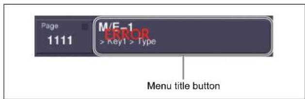
You can select whether or not to indicate the occurrence of an error by the word "ERROR" shown on the menu title button, by setting [Error Popup] in the Error Status menu or Error Log menu.
To display the error status or error log regardless of whether there is currently an error
1 Carry out either of the following.
- Press the [DIAG] button of the top menu selection buttons.
- Press the menu page number button at the upper left of the menu screen, to display the top menu window, then enter 7411 or 7412, and press [Enter].
The Diagnostic menu appears.
2 Press VF1 'Error Info.'
The error information menu appears.
3 Press either of the following buttons.
HF1 'Error Status': display the Error Status menu HF2 'Error Log': display the Error Log menu
Error Status menu
The Error Status menu lists currently occurring error information, listed with the most recent information at the top.
When an error has been cleared, the error disappears from the list.
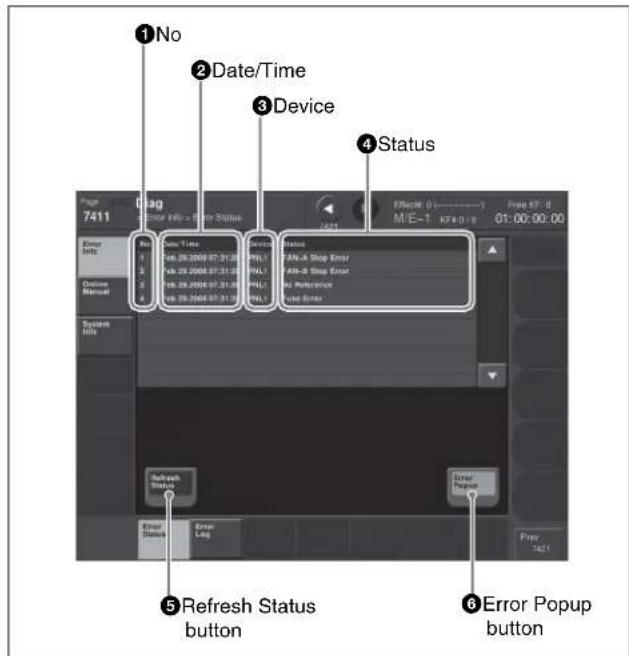
①No
This is a sequential number assigned to the error status.
②Date/Time
This shows the date and time the error occurred.
③Device
This shows the device on which the error occurred.
④Status
This shows the details of the error.
⑤Refresh Status button
This refreshes the list display.
⑥ Error Popup button
This selects whether or not to display "ERROR" on the menu title button when an error occurs. This button is linked to the Error Popup button in the error log menu.
On: if a device error occurs, display "ERROR" on the menu title button.
Off: if a device error occurs, do not display "ERROR" on the menu title button.
Error Log menu
The Error Log menu lists changes in the error status from the time that the menu display in the menu operating
section is started up, listed with the most recent information at the top.
A maximum of 1024 error status changes appear, and when the number exceeds 1024, the oldest items disappear from the list.
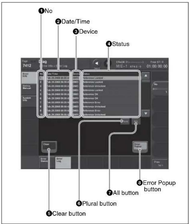
①No
This is a sequential number assigned to the items in the error log.
②Date/Time
This shows the date and time the status change occurred.
③Device
This shows the device on which the status change occurred.
④Status
This shows the details of the status change.
If you press on the list, this switches the display to reverse video, and selects the item. You can also select items in the error log by turning the knob.
⑤ Clear button
This deletes the selected error log item from the list.
⑥ Plural button
When this is on, you can select more than one error log. To cancel the selection, press once again to return to the normal display.
⑦ All button
When this is on, all error log items are selected. To cancel the selection, press once again to return to the normal display.
⑧ Error Popup button
This selects whether or not to display "ERROR" on the menu title button when an error occurs. This button is linked to the Error Popup button in the error status menu.
On: if a device error occurs, display "ERROR" on the menu title button.
Off: if a device error occurs, do not display "ERROR" on the menu title button.
Error Messages Appearing in a Message Box
Corresponding to the content of the message, an icon appears.
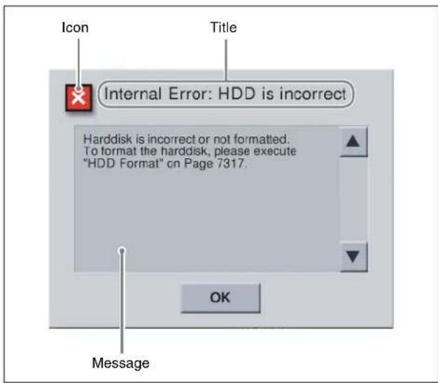
| Icon Message Description |
Activate License
| The license key you entered is invalid.Please check and enter again. | 7316.7: Engineering Setup >System >Install/Unit Config >License >License ManagementIn the above menu, since the entered information was incorrect, the Activate License procedure failed. Check the license key, and enter again. | |
| License key was successfully entered.The license will be activated after rebooting your system. | 7316.7: Engineering Setup >System >Install/Unit Config >License >License ManagementIn the above menu, the Activate License procedure completed successfully. |
Append Key Frame
| [Append Key Frame] cannot be executed.FMx is not assigned to a user region. | 2515: Frame Memory >Still >Create Key FrameIn the above menu, an attempt was made to execute [Append Key Frame], but it failed because the frame memory output (FMx) is not assigned to a user region.7331.4: Make the assignment in the Engineering Setup >Switcher >Config >User1-8 Config menu, and try again. | |
| [Append Key Frame] cannot be executed.Key Frame Register is locked. (UserX) | 2515: Frame Memory >Still >Create Key FrameIn the above menu, an attempt was made to execute [Append Key Frame] using a locked register (UserX region). Unlock the register. | |
| [Append Key Frame] cannot be executed.Key Frame Register is busy. (UserX) | 2515: Frame Memory >Still >Create Key FrameIn the above menu, an attempt was made to execute [Append Key Frame] using a register (UserX region) into which files are being loaded. Try again after file loading has finished. | |
| [Append Key Frame] cannot be executed.Key Frame Register is being edited. (UserX) | 2515: Frame Memory >Still >Create Key FrameIn the above menu, an attempt was made to execute [Append Key Frame] using a register (UserX region) with which a keyframe creating or editing operation is proceeding. Try again after the keyframe operation has finished. | |
| [Append Key Frame] cannot be executed.Key Frame Register is full. (UserX) | 2515: Frame Memory >Still >Create Key FrameIn the above menu, an attempt was made to execute [Append Key Frame] using a register (UserX region) in which no keyframe remains. | |
| [Append Key Frame] cannot be executed.Key Frame Register is not active. (UserX) | 2515: Frame Memory >Still >Create Key FrameIn the above menu, an attempt was made to execute [Append Key Frame] using a register for which the appropriate region selection button in the numeric keypad control block is not selected. Try again after you select the region selection button [UserX] in the numeric keypad control block. |
Backup
| Success!! 2562: Frame Memory >External Device | Ext HDD Backup/RestoreIn the above menu, saving files into the external hard disk completed successfully. | |
| Success!!But the number of folder exceeds the limit(12) and the files expected for the folders were backed up in the default folder.Or the name was changed because it was the same file name. | 2562: Frame Memory > External HDD > Backup/RestoreIn the above menu, file saving to an external hard disk was successful, but the limit on the number of folders was reached, and therefore files were backed up in the default folder. Alternatively, the file name was changed because a file of the same name already existed. | |
| External HDD Backup/Restore is running (-2). | 2564: Frame Memory >External Device >Backup to DDR/VTRWhen [Backup Start] was pressed in the above menu, a backup/ restore operation was being executed with the external hard disk. | |
| FM file auto extraction is running (-3). 2564: | Frame Memory >External Device >Backup to DDR/VTRWhen [Backup Start] was pressed in the above menu, extraction of frame memory file data onto the VTR was being executed. | |
| Clip is recording (-4). 2564:Frame Memory > | External Device >Backup to DDR/VTRIn the above menu, an external device is recording clips. |


| Icon | Message | Description |
| FM DDR/VTR Backup/Restore is running (-5). | 2564:Frame Memory >External Device >Backup to DDR/VTRWhen [Backup Start] was pressed in the above menu, a backup/ restore operation was being executed with the VTR/DDR. | |
| No external HDD was found (-2). 2562: Frame | Memory >External Device >Ext HDD Backup/RestoreIn the above menu, an attempt was made to execute [Backup] but the external hard disk could not be recognized. Check that the external hard disk is correctly connected. | |
| Format operation failed (-10). 2562: Frame | Memory >External Device >Ext HDD Backup/RestoreWhen [Backup] was pressed in the above menu, formatting of the hard disk failed. | |
| Format operation failed (-11). | ||
| Cannot access the partition (-12). 2562: Frame | Memory >External Device >Ext HDD Backup/RestoreIn the above menu, an attempt was made to execute [Backup] but the logical drives of the external hard disk could not be accessed. Check that the external hard disk is correctly formatted. | |
| Cannot access the directory (-20). 2562: Frame | Memory >External Device >Ext HDD Backup/RestoreIn the above menu, an attempt was made to execute [Backup] but the directory of the external hard disk could not be accessed. | |
| Cannot access the directory (-21). | ||
| The external HDD is busy (-22). 2562: Frame | Memory >External Device >Ext HDD Backup/RestoreIn the above menu, an attempt was made to execute [Backup] to the external hard disk which was busy and could not be accessed. Try again after you check that the access lamp of the hard disk or the indicator of the menu is turned off. | |
| The external HDD is full (-32). 2562: Frame | Memory >External Device >Ext HDD Backup/RestoreIn the above menu, an attempt was made to execute [Backup] to the external hard disk which does not have enough capacity. | |
| Backup operation failed (-33) 2562: Frame | Memory >External Device >Ext HDD Backup/RestoreIn the above menu, an attempt was made to execute [Backup] but the file storing process was not completed correctly. | |
| Backup operation failed (-34). | ||
| Backup operation failed (-36). | ||
| Cannot be executed.Amount of FM files exceeds the capacity of usable frame memory. | 2562: Frame Memory >External Device >Ext HDD Backup/RestoreWhen [Backup] was pressed in the above menu, the number of files exceeded the storage capacity. | |
| Cannot be executed.The function requires two frames of frame memory. | 2562: Frame Memory >External Device >Ext HDD Backup/RestoreWhen [Backup] was pressed in the above menu, two files are required, but there was only one file remaining. | |
| No directory exists (-50). 2562: Frame | Memory >External Device >Ext HDD Backup/RestoreWhen [Backup] was pressed in the above menu, the specified directory does not exist. | |
| Rename operation failed (-52). 2562: Frame | Memory >External Device >Ext HDD Backup/RestoreWhen [Backup] was pressed in the above menu, renaming the directory failed. | |
| Rename operation failed (-53). | ||
| Invalid FM OutCh (-6). 2565:Frame Memory | External Device >Restore from DDR/VTRIn the above menu, when [Backup] is pressed, this message appears if the specified frame memory output channel cannot be used. | |
| Specified FM OutCh was locked (-7). 2565: | Frame Memory >External Device >Restore from DDR/VTRIn the above menu, when [Backup] is pressed, this message appears if the specified frame memory output channel is locked. | |
| Not enough free register area for Backup or Restore process (-10). | 2565:Frame Memory >External Device >Restore from DDR/VTRIn the above menu, when [Backup] is pressed, this message appears if there is not enough space to carry out the backup. | |
| Prepare failed, not any file was found on this board (-11). | 2565:Frame Memory >External Device >Restore from DDR/VTRIn the above menu, when [Backup] is pressed, this message appears if no image is present. | |
| Backup failed, not prepared yet (-12). 2565: | Frame Memory >External Device >Restore from DDR/VTRIn the above menu, when [Backup] is pressed, this message appears if not yet ready. | |
| Icon Message Description | ||
 | Backup failed, Clip recall failed (-13). 2565:Frame Memory >External Device >Restore from DDR/VTRIn the above menu, when [Backup] is pressed, this messageappears if All One Clip ID Recall failed (internal processing error). | |
 | Prepare failed, Clip create failed (-14). 2565:Frame Memory >External Device >Restore from DDR/VTRIn the above menu, when [Backup] is pressed, this messageappears if All One Clip creation failed (internal processing error). | |
 | Prepare failed, insufficient Clip id (-15). 2565:Frame Memory >External Device >Restore from DDR/VTRIn the above menu, when [Backup] is pressed, this messageappears if there are not enough Clip IDs (internal processing error). | |
| [SZZ7] | Prepare failed, symbol files create failed(-16). | 2565:Frame Memory >External Device >Restore from DDR/VTRIn the above menu, when [Backup] is pressed, this messageappears if marker frame file creation failed (internal processingerror). |
 | Prepare failed, all one Clip recall failed(-17). | 2565:Frame Memory >External Device >Restore from DDR/VTRIn the above menu, when [Backup] is pressed, this messageappears if All One Clip Recall failed (internal processing error). |
| [XX8S] | ERROR (-19). Bad register number. 2565:Frame Memory >External Device >Restore from DDR/VTRIn the above menu, when [Backup] is pressed, this messageappears if Register Number is invalid (internal processing error). | |
| [COHT] | Prepare failed, because there is clip playing(-22). | 2565:Frame Memory >External Device >Restore from DDR/VTRIn the above menu, when [Backup] is pressed, this messageappears if processing failed during clip playback. |
Change Password
 | The password has been successfully changed. | 7317.1: Engineering Setup >System >Maintenance >Setup Operation LockIn the above menu, the password was successfully changed. |
| [2KB5] | Failed.The password was not changed. | 7317.1: Engineering Setup >System >Maintenance >Setup Operation LockIn the above menu, the password was not changed. |
Create Key Frame
 | [Create Key Frame] cannot be executed.FMx is not assigned to a user region. | 2515: Frame Memory >Still >Create Key FrameIn the above menu, an attempt was made to execute [Create Key Frame], but it failed because the frame memory output (FMx) is not assigned to a user region.7331.4: Make the assignment in the Engineering Setup >Switcher >Config >User1-8 Config menu, and try again. |
 | [Create Key Frame] cannot be executed.Key Frame Register is locked. (UserX) | 2515: Frame Memory >Still >Create Key FrameIn the above menu, an attempt was made to execute [Create Key Frame] using a locked register (UserX region). Unlock the register. |
 | [Create Key Frame] cannot be executed.Key Frame Register is busy. (UserX) | 2515: Frame Memory >Still >Create Key FrameIn the above menu, an attempt was made to [Create Key Frame] using a register (UserX region) into which files are being loaded.Try again after file loading has finished. |
 | [Create Key Frame] cannot be executed.Key Frame Register is being edited. (UserX) | 2515: Frame Memory >Still >Create Key FrameIn the above menu, an attempt was made to execute [Create Key Frame] using a register (UserX region) with which a keyframe creating or editing operation is proceeding. Try again after the keyframe operation has finished. |
 | [Create Key Frame] cannot be executed.There is no free Key Frame. (UserX) | 2515: Frame Memory >Still >Create Key FrameIn the above menu, an attempt was made to execute [Create Key Frame] for a UserX region with insufficient usable keyframes. |
 | [Create Key Frame] cannot be executed.Key Frame Register is not active. (UserX) | 2515: Frame Memory >Still >Create Key FrameIn the above menu, an attempt was made to execute [Create Key Frame] using a register for which the appropriate region selection button in the numeric keypad control block is not selected. Try again after you select the region selection button [UserX] in the numeric keypad control block. |

| Icon Message Description | ||
| Deactivate License | ||
| The license will be deactivated after rebooting your system. | 7316.7: Engineering Setup >System >Install/Unit Config >License >License ManagementIn the above menu, the Deactivate License procedure completed successfully. | |
Disk Format
| Success!! 7317: Engineering Setup >System | >MaintenanceIn the above menu, removable disk formatting procedure completed successfully. | |
| Failure.Make sure of the memory card. | 7317: Engineering Setup >System >MaintenanceIn the above menu, removable disk formatting procedure failed.Check that the memory card is correctly inserted. |
Error
| This operation is cancelled, because the register is locked.Please change the register status to be unlocked first. | 6211.1: Effect >Master Timeline >Store >Edit6311.1: Snapshot >Master Snapshot >Store >Edit6411.1: Shotbox >Register >Store/Recall >EditIn the above menu, an attempt was made to assign to a register that is locked. Unlock the register before carrying out the assignment. | |
| The file was not able to be read. 7142.1: File | >Shotbox, Macro >File EditIn the above menu, [Off Line Edit] was pressed but the selected file could not be read.Select the file again, and press [Off Line Edit] once more. | |
| It was not possible to make a file. 7142.3: File | >Shotbox, Macro >File Edit >Off Line EditIn the above menu, when storing, the file could not be written.Try the store once more. | |
| Failed... 7162: File >All, External File >Import | /ExportIn the above menu, importing a file failed. Check the format of the original file, and try again. | |
| The Source and the target are the same directory.Please change the source or the target directory. | 7172: File >Configure >Unit ID CopyIn the above menu, the same directory and ID were selected for source and target.Select a different directory and ID. |
Extraction
| FM file auto extraction is running (-9). 2542:Frame Memory >File >Auto ExtractionIn the above menu, when the [Extraction Start] button is pressed,this message appears if the CG wipe extraction function is alreadybeing executed. | ||
| FM 1394 HDD Backup or Restore isprocessing. (-11). | ||
| FM DDR/VTR Backup/Restore is running(-16). | ||
| ERROR (-1). 2542:Frame Memory >File >Auto ExtractionIn the above menu, when the [Extraction Start] button is pressed,this message appears if a backup/restore operation using the VTR/DDR is in progress. | ||
| Create thumbnail failed (-2). 2542:Frame Memory >File >Auto ExtractionIn the above menu, when [Extraction Start] is pressed, thismessage appears if a thumbnail processing error occurs. | ||
| Red Symbol file not match (-3). 2542:Frame Memory >File >Auto ExtractionIn the above menu, when [Extraction Start] is pressed, thismessage appears if a red marker frame file is invalid. | ||
| Icon Message | Description | |
 | Blue Symbol file not match (-4). 2542:Frame | Memory >File >Auto ExtractionIn the above menu, when [Extraction Start] is pressed, this message appears if a blue marker frame file is invalid. |
 | No data between two symbol files (-5). 2542: | Frame Memory >File >Auto ExtractionIn the above menu, when [Extraction Start] is pressed, this message appears if there is no data between two marker frames. |
 | Cannot find symbol file (-8). 2542:Frame Memory | >File >Auto ExtractionIn the above menu, when [Extraction Start] is pressed, this message appears if a marker frame file was not found. |
 | Clip frame error (-10). 2542:Frame Memory | >File >Auto ExtractionIn the above menu, when [Extraction Start] is pressed, this message appears if a clip frame count is invalid (internal processing error). |
 | Clip not found (-12). 2542:Frame Memory | >File >Auto ExtractionIn the above menu, when [Extraction Start] is pressed, this message appears if the specified clip does not exist. |
 | Clip is playing or being edited (-13). 2542: | Frame Memory >File >Auto ExtractionIn the above menu, when [Extraction Start] is pressed, this message appears if the specified clip is being played back or edited. |
 | Clip register error (-14). 2542:Frame Memory | >File >Auto ExtractionIn the above menu, when [Extraction Start] is pressed, this message appears if the specified register number data cannot be processed (internal processing error). |
 | Can't extract pair clip (-15). 2542:Frame Memory | >File >Auto ExtractionIn the above menu, when [Extraction Start] is pressed, this message appears if an attempt is made to extract a pair clip. |
 | Clip id not enough (-50). 2542:Frame Memory | >File >Auto ExtractionIn the above menu, when [Extraction Start] is pressed, this message appears if there are 100 clips or more. |
 | Still frame on FM 2nd board (-51). 2542:Frame Memory | >File >Auto ExtractionIn the above menu, when [Extraction Start] is pressed, this message appears if a still image was extracted from an external clip. |
 | Clip frame number can't be ODD in 720P format (-9). | 2542:Frame Memory >File >Auto ExtractionIn the above menu, when [Extraction Start] is pressed, this message appears if an odd number of clips are extracted (720P format only). |
File Frame Memory
| Some requests are skipped.Following operation is not permitted.— Loading that will cause duplicate register name. | 7151: File >Frame Memory7162: File >All, External File >Import/ExportIn the above menu, an attempt was made to load a file of a name already existing in the register. |
File Open Status
| [4W15] | ERROR (01) 533X: Device >DDR/VTR | When an error is returned from the DDR/VTR, one of these messages appears, depending on the error number.Use Menu 7355: Engineering Setup >DCU >Serial Port Assign or Menu 7325.4: Engineering Setup >Panel >Device Interface >Serial Port/MPE Assign to check the device settings. |
| ERROR (02) | ||
| ERROR (FF): No target device has been assigned | ||
| Icon Message Description | ||
| GPI Input | ||
 | Please set Target. 7325.1/2: Engineering Setup >Panel >Device Interface >GPI Input | |
| Please set Trigger Type. | ||
| Please set Reg No. | ||
| Please set Aux Bus No. | ||
| Please set Src No. | ||
| Please set Pulse Width. | ||
| Please set Pulse Timing. | ||
GPI Output
| [0WSX] | Please set Target. 7325.3/4: Engineering Setup >Panel >Device Interface >GPIOutput7337.2/3: Engineering Setup >Switcher >Device Interface >GPIOutput7337.4/5: Engineering Setup >Switcher >Device Interface >GPIOutput7344.3/4: Engineering Setup >DME >Device Interface >DME1 GPI Output7344.7/8: Engineering Setup >DME >Device Interface >DME2 GPI Output7354/7354.1: Engineering Setup >DCU >GPI Output AssignIn the above menus, when making a setting, a parameter setting value was incorrect. Check the settings, and try again. |
| Please set Trigger Type. | |
| Please set Reg No. | |
| Please set Aux Bus No. | |
| Please set Src No. | |
| Please set Pulse Width. | |
| Please set Pulse Timing. |
HDD Format
| Failure.HDD device is busy.In order to complete HDD format, System needs to be restarted and formatted again. System will be restarted, then please execute HDD format again. | 7317: Engineering Setup >System >MaintenanceIn the above menu, the hard disk formatting procedure failed.If the hard disk is functioning correctly, or in some cases when there is damage to the disk, it may not be possible to format the disk correctly in a single attempt. In such cases, it is necessary to restart the system, and then carry out formatting again.Press [OK] to restart the system. | |
| No external HDD was found (-2). 2561: Frame | Memory >External Device >Ext HDD FormatIn the above menu, when [5 Partition] or [15 Partition] is pressed, this message appears if the external hard disk cannot be found. Check that the external hard disk is connected correctly. | |
| Format operation failed (-11). 2561: Frame | Memory >External Device >Ext HDD FormatIn the above menu, when [5 Partition] or [15 Partition] is pressed, this message appears if hard disk formatting failed. | |
| Cannot access the partition (-12). 2561: Frame | Memory >External Device >Ext HDD FormatIn the above menu, when [5 Partition] or [15 Partition] is pressed, this message appears if the external hard disk logical drive could not be accessed. Check that external hard disk formatting has been carried out correctly. | |
| Cannot access the directory (-20). 2561: Frame | Memory >External Device >Ext HDD FormatIn the above menu, when [5 Partition] or [15 Partition] is pressed, this message appears if an external hard disk directory could not be accessed. | |
| The external HDD is busy (-22). 2561: Frame | Memory >External Device >Ext HDD FormatIn the above menu, when [5 Partition] or [15 Partition] is pressed, this message appears if the external hard disk is in use and cannot be accessed. Check that the hard disk access indicator is off, or that the menu indicator is off, then try again. | |
| Success!! 2561: Frame Memory >External Device | Ex t HDD FormatIn the above menu, the external hard disk formatting procedure completed successfully. | |
| Icon Message Description | ||
| [W4DS] | Success!!System will be restarted. | 7317: Engineering Setup >System >MaintenanceIn the above menu, the hard disk formatting procedure completed successfully.Press [OK] to restart the system. |
 | Success!!But some partitions cannot be created because the capacity of the HDD is not enough. | 7317: Engineering Setup >System >MaintenanceIn the above menu, hard disk formatting was completed normally, but because of insufficient hard disk capacity, only the possible number of partitions were created. |

Install
 | No Task.Select a package on the list. | 7316.10: Engineering Setup >System >Install/Unit Config >Install In the above menu, the package for installation was not selected. Select a package to be installed. |
 | An error occurred during the install process. For more details, see Page9900. | 7316.10: Engineering Setup >System >Install/Unit Config >Install In the above menu, the menu software installation package does not match the model on which it is to be installed. |
 | Not Found.The software package does not exist on the removable disk. | 7316.10: Engineering Setup >System >Install/Unit Config >Install In the above menu, the software package to be installed was not found. Check that the memory card is correctly inserted, and try the installation once more. |
 | All processes have succeeded. 7316.10: Engineering Setup >System >Install/Unit Config >Install In the above menu, the installation procedure completed successfully. | |
Internal Error: Data HDD
 | The user data partition of hard disk drive is damaged, and all data is lost. The hard disk drive needs to be reformatted.Please execute HDD format on Page 7317. | When starting up the menu system, an error was found on the hard disk.In Menu 7317: Engineering Setup >System >Maintenance, execute [HDD Format]. |
Internal Error: HDD is incorrect
 | Hard disk is incorrect or not formatted.To format the hard disk, please execute “HDD Format” on Page 7317. | When starting up the menu system, an error was found on the hard disk.In Menu 7317: Engineering Setup >System >Maintenance, execute [HDD Format]. |
Internal Error: Recovery HDD
 | The recovery data partition of hard disk is damaged, and all data is lost.The data needs to be recovered.Please execute Restore Data on Page 9999. | During menu startup, an error was found in the recovery data partition of the hard disk.Restore the recovery data using menu 9999.a) |
Internal Error: Temporary HDD
| The system data partition of hard disk drive is damaged. The hard disk drive needs to be reformatted. Please execute HDD format on Page 7317.Please make sure to save all data in the user data partition of hard disk drive to any other device or media, before reformatted. | When starting up the menu system, an error was found on the hard disk.In Menu 7317: Engineering Setup >System >Maintenance, execute [HDD Format]. | |
| Icon Message Description | ||
| Invalid Name | ||
 | Empty... 2512: Frame Memory >Still >Freeze | /StoreIn the above menu, a Store was carried out without specifying a name.Alternatively:71XX: File Menu7171: File >Configure >DirectoryIn the above menu, when renaming a file or creating a directory, the name was not entered. Enter the name correctly. |
 | The file exists already... 2512: Frame Memory | >Still >Freeze/StoreIn the above menu, the file name specified for a store operation already exists in the switcher. Specify a different name. |
| Loading Texture Pattern | ||
| [BGTX] | Target File: XXXXXFailed to load target bmp file./Illegal Name.This operation is canceled. | 7316.9: Engineering Setup >System >Install/Unit Config >Texture PackageIn the above menu, an error occurred when loading a texture file.Delete texture files with an illegal size or illegal file name, then try again. |
 | Target File: XXXXXFailed to load target bmp file./Illegal Size.This operation is canceled. | |
| Make Package | ||
 | Texture file: XXXXXNot Found.This texture file does not exist on the removable disk. | 7316.9: Engineering Setup >System >Install/Unit Config >Texture PackageIn the above menu, when loading an already created texture package, a texture file within the texture package was not found. |
 | This operation is cancelled, because capacity is full.Please clear texture pattern. | 7316.9: Engineering Setup >System >Install/Unit Config >Texture PackageIn the above menu, when making a texture package, there was insufficient space on a memory card. |
| Password | ||
 | Password Incorrect 7317.1: Engineering Setup | >System >Maintenance >SetupOperation LockIn the above menu, the wrong password was entered.Enter the correct password. |
| Record | ||
| [BH2W] | Cannot be executed. Maximum number of clips are created. | 2523: Frame Memory >Clip >RecordIn the above menu, an attempt was made to execute [Rec Start] but the number of recorded clips had already reached its upper limit. |
| Recovery Complete | ||
 | System disk has been damaged, and then recovered.Shutdown and restart the system is recommended to exit from recovery mode. | Corruption has been detected in the flash memory for starting the menu CPU, but this has been recovered. Since the system is operating in recovery mode, shut down and restart as soon as practicable.a) |
| Refresh Status | ||
 | No external HDD was found (-2). | 2561: Frame Memory >External Device >Ext HDD Format2562: Frame Memory >External Device >Ext HDD Backup/RestoreIn the above menus, an attempt was made to execute [Refresh Status] but the external hard disk could not be recognized. Check that the external hard disk is correctly connected. |
 | Cannot access the partition (-12). 2561: Frame Memory >External Device >Ext HDD Format2562: Frame Memory >External Device >Ext HDD Backup/RestoreIn the above menus, an attempt was made to execute [Refresh Status] but the logical drives of the external hard disk could not be accessed. Check that the external hard disk is correctly formatted. | |
 | Cannot access the directory (-20). | 2561: Frame Memory >External Device >Ext HDD Format2562: Frame Memory >External Device >Ext HDD Backup/RestoreIn the above menus, an attempt was made to execute [Refresh Status] but the directory of the external hard disk could not be accessed. |
 | Cannot access the directory (-21). | |
 | The external HDD is busy (-22). 2561: Frame | Memory >External Device >Ext HDD Format2562: Frame Memory >External Device >Ext HDD Backup/RestoreIn the above menus, an attempt was made to execute [Refresh Status] but the external hard disk was busy and could not be accessed. Try again after you check that the access lamp of the hard disk or the indicator of the menu is turned off. |
Rename
 | This operation is inhibited because of the illegal combination in the selected files. | 7151.1 File >Frame Memory >Frame Memory >File EditIn the above menu, this message appears if you select files of different types and press [Rename].Check that the selected files are all of the same type. |
 | Files currently used for playback cannot be renamed. | 2546: Frame Memory >File >RenameIn the above menu, this message appears if [Rename] is pressed, when the selected files include a movie (clip) currently being played back. |
 | No external HDD was found (-2). 2546:Frame | Memory >External Device >Ext HDD Backup/RestoreIn the above menu, when [Rename] is pressed, this message appears if the external hard disk cannot be found. Check that the external hard disk is connected correctly. |
| [BY44] | Cannot access the directory (-20). 2546:Frame | Memory >External Device >Ext HDD Backup/RestoreIn the above menu, when [Rename] is pressed, this message appears if an external hard disk directory could not be accessed. |
| [W732] | The external HDD is busy (-22). 2546:Frame | Memory >External Device >Ext HDD Backup/RestoreIn the above menu, when [Rename] is pressed, this message appears if the external hard disk is in use and cannot be accessed. Check that the hard disk access indicator is off, or that the menu indicator is off, then try again. |
Restore
| Success!! 2562: Frame Memory >External Device | Device >Ext HDD Backup/RestoreIn the above menu, recalling a file from the external hard disk was correctly done. | |
| Success!!But some files were not restored. | 2562: Frame Memory >External Device >Ext HDD Backup/RestoreIn the above menu, restoring of files from the external hard disk was completed, but some files were not restored because of a different video format or file corruption. | |
| Success!!But the number of folder exceeds the limit (-12) and the files expected for the folders were restored in the default folder.Or the name was changed because it was the same file name. | 2562: Frame Memory >External Device >Ext HDD Backup/RestoreIn the above menu, this message appears if file recall from the external hard disk was completed successfully, but the number of storable folders was exceeded and the default folder used for restoring, or the file name was changed because a file of the same name already existed. | |
| Success!!But the number of folder exceeds the max limit (12) and the files expected for the folders were restored in the default folder (-50)! | 2565: Frame Memory >External Device >Restore from DDR/VTRIn the above menu, restoring of files from the external device was completed, but the limit on the number of folders was reached, and therefore files were restored to the default folder. | |
| Success!!But some still files had been renamed because the same file name already existed (-51)! | 2565: Frame Memory >External Device >Restore from DDR/VTRIn the above menu, restoring of files from the external device was completed, but some files were renamed because of still image file name conflicts. | |
| Success!!But some Clip files had been renamed because the same Clip name already existed (-52)! | 2565: Frame Memory >External Device >Restore from DDR/VTRIn the above menu, restoring of files from the external device was completed, but some clips were renamed because of clip name conflicts. |


| Icon | Message | Description |
| External HDDBackup/Restore is running (-2). | 2565:Frame Memory >External Device >Restore from DDR/VTRIn the above menu, when the [Restore Start] button is pressed, this message appears if the external hard disk is already active in a frame memory file data backup/restore operation. | |
| FM file auto extraction is running (-3). 2565: | Frame Memory >External Device >Restore from DDR/VTRIn the above menu, when the [Restore Start] button is pressed, this message appears if the function for frame memory file extraction to VTR function is running. | |
| Clip is recording (-4). 2565:Frame Memory > | External Device >Restore from DDR/VTRIn the above menu, this message appears if an external device is recording a clip. | |
| FM DDR/VTRBackup/Restore is running (-5). | 2565:Frame Memory >External Device >Restore from DDR/VTRIn the above menu, when the [Restore Start] button is pressed, this message appears if a backup/restore operation using the VTR/DDR is in progress. |
Restore
| No external HDD was found (-2). 2562: Frame | Memory >External Device >Ext HDD Backup/RestoreIn the above menu, an attempt was made to execute [Restore] but the external hard disk could not be recognized. Check that the external hard disk is correctly connected. | |
| Format operation failed (-10). 2562: Frame | Memory >External Device >Ext HDD Backup/RestoreWhen [Restore] was pressed in the above menu, formatting of the hard disk failed. | |
| Format operation failed (-11). | ||
| Cannot access the partition (-12). 2562: Frame | Memory >External Device >Ext HDD Backup/RestoreIn the above menu, an attempt was made to execute [Restore] but the logical drives of the external hard disk could not be accessed. Check that the external hard disk is correctly formatted. | |
| Cannot access the directory (-20). 2562: Frame | Memory >External Device >Ext HDD Backup/RestoreIn the above menu, an attempt was made to execute [Restore] but the directory of the external hard disk could not be accessed. | |
| Cannot access the directory (-21). | ||
| The external HDD is busy (-22). 2562: Frame | Memory >External Device >Ext HDD Backup/RestoreIn the above menu, an attempt was made to execute [Restore] but the external hard disk was busy and could not be accessed. Try again after you check that the access lamp of the hard disk or the indicator of the menu is turned off. | |
| No file was found (-40). 2562: Frame Memory | >External Device >Ext HDD Backup/RestoreIn the above menu, an attempt was made to execute [Restore] but the file to be written into the external hard disk was not found. | |
| Restore operation failed (-42). 2562: Frame | Memory >External Device >Ext HDD Backup/RestoreIn the above menu, an attempt was made to execute [Restore] but the recalling file from the external hard disk was not completed correctly. | |
| Restore operation failed (-43). | ||
| Restore operation failed (-46). | ||
| No directory exists (-50). 2562: Frame Memory | >External Device >Ext HDD Backup/RestoreWhen [Restore] was pressed in the above menu, the specified directory does not exist. | |
| Rename operation failed (-52). 2562: Frame | Memory >External Device >Ext HDD Backup/RestoreWhen [Restore] was pressed in the above menu, directory renaming failed. | |
| Rename operation failed (-53). | ||
| Invalid FM OutCh (-6). 2565:Frame Memory | >External Device >Restore from DDR/VTRIn the above menu, when [Restore] is pressed, this message appears if the specified frame memory output channel cannot be used. | |
| Specified FM OutCh was locked (-7). | 2565:Frame Memory >External Device >Restore from DDR/VTRIn the above menu, when [Restore] is pressed, this message appears if the specified frame memory output channel is locked. | |
| Restore failed, some Clip files cannot be deleted on this board (-8). | 2565:Frame Memory >External Device >Restore from DDR/VTRIn the above menu, when [Restore] is pressed, this message appears if the restore failed because a clip file cannot be deleted. | |
| Icon Message Description | ||
 | FM 2nd board not exist (-9). 2565:Frame Memory >External Device >Restore from DDR/VTRIn the above menu, when [Restore] is pressed, this message appears if there is no second board. | |
 | Not enough free register area for Backup or Restore process (-10). | 2565:Frame Memory >External Device >Restore from DDR/VTRIn the above menu, when [Restore] is pressed, this message appears if there is not enough space to carry out the backup. |
 | Prepare failed, not any file was found on this board (-11). | 2565:Frame Memory >External Device >Restore from DDR/VTRIn the above menu, when [Restore] is pressed, this message appears if no image is present. |
 | Prepare failed, insufficient Clip id (-15). 2565:Frame Memory >External Device >Restore from DDR/VTRIn the above menu, when [Restore] is pressed, this message appears if there are not enough Clip IDs (internal processing error). | |
 | Restore failed, Cannot find symbol files on this tape (-18). | 2565:Frame Memory >External Device >Restore from DDR/VTRIn the above menu, when [Restore] is pressed, this message appears if a marker frame file was not found. |
 | ERROR (-19). Bad register number. 2565:Frame Memory >External Device >Restore from DDR/VTRIn the above menu, when [Restore] is pressed, this message appears if Register Number is invalid (internal processing error) | |
 | Restore failed, file name already exist, try to rename but unsuccessful (-20). | 2565:Frame Memory >External Device >Restore from DDR/VTRIn the above menu, when [Restore] is pressed, this message appears if renaming failed. |
 | Cannot find the File Name Data, please load the File Name Data first (-21). | 2565:Frame Memory >External Device >Restore from DDR/VTRIn the above menu, when [Restore] is pressed, this message appears if the file list was not loaded. |
Restore Data
 | Restoring... Appears while restoring recovery | data using Menu 9999. a) |
 | Success!! Appears when recovery data has been successfully restored using Menu 9999. a) | |
 | Recovery binary on the USB storage device is not found. | Recovery data for restoring using Menu 9999 cannot be found on the memory card. Check that the recovery data has been correctly copied to the memory card, and restart the system to retry. a) |
 | Failure. Copying recovery data hasn't finished. | Restoring recovery data using Menu 9999 failed. Check that the recovery data has been correctly copied to the memory card, and restart the system to retry. a) |
Set Time/Date
 | Error: Wrong Format. 7317: Engineering Setup | >System >MaintenanceIn the above menu, an incorrect date and time was specified.Specify the date and time correctly. |
Trim
| The Start TC or Stop TC is not properly set. 2522:Frame Memory >Clip >PlayIn the above menu, when [Trim] is pressed, this message appears if neither Start TC not Stop TC is set. | |
| 2522:Frame Memory >Clip >PlayIn the above menu, when [Trim] is pressed, this message appears if the interval between Start TC (or Clip Begin) and Stop TC (or Clip End) is the entire clip. | |
| 2522:Frame Memory >Clip >PlayIn the above menu, when [Trim] is pressed, this message appears if the Start TC (or Clip Begin) value is greater than the Stop TC (or Clip End) value. | |
| This file is locked. 2522:Frame Memory >Clip >PlayIn the above menu, when [Trim] is pressed, this message appears if the file is locked. |

| Icon Message Description | ||
| This file is using for playback. 2522:Frame Memory >Clip >PlayIn the above menu, when [Trim] is pressed, this message appears if the file is being played back. | ||
Warning
| No Switcher information available.Please confirm “Network Configuration” on Page 7311. | When starting up the menu system, the switcher is not present in the system information. Check the Data LAN connections, and in Menu 7311: Engineering Setup >System >Network Config, retry [Auto Config]. | |
| This operation will be cancelled, because the register is locked.Please change the register status to be unlocked first. | 6211.1: Effect >Master Timeline >Store >Edit6311.1: Snapshot >Master Snapshot >Store >Edit6411.1: Shotbox >Register >Store >EditIn the above menus, an attempt was made to store in a locked register. Unlock the register before carrying out the store. |
Warning (System Config)
| Illegal Network Config Information (Page 7311) | When starting up the menu system, if the system information read from the control panel is not correct, one of these messages, that corresponds to the situation appears.Following the message, use Menu 7311: Engineering Setup>System >Network Config or 7312: Engineering Setup >System>System Config to retry the operation. | |
| Illegal Panel Assign Information for Dual Simul Operation (Page 7312) | ||
| No Panel Assign Information (Page 7312) | ||
| No Switcher Assign Information (Page 7312) | ||
| No System Operation Mode Information (Page 7312) | ||
| No DME Channel Information |
a) MKS-8010A only
Error Messages Shown in the Error Information Menu
If a file transfer related error occurs, the Error Information menu appears to the following error messages.
| Error message Error description/measures | |
| [Error] Packet Format Load/save the data again. | Still then the message is displayed, contact a Sony service representative. |
| [Error] No Request | |
| [Error] No Request File | |
| [Error] Illegal Host | |
| [Error] Not Supported | |
| [Error] USB Access | |
| [Error] Get File System Info | |
| [Error] Copy Result | |
| [Error] Remove Result | |
| [Error] Move Result | |
| [Error] Make Dir Result | |
| [Error] Path Info | |
| [Error] Dir Operation | |
| [Error] Command Result | |
| [Error] Transfer Result | |
| [Error] Source File Name | |
| [Error] Source File Open | |
| [Error] Source File Read | |
| [Error] Destination File Name Load/save the data | again. Still then the message is displayed, contact a Sony service representative. |
| [Error] Destination File Open | |
| [Error] Destination File Read | |
| [Error] Destination File Write | |
| [Error] Illegal Format | |
| [Error] Edit Header | |
| [Error] Local File Access | |
| [Error] FTP Connect | |
| [Error] FTP Busy | |
| [Error] FTP Access | |
| [Error] FTP No Result | |
| [Error] FTP Put Command | |
| [Error] FTP Delete | |
| [Error] FTP Delete Command | |
| [Error] FTP Delete Result | |
| [Error] Control Table No Space | |
| [Error] Control Table Same Name | |
| [Error] No Queue | |
| [Error] Resize BMP | |
| [Error] Make Vector | |
| [Error] Uncompress | |
| [Error] Compress | |
| [Error] Server Not Respond No reactions are returned from the processor. Check your Data-LAN connections and the power source of the processor. | |
| [Error] No Space There is not sufficient space in the memory card or hard disk. | |

Index
Numerics
3D 25,255
3M/E Mode 261
4M/E Mode 261
A
Action setting 408
for rewind 409, 412, 422
Additive mix 126
Ancillary data 209, 214
Angle 166
Anti-moire filter 341
Art edge settings 286
Aspect ratio 167, 173
Attributes 464
Audio mixer 91
Auto
chroma key adjustments 127
transition 105,464
AUTO button 53
AUTO DELEG button 42
AUTO INS button 51
Auto/manual transition combination 106
Autoload function 521, 534, 543
AUX
bus settings 231
delegation buttons 54
menu operations 231
AUX bus control enable/disable 618
AUX bus control mode switching function 562
AUX bus override 588
AUX bus remote panel 649
AUX delegation button settings 574
shift operation 575
AUX menu 372
AUX Panel-less Function 89
Auxiliary bus control block
for AUX buses 53
for router control 55
Axis location 266
B
Background
changing 20
mask 121
settings 338
transition flip-flop mode 608
Bank selection buttons 58
Banks and registers 496
Basic menu operations 72
Beep 594
Beveled edge settings 285
Blind settings 314
Blink
function 137
Blur settings 298
Border 120
parameters 140
processing order 610
settings 283
Brick settings 347
Brightness adjustment 594
Broken glass settings 313
BS button 79
Bus fixed mode
fader operation 107
wipe direction 108
Bus selection 86
Button
assignment settings 577
numbers 89, 90
operation mode 592
Button assignments 577
C
Calibration 595
Caps Lock button 79
CCP-6224
AUX Panel-less Function 89
CCP-6224 2M/E Control Panel 68
CCP-6324
AUX Panel-less Function 89
CCP-6324 3M/E Control Panel 68
CCR menu 372
Channel ID 268
Character Trail settings 322
Chroma key 120
adjustments 127
shadow 127
shadow adjustment 129
window 127
Circle settings 318
Clean mode 119
Clear button 78, 79
Clip function 209
Clip transition 92
operations 215
Close button 78, 79
Color
combination 224
matte settings 99
vector key 119
Color background
selection 224
setting operations 224
settings menu 224
Color Bkgd menu 371
Color cancel 127
adjustments 128
Color corrector 235
Color data
copy 227
swap 227
Color mix 224
for edge fill matte 164
for key fill 125
Color Mix settings 296
Combiner settings 344
Communications status 648
Contrast settings 301
Control panel 28
configuration 1 28
configuration 2 28
configuration 3 29
Control panel settings 555
Coordinate axes 268
Copy 226, 227
Copy/Swap menu 373
Copying 460
Corner Pinnig 341
Crop settings 284
Cross-point
assign tables 569
button numbers 31
button shift operation 571
buttons 30
control block 29
hold 463
settings 569
Cross-point assign tables 572
Cueup & Play 416
automatic execution 417
settings in a menu 418
Custom mode 542
Cut 93
Cylinder settings 319
D
Date and time 551
DCU
serial port settings 587
setup 626
Dead zone 194
Default recall button 76
Default wipe edge softness 611
Defocus settings 297
Del button 79
Delay setting 429, 450
Delegation buttons 39
DEST button 54
Destination names 591
Detents 265
Device
interface 585, 616, 623
menu 375
setup 544
DEVICE connectors 57
Device control block
joystick 45
search dial 46
trackball 42
Device interface 623
Device management 551
Diagnosis 648
Diagnostic menu 386
Digital multi effects 25, 263
Dim and fade settings 303
Direct store 409
Direction 163, 171, 185
Directory operations 532
creating a directory 532
deleting a directory 532
renaming a directory 532
Disk recorder
control 412
Cueup & Play 416
file operations 423
information check 415
recording to 415
settings 634
timeline 419
timeline editing 421
Display 41, 52
DME 25
applying to a key 134, 142
channel selection buttons 41
menu 374
special effects 268
DME channel
copy 227
swap 227
DME override 229
DME patterns
user programmable 193
DME setup 621
DME wipe pattern 179
edge modification 185
groups 179
selection 183
DME wipe pattern list
for one-channel mode 355
for two-channel mode 360
DME wipe settings 183
for independent key transitions 189
DME wipes 23, 179
copy 226, 227
direction 185
modifiers 185
modify clear 188
position 185, 189
resizer 191
snapshot 192
swap 226, 227
Door 356
Double-click sensitivity 593
Downstream key control block 63
Drop border 120
parameters 140
Dual background bus mode 561
dual resizer effects 154
Duration
effect 428
keyframe 428
modes 427
setting buttons 50
Duration mode setting 445
Dust mix 161, 162
E
Edge
fill 121
modifiers 120
EDIT ENBL button 49
Edit point specification buttons 49
Edit points 439
setting 440
Editing buttons 49
Editing keyboard 587
EFF LOOP button 51
Effect 427
attribute settings 459
attributes 427
dissolve 427,463
duration 428
duration setting 450
editing 427
execution 431,452
execution direction 453
menu 377
repeating 453
resizer 152
saving 454
saving/recalling 427
settings 590
status display 459
Effect execution direction selection
buttons 50
Effect register
copy/move/swap 460
data deletion 461
editing 459
merge 460
naming 461
write-protecting 460
Emboss 120
Engineering setup 535, 555, 596, 621,
626, 637, 649
Engineering Setup menu 381
Enhanced wipes 352
Enter button 78, 79
Error messages 669
Error Information menu 682
error status/log 669
message box 670
Explosion settings 320
Extended VTR 412,636
External
box setting 638
device control 407
processed key 136, 144
External devices 26
shared control functions 407
External hard disk drive 219
F
Fade to black 115
control block 53
transition rate 115
Fader lever operations 609
Fade-to-black function 608
File
locking load operations 553
File menu 380
File operations 423
autoload function 534
batch operations 529
copying 525, 533
deleting 527
directory operations 532
displaying menus 522
import/export 530
individual files 519
loading 524, 529
renaming 526
saving 523,529
selecting a device 523
selecting regions 523
viewing detailed information 522
Files 27,519
autoload function 521
deleting 218
operations 519
renaming 218
Film effect 306
Fine mode 279
Flag settings 309
Flex shadow settings 290
Flexi Pad
settings 591
Flexi Pad control block
simple type 59
standard type 37
Flip tumble 357

Flying bar settings 314
Format converter 540
conversion 601
outputs 606
Formatting a memory card 551
Formatting the hard disk 552
Frame
in-out 357,365
memory data export 531
memory data import 530
Memory menu 371
Frame input mode 102
Frame memory
clip function 209
continuously capturing still images (record) 207
extracting images 222
feed 137, 144
pair file processing 217
recalling a continuous sequence of still images (animation) 207
Frame memory folder 528
Frame memory operations 200
capturing an input image 203
clip 210
input image selection 202
menu display 200
preparations 200
selecting frame memory 203
selecting outputs 203
Freeze settings 306
Fringe 169
FTB button 53
FULL LINK 161
Function
assignment user preference buttons 577
button area 76
links 612
selection buttons 52
Functions assignable to trackball/Z-ring 279
G
Global
coordinate space 263
Effect menu 375
effect operations 343
Glow settings 304
GPI
device control 411
output port settings 411
timeline creation/editing 411
GPI input settings
for control panel 585
for DCU 627
for DME 624
for switcher processor 616
GPI output 464
GPI output settings
for control panel 586
for DCU 630
for DME 625
for switcher processor 618
Graphics
outputting to the monitor 281
Graphics display 267, 281
Grid 268
H
Hard disk 219
partition 219
Hard freeze effect 306
HDD 219
HF buttons 76
I
Illegal color limiter 600, 621
Image
data management 217
extracting 222
Image file
deletion 218
renaming 218
Independent key transition 21, 109
DME wipe settings 189
simple transitions 117
type 113
type selection buttons 37, 62, 63
wipe modifiers 171
wipe settings 171
Independent key transition control block
simple type 61
standard type 112
Independent key transition execution section 37, 62, 63, 68
Independent key transition rate 113
display 114
setting by a menu operation 114
setting in the Flexi Pad control block 113
setting in the numeric keypad control block 113
Initialization
hard disk 552
Input
string 79
value 78
Input reference signal 539
Installation 544
Interpolation settings 340
Invert settings 339
Item display 78, 79
J
Joystick 45
Joystick sensitivity 593
K
Kaleidoscope settings 317
Key 22
1/2 row 31
auto drop 610
border settings 286
bus selection buttons 31
control block 39
default 122
delegation assign 556
delegation buttons 37, 63
deleting 20
density settings 340
disable 463
edge modifications 130, 140
Frame menu 376
inserting 20
mask 121
memory 121
memory mode 610
modifier buttons 40
modifiers 120
modify clear 137
output destination 136
output status display 97, 117
priority operation mode 610
settings 609
signal adjustments 128
snapshot attributes 475
source selection 340
status display 36, 61, 67
using keys 5 to 8 388
Key active 127
adjustment 128
KEY button 54
Key fill
selection 124
selection buttons 40
Key priority 95
display 97,117
for keys 1 to 8 97
setting by a menu operation 96
setting in the transition control block 95
Key setting
using menus 122
Key snapshot 155
buttons 37,64
recalling 156, 158
saving 155, 157
setting buttons 37, 64
using simple transition module 157
Key source
name display 37,64
selection 124
selection buttons 40
Key transition
selection buttons 60
Key type
selection buttons 40
setting 123
Key/AUX bus delegation mode 33
Key/Wipe/FM/CCR menu 609
Keyer
copy 226
swap 226
Keyframe 26,427,441
control block 48
copying 443
creation 441
delay setting 450
deletion 443
duration 428
duration setting 449
effect registers 426
insertion 441
loop 444
modification 441
moving 443
operations 432
path setting 451
pause 444
register operations 459
status 76
strobe settings 328
KF button 36
Knob 41,56
parameter buttons 76
K-SS button 62
L
Left button 79
Lens settings 317
Level selection buttons 55
Lighting settings 323
Line feed button 79
Linear key 119
Link
cross-point buttons 612, 613
key transition 615
M/E banks 614
Local coordinate space 263
Location
size 266
XYZ 265
Lock function 206
Locking the setup data 552
Luminance key 119
M
M/E
bank display 32
copy 226
swap 226
M/E configuration switching 261
M/E-1 to M/E-4 menus 366
Macro 26,487
assignment of operation buttons 561
attachment 27
attachment removal 510
attachment setting 509
auto insert mode 491
creating 488
creation/editing 491
creation/saving 497
editing 488, 489
events 487
execution 489, 491, 496
execution by attachment 511
execution mode 593
file editing rules 650
menu 376
menu macro 512
offline editing 505
online editing 502
overview 487
register recalling 491, 496
registers 487
saving 494
timeline 27
Macro attachment list 510
Macro operations
in Flexi Pad control block 495
in keyframe control block 490
in numeric keypad control block 490
Macro register
editing 502
recalling 491
Macro timeline 517, 518
Magnitude 166
MAIN and SUB delegation button 250
Main mask 121
using 133, 141
Main menu site 81
Main/sub modifier link 161
Manual transition 106
Mask processing order 610
Mask settings 304
Masks 121, 133, 141
Master
region 425
timeline registers 426
timelines 432
Master snapshot creation/saving 476
Master timeline creation/saving 455
with the menu 457
with the numeric keypad control block 455, 456
Matte data
copy 227
swap 227
Max./min. value indication 78
Melt settings 321
Memory
card slot 57
recall buttons 58
Memory card formatting 551
Memory card/USB adaptor block 57
"Memory Stick"/USB connections block 57
"Memory Sticks" 57
Menu
accessing 73,74
control block 56
display 56
organization 72
page number button 75
screen 74
shortcut menu 83
shutting down 77
switching between the main menu sites 81
title button 75
top menu list 72
MENU button 45
Menu macro 512
creation/editing 514
editing a register 516
executing 513
recalling a register 513
Menu shortcut assignment
memory recall button 584
user preference buttons 580
Menu tree 366
Merging 460
Metal settings 303
Minus button 78
Mirror settings 316
Misc menu operations 229
Mix 92,160
Mixing images 346
MKS-8080/8082
setting status 649
simple connection 649
Mode selection buttons 38, 51, 61
Modulation 168
Monitor output
graphics 281

Mono settings 300
MORE button 41
Morphing 161
Mosaic
glass settings 309
settings 301
wipes 353
Motion decay settings 327
Mouse wheel setting 595
Moving 460
Multi 167, 173
mirror settings 316
move settings 299
Multi Program 2 24
basic operation 249
restriction 254
Multi Viewer 606
Multifunction Flexi Pad Control Block
DME Wipe Pattern Operations 195
Wipe Pattern Operations 176
Multifunction Flexi Pad control block effect 454
keyframe 448
macro operations 501
master timeline 456
shotbox 484
snapshot 470
Multifunction flexi pad control block assigning functions 567
MVE-8000A 276
MVE-9000 277
MVS-8000X Multi Format Switcher System 19
N
NAM 92
Nega settings 301
Negative NAM 160
Network settings 536
Next transition 92
selecting 92
selection buttons 34, 66
NFS server 536
Non-additive mix 92
Nonlinear effects settings 307
Non-Sync state 106
Normal
edge 141
mix 126
Numeric display 39,61
Numeric keypad 52
control block 51
0
ON AIR indicators 41
On-air tally 590
One-stroke mode 99
One-time mode 99
Operation
buttons 43
modes 199
Operation mode setting 597
Operation settings 589
Outline 120
parameters 140
Output
destination specification buttons 41
OVERRIDE button 42
P
Page Roll 358
Page turn 358
settings 318
Pair file processing 217
Pair mode 199
Pairing 168
Panorama settings 318
Parallel
input settings 626
output settings 629
tally settings 642
Parameter group button 76
Path setting 451
Path type
for Curve 451
for Hue 451
for Xpt 452
Paths 429
DME 430
switcher 429
types 431
Pattern limit 104,611
buttons 36, 60
setting by a menu operation 104
setting with the fader lever 104
transition 105
Pattern mix 160
types 160
Pause
event 498
insertion 498
P-Bus
action setting 408
timeline creation/editing 408
trigger 410
P-Bus devices 407
control 408
control mode setting 587
Perspective 267
PGM/PST
logical assignment to M/E 598
menu 369
Picture-in-picture 357, 361
Plane function 126
Positioner 165, 171, 185, 189
Positive NAM 160
Posterization 300
Power-on state 542
Preset color mix 92
Preset color mix setting 609
Preview 108
selection buttons 53
Previous page button 76
Primary setting 551
PRIOR SET button 36, 67
R
Random/diamond dust wipes 354
Recording
to DDR 221
to VTR 221
Recording to VTR/disk recorders 415
Reentry buttons 86
Reference
phase adjustment 596
Reference region 425
Region
selecting 439
Regions 425
selection buttons 51
Register
displaying list 462, 476
menu macro 513
operations in the menus 459
recalling 435
Register editing
menu macro 516
Registers 426
Related manuals 18
Replication 173
Reset 544
Reset/initialization 544
Resizer DME wipe 191
Resizer DME wipe patterns 365
Resume mode 542
Right button 79
Ripple settings 310
Rotary wipes 352
Rotation 166, 172, 266
Rotation of key 150
Router destination 557
Router interface settings 637
Router interface/tally setup 637
RTR button 55
Run mode setting 453
S
Safe title settings 606
Screen
saver 594
SCU editor panel port 587
Search dial 46, 414
advanced settings 593
Second (2ND) button 54
Selected
bus display 54
source name displays 54
SEMI LINK 161
Separate sides settings 338
Sepia settings 300
Serial
port settings 631
tally setting 643
Setup 27
for control panel 555
for DCU 626
for the whole switcher system 535
locking the data 552
Setup data saving/recalling 542
Shadow 120
parameters 140
Shadow settings 349
Shaped video settings 338
SHIFT button 32
Shift button 79
Shortcut 83
Shotbox 26
Shotbox execution
in the Flexi Pad control block 484
in the utility/shotbox control block 485
Numeric Keypad Control Block 484
Shotbox menu 379
Shotbox register creation
in the numeric keypad control block 480, 481
using the menus 482
Shotbox register editing 486
SHOW KEY button 41
Show key function 144, 610
Side flags 573
aspect ratio 599
assigning a cross-point button 573
auto crop 599
auto side flags 599
cropping 599
DME wipe action 246
MISC menu 245
wipe action 246
Signal
assignment to buttons 89
name display 91
selection 86
Signal format setting 539
Signal input settings
for DME 621
for switcher processor 600
Signal output settings
for DME 622
for switcher processor 604
Simple
transition 116
Sketch settings 301
Skew 267
Slide 355, 360, 365
Snapshot 26
attributes 463
banks/registers 467
menu 378
register editing 476
saving/recalling 465, 468, 470
status display 475
Snapshot operations
from the numeric keypad control block 465
in the Flexi Pad control block 467
in the menus 473
Soft edge 120, 171
Softening
edge 141
wipe pattern edge 171
Software
installation 544
setting required 545
Solarization 300
Source
coordinate space 263
name displays 54
Source name 591
Source patch 645
Source signal name 571
Space button 79
Speed 166
Sphere settings 320
Spin 266
Spiral 170
Split 163, 355
fader 117
fader setting 608
settings 315
slide settings 315
Spotlighting settings 330
user texture patterns 547
Spring 169
Squeeze 355, 361, 365
Standard wipe patterns 159
Standard wipes 351
Start-up state 543
Status area 76
Status menu 232, 373
STOP NEXT KF button 51
Sub (subsidiary) mask 121 using 134, 142
Subsidiary menu site 81
Super mix 92
settings 99
Swap 226, 227
Swapping 460
Swirl settings 320
Switcher configuration 596
Switcher setup 596
System
maintenance 551
settings 537
T
Tally
copy settings 641
generation settings 640
group settings 639
Tape transport control 413
Target coordinate space 263
TBC window center position 622
TC button 78
Temporary attributes 427, 464
Three-dimensional
coordinate space 263
parameter display 268
parameters 264
transformations 263
Three-dimensional parameters display 279
entering 280
values 280
Three-dimensional transformation 263
Through mode settings 605
Time
settings 449
strobe effect 306
Time offset execution 110
Timecode input mode 102
Timeline menu 433, 434
main parts 433
recalling 433
Top menu list 72
Top menu selection buttons 56
Touch panel calibration 595
TRACE button 42
Trackball sensitivity 593
Trail settings 325
TRANS PVW button 36, 67
Transformation operation modes 265
Transition
execution 101


mode 428,608
next 92
preview 108
preview mode setting 608
Transition control block
simple type 59
standard type 34
Transition execution
section 35, 60, 67
with the fader lever 106
Transition indicator
function 101
Transition rate 101
setting by a menu operation 104
setting in the Flexi Pad control block 102
setting in the MISC menu 230
setting in the numeric keypad control block 103
Transition type 92
selecting by a menu operation 98
selection buttons 35, 59, 66
Trim button 78
Twist settings 309
U
UNDO button 38,61
USB driver reloading 552
User preference button 56
User programmable DME 360, 363
Notes on keyframe creation 193
patterns 193
transition mode 193,445
User region setting 598
User regions 425
User-defined settings 543
UTIL button 31
Utility 26
Utility execution 478
in the utility/shotbox control block 478
with user preference buttons 478
Utility/shotbox control block 58
V
V/K mode 199
Vertical blanking interval adjustment 605
VF buttons 76
Video
clip adjustment 605
processing 85,137
signal adjustment 127
switching settings 608
switching timing 596
Video process 233
memory 234
settings 234
Video process memory 609
Virtual image cancellation 281
VTR
control 412
Cueup & Play 416
information check 415
Loop 419
recording to 415
Recue 419
timeline 419
timeline editing 421
W
Wave settings 307
Wind settings 329
Window adjustment 127, 129
Wipe 22,92
copy 226
enhanced 159
modify clear 170
mosaic 159
pattern list 351
random/diamond dust 159
rotary 159
settings 609
standard 159
swap 226
Wipe Crop settings 294
Wipe direction 163, 171
selection buttons 36, 60, 67
Wipe modifiers 162
Wipe pattern
aspect ratio 167, 173
edge modification 163
key 120
modulation 168
replication 167, 173
rotation 166
selection 159
types 159
Wipe pattern/modifier combinations 170
Wipe position 165, 171
Wipe settings 159
for independent key transitions 171
Wipe snapshot 173
deleting 174
recalling 174
saving 174
Wire frames 267
Wiring settings 639
Working buffer clearing 280
Wrap Around 282
Write-protecting 460
X
XPT HOLD
buttons 31,54
status display 61
XPT HOLD button operation mode 610
Y
Y balance 127
adjustment 129
Z
Zabton 120, 132, 141
Z-ring 44
The material contained in this manual consists of information that is the property of Sony Corporation and is intended solely for use by the purchasers of the equipment described in this manual.
Sony Corporation expressly prohibits the duplication of any portion of this manual or the use thereof for any purpose other than the operation or maintenance of the equipment described in this manual without the express written permission of Sony Corporation.
MVS-8000X System
MVS-7000X System
(SY)
4-287-524-01 (1)

- MVS-8000X System MVS-7000X System
- NOTICE TO USERS
- Functions Newly Supported in Version 11.10
- Functions Not Supported in Version 11.10
- Table of Contents
- Volume 1
- Chapter 1 MVS-8000X/7000X Functions
- Chapter 2 Menus and Control Panel
- Menu Operations.... 81
- Shortcut Menu.... 83
- Chapter 3 Signal Selection and Transitions
- Video Processing Flow.... 85
- Signal Selection 86
- Transitions.... 92
- Procedure for Basic Transition Operation 93
- Key Priority Setting.... 95
- Selecting the Transition Type by a Menu Operation 98
- Super Mix Settings.... 99
- Color Matte Settings 99
- Executing a Transition 101
- Transition Preview 108
- Independent Key Transitions.... 109
- Fade to Black.... 115
- Simple Transition.... 116
- Chapter 4 Keys
- Overview ....119
- Key Setting Operations Using Menus ...122
- Key Adjustments (Menus) ......127
- Key Setting Operations with the Key Control Block ....138
- Key Adjustments (Key Control Block) ..140
- Key Adjustments (Multifunction Flexi Pad Control Block)....145
- Resizer....148
- Key Snapshots ....155
- Chapter 5 Wipes
- Overview 159
- Basic Procedure for Wipe Settings .....159
- Wipe Settings for Independent Key Transitions ....171
- Wipe Snapshots 173
- Wipe Pattern Operations in the Multifunction Flexi Pad Control Block 176
- Chapter 6 DME Wipes
- Overview 179
- Basic Procedure for DME Wipe Settings 183
- DME Wipe Settings for Independent Key Transitions.... 189
- Resizer DME Wipe Setting 191
- DME Wipe Snapshots 192
- Creating User Programmable DME Patterns.... 193
- DME Wipe Pattern Operations in the Multifunction Flexi Pad Control Block 195
- Chapter 7 Frame Memory
- Overview 198
- Still Image Operations 200
- Frame Memory Clip Function ...... 209
- Frame Memory Clip Operations...... 210
- Clip Transition Operations.... 215
- Image Data Management.... 217
- External Hard Disk Drive Access ...... 219
- Managing Images Using a DDR/VTR..... 221
- Chapter 8 Color Backgrounds, Copy and Swap, and Other Settings
- Color Background.... 224
- Copy and Swap 226
- Misc Menu Operations.... 229
- AUX Menu Operations ......231
- Status Menu....232
- Router Control Menu Operations......232
- Video Process....233
- Chapter 9 Color Corrector
- Preparations ......235
- Overall Color Corrector Operations .....236
- Color Corrector Functions ......237
- Chapter 10 Special Functions
- Side Flags 245
- Multi Program 2 ....248
- 3D Support....255
- M/E Configuration Switching .....261
- Chapter 11 DME Operations
- DME 263
- Three-Dimensional Transformation Operations ....277
- Applying Special Effects (Operations Common to Special Effects).... 282
- Applying Special Effects (Edge Effects) 283
- Applying Special Effects (Effects on the Overall Video Signal) 297
- Applying Special Effects (Nonlinear Effect Settings).... 307
- Applying Special Effects (Lighting and Recursive Effects).... 323
- Applying Special Effects (Other Effects) 338
- Global Effect Operations.... 343
- Appendix (Volume 1)
- Wipe Pattern List ....351
- DME Wipe Pattern List ....355
- Resizer DME Wipe Pattern List ....365
- Menu Tree ....366
- Using the M/E-4 Bank....387
- Using Keys 5 to 8 ....388
- Menus accessed by pressing a button twice ....390
- Menus allowing a return to default settings 396
- SpotLighting 400
- Functional Differences With Models of DME 401
- Volume 2
- Chapter 12 External Devices
- Control of External Devices ....407
- Control of P-Bus Devices ....408
- Control of GPI Devices 411
- Control of VTRs, Extended VTRs, and Disk Recorders....412
- Chapter 13 Keyframe Effects
- Chapter 14 Snapshots
- Chapter 15 Utility/Shotbox
- Utility Execution 478
- Shotbox 480
- Shotbox Register Creation......480
- Shotbox Execution....484
- Shotbox Register Editing ....486
- Chapter 16 Macros
- Macros....487
- Macro Operations in the Numeric Keypad Control Block and the Keyframe Control Block....490
- Macro Operations in the Standard Type Flexi Pad Control Block ....495
- Macro Operations in the Simple Type Flexi Pad Control Block ....498
- Macro Operations in the Multifunction Flexi Pad Control Block ....501
- Macro Editing Using Menus ....502
- Macro Attachment Assigning ....507
- Menu Macros ....512
- Macro Timeline ....517
- Chapter 17 Files
- Overview of File Operations .... 519
- Operations on Individual Files...... 522
- File Batch Operations.... 529
- Importing and Exporting Files 530
- Directory Operations 532
- Copying Files Between Different Unit IDs 533
- Saving Files Recalled by Autoload ..... 534
- Chapter 18 System Setup (System)
- Setup for the Whole System .... 535
- Network Settings (Network Config Menu) 536
- System Settings (System Config Menu)537
- Setting the Signal Format (Format Menu) 539
- Setting the Screen Aspect Ratio (Format Menu)....541
- Selecting the State After Powering On (Start Up Menu) 542
- Reset and Initialization (Initialize Menu)544
- Installation and Device Setup (Install/Unit Config Menu) 544
- System Maintenance (Maintenance Menu) 551
- Chapter 19 Control Panel Setup (Panel)
- Overall Control Panel Settings (Config Menu)....555
- Cross-Point Settings (Xpt Assign Menu) 569
- Auxiliary Bus Control Block Settings (Aux Assign Menu)....574
- Setting Button Assignments (Prefs/Utility Menu)....577
- Interfacing With External Devices (Device Interface Menu)....585
- Operation Settings (Operation Menu) ... 589
- Screen Saver and Other Settings (Maintenance Menu).... 594
- Chapter 20 Switcher Setup (Switcher)
- Settings for Switcher Configuration (Config Menu) 596
- Signal Input Settings (Input Menu)...... 600
- Signal Output Settings (Output Menu).. 604
- Settings Relating to Video Switching (Transition Menu) 608
- Settings Relating to Keys, Wipes, Frame Memory and Color Correction (Key/Wipe/FM/CCR Menu) 609
- Settings Relating to Function Links (Link Menu)....612
- Interfacing With External Devices (Device Interface Menu) 616
- Chapter 21 DME Setup (DME)
- Settings Relating to Signal Inputs (Input Menu)....621
- Settings Relating to Signal Outputs (Output Menu)....622
- Interfacing With External Devices (Device Interface Menu) 623
- Chapter 22 DCU Setup (DCU)
- Setup Relating to DCU....626
- Settings Relating to Parallel Inputs (Input Config Menu) ......626
- GPI Input Setting (GPI Input Assign Menu) 627
- Parallel Output Settings (Output Config Menu)....629
- GPI Output Setting (GPI Output Assign Menu)....630
- Serial Port Settings (Serial Port Assign Menu)....631
- Chapter 23 Setup Relating to Router Interface and Tally (Router/Tally)
- Router Interface Settings (Router Menu) 637
- Tally Group Settings (Group Tally Menu) 639
- Wiring Settings (Wiring Menu)......639
- Tally Generation Settings (Tally Enable Menu)....640
- Tally Copy Settings (Tally Copy Menu). 641
- Parallel Tally Settings (Parallel Tally Menu) 642
- Serial Tally Settings (Serial Tally Menu)643
- Chapter 24 User Setup
- Source Patch 645
- Chapter 25 DIAGNOSIS
- Checking the Communications Status. 648
- Appendix (Volume 2)
- Simple Connection of the MKS-8080/8082 AUX Bus Remote Panel 649
- Macro File Editing Rules 650
- About the Macro Attachment List Display 658
- Menu Operations Not Recorded in a Menu Macro.... 661
- Data Saved by [Setup Define] and [Initial Status Define] 662
- Error Messages 669
- Index 684
- MVS-8000X/7000X Functions
- Chapter
- 1
- Introduction
- Devices and system nomenclature
- Principal components and naming
- System nomenclature
- Related manuals
- MVS-8000X-C/7000X-C Switcher Processor Pack
- MVE-8000A DME Processor Pack
- MVE-9000-C DME Processor Pack
- CCP-6000/8000 Center Control Panel Pack
- DCU-8000 Device Control Unit Pack
- DCU-2000 Device Control Unit Pack
- Features of the MVS-8000X/7000X Multi Format Switcher System
- System configuration flexibility
- Multiformat support
- Extensible system configuration
- Powerful external device interfaces
- Powerful tally system
- Comprehensive video manipulation
- M/E banks
- Powerful frame memory functions
- Link operation with DME
- Designed for use in a live broadcasting environment
- Flexible control panel layout
- High-performance user interface
- Basic Video Processing
- Transitions
- Notes
- Changing the background
- Inserting and deleting a key
- Simultaneously changing the background and keys
- Independent Key Transitions
- Effect of a common transition
- Effect of use with an independent key transition
- Keys
- Key modifiers
- Masks
- Resizer
- Wipes
- DME Wipes
- Resizer DME wipes
- Frame Memory
- Color Backgrounds
- Copy and Swap
- Video Process
- Color Corrector
- Side Flags
- Multi Program 2
- 3D Support
- Creation of Special Effects and Management of Data and Operations
- Digital Multi Effects (DME)
- Global effects
- External Devices
- Keyframes
- Snapshots
- Utility
- Shotbox
- Macros
- Menu macros
- Macro timeline
- Macro attachment
- Files
- Setup
- System setup (System)
- Panel setup (Panel)
- Switcher setup (Switcher)
- DME setup (DME)
- DCU setup (DCU)
- Router/tally setup (Router/Tally)
- User setup (User Setup)
- Menus and Control Panel
- 2
- Names and Functions of Parts of the Control Panel
- Control Panel: Example Configuration 1 (With Standard Transition Modules)
- Control Panel: Example Configuration 2 (With Simple Transition Modules)
- Control Panel: Example Configuration 3 (With Compact Transition Modules)
- Cross-Point Control Block
- ① Cross-point buttons
- Cross-point button numbers
- Assigning signals to button
- Visual indications on cross-point buttons
- Assigning a Delegation Function to the Key 1 Row
- ②XPT (cross-point) HOLD buttons
- ③Key bus selection buttons
- ④UTIL (utility) button
- Background A row: utility 1 bus
- ⑤Source name displays
- ⑥ Dedicated SHIFT button
- ⑦M/E bank display
- ⑧Macro buttons
- Cross-Point Control Block in Key/AUX Bus Delegation Mode
- ①Key/AUX delegation button row
- ②Cross-point button row
- ③Source name / bus name display (for key/AUX buses)
- ④DSPLY [display] button
- ⑤DEST button
- 6KEY button
- Transition Control Block (Standard Type)
- ①Next transition selection buttons
- ② Transition type selection buttons
- ③ Transition execution section
- ④ Wipe direction selection buttons
- ⑤TRANS PVW (transition preview) button
- ⑥Pattern limit buttons
- ⑦KF (keyframe) button
- ⑧Key status display
- ⑨PRIOR (priority) SET button
- ⑩Key delegation buttons
- ⑪Independent key transition type selection buttons
- ⑫Independent key transition execution section
- ⑬Key source name display/key snapshot buttons
- ⑭Key snapshot setting buttons
- Flexi Pad Control Block (Standard Type)
- ① Mode selection buttons
- ② Bank selection buttons
- ③ Memory recall section
- ④ UNDO button
- ⑤XPT HOLD (cross-point hold) status display
- 6Numeric display
- Key Control Block
- ①Delegation buttons
- ②Key type selection buttons
- ③Key fill/key source selection buttons
- ④Key modifier buttons
- ⑤MORE button
- ⑥SHOW KEY button
- ⑦Knobs
- ⑧Displays
- ⑨DME channel selection buttons
- ⑩ON AIR indicators
- ⑪ Output destination specification buttons
- OVERRIDE button
- 13TRACE button
- AUTO DELEG (auto delegation) button
- 15RESIZER button
- Device Control Block (Trackball)
- ①Region selection buttons
- ②Operation buttons
- When the positioner operation mode is enabled
- When the three-dimensional transform operation mode is enabled
- When the VTR/disk recorder/frame memory operation mode is enabled
- ③Trackball
- When the resizer control mode is enabled
- ④Z-ring
- When the effect run control mode is enabled
- ⑤ MENU button
- Device Control Block (Joystick)
- ①Joystick
- Device Control Block (Search Dial)
- ①Timecode display
- ②Device selection buttons
- ③SBOX (shotbox) buttons
- ④ DELAY button
- ⑤ Editing buttons
- ⑥ External device operation buttons
- ⑦ TIMELINE button
- ⑧ STOP button
- ⑨Search dial
- Keyframe Control Block
- ①EDIT ENBL (edit enable) button
- ②Edit point specification buttons
- ③ Editing buttons
- ④Duration setting buttons
- ⑤KF LOOP (keyframe loop) button
- PAUSE button
- ⑦ Effect execution section
- ⑧ Effect execution direction selection buttons
- ⑨ STOP NEXT KF (stop next keyframe) button
- ⑩EFF LOOP (effect loop) button
- AUTO INS (auto insert) button
- Numeric Keypad Control Block
- ②Region selection buttons
- ③Function selection buttons
- ④Numeric keypad
- ⑤Display
- ①FTB (fade to black) button
- ②Preview selection buttons
- ③ AUTO button
- Auxiliary Bus Control Block (for AUX Buses)
- ①AUX delegation buttons
- ②Selected source name displays
- ③DEST (destination) button
- ④ Selected bus display
- ⑤ Cross-point buttons
- ⑥XPT HOLD (cross-point hold) buttons
- ⑦ KEY button
- 82ND button
- ⑨Source name displays
- 10SHIFT button
- ⑪RTR (router) button
- 12Level selection buttons
- Auxiliary Bus Control Block (for Router Control)
- ①Destination selection buttons
- ④Selected destination display
- ⑤Source selection button rows
- ⑦KEY button
- ⑧2ND button
- Menu Control Block
- ① Top menu selection buttons
- ②Menu display
- ③Knobs
- ④User preference buttons
- Memory Card/USB Adaptor Block
- ①Memory card slot
- ②DEVICE connectors
- "Memory Stick"/USB Connections Block
- ①"Memory Stick" status indicator
- ②"Memory Stick" slot
- ③DEVICE connectors
- About "Memory Sticks"
- Usable "Memory Sticks"
- Handling "Memory Sticks"
- Utility/Shotbox Control Block
- ①Bank selection buttons
- ②Memory recall buttons
- Transition Control Block and Flexi Pad Control Block (Simple Type)
- ① Transition type selection buttons
- ②Key transition selection buttons
- ⑤Pattern limit buttons
- ⑥Key status display
- ⑦ Mode selection buttons
- ⑧ Memory recall section
- ⑨ UNDO button
- 10XPT HOLD (cross-point hold) status display
- ⑪Numeric display
- ⑫INH (inhibit) button
- Independent Key Transition Control Block (Simple Type)
- ①Independent key transition type selection buttons
- ②Independent key transition execution section
- ③K-SS (key snapshot) button
- ④ Key source name display/key snapshot buttons
- Downstream Key Control Block
- ①Key delegation buttons
- ②Independent key transition type selection buttons
- ③Independent key transition execution section
- ④Key snapshot setting buttons
- ⑤Key source name display/key snapshot buttons
- Downstream Key/Fade-to-Black Control Block
- ④Key source name display/key snapshot buttons
- ⑤FTB (fade to black) button
- AUTO button
- ⑦Preview selection buttons
- Transition Control Block (Compact Type)
- ⑦PRIOR (priority) SET button
- CCP-6224 2M/E Control Panel
- ①Cross-point control block
- ② Transition control block (compact type)
- ③Device control block (track ball)
- ④ Multifunction Flexi Pad control block
- CCP-6324 3M/E Control Panel
- ① Cross-point control block
- ④Multifunction Flexi Pad control block
- Cross-Point Control Block (CCP-6224/6324) in the AUX Operating Mode
- ① AUX control block
- Multifunction Flexi Pad Control Block
- ② AUX CTRL (AUX control) button
- ④ KEY button
- ⑤ AUX DSPLY (AUX display) button
- ⑥A/B bus control block
- ⑦ Source/bus name displays
- ②EDIT ENBL (edit enable) button
- ③Region selection buttons
- ④ Alphanumeric display
- ⑤Memory recall section
- ⑥ Adjustment knob displays
- ⑦ Adjustment knobs
- Basic Menu Operations
- Overview
- About the Top Menu List
- To display the top menu from the top menu list
- To shut down the menus
- Accessing Menus
- Pressing a top menu selection button in the menu control block
- Pressing a button other than a top menu button twice in rapid succession
- Press the menu page selection button at the top left of the menu display
- Example of Displaying a Menu
- Interpreting the Menu Screen
- ①Menu title button
- Switching the VF buttons between the Key1 to Key4 and Key5 to Key8 button displays
- ②Menu page number button
- ③ VF buttons
- ④HF buttons
- ⑤Status area
- ⑥Function button area
- ⑦Parameter group button
- ⑧Knob parameter buttons
- ⑨Previous page button
- ⑩Keyframe status
- ⑪Default recall button
- ◀ (previous) button and ▶ (next) button
- Names and Functions of Parts of the Top Menu Window
- ②Input display
- ③Numeric entry section
- ④ Clear button
- ⑤Enter button
- Close button
- ⑦Shut down button
- Shutting down the menus
- To restart menu operations
- ④ Add Favorite button
- Names and Functions of Parts of the Numeric Keypad Window
- ①Item display
- ②Max./min. (maximum/minimum) value indication
- ③Input value
- ④ Close button
- ⑤TC (timecode) button
- - (minus) button
- ⑦ Clear button
- Trim button
- ⑨ Enter button
- Names and Functions of Parts of the Keyboard Window
- ②Input string
- ③ Close button
- ④BS button
- ⑤ Caps Lock button
- ⑥Shift button
- ⑦Space button
- Clear button
- ⑨Del button
- Left button
- ⑪Right button
- 12Enter button
- Line feed button
- Names and Functions of Parts of the Color Pallet Window
- ①Color palette buttons
- ③Color display
- 4Numeric keypad
- Menu Operations
- Selecting an Item
- Selecting a Function
- Shape and color of the button
- Setting Parameters
- Switching Between the Main Menu Site and Subsidiary Menu Site
- To switch the subsidiary menu site on and off
- Going Back to the Previous Menu
- Returning to Default State in Function Groupings
- Returning Knob Parameters to Default State
- Operation With a Mouse
- To set a parameter with the mouse
- To scroll a list with the mouse
- Shortcut Menu
- Registering a Menu To the Shortcut Menu
- Recalling a Menu Using the Shortcut Menu
- Customizing the Shortcut Menu
- To create a menu group
- To copy a menu group
- To delete menu group settings
- To register a menu on a button
- To copy button settings
- To delete button settings
- To register a menu macro on a button
- To execute a menu macro with a button
- Signal Selection and Transitions
- 3
- Video Processing Flow
- Signal Selection
- Basics of Signal Selection
- Reentry buttons
- Bus Selection
- Dual background bus mode
- AUX Panel-less Function
- Preparations
- Selecting the AUX bus
- Signal Assignment and Selection
- Assigning signals to buttons
- Switching button numbers
- Button numbers in the auxiliary bus control block
- When the [2ND] button is unlit
- When the [2ND] button is lit
- Inhibiting cross-point button operations
- Assigning a button to the function of disabling cross-point button operation
- Buses for which operations can be inhibited
- To inhibit operation of a cross-point button
- To clear a cross-point button operation inhibit setting
- To clear all operation inhibit settings
- Selection of signals linked with the audio mixer
- Signal Name Display
- Colors of lit cross-point buttons
- Selecting the Next Transition
- Transition Types
- Mix
- NAM (non-additive mix)
- Super mix
- Preset color mix
- Wipe
- DME wipe
- Clip transitions
- Cut
- Procedure for Basic Transition Operation
- Transition linked to the audio mixer
- Key Priority Setting
- Setting the Key Priority in the Transition Control Block
- Changing the currently inserted key priority
- Changing the key priority for after the transition
- Setting the Key Priority by a Menu Operation
- Changing the priority of the currently inserted keys
- Display of the Key Output Status and Key Priority
- Display of the key output status
- Key priority display
- Priority Setting for Keys 1 to 8
- Selecting the Transition Type by a Menu Operation
- Super Mix Settings
- Color Matte Settings
- One-stroke mode and one-time mode
- Setting the color matte
- Executing a Transition
- Transition Indicator Function
- Setting the Transition Rate
- Frame input mode and timecode input mode
- Frame display mode and timecode display mode
- Setting the transition rate in the Flexi Pad control block
- Setting the transition rate in the numeric keypad control block
- To enter a difference from the current value
- Setting the transition rate in the Multifunction Flexi Pad control block
- Press the [ENTR] button.
- Setting the transition rate by a menu operation
- Displaying the transition rates in a menu and changing the settings
- Pattern Limit
- Setting the pattern limit with the fader lever
- Setting the pattern limit by a menu operation
- Executing a pattern limit transition
- To cancel the pattern limit
- To set the transition rate when the pattern limit is released
- Executing an Auto Transition
- Auto transition
- Executing a Transition With the Fader Lever (Manual Transition)
- Combinations of Auto and Manual Transitions
- Moving the fader lever during an auto transition
- Executing an auto transition after partly moving the fader lever
- Non-Sync State
- Fader Lever Operation in Bus Fixed Mode
- Flip-flop mode and bus fixed mode
- Transition Preview
- Carrying out a transition preview
- To terminate a transition preview
- What is an independent key transition?
- Combining other transitions with independent key transitions
- Simultaneous execution
- Time offset execution
- Basic Independent Key Transition Operations
- Independent key transition operations when using the CCP-6224/6324 Control Panel
- Setting the Independent Key Transition Type by a Menu Operation
- Setting the Independent Key Transition Rate
- Setting the independent key transition rate in the Flexi Pad control block
- Setting the independent key transition rate in the numeric keypad control block
- Setting the independent key transition rate in the Multifunction Flexi Pad control block
- Setting the independent key transition rate by a menu operation
- Independent key transition rate display
- Displaying the independent key transition rates in a menu and changing the settings
- Fade to Black
- Carrying out a fade to black
- Setting the Fade to Black Transition Rate
- Simple Transition
- Basic Operations for Simple Transitions
- Carrying out a transition using a simple-type transition control block
- Split Fader
- What does "split fader" mean?
- Split fader operation
- Right fader lever: Background A bus
- Independent Key Transitions With a Simple Transition Module
- Carrying out a transition using a simple-type independent key transition control block
- Key Types
- Luminance key
- Linear key
- Color vector key
- Clean mode
- Chroma key
- Wipe pattern key
- Key wipe pattern key
- Note on wipe pattern modifiers
- Edge modifiers
- Edge type and key fill/key source position
- To fix key fill / key source in key drop off mode
- Edge fill
- Key mask and background mask
- Main mask and subsidiary ("sub") mask
- Key Memory
- Key Default
- Key Setting Operations Using Menus
- Key Setting Menus
- Accessing a key setting menu
- Key Type Setting
- Setting the key type in a menu
- Set the parameters.
- Selecting Key Fill and Key Source
- To select a video signal assigned to a cross-point button
- Selecting key source and key fill in the menu
- Selecting key source
- Selecting key fill
- Carrying out a color mix for key fill
- Chroma Key Composition and Basic Settings
- Plane function
- Composing an image by chroma keying
- Using the plane function
- Key Adjustments (Menus)
- Chroma Key Adjustments
- Key active
- Color cancel
- Chroma key window
- Y balance
- Chroma key shadow
- Video signal adjustment
- Making auto chroma key adjustments
- Making key active adjustments
- Making color cancel adjustments
- Making key signal adjustments for color cancel
- Adjusting the window
- Adjusting the Y balance
- Adjusting the chroma key shadow
- Adjusting the video signal
- To fix key fill and key source in key drop off mode
- Carrying out a color mix for the key edge fill matte
- Applying the zabton effects
- Using the main mask
- Using the subsidiary mask
- Applying a DME Effect to a Key
- Assigning a DME to a key
- Using two or three DME channels on one keyer
- Using four DME channels on one keyer
- When using the SDI interface
- Assigning a DME output signal as a monitor signal
- Specifying the Key Output Destination
- Using the key processed keyer signals (external processed key)
- Using the key processed keyer signals or signals to which a DME effect is applied in frame memory (frame memory feed)
- Key Modify Clear
- Blink Function
- Using the blink function
- Video Processing
- Key Setting Operations with the Key Control Block
- Selecting the Bank and Keyer
- Selecting the Key Type
- Parameter Adjustment with the Knobs
- When the [CVK] button is lit green
- Key Adjustments (Key Control Block)
- Setting the border parameters
- Separate edge on
- To adjust the edge fill color
- Setting the drop border or shadow parameters
- Setting the outline parameters
- Setting the embossing parameters
- Selecting a normal edge
- Softening the edge
- Assigning the DME output signal to a monitor signal
- Other Key Setting Operations
- Using an external processed key
- Using a frame memory feed
- Using the show key function
- Using the auto delegation function
- Returning the key adjustment values to their defaults
- Key Adjustments (Multifunction Flexi Pad Control Block)
- Selecting the switcher bank and keyer
- Selecting the key source
- Setting auto chroma key
- Setting the show key function
- Setting the resizer function
- Inverting the sense of the key source
- Selecting the key fill signal
- Selecting the key edge signal
- Selecting the mask source
- Applying modifiers to the key edge
- Setting the degree of edge softening
- Enabling the set key to be used on the AUX bus
- Sending a signal subjected to key processing to frame memory
- Using a DME currently used on another keyer
- Recalling the keyer using the DME channel
- Monitoring DME output
- Selecting the DME channel
- Restrictions on the use of effects
- Relation between resizer and other effects
- Two-Dimensional Transformations and Rotation of Keys
- Menu operations for key shrinking, magnification, rotation and movement
- Key control block operations for key shrinking, magnification, rotation and movement
- Device control block operations for key shrinking, magnification, rotation and movement
- Entering parameters
- Resetting parameters
- Clearing resizer effects
- To clear two-dimensional transform and rotation parameters only and set the initial state
- To clear all resizer parameters, and set the initial state
- Resizer Interpolation Settings
- Resizer Crop/Border Settings
- Making a crop setting for a key for which resizer is on
- Applying a border to a key for which resizer is on
- To apply color to a border
- To soften the inner edge of a border
- To apply a beveled light edge
- To apply a beveled color edge
- Applying Resizer Effects
- Applying a wide key border
- Applying a drop shadow
- Edge enhancement
- Applying a mosaic
- To make the mosaic like a relief pattern
- Defocusing
- Applying a mask to mosaic or defocus
- Restrictions on resizer effects
- Impossibility of simultaneous use within the same keyer
- Setting rotation of the resizer
- Canceling Virtual Images
- Key Snapshots
- Key Snapshot Operations
- Saving a key snapshot
- Recalling a key snapshot
- Key snapshot operation on the Multifunction Flexi Pad control block
- To save a key snapshot
- To recall a key snapshot
- To delete a key snapshot
- To carry out an auto transition execution during key snapshot operation
- Instant key insertion/removal
- Key Snapshot Operations Using a Simple Transition Module
- Types of Wipe Pattern
- Standard wipe patterns
- Enhanced wipes
- Rotary wipes
- Mosaic wipe pattern
- Random and diamond dust wipe patterns
- Basic Procedure for Wipe Settings
- Wipe Settings Menu
- Accessing the wipe settings menu
- Wipe Pattern Selection
- Selecting a wipe pattern by a menu operation
- Pattern Mix
- Types of pattern mix
- Dust mix
- Main and sub modifier link function
- FULL LINK (fully linked) mode
- SEMI LINK (semi-linked) mode
- Combining two patterns
- Applying the effect of a diamond dust wipe to the selected pattern (Dust mix)
- Setting Wipe Modifiers
- Main pattern and sub pattern modifiers
- Independently set modifiers for the main pattern and sub pattern
- Specifying the wipe direction (Direction)
- To specify the wipe direction in a menu
- To specify the wipe direction with a button in the transition control block
- Splitting the wipe pattern (Split)
- Modifying the wipe pattern edge (Edge)
- Set the parameters according to the selection in step 2.
- When you selected border or soft border, select the edge fill signal in the group.
- Depending on the operation in step 4, carry out the following operation.
- Carrying out a color mix for the edge fill matte
- Setting the wipe position (Positioner)
- To return the pattern position to the center of the screen
- To move the pattern from its current position to the center through the course of a transition
- To set the wipe position using the trackball or joystick
- Rotating the wipe pattern (Rotation)
- Angle
- Speed
- Magnitude
- Setting the wipe pattern aspect ratio (Aspect ratio)
- Setting the wipe pattern replication (Multi)
- Making a wipe pattern like a Venetian blind (Pairing)
- Applying modulation to the wipe pattern (Modulation)
- Horizontal modulation
- Vertical modulation
- Fringe
- Applying barrel or pincushion distortion to the edge of the wipe pattern (Spring)
- Applying a spiral effect to the wipe pattern (Spiral)
- Possible combinations of wipe patterns and modifiers
- Wipe Modify Clear
- Wipe Settings for Independent Key Transitions
- Basic Procedure for Independent Key Transition Wipe Settings
- Accessing the independent key transition wipe settings menu
- Selecting the independent key transition wipe pattern
- Setting Independent Key Transition Wipe Modifiers
- Available modifiers
- Setting the wipe direction (Direction)
- Softening the wipe pattern edge (Soft edge)
- To set the wipe position by a menu operation
- Replicating the wipe pattern (Multi)
- Wipe Snapshots
- Wipe Snapshot Operations With the Flexi Pad
- Selecting a wipe pattern in the Flexi Pad control block
- Saving a wipe snapshot
- Meaning of the state of buttons
- Canceling the saving of a wipe snapshot
- Recalling a wipe snapshot
- Canceling the recall of a wipe snapshot
- Deleting a wipe snapshot
- Wipe Snapshot Operations With the Menus
- Menus used
- Button displays
- Saving a wipe snapshot from the menu
- Recalling a wipe snapshot from the menu
- Deleting a wipe snapshot from the menu
- Wipe Pattern Operations in the Multifunction Flexi Pad Control Block
- Selecting the Wipe Pattern
- Editing the Wipe Pattern
- Wipe pattern edge setting buttons
- When border is selected
- When soft border is selected
- When soft edge is selected
- When edge matte is selected
- Buttons for positioning the wipe pattern
- Buttons for setting the wipe direction
- Buttons for setting the wipe pattern limit
- Other buttons
- Saving, Canceling, and Deleting Edited Wipe Patterns
- Saving the edited wipe pattern as a snapshot
- Canceling a saved wipe snapshot
- Canceling recall of a wipe snapshot
- Deleting the data of a saved wipe snapshot
- Types of DME Wipe Pattern
- DME wipe execution mode and pattern numbers that can be used
- DME wipe pattern groups
- DME Wipe Pattern Variation and Modifiers
- Relation Between DME Wipes and Other Effects
- Relation to ordinary wipes
- Relation to processed keys
- Relation to resizer
- Number of DME wipes that can be used simultaneously on a single M/E bank
- Basic Procedure for DME Wipe Settings
- DME Wipe Settings Menu
- Accessing the DME Wipe menu
- DME Wipe Pattern Selection
- Selecting a DME wipe pattern by a menu operation
- Adjusting DME wipe pattern parameters
- When Brick (for three channels) is selected (pattern number 3601)
- Setting DME Wipe Modifiers
- Specifying the DME wipe direction (Direction)
- To specify the DME wipe direction in a menu
- To specify the DME wipe direction with a button in the transition control block
- Modifying the DME wipe pattern edge
- Setting the DME wipe position (Positioner)
- Display indications when multiple channels are selected at the same time
- To return the DME wipe pattern position to the center of the screen
- Displaying and moving the position of the DME wipe pattern (position select)
- Setting relative positions to move the DME wipe pattern
- Setting the DME wipe pattern size (Size)
- Adjusting the DME wipe pattern cropping
- To set the action when a DME wipe crop transition is executed
- Setting the timing of transition completion
- DME Wipe Modify Clear
- DME Wipe Settings for Independent Key Transitions
- Basic Procedure for Independent Key Transition DME Wipe Settings
- Accessing the independent key transition DME wipe settings menu
- Selecting the independent key transition DME wipe pattern
- Setting Independent Key Transition DME Wipe Modifiers
- Cropping a key DME wipe
- To set the operation for DME wipe crop transition execution
- To set the timing of transition completion
- Applying a border to a key DME wipe
- Resizer DME Wipe Setting
- DME wipe patterns available for resizer DME wipe
- Relation between resizer DME wipes and other effects
- Making resizer DME wipe settings
- Press the desired pattern to select it.
- DME Wipe Snapshots
- DME Wipe Snapshot Operations With the Flexi Pad
- Selecting a DME wipe pattern in the Flexi Pad control block
- DME Snapshot Operations With the Menus
- Creating User Programmable DME Patterns
- Register numbers and pattern numbers
- Keyframe effects in the global channel
- User Programmable DME Transition Mode
- Notes on creating keyframe effects
- Notes on single transition mode (one-channel mode)
- Notes on flip tumble (one-channel mode)
- Notes on frame in-out (one-channel mode)
- Notes on Frame in-out H (one-channel mode)
- Notes on frame in-out V (one-channel mode)
- Notes on picture-in-picture (one-channel mode)
- Notes on compress (one-channel mode)
- Notes on dual transition mode (two-channel mode)
- Notes on picture-in-picture (two-channel mode)
- DME Wipe Pattern Operations in the Multifunction Flexi Pad Control Block
- Recalling a DME Wipe Snapshot
- Selecting the DME Wipe Pattern
- Editing the DME Wipe Pattern
- Channel selection buttons
- DME wipe pattern edge setting buttons
- Buttons for positioning the DME wipe pattern
- Buttons for setting DME wipe pattern cropping
- Button for specifying effect size
- Saving, Canceling, and Deleting DME Wipe Snapshots
- 7
- Frame capacity
- Types of image and terminology used
- About extended clips
- Use of frame memory
- Correspondence between input and output
- Pair mode
- Pair files and single files
- Operation modes
- Frame memory folders
- Still Image Operations
- Allocating the frame memory outputs (FM1 to FM8) to cross-point buttons
- Accessing the Frame Memory menu
- Interpreting the Frame Memory Menu
- ①Auto store status display
- ② Display of available image capacity
- Status display
- Still/duration display
- Reposition/Lock status display
- Extended clip display
- Ancillary data-attached clip display
- ④ Pair selection button
- ⑤Pair button
- ⑥File selection area
- Thumbnail indications
- File information detail display
- ⑦Frame memory folder selection area
- ⑧Direct Recall button
- ⑨ Find button
- Selecting an Input Image
- Selecting the signal on a frame memory source bus
- To select a signal with a key or DME effect applied on the frame memory source bus
- Selecting Outputs and Target Frame Memory
- Selecting outputs (FM) and target frame memory
- Selecting a frame memory folder
- Capturing and Saving an Input Image
- Freezing an image and writing it to memory
- Saving a freeze image (Store)
- To carry out a freeze and store simultaneously (Freeze and Store)
- Setting video processing
- Setting a mask
- Recalling Still Images
- Recalling a still image
- To recall in direct recall mode
- To display the subsidiary file in front
- To search by file name
- Image Output
- Moving the output image (reposition function)
- Fixing the output image selection (lock function)
- Continuously Capturing Still Images (Record)
- Continuously freezing input images and writing to memory
- Recalling a Continuous Sequence of Still Images (Animation)
- Creating an effect with still image files as a keyframe
- To cancel creating the effect
- Recalling a sequence of still images
- Frame Memory Clip Function
- What is a "frame memory clip"?
- Ancillary data
- Note on transferring ancillary data
- Frame memory clip settings
- Frame Memory Clip Operations
- Preparations for Operation
- Recalling Clips
- Recalling a clip
- To search the clip file by file name
- Clip Playback
- Playing a clip using the menu
- To cue up
- To play the image at the beginning of the clip (Clip Begin)
- To play the image at the end of the clip (Clip End) Press [FF].
- To specify the playback start point
- To specify the playback stop point
- To change the current position
- To delete the parts of a clip file other than the playback part (trimming)
- Using the device control block (search dial) to play back clips
- To specify the duration
- To carry out the variable speed playback
- To apply a loop to a frame memory clip
- Using the device control block (trackball) or device control block (joystick) to play back clips
- Clip Creation
- Using the menu to record clips
- To set the clip duration
- Creating and Handling Frame Memory Folders
- Creating a new folder
- Changing the folder name
- Deleting a folder
- Clip Output
- Recording and Playback of Ancillary Data
- Recording ancillary data
- To check ancillary data during recording
- Playing back ancillary data
- Clip Transition Operations
- Setting a clip transition
- To reset the start point and end point
- Image Data Management
- Pair File Processing
- Creating a pair file from two single files
- Splitting a pair file into two single files
- Moving Files
- Deleting Files
- Renaming Files
- External Hard Disk Drive Access
- Hard Disk Formatting
- Saving Files
- Press [Yes].
- Press [OK].
- To rename a directory
- Recalling Files
- Carry out steps 1 and 2 of the procedure “Saving Files” (page 219).
- In the group, do either of the following.
- Press [Yes].
- Press [OK].
- Managing Images Using a DDR/VTR
- Using a DDR/VTR for High-speed Backup and Restoring
- High-speed recording of backup data to DDR or VTR
- Restoring backup data from DDR or VTR
- Extracting Images from Video Tape
- Relation between recorded state of video tape and files after extraction
- Example 1: When only video signal clips and a still image are recorded (single files)
- Result of extraction:
- Example 2: When a video signal clip is followed by a key signal clip with the same number of frames (pair file)
- To check the details of the images (still image/clip)
- Color Backgrounds, Copy and Swap, and Other Settings
- 8
- Color Background
- Color background selection
- Color combinations ("color mix")
- Color Background Settings Menu
- Accessing the Color Bkgd1 menu
- Basic Color Background Setting Operations
- Making a single-color matte (Flat Color)
- Making a color combination (color mix)
- Overview of Copy and Swap
- M/E copy and M/E swap
- Keyer copy and keyer swap
- Wipe copy and wipe swap
- Wipe copy and wipe swap in the independent key transition control block
- DME wipe copy and DME wipe swap
- DME wipe copy and DME wipe swap in the independent key transition control block
- Matte data copy and swap
- Color data copy and swap
- DME channel copy and swap
- Copying format converter data
- Copy and Swap Operations
- Copy and Swap Menu Operations
- Examples of Copy and Swap Operations by a Menu Operation
- To undo a copy or swap
- Copy by Button Operation
- Basic button operation
- M/E copy button operation
- To copy from M/E-1 to M/E-2
- Keyer copy button operation
- To copy from M/E-1 key 1 to M/E-2 key 2
- Wipe copy button operation
- To copy the M/E-1 wipe to the M/E-2 wipe
- DME wipe copy button operation
- To copy the M/E-1 DME wipe to the M/E-2 DME wipe
- Misc Menu Operations
- Port Settings for Control From an External Device
- Enabling or disabling control from an external device
- DME override
- Enabling or disabling control from System Manager
- Editing Keyboard Settings
- Enabling or disabling control from the editing keyboard
- To enable control of the preview bus only
- Safe Title Settings
- Switching the safe title function on or off
- Displaying a List of Transition Rates and Changing the Settings
- Displaying the Transition menu
- About the Transition menu display
- Setting the transition rate in the Transition menu
- To set the M/E transition rate
- To set the independent key transition rate
- To set the fade-to-black transition rate in the Transition menu
- AUX Menu Operations
- AUX Bus Settings
- Making video process settings for an AUX bus
- Status Menu
- Viewing the DME operating status
- Router Control Menu Operations
- Checking the List of Inputs for Each Destination
- Selecting the level
- Switching the Source for Each Destination
- Video Process Adjustments for Each Input Signal
- Video Process Adjustments on a Particular Bus
- Buses to which the adjustments apply
- Making the adjustments
- Video Process Memory
- Video Process Settings
- Making video process settings for each bus
- 9
- Assigning the color corrector input buses to AUX delegation buttons
- Selecting the color correction input signal
- Selecting the color corrector output signal
- Accessing the CCR menu
- Overall Color Corrector Operations
- Enabling Color Corrector
- Returning all color corrector settings to their defaults
- Copying color corrector data
- Swapping color corrector data
- To undo copy or swap
- Color Corrector Functions
- Input Video Processing Operations
- Primary Color Correction Operations
- Applying primary color correction
- Masking a part of the primary color correction
- Secondary Color Correction Operations
- Applying secondary color correction
- To return the parameter settings to their default values
- Masking a part of the secondary color correction
- Luminance Processing Operations
- Applying luminance processing
- Spot Color Adjustment
- Adjusting the color of the specified region (key)
- Masking a part of the spot color adjustment
- Adjusting the color outside the spot color adjustment region
- Output Video Processing Operations
- Applying output video processing effects
- YUV Clip Operations
- Applying YUV clip processing
- RGB Clip Operations
- Making RGB clip adjustments
- To return the parameters to their default settings
- Special Functions
- 10
- Side Flag Settings
- Input source aspect ratio, auto side flags, and auto crop settings
- Aspect ratio 4:3 setting
- Auto side flag setting
- Auto crop setting
- Adjusting the width of the side flag area
- Enabling and disabling side flags with a menu operation
- To display a menu for the aspect ratio 4:3, auto side flags, and auto crop settings
- To display a menu for assigning the side flags on/off function to a cross-point button
- Enabling and disabling side flags with a button operation
- Creating an image with side flags
- Wipe Action on Images with Side Flags
- Wipe from a 4:3 image to a 16:9 image
- Wipe from a 4:3 image to another 4:3 image (when side flags are on for both images)
- DME Wipe Action for an Image with Side Flags
- DME wipe from a 4:3 image to a 16:9 image
- Wipe action using slide (No. 1001)
- DME wipe from a 4:3 image to another 4:3 image (when side flags are on for both images)
- What is Multi Program 2?
- Using the software
- Assigning main and/or sub to switcher banks
- Video creation operations in Multi Program 2 mode
- Sequence of Operations in Multi Program 2
- Basic operation sequence
- Optional operations
- Basic Operations (Required)
- Entering the install key of the software (first time only)
- Setting the operating mode for each switcher bank
- Assigning output signals for Multi Program 2 mode
- To assign signals to outputs
- To set the background and key configuration
- To set the key preview configuration
- To assign sub outputs to output ports
- To assign main and sub to a single switcher bank
- To assign main and sub to two consecutive switcher banks
- Assigning the [MAIN] and [SUB] delegation buttons to buttons on the control panel
- To assign the Main/Sub switching function to buttons in the transition control block
- To assign to macro buttons in the cross-point control block
- To assign macro operations to different buttons
- Examples of Operations in the Multi Program 2 Mode (When Sharing a Switcher Bank)
- Making cross-point settings
- Enabling DME wipe operations for sub
- Inhibiting utility 2 bus signal selection
- Inhibiting key operations for main or sub keyer
- Including Multi Program 2 data in recall operations of keyframes and snapshots
- Changing the key assignment for each output (Misc menu)
- Keys recalled in a snapshot recall
- Assigning sub preview output to preview selection buttons
- Changing the matrix size to Standard
- Making settings for timeline-related keyframe operations
- To assign sub regions to the region selection buttons in the numeric keypad control block
- To make region and reference region selections using a menu
- To assign regions shown in the Timeline menu
- Enabling re-entry between the main and sub sides of the same M/E bank
- Restrictions on mutual re-entry when using Multi Program 2
- Functions Added in Multi Program 2 Mode
- Differences between Multi Program 2 Mode and Standard Mode
- Restrictions on Using Multi Program 2 Mode
- How the 3D display works
- Switching the system to 3D mode
- Input primary numbers for left and right signals
- Specify whether to use a combination of left and right signals in the same slot or different slots
- Combinations of left and right signals (Input terminals)
- Setting input signals for 3D mode
- Using pairs of primary input numbers reversed right-to-left
- To assign inputs with the primary input numbers reversed left-to-right to cross-points
- Combinations of left and right signals (output connectors)
- Setting frame memory outputs for 3D mode
- Functions for which left and right frame memory outputs are coupled when [FM Link] is On
- Switching the type of DME output signal (video/key) assigned to a monitor signal
- To switch the signal type of DME output (video/key) assigned to a monitor signal
- Selecting the signal output from a DME monitor output connector
- Restrictions in 3D Mode
- Video Creation in 3D Mode
- Adjusting the parallax using the DME
- M/E Configuration Switching
- Setting the number of M/Es for each board
- Assigning Keys for 3M/E Mode or 4M/E Mode
- Restrictions in 3M/E Mode and 4M/E Mode
- DME Operations
- 11
- DME
- Three-Dimensional Transformations
- Three-dimensional coordinate space
- Source coordinate space and target coordinate space
- Local coordinate space and global coordinate space
- Three-dimensional parameters
- Values for 4:3 mode
- Values for 16:9 mode
- Limits of three-dimensional parameters
- Detents
- Three-dimensional parameter default values
- Resetting of parameter values set in the source coordinate space
- Transformation Operation Modes
- Location XYZ
- Image movement in the source coordinate space
- Image movement in the target coordinate space
- Rotation
- Image rotation in the source coordinate space
- Image rotation in the target coordinate space
- Spin
- Axis Location
- Axis movement
- Location Size
- Magnification and shrinking in the source coordinate space
- Magnification and shrinking in the target coordinate space
- Aspect
- Perspective
- Skew
- Graphics Display
- Wire frames
- Coordinate axes
- Channel ID
- Grid
- Shrinking the graphics display
- To automatically erase the graphic display
- Flex Shadow center axis
- Three-Dimensional Parameter Display
- Special Effects
- Freeze effects
- Corner Pinning effect
- Lighting effects
- Recursive effects
- Background color
- Separate sides (effects for front and back sides)
- Signal inversion (Invert effect)
- Key density adjustment
- Key source selection
- Color mix setting
- Devices for DME Support
- MKS-7470X/7471X DME board set (MVS-7000X only)
- MVE-8000A Multi Format DME Processor
- MVE-9000 Multi Format DME Processor
- Three-Dimensional Transformation Operations
- Basic Operations
- Buttons used when the three-dimensional transform operation mode is enabled
- Transforming an image in three-dimensional coordinate space
- Displaying the three-dimensional parameters in the DME menu
- Viewing the three-dimensional parameter details
- Entering Three-Dimensional Parameter Values
- To enter difference values
- Resetting three-dimensional parameter values
- Clearing the working buffer
- Graphics Display Operation
- Displaying graphics
- Outputting graphics to the monitor output connector
- Applying Special Effects (Operations Common to Special Effects)
- Applying Special Effects (Edge Effects)
- Border Settings
- Adding a border
- Setting the border color
- Softening the border edges
- Crop Settings
- Cropping the image
- Signs of numeric settings
- To specify whether to invert the crop area when inverting the video image
- Key Border Settings
- Applying key borders
- Art Edge Settings
- Applying art edges
- 4:3 mode
- 16:9 mode
- Adjusting the position of art edges
- Softening the inner and outer sides of art edges
- Setting the way in which art edge colors change
- Border line parameters for Gradation Matte and Rainbow Matte
- Rainbow Gradation parameters
- Setting art edge colors
- Relationship between Hue and Hue Offset
- Rounding art edge corners
- Flex Shadow Settings
- Applying a flex shadow
- Adjusting the size of the flex shadow
- Setting the center point of the flex shadow
- Skewing the flex shadow
- Adding perspective to the flex shadow
- Inverting the flex shadow
- Setting a combine shadow
- Flex shadow creation example
- Wipe Crop Settings
- Applying the wipe crop effect
- To select the pattern
- To set the pattern size and position
- To invert the regions of the cropping
- Setting the aspect ratio of the wipe crop pattern (Aspect)
- Rotating the wipe crop pattern (Rotation)
- Applying modulation to the wipe crop pattern (Modulation)
- Replicating the wipe crop pattern (Multiplication)
- Modifying the wipe crop pattern edge
- Selecting the signal or color to be inserted in the wipe crop border
- Color Mix Settings
- Creating a color combination pattern
- To invert the regions of the two colors
- Adjusting the color 1 and color 2
- Set the following parameters.
- Modifying the color combination pattern
- Applying Special Effects (Effects on the Overall Video Signal)
- Defocus Settings
- Applying the Defocus effect
- Masking the Defocus effect with a selected pattern
- Blur Settings
- Applying the Blur effect
- Masking the Blur effect with a selected pattern
- Multi Move Settings
- Applying the Multi Move effect
- Sepia Settings
- Applying the Sepia effect
- Masking the Sepia effect with a selected pattern
- Mono Settings
- Applying the Mono effect
- Masking the Mono effect with a selected pattern
- Posterization and Solarization Settings
- Applying the Posterization or Solarization effect
- Masking the Posterization or Solarization effect with a selected pattern
- Nega Settings
- Applying the Nega effect
- Masking the Nega effect with a selected pattern
- Contrast Settings
- Applying the Contrast effect
- Masking the Contrast effect with a selected pattern
- Mosaic Settings
- Applying the Mosaic effect
- Masking the Mosaic effect with a selected pattern
- Sketch Settings
- Applying the Sketch effect
- Masking the Sketch effect with a selected pattern
- Metal Settings
- Applying the Metal effect
- Masking the Metal effect with a selected pattern
- Dim and Fade Settings
- Applying the Dim effect
- Applying the Fade effect
- Glow Settings
- Applying the Glow effect
- Inverting the highlight areas
- Masking the Glow effect with a selected pattern
- Mask Settings
- Applying masks
- When turning [Aspect] on and adjusting the pattern aspect ratio
- When turning [Speed] on in the group and rotating the pattern at a specified speed
- Freeze Settings
- Applying the Hard Freeze effect
- Applying the Time Strobe effect
- Applying the Film effect
- Applying Special Effects (Nonlinear Effect Settings)
- To turn an effect off
- Wave Settings
- To apply the Wave effect
- When H&V is selected
- To stop the waves
- To select the waveform
- To randomize the modulated waveform
- To limit the wave range
- To smooth the range envelope when the wave range is limited
- To reverse the wave range
- Mosaic Glass Settings
- To apply the Mosaic Glass effect
- Flag Settings
- To apply the Flag effect
- Twist Settings
- To apply the Twist effect
- Ripple Settings
- To apply the Ripple effect
- To limit the direction in which modulation is applied
- To set the ripple center point
- To limit the ripple range
- To reverse the ripple range
- Other settings
- Rings Settings
- To apply the Rings effect
- Broken Glass Settings
- To apply the Broken Glass effect
- To fix the direction in which shards scatter
- Flying Bar Settings
- To apply the Flying Bar effect
- Blind Settings
- To apply the Blind effect
- To set the wedge center position
- Split Settings
- To apply the Split effect
- To set the split position
- Split Slide Settings
- To apply the Split Slide effect
- To set the partition position
- Mirror Settings
- To apply the Mirror effect
- To set the position of the border between original and reflection
- Multi Mirror Settings
- To apply the Multi Mirror effect
- To set the center position of original image
- Kaleidoscope Settings
- To apply the Kaleidoscope effect
- To reflect the kaleidoscope image as if in a mirror
- To set the reflection position
- Lens Settings
- To apply the Lens effect
- To make only the lens part visible
- To set the lens center position
- Circle Settings
- To apply the Circle effect
- To make the axis of modulation vertical
- Panorama Settings
- To apply the Panorama effect
- Page Turn Settings
- To apply the Page Turn effect
- To set the input signal of the back page
- Roll Settings
- To apply the Roll effect
- Cylinder Settings
- To apply the Cylinder effect
- Sphere Settings
- To apply the Sphere effect
- Explosion Settings
- To apply the Explosion effect
- To make the fragments stardust
- To set the explosion center point
- Swirl Settings
- To apply the Swirl effect
- To make the tip of the swirl stardust
- To set the center position of the swirl
- Melt Settings
- To apply the Melt effect
- To stop the waves in the melting part
- To select the shape of the part beginning to melt
- To make the melting part stardust
- Character Trail Settings
- To apply the Character Trail effect
- Applying Special Effects (Lighting and Recursive Effects)
- Lighting Settings
- Applying the Lighting effect
- Setting the bar shape of the highlight area
- Setting the color of the light in the highlight area
- Setting the bar shape of the shade area
- Setting the color of the shade in the shade area
- Setting the bar mode of the highlight area
- Trail Settings
- Applying the Trail effect
- Switching the priority between the current image and trail superimposed
- Selecting the source to create a trail
- Erasing the afterimages that remain in memory whenever a keyframe is passed
- Selecting the freeze timing
- Defocusing the afterimage portion (Defocus)
- Applying stardust to the afterimage portion
- Setting a combine process
- Motion Decay Settings
- Blurring image motion
- Keyframe Strobe Settings
- Leaving a trail of afterimages of the image
- Selecting the overlay priority for movie and still images (video freeze image)
- Disabling the keyframe strobe afterimage
- Wind Settings
- Applying the wind effect
- Selecting the signal for the afterimage portion
- Applying modulation to the afterimage portion (Modulation)
- Spotlighting Settings
- Adjustments to the image surface
- Selecting the image surface effect
- Test sphere function
- Coordinate axis on surface of image
- Texture deformations
- Setting lights
- Light source types
- Linking and unlinking image and spotlight
- Selecting the lighted area
- Surface Flat
- Light shape
- Ring settings
- Fill blending modes
- Relation between test spheres and parallel rays
- Setting the surface where light strikes the image
- Parameters when you selected Texture
- r Notes i n
- To select a texture pattern
- To set a test sphere
- Setting light sources
- Light source menu
- To set light source data
- When you selected Point
- When you selected Line
- To select the lighted area
- To select Surface Flat
- To set the shape of the light
- To rotate the shape pattern
- To change the light to a ring shape
- To rotate the ring
- To invert the lighted area
- To add color to the light source
- Copying or swapping light source settings
- Applying Special Effects (Other Effects)
- Background Settings
- Applying the Background effect
- Selecting the signal to insert in the background
- Separate Sides Settings
- Applying the Separate Sides effect
- Shaped Video Settings
- Switching shaped video on or off
- About on and off for shaped video input (Front Input/Back Input)
- About on and off for shaped video output
- About the relationship between shaped video output and effects
- The output video signal is affected by the key signal
- When key processing is done, a different image may appear in the parts which are removed
- No change in the output video signal for effects which are applied to key signals only
- Invert Settings
- Applying the Invert effect
- Key Density Settings
- Setting the key density
- Selecting the key source signals
- Interpolation Settings
- Selecting an interpolation method for input video signals
- Applying the anti-moire filter
- Corner Pinning Settings
- Setting the Foreground Corner Pinning positions
- Resetting the corner positions
- Selecting the area used for pinning
- Adjusting the density of the foreground
- Adjusting the zoom
- Global Effect Operations
- Operations Common to All Global Effects
- Combiner Settings
- Combination of channel 1 (Ch1) and channel 2 (Ch2)
- Combination of Ch1, Ch2, and Ch3
- Combination of Ch1 and Ch2 / combination of Ch3 and Ch4
- Combination of Ch1, Ch2, Ch3, and Ch4
- Mixing Ch1 and Ch2
- Mixing Ch1, Ch2, and Ch3
- Setting the combiners
- Procedure for combine operation when using an SDI interface
- To cancel a combine
- Mixing the images of up to four consecutive channels
- For case "Ch1+Ch2+Ch3+Ch4"
- Mixing pairwise the images of channels 1 and 2, and channels 3 and 4
- Automatically setting the priority of overlapping images
- Crossing images from up to four consecutive channels in three dimensions
- Crossing images from channels 1 and 2, and channels 3 and 4 in three dimensions
- Brick Settings
- Combinations of Ch1, Ch2, and Ch3
- Combinations of Ch2, Ch3, and Ch4
- Applying the Brick effect
- To invert the image in a side face
- Shadow Settings
- Applying the Drop Shadow effect
- To combine the video images after applying a shadow
- To apply a shadow after combining the video images
- Wipe Pattern List
- Interpreting the illustrations for patterns
- Random/Diamond Dust Wipes
- DME Wipe Pattern List
- DME Wipe Patterns Available in One-Channel Mode
- Mirror
- Sphere
- Character trail
- Wave
- Ripple
- Split slide
- Sparkle
- Mosaic
- Defocus
- User programmable DME
- DME Wipe Patterns Available in Two-Channel Mode
- Slide
- Squeeze
- 3D trans
- Picture-in-picture
- Brick
- Frame in-out
- DME Wipe Patterns Available in Three-Channel Mode
- Resizer DME Wipe Pattern List
- Menu Tree
- Recalling Menus
- M/E-1 to M/E-4 Menus
- PGM/PST Menu
- Frame Memory Menu
- Color Bkgd Menu
- AUX Menu
- CCR Menu
- Copy/Swap Menu
- Misc Menu
- DME Menu
- Global Effect Menu
- Device Menu
- Effect Menu
- Snapshot Menu
- Shotbox Menu
- File Menu
- Engineering Setup Menu
- User Setup Menu
- Diagnostic Menu
- Using the M/E-4 Bank
- Assigning a Button for M/E-4 Selection in the Setup Menu
- Using Keys 5 to 8
- Assigning Buttons for Selection of Keys 5 to 8 in the Setup Menu
- Selecting Keys 5 to 8 for Next Transition
- To select key 5
- To select keys 1 and 5 simultaneously
- Selecting Input Signals for Keys 5 to 8 in the Cross-Point Control Block
- Buttons used for selection of keys 5 to 8
- To select the key 5 fill signal
- When a key delegation function is assigned to the key 1 row
- Menus accessed by pressing a button twice
- Menus allowing a return to default settings
- SpotLighting
- Functional Differences With Models of DME
- SONY®
- 12
- Control of External Devices
- To access the Device menu
- Shared Functions for External Device Control
- Keyframe functions
- Saving to registers
- Editing registers
- File related functions
- Control of P-Bus Devices
- P-Bus device control modes
- Creating and Editing the P-Bus Timeline
- Setting an action
- Testing an action command
- Clearing an action setting
- To clear the setting for separate devices
- To clear the action settings for all devices in a single operation
- Setting the action for a rewind operation
- Carrying out a Direct Store
- P-Bus Trigger
- Action command for an operation in the numeric keypad control block or Multifunction Flexi Pad control block
- Action command for an operation in the keyframe control block or Multifunction Flexi Pad control block
- Outputting an action command
- Control of GPI Devices
- GPI timeline
- GPI timeline actions
- GPI Timeline Creation and Editing
- GPI output port settings
- Testing trigger output
- Clearing output port settings
- To clear the settings for each device (GPI output port)
- To clear the settings for all devices (GPI output ports) in a single operation Press [All Off].
- Control of VTRs, Extended VTRs, and Disk Recorders
- Manual Operation
- Controlling the Tape/Disk Transport
- To switch to VTR/disk recorder operation mode
- Buttons used when the VTR/disk recorder/frame memory operation mode is enabled
- Selecting a VTR/Extended VTR/disk recorder
- Controlling the tape/disk transport with the search dial
- Jog mode
- Shuttle mode
- Variable mode
- Narrow operating angle
- Wide operating angle
- Recording to VTRs and disk recorders
- To stop recording
- Checking VTR/Disk Recorder/Extended VTR Information
- Cueup & Play
- Disk recorder (video disk communications protocol) operation when loop /recue is set
- Making and saving settings relating to Cueup & Play
- Automatically cueing up and playing VTR/Extended VTR/disk recorder
- Setting the start point and stop point with the [SET XX] buttons
- Example 1
- Example 2
- Setting the start point, stop point, and start delay time in a menu
- Clearing the start point, stop point, and start delay time settings in a menu
- Selecting Loop or Recue as the playback mode
- VTR/Disk Recorder/Extended VTR Timeline
- Timeline actions
- VTR/disk recorder/Extended VTR timeline editing
- To set an action in the menu
- To carry out start point and stop point settings and cueing up operations in the device control block
- To test an action command output
- To clear the start point, stop point, and variable speed settings
- To set the action for a rewind operation
- Disk Recorder/Extended VTR File Operations
- Accessing the file list
- Recalling a file
- File list sharing
- File creation
- Refreshing (recalling) the disk recorder/Extended VTR file list
- To cancel recalling the file list
- Sorting files in the list
- Creating new files
- When the loaded file is not a target for recording
- Keyframe Effects
- 13
- Regions
- Classification of the regions
- Regions applicable to keyframe operations
- Regions applicable to snapshot operations
- "User" regions
- Notes on saving or recalling a frame memory still image for or by a snapshot/keyframe
- Reference region
- Master region
- Registers
- Keyframe effect registers
- Dedicated effect registers
- Shared user-programmable DME registers
- Registers for P-Bus Device regions
- Work register
- Master timeline registers
- Snapshot registers
- Master snapshot registers
- Effects
- Saving and Recalling Effects
- Auto save function
- Effect Attributes
- Type of attribute
- Temporary attributes
- Effect Editing
- Duration modes
- Difference in keyframes to which a modify operation applies
- Difference in the effect of a paste operation
- Transition mode
- Time Settings
- Keyframe duration and effect duration
- Changes in the effect duration caused by inserting a keyframe
- Changes in the effect duration caused by deleting a keyframe
- Delay setting
- Paths
- Switcher path settings
- User1 to User8 menus
- Paths relating to DME
- Types of path
- Path types for Curve
- Path types for Hue
- Path types for Xpt
- Effect Execution
- Range of execution
- Run mode setting
- Master Timelines
- Sequence of Keyframe Operations
- Recalling a register (see page 435)
- Specifying the region and edit points (see page 439)
- Creating and editing keyframes (see page 441)
- Time settings (see page 449)
- Path setting (see page 451)
- Executing effects (see page 452)
- Saving effects (see page 454)
- Displaying the Timeline Menu
- Recalling the Timeline menu
- Interpreting the Timeline Menu
- ①Keyframe status
- ②Region name and register number
- ③Delay (numerical display)
- ④Keyframe number / total
- ⑤Display start time
- ⑥ Display end time
- ⑦Delay (display on timeline)
- ⑧ Pause point
- ⑨ Total timeline length
- Effect duration
- ⑪Knob adjustment display
- Settings in the Timeline Menu
- Selecting the region to be displayed
- Recalling the Timeline Assign menu
- Deciding which regions appear on the timeline
- Deciding the precedence order for timeline display
- In the group, press [Insert].
- To delete a region from a precedence order, use any of the following methods to select the region.
- To carry out the deletion, press [Delete] in the group.
- Setting the display of regions in the Timeline menu on or off
- In the Timeline Assign menu, use any of the following methods to select the region.
- To return to the default precedence order and timeline menu display settings
- Recalling a Register
- Recalling a register from the numeric keypad control block
- To undo the recall of a register
- Recalling the master timeline in the Flexi Pad control block
- Recalling a register from the Multifunction Flexi Pad control block
- Press the [ENTER] button.
- To recall the master timeline
- In the Multifunction Flexi Pad control block, press the [EFF] button.
- Press the [MSTR RCLL] button.
- Press the [BANK SEL] button.
- Press the number of the desired bank.
- Press the number of the desired register.
- Specifying the Region and Edit Points
- Selecting the Region in Which Editing Applies
- Selecting by control panel
- Selecting by menus
- Selection screen for regions assigned to region selection buttons
- Selection screen for regions assigned to buttons in the memory recall section
- Setting the Edit Points
- To enter a difference value
- Creating and Editing Keyframes
- Creation
- Creating new keyframes
- To insert a new keyframe before an existing keyframe
- Insertion
- Inserting keyframes
- Modification
- Modifying keyframes
- Modifying more than one keyframe simultaneously
- To modify from the edit point to a particular keyframe
- To modify all keyframes in the effect
- To modify the keyframes in a specified range
- Differences in the changes when a number of keyframes are modified
- Modifying the keyframes by pressing the [MOD] button alone
- Result:
- Modifying the keyframes by holding down the [SHIFT] button and pressing the [MOD] button
- Deletion
- Deleting keyframes
- Movement
- Moving keyframes
- Copying
- Copying keyframes
- Pause
- Keyframe Loop (Repeated Execution of a Specified Range)
- Creating a new keyframe loop
- Changing the keyframe loop settings
- FM TO
- COUNT
- Executing a keyframe loop
- Canceling keyframe loop execution
- Changes to the loop range caused by keyframe insertion/deletion
- Undoing an Edit Operation
- Duration Mode Setting
- Transition Mode Settings for User Programmable DME
- User programmable DME in transition mode
- Transition mode "Compress"
- Transition mode "frame in-out"
- Transition mode "frame in-out H"
- Transition mode "frame in-out V"
- Signals forming part of the background for a DME wipe
- For a DME dedicated interface
- For a DME SDI interface
- Setting the transition mode
- Keyframe Creation and Editing in the Multifunction Flexi Pad Control Block
- Setting the keyframe duration
- Setting the Effect Duration
- Setting the Delay
- Path Setting
- To access the Key Frame >Path menu
- Basic Procedure for Path Settings
- Selecting the category
- Making switcher path settings
- Changing the path type for Curve
- Changing the path type for Hue
- Changing the path type for Xpt
- Executing Effects
- Executing Effects in the Keyframe Control Block
- Executing an effect automatically
- Executing an effect manually
- To use the transition control block fader lever as a keyframe fader
- Moving to the first keyframe of the effect
- Moving to the last keyframe of the effect
- Setting the Run Mode
- Specifying the effect execution direction
- Executing an effect up to the next keyframe
- Repeating an effect
- Executing an Effect in the Flexi Pad Control Block
- Executing an effect
- Executing an Effect in the Multifunction Flexi Pad Control Block
- Setting the execution mode
- Saving Effects
- Saving an effect in a specified register
- To undo the saving of an effect
- Saving an effect with the Multifunction Flexi Pad control block
- Creating and Saving a Master Timeline
- Creating and Saving a Master Timeline Using the Buttons in the Numeric Keypad Control Block
- Changing a master timeline
- Checking the regions saved on a master timeline
- Creating and Saving a Master Timeline Using the Buttons in the Multifunction Flexi Pad Control Block
- Press the [ENTER] button.
- Creating and Saving a Master Timeline With the Menu
- Recalling the Store menu
- To return to the state before saving the master timeline content
- Register Operations in the Menus
- To display the Effect menu
- Effect Attribute Settings
- Applying effect dissolve
- Setting the duration for a temporary attribute
- Effect Status Display
- Effect Register Editing
- Write-protecting the contents of the effect register
- To unlock the register
- Copying, moving, and swapping effect register data
- Operation between regions
- Merging effect registers
- Deleting data from effect registers
- Attaching a name to an effect register
- Displaying a List of Effect Registers for Editing
- Displaying the list of effect registers with status information
- Register name displays
- Indication colors
- Write-protecting the contents of the register (lock function)
- To release the lock
- Copying the contents of a register
- Deleting the contents of a register
- Renaming a register
- 14
- Snapshot Types
- Snapshots applying to a particular region (functional block of the switcher or DME)
- Snapshots applying only to particular functions
- Snapshot Attributes
- Types of attribute
- Table of available attributes
- Attribute display
- Bus override
- Snapshot Operations From the Numeric Keypad Control Block
- Saving and Recalling Snapshots
- Saving a snapshot from the numeric keypad control block
- To cancel a snapshot save operation
- Recalling a snapshot from the numeric keypad control block
- To cancel a snapshot recall operation
- Creating and saving a master snapshot with the numeric keypad control block
- Snapshot Operations in the Flexi Pad Control Block
- Banks and Registers
- Operations with a simple type Flexi Pad control block
- Saving a snapshot in the Multifunction Flexi Pad control block
- Recalling a snapshot in the Flexi Pad control block (standard type or simple type)
- Deleting a snapshot in the Flexi Pad control block (standard type or simple type)
- Snapshot Operations in the Multifunction Flexi Pad Control Block
- To enter the number of the desired snapshot save destination register using the numeric keypad
- Adding attributes in the Multifunction Flexi Pad control block
- Press the [EDIT ENBL] button.
- Add attributes (see page 463) with the following buttons.
- Recalling a snapshot in the Multifunction Flexi Pad control block
- To enter the number of the register to be recalled using the numeric keypad
- Deleting a snapshot in the Multifunction Flexi Pad control block
- Snapshot Operations in the Menus
- Operations in the Snapshot menu
- Operations in the Misc >Snapshot menu
- Selecting a Region or Reference Region in a Menu
- Setting Snapshot Attributes
- Applying snapshot attributes
- To apply the cross-point hold attributes
- To apply the effect dissolve attribute
- To set the duration for a dissolve set as a temporary attribute effect
- To apply the auto transition attribute
- To apply the GPI output attribute
- To apply the clip event attribute
- Snapshot Status Display
- Setting Key Snapshot Attributes
- Applying key snapshot attributes
- Creating and Saving a Master Snapshot
- Snapshot Register Editing
- Displaying a List of Snapshot Registers for Editing
- Displaying the list of snapshot registers with status information
- Recalling a snapshot
- Saving a snapshot
- Changing the bank
- Applying attributes
- Deleting a snapshot
- Renaming a snapshot register
- Utility Execution
- Executing a Utility With the User Preference Buttons (Menu Control Block)
- To execute an assigned action
- Executing a Utility in the Utility/Shotbox Control Block
- Executing Utilities With the Cross-Point Buttons in the Key 2 Row
- To execute the assigned action
- Shotbox Register Creation
- Creating a Shotbox Register in the Numeric Keypad Control Block
- Creating a shotbox register
- To change the contents of a shotbox register
- To check the region saved in a shotbox register
- Creating a Shotbox Register in the Multifunction Flexi Pad Control Block
- To recall an assigned effect and simultaneously execute it
- Creating a Shotbox Register Using the Menus
- Accessing the Shotbox menu
- Shotbox Execution
- Shotbox Execution From the Numeric Keypad Control Block
- Shotbox Execution in the Multifunction Flexi Pad Control Block or the Flexi Pad Control Block
- Shotbox Execution in the Utility/ Shotbox Control Block
- Executing a Shotbox Function With the Key 2 Row Cross-Point Buttons
- Shotbox Register Editing
- Macro registers
- Events
- Macro Creation and Editing
- Creating a macro
- To include all information associated with an operation when registering a macro event
- Events requiring adjustment when creating a macro
- Auto insert mode on/off setting
- Editing a macro
- Event insertion
- Event modification
- Event deletion
- Event copy
- Event paste
- Undoing an editing operation
- Macro merging
- Macro Execution
- Pausing and restarting macro execution
- Pause event
- Pause zero event
- Step execution (requires a Setup menu setting)
- Take operation
- Macro take operation using a GPI input
- Macro Operations in the Numeric Keypad Control Block and the Keyframe Control Block
- Recalling a Macro Register and Executing a Macro
- When you recall an empty register
- When you recall a register holding a macro
- Creating and Editing a Macro
- Switching auto insert mode on or off for macro creation/editing
- Creating a new macro
- Merging a macro for which a macro attachment is set
- Specifying an edit point
- Inserting an event
- Modifying a single event
- Modifying a particular range of events
- Modifying all events at the same time
- Deleting an event
- Moving events
- Copying events
- Inserting a pause event
- Merging macro register data
- Undoing a macro editing operation with the numeric keypad control block
- Saving a Macro
- To cancel the saving of a macro
- Macro Operations in the Standard Type Flexi Pad Control Block
- Carrying out a macro operation in the normal mode
- Executing a macro in normal execution mode (with pause events set)
- Executing a macro in step execution mode
- Creating and Saving a Macro
- Deleting a macro
- Macro Operations in the Simple Type Flexi Pad Control Block
- To use the MCRO button
- Executing a macro in normal execution mode
- Modifying an event
- Deleting all events within a macro register
- To return to the state before editing, without saving the macro editing results
- Macro Operations in the Multifunction Flexi Pad Control Block
- Macro execution modes
- Macro Editing Using Menus
- Macro Register Editing
- Online Editing of Macro Events
- To display the On Line Edit menu
- On Line Edit menu
- Carrying out online editing of macro events
- To insert an event
- To delete an event
- To modify an event
- Offline Editing of Macro Events
- To display the Off Line Edit menu
- Off Line Edit menu
- ⑤Macro editing candidate list
- Insert Before button
- ⑦ Append button
- ⑧ Delete button
- ⑨ Set button
- ⑩Store button
- ⑪Exit button
- Carrying out offline editing of macro events
- : Comment
- To close the Off Line Edit menu without saving the editing results
- To append an event
- To create a new macro
- Macro Attachment Assigning
- Setting a macro attachment to a button
- Enabling and disabling macro attachment
- Setting a macro attachment to a fader lever
- Clearing the macro attachments
- Displaying the macro attachment list
- Setting and Canceling a Macro Attachment
- If you make both pre macro and post macro settings for the same button
- To set a macro attachment without changing cross-points
- To make a macro attachment setting in macro only mode
- To check macro attachment settings
- While the [PRE MCRO] button is held down:
- While the [POST MCRO] button is held down:
- To check a macro attachment setting
- Removing macro attachment settings
- To cancel a macro attachment to a button
- To remove all macro attachment settings in a single operation
- Moving quickly within the macro attachment list from one block to another
- Scrolling the list
- Executing a Macro by Macro Attachment
- Executing a macro assigned to a button
- To disable macro attachment settings
- Executing a macro assigned to a fader lever
- To disable a macro attachment setting
- Menu macro registers
- Menu macro events
- Menu macro creation and editing
- Executing menu macros
- Recalling a Menu Macro Register and Executing a Menu Macro
- Recalling a Menu Macro Register
- Executing a menu macro
- To stop execution of a macro
- Recalling a menu macro register from a macro register
- Executing by assigning a menu macro register to a button in the menu
- Executing a menu macro with a menu button
- Creating a new menu macro
- To set a pause duration
- Editing a menu macro
- Exiting the Menu Macro Edit menu without saving the results of editing
- Scrolling event display using the menu macro listing
- About the menu macro editing mode display
- Screen when the keyframe status is displayed
- Screen when the keyframe status is not displayed
- Menu Macro Register Editing
- Available key frame functions
- Saving to a register
- Forcibly ending a macro timeline
- Register editing functions
- File-related functions
- Creating and Editing a Macro Timeline
- Saving a keyframe
- Overview of File Operations
- Files that can be manipulated
- File operations
- When operating on individual files or registers
- When operating on files or registers in a batch
- Notes on transferring multiple frame memory files together to a memory card
- Importing or exporting files to or from frame memory
- About import image size
- SDTV (480i)
- HDTV (1080i)
- Importing 720P and 1080P movie material
- Directory operations
- File copying between different unit IDs
- Saving data recalled by autoload
- Locking file recall operations
- Operations on Individual Files
- Displaying the Individual File Operation Menus
- Viewing Detailed File Information
- Selecting Regions
- To make a region selection
- Selecting a Device for Operations
- Saving frame memory files
- Loading Files
- Loading frame memory files
- Copying Files
- Copying frame memory files
- Renaming frame memory files
- Deleting frame memory files
- Converting Between Frame Memory Clips and Extended Clips
- Creating a frame memory folder on the device (HDD or Memory Card)
- To rename a frame memory folder
- To delete a frame memory folder
- Saving the list of frame memory files to hard disk or memory card
- To view details of files
- File Batch Operations
- Displaying the Batch Operation Menu
- Batch Saving Files
- Batch Loading Files
- To execute the load after clearing the data in the destination regions
- Batch Copying Files
- Importing and Exporting Files
- Displaying the Import/Export Menu
- Importing Frame Memory Data
- Exporting Frame Memory Data
- Displaying the Directory Menu
- Creating a New Directory
- Renaming a Directory
- Deleting a Directory
- Copying Files Between Different Unit IDs
- Displaying the Unit ID Copy menu
- Saving Files Recalled by Autoload
- Press [→Save].
- 18
- Setup for the Whole System
- Setting the unit ID
- When the signal format is 1080P
- Network Settings (Network Config Menu)
- To display the Network Config menu
- Making the Network Settings
- Checking IP address automatically
- Using the NFS server
- System Settings (System Config Menu)
- To display the System Config menu
- Device hierarchical relationship setting
- Specifying the Switcher Controlled by the Control Panel
- To select the lighting mode of the switcher bus selection buttons on the remote panel
- Specifying the DME Connected to the Switcher
- Enabling the FM Data Port of the Switcher
- Setting the Signal Format (Format Menu)
- To display the Format menu
- Restrictions on signal formats and re-entry
- Setting the Signal Format
- Switching the Input Reference Signal for HD System
- Setting Conversion Formats
- Format converter
- Format combinations allowing conversion
- Setting the conversion format
- To delay unconverted input signals (frame delay function)
- Setting the Screen Aspect Ratio (Format Menu)
- Setting the screen aspect ratio
- Selecting the State After Powering On (Start Up Menu)
- Resume mode
- Custom mode
- Autoload function
- To display the Start Up menu
- Selecting the State at Start-up
- Saving User-Defined Settings
- Saving the Setup settings
- Saving the Initial Status settings
- Setting Automatic Loading of Register Data at Power On (Autoload Function)
- Reset and Initialization (Initialize Menu)
- To display the Initialize menu
- Resetting the device and initializing memory
- Installation and Device Setup (Install/Unit Config Menu)
- To display the Install/Unit Config menu
- Displaying installation details
- Installing Software
- To display all related software
- Making Settings Required to Use the Software
- BZS-7560X Switcher Upgrade Software
- To display the unique device ID
- Entering the install key
- To cancel the license registration
- Adding User Texture Patterns
- To prepare a texture file
- Texture Package menu
- ①The rest of the capacity (available memory space)
- ② Texture number list
- ③Directory selection button
- ④ Texture file list
- ⑤Grid display of memory capacity
- ⑥Select button
- ⑦ Delete button
- ⑧ Make Package button
- Creating a texture package
- To delete a texture file assignment
- Installing the texture package
- Saving a Frame Memory Clip With Ancillary Data
- Setting the DME Input/Output Signal Format
- System Maintenance (Maintenance Menu)
- To display the Maintenance menu
- Setting the Date and Time
- Using a Memory Card
- Displaying memory card information
- Formatting a memory card
- Carrying Out the Primary Setting
- Making the primary setting automatic
- Reloading a USB Driver
- Initializing the Hard Disk
- Locking the Setup Menu Settings
- To deselect a lock candidate
- To deselect all lock candidates in the selected VF group
- Releasing the lock
- Changing the lock password
- Selecting an opened setup menu for locking
- Locking File Loading Operations
- To change the lock password
- Control Panel Setup (Panel)
- 19
- Overall Control Panel Settings (Config Menu)
- To display the Config menu
- Panel Setup
- Panel settings (Config)
- Interchanging the Bank Order or Disabling Operation
- Assigning Two M/E Banks to One M/E Bank
- To return to the original assignment
- Interchanging shifted and non-shifted operations for a dual M/E
- Assigning the Key Delegation in the Downstream Key Control Block
- Linking Switcher Bus and Router Destination
- Selecting a matrix number
- To delete a link
- Defining the position of a matrix
- Setting a link table
- To initialize the set links
- Making link bus settings
- Linking Transitions Between Keyers
- Linking the Next Transition Selection Buttons
- Selecting the Module to Be the Reference for Device Control Block
- To select the reference module
- To select the range to which key wipe positioning applies
- Assigning a Region to the Region Selection Buttons in the Numeric Keypad Control Block or Multifunction Flexi Pad Control Block
- To return the region assignment to the factory default state
- To delete a region assignment
- Setting the region selection buttons selected when the [ALL] button is pressed
- Setting Transition Control Block Button Assignments
- To cancel the assignment
- To make the assignment the default
- Setting the Assignment of Macro Operation Buttons
- Assigning the Dual Background Bus Mode Switching Function
- Assigning the Utility/Shotbox Mode Switching Function
- Assigning the Function to Disable Cross-Point Button Operations to a Button
- Assigning the AUX Bus Control Mode Switching Function
- Assigning Keys to the DSK1 and DSK2 Buttons in the Downstream Key/Fade-to-Black Control Block
- To return the key delegation button assignment to the factory default state
- Assigning Keys to the Independent Key Transition Control Block (Simple Type)
- When the independent key transition control block (simple type) is installed in the main base
- When the independent key transition control block (simple type) is installed in the extension section
- To assign a key to the main base
- To return the key assignment to the default
- To assign a key to an extension
- Assigning Functions to Key Control Block Buttons
- Assigning Preview Output to Preview Selection Buttons
- To cancel an assignment
- To return all preview selection button assignments to the factory default state
- Assigning Functions to the Device Control Block
- Assigning devices or functions to the device selection buttons and other buttons of the device control block (search dial)
- To return all device selection button assignments to the factory default state
- Assigning devices and functions to the region selection buttons of the device control block (trackball)/device control block (joystick)
- Inhibiting Utility 2 Bus and Key Operations
- Inhibiting DME Channel Selection Operations
- Assigning Functions to the Menu Control Block Top Menu and User Preference Buttons
- Assigning Functions to the Buttons in the Multifunction Flexi Pad Control Block
- Assigning a Function to the Independent Key Transition Control Block (Simple Type)
- To remove a function assignment
- To return the function assignments to the factory default state
- To make the same assignment for all control blocks on all banks
- Cross-Point Settings (Xpt Assign Menu)
- To display the Xpt Assign menu
- Creating Cross-Point Assign Tables
- Creating the main table
- To disable a button
- To delete any currently assigned signal
- Creating tables 1 to 14
- Returning the table to its default state
- Setting the cross-point button shift operation
- Setting the action of the [SHIFT] button in the cross-point control block
- Setting the source signal name
- Sequential names for multiple signals
- Example:
- Setting the source name display color
- Copying Cross-Point Assign Tables
- Selecting Cross-Point Assign Tables
- Exporting Source Names and Destination Names
- Making Settings for Audio Mixer
- Enabling the function to link the audio mixer
- Setting the audio mixer cross-points
- Assigning a Cross-Point Button to Enable/Disable Side Flags
- Auxiliary Bus Control Block Settings (Aux Assign Menu)
- To display the Aux Assign menu
- Assigning a Bus to an AUX Delegation Button
- Press [Set] to confirm the selection.
- To set the AUX delegation button shift operation
- Using the Auxiliary Bus Control Block for Router Control
- To display the RTR Mode Setting menu
- Press [RTR Mode Setting].
- Assigning a destination to a destination selection button
- To set the shift operation of the destination selection buttons
- Setting the source table
- To set the shift operation of the source selection buttons
- To expand the shift function
- Assigning levels to a level selection button
- Selecting a destination selection button for a snapshot
- Setting Button Assignments (Prefs/ Utility Menu)
- To display the Prefs/Utility menu
- Assigning Functions to User Preference Buttons
- Press [Action Set].
- To display register names in the Utility Command column
- Using the [PREFS 9] to [PREFS 16] settings
- List of utility commands and user preference button status
- Assigning a menu shortcut to a user preference button
- To abandon the process of menu shortcut assignment
- Assigning a Function to a Memory Recall Button in the Utility/Shotbox Control Block
- List of utility commands and memory recall button status
- Assigning a menu shortcut to a memory recall button
- Setting names to be displayed in memory recall buttons
- Assigning a Function to the Key 2 Row Cross-Point Buttons
- Interfacing With External Devices (Device Interface Menu)
- To display the Device Interface menu
- Making Control Panel GPI Input Settings
- Selectable actions for various trigger types
- Carrying out level settings
- To Set the Level for the Format Converter
- Making Control Panel GPI Output Settings
- Test firing the trigger
- Setting the Control Mode for P-Bus Devices
- Setting the SCU Editor Panel Port
- Making DCU Serial Port Settings
- Associating a serial port with a device selection button
- To select whether to use an editing keyboard
- Sharing Disk Recorder/Extended VTR File Lists
- Setting the AUX Bus Override Operating Mode
- Operation Settings (Operation Menu)
- To display the Operation menu
- Setting the On-Air Tally
- Assigning a Key or AUX Bus to a Button in the Key 1 or Key 2 Row
- Setting key 1 row delegation
- Setting the Transition Rate Display Mode
- Making Settings Relating to Effects
- Setting the First Keyframe When a Rewind is Executed
- Setting the Source and Destination Names
- To replace a name set in the Xpt Assign menu with an S-Bus description name
- Settings for the Flexi Pad and Wipe Snapshot Menu
- Setting the Button Operation Mode
- Setting the Operation Mode of the [ALL] Button in the Transition Control Block
- Setting Trackball, Joystick, Search Dial, and Double-Click Sensitivity
- Making advanced settings for the search dial
- Specifying Main Split Fader
- Setting the Macro Execution Mode
- To have a cross-point button with a macro attachment set lit continuously
- Screen Saver and Other Settings (Maintenance Menu)
- Screen Saver Settings
- Adjusting the Brightness
- Setting Whether or not to Sound a Beep when a Touch Operation is Carried Out
- Calibrating the Touch Panel
- Setting the Menu to be Shown When the Menus Are Started
- Setting the Mouse Wheel Scrolling Direction for Parameter Setting
- Selecting the Mouse Button Used for Adjusting the Knob Parameters
- 20
- Settings for Switcher Configuration (Config Menu)
- Adjusting the Reference Phase
- Specifying the Video Switching Timing
- Setting the Operation Mode
- Assigning the output of each bank in Multi Program mode
- Setting the output configuration for each bank
- Setting the key preview configuration
- Setting User Regions
- Assigning PGM/PST Logically to an M/E
- Setting the Assignments of DME Channels to Use on the Individual M/E Banks
- Setting the Side Flag Video Material and Operation
- Setting the aspect ratio (4:3/16:9)
- To set 4:3 video material to have side flags applied automatically
- Adjusting the width of the side flags
- Displaying the menu for enabling/disabling the side flags
- Displaying the menu for assigning the side flags on/off function to a cross-point button
- Signal Input Settings (Input Menu)
- To display the Input menu
- Making Through Mode Settings
- Making Video Process Settings
- Enabling the Illegal Color Limiter
- Selecting the Primary Input to be Used in the Format Converter
- Selecting the Input to Which the Frame Delay Function Applies
- Selecting the Format Converter Conversion
- Selecting the Format Converter Inputs to be Set
- Making detailed settings for up-conversion
- Setting the image position in edge crop up-conversion mode
- To return the edge crop image to the center
- Setting the image position in letter box up-conversion mode
- To return the letterbox image to the center
- Making enhancer settings
- Making detailed settings for down-conversion
- Making cross-conversion settings
- Copying format converter input data
- Signal Output Settings (Output Menu)
- To display the Output menu
- Assigning Output Signals
- Setting the Output Signal
- Adjusting the video clip
- Making vertical blanking interval adjustment and through mode settings
- Making safe title settings
- Cropping the image to a 4:3 aspect ratio in an HD system
- Setting the format converter outputs
- To set the format converter
- To copy format converter output data
- Making settings for the multi viewer
- Example of 4-split screen:
- Example of 10-split screen:
- To specify whether to show or hide the sub-screen names
- To assign outputs to the sub-screens
- Settings Relating to Video Switching (Transition Menu)
- To display the Transition menu
- Selecting the Bank to Make the Settings
- Setting the transition preview mode
- Selecting the transition mode of the independent key transition control block
- Selecting the background transition flip-flop mode
- Setting the split fader to be enabled or disabled
- Enabling or disabling the fade-to-black function
- Setting a preset color mix
- Settings relating to fader lever operations
- Settings Relating to Keys, Wipes, Frame Memory and Color Correction (Key/Wipe/FM/CCR Menu)
- To display the Key/Wipe/FM/CCR menu
- Switching Video Process Memory On or Off
- Settings for the Show Key Function
- Settings for Key Auto Drop Function
- Automatically Naming and Saving to Frame Memory
- Selecting the key memory mode
- Selecting the processing order of masks and borders
- Selecting the key priority operation mode
- Setting the operation mode of the key bus [XPT HOLD] button
- To change the cross-point hold attribute of a snapshot
- Setting the operation mode when the pattern limit is released
- Setting the default wipe edge softness
- Setting the mode in which all signals can be selected for input to the color corrector
- Settings Relating to Function Links (Link Menu)
- To display the Link menu
- Setting a Cross-Point Button Link
- Making Link Table Settings
- To initialize the set source address
- To change the link number and link table number
- Linking Cross-Point Buttons and GPI Output Ports
- To clear a video/button name link
- Setting the delay value
- Setting the Re-entry Button Operation Mode
- Making a Setting for Linking Two M/E Banks
- To link the banks not only for transition execution but also for the other operations
- To release the link setting
- Making a Link Setting for Key Transition
- Making 9-Pin Port Device Interface Settings
- Making Switcher Processor GPI Input Settings
- - When the trigger type is other than "Level"
- - When the trigger type is "Level"
- Making Switcher Processor GPI Output Settings
- Enabling or Disabling AUX Bus Control
- Setting the Interface Between the DME and the Switcher
- Setting the AUX Bus Output and Reentry Input
- Press [Set].
- Selecting the Mode for Turning Off Keys Upon Receiving the Editor Command
- 21
- Settings Relating to Signal Inputs (Input Menu)
- Setting the Initial Crop
- Setting an Illegal Color Limit for Matte Signals
- Making DME System Phase Adjustment
- Setting the TBC Window Center Position
- Settings Relating to Signal Outputs (Output Menu)
- Adjusting the DME1 and DME2 Output Video Clip Levels
- Setting the Monitor Output
- Setting the editor protocol
- Making editor port settings
- Making DME GPI Input Settings
- Making DME GPI Output Settings
- 22
- Setup Relating to DCU
- Settings Relating to Parallel Inputs (Input Config Menu)
- To display the Input Config menu
- Assigning a GPI Input Port
- Releasing the Assignment of a GPI Input Port
- GPI Input Setting (GPI Input Assign Menu)
- To display the GPI Input Assign menu
- Making DCU GPI Input Settings
- To confirm the setting in step 4, press [Action Set].
- - When the trigger type is other than “Level”
- - When the trigger type is only “Rising Edge” or “Falling Edge”
- Parallel Output Settings (Output Config Menu)
- To display the Output Config menu
- Assigning a GPI Output Port
- Releasing the Assignment of a GPI Output Port
- GPI Output Setting (GPI Output Assign Menu)
- To display the GPI Output Assign menu
- Making DCU GPI Output Settings
- Serial Port Settings (Serial Port Assign Menu)
- To display the Serial Port Assign menu
- Making Serial Port Settings
- Deleting the serial port assignment
- Making Detailed Settings on the External Device Connected to the Serial Port
- Making detailed settings for a P-Bus device
- To return the device name for the selected ID to the default name
- Making detailed settings for a VTR
- Making detailed settings for a disk recorder (Sony disk 9-pin protocol)
- Making detailed settings for a disk recorder (video disk communications protocol)
- To enable or disable the loop and recue functions
- Making detailed settings for an Extended VTR
- Setup Relating to Router Interface and Tally (Router/Tally)
- 23
- Router Interface Settings (Router Menu)
- To display the Router menu
- Assigning Switcher Inputs and Outputs to S-Bus Space
- Making an External Box Setting
- Coupling external boxes
- Setting the group number of an S-Bus description name
- Tally Group Settings (Group Tally Menu)
- To display the Group Tally menu
- Setting the tally groups
- Wiring Settings (Wiring Menu)
- To display the Wiring menu
- Making New Wiring Settings
- Press [Execute].
- Changing the Wiring Settings
- Deleting Wiring Settings
- Sorting Wiring Settings
- Tally Generation Settings (Tally Enable Menu)
- To display the Tally Enable menu
- Making New Tally Generation Settings
- Modifying Tally Generation
- Deleting Tally Generation Settings
- Tally Copy Settings (Tally Copy Menu)
- To display the Tally Copy menu
- Making New Tally Copy Settings
- Modifying Tally Copy Settings
- Press [Execute].
- Deleting Tally Copy Settings
- Parallel Tally Settings (Parallel Tally Menu)
- To display the Parallel Tally menu
- Making or Modifying Parallel Tally Settings
- Deleting Parallel Tally Settings
- Serial Tally Settings (Serial Tally Menu)
- To display the Serial Tally menu
- Setting or Changing the Serial Tally Settings
- Making the Serial Tally Source Address Settings
- Clearing a Source Address Setting
- To clear a source address setting for a particular bit
- To clear all source address settings
- User Setup
- 24
- Source Patch
- Sequence of Source Patch Operations
- Exporting a User Source Name File to the Memory Card
- To apply the signal pairs in the patch table to this menu
- Creating a Patch Table (Conversion Table)
- Replacing Signal Pairs Using the Patch Table
- Checking the Communications Status
- Communications Status Display
- Simple Connection of the MKS-8080/8082 AUX Bus Remote Panel
- Procedure for Simple Connection
- Setting Status of the MKS-8080/8082 in Simple Connection
- C: SET SWITCHER ID (for AUX mode)
- D: SET AUX DESTINATION/SOURCE (for AUX mode)
- H: SET PHANTOM TABLE (for Router mode)
- N: SET PANEL TABLE (for Router mode)
- R: SET ROUTE
- O: SET AVAILABLE SOURCE/DESTINATION
- Y: SET DISPLAY MODES
- Z: SET PANEL STATUS
- Macro File Editing Rules
- Macro File Syntax
- File format
- Newline code
- Statement syntax
- Syntax of Event and Continue Statements
- Word separator character
- Ignored
- Content of line
- How to use Continue statements
- File Name
- Saving and Recalling a File
- Errors
- Correspondence Between Events and Symbols
- Symbols and Parameters
- About the Macro Attachment List Display
- M/E and PGM/PST Banks
- Other Blocks
- Menu Operations Not Recorded in a Menu Macro
- Operations not recorded in menu macros, common to all menus
- Data Saved by [Setup Define] and [Initial Status Define]
- Data Saved by [Setup Define]
- Data Saved by [Initial Status Define]
- Included in Panel
- Included in Switcher (Same as data saved in Snapshots)
- Included in DME
- Error Messages
- Error Messages Displayed in the Error Status/Error Log Menu
- To display the error status or error log regardless of whether there is currently an error
- Error Status menu
- Error Log menu
- ①No
- ②Date/Time
- ③Device
- ④Status
- ⑤ Clear button
- ⑥ Plural button
- ⑦ All button
- ⑧ Error Popup button
- Error Messages Appearing in a Message Box
- Error Messages Shown in the Error Information Menu
- Index
- Numerics
- A
- B
- C
- D
- E
- F
- G
- H
- I
- J
- K
- L
- M
- N
- 0
- P
- R
- S
- T
- U
- V
- W
- X
- Y
- Z
Brand : SONY
Model : MVS-7000X
Category : Video Conferencing System