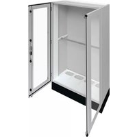
FR24V2 - Electrical cabinet HAGER - Free user manual and instructions
Find the device manual for free FR24V2 HAGER in PDF.


| Product Type | Electrical Control Unit |
| Brand | Hager |
| Model | FR24V2 |
| Dimensions (H x W x D) | 90 mm x 90 mm x 40 mm |
| Weight | 0.2 kg |
| Power Supply | 230 V AC, 50/60 Hz |
| Power Consumption | Max 5 W |
| Operating Temperature | -10°C to +40°C |
| Protection Rating | IP20 |
| Functions | Time control, relay switching, status indication |
| Mounting | Wall-mounting or DIN rail |
| Connectivity | Screw terminals (max 2.5 mm²) |
| Standby Power Consumption | < 0.5 W |
| Maintenance | Wipe with dry cloth; no internal parts user-serviceable |
| Safety | Double insulated; overload protection |
| Spare Parts | Contact Hager customer service for replacement modules |
| Certifications | CE, RoHS |
| Warranty | 2 years |
Frequently Asked Questions - FR24V2 HAGER
User questions about FR24V2 HAGER
0 question about this device. Answer the ones you know or ask your own.
Ask a new question about this device
Download the instructions for your Electrical cabinet in PDF format for free! Find your manual FR24V2 - HAGER and take your electronic device back in hand. On this page are published all the documents necessary for the use of your device. FR24V2 by HAGER.
USER MANUAL FR24V2 HAGER
natural_image
Line drawing of an open industrial electrical cabinet with internal components (no text or symbols)
natural_image
Technical line drawing of an open electrical cabinet with internal compartments and mounting brackets (no text or symbols)Table of contents
1 About this manual 5
1.1 Subject of the manual 5
1.2 Warranty and Liability 5
1.3 Used symbols and trademarks 6
2 For your safety 7
2.1 Proper use 7
2.2 Requirements for the authorised personnel 9
3 Technical data 10
3.1 General technical data 10
3.2 Order number code 14
3.3 Order references and housing dimensions 16
3.3.1 Wall-mounted enclosure 16
3.3.2 Floor standing enclosure 18
4 About the distribution enclosure FR 20
4.1 Important properties 20
4.2 Wall-mounted and floor standing enclosure designs 21
4.3 Scope of delivery and delivery state 22
4.4 Base plinth and accessories 24
4.4.1 Cable gland in base plinth 24
4.4.2 Levelling feet available for compensating height 25
4.5 Doors: Solid doors or transparent doors 26
4.5.1 Locks and access protection 27
4.5.2 Door wire profiles 27
4.6 Cable entry openings 28
4.6.1 Universal cable entry flange FZ402 30
4.6.2 Additional cable entry flanges and accessories 31
4.6.3 Close the flange openings with FZ435A 32
4.6.4 Sealing / access protection 32
4.6.5 Enclosure ventilation 33
4.6.6 Cable grommets and screw connections 34
4.7 Cable terminal box 35
4.8 Cable management duct 36
4.9 Accessories and spare parts for the enclosure expansion 38
4.9.1 Spare part locks 38
4.9.2 Standard supply of replacement parts and common accessories 40
4.9.3 Replacement doors 43
5 Internal extension and assembly 45
5.1 Earthing concept for wall-mounted and floor standing enclosures, protection class CL I 45
5.2 Protective insulation for enclosures with protection class CL II 46
5.3 Comply with protection type IP55 46
5.4 Disassembling and assembling the doors 48
5.5 Mounting rails 49
5.6 Retaining rail and bracket 51
5.7 Crossbar 53
5.8 Lowering angle bracket for crossbar or retaining rail 53
5.9 Mounting plates 55
5.9.1 Mounting plate small UZ*M1 55
5.9.2 Mounting plates up to enclosure height UZ*MP 56
5.10 Busbar gland 57
5.10.1 Busbar gland: Arrangement and dimensions 58
5.10.2 Plastic cover for busbar opening 59
5.11 Enclosure to enclosure connection 60
5.11.1 Side-by-side connection of 2 enclosures 60
5.11.2 Connection of 2 enclosures on top of each other 61
6 Assembly at the installation site 63
6.1 Assembly safety instructions 63
6.2 Assembly conditions at the installation location 64
6.2.1 Preparing the assembly location for wall assembly 64
6.2.2 Preparing the floor standing enclosure 65
6.2.3 Maintaining free spaces 66
6.3 Wall mounting brackets for suspending the enclosure 66
6.3.1 Wall mounting bracket dimensions 67
6.4 Assembly notes for wall-mounted enclosures 68
6.5 Assembly notes for floor standing enclosures 69
7 Transportation and storage 71
7.1 Safety notes for transportation 71
7.2 Transporting the distribution enclosure 73
7.2.1 Crane transportation of individual distribution enclosures 73
7.2.2 Ground transportation with a forklift or pallet truck 75
7.3 Storage / Temporary Storage 76
7.4 Reusing packaging 77
8 Inspection and maintenance 78
8.1 Testing intervals for recurring tests 78
8.2 Minimum inspection / maintenance measures 79
8.3 Clean 80
9 Decommissioning, disassembly and disposal 81
10 Appendix: Weight specifications and power loss 82
10.1 Weight specifications for enclosure types 82
10.2 Power loss specifications 88
10.2.1 Power loss for wall-mounted devices 88
10.2.2 Power loss for wall-mounted units 95
10.3 Assembly instructions: Overview 101
11 Glossary 103
12 Index 106
1 About this manual
This manual is part of the distribution enclosure FR.
1.1 Subject of the manual
This document is intended for users of the distribution enclosures FR from Hager. The manual conveys safety-relevant information for electrically skilled person and the operator concerning the lifecycle phases of the product.
- Read and observe this manual before you start working on the enclosure or the switchgear assembly.
- Also observe the supplied assembly manual for the respective enclosure or enclosure accessories.
- Store the manuals in a safe place. The authorised personnel must have access to the manuals at all times.
1.2 Warranty and Liability
The manual does not extend the Sales and Delivery Conditions of Hager. No new claims concerning the warranty and guarantee, which extend beyond the Sales and Delivery Conditions, can be derived from this manual.
Liability note
Hager reserves the right to modify or supplement the product or the documentation at any time without prior notice. Hager assumes no liability for typographical errors and any damage which may arise from them.
1.3 Used symbols and trademarks
Structure of warning messages
 Signal word Signal word |
| Type and source of the danger!Consequences if the danger is ignored➢ Measures for averting the danger |
Danger levels in warning messages
| Colour | Signal word | Consequences of non-compliance |
| DANGER | Death, serious | personal injury |
| WARNING | Death or serious personal injury possible | |
| CAUTION | Personal injury | |
| ATTENTION | Property damage |
Procedural instructions with a fixed order:
| Step Action | |
| 1 | Procedural instruction step 1 |
| 2 | Procedural instruction step 2 |
Additional symbols and their meaning:
| Symbol Meaning | |
 | The work must only be performed by an electrically skilled person. |
 | The product is intended for indoor installation or indoor use. |
| Visual representation | Meaning |
| 1., 2., 3., etc. Numbered lists with a fixed order | |
| - | Lists and procedural instructions without a fixed order |
| ➢ | Measure / procedural instruction for averting danger |
2 For your safety
- Avoid dangers. Adherence to the safety-relevant information in this section is a precondition for the safe assembly and use of the distribution enclosure.
- Also observe the safety-relevant information provided in other sections.
2.1 Proper use
With the distribution enclosures FR, Hager offers a range of univers wall-mounted enclosures with protection type IP55 and univers floor standing enclosures with protection type IP55. The wall-mounted and floor standing enclosures are available with a depth of 275 mm or 400 mm in various heights and widths.
The Hager distribution enclosure FR can be expanded with the univers N internal extension system / univers N high current (univers HS) components up to maximum supply current of 800 A. With the type-tested distribution enclosure FR and the internal extension system from Hager, switchgear and controlgear assemblies can be implemented according to EN 61439 part 2 (power switchgear and controlgear assemblies / PSC) or EN 61439 part 3 (distribution boards to be operated by ordinary persons / DBO). Distribution enclosure FR can also be extended with the univers Z internal extension system from Hager.
Fixed indoor installation / wall mounting
The enclosed design of the distribution enclosure is intended for fixed indoor wall mounting. It is permanently fastened and operated at the assembly location. The floor standing enclosures must also be mounted on the wall. The operating conditions for indoor installation according to EN 61439 as well as the maximum ambient temperatures must be observed at the assembly location.
The distribution enclosure FR can achieve protection type IP55. When the door is closed, it is also protected against dust and water jets. The instructions in this manual regarding compliance with the protection type must be observed during assembly work.
The distribution enclosures FR are available in protection class CL I (earthed) as well as in protection class CL II (double insulated). The instructions in this manual regarding compliance with the protection class must be observed during assembly work.
For more detailed information, refer to the technical data.
Intended use also includes:
- Reading and observing this manual, the assembly manuals and the manuals on the internal extension system,
- Complying with the requirements for the authorised personnel.
Misuse
Any other or additional use as well as changes and modifications to the distribution enclosure is considered misuse. Hager does not assume any liability for damages resulting from misuse.
Limitation of operating areas
There are different areas where the distribution enclosure may not be used to prevent dangers or damage to the enclosure. The distribution enclosure is not suitable
- in areas that require a higher protection type,
- in areas where the ATEX directives must be observed,
- in operating sites at risk of fire.
- Do not use the distribution enclosure in the corresponding environments, in particular, environments that contain chlorine, sulphur, acid or saline, the enclosure and internal extension components may be damaged.
2.2 Requirements for the authorised personnel

- Only qualified electrically skilled persons may assemble, install, commission switchgear and controlgear assemblies, perform extensions, troubleshooting or maintenance and disassemble and dispose of them.
- The qualified electrically skilled persons must have appropriate experience in initial testing and subsequent commissioning, troubleshooting and maintenance.
| Product lifecycle phase | Minimum training, qualifications or competence |
| Planning | Electrically skilled person |
| Internal extension system at the switchgear manufacturer | Switchgear manufacturer, electrically skilled person |
| Transport, assembly, installation | Switchgear manufacturer / electrically skilled person |
| Commissioning | Electrically skilled person with appropriate testing experience |
| Operation | - Power switchgear and controlgear assemblies according to EN 61439-2 (PSC): only allowed by electrically skilled person / electrically instructed person (under supervision of an electrically skilled person) / no operation by ordinary persons! - Short-circuit devices for operation by ordinary persons inside the distribution boards for operation by ordinary persons according to EN 61439-3 (DBO): Ordinary persons |
| Inspection and maintenance | Electrically skilled person with appropriate testing experience |
| Extensions | Electrically skilled person, planning required |
| Disassembly, disposal | Electrically skilled person, only for clearly defined mechanical and electrical work: electrically instructed person |
An electrically skilled person by virtue of their professional training, skills and experience as well as knowledge of the relevant regulations can assess the work assigned to them and identify possible dangers.
An electrically instructed person must be sufficiently informed and supervised by an electrically skilled person. The instructed person must thus be capable of identifying risks and avoiding dangers as well as dangers due to electricity.
3 Technical data
Intended use
Observing the technical data is important for ensuring the intended use.
3.1 General technical data
Specifications for the switchgear and controlgear assemblies
The distribution enclosure FR is prepared for the univers N or univers N high current (univers N HS) internal extension system.
After corresponding extension, it is also suitable as switchgear and controlgear assemblies according to EN 61439-1/-2/-3 for:
- Rated voltage U _n = 400 V / 690 V
- Rated voltage U _n = 230 V / 400 V
In case of rated voltage U_n = 400 V / 690 V
- Rated peak withstand current
$$ U _ {i m p} = \text { overvoltage category IV } - 8 \mathrm{kV} $$
- Mountable:
- Main busbars suitable for 8 kV operating equipment
- Alternative: Overvoltage protective device downstream of the incoming unit; with 4 kV, all devices can be used
- Rated insulation voltage U _i = 800 V
- CTI of the insulation material = 425; material group II
- Minimum clearances = 8 mm
- Minimum creepage distances = 11 mm
In case of rated voltage U_h = 230 V / 400 V
$$ U _ {\text { imp }} = \text { overvoltage category III } - 4 \text { kV } $$
- Rated peak withstand current
- Rated insulation voltage U i = 400 V
-
CTI of the insulation material = 425; material group II
-
Minimum clearances = 3 mm
- Minimum creepage distances = 5.6 mm
- Hager also recommends using the clearances and creepage distances specified under U_n = 400 V / 690 V for U_n = 230 / 400 V (Minimum clearances = 8 mm, minimum creepage distances = 11 mm).
Rated current
I_nA max. 800 A
Short-circuit resistance I_cc
- 70 kA for busbars
- 70 kA for fused protection devices
- 25 kA for MCCBs
On request, individual values and complete overviews are available as appendices for the VDE certificate according to DIN EN 61439-1/-2 and DIN EN 61439-1/-3.
Application
- Fixed
-
Indoor installation
-
Protection against external mechanical influence IK10 (glass door IK07)
- Ordinary persons may not operate switchgear and controlgear assemblies designed according to EN 61439, part 2 (power switchgear and controlgear assembly / PSC).
- Ordinary persons may operate switchgear and controlgear assemblies designed according to EN 61439, part 3 (distribution boards to be operated by ordinary persons / DBO). Devices that cannot be operated by ordinary persons must be marked by the installer according to standards or must require the use of a key or tool; additional requirements according to standard EN 61439 must be observed.
- Prepared for use under normal operating conditions according to the standard series EN 61439. Deviations are possible after the installer consults with the planner taking into consideration precautions according to the standard series EN 61439.
Mechanical installation of devices / internal extension
- Prepared for univers N, univers N high current and univers Z internal extension system as well as a mounting plate
- For assembly on univers UN*A mounting rails (not included in the scope of delivery)
- Floor standing enclosures, including retaining rail for reinforcing the mounting rails
Protection classes
- CL I earthed
- CL II double insulated
Protection type
- IP55
- IP3X (after the door, in front of covers)
Note:
- Observe the operating equipment protection type.
- A Hager NH switch disconnector with fuse in bar design has the protection type IP2X.
Impact protection
- IK10 all round, except for flange (standard side excluded)
- IK07 for glass door
Colour
- Enclosure RAL 7035 (light grey) powder-coated and burned-in
- Base plinth RAL 9005 (black) powder-coated and burned-in
Doors
- Front-flush, overlay, stop on right or left
- Available with sheet metal doors or transparent doors
- With double door from an enclosure width of 1050 mm (≥ 4 fields)
- Opening angle 110°
- 3-point rod lock with swivelling lever with pushbutton and push rods
- Inside hinges, all-round foamed, temperature and oil-resistant seal
- Standard pushbutton in the swivelling lever can be replaced with Euro profile half-cylinder
Carcass
- 1.5 mm sheet steel (1 mm rear panel), powder-coated and burned-in
- Can be turned 180° (top / bottom)
- Pre-punches in the sides to the busbar gland for an enclosure to enclosure connection (pre-punches depending on the enclosure size 1-3)
- M8 rivet nuts in floor plate and cover plate (2x at the front and 2x at the rear)
- M8 rivets nuts in rear panel (2x at top and 2x at bottom)
Installation
For fixed indoor installation / wall mounting:
- Wall-mounted enclosure via supplied 4 wall mounting brackets on the wall
- Floor standing enclosure on base plinth, height 100 / 200 mm, as well as wall mounting via 2 supplied wall mounting brackets
- Levelling feet available for compensating height, as an alternative to the base plinth
- Possible enclosure combinations:
- Individual enclosure
- Assembled at the side in a row, enclosure connection possible at same depth (using connection set FZ721A / FZ721B)
- Assembled vertically, enclosure connection possible at same width and depth (using connection set FZ77*A)
Cable entry openings
- 1x FZ402 at the top for each field ex works
- In the wall-mounted enclosure: 1x FZ408M at bottom ex works, remaining glands with FZ406M
- In the floor standing enclosure: Ppen at the bottom, without flange (to comply with protection type IP55 and protection class II, the insertion flange must be inserted at the bottom)
- Enclosure, with depth of 400 mm, with second row of flange openings (pre-punched)
Busbar gland of adjoining enclosures
- Via side pre-punches using connection set FZ721A / FZ721B). 1 to 3 pre-punches on the side depending on the enclosure height.
- Pre-punches at top and bottom intended for routing busbars with a 40/60 mm distance between busbars.
- Pre-punch in the centre of the enclosure intended for routing busbars with a 185 mm distance between busbars.
Standards and regulations
- Tested according to EN 61439-1/-2/-3
- Dimensions according to DIN 43780
- Protection type IP55 according to VDE 0470 part 1 (DIN EN 60529)
- Protection type IP3X when the door is open
- Clearances and creepage distances according to VDE 0110, part 1 and 2/1.89
- Rated insulation voltage AC 800 V
- Overvoltage category III/IV
- Degree of pollution 3
- Insulation class I
3.2 Order number code
The order number code contains
- The housing dimensions (inner height and width),
- The protection class, depth and door,
- Height of the base plinth for floor standing enclosures:
Order number code
| Order number | |||
| Product group | F R | ||
| Hight of enclosure | 450 | 3 | |
| Inner dimensions* (mm) | 600 | 4 | |
| 750 | 5 | ||
| 900 | 6 | ||
| 1050 | 7 | ||
| 1200 | 8 | ||
| 1350 | 9 | ||
| 1500 | (1) 0 | ||
| 1650 | (1) 1 | ||
| 1800 | (1) 2 | ||
| Width (mm) | 250 | 1 | |
| 500 | 2 | ||
| 750 | 3 | ||
| 1000 | 4 | ||
| 1250 | 5 | ||
| 1500 | 6 | ||
| Protection Class and depth (mm) | CL I & 275 | E | |
| CL I & 275 (Glazed door) | K | ||
| CL I & 400 | G | ||
| CL I & 400 (Glazed door) | V | ||
| CL II & 275 | S | ||
| CL II & 275 (Glazed door) | L | ||
| CL II & 400 | H | ||
| CL II & 400 (Glazed door) | U | ||
| Plinth** (mm) | 100 | 1 | |
| 200 | 2 | ||
* Height and width: Inner dimensions; height without base plinth; the height of the floor standing enclosure varies with the height of the used base plinth.
** All floor standing enclosures are supplied with base plinth. Base plinth is available with a height of 100 mm or 200 mm. If necessary, two base plinths can be assembled on top of each other (with connection set for 2 plinth panels on top of each other FZ714).
Example of order number code: FR24G2
| FR 2 4 G 2 | ||||
| FR series | ||||
| Height 1800 mm | ||||
| - Inner dimension | ||||
| - Height without base plinth | ||||
| Width 1000 mm | ||||
| - Inner dimension | ||||
| Protection class CL I, depth 400 mm | ||||
| Plinth 200 mm |
3.3 Order references and housing dimensions
3.3.1 Wall-mounted enclosure
Wall-mounted enclosure (outer dimension, without base plinth)
| Depth [mm] | Height [mm] | Width [mm] | mod. | Protection class | |
| CL I | CL II | ||||
| 275 | 500 | 300 | 36 | FR31E | FR31S |
| 550 | 72 | FR32E | FR32S | ||
| 800 | 108 | FR33E | FR33S | ||
| 1050 | 144 | FR34E | FR34S | ||
| 1300 | 180 | FR35E | FR35S | ||
| 275 | 650 | 300 | 48 | FR41E | FR41S |
| 550 | 96 | FR42E | FR42S | ||
| 800 | 144 | FR43E | FR43S | ||
| 1050 | 192 | FR44E | FR44S | ||
| 1300 | 240 | FR45E | FR45S | ||
| 275 | 800 | 300 | 60 | FR51E | FR51S |
| 550 | 120 | FR52E | FR52S | ||
| 800 | 180 | FR53E | FR53S | ||
| 1050 | 240 | FR54E | FR54S | ||
| 1300 | 300 | FR55E | FR55S | ||
| 275 | 950 | 300 | 72 | FR61E | FR61S |
| 550 | 144 | FR62E | FR62S | ||
| 800 | 216 | FR63E | FR63S | ||
| 1050 | 288 | FR64E | FR64S | ||
| 1300 | 360 | FR65E | FR65S | ||
| 275 | 1100 | 300 | 84 | FR71E | FR71S |
| 550 | 168 | FR72E | FR72S | ||
| 800 | 252 | FR73E | FR73S | ||
| 1050 | 336 | FR74E | FR74S | ||
| 1300 | 420 | FR75E | FR75S | ||
| 275 | 1250 | 300 | 96 | FR81E | FR81S |
| 550 | 192 | FR82E | FR82S | ||
| 800 | 288 | FR83E | FR83S | ||
| 1050 | 384 | FR84E | FR84S | ||
| 1300 | 480 | FR85E | FR85S | ||
| 275 | 1400 | 300 | 108 | FR91E | FR91S |
| 550 | 216 | FR92E | FR92S | ||
| 800 | 324 | FR93E | FR93S | ||
| 1050 | 432 | FR94E | FR94S | ||
| 1300 | 540 | FR95E | FR95S | ||
| 400 | 1550 | 300 | 108 | FR01E | FR01S |
| 550 | 216 | FR02E | FR02S | ||
| 800 | 324 | FR03E | FR03S | ||
| 1050 | 432 | FR04E | FR04S | ||
| 1300 | 540 | FR05E | FR05S | ||
| 400 | 650 | 550 | 96 | x | FR42H |
| 800 | 144 | x | FR43H | ||
| 1050 | 192 | x | FR44H | ||
| 400 | 1400 | 550 | 216 | FR92G | FR92H |
| 800 | 324 | FR93G | FR93H | ||
| 1050 | 432 | FR94G | FR94H | ||
Wall-mounted enclosure, assembly dimensions (see assembly manual)
| Tiefe/Depth | Höhe/Height | Breitz/Width | mod. | Ref | Ref | X | Y | XI | YI |
| 275 | 500 | 300 | 36 | FR31E | FR31S | 245 | 540 | 340 | 410 |
| 500 | 550 | 72 | FR32E | FR32S | 495 | 540 | 590 | 410 | |
| 500 | 800 | 106 | FR33E | FR33S | 745 | 540 | 840 | 410 | |
| 500 | 1050 | 144 | FR34E | FR34S | 995 | 540 | 1090 | 410 | |
| 500 | 1300 | 180 | FR35E | FR35S | 1245 | 540 | 1340 | 410 | |
| 650 | 300 | 48 | FR41E | FR41S | 245 | 690 | 340 | 560 | |
| 650 | 550 | 96 | FR42E | FR42S | 495 | 690 | 590 | 560 | |
| 650 | 800 | 144 | FR43E | FR43S | 745 | 690 | 840 | 560 | |
| 650 | 1050 | 192 | FR44E | FR44S | 995 | 690 | 1090 | 560 | |
| 650 | 1300 | 240 | FR45E | FR45S | 1245 | 690 | 1340 | 560 | |
| 800 | 300 | 60 | FR51E | FR51S | 245 | 640 | 340 | 710 | |
| 800 | 550 | 120 | FR52E | FR52S | 495 | 840 | 590 | 710 | |
| 800 | 800 | 180 | FR53E | FR53S | 745 | 840 | 840 | 710 | |
| 800 | 1050 | 240 | FR54E | FR54S | 995 | 840 | 1090 | 710 | |
| 800 | 1300 | 300 | FR55E | FR55S | 1245 | 840 | 1340 | 710 | |
| 950 | 300 | 72 | FR61E | FR61S | 245 | 990 | 340 | 880 | |
| 950 | 550 | 144 | FR62E | FR62S | 495 | 990 | 590 | 860 | |
| 950 | 800 | 216 | FR63E | FR63S | 745 | 990 | 840 | 860 | |
| 950 | 1050 | 288 | FR64E | FR64S | 995 | 990 | 1090 | 860 | |
| 950 | 1300 | 360 | FR65E | FR65S | 1245 | 990 | 1340 | 860 | |
| 1100 | 300 | 84 | FR71E | FR71S | 245 | 1140 | 340 | 1010 | |
| 1100 | 550 | 168 | FR72E | FR72S | 495 | 1140 | 590 | 1010 | |
| 1100 | 800 | 252 | FR73E | FR73S | 745 | 1140 | 840 | 1010 | |
| 1100 | 1050 | 336 | FR74E | FR74S | 995 | 1140 | 1090 | 1010 | |
| 1100 | 1300 | 420 | FR75E | FR75S | 1245 | 1140 | 1340 | 1010 | |
| 1250 | 300 | 96 | FR81E | FR81S | 245 | 1290 | 340 | 1160 | |
| 1250 | 550 | 192 | FR82E | FR82S | 495 | 1290 | 590 | 1160 | |
| 1250 | 800 | 288 | FR83E | FR83S | 745 | 1290 | 840 | 1160 | |
| 1250 | 1050 | 384 | FR84E | FR84S | 995 | 1290 | 1090 | 1160 | |
| 1250 | 1300 | 480 | FR85E | FR85S | 1245 | 1290 | 1340 | 1160 | |
| 1400 | 300 | 108 | FR91E | FR91S | 245 | 1440 | 340 | 1310 | |
| 1400 | 550 | 216 | FR92E | FR92S | 495 | 1440 | 590 | 1310 | |
| 1400 | 800 | 324 | FR93E | FR93S | 745 | 1440 | 840 | 1310 | |
| 1400 | 1050 | 432 | FR94E | FR94S | 995 | 1440 | 1090 | 1310 | |
| 1400 | 1300 | 540 | FR95E | FR95S | 1245 | 1440 | 1340 | 1310 | |
| 1550 | 300 | 108 | FR01E | FR01S | 245 | 1590 | 340 | 1460 | |
| 1550 | 550 | 216 | FR02E | FR02S | 495 | 1590 | 590 | 1460 | |
| 1550 | 800 | 324 | FR03E | FR03S | 745 | 1590 | 840 | 1460 | |
| 1550 | 1050 | 432 | FR04E | FR04S | 995 | 1590 | 1090 | 1460 | |
| 1550 | 1300 | 540 | FR05E | FR05S | 1245 | 1590 | 1340 | 1460 | |
| 400 | 1400 | 300 | 216 | FR92G | FR92H | 495 | 1440 | 590 | 1310 |
| 1400 | 550 | 324 | FR93G | FR93H | 745 | 1440 | 840 | 1310 | |
| 1400 | 800 | 432 | FR94G | FR94H | 995 | 1440 | 1090 | 1310 |

3.3.2 Floor standing enclosure
Floor standing enclosure with base plinth 100 mm (outer dimensions)
| Depth Height 1 | Width mod. Protection class | ||||||
| [mm] | [mm] | [mm] | CL I | CL I glass door | CL II | CL II glass door | |
| 275 1700 | 300 | 132 | FR11E1 | FR11S1 | |||
| 550 | 264 | FR12E1 | FR12S1 | ||||
| 800 | 396 | FR13E1 | FR13S1 | ||||
| 1050 | 528 | FR14E1 | FR14S1 | ||||
| 1300 | 660 | FR15E1 | FR15S1 | ||||
| 1550 | x x | ||||||
| 275 1850 | 300 | 144 | FR21E1 | x | FR21S1 | x | |
| 550 | 288 | FR22E1 | FR22K1 | FR22S1 | FR22L1 | ||
| 800 | 432 | FR23E1 | FR23K1 | FR23S1 | FR23L1 | ||
| 1050 | 576 | FR24E1 | FR24K1 | FR24S1 | FR24L1 | ||
| 1300 | 720 | FR25E1 | FR25K1 | FR25S1 | FR25L1 | ||
| 1550 | 864 | FR26E1 | FR26K1 | FR26S1 | FR26L1 | ||
| 400 1850 | 300 | 144 | FR21G1 | x | FR21H1 | x | |
| 550 | 288 | FR22G1 | FR22V1 | FR22H1 | FR22U1 | ||
| 800 | 432 | FR23G1 | FR23V1 | FR23H1 | FR23U1 | ||
| 1050 | 576 | FR24G1 | FR24V1 | FR24H1 | FR24U1 | ||
| 1300 | 720 | FR25G1 | FR25V1 | FR25H1 | FR25U1 | ||
| 1550 | 864 | FR26G1 | FR26V1 | FR26H1 | FR26U1 | ||
^1 Height specifications without base plinth
Floor standing enclosure with base plinth 200 mm (outer dimensions)
Depth Height 1 Width mod. Protection class
| [mm] | [mm] | [mm] | CL I | CL I glass door | CL II | CL II glass door | |
| 275 1700 | 300 | 132 | FR11E2 | FR11S2 | |||
| 550 | 264 | FR12E2 | FR12S2 | ||||
| 800 | 396 | FR13E2 | FR13S2 | ||||
| 1050 | 528 | FR14E2 | FR14S2 | ||||
| 1300 | 660 | FR15E2 | FR15S2 | ||||
| 1550 | x | x | |||||
| 275 1850 | 300 | 144 | FR21E2 | x | FR21S2 | x | |
| 550 | 288 | FR22E2 | FR22K2 | FR22S2 | FR22L2 | ||
| 800 | 432 | FR23E2 | FR23K2 | FR23S2 | FR23L2 | ||
| 1050 | 576 | FR24E2 | FR24K2 | FR24S2 | FR24L2 | ||
| 1300 | 720 | FR25E2 | FR25K2 | FR25S2 | FR25L2 | ||
| 1550 | 864 | FR26E2 | FR26K2 | FR26S2 | FR26L2 | ||
| 400 1850 | 300 | 144 | FR21G2 | x | FR21H2 | x | |
| 550 | 288 | FR22G2 | FR22V2 | FR22H2 | FR22U2 | ||
| 800 | 432 | FR23G2 | FR23V2 | FR23H2 | FR23U2 | ||
| 1050 | 576 | FR24G2 | FR24V2 | FR24H2 | FR24U2 | ||
| 1300 | 720 | FR25G2 | FR25V2 | FR25H2 | FR25U2 | ||
| 1550 | 864 | FR26G2 | FR26V2 | FR26H2 | FR26U2 |
^1 Height specifications without base plinth
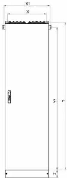
Floor standing enclosure, assembly dimensions (see assembly manual)
| Tiefe / Depth | Höhe / Height | Brolle / Width | mod. | Ref | Ref | Ref | Ref | X | Y | X1 | Y1 | Z |
| 275 | 1700 | 300 | 132 | FR11E1 | FR11S1 | 245 | 1721 | 340 | 1656 | 100 | ||
| 1700 | 550 | 264 | FR12E1 | FR12S1 | 495 | 1721 | 590 | 1656 | 100 | |||
| 1700 | 800 | 396 | FR13E1 | FR13S1 | 745 | 1721 | 840 | 1656 | 100 | |||
| 1700 | 1050 | 528 | FR14E1 | FR14S1 | 995 | 1721 | 1090 | 1656 | 100 | |||
| 1700 | 1300 | 660 | FR15E1 | FR15S1 | 1245 | 1721 | 1340 | 1656 | 100 | |||
| 275 | 1850 | 300 | 144 | FR21E1 | FR21S1 | 245 | 1871 | 340 | 1806 | 100 | ||
| 1850 | 550 | 288 | FR22E1 | FR22K1 | FR22S1 | FR22L1 | 495 | 1871 | 590 | 1806 | 100 | |
| 1850 | 800 | 432 | FR23E1 | FR23K1 | FR23S1 | FR23L1 | 745 | 1871 | 840 | 1806 | 100 | |
| 1850 | 1050 | 576 | FR24E1 | FR24K1 | FR24S1 | FR24L1 | 995 | 1871 | 1090 | 1806 | 100 | |
| 1850 | 1300 | 720 | FR25E1 | FR25K1 | FR25S1 | FR25L1 | 1245 | 1871 | 1340 | 1806 | 100 | |
| 1850 | 1550 | 864 | FR26E1 | FR26K1 | FR26S1 | FR26L1 | 1495 | 1871 | 1590 | 1806 | 100 | |
| 400 | 1850 | 300 | 144 | FR21G1 | FR21H1 | 245 | 1871 | 340 | 1806 | 100 | ||
| 1850 | 550 | 288 | FR22G1 | FR22V1 | FR22H1 | FR22U1 | 495 | 1871 | 590 | 1806 | 100 | |
| 1850 | 800 | 432 | FR23G1 | FR23V1 | FR23H1 | FR23U1 | 745 | 1871 | 840 | 1806 | 100 | |
| 1850 | 1050 | 576 | FR24G1 | FR24V1 | FR24H1 | FR24U1 | 995 | 1871 | 1090 | 1806 | 100 | |
| 1850 | 1300 | 720 | FR25G1 | FR25V1 | FR25H1 | FR25U1 | 1245 | 1871 | 1340 | 1806 | 100 | |
| 1850 | 1550 | 864 | FR26G1 | FR26V1 | FR26H1 | FR26U1 | 1495 | 1871 | 1590 | 1806 | 100 |
| Tiefte/Depth | Höhe /Height | Broite /Width | mod. | Ref | Ref | Ref | Ref | X | Y | X1 | Y1 | Z |
| 275 | 1700 | 300 | 132 | FR11E2 | FR11S2 | 245 | 1721 | 340 | 1656 | 200 | ||
| 1700 | 550 | 264 | FR12E2 | FR12S2 | 495 | 1721 | 590 | 1656 | 200 | |||
| 1700 | 800 | 396 | FR13E2 | FR13S2 | 745 | 1721 | 840 | 1656 | 200 | |||
| 1700 | 1050 | 528 | FR14E2 | FR14S2 | 995 | 1721 | 1090 | 1656 | 200 | |||
| 1700 | 1300 | 660 | FR15E2 | FR15S2 | 1245 | 1721 | 1340 | 1656 | 200 | |||
| 275 | 1850 | 300 | 144 | FR21E2 | FR21S2 | 245 | 1871 | 340 | 1806 | 200 | ||
| 1850 | 550 | 288 | FR22E2 | FR22K2 | FR22S2 | FR22L2 | 495 | 1871 | 590 | 1806 | 200 | |
| 1850 | 800 | 432 | FR23E2 | FR23K2 | FR23S2 | FR23L2 | 745 | 1871 | 840 | 1806 | 200 | |
| 1850 | 1050 | 576 | FR24E2 | FR24K2 | FR24S2 | FR24L2 | 995 | 1871 | 1090 | 1806 | 200 | |
| 1850 | 1300 | 720 | FR25E2 | FR25K2 | FR25S2 | FR25L2 | 1245 | 1871 | 1340 | 1806 | 200 | |
| 1850 | 1550 | 864 | FR26E2 | FR26K2 | FR26S2 | FR26L2 | 1495 | 1871 | 1590 | 1806 | 200 | |
| 400 | 1850 | 300 | 144 | FR21G2 | FR21H2 | 245 | 1871 | 340 | 1806 | 200 | ||
| 1850 | 550 | 288 | FR22G2 | FR22V2 | FR22H2 | FR22U2 | 495 | 1871 | 590 | 1806 | 200 | |
| 1850 | 800 | 432 | FR23G2 | FR23V2 | FR23H2 | FR23U2 | 745 | 1871 | 840 | 1806 | 200 | |
| 1850 | 1050 | 576 | FR24G2 | FR24V2 | FR24H2 | FR24U2 | 995 | 1871 | 1090 | 1806 | 200 | |
| 1850 | 1300 | 720 | FR25G2 | FR25V2 | FR25H2 | FR25U2 | 1245 | 1871 | 1340 | 1806 | 200 | |
| 1850 | 1550 | 864 | FR26G2 | FR26V2 | FR26H2 | FR26U | 1495 | 1871 | 1590 | 1806 | 200 |
4 About the distribution enclosure FR
4.1 Important properties
Area of application for univers FR distribution enclosures
- Wall-mounted enclosure or floor standing enclosure
- Prepared for univers N / univers N high current internal extension system
- Rated voltage U _n = 400 V / 690 V or 230 V / 400 V
- Rated insulation voltage U to 800 V
- Rated current I nA max. 800 A
- Enclosures can be combined side-by-side or on top of each other
Properties of univers FR distribution enclosures
- Protection type IP55, seals with high temperature and oil resistance
- Wall-mounted enclosures
- Available depths: 275 mm / 400 mm
- Available widths: 300, 550, 800, 1050 and 1300 mm
Inner dimension 250 to 1250 mm
Available heights: 500, 600, 800, 950, 1100, 1250 and 1400 mm - With 4 wall mounting brackets that can be positioned horizontally and vertically
- Wall-mounted enclosures equipped with transport feet
- Floor standing enclosures
- Available depths: 275 and 400 mm
- maximum width: 1550 mm, widths: 300, 550, 800, 1050, 1300 and 1550 mm, Inner dimension 250 to 1500 mm
- Available heights: 1700 and 1850 mm
- With 2 wall mounting brackets that can be positioned horizontally and vertically
-
Various base plinth heights available with the floor standing enclosure
-
Flexible main busbar routing through pre-punched side openings (1 to 3 pre-punches)
- Flexible cable entry through pre-punched openings in the roof and base plate and knockout cable gland openings in the base plinth
- Double door from an enclosure width of 1050 mm
- Enclosure carcass manufactured in sheet steel 1.5 mm on all sides
- Interior trim consisting of sturdy plastic plates for the protection classes I and II, defective plates can be easily replaced.
4.2 Wall-mounted and floor standing enclosure designs
Wall-mounted enclosures

natural_image
Open white industrial electrical cabinet with open door (no visible text or symbols)Example: Wall-mounted enclosure, earthed: Protection class CL I

natural_image
Exterior view of a white industrial enclosure with open door and internal compartments (no text or symbols visible)Wall-mounted enclosure example, completely covered with protective insulation: protection class CL II
| Available depths (outer dimensions) | 275 and 400 mm |
| Available widths (outer dimensions) | 300, 550, 800, 1050 and 1300 mm |
| Available heights (outer dimensions) | 500, 600, 800, 950, 1100, 1250 and 1400 mm |
Floor standing enclosures

natural_image
Exterior view of a white metal enclosure with black base and open door (no text or symbols visible)Example of earthed floor standing enclosure: Protection class CL I, standard door

natural_image
Exterior view of a metallic open electrical cabinet with internal compartments (no text or symbols visible)Example of earthed floor standing enclosure: Protection class CL I, transparent door
| Available depths (outer dimensions) | 275 and 400 mm |
| Available widths (outer dimensions) | 300, 550, 800, 1050, 1300 and 1550 mm |
| Available heights (outer dimensions) | 1700 and 1850 mm (without base plinth) |

natural_image
Interior view of an open electrical control cabinet with multiple circuit boards and modules (no visible text or labels)Example of floor standing enclosure with double door, fitted
4.3 Scope of delivery and delivery state
Observe type plate
To facilitate reordering, the data of the type plate attached to the enclosure should be documented.
The enclosures are marked by Hager according to EN 61439-1, section 6.1:
a) Name of the manufacturer of the switchgear and controlgear assemblies or its trademark
b) Type designation or ID number or another marking, which can be used to request the necessary information from the manufacturer of the switchgear and controlgear assembly
c) Marking for determining the date of manufacturer
d) Standard specifications
Example
a) :hager / Hager Lumetal S.p.A
b) FR25H1 IP55
c) 08/02/18
d) EN 60529
EN 61439-2
EN 61439-3
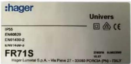
The enclosure marking should be supplemented with information of the switchgear manufacturer in compliance with standards.
Delivery state
- Enclosure with assembled closed door, edge protection on door
- Wall-mounted enclosures with transport protection feet, floor standing enclosures upright on the base plinth
- Enclosures wider than a Euro pallet are delivered on suitable disposable pallets.
- Enclosures packaged upright on a Hager carton on a pallet, with Hager label 1 x at the top and 1 x on the side.
Scope of enclosure delivery
- Cable entry flanges of wall-mounted enclosures: FZ402 at top for each field / opening, 1 x FZ408M at bottom, other FZ406M
- Cable entry flanges of floor standing enclosures: FZ402 at top for each field / opening, lower openings without flange; insulated flanges must be used for protection class CL II applications
- Enclosures, with a depth of 400 mm, have a pre-punch for another cable entry opening for each field
- Enclosures from a width of 1050 mm (or ≥ 4 fields) have double doors.
- Floor standing enclosures from a width of 1700 (or ≥11 rows) are supplied, including a preassembled base plinth (base plinth according to the order).
- Doors are equipped with a swivelling lever ex works (pushbutton insert).
Supplied earthing cable
- Earthing cables are only supplied for enclosures with protection class CL I.
- The enclosures delivered with a transparent door are not supplied with the earthing cable for the door, since door fittings are not possible.
- There are two green and yellow cables, (which are 90 cm long) supplied in earthed enclosures of protection class CL I for connecting the enclosure carcass and, if necessary, other metal parts to the PE. Another green and yellow cable is intended for the conductive connection of the door with the door fittings to the carcass.
Protective insulation
- The inside of the enclosures with protection class CL II is completely lined with protective insulation.
- The door is not additionally insulated. When using the univers N internal extension system, there are covers between the devices and door covers. This ensures the protective insulation.
Note:
A double-insulated enclosure can be “built back” into an earthed enclosure by removing the insulation.
- Ensure a conductive connection of the carcass to the PE.
4.4 Base plinth and accessories
Floor standing enclosures from a width of 1700 mm (or ≥ 11 rows) are supplied, including a preassembled base plinth.
Base plinth
- Colour, black, RAL 9005
- Available height 100 or 200 mm
- Depth according to enclosures depths
- The front and rear panels can be unscrewed
- Knockout cable gland openings on side panels
- If necessary, base plinths can be ordered individually as accessories.
- Two base plinths can be combined on top of each other. The connection set FZ714 is used for this.
Dimensions and order numbers of the base plinth:
| Plinth height 100 mm 200 mm | ||||
| Plinth depth | 275 mm | 400 mm | 275 mm | 400 mm |
| Enclosure width 300 mm | FZ631A | FZ651A | FZ641A | FZ661A |
| Enclosure width 550 mm | FZ632A | FZ652A | FZ642A | FZ662A |
| Enclosure width 800 mm | FZ633A | FZ653A | FZ643A | FZ663A |
| Enclosure width 1050 mm | FZ634A | FZ654A | FZ644A | FZ664A |
| Enclosure width 1300 mm | FZ635A | FZ655A | FZ645A | FZ665A |
| Enclosure width 1550 mm | FZ636A | FZ656A | FZ646A | FZ666A |
Base plinth accessories consist of:
- 2 x side parts, 1 x front panel, 1 x rear panel and corresponding screws, disassembled
- Mounting accessories for connection to the enclosure
4.4.1 Cable gland in base plinth
Pre-punches in the side plinth panels
The base plinth has two rectangular pre-punches on each of the two enclosure sides. The dimensions of the rectangular pre-punch are 65 x 65 mm and the inner circles has a diameter of 40 mm.

natural_image
Close-up of a white and black electronic device casing with circular buttons, no visible text or symbolsStrain relief rail as a plinth accessory
Strain relief rail / cable retaining rail and a corresponding mounting bracket can be ordered as accessories for installation in the base plinth.
The height, depth and angle of inclination of the strain relief rail can be adjusted using the mounting bracket:

natural_image
Technical line drawing of a mechanical bracket with a flat plate and rod (no text or symbols)

natural_image
Technical illustration of a mechanical assembly with an inset showing a close-up of a component (no text or symbols visible)Order number Strain relief rail / mounting bracket
| FZ7801 | Strain relief rail / cable retaining rail, 1 field width |
| FZ7811 | Strain relief rail / cable retaining rail, 2 fields width |
| FZ7821 | Strain relief rail / cable retaining rail, 3 fields width |
| FZ8441 | Strain relief rail / cable retaining rail, 4 fields width |
| FZ8451 | Strain relief rail / cable retaining rail, 5 fields width |
| FZ8461 | Strain relief rail / cable retaining rail, 6 fields width |
| FZ801A | Mounting bracket for strain relief rail in the 100 mm plinth |
| FZ801B | Mounting bracket for strain relief rail in the 200 mm plinth |
4.4.2 Levelling feet available for compensating height
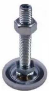
Instead of the base plinth, levelling feet FZ789 can be ordered in a set (4 units). The levelling feet are screwed into the rivet nuts in the floor plate.
natural_image
Close-up of a metallic bolt with hexagonal head and threaded shaft (no text or symbols visible)4.5 Doors: Solid doors or transparent doors
Solid door
- Front-flush, overlay, stop on right or left
Available with solid steel doors, steel plate, powder-coated and burned-in - 3-point rod lock with swivelling lever with pushbutton and push rods
- Inside hinges, all-round foamed, temperature and oil-resistant seal
- Standard pushbutton in the swivelling lever can be replaced with Euro profile half-cylinder
Important notes
- Old FA/FT doors do not fit on the FR housing
- Doors are overlay doors and therefore cannot be opened without plinth / floor clearance.
Transparent doors
Wall-mounted and floor standing enclosures can be also be ordered with a transparent door instead of a solid door. Both cases offer protection type IP55. Single-pane safety glass (ESG) was installed in the transparent door. If it breaks, it shatters into small shards to reduce the risk of injury, compared to normal flat glass.
Transparent doors have a reduced impact resistance IK07.

natural_image
Exterior view of a white open electrical enclosure with black base and internal compartments (no text or symbols visible)Enclosure with special door: Transparent door

natural_image
Exterior view of a modern office building (no signage)Broken pane from the single-pane safety glass (ESG)
Double-door design from width 1050 mm
For enclosures starting from a width of 4 fields ( ≥ 1050 mm) the housing is supplied with double doors. For enclosures fitted with double doors, the doors are designed with different widths and are not symmetrical.
The left door (without lock) has an additional bolt for fixing it in the closed position.

natural_image
Close-up of a white cabinet with black handle and gray floor, showing interior components (no text or symbols visible)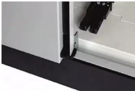
natural_image
Close-up of a white cabinet or shelf with black and gray components, no visible text or symbolsBolt for open door side Door side closed with bolt
4.5.1 Locks and access protection
With all distribution enclosures, a 3-point rod lock and a swivelling lever with pushbutton insert is preassembled at the factory. This lock can be replaced with other locks (see the “Replacement part locks” section).
The enclosure door can be sealed using the swivelling lever, even from the outside.
- To do this, thread a sealing wire in the lower part of the handle.
4.5.2 Door wire profiles
The door wire profiles / reinforcement profiles on the inside of the solid door can be used for fastening the door wiring or diagram pockets.
| Order number | Sealing profile, door width | Example figure |
| FZ739A 1 field, | 250 mm door | 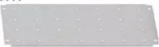 |
| FZ739B 2 fields, | 500 mm door | |
| FZ739C 3 fields, | 750 mm door |
4.6 Cable entry openings
The distribution enclosure FR offers maximum flexibility for inserting cables.
Flange openings (cable entry openings) in the distribution enclosure
- The enclosure, with a depth of 275 mm, has one flange opening in the cover and floor plate for each field.
- The enclosure, with a depth of 400 mm, has one flange opening in the cover and floor plate for each field.
The enclosure, with a depth of 400 mm, has one additional pre-punch in the cover and floor plate for each field. These pre-punches allow additional flange openings.

natural_image
Open white electrical cabinet with two internal compartments, no visible text or symbolsFR23K1 with a depth of 275 mm (protection class CL I)
- Each with a flange opening for each field at the top and bottom (here, 3x 2 flange openings)
natural_image
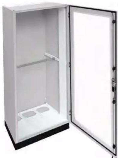
Interior view of a white stainless steel cabinet with open door (no text or symbols visible)FR23V1 with a depth of 400 mm (protection class CL I)
- Each with a flange opening for each field at the top and bottom (here, 3x 2 flange openings)
- Additional pre-punches for additional flange openings for each field at the top and bottom
Supplied cable entry flanges for flange openings
The following cable entry flanges are supplied ex works for the flange openings
| Cable entries in enclosure roof | Cable entries in enclosure base | |
| Wall-mounted enclosure | 1x FZ402 at top for each field | 1x FZ408M, remaining fields with FZ406M |
| Floor standing enclosure with base plinth | 1x FZ402 at top for each field | No flange at bottom ex works ^1 |
^1 floor standing enclosure at bottom: To comply with protection type IP55 and protection class CL II, insulated insertion flanges or sealing plates FZ435A must be inserted at the bottom.
The cable entry flanges can be opened or closed by turning the sash lock by a 14 revolution. The flanges can be locked against unauthorised opening using additional accessories.
Retrofitting flange openings for an enclosure depth of 400 mm
In addition to the flange openings, enclosures with an enclosure depth of 400 mm offer additional pre-punches at the top and bottom for creating additional flange openings as needed. These flange openings can be equipped with cable entry flanges. The same flanges can be used here as those used in the standard openings.
Step Action
| 1 | Cut out the plastic panels inside the enclosure using a cutter knife. Never knock out the plastic panels.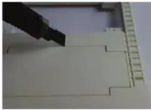 |
| 2 | Then, knock out the underlying pre-punch in the cover plate / floor plate using a hammer.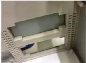 Make sure to precisely knock out the pre-punches to avoid damaging the housing.The high IK10 impact protection of the enclosure also requires a stable pre-punch. A certain degree of effort is therefore required for knocking out the pre-punches.Result:An additional flange opening is created. A cable entry flange can be used. Make sure to precisely knock out the pre-punches to avoid damaging the housing.The high IK10 impact protection of the enclosure also requires a stable pre-punch. A certain degree of effort is therefore required for knocking out the pre-punches.Result:An additional flange opening is created. A cable entry flange can be used. |
4.6.1 Universal cable entry flange FZ402
Wall-mounted enclosures and floor standing enclosures are supplied with a flange opening at the top and a cable entry flange FZ402 for each field:
| Order number | Description Figure | |
| FZ402 Universal cable entry flange |  | |
| FZ401 | Repair set for closing opening cable entries, sealing plugs suitable for the openings in FZ402 |  |
Open cable entries in flange FZ402 can be closed again with accessory FZ401 (sealing plugs) to restore the protection type.
The universal cable entry flange FZ402 offer the following options for inserting lines:
| Number of lines | Cable diameters from .... to [mm] | Cable cross-sections from .... to [mm2] | ||
| NYM NYY H07RN-F | ||||
| 24 | 9 - 11.5 | 3x1.5 - 5x1.5 | 1x4 - 1x16 | - |
| 12 | 11 - 16 | 3x2.5 - 5x4 | 1x16 - 3x6 | - |
| 4 | 12.5 - 20 | 3x4 - 5x10 | 3x2.5 - 5x6 | - |
| 2 | 13 - 27.5 | 3x4 - 4x25 | 3x2.5 - 4x25 | - |
| 2 | 16 - 32 | 3x6 - 4x35 | 3x6 - 4x50 | - |
| 1 | 25 - 50 | 4x25 - 5x25 | 3x25 - 3x240 | 1x120 - 4x70 |
4.6.2 Additional cable entry flanges and accessories
| Order number | Description Figure / example figure | |
| FZ404 | - Cable entry without pre-punches- For openings to be customised | 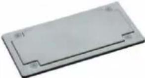 |
| FZ406M | Cable entry with pre-punches: 15x M20 or 13x M20 and 2x M25 |  FZ406M FZ406M |
| FZ407M | Cable entry with pre-punches: 13x M25 or 11x M25 and 2x M32 |  FZ408M FZ408M |
| FZ408M | Cable entry with pre-punches 2x M25 or M32 and 2x M50 or M63 | |
| FZ422 | Sheet metal cable cover with seal IP55; for protection class CL I Sheet metal cover for line opening; no pre-punches for openings to be customised*) | 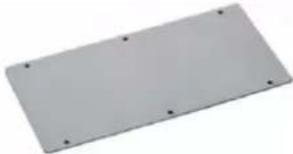 |
| FZ415E | Metal cable entry gland with two insertion grommets; protection class CL I- Stepped grommets for 2 cables withø 23 to 55 mm- Protection type IP55 with supplied cable ties |  |
| FZ415S | Plastic cable entry gland with two insertion grommets; protection class CL II- Stepped grommets for 2 cables withø 23 to 55 mm- Protection type IP55 with supplied cable ties |  |
*) The sheet metal cover FZ422 is only suitable for enclosures with protection class CL I. The earth connection to the enclosure using the self-tapping screws supplied has been tested and is adequate. No additional earthing measures are necessary.
4.6.3 Close the flange openings with FZ435A
Close the lower cable entry openings with FZ435A for CL II

natural_image
Blank white rectangular panel with four small circular holes, no text or symbols visible.Closing plate FZ435A

natural_image
Close-up of a white electronic device with multiple ports and a small metallic component on the front panel (no visible text or symbols)Application: Double-insulated closure from the inside; essential for protection class CL II
The lower flange openings (cable entry openings) in the floor standing enclosure can be closed from the inside with the closing plate FZ435A so that they are safe to touch and double-insulated. The closing plate accessories consist of a plastic plate that can be fixed in the roof panels or base panels using supplied screws.
- Lower insertion flanges are not necessary in the enclosure for floor standing enclosure featuring protection class CL I and a base plinth.
- With protection class CL II applications, insulating insertion flanges or closing plate(s) FZ435A must be used.
- Observe the supplied assembly manual for the closing plate FZ435A.
4.6.4 Sealing / access protection
Locking inserts are used to protect against the unauthorised opening of the flange in the terminal compartment near unmetered current.
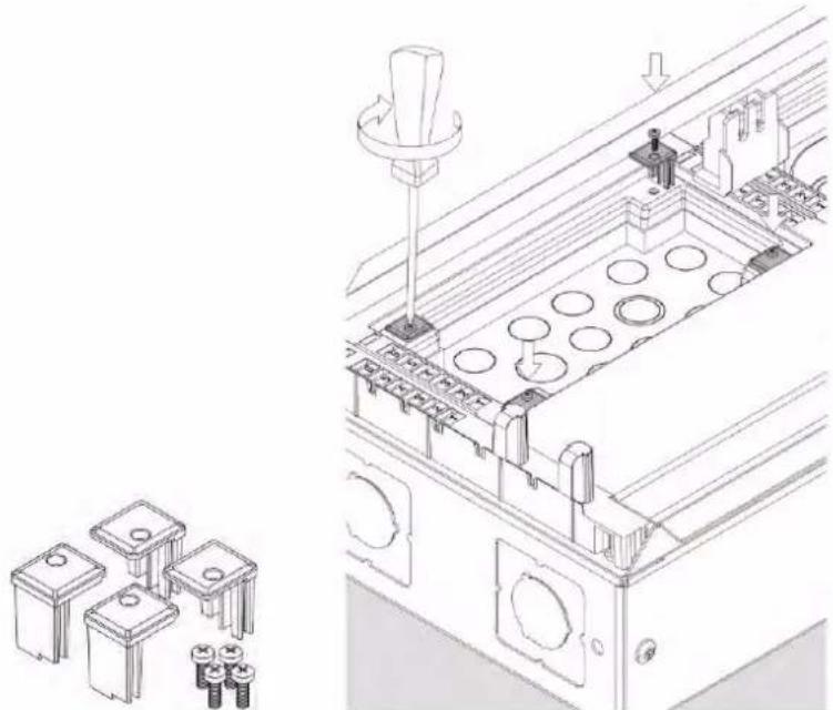
The locking set FZ421A can be used with all plastic cable entry flanges of the distribution enclosure accessories. When using the locking set FZ421A, the flange's locking bolt can no longer be turned without destroying it. This makes it possible to seal the enclosure.
natural_image
Technical line drawing of an industrial machine with internal components and mounting holes (no text or symbols)Locking inserts
Installing the locking inserts in the terminal compartment
Enclosure seal order number:
Order number Description
FZ421A Enclosure seal, locking set
4.6.5 Enclosure ventilation
Ventilation dampers FZ417 can be installed in the flange FZ408M.
Notes:
- Install a ventilation damper at the top and bottom in the enclosure to achieve effective ventilation.
- Cut out the flange FZ408M for assembly on the pre-punch.
- Note: The protection type is reduced to IP2X.
| Order number | Description | |
| FZ417 | Ventilation damper for flange FZ408MOrder reference contains 2 pieces | 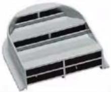 |
| FZ408M | Insertion flange suitable for expansion with FZ417Observe the additional order: Ventilation damper at top and bottom in the enclosure |  |
4.6.6 Cable grommets and screw connections
Cable grommets / stepped grommets
There are suitable cable grommets for cable entry flanges FZ406M, FZ407M and FZ408M.
The cable grommets can be fastened by inserting them in the flanges without using lock nuts.
| Order number | Size | Figure / figure example | |
| FZ409M M20 |  | ||
| FZ410M M25 | |||
| FZ411M M32 | |||
| FZ412M M40 | |||
| FZ413N | Multi range cable grommet (stepped grommet)ø 30 to 72 mm |  | |
Screwed cable glands / pressure compensating screw glands
Screwed cable glands with lock nut in different sizes, IP65, available as a built-in component:
| Order number | Size [∅ in mm] | Example figure |
| VZ016M | M16 |  |
| VZ020M | M20 | |
| VZ025M | M25 | |
| VZ032M | M32 | |
| VZ040M | M40 | |
| VZ050M | M50 | |
| VZ063M | M63 |
Pressure compensating screw glands:
| Order number | Size [∅ in mm] | Example figure |
| VZ020D | M20 | 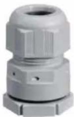 |
| VZ025D | M25 | |
| VZ032D | M32 |
4.7 Cable terminal box
The cable terminal box makes it easier to connect large cable cross-sections, since the cables can be inserted into the cable terminal box from the front. The cable inside the cable terminal box can be spliced and clamped; the connection in the enclosure is easier.
- It is not necessary to provide the wiring space necessary for connecting the cable in the enclosure.
- The cable terminal box can also be attached when wall mounting brackets are already mounted without requiring any adjustments.
- The cable terminal box cannot be flange-mounted on the side.
| Order number | Description | |
| U84LU | Empty cable terminal box for bottom infeed | 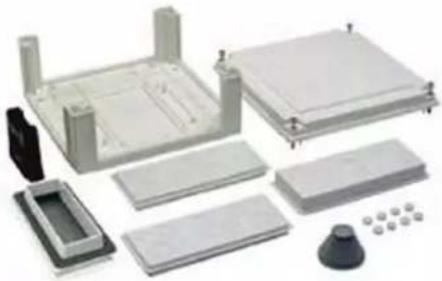 |
| U84LE | Expansion box for empty cable terminal box | |
| FZ420 | Connection accessories for the IP55 enclosure | 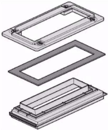 |
4.8 Cable management duct
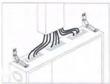
To mount the supply cables, the cable management duct can be attached above and below the distribution enclosure.
The long or short side can be screwed onto the wall here, which in turn swaps the height and width dimensions:
- 190 mm height and 150 mm depth or
- 150 mm height and 190 mm depth
Colour RAL 7035 Colour RAL 9010
| Order number | Size |
| FZ351 | 1-field |
| FZ352 | 2-field |
| FZ353 | 3-field |
| FZ354 | 4-field |
| FZ355 | 5-field |
| Order number | Size |
| FZ441 | 1-field |
| FZ442 | 2-field |
| FZ443 | 3-field |
| FZ444 | 4-field |
| FZ445 | 5-field |
A cable management duct consist of the cable housing on the outside (cover) and 2 cable brackets on the inside, 3 from a size of 750 mm.

Cable management duct, cover Cable management duct, bracket
Assembly example:
natural_image
Isometric line drawing of a ceiling-mounted electrical panel with three small components (no text or symbols)
natural_image
Diagram of a curved mechanical part with an inset showing a pointed tool or feature (no text or symbols present)
natural_image
Technical line drawing of a mechanical component with a directional arrow indicating motion (no text or symbols)
natural_image
Technical line drawing of a mechanical component with two protruding parts and a central shaft (no text or symbols)4.9 Accessories and spare parts for the enclosure expansion
4.9.1 Spare part locks
With all distribution enclosures, a 3-point rod lock and a swivelling lever with pushbutton insert is preassembled at the factory.
This lock can be replaced with other locking systems, e. g. other Euro profile half-cylinders, ratchet handles and swivelling lever handles.
The replacement locks listed below can be used in all enclosures of series FR*, FS*, FA*, FT*, FL*S/SP and FG*.
| Accessories | Order number / description | Figure |
| Door locksReplacement locks | FZ530Lever handle | 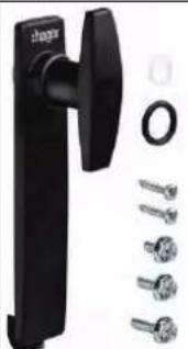 |
| FZ531 | Lever handle, lockable |  |
| FZ532 | Ratchet handle |  |
| FZ533 | Ratchet handle, lockable |  |
| Door locks | FZ537 | 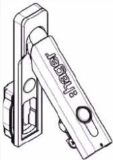 |
| Replacement locks | Swivelling lever |
Euro profile half-cylinders are available for installation in the swivelling lever FZ537.
As a spare part, they must be replaced with the pushbutton:
| Accessories | Order number / description | Figure |
| Euro profile half-cylinder for swivelling lever | FZ506Lock no. 1242EFZ519Lock no. 405FZ520Lock no. 455*) |  |
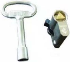 | ||
| MES-PHZ4K8 |  | |
| MES-PHZ3K7 | 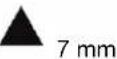 | |
| MES-PHZDB3 | 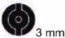 |
*) Any 30/10 Euro profile half-cylinders according to DIN 18252 / EN 1303 can also be installed.
4.9.2 Standard supply of replacement parts and common accessories
| Accessories | Order number | Figure / description |
| Mounting rail holder UT90J | 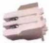 | |
| Hinge pin FZ797A | (Pack of 10) | |
| Wall mounting brackets | FZ829Set with 4 pieces |  |
| Doors | Stop on right or left,doors including closures and hinges | |
| Door wire profile(horizontal) | FZ739AFZ739BFZ739Cdepending on thedoor width | 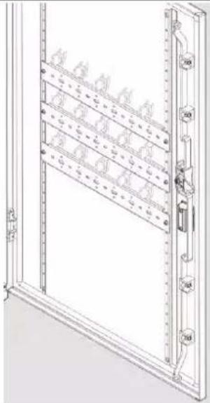 |
| Flange | Pass-through flangefor insulation, edge protection andcompliance of protection type. | |
| Retaining rail(Retaining rail UT21* andfixing bolt FZ800* mustbe ordered separately) | FZ800 andUT21* | 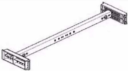 |
| Set with cables and screws | - 770961600Set with cable300 mm, 4 mm^2 for door- 770961700Set with cable900 mm,10 mm^2 for internalextension |  |
| Diagram pockets (optional) | FZ710DIN A4 sheetdocument holder for screw connectionon door reinforcement profiles |  |
| FZ757Reinforced diagram pocket with elasticpleat, glued, strong adhesionFZ757A4 in A4FZ757A5 in A5 |  | |
| FZ757MDIN A4 plastic diagram pocket,magnetic | 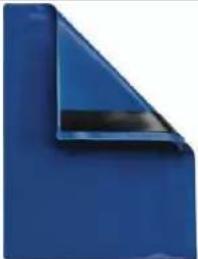 | |
| FZ794Film pocket, glued |  | |
| FZ795DMetaldocument holderDIN A4, glued or screwed | 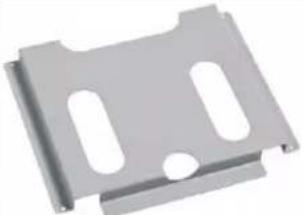 | |
| FZ818Hard plastic documentholder for glueing or screwing |  | |
| Header/footer | FZ230A: Enclosure, 275 mmFZ230B: Enclosure, 400 mm |  |
| Base plinthWith plinth height100 mm or 200 mm | Base plinth accessories consist of:- 2 x side parts, 2 x covers and corresponding screws, disassembled- Mounting accessories for connection to the enclosure | |
| Connection set to mount two base plinths on top of each other | FZ714 | 4 fastening screws,4 nuts,4 spring rings |
| Levelling feet available for compensating height- For use without base plinth | FZ789 | 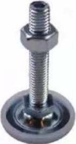 4 units 4 units |
| Strain relief rail as a base plinth accessory,1 field wide FZ78012 fields wide FZ78113 fields wide FZ78214 fields wide FZ84415 fields wide FZ84516 fields wide FZ8461 | Depth, angle and height-adjustable rail fixing possible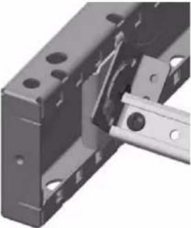 | |
| Mounting bracket for strain relief rail | FZ801A in plinth,height 100 mmFZ801B in plinth,height 200 mm | |
4.9.3 Replacement doors
Replacement doors for single-door enclosures IP55
| For enclosure | Enclosure width | Replacement door | 1 field wide | 2 fields wide | 3 fields wide |
| FR01* | FZ001R X | ||||
| FR11* FZ011R X | |||||
| FR21* FZ021R X | |||||
| FR31* FZ031R X | |||||
| FR41* FZ041R X 300 mm | |||||
| FR51* FZ051R X | |||||
| FR61* FZ061R X | |||||
| FR71* FZ071R X | |||||
| FR81* FZ081R X | |||||
| FR91* FZ091R X | |||||
| FR02* | FZ002R X | ||||
| FR12* FZ012R X | |||||
| FR22* FZ022R X | |||||
| FR32* FZ032R X | |||||
| FR42* FZ042R X 550 mm | |||||
| FR52* FZ052R X | |||||
| FR62* FZ062R X | |||||
| FR72* FZ072R X | |||||
| FR82* FZ082R X | |||||
| FR92* FZ092R X | |||||
| FR03* | FZ003R X | ||||
| FR13* FZ013R X | |||||
| FR23* FZ023R X | |||||
| FR33* FZ033R X | |||||
| FR43* FZ043R X 800 mm | |||||
| FR53* FZ053R X | |||||
| FR63* FZ063R X | |||||
| FR73* FZ073R X | |||||
| FR83* FZ083R X | |||||
| FR93* FZ093R X |
Replacement doors are supplied, including hinges, rod lock and swivelling lever.
Replacement doors for enclosures IP55 with double doors
| Left door(without lock) | Right door (with swivelling lever) | ||||
| For enclosure | Replacement door | 1 field wide | 2 fields wide | 3 fields wide | 3 fields wide |
| FR34* FZ03 | 4R X X | ||||
| FR35* FZ03 | 5R X X | ||||
| FR44* FZ04 | 4R X X | ||||
| FR45* FZ04 | 5R X X | ||||
| FR54* FZ05 | 4R X X | ||||
| FR55* FZ05 | 5R X X | ||||
| FR64* FZ06 | 4R X X | ||||
| FR65* FZ06 | 5R X X | ||||
| FR74* FZ07 | 4R X X | ||||
| FR75* FZ07 | 5R X X | ||||
| FR84* FZ08 | 4R X X | ||||
| FR85* FZ08 | 5R X X | ||||
| FR94* FZ09 | 4R X X | ||||
| FR95* FZ09 | 5R X X | ||||
| FR04* FZ00 | 4R X X | ||||
| FR05* FZ00 | 5R X X | ||||
| FR14* FZ01 | 4R X X | ||||
| FR15* FZ01 | 5R X X | ||||
| FR24* FZ02 | 4R X X | ||||
| FR25* FZ02 | 5R X X | ||||
| FR26* FZ02 | 6R X X | ||||
Replacement doors are supplied, including hinges, rod lock and swivelling lever.
For enclosures fitted with double doors, the doors are designed with different widths and are not symmetrical.
5 Internal extension and assembly
Note:
- Observe the manuals about the univers N internal extension system from Hager.
5.1 Earthing concept for wall-mounted and floor standing enclosures, protection class CL I

- The housing and all other conductive parts in the earthed enclosures with protection class CL I must be connected to the equipotential bonding.
The necessary cables are included in the scope of delivery for this: 2 x 90 cm green / yellow cable with cable lug - Since the mounting rails are fastened insulated in the enclosure, it must be ensured that all mounting rails are connected via conductive modules or cables or earthing accessories, such as UZ010 / UZ020.
The continuity of the earth connection of the individual mounting rails have been tested via conductive modules (such as, uninsulated mounted DIN rail), is sufficient and permissible.
Note on using the univers N internal extension system:
- The door is insulated against live parts by the covers. It is therefore not essential to earth it with a cable.
- An earthing cable for the door is supplied when the enclosure is delivered. It is used for installing devices in doors. The earthing cable, however, is not intended for use as a protective conductor.
- When installing devices in doors, protective conductors must be dimensioned according to the rated current of the installed devices, as prescribed in the relevant standard, once the protective extra-low voltage value is exceeded.
5.2 Protective insulation for enclosures with protection class CL II
In enclosures with protective insulation, the mounting rails are fixed with insulation ex works.
According to EN 61439, mounting rails and other metal parts (such as, the door, housing, mounting plates) are not connected to the PE/PEN via an earthing conductor.
Note:
Enclosures with protection class CL II can be built back into protection class CL I by removing the insulation to the enclosures.
- Ensure a conductive connection of the carcass to the PE.
Ensuring protective insulation for floor standing enclosures of protection class CL II
- Floor standing enclosures of protection class CL II must also be closed in the floor plate with plastic flanges or FZ435A closing plates to ensure the protective insulation. IP55 does not depend on this.
5.3 Comply with protection type IP55
IP55
- 1st code number 5 "Protection against dust deposits (dust protection)"
- 2nd code number 5 "Protection against water jets"
- Use the cable entries and accessories from the distribution enclosure series on the enclosure to ensure protection type IP55.
- Make sure that the cables are inserted correctly through the cable entry flanges in the enclosure.
- Make sure that the enclosure is assembled level / on a plane. The floor standing enclosure with the base plinth is supplied without a flange in the floor plate. The protection type IP55 is verified under standardised testing conditions and when the unit is installed with a base plinth on an even surface.
- This result cannot be ensured on an uneven surface or with non-standardised air movement.
- We thus strongly recommend using flanges or alternative locks
When the door is open, the enclosure achieves protection type IP3X when the univers N internal extension system and Hager devices are consistently used.
5.4 Disassembling and assembling the doors
The doors are equipped with
- edge protection against scratches. Disassembled doors can thus be temporarily stored without any damage. The edge protection is fixed to the enclosure with hot glue and can be removed without leaving any residue after final installation.
- Hinge pins for one-person door assembly. The hinge pins can be pulled without any tools and are locked into the top position by the red locking pin. This makes it possible for one person to assemble and disassemble the door.

natural_image
Close-up of a metallic door lock mechanism against a plain wall (no text or symbols visible)
natural_image
Close-up of a metallic door lock with handle and lock mechanism (no text or symbols visible)Hinge pin for fast door assembly / disassembly.
Important notes:
- Before disassembling the door, secure the enclosure against tipping over.
- Secure the door against unintentional closing. The door is not stable without any hinge pins.
- After the door is assembled, make sure that the hinge pins are locked. If not all hinge pins are locked, the hinge may be damaged.
Changing the door stop
The door stop can be changed by unscrewing the hinge on the opposite side. The holes for the hinges are available on both side and closed with plastic caps.
- Insert the plastic caps on the unused side. This is essential for maintaining the protection type.
5.5 Mounting rails
The mounting rails can be fastened in the grid dimension 12.5 mm
- In the enclosure with a depth of 275 mm, at 6 different depths,
- In the enclosure with a depth of 400 mm, at 16 different depths.

natural_image
Close-up of a metallic mechanical component with internal channels and mounting holes (no text or symbols visible)- To make it easier to arrange the mounting rails, the positions are marked in the plastic panels.
Enclosure dimensions for univers N internal extension system measured at the mounting rail in the front or rear position:

Assembling the mounting rails
To use the mounting rails in the enclosure, the mounting rail fixings / mounts UT90J or UT90G must be used:
- UT90J: For fastening the mounting rails at the same level
- UT90G: For fastening the mounting rails at a different level
The mounting rail fixings / mounts can be moved to different depths without any tools.
Mounting rail fixings / mounts UT90J:

The UT90J mounts are fastened as standard at position 3 in the enclosure ex works.
Mounting rail fixings / mounts UT90G:

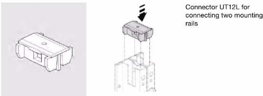
Connectors UT12L / earth connecting bracket UZ00VL
- Connectors UT12L are used to increase the stability of the mounting rails and establish the connection via the mounting rail connection set UT12HSV (U plates) or the earth connecting bracket UZ00VL:

natural_image
Technical diagram showing mechanical assembly with mounting brackets and a separate bracket with bolts (no text or symbols)Earth connecting bracket UZ00VL
- For the conductive connection of 2 mounting rails
- For increasing the mechanical stability
Ensure touch protection depending on the mounting rail position
- Extend the touch protection depending on the mounting rail position. The mounting rail fixing is assembled at position 3 or 4 for enclosures with of a depth of 400mm . If the mounting rails are positioned lower in these enclosures, then accessory parts may be used for extending the lateral circumferential contact protection. Hager offers contact protection cover FZ851.
| Order number | Description | Figure |
| FZ851 | Later contact protection extension Protection class CL I | 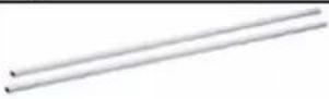 |
5.6 Retaining rail and bracket
A retaining rail is supplied as standard in floor standing enclosures. The retaining rail is used for the additional reinforcement of the mounting rails and prevent the internal extension system from moving to the side as well as backwards and forwards.

natural_image
Technical line drawing of a mechanical or electrical connector assembly with ports and connectors (no text or symbols)Retaining rail accessory part UT21* incl. fixing bolt / bracket FZ800*

natural_image
Close-up of a transparent glass shelf with a metal rod and two side connectors (no visible text or symbols)Retaining rail assembled in the enclosure. 1 retaining rail with the fixing bolts is supplied with the floor standing enclosure.
| Order number | Designation | Example figure |
| FZ800A | Fixing bolt 275, CL I, IP55Retaining rail bracket | 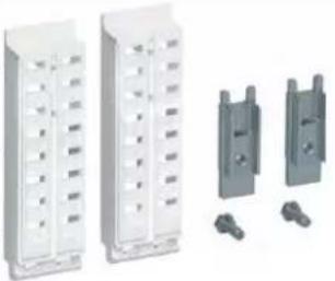 |
| FZ800B | Fixing bolt 275, CL II, IP55Retaining rail bracket | |
| FZ800C | Fixing bolt 400, CL I, IP55Retaining rail bracket | |
| FZ800D | Fixing bolt 400, CL II, IP55Retaining rail bracket | |
| UT21A Retaining rail | 250 mm |  |
| UT21B Retaining rail | 500 mm | |
| UT21C Retaining rail | 750 mm | |
| UT21D Retaining rail | 1000 mm | |
| UT21E Retaining rail | 1250 mm | |
| UT21F | Retaining rail 1500mm |
- Select the retaining rails according to the enclosure width.
- Select the fixing bolt for the retaining rails according to the enclosure variant.
Assembling the retaining rail
There are always 3 holes in the middle of the mounting rails at different heights (1 x middle and ± 150 mm) for fastening the mounting rail on the retaining rail.
- Use the supplied countersunk screws for assembling the mounting rail on the retaining rail. (Normal screw heads would otherwise prevent the assembly of a module at this position.)
Observe the assembly order:
Step Action
| 1 Position the retaining rail in the enclosure. |
| 2 Fix the mounting rails on the retaining rail. Use the supplied countersunk screws. |
| 3 Assemble the univers N modules on the mounting rails. |
5.7 Crossbar
Crossbars are used to intersect vertical mounting rails for assembling multi-field modules. This makes it possible to use univers N modules with different widths on top of each other.

natural_image
Close-up of a metal-framed storage panel with vertical supports and mounting holes (no text or symbols visible)Assembled crossbar UT12PN

natural_image
Technical illustration of a metal frame with mounting holes and a magnified view showing measurement markings (no text or symbols)Assembling the crossbar
Order number Designation
| UT12PN | 2-field crossbar, 500 mm wide with 12 M4 screws and assembly manual |
| UT12QN | 3-field crossbar, 750 mm wide with 12 M4 screws and assembly manual |
5.8 Lowering angle bracket for crossbar or retaining rail
- for lowering the crossbar, retaining rail or U-rail, always order when using in combination with meter support plates or other lower modules
| Order number | Lowering bracket designation | Figure |
| UZ25A | 2 brackets, 25 mm wide with lock nuts 2 and 4 screws * |  |
| UZ25AK | 2 isosceles brackets, 25 mm wide with 4 screws * | 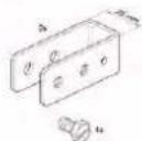 |
| UZ50A | 2 brackets 50 mm wide with 2 lock nuts and with 4 screws * | 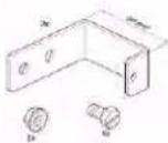 |
| UZ50AK | 2 isosceles brackets, 50 mm wide with 4 screws * |  |
Assembling the lowering bracket on the crossbar:

natural_image
Technical line drawing of a mechanical assembly with mounting brackets and a bracket (no text or symbols)After disassembling the T bracket supplied with the crossbar, the lowering bracket can be assembled on the crossbar.

natural_image
Technical line drawing of a mechanical assembly with no visible text or symbolsAfterwards, the T brackets are screwed on the lowering bracket.
5.9 Mounting plates
One or more mounting plates can be assembled in the housing.
5.9.1 Mounting plate small UZ\*M1
The mounting plates in kit size UZ*M1 are part of the univers N interior fitting system.
The mounting plates are fastened to two mounting rails using the supplied screws. The mounting plates feature integrated cut-outs, which enable univers covers to be fastened to the mounting rails. This allows you to freely select the position and size of the mounting plate in the cabinet.
- Material thickness 2.5 mm, galvanised
| Order number | Height / width of mounting plate univers N |
| UZ31M1 | 450 mm / 1 field wide |
| UZ32M1 | 450 mm / 2 fields wide |
| UZ41M1 | 600 mm / 1 field wide |
| UZ42M1 | 600 mm / 2 fields wide |
| UZ51M1 | 750 mm / 1 field wide |
| UZ52M1 | 750 mm / 2 fields wide |
| UZ61M1 | 900 mm / 1 field wide |
| UZ62M1 | 900 mm / 2 fields wide |
Installation of mounting plates UZ32M1 and UZ61M1, example:

natural_image
Two views of a metal-framed cabinet with open doors and internal compartments (no text or symbols visible)- mounting plates UZ61M1 installed above
- mounting plate UZ32M1 installed below
5.9.2 Mounting plates up to enclosure height UZ\*MP
The mounting plates UZ*MP are fastened directly in the enclosure using supplied screws, without any additional accessories. These mounting plates are adapted to the grid dimension of the mounting rails. You can therefore install these mounting plates in all univers-housings with 1800 mm height (inner dimensions).
Height UZ*MP 1800 mm
| Width | From 250 to 1250 mm (1 to 5 fields) |
| Material | 2 mm-thick, galvanised |
| Order number | Dimensions of the mounting plate [mm] |
| UZ21MP 1800x250 | |
| UZ22MP 1800x500 | |
| UZ23MP 1800x750 | |
| UZ24MP 1800x1000 | |
| UZ25MP 1800x1250 |
Installation of an mounting plate UZ2*MP, example:
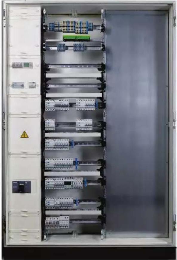
natural_image
Interior view of an open electrical control cabinet with multiple circuit breakers and a green safety guard (no visible text or labels)- The mounting plate UZ*MP can be installed in the same housing next to a univers N field.
- A partition can be fastened between the field with the mounting plate and the univers N field.
5.10 Busbar gland
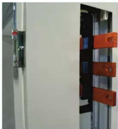
natural_image
Exterior view of a white cabinet with orange metal clamps and a black panel, no visible text or symbolsExample of the busbar gland
The side pre-punches of the distribution enclosures can be used to interconnect busbars through enclosures mounted side by side.
The position of the side pre-punches is selected as follows:
- The top and bottom pre-punches are suitable for the busbar gland on supports with a 40/60 mm distance between busbars.
- The centre pre-punch is suitable for the busbar gland on supports with a 185 mm distance between busbars.
5.10.1 Busbar gland: Arrangement and dimensions
Arrangement and dimensions of the pre-punches for busbar glands

natural_image
Technical line drawing of an open electrical cabinet with internal components and mounting brackets (no text or symbols)The distribution enclosures are equipped with side pre-punches for busbar glands.
Example on figure on the left:
- Enclosure height 1850 mm:
- Enclosure depth 275 mm
The number and position of the side pre-punches vary depending on the enclosure depths and height:
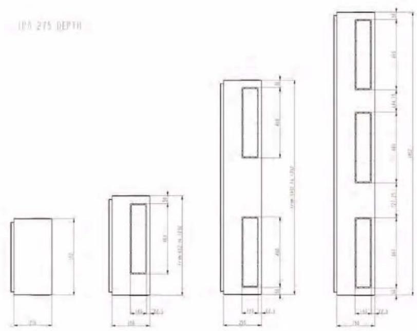
Enclosure depth 275 mm: Side pre-punches for busbar glands

Enclosure depth 400 mm: Side pre-punches for busbar glands
Opening pre-punches: Assembly instructions
Pre-punches for the busbar gland must be knocked out as needed. The high IK10 impact protection of the enclosure also requires a stable pre-punch. A certain degree of effort is therefore required for knocking out the pre-punches.
- With the enclosure featuring protection class CL II, open the protective insulation on the pre-punches inside before knocking them out. You thus avoid damaging the side insulation.
- Make sure to precisely knock out the pre-punches to avoid bending the side panel.
5.10.2 Plastic cover for busbar opening
Open side busbar glands can be closed again using a plastic or steel cover. Hager offers the plastic cover for busbar opening under the order number FZ448 for this.
| Order number | Description | Figure |
| FZ448 | Plastic cover for busbar opening |  |
- The plastic cover is suitable for enclosures of protection class SK I and protection class SK II.
- The plastic cover is suitable for easy processing on a workbench, for example, for attaching screwed cable glands before fastening to the enclosure.
5.11 Enclosure to enclosure connection
5.11.1 Side-by-side connection of 2 enclosures
- Distribution enclosures FR with the same depth can be fitted side by side. When using the Hager accessories, the IP55 protection as well as the mechanical stability is still ensured.
- FR enclosures with the same depth that are assembled side by side can have different heights. The suitable connection set / assembly kit must be used here.
- Enclosures with different depths (1x 275 mm and 1x 400 mm) cannot be connected on the side.
The respective connection set is intended for connecting two FR enclosures assembled side by side (FZ721A, FZ721B). The connection set consists of edge protection tape, 4 m sealing tape, screw-on plate / sheet metal angle bracket.
Connection sets for 2 adjacent enclosures / assembly kit FZ721*
| Order number Description | ||
| FZ721A | Assembly kit / connection set2 adjacent enclosures forenclosures FR/FS with anenclosure depth of 275 mm |  |
| FZ721B | Assembly kit / connection set2 adjacent enclosures forenclosures FR/FS with anenclosure depth of 400 mm |  |
Assembly notes (manual is supplied with the connection set)
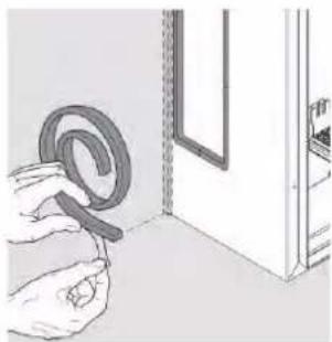
natural_image
Illustration of hands holding a coiled cable next to a door (no text or symbols visible)Edge protection: For the knocked out lateral pre-punch

natural_image
Technical line drawing of two 3D rectangular enclosures or storage compartments, showing internal structure and mounting points (no text or symbols)Sealing strip approx. 4 m: Glue all around the side edge of the enclosure

natural_image
Architectural diagram showing a building interior with structural elements and an inset circular view of a building facade (no text or symbols)Flat plate: On the top of the enclosure, screwed on for the mechanical connection (also at the bottom with the wall-mounted enclosure)
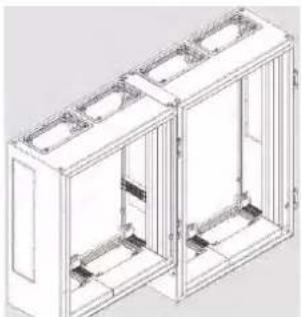
natural_image
Technical line drawing of a two-story rectangular enclosure with internal partitions and mounting holes (no text or symbols)Combination of enclosures with different heights

natural_image
Technical line drawing of a mechanical assembly with mounting brackets and mounting holes (no text or symbols)Fasten sheet metal angle bracket at the bottom on the first enclosure

natural_image
Technical line drawing of a mechanical bracket assembly (no text or symbols)Fasten sheet metal angle bracket at the bottom on the second enclosure
Comment:
The two enclosures assembled side by side must have a small distance between them:
- 6 mm when using FZ721A/B
- 20 mm when using FZ722A/B
5.11.2 Connection of 2 enclosures on top of each other
- Enclosures with the same width can be combined on top of each other at the assembly location.
When using the suitable Hager connection set for the vertical combination, the protection type IP55 and mechanical stability are still ensured.
- Enclosures with protection classes CL I and CL II are connected on top of each other, since the connection set is insulated.
- Enclosures with different widths cannot be combined on top of each other with standard accessories.
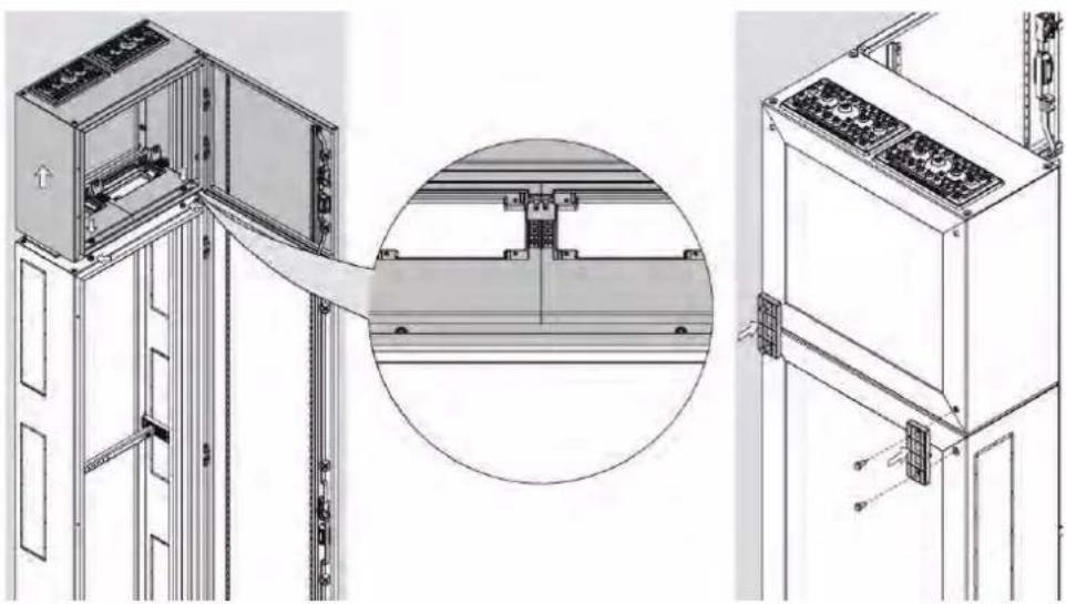
natural_image
Technical line drawing of a server rack unit with internal components and a magnified inset showing structural details (no text or symbols)Connection set for vertical combination:

natural_image
Diagram showing a refrigerator with a door and drawer, connected to a cabinet (no text or symbols present)Vertical combination of FR enclosures with the same width with connection set FZ77*A

natural_image
Product display panel with various fixtures and accessories (no visible text or symbols)Pass-through flange, brackets and fastening elements
| Order number | Connection set width |
| FZ771A 1 field wide | |
| FZ772A 2 fields wide | |
| FZ773A 3 fields wide | |
| FZ774A 4 fields wide | |
| FZ775A 5 fields wide | |
| FZ776A 6 fields wide |
The following is available in the connection set:
- Pass-through flanges for insulation, edge protection and stability, can be cut out as needed
- Brackets for the rear for the insulated, mechanical connection at the rear
- Fastening element for the insulated, mechanical connection on the front side
Observe the assembly manual
- Drill the front side of the enclosure according to the manual supplied with the connection set and connect the enclosures with the supplied screws / spacers.
6 Assembly at the installation site
6.1 Assembly safety instructions
| WARNING | |
 | Risk of crushing if the enclosure falls or tips over at the assembly site.➢ Observe weight, dimensions and load distribution➢ Only perform assembly work with suitable tools, lifting tools and mounting material➢ Secure the load and mount the enclosure immediately |
Risk of accident due to the enclosure tipping or falling!
Uneven load distribution, insufficient tools and mounting results in dangers due to the enclosure tipping or falling. Personnel may be seriously injured or killed.
The enclosure may only be assembled by electrically skilled persons.
Assembly only via wall mounting brackets FZ829 on all designated attachment points (observe the dimensions).
Never use the enclosure as a climbing aid, for support or storage space. Suitable ladders and scaffolding must be used to ascend to the appropriate height for performing work above the enclosure.
➢ Use protective equipment (safety shoes, gloves).
6.2 Assembly conditions at the installation location
Notes about the assembly requirements:
- Observe the intended use and in particular, the ambient conditions in the technical data.
- The distribution enclosure must be securely mounted on a load-bearing wall. A wall mount must also be used in addition to the floor mount for floor standing enclosures.
6.2.1 Preparing the assembly location for wall assembly
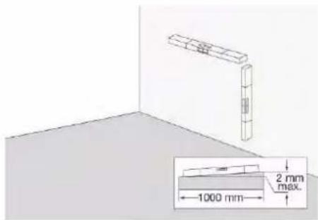
Wall assembly: Load-bearing, even and non-flammable surface required

natural_image
Two identical door lock diagrams with red X-shaped prohibition signs, no text or symbols presentDo not assemble objects in the rear of the distribution enclosure
Ensure an even, load-bearing assembly location
- The unevenness on the wall may be maximum +/- 2 mm per metre.
- Offset it with support material as necessary.
- No objects may be assembled at the rear.
- Check the load-bearing strength of the wall and ensure secure mounting options and a non-flammable surface.
- Observe the weight of the equipped enclosure here.
Additional requirements for the assembly location
- Clean, dry
- Not in a dirty, dusty or excessively damp environment
- Not in corrosive atmospheres, for suitable for ambient conditions
- Protected against dangers due to liquids entering the unit (e.g. water entering the unit after pipe damage)
6.2.2 Preparing the floor standing enclosure

Even surface for floor mount and wall mount Maximum tolerance: +/- 2 mm/m necessary
Ensure an even, load-bearing assembly location
- Ensure that the location is clean and dry.
- The unevennesses on the wall and on the base / surface may be maximum +/- 2 mm per metre. In case of considerable unevennesses, the protection type IP55 cannot be ensured.
- Offset it with support material as necessary. Alternatively to the base plinth, Hager also offers levelling feet as accessories (use cable entry flanges).
- No objects may be assembled at the rear of the enclosure (toward the wall).
- Check the load-bearing strength of the wall and ground and ensure secure mounting options and a non-flammable surface.
- Observe the weight of the equipped enclosure here.
Additional requirements for the assembly location
- Clean, dry
- Not in a dirty, dusty or excessively damp environment
- Not in corrosive atmospheres, for suitable for ambient conditions
- Protected against dangers due to liquids entering the unit (e.g. water entering the unit after pipe damage)
6.2.3 Maintaining free spaces
Observe the clearances
- For incoming cables (also take permissible bending radii into consideration).
- For operation, maintenance and for emergencies.
Ensure escape routes
- Observe safety clearances to ensure escape routes are available in emergencies.
- Minimum gangway width in front of the enclosure: 700 mm. If the doors open against the escape direction, the necessary escape route of 500 mm must also be available when the doors are opened at 90°.
Observe maximum assembly heights
- Readable displays: Ideally, at eye level between 0.2 m and 2.2 m above the standing area
- Main switch (if installed): Can be reached in a range between 0.8 m and 1.6 m above the standing area
- Operating elements: In centre line between 0.2 m and 2 m above the standing area
6.3 Wall mounting brackets for suspending the enclosure
- The wall-mounted enclosures are supplied with 4 wall mounting brackets.
- The floor standing enclosures are supplied with 2 wall mounting brackets.
- The enclosure can be suspended on the assembly rail using the wall mounting brackets.
- Using the wall mounting brackets creates clearance between the wall and the enclosure rear wall.
The wall mounting brackets can be assembled vertically or horizontally
Wall mounting brackets can be screwed on vertically or horizontally:

natural_image
Close-up of a white industrial cabinet with a black vent and metallic bracket (no visible text or symbols)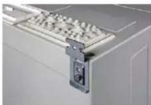
natural_image
Close-up of a white electronic device with a metallic bracket and internal components (no visible text or symbols)Wall mounting bracket as a replacement part
Order number Wall mounting brackets
FZ829 Set = 4 pieces
6.3.1 Wall mounting bracket dimensions
Dimensions of assembled wall mounting brackets


6.4 Assembly notes for wall-mounted enclosures

- Observe the univers IP5 assembly manual
Step Action
| 1 | Select the assembly position of the wall-mounted enclosure. Observe the assembly conditions. |
| 2 Select | the assembly direction of the wall mounting brackets and mark the assembly position of the wall mounting brackets according to the dimensional drawings / tables in the univers IP5 assembly manual. |
| 3 Drill assembly holes suitable for the fastening material. | |
| 4 Preassemble the assembly dowel. | |
| 5 Fasten | the enclosure with assembly screws. Tighten the assembly screws. |
| 6 Remove the transport feet. | |
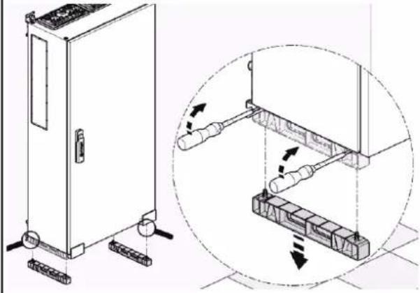
natural_image
Technical line drawing of a cabinet with attached components and an inset showing internal wiring or wiring alignment (no text or symbols)Note about transport feet
To set down the enclosure temporarily, the transport feet of the wall-mounted enclosures can be used. The enclosure is equipped with these feet ex works. The transport feet, however, are not suitable as a replacement plinth due to the weight of the extended enclosure.
- After the unit has been assembled on the wall, remove the transport feet.
6.5 Assembly notes for floor standing enclosures
- Observe the univers IP5 assembly manual
Observe the transport notes
- Observe the transport notes in this manual. In particular, observe the notes about the base plinth and moving the pallet truck under the unit after removing the front panel and rear panel of the base plinth.
Step Action
| 1 Select the assembly position of the floor standing enclosure.Observe the assembly conditions. |
| 2 Select the assembly direction of the wall mounting brackets and mark the assembly position of the wall mounting brackets according to the dimensional drawings / tables (image 08 in the univers IP5 assembly manual). |
| 3 Mark the assembly holes for assembling the base plinth on the floor according to the dimensional drawings / tables (image 09 in the univers IP5 assembly manual / section "Floor mounting via base plinth" on the following page in this manual). |
| 4 Drill assembly holes suitable for the fastening material. |
| 5 Preassemble the assembly dowel. |
| 6 Position the enclosure and then mount it on the wall immediately.Tighten the assembly screws. |
| 7 Fasten the enclosure to the floor with the assembly screws. Tighten the assembly screws. |
Floor mounting via base plinth
The distribution enclosure can be easily mounted to the floor using the offset elongated holes in the base plinth.
Dimensions of and positioning the base plinth:

| Enclosure width [mm] | Plinth width W [mm] | Depth D [mm] | A [mm] | B [mm] |
| 300 | 302 | 275 | 272 | 150 |
| 550 | 552 | 275 | 522 | 150 |
| 800 | 802 | 275 | 772 | 150 |
| 1050 | 1052 | 275 | 1022 | 150 |
| 1300 | 1302 | 275 | 1272 | 150 |
| 1550 | 1552 | 275 | 1522 | 150 |
Dimension H: the plinth height is either 100 or 200 mm
Dimension C: the enclosure spacing depends on the enclosure connection set:
- FZ721A/B: 6 mm
- FZ722A/B: 20 mm
7 Transportation and storage
7.1 Safety notes for transportation
| WARNING | |
 | Risk of crushing if the enclosure falls or tips over.➢ Transport only by qualified personnel.➢ When transporting using a crane, transport the enclosure only as a single unit.➢ Observe the weight, dimensions and load distribution.➢ Ensure secure transportation using suitable auxiliary equipment and lifting tools. The load must be secured at all times.➢ Fasten or secure the enclosure immediately after transportation. |
Risk of accident due to the enclosure tipping or falling!
Uneven load distribution, insufficient tools and mounting results in dangers due to the enclosure falling, tipping or falling. People may be seriously injured or killed due to crushing.
➢ Transport the enclosure upright, secured / fixed.
Only transport connected distribution enclosures when they fixed and secured on pallet.
➢ Never use the enclosure as a climbing aid, for support or storage space.
➢ Use protective equipment (safety helmet, safety shoes, gloves).
Observe the principles of safe transportation
Observe the principles of safe transportation and storage:
- Are sufficiently maintained and suitable transportation aids available?
- Is an even, solid and clean surface available for the transportation or storage / installation?
- Is the surface suitable for the weight of the enclosure?
- Avoid inclinations. Is it possible to brake or coast?
- Are the transportation routes illuminated and secured?
- Are any unauthorised persons in the danger zone?
- Are personnel wearing personal protective equipment and high-visibility clothing if necessary?
-
Are the protection objectives secured during transportation:
-
Head protection,
- Foot protection,
- Hand protection.
Observe the weight and centre of gravity and make sure that the load is secured
- Determine the weight of the enclosure.
- Observe the centre of gravity of the individual enclosure. The centre of gravity of the individual enclosure depends on the expansion state.
- Make sure that the load is secured as required during transportation. This also includes sufficient labelling of the load and the warnings of hazards (centres of gravity, attachment points, security measures).
Transporting the enclosure in a secured and fixed manner
- When the enclosure is transported with installed equipment, it must be transported upright and adequately secured and fixed.
- Never transport the enclosure horizontally if the equipment is installed.
Secured unloading
- When unloading or transporting the enclosure with a forklift, secure it to the forklift using retaining straps. Observe the weight and centre of gravity of the enclosure. The centre of gravity of the enclosure depends on the expansion.
Fixing the enclosure immediately after transportation
- Visually inspect the exterior of the enclosure for transportation damage.
- After transportation, immediately fasten the enclosure. In case of temporary storage, make sure that enclosures are firmly positioned and secure them against slipping or tipping.
- During assembly, make sure that the enclosures are aligned perpendicularly.
7.2 Transporting the distribution enclosure
The distribution enclosures can be lifted using 2 methods:
- Using a crane and lifting individual enclosures from above,
- Through ground transportation with a forklift, pallet truck or roller devices from below.
7.2.1 Crane transportation of individual distribution enclosures
- Never suspend the lifting equipment/lifting cables from the enclosure frame. Instead, only suspend it from the eye bolts / ring bolts.
- The total weight of the enclosure when lifting it using a crane is max. 240 kg.
- We recommend transporting the enclosure with a crane: Use lifting straps or round slings, enclosure upright on pallet.
- The crane eye threads on the enclosure are intended for steady, jerk-free transportation to the workshop. Do not lift the enclosure overhead!
Crane eyes / ring screws FZ831
To transport the enclosure using a crane, the enclosure can be lifted via M8 crane eyelets, which are screwed into the designated openings in the enclosure frame on the enclosure roof.
Order number
Crane eyes / ring screws M8
Figure
FZ831 4 x M8 crane eyelets,
- Max. total enclosure weight: 240 kg
- Load capacity for each crane eyelet: 140 kg
- Thread size M8; cast iron

natural_image
Five metallic ring-shaped objects arranged horizontally (no text or symbols visible)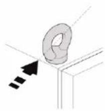
natural_image
Diagram of a hand holding a ring with an arrow indicating direction (no text or symbols)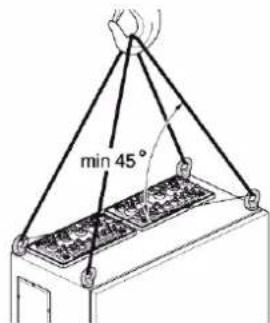

- The ring screws must point diagonally toward the enclosure centre so that the direction of force created by lifting cable is applied diagonally.
- The rings of the screws must not run parallel to an enclosure wall.
The crane hook is positioned over the centre of gravity. When lifting a enclosure with a crane, the enclosure hangs in a balanced position on 4 lifting cables, each with the same length where possible, at an angle of at least 45^ to the enclosure surface (angle of inclination may be maximum 45^ ).
The smaller the angle of inclination, the higher the maximum load.
Transportation on the crane eyelets / ring screws with load support. When lifting an enclosure with a crane, the enclosure hangs in a balanced position on 4 lifting cables, each with the same length where possible, at an angle of at least 90° to the enclosure surface.
Using a crane to transport connected enclosure is prohibited:
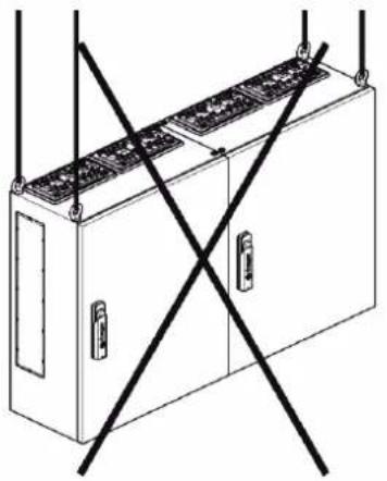
natural_image
Line drawing of an electrical enclosure with two doors and a grid on top, crossed by black lines (no text or symbols)
natural_image
Line drawing of a multi-level electrical cabinet with diagonal black lines indicating safety or resistance (no text or symbols)7.2.2 Ground transportation with a forklift or pallet truck
- When transporting the fitted floor standing enclosure, the centre of gravity must be taken into consideration.
- To make sure that the enclosure cannot tip over or slip, it must be fastened as specified by the transportation device manufacturer, e.g. using tensioning straps. Observe the transportation device manufacturer's manuals.
Transporting floor standing enclosures with base plinth
Floor standing enclosures are supplied as standard with assembled base plinth.
- The base plinths have two side parts that are load-bearing. They are fastened to the enclosure via screws.
- The front panel and rear panel of the base plinth are not load-bearing. They are fastened to the side parts via screws. The front panel and rear panel thus stabilise the base.
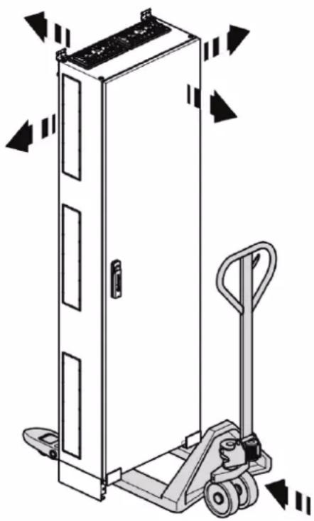
natural_image
Technical line drawing of a door mechanism with a pallet jack and directional arrows indicating motion (no text or symbols)- Before moving the pallet truck under the unit, unscrew the front panel and rear panel of the base plinth.
With double plinth panels, all front panels and rear panels must be unscrewed.
- Observe the weight and centre of gravity of the enclosure.
- Secure the enclosure against tipping over or slipping and transport it in a secured and fixed manner.
- Only use the minimum possible lifting height.
Never move the floor standing enclosures with the plinth panel removed.
The enclosure may only be moved if the front and rear plinth panel have been tightened. Only then is the stability of the lateral plinth panels ensured against twisting.
Ground transportation of connected enclosures on a pallet
When transporting connected enclosures on the ground:
- Transport the enclosures upright, fixed and secured on a pallet to the installation site. Use the pallet for lifting it.
- Do not lift the enclosure from below using a forklift or pallet truck.
7.3 Storage / Temporary Storage
Ensuring safe storage
- Take into account the ambient conditions
- Protected against moisture and extreme temperatures (storage temperatures -5°C - 40°C)
- Protected against dust, sand, chemicals and other causes of damage
- Do not store in a corrosive atmosphere.
-
Store the distribution cabinet separately on a free-standing palette:
-
Place wall cabinets on transport safety feet,
- Place floor-standing cabinets on a base,
- Protected against slipping or falling,
- The stability is secured on a stable, solid surface or by fixing against falling. The following must be observed: The weight and centre of gravity of the cabinets.
The user determines special requirements for the storage packaging according to DIN EN 61439-1 supplementary sheet 1, section 10.5, if there are special application requirements.
- Hager recommendations: Use undamaged transport packaging until the final assembly at the installation site.
Precautionary measures prior to subsequent transport
During subsequent transport:
- Prior to transport, perform a visual inspection for foreign objects left behind.
- Check the stability of the components and the entire cabinet.
- If necessary, clean the cabinet exterior and replace any missing parts.
- Observe the instructions for safe transport.
- For crane transport, have the ring screws checked by an expert before transporting the cabinet again:
- For mechanical damage, such as deformations, indentations,
- For cracks in the material,
- For fixed, correct positioning.
- In case of preliminary damage, the ring screws must be replaced.
7.4 Reusing packaging
The packaging consists of a Hager cardboard box with a label on the top and on the side, which is strapped and packed on a pallet.
The enclosures themselves are protected above and below with a cap and with a circumferential sheet of cardboard.
Note:
- The switchgear manufacturer makes it easy to reuse the cardboard box.

natural_image
Isometric line drawing of an electrical enclosure with internal components and directional arrows indicating movement (no text or symbols)8 Inspection and maintenance
Important for safe operation
Regular preventative maintenance is important for the safe operation of switchgear and controlgear assemblies.
Checks and maintenance only by electrically skilled persons with appropriate testing experience
- Tests and maintenance must be carried out by electrically skilled persons who have experience in testing switchgear and controlgear assemblies.
8.1 Testing intervals for recurring tests
In the interest of ensuring a high level of operational safety, the switchgear and controlgear assembly should be tested every 4 years by an electrically skilled person and verified that it is in perfect working order (recommendation by German Social Accident Insurance regulation 3 (DGUV) (formerly BGV A3)). National or insurer regulations may extend or shorten the test interval. Shortened intervals may be defined to ensure proper functionality and safe operation due to:
- the demands on the operating equipment,
- external influences,
- changes to the operating parameters and ambient conditions,
- Special kinds of compartments and systems according to DIN VDE 100 group 700,
- In case of complicated operating conditions, special circumstances, such as shocks, exposure to moisture,
- According to the specifications of the device or operating equipment manufacturer set forth in their instructions,
- According to applicable national standards and regulations.
Hager recommends performing a test at least once a year:
- A visual inspection (external inspection),
- Switching operations of the individual protection devices and switchgear.
- Document all tests, for example, in an inspection book.
Recommended recurring tests
| System / operating equipment | Test interval | Type of test | Inspector |
| Electrical systems and stationary operating equipment | 4 years5 years in Switzerland | For perfect working order | Electrically skilled person |
| Electrical systems and stationary operating equipment in operating sites, special kinds of spaces and systems according to DIN VDE 100 group 700 | 1 year For perfect working order | Electrically skilled person | |
| - Enclosure, jacketing and protective devices | 1 year Recommendation | - External visual inspection- Switching operation / functional testing | Electrically skilled person |
8.2 Minimum inspection / maintenance measures
At least the maintenance conditions below must be maintained for switchgear and controlgear assemblies with distribution enclosures FR (based on VDE 0100, part 610 for switchgear and controlgear assemblies):
The recurring tests during commissioning, changes, after faults or in suitable intervals include:
- Inspections,
- Measurements,
- Testing,
- Documenting test results,
- Eliminating the identified defects, for example, by replacing the faulty operating equipment or devices,
- Documenting the performed work and changes.
Tests through inspection
The inspection step includes checking the perfect working order of the electrical switchgear, including its operating equipment and devices. It includes an outside inspection and an inspection of the internal expansion.
- Check the protection against the direct and indirect contact of active parts.
- Check the basic protection and the basic insulation.
- Check the additional insulation for fault protection.
- Check all necessary covers for personal protection.
- Check for signs of ageing effects.
- Check for mechanical, chemical, electrical and thermal stress.
External inspections, tests Test values, comments, remedy
| Test the ambient conditions | - Effectiveness of the ventilation system and heating of operating space- Room temperature, relative humidity, aggressive air components, dust |
| Accessibility, minimum distances Escape routes, clearances | |
| Visual inspection of covers and jacketings | Damage that adversely affect the type of protection, such as:- Missing parts- Locks of doors, enclosure walls- Paintwork damage- Ventilation openings- Roof plate |
| Inspections Remarks | |
| Condition of jacketing, roof plate, fastening | If necessary, improve, replace housing parts, clean contamination, fix the fastening, observe the assembly manuals here |
| Check for corrosion traces | - Repair damage with a suitable touch-up stick MES-LSTI7035 for RAL 7035. For more significant damage, grind, clean (e.g. with white spirit, spot-removing spirit, universal thinners) and then paint- Check the operating conditions and ambient conditions |
| Hinge pin lock Lock, replace missing hinge pins | |
| Check that the door hinges can be moved easily | If necessary, spray anhydrous lubricant that protects against corrosion |
| Check that the lock and locking parts can be moved easily | Spray anhydrous lubricant on moving locking parts and replace sealing device if necessary |
| Seals, flange, contact hazard protection covers | Replace if damaged |
| Check according to protection class and protection type | - Earth for protection class CL I- Protective insulation for protection class CL II |
| Type plate / marking of the switchgear and controlgear assembly for legibility | If necessary, clean and ensure legibility |
| Documentation / documentation for completeness / legibility | Ensure completeness and legibility |
8.3 Clean
For operational safety reasons, contamination or pollution must be removed. During cleaning, observe at least the following safety points:
- Cleaning performed only by electrically skilled persons on system free of voltage
- Only perform cleaning work with suction air (vacuum cleaner) and dry towels. During cleaning work, an electrostatic charge in the jet nozzle may result in direct and indirect hazards to personnel.
- Do not use compressed air for cleaning.
- No wet cleaning.
- Remove all contamination on housing, also observe the roof plate.
- Hager offers a cleaning agent for plastic surfaces under the order number VZ404.
9 Decommissioning, disassembly and disposal
Decommissioning
- Decommissioning only by electrically skilled persons
- Switch off the system
- Observe the residual energies, residual voltages and residual heat
- Disconnect the system and supply lines from all poles and on all sides
- Secure against reconnection
- Ensure that no voltage is present
- Disconnect the supply line / incoming unit
- Securely lock the system
- Attach a sign indicating decommissioning
Disassembly and disposal
- Disassembly only by electrically skilled persons
- Check the disconnection and absence of voltage
- Disassemble the system in reverse order of the assembly and installation procedure.

- Devices marked with this symbol are subject to European directive 2012/19/EU for WEEE (Waste Electrical and Electronic Equipment). Electrical and electronic equipment may not be disposed of in domestic waste.
- Dispose of them according to the local applicable regulations.
- Separate the available raw materials of the system by disposal type and material:
- Parts containing copper, such as busbars and lines
- Electrical scrap: Terminals, short circuit devices
- Available NH fuses: NH fuse recycling (AVV 160216)
- Metal scrap: Jacketing, mounting plates
10 Appendix: Weight specifications and power loss
10.1 Weight specifications for enclosure types
- Enclosure depths and enclosure widths: Outer dimensions
- Height of floor standing enclosures: Specifications about enclosure heights, including base plinth
(outer height dimensions of enclosure + 100 mm / + 200 mm)
| Housing | Depth1[mm] | Width1[mm] | Height2[mm] | Volume[cm3] | Net weight[kg] | Gross weight[kg] |
| FR01E | 275 | 300 | 1550 | 127,875 | 33.128 | 33.956 |
| FR01S | 275 | 300 | 1550 | 127,875 | 33.128 | 33.956 |
| FR02E | 275 | 550 | 1550 | 234,437.5 | 43.578 | 44.668 |
| FR02S | 275 | 550 | 1550 | 234,437.5 | 43.578 | 44.668 |
| FR03E | 275 | 800 | 1550 | 341,000 | 54.029 | 55.379 |
| FR03S | 275 | 800 | 1550 | 341,000 | 54.029 | 55.379 |
| FR04E | 275 | 1050 | 1550 | 447,562.5 | 66.107 | 67.759 |
| FR04S | 275 | 1050 | 1550 | 447,562.5 | 66.107 | 67.759 |
| FR05E | 275 | 1300 | 1550 | 554,125 | 76.557 | 78.471 |
| FR05S | 275 | 1300 | 1550 | 554,125 | 76.557 | 78.471 |
| FR11E1 | 275 | 300 | 1800 | 148,500 | 40.275 | 41.282 |
| FR11E2 | 275 | 300 | 1900 | 156,750 | 43.425 | 44.511 |
| FR11S1 | 275 | 300 | 1800 | 148,500 | 40.275 | 41.282 |
| FR11S2 | 275 | 300 | 1900 | 156,750 | 43.425 | 44.511 |
| FR12E1 | 275 | 550 | 1800 | 272,250 | 55.987 | 57.387 |
| FR12E2 | 275 | 550 | 1900 | 287,375 | 59.137 | 60.616 |
| FR12S1 | 275 | 550 | 1800 | 272,250 | 55.987 | 57.387 |
| FR12S2 | 275 | 550 | 1900 | 287,375 | 59.137 | 60.616 |
| FR13E1 | 275 | 800 | 1800 | 396,000 | 71.699 | 73.492 |
| FR13E2 | 275 | 800 | 1900 | 418,000 | 74.849 | 76.720 |
| FR13S1 | 275 | 800 | 1800 | 396,000 | 71.699 | 73.492 |
| FR13S2 | 275 | 800 | 1900 | 418,000 | 74.849 | 76.720 |
| FR14E1 | 275 | 1050 | 1800 | 519,750 | 89.196 | 91.426 |
| FR14E2 | 275 | 1050 | 1900 | 548,625 | 92.346 | 94.655 |
| FR14S1 | 275 | 1050 | 1800 | 519750 | 89.196 | 91.426 |
| FR14S2 | 275 | 1050 | 1900 | 548,625 | 92.346 | 94.655 |
| FR15E1 | 275 | 1300 | 1800 | 643500 | 93.600 | 94.600 |
| FR15E2 | 275 | 1300 | 1900 | 679250 | 97.600 | 100 |
| FR15S1 | 275 | 1300 | 1800 | 643500 | 95.500 | 97.900 |
| FR15S2 | 275 | 1300 | 1900 | 679250 | 99.500 | 101.900 |
| FR21E1 | 275 | 300 | 1950 | 160875 | 42.908 | 43.981 |
| FR21E2 | 275 | 300 | 2050 | 169125 | 46.058 | 47.209 |
| FR21G1 | 400 | 300 | 1950 | 234000 | 46.942 | 48.115 |
| FR21G2 | 400 | 300 | 2050 | 246000 | 50.092 | 51.344 |
| FR21H1 | 400 | 300 | 1950 | 234000 | 46.942 | 48.115 |
| FR21H2 | 400 | 300 | 2050 | 246000 | 50.092 | 51.344 |
| FR21K1 | 275 | 300 | 1950 | 160875 | 40.763 | 41.782 |
| FR21K2 | 275 | 300 | 2050 | 169125 | 43.913 | 45.010 |
| FR21L1 | 275 | 300 | 1950 | 160875 | 40.763 | 41.782 |
| FR21L2 | 275 | 300 | 2050 | 169125 | 43.913 | 45.010 |
| FR21S1 | 275 | 300 | 1950 | 160875 | 42.908 | 43.981 |
| FR21S2 | 275 | 300 | 2050 | 169125 | 46.058 | 47.209 |
| FR21U1 | 400 | 300 | 1950 | 234000 | 44.769 | 45.916 |
| FR21U2 | 400 | 300 | 2050 | 246000 | 47.946 | 49.145 |
| FR21V1 | 400 | 300 | 1950 | 234000 | 44.796 | 45.916 |
| FR21V2 | 400 | 300 | 2050 | 246000 | 47.946 | 49.145 |
| FR22E1 | 275 | 550 | 1950 | 294937.5 | 59.366 | 60.851 |
| FR22E2 | 275 | 550 | 2050 | 310062.5 | 62.516 | 64.079 |
| FR22G1 | 400 | 550 | 1950 | 429000 | 63.848 | 65.444 |
| FR22G2 | 400 | 550 | 2050 | 451000 | 66.998 | 68.673 |
| FR22H1 | 400 | 550 | 1950 | 429000 | 63.848 | 65.444 |
| FR22H2 | 400 | 550 | 2050 | 451000 | 66.998 | 68.673 |
| FR22K1 | 275 | 550 | 1950 | 294937.5 | 56.398 | 57.808 |
| FR22K2 | 275 | 550 | 2050 | 310062.5 | 59.458 | 61.037 |
| FR22L1 | 275 | 550 | 1950 | 294937.5 | 56.398 | 54 |
| FR22L2 | 275 | 550 | 2050 | 310062.5 | 59.548 | 61.037 |
| FR22S1 | 275 | 550 | 1950 | 294937.5 | 59.366 | 60.851 |
| FR22S2 | 275 | 550 | 2050 | 310062.5 | 62.516 | 64.079 |
| FR22U1 | 400 | 550 | 1950 | 429000 | 60.880 | 62.402 |
| FR22U2 | 400 | 550 | 2050 | 451000 | 64.030 | 65.631 |
| FR22V1 | 400 | 550 | 1950 | 429000 | 60.880 | 62.402 |
| FR22V2 | 400 | 550 | 2050 | 451000 | 64.030 | 65.631 |
| FR23E1 | 275 | 800 | 1950 | 429000 | 75.825 | 77.720 |
| FR23E2 | 275 | 800 | 2050 | 451000 | 78.975 | 80.949 |
| FR23G1 | 400 | 800 | 1950 | 624000 | 80.755 | 82.774 |
| FR23G2 | 400 | 800 | 2050 | 656000 | 83.905 | 86.002 |
| FR23H1 | 400 | 800 | 1950 | 624000 | 80.755 | 82.774 |
| FR23H2 | 400 | 800 | 2050 | 656000 | 83.905 | 86.002 |
| FR23K1 | 275 | 800 | 1950 | 429000 | 72.033 | 73.834 |
| FR23K2 | 275 | 800 | 2050 | 451000 | 75.183 | 77.063 |
| FR23L1 | 275 | 800 | 1950 | 429000 | 72.033 | 73.834 |
| FR23L2 | 275 | 800 | 2050 | 451000 | 75.183 | 77.063 |
| FR23S1 | 275 | 800 | 1950 | 429000 | 75.825 | 77.720 |
| FR23S2 | 275 | 800 | 2050 | 451000 | 78.975 | 80.949 |
| FR23U1 | 400 | 800 | 1950 | 624000 | 76.964 | 78.888 |
| FR23U2 | 400 | 800 | 2050 | 656000 | 80.114 | 82.116 |
| FR23V1 | 400 | 800 | 1950 | 624000 | 76.964 | 78.888 |
| FR23V2 | 400 | 800 | 2050 | 656000 | 80.114 | 82.116 |
| FR24E1 | 275 | 1050 | 1950 | 563062.5 | 94.226 | 96.581 |
| FR24E2 | 275 | 1050 | 2050 | 591937.5 | 97.376 | 99.810 |
| FR24G1 | 400 | 1050 | 1950 | 819000 | 99.604 | 102.094 |
| FR24G2 | 400 | 1050 | 2050 | 861000 | 102.754 | 105.323 |
| FR24H1 | 400 | 1050 | 1950 | 819000 | 99.604 | 102.094 |
| FR24H2 | 400 | 1050 | 2050 | 861000 | 102.754 | 105.323 |
| FR24K1 | 275 | 1050 | 1950 | 563062.5 | 89.514 | 91.752 |
| FR24K2 | 275 | 1050 | 2050 | 591937.5 | 92.664 | 94.981 |
| FR24L1 | 275 | 1050 | 1950 | 563062.5 | 89.514 | 91.752 |
| FR24L2 | 275 | 1050 | 2050 | 591937.5 | 92.664 | 94.981 |
| FR24S1 | 275 | 1050 | 1950 | 563062.5 | 94.226 | 96.581 |
| FR24S2 | 275 | 1050 | 2050 | 591937.5 | 97.376 | 99.810 |
| FR24U1 | 400 | 1050 | 1950 | 819000 | 94.893 | 97.265 |
| FR24U2 | 400 | 1050 | 2050 | 861000 | 98.043 | 100.494 |
| FR24V1 | 400 | 1050 | 1950 | 819000 | 94.265 | 94.893 |
| FR24V2 | 400 | 1050 | 2050 | 861000 | 98.043 | 100.494 |
| FR25E1 | 275 | 1300 | 1950 | 697125 | 106.169 | 108.823 |
| FR25E2 | 275 | 1300 | 2050 | 732875 | 109.319 | 112.052 |
| FR25G1 | 400 | 1300 | 1950 | 1014000 | 111.995 | 114.795 |
| FR25G2 | 400 | 1300 | 2050 | 1066000 | 115.145 | 118.024 |
| FR25H1 | 400 | 1300 | 1950 | 1014000 | 111.995 | 114.795 |
| FR25H2 | 400 | 1300 | 2050 | 1066000 | 115.145 | 118.024 |
| FR25K1 | 275 | 1300 | 1950 | 697125 | 100.861 | 103.382 |
| FR25K2 | 275 | 1300 | 2050 | 732875 | 104.011 | 106.611 |
| FR25L1 | 275 | 1300 | 1950 | 697125 | 100.861 | 103.382 |
| FR25L2 | 275 | 1300 | 2050 | 732875 | 104.011 | 106.611 |
| FR25S1 | 275 | 1300 | 1950 | 697125 | 105 | 106.169 |
| FR25S2 | 275 | 1300 | 2050 | 732875 | 109.319 | 112.052 |
| FR25U1 | 400 | 1300 | 1950 | 1014000 | 106.687 | 109.354 |
| FR25U2 | 400 | 1300 | 2050 | 1066000 | 109.837 | 112.583 |
| FR25V1 | 400 | 1300 | 1950 | 1014000 | 106.687 | 109.354 |
| FR25V2 | 400 | 1300 | 2050 | 1066000 | 109.837 | 112.583 |
| FR26E1 | 275 | 1550 | 1950 | 831187.5 | 118.112 | 121.065 |
| FR26E2 | 275 | 1550 | 2050 | 873812.5 | 121.262 | 124.294 |
| FR26G1 | 400 | 1550 | 1950 | 1209000 | 124.387 | 127.497 |
| FR26G2 | 400 | 1550 | 2050 | 1271000 | 127.537 | 130.725 |
| FR26H1 | 400 | 1550 | 1950 | 1209000 | 124.387 | 127.497 |
| FR26H2 | 400 | 1550 | 2050 | 1271000 | 127.537 | 130.725 |
| FR26K1 | 275 | 1550 | 1950 | 831187.5 | 112.207 | 115.012 |
| FR26K2 | 275 | 1550 | 2050 | 873812.5 | 115.357 | 118.241 |
| FR26L1 | 275 | 1550 | 1950 | 831187.5 | 112.207 | 115.012 |
| FR26L2 | 275 | 1550 | 2050 | 873812.5 | 115.357 | 118.241 |
| FR26S1 | 275 | 1550 | 1950 | 831187.5 | 118.112 | 121.062 |
| FR26S2 | 275 | 1550 | 2050 | 873812.5 | 124 | 124.294 |
| FR26U1 | 400 | 1550 | 1950 | 1209000 | 118.481 | 121.443 |
| FR26U2 | 400 | 1550 | 2050 | 1271000 | 121.631 | 124.672 |
| FR26V1 | 400 | 1550 | 1950 | 1209000 | 118.481 | 121.443 |
| FR26V2 | 400 | 1550 | 2050 | 1271 | 121.631 | 124.672 |
| FR31E | 275 | 300 | 500 | 41.250 | 14.700 | 15.068 |
| FR31S | 275 | 300 | 500 | 41.250 | 14.700 | 15.068 |
| FR32E | 275 | 550 | 500 | 75.625 | 19.925 | 20.423 |
| FR32S | 275 | 550 | 500 | 75.625 | 19.925 | 20.423 |
| FR33E | 275 | 800 | 500 | 110 | 25.150 | 25.779 |
| FR33S | 275 | 800 | 500 | 110 | 25.150 | 25.779 |
| FR34E | 275 | 1050 | 500 | 144.375 | 30.901 | 31.673 |
| FR34S | 275 | 1050 | 500 | 144.375 | 30.901 | 31.673 |
| FR35E | 275 | 1300 | 500 | 178.750 | 36.126 | 37.029 |
| FR35S | 275 | 1300 | 500 | 178.750 | 36.126 | 37.029 |
| FR41E | 275 | 300 | 650 | 53.625 | 17.333 | 17.799 |
| FR41S | 275 | 300 | 650 | 53.625 | 17.333 | 17.766 |
| FR42E | 275 | 550 | 650 | 98312.5 | 23.304 | 23.887 |
| FR42H | 400 | 550 | 650 | 143 | 24.900 | 25.522 |
| FR42S | 275 | 550 | 650 | 98312.5 | 23.304 | 23.887 |
| FR43E | 275 | 800 | 650 | 143000 | 29.276 | 30.008 |
| FR43S | 275 | 800 | 650 | 143000 | 29.276 | 31.000 |
| FR44E | 275 | 1050 | 650 | 187687.5 | 35.930 | 36.828 |
| FR44H | 400 | 1050 | 650 | 273 | 38.000 | 38.950 |
| FR44S | 275 | 1050 | 650 | 187687.5 | 35.930 | 39.000 |
| FR45E | 275 | 1300 | 650 | 232375 | 41.902 | 42.949 |
| FR45S | 275 | 1300 | 650 | 232375 | 41.902 | 42.949 |
| FR46H | 400 | 1550 | 650 | 0.403 | 48.000 | 49.200 |
| FR51E | 275 | 300 | 800 | 66000 | 19.965 | 20.464 |
| FR51S | 275 | 300 | 800 | 66000 | 19.965 | 20.464 |
| FR52E | 275 | 550 | 800 | 121000 | 26.683 | 27.350 |
| FR52S | 275 | 550 | 800 | 121000 | 26.683 | 27.350 |
| FR53E | 275 | 800 | 800 | 176000 | 33.401 | 34.236 |
| FR53S | 275 | 800 | 800 | 176000 | 33.401 | 34.236 |
| FR54E | 275 | 1050 | 800 | 231000 | 40.960 | 41.894 |
| FR54S | 275 | 1050 | 800 | 231000 | 40.960 | 41.894 |
| FR55E | 275 | 1300 | 800 | 286000 | 47.678 | 48.870 |
| FR55S | 275 | 1300 | 800 | 286000 | 47.678 | 48.870 |
| FR61E | 275 | 300 | 950 | 78375 | 22.598 | 23.163 |
| FR61S | 275 | 300 | 950 | 78375 | 21.000 | 22.598 |
| FR62E | 275 | 550 | 950 | 143687.5 | 30.062 | 30.814 |
| FR62S | 275 | 550 | 950 | 143687.5 | 30.062 | 30.500 |
| FR63E | 275 | 800 | 950 | 209000 | 37.527 | 38.465 |
| FR63S | 275 | 800 | 950 | 209000 | 37.527 | 38.465 |
| FR64E | 275 | 1050 | 950 | 274312.5 | 45.989 | 47.139 |
| FR64S | 275 | 1050 | 950 | 274312.5 | 45.989 | 48.500 |
| FR65E | 275 | 1300 | 950 | 339625 | 53.454 | 54.790 |
| FR65S | 275 | 1300 | 950 | 339625 | 53.454 | 54.790 |
| FR71E | 275 | 300 | 1100 | 90750 | 25.230 | 25.861 |
| FR71S | 275 | 300 | 1100 | 90750 | 25.230 | 24.000 |
| FR72E | 275 | 550 | 1100 | 166375 | 33.441 | 34.277 |
| FR72S | 275 | 550 | 1100 | 166375 | 33.441 | 34.277 |
| FR73E | 275 | 800 | 1100 | 242000 | 41.652 | 42.694 |
| FR73S | 275 | 800 | 1100 | 242000 | 41.652 | 42.694 |
| FR74E | 275 | 1050 | 1100 | 317625 | 51.018 | 52.294 |
| FR74S | 275 | 1050 | 1100 | 317625 | 51.018 | 52.294 |
| FR75E | 275 | 1300 | 1100 | 393250 | 59.230 | 60.710 |
| FR75S | 275 | 1300 | 1100 | 393250 | 59.230 | 62.500 |
| FR81E | 275 | 300 | 1250 | 103125 | 27.863 | 28.559 |
| FR81S | 275 | 300 | 1250 | 103125 | 27.863 | 28.559 |
| FR82E | 275 | 550 | 1250 | 189062.5 | 36.820 | 37.741 |
| FR82S | 275 | 550 | 1250 | 189062.5 | 36.820 | 38.250 |
| FR83E | 275 | 800 | 1250 | 275000 | 45.778 | 46.922 |
| FR83S | 275 | 800 | 1250 | 275000 | 45.778 | 48.000 |
| FR84E | 275 | 1050 | 1250 | 360937.5 | 56.048 | 57.449 |
| FR84S | 275 | 1050 | 1250 | 360937.5 | 56.048 | 57.449 |
| FR85E | 275 | 1300 | 1250 | 446875 | 56.005 | 66.631 |
| FR85S | 275 | 1300 | 1250 | 446875 | 56.055 | 66.631 |
| FR91E | 275 | 300 | 1400 | 115500 | 30.495 | 31.258 |
| FR91S | 275 | 300 | 1400 | 115500 | 30.495 | 31.258 |
| FR92E | 275 | 550 | 1400 | 211750 | 40.199 | 41.204 |
| FR92G | 400 | 550 | 1400 | 308000 | 43.695 | 44.788 |
| FR92H | 400 | 550 | 1400 | 308000 | 43.695 | 44.788 |
| FR92S | 275 | 550 | 1400 | 211750 | 40.199 | 41.204 |
| FR93E | 275 | 800 | 1400 | 308000 | 49.903 | 51.151 |
| FR93G | 400 | 800 | 1400 | 448000 | 53.847 | 55.194 |
| FR93H | 400 | 800 | 1400 | 448000 | 53.847 | 62.000 |
| FR93S | 275 | 800 | 1400 | 308000 | 49.903 | 51.151 |
| FR94E | 275 | 1050 | 1400 | 404250 | 61.077 | 62.604 |
| FR94G | 400 | 1050 | 1400 | 588000 | 65.470 | 67.106 |
| FR94H | 400 | 1050 | 1400 | 588000 | 65.470 | 78.000 |
| FR94S | 275 | 1050 | 1400 | 404250 | 61.077 | 62.604 |
| FR95E | 275 | 1300 | 1400 | 500500 | 70.781 | 72.551 |
| FR95S | 275 | 1300 | 1400 | 500500 | 70.781 | 72.551 |
^1 Enclosure depths and enclosure widths: Outer dimensions
^2 Height of floor standing enclosures: Specifications of enclosure heights, including base plinth
10.2 Power loss specifications
Thermal / power loss specifications
- The permissible power loss P_zul is specified for all sides of the enclosed housing without ventilation openings and without horizontal separating walls, for example, with the even distribution of the thermal load.
- The overtemperature of the air in the housing t is specified in 75% and in 50% of the housing height.
- The values are measured in compliance with EN 61439-1/-2, section 10.10.4.2.2.
- Make sure that the permissible overtemperature of the air in the switchgear and controlgear assembly does not exceed the maximum operating temperature of the devices.
10.2.1 Power loss for wall-mounted devices
Permissible power loss P_ZUL : Height 500 mm, depth* 275 mm
| Housing Overtemperature Δt | % housing height | ||||||
| Mod. | Width | 10 K | 15 K | 20 K | 25 K | 30 K | |
| mm W | W W W | W | |||||
| FR31... 300 | 10.3 | 17.1 | 24.4 | 32.2 | 40.4 | 75 | |
| 13.5 | 22.3 | 31.9 | 42.1 | 52.8 | 50 | ||
| FR32... 550 | 16.5 | 27.3 | 39.0 | 51.5 | 64.6 | 75 | |
| 20.1 | 33.2 | 47.5 | 62.7 | 78.7 | 50 | ||
| FR33... 800 | 23.0 | 38.1 | 54.5 | 71.9 | 90.2 | 75 | |
| 26.5 | 43.8 | 62.6 | 82.7 | 103.7 | 50 | ||
| FR34... | 1050 | 29.3 | 48.6 | 69.5 | 91.7 | 115.0 | 75 |
| 32.7 | 54.1 | 77.4 | 102.1 | 128.1 | 50 | ||
| FR35... | 1300 | 33.8 | 56.0 | 80.1 | 105.8 | 132.7 | 75 |
| 39.2 | 64.9 | 92.8 | 122.6 | 153.7 | 50 | ||
* At enclosure depths of 275 mm: Installation compartment depth 150 mm
Permissible power loss Pzul: Height 650 mm, depth* 275 mm
| Housing Overtemperature Δt | % housing height | ||||||
| Mod. | Width | 10 K | 15 K | 20 K | 25 K | 30 K | |
| mm W | W W W | W | |||||
| FR41... | 300 | 12.5 | 20.7 | 29.5 | 39.0 | 48.9 | 75 |
| 16.5 | 27.3 | 39.1 | 51.6 | 64.7 | 50 | ||
| FR42... | 550 | 19.3 | 32.0 | 45.8 | 60.4 | 75.8 | 75 |
| 24.5 | 40.5 | 57.9 | 76.5 | 95.9 | 50 | ||
| FR43... | 800 | 26.9 | 44.6 | 63.7 | 84.1 | 105.5 | 75 |
| 32.2 | 53.2 | 76.1 | 100.5 | 126.1 | 50 | ||
| FR44... | 1050 | 33.6 | 55.7 | 79.7 | 105.2 | 131.9 | 75 |
| 40.5 | 67.0 | 95.8 | 126.4 | 158.6 | 50 | ||
| FR45... | 1300 | 43.2 | 71.5 | 102.3 | 135.0 | 169.4 | 75 |
| 51.1 | 84.6 | 121.1 | 159.8 | 200.5 | 50 | ||
* At enclosure depths of 275 mm: Installation compartment depth 150 mm
Permissible power loss P_zul : Height 800 mm, depth* 275 mm
| Housing Overtemperature Δt | % housing height | ||||||
| Mod. | Width | 10 K | 15 K | 20 K | 25 K | 30 K | |
| mm W | W W W | W | |||||
| FR51... | 300 | 14.7 | 24.3 | 34.7 | 45.8 | 57.5 | 75 |
| 19.5 | 32.3 | 46.2 | 60.9 | 76.4 | 50 | ||
| FR52... | 550 | 22.3 | 36.8 | 52.7 | 69.5 | 87.3 | 75 |
| 28.8 | 47.6 | 68.1 | 89.9 | 112.8 | 50 | ||
| FR53... | 800 | 29.9 | 49.4 | 70.7 | 93.3 | 117.1 | 75 |
| 37.8 | 62.6 | 89.5 | 118.2 | 148.3 | 50 | ||
| FR54... | 1050 | 40.9 | 67.7 | 96.8 | 127.8 | 160.3 | 75 |
| 50.4 | 83.4 | 119.3 | 157.5 | 197.6 | 50 | ||
| FR55... | 1300 | 52.6 | 87.1 | 124.6 | 164.5 | 206.3 | 75 |
| 63.3 | 105.3 | 150.7 | 198.9 | 249.5 | 50 | ||
* At enclosure depths of 275 mm: Installation compartment depth 150 mm
Permissible power loss P_zul : Height 950 mm, depth* 275 mm
| Housing Overtemperature Δt | % housing height | ||||||
| Mod. | Width | 10 K | 15 K | 20 K | 25 K | 30 K | |
| mm W | W W W | W | |||||
| FR61... 300 | 16.8 | 27.9 | 39.9 | 52.6 | 66.0 | 75 | |
| 22.4 | 37.1 | 53.1 | 70.1 | 87.9 | 50 | ||
| FR62... 550 | 25.2 | 41.8 | 59.7 | 78.8 | 98.9 | 75 | |
| 33.0 | 54.7 | 78.2 | 103.2 | 129.5 | 50 | ||
| FR63... 800 | 35.1 | 58.1 | 83.2 | 109.8 | 137.7 | 75 | |
| 45.6 | 75.5 | 108.0 | 142.6 | 178.9 | 50 | ||
| FR64... 1050 | 48.2 | 79.7 | 114.0 | 150.5 | 188.8 | 75 | |
| 60.7 | 100.5 | 143.8 | 189.8 | 238.1 | 50 | ||
| FR65... 1300 | 62.1 | 102.8 | 147.0 | 194.0 | 243.8 | 75 | |
| 76.6 | 126.9 | 181.4 | 239.5 | 300.4 | 50 | ||
* At enclosure depths of 275 mm: Installation compartment depth 150 mm
Permissible power loss P_zul : Height 1100 mm, depth* 275 mm
| Housing Overtemperature Δt | % housing height | ||||||
| Mod. | Width | 10 K | 15 K | 20 K | 25 K | 30 K | |
| mm W | W W W | W | |||||
| FR71... 300 | 19.0 | 31.5 | 45.0 | 59.4 | 74.5 | 75 | |
| 25.3 | 41.9 | 60.0 | 79.1 | 99.3 | 50 | ||
| FR72... 550 | 26.9 | 44.5 | 63.6 | 84.0 | 105.4 | 75 | |
| 37.1 | 61.4 | 87.8 | 115.8 | 145.3 | 50 | ||
| FR73... 800 | 40.5 | 67.0 | 95.8 | 126.4 | 158.6 | 75 | |
| 53.7 | 88.9 | 127.1 | 167.8 | 210.5 | 50 | ||
| FR74... 1050 | 55.4 | 91.8 | 131.3 | 173.3 | 217.4 | 75 | |
| 71.4 | 118.3 | 169.1 | 223.2 | 280.0 | 50 | ||
| FR75... 1300 | 71.5 | 118.4 | 169.4 | 223.6 | 280.5 | 75 | |
| 90.0 | 149.1 | 213.3 | 281.5 | 353.1 | 50 | ||
* At enclosure depths of 275 mm: Installation compartment depth 150 mm
Permissible power loss P_zul : Height 1250 mm, depth* 275 mm
| Housing Overtemperature Δt | % housing height | ||||||
| Mod. | Width | 10 K | 15 K | 20 K | 25 K | 30 K | |
| mm W | W W W | W | |||||
| FR81... 300 | 21.1 | 35.0 | 50.1 | 66.1 | 82.9 | 75 | |
| 28.2 | 46.7 | 66.7 | 88.1 | 110.5 | 50 | ||
| FR82... 550 | 31.1 | 51.4 | 73.6 | 97.1 | 121.8 | 75 | |
| 42.9 | 70.9 | 101.5 | 133.9 | 168.0 | 50 | ||
| FR83... 800 | 45.9 | 76.0 | 108.7 | 143.5 | 180.0 | 75 | |
| 62.0 | 102.7 | 146.9 | 193.8 | 243.2 | 50 | ||
| FR84... 1050 | 62.8 | 103.9 | 148.7 | 196.2 | 246.2 | 75 | |
| 82.4 | 136.5 | 195.2 | 257.7 | 323.2 | 50 | ||
| FR85... 1300 | 81.9 | 134.2 | 191.9 | 253.2 | 317.7 | 75 | |
| 103.9 | 172.1 | 246.1 | 324.8 | 407.4 | 50 | ||
* At enclosure depths of 275 mm: Installation compartment depth 150 mm
Permissible power loss P_zul : Height 1400 mm, depth* 275 mm
| Housing Overtemperature Δt | % housing height | ||||||
| Mod. | Width | 10 K | 15 K | 20 K | 25 K | 30 K | |
| mm W | W W W | W | |||||
| FR91... 300 | 23.3 | 38.5 | 55.1 | 72.7 | 91.2 | 75 | |
| 31.0 | 51.3 | 73.4 | 96.9 | 121.6 | 50 | ||
| FR92... 550 | 35.4 | 58.6 | 83.8 | 110.6 | 138.7 | 75 | |
| 48.8 | 80.8 | 115.6 | 152.5 | 191.3 | 50 | ||
| FR93... 800 | 51.2 | 84.7 | 121.2 | 159.9 | 200.6 | 75 | |
| 70.6 | 116.8 | 167.1 | 220.6 | 276.7 | 50 | ||
| FR94... 1050 | 70.2 | 116.3 | 166.3 | 219.5 | 275.4 | 75 | |
| 93.8 | 155.2 | 222.0 | 293.0 | 367.6 | 50 | ||
| FR95... 1300 | 90.6 | 150.0 | 214.5 | 283.1 | 355.1 | 75 | |
| 118.1 | 195.6 | 279.7 | 369.2 | 463.2 | 50 | ||
* At enclosure depths of 275 mm: Installation compartment depth 150 mm
Permissible power loss P_zul : Height 1550 mm, depth* 275 mm
| Housing Overtemperature Δt | % housing height | ||||||
| Mod. | Width | 10 K | 15 K | 20 K | 25 K | 30 K | |
| mm W | W W W | W | |||||
| FR01... 300 | 25.4 | 42.0 | 60.0 | 79.3 | 99.4 | 75 | |
| 33.8 | 56.0 | 80.0 | 105.6 | 132.5 | 50 | ||
| FR02... 550 | 40.3 | 66.8 | 95.5 | 126.0 | 158.1 | 75 | |
| 54.9 | 90.9 | 130.0 | 171.6 | 215.3 | 50 | ||
| FR03... 800 | 58.3 | 96.5 | 138.0 | 182.1 | 228.5 | 75 | |
| 79.3 | 131.3 | 187.8 | 247.9 | 311.0 | 50 | ||
| FR04... 1050 | 78.1 | 129.4 | 185.0 | 244.2 | 306.3 | 75 | |
| 105.3 | 174.4 | 249.5 | 329.3 | 413.1 | 50 | ||
| FR05... 1300 | 97.8 | 161.9 | 231.5 | 305.6 | 383.3 | 75 | |
| 129.0 | 213.5 | 305.4 | 403.1 | 505.7 | 50 | ||
* At enclosure depths of 275 mm: Installation compartment depth 150 mm
Permissible power loss P_zUL : Height 1700 mm, depth* 275 mm
| Housing Overtemperature Δt | % housing height | ||||||
| Mod. | Width | 10 K | 15 K | 20 K | 25 K | 30 K | |
| mm W | W W W | W | |||||
| FR11... 300 | 27.4 | 45.4 | 65.0 | 85.8 | 107.6 | 75 | |
| 36.6 | 60.6 | 86.6 | 114.3 | 143.4 | 50 | ||
| FR12... 550 | 44.9 | 74.4 | 106.3 | 140.4 | 176.1 | 75 | |
| 61.1 | 101.2 | 144.8 | 191.1 | 239.7 | 50 | ||
| FR13... 800 | 64.8 | 107.4 | 153.6 | 202.7 | 254.3 | 75 | |
| 88.3 | 146.2 | 209.0 | 275.9 | 346.1 | 50 | ||
| FR14... 1050 | 86.1 | 142.5 | 203.9 | 269.1 | 337.6 | 75 | |
| 117.2 | 194.0 | 277.5 | 366.3 | 459.5 | 50 | ||
| FR15... 1300 | 103.1 | 170.7 | 244.1 | 322.1 | 404.1 | 75 | |
| 137.7 | 228.0 | 326.1 | 430.4 | 540.0 | 50 | ||
* At enclosure depths of 275 mm: Installation compartment depth 150 mm
Permissible power loss P_zul : Height 1850 mm, depth* 275 mm
| Housing Overtemperature Δt | % housing height | ||||||
| Mod. | Width | 10 K | 15 K | 20 K | 25 K | 30 K | |
| mm W | W W W | W | |||||
| FR21...FS21... | 300 | 29.0 | 48.0 | 68.7 | 90.7 | 113.7 | 75 |
| 40.0 | 66.2 | 94.7 | 125.0 | 156.9 | 50 | ||
| FR22...FS22... | 550 | 48.9 | 81.0 | 115.9 | 152.9 | 191.9 | 75 |
| 67.5 | 111.7 | 159.8 | 210.9 | 264.6 | 50 | ||
| FR23...FS23... | 800 | 70.6 | 116.9 | 167.2 | 220.7 | 276.9 | 75 |
| 97.4 | 161.3 | 230.7 | 304.5 | 382.0 | 50 | ||
| FR24...FS24... | 1050 | 92.0 | 152.3 | 217.9 | 287.6 | 360.8 | 75 |
| 126.9 | 210.1 | 300.5 | 396.6 | 497.6 | 50 | ||
| FR25...FS25... | 1300 | 107.9 | 178.6 | 255.5 | 337.2 | 423.0 | 75 |
| 146.3 | 242.3 | 346.5 | 457.3 | 573.7 | 50 | ||
| FR26... | 1550 | 124.3 | 205.7 | 294.3 | 388.4 | 487.2 | 75 |
| 165.0 | 273.2 | 390.7 | 515.7 | 646.9 | 50 | ||
* At enclosure depths of 275 mm: Installation compartment depth 150 mm
Permissible power loss P_zul : Height 1400 mm, depth* 400 mm
| Housing Overtemperature Δt | % housing height | ||||||
| Mod. | Width | 10 K | 15 K | 20 K | 25 K | 30 K | |
| mm W | W W W | W | |||||
| FR92... | 550 | 50.6 83.8 | 119.8 | 158.1 19 | 8.4 | 75 | |
| 67.2 | 111.2 | 159.1 | 210.0 | 263.4 | 50 | ||
| FR93... | 800 | 72.3 | 119.7 | 171.2 | 226.0 | 283.5 | 75 |
| 92.3 | 152.8 | 218.6 | 288.5 | 362.0 | 50 | ||
| FR94... | 1050 | 95.9 | 158.8 | 227.1 | 299.7 | 376.0 | 75 |
| 118.9 | 196.8 | 281.5 | 371.5 | 466.1 | 50 | ||
* At enclosure depths of 400 mm: Installation compartment depth 290 mm
Permissible power loss P_zul : Height 1850 mm, depth* 400 mm
| Housing Overtemperature Δt | % housing height | ||||||
| Mod. | Width | 10 K | 15 K | 20 K | 25 K | 30 K | |
| mm W | W W W | W | |||||
| FR21...FS21... | 300 | 60.4 | 99.9 | 142.9 | 188.7 | 236.7 | 75 |
| 44.3 | 73.4 | 105.0 | 138.6 | 173.9 | 50 | ||
| FR22...FS22... | 550 | 67.5 | 111.7 | 159.8 | 210.9 | 264.6 | 75 |
| 91.9 | 152.1 | 217.6 | 287.1 | 360.2 | 50 | ||
| FR23...FS23... | 800 | 93.9 | 155.5 | 222.4 | 293.5 | 368.2 | 75 |
| 124.7 | 206.5 | 295.3 | 389.8 | 489.0 | 50 | ||
| FR24...FS24... | 1050 | 112.8 | 186.7 | 267.0 | 352.4 | 442.1 | 75 |
| 145.5 | 241.0 | 344.7 | 454.9 | 570.7 | 50 | ||
| FR25...FS25... | 1300 | 131.2 | 217.2 | 310.7 | 410.0 | 514.4 | 75 |
| 165.5 | 274.1 | 392.0 | 517.4 | 649.1 | 50 | ||
| FR26... | 1550 | 149.3 | 247.2 | 353.5 | 466.6 | 585.4 | 75 |
| 184.8 | 306.0 | 437.6 | 577.6 | 724.7 | 50 | ||
* At enclosure depths of 400 mm: Installation compartment depth 290 mm
10.2.2 Power loss for wall-mounted units
Permissible power loss P_ZUL : Height 500 mm, depth* 275 mm
| Housing Overtemperature Δt | % housing height Mod. | ||||||
| Width | 10 K | 15 K | 20 K | 25 K | 30 K | ||
| mm W | W W W | W | |||||
| FR31... | 300 | 8.2 | 13.6 | 19.4 | 25.6 | 32.1 | 75 |
| 10.7 | 17.7 | 25.4 | 33.5 | 42.0 | 50 | ||
| FR32... | 550 | 13.7 | 22.7 | 32.4 | 42.8 | 53.7 | 75 |
| 16.7 | 27.6 | 39.5 | 52.2 | 65.4 | 50 | ||
| FR33... | 800 | 19.5 | 32.3 | 46.2 | 61.0 | 76.5 | 75 |
| 22.4 | 37.2 | 53.1 | 70.1 | 88.0 | 50 | ||
| FR34... | 1050 | 25.2 | 41.7 | 59.6 | 78.7 | 98.7 | 75 |
| 28.0 | 46.4 | 66.4 | 87.6 | 109.9 | 50 | ||
| FR35... | 1300 | 30.7 | 50.8 | 72.7 | 95.9 | 120.4 | 75 |
| 33.5 | 55.5 | 79.3 | 104.7 | 131.4 | 50 | ||
*At enclosure depths of 275 mm: Installation compartment depth 150 mm
Permissible power loss P_ZUL : Height 650 mm, depth* 275 mm
| Housing Overtemperature Δt | % housing height | ||||||
| Mod. | Width | 10 K | 15 K | 20 K | 25 K | 30 K | |
| mm W | W W W | W | |||||
| FR41... | 300 | 10.0 | 16.6 | 23.8 | 31.4 | 39.4 | 75 |
| 13.3 | 22.0 | 31.5 | 41.5 | 52.1 | 50 | ||
| FR42... | 550 | 16.3 | 27.0 | 38.6 | 51.0 | 63.9 | 75 |
| 20.6 | 34.2 | 48.9 | 64.5 | 81.0 | 50 | ||
| FR43... | 800 | 23.2 | 38.4 | 55.0 | 72.5 | 91.0 | 75 |
| 27.7 | 45.9 | 65.7 | 86.7 | 108.8 | 50 | ||
| FR44... | 1050 | 30.2 | 49.9 | 71.4 | 94.3 | 118.3 | 75 |
| 34.6 | 57.3 | 82.0 | 108.2 | 135.8 | 50 | ||
| FR45... | 1300 | 36.6 | 60.6 | 86.6 | 114.3 | 143.4 | 75 |
| 42.9 | 71.0 | 101.6 | 134.1 | 168.2 | 50 | ||
*At enclosure depths of 275 mm: Installation compartment depth 150 mm
Permissible power loss P_zUL : Height 800 mm, depth* 275 mm
| Housing Overtemperature Δt | % housing height | ||||||
| Mod. | Width | 10 K | 15 K | 20 K | 25 K | 30 K | |
| mm W | W W W | W | |||||
| FR51... | 300 | 11.9 | 19.7 | 28.2 | 37.2 | 46.6 | 75 |
| 15.8 | 26.2 | 37.4 | 49.4 | 62.0 | 50 | ||
| FR52... | 550 | 19.0 | 31.4 | 44.9 | 59.3 | 74.4 | 75 |
| 24.5 | 40.6 | 58.1 | 76.7 | 96.2 | 50 | ||
| FR53... | 800 | 26.6 | 44.0 | 62.9 | 83.0 | 104.2 | 75 |
| 32.9 | 54.5 | 78.0 | 102.9 | 129.1 | 50 | ||
| FR54... | 1050 | 34.8 | 57.6 | 82.3 | 108.7 | 136.3 | 75 |
| 42.5 | 70.4 | 100.6 | 132.8 | 166.7 | 50 | ||
| FR55... | 1300 | 45.3 | 75.0 | 107.2 | 141.6 | 177.6 | 75 |
| 54.3 | 89.9 | 128.6 | 169.7 | 212.9 | 50 | ||
*At enclosure depths of 275 mm: Installation compartment depth 150 mm
Permissible power loss P_zUL : Height 950 mm, depth* 275 mm
| Housing Overtemperature Δt | % housing height Mod. | ||||||
| Width | 10 K | 15 K | 20 K | 25 K | 30 K | ||
| mm W | W W W | W | |||||
| FR61... | 300 | 13.7 | 22.7 | 32.5 | 42.9 | 53.8 | 75 |
| 18.3 | 30.3 | 43.3 | 57.2 | 71.7 | 50 | ||
| FR62... | 550 | 21.6 | 35.8 | 51.3 | 67.7 | 84.9 | 75 |
| 28.3 | 46.9 | 67.1 | 88.6 | 111.1 | 50 | ||
| FR63... | 800 | 29.6 | 49.1 | 70.2 | 92.6 | 116.2 | 75 |
| 38.2 | 63.2 | 90.4 | 119.4 | 149.8 | 50 | ||
| FR64... | 1050 | 41.4 | 68.6 | 98.0 | 129.4 | 162.3 | 75 |
| 51.8 | 85.8 | 122.7 | 162.0 | 203.2 | 50 | ||
| FR65... | 1300 | 54.0 | 89.5 | 128.0 | 168.9 | 211.9 | 75 |
| 66.2 | 109.6 | 156.8 | 206.9 | 259.6 | 50 | ||
*At enclosure depths of 275 mm: Installation compartment depth 150 mm
Permissible power loss P_zul : Height 1100 mm, depth* 275 mm
| Housing Overtemperature Δt | % housing height | ||||||
| Mod. | Width | 10 K | 15 K | 20 K | 25 K | 30 K | |
| mm W | W W W | W | |||||
| FR71... | 300 | 15.6 | 25.8 | 36.8 | 48.6 | 61.0 | 75 |
| 20.7 | 34.3 | 49.1 | 64.8 | 81.3 | 50 | ||
| FR72... | 550 | 24.3 | 40.3 | 57.6 | 76.1 | 95.5 | 75 |
| 32.1 | 53.2 | 76.0 | 100.3 | 125.9 | 50 | ||
| FR73... | 800 | 34.4 | 57.0 | 81.5 | 107.6 | 135.0 | 75 |
| 45.3 | 75.1 | 107.3 | 141.7 | 177.7 | 50 | ||
| FR74... | 1050 | 48.1 | 79.6 | 113.9 | 150.3 | 188.5 | 75 |
| 61.5 | 101.8 | 145.6 | 192.2 | 241.1 | 50 | ||
| FR75... | 1300 | 62.8 | 104.0 | 148.8 | 196.4 | 246.4 | 75 |
| 78.5 | 130.0 | 185.9 | 245.4 | 307.9 | 50 | ||
*At enclosure depths of 275 mm: Installation compartment depth 150 mm
Permissible power loss P_zul : Height 1250 mm, depth* 275 mm
| Housing Overtemperature Δt | % housing height | ||||||
| Mod. | Width | 10 K | 15 K | 20 K | 25 K | 30 K | |
| mm W | W W W | W | |||||
| FR81... | 300 | 17.4 | 28.7 | 41.1 | 54.3 | 68.1 | 75 |
| 23.1 | 38.3 | 54.8 | 72.3 | 90.7 | 50 | ||
| FR82... | 550 | 27.0 | 44.8 | 64.0 | 84.5 | 106.0 | 75 |
| 35.8 | 59.3 | 84.8 | 112.0 | 140.4 | 50 | ||
| FR83... | 800 | 39.4 | 65.2 | 93.2 | 123.0 | 154.4 | 75 |
| 52.7 | 87.2 | 124.8 | 164.7 | 206.6 | 50 | ||
| FR84... | 1050 | 54.8 | 90.8 | 129.9 | 171.4 | 215.0 | 75 |
| 71.4 | 118.3 | 169.2 | 223.3 | 280.2 | 50 | ||
| FR85... | 1300 | 71.7 | 118.7 | 169.7 | 224.0 | 281.0 | 75 |
| 91.2 | 151.1 | 216.1 | 285.2 | 357.8 | 50 | ||
*At enclosure depths of 275 mm: Installation compartment depth 150 mm
Permissible power loss P_zul : Height 1400 mm, depth* 275 mm
| Housing Overtemperature Δt | % housing height | ||||||
| Mod. | Width | 10 K | 15 K | 20 K | 25 K | 30 K | |
| mm W | W W W | W | |||||
| FR91... | 300 | 19.1 | 31.7 | 45.3 | 59.9 | 75.1 | 75 |
| 25.5 | 42.3 | 60.4 | 79.8 | 100.1 | 50 | ||
| FR92... | 550 | 29.9 | 49.5 | 70.8 | 93.4 | 117.2 | 75 |
| 40.2 | 66.6 | 95.3 | 125.8 | 157.8 | 50 | ||
| FR93... | 800 | 44.5 | 73.7 | 105.4 | 139.2 | 174.6 | 75 |
| 60.3 | 99.8 | 142.7 | 188.3 | 236.3 | 50 | ||
| FR94... | 1050 | 61.7 | 102.2 | 146.1 | 192.9 | 242.0 | 75 |
| 81.7 | 135.3 | 193.5 | 255.4 | 320.4 | 50 | ||
| FR95... | 1300 | 80.6 | 133.4 | 190.8 | 251.9 | 316.0 | 75 |
| 104.3 | 172.7 | 247.0 | 326.0 | 409.0 | 50 | ||
*At enclosure depths of 275 mm: Installation compartment depth 150 mm
Permissible power loss P_zUL : Height 1550 mm, depth* 275 mm
| Housing Overtemperature Δt | % housing height | ||||||
| Mod. | Width | 10 K | 15 K | 20 K | 25 K | 30 K | |
| mm W | W W W | W | |||||
| FR01... | 300 | 20.9 | 34.6 | 49.5 | 65.4 | 82.0 | 75 |
| 27.9 | 46.2 | 66.0 | 87.2 | 109.3 | 50 | ||
| FR02... | 550 | 33.8 | 55.9 | 80.0 | 105.6 | 132.5 | 75 |
| 45.4 | 75.2 | 107.6 | 142.0 | 178.2 | 50 | ||
| FR03... | 800 | 50.6 | 83.7 | 119.8 | 158.1 | 198.3 | 75 |
| 68.0 | 112.6 | 161.1 | 212.6 | 266.7 | 50 | ||
| FR04... | 1050 | 69.2 | 114.6 | 163.9 | 216.3 | 271.4 | 75 |
| 92.2 | 152.7 | 218.4 | 288.2 | 361.6 | 50 | ||
| FR05... | 1300 | 90.3 | 149.6 | 214.0 | 282.4 | 354.3 | 75 |
| 117.7 | 194.9 | 278.8 | 367.9 | 461.6 | 50 | ||
*At enclosure depths of 275 mm: Installation compartment depth 150 mm
Permissible power loss P_zul : Height 1700 mm, depth* 275 mm
| Housing Overtemperature Δt | % housing height | ||||||
| Mod. | Width | 10 K | 15 K | 20 K | 25 K | 30 K | |
| mm W | W W W | W | |||||
| FR11... | 300 | 22.7 | 37.5 | 53.7 | 70.9 | 88.9 | 75 |
| 30.2 | 50.0 | 71.6 | 94.5 | 118.5 | 50 | ||
| FR12... | 550 | 37.7 | 62.5 | 89.3 | 117.9 | 147.9 | 75 |
| 50.7 | 84.0 | 120.2 | 158.6 | 199.0 | 50 | ||
| FR13... | 800 | 56.5 | 93.5 | 133.7 | 176.5 | 221.4 | 75 |
| 76.0 | 125.8 | 179.9 | 237.4 | 297.9 | 50 | ||
| FR14... | 1050 | 76.5 | 126.7 | 181.3 | 239.3 | 300.2 | 75 |
| 103.0 | 170.5 | 243.8 | 321.8 | 403.7 | 50 | ||
| FR15... | 1300 | 97.1 | 160.8 | 230.0 | 303.6 | 380.8 | 75 |
| 128.2 | 212.3 | 303.6 | 400.7 | 502.7 | 50 | ||
*At enclosure depths of 275 mm: Installation compartment depth 150 mm
Permissible power loss P_zul : Height 1850 mm, depth* 275 mm
| Housing Overtemperature Δt | % housing height | ||||||
| Mod. | Width | 10 K | 15 K | 20 K | 25 K | 30 K | |
| mm W | W W W | W | |||||
| FR21...FS21... | 300 | 24.4 | 40.4 | 57.8 | 76.3 | 95.7 | 75 |
| 32.5 | 53.9 | 77.1 | 101.7 | 127.6 | 50 | ||
| FR22...FS22... | 550 | 47.2 | 78.2 | 111.9 | 147.6 | 185.2 | 75 |
| 56.2 | 93.0 | 133.0 | 175.6 | 220.3 | 50 | ||
| FR23...FS23... | 800 | 62.4 | 103.4 | 147.9 | 195.2 | 244.8 | 75 |
| 84.1 | 139.2 | 199.1 | 262.8 | 329.6 | 50 | ||
| FR24...FS24... | 1050 | 83.8 | 138.8 | 198.5 | 262.0 | 328.6 | 75 |
| 113.9 | 188.6 | 269.8 | 356.1 | 446.7 | 50 | ||
| FR25...FS25... | 1300 | 101.6 | 168.2 | 240.6 | 317.5 | 398.4 | 75 |
| 136.5 | 226.0 | 323.2 | 426.6 | 535.1 | 50 | ||
| FR26... 1550 | 118.0 | 195.4 | 279.5 | 368.9 | 462.8 | 75 | |
| 154.8 | 256.3 | 366.6 | 483.9 | 607.0 | 50 | ||
*At enclosure depths of 275 mm: Installation compartment depth 150 mm
Permissible power loss P_ZUL : Height 1400 mm, depth* 400 mm
| Housing Overtemperature Δt | % housing height | ||||||
| Mod. | Width | 10 K | 15 K | 20 K | 25 K | 30 K | |
| mm W | W W W | W | |||||
| FR92... 550 | 37.9 | 62.8 | 89.8 | 118.5 | 148.7 | 75 | |
| 49.7 | 82.3 | 117.8 | 155.4 | 195.0 | 50 | ||
| FR93... 800 | 56.7 | 93.9 | 134.3 | 177.3 | 222.4 | 75 | |
| 71.5 | 118.4 | 169.3 | 223.5 | 280.4 | 50 | ||
| FR94... 1050 | 77.4 | 128.1 | 183.2 | 241.8 | 303.3 | 75 | |
| 94.7 | 156.7 | 224.2 | 295.9 | 371.2 | 50 | ||
* At enclosure depths of 400 mm: Installation compartment depth 290 mm
Permissible power loss P_zul : Height 1850 mm, depth* 400 mm
| Housing Overtemperature Δt | % housing height | ||||||
| Mod. | Width | 10 K | 15 K | 20 K | 25 K | 30 K | |
| mm W | W W W | W | |||||
| FR21...FS21... | 300 | 30.7 | 50.8 | 72.7 | 96.0 | 120.4 | 75 |
| 41.3 | 68.4 | 97.8 | 129.1 | 162.0 | 50 | ||
| FR22...FS22... | 550 | 51.2 | 84.8 | 121.2 | 160.0 | 200.7 | 75 |
| 68.9 | 114.0 | 163.1 | 215.2 | 270.0 | 50 | ||
| FR23...FS23... | 800 | 75.3 | 124.7 | 178.4 | 235.4 | 295.3 | 75 |
| 98.8 | 163.6 | 234.0 | 308.8 | 387.4 | 50 | ||
| FR24...FS24... | 1050 | 100.2 | 165.9 | 237.3 | 313.2 | 392.9 | 75 |
| 127.7 | 211.5 | 302.5 | 399.2 | 500.9 | 50 | ||
| FR25...FS25... | 1300 | 118.1 | 195.5 | 279.6 | 369.0 | 462.9 | 75 |
| 147.1 | 243.5 | 348.3 | 459.7 | 576.7 | 50 | ||
| FR26... 1550 | 135.6 | 224.5 | 321.1 | 423.8 | 531.6 | 75 | |
| 165.7 | 274.3 | 392.3 | 517.8 | 649.6 | 50 | ||
*At enclosure depths of 400 mm: Installation compartment depth 290 mm
10.3 Assembly instructions: Overview
- Observe the assembly manuals for the enclosure and components
- For internal extension and
- when assembling at the installation site.
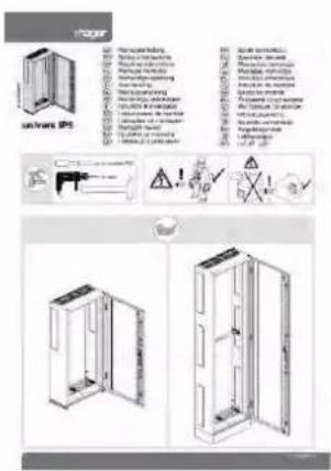
6LE002892*
Assembly manual for univers enclosure IP55 FR (IP41 FS)
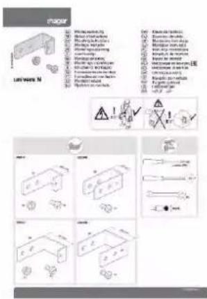
6LE000999*
Lowering kit for lowering the crossbar / retaining rail

6LE003001*
univers N mounting plate
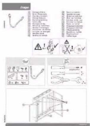
6LE003357*
Earth for protection class I

6LE005131*
Sealing plates for protection class II
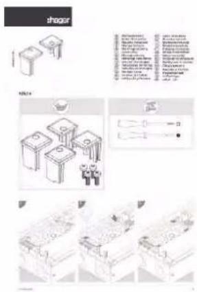
6LE005130*
Cable gland locking set
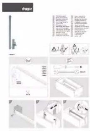
6LE005258*
Retaining rail and bracket

6LE005256*
Cable entry flange

6FZ00200*
Cable management duct
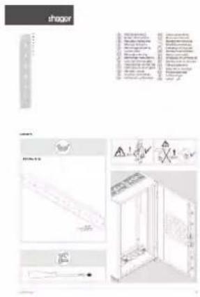
6LE005259*
Door sealing profile FZ 739x

6LE005255*
Locking cylinder / locks
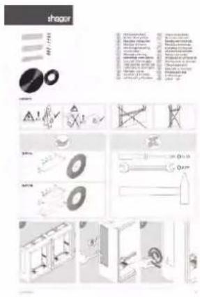
6LE005260*
Connection set for
2 enclosures side-by-side
FZ721x
11 Glossary
Degree of pollution
The degree of pollution defines the ambient conditions of a switching device. If the switching device is installed in an enclosure, the ambient conditions within the enclosure apply. The degree of pollution according to EN 61439 refers to the ambient conditions that are intended for the switchgear and controlgear assembly.
The four defined degrees of pollution are used to assess the clearances and creepage distances in the microenvironment. The degree of pollution 3 is defined as conductive pollution or dry, non-conductive pollution, which is expected to become conductive due to condensation. The degree of pollution 2 is defined only as non-conductive pollution in which, however, temporary conductivity can be expected due to condensation.
Distribution boards for operation by ordinary persons (DBO) according to EN 61439-3
DBO. According to EN 61439-3, a DBO is a distribution boards for operating by ordinary persons (Distribution Board intended to be operated by ordinary persons). This is a switchgear and controlgear assembly for distributing electrical energy for applications in residential areas and other locations where operation is intended by ordinary persons.
The distribution boards are manufactured and tested for operation by ordinary persons (DBO) according to EN 61439 Part 1 and Part 3. Part 3 of the standard 61439 defines the specific requirements for distribution boards for operation by ordinary persons (DBO).
A switchgear and controlgear assembly that allows operation by ordinary persons must include a type plate that specifies the standard EN 61439-3 (VDE 0660-600-3) as the applied standard.
Characteristic features of such a switchgear and controlgear assembly:
① They are intended for operation by ordinary persons, including switching operations and changing fuse inserts. They are applications in residential areas or similar household applications in a functional building.
② The outgoing circuits contain short circuit devices that are intended for operation by ordinary persons. Additional information is provided in section 8 of EN 61439-3.
③ The rated voltage against earth is maximum 300 V alternating current.
④ The rated current ( I_ne ) of the outgoing circuit is maximum 125 A; the rated current of the switchgear and controlgear assembly ( I_nA ) is maximum 250 A.
⑤ The switchgear and controlgear assembly is intended for distributing electrical energy and may also contain controlling and signalling devices to do this.
⑥ The switchgear and controlgear assembly is closed and fixed.
7 The switchgear and controlgear assembly can be provided for indoor or outdoor installation (for distribution enclosures FR and FS: indoor installation). The protection type of a DBO for indoor installation must be at least IP2XC. The IK code against mechanical influence must correspond to at least IK05 for indoor installation. At least the degree of pollution 2 applies.
Additional information is provided in EN 61439 Part 1 as well as Part 3.
^1 About the characteristic feature 4 (rated current of outgoing circuit max. 125 A / rated current of switchgear and controlgear assembly max. 250 A):
The current standard EN 61439-3 only defines the maximum rated currents I_nc and I_nA . No determinations have been made about the rated currents of the operating equipment in the incoming unit of a DBO. The maximum permissible I_nA of 250 A can thus also be routed via a 400 A circuit breaker. The following requirements apply:
- The rated current of the switchgear and controlgear assembly (I nA) must be limited to 250 A.
- Operation of the circuit breaker by ordinary persons must be effectively prevented (use locking devices).
- The setting or calibration of the circuit breaker must be visible. The calibration cannot be changed without the deliberate use of a tool / key.
EN 61439 / IEC 61439 / VDE 0660-600
The EN 61439 standard series replaced the EN 60439 standard series. The EN 61439 standard series has the goal of harmonising the rules and requirements for low-voltage switching equipment combinations.
The valid part of the EN 61439 standard series is always the applicable part of the standard, e.g. EN 61439-6 for busbar trunking systems (busways) together with Part 1 of the standard (EN 61439-1).
Connection between European standard and International standard
| European standard | International standard | German standard | Classification VDE specifications |
| EN 61439(all parts) | IEC 61439(all parts) | DIN EN 61439(VDE 0660-600)(all parts) | VDE 0660-600(all parts) |
Parts of EN 61439 standard
| Part of European standard | Content |
| EN 61439-1 | Low-voltage switchgear and controlgear assemblies - Part 1: General rules |
| EN 61439-2 | Low-voltage switchgear and controlgear assemblies - Part 2: Power switchgear and controlgear assemblies (PSC) |
| EN 61439-3 | Low-voltage switching controlgear assemblies - Part 3: Distribution boards intended to be operated by ordinary persons |
| EN 61439-4 | Low-voltage switchgear and controlgear assemblies - Part 4: Particular requirements for assemblies for construction sites (ACS) |
| EN 61439-5 | Low-voltage switchgear and controlgear assemblies - Part 5: Assemblies for power distribution in public networks |
| EN 61439-6 | Low-voltage switchgear and controlgear assemblies - Part 6: Busbar trunking systems (busways) |
| EN 61439-7 | Low-voltage switchgear and controlgear assemblies - Part 7: Assemblies for specific applications such as marinas, camping sites, market squares, electrical vehicles charging stations |
Supplements for parts of the EN 61439 standard
| Part of European standard | Content |
| EN 61439-1 Supplement 1 | General rules:Guidance to specifying switchgear and controlgear assemblies |
| EN 61439-1 Supplement 2 | General rules:A method of temperature-rise verification of low-voltage switchgear and controlgear assemblies by calculation |
| EN 61439-2 Supplement 1 | Power switchgear and controlgear assemblies:Guide for testing under conditions of arcing due to internal fault |
Power switchgear and controlgear assembly (PSC) according to EN 61439-2
PSC power switchgear and controlgear assembly. As a low-voltage switchgear and controlgear assembly, it distributes and controls electrical energy for all load types according to EN 61439-2. Intended for industrial, commercial and similar applications, which are not intended to be operated by an ordinary person.
It is not prohibited, however, to install in an area that can be accessed by ordinary persons. It must, however, be ensured that operation by ordinary persons is prevented.
Protection type / IP degree of protection
For each switchgear and controlgear assembly, the protection type with the IP code is specified according to IEC 60529 and verified according to EN 61439
- with regard to protection against contact with active parts and preventing solid foreign bodies from entering the system,
- with regard to preventing water from entering the system.
The protection type is important for ensuring protection against electrical shock. The protection type applies to jacketings, covers and housings. The protection type is specified by two code numbers of the IP protection type and optionally an additional letter.
- The first code number (0-6) indicates the protection against solid foreign objects from entering the system and the protection against contact with dangerous parts.
- The second code number (0-8) indicates the protection against water from entering the system.
- The additional letter (A-D) indicates the protection against contact with dangerous parts.
12 Index
A
About the distribution enclosure FR • 20
About this manual • 5
Accessories and spare parts for the enclosure expansion • 38
Additional cable entry flanges and accessories • 31
Appendix
Weight specifications and power loss • 81
Assembly at the installation site • 62
Assembly conditions at the installation location • 63
Assembly instructions
Overview • 99
Assembly notes for floor standing enclosures • 68
Assembly notes for wall-mounted enclosures • 67
Assembly safety instructions • 62
B
Base plinth and accessories • 24
Busbar gland • 56
Arrangement and dimensions • 57
C
Cable entry openings • 28
Cable gland in base plinth • 24
Cable grommets and screw connections • 34
Cable management duct • 36
Cable terminal box • 35
Clean • 79
Close the flange openings with FZ435A • 32
Comply with protection type IP55 • 46
Connection of 2 enclosures on top of each other • 60
Crane transportation of individual distribution enclosures • 72
Crossbar • 52
D
Decommissioning, disassembly and disposal • 80
Degree of pollution • 101
Disassembling and assembling the doors • 47
Distribution boards for operation by ordinary persons (DBO) according to EN 61439-3 • 101
Door wire profiles • 27
Doors
Solid doors or transparent doors • 26
E
Earthing concept for wall-mounted and floor standing enclosures, protection class CL I • 45
EN 61439 / IEC 61439 / VDE 0660-600 • 102
Enclosure to enclosure connection • 59
Enclosure ventilation • 33
F
Floor standing enclosure • 18
For your safety • 7
G
General technical data • 10
Ground transportation with a forklift or pallet truck • 74
|
Important properties • 20
Inspection and maintenance • 77
Internal extension and assembly • 45
L
Levelling feet available for compensating height • 25
Locks and access protection • 27
Lowering angle bracket for crossbar or retaining rail • 52
M
Maintaining free spaces • 65
Minimum inspection / maintenance measures • 78
Mounting plate small UZ*M1 • 54
Mounting plates • 54
Mounting plates up to enclosure height UZ*MP • 55
Mounting rails • 48
0
Order number code • 14
Order references and housing dimensions • 16
P
Plastic cover for busbar opening • 58
Power loss for wall-mounted devices • 86
Power loss for wall-mounted units • 93
Power loss specifications • 86
Power switchgear and controlgear assembly (PSC) according to EN 61439-2 • 103
Preparing the assembly location for wall assembly • 63
Preparing the floor standing enclosure • 64
Proper use • 7
Protection type / IP degree of protection • 103
Protective insulation for enclosures with protection class CL II • 46
R
Replacement doors • 43
Requirements for the authorised personnel • 9
Retaining rail and bracket • 50
Reusing packaging • 76
s
Safety notes for transportation • 70
Scope of delivery and delivery state • 22
Sealing / access protection • 32
Side-by-side connection of 2 enclosures • 59
Spare part locks • 38
Standard supply of replacement parts and common accessories • 40
Storage /Temporary Storage • 75
Subject of the manual • 5
T
Technical data • 10
Testing intervals for recurring tests • 77
Transportation and storage • 70
Transporting the distribution enclosure • 72
U
Universal cable entry flange FZ402 • 30
Used symbols and trademarks • 6
W
Wall mounting bracket dimensions • 66
Wall mounting brackets for suspending the enclosure • 65
Wall-mounted and floor standing enclosure designs • 21
Wall-mounted enclosure • 16
Warranty and Liability • 5
Weight specifications for enclosure types • 81
:hager
- Table of contents
- About this manual 5
- For your safety 7
- Technical data 10
- About the distribution enclosure FR 20
- Internal extension and assembly 45
- Assembly at the installation site 63
- Transportation and storage 71
- Inspection and maintenance 78
- Decommissioning, disassembly and disposal 81
- Appendix: Weight specifications and power loss 82
- Glossary 103
- Index 106
- About this manual
- Subject of the manual
- Warranty and Liability
- Liability note
- Used symbols and trademarks
- For your safety
- Proper use
- Fixed indoor installation / wall mounting
- Misuse
- Limitation of operating areas
- Requirements for the authorised personnel
- Technical data
- Intended use
- General technical data
- Specifications for the switchgear and controlgear assemblies
- In case of rated voltage U_n = 400 V / 690 V
- In case of rated voltage U_h = 230 V / 400 V
- Rated current
- Short-circuit resistance I_cc
- Application
- Mechanical installation of devices / internal extension
- Protection classes
- Protection type
- Note:
- Impact protection
- Colour
- Doors
- Carcass
- Installation
- Cable entry openings
- Busbar gland of adjoining enclosures
- Standards and regulations
- Order number code
- Order references and housing dimensions
- Wall-mounted enclosure
- Floor standing enclosure
- About the distribution enclosure FR
- Important properties
- Area of application for univers FR distribution enclosures
- Properties of univers FR distribution enclosures
- Wall-mounted and floor standing enclosure designs
- Scope of delivery and delivery state
- Observe type plate
- Example
- Delivery state
- Scope of enclosure delivery
- Supplied earthing cable
- Protective insulation
- Base plinth and accessories
- Base plinth
- Cable gland in base plinth
- Pre-punches in the side plinth panels
- Strain relief rail as a plinth accessory
- Levelling feet available for compensating height
- Doors: Solid doors or transparent doors
- Solid door
- Important notes
- Transparent doors
- Double-door design from width 1050 mm
- Locks and access protection
- Door wire profiles
- Cable entry openings
- Flange openings (cable entry openings) in the distribution enclosure
- Supplied cable entry flanges for flange openings
- Retrofitting flange openings for an enclosure depth of 400 mm
- Universal cable entry flange FZ402
- Additional cable entry flanges and accessories
- Close the flange openings with FZ435A
- Sealing / access protection
- Enclosure ventilation
- Cable grommets and screw connections
- Cable grommets / stepped grommets
- Screwed cable glands / pressure compensating screw glands
- Cable terminal box
- Cable management duct
- Accessories and spare parts for the enclosure expansion
- Spare part locks
- Standard supply of replacement parts and common accessories
- Replacement doors
- Internal extension and assembly
- Earthing concept for wall-mounted and floor standing enclosures, protection class CL I
- Protective insulation for enclosures with protection class CL II
- Ensuring protective insulation for floor standing enclosures of protection class CL II
- Comply with protection type IP55
- IP55
- Disassembling and assembling the doors
- Important notes:
- Changing the door stop
- Mounting rails
- Assembling the mounting rails
- Ensure touch protection depending on the mounting rail position
- Retaining rail and bracket
- Assembling the retaining rail
- Crossbar
- Lowering angle bracket for crossbar or retaining rail
- Mounting plates
- Mounting plate small UZ\*M1
- Mounting plates up to enclosure height UZ\*MP
- Busbar gland
- Busbar gland: Arrangement and dimensions
- Opening pre-punches: Assembly instructions
- Plastic cover for busbar opening
- Enclosure to enclosure connection
- Side-by-side connection of 2 enclosures
- Connection of 2 enclosures on top of each other
- Observe the assembly manual
- Assembly at the installation site
- Assembly safety instructions
- Risk of accident due to the enclosure tipping or falling!
- Assembly conditions at the installation location
- Preparing the assembly location for wall assembly
- Ensure an even, load-bearing assembly location
- Additional requirements for the assembly location
- Preparing the floor standing enclosure
- Maintaining free spaces
- Observe the clearances
- Ensure escape routes
- Observe maximum assembly heights
- Wall mounting brackets for suspending the enclosure
- The wall mounting brackets can be assembled vertically or horizontally
- Wall mounting bracket as a replacement part
- Wall mounting bracket dimensions
- Assembly notes for wall-mounted enclosures
- Note about transport feet
- Assembly notes for floor standing enclosures
- Observe the transport notes
- Floor mounting via base plinth
- Transportation and storage
- Safety notes for transportation
- Observe the principles of safe transportation
- Observe the weight and centre of gravity and make sure that the load is secured
- Transporting the enclosure in a secured and fixed manner
- Secured unloading
- Fixing the enclosure immediately after transportation
- Transporting the distribution enclosure
- Crane transportation of individual distribution enclosures
- Crane eyes / ring screws FZ831
- Ground transportation with a forklift or pallet truck
- Transporting floor standing enclosures with base plinth
- Never move the floor standing enclosures with the plinth panel removed.
- Ground transportation of connected enclosures on a pallet
- Storage / Temporary Storage
- Ensuring safe storage
- Precautionary measures prior to subsequent transport
- Reusing packaging
- Inspection and maintenance
- Important for safe operation
- Checks and maintenance only by electrically skilled persons with appropriate testing experience
- Testing intervals for recurring tests
- Minimum inspection / maintenance measures
- Tests through inspection
- Clean
- Decommissioning, disassembly and disposal
- Decommissioning
- Disassembly and disposal
- Appendix: Weight specifications and power loss
- Weight specifications for enclosure types
- Power loss specifications
- Thermal / power loss specifications
- Power loss for wall-mounted devices
- Power loss for wall-mounted units
- Assembly instructions: Overview
- Glossary
- Degree of pollution
- Distribution boards for operation by ordinary persons (DBO) according to EN 61439-3
- EN 61439 / IEC 61439 / VDE 0660-600
- Power switchgear and controlgear assembly (PSC) according to EN 61439-2
- Protection type / IP degree of protection
- Index
- A
- B
- C
- D
- E
- F
- G
- |
- L
- M
- 0
- P
- R
- s
- T
- U
- W
- :hager
Brand : HAGER
Model : FR24V2
Category : Electrical cabinet