
WGCXS3USBKB - Prise électrique USB HAGER - Free user manual and instructions
Find the device manual for free WGCXS3USBKB HAGER in PDF.


| Product Type | USB Charging Station |
| Brand | Hager |
| Model | WGCXS3USBKB |
| Input Voltage | 230V AC, 50/60Hz |
| Output Voltage (USB) | 5V DC |
| Total Output Current | 3.1 A (shared) |
| Number of USB Ports | 3 |
| USB Port Type | USB-A |
| Protection Features | Overload, short circuit, overcurrent, overvoltage |
| Material | Polycarbonate, flame retardant |
| Dimensions (H x W x D) | 85 x 85 x 40 mm |
| Weight | 120 g |
| Mounting Type | Wall-mounted (flush or surface) |
| IP Rating | IP20 (indoor use only) |
| Operating Temperature | 0°C to 40°C |
| Certifications | CE, RoHS |
| Compatible Devices | Smartphones, tablets, and other USB-charged devices |
| Maintenance | Wipe with a dry cloth; do not use liquids |
| Repairability Index | Not applicable (no replaceable parts) |
Frequently Asked Questions - WGCXS3USBKB HAGER
User questions about WGCXS3USBKB HAGER
0 question about this device. Answer the ones you know or ask your own.
Ask a new question about this device
Download the instructions for your Prise électrique USB in PDF format for free! Find your manual WGCXS3USBKB - HAGER and take your electronic device back in hand. On this page are published all the documents necessary for the use of your device. WGCXS3USBKB by HAGER.
USER MANUAL WGCXS3USBKB HAGER
Electrical equipment must only be installed and assembled by a qualified electrician in accordance with the relevant installation standards, regulations, directives and safety and accident prevention directives of the country.
Failure to comply with these installation instructions may result in damage to the device or the mobile device to be charged, fire or other hazards.
Function
Standalone USB charging socket outlet for electrical installations in buildings.

USB features:
- The 3 port USB port charging unit is suitable for charging most portable electronic devices connected via a USB type A or a USB type C plug.
- Allows charging of up to 3 devices at the same time.
- With dynamic load recognition
- Short-circuit proof and overload proof
Correct use
- For the flush-mounted installation in standard wall boxes (recommended wall box depth ≥ 35 mm).
- Only suitable for use in indoor areas with no drip and no spray water.
Charging portable electronic devices

CAUTION!
The use of non-standardised charging cables and connectors can cause damages or malfunctions of the device or the mobile device to be charged.
Use only approved charging cables and connectors.

CAUTION!
The USB ports of some mobile devices might carry external voltages higher than 5V d.c.
The USB charging unit may be destroyed.
Connect only certified mobile devices with a maximum voltage of 5V d.c.
- Insert USB type A connector of the charging cable into one of the two lower USB type A charging ports.
Or:
- Insert USB type C connector of the charging cable into the upper USB type C charging port.

Up to three portable devices can be charged simultaneously with a maximum total charging current of 4.2 A. The charging current is then split depending on the phone or device characteristics and the number of ports used.
If the charging process is complete or shall be interrupted, plug out charging cable.
Technical data
Rated voltage: 220 ... 240 V\~
Frequency: 50/60 Hz
Conductor cross-section of screw terminals: max. 2 x 1,5 mm 4
Distance of fixing holes: 60.3 mm
USB output: 5 V d.c.
USB output current:
- 1 type A port used only: max. 2.4 A
- 2 type A ports used: max. 4.2 A
- type C port used only: max. 3.0 A
- type C port and 1 type A port used: max. 4.2 A
- type C port and 2 type A ports used: max. 4.2 A
Standby power consumption: < 150 mW
USB compliance: IEC 62368-1
Operating temperature: -5 ... +45°C
Relative humidity (no condensation): 0% ... 95%
Information for electricians
Installation and electrical connection

DANGER!
Touching live parts can result in an electric shock.
An electric shock can lead to death.
Disconnect the connecting cables before working on the device and cover all live parts in the area!
Preparing the device for installation
The device is delivered with a transparent dust protection sticker. This sticker must remain on the device during the time of installation.
1
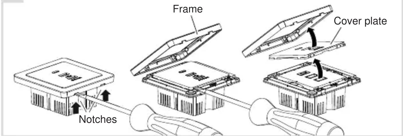
Carefully loosen the frame on the notches with a flat-blade screwdriver. Lift up and remove the frame (1).
■ Remove the cover plate also with a flat-blade screwdriver.
Connecting the device
2

- Strip connection cables approx. 7 mm.
■ Wire the device according to the connection diagram (2).
Installing the device into the wall box
3

natural_image
Diagram of a cable or connector assembly with directional arrows indicating movement (no text or symbols present)■ After wiring, fix the device with the two screws attached into the wall box (3).
Assembling the cover plate and frame
4
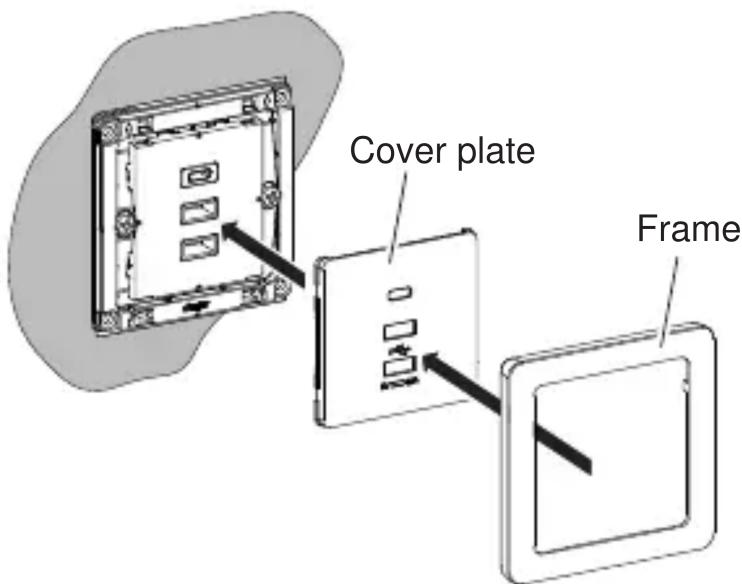
Place the cover plate in the correct position and fix with frame (4).
■ Remove the dust protection sticker.

WARNING!
To avoid possible damage to the product or spurious insulation readings, please DISCONNECT the product from the mains supply before carrying out insulation resistance testing!
- Function
- USB features:
- Correct use
- Charging portable electronic devices
- CAUTION!
- Technical data
- Information for electricians
- Installation and electrical connection
- DANGER!
- Preparing the device for installation
- Connecting the device
- Installing the device into the wall box
- Assembling the cover plate and frame
- WARNING!
Brand : HAGER
Model : WGCXS3USBKB
Category : Prise électrique USB