
L-12G - Scanner Elmo - Free user manual and instructions
Find the device manual for free L-12G Elmo in PDF.


| Product Type | Document Scanner |
| Brand | Elmo |
| Model | L-12G |
| Dimensions (approximate) | 250 x 50 x 30 mm |
| Weight (approximate) | 300 g |
| Power Supply | USB 5V (via computer or USB power adapter) |
| Main Functions | Scan documents and photos, capture images to SD card or computer, create PDF |
| Scan Resolution | Up to 1200 dpi (interpolated) |
| Interface | USB 2.0 |
| Media Supported | Paper, documents, receipts, photos, books |
| Maintenance and Cleaning | Clean the scanning glass with a soft, lint-free cloth; avoid liquids entering the device |
| Safety | Do not disassemble; keep away from water; use only supplied USB cable |
| Spare Parts and Repairability | Contact Elmo support for replacement parts; limited user-serviceable components |
| General Information | User manual available in English (PDF, 73 pages); compatible with Windows and macOS |
Frequently Asked Questions - L-12G Elmo
User questions about L-12G Elmo
0 question about this device. Answer the ones you know or ask your own.
Ask a new question about this device
Download the instructions for your Scanner in PDF format for free! Find your manual L-12G - Elmo and take your electronic device back in hand. On this page are published all the documents necessary for the use of your device. L-12G by Elmo.
USER MANUAL L-12G Elmo
Please read this instruction manual carefully before using this product and keep it for future reference.

IMPORTANT SAFEGUARDS
■ Read Instructions
All the safety and operating instructions should be read before the appliance is operated.
■ Retain Instructions
The safety and operating instructions should be retained for future reference.
■ Heed Warnings
All warnings on the product and in the operating instructions should be adhered to.
■ Follow Instructions
All operating and use instructions should be followed.
■ Cleaning
Unplug this product from the wall outlet before cleaning. Do not use liquid cleaners or aerosol cleaners. Use a damp cloth for cleaning.
■ Attachments
Do not use attachments not recommended by the product manufacturer as they may cause hazards.
■ Water and Moisture
Do not use this product near water - for example, near a bath tub, wash bowl, kitchen sink, or laundry tub, in a wet basement, or near a swimming pool, and the like.
- Placement
Do not place this product on an unstable cart, stand, tripod, bracket, or table. The product may fall, causing serious injury to a child or adult, and serious damage to the product. Use only with a cart, stand, tripod, bracket, or table recommended by the manufacturer, or sold with the product. Any mounting of the product should follow the manufacturer's instructions, and should use a mounting accessory recommended by the manufacturer.
■ Ventilation
Slots and openings in the cabinet are provided for ventilation and to ensure reliable operation of the product and to protect it from overheating, and these openings must not be blocked or covered. The openings should never be blocked by placing the product on a bed, sofa, rug, or other similar surface. This product should not be placed in a built-in installation such as a bookcase or rack unless proper ventilation is provided or the manufacturer's instructions have been adhered to.
■ Power Sources
This product should be operated only from the type of power source indicated on the marking label. If you are not sure of the type of power supply to your home consult your appliance dealer or local power company. For products intended to operate from battery power, or other sources, refer to the operating instructions.
■ Grounding or Polarization
This product may be equipped with either a polarized 2-wire AC line plug (a plug having one blade wider than the other) or a 3-wire grounding type plug, a plug having a third (grounding) pin. The 2-wire polarized plug will outlet, try reversing the plug. If the plug still fails to fit, contact your electrician to replace your obsolete outlet. Do not defeat the safety purpose of the polarized plug. The 3-wire grounding type plug will fit into a grounding type power outlet. This is a safety feature. If you are unable to insert the plug into the outlet, contact your electrician to replace your obsolete outlet. Do not defeat the safety purpose of the grounding type plug.
■ Power-Cord Protection
Power-supply cords should be routed so that they are not likely to be walked on or pinched by items placed upon or against them, paying particular attention to cords at plugs, convenience receptacles, and the point where they exit from the product.
■ Lightning
For added protection for this product during a lightning storm, or when it is left unattended and unused for long periods of time, unplug it from the wall outlet and disconnect the antenna or cable system. This will prevent damage to the product due to lightning and power-line surges.
■ Overloading
Do not overload wall outlets, extension cords, or integral convenience receptacles as this can result in a risk of fire or electric shock.
■ A product and cart combination should be moved with care. Quick stops, excessive force, and uneven surfaces may cause the product and cart combination to overturn.

■ Object and Liquid Entry
Never push objects of any kind into this product through openings as they may touch dangerous voltage points or short-out parts that could result in a fire or electric shock. Never spill liquid of any kind on the product.
Servicing
Do not attempt to service this product yourself as opening or removing covers may expose you to dangerous voltage or other hazards. Refer all servicing to qualified service personnel.
■ Damage Requiring Service
Unplug this product from the wall outlet and refer servicing to qualified service personnel under the following conditions:
- When the power-supply cord or plug is damaged.
- If liquid has been spilled, or objects have fallen into the product.
- If the product has been exposed to rain or water.
- If the product has been exposed to rain or water.
- If the product has been dropped or damaged in any way.
- If the product does not operate normally by following the operating instructions. Adjust only those controls that are covered by the operating instructions as an improper adjustment of other controls may result in damage and will often require extensive work by a qualified technician to restore the product to its normal operation.
- When the product exhibits a distinct change in performance - this indicates a need for service.
■ Replacement Parts
When replacement parts are required, be sure the service technician has used replacement parts specified by the manufacturer or have the same characteristics as the original part. Unauthorized substitutions may result in fire, electric shock or other hazards.
■ Safety Check
Upon completion of any service or repairs to this product, ask the service technician to perform safety checks to determine that the product is in proper operating condition.
■ Heat
The product should be situated away from heat sources such as radiators, heat registers, stoves, or other products (including amplifiers) that produce heat.

CAUTION
RISK OF ELECTRIC SHOCK DO NOT OPEN.

CAUTION: TO REDUCE THE RISK OF ELECTRIC SHOCK, DO NOT REMOVE COVER (OR BACK). NO USER-SERVICEABLE PARTS INSIDE. REFER SERVICING TO QUALIFIED SERVICE PERSONNEL.

SA 1965

The lightning flash with arrowhead symbol, within an equilateral triangle, is intended to alert the user to the presence of uninsulated “dangerous voltage” within the product’s enclosure that may be of sufficient magnitude to constitute a risk of electric shock to persons.
The exclamation point within an equilateral triangle is intended to alert the user to the presence of important operating and maintenance (servicing) instructions in the literature accompanying the product.
SA 1966

This symbol [crossed-out wheeled bin WEEE Annex IV] indicates separate collection of waste electrical and electronic equipment in the EU countries.
Please do not throw the equipment into the domestic refuse.
Please use the return and collection systems available in your country for the disposal of this product.
WARNING:
TO REDUCE THE RISK OF FIRE OR ELECTRIC SHOCK, DO NOT EXPOSE THIS PRODUCT TO RAIN OR MOISTURE.
The connection of a non-shielded equipment interface cable to this equipment will invalidate the FCC Certification or Declaration of this device and may cause interference levels which exceed the limits established by the FCC for this equipment. It is the responsibility of the user to obtain and use a shielded equipment interface cable with this device. If this equipment has more than one interface connector, do not leave cables connected to unused interfaces. Changes or modifications not expressly approved by the manufacturer could void the user's authority to operate the equipment.
FOR UNITED STATES USERS:
INFORMATION
This equipment has been tested and found to comply with the limits for a Class A digital device, pursuant to part 15 of the FCC Rules. These limits are designed to provide reasonable protection against harmful interference when the equipment is operated in a commercial environment. This equipment generates, uses, and can radiate radio frequency energy and, if not installed and used in accordance with the instruction manual, may cause harmful interference to radio communications. Operation of this equipment in a residential area is likely to cause harmful interference in which case the user will be required to correct the interference at his own expense.
This device complies with part 15 of the FCC Rules. Operation is subject to the following two conditions: (1) This device may not cause harmful interference, and (2) this device must accept any interference received, including interference that may cause undesired operation.
FCC CAUTION
Changes or modifications not expressly approved by the party responsible for compliance could void the user's authority to operate the equipment.
This Class A digital apparatus complies with Canadian ICES-003.
Handling the cord on this product or cords associated with accessories sold with this product, will expose you to lead, a chemical known to the State of California to cause birth defects or other reproductive harm.
Wash hands after handling.
BEFORE YOU USE
■When using this device, be sure to use the supplied power cord and AC adapter.
■The power cord and AC adapter that come with this product are for this product only. Do not use them with another product.
■Be sure to use the power cord applicable to your local power specifications.
■When storing the product, do not leave it under direct sunlight or by heaters. It may become discolored, deformed, or damaged.
■Do not place this product in any humid, dusty, salt bearing wind, or vibrating locations.
Only use it under the following environmental conditions:
Temperature: 0°C - 40°C (32°F - 104°F)
Humidity: 30% - 85% (No condensation)
■ Use a soft, dry cloth for cleaning
Do not use any volatile solvent such as thinner or benzene.
■ Do not point the camera lens directly at the sun. It may be damaged and you may not be able to take pictures.
■ Luminescent and Black Spots
There may be some pixels that do not properly operate due to the use of CMOS Area Image Sensors made-up of many pixels.
Though luminescent or black spots may be found on the screen, it is a phenomenon peculiar to the CMOS Area Image Sensors and is not a malfunction.
■Follow the guidelines below to prevent the unit from dropping or overturning.
- Use the product on a stable base, desk, or table. Do not place the product on an unstable base or slanted surface.
-
Place or wire the unit to prevent the AC adapter cord or video cable from pulling.
-
Carry the product by holding the lower part of the main unit in both hands. Never hold the product by the column or the camera head.
■Pay careful attention when using (including setting-up and storing) or transferring the product to prevent the camera head from receiving any shocks.
■Do not look directly into the LED light. If you look directly into it at point-blank range, your eyes may be injured.
■Some type of SD card/USB flash drive can be used.
■Transfer the data from the SD card onto a device such as a PC to save a backup copy. Malfunction of the product or repairs to it may cause the data saved in the SD card to be deleted.
If this product is used for longer than the warranty period, its performance and quality may deteriorate due to the lifetime of its parts. To purchase replacement parts, consult the dealer from whom you purchased this product or our branch/office near your location.
■ Battery precautions: -
If this product is not going to be used for a long time, take the batteries out of the remote control.
- Do not use rechargeable batteries (e.g., Ni-Cd (NiCad batteries)).
- Do not use new and old batteries or batteries of different types together.
- Do not try to recharge or short-circuit the batteries.
- When disposing of used batteries, follow the instructions of your local government.
- Insert from one side and pay particular attention to the polarity (+/- directions).
If any liquid from a battery leaks onto your skin or clothes, flush the area with clean water immediately. If it gets into your eye, flush immediately with clean water and then contact a doctor.
■Do not keep the batteries in the reach of children because there may be a choking hazard.
If a battery is swallowed, consult a physician immediately as this could result in asphyxiation or the battery may become lodged in the stomach or esophagus.
■Battery precautions
- A lithium coin battery is included in the product. Do not swallow the lithium coin battery. There is a risk of injury due to chemical reactions.
- If the battery is swallowed, it can cause serious internal damage leading to death in less than two hours.
- If you have swallowed the battery, or if you suspect that the battery is somewhere in your body, seek medical advice immediately
- Keep new and used batteries out of the reach of children.
- If the battery compartment of the remote control does not close tightly, stop using the remote control and keep it out of the reach of children.
- Do not replace the wrong type of battery. It may cause an explosion.
- Do not expose the battery to excessively high temperature or low pressure at high altitude while using, storing or carrying the battery. It may cause an explosion or the leakage of flammable liquid or gas
- Do not dispose of the battery in a fire or in a heated furnace. An explosion may occur.
- When disposing of the battery, follow the rules of the local government.
- Do not mechanically crush or cut the battery. An explosion may occur.
■ About using microphones
Connecting microphones other than electret condenser microphones (microphones for PCs and so on) could cause a malfunction to occur. If you are concerned about this product's operating noise when using the built-in microphone, we recommend using an external microphone.
■ About the audio input port
Do not connect any audio line-output devices such as a CD/MP3 player to the audio input port when the Audio Selector is set to "Mic-in." Audio input is a dual purpose port (microphone/line-in) which supplies power when "Mic-in" is selected, adding external output devices (CD/MP3) may damage them.
■ Menu
Some functions may not be set or operated depending on the mode or the menu settings being used.
■ Record/Play
- Before recording an important scene, make sure to do a test recording to confirm that the camera is working properly.
- The maximum file size of the continuous recording is 2GB. (The maximum recording length varies depending on other factors such as resolution and recording quality.)
- Movie files that are recorded with this camera or converted by the proprietary software can only be played with this camera.
■ Copyright
Do not commercially use or transfer movies or audio files recorded with the camera without the permission of the copyright holder except for personal use.
Do not use the camera in locations where recording movies or audio files are prohibited.
IMPORTANT SAFEGUARDS ....2
BEFORE YOU USE 6
CONTENTS 8
-
BUNDLED ITEMS ...... 10
-
BASIC OPERATIONS....11
2-1 Document camera....11
Part names....11
Operating panel....12
Rear panel and cable connection 13
Side panel....15
Moving parts of the document camera 16
Output image size 17
2-2 Supplied accessories 19
Remote control....19
Preparation of the remote control.... 19
Operation of the remote control 19
Receiving IR signal from the remote control 19
Fixture....20
How to use the supplied fixture and cable tie....20
2-3 Shooting images 22
Setting up the product 22
Connecting the power cord 22
Connecting the video cable....22
Turn on / off the power.... 23
Adjusting the size....24
Adjusting the brightness 25
Turning on / off LED lighting 26
Selecting the image source 27
Pausing the image 27
Rotating the image....28
Turning on / off the audio 28
2-4 Configuring the setting 29
How to configure the setting....29
About Menus....29
System Setting menu(1/4 page)....31
System Setting menu(2/4 page) 33
System Setting menu(3/4 page) 35
System Setting menu(4/4 page).... 37
Full menu1....38
Compare Picture function.... 38
PinP function....41
Full menu2....38
Highlight function....44
Mask function....45
3. ADVANCED OPERATIONS....46
3-1 Using an SD card / USB flash drive 46
Recording....47
Still image....47
Video 48
Displaying the stored data 49
Thumbnail display (list of still images / videos) 49
Displaying a still image full-screen....51
Playing a video full-screen....53
3-2 Using by connecting to a computer with the USB cable 56
Switching to the External input mode(External input screen) 57
3-3 Using Miracast function 59
3-4 Displaying enlarged image using a microscope on 61
Procedure....62
3-5 Firmware update procedure 64
4. TROUVLE SHOOTING 65
4-1 Symptoms and Confirmation 65
4-2 When you have a problem 68
5. SPECIFICATIONS....70
5-1 General 70
5-2 Main Camera....71
5-3 Illumination Device 71
5-4 TRADEMARKS AND LICENSES 72
The items below are included with this product. If any item is missing, contact the dealer from whom you purchased this product.

2
BASIC OPERATIONS
2-1 Document camera
■Part names
For operations of the main unit, refer to


| No. | Name |
| 1 | LED lighting switch P.26 |
| 2 | LED lighting P.26 |
| 3 | Built-in microphone P.15 |
| 4 | Zoom dial P.24 |
| 5 | AF button/Freeze button P.27 P.24 |
| 6 | Operating panel P.12 |
| 7 | Rear panel P.13 |
| 8 | Side panel P.15 |
| 9 | IR receiver P.19 |

| Mark | Function | ||
| 1 |  | To turn on / off the powerPower ON: Power LED lights up bluePower OFF (standby status): Power LED lights up red | |
| 2 |  | To show the connection destination for Miracasting. P.59 | |
| 3 | Mode button |  —LED —LED | To switch to the Camera mode.The camera image is displayed. (HDMI/RGB/USB/Miracast)Camera resolution can be changed in sequence by long pressing this button.(Auto → HD → UHD → FHD)P.27The currently used support functions (PinP, etc.) will be terminated. |
| 4 |  —LED —LED | To switch to the External input mode.Images being input to the external input ports are displayed. P.27The behavior varies depending on the USB camera mode setting in the System Setting menu.(Refer to: “3.2 Using by connecting to a computer with the USB cable”) | |
| 5 |  —LED —LED | To switch to the Playback mode.Images stored in an SD card, USB flash drive or internal memory are displayed. P.27 | |
| 6 |  | To show/hide the menu on the screen. P.29 | |
| 7 |  | To save a still image on an SD card, USB flash drive or internal memory. P.47This button acts as a direction button (Top) for menu operations. | |
| 8 |  | To turn on / off the audio of microphone (built-in microphone / external microphone). P.28 | |
| 9 |  | To rotate the image.The rotation angle can be switched between 90 and 180 degrees with the Rotate angle setting in the System Setting menu. P.28This button acts as a direction button (Left) for menu operations. | |
| 10 |  | To confirm the selected OSD menu item or to switch images during Compare Picture/PinP display. P.29 | |
| 11 |  | To pause the camera image.This button acts as a direction button (Right) for menu operations. P.27 | |
| 12 |  | To record the camera image as a video on an SD card, USB flash drive or internal memory. P.48This button acts as a direction button (Down) for menu operations. | |
| 13 |  | To darken the camera image.This button acts as a manual focus button (Near) when the MF mode is set to ON. P.25 | |
| 14 |  | To brighten the camera image.This button acts as a manual focus button (Far) when the MF mode is set to ON. P.25 | |
■Rear panel and cable connection
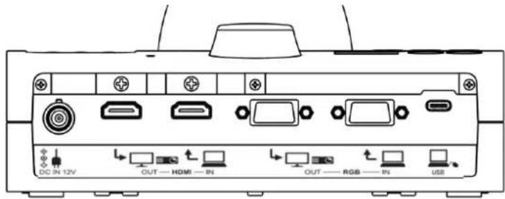
①
②
③
④
⑤
⑥
| Mark | Function | |
| 1 |  | To connect the AC adapter. (AC cord is supplied with the product.) |
| 2 |  | To output digital images. (HDMI cable is not supplied with the product.) [TYPE-A] |
| 3 |  | To input digital images. (HDMI cable is not supplied with the product.) [TYPE-A]Pass-through / Support functions (Split-screen, PinP) / USB image output |
| 4 |  | To output analog RGB images. (RGB cable is not supplied with the product.) [miniDSUB 15pin] |
| 5 |  | To input analog RGB images. (RGB cable is not supplied with the product.) [miniDSUB 15pin] Pass-through |
| 6 |  | To connect to a computer. (USB cable is supplied with the product.) [USB Type-C] |
① Connecting the AC adapter
Before inserting the AC adapter in an outlet, connect the DC plug of the supplied AC adapter to the [DC IN 12V] port on the rear panel.
② Connecting to a device with an HDMI input port
Connect a commercially available HDMI cable to the [☐] port on the rear panel.
③ Connecting to a device with an HDMI output port
Connect a commercially available HDMI cable to the [ ↑ □ ] port on the rear panel.
Note
- Use a monitor that supports video input resolution of 720P or higher.
- The product does not operate properly with the cable that does not conform to the HDMI standard.
- This product conforms to the HDMI standard. However, we do not guarantee proper operation for all HDMI-compatible monitors.
④ Connecting to a device with an analog RGB input port
Connect a commercially available RGB cable to the [→□□□□] port on the rear panel.
⑤ Connecting to a device with an analog RGB output port
Connect a commercially available RGB cable to the [RGB N] port on the rear panel.
■Specifications of the analog RGB port
Signal allocation

Video signal
Horizontal
synchronized signal
Vertical synchronized signal
Analog 0.7V (p-p) 75 Ω
terminated
TTL level (Positive/negative polarity)
TTL level (Positive/negative polarity)
DSUB 15Pshrink terminal (Female)
Pin assignment
| Pin No. | Name |
| 1 | Video signal (Red) |
| 2 | Video signal (Green) |
| 3 | Video signal (Blue) |
| 4 | N.C |
| 5 | GND |
| Pin No. | Name |
| 6 | GND (Red) |
| 7 | GND (Green) |
| 8 | GND (Blue) |
| 9 | N.C |
| 10 | GND |
| Pin No. | Name |
| 11 | GND |
| 12 | N.C |
| 13 | Horizontal synchronizing signal |
| 14 | Vertical synchronizing signal |
| 15 | N.C |
⑥ Connecting to a computer with the USB cable
Connect a commercially available USB cable to the [USB] port on the rear panel.
Note
- If the displayed image is off-center, adjustment of the horizontal and vertical position should be made from the connected device.
- In some cases, vertical stripes may appear on the display device such as a projector and a monitor.
- This can be reduced by adjusting the "clock phase" function of the connected device.
- When using a computer with an external output mode, set the computer to the external output mode after pressing the [ ] button on the operating panel.
- We recommend using a standard USB cable. If you plug into the USB cable with the power on, the computer may not recognize the product.
- Depending on the computer's USB environment or the peripheral equipment, image transfer may be disrupted.
■Side panel

①
②
③
④
⑤
| Mark | Function | |
| 1 | USB | To connect a USB flash drive (commercially available) or mouse. |
| 2 |  | To output audio. (Audio cable is not supplied with the product.) |
| 3 |  | To connect a microphone. (Microphone is not supplied with this product.)Use a commercially available electret condenser microphone. |
| 4 |  | To insert an SD card (commercially available).Push the card again to remove the SD card. |
| 5 | [7S47] | Security slot. |
Note
- Connecting microphones other than electret condenser microphones (microphones for computers and so on) may cause a malfunction.
- When using a speaker connected to the AUDIO port, select "AUDIO OUT" for the audio output destination in the System Setting menu.
- When using a microphone connected to the MIC port, select "External mic" in the "Sound switch" in the "System Setting" menu.
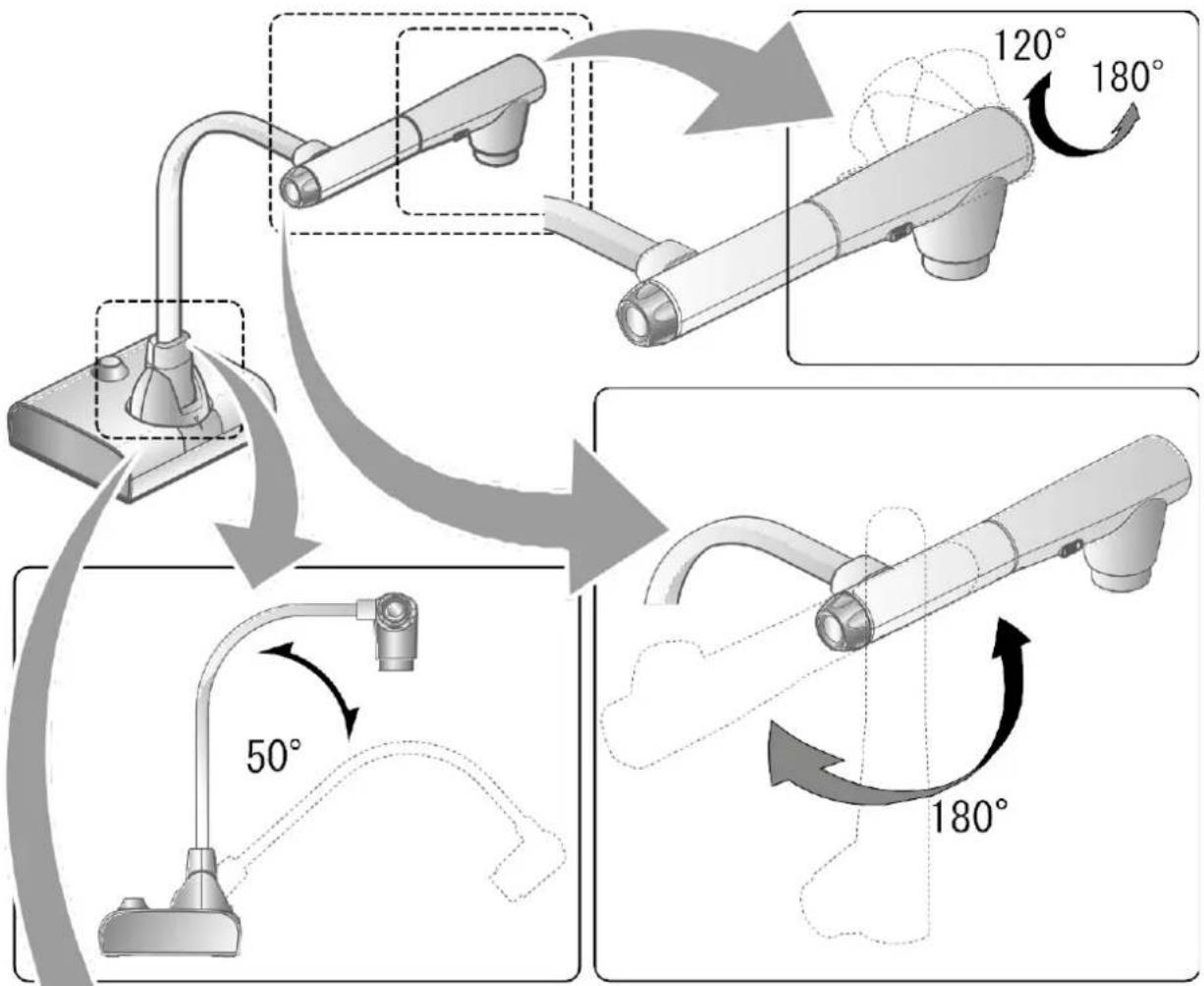
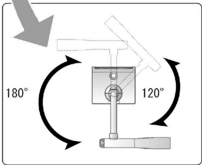
■Moving parts of the document camera
The product can be moved as shown below.
■Output image size
The output image differs depending on the resolution and output mode.
The following table shows the relation between viewing angle, resolution and output mode.
Note that there are shooting conditions.
RGB output / HDMI output
- When HDMI connection is available, the same resolution image as the HDMI output is output simultaneously from the RGB output.
※When the HDMI output resolution is 4K (3840 × 2160), no image is output from the RGB output.
| Setting | Normal (16:9) / 1080p | Full (4:3) / XGA | ||
| HDMI connection | Yes | No | Yes | No |
| RGB output | 1080p or 720p | 1080p | 1080p or 720p | XGA |
| HDMI output | 4K*No RGB image output | 4K*No RGB image output | ||
Viewing angle
①FULL(4:3)

natural_image
Square light blue textured panel with dark border and dotted gray border (no text or symbols)②NORMAL(16:9)

natural_image
Abstract geometric pattern with light blue fill and gray textured border (no text or symbols)| Output image viewing angle | ||
| Normal (16:9) / 1080p | Full (4:3) / XGA | |
| HDMI | 2 | 1 |
| RGB | 2 | 1 |
| HDMI+RGB | 2 | 1 |
| HDMI+USB | 2 | |
| RGB+USB | 2 | |
| HDMI+RGB+USB | 2 | |
※Set the USB output resolution to 4K/30fps, 1080p/30fps, or 720p/30fps. RGB image output is not possible when the USB output resolution is set to 4K.
※The viewing angle varies depending on the image output format (HDMI or RGB).
- When outputting with HDMI: Normal (16:9), Full (4:3)
-
When outputting with RGB only: 1080P/XGA
-
The following table shows the relation between output resolution and frame rate when outputting images to a computer via USB.
- If the computer used has low specifications, the frame rate may be less than that shown in the table.
| Resolution | USB | |
| MJPEG[fps] | YUY2[fps] | |
| 3840x2160 | 30 | - |
| 2048x1536 | 30 | - |
| 1920x1080 | 60/30/15※1 | - |
| 1280x960 | 30 | - |
| 1280x720 | 60/30/15※1 | - |
| 1024x768 | 30 | - |
| 640x480 | 30 | 20 |
※1 This frame rate is only available when connected to an electronic whiteboard in R1 mode.
2-2 Supplied accessories
■Remote control
Preparation of the remote control
Remove the battery case by pressing the release lock inward.
Insert the coin battery into the battery case, so you see the positive (+) side facing up. Then insert the battery case into the remote control.

natural_image
Diagram of a device with an open lid and internal components, showing directional arrows (no text or symbols)Note
Use a commercially available CR2025 coin battery for the remote control.

Warning
Children may ingest small batteries. Always keep batteries safe and out of reach of children.
If a battery is swallowed, consult a doctor immediately as this could result in asphyxiation or be an obstacle to digestion, etc.
Operation of the remote control
For operations when the camera image is displayed, refer to

For operations when data in the SD card/USB flash drive is displayed, refer to
Receiving IR signal from the remote control
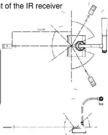
Point the IR transmitter of the remote control to the IR receiver of the product, and press the desired button.
Receivable range: Distance: Within approx. 7m from the front of the IR receiver Angle: Within 45° up, down, left, and right of the IR receiver
Note
The receivable range may be reduced when the product is placed in direct sunlight, near an inverter fluorescent light or in any other unfavorable conditions. Depending on the light source conditions, the sensor may fail to receive any infrared light. In such cases, relocate the product or shield the light source.
■Fixture
How to use the supplied fixture and cable tie
You can fix the HDMI cable to the HDMI port by using the supplied fixture and cable tie. Items to use (supplied)

Fixture x2
(For HDMI cable)
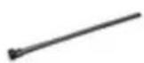
Cable tie x 2
①Before connecting the HDMI cable to the HDMI port, remove the screw above the HDMI port. Attach the fixture and tighten the screw.

②Pass the cable tie through the fixture and tie it around the plug of the HDMI cable.
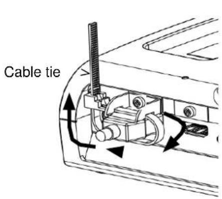

When the plug has a concave part, tie the cable tie around the concave part to get a firm hold.
When the plug does not have a concave part, wrap the cable tie as shown below.


①Wrap the cable tie around the root of the cable and pull it tight.

②Remove the screw above the HDMI port and connect the HDMI cable. Attach the fixture and tighten the screw.

natural_image
Close-up of a white electrical plug with black wires inserted, showing internal components and a visible outlet (no text or symbols)Caution
Depending on the shape of the plug, the fixture may not be used.
2-3 Shooting images

flowchart
graph TD
    A["Power cord"] --> B["AC adapter"]
    B --> C["Cable connection"]
    C --> D["ON/OFF switch for illumination"]
    D --> E["P26"]
    F["Camero"] --> G["Camera"]
    G --> H["PC1"]
■Setting up the product
Set up the product as shown in the figure above. Then connect the product to a projector or a monitor.
■Connecting the power cord
Connect the power cord and the AC adapter. Then connect the AC adapter to the [DC IN 12V] port at the rear panel of the product, and insert the power cord into a wall outlet.

■Connecting the video cable
Connect the product to a display device using the cable corresponding to the specification of the display device. P.22
Caution
Before connecting the product to other devices, be sure to turn off the power for all of the devices.
■Turn on / off the power
Turn on the power
① Connect the supplied AC adapter to the DC jack and plug it into an outlet.
② The LED changes as shown on the right and the product enters standby mode. (The LED lights up red).
③ Press the [ 🔊 ] button on the Operating panel or the [ 🔊 ] button on the remote control to turn on the power.
④ The POWER LED lights up from red to blue.
Turn off the power
① Press the [ ⏻ ] button on the Operating panel or the [ ⏻ ] button on the remote control to turn off the power.
② The POWER LED lights up from blue to red.

flowchart
graph TD
    A["Connect the AC adapter"] --> B["Power Lights up red"]
    B --> C["Power Lights up red"]
    C --> D["Flashes red"]
    D --> E["Power Lights up red"]
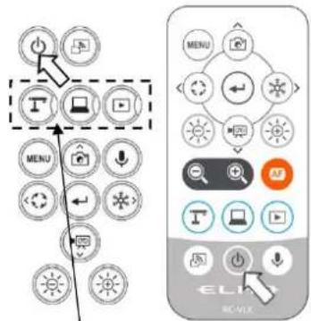
Mode buttons
■ Adjusting the size
The display range of the document can be adjusted by rotating the zoom dial on the product or by pressing the [ / + ] buttons on the remote control.
ZOOM-IN

e object is shown in large size.
ZOOM-OUT

The object is shown in small size.
If you cannot get a focused image, use the AF button on the camera head or the [AF] button on the remote control.

Note
- Zoom ratio: Optical zoom 12x + Digital zoom 16x (Total 192x zoom)
- When the optical zoom reaches 12x, it will automatically shift to the digital zoom.
- The digital zoom can be switched between ON and OFF from the System Setting menu.(System Setting: Digital zoom)
- When "MF mode" is turned on in the System Setting menu, the focus can be
- adjusted using the [ ] buttons on the Operating panel or the remote control.
■ Adjusting the brightness
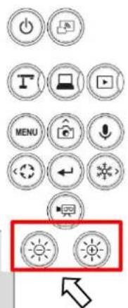
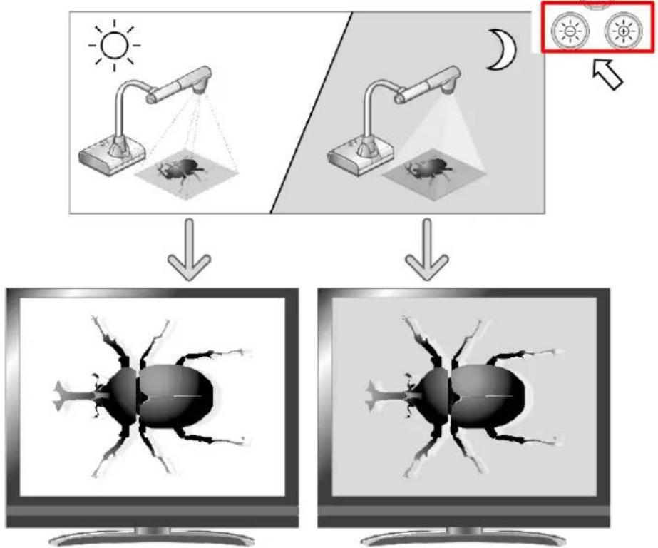
Use the [ 🔍 🔍 ] buttons on the Operating panel or the remote control to change the level of brightness of the displayed image.

flowchart
graph TD
    A["Sunlight"] --> B["Computer monitor"]
    C["Light exposure"] --> D["Computer monitor"]
    E["Light exposure"] --> F["Computer monitor"]
    G["Light exposure"] --> H["Computer monitor"]
    I["Light exposure"] --> J["Computer monitor"]
    K["Light exposure"] --> L["Computer monitor"]
The brightness of the image can be changed.
Note
- To reset the brightness setting to factory default, press the [💡💡] buttons on the Operating panel at the same time.
• In places where the object is exposed to bright sunlight (e.g. near a window), or extremely - bright light, the brightness of the screen may not dim sufficiently, even if the [💡] button on the Operating panel or the [💡] button on the remote control is pressed. In such cases, to adjust the amount of light, close the curtains or move the object away from the light.
- When the "MF mode" in the System Setting menu is turned on, the [💡💡] buttons on the Operating panel or the remote control work as the focus adjustment buttons. Make sure to turn off the MiF mode before adjusting the brightness.
■ Turning on / off the LED lighting

The LED lighting can be turned on or off by sliding the LED lighting switch.
[ON] : The LED lighting turns on.
[OFF] : The LED lighting turns off.
Caution
• To take shots of people, set the LED lighting switch to off.
- Make sure that the light from the LED lighting does not shine directly into the eyes.
- This product is equipped with a high-brightness LED. You can safely use the LED lighting to light up objects, however its brightness will gradually diminish with long-term use. This is not a malfunction, but a normal characteristic of the LED.
- Do not touch the LED lighting while it is on as it may become very hot.
■Selecting the image source
You can select the image source as described below.
① Camera image :
[ Γ ] button on the Operating panel or [ Γ ] button on the remote control.
② Image being input to the [ HDMI — N RGB □ ] ports :
[ ] button on the Operating panel or [ ] button on the remote control.
③ Image stored in an SD card/USB flash drive :
[ ] button on the Operating panel or [ ] button on the remote control.

Note
- When using a computer with an external output mode, set the computer to the external output mode after pressing the [ ] button on the Operating panel or the [ ] button on the remote control.
- When the USB camera mode in the System Setting menu is set to [Camera only], pressing the [ ] button on the Operating panel or the [ ] button on the remote control will output the input video to the [ ] port from the [ ] port and the input video to the [ ] port from the [ ] port only (pass-through function).
■Pausing the image
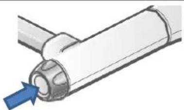
Press the [ ✉] button on the Operating panel or the [ ✉] button on the remote control to pause the camera image. Press the button again to cancel the pause.
Note
- Click the AF/Freeze button twice to pause the screen.
- Clicking the AF/Freeze button twice while the screen is paused will cancel the pause screen.
natural_image
Diagram of a pipe joint with a blue arrow pointing to a specific component (no text or symbols present)AF / Freeze button
■Rotating the image
Press the [ ] button on the Operating panel to rotate the camera image.
The rotation angle can be selected between 90^ and 180^ in the “Image rotation” in the System Setting menu.
■Turning on / off the audio
Press the [ ↓ ] button on the Operating panel or remote control to turn on/off the audio when outputting the camera image to a computer (via USB), or when recording video.
※Default setting: ON
※No audio is available with HDMI(RGB)output or Miracast.
- When audio is on, the Microphone LED lights up blue.

2-4 Configuring the settings
Each setting of the product can be configured from the menu (texts or icons) displayed on the screen.
■How to configure the settings
① Press the [MENU] button on the Operating panel or the remote control to display the menu on the screen. Then use the [ ] buttons to move the cursor to the icon you want to operate or set.
② Press the [ ← ] button to confirm the setting value.
Display or hide the menu on the screen
Move the cursor left
Confirm

Operating panel
③ Operation of the System Setting menu screen: Move the cursor on the Menu screen and select the [ ← ] button to display the System Setting screen. [√: Default setting].
※To go back through the hierarchy or clear the menu, press the right icon (Freeze button)

] to display [

] and press the [

] button.
■About Menus
① There are three types of menus. Each of these menus can be switched by using the Menu item in the System Setting menu.

② Comparison of menus
| Freeze | Highlight | Mask | Split screen | PinP | Settings | ZOOM slider | Brightness slider | AF / Freeze | |
| Settings (Default setting) | x | x | x | x | x | ○ | x | x | ○ |
| Full menu 1 (no mouse) | x | x | x | ○ | ○ | ○ | ○ | ○ | ○ |
| Full menu 2 (with mouse) | ○ | ○ | ○ | ○ | ○ | ○ | ○ | ○ | ○ |
③ Settings To configure system settings and camera quality settings.

In addition to the System Setting icon, Split screen icon and PinP icon are displayed.

⑤ Full menu2
In addition to the Full menu1, icons for other functions such as Mask and Highlight are displayed when a mouse is connected.

■System Setting menu
(1/4 page)

| Icon | Name | Selection item | Factory setting | Function | |
 | Menu item | Settings | To configure system settings and camera quality settings. | ||
| Full menu | To display support functions such as Highlight and Mask. | ||||
 | Horizontal reverse | To invert the screen horizontally. | |||
| [1762] | Microscope mode | To be used to display a microscopic image. | |||
| [2800] | Flicker mode | Frequency setting | 50 Hz | To reduce fluorescent light flickering due to the power supply frequency. Select the same value as used for the power supply frequency. | |
| 60 Hz | |||||
| ND Filter | OFF | Set this item to ON when there is halation due to flickering. (For example, when shooting outside or when the surrounding environment is too bright.) | |||
| ON | |||||
| [D427] | Miracast auto connect | OFF | To set whether to do the Miracast connection automatically. | ||
| ON | |||||
 | Miracast | To connect to a Miracast-supporting device. | |||
 | Resolution | Auto | L | To set the resolution of the output image.※1 | |
| HD(1280 × 720) | |||||
| UHD(3840 × 2160) | |||||
| FHD(1920 × 1080) | |||||
 | Viewing angle | Normal (16:9)/1080P | L | To set the viewing angle of the output image.※2 | |
| Full (4:3)/XGA | |||||
 | Sound switch | Built-in mic | L | To switch the audio source.(monaural)※3 | |
| External mic | |||||
 | Audio output destination | HDMI OUT | L | To set the destination of audio output.※4 | |
| AUDIO OUT | |||||
※1 If the image is not displayed on the connected display device due to the mismatch of resolution between the output image and the display device, press the Camera button [Γ] for over 1 second to change the resolution setting. (The resolution setting changes in the following order "Auto" → "HD" → "UHD" → "FHD".) This function is available in the Camera mode. It cannot be changed in the USB mode or Miracast mode.
※2 The viewing angle cannot be changed in the USB mode or Miracast mode.
※3 Select "Built-in mic" when using the built-in microphone of the product. Select "External mic" when connecting a microphone to the MIC jack on the side panel.
※4 Select "HDMI OUT" when outputting audio to an HDMI monitor. Select "AUDIO OUT" when outputting audio by connecting a speaker to the AUDIO jack on the side panel.
(2/4 page)

| Icon | Name | Selection item | Factory setting | Function |
 | Sound volume | ▲ | To set the HDMI sound volume and the external microphone volume. | |
| 5 | √ | |||
| ▼ | ||||
 | USB camera mode | Camera only | √ | To output the camera image from USB. |
| Camera & HDMI | To output the camera image or HDMI input image from USB. | |||
 | Still image quality | Normal | √ | To set the image quality of the still image to be saved. |
| High Quality | ||||
 | Video rec quality | Excellent Quality | To set the recording bitrate.※ When Excellent Quality or High Quality is selected, the recording time becomes shorter. | |
| High Quality | ||||
| Normal | √ | |||
| Economy | ||||
| Fast Economy | ||||
 | Video mode | NORMAL rec | √ | To continuously record the video. |
| Time-lapse rec | To create a video by combining multiple still images at certain intervals.The recording interval can be set from “Time-lapse interval”. | |||
 | Time-lapse interval | 1 min | The camera acquires still images one at a time at set time intervals and plays back the 30 images as a 1-second video by joining them together. | |
| 10 min | ||||
| 30 min | ||||
| 1 hr | √ | |||
| 2 hr | ||||
| 3 hr | ||||
 | Auto Power OFF | OFF | √ | To automatically turn off the power after no operation for a specific period of time. |
| 30 min | ||||
| 1 hr | ||||
| 2 hr | ||||
| 3 hr | ||||
 | Language | Japanese | To select the language for the on screen display. | |
| English | √ | |||
| Deutsch | ||||
| Francais | ||||
| Chinese | ||||
 | Format SD | To perform a quick format of an SD card. Select “YES” to format. | ||
| [cxac] | Format USB | To perform a quick format of a USB flash drive. Select “YES” to format. |
(3/4 page)

| Icon | Name | Selection item | Factory setting | Function |
 | Rotate angle | 90° | To set the angle of the image rotation. | |
| 180° | √ | |||
 | Auto wake up | OFF | √ | When this setting is set to ON, the product automatically starts up after the AC power is supplied. |
| ON | ||||
 | AF mode | One-push | √ | To perform auto focus only once when the AF button on the camera head or the AF button on the remote control is pressed. |
| Zoom sync | To perform auto focus only once after zooming. | |||
 | Digital zoom | OFF | √ | To enable or disable the digital zoom. If the digital zoom is enabled, the resolution of the following output image will be reduced: USB/Miracast/video and still image resolution at 4K |
| ON | ||||
 | White balance | Auto | √ | To always adjust the white balance automatically.The white balance is adjusted automatically to ensure a more natural color according to the characteristics of the object. |
| Fluorescent | To adjust the white balance according to the environment under the fluorescent light. | |||
| Indoor | To adjust the white balance according to indoor environment. | |||
| Outdoor | To adjust the white balance according to outdoor environment. | |||
 | Image mode | Normal | Suitable for displaying documents. | |
| Black&White | Suitable for displaying black and white images. | |||
| DLP projector | Suitable for projecting images with a projector. | |||
| Color emphasis | √ | Suitable for displaying colorful objects. | ||
 | Contour correct | ▲ | To adjust the level of edge enhancement. | |
| 5 | √ | |||
| ▼ | ||||
 | Contrast | ▲ | To adjust the contrast of the image. | |
| 10 | √ | |||
| ▼ | ||||
 | MF mode | OFF | √ | To set the MF mode.When the MF mode is turned on, you can adjust the focus using the brightness adjustment button on the Operating panel or the remote control. |
| ON | ||||
 | Noise Reduction | ▲ | To reduce the image noise when displaying the camera image via HDMI, RGB, USB or Miracast. | |
| 2 | √ | |||
| ▼ |
(4/4 page)

| Icon | Name | Selection item | Factory setting | Function |
 | R1 mode | OFF | To set the R1 mode.The product enters the most suitable mode for displaying on our electronic whiteboards (EL55R1, EL65R1, EL75R1, EL86R1) via USB. | |
| ON | ||||
| [4H30] | Reset | To reset to factory defaults.Select YES to reset all settings to factory defaults. | ||
 | Camera Information | To display the product information. |
■Full menu 1
This menu appears when no mouse is connected.

| Icon | Name | Function |
 | Compare Picture (Split-screen) | To move to the Split-screen selection mode to select the content to be compared. |
 | PinP | To move to the Picture-in-Picture mode. |
 | Settings | To display the Settings menu. |
■Compare Picture function
①Feature
You can display the live camera image, HDMI input image and still images stored in SD card, USB flash drive or internal memory together in one screen.
(Max. 4 images can be displayed in one screen. It is not possible to display multiple live camera images.)
※Only 1080p HDMI input image can be displayed. Otherwise, an error message is displayed as shown below.
②Operations
Pressing the MENU button on the remote control or the Operating panel [MENU] while the camera image is displayed and selecting the Compare Picture icon [ ] from the Menu screen displays a split-screen consisting of the camera image, HDMI input image, and stored still image.
※By default, split screens are displayed in the following order of priority: Camera > SD card > USB flash drive > HDMI input > Internal memory.
Pressing the MENU button [MENU] while the split-screen is displayed toggles between showing and hiding the menu.
Selecting the Camera mode button [ ] on the Operating panel or the Camera icon [ ] in the menu cancels the Compare Picture function and the camera image is displayed.
Selecting the icon [ ] in the menu displays the Thumbnail screen, where you can select images to be displayed on the split-screen.
The selected images are numbered 1\~4 and displayed in the arrangement shown below.

Three or four screens
※Pressing the Camera icon[ ] at the top left of the screen displays the live camera image in the split-screen.
※Pressing the HDMI icon [ ] at the top right of the screen displays the HDMI input image in the split-screen.
Selecting the Execute Split button [ √ ] displays the split-screen.
Switching between Compare Picture screen and single screen
When one of the split-screens is selected by pressing the [ ] button on the Operating panel or the [ ] button on the remote control during operation of the Compare Picture function, a blue frame appears on the selected screen.
The selected screen can be displayed in single screen by pressing [ ← ] on the Operating panel or on the remote control.

flowchart
graph LR
    A["①"] --> B["②"]
    C["③"] --> D["④"]
    E["①"] --> F["②"]
    style A fill:#fff,stroke:#000
    style C fill:#fff,stroke:#000
    style E fill:#fff,stroke:#000
    style B fill:#fff,stroke:#000
    style D fill:#fff,stroke:#000
    style F fill:#fff,stroke:#000
| Icon | Name | Function | |
 | Prev Page | To move to the previous thumbnail page. | |
| Next Page | To move to the next thumbnail page. | ||
 | To display thumbnails. | ||
 | To display the camera image. | ||
 | Internal memory | To display thumbnails of the images stored in the internal memory. | |
 | SD card | To display thumbnails of the images stored in the SD card. | |
 | USB flash drive | To display thumbnails of the images stored in the USB flash drive. | |
 | To display the selected thumbnail image on the screen. | ||
Note
- The Compare Picture function cannot be used when the External input mode [ ] or Playback mode [ ] is selected.
- The Compare Picture function cannot be used (no image is displayed) during USB streaming or Miracasting. It can only be used during HDMI (RGB) output.
- Only 1080p HDMI input image can be displayed on the Compare Picture screen. If the HDMI input image is not displayed, set the resolution to 1080p. Otherwise, the following error message is displayed.
- The following information is displayed during processing of the Compare Picture function.

natural_image
Orange triangular warning symbol on black background (no text or numbers)Error message

Information
■PinP function
①Feature
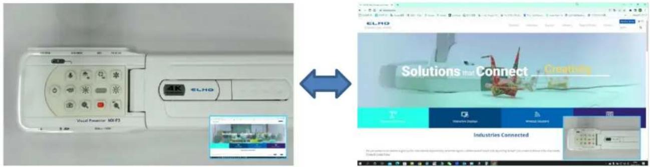
You can display the HDMI input image and still images stored in SD card, USB flash drive or internal memory on a small screen in the lower right corner of the screen while displaying the live camera image.
※For the HDMI input image, only 1080p images can be displayed.
②Operations
Pressing the MENU button on the remote control or the Operating panel [MENU] while the camera image is displayed and selecting the PinP icon [☐] from the Menu screen displays the HDMI input image or a stored still image in the lower right corner of the screen.
Pressing the MENU button [MENU] while the PinP screen is displayed toggles between showing and hiding the menu.
Selecting the icon [ ] in the menu displays the Thumbnail screen, where you can select images to be displayed on the PinP screen.
Selecting the Camera mode button [ ] on the Operating panel or the Camera icon [ ] in the menu cancels the PinP function and the camera image is displayed.
Selecting the icon [ ] in the menu which can be displayed by pressing the MENU button [MENU] displays the Thumbnail screen, where you can select images to be displayed on the PinP screen. (Max. 2 images)
※By default, PinP screen is displayed in the following order of priority:
Camera > HDMI input > SD card > USB flash drive > Internal memory.
※Selecting the Camera icon [ ] in the upper left corner displays the live camera image on the PinP screen.
※Select the HDMI icon [ HDMI ] in the upper right corner displays the HDMI input image on the PinP screen.
Selecting the Execute PinP button [√] displays the live camera image on the PinP screen.

Switching between small screen and large screen
Pressing the [ ← ] button on the Operating panel or the remote control during operation of the PinP function toggles between small screen and large screen.
Note
- The PinP images cannot be saved.
- The PinP function cannot be used (no image is displayed) during USB streaming or Miracasting. It can only be used during HDMI (RGB) output.
- The PinP function cannot be used when the External input mode [ ] or Playback mode [ ] is selected.
- Only 1080p HDMI input image can be displayed on the PinP screen.
- If the HDMI input image is not displayed, set the resolution to 1080p. Otherwise, the following error message is displayed.
- The following information is displayed during processing of the PinP function.

Error message

Information
■Full menu 2
This menu appears when a mouse is connected.
When a mouse is connected, the menu can be operated with the mouse.
When a mouse is connected while the "Full menu" is displayed, the Freeze icon, Highlight icon, and Mask icon are added and can be operated with the mouse.
※When a mouse is connected and the cursor is displayed, only the camera image is slightly darkened.

| Icon | Name | Function |
 | Freeze | To pause the camera image. This function can also be operated from the Operating panel or remote control. |
 | Highlight | To enhance the contrast for the specific area of the image to draw attention of the audience. |
 | Mask | To hide the specific area of the image with the mask. |
 | Compare Picture | To move to the Split-screen selection mode to select the content to be compared. |
 | PinP | To move to the Picture-in-Picture mode. |
 | Settings | To display the Settings menu. |
■Highlight function
①Feature
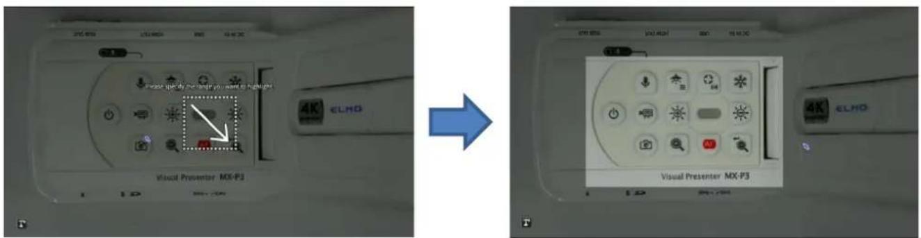
You can enhance the contrast for the specific area of the image to draw attention of the audience.
②Operations
When the [ ] icon at the bottom left of the Menu screen is selected while the camera image is displayed, the Highlight function works.
The mouse cursor can be used to move and zoom in and out of the highlighted area. Selecting the [T] icon or the Camera mode button on the Operating panel [T] cancels the Highlight function and the camera image is displayed.
Note
- The Highlight function cannot be used when the External input mode [ ] or Playback mode [ ] is selected.
- Highlighted image cannot be saved.
- The Highlight function cannot be used (no image is displayed) during USB streaming or Miracasting. It can only be used during HDMI (RGB) output.
- When a mouse is connected and the cursor is displayed, the camera image is slightly
■Mask function
①Feature
This is a function to hide a part of the image.
②Operations
With the camera image displayed, press the MENU button [MENU] on the remote control or the Operating panel to display the Menu screen.
Select the Mask icon [ ] on the Menu screen to add a mask effect to the screen. The mouse cursor can be used to move and zoom in and out of the masked area.
Selecting the [T] icon or the Camera mode button on the Operating panel [T] cancels the Mask function and the camera image is displayed.
natural_image
Completely black image with no visible content, text, or symbols.

Note
- The Mask function cannot be used when the External input mode [ ] or Playback mode [ ] is selected.
- Masked image cannot be saved.
- The Mask function cannot be used (no image is displayed) during USB streaming or Miracasting. It can only be used during HDMI (RGB) output.
- When a mouse is connected and the cursor is displayed, the camera image is slightly darkened.
With the product, you can record the camera image as a still image or video to an SD card, USB flash drive, or internal memory.
The image data recorded in an SD card, USB flash drive, or internal memory can be displayed on the monitor.
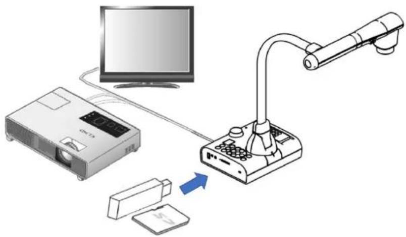
Insert an SD card (SD/SDHC, commercially available) or a USB flash drive (commercially available) into the slot on the side panel before starting the operation.
• Video recording (H.264): SD card / USB flash drive / Internal memory
- Still image recording (JPEG): SD card / USB flash drive / Internal memory
※ For video recording, an SD card with class10 speed or above is required.
- Recording destination priority: SD card > USB flash drive > Internal memory
•The capacity of the internal memory is about 3GB.
natural_image
Diagram showing a projector connected to a desktop monitor via a device, with a monitor on the left and a blue arrow indicating direction (no text or symbols present)Note
About SD card
• The SDXC card cannot be used.
• We recommend that you format an SD card with this product before you use it.
• Video recording is only possible to an SD card (SD / SDHC) with class10 speed or above.
• We recommend that you use an SD card with class 10 speed or above.
About USB flash drive
- Use a USB flash drive up to 32GB.
- We recommend that you format a USB flash drive with this product before you use it.
It may take some time to recognize the memory card (SD card or USB flash drive) after inserting it or to save images on the memory card.
Do not remove the memory card (SD card or USB flash drive) while the product is accessing it (during recording, playing or using the support function).
Note
Formatting an SD card/USB flash drive
When you need to format an SD card/USB flash drive, insert it into the product and execute formatting.
① Press the [MENU] button on the Operating panel to display the menu.
② Select "Format SD" or "Format USB" from the "System Setting" menu.
③ A confirmation window is displayed. Select "Yes" to execute formatting.
④ Select "No" if you do not want to execute formatting.
Note
Recording destination
- If an SD card or a USB flash drive is inserted, the data is recorded to an SD card or USB flash drive.
- If both SD card and USB flash drive are inserted, the data is recorded to the SD card.
- If neither is inserted, the data is recorded in the internal memory.
■Recording
Still image Basic operations

natural_image
Front view of a flat-screen television displaying a black screen with a small icon on the top (no text or symbols visible)\~ Recording \~
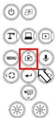

① Press the [ ] button on the Operating panel or the [ ] button on the remote control.
②Make sure that the menu is not displayed on the screen and
press the [ ] button on the Operating panel or the [ ] button on the remote control.
If the menu is displayed on the screen, do the above operation after hiding the menu by pressing the [MENU] button either on the Operating panel or the remote control.
③ Still image recording is executed when the [ ] icon is displayed on the top left of the screen.
Note
Still image recording is performed with the currently displayed resolution. Change the resolution from the System Setting menu if necessary.
※When the Still Image quality setting is set to "Normal", images with a resolution of 3840x2160 will be saved at 1920x1080.
Video
Basic operations
① Press the [ ] button on the Operating panel or the [ ] button on the remote control.
②Make sure that the menu is not displayed on the screen and press the [ ] button on the Operating panel or the [ ] button on the remote control.
If the menu is displayed on the screen, do the above operation after hiding the menu by pressing the [MENU] button either on the Operating panel or the remote control.
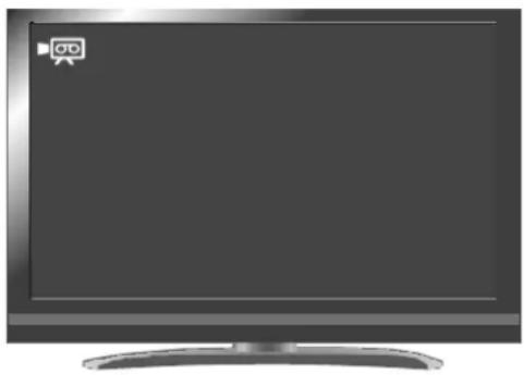
③ Video recording is executed when the [ ] icon is displayed on the top left of the screen. When you press the [ ] button on the Operating panel or the [ ] button on the remote control again, video recording stops and the [ ] icon disappears.
natural_image
Front view of a flat-screen television displaying a logo (no visible text or symbols on screen)\~ Recording \~
Note
- Video recording is performed with the currently displayed resolution. Change the resolution from the System Setting menu if necessary.
- When recording a video, use a memory card (SD card or USB flash drive) with a faster read/write speeds (in case of SD card: Class 10 or above), or the image quality may deteriorate.
- Select the audio for the video to be saved using the "Sound switch" function in the System Setting menu. Select "Built-in mic" when using the built-in microphone of the product, or "External mic" when connecting a microphone to the MIC port on the side panel.
• Video recording is not possible during USB streaming or Miracasting.
■ Displaying the stored data
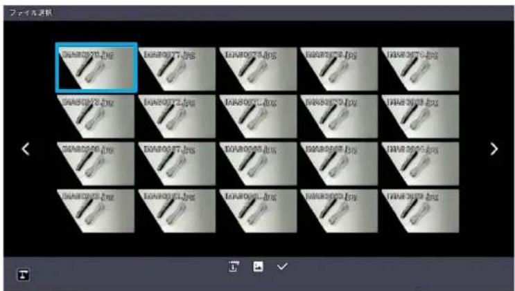
Thumbnail display (list of still images/videos)
Basic operations
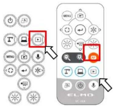
① Press the [播放] button on the Operating panel or the [播放]
button on the remote control to display thumbnails of still images and videos.
②Changing thumbnails of still images and videos, changing the storage location
From the Thumbnail screen, select the storage location (Internal memory [ ] / SD card
[SD] / USB flash drive [ ] and file type (still image [ ] / video [ ]) to change.

Storage location (SD card / USB flash drive / Internal memory) and file type (Video / still image)
③How to move the cursor
-
You can move the cursor (blue flame) using the [ 🔊 ] button on the Operating panel or the [ 🔊 ] button on the remote control.
-
Press the [←] button on the Operating panel or the [←] button on the remote control to play the selected file.
■Descriptions of each menu
Thumbnail display menu
| Icon | Name | Function | ||
 | Prev Page | To move to the previous thumbnail page. | ||
 | Next Page | To move to the next thumbnail page. | ||
 | Prev Menu | To display the previous menu page. | ||
 | Internal memory | To display thumbnails of the images stored in the internal memory. | ||
 | SD card | To display thumbnails of the images stored in the SD card. | ||
 | USB flash drive | To display thumbnails of the images stored in the USB flash drive. | ||
 | Still image | To display thumbnails of still image files. | ||
 | Video | To display thumbnails of video files. | ||
 | File selection | To enter the mode in which multiple files can be selected. | ||
File selection mode menu
| Icon | Name | Function |
 | Return | To cancel the File selection mode and display the previous menu page. |
 | Select all files | To select all thumbnail files. |
 | Cancel selection of all files | To cancel the selection of all selected thumbnail files. |
 | Copy | To copy the selected file to the internal memory/SD card/USB flash drive.*This menu item appears when one or more files are selected. |
 | Delete | To delete all selected files at once.*This menu item appears when one or more files are selected. |
■Displaying a still image full-screen
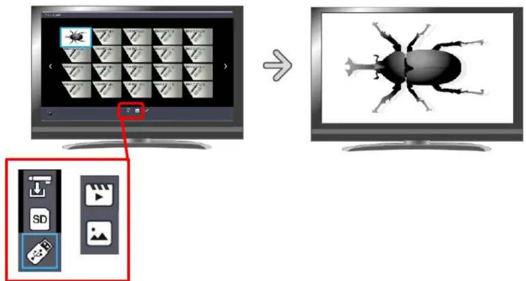
You can display a still image you selected from the thumbnails full-screen.
Basic operations
①Display thumbnails of still images in the Thumbnail screen.
Select the storage location (Internal memory [ ] / SD card [ SD ] / USB flash drive [ ]). When "Still image [ ]" is selected in the Still image [ ] / Video [ ] menu, thumbnails of still images stored on the selected recording media are displayed in the Thumbnail screen.
② Select the still image you want to display full-screen.
Move the cursor using the [ ] button on the Operating panel or the [ ] button on the remote control. A blue frame is displayed over the currently selected still image.


③Confirm the still image you want to display full-screen.
Press the [←] button on the Operating panel or the [←] button on the remote control to display the selected still image full-screen.

Press the [💡] button or [❄️] button on the Operating panel or [💡️] button or [❄️>] button on the remote control to switch the currently displayed image to the next still image. If you want to hide the menu, press the MENU [MENU] button on the remote control or the Operating panel.
④To return to the Thumbnail screen, press the [ ✗ ] button after displaying the menu or press the [ ☑ ] button on the Operating panel or the [ ☐ ] button on the remote control.
※The following information is displayed during the process of displaying thumbnails or still images.

■Playing a video full-screen
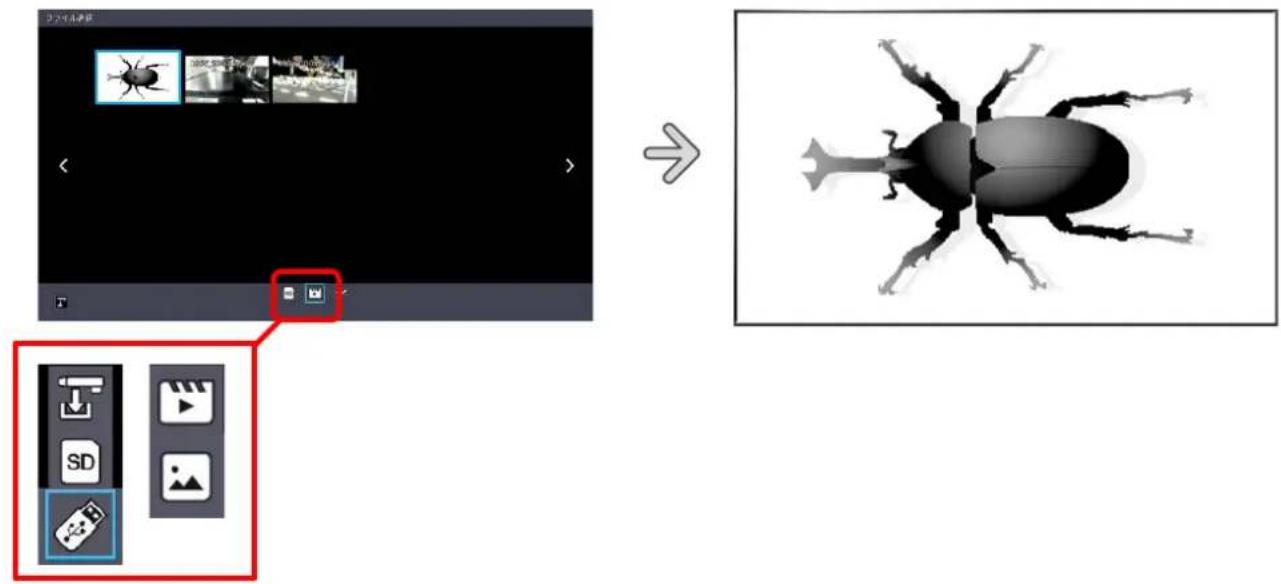
You can play a video you selected from the thumbnails full-screen.
Basic operations
①Display thumbnails of videos in the Thumbnail screen.
Select the storage location (Internal memory [ ↓ ] / SD card [ SD ] / USB flash drive [ 📋 ]).
When "Video [ ]" is selected in the Still image [ ] / Video [ ] menu, thumbnails of videos stored on the selected recording media are displayed in the Thumbnail screen.
②Select the video you want to display full-screen.
Move the cursor using the [ ] button on the Operating panel or the [ ] button on the remote control. A blue frame is displayed over the currently selected video.


③Confirm the video you want to play full-screen.
Press the [←] button on the Operating panel or the [←] button on the remote control to automatically play the selected video full-screen.


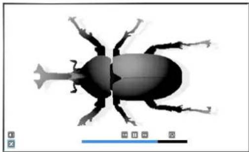
Thumbnails


natural_image
Silhouette of a beetle with visible legs and antennae, shown in grayscale (no text or symbols)Full-screen image (video playback)
Press the [💡] button or [❄️] button on the Operating panel or [💡] button or [❄️] button on the remote control to switch the currently played video to the next video.
If you want to hide the menu, press the MENU [MENU] button on the remote control or the Operating panel.
④To return to the Thumbnail screen, press the [ ✗ ] button after displaying the menu or press the [ ☐ ] button on the Operating panel or the [ ☑ ] button on the remote control.
※The following information is displayed during the process of displaying thumbnails or playing videos.
■Operations of video playback menu
Basic operations
If you want to hide the menu, press the MENU [ ] button on the remote control or the Operating panel while the video is displayed full-screen.
natural_image
Silhouette of a beetle with visible legs and antennae, shown in grayscale (no text or symbols)Move the cursor using the [ ] button on the Operating panel or the [ ] button on the remote control. Then press the [ ] button to confirm.
Descriptions of each menu
Video playback menu
| Icon | Name | Function | |
 | Play | To play/pause the video. | |
 | Pause | ||
 | Fast forward | To fast forward the video. | |
 | Rewind | To rewind the video. | |
| [KSWX] | Repeat On | To play the video on loop. | |
 | Repeat Off | ||
 | Volume | To set the output audio volume. | |
 | Return | To return to the thumbnail display. | |
Note
- Videos and still images other than those recorded by this product cannot be played back.
- Select the audio output destination for video playback in the "Audio output destination" in the System Setting menu.
- Select "HDMI OUT" to output audio to an HDMI monitor. Select "AUDIO OUT" to output audio by connecting a speaker to the AUDIO jack on the side panel.
3-2 Using by connecting to a computer with the USB cable
natural_image
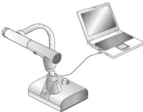
Illustration of a desktop microphone connected to a laptop (no text or symbols present)This product is compliant with UVC and UAC and troublesome installing of a driver is not required.
You can use the product with a video conference system or other various application software by simply connecting the USB cable to the USB port of a computer.
(Operation is not guaranteed on all application software.)
Caution
- Do not connect/disconnect the USB cable while operating the product using the Operating panel or remote control. Doing so may cause a malfunction.
• We recommend using a USB 2.0-compliant USB cable. - When you display the UVC video stream, it may take a while before the image is displayed. Be sure not to turn off the power of the product or disconnect the USB cable until the image is displayed.
- The format of the USB video stream is MJPEG/ YUV2. Depending on the software you are using, you may not be able to display the image.
Note
- Image transfer may be affected by the USB environment used by the computer or the effects of peripheral devices.
• Operation is not guaranteed in all environments.
• Video recording function of the product and Miracasting cannot be used during USB streaming. - When using a TypeC-C cable, use a USB2.0 cable. USB3.0 cables and TypeC-C cables capable of HDMI output cannot be used.
■Switching to the External input mode (External input screen)
Press the [ ] button on the Operating panel or [ ] button on the remote control to switch the mode to the External input mode.
The LED for the External input button [ ] lights up in the External input mode.
Operations in the External input mode vary depending on the setting of "USB camera mode" in the System Setting menu.
①USB camera mode selection
Press the MENU button [MENU] to display the System Setting menu. Then select the desired mode using UP/Down buttons [☐ / ☐].

The external HDMI input signal and external RGB input signal are passed through to the respective output ports.

③Camera&HDMI
The external HDMI input signal is converted to USB signal.
To switch between the L-12G camera image and external HDMI input image during the USB image output, use the Camera mode button [ ] and the External input mode button [ ].
④About the output image at each setting (Mode button/USB camera mode)
| USB camera mode (System Setting menu) | ||||||
| Mode button | Camera only | Camera&HDMI | ||||
| Image output | HDMI | RGB | USB | HDMI | RGB | USB |
| Camera mode | L-12G camera image | L-12G camera image | ||||
| External input mode | HDMI in※1 | RGB in※1 | No USB image output | HDMI in | ||
| Playback mode | Playback image | No USB image output | Playback image | No USB image output | ||
※Audio (UAC) is not from HDMI input, but from internal/external microphone.
※1 Pass-through
Note
Notes on Camera&HDMI settings
- The resolution of the external HDMI input image must be 1080P (1920x1080). Other resolutions cannot be converted properly and will result in an error message as shown below.

natural_image
Orange triangular warning symbol on black background (no text or numbers)- In the external HDMI input mode, only image will be output. No audio will be output.
- When connecting to a computer, the image resolution is automatically set to 1080P by the HDMI EDID function. Otherwise, set the resolution to 1080P manually.
- For devices that allow fixed output resolution (e.g., MX-P3), set the resolution to Auto or 1080P.
- It is not possible to output the external RGB input image. The external HDMI input image is output from the RGB output after converted to RGB image signal.
- Images encrypted with HDCP (copyright protection) cannot be output via USB. Also, the PinP function and Split-screen display function cannot be used. (An error message will be displayed as shown in the above figure.)
3-3 Using Miracast function
The camera image of L-12G camera can be mirrored to the ElmoCast or HS-2 wirelessly.
If the "Miracast auto connect" setting was set to ON the last time the power was turned OFF, the L-12G will automatically connect to a destination device for Miracasting at startup.
If no device is found in the search at startup, the automatic connection process will be repeated until a device is found. (The camera image is displayed on the screen.)
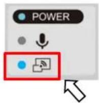
During the Miracast connection, the Miracast LED indicates the connection status.
| Connection status | Miracast LED |
| Connecting | Flashes blue |
| Connected | Lights up blue |
| Connection failed | Lights up red |
| Not connected | Off |
■Connecting via Miracast
①Connect the ElmoCast or HS-2 to an HDMI monitor. The following screen is displayed.

Screen example of ElmoCast

②Connect the L-12G to an HDMI (RGB) monitor and display an image.
③Press the Miracast button on the L-12G or select "Miracast" in the System Setting menu.
④The list of connection devices is displayed in order as shown below. It may take several tens of seconds to display the list.

flowchart
graph LR
    A["規続先リスト"] --> B["SR5900PA2C6B6"]
    A --> C["30419-NISHIWAKI"]
    A --> D["ELMOCast_L-12G"]
    E["規続先リスト"] --> F["SR5900PA2C6B6"]
    E --> G["30419-NISHIWAKI"]
    E --> H["ELMOCast_L-12G<br>... 接続中..."]
⑤Select the device to be connected with the up/down keys and press the Enter key. The ElmoCast starts to display images.
※If you want the L-12G to automatically connect to a device via Miracast at startup, set the "Miracast auto connect" setting to ON.
※When the "Miracast auto connect" setting is set to ON, no image output via USB is possible regardless of whether Miracasting is performed or not performed.
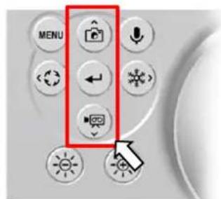

⑥Press the Miracast button again to stop Miracasting.
⑦If a PIN code is required when connecting via Miracast, enter the code (4-8 digit number) using the Operating panel or remote control according to the instructions on the screen of the L-12G (see below).
Note
- Miracasting is only possible with the ElmoCast and HS-2. We do not guarantee proper operation when using with other devices.
- Video recording on the main unit and image output via USB are not possible during Miracasting. If Miracasting is started while the image is being output via USB, the image output via USB will stop and screen mirroring will start.
- If the camera image is rotate by 90^ or 270^ , it is not possible to do Miracasting. Change the image angle to 0^ or 180^ before doing Miracasting.
- When the "Rotate angle" setting in the System Setting menu is set to 90^ , the image rotation cannot be performed during Miracasting.
- When the "Miracast auto connect" setting in the System Setting menu is set to ON, no image output via USB is possible.
- When the "Viewing angle" setting in the System Setting menu is set to "Full (4:3)/XGA", the image will be resized to 16:9 (stretched horizontally).
- The operations that can be performed during Miracasting are image rotation (180°only), freeze, brightness adjustment, zoom in or out, and still image recording.
- The image resolution of screen mirroring is fixed at 1920x1080.
3-4 Displaying enlarged images using a microscope
By attaching the separately sold microscope attachment lens to a microscope, you can display the enlarged image through the document camera lens.

Microscope attachment lens (sold separately)
CODE : 1332
Microscope mode operations
When the Microscope mode in the System Setting menu displayed by pressing the MENU button [MENU] on the remote control or the Operating panel is selected while the camera image is displayed, the product automatically adjusts the focus position and zoom position.

Select the [T] icon displayed at the bottom left of the screen by pressing the MENU button [MENU] or press the Camera mode button [T] on the remote control or the Operating panel to exit the Microscope mode.
■Procedure
① Change the setting of the product for using a microscope.
Display the System Setting menu by pressing the MENU button [MENU] on the remote control or the Operating panel while the camera image is displayed. Then select the Microscope mode.
② Set the microscope.
Place an object you want to view, such as a prepared slide, on the microscope and then look into the microscope to adjust the focus and brightness.
③ Attach the microscope attachment lens.
Attach the microscope attachment lens to the eyepiece.
④ Match the centers of the microscope attachment lens and eyepiece, and use the three screws to evenly tighten the lenses against each other.
Caution
- If the screw is tightened too strongly, the microscope's eyepiece or optical tube may be damaged.
- The fixing screws may leave scars on the microscope where they come in contact with each other.
- Protecting the microscope with tape or other means may reduce the scars.

⑤ Adjust the angle of the microscope and the product to fit each other.

natural_image
Technical line drawing of a mechanical component with a cylindrical base and flange (no text or symbols)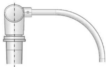
natural_image
Technical line drawing of a pipe fitting with a curved handle (no text or symbols)⑥ Adjust the brightness.
Adjust the brightness with the mirror or the light on the microscope.
⑦ Adjust the display range.

flowchart
graph LR
    A["Computer monitor"] --> B["Device insertion"]
    B --> C["Remote control with CLMD device"]
    C --> D["Computer monitor displaying remote screen"]
Adjust the display range.
⑧ Adjust the focus.

flowchart
graph LR
    A["Computer monitor with screen capture"] --> B["User interacting with remote device"]
    B --> C["Computer monitor with E-LND home control panel highlighting 'OK' button"]
⑨ Exit the Microscope mode.
Select the [MENU] icon displayed at the bottom left of the screen by pressing the MENU button [T] or press the Camera mode button [T] on the remote control or the Operating panel to exit the Microscope mode.
Note
- Depending on the type of eyepiece, you may not be able to view the object clearly even after adjusting the zoom.
- We recommend using a WF type eyepiece. If you do not use a WF type, we recommend using an eyepiece of 10x or less.
- You can use the microscope attachment lens when the external diameter of the eyepiece is 20 to 28mm.
- Use the thinner guide ring for Microscope lens attachment. There are two types of rings included in the package; the thicker one is not used here.
3-5 Firmware update procedure
① Download the firmware from the following web site and save it (*fex and ulmage) to the root directly of the SD card. (There are no other files.)
https://www.elmo.co.jp/support/download/driver/
② Insert the SD card to the L-12G.
Connect the AC adapter to the L-12G. Wait until the product is in standby mode. (The POWER LED changes as shown on the right).
③ Press the Enter button [
button [ ] on the Operating panel at the same time.
System startup
Lens initialization LED flashes red.
Standby mode LED lights up red.
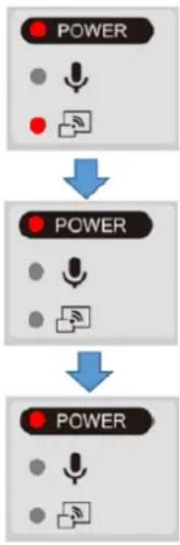
flowchart
graph TD
    A["POWER"] --> B["POWER"]
    B --> C["POWER"]
④ The POWER LED starts to flash purple and the firmware update begins.
⑤ Within one minute the product restarts and enters the standby mode.
Caution
Still images and videos recorded in the internal memory will be retained after the firmware update.
4 TROUBLE SHOOTING
4-1 Symptoms and Confirmation
Check the following items. If any abnormality is found, consult the dealer from whom you purchased this product or our nearest branch/office.
| Symptom | Possible cause/remedy |
| No image is displayed. | The cable is not correctly connected.The AC adapter is disconnected from the wall outlet.The AC adapter is disconnected from the power supply socket of the product.The power is not ON. (LED lights up blue.)Zoom is set at the TELE side, displaying only the white/black part of the document.The output resolution setting of the connected device does not match that of the product. If the resolution setting of the product is set other than AUTO and does not match the resolution of the connected device, the image cannot be displayed.Press the Camera button [ [T] for over one second to change the resolution setting. The resolution setting changes in the following order: “Auto” → “HD” → “UHD” → “FHD”.)※This function is available in the Camera mode.If you turn the power ON immediately after turning it OFF, the product may not start. Wait for several seconds after turning the power OFF, and then turn it back ON.Reconnect the AC adapter |
| The output image (resolution) changes automatically. | When the HDMI monitor is connected, the output image (resolution) is automatically changed based on information from the connected monitor. |
| No image is displayed from the USB. | No image is output from USB when the product is in the Playback mode. Check whether the product is in the Playback mode. If the product is in the Playback mode, change the output image to the camera image. |
| The image is out of focus. | The document (object) is too close to the lens. Move the document (object) slightly away from the lens. |
| The image is too dark. | The intensity of the lighting is insufficient. Adjust the brightness by turning on the LED lighting on the camera head. |
| The image is striped. | This may be interference fringes between dots of printed matter and TV scanning lines or CMOS pixels. Changing the shooting range may improve the problem.Vertical stripes may appear on an LCD projector image. Manually adjusting the dot clock at the projector side may improve the problem. |
| Images on the SD card/USB flash drive are not displayed. | Remove the SD card/USB flash drive, wait a few seconds and reinsert. |
| The image does not move. | The camera image is in pause mode. Press the Pause button on the Operating panel again to cancel the pause. |
| The remote control does not work. | Battery power is low. Replace the coin batteries with new ones.The incorrect remote control is being used. Use the supplied remote control. |
| After inserting the SD card/USB flash drive, operations cannot be performed. | The SD card/USB flash drive is not being read correctly. Use the SD card/USB flash drive after formatting it twice as described below.First, format the card using a computer. Second, format the card using the product. |
| UVC image is upside down. | Check that the graphics driver and other device drivers on your computer are updated. The latest device drivers are available from the computer manufacturer. |
| The displayed UVC image contains images other than the camera image. | The software and OS you are using or the connection status may be causing images other than the camera image to break through while displaying the camera image. This problem can be solved by reconnecting the device or restarting the software. |
| A software error message appears and the UVC image is not displayed | If it is taking too much time for the preparation of the image output, the software may determine this to be an error. Restart the product, reconnect it to the computer, and then start the software. |
| The UVC image fails to be output. | · Disconnect the USB cable, restart the software, and then connect the USB cable again.· If the UVC image still fails to be output after restarting the software, contact the software vendor and ask if the software you are using supports MJPEG.· When you stop the USB camera app during USB streaming, wait at least 5 seconds before restarting the app.· When you disconnect the USB cable during USB streaming, wait at least 5 seconds before reconnecting the cable. |
| Some buttons on the remote control and Operating panel cannot be used in the USB mode (UVC). | · You cannot record the camera image, display a thumbnail, display a still image or play the video while displaying the UVC image. |
About the light (LED lighting)
The brightness of the light will diminish with long-term use. If its brightness has significantly diminished, consult the dealer from whom you purchased this product or our nearest branch/office for replacement.
About long-term usage of this product
Due to the lifetime of its parts, if the product is used for longer than the warranty period, its performance and quality may deteriorate. In this case, we will replace the parts for a charge. Consult the dealer from whom you purchased the product or our nearest branch/office.
About USB connection with an electronic whiteboard
Electronic zooming during USB streaming
The electronic zoom function is not available when the video resolution is set to either 1920x1080 (60fps) or 1280x720 (60fps).
About UVC streaming with an electronic whiteboard
If UVC streaming does not begin after the USB camera app of an electronic whiteboard is started, disconnect the AC adapter or USB cable and then reconnect it.
4-2 When you have a problem
- This product does not support all connected devices such as a mouse.
- Contact your dealer for recommended devices.
- Depending on the USB flash drive / SD card you are using, writing or reading may fail.
- After starting up the product, the lens may move automatically. This operation is an adjustment that makes it easier to focus.
- When connecting a microphone/speaker, set the respective setting (Sound switch / Audio output destination) correctly.
- Using the product near a device which uses infrared signals may adversely affect the IR receiver function of the remote control. Check the performance in advance.
- Depending on the type and length of the cable used, there may be distortion of the image. Check the performance in advance.
- We do not guarantee that the still images and videos recorded by the product will be compatible with all playback devices or software.
- We do not guarantee that the product can playback all still images and videos recorded by third-party devices.
- Some operations and functions are restricted in order to stabilize operation during UVC and recording. Check the performance in advance.
- We do not guarantee proper operation with all possible combinations of other products and PC software (including ELMO's products). Check the performance in advance.
5 SPECIFICATIONS
5-1 General
| Item | Specifications |
| Power source | DC12V (AC adapter AC100 ~ 240V) |
| Power consumption | 22W |
| Outside dimensions | W 349 ×D 377 ×H 435 [mm] (when setup) |
| W 195 ×D 294 ×H 478 [mm] (when folded) | |
| Weight | Approx. 3kg (main body only) |
| Input selection | Main / External (x2) |
| Output port | RGB output Mini Dsub 15P connector, female x1 |
| HDMI output x1 | |
| Line-out φ 3.5mm stereo minijack x1 | |
| Input port | RGB input Mini Dsub 15P connector, female x1 |
| HDMI input x1 | |
| Mic-inφ 3.5mm stereo minijack x1 | |
| USB | USB2.0 host type A USB flash drive / mouse |
| USB2.0 device type C image output | |
| Memory Interface | SD card slot x1 |
※For RCA pins, use pin plugs compliant with EIAJ RC-6703.
5 SPECIFICATIONS
5-1 General
| Item | Specifications |
| Power source | DC12V (AC adapter AC100 ~ 240V) |
| Power consumption | 22W |
| Outside dimensions | W 349 ×D 377 ×H 435 [mm] (when setup) |
| W 195 ×D 294 ×H 478 [mm] (when folded) | |
| Weight | Approx. 3kg (main body only) |
| Input selection | Main / External (x2) |
| Output port | RGB output Mini Dsub 15P connector, female x1 |
| HDMI output x1 | |
| Line-out φ 3.5mm stereo minijack x1 | |
| Input port | RGB input Mini Dsub 15P connector, female x1 |
| HDMI input x1 | |
| Mic-inφ 3.5mm stereo minijack x1 | |
| USB | USB2.0 host type A USB flash drive / mouse |
| USB2.0 device type C image output | |
| Memory Interface | SD card slot x1 |
※For RCA pins, use pin plugs compliant with EIAJ RC-6703.
5-2 Main Camera
| Item | Specifications |
| Lens | f=4.67mm ~ 52.85mm (12x zoom lens) F3.2 ~ F3.8 |
| Frame rate | 30fps, 60fps(only 1080P and 720P supported) |
| Limit of focus adjustment | From lens surfaceWIDE 50mm ~∞TELE 200mm ~∞ |
| Optical zoom | 12 x |
| Digital zoom | 16 x |
| Focus | Auto (One-push / Zoom sync), Manual |
| Image pick-up element | 1/2.3" CMOS |
| Effective pixels | Horizontal 3840, Vertical 2160 (16:9)Horizontal 3520, Vertical 2640 (4:3) |
| Resolution | HDMI: 3840 × 2160 / 1920 × 1080 / 1280 × 720RGB: 1920 × 1080 / 1024 × 768USB: 3840 × 2160 / 2840 × 1536 / 1920 × 1080 / 1280 × 960 / 1280 × 720 / 1024 × 768 / 640 × 480 |
| White balance | Auto / Fluorescent / Indoor / Outdoor |
| Brightness adjustment | Manual |
| Color/B&W selection | Provided |
| Image rotation | 90°/ 180° |
| Image mode | Normal / Color emphasis / Black&White / DLP projector |
| Contour correct | Provided |
| Pause (Freeze) | Provided |
| Still image recording | Provided |
| Video recording | Provided |
| Flicker correction | 60Hz / 50Hz |
5-3 Illumination Device
| Item | Specifications |
| Illumination | White LED |
5-4 TRADEMARKS AND LICENSES
ELMO is a trademark or registered trademark of Elmo Co., Ltd.
SD, SDXC, SDHC, and SD logo are trademarks of SD-3C,LLC.
HDMI, HDMI ^™ logo and High-Definition Multimedia interface are trademarks or registered trademarks of HDMI Licensing LLC.
All other company/product names described in this manual are trademarks or registered trademarks of their respective companies.
This product is licensed under the AVC Visual Patent Portfolio License (AVC Video) for the personal and non-commercial use of a consumer to
- Play AVC Video that was recorded by a consumer engaged in a personal and anon-commercial activity and/or,
- Play AVC Video that was obtained from a video provider licensed from MPEGLA,LLC.
• Additional information including that relating to promotional and commercial uses may be obtained from MPEG-LA, LLC.
ATTENTION
- Unless used for personal use, it is prohibited by copyright law to record slides, books and photos without the prior consent of copyright holder.
- This product is designed to be used in industrial environment. If it is used in a residential area or in an adjacent area thereto, harmful interference to radio or television reception may occur.
- Repair parts
- Repair parts are the items which are needed to maintain product functionality. The holding period of such repair parts is 8 years after the product discontinuation, which is equal to the repair period we will accept.
- Any image, which is obtained by this product, and which can be identified, is considered to be private information. Be forewarned that the person who makes use of such images shall be liable for disclosing of such images..
テクノホライゾン株式会社
〒457-0071
6851 Jericho Turnpike
E-mSuite 145
Syosset, NY 11791
Tel. (516) 501-1400
Fax.(516) 501-0429
E-mail: elmo@elmousa.com
Web: http://www.elmousa.com
ELMO Europe SAS
Headquarters
Tour Voltaire
1 Place des Degrés
92800 Puteaux France
Tel. 33 (0) 1 74 54 49 80
E-mail: info@elmoeurope.com
Web: http://www.elmoeurope.com
German Branch
Monschauerstr. 1
40549 Düsseldorf
Tel. 49 (0) 211 544756 40
Fax. 49 (0) 211 544756 60
- IMPORTANT SAFEGUARDS
- ■ Read Instructions
- ■ Retain Instructions
- ■ Heed Warnings
- ■ Follow Instructions
- ■ Cleaning
- ■ Attachments
- ■ Water and Moisture
- - Placement
- ■ Ventilation
- ■ Power Sources
- ■ Grounding or Polarization
- ■ Power-Cord Protection
- ■ Lightning
- ■ Overloading
- ■ Object and Liquid Entry
- Servicing
- ■ Damage Requiring Service
- ■ Replacement Parts
- ■ Safety Check
- ■ Heat
- CAUTION
- WARNING:
- FOR UNITED STATES USERS:
- INFORMATION
- FCC CAUTION
- BEFORE YOU USE
- ADVANCED OPERATIONS....46
- TROUVLE SHOOTING 65
- SPECIFICATIONS....70
- 2
- BASIC OPERATIONS
- 2-1 Document camera
- ■Part names
- ■Rear panel and cable connection
- Note
- ■Specifications of the analog RGB port
- DSUB 15Pshrink terminal (Female)
- ■Side panel
- ■Moving parts of the document camera
- ■Output image size
- RGB output / HDMI output
- Viewing angle
- 2-2 Supplied accessories
- ■Remote control
- Preparation of the remote control
- Warning
- Operation of the remote control
- Receiving IR signal from the remote control
- ■Fixture
- How to use the supplied fixture and cable tie
- 2-3 Shooting images
- ■Setting up the product
- ■Connecting the power cord
- ■Connecting the video cable
- ■Turn on / off the power
- Turn on the power
- Turn off the power
- ■ Adjusting the size
- ■ Adjusting the brightness
- ■ Turning on / off the LED lighting
- ■Selecting the image source
- ■Pausing the image
- ■Rotating the image
- ■Turning on / off the audio
- 2-4 Configuring the settings
- ■How to configure the settings
- ■About Menus
- ■System Setting menu
- ■Full menu 1
- ■Compare Picture function
- ①Feature
- ②Operations
- Switching between Compare Picture screen and single screen
- ■PinP function
- Switching between small screen and large screen
- ■Full menu 2
- ■Highlight function
- ■Mask function
- About SD card
- About USB flash drive
- ■Recording
- Still image Basic operations
- Video
- ■ Displaying the stored data
- Thumbnail display (list of still images/videos)
- ■Descriptions of each menu
- ■Displaying a still image full-screen
- ■Playing a video full-screen
- ■Operations of video playback menu
- Descriptions of each menu
- 3-2 Using by connecting to a computer with the USB cable
- ■Switching to the External input mode (External input screen)
- Notes on Camera&HDMI settings
- 3-3 Using Miracast function
- ■Connecting via Miracast
- 3-4 Displaying enlarged images using a microscope
- Microscope mode operations
- ■Procedure
- 3-5 Firmware update procedure
- TROUBLE SHOOTING
- 4-1 Symptoms and Confirmation
- About the light (LED lighting)
- About long-term usage of this product
- 4-2 When you have a problem
- SPECIFICATIONS
- 5-4 TRADEMARKS AND LICENSES
- ATTENTION
Brand : Elmo
Model : L-12G
Category : Scanner