
75665592 - Thermostat HAGER - Free user manual and instructions
Find the device manual for free 75665592 HAGER in PDF.


| Product Type | Electrical Control Device |
| Brand | Hager |
| Model | 75665592 |
| Dimensions (mm) | 90 x 36 x 65 |
| Weight | 0.2 kg |
| Power Supply | 230 V AC, 50/60 Hz |
| Rated Current | 16 A |
| Main Functions | Manual ON/OFF switching, remote control, status indication |
| Mounting Type | DIN rail (EN 60715) |
| Protection Class | IP20 |
| Operating Temperature | -5°C to 45°C |
| Connection Type | Screw terminals, 1.5 mm² to 4 mm² |
| Maintenance | No periodic maintenance required; keep clean and dry |
| Cleaning | Wipe with a dry cloth – do not use cleaning agents |
| Safety Standards | EN 60669, EN 60947, CE marked |
| Repairability | Professional repair only – no user serviceable parts |
| Spare Parts | Contact Hager customer service for spare parts |
Frequently Asked Questions - 75665592 HAGER
User questions about 75665592 HAGER
0 question about this device. Answer the ones you know or ask your own.
Ask a new question about this device
Download the instructions for your Thermostat in PDF format for free! Find your manual 75665592 - HAGER and take your electronic device back in hand. On this page are published all the documents necessary for the use of your device. 75665592 by HAGER.
USER MANUAL 75665592 HAGER
natural_image
Close-up of a metallic cylindrical object with a small square mark at the center (no text or symbols visible)B.IQ push-button with room temperature regulation and display
B.
Berker the right way.
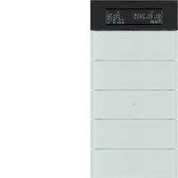
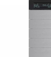
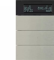
This guide is valid for B.IQ push-buttons with room temperature regulation and display (hereinafter push-button RTR) in the 3gang, 4gang and 5gang models.
You will find the order numbers in chapter 6.5.
We will be pleased to answer any queries you may have.
THE KNX HOTLINE
Phone +49 6842 945 9705
FURTHER INFORMATION
www.berker.com
INTRODUCTION
The push-button RTR allows you to operate numerous sections in a building. The functions of the push-button depend on the programming and the other KNX/EIB installation devices.
To keep operation of the device as easy as possible, the installer can pre-set functions (basic display, required values, timer, etc.) or activate them to suit individual needs. The present document will offer you an introduction to this device.
■ 1. Overview (Page 4)
- Functions, basic display, push-button assistance, overview of device, explanation of buttons and symbols
- Operation (Page 10)
- Operating level, menu navigation, main menus, messages
■ 3. Operation "Level I" (Page 15)
- Room temperature regulation
- Operation "Level II" (Page 16)
- Changing operating mode, expanded operating modes, changing heating/cooling
- Operation "Level III" (Page 20)
- Function and setting of the timer, week timers, settings, troubleshooting
- Installation (Page 32)
- System information, assembly/disassembly, technical data, order numbers
- Appendix (Page 40)
- Warranty, button assignment, index
1.1. Overview of functions
The push-button RTR unites the functions of a push-button, room temperature regulator, timer and display unit in a single device.
When activated, the function buttons can perform the following functions:
- switching on and dimming the lights
- closing/opening blinds etc. and bringing them into position
- calling up and saving eight light scenes
- transmitting temperature and brightness values
- specifying operating modes for the room temperature regulator
- activating/deactivating the room temperature timer
- activating/deactivating weekday timers
The display with two integrated buttons can:
- change the room temperature easily at short notice
- display the room and/or outside temperature as well as the desired set temperature
- display the date and time
- display messages (e.g. alarm messages)
- change the desired set temperature values for the various operating modes
- program the room temperature timer on site
- program the two week timers on site
- change the basic settings
The LEDs on the side show the status indication and the operation indication for the function buttons. In addition, they can be left on or off permanently.
BASIC DISPLAY, PUSH-BUTTON ASSISTANCE
1.2. Basic display
The display represents one of twelve possible basic displays. Three different displays are described by way of example in the following:


NOTES
The easiest way to access the basic display: press any function button at all. You may have to press it several times (see ch. 1.4). You will find information on the display lighting in Chapter 5.4.
1.3. Push-button assistance
The push-button assistance is only available for the function buttons and allows you to briefly display the function of a particular button.
- Briefly press the button whose function you are unsure of.

The function of the button is displayed in the bottom line of the three-line display.
■ Depending on programming: To activate the programmed function, hold the before chosen push button or press it a second time.
NOTE
The push-button assistance may be deactivated. In this case, the basic display will remain unchanged (ch. 5.4.).
The basic operating elements are explained taking the 3gang model as an example.
1.4. Overview of device
The vertical operating elements (item 1 to 4) each consist of one button on the left, and one on the right.
The operating elements at a glance:
■ Display buttons (item 1)
Left or right display button:
- Setting values (e.g. desired set temperature) and
- Programming/calling up menus (see ch. 2.3)
■ Function buttons/rocker (item 2 to 4)
Left or right function button:
- Function depends on programming; the two buttons in question may be combined to form a rocker
- They can be labelled using the labelling fields on the side (optional - order numbers see ch. 6.5.)
■ LEDs (item 5 and 6)
- Blue LED normally means ready for operation
- White LEDs on both sides (item 6) show the operation or the status
NOTE
You can press the buttons briefly, or press and hold them (you can set the minimum duration). The function of the buttons will depend on the programming.
ILLUSTRATION OF THE DEVICE

NOTE
Depending on the setting or the current operating step, the display will differ from the above illustration due to its functions.
1.5. Explanation of the display symbols
The following diagram shows the first of three lines in the display. This first line is reserved for the symbols. The second and third line shows texts and commands.
Only those symbols required for the function which is called up are displayed.


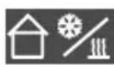
Comfort lengthening ("Frost/heat protection" operating mode)
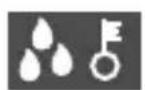
If there is condensation on the cooling system, the room cooler is deactivated for safety reasons.

A change made to the desired set value using the display buttons

Programming mode

Operation of the display buttons or individual rockers or operation of the device locked
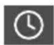
Timer active or control display in programming
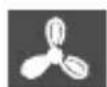
Fan coil control with indication of step 1–3
Heating energy is supplied or control display in the programming

Cooling energy is supplied or control display in the programming

Change the menu item (right display button)

Raise the value (right display button)
NOTE
The display lighting can be activated or deactivated using the »Settings« main menu (see ch. 5.4.).
2.1. Blocking menus
You can make wide-ranging changes in the saved menus. In order to ensure easy, clear operation while also offering a large number of functions, specific setting options can be blocked or activated.
Your installer can specify three blocking levels:
■ Level I: You can adjust the desired set temperature value using the display keys.
- Menus are not accessible!
■ Level II: In addition to the desired set temperature value, you also have access to the menus.
- Switching between operating modes (see ch. 4.1.)
- Setting the »Heating temperatures«
- Setting the »Cooling temperatures«
The temperatures for »Heating« and »Cooling« are adjusted in the same way (see ch. 4.3.).
■ Level III: You can access all menus as long as they are software-based.
NOTE
The “Key symbol” in the display shows that your device or individual functions are blocked by the software (by means of an object) and the push-button lock is activated via the »Settings« menu.
2.2. General information about menu navigation
You mainly use the display buttons to navigate the menu. The following options are available:
■ Press one single display button:
- Select or change the menu item

»Prg« (programming is activated) appears in the display. OK is assigned to the left display button, and ▲ to the right one.
or
- Lower/raise the value

- is assigned to the left display button, and + to the right one. The value to be changed flashes (shown in black here).
■ Press both display buttons simultaneously:
press "Enter" to confirm the value (it may have changed)

The changed/activated value is accepted and the device returns to the super-ordinate menu item.
■ Press any function button at all:
Return to the superordinate menu without accepting the value (= "ESC"), press the key several times to return to the basic display.
If no push-button have been operated for more than 20 sec.:
Without confirming the value, return to the basic display.
NOTE
You will find a leaflet with all possible values included in the documentation as well as on our homepage.
2.3. Menu sequence
a. Deviations in function and display
The push-button RTR is adjusted to suit your individual needs and building functions. The programming which the installer has performed has a decisive influence on the menu display. Only those menu levels which you actually require are displayed.
This makes the device clearly arranged and easier to operate. However, specific menu items described in this manual are not to be found in their individual menu structure.
Some examples:
- Timers which are not required are deactivated:
e.g. »Timer 1« menu is not displayed. - You do not own a air-condition system:
»Cooling temperatures« menu is not displayed.
b. Entering the main menus
The menus offer you numerous setting options. Proceed as follows to enter the menus:
While in the basic display or the required value display, press the left and right display button for at least 3 seconds (= "ENTER"):

Programming mode is activated; the first main menu is displayed (see ch. 4.1.).
c. Procedure in the menus
■ You normally have three options now:
- ▲ press the right display button (more under 2.3.d): change to the next main menu
- OK press left display button: change to the sub-menu of the main menu if the submenu is activated (s. ch. 4.1. onwards)
- Instead of OK or ▲, press a function button: (= "ESC"): return to the basic display or to the superordinate menu.
NOTE
In order to return completely to the basic display, press any function button several times.
d. Main menus
You have already pressed the button ▲ under 2.3.c.
■ Press the right display button ▲ again:

You have now reached the next main menu for adjusting the temperature values for heating (see also ch. 4.3.).
The other main menus which can be accessed via ▲ are as follows (from left to right):

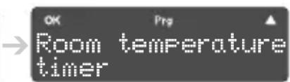

see ch. 4.3. see ch. 5.2. see ch. 5.3.


see ch. 5.3. see ch. 5.4. see ch. 4.1.
2.4. Displaying messages
The push-button RTR allows you to display messages such as alarms in the bottom display line.
a. Effects on the function of the push-buttons
A text message has highest priority in the push-button functions, i.e.:
- Operations on the push-button RTR are aborted (e.g. stopping the function buttons)
- Push-button assistance displays are aborted
- Menu operations are aborted (e.g. programming a timer)
A text message remains displayed until it is acknowledged. New text messages overwrite the previous message.
b. Acknowledging text messages
A text message is displayed.

The contents of the text messages can be adjusted to suit your circumstances.
■ Press any button at all:

The basic display is re-activated.
NOTE
Possibly the acknowledgment via push button press is deactivated.
ROOM TEMPERATURE REGULATION
3.1. Changing the room temperature
In consultation with your installer, you must set a desired temperature value for the various operating modes that best suits your needs.
Proceed as follows to adjust the room temperature temporarily:
■ Press either the left or right display button while in the basic display:

The »Set value« display with the default temperature value appears.
- Press the left or right display button to lower or raise the value in 0.1 steps.
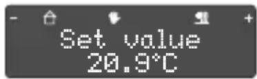
The new set value is shown in the display. Press and hold to change the value in 1.0 steps.
The adjusted value is accepted immediately, no confirmation is required! The hand symbol shows you that the desired set value has been changed.
NOTE
When you change the operating mode, the new desired set value (which you have just set) normally returns to its original value.
4.1. Changing the operating mode
The push-button RTR makes various operating modes available in the following order:
“Comfort” (normal use of the house during the day)
“Standby” (leaving the company, e.g. day trip)
“Night” (limited use is made of the house)
“Frost/heat protection” (longer absence e.g. a holiday lasting several weeks)
a. Calling up the main menu
Change the operating mode as follows:
■ While in the basic display or the desired set value display, press the left and right display button for at least 3 seconds (= "ENTER"):
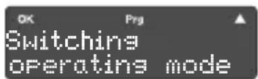
Programming mode is activated; the first main menu is displayed.
b. Setting the required operating mode
■ Press the left display button OK:

In this way, you have reached the first "Operating mode comfort" submenu.
■ You normally have three options now:
- OK: displayed operating mode is activated the device returns to the first main menu or
- ▲: Change to the next operating mode activate the required mode there with OK
EXPANDED OPERATING MODES
or
- Instead of OK or ▲, press a function button:
Return to the main menu (see a).
c. Terminating the input sequence
- Return to the basic display by pressing any function button at all several times:

Check the symbols in the top line of the display to see if the operating mode has been successfully changed.
NOTE
You will find explanations for all symbols in chapter 1.5.
4.2. Expanded operating modes
The push-button RTR allows you to call up a comfort lengthening. This is activated either by a “Presence button” (function button with this definition) or automatically, e.g. by a presence detector, and displayed as follows:


Comfort lengthening “Night” (e.g. watch television for longer or unexpected visit)


Comfort lengthening "Frost/heat protection" (e.g. if the start of your holiday is delayed)
When the comfort lengthening is activated, the comfort temperature is retained for a time programmed by the installer even though the operating mode changes.
4.3. Changing the temperature values
You can change the temperatures in the operating modes to suit your needs:
a. Calling up the main menu
■ While in the basic display or the desired set value display, press the left and right display button for at least 3 seconds (= "ENTER"):

You have now reached the first main menu. The next step takes you into the second main menu.
■ Press the right display button ▲:

Pressing this display button again would call up the next main menu "Cooling". The values are changed in the same manner.
b. Selecting the required operating mode
■ Press the left display button OK:

You have now reached the first submenu. The next step will change the temperature value.
NOTE
The operating modes are saved in the fixed order "Comfort", "Standby" and "Night" both for »heating« and »cooling«. For example, if you only want to change the "Standby" operating mode, omit step 4.3.c. initially.
c. Changing the temperature value
■ Press the left display button OK again:

The temperature value which has been set is now activated (flashes) and can be changed using the left and right display button.
- Press the left display button – to lower the value in 0.1 steps
or press the right display button + to raise the value in 0.1 steps.
In order to accept the changed value, press the left and right display button simultaneously for at least 1 second (= "ENTER"):
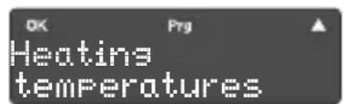
The device returns to the main menu »Heating« (or to »Cooling« if you selected this main menu in 4.3.a).
d. Changing the two other operating modes
■ Proceed as per 4.3.a. and b.
■ Now press the right display button ▲ to access the next submenu.

To change the operating mode "Night", press the right display button again.
■ Change the value as described in c.
e. Terminating the input sequence
After 20 seconds, the device automatically returns to the basic display. Alternatively, press a function button several times (= "ESC").
5.1. Using the room temperature timer
a. How the push-button RTR works
The push-button RTR compares the actual room temperature with the desired set temperature and then decides whether, and how far the heating valves must be opened or closed. The operating mode determines the specified temperature value.
You can use the timer to determine the time at which an operating mode is performed. You can combine the following categories freely for this purpose:
- Operating modes "Comfort", "Standby", "Night"
- Select the day of the week or a group of days such as Mo-Fr or Sa-Su.
- Operating time between 0:00 and 11:59pm
b. Setting criteria
In practice, every heater needs a specific length of time in order to bring a cold room to the desired temperature. For this reason, the room temperature should only be lowered by approx. 4 °C at night (see ch. 4.3.).
Unlike radiators, floor heaters work with a lower water temperature but a larger storage area and therefore reacts relatively lethargically. You should not forget to switch over to daily mode on time each morning. On the other hand, you can also switch over to night-time mode very early because the floor stores the heat very well.
5.2. Setting the room temperature timer
For your comfort and to save energy, you can program up to 28 different operating times in the push-button RTR in order to regulate the room temperature. Your installer will normally have saved several operating times already. If you need to make any changes, proceed as follows:
a. Calling up the main menu
- Change from the basic display to the main menu level as described in 2.3.b.
■ The display should now look like this:

b. Changing to the main menu
■ Press the right display button ▲three times:

If you pressed the right display button once too much, continue pressing it until you reach this menu.
NOTE
When programming switching times, you may encounter different switching time displays.

An operating time has already been saved. This can be changed as programming continues.
or
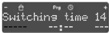
No operating time saved in this storage space. After deleting an operating time, you will receive a display to that effect.
c. Setting/changing the switching times
You have the following options at your disposal:
- Specifying operating time number, week day(s), time and operating mode (see following description)
- Deleting existing switching time/s (see. 5.2.d.)
- Activate/deactivate timer (see ch. 5.2.e.).
■ Press the left display button OK to access the sub-menu and change a switching time.
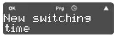
You will find a description on deleting an switching time (press the right display button ▲) in point e.
■ Press the left display button OK again in order to call up switching time 1.

If you wish to call up one of the other 28 switching times, press the right display button ▲ as often as necessary.
- Select the required switching time and then press the left display button OK.

The "Weekday" column flashes. Select Mo-Fr, Sa-Su or Mo-Sa or one single day of the week with the display buttons.
In order to accept the value, press the left and right display button simultaneously for at least 1 second

The time flashes in the display. Both display buttons behave as follows: when pressed, the time changes in 1-minute steps, when pressed and held, the time changes in 5-minute steps.
In order to accept the set time, press the left and right display button simultaneously for at least 1 second:
The operating mode 🏠 or now flashes in the display.

- Press one of the display buttons to select the operating mode "Comfort", "Standby" or "Night".
In order to accept the mode, press the left and right display button simultaneously for at least 1 second. The device returns to the switching time display.

This display is used to monitor your settings - in this example, changing the switching time to 8:00 am.
Example (setting a second switching time)
You now want to define a second switching time to activate "Comfort" at 9.00 am on the weekends.
■ Further in the menu sequence (see also 5.2.c second step):
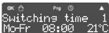
now press the display button ▲ here

press display button OK to activate switching time 2

press display button to change to Sa-So
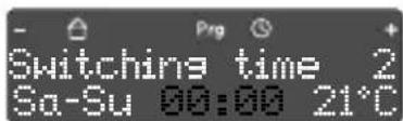
press display button to set the time

press display button to set the operating mode

Display after "ENTER"
- Press a function button to return to the »New switching time« menu.
NOTE
If necessary, activate the timer to perform the switching times.
d. Deleting an existing operating time
Proceed as per 5.2.a., b. and c.
■ Press the left display button OK to access the switching time submenu.

Instead of selecting the switching time as described below in 5.2.c, start the deleting sequence now.
■ Now press the right display button ▲.

To change directly to switching time 2 (or 28), press the right display button ▲, several times if necessary.
■ Press the left display button OK to confirm the deleting.

This security query allows you to leave the deleting sequence by pressing "ENTER".
■ Press the left display button +.
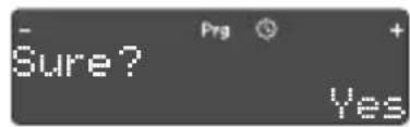
The following step deletes the selected switching time.
■ Now press the left and right display button simultaneously for at least 1 second:
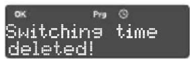
Press the left display button OK to complete deletion.
e. Activating and deactivating the timer
Proceed as per 5.2.a., b. and c.
■ Press the left display button OK to access the switching time submenu.
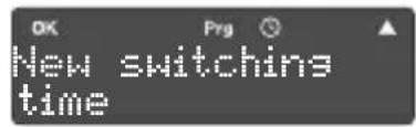
Instead of selecting the switching time as described below in 5.2.c, start de-activation/activation of the timer now.
■ Now press the right display button ▲twice.

Depending on the latest state, the query »activated« or »deactivated« (as shown here) appears in the display.
■ Press the left display button OK to change the behaviour of the timer.

The timer is deactivated/activated – you do not have to press "ENTER" for this to be accepted.
■ Press a function button to return to the main menu.

Press the right display button ▲to access the »Push-button assistance or push-button lock« settings.
NOTE
When the room temperature timer is deactivated, this does not affect just one single switching time but all switching times of the timer.
Deactivation has no effect on the switching times of the two other week timer which are available (see ch. 5.3).
5.3. Setting the week timer
To control the blinds or illumination groups (e.g. garden lights), you can program up to 14 different switching times for each of the two week timers in the push-buttons RTR.
a. Differences from the room temperature timer
The week timer is set and changed in the same way as the room temperature timer.
However, neither week timer calls up any operating modes. Instead, switching statuses or values are specified here by means of software:
- ON or OFF
(e.g. for illumination) - 0–255 or 0–100% or light scene 1–8
(e.g. for positioning blinds or calling up light scenes)
b. Calling up the main menu
- Change from the basic display to the main menu level as described in 2.3.b.
■ The display should now look like this:

c. Changing to the main menu
Press the right display button ▲4 or 5 times:
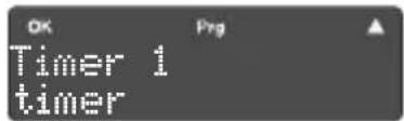
The texts displayed in the top text line are selected arbitrarily. Consult your installer to agree on the names.
Now proceed to call up, change or delete the week timer as described in 5.2.
5.4. Settings
In this menu, you can activate/deactivate basic settings which influence operation. These are:
- Display lights (»LCD disabling«)
- Help texts in the lower display line (»push-button assistance«)
- Blocking operation (»push-button lock«)
a. Decision criteria
The display lights may be a nuisance at times so it is best to deactivate them at night in bedrooms. When the push button RTR (any button at all) is pressed, the display only lights up for a brief time.
The help button is a great aid for new users but is not required by the more experienced user.
The push button lock offers protection against incorrect operation, if unsupervised children are playing.
Make the changes as follows:
b. Calling up the main menu
- Change from the basic display to the main menu level as described in 2.3.b.
c. Changing to the main menu
■ The display should now look like this:

If you pressed the right display button once too much, continue pressing it until you reach »Settings«.
d. Changing the above-mentioned settings
■ Press the left display button OK:
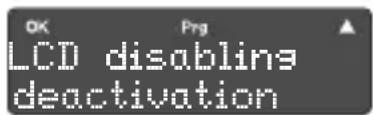
Press OK to activate/deactivate the current setting (display changes and is accepted without confirmation).
- Press the right display button ▲to access the »Push-button assistance or push-button lock« settings. Make the changes as described above.
e. Displaying the version number
■ After calling up/changing the »Push-button lock«, press the right display button ▲in order to display the version number.

The version number cannot be changed - it is important for service queries, for example.
f. Returning to the main menu and the basic display
- Press a function button once to access the »Settings« main menu.
If necessary, return to the basic display by pressing a function button several times (= "ESC").
NOTE
Some of the changes in this menu have considerable influence on operation. Inform the people concerned of any changes made here.
5.5. Troubleshooting
The following table allows you to eliminate specific "problems" which occur.
Problem Cause/remedy
| No display | Lighting of display and operating LED deactivated > see chapter 5.4.No bus voltage > if the bus voltage remains absent for a long period of time, inform the installerDevice faulty > replace it |
| The operating mode cannot be changed via menu operation | It may be that an open window with window contact or a presence detector prevents the change (forced position) |
| The function buttons cannot be pressed | Deactivate the activated push-button lock (ch. 5.4.)If the buttons are locked, have the installer unlock it |
| Menu or submenu cannot be called up in the display | Expand the operating levelMenu's functions are not approved or programmed > get the installer to unlock them and to program the required functions |
Ch. 5 - Operation »Level III« - Page 30
Problem Cause/remedy
»Parameter Download« appears in the display
»No parameters« appears in the display, function buttons show no reaction
Incorrect time/date display
Instead of the time or date, »---;---« or »---.---.----« appears in the display
This cannot be operated while the push-button is being programmed
Programmed push-button may have been connected to a different ("incorrect") bus coupling unit > check which device the push-buttons belong to, and make any necessary changes
■ Reset the time/date in the system clock
■ Functions are performed with slight delays > if necessary, re-synchronise them with the system clock
■ Synchronisation failed, functions are performed with a slight delay > if necessary, re-synchronise functions with system clock
CHAPTER FOR THE INSTALLER
B.
Berker the right way.
INFORMATION ON THE INSTABUS KNX/EIB
6.1. General system information
This device complements the instabus KNX/EIB system and meets the EIBA guidelines. The device should only be used by personnel who have undergone instabus training.
The device can only be operated with software. Information on what software can be loaded and the functions it makes possible, as well as information on the software itself is given in the manufacturer's product database.
The device is planned, installed and commissioned using EIBA-certified software. The product database, technical descriptions and a complete overview of the menu is available online at www.berker.com
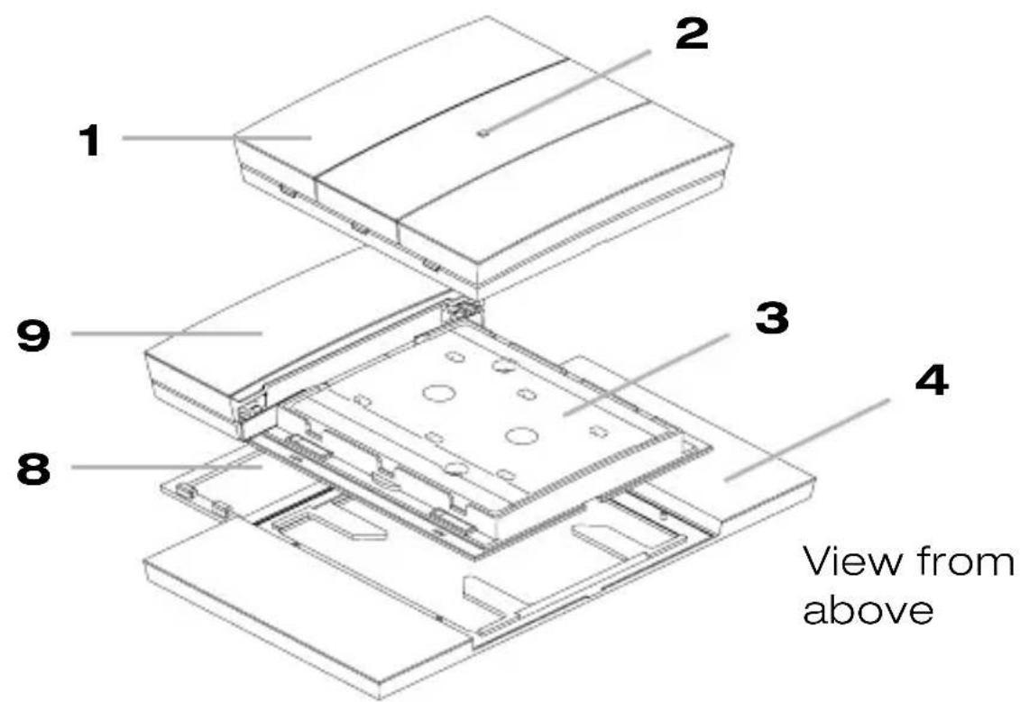

The 4/5gang push-buttons RTR are installed in the same way. A bus coupling unit flush-mounted KNX is required.

Electrical devices may only be installed and assembled by trained KNX/EIB and electrical personnel. They must comply with the valid accident regulations. Non-compliance with the valid regulations or the instructions in the present manual may result in fires or other dangers.
6.2. Assembly
a. Preliminary note
To protect the design cover (item 1) against damage or dirt, do not assemble it until all other construction work is complete. The push-button can be operated without the design cover using the base plate (item 5) with the transparent plastic cover (item 3); this cover protects the electronic equipment and must not be removed or painted over.
b. Assembly height/place
Assemble the device so that it is at the user's eye level. This will allow him to read displays such as room temperature, push-button assistance etc. in the push-button display (item 9) without difficulty. Install the device in a place where it is free from the effects of heat and light reflections.
c. Assembly instructions
■ Connect the base plate to the bus coupling unit flush-mounted KNX - the two are contacted using the physical external interface (item 6).
As an option, you can attach a labelling field (item 4) beneath the base plate. You must order this labelling field separately. In this case, also attach the spacer plate (item 8) to the rear of the display. The spacer plate is delivered with the labelling field.
- Secure the base plate to the supporting ring of the bus coupling unit with the pre-assembled screws (item 7).
■ After completing all building work, attach the design cover to the base plate. Ensure that you align it correctly (TOP/OBEN).
Immediately after you connect the device, the code and firmware are shown briefly in the display if the bus voltage is available. The pre-set basic display then appears and the operating LED (item 2) lights up.
NOTES
In the 4 and 5gang models, use the lower screw holes to secure the push-button RTR to the wall as well.
Use the screw/plug set for this purpose. This set is delivered with the push-button RTR.
- Adjust the push-button RTR to suit the control path so that the temperature measurement will function accurately. Then perform a function test if necessary.
6.3. Disassembly
- Carefully remove the design cover (item 1) from the base plate (item 3).
■ Follow the instructions for assembly but in reverse order.
NOTES
An alarm object may be stored as anti-theft protection for the push-button RTR.
Remember that the bus coupling unit and the push-button form a “unit” after parameterisation and must not be exchanged at will. Note any room or place identifiers and where various parts belong on both devices for re-assembly at a later date.
6.4. Technical data a.
Overview
Supply
via bus coupling unit flush-
mounted KNX 21-32 V DC
typ. 150 mW
Power consumption
2 x 5-pin male connector
Physical external interface
-5 to +45 °C
Ambient temperature
-25 to +70 °C
Storage temperature
IP 20
Degree of protection
|||
Protection class
Suitable for indoor use only.
Protect device from moisture.
b. Dimensions (W x H x D)
Push-button RTR
- 3gang approx. 89 x 118 x 17 mm
- 4gang approx. 89 x 148 x 17 mm
- 5gang approx. 89 x 179 x 17 mm
Labelling field (optional)
- 3gang approx. 152 x 118 mm
- 4gang approx. 152 x 148 mm
- 5gang approx. 152 x 179 mm
NOTE
You will find further details on our homepage.
ORDER NUMBERS
6.5. Order numbers
The push-button RTR is available in different versions. A list of the order numbers:
- 3gang 7566 35 9x
- 4gang 7566 45 9x
- 5gang 7566 55 9x
- Spacer plate included in each delivery package
- Labelling field 3gang 7590 00 80
- Labelling field 4gang 7590 00 81
- Labelling field 5gang 7590 00 82
- Bus coupling unit flush-mounted KNX 75 04 0001
NOTE
You will find more KNX/EIB products in the current "Technical manual KNX/EIB".
Warranty
We reserve the right to make technical and formal changes to the product in the interest of technical progress.
Our products are under guarantee within the scope of the statutory provisions.
If you have a warranty claim, please contact the point of sale or ship the device postage free with a description of the fault to the appropriate regional representative.

Correct Disposal of this product (Waste Electrical & Electronic Equipment).
(Applicable in the European Union and other European countries with separate collection systems).
This marking shown on the product or its literature indicates that it should not be disposed with other household waste at the end of its working life. To prevent possible harm to the environment or human health from uncontrolled waste disposal, please separate this product from other types of wastes and recycle it responsibly to promote the sustainable reuse of material resources.
Household users should contact either the retailer where they purchased this product, or their local government office, for details of where and how they can take this device for environmentally safe recycling.
Business users should contact their supplier and check the terms and conditions of the purchase contract. This product should not be mixed with other commercial wastes of disposal.
Usable in all Europe € and in Switzerland.
Ch. 7 - Appendix - Page 40
Note the functions assigned to the push-button RTR in the following table.
Operating element Function/LED/Operation/Blocking
| Display light...... continuous when activated | |
| - Left/right button...... | The function of the buttons depends on the situation. |
| Button 1 on left/LED... / | |
| - Operation...... | briefly press locked |
| Button 1 on right/LED .. / | |
| - Operation...... briefly press locked | |
| Button 2 on left/LED... / | |
| - Operation...... | briefly press locked |
| Button 2 on right/LED .. / | |
| - Operation...... briefly press locked | |
| Button 3 on left/LED... / | |
| - Operation...... | briefly press locked |
| Button 3 on right/LED .. / | |
| - Operation...... briefly press locked | |
| Button 4 on left/LED... / | |
| - Operation...... | briefly press locked |
| Button 4 on right/LED .. / | |
| - Operation...... briefly press locked | |
| Button 5 on left/LED... / | |
| - Operation...... | briefly press locked |
| Button 5 on right/LED .. / | |
| - Operation...... briefly press locked | |
| Push-button assist.. . activated deactivated | |
1. Overview
Introduction ...... 3
List of chapters....3
Functions 4
Basic display ....5
Push-button assistance....5
Overview of device 6
Illustration of the device 7
Explanation of the display symbols ....8
2. Operation
Blocking menus - Level I to III 10
General information about menu navigation....11
Menu sequence main menus 12
Displaying messages 14
3. Operation "Level I"
Changing the room temperature 15
4. Operation "Level II"
Changing the operating mode 16
Expanded operating modes 17
Changing the temperature values »Heating/Cooling« ...18
5. Operation "Level III"
Using the room temperature timer 20
Setting the room temperature timer....21
Deleting switching times....24
Activating the timer 25
DETAILED INDEX
Week timers....26
Settings....28
Troubleshooting....30
6. Installation (chapter for den installer)
General system information....33
Structure of device 34
Safety notes 35
Assembly....35
Disassembly 37
Technical data....38
Order numbers....39
7. Appendix
Warranty....40
Button assignment (tabular list) 41

Berker Switches and Systems

- B.
- INTRODUCTION
- Overview of functions
- BASIC DISPLAY, PUSH-BUTTON ASSISTANCE
- Basic display
- NOTES
- Push-button assistance
- NOTE
- Overview of device
- ■ Display buttons (item 1)
- ■ Function buttons/rocker (item 2 to 4)
- ■ LEDs (item 5 and 6)
- ILLUSTRATION OF THE DEVICE
- Explanation of the display symbols
- Blocking menus
- General information about menu navigation
- ■ Press one single display button:
- ■ Press both display buttons simultaneously:
- ■ Press any function button at all:
- If no push-button have been operated for more than 20 sec.:
- Menu sequence
- a. Deviations in function and display
- Some examples:
- b. Entering the main menus
- c. Procedure in the menus
- d. Main menus
- Displaying messages
- a. Effects on the function of the push-buttons
- b. Acknowledging text messages
- ROOM TEMPERATURE REGULATION
- Changing the room temperature
- Changing the operating mode
- a. Calling up the main menu
- b. Setting the required operating mode
- EXPANDED OPERATING MODES
- c. Terminating the input sequence
- Expanded operating modes
- Changing the temperature values
- b. Selecting the required operating mode
- c. Changing the temperature value
- d. Changing the two other operating modes
- e. Terminating the input sequence
- Using the room temperature timer
- a. How the push-button RTR works
- b. Setting criteria
- Setting the room temperature timer
- b. Changing to the main menu
- c. Setting/changing the switching times
- Example (setting a second switching time)
- d. Deleting an existing operating time
- e. Activating and deactivating the timer
- Setting the week timer
- a. Differences from the room temperature timer
- b. Calling up the main menu
- c. Changing to the main menu
- Settings
- a. Decision criteria
- d. Changing the above-mentioned settings
- e. Displaying the version number
- f. Returning to the main menu and the basic display
- Troubleshooting
- Problem Cause/remedy
- INFORMATION ON THE INSTABUS KNX/EIB
- General system information
- Assembly
- a. Preliminary note
- b. Assembly height/place
- c. Assembly instructions
- Disassembly
- Technical data a.
- Overview
- b. Dimensions (W x H x D)
- ORDER NUMBERS
- Order numbers
- Warranty
- Overview
- Operation
- Operation "Level I"
- Operation "Level II"
- Operation "Level III"
- DETAILED INDEX
- Installation (chapter for den installer)
- Appendix
Brand : HAGER
Model : 75665592
Category : Thermostat