
PD-9012G - Network Equipment Microchip - Free user manual and instructions
Find the device manual for free PD-9012G Microchip in PDF.


| Type | PoE Injector (Midspan) |
| Brand | Microchip |
| Model | PD-9012G |
| Standards | IEEE 802.3af |
| Number of Ports | 1 Input, 1 Output (Gigabit) |
| Input Voltage | 100-240 V AC, 50-60 Hz |
| Output Voltage | 48 V DC (PoE) |
| Max Output Power | 12 W |
| Dimensions (L x W x H) | 80 x 40 x 25 mm |
| Weight | 100 g |
| Operating Temperature | 0°C to 40°C |
| Housing Material | Plastic |
| Color | White |
| LED Indicators | Power, PoE active |
| Safety Certifications | CE, FCC |
| Installation | Desktop or wall mountable |
Frequently Asked Questions - PD-9012G Microchip
User questions about PD-9012G Microchip
0 question about this device. Answer the ones you know or ask your own.
Ask a new question about this device
Download the instructions for your Network Equipment in PDF format for free! Find your manual PD-9012G - Microchip and take your electronic device back in hand. On this page are published all the documents necessary for the use of your device. PD-9012G by Microchip.
USER MANUAL PD-9012G Microchip
Power over Ethernet AF/AT PowerView Pro User Guide
Introduction
This User Guide introduces Microchip's IPv6 capable Power View Pro Remote Web Managers used for managing Microchip's Power over Ethernet (PoE) product line of IPv6 capable Midspan devices including:
• 10/100Mbit Midspans
– PD-6506/AC/M: 6 port 10 Mbit/100 Mbit Midspan
– PD-6512/AC/M: 12 port 10 Mbit/100 Mbit Midspan
– PD-6524/AC/M: 24 port 10 Mbit/100 Mbit Midspan
- PD-6524/AC/M/F: 24 port 10 Mbit/100 Mbit full power Midspan
Note: Only Network Management Modules with internal FLASH memory of 4MB can be upgraded to latest IPv6 compliant software version. For further information, see 6.2 Midspan Manager Module Software Upgrade.
• 1 Gigabit Midspans
- PD - 6506G/AC/M: 6 port 1 Gigabit Midspan
- PD - 6512G/AC/M: 12 port 1 Gigabit Midspan
- PD - 6524G/AC/M: 24 port 1 Gigabit Midspan
- PD - 6524G/AC/M/F: 24 port 1Gigabit full power Midspan
• 1 Gigabit High Power 802.3at compliant Midspans
- PD - 9006G/ACDC/M: 6-port High Power 1 Gigabit 802.3at compliant Midspan
- PD - 9012G/ACDC/M: 12-port High Power 1 Gigabit 802.3at compliant Midspan
- PD - 9024G/ACDC/M: 24-port High Power 1 Gigabit 802.3at compliant Midspan
- PD - 9024G/ACDC/M/F: 24-port Full High Power 1Gigabit 802.3at compliant Midspan
• 1 Gigabit High Power 802.3at compliant four-pair Midspans
- PD - 9506G/ACDC/M: 6-port High Power 1 Gigabit 802.3at compliant four-pair Midspan
- PD - 9512G/ACDC/M: 12-port High Power 1 Gigabit 802.3at compliant four-pair Midspan
- PD - 9524G/ACDC/M: 24-port High Power 1 Gigabit 802.3at compliant four-pair Midspan
• 1 Gigabit High Power 802.3at compliant energy efficient Midspans
- PD - 5524G/ACDC/M: 24-port High Power 1 Gigabit 802.3at compliant energy efficient Midspan
• 1 Gigabit High Power PoH compliant four-pair Midspans
- PD - 9606G/ACDC/M: 6-port High Power 1 Gigabit PoH compliant four-pair Midspan - PD - 9612G/ACDC/M: 12-port High Power 1 Gigabit PoH compliant four-pair Midspan
This guide is intended for network administrators, supervisors, and installation technicians who have a background in the following domains:
- Basic concepts and terminology of networking
• Network topology - Protocols
• Microsoft Windows environment
Table of Contents
Introduction....1
- Introduction to Power View Pro (IPv4 and IPv6)....5
1.1. Features....5
1.2. System Capabilities....5
1.3. POE Capabilities....6
1.4. Configuration Options....6
1.5. Security and User Authentication....7
1.5.1. Web Security 7
1.5.2. SNMP Security....7
1.5.3. Telnet/SSH Security....7
- Installation 8
2.1. System Requirements....8
2.2. Hardware Setup....8
2.3. Configuration Procedure....9
2.3.1. Connecting to Unit Using a Web Browser....9
2.3.2. Connecting to Unit Using Window's Telnet....9
2.3.3. Connecting to Unit Using serial port and a Hyper Terminal Application....9
2.3.3.1. Windows 2000 and Windows XP ...... 9
2.3.3.2. Windows Vista / Windows 7 / Windows 10....10
2.3.4. Connecting via USB Serial Communication Virtual Port....11
2.3.5. Configuring the System via the serial port.... 11
2.3.5.1. Using the View Menu.... 12
2.3.5.2. Using the Configuration & Maintenance Menu....12
2.3.5.3. Using the Ping Remote Host Menu....14
2.4. Configuring the TFTP Server 14
- Web Interface Description....15
3.1. Overview.... 15
3.2. Opening Screen.... 15
3.3. View Menu....16
3.3.1. View - Status Screen 65xx, 65xxG Midspan Series 16
3.3.2. View - Status Screen 90xxG, 95xxG, 96xxG four-pair High Power Midspan Series... 17
3.3.3. View - Status Screen 55xxG energy efficient High Power Midspan Series....19
3.3.4. View - Status Screen Elements....20
3.3.4.1. Ports Status Panel....20
3.3.4.2. Midspan LED Indications....20
3.3.4.3. Midspan Status Table....21
3.3.4.4. Detailed Port Information Report....22
3.3.4.5. Manual Override Key....23
3.3.4.6. Weekly Scheduled Activated Port/s 23
3.3.5. View - Configuration Summary....24
3.3.5.1. IPv4 in-Use....25
3.3.5.2. Remote Servers.... 26
3.3.5.3. Date and Time....27
3.3.5.4. Remote Trap SNMP Managers List....27
3.3.5.5. Remote Access & Security....27
3.3.5.6. Advanced Features.... 28
3.3.6. View - Product Information 29
3.3.7. System Configuration Screen 30
3.3.7.1. System Configuration - Network....31
3.3.7.2. Auto Services Configuration by DHCPv4....33
3.3.7.3. Log Server....41
3.3.7.4. NTP Server....42
3.3.8. System Configuration SNMP 42
3.3.8.1. SNMPv2c.... 43
3.3.8.2. System Information (MIB-II, v2c/v3)....44
3.3.8.3. PoE MIB (RFC3621, v2c/v3) 44
3.3.8.4. Remote Trap SNMP Managers List....44
3.3.9. System Configuration SNMPv3.... 45
3.3.10. System Configuration Security 47
3.3.10.1. Web Secure Access & Configuration.... 47
3.3.10.2. Telnet/SSH View & Configuration....48
3.3.10.3. Remote Access 49
3.3.11. System Configuration - RADIUS 49
3.3.11.1. Configuring RADIUS Server to Provide Viewer/Administrator a Privileged Access....50
3.3.11.2. How to Differentiate Between Telnet/SSH/Web RADIUS Users....51
3.3.12. System Configuration - Dynamic UPS Power Management....51
3.3.12.1. UPS SNMP Agent 52
3.3.12.2. Custom UPS Vendor SNMP OIDs....52
3.3.12.3. Midspan Max Power versus UPS Battery Charge Level....53
3.3.13. System Configuration - Access List Filter....53
3.3.13.1. ACL Filter Statistics....55
3.3.13.2. ACL Filter Configuration Example ....56
3.3.14. System Configuration - Product Parameters: 65xx, 65xxG Family.....57
3.3.15. System Configuration - Product Parameters: 90xxG Family.... 59
3.3.16. System Configuration - Product Parameters: 95xxG Family.... 61
3.3.17. System Configuration – Product Parameters: 96xxG Family.... 63
3.3.18. System Configuration – Product Parameters: 55xxG Family....65
3.3.19. System Configuration Maintenance....66
3.4. Port Configuration Screen....68
3.4.1. Port Configuration - Enable/Disable....68
3.4.2. Port Configuration – Detailed....70
3.4.2.1. Ports Enable/Disable....73
3.4.2.2. EEPoE (55xxG Midspan family)....73
3.4.2.3. PoH (96xxG Midspan Family)....73
3.4.2.4. Allocating Maximum Power....74
3.4.2.5. Terminal Type / Description.... 74
3.4.3. Port Configuration - Weekly Schedule....75
3.4.3.1. Weekly Schedule Ports Activation....76
- Midspan 90xxG, 95xxG, 55xxG, 96xxG – Power Backup and Power Management....77
4.1. Viewing the Power Source Status....78
4.2. Dual 90xxG, 95xxG, 96xxG, 55xxG Midspan Power Backup ....79
4.2.1. Midspan 90xxG/95xxG/96xxG/55xxG to Midspan 90xxG/95xxG/96xxG/55xxG Power Shift....80
4.2.2. Changing Power Limit (%) by SNMP 80
4.2.3. Activating Dynamic UPS Power Management 81
4.2.4. Power Failure and Invalid Midspan to Midspan Power Backup Connection Report....81
- SNMP Monitoring and Configuration ....83
5.1. Enabling Midspan SNMP 83
5.2. SNMP MIBs....83
5.3. RFC3621 PoE MIB....84
5.4. Private MIB....84
- Software Upgrade....87
6.1. Software upgrade types....87
6.2. Midspan Manager Module Software Upgrade 87
6.2.1. Upgrading from IPv4 to IPv6 (software version 3.xx to 4.xx)....88
6.2.2. Upgrading to Latest IPv6 Software Version (version 4.xx)....88
6.2.3. Checklist Prior to Performing Software Update.... 88
6.2.4. Performing software update....89
- Troubleshooting....91
- Abbreviations....94
- Related Documentation....95
- Revision History....96
The Microchip Website....97
Product Change Notification Service....97
Customer Support....97
Microchip Devices Code Protection Feature....97
Legal Notice....98
Trademarks....98
Quality Management System....99
Worldwide Sales and Service....100
1. Introduction to Power View Pro (IPv4 and IPv6)
Microchip's Power View Pro is a management system used to monitor and control Microchip's Power over Ethernet (PoE) and Power over HDBaseT (PoH) Midspans, via a remote network management station. Management can be done over IPv4, IPv6 or both Network protocols. The system provides direct online power supervision, configuration, monitoring and diagnostics of Microchip products via WEB / SNMPv2c / SNMPv3 / Telnet/SSH.
Note: The principle of operation is similar for all IPv6 capable Midspan models described in this manual.
1.1 Features
The manager provides a number of unique features along with multiple access options:
• Supported network IP protocols:
- IPv4 - IP address is made out of 32 bits (static / DHCPv4).
- IPv6 - IP address is made out of 128 bits (ststic / DHCPv6)
- Access Options:
- HTTP: Web based friendly configuration interface for managing remote Power over Ethernet device
- SSL: Secured WEB based configuration
– SNMP: SNMPv2c and secured plus encrypted SNMPv3 (legacy SNMPv1 is also supported)
• RFC3621 Power over Ethernet (PoE) SNMP MIBs
- Private MIB extension for RFC3621 PoE MIB
– Telnet: Remote terminal over Ethernet Network
- SSH: Remote encrypted terminal over Ethernet Network
• RADIUS: Authentication and accounting for WEB / Telnet / SSH remote WEB users
- SysLog Server: Sends log events to remote SysLog Server
- Automatic Service Configuration by DHCP: Enables DHCP Server to configure automatically Midspan SNMP Manager's IP address, SysLog Servers IP address, Radius Servers IP address
- Access List Filtering: Controls which remote Host or Network can manage the Midspan device, and via which management interface. Interfaces such as SNMP, Telnet, Web, etc.
- Easy software update during run time without affecting active PoE ports
- Configuration and real time monitoring using graphical representations of remote device
- System status display
- Automatic activation / deactivation of PoE ports based on weekly schedule configuration
• Automatic deactivation of low priority ports when UPS battery is low
- Power backup by 2nd Midspan or external Power Source (90xxG, 95xxG series only)
1.2 System Capabilities
The manager can be accessed from any computer using any WEB browser, SNMPv2c/SNMPv3 management station, Telnet/SSH, RS232 Terminal or USB virtual COM (Midspan 90xxG, 95xxG, 55xxG series). The Power View Pro enables monitoring and controlling of Power over Ethernet IP networks as shown in the following figure.
Figure 1-1. Management Deployment
Management Deployment
![graph TD A["Server/Manager"] --> B["IP"] B --> C["Network Management"] B --> D["Element Management"] C --> E["Management Station"] D --> E E --> F["SNMP"] E --> G["SNMP/WEB"] F --> H["Managed Power over Ethenet Midspan"] G --> I["Managed Power over Ethenet Midspan"]](/content/2026/06/1358640/images/f87b96323b9230aa742a88c51dc64004810d4786e88adf52055a722257d276e4.jpg)
1.3 POE Capabilities
The Midspan injects power over data-carrying Ethernet cabling which reduces the need for AC outlets, local UPS and AC/DC adapters near PDs. The following Power over Ethernet (PoE) options are available:
- Legacy PoE – delivers power to pre IEEE 802.3af PoE devices
- IEEE 802.3af – delivers up to 15.4 Watts using two out of four paires on RJ45 Etehrnet connector. Applicable mostly to 65xx/65xxG Midspan family although all Midspans support IEEE-802.3af.
- IEEE 802.3at – delivers up to 30/36 Watts (Microchip Midspan may be configured to deliver up to 36 Watts). Applicable to 55xxG/90xxG/95xxG Midspan family.
- 4-pairs IEEE 802.3at – Microchip Midspan solution to deliver up to 72 Watts by delivering up 36 Watts on each pair of wires on the RJ45 Ethernet connector. Applicable to 95xxG Midspan family.
- EEPoE – Energy Efficient Power over Ethernet deliver up to 30/36 Watts by powering IEEE-802.3at PD device over four paires. By powering PD devices over four paires, the power loss on the Ethernet cable is reduced by 50%. For example a PD device which consumes 30 Watts may cause power loss of up to 5W on the Ethernet cable, forcing the Midspan to deliver 35 Watts. By using 55xxG EEPoE Midspan the power loss on the Ethernet cable will be reduced by 50% to 2.5 Watts, forcing the Midspan to deliver only 32.5 Watts.
- PoH – Power Over HDBaseT delivers up to 95 Watts over four pairs. Applicable to 96xxG Midspan family.
1.4 Configuration Options
Serial communication configuration should be used to set unit's initial IPv4 or IPv6 address (also set by web browser), upload / download unit configuration, restore unit configuration to factory default (also set by web browser), or update software. Any other configuration should be carried out via the web browser.
• Web based: Via a web browser
• SNMPv1/2c/3: Via an SNMP management application on a remote computer
- Telnet: Via a Telnet application on a remote computer
- SSH: Via an SSH client application on a remote computer
- Serial communication port: Via a DB9 port using Terminal emulation software such as Microsoft Windows HyperTerminal, PuTTY, or any similar software (excluding Midspan 90xxG, 95xxG, 55xxG series).
- Serial communication port via USB Virtual Communication Port driver (Midspan 90xxG, 95xxG, and 55xxG series only): Simplifies serial communication whenever laptop is in use (laptops are missing physical serial communication ports).
Note: Serial communication rate must be set to 38400, no hardware flow control. When using RS232 serial port cable, a cross cable must be used (pin 2 crossed with pin 3).
Note: The Midspan default IPv4 address is 192.168.0.50. Make sure that a computer network card is configured to the same IPv4 network (for example 192.168.0.40).
Note: For security reasons, when unit is shipped the SNMP is disabled. Prior to enabling SNMP, modify SNMP community strings and only then enable it. The Telnet/SSH and WEB configuration options are password protected.
1.5 Security and User Authentication
Various security profiles are available based on the type of configuration that is used. The different types of security profiles are described below.
1.5.1 Web Security
Web interface has two user access levels: Viewer and Administrator.
- Viewer: The user has access only to Web pages which report Midspan status of configuration summary and cannot change the Midspan configuration.
- Administrator: The user has full access to all Web pages and can modify Midspan configuration.
Note: SSL (https) offers encryption and authentication protection in addition to Viewer and Administrator access levels.
1.5.2 SNMP Security
- SNMP v1/v2: Community string is utilized for Get/Set/Trap authentication. SNMPv1/v2 is considered an unsecured protocol since the community string password can be easily intercepted by any Network sniffer device.
- SNMP v3: Resolves SNMPv1/v2 security issues by adding authenticating and encryption to SNMP packets.
1.5.3 Telnet/SSH Security
As Telnet/SSH provides access to various configuration parameters, software updates, and data base upload/download, it is always password protected.
Note: The Web interface has a dedicated password, while Telnet and SSH share the same passwords.
Note: The Power View Pro is provided with the following factory defaults passwords:
• WEB/Telnet/SSH:
View (usually user) : user name = "user" password = "password"
- Configure (usually administrator):
user name="admin" password="password".
• SNMP v3:
Guest (usually remote SNMP manager) : user name = "public"
View User (usually user) : user name = "view" authentication password (MD5) = "password" privacy password (DES) = "password"
Admin User (usually administrator) : user name = "admin" authentication password (MD5) = "password" privacy password (DES) = "password",
2. Installation
The following sections detail the installation process.
2.1 System Requirements
The following hardware/software items are required to configure and operate the Power over Ethernet (PoE) Midspan:
- Computer with Ethernet Network card configured to the following parameters:
- IPv4: 192.168.0.40
- IPv4 Mask: 255.255.255.0
- Ethernet cable.
- Ethernet switch connected to the computer and Midspan management RJ-45 port (the user can use a cross cable connected directly between the computer and the Midspan without having to use an Ethernet Switch).
- Telnet application (already provided by Windows/Linux).
- A free serial communication port on the computer.
– Null-modem RS232 crossed cable
- USB cable (90xxG, 95xxG, 96xxG, and 55xxG Midspan series).
Note: The Midspan is shipped with the default IP set to 192.168.0.50. Before connecting the Midspan to your network, verify that no other device has the same IP address.
2.2 Hardware Setup
Before configuring the units, set up your hardware as follows:
- Connect an AC power cable to the PoE unit.
- Verify that all LEDs are lit (self test).
-
Configure the units as seen in the figure below.
-
Serial port: Connect the crossed null-modem cable between the management station serial port and the Midspan RS 232 port.
- Midspan 90xxG, 95xxG, 96xxG, 55xxG: Use USB cable (verify virtual com port driver installation was already done).
- Ethernet network: Connect a network cable to Midspan RJ45 management port (use cross cable whenever connecting directly to the Laptop Ethernet port). Make sure the green LED on the right side of Midspan RJ45 Management port turns on. In case a problem arises, refer to the 7. Troubleshooting section.
Figure 2-1. Connecting the PoE Unit
![graph TD A["LAII"] --> B["PoE Unit"] B --> C["CROSSED NULL MOD EM CABLE"] C --> D["Management Station"] B --> E["To configure Network Interface parameter"]](/content/2026/06/1358640/images/38dbc69e9a715fe5734c890bced62fad99dcf49a490edc342f025a86593ade27.jpg)
2.3 Configuration Procedure
The following sections describe how to install the unit via the configuration options.
The following connection options are available:
• 2.3.1 Connecting to Unit Using a Web Browser
• 2.3.2 Connecting to Unit Using Window's Telnet
• 2.3.3 Connecting to Unit Using serial port and a Hyper Terminal Application (65xx, 65xxG Midspan series)
• 2.3.4 Connecting via USB Serial Communication Virtual Port, page 2.3.4 Connecting via USB Serial Communication Virtual Port (90xxG, 95xxG, 96xxG, 55xxG Midspan series)
2.3.1 Connecting to Unit Using a Web Browser
- Open the web browser.
- In the address field, type: 192.168.0.50
2.3.2 Connecting to Unit Using Window's Telnet
For Windows XP / Windows Vista / Windows 7 / Windows 10:
- In the Start Menu, select Run.
- Type: cmd. (Black DOS window appears).
- Type: telnet 192.168.0.50.
- Type the username and password.
Note: Use the web browser to view the System Configuration->Security web page and make sure that the Telnet is enabled.
2.3.3 Connecting to Unit Using serial port and a Hyper Terminal Application
Windows XP includes Hyper Terminal communication application which can be used to configure the Midspan over the serial port. For Windows Vista, Windows 7, and Windows 10 we recommend using PuTTY application which can be downloaded for free from the Internet.
2.3.3.1 Windows 2000 and Windows XP
-
In the Start Menu, select:
Start >Programs >Accessories >Communications >HyperTerminal.
The Hyper Terminal window appears as seen in the figure below. -
Select the following parameters:
-
Bits per second: 38400
- Data bits: 8
- Parity: None
- Stop bits: 1
- Flow control: None
Figure 2-2. Windows XP Hyper Terminal Specifications

2.3.3.2 Windows Vista / Windows 7 / Windows 10
Windows XP HyperTerminal serial communication is not included in Windows Vista / Windows 7 / Windows 10. It is recommended to use PuTTY, HyperTerminal freeware serial communication software or any other commercial serial communication software tool.
- Download PuTTY freeware at: http://www.putty.org/.
- Run PuTTY.
The Putty Configuration window appears as seen below.
Figure 2-3. Putty Configuration Window

- Under Connection type, select Serial.
The PuTTY Serial Configuration Window appears as seen below.
Figure 2-4. PuTTY Serial Configuration Window Specifications

4. Select:
- Serial line to connect to: Required COM port
• Speed (baud): 38400 - Flow control: None
5. Click Open.
2.3.4 Connecting via USB Serial Communication Virtual Port
The 90xxG/95xxG/96xxG/55xxG Midspan offers USB serial communication rather than the traditional RS232 DB-9 interface. This eases the serial communication whenever a laptop is used (laptops lack serial interface ports).
To install the 90xxG/95xxG/96xxG/55xxG driver:
- Verify that the host's USB port is disconnected from the 90xxG/95xx/96xxG/55xxG Midspan's USB port.
- Install the Virtual Serial Communication driver found on Microchip Software Library.
- Connect the host USB to the 90xxG, 95xxG, 96xxG, 55xxG Midspan USB port.
-
In the host, configure the connection setting.
-
Windows 20000 and Windows XP OS: Run the HyperTerminal application.
- Windows Vista / Windows 7 / Windows 10 OS: Run PuTTY.
-
Select the following settings:
-
Baud rate: 38400
- Number of bits: 8
- Stop bit: 1
- Flow-control: None
2.3.5 Configuring the System via the serial port
Note: There is no password protection while using the serial communication port. Password protection is only applicable for Telnet, SSH or WEB access.
To configure the system via the HyperTerminal:
- Click the ESC or space key (in case you are already in the main menu). The Main Menu appears as seen below:
Figure 2-5. Main Menu Screen
| Main Menu - [Midspan Device] |
| 1. View menu 2. Configuration & maintenance menu 3. Ping remote host |
| E. Exit to debug information screen |
The Main Menu contains the following functions:
• View menu: View PoE ports status, Network configuration, ACL Filter, software version and release date.
- Configuration & maintenance menu: Enable/disable PoE ports, Network configuration, upload/download configuration, update SSL certificate, software update, restore username and password or unit configuration to factory default and reset unit.
- Ping remote host: Determine whether a particular IP system on a network is functional. Use this function to diagnose IPv4 and IPv6 network connectivity.
- Exit to debug information screen: Enables on-going debug information to be reported by the terminal.
2.3.5.1 Using the View Menu
In the Main Menu, select the View Menu option.
The View Menu screen appears.
Figure 2-6. View Menu Screen

ESC - Return to previous menu
The View Menu contains the following functions:
- View PoE ports status: Shows whether a PoE port is enabled/disabled, if the port provides power to a PD device, and PD power consumption.
- View network parameters: Displays the Midspan IPv4 address, subnet mask, default gateway. For IPv6, same data is displayed plus DNS, SysLog servers, NTP server and unit MAC address.
Note: The DHCP server IP appears while DHCP is in use.
• View ACL (Access List) filter parameters: Shows Access List Filter configuration mode and statistics detailing how many network packets were accepted or rejected by HTTP, HTTPS, SNMP, Telnet, and SSH filters.
- View time & system up time: Displays how many days, hours, minutes and seconds the unit has been operational.
• View application & Boot software version: Displays the application and boot version number and creation date.
2.3.5.2 Using the Configuration & Maintenance Menu
In the Main Menu, select the Configuration & Maintenance Menu.
Figure 2-7. Configuration & Maintenance Menu
| Configuration & Maintenance Menu | |
| 1. | Enable/Disable PoE Port |
| 2. | Network configuration |
| 3. | Download configuration file from TFTP Server (reset only Manager module) |
| 4. | Upload configuration file to TFTP Server |
| 5. | Download WEB SSL Certificate from TFTP Server (reset only Manager module) |
| 6. | Software update menu |
| 7. | Turn RADIUS, ACL Filter off. Restore all user & password to factory default |
| 8. | Restore unit to factory default (excluding IP configuration) |
| 9. | Reset Manager module |
| A. | Reset unit |
| B. | Enable/Disable auto ping to Default Gateway to ensure Network connectivity |
| ESC - Return to previous menu | |
The Configuration & Maintenance Menu contains the following options:
- Enable/Disable PoE Port: Allows users to enable/disable a PoE port (same as from WEB/SNMP/Telnet/SSH).
• Network configuration:
- Set IPv4 address (static / DHCPv4), and DNSv4
- Set IPv6 address (static / DHCPv6), and DNSv6
- Set Host name (used by DHCP4 / DHCPv6)
- Download configuration File from TFTP Server: Download a configuration file from a remote host using a TFTP application (host must run TFTP server application prior to using this option; see section 2.4 Configuring the TFTP Server).
Note: Upon successful downloading, only the manager module will reset itself without effecting active powered PD devices.
- Upload Configuration File to TFTP Server: The unit uploads its internal configuration file to the host, utilizing a TFTP application (host must run TFTP server application prior to using this option. See section 2.4 Configuring the TFTP Server).
- Download WEB SSL Certificate from the TFTP Server: Download a valid private key and certificate files for Web SSL by TFTP. The private key eliminates web browser security warnings whenever SSL is used.
Note: For detailed procedure description and applicable utility files, refer to the Web SSL documentation found on Microchip Software Library.
- Software update menu: Enables the user to update management module software or PoE firmware.
Note: It is recommended that you use the TFTP server application found on Microchip Software Library.
- Turn RADIUS, ACL Filter off. Restore all user & password to factory default: Turns RADIUS and Access List Filter (ACL Filter) off, and restores Manager Module view/configure user name and password to default values (only the manager module resets itself without effecting active powered PD devices).
- Restore the unit to factory default. Keep IP configuration unchanged: Restores most of the unit configuration parameters to factory default values. Note that to enable the remote user to access the Midspan after it was restored to factory default; various IP parameters (for example unit IP address) remain the same (only the manager module will reset itself without effecting active powered PD devices.).
- Reset Manager Module: Manager Module resets only itself, without effecting active powered PD devices.
- Reset unit: Reset the entire unit, which causes all powered PD devices to be turned off for several seconds, and then re-powered.
- Enable/Disable auto ping to Default Gateway to ensure Network connectivity: When enabled, it allows the Midspan Network Management Module to verify proper Network connectivity by pinging default gateway every six seconds (IPv4 DGW or IPv6 DGW). After 10 consecutive ping failures, Network Management Module will reset itself without effecting PoE ports.
Note: Manager Module will not reset itself in case there are no DGWs.
• ESC: Return to Previous Menu
2.3.5.3 Using the Ping Remote Host Menu
The Ping Remote Host Menu can be used to test Midspan Network configuration, and also verify access to remote services such as SysLog server, SNMP Network management station, etc.
To ping a remote device:
-
In the Main Menu, select Ping Remote Host Menu.
-
Type the remote IPv4, IPv6 or remote Host name (for using hostname, DNS must be configured).
2.4 Configuring the TFTP Server
The following section describes how to configure the IPv4 TFTP server which is utilized for optional software updates and transferring unit configuration to and from the host.
Notes:
-
Make sure the computer Firewall is turned off for the TFTP Server (or enable UDP port 69 to pass through the Firewall).
-
For Upload Configuration: Make sure Enable Writes checkbox is checked as seen in the figure below.
To configure the TFTP server:
-
From the Microchip Software Library, copy the NBTFTP.exe application to your server's desktop.
-
Run NBTFTP.exe application; the following window appears as seen below:
Figure 2-8. NBTFTP Server Window

- Click ADD, to add the root folder of the TFTP server.
3. Web Interface Description
The Web Interface provides a friendly graphical interface for monitoring and configuring the Midspan unit..
3.1 Overview
The system provides the following features:
- View of PoE ports status, Power consumption and Midspan configuration.
- Modification of Midspan configurations which are applicable for the entire Midspan unit.
- Modification of PoE ports configurations, such as maximum power, priority, port description, etc.
The Web Interface has two authorization levels (see 3.3.10 System Configuration Security, page 3.3.10 System Configuration Security):
- User: Allows remote users to access only web pages which are located under the View menu.
- Administrator: Allows remote users full access to all web pages.
3.2 Opening Screen
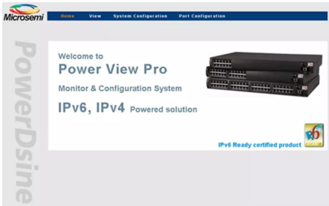
Browse to the Midspan IPv4 or IPv6 address. The Main Window (Opening screen) appears as seen in the figure below. The Opening screen is composed of three main submenus:
- View menu: Used to view unit status, network configuration and product information.
- System Configuration menu: Used for configuring anything that isn't PoE port specific (network, SNMP, security, RADIUS, UPS power management, access list filter, product parameters and maintenance).
- Port Configuration menu: Used for enabling/disabling of ports, allocation of power, setting of priorities, and weekly based schedule automatic PoE ports activation/deactivation.
Figure 3-1. Power View Pro Main Window
3.3 View Menu
The View menu is used to view the following categories as seen in the figure below:
- System status
- Configuration summary
• Product information
The View menu differs according to the model being used:
• 3.3.1 View - Status Screen 65xx, 65xxG Midspan Series
• 3.3.2 View - Status Screen 90xxG, 95xxG, 96xxG four-pair High Power Midspan Series.
• 3.3.3 View - Status Screen 55xxG energy efficient High Power Midspan Series.
Figure 3-2. View Menu

3.3.1 View - Status Screen 65xx, 65xxG Midspan Series
The View - Status screen is used for monitoring which PoE ports are active and power consumption (for the entire unit or per port). It is made up of several elements as seen in the figure below:
- Port status panel – view which PoE ports are enabled, which are provide with power, and amount of power.
- Port power status table – pressing the or images will open a detailed port report table.
- General power status table – reports internal power supply voltage, total power consumption, etc.
- UPS power management information – reports remote UPS battery level, and AC or Battery power source.
Note: UPS Power Management window for 65xx, 65xxG, and 90xxG appears at the bottom right section of the screen only if the UPS Power Management option is enabled (for more details, refer to Section 3.3.12 System Configuration - Dynamic UPS Power Management).
Figure 3-3. View - Status Screen (65xx, 65xxG Midspan Series)

3.3.2 View - Status Screen 90xxG, 95xxG, 96xxG four-pair High Power Midspan Series
In addition to the information provided by the View - Status Screen (65xx, 65xxG Midspan Series) seen above, the 90xxG, 95xxG High Power Midspan series View - Status Screen (see the figure View - Status Screen (90xxG High Power Midspan Series) provides the following addition information:
- PoE PD detection method: Includes IEEE802.3at PoE PD in addition to the 802.3af and legacy PoE PD devices (not supported by 96xxG Midspan).
- Power sources: Internal and external power sources status (redundancy power backup capability was added to 90xxG, 95xxG, 96xxG Midspan series).
- External redundancy power source status: The 90xxG, 95xxG, 96xxG Midspan support redundant power supplies.
- PD power consumption (90xxG): PoE PD Power consumption reports up to 30 watts for IEEE802.3at devices or up to 36W if Extended Power Mode is enabled.
- PD power consumption (95xxG): PoE PD Power consumption reports up to 60 watts or up to 72 watts if the Extended Power Mode is enabled.
- Temperature (95xxG/96xxG/55xxG): Internal temperature sensor is included in 95xxG Midspan series which reports the Midspan internal temperature. The 95xxG/96xxG/55xxG Midspan temperature can be obtained from View System Status WEB page, or from Midspan SNMP Private MIB (version 1.7 and above).
Figure 3-4. View - Status Screen (90xxG High Power Midspan Series)

Figure 3-5. View - Status Screen (95xxG four-pair High Power Midspan Series)
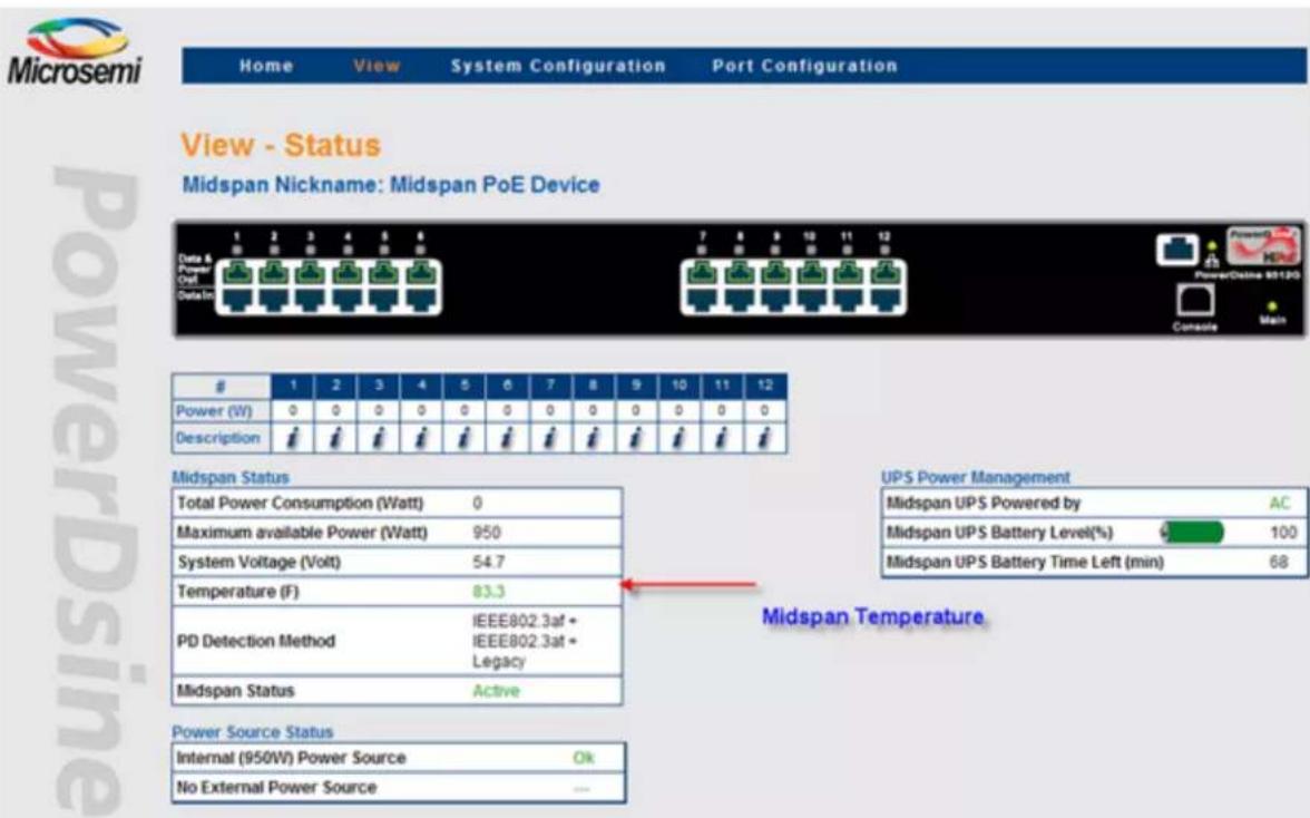
Figure 3-6. View - Status Screen (96xxG PoH four-pair High Power Midspan Series)

3.3.3 View - Status Screen 55xxG energy efficient High Power Midspan Series
In addition to the information provided by the 3.3.2 View - Status Screen 90xxG, 95xxG, 96xxG four-pair High Power Midspan Series, the 55xxG High Power Midspan series View - Status Screen as seen in the figure below provides the following addition information:
- Energy saving information – reports annual Energy saving, annual Co2 Saving and number of EEPoE active ports out of the number of EEPoE enabled ports.
- PD power consumption: PoE PD Power consumption reports up to 30 watts for IEEE802.3at devices or up to 36W if Extended Power Mode is enabled.
Figure 3-7. View - Status Screen (55xxG energy efficient High Power Midspan Series)

3.3.4 View - Status Screen Elements
The following sections describe in detail the View - Status Screen elements.
3.3.4.1 Ports Status Panel
The display panel includes a number of visual indicators as seen in the figure below.
- A green colored RJ45 port indicates that the PoE port is enabled, and may provide power whenever a PD device is connected to this port.
- A green LED on top of the green colored RJ45 port indicates that the PoE port provides power to a PD.
- A red colored RJ45 port with an "X" symbol indicates a disabled PoE port (a port that can't provide power).
Figure 3-8. Ports Status Panel
3.3.4.2 Midspan LED Indications
Two LEDs are located on the front panel, marked "Main" (220/110VAC) and "Link" (Ethernet connection plus activity status) as described in the table below.
Table 3-1. Main Status Indications
| Indicator Color Main Power Status Remarks | |||
| AC LED | Off | Internal power supply unit is unplugged or faulty | Internal power supply voltage is too low. All ports are disconnected |
| Green Indicates AC | power input active | Internal power supply voltage is within limits | |
| Green blinking | Internal power supply voltage is out of range90xxG, 95xxG, 96xxG – Internal power supply is unplugged | All ports are disconnected90xxG, 95xxG – unit powered by external power source | |
| LINK LED Green blinking | Indicates valid Ethernet link, and some data communication flow over the Ethernet network | ||
| LINK LED Green | Indicates valid Ethernet link (no communication data) | ||
Table 3-2. 65xx, 65xxG, 90xxG, 95xxG and 55xxG Gigabit High Power Midspan Port Status Indications
| Port LED Color Port | Load Conditions Port Voltage | |
| Off | Non-active load, unplugged port or disabled port | Power to the port is disconnected. No DC voltage present on spare pairs |
| Green | Active load is plugged in and complies with normal load conditions95xxG: PoE port is configured as two-pair, and power PD device, or as four-pair and power PD device on all four pairs.55xxG: PoE port is configured as EEPoE and power PD device, or as four-pair and power PD device, on all four pairs | Continuous nominal DC voltage is present on the spare pairs |
| Orange | 95xxG/96xxG: PoE port is configured as four-pair, and power PoE device on two pairs only.55xxG: PoE port is configured as EEPoE, and power PoE device on two pairs only. | |
| Green blinking | Overload conditions; or short; or forced external voltage feed (constant DC) into the port | Power to the port is disconnected. No DC voltage is present on the spare pairs |
| Slow Green blinking | Port can't be activated since total aggregated power exceeds maximum power budget | Power to the port is disconnected. No DC voltage is present on the spare pairs |
3.3.4.3 Midspan Status Table
The Midspan Status Table below displays the following parameters:
| Total Power Consumption (Watt) | 14.1 |
| Maximum available Power (Watt) | 1000 |
| System Voltage (Volt) | 55.2 |
| PD Detection Method | IEEE802.3af + IEEE802.3at + Legacy |
| Midspan Status | Active |
Table 3-3. Midspan Status Table Details
| Parameter Description | |
| Total Power Consumption Total power consumed by all PDs | |
| Maximum available Power Maximum available power for all PDs | |
| System Voltage Voltage level supplied to PDs | |
| PD Detection Method Detection method selected by the user from the SystemConfiguration - Product Parameters menu (see Sections 3.3.14 System Configuration - Product Parameters: 65xx, 65xxG Family, 3.3.15 System Configuration - Product Parameters: 90xxG Family, and 3.3.16 System Configuration - Product Parameters: 95xxG Family) | |
| Midspan Status Midspan status display with the following options:Active: Normal operationMidspan has no firmwareInternal communication failureMidspan firmware update | |
3.3.4.4 Detailed Port Information Report
Clicking the i image, or the RJ45 jack image, causes a new popup web page to appear with detailed port description information as seen below:
Figure 3-9. Detailed Port Information

Table 3-4. Detailed Port Description Information
| Parameter Description | |
| Port • Disabled: Port is disabled | • Enabled: Port is enabled• Enabled: Delivering Power; Port is enabled and a valid PoE PD device is connected and consuming power• Enabled: Failure to power a PoE Device; Port is enabled, PoE PD device is connected, but no power is provided. Possible causes include: PoE device consumes too much power (overload) or the PoE PD device is invalid, etc. |
| Power (W) Actual consumed power by individual PD | |
| Max Power (W) Maximal | allocated power per port as configured in the Port ConfigurationMidspan 95xxG reports, if PoE port is configured as two pair or four pair.Midsan 55xxG reports, if PoE port is configured as energy efficient PoE. |
| Priority Current priority level set by the user | |
| Terminal Type / Description | Textual terminal description as configured in the Port Configuration |
| Class PD device class | |
3.3.4.5 Manual Override Key

Whenever the Weekly Schedule feature is activated, the IT manager can configure one of the Midspan PoE ports to act as a Manual Override Deactivation key. This enables easy temporary deactivation of the Weekly Schedule feature, whenever an authorized user arrives at work during unexpected hours. The IT manager selects the override port manually via the Web interface and then enables the override feature; an icon then appears on the selected port.
Note: The Deactivation key is an optional item which may be purchased separately from Microchip.
Upon unexpected user arrival to work, the user inserts the deactivation key into the previously assigned override port (see Figure 4-10) (usually routed through the patch panel near the doorway entrance).
Figure 3-10. Manual Override Deactivation key

As long as the override key is inserted, all Weekly Schedule deactivated PoE ports remain active. Upon leaving work, the user removes the override key, which in-turn will causes all Weekly Schedule assigned ports to turn Off (Weekly Schedule time configuration dependent).
Note: Instances where the 📋 icon appears but the corresponding port LED does not illuminate, it means that the port had been assigned as a 'bypass' port, but the override key has not been inserted.
3.3.4.6 Weekly Scheduled Activated Port/s
The weekly schedule feature enables (when checked) scheduling of automatic PoE ports activation/deactivation as set in the weekly schedule activation scheme.
When the h appears on a port, it means that a specific port was temporary deactivated by the Weekly Schedule algorithm.
Note: Note that PoE port activation/deactivation hours depend on user Weekly Schedule configuration (see Section 3.4.3.1 Weekly Schedule Ports Activation).
Figure 3-11. Weekly Activated/Deactivated Ports

3.3.5 View - Configuration Summary
The View - Configuration Summary screen as seen in the figure below displays the following parameters:
- IPv4 in-use: Currently in use IPv4 address/Mask/Gateway (may be acquired by DHCP or static configuration) and IPv4 Domain name servers.
- IPv6 in-use: Currently in use IPv6 address/Prefix/Gateway (may be acquired by DHCPv6 or static configuration), and IPv6 Domain name servers.
- Network Host Name: Midspan hostname used by IPv4 / IPv6 to register Midpsan hostname in DHCPv4/DHCPv6 Server. NOTE: Only A-Z, a-z, 0-9, minus, and dots are allowed. Hostname must start with a letter.
- Ethernet MAC Address: Six byte (48 bit) unique Ethernet address.
- Remote Servers: IP address of remote NTP (Network Time Protocol) Server, remote SysLog Servers, and remote Radius Servers.
- Remote Trap SNMP Managers List: List of assigned SNMP managers to receive Midspan SNMP Trap reports.
- Date & Time: Unit local time, as acquired from the NTP Server (GMT time zone should be configured by the user)
- Remote Access & Security: A list of Midspan remote access and security options; SNMP v1/v2 and SNMPv3, Telnet/SSH, RADIUS, and SSL Web encryption
- Advanced Features: Indication of Automatic Weekly Schedule PoE ports activation and UPS Power Management features activation.
Figure 3-12. View - Configuration Summary Screen

3.3.5.1 IPv4 in-Use
IPv4 in-use window displays the current IP address being used with the following parameters:
Figure 3-13. IP in-Use Window
IPv4 in-use
| DHCPv4 | No |
| IPv4 Address | 172.16.5.247 |
| IPv4 Mask | 255.255.248.000 |
| IPv4 Default Gateway | 172.16.0.2 |
| Domain Name Server #1 | 172.16.1.46 |
| Domain Name Server #2 | 172.16.1.47 |
Table 3-5. IP in User Parameters
| Parameter Description | |
| DHCPv4 Indicates if DHCPv4 or static IPv4 is in use | |
| IPv4 Address IPv4 address of the Midspan in use. | |
| IPv4 Mask Determines the size of the IPv4 Network | |
| IPv4 Default Gateway IPv4 address of the local Gateway which enables communication with other IPv4 networks | |
| Domain Name Server 1 and 2 | IPv4 address of DNS used for resolving remote host names. |
3.3.5.2 Remote Servers
The Remote Servers window displays IPv4, IPv6 or remote hostname address of a remote SysLog Servers, Radius Servers and NTP Server.
Figure 3-14. Remote Servers Window
Remote Servers
| NTP Server | HODDTC8400.microsemi.net |
| SysLog #1 | HODDTC8400.microsemi.net |
| SysLog #2 | |
| Radius #1 | 172.016.005.254 |
| Radius #2 | 172.016.005.253 |
Table 3-6. Remote Server Parameter Description
| Parameter Description | |
| NTP Server IPv4/IPv6 address of a remote Network Time Protocol (NTP) Server. | |
| SysLog Server#1 SysLog Server#2 | Send SysLog events to Main and Backup IPv4/IPv6 SysLog Server via SysLog protocol. Note that empty fields prohibit the unit from sending Log Events. |
| Radius Server #1 Radius Server #2 | Used for authenticating remote user by sending remote user username and password to Radius Server for authentication and obtaining remote user access level (viewer or administrator). |
3.3.5.3 Date and Time
The Date and Time (GMT time zone) window (see Figure 4-15) displays the unit's local time as acquired from the NTP Time Protocol Server by the user. Set the offset local time zone as well.
Figure 3-15. Date and Time Window

Table 3-7. Date and Time Window Parameter Description
| Parameter Description | |
| Local Time Time (HH:MM:SS) as acquired from the NTP Server, plus time zone offset | |
| Date (D/M/Y) Date (DD/MM/YYYY) as acquired from the NTP Server | |
Notes:
- When the appropriate time and date are acquired from the NTP server, an OK indication appears. Alongside the Time Zone Offset from GMT window in the System Configuration - Weekly Schedule Ports Activation menu (refer to Section 3.4.3.1 Weekly Schedule Ports Activation) If the system fails to acquire the appropriate time and date 'FAIL' indication appears instead!
- If the unit fails to acquire time from NTP Server, it displays the elapsed time starting from 1/1/2005
- If time and date are not acquired, Weekly Schedule functionality will not function!
- If local time zone offset has been improperly set by the user (Weekly Schedule configuration Web page), an incorrect time will be shown!
3.3.5.4 Remote Trap SNMP Managers List
This list displays all of the user pre-configured SNMP managers (see Figure 4-16). All listed managers will receive traps reported by the Midspan (to receive PoE traps, make sure that PoE RFC3621 Notification feature is enabled). Verify that RFC3621 and Midspan private MIB are installed on the SNMP management station that monitors the Midspan device.
Figure 3-16. Remote Trap SNMP Managers List

3.3.5.5 Remote Access & Security
Remote Access & Security list (see Figure 4-17) summarizes whether Midspan can be managed by SNMPv2, SNMPv3 Telnet or SSH, HTTP or HTTPS, and whether RADIUS authentication and accounting is enabled.
Figure 3-17. Remote Access & Security Window

Table 3-8. Remote Access & Security Window Parameter Description
| Parameter Description | |
| Telnet/SSH Indicates whether Midspan can be managed by Telnet, SSHv2 (secure and encrypted terminal) or by none of them. | |
| SNMPv2 Indicates whether Midspan can be managed by SNMPv1/v2. | |
| SNMPv3 Indicates whether Midspan can be managed by SNMPv3. It is not recommended to enable SNMPv2 while SNMPv3 is in use. | |
| Web SSL Indicates whether Midspan WEB pages will be encrypted by SSL. | |
| RADIUS Authentication | When checked, indicates that remote Telnet/SSH/WEB users are authenticated by the RADIUS Server rather then by the Midspan itself. |
| RADIUS Accounting When checked, indicates that the Midspan sends an accounting report to the RADIUS Server whenever remote users access Midspan by Telnet/SSH/WEB.. | |
3.3.5.6 Advanced Features
The Advanced Features window displays which of the Weekly Schedule / UPS Power Management advanced features is activated.
The weekly schedule feature enables scheduling of automatic PoE ports activation/deactivation as set in the weekly schedule activation scheme.
The UPS Power Management feature enables to extend the period of time the Midspan may provide power to high priority PoE devices during a power failure. This is accomplished by monitoring the UPS battery level, and automatically shutting down low priority PoE ports, whenever the UPS battery level drops to a low level.
Figure 3-18. Advanced Features Window

Table 3-9. Advanced Features Window Parameter Description
| Parameter Description | |
| Weekly Schedule Indicates that the weekly schedule feature had been activated via the System Configuration - Weekly Schedule Ports Activation menu. | |
| ......continued | |
| Parameter Description | |
| UPS Power Management | Indicates that the Midspan was configured to communicate with UPS SNMP agent to monitor its UPS battery level and automatically deactivate low priority PoE ports whenever UPS battery becomes low. |
3.3.6 View - Product Information
The View - Product Information web page summarizes production related parameters such as product type, serial number, PoE firmware software version, and Network management module software version as seen below:
Figure 3-19. View - Product Information Screen

Table 3-10. Product Information Details
| Parameter Description | |
| Product Nickname Unit nickname as configured by network administrator to be displayed in the View-Status web page and in serial/Telnet/SSH menus | |
| Part Number Midspan part number | |
| Serial Number Midspan serial number | |
| ......continued | |
| Parameter Description | |
| Production Number Unique | manufacturing product number per each Midspan type (all Midspans of the same type have the same production number) |
| Software Version Power View | Pro Network Manager Module software version |
| Firmware Version PoE Firmware version | |
| Boot Version Network Manager Module boot version | |
| Flash Size Network Management Module flash memory size. | |
3.3.7 System Configuration Screen
The System Configuration menu is used for configuring the following options as seen in the figure below:
• Network Configuration
- SNMP Configuration
- SNMPv3 Configuration
• Security Configuration
• RADIUS Configuration
• UPS Power Management Configuration
- Access List Filter Configuration
• Product Parameters - Configuration
- System Configuration - Maintenance
Figure 3-20. System Configuration Screen

3.3.7.1 System Configuration - Network
The System Configuration - Network menu as seen in the figure below enables configuration of the following:
• static/dynamic IPv4 address
• static/dynamic IPv6 address
• NTP server (IPv4/IPv6)
- SysLog log (IPv4/IPv6) servers
• automatic SNMP Trap list
- SysLog and Radius IP to be obtained by DHCP Server which simplifies management whenever many Midspan devices need to be managed.
For a detailed description see section 3.3.7.2 Auto Services Configuration by DHCPv4.
Note: When enabling Automatic IP configuration for SNMP traps, SysLog, and DARIUS by DHCPv4 server, only IPv4 address type can be obtained automatically for SysLog, SNMP and RADIUS.
Figure 3-21. System Configuration - Network Screen
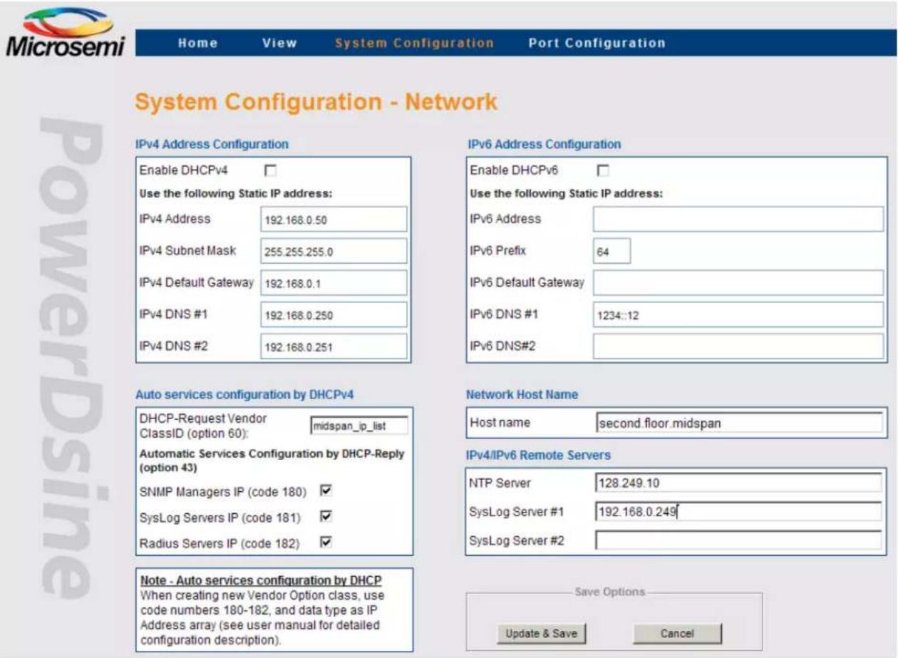
Table 3-11. System Configuration Network Screen Details
| Parameter Description | ||
| IPv4 Address ConfigurationEnable DHCPv4Use the following Static IP address:IPv4 Address172.16.5.247IPv4 Subnet Mask255.255.248.000IPv4 Default Gateway172.16.0.2IPv4 DNS #1172.16.1.46IPv4 DNS #2172.16.1.47 | DHCPv4 En/Dis – When checked enables Midspan to obtain IPv4 address from DHCPv4 Server. | |
| IPv4 Address – Static IPv4 address to be used in case DHCPv4 is disabled. | ||
| IPv4 Subnet Mask – Static IPv4 subnet mask to be used in case DHCPv4 is disabled. | ||
| IPv4 Default Gateway – Static IPv4 default gateway to be used in case DHCPv4 is disabled. | ||
| IPv4 DNS #1 – Static IPv4. First DNS IPv4 address to be used in case DHCPv4 is disabled. | ||
| IPv4 DNS #2 – Static IPv4. Second DNS IPv4 address to be used in case DHCPv4 is disabled. | ||
| Auto services configuration by DHCPv4DHCP-Request Vendor midspan_ip_listClassID (option 60):Automatic Services Configuration by DHCP-Reply (option 43)SNMP Managers IP (code 180)SysLog Servers IP (code 181)Radius Servers IP (code 182) | Set Vendor Class ID string (DHCPv4 option #60) within DHCPv4 request message sent by Midspan to DHCP Server. | |
| Whenever DHCPv4 is active, Enable/Disable DHCPv4 Server to automatically configure SNMP Managers IP, SysLog Server IP, and RADIUS Server IP (for detailed configuration example see manual). | ||
| Network Host NameHost namemidspan.2nd.floor | Midspan Hostname to be send within DHCPv4 and DHCPv6 messages. | |
| IPv6 Address Configuration | DHCPv6 En/Dis – When checked enables Midspan to obtain IPv6 address from DHCPv6 Server. | |
| Enable DHCPv6Use the following Static IP address: |  DHCPv6 functionality varies by M&O bits which are advertised by IPv6 Router over the Netwrok.M=1, O=1: Obtain IPv6 address & DNS from DHCPv6 ServerM=0, O=1: Obtain only DNS from DHCPv6 Server. Use Automatic link-local IPv6 address DHCPv6 functionality varies by M&O bits which are advertised by IPv6 Router over the Netwrok.M=1, O=1: Obtain IPv6 address & DNS from DHCPv6 ServerM=0, O=1: Obtain only DNS from DHCPv6 Server. Use Automatic link-local IPv6 address | |
| IPv6 Address | 1234::AB:3A2 | |
| IPv6 Prefix | 64 | |
| IPv6 Default Gateway | 1234::1 | |
| IPv6 DNS #1 | 1234::98 | |
| IPv6 DNS#2 | 1234::99 | |
| IPv6 Address – Static IPv6 address to be used in case DHCPv6 is disabled. | ||
| IPv6 Prefix – Static IPv6 prefix (subnet mask) to be used in case DHCPv6 is disabled. | ||
| IPv6 Default Gateway – Static IPv6 default gateway to be used in case DHCPv6 is disabled. | ||
| IPv6 DNS #1 – Static IPv6. First DNS IPv6 address to be used in case DHCPv6 is disabled. | ||
| IPv6 DNS #2 – Static IPv6. Second DNS IPv6 address to be used in case DHCPv6 is disabled. | ||
| IPv4/IPv6 Remote Servers | NTP Server – IPv4/IPv6/Hostname address of a remote NTP Server. | |
| NTP Server | 128.249.1.10 | NOTES:Local time GMT offset can be configured via the Weekly Schedule Port Activation WEB page. |
| SysLog Server #1 | 192.168.0.10 | |
| SysLog Server #2 | syslog.server1 | |
| SysLog Server #1 – IPv4/IPv6/Hostname address of remote SysLog Server #1. | ||
| SysLog Server #2 – IPv4/IPv6/Hostname address of remote SysLog Server #2. | ||
| Update & Save | Updates new network parameters. All properties and Remote Server parameters become effective only after this button has been clicked. | |
| Cancel | Cancels current operation and restores previous values in case Update & Save buttons were not clicked. | |
Auto Services Configuration by DHCPv4
DHCPv4 Server can be configured as seen in the figures below to automatically set the Midspan SNMP Manager List, SysLog servers, and Radius Servers. Such a configuration simplifies multiple Midspans management. The configuration example shown below is based on a Windows 2008 Server. The same configuration guidelines should be used when another DHCP Server type is in use.
- Configure Midspan DHCP Vendor Class ID (DHCP option 60) on Midspan: Set Vendor Class ID string which will be sent from the Midspan to DHCP Server in each DHCP-Discover and DHCP-Request message.
Figure 3-22. Auto Services Configuration by DHCP

- Configure DHCP Vendor Class ID on DHCP Server: Configure same Vendor Class ID on DHCP Server. Whenever DHCP Server detects a known Vendor Class ID string, it may be configured to provide various IP addresses which are unique for each pre configured Vendor Class ID string.
To define the DHCP Vendor Class:
- Right click on DHCP root and then choose Define Vendor Class.
- Click Add.
- Fill in the Display name and Description fields.
- Click on the ASCII section and type midpsan_IP_list.
- Click OK to close the window.
Figure 3-23. Defining Vendor Class

Figure 3-24. Set Vendor Class String
![win2UU8 IPv4 Scope [10.2.2.0] IPv4 DHCP Relay Scope [12.2.0] DHCP Vendor Classes Available classes: Name Description Microsoft Windows 20... Microsoft vendor-specific option... Microsoft Windows 98... Microsoft vendor-specific option... Microsoft Options Microsoft vendor-specific option... Add... Ed…](/content/2026/06/1358640/images/61c419f4c826999795291c449901c7c5e2559acead3dfc4bff52137da8308d84.jpg)
-
Adding Pre Defined Sub types:
-
Right click on DHCP root.
- Select the Set Predefined Options.
- Select the new Option Class - Midspan automatic IP configuration.
- Click OK
- Click Add
Figure 3-25. Set Predefined Options

Figure 3-26. Adding Predefined Sub Types

• In the Option Type window:
- Fill in the Name and Description fields.
- Set Data Type to IP Address.
- Check the array checkbox. The Code field must be the same as in the Midspan.
- Click OK.
Figure 3-27. SNMP Manager Option Type

Figure 3-28. Midspan Option Code

• Code 180: SNMP Manager IP list
• Code 181: SysLog IP list
• Code 182: Radius IP list
- Repeat the same procedure to create the SysLog Manager List and Radius Manager List Option Type.
Figure 3-29. SysLog Option Type
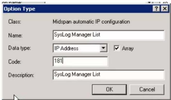
Figure 3-30. RADIUS Option Type

- Setting Scope Options:
- Select the appropriate DHCP.
- Right Click Scope Options.
- Select Configure Options.
- Select the Advanced tab.
- In the Vendor Class select the new defined vendor class (Midspan Automatic IP Configuration).
Figure 3-31. Scope Options Configurations
![DHCP File Action View Help DHCP win2008 IPv4 Scope [10.2.2.0] IPv4 DHCP Rele Scope [12.2.3.0] 12.2.3.30-40 Address Pool Address Leases Reservations Scope Options... Server Options IPv6 Configure Options... View Refresh Export List... Help](/content/2026/06/1358640/images/7dfbe6accc56c0b1026886408b02beecd322c1bc45c8ce80a3e9f1cceaa62454.jpg)
Figure 3-32. Midspan Scope Options

- Check the sub vendor options that the DHCP Server should advertise so as to automatically configure the various IP addresses used by the Midspan. The new configured scope options are added to the Scope Options advertised by the DHCP Server.
Figure 3-33. Configuring Scope Options

Figure 3-34. Advertised Scope Options
![DHCP File Action View Help DHCP win2008 IPv4 Scope [10.2.2.0] IPv4 DHCP Rele Scope [12.2.3.0] 12.2.3.30-40 Address Pool Address Leases Reservations Scope Options Server Options IPv6 Scope Options Option Name Vendor Value 003 Router Standard 12.2.3.253 180 SNMP Manager List Midspan autom... 181 SysLo…](/content/2026/06/1358640/images/83dbf4e6167a3e28054d6dca63895dc914bb641e96a6bf282d45a31c27068753.jpg)
- Setting SNMP Manager IP Address List:
- Select SNMP Manager List.
- Right click and select Properties.
- Type SNMP Manager IP Address (up to 10 SNMP Managers).
- Click Add.
- Repeat same process for SysLog IP list (up to two addresses) and Radius Servers IP list.
Figure 3-35. SNMP Scope Options
![DHCP File Action View Help DHCP win2008 IPv4 Scope [10.2.2.0] II Scope [12.2.3.0] I Address Pool Address Lease: Reservations Scope Options Server Options Scope Options Option Name Vendor 003 Router Standard 180 SNMP Manager List Delete 181 SysLog Manager List Refresh 182 Radius Manager List 006 DNS…](/content/2026/06/1358640/images/8045162f7d6a566ecabffdff5eac42ed7efd8b809eb002d2385b6e490622a268.jpg)
Figure 3-36. Setting SNMP Manager IP List
![DHCP File Action View Help DHCP win2008 IPv4 Scope [10.2.2.0] II Scope [12.2.3.0] I Address Pool Address Lease: Reservations Scope Options Server Options Scope Options Option Name Vendor 003 Router Standard 180 SNMP Manager List Delete 181 SysLog Manager List Refresh 182 Radius Manager List Properti…](/content/2026/06/1358640/images/d2517287d05e3a173927eafac0815e5c554a8ed631e565e703957a9ab5657289.jpg)
- Setting Midspan Automatic Service Configuration: After configuring the DHCP Server to advertise the SNMP Manager List, SysLog Servers List and Radius Server List, configure which all Midspan Network services should be configured dynamically, and which one should use Midspan static configuration. As shown in the figure below, the SNMP Manager IP List and SysLog IP are updated dynamically by the DHCP Server. The Radius Servers IP list is not updated even if advertised by the DHCP Server. Check Obtain IP by DHCP checkbox and click Update & Save.
Figure 3-37. Midspan Automatic Service Configuration

Notes:
- All IP address obtained by the Auto Service Configuration by DHCP will be saved even after Midspan DHCPv4 option was disabled.
SNMP Managers IP (180)
SysLog Servers IP (181)
Radius Servers IP (182)
- Checking the SNMP, SysLog or Radius has no effect if DHCPv4 is disabled.
3.3.7.3 Log Server
The Midspan can send various internal event reports to an external IPv4/IPv6 host running SysLog daemon application which logs those events for future use. An example of such IPv4 SysLog server application can be found at http://www.kiwisyslog.com/.
Figure 3-38. Syslog Server Log Events
![Kiel Syslog Daemon (Version 7.1.4) File View Help Display 00 (Default) Date Time Priority Hostname Message 08-13-2006 11:21:37 LocalInfo 172.16.17.16 Aug 13 8:23:07 172.016.017.016 (GMT): MsgID#001 - Port $12 status changed to [Deliver Pwt] # # # # #](/content/2026/06/1358640/images/64907cfc9e621586199b217663c2b744e0973265410fb0c498753de5b93aa573.jpg)
SysLog messages are sent whenever the SysLog Server's IP field is other than 0.0.0, or none empty string. The following events may be sent by the Midspan:
- System UP
- Port status has changed (PoE port was changed to another RFC3621 SNMP MIB port state)
- Midspan delivers power above xy% threshold
- Midspan delivers power less then xy% threshold (after exceeded power message was sent)
- Remote user tried to access web view pages using an incorrect username or password
- Remote user tried to access web configuration pages using incorrect username or password
- Remote user tried to post web form using incorrect username or password
- Unit was restored to factory default values
- Unit configuration was changed
- PoE controller reset was detected
- Remote Telnet/SSH user failed to login (incorrect username or password)
- Remote Telnet/SSH/Web user was rejected by RADIUS Server (incorrect username or password)
- Remote Telnet/SSH/Web user was rejected since no reply from primary and secondary RADIUS Server
- Remote Telnet/SSH/web user got viewing access privilege from remote RADIUS Server, while trying to access configuration section
• Weekly Schedule override key was inserted
• Weekly Schedule override key was removed - Remote UPS operates on battery
- Remote UPS switched back to AC
- Maximum delivered power by Midspan was changed by remote SNMP manager or UPS dynamic power management algorithm
Additional Midspan 90xxG/95xxG/96xxG55xxG SysLog Messages:
- Internal Power Source failure. External Power Source is in use
- Internal Power Source was restored
• External Power Source failure - External Power Source was restored
- Midspan is connected to incompatible Power-Backup source type. Turn unit off and disconnect it.
Note: Each SysLog message contains a message date and time (GMT). The Midspan acquires date & time from the Network NTP Server.
3.3.7.4 NTP Server
Whenever a valid NTP Server IPv4/IPv6/NTP-Server-hostname is configured, the Midspan acquires date and time (GMT) from the Network NTP Server. In cases where no valid IP is set, or in cases where the Midspan fails to acquire time from the NTP Server, initial Midspan time will be set to 1/1/2005 as default.
3.3.8 System Configuration SNMP
The Unit's SNMP agent (v1/v2/v3) can be accessed either by IPv4 or IPv6. It enables a remote SNMP management station to monitor and configure the unit as per RFC3621 (enable/disable PoE ports, view total power consumption, etc) and view MIB-II Network statistics. The Private MIB extends PoE functionality beyond the RFC3621 PoE MIB. For example:
- Set each individual PoE port maximum power.
- Read each individual port current power.
- Limit entire Midspan maximum power.
The SNMPv3 offers a secured method for accessing the Midspan, both for configuration and monitoring. SNMP Network packets may be authenticated by MD5 and encrypted by DES.
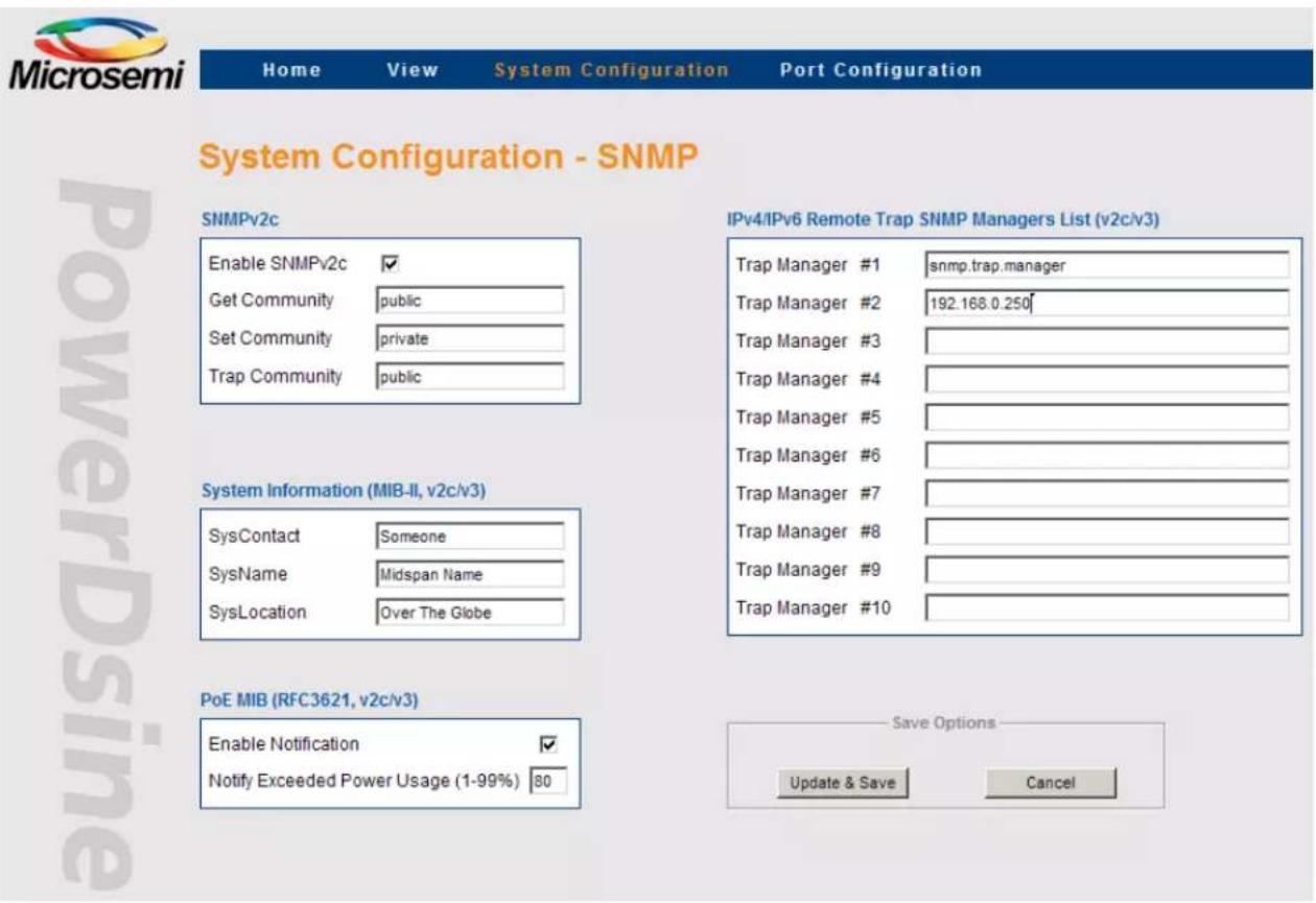
The System Configuration SNMP screen enables configuration of SNMP parameters common to both SNMPv1/v2 and SNMPv3 (SNMPv1/2 community string is the only exception). The following parameters can be configured as seen in the figure below:
• SNMPv1/v2c Community Strings
• MIB-II System Information
- Remote Trap SNMPv2c/v3 Managers List
• RFC3621 PoE MIB partial configuration parameters
Figure 3-39. System Configuration SNMP Screen
3.3.8.1 SNMPv2c
The SNMPv2c feature enables/disables an SNMP agent to respond to SNMPv1/v2c get/set commands, generated by remote SNMP Management station as HP OpenView, IBM Tivoli, etc.
Community strings – Get/Set/Trap community strings are actually SNMP passwords. To enable remote SNMP manager communication with the device, you must configure his community strings to match those of the Midspan. Community Strings window enables configuration of the following parameters:
Figure 3-40. SNMPv2 Window

Table 3-12. SNMPv2 Field Details
| Field Description | |
| Enable SNMPv2c Enable/Disable SNMPv1/v2c agent. | |
| Get community Password to be used by remote SNMP NMS station for SNMP GET commands. | |
| Set community Password to be used by remote SNMP NMS station for SNMP SET commands. | |
| Trap community Each TRAP sent by the Midspan to remote NMS managers contains a Trap community string password. It must match remote SNMP NMS managers password or otherwise be discarded by SNMP manager. | |
3.3.8.2 System Information (MIB-II, v2c/v3)
The System Information window enables configuring the following as described in the table below.
Table 3-13. System Information Window
| Button/Checkbox Description | |
| SysContact SNMP MIB-II | 1.3.6.1.2.1.1.4: Textual identification of the contact person for this managed node, joined by information on how to contact this person. |
| SysName SNMP MIB-II | 1.3.6.1.2.1.1.5: Textual identification of an administratively-assigned name for current managed node. |
| SysLocation SNMP MIB-II | 1.3.6.1.2.1.1.6: Textual identification of the physical location of current node. |
3.3.8.3 PoE MIB (RFC3621, v2c/v3)
This window simplifies the configuration of two major RFC3621 PoE MIB parameters as described in the table below.
Table 3-14. RFC3621 PoE MIB Parameters
| Button/Checkbox Description | |
| Enable Notification Allows/prohibits unit from sending RFC3621 PoE traps (both SNMPv2c and SNMPv3) | |
| Notify Exceeded Power Usage (1-99%) | If Enable Notification is checked, Midspan will send a trap whenever total power consumption exceeds xy%. |
3.3.8.4 Remote Trap SNMP Managers List
This window enables configuration of up to 10 remote IPv4/IPv6 SNMP managers as seen in the figure below. Whenever Midspan needs to send a trap message, the trap will be duplicated and sent by the Midspan to all the remote SNMP managers (in cases where both SNMPv2c and SNMPv3 are set, each trap will be sent twice, once by SNMPv2c and once by SNMPv3).
Figure 3-41. Remote Trap SNMP Managers List

Table 3-15. Remote Trap SNMP Managers List Screen Button Description
| Button Description | |
| Update & Save | Updates Midspan functionality per the new configuration.All SNMP parameters become effective only after this button has been clicked! |
| Cancel | Cancels current operation and restores previous values |
3.3.9 System Configuration SNMPv3
The System Configuration SNMPv3 menu enables configuration of three different SNMPv3 user types and notification (trap) which requires similar parameters as any other SNMPv3 user.
Figure 3-42. System Configuration SNMPv3 Screen

- Enable/Disable SNMPv3: Enables/disables SNMPv3 agent to respond to SNMPv3 GET/SET messages sent by remote SNMP management station (note that SNMPv3 works independently from SNMPv2c).
- Guest User: Enables read only access to the MIB-II System OiD tree. It should be used by SNMP managers who prefer not to expose their real username and password to pool the device for "keep alive" reports. A guest user has no authentication or privacy (encryption) ability.
- View User: Has read only (GET) access to all SNMP branches but cannot perform any modifications (SET).
- User Name: SNMPv3 user (mandatory field).
- Authentication Password (MD5): Applicable when MD5 or MD5+DES are being used.
- Privacy Password (DES): Applicable only when MD5+DES are being used.
-
Authentication + Encryption: Enables selection of one of three security levels:
-
None: SNMPv3 packets are neither authenticated nor encrypted.
- MD5: SNMPv3 packets are authenticated but not encrypted.
- MD5+DES: SNMPv3 packets are authenticated and encrypted.
- Admin User: Has full reading (GET) and writing (SET) access to all SNMP branches.
- User Name: SNMPv3 user (mandatory field).
- Authentication Password (MD5): Applicable when MD5 or MD5+DES are being used.
- Privacy Password (DES): applicable only when MD5+DES are being used.
-
Authentication + Encryption: Enables selection of one of three security levels:
-
None: SNMPv3 packets are not authenticated or encrypted.
- MD5: SNMPv3 packets are authenticated but not encrypted.
- MD5+DES: SNMPv3 packets are authenticated and encrypted.
- Notification Trap: SNMPv3 trap configuration parameters are identical to SNMPv3 user
- User Name: SNMPv3 user (mandatory field).
-
Authentication Password (MD5): applicable when MD5 or MD5+DES is being used.
-
Privacy Password (DES): Applicable only when MD5+DES is being used.
-
Authentication + Encryption: Enables selection of one of three security levels:
-
None: SNMPv3 packets are not authenticated and neither encrypted
- MD5: SNMPv3 packets are authenticated but not encrypted
- MD5+DES: SNMPv3 packets is authenticated and encrypted
3.3.10 System Configuration Security
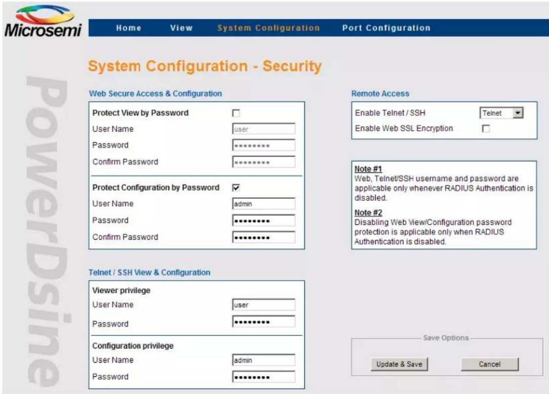
The System Configuration Security menu enables configuration of the following parameters:
• WEB Secure Access & Configuration
• Telnet/SSH View & Configuration
- Remote Access
Figure 3-43. System Configuration Security Screen
3.3.10.1 Web Secure Access & Configuration
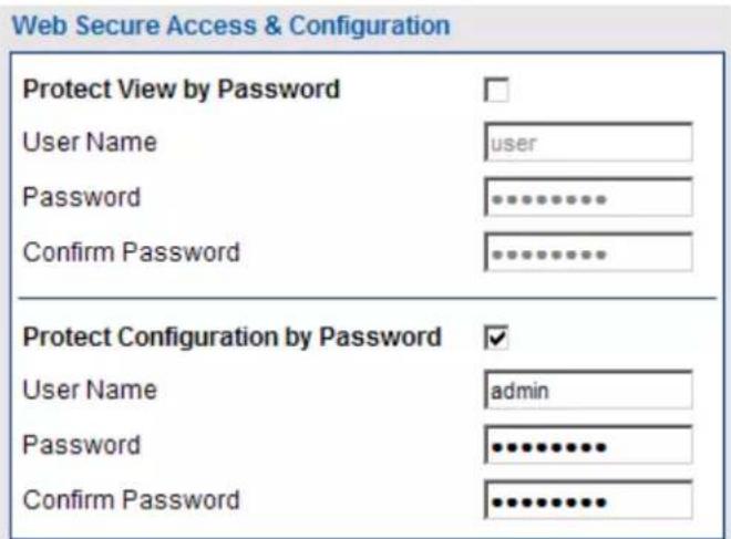
Web pages are divided into two sections, View and Configuration. View web pages provide status reports and configuration summaries, without being able to change configuration. Configuration web pages (under System Configuration and Port Configuration) enable the user to view and modify the Midspan configuration.
View web pages and Configuration web pages use different passwords. View user name and password provides access only to View web pages, while configuration user name and password provides access both to View and Configuration Web pages as seen below.
Figure 3-44. Web Secure Access & Configuration Window
Note: Disabling Web View/Configuration password protection is applicable only when RADIUS Authentication is disabled!
3.3.10.2 Telnet/SSH View & Configuration
The Telnet/SSH remote terminal are always password protected.
The Telnet/SSH menu is divided into View privilege and Configuration privilege sub menus.
- View privilege: Can view Telnet/SSH text menus but will be rejected when trying to access the Configuration text menus.
- Configuration privilege: can access both to View and Configuration text menus.
Figure 3-45. Telnet/SSH View & Configuration Window

Note: Web, Telnet/SSH username and password are applicable only in cases where RADIUS Authentication is disabled.
Remote Terminal view menu example:
View Menu
- View PoE ports status
- View network parameters
- View ACL (Access List) filter parameters
- View time & system up time
- View application & Boot software version
ESC - Return to previous menu
Remote Terminal configuration menu example:
Configuration & Maintenance Menu
- Enable/Disable PoE Port
- Network configuration
- Download configuration file from TFTP Server (reset only Manager module)
- Upload configuration file to TFTP Server
- Download WEB SSL Certificate from TFTP Server (reset only Manager module)
- Software update menu
- Turn RADIUS, ACL Filter off. Restore all user & password to factory default
- Restore unit to factory default (excluding IP configuration)
- Reset Manager module
A. Reset unit
B. Enable/Disable auto ping to Default Gateway to ensure Network connectivity
ESC - Return to previous menu
3.3.10.3 Remote Access
Figure 3-46. Remote Access Window

- Enable Telnet / SSH / None: Enables/disables remote IPv4/IPv6 terminal access by Telnet, SSH or none of them.
- Enable Web SSL Encryption: When checked, enables encryption of WEB pages between remote WEB client and an on-board WEB Server.
Note: Due to Web browser Web pages caching, whenever changing the Web SSL encryption method (encrypted/non encrypted) close the Web browser and re-open it.
Table 3-16. Remote Access Window Button Description
| Button Description | |
| Update & Save | Updates Midspan parameters and saves configuration. All Remote Access parameters become effective only after this button has been clicked. |
| Cancel | | Cancels current operation and restores previous values (in cases where was not clicked). |
3.3.11 System Configuration - RADIUS
Whenever the IPv4 RADIUS client is enabled, the remote Web/Telnet/SSH username and password are sent to the RADIUS Server for authentication purposes. This in turn can provide the user with a viewer access level, administrator access level, or reject the remote user.
Note: Any invalid activity (e.g. user was rejected, user tried to access the configuration section), is reported to the SysLog Server.
Note: Please view the information found on Microchip Software Library, on how to configure Midspan RADIUS to work against Cisco ACS Radius Server.
Figure 3-47. RADIUS Configuration Screen

- Enable RADIUS Authentication: When checked, all remote Telnet/SSH/Web users will be authenticated by the RADIUS Server.
Note: To deactivate RADIUS in case it was enabled while configured incorrectly, connect to Midspan serial port (38400), and select from configuration menu: Turn RADIUS, ACL Filter off. Restore all user and password to factory default.
- Enable RADIUS Accounting Report: When enabled, (checked), the Midspan will send an accounting report whenever login or logout of remote Web/Telnet/SSH users occurs. Note that the Accounting report can be enabled only if RADIUS Authentication is enabled.
- Authentication Method: Determines whether the remote user, username and password are sent to the RADIUS Server via PAP or CHAP (more secure).
- Primary and Secondary RADIUS Server IP Address: IP address of the RADIUS Server. In cases where there is no reply from the primary RADIUS server after 3 retries, the same authentication request will be sent to the backup RADIUS Server.
- Shared Secret: The same string must be configured both in the RADIUS server and the Midspan RADIUS client.
- Authentication UDP Port: Should not be changed, unless you use a RADIUS Server which utilizes UDP port 1645.
- Accounting UDP Port: Should not be changed, unless you use a RADIUS Server which utilizes UDP port 1646.
- Timeout: A period of time (in seconds) during which the Midspan RADIUS client waits for a reply from the RADIUS Server before resending a request. Note that the Midspan RADIUS client retries up to 3 times before accessing the backup RADIUS server. For example, if timeout equals two seconds, the backup server will be accessed only after 6 seconds.
3.3.11.1 Configuring RADIUS Server to Provide Viewer/Administrator a Privileged Access
To get administrator privileges, RADIUS Server Authentication-Reply must contain a 'callback-Number' attribute with an 'admin' value. Failing to do so results in providing viewing access privilege only!
3.3.11.2 How to Differentiate Between Telnet/SSH/Web RADIUS Users
Each Midspan authentication-request message includes a 'Calling-Station-ID' attribute with one of the following values: 'telnet', 'ssh' or 'web'. The RADIUS server may use this attribute to differentiate between Telnet/SSH/Web remote RADIUS users by providing different privilege access levels.
Note: Whenever RADIUS authentication is enabled, Web users will be authenticated regardless of whether or not the Web username and password validation was unchecked (disabled).
3.3.12 System Configuration - Dynamic UPS Power Management
Dynamic UPS power management enables extending UPS operation time whenever power failure occurs by monitoring the UPS battery level. Whenever the battery level starts to decline, the Midspan automatically starts shutting down low priority ports to save overall power consumption, which in turn extends the operation of critical PD devices by extending UPS operation time.
Figure 3-48. Dynamic UPS Power Management
![graph TD A["SNMP Managed Backup UPS"] -->|110/220VAC| B["Ethernet Switch"] B --> C["Midspan"] C --> D["Data & Power"] C --> E["Data only"] C --> F["Telephone"] style A fill:#f9f,stroke:#333 style B fill:#ccf,stroke:#333 style C fill:#cfc,stroke:#333 style D fill:#fcc,stroke:#333 style E fill:#cff,st…](/content/2026/06/1358640/images/ac793505fb1d1733576e2a40487c2a2e7a33ac0a83f22f4a3e7d694c7bd148e2.jpg)
Parameters to be set by the user are:
• UPS SNMP Agent Network Parameters
• Vendor Specific SNMP Parameters
• Maximum Provided Power Versus UPS Battery Level
Whenever Dynamic UPS Power Management is enabled, the View - Status screen provides information related to the UPS status (battery level, UPS operates on AC/Battery, UPS Battery remaining time).
Note: User should not use SNMP private MIB mainPowerUsageBudget OiD to make changes while Dynamic UPS Power Management is enabled.
Figure 3-49. Dynamic UPS Power Management Screen

In a typical Dynamic Power Management configuration, PoE ports priority and power limit must be set. Whenever battery level drops below 80%, 60%, 40%, etc. (main power failure), the Midspan automatically starts to shut down pre-defined low priority PoE ports. This is done to reduce UPS power consumption. The ports which are deactivated are marked by blinking green LEDs which are located on top of each port. The same report can be seen from remote by browsing to the Midspan unit and accessing View System Status Web page.
Note: SysLog reports and SNMP Traps are sent, per each deactivated PoE port.
3.3.12.1 UPS SNMP Agent
- Enable Midspan Dynamic UPS Power Management: Enables/disables Midspan from monitoring remote UPS over the Network by sending IPv4/IPv6 SNMP GET messages.
- IPv4/IPv6 Address: IPv4/IPv6 address of the UPS SNMP agent.
- SNMP Type: Midspan uses either SNMPv1 or SNMPv2c to communicate with the UPS SNMP agent.
- GET Community String: Should be identical to the community string set for the UPS SNMP agent.
- UPS Vendor: For APC and MGE UPS vendors, there is no need to define a dedicated SNMP Object's ID to be used to communicate with the UPS. Instances where another vendor is used, select the 'custom' option and manually type in the SNMP Object ID's to be used.
Note: Whenever APC or MGE UPS vendors are selected, the Custom UPS Vendor SNMP OiDs section is dimmed. It is active only whenever the 'custom' option is selected!
- Timeout: The period of time in which the Midspan waits for reply from the UPS SNMP agent before retrying again.
3.3.12.2 Custom UPS Vendor SNMP OIDs
- Battery charge level (0-100%) OiD: An SNMP object ID which provides battery charge percentage level (100% = battery fully charged).
- UPS on Battery/AC OiD: SNMP object ID which reports if the UPS operates on an AC/Battery.
- UPS on Battery OiD value: Used by the Midspan to properly interpret UPS on AC/Battery returned value.
Note that any other returned value will be considered as if the UPS works on AC.
- Battery time left OiD: An SNMP object ID which provides the amount of UPS battery time remaining.
- Time Unit Type (Minute/Second): Selected time units (seconds, minutes or time ticks) for the Timeout parameter.
3.3.12.3 Midspan Max Power versus UPS Battery Charge Level
- For each 20% drop in battery level, users may limit the maximum power allocated by the Midspan (see Figure 4-50). 100% power applies to Midspan maximum power when operated on AC.
Figure 3-50. Midspan Enforced Maximum Power Levels

Note:
- The user should make sure that the Midspan and the Ethernet Switch are connected to an AC power source through a UPS!
- After configuring, the user should verify that the Midspan communicates with the UPS over the Network. This is performed via the View - Status page; UPS Power Management window appears on the screen with the relevant UPS information.
3 If UPS-Midspan communication fails, the screen below with '???' marks appears.
Figure 3-51. UPS-Midspan Communication Failure

3.3.13 System Configuration - Access List Filter
ACL (Access List) Filter enables configuring which remote networks or even remote users can manage the Midspan over the network.
Note: The Access List Filter filters (block/forward) only HTTP/HTTPS/Telnet/SSH/SNMP traffic. All other network traffic as DHCP, Ping, ARP, etc., is handled the same regardless if the Access List Filter is enabled or disabled.
Figure 3-52. Access List Filtering

- Enable Access Filter: Enable/Disable Access List Filter functionality
- Access List Filter Mode:
- Accept remote users according to the filter list (block all others): Accept only remote users which comply with one or more ACL filters. All other remote users are blocked.
- Block remote users according to the filter list (allow all others): Accept all remote users excluding remote users which comply with one or more ACL filters.
- Remote Users Filter List:
Figure 3-53. Access List Filtering
| Filter # | Enable Filter | Source IP | Network Services | ||||
| IPv4/IPv6-Address | IP-Prefix(mask) | HTTP | HTTPS | Telnet | SSH SNMP | ||
| 1 | ✓ | 1234::1 | / 24 | ✓ | ☐ | ✓ | ✓ ✓ |
A user can configure up to ten ACL filters. The IPv4/IPv6 -Address, plus IP-Prefix (mask), controls the size of the IP network which is affected by these filter settings. IP-Prefix is equivalent to IP-Mask. For example, IP-Prefix 24 = 255.255.255.0, IP-Prefix 16 = 255.255.0.0.
Each filter can be configured to affect one or more of the following network protocols:
- HTTP
- HTTPS
• Telnet
• SSH
• SNMP
The filter configuration does not affect any other network traffic.
Table 3-17. Remote users Filter list Field Description
| Field Description | |
| Enable Filter Enable/Disable one out of ten ACL filters | |
| Source IP: IP-Address IPv4/IPv6-Address or IPv4/IPv6-Net to be affected by this ACL filter | |
| Source IP: IP-Prefix IPv4-Prefix (1 - 32) or IPv6-Prefix (1-128) controls the range of IPs which are affected by this filter setting. Example: 32 (255.255.255.255) = Single IP address 24 (255.255.255.0) = 256 IP address | |
| Network Services: HTTP En/Dis ACL filter from filtering remote user HTTP (Web) access | |
| Network Services: HTTPS En/Dis ACL filter from filtering remote user HTTPS (Web) access | |
| Network Services: Telnet En/Dis ACL filter from filtering remote user Telnet access | |
| Network Services: SSH En/Dis ACL filter from filtering remote user SSH (secure Telnet) access | |
| Network Services: SNMP En/Dis ACL filter from filtering remote user SNMPv1-v3 access | |
3.3.13.1 ACL Filter Statistics
You can access the ACL statistics via the View Menu which is accessible from the serial/Telnet/SSH interface (refer to the figure below).
Figure 3-54. View ACL Filter Parameters from View Menu
View Menu
- View PoE ports status
- View network parameters
- View ACL (Access List) filter parameters
- View time & system up time
- View application & Boot software version
ACL Filter Menu options:
• View ACL filter configuration & statistic counters: Displays ACL filter statistics counters
- Clear ACL filter statistic counters: Clears ACL filter statistics counters
Figure 3-55. View ACL Filter Parameters
ACL Filter Menu
- View ACL filter configuration & statistic counters
- Clear ACL filter statistic counters
ACL statistics offers easy ACL configuration verification by reporting how many packets are accepted (or blocked in Block mode) by each ACL filter, and by which network protocol (HTTP, HTTPS, Telnet, SSH, SNMP).
Figure 3-56. View ACL Filter Statistics Counters

Total accepted packets (HTTP/HTTPS/Telnet/SSH/SNMP): 50 Total blocked packets (HTTP/HTTPS/Telnet/SSH/SNMP): 8
Total accepted packets by all ACL filters
Total blocked packets by all ACL filters
3.3.13.2 ACL Filter Configuration Example
ACL (Access List Filter) example filtering requirements:
- Enable the Midspan to be fully managed only from IP-Network 172.16.5.0-172.16.5.255.
- Limit remote user with IP 174.16.124.35 to manage the Midspan only by HTTP (Web) Solution:
The figure below illustrates the required settings for complying with the above ACL filter requirements.
Figure 3-57. ACL Filter Configuration Example

Notes:
If Midspan network connectivity is lost due to incorrect ACL filter configuration, connect to Midspan via serial port (38400), and from the configuration menu select one of the following options:
- Turn RADIUS, ACL Filter off. Restore all users and passwords to factory default—turn off ACL without changing unit configuration
- Restore the unit to factory default. Keep IP configuration unchanged—turn off ACL filter as part of restoring the unit to factory default configuration (without modifying IP configuration).
3.3.14 System Configuration - Product Parameters: 65xx, 65xxG Family
Figure 3-58. System Configuration - Product Parameters Screen
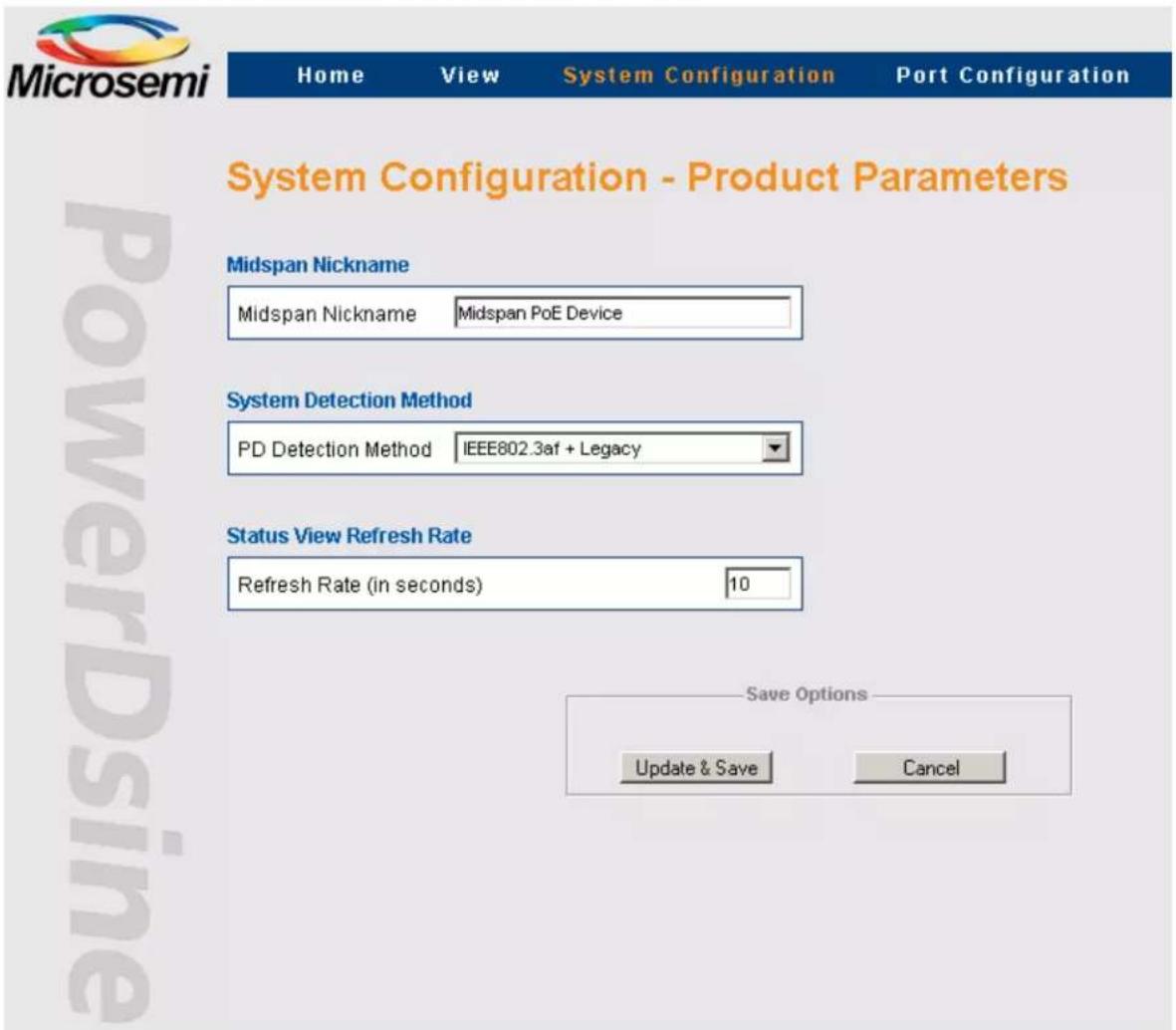
Use the System Configuration Product Parameters Screen to configure the following parameters as seen above:
- Midspan Nickname
• System Detection Method - Status View Refresh Rate
Table 3-18. System Configuration - Product Parameters Screen Field/Button Description (65xx, 65xxG Family)
| Field/Button Description | |
| Midspan NicknameMidspan Nickname Midspan PoE Device | Assists network managers to identify a Midspan by assigning a unique name for each Midspan device. Midspan nickname is displayed when browsing to view->status web page, or accessing the Midspan through Serial / Telnet / SSH |
| ......continued | |
| Field/Button Description | |
| System Detection MethodPD Detection Method IEEE802.3af + Legacy | • IEEE 802.3af• IEEE 802.3af + Legacy (default) |
| Status View Refresh RateRefresh Rate (in seconds) 10 | Set refresh rate for View System Status web page. |
| Update & Save | Updates Midspan product based parameters.All the product parameters become effective only after this button has been clicked! |
| Cancel | Cancels current operation and restores previous values |
3.3.15 System Configuration - Product Parameters: 90xxG Family
Figure 3-59. System Configuration Product Parameters Screen

Product parameters set by the user include the following as seen above:
• System Detection Method
- Other vendors pre 802.3at PD (as Cisco 125x access points)
• Extended Power Mode
• Power Backup Mode
- Midspan Nickname
- Status View Refresh Rate
Table 3-19. System Configuration - Product Parameters Screen Field/Button Description (90xxG Family)
| Field/Button Description | |
| PD Detection Method IEEE802.3af + IEEE802.3at + Legacy | PD Detection Method for 90xxG Midspan series:IEEE 802.3af + IEEE 802.3atIEEE 802.3af +IEEE 802.3at + Legacy |
| Enable pre 802.3at | Powers pre 802.3at PD devices including Cisco 125X access points. |
| Extended Power Mode (36W per port)Enable Extended Power Mode | Extend PD maximum power beyond 802.3at 30W to 36W. |
| Power Backup ModePower Backup Mode Redundancy | External Power Backup modeRedundancy: In this mode the external power source backs up the internal power supply of the Midspan.In case the internal power supply fails to operate, the external source will pick up the full load and all the ports will continue to function normally.Maximum Power: In this mode the external power source offers additional power on top of the power delivered by the internal power supply. For example, the PD-9024G/ACDC/M Midspan is using internal power supply of 430W, when external power source is connected in Max Power mode, the user available power will be 860W (430W internal + 430W external). |
| Midspan NicknameMidspan Nickname Midspan PoE Device | Assists network managers to identify a Midspan by assigning a unique name for each Midspan device.Midspan nickname is displayed when browsing to view->status web page, or accessing the Midspan by Serial / Telnet / SSH. |
| Status View Refresh RateRefresh Rate (in seconds) | Enables Setting of System Status WEB page refresh rate. |
| Update & Save | Updates Midspan product based parameters.All the product parameters become effective only after this button has been clicked! |
| Cancel | Cancels current operation and restores previous values. |
3.3.16 System Configuration - Product Parameters: 95xxG Family
Figure 3-60. System Configuration Product Parameters Screen

Product parameters set by the user include the following as seen above:
• System Detection Method
- Extended Power Mode
- Power Backup Mode
- Unit maximum power Vs Unit Temperature (see note bellow)
- Midspan Nickname
- Status View Refresh Rate
• Temperature Format (Fahrenheit/Celsius)
Note: Please uncheck 'Unit maximum power Vs Unit Temperature' checkbox whenever connecting 95xxG Midspan to a redundant power source such as another Midspan.
Table 3-20. System Configuration - Product Parameters Screen Field/Button Description (95xxG Family)
| Field/Button Description | |
| System Detection Method PD Detection Method IEEE802.3af + IEEE802.3at + Legacy | PD Detection Method for 95xxG Midspan series: • IEEE 802.3af + IEEE 802.3at • IEEE 802.3af +IEEE 802.3at + Legacy |
| Extended Power Mode (72W per port) Enable Extended Power Mode | Extends PD maximum power beyond 2 x 802.3at 60 W to 72 W. |
| ......continued | |
| Field/Button Description | |
| Power Backup ModePower Backup Mode Redundancy | External Power Backup modeRedundancy: In this mode the external power source backs up the internal power supply of the Midspan. In case the internal power supply fails to operate, the external source picks up the full load and all the ports continue to function normally.Maximum Power: In this mode the external power source offers additional power on top of the power delivered by the internal power supply. For example, if the PD-9506G/ACDC/M Midspan uses a 430 W internal power supply, and an external power source is connected in Max Power mode, the user available power is 860 W (430 W internal + 430 W external) |
| Unit maximum power Vs Unit TemperatureEnable automatic unit maximum power reduction | Enables the Midspan to automatically lower the maximum power that can be provided by the unit whenever internal unit temperature becomes too high (typically due to improper cooling). |
| Midspan NicknameMidspan Nickname Midspan PoE Device | Assists network managers to identify a Midspan by assigning a unique name for each Midspan device. Midspan nickname is displayed when browsing to view->status web page, or accessing the Midspan by Serial / Telnet / SSH. |
| Status View Refresh RateRefresh Rate (seconds) 10 | Sets the View System Status WEB page refresh rate. |
| Temperature Format (Fahrenheit / Celcius)Temperature format Fahrenheit | Reports the Midspan temperature in View System Status WEB page in Fahrenheit or Celsius |
| Update & Save | Updates Midspan product based parameters.Note: All product parameters become effective only after clicking this button! |
| Cancel | Cancels current operation and restores previous values |
3.3.17 System Configuration – Product Parameters: 96xxG Family
Figure 3-61. System Configuration Product Parameters Screen

Product parameters set by the user include the following as seen above:
• System Detection Method
• Power Backup Mode
- Unit maximum power Vs Unit Temperature (see note bellow)
- Midspan Nickname
• Status View Refresh Rate
• Temperature Format (Fahrenheit/Celsius)
Note: Uncheck 'Unit maximum power Vs Unit Temperature' checkbox whenever connecting 96xxG Midspan to a redundant power source such as another Midspan.
Table 3-21. System Configuration - Product Parameters Screen Field/Button Description (96xxG Family)
| Field/Button Description | |
| System Detection MethodPD Detection Method HDBaseT PoH | PD Detection Method for 96xxG Midspan series:• HDBaseT PoH• HDBaseT PoH + Legacy (power also older pre PoH HDBase-T devices) |
| ......continued | |
| Field/Button Description | |
| Power Backup ModePower Backup Mode Redundancy | External Power Backup modeRedundancy: In this mode the external power source backs up the internal power supply of the Midspan. In case the internal power supply fails to operate, the external source picks up the full load and all ports continue to function normally.Maximum Power: In this mode the external power source offers additional power on top of the power delivered by the internal power supply. For example, if the PD-9606G/ACDC/M Midspan uses a 950W internal power supply, and an external power source is connected in Max Power mode, the user available power is 1900W (950W internal + 950W external) |
| Unit maximum power Vs Unit TemperatureEnable automatic unit maximum power reduction | Enables the Midspan to automatically lower the maximum power that unit can provide whenever internal unit temperature becomes too high (typically due to improper cooling). |
| Midspan NicknameMidspan Nickname Midspan PoE Device | Assists network managers to identify a Midspan by assigning a unique name for each Midspan device. Midspan nickname is displayed when browsing to view->status web page, or accessing the Midspan by Serial / Telnet / SSH. |
| Status View Refresh RateRefresh Rate (seconds) 10 | Sets the View System Status WEB page refresh rate. |
| Temperature Format (Fahrenheit / Celcius)Temperature format Fahrenheit | Reports the Midspan temperature in View System Status WEB page in Fahrenheit or Celsius |
| Update & Save | Updates Midspan product based parameters.Note: All product parameters become effective only after clicking this button! |
| Cancel | Cancels current operation and restores previous values |
3.3.18 System Configuration – Product Parameters: 55xxG Family
Figure 3-62. System Configuration Product Parameters Screen

Product parameters set by the user include the following as seen above:
• System Detection Method
- Extended Power Mode
- Power Backup Mode
- Unit maximum power Vs Unit Temperature (see note bellow)
- Midspan Nickname
- Status View Refresh Rate
• Temperature Format (Fahrenheit/Celsius)
Note: Please uncheck 'Unit maximum power Vs Unit Temperature' checkbox whenever connecting 55xxG Midspan to a redundant power source such as another Midspan.
Table 3-22. System Configuration - Product Parameters Screen Field/Button Description (55xxG Family)
| Field/Button Description | |
| System Detection MethodPD Detection Method IEEE802.3af + IEEE802.3at + Legacy | PD Detection Method for 55xxG Midspan series:IEEE 802.3af + IEEE 802.3atIEEE 802.3af +IEEE 802.3at + Legacy |
| Extended Power Mode (36W per port)Enable Extended Power Mode | Extend PD maximum power beyond 802.3at 30W to 36W. |
| ......continued | |
| Field/Button Description | |
| Power Backup ModePower Backup Mode Redundancy | External Power Backup modeRedundancy: In this mode the external power source backs up the internal power supply of the Midspan. In case the internal power supply fails to operate, the external source picks up the full load and all the ports continue to function normally.Maximum Power: In this mode the external power source offers additional power on top of the power delivered by the internal power supply. For example, if the PD-5524G/ACDC/M Midspan uses a 430W internal power supply, and an external power source is connected in Max Power mode, the user available power is 860W (430W internal + 430W external) |
| Unit maximum power Vs Unit TemperatureEnable automatic unit maximum power reduction | Enables the Midspan to automatically lower the maximum power that can be provided by the unit whenever internal unit temperature becomes too high (typically due to improper cooling). |
| Midspan NicknameMidspan Nickname Midspan PoE Device | Assists network managers to identify a Midspan by assigning a unique name for each Midspan device. Midspan nickname is displayed when browsing to view->status web page, or accessing the Midspan by Serial / Telnet / SSH. |
| Status View Refresh RateRefresh Rate (seconds) 10 | Sets the View System Status WEB page refresh rate. |
| Temperature Format (Fahrenheit / Celcius)Temperature format Fahrenheit | Reports the Midspan temperature in View System Status WEB page in Fahrenheit or Celsius |
| Update & Save | Updates Midspan product based parameters.Note: All product parameters become effective only after clicking this button! |
| Cancel | Cancels current operation and restores previous values |
3.3.19 System Configuration Maintenance
System Configuration Maintenance screen offers the following options as seen in the figure below:
- Reset Manager Module
- Reset Unit
- Restoring Factory Defaults
Figure 3-63. System Configuration - Maintenance Screen
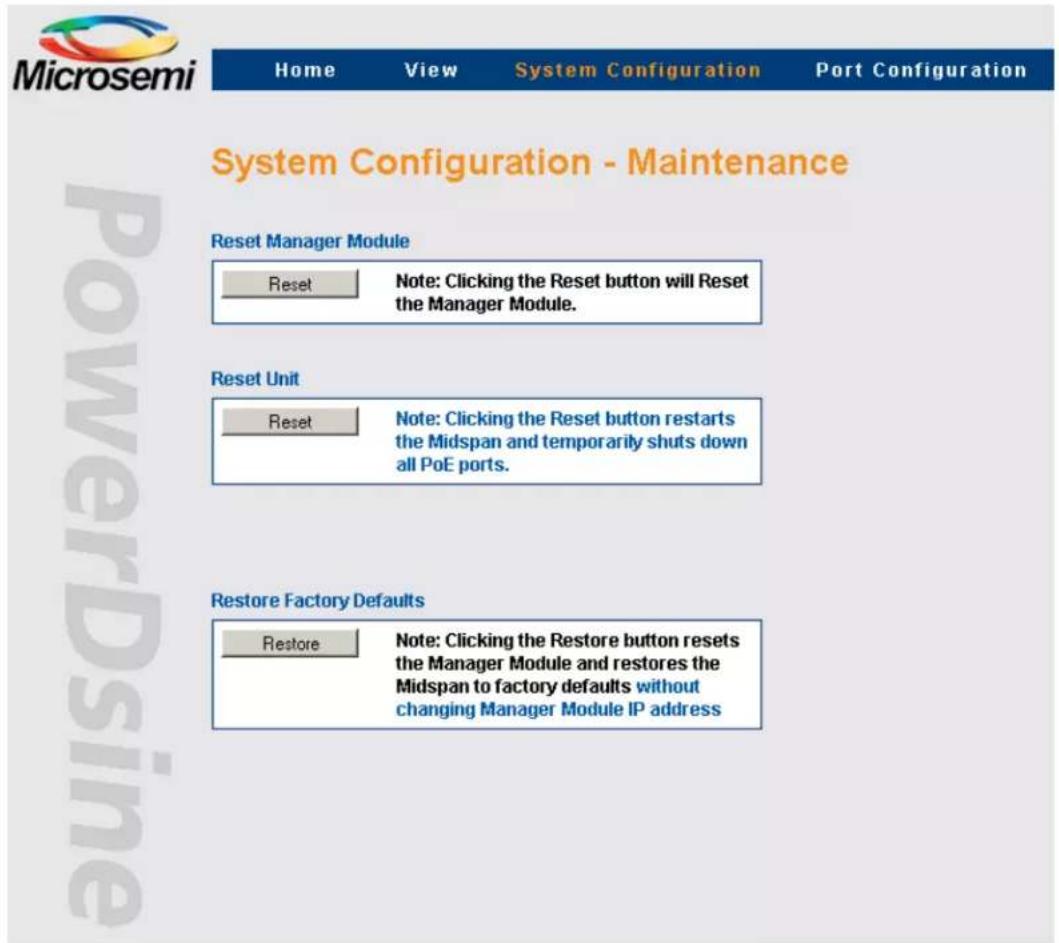
Table 3-23. System Configuration - Maintenance Screen Field/Button Description
| Field/Button Description | |
| Reset Manager Module Reset Note: Clicking the Reset button will Reset the Manager Module. | Resets only the Manager Module without affecting Midspan PoE ports |
| Reset Unit Reset Note: Clicking the Reset button restarts the Midspan and temporarily shuts down all PoE ports. | Resets entire unit. All active PoE ports momentarily stop providing power to PoE devices (configuration does not change) |
| Restore Factory Defaults Restore Note: Clicking the Restore button resets the Manager Module and restores the Midspan to factory defaults without changing Manager Module IP address | Restore most Midspan parameters to their default value (IP isn't changed) |
3.4 Port Configuration Screen
Port Configuration menu enables the following:
- Port Configuration Enable/Disable: Provides a quick access to enable/disable one or more PoE ports.
- Port Configuration Detailed: Enables detailed configuration of various PoE port values such as priority, allocated power and port/PD description.
- Port Configuration – Weekly Schedule: Enables the user to configure weekly scheduled ports activation/deactivation.
Figure 3-64. Port Configuration Screen

3.4.1 Port Configuration - Enable/Disable
All ports or Individual ports can be enabled or disabled in one action.
Disabled ports are marked with a red cross on the RJ-45 port; refer to Section 3.3.4.1 Ports Status Panel.
Figure 3-65. Port Configuration - Enable/Disable Screen
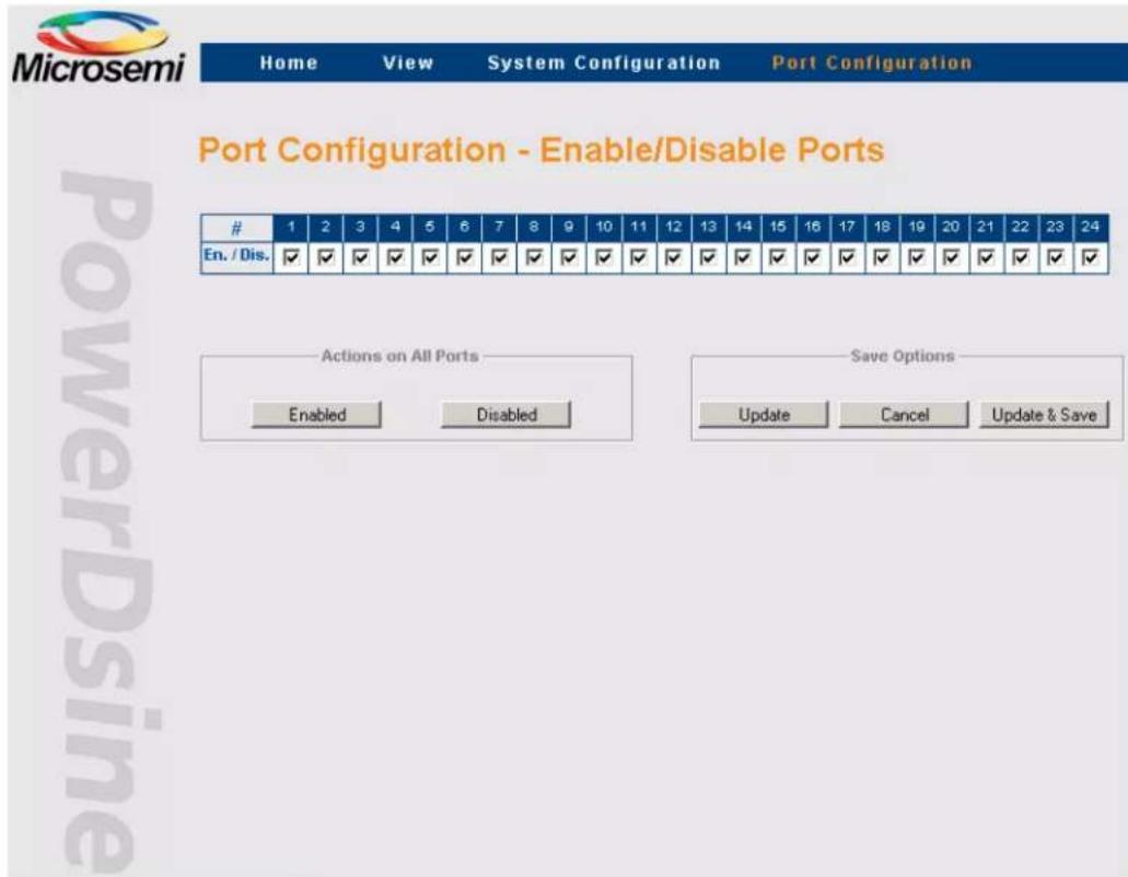
Table 3-24. Port Configuration - Enable/Disable Screen Button Description
| Button Description | |
 | Enabled: Enables all portsDisabled: Disables all portsNote: Only WEB page is effected |
 | Update: Clicking this button, activates the new user settings but does not store new configuration (unit reset overrides latest changes)Cancel: Cancels current operation and restores previous values in cases where Update & Save were not clickedUpdate & Save: Activates new setting and save updated configuration in cases where Midspan restarts. |
Note: If only the Update button is pressed, a blinking image appears near the Update & Save button, reminding the user that latest changes were not saved. Reversing latest changes and pressing Update, eliminates the blinking image. Saving latest changes eliminates this image as well.
3.4.2 Port Configuration – Detailed
The Port Configuration Detailed screen enables the user to control individual ports and set-up parameters as follows:
- Enable/Disable individual PoE ports
- Provide power to PD device over two/four pair (applicable only for 95xxG/55xxG)
- Enable EEPoE for Energy efficient (applicable only for 55xxG)
- Enable PoH/802.3 at (applicable only for 96xxG)
- Set-up the priority of each port
- Allocate maximal power per port
- Add port description
Figure 3-66. Port Configuration Detailed Screen (65xx, 65xxG, 90xxG Family)
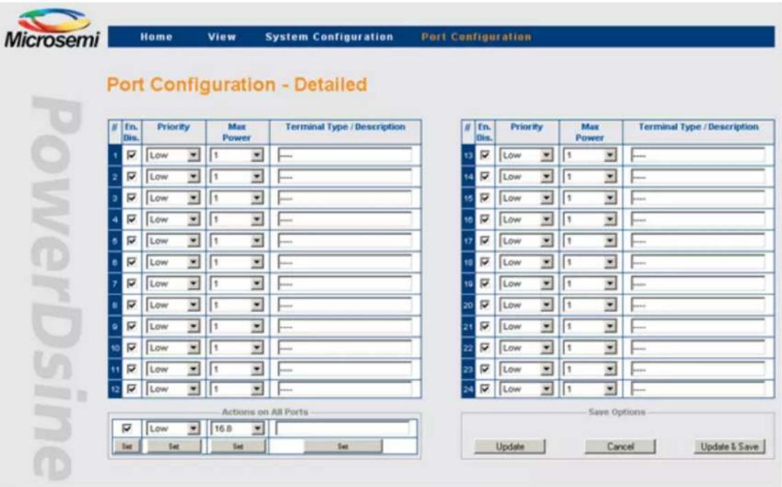
Figure 3-67. Port Configuration Detailed Screen (95xxG Family)

Figure 3-68. Port Configuration Detailed Screen (96xxG Family)

Figure 3-69. Port Configuration Detailed Screen (55xxG Family)

Figure 3-70. Port Configuration Detailed Screen (55xxG Family)

To simplify the configuration of multiple ports, each parameter can be set by pressing a single button (SET), thus applying the selected values to all ports (action on all ports). See Actions on All Ports area on the lower left part of the web page as seen in the figures above.
Notes:
• 1. Midspan 65xxG series enables up to 16.8 watts per port.
• 2. Midspan 90xxG/55xxG series enables up to 30/36 watts per port.
• 3. Midspan 95xxG series enables up to 60/72 watts per port.
• 4. Midspan 96xxG series enables up to 60 (802.3at)/95 (PoH) watts per port.
Ports activation/deactivation is performed by the user according to actual requirements. Each PoE port can be switched to Enable or Disable state.
- Two Pair/Four Pair (95xxG Midspan family)
- Power PD device over two pair (for example traditional 802.3af/802.3at Midspan), or over four pair offering twice the 802.3at power (60/72 W).
3.4.2.2 EEPoE (55xxG Midspan family)
Power PD device over two pair (for example traditional 802.3af/802.3at Midspan), or over four pair offering energy efficient power for up to 36W.
3.4.2.3 PoH (96xxG Midspan Family)
Power HDBase-T PoH PD device over four pairs for up to 95W, or 802.3at device over four pairs for up to 60W.
Setting Priority
The user can assign priorities to desired PDs in cases where the Midspan is operating with a limited source of power. Priority selection is performed from the drop-down menu, located on the Priority column; three priority states are available:
• Critical
• High
- Low (default)
The Midspan allocates all available power to the PDs, according to the PoE ports sequential number, starting from port #1 up to port #24. Critical ports are powered first, followed by High Priority ports. Low priority ports are powered last. A blinking LED indicates that a port is not powered due to lack of power.
3.4.2.4 Allocating Maximum Power
Power allocation is performed by selecting the maximum allowed power per port from the drop-down menu, located on the Max. Power column. Available power values are:
- 65xx: Minimum = 1W, Maximum = 16.8W, Default = 16.8W
- 65xxG: Minimum = 1W, Maximum = 16.8W, Default = 16.8W
- 90xxG: Minimum = 1W, Maximum = 30/36W, Default = 36W
- 95xxG: Minimum = 1W, Maximum = 60/72W, Default = 72W
• 96xxG: Fixed 95W for PoH or 60W for 802.3at - 55xxG: Minimum = 1W, Maximum = 30/36W, Default = 36W
3.4.2.5 Terminal Type / Description
In this column, the operator can enter any free text such as: terminal location, name of user, telephone number, etc. representing the corresponding port. Note that the column has no effect on power itself and it functions as an assistance tool for the IT manager.
Pressing on the RJ45 icon, or the i icon will cause detailed Port Information web page to appear, showing Terminal Type name, and additional information described in the image below.
Figure 3-71. Detailed Port Information

3.4.3 Port Configuration - Weekly Schedule
The Weekly Schedule feature performs an automatic activation/deactivation of PoE ports based on a weekly activation matrix (24 x 7). Activation/Deactivation of PoE ports may be required to save power saving during weekends, for security reasons (for example turns off wireless access points during weekends, disconnect unused IP Phones, or reduce power consumption), or even to reset periodically various PoE PD devices.
Four 24 x 7 weekly schedules schemes are available. Each 24 x 7 scheme manages its own PoE ports, which enables different PoE ports to be turned on/off on different days and hours.
Note: If the same PoE port was assigned to be managed by two different 24x7 schemes, it will be turned on whenever the port becomes enabled by one of the 24x7 weekly schedule scheme.
Prior to using this feature, the user should:
- Set the NTP (Network Time Protocol) Server IP address
- Set the GMT local time offset
- Update at least one out of four 24 × 7 hour matrixes to match the user specific needs
- Assign the Midspan PoE ports to be automatically turned On/Off
- Assign the PoE ports that provide power continuously
Figure 3-72. Port Configuration – Weekly Schedule

Notes:
- For Weekly Schedule feature to work properly, the Midspan must have an access to NTP Server (Network Time Protocol Server).
- Upon updating the weekly schedule NTP configuration by pressing the Update & Save button, the user should wait for a few seconds, refresh the WEB page and verify that green OK indication appears alongside the local time section (meaning that GMT time had been properly acquired).
3.4.3.1 Weekly Schedule Ports Activation
- Enable Weekly Schedule: Enables/disables the Weekly Schedule feature
- Enable Manual Override: Enables/disables the Manual Override key and selects the port assigned as an override key
- Remote NTP Server: Remote NTP (Network Time Protocol) Server IP address
• GMT Offset: User configured GMT offset
- Ports On/Off Weekly Schedule: 24 hours, 7 days checkbox matrix. The Midspan provides power only during the selected (checked) hours
Note: To simplify the configuration of the 24 x 7 matrix, the user can check all 24 ports for a specific day by checking one of the 'ALL' checkboxes.
- Ports Assigned for Automatic Weekly Schedule Activation: Selection of the ports to be activated/de activated automatically by the weekly schedule feature.
Note: Disabled ports cannot be assigned for the Weekly Schedule, even if selected by the user.
Table 3-25. Weekly Schedule Icons Reported by View-Status Web Page
| Icon/Image type Description | |
 | PoE port was Enabled by weekly schedule functionality |
 | PoE port was Disabled by weekly schedule functionality |
 | PoE port was assigned to act as deactivation key. |
4. Midspan 90xxG, 95xxG, 55xxG, 96xxG – Power Backup and Power Management
Midspan 90xxG, 95xxG, 96xxG, 55xxG series can be connected to an external redundant power source or to a secondary 90xxG, 95xxG, 96xxG, 55xxG Midspan. The same internal power supply unit must be installed in both units.
Figure 4-1. External Power Backup
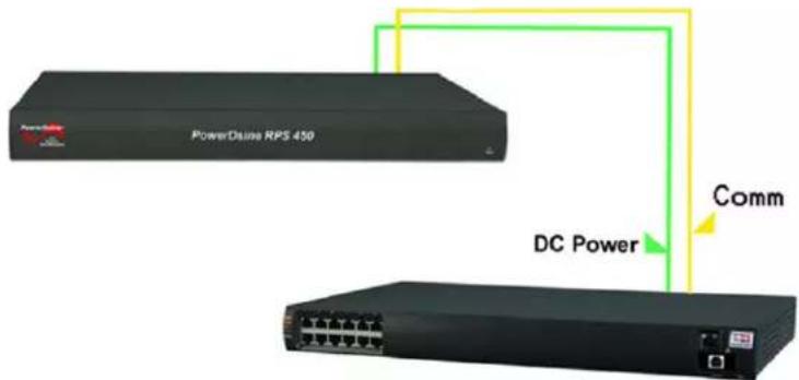
Figure 4-2. Secondary Midspan Power Backup

The table below lists the various connectivity options.
Table 4-1. Power Backup Connectivity Options
| Power Backup Type | ||||||||||||
| Midspan Type | RPS - 450 | RPS - 1000 | PD-90 06G / ACDC/M | PD-90 12G / ACDC/M | PD-902 4G / ACDC/M | PD-9024 G / ACDC/M/F | PD-95 06G / ACDC/M | PD-95 12G / ACDC/M | PD-95 24G / ACDC/M | PD-552 4G / ACDC/M | PD-960 6G / ACDC/M | PD-961 2G / ACDC/M |
| PD-9006G/ ACDC/M | √ √ | √ √ | √ | √ | ||||||||
| PD-9012G/ ACDC/M | √ √ | √ √ | √ | √ | ||||||||
| PD-9024G/ ACDC/M | √ √ | √ √ | √ | √ | ||||||||
| PD-9024G/ ACDC/M/F | √ | √ | √ | √ | √ | √ | ||||||
| ......continued | |||||||||||
| Power Backup Type | |||||||||||
| PD-9506G/ACDC/M | √√ | √√ | √ | √ | |||||||
| PD-9512G/ACDC/M | √ | √ | √ | √ | √ | ||||||
| PD-9524G/ACDC/M | √ | √ | √ | √ | √ | ||||||
| PD-5524G/ACDC/M | √√ | √√ | √ | √ | |||||||
| PD-9606G/ACDC/M | √ | √ | √ | √ | √ | ||||||
| PD-9612G/ACDC/M | √ | √ | √ | √ | √ | ||||||
SNMP RFC3621 MIB and private MIB Object IDs which apply to unit power supply capabilities or total power consumption are reported as if the two Midspans are one. The table below summarizes the affected SNMP Object IDs.
Table 4-2. SNMP Object IDs Affected by Midspan Power Backup Mode Connection
| SNMP Object ID Power Backup Mode | |
| pethMainPsePower (RFC3621) 430W/950W (Power backup mode = Redundant)860W/1900W (Power backup mode = Maximum Power) | |
| pethMainPseOperStatus(RFC3621) | Fault in case of power failure (Midspan is powered by 2nd Midspan). |
| pethMainPseConsumptionPower(RFC3621) | Total power consumption of both Midspans. |
| pethMainPseUsageThreshold (RFC3621) Sends a trap whenever both Midspan power consumption exceeds xy% out of pethMainPsePower OiD (total available power by both Midspans) power. | |
| mainPowerUsageBudget (private MIB) Changing power usage budget (%) in one Midspan will change it in the 2nd Midspan as well. | |
| mainPSE_MaxPower (private MIB) Total maximum power of both Midspans after it was reduced by pethMainPseUsageThreshold (%). | |
4.1 Viewing the Power Source Status
View the external power source status (Ok/Fail) and power source type (Midspan) in the View-Status Web page as seen in the figure below. Refer to Section 3.3 View Menu for details on View - Status Screen.
Figure 4-3. Power Source Status
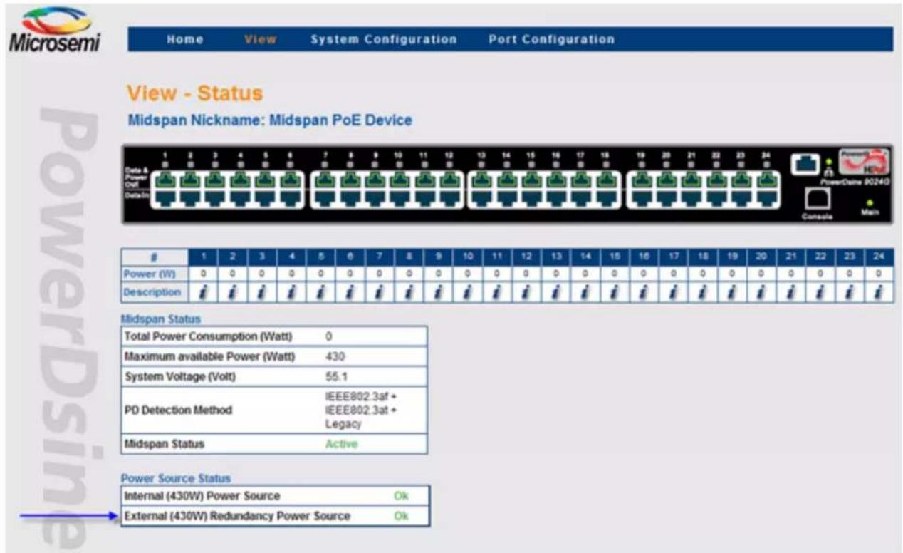
4.2 Dual 90xxG, 95xxG, 96xxG, 55xxG Midspan Power Backup
Connecting a Midspan 90xxG, 95xxG, 55xxG to a second 90xxG, 95xxG, 96xxG, 55xxG Midspan provides power backup by enabling the Midspan to be powered by its internal power source and from second Midspan power source. Two power backup modes are available, Redundancy and Maximum Power. Power-Shift feature enables shifting power from one Midspan to another whenever one Midspan requires more power and the second Midspan has spare unused power.
- Redundancy: A single Midspan internal power source has to power both Midspans in case of a power failure in one Midspan unit. The power sum of both Midspans cannot exceed 430/950 watts. Each Midspan's initial maximum power is set to 430/2 = 215 watts or 950/2 = 475 watts (the maximum power may change during normal operation).
- Maximum Power: The first Midspan power source capabilities are added to second Midspan's internal power source capabilities. Two Midspans having a 430 watt power supply can now provide 860 watts, while two Midspans having a 950 watt power supply can provide up to 1900 watts.
Notes:
- Changing power-backup mode in one of the Midspan's will cause 2nd Midspan power-backup mode to be changed to same power backup mode.
- When two stand alone Midspans are configured to different power-backup modes, after being connected together both Midspans will switch to Redundant power-backup mode.
4.2.1 Midspan 90xxG/95xxG/96xxG/55xxG to Midspan 90xxG/95xxG/96xxG/55xxG Power Shift
Figure 4-4. View - Status Window (Power Shift Display)

Whenever two 90xxG, 95xxG, 96xxG, or 55xxG Midspans powers back up each other, two additional rows are added to the View - Status web page. The first additional row displays the extended Midspan power consumption and maximum power. The second row reports total power consumption and total maximum power.
The figure above describes two PD-9024G/ACDC/M Midspans backing up each other, while in Redundancy Power-Backup mode. Total power of both Midspans is limited to 430 watts (due to redundant mode configuration). Local Midspan maximum power was reduced by the Midspan power manager to 179 watts, while external Midspan maximum power was increased to 251 watts.
4.2.2 Changing Power Limit (%) by SNMP
Midspan maximum power can be limited by SNMP private MIB Object-Id mainPowerUsageBudget, or by Midspan itself whenever Dynamic UPS Power Management is enabled.
Power shift between two 90xxG, 95xxG, 55xxG Midspans pauses whenever the power limit (%) is less than 100% and resumes automatically whenever power limit will be restored back to 100%.
Note: Changing power-limit (%) in one of the 90xxG Midspan's will change automatically power-limit on 2nd Midspan to same value.
Figure 4-5. Midspan Power Limit by SNMP

The table below describes an example of two 9024G Midspans which back up each other in Redundant Mode and whose mainPowerUsageBudget SNMP OiD is changed from 100% to 70%.
Table 4-3. mainPowerUsageBudget SNMP OiD Vs Midspan Maximum Power
| mainPowerUsageBudget SNMP OiD | Midspan-1 Max Power | Midspan-2 Max Power | Total Power | Midspan Power Shift |
| Maximum Power (Power Limit = 100%) | 287 watts 143 watts 430 watts Enabled | |||
| Maximum Power (Power Limit = 70%) | 200 watts 100 watts 300 watts Pause (Power-Limit < 100%) | |||
4.2.3 Activating Dynamic UPS Power Management
Dynamic UPS Power Management feature should be configured only on a single 90xxG, 95xxG Midspan whenever two 90xxG, 95xxG Midspans power backup each other. When the configured Midspan detects a UPS power failure (UPS switched to battery), it will modify Power-Limit % as per the user configuration. A Power-Limit value on the 2nd 90xxG Midspan automatically follows a Power-Limit value of the Midspan which monitors the UPS over SNMP.
Note: The user should not change by SNMP private MIB mainPowerUsageBudget OiD while Dynamic UPS Power Management is enabled.
4.2.4 Power Failure and Invalid Midspan to Midspan Power Backup Connection Report
- Power failure: In case of a power failure in one 90xxG, 95xxG, 55xxG Midspan units, an SNMP trap (see SNMP private MIB) and SysLog message is sent to the SNMP Manager and SysLog manager, and an error message appears in View-Status web page. Another SNMP & SysLog message is sent whenever power is restored.
Note: Main Power LED will blink whenever 90xxG/95xxG/96xxG Midspan is being powered by an external Midspan due to internal power supply failure (no AC power).
- Invalid connection: The following behavior occurs in cases where a 90xxG, 95xxG, 55xxG Midspan having a 450 watt power supply is connected to another 90xxG, 95xxG, 96xxG, 55xxG Midspan having 1000 watt power supply:
- Both Midspans will reduce maximum power to 41 watts which should stop power to most PoE PD devices.
- A Midspan report invalid configuration by sending SNMP Trap & SysLog message.
- An error message appears on the View->Status Web page.
- A repeating error message will appear on Terminal/Telnet/SSH screen.
5. SNMP Monitoring and Configuration
Multiple Midspan devices management can be performed by using 3rd party standard network management tools such as HP Openview, IBM Tivoli or SNMPc (see the figure below).
Figure 5-1. SNMPc Network Management Tool

Note: Due to security concerns, when unit is shipped the SNMP is disabled. Prior to enabling SNMP, modify SNMP community strings and only then enable it.
5.1 Enabling Midspan SNMP
The Midspan manager module supports SNMPv1, SNMPv2c, and SNMPv3.
To use the SNMP:
-
Browse to the System Configuration SNMP or SNMPv3 Web page and verify that either one of them is enabled.
-
For SNMPv2c, browse to the System Configuration SNMP Web page. Make sure that community strings match your SNMP manager configuration.
-
For SNMPv3, browse to System Configuration SNMPv3 Web page and make sure username, authentication and privacy password and encryption method match your SNMP manager configuration.
-
Browse to SNMP Web page. Enable PoE MIB traps and set remote manager IP address in the Trap list.
5.2 SNMP MIBs
Several MIBs are supported by Midspan SNMP manager.
- RFC3621: Power Over Ethernet MIB which provides various management capabilities.
- Private MIB: Enhance PoE functionality beyond RFC3621 PoE MIB.
- RFC1213: MIB2 which provides general IPv4 network statistics, and information on the device being managed.
- Various SNMPv3 MIBs such as RFC3413, RFC3414, and RFC3415.
5.3 RFC3621 PoE MIB
Note: For a detailed PoE MIB description, please refer to Microchip's Technical Note – 132 the found on the Microchip Software Library which describes the PoE MIB functionality in detail.
RFC3621 PoE MIB is located under 1.3.6.1.2.1.105 SNMP MIB tree. The MIB is divided into 3 sections. The first section deals with PoE ports and provides functionality as Enable/Disable, read port status, class, etc. Each OiD is accessed as a two dimensional array table.
The second section deals with power source which is responsible to provide power to a group of PoE ports. It enables reading total power consumption, power supply status, etc.
The 3rd section enable/disables PoE traps to be sent to remote SNMP managers.
Figure 5-2. MIB Tree Structure
![graph TD A["iso (1)"] --> B["org (3)"] B --> C["dod (6)"] C --> D["internet (1)"] D --> E["mgmt (2)"] E --> F["mib-2 (1)"] F --> G["powerEthernetMIB (105)"] G --> H["pethPsePortTable"] H --> I["pethPsePortEntry"] I --> J["pethPsePortGroupIndex"] I --> K["pethPsePortIndex"] I --> L["pethPsePortAdminE…](/content/2026/06/1358640/images/7316ecce0523f604aee38b1a5afc1769338bfbacfabe60338151761b818c7186.jpg)
5.4 Private MIB
Midspan's private MIB extend RFC3621 PoE MIB with the following additional management functionalities as seen below:
Figure 5-3. MIBs Management Functionalities

Port Parameters
- Readout of each individual port's power consumption.
- Set maximum power that the PD device may consume.
- Read/Set provide power on two/four pairs (write applicable only for 95xxG,55xxG series).
System Parameters
- Resolves MIB-II SysobjID description.
- Read Power Supply voltage.
- Read/Set detection method (802.3af+at or 202.3af+at plus legacy).
- Read/Set Midspan power budget percentage (%). For example setting to 50% for Midspan with 400Watt capacity, limits Midspan power to 200 Watt.
- Power budget limitation will be canceled whenever the Midspan manager module is restarted, or the Midspan is turned off and on.
- 65xx, 65xxG - Midspan power budget cannot be set below 37 watts. Whenever configuring power budget in percentage (%), below 37 watt (e.g. 18% for a 200 watt unit), Midspan will report 18% regardless of user power budget configuration. For 400 watts units lowest power budget percentage is 9%.
- 90xxG, 95xxG, 96xxG, 55xxG – Midspan power budget cannot be set below 41 watts.
- Read internal Power Supply maximum power capabilities (regardless of power limitation).
Note:
Private MIB Object IDs which are applicable only for Midspan 90xxG, 95xxG, 96xxG, 55xxG:
- Enable/Disable support for various pre 802.3at PD devices (only 90xxG).
- Enable/Disable extended power. Extend PD maximum power to 36Watt or limit to 30Watt as per 802.3at specification (90xxG, 95xxG, 55xxG).
- Report power backup type - stand alone/2 nd Midspan/Invalid power backup device (90xxG, 95xxG, 96xxG, 55xxG)
- Report internal power source status (90xxG, 95xxG, 96xxG, 55xxG).
• Report external power source status (90xxG, 95xxG, 96xxG, 55xxG) - Midspan temperature (95xxG, 96xxG, 55xxG)
- Midspan temperature format – Celsius/Fahrenheit (95xxG, 96xxG, 55xxG).
6. Software Upgrade
The following sections describe how to upgrade the system software.
6.1 Software upgrade types
There are two types of software upgrades associated with the Power over Ethernet (PoE) Midspan:
- Midspan Manager Module Software: Updates Midspan management application (including all Web pages) that provide remote Network management capabilities.
- Midspan Firmware: Update firmware used to manage PoE Power ports (rarely required).
Figure 6-1. System Software Architecture

6.2 Midspan Manager Module Software Upgrade
Internal FLASH Memory Size Requirements
Only Network Management Modules with internal FLASH memory of 4MB can be upgraded to latest IPv6 compliant software version. Midspan products such as PD-90xxG, PD-95xxG, PD-96xxG, PD-55xxG and PD-65xxG have all internal FLASH memory of 4MB and can be easily upgraded to latest IPv6 compliant software version. In case you are using another Midspan, check memory FLASH size using one of the following methods:
- Browsing to unit view->product information web page with any web browser.
Mon Ver 1.07 (Jul 8 2009, 15:34:57), FLASH=4MB, MAC=00:05:5A:01:FE:78
Waiting 5 sec. Press '@' to enter MONITOR
• 2. Through the serial port (38400) by viewing the first message during power up.
• 3. By Serial/Telnet/SSH accessing to: view-> View application & Boot software version
Figure 6-2. Identifying Flash Memory Size
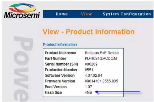
6.2.1 Upgrading from IPv4 to IPv6 (software version 3.xx to 4.xx)
All Network Management Module software versions starting with 3.xy (for example 3.47.10.23) are IPv4 only compliant. All Management Module software versions starting with 4.xy are IPv6 compliant (support both IPv4 & IPv6). When upgrading from v3.xy to v4.xy, same IPv4 address will be used (static IPv4 configuration), or in case DHCPv4 was in use, DHCPv4 will remain enabled. Same for other IP configuration parameters such as SNMP trap list, SysLog servers, RADIUS Servers, and NTP server.
Note: Active PoE ports are not affected by the software update (there is no intermediate power failure to PD devices).
6.2.2 Upgrading to Latest IPv6 Software Version (version 4.xx)
To obtain the latest version of the Microchip Midspan Network Management Module software, browse to http://www.microchip.com/Microchip/Support/Downloads/, or contact Customer.Care_AMSG@microchip.com.
6.2.3 Checklist Prior to Performing Software Update
- Make sure you can access the unit by Telnet or serial connection.
- For serial communication over USB, you need to install the USB virtual COM driver which can be found inside the Microchip Software Library.
- Verify Network connectivity by trying to browse or ping the Midpsan unit.
- Run TFTP server on the computer which has the latest Midpsan Network Manager Module software version. It is recommended to use the TFTP server application from the Microchip Software Library.
- Verify firewall is turned off, or enable firewall UDP port 69.
- Unzip the Network Management Module software version or copy it from the Microchip Software Library and place it in the root folder of the TFTP server as seen in the figure below.
Figure 6-3. TFTP Server Root Folder Setting
![d:\app\TFTP\* ↑Name [..] [application_4M] [web_files_4M] readme update_4M NBTFTP server Search Directories: D:\app\TFTP << ADD >>Remove Write Directory: D:\TEMP Enable Writes Start Minimized Status Finished About Exit](/content/2026/06/1358640/images/5f2f3d492bbb6951eab33d246154026d5bf44011ad0be877107415b455a17025.jpg)
Note: Active PoE ports will not be affected by the software update (no intermediate power failure to PD devices).
6.2.4 Performing software update
To upgrade the software:
- Make sure TFTP Server is running and proper files were copied to TFTP Server root folder.
- Connect to the Midspan unit by Telnet/SSH or serial interface, using HyperTerminal or any other serial communication software (38400, 1 stop bit, flow control off). Press ESC to access the main menu.
![Main Menu - [Midspan PoE Device] 1. View menu 2. Configuration & maintenance menu 3. Ping remote host E. Exit to debug information screen](/content/2026/06/1358640/images/c3209f4a3611b192d36acd80f7fece2b41d3b95d33c612e39d47689267400172.jpg)
- Select Configuration & Maintenance Menu (2). The following screen appears:
Configuration & Maintenance Menu
- Enable/Disable PoE Port
- Network configuration
- Download configuration file from TFTP Server (reset only Manager module)
- Upload configuration file to TFTP Server
- Download WEB SSL Certificate from TFTP Server (reset only Manager module)
- Software update menu
- Turn RADIUS, ACL Filter off. Restore all user & password to factory default
- Restore unit to factory default (excluding IP configuration)
-
Reset Manager module
A. Reset unit
B. Enable/Disable auto ping to Default Gateway to ensure Network connectivity
ESC - Return to previous menu -
Select the Software Update Menu; you will be asked to type the TFTP Server IP address. Type the appropriate TFTP server's IP address; the following screen appears:
Software Update Menu
- Update Midspan Manager module software (reset only Manager module)
- Update Midspan firmware (reset unit)
ESC - Return to previous menu
In the Software Update Menu:
- Select Update Midspan Manager Module Software. Software update will start by loading various files from TFTP server. At the end of the software update, Network Management Module will reset itself without effecting working PoE ports.
- Wait for software power up to finish, browse to the unit (or connect by serial) and verify software version number matches the software version you had upgraded to.
7. Troubleshooting
This paragraph provides a symptom and resolution sequence to assist in the troubleshooting of operating problems. If the steps given do not solve your problem, do not hesitate to call your local dealer for further assistance. Refer to the table below for a list of symptoms and their corresponding corrective steps.
Table 7-1. Troubleshooting Guide
| Symptom Corrective Steps | |
| AC LED does not illuminate (green). | 1. Check your power source.2. Ensure that a proper Ethernet cable is used. |
| Midspan Ethernet LINK LED is off. | In cases where a Network card (NIC) is connected directly to the Midspan's RJ45 connector, make sure you use a crossed Ethernet cable. |
| Midspan Ethernet LINK LED is on and no ping reply. | 1. Midspan is shipped with the following default IP 192.168.0.50. Change your Network card IP to 192.168.0.40 and try to Ping again.2. Connect to Midspan serial communication port and set Midspan IP to the same IP Network as your host computer.3. In case you switched very fast from one Midspan to another (both with default IP 192.168.0.50) erase IP address from your host ARP table. For winXP/Vista/Win7, open DOS window (start->run->cmd), and type arp -d 192.168.0.50. |
| Midspan can be ‘pinged’ from a local Host but when trying to use the Midspan Ping utility, there is no reply. | 1. Try to turn off host Firewall.2. If Ping is OK, access the advanced Firewall options and enable the Ping option and TFTP (UDP port 69), SNMP TRAP ports (UDP port 162). |
| Software update by TFTP cannot be performed. | 1. Use the Midspan Ping utility to ping the Host running the TFTP Server application.2. Turn off Firewall, or enable UDP port 69.3. Verify that appropriate update files package was copied to the TFTP Server root folder. |
| Unit cannot be accessed via Telnet. | Use Web browser to view System Configuration - Security screen and make sure under the Remote Access area, in the Enable Telnet/SSH list, Telnet is selected. For further information, see the section System Configuration Security. |
| When accessing the unit by Telnet, Telnet session is terminated each time the Configuration option is pressed. | Log-on to Telnet via the Administrator username & password option and not via the Viewer username & password. |
| Log-on to unit via Telnet is okay but Telnet session is terminated after a while. | Telnet session is terminated in case no key is pressed and no activity takes place for more than three minutes. |
| No SNMP TRAP events are received | 1. Use WEB browser to view System Configuration->Security WEB page and verify the SNMP checkbox is selected.2. Check System Configuration->SNMP WEB page and verify the remote SNMP manager IP matches and Trap community string matches the Remote SNMP manager Trap configuration.3. Turn of Firewall on SNMP manager station, or allow UDP port 162 to pass through it. |
| ......continued | |
| Symptom Corrective Steps | |
| SysLog Server IP was set properly, but Log messages are not received. | Turn off Host Firewall, or allow UDP port 514 to pass through it. |
| One of the ports was disabled but after turning the unit off and back on, it suddenly turned on again. | 1. When changing port status, verify the Save & Update button is pressed.2. Verify the PD is compatible to the detection method of the system. |
| When using a web Browser and accessing View – Status Web page, all ports are red illuminated and a question mark appears. | If Midspan does not provide power to PoE PDs, try to update the internal firmware. If the problem persists, contact technical support. |
| Weekly schedule was properly configured but PoE ports do not turn on/off in accordance with the weekly schedule scheme. | 1. Verify NTP Server IP address was configured properly.2. Verify the Time Zone Offset on the GMT window displays “Ok”.3. Verify your company's Firewall does not block outgoing/incoming NTP packets (UDP Port 123). |
| In cases where UPS operates on battery, Midspan does not turn off low priority ports. | 1. Browse to View – Status Web page and verify that UPS Power Management window does not display “???” in any one of the fields. If “???” appears, verify UPS dynamic management parameters are properly configured.2. Verify that Midspan SNMP configuration (SNMP v1 or SNMP v2) matches UPS SNMP agent capabilities. |
| Cisco's 1130AG and Cisco 1242G wireless access point shut down its radio while connected to L2/L3 Ethernet Switch through Midspan. | Add to Cisco wireless access point the following configuration line:power inline negotiation injector override |
| Not all Cisco's 125x wireless access point radio channels are operational. | Activate the Pre 802.3at feature (supported by Midspan 90xxG family). |
| Can't power PD devices when connecting 90xxG Midspan to 2nd 90xxG Midspan for power backup | Make sure you have not connected 90xxG Midspan capable of driving 1000W with 2nd Midspan capable of driving 450W.In case of such configuration, an error message will be reported constantly on the terminal/Telnet/SSH interface of both Midspan devices. |
| 90xxG Midspan was connected to another 90xxG Midspan but operates as a stand-alone Midspan | Make sure you have connected power cables and communication cable between first Midspan to second Midspan. |
The information contained in the document is PROPRIETARY AND CONFIDENTIAL information of Microchip and cannot be copied, published, uploaded, posted, transmitted, distributed or disclosed or used without the express duly signed written consent of Microchip. If the recipient of this document has entered into a disclosure agreement with
Microchip, then the terms of such Agreement will also apply. This document and the information contained herein may not be modified, by any person other than authorized personnel of Microchip. No license under any patent, copyright, trade secret or other intellectual property right is granted to or conferred upon you by disclosure or delivery of the information, either expressly, by implication, inducement, estoppels or otherwise. Any license under such intellectual property rights must be express and approved by Microchip in writing signed by an officer of Microchip.
Microchip reserves the right to change the configuration, functionality and performance of its products at anytime without any notice. This product has been subject to limited testing and should not be used in conjunction with life-support or other mission-critical equipment or applications. Microchip assumes no liability whatsoever, and Microchip disclaims any express or implied warranty, relating to sale and/or use of Microchip products including liability or warranties relating to fitness for a particular purpose, merchantability, or infringement of any patent, copyright or other intellectual property right. The product is subject to other terms and conditions which can be located on the web at http://www.microchip.com/legal/tnc.asp.
- Abbreviations
| Abbreviation Description | |
| IPv4 32 bit long IP address | |
| IPv6 128 bit long IP address | |
| DHCPv4 Dynamic IPv4 Host Configuration Protocol | |
| DHCPv6 Dynamic IPv6 Host Configuration Protocol | |
| PoE Power over Ethernet | |
| NTP Network Time Protocol | |
| DES Data Encryption Standard | |
| MD5 Message Digest algorithm 5 | |
| MDI Media Dependent Interface | |
| MIB Management Information Base | |
| PD Powered Device | |
| SNMP Simple Network Management Protocol | |
| SSL Secure Sockets Layer | |
| TFTP Trivial File Transfer Protocol | |
| SysLog System Log | |
| SSH Secure Shell | |
| RADIUS Remote Authentication Dial In User Service | |
| EEPoE Energy Efficient Power over Ethernet | |
| PoH | Power Over HDBaseT |
9. Related Documentation
For additional information, refer to the following documentation:
- Product user guide which can be found on the Microchip Software Library.
- Technical Note 132: Using RFC3621 PoE MIB with Microchip Midspans which can be found on the Microchip Software Library.
- Creating SSL Certificate for Midspan Secured Web Server User Guide which can be found on the Microchip Software Library.
- RFC3621 SNMP MIB, and private MIB which can be found on the Microchip Software Library.
- IEEE Standard 802.3af and DTE Power via MDI.
10. Revision History
| Revision Level/Date Para. Affected Description | ||
| A Whole Document The following changes were made in this revision: | ||
| Converted to Microchip format.Removed the RPS Power Backup section and references to RPS. | ||
| 1.1 Whole Document IPv6 support | ||
| 1.2 Whole Document Update Pictures | ||
| 1.3 4.2, 4.3, 4.4 Main Widow figures update | ||
| 1.4 9524G Midspan Added | ||
| 1.5 Whole Document 55xxG Midspan family Added | ||
| 1.6 Whole Document 96xxG Midspan family Added | ||
The Microchip Website
Microchip provides online support via our website at www.microchip.com/. This website is used to make files and information easily available to customers. Some of the content available includes:
- Product Support – Data sheets and errata, application notes and sample programs, design resources, user's guides and hardware support documents, latest software releases and archived software
- General Technical Support – Frequently Asked Questions (FAQs), technical support requests, online discussion groups, Microchip design partner program member listing
- Business of Microchip – Product selector and ordering guides, latest Microchip press releases, listing of seminars and events, listings of Microchip sales offices, distributors and factory representatives
Product Change Notification Service
Microchip's product change notification service helps keep customers current on Microchip products. Subscribers will receive email notification whenever there are changes, updates, revisions or errata related to a specified product family or development tool of interest.
To register, go to www.microchip.com/pcn and follow the registration instructions.
Customer Support
Users of Microchip products can receive assistance through several channels:
• Distributor or Representative
- Local Sales Office
- Embedded Solutions Engineer (ESE)
- Technical Support
Customers should contact their distributor, representative or ESE for support. Local sales offices are also available to help customers. A listing of sales offices and locations is included in this document.
Technical support is available through the website at: www.microchip.com/support
Microchip Devices Code Protection Feature
Note the following details of the code protection feature on Microchip devices:
- Microchip products meet the specifications contained in their particular Microchip Data Sheet.
- Microchip believes that its family of products is secure when used in the intended manner and under normal conditions.
- There are dishonest and possibly illegal methods being used in attempts to breach the code protection features of the Microchip devices. We believe that these methods require using the Microchip products in a manner outside the operating specifications contained in Microchip's Data Sheets. Attempts to breach these code protection features, most likely, cannot be accomplished without violating Microchip's intellectual property rights.
- Microchip is willing to work with any customer who is concerned about the integrity of its code.
- Neither Microchip nor any other semiconductor manufacturer can guarantee the security of its code. Code protection does not mean that we are guaranteeing the product is “unbreakable.” Code protection is constantly evolving. We at Microchip are committed to continuously improving the code protection features of our products. Attempts to break Microchip’s code protection feature may be a violation of the Digital Millennium Copyright Act. If such acts allow unauthorized access to your software or other copyrighted work, you may have a right to sue for relief under that Act.
Legal Notice
Information contained in this publication is provided for the sole purpose of designing with and using Microchip products. Information regarding device applications and the like is provided only for your convenience and may be superseded by updates. It is your responsibility to ensure that your application meets with your specifications.
THIS INFORMATION IS PROVIDED BY MICROCHIP "AS IS". MICROCHIP MAKES NO REPRESENTATIONS OR WARRANTIES OF ANY KIND WHETHER EXPRESS OR IMPLIED, WRITTEN OR ORAL, STATUTORY OR OTHERWISE, RELATED TO THE INFORMATION INCLUDING BUT NOT LIMITED TO ANY IMPLIED WARRANTIES OF NON-INFRINGEMENT, MERCHANTABILITY, AND FITNESS FOR A PARTICULAR PURPOSE OR WARRANTIES RELATED TO ITS CONDITION, QUALITY, OR PERFORMANCE.
IN NO EVENT WILL MICROCHIP BE LIABLE FOR ANY INDIRECT, SPECIAL, PUNITIVE, INCIDENTAL OR CONSEQUENTIAL LOSS, DAMAGE, COST OR EXPENSE OF ANY KIND WHATSOEVER RELATED TO THE INFORMATION OR ITS USE, HOWEVER CAUSED, EVEN IF MICROCHIP HAS BEEN ADVISED OF THE POSSIBILITY OR THE DAMAGES ARE FORESEEABLE. TO THE FULLEST EXTENT ALLOWED BY LAW, MICROCHIP'S TOTAL LIABILITY ON ALL CLAIMS IN ANY WAY RELATED TO THE INFORMATION OR ITS USE WILL NOT EXCEED THE AMOUNT OF FEES, IF ANY, THAT YOU HAVE PAID DIRECTLY TO MICROCHIP FOR THE INFORMATION. Use of Microchip devices in life support and/or safety applications is entirely at the buyer's risk, and the buyer agrees to defend, indemnify and hold harmless Microchip from any and all damages, claims, suits, or expenses resulting from such use. No licenses are conveyed, implicitly or otherwise, under any Microchip intellectual property rights unless otherwise stated.
Trademarks
The Microchip name and logo, the Microchip logo, Adaptec, AnyRate, AVR, AVR logo, AVR Freaks, BesTime, BitCloud, chipKIT, chipKIT logo, CryptoMemory, CryptoRF, dsPIC, FlashFlex, flexPWR, HELDO, IGLOO, JukeBlox, KeeLoq, Kleer, LANCheck, LinkMD, maXStylus, maXTouch, MediaLB, megaAVR, Microsemi, Microsemi logo, MOST, MOST logo, MPLAB, OptoLyzer, PackeTime, PIC, picoPower, PICSTART, PIC32 logo, PolarFire, Prochip Designer, QTouch, SAM-BA, SenGenuity, SpyNIC, SST, SST Logo, SuperFlash, Symmetricom, SyncServer, Tachyon, TimeSource, tinyAVR, UNI/O, Vectron, and XMEGA are registered trademarks of Microchip Technology Incorporated in the U.S.A. and other countries.
AgileSwitch, APT, ClockWorks, The Embedded Control Solutions Company, EtherSynch, FlashTec, Hyper Speed Control, HyperLight Load, IntelliMOS, Libero, motorBench, mTouch, Powermite 3, Precision Edge, ProASIC, ProASIC Plus, ProASIC Plus logo, Quiet-Wire, SmartFusion, SyncWorld, Temux, TimeCesium, TimeHub, TimePictra, TimeProvider, WinPath, and ZL are registered trademarks of Microchip Technology Incorporated in the U.S.A.
Adjacent Key Suppression, AKS, Analog-for-the-Digital Age, Any Capacitor, AnyIn, AnyOut, Augmented Switching, BlueSky, BodyCom, CodeGuard, CryptoAuthentication, CryptoAutomotive, CryptoCompanion, CryptoController, dsPICDEM, dsPICDEM.net, Dynamic Average Matching, DAM, ECAN, Espresso T1S, EtherGREEN, IdealBridge, In-Circuit Serial Programming, ICSP, INICnet, Intelligent Paralleling, Inter-Chip Connectivity, JitterBlocker, maxCrypto, maxView, memBrain, Mindi, MiWi, MPASM, MPF, MPLAB Certified logo, MPLIB, MPLINK, MultiTRAK, NetDetach, Omniscient Code Generation, PICDEM, PICDEM.net, PICkit, PICtail, PowerSmart, PureSilicon, QMatrix, REAL ICE, Ripple Blocker, RTAX, RTG4, SAM-ICE, Serial Quad I/O, simpleMAP, SimpliPHY, SmartBuffer, SMART-I.S., storClad, SQI, SuperSwitcher, SuperSwitcher II, Switchtec, SynchroPHY, Total Endurance, TSHARC, USBCheck, VariSense, VectorBlox, VeriPHY, ViewSpan, WiperLock, XpressConnect, and ZENA are trademarks of Microchip Technology Incorporated in the U.S.A. and other countries.
SQTP is a service mark of Microchip Technology Incorporated in the U.S.A.
The Adaptec logo, Frequency on Demand, Silicon Storage Technology, and Symmcom are registered trademarks of Microchip Technology Inc. in other countries.
GestIC is a registered trademark of Microchip Technology Germany II GmbH & Co. KG, a subsidiary of Microchip Technology Inc., in other countries.
All other trademarks mentioned herein are property of their respective companies.
© 2021, Microchip Technology Incorporated, Printed in the U.S.A., All Rights Reserved.
ISBN: 978-1-5224-8174-4
Quality Management System
For information regarding Microchip's Quality Management Systems, please visit www.microchip.com/quality.
Worldwide Sales and Service
AMERICAS ASIA/PACIFIC ASIA/PACIFIC EUROPE
| Corporate Office2355 West Chandler Blvd.Chandler, AZ 85224-6199Tel: 480-792-7200Fax: 480-792-7277Technical Support:www.microchip.com/supportWeb Address:www.microchip.comAtlantaDuluth, GATel: 678-957-9614Fax: 678-957-1455Austin, TXTel: 512-257-3370BostonWestborough, MATel: 774-760-0087Fax: 774-760-0088ChicagoItasca, ILTel: 630-285-0071Fax: 630-285-0075DallasAddison, TXTel: 972-818-7423Fax: 972-818-2924DetroitNovi, MITel: 248-848-4000Houston, TXTel: 281-894-5983IndianapolisNoblesville, INTel: 317-773-8323Fax: 317-773-5453Tel: 317-536-2380Los AngelesMission Viejo, CATel: 949-462-9523Fax: 949-462-9608Tel: 951-273-7800Raleigh, NCTel: 919-844-7510New York, NYTel: 631-435-6000San Jose, CASel: 408-735-9110Tel: 408-436-4270Canada - TorontoTel: 905-695-1980Fax: 905-695-2078 | Australia - SydneyTel: 61-2-9868-6733China - BeijingTel: 86-10-8569-7000China - ChengduTel: 86-28-8665-5511China - ChongqingTel: 86-23-8980-9588China - DongguanTel: 86-769-8702-9880China - GuangzhouTel: 86-20-8755-8029China - HangzhouTel: 86-571-8792-8115China - Hong Kong SARTel: 852-2943-5100China - NanjingTel: 86-25-8473-2460China - QingdaoTel: 86-532-8502-7355China - ShanghaiTel: 86-21-3326-8000China - ShenyangTel: 86-24-2334-2829China - ShenzhenTel: 86-755-8864-2200China - SuzhouTel: 86-186-6233-1526China - WuhanTel: 86-27-5980-5300China - XianTel: 86-29-8833-7252China - XiamenTel: 86-592-2388138China - ZhuhaiTel: 86-756-3210040 | India - BangaloreTel: 91-80-3090-4444India - New DelhiTel: 91-11-4160-8631India - PuneTel: 91-20-4121-0141Japan - OsakaTel: 81-6-6152-7160Japan - TokyoTel: 81-3-6880-3770Korea - DaeguTel: 82-53-744-4301Korea - SeoulTel: 82-2-554-7200Malaysia - Kuala LumpurTel: 60-3-7651-7906Malaysia - PenangTel: 60-4-227-8870Philippines - ManilaTel: 63-2-634-9065SingaporeTel: 65-6334-8870Taiwan - Hsin ChuTel: 886-3-577-8366Taiwan - KaohsiungTel: 886-7-213-7830Taiwan - TaipeiTel: 886-2-2508-8600Thailand - BangkokTel: 66-2-694-1351Vietnam - Ho Chi MinhTel: 84-28-5448-2100 | Austria - WelsTel: 43-7242-2244-39Fax: 43-7242-2244-393Denmark - CopenhagenTel: 45-4485-5910Fax: 45-4485-2829Finland - EspooTel: 358-9-4520-820France - ParisTel: 33-1-69-53-63-20Fax: 33-1-69-30-90-79Germany - GarchingTel: 49-8931-9700Germany - HaanTel: 49-2129-3766400Germany - HeilbronnTel: 49-7131-72400Germany - KarlsruheTel: 49-721-625370Germany - MunichTel: 49-89-627-144-0Fax: 49-89-627-144-44Germany - RosenheimTel: 49-8031-354-560Israel - Ra'ananaTel: 972-9-744-7705Italy - MilanTel: 39-0331-742611Fax: 39-0331-466781Italy - PadovaTel: 39-049-7625286Netherlands - DrunenTel: 31-416-690399Fax: 31-416-690340Norway - TrondheimTel: 47-72884388Poland - WarsawTel: 48-22-3325737Romania - BucharestTel: 40-21-407-87-50Spain - MadridTel: 34-91-708-08-90Fax: 34-91-708-08-91Sweden - GothenbergTel: 46-31-704-60-40Sweden - StockholmTel: 46-8-5090-4654UK - WokinghamTel: 44-118-921-5800Fax: 44-118-921-5820 |


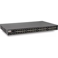
- POWER OVER ETHERNET AF/AT POWERVIEW PRO USER GUIDE
- INTRODUCTION
- TABLE OF CONTENTS
- INTRODUCTION TO POWER VIEW PRO (IPV4 AND IPV6)
- 1.1 FEATURES
- 1.2 SYSTEM CAPABILITIES
- 1.3 POE CAPABILITIES
- 1.4 CONFIGURATION OPTIONS
- 1.5 SECURITY AND USER AUTHENTICATION
- 1.5.1 WEB SECURITY
- 1.5.2 SNMP SECURITY
- 1.5.3 TELNET/SSH SECURITY
- INSTALLATION
- 2.1 SYSTEM REQUIREMENTS
- 2.2 HARDWARE SETUP
- 2.3 CONFIGURATION PROCEDURE
- 2.3.1 CONNECTING TO UNIT USING A WEB BROWSER
- 2.3.2 CONNECTING TO UNIT USING WINDOW'S TELNET
- 2.3.3 CONNECTING TO UNIT USING SERIAL PORT AND A HYPER TERMINAL APPLICATION
- 2.3.3.1 WINDOWS 2000 AND WINDOWS XP
- 2.3.3.2 WINDOWS VISTA / WINDOWS 7 / WINDOWS 10
- SELECT
- CLICK OPEN
- 2.3.4 CONNECTING VIA USB SERIAL COMMUNICATION VIRTUAL PORT
- 2.3.5 CONFIGURING THE SYSTEM VIA THE SERIAL PORT
- 2.3.5.1 USING THE VIEW MENU
- 2.3.5.2 USING THE CONFIGURATION & MAINTENANCE MENU
- 2.3.5.3 USING THE PING REMOTE HOST MENU
- 2.4 CONFIGURING THE TFTP SERVER
- NOTES
- WEB INTERFACE DESCRIPTION
- 3.1 OVERVIEW
- 3.2 OPENING SCREEN
- 3.3 VIEW MENU
- 3.3.1 VIEW - STATUS SCREEN 65XX, 65XXG MIDSPAN SERIES
- 1 2 3 4 5 6 7 8 9 10 11 12 13 14 15 16 17 18 19 20 21 22 23 24
- 3.3.2 VIEW - STATUS SCREEN 90XXG, 95XXG, 96XXG FOUR-PAIR HIGH POWER MIDSPAN SERIES
- 1 2 3 4 5 6 7 8 9 10 11 12
- 3.3.3 VIEW - STATUS SCREEN 55XXG ENERGY EFFICIENT HIGH POWER MIDSPAN SERIES
- 3.3.4 VIEW - STATUS SCREEN ELEMENTS
- 3.3.4.1 PORTS STATUS PANEL
- 3.3.4.2 MIDSPAN LED INDICATIONS
- 3.3.4.3 MIDSPAN STATUS TABLE
- 3.3.4.4 DETAILED PORT INFORMATION REPORT
- 1 2
- 3.3.4.5 MANUAL OVERRIDE KEY
- 3.3.4.6 WEEKLY SCHEDULED ACTIVATED PORT/S
- 3.3.5 VIEW - CONFIGURATION SUMMARY
- 3.3.5.1 IPV4 IN-USE
- 3.3.5.2 REMOTE SERVERS
- 3.3.5.3 DATE AND TIME
- 3.3.5.4 REMOTE TRAP SNMP MANAGERS LIST
- 3.3.5.5 REMOTE ACCESS & SECURITY
- 3.3.5.6 ADVANCED FEATURES
- 3.3.6 VIEW - PRODUCT INFORMATION
- 3.3.7 SYSTEM CONFIGURATION SCREEN
- 3.3.7.1 SYSTEM CONFIGURATION - NETWORK
- AUTO SERVICES CONFIGURATION BY DHCPV4
- 3.3.7.3 LOG SERVER
- 3.3.7.4 NTP SERVER
- 3.3.8 SYSTEM CONFIGURATION SNMP
- 3.3.8.1 SNMPV2C
- 3.3.8.2 SYSTEM INFORMATION (MIB-II, V2C/V3)
- 3.3.8.3 POE MIB (RFC3621, V2C/V3)
- 3.3.8.4 REMOTE TRAP SNMP MANAGERS LIST
- 3.3.9 SYSTEM CONFIGURATION SNMPV3
- 3.3.10 SYSTEM CONFIGURATION SECURITY
- 3.3.10.1 WEB SECURE ACCESS & CONFIGURATION
- 3.3.10.2 TELNET/SSH VIEW & CONFIGURATION
- VIEW MENU
- CONFIGURATION & MAINTENANCE MENU
- 3.3.10.3 REMOTE ACCESS
- 3.3.11 SYSTEM CONFIGURATION - RADIUS
- 3.3.11.1 CONFIGURING RADIUS SERVER TO PROVIDE VIEWER/ADMINISTRATOR A PRIVILEGED ACCESS
- 3.3.11.2 HOW TO DIFFERENTIATE BETWEEN TELNET/SSH/WEB RADIUS USERS
- 3.3.12 SYSTEM CONFIGURATION - DYNAMIC UPS POWER MANAGEMENT
- 3.3.12.1 UPS SNMP AGENT
- 3.3.12.2 CUSTOM UPS VENDOR SNMP OIDS
- 3.3.12.3 MIDSPAN MAX POWER VERSUS UPS BATTERY CHARGE LEVEL
- NOTE
- 3.3.13 SYSTEM CONFIGURATION - ACCESS LIST FILTER
- 3.3.13.1 ACL FILTER STATISTICS
- FIGURE 3-54. VIEW ACL FILTER PARAMETERS FROM VIEW MENU
- FIGURE 3-55. VIEW ACL FILTER PARAMETERS
- 1:HTTP:44 ,HTTPS:0 ,TELNET:0 ,SSH:0 ,SNMP:6
- 2:HTTP:0 ,HTTPS:0 ,TELNET:0 ,SSH:0 ,SNMP:0
- 3:HTTP:0 ,HTTPS:0 ,TELNET:0 ,SSH:0 ,SNMP:0
- 4:HTTP:0 ,HTTPS:0 ,TELNET:0 ,SSH:0 ,SNMP:0
- 5:HTTP:0 ,HTTPS:0 ,TELNET:0 ,SSH:0 ,SNMP:0
- 6:HTTP:0 ,HTTPS:0 ,TELNET:0 ,SSH:0 ,SNMP:0
- 7:HTTP:0 ,HTTPS:0 ,TELNET:0 ,SSH:0 ,SNMP:0
- 8:HTTP:0 ,HTTPS:0 ,TELNET:0 ,SSH:0 ,SNMP:0
- 9:HTTP:0 HTTPS:0 TELNET:0 SSH:0 SNMP:0
- 3.3.13.2 ACL FILTER CONFIGURATION EXAMPLE
- 3.3.14 SYSTEM CONFIGURATION - PRODUCT PARAMETERS: 65XX, 65XXG FAMILY
- 3.3.15 SYSTEM CONFIGURATION - PRODUCT PARAMETERS: 90XXG FAMILY
- 3.3.16 SYSTEM CONFIGURATION - PRODUCT PARAMETERS: 95XXG FAMILY
- 3.3.17 SYSTEM CONFIGURATION – PRODUCT PARAMETERS: 96XXG FAMILY
- 3.3.18 SYSTEM CONFIGURATION – PRODUCT PARAMETERS: 55XXG FAMILY
- 3.3.19 SYSTEM CONFIGURATION MAINTENANCE
- 3.4 PORT CONFIGURATION SCREEN
- 3.4.1 PORT CONFIGURATION - ENABLE/DISABLE
- 3.4.2 PORT CONFIGURATION – DETAILED
- EN. PRIORITY MAX TERMINAL TYPE / DESCRIPTION
- EN. FOUR
- EN. POLH MAX PRIORITY TERMINAL TYPE / DESCRIPTION
- EN. EEPOE PRIORITY MAX TERMINAL TYPE / DESCRIPTION
- 3.4.2.2 EEPOE (55XXG MIDSPAN FAMILY)
- 3.4.2.3 POH (96XXG MIDSPAN FAMILY)
- 3.4.2.4 ALLOCATING MAXIMUM POWER
- 3.4.2.5 TERMINAL TYPE / DESCRIPTION
- 3.4.3 PORT CONFIGURATION - WEEKLY SCHEDULE
- 3.4.3.1 WEEKLY SCHEDULE PORTS ACTIVATION
- MIDSPAN 90XXG, 95XXG, 55XXG, 96XXG – POWER BACKUP AND POWER MANAGEMENT
- 4.1 VIEWING THE POWER SOURCE STATUS
- 4.2 DUAL 90XXG, 95XXG, 96XXG, 55XXG MIDSPAN POWER BACKUP
- 4.2.1 MIDSPAN 90XXG/95XXG/96XXG/55XXG TO MIDSPAN 90XXG/95XXG/96XXG/55XXG POWER SHIFT
- 4.2.2 CHANGING POWER LIMIT (%) BY SNMP
- 4.2.3 ACTIVATING DYNAMIC UPS POWER MANAGEMENT
- 4.2.4 POWER FAILURE AND INVALID MIDSPAN TO MIDSPAN POWER BACKUP CONNECTION REPORT
- SNMP MONITORING AND CONFIGURATION
- 5.1 ENABLING MIDSPAN SNMP
- 5.2 SNMP MIBS
- 5.3 RFC3621 POE MIB
- 5.4 PRIVATE MIB
- PORT PARAMETERS
- SYSTEM PARAMETERS
- SOFTWARE UPGRADE
- 6.1 SOFTWARE UPGRADE TYPES
- 6.2 MIDSPAN MANAGER MODULE SOFTWARE UPGRADE
- 6.2.1 UPGRADING FROM IPV4 TO IPV6 (SOFTWARE VERSION 3.XX TO 4.XX)
- 6.2.2 UPGRADING TO LATEST IPV6 SOFTWARE VERSION (VERSION 4.XX)
- 6.2.3 CHECKLIST PRIOR TO PERFORMING SOFTWARE UPDATE
- 6.2.4 PERFORMING SOFTWARE UPDATE
- SOFTWARE UPDATE MENU
- ESC - RETURN TO PREVIOUS MENU
- TROUBLESHOOTING
- RELATED DOCUMENTATION
- REVISION HISTORY
- THE MICROCHIP WEBSITE
- PRODUCT CHANGE NOTIFICATION SERVICE
- CUSTOMER SUPPORT
- MICROCHIP DEVICES CODE PROTECTION FEATURE
- LEGAL NOTICE
- TRADEMARKS
- QUALITY MANAGEMENT SYSTEM
- WORLDWIDE SALES AND SERVICE
Brand : Microchip
Model : PD-9012G
Category : Network Equipment