
Bite5 - Battery charger Megger - Free user manual and instructions
Find the device manual for free Bite5 Megger in PDF.


| Product Type | Battery Charger / Analyzer |
| Brand | Megger |
| Model | Bite5 |
| Dimensions (approx.) | 250 x 200 x 100 mm |
| Weight (approx.) | 2 kg |
| Input Voltage | 100–240 V AC, 50/60 Hz |
| Output Voltage | 12 V / 24 V (selectable) |
| Max Charging Current | 5 A |
| Battery Compatibility | Lead-acid (AGM, GEL, Flooded), Lithium-ion |
| Charging Modes | Normal, Boost, Maintenance |
| Protection Features | Reverse polarity, overcharge, short circuit, over-temperature |
| Display | LCD screen (backlit) |
| Battery Capacity Range | 1.2 – 100 Ah |
| Operating Temperature | 0 °C to 40 °C (32 °F to 104 °F) |
| Storage Temperature | -20 °C to 60 °C (-4 °F to 140 °F) |
| IP Rating | IP20 (indoor use only) |
| Maintenance | Clean with dry cloth; avoid moisture and dust accumulation |
| Safety Certifications | CE, RoHS |
| Warranty | 2 years (subject to terms) |
| Included Accessories | AC power cord, battery clamps, user manual |
| Spare Parts Availability | Fuses, cables available from Megger support |
| Repairability | User-replaceable fuses; other repairs by authorized service |
Frequently Asked Questions - Bite5 Megger
User questions about Bite5 Megger
0 question about this device. Answer the ones you know or ask your own.
Ask a new question about this device
Download the instructions for your Battery charger in PDF format for free! Find your manual Bite5 - Megger and take your electronic device back in hand. On this page are published all the documents necessary for the use of your device. Bite5 by Megger.
USER MANUAL Bite5 Megger
Register
megger.com/register


User Guide

Support

megger.com/support

This document is copyright of:
Megger Limited, Archcliffe Road, Dover, Kent CT17 9EN. ENGLAND
T +44 (0)1304 502101 F +44 (0)1304 207342 www.megger.com
Megger Limited reserves the right to alter the specification of its products from time to time without notice. Although every effort is made to ensure the accuracy of the information contained within this document it is not warranted or represented by Megger Limited to be a complete and up-to-date description.
For Patent information about this instrument refer to the following web site: megger.com/patents
This manual supersedes all previous issues of this manual. Please ensure that you are using the most recent issue of this document. Destroy any copies that are of an older issue.
Declaration of Conformity
Hereby, Megger Instruments Limited declares that radio equipment manufactured by Megger Instruments Limited described in this user guide is in compliance with Directive 2014/53/EU. Other equipment manufactured by Megger Instruments Limited described in this user guide is in compliance with Directives 2014/30/EU and 2014/35/EU where they apply.
The full text of Megger Instruments EU declarations of conformity are available at the following internet address: megger.com/eu-dofc
Contents
1. Introduction......6
1.1 Product description ....6
1.2 Included with the BITE5....6
1.3 Applications....6
1.4 Company web site 6
2. Safety Warnings and Standards....7
2.1 Warnings, Cautions and Notes ....7
2.2 Safety warnings....7
2.3 Installation category definitions: 8
2.4 Safety, Hazard and Warning symbols on the instrument....8
3. Instrument Overview....9
3.1 Instrument layout....9
4. Zero adjustment....10
4.1 Zero adjustment procedure....10
5. Configuration of BITE5 ADVANCED ....11
6. Configuration of string....12
7. Performing a quick test (Meter Mode)....13
8. Performing an impedance test on a battery string. 15
9. Performing a NERC terminal mode impedance test on a battery string....17
10. Performing an impedance test on a parallel battery string....20
11. Performing a conductance test on a battery string....24
12. Performing an impedance test on a battery pack. 27
13. Measuring battery (DC) float and (AC) ripple voltages and currents 29
13.1 VA Meter Mode....29
14. Adding a Ripple (AC) Voltage, Ripple (AC) Current or a Float (DC) Current value to a string..32
15. Measuring voltages only on a battery string....34
16. Performing a discharge test ....37
17. Performing an impedance and discharge test (special testing)....40
18. Trending recorded data....43
18.1 Trending String Test Data 43
19. Trending Cell Test Data 45
20. Viewing a record 47
20.1 Viewing records....47
21. Deleting recorded meter data....49
21.1 Deleting Meter Ω and Meter VA Ω data....49
21.2 Deleting recorded string data 50
21.3 Deleting a string configuration....52
- Data Logging 53
22.1 Logging Data 53
22.2 Viewing a Recorded Data Log 55
- RFID Tags....57
23.1 Configuring a RFID tag. for new battery string configuration. 57
23.2 Configuring a RFID tag. for an existing battery string configuration. 59
- Saving a screen snapshot 61
- Noisy Strings. 62
- Specifications....63
- Accessories and Equipment....65
27.1 Included accessories....66
27.2 Optional accessories for Model A....66
27.3 Optional accessories for Model B 66
- Maintenance....67
28.1 Battery charging....67
28.1.1 Battery charging status icon 67
28.2 Cleaning and Storage....67
28.2.1 Unit Cleaning....67
28.2.2 Storage 67
28.2.3 Cleaning probes....67
- Calibration, Repair and Warranty 68
29.1 Calibration, Service and Spare Parts 68
29.2 Approved Repair Companies 69
29.3 Return procedure 69
- Decommissioning 70
30.1 WEEE Directive 70
30.2 Battery disposal 70
- Worldwide Sales Offices....71
Introduction
1. Introduction
This document is the user guide for the Megger BITE5 ADVANCED Battery Tester. It provides a description of the operation of the unit as well as operating instructions. Read this manual before installing or using the equipment. Special emphasis should be placed on all safety discussions.
1.1 Product description
The Megger BITE5 ADVANCED Battery Tester has been designed with emphasis on reliability, simplicity, and ease of use. It will provide you with the information you need to reliably test batteries.
1.2 Included with the BITE5
BITE5 ADVANCED battery tester
Duplex probes
Voltage leads
Charger
microSD card
- microSD card reader
Mini USB cable
Neck strap
Zero bar
Stylus
1.3 Applications
Battery testing
1.4 Company web site
Occasionally an information bulletin may be issued via the Megger web site. This may concern new accessories, new usage instructions or a software update. Please occasionally check on the Megger web site for anything applicable to your Megger instruments.
www.megger.com
2. Safety Warnings and Standards
WARNING : Death, serious injury, or fire hazard could result from improper use/installation of this instrument. Read and understand this user guide before installing this instrument.
Installation of this instrument MUST be performed in compliance with the National Electric Code and any additional safety requirements applicable to your installation.
Installation, operation, and maintenance of this instrument MUST be performed by qualified personnel only. The National Electrical Code defines a qualified person as one familiar with the construction and operation of the equipment and the hazards involved.
2.1 Warnings, Cautions and Notes
This user guide follows the internationally recognised definition. These instructions must be adhered to at all times.
Description
DANGER : Indicates a dangerous situation which, if ignored, could lead to death, serious injury or health problems.
WARNING : Indicates a potentially dangerous situation which, if ignored, could lead to death, serious injury or health problems.
ATTENTION : Indicates a dangerous situation which, if ignored, could lead to injuries or health problems.
CAUTION : Indicates a situation which could lead to damage of the equipment or environment
NOTE : Indicates important instructions to be followed to perform the relevant process safely and efficiently.
Icon Description


EN ISO 7010 P007
Interference to the operation of or damage to active implanted cardiac devices from this equipment which generates strong electromagnetic fields. No access for people with active implanted cardiac devices.
EN ISO 7010 W006
Warning of the presence of strong magnetic field.
EN ISO 7010 W001
Warning to consult the user instructions. Caution is necessary when operating the device or control close to where this symbol is placed, or to indicate that an operation needs operator awareness and protective action in order to avoid hazardous situations.
HIGH VOLTAGE,
Risk of electric shock
Earth/Ground
2.2 Safety warnings
The following safety precautions MUST be taken whenever the instrument is installed:
■ Wear safety glasses and insulated gloves when making connections to power circuits
■ Hands, shoes, floor/ground must be dry when making any connection to a powered line
Safety Warnings and Standards
2.3 Installation category definitions:
CAT IV - Measurement category IV: Equipment connected between the origin of the low-voltage mains supply and distribution panel.
CAT III -Measurement category III: Equipment connected between the distribution panel and electrical outlets.
CAT II - Measurement category II: Equipment connected between the electrical outlets and user's equipment.
Measurement equipment may be safely connected to circuits at the marked rating or lower. The connection rating is that of the lowest rated component in the measurement circuit.
2.4 Safety, Hazard and Warning symbols on the instrument
This paragraph details the various safety and hazard icons on the instrument's outer case.
| Icon Description | |
 | Warning: High Voltage, risk of electric shock |
 | Caution: Refer to user guide. |
 | UK conformity. This equipment complies with current UK legislation |
 | EU conformity. Equipment complies with current EU directives. |
 | Conforms to relevant Australian Safety and EMC standards |
 | Do not dispose of to landfill, in sewage systems or by fire. |
 | Equipment protected throughout by double insulation. |
 | Reference earth connection. Not a protective earth terminal |
3. Instrument Overview
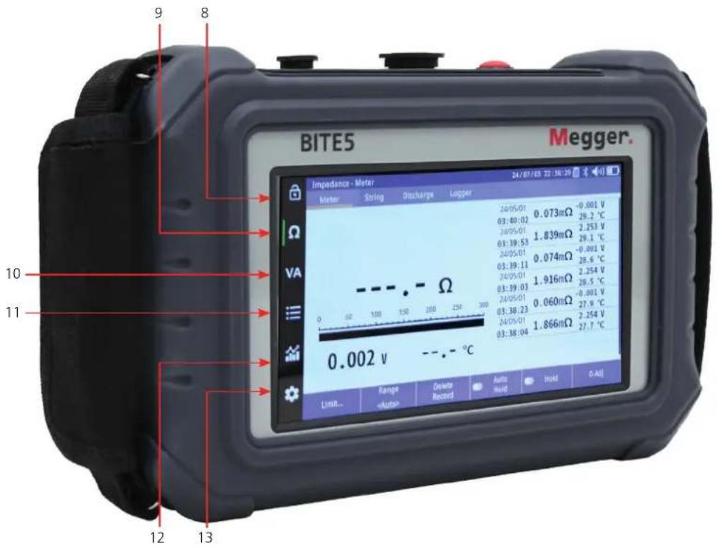
3.1 Instrument layout
One or more relavent viewpoints of the instrument with numbered arrows to reference the table below
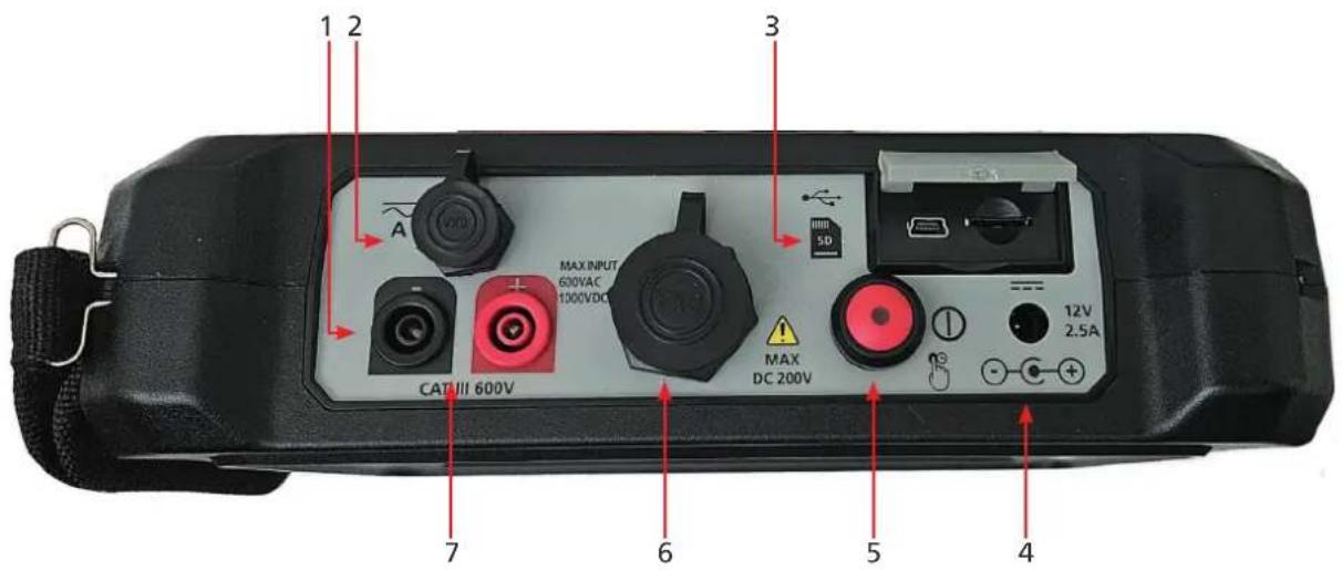
| Item Description Item Description | |||
| 1 Voltage lead input - 8 Lock and unlock screen | |||
| 2 Current probe input 9 Ohmic testing | |||
| 3 Mini USB input and micro SD card slot 10 | VA testing | ||
| 4 DC power adapter input | 11 | Data and string records | |
| 5 ON/OFF switch | 12 | Recorded data charts | |
| 6 Impedance probe inputs | 13 | Instrument configuration | |
| 7 Voltage lead input + | |||
4. Zero adjustment
For accurate ohmic measurements, it is recommended that a zero adjust is performed when changing probes. To perform a zero adjust, use the included zero bar.

When performing a zero adjustment, place the source pin on the outer copper surface of the zero bar and place the sensor pin in one of the holes of the zero adjust bar.

4.1 Zero adjustment procedure
Select "0-ADJ".
The BITE5 ADVANCED will prompt you to make a zero adjustment bar. Select YES.
NOTE: Place the probes on the zero adjustment bar as shown within 10 seconds of selecting YES, or the BITE5 ADVANCED will time out.

This zero adjustment will begin. Hold probes on zero bar until adjustment is complete.

5. Configuration of BITE5 ADVANCED
The BITE5 ADVANCED allows you to customize the unit for your needs.
To configure the unit, select the CONFIGURATION ICON.

IMPEDANCE TAB
| Display Units Set measured ohmic values to ohms or siemens. | |
| CT Source Set to internal for series strings or parallel for parallel strings. | |
| High Current Set tets current to 700mA or 100mA. | |
| Temperature Set temperature units to ei-ther Celsius or Fahrenheit. | |
| Voltage Polarity Set unit to record or disregard voltage polarity. | |
| Noise Avoidance Alter the test frequency to reduce effect of noisy stings. |

ETC TAB
| Language Select | desired language. |
| Date Format Select | desired date format. |
| Brightness Adjust | the brightness of the display. |
| Display Off Set | automatic display turn off time. |
| Time Set the date | and time. |
| Buzzer | Set the buzzer volume. |
| Auto P Off | Set automatic power down time. |
| SD Card | Format SD Card |
| Reset Settings | Reset BITE5. |

6. Configuration of string
The BITE5 ADVANCED allows you to configure strings to be tested.
To configure a new battery string press the RECORD ICON.

Select "String Ω".

Select "Add..."

This will open the String Configuration screen.
| Idx Sets a file index number (Set automatically). |
| Type Select battery chemistry |
| Cell Number of Cells to test |
| Name Name of string |
| Model Model number of batteries |
| Capacity Battery capacity in Ah or mAh |
| Ref Ω Baseline reference value |
| Warning Warning upper ohmic limit |
| Alarm Alarm upper ohmic limit |
| Ref V Cell float voltage |
| Lower Low voltage limit |
| Upper Upper voltage limit |
| RFID Scanned RFID tag number |

7. Performing a quick test (Meter Mode)
In the meter mode the BITE5 will take ohmic measurements but will not save the recordings to a programmed string configuration.

Select the Ohm (Ω) ICON.
When the Ohm ( ) ICON is selected it configures the unit to record ohmic values, voltage, and temperature.
When the Ohm (Ω) ICON is selected the BITE5 Advanced will use the Duplex inputs.
Connect the duplex probes to the BITE5 ADVANCED.
Select "Meter
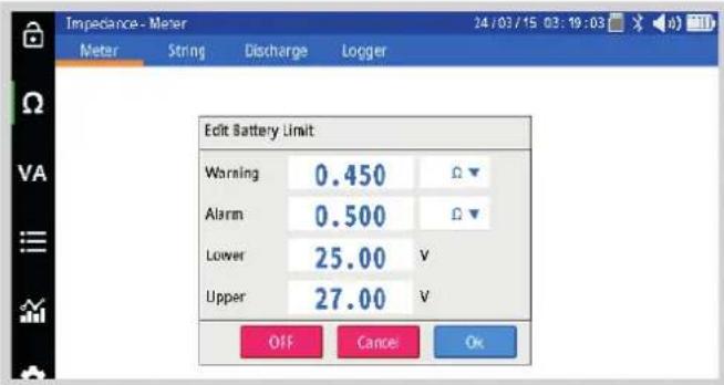
Select "Limit" if you would like to program impedance and voltage limits for the measurement.
This screen will allow you to program a warning and alarm limit for the impedance value and a lower limit for the voltage. This is an optional step. Select OK when done.
Note: This feature can be disabled as well by selecting OFF.
Start testing by placing the probes across the battery.
The BITE5 ADVANCED will beep when the measurement is complete.

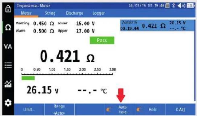
Press "Hold" to freeze the value on the screen.

Select "Auto Hold" and the BITE5 ADVANCED will automatically save any measurement with a date and time stamp.
8. Performing an impedance test on a battery string.
In this mode the BITE5 will take impedance measurements and will save the record values to a programmed string configuration.
| Select the Ohm (Ω) ICON. When the Ohm (Ω) ICON is selected it configures the unit to record ohmic values, voltage and temperature | 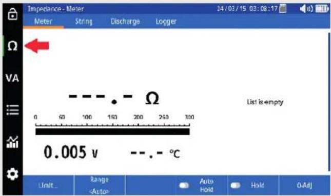 |
| When the Ohm (Ω) ICON is selected the BITE5 Advanced will use the Duplex inputs. | 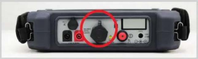 |
| Connect the duplex probes to the BITE5 ADVANCED. | 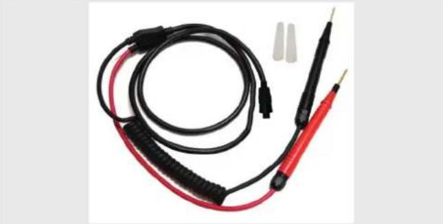 |
| Select "String" | 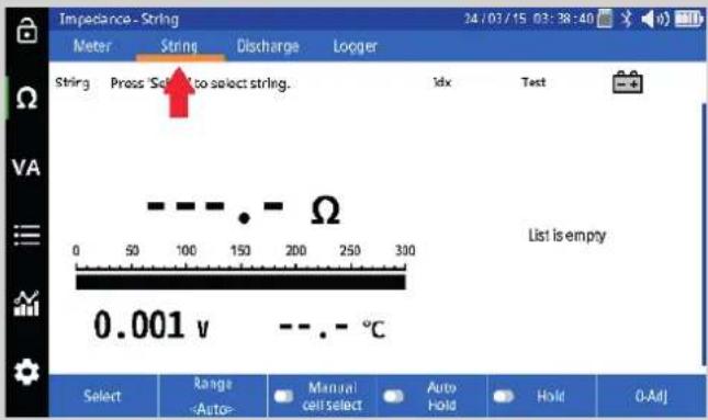 |
| Select "Select". | 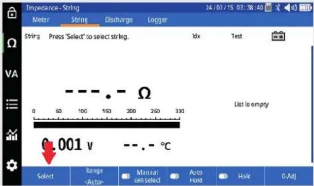 |
| Select desired string or scan the RFID tag, if used. |  |
| Select “New Test” to start a new test on the selected string. | 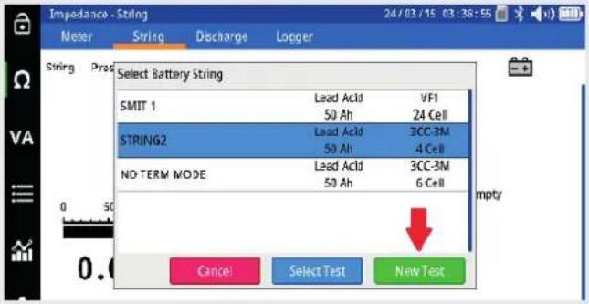 |
| Start testing by placing the probes on the first cell. The unit will beep when the measurement is complete and save the measured values to memory. The results will be displayed on the screen. |  |
| Move to the next battery or strap. The BITE5 ADVANCED will automatically identify if it is on a cell or a strap and take the measurement. The recorded values will be displayed on the screen. | 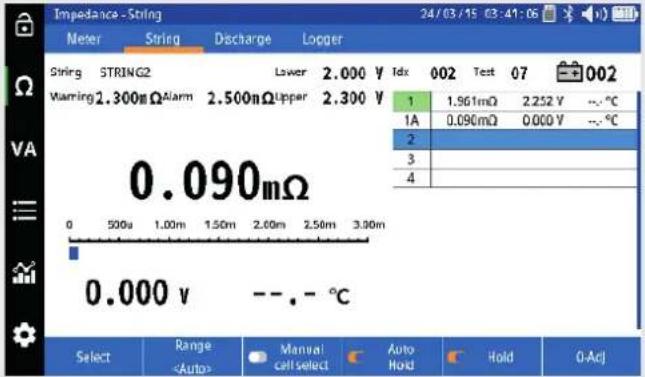 |
| Continue taking measurement of each cell and strap in sequence until you reach the last cell in the string. When the BITE5 ADVANCED measures the last cell in the string, it will display a summary. |  |
9. Performing a NERC terminal mode impedance test on a battery string.
This is a NERC compliance test. In this mode the BITE5 will take the terminal impedance measurements in addition to the cell and strap impedance measurements. All values will be saved to the selected string configuration.

Select the Ohm (Ω) ICON.
When the Ohm (Ω) ICON is selected it configures the unit to record ohmic values, voltage and temperature.
When the Ohm (Ω) ICON is selected the BITE5 Advanced will use the Duplex inputs.
Connect the duplex probes to the BITE5 ADVANCED.
Select "String"
Select "Select".
| Select desired string. or scan the RFID tag, if used. | 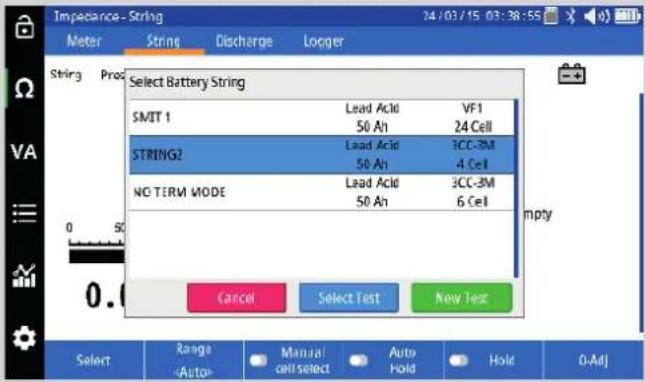 |
| Select “New Test” to start a new test on the selected string. |  |
| Start testing by placing the probes on positive terminal connection. This is the connection from the end of the charger leads to the first positive battery terminal. The BITE5 ADVANCED will automatically identify this as a strap. The value will be saved as strap 0A. The results will be displayed on the screen. | 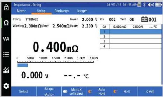 |
| Move to the next battery or strap. The BITE5 ADVANCED will automatically identify if it is on a cell or a strap and take the measurement.The recorded values will be displayed on the screen. | 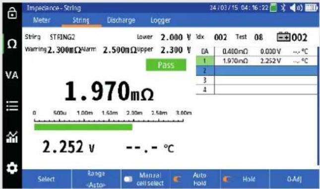 |
Continue taking measurement of each cell and strap in sequence until you reach the last cell in the string. When the BITE5 ADVANCED measures the last cell in the string, it will display a summary.
To record the negative terminal connection, close the summary and measure from the end of the negative charger lead to the last post on the last battery. This value will be saved as a strap.


Performing an impedance test on a parallel battery string.
10. Performing an impedance test on a parallel battery string.
When performing a ohmic test on a parallel string some of the test current escapes through the parallel path. This leads to inaccuracies in the measurement. In this mode the BITE5 will take impedance measurements, while recording the escape current, through the parallel path. This will provide accurate measurements avoiding the need to segment the string. The recorded values will be saved to the selected string configuration.

Place the AC Current clamps on the parallel path.
Select the Ohm (Ω) ICON.
When the Ohm (Ω) ICON is selected it configures the unit to record ohmic values, voltage, and temperature.
When the Ohm (Ω) ICON is selected the BITE5 Advanced will use the Duplex inputs.
Connect the duplex probes to the BITE5 ADVANCED. to voltage inputs of the BITE5 ADVANCED.
Select "String"

natural_image
Close-up of battery packs and red circular components on a blue tray (no visible text or symbols)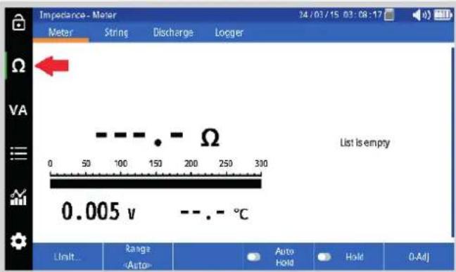

natural_image
Close-up of a digital multimeter with labeled buttons and display (no readable text or symbols)
natural_image
Coiled black and red electrical test probes with terminal connectors (no text or symbols visible)
natural_image
Close-up of battery charging station with red and black components and a white clamp (no visible text or symbols)11. Performing a conductance test on a battery string.
The BITE5 can record the measured data as either milliohms or in Siemens. This test will record the data in Siemens. All the data will be saved to the selected string. NOTE: All limits in the selected string will need to be in Siemens. Select the "Setting" ICON.  Set the Display units to "Siemens"  Select the Siemens (S) ICON.  When the Siemens (S) ICON is selected it configures the unit to record Siemens, voltage and temperature When the Siemens (S) ICON is selected the BITE5 Advanced will use the Duplex inputs. natural_image
Close-up of a digital multimeter with labeled buttons and a red circle highlighting the function (no readable text or symbols)natural_image
Coiled black and red electrical test probes with terminal connectors (no text or symbols visible)12. Performing an impedance test on a battery pack.
In this mode the BITE5 will take a single impedance measurement across a battery pack or across an entire battery string (UP to 500Vdc). This test is applicable to mobile battery packs, such as in forklifts. The batteries do need to be fully charged. In the string configuration verify the number of cells is set to 1.  Select the Ohm (Ω) ICON. When the Ohm (Ω) ICON is selected it configures the unit to record ohmic values, voltage and temperature  When the Ohm (Ω) ICON is selected the BITE5 Advanced will use the Duplex input. natural_image
Close-up of a digital multimeter with labeled buttons and a red circle highlighting the function (no readable text or symbols)natural_image
Coiled black cable with red and black clamps, no visible text or symbols| Select "Select". |  |
| Select desired battery pack / string. or scan the RFID tag, if used. |  |
| Select "New Test" to start a new test on the selected string. |  |
| Place the kelvin clips across the battery pack or the battery string. The BITE5 Advanced will automatically take the measurement and save it to memory. |  |
13. Measuring battery (DC) float and (AC) ripple voltages and currents
The BITE5 ADVANCED can be used to measure and record any of the following, 1. DC Voltage (Up to 1000Vdc) 2. AC Voltage (Up to 600Vac) 3. DC Current from 1A to 1000A. 4. AC Current 1A to 100A13.1 VA Meter Mode
In the meter mode the BITE5 will take the above measurements but will not save the data to a programmed string configuration. Select the VA ICON. When the VA ICON is selected it configures the unit to record voltage and current. line
Voltage vs. Current | Time (s) | Voltage (V) | Current (A) | | :--- | :--- | :--- | | 24/03/14 03:13:23 | 0.026 | 0.024 | | 24/03/14 03:13:22 | 0.044 | 0.023 | | 24/03/14 03:13:21 | 0.061 | 0.011 | The chart displays a single data point at 0.074 VDC and a separate value of 0.014 VRipple, with a range bar labeled 'Range' and mode label 'Mode'. The output is marked as 'Auto' and 'Hold'.natural_image
Close-up of a digital multimeter with labeled ports and control buttons (no readable text or symbols)natural_image
Coiled black and red electrical probes with terminal connectors (no text or symbols visible)line
| Date | Value | |---|---| | 24/03/14 | 0.026 | | 03:13:23 | 0.024 | | 24/03/14 | 0.044 | | 03:13:22 | 0.023 | | 24/03/14 | 0.061 | | 03:13:21 | 0.011 | | 0.074 V_DC | | | 0.014 V_Ripple | || Select “Mode”Select the type of measurement. |  |
| Select “Range”Set the desired range. |  |
| Start testing by place the banana leads or the CT on what is to be measured.For measuring AC (ripple) current the AC CT is required.For measuring DC (float) current the AC/DC CT is required.The BITE5 ADVANCED will beep when the measurement is complete. |  |
| Press “Hold” to freeze the value on the screen. |  |
line
| Date | Voltage (V) | Current (V_Ripple) | | :--- | :--- | :--- | | 24/03/20 04:51:47 | 26.15 | 0.019 | | 24/03/14 03:13:23 | 0.026 | 0.024 | | 24/03/14 03:13:22 | 0.044 | 0.023 | | 24/03/14 03:13:21 | 0.061 | 0.011 | The chart displays a single data point for the 'HOLD' series. The 'Ripple' value is explicitly labeled as 0.019.line
| Time | Voltage (V_DC) | | :--- | :--- | | 24/03/20 04:52:10 | 26.15 | | 24/03/20 04:51:47 | 26.15 | | 24/03/14 03:13:23 | 0.026 | | 24/03/14 03:13:22 | 0.044 | | 24/03/14 03:13:21 | 0.061 | | 24/03/20 04:52:10 | 0.016 | | 24/03/20 04:51:47 | 0.019 | | 24/03/14 03:13:23 | 0.024 | | 24/03/14 03:13:22 | 0.023 | | 24/03/14 03:13:21 | 0.011 | The chart displays a single data point for 'V_Ripple' at the end of the time axis. The vertical axis is labeled 'Range', and the horizontal axis is labeled 'Auto Hold'. The value 'A HOLD' is shown on the left side.14. Adding a Ripple (AC) Voltage, Ripple (AC) Current or a Float (DC) Current value to a string.
In this mode the BITE5 ADVANCED will allow take a ripple or float measurement and add that measurement to the selected string.| Select the VA ICON. When the VA ICON is selected it configures the unit to record voltage and current. | 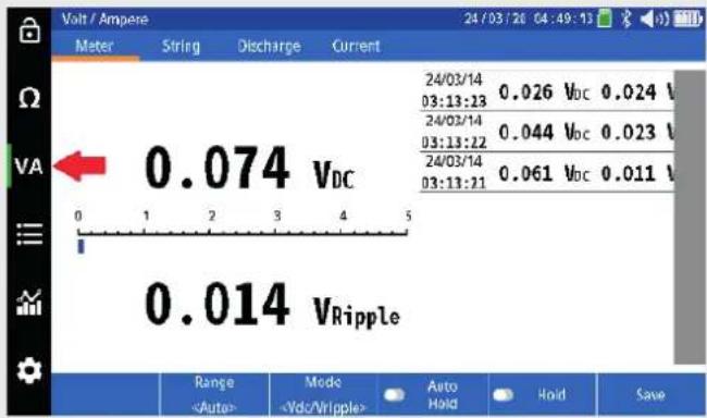 |
| When the VA ICON is selected the BITE5 Advanced will use the banana jack inputs and the current clamp input. | 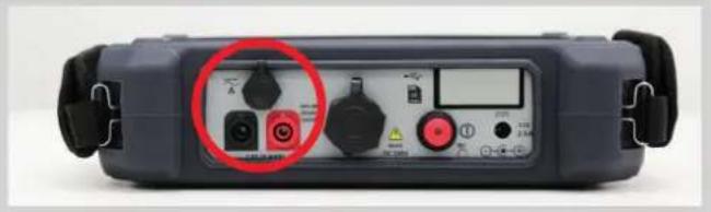 |
| Connect the banana leads and or the CT to the BITE5 |  |
| Select "Current" |  |
| Select "Select". |  |
bar
| Category | Value | |---|---| | Fail | 0.007 Vdc | | Select | 0.02 | | Rangeline
| Parameter | Value | | --------- | --------- | | V_DC | 0.006 | | V_Ripple | 0.021 |15. Measuring voltages only on a battery string.
The BITE5 ADVANCED can be used to measure and record voltage only on a battery string. The recorded data will be saved to the selected string configuration.| Select the VA ICON. When the VA ICON is selected it configures the unit to record voltage and current. |  |
| When the VA ICON is selected the BITE5 Advanced will use the banana jack inputs and the current clamp input. (if desired) |  |
| Connect the banana leads and or the CT to the BITE5 | 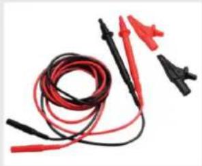 |
| Select "String" |  |
| Select "Select" |  |
bar
| Parameter | Value | | :--- | :--- | | Current | 2.247 Vdc | | Read | 0.021 Vripple | | Threshold | -5.00 | | Current | 2.300 V | | Threshold | -2.50 | | Current | 2.100 V | | Threshold | -2.300 V | | Current | 0.021 Vripple | | Threshold | 0.021 Vripple | | Current | 1 | | Threshold | 2 | | Current | 3 | | Threshold | 4 | | Current | 5 | | Threshold | 6 | | Current | 7 | | Threshold | 8 | | Current | 9 | | Threshold | 10 | | Current | 11 | | Threshold | 12 | 24/03/20 05:42:06 | | Select Range Auto Hold Hold Manual cell select16. Performing a discharge test
The BITE5 ADVANCED can be used in conjunction with the Megger Torkel discharge tester. Program the Torkel for the desired discharge test. Place the Torkel across the battery string and start the discharge test. The BITE5 ADVANCED can then be used to take manual measurements of the cell voltage throughout the discharge process. In this mode, the unit will record the DC voltage of each cell as well as the DC current through the string if the optional Hall Effect CT is used.  Select the VA ICON. When the VA ICON is selected it configures the unit to record voltage and current. When the VA ICON is selected the BITE5 Advanced will use the banana jack inputs and the current clamp input. (if desired) Connect the voltage leads to voltage inputs of the BITE5 ADVANCED. If measuring current, then plug the CT into the BITE5 ADVANCED CT input. Select "Discharge."| Select "Select" | 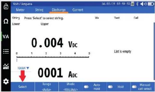 |
| Select desired string. or scan the RFID tag, if used. |  |
| Select "New Test" to start a new test on the selected string. | 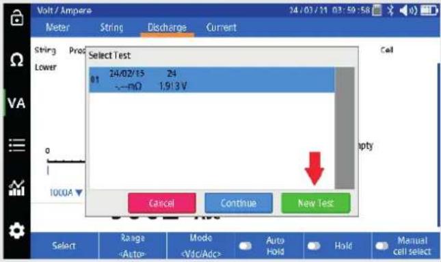 |
| If using the CT, set the correct range on the BITE5 ADVANCED. |  |
natural_image
Close-up of a digital multimeter with labeled buttons and a red circle highlighting the function (no readable text or symbols)natural_image
Coiled black and red electrical test probes with terminal connectors (no text or symbols visible)| Take measurement of each following cell. Each measurement shall be saved in sequence with a cell number, date and time stamp. |  |
| Continue through the string until the last cell is measured. At this point the BITE5 will display a summary of this pass through the string. | 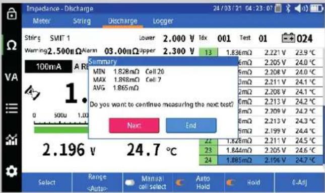 |
| The unit will then prompt the user to either end the test or select “next” to perform the next pass through the string. Press when ready to perform another pass through the string. Press END to end the test. |  |
18. Trending recorded data
The BITE5 ADVANCED will allow trending of all recorded string data. The BITE5 ADVANCED will trend string data; the value of each cell during a single test. The BITE5 ADVANCED can also trend the all the historical test data for each individual cell.18.1 Trending String Test Data
Trending string data will trend all the cells on the X axis for each individual test.| On the BITE5 ADVANCED select the chart ICON. |  |
| On the drop down menu select the desired tested trend to view. Impedance: Trends data for impedance tests. Discharge Impedance: Trends data for impedance data recorded during a discharge test. Float Voltage: Trends data for a voltage only string test. Discharge Voltage: Trends voltage data that was recorded during each pass through a discharge test. |  |
| Select "String". | 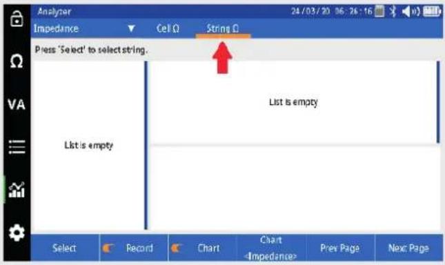 |
| Select "Select". | 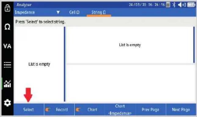 |
| Select the desired battery string to view. Then press OK. |  |
| Select desired test in the left column. | 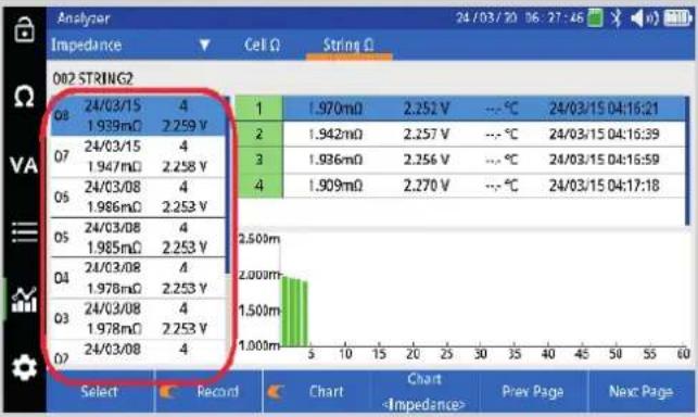 |
| Select “Chart” to change the parameter being trended. | 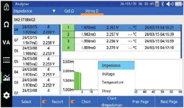 |
19. Trending Cell Test Data
Trending cell data will trend all the measured historical values on the X axis for each cell in the string..| On the BITE5 ADVANCED select the chart ICON. |  |
| On the drop-down menu select the desired tested trend to view. Impedance: Trends data for impedance tests. Discharge Impedance: Trends data for impedance data recorded during a discharge test. Float Voltage: Trends data for a voltage only string test. Discharge Voltage: Trends voltage data that was recorded during each pass through a discharge test. |  |
| Select "Cell" | 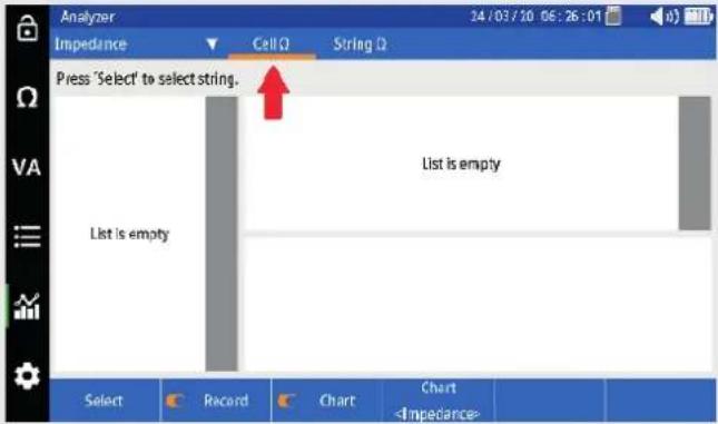 |
| Select "Select". |  |
| Select the desired battery string to view. Then press OK. |  |
| Select desired cell in the left column. | 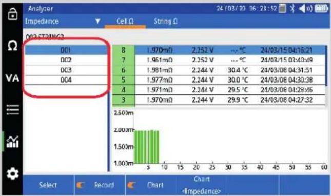 |
| Select “Chart” to change the parameter being trended. | 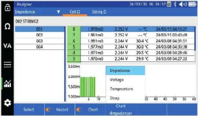 |
20. Viewing a record
The BITE5 ADVANCED allows the viewing of various recorded values or records. These records include the following: Meter Ω - These will be the individual recorded impedance measurements that were made with the BITE5 ADVANCED. These recorded values are not associated with any battery strings. String Ω - These will be the recorded values of individual impedance tests made on strings. D Ω String - These will be the recorded values of individual impedance measurements made during a discharge test on a string. Meter VA - These will be the individual recorded voltage and current measurements that were made with the BITE5 ADVANCED. These recorded value are not associated with any battery strings. String VA - These will be the recorded values of voltage and current measurements made on strings. D VA String - These will be the recorded values of the voltage and current measurements made during a discharge test on a string. Current – Will display current measurements made on a string.20.1 Viewing records
On the BITE5 ADVANCED select the record ICON.  Select desired type of data to view. (See above for data types.) Viewing a record
Select the desired string. NOTE: If "Meter Ω" or "Meter VA" was selected no string needs to be selected. Recorded Meter data is not associated with a string. Therefore, all recorded meter data is displayed.| Select string. | |||||
| SMT 1 | Lead Acid 50 Ah | VF1 24 Cell | 2.200/2.000/2.300V 2.000/2.500/03.00mΩ | ||
| STRING2 | Lead Acid 50 Ah | 3CC-3M 4Cell | 2.200/2.000/2.300V 1.900/2.300/2.500mΩ | ||
| NO TERM MODE | Lead Acid 50 Ah | 3CC-3M 6 Cell | 2.200/2.000/2.300V 1.900/2.200/2.500mΩ | ||
| BSA LEAD ANTIMONY | Lead Acid 50 Ah | LA 6 Cell | 2.200/2.000/2.300V 1.900/2.500/03.00mΩ | ||
| BSA LEAD CALCIUM S | Lead Acid 50 Ah | LC 6 Cell | 2.200/2.000/2.300V 10.00/20.00/030.0mΩ | ||
| BSA LEAD CALCIUM P | Lead Acid 50 Ah | LC 6 Cell | 2.200/2.000/2.300V 10.00/20.00/030.0mΩ | ||
| BSA NICD | Ni-Cd | NICD | 1.300/1.000/1.500V | ||
| Select string. | |||||
| SMT 1 | Lead Acid 50 Ah | VF1 24 Cell | 2.200/2.000/2.300V 2.000/2.500/03.00mΩ | ||
| STRING2 | Lead Acid 50 Ah | 3CC-3M 4Cell | 2.200/2.000/2.300V 1.900/2.300/2.500mΩ | ||
| NO TERM MODE | Lead Acid 50 Ah | 3CC-3M 6 Cell | 2.200/2.000/2.300V 1.900/2.200/2.500mΩ | ||
| BSA LEAD ANTIMONY | Lead Acid 50 Ah | LA 6 Cell | 2.200/2.000/2.300V 1.900/2.500/03.00mΩ | ||
| BSA LEAD CALCIUM S | Lead Acid 50 Ah | LC 6 Cell | 2.200/2.000/2.300V 10.00/20.00/030.0mΩ | ||
| BSA LEAD CALCIUM P | Lead Acid 50 Ah | LC 6 Cell | 2.200/2.000/2.300V 10.00/20.00/030.0mΩ | ||
| BSA MCD | Ni-Cd | NICD | 1.300/1.000/1.500V | ||
| 002 CTRNQ3 | |||||||
| 08 | 24/03/15 | 4 | Min | 1.909mΩ | Cell | 4 | 24/03/15 04:17:18 |
| 1.539mΩ | 2.259 V | Max | 1.970mΩ | Cell | 1 | 24/03/15 04:16:21 | |
| 07 | 24/03/15 | 4 | Avg | 1.939mΩ | |||
| 1.947mΩ | 2.258 V | 0A | 0.400mΩ | 0.000V | -.-°C | 24/03/15 04:16:06 | |
| 06 | 24/03/08 | 4 | 1 | 1.970mΩ | 2.252V | -.-°C | 24/03/15 04:16:21 |
| 1.986mΩ | 2.253 V | 1A | 0.075mΩ | 0.000V | -.-°C | 24/03/15 04:16:31 | |
| 05 | 24/03/08 | 4 | 2 | 1.942mΩ | 2.257V | -.-°C | 24/03/15 04:16:39 |
| 1.985mΩ | 2.253 V | 2A | 0.047mΩ | 0.000V | -.-°C | 24/03/15 04:16:49 | |
| 04 | 24/03/08 | 4 | 3 | 1.936mΩ | 2.256V | -.-°C | 24/03/15 04:16:59 |
| 1.978mΩ | 2.253 V | 3A | 0.090mΩ | 0.000V | -.-°C | 24/03/15 04:17:07 | |
| 03 | 24/03/08 | 4 | 4 | 1.909mΩ | 2.270V | -.-°C | 24/03/15 04:17:18 |
| 1.978mΩ | 2.253 V | 4A | 0.022mΩ | 0.000V | -.-°C | 24/03/15 04:18:03 | |
| 02 | 24/03/08 | 4 | |||||
21. Deleting recorded meter data
21.1 Deleting Meter Ω and Meter VA Ω data
This refers to recorded ohmic or voltage measurements that are not associated with a battery string. 21.2 Deleting recorded string data
This refers to measurements that are saved to a configured string This can include the following. String Ω These will be the recorded values of individual impedance tests made on strings. D Ω String These will be the recorded values of individual impedance measurements made during a discharge test on a string. String VA These will be the recorded values of voltage and current measurements made on strings. D VA String These will be the recorded values of the voltage and current measurements made during a discharge test on a string. Current Will display current measurements made on a string. On the BITE5 ADVANCED select the record ICON.  Select the desired type of data to delete. (See above).  Select the desired string the data is to be deleted from.  Press "Select" Select the desired test to delete NOTE: To delete all tests select "Select All". Press "Delete Test" A window will open asking "Do you want to delete test?". Select "Yes" to delete the test.    21.3 Deleting a string configuration
This allows deletion of an entire string configuration. 22. Data Logging
The BITE5 Advanced provides data logging capabilities. This allows for prolonged automatic logging of impedance, voltage and temperature values.22.1 Logging Data
Select the Ohm (Ω) ICON. When the Ohm (Ω) ICON is selected to configures the unit to record ohmic values, voltage and temperature.  When the Ohm (Ω) ICON is selected the BITE5 Advanced will use the Duplex input. natural_image
Close-up of a digital multimeter with control buttons and display (no visible text or symbols)natural_image
Coiled black and red automotive electrical cable with clamp (no text or symbols visible)Data Logging
Select the "Primary" value to record. (Impedance, Voltage or Temperature) Select the "Secondary" value to record. (Impedance, Voltage or Temperature) Select "Interval" and then desired recording interval. Select "Range" and then desired recording range.  bar
Impedance - Logger | Measurement | Impedance | Voltage | Temperature | | :--- | :--- | :--- | :--- | | Primarybar
Impedance - Logger | Meter | String | Discharge | Logger | |---|---|---|---| | 6.800 | | | 6.800 | | 4.800 | | | 4.800 | | 2.800 | | | 2.800 | | 0.000 ou | | | 0.000 ou | | -2.000 | | | -2.000 | | -4.000 | | | -4.000 | | -6.000 | | | -6.000 | Primary:line
| Time | Voltage | | ---------- | ------- | | 24/02/06 | 3.340m | | 05:00:00 | 3.320m | | 05:15:00 | 3.300m | | 05:30:00 | 3.280m | | 05:45:00 | 3.260m | | 06:00:00 | 3.240m | | 16:00:00 | 3.240m |22.2 Viewing a Recorded Data Log
Select the Ohm (Ω) ICON. When the Ohm (Ω) ICON is selected to configures the unit to record ohmic values, voltage and temperature. Select "Logger"  bar
Impedance - Logger | Measurement | Current (Ω) | | :--- | :--- | | 0.001 V | 6.000 | | Start Time | 2.000 | | Record Length | -2.000 | | Num of Samples | -4.000 | | Load... | -6.000 | | PrimaryData Logging
23. RFID Tags
The BITE5 ADVANCED supports the use of RFID tags. A tag can be configured and placed on a battery string. The operator can then scan the RFID tag with the BITE5 ADVANCED and then proceed to start testing.23.1 Configuring a RFID tag. for new battery string configuration.
Select the RECORD ICON.  Select "String Ω".  Select "Add..."  Program the fields in the in the string configuration (See the String Configuration Section of this manual for details)  When complete scan the RFID tag by placing near the back on the BITE5 ADVANCED. An audible beep will be made when the tag is read. natural_image
Electrical battery pack with red and black components, no visible text or symbols on the main body23.2 Configuring a RFID tag. for an existing battery string configuration.
Select the RECORD ICON.  Select "String Ω".  Select the desired sting.  Select "Edit..."  When complete scan the RFID tag by placing near the back on the BITE5 ADVANCED. An audible beep will be made when the tag is read. natural_image
Electrical battery pack with red and black components, no visible text or symbols on main subject24. Saving a screen snapshot
The BITE5 ADVANCED allows you to save screen images as bitmaps. To do this, momentarily press and release the Power ON/OFF button.  The displayed screen shall be saved to the SD card as a bitmap file. The bitmap will be located at the following path. MEGGER / SCREENS Noisy Strings.25. Noisy Strings.
Excessive electrical noise on strings can cause interference to the battery ohmic measurements. This is can be typical on UPS systems. Noise can cause extended measurement times due to elongated settling times. In extreme cases high signal to noise ratios may not allow a measurement. To address this situation a noise avoidance feature can be enabled on the BITE5 ADVANCED. 26. Specifications
| Specification Detail | ||
| Input power | ||
| AC/Adapter | ||
| Input 100 - 240 V AC (50/60 Hz) | ||
| Output 12 V DC at 2.5 A | ||
| Battery | ||
| Li-ion rechargeable pack > 5.2Ah | ||
| Voltage rating 7.2 V | ||
| Charge time 4 hrs | ||
| Battery life > 8 hrs | ||
| 300 charge/discharge cycles | ||
| Internal impedance | ||
| Range Resolution Accuracy | ||
| 3 mΩ 1 μΩ +/- 1 % of reading +/- 10 digits | ||
| 30 mΩ 10 μΩ +/- 0.8 % of reading +/- 10 digits | ||
| 300 mΩ 100 μΩ +/- 0.8 % of reading +/- 10 digits | ||
| 3 Ω 1 mΩ +/- 0.8 % of reading +/- 10 digits | ||
| 30 Ω 10 mΩ +/- 0.8 % of reading +/- 10 digits | ||
| 300 Ω 100 mΩ +/- 0.8 % of reading +/- 10 digits | ||
| Voltage DC/AC | ||
| Range Resolution Accuracy | ||
| 5 V DC 0.001 V | ||
| 50 V DC 0.01 V | ||
| 500 V DC 0.1 V +/- 0.5 % of reading +/- 5 digits | ||
| 1000 V DC 1 V | ||
| 5 V AC 0.001 V | ||
| 50 V AC 0.01 V +/- 0.75 % of reading +/- 10 digits | ||
| 500 V AC 0.1V (40 Hz - 100 Hz) | ||
| 600 V AC 1 V | ||
| Current DC/AC | ||
| Range Resolution Accuracy | ||
| 4 A DC 0.001 A +/- 0.5 % of reading +/- 1 digit | ||
| 40 A DC 0.01 A + (CT Tolerance) | ||
| 400 A DC 0.1 A +/- 0.5 % of reading +/- 5 digits | ||
| 1000 A DC 1 A + (CT Tolerance) | ||
| 4 A AC 0.001 A +/- 0.75 % of reading +/- 1 digit | ||
| 40 A AC 0.01 A + (CT Tolerance) | ||
| 400 A AC 0.1 A +/- 0.75 % of reading +/- 10 digits | ||
| 1000 A AC 1 A + (CT Tolerance) | ||
| Temperature | ||
| Range Resolution Accuracy | ||
| 10 °C ~ 100 °C 0.1 °C +/-1 °C +/- 2 digits | ||
| Ripple voltage | ||
| Range Resolution Accuracy | ||
| 0-5 V 0.001 V +/- 0.5 % of reading +/- 10 digits(40 Hz - 10 KHz) | ||
| Test Current 1 Khz @ 100 mA / 700 mA | |
| Repeatability 0.1 %, 2 | σ |
| Record Capacity | |
| Memory 8 GB up to 16 GB flash storage | Impedance record: Max 1000 records VA record: Max 512 records |
| Environmental | |
| Operating 0 ~50 °C (32~122 °F) | |
| Storage -20 ~50 °C (-4~122 °F) | |
| Charging temperature: 10 ~40 °C (50~104 °F) | |
| Relative humidity 10 ~ 85 % NC non-condensing | |
| Altitude Operational 0 ~ 2000 m | |
| Ingress protection IP54 | |
| Display (transmitter and receiver) 160 x 90 mm touch screen | |
| Safety/EMC/Vibration/Compliance | |
| Meets the requirements of IEC61010-1, CE, UKCA | |
| CAT Rating: 600 V CAT III, Pollution Degree 2 | |
| Shock and vibration EN61010-1 | EN60529 |
| IEC61010-1:2010 (3rd Ed) | |
| EN61010-1:2010 (3rd Ed) | |
| IEN61326-1:2013 | |
| EN55011/A1:2010 (Class A) | |
| EN61000-3-2:2014 | |
| EN61000-3-3:2013 | |
| Weight/Dimensions | |
| Dimensions 240 x 160 x 65 mm | (9.45" x 6.30" x 2.56") |
| Weight | 0.9 kg (1.98 lbs) |
27. Accessories and Equipment
| OPTIONAL ACCESSORIES | |||
 | Concentric Probe – The concentric probe allows for battery testing on batteries with safety caps or safety lugs. Users can easily access the terminals through the access hole. The concentric probe comes in two styles. One probe comes with a 11.75 mm (1/2") tip the other has a 25.4 mm (1") tip. This allows access to terminals even on batteries with the deepest safety lugs. | 90043-242 (11.75mm tip) | |
| 90043-243 (25.4mm tip) | |||
 | 0 to 100 A AC CT. Used for measuring and recording AC ripple current. Jaw opening 0.96" ID (24.5mm) | MCV-100B5B | |
 | 1 to 1000 A AC/DC CT. Used for measuring and recording DC float current and discharge current. Jaw opening 2 inches (52.0 mm) | MCCV-1KDC-B5B | |
 | BITE5 extension kit for probes. Allow operator to take measurements while being able to stand safely back from the voltages being measured. Available with straight and 90 degree probes. | See ordering information for options | |
 | 3 meter right angle probe. For use with BITE5 extension kit. | 90043-244 | |
 | 3 meter straight probe. For use with BITE5 extension probes. | 90043-245 | |
natural_image
Coiled black cable with red and black clamps, no visible text or symbols| Item Order No. | |
| Duplex probes (with temperature probe) 90043-241 | |
| Voltage test leads 90037-576 | |
| Charger 90039-077 | |
| Neck strap 90037-529 | |
| Zero bar 90037-575 | |
| 16 GB microSD card 90037-572 | |
| microSD card USB reader 90037-571 | |
| USB cable 90037-569 | |
| Stylus 90037-570 | |
| Carry bag 90037-573 | |
| Pouch bag 90037-574 |
| Item Order No. | |
| Concentric probe (1/2" tip) 90043-242 | |
| Concentric probe (1" tip) 90043-243 | |
| 100 A AC current clamp | MCV-100B5B |
| 1000 A AC/DC current clamp | MCCV-1KDC-B5B |
| 3 meter right angle probe 90043-244 | |
| 3 meter straight probe | 90043-245 |
| 3 meter clip on probe | 90043-246 |
| Extension kit with straight probe | 1016-066 |
| Extension kit with 90 degree probe | 1016-064 |
| Extension kit with straight and 90 degree probes | 1016-067 |
28. Maintenance
Do not leave the instrument connected to the system under test when not in use. Do not use the instrument or connect it to any external system if it shows any visible signs of damage, malfunction, or if it has been stored in unfavorable conditions. If this equipment is used in the manner not specified by the manufacturer, the protection provided by the equipment may be impaired.28.1 Battery charging
The BITE5 ADVANCED uses rechargeable Li-ion batteries. Only recharge batteries using the supplied power adapter. Battery charging starts once the power adapter is connected and plugged into AC. The battery charge will take approx. 4 hours to complete. If the unit is operated off of the AC adapter, then the charging time will be longer. The BITE5 ADVANCED can be left connected to the charging adapter for extended periods. The batteries will not be damaged even after full charge.28.1.1 Battery charging status icon
| Icon Description | |
 | Battery charging amount more than 85 % |
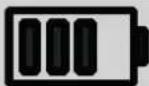 | Battery charging amount more than 70 % |
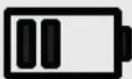 | Battery charging amount more than 50 % |
 | Battery charging amount more than 25 % |
 | Battery is fully discharged (after warning sounds, unit will shut off) |
 | Adapter connected, unit charging |
28.2 Cleaning and Storage
Do not leave the instrument connected to the system under test when storing or cleaning.28.2.1 Unit Cleaning
Clean with wet cloth and soft soap. Do not use organic solvents or alcohol as markings on the unit may be damaged.28.2.2 Storage
When storing for long periods of time, there is no need to remove the battery pack. However, all batteries experience self-discharge. This will lead to a gradually draining of the batteries. For best battery life, it is recommended that batteries are charged once a month. Batteries need to be charged a minimum of once every 6 months.28.2.3 Cleaning probes
Clean with wet cloth and soft soap. Do not use organic solvents or alcohol.29. Calibration, Repair and Warranty
Megger operate fully traceable calibration and repair facilities to make sure your instrument continues to provide the high standard of performance and workmanship that is expected. These facilities are complemented by a worldwide network of approved repair and calibration companies, which offer excellent in-service care for your Megger products. For service requirements for Megger instruments contact:| Megger LimitedArchcliffe RoadDoverKentCT17 9ENU.K.Tel: +44 (0) 1304 502 243Fax: +44 (0) 1304 207 342 | OR | Megger Valley Forge400 Opportunity WayPhoenixvillePA 19460U.S.A.Tel: +1 610 676 8579Fax: +1 610 676 8625 |
29.1 Calibration, Service and Spare Parts
For service requirements for Megger Instruments contact Megger or your local distributor or authorised repair centre. Megger operates fully traceable calibration and repair facilities, to make sure your instrument continues to provide the high standard of performance and workmanship you expect. These facilities are complemented by a worldwide network of approved repair and calibration companies to offer excellent in-service care for your Megger products. See the last page of this User Guide for Megger contact details. To find your local Authorised Service Centre email Megger on ukrepairs@megger.com and give details of your location.29.2 Approved Repair Companies
A number of independent instrument repair companies have been approved to do repair work on most Megger instruments, complete with genuine Megger spare parts. Consult the Appointed Distributor / Agent about spare parts, repair facilities and advice.29.3 Return procedure
WARNING : DO NOT Remove the battery cells before shipping this instrument. The battery pack MUST be inside the BITE5 when it is packed for shipping.
UK and USA Service Centres
1. When an instrument requires recalibration, or in the event of a repair being necessary, a Returns Authorisation (RA) number must first be obtained from one of the addresses shown above. The following information is to be provided to enable the Service Department to prepare in advance for receipt of your instrument and to provide the best possible service to you: ■ Model (for example, BITE5). - Serial number (found on the display under settings, device information, or on the rear cover and by the batteries or on the calibration certificate). - Reason for return (for example, calibration required, or repair). ■ Details of the fault if the instrument is to be repaired. 2. Make a note of the RA number. A returns label can be emailed or faxed to you if required. 3. Pack the instrument carefully to prevent damage in transit. 4. Before the instrument is sent to Megger, freight paid, make sure that the returns label is attached or that the RA number is clearly marked on the outside of the package and on any correspondence. Copies of the original purchase invoice and packing note should be sent simultaneously by airmail to expedite clearance through customs. In the case of instruments which require repair outside the warranty period, an immediate quotation can be provided when obtaining the RA number. 5. Track the progress online at www.megger.com.30. Decommissioning
30.1 WEEE Directive
 The crossed out wheeled bin symbol placed on Megger products is a reminder not to dispose of the product at the end of its life with general waste. Megger is registered in the UK as a Producer of Electrical and Electronic Equipment. The Registration No is WEE/HE0146QT. For further information about disposal of the product consult your local Megger company or distributor or visit your local Megger website.30.2 Battery disposal
 The crossed out wheeled bin symbol placed on a battery is a reminder not to dispose of batteries with general waste when they reach the end of their usable life. For disposal of batteries in other parts of the EU contact your local Megger branch or distributor. Megger is registered in the UK as a producer of batteries (registration No.: BPRN00142). For further information see www.megger.com31. Worldwide Sales Offices
| Sales Office Telephone Email | ||
| UK | T. +44 (0)1 304 502101 E. UKsales@megger.com | |
| USA – Dallas | T. +1 214 333 3201 E. USsales@megger.com | |
| USA – Valley Forge | T. +1 214 333 3201 E. USsales@megger.com | |
| USA – Dallas | T. +1 214 333 3201 E. USsales@megger.com | |
| DEUTSCHLAND – Aachen | T. +49 (0) 241 91380 500 E. info@megger.de | |
| SVERIGE | T. +46 08 510 195 00 E. seinfo@megger.com | |
| AUSTRALIA | T. +61 2 9397 5900 E. ausales@megger.com | |
| 中国 | T. +86 512 6556 7262 E. meggerchina@megger.com | |
| 中国 - 香港 | T. +852 26189964 E. meggerchina@megger.com | |
| ČESKÁ REPUBLIKA | T. +420 222 520 508 E. info.cz@megger.com | |
| AMÉRICA LATINA | T. +1 214 330 3293 E. csasales@megger.com | |
| ESPAÑA | T. +34 916 16 54 96 E. info.es@megger.com | |
| SUOMI | T. +358 08 510 195 00 | E. seinfo@megger.com |
| LA FRANCE | T. +01 30 16 08 90 | E. infos@megger.com |
| ΕΛΑΔΑ | T. +49 (0) 9544 68 0 E. sales@sebakmt.com | |
| MAGYARORSZÁG | T. +36 1 214-2512 | E. info@megger.hu |
| ITALIA | T. +49 (0) 9544 68 0 E. sales@sebakmt.com | |
| 日本 | T. +44 (0)1 304 502101 E. UKsales@megger.com | |
| 한국 | T. +1-800-723-2861 | E. sales@megger.com |
| ضایرلیا قیبregions | T. +966 55 111 6836 E. MEsales@megger.com | |
| نیربالا قکلیم | T. +973 17440620 E. MEsales@megger.com | |
| NEDERLAND | T. +46 08 510 195 00 E. seinfo@megger.com | |
| NORGE | T. +46 08 510 195 00 E. seinfo@megger.com | |
| POLSKA | T. +48 22 2809 808 E. info.pl@megger.com | |
| PORTUGAL | T. +34 916 16 54 96 E. info.es@megger.com | |
| ROMÂNIA | T. +40 21 2309138 | E. info.ro@megger.com |
| РОССИЯ | T. +7 495 2 34 91 61 E. sebaso@sebaspectrum.ru | |
| SLOVENSKO | T. +421 2 554 23 958 | E. info.sk@megger.com |
| SOUTH AFRICA | T. +27 (031) 576 0360 | E. sales.rsa@megger.com |
| TÜRKİYE | T. +46 08 510 195 00 E. seinfo@megger.com | |
| Megger Baker Instruments4812 McMurry Ave., Suite 100Fort Collins, Colorado 80525USAT. 1-970-282-1200 or 1-800-752-8272F. 1-282-1010E. baker.sales@megger.com | Megger USA - Dallas4545 West Davis StreetDallas TX 75237USAT. 800 723 2861 (USA only)T. +1 214 333 3201F. +1 214 331 7399E. USsales@megger.com | Megger Valley Forge400 Opportunity WayPhoenixville,PA 19460USAT. +1 610 676 8500F. +1 610 676 8610 |
| Megger LimitedDover, ENGLANDT. +44 (0)1 304 502101E. uksales@megger.com | Megger ABDanderyd, SWEDENT. +46 08 510 195 00E. seinfo@megger.com | |
| Megger Valley ForgePhoenixville, PA USAT. +1 610 676 8500E. USsales@megger.com | Megger USA - DallasDallas, TX USAT. +1 214 333 3201E. USsales@megger.com | Megger USA - Fort CollinsFort Collins, CO USAT. +1 970 282 1200 |
| Megger GmbHAachen, GERMANYT. +49 (0) 241 91380 500E. info@megger.de | Megger Germany GmbHBaunach, GERMANYT. +49 (0) 9544 68 - 0E. baunach@megger.com | Megger Germany GmbHRadeburg, GERMANYT. +49 (0) 35208 84-0E. radeburg@megger.com |
- This document is copyright of:
- Declaration of Conformity
- Contents
- Introduction......6
- Safety Warnings and Standards....7
- Instrument Overview....9
- Zero adjustment....10
- Configuration of BITE5 ADVANCED ....11
- Configuration of string....12
- Performing a quick test (Meter Mode)....13
- Performing an impedance test on a battery string. 15
- Performing a NERC terminal mode impedance test on a battery string....17
- Performing an impedance test on a parallel battery string....20
- Performing a conductance test on a battery string....24
- Performing an impedance test on a battery pack. 27
- Measuring battery (DC) float and (AC) ripple voltages and currents 29
- Adding a Ripple (AC) Voltage, Ripple (AC) Current or a Float (DC) Current value to a string..32
- Measuring voltages only on a battery string....34
- Performing a discharge test ....37
- Performing an impedance and discharge test (special testing)....40
- Trending recorded data....43
- Trending Cell Test Data 45
- Viewing a record 47
- Deleting recorded meter data....49
- Introduction
- Introduction
- Product description
- Included with the BITE5
- Applications
- Company web site
- Safety Warnings and Standards
- Warnings, Cautions and Notes
- Description
- Icon Description
- EN ISO 7010 P007
- EN ISO 7010 W006
- EN ISO 7010 W001
- HIGH VOLTAGE,
- Earth/Ground
- Safety warnings
- Installation category definitions:
- Safety, Hazard and Warning symbols on the instrument
- Instrument Overview
- Instrument layout
- Zero adjustment
- Zero adjustment procedure
- Configuration of BITE5 ADVANCED
- Configuration of string
- Performing a quick test (Meter Mode)
- Performing an impedance test on a battery string.
- Performing a NERC terminal mode impedance test on a battery string.
- Performing an impedance test on a parallel battery string.
- Performing a conductance test on a battery string.
- Performing an impedance test on a battery pack.
- Measuring battery (DC) float and (AC) ripple voltages and currents
- VA Meter Mode
- Adding a Ripple (AC) Voltage, Ripple (AC) Current or a Float (DC) Current value to a string.
- Measuring voltages only on a battery string.
- Performing a discharge test
- Performing an impedance and discharge test (special testing)
- Trending recorded data
- Trending String Test Data
- Trending Cell Test Data
- Viewing a record
- Viewing records
- Viewing a record
- Deleting recorded meter data
- Deleting Meter Ω and Meter VA Ω data
- Deleting recorded string data
- Deleting a string configuration
- Data Logging
- Logging Data
- Data Logging
- Viewing a Recorded Data Log
- RFID Tags
- Configuring a RFID tag. for new battery string configuration.
- Configuring a RFID tag. for an existing battery string configuration.
- Saving a screen snapshot
- Noisy Strings.
- Specifications
- Accessories and Equipment
- Maintenance
- Battery charging
- Battery charging status icon
- Cleaning and Storage
- Unit Cleaning
- Storage
- Cleaning probes
- Calibration, Repair and Warranty
- Calibration, Service and Spare Parts
- Approved Repair Companies
- Return procedure
- WARNING : DO NOT Remove the battery cells before shipping this instrument. The battery pack MUST be inside the BITE5 when it is packed for shipping.
- UK and USA Service Centres
- Decommissioning
- WEEE Directive
- Battery disposal
- Worldwide Sales Offices
Brand : Megger
Model : Bite5
Category : Battery charger