
Destroyer X250 - Light projector MARTIN - Free user manual and instructions
Find the device manual for free Destroyer X250 MARTIN in PDF.


| Product Type | Food Processor |
| Brand | Martin |
| Model | Destroyer X250 |
| Color | Black/Silver |
| Dimensions (H x W x D) | 40 x 25 x 30 cm |
| Weight | 5.2 kg |
| Power Consumption | 1200 W |
| Voltage | 220-240 V |
| Frequency | 50/60 Hz |
| Bowl Capacity | 2.5 L |
| Blade Material | Stainless Steel |
| Housing Material | Plastic |
| Functions | Chopping, Blending, Pureeing, Grinding |
| Speed Settings | Variable with Pulse |
| Safety Features | Overload Protection, Safety Lock Lid |
| Cleaning | Removable Parts Dishwasher Safe |
| Warranty | 2 Years |
| Included Accessories | Chopping Blade, Dough Hook, Whisk |
Frequently Asked Questions - Destroyer X250 MARTIN
User questions about Destroyer X250 MARTIN
0 question about this device. Answer the ones you know or ask your own.
Ask a new question about this device
Download the instructions for your Light projector in PDF format for free! Find your manual Destroyer X250 - MARTIN and take your electronic device back in hand. On this page are published all the documents necessary for the use of your device. Destroyer X250 by MARTIN.
USER MANUAL Destroyer X250 MARTIN
Destroyer X250 Punisher X250
user manual

natural_image
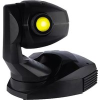
Black Martin projector with X250 model and label (no additional text or symbols visible)
natural_image
Black Martin Punisher X250 projector device with visible branding and no additional text or symbols on the device itself.

natural_image
Technical line drawing of a mechanical assembly with dimension标注 (340), showing no readable text or symbols.dimensions in millimeters
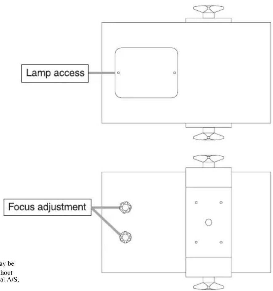
flowchart
graph TD
    A["Lamp access"] --> B["Component"]
    C["Focus adjustment"] --> D["Component"]
    style A fill:#f9f,stroke:#333
    style C fill:#ccf,stroke:#333
© 1996 - 2001
Martin Professional A/S, Denmark.
All rights reserved. No part of this manual may be reproduced, in any form or by any means, without permission in writing from Martin Professional A/S, Denmark.
Printed in Denmark.
P/N 35000035, Rev. C.
INTRODUCTION
The Destroyer X250 and Punisher X250, developed and manufactured by Martin Professional, are aggressive disco lighting effects using a powerful 250W halogen lamp. With a motorized parabolic reflector and gobo wheel, they produce a myriad of turning beams that change color and pattern on demand. There is a “flash” effect for strobe-like animation and, on the Punisher, a motor driven “shake” effect.
Unlike most fixtures of this type, the effects of the Destroyer and Punisher are programmable from any standard DMX-512 controller, using a single or multi-channel protocol. Alternatively, the Destroyer and Punisher can be directly triggered from a music source as stand-alone units. In addition, the Destroyer can run several units in master/client configuration.
FEATURES
Multiple rotating beams
12 pattern gobo wheel, 7 with color and 5 white
24 V/250 W halogen lamp
Dichroic colors
Adjustable focus
Sound-activated beam rotation and color/pattern change
Sound-activated shake effect (Punisher only)
Built-in microphone with automatic sensitivity adjustment
Multi or single channel DMX control
Master/client configuration (Destroyer only)
Stepmotor drive
Adjustable mounting bracket
SAFETY INFORMATION
Warning! This product is not for household use. It presents risks of lethal or severe injury due to fire and heat, electric shock, and falls.
Read this manual before powering or installing the fixture, follow the safety precautions listed below and observe all warnings in this manual and printed on the fixture. If you have questions about how to operate the fixture safely, please contact a Martin distributor for assistance.
To protect yourself and others from electric shock
- Disconnect the fixture from AC power before removing or installing the lamp, fuses, or any part, and when not in use.
- Always ground (earth) the fixture electrically.
- Use only a source of AC power that complies with local building and electrical codes and has both overload and ground-fault protection.
- Do not expose the fixture to rain or moisture.
• Refer all service to a qualified technician. - Never operate the fixture with missing or damaged lenses and/or covers.
To protect yourself and others from burns and fire
- Never attempt to bypass the thermostatic switch or fuses. Always replace defective fuses with ones of the specified type and rating.
- Keep all combustible materials at least 0.1 meters (4 inches) away from the fixture. Keep flammable materials well away from the fixture.
- Do not illuminate surfaces within 0.3 meters (12 inches) of the fixture.
- Provide a minimum clearance of 0.1 meters (4 inches) around fans and air vents.
- Replace the lamp if it becomes defective or worn out. When replacing the lamp, allow the fixture to cool for at least 15 minutes before opening the fixture or removing the lamp. Protect your hands and eyes with gloves and safety glasses.
- Never place filters or other materials over the lens.
- The thumbscrews holding the lamp socket assembly reach temperatures up to 120^ (250° F). Allow the fixture to cool for 15 minutes before handling.
- Do not operate the fixture if the ambient temperature (Ta) exceeds 40^ ( 104^ ).
To protect yourself and others from injury due to falls
- When suspending the fixture above ground level, verify that the structure can hold at least 10 times the weight of all installed devices.
- Verify that all external covers and rigging hardware are securely fastened and use an approved means of secondary attachment such as a safety cable.
- Block access below the work area whenever installing or removing the fixture.
SETUP
3
The package includes the following items:
Destroyer or Punisher
IEC mains cable
Mounting bracket and hardware
User manual
Before starting to operate the unit you need to:
Install the halogen lamp (not included)
Fit a mains plug
Check voltage setting
Fit the mounting bracket
Rig the unit in its permanent site
WARNING! Always disconnect the unit from AC power before performing any installation or service procedure.
INSTALLING THE LAMP
See the specifications on page 16 for lamps that may be used in the Destroyer X250 and Punisher X250. Do not install any other lamp.
Warning! Allow the unit to cool for 15 minutes before handling.
1 Remove the 2 screws from the lamp access plate on the bottom of the unit.
2 Loosen the thumbscrew and pull back on the lamp socket/reflector assembly until the assembly is free of its mounting plate. Remove the lamp assembly.
3 Hold the new lamp in a cloth to avoid contaminating it with oils from your fingers. Press it squarely into the socket.
4 Hold the lamp assembly by the socket end, with the thumbscrew up. Slide the thumbscrew into the notch on the mounting plate. Align the holes in the assembly with the guide screws on the mounting plate and press the lamp assembly flush against the mounting plate. Tighten the thumbscrew.
5 Replace the lamp access cover.
The Destroyer/Punisher is delivered from the factory without a plug on the mains cable. You will have to fit a plug that conforms to your local mains outlet. The double insulated mains cable contains three wires.
1 Connect the BROWN wire to the LIVE pin.
2 Connect the BLUE wire to the NEUTRAL pin.
3 Connect the YELLOW/GREEN wire to the EARTH pin.
ADJUSTING THE VOLTAGE SETTING
The voltage setting on the Destroyer/Punisher shall match the local power supply. The factory setting is printed on the serial number label on rear of the unit. If the setting does not match the local power supply, rewire the unit as follows:
Important! To prevent damage, the RED wire must be connected to an outside pin as shown.
1 Disconnect the fixture from AC power. Remove the top cover from the unit by unscrewing the 4 screws that hold it in place.
2 Locate and disconnect the plug with red, yellow, and blue wires at the top-right corner of the printed circuit board, as seen from the back of the unit.
3 To change to 230 V AC (EU version) or 110 V AC (US version), flip and move the plug right so that the red wire connects to the pin closest to the edge.
4 To change to 245 V AC (EU version) or 120 V AC (US version), flip and move the plug left so that the red wire connects to the pin furthest from the edge.
5 Replace the top cover before applying power.

Power setting plug as seen from rear
REMOVING THE TRANSPORT SECURITY PLATE (PUNISHER ONLY)
Before first operating the Punisher, you need to remove the transport security plate inside the unit. This plate holds the mirror assembly during transit, and must be removed to enable the “shake effect”.
1 Remove the top cover from the unit by unscrewing the 4 Phillips screws that hold it in place.
2 Locate the parabolic mirror assembly in the center of the unit and unscrew the 4 RED Phillips screws holding the transport plate. Remove the plate.
3 Reassemble the unit.
FITTING THE MOUNTING BRACKET
Fit the supplied mounting bracket using the plastic spacers, star washers and thumbscrews. The star washer must be placed between the bracket and the plastic spacer.
RIGGING THE UNIT
1 Verify that the structure can support at least 10 times the weight of all installed fixtures, clamps, cables, auxiliary equipment, etc.
2 If hanging the fixture with a rigging clamp, verify that the clamp is undamaged and is designed for the fixture's weight. Bolt the clamp securely to the bracket with a grade 8.8 (minimum) M12 bolt and lock nut, or as recommended by the clamp manufacturer, through the clamp hole in the mounting bracket.
3 If permanently installing the fixture, verify that the hardware (not included) and mounting surface can bear at least 10 times the fixture's weight. The four small holes and the clamp hole in the mounting bracket may be used for attachment.
4 Working from a stable platform, clamp or fasten the fixture to the structure.
5 Install a safety cable that can hold at least 10 times the weight of the fixture through/over the support and mounting bracket.
6 Loosen the thumbscrews, tilt the fixture to the desired angle, and retighten.
7 Verify that the fixture is at least 0.3 meters (12 in.) from the surface to be illuminated and at least 0.1 meters (4 in.) from any combustible materials. Verify that the clearance around the air vents is at least 0.1 meters (4 in.).
CONNECTING THE DATA LINK
A reliable data connection begins with the right cable. Standard microphone cable cannot transmit DMX data reliably over long runs. For best results, use cable specifically designed for RS-485 applications.
The XLR data sockets are wired with pin 1 to ground, pin 2 to signal - (cold), and pin 3 to signal + (hot). This is the standard pin assignment for DMX devices. One or more adaptor cables may be required to connect the fixture to the controller and/or other lights as many devices have 5-pin connectors and others may have reversed signal polarity.
1 C onnect a data cable to the controller's output. If controller has a 5-pin output, use a 5-pin male to 3-pin female adaptor cable (P/N 11820005).
2 Lead the data cable from the controller to the first fixture. Plug the cable into the fixture's data input.
3 Connect the output of the fixture closest to the controller to the input of the next fixture. If connecting two fixtures with reversed polarity on pins 2 and 3, insert a phase-reversing cable between the two fixtures.
4 Continue connecting fixtures output to input. Up to 32 devices may be connected on a serial link.
5 Terminate the link by inserting a male termination plug (P/N 91613017) into the data output of the last fixture. A termination plug is simply an XLR connector with a 120 ohm, 0.25 W resistor soldered across pins 2 and 3.
| 5-pin to 3-pin Adaptor |
| Male Female1——12——23——345 |
| P/N 11820005 |
| 3-pin to 5-pin Adaptor |
| Male Female1 ———— 12 ———— 23 ———— 345 |
| P/N 11820004 |
| 3-pin to 3-pinPhase-ReversingAdaptor |
| Male Female1——12——23——3 |
| P/N 11820006 |
| MaleTermination Plug |
| Male XLR123 120 |
| P/N 91613017 |
On the rear of the unit is a 10-way DIP-switch with the following functions:
| Switch ON OFF | ||
| 1 - 8 DMX address (1 - 255) | ||
| 9 1-channel | DMX Multi-channel DMX (5/6) | |
| 10 | Client (DMX reception) | Master (DMX transmission - Destroyer only) |
DMX MODE SETTING
The Destroyer/Punisher has two DMX modes: a 1-channel mode and a multi-channel mode that requires 5 channels for the Destroyer and 6 channels for the Punisher.
The 1-channel mode is simpler and saves channels on your controller. In this mode, the unit becomes more aggressive the higher you set the fader. The Martin MC-1 controller is specially designed to operate the Destroy/Punisher and other Martin products is 1-channel mode. When using the Destroyer X250 and Punisher X250 with the MC-1, the address (see below) must be set to DMX channel 1.
For full control of each effect, use the multi-channel mode. The functions of each mode are described in appendix a.
- Use DIP-switch 9 to select the DMX mode. Flip the pin ON for 1-channel operation of OFF for multi-channel operation.
ADDRESS SETTING
Use the first 8 DIP-switches to set the DMX address (the first DMX channel on which the Destroyer/Punisher responds to the controller) to any value between 1 and 255. The address is the sum of the values for each individual DIP-switch that is ON.
Important! DIP-switch 10 must be flipped ON when using the Destroyer or Punisher with a controller. Otherwise, both the unit and the controller will transmit DMX signals and damage to one or both devices may occur.
1 Select an address for the fixture on your controller. When using the MC-1 controller, the address must be DMX channel 1.
2 Look up the DIP-switch setting for the address on page 11.
3 Set pins 1 through 8 to the ON (1) or OFF (0) position as listed in the table.
4 Set pin 9 to ON for 1-channel operation, or OFF for multi-channel operation.
5 Set pin 10 to the ON position.
ADDRESS TABLE
Locate the channel in the table below. Follow the row to the left to find the settings for pins 1 to 5; follow the column to the top to find the settings for pins 6 to 8. Pin 9 selects DMX mode. Pin 10 selects controller or stand-alone operation and stand-alone master/client on the Destroyer.
| DIP-Switch Setting0 = OFF1 = ON | #10 1: controller, 0: stand-alone | ||||||||||||
| #9 1: 1 channel, 0: 5/6 channel DMX | |||||||||||||
| # | 8 | 0 | 0 | 0 | 0 | 1 | 1 | 1 | |||||
| # | 7 | 0 | 0 | 1 | 1 | 0 | 0 | 1 | |||||
| # | 6 | 0 | 1 | 0 | 1 | 0 | 1 | 0 | |||||
| #1 #2 | #3 #4 #5 | ||||||||||||
| 0 0 0 0 | 0 32 64 | 96 128 | 160 192 | 224 | |||||||||
| 1 0 0 0 | 0 1 33 | 65 97 12 | 9 161 1 | 93 225 | |||||||||
| 0 1 0 0 | 0 2 34 | 66 98 13 | 0 162 1 | 94 226 | |||||||||
| 1 1 0 0 | 0 3 35 | 67 99 13 | 1 163 1 | 95 227 | |||||||||
| 0 0 1 0 | 0 4 36 | 68 100 | 132 164 | 196 228 | |||||||||
| 1 0 1 0 | 0 5 37 | 69 101 | 133 165 | 197 229 | |||||||||
| 0 1 1 0 | 0 6 38 | 70 102 | 134 166 | 198 230 | |||||||||
| 1 1 1 0 | 0 7 39 | 71 103 | 135 167 | 199 231 | |||||||||
| 0 0 0 1 | 0 8 40 | 72 104 | 136 168 | 200 232 | |||||||||
| 1 0 0 1 | 0 9 41 | 73 105 | 137 169 | 201 233 | |||||||||
| 0 1 0 1 | 0 10 42 | 74 106 | 138 170 | 202 234 | |||||||||
| 1 1 0 1 | 0 11 43 | 75 107 | 139 171 | 203 235 | |||||||||
| 0 0 1 1 | 0 12 44 | 76 108 | 140 172 | 204 236 | |||||||||
| 1 0 1 1 | 0 13 45 | 77 109 | 141 173 | 205 237 | |||||||||
| 0 1 1 1 | 0 14 46 | 78 110 | 142 174 | 206 238 | |||||||||
| 1 1 1 1 | 0 15 47 | 79 111 | 143 175 | 207 239 | |||||||||
| 0 0 0 0 | 1 16 48 | 80 112 | 144 176 | 208 240 | |||||||||
| 1 0 0 0 | 1 17 49 | 81 113 | 145 177 | 209 241 | |||||||||
| 0 1 0 0 | 1 18 50 | 82 114 | 146 178 | 210 242 | |||||||||
| 1 1 0 0 | 1 19 51 | 83 115 | 147 179 | 211 243 | |||||||||
| 0 0 1 0 | 1 20 52 | 84 116 | 148 180 | 212 244 | |||||||||
| 1 0 1 0 | 1 21 53 | 85 117 | 149 181 | 213 245 | |||||||||
| 0 1 1 0 | 1 22 54 | 86 118 | 150 182 | 214 246 | |||||||||
| 1 1 1 0 | 1 23 55 | 87 119 | 151 183 | 215 247 | |||||||||
| 0 0 0 1 | 1 24 56 | 88 120 | 152 184 | 216 248 | |||||||||
| 1 0 0 1 | 1 25 57 | 89 121 | 153 185 | 217 249 | |||||||||
| 0 1 0 1 | 1 26 58 | 90 122 | 154 186 | 218 250 | |||||||||
| 1 1 0 1 | 1 27 59 | 91 123 | 155 187 | 219 251 | |||||||||
| 0 0 1 1 | 1 28 60 | 92 124 | 156 188 | 220 252 | |||||||||
| 1 0 1 1 | 1 29 61 | 93 125 | 157 189 | 221 253 | |||||||||
| 0 1 1 1 | 1 30 62 | 94 126 | 158 190 | 222 254 | |||||||||
| 1 1 1 1 | 1 31 63 | 95 127 | 159 191 | 223 255 | |||||||||
If the unit does not receive control data, it automatically goes into stand-alone mode and performs a random sequence triggered by sounds picked up by the built-in microphone.
If you have two or more Destroyers, this feature allows you to operate all the units in synchronization. You must assign one, but only one, unit to be master, by setting DIP-switch 10 OFF. The unit will then be sending DMX signals (via its XLR in and output connectors) that correspond to what it is doing itself. You can then connect up to 32 clients which will all perform exactly the same when set to DMX address 1.
Important! To prevent damage to the electronic circuitry, one, and only one, fixture may be set as master (DIP-switch 10 OFF).
1 Disconnect all fixtures from AC power.
2 On the master unit, set DIP-switch 10 OFF.
3 On all client units, set DIP-switch 1 and 10 ON.
4 Insert a 120Ω female XLR termination plug (P/N 91613018) in the DMX input socket of the master unit.
5 Connect the DMX output of the master unit to the input of one of the clients using a XLR-XLR cable. Continue the link this way, always connecting output to input (daisy-chain), until all clients are linked together.
| Female Termination Plug |
| Female XLR123 120 |
| P/N 91613018 |
6 Finally, insert a 120Ω male XLR termination plug (P/N 91613017) in the free output socket of the last unit on the link.
7 Apply power first to the master and then to the client fixtures.
MULTI-CHANNEL MODE
| DMX Channel | DMX Value | Description |
| 1 | 0 - 1112 - 193194 - 255 | Lamp ON/OFFLamp OFFLamp ONGobo strobe: slow → fast |
| 2 | 0 - 1112 - 127128 - 255 | Trigger ModeOffMusic triggeredController triggered - triggers when DMX level crosses 195 |
| 3 | 0 - 9192 - 9899 - 189190 - 231232 - 255 | Parabol SpeedThe rotation time is equal to the trigger decay if trigger mode is set to music or controller Rotation CW, fast → slowStopRotation CCW, slow → fastRandom CW/CCW slow (music/controller triggered)Random CW/CCW fast (music/controller triggered) |
| 4 | 0 - 45 - 252253 - 255 | Trigger Decay0 seconds0.2 to 9.9 secondsRandom (music/controller triggered) |
| 5 | Color/Gobo Wheel | |
| 0 - 5 | Blackout | |
| 6 - 20 | Position 1 | |
| 21 - 36 | Position 2 | |
| 37 -52 | Position 3 | |
| 53 - 68 | Position 4 | |
| 69 - 84 | Position 5 | |
| 85 - 100 | Position 6 | |
| 101 - 116 | Position 7 | |
| 117 - 132 | Position 8 | |
| 133 - 148 | Position 9 | |
| 149 - 164 | Position 10 | |
| 165 - 180 | Position 11 | |
| 181 - 196 | Position 12 | |
| 197 - 244 | No effect | |
| 245 - 255 | Random (music/controller triggered) | |
| 6 | Shake (Punisher only) | |
| 0-4 | Off | |
| 5-252 | Slow → fast | |
| 253-255 | Random (music/controller triggered) |
SINGLE-CHANNEL MODE
Channel DMX Value Effect
| 0 - 50 | Blackout | |
| 51 - 101 | Slow random action | |
| 1 | 102 - 152 | Medium random action |
| 153 - 203 | Fast random action | |
| 204 - 255 | Random speed and action |
TROUBLESHOOTING
Problem Probable cause(s) Suggested remedy
| None of the units respond to the controller. | The controller is disconnected from the DMX link. | Connect controller. |
| Use of incorrect cable between the controller and the first unit on the DMX link. | Check pin-out of DMX controller against Destroyer/Punisher and ensure that signal + goes to signal + and signal - goes to signal -. | |
| One or more of the units does not respond to the controller or respond erratically. | Bad DMX link connection. | Check connections/cables in the DMX link and correct accordingly. |
| DMX link not terminated with termination plug. | Insert termination plug in the last unit on the DMX link. | |
| Incorrectly addressing (DIP-switch setting) of the unit. | Ensure that all units are addressed in compliance with the controller configuration. | |
| Unit not powered on. Power on unit. | ||
| One or more units are set to master, i.e. DIP-switch 10 OFF. | Set DIP-switch 10 ON. | |
| One of the units is defective and disturbs the data transmission on the link. | By-pass one unit at a time until normal operation is regained. Do this by unplugging the XLR in and out connectors and then connect them directly together. | |
| No light emission from unit. No lamp or lamp blown. Install or replace lamp. | ||
| Unit appears to be completely dead (no reset when switching on). | Mains fuse blown. Replace fuse located in power input socket. | |
| PCB fuse blown. Replace PCB fuse. | ||
| Lamp is cutting out intermittently. | Room temperature is too high. | Reduce room temperature. |
| Fan speed is reduced due to fan covered by dirt and dust. | Clean fan and air vents. | |
| Incorrect voltage setting. Check voltage setting. Correct if necessary (230/245V, 110/120V). | ||
SPECIFICATIONS
PHYSICAL
Size (L x W x H).... 340 x 265 x 303 mm (13.4 x 10.4 x 11.9")
Weight.... 7 kg (15.4 lbs.)
THERMAL
Maximum ambient temperature ( T_a ) 40°C (104°F)
Maximum surface temperature....120°C (250°F)
CONTROL AND PROGRAMMING
Data pin-out ......pin 1 shield, pin 2 cold (-), pin 3 hot (+)
Control protocol....USITT DMX-512 (1990)
DMX channels, Destroyer ....1/5
DMX channels, Punisher....1/6
AC POWER
Max. power and current..... 270 W, 1.2 A @ 230 V; 270 W, 2.3 A @ 120 V
Input socket.... 3-prong IEC male socket
Input, 230/245 V model.... 230/245 V, 50-60Hz
Input, 110/120 V model.... 110/125 V, 50-60Hz
Primary fuse, 230/245 V model....2.5 AT / 250 V, P/N 05020010
Primary fuse, 110/120 V model.... 5.0 AT / 250 V, P/N 05020018
INSTALLATION
Minimum distance to combustible materials....0.1 m (4 in)
Minimum distance to illuminated surfaces....0.3 m (12 in)
Minimum clearance around fan and air vents....0.1 m (4 in)
ACCESSORIES
MC-1 controller, EU....90718000
MC-1 controller, US 90718100
50 hour lamp, halogen, EHJ, 24V/250W....97000105
300 hour lamp, halogen, EVC (M33), 24V/250W .....97000103
G-clamp 91602003
Half-coupler....91602005



- Destroyer X250 Punisher X250
- INTRODUCTION
- FEATURES
- SAFETY INFORMATION
- Warning! This product is not for household use. It presents risks of lethal or severe injury due to fire and heat, electric shock, and falls.
- To protect yourself and others from electric shock
- To protect yourself and others from burns and fire
- To protect yourself and others from injury due to falls
- SETUP
- 3
- WARNING! Always disconnect the unit from AC power before performing any installation or service procedure.
- INSTALLING THE LAMP
- Warning! Allow the unit to cool for 15 minutes before handling.
- ADJUSTING THE VOLTAGE SETTING
- Important! To prevent damage, the RED wire must be connected to an outside pin as shown.
- REMOVING THE TRANSPORT SECURITY PLATE (PUNISHER ONLY)
- FITTING THE MOUNTING BRACKET
- RIGGING THE UNIT
- CONNECTING THE DATA LINK
- DMX MODE SETTING
- ADDRESS SETTING
- ADDRESS TABLE
- Important! To prevent damage to the electronic circuitry, one, and only one, fixture may be set as master (DIP-switch 10 OFF).
- SINGLE-CHANNEL MODE
- TROUBLESHOOTING
- SPECIFICATIONS
- PHYSICAL
- THERMAL
- CONTROL AND PROGRAMMING
- AC POWER
- INSTALLATION
- ACCESSORIES
Brand : MARTIN
Model : Destroyer X250
Category : Light projector