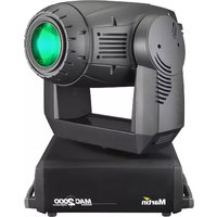
MAC 2000 Performance II - Light projector MARTIN - Free user manual and instructions
Find the device manual for free MAC 2000 Performance II MARTIN in PDF.


| Product Type | Moving Head Spotlight |
| Dimensions (L x W x H) | 450 x 350 x 650 mm |
| Weight | 25 kg |
| Power Consumption | 1500 W |
| Light Source | 1200 W discharge lamp |
| Zoom Range | 15° - 30° (motorized) |
| Color Wheel | 14 colors + open, split colors |
| Gobo Wheel | 8 rotating gobos + open, indexable |
| Dimmer | 0-100% continuous |
| Strobe | 0-20 Hz |
| Pan Movement | 540° |
| Tilt Movement | 270° |
| Control Protocol | DMX512, RDM |
| DMX Channels | 18 or 23 (selectable) |
| Power Connector | PowerCon TRUE1 |
| IP Rating | IP20 (indoor use only) |
| Safety | CE, ETL certified; Safety cable attachment point |
| Maintenance | Lamp replacement every 750 hours; clean air filters monthly |
| Spare Parts | Lamp, gobos, color filters, arc power supply |
Frequently Asked Questions - MAC 2000 Performance II MARTIN
User questions about MAC 2000 Performance II MARTIN
0 question about this device. Answer the ones you know or ask your own.
Ask a new question about this device
Download the instructions for your Light projector in PDF format for free! Find your manual MAC 2000 Performance II - MARTIN and take your electronic device back in hand. On this page are published all the documents necessary for the use of your device. MAC 2000 Performance II by MARTIN.
USER MANUAL MAC 2000 Performance II MARTIN
natural_image
Black Martin MAC 2000 lighting fixture on a stand (no visible text or symbols on device body)Dimensions
All dimensions are in millimeters

CONTENTS
INTRODUCTION 5
Safety information.... 5
TRANSPORTATION 7
Included items....7
Transport locks 7
Single flight case.... 7
Double flight case 8
AC POWER 9
Fuses 9
Power supply adjustments 9
Power connection 9
Reduced power function 9
DATA 10
Connecting fixtures.... 10
RIGGING....11
CONTROL PANEL 12
Navigation.... 12
DMX address and protocol setting 12
Tailoring performance.... 12
Readouts 13
Service messages.... 14
Service utilities 14
EFFECTS 16
Framing shutters.... 16
Gobos 16
Gobo animation system 16
Dimming and strobe 17
Color mixing 17
Color temperature correction 17
Effect wheel 17
Iris 17
Focus and zoom 17
Pan and tilt 17
Speed control 18
ANIMATION GUIDE 19
General animation tips 19
Animation discs and their uses 20
Effects ideas 22
OPTICAL CONFIGURATION 29
Rotating gobo wheel 29
Effect wheel 32
Gobo animation.... 32
ROUTINE MAINTENANCE 34
Lamp 34
Cleaning 36
Software installation 37
DMX PROTOCOL 38
16-bit protocol 39
8-bit protocol 42
CONTROL MENU 45
ADJUSTMENT SUBMENU 49
DISPLAY MESSAGES 51
TROUBLESHOOTING 52
CIRCUIT BOARD CONNECTIONS....53
SPECIFICATIONS
MAC 2000 PERFORMANCE II....54
INTRODUCTION
Thank you for selecting the MAC 2000 Performance II. The MAC 2000 Performance II is a 1200 W moving head spotlight that provides CMY color mixing, continuous color correction (CTC), four-blade framing system, motorized iris, gobo wheel with five indexable rotating gobos, indexable gobo animation wheel, effect wheel with 3 effects (wide-angle converter lens, non-rotating nine-facet prism and variable frost), combined dimmer/shutter, focus, zoom, 540° of pan, and 267° of tilt. The MAC 2000 Performance II has an electronic ballast that provides flicker-free operation, an economic power-saving mode. and an auto-ranging switch-mode power supply (SMPS) that removes the need for manual adjustments to the transformer or ballast.
For the latest firmware updates, documentation, and other information about this and all Martin Professional products, please visit the Martin web site at http://www.martin.com.
Safety information
Warning! This product is for professional use only. It is not for household use.
This product presents risks of lethal or severe injury due to fire and heat, electric shock, ultraviolet radiation, lamp explosion, and falls. Read this manual before powering or installing the fixture, follow the safety precautions listed below and observe all warnings in this manual and printed on the fixture. If you have questions about how to operate the fixture safely, please contact your Martin dealer or call the Martin 24-hour service hot line at +45 70 200 201.
Protection from electric shock
- Disconnect the fixture from AC power before removing or installing the lamp, fuses, or any part, and when not in use.
- Always ground (earth) the fixture electrically.
- Use only a source of AC power that complies with local building and electrical codes and has both overload and ground-fault protection.
- Do not expose the fixture to rain or moisture.
- Refer any service operation not described in this manual to a qualified technician.
Protection from UV radiation and lamp explosion
- Do not operate the luminaire with missing or damaged covers, shields, lenses or ultraviolet screens: an unshielded discharge lamp emits UV radiation that can cause burns and eye damage.
- Do not stare directly into the light output. Never look at an exposed lamp while it is lit.
- A hot discharge lamp is under pressure and can explode without warning. Allow the luminaire to cool for at least 20 minutes and protect yourself with safety glasses and safety gloves before replacing the lamp or servicing the luminaire internals.
- If the quartz envelope of a discharge lamp is broken, the lamp releases a small quantity of mercury and other toxic gases. If a discharge lamp explodes in a confined area, evacuate the area and ventilate it thoroughly. Wear non-porous safety gloves when handling a broken discharge lamp. Treat broken or used discharge lamps and used safety gloves as hazardous waste and send to a specialist for disposal.
- Replace the lamp if it becomes visually deformed, damaged or in any way defective
- Replace the lamp when it reaches the limit of its average life as specified in this manual or by the lamp manufacturer.
• Install only an approved lamp.
Protection from burns and fire
- Never attempt to bypass the thermostatic switch or fuses. Always replace defective fuses with ones of the specified type and rating.
- Keep all combustible materials (for example fabric, wood, paper) at least 1.0 meter (39 inches) away from the fixture. Keep flammable materials well away from the fixture.
- Do not illuminate surfaces within 1.0 meter (39 inches) of the fixture.
- Provide a minimum clearance of 0.1 meters (4 inches) around fans and air vents.
- Never place filters or other materials over the lens.
- The exterior of the fixture can get very hot. Allow the fixture to cool for at least 5 minutes before handling.
- Do not modify the fixture or install other than genuine Martin parts.
- Do not operate the fixture if the ambient temperature (Ta) exceeds 40^ ( 104^ ).
Protection from injury due to falls
- Do not lift or carry the fixture alone.
- When suspending the fixture, verify that the structure can hold at least 10 times the weight of all installed devices.
- Verify that all external covers and rigging hardware are securely fastened and use an approved means of secondary attachment such as a safety cable.
- Block access below the work area whenever installing or removing the fixture.
TRANSPORTATION
Important! Release the transport locks before operating the fixture.
Included items
The MAC 2000 Performance II is shipped in a cardboard carton or 1 or 2 unit flight case that contains the following items.
- User manual
- 2 x 20 A main fuses (for use with 100-130 V local power supply)
- 2 x 15 A main fuses (for use with 200-250 V local power supply)
• 4 additional animation wheels - 2 aluminium gobos
• 2 clamp attachment brackets

Figure 1: Pan and tilt locks
Transport locks
The head and yoke may be locked for transportation and service. The locks are shown in Figure 1. The fixture must be unlocked before operation.
Single flight case
Unpacking the fixture
1 Remove the top of the flight case.
2 With one person on each side, lift the fixture out of the bottom of the flight case.
3 Release the pan and tilt locks before operating.
Packing the fixture
1 Disconnect the fixture from power and allow it to cool.
2 Lock the head and yoke in the position shown in Figure 2.
3 Place the fixture in the bottom of the flight case. Place the top section over the fixture without forcing.

natural_image
Line drawing of a mechanical projector mounted on a base (no text or symbols)Figure 2: Single unit transport position
Double flight case
Unpacking
1 Open the flight case and pull the drawer all the way out.
2 Release the head (tilt) transport lock.
3 Install rigging hardware as described on page 12.
4 With one person on each side, lift the fixture out of the flight case.
Packing
1 Disconnect the fixture from power and allow it to cool.
2 Turn the yoke parallel to the sides of the base with the tilt lock closest to the back.
3 Pull the transport drawer all the way out. With one person on each side, place the fixture on the drawer with the arrow pointing in.
4 Remove and stow rigging hardware. Coil and stow the power cord in the door.
5 Tilt the head so that the lens points away from the door as shown in Figure 3. Lock the head in the horizontal position. Do not lock the yoke.
6 Slide the drawer all the way in without forcing. Close the flight case.

Figure 3: Double unit transport position
Setup for flight case testing
The double flight case has two slide-out arms from which the fixture can hang for testing and setting. Though unnecessary, the pan and tilt reset can be cancelled by pressing [Menu] and [Enter] at the same time when powering on.
1 Open the flight case and pull the drawer all the way out. Release the transport locks.
2 Pull the test arms all out. Tilt the fixture up and over the slide arms so that the handle cross-braces that are second from the back rest on the arms. The fixture should rest at an angle.
3 Push the transport drawer into the flight case.
AC POWER
WARNING! For protection from electric shock, the fixture must be grounded (earthed). The AC mains supply shall be fitted with a fuse or circuit breaker and ground-fault protection.
Important! Verify the power supply settings before applying power.
The chapter describes:
- Installing fuses
- Power supply adjustments for the various MAC 2000 Performance II models
- Connection to a power supply (see page 9)
• The reduced power function (see page 10)
Fuses
The MAC 2000 Performance II comes with two:
- 20 AT (time delay) main fuses for use with AC supplies of 100 - 120 volts.
- 15 A main fuses for use with AC supplies of 200 - 250 volts.
Install the appropriate fuses in the holders near the power switch.
Power supply adjustments
The MAC 2000 Performance II (identified as such by the label on the base of the product) comes with an electronic ballast and an auto-sensing, auto-ranging switch-mode power supply. Manual adjustments to the transformer or ballast are not necessary as the MAC 2000 Performance II automatically adapts to the mains voltage and frequency.
Note that MAC 2000 fixtures from S/N 4006756001 to S/N 4017886000 manufactured from mid-2003 to mid-2004 contained a power supply unit that needed to be switched to match AC power voltages below 130 V or above 200 V.
Power connection
Important! Connect the MAC 2000 Performance II directly to AC power. Do not connect it to a dimmer system; doing so may damage the fixture.
You may need to install a cord cap that fits your supply on the power cable. A 3-prong grounding-type plug must be installed following the manufacturer's instructions. The table shows some possible pin identification schemes; if the pins are not clearly identified, or if you have any doubts about proper installation, consult a qualified electrician.
To apply power, set the power switch on the base to the "I" position.
| Wire Color Pin Symbol Screw (US) | |||
| brown live L | yellow or brass | ||
| blue | neutral | N | silver |
| yellow/green | ground | ± | green |
Table 1: Cord cap connections
Reduced power function
The MAC 2000 Performance II has an automatic power reduction function, which reduces the consumption to 700W if the shutter/dimmer is closed for more than 10 seconds. This not only increases the lamp life, but also further decreases the overall noise emission of the fixture.
DATA
Important! Never connect more than 1 data input and 1 data output.
The MAC 2000 Performance II has both 3-pin and 5-pin XLR sockets for DMX input and output. The pin-out on all sockets is pin 1 to shield, pin 2 to cold (-), and pin 3 to hot (+). There is no connection to pins 4 and 5.
The sockets are wired in parallel: both inputs connect to both outputs. For reliable data transmission and to avoid damage to the fixture, however, use one input and one output!
Connecting fixtures
- Use shielded twisted-pair cable designed for RS-485 devices: standard microphone cable cannot transmit control data reliably over long runs. 24 AWG cable is suitable for runs up to 300 meters (1000 ft). Heavier gauge cable and/or an amplifier is recommended for longer runs.
- Never use both outputs to split the link. To split the serial link into branches use a splitter such as the Martin 4-Channel Opto-Isolated RS-485 Splitter/Amplifier.
- Do not overload the link. Up to 32 devices may be connected on a serial link.
- Terminate the link by installing a termination plug in the output socket of the last fixture. The termination plug, which is a male XLR plug with a 120 ohm, 0.25 watt resistor soldered between pins 2 and 3, "soaks up" the control signal so it does not reflect and cause interference. If a splitter is used, terminate each branch of the link.
- Martin fixtures introduced before 1997 have reversed polarity data sockets (pin 2 hot and pin 3 cold). The socket polarity is labelled. Use a phase-reversing cable between the MAC 2000 Performance II and any Martin device with reversed polarity.
Connecting the data link
1 Connect the DMX data input from the controller to the MAC 2000 Performance II's 3-pin or 5-pin input (male) socket.
2 Using the sockets that match your data cable, connect the output of the fixture closest to the controller to the input of the next fixture.
3 Insert a male 120 Ω XLR termination plug in the 3-pin or 5-pin output of the last fixture on the link.
RIGGING
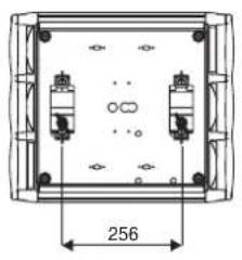
The MAC 2000 Performance II can be placed on stage or clamped to a truss in any orientation. The Fast-Lock system enables quick and easy fastening of the clamp brackets in 4 positions as shown in Figure 4.
natural_image
Technical diagram of a mechanical or electrical component with two vertical slots and a dimension label (256), no readable text or symbols present.
natural_image
Technical diagram of a rectangular electronic component with mounting holes and internal components, dimensioned as 256 (no text or symbols present)
natural_image
Top-down schematic of a square enclosure with two small cylindrical objects and dimension label (256) — no text or symbols present.
natural_image
Top-down schematic of a rectangular device with four small components and dimension label (256) — no readable text or symbols beyond the dimension line.Figure 4: Clamp bracket positions
Warning! Always use 2 clamps to rig the fixture. Lock each clamp with both 1/4-turn fasteners. The fasteners are locked only when turned fully clockwise.
Warning! Attach an approved safety cable to the attachment hole in the base. Never use the carrying handles for secondary attachment.
Clamping the fixture to a truss
1 Verify that the rigging clamps (not included) are undamaged and can bear at least 10 times the weight of the fixture. Verify that the structure can bear at least 10 times the weight of all installed fixtures, clamps, cables, auxiliary equipment, etc.
2 Bolt each clamp securely to a clamp bracket with an M12 bolt (grade 8.8 or better) and lock nut.
3 Align a clamp with 2 mounting points in the base. Insert the fasteners into the base and turn both levers a full 1/4-turn clockwise to lock. Install the second clamp.
4 If the truss can be lowered, fixtures can be clamped on directly from the double flight case. If the fixture must be lifted, block access under the work area. Working safely from a stable platform, hang the fixture on the truss with the arrow towards the area to be illuminated. Tighten the rigging clamps.
5 Install a safety wire that can bear at least 10 times the weight of the fixture. The attachment point is designed to fit a caribiner clamp.
6 Verify that the pan and tilt locks are released. Verify that there are no combustible materials or surfaces to be illuminated within 1 meter of the fixture, and that there are no flammable materials nearby.
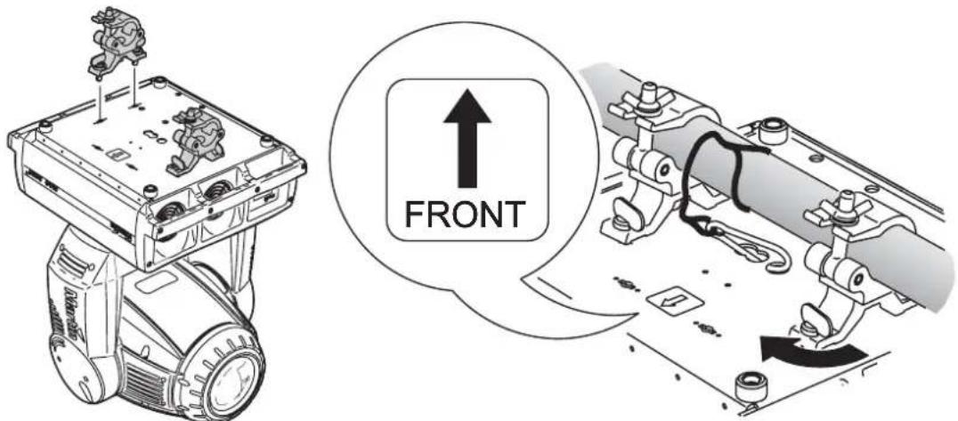
Figure 5: Rigging hardware installation
CONTROL PANEL
The LED control panel is used to set the address and personalities, read lamp hours and other information, calibrate effects, and run a test routine. Most of these functions may be performed remotely via the serial link with the Martin MP-2 Uploader.
Navigation
The DMX address and any messages (see page 52) are displayed when the MAC 2000 Performance II is turned on. To enter the menu, press [Menu]. Press [Up] and [Down] to move within the menu. To select a function or submenu, press [Enter]. To escape a function or menu, press [Menu]. See Table 2 on page 46 for a complete list of the menu items.
Note: [Enter] must be pressed and held for a few seconds to enter the utilities menu.
DMX address and protocol setting
The DMX address, also known as the start channel, is the first channel used to receive instructions from the controller. For independent control, each fixture must be assigned its own control channels. Two MAC 2000 Performance IIs may share the same address, however, if identical behavior is desired. Address sharing can be useful for diagnostic purposes and symmetric control, particularly when combined with the inverse pan and tilt options.
Two DMX protocols, 8-bit and 16-bit, are available. The 8-bit mode uses 28 control channels and provides full basic control. The 16-bit mode uses 3 additional channels to provide finer gobo and pan/tilt positioning.
Setting the DMX address and protocol
1 Press [Menu] to enter the main menu.
2 Press R[D] is displayed Press [Enter]. To snap to channel 1, press [Enter] and [Up]. Scroll to the desired channel and press [Enter].
3 Select PSET from the main menu and press [Enter]. Select 86, t or 166t and press [Enter].
Tailoring performance
Movement
The MAC 2000 Performance II provides six options for optimizing movement for different applications.
- The protocol setting (PSET) setting selects 8-bit or finer 16-bit control of pan, tilt, and gobo index.
- The pan and tilt invert (PRTI) menu swaps and/or inverts pan and tilt.
- The pan/tilt speed (PTSP) menu provides 3 settings: FAST, NORM, and SLOW. NORM is best for most applications. FAST provides better performance in applications where speed is most important. SLOW provides the smoothest movement and is best in long-throw applications with slow movements through narrow angles.
- The studio mode (STUD) setting optimizes all effects besides pan and tilt for speed or quietness.
- The shortcuts (SCUT) setting determines whether the gobo, and effect wheels always take the shortest path between two static positions or oscillate between outer positions.
Tracking Response
The MAC 2000 Performance II has a filter algorithm that looks at several position updates in tracking control mode and calculates the ideal response for smooth movement. Tracking response is adjustable to compensate for variations in controller performance. In most cases the default settings work well.
If tracking mode movement is not satisfactory there are 2 parameters that can be adjusted. The first is selected under PERS/TRAC/MODE. The default, MOD1, is the best choice with controllers that calculate intermediate positions at a steady rate. Begin by selecting the alternative, MODE2, which is better if the intermediate positions stray significantly from the line of travel.
The second parameter is the number of position updates used to calculate speed. The level is adjustable between 1 and 10 under PERS/TRAC/CAL. Increasing the number of samples increases the distance over which speed is calculated, making movement smoother but less responsive to sudden changes. Experiment for best results.
Display
The display intensity (dINT) setting controls display brightness. The display on/off setting (dISP) determines whether the display remains on or extinguishes two minutes after the last key-press. To flip the display, press [Up] and [Down] simultaneously.
Lamp
There are two settings that modify lamp control: Automatic Lamp On (ALON) and DMX Lamp Off (JLOF).
When ALON is off, the lamp remains off until a "lamp on" command is received from the controller. When ALON is on, the lamp strikes automatically after the fixture is powered on. When ALON is set to DMX, the lamp strikes automatically when the fixture receives DMX data, and it extinguishes 15 minutes after DMX data is lost.
When ALON is set to either ON or IMX, the automatic lamp strike timing is staggered to prevent all lamps from striking at once. The delay is determined by the fixture address.
If striking lamps from the controller, note that striking many lamps at once may cause a voltage drop large enough to prevent lamps from striking or trip the main circuit breaker. Avoid this by programming a "lamp on" sequence that strikes lamps one at a time at 5 second intervals.
Power to the lamp can be turned off from the controller if DMX Lamp Off (DLOF) is on.
DMX reset
The fixture can be reset from the controller if DMX reset (PERS→dRES) is ON.
Custom settings
The custom configuration function allows you to save and recall three sets of fixture settings. The savable settings are DMX mode, pan/tilt speed, pan/tilt inverse and swap, DMX lamp off and reset, display settings, shortcuts, studio mode, automatic lamp on, effects feedback, tracking algorithm, and tracking samples.
Readouts
Note: The MP-2 Uploader provides commands to display the time, temperature, and version readouts on the fixture control panel.
Time
INFO→TIME provides readouts of fixture hours (HRS), lamp hours (L HR), and lamp strikes (L ST). Under each item is a resettable (RSET) increment counter and a non-resettable counter for total accumulated hours/strikes since fabrication (T0TL). To reset an increment counter, display it and then press [Up] until it reads 0. (This may also be done remotely using the MP-2 Uploader.)
Temperature
INFO→TEMP provides readouts of the head and base temperature in Celsius and Fahrenheit.
Firmware version
INFO→VER displays the version number of the installed firmware. The firmware version is also displayed briefly at startup.
DMX
The DMXL menu shows the DMX start code (STC0) and DMX values received for each effect.
Service messages
The Service LED on the control panel lights under conditions that require fixture service, and there is a message describing the service required. To display the message, select SMSG in the main menu. This item is available only when the LED is lit. There are two service messages.
REPLACE LAMP is displayed when the lamp counter exceeds 750 hours, which is the rated average life for the HMI 1200 W/S lamp. The maximum service life is 125% of the average life, or 940 hours.
FIXTURE OVERHEATING is displayed when the head temperature exceeds 120^ C ( 248^ F). Overheating is likely due to dirty air filters, fans, or air vents; incorrect power supply settings, or a defective fan.
Service utilities
Important! Enter must be held for several seconds to access the utilities menu.
Test sequences
TSEQ provides a general test of all effects that can be run without a controller. UTIL→PCBT provides routines for circuit board testing that are for service use only.
Feedback toggles
An on-the-fly position correction system monitors the gobo wheel, gobos, and effect wheel. If a position error is detected, the shutter closes while the effect resets. This feature can be disabled by turning effects feedback (UTIL→EFFb) off.
The automatic pan/tilt position correction system may be temporarily turned off under U FEBR . The off setting, however, is not saved and the system will be re-enabled the next time the fixture starts. If the system cannot correct the pan/tilt position within 10 seconds, feedback is automatically disabled.
Adjustment
The adjustment menu (U T I L → R d J) provides manual control for making mechanical adjustments. See page 50.
Calibration
The calibration menu (UTIL→CAL) provides utilities to define offsets in software that are relative to the mechanical reset or home positions. This allows you to fine tune optical alignment and achieve uniform performance between fixtures. Dimmer and zoom are calibrated to defined points. The other effects are calibrated relative to an arbitrary reference fixture.
Default offset settings may be restored by selecting default offsets (UTIL→dFOF).
Calibrating effects
1 Apply power but do not strike the lamp until zoom has been calibrated.
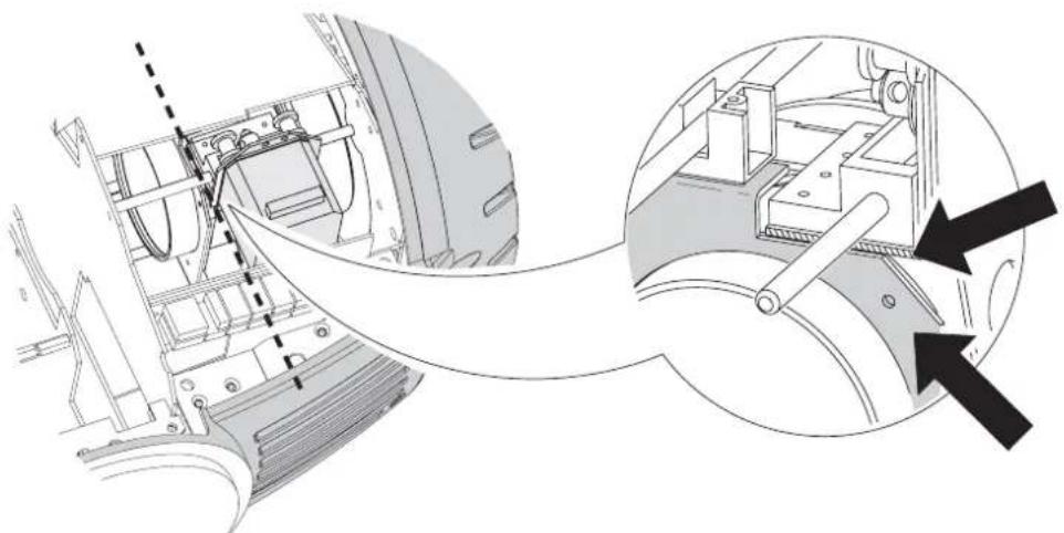
2 To calibrate zoom, first remove the bottom head cover. Select UTIL→CAL→Z00F and press [Enter]. Adjust the offset until the face of the zoom lens plate is flush with the back edge of the focus plate (Figure 6). Press [Enter] to save the setting. Replace the bottom head cover.
natural_image
Technical diagram showing mechanical assembly with zoomed-in detail (no text or symbols)Figure 6: Zoom calibration point
3 Pan calibration is most useful when multiple fixtures are stacked vertically. To calibrate, set zoom, focus, iris, and tilt position for easy one-over-the-other comparison and set each fixture to the same pan DMX value. Select one fixture to be the reference fixture. On the other fixtures, select UTIL→CAL→P OF and press [Enter]. Adjust the offset as necessary to align the beam with the reference beam. Press [Enter] to save the setting.
4 Tilt calibration is most useful when multiple fixtures are arranged horizontally. To calibrate, set zoom, focus, iris, and pan position for easy side-by-side comparison and set each fixture to the same tilt DMX value. Select one fixture to be the reference fixture. On the other fixtures, select UTIL→CAL→T OF and press [Enter]. Adjust the offset as necessary to align the beam with the reference beam. Press [Enter] to save the setting.
5 To calibrate the dimmer, select UTIL→CAL→D OF and press [Enter]. Hold a piece of paper over the lens. Set the offset to 0 and then increase it until light is clearly projected onto the paper. Press [Enter] to save the setting. Remove the paper.
6 To calibrate color mixing flags (cyan, magenta, yellow, and color temperature correction), project white beams with no dimming and position them for easy comparison. On each fixture, including the reference, select UTIL→CAL→C OF and press [Enter]. (This adds a defined amount of cyan.) Select one fixture to be the reference. Adjust the offsets on the other fixtures to match the reference color. Press [Enter] to save the setting. Repeat for M OF (magenta), Y OF (yellow), and CTOF (CTC).
7 Focus calibration is useful when two or more fixtures are the same distance from a projection surface. To calibrate focus, set up all fixtures with the same focus, zoom, dimming, iris, and gobo values. Select a focussed fixture to be the reference. On the other fixtures, select UTIL→CAL→FOOF and press [Enter]. Adjust the offset to focus the image. Press [Enter] to save the setting.
Software upload
The software update mode is normally engaged automatically by the upload device.
EFFECTS
The MAC 2000 Performance II is compatible with USITT DMX512 controllers. The fixture has two DMX operating modes, 8-bit and 16-bit. 16-bit mode requires three more DMX channels than 8-bit mode but provides more precise gobo indexing and pan/tilt positioning. All other functions are identical. The complete DMX protocol begins on page 39.
Framing shutters
Optimized for use in theater, the MAC 2000 Performance II features a fully automated, micro-adjusting framing shutter blade system. For accurate illumination of stage props and scenery, this framing system slices the beam into angled shapes.

natural_image
Diagram of four mechanical components arranged in a circular layout with zigzag lines indicating motion or connection (no text or symbols)The system comprises four shutter blades, arranged in two layers. With this 2-layer system, the MAC 2000 Performance II has been designed to project shapes with crisp, sharp edges.
Each blade can be swiveled +/- 30 degrees, and the entire module rotates 90 degrees. We recommend that the angle of each blade, and the alignment of the entire module be set to 50% of their DMX value. This will set the frame positioning upright, and the shutter blades at right angles. Refer to the "DMX protocol" on page 39 for the specific channels.
Directly attached to the framing system is the iris. You can use either the iris or the framing system, or both together.
Gobos
The gobo wheel provides room for 5 gobos. See page 30 to change gobos.
Gobos may be rotated and shaken at varying speeds and indexed to any position. Extremely accurate positioning is available in 16-bit mode.
The gobo and type of rotation (indexed or continuous, with or without shake) are selected on the wheel's Gobo & Function Channel, which also provide commands for continuous wheel rotation. The gobo position index and rotation speed are selected on its Position/Velocity Channel. In 16-bit mode, the position is further adjusted on the wheel's Fine Position Channel.
Gobo animation system
The gobo animation system is designed to create animated effects such as flames, sky and water imaging. The MAC 2000 Performance II comes with 5 replaceable gobo animation wheels, which are magnetically attached to the motor shaft, and which can be quickly changed. The gobo animation wheel pivots to allow horizontal, vertical, and angled effects, such as rising flames or windswept clouds.
Via your DMX controller, you can control both the starting position of the animation disc and its rotation direction and speed. The animation disc can be set to run continuously or to run in an indexing mode, which will be of great use if you are using custom animation discs with text or company logos. You are also able to choose the angle at which the disc has its starting position, be it horizontally aligned, vertically aligned, or anywhere in between.
For information about:
- Using the gobo animation effects, see "Animation guide" on page 20
- Changing the installed gobo animation wheel, see "Gobo animation" on page 33
Dimming and strobe
The mechanical dimmer/shutter system provides smooth, high-resolution 100 percent dimming, instant open and blackout, random and variable strobe effects up to 10 Hz, and random and variable pulses in which the dimmer snaps open and slowly dims or snaps closed and slowly opens.
Color mixing
The color mixing system uses continuous dichroic cyan, magenta, and yellow (CMY) color filters. It is a subtractive system that removes color from white light. Inserting all three filters results in loss of light: for maximum brightness, mix 2 colors at a time.
Color temperature correction
The color temperature correction (CTC) system uses a continuous 0 - 178 mireds color filter that lowers the color temperature from 6000 K to 2900 K.
Effect wheel
The effect wheel provides a variable frost filter and two slots that house a wide angle converter lens (beam expander) and a nine-facet prism.
Iris
The iris closes down to 15 percent of its full-open diameter with high, 200-step resolution. The Iris Channel also provides random and variable speed pulsating iris effects.
Focus and zoom
The focus lens focusses the beam from approximately 2 meters (6.5 feet) to infinity. The zoom lens widens the beam from approximately 10^ at full spot to 28^ at full flood.
Pan and tilt
The yoke pans 540° and the head tilts 267°. For maximum positioning accuracy, select 16-bit mode.
The pan/tilt speed (fast, norm, or slow) may be selected on the pan/tilt speed channel. Setting the pan/tilt speed channel to "blackout" causes the shutter to black out the light while the head is moving.
Speed control
There are two ways to control the speed at which effects move from one static position to another. These are known as tracking control and vector control and are selected on the Pan/Tilt Speed and Effect Speed Channels. These channels are independent so you may, for example, combine a vector control pan movement with a tracking control color fade.
In tracking mode, speed is determined by the cross-fade time. The controller continuously sends small position changes that the fixture "tracks." To enable tracking mode, set the relevant speed channel to a tracking value. Note that in addition to enabling tracking control, some tracking values also provide overrides of the menu settings.
In vector mode, speed is set directly on a speed channel. The cross-fade time must be 0. Vector control provides a way to set speed on controllers that do not have programmable fade times and results in smooth movement regardless of the cross-fade time or the controller's processing power.
To open the iris slowly in tracking mode, for example, you program a scene with the iris fully closed and a second scene with the iris fully open. Then you set a cross-fade time between the two scenes of, say, 10 seconds. The controller gradually changes the iris position value from 199 (closed) to 0 (open).
To open the iris slowly in vector mode, you program the iris closed and open as before. Then you set the cross-fade time to 0 and program a slow speed, in the second scene, on the Effect Speed Channel.
ANIMATION GUIDE
This chapter is designed to help you get as much as possible from the gobo animation system in your MAC 2000 Performance II. It contains a section on general animation tips, an overview of the animation disc designs available, and a number of examples of different effects that can easily be created using your animation system.
To achieve most of the effects you will use both an animation disc and a regular gobo. Throughout this guide we have used DHA Lighting in the United Kingdom as the reference for the regular gobos. All of the gobo numbers and designs mentioned belong to the standard range available from DHA Lighting. Their contact details are:
DHA Lighting Limited
284-302, Waterloo Road
London, SE1 8RQ
United Kingdom
Tel: +44 207 771 2900
Fax: +44 207 771 2901
Internet: www.dhalighting.co.uk
E-mail: sales@dhalighting.co.uk
Martin Professional A/S are extremely grateful to DHA Lighting for allowing us to use material previously published by them.
Note that there may be some small differences between the graphical images that you see in this guide and the final animation wheel or gobo designs when you use them, due to the difference in scale. However, we have tried to be as accurate as possible.
General animation tips
Via your DMX controller, you can control both the starting position of the animation disc and its rotation direction and speed. The animation disc can be set to run continuously or to run in an indexing mode, which will be of great use if you are using custom animation discs with text or company logos. You are also able to choose the angle at which the disc has its starting position, be it horizontally aligned, vertically aligned, or anywhere in between.
Choice of gobo
The gobo is the basis of the moving image and should be chosen first. It is worth noting, however, that useful and interesting effects can often be achieved with the most unlikely gobos, by projecting them out of focus.
Focus
With the gobo in hard focus the animation will not be optimized, movement is minimal and results will almost always be disappointing. Similarly with the animation disk in hard focus, you will see a far greater movement, but the gobo pattern will be lost. It is essential therefore to experiment with the focus in order to achieve the best effect. The precise quality of the result and the impression of the motions direction will also depend on the position of the focus.
Animation disc patterns
“Effects ideas” on page 23 describes the variations on the basic effect that individual disc patterns can produce.
Direction of movement
The flexible mounting system for the animation discs inside the MAC 2000 Performance II allow you, through DMX control, to position the wheel at any position through a 90 degree section of the disc. This means that effects can be produced with a horizontal movement - such as clouds, with a vertical movement - such as rising flames, or at any angle in between - such as driving rain. The angle of the rotation can be changed during your show via the DMX control of the fixture.
Note that for some animation effects, which are not strictly horizontal or vertical, you may find it necessary to flip the orientation of the complete head via the pan and tilt control channels to give your desired angle of animation. This will depend on the orientation of the head when you began programming your fixture. If you find, for example, that your 'driving rain' effect is not driving the correct way, flip the orientation and if necessary, rotate the animation wheel in the opposite direction.
Through the DMX control you can select the wheel to operate in indexing mode, rather than continuously rotating. This is useful for any custom animation wheels that you may have made with text or logos. Custom animation wheels are available from the major gobo manufacturers, such as DHA Lighting in London.
Speed
The apparent speed of image movement depends not only on the disc rotation speed, but on the complexity of both the gobo and the disc patterns. Speeds suggested in the examples in this handbook are guidelines and are only intended as a starting point.
Color
The use of the dichroic CMY color changing system of the MAC 2000 Performance II can greatly enhance your animation effects. The system has been designed so that refraction across the beam will give slight variants in color, adding depth to your animations, particularly when using multiple dichroic colors. Some color tips are given in the 'EFFECTS IDEAS' section.
Animation discs and their uses
Five gobo animation wheels are supplied as standard with the MAC 2000 Performance II. The others mentioned here can be ordered from your Martin dealer.
Tangential breakup
The Tangential Breakup disc (P/N 62400215) produces a subtle rippling motion, particularly when moving parallel with the lines of the gobo. It is the most suitable for rising flames, flowing water and other effects where a single direction of movement is required.
This animation wheel is supplied as standard with your MAC 2000 Performance II.

natural_image
Abstract circular pattern with concentric rings and a small dot at center (no text or symbols)Radial breakup
The Radial Breakup disc (P/N 62400211) is perfect for providing a strong regular movement suitable for flickering flames, water ripples, reflected water and shimmers for heat haze or mirage effects.
This animation wheel is supplied as standard with the MAC 2000 Performance II.

natural_image
Abstract circular pattern with radial lines and a central dot (no text or symbols)Spiral breakup
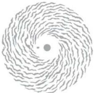
The Spiral Breakup disc (P/N 62400216) pattern is very similar to the Radial Breakup disc, but has some movement at right angles to the main motion, as is seen in wind blown rain, snow, or flames. It is particularly worth experimenting with the angle of the gobo and the orientation of the disc to achieve all the possibilities with this pattern.
This animation wheel is supplied as standard with the MAC 2000 Performance II.
Linear breakup
The Linear Breakup disc (P/N 62400223) provides rhythmic movement and can be used to simulate a breeze through the branches of a tree or the rhythmic undulations of sea waves.
natural_image
Abstract spiral pattern with concentric wavy lines and a central dot (no text or symbols)
natural_image
Circular diagram with brick pattern and central dot, no readable text or symbolsTriangle breakup
The Triangle Breakup disc (P/N 62400225) gives a more pronounced and rapid rhythmic effect than the Linear Breakup disc, and is suitable for use as psychedelic effects or for a rough sea effect.

natural_image
Circular geometric pattern with diagonal striped and circular design, no text or symbols present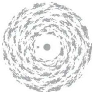
natural_image
Abstract spiral pattern with concentric circles and a small dot at center (no text or symbols)Cloud breakup
The Cloud Breakup disc (P/N 62400213) is designed for a softer directional movement particularly at slow or very slow speeds. It is suitable for cloud effects with cloud gobos or for a soft slow-flowing stream effect.
This animation wheel is supplied as standard with the MAC 2000 Performance II.

Elliptical breakup
The Elliptical Breakup disc (P/N 62400221) produces a bidirectional movement similar to the Spiral Breakup, but with constantly changing direction of movement. This is specifically useful for snow or similar effects where flurries of movement would be expected.
Dot breakup
The Dot Breakup disc (P/N 62400214) gives you the opportunity to cause motion while maintaining a more focused projection of the gobo image. It is suggested for effects such as falling leaves or rising bubbles.
This animation wheel is supplied as standard with the MAC 2000 Performance II.
Flicker wheel
The Flicker Wheel (P/N 62400222) provides a different kind of effect and can be used at high speed for motion effects, such as passing trains. It can also be effectively used for just breaking up the beam of a fixture and for an organic strobe effect.

natural_image
Circular arrangement of gray dots with a central dark circle, no text or symbols present
natural_image
Circular diagram with radial black-and-white stripes and a central dot labeled 'DHA 19', no readable text or symbols beyond the label.Coarse radial breakup
The Coarse Radial Breakup disc (P/N 62400224) is particularly effective for animating light from a non-focused source whilst providing a minimal loss in intensity due to the high 'white to black' ratio of the radial pattern. It is also effective for similar uses to the Radial Breakup disc.

natural_image
Circular abstract pattern with radial black-and-white fan-like design, no text or symbols presentCoarse tangential breakup
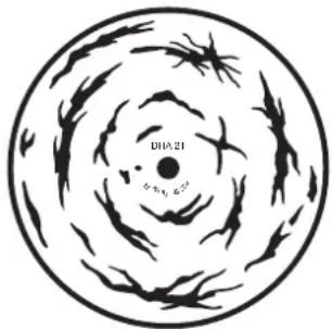
The Coarse Tangential Breakup disc (P/N 62400226) can be used on its own in an unfocused form to give the image of flames. It can also be combined with gobos to give a drifting image to the projection.
natural_image
Circular diagram with concentric spiral lines and a central dot, no text or symbols presentEffects ideas
The ideas outlined here are intended as suggestions only. The precise look of any effect will depend on many factors including the focus setting of your MAC 2000 Performance II, the projection surface onto which the image is directed and any color mixing effects that you choose.
This section is divided into four:
• "Water effects" on page 24
- "Fire effects" on page 26
- "Clouds, rain and snow" on page 27
- "Other effects" on page 28
Water effects
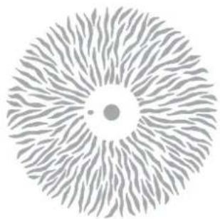
RIPPLING WATER
natural_image
Abstract circular pattern with radial lines and a central dot (no text or symbols)Radial breakup disc
and one of the following
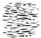
Gobo 955

Gobo 958

Gobo 833
Use slower speeds for gentler or more distant movement. For rough water, substitute a more 'wavy' gobo design such as DHA Lighting's 'Reflected Water 906', 'Flames-4 960', or 'Fire/Waves 238-275' and use the Coarse Radial Breakup animation disc or the Elliptical Breakup animation disc (for an irregular movement) combined with a higher rotation speed.
Alternative gobos: Alternative animation discs:
Linear Breakups 401, 402, 501, 504 Coarse Radial Breakup gives a bolder movement
Shower 882 Spiral Breakup adds some flowing movement
WAVES

natural_image
Circular geometric pattern with diagonal stripes and a central circle, no text or symbols present.and one of the following

natural_image
Abstract black ink brushstroke pattern on white background (no text or symbols)Gobo 504
Gobo 238-275
Triangle breakup disc
As with any animation effect, the rotation speed and image focus will have a great effect on the final projection, so these parameters should be experimented with. With all water effects, it is possible to add an amount of cyan from the color mixing system, which will diffract to give both cyan and white color shifts as the image animates.
Alternative gobos: Alternative animation discs:
Linear Breakups 401, 402, 501, 504 Linear Breakup
Reflected Water 906 Elliptical Breakup gives an irregular rhythm
REFLECTED WATER
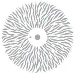
natural_image
Abstract circular pattern with radial lines and a central dot (no text or symbols)and one of the following

Gobo 903

Gobo 906
Radial breakup disc
As with any animation effect, the rotation speed and image focus will have a great effect on the final projection, so these parameters should be experimented with. With all water effects, it is possible to add an amount of cyan from the color mixing system, which will diffract to give both cyan and white color shifts as the image animates.
Alternative animation disc:
Elliptical Breakup gives an irregular movement
WHIRLPOOL

natural_image
Abstract spiral pattern with concentric wavy lines and a central dot (no text or symbols)and
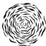
Gobo 893
Spiral breakup disc
A whirlpool effect can be created effectively by leaving the gobo in a static position and just rotating the animation wheel. However, to give a more dynamic whirlpool effect, the gobo for this combination should also be rotated, in a counter direction to the animation wheel. Again differences in the focus and in particular with the speeds on this effect will give you a variety of different options. With all water effects, it is possible to add an amount of cyan from the color mixing system, which will diffract to give both cyan and white color shifts as the image animates.
FLOWING WATER

natural_image
Abstract circular pattern with concentric rings and a small dot at center (no text or symbols)Tangential breakup disc
and one of the following
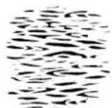
Gobo 955

Gobo 958

Gobo 960
As with any animation effect, the rotation speed and image focus will have a great effect on the final projection, so these parameters should be experimented with. With all water effects, it is possible to add an
amount of cyan from the color mixing system, which will diffract to give both cyan and white color shifts as the image animates.
Fire effects
The range of animation wheels available for the MAC 2000 Performance II is very versatile in producing fire and flame effects. Good results may be obtained from many of the designs together with any standard flame or fire gobo designs.
Here are a few ideas to get you started:
BLOWING FLAMES
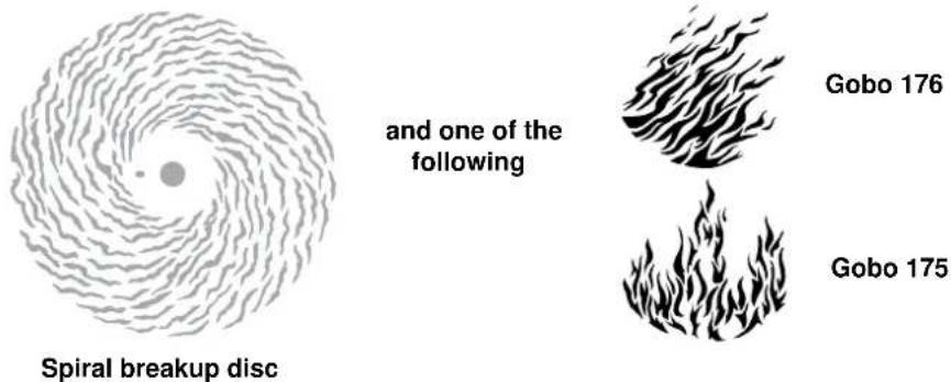
As with any animation effect, the rotation speed and image focus will have a great effect on the final projection, so these parameters should be experimented with. With all fire and flame effects, it is possible to add an amount of magenta (approximately 70%) and yellow (approximately 90%) from the color mixing system, which will diffract to give orange, yellow and red color shifts as the image animates.
Alternative gobos: Alternative animation discs:
Any of the fire or flame gobos from the standard range could be used in substitution for the above suggestions.
Elliptical Breakup gives an irregular movement
Dot Breakup
RISING FLAMES 1
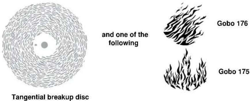
As with any animation effect, the rotation speed and image focus will have a great effect on the final projection, so these parameters should be experimented with. With all fire and flame effects, it is possible to add an amount of magenta (approximately 70%) and yellow (approximately 90%) from the color mixing system, which will diffract to give orange, yellow and red color shifts as the image animates.
Alternative gobos:
Any of the fire or flame gobos from the standard range could be used in substitution for the above suggestions.
RISING FLAMES 2
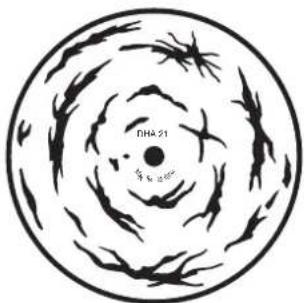
Coarse tangential breakup disc
Different to above, this animation gives a much stronger image of rising flames with the broader pattern on the disc. For this animation, it is possible to use the animation disk on its own to create the rising flame effect. You will need to set the focus away from the disk itself to enhance the effect. To give a different image, you could also add one of the standard fire or flame gobo designs.
Alternative gobos:
Any of the fire or flame gobos from the standard range can be used.
Clouds, rain and snow
The versatility that you can achieve with the animation system of the MAC 2000 Performance II makes this an ideal tool for creating all sorts of weather effects.
CLOUDS
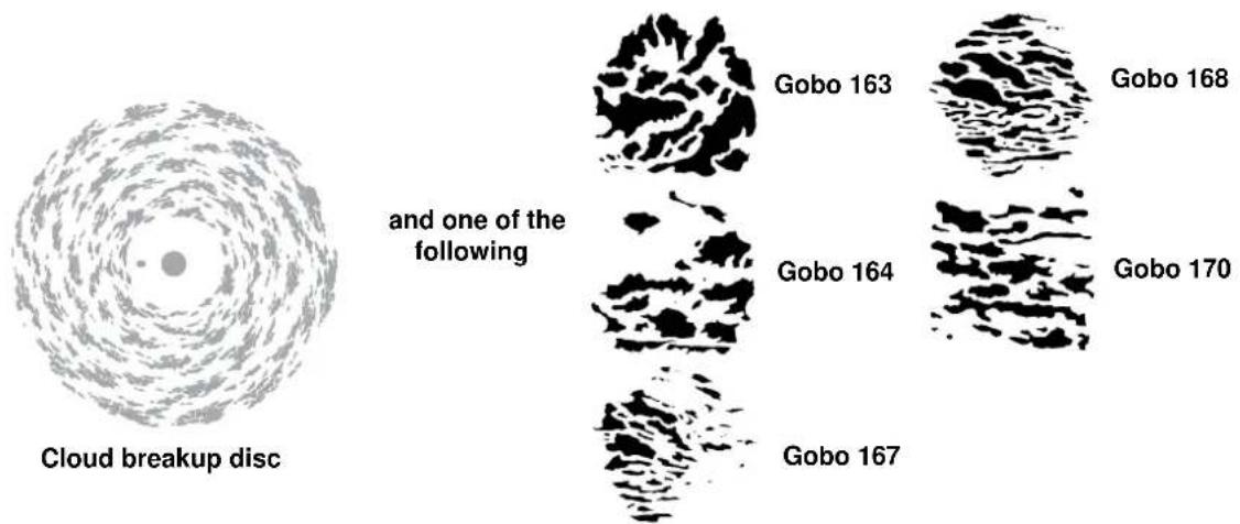
Once again, the speed and focus come greatly into play when creating your final effect, whether you wish to create soft flowing clouds on a summers night or gathering thunder clouds about to explode.
Alternative gobos:
Use any non-meshed cloud gobo to create the desired effect that you need. You should choose your gobo based on the type and density of your desired effect.
RAIN

For driving rain, you should angle the gobo first using the indexing control and then align the animation wheel anywhere between the horizontal and vertical axis to provide the desired effect.
SNOW

This is a simple effect to set up, but looks excellent. The use of the prism on the effect wheel of the MAC 2000 Performance II will help diffuse the image, creating a more random effect, which adds a new dimension to the animation and is very effective in some situations.
Other effects
Here are some further examples of different animations that can be achieved with the MAC 2000 Performance II.
LIGHT THROUGH TREES

It is possible to use almost any of the animation discs to animate a breakup gobo such as this one. There is a wide range of breakup gobos available to choose from on the market today.
By using a combination of the cyan and yellow color mixing flags, you can create various shades of green which will diffract to give a variety of shades. You should adjust the values proportionately to give darker or lighter shades of green to your image.
TREE IN BREEZE
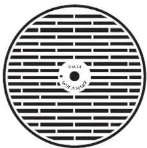
natural_image
Circular diagram with brick pattern and central dot, no readable text or symbolsand
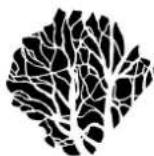
Gobo 110
Linear breakup disc
By using a combination of the cyan and yellow color mixing flags, you can create various shades of green which will diffract to give a variety of shades. You should adjust the values proportionately to give darker or lighter shades of green to your image.
Alternative gobos:
There are a wide range of tree, branch and foliage gobos available which can all be animated to give very distinctive effects.
PASSING TRAIN

natural_image
Circular diagram with radial black-and-white stripes and a central dot, no text or symbols present.and one of the
following

Gobo 901

Gobo 902
Flicker wheel
Adjusting the rotation speed of the animation wheel will give you a faster or slower 'flicker' effect depending on the speed of your train.
OPTICAL CONFIGURATION
Rotating gobo wheel
The MAC 2000 Performance II is supplied with 5 rotating gobos installed. Figure 7 shows the standard gobo configuration with the gobo positions marked.

Figure 7: Standard rotating gobo wheel configuration as seen from lamp
The rotating gobos are magnetically indexed with a special indexing gobo holder in position 2 (the Soft Breakup gobo). The indexing gobo holder, which has a small magnet, must always be in position 2. If it is placed in a different position, the gobos will not index correctly. The indexing gobo holder accepts the same gobos as normal holders; any gobo suitable for the MAC 2000 may be placed in position 2.
Two additional aluminum gobos are supplied.

Gobo specifications
All gobo slots accept round theatrical size-E glass gobos. The rotating-gobo wheel positions hold gobos up to 3 mm thick with the gobo retention spring. Gobos thicker than 3 mm must be glued in the holder.
For the best results, custom glass gobos that meet the following criteria should be used:
Outside diameter: 37.5 + 0/-0.3 mm (1 15/32 + 0/-0.01 in.)
Maximum image diameter: 30 mm (1 3/16 in.)
Material: ...... High temperature Borofloat or better glass
Coating: ....Dichroic or enhanced aluminum
Although glass gobos are generally the most durable, satisfactory results can be obtained in many applications at less expense with aluminum gobos. Our experience with the MAC 2000 Performance II, which is supplied with aluminum gobos, shows that aluminum can hold up to the heat very well. Custom stainless steel gobos can also be used, however they can warp, losing sharpness, in a matter of hours in the MAC 2000 Performance II. The useful life will depend on the gobo pattern and the projection cycle. Consult your gobo supplier for more information.
Orientation
GLASS GOBOS
Coated glass gobos are inserted with the coating against the rim of the holder (away from the spring). Textured gobos are inserted with the smooth side against the spring. This provides the best results when combining rotating gobos.
Coated side

When an object is held up to the coated side there is no space between the object and its reflection. The back edge of the gobo cannot be seen when looking through the coated side.
Uncoated side

When an object is held up to the uncoated side there is a space between the object and its reflection. The back edge of the gobo can be seen when looking through the uncoated side.
Figure 8: Finding the coated side
METAL GOBOS
For correct projection, install metal custom gobos with the true image facing the lamp. The false-image side (which faces away from the lamp) should be coated with a suitable high-temperature black paint to reduce reflections.
Replacing rotating gobos
Important! The gobo can fall out if the spring is inserted backwards.
1 Disconnect the fixture from power and allow it to cool.
2 Lock the head in the top side up position and remove the top cover. Turn the gobo wheels as required to access the desired position. Pull the gobo holder away from the wheel slightly to release. Remove the gobo holder.

3 Remove the gobo retention spring from the gobo holder and drop the gobo out of the holder. Insert the new gobo in the holder. Insert the spring with the narrow end against the gobo. To identify the narrow end, press the spring flat: the narrow end is on the inside. Push the end of the spring in under the lip of the holder.

4 Work the rim of the gobo holder under both clips and snap the gobo holder back into position. If necessary, a small screwdriver or similar tool may be used to pry the clips away from the wheel.
5 Replace the cover and release the pan and/or tilt locks before operating.
Effect wheel
The effect wheel provides a variable frost filter and two positions for effects. The MAC 2000 Performance II comes with a wide angle lens and a nine-fact prism installed in these positions.

Replacing effects
1 Disconnect the fixture from power and allow it to cool.
2 Lock the head in the upside down position and remove the bottom cover. Turn the effect wheel so that the locking plate is under the sensor bracket.
3 To remove, hold the rim of the effect holder and pull back on the locking plate. Remove effect from wheel.
4 To insert, pull back on the locking plate. If both effects are removed, pull straight back on both tabs. Position the groove in the effect holder over the fixed plate. Release the locking plate and verify that the effect is properly seated.
5 Replace the bottom cover and unlock the head before operating.

Gobo animation
The following gobo animation wheel patterns are supplied with the MAC 2000 Performance II.

For information about using the gobo animation effects, see "Animation guide" on page 20.
Replacing the gobo animation wheel
1 Disconnect the fixture from power and allow it to cool.
2 Lock the head in the upside down position and remove the bottom cover.
3 Using a finger or thumb (as illustrated), move the installed animation wheel up.
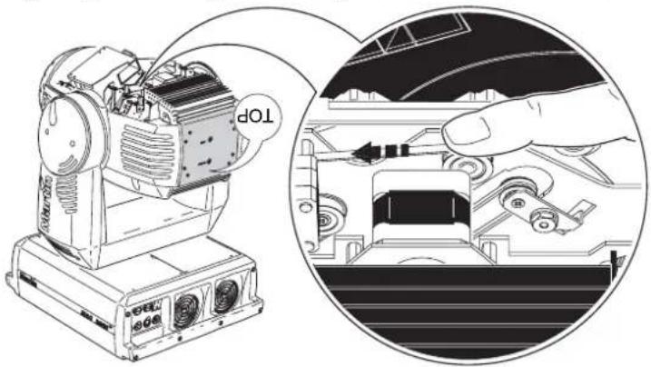
4 The animation wheels are made of thin aluminum, so use a screw driver to release the wheel from the magnetic mount.

natural_image
Mechanical assembly diagram showing a shaft and housing connected to a circular component (no text or symbols)5 Take the wheel out by hand.

natural_image
Illustration of hands operating a mechanical device with an upward arrow, no text or symbols present6 To insert a new wheel, place it over the mount, ensuring that the magnet that is fitted to the animation wheel is facing the mount. There is a small indexing position hole in each animation wheel and the indexing pin on the mount must be positioned in this hole.
7 Replace the bottom cover and unlock the head before operating
ROUTINE MAINTENANCE
Warning! Disconnect the fixture from power and allow to cool before removing any cover.
Important! Excessive dust, smoke fluid, and particulate buildup degrades performance and causes overheating and damage to the fixture that is not covered by the warranty.
The MAC 2000 Performance II requires routine cleaning. To maximize the life of the product and protect the investment it represents, clean the fixture regularly – especially the cooling systems. It is essential to follow the guidelines given later in this section.
Refer any service operation that is not described here to a qualified Martin technician.
It is Martin policy to use the best-quality materials and coatings available to ensure optimum performance and the longest possible component lifetimes. However, optical components in all lighting fixtures are subject to wear and tear over the life of the fixture, resulting in gradual changes in color rendition of dichroic filters or the specular properties of reflectors, for example.
The extent of wear and tear depends heavily on operating conditions, maintenance and environment, so it is impossible to specify precise lifetimes for optical components. However, you will eventually need to replace optical components if their characteristics are affected by wear and tear after an extended period of use and if you require fixtures to perform within very precise optical and color parameters.
Lamp
The MAC 2000 Performance II is supplied with a Philips MSR 1200 SA/DE GOLD 1200 W discharge lamp installed. This source has a color temperature of 6000 K, a color rendering index greater than 85, and an average life of 750 hours.
The lamp is capable of hot restrike. This feature, however, is only supported by the MAC 2000 Performance II with electronic ballast.
The ends of the lamp are profiled with special keys, as shown in Figure 11, to ensure proper installation. Do not use lamps with keys in a non-keyed SFc 10-4 socket.
Warning! Install only an approved lamp (see "Source" on page 55). Installing any other lamp may create a safety hazard or damage the fixture!
The lamp should be replaced when it has reached the limit of its 750 hour average life. To reduce the risk of explosion, never exceed 125% of the lamp's average life, i.e. 940 hours. To read lamp hours from the control panel, please refer to "Readouts" on page 14.
For optimum performance, avoid turning off the lamp before it has warmed up fully.
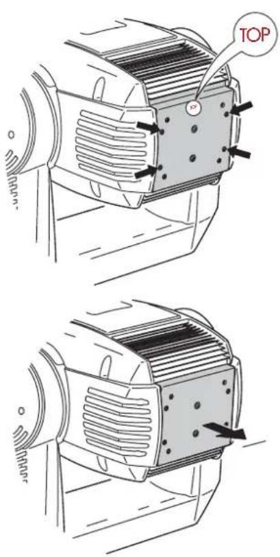
Figure 9: Lamp access
Lamp replacement
Important! Do not touch the quartz bulb with bare fingers.
The lamp can be replaced with either a Philips MSR 1200 SA/DE GOLD (Martin P/N 97010310), or an OSRAM HMI 1200 W/S (Martin P/N 97010304). Both lamps are available from your Martin dealer.
The clear quartz bulb must be clean and free of any oils from your fingers. Clean the lamp with an alcohol wipe and polish it with a dry cloth, particularly if you accidentally touch the bulb.
To replace the lamp:
1 Disconnect the fixture from power and allow it to cool. Lock the head horizontally with the top up.
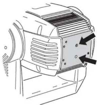
2 See Figure 9. Release the 4 quarter-turn fasteners marked with arrows on the rear plate. Pull the lamp assembly straight back as far as it goes and let it rest in place.
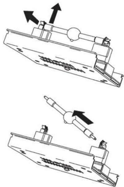
3 See Figure 10. Pull the retention spring on the left-hand end of the lamp socket up and then swing the end of the lamp out. Pull the other end out of the socket.
4 Inspect the socket for corrosion (see "Replacing the lamp socket" on page 36) and replace if necessary.
5 See Figure 11. With the nipple on the bulb facing the back, insert the right end of the new lamp in the socket. Pull up on the left spring and snap the other end into place.
6 Lift the lamp assembly so that lamp is level with the center of the reflector. Push the assembly straight in until it seats, making sure the lamp passes through the reflector opening. Lock the 4 quarter-turn fasteners.
7 When installing a new lamp, reset the lamp hour and lamp strike counters as described in "Time" on page 14.
Replacing the lamp socket
The lamp holder used in the MAC 2000 Performance II eventually wears out due to the high voltages that pass through the contacts.
Wear begins to show up as discoloration at the contact surfaces. When this happens, resistance increases and the lamp becomes harder to strike. If this process is allowed to continue, the lamp is likely to fail prematurely.
Each time the lamp is replaced, inspect the lamp holder and have it replaced by a qualified technician as soon as there are signs of discoloration or pitting at the contact surfaces. We recommend routine replacement of the socket after maximum 4000 hours of use (replace one socket for every five lamps). Damage caused by failure to replace a worn and/or discolored lamp holder is not covered by the product warranty.
natural_image
Technical line drawing showing two mechanical assembly steps with arrows indicating motion direction (no text or symbols)Figure 10: Lamp removal

natural_image
Diagram of a mechanical assembly with a cylindrical component being inserted, showing motion direction (no text or symbols)
natural_image
Technical line drawing of a mechanical assembly with directional arrows indicating motion (no text or symbols)Figure 11: Lamp insertion
Aligning the lamp
1 Switch on the MAC 2000 Performance II and allow it to reset. Using either a controller or the control module, turn on the lamp and project an open white beam on a flat surface.
2 Center the hot spot vertically using the top Allen-head adjustment screw in the center of the rear plate.
3 If there is significant hot spot, turn the bottom adjustment screw counterclockwise until the light is evenly distributed. If the light is brighter around the edge than it is in the center, or if light output is low, turn the bottom adjustment screw clockwise until the light is bright and evenly distributed.
4 Repeat step 2.
natural_image
Technical line drawing of an electric motor with cooling fins and a warning arrow (no text or symbols)Figure 12: Lamp adjustment
Cleaning
Regular cleaning is very important for fixture life and performance. Buildup of dust, dirt, smoke particles, fog fluid residues, etc. degrades the fixture's light output and cooling ability.
Cleaning schedules for lighting fixtures vary greatly depending on the operating environment. It is therefore impossible to specify precise cleaning intervals for the MAC 2000 Performance II. Cooling fans suck in airborne dust and smoke particles, and in extreme cases fixtures may require cleaning after surprisingly few hours of operation. Environmental factors that may result in a need for frequent cleaning include:
- Use of smoke or fog machines.
• High airflow rates (near air conditioning vents, for example).
• Presence of cigarette smoke. - Airborne dust (from stage effects, building structures and fittings or the natural environment at outdoor events, for example).
If one or more of these factors is present, inspect fixtures within their first 25 hours of operation to see whether cleaning is necessary. Check again at frequent intervals. This procedure will allow you to assess cleaning requirements in your particular situation. If in doubt, consult your Martin dealer about a suitable maintenance schedule.
Use care when cleaning optical components and work in a clean, well lit area. The coated surfaces are fragile and easily scratched. Do not use solvents that can damage plastic or painted surfaces.
To maintain adequate cooling, dust must be cleaned from the fans and air vents periodically. Inspect the air filters regularly and clean before they become clogged. Replace the air filters with new ones when replacing the lamp.
Cleaning optical components
1 Disconnect the fixture from power and allow the components to cool completely. Remove the head cover.
2 Vacuum or gently blow away dust and loose particles with compressed air.
3 Remove stuck particles with an unscented tissue or cotton swab moistened with glass cleaner or distilled water. Do not rub the surface: lift the particles off with a soft repeated press.
4 Remove smoke and other residues with cotton swabs or unscented tissues moistened with isopropyl alcohol. A commercial glass cleaner may be used, but residues must be removed with distilled water. Clean with a slow circular motion from center to edge. Dry with a clean, soft and lint-free cloth or compressed air.
Cleaning the fan and air vents
Remove dust from the fans and air vents with a soft brush, cotton swab, vacuum, or compressed air.
Cleaning or replacing the air filters

1 Disconnect the fixture from power. On each side of the head, remove the 2 screws that hold the side cover using a Torx-20 screwdriver. Slide the cover forward to remove. Lift the filter off of the cover.
2 Clean the filters with a vacuum or compressed air, or replace them. If they are saturated with smoke fluid, etcetera, soak them in warm soapy water and blot dry.
3 Place the filters on the covers and replace the covers.
Software installation
Software updates are installed in the MAC 2000 Performance II using a Martin MP-2 Uploader or a LightJockey 4064 DMX interface card. The procedure is found in the MP-2 user manual and the Martin Software Uploader online help file.
Requirements
The following are required in order to install software.
- The MAC 2000 Performance II update file, available for download from the User Support Area of the Martin web site (http://www.martin.dk).
- The Martin Software Uploader program, version 4.0 or later, available for download from the User Support Area of the Martin web site.
- A Martin MP-2 Uploader connected to a Windows 95/98/ME/2000/XP PC, or a LightJockey Controller (DJ or Club) with 4064 DMX Interface card.
Preventing software updates
Software updates are enabled by default, but you can disable this by setting the Write jumper (see "Circuit board connections" on page 54) to disable.
Boot sector jumper
If the normal upload procedure does not work, or if the software update notes call for a boot sector update, move the boot sector jumper on the printed circuit board to the BOOT position before uploading software.
SETTING THE BOOT SECTOR JUMPER
1 Disconnect the fixture from power.
2 Remove the top screws from the ends of the front side panel and tilt the panel down to expose the main circuit board.
3 Using the appropriate diagram in "Circuit board connections" on page 54 or the label inside the base, locate the BOOT jumper (PL16). Move the jumper to the "BOOT" position.
4 Perform a boot mode upload. When the upload is complete, disconnect the fixture from power and move the jumper back to the locked or normal position.

natural_image
Technical line drawing of a mechanical device with fan and control panel (no text or symbols)DMX PROTOCOL
This section contains two DMX protocols (both from protocol version 1.0A):
- "16-bit protocol" on page 40
- "8-bit protocol" on page 43
The 16-bit is the default protocol that is used. To modify this use the control menu. For more information see "Control menu" on page 46.
16-bit protocol
DMX channel Value Percent Function Start code = 0
| 1 | 0 - 19 | 0 - 7 | Shutter, Strobe, Reset, Lamp On/Off |
| 20 - 49 | 8 - 19 | Shutter Closed (lamp reduced to 700 W (E-ballast) after 10 sec.) | |
| 50 - 72 | 20 - 28 | No function (Shutter Open) | |
| 73 - 79 | 29 - 31 | Strobe on fast→slow | |
| 80 - 99 | 32 - 39 | Shutter open, lamp reduced to 700 W (E-ballast) | |
| 100 - 119 | 40 - 47 | Pulse opening fast →slow | |
| 120 - 127 | 48 - 50 | Pulse closing fast →slow | |
| 128 - 147 | 51 - 57 | No function | |
| 148 - 167 | 58 - 65 | Random Strobe Fast | |
| 168 - 187 | 66 - 73 | Random Strobe Medium | |
| 188 - 190 | 74 - 74 | Random Strobe Slow | |
| 191 - 193 | 75 | No function | |
| 194 - 196 | 76 | Random pulse opening slow | |
| 197 - 199 | 77 | Random pulse closing fast | |
| 200 - 202 | 78 - 79 | Random pulse closing slow | |
| 203 - 207 | 80 - 81 | No function | |
| 208 - 217 | 82 - 85 | Reset Fixture | |
| 218 - 227 | 86 - 89 | No function | |
| 228 - 237 | 90 - 93 | Lamp On (Power On) | |
| 238 - 247 | 94 - 97 | No Function | |
| 248 - 255 | 98 - 100 | Lamp Off (Power Off) Note: T > 5 seconds | |
| 2 | 0 - 255 0 - 100 | Intensity0 - 100% | |
| 3 | 0 - 255 0 - 100 | CyanWhite → Cyan | |
| 4 | 0 - 255 0 - 100 | MagentaWhite → Magenta | |
| 5 | 0 - 255 0 - 100 | YellowWhite → Yellow | |
| 6 | 0 - 255 0 - 100 | CTCWhite → CTC | |
| 7 | 0 - 9 | 0 - 3 | Rotating gobo 1 selectionOpen gobo |
| 10 - 14 | 4 - 5 | Gobo 1 – Indexing (set index on channel 8) | |
| 15 - 19 | 6 - 7 | Gobo 2 – Indexing (set index on channel 8) | |
| 20 - 24 | 8 - 9 | Gobo 3 – Indexing (set index on channel 8) | |
| 25 - 29 | 10 - 11 | Gobo 4 – Indexing (set index on channel 8) | |
| 30 - 34 | 12 - 13 | Gobo 5 – Indexing (set index on channel 8) | |
| 35 - 39 | 14 - 15 | Gobo 1 – Cont. Rotation (set dir/speed on channel 8) | |
| 40 - 44 | 16 - 17 | Gobo 2 – Cont. Rotation (set dir/speed on channel 8) | |
| 45 - 49 | 18 - 19 | Gobo 3 – Cont. Rotation (set dir/speed on channel 8) | |
| 50 - 54 | 20 - 21 | Gobo 4 – Cont. Rotation (set dir/speed on channel 8) | |
| 55 - 59 | 22 - 23 | Gobo 5 – Cont. Rotation (set dir/speed on channel 8) | |
| Gobo shake (indexing) | |||
| 60 - 74 | 24 - 29 | Gobo 1 slow → fast | |
| 75 - 89 | 30 - 35 | Gobo 2 slow → fast | |
| 90 - 104 | 36 - 41 | Gobo 3 slow → fast | |
| 105 - 119 | 42 - 46 | Gobo 4 slow → fast | |
| 120 - 134 | 47 - 52 | Gobo 5 slow → fast | |
| Gobo shake (continuous gobo rotation) | |||
| 135 - 149 | 53 - 58 | Gobo 1 slow → fast | |
| 150 - 164 | 59 - 64 | Gobo 2 slow → fast | |
| 165 - 179 | 65 - 70 | Gobo 3 slow → fast | |
| 180 - 194 | 71 - 67 | Gobo 4 slow → fast | |
| 195 - 209 | 77 - 82 | Gobo 5 slow → fast | |
| Gobo wheel continuous rotation (continuous gobo rotation) | |||
| 210 - 232 | 83 - 91 | CW slow → fast | |
| 233 - 255 | 92 - 100 | CCW fast → slow | |
DMX channel Value Percent Function Start code = 0
| 8 | 0 - 255 | 0 - 100 | Rotating gobo 1 index coarse, MSB (Set gobo selection on channel 7)Index min. → max |
| 0 - 2 | 0 | Rotating gobo 1 cont. rotation (Set gobo selection on channel 7)Static | |
| 3 - 127 | 1 - 50 | CCW slow → fast | |
| 128 - 252 | 51 - 99 | CW fast → slow | |
| 253 - 255 | 100 | Static | |
| 9 | 0 - 255 | 0 - 100 | Rotating gobo 1 index fine, LSB (Set gobo selection on channel 7)Index min. → max |
| 0 - 255 | 0 - 100 | Rotating gobo 1 cont. rotation (Set gobo selection on channel 7)No function | |
| 10 | 0 - 9 | 0 - 3 | Gobo Animation wheel position |
| 10 - 19 | 4 - 7 | No Effect | |
| 20 - 29 | 8 - 11 | Vertical position – Indexing (set index on channel 10) | |
| 30 - 39 | 12 - 15 | Horizontal position – Indexing (set index on channel 10) | |
| 40 - 49 | 16 - 19 | Vertical position – Cont. Rotation (set dir/speed on channel 10) | |
| 50 - 139 | 20 - 54 | Horizontal position – Cont. Rotation (set dir/speed on channel 10)Animation wheel scroll position (Vertical → Horizontal) – Indexing (set index on channel 11) | |
| 140 - 229 | 55 - 89 | Animation wheel scroll position (Horizontal → Vertical) – Cont. Rot. (set dir/speed on channel 11) | |
| 230 - 235 | 90 - 92 | No Effect | |
| 236 - 239 | 93 | Gobo Animation MACROS | |
| 240 - 243 | 94 - 95 | Macro 1 | |
| 244 - 247 | 96 | Macro 2 | |
| 248 - 251 | 97 - 98 | Macro 3 | |
| 252 - 255 | 99 - 100 | Macro 4 | |
| Macro 5 | |||
| 11 | 0 - 255 | 0 - 100 | Gobo Animation wheel index (Set position on channel 10)Index min. → max |
| 0 - 2 | 0 | Gobo Animation wheel cont. rotation (Set position on channel 10) | |
| 3 - 127 | 1 - 50 | Static | |
| 128 - 252 | 51 - 99 | CCW slow → fast | |
| 253 - 255 | 100 | CW fast → slow | |
| Static | |||
| 12 | 0 | 0 | Effect selection |
| 1 - 234 | 1 - 91 | Open | |
| 235 - 242 | 92 - 95 | Variable Frost min. → max. | |
| 243 - 250 | 96 - 98 | Effect 1 | |
| 251 - 255 | 99 - 100 | Effect 2 | |
| Open | |||
| 13 | 0 - 199 | 0 - 77 | Iris |
| 200 - 215 | 78 - 84 | Open → close | |
| 216 - 229 | 85 - 89 | Close | |
| 230 - 243 | 90 - 94 | Pulse opening fast → slow | |
| 244 - 246 | 95 - 96 | Pulse closing fast → slow | |
| 247 - 249 | 97 | Random pulse opening fast | |
| 250 - 252 | 98 - 99 | Random pulse closing fast | |
| 253 - 255 | 100 | Random pulse closing slow | |
| 14 0 - 2 | 0 - 1 | Framing MACRO functions | |
| 3 - 255 | 2 - 100 | No MacroReserved for macros | |
| 15 | 0 - 255 0 - 100 | Focus | |
| Focus far → near | |||
| 16 | 0 - 255 0 - 100 | Zoom | |
| Zoom wide → narrow | |||
| 17 | 0 - 255 0 - 100 | Framing shutter 1Out → In | |
| 18 | 0 - 126 | 0 - 49 | Framing shutter 1 |
| 127 - 128 | 50 | Angle – | |
| 129 - 255 | 51 - 100 | Parallel | |
| Angle + | |||
| 19 | 0 - 255 0 - 100 | Framing shutter 2Out → In |
DMX channel Value Percent Function Start code = 0
| 20 | 0 - 126127-128129 - 255 | 050100 | Framing shutter 2Angle –ParallelAngle + |
| 21 | 0 - 255 0 - 100 | Framing shutter 3Out → In | |
| 22 | 0 - 126127 - 128129 - 255 | 050100 | Framing shutter 3Angle –ParallelAngle + |
| 23 | 0 - 255 0 - 100 | Framing shutter 4Out → In | |
| 24 | 0 - 126127 - 128129 - 255 | 050100 | Framing shutter 4Angle –ParallelAngle + |
| 25 | 0 - 255 0 - 100 | Rotate framing shuttersRight → Center → Left | |
| 26 | 0127255 | 050100 | Pan coarseMax LeftNeutralMax Right |
| 27 | 0127255 | 050100 | Pan fineMax LeftNeutralMax Right |
| 28 | 0127255 | 050100 | Tilt coarseMax UpNeutralMax Down |
| 29 | 0127255 | 050100 | Tilt fineMax UpNeutralMax Down |
| 30 | 0 - 23 - 236237 - 239240 - 242243 - 245246 - 251252 - 255 | 0 - 12 - 9293949596 - 9899 - 100 | Speed: Pan/Tilt MovementTrackingSpeed Fast → SlowTracking (Slow speed – overrides the PTSP menu setting)Tracking (Normal speed – overrides the PTSP menu setting)Tracking (Fast speed – overrides the PTSP menu setting)No functionBlackout while moving |
| 31 | 0 - 23 - 239240 - 242243 - 245246 - 248249 - 251252 - 255 | 01 - 9394 - 959697 - 9899100 | Speed: Dimmer, Cyan, Magenta, Yellow, CTC, Effect, Iris, Focus, ZoomTrackingSpeed Fast → SlowTracking (Studio mode disabled – overrides the MODE menu setting)Tracking (Studio mode enabled – overrides the MODE menu setting)Tracking (Shortcuts disabled – overrides the SCUT menu setting)Tracking (Shortcuts enabled – overrides the SCUT menu setting)Fast SpeedSpeed: Gobo 1, Framing, Animation wheel pos., Animation wheel rot. |
| 0 - 23 - 239240 - 242243 - 245246 - 248249 - 251252 - 255 | 01 - 9394 - 959697 - 9899100 | TrackingSpeed Fast → SlowTracking (Studio mode disabled – overrides the MODE menu setting)Tracking (Studio mode enabled – overrides the MODE menu setting)Tracking (Shortcuts disabled – overrides the SCUT menu setting)Tracking (Shortcuts enabled – overrides the SCUT menu setting)Blackout while moving | |
8-bit protocol
DMX channel Value Percent Function Start code = 0
| 1 | 0 - 19 | 0 - 7 | Shutter, Strobe, Reset, Lamp On/Off |
| 20 - 49 | 8 - 19 | Shutter Closed (lamp reduced to 700 W (E-ballast) after 10 sec.) | |
| 50 - 72 | 20 - 28 | No function (Shutter Open) | |
| 73 - 79 | 29 - 31 | Strobe on fast→slow | |
| 80 - 99 | 32 - 39 | Shutter open, lamp reduced to 700 W (E-ballast) | |
| 100 - 119 | 40 - 47 | Pulse opening fast →slow | |
| 120 - 127 | 48 - 50 | Pulse closing fast →slow | |
| 128 - 147 | 51 - 57 | No function | |
| 148 - 167 | 58 - 65 | Random Strobe Fast | |
| 168 - 187 | 66 - 73 | Random Strobe Medium | |
| 188 - 190 | 74 - 74 | Random Strobe Slow | |
| 191 - 193 | 75 | No function | |
| 194 - 196 | 76 | Random pulse opening fast | |
| 197 - 199 | 77 | Random pulse opening slow | |
| 200 - 202 | 78 - 79 | Random pulse closing fast | |
| 203 - 207 | 80 - 81 | Random pulse closing slow | |
| 208 - 217 | 82 - 85 | No function | |
| 218 - 227 | 86 - 89 | Reset Fixture | |
| 228 - 237 | 90 - 93 | No function | |
| 238 - 247 | 94 - 97 | Lamp On (Power On) | |
| 248 - 255 | 98 - 100 | No Function | |
| Lamp Off (Power Off) Note: T > 5 seconds | |||
| 2 | 0 - 255 0 - 100 | Intensity | |
| 0 - 100% | |||
| 3 | 0 - 255 0 - 100 | Cyan | |
| White → Cyan | |||
| 4 | 0 - 255 0 - 100 | Magenta | |
| White → Magenta | |||
| 5 | 0 - 255 0 - 100 | Yellow | |
| White → Yellow | |||
| 6 | 0 - 255 0 - 100 | CTC | |
| White → CTC | |||
| 7 | 0 - 9 | 0 - 3 | Rotating gobo 1 selection |
| 10 - 14 | 4 - 5 | Open gobo | |
| 15 - 19 | 6 - 7 | Gobo 1 – Indexing (set index on channel 8) | |
| 20 - 24 | 8 - 9 | Gobo 2 – Indexing (set index on channel 8) | |
| 25 - 29 | 10 - 11 | Gobo 3 – Indexing (set index on channel 8) | |
| 30 - 34 | 12 - 13 | Gobo 4 – Indexing (set index on channel 8) | |
| 35 - 39 | 14 - 15 | Gobo 5 – Indexing (set index on channel 8) | |
| 40 - 44 | 16 - 17 | Gobo 1 – Cont. Rotation (set dir/speed on channel 8) | |
| 45 - 49 | 18 - 19 | Gobo 2 – Cont. Rotation (set dir/speed on channel 8) | |
| 50 - 54 | 20 - 21 | Gobo 3 – Cont. Rotation (set dir/speed on channel 8) | |
| 55 - 59 | 22 - 23 | Gobo 4 – Cont. Rotation (set dir/speed on channel 8) | |
| Gobo 5 – Cont. Rotation (set dir/speed on channel 8) | |||
| Gobo shake (indexing) | |||
| 60 - 74 | 24 - 29 | Gobo 1 slow → fast | |
| 75 - 89 | 30 - 35 | Gobo 2 slow → fast | |
| 90 - 104 | 36 - 41 | Gobo 3 slow → fast | |
| 105 - 119 | 42 - 46 | Gobo 4 slow → fast | |
| 120 - 134 | 47 - 52 | Gobo 5 slow → fast | |
| Gobo shake (continuous gobo rotation) | |||
| 135 - 149 | 53 - 58 | Gobo 1 slow → fast | |
| 150 - 164 | 59 - 64 | Gobo 2 slow → fast | |
| 165 - 179 | 65 - 70 | Gobo 3 slow → fast | |
| 180 - 194 | 71 - 67 | Gobo 4 slow → fast | |
| 195 - 209 | 77 - 82 | Gobo 5 slow → fast | |
| Gobo wheel continuous rotation (continuous gobo rotation) | |||
| 210 - 232 | 83 - 91 | CW slow → fast | |
| 233 - 255 | 92 - 100 | CCW fast → slow | |
DMX channel Value Percent Function Start code = 0
| 8 | 0 - 255 | 0 - 100 | Rotating gobo index (Set gobo selection on channel 7)Index min. → max |
| 0 - 2 | 0 - 1 | Rotating gobo cont. rotation (Set gobo selection on channel 7)Static | |
| 3 - 127 | 2 - 50 | CCW slow → fast | |
| 128 - 252 | 51 - 98 | CW fast → slow | |
| 253 - 255 | 99 - 100 | Static | |
| 9 | 0 - 9 | 0 - 3 | Gobo Animation wheel position |
| 10 - 19 | 4 - 7 | No Effect | |
| 20 - 29 | 8 - 11 | Vertical position – Indexing (set index on channel 10) | |
| 30 - 39 | 12 - 15 | Horizontal position – Indexing (set index on channel 10) | |
| 40 - 49 | 16 - 19 | Vertical position – Cont. Rotation (set dir/speed on channel 10) | |
| 50 - 139 | 20 - 54 | Horizontal position – Cont. Rotation (set dir/speed on channel 10) | |
| 140 - 229 | 55 - 89 | Animation wheel scroll position (Vertical → Horizontal) – Indexing (set index on channel 10) | |
| 230 - 235 | 90 - 92 | Animation wheel scroll position (Horizontal → Vertical) – Cont. Rot. (set dir/speed on channel 10) | |
| 236 - 239 | 93 | No Effect | |
| 240 - 243 | 94 - 95 | Gobo Animation MACROS | |
| 244 - 247 | 96 | Macro 1 | |
| 248 - 251 | 97 - 98 | Macro 2 | |
| 252 - 255 | 99 - 100 | Macro 3 | |
| Macro 4 | |||
| Macro 5 | |||
| 10 | 0 - 255 | 0 - 100 | Gobo Animation wheel index (Set position on channel 9)Index min. → max |
| 0 - 2 | 0 - 1 | Gobo Animation wheel cont. rotation (Set position on channel 9) | |
| 3 - 127 | 2 - 50 | Static | |
| 128 - 252 | 51 - 98 | CCW slow → fast | |
| 253 - 255 | 99 - 100 | CW fast → slow | |
| Static | |||
| 11 | 0 | 0 | Effect selection |
| 1 - 234 | 1 - 91 | Open | |
| 235 - 242 | 92 - 94 | Variable Frost min. → max. | |
| 243 - 250 | 95 - 98 | Effect 1 | |
| 251 - 255 | 99 - 100 | Effect 2 | |
| Open | |||
| 12 | 0 - 199 | 0 - 78 | Iris |
| 200 - 215 | 79 - 84 | Open → close | |
| 216 - 229 | 85 - 89 | Close | |
| 230 - 243 | 90 - 95 | Pulse opening fast → slow | |
| 244 - 246 | 96 | Pulse closing fast → slow | |
| 247 - 249 | 97 | Random pulse opening fast | |
| 250 - 252 | 98 | Random pulse closing fast | |
| 253 - 255 | 99 - 100 | Random pulse closing slow | |
| Framing MACRO functions | |||
| 13 | 0 - 2 | 0 - 1 | No Macro |
| 3 - 255 | 2 - 100 | Reserved for macros | |
| Focus | |||
| 14 | 0 - 255 0 - 100 | Focus far → near | |
| 15 | 0 - 255 0 - 100 | Zoom | |
| Zoom wide → narrow | |||
| 16 | 0 - 255 0 - 100 | Framing shutter 1 | |
| Out → In | |||
| 17 | 0 - 126 | 0 | Framing shutter 1 |
| 127-128 | 50 | Angle – | |
| 129 - 255 | 100 | Parallel | |
| Angle + | |||
| 18 | 0 - 255 0 - 100 | Framing shutter 2 | |
| Out → In | |||
| 19 | 0 - 126 | 0 | Framing shutter 2 |
| 127-128 | 50 | Angle – | |
| 129 - 255 | 100 | Parallel | |
| Angle + |
DMX channel Value Percent Function Start code = 0
| 20 | 0 - 255 0 - 100 | Framing shutter 3Out → In | |
| 21 | 0 - 126127-128129 - 255 | 050100 | Framing shutter 3Angle –ParallelAngle + |
| 22 | 0 - 255 0 - 100 | Framing shutter 4Out → In | |
| 23 | 0 - 126127-128129 - 255 | 050100 | Framing shutter 4Angle –ParallelAngle + |
| 24 | 0 - 255 0 - 100 | Rotate Framing ShuttersRight → Center → Left | |
| 25 | 0127255 | 050100 | PanMax LeftNeutralMax Right |
| 26 | 0127255 | 050100 | TiltMax UpNeutralMax Down |
| 27 | 0 - 23 - 236237 - 239240 - 242243 - 245246 - 251252 - 255 | 0 - 12 - 929394 - 959697 - 9899 - 100 | Speed: Pan/Tilt MovementTrackingSpeed Fast → SlowTracking (Slow speed -- overrides thePTSPmenu setting)Tracking (Normal speed - overrides thePTSPmenu setting)Tracking (Fast speed - overrides thePTSPmenu setting)No functionBlackout while moving |
| 28 | 0 - 23 - 239240 - 242243 - 245246 - 248249 - 251252 - 255 | 0 - 12 - 9394 - 9596979899 - 100 | Speed: Dimmer, Cyan, Magenta, Yellow, CTC, Effect, Iris, Focus, ZoomTrackingSpeed Fast → SlowTracking (Studio mode disabled - overrides theMODEmenu setting)Tracking (Studio mode enabled - overrides theMODEmenu setting)Tracking (Shortcuts disabled - overrides theSCUTmenu setting)Tracking (Shortcuts enabled - overrides theSCUTmenu setting)Fast SpeedSpeed: Gobo 1, Framing, Animation wheel pos., Animation wheel rot. |
| 0 - 23 - 239240 - 242243 - 245246 - 248249 - 251252 - 255 | 0 - 12 - 9394 - 9596979899 - 100 | TrackingSpeed Fast→ SlowTracking (Studio mode disabled - overrides theMODEmenu setting)Tracking (Studio mode enabled - overrides theMODEmenu setting)Tracking (Shortcuts disabled - overrides theSCUTmenu setting)Tracking (Shortcuts enabled - overrides theSCUTmenu setting)Blackout while moving | |
CONTROL MENU
Menu Item Options Notes (Default settings in bold print)
| Addr - | 1 - 5 12 | DMX address. | |
| PSET - | 86, t | Full control with coarse pan, tilt, and gobo indexing. | |
| 166t | Full control with fine pan, tilt, and gobo indexing. | ||
| PATI | SWAP | ON | Map DMX pan control to tilt channel and vice versa. |
| OFF | Normal pan and tilt control. | ||
| PINV | ON | Reverse DMX pan control, right → left. | |
| OFF | Normal pan control, left → right. | ||
| TINV | ON | Reverse DMX tilt control, down → up. | |
| OFF | Normal tilt control, up → down. | ||
| PTSP - | NORM | Medium pan/tilt speed. | |
| FAST | Optimize movement for speed. | ||
| SLOW | Optimize movement for smoothness. | ||
| Stud - | OFF | Optimize effects for speed. | |
| ON | Optimize effects for silence. | ||
| PERS | dISP | ON | Display remains on. |
| OFF | Display extinguishes 2 minutes after last key press. | ||
| dINT 10 - 100 | Adjust display intensity. | ||
| dLOF | ON | Enable DMX lamp off command. | |
| OFF | Disable DMX lamp off command. | ||
| dRES | ON | Enable DMX reset command. | |
| OFF | Disable DMX reset command. | ||
| ALON | OFF | No automatic lamp strike. | |
| ON | Lamp strikes automatically within 90 seconds of power on. | ||
| dMX | Lamp strikes if DMX is present, douses 15 mins. after it's missing. | ||
| SCUT | ON | Gobo and effect wheels turn shortest distance. | |
| OFF | Gobo and effect wheel paths oscillate. | ||
| dICU DIM1 | Smoother dimming during final 25 percent of fade out. | ||
| DIM2 | More responsive but less smooth | ||
| TRAC MODE | MOD1 (default): Absolute delta value algorithm (for most controllers)MOD2: Real delta value algorithm. | ||
| CAL | 1 - 10. Tracking samples. Increase if pan/tilt is not smooth. (Default = 6). | ||
| dfSE | FACT LOAD | Return all personality settings (not calibrations) to factory defaults. | |
| CUS 1,CUS2,CUS3 | LOAD | Load custom configuration. | |
| SAVE | Save current configuration. |
Table 2: Control menu
Menu Item Options Notes (Default settings in bold print)
| INFO | TIME/HRS | T0TL | Total hours of operation since fabricated. |
| RSET | Hours of operation since counter reset. To reset, display counter and press [↑] for 5 seconds. | ||
| TIME/L HR | T0TL | Total hours of operation with lamp on since fabricated. | |
| RSET | Lamp hours since counter reset. To reset, display counter and press [↑] for 5 seconds. | ||
| TIME/L ST | T0TL | Total number of lamp strikes since fabricated. | |
| RSET | Number of lamp strikes since counter reset. To reset, display counter and press [↑] for 5 seconds. | ||
| TEMP | HEAD | Head temperature. | |
| BASE | Base temperature. | ||
| LAMP | Temperature in the lamp module (not the temperature of the lamp itself). | ||
| VER - | CPU firmware version. | ||
| dMXL - | STCO | Decimal value of the DMX start code. The start code must be 0 for the MAC 2000 Performance II to function properly. | |
| DIM.EFSP | DMX value (from 0 - 255) received for each channel. | ||
| MAN | RST - | Reset fixture. | |
| L ON - | Lamp on. | ||
| LOFF - | Lamp off. | ||
| SHUT | OPEN | Open shutter. | |
| CLOS | Close shutter. | ||
| STRF | Fast strobe. | ||
| STRM | Medium strobe. | ||
| STRS | Slow strobe. | ||
| DIM 0-255 | Dimmer. | ||
| CYAN,MAG,YEL | 0-255 | White →Cyan/Magenta/Yellow. | |
| CTC 0-255 | Color temperature correction. Cold →Warm (0-178 mireds). | ||
| GOB | OPEN | Gobo wheel. Open position. | |
| 91 I-95 I | Gobo wheel. Indexed gobos 1→5. | ||
| 91 9-95 R | Gobo wheel. Rotating gobos 1→5. | ||
| 91IS-9SIS | Gobo wheel. Indexed gobo shake 1→5. | ||
| 91RS-9SRS | Gobo wheel Rotating gobo shake 1→5. | ||
| CW F | Gobo wheel. Clockwise wheel rotation - fast. | ||
| CCWF | Gobo wheel. Counter clockwise wheel rotation - fast. | ||
| CWM | Gobo wheel. Clockwise wheel rotation - medium. | ||
| CCWM | Gobo wheel. Counter clockwise wheel rotation - medium. | ||
| CW S | Gobo wheel. Clockwise wheel rotation - slow. | ||
| CCWS | Gobo wheel. Counter clockwise wheel rotation - slow. | ||
| I/S 0-255 | Clockwise rotation of gobo. Slow→fast. |
Table 2: Control menu
Menu Item Options Notes (Default settings in bold print)
| MAN cont. | ANIW | AWAY | Gobo animation wheel. Move away from optical path. |
| VL 0 - 9 | Gobo animation wheel. Select speed of vertical movement left. | ||
| VR 9 - 0 | Gobo animation wheel. Select speed of vertical movement right. | ||
| HR 0 - 9 | Gobo animation wheel. Select speed of horizontal movement right. | ||
| HL 9 - 0 | Gobo animation wheel. Select speed of horizontal movement left. | ||
| EFF | F 0- F 175 | Effects. Variable frost 0→100%. | |
| EFF 1 | Effect 1. | ||
| EFF2 | Effect 2. | ||
| IRIS | I 0- I 199 | Iris - Open→Closed. | |
| POUT | Pulse opening. | ||
| PIN | Pulse closing. | ||
| RND0 | Random pulse opening. | ||
| RND1 | Random pulse closing. | ||
| FOC 0- 255 | Focus - Infinity→Near. | ||
| ZOOM 0- 255 | Zoom - Flood→spot. | ||
| 61IO 0- 255 | Framing shutter blade 1. Move in or out. | ||
| 61RG | R000- R 127 | Framing shutter blade 1. Angle right 0 - 127. | |
| L000- L 127 | Framing shutter blade 1. Angle left 0 - 127. | ||
| 62IO 0- 255 | Framing shutter blade 2. Move in or out. | ||
| 62RG | R000- R 127 | Framing shutter blade 2. Angle right 0 - 127. | |
| L000- L 127 | Framing shutter blade 2. Angle left 0 - 127. | ||
| 63IO 0- 255 | Framing shutter blade 3. Move in or out. | ||
| 63RG | R000- R 127 | Framing shutter blade 3. Angle right 0 - 127. | |
| L000- L 127 | Framing shutter blade 3. Angle left 0 - 127. | ||
| 64IO 0- 255 | Framing shutter blade 4. Move in or out. | ||
| 64AG | R000- R 127 | Framing shutter blade 4. Angle right 0 - 127. | |
| L000- L 127 | Framing shutter blade 4. Angle left 0 - 127. | ||
| PAN 0- 255 | Pan - Left→Right | ||
| TILT 0- 255 | Tilt - Up→Down | ||
| TSEQ - | RUN | Run a general test of all effects |
Table 2: Control menu
Menu Item Options Notes (Default settings in bold print)
| UTIL (Press and hold Enter for a few seconds to use this menu) | FE6A | ON | Enable pan/tilt position correction system. |
| OFF | Disable pan/tilt feedback. Setting not saved. | ||
| EFFb | ON | Enable on the fly reset of color, gobo, and effect wheels. | |
| OFF | Disable on the fly reset of color, gobo, and effect wheels. | ||
| Add - | See “Adjustment submenu” on page 50. | ||
| CAL/P OF 1-255 | Pan offset. | ||
| CAL/T OF 1-255 | Tilt offset. | ||
| CAL/d OF 1-255 | Dimmer offset. | ||
| CAL/C OF 1-255 | Cyan offset. | ||
| CAL/M OF 1-255 | Magenta offset. | ||
| CAL/Y OF 1-255 | Yellow offset. | ||
| CAL/CTOF 1-255 | CTC offset. | ||
| CAL/GOBO 1-255 | Gobo wheel offset. | ||
| CAL/EFOF 1-255 | Effect wheel offset. | ||
| CAL/IPOF 1-255 | Iris offset. | ||
| CAL/FOOF 1-255 | Focus offset. | ||
| CAL/ZOOF 1-255 | Zoom offset. | ||
| dFOF SURE | Return all offsets to the default settings. | ||
| PCBT LED | PCB test for service use only. | ||
| FANS | REG | Regulate the effect cooling fans for quieter performance. Enabling this option increases the operating temperature and thus increases wear on the components. | |
| FULL | Operate cooling fans at full speed. This is the default from software version 1.4. | ||
| UPLd SURE | Manually set fixture to software update mode. | ||
| SMSG (when Service LED is lit) | REPLACE LAMP | Displayed when lamp hours exceed average life (750 hours). | |
| FIXTURE OVERHEATING | Displayed if head temperature exceeds 120^ C ( 248^ F). | ||
Table 2: Control menu
ADJUSTMENT SUBMENU
This functions are used by Martin service technicians to adjust the fixture. This menu is located under UTIL/ADJ.
| Menu Item | Options Notes | ||
| RST | -- | Reset fixture. | |
| L ON | -- | Strike lamp. | |
| LoFF | -- | Douse lamp. | |
| HERd | DIM | OPEN | Open dimmer. |
| Add | Turn dimmer to adjustment position (closed mechanical stop). | ||
| CLOS | Close dimmer. | ||
| STRO | Strobe. | ||
| CYAN, MAG, YEL, CTC | MIN | Color flags out. | |
| MAX | Color flags in. | ||
| GOBO | TOOL | For gobo adjustment at factory. | |
| OPEN | Turn gobo wheel to open position. | ||
| Add | Turn gobo wheel to adjustment position. | ||
| ANIW | SW P | Animation wheel switch position adjustment. | |
| OUT | Animation wheel out position adjustment. | ||
| VER | Animation wheel vertical position adjustment. | ||
| HOR | Animation wheel horizontal position adjustment. | ||
| EFF | TOOL | For effect wheel adjustment at factory. | |
| OPEN | Turn effect wheel to open position. | ||
| Add | Turn effect wheel to adjustment position. | ||
| IRIS | OUT | Iris out. | |
| IN | Iris in. | ||
| BEAM | Add | Beam adjustment. | |
| IN | Beam in. | ||
| OUT | Beam out. | ||
| FROT | LEFT | Frame rotation left. | |
| RIGHT | Frame rotation right. | ||
| FOCU | NEAR | Move focus lens to front. | |
| FAR | Move focus lens to back. | ||
| ZOOM | NARR | Zoom to full spot. | |
| WIDE | Zoom to full flood. | ||
| PRTI | NEUT | Move pan and tilt to neutral positions. | |
| PNTd | Pan neutral, tilt down. | ||
| PNTU | Pan neutral, tilt up. | ||
| PLTN | Pan left, tilt neutral. | ||
| PRTN | Pan right, tilt neutral. | ||
| PLTd | Pan left, tilt down. | ||
| PRTU | Pan right, tilt up. |
Table 3: Adjustment menu
Table 3: Adjustment menu
DISPLAY MESSAGES
| Message Appears when... What to do | ||
| RST (Reset) | ... the fixture is indexing effects at startup. Wait for reset to complete. | |
| SRST (Serial reset) | ... the fixture has received a reset command from the controller. | Wait for reset to complete. Set PERS' dRES to off to prevent accidental reset commands. |
| HOME | ... the effects have been indexed and are moving to their default positions. | Wait a few moments. |
| OPEN | ...the lamp access cover is not fully closed. | Verify that the lamp access cover is locked in place. |
| LERR (Lamp error) | ... the lamp doesn't ignite within 10 minutes of receiving the 'Lamp ON' command. Likely reasons are a missing or defective lamp, or insufficient AC voltage. | Check the lamp. Check that the voltage and frequency settings match the local supply. |
| MERR (Memory error) ...the EEPROM memory cannot be read. | Contact Martin service personnel for assistance. | |
| SHER (Short error) | ... the fixture detects the lamp is on but no 'Lamp ON' command has been received. This can occur if the lamp relay is stuck or if the lamp-power feedback circuit fails. The fixture may be operated but remote lamp on/off may be affected. | Contact Martin service personnel for assistance. |
| bTER (Base temperature error)HTER (Head temperature error) | ... there is a fault with the temperature sensor in the base or head. | Contact Martin service personnel for assistance. |
| FbEP (Feedback error pan)FbET (Feedback error tilt)FbER (Feedback error pan/tilt) | ...pan (FbEP), tilt (FbET) or both (FbER) feedback circuits are malfunctioning. It will still be possible to operate the fixture, though it goes into a "safe" mode where maximum speed is reduced, thus preventing the fixture from losing track of its home position (losing step). | Contact Martin service personnel for assistance. |
| PRER (Pan time-out)TIER (Tilt time-out)CYER (Cyan time-out)MAER (Magenta time-out)YEER (Yellow time-out)CTER (CTC time-out)FOER (Focus time-out)ZOER (Zoom time-out) | ...the electric indexing circuit is malfunctioning. The fixture will, after the time-out, establish a mechanical stop, and continue to work normally. | Reset fixture again. Contact Martin service personnel if problem continues. |
| 90ER (Gobo wheel time-out)9RER (Gobo wheel rotation time-out)3PER (Animation wheel position time-out)3RER (Animation wheel rotation time-out)EFER (Effect wheel time-out)RFER (Frame rotation index time-out) | ...the magnetic-indexing circuit malfunctions (e.g. sensor defective or magnet missing). After the time-out, the effect in question stops in a random position. | Reset fixture again. Contact Martin service personnel if problem continues. |
| 53SC S 10554SC S 11555SC S 12556SC57SC58SC59SC | ...an effect does not move away from the index position under reset, a sensor or micro-switch circuit is shorted, or a micro-switch is stuck or connected incorrectly. | Contact Martin service personnel for assistance. |
| RAME | ...there is an on board RAM memory error. | Contact Martin service personnel for assistance. |
| OPER ...there is an on-board programming error. | Contact Martin service personnel for assistance. | |
| L1ER | ...light sensor 1 is in error status. | Contact Martin service personnel for assistance. |
| THER | ---there is a thermoswitch error or a jumper on PL47 error. | Contact Martin service personnel for assistance. |
Table 4: Display messages
TROUBLESHOOTING
Problem Probable cause(s) Remedy
| One or more of the fixtures is completely dead. | No power to fixture. | Check that power is switched on and cables are plugged in. |
| Primary fuse blown (located near mains inlet). | Disconnect fixture and replace fuse. | |
| Secondary fuse(s) blown (located on PCB inside base). | Disconnect fixture. Check fuses on PCB and replace. | |
| Fixtures reset correctly but respond erratically or not at all to the controller. | Bad data link. | Inspect connections and cables. Correct poor connections. Repair or replace damaged cables. |
| Data link not terminated. | Insert termination plug in output jack of the last fixture on the link. | |
| Incorrect addressing of the fixtures. Check fixture address and protocol settings. | ||
| One of the fixtures is defective and disturbs data transmission on the link. | Bypass one fixture at a time until normal operation is regained: unplug the XLR in and out connectors and connect them directly together. Have the fixture serviced by a qualified technician. | |
| XLR pin-out on fixtures does not match (pins 2 and 3 reversed). | Install a phase-reversing cable between the fixtures or swap pins 2 and 3 in the fixture that behaves erratically. | |
| Magnetically indexed effect resets correctly but wanders after fixture reaches operating temperature. | Effect wheel requires mechanical adjustment. | Disable effects feedback (page 15). Contact Martin technician for service. |
| Mechanical effect loses position. | Mechanical train requires cleaning, adjustment, or lubrication. | Contact Martin technician for service. |
| No light and LERR error message displayed. | Lamp blown Disconnect fixture and replace lamp. | |
| Lamp not installed Disconnect fixture and install lamp. | ||
| Lamp access safety switch open | Verify that lamp access plate is fully seated and locked in place. | |
| Lamp cuts out intermittently. Fixture is too hot. | Allow fixture to cool.Clean air filters.Reduce ambient room temperature. | |
Table 5: Troubleshooting
CIRCUIT BOARD CONNECTIONS
| Performance | |
| 1 | Gobo |
| 2 | Gobo rot. |
| 3 | LA |
| 4 | LB |
| 5 | TA |
| 6 | TB |
| 7 | RA |
| 8 | RB |
| 9 | BA |
| 10 | BB |
| 11 | Frame rot. |
| 12 | A.W. position |
| 13 | A.W. rot. |
| 14 | Focus |
| 15 | Zoom |
| 16 | Dimmer |
| 17 | CTC |
| 18 | Yellow |
| 19 | Magenta |
| 20 | Cyan |
| 21 | Effect wheel |
| 22 | Iris |
| 23 | Door switch |
| 24 | Tilt feedback |
| 25 | Pan feedback |
| 26/27 | AW / frame switch |
| 26/27 | |
| 26/27 | |
| 26/27 | |
| 28/29 | Gobo sensor |
| 30 | P/ T switch |
| 31 | Effect sensor |
| 31 | |
| 31 | |
| 31 | |
| 32 | Tilt |
| 33 | Pan |
| 34 | CMY switch |
| 35 | |
| 35/36 | |
| 41 | Light sensor |
| 42 | Lamp hous. temp |
| F1 | Head left fan |
| F2 | Head right fan |
| F3 | Head top fan |
| F4 | Head bottom fan |
| F5 | Base power fan |
| F6 | Base dis. side fan |
| F7 | E. ballast fan |

flowchart
graph TD
    subgraph Power
        A["28 35"] --> B["PL 26"]
        C["29 36"] --> D["PL 27"]
        E["30"] --> F["PL 28"]
        G["42"] --> H["PL 29"]
        I["36"] --> J["PL 30"]
        K["31"] --> L["PL 31"]
        M["1"] --> N["PL 19"]
        O["2"] --> P["PL 38"]
        Q["3"] --> R["PL 35"]
        S["4"] --> T["PL 27"]
        U["5"] --> V["PL 31"]
        W["6"] --> X["PL 5"]
        Y["7"] --> Z["PL 7"]
        AA["8"] --> AB["PL 46"]
        AC["9"] --> AD["PL 3"]
        AE["10"] --> AF["PL 4"]
        AG["11"] --> AH["PL 12"]
    end

    subgraph CPU
        AI["PL 19"] --> AJ["CPU"]
        AK["PL 38"] --> AL["CPU"]
        AM["PL 35"] --> AN["CPU"]
        AO["PL 27"] --> AP["CPU"]
        AQ["PL 31"] --> AR["CPU"]
        AS["PL 5"] --> AT["CPU"]
        AU["PL 7"] --> AV["CPU"]
    end

    subgraph Display
        AW["PL 33"] --> AX["CPU"]
        AY["PL 42"] --> AZ["CPU"]
        BA["P48"] --> BB["PL 45"]
        BC["P49"] --> BD["PL 50"]
        BE["P50"] --> BF["PL 51"]
        BG["P51"] --> BH["PL 54"]
        BI["P54"] --> BJ["PL 56"]
        BK["P56"] --> BL["P57"]
        BM["P57"] --> BN["P58"]
    end

    subgraph Boot
        BO["PL 16"] --> BP["BU"]
        BP --> BQ["P13"]
        BR["P14"] --> BS["P13"]
        BT["P15"] --> BU["P15"]
        BV["P16"] --> BW["P17"]
        BX["P17"] --> BY["P18"]
        BZ["P19"] --> CA["P19"]
        CB["P20"] --> CC["P20"]
        DD["P21"] --> DP["P21"]
        EQ["P22"] --> RZ["P22"]
    end

    subgraph Enable
        SB["P34"] --> BT
        BT --> BX
        BX --> BY
        BY --> BZ
    end

    subgraph Disable
        CA --> BT
        DB --> BX
    end

    subgraph Write
        BI --> BZ
    end

    subgraph Receive / Send
        BI -->|22| BZ
    end

    subgraph Power
        B -->|J6| BL(BLUE)
    end

    subgraph Power
        D -->|J4| BL(BLUE)
    end

    subgraph Power
        F -->|J5| BL(BLUE)
    end

    subgraph Power
        H -->|J6| BL(BLUE)
    end

    subgraph Power
        J -->|J6| BL(BLUE)
    end

    subgraph Power
        BZ -->|J6| BL(BLUE)
    end

    subgraph Power
        BZ -->|J6| BL(BLUE)
    end

    subgraph Power
        BZ -->|J6| BL(BLUE)
    end

    subgraph Power
        BZ -->|J6| BL(BLUE)
    end

    subgraph Power
        BZ -->|J6| BL(BLUE)
    end

    sub-Power
    sub-Power
    sub-Power
    sub-Power
    sub-Power
    sub-Power
    sub-Power
    sub-Power
    sub-Power
    sub-Power
    sub-Power
    sub-Power
    sub-Power
    sub-Power
    sub-Power
    sub-Power
    sub-Power
    sub-Power
    sub-Power
    sub-Power
    sub-Power
SPECIFICATIONS
MAC 2000 PERFORMANCE II
PHYSICAL
Length: 408 mm (16.0 in)
Width: 490 mm (19.3 in)
Height: 743 mm (29.3 in)
Weight: 39.5 kg (87 lbs)
SOURCE
Lamp: 1200 W short arc discharge
Base: Double-ended SFc 10-4 with key
Approved models . . . . . . . . . . . Philips MSR 1200 SA/DE Gold (installed), Osram HMI 1200 W/S Short-Arc
Control: automatic and remote, hot re-strike
Ballast: electronic
Low voltage power supply ...... electronic auto-ranging, or manually set
THERMAL
Maximum ambient temperature (Ta): 40°C (104°F)
Maximum surface temperature: 140°C (284°F)
Total heat dissipation: ca. 5120 Btu/hr
PHOTOMETRICS
Light output:....23000 lumens
Beam angle (focused on open gobo) 12^ - 29^
Focal length 58 - 143 mm
Measurement source: Osram HMI 1200 W/S
ELECTRICAL
AC input: 3 m trailing cable w/o cord cap
Operating ranges: 100-130/200-260 V, 50/60 Hz
Ballast: electronic
Power supply . . . . . . . . . . . . . . . . . . . . . . . . . . . . . . . . . . . . . . . . . . . . . . . . . . . . . . . . . . . . . . . . . . . . . . . . . . . . . . . . . . . . . . . . . . . auto-ranging
Main fuses (x 2 - when local AC supply is 208 - 250 V)....15 A
Main fuses (x 2 - when local AC supply is 100 - 120 V)....T 20 A
Fuse F101: T 6.3 A
Fuse F102: T 10 A
Fuse F103: T 3.15 A
Fuse F104: T 3.15 A
MAXIMUM POWER AND CURRENT
100 V, 50 Hz: 1590 W, 19.8 A
100 V, 60 Hz: 1560 W, 19.3 A
120 V, 50 Hz: 1560 W, 16.8 A
120 V, 60 Hz: 1540 W, 16.3 A
208 V, 50 Hz: 1470 W, 10.5 A
208 V, 60 Hz: 1470 W, 10.3 A
230 V, 50 Hz: 1480 W, 9.6 A
230 V, 60 Hz: 1470 W, 9.4 A
250 V, 50 Hz: 1480 W, 8.6 A
250 V, 60 Hz: 1480 W, 8.5 A
Figures are valid at nominal voltage. Allow for +/- 10% variation.
GOBOS
Outside diameter: 37.5 +0/-0.3 mm (1.48 +0/-0.01 in.)
Image diameter: 30 mm (1.18 in.)
Thickness: 1.1 mm in static slots, up to 7 mm in rotating slots
Material: high-temperature Borofloat or better glass
Coating: .... dichroic or enhanced aluminum
GOBO ANIMATION WHEELS
Outside diameter: 133 mm +0/-0.25 mm)
Image outer diameter: 130 mm (5.12 in)
Image inner diameter: 16 mm (0.63 in)
Thickness: 0.5 mm (0.02 in)
Construction: ……Aluminium
CONTROL AND PROGRAMMING
Protocol: USITT DMX-512
Control channels: 28 or 31
Receiver: Opto-isolated RS-485
Data I/O: locking 3-pin & 5-pin XLR, pin 1 shield, pin 2 cold (-), pin 3 hot (+)
Setting and addressing:...... LED control panel, remote w/ MP-2 uploader
Pan/tilt resolution:....8- or 16-bit
Gobo indexing: 8- or 16-bit
Movement control: tracking and vector
Software installation: .... serial upload (MUF)
ELECTROMECHANICAL EFFECTS
Cyan: 0 - 100%
Magenta: 0 - 100%
Yellow: 0 - 100%
Color correction: 0 - 178 mireds
Gobo animation wheel: Animation effects at any angle
Gobo wheel: 5 rotating and indexable slots
Four-blade framing system: Blade tilting +/- 31°, frame rotation +/- 45°
Effect wheel:.....wide-angle converter lens, non-rotating 9-facet prism, variable frost
Iris....motorized
Dimmer/shutter: full range dimming and variable speed flash
Focus: 2 m (6.5 ft.) - infinity
Zoom: 10^ - 28^
Pan: 540°
Tilt: 267°
DESIGN STANDARDS
EU EMC: EN 50 081-1, EN 50 082-1
EU safety:.... EN 60598-1, EN 60598-2-17
Canadian safety: CSA C22.2 No. 166
US safety: ANSI/UL 1573
CONSTRUCTION
Housing: UV-resistant fiber-reinforced composite
Colors: black
Protection factor: IP 20
INSTALLATION
Mounting points: 8 pairs of 1/4 -turn locks, offset 45^
Orientation: any
INCLUDED ITEMS
2 x Omega bracket, 1/4-turn
User manual: P/N 35000103
Realistic stars gobo (E size): P/N 43036008
Cloud gobo (E size): P/N 43036008
Radial breakup gobo animation wheel (installed):....P/N 62400211
Cloud breakup animation wheel: P/N 62400213
Dot breakup animation wheel: P/N 62400214
Tangential breakup animation wheel: P/N 62400215
Spiral breakup animation wheel: P/N 62400216
ACCESSORIES
Wide-angle lens kit.... P/N 91610020
Linear breakup gobo animation wheel P/N 62400223
Triangle break gobo animation wheel P/N 62400225
Elliptical breakup gobo animation wheel.... P/N 62400221
Flicker wheel gobo animation wheel P/N 62400222
Coarse radial breakup gobo animation wheel. P/N 62400224
Coarse tangential breakup gobo animation wheel P/N 62400226
G-clamp: P/N 91602003
Half-coupler clamp.... P/N 91602005
Philips MSR 1200 SA/DE Gold lamp P/N 97010310
OSRAM HMI 1200 W/S lamp....P/N 97010304
ORDERING INFORMATION
MAC 2000 Performance II in cardboard carton: P/N 90205465
MAC 2000 Performance II in 1-unit flight case: P/N 90205460
Two MAC 2000 Performance II's in 2-unit flight case: P/N 90205450

Disposing of this product
Martin products are supplied in compliance with Directive 2002/96/EC of the European Parliament and of the Council of the European Union on WEEE (Waste Electrical and Electronic Equipment), as amended by Directive 2003/108/EC, where applicable.
Help preserve the environment! Ensure that this product is recycled at the end of its life. Your supplier can give details of local arrangements for the disposal of Martin products.


- Dimensions
- CONTENTS
- INTRODUCTION 5
- TRANSPORTATION 7
- AC POWER 9
- DATA 10
- RIGGING....11
- CONTROL PANEL 12
- EFFECTS 16
- ANIMATION GUIDE 19
- OPTICAL CONFIGURATION 29
- ROUTINE MAINTENANCE 34
- DMX PROTOCOL 38
- INTRODUCTION
- Safety information
- Protection from electric shock
- Protection from UV radiation and lamp explosion
- Protection from burns and fire
- Protection from injury due to falls
- TRANSPORTATION
- Included items
- Transport locks
- Single flight case
- Unpacking the fixture
- Packing the fixture
- Double flight case
- Unpacking
- Packing
- Setup for flight case testing
- AC POWER
- Fuses
- Power supply adjustments
- Power connection
- Reduced power function
- DATA
- Connecting fixtures
- Connecting the data link
- RIGGING
- Clamping the fixture to a truss
- CONTROL PANEL
- Navigation
- DMX address and protocol setting
- Setting the DMX address and protocol
- Tailoring performance
- Movement
- Tracking Response
- Display
- Lamp
- DMX reset
- Custom settings
- Readouts
- Time
- Temperature
- Firmware version
- DMX
- Service messages
- Service utilities
- Test sequences
- Feedback toggles
- Adjustment
- Calibration
- Calibrating effects
- Software upload
- EFFECTS
- Framing shutters
- Gobos
- Gobo animation system
- Dimming and strobe
- Color mixing
- Color temperature correction
- Effect wheel
- Iris
- Focus and zoom
- Pan and tilt
- Speed control
- ANIMATION GUIDE
- General animation tips
- Choice of gobo
- Focus
- Animation disc patterns
- Direction of movement
- Speed
- Color
- Animation discs and their uses
- Tangential breakup
- Radial breakup
- Spiral breakup
- Linear breakup
- Triangle breakup
- Cloud breakup
- Elliptical breakup
- Dot breakup
- Flicker wheel
- Coarse radial breakup
- Coarse tangential breakup
- Effects ideas
- Water effects
- Alternative gobos: Alternative animation discs:
- Triangle breakup disc
- Alternative animation disc:
- Fire effects
- Alternative gobos:
- Clouds, rain and snow
- Other effects
- OPTICAL CONFIGURATION
- Rotating gobo wheel
- Gobo specifications
- Orientation
- GLASS GOBOS
- METAL GOBOS
- Replacing rotating gobos
- Replacing effects
- Gobo animation
- Replacing the gobo animation wheel
- ROUTINE MAINTENANCE
- Lamp replacement
- Important! Do not touch the quartz bulb with bare fingers.
- Replacing the lamp socket
- Aligning the lamp
- Cleaning
- Cleaning optical components
- Cleaning the fan and air vents
- Cleaning or replacing the air filters
- Software installation
- Requirements
- Preventing software updates
- Boot sector jumper
- SETTING THE BOOT SECTOR JUMPER
- DMX PROTOCOL
- 8-bit protocol
- CONTROL MENU
- ADJUSTMENT SUBMENU
- DISPLAY MESSAGES
- TROUBLESHOOTING
- CIRCUIT BOARD CONNECTIONS
- SPECIFICATIONS
- MAC 2000 PERFORMANCE II
- PHYSICAL
- SOURCE
- THERMAL
- PHOTOMETRICS
- ELECTRICAL
- MAXIMUM POWER AND CURRENT
- GOBO ANIMATION WHEELS
- CONTROL AND PROGRAMMING
- ELECTROMECHANICAL EFFECTS
- DESIGN STANDARDS
- CONSTRUCTION
- INSTALLATION
- ACCESSORIES
- ORDERING INFORMATION
- Disposing of this product
Brand : MARTIN
Model : MAC 2000 Performance II
Category : Light projector