Pick your language and provide your email: we'll send you a specifically translated version.
This manual is not available in your language
Brand
DENON
Model
AVR-1709
Product Type
Home Theater Amplifier
Number of Channels
7.1
Output Power
7 x 140 W (6 ohms)
Power Supply
230 V AC, 50/60 Hz
Power Consumption
600 W
Dimensions (W x H x D)
434 x 171 x 391 mm
Weight
11.5 kg
HDMI Inputs
3
HDMI Outputs
1
Audio Decoders
Dolby TrueHD, DTS-HD Master Audio
Main Features
7.1 channel amplification, HD audio decoding, automatic calibration with microphone
Care and Cleaning
Avoid high temperatures, humidity, dust. Unplug the power cord when not in use for extended periods. Clean with a soft, dry cloth.
Safety
Do not open the device: risk of electric shock. Refer all repairs to qualified personnel. Do not obstruct ventilation openings.
Spare Parts and Repairability
Spare parts are available from authorized DENON service centers.
General Information
Class B digital device compliant with Canadian ICES-003.
Frequently Asked Questions - AVR-1709 DENON
How to connect speakers to the DENON AVR-1709?
Connect each speaker to the corresponding terminals on the back of the amplifier. Observe polarity (+/-) and use good quality speaker cables. For a 7.1 configuration, connect the front, center, surround, and surround back speakers.
How to perform automatic calibration with the microphone?
Place the supplied microphone at the listening position, then start the Audyssey MultEQ procedure from the setup menu. The amplifier will emit test signals to adjust levels, distances, and equalization.
What to do if no sound comes out of the speakers?
Check that the amplifier is powered on and the correct source is selected. Ensure the speakers are properly connected and the volume is not at zero. Also check the audio output settings on your source (TV, Blu-ray player).
How to reset the DENON AVR-1709 to factory settings?
Press and hold the POWER key while pressing the STATUS key on the front panel. The device will turn off and restart with default settings. This operation erases all custom configurations.
What audio formats are supported by the AVR-1709?
The amplifier supports Dolby TrueHD, DTS-HD Master Audio, Dolby Digital Plus, DTS-HD High Resolution Audio, and multichannel PCM formats via HDMI.
How to use the HDMI function?
Connect your sources (Blu-ray player, console) to the HDMI inputs, and connect the HDMI output to your TV. The amplifier can switch and process the audio and video signal. Ensure you use high-speed HDMI cables.
What to do if the device overheats?
If the amplifier overheats, it will go into protection mode and turn off. Let it cool down in a well-ventilated place. Check that the ventilation openings are not blocked and that the device is not exposed to heat sources.
How to clean the DENON AVR-1709?
Use a soft, dry cloth to dust the casing. Never use chemical products, benzene, or thinner. Avoid letting liquids penetrate inside the device.
Can I use speakers of different impedance?
The AVR-1709 is designed for 6 to 8 ohm speakers. Using lower impedance (4 ohm) speakers may cause overheating. Consult the manual to configure the impedance in the menu if necessary.
How to update the firmware?
Firmware updates can be performed via an Ethernet connection. Download the file from the DENON website, then follow the procedure described in the manual. Make sure not to cut the power during the update.
User questions about AVR-1709 DENON
0 question about this device. Answer the ones you know or ask your own.
Ask a new question about this device
No questions yet. Be the first to ask one.
Download the instructions for your Home cinema amp in PDF format for free! Find your manual AVR-1709 -
DENON and take your electronic device back in hand. On this page are published all the documents necessary for the use of your device. AVR-1709 by DENON.
USER MANUAL AVR-1709 DENON
The lightning flash with arrowhead symbol, within an equilateral triangle, is intended to alert the user to the presence of uninsulated "dangerous voltage" within the product's enclosure that may be of sufficient magnitude to constitute a risk of electric shock to persons.
The exclamation point within an equilateral triangle is intended to alert the user to the presence of important operating and maintenance (servicing) instructions in the literature accompanying the appliance.
WARNING:
TO REDUCE THE RISK OF FIRE OR ELECTRIC SHOCK, DO NOT EXPOSE THIS APPLIANCE TO RAIN OR MOISTURE.
SAFETY INSTRUCTIONS
Read Instructions - All the safety and operating instructions should be read before the product is operated.
Retain Instructions - The safety and operating instructions should be retained for future reference.
HeedWarnings - All warnings on the product and in the operating instructions should be adhered to.
Follow Instructions - All operating and use instructions should be followed.
Cleaning - Unplug this product from the wall outlet before cleaning. Do not use liquid cleaners or aerosol cleaners.
Attachments - Do not use attachments not recommended by the product manufacturer as they may cause hazards.
Water and Moisture - Do not use this product near water - for example, near a bath tub, wash bowl, kitchen sink, or laundry tub; in a wet basement; or near a swimming pool; and the like.
Accessories - Do not place this product on an unstable cart, stand, tripod, bracket, or table. The product may fall, causing serious injury to a child or adult, and serious damage to the product. Use only with a cart, stand, tripod, bracket, or table recommended by the manufacturer, or sold with
the product. Any mounting of the product should follow the manufacturer's instructions, and should use a mounting accessory recommended by the manufacturer.
A product and cart combination should be moved with care. Quick stops, excessive force, and uneven surfaces may cause the product and cart combination to overturn.
Ventilation - Slots and openings in the cabinet are provided for ventilation and to ensure reliable operation of the product and to protect it from overheating, and these openings must not be blocked or covered. The openings should never be blocked by placing the product on a bed, sofa, rug, or other similar surface. This product should not be placed in a built-in installation such as a bookcase or rack unless proper ventilation is provided or the manufacturer's instructions have been adhered to.
Power Sources - This product should be operated only from the type of power source indicated on the marking label. If you are not sure of the type of power supply to your home, consult your product dealer or local power company. For products intended to operate from battery power, or other sources, refer to the operating instructions.
Grounding or Polarization - This product may be equipped with a polarized alternating-current line plug (a plug having one blade wider than the other). This plug will fit into the power outlet only one way. This is a safety feature. If you are unable to insert the plug fully into the outlet, try reversing the plug. If the plug should still fail to fit, contact your electrician to replace your obsolete outlet. Do not defeat the safety purpose of the polarized plug.
NEC-NATIONAL ELECTRICAL CODE (NEC ART 250, PART H)
Power-Cord Protection - Power-supply cords should be routed so that they are not likely to be walked on or pinched by items placed upon or against them, paying particular attention to cords at plugs, convenience receptacles, and the point where they exit from the product.
Outdoor Antenna Grounding - If an outside antenna or cable system is connected to the product, be sure the antenna or cable system is grounded so as to provide some protection against voltage surges and built-up static charges. Article 810 of the National Electrical Code, ANSI/NFPA 70, provides information with regard to proper grounding of the mast and supporting structure, grounding of the lead-in wire to an antenna discharge unit, size of grounding conductors, location of antenna-discharge unit, connection to grounding electrodes, and requirements for the grounding electrode. See Figure A.
Lightning - For added protection for this product during a lightning storm, or when it is left unattended and unused for long periods of time, unplug it from the wall outlet and disconnect the antenna or cable system. This will prevent damage to the product due to lightning and power-line surges.
Power Lines - An outside antenna system should not be located in the vicinity of overhead power lines or other electric light or power circuits, or where it can fall into such power lines or circuits. When installing an outside antenna system, extreme care should be taken to keep from touching such power lines or circuits as contact with them might be fatal.
Overloading - Do not overload wall outlets, extension cords, or integral convenience receptacles as this can result in a risk of fire or electric shock.
Object and Liquid Entry – Never push objects of any kind into this product through openings as they may touch dangerous voltage points or short-out parts that could result in a fire or electric shock. Never spill liquid of any kind on the product.
Servicing - Do not attempt to service this product yourself as opening or removing covers may expose you to dangerous voltage or other hazards. Refer all servicing to qualified service personnel.
Damage Requiring Service - Unplug this product from the wall outlet and refer servicing to qualified service personnel under the following conditions:
a) When the power-supply cord or plug is damaged,
b) If liquid has been spilled, or objects have fallen into the product,
c) If the product has been exposed to rain or water,
d) If the product does not operate normally by following the operating instructions. Adjust only those controls that are covered by the operating instructions as an improper adjustment of other controls may result in damage and will often require extensive work by a qualified technician to restore the product to its normal operation,
e) If the product has been dropped or damaged in any way, and
f) When the product exhibits a distinct change in performance - this indicates a need for service.
Replacement Parts - When replacement parts are required, be sure the service technician has used replacement parts specified by the manufacturer or have the same characteristics as the original part. Unauthorized substitutions may result in fire, electric shock, or other hazards.
Safety Check - Upon completion of any service or repairs to this product, ask the service technician to perform safety checks to determine that the product is in proper operating condition.
Wall or Ceiling Mounting - The product should be mounted to a wall or ceiling only as recommended by the manufacturer.
Heat - The product should be situated away from heat sources such as radiators, heat registers, stoves, or other products (including amplifiers) that produce heat.
FCC INFORMATION (For US customers)
1.PRODUCTThis product complies with Part 15 of the FCC Rules. Operation is subject to the following two conditions: (1) this product may not cause harmful interference, and (2) this product must accept any interference received, including interference that may cause undesired operation.
2.IMPORTANT NOTICE: DO NOT MODIFY THIS PRODUCTThis product, when installed as indicated in the instructions contained in this manual, meets FCC requirements.Modification not expressly approved by DENON may void your authority, granted by the FCC, to use the product.
3. NOTEThis product has been tested and found to comply with the limits for a Class B digital device, pursuant to Part 15 of the FCC Rules. These limits are designed to provide reasonable protection against harmful interference in a residential installation.This product generates, uses and can radiate radio frequency energy and, if not installed and used in accordance with the instructions, may cause harmful interference to radio communications. However, there is no guarantee that interference will not occur in a particular installation. If this product does cause harmful interference to radio or television reception, which can be determined by turning the product OFF and ON, the user is encouraged to try to correct the interference by one or more of the following measures:•Reorient or relocate the receiving antenna.•Increase the separation between the equipment and receiver.•Connect the product into an outlet on a circuit different from that to which the receiver is connected.Consult the local retailer authorized to distribute this type of product or an experienced radio/TV technician for help.
This Class B digital apparatus complies with Canadian ICES-003.
Cautions on Handling 3
Cautions on Installation 3
About the Remote Control Unit 3
Inserting the Batteries 3
Operating Range of the Remote Control Unit 3
Part Names and Functions 4
Front Panel 4
Display 4
Rear Panel 5
Remote Control Unit 6
Connections
Preparations 7
Cables Used for Connections 7
Video Conversion Function 8
Speaker Connections 8
Speaker Installation 8
Speaker Connections 9
Connecting Equipment with HDMI connectors 10
Connecting the Monitor 11
Connecting thePlayback Components 11
DVD Player 11
CD Player 12
iPod 12
TV/CABLE Tuner 13
Connecting the Recording Components 13
Video Cassette Recorder 13
CD Recorder / MD Recorder / Tape Deck 14
Connections to Other Devices 14
Video Camera / Game Console 14
Component with Multi-channel Output connectors 14
SIRIUS connector 15
Antenna terminals 16
Multi-zone 17
Connecting the Power Cord 17
Once Connections are Completed 17
Operations
Menu Map 18
Examples of Front Display 18
Auto Setup
Preparations 19
Auto Setup 20
1 Auto Setup 20
2 Error Messages 21
System Setup
System setup operation 22
Example of Display of Default Values 22
1. Speaker Setup 23
1\~6 Speaker Configuration 23
7 Subwoofer Mode Setup 23
8\~15 Distance 24
16~21 Crossover Frequency 24
22 Test Tone 24
23Restore 25
2. Input Setup 25
1\~3 HDMI In Assign 25
4\~7 Digital In Assign 26
8 iPod Assign 26
9\~11 Component In Assign 26
12\~15 Video Convert 26
16 Audio Delay 26
17EXT.IN Subwoofer Level 27
18 Auto Preset Memory 27
19 Parental Lock 27
20 Edit Lock Code 27
3. Option Setup 28
1 Amp Assign 28
2\~4Volume Control 28
5 ~ 7 ZONE2 Volume Control 28
8\~14 2ch Direct/Stereo Custom 29
15 Auto Surround Mode 30
16 Direct Mode Setup 30
Remote ID Setup 30
Surround Modes
① StandardPlayback 31
SurroundPlaybackof2-channelSources 31
Playing Multi-channel Sources (Dolby Digital, DTS, etc.) 31
② DSP Simulation Playback 32
③ DirectPlayback 32
④ StereoPlayback 32
Checking the SIRIUS Signal Strength and Radio ID 42
Searching Categories 42
Parental Lock 42
iPod® Playback 43
Preparations 43
Listening to Audio 44
Viewing Still Pictures or Videos on the iPod 44
Other Operations and Functions
Other Operations 45
Recording on an External Device (REC OUT mode) 45
Convenient Functions 45
Channel Level 45
Quick Select Function 46
Personal Memory Plus Function 46
Last Function Memory 46
Backup Memory 46
Resetting the Microprocessor 46
Remote Control Unit Operations
Main Remote Control Unit (RC-1098) 47
Operating DENON Audio Components 47
Preseting 47
Operating Preset Components 47
Punch Through Function 50
Sub Remote Control Unit (RC-1108) 50
Amp Assign / Multi-zone Connections and Operations
Multi-zone Settings with the Amp Assign Function 51
Multi-zone Settings and Operations with Zone Output 53
Multi-zone Operations 54
Turning the Power On and Off 54
Selecting the Input Source 54
Adjusting the Volume 54
Turning off the Sound Temporarily 54
Other Information 55
Troubleshooting 63
Specifications 66
List of preset codes.. End of this manual
Getting Started
Thank you for purchasing this DENON product. To ensure proper operation, please read this owner's manual carefully before using the product.
After reading them, be sure to keep them for future reference.
Accessories
Check that the following parts are supplied with the product.
① Owner's manual 1
② Getting Started 1
③ Warranty (for North America model only). 1
④ Service station list 1
⑤ Main remote control (RC-1098) 1
(6) R6/AA batteries (for RC-1098) 2
⑦ Sub remote control (RC-1108) 1
(8) R03/AAA batteries (for RC-1108). 2
⑨ FM indoor antenna 1
⑩ AM loop antenna 1
⑪ Setup microphone (DM-A409, Cord length: Approx. 25 ft / 7.6 m)
10
Cautions on Handling
- Before turning the power switch on
Check once again that all connections are correct and that there are no problems with the connection cables.
Power is supplied to some of the circuitry even when the unit is set to the standby mode. When traveling or leaving home for long periods of time, be sure to unplug the power cord from the power outlet.
- About condensation
If there is a major difference in temperature between the inside of the unit and the surroundings, condensation (dew) may form on the operating parts inside the unit, causing the unit not to operate properly.
If this happens, let the unit sit for an hour or two with the power turned off and wait until there is little difference in temperature before using the unit.
- Cautions on using mobile phones
Using a mobile phone near this unit may result in noise. If so, move the mobile phone away from this unit when it is in use.
- Moving the unit
Turn off the power and unplug the power cord from the power outlet.
Next, disconnect the connection cables to other system units before moving the unit.
Note that the illustrations in these instructions may differ from the actual unit for explanation purposes.
Cautions on Installation
Note:
For proper heat dispersal, do not install this unit in a confined space, such as a bookcase or similar enclosure.
About the Remote Control Unit
In addition to the AVR-1709, the included main remote control unit (RC-1098) can also be used to operate the equipment listed below.
① DENON system components
② Non-DENON system components
- By setting the preset memory (10 page 47 ~ 49)
Inserting the Batteries
① Lift the clasp and remove the rear lid.
(RC-1098)
(RC-1108)
② Load the two batteries properly as indicated by the marks in the battery compartment.
(RC-1098)
(RC-1108)
③ Put the rear cover back on.
NOTE
Replace the batteries with new ones if the set does not operate even when the remote control unit is operated close to the unit.
The supplied batteries are only for verifying operation.
When inserting the batteries, be sure to do so in the proper direction, following the "⊕" and "Θ" marks in the battery compartment.
To prevent damage or leakage of battery fluid:
Do not use a new battery together with an old one.
Do not use two different types of batteries.
Do not attempt to charge dry batteries.
Do not short-circuit, disassemble, heat or dispose of batteries in flames.
If the battery fluid should leak, carefully wipe the fluid off the inside of the battery compartment and insert new batteries.
Remove the batteries from the remote control unit if it will not be in use for long periods.
When replacing the batteries, have the new batteries ready and insert them as quickly as possible.
Operating Range of the Remote Control Unit
Point the remote control unit at the remote sensor when operating it.
NOTE
The set may function improperly or the remote control unit may not operate if the remote control sensor is exposed to direct sunlight, strong artificial light from an inverter type fluorescent lamp or infrared light.
Part Names and Functions
For buttons not explained here, see the page indicated in parentheses ( ).
Front Panel
Power operation button (ON/STANDBY) (39)
Power indicator (39)
3 Power switch (ON OFF) …………………… (39, 46)
4 Headphone jack (PHONES) (40)
INPUT MODE button (39)
6 SPEAKERS button (40, 46)
7 ZONE2 ON/OFF button (54)
8 QUICK SELECT buttons (46)
V. AUX INPUT connectors Remove the cap covering the connectors when you want to use them.
10 SETUP MIC jack (19)
SYSTEM SETUP button (22)
12 SURR. MODE / SURR. PARA button …… (31, 33)
13 SELECT/ENTER knob
The SELECT/ENTER knob on the main unit operates in the same way as the cursor and buttons on the main remote control unit.
SELECT/ENTER
The control functions in the same way as the cursor button when turned counterclockwise, as the cursor button when turned clockwise.
The control functions in the same way as the ENTER button when pressed the knob.
Information display
Input signal indicators
4 Master volume indicator
This displays the volume level.
The Setup item number is displayed in System Setup.
5 ZONE2/REC OUT source indicators
The indicator for the source selected for ZONE2/REC OUT lights.
REC SELECT indicator
Lights while selecting the REC SELECT mode. (Off when the "SOURCE" is selected.)
36 DYNAMIC VOLUME button (36)
About Dynamic Volume
Audyssey Dynamic Volume™ solves the problem of large variations in volume level between television programs, commercials, and between the soft and loud passages of movies.
Audyssey Dynamic EQ™ is integrated into Dynamic Volume so that as the playback volume is adjusted automatically, the perceived bass response, tonal balance, surround impression, and dialog clarity remain the same.
About Dynamic EQ
Audyssey Dynamic EQ solves the problem of deteriorating sound quality as volume is decreased by taking into account human perception and room acoustics. Audyssey Dynamic EQ works in tandem with Audyssey MultEQ® to provide well-balanced sound for every listener at any volume level.
VIDEO SELECT button (40)
7 ZONE2 indicator
This indicator lights when the ZONE2 is turned on. (Off when the "SOURCE" is selected.)
8 Tuner reception mode indicators
These light according to the reception conditions when the input source is set to "TUNER".
- AUTO
This lights when in the auto tuning mode.
STEREO
In the FM mode, this lights when receiving analog stereo broadcasts.
TUNED
This lights when the broadcast is properly tuned in.
Rear Panel
Digital audio connectors
(OPTICAL / COAXIAL) (10 ~ 13, 15)
VIDEO / S-VIDEO connectors (11 ~ 13)
3 Analog audio connectors
(AUDIO) (10~14,17)
EXT. IN connectors (14)
5 REMOTE CONTROL jacks (17)
PRE OUT connector (9)
※:To select“SIRIUS”as the input source,use theSATTU button.
3 Tuner system buttons (40, 41)
4 Test tone button (TEST) (25)
5 Main zone power buttons (MAIN) (39)
Surround mode buttons (31, 32)
System setup button (SYSTEM) (22)
Surround parameter button (PARA)…(31, 33)
9 Enter button (ENT) (22)
10 Input mode button (INPUT) (39)
1 Cursor buttons ( ) (22)
Remote control signal transmitter
Zone power off button (OFF) (50, 54)
CHANNEL buttons (50)
4 TUNING buttons (50)
System buttons (50)
6 REPEAT button (50)
7 RANDOM button (50)
Zone power on button (ON) (50, 54)
9 Source select buttons (50, 54)
※:To select "SIRIUS" as the input source, use the SAT TU button.
10 Volume control buttons (VOLUME) (50, 54)
11 Muting button (MUTE) (50, 54)
12 SHIFT button (50)
15FAVORITES DIRECT PLAY button (50)
NOTE
The DTU button cannot be used.
The FAVORITES DIRECT PLAY button can function when the control dock for iPod ASD-3N/3W is used.
Connections
Connections for all compatible audio and video signal formats are described in this owner's manual. Please select the types of connections suited for the equipment you are connecting.
With some types of connections, certain settings must be made on the AVR-1709. For details, refer to the instructions for the respective connection items below.
NOTE
Do not plug in the power cord until all connections have been completed.
When making connections, also refer to the operating instructions of the other components.
Be sure to connect the left and right channels properly (left with left, right with right).
Do not bundle power cords together with connection cables. Doing so can result in humming or noise.
Preparations
Cables Used for Connections
Select the cables according to the equipment being connected.
Audio cables
Video cables
Coaxial digital connections
(Orange) Coaxial digital (75 Ω/ohms pin-plug) cable
Optical digital connections
Optical cable
Analog connections (stereo)
(White) (Red) Stereo pin-plug cable
Analog connections (monaural, for subwoofer)
(Black) Pin-plug cable
Speaker connections
+ Speaker cables
Component video connections
(Green) (Blue) (Red) Component video cable
S-Video connections
S-Video cable
Video connections
(Yellow) 75 Ω/ohms pin-plug video cable
Audio and video cables
HDMI connections
19-pin HDMI cable
Signal direction
Audio signal: Video signal:
Output Input Output Input Output
Video Conversion Function
This function automatically converts various formats of video signals input to the AVR-1709 into the format used to output the video signals from the AVR-1709 to a monitor.
The AVR-1709's video input/output circuitry is compatible with the following four types of video signals: Digital video signals: HDMI
Analog video signals: Component video, S-Video and Video
[Flow of video signals inside the AVR-1709]
When not using this function, connect a monitor output with the same type of connector as the video input connector.
NOTE
Analog video signal cannot be converted to HDMI signals.
Component input video signals cannot be output to anything other than component video connectors.
When a non-standard video signal from a game machine or some other source is input, the video conversion function might not operate.
Speaker Connections
Speaker Installation
The illustration below shows a basic example of installation of the amplifier combined with 8 speakers and a monitor.
Front speakers
Place the front speakers to the sides of the monitor or screen and as flush with the screen surface as possible.
The table below shows a typical speaker configuration for the AVR-1709.
For surround back speakers :
By default, the AVR-1709's "Amp Assign" setting is set to "ZONE2". To use as the surround back speaker for the main zone, change the "Amp Assign" setting (1 page 28).
When using just one surround back speaker, connect it to the left channel (SBL).
For ZONE2 speakers :
For multi-zone connection and operation, see "Amp Assign / Multi-zone Connections and Operations" (page 51 ~ 53).
Connecting the Speaker Cables
Carefully check the left (L) and right (R) channels and + (red) and - (black) polarities on the speakers being connected to the AVR-1709, and be sure to interconnect the channels and polarities correctly.
1 Peel off about 0.03 ft / 10 mm of sheathing from the tip of the speaker cable, then either twist the core wire tightly or terminate it.
2 Turn the speaker terminal counterclockwise to loosen it.
3 Insert the speaker cable's core wire to the hilt into the speaker terminal.
4 Turn the speaker terminal clockwise to tighten it.
When using a banana plug
Tighten the speaker terminal firmly before inserting the banana plug.
NOTE
Use speakers with an impedance of 6 to 16 Ω/ohms. When using front A and B speakers simultaneously, use speakers with an impedance of 12 to 16 Ω/ohms.
Connect the speaker cables in such a way that they do not stick out of the speaker terminals. The protection circuit may be activated if the core wires touch the rear panel or if the + and - sides touch each other ("Protection circuit").
Never touch the speaker terminals while the power supply is connected. Doing so could result in electric shock.
Protection circuit
If the core wires touch the rear panel and the screws etc., or the ± sides touch each other, the protection circuit will be activated and the power indicator will flash red at intervals of 0.5 secs.
If the protection circuit is activated, the speaker output is isolated, and the power supply goes to the standby state. If the power supply is turned off, after the power supply cord is withdrawn, please confirm that speaker cable and input cable are connected.
Also, if replaying large sound levels by using a speaker having an impedance less than that specified (eg, 4 Ω/ohms), the temperature will rise, and the protection circuit might be activated.
The power supply will go into the standby state, and the power indicator will flash red at 2 second intervals.
In this case, please switch off the power supply, and wait until the AVR-1709 has cooled down, and the surrounding ventilation is good.
Even if there are no problems with the surrounding ventilation and connections, in the event of the protection circuit becoming activated, due to thinking that the AVR-1709 has failed, please contact DENON Service center after switching off.
Connecting Equipment with HDMI connectors
※ The AVR-1709 is equipped for HDMI version 1.3a. This version is compatible with other versions, allowing connection to all components equipped with an HDMI connector.
※ The AVR-1709 is compatible with 30- and 36-bit Deep Color.
※ The AVR-1709 can be connected to a device equipped with an HDMI output connector using an HDMI cable.
※ The AVR-1709 is compatible with HDMI Ver. 1.3a Deep Color and xvYCC.
NOTE
The AVR-1709 cannot be controlled from another device via the HDMI cable.
Video signals are not output if the input video signals do not match the monitor's resolution. In this case, switch the DVD player's resolution to a resolution with which the monitor is compatible.
Use a cable on which the HDMI logo is indicated (a certified HDMI product) for connection to the HDMI connector. Normal playback may not be possible when using a cable other than one on which the HDMI logo is indicated (a non-HDMI-certified product).
If the monitor or DVD player does not support Deep Color, deep color signal transfer is not possible.
If the monitor or DVD player does not support xvYCC, xvYCC signal transfer is not possible.
The audio and video signals input to the AVR-1709's HDMI input connector are output unchanged from the HDMI output connector. Because of this, the sound is output from the monitor connected using the HDMI connectors, but in order to take full advantage of the AVR-1709's playback sound, turn the TV's volume down.
If the connected monitor or DVD player only has a DVI-D connector, use an HDMI/DVI converter cable. When using a DVI cable, no audio signals are transmitted.
Use a Deep Color compatible cable for connection to Deep Color compatible devices.
When connecting with an HDMI/DVI converter cable (adapter)
HDMI video signals are theoretically compatible with the DVI format.
When connecting to a monitor, etc., equipped with a DVI-D connector, connection is possible using an HDMI/DVI converter cable, but depending on the combination of components in some cases the video signals will not be output.
When connecting using an HDMI/DVI converter adapter, the video signals may not be output properly due to poor connections with the connected cable, etc.
Connecting the Monitor
Select the terminal to use and connect the device (K) page 8 "Video Conversion Function").
NOTE
Video/S-Video or Component Video connections are required to playback analog video devices on TV monitor.
The component video connectors may be indicated differently on your monitor. For details, see the monitor's operating instructions.
To play the sound by AVR-1709, make analog or digital audio output connections to AVR-1709's audio input connectors.
The signals output from the HDMI connectors are only the HDMI input signals.
Connecting thePlayback Components
Carefully check the left (L) and right (R) channels and the inputs and outputs, and be sure to interconnect correctly.
DVD Player
Select the terminal to use and connect the device.
The same method can be used to connect an HDP (High-Definition Player) such as a Blu-ray Disc player.
When using a optical cable for the digital audio connection, make the settings at "System Setup" - "Input Setup" - "Digital In Assign" (12 page 26).
CD Player
Select the terminal to use and connect the device.
When using a coaxial cable for the digital audio connection, make the settings at "System Setup" - "Input Setup" - "Digital In Assign" (12 page 26).
iPod®
Use a DENON control dock for iPod (ASD-1R, ASD-3N or ASD-3W, sold separately) to connect the iPod to the AVR-1709. For instructions on the control dock for iPod settings, refer to the control dock for iPod's operating instructions.
With the default settings, the iPod can be used connected to the VCR (iPod) connector.
To assign the iPod to a connector other than VCR (iPod), make the settings at "System Setup" - "Input Setup" - "iPod Assign" (12 page 26).
NOTE
Video/S-Video or Component Video connections are required to playback iPod Video or Photos on TV monitor.
TV/CABLE Tuner
Select the terminal to use and connect the device.
TV tuner
NOTE
The audio signal input to the HDMI input connector cannot be played on the AVR-1709. Input the audio signal to the digital audio input connector or analog audio input connector.
When using a optical cable for the digital audio connection, make the settings at "System Setup" - "Input Setup" - "Digital In Assign" (10 page 26).
Connecting the Recording Components
Carefully check the left (L) and right (R) channels and the inputs and outputs, and be sure to interconnect correctly.
Video Cassette Recorder
Select the terminal to use and connect the device.
When recording via the AVR-1709, the playback device's cable must be of the same type as the cable used to connect the AVR-1709's VCR OUT connector.
Example: TV IN → S-Video cable : VCR OUT → S-Video cable
TV IN → Video cable : VCR OUT → Video cable
When using a component video cable for the video connection, make the settings at "System Setup" - "Input Setup" - "Component In Assign" (12 page 26).
CD Recorder / MD Recorder / Tape Deck
Select the terminal to use and connect the device.
CD recorder /
MD recorder /
Tape deck
Connections to Other Devices
Carefully check the left (L) and right (R) channels and the inputs and outputs, and be sure to interconnect correctly.
Video Camera / Game Console
Select the terminal to use and connect the device.
Component with Multi-channel Output connectors
Select the terminal to use and connect the device.
To play the analog input signals input to the EXT. IN connectors, press the INPUT MODE button on the main unit or the INPUT button on the main remote control unit and select "EXT. IN" (12 page 39).
The video signal can be connected in the same way as a DVD player (4 page 11).
To play copyright-protected discs, connect the AVR-1709's EXT. IN connector with the DVD player's analog multi-channel output connector.
SIRIUS connector
The AVR-1709 is a SIRIUS Satellite Radio Ready® receiver. You can receive SIRIUS® Satellite Radio by connecting to the SiriusConnect Home Tuner and subscribing to the SIRIUS service.
Plug the SIRIUS connector on the rear panel.
Position the Home Tuner antenna near a south-facing window to receive the best signal.
For details, see "Listening to SIRIUS Satellite Radio Programs" (page 42). When making connections, also refer to the operating instructions of the SiriusConnect Home Tuner.
When connecting the Optical terminal, set the input Optical terminal allocations for "System Setup" - "Input Setup" - "Digital In Assign", in "SIRIUS".
NOTE
Keep the power cord unplugged until the SiriusConnect Home Tuner connection have been completed.
For a consistent satellite signal, the antenna must be positioned correctly. Use the following map to determine which area you are in and position the antenna accordingly.
Area 1: Point the antenna toward the sky in the east, northeast, or southeast, either through a window or outside.
Area 2 : Point the antenna toward the sky in the north or northeast, either through a window or outside.
Area 3: Point the antenna toward the sky in the north or northwest, either through a window or outside.
Area 4: Point the antenna toward the sky in the west, northwest, or southwest, either through a window or outside.
Area 5 : Put the antenna outside and point it straight up. The antenna cannot be used indoors.
Antenna terminals
An F-type FM antenna cable plug can be connected directly.
AM loop antenna assembly
Remove the vinyl tie and take out the connection line.
a. With the antenna on top of any stable surface.
Connect to the AM antenna terminals.
Bend in the reverse direction.
b. With the antenna attached to a wall.
Installation hole Mount on wall, etc.
Connection of AM antennas
Push the lever.
Insert the conductor
Return the lever.
NOTE
Do not connect two FM antennas simultaneously.
Even if an external AM antenna is used, do not disconnect the AM loop antenna.
Make sure the AM loop antenna lead terminals do not touch metal parts of the panel.
Note to CATV system installer:
This reminder is provided to call the CATV system installer's attention to Article 820-40 of the NEC which provides guidelines for proper grounding and, in particular, specifies that the cable ground shall be connected to the grounding system of the building, as close to the point of cable entry as practical.
Multi-zone
ZONE2 Out Connections
If another pre-main (integrated) amplifier is connected, the ZONE2 out connectors can be used to play a different program source in ZONE2 the same time ( page 51 ~ 54).
NOTE
For the audio output, use high quality pin-plug cords so that no induction humming or noise is produced.
For instructions on installing and operating separately sold devices, refer to the respective devices' operating instructions.
To conduct multi-zone playback, see "Amp Assign / Multi-zone Connections and Operations" (51 ~ 53).
Connecting the Power Cord
Wait until all connections have been completed before connecting the power cord.
NOTE
Insert the AC plugs securely. Incomplete connections could cause noise.
Only use the AC outlets to plug in audio equipment. Do not use them as power supplies for hairdryers or anything other than audio equipment.
Once Connections are Completed
Turning the Power On (page 39)
Operations
Menu Map
Auto Setup ( page 19 ~ 21)
※ When the setup microphone is connected.
Start Menu
Step 1: Speaker Detection
Step 2: Measurement
Step 3: Calculation
Step 4: Check
Step 5: Store
System Setup ( page 22 ~ 30)
Speaker Setup ( page 23 ~ 25)
Speaker Configuration
Subwoofer Mode Setup
Distance
Crossover Frequency
Test Tone
Restore
Input Setup page 25~27
HDMI In Assign
Digital In Assign
iPod Assign
Component In Assign
Video Convert
Audio Delay
EXT. IN Subwoofer Level
Auto Preset Memory
Parental Lock
Edit Lock Code
Option Setup ( page 28 ~ 30)
Amp Assign
Volume Control
Volume Limit
Power On Level
Mute Level
ZONE2 Volume Control
ZONE2 Volume Limit
ZONE2 Power On Level
ZONE2 Mute Level
2ch Direct/Stereo
Auto Surround Mode
Direct Mode Setup
Remote ID Setup
Parameter ( page 33\~37)
Surround Parameter
Mode
- Cinema EQ
D. Comp
LFE
Center Image
- Panorama
Dimension
CenterWidth
Delay Time
Effect Level
Room Size
SB CH OUT
SUBWOOFER ATT.
Subwoofer
Tone Control
Bass
Treble
MultEQ
Dynamic EQ
Dynamic Volume
DV Setting
RESTORER
Night Mode
Default
Information (page 38)
Status
Audio Input Signal
Examples of Front Display
Some typical examples are described below.
Auto Setup
Symbols used to indicate buttons in this manual
Button located on both the main unit and the remote control unit → BUTTON
Button only on the main unit →
[Front]
[Rear]
Audyssey MultEQ automatically measures the acoustical problems in the listening environment to create the best audio experience for your home theater.
Audyssey MultEQ optimizes a large listening area where one or more listeners are seated.
Measurements are performed by placing the calibrated microphone (DM-A409) successively at multiple positions throughout the listening area as shown in Example ①. For best results, it is strongly recommended to measure 6 positions so that the measurements have the proper spatial weighting.
Even if the listening environment is small as shown in Example ②, measuring at multiple points throughout the listening environment results in more effective correction.
Example ①
Example ②
About the main listening position (*M)
The main listening position refers to the most central position where one would normally sit within the listening environment.
MultEQ uses the measurements from this position to calculate speaker distance, level, polarity, and the optimum crossover value for the subwoofer.
To make manual adjustments to the settings, see pages 23 ~ 25.
Preparations
1 Press to select the front speakers Front A, Front B or Front A+B.
2 Set "Amp Assign" to define how the amplifier for the surround back speaker channels is used (15 page 28).
3 Connect the included calibrated setup microphone to .
"Auto Set Start" is displayed.
4 Place the microphone at ear height on a tripod or stand with the microphone pointing directly up towards the ceiling.
※ Do not hold the microphone in your hand during measurements. Be sure that the path from microphone to the speakers is not blocked by objects. Avoid placing the microphone close to a seat back or wall as sound reflections may give inaccurate results.
When using a subwoofer, make the following settings before starting the auto setup procedure:
Defeat the volume and crossover controls if possible
Do not disconnect the setup microphone until the auto setup procedure is completed.
When using headphones, unplug the headphones before starting the auto setup procedure.
Auto Setup
Optimize settings for speakers in use.
NOTE
Loud test sounds may be played during Audyssey MultEQ automatic speaker setup. This is part of normal operation. If there is background noise in room, these test signals will increase in volume.
Do not stand between the speakers and setup microphone or allow obstacles in the path while the measurements are being made. This will cause inaccurate readings.
Make the room as quiet as possible. Background noise can disrupt the room measurements. Close windows, silence cell phones, televisions, radios, air conditioners, fluorescent lights, home appliances, light dimmers, or other devices as measurements may be affected by these sounds.
Cell phones should be placed away from all audio electronics during the measurement process as Radio Frequency Interference (RFI) may cause measurement disruptions (even if the cell phone is not in use).
Operating MASTER VOLUME during the measurements will cancel the measurements.
About the Auto Setup
The Audyssey MultEQ auto setup function detects the presence of each speaker and automatically calculates the speaker size, channel level, distance, and optimal crossover frequency setting. Audyssey MultEQ corrects acoustical distortions within the listening area. Before starting, connect and position all of your speakers. Once started, MultEQ will play a series of test tones through each speaker.
If an error message appears during the measurements, check "Error Messages", take the advised action, then start the measurements again (page 21).
Step 1: Speaker Detection
The speaker connection and polarity are detected at the first measurement position (main listening position). The following attributes are also determined at this time: "Speaker Size", "Speaker Distance", "Channel Level", "Crossover Frequency".
① Press while "Auto Set<Start" is displayed.
While the measurements are being conducted "Measure:FL < Ccl" ("FL" indicates the speaker being measured) is displayed.
When the measurements are completed, "Sp Detect Check" is displayed.
Press ENTER to display the number of speakers detected.
Example: For a 7.1 channel speaker configuration
To cancel the measurements, press while "Measure:FL < Ccl" is displayed ("Ccl" stands for "Cancel").
If the result differs from the actual connection status or an error message appears, use to display "Retry<" and then press to repeat the measurement.
If the result still differs from the actual connection status after re-measurement or the error message still appears, it is possible that the speakers are not connected properly. Turn the AVR-1709 off, check the speaker connections and repeat the measurement process from the beginning.
NOTE
Do not change the speaker connections or subwoofer volume after "Step 1".
① Press to select "2nd Start<", then press .
- The measurement of the 2nd position starts.
② Move the microphone to the 3rd position and press
- The measurement of the 3rd position starts.
③ Perform ② repeatedly.
- "Calculate < " is displayed when you have completed measurements in 6 positions.
- If you want to stop after measuring just five or fewer positions, use to display "Calculate<".
After completing a measurement position, move the microphone to the next position.
Measure at 6 positions: the main listening position and 5 other surrounding positions. Although it is allowable to measure less than 6 positions, it is recommended to measure 6 for best results.
Step 3: Calculation
The values obtained from the measurements are automatically analyzed and the attributes for each of the speakers in the listening area are determined.
① Press while "Calculate" is displayed.
"Calculating" is displayed and analysis begins.
Analysis takes several minutes to complete.
The time required for this analysis depends on the number of speakers connected. The greater the number of speakers connected, the longer analysis will take.
NOTE
Do not change the speaker connections or subwoofer volume, or speaker locations after making measurements. If changes are necessary, make the changes and use the Audyssey MultEQ auto setup once again for an updated EQ solution.
Step 4: Check
When analysis is complete, "Parameter Check<" is displayed.
Press and check the analysis results for the following four items.
① Make your selection using Δ and press .
Presence and size of speaker
"SpConfig. Check<"
Distance of speaker from listening position
"Distance Check<"
Speaker channel level
"Ch Level Check<
Crossover Frequency
"Crossover Check<"
② Use Δ or to change which speaker is displayed.
To switch to another analysis result item
Press ENTER.
This returns you to analysis results items, so repeat operation ①.
To proceed to "Step 5: Store"
During display of crossover frequency result or analysis results item, press ENTER
"Store < " is displayed.
To proceed to "Step 5" without checking the analysis result, use to select "Store<" while "Parameter Check<" is displayed.
Values that are different from the actual distance may be set for speakers with built-in filters (subwoofoers, etc). This is because filters add electrical delay to the signal that should be compensated.
Step 5 : Store
The auto setup measurement results are stored in the AVR-1709.
① Press while "Store < " is displayed.
"Storing" blinks on the display panel while the results are being stored.
When storing is complete, "Completed" is displayed followed by "Disconnect Mic".
② Disconnect the setup microphone from the AVR-1709.
To cancel storing
Use or to display "Cancel<" while "Store<" is displayed and press .
- All the measured auto setup data will be erased.
NOTE
Do not turn the power off while the settings are being stored.
2 Error Messages
If the auto setup procedure could not be completed due to speaker installation, the measuring environment, etc. an error message is displayed. Check the relevant items and be sure to take the necessary measures. After addressing any issues, perform the auto setup procedure over again.
Error messages (examples)
Cause
Measures
Mic or SP:None
·The included setup microphone is not connected.
·Not all speakers could be detected.
·Connect the included setup microphone to<SETUP MIC>
·Check the speaker connections.
Ambient Noise
·Too much noise in the room for accurate measurements to be made.
·Speaker or subwoofer sound is too low for accurate measurements to be made.
·Either turn off any device generating noise or move it away.
·Try again when the surroundings are quieter.
·Check the speaker installation and the direction in which the speakers are facing.
·Adjust the subwoofer's volume.
Caution:SP None
↑The messages alternate
FR
·Displayed speaker could not be detected.
·The front L and front R speakers were not properly detected.
·Only one channel of the surround speakers was detected.
·Sound was output from the R channel when only one surround back speaker was connected.
·The surround back speaker was detected, but the surrounds were not detected.
·Check the connections of the displayed speaker.
Caution:Phase
↑The messages alternate
SBL
·Displayed speaker connected with the polarities reversed.
·Check the polarities of the displayed speaker.
·For some speakers, this error message may be displayed even if the speaker is properly connected. If the connection is correct, use the △ or ▽ buttons to display "Skip<" and then press ←.
Select "Retry" to make the measurements again.
NOTE
Be sure to turn the power off before checking speaker connections.
System Setup
Symbols used to indicate buttons in this manual
Button located on both the main unit and the remote control unit → BUTTON
Button only on the main unit → [BUTTON]
Button only on the remote control unit → [BUTTON]
[Front]
[Rear]
Make detail settings for various parameters.
System setup operation
The same operation is possible on the main unit or main remote control unit.
For details of the items to be set in each item, see "Menu Map" (12 page 18).
Press to select the item you want to set, then press ENTER.
The detailed setup menu for each item is displayed.
4 Press to select the item you want to change, then press to change the setting.
Press ENTER or to confirm the next settings.
To move to a setup item of another category
Press SYSTEM SETUP.
Returns to the setup menu.
Perform steps 3 and 4.
To exit setup
Press SYSTEM SETUP while the setup menu is displayed.
The display returns to normal.
1 *System Setup
2 1.SF2.In3.0P
3 Speaker Setup
1 Front Large
Example of Display of Default Values
In lists of selectable items or adjustable ranges, the item surrounded by a border is the default value.
[Selectable items]
Large Small
1. Speaker Setup
Use this procedure to set the speakers manually or if you wish to change the settings made with the auto setup procedure.
1 ~ 6 Speaker Configuration
7 Subwoofer Mode Setup
8\~15 Distance
16 ~ 21 Crossover Frequency
Test Tone
23 Restore
1 ~ 6 Speaker Configuration
Select speaker configuration and size. (bass reproduction capability)
[Display]
1.5F 2.In 3.0F
Speaker Setup
1 Front Large
6 Subwoofer Yes
1 Front Speaker
Select front speaker size.
[Selectable items]
Large | Small
Center Speaker
Select center speaker use and size.
[Selectable items]
Large | Small | None
3 Surround Speaker
Select surround speakers use and size.
[Selectable items]
Large | Small | None
4, 5 Surround Back Speaker
Select surround back speaker use and size.
[Selectable items]
Large Small None 2spkrs 1spkr
NOTE
By default, the AVR-1709's "Amp Assign" setting is set to "ZONE2". To use as the surround back speaker for the main zone, change the "Amp Assign" setting ( page 28).
6 Subwoofer
Select subwoofer use.
[Selectable items]
Yes No
Large :Select this when using large speakers with ample low frequency reproduction capabilities.
Small :Select this when using small speakers without ample low frequency reproduction capabilities.
None :Select this when no speaker is connected.
Yes :Select this when a subwoofer is connected.
No :Select this when no subwoofer is connected.
2spkrs 1spkr
Select the number of surround back speakers.
Select "Large" or "Small" not according to the physical size of the speaker but according to the low frequency reproduction capabilities based on the frequency set at "Crossover Frequency" (28 page 24).
When "Front Speaker" is set to "Small", "Subwoofer" is automatically set to "Yes".
If "Subwoofer" is set to "No", "Front Speaker" is automatically set to "Large".
If "Surround Speaker" is set to "None", "Surround Back Speaker" are automatically set to "None".
When "Front Speaker" is set to "Small", "Center Speaker" can not be set to "Large".
When using just one surround back speaker, connect it to the left channel (SBL).
7 Subwoofer Mode Setup
Select low range signal to be reproduced by subwoofer.
[Display]
1.5P2.In3.0P
Speaker Setup
7 SW Mode Norm
[Selectable items]
Norm : Play low range and LFE signal of channels set to "Small".
+Main : Play low range and LFE signal of all channels.
This can be set when "System Setup" - "Speaker Setup" - "Subwoofer" is set to "Yes".
Play music or a movie source and select the mode offering the strongest bass.
Select "+"Main" if you want the bass signals to always be produced from the subwoofer.
8 ~ 15 Distance
Set distance from listening position to speakers.
Before making the settings, measure the distance from the listening position to the different speakers.
[Display]
Distance measurement
Select the speaker you want to set, then set the distance. Set the value closest to the measured distance.
[Variable range]
0ft ~ 60ft : Settable in units of 1 foot.
Default setting :
FL/FR/C/SW 12 ft
SL/SR/SBL/SBR………10 ft
NOTE
Set the distance between the listening position and the various speakers to no more than 20 ft.
16 ~ 21 Crossover Frequency
Select crossover frequency from which subwoofer handles low range signal.
[Display]
F: Front, C: Center, S: Surround, SB: Surround Back, LFE: LFE are displayed.
Only the portion of the bass sound of the various speakers output from the subwoofer that has a frequency below the frequency set here is output.
Set this according to the low frequency reproduction capabilities of the speakers you are using.
[Selectable items]
40Hz
60Hz
80Hz
90Hz
100Hz
110Hz
120Hz
150Hz
200Hz
250Hz
Set the Crossover Frequency of all speakers as one.
Advanced :
Set the Crossover Frequency separately for the different speakers.
① When "Cr.Over:Adv" is displayed, press ENTER or .
② Press to set the crossover frequency of each speaker.
The preset speaker changes each time you press .
[Selectable items]
40Hz
60Hz
80Hz
90Hz
100Hz
110Hz
120Hz
150Hz
200Hz
250Hz
※ In the case of "LFE", there are 8 modes: 80Hz, 90Hz, 100Hz, 110Hz, 120Hz, 150Hz, 200Hz, 250Hz.
If in the "Advanced" settings, "Subwoofer Mode Setup" (12 page 23) in the "System Setup" is set to "LFE (Normal)", it is possible to make this setting for speakers set to "Small" at "Speaker Configuration". If set to "LFE+Main", this setting can be made regardless of the speaker size.
For speakers set to "Small", sound below the crossover frequency is cut from the sound output. The cut bass sound is output from the subwoofer or front speakers.
Always set the crossover frequency to "80Hz". When using small speakers, however, we recommend setting the crossover frequency to a higher frequency.
22 Test Tone
Adjust channel levels to obtain equal volume from all speakers.
[Display]
Test Tone
Select test tone playback method.
[Selectable items]
Auto: Automatically switch speaker from which test tone is output.
Manual : Manually switch speaker from which test tone is output.
Test Tone Start
Press to select "Yes", then press to select "Auto" or "Manual".
Then press . Out put the test tone.
Auto : Press to adjust the volume.
Manual: Press to select the speaker, then press to adjust the volume.
When the adjustments are completed, press ENTER to finish the test tone.
[Variable range] -12dB \~ 0dB \~ +12dB
Operating from the main remote control unit
Adjusting with the main remote control unit using the test tones is only possible in the "Auto" mode and only effective in the STANDARD mode. The adjusted levels for the different modes are automatically stored in the memory.
[Adjusting using test tones]
① Press [TEST].
Test tones are output from the various speakers.
② Use to adjust so that the volume is equal for all speakers.
③ When the adjustments are completed, press [TEST].
When "System Setup" - "Speaker Setup" - "Surround Back Speaker" setting (12 page 23) is set to "1spkr", the surround back speaker display is "SB".
Speakers set to "None" in the Speaker Configuration settings are not displayed.
When "Channel Level" is adjusted, the adjusted values are set for all the surround modes.
23 Restore
After the Auto Setup measurements, it is possible to return those settings to the Auto Setup measurement results after changing the speaker settings (speaker configuration, distance, channel level and crossover frequency) with "System Setup" - "Speaker Setup".
Press to start.
[Display]
It is not possible to return to Amp Assign settings with Restore. After running Auto Setup, if the Amp Assign setting has changed, return to the setting when Auto Setup was run.
2. Input Setup
Use this procedure to select the input source and make the settings related to playing input sources.
1 ~ 3 HDMI In Assign
4 ~ 7 Digital In Assign
8 iPod Assign
9 ~ 11 Component In Assign
12\~15 Video Convert
16 Audio Delay
17 EXT. IN Subwoofer Level
18 Auto Preset Memory
Parental Lock
20 Edit Lock Code
1 ~ 3 HDMI In Assign
Select HDMI connector to assign to this source.
[Display]
[Input terminals] HDMI1 HDMI2 HDMI3
[Assignable input sources]
1 : “DVD” is displayed. 2: "TV" is displayed.
Input terminals
1HDMI1
2HDMI2
3HDMI3
Default setting
DVD/HDP
TV/CBL
VCR
With HDMI, the video and audio signals are transferred simultaneously. (The HDMI audio signal is output from the monitor.) At this time, set the input mode to "Auto".
The audio signals input from the analog, digital and EXT. IN connectors are not output to the monitor.
4 ~ 7 Digital In Assign
Select digital input connector to assign to this source.
[Display]
[Input terminals]
COAX1 COAX2 OPT1 OPT2
[Assignable input sources]
1: "DVD" is displayed. 2 : "TV" is displayed.
Input terminals
4 COAXIAL1
5 COAXIAL2
6 OPTICAL1
7 OPTICAL2
Default setting
DVD/HDP
CD
TV/CBL
VCR
8 iPod Assign
Assign control dock for iPod to this source.
[Display]
[Assignable input sources]
1: "DVD" is displayed. 2 : "TV" is displayed.
With the default settings, the control dock for iPod can be used connected to the VCR (iPod) connector.
9 ~ 11 Component In Assign
Select component video input to assign to this source.
[Display]
[Assignable input sources]
*1 : “DVD” is displayed.
*2 : "TV" is displayed.
Input terminals
9 Component video1
10 Component video2
11 Component video3
Default setting
DVD/HDP
TV/CBL
VCR
12 ~ 15 Video Convert
Automatically convert video input signal to monitor output format.
[Display]
*1: "DVD" is displayed.
*2 : "TV" is displayed.
[Selectable items]
ON : Enable conversion.
OFF : Disable conversion.
See "Relationship between Video Signals and Monitor Output" (62) for details of video signal and monitor output relations.
16 Audio Delay
Compensate for mismatched timing between video and audio.
[Display]
Delay audio.
This sets the delay time for audio signals.
[Variable range] 0 ms ~ 200 ms
With a movie source, for example, adjust so that the movement of the actors' lips is synchronized with the sound.
Operating from the main remote control unit
Press [AUDIO DELAY]
This cannot be adjusted when playing in the EXT. IN, DIRECT or STEREO mode (with "Front Speaker" set to "Large", "Tone Defeat" to "ON" and "MultEQ" to "OFF").
Store each input source.
17EXT. IN Subwoofer Level
Set the subwoofer level for playback.
Select according to the player in use.
[Display]
[Selectable items]
0dB +5dB +10dB :
Select according to the player in use.
+15dB
This is the recommended level.
18 Auto Preset Memory
Use the auto preset function to program radio stations.
Press to start.
"CH" blinks on the display and searching begins.
"Completed" appears once searching is completed.
[Display]
If an FM station cannot be preset automatically, select the desired station by tuning it in manually, then preset it manually.
NOTE
"Auto Preset Memory" is displayed when the input source is "FM" and "AM".
19 Parental Lock
For any channel, set the radio reception limits.
① Press
② Using , input the password (4 digits number) and press ENTER.
③ Set the lock by pressing
[Display]
[Selectable items]
Unlock
Do not lock selected channel(s).
Lock
: Lock selected channel(s).
※ When a Parental Locked channel is tuned, "Code : [ ]" is displayed, then input the password.
The default password is "0000". If you wish to change this password, set the new password with "Edit Lock Code".
If the password is incorrectly input, "Incorrect Code" is displayed, and proceed again from step ①.
If the password input is 3 digits or less, "Enter 4-digit" is displayed, and input again with a 4 digit password.
While listening to the channel being played, you can also set parental lock (10 page 42).
NOTE
"Parental Lock" is displayed when input source is "SIRIUS", and connected to SIRIUS Tuner.
20 Edit Lock Code
Change the password (See "Parental Lock").
① Press .
② Input old password (4 digits) using , and press ENTER.
③ Input new password (4 digits) using , and press ENTER. Be sure to memorize the password you have entered.
④ Input new password (4 digits) again using , and press ENTER. If the correct password is input, "Completed" is displayed, and the new password is modified.
[Display]
If the old password is incorrectly input, "Incorrect Code" is displayed, and proceed again from step ①.
If the password input is 3 digits or less, "Enter 4-digit" is displayed, and input again with a 4 digit password.
If the new password is not correctly input, "Disagreement" is displayed and the password does not change.
NOTE
"Edit Lock Code" is displayed when the input source is "SIRIUS".
3. Option Setup
Make various other settings.
1 Amp Assign
2 ~ 4 Volume Control
5 ~ 7 ZONE2 Volume Control
8 ~ 14 2ch Direct/Stereo Custom
15 Auto Surround Mode
16 Direct Mode Setup
Remote ID Setup
1 Amp Assign
The places where the surround back amplifier are used can be set freely according to the usage environment. This makes it possible to output sound to rooms other than the room (the main zone) where surround playback is performed (multi-zone playback) or play the sound with high quality using the front speakers (bi-amp connections).
For details, see "Amp Assign / Multi-zone Connections and Operations" (page 51 ~ 53).
2 ~ 4 Volume Control
Set the main zone volume setting.
[Display]
2 Volume Limit
Make a setting for maximum volume.
[Selectable items]
OFF : Do not set a maximum volume.
-20dB : Set the maximum volume to -20 dB.
-10dB : Set the maximum volume to -10 dB.
0dB : Set the maximum volume to 0 dB.
3 Power On Level
This sets the volume set when the main zone's power is turned on.
[Selectable items]
Last
Use the memorized setting from the last session.
Always use the muting on condition when power is turned on.
[Variable range]
-80dB\~+18dB
Set the volume level when the power is turned on in units of 1 dB.
※ The variable level when upper limit has been set with "Volume Limit" is "-80 dB ~ the set volume level."
4 Mute Level
This sets the amount of attenuation of the volume when the mute mode is set in the main zone.
[Selectable items]
Full : The sound is cut off entirely.
-40dB : The sound is attenuated by 40 dB.
-20dB : The sound is attenuated by 20 dB.
5 ~ 7 ZONE2 Volume Control
Set the ZONE2 volume setting.
[Display]
5 ZONE2 Volume Limit
Make a setting for maximum volume.
[Selectable items]
OFF : Do not set a maximum volume.
-20dB : Set the maximum volume to -20 dB.
-10dB : Set the maximum volume to -10 dB.
0dB : Set the maximum volume to 0 dB.
6 ZONE2 Power On Level
This sets the volume set when the ZONE2's power is turned on.
[Selectable items]
Last
Use the memorized setting from the last session.
Always use the muting on condition when power is turned on.
[Variable range]
-70dB ~ +18dB : Set the volume level when the power is turned on in units of 1 dB.
The variable level when upper limit has been set with "Volume Limit" is -70dB the set volume level.
7 ZONE2 Mute Level
This sets the amount of attenuation of the volume when the mute mode is set in the ZONE2.
[Selectable items]
Full
: The sound is cut off entirely.
-40dB
: The sound is attenuated by 40 dB.
-20dB
: The sound is attenuated by 20 dB.
"ZONE2 Volume Control" is displayed when "ZONE2" is selected with "Amp Assign" (12 page 28).
8 ~ 14 2ch Direct/Stereo Custom
Make speaker settings for 2-channel mode playback.
[Display]
1.SF 2.In .0P
Option Setup
8 Setting
To change the settings, select "ON".
[Selectable items]
OFF
Use the same settings as in "Speaker Setup".
ON
Make separate settings for 2-channel mode.
9 Front
Select front speaker size.
[Selectable items]
Large
Small : Select front speaker size.
10 Subwoofer
Select subwoofer use.
[Selectable items]
Yes
No
: Select subwoofer use.
11 Subwoofer Mode
Select low range signal to be reproduced by subwoofer.
[Selectable items]
LFE (Normal)
LFE+Main
Select subwoofer signal.
12 Distance FL
Set distance from listening position to front left speaker.
[Variable range] Oft ~ 60ft
13 Distance FR
Set distance from listening position to front right speaker.
[Variable range] 0ft ~ 60ft
14 Crossover
Select crossover frequency from which subwoofer handles low range signal.
[Selectable items]
40Hz
80Hz
90Hz
100Hz
110Hz
120Hz
150Hz
200Hz
250Hz
: Select crossover frequency.
15 Auto Surround Mode
Make setting for memorizing surround mode setting for each input signal type.
[Display]
[Selectable items]
ON
Memorize settings. Most recently stored surround mode is automatically selected.
OFF
Do not memorize settings. Surround mode does not change according to input signal.
The auto surround mode function lets you store in the memory the surround mode last used for playing the three types of input signals listed below.
① Analog and PCM 2-channel signals (STEREO)
② 2-channel signals of Dolby Digital, DTS or other multi-channel format (DOLBY PLIIx Cinema)
③ Multi-channel signals of Dolby Digital, DTS or other multichannel format (DOLBY/DTS SURROUND)
※ Default settings are indicated in ( ).
16 Direct Mode Setup
Select MultEQ use for DIRECT mode playback.
[Display]
[Selectable items]
ON
Use MultEQ.
OFF
Do not use MultEQ.
Remote ID Setup
Set remote control ID.
[Display]
[Selectable items]
1
2
3
NOTE
When using the AVR-1709 with only the included remote control unit (RC-1098), there is no need to make settings.
When using a separately sold remote control unit (RC-7000CI, etc.), this function can be used. Match the ID setting of the remote control unit and the receiver.
Surround Modes
Symbols used to indicate buttons in this manual
Button located on both the main unit and the remote control unit → BUTTON
Button only on the main unit →
[Front]
[Rear]
(1) Standard Playback
This is the mode for enjoying surround sound according to the program source.
Surround Playback of 2-channel Sources
Selecting the surround mode
Select by turning SELECT/ENTER> or pressing [STD].
[Selectable items]
DOLBY PLIIx * or DOLBY PLII
The signals are decoded in DOLBY PLIIx or DOLBY PLII for playback.
DTS NEO:6
: The signals are decoded in DTS NEO:6 for playback.
*: DOLBY PLIIx can be selected when surround back speakers are being used.
DOLBY PLII can be selected when surround back speakers are not being used.
Select the mode to suit the source
Press or [PARAL]. Display "Mode" and select your desired mode using
DOLBY PLIIx or DOLBY PLII
Cinema
: This mode is suited for movie sources.
Music
: This mode is suited for music sources.
Game
: This mode is suited for games.
PL
:This is the Pro Logic playback mode. This can be selected when playing with a DOLBY PLII decoder. When this mode is selected, "DOLBY PL" is displayed.
DTS NEO:6
Cinema
: This mode is suited for movie sources.
Music
: This mode is suited for music sources.
Select the "Cinema", "Music", "Game" and "Pro Logic" modes at "Surround Parameter" - "Mode" (12 page 34).
Playing Multi-channel Sources (Dolby Digital, DTS, etc.)
In the case of standard playback of multi channel sources, the AVR-1709 recognizes the format of the multi-channel audio input signal and automatically operates the appropriate decoder for surround sound.
[Selectable items]
Any of the surround modes in the "Display" column in the following table.
The mode changes depending upon factors such as the
Input signal
Whether or not surround back speakers are being used.
1: This is displayed when the input signal is "DTS-ES Matrix 6.1". 2: This is displayed when the input signal is "DTS-ES Discrete 6.1".
*3 : This is displayed when the input signal is "DTS 96/24".
For details, see page 60.
② DSP Simulation Playback
The desired mode according to the program source and viewing situation can be selected from among 7 DENON original surround modes.
The surround parameters can be adjusted ( page 58, 59) to achieve an even more realistic, powerful sound field.
Selecting the surround mode
Select by turning SELECT/ENTER> or pressing [SIMU].
[Selectable items]
5CH/7CHSTEREO
*1: This mode is for enjoying stereo sound from all speakers.
ROCK ARENA
This mode is for enjoying the atmosphere of a live concert in an arena.
JAZZCLUB
This mode is for enjoying the atmosphere of a live concert in a jazz club.
MONO MOVIE
*2 :This mode is for playing monaural moviesources with surround sound.
VIDEO GAME
This mode is suited for achieving surround sound with video games.
MATRIX
This mode lets you add a sense of expansion to stereo music sources.
VIRTUAL
: This mode is for enjoying surround effects using only the front speakers or headphones.
1: "5CH STEREO" is displayed when "Surround Parameter" - "SB CH Out" is set to "OFF", and "Amp Assign" is set to "ZONE2" (page 35). 2: When playing sources recorded in monaural in the MONO MOVIE mode, the sound will be off balance with a single channel (left or right), so input to both channels.
Depending on the program source being played, it may not be possible to achieve a satisfactory surround effect. In this case, try other modes to achieve a sound field suited to your tastes.
③DirectPlayback
Selecting the mode
Select by turning SELECT/ENTER> or pressing [D/ST].
[Selectable items]
DIRECT
In this mode the signals bypass the tone adjustment circuitry for high quality sound.
The sound is output to the same channels as the input signal.
Input signal
Display
Analog signal / PCM (2ch) / Dolby Digital source / DTS source / Other 2-channel digital signals
DIRECT
For details, see page 61.
④ Stereo Playback
Selecting the mode
Select by turning SELECT/ENTER> or pressing [D/ST].
[Selectable items]
STEREO
This is the mode for playing in stereo. The tone can be adjusted.
Sound is output from the front left and right speakers and subwoofer.
Parameter
Symbols used to indicate buttons in this manual
Button located on both the main unit and the remote control unit → BUTTON
Button only on the main unit →
[Front]
[Rear]
Adjusting the parameters
1 Press or [PARA]. Parameter is displayed.
Use to select which parameters to adjust. Only those parameters which can be adjusted under the current playback status are displayed.
3 Use to adjust the parameters. Repeat steps 2 and 3 to set each parameter.
To exit adjustment
Press or [PARA] during adjustment.
If no adjustment is made for a period of about 5 seconds, the adjustments made up that point are registered and the AVR-1709 returns to the original mode.
Surround Parameter
Adjust surround sound parameters.
The parameters (items) which can be adjusted differ depending upon the following conditions.
Whether an input signal is present (when playing) or not (when stopped, etc.).
The type of input signal
The type of surround mode
For details of which parameters can be adjusted in each surround mode, see "Surround Modes and Parameters" (page 58, 59).
1 Mode
2 Cinema EQ
3 D. Comp
4 LFE
5 Center Image
6 Panorama
7 Dimension
8 CenterWidth
9 Delay Time
10 Effect Level
11 Room Size
12 SB CH OUT
13 SUBWOOFER ATT.
14 Subwoofer
15 Tone Control
16 Bass
Treble
18 MultEQ
19 Dynamic EQ
20 Dynamic Volume
21 DV Setting
22 RESTORER
23 Night Mode
24 Default
1
Mode
Select the mode to match the source (cinema source, music source, etc.).
In the PLIIx or PLII mode [Selectable items]
Cinema
This is the mode for cinema source.
Music
This is the mode for music source.
Game
This is the mode for game source.
PL
Dolby Pro Logic playback mode (PLII mode only).
(This is the mode for 4-channel playback (front L, front R, center, surround (MONO)).)
In the DTS NEO:6 mode [Selectable items]
Cinema
: This is the mode for cinema source.
Music
: This is the mode for music source.
Operating from the main remote control unit
You can operate "Cinema" mode or "Music" mode with the main remote control unit.
Press [CINEMA] or [MUSIC].
The "Music" mode is also effective for movie sources including a lot of stereo music.
Cinema EQ
Soften the treble range of movie soundtracks for better understanding.
[Selectable items]
ON
: "Cinema EQ" is used.
OFF
: "Cinema EQ" is not used.
3
D. Comp
Compress dynamic range (difference between loud and soft sounds).
[Selectable items]
OFF
Turn dynamic range compression off.
Low
Low setting.
Mid
Middle setting.
High
High setting.
When playing DTS sources, this is only displayed for compatible software.
LFE
Adjust the low-frequency effects level (LFE).
[Variable range]
-10dB
\~ 0dB
For proper playback of the different program sources, we recommend setting to the values below.
Dolby Digital sources: "0 dB"
DTS movie sources: "0 dB"
DTS music sources: " -10 dB"
Center Image
Assign center channel signal to front left and right channels for wider sound.
[Variable range]
0.0
0.3
\~
1.0
Panorama
Assign front L/R signal also to surround channels, for wider sound. If the surround effect seems weak, set "Panorama" to "ON".
[Selectable items]
ON
OFF
Dimension
Shift sound image center to front or rear, to adjust playback balance.
[Variable range]
0
3
\~ 6
8
Center Width
Assign center channel signal to front left and right channels for wider sound.
[Variable range]
Delay Time
Adjust delay time to control sound stage size.
[Variable range]
Effect Level
Adjust the strength of the surround effect.
[Variable range]
Set to a lower level if the positioning and sense of phase of the surround signals seems unnatural.
Room Size
Determine size of acoustic environment.
[Selectable items]
Small
: Simulate acoustics of a small room.
Med-S
: Simulate acoustics of a medium-small room.
Med
: Simulate acoustics of a medium room.
Med-L
: Simulate acoustics of a medium-large room.
Large
: Simulate acoustics of a large room.
NOTE
"Room Size" does not indicate the size of the room in which sources are played.
12 SB CH OUT (for Multi-channel sources)
Select playback mode for surround back channels.
[Selectable items]
OFF : No signal is played from the surround back channels.
MTRX ON : The surround channel signals undergo digital matrix processing and are output from the surround back channels.
PLIIx C 1: Decoded in Dolby Pro Logic IIx Cinema mode, surround back signal played.
PLIIx M 2: Decoded in Dolby Pro Logic IIx Music mode, surround back signal played.
ES MTRX 3: DTS signal played with digital matrix processing.
ES DSCRT 4: Signal included in DTS-ES Discrete 6.1-channel sources played.
1: This can be selected when "Surround Back Speaker" is set to "2spkrs" at the "System Setup" - "Speaker Setup" setting ( page 23). 2: This can be selected when "Surround Back Speaker" is set to "2spkrs" or "1spkr" at the "System Setup" - "Speaker Setup" setting. 3: This can be selected when playing DTS sources. 4: This can be selected when playing DTS sources including a discrete 6.1-channel signal identification signal.
Settings can also be made when [STD] is pressed.
When using surround back speakers, adopt the following settings.
① Adopt "7.1CH" for the AMP Assign setting.
- The default setting for the Amp Assign mode of AVR-1709 is "ZONE2".
② Adopt a setting other than "OFF" for the "SB CH OUT" setting of "Surround Parameter".
SB CH OUT (for 2-channel sources)
Determine whether to use surround back speakers.
[Selectable items]
ON : The surround back channel signal is played.
OFF : The surround back channel signal is not played.
13 SUBWOOFER ATT.
Attenuate subwoofer level when using EXT. IN mode.
[Selectable items]
ON : The input from the subwoofer channel is attenuated.
OFF : The input from the subwoofer channel is not attenuated. Usually use in this mode.
Set this to "ON" if the subwoofer channel level seems too high when playing audio signal.
14 Subwoofer
Turn subwoofer output on and off.
[Selectable items]
ON
OFF
The subwoofer is used.
The subwoofer is not used.
15 Tone Control
Turn tone adjustments off.
[Selectable items]
ON
Playback without tone adjustment.
OFF
Allow tone adjustment (treble, bass).
The tone cannot be adjusted when in the DIRECT mode.
NOTE
When the "Dynamic EQ" setting is "ON", setting is not possible.
16 Bass
Adjust low frequency range (bass).
[Variable range]
17 Treble
Adjust high frequency range (treble).
[Variable range]
"Bass" and "Treble" can be set when "Tone Defeat" is set to "OFF".
18 MultEQ
Select the type of room correction desired from the following list:
[Selectable items]
Audyssey: Optimize frequency response of all speakers.
Byp. L/R : Optimize frequency response of speakers except front L and R speakers.
Flat : Optimize frequency response of all speakers to flat response.
OFF : Turn equalizer off.
Operating from the main unit or main remote control unit
Press MULTEO.
When "Audyssey", "Audyssey Byp. L/R" or "Audyssey Flat" is selected, the Audyssey MultEQ indicator lights green.
After running Auto Setup, if the Speaker Configuration, Distance, Channel Level and Crossover Frequency have changed without increasing the number of speakers measured, the Audyssey MultEQ indicator lights red.
NOTE
"MultEQ" can only be set when Auto Setup has been performed.
- "MultEQ" cannot be set in the following situations.
If "Auto Setup" fails to be completed.
After running Auto Setup, when the number of used speakers has increased from the number of measured speakers.
If the settings of speakers for which "None" has been determined at "Auto Setup" are changed, "Audyssey", "Audyssey Byp. L/R" and "Audyssey Flat" cannot be selected. Either perform Auto Setup again, or return to the setting after running Auto Setup with "System Setup" - "Speaker Setup" - "Restore".
When using headphones, "MultEQ" is set to "OFF".
19 Dynamic EQ
Audyssey Dynamic EQ solves the problem of deteriorating sound quality as volume is decreased by taking into account human perception and room acoustics. Audyssey Dynamic EQ works in tandem with Audyssey MultEQ to provide well-balanced sound for every listener at any volume level.
NOTE
"Dynamic EQ" can only be set when auto setup has been performed.
"Dynamic EQ" cannot be set in the following situations.
If "Auto Setup" fails to be completed.
After running Auto Setup, when the number of used speakers has increased from the number of measured speakers.
When "MultEQ" is set to "OFF", "Dynamic EQ" is automatically set to "OFF".
"Night Mode" and "Tone Control" cannot be used jointly.
[Selectable items]
ON
: Use Dynamic EQ function.
OFF
: Do not use Dynamic EQ function.
Operating from the main unit or main remote control unit
Press < DYN VOL> or [DYNAMIC VOLUME]
Dynamic EQ / Volume : ON —— Dynamic EQ : ON / Volume : OFF
Dynamic EQ / Volume : OFF
Before running Auto Setup and after running Auto Setup, if the number of speakers has increased or you pressed or [DYNAMIC VOLUME], "Run Audyssey" is displayed. In this case, either perform Auto Setup again, or return to the setting after running Auto Setup with "System Setup" - "Speaker Setup" - "Restore".
□Operating conditions for each function
Dynamic EQ: When "MultEQ" is set to "ON"
Dynamic Volume: When "Dynamic EQ" is set to "ON"
DV setting: When "Dynamic Volume" is set to "ON"
18 MultEQ
19 Dynamic EQ.
20 Dynamic Volume
2 DV Setting
20 Dynamic Volume
Audyssey Dynamic Volume solves the problem of large variations in volume level between television programs, commercials, and between the soft and loud passages of movies.
Audyssey Dynamic EQ is integrated into Dynamic Volume so that as the playback volume is adjusted automatically, the perceived bass response, tonal balance, surround impression, and dialog clarity remain the same.
NOTE
"Dynamic Volume" can only be set when auto setup has been performed.
"Dynamic Volume" cannot be set in the following situations.
If "Auto Setup" fails to be completed.
After running Auto Setup, when the number of used speakers has increased from the number of measured speakers.
When "MultEQ" is set to "OFF", "Dynamic EQ" is automatically set to "OFF".
"Night Mode" and "Tone Control" cannot be used jointly.
[Selectable items]
ON
Use Dynamic Volume.
The Dynamic Volume effect will be at the level of the "DV Setting".
OFF
Do not use Dynamic Volume.
Operating from the main unit or main remote control unit
Press < DYN VOL> or [DYNAMIC VOLUME].
Before running Auto Setup and after running Auto Setup, if the number of speakers has increased or you pressed <DYN VOL> or [DYNAMIC VOLUME], "Run Audyssey" is displayed. In this case, either perform Auto Setup again, or return to the setting after running Auto Setup with "System Setup" - "Speaker Setup" - "Restore".
21 DV Setting (Dynamic Volume Setting)
Set Dynamic Volume effect.
[Selectable items]
Midnight : High setting affects volume the most, causing all sounds to be of equal loudness.
Evening : Middle setting prevents loud and soft sounds from being much louder and softer respectively than average sounds.
Day : Low setting provides the least adjustments to the loudest and softest of sounds.
NOTE
"DV Setting" can only be set when auto setup has been performed.
"DV Setting" cannot be set in the following situations.
If "Auto Setup" fails to be completed.
After running Auto Setup, when the number of used speakers has increased from the number of measured speakers.
If "Dynamic Volume" setting is "OFF".
About Dynamic EQ.
Audyssey Dynamic EQ™ solves the problem of deteriorating sound quality as volume is decreased by taking into account human perception and room acoustics. Dynamic EQ selects the correct frequency response and surround levels moment-by-moment at any user-selected volume setting. The result is bass response, tonal balance, and surround impression that remain constant despite changes in volume. Dynamic EQ combines information from incoming source levels with actual output sound levels in the room, a prerequisite for delivering a loudness correction solution. Audyssey Dynamic EQ works in tandem with Audyssey MultEQ to provide well-balanced sound for every listener at any volume level.
About Dynamic Volume
Audyssey Dynamic Volume™ solves the problem of large variations in volume level between television programs, commercials, and between the soft and loud passages of movies.
Dynamic Volume looks at the preferred volume setting by the user and then monitors how the volume of program material is being perceived by listeners in real time to decide whether an adjustment is needed. Whenever necessary, Dynamic Volume makes the necessary rapid or gradual adjustments to maintain the desired playback volume level while optimizing the dynamic range. Audyssey Dynamic EQ is integrated into Dynamic Volume so that as the playback volume is adjusted automatically, the perceived bass response, tonal balance, surround impression, and dialog clarity remain the same whether watching movies, flipping between television channels, or changing from stereo to surround sound content.
22 RESTORER
This function restores compressed audio signals to how they were before compression and corrects the sense of volume of the bass and treble to obtain richer playback sound.
[Selectable items]
OFF
Do not use RESTORER.
Mc
(RESTORER 64):
Optimized mode for compressed sources with very weak highs.
Mc
(RESTORER 96):
Apply suitable bass and treble boost for all compressed sources.
Mc
(RESTORER HQ):
Optimized mode for compressed sources with normal highs.
The default setting for "iPod" is "Mode3". All others are set to "OFF".
Operating from the main unit or main remote control unit
Press RESTORER.
About the RESTORER function
Such compressed audio formats as MP3, WMA (Windows Media Audio) and MPEG-4 AAC reduce the amount of data by eliminating signal components that are hard for the human ear to hear. The RESTORER function generates the signals eliminated upon compression, restoring the sound to conditions near those of the original sound before compression. It also corrects the sense of volume of the bass to obtain richer sound with compressed audio signals.
This is displayed on the "Surround Parameter" and can be set when the input source is selected to "SIRIUS" or analog signals (including AM/FM signals) or PCM signals (fs = 44.1/48 kHz) are input.
23 Night Mode
Optimized setting for late-night listening.
Set the dynamic range compression of the output audio.
[Selectable items]
OFF
Turn night mode off.
Lov
Low setting.
Mi
Middle setting.
Hig
High setting.
Operating from the main remote control unit
Press [NIGHT].
NOTE
When the "Dynamic EQ" setting is "ON", setting is not possible.
When the "Dynamic Volume" setting is "ON", setting is not possible.
24 Default
Resetsthe settings to the default values.
[Selectable items]
Yes
Reset.
No
Do not reset.
Information
Symbols used to indicate buttons in this manual
Button located on both the main unit and the remote control unit → BUTTON
Button only on the main unit →
Information on the main unit's various settings (Status) and on input signals (Audio Input Signal) is shown on the display.
The information displayed changes each time you press . The information is displayed for several seconds before the display returns to its original condition.
[Items to be checked]
Surround Mode
Input signal
Dialogue normalization
Input function
Input digital terminal
Audio Delay
Tone Control
Channel level of each speaker
CINEMA EQ
Night Mode
etc.
Dialogue normalization function
This is automatically activated when playing Dolby Digital sources. This function automatically corrects the standard signal level for individual program sources.
The correction value can be checked using .
OFFSET -4dB
The figure is the correction value when the standard level is corrected.
The items displayed will differ depending upon the current settings, the presence or absence of an input signal or the type of input signal, etc.
For details of the content of the items displayed, refer to the page containing an explanation of the settings.
Playback
Symbols used to indicate buttons in this manual
Button located on both the main unit and the remote control unit → BUTTON
Button only on the main unit → [BUTTON]
Button only on the remote control unit → [BUTTON]
Preparations
Turning the Power On
Press.
The power indicator lights red and the power is set to the standby mode.
Press or [ON/SOURCE].
The power indicator flashes green and the power turns on.
Also press [SOURCE SELECT] when in standby mode, the power turns on. In this case the input source is selected by remote control unit.
Also press [QUICK SELECT] when in standby mode, the power turns on. In this case Quick Select is selected (page 46).
Turning the Power Off
①Press or [OFF]
The power is set to the standby mode.
②Press
The power indicator turns off, and so does the power.
NOTE
Power continues to be supplied to some of the circuitry even when the power is in the standby mode. When leaving home for long periods of time or when traveling, either press to turn off the power, or unplug the power cord from the power outlet.
When the multi-zone power is switched on, and you want to switch off the main zone power, press [MAIN OFF].
Selecting the Input Source
Select the source using SOURCE SELECT.
Turn or press [SOURCE SELECT] to switch between input sources.
If "Rec Select" is selected for the input source, press before turning .
Setting the Input Mode
Set the input mode for this source.
Pressor [INPUT].
Each time you press the button, the input mode display will change.
[Selectable items]
Auto
: Detect type of digital input signal and decode and play automatically.
PCM
: Decode and play only PCM input signals.
DTS
: Decode and play only DTS input signals.
Analog
: Play only signals from analog input.
EXT.IN
: Play only signals from EXT. IN input.
When a digital signal is properly input, the "DIGITAL" indicator lights on the display. If the "DIGITAL" indicator does not light, check the digital input connector assignment and the connections.
The surround mode cannot be set if the input mode is set to "EXT. IN".
Only set "PCM" and "DTS" when playing the respective signals.
Operations During Playback
Adjusting the Master Volume
Either turn or press [MASTER VOLUME].
[Variable range] - - - - 80.0dB ~ +18.0dB
NOTE
The adjustable range will differ depending upon factors such as the type of input signal and the channel level setting.
Turning Off the Sound Temporarily (Muting)
Press [MUTING].
To cancel, press [MUTING] again. Muting can also be canceled by adjusting the master volume.
Listening with Headphones
Plug the headphones into .
The sound from the speakers and pre-out connectors is automatically cut.
NOTE
Be careful not to set the volume too high when using headphones.
Switching the front speakers
Press .
Video Select Function
Switch video input source while listening to audio signal.
Press
※To cancel, press
Checking the currently playing program source, etc.
Press.
The current program source and various settings are indicated on the display.
For details, refer to "Information" (12 page 38).
Switching the brightness of the display
Press .
When setting to "OFF", the display brightness of the menu setting in operation changes to "Dark".
Playing Video and Audio Equipment
Basic Operation
1 Prepare the equipment.
① Load the DVD, CD or other software in the player.
See the operating instructions of the respective devices.)
②To play a video device, switch the monitor input.
See the monitor's operating instructions.)
2 Use SOURCE SELECT to select the input source.
Start playback.
See the operating instructions of the respective devices.)
The remote control unit can be used to operate external devices.
See "Remote Control Unit Operations" (page 47).
Listening to FM/AM Broadcasts
Basic Operation
1 Either turn or press [TUNER] to select "TUNER".
2 Set [SOURCE CONTOROL 1] to "AUDIO" and [SOURCE CONTOROL 2] to "TUNER".
page 47 "Remote Control Unit Operations"
Press BAND to select "FM" or "AM".
4 Tune in the desired broadcast station.
① To tune in automatically (Auto Tuning)
Press [MODE] to light the "AUTO" indicator on the display, then use TUNING to select the station you want to hear.
② To tune in manually (Manual Tuning)
Press [MODE] to turn off the display's "AUTO" indicator, then use TUNING to select the station you want to hear.
If the desired station cannot be tuned in with auto tuning, tune it in manually.
When tuning in stations manually, press and hold TUNING to change frequencies continuously.
Symbols used to indicate buttons in this manual
Button located on both the main unit and the remote control unit → BUTTON
Button only on the main unit →
Presetting Radio Stations (Preset Memory)
Your favorite broadcast stations can be preset so that you can tune them in easily. Up to 56 stations can be preset.
1 Tune in the broadcast station you want to preset.
2 Press [MEMORY].
3 Press SHIFT to select the block (A to G) in which the station is to be preset.
Press or [CHANNEL + -] to select the preset number (1 to 8).
Press [MEMORY] again to complete the setting.
To preset other stations, repeat steps 1 to 5.
Stations can be preset automatically at "System Setup" - "Input Setup" - "Auto Preset Memory" (12 page 27).
NOTE
Preset stations are erased by overwriting them.
Listening to Preset Stations
1 Press SHIFT to select the memory block (A to G).
Press or [CHANNEL + -] to select the desired preset channel (1 to 8).
Simply The Best Radio on RadioTM with all your favorite entertainment including 100 % commercial- free music, plus superior sports coverage, uncensored talk and comedy, world- class entertainment, news, weather and more for your car, home or office. For more information visit sirius.com or siriuscanada.ca
Sirius is available in the US for subscribers with addresses in the continental US and is available in Canada for subscribers with a Canadian address. Required subscription plus compatible SIRIUS tuner and antenna are required and sold separately. SIRIUS Programming is subject to change. Visit sirius.com for the most complete and up-to-date channel lineup and product information. "SIRIUS" and the SIRIUS dog logo and related marks are trademarks of Sirius Satellite Radio Inc. All rights reserved.
Basic Operation
1 Either turn or press [SAT TU] to select "SIRIUS".
2 Set [SOURCE CONTOROL 1] to "AUDIO" and [SOURCE CONTOROL 2] to "TUNER".
page 47 "Remote Control Unit Operations")
3 Use TUNING to search the channel. When selecting channel, the Channel No. and Channel name are displayed.
The channel switches continuously when TUNING is pressed and held.
SIRIUS Radio stations can be preset using the same procedure as for FM/AM stations ( page 41 "Presetting Radio Stations (Preset Memory)" and "Listening to Preset Stations").
※ You cannot perform "Auto Preset".
The track name, artist name, composer name, category and reception level can be checked by pressing .
When tuning a channel to which "Parental Lock" is applied, "Code: [ ]" is displayed, so enter the password.
Checking the SIRIUS Signal Strength and Radio ID
1 Either turn or press [SAT TU] to select "SIRIUS".
Press until “SIG.” appears on the display. The display will switch as shown below, depending on the reception conditions.
Display
Status
EXCELLENT
Signal strength is excellent
GOOD
Signal strength is good
WEAK
Signal strength is weak
NO SIGNAL
No signal
3 Adjust the position of the antenna until "SIG.: EXCELLENT" is shown on the display.
Press until the station you want to check (example: "SR001") is displayed.
Press Tuning and select channel 0 (SR000). Channel No. and SIRIUS ID are alternately shown on the display.
※Write your own SIRIUS ID for storage use. SIRIUS ID :
NOTE
You can check Satellite and Terrestrial antenna signal strength each time you press . (On the display, "S" indicates Satellite, and "T" indicates Terrestrial.)
Searching Categories
1
ss
2 Use to select the category, then use to select the desired station.
"UPDATED" is displayed while the encoding code is being updated.
"SIRIUS UPDATING" is displayed when updating SIRIUS tuner firmware.
Refer to "Troubleshooting" ( page 65) regarding other messages.
Parental Lock
1 Tune to the channel you want to lock.
2 Press ENTER for at least 3 seconds. "Code: [] is displayed.
Enter the 4-digit lock code using
When you enter the correct code, the corresponding channel is locked.
Channels under Parental Lock cannot be tuned in by performing Tuning Up/Down or by category search.
Channels stored in preset memory can be tuned in by the preset channel select operation, even if Parental Lock is applied.
When a channel to which Parental Lock is applied is being played, Parental Lock for that channel is cancelled by performing Step 2.
See "Edit Lock Cord" (page 27) for the method of changing Parental Lock Cord.
You can also set "Parental Lock" from the system setup (2) page 27).
Symbols used to indicate buttons in this manual
Button located on both the main unit and the remote control unit → BUTTON
Button only on the main unit →
iPod®Playback
The music on an iPod can be played by using the control dock for iPod (ASD-1R, ASD-3N or ASD-3W, sold separately). The operation can also be performed using the buttons on the remote control unit.
iPod is a trademark of Apple Inc., registered in the U.S. and other countries.
※ The iPod may only be used to copy or play contents that are not copyrighted or contents for which copying or playback is legally permitted for your private use as an individual. Be sure to comply with applicable copyright legislation.
Preparations
1 Make the necessary preparations.
① Set the iPod in the DENON control dock for iPod.
(See the control dock for iPod's operating instructions.)
② Assign the control dock for iPod's input. The input for the control dock for iPod is assigned to VCR by default.
Either turn or press [iPod] to select the input source assigned in step 1-② above.
3 Set [SOURCE CONTROL 1] to "AUDIO" and [SOURCE CONTROL 2] to "iPod/NETWORK".
page 47 "Remote Control Unit Operations")
Press [MODE] and hold it down for a 2 seconds or more to select the display mode.
To switch between modes, press and hold down the button. When remote mode is active, "Remote" is displayed.
[Selectable mode]
Browse mode
Remote mode
Display location
Main unit display
iPod display
Playable files
Audio file
○
○
Video file
○*
○
Active buttons
Remote control unit (AVR-1709)
○
○
iPod
×
○
*: When using an ASD-3N or ASD-3W control dock for iPod.
With the default settings, the iPod can be used connected to the VCR (iPod) connector.
Use the RESTORER mode to expand the low and high frequency components of compressed audio files and achieve a richer sound. The default setting is "Mode3" (128 page 37).
Press or [OFF] and set the AVR-1709's power to the standby mode before disconnecting the iPod. Also switch the input source to one to which "iPod Assign" is not assigned before disconnecting the iPod.
When using an ASD-3N or ASD-3W control dock for iPod, refer to the respective manual to operate.
Listening to Audio
1 Use [ ] to select the item, then press [ENTER] or [▷] to select the music file to be played.
2 Press [ENTER] or [D]. Playback starts.
You can perform the following operations also on the sub remote control unit (12 page 50).
□ Stopping playback temporarily
During playback, press [ENTER] or [▶].
Press again to resume playback.
Fast-forwarding or fast-reversing
During playback, press and hold [▲] (to fast-reverse) or [▶] (to fast-forward).
To cue to the beginning of a track
During playback, press [I] or [▶].
To stop
During playback, either press and hold [ENTER] or press [■].
□Playing repeatedly
Press [TUNING -]
[Selectable items]
All
One
OFF
Shuffling playback
Press [TUNING +]
[Selectable items]
Albums
Songs
OFF
To check the name of the title, the artist or the album when playing in browse mode, press .
The folder name and the file name can be displayed in browse mode. Only alphanumeric characters and certain symbols can be displayed. Any characters that cannot be displayed are replaced with ". (period)".
NOTE
Depending on the type of iPod and the software version, some functions may not operate.
DENON will accept no responsibility whatsoever for any loss of iPod data.
Viewing Still Pictures or Videos on the iPod
Photo and video data on the iPod can be viewed on the monitor.
Only for iPod equipped with slideshow or video functions.
When using an ASD-1R
Press and hold [MODE] to set the Remote mode.
2 Watching the iPod's screen, use [ ] to select "Photos" or "Videos".
Press [ENTER] until the image you want to view is displayed.
"TV Out" at the iPod's "Slideshow Settings" or "Video Settings" must be set to "On" in order to display the iPod's photo data or videos on the monitor. For details, see the iPod's operating instructions.
When using an ASD-3N or ASD-3W
Press and hold [MODE] to set the Browse mode.
2 Watching the display, use [ ] to select "iPod", then press [] or [ENTER].
3 Use [ ] to select "Video", then press [D] or [ENTER].
Use [ ] to select the video file to be played, then press [▷] or [ENTER].
When viewing a still picture, perform the same operation as with ASD-1R.
Other Operations and Functions
Symbols used to indicate buttons in this manual
Button located on both the main unit and the remote control unit → BUTTON
Button only on the main unit → [BUTTON]
Button only on the remote control unit → [BUTTON]
Other Operations
Recording on an External Device (REC OUT mode)
You can listen to one program source while recording a different program source.
Press until "RECOUT" appears on the display.
ZONE2 RECOUT
2 Turn to choose the input source to be recorded.
The "REC" indicator and the indicator for the selected source light.
RECOUT SOURCE RECOUT TUNER RECOUT SIRIUS
Play the program source.
For operating instructions, refer to the respective equipment's operating instructions.
To record FM or AM broadcasts, select the broadcast (40).
Start recording.
For operating instructions, refer to the respective equipment's operating instructions.
To cancel, press , then turn until "ZONE2 SOURCE" is displayed.
Make a test recording before starting the actual recording.
Sources selected with the REC OUT mode are output from ZONE2 as well.
In the REC OUT mode, the remote control unit's ZONE2 mode buttons cannot be operated.
NOTE
Recordings you make are for your personal enjoyment and should not be used for other purposes without permission of the copyright holder.
Digital signals are not output from the REC OUT (CDR/TAPE and VCR) connector.
Convenient Functions
Channel Level
You can adjust the channel level either according to the playback sources or to suit your taste, as described below.
Press SELECT/ENTER> or [CH SELECT].
FL Vol. + 1.5dB
Use ,
The speaker that can be set switches each time one of the buttons is pressed.
Use to adjust the volume.
In the case of a subwoofer, reducing the volume when it is at -12dB will change the setting to OFF (none).
Quick Select Function
With this function, the currently playing input source, volume level, surround mode, MultEQ settings, Dynamic Volume, DV setting and front speaker can be stored in the memory.
1 Set the input source, input mode, surround mode, MultEQ settings and volume to the conditions you want to store.
Press and hold QUICK SELECT until "Memory" appears on the display.
The current settings will be memorized.
[Quick Select Defaults]
Input Source
Volume
Quick Select 1
DVD/HDP
-40 dB
Quick Select 2
TV/CBL
-40 dB
Quick Select 3
VCR
-40 dB
To call out the settings, press QUICK SELECT at which the desired settings were stored.
Personal Memory Plus Function
This function sets the settings (input mode, surround mode, MultEQ, Dynamic EQ, Dynamic Volume, audio delay etc.) last selected for the individual input sources.
When you switch to an input source, the settings are automatically set to the ones that were set the last time that input source was used.
The surround parameters, tone control, MultEQ settings and the volumes of the different speakers are stored for the individual surround modes.
Last Function Memory
This stores the settings as they were directly before the standby mode was set.
When the power is turned back on, the settings are restored to as they were directly before the standby mode was set.
Backup Memory
The various settings are backed up for about 1 week, even if the power is turned off or the power cord is disconnected.
Resetting the Microprocessor
Perform this procedure if the display is abnormal or if operations cannot be performed.
When the microprocessor is reset, all the settings are reset to their default values.
1 Turn off the power using .
Press while simultaneously pressing and .
3 Once the display starts flashing at intervals of about 1 second, release the two buttons.
If in step 3 the display does not flash at intervals of about 1 second, start over from step 1.
Remote Control Unit Operations
Main Remote Control Unit (RC-1098)
Depending on the model and year of manufacture of your equipment, some buttons may not operate.
Operating DENON Audio Components
1 Set [SOURCE CONTROL 1] to "AUDIO".
2 Set [SOURCE CONTROL 2] to the position for the component to be operated (CD, iPod/NETWORK or TUNER).
3 Operate the audio component.
※ For details, refer to the component's operating instructions.
※ While this remote control unit is compatible with a wide range of infrared controlled components, it may be the case that some component models cannot be operated with this remote control unit.
Presetting
DENON and other makes of components can be operated by setting the preset memory.
Operation is not possible for some models.
1 Set [SOURCE CONTROL 1] to "AUDIO" or "VIDEO".
※ Set to the AUDIO side for the CD position, and to the VIDEO side for the DVD/VDP, VCR, SAT/CABLE or TV position.
2 Set [SOURCE CONTROL 2] to the component to be registered.
Press [ZONE2 OFF] and [MAIN ON] at the same time. The indicator starts flashing.
Press [NUMBER] and input the 3-digit number of the brand of the component to be preset. The numbers are shown in the Preset Code Table (End of this manual).
5 To store the codes of another component in the memory, repeat steps 1 to 4.
The signals for the pressed buttons are emitted while setting the preset memory. To avoid accidental operation, cover the remote control unit's transmitting window while setting the preset memory.
Depending on the model and year of manufacture, this function cannot be used for some models, even if they are of makes listed in the list of preset codes.
Some manufacturers use more than one type of remote control code. Refer to the included list of preset codes to change the number and verify correct operation.
The preset memory can be set for one component only among the following: DVD/VDP and SAT/CABLE.
Operating Preset Components
1 Set [SOURCE CONTROL 1] to "AUDIO" or "VIDEO".
※ Set to the AUDIO side for the CD position, and to theVIDEO side for the DVD/VDP, VCR, SAT/CABLE or TV position.
2 Set [SOURCE CONTROL 2] to the component you want to operate.
3 Operate the component.
※ For details, refer to the component's operating instructions.
※ Some models cannot be operated with this remote control unit.
□Front
Device operated
CD Player
iPod
Tuner
DVD Player
Blu-ray Disc Player
Video Disc Player
Video Deck
Satellite Receiver
Cable TV
TV (Monitor)
SOURCE CONTROL 1
AUDIO
VIDEO
SOURCE CONTROL 2
CD
iPod/ NETWORK
TUNER
DVD / VDP
VCR
SAT / CABLE
TV
OFF
-
-
-
Power off
Power off
-
-
-
-
-
ON/SOURCE
-
-
-
Power on
Power on
Power on / Standby
Power on / Standby
Power on / Standby
Power on / Standby
Power on / Standby
▶
Play
Play / Pause
-
Play
Play
Play
Play
Punch through
Punch through
Punch through
■
Stop
Stop
-
Stop
Stop
Stop
Stop
SHIFT, II
Pause
-
Shift
Pause
Pause
Paus e
Pause
▲, SKIP +/ FAVORITE
Disc skip +
※ Favorites Direct
-
Disc skip
-
-
-
TUNING, ▲ ▲ ▲
Manual search (fast-reverse / fast-forward)
Manual search (fast-reverse / fast-forward)
Tuning down / up
Manual search (fast-reverse / fast-forward)
Manual search (fast-reverse / fast-forward)
Manual search (fast-reverse / fast-forward)
Manual search (fast-reverse / fast-forward)
I ▲ ▲ ▲ ▲, CH + -
Auto search (cue)
Auto search (cue)
Tuner Channel - / +
Auto search (cue)
Auto search (cue)
Auto search (cue)
Switch channels (-, +)
SETUP
-
-
-
Setup
Setup
-
-
-
-
-
△ ▼ ▼ ▼
-
Cursor
-
Cursor operation
Cursor operation
-
-
Cursor operation
Cursor operation
Cursor operation
AUDIO
-
-
-
Switching the audio signal
Switching the audio signal
-
-
-
-
-
ENTER
-
Enter
-
Enter setting
Enter setting
-
-
Enter setting
Enter setting
Enter setting
DISPLAY
-
-
-
Switching the display
Switching the display
-
-
Switching the display
Switching the display
Switching the display
RETURN
-
-
-
Return
Return
-
-
Return
Return
Return
MENU / GUIDE
-
-
-
Calling out the menus
Calling out the menus
-
-
Calling out the menus
Calling out the menus
Calling out the menus
※ The iPod/NETWORK's FAVORITE button can be operated when using a control dock for iPod ASD-3N/3W.
Rear
Device operated
CD Player
iPod
Tuner
DVD Player
Blu-ray Disc Player
Video Disc Player
Video Deck
Satellite Receiver
Cable TV
TV (Monitor)
SOURCE CONTROL 1
AUDIO
VIDEO
SOURCE CONTROL 2
CD
iPod/ NETWORK
TUNER
DVD / VDP
VCR
SAT/CABLE
TV
NUMBER (0~9,+10)
-
-
-
Number input / Track selection
Number input / Track selection
Number input / Track selection
-
Channels
Channels
Channels
TUNING (+,-)/ TV VOL (+,-)
⊕ CD Random Θ CD Repeat
⊕ iPod Random Θ iPod Repeat
⊕ Tuning up Θ Tuning down
⊕ DVD Random Θ DVD Repeat
⊕ Blu-ray Disc Random Θ Blu-ray Disc Repeat
⊕ TV Volume▲ Θ TV Volume▼
⊕ TV Volume▲ Θ TV Volume▼
⊕ DBS Volume▲ Θ DBS Volume▼
⊕ Cable Volume▲ Θ Cable Volume▼
⊕ TV Volume▲ Θ TV Volume▼
MODE, TOP MENU
-
Page search mode (once) and Browse/ Remote mode switching (Press and hold)
Switch search modes
Calling out the menus
Calling out the top menus
-
-
Calling out the menus
Calling out the menus
Calling out the menus
SETUP
-
-
-
Setup
Setup
-
-
-
-
-
△▽◇
-
-
-
Cursor operation
Cursor operation
-
-
Cursor operation
Cursor operation
Cursor operation
AUDIO
-
-
-
Audio
Audio
-
-
-
-
-
BAND, PICTURE ADJUST
-
※1 Top menu
AM / FM switching
Picture adjust
Picture adjust
-
-
-
-
-
ENTER
-
-
-
Enter setting
Enter setting
-
-
Enter setting
Enter setting
Enter setting
MEMORY, SUBTITLE
-
※1 Favorite memory
Preset memory
Subtitle
Subtitle
-
-
-
-
-
DISPLAY
-
-
-
Switching the display
Switching the display
-
-
Switching the display
Switching the display
Switching the display
RETURN
-
-
-
Return
Return
-
-
Return
Return
Return
Default setting (Preset code)
DENON (111)
-
-
DENON (111)
※2 DENON (121)
-
HITACHI (108)
-
ABC (007)
HITACHI (134)
Special Remarks
①
-
-
①,②
①
①,③
①,③
[Special Remarks]
① Only one device can be set in the preset memory for each mode. When a new preset code is registered, the existing code is automatically erased.
② For some brands, the DVD remote control buttons may have different function names. Check beforehand.
③ One of the following buttons can be assigned to the TV and satellite receiver or cable TV: CD, iPod/NETWORK, TUNER, DVD/VDP, VCR ("Punch Through Function").
※1: This button can be operated when using a control dock for iPod ASD-3N/3W.
※2: The initial setting of Preset code is 111 (DVD Player).
With the Blu-ray Disc Player setting, when you have set the remote controller code to "DENON2", use the Blu-ray Disc Player preset code "121".
[Front]
[Rear]
Punch Through Function
"Punch Through" is a function allowing you to operate , , , and on CD, iPod/NETWORK, TUNER, DVD/VDP or VCR components when in the SAT/CABLE or TV mode. By default, nothing is set.
1 Set [SOURCE CONTROL 1] to "VIDEO".
2 Set [SOURCE CONTROL 2] to the component to be registered (SAT/CABLE or TV).
Press [MEMORY] and [RETURN] at the same time. The indicator starts flashing.
A Input the number of the component you want to set.
No.
CD
1
iPod/NETWORK
2
TUNER
3
DVD/VDP
4
VCR
5
No setting
0
Sub Remote Control Unit
(RC-1108)
The sub remote control unit (RC-1108) included with the AVR-1709 can be used as the exclusive multi-zone remote control unit.
The following describes operation for the selected zone.
Turning the multi-zone power on and off
Selecting the input source to be played
Adjusting and temporarily muting the multi-zone volume
Listening to the tuner
Operating an iPod (Note that [FAVORITES DIRECT PLAY] can only be used with the ASD-3N/3W.)
POWER OFF
Power off
POWER ON
Power on
SOURCE SELECT
Switching the input source
VOLUME +, -
Volume control
CHANNEL +, -
Channel + / -
TUNING +, -
Tuning + / -
MUTE
Muting
SHIFT
Switching the memory block
I←→ I
Auto search (cue)
■
Stop
▶/II
Play / Pause
REPEAT
1-track / All -track repeat play
RANDOM
1-track / album shuffle play
When using a control dock for iPod (ASD-1R), the [FAVORITES DIRECT PLAY] cannot be used.
Amp Assign / Multi-zone Connections and Operations
The AVR-1709 is compatible with the following types of playback:
Multi-zone playback (ZONE2)
Bi-amp playback (front speakers)
NOTE
For bi-amp playback, use speakers compatible with that type of connection.
When conducting bi-amp playback, remove the short-circuiting boards (or wires) from the speaker terminals.
Multi-zone Settings with the Amp Assign Function
The amp assign function lets you assign the amplifiers for the different channels built into the AVR-1709 to the speaker outputs for the different zones.
Select the desired playback environment from among "Setting 1" to "Setting 3", then set the corresponding "Amp Assign" mode at "System Setup" - "Option Setup" - "Amp Assign" (14 page 28).
Connect the speakers as described at "Speaker connections and channels outputting to the various speaker terminals".
Setting 1:
Multi-zone playback
5.1-channel playback + ZONE2 stereo playback
Speaker connections and channels outputting to the various speaker terminals
Speaker terminal
Amp
Assign mode
FRONT
CENTER
SURROUND
SURROUND BACK/
AMP ASSIGN
R
L
R
L
R
L
ZONE2
FR
FL
C
SR
SL
Z2R
Z2L
Setting 2 :
7.1-channel playback
Speaker connections and channels outputting to the various speaker terminals
Speaker terminal
Amp
Assign mode
FRONT
CENTER
SURROUND
SURROUND BACK/
AMP ASSIGN
R
L
R
L
R
L
7.1ch
FR
FL
C
SR
SL
SBR
SBL
Setting 3 :
Making bi-amp connections for the FL and FR channels in the main zone and conducting 5.1-channel playback
(switching with other modes not possible)
Speaker connections and channels outputting to the various speaker terminals
Speaker terminal
Amp
Assign mode
FRONT-A
FRONT-B
CENTER
SURROUND
SURROUND BACK / AMP ASSIGN
R
L
R
L
R
L
R
L
Front A Bi-Amp
FR-A
FL-A
FR-B
FL-B
C
SR
SL
FR
FL
FL-A/FR-A Bi-Amp connection
Front B Bi-Amp
FR
FL
FL-B/FR-B Bi-Amp connection
Multi-zone Settings and Operations with Zone Output
Prepare pre-main amplifiers for ZONE2.
Connectors for audio output
Audio signals
ZONE2
ZONE2 OUT
Stereo
Button located on both the main unit and the remote control unit → BUTTON
Button only on the main unit →
(Main remote control unit)
(Sub remote control unit)
Multi-zone Operations
Turning the Power On and Off
[Operation on the main unit]
Press for the zone to be operated.
[Operation on the remote control unit]
When using ZONE2, it is possible to turn the power for the MAIN ZONE only on or off by pressing [MAIN ON] or [MAIN OFF].
Selecting the Input Source
[Operation on the main unit]
Press , then turn .
[Operation on the remote control unit]
Set [SOURCE CONTROL 1] to "AUDIO" and [SOURCE CONTROL 2] to "ZONE2" (main remote control unit). Press [SOURCE SELECT].
Adjusting the Volume
Set [SOURCE CONTROL 1] to "AUDIO" and [SOURCE CONTROL 2] to "ZONE2" (main remote control unit).
Press [VOLUME].
[Variable range]
The ZONE2 volume can be adjusted only when "ZONE2" is selected at "System Setup" - "Option Setup" - "Amp Assign" (10 page 28).
Turning off the Sound Temporarily
Set [SOURCE CONTROL 1] to "AUDIO" and [SOURCE CONTROL 2] to "ZONE2" (main remote control unit). Press [MUTING].
※ To cancel, either adjust the volume or press [MUTING] again. The setting is canceled when the zone's power is turned off.
The source selected for ZONE2 is also output from the recording output connectors.
NOTE
Digital audio signals input from the COAXIAL or OPTICAL connectors cannot be played in multi-zone.
Other Information
About Speaker Installation
Surround back speakers
Sound positioning directly to the rear can be achieved easily by adding a surround back speaker to a 5.1-channel system.
In addition, the acoustic image extending between the sides and the rear is narrowed, thus greatly improving the expression of the surround signals for sounds moving from the sides to the back and from the front to the point directly behind the listening position.
Change of positioning and acoustic image with 5.1-channel systems
Movement of acoustic image from SR to SL
Change of positioning and acoustic image with 6.1-channel systems
Movement of acoustic image from SR to SB to SL
In addition to sources recorded in 6.1-channels, the surround effect of conventional 2- to 5.1-channel sources can also be enhanced.
Number of surround back speakers
We recommend using 2 speakers.
When using dipolar speakers in particular, be sure to use 2 speakers.
Placement of the surround left and right channels when using surround back speakers
We recommend installing the speakers for the surround "L" and "R" channels a bit forward.
Examples of speaker layouts
Below we introduce examples of speaker layouts. Refer to these to arrange your speakers according to their type and how you want to use them.
[1] Using surround back speaker(s)
① When mainly playing movies
Recommended when your surround speakers are single or 2-way speakers.
[As seen from above]
[As seen from the side]
② Setting for primarily watching movies using diffusion type speakers for the surround speakers
For the greatest sense of surround sound envelopment, diffuse radiation speakers such as bipolar types, or dipolar types, provide a wider dispersion than is possible to obtain from a direct radiating speaker (monopolar). Place these speakers at either side of the prime listening position, mounted above ear level.
Path of the surround sound from the speakers to the listening position
[As seen from above]
[As seen from the side]
③ When playing movies and music
[As seen from above]
[As seen from the side]
[2] When not using surround back speakers
[As seen from above]
[As seen from the side]
Surround
The AVR-1709 is equipped with a digital signal processing circuit that lets you play program sources in the surround mode to achieve the same sense of presence as in a movie theater.
Dolby Surround
Dolby Digital
Dolby Digital is a multichannel digital signal format developed by Dolby Laboratories.
A total of 5.1-channels are played: 3 front channels ("FL", "FR" and "C"), 2 surround channels ("SL" and "SR") and the "LFE" channel for low frequencies.
Because of this, there is no crosstalk between channels and a realistic sound field with a "three-dimensional" feeling (sense of distance, movement and positioning) is achieved.
A real, overpowering sense of presence is achieved when playing movie sources in AV rooms as well.
Dolby Pro Logic II
Dolby Pro Logic II is a matrix decoding technology developed by Dolby Laboratories.
Regular music such as that on CDs is encoded into 5-channels to achieve an excellent surround effect.
The surround channel signals are converted into stereo and full band signals (with a frequency response of 20Hz to 20kHz or greater) to create a "three-dimensional" sound image offering a rich sense of presence for all stereo sources.
Dolby Pro Logic IIx
Dolby Pro Logic IIx is a further improved version of the Dolby Pro Logic II matrix decoding technology.
Audio signals recorded in 2-channels are decoded to achieve a natural sound with up to 7.1-channels.
There are 3 modes: "Music" suited for playing music, "Cinema" suited for playing movies, and "Game" which is optimized for playing games.
Manufactured under license from Dolby Laboratories. "Dolby," "Pro Logic" and the double-D symbol are trademarks of Dolby Laboratories.
DTS Surround
DTS Digital Surround
DTS Digital Surround is the standard digital surround format of DTS, Inc., compatible with a sampling frequency of 44.1 or 48kHz and up to 5.1-channels of digital discrete surround sound.
DTS-ES™ Discrete 6.1
DTS-ESTM Discrete 6.1 is a 6.1-channel discrete digital audio format adding a surround back (SB) channel to the DTS digital surround sound. Decoding of conventional 5.1-channel audio signals is also possible according to the decoder.
DTS-ES™ Matrix 6.1
DTS-ESTM Matrix 6.1 is a 6.1-channel discrete digital audio format inserting a surround back (SB) channel to the DTS digital surround sound through matrix encoding. Decoding of conventional 5.1-channel audio signals is also possible according to the decoder.
DTS NEO:6™ Surround
DTS NEO:6™ is a matrix decoding technology for achieving 6.1-channel surround playback with 2-channel sources. It includes "DTS NEO:6 CINEMA" suited for playing movies and "DTS NEO:6 Music" suited for playing music.
DTS 96/24
DTS 96/24 is a digital audio format enabling high sound quality playback in 5.1-channels with a sampling frequency of 96kHz and 24 bit quantization on DVD-Video.
Audyssey MultEQ is a room equalization solution that calibrates any audio system so that it can achieve optimum performance for every listener in a large listening area. Based on several room measurements, MultEQ calculates an equalization solution that corrects for both time and frequency response problems in the listening area and also performs a fully automated surround system setup.
Audyssey Dynamic EQ™
Audyssey Dynamic EQ solves the problem of deteriorating sound quality as volume is decreased by taking into account human perception and room acoustics. Audyssey Dynamic EQ works in tandem with Audyssey MultEQ to provide well-balanced sound for every listener at any volume level.
Audyssey Dynamic Volume™
Audyssey Dynamic Volume solves the problem of large variations in volume level between television programs, commercials, and between the soft and loud passages of movies.
Audyssey Dynamic EQ is integrated into Dynamic Volume so that as the playback volume is adjusted automatically, the perceived bass response, tonal balance, surround impression, and dialog clarity remain the same.
AUDYSSEY
MULTEQ
AUDYSSEY
DYNAMIC VOLUME
Manufactured under license from Audyssey Laboratories. U.S. and foreign patents pending. Audyssey MultEQ® is a registered trademark of Audyssey Laboratories. Audyssey Dynamic EQ™ is a trademark of Audyssey Laboratories. Audyssey Dynamic Volume™ is a trademark of Audyssey Laboratories.
HDMI
(High-Definition Multimedia Interface)
HDMI is a digital interface standard for next generation TVs based on DVI (Digital Visual Interface) standards and optimized for use in consumer equipment.
Non-compressed digital video and multi-channel audio signals are transmitted with a single connection.
HDMI is also compatible with HDCP (High-bandwidth Digital Contents Protection), a technology for protecting copyrights that encrypts digital video signals in the same way as with DVI.
Deep Color
Eliminates on-screen color banding, for smooth tonal transitions and subtle gradations between colors.
Enables increased contrast ratio.
Can represent many times more shades of gray between black and white.
At 30-bit pixel depth, a four times improvement would be the minimum, and the typical improvement would be eight times or more.
XVYCC
Next-generation "xvYCC" color space supports 1.8 times as many colors as existing HDTV signals.
Lets HDTVs display colors more accurately.
Enables displays with natural, vivid colors.
"HDMI", "HDMI logo" and "High-Definition Multimedia Interface" are trademarks or registered trademarks of HDMI Licensing LLC.
Surround Modes and Parameters
Surround mode
Signals and adjustability in the different modes
Channel output
Parameter (default values are shown in parentheses)
Front L/R
Center
Surround L/R
Surround Back L/R
Subwoofer
D. Comp *1
LFE *2
SB CH OUT
Cinema EQ.
Mode
Room Size
Effect Level
Delay Time
Subwoofer
DIRECT
○
×
×
×
◎
○ (OFF)
○ (0 dB)
×
×
×
×
×
×
○
STEREO
○
×
×
×
◎
○ (OFF)
○ (0 dB)
×
×
×
×
×
×
×
EXT. IN
○
◎
◎
◎
◎
×
×
×
×
×
×
×
×
×
DOLBY PRO LOGIC IIx
○
◎
◎
◎
◎
○ (OFF)
×
○ (NOTE3)
○ (OFF, NOTE1)
○
×
×
×
×
DOLBY PRO LOGIC II
○
◎
◎
×
◎
○ (OFF)
×
×
○ (OFF, NOTE2)
○
×
×
×
×
DTS NEO:6
○
◎
◎
◎
◎
○ (OFF)
×
○ (NOTE3)
○ (OFF, NOTE1)
○
×
×
×
×
DOLBY DIGITAL
○
◎
◎
◎
◎
○ (OFF)
○ (0 dB)
○ (NOTE3)
○ (OFF)
×
×
×
×
×
DTS SURROUND
○
◎
◎
◎
◎
×
○ (0 dB)
○ (NOTE3)
○ (OFF)
×
×
×
×
×
5CH / 7CH STEREO
○
◎
◎
◎
◎
○ (OFF)
○ (0 dB)
○ (NOTE3)
×
×
×
×
×
×
ROCK ARENA
○
◎
◎
◎
◎
○ (OFF)
○ (0 dB)
○ (NOTE3)
×
×
○ (Medium)
○ (10)
×
×
JAZZ CLUB
○
◎
◎
◎
◎
○ (OFF)
○ (0 dB)
○ (NOTE3)
×
×
○ (Medium)
○ (10)
×
×
MONO MOVIE
○
◎
◎
◎
◎
○ (OFF)
○ (0 dB)
○ (NOTE3)
×
×
○ (Medium)
○ (10)
×
×
VIDEO GAME
○
◎
◎
◎
◎
○ (OFF)
○ (0 dB)
○ (NOTE3)
×
×
○ (Medium)
○ (10)
×
×
MATRIX
○
◎
◎
◎
◎
○ (OFF)
○ (0 dB)
○ (NOTE3)
×
×
×
×
○ (30 ms)
×
VIRTURL
○
×
×
×
◎
○ (OFF)
○ (0 dB)
× (NOTE3)
×
×
×
×
×
×
: Signal / Adjustable
X : No signal / Not adjustable
: Turned on or off by speaker configuration setting
I:Enable
X:Unable
NOTE1: This parameter is available when "Surround Parameter" - "Mode" is set to "Cinema" ( page 34).
NOTE2 : This parameter is available when "Surround Parameter" - "Mode" is set to "Cinema" or "PL" (14 page 34).
NOTE3: "System Setup" - "Speaker Setup" - "Speaker Configuration" - "Surround Back Speaker" are only displayed when "Small" or "Large".
NOTE:
1 : When playing Dolby Digital and DTS signals. 2 : When playing Dolby Digital and DTS.
Surround mode
Signals and adjustability in the different modes
Parameter (default values are shown in parentheses)
PRO LOGIC II/IIx MUSIC mode only
NEO:6 MUSIC mode only
EXT. IN only
Tone Control (NOTE6)
Night Mode (NOTE6)
MultEQ
Dynamic EQ (NOTE7)
Dynamic Volume (NOTE8)
DV Setting
RESTORER
Panorama
Dimension
Center Width
Center Image
SUBWOOFER ATT.
DIRECT
×
×
×
×
×
×
○ (OFF)
○ (OFF, NOTE4)
○ (ON, NOTE4)
○ (OFF, NOTE4)
○ (MEDIUM, NOTE9)
×
STEREO
×
×
×
×
×
○ (0 dB)
○ (OFF, NOTE10)
○ (ON, NOTE10)
○ (OFF, NOTE10)
○ (OFF, NOTE10)
○ (MEDIUM, NOTE9)
○ (OFF, NOTE11)
EXT. IN
×
×
×
×
○
×
×
×
×
×
×
×
DOLBY PRO LOGIC IIx
○ (OFF)
○ (3)
○ (3)
×
×
○ (0 dB)
○ (OFF)
○ (OFF, NOTE10)
○ (ON, NOTE10)
○ (OFF, NOTE10)
○ (MEDIUM, NOTE9)
○ (OFF, NOTE11)
DOLBY PRO LOGIC II
○ (OFF)
○ (3)
○ (3)
×
×
○ (0 dB)
○ (OFF)
○ (OFF, NOTE10)
○ (ON, NOTE10)
○ (OFF, NOTE10)
○ (MEDIUM, NOTE9)
○ (OFF, NOTE11)
DTS NEO:6
×
×
×
○ (0.3)
×
○ (0 dB)
○ (OFF)
○ (OFF, NOTE10)
○ (ON, NOTE10)
○ (OFF, NOTE10)
○ (MEDIUM, NOTE9)
○ (OFF, NOTE11)
DOLBY DIGITAL
×
×
×
×
×
○ (0 dB)
○ (OFF)
○ (OFF, NOTE10)
○ (ON, NOTE10)
○ (OFF, NOTE10)
○ (MEDIUM, NOTE9)
×
DTS SURROUND
×
×
×
×
×
○ (0 dB)
○ (OFF, NOTE5)
○ (OFF, NOTE10)
○ (ON, NOTE10)
○ (OFF, NOTE10)
○ (MEDIUM, NOTE9)
×
5CH / 7CH STEREO
×
×
×
×
×
○ (0 dB)
○
○ (OFF, NOTE10)
○ (ON, NOTE10)
○ (OFF, NOTE10)
○ (MEDIUM, NOTE9)
○ (OFF, NOTE11)
ROCK ARENA
×
×
×
×
×
○ (NOTE3)
○ (OFF)
○ (OFF, NOTE10)
○ (ON, NOTE10)
○ (OFF, NOTE10)
○ (MEDIUM, NOTE9)
○ (OFF, NOTE11)
JAZZ CLUB
×
×
×
×
×
○ (0 dB)
○ (OFF)
○ (OFF, NOTE10)
○ (ON, NOTE10)
○ (OFF, NOTE10)
○ (MEDIUM, NOTE9)
○ (OFF, NOTE11)
MONO MOVIE
×
×
×
×
×
○ (0 dB)
○ (OFF)
○ (OFF, NOTE10)
○ (ON, NOTE10)
○ (OFF, NOTE10)
○ (MEDIUM, NOTE9)
○ (OFF, NOTE11)
VIDEO GAME
×
×
×
×
×
○ (0 dB)
○ (OFF)
○ (OFF, NOTE10)
○ (ON, NOTE10)
○ (OFF, NOTE10)
○ (MEDIUM, NOTE9)
○ (OFF, NOTE11)
MATRIX
×
×
×
×
×
○ (0 dB)
○ (OFF)
○ (OFF, NOTE10)
○ (ON, NOTE10)
○ (OFF, NOTE10)
○ (MEDIUM, NOTE9)
○ (OFF, NOTE11)
VIRTURL
×
×
×
×
×
○ (0 dB)
○ (OFF)
○ (OFF, NOTE10)
○ (ON, NOTE10)
○ (OFF, NOTE10)
○ (MEDIUM, NOTE9)
○ (OFF, NOTE11)
: Adjustable
X:Notadjustable
NOTE3:BASS +6 dB,TREBLE +4 dB
NOTE4 : When "System Setup" - "Option Setup" - "Direct Mode Setup" are turned "ON", also after implementing "Auto Setup".
NOTE5 : This parameter is invalid during input of the “DTS 96/24” signal.
NOTE6 : This parameter is not availa when "Surround Parameter" - "Dynamic EQ" is set to "ON" (1 page 36).
NOTE7 : This parameter is not availab when "Surround Parameter" - "MultEQ" is set to "OFF" (1 page 35).
NOTE8 : This parameter is not availab when "Surround Parameter" - "Dynamic EQ" is set to "OFF" (1 page 36).
NOTE9 : Displayed when "Dynamic Volume" setting is "ON".
NOTE10 : Displays after implementing Auto Setup.
NOTE11 : Displayed when input signal is "Analog" or "PCM 44.1/48 kHz".
Differences in Surround Mode Names Depending on the Input Signals
Button
Note
Input signals
Surround mode
ANALOG
LINEAR PCM
LINEAR PCM (Multi ch)
DTS
DOLBY DIGITAL
DTS ES DSCRT (With Flag)
DTS ES MTRX (With Flag)
DTS (5.1ch)
DTS 96/24
DOLBY DIGITAL EX (With Flag)
DOLBY DIGITAL EX (With no Flag)
DOLBY DIGITAL (5.1/5/4ch)
DOLBY DIGITAL (4/3ch)
DOLBY DIGITAL (2ch)
STANDARD
DTS SURROUND
DTS ES DSCRT6.1
*1
×
×
×
●
×
×
×
×
×
×
×
DTS ES MTRX6.1
*1
×
×
×
×
●
×
×
×
×
×
×
DTS SURROUND
×
×
×
◎
◎
●◎
×
×
×
×
×
DTS 96/24
×
×
×
×
×
×
●◎
×
×
×
×
DTS + PLIIx CINEMA
*2
×
×
×
○
○
○
○
×
×
×
×
DTS + PLIIx MUSIC
*1
×
×
×
○
○
○
○
×
×
×
×
DTS + NEO:6
*1
×
×
×
×
×
○
○
×
×
×
×
DTS NEO:6 CINEMA
○
○
×
×
×
×
×
×
×
×
○
DTS NEO:6 MUSIC
○
○
×
×
×
×
×
×
×
×
○
DOLBY Surround
DOLBY DIGITAL EX
*1
×
×
×
×
×
×
×
○
○
○
×
DOLBY DIGITAL
×
×
×
×
×
×
×
◎
◎●
◎●
×
DOLBY DIGITAL + PLIIx CINEMA
*2
×
×
×
×
×
×
×
●
○
○
×
DOLBY DIGITAL + PLIIx MUSIC
*1
×
×
×
×
×
×
×
○
○
○
×
DOLBY PRO LOGIC IIx CINEMA
○
○
×
×
×
×
×
×
×
×
●
DOLBY PLIIx MUSIC
○
○
×
×
×
×
×
×
×
×
○
DOLBY PLIIx GAME
○
○
×
×
×
×
×
×
×
×
○
DOLBY PLII CINEMA
○
○
×
×
×
×
×
×
×
×
◎
DOLBY PLII MUSIC
○
○
×
×
×
×
×
×
×
×
○
DOLBY PLII GAME
○
○
×
×
×
×
×
×
×
×
○
DOLBY PRO LOGIC
○
○
×
×
×
×
×
×
×
×
○
NOTE:
1: This mode is not available when the surround back speaker setup is set to "None". 2: This mode is not available when the surround back speaker setup is set to "1spkr" or "None".
: Mode selectable in initial status (Amp Assign: ZONE2 ※ The default setting is "ZONE2".)
: Mode selectable in initial status (Amp Assign: 7.1ch)
: Selectable mode
X:Non-selectablemode
*3: If the surround back speaker setup is set to "None", then "5CH STEREO" is displayed.
:Mode selectable in initial status
: Selectable mode
X: Non-selectable mode
Relationship between Video Signals and Monitor Output
: Signal input
X:No signal
I× :Not output
Troubleshooting
If a problem should arise, first check the following:
Are the connections correct?
Is the set being operated as described in the owner's manual?
Are the other components operating properly?
If this unit does not operate properly, check the items listed in the table below. Should the problem persist, there may be a malfunction.
In this case, disconnect the power immediately and contact your store of purchase.
[General]
Symptom
Cause
Countermeasure
Page
Set does not operate properly.
• External noise or interference is causing the set to malfunction.
• Reset the microprocessor.
46
Power does not turn on, or turns off directly after it was turned on.
• Connection of the power cord is faulty.
• Check the insertion of the power cord plug.
17
No sound is produced from speakers.
• Connection with the input devices or connection of the speaker cables is faulty.
• Device you want to play and set input source do not match.
• Master volume is turned too low.
• Mute mode is set.
• Headphones are connected.
• No digital signals are being input.
• The connectors to which the digital inputs are assigned and the settable input modes do not match.
• Check the connections.
• Select an appropriate input source.
• Adjust the master volume to an appropriate level.
• Cancel the mute mode.
• Disconnect the headphones.
• Select an input source for which the digital input setting has been made.
• Set the input mode.
9 ~ 17
39
40
40
40
26
39
Display is off.
• The Dimmer setting is set to “OFF”.
• Set to something other than “OFF”.
40
“DOLBY DIGITAL” indicator does not appear on display.
• DVD player's digital audio output setting is not proper.
• Check the DVD player's audio output setting. For details, read the DVD player's operating instructions.
-
Symptom
Cause
Countermeasure
Page
Power switches off suddenly while you are using the AVR-1709, the power indicator will flash in red at intervals of approximately 2 seconds.
·The protection circuit will be activated depending upon the temperature rise in the internal parts of the unit.
·Please switch off power at once, and re-apply the power after the body temperature has fallen sufficiently.
·Please re-install AVR-1709 in a place having good ventilation.
9
-
Power switches off suddenly while you are using the AVR-1709, the power indicator will flash red at intervals of approximately 0.5 seconds.
·Use speakers having impedance less than that specified.
·If speaker cable core wires touch each other or the core wires become disconnected from their terminals, the protection circuit will be activated in the event of core wires coming into contact with the AVR-1709 rear panel.
·Please use speakers which have the specified impedance.
·Unplug the power cord, then after twisting the core wires together tightly again, or effecting termination treatments etc, please reconnect once again.
9
9
Even applying power, the power display flashes red at intervals of approximately 0.5 seconds.
·The AVR-1709 amplifier circuit has failed.
·Switch off the power and please contact the DENON service adviser.
-
[Remote Control Unit]
Symptom
Cause
Countermeasure
Page
Set does not work properly when remote control unit operated.
·Batteries are worn.
·You are operating outside of the specified range.
·Obstacle between main unit and remote control unit.
·The batteries are not inserted in the proper direction, as indicated by the polarity marks in the battery compartment.
·The set's remote control sensor is exposed to strong light (direct sunlight, inverter type fluorescent bulb light, etc.).
·The remote ID of the main unit and remote control unit do not match.
·The SOURCE CONTROL switches are not set in the correct positions.
·Replace with new batteries.
·Operate within the specified range.
·Remove the obstacle.
·Insert the batteries in the proper direction, following the polarity marks in the battery compartment.
·Move the set to a place in which the remote control sensor will not be exposed to strong light.
·Set “Remote ID” for the main unit to “1.”
·Set the SOURCE CONTROL switches to the correct positions according the operation you are applying.
3
3
3
3
3
3
3
3
30
40, 42, 43, 47 ~ 49
[Audio]
Symptom
Cause
Countermeasure
Page
No sound is produced from center speaker.
You are playing a monaural source (TV, AM radio broadcast, etc.) in the "STANDARD" (Dolby/DTS Surround) mode.
The mode is set to something other than "STANDARD" (Dolby/DTS Surround).
31
No sound is produced from surround speakers.
The surround mode is set to "STEREO" or "DIRECT".
Set to a surround playback mode.
32
No sound is produced from surround back speaker.
The surround back speaker's power amplifier is assigned to a different channel.
Surround back speaker setting is set to "None".
The "Parameter" - "Surround Parameter" - "SB CH OUT" settings are "OFF".
Surround mode not set to a mode for 6.1- or 7.1-channel playback.
Check the setting and change it as necessary.
Set to something other than "None".
Please set "Parameter" - "Surround Parameter" - "SB CH OUT" to settings other than "OFF".
Select a surround playback mode.
28
23
35
31, 32
No sound is produced from subwoofer.
Subwoofer's power not turned on.
The "Subwoofer" setting at "Speaker Setup" is set to "No".
The subwoofer is not properly connected.
The subwoofer's volume is turned off.
Turn on the subwoofer's power.
Set to "Yes".
Check the connections.
Adjust the subwoofer's volume to an appropriate level.
-
23
9
45
No test tones are produced when main remote control unit's TEST button is pressed.
Surround mode not set to "STANDARD" (Dolby/DTS Surround).
Set to the "STANDARD"(Dolby/DTS Surround) mode.
31
DTS sound is not output.
DVD player's audio output setting is not set to bitstream.
DVD player is not compatible with DTS sound playback.
The AVR-1709's "Input Mode" setting is set to other than "DTS".
Set the DVD player. For details, refer to the DVD player's operating instructions.
Use a DTS-compatible player.
Set to the "Auto" or "DTS" mode.
-
-
39
[Video]
Symptom
Cause
Countermeasure
Page
No picture appears.
·The connections between the AVR-1709 and monitor are faulty.
·The monitor's input setting is wrong.
·The player is connected using the component input connectors, the monitor is connected using the video (yellow) or S-Video output connectors.
·Check the connections.
·Set properly.
·In the case of a player which is connected to component terminals, if the monitor is not connected to the component terminals, the image will not appear. Check the connections.
10 ~ 17
-
-
-
Picture cannot be recorded.
·Input source does not match recorder's video connection connector (video or S-Video).
·The video conversion function does not work for the REC OUT connectors. Match the input source and recorder connections.
13
DVDs cannot be copied on a VCR.
-
·This is not a malfunction. Most movie software includes copy prevention signals and cannot be copied.
-
[HDMI]
Symptom
Cause
Countermeasure
Page
HDMI audio signals are not output from speakers.
-
·The audio signal input to the HDMI input connector cannot be played on the AVR-1709. Input the audio signal to the digital audio input connector or analog audio input connector.
10
No picture appears with HDMI connections.
·The connections to the HDMI connectors are faulty.
·HDMI input setting is improper.
·The HDMI format of the player and monitor do not match.
·Check the connections.
·Check the HDMI input setting.
·Match the HDMI format of the player and monitor.
10
25
10
No sound is output from the monitor connected with HDMI connections.
·HDMI input setting is improper.
·Check the HDMI input setting.
25
[iPod]
Symptom
Cause
Countermeasure
Page
iPod cannot be played.
• The input source assigned to control dock for iPod is not selected.
• Cable is not properly connected.
• Control dock for iPod's AC adapter is not connected to power outlet.
• Switch to the input source assigned at control dock for iPod.
• Reconnect.
• Plug the control dock for iPod's AC adapter into a power outlet.
26
12
-
[SIRIUS Satellite Radio]
Symptom
Cause
Countermeasure
Page
"CHECK SR TUNER" is displayed in the SIRIUS mode.
·The Sirius Tuner unit is not connected.
·Check that the connections are correct.
15
"ANTENNA ERROR" is displayed in the SIRIUS mode.
·If the Sirius Tuner is not connected, it will be broken.
·Check that the connections are correct.
15
"NO SIGNAL" is displayed in the SIRIUS mode.
·The signal cannot be received.
·Reposition your SiriusConnect Home Tuner antenna.
42
"INVALID CHANNEL" is displayed in the SIRIUS mode.
·Channel is not present.
·Select another channel.
42
"NO CH AVAILABLE" is displayed in the SIRIUS mode.
·Even searching categories, if none of the channels are present, the "Parental Lock" is on (locked).
·Please search for other categories.
42
"ACQUIRING" is displayed in the SIRIUS mode.
·The selected channel is not currently broadcasting.
·Displays while SiriusConnect Home Tuner is connected.
·Select another channel.
42
"Call SIRIUS"* is displayed in the SIRIUS mode.
·Channels are not subscribed to.
·If you subscribe to the channel, you can receive the channel.
-
"SUB UPDATED" is displayed in the SIRIUS mode.
·While updating contract information.
-
-
"Code? [ ]" is displayed in the SIRIUS mode.
·Selected channels are locked.
·Please insert pass word (4 digits) into "[ ]".
27
*: After scroll displays "Call 888-539..." twice, displays "Call SIRIUS".
Specifications
Audio section
Power amplifier Rated output:
Front (A, B):
80 W + 80 W (8 Ω/ohms, 20 Hz ~ 20 kHz with 0.08 % T.H.D.)
115 W + 115 W (6 Ω/ohms, 1 kHz with 0.7 % T.H.D.)
Center:
80 W (8 Ω/ohms, 20 Hz ~ 20 kHz with 0.08 % T.H.D.)
115 W (6 Ω/ohms, 1 kHz with 0.7 % T.H.D.)
Surround:
80 W + 80 W (8 Ω/ohms, 20 Hz ~ 20 kHz with 0.08 % T.H.D.)
115 W + 115 W (6 Ω/ohms, 1 kHz with 0.7 % T.H.D.)
Surround Back:
80 W + 80 W (8 Ω/ohms, 20 Hz ~ 20 kHz with 0.08 % T.H.D.)
115 W + 115 W (6 Ω/ohms, 1 kHz with 0.7 % T.H.D.)
Output connectors:
Front:
A or B 6~16 Ω/ohms
A+B 12\~16Ω/ohms
Center, Surround, Surround Back:
6 ~ 16 Ω/ohms
Analog
Input sensitivity / Input impedance:
Frequency response:
S/N:
200 mV / 47 kΩ/kohms
10 Hz ~ 100 kHz — +1, -3 dB (DIRECT mode)
98 dB (IHF-A weighted, DIRECT mode)
Video section
Standard video connectors
Input / output level and impedance:
Frequency response:
S-Video connectors
Input / output level and impedance:
Frequency response:
Color component video connectors
Input / output level and impedance:
1 Vp-p, 75 Ω/ohms
5 Hz ~ 10 MHz — +1, -3 dB
Y (brightness) signal — 1 Vp-p, 75 Ω/ohms
C (color) signal — 0.286 Vp-p, 75 Ω/ohms
5 Hz ~ 10 MHz — +1, -3 dB
Y (brightness) signal — 1 Vp-p, 75 Ω/ohms
PB / CB signal 0.7 Vp-p, 75 Ω /ohms
PR / CR signal 0.7 Vp-p, 75 Ω/ohms
Frequency response:
5 Hz ~ 60 MHz — +0, -3 dB
Tuner section
[FM]
[AM]
Receiving Range:
(note: µV at 75Ω /ohms 0dBf = 1× 10-15W)
87.5 MHz ~ 107.9 MHz
520 kHz ~ 1710 kHz
Usable Sensitivity:
1.0µV (11.2 dBf)
18 μV
50 dB Quieting Sensitivity:
MONO 1.6µV (15.3 dBf)
S/N (IHF-A):
STEREO 23µV (38.5 dBf)
Total harmonic Distortion (at 1 kHz):
MONO 77dB
STEREO 72dB
MONO 0.15%
STEREO 0.3%
General
Power supply:
AC 120V,60Hz
Power consumption:
4.6A
0.3 W (Standby)
Maximum external dimensions:
434 (W) x 171 (H) x 377 (D) mm (17-3/32" x 6-47/64" x 14-27/32")
Weight:
11.3 kg (24 lbs 14.6 oz)
Main remote control unit (RC-1098)
Batteries:
R6/AA Type (two batteries)
Maximum external dimensions:
52 (W) x 243 (H) x 21 (D) mm (2-3/64" x 9-9/16" x 53/64")
Weight:
184 g (Approx. 6.5 oz) (including batteries)
Sub remote control unit (RC-1108)
Batteries:
R03/AAA Type (two batteries)
Maximum external dimensions:
54 (W) x 115 (H) x 23 (D) mm (2-1/8" x 4-17/32" x 29/32")
Weight:
80 g (Approx. 2.8 oz) (including batteries)
For purposes of improvement, specifications and design are subject to change without notice.
Blu-Ray Disc Player / DVD Player
A Aiwa 009
Denon 014. [111]*, 121
H Hitachi 010
J JVC 006,011
K Konka 012,013
M Magnavox 005
Mitsubishi 004
P Panasonic 014
Philips 005,015,016,017
Pioneer 003,008
S Sanyo 018
Sony 002,019,020
T Toshiba 001,
Z Zenith 023
VDP
D Denon 028,029,112
M Magnavox 026
Mitsubishi 028
P Panasonic 029,030
Philips 026
Pioneer 028,031
B RCA 032
S Sony 033,034,035,036
Teac 004,009,026,094
Technics 024,049
TMK 087,092
Toshiba 013,017,020,041,059,089 098,099,117
Totevision 007,087,088
U Unirech 087
V Vector Research 005,062,085,089,090
Victor 005,045,046,085
Video Concepts 005,027,085,089,090
Videosonic 007,087
W Wards 013 901
XXR-1000 094
Y Yamaha 004,005,006,026,062,085
Z Zenith 060,078,079
💬 Hi! I'm your manual assistant.I know your DENON AVR-1709.
How can I help you? (use, settings, error codes, maintenance, explaining a step from the manual, etc.)💡 Examples :
• How do I use it ?
• Error code E3 ?
• How do I clean it ?


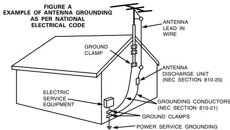


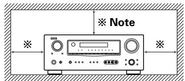
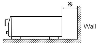
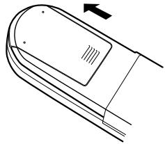
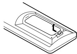
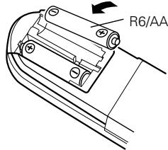
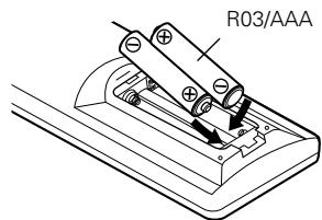
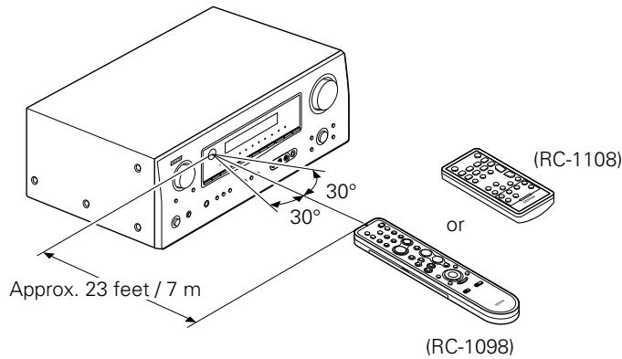
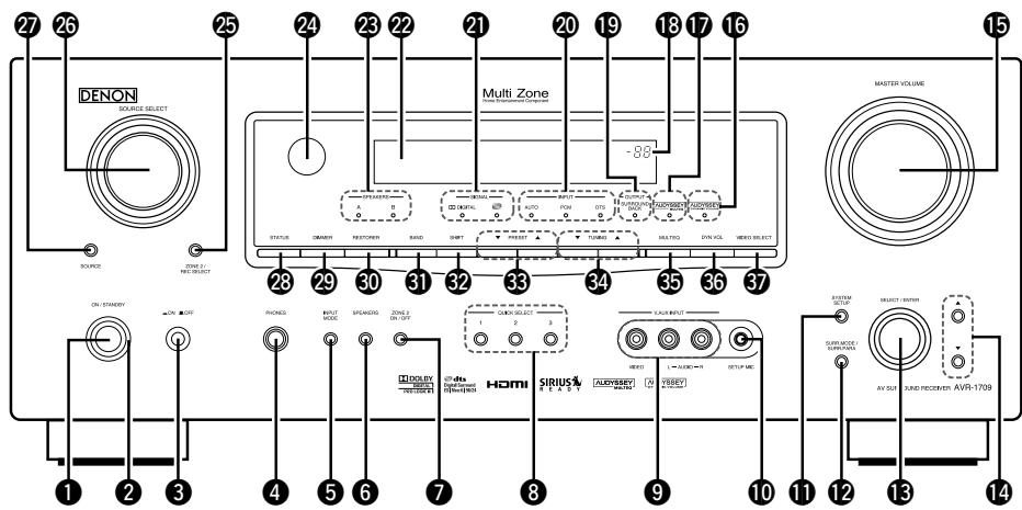
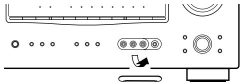


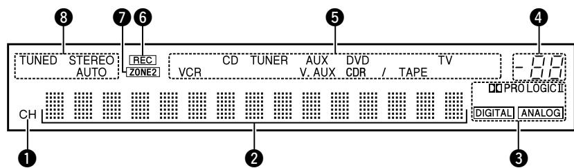
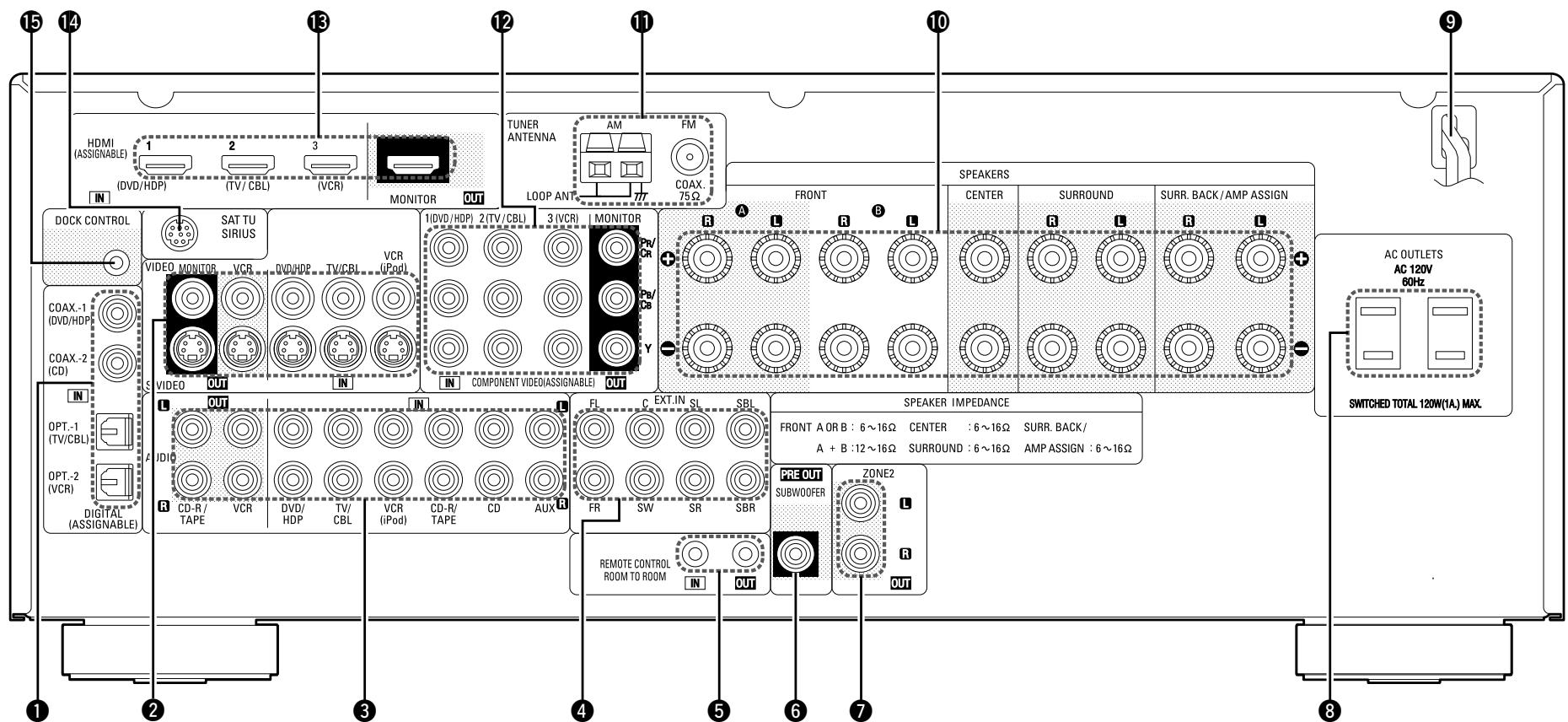
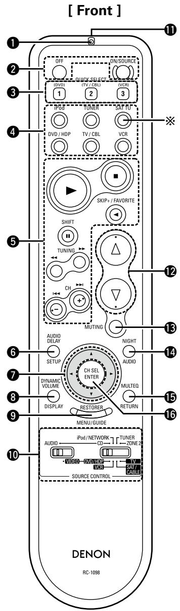
![DENON AVR-1709 - [Rear] - 1](/content/2025/01/135730/images/da4e09fac8e78257c202e38212f240c596d288e175e1b8b2af8001ecd1e70792.jpg)
![DENON AVR-1709 - [Rear] - 2](/content/2025/01/135730/images/d892061a18518ad2fbf03f5ba7253637c328403d0e25df7fe9a8ce4c39829861.jpg)

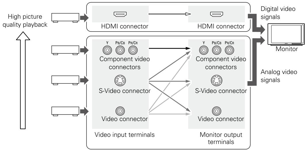

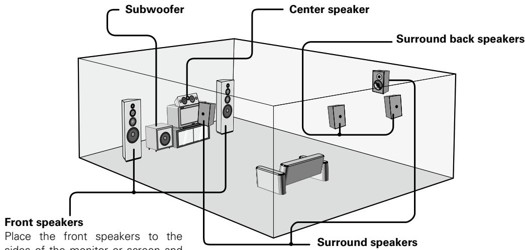


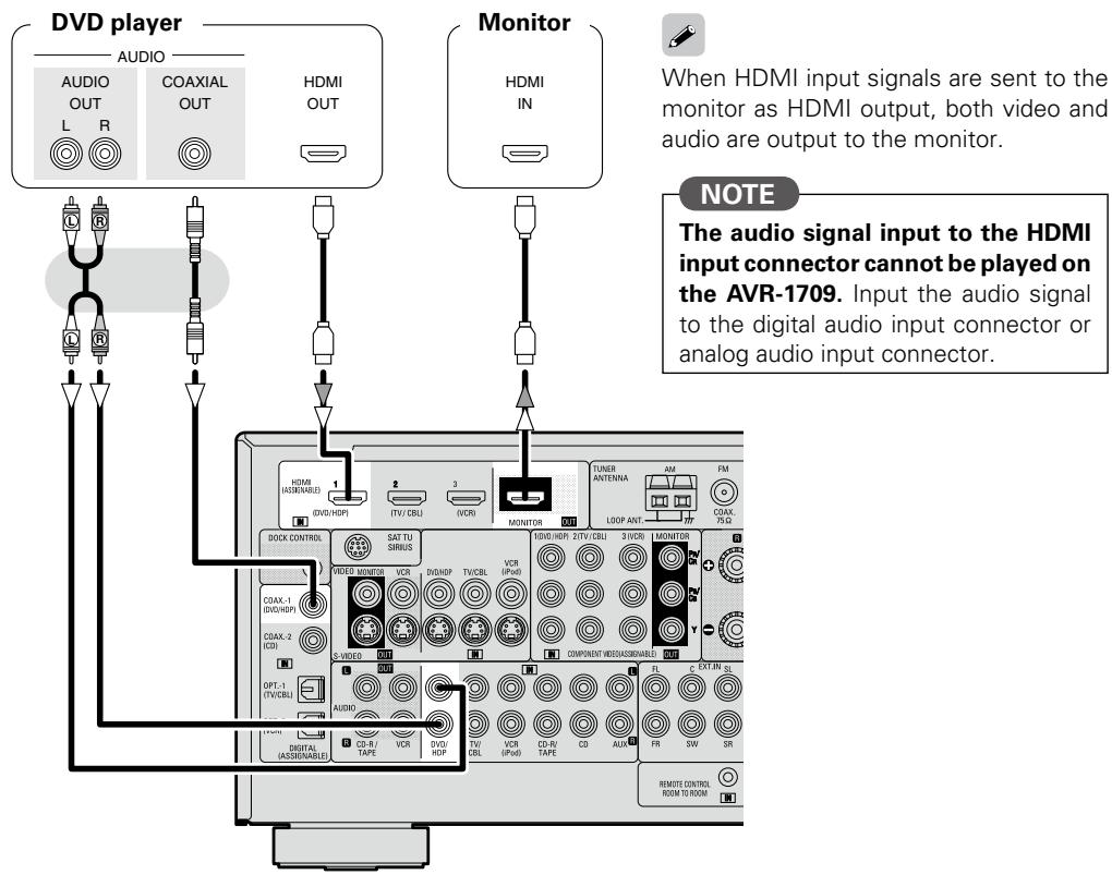

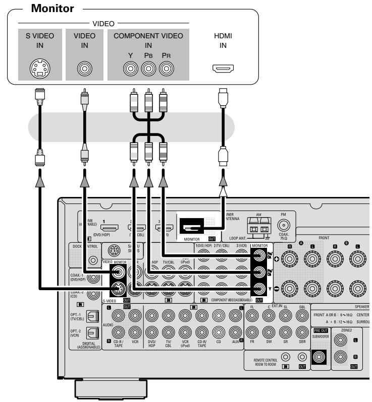
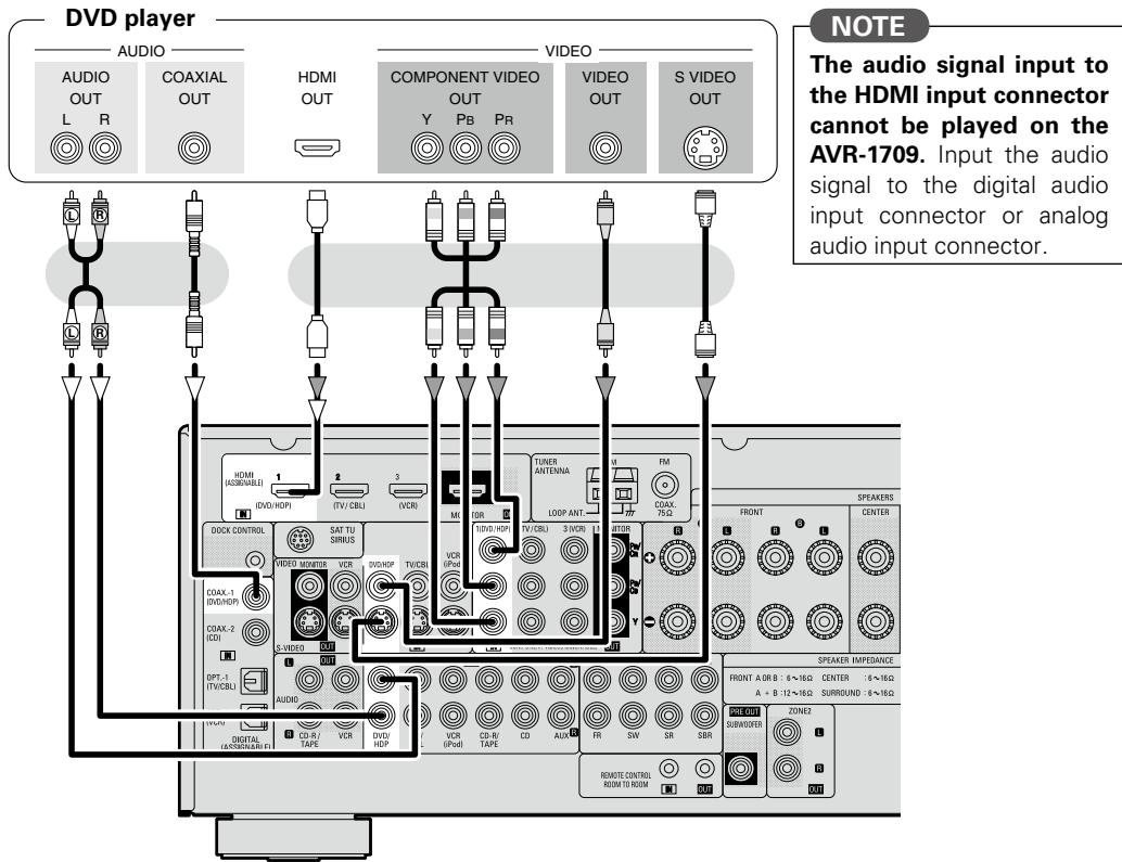

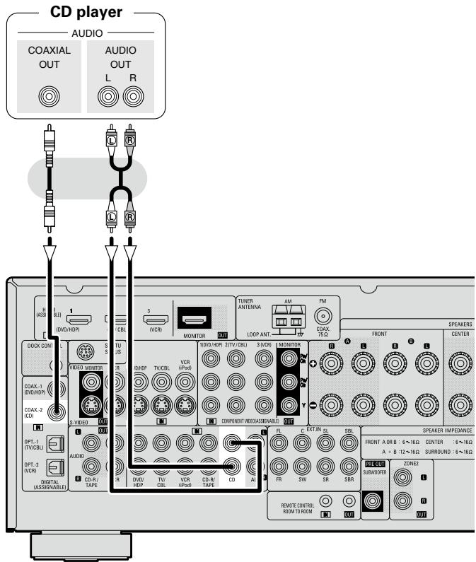

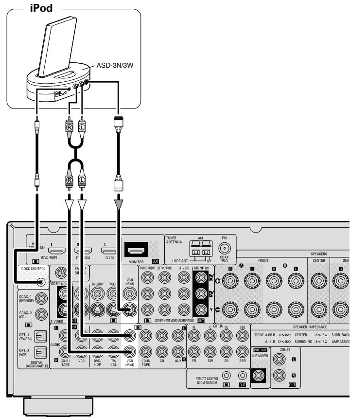

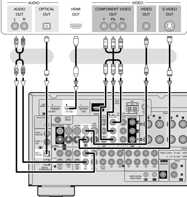

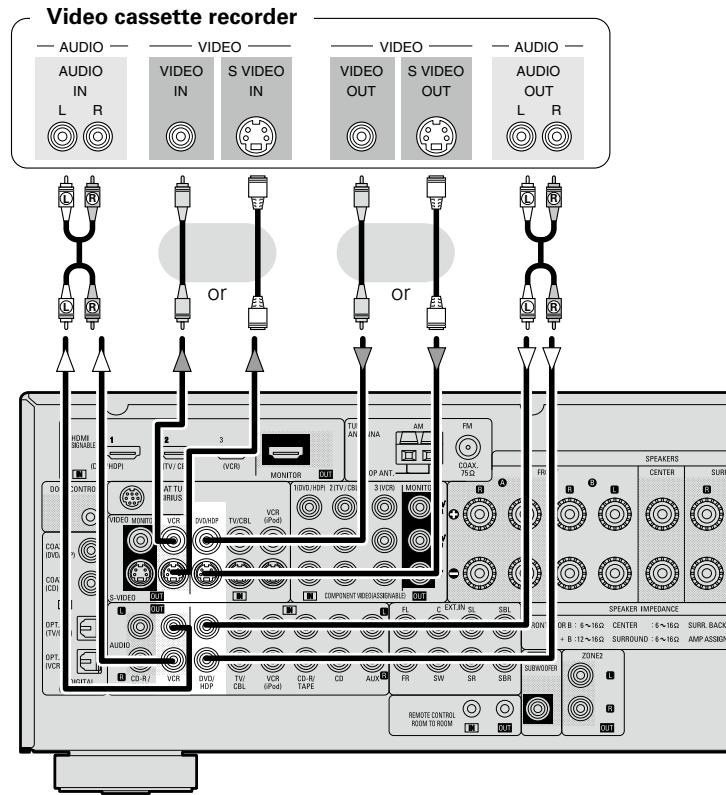

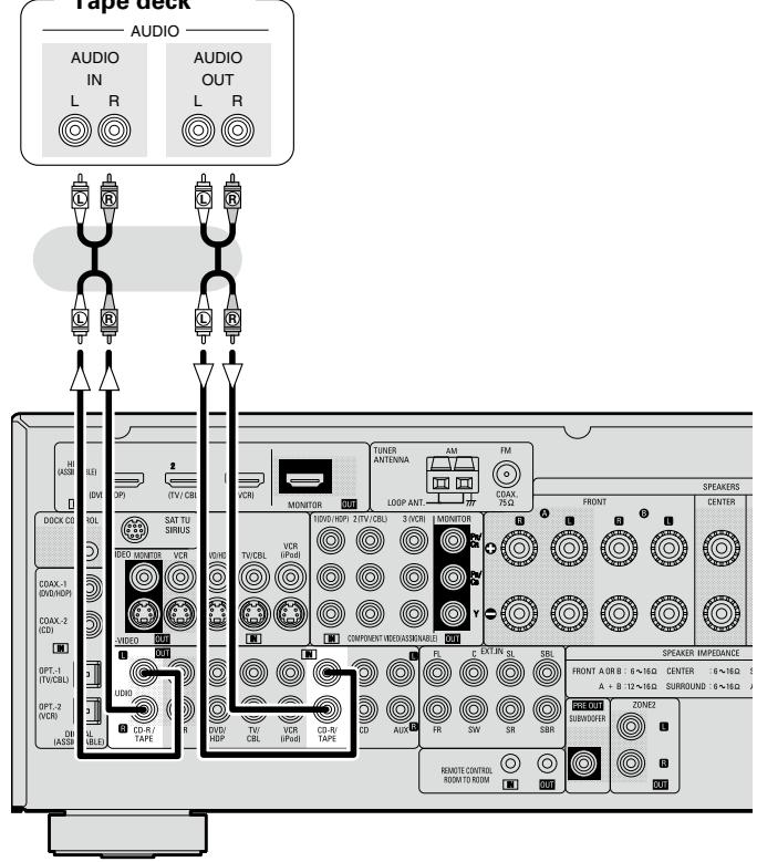
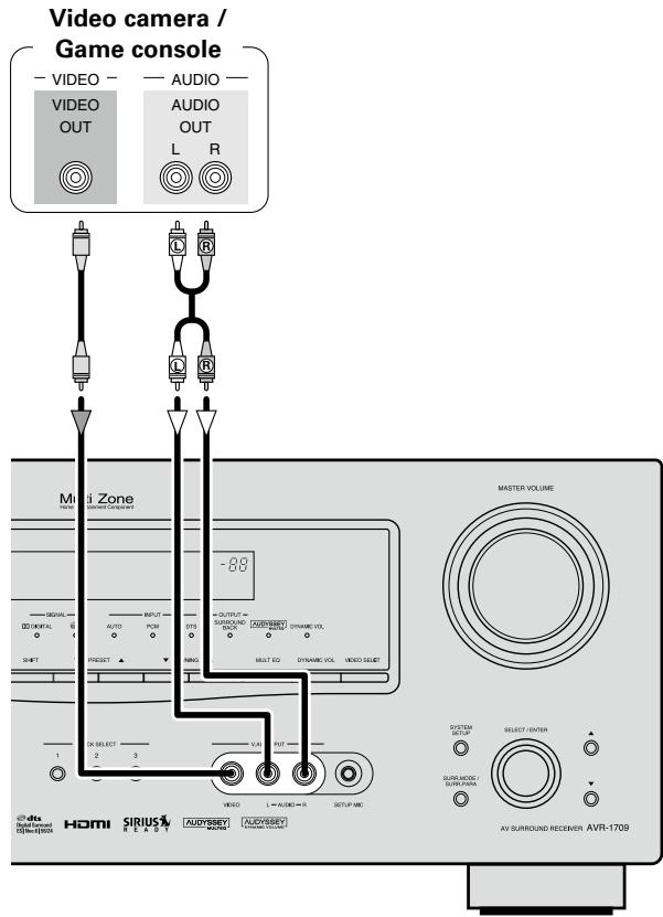
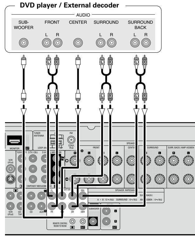

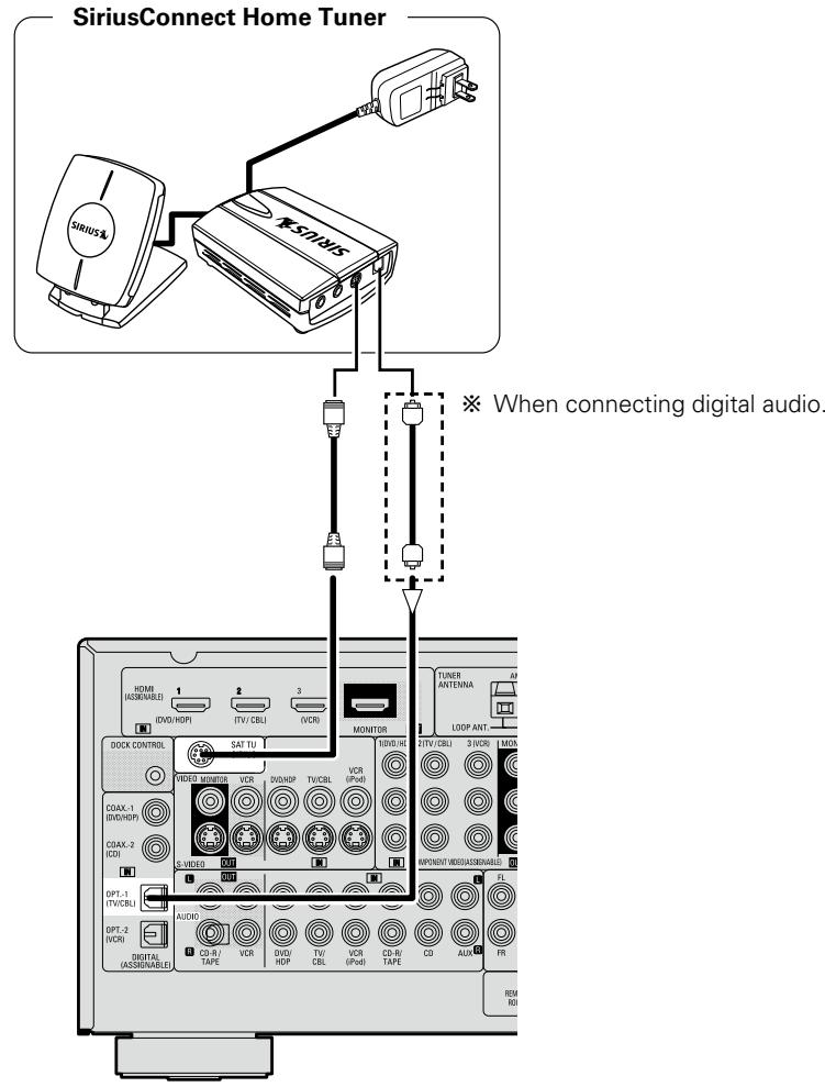

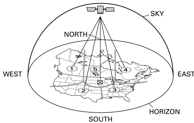
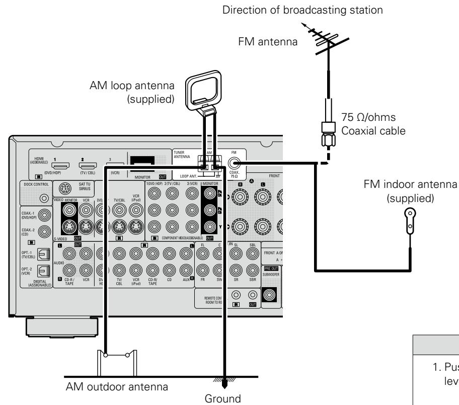


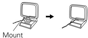

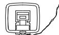


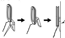


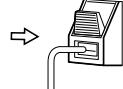

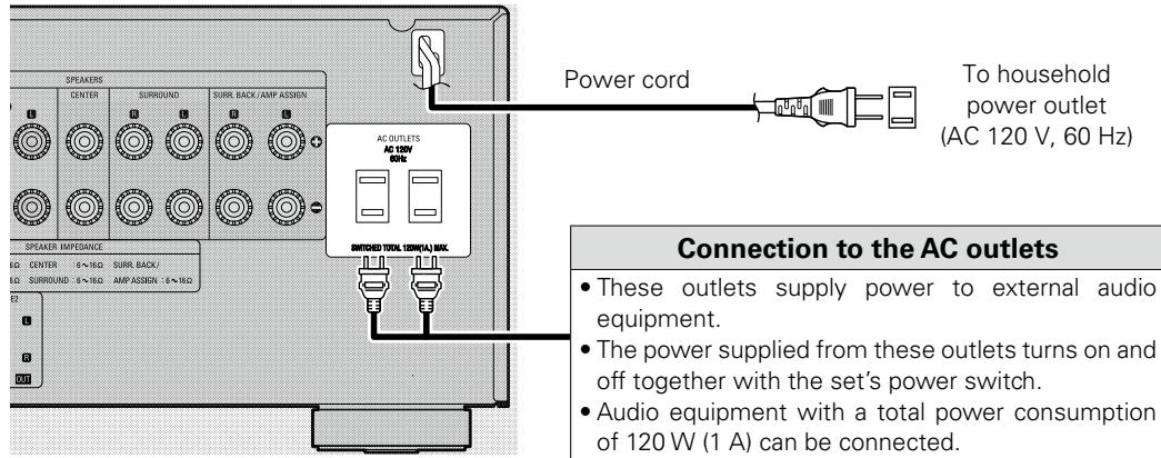
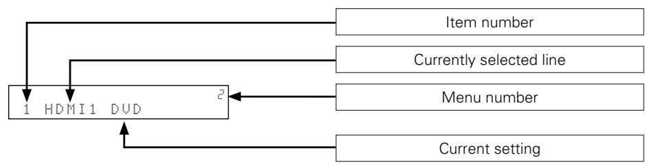
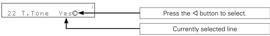

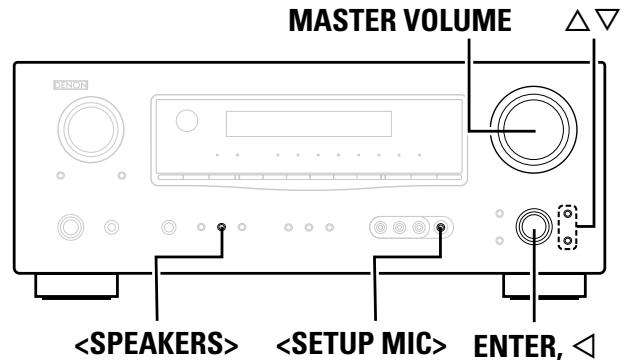
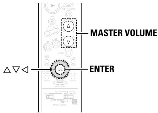
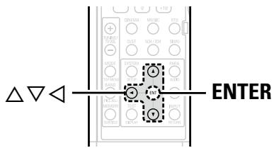
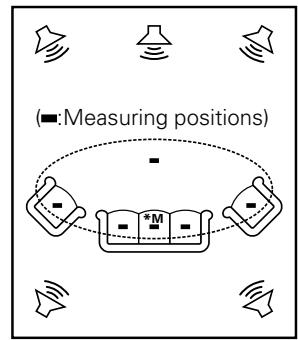
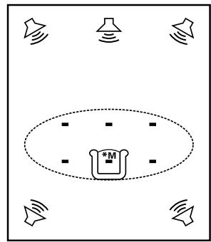


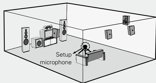

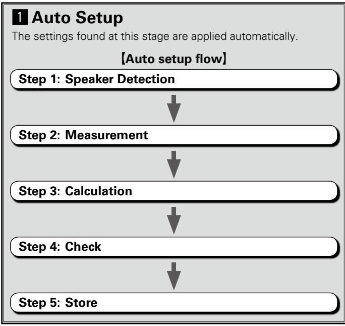

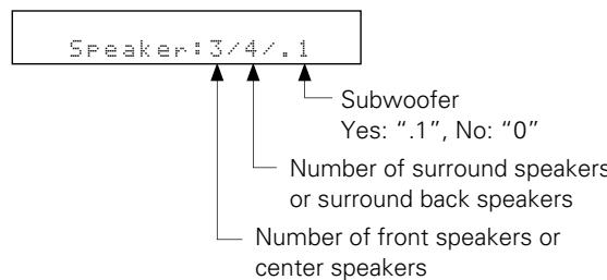


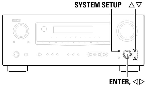
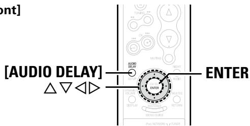
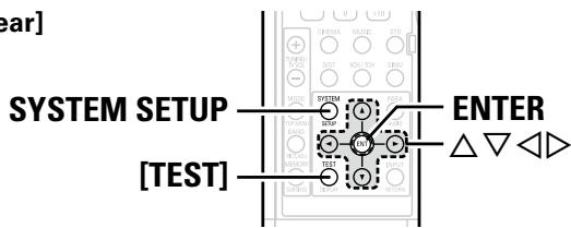

![DENON AVR-1709 - [Selectable items] - 1](/content/2025/01/135730/images/70e8b39fd03e541f9dbf884ed4ea2eb1b69169fd29d12bcd5fe665defc44b97c.jpg)
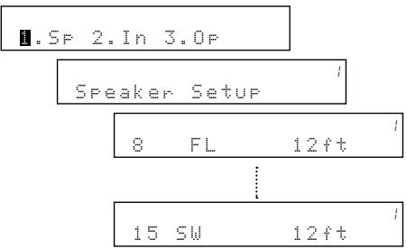
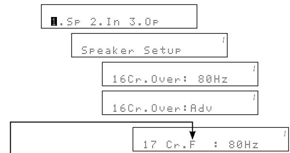

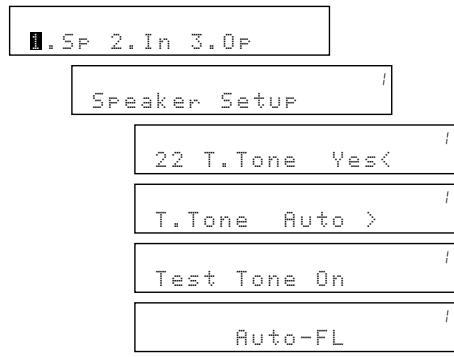

![DENON AVR-1709 - [Adjusting using test tones] - 1](/content/2025/01/135730/images/538deec46591140e217ad687cb36c1432da3720d8c56035b216f45fc4f044606.jpg)
![DENON AVR-1709 - [Display] - 1](/content/2025/01/135730/images/e0b0ce6bfd775329e911685eec48f04e822e03c8ad8df32b287ab3a9f8602004.jpg)
![DENON AVR-1709 - [Display] - 2](/content/2025/01/135730/images/5c3f668182c494a6d263b09182c349656f5e69ae9e3357a28cd6c6e8d0d421f6.jpg)
![DENON AVR-1709 - [Display] - 1](/content/2025/01/135730/images/76c6888782be937ce43446d830bca72ecffba4f20106f2fd040255f499b32781.jpg)
![DENON AVR-1709 - [Assignable input sources] - 1](/content/2025/01/135730/images/092c37f78e4dbe58087e3ce1fffc9f741582ab2656b7485f663f29e4d2bc5c36.jpg)
![DENON AVR-1709 - [Assignable input sources] - 2](/content/2025/01/135730/images/3fcf3e1f89ff8a24f909d47c4419f4fd55458685c0d655add89388a484e16a15.jpg)
![DENON AVR-1709 - [Display] - 1](/content/2025/01/135730/images/ee57101c161e2c0d1e52533773e89c6903aff4d2b26a6422f9bcc55d011867e1.jpg)
![DENON AVR-1709 - [Assignable input sources] - 1](/content/2025/01/135730/images/8f00cbd259278c9ac325884dc8a41568d3e673a1603471e7521806ee460241e2.jpg)
![DENON AVR-1709 - [Display] - 1](/content/2025/01/135730/images/a9f0da592a804f5814cdd288e7d6d9d854689afb62b1a85315b9ec07ccedcabd.jpg)
![DENON AVR-1709 - [Assignable input sources] - 1](/content/2025/01/135730/images/0629b174e8ae8f4a180349a15d1e572e4270dd6a29b0e7a41eafd5527ab288f2.jpg)
![DENON AVR-1709 - [Assignable input sources] - 2](/content/2025/01/135730/images/92d2961662b5b435a1927d46b695b7a5969db91f8f4ef3712006c75bc9969005.jpg)
![DENON AVR-1709 - [Display] - 1](/content/2025/01/135730/images/b37a2504a9acc00a3874406c1141375dec6a31ff53fe2a8ad65e2aa6061213b6.jpg)
![DENON AVR-1709 - [Assignable input sources] - 1](/content/2025/01/135730/images/54f3d276ea41ff48077dce1698167e2888a18f50943751a8da955ed121b8252e.jpg)
![DENON AVR-1709 - [Display] - 1](/content/2025/01/135730/images/2c3f3f37e04775e506e22f16549db8938dff6ced049aed559c19d55a5bf6130e.jpg)
![DENON AVR-1709 - [Display] - 2](/content/2025/01/135730/images/e00316d22c19ada6fcb5c127f4c70564121b55903b8f90f4f6ef939ba8daad2a.jpg)
![DENON AVR-1709 - [Selectable items] - 1](/content/2025/01/135730/images/28e2bb270650ff9151eee907cbe08ff8cb4b5e308f7e2eb453d3f388fd169c87.jpg)
![DENON AVR-1709 - [Display] - 1](/content/2025/01/135730/images/5a9c6c00184b1f7952204219599e20525183f6d009c5998a3ac907ee4ba49715.jpg)
![DENON AVR-1709 - [Variable range] 0 ms ~ 200 ms - 1](/content/2025/01/135730/images/b85b92cc0ec8610c0be1319b2a637afde81ac49fd260e1c7e1dd1688e2ee99d3.jpg)

![DENON AVR-1709 - [Display] - 1](/content/2025/01/135730/images/658fe6a086eccb38d98c5e771143eb7b3bba532a29c1c1a42ac19f5f26c58241.jpg)
![DENON AVR-1709 - [Display] - 1](/content/2025/01/135730/images/9b1623ad504c928ac228d49619459f7fd45d4fce16416411de031bb63b3265d6.jpg)
![DENON AVR-1709 - [Display] - 2](/content/2025/01/135730/images/6a83ec2a7bb9408f87f962402b677f13a7797c6ffde13bcd8c4b81a18aa9b466.jpg)
![DENON AVR-1709 - [Display] - 1](/content/2025/01/135730/images/270b84bbe5f0ddfbe2d8e0f04b1f2fe229f5f810de47aef51dd0ef5c4d5cb0a4.jpg)
![DENON AVR-1709 - [Selectable items] - 1](/content/2025/01/135730/images/0d36befecd2524d96f4726f23e81933ef836a0d2f9f5f61d2ddbfe68a18697c4.jpg)
![DENON AVR-1709 - [Display] - 1](/content/2025/01/135730/images/b119af5fae22247d6687a0999973ba1a5180aec149c20324b5dbb84936841263.jpg)
![DENON AVR-1709 - [Display] - 2](/content/2025/01/135730/images/bb938dbd0d7898bb723b90e76c477c3f5d96b9147eefbc6b1cd3f146ee410fc7.jpg)
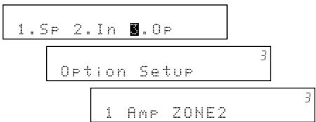
![DENON AVR-1709 - [Selectable items] - 1](/content/2025/01/135730/images/4faf28f0379154e1f32bb625f59f95c3196f880a3af078ece6a6e94bc12bffb1.jpg)
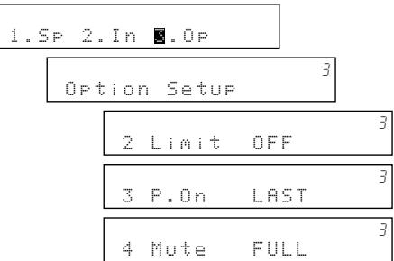
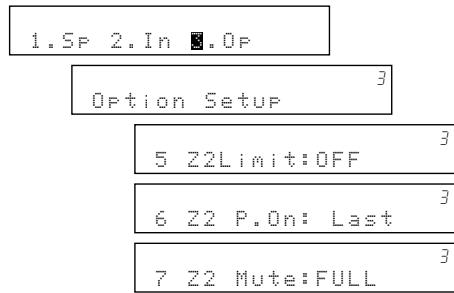
![DENON AVR-1709 - [Selectable items] - 1](/content/2025/01/135730/images/9b874325b0976712d962aa5871eb225223e0c4ad4f9394614416fc923481ece2.jpg)
![DENON AVR-1709 - [Display] - 1](/content/2025/01/135730/images/e55ed9f1e136b6833d85e115036158fd20fdbeb90d78961fe1c112d7fdbcf5a7.jpg)
![DENON AVR-1709 - [Display] - 1](/content/2025/01/135730/images/6ae4e14141e1b79f501dae00f0fcadf359051f6915a65dd99bb3750f2d542870.jpg)
![DENON AVR-1709 - [Selectable items] - 1](/content/2025/01/135730/images/cfe26365e50cbc84f27d5176b6d91afebe920e7d93efe8152f144ff997728537.jpg)
![DENON AVR-1709 - [Display] - 1](/content/2025/01/135730/images/72768c94f33401c484dcb58c28f9dd5be0af5106a435c7c9d9c3b522f01b9672.jpg)
![DENON AVR-1709 - [Display] - 1](/content/2025/01/135730/images/c474b801cd378a5dafd401eb80fae758c1f29696c851430b9554ba29507a3670.jpg)

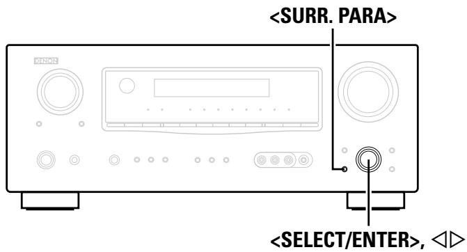
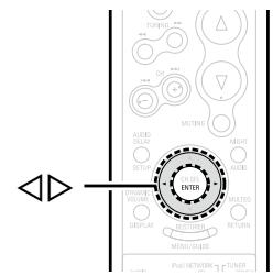
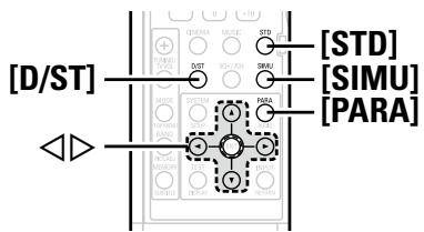

![DENON AVR-1709 - [Selectable items] - 1](/content/2025/01/135730/images/34f5720bdc136eb3b4c71264220e93fa6a46ad63eda1de306097b74357cffb24.jpg)
![DENON AVR-1709 - [Selectable items] - 1](/content/2025/01/135730/images/fcdae83eb716c4bc8643ffb51c827a9ba83ba5580055804034f132462c603d9d.jpg)


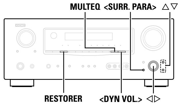
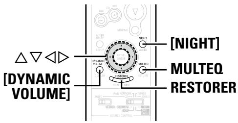
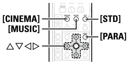
![DENON AVR-1709 - In the DTS NEO:6 mode [Selectable items] - 1](/content/2025/01/135730/images/dfcd8d4de4c3468f34b572e03d494ac58faee7e8d926be51067787014cc17dc0.jpg)


![DENON AVR-1709 - [Selectable items] - 1](/content/2025/01/135730/images/4a6ab01791fbe4147ae45d1341b5aadcc7a510a4ee97c1188ef2325bbb8be3d0.jpg)
![DENON AVR-1709 - [Selectable items] - 2](/content/2025/01/135730/images/9077be8905a4cd8d49c80bba1d6160fc3cc94aa084dbdf855a18fe81a1d255f8.jpg)


![DENON AVR-1709 - [Selectable items] - 1](/content/2025/01/135730/images/533a28358c5d223058bc1452e5c0d444ba6bcbb582ff3481a1f11190c00e30a0.jpg)
![DENON AVR-1709 - [Selectable items] - 1](/content/2025/01/135730/images/dfc2fcf29fd435ebf65deac3b50119218c28662279c5fff99a89a9eb8a4fada2.jpg)
![DENON AVR-1709 - [Selectable items] - 1](/content/2025/01/135730/images/ab389f41af7f8d2dc63738bb6561f4c10d99228d728b3ccf81c3c7025aa20407.jpg)


![DENON AVR-1709 - [Selectable items] - 1](/content/2025/01/135730/images/0f184c60c720db7abd1d70a32be3cead394c783f382fe83d66b9c541f4eee8b8.jpg)
![DENON AVR-1709 - [Selectable items] - 2](/content/2025/01/135730/images/2871f271512a9e418799657f6c04e50bec47d68a54386c22ef9b2c0fa1483e79.jpg)

![DENON AVR-1709 - [Selectable items] - 1](/content/2025/01/135730/images/820972a973846a0789b14d64daa555777e23069f99fef099161403f6954b00e2.jpg)

![DENON AVR-1709 - [Selectable items] - 1](/content/2025/01/135730/images/fcabfeb70ca09e619b1368764fe92e85a94b94e602c927ae4eeb005e3343edcf.jpg)
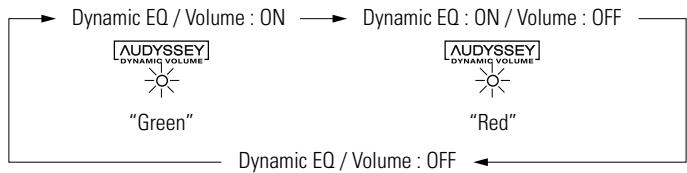

![DENON AVR-1709 - [Selectable items] - 1](/content/2025/01/135730/images/ed315ad3a0cadaaf6800cfde56ff17380b5331af7959052f6ef3e15bfa8b16b9.jpg)
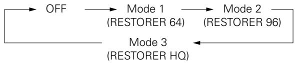
![DENON AVR-1709 - [Selectable items] - 1](/content/2025/01/135730/images/a186445241c826969df21bbbb8a6462a0695088f3f5ff4ef4ea9e6abe08a09cf.jpg)
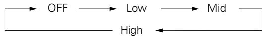

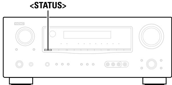


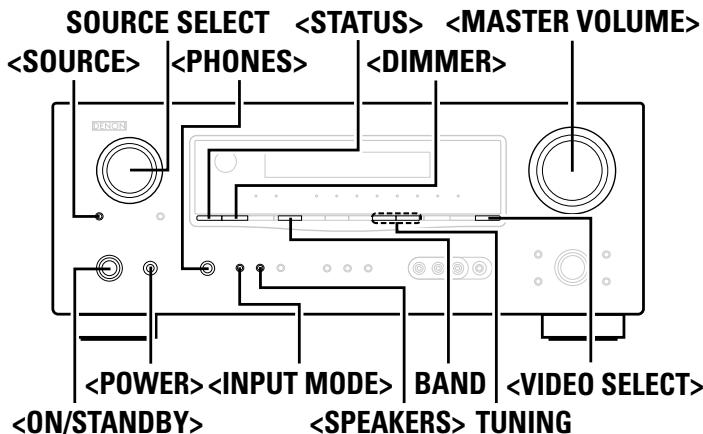
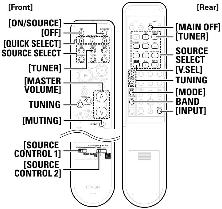

![DENON AVR-1709 - Pressor [INPUT]. - 1](/content/2025/01/135730/images/f307057a3fbe2ed682a4e04a30fb6655d2ed6ccfcb54f70266b867bed54fd013.jpg)


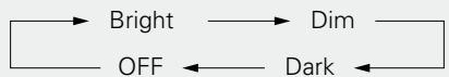


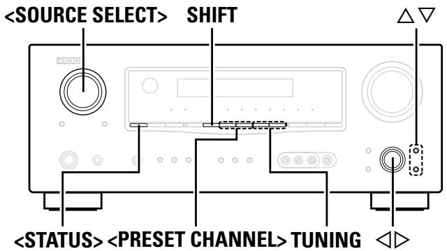
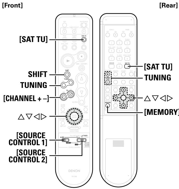


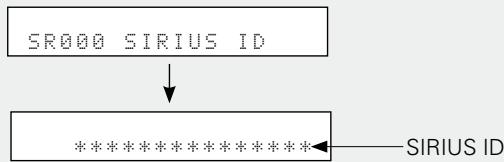


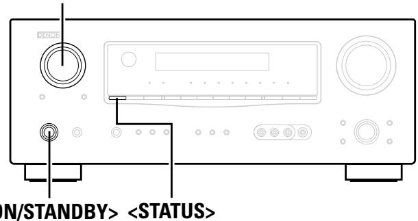
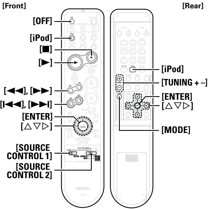

![DENON AVR-1709 - Press [MODE] and hold it down for a 2 seconds or more to select the display mode. - 1](/content/2025/01/135730/images/a8d38250dea94cd53c79f5d04e5e8f0fadad33e0f3ee0841c69a96162646a8f0.jpg)


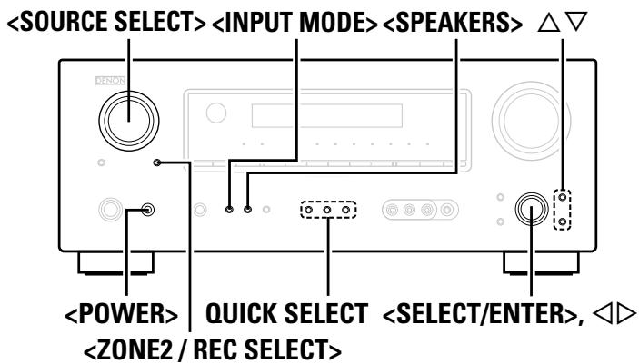
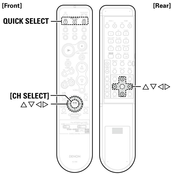


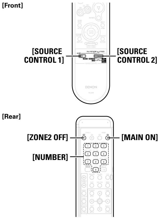


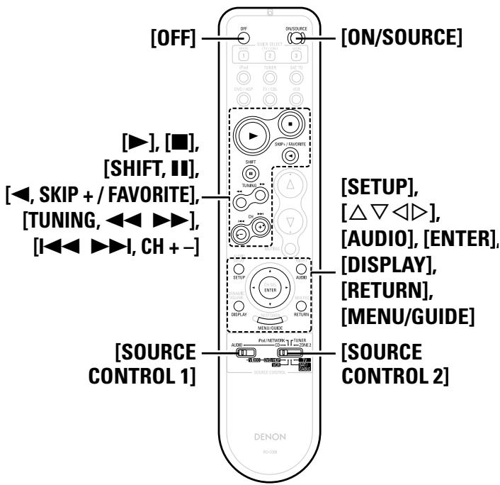

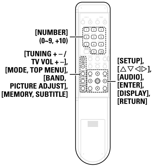
![DENON AVR-1709 - [Special Remarks] - 1](/content/2025/01/135730/images/6fbfe577e500686c2b79a9006fac1bbb5303881bd9c6f788022b504234d724d1.jpg)
![DENON AVR-1709 - [Special Remarks] - 2](/content/2025/01/135730/images/e6d842cce328718deb88521e5467fbda7fa8424e7e215eb5fac6f60e9a51b367.jpg)
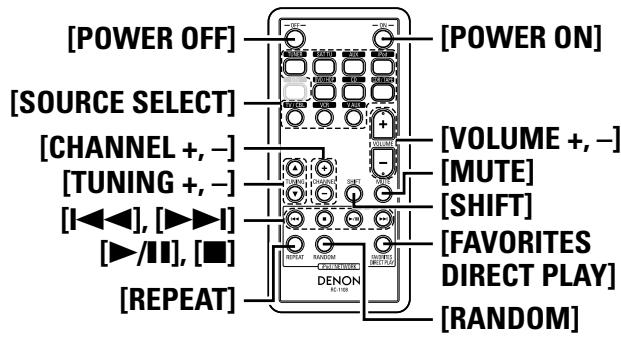
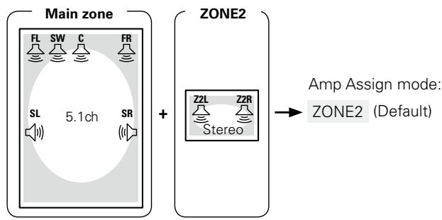
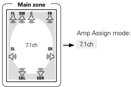
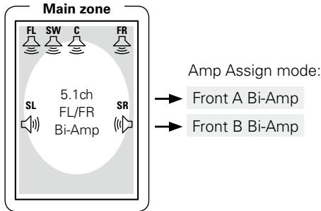
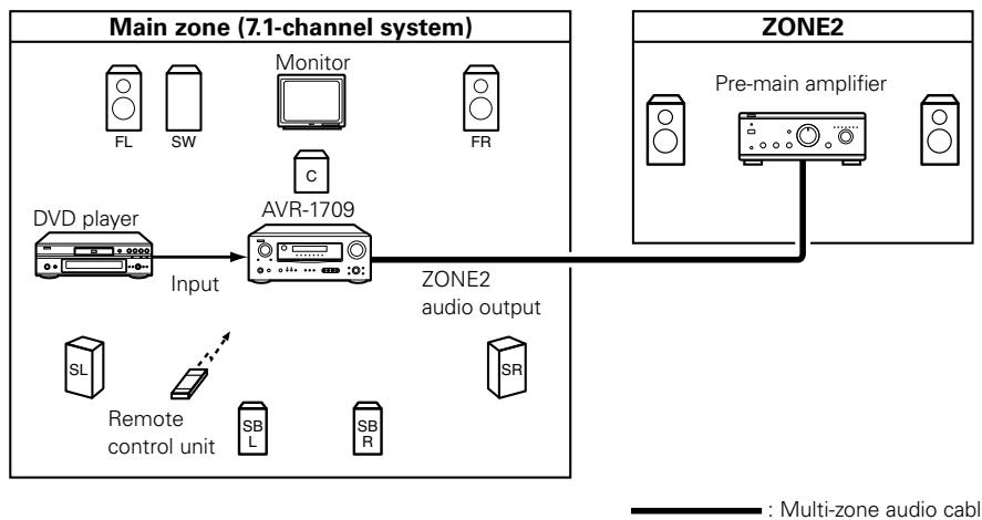
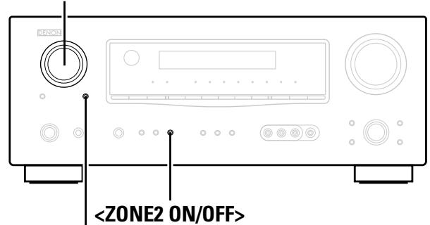
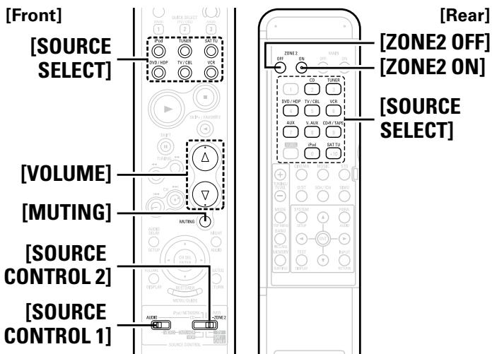
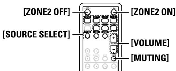


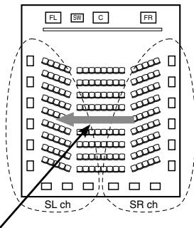
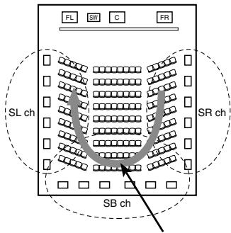
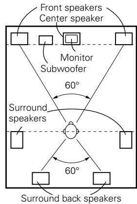
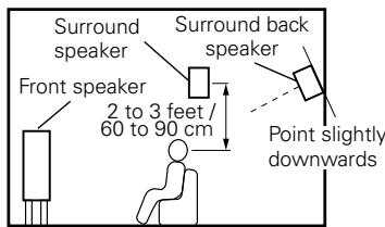
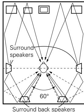
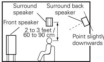
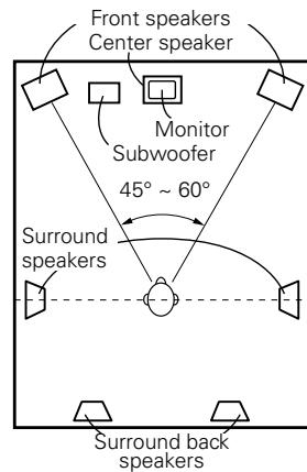
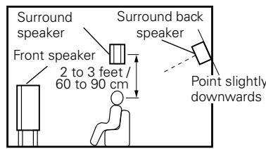
![DENON AVR-1709 - [2] When not using surround back speakers - 1](/content/2025/01/135730/images/d334b9a2d622ffe662f709104ab0db4597c35d04308e726816873ac22c759c1f.jpg)
![DENON AVR-1709 - [2] When not using surround back speakers - 2](/content/2025/01/135730/images/10fb710f9e3010d37f08717622c2cfd7b08f142b7f21a3aea7e0be46c372a68c.jpg)