
D-M51DVS - Compact audio system DENON - Free user manual and instructions
Find the device manual for free D-M51DVS DENON in PDF.
| Product type | Compact audio system |
| Brand | Denon |
| Model | D-M51DVS |
| Dimensions (W x H x D) | 430 x 145 x 310 mm |
| Weight | 5.2 kg |
| Power supply | 220 - 240 V, 50/60 Hz |
| Power consumption | 85 W (standby: < 0.5 W) |
| Output power | 2 x 30 W (RMS) |
| Functions | CD player, AM/FM tuner, amplifier |
| Inputs | Auxiliary (3.5 mm minijack) |
| Outputs | Headphones (3.5 mm minijack) |
| Speakers | 2 built-in passive speakers |
| Remote control | Yes |
| Display | LCD screen |
| Clock / Timer | Yes |
| Sound settings | Bass, treble, balance |
| Housing material | Plastic and metal |
| Color | Black |
| Included accessories | Remote control, power cord, manual |
| Maintenance and cleaning | Clean with a dry, soft cloth. Avoid household cleaning products. |
| Safety | Do not block ventilation holes. Protect from moisture. |
| Spare parts and repairability | Contact Denon after-sales service |
| General information | Full manual available in PDF at notice-facile.com |
Frequently Asked Questions - D-M51DVS DENON
User questions about D-M51DVS DENON
0 question about this device. Answer the ones you know or ask your own.
Ask a new question about this device
Download the instructions for your Compact audio system in PDF format for free! Find your manual D-M51DVS - DENON and take your electronic device back in hand. On this page are published all the documents necessary for the use of your device. D-M51DVS by DENON.
USER MANUAL D-M51DVS DENON
We greatly appreciate your purchase of this unit.
To be sure you take maximum advantage of all the features this unit has to offer, read these instructions carefully and use the set properly. Be sure to keep this manual for future reference should any questions or problems arise.
"SERIAL NO.
PLEASE RECORD UNIT SERIAL NUMBER ATTACHED TO THE REAR OF THE CABINET FOR FUTURE REFERENCE"
TO PREVENT FIRE OR SHOCK HAZARD, DO NOT EXPOSE THIS APPLIANCE TO RAIN OR MOISTURE.

CAUTION
RISK OF ELECTRIC SHOCK DO NOT OPEN

CAUTION:
TO REDUCE THE RISK OF ELECTRIC SHOCK, DO NOT REMOVE COVER (OR BACK). NO USER-SERVICEABLE PARTS INSIDE. REFER SERVICING TO QUALIFIED SERVICE PERSONNEL.

The lightning flash with arrowhead symbol, within an equilateral triangle, is intended to alert the user to the presence of uninsulated "dangerous voltage" within the product's enclosure that may be of sufficient magnitude to constitute a risk of electric shock to persons.

The exclamation point within an equilateral triangle is intended to alert the user to the presence of important operating and maintenance (servicing) instructions in the literature accompanying the appliance.
CAUTION
TO PREVENT ELECTRIC SHOCK, MATCH WIDE BLADE OF PLUG TO WIDE SLOT, FULLY INSERT.
ATTENTION
POUR ÉVITER LES CHOCS ÉLECTRIQUES, INTERODUIRE LA LAME LA PLUS LARGE DE LA FICHE DANS LA BORNE CORRESPONDANTE DE LA PRISE ET POUSSER JUSQU' AU FOND.
FCC INFORMATION (For US customers)
1.PRODUCT
This product complies with Part 15 of the FCC Rules. Operation is subject to the following two conditions: (1) this product may not cause harmful interference, and (2) this product must accept any interference received, including interference that may cause undesired operation.
2. IMPORTANT NOTICE: DO NOT MODIFY THIS PRODUCT
This product, when installed as indicated in the instructions contained in this manual, meets FCC requirements. Modification not expressly approved by DENON may void your authority, granted by the FCC, to use the product.
3. NOTE
This product has been tested and found to comply with the limits for a Class B digital device, pursuant to Part 15 of the FCC Rules. These limits are designed to provide reasonable protection against harmful interference in a residential installation.
This product generates, uses and can radiate radio frequency energy and, if not installed and used in accordance with the instructions, may cause harmful interference to radio communications. However, there is no guarantee that interference will not occur in a particular installation. If this product does cause harmful interference to radio or television reception, which can be determined by turning the product OFF and ON, the user is encouraged to try to correct the interference by one or more of the following measures:
- Reorient or relocate the receiving antenna.
- Increase the separation between the equipment and receiver.
- Connect the product into an outlet on a circuit different from that to which the receiver is connected.
- Consult the local retailer authorized to distribute this type of product or an experienced radio/TV technician for help.
■ NOTE ON USE / OBSERVATIONS RELATIVES A L'UTILISATION
- Avoid high temperatures.
Allow for sufficient heat dispersion when installed on a rack. - Eviter des températures élevées
- Read Instructions - All the safety and operating instructions should be read before the product is operated.
- Retain Instructions - The safety and operating instructions should be retained for future reference.
- HeedWarnings - All warnings on the product and in the operating instructions should be adhered to.
- Follow Instructions - All operating and use instructions should be followed.
- Cleaning - Unplug this product from the wall outlet before cleaning. Do not use liquid cleaners or aerosol cleaners.
- Attachments - Do not use attachments not recommended by the product manufacturer as they may cause hazards.
- Water and Moisture - Do not use this product near water - for example, near a bath tub, wash bowl, kitchen sink, or laundry tub; in a wet basement; or near a swimming pool; and the like.
- Accessories - Do not place this product on an unstable cart, stand, tripod, bracket, or table. The product may fall, causing serious injury to a child or adult, and serious damage to the product. Use only with a cart, stand, tripod, bracket, or table recommended by the manufacturer, or sold with the product. Any mounting of the product should follow the manufacturer's instructions, and should use a
mounting accessory recommended by the manufacturer.

- A product and cart combination should be moved with care. Quick stops, excessive force, and uneven surfaces may cause the product and cart combination to overturn.
- Ventilation – Slots and openings in the cabinet are provided for ventilation and to ensure reliable operation of the product and to protect it from overheating, and these openings must not be blocked or covered. The openings should never be blocked by placing the product on a bed, sofa, rug, or other similar surface. This product should not be placed in a built-in installation such as a bookcase or rack unless proper ventilation is provided or the manufacturer's instructions have been adhered to.
- Power Sources – This product should be operated only from the type of power source indicated on the marking label. If you are not sure of the type of power supply to your home, consult your product dealer or local power company. For products intended to operate from battery power, or other sources, refer to the operating instructions.
- Grounding or Polarization - This product may be equipped with a polarized alternating-current line plug (a plug having one blade wider than the other). This plug will fit into the power outlet only one way. This is a safety feature. If you are unable to insert the plug fully into the outlet, try reversing the plug. If the plug should still fail to fit, contact your electrician to replace your obsolete outlet. Do not defeat the safety purpose of the polarized plug.
NEC-NATIONAL ELECTRICAL CODE
- Power-Cord Protection - Power-supply cords should be routed so that they are not likely to be walked on or pinched by items placed upon or against them, paying particular attention to cords at plugs, convenience receptacles, and the point where they exit from the product.
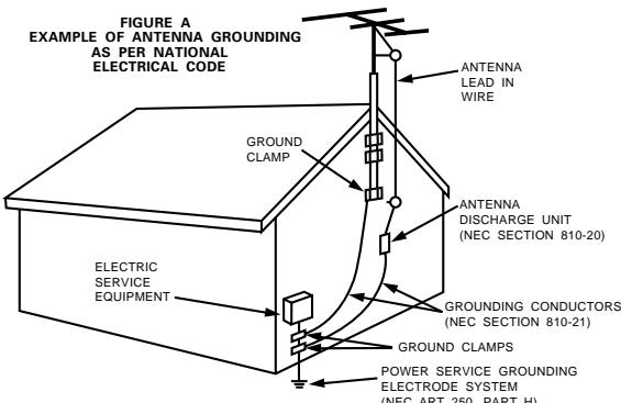
- Outdoor Antenna Grounding - If an outside antenna or cable system is connected to the product, be sure the antenna or cable system is grounded so as to provide some protection against voltage surges and built-up static charges. Article 810 of the National Electrical Code, ANSI/NFPA 70, provides information with regard to proper grounding of the mast and supporting structure, grounding of the lead-in wire to an antenna discharge unit, size of grounding conductors, location of antenna-discharge unit, connection to grounding electrodes, and requirements for the grounding electrode. See Figure A.
- Lightning - For added protection for this product during a lightning storm, or when it is left unattended and unused for long periods of time, unplug it from the wall outlet and disconnect the antenna or cable system. This will prevent damage to the product due to lightning and power-line surges.
- Power Lines - An outside antenna system should not be located in the vicinity of overhead power lines or other electric light or power circuits, or where it can fall into such power lines or circuits. When installing an outside antenna system, extreme care should be taken to keep from touching such power lines or circuits as contact with them might be fatal.
- Overloading – Do not overload wall outlets, extension cords, or integral convenience receptacles as this can result in a risk of fire or electric shock.
- Object and Liquid Entry – Never push objects of any kind into this product through openings as they may touch dangerous voltage points or short-out parts that could result in a fire or electric shock. Never spill liquid of any kind on the product.
- Servicing – Do not attempt to service this product yourself as opening or removing covers may expose you to dangerous voltage or other hazards. Refer all servicing to qualified service personnel.
- Damage Requiring Service – Unplug this product from the wall outlet and refer servicing to qualified service personnel under the following conditions:
a) When the power-supply cord or plug is damaged,
b) If liquid has been spilled, or objects have fallen into the product,
c) If the product has been exposed to rain or water,
d) If the product does not operate normally by following the operating instructions. Adjust only those controls that are covered by the operating instructions as an improper adjustment of other controls may result in damage and will often require extensive work by a qualified technician to restore the product to its normal operation,
e) If the product has been dropped or damaged in any way, and
f) When the product exhibits a distinct change in performance – this indicates a need for service.
- Replacement Parts - When replacement parts are required, be sure the service technician has used replacement parts specified by the manufacturer or have the same characteristics as the original part. Unauthorized substitutions may result in fire, electric shock, or other hazards.
- Safety Check - Upon completion of any service or repairs to this product, ask the service technician to perform safety checks to determine that the product is in proper operating condition.
- Wall or Ceiling Mounting – The product should be mounted to a wall or ceiling only as recommended by the manufacturer.
- Heat - The product should be situated away from heat sources such as radiators, heat registers, stoves, or other products (including amplifiers) that produce heat.
CAUTION:
1. Handle the power supply cord carefully
Do not damage or deform the power supply cord. If it is damaged or deformed, it may cause electric shock or malfunction when used. When removing from wall outlet, be sure to remove by holding the plug attachment and not by pulling the cord.
2. Do not open the top cover
In order to prevent electric shock, do not open the top cover.
3. Do not place anything inside
Do not place metal objects or spill liquid inside the DVD video player.
Electric shock or malfunction may result.
NOTE:
This DVD video player uses the semiconductor laser. To allow you to enjoy music at a stable operation, it is recommended to use this in a room of 5 ^ C (41 ^ F ) ~ 35 ^ C (95 ^ F ).
Copyrights
It is prohibited by law to reproduce, broadcast, rent or play discs in public without the consent of the copyright holder.
INTRODUCTION
Thank you for choosing the DENON ADV-M51 DVD Surround Receiver. This remarkable component has been engineered to provide superb surround sound listening with home theater sources such as DVD, as well as providing outstanding high fidelity reproduction of your favourite music sources. As this product is provided with an immense array of features, we recommend that before you begin hookup and operation that you review the contents of this manual before proceeding.
TABLE OF CONTENTS
1 BEFORE USING 5
2 CAUTIONS ON INSTALLATION 5,6
3 CAUTIONS ON HANDLING 6
4 FEATURES. 7
5 DISCS. 8
6 CAUTIONS ON HANDLING DISCS. 9
7 CONNECTIONs 10~17
PART NAMES AND FUNCTIONS 18~22
9REMOTE CONTROL UNIT. 23~30
10 SETTING UP THE SYSTEM 31~39
11 PLAY BACK. 39~44
12 OPERATING THE SURROUND FUNCTIONS. 44~46
13 DOLBY / DTS SURROUND. 47~49
14 SURROUND PLAYBACK. 50~58
15 LISTENING TO THE RADIO. 59~61
16 ON-SCREEN DISPLAY 62
17 USING THE ON-SCREEN DISPLAY 63~80
18 USING THE TIMER 81~87
19 CHANGING THE DEFAULT SETTINGS (DVD) 88~100
20 SYSTEM FUNCTIONS 101~104
21 LAST FUNCTION MEMORY 105
22 INITIALIZATION OF THE MICROPROCESSOR 105
23 TROUBLESHOOTING 106, 107
24 SPECIFICATIONS 108, 109
■ ACCESSORIES
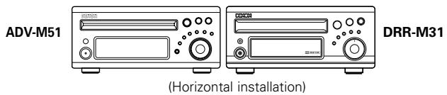
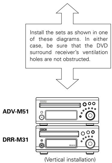
ADV-M51
Check that the following parts are included in addition to the main unit:
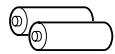
① Operating instructions.....1 ② Warranty ( for North America model only)............1
⑤ R6P/AA batteries. .2 ⑥ AM loop antenna. .1 ⑦ FM indoor antenna..1
③ Service station list............1 ④ Remote control unit
⑧ Video cord. (RC-936). 1
(4)
(5)

6

7
⑧
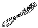
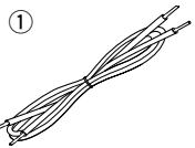
SYS-M51 (D-M51DVS only)
① Cord A 2
(Used to connect the SC-A3L)
Length: Approx. 3 meters)
③ Anti-Slip pad (4 pcs / 1 sheet)
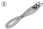
② Cord B. 1
(Used to connect the DSW-3L)
Length: Approx. 3 meters, RCA PIN
3
1 BEFORE USING
Pay attention to the following before using this unit:
- Moving the set
To prevent short circuits or damaged wires in the connection cords, always unplug the power cord and disconnect the connection cords between all other audio components when moving the set.
- Before turning the power switch on
Check once again that all connections are proper and that there are not problems with the connection cords. Always set the power switch to the standby position before connecting and disconnecting connection cords.
- Store this instructions in a safe place.
After reading, store this instructions along with the warranty in a safe place.
- Note that the illustrations in this instructions may differ from the actual set for explanation purposes.
2 CAUTIONS ON INSTALLATION
(1) DVD SURROUND RECEIVER
Noise or disturbance of the picture may be generated if this unit or any other electronic equipment using microprocessors is used near a tuner or TV.
If this happens, take the following steps:
- Install this unit as far as possible from the tuner or TV.
- Set the antenna wires from the tuner or TV away from this unit's power cord and input/output connection cords.
- Noise or disturbance tends to occur particularly when using indoor antennas or 300 /ohms feeder wires. We recommend using outdoor antennas and 75 /ohms coaxial cables.
(2) SPEAKER SYSTEM (D-M51DVS only)
SC-A3L
The quality of the sound produced from the speaker system is affected by the size and type (Japanese or Western) of the room, as well as by the method of installation. Consider the points listed below before installing the speaker system.
- Note that placing the speaker system on the same stand or shelf as a record player may result in howling.
- If there is a wall, glass door, etc., directly in front of or behind the speaker system, cover the wall or door with a thick curtain to prevent resonance and reflection.
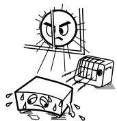
- The SC-A3L speaker systems are of the low-leakage-flux type and can be used near televisions, but depending on the TV there may be color blotching on the picture. If this happens, turn off the TV's power, wait 15 to 30 minutes, then turn the TV's power back on. The TV's automatic degaussing circuit should reduce the blotching on the picture. If blotching persists, move the speaker further away.
- When placing the satellite speaker system (SC-A3L) on a stand, etc., stick the included anti-slip pads (cork, approximately 2 mm thick) at the four corners of the bottom surface. (Refer to the illustration below.)
- When mounting the satellite speaker system (SC-A3L) on a stand or bracket, M5 nuts are inserted into the bottom of the satellite speaker system (SC-A3L) at intervals of 60~mm . When mounting, following the instructions in the manual included with the speaker stand or ceiling mount bracket, and be sure to install properly and securely.
- When the satellite speaker system (SC-A3L) is mounted on a ceiling mount bracket, it is turned upside down due to the installation angle. The Denon mark is also turned upside down, so detach the speaker net and reattach it in the opposite direction.
DSW-3L
- Note that placing the active subwoofer on the same stand or shelf as a record player may result in howling.
- The DSW-3L active subwoofer is a Lowleakage-Flux type speaker system and can be used near televisions, but depending on the TV there may be color blotching on the picture. If this happens, turn off the TV's power, move the TV and subwoofer a little apart, wait 15 to 30 minutes, then turn the TV's power back on. The TV's automatic degaussing circuit should reduce the blotching on the picture. If blotching persists, move the subwoofer and TV further away from each other.
- Install on a firm, flat floor to prevent accidents due to toppling down.
- Do not place a record player, CD player or other AV device on top of the subwoofer.
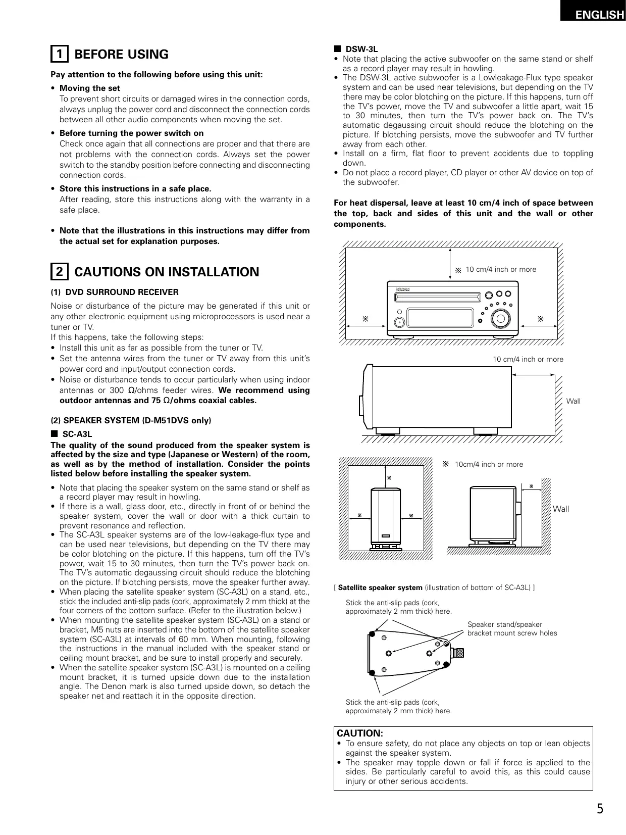
For heat dispersal, leave at least 10~cm / 4 inch of space between the top, back and sides of this unit and the wall or other components.
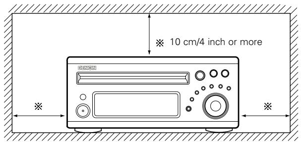
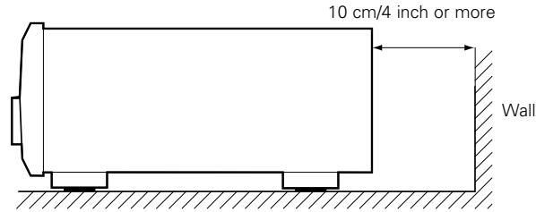
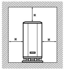
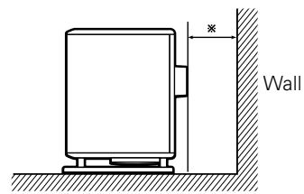
※ 10cm/4 inch or more
[Satellite speaker system (illustration of bottom of SC-A3L)]
Stick the anti-slip pads (cork, approximately 2 mm thick) here.
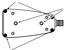
Speaker stand/speaker bracket mount screw holes
Stick the anti-slip pads (cork, approximately 2mm thick) here.
CAUTION:
- To ensure safety, do not place any objects on top or lean objects against the speaker system.
- The speaker may topple down or fall if force is applied to the sides. Be particularly careful to avoid this, as this could cause injury or other serious accidents.
WARNING:
- When installing the speaker systems on the ceiling or wall, to ensure safety, have specialists do the installation work.
- Be sure to fasten the speaker cords to a wall, etc., to prevent people from tripping over them or otherwise pulling on them accidentally, causing the speaker systems to fall.
- Be sure to check for safety after installing the speaker systems. Afterwards, perform safety inspections at regular intervals to be sure there is no danger that the speaker systems will fall. Denon will accept no responsibility for damages or accidents caused by inappropriate choice of the place of installation or improper installation procedures.
- For your safety, do not put anything nor lean yourself on the loudspeakers.
- Do not push the loudspeaker from aside to protect it from topping that may cause serious accident.
Fix speaker cables to prevent being caught on it and making loudspeakers topping down.
3 CAUTIONS ON HANDLING
(1) DVD SURROUND RECEIVER
- Switching the input function when input jacks are not connected
A clicking noise may be produced if the input function is switched when nothing is connected to the input jacks. If this happens, either turn down the MASTER VOLUME control or connect components to the input jacks.
- Muting of PRE OUT jacks, HEADPHONE jack and SPEAKER terminals
The PRE OUT jacks, HEADPHONE jacks and SPEAKER terminals include a muting circuit. Because of this, the output signals are greatly reduced for several seconds after the power switch is turned on or input function, surround mode or any other-set-up is changed. If the volume is turned up during this time, the output will be very high after the muting circuit stops functioning. Always wait until the muting circuit turns off before adjusting the volume.
- Whenever the power switch is in the STANDBY state, the apparatus is still connected on AC line voltage.
Please be sure to unplug the cord when you leave home for, say, a vacation.
(2) SPEAKER SYSTEM (D-M51DVS only)
SC-A3L
- Note that color blotching may occur on a TV, etc., due to interaction with the speaker system if there is a magnet or an object generating magnetic force nearby.
Examples: (a) When there are magnets on the door of the rack, stand, etc.
(b) When a health device, etc., equipped with magnets is placed nearby.
(c) When toys or other objects using magnets are placed nearby.
- Note that the illustrations in this instructions may differ from the actual set for explanation purposes.
- Be sure to keep the operating instructions.
After reading these operating instructions, store them in a safe place. We also recommend filling in the necessary items on the back cover.
DSW-3L
- The built-in amplifier of the active subwoofer (DSW-3L) includes a mating circuit. The output signal is strongly attenuated for several seconds after the power is turned on. If the volume is adjusted during this time, the output may be extremely high when the mating circuit is deactivated. Be sure to wait for the mating circuit to be deactivated before adjusting the volume.
- Note that color blotching may occur on a TV, etc., due to interaction with the subwoofer if there is a magnet or an object generating magnetic force nearby.
Examples: (a) When there are magnets on the door of the rack, stand, etc.
(b) When a health device, etc., equipped with magnets is placed nearby.
(c) When toys or other objects using magnets are placed nearby.
- Note that the illustrations in this instructions may differ from the actual set for explanation purposes.
- Be sure to keep the operating instructions.
After reading these operating instructions, store them in a safe place. We also recommend filling in the necessary items on the back cover.
WARNING:
- Be sure to fasten the power cord to a wall, etc., to prevent people from tripping over it or otherwise pulling on it accidentally, causing the subwoofer to fall.
4 FEATURES
The ADV-M51 combines an AV amplifier and DVD player, the core components of a home theater system, into a single compact, stylish body. The system takes up little space, and the aluminum front panel and half mirror of the display make for an elegant design that blends in nicely with the décor in your room.
1. 2-channel power amplifier with Dolby Virtual Speaker compatibility
The ADV-M51 is equipped with two 35W (6 Ω/ohms 1kHz, T.H.D. 10%) power amplifiers that make it compatible with new Dolby Virtual Speaker technology for recreating a 5.1-channel environment virtually using a 2-channel configuration. (Dolby Virtual Speaker is an proprietary technology of Dolby Laboratories.) A high performance digital signal processor enables playback of Dolby Digital and DTS multi-channel surround signals in the Dolby Virtual Speaker mode. Surround sound can be achieved with the Dolby Virtual Speaker mode for CDs and other 2-channel sources in combination with the Dolby Pro Logic II decoder.
2. DENON's unique sound field simulation using the DSP
The ADV-M51 is compatible with the Rock Arena, Jazz Club and Video Game modes.
3. High performance DVD drive
The ADV-M51 is compatible with various functions offered by DVD sources, including multiple audio (up to 8 languages), multiple subtitle (up to 32 languages), multiple angle playback, viewing restriction, etc.
4. Quick setup and on-screen display compatibility
DVDs can be enjoyed simply by selecting the TV and speaker configuration to be used.
The system can be set up using an on-screen display function.
5. Remote control unit with preset memory function
The ADV-M51 comes with a remote control unit equipped with a preset memory function including the remote control operation codes for D-M31 series cassette decks and DENON remote control compatible components as well as the remote control operation codes of other major brands of TVs and video decks.
6. Convenient system functions
When system connections are made with a D-M31 series cassette deck, such system functions as auto function selection, synchronized recording and timer recording/playback can be performed easily.
DISCS
- The types of discs listed on the table below can be used on the ADV-M51. The marks are indicated on the disc labels or jackets.
| Usable discs | Mark (logo) | Recorded signals | Disc size |
| DVD video DVD audio (NOTE 1)DVD-R DVD-RW (NOTE 2) | VIDEOVIDEOVIDEORVIDEORW | Digital audio + digital video (MPEG2) | 12 cm |
| 8 cm | |||
| Video CD | COMPACT DISC DIGITALVIDEO | Digital audio + digital video (MPEG1) | 12 cm |
| 8 cm | |||
| CD CD-R CD-RW (NOTE 3) | COMPACT DISC DIGITAL AUDIO RECORDABLE | Digital audio MP3 WMA Digital picture (JPEG) | 12 cm |
| 8 cm | |||
| Picture CD | Kodak Picture CD COMPATIBLE | Digital picture (JPEG) | 12 cm |
Disc terminology
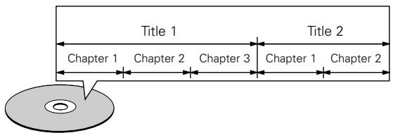
- Titles and chapters (DVD-videos)
DVD-videos are divided into several large sections called "titles" and smaller sections called "chapters".
Numbers are allotted to these sections. These numbers are called "title numbers" and "chapter numbers".
For example:
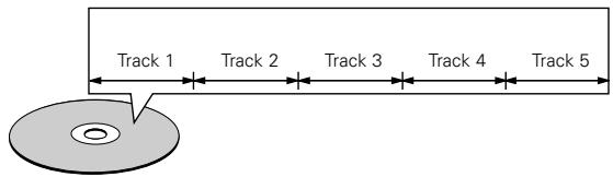
Tracks (video and music CDs)
Video and music CDs are divided into sections called "tracks". Numbers are allotted to these sections. These numbers are called "track numbers".
For example:
The following types of discs cannot be played on the ADV-M51:
- DVDs with region numbers other than "1" or "ALL"
DVD audio discs (NOTE 1)
DVD-ROM/RAMs
CVD
SVCD - CD-ROMs (Only MP3/MMA file can be played)
VSDs - CDVs (Only the audio part can be played.)
- CD-Gs (Only the audio is output.)
- Photo CDs (NEVER play such discs on the ADV-M51)
※ If you attempt to play photo CDs, the data on the disc may be damaged.
NOTE 1: Video part which based on DVD-video specification only can be played.
NOTE 2: Playing DVD-R and DVD-RW discsDVD-R and DVD-RW discs recorded in video format on a DVD recorder can be played on the ADV-M51.
Discs that have not be finalized cannot be played.
Depending on the disc's recording status, the disc may not be accepted or may not be played normally (the picture or sound may be not be smooth, etc.).
NOTE 3: According to recording quality, some CD-R/RW cannot be played.
- Playback control (video CDs)
Video CDs including the words "playback control" on the disc or jacket are equipped with a function for displaying menus on the TV screen for selecting the desired position, displaying information, etc., in dialog fashion.
In this manual, playing video CDs using such menus is referred to "menu playback".
Video CDs with playback control can be used on the ADV-M51.
NOTE:
- This DVD video player is designed and manufactured to respond to the Region Management Information that is recorded on a DVD disc.
If the Region number described on the DVD disc does not correspond to the Region number of this DVD video player, this DVD video player cannot play this disc.
The Region number for this DVD video player is 1.

6 CAUTIONS ON HANDLING DISCS
Discs
Only the discs including the marks shown on page 6 can be played on the ADV-M51.
Note, however, that discs with special shapes (heart-shaped discs, hexagonal discs, etc.) cannot be played on the ADV-M51. Do not attempt to play such discs, as they may damage the player.


Holding Discs
Avoid touching the surface of discs when loading and unloading them.
Be careful not to get fingerprints on the signal surface (the side which shines in rainbow colors).
Cleaning Discs
Fingerprints or dirt on the disc may lower sound and picture quality or cause breaks in playback. Wipe off fingerprints or dirt.
Use a commercially available disc cleaning set or a soft cloth to wipe off fingerprints or dirt.
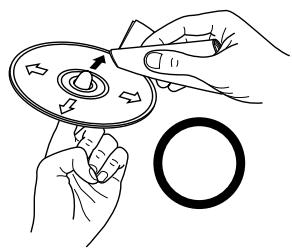
Wipe gently from the middle outwards.
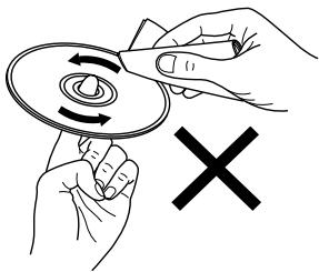
Do not wipe with a circular motion.
NOTE:
- Do not use record spray or antistatic. Also do not use volatile chemicals such as benzene or thinner.

Record Thinner Benzene spray
Cautions on Handling Discs
- Do not get fingerprints, grease or dirt on discs.
- Be especially careful not to scratch discs when removing them from their cases.
- Do not bend discs.
- Do not heat discs.
- Do not enlarge the center hole.
- Do not write on the labeled (printed) side with a ball-point pen or a pencil.
- Water droplets may form on the surface if the disc is moved suddenly from a cold place to a warm one. Do not use a hairdryer, etc., to dry the disc.
Cautions on Storing Discs
Always eject discs after playing them.
- Keep discs in their cases to protect them from dust, scratches and warping.
- Do not put discs in the following places:
- Places exposed to direct sunlight for long periods of time
- Humid or dusty places
- Places exposed to heat from heaters, etc.
Cautions on Loading Discs
- Only load one disc at a time. Loading one disc on top of another may result in damage or scratch the discs.
- Load 8 cm discs securely in the disc guide, without using an adapter. If the disc is not properly loaded, it may slip out of the guide and block the disc tray.
- Be careful not to let your fingers get caught when the disc tray is closing.
- Do not place anything but discs in the disc tray.
- Do not load cracked or warped discs or discs that have been fixed with adhesive, etc.
- Do not use discs on which the adhesive part of cellophane tape or glue used to attach the label is exposed, or discs with traces of tape or labels that have been peeled off. Such discs may get stuck inside the player, resulting in damage.
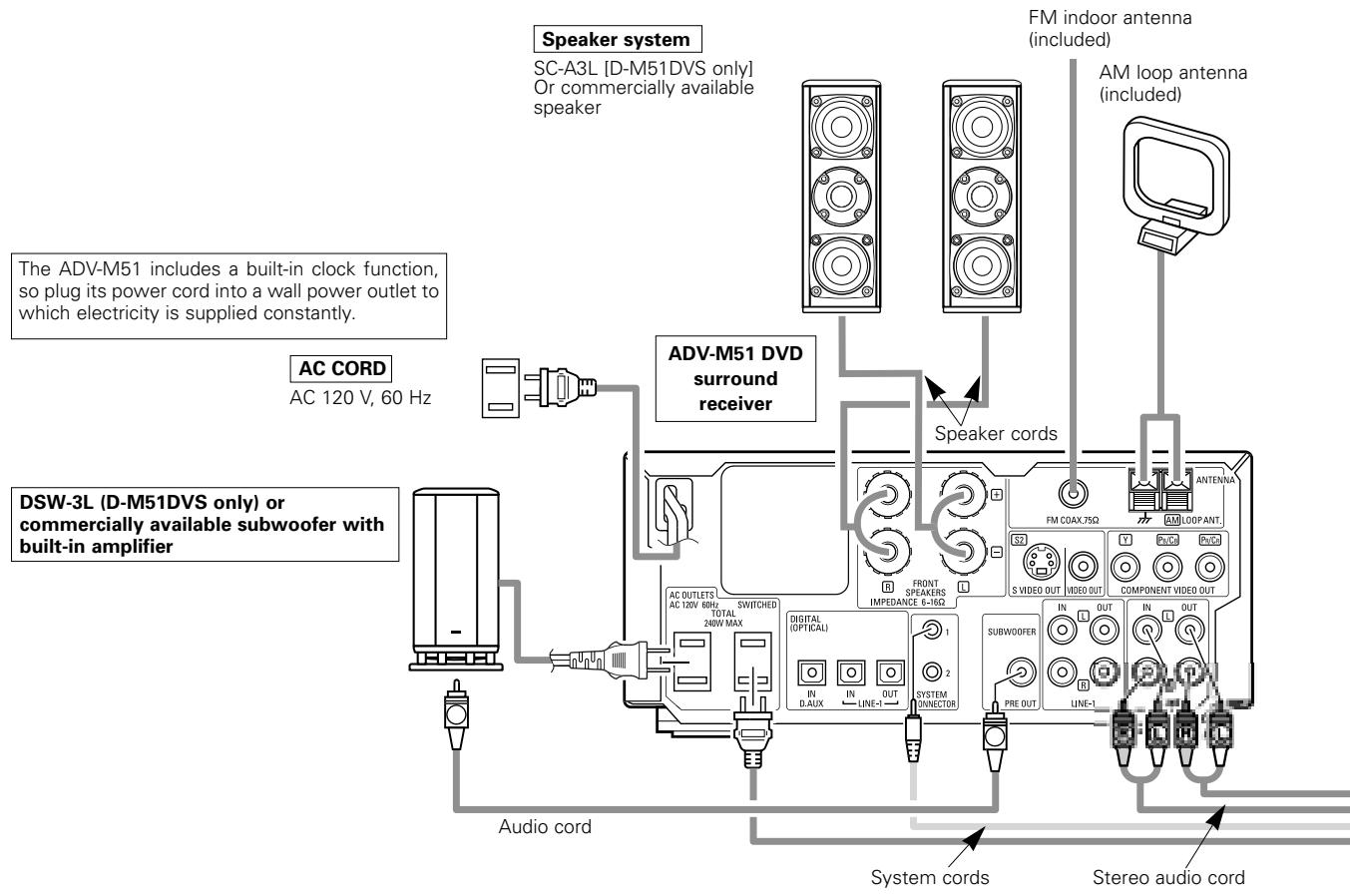
7 CONNECTIONS
- Do not plug in the AC cord until all connections have been completed.
- Be sure to connect the left and right channels properly (left with left, right with right).
-
Insert the plugs securely. Incomplete connections will result in the generation of noise.
-
Note that binding pin plug cords together with AC cords or placing them near a power transformer will result in generating hum or other noise.
- Noise or humming may be generated if a connected audio equipment is used independently without turning the power of this unit on. If this happens, turn on the power of the this unit.
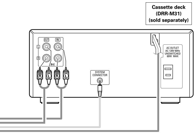
(1) Connecting the audio components (D-M31 series)
- The ADV-M51 can be used connected in a system with the D-M31 series cassette deck (DRR-M31).
- For instructions on operating the separately sold cassette deck (DRR-M31), refer to their respective operating instructions.
- Only the DRR-M31 cassette deck can be connected directly to the ADV-M51 using system connections.
NOTE:
- This system includes digital circuitry which may cause interference such as color blotching or changes in the color on TVs. If this happens, move the system and the TV as far apart as possible.
Connecting the speaker systems
Connect the speaker system for the left channel (the left side as seen from the front) to the L terminals, the speaker system for the right channel to the R terminals. Refer to the instructions supplied with the speaker system for details. Be sure to use speaker systems with an impedance of 6 /ohms or greater.
CAUTION:
- Only one cassette deck can be connected to the ADV-M51 using system connections. System operations cannot be performed properly if two cassette decks are connected using system connections.
- Whenever the power operation switch is in the STANDBY position, the unit is still connected to AC line voltage.
- Please be sure to unplug the power cord when you leave home for, e.g., a vacation, etc.
Note to CATV system installer:
This reminder is provided to call the CATV system installer's attention to Article 820-40 of the NEC which provides guidelines for proper grounding and, in particular, specifies that the cable ground shall be connected to the grounding system of the building, as close to the point of cable entry as practical.
System operations
Such system operations as the timer and the auto power on functions, as well as remote control operations cannot be performed unless all the RCA pin-plug cords and system connector cords are connected between the units, so be sure to make all the connections properly as shown in the diagram. Also, disconnecting system connectors while the system is operating may result in malfunctions. Be sure to unplug the power cord before changing connections.
NOTES:
- Do not plug the power cord into the power outlet until all connections are completed. Be sure to interconnect the channels (L to L (white) and R to R (red)) properly, as shown on the diagram.
- Use the AC OUTLET for audio equipment only. Do not use them for hair driers, etc.
- Insert the plugs securely. Incomplete connections may result in noise.
- Be sure to connect the speaker cords between the speaker terminals and the speaker systems with the same polarities (+ to +, - to -). If the polarities are switched, the sound at the center will be weak, the position of the different instruments will be unclear, and the stereo effect will be lost.
- After unplugging the power cord, wait about 5 seconds before plugging it back in.
- Note that setting the connection cords (pin-plug cords) next to the power cords may result in humming or other noise.
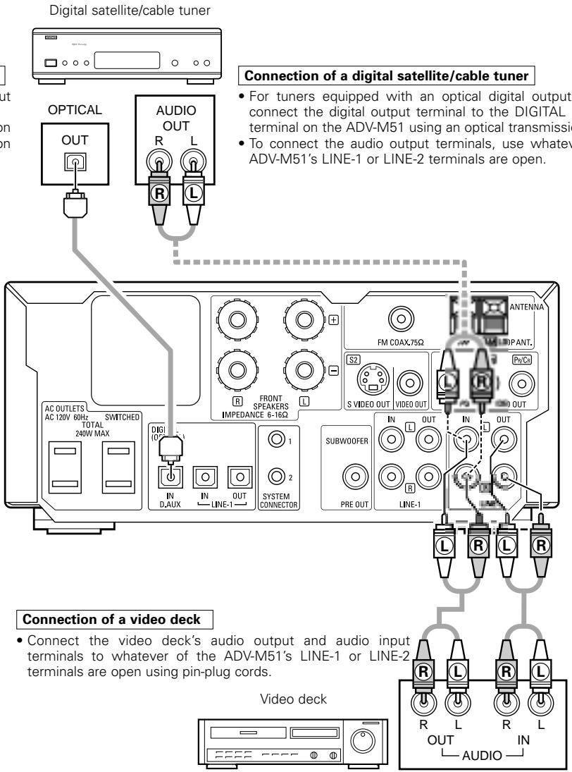
(2) Connecting the Audio Signals of a Digital Satellite Tuner and VCR
- Connect the video signals directly to the TV and switch the picture on the TV.
- When making connections, also refer to the operating instructions of the other components.
Connection to the optical digital input terminal
- Only audio signals are input to the optical digital input terminal.
- Use a commercially available optical transmission cable for connection to the optical transmission terminal (OPTICAL).
(3) Connecting a TV
- When making connections, also refer to the operating instructions of the TV.
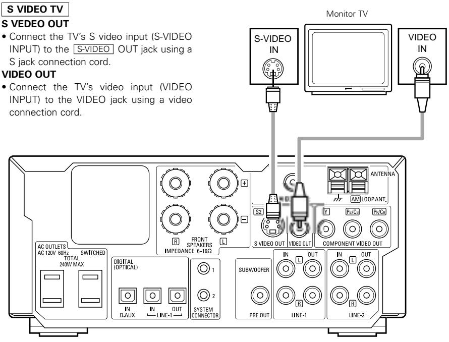
NOTES:
-
Connect this unit video outputs to the TV either directly. Do not connect it via a VCR (video cassette recorder). Some discs contain copy prohibit signals. If such discs are played via a VCR, the copy prohibit system may cause disturbance in the picture.
-
Set the "TV TYPE" in "VIDEO SETUP" in "DVD SETUP" to comply with your TV's video format. When the TV is NTSC formatted set to NTSC.
- When "PROGRESSIVE" is set, no video signals are output from the VIDEO OUT or S-VIDEO OUT terminals. Set "INTERLACED" if you want to use the VIDEO OUT or S-VIDEO OUT signals. (Refer to page 40)
(4) Connecting the antenna terminals
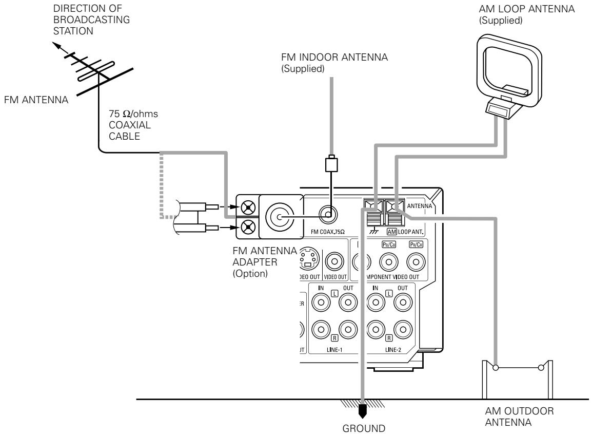
- An F-type FM antenna cable plug can be connected directly.
- If the FM antenna cable's plug is not of the F-type, connect using the F-type antenna adapter (Option).
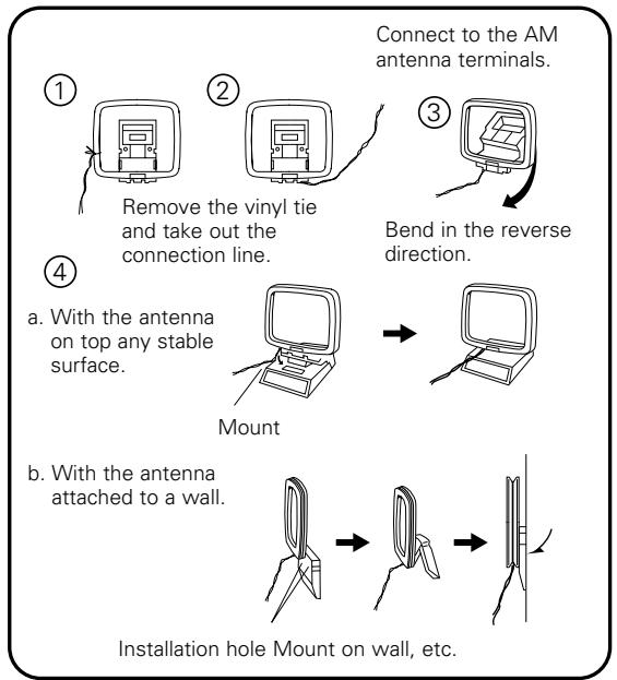
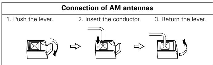
AM loop antenna assembly
Note to CATV system installer:
This reminder is provided to call the CATV system installer's attention to Article 820-40 of the NEC which provides guidelines for proper grounding and, in particular, specifies that the cable ground shall be connected to the grounding system of the building, as close to the point of cable entry as practical.
NOTES:
- Do not connect two FM antennas simultaneously.
- Even if an external AM antenna is used, do not disconnect the AM loop antenna.
- Make sure AM loop antenna lead terminals do not touch metal parts of the panel.
(5) Connecting to a TV or Monitor Equipped with Component Input Connectors
- When making connections, also refer to the operating instructions of the other components.
- The video signals input to the VIDEO input (yellow) and S-Video input jacks are not output to the color difference (component) video jacks.
Color component output connectors (PR / CR,PB / CB and Y
The red (PR / CR) , blue (PB / CB) and brightness (Y) signals are output independently, achieving more faithful reproduction of the colors.
- The color component input connectors may be marked differently on some TVs or monitors (PR, PB and Y/R-Y, B-Y and Y/CR, CB and Y, etc.). For details, refer to the TV's operating instructions.
Connect in this way if your TV is compatible with Progressive Scan.

Connecting a monitor TV
COMPONENTVIDEOOUTjack
- Connect the TV's color difference (component) video input jacks (COMPONENT VIDEO INPUT) to the COMPONENT VIDEO OUT jack using 75 Ω/ohms coaxial video pin-plug cords.
NOTES:
- Use the three commercially available video cords to connect the ADV-M51's color component output connectors to the TV or monitor.
- Set the "TV TYPE" in "VIDEO SETUP" in "DVD SETUP" to comply with your TV's video format. When the TV is NTSC formatted set to NTSC.
- About selecting the video output "INTERLACED" or "PROGRESSIVE", refer to page 40.
CONSUMERS SHOULD NOTE THAT NOT ALL HIGH DEFINITION TELEVISION SETS ARE FULLY COMPATIBLE WITH THIS PRODUCT AND MAY CAUSE ARTIFACTS TO BE DISPLAYED IN THE PICTURE. IN CASE OF 525 PROGRESSIVE SCAN PICTURE PROBLEMS, IT IS RECOMMENDED THAT THE USER SWITCH THE CONNECTION TO THE "STANDARD DEFINITION" OUTPUT.
(6) Sound output from this unit digital and analog audio output connectors
When a disc is played on the ADV-M51 (DIGITAL OUT)
| Settings | Refer to page | Digital audio data output | |||
| DVD videoDVD audio(video part only) | Dolby Digital | Digital out : Normal | 95 | Dolby Digital bitstream | |
| Digital out : PCM conversion | 2 channels PCM data (48 kHz/16bit) | ||||
| DTS | Digital out : Normal | DTS bitstream | |||
| Digital out : PCM conversion | 2 channels PCM data (48 kHz/16bit) | ||||
| Linear PCM | 48 kHz | LPCM conversion mode : OFF | 95 | 48 kHz/16 ~24 bit PCM | |
| LPCM conversion mode : ON | 48 kHz/16 bit PCM | ||||
| 96 kHz | LPCM conversion mode : ON | 48 kHz/16 bit PCM | |||
| CP : ON | LPCM conversion mode : OFF | 48 kHz/16 bit PCM (when copy-protected) | |||
| CP : OFF | LPCM conversion mode : OFF | 96 kHz PCM (when not copy-protected) | |||
| Video CD | MPEG 1 | 44.1 kHz/16 bit PCM | |||
| Music CD | Linear PCM | 44.1 kHz/16 bit PCM | |||
| MP3/WMA CD | MP3/WMA | 32 ~ 48 kHz/16 bit PCM | |||
- Linear PCM audio is the signal recording format used for music CDs.
While the signals are recorded at 44.1 kHz/16 bit for music CDs, for DVDs they are recorded at 48 kHz/16 bit to 96 kHz/24 bit, providing higher sound quality than music CDs.
About the LINE-1 and LINE-2 analog recording outputs
When the DVD or the D.AUX digital input is selected:
- Dolby Digital, DTS, AAC and PCM digital signals are automatically converted to 2-channel stereo signals before being output (except when in the Dolby Headphone mode) and can be recorded in analog. (For what happens in the Dolby Headphone mode, see 3 below.)
When TUNER, LINE-1 or LINE-2 is selected:
- The selected analog audio signals from the tuner or from the device connected to the LINE-1 or LINE-2 analog input terminals (IN) are output unchanged, regardless of the ADV-M51's input mode or surround mode. (The same is true for the device connected to the D.AUX terminals when "LINE-2" under "10 SETTING UP THE SYSTEM - (3) Detailed system setup - [5] Function settings" is set to "D.AUX".)
Recording output during playback of a DVD, D.AUX or LINE-1 digital input source in the Dolby Headphone mode:
- In the Dolby Headphone mode with a DVD or a digital input selected, the Dolby Headphone mode analog audio signals currently being played are output and can be recorded in analog. (See pages 57 and 58.)
Cautions during analog recording of DVDs or digital input sources:
- Do not switch the ADV-M51's input mode, surround mode or surround parameters during recording. Doing so will interrupt the sound being recorded.
We recommend setting the surround mode to "STEREO" or "DIRECT". - When using headphones, recording is automatically performed in the Dolby Headphone mode. Do not disconnect the headphones or switch the headphones mode during recording.
(7) Speaker system connections
Be sure to turn the amplifier's power off when connecting the speaker systems.
- Use the included cables to connect the input terminals on the back of the speaker systems (see diagram) to the amplifier's speaker output terminals. Connect the speaker system for the left channel amplifier's "L" terminals, the one for the right channel to the amplifier's "R" terminals, matching the polarities ("⊕" and "Θ" marks). Inverting the polarities will result in unnatural sound, with the phase off or no low bass sound. Also check that all two terminal knobs are tightly fastened.
Connecting the speaker cords
Use the included connection cords to connect the input terminals on the backs of the speaker systems (see the diagram at the right) to the ADV-M51's speaker output terminals.
- Connect the speaker system for the left channel to the "L" terminals, the speaker system for the right channel to the "R" terminals, and be sure the polarities (^ + ^ and - - ) are properly interconnected.
- Note that if the polarities are inverted, the phase may be off and the bass sound may be missing, resulting in an unnatural sound. Also check that both the speaker terminal's screws are tightly screwed.
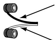
The red side is the "+" side, the black side the "-" side.
To "+" side on amplifier
(copper colored core wire)
NOTE: Make sure the core wires do not touch each other.
To " - " side on amplifier
(silver colored core wire)
Either twist the core wires firmly or terminate the wires.

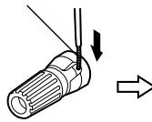
② Insert the cord's core wires.
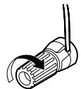
③Turn clockwise to tighten the terminal.
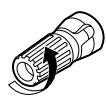
①Turn the speaker terminal counterclockwise to loosen it.
Connecting banana plugs
When using banana plugs, turn clockwise to tighten the terminal before inserting.
Protector circuit
- This unit is equipped with a high-speed protection circuit. The purpose of this circuit is to protect the speakers under circumstances such as when the output of the power amplifier is inadvertently short-circuited and a large current flows, when the temperature surrounding the unit becomes unusually high, or when the unit is used at high output over a long period which results in an extreme temperature rise.
When the protection circuit is activated, the speaker output is cut off and the power supply indicator LED flashes. Should this occur, please follow these steps: be sure to switch off the power of this unit, check whether there are any faults with the wiring of the speaker cables or input cables, and wait for the unit to cool down if it is very hot. Improve the ventilation condition around the unit and switch the power back on.
If the protection circuit is activated again even though there are no problems with the wiring or the ventilation around the unit, switch off the power and contact a DENON service center.
Note on speaker impedance
- The protector circuit may be activated if the set is played for long periods of time at high volumes when speakers with an impedance lower than the specified impedance (for example speakers with an impedance of lower than 4/ohms ) are connected. If the protector circuit is activated, the speaker output is cut off. Turn off the set's power, wait for the set to cool down, improve the ventilation around the set, then turn the power back on.
Cautions on connecting
- With this unit's speaker outputs, signals with the reverse phase of the "+" side output terminal's signals are also output from the "-" side output terminal.
Do not connect to a device for switching between multiple speakers (a speaker selector or audio channel selector) or connect in ways other than described in this manual. Doing so will result in damage.
(8) Using the active subwoofer (DSW-3L) (D-M51DVS only)
-
Set the power switch to the "ON" position.
-
When the unit's AC power cord is plugged into a switched AC outlet on the amplifier, if the power switch is left at the "ON" position, the unit's power turns on and off automatically when the amplifier's power is turned on and off.
-
If the AC power cord is not plugged into a switched AC outlet on the amplifier, set the unit's power switch to the "ON" position after turning on the amplifier's power. When turning the power off, set the unit's power switch to the "OFF" position before turning off the amplifier's power.
-
Adjust the volume using the volume adjustment control.
※ For details, see "PART NAMES AND FUNCTIONS".
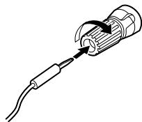
(9) Removing the speaker net (SC-A3L) (D-M51DVS only)
- The net on the front of the speaker systems (SC-A3L) can be removed.
- To remove, grasp both sides of the net and pull forward.
To mount, line up the holes in the four corners of the speaker net with the projecting pieces in the four corners of the cabinet and press in.
PART NAMES AND FUNCTIONS
DVD SURROUND RECEIVER (ADV-M51) Front Panel
- For details on the functions of these parts, refer to the pages given in parentheses ( ).
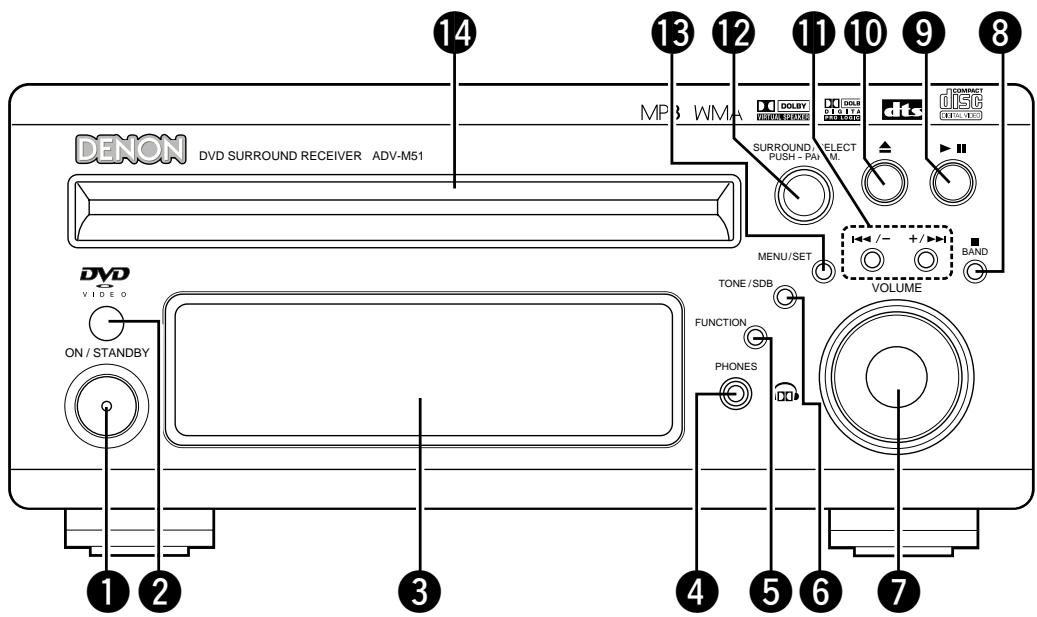
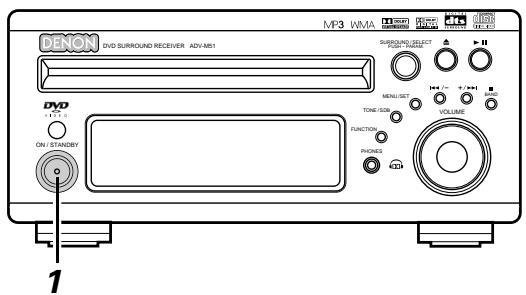
1 Power button (ON/STANDBY) (32)
Remote control sensor. (23)
3 Display
4 Headphones jack (PHONES) (57)
5 Function selector (FUNCTION) (44)
6 Tone/super dynamic bass button (TONE/SDB) (46)
Volume control (VOLUME) (42)
8 Stop/band button ( ■ BAND). (42, 59)
9 Play/pause button ( / ) (41)
10 Open/close button (▲) (41)
11 Skip backward and forward buttons (I /-and + / I ) (43,59)
12 Surround/select knob (SURROUND/SELECT)............(50) Surround parameter button (PARAMETER)............(51)
13 Menu/set button (MENU/SET) (61)
14 Disc holder (40)
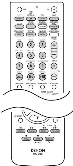
Remote control unit
- For details on the functions of these parts, refer to the pages given in parentheses ( ).
- Some of the buttons on the remote control unit have some functions.
The functions are switched using the remote control mode selector switches.
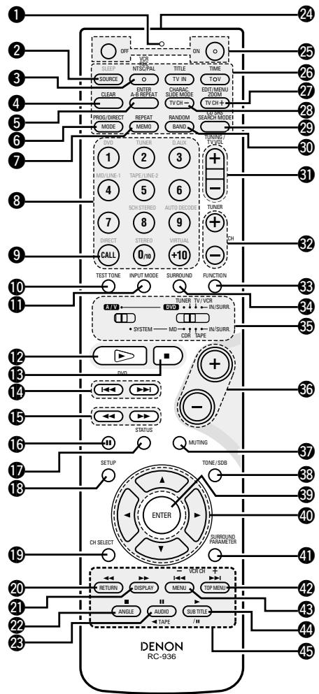
1 Transmission indicator
Sleep timer button (87)
3 NTSC/PAL button (13)
4 Clear button. (67)
A-B repeat button. (66)
6 Program/direct. (67)
Repeat button. (65)
Input source/surround mode selector button
- System buttons. (20, 21, 24, 30)
9 Call button (67)
10 Test tone button. (37)
11 Input mode selector button. (44)
DVD play button (41)
DVD stop button (42)
DVD skip buttons (43)
DVD search buttons (43, 44)
DVD pause button. (43)
17 Status button. (45)
18 Setup button. (32)
19 Channel select button (37)
20 Return button (42)
21 Display button (63)
22 Angle button. (77)
Audio selector button. (75)
Remote control signal transmission window. (23)
25 Power button. (32)
^ 26 串 System buttons. (21, 24)
27 Zoom button. (80)
23 Slide mode button (74)
29 Search mode button. (43)
30 Random button. (68)
31 Tuner tuning + / - buttons. (59)
32 Tuner preset + / - buttons. (61)
33 Function selector button (44)
34 Surround mode selector button (45)
35 Mode selector switches. (20, 21)
36 Main volume control buttons (42)
37Muting button. (46)
38 Tone/SDB button (46)
39 Enter button (31)
40 Cursor button (31)
41 Surround parameter button. (50)
42 Top menu button. (78)
43 Menu button. (79)
44 Subtitle button. (76)
45 * System buttons. (21, 24, 30)
- For details on the function and operation of the various parts, refer to the pages indicated in (parentheses).
- Buttons indicated are DVD control buttons and can be operated when the remote control mode selector switch is set to the A/V and DVD position.
- The functions of the system buttons (*) are switched using the remote control mode selector switch.
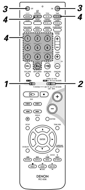
Names and functions of remote control unit buttons on the ADV-M51
- Buttons in sections ① ~ ③ can be operated regardless of the position of mode switches 1 and 2.
- Consider A/V and DVD as standard positions, and switch as necessary to operate.
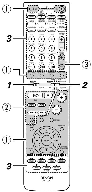
1 Set mode switch 1 to the "A/V" position.
2 Set mode switch 2 to the position of the function you want to operate (DVD, TUNER or IN/SURR).
① Surround amplifier control buttons
ON : Turns the ADV-M51's power on.
OFF :Turns the ADV-M51's power off.
FUNCTION : Function selection (in order)
SURROUND : Surround mode selection
INPUT MODE : Input mode selection
TEST TONE : Test tone on/off
- : Main volume up
- : Main volume down
MUTING : Muting on/off
STATUS : Status display selection
TONE/SDB : Tone/SDB selection and setting
SURROUND : Surround parameter selection and setting
PARAMETER
SET UP : Setup mode on/off
CH SELECT : Channel level selection and setting
, , , : Cursor up, down, left and right
ENTER : Enter setting
② DVD control buttons
:Play (auto power on and auto function selection)
:Stop
:Skip(cueing)
:Search (fast-reverse and fast-forward)
: Pause and frame-by-frame
③ Tuner control buttons
CH + / - : Preset channel up/down (auto power on and auto function selection)

Operate the ADV-M51.
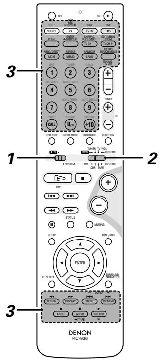
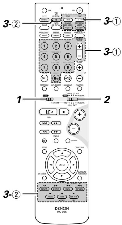
[1] Surround amplifier system buttons (Operated with mode switch 2 set to "IN/SURR.")
- These operations are possible with mode switch 1 at any position.
The operations in gray print can be performed.
![DENON D-M51DVS - [1] Surround amplifier system buttons (Operated with mode switch 2 set to "IN/SURR.") - 1](/content/2025/01/135504/images/6c5216aabce2192bb13433c3986dff7249928c414f73c7858d569424eb895199.jpg)
SLEEP : Sleep on/off
DVD : Function DVD
TUNER : Function TUNER
D.AUX : Function D.AUX
MD/LINE-1 : Function MD/LINE-1
TAPE/LINE-2 : Function TAPE/LINE-2
VIRTUAL : 2-channel mode switching when Dolby Virtual Speaker or Dolby VS surround mode set
STEREO : Stereo mode
DIRECT : Direct mode
5CH STEREO : Not used on this product.
AUTO DECODE: Not used on this product.
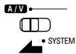
[2] DVD system buttons
(Operated with mode switch 2 set to "DVD")
![DENON D-M51DVS - [1] Surround amplifier system buttons (Operated with mode switch 2 set to "IN/SURR.") - 2](/content/2025/01/135504/images/7559be9d7bfa976f300181c88ffeac62aad8c0dc71980562a48f6519c0b10e15.jpg)
NTSC/PAL : NTSC/PAL selection
ZOOM : Zoom on/off
SLIDE MODE : JPEG image slide mode selection
A-B REPEAT : A-B repeat playback setting
CLEAR : Program clear
SEARCH MODE: Title and chapter search selection
RANDOM : Random play on/off
REPEAT : Repeat play setting
PROG/DIRECT: Program/direct play selection
CALL : Program call
0 ~ 9, +10 : Number buttons
TOP MENU : Top menu call
MENUC:Menu call
DISPLAY : Display call/selection
SUBTITLE : Subtitle language selection
AUDIO : Audio language selection
ANGLE : Angle selection
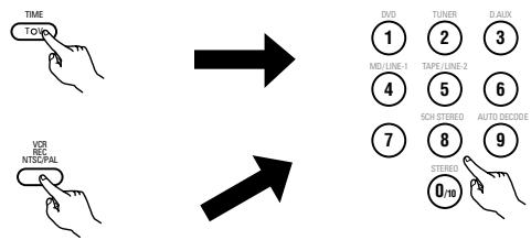
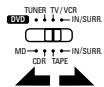
[3] Tuner system buttons
(Operated with mode switch 2 set to "TUNER")
![DENON D-M51DVS - [1] Surround amplifier system buttons (Operated with mode switch 2 set to "IN/SURR.") - 3](/content/2025/01/135504/images/9b94345d37a7e26dac2c0b016964d07e4aac672c237ba7c3b3e4d7abde4d2626.jpg)
BAND : FM/AM band selection
MEMO : Preset memory
MODE : FM auto/mono mode
selection
TUNER + / - : Tuning up/down
1 ~ 10, +10 : Preset channel number
buttons
Active subwoofer (DSW-3L) rear panel
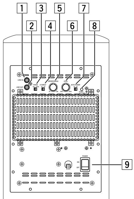
Line input connector (LINE IN)
- Connect this to the AV amplifier's pre-out connector ("SUBWOOFER", "MONO OUT", etc.) using the included connection cord (3-meter RCA pin cord).
Line output connector (LINE OUT)
- The signal input to the line input connector is output as such from here in parallel.
- When using two active subwoofer, connect the other active subwoofer's line input connector to this connector.
3 Phase selector switch (PHASE)
- This switches the phase of the output signal with respect to the input signal.
- Normally use the subwoofer with this switch set at the "NORM." position. If the continuity between the sound of the active subwoofer and the left and right speakers seems unnatural, try switching to the "REV." position, and set the switch to the position in which the sound is most natural.
4 LF direct switch (LF DIRECT)
- When using the active subwoofer connected to a Dolby Digital- or dts-compatible AV amplifier, if this function is turned on the signals bypass the active subwoofer's crossover and volume adjustment circuits, resulting in purer, higher quality sound. Note that when this is done the crossover adjustment control (5) and volume adjustment control (6) will no longer function.
5 Crossover adjustment control (CROSSOVER)
- This control only functions when the LF DIRECT switch (4) is set to the "OFF" position.
- This control sets the upper limit of the frequencies reproduced by the active subwoofer.
- Setting criteria
50Hz : For left/right speakers with diameters of 20 cm or greater
100Hz : For left/right speakers with diameters between 10 and 25 cm
200Hz : For left/right speakers with diameters of 12 cm or less
- When using a Dolby Digital- or dts-compatible AV amplifier, we recommend turning the LF DIRECT switch (4) to the "ON" position and not using this function.
※ “Dolby” is a trademark of the Dolby Laboratories Licensing Corporation.
※“dts” is a trademark of Digital Theater Systems.
About the AV amplifier's crossover frequency selection
The crossover frequency of the satellite speaker/center speaker and the active subwoofer (the boundary between the frequency range produced by the active subwoofer and the other speakers) is set on the connected AV amplifier, and is usually fixed at between 80 and 120kHz .
With some amplifiers, however, including the Denon ADV-M51, this frequency can be selected. When using this type of amplifier, the crossover frequency can be selected to suit your tastes.
When using the DSW-3L active subwoofer with this type of amplifier, a richer sound can be achieved by setting the crossover frequency to around 150Hz . Adjust the crossover frequency to suit your tastes. For instructions on switching, refer to your amplifier's operating instructions.
When connecting to a Dolby Digital- or dts-compatible AV amplifier, whether one on which the crossover frequency is fixed or one on which it can be adjusted, we recommend setting the LF DIRECT switch of the active subwoofer (DSW-3L) to the "ON" position.
Volume adjustment control (LEVEL)
- This control only functions when the LF DIRECT switch (4) is set to the "OFF" position.
- Use this control to adjust the volume of the active subwoofer.
- When turned clockwise () from the center position, the volume of the active subwoofer increases, and when turned counterclockwise () , the volume decreases. Set to the desired position.
7 Auto standby selector switch (AUTO STANDBY)
ON : The auto standby function is activated
OFF : The auto standby function is deactivated
Auto Standby Function
- The amplifier is automatically set to the standby mode if no signal is input for 5 to 11 minutes, thereby saving electricity.
The power turns on immediately when a signal is input.
8 Status indicator
- The two-colored LED indicates the active subwoofer's operating status, as follows:
Power "ON" .Lights green Auto power off (standby mode).Lights red Power "OFF".LED off Protective circuit activated. Flashing red
9 Power switch (POWER)
- The power turns on when this switch is set to the "ON" position.
- Several seconds are required for the set to begin operating. This is because the set includes a built-in muting circuit to prevent noise when the power switch is turned on and off.
- When set to the "OFF" position, the power turns off.
9 REMOTE CONTROL UNIT
- The included remote control unit (RC-936) can be used to operate not only this unit but other remote control compatible DENON components as well. In addition, the memory contains the control signals for other remote control units, so it can be used to operate non-DENON remote control compatible products.
(1) Inserting the batteries
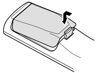
① Remove the remote control unit's rear cover.
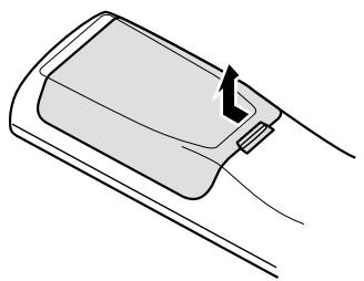
② Set three R6P/AA batteries in the battery compartment in the indicated direction.
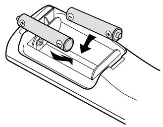
③ Put the rear cover back on.
Notes on Batteries
- Use R6P/AA batteries in the remote control unit.
- The batteries should be replaced with new ones approximately once a year, though this depends on the frequency of usage.
- Even if less than a year has passed, replace the batteries with new ones if the set does not operate even when the remote control unit is operated nearby the set. (The included battery is only for verifying operation. Replace it with a new battery as soon as possible.)
- When inserting the batteries, be sure to do so in the proper direction, following the “ ” and “ ” marks in the battery compartment.
- To prevent damage or leakage of battery fluid:
- Do not use a new battery together with an old one.
- Do not use two different types of batteries.
- Do not short-circuit, disassemble, heat or dispose of batteries in flames.
- Remove the batteries from the remote control unit when you do not plan to use it for an extended period of time.
- If the battery fluid should leak, carefully wipe the fluid off the inside of the battery compartment and insert new batteries.
- When replacing the batteries, have the new batteries ready and insert them as quickly as possible.
(2) Using the remote control unit
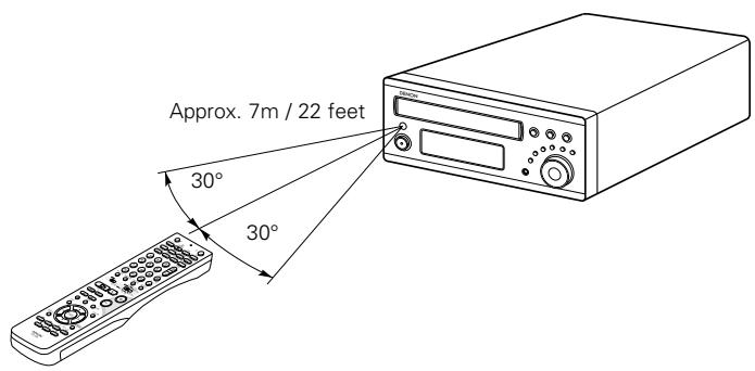
- Point the remote control unit at the remote sensor on the main unit as shown on the diagram.
- The remote control unit can be used from a straight distance of approximately 7 meters/22 feet from the main unit, but this distance will be shorter if there are obstacles in the way or if the remote control unit is not pointed directly at the remote sensor.
- The remote control unit can be operated at a horizontal angle of up to 30 degrees with respect to the remote sensor.
NOTES:
- It may be difficult to operate the remote control unit if the remote sensor is exposed to direct sunlight or strong artificial light.
- Do not press buttons on the main unit and remote control unit simultaneously. Doing so may result in malfunction.
-
Neon signs or other devices emitting pulse-type noise nearby may result in malfunction, so keep the set as far away from such devices as possible.
-
The included remote control unit (RC-936) can be used to operate not only the ADV-M51 but also to perform system operations for the D-M31 series and to operate other remote control compatible DENON products. In addition, the remote control operation codes of other major brands of TVs and video decks are also stored in the remote control unit, so the unit can be used to operate these TVs and video decks as well.
(3) Operating DENON audio components
- Turn on the power of all the components before operating them.
- Depending on the model and year of make of your component, some of the keys may not work.
1 Set mode switch 1 to the "SYSTEM" position. (Blue print)
2 Set mode switch 2 to the position for the component to be operated (MD, CDR or TAPE). (Blue print)
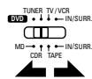
3 Operate the audio component. For details, refer to the component's operating instructions. ※ Operation may not be possible for some models.
[1] CD recorder system buttons (operated with mode switch 2 set to "CDR")
TIME :Disc time display
TITLE : Name display and selection of characters when inputting names
REC : Recording
SOURCE : CD recorder power on/off
EDIT/MENU : Menu selection
ENTER : Entering of menu items
CLEAR : Program clearing
RANDOM : Random play on/off
REPEAT : Repeat play setting
PROG/DIRECT : Program/direct playback selection
CALL : Program calling
1~10, +10 : Track number selection
/II
: Play (play/pause, auto power on and auto function selection with the CDR-M30)
:Pause
:Stop
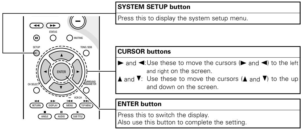
[2] Tape deck system button
(operated with mode switch 2 set to "TAPE")
![DENON D-M51DVS - [2] Tape deck system button - 1](/content/2025/01/135504/images/6325e11577bb4a13c03cdfb2316a4fe26ad7a34bd65977914a4d5ccae0b6fbb5.jpg)
REC : Recording
CD SRS : CD synchronized recording (DRR-M31 system function)
A,
TAPE : Reverse direction play (▶ and▶: auto power on and auto function selection with the DRR-M31)
(4) TV and video deck preset memories
- Components of other brands can be operated with the included remote control unit by storing their codes in the preset memory. Note that depending on the model some operations may not be possible and some buttons may not operate properly.
Not set upon shipment from the factory.
Press the TV button to preset a TV, the VCR button to preset a video deck, then input the 3-digit number corresponding to the brand of the component whose signals are to be stored in the preset memory (refer to the tables of remote control codes on pages 26 to 29).
NOTES:
- When buttons are pressed while setting the preset memory, their signals are sent from the remote control transmitter, so cover the remote control sensor when setting the preset memory to prevent accidental operation.
- Depending on the model and year of make, some of the remote control codes for the brands included on the tables may not operate properly.
- For some brands there are multiple types of remote control codes. If an operation does not work, try changing to one of the other codes.
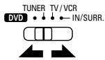
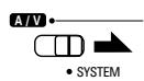
| 1 | Set mode switch 1 to the “A/V” position. | AV SYSTEM |
| 2 | Set mode switch 2 to the “TV/OCR” position. | TUNER TV/OCR MD- IN/SURL MD- IN/SURL CORI TAPE |
| 3 | Press the power ON button and the OFF button simultaneously. • The transmission LED (indicator) flashes. |
Combinations of preset codes for different brands
TV
| Admiral | 045, 121 |
| Adventure | 122 |
| Aiko | 054 |
| Akai | 016, 027, 046 |
| Alleron | 062 |
| A-Mark | 007 |
| Amtron | 061 |
| Anam | 006, 007, 036 |
| Anam National | 061, 147 |
| AOC | 003, 007, 033, 038, 039, 047, 048, 049, 133 |
| Archer | 007 |
| Audiovox | 007, 061 |
| Bauer | 155 |
| Belcor | 047 |
| Bell & Howell | 045, 118 |
| Bradford | 061 |
| Brockwood | 003, 047 |
| Candle | 003, 030, 031, 032, 038, 047, 049, 050, 122 |
| Capehart | 003 |
| Celebrity | 046 |
| Circuit City | 003 |
| Citizen | 029, 030, 031, 032, 034, 038, 047, 049, 050, 054, 061, 095, 122, 123 |
| Concerto | 031, 047, 049 |
| Colortyme | 003, 047, 049, 135 |
| Contec | 013, 051, 052, 061 |
| Cony | 051, 052, 061 |
| Craig | 004, 061 |
| Crown | 029 |
| Curtis Mathes | 029, 034, 038, 044, 047, 049, 053, 095, 118 |
| Daewoo | 027, 029, 039, 048, 049, 054, 055, 106, 107, 137 |
| Daytron | 003, 049 |
| Dimensia | 044 |
| Dixi | 007, 015, 027 |
| Electroband | 046 |
| Electrohome | 029, 056, 057, 058, 147 |
| Elta | 027 |
| Emerson | 029, 051, 059, 060, 061, 062, 118, 123, 124, 139, 148 |
| Envision | 038 |
| Etron | 027 |
| Fisher | 014, 021, 063, 064, 065, 118 |
| Formenti | 155 |
| Fortress | 012 |
Fujitsu 004,062
Funai 004,062
Futuretech 004
GE 020,036,037,040,044,058,066,088,119,120, 125,147
Goldstar 015,029,031,039,048,051,056,057,067 068,069,116,165
Grundy 062
Hitachi 029,031,051,052,070,111,112,113,124,134
Hitachi Pay TV 151
Infinity 017,071
Janeil 122
JBL 017,071
JC Penny 020, 034, 039, 040, 041, 044, 048, 050, 058, 066, 069, 076, 088, 090, 095, 125, 136, 159
JCB 046
JVC 019,051,052,072,073,091,117,126
Kawasho 018,046
Kenwood 038,056,057
Kloss 010,032
Kloss Novabeam 005,122,127,131
KTV 074,123
Loewe 071
Logik 144
Luxman 031
LXI 008,014,017,024,040,044,063,071,075,076, 077,118,125
Magnavox 005, 010, 017, 030, 033, 038, 050, 056, 071, 078, 079, 085, 089, 108, 109, 110, 127, 131, 132, 145
Marantz 015,017,071,080
Matsui 027
Memorex 014,027,045,083,118,144
Metz 160, 161, 162, 163, 164
MGA 001,039,048,056,057,058,065081,083
Midland 125
Minutz 066
Mitsubishi 001, 016, 039, 048, 056, 057, 058, 065, 081, 082, 083, 105
Montgomery Ward 011, 020, 144, 145, 146
Motorola 121, 147
MTC 031,034,039,048,095
NAD 008,075,076,128
National 002,036,061,147
| National Quenties | 002 |
| NEC | 031, 038, 039, 048, 057, 084, 086, 135, 147 |
| Nikko | 054 |
| NTC | 054 |
| Optimus | 128 |
| Optonica | 011, 012, 093, 121 |
| Orion | 004, 139 |
| Panasonic | 002, 009, 017, 036, 037, 071, 141, 143, 147 |
| Philco | 005, 010, 030, 050, 051, 056, 079, 085, 127, 131, 132, 145, 147 |
| Philips | 005, 015, 017, 050, 051, 056, 078, 087, 088, 089, 131, 132, 147 |
| Pioneer | 124, 128, 142 |
| Portland | 054 |
| Price Club | 095 |
| Proscan | 040, 044, 125 |
| Proton | 035, 051, 092, 129 |
| Pulsar | 042 |
| Quasar | 036, 037, 074, 141 |
| Radio Shack | 011, 044, 063, 093, 118 |
| RCA | 040, 044, 125, 130, 137, 151, 152 |
| Realistic | 014, 063, 093, 118 |
| Saisho | 027 |
| Samsung | 003, 015, 034, 053, 055, 057, 094, 095, 136, 153 |
| Sansui | 139 |
| Sanyo | 013, 014, 021, 022, 063, 064, 081, 096 |
| SBR | 015 |
| Schneider | 015 |
| Scott | 062 |
| Sears | 008, 014, 021, 022, 023, 024, 025, 040, 052, 057, 062, 063, 064, 065, 073, 075, 076, 097, 098, 125, 159 |
| Sharp | 011, 012, 013, 026, 093, 099, 100, 104, 121 |
| Siemens | 013 |
| Signature | 045, 144 |
| Simpson | 050 |
| Sony | 043, 046, 138, 146, 150 |
| Soundesign | 030, 050, 062 |
| Spectricon | 007, 033 |
| Squareview | 004 |
| Supre-Macy | 032, 122 |
| Supreme | 046 |
| Sylvania | 005, 010, 017, 030, 078, 079, 085, 089, 101, 127, 131, 132, 145, 155 |
| Symphonic | 004, 148 |
| Tandy | 012, 121 |
| Tatung | 036, 124 |
| Technics | 037 |
| Teknika | 001, 030, 032, 034, 052, 054, 078, 083, 095, 144, 156, 157 |
| Tera | 035, 129 |
| Toshiba | 008, 014, 034, 063, 075, 076, 095, 097, 136, 158, 159 |
| Universal | 020, 066, 088 |
| Victor | 019, 073, 126 |
| Video Concepts | 016 |
| Viking | 032, 122 |
| Wards | 005, 045, 066, 078, 085, 088, 089, 093, 102, 103, 131, 132, 148 |
| Zenith | 042, 114, 115, 140, 144, 149 |
| Zonda | 007 |
VCR
| Admiral | 081 |
| Aiko | 095 |
| Aiwa | 009 |
| Akai | 026, 027, 070, 072, 082, 083, 084 |
| Alba | 055 |
| Amstrad | 009 |
| ASA | 042 |
| Asha | 087 |
| Audio Dynamic | 005, 085 |
| Audiovox | 088 |
| Beaumark | 087 |
| Broksonic | 086, 093 |
| Calix | 088 |
| Candle | 006, 087, 088, 089, 090 |
| Canon | 049, 057 |
| Capehart | 025, 055, 056, 071 |
| Carver | 015 |
| CCE | 095 |
| Citizen | 006, 007, 087, 088, 089, 090, 095 |
| Craig | 007, 087, 088, 091, 115 |
| Curtis Mathes | 006, 049, 073, 080, 087, 090, 092 |
| Cybernex | 087 |
| Daewoo | 025, 055, 059, 074, 089, 093, 095, 096 |
| Daytron | 025, 055 |
| DBX | 005, 085 |
| Dumont | 053 |
| Dynatech | 009 |
| Electrohome | 001, 088, 097 |
| Electrophonic | 088 |
| Emerson | 001, 009, 017, 027, 086, 088, 089, 092, 093, 097, 100, 101, 102, 103, 104, 117 |
| Fisher | 009, 028, 031, 053, 054, 091, 098, 099, 115 |
| GE | 007, 011, 049, 050, 051, 052, 073, 080, 087 |
| Go Video | 047, 048 |
| Goldstar | 006, 012, 062, 088, 129 |
| Gradient | 094 |
| Grundig | 042 |
| Harley Davidson | 094 |
| Harman Kardon | 040, 062 |
| Hi-Q | 091 |
| Hitachi | 009, 013, 023, 026, 058, 108, 109, 110, 111 |
| JC Penny | 004, 005, 007, 023, 028, 049, 062, 085, 087, 088 |
| Jensen | 013, 026 |
| JVC | 004, 005, 006, 026, 029, 043, 044, 045, 046, 085 |
| Kenwood | 004, 005, 006, 026, 029, 033, 045, 085, 090 |
| Kodak | 088 |
| Lloyd | 009, 094 |
| LXI | 088 |
| Magnavox | 015, 016, 042, 049, 063, 106 |
| Magnin | 087 |
| Marantz | 004, 005, 006, 015, 042, 049, 085, 090 |
| Marta | 088 |
| MEI | 049 |
| Memorex | 009, 033, 049, 053, 060, 081, 087, 088, 091, 094, 115 |
| Metz | 123, 124, 125, 126, 127, 128 |
| MGA | 001, 017, 027, 041, 097 |
| MGN Technology | 087 |
| Midland | 011 |
| Minolta | 013, 023 |
| Mitsubishi | 001, 003, 008, 013, 014, 017, 027, 029, 039, 040, 041, 045, 097 |
| Motorola | 081 |
| Montgomery Ward | 001, 002, 007, 009, 049, 063, 081, 115, 117 |
| MTC | 009, 087, 094 |
| Multitech | 007, 009, 011, 087, 090, 094 |
| NAD | 038 |
| NEC | 004, 005, 006, 018, 026, 029, 045, 061, 062, 085 |
| Nikko | 088 |
| Noblex | 087 |
| Optimus | 081, 088 |
| Optonica | 021 |
| Panasonic | 024, 049, 064, 066, 067, 068, 069, 107 |
| Perdio | 009 |
| Pentax | 006, 013, 023, 058, 090 |
| Philco | 015, 016, 049 |
| Philips | 015, 021, 042, 049, 105 |
| Pilot | 088 |
| Pioneer | 005, 013, 029, 036, 037, 038, 045, 085 |
| Portland | 025, 055, 090 |
| Proscan | 063, 080 |
| Pulsar | 060 |
| Quartz | 033 |
| Quasar | 034, 035, 049 |
| Radio Shack | 001, 002, 021, 081, 087, 088, 091, 094, 097, 098, 115 |
| Radix | 088 |
| Randex | 088 |
| RCA | 007, 013, 019, 023, 058, 063, 064, 065, 073, 080, 082, 087 |
| Realistic | 009, 021, 031, 033, 049, 053, 081, 087, 088, 091, 094, 097, 098 |
| Ricoh | 055 |
| Salora | 033, 041 |
| Samsung | 007, 011, 051, 059, 070, 083, 087, 089, 113 |
| Sanky | 081 |
| Sansui | 005, 026, 029, 045, 061, 085, 114 |
| Sanyo | 032, 033, 053, 087, 091, 115, 116 |
| SBR | 042 |
| Scott | 017, 020, 086, 089, 093, 117 |
| Sears | 013, 023, 028, 031, 033, 053, 054, 088, 091, 098, 099, 115 |
| Sentra | 055 |
| Sharp | 001, 002, 021, 097 |
| Shogun | 087 |
| Sony | 075, 076, 077, 078, 079, 121, 122 |
| STS | 023 |
| Sylvania | 009, 015, 016, 017, 041, 049, 094 |
| Symphonic | 009, 094 |
| Tandy | 009 |
| Tashiko | 009, 088 |
| Tatung | 004, 026, 030 |
| Teac | 004, 009, 026, 094 |
| Technics | 024, 049 |
| Teknika | 009, 010, 022, 049, 088, 094 |
| TMK | 087, 092 |
| Toshiba | 013, 017, 020, 041, 059, 089, 098, 099, 117 |
| Totevision | 007, 087, 088 |
| Unirech | 087 |
| Vector Research | 005, 062, 085, 089, 090 |
| Victor | 005, 045, 046, 085 |
| Video Concepts | 005, 027, 085, 089, 090 |
| Videosonic | 007, 087 |
| Wards | 013, 021, 023, 087, 088, 089, 091, 094, 097, 118, 119, 120 |
| XR-1000 | 094 |
| Yamaha | 004, 005, 006, 026, 062, 085 |
| Zenith | 060, 078, 079 |
(5) Operating the TV/video deck after storing its remote control signals in the preset memory
Monitor TV (TV) and video deck (VCR) system buttons ① TV system buttons
TV : Power on/off
0~9 : Channel numbers
TV IN : TV input switching
TV VOL ^+ , - : Volume up/down
TV CH +, - : Channel switching
② Video deck system buttons
VCR : Power on/off
VCR CH + ,- : Channel switching
: Manual search (fast-forward and fast-backward)
:Play
:Pause
:Stop
1 Set mode switch 1 to the "A/V" position.
2 Set mode switch 2 to the "TV/VCR" position.
Operate the video component.
- For details, refer to the component's operating instructions.
※ It may not be possible to operate some models.
NOTE:
- The TV's "TV (POWER)" and "TV IN" buttons can be operated as long as mode switch 1 is set to the "A/V" position, regardless of the position of mode switch 2.
(1) System setup items
- Once all connections with other AV components have been completed as described in "CONNECTIONS" (see pages 10 to 17), make the various settings described below on the monitor screen using the ADV-M51's on-screen display function.
- Use the following buttons to set up the system:
System setup items and default values (set upon shipment from the factory)
| Setup | Default settings | |||||
| Quick set up | Set the screen size and the speaker system. | TV Aspect | Speaker | |||
| 4:3 PS | 2CH Virtual & SW | |||||
| System Setup | Speaker Configuration | Input the combination of speakers in your system and their corresponding sizes (SMALL for regular speakers, LARGE for full-size, full-range) to automatically set the composition of the signals output from the speakers and the frequency response. | Front Sp. | Subwoofer | ||
| Small | Yes | |||||
| Sw Freq. = 150 Hz / SW mode = None | ||||||
| Delay Time | This parameter is for optimizing the timing with which the audio signals are produced from the speakers and subwoofer according to the listening position. | Front | Subwoofer | |||
| 9ft (2.7m) | 9ft (2.7m) | |||||
| Channel Level | At the listening position, listen to the test tones output from the different speakers and set so that the playback level from the different speakers is equal. | Front L | Front R | Subwoofer | ||
| 0 dB | 0 dB | 0 dB | ||||
| DVD auto power off setting | The power automatically switches to standby if no operation is performed for 30 minutes while in the stop mode with the function set to DVD. | power does not turn off automatically | ||||
| Function Setting | Set the LINE-1 and LINE-2 function names and turn the analog recording output (REC OUT) on or off. | LINE-1 | LINE-2 | REC OUT | ||
| MD | TAPE | ON | ||||
| DVD Setup | Disc Setup | Set the audio language, subtitle language and disc menu language for when playing discs. | Dialog | Subtitle | Disc Menu | |
| English | OFF | English | ||||
| OSD Setup | Set the wallpaper for the setup and operation screens. | Wall Paper | ||||
| Blue | ||||||
| Video Setup | Set the screen size and video system for the TV being used. | TV Aspect | TV Type | Video Mode | Black level | |
| 4:3 PS | NTSC | AUTO | LIGHTER | |||
| Audio Setup | Set the digital audio signal format and the linear PCM sampling frequency and bit conversion. | Digital Out | LPCM Select | |||
| Normal | OFF | |||||
| Ratings | Make the playback restriction setting for DVDs with restricted viewing and set the password required for changing the setting. | Rating Level | Pass Word Change | |||
| No Limit | 0000 (Default) | |||||
| Other Setup | Make the closed caption setting for DVDs. (A commercially available decoder is required to display the closed captions.) | Closed Caption | Slide Show | |||
| OFF | 5SEC | |||||
(2) Quick setup procedure
- Refer to "Connections" (pages 10 to 17) and check that all the connections are correct.
1 Turn on the power.
- The power indicator (LED) lights green, the power turns on and the display lights.
Main unit

Remote control unit
※ Several seconds are required from the time the power button is pressed until the power turns on. This is due to the built-in muting circuit that turns off (mutes) the sound when the power is turned on and off. The power indicator flashes green while the muting circuit is activated.
Even when the power button has been pressed again and the power has been set to the standby mode, power is still supplied to some circuits. When leaving home or traveling, be sure to unplug the power cord from the power outlet. In the standby mode, the power indicator is lit red. The indicator is orange when the timer is set.
Press the SETUP button to display the setup screen.

Remote control unit
SETUP MENU
DENON
QUICK SETUP
SYSTEM SETUP
DVD SETUP
EXIT SETUP
SELECT:
DECISION:ENTER BUTTON
Use the and cursor buttons to select "Quick System Setup".
- The selected item is displayed in yellow.

Remote control unit
Press the ENTER button to display the menu's setting screen.
※ On the setting screen, the selected item is displayed in yellow and the values of the other items are displayed in green.

Remote control unit
[1] TV screen size setting
![DENON D-M51DVS - [1] TV screen size setting - 1](/content/2025/01/135504/images/81f3b6d1f1ad26eb8962646bfe862f58bfcabc64f85e331efae9f411e2f2c44b.jpg)
- The currently set value is displayed in yellow.
Use the and cursor buttons to select the desired TV screen size and display type.
※ The selected TV screen size is displayed in yellow and the description is displayed in green.


Remote control unit
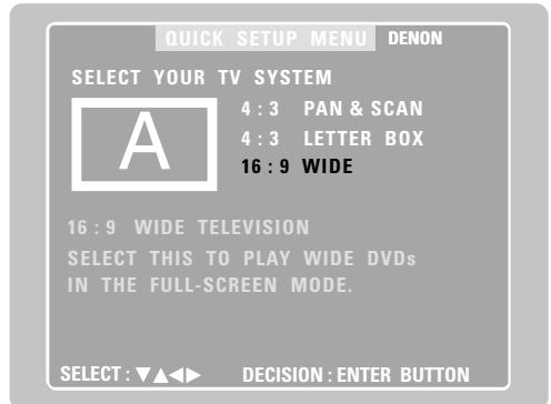
6 Press the ENTER button to set the selected setting.
- The screen shown below appears.

Remote control unit
[2] Speaker system settings
![DENON D-M51DVS - [2] Speaker system settings - 1](/content/2025/01/135504/images/d06fae269a073e0742ef6b664f43bebaae61d89a26f88b5bcf4adebc8931998c.jpg)
- "Return" is displayed in yellow.
- The currently set value is displayed in green.
- If you do not want to change the setting, press the ENTER button at "Return". The screen in step 2 reappears.
- To change the setting, proceed to step 7 below.
Use the and cursor buttons to select the speaker system to be used.

Remote control unit
Press the ENTER button to set the selected setting.
- The setup screen in step 2 reappears. The setup mode is quit in step 9.
The setup mode can also be quit by using the and cursor buttons at the setup screen to select "EXIT SETUP" then pressing the ENTER button.

Remote control unit
9 Press the SETUP button to quit the setup mode.
The setup mode can also be quit by using use the and cursor buttons at the setup screen to select "EXIT SETUP" then pressing the ENTER button.

Remote control unit
About the speaker system settings
© 2CH VIRTUAL
Select this when only using with the two speakers for the front channels.
© 2CH VIRTUAL & SW
Select this when using two speakers for the front channels and a subwoofer with built-in amplifier.
- Settings
Front : Small
Subwoofer : Yes
Subwoofer frequency : 150 Hz
※ Set the front speakers and subwoofer at equal distances.
NOTE:
- The speaker system is set to "2CH VIRTUAL & SW" upon shipment from the factory. It is not possible to achieve the normal bass sound using this setting but with only speakers for the two front channels. If only using speakers for the two front channels, change the setting to "2CH VIRTUAL".
(3) Detailed system setup (changing the system settings)
- The quick system settings and original settings set upon shipment from the factory are changed using the system setting changing menu. The settings are stored in the memory until they are changed the next time, and remain valid even when the power is turned off.
[1] Speaker settings (type of speaker and whether or not the speaker is connected)
- The output component of the different channels and properties are adjusted automatically according to the combination of speakers actually used.
1 Press the SETUP button to display the setup screen.
![DENON D-M51DVS - [1] Speaker settings (type of speaker and whether or not the speaker is connected) - 1](/content/2025/01/135504/images/4d50d943a2da79f9925f0e5079123b6e249507a13210cb2886d67dcf34431f36.jpg)
Remote control unit
![DENON D-M51DVS - [1] Speaker settings (type of speaker and whether or not the speaker is connected) - 2](/content/2025/01/135504/images/295b8fe3d13986255dff4536f9491c41d74f3211201fcdf377557da00a7cf7fa.jpg)
Use the and cursor buttons to select "SYSTEM SETUP" under "
![DENON D-M51DVS - [1] Speaker settings (type of speaker and whether or not the speaker is connected) - 3](/content/2025/01/135504/images/7a7dab93a2bea1439657d531a624d66b12e26e0e46339d68de2b00fa69bb9c58.jpg)
Remote control unit
![DENON D-M51DVS - [1] Speaker settings (type of speaker and whether or not the speaker is connected) - 4](/content/2025/01/135504/images/4a05ef14c7a7c47d1749866d1cc365bc209da8654a601e8a28a0c1097349f1f2.jpg)
![DENON D-M51DVS - [1] Speaker settings (type of speaker and whether or not the speaker is connected) - 5](/content/2025/01/135504/images/6db20ea0d9a29da0e03cda90dbae9dbda74d13ee055fe762faa893e32f86be01.jpg)
Remote control unit
At the system setting changing menu, use the and cursor buttons to select the "SPEAKER CONFIGURATION" tag icon, then press the ENTER button.
![DENON D-M51DVS - [1] Speaker settings (type of speaker and whether or not the speaker is connected) - 6](/content/2025/01/135504/images/35b6152729a69e467667dbc2de3c1f428f34c810341fdcbd31707f29efce7979.jpg)
3


Remote control unit
Remote control unit
※ When the cursor is at a tag icon on the system setting changing menu screen, the settings screen can also be selected by pressing the cursor button. You can return to the tag icon by pressing the cursor button.
- The speaker settings screen in step 4 appears.
4
Use the , , and cursor buttons to select whether or not the various speakers are connected, their size and other parameters.
Remote control unit
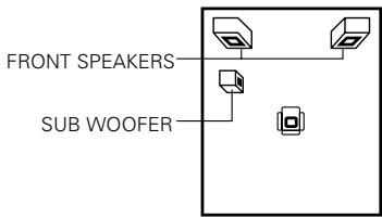
- The item currently being set is displayed in yellow, and the setting values for other items are displayed in green.
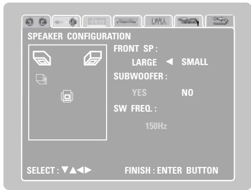
5
Press the ENTER button to enter the settings.
- The next screen in the system setting changing menu appears.

Remote control unit
NOTE:
- Select the speaker size not by the physical size of the speaker but by the speaker's capacity to reproduce low frequencies of 100Hz or less. If you do not know, determine the best setting by comparing the sound when the setting is set to "Small" and "Large", keeping the volume low enough to prevent damage to the speaker.
NOTE:
- Select "Large" or "Small" not according to the actual size of the speaker but according to the speaker's capacity for playing low frequency (approximately 100Hz and below) signals. If you do not know, try comparing the sound at both settings (setting the volume to a level low enough so as not to damage the speakers) to determine the proper setting.
Parameters
Large...... Select this when using speakers that can fully reproduce low sounds of below 100Hz .
Small.... Select this when using speakers that do not provide sufficient volume for playing low frequencies of 100Hz and less. When this setting is made, frequencies below the frequency set at the subwoofer frequency setting are assigned to the subwoofer.
Yes/No.... Select "Yes" when a subwoofer is installed, "No" when a subwoofer is not installed.
※ If the subwoofer has sufficient low frequency playback capacity, good sound can be achieved even when "Small" is set for the front, speakers.
※ For the majority of speaker system configurations, using the SMALL setting for main speakers and Subwoofer On with a connected subwoofer will yield the best results.
Subwoofer (SW FREQ.) frequency
- For the subwoofer frequency at the speaker setting screen, set the bass crossover frequency for playback from the subwoofer.
- Select "80 Hz", "120 Hz", "150 Hz" or "180 Hz" (-6 dB for each). Bass sound below these frequencies is played from the subwoofer.
(This is set to "150 Hz" by factory default.)
Assignment of low frequencies
- In the Dolby Digital, Dolby Pro Logic II, DTS, and virtual surround modes, the low frequency signals for channels whose speaker settings are set to "Small" are assigned to the subwoofer. The low frequencies of channels set to "Large" are played from those channels.
(If set to "120 Hz", channels set to "Small" play sounds of 120 Hz and greater, while bass frequencies of under 120 Hz are played from the subwoofer.) - In surround modes other than the ones listed above, low frequencies below the frequency set at the subwoofer frequency setting are played from the subwoofer regardless of whether the speakers are set to "Large" or "Small".
- Set the subwoofer frequency according to the low frequency playback abilities of your speakers and subwoofer.
Subwoofer mode
- The subwoofer mode setting is only valid when "LARGE" is set for the front speakers and "YES" is set for the subwoofer in the "SPEAKER CONFIGURATION" settings.
- When the "LFE+MAIN" playback mode is selected, the low frequency signal range of channels set to "LARGE" are produced simultaneously from those channels and the subwoofer channel. In this playback mode, the low frequency range expands more uniformly through the room, but depending on the size and shape of the room, interference may result in a decrease of the actual volume of the low frequency range.
- Selection of the "LFE" play mode will play the low frequency signal range of the channel selected with "LARGE" from that channel only. Therefore, the low frequency signal range that are played from the subwoofer channel are only the low frequency signal range of LFE (only during Dolby Digital or DTS signal playback) and the channel specified as "SMALL" in the setup menu.
- Select the play mode that provides bass reproduction with body.
- When the subwoofer is set to "YES", bass sound is output from the subwoofer regardless of the subwoofer mode setting in surround modes other than Dolby/DTS.
[2] Delay time (distance setting)
- Input the distances from the listening position and the various speakers to set the surround delay time.
- Upon shipment from the factory default the delay time is set to the default values in step 3 below.
Preparation:
Measure the distance from the listening position to the various speakers.
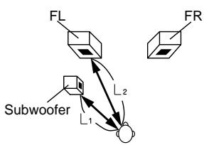
Listening position
If you are not at the system setting changing menu screen, read step 1 and 2 on page 34.
At the system setting changing menu screen, use the and cursor buttons to select "DELAY TIME (Distance) ", then press the ENTER button.
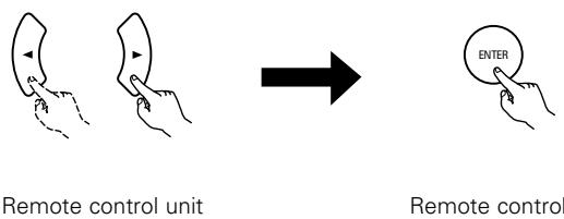
- The delay time setting screen appears.
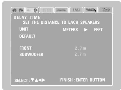
- The unit for the distance can be switched between "m" (meters) and "ft" (feet) using the and cursor buttons. If you do not want to change the unit, press the cursor button to proceed to the next step.
3 At "Default Value", select "Yes" to set the delay times for the different speakers to the default values.
Yes: The values are set to the defaults.
No: The current settings are retained.
L1: Distance between subwoofer and listening position
L2: Distance between front speakers and listening position
Use the and cursor buttons to select the speaker, then use the and cursor buttons to set the distance between the speaker and the listening position.
- The distance changes by 0.1 meters (or 1 foot when the unit is set to feet) each time the and cursor button is pressed. Select the value closest to the measured distance.
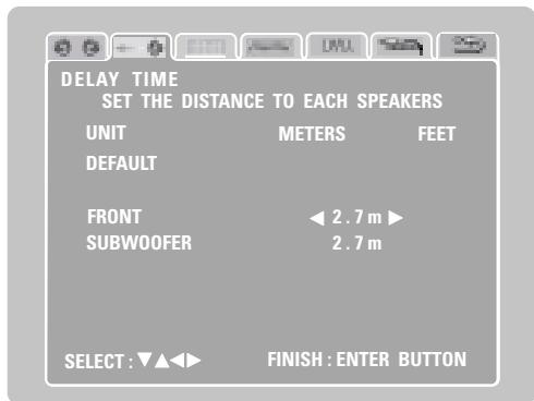
※ Make sure the difference in the distances set for the various speakers is no greater than 3.0 meters (10 feet). If an inappropriate distance is set, "CAUTION: OUT OF SETTING RANGE" is displayed. Change the position of the speaker and make the setting over.
Press the ENTER button to enter the settings.
- The next screen in the system setting changing menu appears.

Remote control unit
[3] Adjusting the channel level
- Adjust so that the playback levels of the different channels are equal.
- Make this adjustment by listening to the test tones output from the speakers at the listening position.
- By factory default all the levels of all the channels are set to 0 dB.
- This adjustment can also be made directly from the remote control unit. (CH SELECT Button)
If you are not at the system setting changing menu screen, read step 1 and 2 on page 34.
At the system setting changing menu screen, use the and cursor buttons to select "Channel Level Adjustment", then press the ENTER button.
![DENON D-M51DVS - [3] Adjusting the channel level - 1](/content/2025/01/135504/images/b8d09cc38826e08eb19f620a9ea6ce6bcd45d6e728b17ffac7e66ec9de1b5059.jpg)
Remote control unit
Remote control unit
- The channel level adjustment screen appears.
![DENON D-M51DVS - [3] Adjusting the channel level - 2](/content/2025/01/135504/images/e578b82586af327dc3c2b62e6cd286cd90ffb07f28350e2aa915d9f8cc3392a4.jpg)
3 Use the and cursor buttons to select "Auto" or "Manual" for the "Test Tone" mode.
- The selected setting is displayed in yellow.
![DENON D-M51DVS - [3] Adjusting the channel level - 3](/content/2025/01/135504/images/d3dfeee72bae8c7af4a383737057efcefec2daa045331b222abb2293bfe9c612.jpg)
Remote control unit
© Auto: Adjust the levels listening to test tones automatically output from the different speakers.
Manual: Select the speakers from which the test tones are output when adjusting the levels.
※ Detailed settings can be made when this is set to "Manual" first.
4 When "Yes" is selected at "Level Clear", the level settings for all the speakers are set to 0 dB.
Yes: The level settings for all the speakers are set to 0 dB.
© No: The currently set level settings are retained.
Adjust the channel levels in the test tone mode.
Use the and cursor buttons to select the "Test Tone Start" mode, then use the cursor button to select "Yes". The test tone is output.
※ Use the MASTER VOLUME control on the main unit or the VOLUME buttons on the remote control unit to adjust the volume of the test tone to a level at which it is easy to make this adjustment.
6 ① When "Auto" is selected at "Test Tone":
![DENON D-M51DVS - [3] Adjusting the channel level - 4](/content/2025/01/135504/images/48da8f180b22f6745923d3a6f4be442dc651ee5cf7dc801aa1a0709e1c11eb61.jpg)
- Test tones are automatically output from the speakers at intervals of 4 seconds for two of the cycles shown below, then at intervals of 2 seconds from the third cycle on.
![DENON D-M51DVS - [3] Adjusting the channel level - 5](/content/2025/01/135504/images/aaaed3ea26260ec530a9e7cd4284418d7fab250b7832cdf633376b0c2e16b4da.jpg)
Use the and cursor buttons to adjust the channel levels so that the volume of the test tones output from the different speakers sounds the same.
- The level changes in units of 1 dB each time the and cursor button is pressed.
The level can be adjusted in the range -12dB to +12dB .
② When "Manual" is selected at "Test Tone":
![DENON D-M51DVS - [3] Adjusting the channel level - 6](/content/2025/01/135504/images/4ca6368ba187da9c968267507a179f03f583d17b88d0a0c4a3d92c55ef4e40cc.jpg)
Use the and cursor buttons to select the speaker from which the test tone is to be output, then use the and cursor buttons to adjust the channel levels so that the volume of the test tones output from the different speakers sounds the same.
- The level changes in units of 1 dB each time the and cursor button is pressed.
The level can be adjusted in the range -12dB to +12dB .
Press the ENTER button to enter the settings.
- The next screen in the system setting changing menu appears.
![DENON D-M51DVS - [3] Adjusting the channel level - 7](/content/2025/01/135504/images/be5cb0a1e840b23b0bac18ff22e3d702e5d5b62b4792241bad8ed637a968c5a9.jpg)
Remote control unit
※ To cancel the settings after the adjustments have been made
Display the channel level adjustment screen, then use the , ,
and cursor buttons to select "Level Clear" and select "Yes".
The level settings for all the speakers are set to 0 dB.
NOTE:
When the channel levels are adjusted at the channel level settings, the adjusted values are applied to all playback modes.
[4] DVD Auto Power Off setting
- The ADV-M51 is equipped with a function for automatically setting the power to the standby mode if no operation is performed for 30 minutes when the function is set to DVD. Here set whether to use this function or not.
- By factory default this is set to "No".
If you are not at the system setting changing menu screen, read step 1 and 2 on page 34.
At the system setting changing menu screen, use the and
cursor buttons to select "DVD AUTO POWER OFF", then press the ENTER button.
![DENON D-M51DVS - [4] DVD Auto Power Off setting - 1](/content/2025/01/135504/images/7f9482ffbf9d6875aa51412917eaee48311504c0b9f45b78c3f06a8247d7ba7b.jpg)
Remote control unit
Remote control unit
- The DVD auto power off setting screen appears.
![DENON D-M51DVS - [4] DVD Auto Power Off setting - 2](/content/2025/01/135504/images/1f52c9ece7238ce04f388a7e13975c2464a4890980ce9715aefb33a4a979b179.jpg)
3 Use the and cursor buttons to select the "Auto Power Off" mode.
Yes: The function for automatically turning the power off when the function is set to DVD is activated.
No: The auto power off function is not activated.
Press the ENTER button to enter the settings.
- The next screen in the system setting changing menu appears.
![DENON D-M51DVS - [4] DVD Auto Power Off setting - 3](/content/2025/01/135504/images/afebb8d53891ce2816217e894b1c085c418cf2d0fa525c7c7bcb8e53c3942d82.jpg)
Remote control unit
[5] Function settings
- Set the LINE-1 and LINE-2 function names and turn the analog recording output (REC OUT) on or off.
- When used in combination with the D-M31 series, set according to the components being used and make system connections for convenient system functions.
It is also possible to assign the D.AUX digital input to LINE-2.
If you are not at the system setting changing menu screen, read step 1 and 2 on page 34.
At the system setting changing menu screen, use the and cursor buttons to select "FUNCTION ASSIGNMENT", then press the ENTER button.
![DENON D-M51DVS - [5] Function settings - 1](/content/2025/01/135504/images/6c479a58878e79e2f775661e80a7d469b5b0d6764ad2f7dfc929ce120000f342.jpg)
- The input function setting screen appears.
![DENON D-M51DVS - [5] Function settings - 2](/content/2025/01/135504/images/8bbe1ec4d8dc62566c01cf586459e6d44162d6046decd4fd8068dca5de8d3289.jpg)
3 Use the and cursor buttons to select the item to be set, then use the and cursor buttons to make the settings.
LINE-1 Function name selection ("MD" by default)
![DENON D-M51DVS - [5] Function settings - 3](/content/2025/01/135504/images/3daaa5590f1409617158e96742c7c4af3be28160594ed3871e3175b31c14103b.jpg)
LINE-2 Function name selection ("TAPE" by default)
![DENON D-M51DVS - [5] Function settings - 4](/content/2025/01/135504/images/10720689d3ac7e399874aab5789fa7fa567c00dca2406633e8bfd3c7ad167efc.jpg)
LINE-1/LINE-2 REC OUT
: Set whether to turn the recording output during playback in the Dolby Virtual Speaker mode when the function set to DVD or the D.AUX exclusive digital input on or off.
On : The signals are output in stereo. (Factory default)
Off: The signals are not output. (Recording is not possible.)
Press the ENTER button to enter the settings.
- The next screen in the system setting changing menu appears.

Remote control unit
Input function settings
- LINE-1 and LINE-2 can be set as described below.
LINE-1: "MD", "CD-R", "MD/CD-R" or "AUX" can be selected. ("MD/CD-R" can only be set when a system MD recorder, cassette deck and CD recorder are all connected and system operations are being used.)
LINE-2 : This can be set to "TAPE", "MD", "AUX" or "D.AUX". (Set "D.AUX" to use the D.AUX digital input in combination with the LINE-2 analog input.)
- The setting for LINE-1 has priority. Once a function is set for LINE-1, it is not possible to set the same function for LINE-2. (For example, if "MD" is selected for LINE-1, "MD" is no longer offered as one of the choices for LINE-2.)
LINE-1/LINE-2 analog recording output setting
- Normally set this to "On"
- With the DVD or D.AUX exclusive digital input function, set this to "Off" if noise is generated when playing sources with high bit rates in the Dolby Virtual Speaker mode.
- This setting is only valid in the Dolby Virtual Speaker mode for the DVD or D.AUX exclusive digital input function. (In surround modes other than the Dolby Virtual Speaker mode and with other input functions, analog recording signals are output, regardless of this setting.)
- Analog recording is not possible when this is set to "Off". To record, use a mode other than the Dolby Virtual Speaker mode (stereo, for example).
(4) After changing the system settings
- This completes the procedure for changing the system settings. Once the speaker settings, delay times and channel levels have been set, there is no need to change the settings again unless the connected AV components or speakers are changed or the speakers are moved to different positions.
DVD auto power off and function settings as necessary.
1 At the system setting changing menu screen, press the SETUP button.
- The new settings are entered and the on-screen display turns off.

Remote control unit
※ The setup procedure can be quit at any point by pressing this button.
NOTE:
- When system settings have been changed with the system setting changing menu and a speaker system is selected with the quick system settings, the speaker settings and delay time settings are changed to the values preset for the quick system settings.
11 PLAY BACK
(1) Before Operating
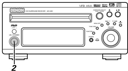
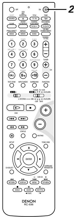
Refer to "CONNECTIONS" (pages 10 to 17) and check that all connections are correct.
2 Turn on the power. Press the POWER button.
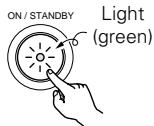

Main unit Remote control unit
When pressed, the power turns on and the display lights. The sound is muted for several seconds, after which the unit operates normally. When pressed again, the power turns off, the standby mode is set and the display turns off.
Whenever the ON/STANDBY button is in the STANDBY state, the apparatus is still connected on AC line voltage. Please be sure to unplug the cord when you leave home for, say, a vacation.
(2) Loading Disc
Set discs in the disc tray with the labeled (printed) side facing up.
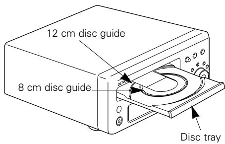
NOTE:
- Do not move the this unit while a disc is playing. Doing so may scratch the disc.
(1) Opening and Closing the Disc Tray
① Turn on the power.
② Press the OPEN/CLOSE button.
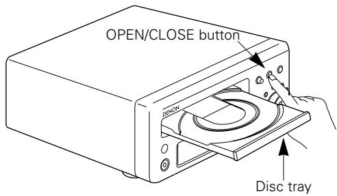
NOTES:
- Even when the power is in the standby mode, when the OPEN/CLOSE button is pressed, the ADV-M51's power turns on and the disc tray operates. (Auto power on function)
- Even if the function is set to something other than DVD, when the OPEN/CLOSE button is pressed, the function switches to DVD and the disc tray operates. (Auto function select function)
- Do not strike on the button with a pencil, etc.
(2) Loading Discs
- Pick up the disc carefully so as not to touch the signal surface and hold it with the labeled side facing up.
- With the disc tray fully open, set the disc in the disc tray.
- Set 12 cm discs in the outer tray guide (Figure 1), 8 cm discs in the inner tray guide (Figure 2).
- Press the OPEN/CLOSE button. The disc is automatically loaded.
- The disc tray can also be closed automatically to load the disc by pressing the PLAY button.
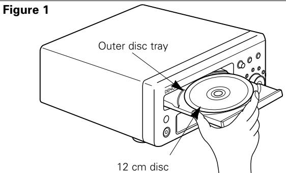
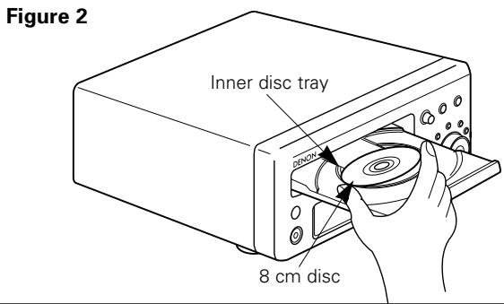
NOTES:
- If a foreign object is caught in the disc tray during closing, simply press the OPEN/CLOSE button again and the tray will open.
- Do not press the disc tray in by hand when the power is off. Doing so will damage it.
- Do not place foreign objects in the disc tray. Doing so will damage it.
(3) Selecting the video output
Factory default: interlace, 525i.
- When a TV compatible with progressive 525p inputs is connected, the setting can be switched using the operation described below.
1 With the function set to "DVD", press the MENU/SET button for at least 2 seconds.
- The current setting ("INTERLACED" or "PROGRESSIVE") is displayed after "VIDEO OUT".
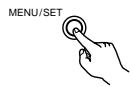
Main unit
2 Turn the surround/select control while the setting is displayed to switch it.
- The setting switches alternately between "INTERLACED" and "PROGRESSIVE".
- The normal display reappears if no operation is performed for several seconds.
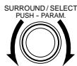
Main unit
NOTE:
- When "PROGRESSIVE" is set, no video signals are output from the VIDEO OUT or S-VIDEO OUT terminals. Set "INTERLACED" if you want to use the VIDEO OUT or S-VIDEO OUT signals.
(3)Playback
IMPORTANT SETUP INFORMATION
This set has the following presettings:
"DISC SETUP", "OSD SETUP", "VIDEO SETUP", "AUDIO SETUP", "RATINGS", and "OTHER SETUP".
These presettings have been preset upon shipment from the factory. If you wish to change them to suit your specific purposes, refer to pages 88 to 100.
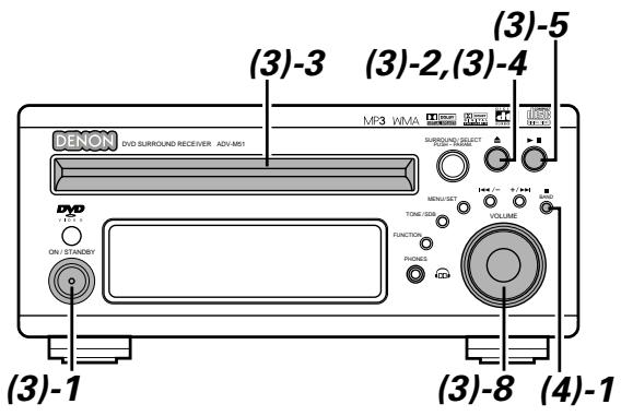
Turn on the power.
- Press the power button, the power indicator lights and the power turns on.
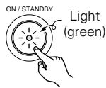
Main unit

Remote control unit
Press the OPEN/CLOSE button to open the disc tray.
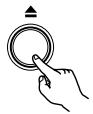
Main unit
3 Set the disc in the disc tray.
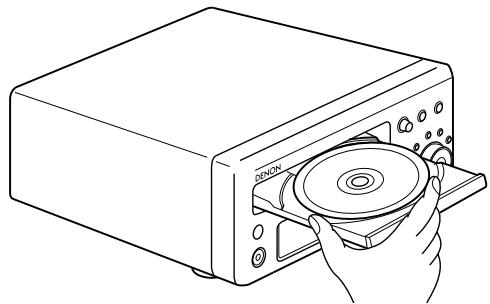
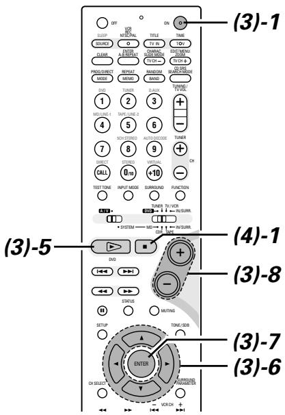
4 Press the OPEN/CLOSE button.

Main unit
Press the PLAY button.
- For many interactive DVDs and video CDs with playback control, a menu screen appears. In this case use the procedure in step 6 to select the desired item.
※ Interactive DVDs are DVDs including multiple angles, stories, etc.
Main unit
Remote control unit
Example: For DVDs with menu screens
Example: For video CDs with playback control
| TOP MENU | |
| Apple | Banana |
| Orange | Strawberry |
| Peach | Pineapple |
| 1. Opening |
| 2. 1st movement |
| 3. 2nd movement |
| 4. 3rd movement |
| 5. Ending |
Use the cursor buttons ( , , and ) to select the desired item.
- For some discs there is a second menu screen. If so, press the button to display the next menu screen. (See the disc's jacket.)
※ The cursor buttons (▲,▼,▲ and ▲) do not work for video CDs. Use the number buttons to select the desired item.
Remote control unit
Press the ENTER button.
- The desired item is selected and playback starts.
- You can return to the menu screen by pressing the TOP MENU button while the DVD is playing, though this depends on the disc.
- Press the RETURN button during playback of a video CD to return to the menu screen.

Example: When "Apple" is selected
Remote control unit

Either turn the main unit's main volume control or use the main volume control buttons on the remote control unit to adjust the volume.
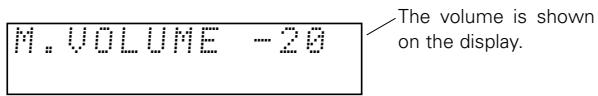
Main unit
Remote control unit
※ For detailed instructions on operations for the surround modes and surround parameters, see "12 Operating the Surround Functions" on pages 44 to 58.
- In the "AUTO" input mode, the signals of the disc being played are identified, Dolby Digital, DTS or PCM decoding is selected automatically and the disc is played.
- In the Dolby Virtual Speaker surround mode, the signals of the disc being played are automatically decoded in Dolby Digital or DTS then played in the Dolby Virtual Speaker surround mode.
NOTES:
- If it appears on the TV screen while buttons are being operated, that operation is not possible on the ADV-M51 or with that disc.
- Set the disc in the disc guide.
- Only set one disc in the tray.
- The disc keeps turning while the menu screen is displayed on the TV screen.
(4) Stopping Playback
During playback, press the STOP button on the main unit or the remote control unit, playback stops and wall paper is displayed.
- With the ADV-M51, when the STOP button is pressed, that position is stored in the memory. At this time, "▶" flashes on the display. When the PLAY button is pressed after pressing the STOP button, playback resumes from the position at which it was stopped. The resume play memory function is canceled if the disc tray is opened or the STOP button is pressed a second time.
About the DVD standby function
When the ADV-M51's function is set to DVD, the DVD standby mode is set automatically if the disc remains in the stop mode for approximately 10 minutes.
- In the DVD standby mode, the DVD section's power is off and output of the video signals is also off.
The ADV-M51's display reads "DVD standby" at this time.
- When in the DVD standby mode, the power of the sections other than the DVD section is on and function switching and other operations can be performed on the main unit and remote control unit. When a DVD control button (the play/pause and button open/close buttons on the main unit, the play button on the remote control unit, etc.) is operated, the DVD section's power turns on automatically and disc playback and opening/closing of the disc holder can be performed.

Main unit

Remote control unit
The resume play memory function only works for discs for which the elapsed time is shown on the display during playback.
Auto power off function.
-
The ADV-M51 is equipped with a function that automatically switches the power to standby if no operation is performed for 30 minutes while in the stop mode with the function set to DVD.
-
This function is set to off upon shipment from the factory. If you wish to turn it on, set the "DVD AUTO POWER OFF" setting to "YES" as described on page 38.
NOTE:
- The DVD standby function only turns off the power of the DVD section. It is different from the DVD auto power off function set with the system settings in Setup in that the DVD section remains functional.
(5) Playing Still Pictures (Pausing)
During playback, press the button on the main unit or the button on the remote control unit.
- Press the PLAY button to resume normal playback.
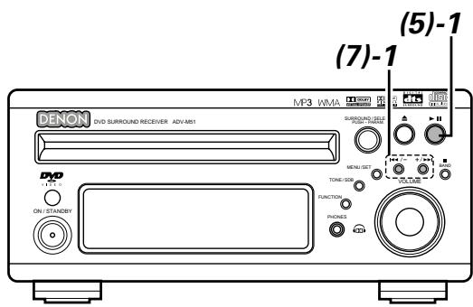
(6) Forward / Reverse Searching
1 During playback, press one of the / buttons on the remote control unit.
: Reverse direction
Forward direction
- When pressed again, the search speed increases (DVD, VIDEO CD in seven steps, CD in four steps).
- Press the PLAY button to resume normal playback.
Remote control unit
NOTE:
- In some cases the menu screen may reappear when one of the / buttons is pressed during menu playback on a video CD.
(7) Skipping to the Beginning of Chapters or Tracks
During playback, press one of the skip buttons on the main unit or the remote control unit.
/ : Reverse direction (PREVIOUS)
Forward direction (NEXT)
- A number of chapters or tracks equal to the number of times the button is pressed is skipped.
- When the skip back button is pressed once, the pickup returns to the beginning of the currently playing chapter or track.
Main unit
Remote control unit

Main unit

Remote control unit
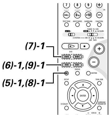
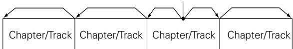
Playing position
Reverse direction Forward direction (direction of playback)
NOTE:
- In some cases the menu screen may reappear when one of the 1 / buttons is pressed during menu playback on a video CD.
Searching using the number buttons
① During playback, press the search mode button on the remote control unit.
- The mode switches as shown below each time the button is pressed:
For DVDs : Title Chapter
For CDs and video CDs: Track (no switching)
※ The search mode set by pressing the search mode button is stored in the memory until the power is turned off.
② Use the number buttons on the remote control unit to input the number of the title, chapter or track to be played.
※ Some DVDs or video CDs may be designed to operate in special ways and will not operate as described here.
(8) Playing Frame by Frame (for DVDs and video CDs only)
During playback, press the button on the remote control unit.
- The picture moves forward one frame each time the button is pressed.
- Press the PLAY button to resume normal playback.

Remote control unit
(9) SlowPlayback (forDVDs and video CDs only)
1 In the still mode, press one of the / buttons on the remote control unit.
: Reverse direction
Forward direction
- When pressed again, the slow play speed increases. (Four step) (Three step on video CDs)
- Press the PLAY button to resume normal playback.
Remote control unit
NOTE:
- Reverse slow play is not possible on video CDs.
Press the FUNCTION button to select the input function to be played.
Main unit

Remote control unit
The function switches as shown below.
Factory default (LINE 1) = MD, (LINE 2) = TAPE

2 When DVD, D.AUX or (LINE1) = MD was selected as the input function, press the remote control unit's INPUT MODE button to select the input mode.

Remote control unit

- "ANALOG" cannot be selected when DVD or D.AUX was selected as the input function.
- "ANALOG" can be selected when "LINE-2" is set to "D.AUX" at "FUNCTION ASSIGNMENT" under "SYSTEM SETUP" in the detailed settings.
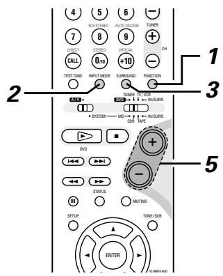
Input mode selection function
- The input mode can be selected when the input function is set to DVD, D.AUX or (LINE1) = MD.
- Different input modes can be selected for each input function. The selected input mode is stored in the memory for the individual input functions.
- When the input function is set to something other than the above, "ANALOG ONLY" is displayed and the input mode cannot be selected.
① AUTO (auto mode)
In this mode, the type of signal being input to the digital and analog input terminals is detected and the program in the set's surround decoder is switched automatically to play the signals for the selected input function.
The presence or absence of digital signals is detected, the signals input to the digital input are identified and decoding and playback are performed automatically in DTS, Dolby Digital or PCM (2 channel stereo) format.
If no digital signal (LINE1) = MD is being input, the analog input jacks are selected.
Use this mode to play Dolby Digital signals.
② PCM (exclusive PCM signal playback mode)
Decoding and playback are only performed when PCM signals are being input.
③ DTS (exclusive DTS signal playback mode)
Decoding and playback are only performed when DTS signals are being input.
(4) ANALOG (exclusive analog audio signal playback mode) The signals input to the analog input jacks are played. (This cannot be selected in the DVD mode.)
The input mode automatically switches to "AUTO" if you switch the input function to DVD from anything other than DVD.
Either turn the SURROUND/SELECT dial or press the SURROUND button on the remote control unit to select the surround mode.
Main unit

Remote control unit
- The function switches as shown below.
- The function only changes in the “ ” direction when operated from the remote control unit.

Start playback on the selected component.
- For operating instructions, refer to the component's manual.
Either turn the MASTER VOLUME dial on the main unit or use the VOLUME buttons on the remote control unit to adjust the volume.
M.VOLUME -28
The volume level is displayed on the display.
Main unit
Remote control unit
- The volume can be adjusted within the range -60 to 0 to +18 dB. Note that depending on the input signal, surround mode, speaker settings and channel level setting, it may not be possible to adjust the volume up to +18 dB.
To check the currently playing program source, etc.
Press the MENU/SET button. Display "STATUS" then turn the SURROUND/SELECT control.
Main unit
Main unit

Remote control unit
※ To perform this operation on the remote control unit, press the STATUS button.
The current program source and surround settings are shown on the display each time the button is pressed or turned. (When the function is set to DVD, the information is also displayed on the TV screen.)
Input mode display
- In the AUTO mode
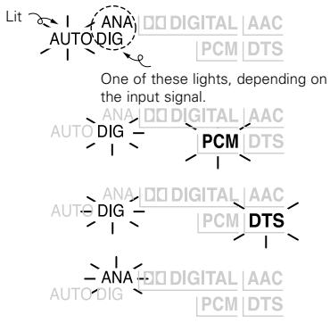
-
In the DIGITAL PCM mode
-
In the DIGITAL DTS mode
- In the ANALOG mode
Input signal display
DOLBY DIGITAL

DTS

- PCM

- "DIG" lights when digital signals are input properly. If "DIG" is flashing, check whether the connections are proper and whether the input component's power is on.
Input mode when playing CD sources
- When playing CDs containing recordings of live concerts, etc., in the "AUTO" mode, the sound may be slightly broken at the beginning. If this happens, switch to the "PCM" mode.
Input mode when playing DTS sources
- If DTS-compatible CDs are played in the "PCM" mode, noise is output because DTS playback is not possible.
To play a DTS-compatible source, be sure to set the input mode to "AUTO" or "DTS". - Noise may be generated at the beginning of playback and while searching during DTS playback in the AUTO mode. If so, play in the DTS mode.
After starting playback
[1] Adjusting the sound quality (TONE/SDB)
The TONE/SDB function will not work in the direct mode.
![DENON D-M51DVS - [1] Adjusting the sound quality (TONE/SDB) - 1](/content/2025/01/135504/images/0508bdff93cedd6d86880fb5c09736703bc6a5b79079dc753997d1ce96826da8.jpg)
![DENON D-M51DVS - [1] Adjusting the sound quality (TONE/SDB) - 2](/content/2025/01/135504/images/f3476e73126bbcfe80a6fc3b5e4f9bcedd41024ae853f25cf4669cdefce563ee.jpg)
Press the TONE/SDB button.
- The tone switches as follows each time the TONE/SDB button is pressed.
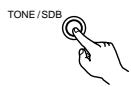
Main unit

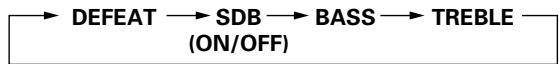
Remote control unit
2 With the name of the volume to be adjusted selected, turn the SURROUND/SELECT knob or cursor button ( ,) to adjust the level.
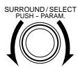
Main unit
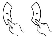
Remote control unit
DEFEAT
- The signals do not pass through the SDB, bass and treble adjustment circuits, providing higher quality sound.
SDB
- Either turn the FUNCTION / SELECT dial or use the ( , ) cursor buttons to select "ON" or "OFF".
BASS, TREBLE
- To increase the bass or treble: Turn the control clockwise or press the cursor button. (The bass or treble sound can be increased to up to +10 dB in steps of 2 dB.)
- To decrease the bass or treble: Turn the control clockwise or press the cursor button. (The bass or treble sound can be decreased to up to -10 dB in steps of 2 dB.)
When TONE/SDB is displayed, the item can be switched using the and buttons on the remote control unit.
※ If no operation is performed within 4 seconds, the display switches back to what was previously displayed.
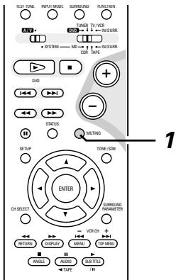
[2]Turning the sound off temporarily (MUTING)
1 Use this to turn off the audio output temporarily. Press the MUTING button.
Cancelling MUTING mode.
Press the MUTING button again.

Remote control unit
NOTES:
- The mute mode is canceled when the main unit's main volume control or one of the main volume control buttons on the remote control unit is operated.
- The setting is canceled if the set's power is turned off.
13 DOLBY / DTS SURROUND
Dolby Surround
(1) Dolby Digital
Dolby Digital is the multi-channel digital signal format developed by Dolby Laboratories.
Dolby Digital consists of up to "5.1" channels - front left, front right, center, surround left, surround right, and an additional channel exclusively reserved for additional deep bass sound effects (the Low Frequency Effects - LFE - channel, also called the ".1" channel, containing bass frequencies of up to 120 Hz).
Unlike the analog Dolby Pro Logic format, Dolby Digital's main channels can all contain full range sound information, from the lowest bass, up to the highest frequencies – 22 kHz. The signals within each channel are distinct from the others, allowing pinpoint sound imaging, and Dolby Digital offers tremendous dynamic range from the most powerful sound effects to the quietest, softest sounds, free from noise and distortion.
Dolby Digital and Dolby Pro Logic
| Comparison of home surround systems | Dolby Digital | Dolby Pro Logic |
| No. recorded channels (elements) | 5.1 ch | 2 ch |
| No. playback channels | 5.1 ch | 4 ch |
| Playback channels (max.) | L, R, C, SL, SR, SW | L, R, C, S (SW - recommended) |
| Audio processing | Digital discrete processing Dolby Digital encoding/decoding | Analog matrix processing Dolby Surround |
| High frequency playback limit of surround channel | 20 kHz | 7 kHz |
■ Dolby Digital compatible media and playback methods
Marks indicating Dolby Digital compatibility: DOLBY DIGITAL
The following are general examples. Also refer to the player's operating instructions.
| Media | Dolby Digital output jacks | Playback method (reference page) |
| LD (VDP) | Coaxial Dolby Digital RF output jack※ 1 | Set the input mode to “AUTO”.(Page 44, 45) |
| DVD | Optical or coaxial digital output(same as for PCM)※ 2 | Set the input mode to “AUTO”.(Page 44, 45) |
| Others(satellite broadcasts, CATV, etc.) | Optical or coaxial digital output(same as for PCM) | Set the input mode to “AUTO”.(Page 44, 45) |
※ 1 Use a commercially available adapter to connect Dolby Digital RF output signals to the digital input terminals. (Refer to the adapter's operating instructions.)
Please refer to the instruction manual of the adapter when making connection.
※ 2 To play in Dolby Digital Surround on the ADV-M51, set "DVD SETUP" - "AUDIO SETUP" - "DIGITAL OUT" to "Normal" in the setup. (The factory default is "Normal".)
(2) Dolby Pro Logic II
- Dolby Pro Logic II is a new multi-channel playback format developed by Dolby Laboratories using feedback logic steering technology and offering improvements over conventional Dolby Pro Logic circuits.
- Dolby Pro Logic II can be used to decode not only sources recorded in Dolby Surround (※) but also regular stereo sources into five channels (front left, front right, center, surround left and surround right) to achieve surround sound.
- Whereas with conventional Dolby Pro Logic the surround channel playback frequency band was limited, Dolby Pro Logic II offers a wider band range (20 Hz to 20 kHz or greater). In addition, the surround channels were monaural (the surround left and right channels were the same) with previous Dolby Pro Logic, but Dolby Pro Logic II they are played as stereo signals.
- Various parameters can be set according to the type of source and the contents, so it is possible to achieve optimum decoding (see page 59).
※ Sources recorded in Dolby Surround
These are sources in which three or more channels of surround have been recorded as two channels of signals using Dolby Surround encoding technology.
Dolby Surround is used for the sound tracks of movies recorded on DVDs, LDs and video cassettes to be played on stereo VCRs, as well as for the stereo broadcast signals of FM radio, TV, satellite broadcasts and cable TV.
Decoding these signals with Dolby Pro Logic makes it possible to achieve multi-channel surround playback. The signals can also be played on ordinary stereo equipment, in which case they provide normal stereo sound.
There are two types of DVD Dolby surround recording signals.
① 2-channel PCM stereo signals
② 2-channel Dolby Digital signals
Sources recorded in Dolby Surround are indicated with the logo mark shown below.
Dolby Surround support mark: DOLBY SURROUND
Manufactured under license from Dolby Laboratories.
"Dolby", "Pro Logic" and the double-D symbol are trademarks of Dolby Laboratories.
DTS Digital Surround
Digital Theater Surround (also called simply DTS) is a multi-channel digital signal format developed by Digital Theater Systems.
DTS offers the same "5.1" playback channels as Dolby Digital (front left, front right and center, surround left and surround right) as well as the stereo 2-channel mode. The signals for the different channels are fully independent, eliminating the risk of deterioration of sound quality due to interference between signals, crosstalk, etc.
DTS features a relatively higher bit rate as compared to Dolby Digital (1234 kbps for CDs and LDs, 1536 kbps for DVDs) so it operates with a relatively low compression rate. Because of this the amount of data is great, and when DTS playback is used in movie theaters, a separate CD-ROM synchronized with the film is played.
With LDs and DVDs, there is of course no need for an extra disc; the pictures and sound can be recorded simultaneously on the same disc, so the discs can be handled in the same way as discs with other formats.
Other media include CDs recorded in DTS. These are the same discs as conventional CDs (recorded in 2 channels) but include 5.1 channel surround signals. They do not include images, but they do permit surround playback on the ADV-M51 and on CD players.DTS surround track playback offers the same intricate, grand sound as in a movie theater, right in your own listening room.
DTS compatible media and playback methods
Marks indicating DTS compatibility:

and

The following are general examples. Also refer to the player's operating instructions.
| Media | DTS Digital output jacks | Playback method (reference page) |
| CD | Optical or coaxial digital output (same as for PCM) ※ 2 | Set the input mode to “AUTO” or “DTS” (page 44, 45). Never set the mode to “ANALOG” or “PCM”. ※ 1 |
| LD (VDP) | Optical or coaxial digital output (same as for PCM) ※ 2 | Set the input mode to “AUTO” or “DTS” (page 44, 45). Never set the mode to “ANALOG” or “PCM”. ※ 1 |
| DVD | Optical or coaxial digital output (same as for PCM) ※ 3 | Set the input mode to “AUTO” or “DTS” (page 44, 45). |
※ 1 DTS signals are recorded in the same way on CDs and LDs as PCM signals. Because of this, the un-decoded DTS signals are output as random "hissy" noise from the CD or LD player's analog outputs. If this noise is played with the amplifier set at a very high volume, it may possibly cause damage to the speakers. To avoid this, be sure to switch the input mode to "AUTO" or "DTS" before playing CDs or LDs recorded in DTS. Also, never switch the input mode to "ANALOG" or "PCM" during playback. The same is true when playing CDs and LDs recorded in DTS on the ADV-M51 or on LD/DVD compatible players. With DVDs, the DTS signals are recorded with a special recording method so there is no problem. For DVDs, the DTS signals are recorded in a special way so this problem does not occur.
※ 2 The signals provided at the digital outputs of a CD or LD player may undergo some sort of internal signal processing (output level adjustment, sampling frequency conversion, etc.). In this case the DTS-encoded signals may be processed erroneously, in which case they cannot be decoded by this unit, or may only produce noise. Before playing DTS signals for the first time, turn down the master volume to a low level, start playing the DTS disc, then check whether the DTS indicator on this unit (see page 45) lights before turning up the master volume.
※ 3 To play in DTS Digital Surround on the ADV-M51, set "DVD SETUP" — "AUDIO SETUP" — "DIGITAL OUT" to "Normal" in the setup. (The factory default is "Normal".)
"DTS" and "DTS Digital Surround" are registered trademarks of Digital Theater Systems, Inc.
"DTS" and "DTS Virtual" are trademarks of Digital Theater Systems, Inc.
Dolby Virtual Speaker
Dolby Virtual Speaker technology uses proprietary technology of Dolby Laboratories to create a virtual surround sound field using only two speakers for the front channels, allowing the user to experience sound as if surround speakers were actually being used.
Features of Dolby Virtual Speaker sound
Accurate surround sound field positioning
The virtual surround speakers are positioned at 105^ to the left and 105^ to the right.
Multi-channel programs played according to the producer's intentions
The sound of the different channels is played in the position set upon mixing. For example, sound set at the rear left is heard from the rear left.
Stereo programs played in surround
The Dolby Pro Logic II circuit is used together with the Dolby Virtual Speaker circuitry to create a rich virtual surround sound field with stereo programs as well.
Selecting the listening mode
Two listening modes are provided: Reference and Wide.
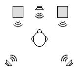
Reference mode
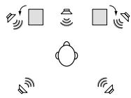
Wide mode
□ : 2 front channels
@P : Virtual sound field created with the Dolby Virtual Speaker mode
Dolby Headphone
Dolby Headphone is a 3D sound technology developed jointly by Dolby Laboratories and Lake Technology of Australia achieving surround sound with regular headphones.
Normally when using headphones all the sounds are sounded in the head, making it uncomfortable to listen with headphones for long periods of time. Dolby Headphone simulates speaker playback in a room and positions the sound sources to the front or the sides, outside of the head, achieving a powerful sound similar to that of a movie theater or home theater. This technology is aimed mainly at multi-channel audio or video equipment including Dolby Digital or Dolby Pro Logic Surround decoding functions and operates inside a high performance digital signal processing chip (DSP).
The Dolby Headphone mode can be used not only with multi-channel sources but also with stereo programs.
(1) Playing in the Dolby Virtual Speaker mode
- The Dolby Virtual Speaker mode is a mode using 3D sound technology from Dolby Laboratories to achieve multi-channel surround sound using only two speakers for the front channels.
- With two speakers for the front channels, one of two modes can be selected: Reference or Wide.
- The Dolby Virtual Speaker mode can be used not only with Dolby Digital and DTS multi-channel sources but also with 2-channel sources. With 2-channel sources, one of two 2-channel modes can be selected: Virtual 1 (Dolby Pro Logic II Cinema) and Virtual 2 (Dolby Pro Logic).
[1]Playing Dolby Digital and DTS surround sound (with digital inputs only)
Applicable sources
- Digital input (LINE-1 and D.AUX functions, including DVD playback discs)
Dolby Digital multi-channel sources
DTS sources
![DENON D-M51DVS - [1]Playing Dolby Digital and DTS surround sound (with digital inputs only) - 1](/content/2025/01/135504/images/037859c97d81585789d81850217725a3ff423ffcb6d3a7faf93bfbe549c4d67a.jpg)
![DENON D-M51DVS - [1]Playing Dolby Digital and DTS surround sound (with digital inputs only) - 2](/content/2025/01/135504/images/3c3c1be98b620e044c2f949e99b1dbe32105db6b5b3a306ee57a69079e7c3177.jpg)
1 Select the digital input function (DVD or LINE-1 or D.AUX digital input).
![DENON D-M51DVS - [1]Playing Dolby Digital and DTS surround sound (with digital inputs only) - 3](/content/2025/01/135504/images/6cc82d2d35f70ef3acc701b840d375fcf249ab3881ed7a28213bac490c6cfb11.jpg)
Main unit
![DENON D-M51DVS - [1]Playing Dolby Digital and DTS surround sound (with digital inputs only) - 4](/content/2025/01/135504/images/5ec03f16377018de60d52e929c960caad772b909081b62ae64e7f2595ffd4aec.jpg)
Remote control unit
Set the input mode to "AUT0"
※ DTS sources can also be played with the input mode set to "DTS".
![DENON D-M51DVS - [1]Playing Dolby Digital and DTS surround sound (with digital inputs only) - 5](/content/2025/01/135504/images/b2130c882f9633f31f736b4843c55e9f0d7a1942170dc3cf4826122d3ed894dc.jpg)
Remote control unit
3 Set the surround mode to "DOLBY VIRTUAL SPEAKER".

Main unit

Remote control unit
- In the Dolby Virtual Speaker mode, this indicator lights.

4 Play a program source including the DOLBY or marks.
- The Dolby Digital indicator lights when playing Dolby Digital sources.

- The DTS indicator lights when playing DTS sources.

※ This switches automatically according to the format of the playback source.
Display the surround parameters for that source.
※ When the function is set to DVD, this is displayed on the screen as well.
Main unit

Remote control unit
6 Select and set the surround parameters.
(On the remote control unit, use the
,cursor buttons to set the parameters.)
If nothing is done for 6 seconds from when the parameter is displayed, the normal display reappears.
Setting the DOLBY VS mode
SURROUND/SELECT

Main unit
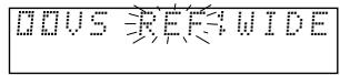
※ The selected mode flashes.
※ The mode is not displayed if it cannot be selected.
D.COMP. setting
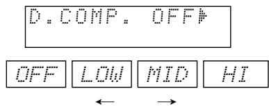
Setting the LFE level
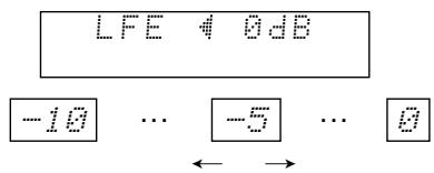
The LFE level can be adjusted in steps of 1 dB between -10 dB and 0 dB.
DEFAULT setting
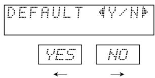
※ When “YES” is selected, the settings are restored to the factory defaults.
When the surround parameters are displayed, use the and cursor buttons on the remote control unit to switch to previous or following items.
※ Once the surround parameters have been set, stop operating the buttons. After several seconds, the normal display reappears and the settings are automatically entered.
Surround parameters (1)
DOLBY VS (Dolby Virtual Speaker mode)
- REF (Reference mode)
This is the standard mode.
- WIDE (Wide mode)
This mode expands the front channel sound field.
D.COMP. (Dynamic range compression)
- This parameter adjusts the dynamic range of the Dolby Digital or DTS sound. When listening with the volume turned relatively low, at night for example, set this to the "HI" side to lower the peak of the sound and amplify the quieter sounds, narrowing the dynamic range and making the sound easier to listen to. Set to "OFF" to turn this function off.

- With DTS sources, only displayed for sources compatible with dynamic range compression.
LFE (Low Frequency Effect):
-
Program source and adjustment range
-
Dolby Digital : -10 dB to 0 dB
-
DTS Surround : -10 dB to 0 dB
-
When Dolby Digital encoded software is played, it is recommended that the LFE LEVEL be set to 0 dB for correct Dolby Digital playback.
- When DTS encoded movie software is played, it is recommended that the LFE LEVEL be set to 0 dB for correct DTS playback.
- When DTS encoded music software is played, it is recommended that the LFE LEVEL be set to -10 dB for correct DTS playback.
[2] 2-channel mode settings
- When 2-channel signals are input, one of two playback modes can be selected and set according to the 2-channel mode setting, Virtual 1 or Virtual 2. (The Virtual 1 mode is set by factory default.)
Virtual 1 : 2-channel sources are played in virtual surround using Dolby Pro Logic II Cinema processing.
Virtual 1 : 2-channel sources are played in virtual surround using Dolby Pro Logic processing.
![DENON D-M51DVS - [2] 2-channel mode settings - 1](/content/2025/01/135504/images/64ba9074fa02898827b56399befbede9b5ede8f4d78b71307123eef6e3491494.jpg)
![DENON D-M51DVS - [2] 2-channel mode settings - 2](/content/2025/01/135504/images/ad7473d0706b0f66f3260c294015fd3806753dab6030e2cf611f81d7b90bb8c9.jpg)
NOTES:
- The 2-channel mode cannot be set when Dolby Digital or DTS 5.1-channel signals.
- The 2-channel mode is set and stored in the memory individually for the different functions.
1 Set the surround mode to "DOLBY VIRTUAL SPEAKER" ("DOLBY VS").
- The normal display reappears after the surround mode is displayed.
Main unit

Remote control unit
Press the SURROUND PARAMETER button and select the 2-channel mode.
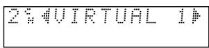

SURROUND/SELECT PUSH-PARAM
Main unit
This can be selected if there is no digital input signal, if the digital input is a PCM or Dolby Digital 2-channel signal and if the input is analog.

Remote control unit
3 Turn the SURROUND/SELECT control on the main unit or use the and cursor buttons on the remote control unit to select the desired 2-channel mode.

Main unit

Remote control unit
VIRTUAL 1←→ VIRTUAL 2
Surround parameters (2)
1. VIRTUAL1 (Virtual 1 mode)
In this mode, 2-channel sources are played with Dolby Pro Logic II Cinema processing. This mode is suited for playing movie sources recorded in Dolby Surround and regular stereo sources.
2. VIRTUAL2 (Virtual 2 mode)
In this mode, 2-channel sources are played with Dolby Pro Logic processing. This mode is compatible with regular Dolby Pro Logic playback. With it, the recorded playback image of sources recorded in Dolby Surround is recreated faithfully.
NOTE:
- If noise is generated for interactive and other high bit rate sources when playing DVDs or D.AUX digital input signals in the Dolby Virtual Speaker mode, set "LINE-1/LINE-2 REC OUT" under "[5] Function settings" at "SYSTEM SETUP" on pages 38 and 39 to "Off".
(When this is done, analog recording in the Dolby Virtual Speaker mode is not possible.)
"Dolby", "Pro Logic" and the double-D symbol are trademarks of Dolby Laboratories.
"DTS" and "DTS Virtual" are trademarks of Digital Theater Systems, Inc.
(2) Playing in the DENON original surround modes
- This unit is equipped with a high performance DSP (Digital Signal Processor) which uses digital signal processing to synthetically recreate the sound field. One of 3 preset surround modes can be selected according to the program source and the parameters can be adjusted according to the conditions in the listening room to achieve a more realistic, powerful sound. These surround modes can also be used for program sources not recorded in Dolby Surround Pro Logic or Dolby Digital.
| 1 | ROCK ARENA | Use this mode to achieve the feeling of a live concert in an arena with reflected sounds coming from all directions. |
| 2 | JAZZ CLUB | This mode creates the sound field of a live house with a low ceiling and hard walls. This mode gives jazz a very vivid realism. |
| 3 | VIDEO GAME | Use this to enjoy video game sources. |
※ Depending on the source being played, the effect may not be very strong.
In such cases, try other surround modes without paying too much attention to their names and choose the one you feel is best.
NOTE 1: When playing sources recorded in monaural, the sound is one-sided if only one channel (left or right) is input, so input signals to both channels.
Personal Memory Plus
This set is equipped with a personal memorize function that automatically memorizes the surround modes and input modes selected for the input different sources. When the input source is switched, the modes set for that source last time it was used are automatically recalled.
- Settings automatically stored in the memory for the individual input functions using the Personal Memory Plus function:
① Surround mode (including 2-channel decode mode and Dolby Pro Logic II mode settings)
② Input mode selection function
The surround parameters, TONE/SDB control settings and playback level balance for the different output channels are memorized for each surround mode.
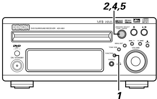
[1] DSP Surround simulation
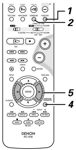
1 Select the input source.
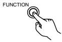
Main unit

Remote control unit
2 Select the surround mode for the input channel.
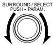
Main unit

Remote control unit
- The surround mode switches in the following order each time the SURROUND MODE button is pressed:
DOLBY VS STEREO DIRECT ROCK ARENA JAZZ CLUB VIDEO GAME DOLBY VS ---
Play a program source.
Refer to instruction manual for handling.
4 To enter the surround parameter setting mode, press the SURROUND mode.
- The surround parameter switches in the following order each time the SURROUND button is pressed for the different surround modes.

Remote control unit
※ When “YES” is selected, the settings are reset to their factory default values.
※ Stop operating buttons once the surround parameter settings have been completed. After several seconds the normal display reappears and the settings are automatically set.
Surround parameters (3)
ROOM SIZE:
- This sets the size of the sound field.
There are five settings: "SMALL", "MED-S" (medium-small), "MED", "MED-L" (medium-large) and "LARGE". "SMALL" recreates a small sound field, "LARGE" a large sound field.
EFFECT LEVEL:
- This sets the strength of the surround effect.
The level can be set in 15 steps from 1 to 15. Lower the level if the sound seems distorted.
Table of Surround Mode Parameters (1)
| Surround Mode DVS: Dolby Virtual Speaker DHP: Dolby Headphone | Presence/absence of signals and controllability in the various modes | ||
| Channel output | |||
| FRONT L/R | SUB-WOOFER | ||
| DVS | REFERENCE | ○ | ◎ |
| WIDE | ○ | ◎ | |
| DHP | DH1 | ○ (H/P ONLY) | × |
| DH2 | ○ (H/P ONLY) | × | |
| DH3 | ○ (H/P ONLY) | × | |
| BYPASS | ○ (H/P ONLY) | × | |
| STEREO | ○ | ◎ | |
| DIRECT | ○ | ◎ | |
| ROCK ARENA | ○ | ◎ | |
| JAZZ CLUB | ○ | ◎ | |
| VIDEO GAME | ○ | ◎ | |
Table of Surround Mode Parameters (2)
| Surround Mode DVS: Dolby Virtual Speaker DHP: Dolby Headphone | Presence/absence of signals and controllability in the various modes | ||||||
| Playback signals and surround modes for the various input functions | |||||||
| DVD / D.AUX /MD/LINE1 | (D.AUX / L2) MD/LINE1 | TAPE1 / LINE2 / TUNER | |||||
| When playing Dolby Digital signals | When playing DTS signals | When playing PCM signals | When playing analog signals | When playing analog signals | |||
| 2-channel | Multi-channel | Multi-channel | 2-channel | 2-channel | 2-channel | ||
| DVS | REFERENCE | ●PL II | ○ | ○ | ●PL II | ●PL II | ●PL II |
| WIDE | ●PL II | ○ | ○ | ●PL II | ●PL II | ●PL II | |
| DHP | DH1 | ●PL II | ○ | ○ | ●PL II | ●PL II | ●PL II |
| DH2 | ●PL II | ○ | ○ | ●PL II | ●PL II | ●PL II | |
| DH3 | ●PL II | ○ | ○ | ●PL II | ●PL II | ●PL II | |
| BYPASS | ○ | ○ D.MIX | ○ D.MIX | ○ | ○ | ○ | |
| STEREO | ○ | ○ D.MIX | ○ D.MIX | ○ | ○ | ○ | |
| DIRECT | ○ | ○ D.MIX | ○ D.MIX | ○ | ○ | ○ | |
| ROCK ARENA | ○ | ○ | ○ | ○ | ○ | ○ | |
| JAZZ CLUB | ○ | ○ | ○ | ○ | ○ | ○ | |
| VIDEO GAME | ○ | ○ | ○ | ○ | ○ | ○ | |
: Can be either present or absent, depending on speaker configuration setting.
: Signal present or controllable. D.MIX: Compatible with down-mixing.
: Can be selected with 2-channel decode mode.
× : No signal or not controllable.
Table of Surround Mode Parameters (3)
| Surround Mode DVS: Dolby Virtual Speaker DHP: Dolby Headphone | Presence/absence of signals and controllability in the various modes | |||
| Surround parameter – default value indicated in (parentheses) | ||||
| SDB | TONE CONTROL | 2ch DECODE MODE | ||
| DVS | REFERENCE | ○ (OFF) | ○ (OFF) | ○*1 (VIRTUAL1) |
| WIDE | ○ (OFF) | ○ (OFF) | ||
| DHP | DH1 | ○ (OFF) | ○ (OFF) | ○ *2 (CINEMA) |
| DH2 | ○ (OFF) | ○ (OFF) | ||
| DH3 | ○ (OFF) | ○ (OFF) | ||
| BYPASS | ○ (OFF) | ○ (OFF) | × | |
| STEREO | ○ (OFF) | ○ (OFF) | × | |
| DIRECT | × | × | × | |
| ROCK ARENA | ○ (OFF) | ○ (OFF) | × | |
| JAZZ CLUB | ○ (OFF) | ○ (OFF) | × | |
| VIDEO GAME | ○ (OFF) | ○ (OFF) | × | |
Table of Surround Mode Parameters (4)
| Surround Mode DVS: Dolby Virtual Speaker DHP: Dolby Headphone | Presence/absence of signals and controllability in the various modes | ||||
| Surround parameter – default value indicated in (parentheses) | |||||
| ROOM SIZE | EFFECT LEVEL | Dolby Digital/DTS signal | |||
| D. COMP. | LFE | ||||
| DVS | REFERENCE | × | × | ○ (OFF) | ○ (0dB) |
| WIDE | × | × | ○ (OFF) | ○ (0dB) | |
| DHP | DH1 | × | × | ○ (OFF) | ○ (0dB) |
| DH2 | × | × | ○ (OFF) | ○ (0dB) | |
| DH3 | × | × | ○ (OFF) | ○ (0dB) | |
| BYPASS | × | × | ○ (OFF) | ○ (0dB) | |
| STEREO | × | × | ○ (OFF) | ○ (0dB) | |
| DIRECT | × | × | ○ (OFF) | ○ (0dB) | |
| ROCK ARENA | ○ (MEDIUM) | ○ (10)) | ○ (OFF) | ○ (0dB) | |
| JAZZ CLUB | ○ (MEDIUM) | ○ (10) | ○ (OFF) | ○ (0dB) | |
| VIDEO GAME | ○ (MEDIUM) | ○ (10) | ○ (OFF) | ○ (0dB) | |
: Signal present or controllable.
× : No signal or not controllable.
1: 2ch DECODE MODE (VIRTUAL1, VIRTUAL2) selectable.
2 : 2ch DECODE MODE (Cinema, Music 1 or Music 2 mode) selectable.
( ): Parameter's default value
(3) Playback using the Dolby Headphone mode
- The ADV-M51 is equipped with the Dolby Headphone mode, a technology developed jointly by Dolby Laboratories and Lake Technology for achieving 3D sound over regular headphones.
- The Dolby Headphone mode is set when headphones are connected to the ADV-M51's headphones jack.
- There are actually four Dolby Headphone modes creating different sound field effects: DH1, DH2, DH3 and Bypass (normal stereo playback).
- The Dolby Headphone mode is compatible with Dolby Digital and DTS multi-channel sources. With 2-channel sources, playback in the Cinema, Music 1 and Music 2 modes can be selected with the 2-channel mode setting.
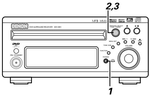
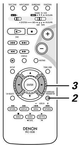
1 Connect headphones (sold separately) to the headphones jack.
- When headphones are plugged in, the output to the speakers is automatically turned off and no sound is produced from the speakers.
Press the surround parameter button and display the surround parameters.
※ When the function is set to DVD, this is also shown on the display.
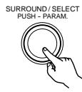
Main unit

Remote control unit
3 Set the various surround parameters.
※ If nothing is done for 6 seconds from when the parameter is displayed, the normal display reappears.
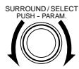
Main unit
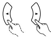
Remote control unit
- Dolby H mode setting
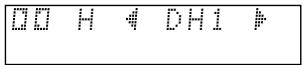


2-channel mode setting
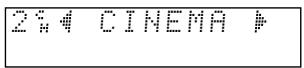
- The mode switches as shown below each time a button is operated.
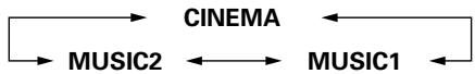
※ Can be selected when there is no signal or when playing a 2-channel source.
There are also the same parameters as those described under "(2) Playing in the Dolby Virtual Speaker mode", namely:
D.COMP. setting
LFE level setting
DEFAULT setting
When the surround parameters are displayed, use the and cursor buttons on the remote control unit to switch to previous or following items.
Surround parameters (4)
DOLBY H (Dolby Headphone modes)
(small room with little reverberation)
DH2 ....Live room
(Larger room than DH1. Use this mode to achieve a sense of distance and diffusion of the sound.)
BYPASS ...... Stereo playback.
2-channel modes
These can be selected when playing 2-channel sources (analog, PCM, etc.). The signals are processed by one of the following decoders to achieve multiple channels then played in the Dolby Headphone mode.
In the Bypass mode, these are not displayed.
CINEMA .......Dolby Pro Logic II Cinema mode
MUSIC1 .......Dolby Pro Logic II Music mode
MUSIC2 .......Signals played in the Dolby Headphone mode with 2 channels.
■ Recording
When playing digital input sources, including function DVDs, signals encoded in the Dolby Headphone mode are output from the recording output terminals and can be recorded on other recording devices.
① Connect headphones to the headphones jack.
② Signals encoded in the Dolby Headphone mode are output from the recording output terminals (in analog).
③ Select the parameters, set the desired mode and start recording.
NOTES:
- Dolby Headphone processing makes the analog recording output level lower than the normal stereo recording output level.
- Do not change the parameters or unplug the headphones during recording. Doing so will cause interruptions in the recorded sound.
- Dolby Headphone signals cannot be recorded during playback of analog sources. The analog input signals are output as such from the recording output terminals.
(1) Tuning
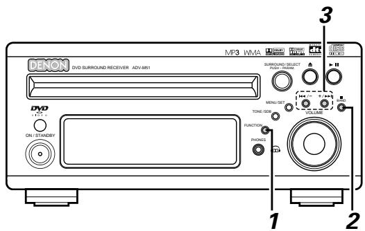
Example: Tuning in FM/AM stations
Press the FUNCTION button and select "TUNER".
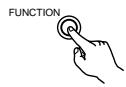
Main unit

Remote control unit
2 Select "FM" or "AM".
- The selected "FM AUTO", "FM MONO" or "AM" is displayed.
- When using the remote control, the mode button is used to select FM AUTO and MONO.

Main unit


Remote control unit
Adjust the receiving frequency.
- When a station is received, the "TUNED" indication will light.
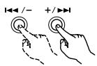
Main unit
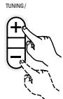
Remote control unit
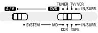
Set the remote control selector switches to A/V and TUNER.
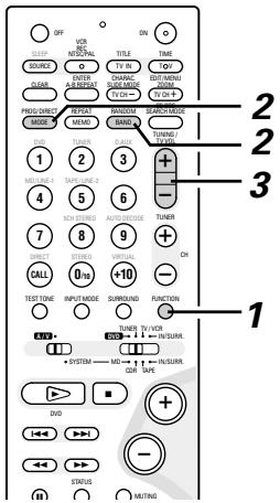
NOTE:
A humming sound may be heard when using a TV nearby while receiving AM programs. If this happens, move the system as far from the TV as possible.
Auto tuning
- When one of the Tuning +/- button is pressed, the frequency changes in steps of 0.2 MHz in the FM band, 10 kHz in the AM band.
- If one of the Tuning +/- button is held for over 1 second, the frequency continues to change when the button is released (auto tuning) and stops when a station is tuned in. Tuning will not stop at stations whose reception is poor.
- To stop the auto tuning function, press the Tuning +/- button once.
FM Stereo Reception
- When a program being broadcast in "FM AUTO" is received, the "ST" indicator lights and the program is received in stereo.
- If reception is poor and there is much noise in the stereo signals, press the BAND or MODE button to set the FM MONO mode.
About the tuning mode and the preset mode
- The function of the "-" and "+" buttons on the main unit can be switched so that they can be used for either tuning (selecting the reception frequency) or for selecting preset stations.
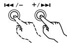
Main unit
- The buttons are set to the tuning mode upon shipment. The mode can be switched to the preset mode by pressing the "+" button while pressing in the BAND button. (When this is done, "PRESET" is flashes for approximately 5 seconds.)
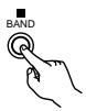
Main unit
- Press the "-" button while pressing in the BAND button to switch to the tuning mode. (When this is done, "TUNING" is flashes for approximately 5 seconds.)
(2) Presetting stations that have been tuned in and giving names to stations (remote control unit only)
A total of 40 stations (including both FM and AM stations) can be preset.
■ Preset stations can be given names with up to 8 characters (letters, numbers and symbols).
■ Preset stations using the including remote control unit.
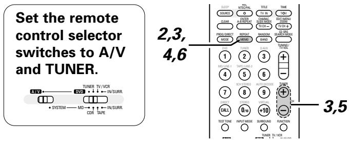
1 Tune in the station you want to preset.
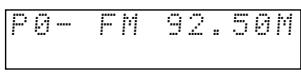
Press the MEMO button twice in a row.
- The name input mode is set.
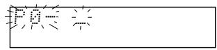

Remote control unit
3 Use the "+" and "-" preset buttons to select the character, then press the MEMO button to input that character.
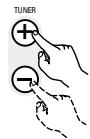
Remote control unit
- When the "+" TUNING button or the MEMO button is pressed, the selected character is entered, the cursor moves to the next position and the next character can be input.
- Use the “-” TUNING button to move back to the previous position. Use this to correct characters that have already been input.
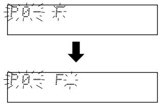
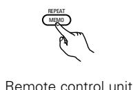
Press the MEMO button twice in a row to enter the station name you have input.
- The preset number indicator, "P", flashes.
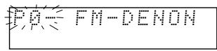

Remote control unit
Use the "+" and "-" preset buttons to select the preset number.
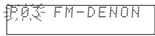
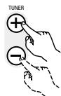
Remote control unit
※ The preset number can also be input directly using the +10 and 1 to 10 buttons on the numeric keypad.
Press the MEMO button to enter the preset number.
- The preset number, band and reception frequency are displayed, then the station name appears.
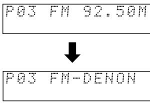

Remote control unit
※ To stop in the middle of the procedure, press the MODE button before pressing the MEMO button at step 4. Everything you have input is cleared.
※ To clear a station name that has been set in the memory, call out that station, set the name input mode in step 2, then press the MODE button. The station name is cleared and the preset channel frequency is displayed.
※ If you only want to preset a station, press the MEMO button once while the station is tuned in. The preset number indicator, "P", flashes, and the preset number input mode is set. Use the "+" and "-" preset buttons to select the preset number then press the MEMO button again to store that station at the selected number. (The number can also be specified directly using the +10 and 1 to 10 buttons on the numeric keypad.)

Remote control unit

Remote control unit
(3) Auto tune presets
Use this to automatically search for FM broadcasts and store up to 40 stations at preset channels 1 to 40.
NOTE:
- If an FM station cannot be preset automatically due to poor reception, use the "Manual tuning" operation to tune in the station, then preset it using the manual "Preset memory" operation.
Using the TUNER function, press and hold the MENU/SET button of the main unit for 2 seconds or longer.
- "AUTO PRESET?" and "-: NO/+: START" will alternately appear on the display of the main unit.
- Press the TUNING - button to cancel.
Main unit
2 Use the TUNING ^+ button to select "START".
"SEARCH" flashes on the display and searching begins.
"COMPLETED" appears once searching is completed.

Main unit
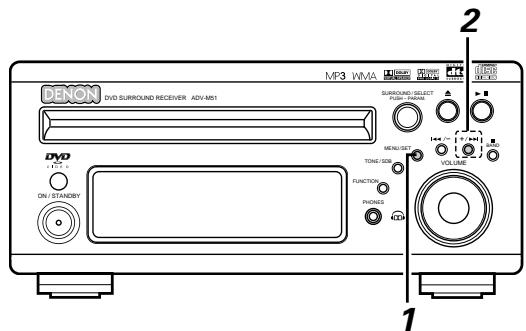
(4) Listening to preset stations
Example: Listening to the station preset at number P03 (This operation is only possible from the remote control unit.)
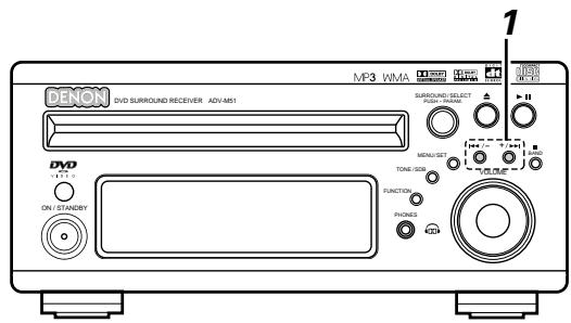
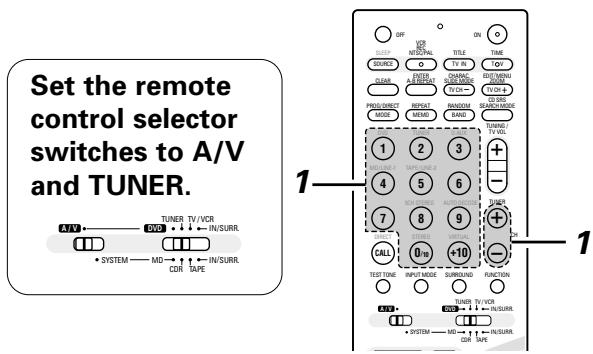
※ The preset buttons on the remote control unit (TUNER CH " + " and "-") can be used at any time.
1 Use the "+" and "-" preset buttons to select preset number "3" or press the "3" button on the numeric keypad to display preset number "P03".
※ The "+" and "-" buttons on the main unit can be selected when the preset mode has been set.

Main unit

Remote control unit

※ The functions of the "+" and "-" buttons on the main unit change according to whether the tuning or preset mode is set. When the tuning mode is set, you can switch to the preset mode by pressing the "+" button while pressing the BAND button.

Main unit

Main unit
16 ON-SCREEN DISPLAY
- The ADV-M51 is equipped with an on-screen display ("OSD") function that displays various types of information on the surround functions and the disc on the screen when the function is set to DVD.
① Setup screen
- This is used to select the speaker system being used (quick system setting) and to change the function of the ADV-M51 and various settings when playing discs (system setting change and DVD setting change).
- The setup screen can be used regardless of the currently set function.
② Display of disc information
- When the function is set to DVD, the OSD displays information on the disc and appears when various playback functions are operated.
③ Display of surround function
- When the function is set to DVD, information on the surround amplifier is also displayed and can be operated.
- The OSD for the surround function (AV OSD) can be turned on and off. (The OSD for the setup screen and DVD disc information cannot be set to "OFF".)
※ Set to "ON" upon shipment from the factory.
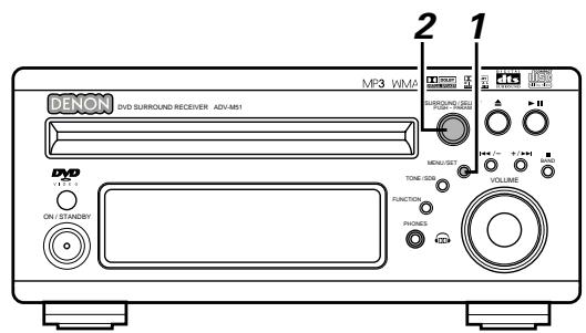
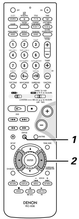
1 With the function set to DVD, press the STATUS button of the remote control for at least 2 seconds.
Press in the MENU/SET button on the main unit, then press the MENU/SET button again for at least 2 seconds while "STATUS" is displayed.
- "AV OSD ON OFF" is displayed.
Main unit

Remote control unit
2 Turn the AV OSD on or off.
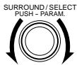
Main unit

Remote control unit


After several seconds, the display turns off and the setting is made.
NOTES:
- Depending on the disc being played, the picture may be disturbed when the OSD turns on. This is not a malfunction. If this should happen, set the AV OSD to "OFF".
- The OSD is also output to the VCR video output terminals. Do not perform setup or OSD operations while recording with a video deck.
17 USING THE ON-SCREEN DISPLAY
(1) Operating using the disc information OSD
Use this function to display and change information on the disc (titles, chapters, time, etc.)
Set the remote control selector switches to A/V and DVD.
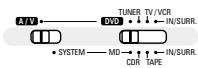
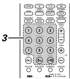
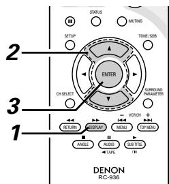
In the play mode, press the DISPLAY button.
- The On-Screen Display appears.
- The picture on the TV screen switches each time the button is pressed.
- The items displayed differ from disc to disc.

Remote control unit
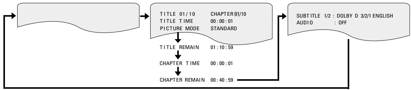
Example: For DVDs
Example: For video and music CDs
- For the on-screen display for video CDs and music CDs, only the disc time changes.
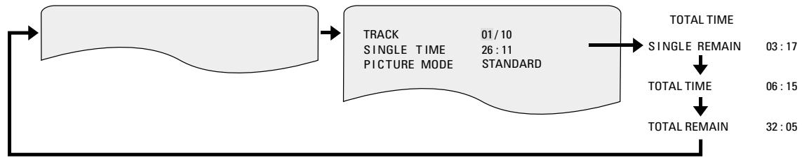
Use the and , cursor buttons to select the item you wish to change.
- The selected item is displayed with a yellow frame.
① For DVDs
"TITLE", "CHAPTER", "TITLE ELAPSED" can be selected.
② For video and music CDs
"TRACK" can be selected.

Remote control unit
3 ① Changing the elapsed time Input using the number buttons, then press the ENTER button. Example: For 1 minute 26 seconds → "00126"
② Changing the title, track or chapter
- For DVDs
Input using the number buttons, then press the ENTER button. (For some discs it is not possible to change the title or chapter.)
- For video and music CDs
Input using the number buttons. Playback starts from that track.
DVO TUNER DALIX ① ② ③
④ ⑤ ⑥
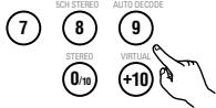
Remote control unit
(2) Adjusting the picture quality
- The quality of the picture when playing discs can be adjusted.
Set the remote control selector switches to A/V and DVD.
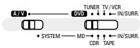
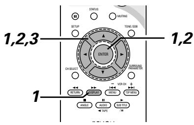
When playing a disc with the function set to DVD, press the DISPLAY button to turn on the on-screen display, use the and cursor buttons to select "PICTURE MODE", then press the ENTER button.
- The picture quality adjustment screen appears.
- The on-screen display also turns on when the DISPLAY button is pressed in the stop mode.
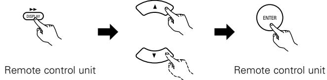
Remote control unit
Use the and cursor buttons to select the item, then press the ENTER button.
Standard:
Both the picture quality and functions are set back to the standard settings set upon shipment from the factory.
Anime:
This sets a brighter more vivid picture quality.
Cinema:
This sets a mellower picture quality.
Memory 1 to 3:
Picture quality settings you have adjusted can be stored at three memory positions. (Set at step 3)
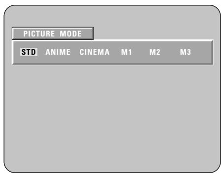
3 Selecting and adjusting the picture quality Use the and cursor buttons to select the picture quality item, then use the and cursor buttons to adjust the value.
- All the adjustments are stored in the memory.
Contrast (-6 to +6) (factory default: 0):
This adjusts the contrast between light and dark portions of the picture.
Brightness (0 to +12) (factory default: 0):
This adjust the brightness (vividness) of the picture.
Color density (-6 to +6) (factory default: 0):
This adjusts the color density.
Hue (-6 to +6) (factory default: 0):
This adjusts the balance between green and red. (This setting does not affect progressive scan outputs.)
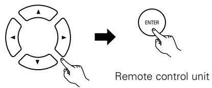
Remote control unit
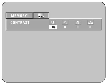
※ To complete the picture quality adjustment:
Press the DISPLAY button again.
NOTE:
- Depending on the disc being played, the picture or sound may be disturbed when the on-screen display is displayed. This is not a malfunction.
(3) Playing Repeatedly
Use this function to play your favourite audio or video sections repeatedly.
Set the remote control selector switches to A/V and DVD.

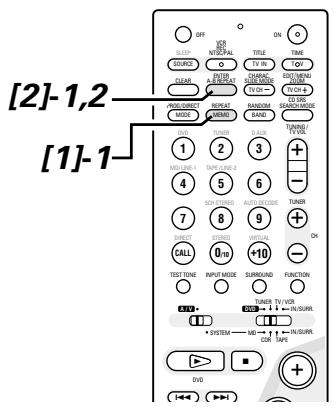
[1] Playing Repeatedly (Repeat Playback)
1 In the play mode, press the REPEAT button.
- The display on the TV screen switches each time the button is pressed, and the corresponding repeat play or stop mode is set.
※ lights on the display when the repeat play mode is set. "ALL" lights when the all repeat play mode is set.

Remote control unit
① For DVDs
- Normal playback
Chapter repeated - Title repeated
- Repeat playback cancelled


CHAPTER REPEAT

TITLE REPEAT
② For video and music CDs
Normal playback
- Track repeated
- Entire disc repeated
- Repeat playback cancelled
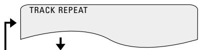

DISC REPEAT
REPEAT OFF
[2] Playing a Certain Section Repeatedly (A-B Repeat Playback)
1 During playback, press the A-B REPEAT button. This sets start point A.
![DENON D-M51DVS - [2] Playing a Certain Section Repeatedly (A-B Repeat Playback) - 1](/content/2025/01/135504/images/b51e864bcb3a79a5df93f8da122724fff49aeaa007d02873e2580aef771eed61.jpg)
![DENON D-M51DVS - [2] Playing a Certain Section Repeatedly (A-B Repeat Playback) - 2](/content/2025/01/135504/images/fb78f8c37b218717a914b26314ee1e4043924bf940fd0bb1f4b18d700976b412.jpg)
Remote control unit
Press the A-B REPEAT button again. This sets end point B, and repeat playback of the A-B section starts.
![DENON D-M51DVS - [2] Playing a Certain Section Repeatedly (A-B Repeat Playback) - 3](/content/2025/01/135504/images/5d39478d0f0d63f4504c1cc6acf5335d022aa84de537c9b7acaee9d8c0c10a5d.jpg)
![DENON D-M51DVS - [2] Playing a Certain Section Repeatedly (A-B Repeat Playback) - 4](/content/2025/01/135504/images/a2894100a85b9bc7be60bf18c6511c7d8f8871346d900e83ecb243407a50a23b.jpg)
Remote control unit
※ To return to normal playback: Press the A-B REPEAT button until "A TO B CANCELLED" appears on the TV screen.
NOTES:
- Repeat playback may not work for some DVDs.
- The repeat playback and A-B repeat playback functions will not work for DVDs and video CDs for which the elapsed time is not shown on the display during playback.
- In some cases, subtitles may not be displayed near the A and B points during A-B repeat playback.
(4) Playing Tracks in the Desired Order
Use this function with video and music CDs to play the tracks in the desired order.
This function does not affect with DVD.
Set the remote control selector switches to A/V and DVD.
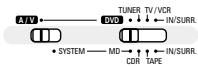
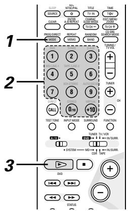
Press the PROG/DIRECT button once in the stop mode.
- The program selection screen appears.
Use the number buttons to select the number you want to program.
- Up to 20 tracks can be programmed.
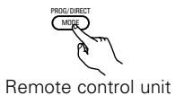
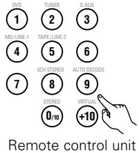
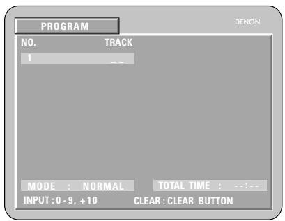
Example: To program tracks 5 and 12
Press number button "5".
Press number button " +10 ".
Press number button "2".
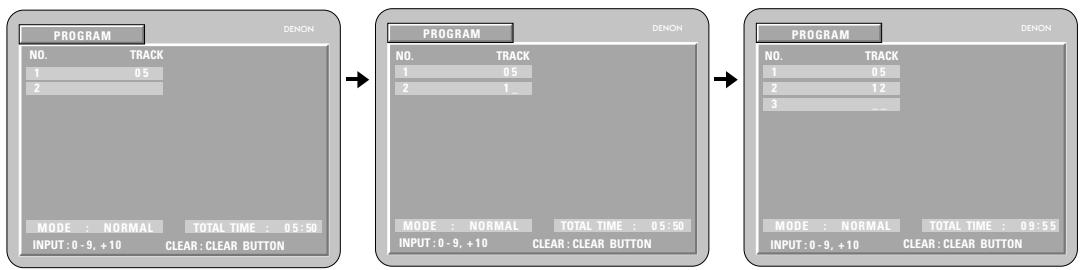
Press the play button. The tracks start play
Remote control unit
※ To return to normal playback:
Press the stop button to stop programmed playback, then press the PROG/DIRECT button.
When the play button is next pressed, normal playback begins from the beginning of the disc.
※ Clearing individual tracks from the program:
Press the stop button to stop programmed playback.
Now press the CLEAR button to clear the last track programmed.
※ Clearing the entire program:
The entire program is cleared when the power is turned off or the disc is unloaded.
The entire program can also be cleared by pressing the stop button to stop programmed playback then pressing the PROG/DIRECT button.
※ Checking the programmed tracks:
Press the CALL button to display the programmed tracks in steps.
(5) Playing Tracks in the Random Order
Use this function with video and music CDs to play the tracks in random order.
This function does not affect with DVD.
Set the remote control selector switches to A/V and DVD.
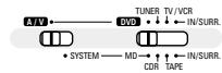
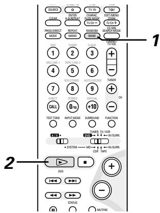
1 In the stop mode, press the RANDOM button.
- The random play screen appears.
RANDOM ON

Remote control unit
Press the PLAY (▶) button.
- The tracks start playing in random order.
Main unit
Remote control unit
- Random playback is not possible for some discs.
※ To return to normal playback:
Press the STOP (■) button to stop random playback, then press the RANDOM button once.
(6) MP3 WMA Playback
[1] Listening to Recorded MP3 CD/CD-R/CD-RW
There are many music distribution sites on the internet from which music files in MP3 format can be downloaded. Music downloaded as instructed on the site and written onto a CD-R/RW disc can be played on the ADV-M51.
If music recorded on commercially available music CDs is converted on a computer into MP3 files using an MP3 encoder (conversion software), the data on a 12 cm CD is reduced into about 1/10 the amount of the original data. Thus, when written in MP3 format, the data of about 10 music CDs can fit onto a single CD-R/RW disc. A single CD-R/RW disc can contain over 100 tracks.
Values when 5-minute tracks are converted with a standard bit rate of 128 kbps into MP3 files and using a CD-R/RW disc with a capacity of 650 MB.
![DENON D-M51DVS - [1] Listening to Recorded MP3 CD/CD-R/CD-RW - 1](/content/2025/01/135504/images/a0297da20a043734b28d6e5bbc4d516dda2d0bb123459816c29ac52e68e724b8.jpg)
![DENON D-M51DVS - [1] Listening to Recorded MP3 CD/CD-R/CD-RW - 2](/content/2025/01/135504/images/5da865306bd798f9f63539518e805ab659f3c1b4a9798bba682904e91de14d00.jpg)
1 Load the CD-R/RW disc on which the MP3 format music files have been written into this unit. (See page 39.)
- When the disc is loaded in the ADV-M51, the disc information screen appears.
- If there are multiple folders, proceed to step 2.
- If there are no folders on the disc (if the disc only contains MP3 files), proceed to step 3.
※ All the folders recorded on the disc are displayed. (The folders are not displayed by layer.)
![DENON D-M51DVS - [1] Listening to Recorded MP3 CD/CD-R/CD-RW - 3](/content/2025/01/135504/images/8880782044d1eece7214e75186d95e9952378a238f323bbe44e4de407d2c5a4a.jpg)
Use the and cursor buttons to select the folder containing the file(s) you want to play, then press the ENTER button.
※ To change the folder
Use the cursor button to select "ROOT" at the upper right of the screen, then press the ENTER button. The screen in step 1 reappears. Select the desired folder.
![DENON D-M51DVS - [1] Listening to Recorded MP3 CD/CD-R/CD-RW - 4](/content/2025/01/135504/images/7bb3aac9d0dc49433b786cd2c8c48cee04c2a9e4d0790172efe072987da2c686.jpg)
Remote control unit
![DENON D-M51DVS - [1] Listening to Recorded MP3 CD/CD-R/CD-RW - 5](/content/2025/01/135504/images/345951e3489280c124afda3dbd3412a9402fdcaeb62e44ebd9553db99e3f91d0.jpg)
Remote control unit
![DENON D-M51DVS - [1] Listening to Recorded MP3 CD/CD-R/CD-RW - 6](/content/2025/01/135504/images/47ccea461621bfbdb9004221192593051d31d47c601d224d3ddf123a1f36b2a9.jpg)
3 Use the and cursor buttons to select the MP3 file you want to play, then press the PLAY (▶) button or ENTER button.
- Playback starts.
※ The display can be switched between the single elapsed time and the single remaining time by pressing the DISPLAY button.
※ Programmed playback is not possible with MP3 discs.
※ To change the MP3 file
Press the STOP button, then use the and cursor buttons to reselect the desired MP3 file.
※ To set the random play mode
In the stop mode, press the RANDOM button.
Then press the PLAY button or ENTER button.
※ To set the repeat mode
The repeat mode changes each time the REPEAT button is pressed.
NORMAL TRACK REPEAT FOLDER REPEAT
※ To return to the initial disc information screen
Press the STOP (■) button, use the cursor button to select "ROOT" at the upper right of the screen, then press the ENTER button.
The screen in step 1 reappears.


Remote control unit


Main unit
Remote control unit

Remote control unit
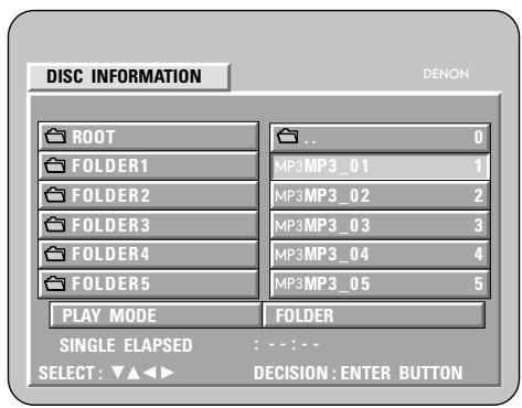
NOTES:
- The ADV-M51 is compatible with the "MPEG-1 Audio Layer 3" standards (sampling frequency of 32, 44.1 or 48 kHz). It is not compatible with such other standards as "MPEG-2 Audio Layer 3", "MPEG-2.5 Audio Layer 3", MP1, MP2, etc.
- It may not be possible to play some CD-R/RW discs due to disc properties, dirt, warping, etc.
- The digital signals output when playing MP3 files are MP3 signals converted into PCM, regardless of whether the audio output presenting is set to "normal" or "PCM conversion". The signals are output with the same sampling frequency as that of the music source.
- In general, the higher an MP3 file's bit rate, the better the sound quality. On the ADV-M51, we recommend using MP3 files recorded with bit rates of 128 kbps or greater.
- MP3 files may not be played in the expected order, since the writing software may change the position of the folders and the order of the files when writing them on the CD-R/RW.
- Manual search and programmed playback are not possible with MP3 discs.
- When writing MP3 files on CD-R/RW discs, select "ISO9660 level 1" as the writing software format. This may not be possible with some types of writing software. For details, refer to the writing software's usage instructions.
- With the ADV-M51 it is possible to display folder names and file names on the screen like titles. The ADV-M51 can display up to 11 characters, consisting of numbers, capital letters, and the " _ " (underscore) mark.
- If recorded in a format other than "ISO9660 level 1", normal display and playback may not be possible. In addition, folder and file names including other symbols will not be displayed properly.
- Be sure to add the extension ".MP3" to MP3 files. Files cannot be played if they have any extension other than ".MP3" or if they have no extension. (with Macintosh computers, MP3 files can be played by adding the extension ".MP3" after the file name consisting of up to 8 capital or numbers and recording the files on the CD-R/RW.)
- Do not apply stickers, tape, etc., to either the label side or the signal side of CD-R/RW discs. If adhesive gets on the surface of a disc, the disc may get stuck inside the ADV-M51 and be impossible to eject.
- The ADV-M51 is not compatible with packet write software.
- The ADV-M51 is not compatible with ID3-Tag.
- The ADV-M51 is not compatible with play lists.
[2] Listening to Recorded WMA (Windows Media Audio) CD-R/CD-RW
This unit can play CD-R/RW music files that have been recorded in the WMA (Windows Media Audio)* audio compression format.
![DENON D-M51DVS - [2] Listening to Recorded WMA (Windows Media Audio) CD-R/CD-RW - 1](/content/2025/01/135504/images/1259584656937b57bdb7686f2cfb5d63b9e398c1124e691aa035b90f2634b5d3.jpg)
Windows Media, and the Windows logo are trademarks, or registered trademarks of Microsoft Corporation in the United States and/or other countries.
※ WMA (Windows Media Audio): New audio coding of Microsoft Corporation (U.S.A.)
-
Uses of recordings you have made other than for your personal enjoyment are not permitted under the Copyright Law without permission of the copyright holder.
-
The method of playback is the same as "[1] Listening to Recorded MP3 CD/CD-R/RW" on Pages 69 and 70.
- In the file display of the disc information screen, WMA files will be displayed with the "WMA" icon instead of the "MP3" icon. (Files for which the "WMA" icon is not displayed cannot be played.)
NOTES:
- Files recorded with a sampling frequency (fs) of 32, 44.1, and 48kHz are supported.
- Programmed playback cannot be performed with WMA files.
- The digital output at the time of WMA file playback is converted to PCM regardless of the initial settings.
- Please use discs that have been recorded in conformity with the ISO 9660 level 1/level 2 CD-ROM file system. (Extended formats are excluded.)
Copyright protected files cannot be played. Also note that depending on the writing software and conditions, playback might not be possible, or the files might not be displayed properly. - Playback of the CD-R/RW might not be possible depending on the disc characteristics, soiling, scratches, and other factors.
- Bit rates of 64k to 160 kbps are supported for WMA files that have an extension of ".wma" or ".WMA".
- This unit can display the folder names and file names on the screen. Up to 11 half-width alphanumeric upper case characters and symbols (including the underscore symbol) can be displayed.
- While in the stop condition, the DISPLAY button of the remote control can be used to switch and display the title names and the artist names. (One folder has a capacity of up to 99 files.)
- Recorded discs with no more than 99 files per folder are recommended. Multiple folder configurations are possible; however, depending on the configuration, playback of all the folders and files might not be possible.
- Multi-session discs and CD-R/RW that have not been finalized can also be played back; however, playback of discs that have had session closure within 10 sessions or have been finalized is recommended.
- Direct track selection using the remote control numerical keys (0 to 9, and +10) can specify up to 179 tracks (179 files) per folder. When 179 tracks are exceeded, while the unit is stopped use the cursor buttons at the disc information screen to select the files, and use the play button of the ENTER button to play.
(7) Playing still picture files (JPEG format)
JPEG files stored on Kodak picture CDs, CD-Rs and CD-RWs can be played as a slide show and enjoyed on the ADV-M51.
[1] Playing Kodak picture CDs
Playing Picture CDs
The ADV-M51 can play Kodak Picture CDs, so you can view the photographs stored on them on a TV screen.
(Picture CDs is CDs containing photographs taken on conventional silver film cameras which have been converted into digital data. For details on Picture CDs, please contact a store providing Kodak development services.)
![DENON D-M51DVS - [1] Playing Kodak picture CDs - 1](/content/2025/01/135504/images/1b7d161fdada2434502fd0734bffb73629925e97f3e87177a7fcf9664eb277cd.jpg)
1 Load the Picture CDs into the set.
- For Picture CDs:
Playback of the still pictures starts automatically when the disc is loaded.
![DENON D-M51DVS - [1] Playing Kodak picture CDs - 2](/content/2025/01/135504/images/7766eacfc4cb69b79e348bc82a2063bfe39ac016fa089b494d974a9474fab399.jpg)
Main unit
※ Press the stop button to stop playback.
- "KODAK" is the registered trademark of Eastman kodak Co.
[2] Playing still pictures stored on CD-Rs/RWs
![DENON D-M51DVS - [2] Playing still pictures stored on CD-Rs/RWs - 1](/content/2025/01/135504/images/1f585a5039a34de14d33e1e02c1afbbb3d4d4b70452e008b7ca617ffc6ac672a.jpg)
Set the remote control selector switches to A/V and DVD.
![DENON D-M51DVS - [2] Playing still pictures stored on CD-Rs/RWs - 2](/content/2025/01/135504/images/85453c1dfef48e4ddf24221785fa74334e69a5776b216268246c75b1d447f5e6.jpg)
![DENON D-M51DVS - [2] Playing still pictures stored on CD-Rs/RWs - 3](/content/2025/01/135504/images/bdd1b6d3a966e8ca41a4e7d5218200fdad75e854e224c7836da28b7f9e9cf5da.jpg)
1 Load the CD-R/RW on which the still pictures have been written into the ADV-M51.
- When the disc is loaded in the ADV-M51, the disc information screen appears.
- If there are multiple folders, proceed to step 2.
- If there are no folders on the disc, proceed to step 3.
![DENON D-M51DVS - [2] Playing still pictures stored on CD-Rs/RWs - 4](/content/2025/01/135504/images/dcc4b7d9969335eaace37c92a1bbaebb24fedb0b23a61dcf8e7ebec1d8d02ac4.jpg)
Use the and cursor buttons to select the folder containing the file(s) you want to play, then press the ENTER button.
※ To change the folder
Use the cursor button to select "ROOT" at the upper right of the screen, then press the ENTER button. The screen in step 1 reappears. Select the desired folder.
![DENON D-M51DVS - [2] Playing still pictures stored on CD-Rs/RWs - 5](/content/2025/01/135504/images/40916f04827011a20153d0c8c0c0b3c7083464605a9dce9f0c86c37f40b61ca7.jpg)
![DENON D-M51DVS - [2] Playing still pictures stored on CD-Rs/RWs - 6](/content/2025/01/135504/images/4311f626c6815adc9ea37bfa4dba86b48a75ef0081b8bed50d6a8529b2e9f81e.jpg)
Remote control unit
![DENON D-M51DVS - [2] Playing still pictures stored on CD-Rs/RWs - 7](/content/2025/01/135504/images/dddf077635fa177b4a6568fe54fc79c00f9163f2e07a51723b83095972b859da.jpg)
Remote control unit
![DENON D-M51DVS - [2] Playing still pictures stored on CD-Rs/RWs - 8](/content/2025/01/135504/images/5d9a8c4a3339c52b5a79dd261f6f3169d508cb9dde680a0e3975bb708e2165e5.jpg)
3 Use the and cursor buttons on the remote control unit to select the still picture file from which you want to start the slide show, then press the PLAY button or the ENTER button on the remote control unit.
- The slide show starts.
- Only the still picture files in the selected folder are played.
※ Once all the still picture files in the folder have been played, the disc information screen reappears.
![DENON D-M51DVS - [2] Playing still pictures stored on CD-Rs/RWs - 9](/content/2025/01/135504/images/274e7a20fb2dc9a7001ec9d020b2af5400d02eee52daabb638cfc0c36a03e2f7.jpg)
![DENON D-M51DVS - [2] Playing still pictures stored on CD-Rs/RWs - 10](/content/2025/01/135504/images/0d30947d3d60f9ac8a317e81b88474abff57e0065aa0261b7c76e314ed433d1f.jpg)
Remote control unit
![DENON D-M51DVS - [2] Playing still pictures stored on CD-Rs/RWs - 11](/content/2025/01/135504/images/4bd058c8a324ffae7f5aca3d2c76412d1dbe0cdd7161800fbe150123850d73f2.jpg)
![DENON D-M51DVS - [2] Playing still pictures stored on CD-Rs/RWs - 12](/content/2025/01/135504/images/b6f72ad11f59b691bc2145c27925852525e0ae1064944436bc9aefca6d8692aa.jpg)
Main unit
![DENON D-M51DVS - [2] Playing still pictures stored on CD-Rs/RWs - 13](/content/2025/01/135504/images/26dfb96fefaf66c73c611bc3dde93103253de3711ec1cba975ef9db69297e54d.jpg)
![DENON D-M51DVS - [2] Playing still pictures stored on CD-Rs/RWs - 14](/content/2025/01/135504/images/c890e4d79dc3c9d6e9e3e765118a2637e851a88c6cf8a868c23c41e1d6fc0a6c.jpg)
Remote control unit
※ To view several of the still pictures stored on the disc at once:
- Press the STOP button to display up to 9 still pictures at once.
- To select and view a still picture (to start the slide show from a specific still picture), use the cursor buttons (, , and ) to select the desired still picture, then press the ENTER button.
※ To temporarily stop the slide show:
- Press the PAUSE button.
- To resume the slide show, press the PLAY button.
※ To cue a still picture you want to view (from which you want to start the slide show):
- During the slide show, press one of the SKIP (I▶,▶) buttons. Press the SKIP I▶ button to cue back to the previous still picture, the SKIP▶ button to cue ahead to the next still picture.
※ Flipping and rotating still pictures:
- Use the cursor buttons (, , and ) to flip the still picture.
cursor button: The currently displayed still picture is flipped vertically.
cursor button: The currently displayed still picture is flipped horizontally.
cursor button: The currently displayed still picture is rotate 90^ counterclockwise.
cursor button: The currently displayed still picture is rotate 90^ clockwise.
※ Play the image in the zoom mode.
- When the ZOOM button is pressed while playing a JPEG image ("ZOOM ON" is displayed on the screen at this time) zoom in and zoom out using the search keys.
(▲: zoom out, ▲▶: zoom in)
- When the image is zoomed, use the cursor buttons (, , and ) to move the zoomed picture.
- Continuous playback (SLIDE SHOW) is not possible in the zoom mode.
※ The way of switching to the next image during continuous JPEG image playback (SLIDE SHOW) can be selected.
- Press the SLIDE MODE button on the remote control unit.
- Select from SLIDE SHOW MODE 1 to MODE 11, MODE RAND and MODE NONE.
Special play modes for MP3/WMA and JPEG files
Use the and cursor buttons to select the play mode, the and cursor buttons to select the special play mode.
- FOLDER (the MP3/WMA and JPEG files in the folder are played in order starting from the selected file)
- FOLDER REPEAT (all the MP3/MMA and JPEG files in the folder are played repeatedly starting from the selected file)
DISC (all the MP3/MMA and JPEG files on the disc are played in order starting from the selected file)
DISC REPEAT (all the MP3/WMA and JPEG files on the disc are played repeatedly starting from the selected file) - RANDOM ON (all the MP3/WMA and JPEG files in the folder are played in random order starting from the selected file)
- TRACK REPEAT (the select MP3/WMA or JPEG file is played repeatedly)
NOTES:
- The ADV-M51 is compatible with image data stored in JPEG format, but Denon does not guarantee that all image data stored in JPEG format can be viewed.
- Pictures with resolutions of up to 2048 x 1536 pixels can be displayed.
- It may not be possible to play some CD-Rs/RWs due to disc properties, dirt, scratches, etc.
- When storing JPEG files on the CD-R/RW, set the writing program to store the files in the "ISO9660 level 1" format.
- Be sure to give JPEG files the extension“.JPG” and“.JPE”. Files with other extensions or with no extensions cannot be viewed on the ADV-M51.
- Do not apply stickers, tape, etc., to either the label side or the signal side of CD-R/RW discs. If adhesive gets on the surface of a disc, the disc may get stuck inside the ADV-M51 and be impossible to eject.
- Do not play CD-R/RW discs containing any files other than music CD files (in CDA format), MP3/WMA and JPEG files. Doing so may result in malfunction or damage, depending on the type of file.
- JPEG files written using Macintosh computers cannot be played.
(8) Using the Multiple Audio, Subtitle and Angle Functions
[1] Switching the Audio Language (Multiple Audio Function)
■ With DVDs containing multiple audio language signals, the audio language can be switched during playback.
Set the remote control selector switches to A/V and DVD.
![DENON D-M51DVS - [1] Switching the Audio Language (Multiple Audio Function) - 1](/content/2025/01/135504/images/5ec394f1d5510e17490ee142ea77ad79508a9c5a82d5dc65b0eed138105b5961.jpg)
![DENON D-M51DVS - [1] Switching the Audio Language (Multiple Audio Function) - 2](/content/2025/01/135504/images/2ecc57502f59558b87aa7078df0300521edc35019bb2e09c3037e536d0d1d6af.jpg)
1 During playback, press the AUDIO button.
- The current audio language number is displayed.
![DENON D-M51DVS - [1] Switching the Audio Language (Multiple Audio Function) - 3](/content/2025/01/135504/images/fb03e077c729697ca5c71bc85ea0d3a87266ca79d3834215ef2191fedd72e57b.jpg)
AUDIO 1/3:DOLBY D3/2/.1 ENG
Remote control unit
Use the and cursor buttons to select the desired language.
- The display turns off when the AUDIO button is pressed.
![DENON D-M51DVS - [1] Switching the Audio Language (Multiple Audio Function) - 4](/content/2025/01/135504/images/e7d8ffb8564c4aac1d949ec9a4ac0b2f61a028214c7bcf091a17cfd7086ca41f.jpg)
AUDIO 2/3:DOLBY D3/2./1 FRA
Remote control unit
NOTES:
- With some discs it is not possible to change the audio language during playback. In such cases, select from the DVD menu. (See page 89.)
- If the desired language is not set after pressing the and cursor buttons several times, the disc does not include that language.
- The language selected in the default settings is set when the power is turned on and when the disc is replaced.
[2] Switching the Subtitle Language (Multiple Subtitle Function)
■ With DVDs containing multiple subtitle language signals, the subtitle language can be switched during playback.
Set the remote control selector switches to A/V and DVD.
![DENON D-M51DVS - [2] Switching the Subtitle Language (Multiple Subtitle Function) - 1](/content/2025/01/135504/images/874fbbada9c758dbd5d79bc294adf41cb43cd2e3569a8abf0468b3a3eb55c801.jpg)
![DENON D-M51DVS - [2] Switching the Subtitle Language (Multiple Subtitle Function) - 2](/content/2025/01/135504/images/061f745a51a6771d81a63beaf294c8f1404475f9e937263adfcadf835ca154b6.jpg)
1 During playback, press the SUBTITLE button.
- The current subtitle language number is displayed.

SUBTITLE 01/03:ENG
Remote control unit
2 Use the and cursor buttons to select the desired language.
- The display turns off when the SUBTITLE button is pressed.
SUBTITLE 02/03:FRA
Remote control unit
NOTES:
- If the desired language is not set after pressing the and cursor buttons several times, the disc does not include that language.
- The subtitle language set with the default settings is set when the power is turned on and when the disc is replaced. If that language is not included on the disc, the disc's default language is set.
- When the subtitle language is changed, several seconds may be required for the new language to appear.
- When a disc supporting the closed caption is played, the subtitle and the closed caption may overlap each other on the TV monitor. In this case, turn the subtitle off.
[3] Switching the Angle (Multiple Angle Function)
■ With DVDs containing multiple angle signals, the angle can be switched during playback.
Set the remote control selector switches to A/V and DVD.
![DENON D-M51DVS - [3] Switching the Angle (Multiple Angle Function) - 1](/content/2025/01/135504/images/ca0fa4359fe796ee08347a306abfc1adbd496efb8117bb0d560de591ab44565d.jpg)
![DENON D-M51DVS - [3] Switching the Angle (Multiple Angle Function) - 2](/content/2025/01/135504/images/cd48c74b78776743a7b145825e605f821d0908be276c71246ce1b8790f0c80fb.jpg)
1 During playback, press the ANGLE button.
- The current angle number is displayed.

Remote control unit
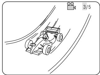
Use the and cursor buttons to select the desired angle.
- The display turns off when the ANGLE button is pressed.

Remote control unit
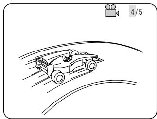
NOTES:
- The multiple angle function only works with discs on which multiple angles are recorded.
- At scenes where multiple angles are recorded, the angle can be switched.
(9) Using the Menus
[1] Using the Top Menu
For DVDs containing multiple titles, the desired title can be selected and played from the top menu.
![DENON D-M51DVS - [1] Using the Top Menu - 1](/content/2025/01/135504/images/d7dac7c65255d3e7044de9c031de320eccedd45d7f470b608256596589c8e4ca.jpg)
1 During playback, press the TOP MENU button.
- The top menu appears.
![DENON D-M51DVS - [1] Using the Top Menu - 2](/content/2025/01/135504/images/fd097675fba8e9805d21db9ab4f04f60c55530515b2b19deb282b56902b23255.jpg)
Remote control unit
Example:
| TOP MENU | |
| Apple | Banana |
| Orange | Strawberry |
| Peach | Pineapple |
Use the cursor or number buttons to select the desired title.
- If you select the title number using the number buttons, skip step 3 below.
![DENON D-M51DVS - [1] Using the Top Menu - 3](/content/2025/01/135504/images/680bec0bd49c1a64c75ed79869748ae7e0828774da1b0ad07c382a07f68071cd.jpg)
Remote control unit
1 2 3
④ ⑤ ⑥
⑦ ⑧ ⑨
![DENON D-M51DVS - [1] Using the Top Menu - 4](/content/2025/01/135504/images/3d7d8fe265f8e98209324107910ba270701ac1c09e640853f6c5e49d55a48fd6.jpg)
Remote control unit
Example:
When "Orange" is selected
TOP MENU
Apple
Banana
Orange
Strawberry
Peach
Pineapple
Press the ENTER button.
- Playback starts.
- Playback also starts if the PLAY (▶) button is pressed.

Remote control unit
[2] Using the DVD Menu
Some DVDs include special menus called DVD menus.
For example, DVDs with complex contents may contain guide menus, and DVDs with multiple languages may contain audio and subtitle language menus.
These menus are called "DVD menus".
Here we describe the general procedure for using DVD menus.
![DENON D-M51DVS - [2] Using the DVD Menu - 1](/content/2025/01/135504/images/34d55ed6cc00185561d67fcab57de8f6160071a900e432c89bb5522077e5b6cd.jpg)
1 During playback, press the MENU button.
- The DVD menu appears.
Example:

Remote control unit
DVD MENU
- SUB TITLE
2.AUDIO - ANGLE
Use the cursor or number buttons to select the desired item.
- If you select the item using the number buttons, skip step 3 below.
Remote control unit
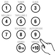
Remote control unit
Example:
"AUDIO" is selected
DVD MENU
- SUB TITLE
2.AUDIO
3.ANGLE
3 Press the ENTER button.
- The selected item is set.
If more menus appear, repeat steps 2 and 3.

Remote control unit
(10) Playing in the zoom mode
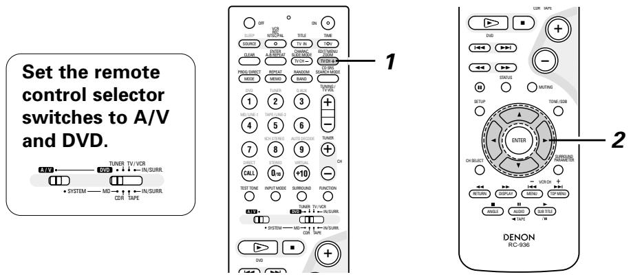
1 In the play or pause mode, press the ZOOM button.
- The zoom rate increases each time the ZOOM button is pressed.
For DVD video discs and video CDs:
OFF x1.5 x2 x4 OFF

Remote control unit
2 Use the cursor buttons (, , and ) to move the zoomed picture.
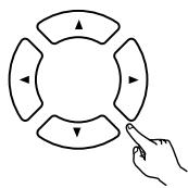
Remote control unit
NOTES:
- Zooming is not possible with some discs.
- The zoom function may not work properly at some scenes.
- Zooming is not possible at the top menu or the menu screen.
18 USING THE TIMER
Timer and system operations are possible once the setup procedure has been completed.
(1) Setting the clock (12-hour display)
Example: Setting the current time to "7:30 p.m."
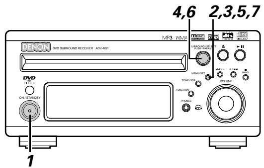
1 Turn on the power.
Main unit
Press the MENU/SET button to display "Time".

Main unit
- If the time has not yet been set or if there has been a power shortage, the time display flashes.
- If the time has been set, the current time is displayed.
Press the MENU/SET button and hold it in for over 2 seconds.
The hours position flashes.
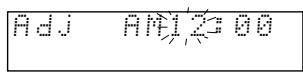

Main unit
1 Turn the SURROUND/SELECT knob to set the hours.
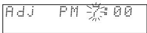
Main unit
Before setting the timer
■ Be sure to set the current time. If the current time is not set, the timer standby indicator does not light and the timer will not function.
■ Be sure to preset the broadcast station before setting the timer. (See page 60.).
Everyday timer: The power is switched on and off (standby) once at the same time each day.
Once timer: The power is switched on and off (standby) at the specified time once only.
Sleep timer: The power can be set to turn off in 120 minutes, 90 minutes, or between 60 and 10 minutes in 10 minute steps.
If the times set for the everyday timer, once timer and sleep timer overlap, the sleep timer has priority. The once time has priority if the everyday timer and once timer times overlap.
It is not possible to set the timer start and stop times to the same time.
Press the MENU/SET button.
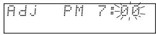
Main unit
6 Turn the SURROUND/SELECT knob to move to the minutes position.
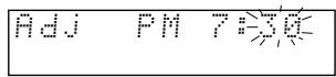

Main unit
Press the MENU/SET button at the sound of a time signal, etc.
- The "30" in the minutes place stops flashing and the current time is displayed.
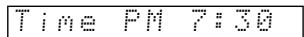
Main unit
※ To check the current time when the regular display is displayed, press the MENU/SET button once. The current time remains displayed until some other operation is performed.
The time can be displayed by pressing the MENU/SET button when the power is in the standby mode. (When this is done, the set is no longer in the low power consumption standby mode.) When pressed twice while the time is displayed, the display turns off and the set is put back in the low power consumption standby mode.
The current time can also be set when the power is in the standby mode by pressing the MENU/SET button to display the time then performing steps 3 to 7.
The clock runs by synchronizing with the power supply frequency. The time may be off by 2 to 3 minutes per month. If so, reset the time.
(2) Setting the everyday timer and once timer
■ Be sure to set the current time before setting the timer. (See page 81.)
Use the everyday timer to switch the power on and off (standby) once at the same time each day.
Use the once timer to switch the power on and off (standby) at the specified time once only.
■ With the ADV-M51 it is possible to play the tuner, a DVD or a CD with the timer.
It is possible to play a DVD, CD, tape, the tuner, MD or the device connected to the AUX terminals with the timer and to record the tuner or the device connected to the AUX terminals onto an MD recorder or cassette deck using the timer.
※ Timer playback is not possible for some DVDs. (Most DVDs stop at the menu screen.)
Example 1: Listening to preset station "3" (FM 92.5 MHz) from p.m.12:35 to p.m.12:56 with the everyday timer
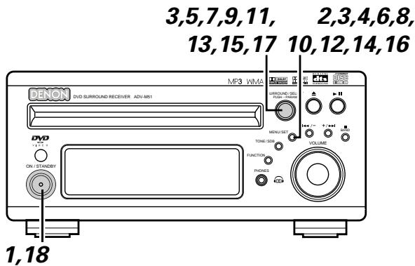
1 Turn on the power.
Main unit
Press the MENU/SET button to display "TIMER".
Main unit
3 Turn the SURROUND/SELECT knob to display "EVERYDAY", then press the MENU/SET button.
- The display switches as follows each time the SURROUND/SELECT knob is turned:

The display switches as follows each time the SURROUND/SELECT knob is turned:
ONCE EVERYDAY
Main unit
Main unit
Press the MENU/SET button.

Main unit
5 Turn the SURROUND/SELECT knob and set the function to "TUNER".
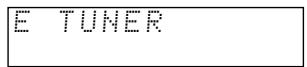
Main unit
※ The function switches as shown below each time the surround button is pressed.
Functions marked ** differ according to whether "LINE1" or "LINE-2" is set.
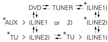
:Clockwise turn
:Counterclockwise turn
6 Press the MENU/SET button.
Main unit
7 Turn the SURROUND/SELECT knob and select preset number "P03".
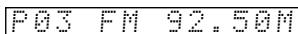

SURROUND/SELECT PUSH-PARAM
Main unit
Press the MENU/SET button.
- The data for the selected station is stored in the memory and the unit is set to the timer start time setting mode.
- "E" and "on" are displayed.
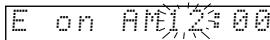

Main unit
0
Turn the SURROUND/SELECT knob to set the hours place to "PM12".
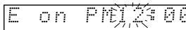
SURROUND/SELECT
Main unit
10 Press the MENU/SET button.
- The "PM12" in the hours place is stored in the memory.
E on PM12:10
Main unit
11 Turn the SURROUND/SELECT knob and set the minutes place to "35".
E on PM12
Main unit
12 Press the MENU/SET button.
- The start time is stored in the memory and the unit is set to the timer stop time setting mode.
- "E" and "off" light.
EoffA

Main unit
12
Turn the SURROUND/SELECT knob to set the hours place to "PM12".
E
Main unit
14 Press the MENU/SET button.
- The "PM12" in the hours place is stored in the memory.
E of fPm12
Main unit
15 Turn the SURROUND/SELECT knob and set the minutes place to "56".
E offPM12#
Main unit
16 Press the MENU/SET button.
- The stop time is stored in the memory.
Main unit
17 Turn the SURROUND/SELECT knob to display "Eon".
- The everyday timer is turned on and the timer standby indicator lights. This completes the setting of the timer.
For more details, see "Turning the everyday timer and once timer on and off" on page 82.
Main unit
1 off/E on
18 Turn off the power.
- The standby mode is set.
(The power indicator turns orange.)
- When the timer start time is reached, the timer operates.
Main unit
※ If you make a mistake when setting the timer.
- Press the stop button at any point between steps 4 and 15. (The display returns to as it was in step 3.)
- Press the MENU/SET button repeatedly to display the item you want to correct, then correct the item.
- After correcting the item, press the MENU/SET button again repeatedly to proceed to step 18 and complete the setting of the timer.
NOTE:
- The timer standby indicator does not light if the current time has not been set. Set the current time before setting the timer. (See page 81.)
Example 2: Listening to a CD with the once timer
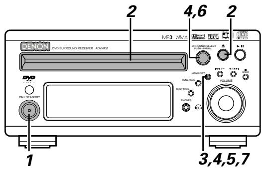
1 Turn on the power.

Main unit
2 Open the disc holder, load the CD, then close the disc holder.

Main unit
Press the MENU/SET button to display "TIMER".
TIME

Main unit
4 Turn the SURROUND/SELECT knob to display "ONCE", then press the MENU/SET button.

The display switches as follows each time the SURROUND/SELECT knob is turned:
ONCE EVERYDAY
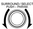
Main unit
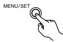
Main unit
Press the MENU/SET button.
- The once timer time setting mode is set.
- "1" (once) lights.
Main unit
6 Turn the SURROUND/SELECT knob and set the function to "DVD".
Main unit
7 Press the MENU/SET button.
- Timer function, "DVD", is stored in the memory.

Main unit
Now follow steps 9 to 18 under "Setting the everyday timer and once timer" (pages 82 and 83).
- "1" and "on" light when setting the start time. "1" and "off" light when setting the stop time.
- Turn the once timer on at step 17.
■ Timer playback and recording can be performed when system connections are made between the ADV-M51 and the D-M31 series cassette deck (DRR-M31). (Both the everyday and once timer can be used.)
- Timer playback of the cassette deck (when TAPE is set for LINE-2)
- Timer playback of the device connected to the AUX input terminals (when AUX is set for LINE-1 or LINE-2)
- Timer recording of radio programs from the ADV-M51 onto the cassette deck (when TAPE is set for LINE-1)
- Timer recording from the device connected to the AUX input terminals onto the cassette deck (when AUX is set for LINE-1 and TAPE is set for LINE-2)
Timer recording onto the device connected to the AUX input terminals is not possible. The timer function changes automatically according to the function set for LINE-1 and LINE-2.
NOTE:
- For timer recording and playback using the device connected to the AUX input terminals, note that the ADV-M51 cannot control the power of the device or playback operations on it. Make the settings accordingly.
(3) Turning the everyday timer and once timer on and off
- After the timer has been set using the procedure described under "(2) Setting the everyday timer and once timer" (pages 82 to 83), turn the everyday timer and/or once timer on so that the set operations will be performed.
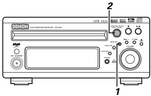
1 Press the MENU/SET button to set the timer standby setting mode.
- The current settings are displayed.
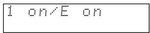
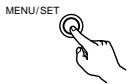
Main unit
2 Turn the SURROUND/SELECT knob and select the timer to be operated.
- The display switches as follows each time the SURROUND/SELECT knob is turned:

Main unit
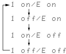
Both the once timer and everyday timer are activated.
Only the everyday timer is activated.
Only the once timer is activated.
Neither the once timer nor the everyday timer are activated.
- When either the once or everyday timer is activated, the timer standby indicator lights. The display returns to normal about 4 seconds after the timer standby indicator is displayed.
※ The timer operation is performed when the SURROUND/SELECT knob has been turned and the timer standby indicator has been lit.
※ If you do not want the timer to operate, turn the SURROUND/SELECT knob to turn the timer standby indicator off.

Main unit
- If only the once timer is set, the setting changes as shown below each time the SURROUND/SELECT knob is turned.
$$ \text {i o n / E o f f} \leftrightarrow \text {i o f f / E o f f} $$
Main unit
- If only the everyday timer is set, the setting changes as follows:
$$ 1 o f f / E \text {o n} \leftrightarrow 1 o f f / E \text {o f f} $$
NOTES:
- The timer standby indicator does not light if the current time has not been set. Set the current time before setting the timer. (See page 81.)
- If the times set for the everyday timer and once timer overlap, the once time has priority.
- Be sure to set the power to the standby mode when you want the timer to operate.
(4) Everyday timer and once timer priority
- If the times set for the everyday timer and once timer overlap, the once time has priority.
(5) About the everyday timer and once timer
Checking the timer settings
- Use the same procedure as when setting the timer to check the timer settings.
① Press the MENU/SET button to display "TIMER".
② Turn the SURROUND/SELECT knob to display "EVERYDAY" or "ONCE".
③ The display switches between the set function, start time, stop time and timer standby indicator each time the MENU/SET button is pressed.
The display returns to as it was before the everyday timer or once timer was set about 4 seconds after the timer standby indicator is displayed.
Changing the timer settings
- Reset the timer from the start using the desired settings.
The new settings overwrite the previous settings. - To change a setting during the process of setting the timer, press the stop button (■) to return to the "EVERYDAY" or "ONCE" display, then redo the operation from there.
Clearing the timer settings
① Press the MENU/SET button to display "TIMER".
② Turn the SURROUND/SELECT knob to display "EVERYDAY" or "ONCE" (the timer whose settings you want to clear).
③ While "EVERYDAY" or "ONCE" is displayed, press the stop button (■) and hold it in for at least 2 seconds. Those timer settings are cleared.
Quitting the timer setting (turning the operation of the timer off)
- Operate as described under "(3) Turning the everyday timer and once timer on and off" (page 85) and change the setting to the mode in which neither the once timer nor the everyday timer are activated ("1off/Eoff").
If there is a power failure)
- If there is a power failure or the power cord is unplugged from the power outlet, the time display flashes when the power comes back on. Reset the current time.
- The once timer settings are deleted. Remake the settings.
- If the everyday timer settings and the tuner presettings have been deleted, reset them.
(6) Setting the sleep timer (remote control unit only)
- The included remote control unit can be used to turn the power to the standby mode after a maximum of 120 minutes. (Sleep timer)
- Use this function to automatically switch the power to the standby mode after a specific amount of time (minutes).
Example: To set the power to the standby mode in 50 minutes according to the clock. Be sure to correct the current time setting.
Set the remote control selector switches to A/V and IN/SURR..
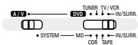
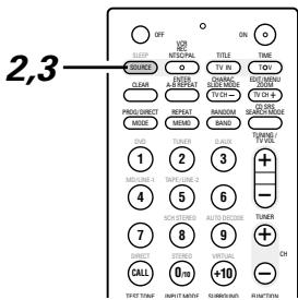
1 Select and play the desired function.
Press the SLEEP button.
- "120" is displayed and the "SLEEP" indicator flashes.
120


Remote control unit
The display switches as follows each time the SLEEP button is pressed:
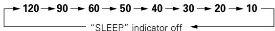
3 When the "SLEEP" indicator is flashing, press the SLEEP button again until "50" is displayed.
- "50" is displayed and the "SLEEP" indicator flashes.
58


Remote control unit
- After 4 seconds, the display returns to as it was before the sleep timer was set, and the "SLEEP" indicator stops flashing, remaining lit. (This completes the sleep timer setting.)
4 The power is set to the standby mode 50 minutes later.
To turn the sleep timer off, press the SLEEP button repeatedly until the "SLEEP" indicator turns off. The sleep timer can also be turned off by press the power button on the main unit or the remote control unit to turn the entire system's power to the standby mode.

Remote control unit
Main unit

Remote control unit
NOTES:
- If the SLEEP button is pressed while the sleep timer is operating, the setting returns to 120 minutes. Make the setting over.
- If the sleep timer and everyday timer settings overlap, the sleep timer has priority.
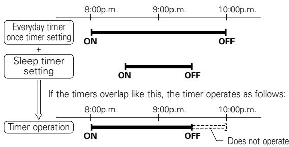
- Also, the everyday timer will not operate if its start time is set within the time during which the sleep timer is operating.
- The remaining time of the sleep timer can be checked with the STATUS button.
19 CHANGING THE DEFAULT SETTINGS (DVD)
The initial setting that was set prior to shipping from the factory can be changed. The setting contents are maintained until they are next changed even when the power is switched off.
1 In the stop mode, press the SETUP button. At the Setup Menu, use the and cursor buttons to select "DVD SETUP" and press the ENTER button.

Remote control unit
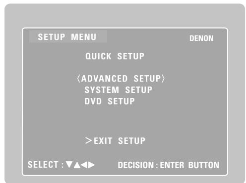
The setup (default settings) screen "DVD SETUP MENU" appears.
DISC SETUP
Use this to set the language to be used when playing the disc.
If the set language is not offered on that disc, the discs default language is set.
- OSD SETUP
Use this to set the wall paper color.
VIDEO SETUP
Use this to set this unit screen mode. (TV aspect and TV type.)
AUDIO SETUP
Use this to set this unit audio output mode. (Digital and LPCM output settings.)
RATINGS
Use this to disable playback of adult DVDs so that children cannot watch them. Note that playback of adult DVDs cannot be disabled if the rating level is not recorded on the DVD, but that it is possible to disable playback of all DVDs.
OTHER SETUP
Closed captions (subtitles) and the time interval for playing still pictures can be set.
Use the and cursor buttons to select the desired setting item, then press the ENTER button.
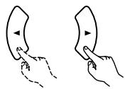

Remote control unit
Remote control unit
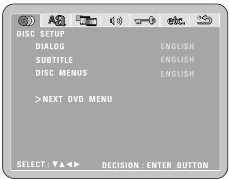
※ To exit the DVD setup mode
Use the and cursor buttons to select "EXIT SETUP", then press the ENTER button. It is also possible to quit by pressing the SETUP button on the remote control unit.
(1) "DISC SETUP" is selected
1
2
See page 88.
3
Use the and cursor buttons to select the "DISC SETUP", then press the ENTER button.
- DIALOG
Use this to set the language of the sound output from the speakers.
- SUBTITLE
Use this to set the language of the subtitles displayed on the TV.
- DISC MENUS
Use this to set the language of the menus recorded on the disc (top menu, etc.).
※ To exit the disc setup mode
Use the and cursor buttons to select " > NEXT DVD MENU", then press the ENTER button.


Remote control unit

Remote control unit
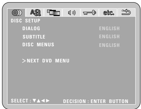
4
Use the and cursor buttons to select the desired setting, then press the ENTER button.
When "DIALOG" is selected:
- ENGLISH (Factory default)
Select this when you want to play the DVD with the sound in English.
FRENCH
Select this when you want to play the DVD with the sound in French.
SPANISH
Select this when you want to play the DVD with the sound in Spanish.
GERMAN
Select this when you want to play the DVD with the sound in German.
JAPANESE
Select this when you want to play the DVD with the sound in Japanese.
OTHERS
The sound is played in the language input with the number buttons. (See the table of language numbers on page 91.)
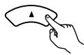


Remote control unit

Remote control unit
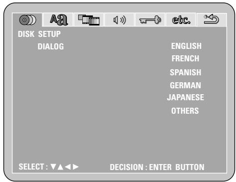
4
※ To exit the dialog mode
Press the ENTER button, you can go back to the previous screen.
When "SUBTITLE" is selected:
- OFF (Factory default)
Select this if you do not want to display the subtitles. (For some discs it is not possible to turn off the subtitle display.)
- ENGLISH
Select this when you want to play the DVD with the subtitles in English.
FRENCH
Select this when you want to play the DVD with the subtitles in French.
SPANISH
Select this when you want to play the DVD with the subtitles in Spanish.
GERMAN
Select this when you want to play the DVD with the subtitles in German.
JAPANESE
Select this when you want to play the DVD with the subtitles in Japanese.
OTHERS
Subtitles are played in the language input with the number buttons. (See the table of language numbers on page 91.)
※ To exit the subtitle mode
Press the ENTER button, you can go back to the previous screen.
When "DISC MENUS" is selected:
- ENGLISH (Factory default)
Select this when you want to display the menus in English.
FRENCH
Select this when you want to display the menus in French.
SPANISH
Select this when you want to display the menus in Spanish.
GERMAN
Select this when you want to display the menus in German.
JAPANESE
Select this when you want to display the menus in Japanese.
OTHERS
The menu screen is played in the language input with the number buttons.
(See the table of language numbers on page 91.)
※ To exit the disc menus mode
Press the ENTER button, you can go back to the previous screen.


Remote control unit

Remote control unit
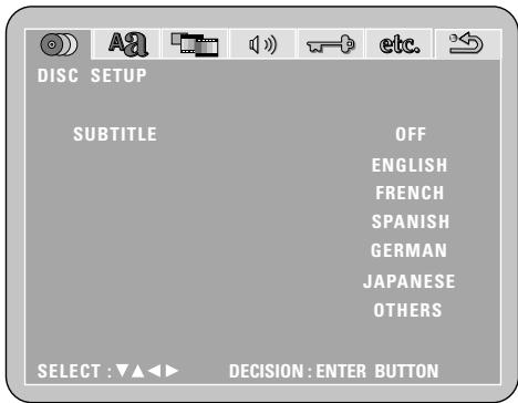


Remote control unit

Remote control unit
Language code list
| Code | Language | Code | Language | Code | Language | Code | Language |
| 6565 | Afar | 7079 | Faroese | 7678 | Lingala | 8375 | Slovak |
| 6566 | Abkhazian | 7082 | French | 7679 | Laothian | 8376 | Slovenian |
| 6570 | Afrikaans | 7089 | Frisian | 7684 | Lithuanian | 8377 | Samoan |
| 6577 | Ameharic | 7165 | Irish, Scots | 7686 | Latvian, Lettish | 8378 | Shona |
| 6582 | Arabic | 7168 | Gaelic | 7771 | Malagasy | 8379 | Somali |
| 6583 | Assamese | 7176 | Galician | 7773 | Maori | 8381 | Albanian |
| 6588 | Aymara | 7178 | Guarani | 7775 | Macedonish | 8382 | Serbian |
| 6590 | Azerbaijan | 7185 | Gujarati | 7776 | Malayalam | 8385 | Sundanese |
| 6665 | Bashkir | 7265 | Hausa | 7778 | Mongolian | 8386 | Swedish |
| 6669 | Byelorussian | 7273 | Hindi | 7779 | Moldavian | 8387 | Swahili |
| 6671 | Bulgarian | 7282 | Croatian | 7782 | Marathi | 8465 | Tamil |
| 6672 | Bihari | 7285 | Hungarian | 7783 | Malay | 8469 | Telugu |
| 6678 | Bengali; Bangla | 7289 | Armenian | 7784 | Maltese | 8471 | Tajik |
| 6679 | Tibetan | 7365 | Interlingua | 7789 | Burmese | 8472 | Thai |
| 6682 | Breton | 7378 | Indonesian | 7865 | Nauru | 8473 | Tigrinya |
| 6765 | Catalan | 7383 | Icelandic | 7869 | Nepali | 8475 | Turkmen |
| 6779 | Corsican | 7384 | Italian | 7876 | Dutch | 8476 | Tagalog |
| 6783 | Czech | 7387 | Hebrew | 7879 | Norwegian | 8479 | Tonga |
| 6789 | Welsh | 7465 | Japanese | 7982 | Oriya | 8482 | Turkish |
| 6865 | Danish | 7473 | Yiddish | 8065 | Panjabi | 8484 | Tatar |
| 6869 | German | 7487 | Javanese | 8076 | Polish | 8487 | Twi |
| 6890 | Bhutani | 7565 | Georgian | 8083 | Pashto, Pushto | 8575 | Ukrainian |
| 6976 | Greek | 7575 | Kazakh | 8084 | Portuguese | 8582 | Urdu |
| 6978 | English | 7576 | Greenlandic | 8185 | Quechua | 8590 | Uzbek |
| 6979 | Esperanto | 7577 | Cambodian | 8277 | Rhaeto-Romance | 8673 | Vietnamese |
| 6983 | Spanish | 7578 | Kannada | 8279 | Romanian | 8679 | Volapük |
| 6984 | Estonian | 7579 | Korean | 8285 | Russian | 8779 | Wolof |
| 6985 | Basque | 7583 | Kashmiri | 8365 | Sanskrit | 8872 | Xhosa |
| 7065 | Persian | 7585 | Kurdish | 8368 | Sindhi | 8979 | Yoruba |
| 7073 | Finnish | 7589 | Kirghiz | 8372 | Serbo-Croatian | 9072 | Chinese |
| 7074 | Fiji | 7665 | Latin | 8373 | Singhalese | 9085 | Zulu |
(2) When "OSD SETUP" is selected
1 If you are not at the DVD setting screen, read steps 1 and 2 on page 88.
3 Use the and cursor buttons to select the "OSD SETUP" tag icon, then press the ENTER button.
WALL PAPER
The image displayed when in the stop mode or when playing a CD can be selected.
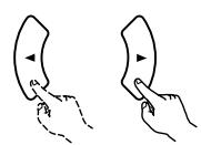

Remote control unit
Remote control unit
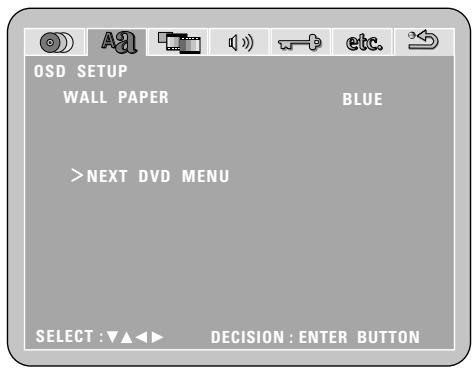
Use the and cursor buttons to select the setting to be set, then press the ENTER button.
■ When "WALL PAPER" has been selected
- Use the and cursor buttons to select the wallpaper.
- BLUE (Factory default)
The wallpaper is set to blue.
- GRAY
The wallpaper is set to gray.
BLACK
The wallpaper is set to black.
- PICTURE
The wallpaper is set to a picture.
※ To complete the "WALL PAPER" setting
Press the ENTER button.
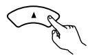


Remote control unit

Remote control unit
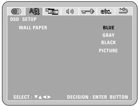
(3) "VIDEO SETUP" is selected
1
2
See page 88.
3
Use the and cursor buttons to select the "VIDEO SETUP", then press the ENTER button.
- TV ASPECT
Use this to set the shape of your TV's screen.
- TV TYPE
Use this to set your TV's video format (NTSC, PAL or MULTI).
VIDEO MODE
Use this to select the video mode. (AUTO, FILM, VIDEO)
- BLACK LEVEL
The picture's black level can be set to "lighter" or "darker".
※ To exit the video setup mode
Use the and cursor buttons to select > > NEXT DVD MENU", then press the ENTER button.


Remote control unit

Remote control unit
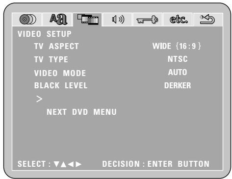
4
Use the and cursor buttons to select the desired setting, then press the ENTER button.
When "TV ASPECT" is selected:
4:3 PS (Factory default)
Select this to play wide DVDs in the pan & scan mode (with the sides of the picture cut off). Discs for which pan & scan is not specified are played in the letter box mode.
4:3LB
Select this to play wide DVDs in the letter box mode (with black strips at the top and bottom).
WIDE (16:9)
Select this to play wide DVDs in the full-screen mode.
※ To exit the TV aspect mode
Press the ENTER button, you can go back to the previous screen.


Remote control unit

Remote control unit
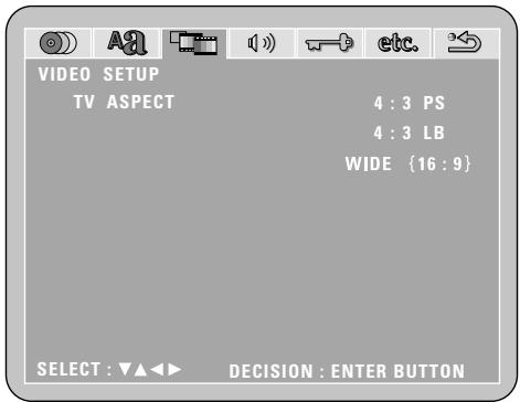

When "TV TYPE" is selected:
- NTSC (Factory default)
Select this when your TV's video format is NTSC. If NTSC is selected, output format is fixed to NTSC.
PAL
Select this when your TV's video format is PAL. If PAL is selected, output format is fixed to PAL.
MULTI
Select this when your TV is compatible with both the NTSC and PAL formats.
NTSC signals are output from the video output jacks when discs recorded in NTSC format are played, and PAL signals are output from the video output jacks when discs recorded in PAL format are played.
※ To exit the TV type mode
Press the ENTER button, you can go back to the previous screen.
■ When "VIDEO MODE" has been selected (see the note below)
- Use the and cursor buttons to select the video mode to be set.
- AUTO (Factory default)
The mode is selected by identifying the type of material (film or video flag) from the disc.
FILM
This setting is suited for playing film material discs or video material discs recorded with progressive scanning.
VIDEO
This setting is suited for playing video material discs.
※ To complete the "VIDEO MODE" setting
Press the ENTER button.
■ When "BLACK LEVEL" has been selected
- Use the and cursor buttons to select the black level.
DARKER
This sets the black level of the output signals to the standard level.
- LIGHTER (Factory default)
This raises the standard level for the black level. Set this if the picture displayed on the TV is extremely dark.
※ To complete the "BLACK LEVEL" setting
Press the ENTER button.


Remote control unit

Remote control unit
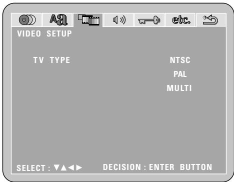


Remote control unit

Remote control unit
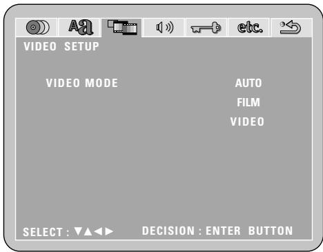


Remote control unit

Remote control unit
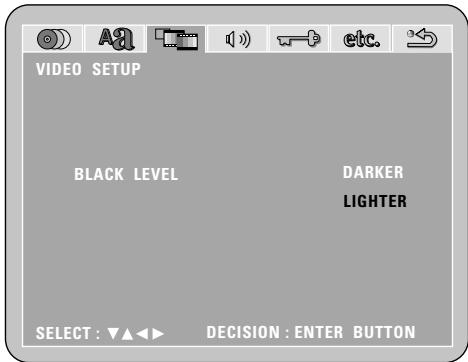
NOTE:
- For the component output only, it is possible to switch between interlace image output and progressive image output. It is not possible to specify progressive image output for the Video output connectors or S-Video output connector.
Note on when "VIDEO MODE" is selected
- Some discs may not be identified properly (for example discs including both film and video materials). For such discs, try changing the video mode setting.
- When certain DVD video discs are played, noise in the form of stripes may appear or the picture may be blurred. In such cases, try changing the video mode setting.
(4) "AUDIO SETUP" is selected
1
2
See page 88.
3
Use the and cursor buttons to select the "AUDIO SETUP", then press the ENTER button.
DIGITAL OUT
Use this to select the digital output's signal format.
LPCM (44.1 kHz / 48 kHz)
Use this to set the digital audio output when playing DVDs recorded in linear PCM audio.
※ To exit the audio setup mode
Use the and cursor buttons to select > > NEXT DVD MENU", then press the ENTER button.
- The screen returns to as it was in step 2.

Remote control unit
Remote control unit
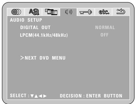
4
Use the and cursor buttons to select the desired setting, then press the ENTER button.
■ When "DIGITAL OUT" is selected.
- NORMAL (Factory default)
Make the selection when playing back in surround playback a DVD that has been recorded with Dolby Digital or DTS on this unit.
The Dolby Digital or DTS digital signal is also output from the digital output jacks.
- PCM
DVDs that were recorded in Dolby Digital DTS are converted to linear PCM 48 kHz/16 bit (2 channels). Make the selection when making a digital recording.
※ To exit the digital out mode
Press the ENTER button, you can go back to the previous screen.


Remote control unit

Remote control unit
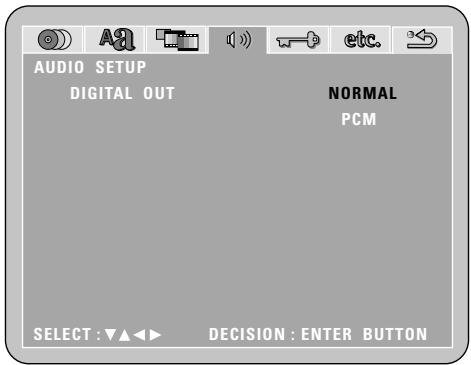
4 "LPCM SELECT (96kHz 48kHz) is selected. OFF (Factory default)
Make the selection when playing back to a decoder DVDs that were recorded with this unit using linear PCM 48 kHz/20/24 bit and 96 kHz modes. Note that DVDs with Copyright Protection are converted to 48 kHz/16 bits and played back.
The same signal is output from the digital output jacks.
ON
DVDs that were recorded with linear PCM 48 kHz/20/24 bit and 96 kHz modes are all converted to 48 kHz/16 bits. Make this selection at the time of digital recording.
※ To exit the LPCM select mode
Press the ENTER button, you can go back to the previous screen.

Remote control unit
Remote control unit
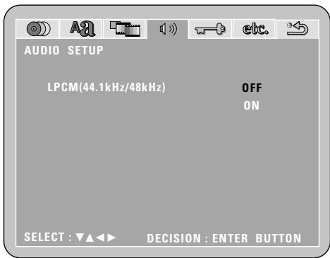
NOTES:
- When playing Dolby Digital/DTS surround DVDs or 96 kHz linear PCM DVDs on the ADV-M51, be sure to set "Digital Output" to "Normal" and "LPCM Conversion Mode" to "Do Not Convert".
- When and only when you want to output the signals of the Dolby Digital/DTS surround DVD being played on the ADV-M51 to a digital PCM device, set "Digital Output" to "PCM Conversion".
With this setting, DVDs cannot be played on the ADV-M51 in the Dolby Digital/DTS surround mode. (The surround mode is set to the mode in which PCM 2-channel signals can be played.)
- When and only when you want to make a digital recording of the signals of a 48 kHz/20-bit/24-bit or 96 kHz linear PCM DVD being played on the ADV-M51 onto a digital recorder, set the "LPCM Conversion" to "Convert".
With this setting it is not possible to decode and play 48 kHz/20-bit/24-bit or 96 kHz linear PCM signals on the ADV-M51 during recording.
(Decoding and playback is in 48 kHz/16-bit linear PCM format.)
(5) "RATINGS" is selected
1
See page 88.
2
3 Use the and cursor buttons to select the "RATINGS", then press the ENTER button.
RATING LEVEL
Use this to restrict playback of adult DVDs you do not want children to view. Note that even with adult DVDs, viewing cannot be restricted unless the restriction level is recorded on the disc. It is however possible to disable playback of all DVDs.
- PASSWORD
Use this to change the password. The set's password is set to "0000" by default.
※ To exit the rating setup mode
Use the and cursor buttons to select > > NEXT DVD MENU", then press the ENTER button.

Remote control unit

Remote control unit
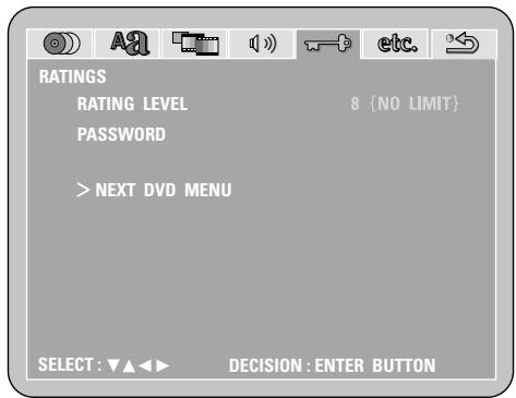
Use the and cursor buttons to select the desired setting, then press the ENTER button.
■ When "RATING LEVEL" is selected.
- Level 0 (LOCK ALL)
Select this to disable playback of all DVDs.
Use this for example to disable playback of adult DVDs on which the rating level is not recorded.
- Level 1
Select this to play only DVDs for children. (Adult and general audience DVDs cannot be played.)
- Level 2 to Level 7
Select this to play DVDs for general audiences and children. Adult DVDs cannot be played.
- NO LIMIT (Factory default)
Select this to play all DVDs.


Remote control unit

Remote control unit
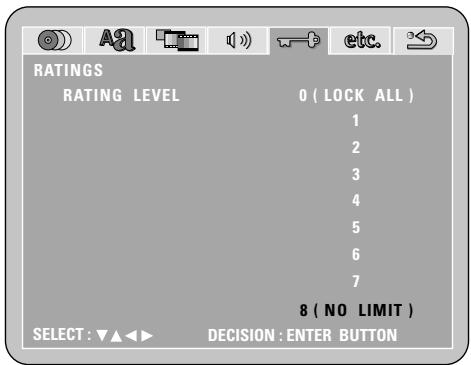

Use the number buttons to input a 4-digit password, then press the ENTER button.
※ Be sure to set the DVD mode using the remote control mode selector buttons.
※ The set's password is set to "0000" by default.
※ Do not forget the password.
※ The setting cannot be changed without inputting the correct password.
※ When the password has been forgotten or when a RATING LEVEL setting change is suspended, press the ENTER button several times and terminate the rating setup mode.
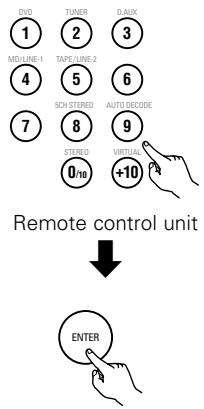
Remote control unit
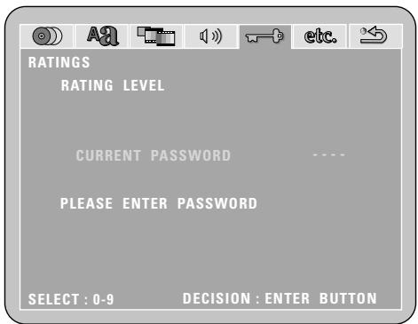
When "password CHANGE" is selected.
Use the number buttons to input a 4-digit password, then press the ENTER button.
※ Be sure to set the DVD mode using the remote control mode selector buttons.
※ Do not forget the password.
※ The setting cannot be changed without inputting the correct password.
※ The set's password is set to "0000" by default.
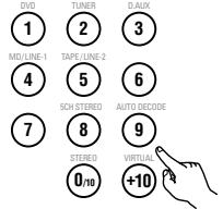
Remote control unit
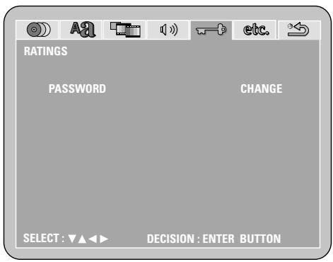
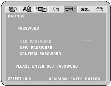
(6) "OTHER SETUP" is selected
NOTES:
- An English caption decoder is required to display English captions.
- DVDs with caption signals are indicated by the , , , mark.
English captions cannot be displayed when playing DVDs which do not contain caption signals.
- The characters in which the captions are displayed (capital letters, small letters, italics, etc.) depend on the DVD and cannot be selected with this unit.
1
2
See page 88.
3
Use the and cursor buttons to select the "OTHER SETUP", then press the ENTER button.
- CAPTIONS
Set whether or not to display the closed captions (subtitles) recorded on the DVD. (A caption decoder (commercially available) is required to display captions.)
- SLIDE SHOW
Set the time interval for switching to the next still image (in JPEG format) when playing slides.
※ To exit the other setup mode
Use the and cursor buttons to select > > NEXT DVD MENU", then press the ENTER button.
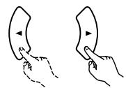

Remote control unit

Remote control unit
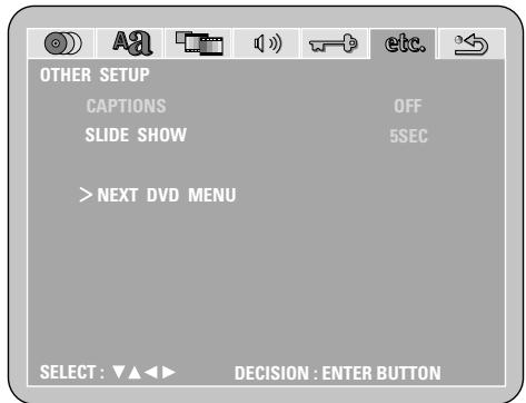
4
Use the and cursor buttons to select the desired setting, then press the ENTER button.
When "CAPTIONS" is selected:
- OFF (Factory default)
Select this when you do not want to display the captions on the screen when playing DVDs containing English captions.
ON
Select this to display the captions on the screen when playing DVDs containing English captions.
※ To exit the captions mode
Press the ENTER button, you can go back to the previous screen.


Remote control unit

Remote control unit
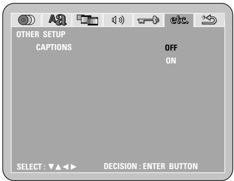
When "SLIDE SHOW" has been selected
-
Use the and cursor buttons to set the time.
-
The interval can be set from 5 to 15 seconds in steps of 1 second.
(Factory default: 5 seconds)

Remote control unit

Remote control unit
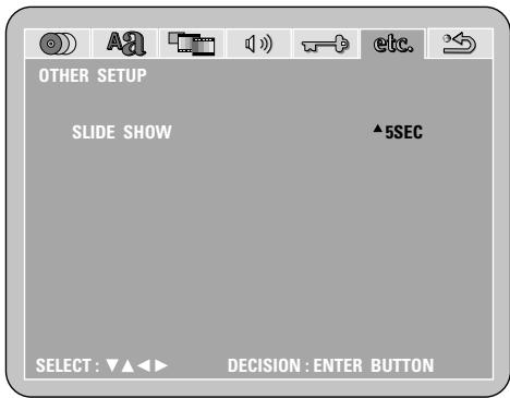

SYSTEM FUNCTIONS
■ Making system connections between the ADV-M51 and the D-M31 series cassette deck (DRR-M31) makes operation even easier. (For instructions on connections, refer to "Connecting to D-M31 Series System Components" on pages 10 to 11.)
System functions will not work properly if the input/output function settings are not right for the connected components. Be sure to set the input/output functions for the components being used. (See page 38.) The setting contents are maintained until they are next changed even when the power is switched off.
(1) Auto power on function
- When the play/pause button on the main unit (▶/■) or the DVD play button on the remote control unit (▶) is pressed while the power is in the standby mode, the ADV-M51's power turns on automatically, and if a disc is loaded in the ADV-M51 the disc is played.
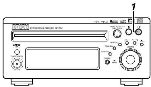
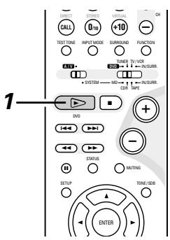
When the ADV-M51 is in the standby mode, the power can be turned on simply by pressing the play/pause button on the main unit or the DVD play button on the remote control unit. If a disc is loaded, playback starts.

Main unit

Remote control unit
※ The auto power on function also turns the power on when the disc holder is opened while the ADV-M51 is in the standby mode.
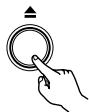
Main unit
- To listen to a radio program, simply press one of the tuner preset buttons (" + ") or - on the remote control unit. The power turns on and a station is tuned in.

Remote control unit
- The power on function works in the same way when system connections are made with the D-M31 series cassette deck (DRRM31). For details, refer to the respective component's operating instructions.
(2) Auto function selection
- At the touch of a button, the function switches automatically to "DVD" and disc playback begins.
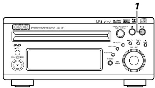
Press the play/pause button on the ADV-M51 or the DVD play button on the remote control unit while a component than the DRR-M31 (cassette deck) is playing.
- Playback on the other component stops, the ADV-M51's function switches to "DVD" and if a disc is loaded playback of the disc starts.
Main unit
Remote control unit
- To listen to a radio program, simply press one of the tuner preset buttons (" + ") or " - " on the remote control unit.
- Auto function selection works in the same way when system connections are made with the D-M31 series cassette deck (DRRM31). For details, refer to the respective component's operating instructions.
- Auto function selection does not work for components connected using the AUX or D.AUX input/output terminals.
Remote control unit
(3) CD TAPE recording (when the ADV-M51 and DRR-M31 are connected with a system cord)
- CDs can easily be recorded onto cassette tapes.
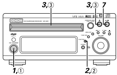
Main unit (ADV-M51)
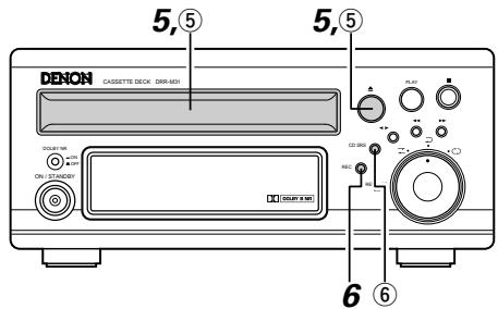
Cassette deck (DRR-M31)
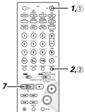
[1] Synchronized recording function
1 Turn on the ADV-M51's power.
The system's
power turns on.
![DENON D-M51DVS - [1] Synchronized recording function - 1](/content/2025/01/135504/images/ea4bd5ca00c7956c09e7827d77cf7c5e37c549171229a6154bacab9b58bf01e3.jpg)
ON/STANDBY
ADV-M51
![DENON D-M51DVS - [1] Synchronized recording function - 2](/content/2025/01/135504/images/866dba6d4f8632b0681e33b79c9ddb21ad6ddf8ec57dfd5a10e73bdb136a0e23.jpg)
Remote control unit
Press the FUNCTION button and switch the function to "DVD".
![DENON D-M51DVS - [1] Synchronized recording function - 3](/content/2025/01/135504/images/7e5fc1d649b13ae1cf77e8d06c9d88f6a2dca8769199d4f1c0153d414628b429.jpg)
ADV-M51
![DENON D-M51DVS - [1] Synchronized recording function - 4](/content/2025/01/135504/images/3479aa1e3f2e13a12afd42b37cf88093683c3813996f685efdf5f931957374ec.jpg)
Remote control unit
3 Open the ADV-M51's disc holder, load the CD, then close the disc holder.
![DENON D-M51DVS - [1] Synchronized recording function - 5](/content/2025/01/135504/images/89ed9fae2623cce33efbc28644b157f751f85f9042ba1def2e8ef86fd85436a8.jpg)
ADV-M51
4 Check that the total number of tracks and total playing time on the CD appear on the display.
Example: For a CD with a total of 16 tracks and a total playing time of 53 minutes, 20 seconds
16Tr 53:20
5 Open the cassette holder, load the cassette tape onto which you want to record, then close the cassette holder.
![DENON D-M51DVS - [1] Synchronized recording function - 6](/content/2025/01/135504/images/0a51981a0f9120dc0204187e42a3a792db2512084574133e548cb2a7334bc88b.jpg)
DRR-M31
6 Press the recording button on the cassette deck once to set the recording standby mode.
![DENON D-M51DVS - [1] Synchronized recording function - 7](/content/2025/01/135504/images/78539a9798368019a4ed5684900153b2324cf064fdfb1e8ad214a04e7808e0fd.jpg)
DRR-M31
Press the play/pause button on the ADV-M51 or the play button on the remote control unit.
- Recording of the CD starts automatically.
![DENON D-M51DVS - [1] Synchronized recording function - 8](/content/2025/01/135504/images/98e8cc45bbf8d49dcbb56d2a70b15119ca990866e2661c27d71a360bcaf57db6.jpg)
ADV-M51
![DENON D-M51DVS - [1] Synchronized recording function - 9](/content/2025/01/135504/images/db3ed4eefbe324438895d7a8b9ae4d12c5c5c90873502db943824ac29365c2c2.jpg)
Remote control unit
[2] Synchronized CD recording
![DENON D-M51DVS - [2] Synchronized CD recording - 1](/content/2025/01/135504/images/fbd8f17e3115cb5616430c8b654b55ac0d4689ea7993013cbceead3b5f550d55.jpg)
Perform the same operations as for steps 1 to 5 above.
![DENON D-M51DVS - [2] Synchronized CD recording - 2](/content/2025/01/135504/images/b769bc30955eb542e7efc70c242b4ecfd060282fcd139aa506d587630ab7ee82.jpg)
Press the CD synchronized recording button on the cassette deck.
- Recording of the CD starts automatically.
![DENON D-M51DVS - [2] Synchronized CD recording - 3](/content/2025/01/135504/images/9715b36dae8db8895c15240cebd0fd3b73f0cb7594c8ba0bac856ad7b0b5c777.jpg)
CD SRS
DRR-M31
※ Once all the tracks on the CD have been played, both the ADV-M51 and cassette deck are automatically set to the stop mode.
※ Even if the entire CD has not yet been played, both the ADV-M51 and cassette deck are automatically set to the stop mode once the cassette tape is full.
※ To stop synchronized recording, press the stop button (■) on the ADV-M51 or the cassette deck.
NOTES:
- Synchronized recording does not work when the ADV-M51 is set to a function other than DVD.
- Synchronized recording does not work when in the programmed play mode. When in the random play or repeat play mode, the respective mode is canceled when synchronized recording starts.
(4) Edited recording (when the ADV-M51 and DRR-M31 are connected with a system cord)
- The tracks on the CD can be automatically divided into sides A and B for recording according to the length of the cassette tape (tape time). (For CDs only)
- Edited recording is possible for CDs containing up to 25 tracks. For CDs with 26 tracks or more, editing is not possible.
Example: Recording a CD with 16 tracks and a total playing time of 56 minutes onto a C-60 (60-minute) cassette tape
Main unit ADV-M51
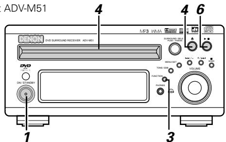
Cassette deck (DRR-M31)
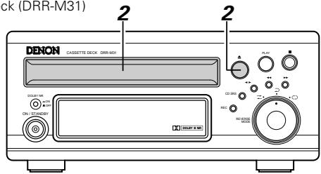
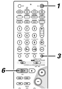
Turn on the ADV-M51's power.
- The system's power turns on.
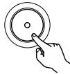
ON/STANDB
ADV-M51

Remote control unit
2 Open the cassette holder, load the cassette tape onto which you want to record, then close the cassette holder.
※ Load the cassette tape with side A facing up.
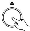
DRR-M31
Press the FUNCTION button and switch the function to "DVD".
ADV-M51

Remote control unit

Open the ADV-M51's disc holder, load the CD, then close the disc holder.
ADV-M51

Press the MENU button on the remote control unit and set the length of the cassette tape onto which you are going to record.
- For example, for a 60-minute cassette tape, press the edit button twice. (The length of the cassette tape is the total time for sides A and B.)

Remote control unit
※ The display switches as follows each time the MENU button is pressed.
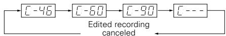
About 4 seconds after setting the length of the cassette tape, the numbers of the tracks to be recorded on side A and the remaining time for side A on the cassette tape are displayed.
(Ex.: When tracks 1 to 9 will be recorded on side A and the remaining time for side A is 2 minutes 40 seconds)
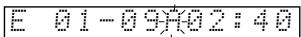
After this, the display switches every few seconds between the numbers of the tracks and remaining time for side B and the numbers of the tracks and remaining time for side A.
(Ex.: When tracks 10 to 16 will be recorded on side B and the remaining time for side B is 1 minute 20 seconds)

※ If “OVER” is displayed for the remaining time, it is not possible to record all the tracks. Change the cassette tape length.
※ To set the cassette tape length to anything other than 46, 60 or 90, use the numeric keypad and +10 button on the remote control unit while “[---]” is displayed to input the time. The time can be set to up to 99 minutes. The time is input in the same way as when searching for CD tracks directly.
[Example:] To set the time to 54 minutes
While "---" is displayed, press +10 , +10 , +10 , +10 ,
+10,4.
6 Press the play/pause button on the ADV-M51 or the DVD play button on the remote control unit.
- Playback of the CD and recording onto the cassette tape start simultaneously.
01Tr 00:01

ADV-M51
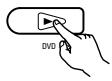
Remote control unit
To quit the edited recording function, press the ADV-M51's stop button.
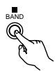
ADV-M51

Remote control unit
NOTES:
- The edited recording function cannot be used with CDs containing 26 tracks or more.
- Load the cassette tape onto which you want to record into the cassette deck's cassette tray with side A facing up before performing the edited recording procedure. The tape is automatically wound to the beginning of the recordable section before recording starts.
- When using an already recorded cassette tape for edited recording, if the tape is longer than the set time, recording stops in the middle of side B and the previous recording remains on the rest of the tape. Because of this, erase the cassette tape before using it.
- If the cassette deck's reverse mode is set to when using the edited recording function, recording will stop after side A. Set the cassette deck's reverse mode to .
- Because the tracks are divided into sides A and B, it may not be possible to record all the tracks from the CD onto the cassette tape, even if the tape is slightly longer than the CD's total playing time.
- The 1, , and buttons do not work during edited recording.
■ About synchronized recording onto the cassette deck (DRR-M31)
- Synchronized recording is possible with discs other than CDs (DVDs, video CDs, discs containing MP3 or WMA files, etc.).
- For digital and analog recording during disc playback, see page 16.
- The synchronized recording function may not work properly for some discs. If so, record the disc manually by setting the recording mode after start playback of the disc.
- The CD SRS function and the function for edited recording onto tapes only works with CDs.

LAST FUNCTION MEMORY
- This unit is equipped with a last function memory which stores the input and output setting conditions as they were immediately before the power is switched off.
This function eliminates the need to perform complicated resettings when the power is switched on. - The unit is also equipped with a back-up memory. This function provides memory storage when the power switch is off and with the power cord disconnected.

INITIALIZATION OF THE MICROPROCESSOR
When the indication of the display is not normal or when the operation of the unit does not show the reasonable result, the initialization of the microprocessor is required by the following procedure.
Press the power button to set the standby mode, then unplug the set's power cord from the wall power outlet.
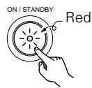
2 Hold the following PLAY/PAUSE (▶/■) button and STOP (■) button after 30 second, and plug the AC cord into the outlet.
3 Check that the entire display is flashing with an interval of about 1 second, and release your fingers from the 2 buttons and the microprocessor will be initialized.
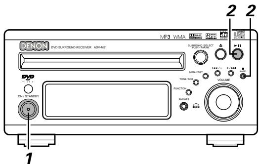
NOTES:
- If step 3 does not work, start over from step 1.
- If the microprocessor is reset, all the buttons and the setup settings are reset to the factory default values.
23 TROUBLESHOOTING
Check again before assuming the player is malfunctioning
Are all the connections correct?
Are you following the instructions in the manual?
Are the speakers and other components operating properly?
If this unit does not seem to be functioning properly, check the table below. If this does not solve the problem, this unit may be damaged. Turn off the power, unplug the power cord from the power outlet, and contact your store of purchase or nearest Denon sales office.
| Symptom | Cause | Measures | Page | |
| Common problems when listening to the discs, tapes and FM broadcasts, etc. | DISPLAY not lit and sound not produced when power switch set to on. | • Power cord not plugged in securely. | • Check the insertion of the power cord plug. | 10 |
| DISPLAY lit but sound not produced. | • Speaker cords not securely connected. • Improper position of the audio function button. • Volume control set to minimum. • MUTING is on. • Digital signals not input Digital input selected. | • Connect securely. • Set to a suitable position. • Turn volume up to suitable level. • Switch off MUTING. • Input digital signals or select input jacks to which digital signals are being input. | 10 44 42 46 47 | |
| Monitor doesn't display an image. | • Connections between the video output jack of this unit and the input connector of the monitor are incomplete. • The input setting of the monitor TV is different. • When "PROGRESSIVE" is set, no video signals are output from the VIDEO OUT or S-VIDEO OUT terminals. | • Check whether the connections are correct. • Set the input switching of the TV to the jack to which the video input is connected. • Set "INTERLACED" if you want to use the VIDEO OUT or S-VIDEO OUT signals. | 13 — 40 | |
| The program cannot be copied from DVD to the VCR. | • Almost all movie software contains a copy prevention signal. | • A copy cannot be made. | — | |
| The subwoofer does not produce sound. | • Power is not being supplied to the subwoofer. • The subwoofer setting is made to "No" in the setup. • The output of the subwoofer has not been connected. | • Switch on the power of the subwoofer. • Change the setting to "Subwoofer" in the setup. • Make the proper connections. | — 31 10 | |
| Remote control unit | This unit does not operate properly when remote control unit is used. | • Batteries dead. • Remote control unit too far from this unit. • Obstacle between this unit and remote control unit. • Different button is being pressed. • ⊕ and ⊕ ends of battery inserted in reverse. • The mode selection of the remote control is not properly selected. The DVD mode, AV mode, or audio mode is not properly selected. | • Replace with new batteries. • Move closer. • Remove obstacle. • Press the proper button. • Insert batteries properly. • Press the remote control mode selection button for the item you wish to operate. To operate this unit, use with the DVD mode. | 23 23 23 19 23 24 |
| Symptom | Check | Page | ||
| DVD operation | Playback does not start when PLAY button is pressed.Playback stops immediately. | ● Is there condensation on the disc or player ? (Let stand for 1 or 2 hours.)● Discs other than DVDs, video CDs and music CDs cannot be played.Disc is dirty. Wipe off the dirt. | —89 | |
| Menu playback of video CD's is not possible. | ● Menu playback is not possible with anything but video CDs with playback control. | — | ||
| Picture is disturbed during the search operation. | ● Some disturbance is normal. | — | ||
| Buttons do not operate. | ● Some operations are disabled for some discs. | 42 | ||
| No subtitles are displayed. | ● Subtitles are not displayed for DVDs not containing subtitles.● Subtitles are turned off. Turn the subtitles setting on. | —89, 90 | ||
| Audio (or subtitle) language does not switch. | ● The audio (or subtitle) language does not switch for discs which do not include multiple audio (or subtitle) languages.For some discs the audio (or subtitle) language cannot be switched when the operation to switch it is performed, but can be switched on the menu screens. | 8989 | ||
| Angle does not switch. | ● The angle cannot be switched for DVDs which do not contain multiple angles. In some cases multiple angles are only recorded for specific scenes. | 77 | ||
| Playback does not start when the title is selected. | ● Check the “RATINGS SETUP” setting. | 97, 98 | ||
| The password for rating level has been forgotten.Set all the DVD setting to Factory Preset. | ● While the player is in the stop mode, hold the FUNCTION button and the MENU/SET button down simultaneously for longer than 3 seconds (until “INITIALIZE” disappears from the TV monitor).The lock will be released and the DVD all default settings and picture settings will return to the default values. | 97, 98 | ||
| The disc is not played with the audio or subtitle language set as the default setting. | ● The disc does not play with the selected audio or subtitle language if that audio or subtitle language is not included on that DVD. | 89 | ||
| Picture is not displayed in 4:3 (or 16:9). | ● Set the “TV ASPECT” default setting to the proper setting for the connected TV. | 93 | ||
| Menu screen messages for the desired language do not display. | ● Check the default setting for the disc language's menu language. | 90, 91 | ||
| Tuner | Continuous noise is heard when receiving FM programs | ● Antenna cable is not properly connected. | ● Connect the antenna cable properly.● Connect an outdoor antenna. | 14 |
| Hissing or continuous noise is heard when receiving AM programs | ● This may be noise from a TV or interference from a radio station. | ● Turn off the TV.Change the position and direction of the AM loop antenna. | 14 | |
| Humming noise is heard when receiving AM programs | ● The radio waves transmitted over the power cord are being modulated. | ● Unplug the power cord, flip the plug over in the opposite direction, then plug the cord back in. | 14 | |
| Active subwoofer | LED does not light and no sound is produced when power is turned on. | ● Check the connection of the AC power plug. | 10 | |
| LED lights but no sound is produced. | ● Connect securely.Turn the control and set it to the desired position. | 22 | ||
| LED flashes and no sound is produced. | ● Set the power switch to the “OFF” position, wait at least 1 minute, then set the power switch back to the “ON” position. If the problem persists, unplug the AC power cord from the AC power outlet and contact your store of purchase. | 22 | ||
| Sound is distorted. | ● Turn the volume adjustment control counterclockwise to lower the volume.Do not amplify the bass sound on the amplifier. (Lower the amplifier's bass adjustment control or volume.) | 22 | ||
| Oscillation (loud continuous sound produced). | ● Lower the volume of the active subwoofer or amplifier. | 22 | ||
24 SPECIFICATIONS
Audio Section
Power Amplifier Section
Rated output:
Practical maximum output:
Output terminals:
- Analog Section
Input sensitivity/Input impedance:
Frequency response:
Signal-to-noise ratio:
Rated output:
Tuner Section
Reception frequency range:
Receiving sensitivity:
FM stereo separation:
Digital Section
Digital input/output:
Video Section
Standard Video Jack
Output level/impedance:
S-video Connector
Output level/impedance:
Color Difference (Component)
Video Connector:
Output level/impedance:
Front: 20 W + 20 W (8 Ω/ohm load, 20 Hz to 20 kHz, T.H.D. 0.08%)
Front: 35 W + 35 W (6 Ω/ohm load, 1 kHz)
Speaker impedance: 6 to 16 Ω/ohms
200 mV/47 kΩ/kohms
10 Hz to 50 kHz: +0, -3 dB (2 Channel setting, direct mode)
98 dB (Direct mode)
0.6 V (Subwoofer PRE OUT)
FM: 87.5 MHz to 107.9 MHz AM: 520 kHz to 1710 kHz
FM: 1.5 V / 75 /ohms AM: 20~ V
35 dB (1 kHz)
Format — Digital audio interface
1 Vp-p/75 Ω/ohms
Y (Brightness) signal — 1 Vp-p/75 Ω/ohms
C (Color) signal — 0.286 Vp-p/75 Ω/ohms
Y (Brightness) signal — 1 Vp-p/75 Ω/ohms
C_B / P_B (Blue) signal — 0.7 Vp-p/75 Ω/ohms
12 cm single side 1 layer, 12 cm single side 2 layers,
12 cm both sides 2 layers (single side 1 layer),
8 cm single side 1 layer, 8 cm single side 2 layers,
8 cm both sides 2 layers (single side 1 layer)
(2) Compact Disc (CD-DA,VIDEO CD)
12 cm discs, 8 cm discs
Output level: 1.2 Vrms (LINE-1, LINE-2 OUT)
Clock/Timer Section
Clock method:
Timer:
Power line frequency synchronized method
Everyday/Once timer: One system each
Sleep timer: 120 minutes, maximum
General
Power supply:
Power consumption:
120 V AC, 60 Hz
75W
(At standby: Approximately 0.7 W)
210 (W) x 95 (H) x 367 (D) mm (8-17/64" x 3-47/64" x 14-29/64")
(including feet, knobs, and connectors)
3.5 kg (7 lbs 11 oz)
RC-936
IR pulse method
3 V DC, using two AA batteries
■ Speakers SYS-M51 (D-M51DVS only)
- Satellite speaker system (SC-A3L)
Type:
2-way, 3-speakers
Closed box / Low-leakage-flux
Speakers:
5.7 cm cone bass-mid x 2
1.9 cm super-high range x 1
Input impedance:
6 Ω/ohms
Max. input:
40 watts (IEC)
100 watts (PEAK)
Frequency range:
120 Hz ~ 90 kHz
Dimensions:
70 (W) x 210 (H) x 161 (D) mm (3-3/4" x 8-17/64" x 6-11/32")
Mass:
1.1 kg (2 lbs 7 oz)
Active subwoofer (DSW-3L)
Type:
1-way, 1-speaker
Reflex box / Low-leakage-flux / Built-in amplifier
16 cm cone woofer x 1
Speaker:
4 Ω/ohms
Speaker impedance:
25 Hz ~ 200 Hz (LF Direct / Off)
Frequency range:
95 watts
Rated output power:
(4 Ω/ohms load, 55 Hz, T.H.D. 0.7%)
Input impedance:
22 kΩ/kohms
Crossover frequency:
50 Hz ~ 200 Hz (Variable) (LF Direct / Off)
Power supply:
120V/60Hz
Power consumption:
53 watts (UL / IEC)
Dimensions:
< 1 watt (Standby)
Mass:
232 (W) x 452 (H) x 395 (D) mm (9-9/64" x 17-51/64" x 15-35/64") (including base)
11.2 kg (24 lbs 11 oz) (including base)
This product incorporates copyright protection technology that is protected by method claims of certain U.S. patents and other intellectual property rights owned by Macrovision Corporation and other rights owners. Use of this copyright protection technology must be authorized by Macrovision Corporation, and is intended for home and other limited viewing uses only unless otherwise authorized by Macrovision Corporation. Reverse engineering or disassembly is prohibited.
- For improvement purposes, specifications and design are subject to change without notice.
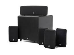
- CAUTION
- CAUTION:
- ATTENTION
- FCC INFORMATION (For US customers)
- 1.PRODUCT
- IMPORTANT NOTICE: DO NOT MODIFY THIS PRODUCT
- NOTE
- ■ NOTE ON USE / OBSERVATIONS RELATIVES A L'UTILISATION
- Handle the power supply cord carefully
- Do not open the top cover
- Do not place anything inside
- NOTE:
- Copyrights
- INTRODUCTION
- TABLE OF CONTENTS
- ■ ACCESSORIES
- ADV-M51
- Check that the following parts are included in addition to the main unit:
- SYS-M51 (D-M51DVS only)
- BEFORE USING
- Pay attention to the following before using this unit:
- - Moving the set
- - Before turning the power switch on
- - Store this instructions in a safe place.
- CAUTIONS ON INSTALLATION
- DVD SURROUND RECEIVER
- SPEAKER SYSTEM (D-M51DVS only)
- SC-A3L
- DSW-3L
- WARNING:
- CAUTIONS ON HANDLING
- FEATURES
- 2-channel power amplifier with Dolby Virtual Speaker compatibility
- DENON's unique sound field simulation using the DSP
- High performance DVD drive
- Quick setup and on-screen display compatibility
- Remote control unit with preset memory function
- Convenient system functions
- DISCS
- Disc terminology
- For example:
- The following types of discs cannot be played on the ADV-M51:
- CAUTIONS ON HANDLING DISCS
- Holding Discs
- Cleaning Discs
- Cautions on Handling Discs
- Cautions on Storing Discs
- Cautions on Loading Discs
- CONNECTIONS
- Connecting the audio components (D-M31 series)
- Connecting the speaker systems
- Note to CATV system installer:
- System operations
- NOTES:
- Connecting the Audio Signals of a Digital Satellite Tuner and VCR
- Connection to the optical digital input terminal
- Connecting a TV
- Connecting to a TV or Monitor Equipped with Component Input Connectors
- Color component output connectors (PR / CR,PB / CB and Y
- Connecting a monitor TV
- COMPONENTVIDEOOUTjack
- Sound output from this unit digital and analog audio output connectors
- About the LINE-1 and LINE-2 analog recording outputs
- When the DVD or the D.AUX digital input is selected:
- When TUNER, LINE-1 or LINE-2 is selected:
- Recording output during playback of a DVD, D.AUX or LINE-1 digital input source in the Dolby Headphone mode:
- Cautions during analog recording of DVDs or digital input sources:
- Speaker system connections
- Be sure to turn the amplifier's power off when connecting the speaker systems.
- Connecting the speaker cords
- Protector circuit
- Note on speaker impedance
- Cautions on connecting
- Using the active subwoofer (DSW-3L) (D-M51DVS only)
- Removing the speaker net (SC-A3L) (D-M51DVS only)
- PART NAMES AND FUNCTIONS
- DVD SURROUND RECEIVER (ADV-M51) Front Panel
- Remote control unit
- Names and functions of remote control unit buttons on the ADV-M51
- [1] Surround amplifier system buttons (Operated with mode switch 2 set to "IN/SURR.")
- Active subwoofer (DSW-3L) rear panel
- Line input connector (LINE IN)
- Line output connector (LINE OUT)
- Phase selector switch (PHASE)
- LF direct switch (LF DIRECT)
- Crossover adjustment control (CROSSOVER)
- About the AV amplifier's crossover frequency selection
- Volume adjustment control (LEVEL)
- Auto standby selector switch (AUTO STANDBY)
- Auto Standby Function
- Status indicator
- Power switch (POWER)
- REMOTE CONTROL UNIT
- Inserting the batteries
- Notes on Batteries
- Using the remote control unit
- Operating DENON audio components
- [2] Tape deck system button
- TV and video deck preset memories
- Combinations of preset codes for different brands
- Operating the TV/video deck after storing its remote control signals in the preset memory
- System setup items
- Quick setup procedure
- Turn on the power.
- Press the SETUP button to display the setup screen.
- Use the and cursor buttons to select "Quick System Setup".
- Press the ENTER button to display the menu's setting screen.
- [1] TV screen size setting
- Use the and cursor buttons to select the desired TV screen size and display type.
- Press the ENTER button to set the selected setting.
- [2] Speaker system settings
- Use the and cursor buttons to select the speaker system to be used.
- Press the ENTER button to set the selected setting.
- Press the SETUP button to quit the setup mode.
- About the speaker system settings
- © 2CH VIRTUAL
- © 2CH VIRTUAL & SW
- Detailed system setup (changing the system settings)
- [1] Speaker settings (type of speaker and whether or not the speaker is connected)
- 3
- 4
- 5
- Parameters
- Subwoofer (SW FREQ.) frequency
- Assignment of low frequencies
- Subwoofer mode
- [2] Delay time (distance setting)
- Preparation:
- [3] Adjusting the channel level
- [4] DVD Auto Power Off setting
- [5] Function settings
- Press the ENTER button to enter the settings.
- Input function settings
- LINE-1/LINE-2 analog recording output setting
- After changing the system settings
- At the system setting changing menu screen, press the SETUP button.
- PLAY BACK
- Before Operating
- Loading Disc
- Opening and Closing the Disc Tray
- Loading Discs
- Selecting the video output
- (3)Playback
- IMPORTANT SETUP INFORMATION
- This set has the following presettings:
- Turn on the power.
- Press the OPEN/CLOSE button to open the disc tray.
- Set the disc in the disc tray.
- Press the OPEN/CLOSE button.
- Press the PLAY button.
- Stopping Playback
- About the DVD standby function
- Playing Still Pictures (Pausing)
- Forward / Reverse Searching
- Skipping to the Beginning of Chapters or Tracks
- Searching using the number buttons
- Playing Frame by Frame (for DVDs and video CDs only)
- SlowPlayback (forDVDs and video CDs only)
- Input mode selection function
- Input mode display
- Input signal display
- Input mode when playing CD sources
- Input mode when playing DTS sources
- After starting playback
- [1] Adjusting the sound quality (TONE/SDB)
- Press the TONE/SDB button.
- DEFEAT
- SDB
- BASS, TREBLE
- Use this to turn off the audio output temporarily. Press the MUTING button.
- DOLBY / DTS SURROUND
- Dolby Surround
- Dolby Digital
- Dolby Digital and Dolby Pro Logic
- ■ Dolby Digital compatible media and playback methods
- Dolby Pro Logic II
- DTS Digital Surround
- DTS compatible media and playback methods
- Dolby Virtual Speaker
- Features of Dolby Virtual Speaker sound
- Dolby Headphone
- Playing in the Dolby Virtual Speaker mode
- [1]Playing Dolby Digital and DTS surround sound (with digital inputs only)
- Set the surround mode to "DOLBY VIRTUAL SPEAKER".
- Play a program source including the DOLBY or marks.
- Select and set the surround parameters.
- Surround parameters (1)
- DOLBY VS (Dolby Virtual Speaker mode)
- D.COMP. (Dynamic range compression)
- LFE (Low Frequency Effect):
- [2] 2-channel mode settings
- Surround parameters (2)
- VIRTUAL1 (Virtual 1 mode)
- VIRTUAL2 (Virtual 2 mode)
- Playing in the DENON original surround modes
- Personal Memory Plus
- Surround parameters (3)
- ROOM SIZE:
- EFFECT LEVEL:
- Playback using the Dolby Headphone mode
- Surround parameters (4)
- DOLBY H (Dolby Headphone modes)
- 2-channel modes
- ■ Recording
- Tuning
- Auto tuning
- FM Stereo Reception
- About the tuning mode and the preset mode
- Presetting stations that have been tuned in and giving names to stations (remote control unit only)
- Auto tune presets
- Listening to preset stations
- ON-SCREEN DISPLAY
- USING THE ON-SCREEN DISPLAY
- Operating using the disc information OSD
- Adjusting the picture quality
- Standard:
- Playing Repeatedly
- [1] Playing Repeatedly (Repeat Playback)
- In the play mode, press the REPEAT button.
- [2] Playing a Certain Section Repeatedly (A-B Repeat Playback)
- Playing Tracks in the Desired Order
- Example: To program tracks 5 and 12
- Playing Tracks in the Random Order
- MP3 WMA Playback
- [1] Listening to Recorded MP3 CD/CD-R/CD-RW
- ※ To change the MP3 file
- ※ To set the random play mode
- ※ To set the repeat mode
- ※ To return to the initial disc information screen
- [2] Listening to Recorded WMA (Windows Media Audio) CD-R/CD-RW
- Playing still picture files (JPEG format)
- [1] Playing Kodak picture CDs
- [2] Playing still pictures stored on CD-Rs/RWs
- Special play modes for MP3/WMA and JPEG files
- Using the Multiple Audio, Subtitle and Angle Functions
- [1] Switching the Audio Language (Multiple Audio Function)
- [2] Switching the Subtitle Language (Multiple Subtitle Function)
- During playback, press the SUBTITLE button.
- Use the and cursor buttons to select the desired language.
- [3] Switching the Angle (Multiple Angle Function)
- During playback, press the ANGLE button.
- Use the and cursor buttons to select the desired angle.
- Using the Menus
- [1] Using the Top Menu
- TOP MENU
- [2] Using the DVD Menu
- During playback, press the MENU button.
- DVD MENU
- Use the cursor or number buttons to select the desired item.
- Press the ENTER button.
- Playing in the zoom mode
- USING THE TIMER
- Setting the clock (12-hour display)
- Before setting the timer
- Setting the everyday timer and once timer
- Press the MENU/SET button.
- Turn the SURROUND/SELECT knob and set the minutes place to "35".
- Press the MENU/SET button.
- 12
- Press the MENU/SET button.
- Turn the SURROUND/SELECT knob and set the minutes place to "56".
- Press the MENU/SET button.
- Turn the SURROUND/SELECT knob to display "Eon".
- Turn off the power.
- ※ If you make a mistake when setting the timer.
- Turning the everyday timer and once timer on and off
- Everyday timer and once timer priority
- About the everyday timer and once timer
- Setting the sleep timer (remote control unit only)
- Select and play the desired function.
- Press the SLEEP button.
- When the "SLEEP" indicator is flashing, press the SLEEP button again until "50" is displayed.
- The power is set to the standby mode 50 minutes later.
- CHANGING THE DEFAULT SETTINGS (DVD)
- The setup (default settings) screen "DVD SETUP MENU" appears.
- DISC SETUP
- - OSD SETUP
- VIDEO SETUP
- AUDIO SETUP
- RATINGS
- OTHER SETUP
- ※ To exit the DVD setup mode
- "DISC SETUP" is selected
- - DIALOG
- - SUBTITLE
- - DISC MENUS
- ※ To exit the disc setup mode
- When "DIALOG" is selected:
- - ENGLISH (Factory default)
- FRENCH
- SPANISH
- GERMAN
- JAPANESE
- OTHERS
- ※ To exit the dialog mode
- When "SUBTITLE" is selected:
- - OFF (Factory default)
- - ENGLISH
- ※ To exit the subtitle mode
- When "DISC MENUS" is selected:
- ※ To exit the disc menus mode
- When "OSD SETUP" is selected
- "VIDEO SETUP" is selected
- - TV ASPECT
- - TV TYPE
- VIDEO MODE
- - BLACK LEVEL
- ※ To exit the video setup mode
- When "TV ASPECT" is selected:
- 4:3 PS (Factory default)
- 4:3LB
- WIDE (16:9)
- ※ To exit the TV aspect mode
- When "TV TYPE" is selected:
- - NTSC (Factory default)
- PAL
- MULTI
- ※ To exit the TV type mode
- ■ When "VIDEO MODE" has been selected (see the note below)
- - AUTO (Factory default)
- FILM
- VIDEO
- ※ To complete the "VIDEO MODE" setting
- ■ When "BLACK LEVEL" has been selected
- DARKER
- - LIGHTER (Factory default)
- ※ To complete the "BLACK LEVEL" setting
- Note on when "VIDEO MODE" is selected
- "AUDIO SETUP" is selected
- "LPCM SELECT (96kHz→ 48kHz) is selected. OFF (Factory default)
- ON
- ※ To exit the LPCM select mode
- "RATINGS" is selected
- RATING LEVEL
- - PASSWORD
- ※ To exit the rating setup mode
- ■ When "RATING LEVEL" is selected.
- - Level 0 (LOCK ALL)
- - Level 1
- - Level 2 to Level 7
- - NO LIMIT (Factory default)
- When "password CHANGE" is selected.
- "OTHER SETUP" is selected
- - CAPTIONS
- - SLIDE SHOW
- ※ To exit the other setup mode
- When "CAPTIONS" is selected:
- ※ To exit the captions mode
- When "SLIDE SHOW" has been selected
- SYSTEM FUNCTIONS
- Auto power on function
- Auto function selection
- CD → TAPE recording (when the ADV-M51 and DRR-M31 are connected with a system cord)
- [1] Synchronized recording function
- [2] Synchronized CD recording
- Edited recording (when the ADV-M51 and DRR-M31 are connected with a system cord)
- ■ About synchronized recording onto the cassette deck (DRR-M31)
- LAST FUNCTION MEMORY
- INITIALIZATION OF THE MICROPROCESSOR
- TROUBLESHOOTING
- Check again before assuming the player is malfunctioning
- SPECIFICATIONS
- Audio Section
- ■ Speakers SYS-M51 (D-M51DVS only)
Brand : DENON
Model : D-M51DVS
Category : Compact audio system