
3Com Baseline 2816 - Switch HP - Free user manual and instructions
Find the device manual for free 3Com Baseline 2816 HP in PDF.


| Product Type | Unmanaged Ethernet Switch |
| Model | 3Com Baseline 2816 (HP) |
| Ports | 16 x RJ45 10/100 Mbps |
| Form Factor | Desktop/Rackmount |
| Dimensions (W x D x H) | 27.9 x 22.3 x 4.4 cm (11.0 x 8.8 x 1.7 in) |
| Weight | 1.2 kg (2.6 lbs) |
| Power Supply | External AC adapter, 100-240V, 50-60Hz |
| Power Consumption | 8 W (max) |
| Switching Capacity | 3.2 Gbps |
| MAC Address Table | 8K entries |
| Auto MDI/MDIX | Yes, on all ports |
| Flow Control | IEEE 802.3x full-duplex, backpressure half-duplex |
| Cooling | Fanless, silent operation |
| Operating Temperature | 0°C to 40°C (32°F to 104°F) |
| Storage Temperature | -10°C to 70°C (14°F to 158°F) |
| Humidity | 10% to 90% non-condensing |
| Safety Compliance | FCC, CE, UL |
| Maintenance | Clean with dry cloth; avoid liquids |
| Spare Parts / Repairability | No user-serviceable parts; contact HP support for issues |
| General Information | Designed for small office/home office; plug-and-play, no configuration needed |
Frequently Asked Questions - 3Com Baseline 2816 HP
User questions about 3Com Baseline 2816 HP
0 question about this device. Answer the ones you know or ask your own.
Ask a new question about this device
Download the instructions for your Switch in PDF format for free! Find your manual 3Com Baseline 2816 - HP and take your electronic device back in hand. On this page are published all the documents necessary for the use of your device. 3Com Baseline 2816 by HP.
USER MANUAL 3Com Baseline 2816 HP
3Com® Switch 2824 (24-Port, Unmanaged Gigabit) - (3C16479) 3Com® Switch 2816 (16-Port, Unmanaged Gigabit) - (3C16478) User Guide
DUA1647-8AAA01

INTRODUCTION
The 3Com Switch 2824/3Com Switch 2816 is a versatile, easy-to-use switch. It is ideal for users who want the high-speed performance of 10/100/1000 switching but do not need sophisticated management functions. The Switch is shipped ready for use. No configuration is necessary.
The Switch can be rack-mounted or free standing.
Your Switch includes:
■ One power cord ■ Rack mounting kit ■ Four standard height, self-adhesive rubber pads ■ This User Guide and warranty card
The Switch is powered from the AC mains supply.
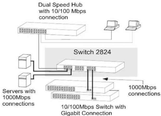
The Switch provides high performance switched connections to 10 Mbps, 100 Mbps, and 1000 Mbps hubs, switches, servers and workstations that need a dedicated switched link. The following figure illustrates one possible configuration. Each port has a shielded RJ-45 connector on the front panel. Each port is capable of operating at 10 Mbps, 100 Mbps or 1000 Mbps. The ports can automatically determine the speed and the duplex mode of the connected equipment and provides a suitable switched connection. At 10 Mbps and at 100 Mbps, the ports can operate in half or full duplex mode. At 1000 Mbps, the ports operate in full duplex mode only.
The numbers in this diagram refer to numbered sections in the text. A 24-port unit is shown.
Front Panel
1 24 RJ-45 10/100/1000 Ports

WARNING: RJ-45 ports. These are shielded RJ-45 data sockets. They cannot be used as standard traditional telephone sockets, or to connect the unit to a traditional PBX or public telephone network. Only connect RJ-45 data connectors, network telephony systems, or network telephones to these sockets. Either shielded or unshielded data cables with shielded or unshielded jacks can be connected to these data sockets.

The Switch has 24/16 10/100/1000 Mbps auto-negotiating ports. Each port automatically negotiates with the attached device to determine the correct speed and duplex mode of operation. Once negotiated, the port will operate in one of the following modes:
■ 10BASE-T half duplex ■ 10BASE-T full duplex ■ 100BASE-TX half duplex ■ 100BASE-TX full duplex ■ 1000BASE-T full duplex

CAUTION: The Switch supports full duplex auto-negotiation. If the connected device does not support auto-negotiation, the Switch will operate in half duplex mode, and therefore can only operate at 10 Mbps or 100 Mbps. In such a configuration, you may notice some degradation of network performance. 3Com recommends that you use devices that are capable of auto-negotiation (and that you ensure that auto-negotiation is enabled, if it is a configurable option).
All ports auto-sense an MDI/MDIX connection so each port can be connected to a device with a normal 'straight through' TP (twisted pair) cable or a 'cross-over' TP cable. Any port can therefore be used to connect to either another switch port, server, or workstation without additional configuration.
Traffic Prioritization
The Switch offers priority queuing, which means all packets that are received are examined to see if they have been priority encoded. When a packet is received, the Switch will read the priority level and determine the appropriate channel to forward the packet based on the priority level. This feature can be useful, for example, during excessive loads when one type of traffic may require priority over another. The Switch is configured to comply with 802.1p, VLAN tagged frames.
Traffic prioritization ensures that high priority data is forwarded through the Switch without being delayed by lower priority data. It differentiates traffic into classes and prioritizes those classes automatically. Traffic prioritization uses the multiple traffic queues that are present in the hardware of the Switch to ensure that high priority traffic is forwarded on a different queue from lower priority traffic, and is given preference over that traffic. This ensures that time-sensitive traffic gets the highest level of service. The 802.1D standard specifies eight distinct levels of priority (0 to 7), each of which relates to a particular type of traffic. The priority levels and their traffic types are shown in the following table.
Priority Level Traffic Type
0 Best Effort
1 Background
2 Standard (spare)
3 Excellent Effort (business critical)
4 Controlled Load (streaming multimedia)
5 Video (Interactive media), less than 100 milliseconds latency and jitter.
6 Voice (Interactive voice), less than 10 milliseconds latency and jitter.
7 Network Control Reserved traffic

The traffic prioritization feature supported by the Switch is compatible with the relevant sections of the IEEE 802.1D standard (incorporating IEEE 802.1p).
2 Activity/Link/Speed Status LEDs
The top and third row of Status LEDs, labelled "Link/Activity," show the link and activity status of the related ports:
Status Meaning
Green: The link is operating at 1000 Mbps.
Yellow: The link is operating at 10 or 100 Mbps.
Flashing: Packets are being received or transmitted on the port.
Off: The link has not been established, either nothing is connected to the port, or there is a problem:
Check that the attached device is powered on. Check that the cable is the correct type and is not faulty. If these checks do not identify the cause of the problem, it may be that the unit or the device connected to the port is faulty. Contact your supplier for further advice.
INSTALLING THE SWITCH
Positioning the Switch
When deciding where to position the Switch ensure:
It is accessible and cables can be connected easily. Cabling is away from sources of electrical noise. These include lift shafts, microwave ovens, and air conditioning units. Electromagnetic fields can interfere with the signals on copper cabling and introduce errors, therefore slowing down your network. Water or moisture cannot enter the case of the unit. Air flow around the unit and through the vents in the side of the case is not restricted (3Com recommends that you provide a minimum of 25 mm (1 in.) clearance). The air is as free from dust as possible. Temperature operating limits are not likely to be exceeded. It is recommended that the unit is installed in a clean, air conditioned environment.

It is always a good practice to wear an anti-static wrist strap when installing network equipment, connected to a ground point. If one is not available, try to keep in contact with a grounded rack and avoid touching the unit's ports and connectors, if possible. Static discharge can cause reliability problems in your equipment.
3 Duplex Status LEDs
The second and fourth row of Status LEDs, which are colored yellow, show the duplex status of the related ports:
Status Meaning
Yellow The port is operating in full duplex mode.
Off The port is operating in half duplex mode.

1000BASE-T only operates in full duplex mode. 10BASE-T/100BASE-TX can be in half or full duplex mode.
4 Power LED
The Power LED shows the power status of the Switch:
Status Meaning
Green The unit is powered on and ready for use.
Off ■The unit is not receiving power:
■Check that the power cord is connected correctly. ■If the unit still does not operate, contact your supplier.
Rear Panel Connections
5 Power Supply
The Switch automatically adjusts to the supply voltage. Only use the power cord that is supplied with the unit.
Rack Mounting or Free Standing
This unit can be mounted in a 19-inch equipment rack using the Mounting Kit. Refer to "Mounting Kit Instructions" on page 4. It can also be free standing. Do not place objects on top of the unit or stack.
The unit is supplied with four self-adhesive rubber pads. If the unit is to be part of a free standing stack, apply the pads to each marked corner area on the underside of the unit. Place the unit on top of the lower unit, ensuring that the pads locate with the recesses of the lower unit.

Do not apply the pads if you intend to rack mount the unit.

CAUTION: If installing the Switch in a free standing stack of different sized units, the smaller units must be installed above the larger ones. Do not build a free standing stack of more than six units.
Connecting to a Network Device
Follow these guidelines to connect a device to the Switch:
■ Use Category 5 unshielded or shielded (screened) 100 Ohm TP cable (or Category 3 cable for a 10 Mbps connection). 3Com recommends using Category 5E cable for 1000BASE-T operation. ■ The maximum length of cable for each connection is 100 m (328 ft). ■ Connect one end of the cable to an RJ-45 port on the Switch, and the other end to the appropriate RJ-45 port on the connecting device.
Power Supply
Power problems can be the cause of serious failures and downtime in your network. Ensure that the power input to your system is clean and free from sags and surges to avoid unforeseen network outages. 3Com recommends that you install power conditioning, especially in areas prone to black outs, power dips and electrical storms.
Powering Up
Use the following sequence to power up the Switch:
1 Check the network connections and cables. 2 Connect the power supply cable to the appropriate power socket located on the rear panel of the unit. 3 Connect the plug to the power supply outlet socket and switch on the power supply at the socket.
When the switch is powered on, the Power LED lights green. If it does not, see reference 4 in "Features of the Switch" on page 3.
MOUNTING KIT INSTRUCTIONS
Introduction
The Switch is supplied with two mounting brackets and four screws. These are used for rack mounting the unit. When mounting the unit, you should take note of the guidelines given in "Positioning the Switch" on page 3.
Rack Mounting the Units
The Switch is 1U high and will fit a standard 19-inch rack.

CAUTION: Disconnect all cables from the unit before continuing. Remove the self-adhesive pads from the underside of the unit, if already fitted.
1. Place the unit the right way up on a hard, flat surface with the front facing towards you. 2. Locate a mounting bracket over the mounting holes on one side of the unit (refer to the figure following step 6).
3. Insert the two screws supplied in the mounting kit and fully tighten with a suitable screwdriver. 4. Repeat the two previous steps for the other side of the unit. 5. Insert the unit into the 19-inch rack and secure with suitable screws (not provided). 6. Reconnect all cables.

PROBLEM SOLVING
At frequent intervals you should visually check the Switch. Regular checks can give you an early warning of a possible failure; any problems can then be attended to when there will be least effect on users.
Check that all external cabling connections are secure and that no cables are pulled taut.
Refer to the information about LEDs given earlier in this guide to see if the problem can be identified and solved. Here are some common problems that can occur:
Activity Status LED not lit for a port that has a connection.
There is a problem with this connection. Check that:
■ The device being connected to is powered on and operating correctly. ■ The cable is connected at both ends. ■ You are using a TP cable that is not damaged. If the connection is to a workstation, that the workstation's network interface card is installed and configured correctly.
All Activity LEDs appear to be lit continually. There may be broadcast storms on the network. Remove port connections one at a time, waiting a few seconds between each port. If the LEDs go off after removing a port connection, the device that was connected to that port is introducing an excessive amount of broadcast frames to the network (some pieces of network equipment operate by sending out broadcast frames regularly). Refer to the documentation that accompanies the device for information on disabling the broadcast operation.
If the problem persists and the unit still does not operate successfully, contact your supplier with the following information before returning the unit:
■ Product number and serial number (printed on a label supplied with the unit) ■ A brief description of the fault condition
SAFETY INFORMATION
Please read the following safety information carefully before installing the Switch.

WARNING: Installation and removal of the unit must be carried out by qualified personnel only.
■ If installing Switch 2824/Switch 2816 in a stack with other 3Com Hub or Switch units, larger units must be installed below the narrower Hub or Switch units. ■ The unit must be connected to an earthed (grounded) outlet to comply with international safety standards. ■ Do not connect the unit to an A.C. outlet (power supply) without an earth (ground) connection.
■ The appliance coupler (the connector to the unit and not the wall plug) must have a configuration for mating with an EN 60320/IEC 320 appliance inlet.
■ The socket outlet must be near to the unit and easily accessible. You can only remove power from the unit by disconnecting the power cord from the outlet.
This unit operates under SELV (Safety Extra Low Voltage) conditions according to IEC 60950. The conditions are only maintained if the equipment to which it is connected also operates under SELV conditions.
France and Peru only This unit cannot be powered from IT supplies. If your supplies are of IT type, this unit must be powered by 230 V (2P+T) via an isolation transformer ratio 1:1, with
the secondary connection point labelled Neutral, connected directly to earth (ground).
This must be approved for the country where it will be used. e.g.
U.S.A. and
Canada
■ The cord set must be UL-approved and CSA certified. ■ The minimum specifications for the flexible cord are: No. 18 AWG Type SV or SJ 3-conductor ■The cord set must have a rated current capacity of at least 10 A. ■The attachment plug must be an earth-grounding type with a NEMA 5-15P (15 A, 125 V) or NEMA 6-15P (15 A, 250 V) configuration.
Denmark
■The supply plug must comply with Section 107-2-D1, Standard DK2-1a or DK2-5a.
Switzerland
■The supply plug must comply with SEV/ASE 1011. ■The supply plug must comply with BS1363 (3-pin 13-amp) and be fitted with a 5 A fuse which complies with BS1362. ■The mains cord must be or marked and be of type HO3VVF3GO.75 (minimum).
Europe
■The supply plug must comply with CEE7/7 ("SCHUKO")
■The mains cord must be or marked and be of type HO3VVF3GO.75 (minimum).
IMPORTANT SAFETY INFORMATION
The 3Com Switch 2824/3Com Switch 2816 has been designed to meet the following standards:
Functional ISO 8802-3, IEEE 802.3 (Ethernet), IEEE 802.3u (Fast Ethernet), IEEE 802.3ab (Gigabit Ethernet), IEEE 802.3x (Flow control on full duplex links), IEEE 802.3d (Bridging), IEEE 802.1p (VLAN tagging/ priority queuing)
Safety UL 60950, EN 60950, CSA 22.2 #60950, IEC 60950
EMC Emissions EN 55022 Class A, FCC Part 15 Subpart B Class A, ICES-003 Class A, VCCI Class A, AS/NZS 3548 Class A, CNS 13438 Class A
Immunity EN 55024
Environmental
Operating 0–45 °C (32–113 °F)
Temperature
Humidity 10–95% (non-condensing)
Physical
Width 440 mm (17.3 in.)
Depth 173 mm (6.8 in.)
Height 43.6 mm (1.7 in.) or 1U
Weight Switch 2824: 1.96 kg (4.32 lb)
Switch 2816: 1.87 kg (4.12 lb)
Mounting
Free standing, or 19-inch rack mounted using the mounting kit supplied
Electrical
Power Inlet IEC 320
AC Line Frequency 47 to 63 Hz
Input Voltage 100-240 VAC
Current Rating 0.4 A at 115 V, 0.2 A at 230 V
Maximum Power Switch 2824: 45.7W
Consumption Switch 2816: 36.5W
Maximum Power Switch 2824: 156 BTU/hr
Dissipation Switch 2816: 124.6 BTU/hr
REGULATORY NOTICES
FCC Statement
This equipment has been tested and found to comply with the limits for a Class A digital device, pursuant to part 15 of the FCC rules. These limits are designed to provide reasonable protection against harmful interference when the equipment is operated in a commercial environment. This equipment generates, uses and can radiate radio frequency energy and, if not installed and used in accordance with the instructions, may cause harmful interference to radio communications. Operation of this equipment in a residential area is likely to cause harmful interference to radio communications, in which case the user will be required to correct the interference at their own expense.
Information To The User
If this equipment does cause interference to radio or television reception, which can be determined by turning the equipment off and on, the user is encouraged to try to correct the interference by one or more of the following measures:
■ Reorient the receiving antenna ■ Relocate the equipment in relation to the receiver. ■ Move the equipment away from the receiver. ■ Plug the equipment into a different outlet so that equipment and receiver are on different branch circuits.
If necessary, the user should consult the dealer or an experienced radio/television technician for additional suggestions. The user may find the following booklet prepared by the Federal Communications Commission helpful:
How to Identify and Resolve Radio-TV Interference Problems
This booklet is available from the U.S. Government Printing Office, Washington,
DC 20402, Stock No. 004-000-00345-4.
In order to meet FCC emissions limits, this equipment must be used only with cables which comply with IEEE 802.3.
CE Statement (Europe)
This product complies with the European Low Voltage Directive 73/23/EEC and EMC Directive 89/336/EEC as amended by European Directive 93/68/EEC.

Warning: This is a Class A product. In a domestic environment, this product may cause radio interference, in which case the user may be required to take adequate measures.
CSA Statement
This Class A digital apparatus meets all requirements of the Canadian Interference-Causing Equipment Regulations.
Where To Go For Help
Contact your authorized 3Com reseller or 3Com for additional product and support information. You will find support tools posted on the 3Com web site at www.3com.com
Register Your Product to Gain Service Benefits
To take advantage of warranty and other service benefits, you must first register your product at http://eSupport.3com.com. Services on eSupport are based on accounts that you create or have authorization to access. First-time users must apply for a user name and password that provides access to a number of eSupport features, including product registration, repair services, and service requests.
Troubleshoot Online
The 3Com knowledgebase, which contains thousands of technical solutions written by 3Com support engineers, helps you
troubleshoot 3Com products. This query-based interactive tool is located at: http://knowledgebase.3com.com
Purchase Value-Added Services
To enhance response times or extend warranty benefits, contact 3Com or your authorized reseller. Value-added services can include 24x7 telephone technical support, software upgrades, onsite assistance, or advance hardware replacement. Experienced engineers are available to manage your installation with minimal disruption to your network. Expert assessment and implementation services are offered to fill resource gaps and ensure the success of your networking projects.
Contact Us
3Com offers telephone, e-mail, and internet access to technical support and repair services. To access these services for your region, use the appropriate telephone number, URL, or e-mail address from the list below.
Telephone Technical Support and Repair
To obtain telephone support as part of your warranty and other service benefits, you must first register your product at http://eSupport.3com.com/
When you contact 3Com for assistance, please have the following information ready:
• Product model name, part number, and serial number
- A list of system hardware and software, including rev level
• Diagnostic error messages
• Details about recent configuration changes, if applicable
Before you send a product directly to 3Com for repair, you must first obtain an authorization number. Products sent to 3Com without authorization numbers will be returned to the sender unopened, at the sender's expense.
If your product is registered and under warranty, you can obtain an RMA number online at http://eSupport.3com.com/
These numbers are correct at the time of publication. Find a current directory of support telephone numbers posted on the 3Com web site at http://csoweb4.3com.com/contactus/
| Country | Telephone Number | Country | Telephone Number | Country | Telephone Number |
| Asia, Pacific Rim Telephone Technical Support and Repair | |||||
| Australia | 1 800 678 515 | New Zealand | 0800 446 398 | Singapore | 800 6161 463 |
| Hong Kong | 800 933 486 | Pakistan | +61 2 9937 5083 | S. Korea | 080 333 3308 |
| India | +61 2 9424 5179 or 000800 650 1111 | Philippines | 1235 61 266 2602 or +61 2 9937 5076 | Taiwan | 00801 611 261 |
| Indonesia | 001 803 61009 | P.R. of China | 10800 61 00137 or 021 6350 1590 or 00800 0638 3266 | Thailand | 001 800 611 2000 |
| Japan | 00531 616 439 or 03 5977 7991 | ||||
| You can also obtain support for this region using the following e-mail: apr_technical_support_@3com.com Or request a repair authorization number (RMA) by fax using this number: +65 543 6348 | |||||
Europe, Middle East and Africa Telephone Technical Support and Repair
From anywhere in these regions, call: +44 (0)1442 435529 From the following countries, you may use the numbers shown:
| Austria | 01 7956 7124 | Ireland | 01407 3387 | Portugal | 707 200 123 |
| Belgium | 070 700 770 | Israel | 1800 945 3794 | South Africa | 0800 995 014 |
| Denmark | 7010 7289 | Italy | 199 161346 | Spain | 9 021 60455 |
| Finland | 01080 2783 | Luxembourg | 342 0808128 | Sweden | 07711 14453 |
| France | 0825 809 622 | Netherlands | 0900 777 7737 | Switzerland | 08488 50112 |
| Germany | 01805 404 747 | Norway | 815 33 047 | U.K. | 0870 241 3901 |
| Hungary | 06800 12813 | Poland | 00800 441 1357 |
You can also obtain support for this region from the following URL: http://emea.3com.com/support/email.html
Latin America Telephone Technical Support and Repair
| Antigua | 1 800 988 2112 | Chile | AT&T +800 998 2112 | Mexico | 01 800 849CARE |
| Argentina | 0 810 444 3COM | Colombia | AT&T +800 998 2112 | Nicaragua | AT&T +800 998 2112 |
| Aruba | 1 800 998 2112 | Costa Rica | AT&T +800 998 2112 | Panama | AT&T +800 998 2112 |
| Bahamas | 1 800 998 2112 | Curacao | 1 800 998 2112 | Paraguay | 54 11 4894 1888 |
| Barbados | 1 800 998 2112 | Ecuador | AT&T +800 998 2112 | Peru | AT&T +800 998 2112 |
| Belize | 52 5 201 0010 | Dominican Republic | AT&T +800 998 2112 | Puerto Rico | 1 800 998 2112 |
| Bermuda | 1 800 998 2112 | Guatemala | AT&T +800 998 2112 | Salvador | AT&T +800 998 2112 |
| Bonaire | 1 800 998 2112 | Haiti | 57 1 657 0888 | Trinidad and Tobago | 1 800 998 2112 |
| Brazil | 0800 13 3COM | Honduras | AT&T +800 998 2112 | Uruguay | AT&T +800 998 2112 |
| Cayman | 1 800 998 2112 | Jamiaca | 1 800 998 2112 | Venezuela | AT&T +800 998 2112 |
| Martinique | 571 657 0888 | Virgin Islands | 57 1 657 0888 |
Spanish speakers can also obtain support for this region from the following URL: http://lat.3com.com/lat/support/form.html Portuguese speakers can also obtain support for this region from the following URL: http://lat.3com.com/br/support/form.html English speakers in Latin America should send e-mail for support to: lat_support_anc@3com.com
North America Telephone Technical Support and Repair
1 800 876 3266
LEGAL NOTICES
© 3Com Technologies, 2003. All rights reserved. No part of this documentation may be reproduced in any form or by any means or used to make any derivative work (such as translation, transformation, or adaptation) without permission from 3Com Technologies.
3Com Technologies reserves the right to revise this documentation and to make changes in content from time to time without obligation on the part of 3Com Technologies to provide notification of such revision or change.
3Com Technologies provides this documentation without warranty of any kind, either implied or expressed, including, but not limited to, the implied warranties of merchantability and fitness for a particular purpose. 3Com may make improvements or changes in the product(s) and/or the program(s) described in this documentation at any time.
UNITED STATES GOVERNMENT LEGENDS:
If you are a United States government agency, then this documentation and the software described herein are provided to you subject to the following restricted rights:
For units of the Department of Defense:
Restricted Rights Legend: Use, duplication or disclosure by the Government is subject to restrictions as set forth in subparagraph (c) (1) (ii) for restricted Rights in Technical Data and Computer Software clause at 48 C.F.R. 52.227-7013. 3Com Centre, Boundary Way, Maylands Park South, Hemel Hempstead, Herts, HP2 7YU, U.K.
For civilian agencies:
Restricted Rights Legend: Use, reproduction or disclosure is subject to restrictions set forth in subparagraph (a) through (d) of the Commercial Computer Software - Restricted Rights Clause at 48 C.F.R. 52.227-19 and the limitations set forth in 3Com Corporation's standard commercial agreement for the software. Unpublished rights reserved under the copyright laws of the United States.
If there is any software on removable media described in this documentation, it is furnished under a license agreement included with the product as a separate document, in the hard copy documentation, or on the removable media in a directory file named LICENSE.TXT. If you are unable to locate a copy, please contact 3Com and a copy will be provided to you.
Unless otherwise indicated, 3Com registered trademarks are registered in the United States and may or may not be registered in other countries.
3Com and SuperStack are registered trademarks of 3Com Corporation.
IEEE and 802 are registered trademarks of the Institute of Electrical and Electronic Engineers, Inc.
Other brand and product names may be registered trademarks or trademarks of their respective holders.
ENVIRONMENTAL STATEMENTS
General Environmental Statement
It is the policy of 3Com Corporation to be environmentally-friendly in all operations. To uphold our policy, we are committed to:
■ Establishing environmental performance standards that comply with national legislation and regulations ■ Conserving energy, materials and natural resources in all operations ■ Reducing the waste generated by all operations ■ Ensuring that all waste conforms to recognized environmental standards ■ Maximizing the recyclable and reusable content of all products ■ Ensuring that all products can be recycled, reused and disposed of safely ■ Ensuring that all products are labelled according to recognized environmental standards ■ Improving our environmental record on a continual basis
End Of Life Statement
3Com processes allow for the recovery, reclamation and safe disposal of all end-of-life electronic components.
Regulated Materials Statement
3Com products do not contain any hazardous or ozone-depleting material.
Environmental Statement about the Documentation
The documentation for this product is printed on paper that comes from sustainable, managed forests; it is fully biodegradable and recyclable, and is completely chlorine-free. The varnish is environmentally-friendly, and the inks are vegetable-based with a low heavy-metal content.
Documentation Feedback
Your suggestions are very important to us. They will help make our documentation more useful to you. Please e-mail comments about this document to 3Com at:
pddtechpubs_comments@3Com.com
Please include the following information when commenting: the document title, part number (shown at the bottom of this page), and page number, if appropriate.
- COM® SWITCH 2824 (24-PORT, UNMANAGED GIGABIT) - (3C16479) 3COM® SWITCH 2816 (16-PORT, UNMANAGED GIGABIT) - (3C16478) USER GUIDE
- INTRODUCTION
- FRONT PANEL
- RJ-45 10/100/1000 PORTS
- TRAFFIC PRIORITIZATION
- PRIORITY LEVEL TRAFFIC TYPE
- ACTIVITY/LINK/SPEED STATUS LEDS
- STATUS MEANING
- INSTALLING THE SWITCH
- POSITIONING THE SWITCH
- DUPLEX STATUS LEDS
- POWER LED
- REAR PANEL CONNECTIONS
- POWER SUPPLY
- RACK MOUNTING OR FREE STANDING
- CONNECTING TO A NETWORK DEVICE
- POWERING UP
- MOUNTING KIT INSTRUCTIONS
- RACK MOUNTING THE UNITS
- PROBLEM SOLVING
- ACTIVITY STATUS LED NOT LIT FOR A PORT THAT HAS A CONNECTION
- SAFETY INFORMATION
- PLEASE READ THE FOLLOWING SAFETY INFORMATION CAREFULLY BEFORE INSTALLING THE SWITCH
- IMPORTANT SAFETY INFORMATION
- ENVIRONMENTAL
- PHYSICAL
- ELECTRICAL
- REGULATORY NOTICES
- FCC STATEMENT
- INFORMATION TO THE USER
- CE STATEMENT (EUROPE)
- CSA STATEMENT
- WHERE TO GO FOR HELP
- REGISTER YOUR PRODUCT TO GAIN SERVICE BENEFITS
- TROUBLESHOOT ONLINE
- PURCHASE VALUE-ADDED SERVICES
- CONTACT US
- TELEPHONE TECHNICAL SUPPORT AND REPAIR
- LEGAL NOTICES
- UNITED STATES GOVERNMENT LEGENDS
- FOR UNITS OF THE DEPARTMENT OF DEFENSE
- FOR CIVILIAN AGENCIES
- ENVIRONMENTAL STATEMENTS
- GENERAL ENVIRONMENTAL STATEMENT
- END OF LIFE STATEMENT
- REGULATED MATERIALS STATEMENT
- ENVIRONMENTAL STATEMENT ABOUT THE DOCUMENTATION
- DOCUMENTATION FEEDBACK
Brand : HP
Model : 3Com Baseline 2816
Category : Switch