
RPS2 - Computer Cable TP-LINK - Free user manual and instructions
Find the device manual for free RPS2 TP-LINK in PDF.


| Product Type | Computer Cable |
| Brand | TP-Link |
| Model | RPS2 |
| Length | 1.5 m (approx.) |
| Connector Type | USB-A to USB-B (standard printer cable) |
| Data Transfer Speed | Up to 480 Mbps (USB 2.0) |
| Compatibility | Computers, printers, and peripherals with USB ports |
| Power Delivery | Up to 2.5W (5V, 0.5A) |
| Shielding | Aluminum foil and braided |
| Cable Gauge | 28 AWG data / 24 AWG power (typical) |
| Jacket Material | PVC |
| Operating Temperature | 0°C to 50°C (32°F to 122°F) |
| Storage Temperature | -20°C to 70°C (-4°F to 158°F) |
| Weight | Approx. 100 g |
| Warranty | 2 years limited |
| Certifications | CE, FCC, RoHS |
| Cleaning Instructions | Wipe with a dry, soft cloth; do not use liquids or abrasives |
| Safety Precautions | Avoid bending sharply, pulling with force, or exposing to moisture |
| Repairability | Non-repairable; replace if damaged |
| Spare Parts Availability | Not applicable for cables |
Frequently Asked Questions - RPS2 TP-LINK
User questions about RPS2 TP-LINK
0 question about this device. Answer the ones you know or ask your own.
Ask a new question about this device
Download the instructions for your Computer Cable in PDF format for free! Find your manual RPS2 - TP-LINK and take your electronic device back in hand. On this page are published all the documents necessary for the use of your device. RPS2 by TP-LINK.
USER MANUAL RPS2 TP-LINK
Redundant Power Supply
RPS150
Dual Bay Rackmountable RPS Shelf
RPS2
COPYRIGHT & TRADEMARKS
Specifications are subject to change without notice. is a registered trademark
of TP-LINK TECHNOLOGIES CO., LTD. Other brands and product names are trademarks of their respective holders.
No part of the specifications may be reproduced in any form or by any means or used to make any derivative such as translation, transformation, or adaptation without permission from TP-LINK TECHNOLOGIES CO., LTD. Copyright © 2014 TP-LINK TECHNOLOGIES CO., LTD. All rights reserved.
http://www.tp-link.com
FCC STATEMENT

This equipment has been tested and found to comply with the limits for a Class A digital device, pursuant to part 15 of the FCC Rules. These limits are designed to provide reasonable protection against harmful interference when the equipment is operated in a commercial environment. This equipment generates, uses, and can radiate radio frequency energy and, if not installed and used in accordance with the instruction manual, may cause harmful interference to radio communications. Operation of this equipment in a residential area is likely to cause harmful interference in which case the user will be required to correct the interference at his own expense.
This device complies with part 15 of the FCC Rules. Operation is subject to the following two conditions:
This device may not cause harmful interference.1)
This device must accept any interference received, including interference that may cause 2) undesired operation.
Any changes or modifications not expressly approved by the party responsible for compliance could void the user's authority to operate the equipment.
CE Mark Warning

This is a Class A product. In a domestic environment, this product may cause radio interference, in which case the user may be required to take adequate measures.

Related Document
This Installation Guide is also available in PDF on our website. To obtain the latest documentation and product information, please visit the official website:
http://www.tp-link.com
About this Installation Guide
This Installation Guide describes the hardware characteristics, installation methods and the points that should be attended to during the installation. This Installation Guide is structured as follows:
Chapter 1 Introduction. This chapter describes the features and external components of RPS150 and the appearance of RPS2.
Chapter 2 Installation. This chapter illustrates how to install RPS150.
Chapter 3 Connection. This chapter illustrates how to do the physical connection of RPS150.
Appendix A Specifications.
Appendix B Technical Support.
Audience
This Installation Guide is for:
Network Engineer
Network Administrator
Conventions
This Installation Guide is shared by RPS150 and RPS2. Considering RPS2 is just a rackmountable shelf, this Installation Guide will only introduce its appearance in section 1.3 Appearance and installation method in section 2.4 Product Installation. For other parts of the Installation Guide, they are all applicable to RPS150.
This Installation Guide uses specific formats to highlight special messages. The following table lists the notice icons that are used throughout this guide.
| Remind to be careful. A caution indicates a potential which may result in device damage. | |
| Remind to take notice. The note contains the helpful information for a better use of the product. |
Contents
Chapter 1 Introduction 01
1.1 Product Overview 01 1.2 Features 01 1.3 Appearance 01
Chapter 2 Installation 04
2.1 Package Contents 04 2.2 Safety Precautions 04 2.3 Installation Tools 07 2.4 Product Installation 07
Chapter 3 Connection 09
3.1 Connect to Ground 09 3.2 Connect to the Powered Device 10 3.3 Power On 11 3.4 Verify Installation 11
Appendix A Specifications 12
Appendix B Technical Support 13
Introduction Chapter 1
Product Overview 1.1
The TP-LINK Redundant Power Supply (RPS) RPS150 is designed to maximize availability for the business network. RPS150 is used as a redundant power supply for TP-LINK RPS capable L2 and L3 Managed switches. When worked with these switches, RPS150 provides a quick failover feature to ensure that the connected switches can work uninterruptedly in the event of an internal power supply failure. Without any necessary configuration, RPS150 can be easily installed as an independent power supply unit, or placed inside RPS2 chassis which is designed to accommodate two RPS150 for rack-mount installation. Overall, the system integration between TP-LINK's managed switches and RPS devices, provides you a resilient and highly available converged network at an affordable price.
Features 1.2
- Redundant power supply for the switch's built-in power supply ■ 100 to 240 Volts, 50 to 60Hz AC input range ■ +12V/12.5A DC output ■ Up to 150 watts output power ■ LED status indicators ■ Over current/voltage protection ■ Independent or rack-mount installation.
Appearance 1.3
■ Front Panel of RPS150
The front panel of RPS150 is shown as the following figure.

Front Panel of RPS150 Figure 1-1
Indicators
You can monitor the running status of RPS150 through the Power and FAN LEDs.
| LED Status | Indication | |
| Power | On The system power supply is normal | |
| Flashing The system power supply is abnormal | ||
| Off The system power supply is off or abnormal | ||
| FAN | On | The fan works normally |
| Flashing The fan works abnormally | ||
| Off | The power supply is off or the fan works abnormally | |
■ Rear Panel of RPS150
The rear panel of RPS150 is shown as the following figure.

Rear Panel of RPS150 Figure 1-2
AC Power Input
On the right side of the rear panel, the input AC power should be 100-240V~50/60Hz.
Grounding Terminal
On the left side of the AC Power Input, please ground the device with the provided Ground Cable. You can also ground the device through the PE (Protecting Earth) cable of the AC cord. For detailed information, please refer to section 3.1 Connect to Ground.
Protective Cover
It is used to protect the DC Power Output Socket. Remove it to connect RPS150 to the powered device.

Caution:
- Please use the provided power cord and verify the power supply is 100-240V~50/60Hz.
- The electrical outlet shall be installed near the device and shall be easily accessible.
Redundant Power Supply
■ Appearance of RPS2
The appearance of RPS2 is shown in the following figure.
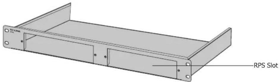
Appearance of RPS2 Figure 1-3
RPS Slot
To install RPS150 into RPS2, please insert RPS150 into the RPS Slot. Each RPS2 is designed to hold up to 2 RPS150. For detailed instructions, please refer to 2.4
Product Installation.
Installation Chapter 2
Package Contents 2.1
Make sure that the package contains the following items. If any of the listed items is damaged or missing, please contact your distributor.


Safety Precautions 2.2
To avoid any device damage and bodily injury caused by improper use, please observe the following rules:
■ Safety Precautions
- Keep the power off during the installation. Wear an ESD-preventive wrist strap, and make sure that the wrist strap has good skin contact and is well grounded.
- Make sure that the input AC power voltage matches the specifications indicated on the rear panel of the RPS150. ■ Before switching on the power, make sure that the power circuit will not be overloaded, otherwise the RPS150 will work abnormally or be damaged.
- Do not open or remove the cover of the RPS150, even if it is not electrified. ■ Before cleaning the device, cut off the power supply. Do not clean it with a wet cloth, and never use any other liquid cleaning method.
■ Site Requirements
To ensure normal operation and long service life of the device, please install it in an environment that meets the requirements described in the following subsection.
Redundant Power Supply
Temperature/Humidity
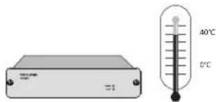
Please maintain proper temperature and humidity in the equipment room. Excessively high or low humidity can lead to poor insulation, electrical leakage, mechanical property changes, and corrosion. Excessively high temperatures can accelerate the aging of insulation materials and significantly shorten the device's service life. For normal temperature and humidity requirements, please refer to the following table.
| Environment Temperature Humidity | |
| Operating 0°C ~ 40°C | 20% ~ 90%RH Non-condensing |
| Storage -40°C ~ 70°C | 10% ~ 95%RH Non-condensing |
Cleanliness

Dust accumulated on the device can be attracted by static electricity and cause poor contact at metal contact points. Some measures have been taken to prevent static electricity, but excessive static electricity can cause severe damage to the electronic components on the internal circuit board. To avoid the effects of static electricity on device operation, please pay close attention to the following:
- Dust the device regularly and keep the indoor air clean.
- Ensure the device is properly grounded and that static electricity is discharged.
Electromagnetic Interference

Electronic components such as capacitors and inductors on the device can be affected by external interference, including conducted emissions through capacitive coupling, inductive coupling, and impedance coupling. To reduce interference, please ensure the following measures are taken:
- Use a power supply that effectively filters interference from the power grid.
- Keep the device away from high-frequency, high-current equipment, such as radio transmitting stations.
- Use electromagnetic shielding when necessary.
Lightning Protection
Extremely high voltage currents can be generated instantly when lightning occurs, and the air in the discharge path can be instantly heated to 20,000°C. Since this instantaneous current is strong enough to damage electronic devices, more effective lightning protection measures should be taken.
- Ensure the rack and device are properly grounded.
- Make sure the power socket has good contact with the ground.
- Maintain a proper cabling system to avoid induced lightning.
- Use a signal SPD (Surge Protective Device) when wiring outdoors.

Note: For detailed lightning protection measures, refer to section 3.1, Connect to Ground.
Installation Site
When installing the device on a rack or a flat workbench, note the following:
- The rack or workbench is flat, stable, and sturdy enough to support at least 5.5 kg.
- The rack or workbench has good ventilation, and the equipment room is well ventilated.
- The rack is well grounded. Keep the power socket within 1.5 meters of the device.
Installation Tools 2.3
- Phillips screwdriver, ESD-preventive wrist wrap
Product Installation 2.4
The RPS150 can be installed either in a standard 19-inch rack via RPS2 or directly on a tabletop.
Desktop Installation
To install the device on a desktop, follow these steps:

Caution:
- Leave 5-10 cm gaps around the device for heat dissipation and air circulation.
- Please avoid placing any heavy objects on the device.
Place the device upside down on a flat desktop that is strong enough to support the entire weight of the device with all fittings.
Remove the adhesive backing papers from the supplied rubber feet and attach the rubber feet to the recessed areas on the bottom at each corner of the device.
Turn the device over and place it stably on the tabletop.
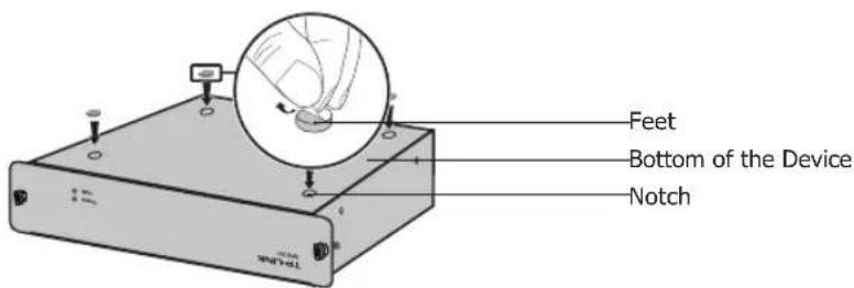
Desktop Installation Figure 2-1
■ Rack Installation
RPS150 can be installed in a standard rack via the RPS2 chassis. One RPS2 chassis is designed to hold up to 2 RPS150 units. You should install the RPS2 chassis to the rack first, and then insert RPS150 into the RPS2. The detailed instructions are described below:
Check the grounding and stability of the rack.
Place the RPS2 horizontally in an appropriate position in the rack and then support it with a bracket.
Secure the RPS2 to each side of the fixed guide slot with screws. Verify the stability and horizontality of RPS2 in the rack.

Install the RPS2 to a standard rack Figure 2-2
Insert the RPS150 into the RPS2 and fix it with screws, as illustrated in the figure below:

Insert RPS150 into RPS2 Figure 2-3

Note:
- Do not attach the supplied rubber feet on the bottom of RPS150 if it is supposed to be inserted into RPS2 in the bracket.
- A well grounded bracket can largely prevent the device from static electricity, electric leakage, lightning, and electromagnetic interference. Make sure the grounding cable of the bracket is correctly installed.
- Ensure the device is well ventilated for the purpose of heat dissipation.
Connection Chapter 3
Connect to Ground 3.1
Connecting the device to ground is to quickly release the lightning over-voltage and over-current of the device, which is also a necessary measure to protect the body from electric shock.
In different environments, the device may be grounded differently. The following will instruct you to connect the device to the ground in two ways: connecting to the grounding bar or connecting to the ground via the power cord. Please connect the device to ground in the optimum way according to your specific operation environment.
■ Connecting to the Grounding Bar
If the device is installed in the Equipment Room, where a grounding bar is available, you are recommended to connect the device to the grounding bar as shown in the following figure.

① Grounding Terminal
② RPS150 (Rear Panel)
③ Ground Cable
④ Grounding Bar
Figure 3-1 Connecting to the Grounding Bar

Note: The grounding bar and ground cable are not provided with our product. If needed, please self-purchase them.
■ Connecting to the Ground via the Power Supply
If the device is installed in the normal environment, the device can be grounded via the PE (Protecting Earth) cable of the AC power supply as shown in Figure 3-4.
To connect the device to the ground via the PE (Protecting Earth) cable of AC power cord, please make sure the PE (Protecting Earth) cable in the electrical outlet is well grounded in advance.
Connect to the Powered Device 3.2
The RPS150 can be used as a redundant backup power supply unit for multiple switch models. Follow the steps below to connect the RPS150 to a powered device.
1. Confirm that the power supply of the RPS150 is cut off.
2. Remove the protective covers covering the redundant power socket of RPS150 and the switch. Here we take the removing process of RPS150 for example:

Figure 3-2 Removing the RPS Protective Cover ① Protective Cover ② RPS DC Output
3. Connect the RPS150 and the switch with DC power cord, as illustrated in Figure 3-3. One end of the DC power cord is marked by the letters "TOP" and the other end has a positioning card attached to it. Plug the end with the letters "TOP" into the input socket of the switch with "TOP" facing up and the other end with positioning card into the DC output socket of the RPS150 with the positioning card facing up.

Caution:
Make sure the power supply of RPS150 is cut off when connecting or disconnecting RPS150 and the switch, otherwise both RPS150 and the switch may work abnormally or even be damaged.

Figure 3-3 Connecting to the Powered Switch ① RPS150 ② Positioning Card ③ Switch ④ One connector with letters "TOP"
Power On 3.3
The RPS150 requires 100-240V~50/60HZ AC power input.
1. Confirm that the power supply satisfies the requirement of the input voltage of RPS150;
2. Plug the negative connector of the provided AC power cord into the power socket of RPS150, and the positive connector into a power outlet as the following figure shown. After RPS150 is powered on normally, the Power LED and FAN LED indicators on its front panel will light on all the time.

Connecting to Power Supply Figure 3-4

Caution:
- Make sure that the power supply is well grounded. Locate the switch of the power supply in advance, so that you can cut it off in time when needed.
- Disconnect RPS150 from its AC power supply when plugging or removing the DC power cable.
- The figure is to illustrate the application and principle. The power cord you get from the package and the socket in your situation will comply with the regulation in your country, so they may differ from the figure above.
Verify Installation 3.4
After completing the installation, please verify the following items:
- There is enough room around the sides of RPS150 for heat dissipation and the air flow is adequate;
- The voltage of the power supply meets the requirement of the input voltage of the device;
- The power socket, device and rack are well grounded.
Appendix A Specifications
| Item Content | |
| AC Power Input 100-240V~ 50/60Hz 2.5A | |
| DC Power Output 12V 12.5A | |
| Maximum Power Output | 150W |
| LEDs Power, FAN | |
| Operating Temperature 0°C | ~40°C |
| Storage Temperature -40°C | ~70°C |
| Operating Humidity 20% | ~90%RH Non-condensing |
| Storage Humidity 10% | ~95%RH Non-condensing |
Appendix B Technical Support
■ For more help, please go to: http://www.tp-link.com/en/support/faq - To download the latest Firmware, Driver, Utility and User Guide, please go to: http://www.tp-link.com/en/support/download - For all other technical support, please contact us by using the following details:
| Global Tel: +86 755 2650 4400Fee: Depending on rate of different carriers, IDD.E-mail: support@tp-link.comService time: 24hrs, 7 days a week | |
| Australia/New Zealand Tel: AU 1300 87 5465 (Depending on 1300 policy.)NZ 0800 87 5465 (Toll Free)E-mail: support.au@tp-link.com (Australia)support.nz@tp-link.com (New Zealand)Service time: 24hrs, 7 days a week | |
| Brazil Toll Free: 0800 608 9799 (Portuguese Service)E-mail: suporte.br@tp-link.comService time: Monday to Saturday, 09:00 to 20:00; Saturday, 09:00 to 15:00 | |
| France Tel: 0820 800 860 (French service)Fee: 0.118 EUR/min from FranceEmail: support.fr@tp-link.comService time: Monday to Friday 9:00 to 18:00 *Except French Bank holidays | |
| Germany/Austria Tel: +49 1805 875 465 (German Service)+49 1805 TPLINK+49 820 820 360Fee: Landline from Germany: 0.14EUR/min.Landline from Austria: 0.20EUR/min.E-mail: support.de@tp-link.comService time: Monday to Friday, 9:00 to 12:30 and 13:30 to 17:30.GMT+ 1 or GMT+ 2 (DST in Germany) *Except bank holidays in Hesse | |
| Indonesia Tel: (+62) 021 6386 1936Fee: Depending on rate of different carriers.E-mail: support.id@tp-link.comService time: Monday to Friday 9:00 to 18:00 *Except public holidays | |
| Italy Tel: +39 023 051 9020Fee: Depending on rate of different carriers.E-mail: support.it@tp-link.comService time: Monday to Friday, 9:00 to13:00 and 14:00 to 18:00 | |
| MalaysiaToll Free: 1300 88 875 465Email: support.my@tp-link.comService time: 24hrs, 7 days a week | |
| Poland Tel: +48 (0) 801 080 618+48 223 606 363 (if calls from mobile phone)Fee: Depending on rate of different carriers.E-mail: support.pl@tp-link.comService time: Monday to Friday 9:00 to 17:00. GMT+1 or GMT+2 (DST) | |
| Russian Federation Tel: 8 (499) 754 5560 (Moscow NO.)8 (800) 250 5560 (Toll-free within RF)E-mail: support.ru@tp-link.comService time: From 9:00 to 21:00 (Moscow time)*Except weekends and holidays in RF | |
| Singapore Tel: +65 6284 0493 | Fee: Depending on rate of different carriers.E-mail: support.sg@tp-link.comService time: 24hrs, 7 days a week |
| Switzerland Tel: +41 (0) 848 800 998 (German Service)Fee: 4-8 Rp/min, depending on rate of different time.E-mail: support.ch@tp-link.comService time: Monday to Friday, 9:00 to 12:30 and 13:30 to 17:30.GMT+ 1 or GMT+ 2 (DST) | |
| Turkey Tel: 0850 7244 488 (Turkish Service)Fee: Depending on rate of different carriers.E-mail: support.tr@tp-link.comService time: 9:00 to 21:00, 7 days a week | |
| UK Tel: +44 (0) 845 147 0017 | Fee: Landline: 1p-10.5p/min, depending on the time of day.Mobile: 15p-40p/min, depending on your mobile network.E-mail: support.uk@tp-link.comService time: 24hrs, 7 days a week |
| Ukraine Tel: 0800 505 508 | Fee: Free for Landline; Mobile: Depending on rate of different carriers.E-mail: support.ua@tp-link.comService time: Monday to Friday 10:00 to 22:00 |
| USA/Canada Toll Free: +1 866 225 8139E-mail: support.usa@tp-link.comService time: 24hrs, 7 days a week | |
TP-LINK®
The Reliable Choice
- REDUNDANT POWER SUPPLY
- RPS
- DUAL BAY RACKMOUNTABLE RPS SHELF
- COPYRIGHT & TRADEMARKS
- FCC STATEMENT
- CE MARK WARNING
- RELATED DOCUMENT
- ABOUT THIS INSTALLATION GUIDE
- AUDIENCE
- CONVENTIONS
- CONTENTS
- CHAPTER 1 INTRODUCTION
- CHAPTER 2 INSTALLATION
- CHAPTER 3 CONNECTION
- APPENDIX A SPECIFICATIONS
- APPENDIX B TECHNICAL SUPPORT
- INTRODUCTION CHAPTER
- PRODUCT OVERVIEW
- FEATURES
- APPEARANCE
- FRONT PANEL OF RPS
- INDICATORS
- REAR PANEL OF RPS
- AC POWER INPUT
- GROUNDING TERMINAL
- PROTECTIVE COVER
- CAUTION
- APPEARANCE OF RPS
- RPS SLOT
- INSTALLATION CHAPTER
- PACKAGE CONTENTS
- SAFETY PRECAUTIONS
- SITE REQUIREMENTS
- TEMPERATURE/HUMIDITY
- CLEANLINESS
- ELECTROMAGNETIC INTERFERENCE
- INSTALLATION TOOLS
- PRODUCT INSTALLATION
- DESKTOP INSTALLATION
- RACK INSTALLATION
- NOTE
- CONNECTION CHAPTER
- CONNECT TO GROUND
- CONNECTING TO THE GROUNDING BAR
- CONNECTING TO THE GROUND VIA THE POWER SUPPLY
- CONNECT TO THE POWERED DEVICE
- POWER ON
- VERIFY INSTALLATION
Brand : TP-LINK
Model : RPS2
Category : Computer Cable