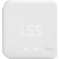
Wireless Temperature Sensor - Thermostat TADO - Free user manual and instructions
Find the device manual for free Wireless Temperature Sensor TADO in PDF.


| Product Type | Wireless Temperature Sensor |
| Brand | Tado |
| Model | Wireless Temperature Sensor |
| Category | Thermostat Accessory |
| Dimensions | 86 x 86 x 15 mm |
| Weight | 40 g |
| Power Source | 2 x AA batteries |
| Battery Life | Up to 2 years |
| Connectivity | Wireless (868 MHz / 915 MHz) |
| Wireless Protocol | Proprietary Tado protocol |
| Range | Up to 30 m indoors |
| Temperature Measurement Range | 0°C to 50°C |
| Temperature Accuracy | ±0.5°C |
| Resolution | 0.1°C |
| Humidity Sensor | Yes |
| Mounting | Free-standing or wall mount |
| IP Rating | IP20 |
| Material | Polycarbonate |
| Color | White |
| Operating Temperature | 0°C to 50°C |
| Storage Temperature | -10°C to 60°C |
| Certifications | CE, FCC, RoHS |
| Warranty | 2 years |
| Included Accessories | Mounting kit, user manual |
| Compatible Systems | Tado Smart Thermostat, Tado app |
Frequently Asked Questions - Wireless Temperature Sensor TADO
User questions about Wireless Temperature Sensor TADO
0 question about this device. Answer the ones you know or ask your own.
Ask a new question about this device
Download the instructions for your Thermostat in PDF format for free! Find your manual Wireless Temperature Sensor - TADO and take your electronic device back in hand. On this page are published all the documents necessary for the use of your device. Wireless Temperature Sensor by TADO.
USER MANUAL Wireless Temperature Sensor TADO
Manual for Professional Installers
For the Starter Kit - Wireless Smart Thermostat V3+ (Incl. Programmer with Hot Water Control)

This manual is meant exclusively for professional installers. It includes generic instructions to install the Wireless Receiver (Programmer) and the Wireless Temperature Sensor.
Manual version 3.2
DIY Installation
If you are not a professional installer, please download the tado° app. There you will find specific installation instructions.


1. Install the Internet Bridge
A. Connect the Internet Bridge to the router. If no free USB port is available on the router, use the included 5V power adapter.
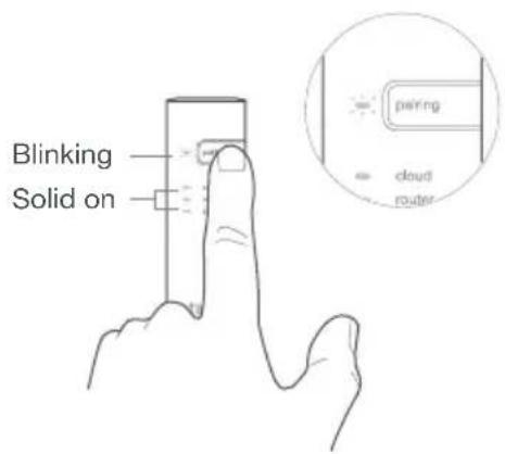
B. Press and hold the pairing button until the pairing LED starts blinking.

2. Pair the Wireless Temp. Sensor
A. Remove the battery protection strip.
B. Press the button for 3 sec to start pairing.
C. Pairing may take up to 2 min.
D. The static icon below indicates successful pairing.

natural_image
Illustration of a digital kitchen appliance with a monitor and control panel (no text or symbols)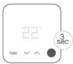

natural_image
Simple icon of a device with dotted outline and circular button (no text or symbols)If pairing fails (E0), make sure the distance between the devices is approximately 3 meters. Pair again by pressing the button for 3 sec.
3. Replace the room thermostat

Caution! Turn OFF the power before wiring!
If there is a wired room thermostat installed in the zone that is intended to be controlled by the Wireless Receiver, please decommission it by bridging the control wires and insulating the other wires with the included 2-terminal connector blocks as shown in the images.
Once tado° is installed, the Wireless Receiver will be the only device that controls the heating system.

flowchart
graph LR
    A["Hand icon"] --> B["LIVE (COM)"]
    B --> C["SWITCHED LIVE (NO)"]
    C --> D["NEUTRAL EARTH"]
    D --> E["Digital display with 'tado' icon"]
For Neutral and Earth, Insert only one wire per block, even though the block has more than one opening.
Extra information: Wireless Receiver Symbols
Power supply, testing mode & configuration
Connection with other tado° devices
Device errors Heat request Hot water request


Unfold to check:
Step 4: Wire the Wireless Receiver
Step 5: Pair the Wireless Receiver
Step 6: Configuration
4. Wire the Wireless Receiver
S-Plan
The Wireless Receiver is configured by default for fully-pumped S-plan and Y-plan heating systems.

Caution! Turn OFF the power before wiring!

Mount the Wireless Receiver to the wall before wiring.

Always use the included strain reliefs and position them on the outer insulation layer of the cable.

HW ValveCH Valve
Stat
Boiler HW Cylinder

natural_image
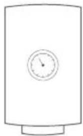
Simple line drawing of a rectangular device with a handle and control buttons at the bottom (no text or symbols)

natural_image
Simple line drawing of a cylindrical container with a circular top and side base (no text or symbols)
Included bridging wires (purple)
Y-Plan
The Wireless Receiver is configured by default for fully-pumped S-plan and Y-plan heating systems.

Caution! Turn OFF the power before wiring!

Mount the Wireless Receiver to the wall before wiring.

Always use the included strain reliefs and position them on the outer insulation layer of the cable.

HW Cylinder Stat
Boiler Mid-Position

natural_image
Simple line drawing of a device with a handle and control buttons (no text or symbols)Valve


natural_image
Simple line drawing of a cylindrical device with a circular dial and base (no text or symbols)
Included bridging wires (purple)
Potential FreeCombi Boilers: Switched Live
When connecting tado° to a combi boiler, the configuration should be changed to single relay to deactivate hot water control on the Wireless Receiver (see step 6).

Caution! Turn OFF the power before wiring!

Mount the Wireless Receiver to the wall before wiring.

Always use the included strain reliefs and position them on the outer insulation layer of the cable.

Combi boiler

natural_image
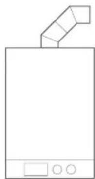
Simple line drawing of a device with a handle and control buttons (no text or symbols)Combi boiler
natural_image
Simple line drawing of a device with a handle and control buttons (no text or symbols)
Included bridging wires (purple)
5. Pair the Wireless Receiver
A. Put the cover on the device.

natural_image
Line drawing of a hand holding a compact device with a handle and internal components (no text or symbols)B. Turn the power back ON and wait 30 sec.
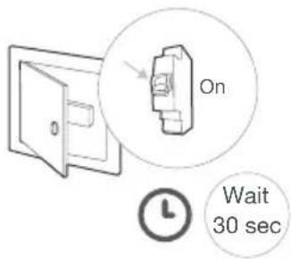
C. Press the main button above the signal icon for 3 sec to start pairing.

D. Solid on indicates successful pairing.

6. Configuration
i Configuration is only required if tado° is wired to a combi boiler or to a gravity-fed system.
A. Press both test buttons at the same time for 5 sec, until the coloured power LED shows the current configuration.

Colour Configuration HW controlSystem
Green Dual relay-Fully pumped
YesS-Plan & Y-plan
(factory default)
Yellow Single Relay NoCombi Boiler
Blue Dual Relay - Gravity fed YesGravity fed
B. Press the heating TEST button to switch between configurations. Wait 5 sec to confirm selection.

C. Once the selection is confirmed, the LED will blink to indicate is being saved. After, the LED stays solid 20 sec in the colour of the selected configuration.

i Testing instructions in the next pages
7. Test the system
A. Press the heating or hot water TEST button once. The orange LED will start fading in and out indicating that the testing mode is active.
B. Press the TEST button for either heating or hot water to switch the relay ON or OFF. The TEST button's LED will turn ON when the relay is in the closed position.
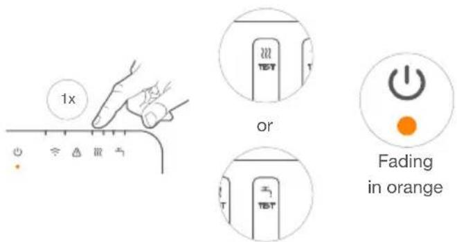

The device exits the testing mode automatically after 2 minutes of not pressing either TEST button.
Please note that the TEST buttons adhere to the configuration of the device, meaning that the hot water TEST button will be inactive if the configuration is set to single relay.
Need help?
Find additional Professional Installer Manuals here.
Find more information on error codes in our Help Center.
Register on our tado°
Professional site for help, tips, and more information.

tado.com/professional-manuals

tado.com/support

tado.com/installers
Get expert advice on our tado° installer hotline: +44 20 3893 2159


- Manual for Professional Installers
- Install the Internet Bridge
- Pair the Wireless Temp. Sensor
- Replace the room thermostat
- Extra information: Wireless Receiver Symbols
- Wire the Wireless Receiver
- S-Plan
- Y-Plan
- Potential FreeCombi Boilers: Switched Live
- Pair the Wireless Receiver
- Configuration
- Colour Configuration HW controlSystem
- Test the system
- Need help?
Brand : TADO
Model : Wireless Temperature Sensor
Category : Thermostat