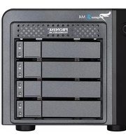
Pegasus2 M4 - Disk array Promise Technology - Free user manual and instructions
Find the device manual for free Pegasus2 M4 Promise Technology in PDF.


| Product Type | Disk Array |
| Brand | Promise Technology |
| Model | Pegasus2 M4 |
| Drive Bays | 4 (supports 2.5in or 3.5in SATA drives) |
| Interface | Thunderbolt 2 (2 ports) |
| Data Transfer Rate | Up to 20 Gbps (Thunderbolt 2) |
| RAID Levels | 0, 1, 5, 6, 10, JBOD |
| Dimensions (H x W x D) | 203 x 198 x 145 mm (8.0 x 7.8 x 5.7 in) |
| Weight | 3.2 kg (7.1 lb) without drives |
| Power Supply | External 90W power adapter |
| Cooling | 1 x 80mm fan (variable speed) |
| LED Indicators | Power, Activity, Drive status, Mode |
| Operating Temperature | 5°C to 40°C (41°F to 104°F) |
| Storage Temperature | -20°C to 60°C (-4°F to 140°F) |
| Compatibility | Mac OS X 10.9 or later, Windows 7/8/10 (requires driver) |
| Included Accessories | Thunderbolt cable, power adapter, quick start guide, software CD |
| Maintenance | Clean with dry cloth; avoid liquids; ensure adequate ventilation |
| Safety Certifications | CE, FCC, UL, RoHS |
| Warranty | 3 years limited |
Frequently Asked Questions - Pegasus2 M4 Promise Technology
User questions about Pegasus2 M4 Promise Technology
0 question about this device. Answer the ones you know or ask your own.
Ask a new question about this device
Download the instructions for your Disk array in PDF format for free! Find your manual Pegasus2 M4 - Promise Technology and take your electronic device back in hand. On this page are published all the documents necessary for the use of your device. Pegasus2 M4 by Promise Technology.
USER MANUAL Pegasus2 M4 Promise Technology
© 2014 PROMISE Technology, Inc. All Rights Reserved. PROMISE, the PROMISE logo, VTrak, Pegasus, SmartStor, SuperTrak, FastTrak, VessRAID, Vess, PerfectPATH, PerfectRAID, SATA150, ULTRA133, VTrak S3000, BackTrak, HyperCache, HyperCache-R, HyperCache-W, DeltaScan and GreenRAID are registered or pending trademarks of PROMISE Technology, Inc. in the U.S. and other countries. All other trademarks are the property of their respective owners. Information regarding products, services and offerings may be superseded by subsequent documents and are subject to change without notice. For the latest information and specifications regarding PROMISE Technology, Inc. and any of its offerings or services, please contact your local PROMISE office or the corporate headquarters. Visit www.PROMISE.com for more information on PROMISE products.
Important data protection information
You should back up all data before installing any drive controller or storage peripheral. PROMISE Technology is not responsible for any loss of data resulting from the use, disuse or misuse of this or any other PROMISE Technology product.
Notice
Although PROMISE Technology has attempted to ensure the accuracy of the content of this document; it is possible that this document may contain technical inaccuracies, typographical, or other errors. PROMISE Technology assumes no liability for any error in this publication, and for damages, whether direct, indirect, incidental, consequential or otherwise, that may result from such error, including, but not limited to loss of data or profits.
PROMISE Technology provides this publication “as is” without warranty of any kind, either express or implied, including, but not limited to implied warranties of merchantability or fitness for a particular purpose. The published information in the manual is subject to change without notice. PROMISE Technology reserves the right to make changes in the product design, layout, and driver revisions without notification to its users. This version of this document supersedes all previous versions.
Recommendations
In this Product Manual, the appearance of products made by other companies, including but not limited to software, servers, and disk drives, is for the purpose of illustration and explanation only. PROMISE Technology does not recommend, endorse, prefer, or support any product made by another manufacturer.
ABOUT THIS GUIDE
This Product Manual describes how to setup, use, and maintain the Pegasus2 M4 unit. It also describes how to use the PROMISE Utility software that you install and run on your Macintosh computer.
Although this manual is written specifically for the Pegasus2 models, many of the functions and descriptions can be applied to the original release of Pegasus, Pegasus R4 and Pegasus R6. Pegasus2 is operationally compatible with the original release of Pegasus. Material that applies only to the Pegasus2 will specify Pegasus2. Use of the term "Pegasus" implies that the material applies to both versions.
This manual includes a full table of contents, chapter task lists, and numerous cross-references to help you find the specific information you are looking for.
Also included are four levels of notices:

Note
A Note provides helpful information such as hints or alternative ways of doing a task.

Important
An Important notice calls attention to an essential step or point required to complete a task. Important items include things often missed.

CAUTION
A Caution informs you of possible equipment damage or loss of data and how to avoid them.

WARNING
A Warning notifies you of probable equipment damage or loss of data, or the possibility of physical injury, and how to avoid them.
FCC
This equipment has been tested and found to comply with the limits for a Class B digital device, pursuant to Part 15 of the FCC Rules. These limits are designed to provide reasonable protection against harmful interference when the equipment is operated in a residential installation. This equipment generates, uses, and can radiate radio frequency energy and if not installed and used in accordance with the instruction manual may cause harmful interference to radio communications. However, there is no guarantee that interference will not occur in a particular installation. If this equipment does cause harmful interference to radio or television reception, which can be determined by turning the equipment off and on, the user is encouraged to try to correct the interference by one or more of the following measures:
• Reorient or relocate the receiving antenna.
- Increase the separation between the equipment and receiver.
- Connect the equipment into an outlet on a circuit different from that to which the receiver is connected.
- Consult the dealer or an experienced radio TV technician for help.
Notice: The changes or modifications not expressly approved by the party responsible for compliance could void the user's authority to operate the equivalent.
VCCI
Use the power cord included with the Pegasus2 M4.
CAUTION
The electronic components within the Pegasus unit are sensitive to damage from Electro-Static Discharge (ESD). Observe appropriate precautions at all times when handling the Pegasus unit or its subassemblies.

CAUTION
To avoid hand contact with an electrical hazard, do not remove more than one drive carrier a time" or the equivalent.
CONTENTS
ABOUT THIS GUIDE III
INTRODUCTION TO PEGASUS2 1
Architecture 2
Protocol Support 2
Key Benefits 2
SPECIFICATIONS 3
HARDWARE 4
INSTALLATION AND SETUP 6
SUMMARY OF THE SETUP PROCEDURE 7
PACKING LIST 7
CONNECT THE POWER CORD 8
CONNECT PEGASUS2 TO YOUR MAC 9
INSTALLING THE SOFTWARE 10
Displaying Multiple Pegasus/Pegasus2 Units 15
To Create a Disk Array and Logical Drive 16
MANAGE WITH PROMISE UTILITY 17
ACCESSING THE PROMISE UTILITY 18
Opening 18
Closing 18
UNLOCKING THE UI 19
PERUSING THE PROMISE UTILITY INTERFACE 20
Toolbar Icons 21
Customizing the Toolbar 21
DEVICE MENUS 22
Component List 22
Physical Drive menu 22
Front View 23
Back View 24
MANAGING SUBSYSTEMS 25
VIEWING SUBSYSTEM INFORMATION 25
MAKING SUBSYSTEM SETTINGS 26
CLEARING STATISTICS 26
RESTORING FACTORY DEFAULT SETTINGS 27
SAVING A SERVICE REPORT 27
UPDATING FIRMWARE 28
Green RAID Features 32
VIEWING TEMPERATURE SENSOR INFORMATION 34
LOCATING AN ENCLOSURE 35
MANAGING BACKGROUND ACTIVITIES 36
VIEWING CURRENT BACKGROUND ACTIVITIES 37
VIEWING SCHEDULED BACKGROUND ACTIVITIES 37
ADDING A SCHEDULED BACKGROUND ACTIVITY 37
CHANGING A BACKGROUND ACTIVITY SCHEDULE 39
ENABLING OR DISABLING A SCHEDULED BACKGROUND ACTIVITY 40
DELETING A SCHEDULED BACKGROUND ACTIVITY 40
MEDIA PATROL 41
Making Media Patrol Settings 41
REDUNDANCY CHECK 42
Making Redundancy Check Settings 42
INITIALIZATION 42
Making Initialization Settings 43
REBUILD 43
Making Rebuild Settings 44
MIGRATION 44
Making Migration Settings 44
PDM 45
Making PDM Settings 45
TRANSITION 46
Making Transition Settings 46
SYNCHRONIZATION 47
Making Synchronization Settings 47
MANAGING PHYSICAL DRIVES 48
VIEWING A LIST OF PHYSICAL DRIVES 48
VIEWING PHYSICAL DRIVE INFORMATION 49
VIEWING PHYSICAL DRIVE STATISTICS 50
VIEWING PHYSICAL DRIVE SMART LOG INFORMATION 51
LOCATING A PHYSICAL DRIVE 51
MAKING GLOBAL PHYSICAL DRIVE SETTINGS 52
MAKING INDIVIDUAL PHYSICAL DRIVE SETTINGS 52
MAKING PHYSICAL DRIVE SMART LOG SETTINGS 53
CLEARING A STALE OR A PFA CONDITION 53
Running Media Patrol on your Physical Drives 55
MANAGING DISK ARRAYS 56
VIEWING A LIST OF DISK ARRAYS 56
VIEWING DISK ARRAY INFORMATION 57
CREATING A DISK ARRAY MANUALLY 58
CREATING A DISK ARRAY AND LOGICAL DRIVE WITH THE WIZARD 59
Choosing Automatic Configuration 60
Choosing Express Configuration 61
Choosing Advanced Configuration 63
MAKING DISK ARRAY SETTINGS 65
Performing a Manual Rebuild 68
Pausing and Resuming a Rebuild 69
Stopping a Rebuild 69
MANAGING LOGICAL DRIVES 70
VIEWING A LIST OF LOGICAL DRIVES 71
VIEWING LOGICAL DRIVE INFORMATION 71
VIEWING LOGICAL DRIVE STATISTICS 72
MAKING LOGICAL DRIVE SETTINGS 73
VIEWING LOGICAL DRIVE CHECK TABLES 74
CREATING A LOGICAL DRIVE MANUALLY 74
FORMATTING YOUR LOGICAL DRIVES 76
LOCATING A LOGICAL DRIVE 76
DELETING A LOGICAL DRIVE 77
INITIALIZING A LOGICAL DRIVE 77
Pausing and Resuming an Initialization 78
Stopping an Initialization 78
REDUNDANCY CHECK ON A LOGICAL DRIVE 78
Pausing and Resuming a Redundancy Check 79
Stopping a Redundancy Check 79
MIGRATING A LOGICAL DRIVE 79
RUNNING PDM ON A LOGICAL DRIVE 81
Pausing and Resuming PDM 81
Stopping PDM 81
MANAGING SPARE DRIVES 82
VIEWING A LIST OF SPARE DRIVES 82
VIEWING SPARE DRIVE INFORMATION 83
CREATING A SPARE DRIVE MANUALLY 84
MAKING SPARE DRIVE SETTINGS 85
RUNNING SPARE CHECK 85
DELETING A SPARE DRIVE 86
Running a Transition on a Spare Drive 86
RUNNING A TRANSITION 87
Pausing and Resuming a Transition 87
Stopping, Pausing or Resuming a Transition 87
TECHNOLOGY BACKGROUND 88
DISK ARRAYS 89
MEDIA PATROL 89
PDM 90
LOGICAL DRIVES 91
RAID LEVELS 91
RAID 0 - Stripe 91
RAID 1 - Mirror 93
RAID 1E - Enhanced Mirror 94
RAID 5 - Block and Parity Stripe 95
RAID 6 – Block and Double Parity Stripe 96
RAID 10 - Mirror + Stripe 97
RAID 50 – Striping of Distributed Parity 98
RAID 60 - Double Parity + Stripe 100
RAID LEVEL MIGRATION 101
Migration Requirements 101
Source and Target RAID Levels 101
STRIPE SIZE 106
SECTOR SIZE 107
INITIALIZATION 107
FORMATTING LOGICAL DRIVES 108
PROMISE Utility with Default Settings 108
PROMISE Utility with Custom Settings 109
Disk Utility 110
SPARE DRIVES 111
DEFINITION 111
OPTIONS 111
REQUIREMENTS 112
TRANSITION 112
Running a Transition 112
RAID CONTROLLERS 115
Read Cache Policy 115
Write Cache Policy 115
CAPACITY COERCION 116
TROUBLESHOOTING 118
RESPONDING TO AN AUDIBLE ALARM 118
CHECKING LEDs 119
Subsystem LEDs 119
Drive Carrier LEDs 120
PROMISE UTILITY 121
VIEWING THE EVENT LOGS 121
Viewing Runtime Events 121
Viewing NVRAM Events 122
Event Severity Descriptions 122
MANAGING ALERTS 123
Configure alert notification level 124
PHYSICAL DRIVE PROBLEMS 125
DIAGNOSIS USING THE PROMISE UTILITY 125
LOCATING A PHYSICAL DRIVE 126
REPLACING A PHYSICAL DRIVE 127
Physical Drive Warning Message 130
DISK ARRAY AND LOGICAL DRIVE PROBLEMS 131
DISK ARRAY DEGRADED/LOGICAL DRIVE CRITICAL 131
Inadequate Air Circulation 138
POWER SUPPLY 138
CONNECTION PROBLEMS 139
CABLES 139
DAISY-CHAINS 140
PERFORMANCE MONITOR 141
CONTACTING TECHNICAL SUPPORT 142
LIMITED WARRANTY 146
Disclaimer of other warranties 147
Your Responsibilities 148
Returning the Product For Repair 148
APPENDIX A 150
TRANSFERRING A PHYSICAL HARD DISK FROM MAC TO PEGASUS2 150
Pass-through disk procedure for Mac 150
APPENDIX B 152
IMPORTANT INFORMATION 152
Hard Drive Compatibility 152
GNU General Public License 153
INTRODUCTION TO PEGASUS2
This chapter covers the following topics:
- "Architecture"
- "Protocol Support"
• "Key Benefits" - "Specifications"
- "Hardware"
PROMISE Technology's Pegasus2 M4, R8, R6 and R4 are direct attached storage (DAS) solutions for external storage targeted for small and medium business (SMB) users, small office / home office (SOHO) users, and digital Audio and Video production professionals.
Pegasus2 models (M4, R4, R6, R8) are operationally compatible with the original release Pegasus R4 and R6 models. Use the latest version of the PROMISE Utility to monitor the Pegasus2 status and perform maintenance and management functions. The latest version of the PROMISE Utility can also be used for the original release of Pegasus.

Important
If you are planning to transfer a Hard Disk Drive (HDD) from your Mac and want to retain user settings and permissions and keep the data, please see "Transferring A Physical Hard Disk From Mac To Pegasus2" on page 150.
ARCHITECTURE
The Pegasus2 architecture is based on a state-of-the-art PMC Sierra 8011
I/O processor coupled with 512 MB of DDR2 SDRAM memory and a world class enterprise-proven RAID engine.
PROTOCOL SUPPORT
Pegasus2 supports Thunderbolt 2 ^™ technology, providing two channels with 20 Gb/s of throughput in both directions simultaneously. Thunderbolt 2 is compatible with the previous original version of Thunderbolt.
Thunderbolt and Thunderbolt 2 support daisy-chaining up to six (6) high-speed peripheral devices, including external disks, video capture devices, and a Mini DisplayPort monitor.
Pegasus2 has two Thunderbolt ports, as required for daisy-chaining.
KEY BENEFITS
• Thunderbolt 20 Gb/s data connection
• PMC Sierra 8011 I/O processor
• 512 MB of DDR2 SDRAM memory
• PROMISE Utility management tool
• Compatible with Apple Time Machine
• M4, includes four SATA 2.5-inch hard disk drives (also supports SSD drives)
• Additional storage using multiple daisy-chained Pegasus and Pegasus2 enclosures

Note
The illustrations in this Product Manual are use Mac computers. Pegasus2 is supported on Windows computers equipped with a Thunderbolt port. Please refer to the Pegasus2 Installation Guide for Windows for information such as Windows driver installation.
SPECIFICATIONS
| Storage Disks | The Pegasus2 M4 is shipped with 2.5 inch SATA Hard Disk Drives (HDD) installed in the drive carriers and placed in the drive bays.Users can replace the drives with any of the supported drive types. For many RAID configurations, it is best to install drives that are identical in type and storage capacity.The following storage disk types are supported on the Pegasus2:2.5-inch SATA hard disk drives2.5-inch SSD |
| Capacity | Total capacity depends on the size of the HDD shipped with the unit. The Pegasus2 M4 is shipped with four HDD. In addition, Pegasus2 enclosures can be connected or “daisy-chained” to other Pegasus2 or Pegasus units to scale up the available storage capacity. |
| Power supply | 110W, 100-240V auto-ranging, 57-63Hz AC |
| System Fan | Dimension: 75(W) x 73(H) x 20(D)Airflow: 8.83 CFM |
| RAID function | RAID level support: RAID 0, 1, 1E, 5, 6, 10 |
| OS Support | Mac: OS X 10.8 or laterWindows OS support: Windows 7 and Windows 8 |
| HW monitoring | Fan, Temperature, Power, Enclosure, Physical drives, Logical drives, RAID controller |
| Temperature | Operating: 5° ~ 35° CNon-operating: -40° ~ 70°C |
| Humidity | Operating: 10% ~ 95% non-condensingStorage: 5% - 95% non-condensing |
| Dimensions | 168(L) 127(W) 107(H) mm 6.6(L) 5(W) 4.2(H) in |
| Weight | M4 with 2.5" HDD installed: 1.92kgM4 without 2.5" HDD: 1.49kg |
| Certification | EMC: FCC, CE, VCCI, BSMI, C-tick, KCCSafety: TUV, CB, UL/CUL, BSMIEnvironmental: Erp/Eup, ROHS, WEEE |
HARDWARE
This section provides a brief introduction to the external hardware of the Pegasus2 M4.
Pegasus2 M4 front view

LED Description
| System Status* | The System Status LED located on the Power button lights blue when the Pegasus2 is operating normally. When the system is booting up, this lights orange and will light blue when fully booted if there are no problems detected. A red System Status LED indicates a serious problem such as an incomplete array or failed hard disk drive. |
| Thunderbolt Link | These light blue when the Thunderbolt cable is connected, they remain dark when there is no link. |
| Drive Status and Activity* | The Drive Status LED lights blue when a physical drive is present and functioning normally. A red Drive Status LED indicates a problem with the physical drive or an array. The Drive Activity LED lights blue when the physical drive is present and blinks blue when there is activity on the drive. |
* See "Checking LEDs" on page 119 for more details about using LED indicators for troubleshooting.

CAUTION
Do not block the cooling vent on the bottom of the device housing.
Pegasus2 M4 back view

Feature Description
Thunderbolt Ports
Power Receptacle
Use a Thunderbolt cable to connect the Pegasus2 to a Thunderbolt ready computer. This connection completes the physical link, it is the path through which the SATA link is established.
Use only the power cord shipped with the device to connect the power. Insert one end of the power cord into the power receptacle and insert the other end into a suitable power source such as a wall outlet or a power strip.
INSTALLATION AND SETUP
This chapter contains the following topics:
- "Packing List" on page 7
- "Connect the power cord" on page 8
- "Connect Pegasus2 to your Mac" on page 9
• "Installing the Software" on page 10
• "Power modes on the Pegasus2" on page 13 - "Shutting down the Pegasus2" on page 13

CAUTION
The electronic components within the Pegasus2 unit are sensitive to damage from Electro-Static Discharge (ESD). Observe appropriate precautions at all times when handling the Pegasus2 unit or its subassemblies.
SUMMARY OF THE SETUP PROCEDURE
The setup procedure for the Pegasus2 is simple and easy. The device is shipped with hard disk drives installed and a RAID array configured, so it is just necessary to plug it in and connect the device. However you should install the PROMISE Utility software used for monitoring and administration of the system. Please follow the setup procedure here or in the Quick Start Guide.
The setup process is summarized below.
- Unpack the Pegasus2 shipping package
- Connect the power cord and power on the Pegasus2 M4.
- Connect the Pegasus2 to your Mac computer with a Thunderbolt cable.
- Find the Pegasus2 Utility installation package located on the device (Pegasus2 is shipped with RAID 5 configuration) and install the management software utility.
PACKING LIST
Check the shipping package to make sure you have the following items:
- Pegasus2 M4
- Thunderbolt cable
• Hard disk drives (four in M4)
- Power cord
- Quick Start Guide
To connect the power cord the Pegasus2 unit:
-
Attach the power cord on the back of the Pegasus2 unit. See "Thunderbolt and power connections" below.
-
Plug the other end into a suitable power source.
Thunderbolt and power connections

CONNECT PEGASUS2 TO YOUR MAC

Note
If the Thunderbolt cable is connected to a Mac that is running, the Pegasus2 will power up as soon as the power is connected. This is a new feature for the Pegasus2.
To establish the Thunderbolt connection:
- Connect a Thunderbolt cable from one of the Thunderbolt ports on the back of the Pegasus2 to the Thunderbolt port on your Mac computer. See "Thunderbolt and power connections" on page 8.
- If the Pegasus2 is plugged into a power source and the Mac is running, the Pegasus2 will power on and begin to boot up. See "Power modes on the Pegasus2" on page 13 for information on power up and shut down behavior.
You will notice the following:
- The Power Button LED lights orange at first, then blue.
• The drive carrier Power / Status LEDs light blue.
• The Thunderbolt Link LED for the port connected to the Mac lights blue.
See "Pegasus2 M4 front view" on page 4 for illustration of the front of the device.
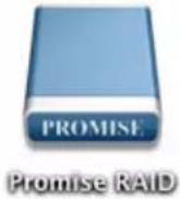
- The "PROMISE RAID" storage drive icon (see picture below) appears on your desktop. This indicates the Pegasus2 is ready for use.

Promise RAID

Note
When the device is powered on by connecting the Thunderbolt cable, or by pressing the Power Button, the Power Button turns orange. It takes about 30 seconds to start the Pegasus2 unit.
INSTALLING THE SOFTWARE
The Pegasus2 unit ships ready to use without configuration or set-up. However it is a good idea to install the PROMISE Utility software even if you do not plan to make any changes to device configuration. The utility is useful for monitoring the system and getting firmware updates.

Important
Windows users please follow the instructions in the Pegasus2 Installation Guide for Windows to install the driver and other software needed for the Pegasus2.
The utility is necessary if you plan to change the default RAID configuration (Pegasus2 is shipped with a RAID 5) or if you will swap out any of the hard disks shipped with the device.
The software utility installation package is located on the Pegasus2. Follow the instructions below to install the utility.
To install the Pegasus2 Software Utility:
- Double-click on the Pegasus2 icon on your desktop to view the device contents. See example to right.
- Find the file R_PROMISE_Utility.dmg and double-click on it to mount the virtual drive containing the installation software package.*

- Double-click on the R_PROMISE_Utility.pkg file to begin the software installation.*
* The .dmg file and .pkg file might include a version number that will change as it is updated.

The Welcome menu explains that software will be installed on the Mac. Click the Continue button to proceed with installation.

- The Software License Agreement appears, please read the statement and click Continue to proceed.

- Click Agree if you agree to the terms of the license. To read the license, click Read License. Choose Disagree if you do not agree the terms, in which case the installation procedure is terminated.
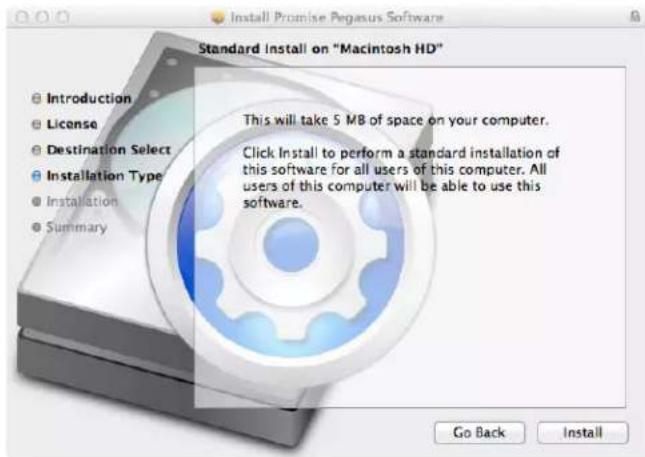
- If you clicked Agree in the previous menu, the software is now ready to install. Click Install to begin.

- It takes a few seconds for the utility software to be installed. When the installation has completed, a message informs you that the installation was successful. Click Close to end the installation procedure.
The PROMISE Utility is now available to be used for management of the Pegasus2. Use this if you need to change a hard disk drive, or change the default array configuration, or to update the device firmware. This is also useful for monitoring the status of the system and for troubleshooting. For more information on using the PROMISE Utility, including instructions on how to use the Wizard menus to install a different RAID array configuration, please read "Manage with PROMISE Utility" on page 17.
The Pegasus2 introduces new power saving and response features. These are described below.
The automatic power features are:
- Sleep - When your Mac computer goes to sleep, the Pegasus2 unit automatically shuts down after all background activities are finished.
- Wake – When your Mac computer wakes, the Pegasus2 unit automatically powers on.
- Shutdown – When your Mac computer shuts down, the Pegasus2 unit automatically shuts down.
- Restart After Shutdown – When your Mac computer powers up, the Pegasus2 unit automatically powers up.
- Spin down HDD - The Pegasus2 includes a power saving feature that spins down the hard disk drives if the logical drive is idle for 30 minutes. This can be enabled or disabled and the idle time can be changed in the PROMISE Utility. Click on the Controller link in the Dashboard, then click the Settings button to see how to change this setting.
The shuts down automatically if you turn off your Mac. If you want to turn off the Pegasus2 without shutting down your computer, follow the steps below.
To shut down the Pegasus2 unit:
- Eject the Pegasus2 by right-clicking on the drive icon and choosing the Eject option.
- Launch the PROMISE Utility and click on the Subsystem Information menu button at the top of the interface, unlock the user interface (see "Unlocking the UI" on page 15), click on the Shutdown button, then click on Shutdown in the new menu that appears. You will need to type "confirm" in the pop-up menu and click on the Confirm button.
Alternatively, you can press and hold the Power Button until the Power LED on the button turns orange. When you release the Power Button, the LED goes dark.
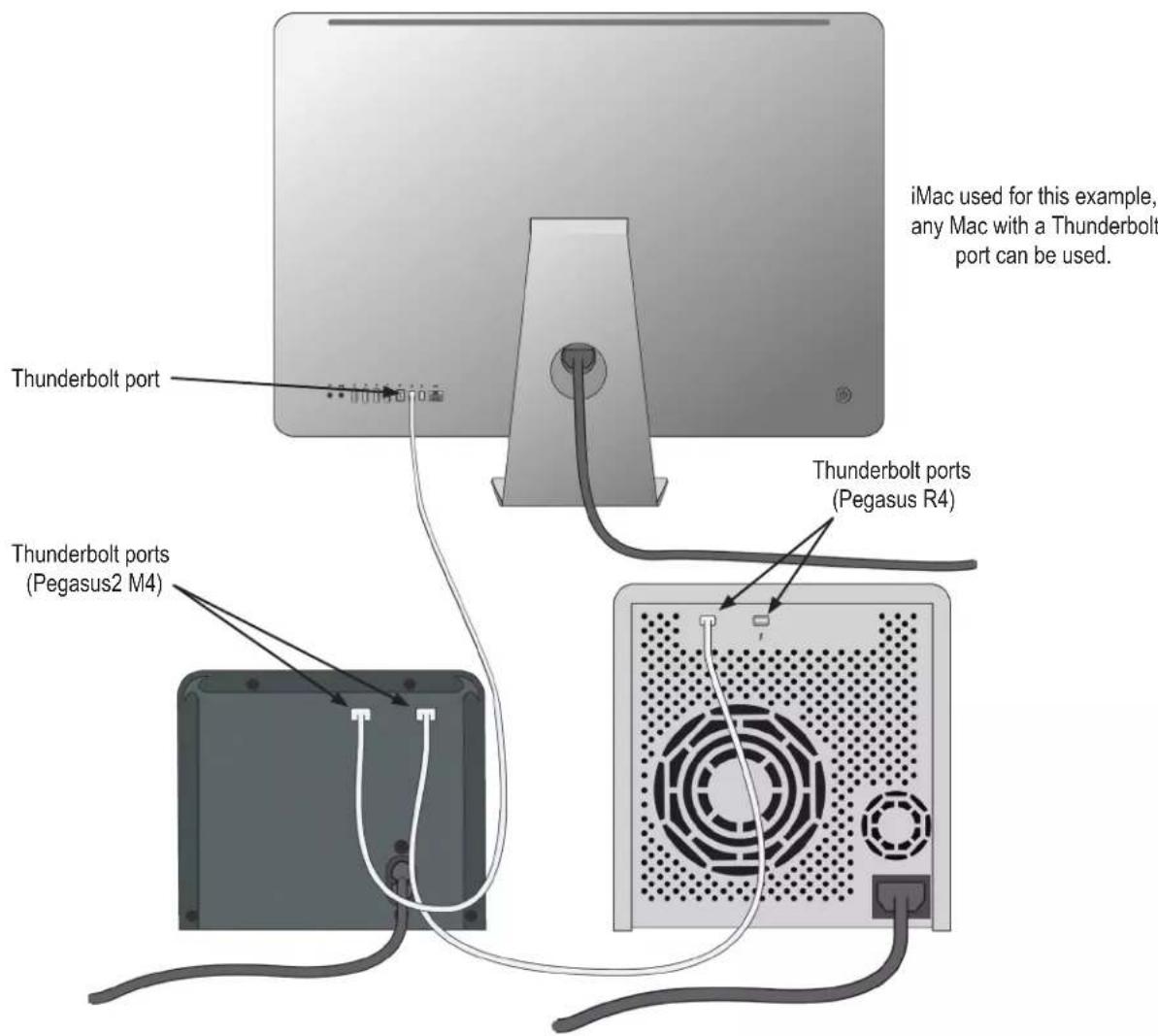
DAISY-CHAINING MULTIPLE PEGASUS/PEGASUS2 UNITS
Up to 6 Pegasus or Pegasus2 devices can be connected to each other and to your Mac in a daisy chain sequential Thunderbolt connection. To daisy-chain multiple Pegasus and/or Pegasus2 units:
-
Connect a Thunderbolt cable from one of the Thunderbolt ports on the back of your Mac computer to one of the Thunderbolt ports on the first Pegasus/Pegasus2 unit.
-
Connect a second Thunderbolt cable from other Thunderbolt port on the first Pegasus/Pegasus2 unit to one of the Thunderbolt ports on the second Pegasus/Pegasus2 unit.
Thunderbolt daisy-chain connections
UNLOCKING THE UI
By default, the UI is locked to prevent unauthorized changes to your RAID system. When the UI is locked, you cannot create logical drives or change settings on the Pegasus2 unit.
To unlock the UI:
- At the lower left screen of the PROMISE Utility window, click the closed lock icon.

The PROMISE Utility password dialog box opens.
- Type your Mac computer password into the Password field and click the OK button.

The lock icon changes to open and you can now add and delete logical drives, make settings, run background activities, and update your Pegasus2 system.
DISPLAYING MULTIPLE PEGASUS/PEGASUS2 UNITS
The PROMISE Utility displays a separate window for each Pegasus unit connected by Thunderbolt cable and powered up.
• To view a list of the Pegasus or Pegasus2 units, click the View menu.
- To display a Pegasus or Pegasus2 unit in the PROMISE Utility, click the View menu and choose unit you want to see.
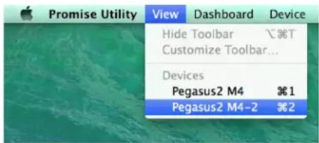
The first Pegasus unit is Pegasus R4 or (R6, R8), the second is Pegasus R4-2 or (R6-2, R8-2), the third is Pegasus R4-3 or (R6-3, R8-3), and so on. The Pegasus units are listed by the order in which they are recognized, not by the cable configuration.
The PROMISE Utility can be used for either Pegasus or Pegasus2 models.
To Create a Disk Array and Logical Drive
The Pegasus2 is shipped with HDD installed and a RAID array configured, so it is not necessary to do this yourself. However, if you want to change the disk drives or configure a different RAID, you will need to create an array and logical drive to use the storage.

Important
The Pegasus2 does NOT require any configuration to use the RAID storage. It is shipped ready to use.
If you are installing new disk drives, use the Wizard to create a disk array and logical drive. The procedures are described in the next chapter.
To see the Wizard menu, launch the PROMISE Utility, in the Dashboard menu, under System Status, click the Disk Array link. See “The PROMISE Utility interface with the Dashboard displayed” on page 20.
The Wizard dialog box opens with three configuration methods.
Wizard dialog box

Choose the best method for your situation. See the table below.
| Method User | options Suggested for users who are See | |
| Automatic None New to data storage page 60 | ||
| Express General parameters Familiar with data storage page 61 | ||
| Advanced Individual parameters Data storage professionals page 63 | ||
MANAGE WITH PROMISE UTILITY
This chapter contains the following topics:
- "Accessing the PROMISE Utility"
• "Perusing the PROMISE Utility Interface" - "Managing Subsystems"
- "Managing the RAID Controller"
• "Managing Background Activities"
• "Managing Physical Drives" - "Managing Disk Arrays"
• "Managing Logical Drives"
• "Managing Spare Drives"
The PROMISE Utility requires a Thunderbolt connection between your computer and the Pegasus unit. See “Connect Pegasus2 to your Mac” on page 9.
The PROMISE Utility must be installed onto your computer before you can use it. See “Installing the Software” on page 10.
ACCESSING THE PROMISE UTILITY
Accessing the PROMISE Utility includes:
- Opening and Closing
- Unlocking the UI
OPENING
To open the PROMISE Utility, double-click the PROMISE Utility icon in the Macintosh Dock (right).
The PROMISE Utility window opens and displays the Dashboard. See “The PROMISE Utility interface with the Dashboard displayed” on page 20.
CLOSING
There are two ways close the PROMISE Utility:
PROMISE Utility icon

- Click the PROMISE Utility dropdown menu and choose Quit PROMISE Utility
- Press cmd-Q ( ♜Q)
UNLOCKING THE UI
By default, the UI is locked to prevent unauthorized changes to your RAID system. When the UI is locked, you cannot create logical drives or change settings on the Pegasus2 unit.
To unlock the UI:
- At the lower left screen of the PROMISE Utility window, click the closed lock icon.

Click the lock to make changes.
The PROMISE Utility password dialog box opens.

- Type your Mac computer password into the Password field and click the OK button.
The lock icon changes to open and you can now add and delete logical drives, make settings, run background activities, and update your Pegasus2 system.
DISPLAYING MULTIPLE PEGASUS/PEGASUS2 UNITS
The PROMISE Utility displays a separate window for each Pegasus unit connected by Thunderbolt cable and powered up.
• To view a list of the Pegasus or Pegasus2 units, click the View menu.
- To display a Pegasus or Pegasus2 unit in the PROMISE Utility, click the View menu and choose unit you want to see.

The first Pegasus unit is Pegasus R4 or (R6, R8), the second is Pegasus R4-2 or (R6-2, R8-2), the third is Pegasus R4-3 or (R6-3, R8-3), and so on. The Pegasus units are listed by the order in which they are recognized, not by the cable configuration.
PERUSING THE PROMISE UTILITY INTERFACE
The PROMISE Utility interface consists of menus and icons, each leading you to a specific function.
The PROMISE Utility interface with the Dashboard displayed
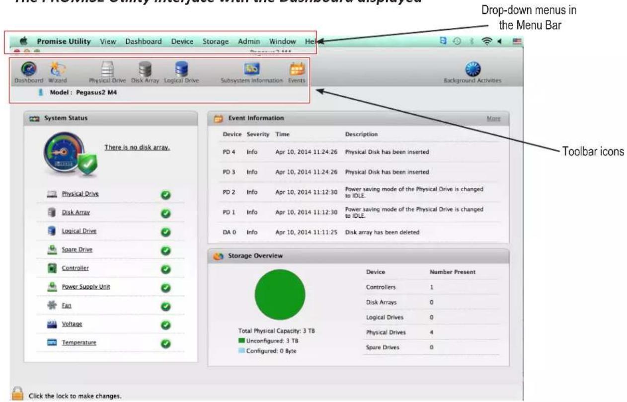
- PROMISE Utility – About, Checking for Updates, Preferences, Services, Hide, Quit
• View – Show/Hide Toolbar, Customize Toolbar, Devices (Pegasus units) - Dashboard – Show the Dashboard
• Device – Front and Back Views, Component List, Physical Drive List
• Storage – Wizard, Disk Array List, Logical Drive List, Spare Drive List - Admin – Enclosure (Pegasus unit) Information, Events, Background Activities, Firmware Update, Performance Monitor (see page 141) and Restore Factory Default (settings)
- Window – Minimize, Zoom, Close Window, Bring All to Front, Pegasus unit
• Help – Online help search
Most of the functions accessed in the menu bar are described in this chapter.
TOOLBAR ICONS
The default toolbar icons are listed here:
- Dashboard icon – Displays the Dashboard and overview
- Wizard icon - Displays the Wizard options for quickly setting up RAID arrays
- Physical Drive icon – Displays the physical drive list, settings and functions
- Disk Array icon - Display menu for monitoring, managing and creating disk arrays
- Logical Drive icon – Displays the logical drive list, settings and functions
- Subsystem Information icon – Displays Pegasus unit information and settings
- Events icon – Displays the event logs
CUSTOMIZING THE TOOLBAR
You can customize the toolbar by adding or removing icons. To add and remove toolbar icons:
- From the PROMISE Utility window, click the View menu and choose Customize Toolbar... The toolbar options dialog box appears.
- Do one or both actions are needed:
- Click and drag an icon from the dialog box to the toolbar to add the icon.
- Click and drag an icon from the toolbar to delete the icon.
- When you are finished, click the Done button.
DEVICE MENUS
Use the Device drop-down menu in the menu bar at the top of your desktop to view an active display of the Pegaus2 device, as well as access to menus used to configure settings for device hardware and physical drives.
To view the PROMISE Utility menu bar, just select the PROMISE Utility window, and the menu bar lists the Device, Admin and other menus categories.
Device menu options


Note
The Physical Drive menu and Component List are also accessible using the Physical Drive and Controller menu links listed under System Status in the Dashboard menu.
COMPONENT LIST
Go to the Device drop-down menu and choose the Component List option to display the device ID, operational status, enclosure type, and status description of all enclosures. The Enclosure, Controller, and Buzzer are described in relevant sections of this chapter. See "Viewing Controller Information" on page 29, "Viewing the Enclosure Information" on page 33, "Making Buzzer Settings" on page 32 for more information.
PHYSICAL DRIVE MENU
Go to the Device drop-down menu and choose the Physical Drive option to display the Physical Drive menu. This is the same menu you see by clicking the Physical Drive menu button at the top of the PROMISE Utility window, or by clicking the Physical Drive menu link under System Status in the Dashboard. See "Managing Physical Drives" on page 48 for more information.
FRONT VIEW
The Front View active menu lets you view the enclosures and all components on the front of the Pegasus2.
Move the cursor over the drive carrier to display the information of the installed physical drive, including the device ID, physical capacity, operational status, etc. Click on the drive to bring up the Physical Drive Information, displaying the detailed information of the device.
Front View options include the ability to indicate which carriers contain unconfigured physical disks (colored green), or to highlight arrays (colored purple).
Device - Front View display menu

Show Unconfigured Physical Drives
Click the Show unconfigured PD(s) box to identify any unconfigured physical drives, these appear colored light green.
Highlight Arrays
Click the Highlight Arrays button to identify the physical drives assigned to a disk array, these appear colored purple.
Click on of the following items in the drop-down menu:
• All DA – Show all disk arrays
- DA0 (DA1, DA2, etc.) – a specific disk array
- close – Click to close the menu and return to normal view.
The carriers containing drives that do not belong to the chosen disk array will be highlighted.
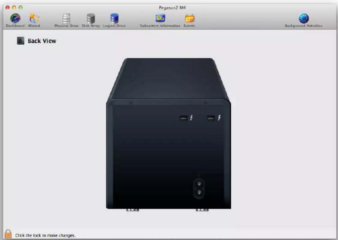
BACK VIEW
Go to the Device drop-down menu and choose the Back View option to see a virtual view of the back of the Pegasus2. Move the cursor over the Power Supply (PSU) and enclosure information is displayed.
Device - Back View display menu
MANAGING SUBSYSTEMS
Enclosure management includes:
• "Viewing Subsystem Information"
- "Making Subsystem Settings"
- "Clearing Statistics"
- "Restoring Factory Default Settings"
- "Saving a Service Report"
- "Updating Firmware"
VIEWING SUBSYSTEM INFORMATION
The term enclosure refers to the Pegasus unit.
To view enclosure information, click the Subsystem Information icon.
Subsystem Information includes:
- Alias * – Same as controller alias
- Model
- WWN – World Wide Number
- Vendor
- Serial number
- Revision number
• System date and time - Firmware Version
Items with an asterisk (*) are adjustable under “Making Subsystem Settings” below.
MAKING SUBSYSTEM SETTINGS
To make enclosure settings:
-
Click the Subsystem Information icon.
-
Click the Settings button.
-
Make changes as required:
- Enter an alias or change the existing alias in the field provided.
- Click the Save button.
CLEARING STATISTICS
This function clears statistical data on the RAID controller, physical drives, and logical drives.
To clear statistics:
-
Click the Subsystem Information icon.
-
Click the Clear Statistics button.
-
Type the word "confirm" in the field provided.
-
Click the Confirm button.
RESTORING FACTORY DEFAULT SETTINGS
This feature restores settings to their default values.
To restore all settings to their default values:
- From the Admin drop-down menu in teh menu bar at the top of your desktop, choose Restore Factory Default.
- In the Restore Factory Default settings screen, check the boxes beside the settings you want to reset to default value.
• Background activity settings
- Controller settings
• Physical drive settings
- Subsystem settings
- Click the Submit button.
- In the Confirmation box, type the word "confirm" in the field provided and click the Confirm button.

Note
You must unlock the PROMISE Utility interface to allow selection of Restore Factory Default.
SAVING A SERVICE REPORT
A service report can be useful to technical support for troubleshooting or diagnosing issues on the device. To save a service report to your Mac, click on the Subsystem Information menu link, and click on the Save Service Report button. A prompt asks you where you want to save the html file containing the service report. Choose a location and click the Save button. A technical support representative might ask you to email this file for system analysis.
UPDATING FIRMWARE
For best performance, it is a good idea to keep the Pegasus2 firmware up to date. The update procedure is used for the controller and other system hardware. Download the latest firmware from the PROMISE website at www.PROMISE.com/support/download.aspx and place the .img file on your Mac.
Keep in mind that after the update process, it will be necessary to restart your Mac.
To update the controller firmware:
- From the Admin drop-down menu in the menu bar at the top of your desktop, choose Firmware Update.
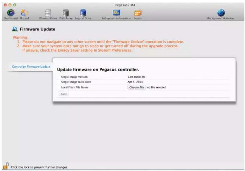
- Click on the padlock icon to unlock the menu, and type in the password for your Mac when the prompt appears.
- Click the Choose File button and locate the .img file you downloaded from PROMISE.
- Click the Submit button.
- In the Confirmation box, type the word "confirm" in the field provided and click the Confirm button.
- The process will take several seconds. When it is completed, you will be prompted to restart the Mac. Restart your Mac and continue to use the Pegasus2.
RAID controller management includes:
• "Viewing Controller Information"
• "Viewing Controller Statistics"
• "Making Controller Settings"
- "Making Buzzer Settings"
VIEWING CONTROLLER INFORMATION
To view controller information, from the Device menu, choose Component List, the Information tab is displayed.
Controller information includes:
- Controller ID
- Alias * – Same as enclosure alias
- Vendor
- Model
- Operational Status
- Power On Time
- Cache Usage – Percentage
- Dirty Cache Usage – Percentage
- Part Number
- Serial Number
- Hardware Revision
- WWN – Worldwide Number
- SCSI Protocol Supported
- BIOS Version
- Single Image Version
- Single Image Build Date
- Host Driver Version
To view advanced information, click the Advanced Information tab.
Advanced controller information includes:
- Memory Type
- Memory Size
- Flash Type
- Flash Size
- NVRAM Type
- NVRAM Size
• Preferred Cache Line Size - Cache Line Size
- Coercion *
- Coercion Method *
- SMART *
• SMART Polling Interval *
• Write Back Cache Flush Interval *
• Write Through Mode *
• Enclosure Polling Interval *
• Adaptive Writeback Cache * - Forced Read Ahead (cache) *
Items with an asterisk (*) are adjustable under "Making Controller Settings" on page 31.
- Click the X icon to close the information panel.
VIEWING CONTROLLER STATISTICS
To view controller statistics:
-
Click the Dashboard icon, then click the Controller link.
-
Click the Statistics tab.
Controller statistics include:
- Data Transferred
- Read Data Transferred
• Write Data Transferred - Errors
• Non-Read/Write Errors - Read Errors
- Write Errors
- I/O Requests
• Non-Read/Write Requests - Read I/O Requests
-
Write I/O Requests
• Statistics Start date and time
• Statistics Collection date and time -
Click the X icon to close the information panel.
MAKING CONTROLLER SETTINGS
To make controller settings:
- Click the Dashboard icon, then click the Controller link.
- Mouse-over the controller, then click the Settings button.
Make setting changes as required:
- Enter, change or delete the alias in the Alias field.
- SMART Log – Check the box to enable or uncheck to disable. To view SMART Log information, open the Disk Array menu, click on the SMART Log tab.
- SMART Polling Interval – Enter a value into the field, 1 to 1440 minutes. 1440 minutes = 24 hours
- Enable Coercion – Check the box to enable or uncheck to disable.
- Coercion Method – Choose a method from the dropdown menu:
- GBTruncate
- 10GBTruncate
- GrpRounding
-
TableRounding
-
Write Back Cache Flush Interval – Enter a value into the field, 1 to 12 seconds.
• Enclosure Polling Interval – 15 to 255 seconds. - Adaptive Writeback Cache – Check the box to enable or uncheck to disable.
- Forced Read Ahead – Check the box to enable or uncheck to disable.
-
Green RAID features – Power saving physical disk management (see "Green RAID Features" on page 32)
-
Click the Save button.
-
Click the X icon to close the settings panel.
GREEN RAID FEATURES
The Pegasus2 M4 includes controller management features to reduce power consumption when the device is inactive or at a low level of activity, such as running background activities but not reading or writing to disk. The power saving features are disabled by default.
There are three levels of power saving for physical disks to enable in the Controller Settings menu. To reduce HDD power consumption, disk rotation speeds decrease as each successive power saving level is triggered. The Level 1 setting must be enabled to enable Level 2 and Level 3; Level 2 must be enabled to enable Level 3. Click to check the box for each level you want to enable.
To configure Green RAID HDD power saving:
- Click the Dashboard icon, then click the Controller link.
- Click the Settings button.
- Check the box to Enable HDD Park Ahead (Level 1), or uncheck the box to disable.
- Enter the time in minutes allowed for the device to be idle to trigger Level 1 HDD power saving.
- Repeat Steps 3 and 4 for Level 2 and Level 3 to enable and set idle time for those levels.
- Click the Save button.

Note
Idle time setting for Level 2 must be longer than Level 1, and idle time for Level 3 must be longer than Level 3.
To make buzzer settings:
- Click the Dashboard icon, then click the Controller link.
- Mouse-over the buzzer, then click the Settings button.
- Check the Enable Buzzer box to enable the buzzer.
Or uncheck the box to disable.
- Click the Save button.
MANAGING ENCLOSURES
Enclosure management includes the following functions:
• "Viewing Subsystem Information"
• "Viewing Temperature Sensor Information"
- "Locating an Enclosure"
VIEWING THE ENCLOSURE INFORMATION
To access enclosure information:
- Click the Dashboard icon, then click the Controller link.
- Mouse-over the Enclosure, then click the View button.
Enclosure information includes:
- Enclosure ID
• Enclosure Warning Temperature Threshold
• Controller Warning Temperature Threshold - SEP Firmware Version
• Max Number of Controllers
• Max Number of Fans
• Max Number of Power Supply Units -
Enclosure Type
• Enclosure Critical Temperature Threshold
• Controller Critical Temperature Threshold
• Max Number of Physical Drive Slots
• Max Number of Temperature Sensors
• Max Number of Voltage Sensors -
Click the X icon to close the information panel.
VIEWING TEMPERATURE SENSOR INFORMATION
To view the status of the temperature sensor:
- Click the Dashboard icon, then click the Temperature link.
- Scroll down until you see Temperature Sensors.
Temperature Sensors information includes:
• ID
• Status (Normal, Warning or Critical icon)
- Location (Controller or Backplane)
• Healthy Threshold (Enclosure Warning Temperature Threshold)
- Current Temperature
- Click the X icon to close the information panel.
If you have multiple Pegasus units, and you want to verify which unit you are accessing in the PROMISE Utility, use the Locate function.
To locate a enclosure:
- From the Device menu, choose Component List.
- Mouse-over the Enclosure, then click the Locate button.
The Drive Power / Status LEDs on all drive carriers blink blue and orange for one minute.
Running the Locate function to identify an enclosure

MANAGING BACKGROUND ACTIVITIES
Background activity management includes:
• "Viewing Current Background Activities"
- "Adding a Scheduled Background Activity"
- "Changing a Background Activity Schedule"
- “Enabling or Disabling a Scheduled Background Activity”
- “Deleting a Scheduled Background Activity”
- "Media Patrol"
- "Redundancy Check"
- "Initialization"
- "Rebuild"
- "Migration"
• "PDM"
Background activities perform a variety of preventive and remedial functions on your physical drives, disk arrays, logical drives, and other components.
You can run a background activity immediately or schedule it to run at a later time. Scheduling options are described below.
Setting options for each activity are listed after the scheduling options. These settings determine how the background activity affects I/O performance.
VIEWING CURRENT BACKGROUND ACTIVITIES
To view a list of background activities, click on the Background Activities icon.
The list of background appears:
• Media Patrol
- PDM
- Redundancy Check
- Transition
- Rebuild
- Synchronization
- Migration
Currently running activities show a progress bar.
VIEWING SCHEDULED BACKGROUND ACTIVITIES
To view a list of scheduled background activities:
- Click on the Background Activities icon.
- Click the Scheduler button.
The list of scheduled background appears.
Adding a Scheduled Background Activity
To add a new scheduled background activity:
- Click on the Background Activities icon.
- Click the Scheduler button.
The list of scheduled background appears.
- Click the Add Schedule button.
- Make schedule settings as desired.
Choose the option for the activity you want:
- Media Patrol
- Redundancy Check
- Spare Check
Choose a Start Time from the dropdown menus.
The menus have a 24-hour clock.
- Choose a Recurrence Pattern option, daily, weekly, or monthly.
- For the Daily option, enter an interval in the Every field.
- For the Weekly option, enter an interval in the Every field and choose one or more days of the week.
- For the Monthly option, choose, Day of the Month option or a sequential and specific day from the dropdown menu. Also choose which months.
- Choose a Start From date from the dropdown menus.
- Choose an End On option:
• No end date or perpetual.
• End after a specific number of activity actions.
• Until date from the dropdown menus.
• For Redundancy Check, choose:
- Auto Fix option – Attempts to repair the problem when it finds an error. Check to enable
- Pause on Error option – The process stops when it finds a non-repairable error. Check to enable
- Select LD – Check the boxes for the logical drives to run
Redundancy Check. Check at least one logical drive.
- Click the Save button.
To return to currently running background activities, click the Background Activities button.
CHANGING A BACKGROUND ACTIVITY SCHEDULE
To change an existing scheduled background activity:
- Click on the Background Activities icon.
- Click the Scheduler button.
The list of scheduled background appears.
- Mouse-over the background activity, then click the Settings button.
- Make settings as needed.
Choose the option for the activity you want:
• Media Patrol
- Redundancy Check
- Spare Check
Choose a Start Time from the dropdown menus.
The menus have a 24-hour clock.
Choose a Recurrence Pattern option, daily, weekly, or monthly.
- For the Daily option, enter an interval in the Every field.
- For the Weekly option, enter an interval in the Every field and choose one or more days of the week.
- For the Monthly option, choose, Day of the Month option or a sequential and specific day from the dropdown menu. Also choose which months.
Choose a Start From date from the dropdown menus.
Choose an End On option,
• No end date or perpetual.
• End after a specific number of activity actions.
• Until date from the dropdown menus.
For Redundancy Check, choose,
- Auto Fix option – Attempts to repair the problem when it finds an error. Check to enable
- Pause on Error option – The process stops when it finds a non-repairable error. Check to enable
- Select LD – Check the boxes for the logical drives to run
-
Redundancy Check. Check at least one logical drive.
-
Click the Save button.
To return to currently running background activities, click the Background Activities button.
ENABLING OR DISABLING A SCHEDULED BACKGROUND ACTIVITY
Background activity schedules are enabled by default when you create the schedule. If you want to stop a background activity now but plan to use it again in the future, disable the scheduled activity rather than deleting it.
To enable or disable change an existing scheduled background activity:
- Click on the Background Activities icon.
- Click the Scheduler button.
The list of scheduled background appears.
- Mouse-over the background activity and click the Settings button.
- Uncheck the Enable This Schedule box to disable this schedule.
Check the box to enable this schedule.
- Click the Save button.
To return to currently running background activities, click the Background Activities button.
DELETING A SCHEDULED BACKGROUND ACTIVITY
To delete a scheduled background activity:
- Click on the Background Activities icon.
- Click the Scheduler button.
The list of scheduled background appears.
- Mouse-over the background activity, then click the Delete button.
- Type the word "confirm" in the field provided.
- Click the Confirm button.
To return to currently running background activities, click the Background Activities button.
MEDIA PATROL
Media Patrol is a routine maintenance procedure that checks the magnetic media on each disk drive. Media Patrol checks are enabled by default on all disk arrays and spare drives. Media Patrol is concerned with the media itself, not the data recorded on the media. If Media Patrol encounters a critical error, it triggers PDM if PDM is enabled on the disk array. See “Making Disk Array Settings” on page 65.
MAKING MEDIA PATROL SETTINGS
To make Media Patrol settings:
- Click on the Background Activities icon.
- Click the Settings button.
- Check the Enable Media Patrol box to enable, uncheck to disable. This settings enables or disables Media Patrol for all physical drives.
- Click the Confirm button.
- Click the X icon to close the background activities panel.
REDUNDANCY CHECK
Redundancy Check is a routine maintenance procedure for fault-tolerant disk arrays (those with redundancy) that ensures all the data matches exactly. Redundancy Check can also correct inconsistencies.
See "Redundancy Check on a Logical Drive" on page 64.
MAKING REDUNDANCY CHECK SETTINGS
To make Redundancy Check settings:
-
Click on the Background Activities icon.
-
Click the Settings button.
-
Click the Redundancy Check Rate dropdown menu and choose a rate:
-
Low – Fewer system resources to Redundancy Check, more to data read/write operations.
- Medium – Balances system resources between Redundancy Check and data read/write operations.
-
High – More system resources to Redundancy Check, fewer to data read/write operations.
-
Click the Confirm button.
-
Click the X icon to close the background activities panel.
INITIALIZATION
Technically speaking, Initialization is a foreground activity, as you cannot access a logical drive while it is initiating.
Initialization is normally done to logical drives after they are created from a disk array. Initialization sets all data bits in the logical drive to zero. The action is useful because there may be residual data on the logical drives left behind from
earlier configurations. For this reason, Initialization is recommended whenever you create a logical drive.
See "Initializing a Logical Drive" on page 77.
MAKING INITIALIZATION SETTINGS
To make initialization settings:
-
Click on the Background Activities icon.
-
Click the Settings button.
-
Click the Logical Drive Initialization Rate dropdown menu and choose a rate:
-
Low – Fewer system resources to Initialization, more to data read/write operations.
- Medium – Balances system resources between Initialization and data read/write operations.
-
High – More system resources to Initialization, fewer to data read/write operations.
-
Click the Confirm button.
-
Click the X icon to close the background activities panel.
REBUILD
When you rebuild a disk array, you are actually rebuilding the data on one physical drive.
- When a physical drive in a disk array fails and a spare drive of adequate capacity is available, the disk array begins to rebuild automatically using the spare drive.
- If there is no spare drive of adequate capacity, but the Auto Rebuild function is ENABLED, the disk array begins to rebuild automatically as soon as you remove the failed physical drive and install an unconfigured physical drive in the same slot. See “Making Rebuild Settings” on page 34.
- If there is no spare drive of adequate capacity and the Auto Rebuild function is DISABLED, you must replace the failed drive with an unconfigured physical drive, then perform a Manual Rebuild.
See “Rebuilding a Disk Array” on page 68 and "Managing Spare Drives" on page 82. Also see "Disk Array Degraded / Logical Drive Critical" on page 131 and "Disk Array Offline / Logical Drive Offline" on page 132.
MAKING REBUILD SETTINGS
-
Click on the Background Activities icon.
-
Click the Settings button.
-
Click the Rebuild Rate dropdown menu and choose a rate:
-
Low – Fewer system resources to the Rebuild, more to data read/write operations
• Medium – Balances system resources between the Rebuild and data read/write operations. -
High – More system resources to the Rebuild, fewer to data read/write operations.
-
Check the Enable Auto Rebuild box to enable Auto Rebuild (rebuilds when you swap out the failed drive with a new one).
-
Click the Confirm button.
- Click the X icon to close the background activities panel.
MIGRATION
The term "Migration" means either or both of the following:
- Change the RAID level of a logical drive.
- Expand the storage capacity of a logical drive. See "Migrating a Logical Drive" on page 79.
MAKING MIGRATION SETTINGS
To make migration settings:
- Click on the Background Activities icon.
- Click the Settings button.
-
Click the Migration Rate dropdown menu and choose a rate:
-
Low – Fewer system resources to Migration, more to data read/write operations.
• Medium – Balances system resources between Migration and data read/write operations. -
High – More system resources to Migration, fewer to data read/write operations.
-
Click the Confirm button.
-
Click the X icon to close the background activities panel.
PDM
Predictive Data Migration (PDM) is the migration of data from the suspect disk drive to a spare drive, similar to rebuilding a disk array. But unlike rebuilding, PDM automatically copies your data to a spare drive before the drive fails and your logical drive goes Critical.
PDM can be triggered automatically by Media Patrol. Also see "Running PDM on a Logical Drive" on page 81.
MAKING PDM SETTINGS
To make PDM settings:
- Click on the Background Activities icon.
- Click the Settings button.
- Make the following settings are required:
- Click the PDM Rate dropdown menu and choose a rate:
- Low – Fewer system resources to PDM, more to data read/write operations.
• Medium – Balances system resources between PDM and data read/write operations. - High – More system resources to PDM, fewer to data read/write operations.
- Highlight the current values in the block threshold fields and input new values.
Reassigned block threshold range is 1 to 512 blocks. Error block threshold range is 1 to 2048 blocks.
- Click the Confirm button.
- Click the X icon to close the background activities panel.
TRANSITION
Transition is the process of replacing a revertible spare drive that is currently part of a disk array with an unconfigured physical drive or a non-revertible spare drive.
See "Running a Transition on a Spare Drive" on page 86.
MAKING TRANSITION SETTINGS
To make Transition settings:
-
Click on the Background Activities icon.
-
Click the Settings button.
-
Click the Transition Rate dropdown menu and choose a rate:
- Low – Fewer system resources to Transition, more to data read/write operations.
• Medium – Balances system resources between Transition and data read/write operations.
- High – More system resources to Transition, fewer to data read/write operations.
-
Click the Confirm button.
-
Click the X icon to close the background activities panel.
SYNCHRONIZATION
Synchronization is automatically applied to logical drives when they are created. Synchronization recalculates the redundancy data to ensure that the working data on the physical drives is properly in sync.
Mouse-over on the logical drive, click the View button, and look under Logical Drive Information beside the line that says Synchronized. A Yes means the logical drive was synchronized. See “Viewing Logical Drive Information” on page 71.
MAKING SYNCHRONIZATION SETTINGS
To make Synchronization settings:
- Click on the Background Activities icon.
- Click the Settings button.
-
Click the Background Synchronization Rate dropdown menu and choose a rate:
-
Low – Fewer system resources to Synchronization, more to data read/write operations.
- Medium – Balances system resources between Synchronization and data read/write operations.
-
High – More system resources to Synchronization, fewer to data read/write operations.
-
Click the Confirm button.
-
Click the X icon to close the background activities panel.
MANAGING PHYSICAL DRIVES
Physical drive management includes:
• "Viewing a List of Physical Drives"
• "Viewing Physical Drive Information"
• "Viewing Physical Drive Statistics"
- "Viewing Physical Drive SMART Log Information"
- "Locating a Physical Drive"
- "Making Global Physical Drive Settings"
- "Making Individual Physical Drive Settings"
- "Making Physical Drive SMART Log Settings"
- "Clearing a Stale or a PFA Condition"
• "Forcing a Physical Drive Offline"
VIEWING A LIST OF PHYSICAL DRIVES
To view a list of physical drives in the Pegasus unit, click the Physical Drive icon.
Physical drive information includes:
• ID – ID number of the physical drive
• Status (Normal, Stale or PFA or Dead icon)
- Model Number
• Type – SATA, HDD or SSD
- Location – Enclosure number and slot number
- Configuration – Array number and sequence number, spare number, unconfigured, or stale configuration
- Capacity – In GB
VIEWING PHYSICAL DRIVE INFORMATION
To view physical drive information:
- Click the Physical Drive icon.
- Mouse-over the physical drive you want then click the View button.
Physical drive information includes:
- Physical Drive ID – ID number of the physical drive
- Location – Enclosure number and slot number
- Alias – If assigned
• Physical Capacity – Total capacity in GB - Configurable Capacity – Usable capacity in GB
• Used Capacity – Capacity actually used in GB
• Block Size – Typically 512 Bytes -
Operational Status – OK is normal, Stale, PFA, Dead
-
Click the Advanced Information tab.
-
Configuration Status – Array number and sequence number, spare number
- Model Number – Make and model of the drive
• Drive Interface – SATA 1.5Gb/s or 3Gb/s - Serial Number – Serial number of the drive
- Firmware Version – Firmware version on the drive
- Protocol Version – ATA/ATAPI protocol version
Advanced information for physical drives includes:
- Write Cache – Enabled or disabled *
-
Read Look Ahead Cache – Enabled or disabled *
• SMART Feature Set – Yes or No
• SMART Self Test – Yes or No
• SMART Error Logging – Yes or No
• Command Queuing Support – TCQ or NCQ -
Command Queuing – Enabled or disabled *
- Queue Depth – Number of commands
• Power Saving Level – Supported by this drive
• Medium Error Threshold ** - Drive Temperature
• Drive Reference Temperature
Items with an asterisk (*) are adjustable under “Viewing Physical Drive Statistics” on page 50.
Items with two asterisks ( ^** ) are adjustable under “Making PDM Settings” on page 45.
- Click the X icon to close the information panel.
VIEWING PHYSICAL DRIVE STATISTICS
To view physical drive statistics:
- Click the Physical Drive icon.
-
Mouse-over the physical drive you want then click the View button.
-
Click the Statistics tab.
Physical drive statistics include:
- Data Transferred
• I/O Request – Number of requests - Read Data Transferred
• Non Read/Write Request – Number of requests
• Write Data Transferred - Read I/O Request – Number of requests
- Errors – Number of errors
• Write I/O Request – Number of requests
• Non Read/Write Errors
• Statistics Start Time – Time and date - Read Errors
• Statistics Collection Time – Time and date - Write Errors
To clear physical drive statistics, see "Clearing Statistics" on page 21.
- Click the X icon to close the settings panel.
VIEWING PHYSICAL DRIVE SMART LOG INFORMATION
To view physical drive SMART Log information:
- Click the Physical Drive icon.
-
Mouse-over the physical drive you want then click the View button.
-
Click the SMART Log tab.
SMART Log information includes:
• Physical Drive ID
• SMART Support – Yes or No, depending on the drive
• SMART Status – Enabled or disabled *
• SMART Health Status – OK is normal
Items with an asterisk (*) are adjustable under "Making Controller Settings" on page 31.
- Click the X icon to close the settings panel.
LOCATING A PHYSICAL DRIVE
This feature causes the drive carrier LEDs to blink for one minute to assist you in locating the physical drive, and is supported by RAID enclosures and JBOD expansion units.
To locate a physical drive:
- Click the Physical Drive icon.
- Mouse-over the physical drive you want then click the Locate button.
The Drive Power / Status LED for the drive carrier holding that drive blinks blue and orange for one minute.
Running the Locate function to identify a physical drive

MAKING GLOBAL PHYSICAL DRIVE SETTINGS
To make global physical drive settings:
- Click the Physical Drive icon..
-
Click the Global Physical Drive Settings button.
-
Check the boxes to enable, uncheck to disable.
-
Enable Write Cache
- Enable Read Look Ahead Cache
-
Enable Command Queuing
-
Click the Save button.
-
Click the X icon to close the settings panel.
MAKING INDIVIDUAL PHYSICAL DRIVE SETTINGS

CAUTION
Changing the status of a pass-through disk will destroy any data on the disk. Back up your data before you proceed.
To make individual physical drive settings:
-
Do one of the following actions:
-
Click the Physical Drive icon.
• From the Device menu, choose Physical Drive. -
Mouse-over the physical drive you want then click the Settings button.
-
Make changes as needed:
-
Enter, change, or delete the alias in the Alias field.
- Choose Unconfigured or PassThru Configuration.
Unconfigured drives are not visible to your computer. Use them to make disk arrays.
PassThru drives are visible to your computer and are configured as individual drives. They cannot be used to make a disk array.
- Click the Save button.
- Click the X icon to close the settings panel.
MAKING PHYSICAL DRIVE SMART LOG SETTINGS
To make physical drive SMART log settings:
- Click the Physical Drive icon.
- Click the SMART Log Settings tab.
- Check the box to enable the SMART log.
- Click the Save button.
-
Click the X icon to close the settings panel.
-
Mouse-over the physical drive you want then click the Settings button.
CLEARING A STALE OR A PFA CONDITION
Stale - The physical drive contains obsolete disk array information.
PFA – The physical drive has errors resulting in a prediction of failure.
Be sure you have first corrected the condition by a physical drive replacement, rebuild operation, etc. Then clear the condition.
To clear a Stale or a PFA condition:
- Click the Physical Drive icon.
- Mouse-over the physical drive you want then click the Clear button.
- Click the Confirm button.
If the physical drive has both a Stale condition and a PFA condition, the first click removes the Stale condition. Click the Clear button a second time to remove the PFA condition.
This feature applies only to physical drives assigned to disk arrays.

CAUTION
Forcing a physical drive offline is likely to cause data loss. Back up your data before you proceed. Use this function only when required.

Important
Forcing a physical drive offline causes your logical drives to become degraded. If Auto Rebuild is enabled and a spare drive is available, the disk array begins rebuilding itself automatically.
To force a physical drive offline:
- Click the Physical Drive icon.
- Mouse-over the physical drive you want then click the Force Offline button.
- In the Confirmation box, type the word "confirm" in the field provided and click the Confirm button.
Media Patrol is a routine maintenance procedure that checks the magnetic media on each disk drive. Media Patrol checks are enabled by default on all disk arrays and spare drives. Media Patrol is concerned with the media itself, not the data recorded on the media. If Media Patrol encounters a critical error, it triggers PDM if PDM is enabled on the disk array. Media Patrol checks all physical drives one at a time.
To run Media Patrol on your physical drives:
- Click on the Background Activities icon. The list of background activities appears.
- Mouse-over Media Patrol and click the Start button.
Pausing and Resuming a Media Patrol
To pause or resume a Media Patrol:
- Click on the Background Activities icon. The list of background activities appears.
- Mouse-over Media Patrol and click the Pause or Resume button.
Stopping a a Media Patrol
To stop is to cancel the Media Patrol:
- Click on the Background Activities icon. The list of background activities appears.
- Mouse-over Media Patrol and click the Stop button.
- In the Confirmation box, type the word "confirm" in the field provided and click the Confirm button.
MANAGING DISK ARRAYS
Disk array management includes:
• "Viewing a List of Disk Arrays"
• "Viewing Disk Array Information"
- "Creating a Disk Array Manually"
- “Creating a Disk Array and Logical Drive with the Wizard”
- "Making Disk Array Settings"
- "Locating a Disk Array"
- "Deleting a Disk Array"
- "Preparing a Disk Array for Transport"
- "Rebuilding a Disk Array"
Also see "Disk Array and Logical Drive Problems" on page 131.
VIEWING A LIST OF DISK ARRAYS
To view a list of disk arrays, do one of the following actions:
• From the Dashboard window, click the Disk Array link.
- From the Storage menu, choose Disk Array. The list of disk arrays appears. Each disk array lists:
• ID – DA0, DA1, etc.
- Alias – If assigned
• Status (Normal, Degraded or Incomplete/physical drive missing icon)
• Capacity – Data capacity of the array
• Free Capacity – Unconfigured or unused capacity on the physical drives
• Media Patrol – Enabled or disabled on this array
• Number of Logical Drives – The number of logical drives on this array
VIEWING DISK ARRAY INFORMATION
To view disk array information:
-
Do one of the following actions:
-
From the Dashboard window, click the Disk Array link.
• From the Storage menu, choose Disk Array. -
Mouse-over the disk array you want then click the View button.
Disk array information includes:
- Disk Array ID – DA0, DA1, etc.
- Alias – If assigned
- Operational Status – OK, Degraded, or Offline
• Media Patrol – Enabled or disabled on this array - PDM – Enabled or disabled on this array
- Total Physical Capacity – Maximum capacity, including used and unused capacity on the physical drives
- Configurable Capacity – Data capacity of the array
• Free Capacity – Unconfigured or unused capacity on the physical drives - Max. Contiguous Free Capacity – A single chunk of used capacity on the physical drives
• Number of Physical Drives – The number of physical drives on this array
• Number of Logical Drives – The number of logical drives on this array
• Number of Dedicated Spares – The number of spare drives dedicated to this array
• Available RAID Levels – RAID levels that this disk array can support
CREATING A DISK ARRAY MANUALLY
This feature creates a disk array only. You can also use the Wizard to create a disk array with logical drives and spare drives at the same time.
To create a disk array:
-
From the Dashboard menu, click the Disk Array link.
-
Click the Create Disk Array button.
-
Accept the defaults or make changes:
-
Enter an alias in the Alias field Maximum of 32 characters; letters, numbers, space between characters, and underline.
- Enable Media Patrol – Uncheck to disable on this array. For more information, see “Media Patrol” on page 41.
-
Enable PDM – Uncheck to disable on this array. For more information, see “PDM” on page 45.
-
In the Select Physical Drives diagram, click the drives to add them to your array.
The drive carriers turn blue when you click them. The physical drives' ID numbers appear in the field below the diagram.
- When you have finished your settings and choices, click the Submit button.
The new array appears in the list.
• If you are done creating disk arrays, click the Finish button.
• To create additional disk arrays, click the Create More button.
After you create a disk array, create a logical drive on it. See “Creating a Logical Drive Manually” on page 61.
CREATING A DISK ARRAY AND LOGICAL DRIVE WITH THE WIZARD
A disk array is the method of organizing the hard disk drives or solid state drives in the Pegasus unit. A logical drive is created on a disk array. The logical drive is where your computer saves files on the Pegasus.
The PROMISE Utility includes a Wizard to help you set up a disk array, logical drives, and spare drive.
To open the Wizard, click the Storage menu and choose Wizard.
The Wizard dialog box opens with three configuration methods.
Wizard dialog box

Wizard
The configuration can be done in one of the following ways.
Automatic
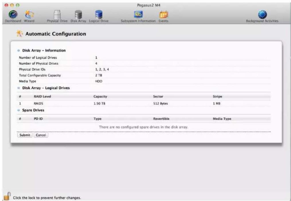
This option enables you to create a new disk array following a default set of parameters, proposes a disk array and logical drive arrangement. You can accept or reject the proposed arrangement but you cannot modify it.
Express
You choose the parameters for a new disk array by specifying the characteristics you want.
Advanced
You directly specify all parameters for a new disk array, logical drives and spare drive.
Choose the best method for your situation. See the table on the next page.
| Method User Options | Suggested for users who are Page | |
| Automatic None New to data storage page 60 | ||
| Express General parameters Familiar with data storage page 61 | ||
| Advanced Individual parameters Data storage professionals page 63 |
CHOOSING AUTOMATIC CONFIGURATION
To use the Automatic Configuration Wizard:
- From the Storage menu choose Wizard.
- Click the Automatic button.
The Automatic Configuration dialog box appears.
Automatic Configuration dialog box
-
Do one of the following actions:
-
If you agree with the proposed configuration, click the Submit button.
The Wizard creates your disk array and logical drive. If you have a Pegasus R6, the Wizard also creates a spare drive. - If you do NOT agree with the proposed configuration, click the Cancel button to return to the original Automatic Configuration menu.
CHOOSING EXPRESS CONFIGURATION
To use the Express Configuration Wizard:
- From the Storage menu choose Wizard.
- Click the Express button.
The Express configuration dialog box appears. See Figure 7.
Express Configuration dialog box

-
Check the boxes to choose any one or a combination of:
-
Redundancy – The array remains available if a physical drive fails
• Capacity – The greatest possible amount of data capacity
• Performance – The highest possible read/write speed -
Spare Drive – Check box to create a hot spare drive (R6 and R8 only)
• Number of Logical Drives – Enter a number of logical drives to create
• Application Type - Choose how the storage is used -
In the Number of Logical Drives field, type the number of logical drives you want to make from this disk array. Pegasus supports 1 to 32 logical drives.
-
From the Application Type dropdown menu, choose an application that best describes your intended use for the logical drives.
-
File Server (default)
- Video Stream
- Transaction Data
- Transaction Log
-
Other
-
Click the Next button to continue.
The Summary dialog box appears with information on the disk arrays, logical drives, and spare drives you are about to create. See example below.
The Summary dialog box
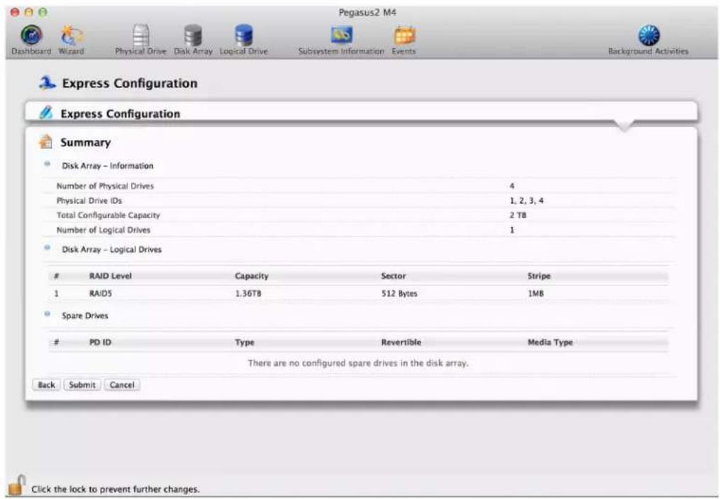
- Do one of the following actions:
• If you accept these parameters, click the Submit button.
The Wizard creates your disk array and logical drives. If you have an R6 or R8, the Wizard also creates a spare drive.
- If you do NOT accept these parameters, click the Back button, then review and modify your choices.
CHOOSING ADVANCED CONFIGURATION
This option enables you to directly specify all parameters for a new disk array, logical drives, and spare drives.
To use the Advanced Configuration Wizard:
-
From the Storage menu choose Wizard.
-
Click the Advanced button. The Create Disk Array screen displays.
Task 1 – Disk Array Creation
To create your disk array:
- Accept the defaults or make changes:
• Enter an alias in the Alias fiel.
Maximum of 32 characters; letters, numbers, space between characters, and underline.
• Media Patrol – Uncheck to disable on this array.
For more information, see "Media Patrol" on page 73.
- PDM – Uncheck to disable on this array.
For more information, see "PDM" on page 73.
-
In the Select Physical Drives diagram, click the drives to add them to your array. The drive carriers turn blue when you click them. The physical drives' ID numbers appear in the field below the diagram.
-
Click the Next button to continue. The Create Logical Drive screen displays.
Task 2 – Logical Drive Creation
To create your logical drive:
-
Enter your information and choose your options.
-
Enter a logical drive alias in the field provided
- Choose a RAID level from the dropdown menu.
Note the Max: capacity value. Then enter a capacity value the field provided and choose a unit of measure from the dropdown menu. - Enter a value for Capacity and choose the unit for the value (MB, GB, TB)
- Choose a Stripe size. 64 KB, 128 KB, 256 KB, 512 KB, and 1 MB are available.
-
Choose a Sector size. 512 B, 1 KB, 2 KB, and 4 KB are available.
-
Choose a Read (cache) Policy.
The choices are Read Cache, Read Ahead (cache), and None. - Choose a Write (cache) Policy.
The choices are WriteThru (write through) and WriteBack. Write back requires a Read Cache or Read Ahead Read Cache Policy.
• RAID 50 only. Choose the number of axles to use. -
If you want the PROMISE Utility to format your logical drives, leave the Format box checked.
For additional format options, see "Formatting Your Logical Drives" on page 76. -
Click the Add button.
The new logical drive appears on the list at the right.
If there is capacity remaining, you can create an additional logical drive.
- Click the Next button to continue.
The Create Spare Drive screen displays.
Task 3 – Spare Drive Creation
To create your spare drive:
-
For each of the following items, accept the default or change the settings as required:
-
Check the Revertible box if you want a revertible spare drive.
A revertible spare drive returns to its spare drive assignment after you replace the failed physical drive in the disk array and run the Transition function.
- Global – Can be used by any disk array
• Dedicated to newly created disk array – The disk array you are now creating.
- In the Select Physical Drives diagram, click a drive to choose it for your spare.
The drive carrier turns blue when you click it. The physical drive's ID number appears in the field below the diagram.
- Click the Next button to continue.
The Summary screen displays.
Task 4 – Summary
- Review your choices of disk array, logical drives, and spare drive.
• To make a change, click the Back button to reach the appropriate screen.
• To accept, click the Submit button.
The disk array, logical drive, and spare drive take a few moments to create.
- Click the Finish button to close the Wizard.
Formatting your Logical Drives
If you left the Format box checked under Task 2 – Logical Drive Creation, your logical drives are formatted automatically.
If you UNchecked the Format box, you must format your logical drives manually.
When the PROMISE Utility has finished the partition and format operation, new removable-drive icons, each representing one logical drive, appear on your desktop (right).
When you see the icon, your logical drive is ready to use.
MAKING DISK ARRAY SETTINGS
To make disk array settings:
- Do one of the following actions:
• From the Dashboard window, click the Disk Array link.
• From the Storage menu, choose Disk Array.
-
Mouse-over the disk array you want then click the Settings button.
-
Make setting changes as required:
-
Enter, change or delete the alias in the Alias field Maximum of 32 characters; letters, numbers, space between characters, and underline.
- Enable Media Patrol – Check to enable, uncheck to disable on this array.
-
Enable PDM – Check to enable, uncheck to disable on this array.
-
Click the Save button.

Note
You can also enable or disable Media Patrol for the entire RAID system. see "Making Media Patrol Settings" on page 41.
This feature causes the drive carrier LEDs to flash for one minute to assist you in locating the physical drives that make up this disk array.
To locate a disk array:
- Do one of the following actions:
• From the Dashboard window, click the Disk Array link.
• From the Storage menu, choose Disk Array.
- Mouse-over the disk array you want then click the Locate button.
The Drive Power / Status LED for the physical drives that make up the disk array blink blue and orange for one minute.
Running the Locate function to identify a disk array

DELETING A DISK ARRAY

CAUTION
When you delete a disk array, you also delete any logical drives that belong to it, along with the data on those logical drives. Back up any important data before deleting a disk array.
To delete a disk array:
- Do one of the following actions:
• From the Dashboard window, click the Disk Array link.
• From the Storage menu, choose Disk Array.
-
Mouse-over the disk array you want then click the Delete button.
-
In the Confirmation box, type the word "confirm" in the field provided and click the Confirm button.
PREPARING A DISK ARRAY FOR TRANSPORT
This feature prepares the physical drives that make up the disk array to be removed from the enclosure and installed in a different location.
To prepare a disk array for transport:
- Do one of the following actions:
• From the Dashboard window, click the Disk Array link.
• From the Storage menu, choose Disk Array.
-
Mouse-over the disk array you want then click the Transport button.
-
In the Confirmation box, type the word "confirm" in the field provided and click the Confirm button.
The disk array status changes to Transport Ready.
- Remove the physical drives and install them in their new location.
See "Replacing a Physical Drive" on page 127 for more information.
REBUILDING A DISK ARRAY
When you rebuild a disk array, you are actually rebuilding the data on one of its physical drives.
If there is no spare drive of adequate capacity, you must replace the failed drive with an unconfigured physical drive, then perform a Manual Rebuild.
On the carrier with the failed drive, the Drive Power / Status LED is red and the Drive Activity LED is dark.
Drive carrier LEDs for a dead or failed drive
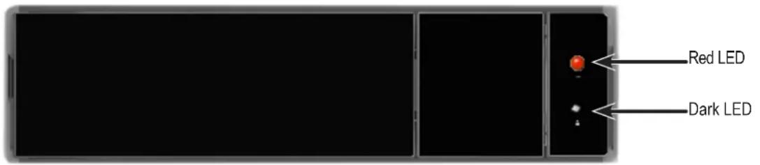
That is the physical drive you must replace.
PERFORMING A MANUAL REBUILD
To perform a manual rebuild:
- Click on the Background Activities icon.
- Mouse-over Rebuild and click the Start button.
- From the Source Physical Drive dropdown menu, choose a Source disk array and physical drive.
Arrays have an ID No. Physical drives have a Seq. No.(sequence number)
- From the Target Physical Drive dropdown menu, choose a Target physical drive.
- In the Confirmation box, type the word "confirm" in the field provided and click the Confirm button.
When the disk array is rebuilding:
• The disk array shows a green check icon and Rebuilding status.
- Logical drives under the disk array continue to show a yellow! icon and Critical, Rebuilding status.
- If the buzzer is enabled, the Pegasus unit emits two quick beeps every five seconds. When the beeps stop, the rebuild is done.
PAUSING AND RESUMING A REBUILD
To pause or resume a Rebuild:
- Click on the Background Activities icon.
- Mouse-over Rebuild and click the Pause or Resume button.
STOPPING A REBUILD
To stop or cancel a Rebuild:
- Click on the Background Activities icon.
- Mouse-over Rebuild and click the Stop button.
- Click the Confirm button. Also see "Making Rebuild Settings" on page 44.
MANAGING LOGICAL DRIVES
Logical drive management includes:
• "Viewing a List of Logical Drives"
• "Viewing Logical Drive Information"
• "Viewing Logical Drive Statistics"
- "Making Logical Drive Settings"
• "Viewing Logical Drive Check Tables"
- “Creating a Logical Drive Manually”
- "Formatting Your Logical Drives"
- “Locating a Logical Drive”
- "Deleting a Logical Drive"
- "Initializing a Logical Drive"
- "Redundancy Check on a Logical Drive"
• "Migrating a Logical Drive"
- "Running PDM on a Logical Drive"
VIEWING A LIST OF LOGICAL DRIVES
To view a list of logical drives, do one of the following actions:
- Click the Logical Drive icon.
• From the Storage menu, choose Logical Drive.
The list of logical drives appears. Logical drive information includes:
• ID – LD0, LD1, etc.
- Alias – If assigned.
• Status (Normal, Critical or Offline icon)
- Capacity – Data capacity of the logical drive.
- RAID Level – Set when the logical drive was created.
- Stripe – Set when the logical drive was created.
- Cache Policy – Read cache and Write cache settings.
- Array ID – ID number of the disk array where this logical drive was created.
VIEWING LOGICAL DRIVE INFORMATION
To view logical drive information:
-
Do one of the following actions:
-
ClicktheLogical Drive icon.
• From the Storage menu, choose Logical Drive. The list of logical drives appears. -
Mouse-over the logical drive you want then click the View button.
Logical Drive information displays, including:
• Logical Drive ID – LD0, LD1, etc.
- Alias – If assigned
- Array ID – ID number of the disk array where this logical drive was created
- RAID Level – Set when the logical drive was created
• Operational Status – OK, Critical, or Offline
• Capacity – Data capacity of the logical drive
• Number of Axles – For RAID 10, 2 axles
- Physical Capacity – Data capacity of the physical drives
• Number of Physical Drives – The number of physical drives in the disk array
- Stripe size – Set at logical drive creation
- Read Policy – ReadCache, ReadAhead, or None *
• Sector size – Set at logical drive creation
• Write Policy – WriteThru or WriteBack *
- Current Write Policy – May change from WriteBack to WriteThru under certain conditions.
• Preferred Controller ID – Not applicable
- Tolerable Number of Dead Drives Per Axle – Number of physical drives that can fail without the logical drive going offline
- Synchronized – A new logical drive shows “No” until synchronizing is completed. See “” on page 46
- Parity Pace – Pertains to some RAID levels
- WWN – Worldwide Number, a unique identifier assigned to this logical drive
- RAID 5 & 6 Algorithm – Pertains to RAID 5 and 6
- Codec Scheme – Pertains to some RAID levels
- Serial No – Serial number assigned to this logical drive
- Click the X icon to close the information panel.
VIEWING LOGICAL DRIVE STATISTICS
To view logical drive statistics:
-
Do one of the following actions:
-
Click the Logical Drive icon.
• From the Storage menu, choose Logical Drive. The list of logical drives appears. -
Mouse-over the logical drive you want then click the View button.
-
Click the Statistics tab.
-
Logical Drive statistics display, including:
• Data Transferred – In megabytes
- I/O Requests
- Read Data Transferred – In megabytes
• Non-Read/Write I/O Requests
• Write Data Transferred – In megabytes
- Read I/O Requests
- Errors
- Write I/O Requests
• Non-Read/Write Errors
• Statistics Start Time
- Read Errors
• Statistics Collection Time
- Write Errors
- Click the X icon to close the statistics panel.
To clear the check tables, see "Clearing Statistics" on page 26.
MAKING LOGICAL DRIVE SETTINGS
To make logical drive settings:
-
Do one of the following actions:
-
Click the Logical Drive icon.
• From the Storage menu, choose Logical Drive. The list of logical drives appears. -
Mouse-over the logical drive you want then click the Settings button.
-
Make setting changes as required:
-
Enter, change, or delete the alias in the Alias field. Maximum of 32 characters; letters, numbers, space between characters, and underline.
- Choose a Read (cache) Policy. Read Cache, Read Ahead, and No Cache are available.
-
Choose a Write (cache) Policy. Write Back and Write Through (Thru) are available.
-
Click the Save button.
For more information, see "Read Cache Policy" and "Write Cache Policy" on page 115
VIEWING LOGICAL DRIVE CHECK TABLES
This feature enables you to view error tables. Use this information to evaluate the integrity of the logical drive and to determine whether corrective action is needed.
To view logical drive check tables:
-
Do one of the following actions:
-
Click the Logical Drive icon.
• From the Storage menu, choose Logical Drive. The list of logical drives appears. -
Mouse-over the logical drive you want then click the Check Table button.
-
Choose an option:
-
All – All errors. The default choice.
- Read Check – Read errors for this logical drive.
- Write Check – Write errors for this logical drive.
- Inconsistent Block – Inconsistent blocks for this logical drive. Mirror data for RAID levels 1, 1E and 10 or Parity data for RAID levels 5 and 6. Identified by the Redundancy Check.
The Check Table lists:
- Table Type – Read Check, Write Check or Inconsistent Block.
- Start Logical Block Address – LBA of the first block for this entry.
-
Count – Number of errors or continuous blocks starting from this LBA.
-
Click the X icon to close the information panel.
To clear the check tables, see "Clearing Statistics" on page 26.
CREATING A LOGICAL DRIVE MANUALLY
This feature creates a logical drive only. You can also use the Wizard to create a disk array with logical drives and spare drives at the same time. See “Creating a Disk Array and Logical Drive with the Wizard” on page 59.
To create a logical drive manually:
-
Do one of the following actions:
-
Click the Logical Drive icon.
• From the Storage menu, choose Logical Drive. -
Click the Create Logical Drive button.
-
Click the radio button of the disk array you want to use and click the Next button.
-
Accept the defaults or make changes:
-
Optional. Enter an alias in the Alias field.
Maximum of 32 characters; letters, numbers, space between characters, and underline. - Choose a RAID level.
The choice of RAID levels depends the number of physical drives in the disk array. - In the Capacity field, accept the default maximum capacity or enter a lesser capacity and size in MB, GB or TB.
Any remaining capacity is available for an additional logical drive. - Choose a Stripe size.
64 KB, 128 KB, 256 KB, 512 KB, and 1 MB are available. - Choose a Sector size.
512 B, 1 KB, 2 KB, and 4 KB are available. - Choose a Read (cache) Policy.
Read Cache, Read Ahead, and No Cache are available. - Choose a Write (cache) Policy.
Write Back and Write Through (Thru) are available.
The Write Cache is always set to WriteThru when the Read Cache is set to NoCache. - For RAID 6 logical drives, choose a Codec Scheme from the dropdown menu.
P+Q and Q+Q are available. -
If you want the PROMISE Utility to format your logical drives, leave the Format box checked.
See "Formatting Logical Drives" on page 108. -
Click the Add button.
The new logical drive appears on the list at the right.
If there is capacity remaining, you can create an additional logical drive. Pegasus supports up to 32 logical drives.
- When you are finished, click the Submit button.
The new logical drive or drives appear in the logical drive list.
FORMATTING YOUR LOGICAL DRIVES
If you left the Format box checked when you created your logical drives, they are formatted automatically.
If you UNchecked the Format box, you must format your logical drives manually. See "Formatting Logical Drives" on page 108.
When the PROMISE Utility has finished the format operation, new removable-drive icons, each representing one logical drive, appear on your desktop (right).

When you see the icon, your logical drive is ready to use. Your logical drives are ready to use.
LOCATING A LOGICAL DRIVE
This feature causes the drive carrier LEDs to flash for one minute to assist you in locating the physical drives that make up this logical drive.
To locate a logical drive:
- Click the Storage tab.
-
Click the Logical Drive icon. The list of logical drives appears.
-
Mouse-over the logical drive you want then click the Locate button. The Drive Power / Status LEDs for the physical drives that make up the logical drive blink blue and orange for one minute.
Running the Locate function to identify a disk array
Drive Power / Status LEDs blink blue and orange

DELETING A LOGICAL DRIVE

CAUTION
When you delete a logical drive, all the data on the logical drive is lost. Back up any important data before deleting a logical drive.
This action requires Administrator or Super User privileges. To delete a logical drive:
-
Do one of the following actions:
-
Click the Logical Drive icon.
• From the Storage menu, choose Logical Drive. The list of logical drives appears. -
Mouse-over the logical drive you want then click the Delete button.
- In the Confirmation box, type the word "confirm" in the field provided and click the Confirm button.
INITIALIZING A LOGICAL DRIVE
Initialization is normally done to logical drives after they are created from a disk array.

CAUTION
When you initialize a logical drive, all the data on the logical drive is lost. Backup any important data before you initialize a logical drive.
To initialize a logical drive:
- Click on the Background Activities icon. The list of background activities appears.
- Mouse-over Initialization and click the Start button.
-
Check the box to the left of the logical drive you want to initialize.
-
Choose the initialization option you want:
-
Quick Initialization – Check the box and enter a value in the Quick Initialization Size field. This value is the size of the initialization blocks in MB.
-
Full Initialization – Do not check the box. Enter a hexadecimal value in the Initialization Pattern in Hex field or use the default 00000000 value.
-
Click the Confirm button.
-
In the Confirmation box, type the word "confirm" in the field provided and click the Confirm button.
PAUSING AND RESUMING AN INITIALIZATION
To pause or resume Initialization:
-
Click on the Background Activities icon. The list of background activities appears.
-
Mouse-over Initialization and click the Pause or Resume button.
STOPPING AN INITIALIZATION
To stop means to cancel an Initialization:
-
Click on the Background Activities icon. The list of background activities appears.
-
Mouse-over Initialization and click the Stop button.
-
In the Confirmation box, type the word "confirm" in the field provided and click the Confirm button.
REDUNDANCY CHECK ON A LOGICAL DRIVE
Redundancy Check is a routine maintenance procedure for fault-tolerant disk arrays (those with redundancy) that ensures all the data matches exactly. Redundancy Check can also correct inconsistencies.
To run Redundancy Check on a logical drive:
-
Click on the Background Activities icon.
The list of background activities appears. -
Mouse-over Redundancy Check and click the Start button.
-
Check the boxes to the left of the logical drives on which to run Redundancy Check.
-
Check the options you want:
-
Auto Fix – Attempts to repair the problem when it finds an error
-
Pause on Error – The process stops when it finds a non-repairable error
-
Click the Confirm button.
PAUSING AND RESUMING A REDUNDANCY CHECK
To pause or resume a Redundancy Check:
- Click on the Background Activities icon. The list of background activities appears.
- Mouse-over Redundancy Check and click the Pause or Resume button.
STOPPING A REDUNDANCY CHECK
To stop is to cancel the Redundancy Check:
- Click on the Background Activities icon. The list of background activities appears.
- Mouse-over Redundancy Check and click the Stop button.
- Click the Confirm button.
MIGRATING A LOGICAL DRIVE
The term “Migration” means either or both of the following:
- Change the RAID level of a logical drive.
- Expand the storage capacity of a logical drive.
Before you begin a migration, examine your current disk array to determine whether:
- The physical drives in your array can support the target RAID level.
- There is sufficient capacity to accommodate the target logical drive size.
If you need to add physical drives to your array, be sure there are unassigned physical drives are installed in your RAID system before you begin migration.
See “RAID Levels” on page 91, and “RAID Level Migration” on page 101 and “RAID Level Migration” on page 84.
To migrate a logical drive:
- Click on the Background Activities icon. The list of background activities appears.
- Mouse-over Migrate and click the Start button.
- In the Select Disk Array dropdown menu, choose the source disk array.
- In the Select Physical Drives diagram, click the drives to add them to your array. The ID numbers of the chosen drives appear in the field below the diagram.
- Click the Next button.
- Check the box next to the logical drive you want to modify.
- From the dropdown menu, choose a target RAID level. The choice of RAID levels depends the number of physical drives in the disk array. See the Note below.
- In the Capacity field, accept the current capacity. Or check the Expand Capacity box and enter a greater capacity and size in MB, GB or TB. If there is capacity remaining, you can create an additional logical drive.
- Click the Next button. The logical drive ID numbers, with the original and target RAID levels and capacities are shown
- To accept the proposed target values, click the Confirm button.

Note
When you add physical drives to a RAID 10 array, it becomes a RAID 1E array by default. If you are adding an even number of physical drives to a RAID 10 array and you want the target array to be RAID 10, you must specify RAID 10 under RAID level.
RUNNING PDM ON A LOGICAL DRIVE
Predictive Data Migration (PDM) is the migration of data from the suspect disk drive to a spare drive, similar to rebuilding a disk array. But unlike rebuilding, PDM automatically copies your data to a spare drive before the drive fails and your logical drive goes Critical.
PDM can be triggered automatically by Media Patrol. See “PDM” on page 35. To run PDM on a logical drive:
- Click on the Background Activities icon. The list of background activities appears.
- Mouse-over PDM and click the Start button.
- Choose a Source Physical Drive. The Source Physical Drive is the drive suspected of possible failure. Source Physical Drives are identified by the disk array number and their sequence number in the disk array.
- Choose a Target Physical Drive. The Target Physical Drive is the replacement drive. Target physical drives are identified by their physical drive ID number.
- Click the Confirm button.
PAUSING AND RESUMING PDM
To pause or resume PDM:
-
Click on the Background Activities icon. The list of background activities appears.
-
Mouse-over PDM and click the Pause or Resume button.
STOPPING PDM
To stop is to cancel PDM:
- Click on the Background Activities icon. The list of background activities appears.
- Mouse-over PDM and click the Stop button.
- Click the Confirm button.
MANAGING SPARE DRIVES
Spare drive management includes:
• Viewing a List of Spare Drives (below)
- “Creating a Spare Drive Manually”
• "Making Spare Drive Settings"
- "Running Spare Check"
- "Deleting a Spare Drive"
- "Running a Transition"
VIEWING A LIST OF SPARE DRIVES
To view a list of spare drives, do one of the following actions:
• From the Dashboard window, click the Spare Drive link.
• From the Storage menu, choose Spare Drive.
Spare Drive information displays, including:
• ID – Spare0, Spare1, etc.
- Status (Normal, Rebuilding or Failed/missing icon)
- Configurable Capacity – Usable capacity of the spare drive
• Physical Drive ID – ID number of the physical drive chosen for this spare
- Revertible – Yes or No
- Spare Type – Global or Dedicated
• Dedicated to Array – ID number of the disk array to which the spare is dedicated
VIEWING SPARE DRIVE INFORMATION
To view spare drive information:
- Do one of the following actions:
• From the Dashboard window, click the Spare Drive link.
• From the Storage menu, choose Spare Drive. The list of spare drives appears.
- Mouse-over the spare drive you want then click the View button.
Spare Drive information displays, including:
- Spare Drive ID – Spare0, Spare1, etc.
• Physical Drive ID – ID number of the physical drive chosen for this spare - Location – Enclosure number and slot number
- Model Number – Make and model of the physical drive
- Operational Status – OK, Rebuilding, Failed or Missing
- Spare Type – Global or Dedicated *
• Physical Capacity – Total data capacity of the spare drive - Revertible – Yes or No *
- Configurable Capacity – Usable capacity of the spare drive
-
Spare Check Status – Not Checked or Healthy
• Media Patrol – Enabled or Not Enabled *
• Dedicated to Array – ID number of the disk array to which the spare is dedicated *
Items with an asterisk (*) are adjustable under "Making Spare Drive Settings" on page 85.
For Spare Check, see "Running Spare Check" on page 85. -
Click the X icon to close the information panel.
CREATING A SPARE DRIVE MANUALLY
This feature creates a spare drive only. You can also use the Wizard to create a disk array with logical drives and spare drives at the same time. See Spare Drives for more information.
For more information on settings options, see "Spare Drives" on page 92. To create a spare drive:
-
From the Dashboard window, click the Spare Drive link.
-
Click the Create Spare Drive button.
-
For each of the following items, accept the default or change the settings as required:
- Check the Revertible box if you want a revertible spare drive. A revertible spare drive returns to its spare drive assignment after you replace the failed physical drive in the disk array and run the Transition function.
• Type (choose spare type)
- Global – Can be used by any disk array
• Dedicated to a disk array. Click the radio button next to the disk array to which this spare drive is dedicated.
- Media Type If you have more than one type of physical drive installed (SSD and HDD for example) choose the type of drive for the spare.
- In the Create Spare Drive diagram, click a drive to choose it for your spare.
The drive carrier turns blue when you click it. The physical drive's ID number appears in the field below the diagram.
- Click the Submit button to continue.
If you are done creating spare drives, click the Finish button. To create another spare drive, click the Create More button.
MAKING SPARE DRIVE SETTINGS
For more information on settings options, see "Spare Drives" on page 92. To make spare drive settings:
- From the Dashboard window, click the Spare Drive link.
The list of spare drives appears.
-
Mouse-over the spare drive you want then click the Settings button.
-
Accept the default or change the settings as required:
• In the Revertible dropdown menu, choose Yes or No.
• In the Spare Type dropdown menu, choose Global or Dedicated.
- If you use chose a Dedicated spare, check the box beside the disk array to which this spare drive is assigned.
- Click the Save button.
RUNNING SPARE CHECK
Spare Check verifies the status of your spare drives. To run spare check:
- From the Dashboard window, click the Spare Drive link. The list of spare drives appears.
- Mouse-over the spare drive you want then click the Spare Check button.
- Click the Confirm button. Spare Check has no pause, resume or stop functions. When the Spare Check is completed, it adds Healthy next to Spare Check Status on the Spare Drive information box.
After the "Spare Check completed" message appears, click the View button to see Spare Check Status.
DELETING A SPARE DRIVE
This action requires Administrator or a Super User privileges. To delete a spare drive:
- From the Dashboard window, click the Spare Drive link. The list of spare drives appears.
- Mouse-over the spare drive you want then click the Delete button.
- In the Confirmation box, type the word "confirm" in the field provided and click the Confirm button.
RUNNING A TRANSITION ON A SPARE DRIVE
Transition is the process of replacing a revertible spare drive that is currently part of a disk array with an unconfigured physical drive or a non-revertible spare. You must specify an unconfigured physical drive of the same or larger capacity and same media type as the revertible spare drive.
Also see “Transition” on page 112 and “Transition” on page 46.
RUNNING A TRANSITION
To run a transition on a revertible spare drive:
- Click on the Background Activities icon. The list of background activities appears.
- Mouse-over Transition and click the Start button.
- Choose a Source Physical Drive. The Source Physical Drive is the revertible spare drive that is now part of the disk array. Source Physical Drives are identified by the disk array number and their sequence number in the disk array.
- Choose a Target Physical Drive. The Target Physical Drive is the drive that replaces the revertible spare. Target physical drives are identified by their physical drive ID number.
- Click the Confirm button.
PAUSING AND RESUMING A TRANSITION
To pause or resume Transition:
-
Click on the Background Activities icon. The list of background activities appears.
-
Mouse-over Transition and click the Pause or Resume button.
STOPPING, PAUSING OR RESUMING A TRANSITION
To stop is to cancel a Transition:
- Click on the Background Activities icon. The list of background activities appears.
- Mouse-over Transition and click the Stop button.
- Click the Confirm button
TECHNOLOGY BACKGROUND
This chapter covers the following topics:
- "Disk Arrays"
- "Logical Drives"
- "Formatting Logical Drives"
- "Spare Drives"
- "RAID Controllers"
Disk Arrays
Disk array technology includes:
• Media Patrol
- PDM
MEDIA PATROL
Media Patrol is a routine maintenance procedure that checks the magnetic media on each disk drive. Media Patrol checks all physical drives assigned to disk arrays and spare drives. Media Patrol does not check unconfigured drives.
Media Patrol checks are enabled by default on all disk arrays and spare drives. You can disable Media Patrol in the disk array and spare drive settings, however that action is not recommended.
Unlike Synchronization and Redundancy Check, Media Patrol is concerned with the condition of the media itself, not the data recorded on the media. If Media Patrol encounters a critical error, it triggers PDM, if PDM is enabled on the disk array.
Media Patrol has three status conditions:
- Running – Normal. You can access your logical drives at any time.
- Yield – Temporary pause while a read/write operation takes place.
- Paused – Temporary pause while another background runs. Or a pause initiated by the user.
See "Media Patrol" on page 41.
PDM
Predictive Data Migration (PDM) is the migration of data from the suspect disk drive to a spare disk drive, similar to rebuilding a logical drive. But unlike Rebuilding, PDM constantly monitors your disk drives and automatically copies your data to a spare disk drive BEFORE the disk drive fails and your logical drive goes Critical.
The following actions trigger PDM:
• A disk drive with unhealthy status (see below)
• Media Patrol finds a disk critical error
- You initiate PDM manually
See "Running PDM on a Logical Drive" on page 81.
PDM also counts the number of media errors reported by Media Patrol. A disk drive becomes unhealthy when:
• A SMART error is reported
- The bad sector remapping table fills to the specified level.
Because data would be lost if written to a bad sector, when a bad sector is detected, the disk drive creates a map around it. These maps are saved in the bad sector remapping table, which have a capacity of 512 reassigned blocks and 2048 error blocks. See “PDM” on page 45.
You can specify the maximum levels for the reassigned and error blocks in PDM settings. When the table fills to a specified value, PDM triggers a migration of data from the suspect drive (the disk drive with the bad sectors) to a replacement physical drive.
During data migration, you have access to your logical drives but they respond more slowly to read/write tasks because of the additional operation. The time required for data migration depends on the size of the disk drives.
PDM is enabled on all disk arrays by default. You can disable PDM in the disk array settings, however that action is not recommended. See “Making Disk Array Settings” on page 65.
LOGICAL DRIVES
Logical drive technology includes:
- "RAID Levels"
- "RAID Level Migration"
- "Stripe Size"
- "Sector Size"
- "Initialization"
RAID LEVELS

Note
Which RAID levels supported on your Pegasus or Pegasus2 depends on the number of physical drives that are installed. The RAID levels discussed in this section are not supported on all models. Only the Pegasus2 R8 is capable of supporting every RAID level illustrated here.
RAID (Redundant Array of Independent Disks) allows multiple physical drives to be combined together in a disk array. Then all or a portion of the disk array is formed into a logical drive. The operating system sees the logical drive as a single storage device, and treats it as such.
RAID 0 - STRIPE
When a logical drive is striped, the read and write blocks of data are interleaved between the sectors of multiple physical drives. Performance is increased, since the workload is balanced between drives or “members” that form the logical drive. Identical drives are recommended for performance as well as data storage efficiency.
RAID 0 Striping interleaves data across multiple drives

The disk array's data capacity is equal to the number of disk drive members multiplied by the smallest drive's capacity. For example, one 100 GB and three
120 GB drives form a 400 GB (4 x 100 GB) disk array instead of 460 GB.
If physical drives of different capacities are used, there is unused capacity on the larger drives.
RAID 0 logical drives on Pegasus consist of one or more physical drives.
| Advantages Disadvantages | |
| Implements a striped disk array, the data is broken down into blocks and each block is written to a separate disk driveI/O performance is greatly improved by spreading the I/O load across many channels and drivesNo parity calculation overhead is involved | Not a true RAID because it is not fault-tolerantThe failure of just one drive results in all data in an disk array being lostDo not in mission-critical environments |
Recommended Applications for RAID 0:
- Image Editing
• Pre-Press Applications
• Any application requiring high bandwidth
RAID 1 - MIRROR
When a logical drive is mirrored, identical data is written to a pair of physical drives, while reads are performed in parallel. The reads are performed using elevator seek and load balancing techniques where the workload is distributed in the most efficient manner. Whichever drive is not busy and is positioned closer to the data is accessed first.
With RAID 1, if one physical drive fails or has errors, the other mirrored physical drive continues to function. Moreover, if a spare physical drive is present, the spare drive is used as the replacement drive and data begins to mirrored to it from the remaining good drive.
RAID 1 Mirrors identical data to two drives

The logical drive's data capacity equals the smaller physical drive. For example, a 100 GB physical drive and a 120 GB physical drive have a combined capacity of 100 GB in a mirrored logical drive.
If physical drives of different capacities are used, there is unused capacity on the larger drive.
RAID 1 logical drives on Pegasus consist of two physical drives.
If you want a mirrored logical drive with more than two physical drives, see "RAID 1E – Enhanced Mirror".
| Advantages Disadvantages | |
| Simplest RAID levelCan increase read performance by processing data requests in parallel since the same data resides on two different drives | Very high disk overhead – uses only 50% of total capacity |
Recommended Applications for RAID 1:
- Accounting
- Payroll
- Financial
• Any application requiring very high availability
RAID 1E - ENHANCED MIRROR
RAID 1E offers the security of mirrored data provided by RAID 1 plus the added capacity of more than two physical drives. It also offers overall increased read/write performance plus the flexibility of using an odd number of physical drives. With RAID 1E, each data stripe is mirrored onto two physical drives. If one drive fails or has errors, the other drives continue to function, providing fault tolerance.
RAID 1E can mirror data over an odd number of drives

The advantage of RAID 1E is the ability to use an odd number of physical drives, unlike RAID 1 and RAID 10. You can also create a RAID 1E Logical Drive with an even number of physical drives. However, with an even number of drives, you obtain somewhat greater security with comparable performance using RAID 10.
RAID 1E logical drives consist of three or more physical drives. You can create an array with just two physical drives and specify RAID 1E. But the resulting array is actually a RAID 1.
| Advantages Disadvantages | |
| Implemented as a mirrored disk array whose segments are RAID 0 disk arraysHigh I/O rates are achieved thanks to multiple stripe segmentsCan use an odd number of disks | Very high disk overhead – uses only 50% of total capacity |
Recommended Applications for RAID 1E:
- Imaging applications
- Database servers
- General fileserver
RAID 5 - BLOCK AND PARITY STRIPE
RAID 5 organizes block data and parity data across the physical drives. Generally, RAID Level 5 tends to exhibit lower random write performance due to the heavy workload of parity recalculation for each I/O. RAID 5 is generally considered to be the most versatile RAID level. It works well for file, database, application and web servers.
RAID 5 stripes all drives with data and parity information

The capacity of a RAID 5 logical drive equals the smallest physical drive times the number of physical drives, minus one. Hence, a RAID 5 logical drive with four 100 GB physical drives has a capacity of 300 GB. A RAID 5 logical drive with two 120 GB physical drives and one 100 GB physical drive has a capacity of 200 GB. RAID 5 is generally considered to be the most versatile RAID level.
A RAID 5 on Pegasus R4 or M4 consists of three or four physical drives. A RAID 5 on Pegasus R6 consists of three to six physical drives.
| Advantages Disadvantages | |
| ·High Read data transaction rate·Medium Write data transaction rate·Good aggregate transfer rate·Most versatile RAID level | ·Disk failure has a medium impact on throughput |
Recommended Applications for RAID 5:
• File and Application servers
• WWW, E-mail, and News servers
- Intranet servers
RAID 6 - BLOCK AND DOUBLE PARITY STRIPE
RAID level 6 stores dual parity data is rotated across the physical drives along with the block data. A RAID 6 logical drive can continue to accept I/O requests when any two physical drives fail.
Figure 5. RAID 6 stripes all drives with data and dual parity

Hence, a RAID 6 logical drive with (7) 100 GB physical drives has a capacity of 500 GB. A RAID 6 logical drive with (4) 100 GB physical drives has a capacity of 200 GB.
RAID 6 becomes more capacity efficient in terms of physical drives as the number of physical drives increases.
RAID 6 provides double fault tolerance. Your logical drive remains available when up to two physical drives fail.
RAID 6 is generally considered to be the safest RAID level. A RAID 6 on Pegasus R4 or M4 consists of four physical drives.
A RAID 6 on Pegasus R6 consists of four to six physical drives.
| Advantages Disadvantages | |
| ·High Read data transaction rate·Medium Write data transaction rate·Good aggregate transfer rate | ·High disk overhead – equivalent of two drives used for parity·Slightly lower performance than RAID 5 |
Recommended Applications for RAID 6:
• Accounting and Financial
- Database servers
• Any application requiring very high availability
RAID 10 - MIRROR + STRIPE
Mirror + Stripe combines both of the RAID 1 and RAID 0 logical drive types. RAID
10 can increase performance by reading and writing data in parallel or striping, and duplicating the data, or mirroring.
PROMISE implements RAID 10 by creating a data stripe over one pair of disk drives, then mirroring the stripe over a second pair of disk drives. Some applications refer to this method as RAID 0+1.
PROMISE RAID 10 starts with a data stripe, then mirrors it

The data capacity RAID 10 logical drive equals the capacity of the smallest physical drive times the number of physical drives, divided by two.
In some cases, RAID 10 offers double fault tolerance, depending on which physical drives fail.
RAID 10 arrays require an even number of physical drives and a minimum of four.
For RAID 10 characteristics using an odd number of physical drives, choose RAID 1E.
| Advantages Disadvantages | |
| Implemented as a mirrored disk array whose segments are RAID 0 disk arraysHigh I/O rates are achieved thanks to multiple stripe segments | Very high disk overhead – uses only 50% of total capacity |
Recommended Applications for RAID 10:
- Imaging applications
- Database servers
- General fileserver
RAID 50 - STRIPING OF DISTRIBUTED PARITY
RAID 50 combines both RAID 5 and RAID 0 features. Data is striped across physical drives as in RAID 0, and it uses distributed parity as in RAID 5. RAID 50 provides data reliability, good overall performance, and supports larger volume sizes.
The data capacity RAID 50 logical drive equals the capacity of the smallest physical drive times the number of physical drives, minus two.
RAID 50 also provides very high reliability because data is still available even if multiple physical drives fail (one in each axle). The greater the number of axles, the greater the number of physical drives that can fail without the RAID 50 logical drive going offline.
A minimum of six drives are required for a RAID 50.
RAID 50 - Striping of Distributed Parity

flowchart
graph TD
    A["RAID 0"] --> B["RAID 5 Set 1"]
    A --> C["RAID 5 Set 2"]
    B --> D["1a"]
    B --> E["1b"]
    B --> F["1c"]
    B --> G["d parity"]
    B --> H["2a"]
    B --> I["2b"]
    B --> J["c parity"]
    B --> K["2d"]
    B --> L["3a"]
    B --> M["b parity"]
    B --> N["3c"]
    B --> O["3d"]
    B --> P["a parity"]
    B --> Q["4b"]
    B --> R["4c"]
    B --> S["4d"]
    C --> T["5a"]
    C --> U["5b"]
    C --> V["5c"]
    C --> W["d parity"]
    C --> X["6a"]
    C --> Y["6b"]
    C --> Z["c parity"]
    C --> AA["6d"]
    C --> AB["7a"]
    C --> AC["b parity"]
    C --> AD["7a"]
    C --> AE["7d"]
    C --> AF["a parity"]
    C --> AG["8b"]
    C --> AH["8b"]
| Advantages Disadvantages | |
| ·High Read data transaction rate·Medium Write data transaction rate·Good aggregate transfer rate·High reliability·Supports large volume sizes | ·Higher disk overhead than RAID 5 (two drives as hot spares) |
Recommended Applications for RAID 50 include applications that require high fault tolerance and good I/O performance.
• File and Application servers
• Transaction processing
• Office application with many users accessing small files
RAID 60 - DOUBLE PARITY + STRIPE
The PROMISE RAID 60 combines RAID 6 distributed (double) parity and RAID 0 block-level striping.
RAID 60 can increase performance by reading and writing data in parallel or striping, while simultaneously providing parity.
PROMISE implements RAID 60 by creating a data stripe across two RAID 6 sets. This creates very high fault tolerance, two drives in each RAID 6 set can fail without interrupting I/O or loss of data.
A minimum of eight drives are required for a RAID 60, so this option is available on the R8.
PROMISE RAID 60 starts with RAID 6 double parity, then stripes the blocks

flowchart
graph TD
    A["RAID 0"] --> B["RAID 6 Set 1"]
    A --> C["RAID 6 Set 2"]
    B --> D["1a Q1"]
    B --> E["1b Q2"]
    B --> F["1c Q1"]
    B --> G["1d Q2"]
    C --> H["4a Q1"]
    C --> I["4b Q2"]
    C --> J["4c Q1"]
    C --> K["4d Q2"]
    style A fill:#f9f,stroke:#333
    style B fill:#ccf,stroke:#333
    style C fill:#ccf,stroke:#333
    style D fill:#cfc,stroke:#333
    style E fill:#cfc,stroke:#333
    style F fill:#cfc,stroke:#333
    style G fill:#cfc,stroke:#333
    style H fill:#cfc,stroke:#333
    style I fill:#cfc,stroke:#333
    style J fill:#cfc,stroke:#333
    style K fill:#cfc,stroke:#333
RAID 60 is available on the R8. To figure out the capacity, multiply the smallest drive capacity by four. So an R8 with 8 2 TB drives has a capacity of 8 TB with a RAID 60.
| Advantages Disadvantages | |
| High Read data transaction rateMedium Write data transaction rateGood aggregate transfer rateSafest RAID level | High disk overhead(four drives as hot spares on R8)Slightly lower performance than RAID 50 |
Recommended Applications for RAID 50 include applications that require extremely high fault tolerance and good I/O performance.
RAID LEVEL MIGRATION
The term “Migration” means either or both of the following:
- Change the RAID level of a logical drive.
- Expand the storage capacity of a logical drive.
On Pegasus, RAID level migration is performed on the disk array but it applies to the logical drives. Migration does not disturb your data. You can access the data while the migration is in progress. When migration is done, your disk array has a different RAID level and/or a larger capacity.
MIGRATION REQUIREMENTS
The following conditions affect RAID level migration:
- The disk array and logical drive must show a green check icon.
- The Target disk array may require more physical drives than the Source disk array.
- If the Target disk array requires an EVEN number of physical drives but the Source disk array has an ODD number, ADD a physical drive as part of the migration process.
- You cannot reduce the number of physical drives in your disk array, even if the Target disk array requires fewer physical drives than the Source disk array.
- RAID 1 (mirroring) works with two drives only. Only a single-drive RAID 0 disk array can migrate to RAID 1. Other RAID Levels use too many drives to migrate.
- You cannot migrate a disk array when it is Critical or performing activities such as Synchronizing, Rebuilding, and PDM.
- For RAID 6, you can add more physical drives but you cannot change the RAID level.
SOURCE AND TARGET RAID LEVELS
The tables on the following pages show the migration options for each source logical drive by its RAID level. The available target RAID levels are shown with their requirements.

Note
Not every RAID level is supported on every Pegasus and Pegasus2 model.
The number of drives that can be installed sets a limit for what RAID levels are used and what migrations are possible.
RAID 1
A RAID 1 Source logical drive can migrate to the following Target logical drives:
| Target Requirements | |
| RAID 0 | None. |
| RAID 1E | 3 or more physical drives.Add 1 or more physical drives. |
| RAID 5 | 3 physical drives minimum, maximum _4 (M _4 , R _4 ), 6 (R6) or 8 (R8).RAID 1 must have less than _4 (M _4 , R _4 ), 6 (R6) or 8 (R8) physical drives. Add 1 or more physical drives. |
| RAID 10 | 4 physical drives minimum. Even number of physical drives. Add 2 or more physical drives. |
| RAID 50 | 6 physical drives minimum. |
See "Migrating a Logical Drive" on page 79.
RAID 0
A RAID 0 source logical drive can migrate to the following target logical drives:
| Target Requirements | |
| RAID 0 | Add physical drives. |
| RAID 1 | 2 physical drives only.Only a single-drive RAID o can migrate to RAID 1 by adding 1 physical drive. |
| RAID 1E | 3 or more physical drives.If existing physical drives have no unused space, add 1 or more physical drives. |
| RAID 5 | 3 physical drives minimum, maximum 4 (M4, R4), 6 (R6) or 8 (R8).RAID o must have less than 4 (M4, R4), 6 (R6) or 8 (R8) physical drives. If existing physical drives have no unused space, add 1 or more physical drives. |
| RAID 6 | 4 physical drives minimum, 4 (M4, R4), 6 (R6) or 8 (R8).If existing physical drives have no unused space, add 1 or more physical drives. |
| RAID 10 | 4 physical drives minimum. Even number of physical drives. If existing physical drives have no unused space, add 1 or more physical drives. |
| RAID 50 | 6 physical drives minimum. |
| RAID 60 | 8 physical drives minimum. |
See "Migrating a Logical Drive" on page 79.
RAID 1E
A RAID 1E Source logical drive can migrate to the following Target logical drives:
| Target Requirements | |
| RAID 0 | None. |
| RAID 1E | Add physical drives. |
| RAID 5 | 3 physical drives minimum, 4 (M4, R4), 6 (R6) or 8 (R8).RAID 1E must have less than 4 (M4, R4), 6 (R6) or 8 (R8) physical drives. If existing physical drives have no unused space, add 1 or more physical drives. |
| RAID 10 | 4 physical drives minimum. Even number of physical drives. If existing physical drives have no unused space, add 1 or more physical drives. |
| RAID 50 | 6 physical drives minimum. |
See "Migrating a Logical Drive" on page 79.
RAID 5
A RAID 5 Source logical drive can migrate to the following Target logical drives:
| Target Requirements | |
| RAID 0 | None. |
| RAID 1E | None. |
| RAID 5 | Add physical drives. Maximum of 4 (M_4, R_4) , 6 (R6) or 8 (R8). |
| RAID 6 | 4 physical drives minimum, maximum of 4 (M_4, R_4) , 6 (R6) or 8 (R8). If existing physical drives have no unused space, add 1 or more physical drives. |
| RAID 10 | 4 physical drives minimum. Even number of physical drives. If existing physical drives have no unused space, add 1 or more physical drives. |
| RAID 50 | 6 physical drives minimum. |
| RAID 60 | 8 physical drives minimum. |
See "Migrating a Logical Drive" on page 79.
RAID 6
A RAID 6 Source logical drive can migrate to the following Target logical drives:
| Target Requirements | |
| RAID 6 | Add physical drives. Maximum of _4 (M _4 , R _4 ), 6 (R6) or 8 (R8). |
| RAID 6o | 8 physical drives minimum. |
See "Migrating a Logical Drive" on page 79.
RAID 10
A RAID 10 Source logical drive can migrate to the following Target logical drives:
| Target Requirements | |
| RAID 0 | None. |
| RAID 1E | None. |
| RAID 5 | 3 physical drives minimum, maximum of 4 (M_4, R_4) , 6 (R6) or 8 (R8). RAID 10 must have less than 4 (M_4, R_4) , 6 (R6) or 8 (R8) physical drives. |
| RAID 6 | 4 physical drives minimum, maximum of 4 (M_4, R_4) , 6 (R6) or 8 (R8). The RAID 10 logical drive must have less than 4 (M_4, R_4) or 6(R6) physical drives.If existing physical drives have no unused space, add 1 or more physical drives. |
| RAID 10 | Add physical drives in multiples of two. Even number of physical drives. |
| RAID 50 | 6 physical drives minimum. |
| RAID 60 | 8 physical drives minimum. |
When you migrate RAID 10 logical drive, it becomes RAID 1E by default.
If you want a RAID 10 logical drive, there must be an even number of physical drives and you must specify RAID 10 for the target logical drive.
See "Migrating a Logical Drive" on page 79.
RAID 50
A RAID 50 Source logical drive can migrate to the following Target logical drives:
| Target Requirements | |
| RAID 0 | None |
| RAID 5 | None |
| RAID 6 | None |
| RAID 10 | None |
| RAID 1E | None |
| RAID 60 | None |
See "Migrating a Logical Drive" on page 79.
RAID 60
A RAID 60 Source logical drive can migrate to the following Target logical drives:
| Target Requirements | |
| RAID 6 | None |
See "Migrating a Logical Drive" on page 79.
STRIPE SIZE
Stripe Size, also called "Stripe Block Size," refers to the size of the data blocks written to, and read from, the physical drives. Stripe Size is specified when you create a logical drive. You can choose Stripe Size directly when you use the Wizard Advanced Configuration function to create a logical drive.
You cannot change the Stripe Size of an existing logical drive. You must delete the logical drive and create a new one.
The default stripe size is 1 MB. When you create your logical drive using the Wizard Advanced option or you create a logical drive manually, you can choose a stripe size of 64 KB, 128 KB, 256 KB, 512 KB, and 1 MB.
See “Creating a Disk Array and Logical Drive with the Wizard” on page 59 and “Creating a Logical Drive Manually” on page 74.
There are two issues to consider when choosing the Stripe Size:
- You should choose a Stripe Size equal to, or smaller than, the smallest cache buffer found on any physical drive in the disk array. Selecting a larger value slows read/write performance because physical drives with smaller cache buffers need more time for multiple accesses to fill their buffers.
- If your data retrieval consists of fixed data blocks, such as with some database or video applications, then you should choose that size as your Stripe Size.
Generally speaking,
- Email, POS, and web servers prefer smaller stripe sizes.
• Video and database applications prefer larger stripe sizes.
SECTOR SIZE
A sector is the smallest addressable area on a physical drive. Sector size refers to the number of data bytes a sector can hold. A smaller sector size is a more efficient use of a physical drive's capacity. 512 bytes (512 B) is the most common sector size, and the default in the PROMISE Utility.
When you create your logical drive using the Wizard Advanced option or you create a logical drive manually, you can choose a sector size of 512 B, 1 KB, 2 KB, or 4 KB.
See “Creating a Disk Array and Logical Drive with the Wizard” on page 59 and “Creating a Logical Drive Manually” on page 74.
INITIALIZATION
Initialization is done to logical drives after they are created from a disk array. Full initialization sets all data bits in the logical drive to a specified pattern, such as all zeros. The action is useful because there may be residual data on the logical drives left behind from earlier configurations. For this reason, Initialization is recommended for all new logical drives.
See "Initializing a Logical Drive" on page 77.

CAUTION
When you initialize a logical drive, all the data on the logical drive is lost. Backup any important data before you initialize a logical drive.
FORMATTING LOGICAL DRIVES
A RAID logical drive must also be formatted to be compatible with your computer. In this Product Manual, the term format includes both partition and format operations.
You can format your logical drives using the:
- PROMISE Utility with default settings (below)
- PROMISE Utility with Custom Settings (page 90)
- Disk Utility (page 91)
Both the PROMISE Utility and the computer's disk utility offer a choice of formatting options. However, if there is no specific reason to customize, the default format settings are recommended.
PROMISE UTILITY WITH DEFAULT SETTINGS
Wizard Automatic or Express
When you create your logical drives using the Wizard Automatic or Express options, your logical drives are always formatted automatically.
When the PROMISE Utility has finished the format operation, new removable-drive icons, each representing one logical drive, appear on your desktop (right).
When you see the icon, your logical drive is ready to use.
Wizard Advanced or Manual Creation

When you create your logical drives using the Wizard Advanced option, the Format option is enabled by default.
When the PROMISE Utility has finished the format operation, new removable-drive icons, each representing one logical drive, appear on your desktop (right).
When you see the icon, your logical drive is ready to use.
For more information, see "Creating a Disk Array and Logical Drive with the
Wizard" on page 47 and "Creating a Logical Drive Manually" on page 61.

PROMISE UTILITY WITH CUSTOM SETTINGS
To use your own format settings, you must create your logical drives using the Wizard Advanced option or create your logical drives manually, and you must UNcheck the Format box.
See "Creating a Disk Array and Logical Drive with the Wizard" on page 47 and
"Creating a Logical Drive Manually" on page 61.
To format your logical drives using the PROMISE Utility with your own settings:
- In the Logical Drive list, mouse-over the logical drive you want to format, and click the Format button.
-
Supply information as required:
-
Optional: Type a different name into the Volume Name field.
- Choose a partition from the Partition Type dropdown menu.
-
Choose a format type from the Format Type dropdown menu.
• For Macintosh computers, the default GPT Format partition and the default
• Journaled HFS+ format are recommended. -
Click the Format button.
When the PROMISE Utility has finished the partition and format operation, new removable-drive icons, each representing one logical drive, appear on your desktop (right).
When you see the icon, your logical drives are ready to use.

Promise RAID
Disk Utility
For information on using your computer's disk utility, see the online help or the computer's User Manual.
To format your logical drives using the computer's disk utility, you must create your logical drives using the Wizard Advanced option or create your logical drives manually, and you must UNcheck the Format box.
See “Creating a Disk Array and Logical Drive with the Wizard” on page 59 and “Creating a Logical Drive Manually” on page 74.
To format your logical drives using the computer's disk utility:
- Click the Go menu and choose Utilities from the dropdown list.
- Double-click the Disk Utility icon to open the utility.
- In the drive list, highlight the logical drive you want to format and click the Partition button.
- Make your Volume Scheme, Volume Information, and Options settings and click the Apply button.
For Macintosh computers, the default GPT Format partition and the default Journaled HFS+ format are recommended.
- In the Confirmation dialog box, click the Partition button.
When the disk utility has finished the partition and format operation, new removable-drive icons, each representing one logical drive, appear on your desktop (right).
Your logical drives are ready to use.

SPARE DRIVES
Spare drive technology includes:
• Definition (page 92)
- Options (page 92)
- Requirements (page 92)
• Transition (page 93)
DEFINITION
A spare drive is a physical drive that you designate to automatically replace the failed physical drive in a disk array. See “Creating a Spare Drive Manually” on page 69.
The general recommendation is to:
- Provide at least one spare drive
- Configure the spares as global revertible spare drives
OPTIONS
There are several options you can specify for a spare drive:
- System Options
- Revertible – Returns to its spare drive assignment after you replace the failed physical drive in the disk array and run the Transition function.
• Media Patrol – By default, Media Patrol runs on spare drives unless you disable it.
- Spare Type
- Global – Can be used by any disk array
• Dedicated – Can be used only by the assigned disk array
• Media Type (type of physical drive)
• Hard Disk Drive (HDD)
• Solid State Drive (SSD)
REQUIREMENTS
The spare drive must:
- Have adequate capacity to replace the largest physical drive in your disk arrays.
- Be the same media type as the physical drives in your disk arrays.
A reversible spare drive requires:
- You to replace the failed physical drive in the disk array
- You to run the Transition function
TRANSITION
Transition is the process of replacing a revertible spare drive that is currently part of a disk array with an unconfigured physical drive or a non-revertible spare. The revertible spare drive returns to its original status. In order to run the Transition function, the spare drive must be revertible.
In addition, you must specify an unconfigured physical drive of the same or larger capacity and same media type as the revertible spare drive.
RUNNING A TRANSITION
The Transition feature enables you to specify “permanent” spare drives for your Pegasus unit. Transition is the process of replacing a revertible spare drive that is currently part of a disk array with an unconfigured physical drive or a non-revertible spare. The revertible spare drive returns to its original status.
Transition happens automatically when the following sequence of events takes place:
- You create a revertible spare drive. See “Creating a Spare Drive Manually” on page 84.
• A physical drive assigned to your disk array fails and the array goes critical or degraded. - Pegasus automatically rebuilds your array to the revertible spare drive and the array becomes functional again.
• You replace the failed physical drive with a new physical drive of equal or greater capacity. - Pegasus automatically transitions (moves) the data from the revertible spare to the new physical drive.
- The new physical drive becomes part of the array and the revertible spare drive returns to its original spare status.
Transition happens manually when you specify a different unconfigured physical drive to transition (move) the data from the revertible spare drive.
See the example on the following pages.
Example
Following is an example to explain the Transition function.

In the example above, there is a four-drive RAID 5 disk array and a global spare drive. Physical drives 1, 2, 3, and 4 belong to the disk array. Physical drive 5 remains unconfigured. Physical drive 6 is a revertible spare drive.

If a physical drive fails in a disk array and there is a spare drive of adequate capacity available, the controller automatically rebuilds the array using the spare drive. In this example, physical drive 3 failed and the array is rebuilt using physical drive 6, the revertible spare drive.
When the rebuild is complete, the spare drive has replaced the failed drive. In this example, failed drive 3 was replaced by spare drive 6. The disk array now consists of physical drives 1, 2, 4, and 6.
There is no spare drive at this moment. Even if physical drive 5 is of adequate capacity, it has not been designated as a spare, therefore the Pegasus controller cannot use it as a spare.
Automatic Transition
At this juncture, you would replace the failed drive in slot 3 with a new physical drive of the same or greater capacity.
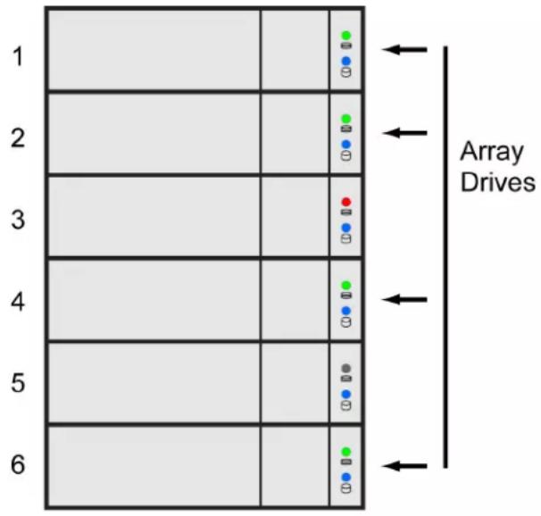
When the Pegasus controller detects the new drive in slot 3, the controller:
Automatically transitions the data on drive 6 to drive 3
Returns drive 6 to spare status
When the Automatic Transition is finished, physical drives 1, 2, 3, and 4 belong to the disk array and physical drive 6 is a revertible spare drive. The original configuration is restored.
Manual Transition
If you wanted to use the drive in slot 5 as a member of the disk array, rather than the drive in slot 3, you would run the Transition function manually. See “Running a Transition on a Spare Drive” on page 71.
When the Manual Transition is finished, physical drives 1, 2, 4, and 5 belong to the disk array and physical drive 6 is a revertible spare drive.
At this point, you would replace the drive in slot 3. The new drive in slot 3 remains unconfigured until you assign it to a disk array or as a spare.
RAID CONTROLLERS
RAID controller technology includes:
- Cache Policy ("Read Cache Policy" and "Write Cache Policy")
- "Capacity Coercion"
As it is used with Pegasus, the term cache refers to any of several kinds of high-speed, volatile memory that hold data moving from your computer to the physical drives or vice-versa. Cache is important because it can read and write data much faster than a physical drive. There are read caches, which hold data as it is read from a physical drive; and write caches, which hold data as it is written to a physical drive.
In order to tune the cache for best performance in different applications, user-adjustable settings are provided. Cache settings are made on the RAID controller. See "Making Controller Settings" on page 25.
READ CACHE POLICY
Read Cache – The read cache is enabled but no pre-fetch action.
Read Ahead – The read cache and predictive pre-fetch feature are enabled.
Read-ahead anticipates the next read and performs it before the request is made. Can increase read performance.
No Cache – The read cache is disabled.
WRITE CACHE POLICY
Write Back – Data is written first to the cache, then to the logical drive. Results in better performance.
Write Thru – Also “Write Through.” Data is written to the cache and the logical drive at the same time. This is the most safe.
CAPACITY COERCION
This feature is designed for fault-tolerant logical drives (RAID 1, 1E, 5, 6, and 10). It is generally recommended to use physical drives of the same size in your disk arrays. When this is not possible, the system adjusts for the size differences by reducing or coercing the capacity of the larger drives to match the smaller ones. With Pegasus, you can choose to enable capacity coercion and any one of four methods.
Enable capacity coercion and choose the method in the Controller Settings menu. See “Making Controller Settings” on page 25.
The choices are:
- GB Truncate – (Default) Reduces the useful capacity to the nearest 1,000,000,000 byte boundary.
- 10GB Truncate – Reduces the useful capacity to the nearest 10,000,000,000 byte boundary.
- Group Rounding – Uses an algorithm to determine how much to truncate. Results in the maximum amount of usable drive capacity.
- Table Rounding – Applies a predefined table to determine how much to truncate.
Capacity coercion also affects a replacement drive used in a disk array. Normally, when an physical drive fails, the replacement drive must be the same capacity or larger. However, the capacity coercion feature permits the installation of a replacement drive that is slightly smaller (within 1 gigabyte) than the remaining working drive. For example, the remaining working drives can be 80.5 GB and the replacement drive can be 80.3, since all are rounded down to 80 GB. This permits the smaller drive to be used.
Without capacity coercion, the controller does not permit the use of a replacement physical drive that is slightly smaller than the remaining working drives.
TROUBLESHOOTING
This chapter deals problems you might encounter with your Pegasus unit and how to resolve them.
- "Responding to an Audible Alarm" (below)
- "Checking LEDs"
- "PROMISE Utility"
• "Viewing the Event Logs"
• "Physical Drive Problems" - "Disk Array and Logical Drive Problems"
- "Subsystem Problems"
- "Connection Problems"
RESPONDING TO AN AUDIBLE ALARM
The Pegasus unit has two beep patterns:
- Two beeps, not repeated – The Pegasus is powering up or ready
- Two beeps, continuously repeated – The Pegasus reports a problem
When you boot Pegasus unit, the buzzer beeps twice to acknowledge power up and twice again when the unit is online and ready for work.
If you hear the repeating two-beep pattern, check the following items:
- System Status LED
- Drive Carrier LEDs
CHECKING LEDs
When you boot Pegasus unit, the Power Button LED turns orange. When fully booted, the LED turns blue. See page 102, Figure 1.
See "Subsystem LEDs" on page 102.
The drive carrier Power / Status LEDs turn blue if a physical drive is installed. See "Drive Carrier LEDs" on page 103.
SUBSYSTEM LEDs
The Pegasus subsystem LEDs are the Power Button and the Thunderbolt ports.
| State Power Button Thunderbolt LEDs | |
| Dark No power No connection | |
| Blue Normal Normal | |
| Flashing Blue — Activity | |
| Orange Booting or shutting down — |
Subsystem LEDs

DRIVE CARRIER LEDs
The Pegasus unit spins up the disk drives sequentially to equalize power draw during start-up. After a few moments:
• The Power / Status LEDs turn blue.
- The Activity LEDs turn blue if a drive is installed.
The drive carrier Power / Status LEDs report the condition of the physical drives. See the table below.
Drive carrier LEDs

| Drive Carrier LEDs | ||
| State Power/StatusDrive Activity | ||
| Dark No power No drive in carrier | ||
| Steady Blue Power is present Drive is present | ||
| Flashing Blue — Activity on drive | ||
| Blinking Blue and Orange Locator feature or Drive is rebuilding — | ||
| Red | Drive error or failure | — |
See “Physical Drive Problems” on page 106 for a discussion of rebuilding and failed physical drives for more information.
The Locator feature is triggered from the PROMISE Utility. It causes the LEDs to blink orange and blue for one minute. That action helps you find the specific drive. See “Locating a Physical Drive” on page 51.
Locate feature on a drive carrier

PROMISE UTILITY
If you can open the PROMISE utility, but you cannot create or delete disk arrays and logical drives, nor can you make settings changes, check the UI lock. See “Unlocking the UI” on page 15.
VIEWING THE EVENT LOGS
Viewing Event Logs includes:
• "Viewing Runtime Events"
• "Viewing NVRAM Events"
• "Event Severity Descriptions"
VIEWING RUNTIME EVENTS
To display Runtime Events, click the Events icon. The log of Runtime Events appears.
Events are added to the top of the list. Each event includes:
- Index – Sequence number of the event. Begins with 0 at system startup.
• Device – Disk Array, Logical Drive, Physical Drive by its ID number.
• Event ID – Hexadecimal identifier of the event
• Severity – (lowest to highest) Information, Warning, Minor, Major, Critical and Fatal
• Time – Date and time the event happened.
• Description – A description of the event in plain language.

Note
The Event Log can also be viewed by clicking on any alerts that appear on the desktop. See "Managing Alerts" on page 123.
VIEWING NVRAM EVENTS
This screen displays a list of and information about 508 most important events over multiple subsystem startups.
To display NVRAM events:
- Click the Events icon.
The log of Runtime Events appears.
- Click the NVR Events button.
The log of NVRAM Events appears.
Events are added to the top of the list. Each item includes:
- Index – Sequence number of the event. Begins with 0 at system startup.
• Device – Disk Array, Logical Drive, Physical Drive by its ID number.
• Event ID – Hexadecimal identifier of the event
• Severity – (lowest to highest) Information, Warning, Minor, Major, Critical and Fatal
• Time – Date and time the event happened.
• Description – A description of the event in plain language.
EVENT SEVERITY DESCRIPTIONS
| Level Meaning | |
| Fatal Non-Recoverable error or failure has occurred | |
| Critical Action is required now and the implications of the condition are serious | |
| Major Action is required now | |
| Minor Action is required but the condition is not a serious at this time | |
| Warning User can decide whether or not action is required | |
| Information Information only, no action is required | |
MANAGING ALERTS
One of the reasons PROMISE recommends running the utility when using the Pegasus2 M4 or any Pegasus model is for immediate user notification of any critical problems that might arise, for example, if a hard disk is removed improperly. Some users might want to change the default settings for the level of event that triggers a notification, or the way notifications appear on the desktop.
To configure how Pegasus2 event notifications appear on the desktop:
- Open the System Preferences folder in your Mac and click on the Notifications icon.

- Scroll down the list of applications to the PROMISE Utility.

- Choose the style of alert (Banner or regular Alert) or choose None to disable alerts.
CONFIGURE ALERT NOTIFICATION LEVEL
To change the level of notification that triggers an alert to appear:
- Go to PROMISE Utility application Preferences.
- Set the Notification Center Event Level with the pull-down menu. There are 5 levels of event notification, Warning (lowest level), Minor (default), Major, Critical and Fatal, the highest level of severity.


PHYSICAL DRIVE PROBLEMS
Physical drive troubleshooting includes:
• "Diagnosis using the PROMISE Utility"
- "Locating a Physical Drive"
- "Replacing a Physical Drive"
- "Physical Drive Warning Message"
Physical drives are the foundation of data storage. A physical drive problem can affect your entire RAID system.
DIAGNOSIS USING THE PROMISE UTILITY
In the PROMISE Utility, when a yellow! check the drive's operational status:

icon or a red X

icon appears beside a physical drive,
- Click the Physical Drive icon.
- Mouse-over and click the physical drive you want then click the View button.
Look under Operational Status for the condition of the physical drive.
- Offline – Check the drive for:
- PFA Condition – Caused by a bad block or sector. See Note 1 below.
- Stale Condition – Caused by obsolete array information on the physical drive. See Note 2 below.
- Drive Failed or Dead – The physical drive cannot be repaired. You must replace the failed drive.
Note 1: Clear the error condition. Then the physical drive is available. See “Clearing a Stale or a PFA Condition” on page 53.
Note 2: Identify the disk array to which the physical drive belongs. Then delete the disk array. If the error condition remains on the physical drive, clear the error condition.
LOCATING A PHYSICAL DRIVE
To locate a physical drive:
-
Do one of the following actions:
-
Click the Physical Drive icon.
• From the Device menu, choose Physical Drive. -
Mouse-over and click the physical drive you want then click the Locate button.
The Power/Status LED for the drive carrier holding that drive blinks blue and orange for one minute.
Running the Locate function to identify a physical drive


IMPORTANT
Please read the Compatibly List for physical drives before purchasing new drives to install in Pegasus2. Download the list from the PROMISE website. See "Hard Drive Compatibility" on page 152 for instructions.
REPLACING A PHYSICAL DRIVE
A failed physical drive displays a red X on the drive carrier.

icon in the PROMISE Utility and a red Power/Status LED
Failed physical drive

Check the failed drive, then obtain a replacement drive of the same:
- Interface – SATA 3 Gb/s or 6 Gb/s
• Spin speed – 5,400 RPM or 7,200 RPM
• Capacity – Equal size or larger
• Type – Hard disk drive (HDD) or solid state drive (SSD)
You do not have to install the identical make and model of physical drive. However replacing with the same make and model of drive makes the process easier and simpler.
You can replace a physical drive without shutting down the Pegasus unit.

CAUTION
To avoid hand contact with an electrical hazard, remove only one drive carrier a time.
To replace a physical drive:
- Press the release button to unlock the drive carrier.
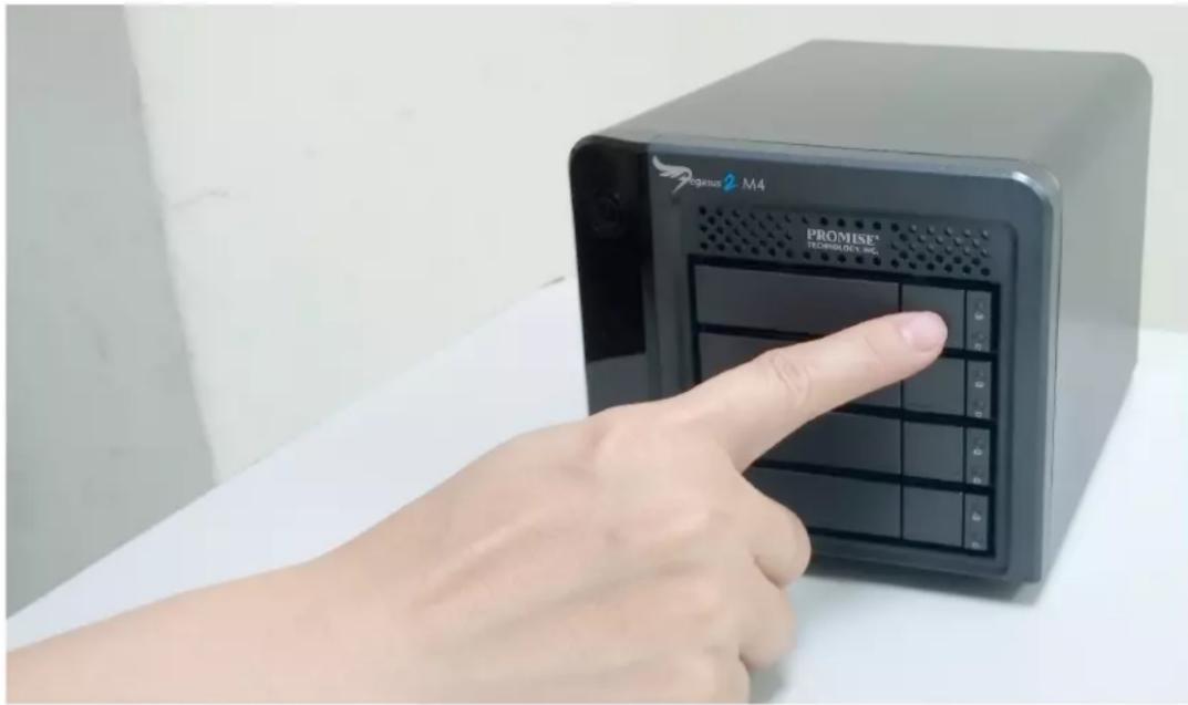
The drive carrier handle swings out.
- Grasp the handle and gently pull the drive carrier out of the Pegasus unit and place it onto a static-free surface.
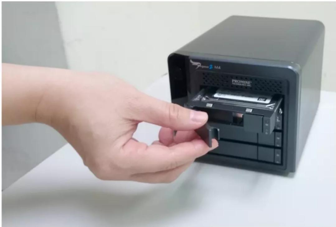
natural_image
Hand inserting a USB into a black PROMISE M4 device on a white surface (no text or symbols visible)- Remove the four mounting screws, then slide the failed drive out of the carrier.
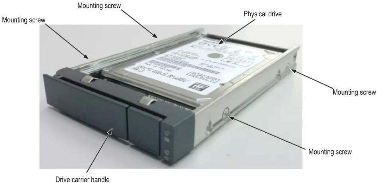
- Place the replacement drive into the carrier then install the four mounting screws. Tighten the screws just until they are snug. Position the drive carrier handle in outward position and slide the drive carrier back into the Pegasus unit.

- Press the drive carrier handle inward until it locks.
PHYSICAL DRIVE WARNING MESSAGE
If you see messages telling you that a physical drive has been removed, you must reseat the physical drives.
To reseat the physical drives:
- On the Pegasus unit, press and hold the Power Button LED until it turns red.
- Wait until the Power Button LED goes dark.
- For each drive carrier, press the Release button, pull the drive carrier part way out of the unit, then press the drive carrier back in until it locks.
See "Replacing a Physical Drive" on page 127.
- Press the Power Button LED to power up the Pegasus unit.
Disk Array and Logical Drive Problems
Disk array and logical drive troubleshooting includes:
- "Disk Array Degraded / Logical Drive Critical"
- "Disk Array Offline / Logical Drive Offline"
- “Repairing an Offline Disk Array or Logical Drive”
- "Rebuilding a Disk Array"
- "Incomplete Array"
- "Unreadable Disk Warning"
Disk array problems typically result from a physical drive failure. The most common problem is a degraded disk array. The RAID controller can rebuild a degraded disk array. See “Rebuilding a Disk Array” on page 133.
DISK ARRAY DEGRADED/LOGICAL DRIVE CRITICAL
Disk arrays are made up of physical drives. Logical drives are created on the disk array.
When one of the physical drives in a disk array fails:
- The operational status of the disk array becomes Critical.
• The operational status of the logical drives becomes Critical or Degraded. - The operational status of the physical drive becomes Dead or Offline. The PROMISE Utility reports these conditions in the following places:
- Dashboard icon – A yellow! 🤓 icon beside the disk arrays, logical drives, and physical drives under System Status.
- Physical Drive icon – Physical drives are shown Dead or Offline and marked with a red X ✗ icon, or Missing.
- Logical Drive icon – Disk Array and Logical Drive are marked Critical with a yellow!
-
RAID 6 logical drives are marked:
-
Degraded with a yellow! 🤒 icon when ONE physical drive is offline.
- Critical with a yellow ! 🎨 icon when TWO physical drives are offline. RAID 0 logical drives show Offline status and a red X ✗ icon.
- Events icon – Logs a Major event for the logical drives and a Warning event for the physical drive.
If there is no spare drive in the Pegasus unit, you must provide the replacement drive. See “Replacing a Physical Drive” on page 127.
Disk arrays are made up of physical drives. Logical drives are created on the disk array. When a disk array and its logical drives go Offline, the data stored in the logical drives is no longer accessible.
RAID 0 logical drives go Offline when ONE physical drive is removed or fails. RAID 1, 1E, 5, and 10 logical drives go Offline when TWO physical drives are removed or fail.
RAID 6 logical drives go Offline when THREE physical drives are removed or fail.
The PROMISE Utility reports these conditions in the following places:
- Dashboard icon – A red X icon appears beside the disk arrays, logical drives, and physical drives under System Status.
- Physical Drive icon – Physical drives are shown Dead, Offline, or Missing.
- Logical Drive icon – Disk Array and Logical Drives are marked with a red X icon.
- Event icon – Major event for the logical drive and a Warning event for the physical drive. Under Background Activities, no Rebuild takes place. See Repairing, below.
REPAIRING AN OFFLINE DISK ARRAY OR LOGICAL DRIVE
RAID 1, 1E, 5, 6, and 10 Logical Drives
If a fault-tolerant logical drive, RAID 1, 1E, 5, 6, and 10, goes Offline, it may be possible to recover your data.

WARNING
Take no further corrective action until you have consulted with Technical Support!
RAID 0 Logical Drives
If a logical drive based on a non-fault-tolerant disk array, RAID 0, goes offline, all of the data on the logical drive is lost.
To recreate your logical drive:
- Identify the failed physical drive.
See "Locating a Physical Drive" on page 126.
- Replace the failed drive.
See "Replacing a Physical Drive" on page 127.
- If the disk array had more than one physical drive, delete the disk array and re-create it.
See “Deleting a Disk Array” on page 67 and “Creating a Disk Array and Logical Drive with the Wizard” on page 59.
- Restore the data from your backup source.
REBUILDING A DISK ARRAY
When you rebuild a disk array, you are actually rebuilding the data on one of its physical drives.
If there is no spare drive of adequate capacity, you must replace the failed drive with an unconfigured physical drive, then perform a Rebuild manually.
See "Replacing a Physical Drive" on page 127. To perform a manual rebuild:
-
Click on the Background Activities menu icon.
-
Mouse-over Rebuild and click the Start button.
-
From the Source Physical Drive dropdown menu, choose a Source disk array and physical drive.
Arrays have an ID No. Physical drives have a Seq. No.(sequence number)
-
From the Target Physical Drive dropdown menu, choose a Target physical drive.
-
In the Confirmation box, type the word "confirm" in the field provided and click the Confirm button.
When the disk array is rebuilding:
- The disk array shows a green check √ icon and Rebuilding status.
- Logical drives under the disk array continue to show a yellow ! 🎨 icon and Critical, Rebuilding status.
- If the buzzer is enabled, the Pegasus2 unit emits two quick beeps every five seconds. When the beeps stop, the rebuild is done.
INCOMPLETE ARRAY
A more serious, but far less common problem is an Incomplete Array. An incomplete array results from a physical drive that fails or becomes missing during:
- RAID level migration
- Disk array transport
MIGRATION
Normally, if a physical drive or the controller fails during migration, the disk array goes critical, and you can rebuild it.
TRANSPORT
Transport is the action of moving the physical drives of a disk array:
• To different slots in the same subsystem
• From one subsystem to another
If a physical drive fails during a transport, or you do not move all of the physical drives to their new locations, the PROMISE Utility displays an incomplete array. When the PROMISE Utility discovers an incomplete array, it displays a dialog box asking you to:
- Click the OK button to accept the incomplete array.
- Click the Cancel button to reject the incomplete array.
Before you accept the incomplete array, be sure all of the physical drives are present and that their drive carriers are properly installed into the subsystem. See "Replacing a Physical Drive" on page 127.
If you choose to accept the incomplete array:
- Click OK in the incomplete array dialog box.
- Check the operational status of the logical drives in the array.
• If the logical drives are Critical, proceed with a rebuild. -
Restore your data from a backup source.
-
If the logical drives are Offline, contact Technical Support. See “Contacting Technical Support” on page 142.
If you choose NOT to accept the incomplete array:
- Click Cancel in the incomplete array dialog box.
- Do one of the following:
- Delete the array. This action deletes all logical drives on the array.
- Replace the missing physical drive.
UNREADABLE DISK WARNING
Your Pegasus logical drive displays on the computer's desktop as a removable-drive icon (right).
If your computer's operating system recognizes a logical drive but cannot access it, the computer might display a warning message. See Figure 6.
Warning message

Normally, you never see this warning message for Pegasus logical drive because the PROMISE Utility formats your logical drives automatically.
If the warning message appears, try using the computer's disk utility to REPAIR the problem logical drive. For more information, see the utility's online help or the computer's User Manual.
If the disk utility cannot repair the logical drive, contact Technical Support for advice and assistance. See "Contacting Technical Support" on page 142.

CAUTION
If a logical drive has been in use and suddenly displays this warning message, do NOT format the logical drive. Formatting erases all of your data on your logical drive.
SUBSYSTEM PROBLEMS
Subsystem problem troubleshooting includes:
• "Diagnosing a Subsystem Problem"
- "Overheating"
- "Power Supply"
DIAGNOSING A SUBSYSTEM PROBLEM
Check System Status on the Dashboard tab. If a yellow ! 🎨 or red X ✗ appears in the System Status box:
- Click the name link of the component with the red X icon.
System Status box on the Dashboard
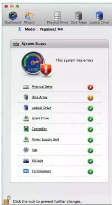
The list containing the problem component displays. In the case of a high- temperature issue, shown in the example above, the Component List displays.
- For physical drives, disk arrays, logical drives, and spare drives, mouse-over the component with the red X icon and click the View button.
OVERHEATING
Overheating is a potentially serious condition because the excessively high temperatures can lead to physical drive failure and controller malfunction. Make sure the unit has adequate airflow through the vent holes on the front.
Overheating usually results from:
- Fan failure
- Inadequate air circulation around the Pegasus unit
FAN FAILURE
Cooling fans are not field-replaceable. If there is any problem with a cooling fan, contact Technical Support to make arrangements for a repair.
Pegasus cooling vent
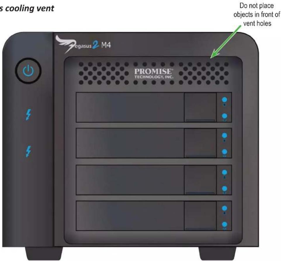
INADEQUATE AIR CIRCULATION
Air circulation around the Pegasus unit might be a more complex problem. Check for these conditions:
• Accumulated dust or objects blocking the fans.
- Less than a minimum of 13 cm (5 inches) space between the back of the unit and the wall or other object.
- Ambient temperature above 35^ (95°F) where the unit is operating.
To cool down a Pegasus unit:
- Correct any problems identified above.
- Shut down the Pegasus unit.
Press and hold the Power Button for a few seconds until the LED turns red. The PROMISE Utility displays the message: Unable to connect to the device.
- Wait at least one hour, then restart the Pegasus unit.
Press the Power Button. The Pegasus boots within a few seconds.
POWER SUPPLY
The power supply used in the Pegasus unit is not field-replaceable. If there is any problem with the power supply, contact Technical Support to make arrangements for a repair. See “Contacting Technical Support” on page 142.
CONNECTION PROBLEMS
Connection problem troubleshooting includes:
- "Cables"
- "Daisy-Chains"
CABLES
While the installation of the cables and components was correct, they don't function properly, or at all, because:
• A connector is dirty or corroded
• A connector is loose or damaged
• A cable looks OK outside but has an open circuit inside
• The wrong cable was used. See the Note below
Be sure to use approved cables because:
• They are the proper ones for your system.
• They are sold in brand-new condition.

Note
Mini Display extension cables cannot be used to connect data devices such as Pegasus to Thunderbolt-enabled computers.
Mini Display extension cables can only be used to connect display devices to Pegasus.
DAISY-CHAINS
If you have multiple Pegasus units daisy-chained together, all Pegasus units must be running to provide access to your volumes and the data they contain.
If you shut down a Pegasus unit in the chain, that unit and those below it are effectively disconnected from your computer.
Thunderbolt daisy-chain connections

If you shut down Pegasus unit 1, your connection to Pegasus unit 2 is lost
PERFORMANCE MONITOR
The Performance Monitor display can be useful for diagnosing performance issues that will not necessarily trigger any alerts to appear in the System Status display or event logs. Or you can use it for testing performance of different drive types.
To display the Performance Monitor information, choose Performance Monitor from the Admin drop-down menu in the Menu Bar. Note that it is necessary to unlock the interface before the option can be selected.
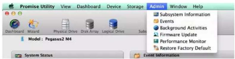

Note
You must unlock the PROMISE Utility interface to allow selection of the Performance Monitor display.
Performance information is displayed in graph form for logical drives and physical drives. Use the pull-down menus to displayed what parameter is being measured and which logical or physical drive you want to monitor. The parameters available for measurement are Bandwidth (in MB/s) and I/O requests.
Performance Monitor display
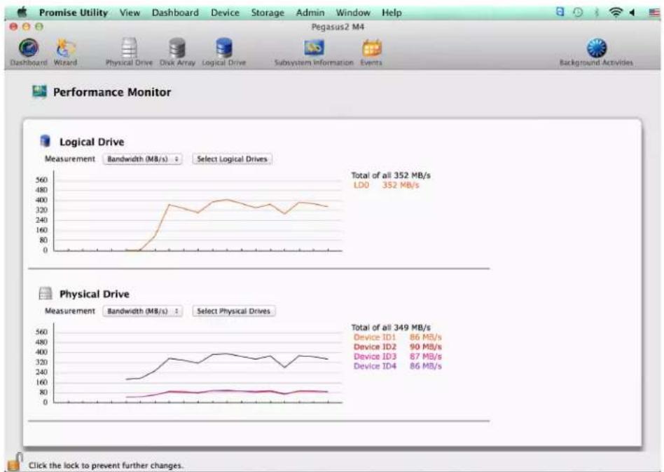
line
| Drive Type | Bandwidth (MB/s) | | ---------------- | ---------------- | | Logical Drive | 352 | | Physical Drive | 349 |CONTACTING TECHNICAL SUPPORT
PROMISE Technical Support provides several support options for PROMISE users to access information and updates. We encourage you to use one of our electronic services, which provide product information updates for the most efficient service and support.
Promise offers local Phone Support for Pegasus2 during normal business hours Monday to Friday.
Please check the Contact Us page for phone numbers of local Phone Support and other contact information.
PROMISE E-Support: https://support.PROMISE.com
PROMISE web site: http://www.PROMISE.com//
When you contact us, please have the following information available:
• Product model and serial number
• BIOS, firmware, and driver version numbers
• A description of the problem / situation
- System configuration information, including: motherboard and CPU type, hard drive models, SAS/SATA/ATA/ATAPI drives & devices, and other controllers.
Return the product to your dealer or retailer or contact Promise technical support for instructions before shipping the product.
United States
580 Cottonwood Drive
Milpitas, Ca 95035, USA
Technical Support (E-Support): https://support.PROMISE.com
Web site: http://www.PROMISE.com//
Australia
Technical Support (E-Support): https://support.PROMISE.com
Web site: http://www.PROMISE.com//
EMEA
Netherlands
Science Park Eindhoven 5228
5692 EG Son, The Netherlands
Technical Support (E-Support): https://support.PROMISE.com
Web site: http://www.PROMISE.com//
Austria
Technical Support (E-Support): https://support.PROMISE.com
Web site: http://www.PROMISE.com//
France
Technical Support (E-Support): https://support.PROMISE.com
Web site: http://www.PROMISE.com//
Germany
Europaplatz 9
44269 Dortmund, Germany
Technical Support (E-Support): https://support.PROMISE.com
Web site: http://www.PROMISE.com//
Sweden
Technical Support (E-Support): https://support.PROMISE.com
Web site: http://www.PROMISE.com//
Switzerland ITF
Technical Support (E-Support): https://support.PROMISE.com
Web site: http://www.PROMISE.com//
Norway ITF
Technical Support (E-Support): https://support.PROMISE.com
Web site: http://www.PROMISE.com//
Belguim
Technical Support (E-Support): https://support.PROMISE.com
Web site: http://www.PROMISE.com//
Luxembourg
Technical Support (E-Support): https://support.PROMISE.com
Web site: http://www.PROMISE.com//
United Kingdom
Technical Support (E-Support): https://support.PROMISE.com
Web site: http://www.PROMISE.com//
Taiwan
Technical Support (E-Support): https://support.PROMISE.com
Web site: http://www.PROMISE.com//
China
Room 1108, West Wing, Shi Chuang Plaza, 22 Information Road
Shangdi IT Park, Haidian District, Beijing 100085
Fax: 86-10-8857-8015
Technical Support (E-Support): https://support.PROMISE.com
Web site: http://www.PROMISE.com//
Korea
Technical Support (E-Support): https://support.PROMISE.com
Web site: http://www.PROMISE.com//
Hong Kong
Technical Support (E-Support): https://support.PROMISE.com
Web site: http://www.PROMISE.com//
Singapore
Technical Support (E-Support): https://support.PROMISE.com
Web site: http://www.PROMISE.com//
Japan
3F, Mura Matsu Bldg, 3-8-5, Hongo Bunkyo-ku
Tokyo 113-0033, Japan
Technical Support (E-Support): https://support.PROMISE.com
Web site: http://www.PROMISE.com//
LIMITED WARRANTY
PROMISE Technology, Inc. ("PROMISE") warrants that this product, from the time of the delivery of the product to the original end user:
a) all components for a period of two (2) years;
b) will conform to PROMISE's specifications:
c) will be free from defects in material and workmanship under normal use and service.
This warranty:
a) applies only to products which are new and in cartons on the date of purchase;
b) is not transferable;
c) is valid only when accompanied by a copy of the original purchase invoice.
d) Is not valid on spare parts.
This warranty shall not apply to defects resulting from:
a) improper or inadequate maintenance, or unauthorized modification(s), performed by the end user:
b) operation outside the environmental specifications for the product;
c) accident, misuse, negligence, misapplication, abuse, natural or personal disaster, or maintenance by anyone other than a PROMISE or a PROMISE-authorized service center.
DISCLAIMER OF OTHER WARRANTIES
This warranty covers only parts and labor, and excludes coverage on software items as expressly set above.
Except as expressly set forth above, PROMISE disclaims any warranties, expressed or implied, by statute or otherwise, regarding the product, including, without limitation, any warranties for fitness for any purpose, quality, merchantability, non-infringement, or otherwise. PROMISE makes no warranty or representation concerning the suitability of any product for use with any other item. You assume full responsibility for selecting products and for ensuring that the products selected are compatible and appropriate for use with other goods with which they will be used.
PROMISE does not warrant that any product is free from errors or that it will interface without problems with your computer system. It is your responsibility to back up or otherwise save important data before installing any product and continue to back up your important data regularly.
No other document, statement or representation may be relied on to vary the terms of this limited warranty.
PROMISE's sole responsibility with respect to any product is to do one of the following:
a) replace the product with a conforming unit of the same or superior product;
b) repair the product.
PROMISE shall not be liable for the cost of procuring substitute goods, services, lost profits, unrealized savings, equipment damage, costs of recovering, reprogramming, or reproducing of programs or data stored in or used with the products, or for any other general, special, consequential, indirect, incidental, or punitive damages, whether in contract, tort, or otherwise, notwithstanding the failure of the essential purpose of the foregoing remedy and regardless of whether PROMISE has been advised of the possibility of such damages. PROMISE is not an insurer. If you desire insurance against such damage, you must obtain insurance from another party.
Some states do not allow the exclusion or limitation of incidental or consequential damages for consumer products, so the above limitation may not apply to you.
This warranty gives specific legal rights, and you may also have other rights that vary from state to state. This limited warranty is governed by the State of California.
YOUR RESPONSIBILITIES
You are responsible for determining whether the product is appropriate for your use and will interface with your equipment without malfunction or damage. You are also responsible for backing up your data before installing any product and for regularly backing up your data after installing the product. PROMISE is not liable for any damage to equipment or data loss resulting from the use of any product.
RETURNING THE PRODUCT FOR REPAIR
If you suspect a product is not working properly, or if you have any questions about your product, contact our Technical Support staff, and be ready to provide the following information:
• Product model and serial number (required)
- Return shipping address
• Daytime phone number
• Description of the problem
• Copy of the original purchase invoice
The technician helps you determine whether the product requires repair. If the product needs repair, the technician issues an RMA (Return Merchandise Authorization) number.

IMPORTANT
Obtain an RMA number from Technical Support before you return the product and write the RMA number on the label. The RMA number is essential for tracking your product and providing the proper service.
Return ONLY the specific product covered by the warranty. Do not ship cables, manuals, CDs, etc.
USA and PROMISE Technology, Inc.
Canada: Customer Service Dept.
Attn.: RMA # ____
47654 Kato Road
Fremont, CA 94538
Asia-Pacific: Please return the product to your dealer or retailer or Contact
PROMISE technical support for instructions before shipping the product.
Other Countries Please check PROMISE E-Support: https://support.promise.com for the location nearest you. Contact the office or repair depot for full instructions before shipping the product.
You must follow the packaging guidelines for returning products:
- Use the original shipping carton and packaging
- Include a summary of the product's problem(s)
- Write an attention line on the box with the RMA number
- Include a copy of your proof of purchase
You are responsible for the cost of insurance and shipment of the product to PROMISE. Note that damage incurred due to improper transport or packaging is not covered under the Limited Warranty.
When repairing returned product(s), PROMISE may replace defective parts with new or reconditioned parts, or replace the entire unit with a new or reconditioned unit. In the event of a replacement, the replacement unit is under warranty for the remainder of the original warranty term from purchase date, or 30 days, whichever is longer.
PROMISE pays for outbound standard shipping charges only. You must pay for any additional shipping options, such as express shipping and return of the defective part or unit.
APPENDIX A
Transferring A Physical Hard Disk From Mac To Pegasus2
Pegasus2 supports taking a hard disk out of a Mac computer and installing it as a “pass-through” disk in the Pegasus2 enclosure. When the procedure is completed, the relocated pass-through disk retains all the data and user information from the original Mac. For example, if you remove the internal hard disk labeled “Mac” and install it in Pegasus2 as a pass-through disk, the file system and all the user information including passwords, permissions, etc. are carried over to the new Mac. The only difference the user sees is the appearance of the icon for the pass-through drive. Instead of the internal hard drive icon, the pass-through drive appears as an attached drive, orange in color, with the same drive name used in the original Mac.

Note
A Pass-through Disk retains the file system, and cannot be used as part of a RAID array on the Pegasus2.
PASS-THROUGH DISK PROCEDURE FOR MAC
If you want to remove a hard disk from a Mac and place it in the Pegasus2 as a pass-through disk, make sure you have the relevant user documentation from Apple for your Mac, then follow the steps in the instructions below.
- Following the instructions for hard disk removal in the user documentation for your Mac computer, remove the hard disk drive you intend to install in the Pegasus2. This disk should be the primary drive on the Mac if you want to keep all the user information and settings.
- Remove any mounting hardware, if any, attached to the hard disk drive.
- Install the drive following instructions in "Replacing a Physical Drive" on page 127.
-
The drive will be recognized as soon as it is installed. By default, this drive will have "Pass-through" status. It will be separate from any array that currently exists on the Pegasus2.
-
Launch the PROMISE Utility and click on the Physical Drive menu link in the Dashboard. You will see the new drive status as "Pass-Thru" listed in the menu. Launch the PROMISE Utility and click on the Physical Drive menu link in the Dashboard. You will see the new drive status as "Pass-Thru" listed in the menu.
Physical Drive List in PROMISE Utility

- The Pass-Through drive also appears on the desktop. It is now ready for use.

APPENDIX B
Important Information
HARD DRIVE COMPATIBILITY
To view or download the most up-to-date list of compatible physical drives for Pegaus2, follow these steps:
- Go to PROMISE Support > Download Center
- Use the pull-down menus near the bottom of the page to locate Pegasus2 Series and then the model (R8, R6, R4, M4).
- Click on Compatibility to see links for the compatibility list, and click on the latest version to view the (PDF) file
PROMISE Download Center web page
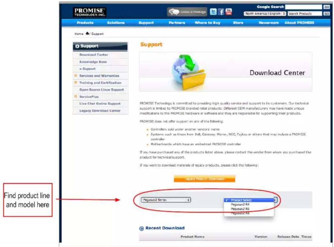
GNU GENERAL PUBLIC LICENSE
This product includes copyrighted third-party software licensed under the terms of the GNU General Public License. Please see the GNU General Public License ("GPL") for the exact terms and conditions of this license at www.gnu.org.
The GPL source code incorporated into the product is available for free download from our web site at http://www.PROMISE.com.
Subject to GPL, you may re-use, re-distribute and modify the GPL source code. Note that with respect solely to the GPL Software, no warranty is provided, we do not offer direct support for the distribution.
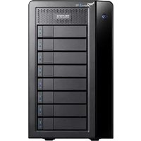
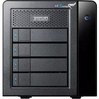


- Important data protection information
- Notice
- Recommendations
- ABOUT THIS GUIDE
- Note
- Important
- CAUTION
- WARNING
- FCC
- VCCI
- CONTENTS
- INTRODUCTION TO PEGASUS2 1
- HARDWARE 4
- INSTALLATION AND SETUP 6
- PACKING LIST 7
- CONNECT THE POWER CORD 8
- CONNECT PEGASUS2 TO YOUR MAC 9
- MANAGE WITH PROMISE UTILITY 17
- ACCESSING THE PROMISE UTILITY 18
- UNLOCKING THE UI 19
- PERUSING THE PROMISE UTILITY INTERFACE 20
- DEVICE MENUS 22
- MANAGING SUBSYSTEMS 25
- MANAGING BACKGROUND ACTIVITIES 36
- MEDIA PATROL 41
- REDUNDANCY CHECK 42
- INITIALIZATION 42
- REBUILD 43
- MIGRATION 44
- PDM 45
- MANAGING PHYSICAL DRIVES 48
- MANAGING DISK ARRAYS 56
- MANAGING LOGICAL DRIVES 70
- MANAGING SPARE DRIVES 82
- TECHNOLOGY BACKGROUND 88
- DISK ARRAYS 89
- LOGICAL DRIVES 91
- RAID LEVELS 91
- RAID LEVEL MIGRATION 101
- STRIPE SIZE 106
- SECTOR SIZE 107
- FORMATTING LOGICAL DRIVES 108
- SPARE DRIVES 111
- DEFINITION 111
- OPTIONS 111
- REQUIREMENTS 112
- TRANSITION 112
- RAID CONTROLLERS 115
- CAPACITY COERCION 116
- TROUBLESHOOTING 118
- CHECKING LEDs 119
- PROMISE UTILITY 121
- VIEWING THE EVENT LOGS 121
- MANAGING ALERTS 123
- PHYSICAL DRIVE PROBLEMS 125
- DIAGNOSIS USING THE PROMISE UTILITY 125
- REPLACING A PHYSICAL DRIVE 127
- DISK ARRAY AND LOGICAL DRIVE PROBLEMS 131
- POWER SUPPLY 138
- CONNECTION PROBLEMS 139
- CABLES 139
- PERFORMANCE MONITOR 141
- CONTACTING TECHNICAL SUPPORT 142
- LIMITED WARRANTY 146
- APPENDIX A 150
- TRANSFERRING A PHYSICAL HARD DISK FROM MAC TO PEGASUS2 150
- APPENDIX B 152
- IMPORTANT INFORMATION 152
- INTRODUCTION TO PEGASUS2
- ARCHITECTURE
- PROTOCOL SUPPORT
- KEY BENEFITS
- HARDWARE
- Feature Description
- Thunderbolt Ports
- Power Receptacle
- INSTALLATION AND SETUP
- SUMMARY OF THE SETUP PROCEDURE
- PACKING LIST
- Thunderbolt and power connections
- CONNECT PEGASUS2 TO YOUR MAC
- INSTALLING THE SOFTWARE
- DAISY-CHAINING MULTIPLE PEGASUS/PEGASUS2 UNITS
- UNLOCKING THE UI
- DISPLAYING MULTIPLE PEGASUS/PEGASUS2 UNITS
- To Create a Disk Array and Logical Drive
- MANAGE WITH PROMISE UTILITY
- ACCESSING THE PROMISE UTILITY
- OPENING
- CLOSING
- PROMISE Utility icon
- PERUSING THE PROMISE UTILITY INTERFACE
- TOOLBAR ICONS
- CUSTOMIZING THE TOOLBAR
- DEVICE MENUS
- COMPONENT LIST
- PHYSICAL DRIVE MENU
- FRONT VIEW
- Device - Front View display menu
- Show Unconfigured Physical Drives
- Highlight Arrays
- BACK VIEW
- MANAGING SUBSYSTEMS
- VIEWING SUBSYSTEM INFORMATION
- Subsystem Information includes:
- MAKING SUBSYSTEM SETTINGS
- CLEARING STATISTICS
- RESTORING FACTORY DEFAULT SETTINGS
- SAVING A SERVICE REPORT
- UPDATING FIRMWARE
- VIEWING CONTROLLER INFORMATION
- VIEWING CONTROLLER STATISTICS
- MAKING CONTROLLER SETTINGS
- GREEN RAID FEATURES
- MANAGING ENCLOSURES
- VIEWING THE ENCLOSURE INFORMATION
- VIEWING TEMPERATURE SENSOR INFORMATION
- MANAGING BACKGROUND ACTIVITIES
- VIEWING CURRENT BACKGROUND ACTIVITIES
- VIEWING SCHEDULED BACKGROUND ACTIVITIES
- Adding a Scheduled Background Activity
- CHANGING A BACKGROUND ACTIVITY SCHEDULE
- ENABLING OR DISABLING A SCHEDULED BACKGROUND ACTIVITY
- DELETING A SCHEDULED BACKGROUND ACTIVITY
- MEDIA PATROL
- MAKING MEDIA PATROL SETTINGS
- REDUNDANCY CHECK
- MAKING REDUNDANCY CHECK SETTINGS
- INITIALIZATION
- MAKING INITIALIZATION SETTINGS
- REBUILD
- MAKING REBUILD SETTINGS
- MIGRATION
- MAKING MIGRATION SETTINGS
- PDM
- MAKING PDM SETTINGS
- TRANSITION
- MAKING TRANSITION SETTINGS
- SYNCHRONIZATION
- MAKING SYNCHRONIZATION SETTINGS
- MANAGING PHYSICAL DRIVES
- VIEWING A LIST OF PHYSICAL DRIVES
- VIEWING PHYSICAL DRIVE INFORMATION
- VIEWING PHYSICAL DRIVE STATISTICS
- VIEWING PHYSICAL DRIVE SMART LOG INFORMATION
- LOCATING A PHYSICAL DRIVE
- MAKING GLOBAL PHYSICAL DRIVE SETTINGS
- MAKING INDIVIDUAL PHYSICAL DRIVE SETTINGS
- MAKING PHYSICAL DRIVE SMART LOG SETTINGS
- CLEARING A STALE OR A PFA CONDITION
- MANAGING DISK ARRAYS
- VIEWING A LIST OF DISK ARRAYS
- VIEWING DISK ARRAY INFORMATION
- CREATING A DISK ARRAY MANUALLY
- CREATING A DISK ARRAY AND LOGICAL DRIVE WITH THE WIZARD
- Wizard dialog box
- Wizard
- CHOOSING AUTOMATIC CONFIGURATION
- Automatic Configuration dialog box
- RAID Level Capacity Sector Stripe
- PD ID Type Revertible Media Type
- CHOOSING EXPRESS CONFIGURATION
- Express Configuration dialog box
- CHOOSING ADVANCED CONFIGURATION
- Task 1 – Disk Array Creation
- Task 2 – Logical Drive Creation
- Task 3 – Spare Drive Creation
- Task 4 – Summary
- Formatting your Logical Drives
- MAKING DISK ARRAY SETTINGS
- DELETING A DISK ARRAY
- PREPARING A DISK ARRAY FOR TRANSPORT
- REBUILDING A DISK ARRAY
- PERFORMING A MANUAL REBUILD
- PAUSING AND RESUMING A REBUILD
- STOPPING A REBUILD
- MANAGING LOGICAL DRIVES
- VIEWING A LIST OF LOGICAL DRIVES
- VIEWING LOGICAL DRIVE INFORMATION
- VIEWING LOGICAL DRIVE STATISTICS
- MAKING LOGICAL DRIVE SETTINGS
- VIEWING LOGICAL DRIVE CHECK TABLES
- CREATING A LOGICAL DRIVE MANUALLY
- LOCATING A LOGICAL DRIVE
- Running the Locate function to identify a disk array
- DELETING A LOGICAL DRIVE
- INITIALIZING A LOGICAL DRIVE
- PAUSING AND RESUMING AN INITIALIZATION
- STOPPING AN INITIALIZATION
- REDUNDANCY CHECK ON A LOGICAL DRIVE
- PAUSING AND RESUMING A REDUNDANCY CHECK
- STOPPING A REDUNDANCY CHECK
- MIGRATING A LOGICAL DRIVE
- RUNNING PDM ON A LOGICAL DRIVE
- PAUSING AND RESUMING PDM
- STOPPING PDM
- MANAGING SPARE DRIVES
- VIEWING A LIST OF SPARE DRIVES
- VIEWING SPARE DRIVE INFORMATION
- CREATING A SPARE DRIVE MANUALLY
- MAKING SPARE DRIVE SETTINGS
- RUNNING SPARE CHECK
- DELETING A SPARE DRIVE
- RUNNING A TRANSITION ON A SPARE DRIVE
- RUNNING A TRANSITION
- PAUSING AND RESUMING A TRANSITION
- STOPPING, PAUSING OR RESUMING A TRANSITION
- TECHNOLOGY BACKGROUND
- Disk Arrays
- LOGICAL DRIVES
- RAID LEVELS
- RAID 0 - STRIPE
- Recommended Applications for RAID 0:
- RAID 1 - MIRROR
- Recommended Applications for RAID 1:
- RAID 1E - ENHANCED MIRROR
- Recommended Applications for RAID 1E:
- RAID 5 - BLOCK AND PARITY STRIPE
- Recommended Applications for RAID 5:
- RAID 6 - BLOCK AND DOUBLE PARITY STRIPE
- Recommended Applications for RAID 6:
- RAID 10 - MIRROR + STRIPE
- Recommended Applications for RAID 10:
- RAID 50 - STRIPING OF DISTRIBUTED PARITY
- RAID 60 - DOUBLE PARITY + STRIPE
- RAID LEVEL MIGRATION
- MIGRATION REQUIREMENTS
- SOURCE AND TARGET RAID LEVELS
- RAID 1
- RAID 0
- RAID 1E
- RAID 5
- RAID 6
- RAID 10
- RAID 50
- RAID 60
- STRIPE SIZE
- SECTOR SIZE
- FORMATTING LOGICAL DRIVES
- PROMISE UTILITY WITH DEFAULT SETTINGS
- Wizard Automatic or Express
- Wizard Advanced or Manual Creation
- PROMISE UTILITY WITH CUSTOM SETTINGS
- Disk Utility
- SPARE DRIVES
- DEFINITION
- OPTIONS
- - System Options
- - Spare Type
- REQUIREMENTS
- Example
- Automatic Transition
- Manual Transition
- RAID CONTROLLERS
- READ CACHE POLICY
- WRITE CACHE POLICY
- CAPACITY COERCION
- TROUBLESHOOTING
- RESPONDING TO AN AUDIBLE ALARM
- CHECKING LEDs
- SUBSYSTEM LEDs
- DRIVE CARRIER LEDs
- PROMISE UTILITY
- VIEWING THE EVENT LOGS
- VIEWING RUNTIME EVENTS
- VIEWING NVRAM EVENTS
- EVENT SEVERITY DESCRIPTIONS
- MANAGING ALERTS
- CONFIGURE ALERT NOTIFICATION LEVEL
- PHYSICAL DRIVE PROBLEMS
- DIAGNOSIS USING THE PROMISE UTILITY
- REPLACING A PHYSICAL DRIVE
- PHYSICAL DRIVE WARNING MESSAGE
- Disk Array and Logical Drive Problems
- DISK ARRAY DEGRADED/LOGICAL DRIVE CRITICAL
- REPAIRING AN OFFLINE DISK ARRAY OR LOGICAL DRIVE
- RAID 0 Logical Drives
- INCOMPLETE ARRAY
- TRANSPORT
- UNREADABLE DISK WARNING
- Warning message
- SUBSYSTEM PROBLEMS
- DIAGNOSING A SUBSYSTEM PROBLEM
- OVERHEATING
- FAN FAILURE
- INADEQUATE AIR CIRCULATION
- POWER SUPPLY
- CONNECTION PROBLEMS
- CABLES
- DAISY-CHAINS
- Thunderbolt daisy-chain connections
- PERFORMANCE MONITOR
- Performance Monitor display
- CONTACTING TECHNICAL SUPPORT
- United States
- Australia
- EMEA
- Netherlands
- Austria
- France
- Germany
- Sweden
- Switzerland ITF
- Norway ITF
- Belguim
- Luxembourg
- United Kingdom
- Taiwan
- China
- Korea
- Hong Kong
- Singapore
- Japan
- LIMITED WARRANTY
- DISCLAIMER OF OTHER WARRANTIES
- YOUR RESPONSIBILITIES
- RETURNING THE PRODUCT FOR REPAIR
- APPENDIX A
- Transferring A Physical Hard Disk From Mac To Pegasus2
- PASS-THROUGH DISK PROCEDURE FOR MAC
- Important Information
- HARD DRIVE COMPATIBILITY
- GNU GENERAL PUBLIC LICENSE
Brand : Promise Technology
Model : Pegasus2 M4
Category : Disk array