
3Com SuperStack 3 Switch 4400 - Switch HP - Free user manual and instructions
Find the device manual for free 3Com SuperStack 3 Switch 4400 HP in PDF.


| Product Type | Managed Switch |
| Brand | HP (3Com) |
| Model | SuperStack 3 Switch 4400 |
| Ports | 24 x 10/100 Mbps RJ-45, 2 x Gigabit uplink slots (optional) |
| Form Factor | Rackmount 1U |
| Dimensions (W x D x H) | 44.2 x 33.5 x 4.4 cm |
| Weight | Approx. 3.5 kg |
| Power Supply | AC 100-240V, 50-60Hz, internal |
| Power Consumption | Max 50W |
| Layer Support | Layer 2 (802.1Q VLAN, STP, IGMP snooping) |
| Stacking | Yes, via dedicated stacking ports (up to 8 units) |
| Management | Web interface, SNMP, CLI (telnet/SSH), RMON |
| Switching Capacity | 8.8 Gbps |
| MAC Address Table | 8K entries |
| Cooling | 2 internal fans |
| Operating Temperature | 0°C to 45°C |
| Safety Certifications | UL, CE, FCC Class A |
| Cleaning Instructions | Use a soft, dry cloth. Do not use liquids or sprays. |
| Spare Parts Available | Power supply unit, fan modules, stacking cables |
| Repairability | Modular design; hot-swappable fans and power supply |
Frequently Asked Questions - 3Com SuperStack 3 Switch 4400 HP
User questions about 3Com SuperStack 3 Switch 4400 HP
0 question about this device. Answer the ones you know or ask your own.
Ask a new question about this device
Download the instructions for your Switch in PDF format for free! Find your manual 3Com SuperStack 3 Switch 4400 - HP and take your electronic device back in hand. On this page are published all the documents necessary for the use of your device. 3Com SuperStack 3 Switch 4400 by HP.
USER MANUAL 3Com SuperStack 3 Switch 4400 HP
Published March 2004

3Com Corporation 350 Campus Drive Marlborough, MA 01752-3064
Copyright © 2004, 3Com Corporation. All rights reserved. No part of this documentation may be reproduced in any form or by any means or used to make any derivative work (such as translation, transformation, or adaptation) without written permission from 3Com Corporation.
3Com Corporation reserves the right to revise this documentation and to make changes in content from time to time without obligation on the part of 3Com Corporation to provide notification of such revision or change.
3Com Corporation provides this documentation without warranty, term, or condition of any kind, either implied or expressed, including, but not limited to, the implied warranties, terms or conditions of merchantability, satisfactory quality, and fitness for a particular purpose. 3Com may make improvements or changes in the product(s) and/or the program(s) described in this documentation at any time.
If there is any software on removable media described in this documentation, it is furnished under a license agreement included with the product as a separate document, in the hard copy documentation, or on the removable media in a directory file named LICENSE.TXT or !LICENSE.TXT. If you are unable to locate a copy, please contact 3Com and a copy will be provided to you.
UNITED STATES GOVERNMENT LEGEND
If you are a United States government agency, then this documentation and the software described herein are provided to you subject to the following:
All technical data and computer software are commercial in nature and developed solely at private expense. Software is delivered as "Commercial Computer Software" as defined in DFARS 252.227-7014 (June 1995) or as a "commercial item" as defined in FAR 2.101(a) and as such is provided with only such rights as are provided in 3Com's standard commercial license for the Software. Technical data is provided with limited rights only as provided in DFAR 252.227-7015 (Nov 1995) or FAR 52.227-14 (June 1987), whichever is applicable. You agree not to remove or deface any portion of any legend provided on any licensed program or documentation contained in, or delivered to you in conjunction with, this User Guide.
Unless otherwise indicated, 3Com registered trademarks are registered in the United States and may or may not be registered in other countries.
3Com, the 3Com logo and SuperStack are registered trademarks of 3Com Corporation.
Intel and Pentium are registered trademarks of Intel Corporation. Microsoft, MS-DOS, Windows, and Windows NT are registered trademarks of Microsoft Corporation. Novell and NetWare are registered trademarks of Novell, Inc. UNIX is a registered trademark in the United States and other countries, licensed exclusively through X/Open Company, Ltd.
IEEE and 802 are registered trademarks of the Institute of Electrical and Electronics Engineers, Inc.
Netscape Navigator is a registered trademark of Netscape Communications.
JavaScript is a trademark of Sun Microsystems.
All other company and product names may be trademarks of the respective companies with which they are associated.
ENVIRONMENTAL STATEMENT
It is the policy of 3Com Corporation to be environmentally-friendly in all operations. To uphold our policy, we are committed to:
Establishing environmental performance standards that comply with national legislation and regulations.
Conserving energy, materials and natural resources in all operations.
Reducing the waste generated by all operations. Ensuring that all waste conforms to recognized environmental standards. Maximizing the recyclable and reusable content of all products.
Ensuring that all products can be recycled, reused and disposed of safely.
Ensuring that all products are labelled according to recognized environmental standards.
Improving our environmental record on a continual basis.
End of Life Statement
3Com processes allow for the recovery, reclamation and safe disposal of all end-of-life electronic components.
Regulated Materials Statement
3Com products do not contain any hazardous or ozone-depleting material.
Environmental Statement about the Documentation
The documentation for this product is printed on paper that comes from sustainable, managed forests; it is fully biodegradable and recyclable, and is completely chlorine-free. The varnish is environmentally-friendly, and the inks are vegetable-based with a low heavy-metal content.
ENCRYPTION
This product contains encryption and may require U.S. and/or local government authorization prior to export or import to another country.
CONTENTS
ABOUT THIS GUIDE
Before You Start 7
Release Notes 7
About Your CD-ROM 8
Conventions 8
Related Documentation 9
Accessing Online Documentation 10
Documentation Comments 10
Product Registration 11
1 INTRODUCING THE SUPERSTACK 3 SWITCH 4400
About the Switch 4400 14
Summary of Hardware Features 14
Switch 4400 — Front View Detail 15
10BASE-T/100BASE-TX Ports 16
100BASE-FX Ports 16
LEDs 17
Switch 4400 — Rear View Detail 19
Power Socket 19
Redundant Power System Socket 19
Console Port 19
Expansion Module Slots 19
Default Settings 20
2 INSTALLING THE SWITCH
Package Contents 24
Choosing a Suitable Site 24
Rack-mounting 25
Placing Units On Top of Each Other 27
Stacking Units 27
How To Stack Units 27
Rules For Stacking Units 28
The Power-up Sequence 30
Powering-up the Switch 4400 30
Checking for Correct Operation of LEDs 30
Connecting a Redundant Power System 30
Using Power over Ethernet 31
Choosing the Correct Cables (Switch 4400, 4400 SE and 4400 PWR) 32
Choosing the Correct Cables (Switch 4400 FX) 33
3 SETTING UP FOR MANAGEMENT
Setting Up Overview 36
IP Configuration 37
Preparing for Management 38
Manually Configuring IP Information 39
Connecting to a Front Panel Port 39
Connecting to the Console Port 42
Viewing Automatically Configured IP Information 46
Using 3Com Network Supervisor 46
Connecting to the Console Port 46
Methods of Managing a Switch 49
Command Line Interface Management 49
Command Line Interface Management using SSH 50
Web Interface Management 50
SNMP Management 50
Setting Up Command Line Interface Management 50
CLI Management via the Console Port 51
CLI Management over the Network 51
Setting Up Command Line Interface Management using SSH 52
Setting Up Web Interface Management 53
Pre-requisites 53
Web Management Over the Network 54
Setting Up SNMP Management 54
Pre-requisites 55
Default Users and Passwords 55
Changing Default Passwords 55
4 PROBLEM SOLVING
Solving Problems Indicated by LEDs 58
Solving Hardware Problems 59
Solving Communication Problems 62
Solving Software Upgrade Problems 63
A SAFETY INFORMATION
Power Cord Set — Japan 65
Important Safety Information 66
RJ-45 Pin Assignments 74
C TECHNICAL SPECIFICATIONS
Switch 4400 (24-port) and Switch 4400 SE 77
Switch 4400 PWR (24-port) 79
Switch 4400 (48-port) 80
Switch 4400 FX 81
D OBTAINING SUPPORT FOR YOUR PRODUCT
Register Your Product to Gain Service Benefits 83
Purchase Value-Added Services 83
Troubleshoot Online 83
Access Software Downloads 84
Contact Us 84
Telephone Technical Support and Repair 84
INDEX
REGULATORY NOTICES
ABOUT THIS GUIDE
This guide provides all the information you need to install and use the following switches in their default state:
■ SuperStack 3 Switch 4400 (3C17203) ■ SuperStack 3 Switch 4400 (3C17204) ■ SuperStack 3 Switch 4400 PWR (3C17205) ■ SuperStack 3 Switch 4400 SE (3C17206) ■ SuperStack 3 Switch 4400 FX (3C17210)
All procedures described in this guide apply to all models except where stated.
The guide is intended for use by network administrators who are responsible for installing and setting up network equipment; consequently, it assumes a basic working knowledge of LANs (Local Area Networks).
Before You Start
This section contains information about the documents and CD-ROM that accompany your Switch 4400.
Release Notes The Release Notes provide important information about the current software release, including new features, modifications, and known problems. You should read the Release Notes before installing the Switch in your network.

If the information in the Release Notes differs from the information in this guide, follow the instructions in the Release Notes.
About Your CD-ROM The CD-ROM contains the following:
■ Online documentation for the Switch 4400 — refer to Related Documentation on page 9 for details. ■ 3Com Network Supervisor — a powerful and easy-to-use network management platform. ■ A number of other useful applications.
Most user guides and release notes are available in Adobe Acrobat Reader Portable Document Format (PDF) or HTML on the 3Com World Wide Web site:
http://www.3com.com/
Conventions
Table 1 and Table 2 list conventions that are used throughout this guide. Table 1 Notice Icons
| Icon Notice Type Description | ||
 | Information note | Information that describes important features or instructions |
 | Caution | Information that alerts you to potential loss of data or potential damage to an application, system, or device |
 | Warning | Information that alerts you to potential personal injury |
Table 2 Text Conventions
| Convention Description | |
| Screen displays | This typeface represents information as it appears on the screen. |
| Syntax | The word “syntax” means that you must evaluate the syntax provided and then supply the appropriate values for the placeholders that appear in angle brackets. Example:To change your password, use the following syntax:system password. |
| Commands | The word “command” means that you must enter the command exactly as shown and then press Return or Enter. Commands appear in bold. Example:To display port information, enter the following command:bridge port detail |
| The words “enter” and “type” | When you see the word “enter” in this guide, you must type something, and then press Return or Enter. Do not press Return or Enter when an instruction simply says “type.” |
| Keyboard key names | If you must press two or more keys simultaneously, the key names are linked with a plus sign (+). Example:Press Ctrl+Alt+Del |
| Words in italics Italics are used to:■Emphasize a point.■Denote a new term at the place where it is defined in the text.■Identify menu names, menu commands, and software button names. Examples:From the Help menu, select Contents.Click OK. | |
Related Documentation
In addition to this guide, each Switch documentation set includes the following:
■ SuperStack 3 Switch Implementation Guide
This guide contains information on the features supported by your Switch and how they can be used to optimize your network. It is supplied in PDF format on the CD-ROM that accompanies the Switch.
■ SuperStack 3 Switch Management Quick Reference Guide
This guide contains:
■ a list of the features supported by the Switch.
■ a summary of the web interface and command line interface commands for the Switch.
■ SuperStack 3 Switch Management Interface Reference Guide
This guide provides detailed information about the web interface and command line interface that enable you to manage the Switch. It is supplied in HTML format on the CD-ROM that accompanies the Switch.
■ Release Notes
These notes provide information about the current software release, including new features, modifications, and known problems. The Release Notes are supplied in hard copy with your Switch.
There are other publications you may find useful, such as:
■ Documentation accompanying the Advanced Redundant Power system.
Documentation accompanying the Expansion Modules.
Documentation accompanying 3Com Network Supervisor. This is supplied on the CD-ROM that accompanies the Switch.
Accessing Online Documentation
To access the documentation on the CD-ROM supplied with your Switch, do the following:
1. Insert the CD-ROM into your CD-ROM drive. If your PC has auto-run enabled, a splash screen will be displayed automatically.
2. Select the Documentation section from the contents page.
If the online documentation is to be accessed from a local drive or server, you will need to access the CD-ROM contents via the root directory and copy the files from the CD-ROM to a suitable directory.
The HTML Reference Guide is stored in the Docs/reference directory on the CD-ROM. The documentation is accessed using the contents.htm file.
The PDF Implementation Guide is stored in the Docs/implementation directory of the CD-ROM.

3Com recommends that you copy the Docs/reference directory as a whole to maintain the structure of the files.
Documentation Comments
Your suggestions are very important to us. They will help make our documentation more useful to you. Please e-mail comments about this document to 3Com at:
pddtechpubs_comments@3com.com
Please include the following information when commenting:
Document title, Document part number (on the title page), Page number (if appropriate)
Example:
Part Number DUA1720-3AAA07
SuperStack 3 Switch 4400 Series Getting Started Guide
Page 21

Please note that we can only respond to comments and questions about 3Com product documentation at this e-mail address. Questions related to technical support or sales should be directed in the first instance to your network supplier.
Product Registration
You can now register your SuperStack 3 Switch on the 3Com web site to receive up-to-date information on your product:
http://www.3com.com/register
1
INTRODUCING THE SUPERSTACK 3 SWITCH 4400
This chapter contains introductory information about the Switch 4400 and how it can be used in your network. It covers summaries of hardware and software features and also the following topics:
■ About the Switch 4400 ■ Switch 4400 — Front View Detail ■ Switch 4400 — Rear View Detail ■ Default Settings
| About the Switch 4400 | The Switch 4400 is a stackable 10/100 Mbps Ethernet switch and provides high-performance workgroups with a backbone to server connection. The Switch 4400 allows Cascade, Gigabit Ethernet or Fast Ethernet Fiber connections when expansion modules are installed in the expansion slots on the rear of the unit. You can also add the Switch 4400 to any SuperStack® system as your network grows.The Switch 4400 PWR (3C17205) supports Power over Ethernet on all front panel ports. If you plug in a compatible (IEEE 802.3af compliant) device, it will be automatically detected and power supplied to it. Power over Ethernet is enabled on each port by default.The Switch 4400 FX (3C17210) has 24 100BASE-FX MT-RJ ports. These allow easy connection of 100 Mbps fiber-optic links. |
| Summary of Hardware Features | Table 3 summarizes the hardware features that are supported by the Switch 4400.Table 3 Hardware features |
| Feature Switch 4400 | |
| Addresses ■Up to 8000 supported■Up to 64 permanent entriesAuto-negotiation ■Supported on all ports■Auto MDI/MDI-X (not 3C17210)Forwarding Modes Store and ForwardDuplex Modes Half and full duplex on all front panel portsFlow Control In full duplex operation all ports are supportedSmart Auto-sensing Supported on all portsTraffic Prioritization Supported (using the IEEE Std 802.ID, 1998 Edition): 4 queues per portPower over Ethernet Supported on all front panel ports (3C17205 only).Ethernet and Fast Ethernet Ports Auto-negotiating 10BASE-T/100BASE-TX ports or 100BASE-FX ports (3C17210)RPS Support Connects to SuperStack 3 Advanced Redundant Power System (ARPS) (3C16071B)Mounting 19-inch rack or stand-alone mountingStacking All Switch units in the stack can be managed as a single entity with one IP address |
Switch 4400 — Front View Detail Figure 1 Switch 4400 FX — front view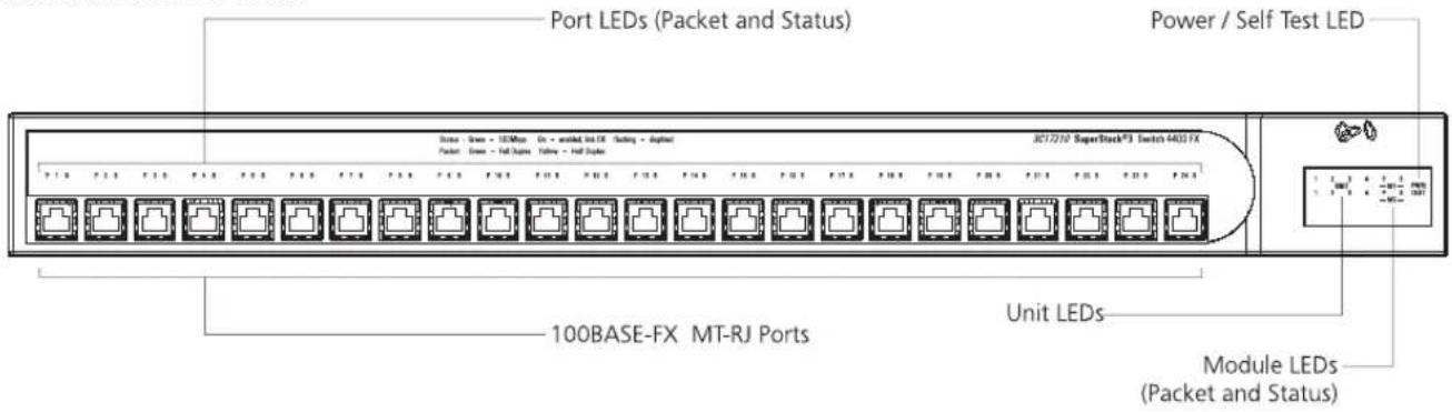
Figure 2 Switch 4400 (24-port) / Switch 4400 SE — front view
Figure 3 Switch 4400 PWR — front view
Figure 4 Switch 4400 (48-port) — front view

WARNING: RJ-45 Ports. These are shielded RJ-45 data sockets. They cannot be used as standard traditional telephone sockets, or to connect the unit to a traditional PBX or public telephone network. Only connect RJ-45 data connectors, network telephony systems, or network telephones to these sockets.
Either shielded or unshielded data cables with shielded or unshielded jacks can be connected to these data sockets.
10BASE-T/100BASE-TX Ports: The Switch 4400, 4400 SE, and 4400 PWR have 24 or 48 auto-negotiating 10BASE-T/100BASE-TX ports configured as Auto MDIX (cross-over). These ports automatically provide the appropriate connection. Alternatively, you can manually set these ports to 10BASE-T half duplex, 10BASE-T full duplex, 100BASE-TX half duplex, or 100BASE-TX full duplex. The maximum segment length is 100 m (328 ft) over Category 5 twisted pair cable.
The 4400 PWR will supply up to 15.4W of power through any of the 24 front panel ports in conformance to the 802.3af specification. The Switch 4400 PWR incorporates a LED Mode Button on the front panel, which when pressed changes the mode of the front panel port LEDs functionality between Switch and Power mode.
100BASE-FX Ports: The Switch 4400 FX has 24 100BASE-FX MT-RJ ports. These are 100 Mbps fiber-optic ports that can use standard multi-mode fiber-optic cable of up to 2 kilometers (1.2 miles). They use the standard MT-RJ
connector that allows both the transmit and the receive fibers to be connected in the same space as an RJ-45 port.
LEDs: Table 4 lists LEDs visible on the front of the Switch, and how to read their status according to color. For information on using the LEDs for problem solving, see "Solving Problems Indicated by LEDs" on page 58.
Table 4 LED behavior
| LED Color Indicates | ||
| Power/Self Test LED | ||
| Green The Switch is powered-up and operating normally. | ||
| Green flashing The Switch is either downloading software or is initializing (which includes running a Power On Self Test). | ||
| Yellow The Switch has failed its Power On Self Test or A port has failed and has been automatically disabled. You can verify this by checking that the Port Status LED is quickly flashing Yellow. If a port fails the Switch passes its Power On Self Test and continues to operate normally. | ||
| Off | The Switch is not receiving power or there is a fault with the Power Supply Unit. | |
| Port LEDs | ||
| Packet | Green | Full duplex packets are being transmitted/received on the port. |
| Yellow | Half duplex packets are being transmitted/received on the port. | |
| Off No packets are being transmitted/received on the port. | ||
| Status | Green | A high speed (100 Mbps) link is present, and the port is enabled. |
| Green flashing A high speed (100 Mbps) link is present, but the port is disabled. | ||
| Yellow | A low speed (10 Mbps) link is present, and the port is enabled (not 4400 FX). | |
| Yellow flashing A low speed (10 Mbps) link is present, but the port is disabled (not 4400 FX). | ||
| Yellow flashing (fast) | The port has failed and has been automatically disabled. The Switch passes its Power On Self Test and continues to operate normally even if one or more ports are disabled. | |
| Off No link is present. | ||
LED Color Indicates
Port LEDs — Power over Ethernet mode (3C17205 only)
Packet Green Power is being delivered to the port.
Green flashing Exceeded port power limit (overCurrent MIB state) or unable to supply power due to unit over budget (denyLowPriority MIB state).
Yellow Power over Ethernet error, no power supplied on port.
Off No power is being delivered.
Status Yellow flashing Power over Ethernet POST error on port. Flash rate is 4 Hz
Module LEDs
Packet Refer to the user documentation accompanying the module, if installed.
Status Refer to the user documentation accompanying the module, if installed.
Off There is no module installed in the expansion module slot.
Yellow flashing (fast) The module has failed and has been automatically disabled. The Switch passes its Power On Self Test and continues to operate normally even if one or more modules are disabled.
Unit LEDs
| 1–8 | Green | When the Switch forms a stack with other Switch 4400 units, the LED indicates the position of the unit in the stack and that a link is present.When the Switch is stand-alone and not part of a stack, LED 1 is on. |
| Green/Yellow rotational | When a software upgrade is in progress, the LEDs of the unit that is being upgraded ‘rotate’ in an clockwise and anti-clockwise sequence. | |
| Green flashing | The Switch physically forms a stack with other Switch 4400 units, but cannot be managed as part of that stack until all units have been upgraded to software version 2.0 or later. | |
| Off A fault has occurred. | ||
Port LED Status LED (3C17205 only)
Green Port LEDs are operating in power mode
Yellow flashing Port LEDs are operating in normal mode. One or more ports has a Power over Ethernet error.
Off Port LEDs are operating in normal mode.
Power Utilization LEDs (3C17205 only)
Green 4 LEDs showing total power being delivered as a percentage of maximum possible.
Switch 4400 — Rear View Detail
Figure 5 Switch 4400 (all models) — rear view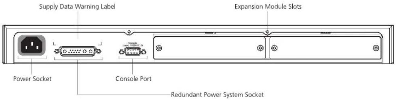
Power Socket
The Switch automatically adjusts its power setting to any supply voltage in the range 90-240 VAC.
Redundant Power System Socket
To protect against internal power supply failure, you can use this socket to connect a Switch 4400 to a SuperStack 3 Advanced Redundant Power System (RPS). See "Connecting a Redundant Power System" on page 30.
Console Port
The console port allows you to connect a terminal and perform remote or local out-of-band management. The console port uses a standard null modem cable and is set to auto-baud, 8 data bits, no parity and 1 stop bit.
Expansion Module Slots
You can use these slots to install Expansion Modules. These allow the Switch to support various forms of connection and add extra functionality to your Switch. For example you can install a Cascade module to enable the Switch to be stacked with other Switches. Please note that Power over Ethernet is not supported on expansion modules on the Switch 4400 PWR (3C17205). Contact your supplier for more information.

WARNING: When an Expansion Module is not installed, ensure the blanking plate is fitted by tightening all screws with a suitable tool.
Default Settings Table 5 shows the default settings for the Switch 4400: Table 5 Default Settings
| Feature Switch 4400 | |
| Automatic IP Configuration Enabled | |
| Port Status Enabled | |
| Port Speed 10/100 Mbps ports are auto-negotiated | |
| MT-RJ ports (3C17210) are fixed at 100 Mbps | |
| Duplex Mode All fixed 10BASE-T and 100BASE-TX ports are auto-negotiated | |
| 100BASE-FX ports default to full-duplex mode (100 FD) and must be manually set to half-duplex mode (100 HD) if required. | |
| Power over Ethernet Enabled (3C17205 only) | |
| Flow Control ■Enabled in half-duplex mode | |
| ■Auto-negotiated in full-duplex mode | |
| Broadcast Storm Control | Enabled |
| Virtual LANs (VLANs) | All ports belong to the untagged Default VLAN (VLAN 1) with IEEE Std 802.1Q-1998 learning operational |
| Management VLAN | VLAN 1 |
| Trust IP | Disabled |
| Link Aggregation Control Protocol (LACP) | Disabled per port |
| IP Multicast Filtering | Filtering enabled |
| Rapid Spanning Tree Protocol | Enabled |
| Fast Start | ■ Enabled on front panel ports■Disabled on rear panel port |
| RMON Alarm | Enabled |
| Smart Auto-Sensing | Enabled |
| Webcache Support | Disabled |
| Traffic Prioritization | All ports prioritize NBX VoIP traffic (LAN and IP). All ports set to “best effort” for all other traffic. |
| Port Security | Disabled per port |
| Configuration Save and Restore | Disabled |

To make SSH, Webcache redirection, RADIUS (including 802.1x Network Login), Auto VLAN assignment, and Traffic Prioritization available on the SuperStack 3 Switch 4400 SE, upgrade the product to the Switch 4400 SE Enhanced Software Upgrade (3C17207).
If you initialize a Switch unit by selecting System > Control > Initialize in the Web interface or by entering system control initialize in the Command Line Interface, the following settings are retained to allow you to connect to and manage the Switch:
■IP Address ■Subnet Mask ■Default Router
2
INSTALLING THE SWITCH
This chapter contains the information you need to install and set up the Switch 4400. It covers the following topics:
■ Package Contents ■ Choosing a Suitable Site ■ Rack-mounting ■ Placing Units On Top of Each Other ■ Stacking Units ■ The Power-up Sequence

WARNING: Safety Information. Before installing or removing any components from the Switch 4400 or carrying out any maintenance procedures, you must read the safety information provided in Appendix A of this guide.

■ CD-ROM (includes documentation related to your Switch) ■ Getting Started Guide (this guide) ■ Management Quick Reference Guide ■ Release Notes ■ Unit Information Labels ■ Warranty Information ■ Power Cord ■ 2 x Mounting brackets ■ 4 x Screws ■ 4 x Rubber feet
Choosing a Suitable Site
The Switch is suited for use on a desktop, either free standing or mounted in a standard 19-inch equipment rack. Alternatively, the Switch can be mounted in a wiring closet or equipment room, as an aggregator for other Hubs and Switches. A rack-mounting kit containing two mounting brackets is supplied with the Switch.

CAUTION: Ensure that the ventilation holes are not obstructed.
When deciding where to position the Switch, ensure that:
■ Cabling is located away from:
■ sources of electrical noise such as radios, transmitters and broadband amplifiers.
■ power lines and fluorescent lighting fixtures
■ The Switch is accessible and cables can be connected easily.
■ Water or moisture cannot enter the case of the Switch.
■ Air flow is not restricted around the Switch or through the vents in the side of the Switch. 3Com recommends that you provide a minimum of 25mm (1in.) clearance.
■ Air temperature around the Switch does not exceed 40 °C (104 °F).

If the Switch is installed in a 19-inch rack or closed assembly, its local air temperature may be greater than room ambient temperature.
■ The air is as free from dust as possible. ■ The unit is installed in a clean, air-conditioned environment. ■ No more than eight Switch units are placed on top of one another, if the units are free-standing. ■ The Switch is situated away from sources of conductive (electrical) dust, for example laser printers. ■ The AC supply used by the Switch is separate to that used by units that generate high levels of AC noise, for example air conditioning units and laser printers.
Rack-mounting
The Switch 4400 is 1U high and will fit in most standard 19-inch racks.

CAUTION: Disconnect all cables from the Switch before continuing. Remove all self-adhesive pads from the underside of the Switch if they have been fitted.
To rack-mount your Switch:
1. Place the Switch the right way up on a hard flat surface, with the front facing towards you. 2. Locate a mounting bracket over the mounting holes on one side of the Switch, as shown in Figure 6.
Figure 6 Fitting a bracket for rack-mounting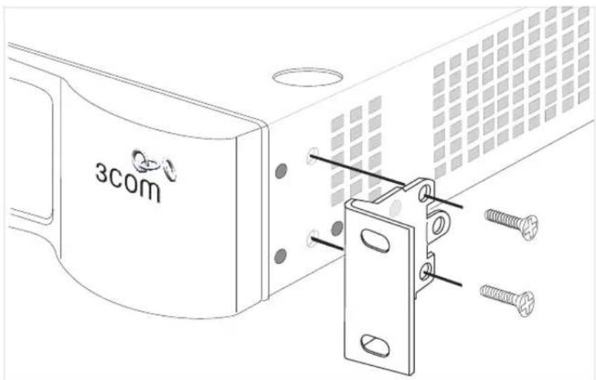
3. Insert the two screws and tighten with a suitable screwdriver.

You must use the screws supplied with the mounting brackets. Damage caused to the unit by using incorrect screws invalidates your warranty.
4. Repeat steps 2 and 3 for the other side of the Switch.
5. Insert the Switch into the 19-inch rack and secure with suitable screws (not provided). Ensure that ventilation holes are not obstructed.
6. Connect network cabling.
7. Finally place a unit information label on the unit in an easily accessible position. The unit information label shows the following:
■ The 3Com product name of the Switch ■ The 3Com 3C number of the Switch ■ The unique MAC address (Ethernet address) of the Switch ■ The serial number of the Switch
You may need this information for fault reporting purposes.
| Placing Units On Top of Each Other | If the Switch units are free-standing, up to eight units can be placed one on top of the other. If you are mixing a variety of SuperStack® 3 Switch and Hub units, the smaller units must be positioned at the top.If you are placing Switch units one on top of the other, you must use the self-adhesive rubber pads supplied. Apply the pads to the underside of each Switch, sticking one in the marked area at each corner. Place the Switch units on top of each other, ensuring that the pads of the upper unit line up with the recesses of the lower unit. |
Stacking Units | Switch 4400 units can be stacked together and then treated as a single manageable unit with one IP address. Any combination of 24-port and 48-port units is allowed in a single stack.The SuperStack 3 Switch 4400 SE can only be stacked with non-SE Switches if it has been upgraded using the Switch 4400 SE Enhanced Software Upgrade (3C17207). An upgraded Switch 4400 SE cannot be stacked with a normal Switch 4400 SE. |
| How To Stack Units | To stack two Switch 4400 units you will need to order the SuperStack 3 Switch Cascade Stacking Kit (3C17227). The kit consists of two Cascade Modules and a Cascade Cable. Both Switches must have an unused expansion slot to allow a Cascade Module to be fitted. |
Figure 7 Stacking two Switch 4400 units
To stack more than two Switch units you will need to order one SuperStack 3 Cascade Extender Kit (3C17228) for each additional unit. This Kit consists of one Cascade Module, one Cascade Cable and one
Cascade Extender Unit. The Cascade Module is installed into the expansion slot at the rear of the Switch and the Cascade Extender Unit plugs into the Cascade Module.
Figure 8 Stacking more than two Switch 4400 units
For information on ordering the Cascade Kits contact your supplier. For illustrations and information on how to install the Cascade Kits, refer to the user documentation that accompanies these Kits.
Rules For Stacking Units
This information is also provided in the user documentation that accompanies the Cascade Kits.
■ The maximum number of Switch units in a stack is limited to 8. The stack may contain a combination of 24 and 48 port units. ■ Only one Cascade Module can be installed per Switch. If Cascade Modules are fitted to both expansion slots in a Switch then both Modules will be disabled. ■ Cascade Modules are NOT hot-swappable or hot-insertable. Ensure that the Switch is powered off before inserting or removing a Cascade Module.
■ The Cascade Extender Unit is hot-insertable. This allows its host Switch unit to be removed and replaced without disturbing the rest of the stack. ■ Only 3Com® Cascade Cables can be used to connect between Cascade Modules/Cascade Extender Units. ■ Due to the length of the Cascade Cables, you must insert all of the Cascade Modules into Expansion Module Slot 1 or all of the Cascade Modules into Expansion Module Slot 2 on the Switches. ■ It is not possible to stack a Switch 4400, Switch 4400 SE, Switch 4400 PWR or Switch 4400 FX unit with SuperStack II or other SuperStack 3 products using the Cascade Stacking Kit (3C17227) or Cascade Extender Kit (3C17228). ■ 3Com strongly recommends that you upgrade all Switch 4400 units (24-port and 48-port) in a stack to the latest software agent. ■ 3Com recommends that you initialize a Switch 4400, Switch 4400 SE, Switch 4400 PWR or Switch 4400 FX unit that has previously been used elsewhere in your network before you add it to an existing stack. If you do not initialize the unit, problems may be caused by conflicting Switch configurations. ■ When the Switch 4400s are stacked together they are assigned a unit number from bottom-to-top for management purposes. When further Switches are added to the stack, they can be positioned at the bottom of the stack or at the top. Either way, the Switch management software will re-order the Switch unit numbers into a logical order again (from bottom to top).
| The Power-upSequence | The following sections describe how to get your Switch 4400 powered-up and ready for operation. |
| Powering-up theSwitch 4400 | Use the following sequence of steps to power-up the Switch. |
| 1 Plug the power cord into the power socket at the rear of the Switch.2 Plug the other end of the power cord into your power outlet.The Switch powers-up and runs through its Power On Self Test (POST), which takes approximately 10 seconds. | |
| Checking for CorrectOperation of LEDs | During the Power On Self Test, all ports on the Switch are disabled and the LEDs light in a set sequence.When the POST has completed, check the Power/Self Test LED to make sure that your Switch is operating correctly. Table 6 shows possible colors for the LED.Table 6 Power/Self Test LED colors |
| Color State | |
| Green The Switch is powered-up and operating normally.Yellow The Switch has failed its Power On Self Test.Off The Switch is not receiving power. | |
| If there is evidence of a problem, see “Solving Problems Indicated by LEDs” on page 58. | |
| Connecting aRedundant PowerSystem | You can connect a SuperStack 3 Advanced Redundant Power System (3C16071B) to the Switch. This unit, which is also known as an RPS, is designed to maintain the power to your Switch if a power supply failure occurs.For normal redundancy, the Switch 4400, Switch 4400 SE, and Switch 4400 FX require one Type 2A Power Module (3C16074A). For full redundancy, the Switch 4400, Switch 4400 SE, and Switch 4400 FX require two type 2A Power Modules combined using a Type 2 Y-Cable. The Switch 4400 PWR (3C17205) requires one Type 3 Power Module (3C16075) for normal redundancy and two Type 3 Power Modules for full redundancy. |

CAUTION The Switch has no ON/OFF switch; the only method of connecting or disconnecting mains power is by connecting or disconnecting the power cord.

CAUTION: The Switch can only use a SuperStack Advanced Redundant Power System output.
Using Power over Ethernet
The Switch 4400 PWR can power any IEEE 802.3af compliant device through any of its front panel ports. The Switch will support the following 3Com 802.3af equipment:
Wireless:
3Com 11 Mbps Wireless LAN Access Point 8000 (3CRWE80096B), 3Com 11 Mbps Wireless LAN Access Point 8200 (3CRWE820096A), 3Com 11 Mbps Wireless LAN Access Point 8500 (3CRWE850096A), 3Com 11 Mbps Wireless LAN Access Point 8700 (3CRWE870096A), 3Com Wireless LAN Building to Building Bridge (3CRWE91096B)
Voice Over IP Telephones:
3Com 11 Mbps Wireless LAN Access Point 8000 (3CRWE80096B), 3Com 11 Mbps Wireless LAN Access Point 8200 (3CRWE820096A), 3Com 11 Mbps Wireless LAN Access Point 8500 (3CRWE850096A), 3Com 11 Mbps Wireless LAN Access Point 8700 (3CRWE870096A), 3Com Wireless LAN Building to Building Bridge (3CRWE91096B)
The following 3Com NBX phones are also supported using the 3Com NBX VoIP Phone Module (3CNJVOIPMOD-NBX):
3Com NBX 1102 Business Phone (3C10121), 3Com NBX 1102B Business Phone (3C10281B), 3Com NBX 1102PE Business Phone (3C10281PE), 3Com NBX 2101 Basic Phone (3C10248B), 3Com NBX 2101PE Basic Phone (3C10248PE), 3Com NBX 2102 Business Phone (3C10226A), 3Com NBX 2102IR Business Phone with IR (3C10228IRA), 3Com NBX 2102B Business Phone (3C10226B), 3Com NBX 2102IRB Business Phone with IR (3C10228IRB)
3Com NBX 2102PE Business Phone (3C10226PE), 3Com NBX 2102PEIR Business Phone with IR (3C10228RPE), 3Com NBX 3102 Business Phone (3C10402A), 3Com NBX ATA Business Phone (3C10400)
Network Jacks:
3Com NJ90 (3CNJ90), 3Com NJ95 (3CNJ95), 3Com NJ100 (3CNJ100, 3CNJ100-CRM), 3Com NJ105 (3CNJ105), 3Com NJ105 + forwarding (3CNJ105), 3Com NJ200 (3CNJ200, 3CNJ200-CRM), 3Com NJ200 + forwarding (3CNJ200), 3Com NJ205 (3CNJ205), 3Com NJ205 + forwarding (3CNJ205)

For the latest list of supported devices, go to the product page on the 3Com web site http://www.3com.com/.
For further information about Power Over Ethernet, refer to “Power Management and Control” in the Switch Implementation Guide supplied on the CD-ROM that accompanies your Switch. Power over Ethernet management is available using the web interface or the command line interface (CLI).
Choosing the Correct Cables (Switch 4400, 4400 SE and 4400 PWR)
All of the ports on the front of the Switch 4400, 4400 SE and 4400 PWR are Auto-MDIX, that is they have a cross-over capability. The port can automatically detect whether it needs to operate in MDI or MDIX mode. Therefore you can make a connection to a port with a straight-through (MDI) or a cross-over cable (MDIX).

The Auto-MDIX feature only operates when enabled per port and if auto-negotiation is enabled.
If auto-negotiation is disabled, all the Switch ports are configured as MDIX (cross-over). If you want to make a connection to another MDIX port, you need a cross-over cable. Many ports on workstations and servers are configured as MDI (straight-through). If you want to make a
connection to an MDI port, you need to use a standard straight-through cable. See Table 7.

WARNING: The 4400 PWR (3C17205) supports Power over Ethernet on all front ports. These ports should only be used for Ethernet wiring within the same building. The Rear Module ports of the Switch 4400 PWR can be used for ethernet wiring between buildings.
3Com recommends that you use Category 5 twisted pair cable — the maximum segment length for this type of cable is 100 m (328 ft).
Table 7 Cables required to connect the Switch 4400 to other devices if auto-negotiation is disabled
| Cross-over Cable Straight-through Cable | ||
| Switch to Switch (MDIX to MDIX) | √ | × |
| Switch to Hub (MDIX to MDIX) | √× | |
| Switch to PC (NIC) (MDIX to MDI) | × | √ |

CAUTION: If you want to install the Switch using a Category 5E or Category 6 cable, 3Com recommends that you briefly connect the cable to a grounded port before connecting network equipment. If you do not, the cable's Electrostatic Discharge (ESD) may damage the Switch's port.
You can create a grounded port by connecting all wires at one end of a UTP cable to an earth ground point, and the other end to a female RJ-45 connector located, for example, on a Switch rack or patch panel. The RJ-45 connector is now a grounded port.
Choosing the Correct Cables (Switch 4400 FX)
All of the ports on the front of the Switch 4400 FX are 100BASE-FX MT-RJ multi-mode ports. The MT-RJ port is a small form factor fiber-optic port with the transmit and receive fibers in the same cable. Unlike many fiber-optic systems, only one MT-RJ cable is needed to connect two MT-RJ ports together.
To connect a front-panel port to another 100BASE-FX MT-RJ multi-mode port, or to a patch panel, a single MT-RJ multi-mode pinless jumper cable is required. Since standard MT-RJ cables are cross-over cables, no
Auto-MDIX sensing is required. The maximum cable length is 2 kilometers (1.24 miles).

CAUTION: Do not connect pinned MT-RJ connectors into any port on the Switch 4400 FX as this may damage the unit. The ports have locator pins fitted and are designed for standard (pinless) connectors.
To connect a front-panel port to a 100BASE-FX single mode port, or to a port that does not have an MT-RJ connector, an adaptor will be required. It is not possible to connect a front panel port to a 1000BASE-FX port.
SETTING UP FOR MANAGEMENT
Your Switch can operate in its default state, that is, you can install it and it will work straight away (plug-and-play). However, to make full use of the features offered by the Switch, and to change and monitor the way it works, you have to access the management software that resides on the Switch. This is known as managing the Switch.
Managing the Switch can help you to improve the efficiency of the Switch and therefore the overall performance of your network.
This chapter explains the initial set up of the Switch and the different methods of accessing the management software to manage a Switch. It covers the following topics:
■ Setting Up Overview ■ Manually Configuring IP Information ■ Viewing Automatically Configured IP Information ■ Methods of Managing a Switch ■ Setting Up Command Line Interface Management ■ Setting Up Command Line Interface Management using SSH ■ Setting Up Web Interface Management ■ Setting Up SNMP Management ■ Default Users and Passwords
Setting Up Overview
This section gives an overview of what you need to do to get your Switch set up and ready for management when it is in its default state. The whole setup process is summarized in Figure 9. Detailed procedural steps are contained in the sections that follow. In brief, you need to:
■ Configure IP information manually for your Switch or view the automatically configured IP information ■ Prepare for your chosen method of management
Figure 9 Initial Switch Setup and Management Flow diagram![graph TD A["Power Up the Switch."] --> B["IP Information is automatically configured. See page 37"] B --> C["Do you want to manually configure the IP information?"] C --> D{How do you want to connect to the Switch?} C --> E{How do you want to view the automatically configured IP information?} D -->…](/content/2026/06/1344347/images/a4d072e7fe1901dbeb9fc379af0f42f492be0b72c701d363075572221050254e.jpg)

CAUTION: To protect your Switch from unauthorized access, you must change all three default passwords as soon as possible, even if you do not intend to actively manage your Switch. For more information on default users and changing default passwords, see "Default Users and Passwords" on page 55.
IP Configuration
You can use one of the following methods to allocate IP information to your Switch (essential if you wish to manage your Switch across the network).
Manual IP Configuration
You can choose to configure the IP information yourself. The Switch remembers the information that you enter until you change it again or set the configuration method to Automatic.
You should use the Manual IP configuration method if:
■ you do not have a DHCP or BootP server on your network, or ■ you want to remove the risk of the IP address ever changing, or ■ your DHCP or BootP server does not allow you to allocate static IP addresses. (Static IP addresses are necessary to ensure that the Switch is always allocated the same IP information.)

For most installations, 3Com recommends that you configure the Switch IP information manually. This makes management simpler and more reliable as it is not dependent on a DHCP or BootP server, and eliminates the risk of the IP address changing.
If you wish to manually enter IP information for your Switch, work through the "Manually Configuring IP Information" section on page 39.
Automatic IP Configuration
By default the Switch tries to configure itself with IP information without requesting user intervention. It tries to obtain an IP address from a DHCP or BootP server on the network.
If neither server is found, the Switch will configure itself with its default IP address 169.254.100.100 if it is operating in a standalone mode, and/or no other Switches on the network have this IP address. If this default IP address is already in use on the network then the Switch detects this and configures itself with an IP address in the range 169.254.1.0 to 169.254.254.255.
This process is known as Auto-IP and is the same mechanism used by Windows 98 and Windows 2000. IP addresses configured by Auto-IP are temporary as they cannot be routed but are useful for small networks which are not connected to other networks, or for initial configuration.
However, as soon as a DHCP or BootP server is detected, the Switch will configure itself with the IP address allocated by that server.
When using automatic IP configuration it is important that the IP address of the Switch is static, otherwise you will not know what the IP address is and it will be difficult to manage. Most DHCP and BootP servers allow static IP addresses to be configured so that you know what IP address will be allocated to the Switch. Refer to the documentation that accompanies your DHCP/BootP server.

For a detailed description of how automatic IP configuration operates, please refer to the Implementation Guide on the CD-ROM that accompanies your Switch or on the 3Com Web site.
You should use the automatic IP configuration method if:
■ your network uses DHCP or BootP to allocate IP information, or - flexibility is needed. If the Switch is re-deployed onto a different subnet, it will automatically reconfigure itself with an appropriate IP address, instead of you having to manually reconfigure the Switch.
If you use the automatic IP configuration method, you need to discover the automatically allocated IP information before you can begin management. Work through the "Viewing Automatically Configured IP Information" section on page 46.
Preparing for Management
Once your Switch's initial set up is complete you can set up your chosen management method as described in "Methods of Managing a Switch" on page 49.

For detailed information about the specific web interface operations and command line interface commands and problem solving, refer to the "SuperStack 3 Switch Management Interface Reference Guide" on the CD-ROM that is supplied with the Switch or on the 3Com Web site.
Manually Configuring IP Information
You can manually configure the Switch IP information in the following ways:
■ Connecting to a front panel port — Connect a workstation using an Ethernet cable to a front panel port of the Switch. You can then manually enter IP information using the web interface or the command line interface (CLI). ■ Connecting to the console port — Connect a workstation using a console cable to the console port of the Switch. You can then manually enter IP information using the command line interface (CLI).
Connecting to a Front Panel Port
To set up your Switch manually you can make a connection to a front panel port. You must do this whilst the Switch is offline, that is, before you connect the Switch to a network.

The procedure described in this section assumes the unit has been powered up in standalone mode and has the default IP address of 169.254.100.100.
Pre-requisites
■ A workstation running Windows 95/98/2000, Windows NT or Windows XP. ■ A Network Interface Card (NIC). ■ A Category 5 twisted pair Ethernet cable with RJ-45 connectors. ■ A suitable Web browser — refer to "Choosing a Browser" on page 53. ■ You need to have the following so that you can manually set up the Switch with IP information:
■ IP address ■ subnet mask ■ default gateway ■ management VLAN ID, normally set to the default value (1)
Connecting the Workstation to the Switch
1 Connect the workstation to a front panel port using an Ethernet cable as shown in Figure 10.
Figure 10 Connecting a workstation to the Switch via a front panel port
To connect the cable:
a Attach an RJ-45 connector at one end of the Ethernet cable to the Network Interface Card (NIC) in the workstation. b Connect the RJ-45 connector at the other end of the cable to one of the front panel ports on the Switch.

Do not interconnect the Switch to any other unconfigured Switch.
Configuring the Workstation with IP Information
You need to change the IP address and subnet mask of the workstation that you have connected to the Switch. Make a note of the existing settings so you can return to them later. Change the workstation to the following settings:
■ IP address — 169.254.100.99
■ Subnet mask — 255.255.0.0
Setting Up the Switch with IP Information
You are now ready to manually set up the Switch with IP information. You can do this using the Web interface or the command line interface (CLI) via telnet.
Using the Web Interface
1. Power-up the Switch. This takes approximately one minute. 2. Open a suitable Web browser and enter 169.254.100.100 in the Location Address field. This is the default IP address that is automatically assigned to an offline unit.

If there is no response, wait for one minute then re-enter the default IP address.
3. At the login and password prompts, enter admin as your user name and press Return at the password prompt (default user name and password). If you have logged on correctly, a set of Getting Started pages are displayed. 4. The Getting Started pages allow you to enter basic setup information for the Switch. Select Manual and then enter the IP address, subnet mask, and default gateway that you want the Switch to use when it is connected to the network. The final page displays a summary of the information entered.
The initial set up of your Switch is now complete and the Switch is ready for you to set up your chosen management method. See "Methods of Managing a Switch" on page 49.
Using Command Line Interface via Telnet
1. To start a Telnet session to the unit, click Start in Microsoft Windows 95/98/2000/NT/XP.
a. Click Run. b. In the dialogue box that appears type the default IP address of the unit, that is: Telnet 169.254.100.100 c. Click OK.
2. Press Enter to open a login prompt.

If the login prompt does not begin immediately, press Return a few times until it starts.
3 At the login and password prompts, enter admin as your user name and press Return at the password prompt. If you have logged on correctly, the top-level menu of the command line interface is displayed as shown in the example in Figure 11.
Figure 11 Example top-level command line interface menu
4 At the Select menu option prompt you can either:
■ enter the protocol ip basicConfig command. At the Enter configuration method prompt enter manual. The screen prompts you to enter IP information.
or
■ enter the gettingStarted command. At the Enter configuration method prompt enter manual. The screen prompts you to enter IP information.
5 Enter the IP address, subnet mask, and gateway IP address for the Switch. The screen displays a summary of the information entered.
If using the gettingStarted command you will then be prompted to enter system information, change passwords, and then given the option to carry out advanced configuration.

The protocol ip basicConfig command will prompt you for the management VLAN ID. If the unit is new there is only one VLAN (VLAN 1) to choose from.
The initial set up of your Switch is now complete and the Switch is ready for you to set up your chosen management method. See "Methods of Managing a Switch" on page 49.
Connecting to the Console Port
To set up your Switch manually you can alternatively make a connection to the console port (this example describes a local connection to the console port, rather than a remote one via a modem). You can do this whilst the Switch is offline, that is, before you connect the Switch to a network, or whilst the Switch is online, that is, connected to a network.
Pre-requisites
■A workstation with terminal emulation software installed, such as Microsoft Hyperterminal. This software allows you to communicate with the Switch via the console port directly, or through a modem. ■ Documentation supplied with the terminal emulation software. ■A suitable cable:
A standard null modem cable — if you are connecting directly to the console port, or a standard modem cable — if you are connecting to the console port using a modem.
You can find pin-out diagrams for both cables in Appendix B on page 73.
You need to have the following so that you can manually set up the Switch with IP information:
IP address, subnet mask, default gateway, and management VLAN ID, normally set to the default value (1).
Connecting the Workstation to the Switch
1. Connect the workstation to the console port using a standard null modem cable as shown in Figure 12.
Figure 12: Connecting a workstation to the Switch via the console port
To connect the cable:
a. Attach the female connector on the cable to the male connector on the console port of the Switch. b. Tighten the retaining screws on the cable to prevent it from being loosened. c. Connect the other end of the cable to one of the serial ports (also known as a COM port) on your workstation.
2. Open your terminal emulation software and configure the COM port settings to which you have connected the cable. The settings should be set to match the default settings for the Switch, which are:
19,200 baud, 8 data bits, no parity, 1 stop bit, no hardware flow control.
Refer to the documentation that accompanies the terminal emulation software for more information.
Setting Up the Switch with IP Information
You are now ready to manually set up the Switch with IP information using the command line interface.
1. The command line interface login sequence begins as soon as the Switch detects a connection to its console port.

If the login prompt does not begin immediately, press Return a few times until it starts.
2 At the login and password prompts, enter admin as your user name and press Return at the password prompt. If you have logged on correctly, the top-level menu of the command line interface is displayed as shown in the example in Figure 13.
Figure 13 Example top-level command line interface menu
3 At the Select menu option prompt you can either:
■ enter the protocol ip basicConfig command. At the Enter configuration method prompt enter manual. The screen prompts you to enter IP information.
or
■ enter the gettingStarted command. At the Enter configuration method prompt enter manual. The screen prompts you to enter IP information.
4 Enter the IP address, subnet mask, and gateway IP address for the Switch. The screen displays a summary of the information entered.
If using the gettingStarted command you will then be prompted to enter system information, change passwords, and then given the option to carry out advanced configuration.

The protocol ip basicConfig command will prompt you for the management VLAN ID. If the unit is new there is only one VLAN (VLAN 1) to choose from.
The initial set up of your Switch is now complete and the Switch is ready for you to set up your chosen management method. See "Methods of Managing a Switch" on page 49.
If you do not intend to use the command line interface via the console port to manage the Switch, you can disconnect the serial cable and close the terminal emulator software.
| Viewing Automatically Configured IP Information | If you allow the Switch to automatically configure its own IP information you need to discover and view the IP information before you can begin to manage the Switch. You can discover the IP information in two ways:■ Using 3Com Network Supervisor — This application will auto-discover the Switch and display the automatically allocated IP information assigned to the Switch.■Connecting to the Console Port — Connect a workstation using a console cable to the console port of the Switch. You can then view the IP information automatically assigned to the Switch using the command line interface (CLI). |
| Using 3Com Network Supervisor | You can use the 3Com Network Supervisor application provided on the CD-ROM that accompanies your Switch to discover the automatically allocated IP information.1 Connect your Switch to the network.2 Power-up the Switch and wait for two minutes.3 Launch 3Com Network Supervisor and run the Auto-discovery wizard. 3Com Network Supervisor will auto-discover the new Switch and display the IP information that has been automatically allocated to the Switch. Most DHCP and BootP servers allow static IP addresses to be configured so that you know what IP address the Switch will be given. Refer to the documentation that accompanies your DHCP or BootP server. Most DHCP and BootP servers allow static IP addresses to be configured so that you know what IP address the Switch will be given. Refer to the documentation that accompanies your DHCP or BootP server. If your network does not have a DHCP or BootP server, the workstation running 3Com Network Supervisor must be on the same subnet as the Switch, because Auto-IP addresses are non-routable. If your network does not have a DHCP or BootP server, the workstation running 3Com Network Supervisor must be on the same subnet as the Switch, because Auto-IP addresses are non-routable. |
| Connecting to the Console Port | Alternatively, you can view the automatically configured IP information via the command line interface (CLI) through a connection to the console port. (This example describes a local connection to the console port, rather than a remote one via a modem.)Pre-requisites■A workstation with terminal emulation software installed, such as Microsoft Hyperterminal. This software allows you to communicate with the Switch via the console port directly, or through a modem.■Documentation supplied with the terminal emulation software. |
Connecting to the Console Port
■A suitable cable:
■A standard null modem cable — if you are connecting directly to the console port, or - A standard modem cable — if you are connecting to the console port using a modem.

You can find pin-out diagrams for both cables in Appendix B on page 73.
A Category 5 twisted pair Ethernet cable with RJ-45 connectors to connect your Switch to the network.
Connecting the Workstation to the Switch
1. Connect the workstation to the console port using a standard null modem cable as shown in Figure 14.
Figure 14: Connecting a workstation to the Switch via the console port
To connect the cable:
a. Attach the female connector on the cable to the male connector on the console port of the Switch. b. Tighten the retaining screws on the cable to prevent it from being loosened. c. Connect the other end of the cable to one of the serial ports (also known as a COM port) on your workstation.
2. Open your terminal emulation software and configure the COM port settings to which you have connected the cable. The settings should be set to match the default settings for the Switch, which are:
19,200 baud, 8 data bits, no parity, 1 stop bit
No hardware flow control
Refer to the documentation that accompanies the terminal emulation software for more information.
Viewing IP Information via the Console Port
You are now ready to view the automatically allocated IP information using the command line interface.
1. Connect your Switch to the network using an Ethernet cable. As soon as a network connection is made, the Switch begins the automatic IP configuration process.

The automatic IP configuration process usually completes within one minute.

If there is no response from a DHCP server within 30 seconds, the Auto-IP configuration mechanism attempts to allocate the default IP address 169.254.100.100. If this address is not available, it then allocates an IP address in the range of 169.254.x.y (where x is in the range 1 to 254, and y is in the range 0 to 255).
2 The command line interface login sequence begins as soon as the Switch detects a connection to its console port.

If the login prompt does not begin immediately, press Return a few times until it starts.
3 At the login and password prompts, enter admin as your user name and press Return at the password prompt. If you have logged on correctly, the top-level menu of the command line interface is displayed as shown in the example in Figure 15.
Figure 15 Example top-level command line interface menu
| Menu options: | -3Com SuperStack 3 Switch 4xxx- |
| bridge | - Administer bridge-wide parameters |
| feature | - Administer system features |
| gettingStarted | - Basic device configuration |
| logout | - Logout of the Command Line Interface |
| physicalInterface | - Administer physical interfaces |
| protocol | - Administer protocols |
| security | - Administer security |
| system | - Administer system-level functions |
| trafficManagement | - Administer traffic management |
Type ? for help
Select menu option:
(2)
4 At the Select menu option prompt enter the protocol ip interface summary command. At the Select IP interfaces prompt enter all. A summary of the automatically allocated IP information is displayed. Make a note of the Network IP Address.
The initial set up of your Switch is now complete and the Switch is ready for you to set up your chosen management method. See "Methods of Managing a Switch" on page 49.
If you do not intend to use the command line interface via the console port to manage the Switch, you can logout, disconnect the serial cable and close the terminal emulator software.
Methods of Managing a Switch
Once you have completed the initial set up of your Switch, you can decide how you wish to manage the Switch. You can use one of the following methods:
■Command line interface management ■Command line interface management using SSH ■Web interface management ■SNMP management
Command Line Interface Management
Each Switch has a command line interface (CLI) that allows you to manage the Switch from a workstation, either locally via a console port connection (see Figure 16), or remotely over the network (see Figure 17).
Figure 16 CLI management via the console port
Figure 17 CLI management over the network![graph LR A["Workstation"] -->|Connect over Network via Telnet| B["Switch"]](/content/2026/06/1344347/images/f04a5e37ab7249e9e3d1d96c47a0ad9ee6dd00e84f486e4b9ee27933caf13bc0.jpg)
Refer to "Setting Up Command Line Interface Management" on page 50.
Command Line Interface Management using SSH
The Switch 4400 supports Secure Shell version 2 (SSHv2), allowing secure access to the Command Line Interface of the Switch.
If you use SSH to administer your Switch and the network traffic is intercepted, no passwords or configuration information will be visible in the data. To securely administer the Switch using the Command Line Interface you need a third party SSH client.
Web Interface Management
Each Switch has an internal set of web pages that allow you to manage the Switch using a Web browser remotely over an IP network (see Figure 18).
Figure 18 Web interface management over the network
Refer to "Setting Up Web Interface Management" on page 53.
SNMP Management You can manage a Switch using any network management workstation running the Simple Network Management Protocol (SNMP) as shown in Figure 19. For example, you can use the 3Com Network Supervisor software that is provided on the CD-ROM that accompanies your Switch.
Figure 19 SNMP management over the network![graph LR A["SNMP Network Management Workstation"] -->|Connect over Network using SNMP| B["Switch"]](/content/2026/06/1344347/images/f99cdc45d41097831aa25be9e807c6554c3092a9afbe20c25d18cbe02df87a4e.jpg)
Refer to "Setting Up SNMP Management" on page 54.
Setting Up Command Line Interface Management
This section describes how you can set up command line interface management using a local console port connection or over the network.
CLI Management via the Console Port
To manage a Switch using the command line interface via the local console port connection:
1. Ensure you have connected your workstation to the console port correctly as described in "Connecting to the Console Port" on page 42. 2. Your Switch is now ready to continue being managed and/or configured through the CLI via its console port.
CLI Management over the Network
To manage a Switch using the command line interface over a network using Telnet:
1. Ensure you have already set up the Switch with IP information as described in "Setting Up Overview" on page 36. 2. Check that you have the IP protocol correctly installed on your management workstation. You can check this by trying to browse the World Wide Web. If you can browse, the IP protocol is installed. 3. Check you can communicate with the Switch by entering a ping command at the DOS prompt in the following format:
c:\ ping xxx.xxx.xxx.xxx
(where xxx.xxx.xxx.xxx is the IP address of the Switch)
If you get an error message, check that your IP information has been entered correctly and the Switch is powered up.
4. To open a Telnet session via the DOS prompt, enter the IP address of the Switch that you wish to manage in the following format:
telnet xxx.xxx.xxx.xxx
(where xxx.xxx.xxx.xxx is the IP address of the Switch)

If opening a Telnet session via third party software you will need to enter the IP address in the format suitable for that software.
5. At the login and password prompts, enter admin as your user name and press Return at the password prompt (or the password of your choice if you have already modified the default passwords).

If the login prompt does not display immediately, press Return a few times until it starts.
6 If you have logged on correctly, the top-level menu of the command line interface for the Switch you wish to manage is displayed as shown in Figure 13 on page 45.
Setting Up Command Line Interface Management using SSH
This section describes how you can set up Command Line Interface management using SSH over a network.
To manage a Switch using the command line interface over a network using SSH:
1 Ensure you have already set up the Switch with IP information as described in "Setting Up Overview" on page 36. 2 Check that you have the IP protocol correctly installed on your management workstation. You can check this by trying to browse the World Wide Web. If you can browse, the IP protocol is installed. 3 Check you can communicate with the Switch by entering a ping command at the DOS prompt in the following format:
c:\ ping xxx.xxx.xxx.xxx (where xxx.xxx.xxx.xxx is the IP address of the Switch)
If you get an error message, check that your IP information has been entered correctly and the Switch is powered up.

The switch automatically generates a host key pair when it is powered up for the first time, or after any reset to factory defaults. Host key generation may take a while, during which time SSH connections to the switch will be refused.
4 Install an SSH client application on the workstation you want to use to access the switch.

3Com recommends the following SSH clients; PuTTY, OpenSSH and SSH Communications Security Corp Secure Shell.
5 Open an SSH session and access the switch using the switch's IP address and port number.

The first time you connect to the switch the client will ask you to confirm that the host key is correct for the device.
6 The switch and the SSH client will authenticate each other and a secure connection will be established.
7 Enter your usual username and password to access the CLI commands.

For increased security, please change the default password when using SSH for the first time.

For further information on generating a host key on your switch and transferring keys to the switch using a TFTP server, please refer to Chapter 11 of the "SuperStack 3 Switch Implementation Guide".
Setting Up Web Interface Management
This section describes how you can set up web interface management over the network.
Pre-requisites
- Ensure you have already set up the switch with IP information as described in "Setting Up Overview" on page 36. Ensure that the switch is connected to the network using a Category 5 twisted pair Ethernet cable with RJ-45 connectors. A suitable web browser.
Choosing a Browser
To display the web interface correctly, use one of the following web browser and platform combinations:
Table 8 Supported Web Browsers and Platforms
| Windows 95 Windows 98 | Windows NT 4 | Windows 2000 | Windows XP | Solaris 2.6 | |
| Netscape 4.76 | √XXXX√ | ||||
| Netscape 6.2 | X√√√√X | ||||
| Netscape 7.0 | X√√√√X | ||||
| Internet Explorer 5.5 | √√√√√X | ||||
| Internet Explorer 6.0 | X√√√√X |
For the browser to operate the web interface correctly, JavaScript™ and Cascading Style Sheets must be enabled on your browser. These features are enabled on a browser by default. You will only need to enable them if you have changed your browser settings.
To enable style sheets in Netscape Navigator 4.76 on Solaris 2.6, open Netscape Navigator and select Edit > Preferences > Fonts. Select the "Use document-specified fonts, including Dynamic Fonts" radio button. You should also set the font sizes as follows:
Variable Width Font - Size 10.0; Fixed Width Font - Size 12.0
This ensures that the text spacing is correct. Finally, in the Advanced category, ensure that "Enable JavaScript" and "Enable style sheets" are checked.
Web Management Over the Network
To manage a switch using the web interface over an IP network:
1 Check that you have the IP protocol correctly installed on your management workstation. You can check this by trying to browse the World Wide Web. If you can browse, the IP protocol is installed. 2 Check you can communicate with the Switch by entering a ping command at the DOS prompt in the following format:
c:\ ping xxx.xxx.xxx.xxx
(where xxx.xxx.xxx.xxx is the IP address of the Switch)
If you get an error message, check that your IP information has been entered correctly and the Switch is powered up.
3 Open your web browser and enter the IP address of the Switch that you wish to manage in the URL locator, for example, in the following format: http://xxx.xxx.xxx.xxx
4 At the login and password prompts, enter admin as your user name and press Return at the password prompt (or the password of your choice if you have already modified the default passwords).
5 Click on the Device View button to display the web management options.
Setting Up SNMP Management
Any network management application running the Simple Network Management Protocol (SNMP) can manage a Switch if:
■ The correct Management Information Bases (MIBs) are installed on the management workstation. ■ The management workstation is connected to the Switch using a port in VLAN 1 (the Default VLAN). By default, all ports on the Switch are in VLAN 1.

You can use the 3Com Network Supervisor application that is provided on the CD-ROM that accompanies your Switch to provide SNMP management for your Switch. If you use 3Com Network Supervisor it
automatically loads the correct MIBs and necessary files onto your workstation.
Pre-requisites
■ Documentation supplied with the SNMP network management application software.

To manage your Switch using an SNMP network management application, you need to specify SNMP community strings for the users defined on the Switch. You can do this using the command line interface system management snmp community command — refer to the command line interface section of the "SuperStack 3 Switch Management Interface Reference Guide" for more information.
Default Users and Passwords
If you intend to manage the Switch using the web interface or the command line interface, or to change the default passwords, you need to log in with a valid user name and password. The Switch has three default user names, and each user name has a different password and level of access. These default users are listed in Table 9.

CAUTION: To protect your Switch from unauthorized access, you must change all three default passwords as soon as possible, even if you do not intend to actively manage your Switch.
Table 9 Default Users
| User Name | Default Password | Access Level |
| monitor | monitor | monitor — the user can view all manageable parameters, except special/security features, but cannot change any manageable parameters |
| manager manager manager — the user can access and change the operational parameters but not special/security features | ||
| admin (no password) | security — the user can access and change all manageable parameters | |

Use the admin default user name (no password) to login and carry out initial Switch setup.
Changing Default Passwords
You can change the default passwords using either:
■ The gettingStarted command on the CLI, or
■ The security device user modify command on the CLI, or ■ The Security > Device > User > Modify operation on the web interface.

For more information about default users and passwords, refer to the "Superstack 3 Switch Management Interface Reference Guide" on the Switch CD-ROM.
4
PROBLEM SOLVING
This chapter helps you to diagnose and solve problems you may have with the operation of your Switch. There is also an explanation of IP addressing.
The topics covered are:
■ Solving Problems Indicated by LEDs ■ Solving Hardware Problems ■ Solving Communication Problems ■ Solving Software Upgrade Problems
If you experience a problem that is not listed here, it may be included in the Support section of the Superstack 3 Switch Management Interface Reference Guide on the CD-ROM that accompanies your Switch.
For Technical Support information, see Appendix D.
Solving Problems Indicated by LEDs
If the LEDs on the Switch indicate a problem, refer to the list of suggested solutions below.
The Power LED does not light
Check that the power cable is firmly connected to the Switch and to the supply outlet. If the connection is secure and there is still no power, you may have a faulty power cord or an internal fault. Firstly, check the power cord by:
■testing it in another device ■connecting a working power cord to the 'problem' device
then contact your supplier for advice.
On powering-up, the Power/Self Test LED lights yellow
Either:
■The Switch unit has failed its Power On Self Test (POST) because of an internal problem. The fault type will be indicated on the unit LEDs. Contact your supplier for advice.
or
■ A port has failed and has been automatically disabled. You can verify this by checking that the Port Status LED is quickly flashing Yellow. If a port fails the Switch passes its Power On Self Test and continues to operate normally.
A Port Status LED is quickly flashing yellow
The port has failed and has been automatically disabled. The Switch passes its Power On Self Test and continues to operate normally, even if one or more ports are disabled.
A link is connected and yet the Status LED for the port does not light.
Check that:
■ The Switch and the device at the other end of the link (or cable) are connected securely. ■ The devices at both ends of the link are powered up. ■ The quality of the cable is satisfactory.
■ Auto-negotiation settings are the same at both ends.
Auto-negotiation problems will occur with 10BASE-T or 100BASE-T where auto-negotiation is disabled and incorrect cables are being used (cross-over or straight).
Auto-negotiation problems will occur with fiber if:
■ The Receiver (RX) and Transceiver (TX) cable connectors are swapped.
■ Fibers are broken.
■ Auto-negotiation differs at either end (a link appears at the 'fixed' end and not at the auto-negotiation end).
The Unit LED is flashing green.
The Switch unit physically forms a stack with other Switch 4400 units, but cannot be managed as part of that stack because one or more units have not been upgraded to software version 2.0 or later. You must upgrade each unit in the stack to this software version, which is available on the CD-ROM that accompanies your Switch.
Port LED Status LED is flashing yellow (3C17205 only).
The Switch has a Power over Ethernet error. You must press the LED Mode button to see which ports are affected and to see whether it is a fault or a power budget issue. If there is a fault, then the Packet LED of the affected port will be yellow. If a port exceeds its power limit, then the Packet LED of the port will flash green. If a port has a Power over Ethernet POST error then the Status LED of the affected port will flash yellow.
Solving Hardware Problems
In the rare event of your Switch unit experiencing a hardware failure, refer to the list of suggested solutions below.
An expansion module is installed and the unit will not power up
Ensure that the expansion module is fully seated in the slot and the connectors are engaged so that the securing screws can be tightened.
A fan failure warning message is received
Your Switch has a fan monitoring system that will generate fan failure warning messages. Fan failure could potentially reduce the lifetime of the
Switch. The monitoring system polls the fan status at periodic intervals while the unit is powered up.
If one fan has failed in the Switch, a warning message will be generated in the following ways:
■ RMON Email Notification — If configured, you will receive notification of the fan failure via email, SMS (Short Message Service), or pager. ■ RMON Trap — If configured, an RMON trap is generated and sent to the management workstation.
For further information about RMON, refer to "Chapter 7: Status Monitoring and Statistics" in the Switch Implementation Guide supplied in PDF format on the CD-ROM that accompanies the Switch.
If more than one fan has failed in the Switch, a warning message will be generated by RMON Email Notification, RMON Trap and also in the following ways:
■ Command Line Interface — An indication of a general hardware failure is provided through the Top level menu displayed when logging on to the CLI. For more detailed information about the failure select the system summary command. ■ Web interface — An indication of fan failure is provided through the Device Summary table for the specific unit. In addition all Summary tables turn red to indicate the fan failure.
If a fan failure warning message is generated:
1 Power off the unit. 2 Check that the air vents are not obstructed. 3 Power cycle the unit. To do this, remove and reconnect the AC mains supply. If the unit has no AC main supply, remove and reconnect the DC RPS supply. 4 If another fan failure warning message is generated via the Command Line Interface or the Web interface, return the unit.
Unit fails, no SNMP fan failure message is received
1 Power cycle the unit. To do this, remove and reconnect the AC mains supply. If the unit has no AC mains supply, remove and reconnect the DC RPS supply.
2 Check the command line interface (system summary command) to determine whether a thermal shutdown has occurred.
3 If no, return the unit:
If yes, check that:
■The air vents are not obstructed.
■The ambient temperatures and environmental conditions meet those specified in Appendix C.
4 Power cycle the unit. If a further thermal shutdown occurs, and all environmental conditions are satisfactory, return the unit to 3Com.
A device is connected to a Switch 4400 PWR but power is not being supplied
If power is not being supplied to a device connected to a Switch 4400 PWR, you should do the following checks:
■Check that the device is compliant with the 802.3af standard ref. [18].
The 4400 PWR will only supply power through the front panel ports to 802.3af compliant devices.
■Check that the power budget for the Switch has not been exceeded.
If the power budget has been exceeded, then by default, the powered device connected to the Power over Ethernet port with the lowest priority port will lose power. However, if all the devices connected to the Switch have equal priority levels, then the port with the highest number will lose power.
By default the Switch will allow a device to receive power as long as the Power over Ethernet power supply has 18 watts spare in its power budget. If this much power is not available the device will not be powered (unless it has a higher priority than existing powered ports) and a Power over Ethernet fault will be reported for that port. If enough power subsequently becomes available the port will be powered.
■Check that the port has not had a power limit imposed upon it.
Solving Communication Problems
If you experience communication problems with the Switch, ensure that:
■ The Switch IP address and Management VLAN ID has been configured as described in Chapter 3. ■ If the Switch is separated from your management application by a router, ensure that the default gateway IP address within the Switch is the same as the IP address of the router. ■ The Switch's IP address has been entered correctly in your network management application (such as 3Com Network Supervisor).
The following is a brief overview of IP addressing, and how to obtain a registered IP address.
IP Addressing
To be managed correctly, each device on your network (for example a Switch or Hub) must have a unique IP address. IP addresses have the format n.n.n.n where n is a decimal number between 0 and 255. An example IP address is 192.168.100.8.
The IP address is split into two parts:
■ The first part ('192.168.100' in the example) identifies the network on which the device resides ■ The second part ('.8' in the example) identifies the device within the network
The natural subnet mask for this example is 255.255.255.0.

If your network has a connection to the external IP network, that is, you access the Internet, you must apply for a registered IP address.
How do you obtain a registered IP Address?
The IP registration system ensures that every IP address used is unique; if you do not have a registered IP address, you may be using an identical address to someone else and your network will not operate correctly.
InterNIC Registration Services is the organization responsible for supplying registered IP addresses. The following contact information is correct at time of publication:
World Wide Web site: http://www.internic.net
If your IP network is internal to your organization only, that is, you do not access the Internet, you may use any arbitrary IP address as long as it is not being used by another device on your network. 3Com suggests you use addresses in the range 192.168.0.0 to 192.168.255.255 with a subnet mask of 255.255.255.0.

These suggested IP addresses are part of a group of IP addresses that have been set aside specially for use 'in house' only.
Solving Software Upgrade Problems
You can upgrade the management software of the Switch by using the System > Control > Software Upgrade operation in the Web Interface, or the system control softwareUpgrade command in the command line interface. For details on these options, refer to the Management Interface Reference Guide supplied in HTML format on the CD-ROM that accompanies your Switch.
If you have problems with your software upgrade, refer to the Problem Solving section in the Management Interface Reference Guide.
SAFETY INFORMATION
You must read the following safety information before carrying out any installation or removal of components, or any maintenance procedures on the Switch 4400.

WARNING: Warnings contain directions that you must follow for your personal safety. Follow all directions carefully.
You must read the following safety information carefully before you install or remove the unit.

WARNING: Installation and removal of the unit must be carried out by qualified personnel only.

WARNING: If installing the Switch 4400 in a stack with SuperStack II or SuperStack 3 units that are narrower than the 4400, the Switch 4400 unit must be installed below the narrower units.

WARNING: The unit must be earthed (grounded).

WARNING: Connect the unit to an earthed power supply to ensure compliance with safety standards.

WARNING: Power Cord Set: This must be approved for the country where it is used:
| U.S.A. and Canada | The cord set must be UL-approved and CSA certified.The minimum specification for the flexible cord is:No. 18 AWGType SV or SJ3-conductorThe cord set must have a rated current capacity of at least 10A.The attachment plug must be an earth-grounding type with a NEMA 5-15P (15A, 125V) or NEMA 6-15P (15A, 250V) configuration. |
| United Kingdom only | The supply plug must comply with BS1363 (3-pin 13 amp) and be fitted with a 5A fuse which complies with BS1362.The mains cord must borASEC> marked and be of type H03VVF3GO.75 (minimum). |
| Europe only: | The supply plug must comply with CEE 7/7 ("SCHUKO").The mains cord must borASEC> marked and be of type H03VVF3GO.75 (minimum). |
| Denmark | The supply plug must comply with section 107-2-D1, standard DK2-1a or DK2-5a. |
| Switzerland | The supply plug must comply with SEV/ASE 1011. |

WARNING: The appliance coupler (the connector to the unit and not the wall plug) must have a configuration for mating with an EN60320/IEC320 appliance inlet.

WARNING: The socket outlet must be near to the unit and easily accessible. You can only remove power from the unit by disconnecting the power cord from the outlet.

WARNING: This unit operates under SELV (Safety Extra Low Voltage) conditions according to IEC 60950. The conditions are only maintained if the equipment to which it is connected also operates under SELV conditions.

WARNING: France and Peru only: This unit cannot be powered from IT supplies. If your supplies are of IT type, this unit must be powered by 230V (2P+T) via an isolation transformer ratio 1:1, with the secondary connection point labelled Neutral, connected directly to earth (ground). *Impedance to earth.

WARNING: U.K. only: If connecting a modem to the console port of the Switch 4400, only use a modem which is suitable for connection to the telecommunications system.

WARNING: RJ-45 Ports. These are shielded RJ-45 data sockets. They cannot be used as standard traditional telephone sockets, or to connect the unit to a traditional PBX or public telephone network. Only connect RJ-45 data connectors, network telephony systems, or network telephones to these sockets.
Either shielded or unshielded data cables with shielded or unshielded jacks can be connected to these data sockets.

WARNING: Fiber Optic ports – Optical Safety

Never look at the transmit LED through a magnifying device while it is powered on. Never look directly at the fiber TX port and fiber cable ends when they are powered on.

WARNING: The 4400 PWR (3C17205) supports Power over Ethernet on all front ports. These ports should only be used for ethernet wiring within the same building.

WARNING: When an Expansion Module is not installed ensure the blanking panel is fitted by tightening all screws with a suitable tool.
Null Modem Cable 9-pin to RS-232 25-pin
![graph TD A["Switch 4400 Series Cable connector: 9-pin female"] --> B["PC/Terminal Cable connector: 25-pin male/female"] B --> C1["Screen: 1"] B --> C2["Screen: 3"] B --> C3["Screen: 7"] B --> C4["RSD: 2"] B --> C5["RSD: 4"] B --> C6["RSD: 20"] B --> C7["RSD: 5"] B --> C8["RSD: 6"] B --> C9["RSD: 8"]…](/content/2026/06/1344347/images/e15d9e3bb83e3ad6241af235f0ddeba12ad970fb950e55479146a587580d53c0.jpg)
PC-AT Serial Cable 9-pin to 9-pin
![graph TD A["Switch 4400 Series Cable connector: 9-pin female"] --> B["PC-AT Serial Port Cable connector: 9-pin female"] B --> C1["Screen"] B --> C2["Shell"] B --> C3["DTR"] B --> C4["TxD"] B --> C5["RxD"] B --> C6["CTS"] B --> C7["Ground"] B --> C8["DSR"] B --> C9["RTS"] B --> C10["DCD"] C1 --> D1["…](/content/2026/06/1344347/images/e0a5774756db73a91441e62b95c5bb8954924983753c00c6ecf811858475d580.jpg)
Modem Cable 9-pin to RS-232 25-pin
| Switch 4400 SeriesCable connector: 9-pin female | RS-232 Modem PortCable connector: 25-pin male | |||
| Screen | Shell | ● | ● | 1 Screen |
| TxD | 3 | ● | ● | 2 TxD |
| RxD | 2 | ● | ● | 3 RxD |
| RTS | 7 | ● | ● | 4 RTS |
| CTS | 8 | ● | ● | 5 CTS |
| DSR | 6 | ● | ● | 6 DSR |
| Ground | 5 | ● | ● | 7 Ground |
| DCD | 1 | ● | ● | 8 DCD |
| DTR | 4 | ● | ● | 20 DTR |
RJ-45 Pin Assignments
Pin assignments are identical for 10BASE-TX and 100BASE-T RJ-45 connectors.
Table 10 Pin assignments
| Pin Number Signal Function |
| Ports configured as MDI |
| 1 Transmit Data + Bidirectional Data A+ |
| 2 Transmit Data + Bidirectional Data A- |
| 3 Receive Data + Bidirectional Data B+ |
| 4 Not assigned Bidirectional Data C+ |
| 5 Not assigned Bidirectional Data C- |
| 6 Receive Data – Bidirectional Data B- |
| 7 Not assigned Bidirectional Data D+ |
| 8 Not assigned Bidirectional Data D- |
Table 11 Pin assignments
| Pin Number Signal Function |
| Ports configured as MDIX |
| 1 Receive Data + Bidirectional Data B+ |
| 2 Receive Data - Bidirectional Data B- |
| 3 Transmit Data + Bidirectional Data A+ |
| 4 Not assigned Bidirectional Data A- |
| 5 Not assigned Bidirectional Data D+ |
| 6 Transmit Data Bidirectional Data D- |
| 7 Not assigned Bidirectional Data C+ |
| 8 Not assigned Bidirectional Data C- |
C
TECHNICAL SPECIFICATIONS
Switch 4400
(24-port) and
Switch 4400 SE
Physical Dimensions
Height: 44 mm (1.7 in.) x Width: 440 mm (17.3 in.) x Depth: 274 mm (10.8 in.)
Weight: 2.8 kg (6.2 lbs)
Environmental Requirements
Operating Temperature 0 ° to 40 °C (32 ° to 104 °F)
Storage Temperature -40° to +70°C (-40° to 158°F)
Operating Humidity 10–95% relative humidity, non-condensing
Standards EN60068 to 3Com schedule (Package testing: paras 2.1, 2.2, 2.30, and 2.32.
Operational testing: paras 2.1, 2.2, 2.30 and 2.13).
Safety
Agency Certifications UL 1950, EN60950, CSA 22.2 No. 950, IEC 60950
EMC
Emissions CISPRR 22 Class A, EN55022 Class A, FCC Part 15 Subpart B Class A,
ICES-003 Class A, AS/NZS 3548 Class A, EN61000-3-2, EN61000-3-3
Immunity EN 55024
Heat Dissipation 80 watts maximum (275 BTU/hour maximum)
Power Supply
AC Line Frequency 50/60 Hz
Input Voltage Options 90–240 VAC
Current Rating 2.3 A (amps)(maximum)
(continued)
| Standards Supported SNMP | Terminal Emulation | |
| SNMP protocol (RFC 1157) | Telnet (RFC 854) | |
| MIB II Traps (RFC 1215) | Protocols Used for Administration | |
| MIB-II (RFC 1213) | UDP (RFC 768) | |
| Bridge MIB (RFC 1493) | IP (RFC 791) | |
| Bridge extensions (RFC 2674) | ICMP (RFC 792) | |
| RMON MIB II (RFC 2021) | TCP (RFC 793) | |
| Remote Monitoring MIB (RFC 1757) | ARP (RFC 826) | |
| TFTP (RFC 783) | ||
| RS232 (RFC 1659) | DHCP (RFC 2131, RFC 2132, RFC 1534) | |
| Interfaces (RFC 2233) | BOOTP (RFC 951, RFC 1497) | |
| MAU MIB (RFC 2239) | Link aggregation (IEEE 802.3ad) | |
| Ether-like MIB (RFC 2665) | Network Login (IEEE 803.1x) * | |
| MAU MIB (RFC 2668) | RADIUS (RFC 2618, 2620)* | |
| * Supported on a Switch 4400 and an upgraded Switch 4400 SE. |
Switch 4400 PWR (24-port)
| Physical Dimensions | Height: 44 mm (1.7 in.) x Width: 440 mm (17.3 in.) x Depth: 295 mm (11.4 in.) Weight: 4.4 kg (9.7 lbs) | |
| Environmental Requirements | ||
| Operating Temperature 0 ° to 40 °C (32 ° to 104 °F) | ||
| Storage Temperature -20 ° to +70 °C (-4 ° to 158 °F) | ||
| Operating Humidity 10-95% relative humidity, non-condensing | ||
| Standards EN60068 to 3Com schedule (Package testing: paras 2.1, 2.2, 2.30, and 2.32. Operational testing: paras 2.1, 2.2, 2.30 and 2.13). | ||
| Safety | ||
| Agency Certifications UL60950, EN60950, CSA 22.2 No. 60950, IEC 60950 | ||
| EMC | ||
| Emissions CISPRR 22 Class A, EN55022 Class A, FCC Part 15 Subpart B Class A, ICES-003 Class A, AS/NZS 3548 Class A, EN61000-3-2, EN61000-3-3 Immunity EN 55024 | ||
| Heat Dissipation 170 watts maximum (580 BTU/hour maximum) | ||
| Power Supply | ||
| AC Line Frequency 50/60 Hz | ||
| Input Voltage Options 100-240 VAC | ||
| Current Rating 2.5 A (amps)(maximum) | ||
| Standards Supported SNMP | SNMP protocol (RFC 1157) | Terminal Emulation |
| MIB-II (RFC 1213) | Telnet (RFC 854) | |
| Bridge MIB (RFC 1493) | Protocols Used for Administration | |
| RMON MIB II (RFC 2021) | UDP (RFC 768) | |
| Remote Monitoring MIB (RFC 1757) | IP (RFC 791) | |
| MAU MIB (RFC 2239) | ICMP (RFC 792) | |
| MAU MIB (RFC 2668) | TCP (RFC 793) | |
| MIB II Traps (RFC 1215) | ARP (RFC 826) | |
| RS232 (RFC 1659) | TFTP (RFC 783) | |
| Interfaces (RFC 2233) | DHCP (RFC 2131, RFC 2132, RFC 1534) | |
| Ether-like MIB (RFC 2665) | BOOTP (RFC 951, RFC 1497) | |
| Bridge extensions (RFC 2674) | Network Login (IEEE 803.1x) | |
| RADIUS (RFC 2618, 2620) | ||
| Link aggregation (IEEE 802.3ad) | ||
Switch 4400 (48-port)
| Physical Dimensions | Height: 44 mm (1.7 in.) x Width: 440 mm (17.3 in.) x Depth: 274 mm (10.8 in.) Weight: 3.2 kg (7.1 lbs) |
| Environmental Requirements | |
| Operating Temperature 0 ° to 40 °C (32 ° to 104 °F) | |
| Storage Temperature -40 ° to +70 °C (-40 ° to 158 °F) | |
| Operating Humidity 10–95% relative humidity, non-condensing | |
| Standards EN60068 to 3Com schedule (Package testing: paras 2.1, 2.2, 2.30, and 2.32. Operational testing: paras 2.1, 2.2, 2.30 and 2.13). | |
| Safety | |
| Agency Certifications UL60950, EN60950, CSA 22.2 No. 60950, IEC 60950 | |
| EMC | |
| Emissions CISPR 22 Class A, EN55022 Class A, FCC Part 15 Subpart B Class A, ICES-003 Class A, AS/NZS 3548 Class A, VCCI Class A, EN61000-3-2, EN61000-3-3 | |
| Immunity EN 55024 | |
| Heat Dissipation 80 watts maximum (275 BTU/hour maximum) | |
| Power Supply | |
| AC Line Frequency 50/60 Hz | |
| Input Voltage Options 90–240 VAC | |
| Current Rating 2.3 A (amps)(maximum) | |
| Standards Supported SNMP | Terminal Emulation | |
| SNMP protocol (RFC 1157) | Telnet (RFC 854) | |
| MIB-II (RFC 1213) | Protocols Used for Administration | |
| Bridge MIB (RFC 1493) | UDP (RFC 768) | |
| RMON MIB II (RFC 2021) | IP (RFC 791) | |
| Remote Monitoring MIB (RFC 1757) | ICMP (RFC 792) | |
| TCP (RFC 793) | ||
| MAU MIB (RFC 2239) | ARP (RFC 826) | |
| MIB II Traps (RFC 1215) | TFTP (RFC 783) | |
| RS232 (RFC 1659) | DHCP (RFC 2131, RFC 2132, RFC 1534) | |
| Interfaces (RFC 2233) | BOOTP (RFC 951, RFC 1497) | |
| Ether-like MIB (RFC 2665) | Network Login (IEEE 803.1x) | |
| MAU MIB (RFC 2668) | RADIUS (RFC 2618, 2620) | |
| Bridge extensions (RFC 2674) | Link aggregation (IEEE 802.3ad) |
Switch 4400 FX
| Physical Dimensions | Height: 44 mm (1.7 in.) x Width: 440 mm (17.3 in.) x Depth: 274 mm (10.8 in.) Weight: 2.8 kg (6.2 lbs) |
| Environmental Requirements | |
| Operating Temperature 0 ° to 40 °C (32 ° to 104 °F) | |
| Storage Temperature -40 ° to +70 °C (-40 ° to 158 °F) | |
| Operating Humidity 10–95% relative humidity, non-condensing | |
| Standards EN60068 to 3Com schedule (Package testing: paras 2.1, 2.2, 2.30, and 2.32. Operational testing: paras 2.1, 2.2, 2.30 and 2.13). | |
| Safety | |
| Agency Certifications UL60950, EN60950, CSA 22.2 No. 60950, IEC 60950 | |
| EMC | |
| Emissions CISPRR 22 Class A, EN55022 Class A, FCC Part 15 Subpart B Class A, ICES-003 Class A, AS/NZS 3548 Class A, EN61000-3-2, EN61000-3-3 | |
| Immunity EN 55024 | |
| Heat Dissipation 80 watts maximum (275 BTU/hour maximum) | |
| Power Supply | |
| AC Line Frequency 50/60 Hz | |
| Input Voltage Options 90–240 VAC | |
| Current Rating | 2.3 A (amps)(maximum) |
| (continued) | ||
| Standards Supported SNMP | Terminal Emulation | |
| SNMP protocol (RFC 1157) | Telnet (RFC 854) | |
| MIB-II (RFC 1213) | Protocols Used for Administration | |
| Bridge MIB (RFC 1493) | UDP (RFC 768) | |
| RMON MIB II (RFC 2021) | IP (RFC 791) | |
| Remote Monitoring MIB (RFC 1757) | ICMP (RFC 792) | |
| TCP (RFC 793) | ||
| MAU MIB (RFC 2239) | ARP (RFC 826) | |
| MIB II Traps (RFC 1215) | TFTP (RFC 783) | |
| RS232 (RFC 1659) | DHCP (RFC 2131, RFC 2132, RFC 1534) | |
| Interfaces (RFC 2233) | BOOTP (RFC 951, RFC 1497) | |
| Ether-like MIB (RFC 2665) | Network Login (IEEE 803.1x) | |
| MAU MIB (RFC 2668) | RADIUS (RFC 2618, 2620) | |
| Bridge extensions (RFC 2674) | Link aggregation (IEEE 802.3ad) | |
OBTAINING SUPPORT FOR YOUR PRODUCT
| Register Your Product to Gain Service Benefits | To take advantage of warranty and other service benefits, you must first register your product at http://eSupport.3com.com/. 3Com eSupport services are based on accounts that you create or have authorization to access. First time users must apply for a user name and password that provides access to a number of eSupport features including Product Registration, Repair Services, and Service Request. |
| Purchase Value-Added Services | To enhance response times or extend warranty benefits, contact 3Com or your authorized 3Com reseller. Value-added services can include 24x7 telephone technical support, software upgrades, onsite assistance or advance hardware replacement. Experienced engineers are available to manage your installation with minimal disruption to your network. Expert assessment and implementation services are offered to fill resource gaps and ensure the success of your networking projects. More information on 3Com Extended Warranty and Professional Services is available at http://www.3com.com/Contact your authorized 3Com reseller or 3Com for additional product and support information. |
| Troubleshoot Online | You will find support tools posted on the 3Com web site at http://www.3com.com/■ 3Com Knowledgebase helps you troubleshoot 3Com products. This query-based interactive tool is located at http://knowledgebase.3com.com and contains thousands of technical solutions written by 3Com support engineers. |
■ Connection Assistant helps you install, configure and troubleshoot 3Com desktop and server NICs, wireless cards and Bluetooth devices. This diagnostic software is located at: http://www.3com.com/prodforms/software/connection_assistant/ca_thankyou.html
| Access Software Downloads | Software Updates are the bug fix / maintenance releases for the version of software initially purchased with the product. In order to access these Software Updates you must first register your product on the 3Com web site at http://eSupport.3com.com/.First time users will need to apply for a user name and password. A link to software downloads can be found at http://eSupport.3com.com/, or under the Product Support heading at http://www.3com.com/Software Upgrades are the software releases that follow the software version included with your original product. In order to access upgrades and related documentation you must first purchase a service contract from 3Com or your reseller. |
| Contact Us | 3Com offers telephone, e-mail and internet access to technical support and repair services. To access these services for your region, use the appropriate telephone number, URL or e-mail address from the list below. You will find a current directory of support telephone numbers posted on the 3Com web site at http://csoweb4.3com.com/contactus/ |
| Telephone Technical Support and Repair | To obtain telephone support as part of your warranty and other service benefits, you must first register your product athttp://eSupport.3com.com/When you contact 3Com for assistance, please have the following information ready:■Product model name, part number, and serial number■A list of system hardware and software, including revision level■Diagnostic error messages■Details about recent configuration changes, if applicable |
To send a product directly to 3Com for repair, you must first obtain a return authorization number (RMA). Products sent to 3Com, without authorization numbers clearly marked on the outside of the package, will be returned to the sender unopened, at the sender's expense. If your product is registered and under warranty, you can obtain an RMA number online at http://eSupport.3com.com/. First time users will need to apply for a user name and password.
Telephone numbers are correct at the time of publication. Find a current directory of support telephone numbers posted on the 3Com web site at http://csoweb4.3com.com/contactus/
Country Telephone Number Country Telephone Number Asia, Pacific Rim Telephone Technical Support and Repair
| Australia | 1 800 678 515 | Philippines | 1235 61 266 2602 or |
| Hong Kong | 800 933 486 | 1800 1 888 9469 | |
| India | +61 2 9424 5179 or000800 650 1111 | P.R. of China | 10800 61 00137 or021 6350 1590 or |
| Indonesia | 001 803 61009 | 00800 0638 3266 | |
| Japan | 00531 616 439 or03 5977 7991 | SingaporeS. Korea | 800 6161 463080 333 3308 |
| Malaysia | 1800 801 777 | Taiwan | 00801 611 261 |
| New Zealand | 0800 446 398 | Thailand | 001 800 611 2000 |
| Pakistan | +61 2 9937 5083 |
You can also obtain support in this region using the following e-mail: apr_technical_support@3com.com
Or request a repair authorization number (RMA) by fax using this number: +65 543 6348
Europe, Middle East, and Africa Telephone Technical Support and Repair
| From anywhere in these regions, call: | +44 (0)1442 435529 |
From the following countries, you may use the numbers shown:
| Austria | 01 7956 7124 | Luxembourg | 342 0808128 |
| Belgium | 070 700 770 | Netherlands | 0900 777 7737 |
| Denmark | 7010 7289 | Norway | 815 33 047 |
| Finland | 01080 2783 | Poland | 00800 441 1357 |
| France | 0825 809 622 | Portugal | 707 200 123 |
| Germany | 01805 404 747 | South Africa | 0800 995 014 |
| Hungary | 06800 12813 | Spain | 9 021 60455 |
| Ireland | 01407 3387 | Sweden | 07711 14453 |
| Israel | 1800 945 3794 | Switzerland | 08488 50112 |
| Italy | 199 161346 | U.K. | 0870 909 3266 |
You can also obtain support in this region using the following URL:
http://emea.3com.com/support/email.html
| Country | Telephone Number | Country | Telephone Number |
| Latin America Telephone Technical Support and Repair | |||
| Antigua | 1 800 988 2112 | Guatemala | AT&T +800 998 2112 |
| Argentina | 0 810 444 3COM | Haiti | 57 1 657 0888 |
| Aruba | 1 800 998 2112 | Honduras | AT&T +800 998 2112 |
| Bahamas | 1 800 998 2112 | Jamaica | 1 800 998 2112 |
| Barbados | 1 800 998 2112 | Martinique | 571 657 0888 |
| Belize | 52 5 201 0010 | Mexico | 01 800 849CARE |
| Bermuda | 1 800 998 2112 | Nicaragua | AT&T +800 998 2112 |
| Bonaire | 1 800 998 2112 | Panama | AT&T +800 998 2112 |
| Brazil | 0800 13 3COM | Paraguay | 54 11 4894 1888 |
| Cayman | 1 800 998 2112 | Peru | AT&T +800 998 2112 |
| Chile | AT&T +800 998 2112 | Puerto Rico | 1 800 998 2112 |
| Colombia | AT&T +800 998 2112 | Salvador | AT&T +800 998 2112 |
| Costa Rica | AT&T +800 998 2112 | Trinidad and Tobago | 1 800 998 2112 |
| Curacao | 1 800 998 2112 | Uruguay | AT&T +800 998 2112 |
| Ecuador | AT&T +800 998 2112 | Venezuela | AT&T +800 998 2112 |
| Dominican Republic | AT&T +800 998 2112 | Virgin Islands | 57 1 657 0888 |
| You can also obtain support in this region using the following: | |||
| Spanish speakers, enter the URL:http://lat.3com.com/lat/support/form.html | |||
| Portuguese speakers, enter the URL:http://lat.3com.com/br/support/form.html | |||
| English speakers in Latin America should send e-mail to:lat_support_anc@3com.com | |||
| US and Canada Telephone Technical Support and Repair | |||
| 1 800 876 3266 | |||
INDEX
Numbers
3C number 26
A
access levels of default users 55
automatic setup 46
3Com Network Supervisor 46
console port 46
B
browsers
choosing 53
C
cable
choosing the correct 32
pin-outs 73
cascade cable 27
Cascade Extender Kit 27
Cascade Stacking Kit 27
CD-ROM 10
command line interface
management 49
console port 19
conventions
notice icons, About This Guide 8
text, About This Guide 8
cross-over configuration 32
D
default
settings 20
users 55
documentation
related 9
E
Ethernet address of the Switch 26
F
factory defaults 20
H
hardware features 14
|
installing the Switch 23
prerequisites 24
IP addressing
registered 62
IP configuration 37
L
LEDs 17
logging in as a default user 55
M
MAC address of the Switch 26
management
methods 49
preparing for 38
setting up 35, 36
manual setup
console port 42
front panel port 39
MDI configuration 32
MDIX configuration 32
P
passwords
of default users 55
pin assignments
modem cable 74
null modem cable 73
RJ45 74
serial cable 73
pin-outs 73
ports 16
console 19
power over ethernet
using 31
power socket 19
powering-up a Switch 4400 30
problem solving 57
communication problems 62
hardware problems 59
IP addressing 59
LEDs 58
product name 26
R
rack mounting a Switch 4400 25
Redundant Power System. See RPS
related documentation 9
RPS 19
connecting 30
socket 19
S
safety information
English 66
French 68
German 70
serial number of the Switch 26
serial port. See console port
Simple Network Management Protocol. See SNMP
SNMP 54
SNMP management 50
setting up 54
socket
power 19
RPS 19
specifications, system 77
SSH 52
straight-through configuration 32
Switch
automatic setup 46
Switch 4400
3C number 26
console port 19
dimensions 77
Ethernet address 26
features 14
installation 23, 24
MAC address 26
power socket 19
powering-up 30
product name 26
rack mounting 25
RPS socket 19
serial number 26
size 77
stacking 27
unit information label 26
weight 77
system specifications 77
T
troubleshooting 57
U
unit information label 26
W
Web browsers
choosing 53
web interface
choosing a browser 53
web interface management 50
setting up 53
REGULATORY NOTICES
| FCC STATEMENT | This equipment has been tested and found to comply with the limits for a Class A digital device, pursuant to part 15 of the FCC rules. These limits are designed to provide reasonable protection against harmful interference when the equipment is operated in a commercial environment. This equipment generates, uses and can radiate radio frequency energy and, if not installed and used in accordance with the instructions, may cause harmful interference to radio communications. Operation of this equipment in a residential area is likely to cause harmful interference to radio communications, in which case the user will be required to correct the interference at their own expense. |
| INFORMATION TO THE USER | If this equipment does cause interference to radio or television reception, which can be determined by turning the equipment off and on, the user is encouraged to try to correct the interference by one or more of the following measures:■Reorient the receiving antenna.■Relocate the equipment with respect to the receiver.■Move the equipment away from the receiver.■ Plug the equipment into a different outlet so that equipment and receiver are on different branch circuits. If necessary, the user should consult the dealer or an experienced radio/television technician for additional suggestions. The user may find the following booklet prepared by the Federal Communications Commission helpful:How to Identify and Resolve Radio-TV Interference ProblemsThis booklet is available from the U.S. Government Printing Office, Washington, DC 20402, Stock No. 004-000-00345-4.In order to meet FCC emissions limits, this equipment must be used only with cables which comply with IEEE 802.3. |
| CSA STATEMENT | This Class A digital apparatus meets all requirements of the Canadian Interference-Causing Equipment Regulations.Cet appareil numérique de la classe A respecte toutes les exigences du Règlement sur le matériel brouilleur du Canada. |
| CE STATEMENT (EUROPE) | This product complies with the European Low Voltage Directive 73/23/EEC and EMC Directive 89/336/EEC as amended by European Directive 93/68/EEC.Warning: This is a class A product. In a domestic environment this product may cause radio interference in which case the user may be required to take adequate measures. |
VCCI STATEMENT

- UNITED STATES GOVERNMENT LEGEND
- ENVIRONMENTAL STATEMENT
- END OF LIFE STATEMENT
- REGULATED MATERIALS STATEMENT
- ENVIRONMENTAL STATEMENT ABOUT THE DOCUMENTATION
- ENCRYPTION
- CONTENTS
- ABOUT THIS GUIDE
- INTRODUCING THE SUPERSTACK 3 SWITCH
- INSTALLING THE SWITCH
- SETTING UP FOR MANAGEMENT
- PROBLEM SOLVING
- A SAFETY INFORMATION
- C TECHNICAL SPECIFICATIONS
- D OBTAINING SUPPORT FOR YOUR PRODUCT
- BEFORE YOU START
- CONVENTIONS
- RELATED DOCUMENTATION
- ACCESSING ONLINE DOCUMENTATION
- DOCUMENTATION COMMENTS
- PRODUCT REGISTRATION
- LED COLOR INDICATES
- PORT LEDS — POWER OVER ETHERNET MODE (3C17205 ONLY)
- MODULE LEDS
- UNIT LEDS
- PORT LED STATUS LED (3C17205 ONLY)
- POWER UTILIZATION LEDS (3C17205 ONLY)
- SWITCH 4400 — REAR VIEW DETAIL
- POWER SOCKET
- REDUNDANT POWER SYSTEM SOCKET
- CONSOLE PORT
- EXPANSION MODULE SLOTS
- CHOOSING A SUITABLE SITE
- RACK-MOUNTING
- RULES FOR STACKING UNITS
- USING POWER OVER ETHERNET
- SETTING UP OVERVIEW
- IP CONFIGURATION
- MANUAL IP CONFIGURATION
- AUTOMATIC IP CONFIGURATION
- PREPARING FOR MANAGEMENT
- MANUALLY CONFIGURING IP INFORMATION
- CONNECTING TO A FRONT PANEL PORT
- PRE-REQUISITES
- CONNECTING THE WORKSTATION TO THE SWITCH
- CONFIGURING THE WORKSTATION WITH IP INFORMATION
- SETTING UP THE SWITCH WITH IP INFORMATION
- USING THE WEB INTERFACE
- USING COMMAND LINE INTERFACE VIA TELNET
- CONNECTING TO THE CONSOLE PORT
- VIEWING IP INFORMATION VIA THE CONSOLE PORT
- METHODS OF MANAGING A SWITCH
- COMMAND LINE INTERFACE MANAGEMENT
- COMMAND LINE INTERFACE MANAGEMENT USING SSH
- WEB INTERFACE MANAGEMENT
- SETTING UP COMMAND LINE INTERFACE MANAGEMENT
- CLI MANAGEMENT VIA THE CONSOLE PORT
- CLI MANAGEMENT OVER THE NETWORK
- SETTING UP COMMAND LINE INTERFACE MANAGEMENT USING SSH
- SETTING UP WEB INTERFACE MANAGEMENT
- CHOOSING A BROWSER
- WEB MANAGEMENT OVER THE NETWORK
- SETTING UP SNMP MANAGEMENT
- DEFAULT USERS AND PASSWORDS
- CHANGING DEFAULT PASSWORDS
- SOLVING PROBLEMS INDICATED BY LEDS
- THE POWER LED DOES NOT LIGHT
- ON POWERING-UP, THE POWER/SELF TEST LED LIGHTS YELLOW
- A PORT STATUS LED IS QUICKLY FLASHING YELLOW
- A LINK IS CONNECTED AND YET THE STATUS LED FOR THE PORT DOES NOT LIGHT
- THE UNIT LED IS FLASHING GREEN
- PORT LED STATUS LED IS FLASHING YELLOW (3C17205 ONLY)
- SOLVING HARDWARE PROBLEMS
- AN EXPANSION MODULE IS INSTALLED AND THE UNIT WILL NOT POWER UP
- A FAN FAILURE WARNING MESSAGE IS RECEIVED
- UNIT FAILS, NO SNMP FAN FAILURE MESSAGE IS RECEIVED
- A DEVICE IS CONNECTED TO A SWITCH 4400 PWR BUT POWER IS NOT BEING SUPPLIED
- SOLVING COMMUNICATION PROBLEMS
- IP ADDRESSING
- HOW DO YOU OBTAIN A REGISTERED IP ADDRESS
- SOLVING SOFTWARE UPGRADE PROBLEMS
- SAFETY INFORMATION
- MODEM CABLE 9-PIN TO RS-232 25-PIN
- RJ-45 PIN ASSIGNMENTS
- C
- TECHNICAL SPECIFICATIONS
- ENVIRONMENTAL REQUIREMENTS
- SAFETY
- EMC
- POWER SUPPLY
- OBTAINING SUPPORT FOR YOUR PRODUCT
- INDEX
- NUMBERS
- A
- B
- D
- E
- F
- H
- L
- M
- P
- R
- S
- T
- U
- W
- VCCI STATEMENT
Brand : HP
Model : 3Com SuperStack 3 Switch 4400
Category : Switch