
VX6E - Ham Radio YAESU - Free user manual and instructions
Find the device manual for free VX6E YAESU in PDF.
User questions about VX6E YAESU
0 question about this device. Answer the ones you know or ask your own.
Ask a new question about this device
Download the instructions for your Ham Radio in PDF format for free! Find your manual VX6E - YAESU and take your electronic device back in hand. On this page are published all the documents necessary for the use of your device. VX6E by YAESU.
USER MANUAL VX6E YAESU
10900 Walker Street, Cypress, CA 90630, U.S.A.
YAESU EUROPE B.V.
P.O. Box 75525, 1118 ZN Schiphol, The Netherlands
YAESU UK LTD.
Unit 12, Sun Valley Business Park, Winnall Close
Winchester, Hampshire, SO23 0LB, U.K.
VERTEX STANDARD HK LTD.
Unit 5, 20/F., Seaview Centre, 139-141 Hoi Bun Road, Kwun Tong, Kowloon, Hong Kong
Contents
General Description 1
Accessories & Options 2
Controls & Connections 3
Top & Front Panel 3
LCD 4
Side & Bottom Panel 5
Keypad 6
Installation of Accessories 8
Antenna Installation 8
Belt Clip & Hand Strap Installation 8
Installation of FNB-80LI Battery Pack 9
Battery Charging 9
Installation of FBA-23 Battery Case 10
Low Battery Indication 10
Interface of Packet TNCs 11
Operation 12
Switching Power On and Off 12
Adjusting the Volume Level 12
Squelch Adjustment 13
Selecting the Operating Band 14
Frequency Navigation 14
Transmission 16
Changing the Transmit Power Level 17
Changing the Microphone Gain Level 18
AM Broadcast Reception 18
AM Aircraft Reception 19
FM Broadcast/TV Audio Reception 19
Advanced Operation 20
Keyboard Locking 20
Adjusting the Keypad Beeper Volume Level 21
Keypad/LCD Illumination 21
Changing the Channel Steps 22
Changing the Receiving Mode 22
RF Squelch 23
Checking the Battery Voltage 23
Repeater Operation 24
Repeater Shifts 24
Automatic Repeater Shift (ARS) 24
Manual Repeater Shift Activation 25
CTCSS/DCS Operation 27
CTCSSOperation 27
DCS Operation 28
DCS Code Inversion 29
CTCSS/DCS Bell Operation 30
Tone Search Scanning 31
Split Tone Operation 32
Tone Calling (1750 Hz) 32
Memory Mode 33
Memory Storage 34
Storing Independent Transmit Frequencies ("Odd Split") 34
Memory Recall 35
Labeling Memories 35
Memory Offset Tuning 37
Moving Memory Data to the VFO 38
Masking Memories 38
Memory Only Mode 38
HOME Channel Memory 39
Memory Bank Operation 40
Direct Memory Recall Channel 42
Short-Wave Broadcast Station Memory Channels 43
Weather Broadcast Channels 44
VHF-Marine Channels 45
Scanning 46
VFO Scanning 47
Setting the Squelch Level during activate Scanning Opertion 48
How to Skip (Omit) a Frequency during VFO Scan 48
Memory Scanning 49
How to Skip (Omit) a Channel during Memory Scan 49
Preferential Memory Scan 50
Memory Bank Scan 51
Programmable (Band Limit) Memory Scan (PMS) 52
"Priority Channel" Scanning (Dual Watch) 53
Automatic Lamp Illumination on Scan Stop 54
Band Edge Beeper 54
Weather Alert Scan 55
Smart Search Operation 56
Channel Counter Operation 58
EPCS (Enhanced Paging & Code Squelch) 60
Storing the CTCSS Tone Pairs for EPCS Operation 60
Activating the Enhanced Paging & Code Squelch System 61
Paging Answer Back 61
Emergency Feature 62
Emergency Channel Operation 62
Emergency Automatic ID (EAI) Feature 62
Selecting the EAI mode and its Transmit Time 63
Activating the EAI feature 63
To Locate an Unresponsive Operator Using the EAI Feature 64
ART^TM (Automatic Range Transponder System) 65
Sensor Mode 68
To display the Temperature 68
To display the Sensor Information 68
Selecting and Correcting the Atmospheric Pressure Meter 69
Selecting and Correcting the Altimeter 69
Internet Connection Feature 70
SRG ("Sister Radio Group") Mode 70
FRG ("Friendly Radio Group") Mode 71
DTMF Operation 73
Manual DTNF Tone Generation 73
DTNF Autodialer 73
CW Training Feature 75
Miscellaneous Settings 76
Password 76
Programming the "P" Key 77
Receive Battery Saver Setup 77
Wakeup Feature Setup 78
TX Battery Saver 79
ATT (Front End Attenuator) 79
Disabling the TX/BUSY Indicator 80
Automatic Power-Off (APO) Feature 80
Automatic Power-On Feature 81
Busy Channel Lock-Out (BCLO) 82
Transmitter Time-Out Timer (TOT) 83
Changing the TX Deviation Level 83
Reset Procedures 85
Cloning 86
Set (Menu) Mode 87
Specifications 104
"AUTO" Mode Preset Operating Parameters .... 106
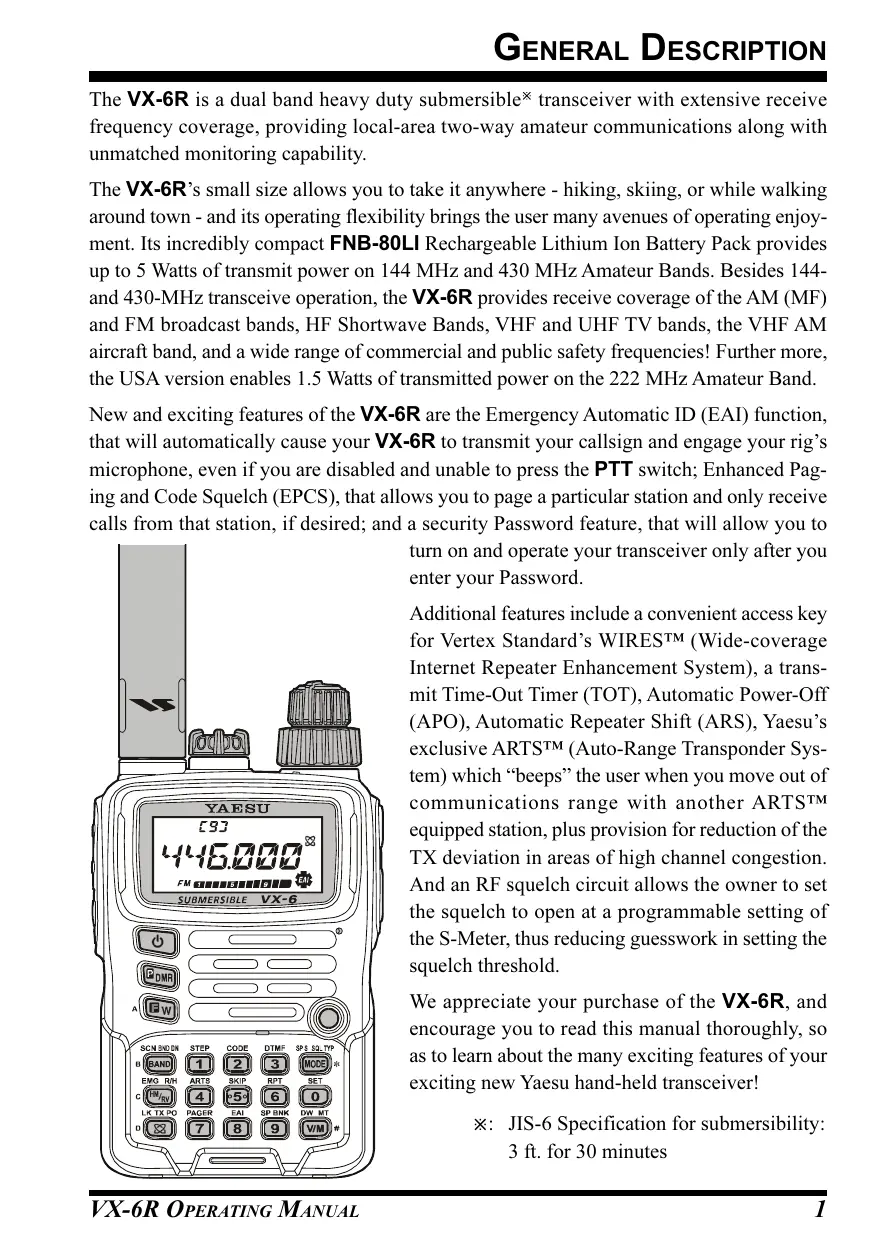
The VX-6R is a dual band heavy duty submersible transceiver with extensive receive frequency coverage, providing local-area two-way amateur communications along with unmatched monitoring capability.
The VX-6R's small size allows you to take it anywhere - hiking, skiing, or while walking around town - and its operating flexibility brings the user many avenues of operating enjoyment. Its incredibly compact FNB-80LI Rechargeable Lithium Ion Battery Pack provides up to 5 Watts of transmit power on 144 MHz and 430 MHz Amateur Bands. Besides 144- and 430-MHz transceive operation, the VX-6R provides receive coverage of the AM (MF) and FM broadcast bands, HF Shortwave Bands, VHF and UHF TV bands, the VHF AM aircraft band, and a wide range of commercial and public safety frequencies! Further more, the USA version enables 1.5 Watts of transmitted power on the 222 MHz Amateur Band.
New and exciting features of the VX-6R are the Emergency Automatic ID (EAI) function, that will automatically cause your VX-6R to transmit your callsign and engage your rig's microphone, even if you are disabled and unable to press the PTT switch; Enhanced Paging and Code Squelch (EPCS), that allows you to page a particular station and only receive calls from that station, if desired; and a security Password feature, that will allow you to
turn on and operate your transceiver only after you enter your Password.
Additional features include a convenient access key for Vertex Standard's WIRES™ (Wide-coverage Internet Repeater Enhancement System), a transmit Time-Out Timer (TOT), Automatic Power-Off (APO), Automatic Repeater Shift (ARS), Yaesu's exclusive ART™ (Auto-Range Transponder System) which "beeps" the user when you move out of communications range with another ART™ equipped station, plus provision for reduction of the TX deviation in areas of high channel congestion. And an RF squelch circuit allows the owner to set the squelch to open at a programmable setting of the S-Meter, thus reducing guesswork in setting the squelch threshold.
We appreciate your purchase of the VX-6R, and encourage you to read this manual thoroughly, so as to learn about the many exciting features of your exciting new Yaesu hand-held transceiver!
× : JIS-6 Specification for submersibility: 3 ft. for 30 minutes
SUPPLIED ACCESSORIES
| FNB-80LI | 7.4 V, 1,400 mAh Rechargeable Lithium Ion Battery Pack |
| NC-72B/C* | 5-Hour Battery Charger |
| CLIP-14 | Quick Draw Belt Clip |
| YHA-67 | Antenna |
| Operating Manual | |
| Warranty Card |
AVAILABLE OPTIONS
| FNB-80LI | 7.4 V, 1,400 mAh |
| Rechargeable Lithium Ion Battery Pack | |
| FBA-23 | 2 x “AA” Cell Battery Case (batteries not supplied) |
| CD-15A | Rapid Charger (requires NC-72B/C/U) |
| NC-72B/C/U× | 5-Hour Battery Charger |
| E-DC-5B | DC Cable with Cigarette-Lighter Adapter |
| E-DC-6 | DC Cable; plug and wire only |
| MH-57A4B | Speaker/Microphone |
| CMP460A | Waterproof Speaker/Microphone |
| VC-27 | Ear piece/Microphone |
| CT-91 | Microphone Adapter |
| CN-3 | BNC-to-SMA Adapter |
| SU-1 | Barometric Pressure Sensor Unit |
| CSC-91 | Soft Case |
※ : “B” suffix is for use with 100-120 VAC, “C” suffix is for use with 230-240 VAC.
Availability of accessories may vary. Some accessories are supplied as standard per local requirements, while others may be unavailable in some regions. This product is designed to perform optimally when used with genuine Yaesu accessories. Vertex Standard shall not be liable for any damage to this product and/or accidents such as fire, leakage or explosion of a battery pack, etc., caused by the malfunction of non-Yaesu accessories. Consult your Yaesu dealer for details regarding these and any newly-available options. Connection of any non-Yaesu-approved accessory, should it cause damage, may void the Limited Warranty on this apparatus.
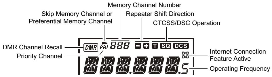
① Antenna Jack
Connect the supplied rubber flex antenna (or another antenna presenting a 50-Ohm impedance) here.
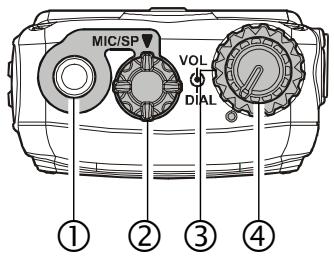
② MIC/SP Jack
This four-conductor miniature jack provides connection points for microphone audio, earphone audio, PTT, and ground.

Do not allow the VX-6R to become submerged in water while the plastic cover over the MIC/SP jack is removed.
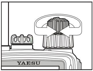
③ VOL Knob
This control adjusts the audio volume level. Clockwise rotation increases the volume level.
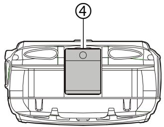
④ DIAL Knob
This (inner) 20-position detented rotary switch is used for setting the operating frequency, and also is used for menu selections and other adjustments.
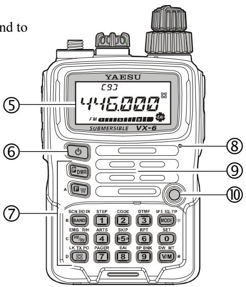
⑤ LCD (Liquid Crystal Display)
The display shows current operating conditions, as indicated on the next page.
⑥ POWER Switch
Press and hold in this switch for one second to toggle the transceiver's power on and off.
⑦ Keypad
These 18 keys select many of most important operating features on the VX-6R. The functions of the keys are described in detail on the pages to follow.
⑧ Microphone
The internal microphone is located here.
⑨ Speaker
The internal speaker is located here.
© TX/BUSY Indicator Lamp
This indicator glows green when the squelch opens, and turns red during transmit. During "Emergency Channel" operation (see page 62), this indicator will glow (or flash) white. Also, this indicator can be useful as a flashlight in a dark environment via Set Mode Item 34: LED LT; see page 96 for details.
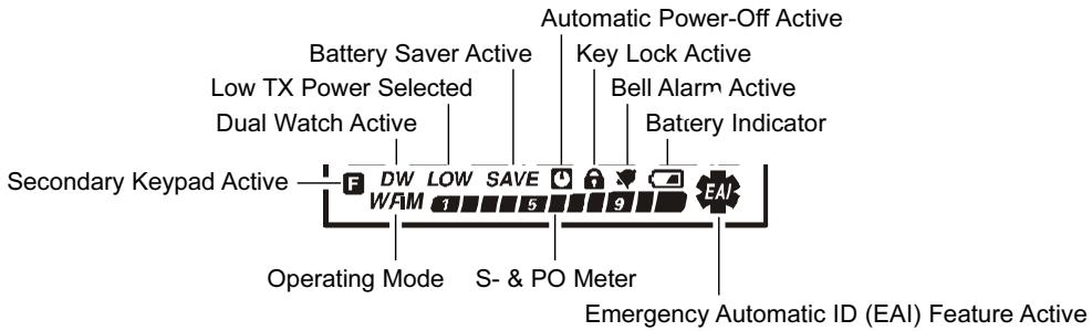
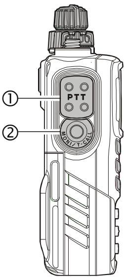
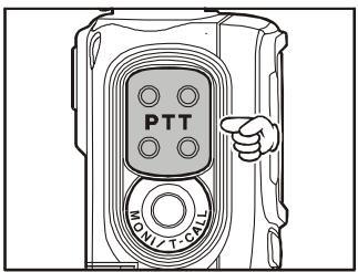
(1) PTT (Push To Talk) Switch Press this switch to transmit, and release it (to receive) after your transmission is completed.
② MONI Switch Pressing this switch disables the noise squelching action, allowing you to hear very weak signals near the background noise level temporarily.
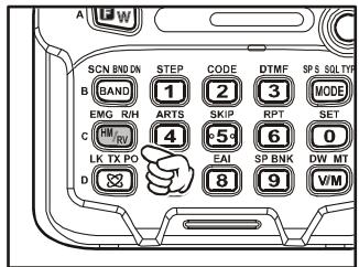
Press the [F/W] key on the keypad first, then press this switch to enable to adjustment of the squelch threshold level.
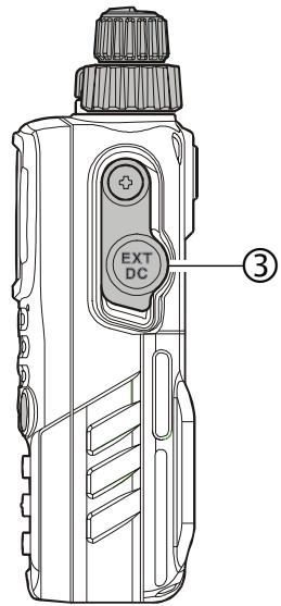
③ EXT DC Jack
This coaxial DC jack allows connection to an external DC power source (6-16V DC). The center pin of this jack is the Positive (+) connection.

Do not allow the VX-6R to become submerged in water while the rubber cap over the EXT DC jack is removed.
④ Battery Pack Latch Open this latch for battery removal.
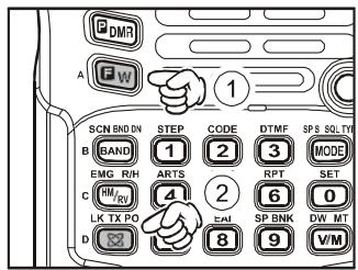
CONTROL & CONNECTIONS (KEYPAD)
| SCN BAND ON BAND | STEP 1 | CODE 2 | |
| Primary Function (PRESS KEY) | Moves operation to the next-highest frequency band | Frequency entry digit “1” | Frequency entry digit “2” |
| Secondary Function (PRESS [F/W] + KEY) | Moves operation to the next-lowest frequency band | Selects the synthesizer steps to be used during VFO operation. | Selects the CTCSS tone or DCS code number |
| Third Function (PRESS & HOLD KEY) | Starts the scanner upward (toward a higher frequency or a higher channel number) | Stores the current setting into Direct Memory Recall Channel “1” | Stores the current setting into Direct Memory Recall Channel “2” |
| EMG_RIN M7R0 | ARTS 4 | SKIP 5+ | |
| Primary Function (PRESS KEY) | Reverses the transmit and receive frequencies while working through a repeater | Frequency entry digit “4” | Frequency entry digit “5” |
| Secondary Function (PRESS [F/W] + KEY) | Activates the EMER-GENCY function | Activates the ARTSTM feature | Selects the Memory Scan “Skip” channel-selection mode |
| Third Function (PRESS & HOLD KEY) | Switches to the “Home” (favorite frequency) Channel | Stores the current setting into Direct Memory Recall Channel “4” | Stores the current setting into Direct Memory Recall Channel “5” |
| LK_TXPO 83 | PAGER 7 | EAI 8 | |
| Primary Function (PRESS KEY) | Activates the Internet Connection feature | Frequency entry digit “7” | Frequency entry digit “8” |
| Secondary Function (PRESS [F/W] + KEY) | Selects the desired transmit power output level | Activates the EPCS (Enhanced Paging & Code Squelch) feature | Activates the EAITM (Emergency Automatic ID) feature |
| Third Function (PRESS & HOLD KEY) | Activates the Key Lockout feature | Stores the current setting into Direct Memory Recall Channel “7” | Stores the current setting into Direct Memory Recall Channel “8” |
| DTMF 3 | SPS SOLTP MODE | GDMR | |
| Frequency entry digit "3" | Selects the Receive mode among AM, FM, and Wide FM | Primary Function (PRESS KEY) | Activates the "User Programmed" mode |
| Selects the DTMF mode | Activates CTCSS or DCS Operation | Secondary Function (PRESS [F/W] + KEY) | No Action |
| Stores the current setting into Direct Memory Recall Channel "3" | Engage the Special Search mode | Third Function (PRESS & HOLD KEY) | Activates the Direct Memory Recall Channel function |
| RPT 6 | SET 0 | GW | |
| Frequency entry digit "6" | Frequency entry digit "0" | Primary Function (PRESS KEY) | Activates the "Second-ary" key function |
| Selects the direction of the uplink frequency shift (either “-, ”+, ” or "simplex") during repeater operation | Engages the Set (Menu) Mode | Secondary Function (PRESS [F/W] + KEY) | Disables the "Second-ary" key function |
| Stores the current setting into Direct Memory Recall Channel "6" | Stores the current setting into Direct Memory Recall Channel "0" | Third Function (PRESS & HOLD KEY) | Activates the "Memory Write" mode (for memory channel storage) |
| SP BNK 9 | DW MT VIM | ||
| Frequency entry digit "9" | Switches frequency control between the VFO and Memory Systems | Primary Function (PRESS KEY) | |
| Enter the Special Bank mode | Activates the "Memory Tune" mode while in the Memory Recall mode | Secondary Function (PRESS [F/W] + KEY) | |
| Stores the current setting into Direct Memory Recall Channel "9" | Activates the Priority (Dual Watch) function | Third Function (PRESS & HOLD KEY) |
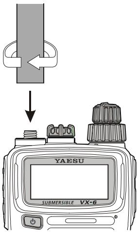
ANTENNA INSTALLATION
The supplied antenna provides good results over the entire frequency range of the transceiver. However, for enhanced reception on certain non-Amateur frequencies, you may wish to connect an antenna designed specifically for that frequency range, as the supplied antenna is necessarily a compromise outside the Amateur bands, and cannot be expected to provide high performance at all frequencies.
To install the supplied antenna, hold the bottom end of the antenna, then screw it onto the mating connector on the transceiver until it is snug. Do not over-tighten by use of extreme force.
Notes:
Never transmit without having an antenna connected.
- When installing the supplied antenna, never hold the upper part of the antenna while screwing it onto the mating conn
- If using an external antenna for transmission, ensure that the SWR presented to the transceiver is 1.5:1 or lower, to avoid excessive feedline loss.
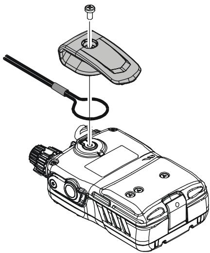
BELT CLIP & HAND STRAP INSTALLATION
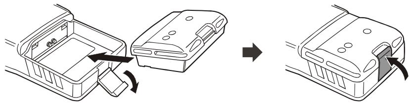
INSTALLATION OF FNB-80LIBATTERY PACK
The FNB-80LI is a high-performance Lithium-Ion battery providing high capacity in a very compact package. Under normal use, the FNB-80LI may be used for approximately 300 charge cycles, after which operating time may be expected to decrease. If you have an old battery pack which is displaying capacity which has become diminished, you should replace the pack with a new one.
Install the FNB-80LI as shown in the illustration.
- Close the Battery Pack Latch on the bottom of the radio.

1) Do not attempt to open any of the rechargeable Li-Ion packs, as personal injury or damage to the Li-Ion pack could occur if a cell or cells become acci-
dently short-circuited.
2) Danger of explosion if battery is incorrectly replaced. Replace only with the same or equivalent type.
BATTERY CHARGING
If the battery has never been used, or its charge is depleted, it may be charged by connecting the NC-72B/C Battery Charger, as shown in the illustration, to the EXT DC jack. If only 12 16 Volt DC power is available, the optional E-DC-5B or E-DC-6 DC Adapter (with its cigarette lighter plug) may also be used for charging the battery.
The display will indicate "CHGING," and the TX/BUSY indicator will glow red, while the battery is being charged. When charging is finished, the display will change to indicate "CHGFUL" and the TX/BUSY indicator will glow green.
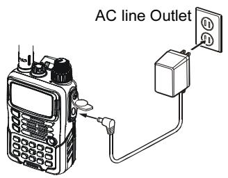
NC-72
E-DC-5B
E-DC-6
INSTALLATION OF FBA-23 ALKALINE BATTERY CASE (OPTION)
The optional FBA-23 Battery Case allows receive monitoring using two "AA" size Alkaline batteries. Alkaline batteries can also be used for transmission in an emergency, but power output will only be selectable 300mW and 50mW , and battery life will be shortened dramatically.
To Install Alkaline Batteries into the FBA-23
- Slide the batteries into the FBA-23 as shown in the illustration, with the Negative [-] side of the batteries touching the spring connections inside the FBA-23.
Open the Battery Pack Latch on the bottom of the radio.
Install the FBA-23 as shown in the illustration, with the [+] side facing the bottom of the transceiver. - Close the Battery Pack Latch on the bottom of the radio.
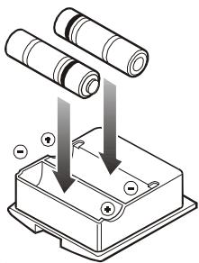
The FBA-23 does not provide connections for charging, since Alkaline cells cannot be re-charged. Therefore, the NC-72B/C, E-DC-5B, or E-DC-6 may safely be connected to the EXT DC jack when the FBA-23 is installed.

1) The FBA-23 is designed for use only with AA-type Alkaline cells.
2) If you do not use the VX-6R for a long time, remove the Alkaline batteries
from the FBA-23, as battery leakage could cause damage to the FBA-23 and/or the transceiver.
LOW BATTERY INDICATION
As your battery discharges during use, the voltage will gradually become lower. When
the battery voltage is becoming too low for reliable operation, the “ ” icon will blink on the LCD display, indicating that the battery pack must be recharged before further use.
- Avoid recharging Lithium-Ion batteries before the “ ” indicator is observed, as this can degrade the charge capacity of your Lithium-Ion battery pack.
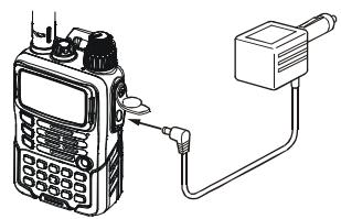
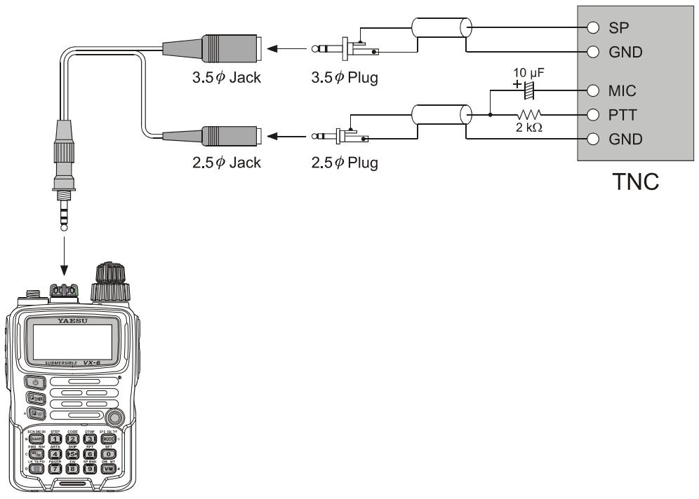
The VX-6R may be used for Packet operation, using the optional CT-91 microphone adapter (available from your Yaesu dealer) for easy interconnection to commonly-available connectors wired to your TNC. You may also build your own cable, using a four-conductor miniature phone plug, per the diagram below.
The audio level from the receiver to the TNC may be adjusted by using the VOL knob, as with voice operation. The input level to the VX-6R from the TNC may be adjusted via Set Mode Item 37: MCGAIN; see page 18 for details.
Be sure to turn the transceiver and TNC off before connecting the cables, so as to prevent voltage spikes from possibly damaging your transceiver.
When you are operating on Packet, switch the Receive Battery Saver OFF, as the "sleep" cycle may "collide" with the beginning of an incoming Packet transmission, causing your TNC not to receive the full data burst. See page 77 for details regarding Receive Battery Saver setup. Remember to readjust the default microphone input level to "LVL 5" (Set Mode Item 37: MCGAIN) when Packet operation is finished.

Hi! I'm R. F. Radio, and I'll be helping you along as you learn the many features of the VX-6R. I know you're anxious to get on the air, but I encourage you to read the "Operation" section of this manual as thoroughly as
possible, so you'll get the most out of this fantastic new transceiver. Now.. . .let's get operating!
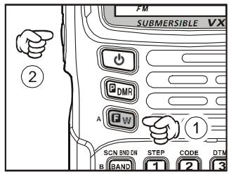
SWITCHING POWER ON AND OFF
- Be sure the Battery Pack is installed, and that the battery is fully charged. Connect the antenna to the top panel ANTENNA jack.
- Press and hold in the orange POWER switch (on the left side of the front panel) for one second. Two beeps will be heard when the switch has been held long enough, and the current DC supply voltage will indi
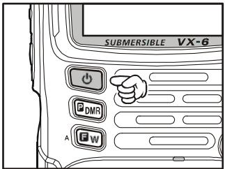
ated on the display for 2 seconds; if you are using the FNB-80LI Battery Pack, the small "Lit" notation at the top of the display confirms that the Lithium-Ion Battery Pack has been detected. After this 2-second interval, the display will resume its normal indication of the operating frequency.
- To turn the VX-6R off, press and hold in the POWER switch again for one second.

1) If you don't hear the two "Beep" tones when the radio comes on, the Beeper may have been disabled via the Menu system. See page 21, which tells you how to reactivate the Beeper.
2) You can change the Opening Message (DC supply voltage indication) to any desired message (up to 6 characters) via Set Mode Item 42: OPN.MSG; see page 48 for details.
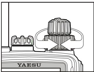
ADJUSTING THE VOLUME LEVEL
Rotate the VOLUME control (inner knob) to set the desired audio level. Clockwise rotation increases the volume level.
SQUELCH ADJUSTMENT
The VX-6R's Squelch system allows you to mute the background noise when no signal is being received. Not only does the Squelch system make "standby" operation more pleasant, it also significantly reduces battery current consumption.
The Squelch system may be adjusted independently for the FM and Wide-FM (FM Broadcast) modes. AM utilizes the setting chosen for FM.
- Press the [F/W] key, then press the MONI switch on the left side of the radio. This provides a “Short-cut” to Set Mode Item 58: SQL.
- Now, rotate the DIAL knob to set the Squelch so that the background noise is just silenced (typically at a setting of about “1” or “2” for FM and AM, and “2” or “3” for Wide-FM); this is point of maximum sensitivity to weak signals.
- When you are satisfied with the Squelch threshold setting, press the PTT key momentarily to save the new setting and exit to normal operation.

1) A special "RF Squelch" feature is provided on the VX-6R. This feature allows you to set the squelch so that only signals exceeding a certain S-meter level will open the squelch. See page 23 for details.
2) If you're operating in an area of high RF pollution, you may need to consider "Tone Squelch" operation using the built-in CTCSS Decoder. This feature will keep your radio quiet until a call is received from a station sending a carrier which contains a matching (subaudible) CTCSS tone. Or, if your friends have radios equipped with DCS (Digital Coded Squelch) like your VX-6R has, try using that mode for silent monitoring of busy channels.
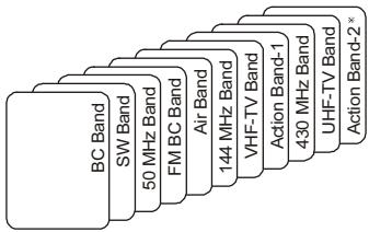
The VX-6R covers an incredibly wide frequency range, over which a number of different operating modes are used. Therefore, the VX-6R's frequency coverage has been divided into different operating bands, each of which has its own pre-set channel steps and operating modes. You can change the channel steps and operating modes later, if you like (see page 22).
| BAND [BAND NUMBER] | FREQUENCY RANGE | ||
| USA VERSION | EXP VERSION | ||
| BC Band | [1] | 0.5 - 1.8 MHz | 0.504 - 1.8 MHz |
| SW Band | [2] | 1.8 - 30 MHz | 1.8 - 30 MHz |
| 50 MHz Ham Band | [3] | 30 - 59 MHz | 30 - 88 MHz |
| FM BC Band | [4] | 59 - 108 MHz | 88 - 108 MHz |
| Air Band | [5] | 108 - 137 MHz | 108 - 137 MHz |
| 144 MHz Ham Band | [6] | 137 - 174 MHz | 137 - 174 MHz |
| VHF-TV Band | [7] | 174 - 222 MHz | 174 - 222 MHz |
| 222 MHz Ham Band | [8] | 222 - 420 MHz | 222 - 420 MHz |
| 430 MHz Ham Band | [9] | 420 - 470 MHz | 420 - 470 MHz |
| UHF-TV Band | [A] | 470 - 800 MHz | 470 - 800 MHz |
| Action Band | [b] | 803 - 999 MHz | 800 - 999 MHz |
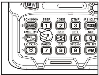
To Change Operating Bands:
- Press the [BAND(SCN)BND DN] key repetitively. You will see the LCD indication
move toward a higher frequency band each time you press the [BAND(SCN)BND DN] key.
- If you wish to move the operating band selection downward (toward lower frequencies), press the [F/W] key first, then press the [BAND(SCN)BND DN] key.
- Once you have selected the desired band, you may initiate manual tuning (or scanning) per the discussion in the next chapter.
When receiving in the AM Broadcast or Shortwave bands (0.5-30 MHz), we recommend that you connect an external antenna, for improved reception.
The VX-6R will initially be operating in the "VFO" mode, a channelized system which allows free tuning throughout the currently-selected operating band.
Three basic frequency navigation methods are available on the VX-6R:
1) Tuning Dial
Rotation of the DIAL allows tuning in the pre-programmed steps established for the current operating band. Clockwise rotation of the DIAL causes the VX-6R to be tuned toward a higher frequency, while counter-clockwise rotation will lower the operating frequency.
If you press the [F/W] key momentarily, then rotate the
DIAL, frequency steps of 1MHz will be selected. This feature is extremely useful for making rapid frequency excursions over the wide tuning range of the VX-6R.
2) Direct Keypad Frequency Entry
The desired operating frequency may be entered directly from the keypad.
To enter a frequency from the keypad, just press the numbered digits on the keypad in the proper sequence. There is no "Decimal point" key on the VX-6R, so if the frequency is below 100MHz (e.g. 15.150 MHz), any required leading zeroes must be entered. However, there is a short-cut for frequencies ending in zero - press the [V/M(DW)MT] key after the last non-zero digit.
Examples:
To enter 146.520MHz , press [1] [4] [6] [5] [6] [0]
To enter 15.255MHz , press [0] [1] [5] [2] [5] [5]
To enter 1.250MHz (1250kHz) , press [0] [0] [1] [2] [5] [0]
To enter 0.950MHz (950 kHz), press [0] [0] [0] [9] [5] [0]
To enter 430.000MHz , press [4] [3] [V / M(DW)MT]
3) Scanning
From the VFO mode, press and hold in the [BAND(SCN)BND DN] key for one second,
and rotate the DIAL knob while holding in the [BAND(SCN)BND DN] key, to select the bandwidth for the VFO scanner, then release the [BAND(SCN)BND DN] key to begin scanning toward a higher frequency. The scanner will stop when it receives a signal strong enough to break through the Squelch threshold. The VX-6R will then hold on that frequency according to the setting of the “RESUME”
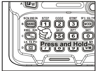
mode (Set Mode Item 48: RESUME). See page 46 for details regarding Scan Operation.
If you wish to reverse the direction of the scan (i.e. toward a lower frequency, instead of a higher frequency), just rotate the DIAL one click in the counter-clockwise direction while the VX-6R is scanning. The scanning direction will be reversed. To revert to scanning toward a higher frequency once more, rotate the DIAL one click clockwise.
Press the PTT switch momentarily to cancel the scanning. This only stops the scan; it does not cause transmission to occur.
TRANSMISSION
Once you have set up an appropriate frequency inside one of the 144MHz , 222MHz^× , or 430MHz Amateur bands on which the VX-6R can transmit, you're ready to go on the air! These are the most basic steps; more advanced aspects of transmitter operation will be discussed later (222 MHz: USA version only).
- To transmit, press the PTT switch, and speak into the front panel microphone (located in the upper right-hand corner of the speaker grille) in a normal voice level. The TX/BUSY indicator will glow red during transmission.
- To return to the receive mode, release the PTT switch.
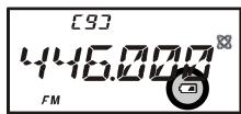
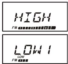
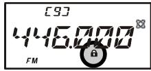
- During transmission, the relative power level will be indicated on the bar graph at the bottom of the LCD; full scale deflection confirms "High Power" operation, while deflection of three bars indicates "Low 1 Power" operation. Five bars indicate "Low 2 Power" operation and seven bars indicate "Low 3 Power" operation. Additionally, the "LOW" icon will appear at the bottom of the display while operating on the "Low Power" settings.
[9]
446000
FM LOW
"LOW 1" POWER
[9]
446000
LOW FM
"LOW 2" POWER

1) If you're just talking to friends in the immediate area, you'll get much longer battery life by switching to Low Power operation, described in the next chapter. And don't
forget: always have an antenna connected when you transmit.
2) Transmission is possible only on the 144MHz , 222MHz (U.S.A. version only), and 430MHz bands.
3) If other users report that you always have a DTMF "beep" at the beginning of each transmission, you may have accidentally switched
on the "Internet Connection" feature. Just press the [⊗(LK)TXPO] key momentarily to disable this feature, which is described in detail on page 70.
[9]
446000
LOWFM
"Low 3" POWER
[9]
446000
FM
"High" POWER
TRANSMISSION
Changing the Transmitter Power Level
You can select between a total of four transmitter power levels on your VX-6R. The exact
power output will vary somewhat, depending on the voltage supplied to the transceiver. With the standard FNB-80LI Battery Pack and external DC source, the power output levels available are:
| 144/430 MHz | 220 MHz | |
| High | 5.0 W | 1.5 W |
| Low 3 | 2.5 W | 1.0 W |
| Low 2 | 1.0 W | 0.5 W |
| Low 1 | 0.3 W | 0.2 W |
To change the power level:
- The default setting for the power output is "High;" in
this configuration, the LCD shows no indication of the power output level. Pressing the [FW] key, followed by the [LK)TXPO] key, will display the current power output level.
- Within one second of releasing the [(LK)TXPO] key, press the [(LK)TXPO] key repetitively; this will cause the power level "LOW1," "LOW2," or "LOW3" to appear.
- Press the [F/W] key, followed by the [⊗(LK)TXPO] key (repeatedly, if necessary) to make the "HIGH" notation appear and restore High Power operation.

1) The VX-6R is smart! You can set up Low power on the 144 MHz band, while leaving 430 MHz on High power, and the radio will remember the different settings on both bands. And when you store memories, you can store
the power output settings separately in each memory, so you don't waste battery power when using very close-in repeaters!
2) When you are operating on the "Low" power settings, you can press the [F / W] key, then press the PTT switch, to cause the VX-6R to transmit (temporarily) on High power. After one transmission, the power level will revert to the previously-selected setting.
TRANSMISSION
Changing the Microphone Gain Level
Different operators speak at different voice levels, and speak at varying distances from the radio's microphone. So as to compensate for these differences, the VX-6R includes a Microphone Gain control, that allows you to set the Microphone Gain to the best level according to your operating preferences. Here's how to set the level:
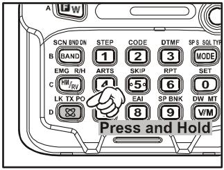
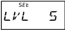
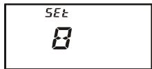
- Press the [F/W] key, then press the [0(SET)] key to enter the Set mode.
- Rotate the DIAL knob to select Set Mode Item 37: MCGAIN.
- Press the [0(SET)] key momentarily to enable adjustment of this Set Mode Item.
- Rotate the DIAL knob to set the gain to a different level. The default setting is “LVL 5;” if you wish to reduce the level, try a setting or “LVL 3” or “LVL 4” while transmitting and speaking
into the microphone; you can hear the effects by monitoring on another radio tuned to your operating frequency.
- When you have made your selection, press and hold in the [0(SET)] key for 2 seconds to save the new setting and exit to normal operation
AM BROADCAST RECEPTION
The VX-6R includes provision for reception of AM broadcasts, either on the standard medium-wave (MW) broadcast band, or on the shortwave bands up to 30MHz .
- Press the [BAND(SCN)BND DN] key (or press the [F/W] key, followed by the [BAND(SCN)BND DN] key) repetitively until you see a frequency in the frequency range desired. The MW coverage is 0.5MHz to 1.8MHz , while the shortwave broad-
cast coverage is 1.8MHz to 30MHz . In either case, the operating mode (displayed on the bottom left of the LCD) should be shown as being "AM."
- Rotate the DIAL to tune across the broadcast band.
- You may also use the keypad to enter frequencies directly. This method will be quicker for changing from the 49-meter broadcast band to the 31-meter band, for example.
EXP Version

1) If the operating mode is not correct, you may change the operating mode by pressing the [MODE(SP S)SQ TYP] key.
2) The VX-6R includes a special memory bank into which the factory has stored 89 frequencies representing popular Short-wave Broadcast stations. See page 43 for details.
AM AIRCRAFT RECEPTION
Reception of AM signals in the aeronautical band (108-137 MHz) is similar to that described in the previous section.
- Press the [BAND(SCN)BND DN] key (or press the [F/W] key, followed by the
[BAND(SCN)BND DN] key (repetitively, if necessary), until you see a frequency in the aeronautical band.

- Rotate the DIAL to tune across the aeronautical band.
- You may also use the keypad to enter frequencies directly. Remember that frequencies quoted by aircraft operators may be abbreviated, and that the "5" at the end of a frequency may be dropped. Since aeronautical channels are assigned in 25-kHz steps, therefore, a frequency announced as "thirty-two, forty-two" corresponds to an operating frequency of 132.425 MHz.
FM BROADCAST/TV AUDIO RECEPTION
The VX-6R also includes provision for reception in the FM broadcast band, utilizing a wide-bandwidth filter which provides excellent fidelity.
To Activate FM Broadcast Reception
- Press the [BAND(SCN)BND DN] key (or press the [F/W] key, followed by the [BAND(SCN)BND DN] key) repetitively until a frequency in the FM broadcast band appears on the display. The total frequency range included in the "FM" band is 59-108 MHz.
- Rotate the DIAL to select the desired station. The default synthesizer steps for the W-FM mode are 100kHz /step.

USA Version

EXP Version
To Activate VHF or UHF TV Audio Reception
- Press the [BAND(SCN)BND DN] key (or press the [F/W] key, followed by the [BAND(SCN)BND DN] key) repetitively until a frequency in the VHF or UHF TV bands appears on the LCD.
- Rotate the DIAL to select the desired station.
VHF TV Band

Remember that the Wide-FM Squelch setting may be made independently from the Narrow-FM setting, adjust the Wide-FM Squelch setting by pressing the [F/W]

UHF TV Band
key, followed by the MONI switch while in the Wide-FM mode. See page 13 for details.
Now that you're mastered the basics of VX-6R operation, let's learn more about some of the really neat features.
KEYBOARD LOCKING
In order to prevent accidental frequency change or inadvertent transmission, various aspects of the VX-6R's DIAL and keypad may be locked out. The possible lockout combinations are:
KEY: Just the front panel keypad is locked out
DIAL: Just the top panel DIAL is locked out
K + D : Both the keypad and DIAL are locked out (factory default)
PTT: The PTT switch is locked out (TX not possible)
K + P : Both the keypad and PTT switch are locked out
D+P: Both the DIAL and PTT switch are locked out
ALL: All of the above are locked out
To lock out some or all of the keys:
- Press the [F/W] key, then press the [0(SET)] key to enter the Set mode.
- Rotate the DIAL knob to select Set Mode Item 35: LOCK.
- Press the [0(SET)] key momentarily to enable adjustment of this Item.
- Rotate the DIAL knob to choose between one of the locking schemes as outlined above.
- When you have made your selection, press the PTT switch to save the new setting and return to normal operation.
To activate the locking feature, press and hold in the [LK]TXPO] key for 2 seconds. The “@” icon will appear on the LCD. To cancel locking, repeat this process.

ADJUSTING THE KEYPAD BEEPER VOLUME LEVEL
A keypad beeper provides useful audible feed back whenever a keypad is pressed. The keypad beeper level changes according to the VOL konb setting. However, you may adjust the volume balance between the receiving audio and keypad beeper via the Set mode.
- Press the [F/W] key, then press the [0(SET)] key to enter the Set mode.
- Rotate the DIAL knob to select Set Mode Item 9: BP LVL.
- Press the [0(SET)] key momentarily to enable adjustment of this Item.
- Rotate the DIAL knob to select the desired level.
- Press the PTT switch to save the new setting and return to normal operation.

Additionally, if you want to turn the beep off:
- Press the [F/W] key, then press the [0(SET)] key to enter the Set mode.
- Rotate the DIAL knob to select Set Mode Item 7: BEEP.
- Press the [0(SET)] key momentarily to enable adjustment of this Item.
- Rotate the DIAL knob to change the setting to "OFF."
- Press the PTT switch to save the new setting and return to normal operation.
- To turn the beep back on again, select "ON" in step 4 above.


KEYPAD/LCD ILLUMINATION
Your VX-6R includes a reddish illumination lamp which aids in nighttime operation. The reddish illumination yields clear viewing of the display in a dark environment, with minimal degradation of your night vision.
Three options for activating the lamp are provided:
KEY Mode: Illuminates the Keypad/LCD for 5 seconds when any key pressed.
CONT Mode: Illuminates the Keypad/LCD continuously.
OFF Mode: Disables the Keypad/LCD lamp.
Here is the procedure for setting up the Lamp operating mode:
- Press the [F/W] key, then press the [0(SET)] key to enter the Set mode.
- Rotate the DIAL knob to select Set Mode Item 33: LAMP.
- Press the [0(SET)] key momentarily to enable adjustment of this Item.
- Rotate the DIAL knob to select one of the three modes described above.
- When you have made your choice, press the PTT switch to save the new setting and return to normal operation.


CHANGING THE CHANNEL STEPS
The VX-6R's synthesizer provides the option of utilizing channel steps of 5/10/12.5/15/20/25/50/100 kHz per step, as well as an automatic step selection based on the current operating frequency ("AUTO"), any number of which may be important to your operating requirements. The VX-6R is set up at the factory in the "AUTO" configuration, which probably is satisfactory for most operation. However, if you need to change the channel step increments, the procedure to do so is very easy.
- Press the [F/W] key, then press the [1(STEP)] key. This provides a "Short-cut" to Set Mode Item 61: STEP.
- Rotate the DIAL to select the new channel step size.
- Press the PTT key to save the new setting and exit to normal operation.
200K

1) 9kHz steps are available only when receiving on the BC band.
2) While operating on the BC band, you may only select channel steps of 9 kHz or 10 kHz; the other step selections are disabled.
3) 5kHz and 15kHz steps are not available for use on 250 - 300 MHz, nor above 580 MHz.
CHANGING THE RECEIVING MODE
The VX-6R provides for automatic receiving mode changing when the radio is tuned to different operating frequencies. However, should an unusual receiving situation arise in which you need to change other receiving mode, just press the [MODE(SP S)SQ TYP] key. The receiving modes available are:
AUTO: Automatic mode setting per default values for the selected frequency range.
FM: Frequency Modulation for receiving an Amateur Radio Station and most VHF/UHF Communication.
WFM: Frequency Modulation for receiving an FM Broadcast Station.
AM: Amplitude Modulation for receiving a Short-wave Broadcast Station and Air Band Communication.

Unless you have a compelling reason to do so, leave the Automatic Mode Selection feature on so as to save time and trouble when changing bands. If you make a mode change for a particular channel or station, you can always
store that one channel into memory, as the mode setting will be memorized along with the frequency information.
RF SQUELCH
A special RF Squelch feature is provided on this radio. This feature allows you to set the squelch so that only signals exceeding a certain S-meter level will open the squelch.
To set up the RF squelch circuit for operation, use the following procedure:
- Press the [F/W] key, then press the [0(SET)] key to enter the Set mode.
- Rotate the DIAL knob to select Set Mode Item 50: RF SQL.
- Press the [0(SET)] key momentarily to enable adjustment of this Item.
- Rotate the DIAL knob to select the desired signal strength level for the squelch threshold (S1, S2, S3, S4, S5, S6, S7, S8, S9, S9+, or OFF).
- Press the PTT switch to save the new setting and return to normal operation.


CHECKING THE BATTERY VOLTAGE
The VX-6R's microprocessor includes programming which will measure the current battery voltage.
- Press the [F/W] key, then press the [0(SET)] key to enter the Set mode.
- Rotate the DIAL knob to select Set Mode Item 16: DC VLT.
- Press the [0(SET)] key momentarily to display the current DC voltage being supplied.
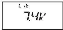
Lit: FNB-80LI is in use.
Edc: An external DC source is in use.
- Press and hold in the [0(SET)] key for 2 seconds to return to normal operation.

Repeater stations, usually located on mountaintops or other high locations, provide a dramatic extension of the communication range for low-powered hand-held or mobile transceivers. The VX-6R includes a number of features which make repeater operation simple and enjoyable.
REPEATER SHIFTS
Your VX-6R has been configured, at the factory, for the repeater shifts customary in your country. For the 144MHz band shift will be 600kHz and 222MHz band (USA version only) shift will be 1.6MHz ; on the 430MHz band, the shift may be 1.6MHz , 7.6MHz , or 5MHz (USA version).
Depending on the part of the band in which you are operating, the repeater shift may be
either downward (□) or upward (□), and one of these icons will appear at the top of the LCD when repeater shifts have been enabled.


AUTOMATIC REPEATER SHIFT (ARS)
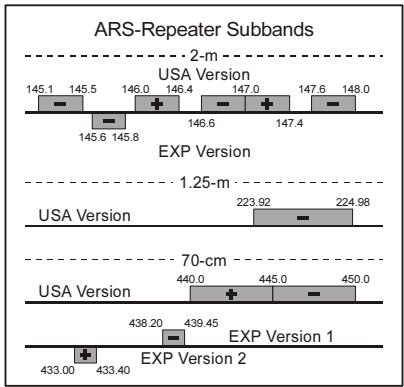
The VX-6R provides a convenient Automatic Repeater Shift feature, which causes the appropriate repeater shift to be applied automatically whenever you tune into the designated repeater sub-bands in your country. These sub-bands are shown below.
If the ARS feature does not appear to be working, you may have accidentally disabled it.
To re-enable ARS:
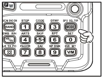
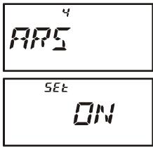
- Press the [F/W] key, then press the [0(SET)] key to enter the Set mode.
- Rotate the DIAL knob to select Set Mode Item 4: ARS.
- Press the [0(SET)] key momentarily to enable adjustment of this Item.
- Rotate the DIAL knob to select "ON."
- When you have made your selection, press the PTT switch to save the new setting and return to normal operation.
MANUAL REPEATER SHIFT ACTIVATION
If the ARS feature has been disabled, or if you need to set a repeater shift direction other than that established by the ARS, you may set the direction of the repeater shift manually.
To do this:
- Press the [F/W] key, then press the [6(RPT)] key. This provides a “Short-cut” to Set Mode Item 51: RPT.
- Rotate the DIAL knob to select the desired shift among “-RPT,” “+RPT,” and “SIMP.”
- When you have made your selection, press the PTT switch to save the new setting and return to normal operation.

If you make a change in the shift direction, but still have Automatic Repeater Shift still engaged (see previous section), when you change frequency (by rotating the DIAL knob, for example) the ARS will over-ride your manual
setting of the shift direction. Turn ARS off if you do not wish this to happen.
Changing the Default Repeater Shifts
If you travel to a different region, you may need to change the default repeater shift so as to ensure compatibility with local operating requirements.
To do this, follow the procedure below:
- Set the VX-6R's frequency to the band on which you wish to change the default repeater shift (144 MHz or 430 MHz Amateur Band).
- Press the [F/W] key, then press the [0(SET)] key to enter the Set mode.
- Rotate the DIAL knob to select Set Mode Item 56: SHIFT.
- Press the [0(SET)] key momentarily to enable adjustment of this Item.
- Rotate the DIAL knob to select the new repeater shift magnitude.
- When you have made your selection, press the PTT switch to save the new setting and return to normal operation.
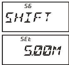

If you just have one "odd" split that you need to program, don't change the "default" repeater shifts using this Set Mode Item. Enter the transmit and receive frequencies separately, as shown on page 34.
MANUAL REPEATER SHIFT ACTIVATION
Checking the Repeater Uplink (Input) Frequency
It often is helpful to be able to check the uplink (input) frequency of a repeater, to see if the calling station is within direct ("Simplex") range.
To do this, just press the [HM/RV(EMG)R/H] key. You'll notice that the display has shifted to the repeater uplink frequency. Press the [HM/RV(EMG)R/H] key again to cause operation to revert to normal monitoring of the repeater downlink (output) frequency. While you are listening on the input frequency to the repeater using the [HM/RV(EMG) R/H] key, the repeater offset icon will blink.

The configuration of this key may be set either to "RV" (for checking the input frequency of a repeater), or "HM" (for instant switching to the "Home" channel for the band you are operating on). To change the configuration of
this key, use Set Mode Item 28: HM/RV. See page 45.
CTCSS OPERATION
Many repeater systems require that a very-low-frequency audio tone be superimposed on your FM carrier in order to activate the repeater. This helps prevent false activation of the repeater by radar or spurious signals from other transmitters. This tone system, called "CTCSS" (Continuous Tone Coded Squelch System), is included in your VX-6R, and is very easy to activate.

CTCSS setup involves two actions: setting the Tone Mode and then setting of the Tone Frequency. These actions are set up by using the [MODE(SP S) SQ TYP] key and [2(CODE)] key.
- Press the [F/W] key, then press the [MODE(SP S)SQ TYP] key to enable selection of the CTCSS/DCS mode.
- Rotate the DIAL knob so that the "TONE" indication appears on the display; this activates the CTCSS Encoder, for access to repeaters requiring a CTCSS tone.
- Rotation of the DIAL knob one more “click” in step “2” above will cause the “T SQL” notation to appear. When “T SQL” is displayed, this means that the Tone SQueLch system is active, which mutes your VX-6R’s receiver until it receives a call from
another radio sending out a matching CTCSS tone. This can help keep your radio quiet until a specific call is received, which may be helpful while operating in congested areas of the band.


1) You may notice a “RV TN” indication on the display while you rotate the DIAL knob in this step; this means that the Reverse Tone Squelch system is active, which mutes your VX-6R's receiver (instead of opening ch) when it receives a call from the radio sending a matched CTCSS tone. SQU ” icon will blink on the display when the Reverse Tone Squelch system is on.
2) You may notice a "DCS" indication on the display while you rotate the DIAL knob still more. We'll discuss the Digital Code Squelch system shortly.
- When you have made your selection of the CTCSS tone mode, press the PTT switch to save the new setting.
- Press the [F/W] key, then press the [2(CODE)] key to enable adjustment of the CTCSS frequency.
- Rotate the DIAL knob until the display indicates the Tone Frequency you need to
be using (ask the repeater owner/operator if you don't know the tone freq

| CTCSS TONE FREQUENCY (Hz) | |||||
| 67.0 | 69.3 | 71.9 | 74.4 | 77.0 | 79.7 |
| 82.5 | 85.4 | 88.5 | 91.5 | 94.8 | 97.4 |
| 100.0 | 103.5 | 107.2 | 110.9 | 114.8 | 118.8 |
| 123.0 | 127.3 | 131.8 | 136.5 | 141.3 | 146.2 |
| 151.4 | 156.7 | 159.8 | 162.2 | 165.5 | 167.9 |
| 171.3 | 173.8 | 177.3 | 179.9 | 183.5 | 186.2 |
| 189.9 | 192.8 | 196.6 | 199.5 | 203.5 | 206.5 |
| 210.7 | 218.1 | 225.7 | 229.1 | 233.6 | 241.8 |
| 250.3 | 254.1 | - | - | - | - |
CTCSS OPERATION
- When you have made your selection, press the [2(CODE)] key momentarily to save
the new settings and exit to normal operation. This is different than the usual method of restoring normal operation, and it applies only to the configuration of the CTCSS/DCS frequencies.
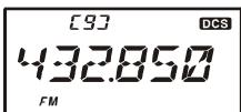
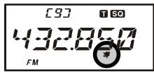
[9]
T SQ
432850
FM

Your repeater may or may not re-transmit a CTCSS tone - some systems just use CTCSS to control access to the repeater, but don't pass it along when transmitting. If the S-Meter deflects, but the VX-6R is not passing audio,
repeat steps "1" through "4" above, but rotate the DIAL so that "TONE" appears - this will allow you to hear all traffic on the channel being utilized.
DCS OPERATION
Another form of tone access control is Digital Code Squelch, or DCS. It is a newer, more advanced tone system which generally provides more immunity from false paging than does CTCSS. The DCS Encoder/Decoder is built into your VX-6R, and operation is very similar to that just described for CTCSS. Your repeater system may be configured for DCS; if not, DCS is frequently quite useful in Simplex operation if your friend(s) use transceivers equipped with this advanced feature.
Just as in CTCSS operation, DCS requires that you set the Tone Mode to DCS and that you select a tone code.
- Press the [F/W] key, then press the [1(SQ TYP)] key to enable selection of the CTCSS/DCS mode.
- Rotate the DIAL knob until the "DCS" indication appears on the display; this activates the DCS Encoder/Decoder.
- Press the PTT key to save the new setting.
- Press the [F/W] key, then press the [2(CODE)] key to enable adjustment of the DCS code.
- Rotate the DIAL knob to select the desired DCS Code (a three-
digit number). Ask the repeater owner/operator if you don't know DCS Code; if you are working simplex, just set up the DCS Code to be the same as that used by your friend(s).
- When you have made your selection, press the [F/W] key momentarily to save the
new settings and exit to normal operation.


| DCS CODE | |||||||||
| 023 | 025 | 026 | 031 | 032 | 036 | 043 | 047 | 051 | 053 |
| 054 | 065 | 071 | 072 | 073 | 074 | 114 | 115 | 116 | 122 |
| 125 | 131 | 132 | 134 | 143 | 145 | 152 | 155 | 156 | 162 |
| 165 | 172 | 174 | 205 | 212 | 223 | 225 | 226 | 243 | 244 |
| 245 | 246 | 251 | 252 | 255 | 261 | 263 | 265 | 266 | 271 |
| 274 | 306 | 311 | 315 | 325 | 331 | 332 | 343 | 346 | 351 |
| 356 | 364 | 365 | 371 | 411 | 412 | 413 | 423 | 431 | 432 |
| 445 | 446 | 452 | 454 | 455 | 462 | 464 | 465 | 466 | 503 |
| 506 | 516 | 523 | 526 | 532 | 546 | 565 | 606 | 612 | 624 |
| 627 | 631 | 632 | 654 | 662 | 664 | 703 | 712 | 723 | 731 |
| 732 | 734 | 743 | 754 | - | - | - | - | - | - |
DCS OPERATION

Remember that the DCS is an Encode/Decode system, so your receiver will remain muted until a matching DCS code is received on an incoming transmission. Switch the DCS off when you're just tuning around the band!
DCS CODE INVERSION
The DCS system was first introduced in the commercial LMR (Land Mobile Radio) service, where it is now in widespread use. DCS is sometime referred to by its different proprietary names, such as DPL® (Digital Private Line®, a registered trademark of Motorola, Inc.).
DCS uses a codeword consisting of a 23-bit frame, transmitted (subaudible) at a data rate of 134.4 bps (bit/sec). Occasionally, signal inversion can result in the complement of a code to be sent or received. This prevents the receiver's squelch from opening with DCS enabled, as the decoded bit sequence would not match that selected for operation.
Typical situations that might cause inversion to occur are:
- Connection of an external receiver preamplifier.
□ Operating through a repeater. - Connection of an external linear amplifier.
Note that code inversion does not mean that any of the above listed equipment is defective!
In certain amplifier configurations, the output signal (phase) is inverted from the input. Small signal or power amplifiers having an odd number (1, 3, 5, etc.) of amplification stages may result in inversion of a transmitted or received DCS code.
While under most circumstances this should not occur (amplifier designs and industry standards take this into account), if you find that your receiver squelch does not open when both you and the other station are using a common DCS code, you or the other station (but not both) can try the following:
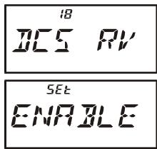
- Press the [F/W] key, then press the [0(SET)] key to enter the Set mode.
- Rotate the DIAL knob to select Set Mode Item 18: DCS RV.
- Press the [0(SET)] key momentarily, then rotate the DIAL knob to set this Set Mode Item to “ENABLE” (thus inverting the DCS Code).
- When you have made your selection, press the PTT switch to save the new setting and exit to normal operation.
- Remember to restore the default setting to "DISABLE" when done.
CTCSS/DCSBELL OPERATION
During CTCSS Decode or DCS operation, you may set up the VX-6R such that a ringing "bell" sound alerts you to the fact that a call is coming in. Here is the procedure for activating the CTCSS/DCS Bell:
- Set the transceiver up for CTCSS Decode ("Tone Squelch") or DCS operation, as described previously.
- Adjust the operating frequency to the desired channel.
- Press the [F/W] key, then press the [0(SET)] key to enter the Set mode.
- Rotate the DIAL knob to select Set Mode Item 8: BELL.
- Press the [0(SET)] key momentarily to enable adjustment of this Set Mode Item.
- Rotate the DIAL knob to set the desired number of rings of the Bell. The available choices are “1,” “3,” “5,” or “8” rings, “CONT” (continuous ringing), or “OFF.”
- Press the PTT switch momentarily to save the new setting and exit to normal operation.
When you are called by a station whose transceiver is sending a CTCSS tone or DCS code
which matches that set into your Decoder, the Bell will ring in accordance with this programming. When the CTCSS/DCS Bell is activated, the “ ” icon will appear at the upper right corner on the LCD.

TONE SEARCH SCANNING
In operating situations where you don't know the CTCSS or DCS tone being used by another station or stations, you can command the radio to listen to the incoming signal and scan in search of the tone being used. Two things must be remembered in this regard:
You must be sure that your repeater uses the same tone type (CTCSS vs. DCS).
Some repeaters do not pass the CTCSS tone; you may have to listen to the station(s) transmitting on the repeater uplink (input) frequency in order to allow Tone Search Scanning to work.
To scan for the tone in use:
-
Set the radio up for either CTCSS or DCS Decoder operation (see the previous discussions). In the case of CTCSS, “T S0” will appear on the display; in the case of DCS, “DCS” will appear on the display.
-
Press the [F/W] key, then press the [2(CODE)] key.
- Press and hold in the [BAND(SCN)BND DN] key for one second to start scanning for the incoming CTCSS or DCS tone/code.
- When the radio detects the correct tone or code, it will halt on that tone/code, and audio will be allowed to pass. Press the [BAND(SCN)BND DN] key to lock in that tone/code, then press the [F/W] key to exit to normal operation.
1000H2
23

If the Tone Scan feature does not detect a tone or code, it will continue to scan indefinitely. When this happens, it may be that the other station is not sending any tone. You can press the PTT switch to halt the scan at any time.
You may listen to the (muted) signal from the other station during Tone Scanning when Set Mode Item 68: TS MUT is set to “OFF.” See page 102 for details. You can also change the Tone Search scanning speed, using Set Mode Item 69: TS SPD.” See page 102.
Tone Scanning works either in the VFO or Memory modes.
SPLIT TONE OPERATION
The VX-6R can be operated in a Split Tone configuration via the Set mode.
- Press the [F / W] key, then press the [0(SET)] key to enter the Set mode.
- Rotate the DIAL knob to select Set Mode Item 58: SPLIT.
- Press the [0(SET)] key momentarily to enable adjustment of this Set Mode Item.
- Rotate the DIAL knob to select ON (to enable the Split Tone feature).
- Press the PTT key momentarily to save the new setting and exit to normal operation.


When the Split Tone feature is activated, you can see the following additional parameters following the “RV TN” parameter (while selecting the tone mode by pressing [F / W] [MODE(SPS)SQTYP] ):
D CODE: DCS Encode only (the “DCS” icon will blink during operation)
T DCS: Encodes a CTCSS Tone and Decodes a DCS code
(the “T” icon will blink and the “DCS” icon will appear during operation)
D TONE: Encodes a DCS code and Decodes a CTCSS Tone
(the “T S C” icon will appear and the “D C S” icon will blink during operation)
Select the desired operating mode, from the selections shown above.
TONE CALLING (1750 Hz)
If the repeaters in your country require a 1750-Hz burst tone for access (typically in Europe), you can set the MONI switch to serve as a “Tone Call” switch instead. To change the configuration of this switch, we again use the Set Mode to help us.
- Press the [F/W] key, then press the [0(SET)] key to enter the Set mode.
- Rotate the DIAL knob to select Set Mode Item 36: M/T-CL.
- Press the [0(SET)] key momentarily to enable adjustment of this Set Mode Item.
- Rotate the DIAL knob to select "T-CALL" on the display.
- Press the PTT switch to save the new setting and exit to normal operation.


To access a repeater, press and hold in the MONI switch for the amount of time specified by the repeater owner/operator. The transmitter will automatically be activated, and a 1750-Hz audio tone will be superimposed on the carrier. Once access to the repeater has been gained, you may release the MONI switch, and use the PTT switch for activating the transmitter thereafter.
The VX-6R provides a wide variety of memory system resources. These include:
Regular Memory Channels, which made up of:
O 900 "Standard" memory channels, numbered "1" through "900."
99 "Frequency Skip Memory" channels, numbered "901" through "999."
11 "Home" channels, providing storage and quick recall of one prime frequency on each operating band.
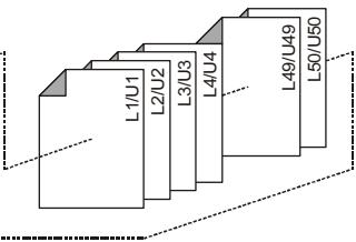
O 50 sets of band-edge memories, also known as "Programmable Memory Scan" channels, labeled "L1/U1" through "L50/U50."
24 Memory Banks, labeled “BANK 1” through “BANK24.” Each Memory Bank can be assigned up to 100 channels from the “standard” and “PMS” memory channels.
Special Memory Channels, which include:
A "Emergency Automatic ID (EAI)" Channel.
10 "Direct Memory Recall" Channels.
10 "Weather Broadcast" Channels.
89 Popular Short-wave Broadcast Station Memory Channels.
O 281 VHF Marine Channels.
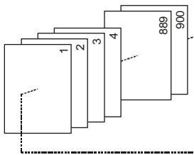
Standard Memory Channels (900 channels)
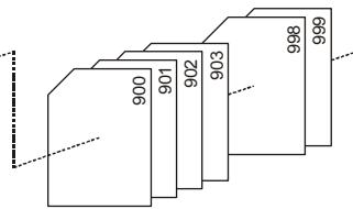
Frequency Skip Memory Channels (99 channels)
PMS Memory Channels (50 Sets)

EAI Channel (1 channel)
HOME Channels (11 channels)
Direct Memory Recall Channels (10 channels)
Weather Broadcast Channels (10 channels)

VHF Marine Channels (280 channels)

Short-wave Broadcast Station Memory Channels (89 channels)
MEMORY STORAGE
- Select the desired frequency, while operating in the VFO mode. Be sure to set up any desired CTCSS or DCS tones, as well as any desired repeater offset. The power level may also be set at this time, if you wish to store it.
- Press and hold in the [F / W] key for one second.
- Within five seconds of releasing the [F / W] key, you need to make a decision regarding channel storage. The microprocessor will automatically select the next-available "free" channel (a memory register on which no data has been stored), so you may not wish to make any change; if this is the case, proceed to step 4.
If you wish to select a different channel number into which to store the data, rotate the DIAL knob to select the desired memory channel. If you see a blinking memory channel number, it means that the channel currently has no data written on it (i.e. the channel is "free").
- Press the [F/W] key once more to store the frequency into memory.
- You still will be operating in the "VFO" mode, so you may now enter other frequencies, and store them into additional memory locations, by repeating the above process.

1) You may change the automatic memory channel selection feature to select the "next-highest memory channel above the last-stored memory channel" by instead of the "next-available 'free' channel" via the Set Mode Item 38:
MWMD; see page 97.
2) In step 4 above, you may jump 100 memory channels, if you're in a hurry ( 101 201 301 ) by pressing the [P(DMR)] key (multiple times, if necessary). Similarly, if you wish to store to the designated memory channel, an easy way to designated memory is to key in the memory channel number, then press the [V / M(DW)MT] key. For example, to designate memory channel #14, press [1] [4] [V / M(DW)MT] . You may also designate the Memory Channel #000 and Programmable Memory channels ("L1/U1" through "L50/U50") using the following numbers: Memory Channel #000 = "1000," Programmable Memory channels #L1 = "1001," U1 = "1002," L50 = "1099," and U50 = "1100." In this case, you does not need pressing the [V / M(DW)MT] key.
Storing Independent Transmit Frequencies ("Odd Splits")
All memories can store an independent transmit frequency, for operation on repeaters with non-standard shift. To do this:
- Store the receive frequency (downlink) using the method already described under MEMORY STORAGE (it doesn't matter if a repeater offset is active).
- Turn to the desired transmit (uplink) frequency, then press and hold in the [F/W] key for one second.
- Within five seconds of releasing the [F / W] key, rotate the DIAL knob to select the same memory channel number as used in step "1" above.
MEMORY STORAGE
- Press and hold in the PTT switch, then press the [F/W] key once more momentarily while holding the PTT switch in (this does not key the transmitter).

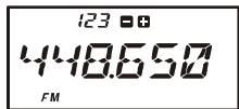
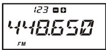
Whenever you recall a memory which contains independently-stored transmit and receive frequencies, the "■■" indication will appear in the display.
123
448650
FM
MEMORY RECALL
- While operating in the VFO mode, press the [V/M(DW)MT] key to enter the Memory mode.
- Rotate the DIAL knob to select the desired channel.
- To return to the VFO mode, press the [V/M(DW)MT] key.

When the radio is already set to the Memory mode, an easy way to recall memories is to key in the memory channel number, then press the [V/M(DW)MT] key.
For example, to recall memory channel #14, press [1] [4] [V/M(DW)MT].
You may also recall Memory Channel #000 and Programmable Memory channels ("L01/U01" through "L50/U50") using the following numbers: Memory Channel #000 = "1000," Programmable Memory channels #L1 = "1001," U1 = "1002," L50 = "1099," and U50 = "1100." In these cases, you do not need to press the [V/M(DW)MT] key.
LABELING MEMORIES
You may wish to append an alpha-numeric "Tag" (label) to a memory or memories, to aid in recollection of the channel's use (such as a club name, etc.). This is easily accomplished using the Set Mode.
- Recall the memory channel on which you wish to append a label.
- Press the [F/W] key, then press the [0(SET)] key to enter the Set mode.
- Rotate the DIAL knob to select Set Mode Item 40: NM SET.
- Press the [0(SET)] key momentarily to enable programming of the name tag.
- Rotate the DIAL knob to select the first digit of the desired label.
- Press the [MODE(SP S)SQ TYP] key to move to the next character.
- If you make a mistake, press the [BAND(SCN)BND DN] key to back-space the cursor, then re-enter the correct letter, number, or symbol.
- Repeat steps 5 through 7 to program the remaining letters, numbers, or symbols of the


LABELING MEMORIES
desired label. A total of six characters may be used in the creation of a label.
9. When you have programmed a label which is under 6 characters, press the [0(SET)] key to confirm the label.
10. When you have completed the creation of the label, press the PTT key to save the label and exit.
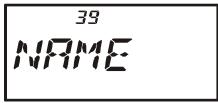
To display the alpha-numeric "Tag" (label):
- Set the VX-6R to the “MR” (Memory Recall) mode, and recall the memory channel on which you wish to display its label.
- Press the [F/W] key, then press the [0(SET)] key to enter the Set mode.
- Rotate the DIAL knob to select the Set Mode Item labeled 39: NAME.
- Press the [0(SET)] key momentarily to enable adjustment of this Item's setting.
- Rotate the DIAL knob to set this Set Mode Item to "ALPHA" (thus enabling the alpha-numeric display).
- Press the PTT key to save the new setting and activate the alphanumeric Tag.


To disable the alpha-numeric Tag (enabling the frequency display), just repeat the above procedure, rotating the DIAL knob to select “FREQ” in step 5 above.

You may check the frequency of any Name-tagged channel by pressing the MONI switch. Release the MONI switch, and the display returns to the alpha-numeric "Tag" display.
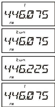
Once you have recalled a particular memory channel, you may easily tune off that channel, as though you were in the "VFO" mode.
- With the VX-6R in the "MR" (Memory Recall) mode, select the desired memory channel.
- Press the [F/W] key, then press the [V/M(DW)MT] key to activate the "Memory Tuning" feature. The Memory Channel number will be replaced by "tun." And if you have an alpha-numeric Tag displayed on the memory channel, the display will automatically revert to display of the operating frequency, so you can navigate without having to enter the Menu to change the display configuration.
- Rotate the DIAL knob, as desired, to tune to a new frequency. The synthesizer steps selected for VFO operation on the current band will be the steps used during Memory Tuning.
- If you wish to return to the original memory frequency, just press the [V/M(DW)MT] key momentarily. The display will revert to display of the alpha-numeric Tag (if any) that may have originally appeared on the LCD.
- If you wish to store a new frequency set during Memory Tuning, just press and hold in the [F / W] key for one second, per normal memory storage procedure. The microprocessor will automatically set itself to the next-available clear memory location, and you then press [F / W] again to lock in the new frequency.

1) If you want to replace the original memory contents with those of the new frequency, be sure to rotate the DIAL knob to the original memory channel number!
2) Any required CTCSS/DCS changes, or repeater offset modifications, must be done before storing the data into the new (or original) memory channel location.
MOVING MEMORY DATA TO THE VFO
Data stored on memory channels can easily be moved to the VFO, if you like.
- Select the memory channel containing the frequency data to be moved to the VFO.
- Press the [F/W] key, then press the [V/M(DW)MT] key to activate the "Memory Tune" feature temporarily, then press the [F/W] key, followed by the [⊗(LK)TXPO] key. The data will now have been copied to the VFO, although the original memory contents will remain intact on the previously-stored channel.
If a Split Frequency Memory channel was transferred, the TX frequency will be ignored (you will be set up for Simplex operation on the Receive frequency).
MASKING MEMORIES
There may be situations where you want to "Mask" memories so they are not visible during memory selection or scanning. For example, several memories used only in a city you visit infrequently may be stored, then "Masked" until you visit that city, at which time you can "Unmask" them for normal use.
- Press the [V/M(DW)MT] key, if needed, to enter the MR mode.
- Press and hold in the [F/W] key for one second, then rotate the DIAL knob to select the memory channel to be "Masked."
- Press the [⊗(LK)TXPO] key momentarily. The display will revert to memory channel #1. The previously-selected memory will be Masked.
- To Unmask the hidden memory, repeat the above procedure: press and hold in the [F/W] key for one second, rotate the DIAL to select the masked memory's number, then press the [⊗(LK)TXPO] key to restore the memory channel's data.

Watch out! You can manually store data over a “Masked” memory, deleting previous data, if you’re not careful. Use the “next available memory” technique (look for the blinking memory channel number) storage technique to
avoid over-writing a masked memory.
MEMORY ONLY MODE
Once memory channel programming has been completed, you may place the radio in a "Memory Only" mode, whereby VFO operation is impossible. This may be particularly useful during public-service events, where a number of operators may be using the radio for first time, and ultimate simplicity of channel selection is desired.
To place the radio into the Memory Only mode, turn the radio off. Now, press and hold in the [VIM(DW)MT] key while turning the radio on. To return to normal operation, repeat the above power-on procedure.
HOME CHANNEL MEMORY
A special one-touch "HOME" channel is available for each of operating bands, to allow quick recall of a favorite operating frequency on each band.
Home Channel storage is simple to accomplish:
- Change the setting of Set Mode Item 28: HM/RV from “REV” to “HOME,” if it is not already set to this option (see page 95).
- Select the desired frequency, while operating in the VFO mode. Be sure to set up any desired CTCSS or DCS tones, as well as any desired repeater offset. The power level may also be set at this time, if you wish to store it.
- Press and hold in the [F / W] key for one second.
- While the memory channel number is blinking, just press the [HM/RV(EMG)R/H] key. The frequency and other data (if any) will now be stored in the special HOME channel register.
- You may repeat this process on the other operating bands.
- To recall the HOME channel, press the [HM/RV(EMG)R/H] key momentarily while operating either in the VFO or MR mode.

USA Version

EXP Version
The UHF HOME channel is the one used during "Emergency Channel Operation." See page 62 for details regarding this feature.
| BAND | DEFAULT HOME CHANNEL FREQUENCY | |
| USA VERSION | EXP VERSION | |
| BC Band | 0.540 MHz | 0.540 MHz |
| SW Band | 1.800 MHz | 1.800 MHz |
| 50 MHz Ham Band | 30.000 MHz | 30.000 MHz |
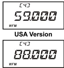
| FM BC Band | 59.000 MHz | 88.000 MHz |
| Air Band | 108.000 MHz | 108.000 MHz |
| 144 MHz Ham Band | 146.520 MHz | 144.000 MHz |
| VHF-TV Band | 174.000 MHz | 174.000 MHz |
| 222 MHz Ham Band | 222.000 MHz | 230.000 MHz |
| 430 MHz Ham Band | 446.000 MHz | 430.000 MHz |
| UHF-TV Band | 470.000 MHz | 470.000 MHz |
| Action Band | 860.000 MHz | 860.000 MHz |
The large number of memories available in the VX-6R could be difficult to utilize without some means of organizing them. Fortunately, the VX-6R includes provision for dividing the memories into as many as 24 Memory Banks, so you can categorize the memories in a manner convenient to you. You may enter and exit the “Memory Bank” mode by a single press of the [BAND(SCN)BND DN] key, as we shall see below.
Assigning Memories to a Memory Bank
- Recall the memory channel to be assigned to a Memory Bank.
- Press and hold in the [F / W] key for one second, then rotate the DIAL knob to select the Memory Bank number (“b 1”~“b24”) you want as the Memory Bank for this channel.
- Here's a short cut for choosing the desired Memory Bank: press and hold in the [F/W] key for one second, then enter the follow-
ing numbers: 1101 (for Memory Bank "b1") through 1124 (for Memory Bank "b24").
4. Press the [F/W] key to copy the memory channel data into the Memory Bank.
| Memory Bank “1” 144 MHz Amateur Band Channels |
| Memory Bank “2” 430 MHz Amateur Band Channels |
| Memory Bank “3” All Amateur Band Channels |
| Memory Bank “4” Club Channels |
| Memory Bank “5” Air Band Channels |

1) You may assign one memory channel into several
2) The PMS memory channels (L1/U1 through L50/U50) may not be assigned to a Memory Bank.
Memory Bank Recall
- Press the [VIM(DW)MT] key, if needed, to enter the Memory mode.
- Press the [BAND(SCN)BND DN] key to activate the "Memory Bank" mode. The Memory Bank number will appear on the display.
- Press the [F/W] key, followed by the [BAND(SCN)BND DN] key, then rotate the DIAL knob to select the desired Memory Bank ("BANK 1" through "BANK24").
- Press the [BAND(SCN)BND DN] key momentarily once more; now, as you rotate the DIAL knob to select memories, you will observe that you can only select memory channels in the current memory bank. The small memory bank number will appear at quency display while operating within a Memory Bank.
- To change to another Memory Bank, press the [F / W] key, followed by the [BAND(SCN)BND DN] key, rotate the DIAL knob to select the new Memory Bank,


then press the [BAND(SCN)BND DN] key momentarily.
6. To exit from Memory Bank operation, just press the [BAND(SCN)BND DN] key. "MEMORY" will appear on the display, indicating that you are now in the "standard" Memory Recall mode, without utilization of the Memory Banks. The memories stored in the various Banks will remain in those banks, however; you do not need to store them again.
Removing Memories from a Memory Bank
- Recall the memory channel to be removed from a Memory Bank.
- Press and hold in the [F/W] key for one second, then press the [⊗(LK)TXPO] key to remove the memory channel data from the Memory Bank.
Changing a Memory Bank's Name
You may change the default Memory Bank Name which is indicates on the display while selecting the Memory Bank to your desired name.
- Press the [F/W] key, then press the [0(SET)] key to enter the Set mode.
- Rotate the DIAL knob to select Set Mode Item 10: BNK NM.
- Press the [0(SET)] key momentarily, then rotate the DIAL knob to recall the memory bank on which you wish to change a label.
- Press the [MODE(SP S)SQ TYP] key to enable changing of the name tag.
- Rotate the DIAL knob to select the first digit of the desired label.
- Press the [MODE(SP S)SQ TYP] key to move to the next character.
- If you make a mistake, press the [BAND(SCN)BND DN] key to back-space the cursor, then re-enter the correct letter, number, o
- Repeat steps 5 through 7 to program the remaining letters, numbers, or symbols of the desired label. A total of six characters may be used in the creation of a label.
- When you have programmed a name which is under 6 characters, press the [0(SET)] key to confirm the label.
- When you have completed the changing of the name, press the PTT key to save the label and exit.


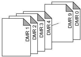
DIRECT MEMORY RECALL CHANNEL
The Direct Memory Recall Channel (DMR) feature allows you to recall up to ten favorite frequencies directly via the numeric ([0] through [9]) keys. DMR channels may be selected from the VFO, an already-programmed memory, or a Home channel.
Storing the "Direct Memory Recall" Channels
- Set up the transceiver frequency according to the desired configuration, including parameters such as CTCSS/DCS data, Repeater Shift, Power Level etc.
- Press and hold in the numeric ([0] through [9]) key, corresponding to the Direct Memory Recall Channel into which you wish to store this configuration, for 2 seconds.
- You still will be operating in the "normal" mode (Memory, VFO, or Home Channel), so you may now select other frequency, and store them into additional Direct Memory Recall Channels, by repeating the above process.
Recalling the "Direct Memory Recall" Channels
- Press and hold in the [P(DMR)] key for 2 seconds to recall the Direct Memory Recall Channel mode. The “ ” icon will appear at the upper left corner of the display while operating on a Direct Memory Recall Channel.

- Press the numeric ([0] through [9]) key corresponding to the Direct Memory Recall Channel you wish to recall.
- Once you have recalled a DMR channel, you may rotate the DIAL knob to change frequencies, as though you were operating on the VFO.
- If you wish to over-write the data stored on a particular DMR channel after tuning off of the original frequency, just press and hold in (for 2 seconds) the numeric key which was pressed in step 2.
- To exit the Direct Memory Recall Channel mode, press and hold in the [P(DMR)] key for 2 seconds.
| DEFAULT DMR CHANNEL FREQUENCY | ||
| KEY | USA VERSION | EXP VERSION |
| [1] | 145.000 MHz | 144.500 MHz |
| [2] | 146.520 MHz | 145.000 MHz |
| [3] | 147.500 MHz | 145.500 MHz |
| [4] | 435.000 MHz | 430.000 MHz |
| [5] | 440.000 MHz | 435.000 MHz |
| [6] | 446.000 MHz | 439.000 MHz |
| [7] | 222.000 MHz | 0.540 MHz |
| [8] | 0.540 MHz | 7.000 MHz |
| [9] | 88.000 MHz | 88.000 MHz |
| [0] | 120.000 MHz | 120.000 MHz |
SHORT-WAVE BROADCAST STATION MEMORY CHANNELS
A large number of Short-Wave Broadcast Station Memory Channels have also been preprogrammed at the factory, for convenient selection of broadcast stations.
- Press the [F/W] key, then press the [9(SP BNK)] key, to recall the Special Memory Channel Bank.
- Press the [BAND(SCN)BND DN] key to select "RADIO" (thus recalling the Broadcast Station Channel Memory Bank).
- Rotate the DIAL knob to select any of the 89 available Broadcast Stations.
- You may view the channel frequency temporarily using Set Mode Item 36: NAME (set its parameter to “FREQ”).
- To exit to normal operation, press the [V/M(DW)MT] key, or press the [F/W] key followed by the [9(SP BNK)] key.


BROADCAST STATION FREQUENCY LIST
| Ch No. | Freq. (MHz) | MODE | Tag | Station Name | Ch No. | Freq. (MHz) | MODE | Tag | Station Name |
| 1 | 6.030 | AM | VOA | Voice of America | 45 | 7.270 | AM | SPAIN | Radio Exterior de Espana |
| 2 | 6.160 | AM | VOA | Voice of America | 46 | 9.520 | AM | SPAIN | Radio Exterior de Espana |
| 3 | 9.760 | AM | VOA | Voice of America | 47 | 11.920 | AM | SPAIN | Radio Exterior de Espana |
| 4 | 11.930 | AM | VOA | Voice of America | 48 | 15.585 | AM | SPAIN | Radio Exterior de Espana |
| 5 | 5.995 | AM | CANADA | Radio Canada International | 49 | 6.090 | AM | LUXBRG | Radio Luxembourg |
| 6 | 7.235 | AM | CANADA | Radio Canada International | 50 | 7.485 | AM | NORWAY | Radio Norway International |
| 7 | 9.735 | AM | CANADA | Radio Canada International | 51 | 9.590 | AM | NORWAY | Radio Norway International |
| 8 | 11.955 | AM | CANADA | Radio Canada International | 52 | 9.985 | AM | NORWAY | Radio Norway International |
| 9 | 6.195 | AM | BBC | British Broadcasting Corporation | 53 | 13.800 | AM | NORWAY | Radio Norway International |
| 10 | 9.410 | AM | BBC | British Broadcasting Corporation | 54 | 6.065 | AM | SWEDEN | Radio Sweden |
| 11 | 12.095 | AM | BBC | British Broadcasting Corporation | 55 | 9.490 | AM | SWEDEN | Radio Sweden |
| 12 | 15.310 | AM | BBC | British Broadcasting Corporation | 56 | 13.625 | AM | SWEDEN | Radio Sweden |
| 13 | 6.045 | AM | FRANCE | Radio France International | 57 | 17.505 | AM | SWEDEN | Radio Sweden |
| 14 | 9.790 | AM | FRANCE | Radio France International | 58 | 6.120 | AM | FINLND | Radio Finland |
| 15 | 11.670 | AM | FRANCE | Radio France International | 59 | 9.630 | AM | FINLND | Radio Finland |
| 16 | 15.525 | AM | FRANCE | Radio France International | 60 | 11.755 | AM | FINLND | Radio Finland |
| 17 | 3.955 | AM | DW | Deutsche Welle | 61 | 9.795 | AM | FINLND | Radio Finland |
| 18 | 6.075 | AM | DW | Deutsche Welle | 62 | 5.940 | AM | RUSSIA | Voice of Russia |
| 19 | 9.545 | AM | DW | Deutsche Welle | 63 | 5.920 | AM | RUSSIA | Voice of Russia |
| 20 | 9.735 | AM | DW | Deutsche Welle | 64 | 7.205 | AM | RUSSIA | Voice of Russia |
| 21 | 6.060 | AM | ITALY | Italian Radio International | 65 | 12.030 | AM | RUSSIA | Voice of Russia |
| 22 | 7.175 | AM | ITALY | Italian Radio International | 66 | 9.435 | AM | ISRAEL | Israel Broadcasting Authority |
| 23 | 9.515 | AM | ITALY | Italian Radio International | 67 | 11.585 | AM | ISRAEL | Israel Broadcasting Authority |
| 24 | 17.710 | AM | ITALY | Italian Radio International | 68 | 15.615 | AM | ISRAEL | Israel Broadcasting Authority |
| 25 | 3.985 | AM | SWISS | Swiss Radio International | 69 | 17.545 | AM | ISRAEL | Israel Broadcasting Authority |
| 26 | 6.165 | AM | SWISS | Swiss Radio International | 70 | 6.045 | AM | INDIA | All India Radio (AIR) |
| 27 | 9.885 | AM | SWISS | Swiss Radio International | 71 | 9.595 | AM | INDIA | All India Radio (AIR) |
| 28 | 15.220 | AM | SWISS | Swiss Radio International | 72 | 11.620 | AM | INDIA | All India Radio (AIR) |
| 29 | 5.985 | AM | BELGUM | Radio Vlaanderen International | 73 | 15.020 | AM | INDIA | All India Radio (AIR) |
| 30 | 9.925 | AM | BELGUM | Radio Vlaanderen International | 74 | 7.190 | AM | CHINA | China Radio International (CRI) |
| 31 | 11.780 | AM | BELGUM | Radio Vlaanderen International | 75 | 5.250 | AM | CHINA | China Radio International (CRI) |
| 32 | 13.740 | AM | BELGUM | Radio Vlaanderen International | 76 | 9.855 | AM | CHINA | China Radio International (CRI) |
| 33 | 5.955 | AM | NDELND | Radio Nederland | 77 | 11.685 | AM | CHINA | China Radio International (CRI) |
| 34 | 6.020 | AM | NDELND | Radio Nederland | 78 | 5.975 | AM | KOREA | Radio Korea |
| 35 | 9.895 | AM | NDELND | Radio Nederland | 79 | 7.275 | AM | KOREA | Radio Korea |
| 36 | 11.655 | AM | NDELND | Radio Nederland | 80 | 9.570 | AM | KOREA | Radio Korea |
| 37 | 9.590 | AM | DENMARK | Radio Denmark | 81 | 13.670 | AM | KOREA | Radio Korea |
| 38 | 9.985 | AM | DENMARK | Radio Denmark | 82 | 6.155 | AM | JAPAN | Radio Japan |
| 39 | 13.800 | AM | DENMARK | Radio Denmark | 83 | 7.200 | AM | JAPAN | Radio Japan |
| 40 | 15.735 | AM | DENMARK | Radio Denmark | 84 | 9.750 | AM | JAPAN | Radio Japan |
| 41 | 9.780 | AM | PORTGL | Radio Portugal | 85 | 11.850 | AM | JAPAN | Radio Japan |
| 42 | 11.960 | AM | PORTGL | Radio Portugal | 86 | 5.995 | AM | ASTRLA | Radio Australia |
| 43 | 15.555 | AM | PORTGL | Radio Portugal | 87 | 9.580 | AM | ASTRLA | Radio Australia |
| 44 | 21.655 | AM | PORTGL | Radio Portugal | 88 | 9.660 | AM | ASTRLA | Radio Australia |
| 89 | 12.080 | AM | ASTRLA | Radio Australia |
WEATHER BROADCAST CHANNELS (U. S. VERSION)
The VHF Weather Broadcast Station Memory Channel Bank has been pre-programmed at the factory, for quick selection of NOAA weather information stations.
- Press the [F/W] key, then press the [9(SP BNK)] key, to recall the Special Memory Channel Bank.
- Press the [BAND(SCN)BND DN] key, repeatedly if necessary to select "WX CH" (thus recalling the Weather Broadcast Memory Bank).
- Rotate the DIAL knob to select the desired Weather Broadcast channel.
- If you wish to scan this bank to search for louder stations, just press
the PTT switch. When the scanner pauses on a station, press the PTT key once to halt the scan; press it once moore to restart the scan.
- To exit to normal operation, press the [V/M(DW)MT] key, or press the [F/W] key followed by the [9(SP BNK)] key.
Severe Weather Alert
In the event of extreme weather disturbances, such as severe thunderstorms and hurricanes, the NOAA (National Oceanic and Atmospheric Administration) sends a weather alert accompanied by a 1050Hz tone and subsequent weather report on one of the NOAA weather channels. See page 55 for details regarding activation of this mode.

| CH | FREQUENCY | CH | FREQUENCY |
| 01 | 162.550 MHz | 06 | 162.500 MHz |
| 02 | 165.400 MHz | 07 | 165.525 MHz |
| 03 | 162.475 MHz | 08 | 161.650 MHz |
| 04 | 162.425 MHz | 09 | 161.775 MHz |
| 05 | 162.450 MHz | 10 | 163.275 MHz |
VHF MARINE CHANNELS
Another special Memory Bank contains VHF Marine Channels, pre-programmed at the factory, for quick selection.
- Press the [F/W] key, then press the [9(SP BNK)] key, to recall the Special Memory Channel Bank.
- Press the [BAND(SCN)BND DN] key, repeatedly if necessary, to select "MARINE" (thus recalling the Marine Channel Memory Bank).
- Rotate the DIAL knob to select any of the 280 available VHF Marine Channels.
- To exit to normal operation, press the [V/M(DW)MT] key, or press the [F/W] key followed by the [9(SP BNK)] key.


VHF MARINE CHANNEL FREQUENCY LIST
| CH No. | Frequency (MHz) | CH No. | Frequency (MHz) | CH No. | Frequency (MHz) | CH No. | Frequency (MHz) | CH No. | Frequency (MHz) | CH No. | Frequency (MHz) | CH No. | Frequency (MHz) |
| 0 | 156.000 | 41 | 158.050 | 82 | 157.125 | 123 | 159.075 | 164 | 160.100 | 205 | 161.125 | 246 | 155.875 |
| 1 | 156.050 | 42 | 158.100 | 83 | 157.175 | 124 | 159.100 | 165 | 160.125 | 206 | 161.150 | 247 | 155.850 |
| 2 | 156.100 | 43 | 158.150 | 84 | 157.225 | 125 | 159.125 | 166 | 160.150 | 207 | 161.175 | 248 | 155.825 |
| 3 | 156.150 | 44 | 158.200 | 85 | 157.275 | 126 | 159.150 | 167 | 160.175 | 208 | 161.200 | 249 | 155.800 |
| 4 | 156.200 | 45 | 158.250 | 86 | 157.325 | 127 | 159.175 | 168 | 160.200 | 209 | 161.225 | 250 | 155.775 |
| 5 | 156.250 | 46 | 158.300 | 87 | 157.375 | 128 | 159.200 | 169 | 160.225 | 210 | 161.250 | 251 | 155.750 |
| 6 | 156.300 | 47 | 158.350 | 88 | 157.425 | 129 | 159.225 | 170 | 160.250 | 211 | 161.275 | 252 | 155.725 |
| 7 | 156.350 | 48 | 158.400 | 89 | 157.475 | 130 | 159.250 | 171 | 160.275 | 212 | 161.300 | 253 | 155.700 |
| 8 | 156.400 | 49 | 158.450 | 90 | 157.525 | 131 | 159.275 | 172 | 160.300 | 213 | 161.325 | 254 | 155.675 |
| 9 | 156.450 | 50 | 158.500 | 91 | 157.575 | 132 | 159.300 | 173 | 160.325 | 214 | 161.350 | 255 | 155.650 |
| 10 | 156.500 | 51 | 158.550 | 92 | 157.625 | 133 | 159.325 | 174 | 160.350 | 215 | 161.375 | 256 | 155.625 |
| 11 | 156.550 | 52 | 158.600 | 93 | 157.675 | 134 | 159.350 | 175 | 160.375 | 216 | 161.400 | 257 | 155.600 |
| 12 | 156.600 | 53 | 158.650 | 94 | 157.725 | 135 | 159.375 | 176 | 160.400 | 217 | 161.425 | 258 | 155.575 |
| 13 | 156.650 | 54 | 158.700 | 95 | 157.775 | 136 | 159.400 | 177 | 160.425 | 218 | 161.450 | 259 | 155.550 |
| 14 | 156.700 | 55 | 158.750 | 96 | 157.825 | 137 | 159.425 | 178 | 160.450 | 219 | 161.475 | 260 | 155.525 |
| 15 | 156.750 | 56 | 158.800 | 97 | 157.875 | 138 | 159.450 | 179 | 160.475 | 220 | 161.500 | 261 | 155.500 |
| 16 | 156.800 | 57 | 158.850 | 98 | 157.925 | 139 | 159.475 | 180 | 160.500 | 221 | 161.525 | 262 | 155.475 |
| 17 | 156.850 | 58 | 158.900 | 99 | 157.975 | 140 | 159.500 | 181 | 160.525 | 222 | 161.550 | 263 | 155.450 |
| 18 | 156.900 | 59 | 158.950 | 100 | 158.025 | 141 | 159.525 | 182 | 160.550 | 223 | 161.575 | 264 | 155.425 |
| 19 | 156.950 | 60 | 156.025 | 101 | 158.075 | 142 | 159.550 | 183 | 160.575 | 224 | 161.600 | 265 | 155.400 |
| 20 | 157.000 | 61 | 156.075 | 102 | 158.125 | 143 | 159.575 | 184 | 160.600 | 225 | 161.625 | 266 | 155.375 |
| 21 | 157.050 | 62 | 156.125 | 103 | 158.175 | 144 | 159.600 | 185 | 160.625 | 226 | 161.650 | 267 | 155.350 |
| 22 | 157.100 | 63 | 156.175 | 104 | 158.225 | 145 | 159.625 | 186 | 160.650 | 227 | 161.675 | 268 | 155.325 |
| 23 | 157.150 | 64 | 156.225 | 105 | 158.275 | 146 | 159.650 | 187 | 160.675 | 228 | 161.700 | 269 | 155.300 |
| 24 | 157.200 | 65 | 156.275 | 106 | 158.325 | 147 | 159.675 | 188 | 160.700 | 229 | 161.725 | 270 | 155.275 |
| 25 | 157.250 | 66 | 156.325 | 107 | 158.375 | 148 | 159.700 | 189 | 160.725 | 230 | 161.750 | 271 | 155.250 |
| 26 | 157.300 | 67 | 156.375 | 108 | 158.425 | 149 | 159.725 | 190 | 160.750 | 231 | 161.775 | 272 | 155.225 |
| 27 | 157.350 | 68 | 156.425 | 109 | 158.475 | 150 | 159.750 | 191 | 160.775 | 232 | 161.800 | 273 | 155.200 |
| 28 | 157.400 | 69 | 156.475 | 110 | 158.525 | 151 | 159.775 | 192 | 160.800 | 233 | 161.825 | 274 | 155.175 |
| 29 | 157.450 | 70 | 156.525 | 111 | 158.575 | 152 | 159.800 | 193 | 160.825 | 234 | 161.850 | 275 | 155.150 |
| 30 | 157.500 | 71 | 156.575 | 112 | 158.625 | 153 | 159.825 | 194 | 160.850 | 235 | 161.875 | 276 | 155.125 |
| 31 | 157.550 | 72 | 156.625 | 113 | 158.675 | 154 | 159.850 | 195 | 160.875 | 236 | 161.900 | 277 | 155.100 |
| 32 | 157.600 | 73 | 156.675 | 114 | 158.725 | 155 | 159.875 | 196 | 160.900 | 237 | 161.925 | 278 | 155.075 |
| 33 | 157.650 | 74 | 156.725 | 115 | 158.775 | 156 | 159.900 | 197 | 160.925 | 238 | 161.950 | 279 | 155.050 |
| 34 | 157.700 | 75 | 116 | 158.825 | 157 | 159.925 | 198 | 160.950 | 239 | 161.975 | 280 | 155.025 | |
| 35 | 157.750 | 76 | 117 | 158.875 | 158 | 159.950 | 199 | 160.975 | 240 | 162.000 | 281 | 155.000 | |
| 36 | 157.800 | 77 | 156.875 | 118 | 158.925 | 159 | 159.975 | 200 | 161.000 | 241 | 162.025 | ||
| 37 | 157.850 | 78 | 156.925 | 119 | 158.975 | 160 | 160.000 | 201 | 161.025 | 212 | 155.975 | ||
| 38 | 157.900 | 79 | 156.975 | 120 | 159.000 | 161 | 160.025 | 202 | 161.050 | 243 | 155.950 | ||
| 39 | 157.950 | 80 | 157.025 | 121 | 159.025 | 162 | 160.050 | 203 | 161.075 | 244 | 155.925 | ||
| 40 | 158.000 | 81 | 157.075 | 122 | 159.050 | 163 | 160.075 | 204 | 161.100 | 245 | 155.900 |
The VX-6R allows you to scan just the memory channels, the entire operating band, or a portion of that band. It will halt on signals encountered, so you can talk to the station(s) on that frequency, if you like.
Scanning operation is basically the same in each of the above modes. Before you begin, take a moment to select the way in which you would like the scanner to resume scanning after it halts on a signal.
Setting the Scan-Resume Technique
Three options for the Scan-Resume mode are available:
3 SEC/5 SEC/10 SEC: In this mode, the scanner will halt on a signal it encounters, and will hold there for the selected resume time. If you do not take action to disable the scanner within that time period, the scanner will resume even if the stations are still active.
BUSY: In this mode, the scanner will halt on a signal it encounters. One second after the carrier has dropped because the other station(s) ceased transmission, the scanner will resume. In the case of constant-carrier signals like Weather Station broadcasts, the scanner will likely remain on this frequency indefinitely.
HOLD: In this mode, the scanner will halt on a signal it encounters. It will not restart automatically; you must manually re-initiate scanning if you wish to resume.
To set the Scan-Resume mode:
- Press the [F/W] key, then press the [0(SET)] key to enter the Set mode.
- Rotate the DIAL knob to select Set Mode Item 49: RESUME.
- Press the [0(SET)] key momentarily to enable adjustment of this Set Mode Item.
- Rotate the DIAL knob to select the desired scan-resume mode.
- When you have made your selection, press the PTT key to save the new setting and exit to normal operation.


The default condition for this Set Mode Item is "5 SEC."
VFO SCANNING
- Select the VFO mode by pressing the [V/M(DW)MT] key, if necessary.
- Press and hold in the [BAND(SCN)BND DN] key for one second, then rotate the
DIAL knob while holding the [BAND(SCN)BND DN] key to select the bandwidth for the VFO scanner. Available selections are ± 1 MHz, ± 2 MHz, ± 5 MHz, ALL, PMS-X, and BAND.
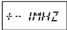
± 1 MHz, ± 2 MHz, ± 5 MHz: The scanner will sweep frequencies within the selected bandwidth.
ALL: The scanner will sweep all frequencies.
PMS-X: The scanner will sweep frequencies within the currently-selected PMS frequency pair. See page 52 for details.
Note: When an alpha-numeric "Tag" is appended to the Low sub-band limit memory channel, the alphanumeric "Tag" will appear while you are selecting the bandwidth for the VFO scanner.
BAND: The scanner will sweep frequencies only on the current band.
- Release the [BAND(SCN)BND DN] key to start scanning.
- If and when the scanner encounters a signal strong enough to open the squelch, the scanner will halt temporarily; the decimal point of the frequency display will blink during this "Pause" condition.
- The scanner will then resume according to the Scan-Resume mode selected in the previous section.
- To cancel scanning, press the PTT switch or [V/M(DW)MT] key.
※ : When an alpha-numeric “Tag” is appended to the Low sub-band limit memory channel, the alpha-numeric “Tag” will appear while you are selecting the bandwidth for the VFO scanner.

1) When you start the VFO Scanner, the VX-6R will be changing frequency in the upward direction. If you want to change direction of the scan while it is underway, rotate the DIAL knob one click in the opposite direction (in this
case, one click counter-clockwise). You'll see the scanner turn around and change frequency downward!
2) You may change the scanner's method of operation so that the VFO frequency will jump to the low band edge of the next band when the VFO frequency reaches the high edge of the current band (or vice versa). See page 102 regarding Set Mode Item 71: VFO MD.
VFO SCANNING
Setting the Squelch Level during active Scanning Operation
The VX-6R allows adjustment of the Squelch level "on the fly" while you are scanning.
- While the scanner is engaged, press the [F/W] key, then press the MONI key (the
current squelch level (e.g. "S 1") will appear in fine print above the frequency display).
- Rotate the DIAL to select the desired Squelch level.
- Press the PTT switch momentarily to save the new setting

and exit to normal operation. In this case, pressing the PTT switch this one time will not causing scanning to stop.
How to Skip (Omit) a Frequency during VFO Scan
If the VFO scan stops on a frequency or frequencies that you do not need (such as a spurious radiation from a television), such frequencies can be "skipped" during VFO scanning. This accomplished by storing these frequencies in a special "Frequency Skip Memory" bank reserved for this purpose.
To skip a frequency during VFO scanning:
- While VFO scanning is stopped ("pause" state) on the frequency that you do not need, press and hold in the [F/W] key for one second, then rotate the DIAL knob to select the desired Frequency Skip Memory channel (901 - 999). The microprocessor will automatically select the next-available "free" Frequency Skip Memory channel (a memory register on which no data has been stored). Any channel with a blinking channel number is one that currently has no data written on it (i.e. the channel is "free").
- Press the [F/W] key to store the frequency into the Frequency Skip Memory; it now is programmed to be ignored during VFO scanning.
The VX-6R has 99 VFO Frequency Skip Memory Channels.
To re-institute a frequency into the VFO scan loop:
- Press the [VIM(DW)MT] key, if needed, to enter the MR mode.
- Press and hold in the [F / W] key for one second, then rotate the DIAL knob to select the memory channel to be re-instituted.
- Press the [⊗(LK)TXPO] key to delete the channel from the Frequency Skip Memory; this will re-institute the frequency into the VFO scan loop.
MEMORY SCANNING
Memory scanning is similarly easy to initiate:
- Set the radio to the Memory mode by pressing the [V/M(DW)MT] key, if necessary.
- Press and hold in the [BAND(SCN)BND DN] key for one second, and rotate the DIAL knob while holding in the [BAND(SCN)BND DN] key to select the desired Memory Scan mode. Available selections are ALL CH, TAG1, TAG2, BAND, and PMS-X.
ALL CH: The scanner sweeps all Memory channels.
TAG1: The scanner sweeps only those Memory channels with the same "first" digit of the alpha/numeric tag as the first channel on which scanning started.
TAG2: The scanner sweeps only those Memory channels with the same "first" and "second" digits of the alpha/numeric tag as the first channel on which scanning started.
BAND: The scanner sweeps only those Memory channels which are memorized on the same operating band as the first channel on which scanning started.
PMS-X: The scanner will sweep frequencies within the currently-selected PMS frequency pair. See page 52 for details.
Note: When an alpha-numeric “Tag” is appended to the Low sub-band limit memory channel, the alpha-numeric “Tag” will appear while you are selecting the Memory Scan mode.
- Release the [BAND(SCN)BND DN] key to initiate scanning.
- As with VFO scanning, the scanner will halt on any signal encountered that is strong enough to open the squelch; it will then resume scanning according to the Scan-Re
sume mode set previously. When there are no memory channels corresponding to the selected Memory Scan mode, the "MS ERR" notation will appear on the display.

- To cancel scanning, press the PTT switch or the [V/M(DW)MT] key.
How to Skip (Omit) a Channel during Memory Scan Operation
If the scanner repeatedly stops on a memory channel due to temporary noise or interference, you can mark it to be skipped by pressing the [F/W] key, followed by the [5(SKIP)] key while the scanner has stopped on the channel to be skipped. The scanner will instantaneously resume, and that channel will not be scanned henceforth.
As mentioned previously, some continuous-carrier stations like a Weather Broadcast station will seriously impede scanner operation if you are using the "Carrier Drop" Scan-Resume mode, as the incoming signal will not pause long enough for the transceiver to resume scanning.
Here is the procedure for skipping certain memories during scanning:
- Recall the Memory Channel to be skipped during scanning.
- Press the [F/W] key, then press the [0(SET)] key to enter the Set mode.
MEMORY SCANNING
- Rotate the DIAL knob to select Set Mode Item 57:SKIP.
- Press the [0(SET)] key momentarily to enable adjustment of this Set Mode Item.
- Rotate the DIAL knob so as to select "SKIP." The current Memory Channel will now be ignored during scanning. The "ONLY" selection is used for "Preferential Memory Scan," described in the next section.
- When you have made your selection, press the PTT key to save the setting and exit to normal operation.
When you recall the "skipped" memory channel manually, a small "▶" icon will appear at the left of the memory channel number, indicating it is to be ignored during scanning. It is still available for recall manually, however, using the DIAL knob or keyboard.
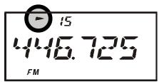
To re-institute a channel into the scanning loop, select "OFF" in step 5 above.
Preferential Memory Scan
The VX-6R also allows you to set up a "Preferential Scan List" of channels which you can "flag" within the memory system. These channels are designated by a blinking "▶" icon when you have selected them, one by one, for the Preferential Scan List.
Here is the procedure for setting up and using the Preferential Scan List:
- Recall the Memory Channel which you wish to add to the Preferential Scan List.
- Press the [F/W] key, then press the [0(SET)] key to enter the Set mode.
- Rotate the DIAL knob to select Set Mode Item 57:SKIP.
- Press the [0(SET)] key momentarily to enable adjustment of this Set Mode Item.
- Rotate the DIAL knob so as to select "ONLY."
- When you have made your selection, press the PTT key to save the settings and exit to normal operation.
- To remove a channel from the Preferential Scan List, just repeat the above procedure, rotating the DIAL knob to select “OFF” in step 5 above.

To initiate Preferential Memory Scan:
- Press the [V/M(DW)MT] key momentarily to enter the Memory Recall mode, if you are not using memories already.
- Rotate the DIAL to select any channel which has a blinking “▶” icon appended to the channel number.
- Press and hold in the [BAND(SCN)BND DN] key for one second, and rotate the DIAL knob while holding in the [BAND(SCN)BND DN] key to select the desired Memory Scan mode. Available selections are ALL CH, TAG1, TAG2, BAND, and PMS-X.
MEMORY SCANNING
ALL CH: The scanner sweeps all Preferential Memory channels.
TAG1: The scanner sweeps only those Preferential Memory channels with same "first" digit of the alpha/numeric tag as the first channel on which scanning started.
TAG2: The scanner sweeps only those Preferential Memory channels with same "first" and "second" digits of the alpha/numeric tag as the first channel on which scanning started.
BAND: The scanner sweeps only those Preferential Memory channels which are memorized on the same operating band as the first channel on which scanning started.
PMS-X: The scanner will sweep frequencies within the currently-selected PMS frequency pair. See page 52 for details.
Note: When an alpha-numeric “Tag” is appended to the Low sub-band limit memory channel, the alpha-numeric “Tag” will appear while you are selecting the Memory Scan mode.
- Release the [BAND(SCN)BND DN] key to initiate Preferential Memory Scanning. Only the channels which have a blinking “▶” icon appended to the channel number will be scanned.
Memory Bank Scan
When the Memory Bank feature is engaged, the scanner sweeps only memory channels in the current Memory Bank. However, if the Memory Bank Link Scan feature is enabled, you may sweep the memory channels in several Memory Banks which you have selected.
To enable the Memory Bank Link Scan feature:
- Set the radio to the Memory mode by pressing the [V/M(DW)MT] key, if necessary.
- Press the [F/W] key, followed by the [BAND(SCN)BND DN] key to recall the Memory Bank.
- Rotate the DIAL knob to select the first Memory Bank ("BANK 1" ~ "BANK24") you wish to sweep using Memory Bank Link Scan.
- Press the [V/M(DW)MT] key momentarily. A small blinking “▶” icon will appear at the left of the Memory Bank number, indicating this Memory Bank will now be swept during Memory Bank Scan.
- Repeat steps 3 and 4 above, to append the blinking “▶” icon to any other Memory Banks you wish to sweep.
- Now, press and hold in the [BAND(SCN)BND DN] key for one second to initiate the Memory Bank Link Scan.
- To remove a Memory Bank from the Memory Bank Link Scan, repeat steps 2 and 3 above, to delete the blinking “▶” icon from the Memory Bank number indication.
PROGRAMMABLE (BAND LIMIT) MEMORY SCAN (PMS)
This feature allows you to set sub-band limits for either scanning or manual VFO operation. For example, you might wish to set up a limit (in North America) of 144.300MHz to 148.000MHz so as to prevent encroachment into the SSB/CW "Weak Signal" portion of the band below 144.300MHz . Here's how to do this:
- Set the radio to the VFO mode by pressing the [V/M(DW)MT] key, if necessary.
- Using the techniques learned earlier, store (per the above concept) 144.300MHz into Memory Channel #L1 (the "L" designates the Lower sub-band limit).
- Likewise, store 148.000 MHz into Memory Channel #U1 (the "U" designates the Upper sub-band limit).
- Press and hold in the [BAND(SCN)BND DN] key for one second, and (while holding the [BAND(SCN)BND DN] key in) rotate the DIAL knob to select the desired PMS frequency pair (PMSxx), then release the [BAND(SCN)BND DN] key.
- Releasing the [BAND(SCN)BND DN] key to initiates the Programmable (Band Limit) Memory Scan; the Memory Channel number will be replaced by “Pxx.” Scanning and tuning will now just-programmed range.
- 50 pairs of Band Limit memories, labeled L1/U1 through L50/U50 are available. You therefore can set upper and lower operation limits in multiple segments on a number of bands, if you like.
- To exit from PMS operation, press the [V/M(DW)MT] key.


Please be sure only to store limit frequencies which are on the same band and set to the same frequency steps in both the upper and lower frequency limit memories.
"PRIORITY CHANNEL" SCANNING (DUAL WATCH)
The VX-6R's scanning features include a two-channel scanning capability which allows you to operate on a VFO or Memory channel, while periodically checking a user-defined Memory Channel for activity. If a station is received on the Memory Channel which is strong enough to open the Squelch, the scanner will pause on that station in accordance with the Scan-Resume mode set via Set Mode Item 49: RESUME. See page 46.
Here is the procedure for activating Priority Channel Dual Watch operation:
-
Press the [VIM(DW)MT] key momentarily to enter the Memory Recall mode, if you are not using memories already. If you are operating within a Memory Bank, you must exit from Memory Bank operation by pressing the [BAND(SCN)BND DN] key momentarily.
-
Press and hold in the [F / W] key for one second, then rotate the DIAL knob to select the memory channel you wish to be the "Priority" channel.
-
Press the [BAND(SCN)BND DN] key. The “PRI” icon will appear to the left side of the memory channel number, indicating it is the Priority channel while recalling the channel.
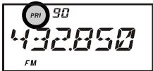
4 Now set the VX-6R for operation on another memory channel, Home channel, or on a VFO frequency.
5. Press and hold in the [V / M(DW)MT] key for one second. The display will remain on
the VFO or memory channel selected; however, the “DW” icon will appear on the display, and every five seconds the VX-6R will check the Priority Channel for activity. If a station appears
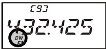
on the Priority Channel, the radio will pause on that channel, as described previously.
- To exit from Dual Watch, press the [V/M(DW)MT] key momentarily
AUTOMATIC LAMP ILLUMINATION ON SCAN STOP
The VX-6R will automatically illuminate the LCD/Keypad Lamp whenever the scanner stops on a signal; this allows you to see the frequency of the incoming signal better at night. Note that this will, of course, increase the battery consumption, so be sure to switch it off during the day (the default condition for this feature is "ON").
The procedure for disabling the Scan Lamp is:
- Press the [F/W] key, then press the [0(SET)] key to enter the Set mode.
- Rotate the DIAL knob to select Set Mode Item 55: SCN.LMP.
- Press the [0(SET)] key momentarily to enable adjustment of this Set Mode Item.
- Rotate the DIAL knob to set this Set Mode Item to "OFF."
- When you have made your selection, press the PTT key to save the setting and exit to normal operation.
BAND EDGE BEEPER
The VX-6R will automatically "beep" when a band edge is encountered during scanning (either in standard VFO scanning or during PMS operation). You may also enable this feature (band edge beeper) to sound the beeper when the frequency reaches the band edge while tuning using the DIAL knob.
The procedure for enabling the Band-Edge Beeper is:
- Press the [F/W] key, then press the [0(SET)] key to enter the Set mode.
- Rotate the DIAL knob to select Set Mode Item 25: EDG.BEP.
- Press the [F/W] key momentarily to enable adjustment of this Set Mode Item.
- Rotate the DIAL knob to set this Set Mode Item to "ON."
- When you have made your selection, press the PTT key to save the setting and exit to normal operation.


WEATHER ALERT SCAN
This feature allows you to check the Weather Broadcast Memory Channels for the presence of the NOAA Alert Tone while operating using VFO scan or Memory channel scan.
When the Weather Alert Scan feature is engaged, the VX-6R will check the Weather Broadcast Memory Channels for activity every five seconds while scanning. If you watch the display carefully, you'll observe the scanner periodically shifting to the Weather Broadcast bank, scanning the Weather channels quickly in search of the Alert Tone, after which regular scanning will resume for another five seconds.
To enable the Weather Alert Scan feature:
- Press the [F/W] key, then press the [0(SET)] key to enter the Set mode.
- Rotate the DIAL knob to select Set Mode Item 73: WX ALT.
- Press the [0(SET)] key momentarily to enable adjustment of this Set Mode Item.
- Rotate the DIAL knob so as to select "ON."
- When you have made your selection, press the PTT key to save the setting and exit to normal operation.
- To disable the Weather Alert Scan feature, select "OFF" in step 4 above.


1) When the Weather Alert Scan feature is engaged, the Scan-Resume mode is fixed to "TIME."
2) If you are just scanning the Weather Broadcast Channels, the VX-6R's receiver will remain muted indefinitely unless the Alert Tone is received. This yields a long period of monitoring time, as no power will be consumed via audio output while scanning for the Alert Tone is in progress.
The Smart Search feature allows you to load frequencies automatically according to where activity is encountered by your radio. When Smart Search is engaged, the transceiver will search above and below your current frequency, storing active frequencies as it goes (without stopping on them even momentarily); these frequencies are stored into a special Smart Search memory bank, consisting of 31 memories (15 above the current frequency, 15 below the current frequency, plus the current frequency itself).
Two basic operating modes for Smart Search are available:
SINGLE: In this mode, the transceiver will sweep the current band once in each direction starting on the current frequency. All channels where activity is present will be loaded into the Smart Search memories; whether or not all 31 memories are filled, the search will stop after one sweep in each direction.
CONT: In this mode, the transceiver will make one pass in each direction as with One-Shot searching; if all 31 channels are not filled after the first sweep, however, the radio will continue sweeping until they are all filled.
Setting the Smart Search Mode
- Press the [F/W] key, then press the [0(SET)] key to enter the Set mode.
- Rotate the DIAL knob to select Set Mode Item 54: S SRCH.
- Press the [0(SET)] key momentarily to enable adjustment of this Set Mode Item.
- Rotate the DIAL knob to select the desired Smart Search mode (see above).
- When you have made your selection, press the PTT switch to save the setting and exit to normal operation.


Storing Smart Search Memories
- Set the radio to the VFO mode. Be sure that you have the Squelch adjusted properly (so that band noise is quieted).
- Press and hold in the [MODE(SP S)SQ TYP] key for one second, and rotate the
DIAL knob while holding in the [MODE(SP S)SQ TYP] key to that “S SRCH” indication appears on the display: this activates the Smart Search feature.

- Press and hold in the [BAND(SCN)BND DN] key for one second to begin the Smart Search scanning.
- As active channels are detected, you will observe the number of "loaded" channels increasing in the regular memory channel window.
- Depending on the mode you set for Smart Search operation ("SINGLE" or "CONT"), the Smart Search scan will eventually terminate, and the LCD will revert to Smart Search Memory Channel "C."
- To recall the Smart Search memories, rotate the DIAL knob to choose from among the
frequencies stored by Smart Search.
- To return to normal operation, press the [MODE(SP S)SQ TYP] key.

Smart Search is a great tool when visiting a city for the first time. You don't need to spend hours looking up repeater frequencies from a reference guide-book. .just ask your VX-6R where the action is!
The Channel Counter allows measuring of the frequency of a nearby transmitter, without knowing that frequency in advance. The frequency can be measured by bringing the VX-6R close to the transceiver which is transmitting.
The VX-6R performs a high-speed search within a ± 5 MHz range from the frequency displayed on the LCD. When the strongest signal in that range is identified, the VX-6R displays the frequency of that (strongest) signal, and writes it into the special "Channel Counter" memory.
Note: This Channel Counter is designed to provide an indication of the operating frequency of the incoming signal, one that is close enough to allow the user, thereafter, to tune precisely to the other station's frequency. This feature is not, however, designed to provide a precise determination of the other station's frequency.
- Set the radio to the VFO mode in the predicted frequency range for the transmitter to be measured.
- Bring the VX-6R into close proximity to the transmitter to be measured.
- Press and hold in the [MODE(SP S)SQ TYP] key for one second, and rotate the
DIAL knob while holding in the [MODE(SP S)SQ TYP] key to that “CH CNT” indication appears on the display: this activates the Channel Counter feature.
- Release the [MODE(SP S)SQ TYP] key to begin the Channel Counter; the frequency of the nearby station will be displayed. When the channel counter is active, a 50 dB receiver front-end attenuator will be engaged. Therefore, only stations in close proximity may have their frequencies measured using this feature.
- If it isn't possible to determine the signal's frequency, the transceiver will return to the frequency on which you were operat Channel Counter operation.
- When you are finished, just press the [MODE(SP S)SQ TYP] key. The radio will exit from Channel Counter operation.


Setting the Channel Counter Sweep Width
You may change the bandwidth of the Channel Counter. Available selections are ± 5, ± 10, ± 50 , and ± 100 MHz (default: ± 5 MHz).
Here is the procedure for setting the Channel Counter Bandwidth:
- Press the [F/W] key, then press the [0(SET)] key to enter the Set mode.
- Rotate the DIAL knob to select Set Mode Item 12: CH CNT.
- Press the [F/W] key momentarily to enable adjustment of this Set Mode Item.
- Rotate the DIAL knob to select the desired bandwidth.
- When you have made your selection, press the PTT key to save the setting and exit to normal operation.

The VX-6R includes an Enhanced CTCSS tone encoder/decoder and a dedicated microprocessor providing paging and selective calling feature. This allows you to place a call to a specific station (Paging), and to receive calls of your choice directed only to you (Code Squelch).
The paging and code squelch systems use two pairs of (alternately switched) CTCSS tones which are stored in the pager memories. Basically, your receiver remains silent until it receives the CTCSS tone pair that matches those stored in the Receiving Pager Memory. The squelch then opens so the caller is heard, and the paging ringer immediately sounds, if activated. When you close the PTT switch to transmit, the CTCSS tone pair which is stored in the Transmitting Pager Memory will be transmitted automatically.
On the paged radio, the squelch will close automatically after the incoming page ends. Meanwhile, on the paging radio, the Enhanced Paging and Code Squelch system will be disabled after the PTT switch is released after the paging transmission. You may re-activate the Enhanced Paging and Code Squelch system again using Set Mode Item 43: PAGER, if desired.
Storing the CTCSS Tone Pairs for EPCS Operation
- Press the [F/W] key, then press the [0(SET)] key to enter the Set mode.
- Rotate the DIAL knob to select Set Mode Item 45: PAG.CDR for the Receiving CTCSS Tone Pair or Set Mode Item 46: PAG.CDT for the Transmitting CTCSS Tone Pair.
- Press the [0(SET)] key momentarily to enable adjustment of this Set Mode Item.
- Rotate the DIAL knob to set the CTCSS Tone number which corresponds to the first tone of the CTCSS Tone Pair.
- Press the [MODE(SP S)SQ TYP] key, then rotate the DIAL knob to set the CTCSS Tone number which corresponds to the second tone of the CTCSS Tone Pair.
- Press the PTT switch to save the new setting and exit to normal operation.


The V X - 6 R does not recognize the order of
the 1st tone and the 2nd tone. In other words, for example, the VX-6R considers both CTCSS pairs "10, 35" and "35, 10" to be identical.
CTCSS TONE NUMBER
| No. | Hz | No. | Hz | No. | Hz | No. | Hz | No. | Hz |
| 01 | 67.0 | 11 | 94.8 | 21 | 131.8 | 31 | 171.3 | 41 | 203.5 |
| 02 | 69.3 | 12 | 97.4 | 22 | 136.5 | 32 | 173.8 | 42 | 206.5 |
| 03 | 71.9 | 13 | 100.0 | 23 | 141.3 | 33 | 177.3 | 43 | 210.7 |
| 04 | 74.4 | 14 | 103.5 | 24 | 146.2 | 34 | 179.9 | 44 | 218.1 |
| 05 | 77.0 | 15 | 107.2 | 25 | 151.4 | 35 | 183.5 | 45 | 225.7 |
| 06 | 79.7 | 16 | 110.9 | 26 | 156.7 | 36 | 186.2 | 46 | 229.1 |
| 07 | 82.5 | 17 | 114.8 | 27 | 159.8 | 37 | 189.9 | 47 | 233.6 |
| 08 | 85.4 | 18 | 118.8 | 28 | 162.2 | 38 | 192.8 | 48 | 241.8 |
| 09 | 88.5 | 19 | 123.0 | 29 | 165.5 | 39 | 196.6 | 49 | 250.3 |
| 10 | 91.5 | 20 | 127.3 | 30 | 167.9 | 40 | 199.5 | 50 | 254.1 |
Activating the Enhanced Paging & Code Squelch System
- Press the [FW] key, then press the [0(SET)] key to enter the Set mode.
- Rotate the DIAL knob to select Set Mode Item 43: PAGER.
- Press the [0(SET)] key momentarily to enable adjustment of this Set Mode Item.
- Rotate the DIAL knob to select "ON."
- Press the PTT switch to save the new setting and activate the Enhanced Paging & Code Squelch.
- To disable the Enhanced Paging & Code Squelch, just repeat the above procedure, rotating the DIAL knob to select "OFF" in step 4 above.
When the Enhanced Paging & Code Squelch feature is activated, the "P" notation will appear at the 100MHz digit of the frequency display.


During Enhanced Paging & Code Squelch operation, you may set up the VX-6R such that a ringing "bell" sound alerts you to the fact that a call is coming in, as described previously. See page 30 for details.
Paging Answer Back
When you press the PTT switch to respond to a page call, the VX-6R transmits the same CTCSS tone pair. This tone pair will open the Code Squelch of the calling station. If you prefer, you can have the VX-6R respond to page calls automatically ("transpond").
To enable this feature:
- Press the [F/W] key, then press the [0(SET)] key to enter the Set mode.
- Rotate the DIAL knob to select Set Mode Item 44: PAG.ABK.
- Press the [0(SET)] key momentarily to enable adjustment of this Set Mode Item.
- Rotate the DIAL knob to select "ON."
- Press the PTT switch to save the new setting and exit to normal operation.


The Paging Answer Back feature constitutes a form of "remote control" operation that may be restricted to certain frequencies. U.S. users should confirm the current status of §97.201(b) of the FCC's rules governing the Ama
teur service before utilizing this feature on the 144 MHz band.
The VX-6R includes an "Emergency" feature which may be useful if you have someone monitoring on the same frequency as your transceiver's UHF "Home" channel. See page 39 for details on setting the Home channel.
The "Emergency" feature is activated by pressing and holding in the [HM/RV(EMG)R/H] key for one second. When this is done, (A) the radio is placed on the UHF amateur band Home channel, (B) it emits a loud "Alarm" sound (the volume is controlled by the VOL knob), (C) it flashes the TX/BUSY indicator in white, (D) if you press the PTT switch, you will disable the Emergency feature temporarily; you can then transmit on the UHF Home channel, and (E) two seconds after the PTT release, the Emergency feature will resume.
To disable the "Emergency" feature, pressing and holding in the [HM/RV(EMG)R/H] key for one second or turn the radio off by pressing the POWER switch.
Use this feature if you are out for a walk and want a quick way of alerting a family member as to a dangerous situation. The alarm sound may discourage an attacker and allow you to escape.

1) Be sure to arrange with a friend or family member to be monitoring on the same frequency, as there will be no identification sent via the Emergency alarm sound. And do not transmit the alarm tone except in a true emergency!
2) The "Emergency" feature may be changed to another function via Set Mode Item 26: EMG S; see page 95 for details.
EMERGENCY AUTOMATIC ID (EAI) FEATURE
The Emergency Automatic ID (EAI) feature can be used for searching for persons who are incapacitated in disasters like earthquakes, especially search-and-rescue personnel who may have become injured in a debris field. In such cases, if another searcher sends out a unique command (CTCSS tone pair), the radio of the incapacitated party, who may not be able to speak or even press the PTT switch, will automatically cause the injured party's radio to transmit, so others may perform direction-finding and effect a rescue. The callsign of the incapacitated person will also be transmitted, to assist the rescue team.
If an emergency group is working in a dangerous area, all members should engage the EAI feature on their transceiver, so that others can provide assistance to a fallen team member, if necessary.
The Emergency Automatic ID (EAI) Feature has two operating modes: (1) Interval mode and (2) Continuous mode.
In the Interval mode, when the VX-6R receives the CTCSS tone pair which is stored in the Receiving Pager Code Memory (configured via Set Mode Item 45: PAG.CDR) on the frequency which is stored in Memory Channel “EAI” for more than five seconds, the radio will automatically transmit a brief (0.5 second) beep tone every 2.5 seconds until the EAI
EMERGENCY AUTOMATIC ID (EAI) FEATURE
timer expiration at the power level stored in that memory channel; it is NOT necessary for the incapacitated person to press the PTT switch.
In the Continuous mode, when the VX-6R receives the CTCSS tone pair which is stored in the Receiving Pager Code Memory (configured via Set Mode Item 45: PAG.CDR) on the frequency which is stored in Memory Channel "EAI" for more than five seconds, the radio will automatically transmit (with maximum microphone gain) continuously, until the EAI timer expiration, at the power level stored in that memory channel; it is NOT necessary for the incapacitated person to press the PTT switch.
Furthermore, if your call sign is stored in the radio and enabling the CW identifier via Set Mode Item 14: CW ID, the radio will transmit your callsign on the air when the EAI feature is first engaged by the remote page, and every 10 minutes thereafter. The "callsign" ID can be changed to any desired sequence of characters, such as a name. After sending the callsign or name, the radio will repeatedly transmit three tones for a user-defined period of time (between 1 and 30 minutes). The callsign or name will be transmitted every 10 minutes.
The Emergency Automatic ID (EAI) Feature requires that you (1) store the CTCSS Tone Pair into the Receiving Pager Memory (see page 60 for procedure), and (2) store the desired UHF coordination frequency into Memory Channel "EAI" (see page 34 for procedure).
Selecting the EAI mode and its Transmit Time
- Press the [F/W] key, then press the [0(SET)] key to enter the Set mode.
- Rotate the DIAL knob to select Set Mode Item 24: EAI.TMR.
- Press the [0(SET)] key momentarily to enable adjustment of this Set Mode Item.
- Rotate the DIAL knob to select the desired EAI mode (Interval EAI “INT” or Continuous EAI “CON”) and its transmit time (1-10, 15, 20, 30, 40, and 50 minutes).
- Press the PTT switch to save the new setting and exit to normal operation.
Activating the EAI feature
- Press the [F/W] key, then press the [0(SET)] key to enter the Set mode.
- Rotate the DIAL knob to select Set Mode Item 23: EAI.
- Press the [0(SET)] key momentarily to enable adjustment of this Set Mode Item.
- Rotate the DIAL knob to select “ON” (thus activating the EAI feature).
- Press the PTT switch to save the new setting and exit from the
EMERGENCY AUTOMATIC ID (EAI) FEATURE
Set mode. When the EAI feature is activated, the "..." icon will appear at the bottom right on the LCD.

- To disable the EAI feature, just repeat above procedure, rotating the DIAL knob to select “OFF” in step “4” above.

1) Do not activate the EAI feature by pressing the [F / W] key, followed by the [8(EAI)] key. This key function is used to locate an unresponsive operator, described in the next chapter.
2) The VX-6R will ignore the EAI feature when the (1) the squelch is open, (2) there is an incoming the signal on the operating frequency, (3) the operating frequency is the same as the frequency which is stored in the Memory Channel "EAI," or (4) a VHF frequency is stored in Memory Channel "EAI."
To Locate an Unresponsive Operator Using the EAI feature
- Press the [F/W] key, then press the [8(EAI)] key to recall Memory Channel "EAI" (of the searched person's radio).
- Press the [F/W] key, then press the [2(CODE)] key to enable adjustment of the Transmitting Pager Memory. Set the CTCSS tone pair which is the same CTCSS tone pair stored in the Receiving Pager Code Memory of the missing person's radio.

A. Rotate the DIAL knob to select the first tone.
B. Press the [BAND(SCN)BND DN] key.
C. Rotate the DIAL knob to select the second tone.
D. Press the PTT switch to save the new setting and exit from setting mode.
- Press and hold in the PTT switch for five seconds to find out the persons who are activating the EAI feature. The lost operator's radio will beep loudly, and its transmitter will respond repetitively. You may now begin direction-finding efforts.
- You may select the ATT (Front End Attenuator) level among “ATT 1 (10 dB),” “ATT 2 (50 dB),” and “ATT OFF” by pressing the [BAND(SCN)BND DN] key to reduce the signal. The ATT is often useful in helping you locate the missing person's radio, as peaks in weaker signals are more easily observed).
- Press the [F/W] key, then press the [8(EAI)] key, to exit to normal operation.
The ARTSTM feature uses DCS signaling to inform both parties when you and another ARTSTM-equipped station are within communications range. This may be particularly useful during Search-and Rescue situations, where is important to stay in contact with other members of your group.
Both stations must set up their DCS codes to the same code number, then activate their ARTSTM feature using the command appropriate for their radio. Alert ringers may be activated, if desired.
Whenever you push the PTT, or every 25 (or 15) seconds after ARTSTM is activated, your radio will transmit a signal which includes a (subaudible) DCS signal for about 1 second. If the other radio is in range, the beeper will sound (if enabled) and the display will show "IN RNG" as opposed to the out of range display "OUTRNG" in which ARTSTM operation begins.
Whether you talk or not, the polling every 15 or 25 seconds will continue until you de-activate ARTSTM. Every 10 minutes, moreover, you can have your radio transmit your callsign via CW, so as to comply with identification requirements. When ARTSTM is de-activated, DCS will also be deactivated (if you were not using it previously in non-ARTSTM operation).


If you move out of range for more than one minute (four pollings), your radio will sense that no signal has been received, three beeps will sound, and the display will revert to "OUTRNG." If you move back into range, your radio will again beep, and the display will change back to the "IN RNG" indication.
During ARTSTM operation, it is not possible to change the operating frequency or other settings; you must terminate ARTSTM in order to resume normal operation. This is a safety feature designed to prevent accidental loss of contact due to channel change, etc.
Basic ARTS™ Setup and Operation
- Set your radio and the other radio(s) to the same DCS code number, per the discussion on page ??
- Press the [F/W] key, then press the [4(ARTS)] key. You will observe the “OUTRNG” display on the LCD below the operating frequency. ARTSTM operation has now commenced.
- Every 25 seconds, your radio will transmit a "polling" call to the other station. When
that station responds with its own ARTSTM polling signal, the display will change to "IN RNG" to confirm that the other station's polling code was received in response to yours.

- Press the [F/W] key momentarily to exit ARTSTM operation and resume normal functioning of the transceiver.

ARTS™ constitutes a form of “remote control” operation that may be restricted to certain frequencies. U.S. users should confirm the current status of §97.201(b) of the FCC's rules governing the Amateur service before utilizing
ing this feature on the 144 MHz band.
ARTSTM Polling Time Options
The ARTSTM feature may be programmed to poll every 25 seconds (default value) or 15 seconds. The default value provides maximum battery conservation, because the polling signal is sent out less frequently. To change the polling interval:
- Press the [F/W] key, then press the [0(SET)] key to enter the Set mode.
- Rotate the DIAL knob to select Set Mode Item 3: AR INT.
- Press the [0(SET)] key momentarily to enable adjustment of this Set Mode Item.
- Rotate the DIAL knob to select the desired polling interval (15 or 25 seconds).
- When you have made your selection, press the PTT switch to save the new setting and exit to normal operation.


ARTSTM Alert Beep Options
The ARTSTM feature allows two kinds of alert beeps (with the additional option of turning them off), so as to alert you to the current status of ARTSTM operation. Depending on your location and the potential annoyance associated with frequent beeps, you may choose the Beep mode which best suits your needs. The choices are:
INRANG: The beeps are issued only when the radio first confirms that you are within range, but does not re-confirmed with beeps thereafter.
ALWAYS: Every time a polling transmission is received from the other station, the alert beeps will be heard.
OFF: No alert beeps will be heard; you must look at the display to confirm current ARTSTM status.
To set the ARTS™ Beep mode, use the following procedure:
- Press the [F/W] key, then press the [0(SET)] key to enter the Set mode.
- Rotate the DIAL knob to select Set Mode Item 2: AR BEP.
- Press the [0(SET)] key momentarily to enable adjustment of this Set Mode Item.
- Rotate the DIAL knob to select the desired ARTSTM Beep mode (see above).
- When you have made your selection, press the PTT switch to save the new setting and exit to normal operation.


CW Identifier Setup
The ARTSTM feature includes a CW identifier, as discussed previously. Every ten minutes during ARTSTM operation, the radio can be instructed to send "DE (your callsign) K" if this feature is enabled. The callsign field may contain up to 6 characters.
Here's how to program the CW Identifier:
- Press the [F/W] key, then press the [0(SET)] key to enter the Set mode.
- Rotate the DIAL knob to select Set Mode Item 14: CW ID.
- Press the [0(SET)] key momentarily to enable adjustment of this Set Mode Item.
- Rotate the DIAL knob to set this Item to "ON" (to enable the CW ID function).
- Press the [MODE(SP S)SQ TYP] key momentarily to display the previously stored callsign.
- Press and hold in the [HM/RV(EMG)R/H] key for 2 seconds to clear any previous callsign.
- Rotate the DIAL knob to select the first letter/number of your callsign, then press the [MODE(SP S)SQ TYP] key momentarily to save the first letter/number and move on to the next character.
- Repeat the previous step, as many times as necessary, to complete your callsign. Note that the "slant bar" (- - ) is among the available characters, should you be a "portable" station.
- If you mistake, press the [BAND(SCN)BND DN] key to back-space the cursor, then re-enter the correct letter/number.
- Press and hold in the [HM/RV(EMG)R/H] key for 2 seconds to delete all data after the cursor that may have been previously stored erroneously.
- When you have entered your entire callsign, press the [0(SET)] key momentarily to confirm the callsign, then press the PTT key to save the settings and exit to normal operation.

You may check your work by monitoring the entered callsign. To do this, repeat steps 1-7 above, then press the [F / W] key.
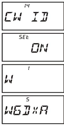
The VX-6R can display the radio's inside-the-case temperature, measured by internal sensors. Also, when the optional Barometric Pressure unit (SU-1) is installed, you get the unique capability of providing readout of the current barometric pressure. This information is then used for calculation of your current altitude.
The Barometric Pressure unit requires calibration of the "offset" parameters, so that differences in pressure can be used to calculate altitude. This procedure requires that you have a calculated barometer, and that you know your current altitude. If you are at sea level, of course, the latter parameter requires no research.
To display the Temperature
- Press the [F/W] key, then press the [0(SET)] key to enter the Set mode.
- Rotate the DIAL knob to select Set Mode Item 65: TEMP.
- Press the [0(SET)] key momentarily to indicate the current temperature inside the transceiver's case.
- Press the [MODE(SP S)SQ TYP] key to select the preferred unit (F (°F) or C (°C)).
- Press the PTT switch to exit to normal operation.


To display the Sensor Information
- Press the [F/W] key, then press the [0(SET)] key to enter the Set mode.
- Rotate the DIAL knob to select Set Mode Item 64: SU1.SET.
- Press the [0(SET)] key momentarily to enable adjustment of this Set Mode Item.
- Rotate the DIAL knob to select the sensor mode you wish to display.
BARO: Indicates the Barometric Pressure on the frequency area and relative changes in pressure on the S-meter area (requires optional SU-1). After 10 minutes, if the barometric pressure rises, the “8” and “9” segments of the S-meter will blink. If the pressure goes down, the “4” and “5” segments of the S-meter will blink.
ALTI: Indicates the Altitude (requires optional SU-1).
OFF: Disables display of the sensor information.
- Press the PTT switch to save the new setting and display the sensor information five seconds after releasing the PTT switch.
- When you operate the radio, the display will change to show the frequency information, then resume the display of the sensor information after five seconds.
- To disable the display of sensor information, repeat the above procedure, rotating the DIAL knob to select "OFF" in step 4 above.


Selecting and Correcting the Atmospheric Pressure Meter
- Press the [F/W] key, then press the [0(SET)] key to enter the Set mode.
- Rotate the DIAL knob to select Set Mode Item 63: SU1.BRM.
- Press the [0(SET)] key momentarily to enable adjustment of this Set Mode Item.
- Press the [MODE(SP S)SQ TYP] key to select the preferred units of measure (HP (hpa), MB (mbar), HG (mmHg), or IC (inches of Mercury)).
- Press the [F/W] key momentarily to enable correction of the Atmospheric Pressure Meter.
- Rotate the DIAL knob to adjust the VX-6R display to the reading on your calibrated barometer.
- Press the PTT switch to save the new setting and exit to normal operation.
Selecting and Correcting the Altimeter
- Press the [F/W] key, then press the [0(SET)] key to enter the Set mode.
- Rotate the DIAL knob to select Set Mode Item 62: SU1.ALT.
- Press the [0(SET)] key momentarily to enable adjustment of this Set Mode Item.
- Press the [MODE(SP S)SQ TYP] key to select the preferred units (M, or Ft).
- Press the [F/W] key momentarily to enable correction of the Altimeter.
- Rotate the DIAL knob to adjust the VX-6R display to the true altitude at your current location.
- Press the PTT switch to save the new setting and exit to normal operation.
The Barometer and Altimeter will only track correctly in the short term. That is, if you calibrate the Barometer and altitude at the beginning of a day hike, the altitude will be correctly measured during your hike. But if the radio is not used for several weeks, you will need to check the altitude correction again, because pressure changes associated with changing weather may be mis-interpreted as a change in altitude.
The VX-6R can be used to access a "node" (repeater or base station) which is tied into the Vertex Standard WIRES™ (Wide-Coverage Internet Repeater Enhancement System) network. Details may be found at the WIRES-II Web site: http://www.vxstd.com/en/wiresinfoen/. This feature may also be used to access other systems, as described below.
SRG ("SISTER RADIO GROUP") MODE
- Press the [⊗(LK)TXPO] key momentarily to activate the Internet Connection feature. The “⊗” icon will appear in the upper right corner of the display.
- Rotate the DIAL knob while pressing the [O(SET)] key to select the access number (DTMF “O” ~ “9,” “A,” “B,” “C,” “D,” “E (*),” “F (#),”) corresponding to the WIREF™ node to which you wish to establish an Internet link (ask the node or re
peater owner/operator if you don't know the access number in the network). Now press the PTT switch to exit from the selection mode.

- With the Internet Connection feature activated (as in step 1 above), the VX-6R will generate a brief (0.1 second) DTMF tone according to your selection in step 2. This DTMF tone is sent at the beginning of every transmission to establish or maintain the link to the local WIRES™ node operating in the SRG mode.
- To disable the Internet Connection feature, press the [⊗(LK)TXPO] key momentarily (the “⊗” icon will disappear from the display).

If other users report that you always have a DTMF "beep" at the beginning of each transmission, and you are not operating in conjunction with Internet access, disable this function via step (4) above.
FRG ("FRIENDLY RADIO GROUP") MODE
You may access other Internet Link Systems (including WIRES™ in the "FRG" mode) that use a DTMF string for access.
Programming the FRG code
- Load the DTMF tones which you wish to use for Internet-link access into a Internet Memory register. For purposes of this example, we will use "#(F)1101D" as the access code (the "#" key is denoted by the letter "F").
2 Press the [F/W] key, then press the [0(SET)] key to enter the Set mode.
3 Rotate the DIAL knob to select Set Mode Item 32: INT.SET.
4 Press the [0(SET)] key to enable adjustment of this Set Mode Item. - Rotate the DIAL knob to select the Internet Memory register (F ~ F63) into which you wish to store the access code.
- Press the [MODE(SP S)SQ TYP] key momentarily. The first digit will blink.
- Rotate the DIAL knob to select “F” (representing DTMF “#”: the first digit of the DTMF string).
- Press the [MODE(SP S)SQ TYP] key momentarily to accept the first digit and move to the second digit of the DTMF string.
- Repeat the previous steps until you have completed the access code ("#(F)1101D").
- If you attach an alpha/numeric name “Tag” to the Internet Memory, proceed to the next step; otherwise press and hold in the [O(SET)] key for one second to save the setting.
- Press the [V/M(DW)MT] key momentarily to enable programming of the name tag.
- Rotate the DIAL knob to select the first digit of the desired label.
- Press the [MODE(SP S)SQ TYP] key to move to the next character.
- If you make a mistake, press the [BAND(SCN)BND DN] key to back-space the cursor, then re-enter the correct letter, number, or symbol.
- Repeat steps 12 through 14 to program the remaining letters, numbers, or symbols of the desired label. A total of six characters may be used in the creation of a label.
- When you have programmed a label which is under 6 characters, press the [0(SET)] key to confirm the label.
- Repeat steps 1 through 16 to store other access codes, if so desired.
- Press the PTT switch to save the setting and exit to normal operation.
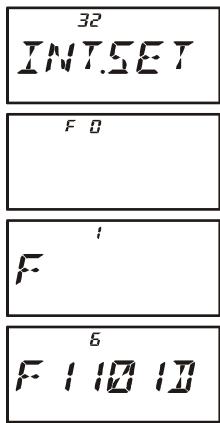
FRG ("FRIENDLY RADIO GROUP") MODE
Operation (Accessing an FRG Node)
- Press the [F / W] key, then press the [0(SET)] key to enter the Set mode.
- Rotate the DIAL knob to select Set Mode Item 30: INT MD.
- Press the [0(SET)] key to enable adjustment of this Set Mode Item.
- Rotate the DIAL knob to set this Set Mode Item to "FRG" (thus activating the "Other Internet Link System" mode).
- Press the PTT switch to save the new settings.
- Press the [(LK)TXPO] key momentarily to activate the Internet Connection feature. The “ ” icon will appear in the upper right corner of the display.
- Rotate the DIAL knob while pressing the [O(SET)] key to select the Internet Memory
register number (F 0 ~ F63) corresponding to the Internet link repeater to which you wish to establish an Internet link, then press the PTT switch momentarily to lock in the selected access number.
- Once the Internet Connection feature is activated per step 7 above, you may now press
the [0(SET)] key, while you are transmitting, to send out the selected DTMF string (to establish the link to the desired Internet-link mode).
- To return to the WIRES™ mode, repeat steps 1 - 5 above, selecting "SRG" in step 4.
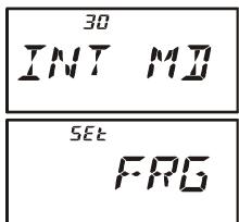


The VX-6R's 16-button keypad allows easy DTMF dialing for Autopatch, repeater control, or Internet-link access purposes. Besides numerical digits [0] through [9], the keypad includes the [] and [#] digits, plus the [A], [B], [C], and [D] tones often used for repeater control.
Manual DTMF Tone Generation
You can generate DTMF tones during transmission manually.
- Press the [F/W] key, followed by the the [3(DTMF)] key, then rotate the DIAL knob to
select "MANUAL." - Press the [3(DTMF)] key to save the new setting and exit to normal operation.
MANUAL - Press the PTT switch to begin transmission.
- While transmitting, press the desired numbers on the keypad.
- When you have sent all the digits desired, release the PTT switch.
DTMF Autodialer
Nine DTMF Autodial memories are provided, allowing you to store telephone numbers for autopatch use. You can also store short autopatch or Internet-link access code streams so as to avoid having to send them manually.
Here is the DTMF Autodial storage procedure:
- Press the [F/W] key, then press the [0(SET)] key to enter the Set mode.
- Rotate the DIAL knob to select Set Mode Item 22: DT SET.
- Press the [0(SET)] key momentarily to enable adjustment of this Set Mode Item.
- Rotate the DIAL knob to select the DTMF Memory register into which you wish to store this DTMF string.
- Press the [MODE(SP S)SQ TYP] key momentarily to begin DTMF Memory entry into the selected register.
- Rotate the DIAL knob to select the first digit of the DTMF string. Selectable entries are 0 - 9, and A - F, with E and F representing DTMF “*” and “#” tones respectively.
- Press the [MODE(SP S)SQ TYP] key to accept the first digit and move to the next digit of the DTMF string.
- Repeat steps 5 and 6 until you have completed the telephone number.
- If you make a mistake, press the [BAND(SCN)BND DN] key to move back to the previous digit, then re-select the correct numb
- Press and hold in the [HM/RV(EMG)R/H] key for 2 seconds to delete all data after the cursor that may have been previously stored erroneously.
-
Press the [0(SET)] key momentarily to save the setting.
-
If you store other numbers, repeat steps 3- 11 above, using a different DTMF memory register.
- When all required DTMF memories are filled to your satisfaction, press the PTT switch to save the settings and exit to normal operation

You may check your work by monitoring the entered DTMF string. To do this, repeat steps 1-4 above, then press the [F / W] key.
To send the telephone number:

- Press the [F/W] key, followed by the the [3(DTMF)] key, then rotate the DIAL knob to select “AUTO.”
- Press the [3(DTMF)] key to save the new setting and exit to normal operation.
- While the DTMF Autodialer is activated, first press the PTT switch, then press the numerical key ([1] through [9]) corresponding to the DTMF memory string you wish to send. Once the string begins, you may release the PTT switch, as the transmitter will be held "on the air" until the DTMF string is completed.
- To disable the DTMF Autodialer, press the [F/W] key, followed by the the [3(DTMF)] key, then rotate the DIAL knob to select "MANUAL."
The VX-6R provides a CW Training feature, which sends random Morse Code via the sidetone (heard in the speaker), so you can improve your CW proficiency.
- Press the [F/W] key, then press the [0(SET)] key to enter the Set mode.
- Rotate the DIAL knob to select Set Mode Item 15: CWTRNG.
- Press the [0(SET)] key momentarily to enable adjustment of this Set Mode Item.
- Press the [MODE(SP S)SQ TYP] key to select the Trainig mode (displayed in fine print at the upper edge of the LCD):
A: Sends five Alphabet characters only
A_r: Sends Alphabet characters only (Repeatedly)
n: Sends five Numeric characters only
n_r: Sends Numeric characters only (Repeatedly)
An: Sends five Alphabet, Numeric, “?,” and “/” characters (Mixed)
Anr: Send Alphabet, Numeric, “?,” and “/” characters (Mixed, Continuously in group of five)
Trainig mode Morse Speed

TX/BUSY Indicator Status
- Rotate the DIAL knob to select the Morse speed. You may select the units of the code speed between “WPM (Words per minute)” and “CPM: characters per minute”) by pressing the [V/M(DW)MT] key.
- Press the [BAND(SCN)BND DN] key to switch the flashing of the LED (white) on and off; a “dot” by the CW speed indicates that the LED is on.
- Press the [F/W] key to bigin generation of the code characters (CW sidetone only, the radio does not transmit); the transmitted characters will appear on the display. If one of the "r" modes is not selected in step 4 above, press the [F/W] key to send another code group.
- To disable the CW Training feature, press the [O(SET)] key momentarily.
- Press the PTT switch to exit to normal operation.

The "CPM" selection is based on the international "PARIS" standard, which stipulates five characters per word.
Password
The VX-6R provides a password feature which can minimize the chance that your transceiver could be used by an unauthorized party.
When the password feature is activated, the radio will ask for the four digit password to be
entered when the radio is first turned on. You must enter the four digit password from the keypad. If the wrong password is entered, the microprocessor will shut down the radio automatically.
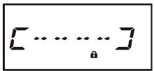
To enter the password and activating this feature, use the following procedure:
- Press the [F/W] key, then press the [0(SET)] key to enter the Set mode.
- Rotate the DIAL knob to select Set Mode Item 47: PSWD.
- Press the [0(SET)] key momentarily to enable adjustment of this Set Mode Item.
- Press the [MODE(SP S)SQ TYP] key momentarily to display any previously-stored password.
- Rotate the DIAL knob to select the first digit of the desired number/letter (O-9, A, B, C, D, E (substitute for “*”), and F (substitute for “#”).
- Press the [MODE(SP S)SQ TYP] key to move to the next digit.
- Repeat steps 5 and 6 to program the remaining numbers/letters of the desired password.
- If you make a mistake, press the [BAND(SCN)BND DN] key to move back to the previous digit, then re-select the correct number/letter.
- When you have finished entering the password, press the PTT switch to save the new setting and exit to normal operation.
- If you wish to disable the Password feature, repeat steps 1 - 4 above, rotating the DIAL knob to select “OFF” in step 4 above, then press the PTT switch.


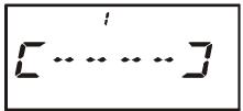
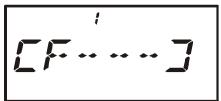
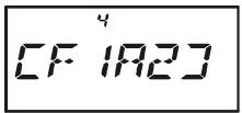

1) We recommend that you to write down the password number, and keep it in a safe place you can easily find if you forget your password.
2) If you forget the password number, you may turn on the transceiver by performing the "Microprocessor Resetting" procedure (see page 85). However, the VX-6R will clear the password, as well as all memories, and will restore all other settings to factory defaults.
PROGRAMMING THE "P" KEY
The VX-6R can assign, using the Set Mode, a user-selected Menu Item to the "primary" function of the [P(DMR)] key.
To assign a preferred Set Mode Item to the [P(DMR)] key:
- Press the [F/W] key, then press the [0(SET)] key to enter the Set mode.
- Rotate the DIAL knob to select the Set Mode Item which you wish to assign to the key as a Menu short-cut.
- Press and hold in the [P(DMR)] key for one second to assign the Set Mode Item to the [P(DMR)] key.
- Now you can recall this preferred Set Mode Item by simply pressing the [P(DMR)] key momentarily.
RECEIVE BATTERY SAVER SETUP
An important feature of the VX-6R is its Receive Battery Saver, which “puts the radio to sleep” for a time interval, periodically “waking it up” to check for activity. If somebody is talking on the channel, the VX-6R will remain in the “active” mode, then resume its “sleep” cycles. This feature significantly reduces quiescent battery drain, and you may change the amount of “sleep” time between activity checks using the Set Mode:
- Press the [F/W] key, then press the [0(SET)] key to enter the Set mode.
- Rotate the DIAL knob to select Set Mode Item 53: RXSAVE.
- Press the [0(SET)] key momentarily to enable adjustment of this Set Mode Item.
- Rotate the DIAL knob to select the desired "sleep" duration. The available selections are 200 ms, 300 ms, 500 ms, 1 second, 2 seconds, or OFF. The default value is 200 ms.
- When you have made your selection, press the PTT switch to save the new setting and exit to normal operation.
SAVE
SET

When you are operating on Packet, switch the Receive Battery Saver OFF, as the sleep cycle may "collide" with the beginning of an incoming Packet transmission, causing your TNC not to receive the full data burst.
WAKEUP FEATURE SETUP
The Wakeup feature is similarly to the Receive Battery Saver. However, it is a newer, more advanced feature which conserves battery life by providing a longer "sleep" time than the regular Receive battery Saver. The Wakeup feature, once engaged, operates while the transceiver is turned off ("WAKEUP" will appear on the LCD).
To set up the Wakeup feature:
- Press the [F/W] key, then press the [0(SET)] key to enter the Set mode.
- Rotate the DIAL knob to select Set Mode Item 72: WAKEUP.
- Press the [0(SET)] key momentarily to enable adjustment of this Set Mode Item.
- Rotate the DIAL knob to select the desired “sleep” duration. 5SEC/10SEC/20SEC/30SEC:
Based on the selected time value, the radio will periodically check

5Et

the operating frequency which it was on when the radio was turned off for activity. If a signal is received on the frequency which is strong enough to open the Squelch, the radio will turn itself on fully. If the EAI feature is activated when the radio was turned off, the radio also checks on the EAI frequency (Memory Channel "EAI") for activity. EAI:
Checks the EAI frequency (Memory Channel "EAl") every 5 seconds. If a properly-coded signal is received on the EAI frequency, the radio will turn itself on and then automatically transmit in accordance with the setting of Set Mode Item 18: EAl.
OFF:
Disables the Wakeup feature.
- When you have made your selection, press the PTT switch to save the new setting and exit to normal operation.
- If you wish to disable the Wakeup feature, just repeat the above procedure, rotating the DIAL knob to select "OFF" in step 4 above.
When the radio is turned off, the Wakeup feature will be engaged, and the "WAKEUP"notition will be been on the display.

You may observe a low-level "pop" noise while the Wakeup feature is polling; you may disable this popping by pressing the [MODE(SP S)SQ TYP] key in step 4 above (the "SAVE" notation will disappear). However, the battery life will be reduced somewhat.

You may cancel the Wakeup feature temporarily by pressing the PWR switch while the Wakeup feature is engaged.
TX BATTERY Saver
The VX-6R also includes a useful Transmit Battery Saver, which will automatically lower the power output level when the last signal received was very strong. For example, when you are in the immediate vicinity of a repeater station, there generally is no reason to use the High Power output selection in order to achieve full-quieting access to the repeater. With the Transmit Battery Saver, the automatic selection of Low Power operation conserves battery drain significantly.
To activate the Transmit Battery Saver:
- Press the [F/W] key, then press the [0(SET)] key to enter the Set mode.
- Rotate the DIAL knob to select Set Mode Item 70: TXSAVE.
- Press the [0(SET)] key momentarily to enable adjustment of this Set Mode Item.
- Rotate the DIAL knob to set this Set Mode Item to "ON" (thus activating the Transmit Battery Saver).
- When you have made your selection, press the PTT switch to save the new setting and exit to normal operation.

SE
ATT (FRONT END ATTENUATOR)
The attenuator will reduce all signals (and noise) by 10 dB, and it may be used to make reception more pleasant under extremely crowded conditions.
- Press the [F/W] key, then press the [0(SET)] key to enter the Set mode.
- Rotate the DIAL knob to select Set Mode Item 5: ATT.
- Press the [0(SET)] key momentarily to enable adjustment of this Set Mode Item.
- Rotate the DIAL knob to set this Set Mode Item to “ON” (thus activating the attenuator).
- When you have made your selection, press the PTT switch to save the new setting and exit to normal operation.
- If you wish to disable the attenuator, just repeat the above procedure, rotating the DIAL knob to select “OFF” in step “4” above.

When the attenuator is activated, the Operating Mode icon (AM, FM, or WFM) will blink on the display.
DISABLING THE TX/BUSY INDICATOR
Further battery conservation may be accomplished by disabling the BUSY indicator which appears while the VX-6R is receiving a signal. Use the following procedure:
- Press the [F/W] key, then press the [0(SET)] key to enter the Set mode.
- Rotate the DIAL knob to select Set Mode Item 11: BSY.LED.
- Press the [0(SET)] key momentarily to enable adjustment of this Set Mode Item.
- Rotate the DIAL knob to set this Set Mode Item to “OFF” (thus disabling the BUSY indicator).
- When you have made your selection, press the PTT switch to save the new setting and exit to normal operation.
- If you wish to re-enable the BUSY Indicator, just repeat the above procedure, rotating the DIAL knob to select "ON" in step 4 above.
1
B5yLED
SEt
DFF
AUTOMATIC POWER-OFF (APO) FEATURE
The APO feature helps conserve battery life by automatically turning the radio off after a user-defined period of time within which there has been no dial or key activity. The available selections for the time before power-off are 0.5 / 1 / 3 / 5 / 8 hours, as well as APO Off. The default condition for the APO is OFF, and here is the procedure for activating it:
- Press the [F/W] key, then press the [0(SET)] key to enter the Set mode.
- Rotate the DIAL knob to select Set Mode Item 1: APO.
- Press the [0(SET)] key momentarily to enable adjustment of this Set Mode Item.
- Rotate the DIAL knob to select the desired time period after which the radio will automatically shut down.
- When you have made your selection, press the PTT switch to save the new setting and exit to normal operation.

SEt
IHOUR
When the APO is activated, the “O” icon will appear at the upper right corner on the LCD. If there is no action by you within the time interval programmed, the microprocessor will shut down the radio automatically.
[9]
445622
Press and hold in the PWR switch for one second, to turn the radio back on after an APO shutdown, as usual.
AUTOMATIC POWER-ON FEATURE
The VX-6R also includes the capability to turn itself on after a programmed time interval.
- Press the [F/W] key, then press the [0(SET)] key to enter the Set mode.
- Rotate the DIAL knob to select Set Mode Item 41: ON TMR.
- Press the [0(SET)] key momentarily to enable adjustment of this Set Mode Item.
- Rotate the DIAL knob to set the desired time priod after which the radio will automatically turn on.
Note that this is not the time of day when the radio will turn on; it is the numbaer of hours and minutes until the radio turns on.
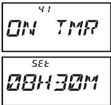
- When you have made your selection, press the PTT switch to save the new setting and exit to normal operation.
When the radio is turned off, this activates the Automatic Power-On feature; a count-down timer in the display will show the time remaining until automatic switch-on.

You may cancel the Automatic Power-On feature (to turn off the radio) by pressing and holding the PWR switch for one second while the Automatic Power-On feature is engaged.

The Automatic Power-On feature will be ignored when the Wakeup feature is activated.
BUSY CHANNEL LOCK-OUT (BCLO)
The BCLO feature prevents the radio's transmitter from being activated if a signal strong enough to break through the "noise" squelch is present. On a frequency where stations using different CTCSS or DCS codes may be active, BCLO prevents you from disrupting their communications accidentally (because your radio may be muted by its own Tone Decoder). The default setting for the BCLO is OFF, and here is how to change that setting:
- Press the [F/W] key, then press the [0(SET)] key to enter the Set mode.
- Rotate the DIAL knob to select Set Mode Item 6: BCLO.
- Press the [0(SET)] key momentarily to enable adjustment of this Set Mode Item.
- Rotate the DIAL knob to set this Set Mode Item to “ON” (thus activating the BCLO feature).
- When you have made your selection, press the PTT switch to save the new setting and exit to normal operation.
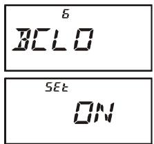

Remember that BCLO is controlled by the Noise Squelch; if you have DCS or TSQ engaged, BCLO will inhibit transmission if a station is on frequency but not transmitting the proper tone; BCLO will thus prevent you from interfer-
ing with the other station's transmission.
TRANSMITTER TIME-OUT TIMER (TOT)
The TOT feature provides a safety switch which limits transmission time to a pre-programmed value. This will promote battery conservation by not allowing you to make excessively-long transmissions, and in the event of a stuck PTT switch (perhaps if the radio or a Speaker/Mic is wedged between car seats) it can prevent interference to other users as well as battery depletion. As configured at the factory the TOT feature is set to 3 minutes, and here is the procedure for activating it:
- Press the [F/W] key, then press the [0(SET)] key to enter the Set mode.
- Rotate the DIAL knob to select Set Mode Item 67: TOT.
- Press the [0(SET)] key momentarily to enable adjustment of this Set Mode Item.
- Rotate the DIAL knob to set the Time-Out Timer to the desired "Maximum TX" time (2.5/5/10 minutes), or OFF.
- When you have made your selection, press the PTT switch to save the new setting and exit to normal operation.
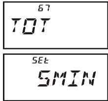

1) When your transmission time is within 10 seconds of the Time-Out Timer expiration, an Alert bell will provide an audible warning from the speaker.
2) Since brief transmissions are the mark of a good operator, try setting up
your radio's TOT feature for a maximum transmission time of one minute. This will significantly improve battery life, too!
CHANGING THE TX DEVIATION LEVEL
In many areas of the world, channel congestion has required that operating channels be closely spaced. In such operating environments, it often is required that operators use reduced deviation levels, so as to reduce the potential for interference to users on adjacent channels. The VX-6R includes a simple method of accomplishing this:
-
Press the [F/W] key, then press the [0(SET)] key to enter the Set mode.
-
Rotate the DIAL knob to select Set Mode Item 27: HLF.DEV.
-
Press the [0(SET)] key momentarily to enable adjustment of this Set Mode Item.
-
Rotate the DIAL knob to set this Set Mode Item to "ON." In this configuration (HALF DEVIATION active), the transmitter's deviation will be approximately ± 2.5kHz and the received audio output level will be increased, for easier listening on the narrow
-
When you have made your selection, press the PTT switch to save the new setting and exit to normal operation.

The "normal" setting for the deviation (when this Set Mode Item is set to "OFF") is ± 5kHz .

5Et
0
NOTE
In the event of erratic operation of the transceiver, it is possible that data on the microprocessor may have become corrupted. While this is a highly unusual situation, the only path to recovery may involve resetting of the microprocessor. Here's how to do this:
MICROPROCESSOR RESETTING
To clear all memories and all other settings to factory defaults:
- Turn the radio off.
- Press and hold in the [MODE(SP S)SQ TYP], [0(SET)], and [V/M(DW)MT] keys while turning the radio on.
- Press the [F/W] key momentarily to reset all settings to their factory defaults (press any other key to cancel the Reset procedure).
SET MODE RESETTING
To reset the Set Mode Item settings to their factory defaults:
- Turn the radio off.
- Press and hold in the [MODE(SP S)SQ TYP] and [V/M(DW)MT] keys while turning the radio on.
- Press the [F/W] key momentarily to reset the Set (Menu) mode settings to their factory defaults (press any other key to cancel the Reset procedure).
The VX-6R includes a convenient "Clone" feature, which allows the memory and configuration data from one transceiver to be transferred to another VX-6R. This can be particularly useful when configuring a number of transceivers for a public service operation. Here is the procedure for Cloning one radio's data to another:
- Turn both radios off.
- Connect the user-constructed cloning cable and two optional CT-91 Microphone Adapter (one on each end) between the MIC/SP jacks of the two radios.
- Press and hold in the [F / W] key while turning the radios on. Do this for both radios (the order of switch-on does not matter). The "CLONE" notation will appear on the displays of both radios.
- On the Destination radio, press the [V/M(DW)MT] key ("--WAIT--" will appear on the LCD).
- Press the [BAND(SCN)BND DN] key on the Source radio; “----TX----” will appear on the Source radio, and the data from this radio will be transferred to the other radio.
- If there is a problem during the cloning process, "ERROR" will be displayed. Check your cable connections and battery voltage, and try again.
- If the data transfer is successful, "CLONE" will reappear on the Source radio and the Destination radio will return to the normal operation. Turn both radios off and disconnect the cloning cable. You can then turn the Source radio back on, and begin normal operation.
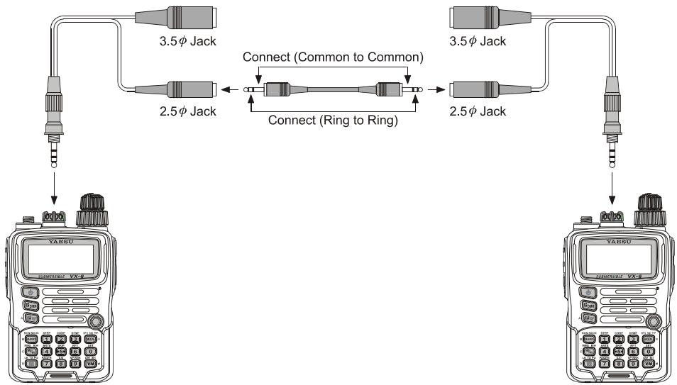


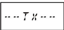

The VX-6R Set Mode, already described in parts of many previous chapters, is easy to activate and set. It may be used for configuration of a wide variety of transceiver parameters, some of which have not been detailed previously. Use the following procedure to activate the Set Mode:
- Press the [F/W] key, then press the [0(SET)] key to enter the Set mode.
- Rotate the DIAL knob to select the Set Mode Item to be adjusted.
- Press the [0(SET)] key momentarily to enable adjustment of the Set Mode Item.
- Rotate the DIAL knob to adjust or select the parameter to be changed on the Set Mode Item selected in above step.
- After completing your selection and adjustment, press the PTT switch momentarily to save the new setting and exit to normal operation.
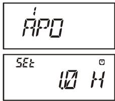

Some Set Mode Items (like Set Mode Item 50: TN FRQ) require that the [0(SET)] key be pressed after setting of the parameter, and before exiting to normal operation.
"MY MENU" Short-cut Key Setup
In the factory default, the primary (press key) function of the [(LK)TXPO] key is set to activating the Internet Connection feature. However, you may change the primary (press key) function of the [(LK)TXPO] key to a short-cut path for recall of one of Set Mode Items.
- Press and hold in the [(LK)TXO] key while turning the radio on. This procedure switches the [(LK)TXO] key between the "Internet Connection" function and the "MY MENU" key function.
- Recall the Set Mode Item which you wish to assign to the [⊗(LK)TXPO] key as a Menu short-cut.
- Press and hold in the (LK)TXPO key for one second to assign the Set Mode Item to the (LK)TXPO key. "MY KEY" will appear on the display, to confirm that the command was executed.
- Now, a momentary press of the (LK)TXPO key will immediately recall the selected Menu item. You must press the (LK)TXPO key again to exit to normal operation.
| SET MODE ITEM | FUNCTION | AVAILABLE VALUES(DEFAULT: BOLD ITARIC) |
| 1 [APO] | Setting of the Automatic Power-Off feature. | OFF / 30MIN / 1HOUR / 3HOUR /5HOUR / 8HOUR |
| 2 [AR BEP] | Selects the Beep option during ARTS operation. | IN RNG / ALWAYS / OFF |
| 3 [AR INT] | Selects the Polling Interval during ARTS operation. | 25 SEC / 15 SEC |
| 4 [ARS] | Enables/Disables the Automatic Repeater Shift function. | ON / OFF |
| 5 [ATT] | Enables/Disables the Receiver Front-end (10 dB) Attenuator. | OFF / ON |
| 6 [BCLO] | Enables/Disables the Busy Channel Lock-Out feature. | OFF / ON |
| 7 [BEEP] | Enables/Disables the keypad beeper. | ON / OFF |
| 8 [BELL] | Selects the number of CTCSS/DCS Bell ringer repetitions. | OFF / 1 / 3 / 5 / 8 / CONT (Continuous ringing) |
| 9 [BP LVL] | Adjust the Beep volume level. | LVL 1 - LVL 9 (LVL 5) |
| 10 [BNK NM] | Stores Alpha-Numeric "Tags" for the Memory Group. | --- |
| 11 [BSY.LED] | Enables/Disables the BUSY LED while the Squelch is open. | ON / OFF |
| 12 [CH CNT] | Selects the Channel Counter Search Width. | ±5 MHz / ±10 MHz /±50 MHz / ±100 MHz |
| 13 [CLK.SFT] | Shifting of the CPU clock frequency. | OFF / ON |
| 14 [CW ID] | Programs and activates the CW Identifier (used during ARTS operation). | --- |
| 15 [CWTRNG] | Enables/Disables the CW Training feature and selects the sending speed of the Morse Code. | OFF /4WPM-13WPM / 15WPM /17WPM / 20WPM / 24WPM /30WPM / 40WPM(20CPM-65CPM (5CPM multiples) /75CPM / 85CPM / 100CPM /120CPM / 150CPM / 200CPM) |
| 16 [DC VLT] | Indicates the DC Supply Voltage. | --- |
| 17 [DCS CD] | Setting of the DCS code. | 104 standard DCS codes (023) |
| 18 [DCS RV] | Enables/Disables "Inverted" DCS code decoding. | DISABLE / ENABLE |
| 19 [DIMMER] | Setting of the Display brightness level. | LVL 0 - LVL 12 (LVL 7) |
| 20 [DMR.WRT] | Enables/Disables over-written the Direct Memory Recall Channel while operating on the Direct Memory Recall Channel. | MANUAL / AUTO |
| 21 [DT A/M] | Enables/Disables the DTMF Autodial feature. | OFF / ON |
| 22 [DT SET] | Programming of the DTMF Autodialer. | --- |
| 23 [EAI] | Enables/Disables the Emergency Automatic ID (EAI) Feature. | OFF / ON |
| 24 [EAI.TMR] | Setting of the Emergency Automatic ID (EAI) operating mode and its Transmit Time. | INT. 1M through INT.10M /INT.15M / INT.20M / INT.30M /INT.40M / INT.50MCON. 1M through CON.10M /CON.15M / CON.20M / CON.30M /CON.40M / CON.50M (CON.5M) |
| 25 [EDG.BEP] | Enables/Disables the Band-edge beeper while selecting the frequency via the DIAL knob. | OFF / ON |
| 26 [EMG S] | Selects the alarm(s) utilized when the Emergency function is engaged. | BP+STR / BEAM / BP+BEM / CW /BP+CW / BEEP / STROBE |
| 27 [HLF.DEV] | Reducing the Deviation level by 50 %. | OFF / ON |
| 28 [HM/RV] | Selects the Primary function of the [HM/RV(EMG)R/H] key. | REV / HOME |
| 29 [INT CD] | Selects the Access Number (DTMF digit) for WIRESTM operation. | DTMF 1 - DTMF F |
| 30 [INT MD] | Selects the Internet Link Connection mode. | SRG / FRG |
| 31 [INT.A/M] | Enables/Disables DTMF Autodialer feature while operating on the Internet Connection feature. | MANUAL / AUTO |
| 32 [INT.SET] | Selects the memory register for an Access Number (DTMF code) for non-WIRESTM Internet Link System access. | --- |
| 33 [LAMP] | Selects the LCD/Keypad Lamp mode. | KEY / CONT / OFF |
| 34 [LED LT] | Illuminates the STROBE glows continuously in white. | --- |
| 35 [LOCK] | Selects the Control Locking lockout combination. | KEY / DIAL / K+D / PTT /P+K / P+D / ALL |
| 36 [M/T-CL] | Selects the MONI switch (just below the PTT switch) function. | MONI / T-CALL×1 |
| 37 [MCGAIN] | Adjust the microphone gain level. | LVL 1 - LVL 9 (LVL 5) |
| 38 [MW MD] | Selects the method of selection of channels for Memory Storage. | NEXT / LOWER |
| 39 [NAME] | Toggles the display indication between "frequency" and the channel's "Alpha/Numeric Tag." | FREQ / ALPHA |
| 40 [NM SET] | Stores Alpha-Numeric "Tags" for the Memory channels. | -- |
× 1 :Depends on the transceiver version.
| SET MODE ITEM | FUNCTION | AVAILABLE VALUES(DEFAULT: BOLD ITARIC) |
| 41 [ON TMR] | Set the ON Timer time. | OFF /00H10M (00:10) - 24H00M (24:00)(10 minutes multiples) |
| 42 [OPN.MSG] | Selects the Opening Message that appears when the radio is pow-ered on. | DC / MSG / OFF |
| 43 [PAGER] | Enables/disables the Enhanced CTCSS Paging & Code Squelch function. | OFF / ON |
| 44 [PAG.ABK] | Enables/disables the Answer Back function of the Enhanced CTCSS Paging & Code Squelch. | OFF / ON |
| 45 [PAG.CDR] | Setting the Receiver Pager Code for the Enhanced CTCSS Paging & Code Squelch. | (05_47) |
| 46 [PAG.CDT] | Setting the Transmitting Pager Code for the Enhanced CTCSS Pag-ing & Code Squelch. | (05_47) |
| 47 [PSWD] | Programs and activates the Password feature. | -- |
| 48 [PTT.DLY] | Select the time delay between when the PTT switch is pressedand the carrier is transmitted. | OFF / 20MS / 50MS /100MS / 200MS |
| 49 [RESUME] | Selects the Scan Resume mode. | 3 SEC / 5 SEC / 10 SEC /BUSY/HOLD |
| 50 [RF SQL] | Adjusts the RF Squelch threshold level. | OFF / S1 / S2 / S3 / S4 / S5 /S6 / S7 / S8 / S9 / S9+ |
| 51 [RPT] | Sets the Repeater Shift Direction. | SIMP / -RPT / +RPT |
| 52 [RX MD] | Selects the receiving mode. | AUTO / N-FM / AM / W-FM |
| 53 [RXSAVE] | Selects the Receive-mode Battery Saver interval ("sleep" ratio) | 200 MS / 300 MS / 500 MS /1 S / 2 S / OFF |
| 54 [S SRCH] | Selects the Smart Search Sweep mode. | SINGLE / CONT |
| 55 [SCN.LMP] | Enables/Disables the Scan lamp while paused. | ON / OFF |
| 56 [SHIFT] | Sets the magnitude of the repeater Shift. | 0.00 - 149.95 MHz*2(50 kHz increments) |
| 57 [SKIP] | Selects the Memory Scan "Skip" channel-selection mode. | OFF / SKIP / ONLY |
| 58 [SPLIT] | Enables/Disables split CTCSS/DCS coding. | OFF / ON |
| 59 [SQL] | Sets the Squelch threshold level. | LVL 0 - LVL 15 (Narrow FM: LVL 1),LVL 0 - LVL 8 (Wide FM: LVL 2) |
| 60 [SQL.TYP] | Selects the Tone Encoder and/or Decoder mode. | OFF / TONE / T SQL/DCS / RV TN |
| 61 [STEP] | Setting of the synthesizer steps. | 5.0k / 10.0k / 12.5k / 15.0k / 20.0k /25.0k / 50.0k / 100.0k / AUTO |
| 62 [SU1.ALT] | Selects the measurement units for the altimeter, and correcting the altimeter. | M / Ft*1,3Offset: -1000 - 0 - +1000 |
| 63 [SU1.BRM] | Selects the measurement units for the Barometric Pressure, andcorrecting the Barometric Pressure. | HP / MB / HG / IC*1,3Offset: -1000 - 0 - +1000 |
| 64 [SU1.SET] | Selects the display of the sensor units' information. | OFF / BARO / ALTI*3 |
| 65 [TEMP] | Indicates indicate the current temperature inside the transceive's case and selects the measurement units ("°F" or "°C") for the tem-perature sensor. | -- |
| 66 [TN FRQ] | Setting of the CTCSS Tone Frequency. | 50 standard CTCSS tones (100 Hz) |
| 67 [TOT] | Setting of the TOT time. | OFF / 1MIN / 3MIN / 5MIN / 10MIN |
| 68 [TS MUT] | Enables/Disables the receiver audio output during the Tone SerchScanner is activated. | ON / OFF |
| 69 [TS SPD] | Selects the Tone Serch Scanner speed. | FAST / LOW |
| 70 [TXSAVE] | Enables/Disables the Transmitter Battery Saver. | OFF / ON |
| 71 [VFO MD] | Enables or disables the VFO band edge limiting for the currentband. | BAND / ALL |
| 72 [WAKEUP] | Setting of the Wakeup feature. | OFF / 5S / 10S / 20S / 30S / EAI |
| 73 [WX ALT] | Enables/Disables the Weather Alert Scan feature. | OFF / ON |
× 1 :Depends on the transceiver version.
× 2 :Depends on the frequency band.
× 3 : Requires optional SU-1.
| REPEATER SETTING | SET MODE ITEM | AVAILABLE VALUES (DEFAULT) |
| Enables/Disables the Automatic Repeater Shift function. | 4 [ARS] | ON / OFF |
| Sets the Repeater Shift Direction. | 51 [RPT] | SIMP / -RPT / +RPT |
| Sets the magnitude of the repeater Shift. | 56 [SHIFT] | 0.00 - 149.95 MHz*1 |
| CTCSS/DCS SETTING | SET MODE ITEM | AVAILABLE VALUES (DEFAULT) |
| Selects the number of CTCSS/DCS Bell ringer repetitions. | 8 [BELL] | OFF / 1 / 3 / 5 / 8 / CONT (Continuous ringing) |
| Setting of the DCS code. | 17 [DCS CD] | 104 standard DCS codes (023) |
| Enables/Disables "Inverted" DCS code decoding. | 18 [DCS RV] | DISABLE / ENABLE |
| Enables/Disables the DTMF Autodial feature. | 21 [DT A/M] | OFF / ON |
| Programming of the DTMF Autodialer. | 22 [DT SET] | --- |
| Sets the Squelch threshold level. | 59 [SQL] | LVL 0 - LVL 15 (NFM: LVL 1), LVL 0 - LVL 8 (WFM: LVL 2) |
| Selects the Tone Encoder and/or Decoder mode. | 60 [SQL.TYP] | OFF / TONE / T SQL / DCS / RV TN |
| Setting of the CTCSS Tone Frequency. | 66 [TN FRQ] | 50 standard CTCSS tones (100 Hz) |
| ARTS SETTING | SET MODE ITEM | AVAILABLE VALUES (DEFAULT) |
| Selects the Beep option during ARTS operation. | 2 [AR BEP] | IN RING / ALWAYS / OFF |
| Selects the Polling Interval during ARTS operation. | 3 [AR INT] | 25 SEC / 15 SEC |
| Programs and activates the CW Identifier. | 14 [CW ID] | -- |
| MEMORY SETTING | SET MODE ITEM | AVAILABLE VALUES (DEFAULT) |
| Stores Alpha-Numeric "Tags" for the Memory Group. | 10 [BNK NM] | -- |
| Enables/Disables over-written the Direct Memory Recall Channel while operating on the Direct Memory Recall Channel. | 20 [DMR.WRT] | MANUAL / AUTO |
| Selects the method of selection of channels for Memory Storage. | 38 [MW MD] | NEXT / LOWER |
| Toggles the display indication between "Frequency" and the channel's "Alpha/Numeric Tag." | 39 [NAME] | FREQ / ALPHA |
| Stores Alpha-Numeric "Tags" for the Memory channels. | 40 [NM SET] | -- |
| SCAN SETTING | SET MODE ITEM | AVAILABLE VALUES (DEFAULT) |
| Selects the Scan Resume mode. | 49 [RESUME] | BUSY / HOLD / TIME |
| Enables/Disables the Scan lamp while paused. | 55 [SCN.LMP] | ON / OFF |
| Selects the Memory Scan "Skip-Echannel-selection mode. | 57 [SKIP] | OFF / SKIP / ONLY |
| Enables/Disables the Weather Alert Scan feature. | 73 [WX ALT] | OFF / ON |
| Enables/Disables the receiver audio output during the Tone Serch Scanner is activated. | 68 [TS MUT] | OFF / ON |
| Selects the Tone Serch Scanner speed. | 69 [TS SPD] | FAST / SLOW |
| POWER SAVING SETTING | SET MODE ITEM | AVAILABLE VALUES (DEFAULT) |
| Selects the Receive-mode Battery Saver interval. | 53 [RXSAVE] | 200 MS / 300 MS / 500 MS / 1 S / 2 S / OFF |
| Enables/Disables the Transmitter Battery Saver. | 70 [TXSAVE] | OFF / ON |
| Setting of the Wakeup feature. | 72 [WAKEUP] | OFF / 5S / 10S / 20S / 30S / EAI |
| WIRES™ SETTING | SET MODE ITEM | AVAILABLE VALUES (DEFAULT) |
| Selects the Access Number (DTMF digit) for WIRES™ operation. | 29 [INT CD] | DTMF 1 - DTMF F |
| Selects the Internet Link Connection mode. | 30 [INT MD] | SRG / FRG |
| Selects the memory register for an Access Number (DTMF code) for non-WIRES™ Internet Link System access. | 31 [INT.A/M] | MANUAL / AUTO |
| Enables/Disables DTMF Autodialer feature while operating on the Internet Connection feature. | 32 [INT.SET] | -- |
| EAI SETTING | SET MODE ITEM | AVAILABLE VALUES (DEFAULT) |
| Enables/Disables the Emergency Automatic ID (EAI) Feature. | 23 [EAI] | OFF / ON |
| Setting of the Emergency Automatic ID (EAI) operating mode and its Transmit Time. | 24 [EAI.TMR] | INT. 1M through INT.10M, INT.15M, INT.20M, INT.30M, INT.40M, INT.50M, CON. 1M through CON.10M, CON.15M, CON.20M, CON.30M, CON.40M, and CON.50M (CON.15M) |
| Selects the alarm(s) utilized when the Emergency function is engaged. | 26 [EMG S] | BP+STR / BEAM / BP+BEM / CW / BP+CW / BEEP / STROBE |
| EPCS SETTING | SET MODE ITEM | AVAILABLE VALUES (DEFAULT) |
| Enables/disables the Enhanced CTCSS Paging & Code Squelch function. | 43 [PAGE] | OFF / ON |
| Enables/disables the Answer Back function of the Enhanced CTCSS Paging & Code Squelch. | 44 [PAG.ABK] | OFF / ON |
| Setting the Receiver Packet Code for the Enhanced CTCSS Paging & Code Squelch. | 45 [PAG.CDR] | (05_47) |
| Setting the Transmitting Packet Code for the Enhanced CTCSS Paging & Code Squelch. | 46 [PAG.CDT] | (05_47) |
× 1 :Depends on the frequency band.
| SWITCH/KNOB SETTING | SET MODE ITEM | AVAILABLE VALUES (DEFAULT) |
| Enables/Disables the keypad beeper. | 7 [BEEP] | ON / OFF |
| Adjust the Beep volume level. | 9 [BP LVL] | LVL 1 - LVL 9 (LVL 5) |
| Enables/Disables the BUSY LED while the Squelch is open. | 11 [BSY.LED] | ON / OFF |
| Selects the Primary function of the [HM/RV(EMG)R/H] key. | 28 [HM/RV] | REV / HOME |
| Selects the LCD/Keypad Lamp mode. | 33 [LAMP] | KEY / CONT / OFF |
| Selects the Control Locking lockout combination. | 35 [LOCK] | KEY / DIAL / K+D / PTT / P+K / P+D / ALL |
| Selects the MONI switch (just below the PTT switch) function. | 36 [M/T-CL] | MONI / T-CALL*2 |
| SU-1 SETTING | SET MODE ITEM | AVAILABLE VALUES (DEFAULT) |
| Selects the measurement units for the altimeter, and correcting the altimeter. | 62 [SU1.ALT] | M / Ft*2,3 |
| Offset: -1000 - 0 - +1000 | ||
| Selects the measurement units for the Barometric Pressure, and correcting the Barometric Pressure. | 63 [SU1.BRM] | HP / MB / HG / IC*2,3 |
| Offset: -1000 - 0 - +1000 | ||
| Selects the display of the sensor units' information. | 64 [SU1.SET] | OFF / BARO / ALTI*3 |
| DISPLAY SETTING | SET MODE ITEM | AVAILABLE VALUES (DEFAULT) |
| Indicates the DC Supply Voltage | 16 [DC VLT] | -- |
| Setting of the Display brightness level. | 19 [DIMMER] | LVL 0 - LVL 12 (LVL 7) |
| Indicates indicate the current temperature inside the transceivre's case and selects the measurement units ("F" or "C") for the temperature sensor. | 65 [TEMP] | -- |
| MISCELLANEOUS SETTING | SET MODE ITEM | AVAILABLE VALUES (DEFAULT) |
| Setting of the Automatic Power-Off feature. | 1 [APO] | OFF / 30MIN / 1HOUR / 3HOUR / 5HOUR / 8HOUR |
| Enables/Disables the Receiver Front-end (10 dB) Attenuator. | 5 [ATT] | OFF / ON |
| Enables/Disables the Busy Channel Lock-Out feature. | 6 [BCLO] | OFF / ON |
| Selects the Channel Counter Search Width. | 12 [CH CNT] | ±5 MHz / ±10 MHz / ±50 MHz / ±100 MHz |
| OFF / ON | ||
| Shifting of the CPU clock frequency. | 13 [CLK.SFT] | OFF / 4WPM-13WPM / 15WPM / 17WPM / 20WPM / 24WPM / 30WPM / 40WPM (20CPM - 65CPM (5CPM multiples) / 75CPM / 85CPM /100CPM / 120CPM / 150CPM / 200CPM) |
| Enables/Disables the CW Training feature and selects the sending speed of the Morse Code. | 15 [CWTRNG] | |
| Enables/Disables the Band-edge beeper while selecting the frequency via the DIAL knob. | 25 [EDG.BEP] | OFF / ON |
| Reducing the Deviation level by 50%. | 27 [HLF.DEV] | OFF / ON |
| Illuminates the STROBE glows continuously in white. | 34 [LED LT] | --- |
| Adjust the microphone gain level. | 37 [MCGAIN] | LVL 1 - LVL 10 (LVL 5) |
| Set the ON Timer time. | 41 [ON TMR] | OFF / 00H10M (00:10) - 24H00M (24:00) (10 minutes multiples) |
| Selects the Opening Message that appears when the radio is powered on. | 42 [OPN.MSG] | DC / MSG / OFF |
| Programs and activates the Password feature. | 47 [PSWD] | -- |
| Select the time delay between when the PTT switch is pressed and the carrier is transmitted. | 48 [PTT.DLY] | OFF / 20MS / 50MS / 100MS / 200MS |
| Adjusts the RF Squelch threshold level. | 50 [RF SQL] | OFF / S1 / S2 / S3 / S4 / S5 / S6 / S7 / S8 / S9 / S9+ |
| Selects the receiving mode. | 52 [RX MD] | AUTO / N-FM / AM / W-FM |
| Selects the Smart Search Sweep mode. | 54 [S SRCH] | SINGLE / CONT |
| Enables/Disables split CTCSS/DCS coding. | 58 [SPLIT] | OFF / ON |
| Setting of the synthesizer steps. | 61 [STEP] | 5.0k / 10.0k / 12.5k / 15.0k / 20.0k / 25.0k / 50.0k / 100.0k / AUTO |
| Setting of the TOT time | 67 [TOT] | OFF / 1MIN / 3MIN / 5MIN / 10MIN |
| Enables or disables the VFO band edge limiting for the current band. | 71 [VFO MD] | BAND / ALL |
× 1 :Depends on the frequency band.
× 2 :Depends on the transceiver version.
× 3 : Requires optional SU-1.
Set Mode Item 1 [APO]
Function: Setting of the Automatic Power-Off feature.
Available Values: OFF/30MIN/1HOUR/3HOUR/5HOUR/8HOUR
Default: OFF
Set Mode Item 2 [AR BEP]
Function: Selects the Beep option during ARTS operation.
Available Values: INRANG/ALWAYS/OFF
Default: INRANG
INRANG: Beeps sound only when the radio first detects that you are within range.
ALWAYS: Beeps sound every time a polling transmission is received from the other station (every 15 or 25 seconds when in range).
OFF: No alert beeps sound.
Set Mode Item 3 [AR INT]
Function: Selects the Polling Interval during ARTS operation.
Available Values: 25 SEC/15 SEC
Default: 25SEC
Set Mode Item 4 [ARS]
Function: Enables/Disables the Automatic Repeater Shift function.
Available Values: ARS. ON/ARS.OFF
Default: ARS. ON
Set Mode Item 5 [ATT]
Function: Enables/Disables the Receiver Front-end (10 dB) Attenuator.
Available Values: OFF/ON
Default: OFF
Set Mode Item 6 [BCLO]
Function: Enables/Disables the Busy Channel Lock-Out feature.
Available Values: OFF/ON
Default: OFF
Set Mode Item 7 [BEEP]
Function: Enables/Disables the keypad beeper.
Available Values: ON/OFF
Default: ON
Set Mode Item 8 [BELL]
Function: Selects the number of CTCSS/DCS Bell ringer repetitions.
Available Values: OFF/1/3/5/8/CONT (Continuous ringing)
Default: OFF
Set Mode Item 9 [BP LVL]
Function: Adjust the Beep volume level.
Available Values: LVL 1 - LVL 10
Default: LVL 5
Set Mode Item 10 [BNK NM]
Function: Stores Alpha-Numeric "Tags" for the Memory Group.
See page ?? for details.
Set Mode Item 11 [BSY.LED]
Function: Enables/Disables the BUSY LED while the Squelch is open.
Available Values: ON/OFF
Default: ON
Set Mode Item 12 [CH CNT]
Function: Selects the Channel Counter Search Width.
Available Values: ± 5MHz / ± 10MHz / ± 50MHz / ± 100MHz
Default: ± 5MHz
Set Mode Item 13 [CLK.SFT]
Function: Shifting of the CPU clock frequency.
Available Values: OFF/ON
Default: OFF
This function is only used to move a spurious response "birdie," should it fall on a desired frequency.
Set Mode Item 14 [CW ID]
Function: Programs and activates the CW Identifier (used during ARTS operation). See page ?? for details.
Set Mode Item 15 [CWTRNG]
Function: Enables/Disables the CW Training feature and selects the sending speed of the Morse Code character groups.
Available Values: OFF/4/5/6/7/8/9/10/11/12/13/15/17/20/24/30/40 WPM or
OFF/20/25/30/35/40/45/50/55/60/65/75/85/100/120/150/200 CPM
Default: OFF
Note: To switch units between "WPM" and "CPM," just press the [V/M(DW)MT] key.
Set Mode Item 16 [DC VLT]
Function: Indicates the DC Supply Voltage.
Set Mode Item 17 [DCS CD]
Function: Setting of the DCS code.
Available Values: 104 standard DCS codes
Default: DCS.023
Set Mode Item 18 [DCS RV]
Function: Enables/Disables "Inverted" DCS code decoding.
Available Values: DISABLE/ENABLE
Default: DISABLE
| DCS CODE | |||||||||
| 023 | 025 | 026 | 031 | 032 | 036 | 043 | 047 | 051 | 053 |
| 054 | 065 | 071 | 072 | 073 | 074 | 114 | 115 | 116 | 122 |
| 125 | 131 | 132 | 134 | 143 | 145 | 152 | 155 | 156 | 162 |
| 165 | 172 | 174 | 205 | 212 | 223 | 225 | 226 | 243 | 244 |
| 245 | 246 | 251 | 252 | 255 | 261 | 263 | 265 | 266 | 271 |
| 274 | 306 | 311 | 315 | 325 | 331 | 332 | 343 | 346 | 351 |
| 356 | 364 | 365 | 371 | 411 | 412 | 413 | 423 | 431 | 432 |
| 445 | 446 | 452 | 454 | 455 | 462 | 464 | 465 | 466 | 503 |
| 506 | 516 | 523 | 526 | 532 | 546 | 565 | 606 | 612 | 624 |
| 627 | 631 | 632 | 654 | 662 | 664 | 703 | 712 | 723 | 731 |
| 732 | 734 | 743 | 754 | - | - | - | - | - | - |
Set Mode Item 19 [DIMMER]
Function: Setting of the Display brightness level.
Available Values: LVL 0 - LVL 12
Default: LVL 12
Set Mode Item 20 [DMR.WRT]
Function: Enables/Disables over-writing of the Direct Memory Recall Channels while operating on a Direct Memory Recall Channel.
Available Values: ON/OFF
Default: ON
Set Mode Item 21 [DT A/M]
Function: Enables/Disables the DTMF Autodial feature.
Available Values: MANUAL/AUTO
Default: MANUAL
Set Mode Item 22 [DT SET]
Function: Programming of the DTMF Autodialer.
See page 73 for details.
Set Mode Item 23 [EAI]
Function: Enables/Disables the Emergency Automatic ID (EAI) Feature.
Available Values: OFF/ON
Default: OFF
Set Mode Item 24 [EAI.TMR]
Function: Setting of the Emergency Automatic ID (EAI) operating mode and its Transmit Time.
Available Values:
INT. 1M through INT.10M, INT.15M, INT.20M, INT.30M, INT.40M, INT.50M,
CON. 1M through CON.10M, CON.15M, CON.20M, CON.30M, CON.40M, and CON. 50M
Default: CON. 5M
Set Mode Item 25 [EDG.BEP]
Function: Enables/Disables the Band-edge Beeper while selecting the frequency via the DIAL knob.
Available Values: OFF/ON
Default: OFF
Set Mode Item 26 [EMG S]
Function: Selects the alarm(s) utilized when the Emergency function is engaged.
Available Values: BP+STR/BEAM/BP+BEM/CW/BP+CW/BEEP/STROBE
Default: BP+STR
BP+STR: Loud "Alarm" sounds and the TX/BUSY indicator flashes.
BEAM: The TX/BUSY indicator glows continuously in white.
BP+BEM: Loud "Alarm" sounds and the TX/BUSY indicator glows continuously in white.
CW: Transmits the Morse Code "SOS" ( ·s - ·s ) message on the air beginning one minute after activation of the Emergency function.
BP+CW: Loud "Alarm" sounds and the Morse Code "SOS" ( ·s - - - ) message is transmitted on the air beginning one minute after activation of the Emergency function.
BEEP: Loud "Alarm" sounds.
STROBE: The TX/BUSY indicator lamp flashes.
When the radio is set to the CW or BP + CW mode, the radio will be instructed to send "DE (your callsign)" after the sending of the SOS message, if your callsign is entered via Set Mode Item 14: CW ID.
Set Mode Item 27 [HLF.DEV]
Function: Reducing the Deviation level by 50% .
Available Values: OFF/ON
Default: OFF
Set Mode Item 28 [HM/RV]
Function: Selects the Primary function of the [HM/RV(EMG)R/H] key.
Available Values: REV/HOME
Default: REV
REV: Pressing the [HM/RV(EMG)R/H] key reverses the transmit and receive frequencies during repeater operation.
HOME: Pressing the [HM/RV(EMG)R/H] key instantly recalls a favorite “Home” channel.
Set Mode Item 29 [INT CD]
Function: Selects the Access Number (DTMF digit) for WIRES™ operation.
Available Values:DTMF 1 -DTMF F
Default:DTMF1
Set Mode Item 30 [INT MD]
Function: Selects the Internet Link Connection mode.
Available Values: SRG/FRG
Default: SRG (Single DTMF Digit is appended at the beginning of each transmission)
Set Mode Item 31 [INT.A/M]
Function: Enables/Disables the DTMF Autodialer feature while operating using the Internet Connection feature.
Available Values: ON/OFF
Default: OFF
Set Mode Item 32 [INT.SET]
Function: Selects the memory register for an Access Number (DTMF code) for non-WIRESTM Internet Link System access.
Available Values: F0 - F63
Default: F 1
Set Mode Item 33 [LAMP]
Function: Selects the LCD/Keypad Lamp mode.
Available Values: KEY/CONT/OFF
Default: KEY
KEY: Illuminates the Keypad/LCD for five seconds when you rotate the DIAL knob or press any key or switch (except the PTT switch).
CONT: Illuminates the Keypad/LCD continuously.
OFF: Disables the Keypad/LCD lamp illumination.
Set Mode Item 34 [LED LT]
Function: Illuminates the STROBE glows continuously in white (useful as emergency flashlight at night).
Set Mode Item 35 [LOCK]
Function: Selects the Control Locking lockout combination.
Available Values: KEY/DIAL/K+D/PTT/P+K/P+D/ALL
Default: K+D
Note: "K" = "Key;" "D" = "Dial;" and "P" = "PTT."
Set Mode Item 36 [M/T-CL]
Function: Selects the MONI switch (just below the PTT switch) function.
Available Values: MONI/T-CALL
Default: MONI
MONI: Pressing the MONI switch causes the Noise/Tone Squelch to be over-ridden, allowing you to listen for weak (or non-encoded) signals.
T-CALL: Pressing the MONI switch activates a 1750-Hz burst tone, used for repeater access in many countries (especially in Europe).
Set Mode Item 37 [MCGAIN]
Function: Adjust the microphone gain level.
Available Values: LVL 1 - LVL 10
Default: LVL 5
Set Mode Item 38 [MW MD]
Function: Selects the method of selection of channels for Memory Storage.
Available Values: NEXT/LOWER
Default: NEXT
NEXT: Stores the data into the memory channel which is next-highest from the last-stored memory channel.
LOWER: Stores the data into the lowest-available "free" channel.
Set Mode Item 39 [NAME]
Function: Toggles the display indication between "frequency" and the channel's "Alpha/ Numeric Tag."
Available Values: FREQ/ALPHA
Default: FREQ
Set Mode Item 40 [NM SET]
Function: Stores Alpha-Numeric "Tags" for the Memory channels.
See page 35 for details.
Set Mode Item 41 [ON TMR]
Function: Set the ON Timer time.
Available Values: OFF/00H10M (00:10) - 24H00M (24:00) (10 minutes multiples)
Default: OFF
The ON Timer turns on the radio at the programmed time.
Set Mode Item 42 [OPN.MSG]
Function: Selects the Opening Message that appears when the radio is powered on.
Available Values: DC/MSG/OFF
Default: DC
DC: DC supply voltage
MSG: Set by user. See below.
OFF: No Opening Message
Here's how to program the Opening Message:
- Set this Set Mode Item to "MSG."
- Press the [MODE(SPS)SQ TYP] key momentarily to enable programming of the opening message. You will notice the first character entry's location blinking.
- Rotate the DIAL knob to select the first letter/number of the message, then press the [MODE(SPS)SQ TYP] key momentarily to save the first letter/number and move on to the next character.
- Repeat the previous step as necessary to complete the message (up to six characters).
- If you make a mistake, press the [BAND(SCN)BND DN] key to back-space the cursor; now re-enter the correct letter/number.
- When you have entered the desired opening message, press the [0(SET)] key momentarily to confirm the message, then press the PTT key to save the settings and exit to normal operation.
Set Mode Item 43 [PAGER]
Function: Enables/disables the Enhanced CTCSS Paging & Code Squelch function.
Available Values: OFF/ON
Default: OFF
Set Mode Item 44 [PAG.ABK]
Function: Enables/disables the Answer Back function of the Enhanced CTCSS Paging & Code Squelch.
Available Values: OFF/ON
Default: OFF
Set Mode Item 45 [PAG.CDR]
Function: Setting the Receiver Pager Code for the Enhanced CTCSS Paging & Code Squelch.
See page 60 for details.
Set Mode Item 46 [PAG.CDT]
Function: Setting the Transmitting Pager Code for the Enhanced CTCSS Paging & Code Squelch.
See page 60 for details.
Set Mode Item 47 [PSWD]
Function: Programs and activates the Password feature.
See page ?? for details.
Set Mode Item 48 [PTT.DLY]
Function: Select the time delay between when the PTT switch is pressed and the carrier is transmitted.
Available Values: OFF/20MS/50MS/100MS/200MS
Default: OFF
Set Mode Item 49 [RESUME]
Function: Selects the Scan Resume mode.
Available Values: 3SEC/5SEC/10SEC/BUSY/HOLD
Default: BUSY
3SEC/5SEC/10SEC: The scanner will hold for the selected resume time, then resume whether or not the other station is still transmitting.
BUSY: The scanner will hold until the signal disappears, then will resume when the carrier drops.
HOLD: The scanner will stop when a signal is received, and will not restart.
Set Mode Item 50 [RF SQL]
Function: Adjusts the RF Squelch threshold level.
Available Values: OFF/S1/S2/S3/S4/S5/S6/S7/S8/S9/S9+
Default: OFF
Set Mode Item 51 [RPT]
Function: Sets the Repeater Shift Direction.
Available Values: -RPT/+RPT/SIMP
Default: Depends on the transceiver version, as well as the setting of Set Mode Item 4: ARS.
Set Mode Item 52 [RX MD]
Function: Selects the receiving mode.
Available Values: AUTO/N-FM/AM/W-FM
Default: AUTO (Mode automatically changes according to operating frequency)
Set Mode Item 53 [RXSAVE]
Function: Selects the Receive-mode Battery Saver interval ("sleep" ratio)
Available Values: 200 MS(1:1)/300 MS(1:1.5)/500 MS(1:2.5)/1 S(1:5)/2 S(1:10)/OFF
Default: 200 MS
Set Mode Item 54 [S SRCH]
Function: Selects the Smart Search Sweep mode.
Available Values: SINGLE/CONT
Default: SINGLE
SINGLE: The transceiver sweeps the current band once in each direction, starting on the current frequency. All channels where activity is present (up to 15 in each direction) are loaded into the Smart Search memories. Whether or not all 31 memories are filled, the search stops after one sweep in each direction.
CONT: The transceiver makes a sweep in each direction as with the "SINGLE" mode, but if all 31 channels are not filled after the first sweep, the radio continues sweeping until they are all filled.
Set Mode Item 55 [SCN.LMP]
Function: Enables/Disables the Scan lamp while paused.
Available Values: ON/OFF
Default: ON
Set Mode Item 56 [SHIFT]
Function: Sets the magnitude of the repeater Shift.
Available Values: 0.00 - 149.95 MHz (50 kHz increments)
Default: Depends on the operating band and transceiver version.
Set Mode Item 57 [SKIP]
Function: Selects the Memory Scan "Skip" channel-selection mode.
Available Values: OFF/SKIP/ONLY
Default: OFF
SKIP: The scanner will "skip" the flagged channels during scanning.
ONLY: The scanner will only scan channels that are flagged (Preferential Scan List).
OFF: All memory channels will be scanned (the "flag" will be ignored).
Set Mode Item 58 [SPLIT]
Function: Enables/Disables Split CTCSS/DCS coding.
Available Values: OFF/ON
Default: OFF
When this Set Mode Item is set to "ON," you will see the following additional parameters after the "RV TN" parameter while configuring Set Mode Item 60: SQL.TYP.
D_CODE: DCS Encode only.
T DCS: Encodes a CTCSS tone and Decodes a DCS code.
D TONE: Encodes a DCS code and Decodes a CTCSS tone.
Select the desired operating mode from the selections shown above.
Set Mode Item 59 [SQL]
Function: Sets the Squelch threshold level.
Available Values: LVL 0 - LVL 15 (Narrow FM), LVL 0 - LVL 8 (Wide FM)
Default: LVL 1 (Narrow FM), LVL 2 (Wide FM)
Set Mode Item 60 [SQL.TYP]
Function: Selects the Tone Encoder and/or Decoder mode.
Available Values: OFF/TONE/T SQL/DCS/RV TN
Default: OFF
TONE: CTCSS Encoder
TSQL: CTCSS Encoder/Decoder
DCS: Digital Coded Encoder/Decoder
RV TN: Reverse CTCSS Decoder (Mutes receiver when matching tone is received)
Note: See also Set Mode Item 58: SPLIT regarding additional selections available during "Split Tone" operation.
Set Mode Item 61 [STEP]
Function: Setting of the synthesizer steps.
Available Values: 5.0k / 10.0k / 12.5k / 15.0k / 20.0k / 25.0k / 50.0k / 100.0k or AUTO
Default: AUTO (Step automatically changes according to operating frequency.)
Set Mode Item 62 [SU1.ALT]
Function: Selects the measurement units for the altimeter (require optional SU-1), and correcting the altimeter.
Available Values: M (meter)/Ft (feet), offset: -1000 to +1000
Default: Depends on the transceiver version.
Note: “OPTION” will be displayed if the SU-1 is not installed.
Set Mode Item 63 [SU1.BRM]
Function: Selects the measurement units for the Barometric Pressure (require optional SU-1), and correction of the Barometric Pressure.
Available Values: HP (hpa)/MB (mbar)/HG (mmHg)/IC (inch), offset: -1000 to +1000
Default: Depends on the transceiver version.
Note: "OPTION" will be displayed if the SU-1 is not installed.
Set Mode Item 64 [SU1.SET]
Function: Selects the display of the sensor units' information.
Available Values: OFF/BARO/ALTI
Default: OFF
Note: The barometric pressure (BARO) and altitude (ALTI) information require the optional SU-1.
Set Mode Item 65 [TEMP]
Function: Indicates indicate the current temperature inside the transceivre's case and selects the measurement units ("°F" or "°C") for the temperature sensor.
Set Mode Item 66 [TN FRQ]
Function: Setting of the CTCSS Tone Frequency.
Available Values: 50 standard CTCSS tones
Default: 100.0Hz
Set Mode Item 67 [TOT]
Function: Setting of the TOT time
Available Values: OFF/1MIN/3MIN/5MIN/ 10MIN
Default: 3MIN
The time-out timer shuts off the transmitter after continuous transmission of the programmed time.
Set Mode Item 68 [TS MUT]
Function: Enables/Disables the receiver audio output while the Tone Serch Scanner is activated.
Available Values: OFF/ON
Default: OFF
Set Mode Item 69 [TS SPD]
Function: Selects the Tone Serch Scanner speed.
Available Values: FAST (2.5 tone/sec)/SLOW (1.25 tone/sec)
Default: FAST
Set Mode Item 70 [TXSAVE]
Function: Enables/Disables the Transmitter Battery Saver.
Available Values: OFF/ON
Default: OFF
Set Mode Item 71 [VFO MD]
Function: Enables or disables the VFO band edge limiting for the current band.
Available Values: BAND/ALL
Default: BAND
BAND: When the VFO frequency reaches the high band edge of the current band, the VFO frequency will jump to the low band edge of the current band (or vice versa).
ALL: When the VFO frequency reaches the high edge of the current band, the VFO frequency will jump to the low band edge of the next band (or vice versa).
| CTCSS TONE FREQUENCY (Hz) | |||||
| 67.0 | 69.3 | 71.9 | 74.4 | 77.0 | 79.7 |
| 82.5 | 85.4 | 88.5 | 91.5 | 94.8 | 97.4 |
| 100.0 | 103.5 | 107.2 | 110.9 | 114.8 | 118.8 |
| 123.0 | 127.3 | 131.8 | 136.5 | 141.3 | 146.2 |
| 151.4 | 156.7 | 159.8 | 162.2 | 165.5 | 167.9 |
| 171.3 | 173.8 | 177.3 | 179.9 | 183.5 | 186.2 |
| 189.9 | 192.8 | 196.6 | 199.5 | 203.5 | 206.5 |
| 210.7 | 218.1 | 225.7 | 229.1 | 233.6 | 241.8 |
| 250.3 | 254.1 | - | - | - | - |
Set Mode Item 72 [WAKEUP]
Function:
Available Values: OFF/5S/10S/20S/30S/EAI
Default: OFF
Set Mode Item 73 [WX ALT]
Function: Enables/Disables the Weather Alert Scan feature.
Available Values: OFF/ON
Default: OFF
General
| Frequency Ranges: (USA Version) | RX 0.5 - 1.8 MHz (BC Band), 1.8 - 30 MHz (SW Band), 30 - 76(59) MHz (50 MHz HAM Band), 76(59) - 108 MHz (FM Band), 108 - 137 MHz (Air Band), 137 - 174 MHz (144 MHz HAM Band), 174 - 222 MHz (VHF TV Band), 222 - 420 MHz (ACT 1 Band), 420 - 470 MHz (430 MHz HAM Band), 470 - 800 (729) (UHF TV Band), (757 - 774) (UHF TV Band), 800 - 999.990 MHz (ACT 2 Band; USA Cellular Blocked) |
| TX 144 - 146(148) MHz, 222 - 225 MHz (USA only) 430 - 440(450) MHz, | |
| Channel Steps: | 5/9/10/12.5/15/20/25/50/100 kHz |
| Frequency Stability: | ±5 ppm @ 14 °F to 140 °F (-10 °C to +60 °C) |
| Repeater Shift: | ±600 kHz (144 MHz), ±1.6/5.0/7.6 MHz (430 MHz) |
| Emission Type: | F2D, F3E |
| Antenna Impedance: | 50 Ω |
| Supply Voltage: | Nominal: 7.4 V DC, Negative Ground |
| (Negative Ground) | Operating: 5.0 ~ 16.0 V DC (EXT DC Jack) 11.0 ~ 16.0 V DC (EXT DC Jack with Charging) |
| Current Consumption: | 150 mA (Receive) |
| (Approx. @7.4 V) | 60 mA (Standby, Saver Off) 20 mA (Standby, Saver On) 1 mA (ON Timer Activated) 200 μA (Auto Power Off) 1.6 A (5 W TX, 144 MHz) ?? A (1.5 W TX, 222 MHz: USA only) 1.8 A (5 W TX, 430 MHz) |
| Operating Temperature: | -4 °F to 140 °F (-20 °C to +60 °C) |
| Case Size: | 2.3" (W) x 3.5" (H) x 1.1" (D) (58 x 89 x 28.5 mm) (W/O knob, antenna, and belt clip) |
| Weight: | 9.5 Oz (270 g) with FNB-80LI, and antenna |
Transmitter
| RF Power Output: | High | Low 3 | Low 2 | Low 1 |
| 144 MHz/430 MHz | 5.0 W | 2.5 W | 1.0 W | |
| 222 MHz | 1.5 W | 1.0 W | 0.5 W | |
| Modulation Type: | Variable Reactance F2D, F3E | |||
| Maximum Deviation: | ±5.0 kHz (F2D, F3E) | |||
| Spurious Emission: | At least 60 dB down (@ High power) | |||
| At least 50 dB down (@ Low 2 and Low 1 power) | ||||
| Microphone Impedance: | 2 kΩ | |||
Receiver
| Circuit Type: | AM, NFM: Double-Conversion Superheterodyne WFM: Triple-Conversion Superheterodyne | ||
| Intermediate Frequencies: | 1st | 2nd | 3rd |
| AM, NFM: 47.25 MHz | 450 kHz | - | |
| WFM: 47.25 MHz | 10.7 MHz | 1 MHz | |
| Sensitivity: | 3 μV TYP for 10 dB SN (0.5-30 MHz, AM) | ||
| (Cellular Blocked) | 0.35 μV TYP for 12 dB SINAD (30-54 MHz, NFM) | ||
| 1 μV TYP for 12 dB SINAD (54-76 MHz, NFM) | |||
| 1 μV TYP for 12 dB SINAD (54-59 MHz, NFM: USA) | |||
| 1.5 μV TYP for 12 dB SINAD (76-108 MHz, WFM) | |||
| 1.5 μV TYP for 12 dB SINAD (59-108 MHz, WFM: USA) | |||
| 1.5 μV TYP for 10 dB SN (108-137 MHz, AM) | |||
| 0.2 μV for 12 dB SINAD (137-140 MHz, FM) | |||
| 0.16 μV for 12 dB SINAD (140-150 MHz, FM) | |||
| 0.2 μV for 12 dB SINAD (150-174 MHz, FM) | |||
| 1 μV TYP for 12 dB SINAD (174-222 MHz, WFM) | |||
| 0.5 μV for 12 dB SINAD (300-350 MHz, NFM) | |||
| 0.2 μV for 12 dB SINAD (350-400 MHz, NFM) | |||
| 0.18 μV for 12 dB SINAD (400-470 MHz, NFM) | |||
| 1.5 μV for 12 dB SINAD (470-540 MHz, WFM) | |||
| 3 μV TYP for 12 dB SINAD (540-800 MHz, WFM) | |||
| 1.5 μV TYP for 12 dB SINAD (800-999.990 MHz, NFM) | |||
| Selectivity: | AM, NFM: 12 kHz/35 kHz (-6 dB /-60 dB) | ||
| WFM: 200 kHz/300 kHz (-6 dB /-20 dB) | |||
| AF Output: | 200 mW @ 8 W for 10 % THD (@ 7.4 V) | ||
| 400 mW @ 8 W for 10 % THD (@ 13.8 V) | |||
Specifications are subject to change without notice, and are guaranteed within the 144, 222, and 430MHz amateur bands only. Frequency ranges will vary according to transceiver version; check with your dealer.
"AUTO" MODE PRESET OPERATING PARAMETERS
USA Version
| FREQUENCY RANGE (MHz) | MODE | STEP |
| 0.500 - 1.800 | AM | 10 kHz |
| 1.800 - 30.000 | AM | 5 kHz |
| 30.000 - 50.500 | AM | 5 kHz |
| 50.500 - 59.000 | FM | 5 kHz |
| 59.000 - 88.000 | WFM | 50 kHz |
| 88.000 - 108.000 | WFM | 100 kHz |
| 108.000 - 137.000 | AM | 25 kHz |
| 137.000 - 144.000 | FM | 12.5 kHz |
| 144.000 - 148.000 | FM | 5 kHz |
| 148.000 - 156.000 | FM | 12.5 kHz |
| 156.000 - 157.450 | FM | 25 kHz |
| 157.450 - 160.600 | FM | 12.5 kHz |
| 160.600 - 160.975 | FM | 25 kHz |
| 160.975 - 161.500 | FM | 12.5 kHz |
| 161.500 - 162.900 | FM | 25 kHz |
| 162.900 - 174.000 | FM | 12.5 kHz |
| 174.000 - 222.000 | WFM | 50 kHz |
| 222.000 - 225.000 | FM | 5 kHz |
| 225.000 - 300.000 | FM | 12.5 kHz |
| 300.000 - 336.000 | AM | 100 kHz |
| 336.000 - 420.000 | FM | 12.5 kHz |
| 420.000 - 450.000 | FM | 25 kHz |
| 450.000 - 470.000 | FM | 12.5 kHz |
| 470.000 - 800.000 | WFM | 50 kHz |
| 803.000 - 999.000 | FM | 12.5 kHz |
EXP Version
| FREQUENCY RANGE (MHz) | MODE | STEP |
| 0.500 - 1.800 | AM | 9 kHz |
| 1.800 - 30.000 | AM | 5 kHz |
| 30.000 - 76.000 | FM | 5 kHz |
| 76.000 - 88.000 | FM | 5 kHz |
| 88.000 - 108.000 | WFM | 100 kHz |
| 108.000 - 137.000 | AM | 25 kHz |
| 137.000 - 160.600 | FM | 12.5 kHz |
| 160.600 - 162.025 | FM | 25 kHz |
| 162.025 - 174.000 | FM | 12.5 kHz |
| 174.000 - 222.000 | WFM | 50 kHz |
| 222.000 - 300.000 | FM | 12.5 kHz |
| 300.000 - 320.000 | AM | 25 kHz |
| 320.000 - 420.000 | FM | 12.5 kHz |
| 420.000 - 430.000 | FM | 12.5 kHz |
| 430.000 - 440.000 | FM | 25 kHz |
| 440.000 - 470.000 | FM | 12.5 kHz |
| 470.000 - 800.000 | WFM | 50 kHz |
| 800.000 - 999.000 | FM | 12.5 kHz |
- Make sure that the transceiver is off. Remove the hard or soft case, if used.
- Remove the battery pack.
- Locate the connector for the SU-1 under the caution seal in the battery compartment on the back of the radio, just peel off the caution seal.
- Align the connector on the SU-1 with the transceiver's connector and gently press the unit into place.
- Affix the new (supplied) caution seal, and replace the battery.
- Installation is now complete.
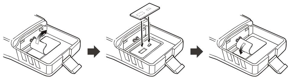
Important note
The Barometric Pressure/Altitude features of the optional SU-1 are designed to be supplemental aids for the information of the user, and are not intended to be a substitute for accurate, calibrated Barometer or Altimeter devices used for navigation critical to personal safety.
- Changes or modifications to this device not expressly approved by VERTEX STANDARD could void the user's authorization to operate this device.
- This device complies with part 15 of the FCC Rules. Operation is subject to the following two conditions: (1) This device may not cause harmful interference, and (2) this device must accept any interference including received, interference that may cause undesired operation.
- The scanning receiver in this equipment is incapable of tuning, or readily being altered, by the User to operate within the frequency bands allocated to the Domestic public Cellular Telecommunications Service in Part 22.
DECLARATION BY MANUFACTURER
The Scanner receiver is not a digital scanner and is incapable of being converted or modified to a digital scanner receiver by any user.
WARNING: MODIFICATION OF THIS DEVICE TO RECEIVE CELLULAR RADIOTELEPHONE SERVICE SIGNALS IS PROHIBITED UNDER FCC RULES AND FEDERAL LAW.
YAESU
Copyright 2005
VERTEX STANDARD CO., LTD.
All rights reserved.
No portion of this manual
may be reproduced
without the permission of
VERTEX STANDARD CO., LTD.
Printed in Japan

0502d-0M