
137 MD Quartz - Camera CONTAX - Free user manual and instructions
Find the device manual for free 137 MD Quartz CONTAX in PDF.



| Product Type | 35mm Film SLR Camera |
| Brand | Contax |
| Model | 137 MD Quartz |
| Category | Camera |
| Film Format | 35mm (135) Film |
| Lens Mount | Contax/Yashica (C/Y) Mount |
| Shutter Type | Vertical-travel metal focal-plane shutter |
| Shutter Speeds | 1 to 1/1000 sec plus B |
| Exposure Metering | Center-weighted average TTL metering |
| Exposure Modes | Aperture-priority auto, Manual |
| ISO Range | 25–3200 |
| Viewfinder | Fixed eye-level pentaprism with split-image and microprism focusing |
| Flash Compatibility | Hot shoe (X-sync 1/60 sec) |
| Self-Timer | Electronic, approx. 10 sec delay |
| Film Advance | Manual lever advance, 180° single stroke |
| Film Rewind | Manual rewind by crank |
| Power Source | 2×1.5V silver oxide (SR44) or 4×1.5V alkaline (LR44) batteries |
| Dimensions | 143 × 90 × 50 mm |
| Weight | Approx. 600 g (with batteries but no lens) |
| Color | Black (standard) |
| Materials | Metal body with leatherette covering |
| Battery Life | Approx. 200 hours (typical usage) |
Frequently Asked Questions - 137 MD Quartz CONTAX
User questions about 137 MD Quartz CONTAX
0 question about this device. Answer the ones you know or ask your own.
Ask a new question about this device
Download the instructions for your Camera in PDF format for free! Find your manual 137 MD Quartz - CONTAX and take your electronic device back in hand. On this page are published all the documents necessary for the use of your device. 137 MD Quartz by CONTAX.
USER MANUAL 137 MD Quartz CONTAX
Updated in accordance with Yashica Inc. memo, August 7, 1980.
1) EXTERIOR VIEW
Upper Cover Removal
(1) Remove the winding lever lid (139602). Since it is glued on, pry it off with a screwdriver.
(2) Remove the winding lever setscrew (counterclockwise screw), washer (60354113), W levers (139603 and 139601), and W lever spring hook (139604).
(3) Remove the upper cover press (139605) and washer (6012 and 6110).
(4) Remove the release button by turning it with a piece of rubber. (Clockwise screw thread)
(5) Remove ASA ring as an assembly.
Note: Be careful of engagement of the lock lever and its plate, and the click lever and its plate, and the click lever and its plate, also make sure the arm of the ASA name plate and its contact piece are engaged when reassembling ASA ring assembly.
(6) Remove the rewinding knob assembly and the shutter dial.
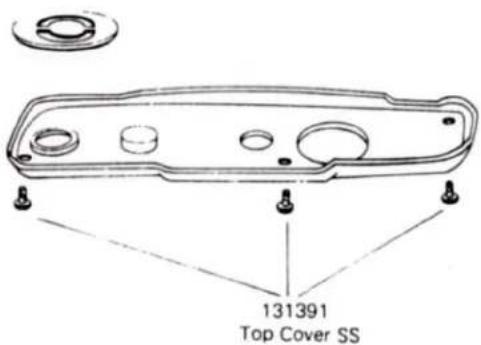
(7) Remove the upper cover by taking off the release socket decorative ring, three upper cover press setscrews and two front cover assembly setscrews.
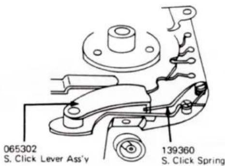
Note: After removing the upper cover, be careful of the shutter click spring. If it is removed carelessly, the shutter dial contact piece will be bent.
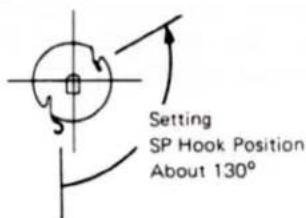
(1) When placing the W lever SP hook the rough edge should face up.
(2) Always check that the tip of the ME lever engages with the inside lever. To check the engagement of these lever: It works OK. If the multiexposure bottom returns itself. When pressure is released and the compensation dial is set at 2X, 4X, 1/2X or 1/4.
(3) If the shutter click spring is removed carelessly, the shutter dial contacts will be damaged.
Lower Cover Removal
(1) Remove three screws.
Note: Since the body number is marked on the lower cover, be careful not to damage it.
Removing Leather
(1) Peel off the right and left sides of the leather.
Note: Since this leather is selfstick type, so it is reusable. (However, since the edge easily peels off when replaced, use additional leather adhesive if necessary.)
Front Cover
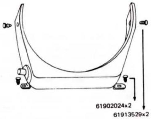
Remove the two screws (61902024 x 2) hidden under the lower cover and pull it downward. (This front cover is also attached by two screws (61913529 x 2) which are removed along with the upper cover.)
2) FRONT
Reinforcement Plate
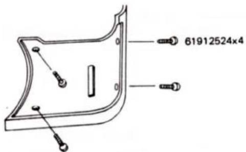
(1) Remove the reinforcement plate after removing its four setscrews (61912524 x 4). (The lower cover must be removed first.)
Front Plate Removal
(1) Remove the front plate after removing its three setscrews (66001043 x 2 and 61913524). (The upper cover, front cover, and lower cover must be removed first.)
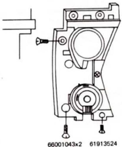
(1) Replace screws so that both the body rim surface and the front plate rim surface are even.

3) MIRROR BOX REMOVAL
The mirror box can be removed together with ASA base plate assembly and the amp unit. (See page 3)
(1) Remove 11 Leads
(A) Bottom surface (five)
(a) Violet and orange leads (2) from T.F. SW. (Micro Switch)
(b) Leads (2) of D. LED.
(c) Green lead (1) from the connector substrate.
(B) Front (One)
(a) Red lead (1) from the battery case.
(C) Upper surface (five)
(a) Yellow, black, and brown leads (3) from the shutter.
(b) Brown lead (1) from the synchro socket.
(c) Green lead (1) from the release socket.
(2) Shutter Substrate
(a) Remove the shutter click spring, its click lever, its click shaft, its substrate setscrews and the two chrome screws (61912522 x 2).
(b) Remove two GS rings and the shutter lock lever.
Note: Do not reuse the removed GS ring. (Reuse will lead to malfunction.)
(c) Remove the rewind shaft holder nut and the shutter click plate.
(3) ASA Base Plate
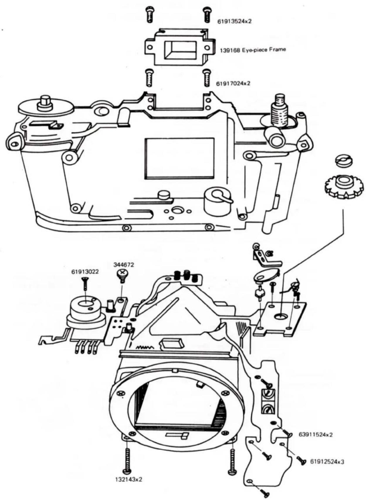
Remove the chrome screw (61913022) and the black screw (344672) holding the ASA base plate to the body.
(b) Remove the eyepiece frame.
(4) Remove four screws from the front and lower surface, which holds the amp to the body.
(a) Front
63911524 × 2
(Black)
(b) Lower surface
61912522×2
(Chrome)
(5) Mirror box removal
(a) Remove the two screws (132143 x 2) under the front and the two (61927024 x 2) on the back. Pull the mirror box from the body towards the front being careful that force is not applied to the amp unit.
Note 1: Since the wall surface of the mirror box is thin and easily damaged, always place the mount surface down on a desk.
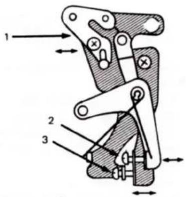
Note 2: The mirror box consists of six basic components: a pentagonal framework, ML base plate (right), MC base plate (left), AVR base plate (right), QR base plate (lower surface), and the mirror box main body. Be careful to keep clean the release magnet of QR·base plate.
R-Magnet adjustment
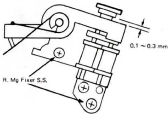
(1) Adjust it so that the metal piece touches evenly on the magnet before the mirror box is set. And allow a play of an 0.1 to 0.3 mm with the mounting screws when the QRL-1 Ass'y is moved.
(2) Mirror adjustment
1 Horizontal adjustment of mirror
2 45° adjustment of mirror
3 Upward and downward location of mirror and fine a adjustment of focussing.
The rough adjustment (0.1 mm or more) of focussing is done by exchanging the washer under the pentagonal frame work. (Since visual field rate is 95%, the rough adjustment of focussing generates parallax due to ML base plate.)
(3) AVR base plate
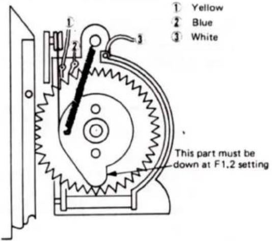
1 When mounting the AVR base plate, set the diaphragm interlocking ring to the stopper on the F 1.2 side and the AVR gear to the position in the following figure engaging gear teeth.
(4) Diaphragm display adjustment
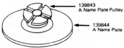
Adjust diaphragm display by revolving the [A] name plate pulley using a standard lens or gauge while checking it through the finder.
(The [A] display base plate is located at the upper right on the mount side.)
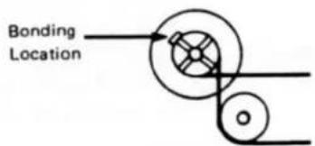
Note: Since the [A] cord is bonded on one location of the [A] name plate pulley, adjust it after removal and rebond it after adjustment.
The square notch on the [A] name plate is provided as the bonding location. Apply adhesive approximately 1 mm wide to prevent the band from moving.
4) SHUTTER REMOVAL
(1) Remove the ME driving lever, ME driving lever metal, and screw (61925024).
(2) Remove the three shutter setscrews (61924022 x 3) and pull the shutter upward.
Two screws are located at the front upper part, and one is located under the moquette of the back cover.
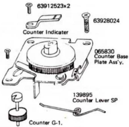
5) COUNTER BASE PLATE REMOVAL
The counter base plate is removed without removing the mirror box.
(1) Remove C lever spring (139895).
(2) Remove three screws (63928024 and 63912524 x 2) and the counter indicator. Then, remove the counter base plate being careful not to damage counter G - 1.
(3) Remove counter G - 1. Note: When the head of counter G - 1 is damaged, it skips two or three frames.
Turn the notched section of counter G - 1 in the opposite direction of the winding shaft.
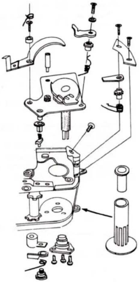
6) W BASE PLATE ASSEMBLY REMOVAL
A) Body Lower Surface
(1) Remove the W shaft B setscrew (139637 counterclockwise screw) in the MD capring and remove the MD capring ass'y.
(2) Remove three SM set lever fixer setscrews (61913024 x 3), SM set lever fixer, and SM set lever.
(3) Remove the anti-rewind proof gear ass'y.
(4) Remove the W shaft metal lower.
B) Body Upper Surface
(1) Remove the W stopper and the anti-rewind proof lever.
(2) Remove the ME W lever, W base plate post, and ME driving lever.
C) After finishing procedures
A) and B), remove the W base plate assembly by pulling it upward.
Precaution: To replace the sprocket, remove the W base plate assembly in the same way.
Note: Since the MD capring ass'y is pressed in against the W shaft, the riveting of the MD cap ring may be loosened if forcibly removed.
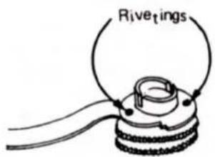
MD capring ass'y
D) W base plate mounting
(1) Mount W base plate.
(2) Mount the anti-rewind proof lever and W stopper. (Adjustment will be described later.)
(3) Fully revolving W shaft B ass'y clockwise and give W shaft B ass'y a slight pressure with the finger then turn it upside down. Attach the W base plate, after engaging W shaft metal lower and W shaft rewind spring, and then revolve W shaft metal lower counterclockwise 1 and 2/3 times.
(4) Mount MD Capring Ass'y
(5) Mount ME W lever.
Note: For pawl adjustment, if pressure is applied to the sprocket, the ME W lever becomes difficult to move when winding. Accordingly, may be stopped by the reverse movement of the sprocket without applying slight pressure to the sprocket.
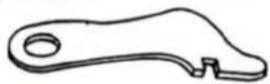
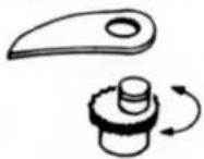
○ Working sequence and adjustment of anti-rewind proof lever, ME W lever, and anti-rewind proof claw (A).
(1) Shift W base plate to adjust the anti-rewind proof lever.
(2) To check anti-rewind proof lever.
The lever should actuate correctly three times or more in succession.
1 ME W Lever
2 Anti-rewind Proof Lever
.3 Anti-rewind Proof Claw (A)
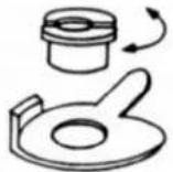
Adjustment of kick pawl, kick lever, and TF-SW.
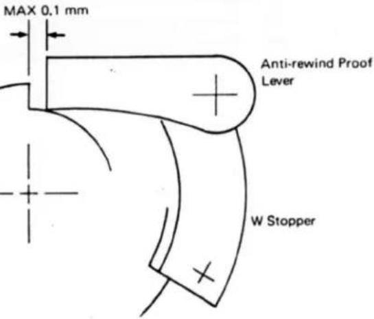
○ Adjustment of anti-rewind proof lever (Body upper surface)
Make sure that the sprocket return (film return) is 0.5 mm or less after winding.
(When the sprocket return of 0.5 mm or less has been verified, a clearance of 0.1 mm need not be checked.)
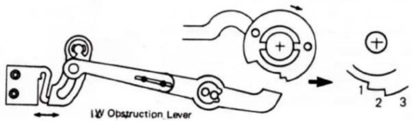
○ Adjustment of the TF-SW (Micro SW)
The shutter must not actuate at the lever return after winding when the W check lever is located at Position 2 or 3 of the MD cap ring. Be sure to actuate the shutter at Position 1.
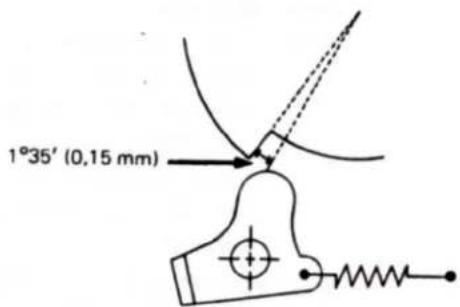
○ Adjustment of anti-rewind proof claw (A).
(Body lower surface)
(When the clearance of the kick pawl is adjusted to 0.1 mm or less, reversal timing must be 1°35' or less.) Check for shutter charge completion before reversal. (1°35' is almost equal to 0.15 mm on the surface of a cam.)
7) AMP REPLACEMENT PROCEDURE
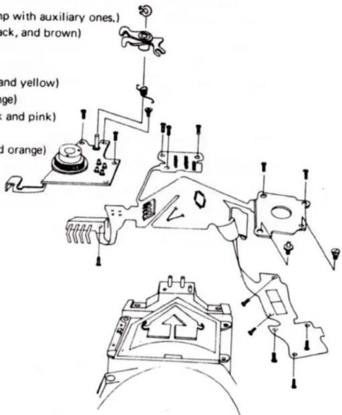
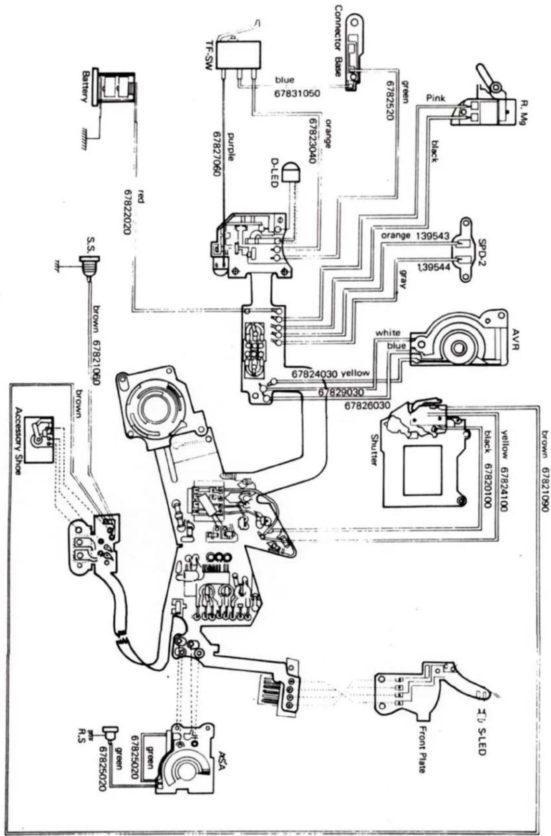
- Replace amp after removing the upper cover, lower cover, front cover, auxiliary plate, and front plate.
(1) Remove 18 leads. (24 leads for the amp with auxiliary ones.)
- Three leads from the shutter (Yellow, black, and brown)
o Green lead from the release socket
○ Brown lead from the synchro socket
○ Three leads from the AVR (Blue, white, and yellow)
○ Two leads from the SPD₂ (Gray and orange)
- Two leads from the release magnet (Black and pink)
- Red lead from the battery case
○ Two leads from the TF switch (Violet and orange)
○ Two legs from the D-LED
○ Green lead from the connector substrate
(2) Remove the shutter substrate.
(3) Remove the LED holder setscrew.
LED POSITIONING
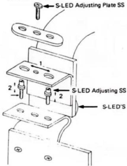
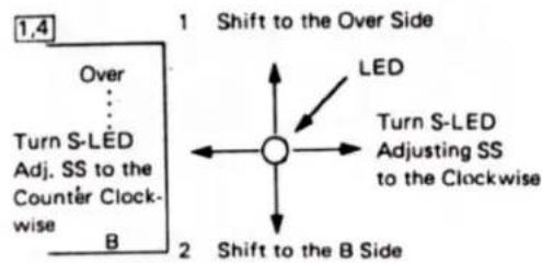
- LED positioning adjustment is done by observing through the center of eyepiece and all LEDs from "B" to "OVER" and "∧" are cented at the respective positions. Always perform this when replacing flexible amps.
1 When LEDs are located on the OVER side (upper) or B side (lower), loosen the LED setscrew and shift the LEDs toward the lens side (shifted to the OVER side) or film side (shifted to the B side).
2 When the LED position moves on the right or the left, adjust it with the LED positioning screw.
S-LED Adjusting Direction
(4) Remove the correction lock lever of the ASA base plate and the soldering between the amp and the pin on the ASA base plate.
(5) ASA base plate removal
(a) Remove the correction intermediate lever, its lever spring, its lever shaft, chrome screws (61913022 x 2), and the screw (63902024) holding the combination connector.
(6) Three screws (61912524 × 3) to attach shoe terminal. Two right front amp setscrews (63911524 × 2). Two lower surface amp setscrews (61912522 × 2).
(7) Remove the amp.
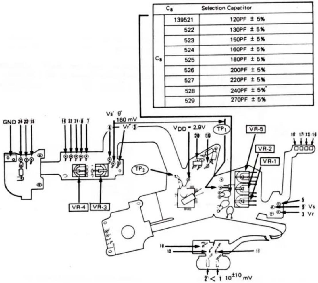
Voltage Check
When checking following voltages. Remove lens, set ASA dial to 100, connect (+) lead of multimeter to VDD , and DC power (2.9 V) must be supplied by regulated DC power supply.
VR-1 Offset Voltage Adjustment
Check voltages at 1 and then 2 respectively by connect the (−) lead of multimeter.
The respective multimeter voltage reading at 1 and 2 the difference of which should be 10± 10mV and this is obtained by VR-1.
1 - 2 = 1 0 ± 1 0 mV.
VR-2 Basic Voltage Adjustment
Check voltages at 9 and then 3 respectively by connect the (-) lead of multimeter.
The respective multimeter voltage reading at 9 and 3 the difference of which should be 295 ± 10 mV(A) or 315 ± 10 mV(B) . And this is obtained by VR-2.
To check difference of type (A) and (B), check IC₁. If you read any sign on IC₁, that is type A. If you can't read any, that is type B.
9 - 3 = 2 9 5 ± 1 0 mV or 3 1 5 ± 1 0 mV
VR-3 Auto Exposure Adjustment
(See Figure, page 17)
VR-4 Basic Voltage of Flash Adjustment
Check voltages at 9 and then TP1 respectively by connect the (-) lead of multimeter.
(Voltage leading of 9)–(Voltage leading of TP) =160 mV.
VR-5 Battery Check Circuit Adjustment
Set shutter dial to auto and adjust VR-5 to get following S-LED lighting condition.
VDD = 2.9 V - Light Continuously
VDD = 2.7V - Light Flicker
VDD = 2.65 V - Doesn't come on
10
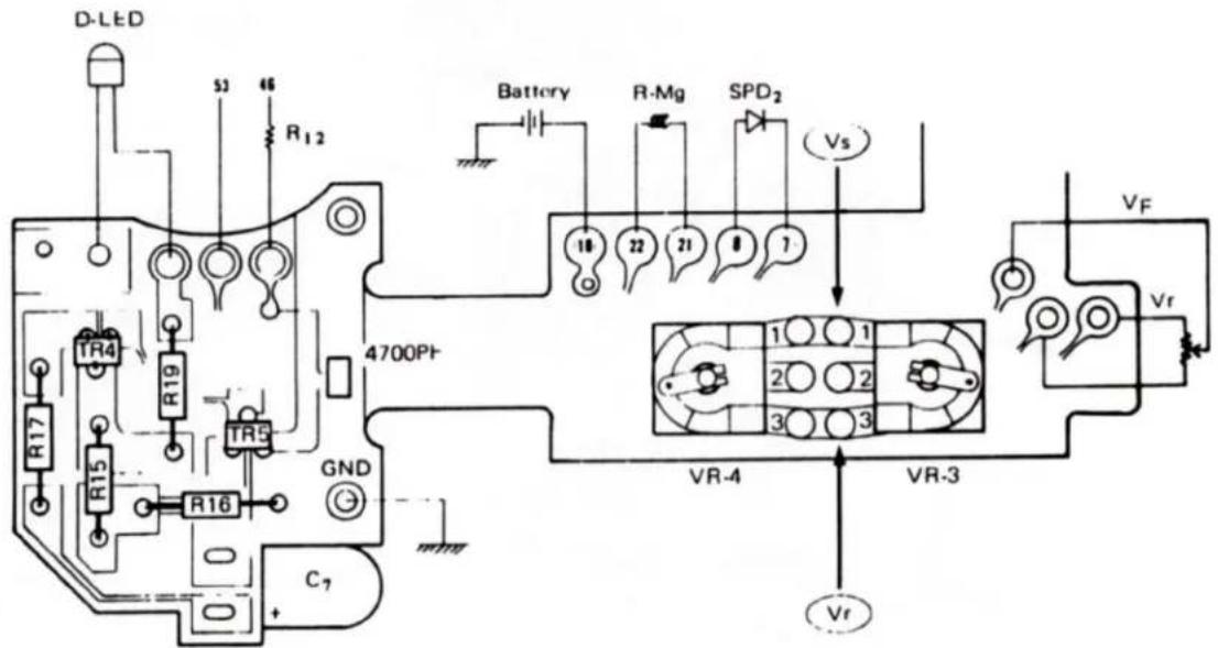
| Code | Standard | Function | Defect cause | |
| VR-3 | Special sum fixed-resistor | Adjustment of auto exposureFull resistance range 50KΩ Ra/Ha+Hb = 0.42 0.65 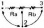 | Auto defectNo auto exposure readingOffset adjustment not possible | |
| VR-4 | Special Semi-fixed resistor | Flash out put adjustment Ra/Ra + Rb = 0.2 0.45 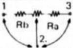 | Abnormal flash out putDoes not regulate the flash out put | |
| TR-4 | M6 | Drives both D-LED and R/MG. | Shutter does not actuate.D-LED does not light up or remains lit. | |
| R19 | 1 KΩ | D-LED current limit | D LED does not light up. Dark or Bright. | |
| TR-5 | L7 | Drive R MG. | Shutter does not actuate. | |
| R15 | 1 KΩ | TR-5 bleeder resistance | Shutter does not actuate | |
| R16 | 10 KΩ | |||
| R17 | 1 KΩ | Charge C7 | High current at chargeShutter does not actuate | |
| C7 | 100 μF | Charge the power for actuating the shutter | Shutter does not actuate | |
![graph TD A["ST-MG"] --> B["TR3"] B --> C["TR13"] B --> D["R12"] B --> E["28"] B --> F["19"] G["VDD"] --> H["TR-6"] H --> I["1"] I --> J["C2"] J --> K["43"] J --> L["42"] M["XTAL"] --> N["IC2"] N --> O["29"] N --> P["E1"] N --> Q["RQ"] N --> R["R10"] N --> S["R11"] T["Trigger SW"] --> U["TR-1"] U -->…](/content/2026/06/1334521/images/47e285f575f5c3dc95565bfbeeb68afdf4f33c29e7fb55264f2841e6d3117335.jpg)
| Code | Standard | Function | Defect Cause |
| IC2 | MSM5988 | Control digital IC (sequence), Power Hold, OSC circuit, etc. | Not controlled |
| XTALC5 C6 | KF 3833PF33PF | Crystal oscillation | |
| TR3 | M6 | ST-MG drive | Shutter sticks close or remains open |
| TR6 | L7 | LED drive | N LED does not light up or remains lit. |
| R18 | 360 Ω | LED current limit | N LED does not light up, dark or bright |
| R12 | 200 KΩ | Release input | Shutter does not actuate |
| R13 | 120 KΩ | ||
| R9 | 10 KΩ | Stroboscopic charge input | N LED does not light up. |
| R10 | 10 KΩ | Flash control signal | Abnormal flash out put |
| R11 | 47 KΩ | ||
| C2 | 0.1 μF | Power stabilization | Circuit malfunction |
| TR1 | L7 | Power hold | Power Hold Insufficient Shutter does not actuate |
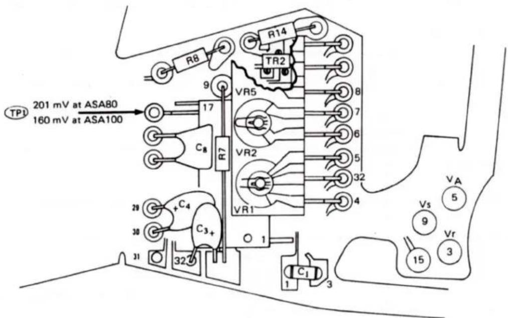
| Code | Standard | Function | Defect Cause |
| IC1 | MSA422 | Photometric analog IC | Poor photometric condition |
| Semi-fixed block | VR1 | Offset adjustmentBalance of photometric amps | Exposure adjustment damaged (all regions) |
| VR2 | Reference voltage adjustmentType A 305 ± 10 mVType B 305 ± 10 mV VR2/R1 = 0.8 0.9 | Vr can not be adjustedExposure adjustment damagedLED Display adjustment damagedDoes not regulate the flash out put | |
| R1 | |||
| VR5 | BC adjustmentLighting up at 2.9 VAlarm at 2.7 VLight off at 2.65 V | BC cannot be adjustedPower hold damaged | |
| R6 | |||
| C1 | 33PF | Oscillation prevention (feedback) | Oscillation (Unstable photometry) |
| C3 | 0.1 μF | ||
| C4 | 0.1 μF | Double intergration | Auto exposure.LED Display |
| TR2 | M6 | S-LED drive | S-LED does not light up or remains lit.S-LED dark or bright |
| R14 | 130 Ω | S-LED current limit | |
| R7 | 120 KΩ | ||
| R8 | 1 KΩ | TR-1 bias resistance | Power hold damaged |
| CB | Selection capacitor | Determine the flash out put adjustment120PF ~ 270PF | Does not regulate the flash out putOver flash out putUnder flash out put |
Time Sequence of Electric Circuit (AE SW ON, Release SW ON, Selftimer SW ON and FLASH)
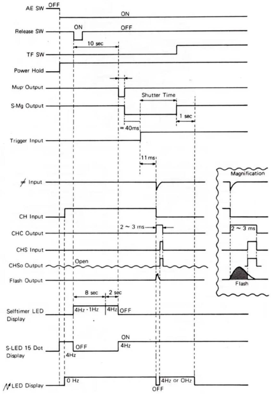
1. Shutter LED Display
| ○=0 Hz●=4 Hz | Auto | Manual | X | AE Lock | With TLA-20 Flash | |||||||
| Auto | Manual | B | X | AE Lock | Auto | AE Lock At Auto | ||||||
| Manual | B | X | ||||||||||
| Over1/10001LTB | ||||||||||||
| ○ | ||||||||||||
| Shutter Dial | ||||||||||||
1 Takes priority when A is matched.
2 Lights up for 10 seconds and then goes off when the release switch is actuated.
3 Remains lit and fixed by AE LOCK
Lights up for 10 seconds after AE LOCK LEVER is released.
4 Light does not go off when the release switch is actuated. At AE LOCK, LED (shutter speed) is fixed.
5 The over photometric value is not displayed.
After flash when exposure is correct the flash mark winks at 4Hz frequency for one second and then remains on even if the release button is kept depressed.
7 LED display position will be fixed.
2. Selftimer LED Display
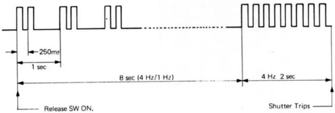
- Battery Check Display (At Voltage 2.65 V \~ 2.8 V)
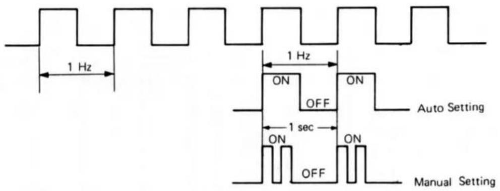
- Green ∩ Display
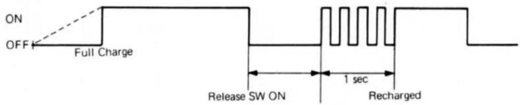
[STANDARD]
- Basic Voltage of Electric Circuit
| Item | Mark | Condition | Standard |
| Basic Voltage 1 | Vs | Vcc = 2.9 V ± 5 mV | |
| Basic Voltage 2 | Vr | Same as above | 305 ± 10 mV 305 ± 10 mV |
| Basic Voltage for TUA-20 | TP1 | ASA 100 | 160 mV |
| Offset | VR-1 | Turn Camera to LV12 or more | 10 mV ± 10 mV |
| Battery Check | V JB | Lighting Up | Vcc = 2.85 V |
| ,Alarm | Vcc = 2.7 V | ||
| Light Off | Vcc = 2.65 V |
(See page 10)
- Manual Shutter Speed
| S-Dial Setting | Max | Standard | Min |
| X | 11.52 | 10.75 | 10.03 |
| 1 | 1,035 | 1,000 | 966 |
| 2 | 517.6 | 500 | 483 |
| 4 | 258.8 | 250 | 241.5 |
| 8 | 134.0 | 125 | 116.6 |
| 15 | 67.0 | 62.5 | 58.31 |
| 30 | 33.55 | 31.3 | 29.2 |
| 60 | 16.75 | 15.63 | 14.58 |
| 125 | 8.37 | 7.81 | 7.29 |
| 250 | 4.49 | 3.91 | 3.40 |
| 500 | 2.40 | 1.95 | 1.58 |
| 1,000 | 1.33 | 0.98 | 0.72 |
3. Synchro contact
3-1. Synchronizer delay time
0.3 to 0.9 ms
Set Shutter Dial at "X" position and check with shutter tester.
3-2. Sync. contact efficiency
70% or more (TIME INT. 1 ms, 2 ms)
3-3. Sync. insulation resistance 30 MΩ or more (DC 500V)
4. Exposure metering
4-1. LED should display
Within the range of ±0.7 EV at LV 4 to LV 15. (ASA 80, k=1.3) of the standard value.
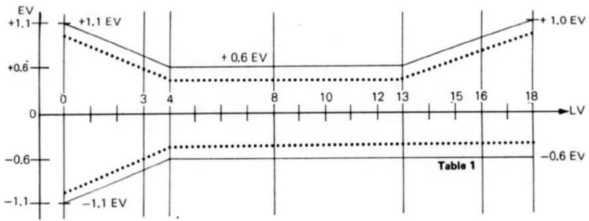
4-2. Auto exposure error
The AE error should be corrected to conform with the range in the Table 1 For adjustment, use the following luminance:
ASA 80 K = 1.3
| LV | Aperture | ||
| LV 12 | F 5.6 | Adjust to ± 0.6 | Adjusted by VR-3 |
| LV 15 | F 5.6 | “ | |
| LV 10 | “ | “ | |
| LV 4 | “ | “ |
5. On Auto at B Display
Cover the lens with the lens cap, stop down to F5.6 or more, at the same time, cover the camera eyepiece then release the shutter and under normal temperature and humidity. The shutter should remain open for 11±1 seconds.
6. On Auto at Over Display
Shutter speed must be 0.5 ms or more.
7. Flash out put Adjustment (Flash at Auto Mode)
Adjust the Flash out put to ±0.6EV at ASA100, F5.6 and the distance 2 m by replacing C8 capacitor. (Use same type of Film as customer's when checking.)
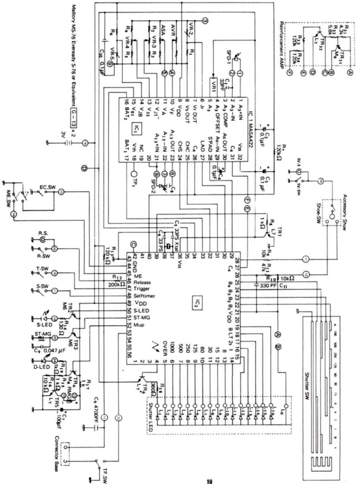
Explanation of codes used in basic wiring diagrams
1) VR-1 Semi-fixed resistor for offset voltage adjustment.
2) VR-2 Semi-fixed resistor for input voltage adjustment
3) VR-3 AUTO exposure adjusting semi-fixed resistor
4) VR-4 Semi-fixed resistor for flash voltage adjustment
5) VR-5 Semi-fixed resistor for battery check voltage adjustment
6) SPD-1 SPD for normal photograph
7) SPD-2 SPD for flash light
8) S.S. Synchro socket
9) Sy.SW Synchro switch
10) Xtai Quartz
11) ME SW AE lock switch
12) R.S. Release socket
13) R.SW Release switch
14) T-SW Trigger switch
15) S-SW Self-timer switch
16) S-LED Self-timer LED
17) ST-Mg Shutter magnet
18) R-Mg Release magnet
19) TF-SW Transfer switch (Same as RTS's timing switch)
20) D-LED Data back driving LED
This scan of this manual and any included edits is copyright © 2011 Peter Robinson. All rights reserved. Reproduction for personal use is allowed. Reproduction for commercial use is strictly prohibited.
139 Electrical Failure Causes
Failure Item
1) Shutter does not actuate
Cause
(1) C, 100μF soldering defect.
(2) TF SW adjustment error.
(3) Ground screw loose.
(4) R15 soldering defect.
(5) R12 soldering defect.
(6) Thru-hole of FPC does not connected (15 - R 12 line).
(7) TR-4 (M6) Soldering defect.
(8) TR-5 (L7) Soldering defect.
(9) IC 2 Pin #38 or #39 soldering (no oscillation) defect.
(10) White lead is solder-bridged on AVR riveting section. (Leak status of about 5 mA).
(11) Jumper lead (green) on ASA base plate is disconnected.
(12) Xtal leg floating or shorting.
(13) R Mg SP removal (mechanical).
(14) AVR yellow lead is shorted to the body (Leak of about 23 mA).
(15) R Mg lead removal.
(16) IC 1 Pins 17 and 18 solder bridge.
(17) SP strikes on SPD-2 anode and acts as body ground. (Leak of about 25 mA).
(18) Lever (QRL-4) touches the cord retaining plate of QR base plate.
(19) The W obstruction lever malfunctions and TF SW cannot be switched.
(20) Play in rivetted contact plates in battery case.
(21) Pin of ASA base plate assembly is high and touches the lever.
(22) Red lead removed from the battery case.
(23) R7 (120 KΩ) is floating.
(24) ASA contact plate is bent outside and touches the release circuit.
(25) The soldering section of B amp red-pink lead (B AMP is located on IC₂) is shortcircuited. (Latch of about 1 sec.)
(26) IC2 pins 32 and 33 Solder bridge IC2 pin 33 Improper soldering
Shutter does not actuate due to high brightness.
(27) Release SW continuity failure.
(28) Release Mg difective.
Check whether or not D-LED lights up.
If D-LED remains LIT and shutter does not operate. Remove batteries and replace them again. This will turn the D-LED off and the shutter will operate normally.
2) Shutter LED Instability
(1) IC1 pins 4 to 8 improper soldering.
3) 1 Hz flashing always
(2) C1 improper soldering.
4) N LED lights up by actuating the shutter
(1) IC1 pin 16 improper soldering.
5) N LED lights up.
. IC2 pins 3 and 4 bridge
6) OVER remains lit.
- IC 2 pins 27 and 28 solder bridge
(1) IC1 pin 30 improper soldering
(2) VR-3 improper soldering
(3) AVR contact piece continuity defective ( VF = VDD' offset voltage about 0.9V)
(4) AVR yellow lead removal
(5) ASA base plate assembly pin ( VA ) improper soldering
(6) ASA contact piece floating
| 7) | All LEDs do not light up. | (1) | LED common circuit soldering defective |
| 8) | LEDs only light up partially. | (1) | Heat contact bonding section improper soldering. |
| (2) | IC2 pins 4 to 19 improper soldering. | ||
| 9) | LEDs remain lit. | (1) | The solder of the combination connector strikes on ASA base plate and acts as ground. |
| (2) | TR-1 failure (latch status) | ||
| (3) | The front plate check switch remains turned ON. | ||
| 10) | LEDs remain lit at W lever lock | (1) | EL lock lever strikes on EL substrate due to excessive solder. |
| 11) | B remains lit. | (1) | AVR white lead removal. |
| SHUTTER remains open at auto | (2) | VR-3 contact failure. | |
| (3) | C4 leg strikes on the upper cover. | ||
| (4) | C1 leg strikes on the upper cover. | ||
| 12) | Does not regulate the FLASH out put | (1) | VR-4 improper soldering |
| (2) | VR-4 defective | ||
| (3) | SPD-2 solder protuberance is high and touches the body. | ||
| (4) | SPD-2 lead (gray) is shorted to lead press. ( Vth = about 2.2V ). | ||
| (5) | SPD-2 improper soldering. | ||
| (6) | SPD mirror tension angle defective. | ||
| (7) | IC1 pin 20 improper soldering. | ||
| (8) | IC1 pin 21 improper soldering. | ||
| (9) | TR-3 defective (Shutter sticks close). | ||
| (10) | SPD-2 shortcircuit between anode and cathode. | ||
| (11) | SPD-2 polarity inversion. | ||
| (12) | IC2 pin 28 improper soldering. | ||
| 13) | Auto exposure can not be adjusted | (1) | VR-3 defective. |
| (2) | The Vr value is not within allowance range. | ||
| 14) | Shutter remains open | (1) | TR-3 defective (Shortcircuit between E and B). |
| 15) | High shutter speed sticks close | (1) | Trigger SW ground defective. |
| 16) | Shutter sticks close | (1) | TR-3 © improper soldering. |
| (2) | TR-3 defective. | ||
| (3) | ST- Mg disconnection or lead (black) removal. | ||
| (4) | The absorption state of the shutter magnet iron piece is bad. | ||
| 17) | All shutter speed settings are slow | (1) | B amp 10KΩ damage. |
| (2) | B amp M6 plated solder. | ||
| (3) | Trigger switch does not turn off. | ||
| 18) | 1/1000 over or under | (1) | Trigger switch is re-adjusted. |
| 19) | Incorrect shutter curtain speed | (1) | Shutter curtain speed is re-adjusted. (5.7~6.0 ms) |
| 20) | Time lag of X defective | (1) | Synchro SW is re-adjusted. |
| 21) | Contact efficiency of X defective | (1) | Synchro SW is re-adjusted. |
| 22) | Self LED does not light up. | (1) | Self LED anode side body ground. |
| (2) | Combination connector contact piece continuity defective 1# | ||
| (3) | TR-2 defective. | ||
| (4) | LED leg removal. | ||
| 23) | AE remains work | (1) | Combination connector 1# contact piece is shorted to body. |
| 24) | AE does not work. | (1) | Combination connector 1# contact piece continuity defective. |

- EXTERIOR VIEW
- UPPER COVER REMOVAL
- LOWER COVER REMOVAL
- REMOVING LEATHER
- FRONT COVER
- FRONT
- REINFORCEMENT PLATE
- FRONT PLATE REMOVAL
- MIRROR BOX REMOVAL
- REMOVE 11 LEADS
- SHUTTER SUBSTRATE
- ASA BASE PLATE
- R-MAGNET ADJUSTMENT
- MIRROR ADJUSTMENT
- AVR BASE PLATE
- DIAPHRAGM DISPLAY ADJUSTMENT
- SHUTTER REMOVAL
- COUNTER BASE PLATE REMOVAL
- W BASE PLATE ASSEMBLY REMOVAL
- W BASE PLATE MOUNTING
- ○ ADJUSTMENT OF THE TF-SW (MICRO SW)
- ○ ADJUSTMENT OF ANTI-REWIND PROOF CLAW (A)
- AMP REPLACEMENT PROCEDURE
- LED POSITIONING
- VOLTAGE CHECK
- SHUTTER LED DISPLAY
- SELFTIMER LED DISPLAY
- [STANDARD]
- SYNCHRO CONTACT
- EXPOSURE METERING
- ON AUTO AT B DISPLAY
- ON AUTO AT OVER DISPLAY
- FLASH OUT PUT ADJUSTMENT (FLASH AT AUTO MODE)
- EXPLANATION OF CODES USED IN BASIC WIRING DIAGRAMS
- ELECTRICAL FAILURE CAUSES
- FAILURE ITEM
- CAUSE
Brand : CONTAX
Model : 137 MD Quartz
Category : Camera