
FO FI110/3 W - Oven IBERNA - Free user manual and instructions
Find the device manual for free FO FI110/3 W IBERNA in PDF.


| Product Type | Built-in Electric Oven |
| Brand | Iberna |
| Model | FO FI110/3 W |
| Dimensions (H x W x D) | 595 x 595 x 575 mm (approx.) |
| Weight | 30 kg (approx.) |
| Power Supply | 220-240 V ~ 50/60 Hz |
| Power Rating | 2500 W (approx.) |
| Oven Functions | Conventional, Grill, Fan-assisted, Defrost |
| Temperature Range | 50°C - 250°C |
| Interior Capacity | 70 liters (approx.) |
| Cleaning Type | Easy-clean enamel interior |
| Control Type | Mechanical knobs and timer |
| Display | Analog timer |
| Safety Features | Child lock, overheat protection |
| Door Type | Triple-glazed, cool touch |
| Oven Lighting | Interior light |
| Spare Parts Availability | Genuine parts available from Iberna service centers |
| Repairability Index | High (standard components) |
| Energy Class | A (estimated) |
| Color | White |
Frequently Asked Questions - FO FI110/3 W IBERNA
User questions about FO FI110/3 W IBERNA
0 question about this device. Answer the ones you know or ask your own.
Ask a new question about this device
Download the instructions for your Oven in PDF format for free! Find your manual FO FI110/3 W - IBERNA and take your electronic device back in hand. On this page are published all the documents necessary for the use of your device. FO FI110/3 W by IBERNA.
USER MANUAL FO FI110/3 W IBERNA

INSTALLATION
The Purchaser is responsible for the installation of the hob. The Manufacturer does not accept any responsibility for any damage or loss resulting from incorrect installation, and as such this will not be covered by the Manufacturer's Guarantee.
The hob may be installed in any worktop which is heat resistant to a temperature of 100°C, and has a thickness of 25 - 40 mm. The dimensions of the insert to be cut out of the worktop are shown in Fig. 1.

If the hob is fitted next to a cabinet on either side, the distance between the hob and the cabinet must be at least 150 mm (see Fig. 2); while the distance between the hob and the rear wall must be at least 55 mm.
If no other appliance is fitted below the hob, there must be a partition panel in insulating material (wood or similar) providing a space of at least 10 mm below the hob (see Fig. 2).
The hob unit is fitted by attaching the fixing clamps supplied, using the holes at the base of the unit.
VERY IMPORTANT - APPLYING THE SEALANT
Important - The diagram below shows how the sealant should be applied.

This appliance has been designed for non-professional, i.e. domestic, use.
Appropriate checks and tests have ensured that, even in the most extreme conditions, the temperatures reached are within acceptable limits. Where there is another appliance below the hob, it is recommended that an insulated heat resistant panel is fitted to provide added protection to the hob control switches. The hob is thermally insulated (in line with Regulation EN) and may be installed: next to panels higher than the worktop, for type «Y», or next to panels not higher than the worktop for type «X». See technical characteristics table «Degree of protection».
Instructions for the installer
The following information is intended for qualified and competent persons only who will ensure that your appliance is installed correctly. All current legislation concerning the installation of gas appliances must be observed by the installer*
* For the U.K. only - By law, the gas installation/commissioning must be carried out by a «Corgi», registered installer.
This appliance must be installed in accordance with applicable regulations and should only be used in well-ventilated locations. Before using this appliance carefully study the instruction book.
Electrical connection (4 electric plates)
In the installation of this appliance, a double pole switch must be incorporated into the electrical connection.
The electric hob should always be connected to the 30 amp supply by a qualified electrician.
To replace the power supply cord, unscrew the 3 screws marked "A" to remove the cover. In this instance, it must be connected to the mains supply via the appropriately rated cable/flex. Connect the supply cord to the terminal block and to the earth terminal (Fig. 4).
Fasten the cord by means of the 2 screws marked "B" and reset the cover (Fig. 4 bis). Before connecting the appliance, check the efficiency of the earth circuit. Earthing of the appliance is required by law. The manufacturer declines any responsibility should this safety measure not be observed. Connection to the electrical supply should be made with 4.00 mm² flex, 85°C, BS 6007, and connected through the cooker junction unit to the cooker control unit.
To connect the cable, remove the protection cover and insert the cable through the cable chock and fasten it. Effect the connection according to the diagram shown on the label fixed to the side of the terminal board, taking care to connect the earth wire to the threaded pin near the terminal board.
Always seek the advice of a qualified electrician regarding installation.
Electrical connection
Warning - this appliance must be earthed
This appliance is designed for domestic use only. Connection to the mains supply must be made by a competent electrician, ensuring that all current regulations concerning such installations are observed.
The appliance must only be connected to a suitably rated spur point; a 3-pin 13 amp plug/socket is not suitable. A double pole switch must be provided and the circuit must have appropriate fuse protection. Further details of the power requirement of the individual product will be found in the users' instruction and on the appliance rating plate. In the case of built-in products, you are advised, should you wish to use a longer cable than the one supplied, that a suitably rated heat resistant type must be used. (Rubber insulated cable type H05RR-F must be used. The cables should be 1.5 mm² section for products with electrically heated elements, and 0.75 mm² for other products. Also, the maximum external diameter of the cable should not be greater than 7 mm.) The wiring must be connected to the mains supply as follows:
CONNECT TO SPUR TERMINAL
Green & Yellow Wire Earth Connection
Blue Wire Neutral Connection
Brown Wire Live Connection
Note: We do not advocate the use of earth leakage devices with electric cooking appliances installed to spur points because of the "nuisance tripping" which may occur. You are again reminded that the appliance must be correctly earthed; the manufacturer declines any responsibility for any event occurring as a result of incorrect electrical installation.
Installation of electrical connections


Declaration of compliance: This equipment, in the parts intended to come into contact with food, complies with the regulations laid down in EEC directives 89/109.
CE This appliance complies with directive 89/336/EEC, 73/23/EEC, 90/396/EEC and the following changes.
Gas connection (see page 11)
The labels on the Hob indicate the types of gas that can be used.
It is possible to use other types of gas after carrying out simple modifications.
Warning: If gas can be smelt in the vicinity of this appliance turn off the gas supply to the appliance and call the engineer directly.
Do not search for a leak with a naked flame.
Adapting the hob to different types of gas
To adapt the Hob for use with different types of gas, carry out the following instructions:
— remove the grids and burners
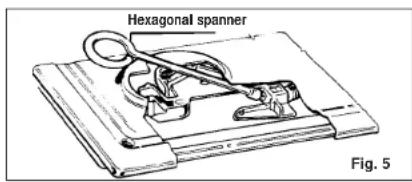
— insert the hexagonal spanner (supplied) into the burner support (Fig. 5)
— unscrew the injector and replace it with one suitable for the gas to be used (see Table below)
— regulate minimum flame and flame combustion (see nexts chapters).
Table of Gas Consumption 1 W = 0.860 kcal/h
| GAS TYPE | BURNER | O INJECTORS 1/100 mm. | NOMINAL THERMAL POWER | CAPACITY | REDUCED THERMAL POWER | PRESSURE m bar | ||||
| kW kcal/h | kW kcal/h | Norm. M | h. Max. | |||||||
| METHANE MGAS G 20 | MEDIUM LARGE | 93127 | 1,52,95 | 1,2902,537 | 143 l/h261 l/h | 0,38 3270,65 558 | 20 17 25 | |||
| BUTANE GAS G 30 | MEDIUM LARGE | 6184 | 1,52,95 | 1,2902,537 | 109 g/h215 g/h | 0,38 3270,65 558 | 28/30 20 | 65 | ||
| PROPANE GAS G 31 | MEDIUM LARGE | 6184 | 1,52,95 | 1,2902,537 | 107 g/h211 g/h | 0,38 3270,65 558 | 37 25 45 | |||
Regulating the minimum flame
After lighting the burners, turn the control knob to the minimum setting and then remove the knob (this can easily be removed by applying gentle pressure).
Using a small "Terminal" type screwdriver, the regulating screw can be adjusted as in Fig. 8. Turning the screw clockwise reduces the gas flow, whilst turning it anticlockwise increases the flow – use this adjustment to obtain a flame of approximately 3 to 4 mm in length and then replace the control knob.
If GPL (cylinder) gas is being used, turn the screw clockwise right to the end of the travel of the by-pass.
Screws regulating (for different models)
Fig. 8


REGULATING THE BURNERS
Flame Combustion
For maximum efficiency from the burners, the correct combustion of the flame is necessary. A good flame must be well aligned and without yellow tips (Fig. 7/B). If there is insufficient air, the flame will be uneven with yellow tips (Fig. 7/A). If there is too much air, the flame will be very short and bright (Fig. 7/C). In these cases, the combustion must be adjusted by re-fitting the carburation tube to the Venturi (where there is insufficient air) or removing the carburation tube (in the case of too much air). To position the carburation tube, the fixing screws must be loosened, and retightened when satisfactory combustion is obtained. Standard regulation values are stated in Fig. 6 and the following table.

Fig. 6 Fig. 7

| Type of burner | Quota «X» depending on type of gas | ||
| Butane G 30 | Propane G 31 | Methane G 20 | |
| Medium | 5 mm | 7 mm | 2 mm |
| Large | 0 mm | 5 mm | 3 mm |
INSTRUCTIONS FOR USE
Using the Gas Burner
If the burners have not been used for a couple of days, wait for a few seconds before lighting the burner; this will allow any air present in the pipes to escape.
To ignite the burners on hobs without electric ignition, place a lighted taper close to the burner, press in and turn the control knob anticlockwise.
For those hobs with electric ignition, simply turn the control knob to the ignition or maximum position and press the button marked ★. The spark is fired only when the button is released. If the burner does not ignite the first time, try again.
As a safety device, some models automatically cut off the gas supply if the flame is accidentally extinguished. In this case, push and rotate the control knob and keep it held down for approx 5-6 seconds.
The burner will then remain lit.
ATTENTION: When cleaning the hob, take care to replace the burners correctly, this will ensure that the ignition point is not blocked.
Use of electric hotplates
For the best use of the electric hotplates and to minimise energy consumption, the following recommendations should be noted.
| POWER OUTPUT - ELECTRIC HOTPLATES | ||
| Setting | ||
| 0 OFF | ||
| 1 VERY LOW Warming dishes & melting butter and chocolate | ||
| 2 LOW Simmering, sauces, stews, milk puddings, poached eggs | ||
| 3 | MODERATE | Vegetables, frozen foods, boiling water |
| 4 | MEDIUM | Fresh Vegetables, pasta, fish, pancakes. |
| 5 | HIGH | Omelettes, steaks |
| 6 | VERY HIGH | Chops |
A neon indicator light adjacent to the control knob will glow when the electric plate is in use.
GENERAL ADVICE
For the best results, the flat-bottomed pans should match the gas burner size as follows:
— Medium from 12 - 20 cm.
— Large from 20 - 26 cm.
For smaller containers a reducer stand (supplied with some models) should be used and the gas burner should be regulated so that the flame does not overlap the base of the pan. The reducer stand is for use with the medium burner. Vessels with concave or convex base should not be used.
WARNING: If a burner is accidentally extinguished, turn the knob to the off position and do not attempt to re-ignite if for at least 1 minute.
To protect the glass lid from damage and in the interests of safety, the burners/plates must be turned off and the burner/pan support/plate area must be cool before closing the lid down.
Only pans which have smooth flat bases should be used on the electric hotplates. The size of the pan should be as close as possible to the diameter of the hotplate, and never smaller (see Fig. 9). The base of the pan should be dry and spillages should be avoided. Empty pans should not be left on the plates, nor should the plates left switched on without a pan.

MAINTENANCE AND CLEANING
Important Advice
Before cleaning the Hob, ensure the appliance has cooled down. Switch off the electricity supply.
When cleaning the enamelled, varnished or chrome sections, use warm soapy water or a non-caustic detergent. For stainless steel use an appropriate cleaning solution. Hotplates should only be cleaned with a cotton cloth coated with vaseline or seed oil. Never use abrasives, corrosive detergents, bleaching agents or acids. Avoid any acid or alkaline substances (lemon, juice, vinegar etc.) on the enamelled, varnished or stainless steel sections.
The burners can be cleaned with soapy water. To restore their original shine, use a household stainless steel cleaner. After cleaning, dry the burners and replace.
It is important the Burners are replaced correctly.
This appliance must only be used for the purpose for which it is intended, domestic cooking, and any other use will be considered improper and could therefore be dangerous. The Manufacturer will not be responsible for any damage or loss resulting from improper use.
Lubricating the gas taps
If a gas tap becomes stiff, it should be dismantled, cleaned carefully with petrol and smeared with a drop of special heat resistant grease.
The following operations should be carried out:
— Disconnect the electrical power supply, close the gas supply tap from the mains or cylinder. — Remove the hob top plate by removing the corner screws and those under the burners. — Remove the two screws holding down the head flange. — Remove the head flange and the retaining spring on the knob shaft. — Remove the gas regulation cone, clean it with petrol and smear it with some heat resistant grease, taking care not to obstruct any holes through which gas must pass. — Re-assemble all the parts, making sure that the spring and the rotating axis of the cone fitted to the knob shaft are correctly seated.
Aftercare
Before calling out a Service Engineer please check the following:
— that the plug is correctly inserted and fused;
— that the gas supply is not faulty.
If the fault cannot be identified:
Switch off the appliance — do not tamper with it — call the Aftercare Service Centre.
The appliance is covered by a 12-month guarantee giving free Aftercare Service.
The Manufacturer will not be responsible for any inaccuracy resulting from printing or transcript errors contained in this brochure. We reserve the right to carry out modifications to products as required, including in the interests of consumption, without prejudice to the characteristics relating to safety or function.
Electrical diagrams
① ELECTRONIC IGNITION BUTTON (incorporated)
NOTES
INSTRUCTIONS FOR ASSEMBLY OF THE HOB TO THE GAS SUPPLY PIPES
These instructions are for fitters qualified for installation of equipment in line with the relevant national standard. All work must be carried out with the electricity supply disconnected.
ASSEMBLY PROCEDURE
2 spanners, sizes 17 and 23 mm are required.

A) As illustrated, assemble parts in sequence:
A) fixed pipe
B) washer
C) elbow fitting with tapered thread connection

2) Tighten the joints with the spanners, remembering to twist the pipes into position before tightening.

3) Attach fitting C to mains supply using rigid copper pipe.
VERY IMPORTANT
For ease of installation and to avoid gas leaks, it is recommended to connect the pipes as follows:
First connect the pipe to the Hob
and then
Connect the pipe to the gas supply.
If this sequence is not followed, there is a danger that gas will be trapped in the pipe.
AFTER INSTALLATION, CHECK THE TIGHTNESS OF ALL JOINTS USING A SOAPY SOLUTION
TECHNICAL DATA
| Kookplaten 60x50 | Bekirisch |  Fig. 1 Fig. 1 |
| Kookzones 4 elektrischType vanerijzing PE 01Scanningfrequente (V/Hz) *Vermogen elektrische installatie (W) 6300Almeting mm. 585x500Bevolligingsgraad Type Y |
* 220-240V-/380-415 V3N-
INSTALLATION

MAINTENANCE AND CLEANING

INSTALLATION
- INSTALLATION
- INSTRUCTIONS FOR THE INSTALLER
- ELECTRICAL CONNECTION (4 ELECTRIC PLATES)
- ELECTRICAL CONNECTION
- WARNING - THIS APPLIANCE MUST BE EARTHED
- CONNECT TO SPUR TERMINAL
- INSTALLATION OF ELECTRICAL CONNECTIONS
- GAS CONNECTION (SEE PAGE 11)
- ADAPTING THE HOB TO DIFFERENT TYPES OF GAS
- REGULATING THE MINIMUM FLAME
- REGULATING THE BURNERS
- FLAME COMBUSTION
- INSTRUCTIONS FOR USE
- USING THE GAS BURNER
- USE OF ELECTRIC HOTPLATES
- GENERAL ADVICE
- MAINTENANCE AND CLEANING
- IMPORTANT ADVICE
- IT IS IMPORTANT THE BURNERS ARE REPLACED CORRECTLY
- LUBRICATING THE GAS TAPS
- AFTERCARE
- BEFORE CALLING OUT A SERVICE ENGINEER PLEASE CHECK THE FOLLOWING
- ELECTRICAL DIAGRAMS
- INSTRUCTIONS FOR ASSEMBLY OF THE HOB TO THE GAS SUPPLY PIPES
- ASSEMBLY PROCEDURE
- VERY IMPORTANT
Brand : IBERNA
Model : FO FI110/3 W
Category : Oven