
EOS-1V - Camcorder CANON - Free user manual and instructions
Find the device manual for free EOS-1V CANON in PDF.


| Product Type | 35mm Film SLR Camera |
| Dimensions (W x H x D) | 161 x 119.2 x 70.8 mm (6.3 x 4.7 x 2.8 in) |
| Weight (Body Only) | Approx. 990 g (2.2 lbs) |
| Battery Type | 2 x CR123A lithium batteries |
| Lens Mount | Canon EF mount |
| Shutter Speed Range | 30 to 1/8000 sec, bulb |
| ISO Film Speed Range | ISO 6 to 6400 |
| Autofocus System | 45-point area AF (TTL-CT-SIR) |
| Exposure Modes | Program AE, Shutter-priority AE, Aperture-priority AE, Manual |
| Metering Modes | Evaluative, Partial, Spot, Center-weighted average |
| Continuous Shooting Speed | Up to 10 fps |
| Film Transport | Automatic film loading, advance, and rewind |
| Viewfinder Coverage | Approx. 100% |
| Built-in Flash | None (compatible with Canon EX-series Speedlites) |
| Maintenance | Keep battery contacts clean; store in dry place |
| Safety Precautions | Avoid exposing to rain/moisture; use only specified batteries |
| Spare Parts and Repairability | Professional service centers available; parts may be limited |
| General Information | Professional-grade film camera, weather-sealed body |
Frequently Asked Questions - EOS-1V CANON
User questions about EOS-1V CANON
0 question about this device. Answer the ones you know or ask your own.
Ask a new question about this device
Download the instructions for your Camcorder in PDF format for free! Find your manual EOS-1V - CANON and take your electronic device back in hand. On this page are published all the documents necessary for the use of your device. EOS-1V by CANON.
USER MANUAL EOS-1V CANON
By Portable Document Format
EOS-1V
EOS LINK SOFTWARE ES-E1
C12-8401
C50-2301
CY8-1201-225
Canon
EOS-1V
0 PREFACE
1 General
2 Technical
3 Repair
4 Electrical Adjustments
5 Parts Catalog
6 Electrical Diagrams
Appendix
SI Adjustment Chart
EOS LINK SOFTWARE ES-E1
1 Product Overview
3 Repair
5 Parts Catalog
Part 1
General Information
1. FEATURES
1.1 High-Performance, High-Precision Area AF
- The world's fastest continuous shooting speed of 9 fps in predictive AI Servo AF mode.
- 8 · 15mm Area AF for easy subject capture.
- Improved AF performance.
- Focusing point registration and shifting and limiting the selectable focusing points to 11 or 9 result in faster focusing point selection.
- Active, superimposed focusing points are brighter by over 2 stops.
1.2 High-Speed, Quiet Film Transport
- AF SLR camera boasting the world's fastest continuous shooting speed at approx. 10 fps (in the One Shot AF mode w/PB-E2 and NP-E2).
- Built-in motor drive enables approx. 3.5 fps continuous shooting.
- Film transport noise level is on par with the EOS-1N's.
1.3 High Reliability
- Moving parts are thoroughly sealed for excellent water and dust resistance.
- Grip's new battery chamber cover is lined with packing.
- The Remote control/Data transfer terminal cap is fixed on the camera to prevent loss and it protects the terminal against water.
- New lens mount coupling surface which matches the EF 300mm f/2.8L IS USM and later lenses equipped with an O-ring for enhanced water and dust resistance.
- Rigid magnesium alloy top and front covers with highly durable metallic finish.
- Shutter durability of 150,000 cycles.
- The grip mount and electrical contacts (system connector) are bipolar to enhance reliability.
- Ambient temperature range for normal operation is -20°C to +45°C with 95% maximum humidity. (Film ID imprinting is assured down to -10°C.)
1.4 Excellent Basic Features
- The algorithm for 21-zone evaluative metering and E-TTL autoflash metering has been improved for better metering stability.
- Ultra-high speed, high-precision shutter for 30 sec. - 1/8000 sec. and X-sync at 1/250 sec.
- 100% viewfinder coverage, dioptric correction, and built-in eyepiece shutter.
- Laser Matte focusing screen with Area AF ellipse.
- Short viewfinder blackout time of 87 ms (approx. 38% shorter than the EOS-1N's 140 ms and 17% shorter than the EOS-3's 105 ms). Insures stable viewfinder image during continuous shooting.
- Shutter release time lag is short and fixed at 55 ms for all lenses set at the maximum aperture or up to three stops smaller. See 3. Specifications, item 5-4. • Infrared film can be used.
- Film ID imprinting enabled for easier identification and organization of film rolls.
1.5 Outstanding Operation Ease
- Camera control layout conforms to the EOS-1N's
- EOS-1N users will feel at home with the EOS-1V. Using the EOS-1V and the EOS-1N at the same time presents no familiarity problems with the camera controls.
- Comfortable hold and feel with rubber covering on all grip surfaces.
- Fast Main Dial and Quick Control Dial operations.
- With full-time manual focusing lenses, manual focusing is enabled after One Shot AF or AI Servo AF operation.
- Hidden buttons inside the side door improve operational ease.
1.6 More Custom Functions
- Enhanced flexibility with 20 Custom Functions and 63 settings (two more Custom Functions and 11 more settings than the EOS-3).
- Three groups of Custom Function settings can be set to suit the particular subject.
- Personal Functions can be used to switch the EOS-1V's Custom Function settings on the fly.
1.7 Shooting Data and Personal Computer Linkage
- Shooting data for up to 100 rolls of 36-ex. film can be recorded.
- With EOS Link software ES-E1, the shooting data can be viewed or edited.
2. OVERVIEW
2.1 EOS-1V
The EOS-1V combines the EOS-1N's outstanding reliability and the EOS-3's advanced features (enhanced as described below). Its overall performance surpasses that of the Nikon F5 to become the world's top-performance AF SLR camera.
Specifications surpassing the EOS-1N's
- The EOS-3's 45-point Area AF improved for EOS-1V
- More focusing point selection methods (described later) with focusing point registration and shifting and CF-13-1 for limiting the selectable focusing points to 9.
- Improved AF mechanism and Area AF sensor for better focusing precision.
- The superimposed focusing point display is two stops brighter than the EOS-3's.
- AI Servo AF at 9 fps for subjects moving up to 50 kph as close as 8 m (EOS-1N: 5 fps as close as 10 m, EOS-3: 7 fps as close as 8 m)
- Max. continuous shooting speed of 10 fps (in the One Shot AF mode with PB-E2 and NP-E2 attached) (EOS-1N: 6 fps, EOS-3: 7 fps)
- Moving parts sealed against water and dust
- The grip's battery chamber cover is lined with packing.
- The camera's remote control/Data transfer terminal cap keeps out water and it cannot be lost. (The terminal has the same shape and pin count as the EOS-3's remote control terminal and it can be connected to remote switches like the RS-80N3 as well as to the EOS Link Software ES-E1 cable.)
- The first EOS-1 series camera to have highly rigid magnesium alloy top and front covers.
- The first EOS-1 series camera to have a durability of 150,000 shutter cycles (same as the Nikon F5, and exceeding the EOS-1N and EOS-3's 100,000 cycles).
- Twenty Custom Functions with 63 settings (compared to the EOS-3's 18 Custom Functions and 52 settings and the EOS-1N's 14 Custom Functions and 35 settings)
- Three groups of Custom Function settings can be set to suit the shooting objective
- Shooting data can be recorded by the camera
- By connecting the camera to a personal computer via EOS Link Software ES-E1, you can view and edit the shooting data and modify EOS-1V Personal Function settings.
- A user-selectable No. and film ID No. are imprinted on the film leader
- Automatic battery check (EOS Elan II/50/55 type) displays the battery level at all times on the LCD panel.
- Bulb exposures up to 23 hours, 59 min., 59 sec. indicated digitally
- Incorporates the EOS-3's state-of-the-art exposure control system
- 21-segment evaluative metering (not found on the EOS-1N), focusing point-linked spot metering, multi-spot metering, E-TTL autoflash, FP flash, FEL, FEB, and wireless multi-Speedlite flash. (The algorithm for evaluative metering and E-TTL flash metering has been improved.)
- Safety shift enabled in the shutter speed-priority AE and aperture-priority AE modes (set with a Custom Function).
- Viewfinder blackout time of 87 ms (EOS-1N: 140 ms, EOS-3: 105 ms)
• Digital frame counter in the viewfinder
- Frame countdown icon (not found on the EOS-3) provided and a Custom
Function can set the frame counter to be the same as the EOS-1N's
Specifications Exceeding the EOS-3's
- 100% viewfinder coverage, dioptric correction, built-in eyepiece cover, and other viewfinder specs on par with the EOS-1N's
- Newly-developed Laser Matte focusing screen (also compatible with the EOS-3)
- Compatible with infrared film
- Rubber skin on all camera grip surfaces (like the EOS-1N)
There is no Eye Control since priority was given to 100% viewfinder coverage,
0.72 · viewfinder magnification, dioptric correction, and the built-in eyepiece shutter.
Table 1-1 Comparison with EOS-1N and EOS-3
| Item | Camera | EOS-1N | EOS-1V | EOS-3 | |
| AF | Focusing Area■: f/2.8 high-precision focusing | □ □ ▪ □ □ |  |  | |
| Predictive AF at 50 kph & Continuous Shooting Speed w/PB-E2+300mm/2.8L | 10 m5 fps | 8 m9 fps | 8 m7 fps | ||
| Eye Control | - | - | ○ | ||
| Focusing Point Registration/Shift | - | ○ | - | ||
| View finder | Coverage | 100% | 100% | 97% | |
| Eye Relief | 20 mm | 20 mm | 19.5 mm | ||
| Dioptric Correction | -3 - +1 dpt | -3 - +1 dpt | - | ||
| Eyepiece Shutter | ○ | ○ | - | ||
| Metering | Sensor Segments | 16 | 21 | 21 | |
| Multi-spot Metering | - | ○ | ○ | ||
| Shutter | Speeds, X-sync | 30 - 1/8000 sec., 1/250 sec. | 30 - 1/8000 sec., 1/250 sec. | 30 - 1/8000 sec., 1/200 sec. | |
| Durability | 100,000 cycles | 150,000 cycles | 100,000 cycles | ||
| Flash Control | E-TTL Autoflash, FP Flash | - | ○ | ○ | |
| FE Lock, FEB | - | ○ | ○ | ||
| Wireless Multi-Speedlite Flash | - | ○ | ○ | ||
| Film Transport | Max. Speed | Body Only | 3 fps | 3.5 fps | 4.3 fps |
| w/PB-E2 | 6 fps | 10 fps | 7 fps | ||
| Infrared Film | ○ | ○ | × | ||
| Custom Functions/Settings | 14/35 | 20/63 | 18/52 | ||
| Film ID Imprinting/Data Recording | - | ○ | - | ||
| PC Link | - | ○ | - | ||
| Water/Dust Resistance | ○ | ○ | ○ | ||
| Top/Front Cover Material | Plastic | Magnesium alloy | Plastic | ||
| Dimensions (W · H · D mm) | 161 · 112.1 · 71.8 | 161 · 120.8 · 70.8 | 161 · 119.2 · 70.8 | ||
| Weight (excluding battery) | 855 g | 945 g | 780 g | ||

Fig. 1-1 Viewfinder comparison.

Fig. 1-2 LCD panel comparison.
1) Exterior design
As an imaging tool for advanced amateurs and pros, the EOS-IV's basic design concept is based on the EOS-1-series. The following were emphasized in the design:
q Imposing and refined exterior while looking tough and elegant The camera has been sculptured like a top-notch athlete with a lean and tough body. The smooth, curved surfaces are elegant to the smallest detail exuding a strong presence.
w Highly rigid, luxurious exterior The magnesium-alloy top and front covers are very durable and coated with a deep-black metallic finish. Also, like the EOS-1N, a rubber skin covers all the surfaces held by the hands. The result is a better grip, holding comfort, and enhanced joy of ownership. e Improved operation ease
The new Assist button (see Fig. 1-3), used for focusing point selection and other functions, is strategically positioned. The remote control/Data transfer terminal has a rubber cap to keep out water and dust. The EOS-1V retains the EOS-1N's basic camera controls while adopting additional ones to enhance op

Fig. 1-3 EOS-1V exterior.
2) Water- and Dust-Resistant
All the switches and major body seams are sealed, and the camera back edges are lined with packing. The grip's battery chamber cover is also lined with packing (see Fig. 1-4). Countermeasures against water and dust enable the camera to be used even in harsh environments. To better seal out dust and water, the lens mount perimeter also has a new coupling surface where the rubber O-ring on EF 300mm f/2.8L IS and later lenses contact against.

Fig. 1-4 Water-resistant grip
3) AF
The EOS-3's Area AF sensor (Fig. 1-5) has been refined for the EOS-1V. The S/N ratio is better and the AF optics have been revamped to improve AF performance. In the One Shot AF mode, the AF speed and predictive AF performance exceed the EOS-3's.
For fast focusing point selection even without Eye Control, a focusing point can be registered for instant shifting to it. There are also more focusing point selection methods. These improvements reflect the suggestions of EOS-3 professional users. (See next page.)

Fig. 1-5 Area AF sensor
EOS-1V's New AF Features (For details, see "4. Nomenclature".)
Focusing Point Registration and Shifting (HP: Home position)
This feature was suggested by many pro users of the EOS-3. It enables the user to register the most often-used focusing point and shift the focusing to this registered one. Among the 45 focusing points, only one focusing point can be registered. Or, the camera can be set for automatic focusing point selection with the 45 focusing points (the automatic selection of 2 focusing points can also be registered). Using a registered focusing point gives priority to composition, while automatic selection of 45 focusing points results in shutter release priority. The focusing point can thereby be registered to suit the objective.
The focusing point is shifted mainly with the new Assist button provided for this purpose. When CF-
18-1/2 is set, pressing the Assist button alone can shift the focusing point instantly.
![graph TD A["Shifting to the registered focusing point (normal)"] --> B["Register with Assist button + FEL button."] B --> C["The focusing points shown on the left can also be registered."] C --> D["Shifting to the registered focusing point (normal)"] D --> E["Shift with Assist button + Focusing poin…](/content/2026/06/1326220/images/2de4b438bc2aa4fbdace6a56f62cc0d083ffd8fdb49a41fb9470ec7d1632fea6.jpg)
Fig. 1-6 Focusing point registration and shifting.
New focusing point selection method (CF-13-3) In addition to limiting the selectable focusing points to 11 (with CF-13-1/2), a new Custom Function setting (CF-13-3) can also limit it to 9. Turning the Main Dial selects one of the three horizontal focusing points at the center or sets the automatic selection of 45 focusing points. Meanwhile, turning the Quick Control Dial selects one of the 8 peripheral focusing points. Thus, the user can quickly select the often-used center focusing point, a peripheral focusing point, or the 45 focusing points to achieve focus.
Also, the new CF-18-1/2 settings enable the Assist button alone to instantly select the center focusing point, and the Quick Control Dial and Assist button can be used to select one of the 9 focusing points.
![graph TD A["Automatic selection"] --> B["Selectable focusing points"] B --> C["9 selectable focusing points"] C --> D["Selectable peripheral focusing points"] D --> E["Press and turn."] E --> F["Manual selection of horizontal"] F --> G["To switch between horizontal focusing point shifting and automa…](/content/2026/06/1326220/images/4561cb9550dbe4a6cd3f2ccef13b2daf905c5c0b15ec20b33e74ea025a4eb225.jpg)
Fig. 1-7 Focusing point selection method with CF-13-3.
Limiting the selectable focusing points (CF-13-1/2/3) and expanding the focusing point range (CF-17-1/2) By limiting the selectable focusing points to 11 (CF-13-1/2) or 9 (CF-13-3) and expanding the focusing point range (CF-17-1/2), all 45 focusing points can be used to cover the subject.* This combination enables both quick focusing point selection and quick subject capture.
* With CF-13-3 and CF-17-1, 37 focusing points will be usable. With CF-17-2, the focusing point coverage varies depending on the lens focal length and AF mode.

* During One Shot AF, the selected focusing point and the focusing point achieving focus light up.
Fig. 1-8 CF-13 and focusing point expansion. (With CF-13-3)
4) The Viewfinder and Information Display
Like the EOS-1N, the EOS-1V's viewfinder coverage is 100 percent, the viewfinder magnification is 0.72x, the eye relief is 20 mm, and the dioptric correction range is -3 to +1 dpt. The viewfinder blackout time is shorter at 87 ms (EOS-1N: 140 ms, EOS-3: 105 ms). The viewfinder image is also stable even during continuous shooting.
The standard focusing screen is the newly developed Laser Matte focusing screen with the Area AF ellipse. Other Ec-series focusing screens can also be used. The superimposed focusing point is two stops brighter

Fig. 1-9 Viewfinder.
than the EOS-3's. It is easier to see under bright conditions. The viewfinder display on the right and bottom of the image area is almost the same as the EOS-1N's. The new FP flash icon has been added below the image area, and the new flash exposure level scale is on the right of the image area. The frame counter is fully digital, and it reflects the frame counter displayed on the LCD panel. There is also a frame countdown icon (new) which indicates that the frames are being counted in reverse order. With CF-8-2, the same frame counter display (F 9 - 0) as the EOS-1N's can be set.
5) Metering, Exposure Control, and the Shutter
The algorithm for evaluative metering and E-TTL autoflash metering has been changed to attain better stability. Otherwise, the exposure control and metering modes are the same as the EOS-3's. The shutter is based on the highly reliable rotary magnet-controlled shutter used in the EOS-3. It has carbon curtains. Improved shutter cocking has made the curtain speed faster to attain a maximum X-sync of 1/250 sec. and shutter speeds from 30 to 1/8000 sec. The shutter durability is 150,000 cycles. Bulb exposures can be as long as 23 hr., 59 min., and 59 sec. The bulb exposure's elapsed time is indicated digitally on the LCD panel.

Fig. 1-10 Bulb exposure time indicator.
6) Film Transport
The continuous shooting speed is shown in Table 2. With PB-E2 and NP-E2, the EOS-1V is the world's fastest 35mm AF SLR camera at 10 fps. This applies when the scene is metered for each shot, and it does not apply to stopped-down shooting. With PB-E2 and NP-E2, the EOS-1V can be set to one of four film advance modes: Single-frame, low-speed, high-speed, and ultra-high speed continuous advance. The EOS-1V is also compatible with bottom-attachable accessories for the EOS-1, EOS-1N, and EO With silencing technologies such as floating supports for film advance and shutter cocking, the film transport noise level is almost the same as the EOS-1N's (6 fps) during high-speed continuous shooting (7 fps). Film rewind noise is also the same level as the EOS-1N's.
Although an infrared sensor is used to detect the film transport, infrared film can be used with the EOS-1V since new optics prevent the picture area from getting fogged.
Table 1-2 Continuous Shooting Speed L: Low speed, H: High speed, H: Ultra-high speed
| Configuration | Power Source | Mode | One Shot Manual | AI Servo |
| EOS-1V only | 2CR5 | L | 3.5 fps | 3 fps |
| w/PB-E2 | NP-E2 | H « | 10 fps | 9 fps |
| H | 7 fps | 7 fps | ||
| L | 3 fps | 3 fps | ||
| LR6 | H | 6 fps | 5 fps | |
| L | 3 fps | 3 fps |
7) Custom Functions
Besides having the EOS-3's Custom Functions, the EOS-1V has the following new Custom Functions. Personal Functions also enable the user to set three groups of Custom Function settings (Fig. 1-11). C.Fn-0 cannot be registered in a Custom Function group.
Table 1-3 New Custom Functions
| CF No. | Function | Description | |
| 8 | Frame counter | 3 | Makes the viewfinder's frame counter display identical to the EOS-1N's (F 9 - 0) |
| 13 | Focusing point and spot metering linkage | 3 | The selectable focusing points are limited to 9 which are also linked to spot metering. |
| 18 | Shift to registered focusing point (home position) | 0 | Shifts with the Assist button and focusing point selector. |
| 1 | Shifts with the Assist button. | ||
| 2 | Shifts only while the Assist button is held down. | ||
| 19 | AF stop button function (Provided for IS lenses and super telephoto lenses) | 0 | AF stop while the button is held down. |
| 1 | AF operates while the button is held down. | ||
| 2 | AE lock (while metering is active) when the button is pressed. | ||
| 3 | Automatic selection of 45 focusing points while the button is held down. | ||
| 4 | Toggles between One Shot AF and AI Servo AF while the button is held down. For example, in the One Shot AF mode while the shutter button is pressed halfway for AF lock, pressing the button switches to AI Servo AF and releasing the button switches back to One Shot AF. | ||
| 5 | Image Stabilizer operates while the button is held down (the IS switch must be on). |

Fig. 1-11 Sample Custom Function groups.
8) Recording shooting data
The shooting data (see Table 1-4) is recorded automatically in the camera's built-in memory. With EOS Link Software ES-E1, the data can be transferred to a personal computer and then viewed and edited. The memory can hold the standard shooting data (shown by Table 1-4-1 and 1-4-2) for 100 rolls of 36-ex. film. When the memory becomes full, the oldest data for 1 roll is deleted and the data for the latest roll is written in its place. Any of the 27 items of shooting data can be recorded. The shooting data items in Table 1-4-1 are recorded at all times. The shooting data items in Tables 1-4-2 and 1-4-3 can be

Each bar represents 5 data-recordable rolls remaining. This bar displays indicates that 91 or more rolls are data-recordable.
Fig. 1-12 Remaining number of data-recordable rolls. recorded as selected by the user with EOS Link Software ES-E1. However, all 27 items of data cannot be selected for recording because the CPU's processing speed is unable to handle all of them. With the maximum number of shooting data items selected for recording, the memory can store data for 50 rolls of 36-ex. If only the minimum number of shooting data items are selected for recording, the memory can store data for 200 rolls of 36-ex. film.
The EOS-1V can only display the remaining number of data-recordable rolls (see Fig. 1-12 for 36-ex. rolls). The shooting data can be viewed only with the EOS Link Software ES-E1. Also, date and time information such as the shooting date and time and film loading date and time are not recorded unless EOS Link Software ES-E1 is used to enable the date and time to be recorded.
Table 1-4 Shooting Data Items Table 1-4-1 Items Always Recorded
| 1. User-selectable No. |
| 2. Film ID No. |
| 3. Film-loaded date and time |
| 4. DX-coded film speed |
| 5. Frame No. |
| 6. Picture-taking mode |
| 7. Multiple exposures |
Table 1-4-2 Items Always Recorded
| 1. Focal length |
| 2. Lens max. aperture |
| 3. Shutter speed |
| 4. Aperture |
| 5. Manually-set ISO speed |
| 6. Exposure compensation amount |
| 7. Flash exposure compensation amount |
| 8. Flash mode |
| 9. Metering mode |
| 10. Film advance mode |
| 11. AF mode |
Table 1-4-3 Extra Shooting Data Items
| 1. Bulb exposure time |
| 2. Date |
| 3. Time (hr., min., sec.) |
| 4. Custom Function settings |
| 5. Focusing point selection |
| 6. Focusing points achieving focus |
| 7. Battery-loaded date and time |
9) Film ID Imprinting
The film leader is always imprinted with a user-selectable 2-digit number (00-99) and a sequential 3-digit (001-999) film ID number (see Figs. 1-13 and 1-14). When multiple EOS-1V cameras are used, the user-selectable number can be used to identify which EOS-1V was used to shoot that particular roll of film. The film ID number counts up automatically each time a new roll of film is loaded. The film ID number is used as a reference to view or edit the shooting data of the corresponding roll with EOS Link Software ES-E1.
The imprinting mechanism is on the standard camera back. Immediately after the film advances to frame 1, a

Fig. 1-13 User-selectable number and film ID number display.
transparent LCD numeral is imprinted on the film by a mini lamp. The imprinting time is 25 ms to 180 ms (depending on the ISO film speed) at 20°C. The power source is the same as the camera's. The imprinting cannot be turned off. The EOS-1V camera back cannot be attached to the EOS-1N because the hinge length differs. It also cannot be attached to the EOS-3 because its inner parts will hit the EOS-3's film transport detector. Closing the camera back by force will have it pop up. (The Dateback DB-E2 can be attached to the EOS-1V.)

Fig. 1-14 Imprinting position of user-selectable number and film ID number (actual size).
10) Power Source
The power source is one lithium 2CR5 battery which can power the film transport for 50 rolls of 36-exposure film at 20°C.
11) Dimensions and Weight
The camera dimensions are 161 (W) × 120.8 (H) × 70.8 (D) mm. Body thickness is 54.8 mm. The camera body weighs 945 g without the battery. (The 2CR5 battery weighs 40 g.)
2.2 New Accessories
The following system accessories were developed at the same time as the EOS-1V.
(1) EOS Link Software ES-E1
EOS Link Software ES-E1 consists of driver software and a cable which connects the EOS-1V's remote control/Data transfer terminal to the personal computer's USB port. It has the following functions:
• Transfer, viewing, and editing of the shooting data. • EOS-1V control
- Personal Functions (Fine-tune settings of EOS-1V functions such as limiting the shooting modes and changing the metering time.)

Fig. 1-15 EOS Link Software ES-E1
(2) MACRO RING LITE MR-14EX
Macro Speedlite (Guide No. 14) with E-TTL autoflash control and two curved flash tubes. A flash ratio can be set between the left and right flash tubes. FEB, FEL, wireless multi-Speedlite flash, and other flash exposure control features found on the 550EX are possible. It can also use external power packs, including the existing Speedlite power packs.

Fig. 1-16 MACRO RING LITE MR-14EX
3. SPECIFICATIONS
1. Type
1-1 Type: 35mm AF/AE single-lens reflex camera with focal-plane shutter (vertical travel) and built-in motor drive 1-2 Picture size: 24 mm · 36 mm 1-3 Compatible lenses: Canon EF lenses 1-4 Standard lens: Canon EF 50mm f/1.4 1-5 Lens mount: Canon EF mount
2. AF
2-1 Type: TTL-AREA-SIR** with a CMOS sensor 2-2 Focusing points: 45-point Area AF, 8 mm (vertical) · 15 mm (horizontal)
* The 7 focusing points at the center are cross-type sensors which are also vertical-line sensitive.
2-3 Focusing modes: The mode can be switched between the following three:
(1) One-Shot AF
Autofocus locks when focus is achieved.
* AF-priority: The shutter can be released only when focus is achieved. * During evaluative metering, AE lock is set at the same time as AF lock. (In the other metering modes, exposure metering continues in real-time until the shutter is released.)
(2) AI Servo AF
Constantly tracks subject movement up to the start of exposure.
* While the shutter button is pressed halfway, the shutter button can be depressed fully at any time to release the shutter regardless of focus. (Shutter release-priority) * When the shutter button is pressed completely without pressing it halfway first, the shutter is released after AF operation is executed once. * During continuous shooting of a moving subject, the lens is driven (taking 0 to 250 ms) from the second successive frame to track the subject, then the shutter is released. * No in-focus indicator. The indicator only blinks (8 Hz) if AF fails.
(3) Manual focusing
Switching from AF to manual focusing
* With mechanical manual-focus lenses, the focus mode is switched to manual with the lens. * With electronic manual-focus lenses, the focus mode can be switched to manual as above or automatically with CF-7-0).
When focus is achieved, the in-focus indicator and superimposed focusing point light up. If focus fails, neither is displayed.
| During continuous shooting, electronic-ring manual focusing is enabled during film advance and disabled during exposure (but enabled with PB-E2 + NP-E2 attached). | ||
| 2-4 | Focusing point selection: | (1) Manual selection of focusing pointHorizontal focusing point selection: Focusing point selector + Main DialVertical focusing point selection: Focusing point selector + Quick Control Dial* Focusing point selector pressed → Assist button + Main Dial* Focusing point selector + FE lock button pressed → Hold down the Focusing point selector and turn Main Dial(2) Automatic selection of focusing point* In the One-Shot AF mode: Based on the subject information obtained by the Area AF focusing points, the optimum focusing point is selected automatically.* In the AI Servo AF mode: The center focusing point is initially selected. If the subject moves to another focusing point, AI Servo AF will continue to track the subject.* If CF-11-2 is set, pressing the focusing point selector while the shutter button is pressed halfway or completely will select the focusing point automatically.(3) Center focusing point selection CF-13-3* Focusing point selector press → Assist button ON |
| 2-5 | Active focusing point indicator: | The focusing point is superimposed in the viewfinder. |
| 2-6 | Focusing point registration and shifting (HP: Home position): | Focusing point registration: After selecting the focusing point, press the Assist button and FEL button (the center focusing point is the default setting)Shifting to registered focusing point: Press Assist button and focusing point selector.* 45-point and 2-point automatic selection also can be registered. |
| 2-7 | AF activation: AF is activated by pressing the shutter button halfway. | |
| 2-8 | AF operation speed: Same as or faster than the EOS-3. | |
| 2-9 | In-focus indicators: Focusing point superimposed in viewfinder (cancelable with Custom Function), in-focus indicator (dot), and electronic beeper (which can be enabled or disabled with the main switch) | |
| 2-10 | AF precision: Same as the EOS-1N's | |
| 2-11 | AF working range: EV 0-18 (at ISO 100), according to Canon's testing conditions. | |
2-12 AF-assist beam: With an EOS Speedlite attached (with built-in AF-assist light) and turned on, a near-infrared beam (peak wavelength of 700 nm) is emitted automatically by the Speedlite when necessary.
550EX and ST-E2: Linked to the 45-point Area AF. 540EZ: Emitted during automatic focusing point selection or when a focusing point along the center horizontal row is selected.
Other EOS Speedlites: Emitted during automatic focusing point selection or when the center focusing point is selected.
* The camera has no built-in AF-assist beam emitter.
3. Viewfinder
3-1 Type: SLR-type, fixed eye-level pentaprism with condenser lens
3-2 Standard focusing Interchangeable screen: Laser-matte screen with Area AF ellipse, focusing points, and fine spot metering circle provided as the standard screen.
Interchangeable with Ec-series focusing screens. Metering correction data can be set with a Custom Function for the Laser Matte and New Laser Matte screens.
3-3 Standard diopter: -1 diopter. Adjustable from -3 diopter to +1 diopter.
3-4 Eye relief: 20mm
3-5 Picture coverage: 100 percent vertically and horizontally
3-6 Magnification: 0.72 · (with 50mm lens at infinity, -1 diopter)
3-7 Viewfinder (1) On the screen information: ① Area AF ellipse
② Focusing points
③ Fine spot metering circle
(2) Below the screen (Main indicators)
① Manual exposure level
② AE lock (Blinks at 2 Hz during AEB.)
③ Flash ready (Blinks when the FE lock setting is unsuitable)
④ High-speed sync (FP flash)
⑤ Shutter speed (If unsuitable, it blinks at 2 Hz as a warning.)
⑥ FE lock (FEL)
⑦ Bulb (buLb)
⑧ Focusing point selection mode
Depth-of-field AE mode (DEP1, DEP2)
Aperture setting (If unsuitable, it blinks at 2 Hz as a warning.)
Exposure compensation / Flash exposure compensation
In-focus indicator (Blinks at 8 Hz if focus cannot be achieved.)
(3) Right of screen
Exposure level scale in 1/3-stop increments (±3 stops) ② Exposure level
②-1. AE exposure compensation amount ②-2. AE lock and real-time metering indicator ②-3. Manual exposure level ②-4. AEB amount (3 dots) ②-5. Background exposure with flash (camera metering reading) ②-6. Multi-spot metering
Metering level
③-1. Flash exposure compensation amount ③-2. Reverse highlight of dot bars during FE lock ③-3. FEB amount (3 dots) ③-4. Multi-spot metering value
Frame counter
Frame countdown icon
3-8 Mirror: Quick-return half mirror (Transmittance: reflectance ratio of 37:63)
Viewfinder blackout time: 87 ms or less at 1/60 sec. or faster speeds.
3-9 Mirror lockup: Enabled with CF-12-1
* Mirror locks up when the shutter button is pressed completely. The shutter is then released when the shutter button is released and pressed completely again. Mirror lockup lasts for 30 sec. after which the mirror returns. There is no exposure during this time.
3-10 Mirror vignetting: No vignetting with lenses up to EF 1200mm f/5.6
3-11 Depth-of-field preview: Enabled with depth-of-field preview button. * With Speedlites capable of wireless flash, a modeling flash fires when the depth-of-field preview button is pressed.
3-12 Built-in eyepiece. Provided shutter:
3-13 Misc.: Eyecup Ec-II provided (same as for EOS-1N)
* E-series dioptric adjustment lenses, Angle Finder B and C, and Magnifier S attachable.
4. Exposure Control
4-1 Metering modes: TTL metering at the maximum aperture with a 21-zone silicon photocell sensor. The following four metering modes can be selected:
(1) Evaluative (linkable to any focusing point) (2) Partial Metering area: Approx. 8.5% of screen. (3) Center spot metering (CF-13-0, 2) Metering area: Approx. 2.4% of screen (4) Focusing point-linked spot metering: CF-13-1 (11 points), CF-13-3 (9 points) Metering area: Approx. 2.4% of screen, fixed at center during automatic focusing point selection * For (3) and (4), real-time metering occurs while the shutter button is pressed halfway. During continuous shooting, the same meter reading taken for the first shot is locked (AE lock) for subsequent shots. (5) Multi-spot metering For (3) or (4), pressing the FEL button enables up to 8 spot meter readings (when flash is not used). (6) Centerweighted averaging metering
4-2 AE modes: The following seven AE modes and manual mode can be set:
① Shutter speed-priority AE (Safety shift enabled with CF-16-1) ② Aperture-priority AE (As above) ③ Depth-of-field AE (Non-shiftable)
1) With a manually-selected focusing point: The selected focusing point can be used to set the two DEP points. When a pair of manually-selected focusing points is selected automatically, the focusing point focused at the closer distance is used to set the two DEP points.
2) With an automatically selected focusing point: The center focusing point is used to set the two DEP points.
④ Program AE (Shiftable) ⑤ E-TTL program flash AE (21-segment flash metering) ⑥ A-TTL program flash AE (3-segment flash metering) ⑦ TTL program flash AE (3-segment flash metering) ⑧ Manual exposure
* To set the aperture, the exposure compensation button + Main Dial can be used.
⑨ Bulb
4-3 Metering range: EV 0-20 in all metering modes (at 20°C with 50mm f/1.4 lens, ISO 100). 4-4 Unsuitable exposure warning: Shutter speed or aperture display blinks at 2 Hz. 4-5 Exposure metering: Activated when shutter button is pressed halfway. * Before shutter release: Metering remains active for 6 sec. after the halfway-depressed shutter button is released. * After shutter release: Metering remains active for 2 sec. after the halfway-depressed shutter button is released. 4-6 ISO Film Speed Range: Automatically set with DX-coded film at ISO 25-5000 or settable manually at ISO 6-6400. Settable in 1/3-stop increments. * The manually set ISO film speed and exposure compensation are displayed during film rewind and after film rewind before the film cartridge is removed. * With non-DX-coded film, the ISO speed set previously will blink to indicate that manual setting of ISO is required. 4-7 Exposure (1) AEB: Autoexposure bracketing Compensation: * Set by pressing the Shooting mode selector and AF mode button and turning Main Dial. Bracketing amount: Up to ±3 stops in 1/3-stop increments * The bracketing sequence is correct exposure, under-exposure, and overexposure, taken according to the film advance mode. If the self-timer is used, the three bracketed shots will be exposed successively after the self-timer delay.
Bracketing method of each shooting mode
| Shooting Mode | Bracketing Method | ||
| Shutter speed | Aperture | ||
| 1 Shutter speed-priority AE | — | ● | |
| 2 Aperture-priority AE | ● | — | |
| 3 Depth-of-field AE | ● | — | |
| 4 Program AE | ● | ● | |
| 5 Manual | CF-5-0 | ● | — |
| CF-5-1 | — | ● | |
* AEB cancellation
AEB is canceled with any of the following: 0 bracketing amount, CLEAR, flash ready, bulb, main switch set to L, lens interchange, film loading and initial advance, or rewind.
* If the battery is replaced during AEB, AEB will start from the first shot (correct exposure) again.
(2) Manual exposure compensation
* Turn Quick Control Dial or press exposure compensation button and turn Main Dial. Set up to ±3 stops in 1/3-stop increments.
(3) (1) and (2) above can be set in combination.
4-8 AE Lock (1) Auto AE lock
In the One-Shot AF mode with evaluative metering, AE lock is set when focus is achieved.
(2) Manual AE lock
Set with the AE lock button (resets when pressed again). Enabled in all metering modes.
* AE lock cancels when any of the following occurs: The metering turns off, main switch is set to L, a mode button (CLEAR, REW, Custom Function, etc.) is pressed. * When a Speedlite is used and it is charged and ready, the AE lock button will not function.
4-9 Multiple exposures: Maximum 9 multiple exposures per frame.
(Cancelable and resettable at any time.)
Cancels automatically after all the multiple exposures are taken. Multiple exposures during continuous shooting enabled (exposure shift less than 0.1 mm).
5. Shutter
5-1 Type: Vertical-travel, focal-plane shutter with all speeds electronically-controlled.
* Front and rear shutter curtains both have dedicated rotary magnet control. (Curtain speed: 2.2 ms/24mm)
5-2 Shutter speeds: 30 to 1/8000 sec., X-sync at 1/250 sec.
In the shutter speed-priority AE and manual exposure modes, shutter speeds in 1/3-stop increments can be set.
◆For bulb exposures, the exposure time is displayed on the LCD panel from 1 - 23 hours and 00:00 - 59:59 min. and sec. (LCD panel shows three bars for every 30 min. up to 120 min.)
5-3 Shutter release: Soft-touch electromagnetic release (no cable release socket) 5-4 Release time lag: Shutter release time lag for stopping down three stops from the maximum aperture (excludes AF operation time):
(1) Time lag from SW-1 ON to SW-2 ON and film exposure: 55 ms (2) Time lag from SW-1 and SW-2 to film exposure: 191 ms
5-5 Self-timer: 10- or 2-sec. delay.
* Self-timer in progress is cancelable by turning the main switch to L. * Self-timer operation indicated by self-timer lamp (2 Hz for the first 8 sec., then 8 Hz for the remaining two sec.)
Self-timer countdown displayed on frame counter.
5-6 Camera shake None warning:
6. Film Transport
6-1 Film loading and initial film advance:
Autoloading with a sprocketless system.
After the film leader is set properly and the back is closed, the film advances to frame 1 automatically (taking about 1 sec.). If the main switch is set to L, the film does not advance to frame 1.
6-2 Film advance system:
Automatic film advance with a small coreless motor dedicated to film transport. Film perforation detected with an infrared photo reflector.
6-3 Infrared film compatibility:
Compatible.
6-4 Film advance start:
Starts with the exposure completed signal.
6-5 Film transport confirmation:
Confirmable with LCD panel bars and frame counter (on lower right in viewfinder).
6-6 Film advance modes and speed:
(1) See table below for continuous shooting at 1/250 sec. or faster shutter speeds:
L: Low-speed H: High-speed H': Ultra-high speed Approx. fps
| Configuration | Power Source | Film Advance Mode | One Shot AF/Manual | AI Servo AF |
| EOS-1V | 2CR5 | L | 3.5 | 3 |
| w/BP-E1 | LR6/FR6 | L | ||
| w/PB-E2 | NP-E2 | H' | 10 | 9 |
| H | 7 | 7 | ||
| L | 3 | 3 | ||
| LR6/FR6 | H | 6 | 5 | |
| L | 3 | 3 | ||
| w/PDB-E1 | LR6/FR6/Ni-Cd Pack E1 | H | 6 | 5 |
| L | 3 | 3 |
(2) Single-frame shooting: Single frame advances at the same speed as during continuous shooting.
6-7 Shooting capacity: Indicated by the table below with a new battery and EF 50mm f/1.4 lens.
24-ex. rolls (36-ex. rolls)
| Configuration | Power Source | Ambient Temperature | |
| At 20°C | At -20°C | ||
| EOS-1V | 2CR5 · 1 | 75 (50) | 18 (12) |
| w/BP-E1 | 2CR5 · 1 | 75 (50) | 18 (12) |
| LR6 · 4 | 60 (40) | 0 (0) | |
| KR15/51 · 4 | 20 (14) | 15 (10) | |
| w/PB-E2 | LR6 · 8 | 125 (85) | 7 (5) |
| FR6 · 8 | 180 (120) | 75 (50) | |
| KR15/51 · 8 | 50 (35) | 36 (24) | |
| NP-E2 | 100 (70) | 30 (20) | |
| w/PDB-E1 | LR6 · 8 | 120 (85) | 7 (5) |
| FR6 · 8 | 180 (120) | 75 (50) | |
| KR15/51 · 8 | 50 (35) | 35 (24) | |
| Ni-Cd Pack E1 | 65 (45) | 45 (30) | |
When an AA nickel-hydrogen storage battery (Ni-MH) is used, the level is the same as when an AA Ni-Cd battery (KR15/51) is used.
6-8 Film rewind system: Automatic film rewind with a small coreless motor.
6-9 Film rewind initiation: (1) Automatic rewind Rewind initiated automatically in the following cases: * After the DX-coded number of exposures are taken. * After the end of the film is detected. * After 36 exposures have been taken. (2) Midroll film rewind Pressing the midroll rewind button rewinds the film in midroll. During film rewind in cases (1) and (2) above, the midroll rewind button can toggle between high-speed and silent rewind.
6-10 Film rewind confirmation: Confirmable with the bars and frame counter on the LCD panel.
6-11 Film rewind time: For 24-exposure (36-ex.) film, with new battery, and in room temperature.
| High-speed rewind Approx. 4.5/(8) sec. |
| Silent rewind Approx. 12/(18) sec. |
* The film rewind time is the same with or without the PB-E2.
6-12 Film rewind stoppage: Stops automatically when the film leader is wound into the cartridge.
6-13 Film rewind completed Indicated by the film cartridge icon blinking at 2 Hz on the LCD panel.
6-14 Film-loaded confirmation: Indicated by the film cartridge symbol displayed on the LCD panel and visually confirmable with the film window.
6-15 Frame counter: (1) Digital counter on LCD panel and lower right of viewfinder screen.
* The viewfinder frame counter is not displayed during film rewind.
6-16 Film transport noise: High-speed rewind: 59 dB Silent rewind: 49 dB * At 15 cm from the camera back:
7. Flash Specifications
7-1 Flash contacts: (1) Hot shoe: Sync contacts (2) Side terminal: Threaded sync terminal (Shock protection feature on hot shoe) * The PC terminal's cap is the same as the EOS-1N's. * Flash connectable and usable simultaneously on both (1) and (2) above.
7-2 Hot shoe: Locking pin hole provided to prevent Speedlite slippage.
7-3 Flash exposure compensation:
(1) Manual setting
1) Increments: ±3 stops in 1/3-stop increments 2) Procedure: Metering mode button + Quick Control Dial or Metering mode button + Focusing point selector + Main Dial
(2) FEB (Flash Exposure Bracketing) Enabled and set with the 550EX, MR-14EX. When the flash is unable to fire anymore during FEB continuous shooting, the shutter release locks. The shutter release unlocks when the SW-2 is released. If the flash is not ready, the AE mode takes effect.
* If flash exposure compensation has been set with both the EOS-1V and external Speedlite, the Speedlite's setting will take effect.
7-4 FE lock: With E-TTL autoflash Speedlites, FE lock is set with the FE lock button.
* FE lock is effective for 6 sec. Pressing the button again renews FE lock.
* FE lock is canceled if any of the following occurs: 6 sec. elapse, the main switch is set to L, one of the mode buttons (BC, CLEAR, REW, CF) is pressed.
7-5 Wireless flash: Enabled.
* With the 550EX, MR-14EX, or ST-E2, those Speedlites set as slave units will fire a preflash and meter the light reflected off the subject with the AE metering sensor. The flash output is then set and stored in memory and wireless flash is fired.
* Wireless high-speed sync (FP flash), FE lock, and automatic fill-in flash are also possible.
8. Film ID Imprinting
(Built-in with EOS-1V's camera back.)
8-1 Imprinted information: User-selectable two-digit number (00 - 99) and 3-digit film ID No. (001 - 999).
8-2 User-selectable No.: With no film loaded, press the Multi Function button to set the film ID setting mode, then turn the Main Dial to set the desired two-digit No. (00 - 99).
8-3 Imprinting position/size: Imprinted on frame 0 on the film leader. Text height is about 1 mm.
8-4 Imprinting method: After the film loads, a minilamp imprints transparent LCD digits through the film base (imprinting cannot be disabled).
8-5 Imprint confirmation: During imprinting, the ID symbol is displayed on the LCD panel.
* If the shutter is released during imprinting, the shutter release will override the imprinting.
8-6 Imprinting time:
| ISO | 64 or lower | 80 ~ 125 | 160 ~ 250 | 320 ~ 500 | 640 or higher | NON DX |
| [ms] | 180 | 120 | 80 | 40 | 25 | 88 |
8-7 Power source: Same as used by the camera.
9. Shooting data
When a picture is taken, the shooting data is automatically recorded in the camera's built-in memory. With the ES-E1, the data can be transferred to a personal computer for viewing and editing.
9-1 Shooting data
| Item | Description |
| 1. Selectable No. | Any 2 digits from 00 to 99. |
| 2. Film ID | A 3-digit No. from 001 to 999 counts up each time a roll of film is loaded in the camer a. |
| 3. Film-loaded date and time | Year, month, day, hour, and minute. |
| 4. DX-coded film speed | 25 - 5000 |
| 5. Frame No. | 1 - 36 |
| 6. Lens focal length used | 0 - 9999mm |
| 7. Shooting mode | Shutter speed-priority AE, aperture-priority AE, depth-of-field AE, program AE, manual, bulb, AEB |
| 8. Lens max. aperture | f/00 - f/91 |
| 9. Shutter speed used | 30 - 1/8000 sec. |
| 10. Aperture used | f/00 - f/91 |
| 11. Manually set ISO speed | 6 - 6400 |
| 12. Exposure compensation amount | -6.0 - +6.0 (including any AEB amount) |
| 13. Flash exposure compensation amount | -6.0 - +6.0 (including any FEB amount) |
| 14. Flash mode | E-TTL, A-TTL, TTL autoflash, manual, OFF |
| 15. Metering mode | Evaluative, partial, spot, and centerweighted metering |
| 16. Film advance mode | Single frame, continuous (w/o Power Drive Booster), low-speed continuous, high-speed continuous, ultra-high-speed continuous, self-timer (10 sec. or 2 sec. delay) |
| 17. AF mode | One Shot AF, AI Servo AF, manual focusing |
| 18. Bulb exposure time | 0 to 23 hr. 59 min. 59 sec. |
| 19. Picture-taking date | Year, month, day |
| 20. Picture-taking time | Hr., min., sec. |
| 21. Custom Function settings | CF-0 to CF-19 |
| 22. Focusing point selection | One focusing point among the 45, or automatic selection |
| 23. Multiple exposures | ON/OFF |
| 24. Focusing points achieving focus | Multiple focusing points recorded (Only in the One-Shot AF mode) |
| 25. Battery-loaded time and date | Year, month, day, hour, and minute. |
9-2 Viewing and editing shooting data:
9-3 Data configuration:
9-4 Data recording timing:
* The user-selectable No. and film ID No. are imprinted automatically on the film leader when the film is loaded.
Enabled only with the EOS Link Software ES-E1 and a personal computer (not possible with the camera only).
The recording of data items 6 to 25 is optional. EOS Link Software ES-E1 is used to select the items to be recorded.
Film data: Recorded when the film is loaded and advanced to frame 1.
Shooting data: Recorded when the shutter button is pressed completely.
9-5 No. of rolls recordable:
50 to 200 36-ex. rolls
* The maximum number depends on the number of data items to be recorded. When setting the data configuration with EOS Link Software ES-E1, the maximum number of recordable rolls can be checked. * The recorded data is retained even when the camera battery is removed. * When the memory becomes full, the oldest data is deleted and the newest data is written. * The memory capacity cannot be expanded.
9-6 Memory check: While the Assist button is active in the film ID setting mode, the LCD panel displays the remaining number of data-recordable 36-ex. rolls.
* The film transport bars also indicate the remaining number of data-recordable 36-ex. rolls (one bar represents 5 rolls).
9-7 Shooting data deletion:
Done with EOS Link Software ES-E1 (not possible with the camera)
- Personal Computer Connection (Camera)
10-1 Multi functions: After the camera is connected to the personal computer, press the Multi Function button to set the data transfer mode. Subsequent operations are done with the EOS Link Software ES-E1.
10-2 Interface standards: Serial interface
10-3 Connector port: Remote Control/Data transfer terminal
10-4 Transmission speed: 9.6 kbps - 115.2 kbps
10-5 Data transmitted: Set with EOS Link Software ES-E1.
- Date Function
11-1 Auto calendar: Built-in and compatible with the Gregorian calendar year (year 2000 - 2099) and adjusts automatically for short and long months and leap years (including the leap year of 2000).
11-2 Date setting: Press the Multi Function button to set the date mode. Press the Assist button to select the number to be adjusted. Turn the Main Dial to adjust the number.
* The date and time must first be set with the EOS Link Software ES-E1 before the date and time can be adjusted with the camera. Otherwise, pressing the Multi Function button will not set the date setting mode. * With the EOS-1V, only the last two digits of the year can be adjusted.
11-3 Date imprinting: None (provided with Dateback DB-E2)
11-4 Clock backup: Backup for 24 hours after battery removal.
12. Camera Specifications
12-1 Camera back: Opens and detaches with a camera back release lever (with lock-release button). Film window provided. 12-2 Custom Functions: 20 user-selectable Custom Functions (No. 0 - 19)
* The LCD panel's exposure level scale bars indicate the Custom Functions (except CF-0) already set.
12-3 Personal functions: (1) Custom Functions settable in 3 groups
① After setting the Custom Functions, use the Multi Function button to create Personal Functions. ② Turn the Main Dial to select PF-0, then press the Custom Function set button to select PF-0-1, PF-0-2, or PF-0-3.
③ Press the Assist button to complete the setting. To call up the Personal Function, follow steps ① and ② above, then press the shutter button halfway.
* EOS Link Software ES-E1 can also be used to set Custom Functions (except C.Fn-0).
* C.Fn-0 cannot be registered in a Custom Function group.
(2) ON/OFF of Personal Functions set with EOS Link Software ES-E1
① Press the Multi Function button to set the Personal Function.
② Turn the Main Dial to select the Personal Function from PF-1 to PF-30.
③ Press the Custom Function set button to select 0 (OFF) or 1 (ON).
④ Press the shutter button halfway to complete the procedure.
12-4 Clear button: (1) Pressing this button resets the settings to default shown in the table below.
| No. Item | Default |
| 1. Shooting mode | Program AE |
| 2. AF mode | One Shot AF |
| 3. Metering mode | Evaluative metering |
| 4. Film advance mode | Single frame |
| 5. Focusing point selection mode | Automatic |
| 6. Focusing point home position | Center focusing point |
| 7. Multiple exposures | Canceled/Default setting |
| 8. Exposure compensation | |
| 9. Flash exposure compensation | |
| 10. AE lock | |
| 11. FE lock | |
| 12. AEB | Canceled |
(2) Pressing the Clear button while a Custom Function can be set resets all Custom Functions (except CF-0) to the default.
(3) When the CLEAR button is pressed in the Personal Function mode, all Custom Functions will be reset to P.Fn-*-0.
* Personal Functions which were set with EOS Link Software ES-E1 can be set again even after the Personal Functions have been reset. For the setting procedure, see 12-3 (2).
12-5 Power source:
| Configuration | Power Source | Voltage [V] |
| EOS-1V | 2CR5 · 1 | 6 |
| w/Battery PackBP-E1 | 2CR5 · 1 | |
| LR6 · 4 | ||
| KR15/51 · 4 | 4.8 | |
| w/Power DriveBooster PB-E2 | LR6 · 8 | 12 |
| FR6 · 8 | ||
| KR15/51 · 8 | 9.6 | |
| NP-E2 | 12 | |
| w/Power DriveBooster E1 | LR6 · 8 | 12 |
| FR6 · 8 | ||
| KR15/51 · 8 | 9.6 | |
| Ni-Cd Pack E1 |
When an AA nickel-hydrogen storage battery (Ni-MH) is used, the level is the same as when an AA Ni-Cd battery (KR15/51) is used.
12-6 Main switch: Three settings: OFF/ON/Signal on.
12-7 Battery check: Automatic battery check when the main switch is turned on. The battery level is indicated by one of four battery check icons (not including OFF) on the LCD panel.
12-8 External display: Large LCD panel provided. Built-in, uniform illumination (EL).
Pressing the ELEMENT button turns on the illumination for 6 sec. During illumination, the 6-sec. period is restarted if another switch is touched. Illumination turns off after 6 sec. or if the EL button is pressed again.
12-9 Film advance coupler cap: Same as for EOS-1N.
12-10 Tripod socket: CU 1/4.
12-11 Remote control: Remote Control/Data transfer terminal provided
* The terminal is protected against water and dust with a pressure-fixed cap.
* The terminal is also used for connecting to EOS Link Software ES-E1.
12-12 Standard grip: New for EOS-1V. Battery chamber cover designed to be water and dust resistant.
12-13 Interchangeable Compatible with GR-E1, PB-E2, BP-E1, and PDB-E1. grip:
12-14 Body material: Magnesium (top and front covers), aluminum diecast (aperture portion) and polycarbonate resin with glass fiber.
12-15 Exterior color: Black
12-16 Dimensions: 161 (W) · 120.8 (H) · 70.8 (D) mm (Body thickness: 54.8 mm) 6.34 (W) · 4.72 (H) · 2.79 (D) in (Body thickness: 2.16 in.)
12-17 Weight: 945 g (add 40 g for the lithium battery) 33.3 oz. (add 1.41 oz. for the lithium battery)
13. Major Accessories
13-1 New accessories: (1) EOS Link Software ES-E1 (2) MACRO RING LITE MR-14EX (3) EOS-1V standard grip GR-E2 (Also attachable to EOS-1N, EOS-1, and EOS-3) (4) Laser Matte focusing screen with Area AF ellipse 13-2 Major EOS System See “6. Accessory Compatibility (Compatible System Accessories).” Accessories:
14. Misc.
14-1 Battery service life testing conditions
① Batteries used: Primary battery is new (less than 3 months old) Secondary battery is fully charged.
② Lens: EF 50mm f/1.4 USM
③ Shooting mode: Shutter speed-priority AE (at 1/1000 sec.)
④ Subject brightness: EV 15
⑤ Film advance mode: Continuous
⑥ Film rewind mode: Standard (CF-1-0)
⑦ AF mode: AI Servo AF
⑧ SI display: On (Standard CF-10-0)
⑨ Film: Kodak Tri-X, 36-ex. (fresh roll)
⑩ Shooting conditions: The following operation sequence was executed as described below: AF search (infinity to near focus to infinity), shutter button pressed halfway for 6 sec., shutter released, and meter active for 2 sec.
- At 20°C
Film loaded, continuous shooting of 36 frames, automatic film rewind, film cartridge removed, 20-sec. break, stop down to f/5.6 for 5 sec., depth-of-field preview.
- At -20°C
After the camera and film were exposed to a temperature of -20°C for three hours, the following operation was executed: Film loaded, continuous shooting of 5 frames at 20-sec. intervals until 36 frames exposed (the last frame is exposed singly), automatic film rewind, film cartridge removed, and 20 sec. break, stop down to f/5.6 for 5 sec., depth-of-field preview, and 3-min. break.
* One roll is considered to be one whose film was advanced and rewound completely. Specifications for 24-exposure are interpolated from 36-exposure results.
4. NOMENCLATURE


Fig. 1-17
| Selectable Focusing Points |  | 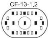 ■:User-selectable focusing points. ■:User-selectable focusing points. |  ■ser-selectable focusing points. ■ser-selectable focusing points. | |
| Standard Focusing Point Selection |  |  |  | |
| Focusing Point Registration | Focusing point selection  | Procedure is the same as left.Eleven focusing points are user-selectable and automatic selection can be registered. | Not possible. | |
| Shifting to the Registered Focusing Point and Automatic Selection/Center Focusing Point Selection | Standard Setting | Shift to registered focusing point With CF-11-2:+/- button + Assist buttonWith CF-11-3:FEL button + Assist button With CF-11-2:+/- button + Assist buttonWith CF-11-3:FEL button + Assist button | Same as left. | Center focusing point selected. With CF-11-2:+/- button + Assist buttonWith CF-11-3:FEL button + Assist button With CF-11-2:+/- button + Assist buttonWith CF-11-3:FEL button + Assist button |
| CF-18-1 | Shift to registered focusing point | Same as left. | Center focusing point selected. | |
| CF-18-2 | Press the button to shift to the registered focusing point.Release the button to return to the original focusing point. | Same as left. | Press the button to select the center focusing point.Release the button to return to the original focusing point. | |
| CF-11-2 | Automatic selectionDuring SW1 or SW2,press the focusing point selector.  | Same as left. | During SW1 or SW2, Automatic press the focusing point selector  | |
Fig. 1-18 Focusing point selection, registration, and shifting.
Table 1-5 Focusing Point Selection Methods
| Setting | Selection Range | Selection Operation | Remarks | ||||||
| During Metering | Assist Button | +/- | FEL | / : After the button is pressed, it can be released to continue the operation. +: Hold down the button for the operation. | |||||
| Selection of 45 focusing points (Same as with CF-13-1/2) | Left/right | ● / | ● | ||||||
| Up/down | ● / | ● | |||||||
| ● / | ● + | ● | Convenient when the Quick Control Dial switch is off. | ||||||
| ● + | ● / | ● | After pressing the buttons simultaneously, release only the FEL button and turn the Main Dial. | ||||||
| Selection of 45 focusing points + CF-11-2 (Same as with CF-13-1/2) | Left/right | ● / | ● | ||||||
| ● | ● | The extreme left or right focusing point is selected. No automatic selection. | |||||||
| Up/down | ● / | ● | |||||||
| ● | ● + | ● | The extreme left or right focusing point is selected. No automatic selection. | ||||||
| ● / | ● + | ● | Convenient when the Quick Control Dial switch is off. | ||||||
| Selection of 9 focusing points with CF-13-3 | Left/right | ● / | ● | ||||||
| Periphery | ● / | ● | |||||||
| Center | ● / | ● | |||||||
| Selection of 9 focusing points with CF-13-3 + CF-11-2 | Left/Right | ● / | ● | ||||||
| ● / | ● | ||||||||
| Periphery | ● | ● | |||||||
| Center | ● | , ● | |||||||
Table 1-6 Custom Function List
| Function CF-No. | Setting | Description | New | Old | Remarks | |
| Focusing screen characteristics | CF-0 | 0 | Setting for New Laser Matte screens (Ec-N, Ec-R). | ● | ||
| 1 | Setting for Laser Matte screens (Ec-A, Ec-B, Ec-C, Ec-CII, Ec-D, Ec-H, Ec-I, Ec-L, EOS-1V standard screen). | ● | ||||
| Auto film rewind mode | CF-1 | 0 | High-speed automatic film rewind. | ● | CF-1-1 and CF-1-3 are ideal when film rewind noise would be disturbing. | |
| 1 | No automatic film rewind. High-speed film rewind with midroll rewind button. | ● | ||||
| 2 | Silent (low-speed) automatic film rewind. | ● | ||||
| 3 | No automatic film rewind. Silent film rewind with midroll rewind button. | ● | ||||
| Film leader position | CF-2 | 0 | Rewinds film leader into the cartridge. | ● | This is convenient if you develop the film yourself.With CF-2-1, the shutter speed will always be 1/8000 sec. if you release the shutter with the camera back open. | |
| 1 | Leaves film leader outside the cartridge. | ● | ||||
| Film speed setting method | CF-3 | 0 | Set automatically with the DX code. | ● | This is for when you want to set the film speed yourself.It saves you from setting the film speed each time you load film. | |
| 1 | Set manually. | ● | ||||
| AF activation | CF-4 | 0 | Enables AF and AE operation with the shutter button pressed halfway.AE lock with the (*) button. | ● | ||
| 1 | Enables AE and AF operations with the M-16 button.AE lock with the shutter button pressed halfway. | ● | This is effective when you want to focus and meter at different portions of the scene. | |||
| 2 | Enables AF and AE operations with shutter button pressed halfway.AF lock (no AE lock) with the (*) button. | ● | This is effective when you want to stop Al Servo AF operation momentarily.If an obstruction comes between the camera and subject, it will not throw off the AF. The exposure is set at the moment of exposure. | |||
| 3 | Enables AF and AE operation (no AE lock) with the (*) button.Pressing the shutter button completely releases the shutter (pressing it halfway executes AE operation only). | ● | When you use Al Ser vo AF, you can toggle between Al Servo AF and focus lock just by pressing the (*) button. This is useful for subjects which keep moving and stopping repeatedly. The exposure is also set at the moment when the picture is taken. Thus, the focusing and exposure are always set correctly and all you do is wait for the right moment to capture the shot. | |||
| Manual Tv/Av settings | CF-5 | 0 | Shutter speed: Set with Main Dial Aperture: Set with Quick Control Dial or +/- button and Main Dial. | ● | ||
| 1 | Aperture: Set with Main-Dial.Shutter speed: Set with Quick Control Dial or +/- button and Main Dial.The functions of the Main Dial and Quick Control Dial are reversed. | ● | This makes it easier to change the aperture during studio sessions with studio flash units. Also, when AEB is used in the manual exposure mode, the shutter speed can be fixed while only the aperture is shifted for AEB. | |||
●: Also provided with the EOS-3.
| Function CF-No. | Setting | Description New Old | Remarks | ||||
| Manual Tv/Av settings | CF-5 | 2 | The shutter speed and aper ture are set in the same way as with CF-5-0. In the aperture-priority AE or manual mode, the aperture can be set with the EOS-1V even while the lens is detached. | ● | If you are using a super telephoto lens with more than one EOS-1V body, you can still set the aper ture with the cam-era(s) not attached to the lens. This function is mainly for pro photographer assistants. | ||
| 3 | The shutter speed and aper ture are set in the same way as with CF-5-1. In the aperture-priority AE or manual mode, the aperture can be set with the EOS-1V even while the lens is detached. | ● | Same as CF-5-2. | ||||
| Exposure level increments | CF-6 | 0 | 1/3-stop increments in all cases. | ● | This is suited for slide films which have a narrow exposure latitude. | ||
| 1 | Whole-stop increments for the shut-ter speed and aperture, and 1/3-stop increments for exposure comp-pensation and flash exposure com-pensation. | ● | The shutter speed and aper ture can be set in the familiar full-stop increments. | ||||
| 2 | 1/2-stop increments in all cases. | ● | Suited for negative films which have a wide exposure latitude. | ||||
| USM lens electronic ring MF | CF-7 | 0 | The lenses listed on the right enable electronic manual focusing after AF operation. | ● | EF 50mm f/1.0L USM EF 85mm f/1.2L USM EF 200mm f/1.8L USM EF 300mm f/2.8L USM EF 400mm f/2.8L USM EF 500mm f/4.5L USM EF 600mm f/4L USM EF 1200mm f/5.6L USM EF 26-80mm f/2.8-4.0L USM. | ||
| 1 | Disables electronic manual focus-ing after AF operation. | ● | This prevents the focus from being thrown off by inadvertent turning of the focusing ring after One-Shot AF. | ||||
| 2 | Disables electronic manual focus-ing at all times. | ● | When CF-7-0/1 and CF-4-1/3 are set, the focusing ring can be used to focus before AF operation. However, this is disabled with this setting.* When CF-7-1/2 is set, you must first set the lens focus switch to MF (or M) to focus manually. | ||||
| Frame counter | CF-8 | 0 | The frame counter counts up. | ● | |||
| 1 | The frame counter counts down (indicates the remaining number of frames). | ● | You can see how many frames are left in the roll. | ||||
| 2 | The frame counter in the viewfinder is displayed in the same way as the EOS-1N. | ● | |||||
| AEB sequence and auto cancellation | CF-9 | 0 | Correct exposure, underexposure, overexposure, then automatic can-cellation. | ● | |||
| 1 | Correct exposure, underexposure, overexposure, and no automatic cancellation. | ● | AEB is not canceled even when the lens is interchanged or when the film is replaced. Therefore you can keep tak-ing AEB shots (with the correct e xpo-sure first). | ||||
| 2 | Underexposure, correct exposure, overexposure, then automatic can-cellation. | ● | |||||
| 3 | Underexposure, correct exposure, overexposure, and no automatic cancellation. | ● | You can keep taking AEB shots in this sequence. | ||||
| Focusing point flashing mode | CF-10 | 0 | Standard mode• Flashes when focus is achieved, lights dimly while you press the shutter button halfway after focus is achieved. | • | This applies during manual focusing point selection.During automatic focusing point selec-tion, the focusing point does not light dimly after focus is achieved. | ||
| 1 | No flashing at all. | • | If the flashing of the focusing point is annoying, you can disable it. | ||||
| 2 | No flashing after focus is achieved. | • | For the standard mode, this disables the focusing point from lighting dimly after focus is achieved. | ||||
| 3 | Flashes brightly. | • | This makes the focusing point easier to see even in bright light. | ||||
| Focusing point selection method | CF-11 | 0 | Enables the focusing point to be selected by pressing the focusing point selector and turning the Main Dial or Quick Control Dial.• Turn the Main Dial to select a focusing point on the right or left, and turn the Quick Control Dial to select a focusing point on the top or bottom. | • | When CF-11-2 and CF-13-3 are set, turning the Quick Control Dial selects one of 8 off-center focusing points, and pressing the Assist button selects the center focusing point. | ||
| 1 | Enables the focusing point to be selected by pressing the exposure compensation button and turning the Main Dial or Quick Control Dial. | • | This reverses the functions between the standard mode's focusing point selector and exposure compensation button. This enables the exposure comp-pensation and manual exposure's aperture to be set in the same way as with the EOS-1. | ||||
| 2 | Turn the Quick Control Dial alone to select a left or right focusing point, and press the Assist button and turn the Main Dial to select a focusing point on the top or bottom.• CF-11-1 operations can also be executed. | • | This setting is identical to the EOS-1N's CF-11-2 for selecting the left or right focusing point. With this setting, you can select the focusing point while pressing the shutter button halfway (or while the metering is active) or during continuous shooting in the Al Ser vo AF mode. The focusing point selection stops at the extreme left or right focusing point.• During AF operation, pressing the focusing point selector enables you to switch from manual focusing point selection to automatic focusing point selection. You can thereby instantly switch to automatic focusing point selection. | ||||
| 3 | Enables the focusing point to be selected by pressing the FEL but-ton and turning the Main Dial or Quick Control Dial. | • | This reverses the functions between the focusing point selector button and FEL button. The button next to the AE lock button then functions as an FEL button. | ||||
| Mirror lockup | CF-12 | 0 | No mirror lockup (normal position). | • | Effective for close-up shots and with super telephoto lenses.Mirror lockup eliminates camera vibra-tion caused by the mirror's reflex action. A tripod is required. | ||
| 1 | Mirror lockup | • | |||||
| Focusing point and spot metering linkage | CF-13 | 0 | No linkage.● Spot metering is always at the center. | ● | |||
| 1 | Spot metering linked to the focusing point.● Spot metering is linked to one of 11 focusing points selected manually. | ● | The selectable focusing points are limited to 11. This makes focusing point selection faster and links spot metering to the focusing point you select. This setting is effective for spotlighted subjects on-stage, etc., when you want to control the framing of the subject. | ||||
| 2 | No linkage.● Spot metering is always at the center.● You can select only one of 11 focusing points. | ● | Compared to CF-13-0, this setting makes focusing point selection faster. (* When automatic focusing point selection is used with CF-13-1/2/3, all 45 focusing points will be subject to automatic selection.) | ||||
| 3 | Spot metering linked to the focusing point.● Spot metering is linked to one of 9 focusing points selected manually. | ● | Compared to CF-13-1/2, this setting makes focusing point selection faster. | ||||
| Automatic reduction of fill-in flash output | CF-14 | 0 | Enabled. | ● | Natural-looking fill-in flash effects are obtained automatically. | ||
| 1 | Disabled. | ● | Effective for backlit subjects in front of a sunset, etc., to prevent underexposure of the subject. | ||||
| Shutter curtain synchronization | CF-15 | 0 | First-curtain synchronization.● The flash fires immediately after the shutter opens. | ● | |||
| 1 | Second-curtain synchronization.● At slow sync speeds, the flash fires immediately before the shutter closes. | ● | By using a slow sync speed, you can create a light trail following a moving subject. (* Works with Speedlite 380EX and 220EX.) (* This is effective for EX-series Speedlites which do not have shutter-curtain synchronization setting capability. Speedlite 550EX has this capability and its shutter-curtain synchronization setting overrides the camera's.) | ||||
| Safety shift | CF-16 | 0 | Disabled. | ● | |||
| 1 | Enabled.I Safety shift works in the shutter speed-priority AE and aper ture-priority AE modes.● If a correct exposure cannot be obtained with the shutter speed or aperture you have set, then the camera automatically shifts the shutter speed or aperture so that a correct exposure can be obtained. | ● | Even if the exposure settings you have set are not suitable, the camera will automatically alter the settings to obtain a correct exposure. This feature is convenient when the scene's brightness changes suddenly. | ||||
| Function CF-No. | Setting | Description New Old | Remarks | ||||
| Manual focusing point selection range | CF-17 | 0 | Standard | ● | |||
| 1 | Expanded selection | ● | The focusing point selection range expands by one point all around the manually-selected focusing point. This setting is effective when the manually-selected focusing point is unable to focus track a subject moving irregularly. | ||||
| 2 | Automatically-selected range | ● | The camera automatically sets this focusing point selection range (as shown below) to suit the lens f ocal length, AF mode, and the subject's movement during predictive AF. This is effective when the subject's movement is unpredictable. | ||||
| AF Mode | Lens Focal Length | ||||||
| Shorter than 300mm 300mm or Longer | |||||||
| One Shot AF | No expansion. Expanded by 1 point. | ||||||
| Al Servo AF | For slow-moving For fast-moving subjects. For slow-moving For fast-moving subjects. | ||||||
| Selection of preselected focusing point | CF-18 | 0 | Selectable with the Assist button + Focusing point selector. | ● | |||
| 1 | Selectable with the Assist button. | ● | |||||
| 2 | Selectable only while the Assist button is pressed. | ● | |||||
| AF stop button (Works with super telephoto IS lenses) | CF-19 | 0 | AF stop when pressed. | ● | 3: When the button is released, the previous focusing point is selected.4: When pressed while in the One Shot AF mode, Al Servo AF is set. When pressed while in the Al Ser vo AF mode, One Shot AF is set. Toggling is possible even during shutter release.5: The IS switch must be turned ON. | ||
| 1 | AF operation when pressed. | ● | |||||
| 2 | AE lock when pressed while metering is active. | ● | |||||
| 3 | When pressed, the focusing point is selected from among the 45 points. | ● | |||||
| 4 | When pressed, toggles between One Shot AF and Al Ser vo AF. | ● | |||||
| 5 | When pressed, Image Stabilization operates. | ● | |||||
Table 1-7 Using CF-4 and CF-19 Together (AF start/stop operation with the EOS-1V and lens)
| Operation | Result |
| During AF start → AF stop | AF stop |
| During AF stop → AF start | No AF start |
| During AF start → AF start | No AF start again |
| During AF stop → AF stop | AF stop maintained |
Table 1-8 USM Electronic Ring Manual Focusing
| CF-4-0 | CF-4-1 | CF-4-2 | CF-4-3 | |
| CF-7-0 | × / ° | ° / ° | × / ° | ° / ° |
| CF-7-1 | × / × | ° / × | × / × | ° / × |
| CF-7-2 | × / × | × / × | × / × | × / × |
* Before focus/After focus ○: USM electronic ring manual focusing enabled. X: Disabled.
1-36 The body thickness is the total of this number and the flange back of 44 mm. ☆Figures with stars are official dimensions, rounded OFF to two decimal places.
Fig. 1-19 Six external views

Fig. 1-20 LCD Panel Nomenclature

Fig. 1-21 Viewfinder Information

Fig. 1-22 E-TTL autoflash program line (With EF 50mm f/1.8 at ISO 100)
Fig. 1-23 A-TTL autoflash program lines (With EF 50mm f/1.8 at ISO 100)
5. ACCESSORIES
Speedlites![graph TD A["Speedlite 220EX"] --> B["Speedlite Transmitter ST-E2"] C["Speedlite 360EX"] --> D["Speedlite 550EX"] E["Slave Unit E"] --> F["Sync Cord 485 (includes A-B)"] G["TTL Shoe Cord E"] --> H["TTL Shoe Cord E (115 dB) vs. 480 GB"] I["Speedlite 480CG"] --> J["MACRO RING LITE MR-14EX"] K["Macro Ri…](/content/2026/06/1326220/images/da4470cb8da3f264e917144826f8faa441c715501ed52be8446ef9b79bfcd282.jpg)
Fig. 1-24 Compatible System Accessories
◎ : Compatible. c: AF and EMD can be driven simultaneously. - : Compatible under certain conditions. ×: Not compatible.
- Compatible Single Focal Length Lenses
| No | Accessory | Status | Note |
| 1 | EF 14mm f/2.8 L USM | ◎ | |
| 2 | EF 15mm f/2.8 FE | ○ | |
| 3 | EF 20mm f/2.8 USM | ◎ | |
| 4 | EF 24mm f/1.4 L | ◎ | |
| 5 | EF 24mm f/2.8 | ○ | |
| 6 | EF 28mm f/1.8 USM | ◎ | |
| 7 | EF 28mm f/2.8 | ○ | |
| 8 | EF 35mm f/1.4 L USM | ◎ | |
| 9 | EF 35mm f/2 | ○ | |
| 10 | EF 50mm f/1 L USM | ◎ | |
| 11 | EF 50mm f/1.4 USM | ◎ | |
| 12 | EF 50mm f/1.8 | ○ | |
| 13 | EF 50mm f/1.8II | ◎ | |
| 14 | EF 85mm f/1.2 L USM | ◎ | |
| 15 | EF 85mm f/1.8 USM | ◎ | |
| 16 | EF 100mm f/2 USM | ◎ | |
| 17 | EF 135mm f/2 L USM | ◎ | |
| 18 | EF 135mm f/2.8 SF | ○ | |
| 19 | EF 180mm f/3.5 L USM MA CRO | ◎ | |
| 20 | EF 200mm f/1.8 L USM & II USM | ◎ | |
| 21 | EF 200mm f/2.8 L USM & II USM | ◎ | |
| 22 | EF 300mm f/2.8 L USM & II USM | ◎ | |
| 23 | EF 300mm f/2.8 L IS USM | ◎ | |
| 24 | EF 300mm f/4 L USM | ◎ | |
| 25 | EF 300mm f/4 IS L USM | ◎ | |
| 26 | EF 400mm f/2.8 L USM & II USM | ◎ | |
| 27 | EF 400mm f/2.8 L IS USM | ◎ | |
| 28 | EF 400mm f/5.6 L USM | ◎ | |
| 29 | EF 500mm f/4 L IS USM | ◎ | |
| 30 | EF 500mm f/4.5 L USM & II USM | ◎ | |
| 31 | EF 600mm f/4 L USM & II USM | ◎ | |
| 32 | EF 600mm f/4 L IS USM | ◎ | |
| 33 | EF 1200mm f/5.6 L USM | ◎ | |
| 34 | EF 50mm f/2.5 MACRO | ○ | |
| 35 | EF 100mm f/2.8 MACRO | ◎ | |
| 36 | MACRO PHOTO LENS MP-E 65mm F/2.8 1-5 X | ◎ | |
| 37 | TS-E 24mm f/3.5 L | ◎ |
| No | Accessory | Status | Note |
| 38 | TS-E 45mm f/2.8 | ◎ | |
| 39 | TS-E 90mm f/2.8 | ◎ | |
| 40 | Extender EF 2x | ◎ | |
| 41 | Extender EF 1.4x | ◎ | |
| 42 | Extension Tube EF12 | ● | *1 |
| 43 | Extension Tube EF25 | ● | *1 |
| 44 | Life-size Converter EF | ◎ | |
| 45 | Lens Mount Converter FD-EOS | ◎ | |
| 46 | Macro Lens Mount Converter FD-EOS | ● | *1 |
| 47 | Close-up Lens 250D | ● | *1 |
| 48 | Close-up Lens 500D | ● | *1 |
| 49 | Close-up Lens 500 | ● | *1 |
*1 Compatible with the Laser Matte focusing screen. With the New Laser Matte Ec-N and Ec-R focusing screens, the exposure level may be thrown off. Test shots are recommended.
- Compatible Zoom Lenses
| No | Accessory | Status | Note |
| 50 | EF 17-35mm f/2.8 L USM | ◎ | |
| 51 | EF 20-35mm f/2.8 L | ◎ | |
| 52 | EF 20-35mm f/3.5-4.5 USM | ◎ | |
| 53 | EF 22-55mm f/4-5.6 USM | ◎ | |
| 54 | EF 24-85mm f/3.5-4.5 USM | ◎ | |
| 55 | EF 28-70mm f/2.8 L USM | ◎ | |
| 56 | EF 28-70mm f/3.5-4.5 & II | ○ | |
| 57 | EF 28-80mm f/2.8-4 L USM | ◎ | |
| 58 | EF 28-80mm f/3.5-5.6 & II | ◎ | |
| 59 | EF 28-80mm f/3.5-5.6 USM& II & III & IV & V USM | ◎ | |
| 60 | EF 28-105m f/3.5-4.5 USM | ◎ | |
| 61 | EF 28-135mm f/3.5-4 IS USM | ◎ | |
| 62 | EF 35-70mm f/3.5-4.5 & A | ○ | |
| 63 | EF 35-80mm f/4-5.6 & PZ & II & III | ◎ | |
| 64 | EF 35-80mm f/4-5.6 USM | ◎ | |
| 65 | EF 35-105mm f/3.5-4.5 | ○ | |
| 66 | EF 35-105mm f/4.5-5.6 | ◎ | |
| 67 | EF 35-105mm f/4.5-5.6 USM | ◎ | |
| 68 | EF 35-135mm f/3.5-4.5 | ○ | |
| 69 | EF 35-135mm f/4-5.6 USM | ◎ | |
| 70 | EF 35-350mm f/3.5-5.6 L USM | ◎ | |
| 71 | EF 38-76mm f/4.5-5.6 | ◎ | |
| 72 | EF 50-200mm f/3.5-4.5 | ○ | |
| 73 | EF 50-200mm f/3.5-4.5 L | ○ | |
| 74 | EF 55-200mm f/4.5-5.6 USM | ◎ | |
| 75 | EF 70-200mm f/2.8 L USM | ◎ | |
| 76 | EF 70-200mm f/4 L USM | ◎ | |
| 77 | EF 70-210mm f/4 | ○ | |
| 78 | EF 70-210mm f/3.5-4.5 USM | ◎ | |
| 79 | EF 75-300mm f/4-5.6 & II & III | ◎ | |
| 80 | EF 75-300mm f/4-5.6 USM& II USM & III USM | ◎ | |
| 81 | EF 75-300mm f/4-5.6 IS USM | ◎ | |
| 82 | EF 80-200mm f/2.8 L | ◎ | |
| 83 | EF 80-200mm f/4.5-5.6 & II | ◎ | |
| 84 | EF 80-200mm f/4.5-5.6 USM | ◎ | |
| 85 | EF 100-200mm f/4.5 A | ○ | |
| 86 | EF 100-300mm f/4-5.6 USM | ◎ | |
| 87 | EF 100-300mm f/5.6 | ○ | |
| 88 | EF 100-300mm f/5.6 L | ○ | |
| 89 | EF 100-400mm f/4.5-5.6 L IS USM | ◎ |
- Speedlites
| No | Accessory | Status | Note | |
| 1 | 550EX | ◎ | ||
| 2 | Speedlite Transmitter ST-E2 | ◎ | ||
| 3 | 220EX | ◎ | ||
| 4 | 380EX | ◎ | ||
| 5 | 540EZ | ◎ | ||
| 6 | 480EG system | ◎ | ||
| 7 | 430EZ | ◎ | ||
| 8 | 420EZ | ◎ | ||
| 9 | 300EZ | ◎ | ||
| 10 | 200E | ◎ | ||
| 11 | 160E | ◎ | ||
| 12 | Macro Ring | ML-3 | ◎ | |
| 13 | Lite | MR-14EX | ◎ | |
| 14 | Multi-Speedlite System (Wired) | ◎ | ||
- EOS Camera Cases
| No | Accessory | Status | Note |
| 1 | EOS-3 case | ◎ | |
| 2 | EOS 650 & EOS 620 cases | ✕ | |
| 3 | EOS-1 cases | ✕ | |
| 4 | EOS 5/A2/A2E cases | ✕ | |
| 5 | EOS 100/ELAN cases | ✕ | |
| 6 | EOS 500/Rebel X cases | ✕ | |
| 7 | EOS-1N cases | ✕ | |
| 8 | EOS 50 E/ELAN II E cases | ✕ | |
| 9 | EOS IXE cases | ✕ |
- Remote Control
| No | Accessory | Status | Note | |
| 1 | Remote Switch | RS-80N3 | ◎ | |
| 2 | 60T3 | ● | *2 | |
| 3 | RS-60E3 | × | ||
| 4 | Remote Controller | RC-1 | × | |
| 5 | LC-3 | ● | *2 | |
| 6 | LC-4 | ◎ | ||
| 7 | Timer Remote Controller TC-80N3 | ◎ | ||
*2 Usable with the Remote Switch Adapter RA-N3.
- Grips and Motor Drives
| No | Accessory | Status | Note | |
| 1 | Grips | GR10 | × | |
| 2 | GR20 | × | ||
| 3 | GR50(EOS750,850) | × | ||
| 4 | GR60(EOS10) | × | ||
| 5 | GR70(EOS1000) | × | ||
| 6 | GR-80TP (EOS Rebel X/Rebel XS/500/Kiss, 888/5000, Rebel G/500 N/New EOS Kiss) | × | ||
| 7 | GR-E1 | ◎ | ||
| 8 | Vertical Grip VG10 (EOS A2/A2E/5) | × | ||
| 9 | Battery Pack | BP-5 (EOS A2/A2E/5, Elan II/Elan II E/50/50 E/55) | × | |
| 10 | BP-8 (EOS Rebel X/Rebel XS/500/Kiss, 888/5000, Rebel G/500 N/New EOS Kiss) | × | ||
| 11 | BP-200 (EOS Rebel 2000/300) | × | ||
| 12 | BP-50 (EOS Elan II/Elan II E/50/50 E/55) | × | ||
| 13 | BP-E1 (EOS-1, 1N) | ◎ | ||
| 14 | Power Drive Booster | PDB-E1 | ◎ | |
| 15 | PB-E2 | ◎ | ||
- Viewfinder Accessories
| No | Accessory | Status | Note | |
| 1 | Eyecup | E (650,620) | × | |
| 2 | Eb (750,850) | × | ||
| 3 | Ec (EOS-1) | ◎ | ||
| 4 | Ec-II (EOS-IN) | ◎ | ||
| 5 | Ed (EOS5,3) | × | ||
| 6 | Ed-E (EOS5,3) | × | ||
| 7 | Dioptric Adjustment Lenses | E (10 types) | ◎ | |
| 8 | Ed (EOS5,55,3) | × | ||
| 9 | Ee (EOSIXE) | × | ||
| 10 | Rubber Frame Eb | Eb | × | |
| 11 | Ec (EOS-1) | ◎ | ||
| 12 | Ed (EOS5,3) | × | ||
| 13 | Focusing Screen | E (7 types) | × | |
| 14 | Ec (11 types) | ◎ | ||
| 15 | Ed (6 types) | × | ||
| 16 | Antifog Eyepiece | Ec (for EOS-1N) | ◎ | |
| 17 | Ed (for EOS-3) | × | ||
| 18 | Angle Finder | C | ◎ | |
| 19 | B | ◎ | ||
| 20 | Adapter Ed | ◎ | ||
| 21 | Adapter EdII | × | ||
| 22 | Magnifier S | ◎ | ||
| 23 | Eyepiece Extender EP-EX15 | × | ||
- Databacks
| No | Accessory | Status | Note |
| 1 | Databack DB-E2 | ◎ | |
| 2 | Quartz Dateback E | × | |
| 3 | Technical Back E | × | |
| 4 | Keyboard Unit TB | × | |
| 5 | Interface Unit TB | × | |
| 6 | Command Back EOS-1N | × |
- PC Link
| No | Accessory | Status | Note |
| 1 | EOS Link Software ES-E1 |
- Filters
| No | Accessory | Status | Note | |
| 1 | Circular Polarizing Filter | PL-C52mm | ◎ | |
| 2 | PL-C58mm | ◎ | ||
| 3 | PL-C72mm | ◎ | ||
| 4 | PL-C77mm | ◎ | ||
| 5 | Drop-in Circular Polarizing Filter | PL-C52 | ◎ | |
| 6 | PL-C48mm | ◎ | ||
| 7 | Drop-in Gelatin Filter | Holder II | ◎ | |
| 8 | Holder 52 | ◎ | ||
| 9 | Drop-in Threaded Filter Holder 52 | ◎ | ||
| 10 | Gelatin Filter Holder | E52,58,72,77mm | ◎ | |
| 11 | III / IV | ◎ | ||
| 12 | ADIII / IV52,58,67,72,77mm | ◎ | ||
| 13 | Hood III/IV | ◎ | ||
- Misc.
| No | Accessory | Status | Note |
| 1 | Panorama Adapter PA-1000 | × |
- COMPARISON WITH COMPETING MODELS
| Item | Camera | EOS-1V | Nikon F5 | Minolta alpha 9 | |
| AF | Focusing Area | 45-point Area AF | + + + | | + | | |
| High-precision Focusing (f/2.8) | ○ (7 points at center) | — | — | ||
| Predictive AF Performance at 50 kph (300mm f/2.8) | 8 m, 9 fps | 8 m, 8 fps | 9 m, 4.5 fps | ||
| Focusing Point Selection | Manual/Auto | ○ / ○ | ○ / — | ○ / ○ | |
| Memory/Shift | ○ | — | — | ||
| Multi-point Tracking | ○ | ○ | ○ | ||
| Working Range (EV) | 0 - 18 | -1 - 19 | -1 - 18 | ||
| View finder | Pentaprism | Fixed pentaprism | Interchangeable pentaprism | Fixed pentaprism | |
| Coverage (%) / Magnification | 100% / 0.72x | 100% / 0.75x | 100% / 0.73x | ||
| Eye Relief (mm) | 20 | 20.5 | 22.1 | ||
| Dioptric Correction (dpt) | -3 to +1 dpt | -3 - +1 | -3 - +1 | ||
| Eyepiece shutter | ○ | ○ | ○ | ||
| Metering | Evaluative | 21 | 1005 | 14 | |
| Centerweighted Averaging | ○ | ○ | ○ | ||
| Spot | ○(11 points, linked to 9 points (2.4%) | ○(linked to 5 points [1.5%]) | ○ (2.8%) | ||
| Multi-spot | ○ | — | — | ||
| Metering Range (EV at 20°C) | 0 - 20 | 0 - 20 | 0 - 20 | ||
| Exposure Control | Tv, Av, Program, M | ○ | ○ | ○ | |
| Depth-of-field AE | ○ | — | — | ||
| Exposure Control | Manual/AEB | ○ / ○ | ○ / ○ | ○ / ○ | |
| Increments | ±3, 1/3, <1/2> | ±5, 1/3 | ±3, 1/3 | ||
| Multiple Exposures | ○ (9) | ○ (Unlimited) | ○ (Unlimited) | ||
| Shutter | Range | 30 sec. - 1/8000 sec., X-sync: 1/250 sec. | 30 sec. - 1/8000 sec., X-sync: 1/250 sec. | 30 sec. - 1/12000 sec., X-sync: 1/300 sec. | |
| Durability | 150,000 cycles | 150,000 cycles | 100,000 cycles | ||
| Flash Control | TTL Flash Control | E-TTL, A-TTL, TTL | 3D Multi-sensor BL | Dual interactive | |
| Focusing Point Linkage | ○ (21 zones or 3 zones) | ○ (5 segments) | ○ (4 segments) | ||
| FP Flash | ○ | ○ | ○ | ||
| FE Lock | ○ | — | — | ||
| FEB | ○ | ○ | ○ | ||
| Flash Exposure Compensation w/Camera | ○ | — | ○ | ||
| Wireless Multi-Speedlites | ○ Flash ratio range: 8:1 - 1:8 | — | ○ Flash ratio: 2:1, 1:1, 1:2 | ||
| Film Transport | Silent Film Advance/Rewind | — / ○ | ○ / ○ (Manual) | — / ○ | |
| Shooting Speed (fps) | Standard | 3.5 | 3 | 2 | |
| Max. Speed | 10 | 8 | 5.5 | ||
| Rewind Time (36-ex.) | 8 sec. (Silent mode: 18 sec.) | 4 | 6 | ||
| Infrared Film Compatibility | ○ | ○ | |||
| Battery Life (Rolls) at 20 C/Lo w C | 50 / 12 (-20°C) | 90 / 10 (-10°C) | 30 / 28 (-20°C) | ||
| Film ID Imprinting | ○ (Built-in) | With MF-28 back (sold separately) | With DM-9 back (sold separately) | ||
| Power Source | Main Power Source | 2CR5 | Size-AA alkaline · 8 | CR123A · 2 | |
| High-Speed Film Advance Power Source | Nickel hydride battery pack | Nickel hydride battery pack | — | ||
| Separate Battery Pack | 2CR5 & size-AA · 4 | — | CR123A, 2CR5, size-AA | ||
| Custom Functions/Groups | 20/3 | 24 / 2 | 21 / — | ||
| Shooting Data Recording/Viewing | ○ / ES-E1 | ○ /with software and PC | ○/with software, PC, & camera | ||
| Camera Control with PC | △ | ○ | — | ||
| Dimensions (W · H · D) (mm) | 161 · 120.8 · 70.8 | 158 · 149 · 79 | 155 · 111 · 75 | ||
| Weight (excluding batteries) g | 945 | 1210 | 910 | ||
| Marketing Date | 2000 | 1996.10 | 1998.09 | ||
| Price in Japan (yen) | 325,000 | 250,000 | |||
* Settings in < > apply when a Custom Function is set.
7. OPERATION CAUTIONS
◇ : Items which are different from the EOS-1N's. □ : Items which also apply to the EOS-1N. ■ : Items to be mentioned in the Instructions.
| No. Cautions | Remarks |
| ◇■ 1. Be sure to set CF-0 to either 0 or 1 to suit the focusing screen. | The camera has two types of compensation data to suit the two types of focusing screens. Therefore, if the setting is wrong, an exposure error will result. |
| ◇■ 2. For CF-0, the CF button must be held down at least 2 sec. to set 0 or 1. | CF-0 is for changing the focusing screen's compensation value and for preventing a wrong setting to be set accidentally. |
| ◇■ 3. Even if the CLEAR button is pressed immediately after the CF button is pressed, CF-0 will not be cleared. | This prevents the focusing screen compensation data from being cleared unnecessarily when the Custom Function settings are cleared. |
| □■ 4. If CF-6-1 is set for whole-stop increments with Tv and Av settings, the aperture reading on the camera may differ from the Speedlite's. | The accuracy of the information transmitted between the camera and Speedlite is 1/8 stop. When a whole-stop display is used, different readings may be unavoidable. |
| □■ 5. When CF-12-1 is set and mirror loc kup is in progress, do not point the camer a toward the sun or any other bright light. | This is to prevent burn-in of the shutter cur tains and light damage. |
| □ 6. When CF-12-1 is set and mirror loc kup and the self-timer are used together, the mirror will lockup when the shutter button is pressed completely the first time. After the self-count, the film is exposed and the mirror returns. | As per the design. |
| □■ 7. With CF-12-1's mirror lockup, self-timer, and bulb exposure set together, the mirror will lockup when the shutter button is pressed completely the first time. After the self count, the exposure starts (front curtain starts). When the shutter button is released, the exposure ends (rear cur tain starts) and the mirror returns. If the shutter button is released from a complete pressing during the self count, the shot will be canceled. The shutter curtains close and the mirror return ns. The film does not advance. | As per the design. |
| □■ 8. When PB-E2 or PDB-E1 is attached to the camera, align the positioning guide pin and screw. Keep the camera bottom, PB-E2, and PDB-E1 mounting surfaces parallel and tighten the knob. | If the positioning guide pin is first inser ted and then the knob screw is aligned with the soc ket, proper attachment will not result. The electrical contacts will not connect properly and proper operation will not occur. |
| □■ 9. Do not touch the electrical contacts on the PB-E2, PDB-E1, and EOS-1V. | Doing so may cause faulty connections and the camera may not operate properly. |
| ☐ | 10. When automatic focusing point selection, AI Servo AF, and continuous shooting are used in combination, the continuous shooting speed may become irregular if the subject moves to another focusing point. | If the subject moves from one focusing point to another, focusing might be disrupted for an instant. It takes time to refocus. (Same as with EOS-1N). | ||
| ☐■ | 11. With interchangeable focusing screens Ec-A, Ec-B, Ec-I, and Ec-L, only spot meter ing or centerweighted averaging metering can be used. | The focusing screen's prism at the center is clear. Therefore, evaluative, partial, focusing point-linked spot metering (A0: center used) may result in error. | ||
| ☐■ | 12. When using spot meter ing during continuous shooting, the first shot will be used f or AE lock and subsequent frames will be based on the AE lock of the first image. Even with single-frame shooting, pressing the shutter button completely during film advance will retain the previous AE lock setting. | Designed to suit the actual picture-taking conditions .It is not necessary y to release the shutter b utton from the halfway position first to take the next picture. | ||
| ☐■ | 13. To remove the focusing screen from the camera, turn the lens mount upward and release the locks for the screen's frame. | If the lock is released while the camer a is upright on a table, the screen will bound when it drops to the replacement position. The resulting shock may cause the screen to jump out. | ||
| ☐■ | 14. If AI Servo AF is set for flash photography, the Speedlite's built-in AF-assist beam will not be emitted. (In the One-Shot AF mode, the beam is emitted automatically when necessary.) | Since it does not match predictiv e AF very well, this has been incorporated in the design.One-Shot AF is recommended for flash photography. | ||
| ☐■ | 15. When Battery Pack BP-E1 is attached, size-AA lithium batteries cannot be used. | New lithium batteries initially have a high effective voltage which may damage electronic circuits in cameras and lenses. | ||
| ◇■ | 16. With the 550EX attached, the FEB shooting sequence follows the 550EX's settings instead of the CF-9 (AEB sequence change). | For flash exposure compensation, the Speedlite takes priority. This is to prevent confusion on FEB and giv e the Speedlite priority. | ||
| ◇ | 17. The AEB sequence is different from the EOS-1N's (including CF-9). The standard sequence is 0, -, and +. With the Custom Function, it is -, 0, +. | With the EOS A2/A2E/5 and later EOS camer as, the AEB sequence starts with a correct exposure (0, -, +). This gives the user a better chance of capturing a great picture. The EOS-1N's AEB sequence is based on the EOS-1's with -, 0, and +. There are plans to apply this AEB bracketing sequence to APS cameras as well. Canon's AEB bracketing sequence will be standardized to 0, -, +. | ||
| ◇■ | 18. When date imprinting is enabled during continuous shooting, the continuous shooting speed will be slower. | This is due to the time it takes to imprint the date. Approx. shooting speed (fps) with One Shot AF at 20°C with a new battery: | ||
| Film Speed | With EOS-1V Only | EOS-1V + PB-E2 | ||
| NP-E2 | ||||
| ISO 160 or higher | 3.5 | 6 | ||
| ISO 80-125 | 3.5 | 5 | ||
| ISO 64 or lower | 2.6 | 3 | ||
| No imprinting | 3.5 | 10 | ||
| ◇■ 19. When the focusing point is camera-selected (automatic), focus aid will apply only to the center focusing point. | Sometimes the user will not know which focusing point is active. The wrong focusing point might also be active. Focus aid fixed at the center focusing point is therefore best. |
| ◇ 20. If the 550EX, MR-14EX fails to recharge fast enough during continuous shooting with FEB, the shutter release locks. After the shutter button is released from the fully depressed position, AE metering takes effect before the flash is ready. | Normally, AE metering takes effect if the Speedlite is not ready. If during FEB continuous shooting the flash fails to recharge and AE takes immediate effect, the AE-metered picture in the shooting sequence would look unnatural. |
| ◇■ 21. If the lens focal length is 85mm or longer, the 550EX and ST-E2's AF-assist beam pattern spacing will look wider. Therefore, some of the 45 focusing points will not be covered by the AF-assist beam. | The center focusing point must be selected for focusing. |
| ◇■ 22. When the camera is shaken, the camera orientation switch will make a sound. | As per the design. |
| ◇■ 23. With a EF 70-200mm f/2.8L USM and EXT. 1.4x attached to the camera, the center focusing point must be used for AF. | Although focusing is possible at all 45 focusing points, the focusing precision is guaranteed only at the center focusing point. |
| ■ 24. To register a focusing point, the Assist button and FE lock button are pressed simultaneously. In this case, the Assist button should be pressed before the FE lock button. | During AE, either button may be pressed first. However, when a Speedlite is used and the flash is ready, pressing the FE lock button first will result in FE lock and the focusing point selection mode will be canceled. The focusing point will not be registered. |
| ■ 25. If the film ID No. has been imprinted on slide film and you want the slides to be mounted, be sure to request the lab to return the film leader together with the mounted slides. Some labs discard the film leader. | |
| ■ 26. In low temperatures, imprinting the film ID takes longer. Since taking a picture while the film ID is being impr inted (indicated by the ID mark displayed on the LCD panel) may prevent the ID from being impr inted, you must wait until the ID mar k turns off. From the time the camera back is closed and the imprinting is completed, it takes a maximum of about 2 sec. in -10°C and about 8 sec. in -20°C. | In low temperatures, the response of the liquid crystal is slower. Film ID imprinting is assured from -10°C to 45°C. |
| ■ 27. If the shutter button is pressed completely while the film ID is being impr inted, the imprinting will be canceled and frame 1 will be exposed. | Due to shutter release-priority, pressing the shutter button overrides the film ID impr inting. Depending on the timing of the shutter release , the film ID imprinting might be light or indiscer nible. At 20 C, imprinting is completed within 180 ms after the film loads. Therefore, there is hardly any waiting time until the imprinting is completed and frame 1 can be exposed almost immediately. |
| ■ | 28. Although infrared film can be used with the camera, slight fogging will occur along the edges outside the picture area. | As per the design. |
| ■ | 29. Be aware that the Ec-N (standard on the EOS-3) focusing screen looks the same as the EOS-1V's standard focusing screen even though the former is a New Laser Matte screen and the latter is a Laser Matte screen. Be sure not to set the wrong CF-0 setting. | The EOS-1V's standard focusing screen can be dis-tinguished by the C III mark on the protruding tab. |
| ■ | 30. If a roll of film already partially exposed with the EOS-1V is rewound in midroll and then reloaded in the EOS-1V again, a new film ID will be imprinted over the old one. | The camera cannot distinguish between a new roll of film and a partially exposed one. |
| ■ | 31. When CF-13 and CF-17 have been set and focus is achieved with a focusing point other than the one selected, spot metering might not cover the subject whose magnifi-cation is low. The same applies to center spot metering and CF-17. | Fig. 23 Spot metering with CF-17 focusing point Focusing point expanded with  Spot metering area Spot metering area |
| ■ | 32. Do not attached the EOS-1V's camer a back to the EOS-3. | The camera back's inner part will hit against the EOS-3's film transport detector and the camera will be unable to close completely. The camera back also can-not be attached to the EOS-1 and EOS-1N due to the different hinge length. |
| ■ | 33. C.Fn-0 cannot be registered in a Custom Function group. | The EOS-1V's C.Fn-0 is set to C.Fn-0-1 as the default setting to suit the standard Laser matte focus-ing screen that comes with the camer a. However, when the Custom Functions are re verted to the default settings with the EOS Link Softw are ES-E1, they will all be C.Fn-*-0. So if the user forgets to set C.Fn-0-0 back to C.Fn-0-1, exposure error will occur. This is prevented by excluding C.Fn-0 from any Custom Function group. |
The following must be mentioned in the EOS Link Software ES-E1 Instructions.
| ■ | 34. All 20 optional shooting data items cannot be selected and stored. | As per the design. |
| ■ | 35. Before the date and time can be set with the EOS-1V, the date and time must be set with the EOS Link Software ES-E1 the first time. | Since this feature is only for EOS Link Software ES-E1 users, the date and time must initially be set with EOS Link Software ES-E1. Otherwise, the date setting mode cannot be set even when the menu button is pressed. |
| ■ | 36. Although the year is recorded in four digits according to the Gregor ian calendar, the EOS-1V can only set the year with the last two digits. | The LCD panel's two-digit aperture display is used to display the year. |
| ■ | 37. To store date-related shooting data, the date must be set beforehand. | The date is not set upon shipment. |
| ■ | 38. If the number of multiple exposures is extremely large, data can be recordable for fewer subsequent rolls of film. | Shooting data is recorded for each multiple exposure. For example, if 36 multiple exposures are taken for one frame, the amount of data recorded will be the same as for a 36-exposure roll of film. |
Part 4
Electrical Adjustments
1. ELECTRICAL ADJUSTMENTS
1.1 CAUTIONS
- The EOS-1V's FPU IC has a flash ROM. The flash ROM has a limited durability (rewriteable up to 20 times officially and over 50 times in actuality). If it is written excessively, it may damage the FPU. If the screen on the right appears, do not rewrite the data needlessly. The camera's FPU firmware, basic AF adjustments, and exposure program are written in the flash ROM.
FLASH_NG
Flash ROM data writing has been made
25
times.
Flash ROM data writing exceeds 20 times. Data should be stored.
Press space bar to return to previous screen.
Press RETURN to continue Adjustment.
- When data is written in the flash ROM a number of times, the output may decrease. To restore the output to normal, select "F10: Exit" to refresh the flash ROM. Since refreshing the flash ROM overwrites the data, it does not deteriorate the flash ROM.
- The EOS-1V adjustment software program requires about 800 KB of disk space. Each time the camera's data is read, more disk space is consumed. Data (all data, AF data only, data except the AF data, or EOS Link data) transferred from up to five EOS-1V cameras can be stored. Storing all the data from five cameras will require over 2 MB of disk space. Before using the adjustment software, first install it in the personal computer's hard disk. (It can run on a 1.4 MB disk, but an error will occur when the disk space runs out.) To install the software in a Windows 95/98 system, refer to the Service Manual Report AG1-054.
- Install the adjustment software onto the hard disk. This is to facilitate the data transfer of the front panel unit or camera's firmware. It will also make the adjustment faster.
- If the HS-I/F is used, additional memory is required. Install the Expanded Memory Unit (CY9-7082-002). Installation instructions are included with the unit.
- With earlier EOS cameras, the AF unit alone could be replaced. However, as with the EOS-3, this is not possible with the EOS-IV. If the AF unit must be replaced, the front panel must be replaced. Aging has been executed for the spare front panel units, but not basic AF adjustments.
- New main flexible board units are already written with initialization data. Therefore initialization is not necessary.
1.2 DESCRIPTION OF ELECTRICAL ADJUSTMENTS
| Shutter adjustment | Shutter speed adjustment. |
| SPC positioning | Adjustment and check of AE sensor position. |
| AE adjustment | Adjustment of the AE sensor's output. |
| AE shift | Enables exposure shifting in 1/8-stop increments to suit customer preferences. |
| Basic AF adjustments | Adjustment to optimize the AF sensor's output. |
| AF focusing adjustment | Adjustment to set the optimum focusing position. |
| Image data output | The AF sensor's output data is used for waveform and chart setting and to check the AF precision. |
| Defocus output | Displays the focusing data. |
| Simple check of AF sensor | Execute a simple check of the AF sensor. |
| AF sensor cleaning | This is to clean the AF sensor. |
| Flash metering adjustment | TTL and E-TTL adjustments and flash metering sensor output adjustment. |
| Inhibit voltage adjustment | Sets the camera's inhibit voltage. |
| Display adjustment | Adjusts the position and brightness of the superimposed display. |
| Self check | Lights the entire LCD, clears error codes, and displays the error No. |
| Data transfer | Enables camera data initialization, data saving, and data transfer. |
| FPU firmware transfer | Used when the FPU program is to be upgraded. |
| Temperature adjustment | Adjusts the camera's temperature sensor. |
| Shot count reset | Clears the shutter counter or sets the desired shot count. |
1.3 ADJUSTMENTS AFTER PARTS REPLACEMENT
| Data Set/Check | Shot Counter Reset | ▲ | ▲ | |||||||
| FPU Firmware | ||||||||||
| Display Self-Check | SI Brightness Adjustment | |||||||||
| SI Position Adjustment | ●1 | |||||||||
| Error No. Display | ||||||||||
| Error Code Clearing | ||||||||||
| LCD Check | ||||||||||
| E-TTL Level Check | ||||||||||
| E-TTL Level Adjustment | ||||||||||
| Basic E-TTL Adjustments | ●9 | |||||||||
| TTL Level Adjustment | ||||||||||
| Basic TTL Adjustments | ●8 | ●3 | ||||||||
| Front Panel Operation Count Reset | ||||||||||
| AF Cleaning | ||||||||||
| AF Self Check | ▲ | |||||||||
| Focusing (Overall) | ●7 | ●2 | ||||||||
| Basic | ●6 | ●1 | ||||||||
| AE | Exposure Program Rewriting | |||||||||
| Shift | ||||||||||
| Precision | ●5 | ●2 | ||||||||
| SPC | ●1 | ●1 | ▲ | |||||||
| Curtain Closing Check/Adjustment | ||||||||||
| Shutter Adjustment/Curtain Closing Adjustment | ●4 | ●1 | ●1 | |||||||
| PDB | ||||||||||
| 2 CR5 | ||||||||||
| Overall Correction | ●3 | ▲ | ||||||||
| Temperature Correction compensation | ●2 | |||||||||
| Initialization | ▲ | |||||||||
| Main Flexible Board CG1-3740 (No data reading) | Main Flexible Board CG1-3740 (Data reading) | Front Panel Unit (CG1-3710) | Shutter Unit (CG1-3707) | SLC Unit (CG1-3737) | System Connector Unit (CG1-3728) | Shutter Curtains CY3-1235 CY3-1236 | AF Focusing Inspection | |||
Notes: ▲ Execute only when necessary. Execute temperature correction immediately after initialization.
1.4 ADJUSTMENT SOFTWARE FOR THIS CAMERA
1) Adjustment Software Start-up
CAUTION
If the HS-I/F is used, the memory must be increased.
The adjustment software's file name is EOS1V.EXE. If a work disk is made, the software will start up automatically with the AUTOEXEC.BAT file.
NOTE: If a transmission error occurs frequently, decrease the transmission speed by typing "EOS1V /9" (type a space before the slash) and pressing Return when the program starts up. This is to make errors less prone to occur.
2) Operating the Adjustment Software
You can execute most adjustment software operations with the Return (or Enter) key, space bar, and cursor keys. Just follow the on-screen instructions.
3) Tools
The adjustment software is compatible with both Multiple Tool II and HS-I/F. Although this manual and the software's on-screen instructions will refer to Multiple Tool II, HS-I/F can also be used instead of Multiple Tool II. However, the HS-I/F will require additional memory (CY9-7082-002).
4) Connecting the Camera to Multiple Tool II or HS-I/F.

Fig. 4-1 Connecting the camera to a personal computer.
5) Start-up Procedure
Insert the work disk into the personal computer and turn on the personal computer. The screen shown on the right will appear. If the software has been installed on the hard disk, type "EOS1V."
Follow the on-screen instructions and turn on Multiple Tool II or HS-I/F. If it has already been turned on, turn it off and on again.
When the personal computer has been connected to Multiple Tool II or HS-I/F, the adjustment software will display the screen on the right.
Follow the on-screen instructions to connect the camera, then turn on the camera's main switch.
After the connection is completed, press the Return key.
To communicate with the camera, it may be necessary to turn the camera's Main Dial to turn on the camera. Just follow the adjustment software's on-screen instructions.
If you do not turn the Main Dial within 1 minute, a communication error will occur.
NOTE 1
Pressing the shutter button halfway (SW1) or completely (SW2) will cause an error to occur.
The adjustment software will check whether communication with the camera has been established. After this is completed, the following will be displayed on the screen as shown on the right: Shutter's shot count, front panel unit's operation count, camera's ROM version, error code, and the lens that was being used when the error occurred.
POXON
Ver.1.0
EOS-1V
Turn on the Multiple Tool II or HS-I/F. If it is already on, press the HS-I/F's Reset switch.
(To cancel, press the ESC key.)
Copyright Canon Inc. 2000.03
SET
Connect the camera.
Then turn on the camera's Main Switch.
Press the Return key.
WakeUP
Either turn the Main Dial
or press the AE lock button.
Pressing the shutter button halfway
will cause a communication error.
The ROM software is compatible with the 313A2E or later MPU, 2B0111 or later FPU, and OA or later BPPU. (When the camera back is open, "00" will be displayed for the BPPU version.) It keeps a record of the last ten errors that have occurred. This record of errors can be deleted by selecting the "Delete Error Codes" option.
For details on the error codes, see Chapter 2's "5. Error Code Display."

* If "Other Manufacture" is displayed for the lens designation, it indicates that an error occurred with a non-Canon lens.
For the EOS-1V electrical adjustment, Multiple Tool II or HS-I/F with ROM version 1.1 or later is required.
If you are not using Multiple Tool II or HS-I/F with ROM version 1.1 or later, the adjustment software will display the message shown on the right.
ERRHSVER
The HS-I/F's ROM version is not 1.1 or later.
This adjustment software requires ROM version 1.1 of HS-I/F or later.
Press any key to quit.
If you use HS-I/F, additional memory will be necessary. If it does not have additional memory, the message shown on the right will appear.
ERRMEM
The HS-I/F's memory has not been expanded.
The HS-I/F requires additional memory.
To expand the memory,
install expanded memory unit (CY9-7082-002).
Press any key to quit.
Also, if a camera other than the EOS-1V has been connected or if the camera ROM version is incompatible, the adjustment software will display the message shown on the right.
ERRCAM
The camera is not an EOS-1V
This adjustment software is compatible only with the EOS-1V.
Press any key to quit.
ERRCVER
This EOS-1V's ROM version is
This adjustment software is not compatible with this camera's ROM version.
Press any key to quit.
6) Ending Operation
CAUTION
- Refreshing the flash ROM overwrites the data. Therefore, it will not damage the flash ROM. You should refresh the flash ROM in all cameras brought in for repair.
The EOS-1V has a flash ROM. To better ensure that the flash ROM data is saved properly, select F10 END. The screen on the right then appears.
If you have executed AF adjustment and initialization, follow the on-screen instructions to rewrite the flash ROM.
F REF
Flash ROM Refresh
Flash ROM will be refreshed.
Flash ROM refresh is required when data is written to flash ROM several times to store the data safely. To give stability to the data, Flash ROM refresh should be carried out even though no data is written to Flash ROM.
Carry out after all adjustments are completed.
To carry out Flash ROM Refresh, press the space bar. To close the adjustment, press RETURN.
After the flash ROM refresh program is transmitted, the screen on the right appears.
Press the shooting mode button and metering mode button simultaneously, then press the Exposure Compensation button. Keep pressing the Exposure Compensation button for about 1 second.
The program will end after about 1.5 minutes. Then remove (reset) the camera's power source and reinstall it again. Press the Return key to cancel the program.
Flash ROM Refresh
Flash ROM Refresh will be carried out.
To start the job, hold 'MODE mode' and 'METERING mode', then press 'Exposure Compensation' button.
When Film loaded indicator on LCD panel stops, press RETURN. DO NOT press RETURN during operation. Job will be completed when counter reaches '03FF'.
When job completed, remove power supply of camera once and reset it.
Then, press RETURN. Camera returns to be normal condition.
7) Adjustment Software Menu Configuration![graph TD A["Main Menu"] --> B["F1"] A --> C["F2"] A --> D["F3"] A --> E["F4"] A --> F["F5"] B --> G["Shutter Adjustment Menu"] G --> H["F1: Shutter Adjustment/Shutter Curtain Closing Adjustment"] G --> I["F2: Shutter Curtain Closing Check & Adjustment"] C --> J["AE Adjustment Menu"] J --> K["F1: SPC…](/content/2026/06/1326220/images/cac468638cc4b7bd78110d41970bbabeb0bf98cf6898b7eff97c295f84c4f98f.jpg)
Fig. 4-2 Adjustment software menu configuration 1.
![graph TD F6["Self-Check Menu"] --> F1["LCD Check"] F6 --> F2["Delete Error Code"] F6 --> F3["Display Error Code"] F8["Display Related Menu"] --> F1["SI Position Adjustment"] F8 --> F2["SI Brightness Adjustment"] F9["Initialize/Data Transfer Menu"] --> F1["Initialize"] F9 --> F2["Data Storage (All da…](/content/2026/06/1326220/images/4e4d0b567e20ec21c1eaf89b6a3c79b7d84ffc23a4438e2a1d0cb0031d967865.jpg)
Fig. 4-3 Adjustment software menu configuration 2.
1.5 SHUTTER ADJUSTMENT
PURPOSE
To adjust the shutter speeds. If the fastest shutter speed meets the standard, it means that all the shutter speeds have been properly adjusted. Also, as the shutter speeds are adjusted, the shutter curtain closing adjustment is executed automatically.
CAUTION
Shutter curtain travel time is not adjustable. If the curtain travel times fail to meet the standard, the shutter unit must be replaced.
Curtain Travel Time Standards
First curtain: 2.2 +/-0.1 ms
Second curtain: 2.2 +/-0.1 ms
Definition of Shutter Curtain Closing Adjustment
If there is a problem with the shutter and the shutter curtains run without opening, a warning is issued to the user. The camera measures the time from the X-sync ON timing to the CN2 (second curtain switch) ON timing. If the time fails to meet the standard, a BC error (error No. 21) is displayed.
STANDARDS
At a shutter speed of 1/8000 sec.:
Center time: 0.122 ms
Standard range: 0.086 - 0.173 ms
Shutter curtain speed: 2.2 ms
TOOLS
EF-8000
EF 50mm f/1.8 lens (commercially available)
PREPARATIONS
1) Attach the EF 50mm f/1.8 lens to the camera and set up the EF-8000 as shown in the figure. Set the EF-8000 to the shutter speed measurement mode. 2) Start up the adjustment software and connect the camera to Multiple Tool II (or HS-I/F). On the Main Menu, select [F1] shutter adjustment. Set the camera to manual mode, shutter speed to 1/8000 sec., and aperture to f/1.8.

Fig. 4-4 Shutter adjustment.
ADJUSTMENT PROCEDURE
1) Measure the shutter speed. Move the cursor to the measured value, then press Return.
After transmitting to the camera, the shutter's correction value will be written.
- Pressing ESC will write in the standard value (default). Do this if something goes wrong with the measurement.
2) After the transmission is completed, measure the shutter speed to check it. If it fails to meet the standard, press the space bar and do the adjustment again.
- The “measurement range” is the current measurement’s adjustment reference. If the measured value is way off from this measurement range, the settings or shutter unit might be faulty.
3) Next is the shutter curtain closing adjustment. Follow the on-screen instructions and release the shutter 10 times or more. After releasing the shutter, press the Return key.
4) The optimum shutter curtain closing time is set automatically.
If the difference between the MAX and MIN values is over 150µs , the shutter is probably faulty.
NOTE:
MAX and MIN values are the longest and shortest X-sync On to CN2 On times measured during the adjustment. The correction value is the one written to the camera.


1.6 SHUTTER CURTAIN CLOSING ADJUSTMENT
CAUTION
- Before executing the shutter curtain closing adjustment, be sure to execute the shutter adjustment.
- If BC error 21 occurs often, the shutter is probably faulty. Replacing the shutter is recommended. (When the MAX and MIN values differ greatly.)
PURPOSE
Checking and executing the shutter curtain closing adjustment if BC error 21 occurs often.
1) Follow the on-screen instructions as shown on the right, and release the shutter 10 times or more. Then press the Return key.
SHU3
Shutter Adjustment
Shutter Adjustment
Shutter curtain operation adjustment will be carried out.
Release shutter more than 10 times.
After releasing, press RETURN.
2) The shutter curtain closing value when it was adjusted the last time and the currently measured shutter curtain closing value are displayed. Either press the Return key to write the currently measured value to the camera or press the space bar to not write it to the camera.
NOTE:
If the previous correction value and the current correction value differ greatly, BC error 21 is less prone to occur. This is because the shutter's characteristics are different from the time of the last adjustment.
SHU MENU
Shutter Adjustment
The Shutter has been released 12 times. Reference Data is adjusted as follows:
MIN 230 µs, MAX 270 µs Difference between MIN and MAX is 40 µs The previous compensation value is -646. The current compensation value is 8.
(If the difference between MIN and MAX is greater than 150 µs, replacing Shutter Unit is recommended.)
Press RETURN key to execute the adjustment. Press SPACE bar to return to Shutter Menu without writing the adjusted data.
1.7 X-SYNC TIME LAG CHECK
PURPOSE
To check that the shutter curtains are fully open when the flash fires. This cannot be adjusted. Perform this check if the user complains that part of the flash picture looks dark. If the shutter curtains do not meet the standard, replace the shutter.
STANDARDS
Shutter speed: 1/250 sec.
Value A: 0.18 ms or longer (Time from the start of the 1st curtain until X-sync ON)
Value B: 1.50 ms or longer (Time from X-sync ON to the closing of 2nd curtain)
TOOLS
EF-8000 or EF-5000
X-sync time lag checking shoe
CHECK PROCEDURE
1) Set the shutter speed to 1/250 sec. in the shutter speed-priority AE mode or manual mode. 2) Make the connections as shown in the figure below, and set the EF-8000 or EF-5000 to the DELAY mode. Then execute the measurement.

Fig. 4-5 Checking the X-sync time lag.
1.8 SPC POSITIONING
PURPOSE
To align the SPC's center with the camera's optical axis. This can be done with or without Multiple Tool II (or HS-I/F). If you do not use Multiple Tool II (or HS-I/F), a bright penlight and expert skill will be required.
• Procedure Without Using Multiple Tool II or HS-I/F
CAUTION
This procedure requires expert skill. Until you become an expert at it, follow the procedure which uses the Multiple Tool II or HS-I/F to perform a final check.
TOOLS
Bright penlight
EF 50mm f/1.8 lens
Instant glue
PREPARATIONS
1) Attach the EF 50mm f/1.8 lens to the camera. 2) While following the procedure for AF sensor positioning, use your hand to cover the viewfinder and illuminate the SPC's side (clear portion) with the penlight. 3) Look through the lens and move the penlight so you can see the SPC's S0 and other border lines. When doing this, cover the viewfinder so that the center focusing point in the viewfinder is faintly visible. Also, keep the penlight at a fixed position. This will make it easier to move the SPC.
ADJUSTMENT PROCEDURE
1) Move the SPC so that the SPC's S0 aligns with the viewfinder's center focusing point. 2) Make fine adjustments so that it aligns with the center of the viewfinder's left and right focusing points.

Fig. 4-6 SPC positioning.
• Procedure Using Multiple Tool II or HS-I/F
CAUTION
Before proceeding with this adjustment, do the [F2] AE precision adjustment first as a temporary adjustment. Also, after completing this adjustment, do the [F2] AE precision adjustment as the final adjustment.
TOOLS
EF-8000 or EF-5000
EF 50mm f/1.8 lens
SPC positioning mask (Same one for EOS Rebel X/Rebel XS/500/Kiss)
Instant glue
PREPARATIONS
1) Attach the EF 50mm f/1.8 lens to the camera. Mount the camera on a tripod and point it at the light source. Also, cover the SPC with a black cloth to block any stray light. 2) Start up the adjustment software and connect the camera to the Multiple Tool II or HS-I/F. On the Main Menu, select [F2] AE Adjustment Menu. 3) Affix the SPC positioning mask on the EF-8000 or EF-5000 light source. Set the brightness to LV15. 4) Place the camera 45 cm away from the positioning mask. Align the viewfinder's center focusing point with the center of the mask. Also, focus manually.

Fig. 4-7 SPC positioning.
ADJUSTMENT PROCEDURE
1) On the AE Adjustment Menu, select [F1] SPC positioning. The approximate EV of the SPC's metering sensors will be displayed. 2) As shown in the figure below, block the light at the four holes at the bottom and take EV readings of the S0 sensor. 3) As shown in the figure below, block the light at the left, top, and bottom individually and take EV readings from the S0 sensor each time. 4) Move the SPC to position it so that the readings displayed for the top, bottom, left, and right are within 2 stops. 5) After the adjustment, use instant glue to set the SPC holder in place. After attaching the cover, do steps 2) and 3) again to check it.


Fig. 4-8 SPC positioning.
1.9 AE ACCURACY ADJUSTMENT
PURPOSE
To adjust the metering sensor's output level.
STANDARDS
Light Source Image Plane Light Level
(During Evaluative Metering)
(During Partial/Spot Metering)
SPC Positioning Output Check
EV9 0.0 +/-0.5 EV 0.0 +/-0.5 EV 0.0 +/-0.25
EV12 0.0 +/-0.5 EV 0.0 +/-0.5 EV 0.0 +/-0.25
EV15 0.5 +/-0.5 EV 0.0 +/-0.5 EV 0.0 +/-0.25
NOTE:
As shown in the graph on the right, the image plane light level for evaluative metering has been modified to obtain a more natural-looking picture. This correction is not applied during test using a uniform light source.

TOOLS
EF-8000 or EF-5000
EF 50mm f/1.8 lens
PREPARATIONS
1) Start up the adjustment software and connect the camera to the HS-I/F. On the Main Menu, select [F2] AE Adjustment Menu. 2) Attach the EF 50mm f/1.8 lens to the camera and point the lens at the EF-8000 or EF-5000 light source. Cover the eyepiece so that the external light does not affect the results.

Fig. 4-9 AE precision adjustment.
ADJUSTMENT PROCEDURE
1) On the AE Adjustment Menu, select [F2] AE Accuracy Adjustment. 2) Set the light source to LV9, then press Return.
K: 12.5
ISO: 100
AEM1

3) After the transmission, the screen on the right will appear. Set it to LV15 and press Return.
K: 12.5
ISO: 100
AEM2

4) After the transmission is completed, the shooting mode will be set to Program. Measure the film plane illumination at EV9, EV12, and EV15 to check the adjustment. If it does not meet the standards, press the space bar and do the adjustment again.
You can also check it during SPC positioning.
AEM3

NOTE 3
Before you check the film plane illumination, you must first execute the shutter adjustment.
Since the SPC positioning is based on the EF 50mm f/1.8 lens, the value will differ with a different lens.
1.10 AE SHIFT
PURPOSE
The exposure level can be set to overexpose or underexpose according to the user's preference. This adjustment shifts the exposure level by the compensation amount as set with the AE accuracy adjustment's level adjustment.
TOOLS
EF-8000 or EF-5000
EF 50mm f/1.8 lens
PREPARATIONS
1) Start up the adjustment software and connect the camera to the Multiple Tool II or HS-I/F. On the Main Menu, select [F2] AE Adjustment Menu. 2) Attach the EF 50mm f/1.8 lens to the camera and point the lens at the EF-8000's light source. Cover the eyepiece so that the external light does not affect the results. (This is the same procedure as for AE accuracy adjustment.)
K: 12.5
ISO: 100

Fig. 4-10 AE shift.
ADJUSTMENT PROCEDURE
1) On the AE Adjustment Menu, select [F3] AE Shift. 2) Use the cursor keys to select the compensation amount. The compensation amount can be set in approx. 0.25-stop increments. To set 1-stop overexposure, set +1.

3) After the transmission is completed, the shooting mode will be set to Program. Measure film plane illumination at EV9, EV12, and EV15 to check the adjustment.

1.11 REWRITING THE EXPOSURE PROGRAM
CAUTION
- Before rewriting the exposure program, execute the basic AE adjustments. For normal servicing, select "Normal (0)." Or set the compensation amount (+ or -) according to the user's preference. (Initialization will set it to "Normal [0].")
- The data is written to the FPU IC's flash ROM. Therefore, do not repeat rewrite the exposure program.
PURPOSE
To fine-tune the correction data the EOS-1V has (like the EOS-3) for each maximum aperture.
TOOLS
EF-8000 or EF-5000
EF 50mm f/1.8 lens or user's lens or EF 28-135mm f/3.5-5.6 IS lens
PREPARATIONS
1) On the AE Adjustment Menu, select [F4] Exposure Program Rewriting. 2) Attach the EF 50mm f/1.8 lens to the camera and set the camera to aperture-priority AE with an f/8 aperture. Set the lens to infinity with manual focus, and measure the exposure level for each brightness. 3) Next, attach the user's lens or the EF 28-135mm f/3.5-5.6 IS lens to the camera and set the camera to aperture-priority AE and f/8.
ADJUSTMENT PROCEDURE
1) Select the difference between the EF 50mm f/1.8 lens and the user's lens or EF 28-135mm f/3.5-5.6 IS lens.
Example:
EF 50mm f/1.8 lens exposure:
-0.15 EV
User's lens: +0.10 EV
-0.15 EV - (+0.10 EV) = -0.25 EV

The example here corrects the exposure level to match the EF 50mm f/1.8 lens' exposure level.
sure level to match the EF 50mm f/1.8 lens' exposure level.
To change the exposure level to overexpose or underexpose for all lenses, use AE shift.
To change the exposure level to overexpose or underexpose for all lenses, use AE shift.
2) The rewriting takes about 1 minute. To confirm the change, follow the PREPARATIONS procedure.
CAUTION
It will take about 15 minutes to complete all of the basic AF adjustments. If you want to stop before completing all the adjustments, press ESC to quit. The basic AF adjustments will be written to the FPU IC's flash ROM. Therefore, do not repeat the basic AF adjustments needlessly.
It will take about 15 minutes to complete all of the basic AF adjustments. If you want to stop before completing all the adjustments, press ESC to quit. The basic AF adjustments will be written to the FPU IC's flash ROM. Therefore, do not repeat the basic AF adjustments needlessly.
PURPOSE
To adjust the AF sensor's output data.
AGC (Auto Gain Control): To be set so that the optimum AF waveform is always obtained.
Dark: The output waveform is to be recorded while there is no light, and it is used for the correction.
Shading: The irregularity of the AF sensor's output waveform is to be recorded and used for the correction.
TOOLS
EF 50mm f/1.8 tool lens
Video light
Tripod
Dark bag
AF Standard Chart Set (CY9-1124-000) (3 charts)
PREPARATIONS
1) As shown in the figure below, place the camera (with the EF 50mm f/1.8 lens attached) 2.5 m away from the AF Standard Chart (vertical 1). Use the video light to illuminate the chart so that the chart's surface is about EV 12 (in the Program mode, Tv=1/125 sec. and Av=f/5.6). 2) Start up the adjustment software and select [F3] AF Adjustment Menu on the Main Menu.


Fig. 4-11 AGC adjustment.
ADJUSTMENT PROCEDURE
1) When Basic AF Adjustments is selected, the screen as shown on the right will appear. Set up the camera, then press Return. The AGC adjustment will then begin.
* Press the ESC key to go to the Dark Adjustment screen.
AFB1

2) When you press Return, the waveforms will be output as shown on the right. Set up the camera so that the peak of each waveform is at the center. Then press Return. (The adjustment will begin.)
3) Next, use the Basic AF Chart (horizontal 2) and execute the same adjustment procedure.
AFBAGC

4) After the AGC adjustment is completed, the screen shown on the right will appear. Put the camera in the dark bag and press Return. Start the dark adjustment.
* Press the ESC key to go to the Shading Adjustment screen.
AFB2

AFDARK

5) When the dark adjustment is completed, the screen shown on the right will appear. Prepare for the shading adjustment. Attach the lens and place the camera at the camera tester's light source. Then press Return. Start the shading adjustment.
After the shading adjustment is completed, the screen will return to the AF Adjustment Menu.
* To exit the adjustment, press the ESC key.

NOTE 4
Except for the AGC adjustment, detach the lens before executing the adjustments. Also, close the eyepiece shutter to prevent any bright light from leaking out the eyepiece.
1.13 AF Focus Adjustment
CAUTION
- Before doing this adjustment, first complete the temperature correction, basic AF adjustments, and flange focal distance adjustment.
- Be careful not to have dust particles adhering to the main mirror, secondary mirror, and AF sensor.
- There are two AF focus adjustments: Overall AF adjustment and uniform AF shift. Overall AF adjustment adjusts all of the Area AF's sensors. Uniform AF shift is the same as with the conventional AF shift which corrects all the sensors as desired.
PURPOSE
To record the AF's standard distance.
TOOLS
EF 50mm f/1.8 tool lens
Video light
Tripod
AF Standard Chart (CY9-1124-000)
Best Focus Tester (CY9-7110-000, CY9-7110-001)
PREPARATIONS
1) As shown in the figure below, place the camera 2.5 m +/-1 cm away from the AF Standard Chart (vertical). Place the chart horizontally and use the video light to illuminate it evenly at EV 12 (in the Program mode, Tv=1/125 sec. and Av=f/5.6). 2) Start up the adjustment software. On the Main Menu, select the AF Adjustment Menu.

Fig. 4-12 AF focusing adjustment set-up.
ADJUSTMENT PROCEDURE
1) Select "F1 Overall AF adjustment" from AF Focusing Adjustment, then the screen shown on the right appears. To carry out aging, press RETURN. If ESC key is pressed, aging is cancelled and AF focusing adjustment can be made.
PINT_AG
AF Focusing Adjustment
Do you want to carry out AF sensor aging? (Before focus adjustment, performing three minutes aging is recommended.)
AF sensor aging is not necessary if AF basic adjustment has already been completed and AF focusing adjustment will be carried out from now.
To carry out aging, press RETURN. To return to AF menu, press space bar. To go to AF focusing adjustment menu, press ESC key.
2) If RETURN is pressed, the screen shown on the right appears. Wait for completion of aging (about three minutes).
The indicated temperature changes about three degrees in three minutes. If the sensor has already been warm enough, the temperature does not change. (Aging was unnecessary.)
AFPINT A

3) On the AF focus adjustment menu, select [F1] Overall AF adjustment. The screen shown on the right will appear. Use the cursor to move the center value of the flange focal distance, then press Return.
AFFINT1

4) When you press Return, the screen shown on the right will appear. Place the camera 2.5 m +/-10 mm away from the standard chart. Set the lens to infinity, then set it manually to the 2.5 m index on the focusing distance scale. Align the viewfinder's focusing point with the chart's bars. Then press Return. Start with the f/5.6 (vertical) sensor.
AFFINT

5) Check that the AF sensor sees the chart clearly. Set it so that the peak of each waveform moves toward the center. When everything is ready, press Return. (The adjustment will start.)

6) Next, at f/5.6 (vertical), the top, bottom, and center are to be adjusted. Replace the chart with the AF Standard Chart (vertical 2) and press Return.
7) Check that each AF sensor sees the chart clearly. Set it so that the peak of each waveform moves toward the center. When everything is ready, press Return. (The adjustment will start.)
- Later, do the adjustment for the AF Standard Chart (horizontal) at the center top and bottom. After the adjustment is completed, the screen will return to the AF Adjustment Menu.

NOTE 4
If the tool lens has a focus variation other than 0.00, add the variation to the flange focal distance correction.
Example:
If the variation is +0.03 and the flange focal distance correction is 0, correct the indication to -0.03 (-30 microns).

1.14 UNIFORM AF SHIFT
PREPARATION
1) First do the AF Focus Data Check to find out how much adjustment is necessary.
ADJUSTMENT PROCEDURE
1) On the AF Focus Adjustment Menu, select [F3] Uniform AF Shift. 2) Use cursor keys to select the correction amount. If the AF Focus Data Check indicates a negative (-) amount, select a positive (+) amount. To set a negative amount, select a negative amount. The correction amount can be set in 0.005 mm increments. 3) To set the correction again, press the space bar. To return to the AF Focus Menu, press Return.
AFSHIFT1
Uniform AF Shift
Select compensation with cursor keys.
00.00 mm
Minus value represents back focus, plus value does front focus.
After measuring, press RETURN.
To return to AF Focus Adjustment Menu, press space bar.
AFSHIFT2
Uniform AF Shift
Correction has been completed.
To make the correction again, press the space bar.
To return to the AF Focusing Menu, press Return.
1.15 IMAGE DATA OUTPUT
PURPOSE
To check the AF sensor's output waveform. The AF sensor's light path can be easily checked for dust, etc., by executing the AF sensor's self check.
TOOLS
EF-8000 or EF-5000
CHECK PROCEDURE
1) On the AF Menu, select [F3] Image Data Output. 2) The screen on the right will appear. Select the sensor to be checked. 3) If the output waveform is grossly distorted, the AF unit is probably faulty. Replace the front panel unit.

By looking at an even light, you can determine whether the sensor is normal or not.

Fig. 4-13 Image data output.
1.16 AF Focus Data Check
Purpose
To check the AF precision.
Tools
EF 50mm f/1.8 tool lens
Light
Tripod
Standard Chart
Check Procedure
1) Set up for the focus adjustment. 2) Place the Standard Chart 2.5 m away from the camera. Set the service lens to the index manually. 3) On the AF menu, select [F4] Focus Output Menu. 4) When the Focus Output Menu is selected, the sensor selection screen on the right will appear. Select the sensor to be checked.
Check that each sensor's output meets the "focus output" standard indicated in the table.
5) If the output does not meet the standard, try the AF sensor self-check.


Table 4-1 Defocus Standards Table
| Standard Chart | 45° Bar Chart | |||||
| Center | Periphery 1 | Periphery 2 | Center | Periphery 1 | Periphery 2 | |
| 50 mm f/1.8 tool lens | ±0.070 | ±0.077 | ±0.091 | ±0.220 | ±0.286 | ±0.286 |
1.17 AF SENSOR SELF CHECK
Since it is too much to inspect all of the AF sensors with the image data output, this easy method of inspection has been devised.
CAUTION
- When the AF sensor's output is inspected while light strikes the sensor, any uneven brightness of the EF-8000 or EF-5000 will affect the AF sensor's output. Therefore, before proceeding, clean the light source.
PURPOSE
To check whether the AF sensor is working properly. The following items are to be checked:
- AF data • AF sensor output in the dark • AF sensor output with light
TOOLS
EF-8000 or EF-5000
Dark bag
INSPECTION PROCEDURE
1) On the AF Adjustment Menu, select [F5] AF Sensor Self Check. 2) Continue to press Return until the top screen appears. Press Return to execute the AF data check. 3) Next, when the screen on the right appears, put the camera inside a dark bag and press Return. 4) Also check the AF sensor's output while light strikes the sensor. Set the camera against the EF-8000 or EF-5000 and set the brightness to EV12. The lens is to be attached to the camera and set to infinity. Then press Return.
5) If any check item fails the inspection, the screen on the right will appear. Some items can be corrected automatically. However, those displayed on the screen must undergo readjustment.
AF_SELF1
AF Sensor Self Check
AF Sensor Self Check will be carried out.
Press RETURN to check AF data.
To return to AF adjustment menu, press the SPACE bar.
AF_SELF2
AF Sensor Self Check
Put the camera inside a dark bag.
Press Return to check the AF sensor in the dark.
(Press ESC to quit anytime
and return to the AF Adjustment Menu.)
AF_SELF3
AF Sensor Self Check
AF Sensor Self Check Result
Shading adjustment data is faulty. Make shading adjustment in AF accuracy adjustment.
Press RETURN to return to AF adjustment menu.
1.18 AF SENSOR CLEANING
CAUTION
- Blow just enough air so that it reaches the AF sensors. Wiping the sensors with alcohol, etc., will cause uneven cleanliness and worsen the condition.
- At the same time, clean the secondary mirror and the rear of the main mirror.
The AF sensors cannot be cleaned because the AF light shield is in the way. To clean the AF sensors, blow air through the aperture.
PURPOSE
To clean the AF sensors.
INSPECTION PROCEDURE
1) On the AF Adjustment Menu, select [F6] AF Sensor Cleaning. 2) The reflex mirror will go up and down and the shutter will be set to bulb. 3) Clean the AF sensors and mirrors. 4) After cleaning is completed, press Return.
SHU_OPEN
AF/TTL Sensor Cleaning
Start cleaning.
To clean, blow air just enough to reach the parts.
Using alcohol, etc.
to wipe the sensors may degrade the AF performance.
After cleaning, press Return.
(Do not press the shutter button.
It will result in error.)
1.19 FRONT PANEL OPERATION COUNT RESET
CAUTION
- After replacing the front panel unit, be sure to do this adjustment before the AF focus adjustment.
PURPOSE
Like the EOS-3, the EOS-1V is designed to automatically correct the AF focus according to the front panel operation count. Therefore, when the front panel unit is replaced, the front panel operation count must be reset to 0.
PROCEDURE
1) On the AF Adjustment Menu, select [F7] Front Panel Operation Count Reset.
2) After communication with the camera, the screen on the right will appear, and the front panel operation count and shutter operation count will be displayed. The shutter operation count is for reference purposes.
3) Press the Return key to reset the front panel operation count to 0. To return to the AF Adjustment Menu, press the space bar.

1.20 FLASH METERING ADJUSTMENT
This consists of the basic adjustments and level adjustments of TTL and E-TTL. The basic adjustment mainly adjusts the gain when the ISO changes. The level adjustment adjusts the exposure level when flash is used.
CAUTION
- When adjusting TTL, use a TTL Speedlite (540EZ, 300EZ, etc.). When adjusting E-TTL, use an E-TTL Speedlite (550EX, 380EX, etc.). If the wrong type of Speedlite is used, the adjustment cannot be made.
- After performing the basic adjustments for TTL and E-TTL (A-TTL adjustment is usually not necessary), do the level adjustment.
- In a dark place (EV 3 or lower or in a darkroom), use a standard 18-percent gray card (or a white wall with low reflectance) and obtain readings from several units and average the results. Use the average as the center value. Take each reading under the same conditions.
- After replacing the main flexible board, adjust the TTL and E-TTL. After the front panel unit (with built-in TTL sensor) is replaced, only TTL needs to be adjusted.
- Before adjusting TTL and E-TTL, the shutter adjustment must be completed.
- Before adjusting E-TTL, the Basic AE Adjustments must be completed.
- The EF-8000 or EF-5000's direct light metering sensor can be used as a flash meter to obtain accurate readings.
TOOLS
EF 50mm f/1.8 tool lens
Speedlite (TTL models like 300EZ, 540EZ)
Tripod
Standard 18-percent gray card (or a low-reflectance wall)
Flash meter or the EF-8000 or EF-5000's direct light metering sensor
SET-UP FOR MEASUREMENT
As shown, place the camera 2 m from the standard 18-percent gray card (or low-reflectance white wall). When measuring for E-TTL, the measured value will not be different for manual focus and autofocus. When measuring TTL, one of the three metering sensors is selected in correspondence to the focusing point's position. Therefore, set the lens to AI Servo (it does not need to be in focus). To measure the left metering sensor, select the left focusing point. To measure the right metering sensor, select the right focusing point. To measure the center or peripheral metering sensor, select the center focusing point.

Fig. 4-14 Flash metering set-up.
- Basic TTL Adjustments
CAUTION
- Be sure to use a TTL Speedlite (540EZ, 300EZ, etc.). (A 550EX set to C.Fn-3-1 can also be used.)
- If the level adjustment is not done before the check procedure, the measuring instrument's measuring limit will be exceeded and an error may result. It will be faster to perform the check procedure below along with the level adjustment.
PURPOSE
To adjust the flash metering sensor's gain. Normally, this adjustment is not necessary even after the sensor (front panel unit) or main flexible board is replaced. (Initialization will write the factory's center value.) Do this adjustment if the user says that there is no problem at ISO 100 but overexposure or underexposure occurs at ISO 800 or 1600. Perform the level adjustment if the problem occurs at ISO 100 or at ISO 800 and 1600.
STANDARDS
Average of +/-1EV
PREPARATIONS
1) There are none.
ADJUSTMENT PROCEDURE
1) The screen on the right will appear. When ready, press Return. 2) The adjustment is executed automatically. 3) After the gain adjustment, the level adjustment is executed.
A-TTL1
Basic TTL Adjustment
TTL gain adjustment will be carried out. Turn Speedlite main switch off.
Press RETURN to start adjustment. Press space bar to return to Flash Metering Adjustment menu.
CHECKING PROCEDURE (SEE PAGE 4-34)
1) Mount the camera on a tripod and attach an EF 50mm f/1.8 lens and Speedlite. 2) Set the camera to manual mode and set Tv to 1/250 sec. and Av to f/5.6. 3) Set the camera to ISO 100 and the measuring instrument (flash meter or EF-8000 or EF-5000) to ISO 100. Release the shutter and take a reading. Then set ISO 1600 and release the shutter again and take a reading. 4) If the readings taken at ISO 100 and ISO 1600 meet the standards, the gain is normal (already adjusted). 5) If the readings do not meet the standards even after the adjustment, replace the flash metering sensor (front panel unit).
• TTL Level Adjustment
CAUTION
- When TTL Level Adjustment is selected, the camera will be automatically set to the manual mode, Tv = 1/250 sec., Av = f/5.6, and AI Servo. The focusing point will be selected in correspondence to the sensor (right, left, center, peripheral) to be adjusted.
- During the measurement, do not change the focusing point. Doing so will result in an inaccurate measurement.
PURPOSE
To adjust the flash meter sensor's level. Before performing this adjustment, the TTL Gain Adjustment (usually not necessary) must be completed first.
STANDARDS
Average +/-1EV
PREPARATIONS
1) Mount the camera on a tripod and attach an EF 50mm f/1.8 lens and Speedlite. 2) Set the camera to the manual mode and set Tv to 1/250 sec. and Av to f/5.6. 3) Set the measuring instrument and camera to ISO 100.
ADJUSTMENT PROCEDURE
1) On the Flash Metering Adjustment Menu, select [F2] TTL Level Adjustment. First, adjust the left sensor's flash metering level. Measure the image plane light level and move the cursor to select the correction amount. Then press Return.
- When you press ESC, the standard value (default) will be written. Do this if the adjustment does not go well.
2) Check the right sensor's flash metering level adjustment. Measure the film plane illumination. If it is OK, press Return.
- The “Adjustment Range” is the current reference for the adjustment. If the level is well outside of this adjustment range, the set-up or TTL sensor is probably faulty.
3) In the same way as with the left sensor, adjust the flash metering level for the right, center, and peripheral sensors. When the sensor is selected, the adjustment software will perform the adjustment automatically.


- Basic E-TTL Adjustment
CAUTION
Be sure to use an E-TTL Speedlite (550EX, 380EX, etc.) for the check procedure. For the basic adjustment, flash is not necessary. It is necessary for the check procedure.
PURPOSE
To adjust the flash metering sensor's (E-TTL uses the AE sensor) gain and level. Do this adjustment after replacing the main flexible board.
STANDARDS
Average +/-1EV
PREPARATIONS
1) Start up the adjustment software and connect the camera and HS-I/F. On the Flash Metering Adjustment Menu, select [F3] Basic E-TTL Adjustment.
2) Attach the EF 50mm f/1.8 lens to the camera and place it against the EF-8000 or EF-5000's light source. Cover the eyepiece so that ambient light does not enter.

Fig. 4-15 Basic E-TTL adjustment.
ADJUSTMENT PROCEDURE
1) On the Flash Metering Adjustment Menu, select [F3] Basic E-TTL Adjustment.
2) Set the light source to LV9 and press Return.
K: 12.5
ISO: 100
ETTI_M1
Basic E-TTL Adjustment
LV9
Set the brightness.
K: 12.5
ISO: 100
After setting it, press Return.
To return to the Flash Metering Adjustment Menu, press the space bar.
3) After the transmission, the screen on the right will appear. Set the brightness to LV15 and press Return.
K: 12.5
ISO: 100

4) After the transmission, the screen on the right will be displayed. Use an E-TTL Speedlite to check the brightness on the image plane.

CHECK PROCEDURE (SEE PAGE 4-34)
1) Mount the camera on a tripod and attach an EF 50mm f/1.8 lens and Speedlite. 2) Set the camera to the Program mode. 3) Set the camera to ISO 100 and set the measuring instrument (flash meter or EF-8000 or EF-5000) to ISO 100. Then release the shutter and take a reading. If you are using a flash meter, press the camera's FE-L button, then release the shutter. This way, the preflash will not be metered. 4) If the readings are within the standard, set the ISO to 1600 and release the shutter and take a reading. 5) If the readings taken at ISO 100 and ISO 1600 meet the standards, it is normal (already adjusted). 6) If the readings do not meet the standard even after the adjustment, the AE tester's brightness might be faulty.
• E-TTL Level Adjustment
CAUTION
Be sure to use an E-TTL Speedlite (550EZ, 380EZ, etc.).
PURPOSE
This corrects the E-TTL flash metering sensor's level. As with the AE Shift Adjustment, the flash exposure level can be set to overexpose or underexpose according to the user's preference.
STANDARDS
Average +/-1EV
PREPARATIONS
1) Mount the camera on a tripod and attach an EF 50mm f/1.8 lens and Speedlite. 2) Set the camera to the Program mode. 3) Set the measuring instrument and camera to ISO 100.
ADJUSTMENT PROCEDURE
1) On the Flash Metering Adjustment Menu, select [F4] E-TTL Level Adjustment. 2) Select the correction amount with the cursor. - The correction amount can be set in approx. 0.25-stop increments. To set 1-stop overexposure, set it to +1.

3) After the transmission is completed, release the shutter. Make sure the flash has fully recycled.
4) If the level meets the standard, press Return to complete the adjustment.

• E-TTL Precision Check
CAUTION
This is a simplified check procedure. For an underexposure or overexposure adjustment to be made according to the user's preference, follow the procedure which uses a flash in a dark room.
PURPOSE
To check the precision of the E-TTL flash metering sensor. As with SPC Positioning, this procedure enables a simple check of the E-TTL flash metering.
STANDARDS
Average +/-0.25 EV
PREPARATIONS
1) Use EF-5000 or EF-8000 and set the camera against the light source.
ADJUSTMENT PROCEDURE
1) On the Flash Metering Adjustment Menu, select [F5] E-TTL Precision Check. 2) The brightness received by the E-TTL flash metering sensor (AE sensor) is displayed. Change the brightness of the EF-5000 or EF-8000 and see if the sensor's brightness meets the standard.

1.21 INHIBIT VOLTAGE ADJUSTMENT
CAUTION
- This adjustment is required after the main flexible board is replaced.
- Since the system connector has battery check resistors (RBAT, RBAT2), adjustment and check are also required after the system connector is replaced.
Three types of inhibit voltages must be adjusted: 2CR5 lithium batteries, PDB (size-AA batteries), and PDB (Ni-MH). However, by selecting Overall Correction, all the inhibit voltage levels will be based on the 2CR5 battery's level. Normally, after replacing the main flexible board, do the Overall Correction. If the user complains that only one type of battery (like the PDB Ni-MH) becomes exhausted quickly (assuming that there is no leaking current or other problem), the adjustment can be made only for that battery type.
Tip: If the user complains that the batteries become exhausted fast, first check for any problems with leaking current and other operating current. Compensate by setting the inhibit voltage level slightly lower with the Overall Adjustment or Individual Adjustment. Note that if it is set it too low, it will not be applied because the adjustment software has certain limits. (If it is set too low, the lens EMD operation will become unstable.)
PURPOSE
This adjustment sets the minimum power voltage required to ensure operating precision of the camera's operating parts. Any lower voltage prohibits the respective camera operation. It also adjusts the battery check icon indications displayed on the external LCD panel.
STANDARDS
2CR5 PB-E2
Size-AA Batteries (Ni-MH)
Fully-charged indicator 5.40 V 9.65 V 12.85 V
Half exhausted indicator 5.15 V 9.35 V 12.70 V
Blinking 4.80 V 9.05 V 12.35 V
Shutter release inhibited 4.50 V 8.35 V 11.85 V
Metering inhibited 3.60 V 7.10 V 11.00 V
* To check the battery check icon indications, turn the main switch from OFF to ON.
TOOLS
Regulated DC power source
Tool battery probe kit (CY9-1101-000): For Overall Correction, 2CR5 lithium battery adjustment
Tool battery kit (CY9-1104-000): For PDB (size-AA), PDB (Ni-MH) adjustment
Tester
PDB-E2
- Overall Correction
Based on the 2CR5 lithium battery's voltage as the standard, do the adjustment for the 2CR5 lithium batteries, PDB (size-AA batteries), and PDB (Ni-MH).
PREPARATIONS
1) Connect the tool battery probe kit to the camera. On the Inhibit Voltage Menu, select [F1] Overall Correction.
ADJUSTMENT PROCEDURE
1) Set the power voltage to the voltage displayed on the screen. Then press Return.
- Pressing ESC will write the standard value (default). Do this if something goes wrong with the adjustment.
2) After the transmission, the screen on the right will appear. Press the shutter button and check the inhibit voltage.
INHN
Inhibit Voltage Adjustment
{Overall Correction}
4.50V
Use the service battery and set the constant voltage power source to 4.50 V.
and set the constant voltage power source to 4.50 V.
To return to the Inhibit Voltage Menu, press the space bar.
To return to the Inhibit Voltage Menu, press the space bar.
Inhibit Voltage Adjustment
2CR5 PB-E1(AN) PB-E2(BI-KE) FULL 5.40v 9.65v 12.85v HALF 5.15v 9.35v 12.70v BLINK 4.80v 9.05v 12.35v Release Inh. 4.50v 8.35v 11.85v Metaring Inh. 3.60v 7.10v 11.00v
2CR5 PB-E1(AN) PB-E2(BI-KE) FULL 5.40V 9.65V 12.85V HALF 5.15V 9.35V 12.70V BLINK 4.80V 9.05V 12.35V Release Inh. 4.50V 8.35V 11.85V Metaring Inh. 3.60V 7.10V 11.00V
If it is OK, press RETURN key.
If this is not OK, press the SPACE bar and do the adjustment again.
If this is not OK, press the SPACE bar and do the adjustment again.
• 2CR5 Lithium Battery Correction
This adjusts only the 2CR5 lithium battery's inhibit voltage level.
PREPARATIONS
1) Connect the tool battery probe kit to the camera. On the Inhibit Voltage Menu, select [F2] 2CR5 Lithium Battery Correction.
ADJUSTMENT PROCEDURE
This procedure is the same as for the Overall Correction.
INHN_2CR5
Inhibit Voltage Adjustment (2CR5 Lithium Battery)
4.50V
Use the service battery and set the constant voltage power source to 4.50 V.
When ready, press Return.
To return to the Inhibit Voltage Menu, press the space bar.
This adjusts the inhibit voltage level of size-AA batteries or Ni-MH batteries when a PDB is used with the camera.
PREPARATIONS
1) Connect the PDB tool battery kit and PDB-E2 to the camera. On the Inhibit Voltage Menu, select [F3] or [F4] PDB (size-AA), PDB (Ni-MH).
ADJUSTMENT PROCEDURE
This procedure is the same as for the Overall Correction.
INHN PDB
Inhibit Voltage Adjustment (PDB [Ni-MH])
11.85V
Use the service battery and set the constant voltage power source to 11.85 V.
When ready, press Return.
To return to the Inhibit Voltage Menu, press the space bar.
1.22 SELF CHECK
With the self check, the following operations are possible.
- LCD check: Displays all the items on the external LCD panel and viewfinder LCD to check for any missing items.
- Error code clearing: Clears the camera's internal error No.
- Error code display: Sets the mode which displays the error No. at the same time the battery check icon blinks.
On the Main Menu, select Self Check. The Self Check Menu will then appear.

- LCD Check
When you select LCD Check, the screen on the right will appear. All the camera's LCD items will be displayed. If there are any LCD items not displayed, the LCD is probably faulty.

- Error Code Clearing
This deletes the error code. For problems which do not recur, deleting the respective error code will be helpful the next time the camera is repaired.

On the Self Check menu, select [F2] Error Code Clear. The screen on the right will appear. Press Return to delete the error code.

- Error No. Display
In the normal camera mode, when an error occurs, only the battery check icon blinks. When Error No. Display is selected, the error No. will also be displayed when an error occurs. For the error No., see Part 2 Technical Information.
1.23 DISPLAY ADJUSTMENT MENU
This menu enables the following adjustments:
- SI position adjustment: Adjusts the SI (Superimpose) position.
- SI brightness adjustment: Sets the SI brightness brighter or darker. (Normally, this adjustment is not necessary.)
- SI Position Adjustment
CAUTION
Be sure to do this adjustment after replacing or removing the SLC unit. The AF sensor's center and the viewfinder center (spotmetering circle at center) are slightly different. Therefore, do the adjustment while attaining a balance between the AF sensor's center and the viewfinder center.
PURPOSE
To align the AF sensor position and the SI position.
STANDARDS
Within 0.15 mm at the top, bottom, right, and left.
CHECK PROCEDURE
With the Ec-D (Laser-matte with grid) or Ec-H (Laser-matte with scale) focusing screen installed, the SI position must be within +/-8 line widths over the center focusing point. (One line width is about 0.02 mm.) Since the focusing screen has an acceptable error of about 0.07 mm, it is acceptable if the SI position is nearly center with the standard focusing screen.
TOOLS
SI Adjustment Chart (to be custom-made, instructions included in the appendix).

Fig. 4-16 Standards
PREPARATIONS
1) On the SI unit, attach the screws (X99-0689) and washer (CA1-7752) that are used to attach the SPC. 2) As shown on the right, slide off the top cover, then connect the transmission connector. 3) As shown below, place the camera 1.0 m +/-1 cm in front of the SI Adjustment Chart. 4) On the Display Adjustment Menu, select [F1] SI Position Adjustment.

Fig. 4-17


Fig. 4-18
4) When the SI Adjustment Menu is selected, the screen on the right will appear. Move the camera so that all the vertical and horizontal waveform peaks (trapezoid) are centered.

ADJUSTMENT PROCEDURE
1) All the SI points will be lit. Look through the viewfinder and move the SI so that the SI Adjustment Chart's squares align (while attaining a good balance) with the respective SI's center, left, right, top, and bottom points. 2) When all the SI points are properly aligned, use Aron Alpha to fix it in place temporarily. Then use Diabond to glue the entire SLC unit. 3) After completing the adjustment, press Return.
• SI Brightness Adjustment
CAUTION
- The adjustment is very fine, and it is difficult to see the adjusted brightness with the naked eye.
- Stray light will affect the SI brightness. Do the adjustment in a dark place (with constant lighting).
PURPOSE
To adjust the SI brightness. Normally, this adjustment is not necessary. It is done only when the user requests the SI to be brighter or darker.
TOOLS
Body cap
PREPARATIONS
1) Attach the body cap to the camera. 2) On the Display Adjustment Menu, select [F2] SI Brightness Adjustment.
ADJUSTMENT PROCEDURE
1) All the SI points will be lit. While looking through the viewfinder, use the cursor to select the desired brightness correction (brighter or darker). Then press Return.
2) Check the resulting brightness after the adjustment is completed. If it is OK, press Return. If further adjustment is necessary, press the space bar.


1.24 DATA TRANSFER
With data transfer, the following are possible:
- Initialize: All data, the AF data, or the various settings can be initialized. Select the item to be initialized.
- Data Storage: All data, only the AF data, or the various individual settings can be saved.
- Data Transfer: The same data listed in "Data Storage" can be transferred.
- Transfer FPU firmware: This updates the FPU (which stores the AF's program) program (firmware). The current firmware version is 2B0111. When future upgrades become available, the firmware can be rewritten.
- Temperature correction: The temperature correction value is stored in the camera. (This corrects the camera's internal thermometer's measurement tolerance. This data is used by the AE and AF sequences.)
- Reset shot counter: The shot count can be reset or set to any number.
On the Main Menu, select Self Check. The Self Check menu will appear.

- Initialize
CAUTION
- With previous cameras, when the main flexible board was replaced, initialization and then adjustment were executed. However, with the EOS-1V, the basic data is written in the main flexible board and initialization is not necessary.
- Initializing all the data will take about 15 minutes.
There are the following initialization operations:
Initialize all data: This initializes all the adjustment data and other data. All the adjustments must be done again afterward.
Initialize AF data: This initializes only the AF data. Do this if the AF operation is abnormal. After the initialization, all AF adjustments must be done.
Initialize various settings: This initializes the Custom Functions, exposure modes, error codes, and other data. It reverts the data to the factory defaults.
Initialize EOS Link data: This initializes only the EOS Link data. It also sets the camera ID to "00-000" (user-settable No. and film No.). The camera ID is also reset in the same way when the above "Initialize all data" or "Initialize various settings" is executed.
1) When Initialize is selected, the screen on the right will appear. Select the data to be initialized and press Return.

2) A message will then ask whether to execute the initialization. To execute the initialization, press Return. To abort, press the space bar.

- Data Storage
CAUTION
- Storing all the data for five cameras requires over 2 MB of disk space. Be aware of the available disk space.
As with data initialization, there are three data storage categories: All Data, AF Data, and Various Settings 1 EOS LINK data. Select the required option.
Tip: Before proceeding with the repair, record the Various Settings. Then after the repair is completed, these settings can be reinstalled before the camera is delivered to the user. The user's original settings will thereby be intact.
TR_MENU

Select with cursor keys and press RETURN. Press space bar to return to Main Menu.
1) On the Data Storage Menu, use the up and down arrow keys to select the data to be saved. Then press Return. 2) The screen on the right will then appear. Press the up or down cursor key to select a file. Then press Return. Remarks can also be entered. 3) After entering any remarks, press Return. The camera's data will then be saved.
DATC T

- Data Transfer
CAUTION
- In the beginning, there is no data tr answer data.
1) On the Data Transfer Menu, select the data to be transferred. Use the up or down cursor key to select the data, then press Return. 2) The screen on the right will then appear. Use the up or down cursor keys to select a file, then press Return. The camera's data will be transferred.
DATT_C

- Transfer FPU Firmware
This rewrites the FPU IC program.
CAUTION
- If power to the camera or personal computer is cut off during the transfer, the camera will no longer be able to conduct a transfer. Be sure to use a constant-voltage power source for the camera.
1) On the Save Data Menu, select Transfer FPU Firmware. 2) After communication with the camera, the screen on the right will appear. Use the up or down arrow key to select the option, then press Return.
With the first communication, the existing MPU and BPU version are checked to see whether the FPU's firmware can be rewritten.
3) When the transfer ends properly, the screen on the right will appear to indicate that the transfer has been completed.
FPU_VER1
Transfer FPU Firmware
The current FPU version is 2B0111. This can be upgraded to 2B0111.
F1 Upgrade to FPU 2B0111.
FPU VER2
Transfer FPU Firmware
The transfer has been completed.
Press Return to return to the Data Transfer Menu.
If the transfer is not possible due to MPU and BPU being an old version, the screen on the right will appear.
FPU NG
Transfer FPU Firmware
This MPU and BPU version does not allow the FPU's firmware to be rewritten.
MPU: XX FPU: XX BPPU: XX
Press Return to return to the Data Transfer Menu.
• Temperature Correction
1) When Temperature Correction is selected, the room temperature (as measured by the Multiple Tool II or HS-I/F) and the temperature measured by the camera will be displayed as shown on the right. If the temperature difference between the room temperature and camera's temperature reading is 3°C or greater, press Return to do the temperature correction. 2) The room temperature (as measured by the Multiple Tool II or HS-I/F) will be displayed. To correct this temperature in comparison with the current room temperature, press the space bar and enter the temperature with the numeric keys. If it is OK, press Return. 3) Press Return. After the transmission, the screen on the right will appear. If the difference between the room temperature (as measured by the Multiple Tool II or HS-I/F) and the temperature measured by the camera is within 3°C, press Return. If it is greater than 3°C, press the space bar to correct it again.


- Reset Shot Counter
CAUTION
• After replacing the shutter, be sure to reset the shot counter to 0.
This resets the shot counter. After replacing the shutter, reset the shot counter or set it to the desired number.
On the Data Transfer Menu, press the F10 key. The screen on the right will appear. Press Return to enter "0". Or press ESC for entering any number for the shot count. To return to the Data Transfer Menu, press the space bar.
CNTRST
Release Counter Reset
Current release counter:
00000000
< >
Front panel operation count:
00000000
Press RETURN to set '0'.
Press SPACE bar to return to DATA TRANSFER MENU.
Press ESC key to change option counter.
Part 5
Parts Catalog
PARTS CATALOG
This page intentionally left blank
CANON EOS-IV
PARTS LIST
REF.NO. C12-8401
NEW PARTS NO. CLASS QTY DESCRIPTION
| CA1-9080-000 | D 1 CCOVER, COUPLER |
| CA1-9401-000 | F 1 SCREW, CROSS-RECESS, PH |
| CA1-9402-000 | F 2 SCREW, CROSS-RECESS, PH |
| CA1-9405-000 | F 2 SCREW, CROSS-RECESS, PH |
| CA1-9427-000 | F 4 SCREW, CROSS-RECESS, PH |
| CB1-4255-000 | F 1 SCREW, CROSS-RECESS, PH |
| CB1-7772-000 | F 2 SCREW |
| * CB1-7979-000 | E 1 SCREW |
| * CB1-7980-000 E 1 SCREW | |
| * CB1-7981-000 | E 2 SCREW |
| * CB1-7982-000 | E 2 SCREW |
| * CB1-7983-000 | E 3 SCREW |
| * CB1-8580-000 | E 1 SCREW |
| * CB1-8581-000 | E 1 SCREW |
| * CB1-8585-000 | D 1 PLATE, NAME |
| * CB1-8595-000 | D 6 WASHER (0.1mm) |
| * CB1-9147-000 D 1 COVER, FRONT PANEL (LEFT) | |
| * CB1-9148-000 D 1 COVER, FRONT PANEL (RIGHT) | |
| * CB1-9167-000 | D 1 DIAL, EYEPIECE ADJUSTING |
| * CB1-9168-000 | E 1 LEVER, EYEPIECE SHUTTER |
| * CB1-9191-000 D 1 CAP, REMOTE | |
| * CB1-9195-000 D 1 MASK, OLC | |
| * CB1-9196-000 D 1 WINDOW, OLC | |
| * CB1-9216-000 D 1 TAPE, DOUBLE SIDED (LEFT) | |
| * CB1-9217-000 D 1 TAPE, DOUBLE SIDED (RIGHT) | |
| * CB1-9223-000 | C 1 SEAL, GRIP |
| * CB1-9282-000 | E 1 SHAFT, EYEPIECE ADJUSTING |
| * CB1-9367-000 | D 2 O RING |
| * CB1-9373-000 | D 2 SPACER, EYEPIECE |
CANON EOS-IV
CY3-1240-000 (XXX) detail ☑ STANDARD
 | A (mm) | B (mm) | C (mm) | SIZE | A (mm) | B (mm) | C (mm) | SIZE | A (mm) | B (mm) | C (mm) | SIZE |
| 2.00 | 3.00 | 0.00 | * | 2.00 | 2.80 | 0.00 | (020) | 2.50 | 3.20 | 0.00 | (040) | |
| 3.00 | 1.35 | (001) | 2.80 | 1.35 | (021) | 3.20 | 1.35 | (041) | ||||
| 3.00 | 1.25 | (002) | 2.80 | 1.25 | (022) | 3.20 | 1.25 | (042) | ||||
| 3.20 | 0.00 | (010) | 2.50 | 3.00 | 0.00 | (030) | 2.80 | 0.00 | (050) | |||
| 3.20 | 1.35 | (011) | 3.00 | 1.35 | (031) | 2.80 | 1.35 | (051) | ||||
| 3.20 | 1.25 | (012) | 3.00 | 1.25 | (032) | 2.80 | 1.25 | (052) |
PARTS LIST
REF.NO. C12-8401
NEW PARTS NO. CLASS QTY DESCRIPTION
| CA1-6504-040 | D 1 SHOE, ACCSESSORY |
| CA1-9168-000 | D 1 SPACER, INSULATING |
| CA1-9176-000 | C 1 BOTTON, RELEASE |
| CA1-9328-000 | C 1 SPRING, PLATE |
| CA1-9422-000 | F 1 SCREW, CROSS-RECESS, PH |
| CB1-6761-000 | C 1 CONTACT, ACCSESSORY |
| CB1-6762-000 | C 1 CONTACT, ACCSESSORY X |
| * CB1-8593-000 | D 1 TAPE, TOP METAL |
| * CB1-9184-000 | C 2 BUTTON, MODE |
| * CB1-9186-000 | C 1 COVER, MODE SWITCH |
| * CB1-9187-000 | D 1 BASE, MODE SWITCH |
| * CB1-9194-000 C 1 BUTTON, ADD | |
| * CB1-9198-000 C 1 COVER, ACCSESSORY SHOE PIN | |
| * CB1-9199-000 (020) D 1 PIN, ACCSESSORY SHOE | |
| * CB1-9201-000 C 1 COVER, BACK SWITCH | |
| * CB1-9202-000 C 1 BUTTON, AEL | |
| * CB1-9203-000 C 1 BUTTON, FPSEL | |
| * CB1-9204-000 D 1 BASE, BACK SWITCH | |
| * CB1-9206-000 C 1 COVER, EL-C SWITCH | |
| * CB1-9207-000 C 2 BUTTON, EL-C | |
| * CB1-9208-000 D 1 BASE, EL-C SWITCH | |
| * CB1-9209-000 C 1 BUTTON, FEL | |
| * CB1-9210-000 C 2 COVER, FEL SWITCH | |
| * CB1-9211-000 C 1 COVER, RELEASE | |
| * CB1-9213-000 D 1 PIN, RELEASE | |
| * CB1-9214-000 D 1 SHAFT, RELEASE | |
| * CB1-9225-000 | C 1 SEAL, DIAL |
| * CB1-9349-000 | E 1 BASE, ACCE |
| * CB1-9354-000 | E 1 HOLDER, EL |
| * CB1-9363-000 | C 1 BOTTON, AF MODE |
| * CG1-3750-000 | C 1 COVER ASS'Y, TOP |
| * CG1-3754-000 | D 1 PCB ASS'Y, TOP |
| * CH2-5285-000 | D 1 SWITCH, BACK |
| * CH2-5286-000 | D 1 SWITCH, EL-C |
| * CH2-5287-000 | D 1 SWITCH, MODE |
| * CY3-1240-000 (xxx) | D 1 SHAFT, ADJUSTING |
| XA1-3170-457 | F 4 SCREW |
| XA4-9170-357 | F 3 SCREW, CROSS-RECESS, PH |
| XA4-9170-457 | F 2 SCREW, CROSS-RECESS, PH |
| XA4-9170-707 | F 2 SCREW, CROSS-RECESS, PH |
| XD2-1100-132 | F 4 WASHER, RETAINING 1.3MM |
| XD2-1100-202 | F 1 WASHER, RETAINING |
CANON EOS-IV
PARTS LIST
REF.NO. C12-8401
NEW PARTS NO. CLASS QTY DESCRIPTION
| * | CA1-9418-000 | E 1 SCREW |
| CB1-7756-000 | D 1 CONNECTOR, REMOTE | |
| * | CB1-9145-000 | D 1 BUTTON, PV |
| * | CB1-9182-000 | D 1 RING, MOUNT |
| * | CB1-9183-000 | D 3 PLATE, MOUNT RING |
| * | CB1-9218-000 C 1 SEAL, FRONT COVER 1 | |
| * | CB1-9219-000 C 1 SEAL, FRONT COVER 2 | |
| * | CB1-9220-000 C 1 SEAL, FRONT COVER 3 | |
| * | CB1-9221-000 C 1 SEAL, FRONT COVER 4 | |
| * | CB1-9353-000 | E 1 STOPPER, RT SOCKET |
| * | CB1-9360-000 | D 1 BOTTON, UNLOCK |
| * | CB1-9377-000 | E 1 PLATE, FRONT COVER GND |
| * | CB1-9379-000 | E 3 SCREW |
| * | CG1-3720-000 | D 1 PCB ASS'Y, REMOTE |
| * | CG1-3755-000 | C 1 COVER ASS'Y, FRONT |
| * | CH2-5288-000 | D 1 SWITCH, PV |
| * | CS3-5021-000 | E 1 SPRING, UNLOCK BOTTON |
CANON EOS-IV

PARTS LIST
REF.NO. C12-8401
NEW PARTS NO. CLASS QTY DESCRIPTION
| CA1-9184-000 | E 1 COVERING, GRIP | |
| CA1-9185-000 | F 1 SCREW, CROSS-RECESS, PH | |
| * | CB1-7974-000 | E 2 SCREW |
| * | CB1-7975-000 | E 3 SCREW |
| * | CB1-8586-000 | E 1 TAPE, DOUBLE SIDED |
| * | CB1-8595-000 | D 1 WASHER (0.1mm) |
| * | CB1-9170-000 | D 1 COVER, BATTERY |
| * | CB1-9174-000 D 1 GRIP, TOP | |
| * | CB1-9792-000 | C 1 O RING |
| * | CG1-3760-000 | C 1 GRIP UNIT |
CANON EOS-IV
PARTS LIST
REF.NO. C12-8401
NEW PARTS NO. CLASS QTY DESCRIPTION
| CA1-9085-000 | D 1 CONTACT, MAIN SWITCH |
| CB1-9181-000 | D 1 LEVER, MAIN SWITCH |
| CB1-9235-000 C 1 SEAL, TRIPOD | |
| CB1-9236-000 C 1 SEAL, BOTTOM COVER 1 | |
| CB1-9237-000 C 1 SEAL, BOTTOM COVER (GRIP) | |
| * | CB1-9370-000 | C 1 SEAL, BOTTOM COVER 2 |
| * | CB1-9371-000 | C 1 SEAL, BOTTOM COVER 3 |
| * | CB1-9372-000 | C 1 SEAL, BOTTOM COVER |
| * | CB1-9378-000 | E 1 SCREW |
| CH1-0903-000 D 1 BOARD, MAIN SWITCH | ||
| * | CH1-1551-000 | D 1 FPC, MS |
| * | CH2-5289-000 | D 1 SWITCH, REWIND |
| * | CG1-3759-000 D 1 COVER ASS'Y, BOTTOM X91-1737-170 F 1 SCREW, CROSS-RECESS, PH XG8-1100-561 | D 1 BALL, CLICK |
CANON EOS-IV

PARTS LIST
REF.NO. C12-8401
NEW PARTS NO. CLASS QTY DESCRIPTION
| CA1-9094-000 | E 1 SHAFT, PALM WING | |
| CA1-9404-000 | F 2 SCREW, CROSS-RECESS, PH | |
| CA1-9410-000 F 1 SCREW, CROSS-RECESS, PH | ||
| CA1-9411-000 F 1 SCREW, CROSS-RECESS, PH | ||
| CA1-9427-000 | F 2 SCREW, CROSS-RECESS, PH | |
| CB1-6739-000 | E 1 SHAFT, BACK COVER | |
| * | CB1-7706-000 | D 1 RING, STRAP (L) |
| * | CB1-7707-000 | D 1 RING, STRAP (R) |
| * | CB1-7977-000 | C 1 SEAL, STRAP R |
| * | CB1-8578-000 | E 1 PLATE, STRAP L GND |
| CB1-8582-000 | D 1 TAPE, PALM SWITCH HOLDER | |
| * | CB1-8584-000 | E 1 PLATE, STRAP R GND |
| * | CB1-8592-000 | D 1 TAPE, DIAL INSULATION |
| * | CB1-9144-000 | E 1 BASE, BACK SWITCH |
| * | CB1-9188-000 | C 1 COVER, PARM WING |
| CB1-9189-000 | D 1 PLATE, CATCH | |
| * | CB1-9190-000 | E 1 HOLDER, PALM SWITCH |
| * | CB1-9226-000 | C 1 SEAL, BACK SWITCH |
| * | CB1-9233-000 C 1 SEAL, HINGE COVER (TOP) | |
| * | CB1-9240-000 | C 1 SEAL, BODY R |
| CB1-9369-000 | C 1 SEAL, STRAP L | |
| * | CG1-3745-000 | C 1 COVER ASS'Y, BACK |
| CH2-5212-000 | D 1 SWITCH, PARM | |
| CS2-6931-000 | D 1 SPRING, COIL | |
| * | XA4-8140-257 | F 1 SCREW |
| XA4-8200-357 | F 2 SCREW | |
| XA4-9200-559 | F 2 SCREW, CROSS-RECESS, PH | |
| XA4-9200-607 | F 2 SCREW, CROSS-RECESS, PH | |
CANON EOS-IV
CS2-5003-000 (XXX) detail
| Strength | SIZE |
| 420g | (010) |
| 340g | (020) |
| * 300g | (030) |
* STANDARD
PARTS LIST
REF.NO. C12-8401
NEW PARTS NO. CLASS QTY DESCRIPTION
| CA1-7606-000 | D 1 RING, DIAL |
| CA1-9118-000 | D 2 SPACER, CONTACT |
| CA1-9119-000 E 1 CONTACT, DAIL | |
| CA1-9126-000 D 1 COVER, DIAL CONTACT | |
| CA1-9407-000 F 2 SCREW, CROSS-RECESS, PH | |
CA1-9415-000 F 1 SCREW, CROSS-RECESS, PH
* CB1-9149-000 D 1 DIAL, MODE CHANGE * CB1-9152-000 E 1 PLATE, RELEASE STOPPER * CB1-9153-000 D 1 CONTACT, RELEASE GROUND * CB1-9154-000 D 1 CONTACT, RELEASE SWITCH 1 * CB1-9155-000 D 1 CONTACT, RELEASE SWITCH 2 * CB1-9367-000 D 1 O RING * CB1-9374-000 D 1 SPACER, DIAL * CG1-3743-000 D 1 DIAL UNIT * CG1-3749-000 D 1 PCB ASS'Y, AD SWITCH
CS2-5003-000 (xxx) E 1 SPRING, COIL
X99-0583-000 F 1 SCREW, CROSS-RECESS, PH
X99-0630-000 F 1 SCREW, CROSS-RECESS, PH
XA4-9170-557 F 1 SCREW, CROSS-RECESS, PH
XG8-1100-581 F 1 BALL, STEEL
CANON EOS-IV
REF.NO. C12-8401
NEW PARTS NO. CLASS QTY DESCRIPTION
CA1-5074-000 E 1 SCREW, STOPPER
CA1-6522-000 E 1 CLAW, BACK COVER
CA1-6523-060 E 1 HOLDER, FILM MAGAZINE
CA1-6525-000 E 1 PLATE, SPRING
CB1-0183-000 D 1 ROLLER-1, BACK COVER GUIDE
CB1-1927-000 E 1 CONTACT, DIAL LOCK SWITCH
CB1-1928-000 E 1 HOLDER, ROLLER
CB1-2678-000 F 1 SCREW
CB1-2748-000 E 2 SCREW, CROSS-RECESS, PH
CB1-6734-000 E 1 HOLDER, CLICK
CB1-6735-000 E 1 SHIELD, LIGHT DX
CB1-6745-000 E 1 SHAFT, HINGE
* CB1-7702-000 D 1 PLATE, S-DAIL CLICK
• CB1-7708-000 D 1 PLATE, DBP ROLL GND
* CB1-7709-000 D 1 SCREW
CB1-7775-000 F 1 SCREW
CB1-7789-000 F 2 SCREW
CB1-8576-000 E 1 PLATE, FILM GUIDE
CB1-8577-000 E 2 SCREW
* CB1-8579-000 D 1 TAPE, DB RUBBER 2
* CB1-8587-000 D 1 SPACER, S-DIAL 1
• CB1-8596-000 D 1 DIAL, BACK COVER
• CB1-9158-000 C 1 SEAL, BACK COVER
* CB1-9159-000 D 1 COVER, BACK INNER
CB1-9160-000 D 1 LEVER, BACK DIAL SWITCH
CB1-9161-000 D 1 WINDOW, FILM
CB1-9162-000 E 1 PLATE, BACK COVER GND
* CB1-9163-000 C 1 COVERING, BACK COVER
CB1-9164-000 E 1 MAGNET, PERMANENT
CB1-9166-000 C 1 GRIP, BACK COVER
• CB1-9222-000 C 1 SEAL, BACK COVER L
* CB1-9264-000 C 1 TAPE, DOUBLE SIDED
* CB1-9283-000 C 1 TAPE, DOUBLE SIDED
CB1-9366-000 E 2 PLATE, MAGNET
* CB1-9368-000 D 1 O RING
* CB1-9375-000 D 1 SPACER, S-DIAL
* CF1-3871-000 D 1 BACK SIGNAL CONTACT ASS'Y
* CF1-3872-000 D 1 FILM GUIDE ASS'Y 1
* CF1-3873-000 D 1 FILM GUIDE ASS'Y 2
* CF1-3877-000 D 1 COVER ASS'Y, BACK
* CG1-3756-000 D 1 PLATE, PRESSURE
* CG1-3758-000 D 1 PCB ASS'Y, BP
CH1-1469-000 D 1 PCB, BACK DIAL
* CH4-1050-000 E 1 DATA MODULE UNIT
CY3-1063-000 E 1 CONTACT, DIAL ASS'Y
X99-0467-000 F 6 SCREW, CROSS-RECESS, PH
X99-0573-000 F 3 SCREW, CROSS-RECESS, PH
X99-0630-000 F 1 SCREW, CROSS-RECESS, PH
XA4-9170-257 F 1 SCREW, CROSS-RECESS, PH
XA4-9170-307 F 1 SCREW, CROSS-RECESS, PH
XA4-9170-357 F 1 SCREW, CROSS-RECESS, PH
XA4-9170-457 F 1 SCREW, CROSS-RECESS, PH
XD1-1103-616 F 1 WASHER
XG8-1100-591 F 1 BALL, STEEL
CANON EOS-IV
PARTS LIST
REF.NO. C12-8401
NEW PARTS NO. CLASS QTY DESCRIPTION
| CA1-4257-000 | D 1 SEAL, FILM |
| CA1-7618-000 | E 1 SPRING, PLATE |
| CA1-7619-000 | E 1 HOLDER, CASSETTE |
| CA1-9403-000 | F 1 SCREW, CROSS-RECESS, PH |
| CA1-9427-000 | F 2 SCREW, CROSS-RECESS, PH |
| CB1-6727-000 | E 1 COVER, BACK CONTACT |
| CB1-7770-000 (025) | E 1 SHAFT, FILM GUIDE |
| * CB1-7976-000 | C 1 SEAL, BODY |
| * CB1-9185-000 | E 1 BASE, MODE SWITCH |
| * CB1-9239-000 | C 1 SEAL, BODY L RUBBER |
| * CB1-9247-000 | C 1 SEAL, SYSTEM CONNECTOR |
| * CG1-3728-000 | E 1 SYSTEM CONNECTOR UNIT |
| * CG1-3748-000 D 1 PCB ASS'Y, HV | |
| XA1-1170-257 | F 1 SCREW, CROSS-RECESS, PH |
| XA1-7170-257 | F 2 SCREW, CROSS-RECESS, PH |
| XA4-9170-459 | F 3 SCREW, CROSS-RECESS, PH |
| XA4-9170-557 | F 2 SCREW, CROSS-RECESS, PH |
| XA4-9170-907 | F 1 SCREW, CROSS-RECESS, PH |
CANON EOS-IV
PARTS LIST
REF.NO. C12-8401
NEW PARTS NO. CLASS QTY DESCRIPTION
* CB1-9310-000 E 1 CASE, OLC * CB1-9311-000 E 1 BASE, OLC * CB1-9313-000 E 1 HOLDER, OLC 1 * CB1-9314-000 E 1 HOLDER, OLC 2 * CG1-3751-000 D 1 LCD UNIT (OUTSIDE) * CG1-3752-000 D 1 PCB ASS'Y, DISPLAY * CH2-6170-000 E 1 CONNECTOR, OLC * CH5-0163-000 D 1 LCD, EXTERNAL * CH5-0164-000 D 1 ELECTRO LUMINESCENCE XA1-7170-307 F 2 SCREW
CANON EOS-IV
REF.NO. C12-8401
NEW PARTS NO. CLASS QTY DESCRIPTION
| CA1-7531-000 F | 2 SCREW, CROSS-RECESS, PH |
| CA1-9002-000 D 1 SOCKET, TRIPOD | |
| CA1-9138-000 | E 1 WASHER, DC/DC |
| CB1-2688-000 | E 1 VIBRATION MOUNT |
| CB1-2689-000 F 2 SCREW, CROSS-RECESS, PH | |
* CB1-7983-000 E 2 SCREW
* CB1-9169-000 E 1 COVER, EYEPIECE
* CB1-9315-000 E 1 BASE, CONNECTOR
* CB1-9317-000 E 1 HOLDER, DC/DC
* CB1-9319-000 E 1 BASE, BOTTOM
* CB1-9320-000 E 1 SHEET, BOTTOM
* CB1-9322-000 E 1 PLATE, RAG-GND CF1-3343-000 E 1 FORK PRESSURE UNIT CG1-3044-000 D 1 REWIND WORM GEAR UNIT CG1-3045-000 D 1 FORK UNIT
CG1-3046-000 D 1 REWIND PLANETARY GEAR UNIT
| * | CG1-3731-000 | D 1 PCB ASS'Y, DC/DC |
| * | CG1-3735-000 | D 1 EYEPIECE UNIT |
| * | CG1-3740-000 | D 1 PCB ASS'Y, MAIN |
| * | CH1-1548-000 | D 1 FPC, SPDN |
| CS3-0038-000 | D | 1 | GEAR, REWIND SUN |
| X99-0481-000 | F 2 | SCREW, CROSS-RECESS, PH |
| * XA1-7200-959 F 2 SCREW | |
| XA4-1200-507 F 4 SCREW, CROSS-RECESS, PH | |
| XA4-6170-659 | F 3 SCREW |
| XA4-8170-409 F 2 SCREW, CROSS-RECESS, FCH | |
| XA4-9170-357 F 2 SCREW, CROSS-RECESS, PH | |
| XA4-9170-557 F 2 SCREW, CROSS-RECESS, PH | |
| XA4-9200-707 | F 2 SCREW |
| XA4-9200-809 | F 1 SCREW, CROSS-RECESS, PH |
CANON EOS-IV

PARTS LIST
REF.NO. C12-8401
NEW PARTS NO. CLASS QTY DESCRIPTION
| CA1-9810-000 | E 3 SCREW | |
| CB1-4289-000 E 1 SCREW | ||
| CB1-7978-000 | E 1 PLATE, EYEPIECE LUG-GND | |
| CB1-8583-000 | E 1 PLATE, EYEPIECE SHUTTER-GND | |
| CB1-8599-000 C 1 SEAL, EYEPIECE 3 | ||
| CB1-9227-000 | C 1 SEAL, EYEPIECE 3 | |
| CB1-9228-000 | C 1 SEAL, EYEPIECE 1 | |
| CB1-9229-000 | C 2 SEAL, EYEPIECE 2 | |
| CB1-9274-000 | E 1 | SPRING, EYEPIECE CLICK |
| CB1-9275-000 | D 1 | CAM, EL FEED |
| CB1-9276-000 | E 1 | SPRING, EL CLICK |
| CB1-9279-000 E 1 SHAFT, EYEPIECE YOKE | ||
| CB1-9280-000 | D 1 | LEVER, EYEPIECE YOKE |
| CB1-9285-000 E 1 SCREW | ||
| CB1-9288-000 D 1 CASE, EYEPIECE B | ||
| CB1-9372-000 C 1 SEAL, EYEPIECE RIGHT | ||
| CF1-3868-000 | D 1 LENS ASS'Y, EYEPIECE 1 | |
| CF1-3869-000 | D 1 LENS ASS'Y, EYEPIECE 2 | |
| CF1-3870-000 | D 1 LENS ASS'Y, EYEP. ADJUSTING | |
| CF1-3874-000 | D 1 EYEPIECE SHUTTER ASS'Y | |
| CS2-3923-000 E 1 SHAFT, EYEPIECE DRIVE | ||
| CS2-6481-000 E 1 SPRING, EYEPIECE SHUTTER | ||
| CS2-6482-000 | E 1 SPRING, EYEPIECE YOKE | |
| CS3-2047-000 E 1 SHAFT, FEED CAM | ||
| XA4-9140-307 F 2 SCREW | ||
XA4-9170-307 F 2 SCREW, CROSS-RECESS, PH XA4-9170-457 F 2 SCREW, CROSS-RECESS, PH XG8-1100-581 F 2 BALL, STEEL
CANON EOS-IV
PARTS LIST
REF.NO. C12-8401
NEW PARTS NO. CLASS QTY DESCRIPTION
| CA1-2474-000 A 1 CAP, PC TERMINAL | |
| CA1-6485-000 | E 1 INSULATOR |
| CA1-9007-000 | D 1 RING, PC RETAINER |
| CA1-9121-000 | D 1 LEVER, LATCH |
| CA1-9122-000 | E 1 BUTTON, LATCH |
| CA1-9128-000 | D 1 SPACER |
| CA1-9411-000 | F 1 SCREW, CROSS-RECESS, PH |
| CB1-2685-030 | E 1 SPOOL |
| CB1-6599-000 | E 1 SHIELD, LIGHT |
| * CB1-8590-000 | E 1 SCREW |
| * CB1-9177-000 | D 1 COVER, LATCH |
| * CB1-9248-000 | E 1 CONTACT, BACK COVER SWITCH GND |
| * CB1-9249-000 | E 1 CONTACT, BACK COVER SWITCH |
| * CB1-9316-000 | E 1 BASE, FILM |
| * CB1-9338-000 E 1 BASE, MD CONNECTOR | |
| * CB1-9350-000 | E 1 HOOK, LATCH |
| * CB1-9351-000 | E 1 LEVER, LATCH LOCK |
| * CB1-9352-000 | E 1 HOLDER, LATCH SWITCH |
| * CB1-9364-000 | E 1 PIN, LATCH SWITCH |
| * CB1-9376-000 | E 1 INSULATOR |
| CF1-3332-000 | C 1 TERMINAL, PC |
| * CG1-3715-000 E 1 FILM ADVANCE UNIT | |
| * CG1-3723-000 | E 1 FILM LOADING SENSOR ASS'Y |
| * CG1-3726-000 | D 1 DX UNIT |
| CS1-5690-000 | D 1 SPRING, COIL |
| CS1-5780-000 | D 1 SPRING, COIL |
| * CS2-6488-000 | E 1 SPRING, LATCH LOCK |
| * CY3-1234-000 | D 1 BODY UNIT |
| X99-0481-000 | F 1 SCREW, CROSS-RECESS, PH |
| XA4-9170-359 | F 3 SCREW, CROSS-RECESS, PH |
| XA4-9170-409 | F 3 SCREW, CROSS-RECESS, PH |
| XA4-9170-459 | F 7 SCREW, CROSS-RECESS, PH |
| XA4-9170-507 F 3 SCREW, CROSS-RECESS, PH | |
| XA4-9200-457 | F 2 SCREW, CROSS-RECESS, PH |
CANON EOS-IV
REF.NO. C12-8401
NEW PARTS NO. CLASS QTY DESCRIPTION
| CA1-5077-000 (xxx) E 2 WASHER, FINDER FOCUSING |
| CA1-7777-000 C 1 MOUNT, BODY |
| CA1-9078-000 (xxx) E 1 SHIM, FINDER FOCUSING |
| CA1-9079-000 (xxx) E 2 PLATE, PARALLAX ADJUSTING |
| CA1-9245-000 E 1 LEVER, SENSOR |
| CB1-4228-000 (030) E 1 STOPPER, RUBBER |
| CB1-4236-000 | D 1 PLATE, LIGHT SHIELD | ||
| * | CB1-8578-000 | E 1 PLATE, STRAP L GND | |
| * | CB1-9119-000 (024) | E 1 | COLLAR |
| * | CB1-9127-000 | D 1 | STOPPER, MIRROR |
| * | CB1-9262-000 | E 1 | SHIELD, LIGHT |
* CB1-9285-000 E 4 SCREW
* CB1-9308-000 E 1 CUSHION, MIRROR 1
* CB1-9309-000 E 1 CUSHION, MIRROR 2
* CB1-9318-000 E 1 PLATE, WING
* CB1-9345-000 E 3 SCREW
| * | CB1-9799-000 | E 2 SCREW |
| CF1-2987-000 D 1 SWITCH, LENS | ||
* CF1-3063-000 E 1 LOCK PIN UNIT
| * | CG1-3708-000 | E | 1 | MOUNT CONTACT ASS'Y |
| * | CG1-3710-000 | C | 1 | FRONT PANEL UNIT |
| * | CG1-3714-000 | D | 1 | TTL UNIT |
| * | CG1-3730-000 E 1 PENTAPRISM UNIT |
| CS2-5020-000 E 1 SPRING, COIL | |
| CS2-7205-000 D 1 SPRING, MOUNT |
* CS3-5014-000 E 1 SPRING, QR
| CS3-6036-000 | E | 1 | SPRING, MIRROR |
| CY1-1280-000 | C 1 | MOUNT, BODY (0.1mm under) | |
| X99-0635-000 | F 4 | SCREW, CROSS-RECESS, PH | |
| XA1-3140-189 | F 2 SCREW, CROSS-RECESS, FCH | ||
| XA1-3170-307 | F 1 | SCREW, CROSS-RECESS, PH |
| * | XA1-7170-359 | F 4 SCREW, CROSS-RECESS, PH | |
| XA1-7200-357 | F 1 SCREW, CROSS-RECESS, PH | ||
| XD1-1102-120 | F N | WASHER (0.05mm) | |
| XD1-1102-121 | F N | WASHER (0.1mm) | |
| XD1-1102-122 | F N | WASHER (0.2mm) | |
CANON EOS-IV
REF.NO. C12-8401
NEW PARTS NO. CLASS QTY DESCRIPTION
CA1-2005-000 E 1 BALL BEARING, NMB L-520
CA1-9016-000 F 1 SCREW, CROSS-RECESS, PH
CA1-9022-000 (030) E 1 COLLAR, MC
CA1-9421-000 F 2 SCREW, CROSS-RECESS, PH
* CB1-7781-000 (030) D 1 STOPPER, CHARGE RUBBER
CB1-7782-000 (035) E 1 STOPPER, CHARGE RUBBER
* CF1-2963-000 E 1 MC LEVER UNIT
CF1-3335-000 E 1 GEAR UNIT, CAM
CANON EOS-IV
REF.NO. C12-8401
NEW PARTS NO. CLASS QTY DESCRIPTION
CA1-7752-000 E 2 WASHER, WAVE
* CB1-8598-000 D 1 RUBBER, PENTA HOLDER
* CB1-9256-000 D 1 MASK, FIELD
* CB1-9258-000 E 1 PLATE, FS HINGE
* CB1-9259-000 E 1 HOLDER, FOCUSING SCREEN
* CB1-9260-000 E 1 SHAFT, FS HOLDER
* CB1-9286-000 C 1 TAPE, PENTA HOLD
* CB1-9292-000 E 1 SPRING, HLC HOLDER
* CB1-9357-000 E 2 WASHER, SPC
* CG1-3732-000 D 1 LCD UNIT (HORIZONTAL)
* CG1-3734-000 D 1 SPC UNIT
* CG1-3736-000 D 1 SI SUPPORT UNIT
* CG1-3737-000 D 1 SLC UNIT
* CG1-3738-000 D 1 LCD UNIT (VERTICAL)
* CG1-3744-000 D 1 PENTAPRISM HOLDER UNIT
X91-1737-170 F 3 SCREW, CROSS-RECESS, PH
X99-0689-000 F 2 SCREW, CROSS-RECESS, PH
XA4-6170-309 F 2 SCREW, CROSS-RECESS, PH
XA4-9140-509 F 2 SCREW, CROSS-RECESS, PH
XA4-9170-509 F 3 SCREW, CROSS-RECESS, PH
* YN2-9547-000 C 1 SCREEN, FOCUSING
CANON EOS-IV
PARTS LIST
REF.NO. C12-8401
NEW PARTS NO. CLASS QTY DESCRIPTION
| CA1-9417-000 F 2 SCREW | ||
| CB1-2688-000 | E 1 VIBRATION MOUNT | |
| CB1-4217-000 | D 4 | MOUNT, VIBRATION |
| CB1-4288-000 | E 1 | PLATE, M2 GEAR |
| CF1-2986-000 | E 1 | MOTOR (2) |
| CG1-3719-000 | D 1 | MOTOR 2 UNIT |
| CS3-0041-000 | E 1 | GEAR, MOTOR 2 SUN |
| CY1-1970-000 | D 1 GEAR UNIT, MOTOR 2 PLANETARY | |
| X99-0481-000 | F 2 SCREW, CROSS-RECESS, PH | |
REF. NO. C46-2021(L)
C46-2022(LL)
C56-1421
CANON SEMI HARD CASE EHII-L EHII-LL

C56-1421 NECK STRAP L3
REF.NO. C46-2021 (L), C46-2022 (LL)
NEW PARTS NO. CLASS QTY DESCRIPTION
CA4-4411-000 D 1 TIGHTENING SCREW
CY3-0005-000 D 1 HOOK
CY3-0025-000 D 1 HOOK
XD2-1100-502 F 1 RETAINING RING (E-TYPE)
NECK STRAP L3
REF.NO. C56-1421
NEW PARTS NO. CLASS QTY DESCRIPTION
C56-1421-001 D 1 NECK STRAP L3
CA4-3842-000 D 2 LOOP
CA4-4383-000 D 2 CLASP
ELECTRIC PARTS LIST
REF.NO. C12-8401
NEW SYMBOL PARTS NO. DESCRIPTION REMARK
MTDR2 WA4-6332-000 MOTOR DRIVER 2 MPC17A10SVM
T-MOS WA2-5620-000 MOS-FET SFX-50
Y11-3706-000 LEAD ORANGE
Y11-3902-000 LEAD BLACK
Y11-3903-000 LEAD RED
Y11-3907-000 LEAD YELLOW
Y11-3914-000 LEAD GRAY
Y11-5002-000 LEAD BLACK
* Y11-5004-000 LEAD PINK
Y11-5007-000 LEAD YELLOW
Y11-5011-000 LEAD BLUE
INDEX OF PARTS LIST
REF.NO. C12-8401
NEW PARTS NO. PAGE NEW PARTS NO. PAGE
| CA1-2005-000 15 | CA1-9403-000 9 |
| CA1-2474-000 13 | CA1-9404-000 6 |
| CA1-4257-000 9 | CA1-9405-000 1 |
| CA1-5074-000 8 | CA1-9407-000 7 |
| CA1-5077-000 (xxx) 14 | CA1-9410-000 6 |
| CA1-6485-000 13 | CA1-9411-000 6,13 |
| CA1-6504-040 2 | CA1-9415-000 7 |
| CA1-6522-000 8 | CA1-9417-000 18 |
| CA1-6523-060 8 | * CA1-9418-000 3 |
| CA1-6525-000 8 | CA1-9421-000 15 |
| CA1-7531-000 11 | CA1-9422-000 2 |
| CA1-7606-000 7 | CA1-9427-000 1,6,9 |
| CA1-7618-000 9 | CA1-9810-000 12 |
| CA1-7619-000 9 | CB1-0183-000 8 |
| CA1-7752-000 17 | CB1-1927-000 8 |
| CA1-7777-000 14 | CB1-1928-000 8 |
| CA1-9002-000 11 | CB1-2678-000 8 |
| CA1-9007-000 13 | CB1-2685-030 13 |
| CA1-9016-000 15 | CB1-2688-000 11,18 |
| CA1-9022-000 (030) 15 | CB1-2689-000 11 |
| CA1-9078-000 (xxx) 14 | CB1-2748-000 8 |
| CA1-9079-000 (xxx) 14 | CB1-4217-000 18 |
| CA1-9080-000 1 | CB1-4228-000 (030) 14 |
| CA1-9085-000 5 | CB1-4236-000 14 |
| CA1-9094-000 6 | CB1-4255-000 1 |
| CA1-9118-000 7 | CB1-4288-000 18 |
| CA1-9119-000 7 | * CB1-4289-000 12 |
| CA1-9121-000 13 | CB1-6599-000 13 |
| CA1-9122-000 13 | CB1-6727-000 9 |
| CA1-9126-000 7 | CB1-6734-000 8 |
| CA1-9128-000 13 | CB1-6735-000 8 |
| CA1-9138-000 11 | CB1-6739-000 6 |
| CA1-9168-000 2 | CB1-6745-000 8 |
| CA1-9176-000 2 | CB1-6761-000 2 |
| CA1-9184-000 4 | CB1-6762-000 2 |
| CA1-9185-000 4 | * CB1-7702-000 8 |
| CA1-9245-000 14 | * CB1-7706-000 6 |
| CA1-9328-000 2 | * CB1-7707-000 6 |
| CA1-9401-000 1 | * CB1-7708-000 8 |
| CA1-9402-000 1 | * CB1-7709-000 8 |
INDEX OF PARTS LIST
REF.NO. C12-8401
NEW PARTS NO. PAGE NEW PARTS NO. PAGE
| CB1-7756-000 3 | * CB1-9147-000 1 |
| CB1-7770-000 (025) 9 | * CB1-9148-000 1 |
| CB1-7772-000 1 | * CB1-9149-000 7 |
| CB1-7775-000 8 | * CB1-9152-000 7 |
| * CB1-7781-000 (030) 15 | * CB1-9153-000 7 |
| CB1-7782-000 (035) 15 | * CB1-9154-000 7 |
| CB1-7789-000 8 | * CB1-9155-000 7 |
| * CB1-7974-000 4 | * CB1-9158-000 8 |
| * CB1-7975-000 4 | * CB1-9159-000 8 |
| * CB1-7976-000 9 | * CB1-9160-000 8 |
| * CB1-7977-000 6 | * CB1-9161-000 8 |
| * CB1-7978-000 12 | * CB1-9162-000 8 |
| * CB1-7979-000 1 | * CB1-9163-000 8 |
| * CB1-7980-000 1 | * CB1-9164-000 8 |
| * CB1-7981-000 1 | * CB1-9166-000 8 |
| * CB1-7982-000 1 | * CB1-9167-000 1 |
| * CB1-7983-000 1,11 | * CB1-9168-000 1 |
| * CB1-8576-000 8 | * CB1-9169-000 11 |
| * CB1-8577-000 8 | * CB1-9170-000 4 |
| * CB1-8578-000 6,14 | * CB1-9174-000 4 |
| * CB1-8579-000 8 | * CB1-9177-000 13 |
| * CB1-8580-000 1 | * CB1-9181-000 5 |
| * CB1-8581-000 1 | * CB1-9182-000 3 |
| * CB1-8582-000 6 | * CB1-9183-000 3 |
| * CB1-8583-000 12 | * CB1-9184-000 2 |
| * CB1-8584-000 6 | * CB1-9185-000 9 |
| * CB1-8585-000 1 | * CB1-9186-000 2 |
| * CB1-8586-000 4 | * CB1-9187-000 2 |
| * CB1-8587-000 8 | * CB1-9188-000 6 |
| * CB1-8590-000 13 | * CB1-9189-000 6 |
| * CB1-8592-000 6 | * CB1-9190-000 6 |
| * CB1-8593-000 2 | * CB1-9191-000 1 |
| * CB1-8595-000 1,4 | * CB1-9194-000 2 |
| * CB1-8596-000 8 | * CB1-9195-000 1 |
| * CB1-8598-000 17 | * CB1-9196-000 1 |
| * CB1-8599-000 12 | * CB1-9198-000 2 |
| * CB1-9119-000 (024) 14 | * CB1-9199-000 (020) 2 |
| * CB1-9127-000 14 | * CB1-9201-000 2 |
| * CB1-9144-000 6 | * CB1-9202-000 2 |
| * CB1-9145-000 3 | * CB1-9203-000 2 |
INDEX OF PARTS LIST
REF.NO. C12-8401
NEW PARTS NO. PAGE NEW PARTS NO. PAGE
| CB1-9204-000 2 | * CB1-9279-000 12 |
| CB1-9206-000 2 | * CB1-9280-000 12 |
| CB1-9207-000 2 | * CB1-9282-000 1 |
| CB1-9208-000 2 | * CB1-9283-000 8 |
| CB1-9209-000 2 | * CB1-9285-000 12,14 |
| CB1-9210-000 2 | * CB1-9286-000 17 |
| CB1-9211-000 2 | * CB1-9288-000 12 |
| CB1-9213-000 2 | * CB1-9292-000 17 |
| CB1-9214-000 2 | * CB1-9308-000 14 |
| CB1-9216-000 1 | * CB1-9309-000 14 |
| CB1-9217-000 1 | * CB1-9310-000 10 |
| CB1-9218-000 3 | * CB1-9311-000 10 |
| CB1-9219-000 3 | * CB1-9313-000 10 |
| CB1-9220-000 3 | * CB1-9314-000 10 |
| CB1-9221-000 3 | * CB1-9315-000 11 |
| CB1-9222-000 8 | * CB1-9316-000 13 |
| CB1-9223-000 1 | * CB1-9317-000 11 |
| CB1-9225-000 2 | * CB1-9318-000 14 |
| CB1-9226-000 6 | * CB1-9319-000 11 |
| CB1-9227-000 12 | * CB1-9320-000 11 |
| CB1-9228-000 12 | * CB1-9322-000 11 |
| CB1-9229-000 12 | * CB1-9338-000 13 |
| CB1-9233-000 6 | * CB1-9345-000 14 |
| CB1-9235-000 5 | * CB1-9349-000 2 |
| CB1-9236-000 5 | * CB1-9350-000 13 |
| CB1-9237-000 5 | * CB1-9351-000 13 |
| CB1-9239-000 9 | * CB1-9352-000 13 |
| CB1-9240-000 6 | * CB1-9353-000 3 |
| CB1-9247-000 9 | * CB1-9354-000 2 |
| CB1-9248-000 13 | * CB1-9357-000 17 |
| CB1-9249-000 13 | * CB1-9360-000 3 |
| CB1-9256-000 17 | * CB1-9363-000 2 |
| CB1-9258-000 17 | * CB1-9364-000 13 |
| CB1-9259-000 17 | * CB1-9366-000 8 |
| CB1-9260-000 17 | * CB1-9367-000 1,7 |
| CB1-9262-000 14 | * CB1-9368-000 8 |
| CB1-9264-000 8 | * CB1-9369-000 6 |
| CB1-9274-000 12 | * CB1-9370-000 5 |
| CB1-9275-000 12 | * CB1-9371-000 5 |
| CB1-9276-000 12 | * CB1-9372-000 5,12 |
INDEX OF PARTS LIST
REF.NO. C12-8401
NEW PARTS NO. PAGE NEW PARTS NO. PAGE
| CB1-9373-000 1 | * CG1-3730-000 14 |
| CB1-9374-000 7 | * CG1-3731-000 11 |
| CB1-9375-000 8 | * CG1-3732-000 17 |
| CB1-9376-000 13 | * CG1-3734-000 17 |
| CB1-9377-000 3 | * CG1-3735-000 11 |
| CB1-9378-000 5 | * CG1-3736-000 17 |
| CB1-9379-000 3 | * CG1-3737-000 17 |
| CB1-9792-000 4 | * CG1-3738-000 17 |
| CB1-9799-000 14 | * CG1-3740-000 11 |
| CF1-2963-000 15 | * CG1-3743-000 7 |
| CF1-2986-000 18 | * CG1-3744-000 17 |
| CF1-2987-000 14 | * CG1-3745-000 6 |
| CF1-3063-000 14 | * CG1-3748-000 9 |
| CF1-3332-000 13 | * CG1-3749-000 7 |
| CF1-3335-000 15 | * CG1-3750-000 2 |
| CF1-3343-000 11 | * CG1-3751-000 10 |
| CF1-3763-000 15 | * CG1-3752-000 10 |
| CF1-3765-000 15 | * CG1-3754-000 2 |
| CF1-3868-000 12 | * CG1-3755-000 3 |
| CF1-3869-000 12 | * CG1-3756-000 8 |
| CF1-3870-000 12 | * CG1-3758-000 8 |
| CF1-3871-000 8 | * CG1-3759-000 5 |
| CF1-3872-000 8 | * CG1-3760-000 4 |
| CF1-3873-000 8 | CH1-0903-000 5 |
| CF1-3874-000 12 | CH1-1346-000 15 |
| CF1-3877-000 8 | CH1-1469-000 8 |
| CG1-3044-000 11 | * CH1-1548-000 11 |
| CG1-3045-000 11 | * CH1-1551-000 5 |
| CG1-3046-000 11 | CH2-5212-000 6 |
| CG1-3707-000 16 | * CH2-5285-000 2 |
| CG1-3708-000 14 | * CH2-5286-000 2 |
| CG1-3710-000 14 | * CH2-5287-000 2 |
| CG1-3714-000 14 | * CH2-5288-000 3 |
| CG1-3715-000 13 | * CH2-5289-000 5 |
| CG1-3719-000 18 | * CH2-6170-000 10 |
| CG1-3720-000 3 | * CH4-1050-000 8 |
| CG1-3723-000 13 | * CH5-0163-000 10 |
| CG1-3725-000 15 | * CH5-0164-000 10 |
| CG1-3726-000 13 | CS1-5690-000 13 |
| CG1-3728-000 9 | CS1-5780-000 13 |
INDEX OF PARTS LIST
REF.NO. C12-8401
NEW PARTS NO. PAGE NEW PARTS NO. PAGE
| CS2-3233-000 8 | X99-0635-000 | 14 |
| CS2-3923-000 12 | X99-0689-000 | 17 |
| CS2-5003-000 (xxx) 7 | XA1-1170-257 9 | |
| CS2-5020-000 14 | XA1-3140-189 14 | |
| CS2-5857-000 (020) 8 | XA1-3170-307 14 | |
| CS2-5887-000 (020) 8 | XA1-3170-457 2 | |
| CS2-6481-000 12 | XA1-7170-257 9 | |
| CS2-6482-000 12 | XA1-7170-307 10 | |
| CS2-6488-000 13 | XA1-7170-359 14 | |
| CS2-6489-000 15 | * XA1-7200-357 14 | |
| CS2-6926-000 (120) 15 | * XA1-7200-959 11 | |
| CS2-6927-000 (008) 15 | XA4-1200-507 11 | |
| CS2-6931-000 6 | XA4-6170-309 17 | |
| CS2-6966-000 8 | XA4-6170-659 11 | |
| CS2-7205-000 14 | * XA4-8140-257 6 | |
| CS3-0038-000 11 | XA4-8170-409 11 | |
| CS3-0041-000 18 | XA4-8200-357 6 | |
| CS3-0612-000 15 | XA4-9140-307 12 | |
| CS3-0613-000 15 | XA4-9140-509 17 | |
| CS3-2047-000 12 | XA4-9170-257 8 | |
| CS3-5014-000 14 | XA4-9170-307 | 8,12 |
| CS3-5018-000 15 | XA4-9170-357 | 2,8,11 |
| CS3-5021-000 3 | XA4-9170-359 13 | |
| CS3-6036-000 14 | XA4-9170-409 13 | |
| CY1-1280-000 14 | XA4-9170-457 | 2,8,12 |
| CY1-1970-000 18 | XA4-9170-459 | 9,13 |
| CY3-1063-000 8 | XA4-9170-507 13 | |
| CY3-1234-000 13 | XA4-9170-509 17 | |
| CY3-1235-000 16 | XA4-9170-557 | 7,9,11 |
| CY3-1236-000 16 | XA4-9170-707 2 | |
| CY3-1237-000 16 | XA4-9170-907 9 | |
| CY3-1238-000 16 | XA4-9200-457 13 | |
| CY3-1239-000 16 | XA4-9200-559 6 | |
| CY3-1240-000 (xxx) 2 | XA4-9200-607 6 | |
| X91-1737-170 5,17 | XA4-9200-707 11 | |
| X99-0467-000 | 8 | XA4-9200-809 11 |
| X99-0481-000 | 11,13,18 | XD1-1102-120 14 |
| X99-0573-000 | 8 | XD1-1102-121 14 |
| X99-0583-000 | 7 | XD1-1102-122 14 |
| X99-0630-000 | 7,8 | XD1-1103-616 8 |
INDEX OF PARTS LIST
REF.NO. C12-8401
NEW PARTS NO. PAGE NEW PARTS NO. PAGE
XD2-1100-102 15
XD2-1100-132 2,15
XD2-1100-2022
XG8-1100-561 5
XG8-1100-581 7,12
XG8-1100-591 8
* YN2-9547-000 17
Part 6
Electrical Diagrams
- SCHEMATIC DIAGRAM REF. NO. C12-8401

01 April, 2000
© CANON INC. 2000
2. WIRING DIAGRAM
REF. NO. C12-8401
![graph TD subgraph Power Source A["DSP FPC"] --> B["EL"] B --> C["LEL"] C --> D["LEL(Rsc)"] C --> E["VA(1/2/6/Hz)"] D --> F["M1"] F --> G["DC/DC FPC"] G --> H["SH"] H --> I["ID Module"] I --> J["BP FPC"] J --> K["BUBON-SW"] K --> L["SYSTEM CON"] L --> M["PGND/Back"] M --> N["VBRA PLK"] N --> O["PGND-…](/content/2026/06/1326220/images/c6af5a7d2211529d6837ec86b89944d475537690dda4d30986dd9122bd31d223.jpg)
01 April, 2000
© CANON INC. 2000
3. MAIN FPC
3-1. MAIN FPC (A-1)
REF. NO. C12-8401

01 April, 2000
© CANON INC. 2000

3-3. MAIN FPC (B-1) REF. NO. C12-8401
01 April, 2000 © CANON INC. 2000
3-4. MAIN FPC (B-2) REF. NO. C12-8401
01 April, 2000
© CANON INC. 2000


15. TOP FPC
15-1. TOP FPC (A)
REF. NO. C12-8401


1.1 PRODUCT OVERVIEW
The EOS LINK SOFTWARE ES-E1 consists of the following two software programs compatible with Windows 98 (Japanese or English version indicated by J/E) and Windows 98/2000 (Japanese, English, or French version indicated by J/E/F), a connecting cable, and a USB driver for the connecting cable.
The instruction manual (in electronic form) and installation manual are provided in Japanese and English (J/E) or Japanese, English, French, German, and Spanish (J/E/F).
1) Two application programs
① EOS-1V Remote (Fig. 1-1) enables EOS-1V customization, shooting data downloading, and other functions. ② EOS-1V Memory (Fig. 1-2) enables the shooting data to be viewed and managed.


Fig. 1-1 EOS-1V Remote menu. Fig. 1-2 EOS-1V Memory main window.
2) Dedicated connecting cable
The cable connects the EOS-1V's remote control/data transfer terminal to the computer's USB port.

Fig. 1-3 System configuration.
1.2 SOFTWARE OVERVIEW
1) EOS-1V Remote
This program is used for EOS-1V customization, shooting data downloading, selecting the shooting data items to be recorded, setting the film ID, setting the date and time, and other functions.
(1) Customizable functions
Thirty-one P.Fn (Personal Functions) can be set (see Table 1-1). The settings and descriptions are displayed on-screen (Fig. 1-4). The help menu also explains the effects of the Personal Functions. (P.Fn-0 is set with a Custom Function.) The Personal Function settings can be saved in the personal computer and read by the camera later. The Combination dialog box (Fig. 1-5) lists the descriptions of Personal Function settings. (This is also possible for Custom Function settings.)
The Personal Functions set with the EOS Link Software ES-E1 can be enabled or disabled with the EOS-1V individually. However, the P.Fn setting itself cannot be changed with the EOS-1V.
Table 1-1 List of Personal Functions
| P.Fn No. | Function |
| 0 Registers custom function groups. | |
| 1 Disables unwanted picture-taking mode(s). | |
| 2 Disables unwanted metering mode(s). | |
| 3 Specifies the metering mode for manual exposure. | |
| 4 Sets the maximum and minimum shutter speeds to be used. | |
| 5 Sets the maximum and minimum apertures to be used. | |
| 6 Registers and switches the picture-taking mode and metering mode. | |
| 7 Repeats AEB during continuous shooting. | |
| 8 Sets AEB only for the first two frames. | |
| 9 Changes the AEB sequence for C.Fn-9-2/3 to overexposure, correct exposure, and underexposure. | |
| 10 Retains the program shift amount. | |
| 11 Prevents cancellation of multiple exposures. | |
| 12 Sets the AI Servo AF's subject-tracking sensitivity. | |
| 13 AI Servo AF continuous shooting is executed according to the film advance speed. | |
| 14 Disables AF lens driving for focus search. | |
| 15 Disables the AF-assist beam from being emitted. | |
| 16 Enables the picture to be taken automatically when focus is achieved at the fixed point of focus while the shutter button is pressed completely. | |
| 17 Disables automatic focusing point selection. | |
| 18 Enables automatic focusing point selection when C.Fn-11-2 has been set. | |
| 19 Sets the shooting speed of the various film advance modes for when the Power Drive Booster is attached. | |
| 20 Limits the number of frames exposed during continuous shooting. | |
| 21 Enables silent (low-speed) film rewind when the shutter button is OFF after picture-taking. | |
| 22 Disables the shutter release when film has not been loaded. | |
| 23 Changes the function activation timer after the button is pressed to a different time length (6 sec., 16 sec., etc.). | |
| 24 Keeps the LCD panel illuminated during bulb exposures. | |
| 25 Changes the default settings for when the CLEAR button is ON. | |
| 26 Shortens the shutter release time lag. | |
| 27 Reverses the rotational function of the electronic dial. | |
| 28 Prevents exposure compensation with the Quick Control Dial. | |
| 29 Issues a warning when there is enough memory to store shooting data for only a few more rolls of film. | |
| 30 Changes the imprinting density of the film ID. | |

Fig. 1-4 Personal Function setting dialog box.

Fig. 1-5 Combination dialog box.
(2) Custom Functions
Excluding C.Fn-0, you can set 19 Custom Functions. P.Fn-0 is set with the Custom Function dialog box.
* To prevent accidental setting, which will result in exposure error, EOS Link Software ES-E1 excludes C.Fn-0 from being user-settable.
![Custom Functions EOS-IV-26 Custom Function group: P.Fn-0 0 [Current CFn settings of the camera] File Transport Functions Flash Functions Other Functions Combination Exposure Functions 1 Exposure Functions 2 AF Functions 1 AF Functions 2 (C.Fn 3) DM coded line speed setting method: 0. Automatic (C.Fn…](/content/2026/06/1326220/images/2550f3a5e202d610f4c333056abfb8a1d084b37d970045e1ab814d0917b2831b.jpg)
Fig. 1-6 Custom Function dialog box.
(3) Shooting data
The Data Handling dialog box (Fig. 1-7) provides options to download the EOS-1V's shooting data to the computer, delete the shooting data in the EOS-1V, or to start up EOS-1V Memory after the shooting data is downloaded. It also indicates the number of film rolls whose shooting data is stored in the EOS-1V.
The Shooting Data Items to be Recorded dialog box (Fig. 1-8) shows the shooting data items recorded by the camera and the number of film rolls recorded. Table 1-2-2 shows the shooting data items that can be recorded. The user can select which shooting data items are to be recorded by the camera. (This can also be done while film is in the camera.) The number of film rolls whose shooting data can be recorded by the camera will vary depending on the number of shooting data items that are recorded.

Fig. 1-7 Data Handling dialog box.

Fig. 1-8 Shooting Data Items to be Recorded dialog box.
Table 1-2 Shooting Data Items Table 1-2-1 Items recorded by default.
| 1. User-settable No. (1) |
| 2. Film ID No. (2) |
| 3. Film-loaded date (6) |
| 4. DX-coded film speed (1) |
| 5. Frame No. (1) |
| 6. Picture-taking mode (1) |
| 7 Multiple exposures (1) |
Table 1-2-2 Optional items that can be recorded.
| 1. Focal length (2) |
| 2. Lens max. aperture (1) |
| 3. Shutter speed (1) |
| 4. Aperture (1) |
| 5. Manually-set ISO speed (1) |
| 6. Exposure compensation amount (1) |
| 7. Flash exposure compensation amount (1) |
| 8. Flash mode (1) |
| 9. Metering mode (1) |
| 10. Film advance mode (1) |
| 11. AF mode (1) |
| 12. Bulb exposure time (2) |
| 13. Date (3) |
| 14. Time (3) |
| 15. Custom Function settings (11) |
| 16. Focusing point selection (1) |
| 17. Focusing points achieving focus (7) |
| 18. Battery-loaded date and time (6) |
Table 1-3 Correlation between recordable film rolls and bytes recorded.
| Total Bytes Recorded | Recordable Film Rolls |
| 0 ~ 4 | 200 |
| 5 ~ 12 | 100 |
| 13 ~ 28 | 52 |
The number of bytes required is in parentheses.
* The shaded items in Table 1-2-2 are initially set to be recorded. * The total number of bytes required by all the items in Table 1-2-2 is 28. * The total bytes do not include the 12 bytes required by the items in Table 1-2-1.
(4) Properties
The Information dialog box (Fig. 1-9) shows the model name of the EOS-1V currently connected to the computer. If the camera does not contain film, you can enter the user-settable No. and apply it to the camera.
The Date and Time dialog box (Fig. 1-10) is for setting the EOS-1V's date and time. You can either apply the computer's date and time to the camera or enter the date and time manually.


Fig. 1-9 Information dialog box. Fig. 1-10 Date and Time dialog box.
2) EOS-1V Memory
EOS-1V Memory enables you to view, edit, and search the shooting data downloaded with EOS-1V Remote. You can also add thumbnail images to the shooting data by using a scanner to input the images. The shooting data can also be exported in CSV (Comma-Separated Values) format (text only) to applications such as Microsoft Excel which support the CSV format. EOS-1V Remote can also start up within EOS-1V Memory to download the shooting data.
EOS-1V Memory's main screens and their functions are shown below in Fig. 1-11.
Main window

Film data-editing window
Frame data-editing
dialog box
Displayed when EOS-1V Memory starts up.
• View shooting data. - Create and delete folders. - Organize shooting data into folders. • Search for shooting data (Fig. 1-12). - Create or delete film data. - Export the shooting data. - Print the shooting data.
Opens from within the main window.
- Edit the film data.
- Create, delete, or update the thumbnails.
- Cut, copy, paste, or delete frame data. Insert new or copied frame data.
Opens from within the main window or film data-editing window.
- Edit the frame data.
- Create thumbnails.
* If it can be resized, it is called a window. If it cannot be resized, it is called a dialog box.
Fig. 1-11 EOS-1V Memory main screens and functions.
Fig. 1-12 Shooting data search box.
List view Detailed view (without thumbnails)
| Frame No. | Focal length | Max aperture | Tv | Av | ISO (M) | Exposure compensation |
| 1 | 20mm | 2.8 | 1/15 | 5.6 | ||
| 2 | 28mm | 2.8 | 1/62 | 8.0 | -0.3 | |
| 3 | 20mm | 2.8 | 1/18 | 10 | ||
| 4 | 28mm | 2.8 | 1/90 | 8.0 | -0.7 | |
| 5 | 80mm | 5.0 | 1/125 | 8.0 | -0.3 | |
| 6 | 28mm | 2.8 | 1/90 | 8.0 | 0.0 | |
| 7 | 15mm | 3.5 | 1/125 | 8.0 | 0.0 | |
| 8 | 15mm | 3.5 | 1/200 | 8.0 | -0.7 | |
| 9 | 15mm | 3.5 | 1/60 | 4.5 | -0.7 | |
| 10 | 15mm | 5.6 | 1/125 | 8.0 | 0.0 | |
| 11 | 15mm | 5.6 | 1/125 | 10 | -0.7 | |
| 12 | 15mm | 5.6 | 1/125 | 8.3 | -0.7 | |
| 13 | 70mm | 2.8 | 1/65 | 8.0 | 0.0 | |
| 14 | 20mm | 2.8 | 1/250 | 11 | -0.7 | |
| 15 | 20mm | 2.8 | 1/36 | 5.6 | -0.9 | |
| 16 | 40mm | 5.6 | 1/125 | 5.6 | -0.7 |

Detailed view Thumbnail view
![[13] 70mm Av8.0 Tv 1/60 [14] 20mm Av11 Tv 1/250 [15] 200mm Av5.6 Tv 1/30 [16] 400mm Av5.6 Tv 1/125 [17] 300mm Av4.0 Tv 1/90 [19] 50mm Av4.0 Tv 1/45 [20] 50mm Av2.5 Tv 1/60 [21] 50mm Av2.5 Tv 1/60 [22] 50mm Av2.5 Tv 1/45 [23] 300mm Av4.0 Tv 1/90](/content/2026/06/1326220/images/1081a46507b3f6546d3694867f72236097568ac102e602538f6be7b143402b1c.jpg)
Fig. 1-13 Sample frame data in the main window and film data-editing window.
* Applies to both the main window and film data-editing window.
List view Detailed view

* This applies to the Detailed view with or without thumbnails. * For Windows 2000 and later versions, all frame data items are set to be displayed in the Detailed view by default.
Fig. 1-14 Choose Frame Data Items Displayed dialog box.
Film List Frame List
| Frame No. | Focal length | Max. aperture | Tv | Av | I |
| 1 | 20mm | 2.8 | 1/15 | 5.6 | |
| 2 | 26mm | 2.8 | 1/60 | 8.0 | |
| 3 | 20mm | 2.8 | 1/10 | 10 | |
| 4 | 28mm | 2.8 | 1/30 | 8.0 | |
| 5 | 80mm | 3.0 | 1/125 | 8.0 | |
| 6 | 28mm | 2.8 | 1/90 | 8.0 | |
| 7 | 135mm | 3.5 | 1/125 | 8.0 | |
| 8 | 135mm | 3.5 | 1/200 | 8.0 |
Frame List with Thumbnails Frame List without Thumbnails![Film ID : 01-001 Date and time film loaded : 2/9/2000 11:05:56 ISO (DX) : 100 Title : Remarks : [1] 20mm [2] 28mm [3] 20mm [4] 28mm Av 5.6 Tv 1/15 Av 8.0 Tv 1/60 Av 10 Tv 1/10 Av 8.0 Tv 1/50](/content/2026/06/1326220/images/e57206ddded8b36922c102fd9825ee3f89c9e5f3b5379effa4aaf6af3698ac41.jpg)
![Film ID : 01-001 Date and time film loaded : 2/9/2000 11:06:56 ISO (DX) : 100 Title : Remarks : [1] 20mm Av 5.6 Tv 1/15 Partial Mode : M One-Shot AF [2] 28mm Av 8.0 Tv 1/60 Center weighted ... Mode : Av -0.3 One-Shot AF [3] 20mm Av 10 Tv 1/10 Center weighted ... Mode : M One-Shot AF [4] 28mm Av 8.0…](/content/2026/06/1326220/images/b82f5b677e0f2056e79333b258f266c329c64c36f63c96e8bf1177ca81bf6836.jpg)
Fig. 1-15 Sample printout of shooting data.
2. FEATURES
1) Customizing EOS-1V
- Thirty-one Personal Functions for further customization.
- The Custom Functions (except C.Fn-0) found in the EOS-1V can be easily set while you can confirm the meaning and effect (with the Help menu) of the Custom Function setting.
- The shooting data items to be recorded by the EOS-1V can be selected.
2) Using the shooting data
- The shooting data recorded automatically by the EOS-1V can be downloaded to a personal computer for data manipulation.
- Data searches can be conducted according to film ID, shooting date, etc.
- Thumbnail images scanned separately can be incorporated in the shooting data.
3) Simple plug-and-play with USB
- Only one dedicated connecting cable is required to connect the EOS-1V to a personal computer.
- After the cable is connected, transmissions with the EOS-1V can be executed immediately.
3. DESIGN SPECIFICATIONS
1. System
1-1 Type: Computer link system for EOS-1V. 1-2 Components: CD-ROM and Connecting Cable ES 1-3 CD-ROM contents: EOS-1V Remote and EOS-1V Memory (application programs) EOS USB Driver (driver software) Electronic manual (PDF) Adobe Acrobat Reader 4.0 (for viewing electronic manual)
1-4 Compatible OS languages: J/E: Japanese and English
J/E/F: Japanese, English, French
1-5 Connection to computer: Connecting Cable ES (1.5 m) connects the EOS-1V's
Remote control/Data transfer terminal to the computer's
USB port.
2. Operating Environment
2-1 Computer: IBM PC/AT-compatible equipped with CD-ROM drive and USB port.
2-2 OS: Windows 98 Second Edition preinstalled (J/E).
* For machines preinstalled with Windows 98, upgrading to Service Pack 1 is recommended.)
Windows 98 Second Edition/Windows 2000 preinstalled (J/E/F).
* For machines preinstalled with Windows 98, upgrading to Service Pack 1 is recommended.)
2-3 CPU: Pentium or higher for J/E.
Pentium 133 MHz or higher for J/E/F.
2-4 Required hard disk space: Minimum 50 MB
2-5 Main memory: Minimum 48 MB for J/E.
Minimum 64 MB for J/E/F.
2-6 Display: 640 x 480 pixels and 256 colors or more.
3. EOS-1V Remote
3-1 Personal Functions: Sets various functions such as exposure, AF, and film transport for the EOS-1V. The settings can be saved in the personal computer. 3-2 Custom Functions: Nineteen Custom Functions related to exposure, AF, film transport, flash, etc., can be set for the EOS-1V. Custom Function settings can be registered in three groups. Custom Function settings can be saved in the personal computer. 3-3 Shooting data: The shooting data recorded by the EOS-1V can be downloaded or deleted. EOS-1V Memory can be started within EOS-1V Remote. The shooting data items to be recorded can be selected. 3-4 Properties: The user-settable No. and date and time can be set for the EOS-1V.
4. EOS-1V Memory
Downloads the shooting data to the personal computer and enables the shooting data to be organized, viewed, edited, searched, printed, or exported in CSV format.
Personal Function (P.Fn) List
| Function Type | P.Fn No. | Function Description | Application | Remarks |
| Exposure Functions | 1 | Disables unwanted picture-taking mode(s). | While the picture-taking mode is being selected, the one(s) that are disabled are skipped. | This makes it faster to select the desired picture-taking mode. |
| 2 | Disables unwanted metering mode(s). | When the metering mode is being selected, the one(s) that are disabled are skipped. | This makes it faster to select the desired metering mode. | |
| 3 | Specifies the metering mode for manual exposure. | The metering mode to be used when the camera is set to manual exposure can be set. | When the manual exposure mode is set, the metering mode selected here will be set. Effective when you want to use a specific metering mode during manual exposure. | |
| 4 | Sets the maximum and minimum shutter speeds that can be used. | The settable range of shutter speeds can be set.For example, if the maximum shutter speed is set to 1/2000 and the minimum shutter speed is set to 1/60 sec., the shutter speeds that can be used will be limited to 1/60 to 1/2000 sec. | This is to make shutter speed selection faster. Also effective when you do not want the camera to set a slow sync speed in aperture-priority AE mode with flash. | |
| 5 | Sets the maximum and minimum apertures that can be used. | The settable range of apertures can be set.For example, if the maximum aperture limit is set to f/1.4 and the minimum aperture limit is set to f/8.0, the apertures that can be used will be limited to f/1.4 to f/8.0. | By limiting the selectable apertures, aperture selection becomes faster. |
| Exposure Functions | 6 | Registers and switches the shooting mode and metering mode.LCD panel display immediately after registration. | The desired picture-taking mode (except DEP and bulb), exposure settings (shutter speed, aperture, manual exposure setting), metering mode, and exposure compensation amount can be registered as follows:1 Set the desired picture-taking mode and exposure settings.↓2 Press the exposure compensation button.↓3 Press the Assist button.↓4 The box displayed on the frame counter indicates that the registration is completed. | This enables the user to instantly switch to the registered settings to suit the front or backlighting conditions. | Depth-of-field AE and bulb cannot be registered.If P.Fn-3 has been set and P.Fn-6 is used to register manual exposure together with a metering mode different from the one set with P.Fn-3, the metering mode set with P.Fn-3 will override the one registered with P.Fn-6.If C.Fn-4-1/3 has been set, pressing the Assist button will start AF/AE.If a Custom Function like C.Fn-18 is set to enable the Assist button to function by itself, the Custom Function setting will override P.Fn-6.For the registration procedure, first press the exposure compensation button, then press the Assist button. If the Assist button is pressed first, registration will not occur and it will revert to the P.Fn-6 setting step.If any item disabled with P.Fn-1, 2, 3, 4, and 5 is set, use the camera to cancel that Personal Function temporarily. Then set P.Fn-6. Afterward when P.Fn-1, 2, 3, 4, or 5 takes effect, items disabled with P.Fn-1, 2, 3, 4, and 5 that have been set with P.Fn-6 will remain effective with P.Fn-6.The Programmed Image Control mode and metering mode cannot be switched during continuous shooting. |
| 7 | Repeats AEB during continuous shooting. | While the shutter button is held down, AEB repeats during continuous shooting at the current film advance mode. | Effective when you want to repeat AEB during continuous shooting. | ||
| 8 | Sets AEB only for the first two frames. | AEB, which normally takes three frames, takes only two frames with this P.Fn. | Effective when the third AEB frame is unnecessary. | The exposure scale on the LCD panel and in the viewfinder will still display the bracketing amount for three AEB frames. | |
| Exposure Functions | 9 | Changes the AEB sequence for C.Fn-9-2/3 to overexposure, correct exposure, and underexposure. | The AEB sequence set with C.Fn-9-2/3 (underexposure, correct exposure, over exposure) is changed to overexposure, correct exposure, underexposure. | Effective when you want to start the AEB with an overexposed shot instead of an underexposed one. | • Effective when C.Fn-9-2/3 has been set. |
| 10 | Retains the program shift amount. | The program shift amount can be retained instead of being canceled after the picture is taken.The program shift amount is retained even after the lens is interchanged. For example, when the program is shifted by two stops toward a higher shutter speed, the exposure will shift by two stops toward a faster shutter speed when the lens is interchanged or zoomed. | Effective when you want the standard program to be biased toward the shutter speed or aperture. | The program shift is retained until it is shifted back manually or the battery is replaced or the CLEAR button is pressed. | |
| 11 | Prevents cancellation of multiple exposures. | The set number of multiple exposures is taken repeatedly (after the set number of multiple exposures is taken, the frame advances and the set number of multiple exposures is taken again) until the EOS-1V's multiple exposure setting is set to 0. | Effective when you want to repeat the same number of multiple exposures for subsequent frames. | Since the frame counter displays the number of multiple exposures at all times, you cannot see how many exposures are left in the roll while multiple exposures are being taken. | |
| AF Functions | 12 | Sets the AI Servo AF's subject-tracking sensitivity. | The AF subject-tracking sensitivity during AI Servo AF can be set to one of five levels: Slow, slightly slow, standard, slightly fast, and fast. | At the "Fast" setting, the AF response to the subject's movement is very sensitive. It is effective for fast-moving subjects and for shooting multiple subjects at different distances.The "Slow" setting has a slow response. It is effective when a subject is being focused and an obstruction passes in front of the camera. There is less chance of the focus being thrown off by the obstruction. The AI Servo AF can thereby continue without disruption. | Even at the "Slow" setting, the AI Servo AF mode's subject-tracking performance does not decrease. |
| 13 | Al Servo AF continuous shooting is executed according to the film advance speed. | Normally, during continuous shooting when the AF lens drive cannot keep up with the shooting speed, the film advance speed is decreased to give priority to focusing. P.Fn-13 can be set to override the focusing priority and enable the film advance speed to be maintained to allow picture-taking even if focus has not been achieved. | Effective when obtaining an image is more important even if it might be slightly out of focus. | If the AF lens drive can keep up with the film advance speed, focus priority is maintained. However, if it can not keep up the film advance speed is given priority. | |
| 14 | Disables AF lens driving for focus search. | If the shutter button is pressed halfway and focus cannot be detected, this Personal Function prevents focus search and lens drive occurring throughout the entire focusing range. | When focus has been achieved once and focusing is attempted again only to fail, the subsequent lens driving search results in grossly inaccurate focus. This Personal Function prevents this shot. It is effective with a super telephone to lens since it has difficulty recognizing even the subject outline when the lens is way out of focus. | Since AF does not work when the lens is way out of focus beyond the predictive AF capability, it will be necessary to focus manually until the AF can detect the subject outline. | |
| 15 | Disables the AF-assist beam from being emitted. | This prevents the external Speedile's AF-assist beam from turning on. | At a joint photo session, etc., the AF-assist beam's pattern on the subject may be photographed by someone else's camera. | ||
| 16 | Enables the picture to be taken automatically when focus is achieved at the fixed point of focus while the shutter button is pressed completely. | The focus is first set manually at a fixed point. When the shutter button is held down completely and the subject comes into focus, the picture is taken automatically. (Any of the 45 focusing points can be selected. Automatic focusing point selection selects the center focusing point.) The exposure is set at the moment of exposure. | Effective for unmanned, automated picture-taking. | Without the Power Drive Booster attached and with a new battery, the camera can wait for the subject for up to about 7 hours. Using the Remote Switch is recommended. In the single-frame film advance mode, a picture is taken each time focus is achieved. In the continuous shooting mode, when focus is achieved once, the picture will be taken continuously until the film runs out. Therefore, limiting the number of continuous frames with P.Fn-20 is recommended. When a Speedilie is used with continuous shooting, the shooting will continue even if the Speedilie can not keep up. | |
| AF Functions | 17 | Disables automatic focusing point selection. | During manual focusing point selection, this prevents automatic focusing point selection from being set when the user tries to select a focusing point beyond a peripheral focusing point. | This prevents the camera from switching to automatic focusing point selection at an inconvenient time. Since the focusing point selection stops at the periphery, it makes it faster to select a peripheral focusing point. | · During picture-taking with C.Fn-11-2, pressing the focusing point selector enables automatic focusing point selection. · If automatic focusing point selection is registered before P.Fn-17 is set, pressing the Assist button and focusing point selector enables automatic focusing point selection. |
| 18 | Enables automatic focusing point selection when C.Fn-11-2 has been set. | With C.Fn-11-2, normally you use the Quick Control Dial alone to select the focusing point. When the selection stops at a peripheral focusing point, automatic focusing point selection does not take effect. However, the horizontal focusing points at the center can be selected and automatic focusing point selection can be used as well. | Effective when you want to use automatic focusing point selection while C.Fn-11-2 has been set. | · If P.Fn-17 is also set, P.Fn-17 will override P.Fn-18 and automatic focusing point selection will be disabled. | |
| Film Transport Functions | 19 | Sets the shooting speed of the film advance modes for when the Power Drive Booster is attached. | The maximum shooting speed can be set within the following ranges. Depending on the power source and AF mode, the continuous shooting speed you set might not be attained. Ultra-high continuous shooting: 8 - 10 fps High-speed continuous shooting: 4 - 7 fps Low-speed continuous shooting: 1 - 3 fps This setting cannot be altered with the EOS-1V alone. | Effective when you want to attain more stable AI Servo AF continuous shooting or when you set the continuous shooting speed to suit the subject's speed. It is also effective if you want to set it to the same continuous shooting speed as the EOS-1N. | |
| 20 | Limits the number of frames exposed during continuous shooting. | This enables you to set the maximum number of frames (1 - 36) to be exposed during a single burst of continuous shooting. | Effective when you do not want to photograph an unwanted scene that follows. | ||
| Film Transport Functions | 21 | Enables silent (low-speed) film rewind when the shutter button is OFF after picture-taking. | When the EOS-1V without the Power drive Booster is set for single-frame shooting, releasing the shutter button from the fully depressed position advances the film silently at low speed. | This is useful when the film advance noise after taking a pic-ture would be disturbing. | · The shutter is actually cocked at low speed to make it quiet. (The film advance operation itself remains the same.) |
| 22 | Disables the shutter release when film has not been loaded. | If film has not been loaded and the cam-era back is closed, pressing the shutter button will have the film cartridge icon and P.Fn-22 indicator blink on the LCD panel to warn that shutter release has been disabled since no film has been loaded. The P.Fn-22 indicator will also be displayed in the viewfinder. | This prevents the user from trying to take pictures without having film loaded. | · With the Power Drive Booster and single-frame shooting mode, releasing the shutter button from the fully depressed position to the halfway position advances the film and cocks the shutter normally. · During continuous shooting, nor mal film advance is used. · If C.Fn-12 is also set for mirror lockup, the camera noise can be further reduced. | |
| 23 | The function activa-tion timer can be changed to a differ-ent time length (6 sec., 16 sec., etc.). | The activation time can be changed any where from 0 to 3600 sec. (60 min.) for the following buttons:1 Shutter button halfway position and AE lock button (standard activation time: 6 sec.),2 FE lock button (standard activation time: 16 sec.),3 Shutter button fully depressed posi-tion (standard activation time: 2 sec.). | The user's preferred activation time after pressing the button can be set. Also setting the activation time to 0 sec. conserves battery power.In the case of 3, metering remains active for 2 sec. after the shutter button is pressed com-pletely. This enables AE lock or FE lock to remain active. | · If the shutter button can work while the camera back is open. In this case, the shutter speed will be fixed at 1/8000 sec. | |
| Other Functions & Operations | 24 | Keeps the LCD panel illumination turned on during bulb exposures. | After the bulb exposure starts, pressing the LCD panel illumination button turns on the illumination until the bulb exposure ends. | Effective when you want to moni-tor the elapsed bulb exposure time. Normally, the LCD panel ilu-mination turns off when the bulb exposure starts. | Since this will consume more battery power, the bulb exposure time can-not be as long or fewer rolls of film can be shot with the battery. |
| 25 | Sets the default set-tings when the CLEAR button is ON. | This sets the picture-taking mode, meter-ing mode, film advance mode, AF mode, and focusing point selection (center focusing point or automatic selection). | When the often-used settings are set, just pressing the CLEAR but-ton can call up those settings. | ||
| Other Functions & Operations | 26 | Shortens the shutter release time lag. | Normally, after focus is achieved and the shutter button is pressed completely, the shutter release time lag is fixed at 55 ms. This is the time it takes for the aperture to stop down by 3 stops. However, when the aperture stops down by fewer than 3 stops, the shutter release time lag can be shortened by as much as about 20 per cent. | This increases the chances of capturing the decisive moment. | Since the difference will only be 10 milliseconds, you might not be able to sense the difference. |
| 27 | Enables the electronic dial's function to be used in the reverse direction. | This reverses the electronic dial's setting (rotation) direction. The sequence for selecting a focusing point and setting the shutter speed or aperture will be reversed when the dial is turned. This can be set individually for the Main Dial and Quick Control Dial. Even if the Main Dial's rotation function is reversed, the rotation direction for selecting a focusing point remains the same. | With C.Fn-11-2 set and the Power Drive Booster attached during vertical shooting, selecting the focusing point with the Quick Control Dial might not match the dial's rotation direction (the same goes for the exposure level movement). This Personal Function remedies this. Rotation direction during vertical shooting with P.Fn-27 not set. Rotation direction during vertical shooting with P.Fn-27 not set. | ||
| 28 | Prevents exposure compensation with the Quick Control Dial. | Setting exposure compensation with the Quick Control Dial is disabled. | This prevents exposure compensation from being set accidentally while the focusing point is being selected. | ||
| 29 | Issues a warning when there is enough memory to store shooting data for only a few more rolls of film. | This can be set to 1 to 20 rolls of film. When the remaining memory capacity can store the shooting data only for this number of rolls, the communications icon blinks on the LCD panel as a warning. | This prevents previous shooting data from being overwritten when the memory capacity becomes full. | ||
| 30 | Changes the imprinting density of the film ID. | The film ID imprinting can be made dark-er or lighter by about one stop. | This is effective when you want to match the imprinting density with the film type. |
4. COMPARISON WITH COMPETING PRODUCTS
Table 1-4 (Shaded items indicate the EOS Link Software ES-E1 specifications superior to Nikon's AC-1WJ/1MJ.)
| Maker Canon Nikon Nikon MINOLTA | |||||
| Product | EOS Link Software ES-E1 | AC-2WJ AC-1WJ / 1MJ DM-9 | |||
| Picture-taking Items | User-settable No. | ● | —— | ● | |
| Film ID No. | ● | —— | ● | ||
| Film-loaded date | ● | —— | |||
| DX-coded film speed | ● | —— | ● | ||
| Frame No. | ● | ● | —— | ||
| Picture-taking mode ● | ● | ● | ● | ||
| Max. aperture of lens | ● | ● | ● | ● | |
| Shutter speed used | ● | ● | ● | ● | |
| Aperture used ● ● | ● | ● | |||
| Manually-set ISO speed | ● | —— | |||
| Exposure compensation amount ● | ● | ● | ● | ||
| Flash exposure compensation amount | ● | ● | — | ● | |
| Flash mode ● ● | ● | ● | |||
| Metering mode | ● | ● | ● | ● | |
| Focal length used ● ● | ● | ● | |||
| Film advance mode | ● | —— | ● | ||
| AF mode | ● | —— | ● | ||
| Bulb exposure time | ● | —— | |||
| Date of picture | ● | — | ● | ● | |
| Time of picture ● | — | ● | ● | ||
| Custom Function settings | ● | —— | |||
| Focusing point selection | ● | —— | ● | ||
| Multiple exposures ● | ● | —— | |||
| Active focusing point | ● | —— | |||
| Battery-loaded date | ● | —— | |||
| File Format | Canon format | Nikon format | Nikon format | — | |
| Save Formats | 2 formats | 2 formats | 2 formats | — | |
| Display Format(Thumbnails provided/not provided) | ●/● | ●/● | ●/● | — | |
| Data-Editing Feature | ● | ● | ● | — | |
| Data Search Feature | ● | ● | ● | — | |
| Compatible Image Formats | BMP, JPEG, TIFF | BMP | BMP | — | |
| Remote Control Functions | — | ● | ● | — | |
| Customization | Custom Functions | 19 | 22 | 24 | — |
| Personal Functions | 31 | —— | |||
| Compatible Computers | PC/AT-compatible | PC/AT-compatible | PC/AT-compatible | — | |
| --- | Macintosh | — | |||
| Compatible OS | Windows | J/E: 98J/E/F: 98/2000 | 95, 98, NT4.0 | 95 | — |
| Mac OS | --- | 7.1~7.6 | — | ||
| Compatible Cable | Dedicated transmission cable | Dedicated transmission cable | Dedicated transmission cable | — | |
| Remote control / Data transfer terminal | 10-pin terminal | 10-pin terminal | Camera-Terminal | ||
| Computer Termina Macintosh | PC/AT-compatible | USB port Serial port Serial port | — | ||
| Cartintosh | — | Serial port Serial port | — | ||
| Shooting Data Capacity* (36-ex. rolls) | Approx. 52 - 200 rolls | 70 | 78 | 400 | |
| Price in Japan 68,000 yen | — | Software: 22,000 yenCable: 12,000 yen | Software: 45,000 yenCable: 12,000 yen | ||
| — | 1999/** 1998 | 8/**Marketing Date 1998/** | |||
| Remarks | Only the Windows version is available. | The Windows and Macintosh versions are sold separately. | Smart Media is used as the storage media.The data is viewed with the camera's LCD panel.The data can be printed out by the service center. | ||
* The shooting data capacity depends on the number of exposures on the roll and the number of data items recorded.
Part 3
Repair Information
1. BEFORE YOU START
1.1 To Ensure Proper Repairs
(1) Before disassembly, note how the covers and cables are arranged. (2) After completing the repair, connect it to the EOS-1V for test transmissions and check the operation. (3) If the connecting cable for servicing is not available, use the commercially-available connecting cable.
![graph TD A["EOS-1V"] --> B["C50-8031 CONNECTING CABLE ES (Sold as a Product.)"] C["Personal Computer"] --> B D["CD-ROM"] --> B B --> E["C50-2301 EOS LINK SOFTWARE ES-E1"]](/content/2026/06/1326220/images/3f4b6550a4f356d9340e2e2ecfdb3a9ab978781037f425ed8393279ab3b89fe9.jpg)
Fig. 3-1 Product configuration.
This page intentionally left blank
2. DISASSEMBLY & REASSEMBLY
2.1 CONNECTING CABLE DISASSEMBLY

Fig. 3-2 Connecting Cable disassembly.
(1) Remove the top and bottom covers.
- The covers are held together by hook lugs. Insert a blade screwdriver into the gap between the covers and pry them apart. Note that one of the covers will have to be replaced as a result.
(2) Remove the top and bottom shield cases.
- Remove the soldered parts at the four corners.
(3) Remove the two cables at the soldered ends.
- On the USB side of the cable, remove the connector at the four soldered points.
- On the three-pin connector side of the cable, unsolder the three lead wires.
- Check for any problems with the soldered places.
- Make sure the stickers are affixed in the proper direction on the top and bottom covers with regard to the three-pin connector. (When you look at the sticker right side up, the three-pin connector must be on the right side of the sticker.)
Three-pin connector on the right→


Fig. 3-3 Canon logo sticker. Fig. 3-4 Notice label.

Fig. 3-5 Main board and lead wires.
Part 5
Parts Catalog
Canon
EOS LINK SOFTWARE ES-E1 REF.NO. C50-2301 (CONNECTING CABLE ES REF.NO. C50-8031)
PARTS CATALOG
This page intentionally left blank
CANON EOS LINK SOFTWARE ES-EI
(CONNECTING CABLE ES)

PARTS LIST
REF.NO. C50-2301
NEW PARTS NO. CLASS QTY DESCRIPTION
* CY1-4296-000 D 1 INTERFACE CABLE ASS'Y (USB) * CY1-4297-000 D 1 INTERFACE CABLE ASS'Y (3P PLUG) * CY1-4298-000 D 1 CASE, UPPER * CY1-4299-000 D 1 CASE, LOWER * CY1-4300-000 D 1 PCB ASS'Y, MAIN (ES-E1)
![graph TD A["EOS-1V"] --> B["C50-8031 CONNECTING CABLE ES (Sold as a Product.)"] C["Personal Computer"] --> B D["CD-ROM"] --> B B --> E["C50-2301 EOS LINK SOFTWARE ES-E1"]](/content/2026/06/1326220/images/cc49bbeb0c539f34ff94a66deb0b93fa4677e9ab283e6abed0acba70004452cb.jpg)
Appendix
EOS-1V
Major Water-resistant
1. Top Cover Unit 2. Bottom Cover Unit 3. Back Cover Unit 4. Body 5. Body (Front side) 6. Latch Cover & PC Terminal 7. Body (Back side & Strap) 8. Eyepiece Unit 9. Body & Dial Unit 10. Palm Switch Holder 11. Release Button 12. Dial Unit 13. Front Cover Unit 14. Grip Unit 15. System connector
1. Top Cover Unit

2. Bottom Cover Unit

3. Back Cover Unit


4. Body

5. Body (Front side)

6. Latch Cover & PC Terminal

7. Body (Back side & Strap)

8. Eyepiece Unit

9. Body & Dial Unit

10. Palm Switch Holder

11. Release Button

12. Dial Unit

13. Front Cover Unit

14. Grip Unit

15. System Connector

- EOS-1V
- EOS LINK SOFTWARE ES-E
- PART
- GENERAL INFORMATION
- FEATURES
- HIGH-PERFORMANCE, HIGH-PRECISION AREA AF
- HIGH-SPEED, QUIET FILM TRANSPORT
- HIGH RELIABILITY
- EXCELLENT BASIC FEATURES
- OUTSTANDING OPERATION EASE
- MORE CUSTOM FUNCTIONS
- SHOOTING DATA AND PERSONAL COMPUTER LINKAGE
- OVERVIEW
- SPECIFICATIONS SURPASSING THE EOS-1N'S
- EXTERIOR DESIGN
- WATER- AND DUST-RESISTANT
- AF
- EOS-1V'S NEW AF FEATURES (FOR DETAILS, SEE "4. NOMENCLATURE".)
- THE VIEWFINDER AND INFORMATION DISPLAY
- METERING, EXPOSURE CONTROL, AND THE SHUTTER
- FILM TRANSPORT
- CUSTOM FUNCTIONS
- RECORDING SHOOTING DATA
- FILM ID IMPRINTING
- POWER SOURCE
- DIMENSIONS AND WEIGHT
- NEW ACCESSORIES
- SPECIFICATIONS
- TYPE
- ONE-SHOT AF
- AI SERVO AF
- MANUAL FOCUSING
- VIEWFINDER
- RIGHT OF SCREEN
- EXPOSURE CONTROL
- AE LOCK (1) AUTO AE LOCK
- MANUAL AE LOCK
- MULTIPLE EXPOSURES: MAXIMUM 9 MULTIPLE EXPOSURES PER FRAME
- SHUTTER
- FLASH SPECIFICATIONS
- FLASH EXPOSURE COMPENSATION
- MANUAL SETTING
- FE LOCK: WITH E-TTL AUTOFLASH SPEEDLITES, FE LOCK IS SET WITH THE FE LOCK BUTTON
- WIRELESS FLASH: ENABLED
- IMPRINTING TIME
- POWER SOURCE: SAME AS USED BY THE CAMERA
- SHOOTING DATA
- CAMERA SPECIFICATIONS
- MAJOR ACCESSORIES
- MISC
- NOMENCLATURE
- ACCESSORIES
- OPERATION CAUTIONS
- ELECTRICAL ADJUSTMENTS
- CAUTIONS
- DESCRIPTION OF ELECTRICAL ADJUSTMENTS
- ADJUSTMENT SOFTWARE FOR THIS CAMERA
- ADJUSTMENT SOFTWARE START-UP
- CAUTION
- OPERATING THE ADJUSTMENT SOFTWARE
- TOOLS
- CONNECTING THE CAMERA TO MULTIPLE TOOL II OR HS-I/F
- START-UP PROCEDURE
- NOTE
- ENDING OPERATION
- SHUTTER ADJUSTMENT
- PURPOSE
- STANDARDS
- PREPARATIONS
- ADJUSTMENT PROCEDURE
- SHUTTER CURTAIN CLOSING ADJUSTMENT
- X-SYNC TIME LAG CHECK
- CHECK PROCEDURE
- SPC POSITIONING
- PROCEDURE WITHOUT USING MULTIPLE TOOL II OR HS-I/F
- PROCEDURE USING MULTIPLE TOOL II OR HS-I/F
- AE ACCURACY ADJUSTMENT
- AE SHIFT
- REWRITING THE EXPOSURE PROGRAM
- IT WILL TAKE ABOUT 15 MINUTES TO COMPLETE ALL OF THE BASIC AF ADJUSTMENTS. IF YOU WANT TO STOP BEFORE COMPLETING ALL THE ADJUSTMENTS, PRESS ESC TO QUIT. THE BASIC AF ADJUSTMENTS WILL BE WRITTEN TO THE FPU IC'S FLASH ROM. THEREFORE, DO NOT REPEAT THE BASIC AF ADJUSTMENTS NEEDLESSLY
- AF FOCUS ADJUSTMENT
- EXAMPLE
- UNIFORM AF SHIFT
- PREPARATION
- IMAGE DATA OUTPUT
- AF FOCUS DATA CHECK
- AF SENSOR SELF CHECK
- INSPECTION PROCEDURE
- AF SENSOR CLEANING
- FRONT PANEL OPERATION COUNT RESET
- PROCEDURE
- FLASH METERING ADJUSTMENT
- SET-UP FOR MEASUREMENT
- BASIC TTL ADJUSTMENTS
- CHECKING PROCEDURE (SEE PAGE 4-34)
- TTL LEVEL ADJUSTMENT
- BASIC E-TTL ADJUSTMENT
- CHECK PROCEDURE (SEE PAGE 4-34)
- E-TTL LEVEL ADJUSTMENT
- E-TTL PRECISION CHECK
- INHIBIT VOLTAGE ADJUSTMENT
- OVERALL CORRECTION
- CR5 LITHIUM BATTERY CORRECTION
- SELF CHECK
- LCD CHECK
- ERROR CODE CLEARING
- ERROR NO. DISPLAY
- DISPLAY ADJUSTMENT MENU
- SI POSITION ADJUSTMENT
- SI BRIGHTNESS ADJUSTMENT
- DATA TRANSFER
- INITIALIZE
- DATA STORAGE
- TRANSFER FPU FIRMWARE
- TEMPERATURE CORRECTION
- RESET SHOT COUNTER
- PARTS CATALOG
- PARTS LIST
- CANON EOS-IV
- NEW PARTS NO. CLASS QTY DESCRIPTION
- CANON SEMI HARD CASE EHII-L EHII-LL
- NECK STRAP L
- ELECTRIC PARTS LIST
- INDEX OF PARTS LIST
- ELECTRICAL DIAGRAMS
- WIRING DIAGRAM
- PRODUCT OVERVIEW
- TWO APPLICATION PROGRAMS
- DEDICATED CONNECTING CABLE
- SOFTWARE OVERVIEW
- EOS-1V REMOTE
- CUSTOMIZABLE FUNCTIONS
- PROPERTIES
- EOS-1V MEMORY
- MAIN WINDOW
- DISPLAYED WHEN EOS-1V MEMORY STARTS UP
- OPENS FROM WITHIN THE MAIN WINDOW
- OPENS FROM WITHIN THE MAIN WINDOW OR FILM DATA-EDITING WINDOW
- CUSTOMIZING EOS-1V
- USING THE SHOOTING DATA
- SIMPLE PLUG-AND-PLAY WITH USB
- DESIGN SPECIFICATIONS
- SYSTEM
- OPERATING ENVIRONMENT
- COMPARISON WITH COMPETING PRODUCTS
- REPAIR INFORMATION
- BEFORE YOU START
- TO ENSURE PROPER REPAIRS
- DISASSEMBLY & REASSEMBLY
- CONNECTING CABLE DISASSEMBLY
- CANON
- CANON EOS LINK SOFTWARE ES-EI
- (CONNECTING CABLE ES)
- APPENDIX
- MAJOR WATER-RESISTANT
- TOP COVER UNIT
- BOTTOM COVER UNIT
- BACK COVER UNIT
- BODY
- BODY (FRONT SIDE)
- LATCH COVER & PC TERMINAL
- BODY (BACK SIDE & STRAP)
- EYEPIECE UNIT
- BODY & DIAL UNIT
- PALM SWITCH HOLDER
- RELEASE BUTTON
- DIAL UNIT
- FRONT COVER UNIT
- GRIP UNIT
- SYSTEM CONNECTOR
Brand : CANON
Model : EOS-1V
Category : Camcorder