
Micro Calypso - Remote control toy Flyzone - Free user manual and instructions
Find the device manual for free Micro Calypso Flyzone in PDF.


| Product Type | Remote Control Airplane (Micro) |
| Brand | Flyzone |
| Model | Micro Calypso |
| Wingspan | Approximately 22 cm (8.7 in) |
| Length | Approximately 18 cm (7.1 in) |
| Weight | 20 g (0.7 oz) ready to fly |
| Power Source | Built-in 3.7V 150mAh LiPo battery |
| Charging Time | Approximately 30-40 minutes via USB charger |
| Flight Time | Approximately 8-10 minutes |
| Radio System | 2.4GHz 3-channel transmitter included |
| Control Range | Up to 100 meters (328 feet) |
| Materials | EPP foam and plastic |
| Skill Level | Beginner |
| Functions | Throttle, elevator, rudder control; stable flight characteristics |
| Maintenance | Clean with dry cloth; store in cool place |
| Safety | Keep away from obstacles and people; charge away from flammables |
| Spare Parts | Available through Flyzone dealers (propellers, battery, replacement foam parts) |
| Repairability | Easy to repair with foam-safe glue |
| Included Items | Airplane, 2.4GHz transmitter, USB charger, spare propeller, user manual |
Frequently Asked Questions - Micro Calypso Flyzone
User questions about Micro Calypso Flyzone
0 question about this device. Answer the ones you know or ask your own.
Ask a new question about this device
Download the instructions for your Remote control toy in PDF format for free! Find your manual Micro Calypso - Flyzone and take your electronic device back in hand. On this page are published all the documents necessary for the use of your device. Micro Calypso by Flyzone.
USER MANUAL Micro Calypso Flyzone
| Wingspan: | 24.8 in [630 mm] |
| Total Length: | 19.1 in [485 mm] |
| Weight: | 1.90 oz [54 g] |
IMPORTANT
● This radio controlled model is not a toy! - This model must be assembled and operated according to the instructions. - It may cause serious injury to persons or property if not used responsibly. Not suitable for children under 14 years old.
WARRANTY
Flyzone® guarantees this kit to be free from defects in both material and workmanship at the date of purchase. This warranty does not cover any component parts damaged by use or modification. In no case shall Flyzone's liability exceed the original cost of the purchased kit. Further, Flyzone reserves the right to change or modify this warranty without notice.
In that Flyzone has no control over the final assembly or material used for final assembly, no liability shall be assumed nor accepted for any damage resulting from the use by the user of the final user-assembled product. By the act of using the user-assembled product, the user accepts all resulting liability.
If the buyer is not prepared to accept the liability associated with the use of this product, the buyer is advised to return this kit immediately in new and unused condition to the place of purchase.
For warranty claims contact Hobbico Product Support:
Hobbico Product Support
3002 N. Apollo Drive Suite 1
Champaign IL 61822 USA
Telephone: (217) 398-8970 ext. 6
Fax: (217) 398-7721
E-mail: airsupport@hobbico.com
READ THROUGH THIS MANUAL BEFORE STARTING CONSTRUCTION. IT CONTAINS IMPORTANT INSTRUCTIONS AND WARNINGS CONCERNING THE ASSEMBLY AND USE OF THIS MODEL.
For more info, go to the YouTube Hobbico how-to channel.

WARNINGS

FOR YOUR SAFETY PLEASE READ AND UNDERSTAND THESE WARNINGS.
Radio control models are not toys. Serious injury to persons or damage to property can result if they are not used in a responsible manner.
Read all instructions carefully prior to assembling and before flying this model. Seek advice should any information be unclear. You assume all risk and responsibility when using this model.
General Warnings
● Never fly your aircraft from the street or at night. Always fly in an open area free of obstructions.
- When flying, make sure any spectators are behind you.
● Always be conscious of the spinning propeller. Be careful not to allow loose clothing to be drawn into the propeller.
● Because your aircraft is operated by radio control, it is important to make sure you are always using fresh and/or fully charged batteries. Never allow the batteries to run low, or you could lose control of the aircraft.
● Never attempt to disassemble any of the aircraft's components, especially the electronics.
- Do not allow any of the electrical components to get wet, or electrical damage may occur.
- You should complete a successful range check of your radio equipment prior to each new day of flying, or prior to the first flight of a new or repaired aircraft.
- If your aircraft gets dirty, do not use any solvents to clean it. Solvents will damage the foam and plastic. Use a dry cloth to clean any dirt from outside of the aircraft.
- This product includes small and sharp-edged parts. Always assemble and keep this product out of children's reach.
- Do not fly your airplane on days with strong winds or side winds.
- When not using the model, always take the battery out of the plane and switch off the transmitter. Also, remove the batteries from the transmitter as batteries may overheat or leak, causing damage.
- Do not store this model in a high-temperature/humidity area or in direct sunlight.
- The wing is designed to pop off in a crash to minimize damage. Prolonged vertical dives with abrupt "pull-outs" should be avoided.
Radio Control System Warnings
● Always turn on your transmitter before turning on the aircraft and always remove the battery from the aircraft before turning off your transmitter.
● Always unplug the battery when not flying the aircraft.
● Never cut the receiver antenna shorter, or you could lose control of the aircraft during flight.
● Never attempt to disassemble or modify any of the radio control system components.
LiPo Battery Warnings

YOU MUST READ THIS BEFORE CHARGING THE BATTERY
● All instructions, warnings, and cautions must be followed at all times. Failure to do so can lead to serious injury or fire. Do NOT use this product before reading and understanding all directions and warnings.
- Do NOT use or charge if the battery is hot or swollen.
- Do NOT leave in direct sunlight or in a hot car or storage area. Do NOT get wet or expose to moisture.
- Do NOT overcharge. Maximum voltage for each battery must be followed.
- Do NOT short-circuit the battery. Check polarity, then connect the battery to the charger.
- Do NOT leave the battery connected when not in use.
- Do NOT operate or charge unattended.
- Do NOT use the battery if you do not understand the warnings and proper use of the battery.
- Always let the battery cool and "rest" between uses and charging. Do NOT charge inside your car or inside your house.
- Inspect the battery before each use for swelling or other malformation. If the battery has swelled, it MUST be discarded.
- Do NOT poke, bend or damage the battery. The outer casing is soft and can be damaged.
- The battery must never exceed 71°C (160°F) for any reason.
Battery Recycling
ATTENTION: The Micro Calypso is powered by a rechargeable battery. At the end of the battery's useful life, under various state and local laws, it may be illegal to dispose of the battery into the municipal waste system. Check with your local solid waste officials for details in your area for recycling options or proper disposal. We encourage contacting your local recycling center for more information.
ITEMS INCLUDED


AA Alkaline Batteries x 4 (RTF Only)
Tx-R ADDITIONAL ITEMS REQUIRED
- 4-channel SLT Protocol Transmitter
The Micro Calypso can be flown with Tactic transmitters (SLT protocol). When doing this please refer to the Tactic radio instructions and be aware some channels may need to be reversed or re-assigned for proper operation. This includes the throttle channel, so extra care must be taken to be sure the throttle direction is correct.
TACJ2403 Tactic TTX403 4-Channel SLT Mini Transmitter
TACJ2410 Tactic TTX410 4-Channel SLT System
TACJ2610 Tactic TTX610 6-Channel SLT System
TACJ2650 Tactic TTX650 6-Channel SLT Computer Transmitter
AVAILABLE PARTS
FLZA6470 Fuselage
FLZA6471 Wing
FLZA6472 Tail Surface Set
FLZA6473 Folding Prop Set
FLZA6474 Prop Blade Set
FLZA6475 Spinner/Hub
FLZA6476 Motor Set
FLZA6477 Pushrod Set
FLZA6478 Nose Cone
FLZA6479 USB Charger
FLZA6480 Receiver/Servos
FLZA6481 Gearbox Set
FLZA6482 Motor Shaft Set
FLZA6483 LiPo 3.7V 200mAh
FLZA6484 Transmitter
PARTS GUIDE
RTF TRANSMITTER
MODE 2 SHOWN. SEE PAGE 9 FOR MODE 1.

1 Mode Change Switch 2 Power Switch 3 Elevator Trim (Up/Down) Adjust up/down so plane flies horizontal. 4 Elevator Stick (Up/Down) Controls plane's upwards/downwards movement. Rudder Stick (Left/Right) Controls plane's left/right movement. 5 Rudder Trim (Left/Right) Adjust left/right so plane flies straight. 6 Throttle Trim (Up/Down) Adjusts throttle so motor will not move at the down position. 7 Throttle Stick (Up/Down) Controls propeller speed. 8 Function Selector Additional details on page 7.
RUDDER ELEVATOR
REVERSER REVERSER D/R-Dual Rate
9 Power Indicator 10 Charge Lamp 11 Battery Cover 12 Charger Cover
BEFORE OPERATING
Batteries for Transmitter
![graph TD A["Remove Battery Cover"] --> B["Confirm Polarity Markings"] B --> C["Re-Install Battery Cover"] style A fill:#f9f,stroke:#333 style B fill:#ccf,stroke:#333 style C fill:#cfc,stroke:#333](/content/2026/06/1323388/images/b85d3ce5044bb9a4ba395d620d717b2967e1843fe8338f5ebe2013eb06ed7afb.jpg)
ASSEMBLY INSTRUCTIONS
NOTE: Use caution and care when assembling the parts so that you do not damage them.
Tail Assembly

- Install the horizontal stabilizer onto the tail of the fuselage. Make sure the assembly keys onto the fuselage as shown. Align the stabilizer 90° to the fuselage.

- Install the vertical stabilizer onto the tail of the plane and gently press it down until it locks into place.

- Use the included tape strips to secure the aligned horizontal stabilizer in place. Make sure the tape strips wrap from the top of the horizontal stabilizer to the bottom of the horizontal stabilizer and cover the front plastic elevator supports.

- Attach the elevator pushrod into the control horn on the elevator and make sure that it snaps into place. Start off by installing the elevator pushrod in the lower hole for lower control throws (less responsive). Once you become familiar with how the Micro Calypso flies, you can install the elevator pushrod in the upper hole for higher control throws (more responsive).

- Attach the rudder pushrod into the control horn on the rudder and make sure that it snaps into place. Start off by installing the rudder pushrod in the outer hole for lower control throws (less responsive). Once you become familiar with how the Micro Calypso flies, you can install the rudder pushrod in the inner hole for higher control throws (more responsive). Center and adjust wire bends.

NOTE: There is a clear band securing the throttle and elevator pushrods in place on the fuselage. DO NOT remove this band. The band keeps the pushrods from flexing during flight.
Wing Assembly
- Insert the wing tab into the fuselage.

- Lower the back of the wing down onto the fuse until the magnets lock it in place. NOTE: Make sure the wing is properly seated before each flight.
Charging the Battery (RTF)

- Read the LiPo battery warnings on page 2 carefully and charge the battery accordingly.
● Use only the battery charger specified. - Do not attempt to charge a damaged or swollen battery. This may cause fire or serious damage. - For safety reasons, batteries with a high voltage cannot be recharged. Run down the battery completely and then recharge. ● Do not leave the charger unattended while charging.

1.
the transmitter.
2.
battery to the charge socket. (A) Up label visible.
3.
and charging starts. A fully discharged battery takes about 40 minutes to charge.
4.
charging is complete.
NOTE: When the transmitter batteries are dead, the battery can not be charged. The battery can be charged whether the transmitter power is switched ON or OFF. If you have an additional Micro Calypso battery, you can charge while flying.

USB Charger Instructions (Tx-R Version Only)
Approximate charge time is 1 hour.
- Plug the Micro Calypso USB charger into a USB charge port on your computer or USB adapter (like the one used for cell phones).
- Plug the Micro Calypso battery into the charger. The red LED on the charger should illuminate.
- Once the battery is charged the red LED will shut off.
- Once the red LED shuts off remove the battery and charger from the USB port.
- Do not leave the charger unattended while charging.
Flight Battery Installation, Linking and ESC Arming
WARNINGS
- Always turn the transmitter's power switch ON before plugging the battery into the plane. ● The motor will not operate unless the throttle stick is first moved to the lowest position.
- Keep clear of propeller to prevent bodily harm.
NOTE: The Micro Calypso is equipped with an auto-linking feature. This means the transmitter will automatically link to the plane after they are turned on.

- way down.
- "beep" will be heard.
- ESC plug in the bottom of the plane. Observe the correct polarity.
- bottom of the Micro Calypso fuse using the hook and loop material.

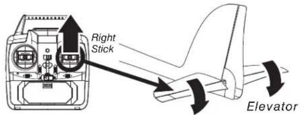

- Move the elevator/rudder stick (right stick) and confirm the elevator and rudder respond correctly.

- Move the throttle stick (le stick) up gently to confirm the motor/prop spin.
CAUTION: Do not run the Micro Calypso motor for more than 15 seconds when not in flight. Running the motor for extended times while the plane is not flying could cause damage to the motor.
LED Display (Located Behind Flight Battery)
| When the | is | this means the | You should |
| Rx LED inside the plane | Steady on | Tx & Rx are linked & ready. | |
| Slow Flash | The throttle's in the Hi position (The motor will not activate). | Move the throttle stick to the lowest position, until the LED is steady ON. Then the motor will activate. | |
| Fast Flash | The battery is low. | Charge the battery. | |
| Tx LED | Fast Flash | The battery is low. | Replace the Tx batteries. |
Move the throttle stick all the
RTF SERVO REVERSING
The red LED lights up and can be reversed by simply switching the location of the reversing switches.

DUAL RATES
The Micro Calypso transmitter (RTF only) is equipped with a dual rate switch which allows you to adjust the amount of throw the elevator and rudder have. With the dual rate switch down, you can fly on high rates (more elevator/rudder throw for experienced pilots) or you can move the dual rate switch up and fly on low rates (less elevator/rudder throw for inexperienced pilots) to make the plane easier to fly.
You can also adjust the elevator and rudder throw by changing the position of the linkage at the mounting point on the elevator and rudder. Moving the elevator linkage to the upper hole will increase throw and elevator response. Moving the rudder linkage to the inner hole will increase rudder throw and rudder response.

RUDDER/ELEVATOR CONTROL SURFACE CENTERING
Before your first flight or after a crash you will need to check the centering of the rudder and elevator control surfaces. To prevent excessive transmitter trim you should first make mechanical adjustments to the rudder and elevator servo linkages. The linkages have a "U" shaped section in them that can be compressed or expanded to adjust the control
surfaces when the transmitter trims are centered. Be careful to only make slight adjustments. Once you get the mechanical trim close you can use the transmitter trim to fine tune the rudder and elevator trim.
CHOOSING YOUR FLYING FIELD
The flying field you choose should be a large, open field with grass. There should not be any vehicles, buildings, power lines, trees, large rocks or anything else that your model can crash into.
CHOOSING A DAY TO FLY


Calm weather with either no wind or wind speed of 1–5 mph is suitable for flying.
PRE-FLIGHT CHECK

- damaged parts on the main wing, fuselage or tail wing.
- spinner are properly attached!
- connect the battery, and advise any people nearby. Make sure there is no one near the propeller.
- rotating accidentally, have an assistant hold the rear part of the plane securely.
- responds properly to control signals. See page 6.
6. signal. Step back about 30 ft [10m] and check for any unusual behavior.


TAKEOFF
- Before takeoff, check again to see if the plane responds properly to control signals.

- Apply 3/4 throttle while facing into the wind. Hold the plane horizontally and launch straight and level with a gentle pushing motion.

- After launching, use the rudder to keep the wings level. Climb to an altitude of about 50 feet [15.24 m], begin circling the plane. (If the battery is not charged properly, the plane will not ascend).
Use the elevator stick and throttle to adjust the climb and altitude.
Put the throttle stick to the lowest position when crashing to avoid damage to the airplane and radio equipment. Crash damage is not covered under the warranty.
FLIGHT
Continue circling in an oval pattern until you're accustomed to flying. If the plane nose dips, add a slight amount of up elevator control.
![graph TD A["Switch the transmitter ON"] --> B["Move rudder stick halfway to left"] B --> C["In case the motor starts"] C --> D["Release the elevator stick."] D --> E["Check to see if the plane is slowly."] E --> F["Move the control stick"] F --> G["Wind"] G --> H["Car with airplane"] H --> I["Truck…](/content/2026/06/1323388/images/7710a736070b0df673ccd3d26923fda65c0e13ddf814b7c7a88b8ca77e5cac5c.jpg)
Test the range of the radio
ADJUSTING TRIMS
Neutral
Adjusting trim for horizontal flight.


Take your finger off of the rudder stick and if the plane flies to the right, adjust the rudder trim to the left side.


Take your finger off of the elevator stick and if the plane flies upwards, adjust the elevator trim upward.


Adjust the elevator and rudder trims so the plane flies straight and horizontal when the sticks are free.
LANDING
![graph TD A["Start"] --> B{Wind} B --> C["Path 1"] B --> D["Path 2"] C --> E["End"] D --> F["End"] G["Landing Course"] --> H["Flow Path"] H --> I["Path 3"] H --> J["Path 4"]](/content/2026/06/1323388/images/ea9dd7327bbe49a1b90ab52ea1e7c360174b667eb5e5b7ce04ef2661e38d51b0.jpg)
When you're ready to land or the battery runs low, the propeller will stop spinning. Flight times will be 5–7 minutes depending on full throttle use, presence of thermals, outside temperature, and battery condition.
When landing, make a wide turn with the wind, and then land directly into the wind.
![graph TD A["④: When approaching the ground, use the elevator to keep the plane horizontal, then land."] --> B["①: Face into the wind and control any left/right lean with the rudder."] B --> C["②: Use the Throttle Stick to reduce speed and altitude."] C --> D["③: Try to keep the plane horizontal."] D…](/content/2026/06/1323388/images/9e409ed7edb99588e37bec3c3b4d7efac6a80980308ec52802d4e969ad7b4eb4.jpg)
LVC (Low Voltage Cutoff)
The Micro Calypso has a built in LVC to protect your LiPo battery from discharging too low while flying. Once the battery reaches LVC, the power to the motor will shut off and you need to land the Micro Calypso.
Make sure to always disconnect the flight battery from the plane to prevent the battery from discharging any further. The LVC does not prevent over-discharging when the plane is not in use.
AFTER LANDING

- Always disconnect the battery before turning off the transmitter. Hold the connector when disconnecting the battery. Do not pull on the cord.

- Then, switch the transmitter OFF.

CAUTION: The battery may be hot after a flight! Allow the battery to cool down before recharging.
AFTER-FLIGHT MAINTENANCE

1.
airplane when not in use. Fully charge the flight battery before storing it. Also remove the batteries from the transmitter.


2.
no screws have loosened and replace any scratched or damaged parts.
- Clean away any dirt etc. and perform any needed maintenance.
TRANSMITTER MODE SELECTION
As supplied, the transmitter is in Mode 2.
NOTE: The transmitter can be used in Mode 1 or Mode 2 with the mode change switch. After the Mode has been changed, the throttle stick spring is cancelled.

1.
to the neutral position.

2.
switch is moved all the way to the end.
Mode Stick Functions

Mode 1

Mode 2

Throttle

Elevator


Rudder

● The Mode change switch will only slide if the throttle stick is in neutral.
- Be sure to slide the Mode change switch all the way to the end. The sticks will not move correctly unless the switch is moved all the way to the end.
Mode 1 Transmitter Information

1 Mode Change Switch 2 Power Switch 3 Throttle MakeUpDown ModeEdshown
Adjusts throttle so motor will not move at the down position.
4 Throttle Stick (Up/Down) MODE 1
Controls propeller speed.
Rudder Stick (Left/Right) MODE 2
Controls plane's left/right movement.
5 Rudder Trim (Left/Right)
Adjust left/right so plane flies straight.
6 Elevator Trim (Up/Down) MODE 1 SHOWN
Adjust left/right so plane flies straight.
7 Elevator Stick (Up/Down) MODE 1 SHOWN
Controls plane's upwards/downwards movement.
8 Function Selector

9 On/Off Indicator
10 Charge Lamp 11 Battery Cover 12 Charger Terminal Cover
REPAIR
If your Micro Calypso becomes damaged you can use white glue, foam safe CA glue or clear tape to make repairs. You can also order replacement parts (found on page 3 of this manual) if your parts are beyond repair.
TROUBLESHOOTING GUIDE
PROBLEM: Transmitter LED does not illuminate when turned on.
Solution: Batteries are installed into the transmitter incorrectly. Remove batteries and check polarity markings on transmitter.
Solution: The transmitter batteries are bad. Replace the batteries.
PROBLEM: Micro Calypso does not power up.
Solution: Micro Calypso battery needs to be charged.
PROBLEM: Rudder or elevator control surfaces are not neutral when the trims on the transmitter trims are centered.

Solution: The "U" shaped servo linkage needs to be adjusted. Compress or expand the "U" portion of the linkage until the control surfaces are neutral. Use the transmitter trim to fine tune the control surfaces.
PROBLEM: Rudder or elevator moves in the opposite direction it is supposed to.
Solution: Adjust the servo reversing on the transmitter.
PROBLEM: Flight time is short.
Solution: The flight battery was not fully charged. Charge again.
Solution: Flying conditions may be too cold (below 60 degrees Fahrenheit [15.56 degrees Celsius]).
Solution: The flight battery needs to be replaced.
Solution: Replace the transmitter batteries with fresh batteries.
NOTES
Flyzone™ how high will you soar


- IMPORTANT
- WARRANTY
- WARNINGS
- FOR YOUR SAFETY PLEASE READ AND UNDERSTAND THESE WARNINGS
- GENERAL WARNINGS
- RADIO CONTROL SYSTEM WARNINGS
- LIPO BATTERY WARNINGS
- YOU MUST READ THIS BEFORE CHARGING THE BATTERY
- BATTERY RECYCLING
- TX-R ADDITIONAL ITEMS REQUIRED
- AVAILABLE PARTS
- RTF TRANSMITTER
- BEFORE OPERATING
- BATTERIES FOR TRANSMITTER
- ASSEMBLY INSTRUCTIONS
- TAIL ASSEMBLY
- CHARGING THE BATTERY (RTF)
- USB CHARGER INSTRUCTIONS (TX-R VERSION ONLY)
- FLIGHT BATTERY INSTALLATION, LINKING AND ESC ARMING
- RTF SERVO REVERSING
- DUAL RATES
- RUDDER/ELEVATOR CONTROL SURFACE CENTERING
- CHOOSING YOUR FLYING FIELD
- CHOOSING A DAY TO FLY
- PRE-FLIGHT CHECK
- TAKEOFF
- FLIGHT
- ADJUSTING TRIMS
- LANDING
- LVC (LOW VOLTAGE CUTOFF)
- AFTER LANDING
- AFTER-FLIGHT MAINTENANCE
- TRANSMITTER MODE SELECTION
- AS SUPPLIED, THE TRANSMITTER IS IN MODE
- MODE STICK FUNCTIONS
- MODE 1 TRANSMITTER INFORMATION
- REPAIR
- TROUBLESHOOTING GUIDE
- FLYZONE™ HOW HIGH WILL YOU SOAR
Brand : Flyzone
Model : Micro Calypso
Category : Remote control toy