
KeyFob - Remote control Fibaro - Free user manual and instructions
Find the device manual for free KeyFob Fibaro in PDF.


| Product Type | Z-Wave Remote Control |
| Brand | Fibaro |
| Model | KeyFob |
| Dimensions | Approx. 10 x 4 x 1.5 cm |
| Weight | Approx. 30 g (including battery) |
| Power Source | CR2032 lithium coin cell battery (3V) |
| Battery Life | Up to 2 years with normal use |
| Wireless Technology | Z-Wave (868.4 MHz or 908.4 MHz depending on region) |
| Range | Up to 30 meters indoors (line of sight) |
| Number of Buttons | 4 programmable buttons |
| Main Functions | Arm/disarm alarm, control scenes, trigger devices, status indicators |
| Protection Class | IP20 (indoor use only) |
| Operating Temperature | 0°C to 40°C |
| Certifications | Z-Wave Plus, CE, FCC |
| Cleaning Instructions | Wipe with a dry soft cloth; do not use liquids or abrasives |
| Safety | Keep away from water and extreme temperatures; replace battery with same type only |
| Spare Parts & Repairability | Battery user-replaceable; no other serviceable parts; contact support for issues |
| General Information | Fibaro KeyFob is a portable Z-Wave controller for home automation, ideal for quick actions |
Frequently Asked Questions - KeyFob Fibaro
User questions about KeyFob Fibaro
0 question about this device. Answer the ones you know or ask your own.
Ask a new question about this device
Download the instructions for your Remote control in PDF format for free! Find your manual KeyFob - Fibaro and take your electronic device back in hand. On this page are published all the documents necessary for the use of your device. KeyFob by Fibaro.
USER MANUAL KeyFob Fibaro
FIBARO KEYFOB
FGKF-601
CONTENTS
v1.1
1: Description and features 3
2: Basic activation 4
3: Adding/removing the device 5
4: Operating the device 6
5: Visual indications 7
6: Lock Mode 8
7: Sequences 10
8: Activating scenes 11
9: Battery 12
10: Associations 13
11: Advanced parameters 15
12: Specifications 19
13: Regulations 20
Important safety information

Read this manual before attempting to install the device!
Failure to observe recommendations included in this manual may be dangerous or cause a violation of the law. The manufacturer, Fibar Group S.A. will not be held responsible for any loss or damage resulting from not following the instructions of operating manual.
The alarm functionality of devices is an additional feature increasing the comfort level of your home automation system. If you want to use professional security service, please contact them to determine what systems can provide a protection of your estate.
Compliance with safety standards:
The device is designed to be used in Z-wave home automation systems (e.g. FIBARO) and is complaint with IEC/UL/CSA 60950-1. In case of the integration with another system, e.g. alarm system, it is required to verify the compliance with additional standards.
General information about the FIBARO System
FIBARO is a wireless smart home automation system, based on the Z-Wave protocol. All of available devices can be controlled through a computer (PC or Mac), smartphone or tablet. Z-Wave devices are not only receivers, but can also repeat the signal, increasing the Z-Wave network's range. It gives advantage over traditional wireless systems that require direct link between transmitter and receiver, as a result the construction of the building could affect network's range negatively.
Every Z-Wave network has its unique identification number (home ID). Multiple independent networks can exist in the building without interfering. Transmission security of FIBARO System is comparable to wired systems.
Z-Wave technology is the leading solution in smart home automation. There is a wide range of Z-Wave devices that are mutually compatible, independently of manufacturer. It gives the system the ability to evolve and expand over time. For more information visit www.fibaro.com.
#1: Description and features
FIBARO KeyFob is a Z-Wave Plus compatible, battery-powered, compact remote control.
Six buttons allow you to control other devices through the Z-Wave network and run various scenes defined in FIBARO System.
Configure actions for one, two, three clicks, holding the button and button sequences to suit all your needs.
Built-in locking system will ensure that unauthorized person will not take control of your home.
Main features of FIBARO KeyFob:
- Compatible with any Z-Wave or Z-Wave+ Controller,
• Supports Z-Wave network Security Mode with AES-128 encryption, - Battery powered,
• Completely wireless, - Pocket size,
• Equipped with 6 easily recognizable buttons, - 30 different actions, single/double/triple click, hold for each button and sequences,
- Easy to operate menu,
- Actions are confirmed by the built-in LED diode.

FIBARO KeyFob is a fully compatible Z-Wave PLUS device.
i NOTE
This device may be used with all devices certified with the Z-Wave Plus certificate and should be compatible with such devices produced by other manufacturers.
i NOTE
Z-Wave Controller must support Z-Wave Security Mode in order to fully utilize the product.
#2: Basic activation
natural_image
Line drawing of a hand pressing a curved object with an arrow indicating rotation (no text or symbols)-
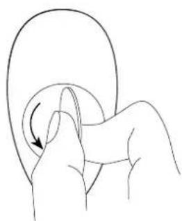
Using included keyring or a coin, open the battery cover by turning it counter-clockwise.
-
Remove the sticker protecting the battery.
natural_image
Line drawing of a hand pressing a curved object with an arrow indicating rotation (no text or symbols)-
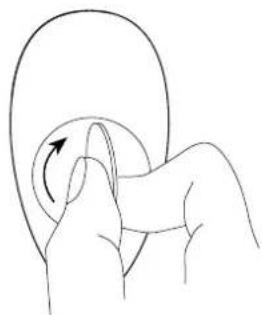
Using included keyring or a coin, close the battery cover by turning it clockwise.
-
Locate the device nearby the main Z-Wave controller.
-
Set the main Z-Wave controller in (Security/non-Security Mode) add mode (see the controller's manual).
-
Click any button three times.
-
LED will pulse white during the adding process.
-
Wait for the device to be added into the system.
-
Successful adding will be confirmed by the Z-Wave controller's message and green LED colour.
#3: Adding/removing the device
Adding (Inclusion) - Z-Wave device learning mode, allowing to add the device to existing Z-Wave network.
To add the device:
- Set the main Z-Wave controller in (Security/non-Security Mode) add mode (see the controller's manual).
- Power the device (insert the battery).
- Click any button three times.
- LED will pulse white during the adding process.
- Wait for the adding process to end.
- Successful adding will be confirmed by the Z-Wave controller's message and green LED colour.
Removing (Exclusion) - Z-Wave device learning mode, allowing to remove the device from existing Z-Wave network.
To remove the device:
- Set the main Z-Wave controller in remove mode (see the controller's manual).
- Click ◦ and -simultaneously.
- Click ▲ or × until LED glows green.
- Click +.
- Wait for the removing process to end.
- Successful removing will be confirmed by the Z-Wave controller's message.
i NOTE
Adding in Security Mode must be performed up to 2 meters from the controller.
i NOTE
In case the device is not added, please reset the device and repeat the adding procedure.
i NOTE
Removing the KeyFob from the Z-Wave network restores all the default parameters of the device.

NOTE
* Resetting the device from the menu is not available in Lock Mode.

NOTE
Resetting the device is not the recommended way of removing the device from the Z-Wave network. Use the reset procedure only if the primary controller is missing or inoperable. Certain device removal can be achieved by the procedure of removing described in "Adding/ removing the device" on page 5.
#4: Operating the device
Menu allows to perform Z-Wave network actions. In order to use the menu:
- Click ◦ and -simultaneously.
- Click ▲ or × until LED indicates desired menu position with colour:
- White - wake up the device
- Green - learning mode (adding/removing)
• Cyan - check battery level -
Yellow - reset the device*
-
Click + to confirm selection, Click - to exit the menu.
-
LED will pulse twice with same colour as selected menu position to confirm completing action.
Waking up the device:
The KeyFob needs to be woken up to receive information about the new configuration from the Z-Wave controller, like parameters and associations. Use 1st menu position (white) or click ○ and +imultaneously to wake up the device.
Resetting the device to factory defaults:
Reset procedure allows to restore the device back to its factory settings, which means all information about the Z-Wave controller and user configuration will be deleted. There are two ways of resetting the device:
Resetting the device using the menu:
- Click ◦ and -simultaneously.
- Click ▲ or × until LED glows yellow.
- Click +.
Emergency resetting the device on start-up:
- Remove the battery.
- Hold □ and +while inserting the battery.
Successful resetting will be confirmed by smoothly brightening and dimming of the yellow LED colour.
#5: Visual indications
Visual indications:
The KeyFob is equipped with a LED diode, signalling pushing the buttons, sequences, menu position and status of the device.
Indications for scenes and associations:
After pressing one of the buttons or using sequence, KeyFob indicates status of action with the LED diode.
| What you see | What it means |
| Green blink | Receiving command confirmed by the controller and associated devices |
| Yellow blink every 1s | Sending commands in progress |
| Red blink | Receiving at least one command was not confirmed by the controller or associated devices |
Indications for sequences:
| What you see | What it means |
| Blue pulse | Entering sequence |
| 3 blue pulses | Sequence valid |
| 3 red pulses | Sequence not valid |
Device status indications:
| What you see What it means What to do | ||
| Learning mode | ||
| Red blink Device not added | Click any button three times to start adding | |
| Fast white puls-ing | Device in adding mode | Wait for adding process to end |
| Green blink Device added – | ||
| Lock Mode | ||
| Red blink Device locked Unlock using sequence | ||
| 3 red pulses Wrong sequence Try unlocking again | ||
| Red to green transition | Device unlocked | Press buttons to activate scenes/associations |
| Green to red transition | Device locked using button hold | – |
| Battery | ||
| 3 magenta pulses Low battery Replace the battery | ||
| Configuration | ||
| 2 white pulses Dev ice woken up – | ||
#6: Lock Mode
The KeyFob can be protected with a sequence of 2 to 5 button clicks. When unlocking sequence is set, the device will lock itself after:
- being inactive for time set in parameter 2 (60 seconds by default),
- pressing and holding selected button (if set in parameter 2).
To enable Lock Mode:
- set sequence in parameter 1,
- set time and/or locking button in parameter 2 (60 seconds by default),
- set PROTECTION Command Class to Local Protection by Sequence (done automatically by Home Center controller).
Lock Mode will be disabled when:
• parameter 1 and/or parameter 2 is set to 0,
• PROTECTION Command Class is set to Unprotected.
When device is locked:
- pushing buttons will not activate any actions,
- menu is available, but without option of resetting the device.
Setting the unlocking sequence and locking time-out using Home Center configuration interface:
- Go to the device options by clicking the icon:
- Select the „Advanced“ tab.
- Click the "Configure" button in "Lock Mode" section.
- Select sequence of 2 to 5 buttons, click "Next".
- Select time to lock and locking button, click "Next".
- Click ○ and +simultaneously to wake up the device.
- Wait for the device to configure.
Setting the unlocking sequence using advanced parameter:
- Calculate value of parameter using table and formula:
| Button | × | - | + | |||
| Value 1 | 2 3 4 5 | 6 |
Value of parameter = Value of first button + 8 * Value of second button + 64 * Value of third button + 512 * Value of fourth button + 4096 * Value of fifth button
- Change the value of parameter 1 [2 bytes] to calculated value.
- Click ◦ and +simultaneously to wake up the device.
- Wait for the device to configure.
Setting time to lock and locking button using advanced parameter:
- Calculate value of parameter using table and formula:
| Button | × | - | + | |||
| Value 1 | 2 3 4 5 | 6 |
Time to lock should be 0 or 5-255 (seconds)
Value of parameter = Time to lock in seconds + +256 * Value of locking button
- Change the value of parameter 2 [2 bytes] to calculated value.
- Click ○ and +simultaneously to wake up the device.
- Wait for the device to configure.
#7: Sequences
Sequences:
User can create sequences of two to five button to expand number of possible actions. Every sequence sends corresponding Scene ID to the Z-Wave controller with attribute "Key pressed 1 time" (see "Scene activation" on page 11).
Sequences are saved in advanced parameters (no. 3-8).
Activating sequence introduces delay in single, double and triple click actions for first button in the sequence.
Rules of creating sequences:
• Maximum of six sequences can be created.
• Each sequence must be unique.
- Sequence can consist of two to five button pushes.
- Sequence can contain multiple clicks of the same button.
Setting a new sequence using advanced parameter:
- Calculate value of parameter using table and formula:
| Button | × | - | + | |||
| Value 1 | 2 3 4 5 | 6 |
Value of parameter = Value of first button +
+ 8 * Value of second button + 64 * Value of third button +
+ 512 * Value of fourth button + 4096 * Value of fifth button
- Change the value of corresponding parameter [2 bytes] (parameters 3 to 8 for slots 1 to 6).
- Click ◦ and +simultaneously to wake up the device.
- Wait for the device to configure.
#8: Activating scenes
Activating scenes:
The KeyFob can activate scenes in the Z-Wave controller by sending scene ID and attribute of a specific action using Central Scene Command Class.
By default scenes are activated after single clicking or pressing and holding any of the buttons and sequences. Other actions can be activated in parameters 21-26.
Activating a double click will introduce delay to a single click reaction and activating a triple click will introduce delay to a double click reaction.
Scene IDs of buttons:
| Button | × | - | + | |||
| Scene ID 1 | 2 3 4 5 6 |
Scene IDs of sequences:
| Sequence number | 1 2 3 | 4 5 6 | ||||
| Scene ID | 7 | 8 | 9 | 10 | 11 | 12 |
Attributes of actions:
| Action Attribute | |
| Button clicked once Key Pressed 1 time | |
| Button clicked twice Key Pressed 2 times | |
| Button clicked thrice Key Pressed 3 times | |
| Button held Key Held Down | |
| Button released Key Released | |
| Sequence performed Key Pressed 1 time | |

CAUTION
Using batteries other than specified may result in explosion. Dispose of properly, observing environmental protection rules.

NOTE
Battery life depends on frequency of usage, number of associations/scenes, Z-Wave routing and network load.
#9: Battery
The KeyFob can be powered with CR2450 (included) battery. Estimated battery life with device added once, default settings, direct range and maximum 5 pushes per day is 2 years.
Checking battery level:
KeyFob automatically warns about low battery with 3 magenta blinks.
-
Click ◦ and -simultaneously.
-
Click ▲ or × until LED glows cyan.
-
Click +.
-
LED indicates battery level with a smoothly transitioning colours, where:
-
Green - 100%
- Yellow - 50%
-
Red - 1%
-
Wait 2 second or click any button to exit.
Replacing the battery:
1.
natural_image
Line drawing of a hand pressing down on a curved object with an arrow indicating rotation (no text or symbols)2.3

natural_image
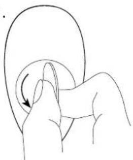
Line drawing of a hand holding a curved object with an arrow indicating rotation (no text or symbols)- Using included keyring or a coin, open the battery cover by turning it counter-clockwise.
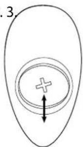
- Replace the battery.
- Using included keyring or a coin, close the battery cover by turning it clockwise.
#10: Associations
Association (linking devices) - direct control of other devices within the Z-Wave system network e.g. Dimmer, Relay Switch, Roller Shutter or scene (may be controlled only through a Z-Wave controller).
The device provides the association of thirteen groups:
1st association group – “Lifeline” reports the device status and allows for assigning single device only (main controller by default).
2nd association group - "Square - On/Off" is assigned to clicking the □ button and is used to turn on/off associated devices.
3rd association group – “Square - Multilevel” is assigned to clicking and holding the □ button and is used to turn on/off and change level of associated devices.
4th association group – "Circle - On/Off" is assigned to clicking the O button and is used to turn on/off associated devices.
5th association group – “Circle - Multilevel” is assigned to clicking and holding the ○ button and is used to turn on/off and change level of associated devices.
6th association group – “Cross - On/Off” is assigned to clicking the ✗ button and is used to turn on/off associated devices.
7th association group – “Cross - Multilevel” is assigned to clicking and holding the × button and is used to turn on/off and change level of associated devices.
8th association group – “Triangle - On/Off” is assigned to clicking the ▲ button and is used to turn on/off associated devices.
9th association group – “Triangle - Multilevel” is assigned to clicking and holding the ▲ button and is used to turn on/off and change level of associated devices.
10th association group – “Minus - On/Off” is assigned to clicking the — button and is used to turn on/off associated devices.
11th association group – “Minus - Multilevel” is assigned to clicking and holding the — button and is used to turn on/off and change level of associated devices.
12th association group – “Plus - On/Off” is assigned to clicking the + button and is used to turn on/off associated devices.
13th association group – “Plus - Multilevel” is assigned to clicking and holding the + button and is used to turn on/off and change level of associated devices.
i NOTE
Association ensures direct transfer of control commands between devices, is performed without participation of the main controller and requires associated device to be in the direct range.
i NOTE
States of the association groups are affected only by buttons. Changing state of associated device by other means will not update remembered state of association group.
i NOTE
2, 4, 6, 8, 10 and 12 association groups use BASIC CC, but device does not respond to GET commands.
The KeyFob in 2nd to 13th group allows to control 5 devices (regular or multichannel) per an association group. "LifeLine" group is reserved solely for the controller and hence only 1 node can be assigned.
It is not recommended to associate more than 10 devices in general, as the response time to control commands depends on the number of associated devices. In extreme cases, system response may be delayed.
To add an association (using the Home Center controller):

- Go to the device options by clicking the icon:
- Select the „Advanced“ tab.
- Click the "Setting Association" button.
- Specify to which group and what devices are to be associated.
- Save the changes.
- Click ○ and +simultaneously to wake up the device.
Paired buttons associations
After pairing buttons, horizontal pairs of buttons (☐ and ○, ✗end, ▲ — and +work as one button and send associations to left buttons groups only.
Left buttons (☐, ✗) turn on associated devices and right buttons (○, ▲) turn them off.
In multilevel association groups (3, 7, 11) left buttons increase level while holding and right buttons decrease it.
To pair buttons:
-
Change settings of parameters:
-
□ and ○ – set parameter 6 to value 1
• X and ▲ set parameter 7 to value 1 -
and + set parameter 8 to value 1
-
Save the changes.
- Click ◦ and +simultaneously to wake up the device.
#11: Advanced parameters
The KeyFob allows to customize its operation to user's needs. The settings are available in the FIBARO interface as simple options that may be chosen by selecting the appropriate box.
In order to configure the KeyFob (using the Home Center controller):
- Go to the device options by clicking the icon:

-
Select the „Advanced“ tab.
-
Modify values of chosen parameters.
-
Save the changes.
-
Click ○ and +simultaneously to wake up the device.
1. Lock Mode - unlocking sequence
This parameter allows to activate Lock Mode and set up unlocking sequence. Device will lock after time set in parameter 2 or after pressing and holding selected button. See "Lock Mode" on page 9 for more information.
| Available settings: 0 - Lock Mode disabled9-28086 - unlocking sequence | |||
| Default setting: 0 P | parameter size: | 2 [bytes] | |
2. Lock Mode - time to lock and locking button
This parameter allows to set time that must elapse from the last press of the button to lock the device and locking button.
Setting locking button will deactivate associations and scenes for pressing and holding the selected button.
This parameter is irrelevant if parameter 1 is set to 0 (Lock Mode disable).
See "Lock Mode" on page 9 for more information.
| Available settings: | 0 - Lock Mode disabled5-1791 - calculated value | ||
| Default setting: 60 | (60s) Parameter size: 2 [bytes] | ||
3. First scene sequence
This parameter allows to set up sequence that activates scene with ID 7. See "Sequences" on page 10 for more information.
| Available settings: 0 - 1st sequence disabled9-28086 - value of sequence | |||
| Default setting: 0 P | Parameter size: | 2 [bytes] | |
i NOTE
Entering invalid value of parameter will result in response with Application Rejected frame and not setting the value.
4. Second scene sequence
This parameter allows to set up sequence that activates scene with ID 8. See "Sequences" on page 10 for more information.
| Available settings: 0 - 2nd sequencedisabled9-28086 - value of sequence | |||
| Default setting: 0 P | Parameter size: | 2 [bytes] | |
5. Third scene sequence
This parameter allows to set up sequence that activates scene with ID 9. See "Sequences" on page 10 for more information.
| Available settings: 0 - 3rd sequencedisabled9-28086 - value of sequence | |||
| Default setting: 0 Parameter size: 2 [bytes] | |||
6. Fourth scene sequence
This parameter allows to set up sequence that activates scene with ID 10. See "Sequences" on page 10 for more information.
| Available settings: 0 - 4th sequencedisabled9-28086 - value of sequence | |||
| Default setting: 0 P | Parameter size: | 2 [bytes] | |
7. Fifth scene sequence
This parameter allows to set up sequence that activates scene with ID 11. See "Sequences" on page 10 for more information.
| Available settings: 0 - 5th sequencedisabled9-28086 - value of sequence | |||
| Default setting: 0 Parameter size: 2 [bytes] | |||
8. Sixth scene sequence
This parameter allows to set up sequence that activates scene with ID 12. See "Sequences" on page 10 for more information.
| Available settings: 0 - 6th sequencedisabled9-28086 - value of sequence | |||
| Default setting: 0 P | Parameter size: | 2 [bytes] | |
9. Sequences - timeout
This parameter allows to set time that must elapse from the last click of the button to check if the sequence is valid.
| Available settings: 5-30 (0.5-3s, 0.1s step) - time to lock | |||
| Default setting: 10 (1s) Parameter | size: 1 [byte] | ||
10. Single button associations - operating mode
This parameter allows to choose operating mode for single button associations.
| Available settings: | 0 - single click switches state to opposite1 - single click switches state to opposite, double click sets to maximum level2 - single click turns on, double click turns off | |
| Default setting: 0 | (switch) | Parameter size: 1 [byte] |
- Value sent to □association groups
- Value sent to O association groups
- Value sent to X association groups
- Value sent to △ association groups
- Value sent to—association groups
- Value sent to + association groups
This parameter allows to set value sent to devices in association group. It will result in turning multilevel devices on with set or last level. Value is irrelevant for simple on/off devices.
| Available settings: 1-99 or 255 | |||
| Default setting: 255 Parameter size: 2 [bytes] | |||
17. Paired buttons association for □ and ○
This parameter allows to activate paired buttons association mode for □ and ○buttons. Paired buttons are dependent and association are sent only to □ groups. ○turns devices on and increases value, □ turns them off and decreases value.
| Available settings: | 0 - paired buttons association inactive1 - paired buttons association active | ||
| Default setting: | 0 (inactive) | Parameter size: | 1 [byte] |
18. Paired buttons association for X and △
This parameter allows to activate paired buttons association mode for X and ▲buttons. Paired buttons are dependent and association are sent only to X groups. ▲turns devices on and increases value, X turns them off and decreases value.
| Available settings: 0 - paired buttons association inactive1 - paired buttons association active | |||
| Default setting: 0 (inactive) Parameter size: 1 [byte] | |||
i NOTE
Setting parameters 11-16 to appropriate value will result in:
1-99 - forcing level of associated devices
255 - setting associated devices to the last remembered state or turning them on

NOTE
Parameters 21 to 26 values may be combined, e.g. 1+2=3 means that clicking button once or twice will result in sending assigned scene ID.

NOTE
Parameter 29 values may be combined, e.g. 1+2=3 means that 2nd & 3rd group are sent using Security Mode.
19. Paired buttons association for -and +
This parameter allows to activate paired buttons association mode for — and +buttons. Paired buttons are dependent and association are sent only to — groups. +turns devices on and increases value, — turns them off and decreases value.
| Available settings: | 0 - paired buttons association inactive1 - paired buttons association active | ||
| Default setting: | 0 (inactive) | Parameter size: | 1 [byte] |
- Scene activation for □ button
- Scene activation for ○ button
- Scene activation for X button
- Scene activation for △ button
- Scene activation for — button
- Scene activation for + button
This parameter determines which actions result in sending assigned scene IDs and attributes to the controller.
| Available settings: | 1 - Key Pressed 1 time2 - Key Pressed 2 times4 - Key Pressed 3 times8 - Key Held Down & Released | ||
| Default setting: 9 (1x & hold) Para | meter size: 1 [byte] | ||
29. Associations in Z-Wave network Security Mode
Parameter defines how commands are sent in specified association groups: using Security Mode or not. Parameter is active only in Z-Wave network Security Mode. It does not apply to 1st "Lifeline" association group.
| Available settings: | 1 - 2nd group sent using Security Mode2 - 3rd group sent using Security Mode4 - 4th group sent using Security Mode8 - 5th group sent using Security Mode16 - 6th group sent using Security Mode32 - 7th group sent using Security Mode64 - 8th group sent using Security Mode128 - 9th group sent using Security Mode256 - 10th group sent using Security Mode512 - 11th group sent using Security Mode1024 - 12th group sent using Security Mode2048 - 13th group sent using Security Mode | ||
| Default setting: | 40 | 95 Parameter size: 2 [bytes] | |
#12: Specifications
| Power supply: | CR2450 3.0V battery (included) |
| Battery life: | est. 2 years (default settings, max. 5 pushes per day and direct range) |
| Operating temperature: | 10 - 40°C |
| Protection class: | IP54 |
| EU directives compliance: | RoHS 2011/65/EURED 2014/53/EU |
| Radio protocol: | Z-Wave (500 series chip) |
| Radio frequency: | 868.4, 868.42 or 869.8 MHz EU;908.4, 908.42 or 916.0 MHz US;921.4, 921.42 or 919.8 MHz ANZ;869.0 or 869.02 MHz RU; |
| Range: | up to 50m outdoorsup to 40m indoors(Depending on terrain and building structure) |
| Dimensions: | 70 x 38 x 15 mm |
CAUTION
Using batteries other than specified may result in explosion. Dispose of properly, observing environmental protection rules.
i NOTE
Battery life depends on frequency of usage, number of associations/scenes, Z-Wave routing and network load.
i NOTE
Radio frequency of individual device must be same as your Z-Wave controller. Check information on the box or consult your dealer if you are not sure.
#13: Regulations
This device complies with Part 15 of the FCC Rules
Operation is subject to the following two conditions:
- This device may not cause harmful interference
-
This device must accept any interference received, including interference that may cause undesired operation. This equipment has been tested and found to comply with the limits for a Class B digital device, pursuant to part 15 of the FCC Rules. These limits are designed to provide reasonable protection against harmful interference in a residential installation. This equipment generates, uses and can radiate radio frequency energy and, if not installed and used in accordance with the instructions, may cause harmful interference to radio communications. However, there is no guarantee that interference will not occur in a particular installation. If this equipment does cause harmful interference to radio or television reception, which can be determined by turning the equipment off and on, the user is encouraged to try to correct the interference by one or more of the following measures:
-
Reorient or relocate the receiving antenna.
- Increase the separation between the equipment and receiver.
- Connect the equipment into an outlet on a circuit different from that to which the receiver is connected.
- Consult the dealer or an experienced radio/TV technician for help.
Changes and modifications not expressly approved by the manufacturer or registrant of this equipment can void your authority to operate this equipment under Federal Communications Commission's rules.
Industry Canada (IC) Compliance Notice
All information, including, but not limited to, information regarding the features, functionality, and/or other product specification are subject to change without notice. Fibaro reserves all rights to revise or update its products, software, or documentation without any obligation to notify any individual or entity.
FIBARO and Fibar Group logo are trademarks of Fibar Group S.A. All other brands and product names referred to herein are trademarks of their respective holders.
DGT Warning Statement
Article 12
Without permission, any company, firm or user shall not alter the frequency, increase the power, or change the characteristics and functions of the original design of the certified lower power frequency electric machinery.
Article 14
The application of low power frequency electric machineries shall not affect the navigation safety nor interfere a legal communication, if an interference is found, the service will be suspended until improvement is made and the interference no longer exists.
第十二條
This product is not a toy. Keep away from children and animals!
Declaration of conformity
Hereby, Fibar Group S.A. declares that the device is in compliance with the essential requirements and other relevant provisions of Directive 2014/53/EU. The full text of the EU declaration of conformity is available at the following internet address: www.manuals.fibaro.com
WEEE Directive Compliance
Device labelled with this symbol should not be disposed with other household wastes. It shall be handed over to the applicable collection point for the recycling of waste electrical and electronic equipment.




- FIBARO KEYFOB
- FGKF-601
- CONTENTS
- 1: Description and features 3
- 2: Basic activation 4
- 3: Adding/removing the device 5
- 4: Operating the device 6
- 5: Visual indications 7
- 6: Lock Mode 8
- 7: Sequences 10
- 8: Activating scenes 11
- 9: Battery 12
- 10: Associations 13
- 11: Advanced parameters 15
- 12: Specifications 19
- 13: Regulations 20
- Important safety information
- Read this manual before attempting to install the device!
- Compliance with safety standards:
- General information about the FIBARO System
- #1: Description and features
- Main features of FIBARO KeyFob:
- i NOTE
- #2: Basic activation
- #3: Adding/removing the device
- NOTE
- #4: Operating the device
- Waking up the device:
- Resetting the device to factory defaults:
- #5: Visual indications
- Visual indications:
- Indications for scenes and associations:
- #6: Lock Mode
- To enable Lock Mode:
- Lock Mode will be disabled when:
- When device is locked:
- Setting the unlocking sequence and locking time-out using Home Center configuration interface:
- Setting the unlocking sequence using advanced parameter:
- Setting time to lock and locking button using advanced parameter:
- #7: Sequences
- Sequences:
- Rules of creating sequences:
- Setting a new sequence using advanced parameter:
- #8: Activating scenes
- Activating scenes:
- CAUTION
- #9: Battery
- Checking battery level:
- Replacing the battery:
- #10: Associations
- The device provides the association of thirteen groups:
- To add an association (using the Home Center controller):
- Paired buttons associations
- To pair buttons:
- #11: Advanced parameters
- Lock Mode - unlocking sequence
- Lock Mode - time to lock and locking button
- First scene sequence
- Second scene sequence
- Third scene sequence
- Fourth scene sequence
- Fifth scene sequence
- Sixth scene sequence
- Sequences - timeout
- Single button associations - operating mode
- Paired buttons association for □ and ○
- Paired buttons association for X and △
- Paired buttons association for -and +
- Associations in Z-Wave network Security Mode
- #12: Specifications
- #13: Regulations
- This device complies with Part 15 of the FCC Rules
- Industry Canada (IC) Compliance Notice
- DGT Warning Statement
- Article 12
- Article 14
- Declaration of conformity
- WEEE Directive Compliance
Brand : Fibaro
Model : KeyFob
Category : Remote control