
SC-HTR310 - Home Theater System PANASONIC - Free user manual and instructions
Find the device manual for free SC-HTR310 PANASONIC in PDF.


| Product Type | Home Theater System |
| Brand | Panasonic |
| Model | SC-HTR310 |
| Channels | 2.1 |
| Total Power Output | 200 W |
| Subwoofer Type | Wireless Active |
| Supported Audio Formats | Dolby Digital, DTS, MP3, WMA |
| Connectivity | HDMI ARC, Optical, USB, Bluetooth, AUX |
| Bluetooth Version | 4.2 |
| FM Tuner | Yes |
| Dimensions (Main Unit) | 800 x 50 x 70 mm |
| Weight (Main Unit) | 1.5 kg |
| Dimensions (Subwoofer) | 200 x 400 x 300 mm |
| Weight (Subwoofer) | 4.0 kg |
| Power Supply | AC 220-240V, 50/60 Hz |
| Power Consumption | 50 W (Standby: 0.5 W) |
| Remote Control | Included |
| Mounting Options | Wall-mountable or Table-top |
| Cleaning Instructions | Wipe with a soft, dry cloth |
| Safety Certifications | CE, RoHS |
| Repairability | Spare parts available via authorized service |
Frequently Asked Questions - SC-HTR310 PANASONIC
User questions about SC-HTR310 PANASONIC
0 question about this device. Answer the ones you know or ask your own.
Ask a new question about this device
Download the instructions for your Home Theater System in PDF format for free! Find your manual SC-HTR310 - PANASONIC and take your electronic device back in hand. On this page are published all the documents necessary for the use of your device. SC-HTR310 by PANASONIC.
USER MANUAL SC-HTR310 PANASONIC
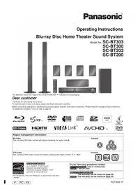
Operating Instructions
Home Theater Audio System
Model No. SC-HTR310
SC-HTR210

The illustration shows SC-HTR310.
Dear customer
Thank you for purchasing this product.
For optimum performance and safety, please read these instructions carefully.
Before connecting, operating or adjusting this product, please read the instructions completely.
Please keep this manual for future reference.
Note
“EB” on the packaging indicates the United Kingdom.
Setting up your Home Theater system
In this manual, illustrations of SC-HTR310 are used to represent this system unless otherwise mentioned.
Step
Installing the rack (see pages 10 to 15)
After you have installed the rack, attach the glass top panel, shelf and glass doors.
Step
2
Connecting the television and DVD player (see page 16)
(Peripheral equipment and cables are not included unless otherwise mentioned.)
■ Recommended TV size:
SC-HTR310 : 50 inches or less
SC-HTR210 : 42 inches or less
Basic connection (see page 16)
Connect with an HDMI cable for high-quality audio and video.
This connection requires HDMI terminals on both the television and the DVD recorder. (see page 17)
Step
3
Enjoying movies and music (→ pages 24 to 27)
Enjoy surround sound with DVDs, TV, and other sources.
■ This system has built-in speakers.
Do not connect other speakers with the front speakers, center speaker and subwoofer.
If you connect other speakers, the sound will not be produced with proper characteristics and malfunction may occur.
Table of contents
| Before use |  | Setting up your Home Theater system ..... 2Caution for AC Mains Lead ..... 4Safety precautions ..... 5Supplied accessories ..... 6Control guide ..... 7Remote control preparation ..... 9 | Before useCo |
| Connection |  | Installing and assembling the rack ..... 10Home Theater connections ..... 16Basic connections ..... 16Connecting equipment with HDMI terminal (TV, DVD recorder, etc.) ..... 17Connecting with digital terminal-mounted equipment ..... 18Connecting with VCR ..... 19Other connections ..... 20Connecting a set top box (cable or satellite) ... 20Connecting a combination DVD recorder/VCR 21AC mains supply connection ..... 22Checking speaker output ..... 23 | |
| Play |  | Enjoying movies and music ..... 24Sound field ..... 26Using the VIERA Link “HDAVI ControlTM” .. 28Functions and settings ..... 29Using “WHISPER MODE SURROUND” ..... 29Using “GAME” ..... 29Muting ..... 29Adjusting speaker output ..... 29REAL CENTER function ..... 30Adjusting sound quality ..... 30Adjusting the balance ..... 30Reducing standby power consumption(Standby mode) ..... 31Setting VIERA Link “HDAVI Control” to “OFF ”: 31Adjusting the time lag by delaying audio output when pictures on TV arrives after sounds ..... 31Switching between dual sounds ..... 32Clear audio at low volume ..... 32Switching the attenuator ..... 32Setting input signals ..... 33Reset (factory settings) ..... 33When other equipment (mini component system, AV amp, etc.) manufactured by Panasonic operate ..... 34 | |
| Reference |  | Error messages ..... 35Specifications ..... 35Troubleshooting guide ..... 36Digital signals that can be played on this system ..... 37Glossary ..... 38Maintenance ..... 38 | Reference |
Caution for AC Mains Lead
(For United Kingdom)
("EB" area code model only)
For your safety, please read the following text carefully.
This appliance is supplied with a moulded three pin mains plug for your safety and convenience.
A 5-ampere fuse is fitted in this plug.
Should the fuse need to be replaced please ensure that the replacement fuse has a rating of 5-ampere and that it is approved by ASTA or BSI to BS1362.
Check for the ASTA mark on the BSI mark on the body of the fuse.

If the plug contains a removable fuse cover you must ensure that it is refitted when the fuse is replaced.
If you lose the fuse cover, the plug must not be used until a replacement cover is obtained.
A replacement fuse cover can be purchased from your local dealer.
CAUTION!
IF THE FITTED MOULDED PLUG IS UNSUITABLE FOR THE SOCKET OUTLET IN YOUR HOME, THEN THE FUSE SHOULD BE REMOVED AND THE PLUG CUT OFF AND DISPOSED OF SAFELY.
THERE IS A DANGER OF SEVERE ELECTRICAL SHOCK IF THE CUT OFF PLUG IS INSERTED INTO ANY 13-AMPERE SOCKET.
If a new plug is to be fitted, please observe the wiring code as stated below.
If in any doubt, please consult a qualified electrician.
IMPORTANT
The wires in this mains lead are coloured in accordance with the following code:
Blue: Neutral, Brown: Live.
As these colours may not correspond with the coloured markings identifying the terminals in your plug, proceed as follows:
The wire which is coloured Blue must be connected to the terminal which is marked with the letter N or coloured Black or Blue.
The wire which is coloured Brown must be connected to the terminal which is marked with the letter L or coloured Brown or Red.
WARNING: DO NOT CONNECT EITHER WIRE TO THE EARTH TERMINAL WHICH IS MARKED WITH THE LETTER E, BY THE EARTH SYMBOL OR COLOURED GREEN OR GREEN/YELLOW.
THIS PLUG IS NOT WATERPROOF—KEEP DRY.
Before use
Remove the connector cover.
How to replace the fuse
The location of the fuse differs according to the type of AC mains plug (figures A and B). Confirm the AC mains plug fitted and follow the instructions below. Illustrations may differ from the actual AC mains plug.
- Open the fuse cover with a screwdriver.


- Replace the fuse and close or attach the fuse cover.


Safety precautions
Placement
Set the system up on an even surface away from direct sunlight, high temperatures, high humidity, and excessive vibration. These conditions can damage the system and other components, thereby shortening the system's service life.
Do not hang from or climb on the system. This may result in serious injury.
Place the television properly on the system. Use the fall-prevention band to prevent the television from falling over and causing serious damage or injury. Do not place items heavier than the recommended weight on the system or the shelves.
Voltage
Do not use high voltage power sources. This can overload the system and cause a fire.
Do not use a DC power source. Check the source carefully when setting the system up on a ship or other place where DC is used.
AC mains lead protection
Ensure the AC mains lead is connected correctly and not damaged. Poor connection and lead damage can cause fire or electric shock. Do not pull, bend, or place the system on the lead.
Grasp the plug firmly when unplugging the lead. Do not move the system if the AC mains lead is still connected to the socket outlet. Pulling the AC mains lead can cause electric shock.
Do not handle the plug with wet hands. This can cause electric shock.
Remove the AC mains plug from the socket outlet when not using the system for a long period.
Foreign matter
Do not let metal objects fall inside the system. This can cause electric shock or malfunction.
Do not let liquids get into the system. This can cause electric shock or malfunction. If this occurs, immediately disconnect the system from the power supply and contact your dealer.
Do not spray insecticides onto or into the system. They contain flammable gases which can ignite if sprayed into the system.
Glass doors
Protect the doors from scratching.
Take care not to get your fingers caught when opening and closing the doors.
Do not touch the doors if they crack. Consult your dealer for immediate replacement.
Service
Do not attempt to repair this system by yourself. If sound is interrupted, indicators fail to light, smoke appears, or any other problem that is not covered in these instructions occurs, disconnect the AC mains lead and contact your dealer or an authorized service center. Electric shock or damage to the system can occur if the system is repaired, disassembled, or reconstructed by unqualified persons.
Extend operating life by disconnecting the system from the power source if it is not to be used for a long time.
Supplied accessories

Please check and identify the supplied accessories.
Use numbers when asking for replacement parts.
(Product numbers correct as of March 2008. These may be subject to change.)
Supplied accessories for rack
□ 1 Glass top panelSC-HTR310 : (RXQ1618) SC-HTR210 : (RXQ1619)  | □ 4 Caster stoppers (TBLB3008) | |
□ 2 Glass doorsSC-HTR310 : 1 x Left (RXQ1607)1 x Right (RXQ1608)SC-HTR210 : 1 x Left (RXQ1612)1 x Right (RXQ1612A) Lε  ide ide |  | |
□ 2 Shelves SC-HTR310 :(RKQ2G0004-K)1 Shelf SC-HTR210 :(RKQ2G0005-K)  | □ 8 Moulded dowels SC-HTR3104 Moulded dowels SC-HTR210(RMQ1649)  | |
Supplied accessories for amplifier
□ 1 AC mains leadFor the United Kingdom (K2CT3CA00004) | For continental Europe and Malaysia (K2CQ2CA00007) | □ 2 Batteries 1 Remote control | (N2QAYB000288) |


■ Sales and Support Information
(For the United Kingdom and Republic of Ireland)
Customer Care Centre
• For customers within the UK: 0844 844 3852 • For customers within the Republic of Ireland: 01 289 8333 - Visit our website for product information • E-mail: customer.care@panasonic.co.uk
Direct Sales at Panasonic UK
- Order accessory and consumable items for your product with ease and confidence by phoning our Customer Care Centre Monday-Thursday 9:00am-5:30pm, Friday 9:30am-5:30pm (Excluding public holidays).
- Or go on line through our Internet Accessory ordering application at www.panasonic.co.uk.
- Most major credit and debit cards accepted.
- All enquiries transactions and distribution facilities are provided directly by Panasonic UK Ltd.
- It couldn't be simpler!
- Also available through our Internet is direct shopping for a wide range of finished products, take a browse on our website for further details.
Interested in purchasing an extended guarantee?
Please call 0870 240 6284 or visit our website
www.panasonic.co.uk/guarantee.
Control guide
This system
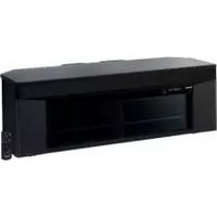
SC-HTR310 (Front view)
(Rear view) Rear panel Amplifier
Cut-outs Cut-outs
SC-HTR210 (Front view)
(Rear view) Rear panel Amplifier
Cut-outs
Control guide
Control panel
Display
DIGITAL: Dolby Digital sources
DTS: DTS sources
VS: When Dolby Virtual Speaker is working
SFC: When you are using an SFC mode
PL II:
When Dolby Pro Logic II decoder is being used
(When using Dolby Virtual Speaker on 2 channel stereo source)
Amplifier
Speaker terminals
The speakers are already connected. Do not touch the connectors unless absolutely necessary. If the connectors become disconnected, refer to the illustrations below for connection.
Connector connection: How to attach the connectors

Make sure the colour on the connector indicates the same as corresponding terminal and insert the connector straight all the way.
Remote control
Standby/on button (→ pages 23 to 25)
Test signal output (→ page 23)
For using "WHISPER MODE SURROUND" (→ page 29)
For using "GAME" (→ page 29)
To enter setup mode (→ pages 29 to 34)
For selecting or cancelling Dolby Virtual Speaker, Dolby Pro Logic II and SFC mode (→ pages 26 and 27)

Input mode and remote control mode buttons (→ pages 24, 25 and 34)
Adjusting speaker output (→ pages 23 and 29)
For adjusting the volume (→ pages 23 to 25)
Muting (→ page 29)
For adjusting settings/For activating settings (→ pages 29 to 34)
For returning to the previous menu (→ pages 29 to 34)
Remote control preparation
Inserting the batteries
Press on the tab to open.
(R6/LR6, AA)
Insert so the poles (+ and −) match those in the remote control.
Do not:
- mix old and new batteries.
- use different types at the same time. • take apart or short circuit.
- attempt to recharge alkaline or manganese batteries.
- use batteries if the covering has been peeled off.
Mishandling of batteries can cause electrolyte leakage which can severely damage the remote control.
Remove the batteries if the remote control is not going to be used for a long period of time. Store in a cool, dark place.
CAUTION
Danger of explosion if battery is incorrectly replaced. Replace only with the same or equivalent type recommended by the manufacturer. Dispose of used batteries according to the manufacturer's instructions.
- Do not use rechargeable type batteries.
- Do not heat or expose to flame.
- Do not leave the batteries in an automobile exposed to direct sunlight for a long period of time with doors and windows closed.
Using the remote control
Remote control signal sensor
Note
- Do not place an object between the signal sensor and the remote control.
- Do not place the signal sensor under direct sunlight or the strong light of a fluorescent lamp.
- Keep the transmission window and the system's sensor free from dust.
Installing and assembling the rack

Installing each equipment (DVD player/Blu-ray Disc player/DVD recorder → page 13) (TV → page 13)
Installation
■ At least 2 people are necessary for installation. ■ Use a Phillips-head screwdriver. (Do not use a powered screwdriver.) ■ Choose a stable location for installation. ■ Handle the glass top panel and glass doors with enough care.

Setup example: This system, This system, This system


- Make sure to place the rack on a flat, stable surface so there is no danger of it falling over. Take enough safety measures to prevent the television from falling down.
- You can install this system so that it is flush with the wall at either the sides or back, but you will require some space for working during setup and connection.
- Do not place in front of curtains as they may obstruct the system's exhaust hole.
- Avoid pressing on the speaker nets during installation.
- If the surface of the wooden floor is soft, the caster mark may remain. • See page 11 for removing casters.
Caution
- Use the speakers only with the recommended system. Failure to do so can damage the amplifier and speakers, and can cause fire.
- Consult a qualified service person if damage occurs or if performance worsens.
Removing casters
- Remove casters at unstable places. (thick-piled carpet, etc.)
- Spread soft cloth on the floor and tip the rack back to remove the casters.
- Hold and pull to remove.
- At least 2 people are necessary for removing casters.
- Make sure that at least 2 people hold the bottom plate when moving the rack after removing the casters. See the following instructions about how to lift the rack.
- Do not put anything on and in the rack when removing casters. Do not put the included glass top panel either.

How to lift the rack
① Lift the back side of the top board and insert your hand to the bottom of the back side.

② Insert your hand to the bottom of the front side.

③ Lift the rack horizontally using your both hands.

Installing and assembling the rack
Glass top panel assembly
1 Adjust the glass top panel (included) to protrusion.
- The glass top panel has the front side and back side. Face up the front side with the sticker.
- The nonslip sheet has been put on the top panel of the rack. Do not remove the sheet when installing the glass top panel.

2 Put it down slowly adjusting to the top panel of the rack.

Note
Lift up and down slowly not to make an impact on the glass.
Shelf assembly
1 Insert the moulded dowel (included) into the dowel hole on one side. 2 Insert the shelf (included) with a slope and set it adjusting the shelf groove to the moulded dowel. 3 Hold the shelf, insert the moulded dowel into the dowel hole on the other side. Set the shelf horizontally.
- The height of the shelf can be adjusted at 3 different levels.
- Change the position of the dowels to move the shelf up or down.
- Insert the moulded dowel not to lose even when the shelf is not set.


SC-HTR310 SC-HTR210 UNIT: mm
| Dowel position Upper Middle Lower | ||||
| Compartment | H | Upper shelf 101 131 161 | ||
| Lower shelf 101 71 41 | ||||
| W 448 (both L and R) | ||||
| D 354 | ||||
UNIT: mm
| Dowel position Upper Middle Lower | ||||
| Compartment | H | Upper shelf 98 128 158 | ||
| Lower shelf 101 71 41 | ||||
| W 700 | ||||
| D 354 | ||||
Installing a DVD player/Blu-ray Disc player/DVD recorder or other equipment on the shelf (Please also refer to the other equipment's operating instructions.)
1 Press the cut-out on the back panel using your thumb etc. with force to remove it for wiring after installing the equipment.
• Refer to pages 16 to 21 for connections with other equipment. - If the operating instructions of the equipment require heat release or ventilation, remove the cut-out on the back panel to secure ventilation. - When setting equipment with the exhaust hole on the side, follow the operating instruction of the equipment before setting.

2 Pull out the bundled cords of stored equipment from the cut-outs for connection.

Note
- Do not put equipment weighing more than 12 kg on the upper shelf or more than 20 kg on the lower shelf.
- Image interference may occur if you put a DVD recorder, etc. on the upper shelf. Put it on the lower shelf if this occurs.
- Depending on the equipment to install, the cables may not be connected. To install the equipment, adjust the height of the shelf to the position where the cables come out.
- If you set on the lowest level (on the floor panel), the equipment with long depth may not be set properly or the equipment cord may not be taken out.
- When installing equipment, refer to the table for "Shelf assembly" on page 12.

(Side view in cross section)
Shelf top (dimension Ⓐ): 348 mm (Maximum depth of equipment when the big cut-outs part on the back panel is opened)
Shelf top (dimension Ⓐ): 255 mm (Maximum depth of equipment when the small cut-outs part on the back panel is opened)
The lowest level (on the floor panel) (dimension ⑧): 255 mm (Maximum depth of equipment)
Installing the television (Please also refer to the television's operating instructions.)
Recommended: SC-HTR310 : 50 inches or less
SC-HTR210 : 42 inches or less
Place the television (with stand attached) in the center of the rack.
Note
- Lift the television when placing it on the rack. Dragging it may damage the top panel. (For details, refer to the television's operating instructions.)
- If the television stand adheres to the glass top panel too tightly to remove, lift the stand by inserting a flat and thin object. This may help in removing the stand.
- Install the rotary television stand so that it does not run over the rack even when it rotates.

Installing and assembling the rack
Setting the caster stoppers
Set the caster stoppers (included) under the casters to fix this system and prevent it from moving.
- When setting the caster stoppers, match the front side of the caster with the arrow on the caster stopper.

- Lift the rack to remove caster stoppers. See page 11 for how to lift the rack.
(Caster stopper position)
Set the caster stoppers under the 4 casters circled with the dotted line in the figure below.


Stabilising the television
Attach the television to the rack to prevent it from falling over.
■ Fixing to the rack
- Attach the fall-prevention band etc. supplied with TV using the included screws as illustrated at right. (If the fall-prevention band is not supplied with TV, use a commercially available band to fix.) Attach the fall-prevention band to the prepared hole in the center of the underside of the top board. If the hole is not positioned at a suitable place, drill approx. 2 mm hole on the underside and attach the band with the screw.
- If you fasten the screw too tightly, it goes around in circles and the TV cannot be fixed.
■ Fixing to the wall
- Use commercially available screws, strong string or chain suitable for materials of the wall or pillar to fix to the solid parts.
- Walls and pillars must be strong enough to support the weight of TV. Ask installation personnel for more information. • Fix 2 parts at both left and right.
(Setup example)
(Setup example)
The illustration is an example. The shape may differ from the actual product.
Glass door assembly
1 Remove 4 screws from the glass holder using a Phillips-head screwdriver and take out the board.
- Before taking out the board, remove the tape fixing the glass holder.
- Use the Phillips-head screwdriver that matches the screw size.
2 Insert the glass door (included) to the glass holder firmly and tighten the 2 screws in front tentatively.
- The illustration at right shows how to fix the left glass door.
• One side of the magnet catch has a hole.
This is the inner side of the glass.
- The slippage prevention sheet is pasted on the glass holder inserting part on the surface of the glass door. Fix as it is.
3 Close the glass door to adjust the height and gap on both sides. Open the glass door so it does not misalign and tighten 2 screws in front with the Phillips-head screwdriver.
4 Tighten 2 screws at the back firmly.
• Install the other glass door in the same way.

Home Theater connections
Basic connections
Connection cable
Stereo phono cable (not included)

(For the United Kingdom and continental Europe) 21-pin scart cable (not included)

Refer to the operating instructions for the equipment you are connecting for the correct type of video cable.
![graph TD A["TV"] --> B["Audio out R L"] B --> C["Amplifier"] C --> D["DVD player etc."] C --> E["Video cable"] C --> F["Audio cable"] C --> G["Video OUT"] C --> H["AUDIO OUT"] B --> I["(For the United Kingdom and continental Europe)"] I --> J["AV 21-Pin scart cable connection also possible."] C -->…](/content/2026/06/1304653/images/88b1659f062bf581e96fcca4402d3f90c17214cf42358c4804b902067f818bb9.jpg)
Reduce the volume on the television and select "TV" after you have done connections as above if you want to use this system.
- Turn off all components before making any connections.
- To connect equipment, refer to the appropriate operating instructions.
Connecting equipment with HDMI terminal (TV, DVD recorder, etc.)
Connection cable
| Stereo phono cable (not included) | HDMI cable (not included) Optical fibre cable (not included) |
HDMI cable notes
Use a Panasonic HDMI cable for best results.
Make the connection either Ⓐ or Ⓑ according to the suitability for your equipment.![graph TD A["Audio out R L"] --> B["Amplifier"] C["HDMI input"] --> D["Digital audio out (optical)"] E["TV AUX 3 AUDIO IN"] --> F["Amplifier"] G["Blu-ray Disc player/DVD recorder, etc."] --> H["HDMI Video/Audio out"] I["Connecting the optical fibre cable"] --> J["Note the shape and fit it correctly i…](/content/2026/06/1304653/images/a6a3b1dda4a103f7935cb5ed25aad7aa5962087c72ff9809e271c5e842d5f3ba.jpg)
Home Theater connections
Connecting with digital terminal-mounted equipment
Connection cable
Optical fibre cable (not included)

Coaxial cable (not included)

Refer to the operating instructions for the equipment you are connecting for the correct type of video cable.
![graph TD A["TV"] --> B["Digital audio out (optical)"] B --> C["Amplifier"] C --> D["Digital audio out (optical)"] C --> E["Digital audio out (coaxial)"] D --> F["Connect the video directly from the other equipment to the television."] E --> G["Connecting the optical fibre cable\nNote the shape and f…](/content/2026/06/1304653/images/8f1461999dfbbd1cd30a019df92ab574cea5b728e5f2e43804f26b09a16232af.jpg)
Make the connection either Ⓐ or Ⓤ according to the suitability for your equipment.
- Turn off all components before making any connections.
- To connect equipment, refer to the appropriate operating instructions.
Connecting with VCR
Connection cable
Stereo phono cable (not included) | Optical fibre cable (not included) |
Refer to the operating instructions for the equipment you are connecting for the correct type of video cable.
![graph TD A["TV"] --> B["Digital audio out (optical)"] B --> C["Amplifier"] C --> D["Video cable"] D --> E["Audio cable"] C --> F["VCR etc."] F --> G["Audio out"] style A fill:#f9f,stroke:#333 style B fill:#ccf,stroke:#333 style C fill:#cfc,stroke:#333 style D fill:#fcc,stroke:#333 style E fill:#cff,…](/content/2026/06/1304653/images/59b91078a0411f5d6e2f7c4e26bcd8a83369b2e44ccaf00681295d072defa14f.jpg)
Other connections
Connecting a set top box (cable or satellite)
Connection cable
Optical fibre cable (not included) | Coaxial cable (not included) |
Refer to the operating instructions for the equipment you are connecting for the correct type of video cable.
![graph TD A["Connect the video directly from the other equipment to the television."] --> B["Video IN"] C["Use this connection so audio from the equipment can be heard through the television's speakers even if this system is in standby mode."] --> D["AUDIO IN"] E["Digital audio out (optical)"] --> F[…](/content/2026/06/1304653/images/3f7e1d75344eb50e37e2368c19e790e054552c8c3a16c9aa1e2928b8912e1d39.jpg)
- Turn off all components before making any connections.
- To connect equipment, refer to the appropriate operating instructions.
Connecting a combination DVD recorder/VCR
Connection for equipment with DVD/VCR terminal.
Connection cable
Optical fibre cable (not included) Stereo phono cable (not included)


Refer to the operating instructions for the equipment you are connecting for the correct type of video cable.
![graph TD A["TV"] --> B["Digital audio out (optical)"] B --> C["Amplifier"] C --> D["Combination DVD recorder/VCR"] D --> E["Video OUT"] D --> F["Audio OUT"] C --> G["Video cable"] G --> H["Connect the video directly from the other equipment to the television."] G --> I["Use this connection so audio…](/content/2026/06/1304653/images/51f9fef6913df6c39813e2af2dc9af914b9cd92627af4e015444f6d4de3aa3e5.jpg)
AC mains supply connection
Connect AC mains lead after all other cables are connected.
FOR THE UNITED KINGDOM ONLY READ THE CAUTION FOR THE AC MAINS LEAD ON PAGE 4 BEFORE CONNECTION.
Amplifier
Insertion of connector
Even when the connector is perfectly inserted, depending on the type of inlet used, the front part of the connector may jut out as shown in the drawing. There is however no problem using the system.
Appliance inlet
Note
- The included AC mains lead is for use with this system only. Do not use it with other equipment.
- Also, do not use AC mains lead for other equipment with this system.
Conserving power
This system consumes a small amount of power, even when it is in standby mode (approx. 0.7 W). To save power when the system is not to be used for a long time, unplug it from the household mains socket. You will need to reset some memory items after plugging in this system.
"Standby" indicator
Standby/on switch [∅/l]
Press to switch the unit from on to standby mode or vice versa. In standby mode, the unit is still consuming a small amount of power.
Standby indicator [○]
When the unit is connected to the AC mains supply, this indicator lights up in standby mode and goes out when the unit is turned on.
Checking speaker output

You can check audio output with a test signal
- Press to turn on the system.
- Press to output the test signal.
- Press - + to adjust the volumes of

front speakers to the normal listening level.
- Test signal is output from one speaker at a time for two seconds in the following order.
L (Front left) → C (Center) → R (Front right) → SUBW (Subwoofer)
- Press to stop the test signal.
Note
Check connections when the speaker does not have output the test signal. (→ page 8)
Adjusting speaker output
If you feel the output of the center speaker and subwoofer are not balanced with front speakers adjust the speaker output according to your preference.
- Output the test signal. (Refer to steps 1 to 3 above)
- Press CH to select a speaker for adjustment.

SUBW 15

- Press - + to adjust each speaker's output level.
- The test signal comes from the speaker being adjusted.
- The test signal is output again in the above order 2 seconds after adjustment.
- Press to stop the test signal.
SUBW 10
Adjustment range:
SUBW: OFF, MIN,
1 to 19, MAX
C: -6 to +6
Note
- To adjust the front speaker volumes, press [VOL−, +]. To adjust the volume balance of left and right front speakers, see "Adjusting the balance". (→ page 30)
- When you select "OFF" for subwoofer adjustment, there is no output from the subwoofer. Even if you adjust each channel level in this adjustment, each channel level setting in each SFC mode does not change.
- When you make this adjustment, Dolby Virtual Speaker functions. When playing 2-channel sources, Dolby Pro Logic II also works in conjunction. (→ pages 26 and 27)
- You can adjust the speaker level while playing movies and music. (→ page 29)
Enjoying movies and music
Preparation
Turn on the television and switch its input to match the connection (HDMI, for example) using television remote control.

Operation on the control panel
Turn on the system
Press

1
2
Select the source.
Press

(The input source switches each time you press the button.)
TV: TV
BD/DVD: Blu-ray Disc player/
(factory setting) DVD recorder
AUX 1: AUX1 terminal
AUX 2: AUX2 terminal
AUX 3: AUX3 terminal
3
4
Start play on the other equipment.
Adjust the volume.
Press

■ See page 37 for digital signals that can be played on this system.

To turn on the system Press the button.

To select the source, press one of these buttons.
(factory setting)
TV: TV
BD/DVD: Blu-ray Disc player/DVD recorder
AUX 1: AUX1 terminal
AUX 2: AUX2 terminal
AUX 3: AUX3 terminal
■ "AUX 1", "AUX 2" and "AUX 3" switch every time you press [AUX].
3 Start play on the other equipment.
■ You can enjoy a variety of surround effects. (→ pages 26 and 27)

To adjust the volume Press the buttons.

■ After playback, reduce the volume level and turn off.
Note
- Depending on the playback source, you may feel the volume of the subwoofer or center speaker is not balanced with the volume of the front speakers. In this case, you can adjust the speaker volume during playback. (→ page 29)
- Even if you switch input to sources other than “BD/DVD”, images (or audio) of the equipment connected to BD/DVD terminal are output from TV output terminal.
Enjoying images and audio when this system is OFF
- When image equipment such as TV and recorder is connected to this system via HDMI (→ page 17), images/audio signals from the recorder go through this system and are transmitted to TV even if this system is turned off. (Standby through function) This is convenient to enjoy only with TV speaker.
- Images recorded with x.v.Colour (→ page 38) are also supported.
Note
When you turn this system off, the audio/video signals from a recorder connected to this system's BD/DVD HDMI input terminal are output through the television, even if you have set input on this system to anything other than "BD/DVD". (The selector returns to the previous setting when you turn this system on again.)
Playing a DVD recorder with built-in VCR
If the equipment has the output terminal specifically for DVD/VHS, select input as described in step 2 above.
- To enjoy DVD: select "AUX 1".
- To enjoy video: select "AUX 3".
Enjoying movies and music
The effects for sound field differ depending on input source. Select the mode you prefer.
Sound field
■ Dolby Virtual Speaker
You can enjoy surround effects just like 5.1 channel. (Dolby Pro Logic II works with video cassettes or CD stereo sources.) Dolby Virtual Speaker has the following modes.
| REFERENCE (Standard mode) Standard | sound effect. |
| WIDE (Wide mode) Broadens the effect to | the left and right. |
■ Dolby Pro Logic II
You can enjoy 2-channel sources including CD with the surround effect.
■ SFC (Sound Field Control)
You can add presence and spread to surround sound according to your choice when you use SFC with Dolby Digital, DTS, stereo sources (video, CD, etc.). SFC has the following modes.
| MUSIC | MOVIE | ||
| LIVE | Imparts the reflection and spread of a large concert hall. | DRAMA | Best suited for dialogues in drama movies. |
| POP/ROCK | Best suited for dynamic sound such as pop and rock music. | ACTION | Best suited for action movies with impact. |
| VOCAL | Best suited to enhance vocals. | SPORTS | Enjoy a feeling like being at a live sporting event. |
| JAZZ | Enjoy sound reflections as if you were in a small Jazz club. | MUSICAL | Enjoy a feeling like being at a live musical performance. |
| DANCE | Enjoy a dance hall like audio effect. | GAME | Enjoy games with greater audio impact. |
| MONO | Best suited for older monaural audio movies. | ||
Note
• See page 8 about how to display the surround digital signal/sound field. - If the input source is 2-channel, Dolby Virtual Speaker also works in conjunction by pressing [D]– II]. - SFC is not available for multi-channel LPCM signal. - You cannot use Dolby Virtual Speaker, Dolby Pro Logic II and SFC when the source contains PCM signals with sampling frequencies of over 48 kHz. They are automatically cancelled if those signals are input. To use the effect when playing back other sources, press [☐]RTUAL SPEAKER], [ ☐] or [SFC MUSIC, MOVIE] again to select. - You can also press [GAME] on the remote control to select "GAME" mode (→ above) of SFC. (→ page 29) - When sound field is cancelled, the previous condition before sound field is cancelled returns by changing input source, turning the system ON/OFF, or switching input. - This system supports 7.1 channel LPCM signals.
You can enjoy wider sound field effects when playing back.
The following display appears when 7.1 channel LPCM signals arrive.
7.1 LPCM

Using SFC (Sound Field Control)
You can enjoy by adding your favourite surround effect in addition to the Dolby Virtual Speaker (→ above) effect.
Press

- The mode switches each time you press the button. (→ page 26)
LINE DOWS SFC
■ To cancel SFC mode

Press
DO VIRTUAL
SPEAKER

Cancelling sound field
Press
-SETUP

- The surround effects disappear for 2-channel sources such as CD and TV.
- The surround digital signals whose input sources are Dolby digital or DTS and multi-channel LPCM signals are converged to 3.1-channel and the signals are output from the left and right front speakers, center speaker and subwoofer.
Using the VIERA Link “HDAVI Control™”
What is VIERA Link "HDAVI Control"?
VIERA Link “HDAVI Control” is a convenient function that offers linked operations of this system, a Panasonic TV (VIERA) and a Panasonic DVD recorder (DIGA) under “HDAVI Control”. You can use this function by connecting the equipment with the HDMI cable. See the operating instructions for connected equipment for operational details.
- VIERA Link “HDAVI Control”, based on the control functions provided by HDMI which is an industry standard known as HDMI CEC (Consumer Electronics Control), is a unique function that we have developed and added. As such, its operation with other manufacturers’ equipment that supports HDMI CEC cannot be guaranteed.
- This system supports "HDAVI Control 1" function. This standard is compatible with Panasonic's conventional HDAVI equipment.
- Please refer to individual manuals for other manufacturers' equipment supporting VIERA Link function.
You can enjoy the followings by using the remote control of TV (VIERA)
① You can select “Speaker Selection” (“Home Cinema” or “TV”). Home Cinema: This system will be automatically turned on if it is in standby mode and the sound is from this system's speaker. You can also adjust the volume level by using the volume control buttons. TV: TV speakers are active. ② When you switch off the TV (VIERA), this system automatically turns off. When VIERA Link “HDAVI Control” compatible recorder (DIGA) is connected with HDMI cable, the recorder (DIGA) also turns off.
Note
- When you operate the TV (VIERA) such as selecting a channel this system's input selector will automatically switch to "TV"
- When you operate DIGA DVD recorder, this system's input selector will automatically switch to "BD/DVD".
- To operate other functions, use this system's remote control.
Connection
Connect your home theater equipment (VIERA Link “HDAVI Control” compatible VIERA television and DIGA DVD recorder) with an HDMI cable.
- It is recommended that you use Panasonic's HDMI cable. Non-HDMI-compliant cables cannot be utilised. Recommended part number: RP-CDHG10 (1.0 m), RP-CDHG15 (1.5 m), RP-CDHG20 (2.0 m), RP-CDHG30 (3.0 m), RP-CDHG50 (5.0 m), etc.
- Only with HDMI cable connection, you cannot enjoy TV sounds on this system. Connect TV to this system with the optical fibre cable to enjoy TV sound.
![graph LR A["TV (VIERA)"] --> B["Digital audio out (optical)"] B --> C["Amplifier"] C --> D["HDMI IN"] D --> E["HDMI OUT"] E --> F["DVD recorder (DIGA)"]](/content/2026/06/1304653/images/1d63a24287218de0831c1b744bdebf39472fdc1ef6cec403b7f9097aff2d9c1b.jpg)
Setup
① Switch on all your equipment. ② Switch on your television (VIERA). ③ Switch television (VIERA) input to HDMI terminal that this system is connected to. ④ Ensure that this system's input is set to "BD/DVD" in order to view pictures from DIGA correctly.
Note
This setup should be done each time when the following conditions occur:
- for the first time
- when adding or reconnecting equipment
- when changing setup
- for the first time - when adding or reconnecting equipment - when changing setup
When not using this function
Set VIERA Link "HDAVI Control" to "OFF". (→ page 31)
Functions and settings

| Using “WHISPER MODE SURROUND”You can enjoy dynamic surround effect even when the sound volume level is low. | PressWHISPER MODE SURROUND■ To cancel Press again.If cancelled, “W.S.OFF” is displayed.This setting can be made on control panel as well.Control panel[WHISPER MODE SURROUND] indicatorWhen this function is on, [WHISPER MODE SURROUND] indicator lights up on the control panel. |
| NoteWHISPER MODE SURROUND cannot be used in the following cases.When Dolby Virtual Speaker is offIf the above setting is made when this function is on,[WHISPER MODE SURROUND] indicator disappears and this function temporarily becomes off. | |
| Using “GAME”Enjoy gaming with more impact. | PressGAME“GAME” mode (→ pages 26 and 27) in SFC is selected.■ To cancel Press again.If cancelled, SFC’s effect itself is cancelled. |
| Muting“MUTING IS ON” scrolls across the display while the volume is muted. | PressMUTING■ To cancel Press again.Muting is cancelled when you switch the system to standby.Muting is also cancelled when you adjust the volume. |
| Adjusting speaker outputDepending on the playback source, you may feel the volume of the subwoofer or center speaker is not balanced with the volume of the front speakers. In this case, you can adjust the speaker volume during playback. | 1 PressCHto select a speaker for adjustment.(The speaker is switched each time you press the button.)SUBW(Subwoofer) → C(Center)↑SPEAKER LEVEL2 Pressto adjust each speaker's output level.Adjustment range: SUBW: OFF, MIN,1 to 19, MAXC: — 6 to +6NoteTo adjust the volume balance of the front speakers, see “Adjusting the balance”. (→ page 30)There is no output from the subwoofer if you select “OFF”.If the sound is distorted, lower the level.You cannot adjust the output level of speakers if the speakers’ audio output is set to off. (→ pages 26 and 27)You can adjust the speaker’s output level in SFC’s each mode respectively. (→ pages 26 and 27) |
Functions and settings
| REAL CENTER functionMakes the dialogue from the center speaker clearer when playing surround sources.Factory setting is “ON”. See right to set it “OFF”. | 1 Press and hold [7Y2X] about 2 seconds.2 Press  ect “REAL C.”. ect “REAL C.”. REAL C., *E S, *TREBLE, BALANCE, HDMI, TV DELAY, [HTCS] AL PRG, DRCOMP, ATTENUATOR, REMOTE, II INT MODE, RESET, EXIT※ Only appea when audio adjustment can be made.3 Press REAL C., *E S, *TREBLE, BALANCE, HDMI, TV DELAY, [HTCS] AL PRG, DRCOMP, ATTENUATOR, REMOTE, II INT MODE, RESET, EXIT※ Only appea when audio adjustment can be made.3 Press  ect “FF”.[HTTS]Press to confirm. Factory setting: ON• The effect changes soon as you select “ON” or “OFF” but you must press [OK] to confirm selection.4 Press time to select ect “FF”.[HTTS]Press to confirm. Factory setting: ON• The effect changes soon as you select “ON” or “OFF” but you must press [OK] to confirm selection.4 Press time to select  [CKW4]Press to confirm.“EXIT■ Return to previ; menu/cancel. Press RETURN [CKW4]Press to confirm.“EXIT■ Return to previ; menu/cancel. Press RETURN |
| Adjusting sound qualityYou can adjust the level of bass and treble.Input signals must be 2 channel of either analogue or PCM.This setting is not displayed in other conditions. Make sure the above setting is made before setup this function. | 1 Press and hold for about 2 seconds.2 Press [A977] to elect “BASS” [10CC2]or “TREBLE”.[DCEK]AL C., *BASS, *TREBLE, BALANCE, HDMI, TV DELAY, DUAL PRG, DRCOMP, ATTENUATOR, REMOTE, INPUT MODE, RESET, EXIT※ Only appears when audio adjustment can be made.3 Press [TT48] to just range. BAS [4032]Adjust +6Press OK to confirm.4 Press [85248] new ti s to select [2W0X]■ Return to prevs menu/cancel. Press○Press OK to confirm. |
| Adjusting the balanceYou can adjust the balance of the front speakers.L: Front speaker (left)R: Front speaker (right) | 1 Press and hold [6222] or about 2 seconds.2 Press [3858] to select [7042]Press OK to confirm.“BALANCE”.[1548]AL C., *BASS, *TREBLE, BALANCE, HDMI, TCFV [7C4V] DELAY, DUAL PRG, DRCOMP, ATTENUATOR, MOTE, INPUT MODE, RESET, EXIT※ Only appears when audio adjustment can be made.3 Press [4000] to adjust the [7Y4W]Press OK to confirm.balance. [DA4W]guide.4 Press [8444] new times to select  “EXIT■ Return to prevs menu/cancel. Press○Press OK to confirm. “EXIT■ Return to prevs menu/cancel. Press○Press OK to confirm. |


| Reducing standby power consumption(Standby mode) | 1 Press and hold for about 2 seconds.2 Press to select “HDMI”.REAL C., *BASS, *TREBLE, BALANCE, HDMI, TV DELAY, DUAL PRG, DRCOMP, ATTENUATOR, REMOTE, INPUT MODE, RESET, EXIT※ Only appears when audio adjustment can be made. | →Press to confirm.· Select “EXIT” and confirm to finish the setup mode. |
| Standby through function (→ pages 25 and 38) does not work in this mode if you have connected through the HDMI terminal.VIERA Link “HDAVI Control” (→ page 28) will not function when this system is off. | 3 Press to select “STNBY”.STNBY, CTRL4 Press to select “OFF”.STNBY OFF: Standby power consumption reduced (approx. 0.3 W)ON: Normal standby power consumption5 Press a few times to select “EXIT”.■ Return to previous menu/cancel. | →Press to confirm.→Press to confirm.→Factory setting: ON→Press to confirm. |
| Setting VIERA Link “HDAVI Control” to “OFF” | 1 Press and hold for about 2 seconds.2 Press to select “HDMI”.REAL C., *BASS, *TREBLE, BALANCE, HDMI, TV DELAY, DUAL PRG, DRCOMP, ATTENUATOR, REMOTE, INPUT MODE, RESET, EXIT※ Only appears when audio adjustment can be made.3 Press to select “CTRL”.STNBY, CTRL4 Press to select “OFF”.STNBY, CTRLOFF: When the operation is not linkedON: When the operation is linked5 Press a few times to select “EXIT”.■ Return to previous menu/cancel. | →Press OK to confirm.· Select “EXIT” and confirm to finish the setup mode.→Press OK to confirm.→Press OK to confirm.→Factory setting: ON→Press OK to confirm. |
| Adjusting the time lag by delaying audio output when pictures on TV arrives after sounds | 1 Press and hold for about 2 seconds.2 Press to select “TV DELAY”.TV DELAY: REAL C., *BASS, *TREBLE, BALANCE, HDMI, TV DELAY, DUAL PRG, DRCOMP, ATTENUATOR, REMOTE, INPUT MODE, RESET, EXIT※ Only appears when audio adjustment can be made.3 Press to select setting.AUTO, OFF, 10, 20, 30, 40※ For only combination with Panasonic TV (VIERA) Supporting HDAVI Control 3.4 Press a few times to select “EXIT”.■ Return to previous menu/cancel. | →Press to confirm.· Select “EXIT” and confirm to finish the setup mode.→Press to confirm.→Factory setting: AUTO→Press to confirm. |
Functions and settings
| Switching between dual soundsYou can switch between dual sounds of Dolby Digital signals. | 1 Press a  d for about 2 seconds d for about 2 seconds |  | Press to confirm. | |
2 Press "DUAL"   | act |   | Select "EXIT" and confirm to finish the setup mode. | |
[AA]  |  | |||
  |  | |||
3 Press "EXIT" [3G77]  M1: Main audio, M2: Sub M1+M2: Main + Sub char M1: Main audio, M2: Sub M1+M2: Main + Sub char |  | Press to confirm. | ||
|  | |||
 |  | |||
4 Press "EXIT"  mes to select mes to select |  | |||
| ■ Retu previous menu/cancel. |  | |||
| Clear audio at low volumeDynamic range compression for Dolby DigitalIt compresses the dynamic range so that you can still hear dialogue and leave the sound field unaffected. Use this function when you have to turn the volume down, such as late at night. | 1 Press a  d for about 2 seconds d for about 2 seconds |  | Press to confirm. Select "EXIT" and confirm to finish the setup mode. | |
2 Press "DUAL"  S, * TREBLE, BALANCE, H COMP, ATTENUATOR, RE S, * TREBLE, BALANCE, H COMP, ATTENUATOR, RE |   | |||
※ Only a  when audio adjustment can when audio adjustment can |  | |||
3 Press "EXIT"  ct setting. ct setting. |  | Press to confirm. Factory setting: OFF | ||
 OFF: Normal playback; ST recommended by the product household viewing; MAX: T compression (recommend) OFF: Normal playback; ST recommended by the product household viewing; MAX: T compression (recommend) |  | |||
 |  | |||
4 Press "EXIT"  new times to select new times to select | [3GTX1] | Press OK to confirm. | ||
| ■ Retu previous menu/cancel. |  | |||
 | ||||
| Switching the attenuatorSwitch the attenuator "ON" when big sounds become distorted while playing an analogue input source. | 1 Press a [7KWD] d for about 2 seconds |  | Press to confirm. Select "EXIT" and confirm to finish the setup mode. | |
2 Press "ATTE"  ct ct |  | |||
* Only a  R". R". |  | |||
REAL O DUAL F RESET,  S, * TREBLE, BALANCE, H COMP, ATTENUATOR, RE S, * TREBLE, BALANCE, H COMP, ATTENUATOR, RE |  | |||
※ Only a  when audio adjustment can when audio adjustment can |  | |||
3 Press "EXIT"  ct "ON". ct "ON". |  | Press to confirm. Factory setting: OFF | ||
| 4 Press "EXIT" [SMAS] mes to select |  | Press to confirm. | ||
| ■ Retu previous menu/cancel. |  | |||


Setting input signals
Most sources can be played with “AUTO” (factory setting). However, in the following cases, change the input signal detection setting.
- When the beginning of the song is cut during playback of CD, set to “PCM” (PCM FIX).
- When the signal is not detected during playback of DTS sources, set to "DTS" (DTS FIX).
- You can fix the signal type (digital or analogue) supplied by TV.
When noise occurs, return the setting to "AUTO".
1 Press and hold for about 2 seconds. 2 Press (to select "INPUT
MODE".
INPUT MODE
Press to confirm.
REAL C., *BASS, *TREBLE, BALANCE, HDMI, TV DELAY, DUAL PRG, DRCOMP, ATTENUATOR, REMOTE, INPUT MODE, RESET, EXIT
※ Only appears when audio adjustment can be made.
- Select "EXIT" and confirm to finish the setup mode.
3 Press (◀) ▶ to select source.
TV, DVD, AUX1, AUX2
→ Press OK to confirm.
4 Press ✉ to select input signal.
TV AUTO
→ Press OK to confirm.
Factory setting: AUTO
AUTO: Automatic detection
PCM: PCM (from CDs) digital input fixed
DTS: DTS digital input fixed
ANLG (TV only): Fixes the input signal to analogue
DIG (TV only): Fixes the input signal to digital
■ Repeat steps 3 and 4 to change setting.
5 Press ○ a few times to select "EXIT".
■ Return to previous menu/cancel.
EXIT Press RETURN
→ Press OK to confirm.
Reset (factory settings)
The operation settings for the system will be initialised to the settings made at the time of shipment.
1 Press and hold -SETUP for about 2 seconds.
2 Press (to select "RESET".
REAL C., *BASS, *TREBLE, BALANCE, HDMI, TV DELAY, DUAL PRG, DRCOMP, ATTENUATOR, REMOTE, INPUT MODE, RESET, EXIT
※ Only appears when audio adjustment can be made.
3 Press to select "YES".
RESET > YES YES, NO
Press to confirm.
- Select "EXIT" and confirm to finish the setup mode.
- All the settings are reset when you select "YES" and the input selector automatically switches to "BD/DVD".
- If you select "NO", you will return to step 2. To exit setup mode, press [RETURN] a few times to display "EXIT", and then press [OK].
Functions and settings
When other equipment (mini component system, AV amp, etc.) manufactured by Panasonic operate
When using this system's remote control, other equipment may operate. In this case, switch this system's remote control code to "REMOTE 1". Do the following to set the same code number for this system and remote control.
- Press and hold for about 2 seconds.
- Press to select "REMOTE".


Press to confirm.
REAL C., BASS, TREBLE, BALANCE, HDMI, TV DELAY, DUAL PRG, DRCOMP, ATTENUATOR, REMOTE, INPUT MODE, RESET, EXIT
- Select "EXIT" and confirm to finish the setup mode.
※ Only appears when audio adjustment can be made.
- Press to select the number.


Press to confirm.
1,2 Factory setting: 2
- The remote control code on this system is set.
- You cannot finish the setting mode until the setting on the remote control is changed. Go to step 4.
- While pressing, press and hold

BR/DVD for about 2 seconds.
TV: Remote control code 1
BD/DVD: Remote control code 2 (factory setting)
- The remote control code on the remote control is set.
- Select the same number as the code number you have selected in step 3.
- Press a few times to select "EXIT".

→ Press to confirm.
Error messages
| Display Check point/Cause/Countermeasure Pages | ||
| REMOTE 2REMOTE 1 | Set the same remote control code for this system and remote control.If “REMOTE 2” is displayed, set remote control code to “2”.If “REMOTE 1” is displayed, set remote control code to “1”. | 34 |
| U70-1-1 | The equipment connected by the HDMI cable is not compatible with this system’s copyright protection technology. | — |
| U70-1-2 | The system is receiving video signals that are incompatible with it through HDMI connection. Check the settings of the connected equipment. | — |
| U70-3 | A problem has occurred with the HDMI connection. Try the following to correct the problem. Consult your dealer if the error code remains on the display.- Turn the connected equipment off and on again.- Disconnect the HDMI cable then reconnect it.- Do not connect more than 2 equipment in series to the output of this system. | ——— |
| NOT POSSIBLE FOR THIS INPUT SOURCE (Scrolling) | You cannot use Dolby Virtual Speaker, Dolby Pro Logic II and SFC for dual sounds. | 32 |
| NOT POSSIBLE FOR THIS PCM SOURCE (Scrolling) | You cannot use Dolby Virtual Speaker, Dolby Pro Logic II and SFC effect with PCM signals with sampling frequency over 48 kHz.SFC is not available for multi-channel LPCM signal. | 2626 |
Specifications
■ AMPLIFIER SECTION
RMS Output Power of each channel driven
10 % total harmonic distortion
1 kHz Front CH 70 W per channel (4 Ω)
1 kHz Center CH 70 W per channel (4 Ω)
100 Hz Subwoofer CH 90 W per channel (3 Ω)
Total RMS Output Power 300 W
Total harmonic distortion
half power at 1 kHz (Front CH) 0.5 % (4 Ω)
Input sensitivity
S/N at rated power (4 Ω)
BASS 50 Hz, +6 dB to -6 dB
TREBLE 20 kHz, +6 dB to -6 dB
Digital input
Optical 2
Coaxial 1
HDMI Input 1
HDMI Output 1
This system supports "HDAVI Control 1" function.
GENERAL
Power supply AC 230 V to 240 V, 50 Hz
Power consumption
Main set 68 W
Standby (HDMI ON) 0.7 W
Standby (HDMI OFF) 0.3 W
■ RACK SYSTEM
(SC-HTR310)
INCLUDING SPEAKER
Dimensions (W x H x D) 1300 mm x 444 mm x 458 mm
Mass approx. 50 kg
Mass is a Completed (AMP, Speaker Unit inc)
Maximum Loading Weight 80 kg
(SC-HTR210)
INCLUDING SPEAKER
Dimensions (W x H x D) 1080 mm x 444 mm x 458 mm
Mass approx. 43 kg
* Mass is a Completed (AMP, Speaker Unit inc)
Maximum Loading Weight 80 kg
■ SPEAKER SYSTEM
FRONT (L/R) 1-Way 1 Speaker System (Bass Reflect)
6.5 cm Cone Type Full Range x1
CENTER 1-Way 1 Speaker System (Bass Reflect)
6.5 cm Cone Type Full Range x1
SUBWOOFER 1-Way 2 Speaker System (Bass Reflect)
13 cm Cone Type Woofer x2
Note
- Specifications are subject to change without notice.
- Total harmonic distortion is measured by the digital spectrum analyser.
Troubleshooting guide
Before requesting service, make the following checks.
If you are in doubt about some of the check points, or if the remedies indicated in the chart do not solve the problem, consult your dealer for instructions.
| Problem Possible solution Pages | |||
| Common problems | No power. Ensure the AC mains lead is connected.• 22 | ||
| No sound or image after playback starts. | Select the correct source.Turn the muting off.Check that the digital signals can be decoded by this system.Cannot playback PCM signal with sampling frequency over 96 kHz.Check connections to other equipment.Set “DIG” or “ANLG” in “Setting input signals”.Set “AUTO” in “Setting input signals”.Turn this system off then on again. | 24, 25293716 to 213333— | |
| The remote control does not work. | Replace the batteries if they are worn.• 9 | ||
| The standby indicator lights up even if the system turned off. | When you connect the AC mains lead to the household mains socket, the standby indicator lights up while the system is off. When you turn the system on, the indicator goes off. | 22 | |
| No sound from microphone connected to DVD player (karaoke). | No sound output from microphone if connection to this system is digital. Change to analogue connection and input. Make analogue connection to AUX3. | 19 | |
| There is no DTS audio output. There is audio output, but the DTS decoder indicator is not lit. | Set the DTS Digital Audio Output setting on the DVD player, Blu-ray Disc player or DVD recorder to “Bitstream”.Set “DTS” in “Setting input signals”. | —33 | |
| Sound is not heard when playing DVD audio. | This may occur due to digital copyright protection of the disc if using digital connection. This system may not be able to play sources with sampling frequency over 48 kHz. | — | |
| Sound stops.(“F61” appears on the display for about a second.)The protection circuit activates when some abnormality is detected, and turns off the system automatically. | Straining of the speakers through excessive volume or power.This may occur if you use the system in an extremely hot environment.Curtains or other objects may be blocking the exhaust hole.⇒ Determine and correct the cause, then turn the system on.(The protection circuit is reset.)(Consult your dealer if the problem persists.) | —— | |
| “F70 □□□□” appears on the display.(“DSP” or “HDMI” is displayed in place of □.) | Turn off the system, unplug the AC mains lead, and consult your dealer.• — | ||
| “F76” appears on the display.(After display, the system turns off.) | Disconnect the AC mains lead, and consult your dealer.• — | ||
| Sound field | No sound in surround mode. | Set to Dolby Virtual Speaker, Dolby Pro Logic II or SFC• 26, 27 | |
| Cannot use Dolby Virtual Speaker, Dolby Pro LogicII or SFC. | You cannot use these features with PCM signals with sampling frequency over 48 kHz. Make analogue connection to AUX3.You cannot use for Dolby Digital dual sounds. | 1932 | |
| HDMI | When using an HDMI connection, the first few seconds of sound is cut off. | This may occur if you start play from a chapter on a DVD. The following will correct the problem.1 Change the audio output setting on the Blu-ray Disc player, DVD recorder or DVD player from “Bitstream” to “PCM”.2 Change input signal setting to “PCM” in “Setting input signals”. | —33 |
| The system does not work properly. | The system does not work properly if you have connected the HDMI input and output terminals incorrectly. Turn the system off, unplug the AC mains lead, and make the connections again. | 17 | |
| HDMI | When VIERA Link “HDAVI Control” does not function properly | Confirm “Setting VIERA Link “HDAVI Control” to “OFF” is set to “ON” (in simultaneous operation).When it is “OFF”, change to “ON”.VIERA Link “HDAVI Control” does not function in power saving standby mode when this system is turned off. See “Reducing standby power consumption (Standby mode)” and set to “ON” (normal power consumption).Check VIERA Link “HDAVI Control” settings of the connected equipment.VIERA Link “HDAVI Control” may not function when you change the connections for HDMI equipment, insert and remove the outlet, or during blackout. Do the following operations in this case.- Turn the TV (VIERA) on again while all the equipment connected with HDMI cables are on.- Set “VIERA Link “HDAVI Control” (HDMI equipment control)” of TV (VIERA) to “OFF” and then set to “ON” again. (For details, refer to the operating instructions for TV (VIERA).)- Connect this system to TV (VIERA) using the HDMI cable, switch the TV (VIERA) on, unplug this system’s AC mains lead, and insert it into a household mains socket again. | 3131— |
Digital signals that can be played on this system
| Dolby Digital DTS PCM (2-channel) | Multi-channel LPCM(Linear PCM) | ||
DVD etc. DVD etc. CD, DVD audio etc. |  |  (Signals with sampling frequencies of up to 96 kHz) (Signals with sampling frequencies of up to 96 kHz) | Blu-ray disc, DVD audio etc. (Signals with sampling frequencies of up to 48 kHz) (Signals with sampling frequencies of up to 48 kHz) |
Note
- Playback of the following signals is also available when you make HDMI connections. (→ pages 17 and 28)
- PCM signals with sampling frequencies of over 96 kHz
– Multi-channel signals with sampling frequencies of over 48 kHz
※ Depending on the connected equipment, the playback condition differs. (Playback may be impossible if not supported.) See operating instructions of playback equipment for more information.
- See "Glossary" (→ page 38) for more detailed information on each signal.
Glossary
Analogue
Audio signals produced from L/R audio output terminals of general equipment is called analogue audio.
CPPM (Content Protection for Prerecorded Media)
This is the copyright protection technology which prevents file copy of DVD audio.
Decoder, Decode
Decoder is the device to enable us to hear audio data that is encoded on DVD, etc., as a normal audio signal. This process is called Decode.
Digital
Blu-ray Disc players, DVD recorders, DVD players, and CD players are usually equipped with digital output terminals. Connect through the digital terminal to enjoy digital surround systems such as Dolby Digital and DTS.
Dolby Digital (DVD etc.)
Digital surround system developed by Dolby Laboratories.
Dolby Pro Logic II
This system can process not only Dolby Surround, but also other 2-channel sources to produce a 5.1-channel sound for a more realistic sound field. It is also possible to enhance old movies recorded in stereo with this dynamic 5.1-channel sound. This system uses Dolby Pro Logic II to add surround effects to stereo sources such as video cassettes and CDs.
Dolby Virtual Speaker
This system allows you to enjoy a surround effect with two front speakers, a center speaker, and a subwoofer. This is not merely a “virtual surround” effect, but rather uses the optimal speaker arrangements and listening positions for 5.1-channel sound.
DTS (Digital Theater Systems)
Digital surround system developed by DTS, Inc.
Dynamic range
Dynamic range is the difference between the lowest level of sound that can be heard above the noise of the equipment and the highest level of sound before distortion occurs.
HDMI (High Definition Multimedia Interface)
HDMI enables you to transmit digital audio and video signals using a single cable. You can also transmit control signals using HDMI connection.
LPCM (Linear PCM)
This is one of the PCM methods and the uncompressed audio signal encoded digitally. This method is used for music CD, etc. Multi-channel LPCM signals used for Blu-ray Disc, DVD audio, etc. enable playback with higher-sound quality. Up to 7.1 channel LPCM signals can be entered to this system.
Optical
Using optical fibre cable for digital signal input/output from DVD, CD, etc., provides better sound quality for playback or recording compared to analogue. Only possible with equipment that has an optical terminal.
PCM (Pulse Code Modulation)
This is one of the methods that enables analogue sounds to be converted to digital sounds.
Sampling frequency
Sampling is the process of converting the heights of sound wave (analogue signal) samples taken at set periods into digits (digital encoding).
Sampling frequency is the number of samples taken per second, so larger numbers mean faithful reproduction of the original sound.
Standby through function
When this system and TV and DVD recorder are connected with HDMI cables, image/audio from DVD recorder can still be transmitted to TV even though the system is turned off. This is useful when you want to enjoy late night viewing only with the television's speakers.
Images recorded with x.v.Colour are also supported.
Surround signal
Audio signal made up with front speakers, center speaker and surround speakers. For this system, surround signal is automatically played by Dolby Virtual Speaker.
x.v.Colour
This is a name of products compliant with ISO Standard for wider colour space: "xvYCC". This system supports x.v.Colour.
1080p
This is one of the digital hi-vision images.
1080 is the number of effective scanning lines that constitute the actual screen. This enables every detail to be beautifully expressed. Images are less flickered with progressive method that scans in order from the top. This system supports 1080p.
5.1 channel surround
Monaural and stereo use one channel and two channels respectively to reproduce sound, but 5.1-channel surround uses 5 speakers and a low frequency effect channel. The 5 channels are: 1 center speaker, 2 front speakers, and 2 surround speakers at the side of or to the rear of the sitting position. Sound output of the subwoofer is much narrower than the other speakers, and so is considered as 0.1. This is called 5.1-channel surround when played through all 5.1 channels, and with this system you can achieve a similar effect with Dolby Virtual Speaker.
Maintenance
Unplug the AC mains lead from the household mains socket and wipe the system using a soft and dry cloth.
- When the system is very dirty, wring the cloth soaked in water thoroughly, wipe the dirt and wipe moisture off with a dry cloth.
- Do not use solvents such as benzine, thinner, alcohol, etc. because they may cause casing to deform and coating to go off.
- Before using chemically treated cloth, read the instructions that come with the cloth carefully.
Information for Users on Collection and Disposal of Old Equipment and used Batteries

These symbols on the products, packaging, and/or accompanying documents mean that used electrical and electronic products and batteries should not be mixed with general household waste.
For proper treatment, recovery and recycling of old products and used batteries, please take them to applicable collection points, in accordance with your national legislation and the Directives 2002/96/EC and 2006/66/EC.
By disposing of these products and batteries correctly, you will help to save valuable resources and prevent any potential negative effects on human health and the environment which could otherwise arise from inappropriate waste handling.
For more information about collection and recycling of old products and batteries, please contact your local municipality, your waste disposal service or the point of sale where you purchased the items.
Penalties may be applicable for incorrect disposal of this waste, in accordance with national legislation.

For business users in the European Union
If you wish to discard electrical and electronic equipment, please contact your dealer or supplier for further information.
[Information on Disposal in other Countries outside the European Union]
These symbols are only valid in the European Union. If you wish to discard these items, please contact your local authorities or dealer and ask for the correct method of disposal.
![PANASONIC SC-HTR310 - [Information on Disposal in other Countries outside the European Union] - 1](/content/2026/06/1304653/images/52387ecfd9af7588d8d0d43e87d18a712a7c25615d6dd1b9894646341feebf16.jpg)
Note for the battery symbol (bottom two symbol examples):
This symbol might be used in combination with a chemical symbol. In this case it complies with the requirement set by the Directive for the chemical involved.
Cd
HDMI, the HDMI logo and High-Definition Multimedia Interface are trademarks or registered trademarks of HDMI Licensing LLC.
HDAVI Control™ is a trademark of Matsushita Electric Industrial Co., Ltd.
CAUTION!
- DO NOT INSTALL OR PLACE THIS UNIT IN A BOOKCASE, BUILT-IN CABINET OR IN ANOTHER CONFINED SPACE. ENSURE THE UNIT IS WELL VENTILATED. TO PREVENT RISK OF ELECTRIC SHOCK OR FIRE HAZARD DUE TO OVERHEATING, ENSURE THAT CURTAINS AND ANY OTHER MATERIALS DO NOT OBSTRUCT THE VENTILATION VENTS.
- DO NOT OBSTRUCT THE UNIT'S VENTILATION OPENINGS WITH NEWSPAPERS, TABLECLOTHS, CURTAINS, AND SIMILAR ITEMS.
- DO NOT PLACE SOURCES OF NAKED FLAMES, SUCH AS LIGHTED CANDLES, ON THE UNIT.
- DISPOSE OF BATTERIES IN AN ENVIRONMENTALLY FRIENDLY MANNER.
The socket outlet shall be installed near the equipment and easily accessible.
The mains plug of the power supply cord shall remain readily operable. To completely disconnect this apparatus from the AC Mains, disconnect the power supply cord plug from AC receptacle.
NORWEGIAN
WARNING:
FOLLOW THE INSTRUCTIONS BELOW TO REDUCE THE RISK OF FIRE, ELECTRIC SHOCK, AND DAMAGE TO THE PRODUCT.
- THE APPARATUS MUST NOT BE EXPOSED TO RAIN, MOISTURE, DRIPPING OR SPLASHING, AND NO OBJECTS FILLED WITH LIQUIDS, SUCH AS VASES, MUST BE PLACED ON THE APPARATUS. ● USE ONLY RECOMMENDED ACCESSORIES.
- DO NOT REMOVE THE COVER (OR BACK); THE APPARATUS CONTAINS NO PARTS THAT CAN BE REPLACED OR REPAIRED BY THE USER. REFER SERVICING TO QUALIFIED SERVICE PERSONNEL.
WARNING!
- THE APPARATUS MUST NOT BE PLACED IN A BOOKSHELF, BUILT-IN CABINET, OR ANY OTHER ENCLOSED SPACE WHERE VENTILATION IS INSUFFICIENT. ENSURE THAT CURTAINS OR SIMILAR DO NOT WORSEN VENTILATION CONDITIONS, SO AS TO AVOID RISK OF ELECTRIC SHOCK OR FIRE CAUSED BY OVERHEATING.
- THE APPARATUS'S VENTILATION OPENINGS MUST NOT BE COVERED WITH NEWSPAPERS, TABLECLOTHS, CURTAINS, AND THE LIKE.
- DO NOT PLACE OPEN FLAMES, SUCH AS LIT CANDLES, ON THE APPARATUS.
- USED BATTERIES MUST BE DISPOSED OF WITHOUT HARMING THE ENVIRONMENT.
THIS APPARATUS IS INTENDED FOR USE UNDER MODERATE CLIMATIC CONDITIONS.
Manufactured under license from Dolby Laboratories. Dolby, Pro Logic, and the double-D symbol are trademarks of Dolby Laboratories.
“DTS” is a registered trademark of DTS, Inc. and “DTS Virtual” is a trademark of DTS, Inc.
WARNING:
TO REDUCE THE RISK OF FIRE, ELECTRIC SHOCK OR PRODUCT DAMAGE,
●DO NOT EXPOSE THIS APPARATUS TO RAIN, MOISTURE, DRIPPING OR SPLASHING AND THAT NO OBJECTS FILLED WITH LIQUIDS, SUCH AS VASES, SHALL BE PLACED ON THE APPARATUS.
●USE ONLY THE RECOMMENDED ACCESSORIES.
●DO NOT REMOVE THE COVER (OR BACK); THERE ARE NO USER SERVICEABLE PARTS INSIDE. REFER SERVICING TO QUALIFIED SERVICE PERSONNEL.
(For the United Kingdom and continental Europe) THIS UNIT IS INTENDED FOR USE IN MODERATE CLIMATES. (For Malaysia) THIS UNIT IS INTENDED FOR USE IN TROPICAL CLIMATES.
This product may receive radio interference caused by mobile telephones during use. If such interference is apparent, please increase separation between the product and the mobile telephone.
FINNISH
WARNING:
TO REDUCE THE RISK OF FIRE, ELECTRIC SHOCK, OR DAMAGE TO THE EQUIPMENT
- DO NOT EXPOSE THIS DEVICE TO RAIN, MOISTURE, SPLASHES, OR DRIPPING LIQUIDS. DO NOT PLACE ANY OBJECT FILLED WITH LIQUID, SUCH AS A VASE, ON TOP OF THE DEVICE.
● USE ONLY RECOMMENDED ACCESSORIES.
- DO NOT REMOVE THE COVER (OR BACK). THERE ARE NO USER-SERVICEABLE PARTS INSIDE. SERVICING SHOULD BE PERFORMED BY QUALIFIED PERSONNEL ONLY.
WARNING!
- DO NOT INSTALL OR PLACE THIS DEVICE IN A CABINET-TYPE BOOKCASE OR OTHER ENCLOSED SPACE TO ALLOW FOR VENTILATION. MAKE SURE THAT CURTAINS OR ANY OTHER MATERIAL DO NOT IMPAIR VENTILATION TO AVOID THE RISK OF ELECTRIC SHOCK OR FIRE DUE TO OVERHEATING.
- DO NOT COVER THE VENTILATION OPENINGS OF THE DEVICE WITH NEWSPAPER, TABLECLOTH, CURTAIN, OR SIMILAR ITEMS.
- DO NOT PLACE A BURNING CANDLE OR OTHER OPEN FLAME SOURCE ON TOP OF THE DEVICE.
- DISPOSE OF BATTERIES IN AN ENVIRONMENTALLY FRIENDLY MANNER.
THIS DEVICE IS INTENDED FOR USE IN MODERATE CLIMATES.

- OPERATING INSTRUCTIONS
- HOME THEATER AUDIO SYSTEM
- DEAR CUSTOMER
- NOTE
- SETTING UP YOUR HOME THEATER SYSTEM
- STEP
- INSTALLING THE RACK (SEE PAGES 10 TO 15)
- CONNECTING THE TELEVISION AND DVD PLAYER (SEE PAGE 16)
- BASIC CONNECTION (SEE PAGE 16)
- ENJOYING MOVIES AND MUSIC (→ PAGES 24 TO 27)
- ENJOY SURROUND SOUND WITH DVDS, TV, AND OTHER SOURCES
- CAUTION FOR AC MAINS LEAD
- (FOR UNITED KINGDOM)
- ("EB" AREA CODE MODEL ONLY)
- CAUTION
- IMPORTANT
- THIS PLUG IS NOT WATERPROOF—KEEP DRY
- BEFORE USE
- HOW TO REPLACE THE FUSE
- SAFETY PRECAUTIONS
- PLACEMENT
- VOLTAGE
- AC MAINS LEAD PROTECTION
- FOREIGN MATTER
- GLASS DOORS
- SERVICE
- SUPPLIED ACCESSORIES
- SALES AND SUPPORT INFORMATION
- (FOR THE UNITED KINGDOM AND REPUBLIC OF IRELAND)
- CONTROL GUIDE
- THIS SYSTEM
- SPEAKER TERMINALS
- REMOTE CONTROL
- REMOTE CONTROL PREPARATION
- INSERTING THE BATTERIES
- USING THE REMOTE CONTROL
- INSTALLING AND ASSEMBLING THE RACK
- INSTALLATION
- REMOVING CASTERS
- HOW TO LIFT THE RACK
- GLASS TOP PANEL ASSEMBLY
- ADJUST THE GLASS TOP PANEL (INCLUDED) TO PROTRUSION
- PUT IT DOWN SLOWLY ADJUSTING TO THE TOP PANEL OF THE RACK
- SHELF ASSEMBLY
- INSTALLING A DVD PLAYER/BLU-RAY DISC PLAYER/DVD RECORDER OR OTHER EQUIPMENT ON THE SHELF (PLEASE ALSO REFER TO THE OTHER EQUIPMENT'S OPERATING INSTRUCTIONS.)
- PRESS THE CUT-OUT ON THE BACK PANEL USING YOUR THUMB ETC. WITH FORCE TO REMOVE IT FOR WIRING AFTER INSTALLING THE EQUIPMENT
- PULL OUT THE BUNDLED CORDS OF STORED EQUIPMENT FROM THE CUT-OUTS FOR CONNECTION
- INSTALLING THE TELEVISION (PLEASE ALSO REFER TO THE TELEVISION'S OPERATING INSTRUCTIONS.)
- PLACE THE TELEVISION (WITH STAND ATTACHED) IN THE CENTER OF THE RACK
- SETTING THE CASTER STOPPERS
- SET THE CASTER STOPPERS (INCLUDED) UNDER THE CASTERS TO FIX THIS SYSTEM AND PREVENT IT FROM MOVING
- STABILISING THE TELEVISION
- ATTACH THE TELEVISION TO THE RACK TO PREVENT IT FROM FALLING OVER
- FIXING TO THE RACK
- FIXING TO THE WALL
- GLASS DOOR ASSEMBLY
- REMOVE 4 SCREWS FROM THE GLASS HOLDER USING A PHILLIPS-HEAD SCREWDRIVER AND TAKE OUT THE BOARD
- INSERT THE GLASS DOOR (INCLUDED) TO THE GLASS HOLDER FIRMLY AND TIGHTEN THE 2 SCREWS IN FRONT TENTATIVELY
- CLOSE THE GLASS DOOR TO ADJUST THE HEIGHT AND GAP ON BOTH SIDES. OPEN THE GLASS DOOR SO IT DOES NOT MISALIGN AND TIGHTEN 2 SCREWS IN FRONT WITH THE PHILLIPS-HEAD SCREWDRIVER
- TIGHTEN 2 SCREWS AT THE BACK FIRMLY
- HOME THEATER CONNECTIONS
- BASIC CONNECTIONS
- CONNECTION CABLE
- CONNECTING EQUIPMENT WITH HDMI TERMINAL (TV, DVD RECORDER, ETC.)
- HDMI CABLE NOTES
- CONNECTING WITH DIGITAL TERMINAL-MOUNTED EQUIPMENT
- CONNECTING WITH VCR
- OTHER CONNECTIONS
- CONNECTING A SET TOP BOX (CABLE OR SATELLITE)
- CONNECTING A COMBINATION DVD RECORDER/VCR
- AC MAINS SUPPLY CONNECTION
- INSERTION OF CONNECTOR
- CONSERVING POWER
- STANDBY/ON SWITCH [∅/L]
- STANDBY INDICATOR [○]
- CHECKING SPEAKER OUTPUT
- YOU CAN CHECK AUDIO OUTPUT WITH A TEST SIGNAL
- ADJUSTING SPEAKER OUTPUT
- ENJOYING MOVIES AND MUSIC
- PREPARATION
- START PLAY ON THE OTHER EQUIPMENT
- ENJOYING IMAGES AND AUDIO WHEN THIS SYSTEM IS OFF
- PLAYING A DVD RECORDER WITH BUILT-IN VCR
- SOUND FIELD
- DOLBY VIRTUAL SPEAKER
- DOLBY PRO LOGIC II
- SFC (SOUND FIELD CONTROL)
- USING SFC (SOUND FIELD CONTROL)
- PRESS
- CANCELLING SOUND FIELD
- USING THE VIERA LINK “HDAVI CONTROL™
- WHAT IS VIERA LINK "HDAVI CONTROL
- YOU CAN ENJOY THE FOLLOWINGS BY USING THE REMOTE CONTROL OF TV (VIERA)
- CONNECTION
- SETUP
- WHEN NOT USING THIS FUNCTION
- FUNCTIONS AND SETTINGS
- SETTING INPUT SIGNALS
- RESET (FACTORY SETTINGS)
- WHEN OTHER EQUIPMENT (MINI COMPONENT SYSTEM, AV AMP, ETC.) MANUFACTURED BY PANASONIC OPERATE
- ERROR MESSAGES
- SPECIFICATIONS
- AMPLIFIER SECTION
- RMS OUTPUT POWER OF EACH CHANNEL DRIVEN
- TOTAL HARMONIC DISTORTION
- INPUT SENSITIVITY
- S/N AT RATED POWER (4 Ω)
- DIGITAL INPUT
- GENERAL
- POWER CONSUMPTION
- RACK SYSTEM
- (SC-HTR310)
- INCLUDING SPEAKER
- (SC-HTR210)
- SPEAKER SYSTEM
- TROUBLESHOOTING GUIDE
- GLOSSARY
- ANALOGUE
- CPPM (CONTENT PROTECTION FOR PRERECORDED MEDIA)
- DECODER, DECODE
- DIGITAL
- DOLBY DIGITAL (DVD ETC.)
- DTS (DIGITAL THEATER SYSTEMS)
- DYNAMIC RANGE
- HDMI (HIGH DEFINITION MULTIMEDIA INTERFACE)
- LPCM (LINEAR PCM)
- OPTICAL
- PCM (PULSE CODE MODULATION)
- SAMPLING FREQUENCY
- STANDBY THROUGH FUNCTION
- SURROUND SIGNAL
- X.V.COLOUR
- P
- CHANNEL SURROUND
- MAINTENANCE
- INFORMATION FOR USERS ON COLLECTION AND DISPOSAL OF OLD EQUIPMENT AND USED BATTERIES
- FOR BUSINESS USERS IN THE EUROPEAN UNION
- [INFORMATION ON DISPOSAL IN OTHER COUNTRIES OUTSIDE THE EUROPEAN UNION]
- NOTE FOR THE BATTERY SYMBOL (BOTTOM TWO SYMBOL EXAMPLES)
- NORWEGIAN
- WARNING
- FINNISH
Brand : PANASONIC
Model : SC-HTR310
Category : Home Theater System