
CC-TR100 - Meter Cateye - Free user manual and instructions
Find the device manual for free CC-TR100 Cateye in PDF.
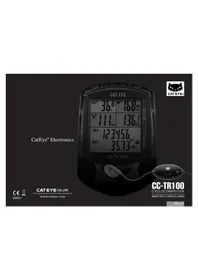


| Product type | Cycle computer (wired) |
| Brand | Cateye |
| Model | CC-TR100 |
| Dimensions | Approx. 50 x 40 x 20 mm (2.0 x 1.6 x 0.8 in) |
| Weight | Approx. 30 g (1.1 oz) with battery |
| Power supply | One CR2032 lithium battery (3V) |
| Battery life | Approx. 1 year (1 hour use per day) |
| Display type | LCD, 5-digit |
| Functions | Current speed, average speed, maximum speed, trip distance, total distance (odometer), elapsed time, clock (12/24h) |
| Auto start/stop | Yes, based on wheel rotation |
| Speed range | 0.0 to 99.9 km/h (0.0 to 62.1 mph) |
| Distance range | 0.00 to 99999 km (0.00 to 62137 mi) |
| Time range | 0:00:00 to 9:59:59 |
| Wheel circumference setting | User selectable (mm) |
| Water resistance | IPX4 (splash proof) |
| Mounting type | Handlebar bracket (22-31.8 mm) |
| Sensor type | Magnetic reed switch (wired) |
| Cable length | Approx. 700 mm (27.6 in) |
| Operating temperature | 0°C to 50°C (32°F to 122°F) |
| Storage temperature | -10°C to 60°C (14°F to 140°F) |
| Maintenance | Wipe with a soft, dry cloth; do not use solvents |
| Spare parts | Mounting bracket, sensor, magnet, cable ties available |
Frequently Asked Questions - CC-TR100 Cateye
User questions about CC-TR100 Cateye
0 question about this device. Answer the ones you know or ask your own.
Ask a new question about this device
Download the instructions for your Meter in PDF format for free! Find your manual CC-TR100 - Cateye and take your electronic device back in hand. On this page are published all the documents necessary for the use of your device. CC-TR100 by Cateye.
USER MANUAL CC-TR100 Cateye
Thank you for purchasing the CATEYE CC-TR100.
The CC-TR100 is a high-performance computer for riders who wish to train extensively and analyze their data. It features wired speed and cadence, and coded wireless heart rate for minimal interference with other external signals. The computer can store up to 150 hours of computer downloadable data through the use of an optional download kit. An optional power unit can also be purchased to record your torque and power output in watts.
Read this instruction manual thoroughly and understand the functions of the product before using it.
Important
- Always follow the sections that are marked with " Warning!!!".
- No part of this manual may be reproduced or transmitted without the prior written permission of CatEye Co., Ltd.
- The contents and illustrations in this manual are subject to change without notice.
- If you have any questions or concerns about this manual, please contact CatEye at www.cateye.com.
This device complies with Part 15 of the FCC Rules. Operation is subject to the following two conditions: (1) This device may not cause harmful interference, and (2) this device must accept any interference received, including interference that may cause undesired operation.
Modifications
The FCC requires the user to be notified that any changes or modifications made to this device that are not expressly approved by CatEye Co., Ltd. may void the user's authority to operate the equipment.
About the manuals
You can find the desired operating method or function description from the following three guides:
Basic installation and operation
Please go here for installation of the unit on the bicycle, setup of the main unit, mounting of the heart rate sensor, and the basic operation of the product.
Complete description of computer functions
Please go here to learn how to operate the computer functions.
page 20 - 27.
How to change and customize settings
Please go here to change and customize the settings on your computer.
Using the device in special ways
- Gathering secondary trip data .... Second measurement (See page 18.)
- Recording lap and split time data .... Lap function (See page 26.)
- Training with target heart rate and cadence
Heart rate zone/Cadence zone (See page 24.)
- Downloading recorded data to a personal computer
Data storage function (See page 27.)
See the table of contents on the next page for more specific information. Be sure to note that some functions described can only be used with optional parts; each optional part will come with its own operating instructions.
The meaning of icons in this manual:
Warning!!! Sections marked with these icons are critical for safe use of the device. Be sure to follow these instructions.
CAUTION! Important cautionary notes on the use and operation of the TR100.
NOTE Helpful tips are highlighted this way.
Registration
Please register your TR100 to validate the warranty. Refer to page 51, and make user registration.
Contents
Introduction 1
About the manuals 2
Proper use of the CatEye CC-TR100 4
Description of computer and its parts 5
Screen display 6
Installing the unit on your bicycle ..... 8
Main unit set-up 11
- Pull out insulation sheet ..... 11
- Formatting / restarting operations
11
- Checking heart rate sensor ID ... 12
- Selecting speed unit ..... 12
- Tire circumference Input ..... 13
- Operation test 13
Heart rate function 14
Before wearing the heart rate sensor 14
Wearing the heart rate sensor ..... 14
Heart rate sensor test 15
Basic operations 16
Main computer functions ..... 16
Starting/stopping main measurement
16
Switching displayed data 17
Lap 18
Backlight 18
Second measurement 18
Resetting operation 19
Power-saving function 19
Measured data 20
Display-1 and 4 20
Display-2 and 3 21
Display-5 22
Lap screen display 23
Functions of main unit 24
Heart rate zone/Cadence zone ..... 24
Auto-mode (auto-start / stop) ..... 25
Pace functions 25
Lap function 26
Data storage function 27
Configuring main unit 28
Wheel selection 28/29
Tire circumference input ..... 28 / 29
Auto-mode 28/30
Sound 28/30
Date 28/31
Setting clock 28/31
Manual odometer input ..... 28 / 32
Speed unit 28 / 32
Defining remote button setting
28/33
Cadence zone 28/34
Heart rate zone 28 / 36
Heart rate sensor ID 28 / 38
Data file 28 / 39
Data storage 28 / 41
PC Link 28/42
Torque 28/43
Power select 28/43
Heart rate training 44
Troubleshooting 46
Replacing battery 48
Main Unit 48
Heart rate sensor 48
Maintenance 48
Spare accessories 49
Specifications 50
Registration 51
Registration card 51
Limited warranty 52
Tire circumference reference table ... 53
Proper use of the CatEye CC-TR100
Observe the following instructions for safe usage.
Warning!!!
- Pace maker users should never use this device.
- Do not concentrate on the data while riding. Always be sure to ride safely.
- Do not leave any battery within the reach of children, and dispose of them correctly. If a battery is swallowed, consult a doctor immediately.
CAUTION!
- Avoid leaving the main unit / wireless sensor in direct sunlight for extended periods of time.
- Do not disassemble the main unit, HR receiver, or sensors.
- Regularly check the positions of the magnet and the speed/cadence sensors and make sure that they are securely mounted.
- Do not use paint thinner or rubbing alcohol to clean the unit.
- Do not subject the main unit, HR receiver, or sensors to strong impact; take care also to prevent any of them from falling.
Heart rate sensor
NOTE
The heart rate transmitter has a maximum and minimum transmission distance. Make sure that the distance between the transmitter and main unit is between 20 and 80 cm at all times to ensure proper transmission. If the distance is less than 20 cm, the signal will be too strong for proper reception.
Signals from the heart rate sensor can be received with the main unit attached to the HR receiver. Signals, however, cannot be received by the main unit alone.
CAUTION!
- The following objects and places may generate strong electromagnetic wave and interference, which may result in incorrect measurement:
- TV, PC, radios, motors/engines, or in cars and trains.
- Railroad crossings and near railway tracks, around television transmitting stations and radar bases.
- Avoid using the main unit together with other cordless devices. Doing so may result in transmission interference.
- Consult a doctor if any part of the HR strap results in a rash.
- Do not twist or pull the heart rate sensor using unnecessary force.
- Like all products, the heart rate sensor has a limited lifetime, and may stop functioning after extended usage. If you have any problems receiving heart rate data, it may be time to replace the heart rate sensor.
Description of computer and its parts


Main unit
① Display-1 (Speed) ② Display-2 (Heart rate) ③ Display-3 (Cadence) ④ Display-4 (Calories) ⑤ Display-5 (Displays selections) ⑥ MENU button (MENU) ⑦ RESTART button (RESTART) ⑧ LAP button (LAP) ⑨ START / STOP / ENTER button (This button is indicated as the S/S/E button in the subsequent procedure charts.) ⑩ Mode-1 button (MODE-1) ⑪ Mode-2 button (MODE-2) ⑫ BACK-LIGHT button (LIGHT) ⑬ Battery cover
Accessories
A Heart rate sensor/transmitter B HR Strap C Cloth loop HR receiver D Bracket E Speed sensor (Long wire) F Cadence sensor (Short wire) G Sensor rubber pad x 2 H Remote buttons I Nylon ties x 18 J Rubber bracket spacing pad x 2 K Wheel magnet L Cadence magnet M Remote button cover for drop (road) handlebars x 2 N Remote button cover for flat handlebars x 2

Screen display
Display-1
Display-2
Display-3
Display-1 (Main Speed Display)
① Speed Icon ② Displayed data icon ③ Speed pace arrow
The pace arrows show whether the current speed is faster or slower than the average speed.
④ Speed unit Flashes while speed measurement is in progress. ⑤ Memory remaining and usage (%)
Lights up to indicate the amount of remaining data or usage in the Data file menu.
Display-2 (Main Heart Rate Display)
6 Heart rate icon: Flashes in sync with heart rate signals. ⑦ Heart rate pace arrow
Shows whether the current heart rate is above or below the average heart rate.
⑧ Heart rate mode icon: Indicates type of data displayed in Display-2. A: Average heart rate, M: Maximum heart rate. ⑨ Auto-mode icon: Lights up when the auto-mode function is on. ⑩ Heart rate unit
Display-3 (Main Cadence Display)
① Cadence icon. ⑫ Cadence pace arrow: Shows whether the current cadence is above or below the average cadence. ⑬ Cadence mode icon: Indicates type of data displayed in Display-3. A: Average cadence, M: Maximum cadence, Total: Pedal count. ⑭ Cadence unit. ⑮ Factor of 10: Displayed when total pedal count exceeds 9999.

Display-4
Display-5

Display-4
(Calorie display [Also displays power when optional power unit is installed].)
⑯ Power icon *1: Lights up when the optional power unit is installed and the power (watts) is displayed. ⑰ Power pace arrow *1: Shows whether the current power is greater or lower than the average power. ⑱ Power select mode icon *1: Indicates type of data displayed in Display-4. A: Average power, M: Maximum power. ⑲ Unit of calorie consumption: Lights up when calorie consumption is displayed. ⑳ Factor of 10: Displayed when the calorie consumption exceeds 9999.
Display-5 (Displays selected functions.)
② Mode icon
Indicates type of data displayed in Display-5.
Second measurement icon
Lights up while the second measurement data is displayed.
Lap icon
Lights up while the lap data is displayed.
24PC link icon
*1: Lights up when the optional power unit is installed, online power measurement is performed, and TR100 is connected to a personal computer. *2: Lights up when linking to a personal computer.
Sound icon: Lights up when the alarm sound for heart rate zone and cadence zone is on. Power measurement icon *1: Lights up when the optional power unit is being used. Target icon: Lights up when the alert function is turned on in either the heart rate zone or cadence zone. Stored Data Icon: Lights up when the Stored Data function is turned on. Flashes when the Stored Data cannot be performed. Wheel selection icon: Indicates the wheel currently selected.
*1: In order to use this function, the optional power unit must be installed.
*2: In order to use this function, the optional download kit or power unit is required.
Installing the unit on your bicycle
Follow steps 1 through 5 to mount the TR100 on your bicycle.

1 Mount the bracket and HR receiver, and then attach the main unit
- Mount the bracket E to the handlebar, using the rubber pad K as a spacer. Adjust the bracket to a position that provides good visibility and securely fasten it with the screw. Adjust the angle of the bracket and receiver so that each provides good visibility with the main unit attached. Then, tighten all screws securely.
CAUTION: Check periodically that the receiver screw is not loose in order to prevent the receiver from falling.
- Attach the main unit to receiver D by sliding it in from the front until a click is heard. To remove the main unit, push it forward while lowering the lever on the side of the receiver.


2 Mount the cadence magnet and cadence sensor
- Mount the cadence magnet M to the inner side of the left crank so that the magnet surface faces the sensor.
NOTE: The center of the magnet L should pass in front of the sensor F marking line. The distance between the sensor and the magnet L should be no more than 5 mm. After adjusting the magnet and cadence sensor G (short wire), secure them tightly with nylon ties.
CAUTION!: The nylon ties can only be used once, please install with care.
The smooth side of the zip tie should be on the outside.
Inward side of the left crank arm.
Left chain stay.
NOTE:
When the crank is spinning, the center of the magnet M should pass in front of the sensor G marking line. The distance between the sensor and the magnet M should be within 5 mm. After adjusting the magnet and sensor, secure tightly with nylon ties.


3 Mount the wheel magnet and speed sensor
- Mount the wheel magnet ⬆ to a spoke on the rear wheel so that the magnet surface faces the sensor.
- Secure the speed sensor F (long wire) onto the left chain stay with nylon ties J.


NOTE:
The center of the magnet L should pass in front of the sensor F marking line. The distance between the sensor and the magnet L should be no more than 5 mm. After adjusting the magnet and sensor, secure them tightly with nylon ties.


4 Secure the sensor wire
Secure the wire onto the frame using the supplied nylon ties.


CAUTION !:
Allow enough wire clearance in the area marked with ➞ to ensure you can turn the handlebars all the way from side to side without pulling the wire.
5 Installing the remote buttons
Select the positions to mount the remote buttons according to your bicycle type.
CAUTION!: • Install the remote button so that it does not interfere with shift or brake operation.
- On road bikes, be sure to wrap the handlebar tape over the button wires to prevent wire damage.
When installing the remote button onto road bicycles
- Peel back the brake lever hoods as shown in the figure below.
- Fit the road bike button cover Ⓝ to the remote button ⏻, and stick the button to the inside of the brake lever.
- Replace the brake hood cover and then adjust the button position.
- Firmly secure the button and cable to the handlebar with a nylon tie ⚪ before wrapping the bar with handlebar tape.
Example of installing onto drop (road) handlebars
When installing the button onto a flat handlebar
- Install the proper button cover Ⓐ on the remote button ⏻, and stick the button on an easily accessible position on the handlebar.
- Firmly secure the button Ⓑ to the handlebar using the supplied nylon ties ⚠
Example of installing onto flat handlebar
Main unit set-up
To use the CC-TR100, follow the steps below to set up the main unit.
1. Pull out battery insulation sheet
Using a coin, open the battery cover of the main unit and pull out the insulation sheet, then close the battery cover.

2. Formatting / restarting operations
Formatting is required during the initial set-up, and when all items of data are to be reset to zero.
NOTE: Formatting operation initializes all of the data in the memory. Be absolutely certain that you want to initialize all of the data.
When all items light up for a few seconds and formatting is completed, proceed to the heart rate sensor ID check screen.
NOTE: If there is little memory available, all screen items may remain on for approximately one minute.

Restarting operation
You must restart the computer when you replace the batteries, or when an error has been displayed.
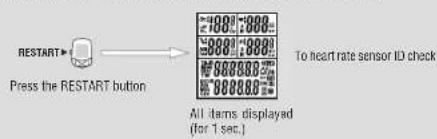
When the RESTART button is pressed, all of the items light up for one second. You will then proceed to the heart rate sensor ID check screen.
NOTE: In the restart operation the date, total time, and total distance are retained, but the heart rate sensor ID check and time settings must be performed again.
Attach the main unit to the receiver.
3. Checking heart rate sensor ID
The heart rate sensor ID must be checked within five minutes after the formatting or restarting operation.
Before performing an ID check, mount the main unit to the HR receiver.
NOTE: Be sure to attach the main unit to the HR receiver. Signals from the heart rate sensor cannot be received by the main unit alone.
Place the heart rate sensor approximately 20-80 cm from the main unit, and press the reset button of the HR sensor for five seconds. The main unit will receive the signal from the heart rate sensor, and will start checking the heart rate sensor ID. When the check is completed, the ID number is displayed, followed by the next screen.
NOTE: If the HR sensor is placed too close to the main unit (within 20 cm), the main unit cannot receive the ID signal. If an ID check failed, change the distance, and reset the heart rate sensor.
If "E" appears on Display-2, or a HR sensor ID check failed even at a proper distance, the batteries may be dead. Replace the batteries of the heart rate sensor in the procedure shown on page 48, and format (restart) the computer again.
![graph LR A["Pressing the reset button for five seconds"] --> B["For formatting 4. Selecting speed unit"] B --> C["For restarting Ready"]](/content/2026/06/1304628/images/da9ac4c92541c8fd2adb9597fb38e895f81a333d1c92373c474152b45c32d254.jpg)
4. Selecting speed unit
The default speed unit is "km/h."
By pressing the MODE-1 or MODE-2 button, you can switch the unit between "K (km/h)" and "M (miles/h)." Select the desired speed unit, and press the START/STOP/ENTER button. The selected unit is now accepted, and the tire circumference screen appears.
![graph LR A["Select"] --> B["Un it"] B --> C["MODE-1 OF MODE-2 Switch"] C --> D["Select"] D --> E["Un it"] E --> F["M"] F --> G["S/S/E Select"]](/content/2026/06/1304628/images/8790c895477cd289225d93a60eea41463e2bd55b6ba6997d44d4586e9fdf9d9d.jpg)
5. Tire circumference input
Enter the circumference of the tire of your bicycle in mm. 2096 mm (700 x 23 C) is preset as the initial value. To change the value, use the MODE-2 button to increase the value, and use the MODE-1 button to shift the digit selected.
Pressing the START/STOP/ENTER button and this is the last step in the initial set-up. Adjustable range: 0100 to 3999 mm
NOTE: • You can find your approximate tire size on the tire circumference chart on page 53. • When a value outside the adjustable range is entered, an error indication appears on the screen and you cannot select the value.
![graph LR A["MODE-1"] --> B["Shifting the digit"] B --> C["MODE-2"] C --> D["Increasing the value"] D --> E["Changing a value"] E --> F["S/S/E Select"]](/content/2026/06/1304628/images/20ca1e845d0ad69c26f677534224e33bd4e50d5aaa4e059dcf6d0a373390730c.jpg)
6. Operation test
Test the functioning of the speed sensor, cadence sensor, and remote buttons with the main unit attached to the receiver.
- Raise the rear wheel and spin the tire, and make sure that the speed (Display 1) shows a number greater than zero.
- Turn the crank (backpedal) and make sure that the cadence (Display 3) shows a number greater than zero.
Rotate the rear wheel

NOTE: If the screen remains at "0", the relative positions of the magnets to the sensors may be inappropriate. Follow the instructions given in "Installing the unit on your bicycle", on page 8.
- Press the right and left remote buttons to check that you can operate the main unit with them. NOTE: • If the button is not operable, it indicates that the main unit and/or the button connector may not have been installed properly.
- In the initial setup, the MODE-1 and MODE-2 button functions have been specified. To change the settings, see "Defining remote button setting" on page 33.
Completion of initial set-up
When the setup is completed, set the date and time as described in "Configuring main unit" on page 28.
Heart Rate Function
Heart rate is measured when the heart rate sensor is worn on the chest.
NOTE: Heart rate sensor reception range is approximately 20 cm and 80 cm.
Heart rate sensor
Electrode pad

Before wearing the heart rate sensor
Warning!!! This product must NOT be used by those who have a pacemaker.
NOTE: • Wear the heart rate sensor in the center of the chest. The rubber part of the electrode pad must be in direct contact with the skin.
- To avoid measurement errors, it is recommended to moisten the electrode pads with water.
- If your skin is ultra-sensitive, the electrode pad may be moistened with water and worn on a thin undershirt.
- Chest hair may interfere with the measurement.
- Using the heart rate sensor together with other cordless devices may cause interference with the data transmission.
Wearing the heart rate sensor
Besides using the conventional chest strap, it can be worn directly attached to a sports bra using an optional neck strap.
NOTE: - Ensure that the rubber part of the electrode pad is in close or direct contact with the body.
• Some sports bras cannot be worn with the heart rate sensor. - Wearing the heart rate sensor on top of your undershirt may produce measurement errors. Measurement errors may also occur if the skin is exceptionally dry. To avoid errors, moisten the rubber part of the electrode pad.
Using the HR strap
- Adjust the length of the HR strap to fit your chest size. Fastening the strap too tightly may cause discomfort.
- Fasten the hook of the transmitter.
NOTE: Secure the transmitter with the cloth loop.
- Insert the electrode pads (one on the left and the other on the right) between the HR strap and the body, and secure the electrode pad onto the HR strap using the hook.
Ensure that the rubber part of the electrode pad is in direct contact with the body.
① If the electrode pads are loose, please wear the chest strap as indicated below.
![graph TD A["HR strap"] --> B["Shift the HR Strap to adjust its position"] B --> C["Electrode pad"] C --> D["Cloth loop"]](/content/2026/06/1304628/images/8ab1c8eaae8f5ec4645e2843817256e7f3909c20b50b1d1ae0834998ee8d0431.jpg)
When a sports bra is worn
NOTE: Wearing the heart rate sensor on a sports bra requires the optional neck strap.
- Attach the strap to the transmitter as shown in the picture below, looping the strap through the hole in the transmitter hook.
- Wearing the neck strap, adjust the length to bring the transmitter to the correct height.
- Attach the electrode pads to the sports bra using the hook on the pad, making sure the rubber part of the electrode pad itself is in direct contact with the body.


Electrode pad
Heart rate sensor test
- Wear the heart rate sensor.
- Mount the main unit to the HR receiver, and stand so that the HR transmitter is within 20-80 cm. NOTE: Be sure to attach the main unit to the HR receiver. Signals from the heart rate sensor cannot be received by the main unit alone.
- When the ♥ icon flashes and the heart rate is indicated on Display-2, the heart rate sensor is operating properly.
NOTE: • The heart rate sensor will start transmission approximately three seconds after it has stabilized. Therefore, a short time lag occurs before the ♥ icon begins to blink.
- If the ♥ icon does not flash, move the electrode pad little by little to find the optimum position for the heart rate reception. Dryness may make measurement difficult. Moistening the electrode pad allows easier measurement.


Basic operations
TR100 measures data when the bicycle starts moving. You can view various data by pressing the MODE-1 and MODE-2 buttons. You can also record lap data up to 199 laps or intervals.
Main computer functions
The main screen has 5 windows which display different types of data. Pressing the MODE-1 and the MODE-2 buttons change the displayed information, as shown in the illustration. The displayed items of data are as follows:
- Display-1 ...... Displays the current speed.
- Display-2 .... Displays heart rate data. (Press MODE-1 to cycle through data shown on Display-3.)
- Display-3 ...... Displays cadence data. (Press MODE-1 to cycle through data shown on Display-2.)
- Display-4 ...... Displays the calorie consumption in kcal.
When the power unit is used, power-related data is displayed. For details, see the instruction manual for the power unit.
- Display-5 ...... Displays other data. (Use MODE-2 to cycle through this data.)
NOTE: For more information on displayed items of data, see "Measured data" on page 20.

Starting / stopping main measurement
When you begin riding, the elapsed time starts and the speed unit will flash.
The total distance, maximum speed, maximum heart rate and maximum cadence are updated independently of starting/stopping of the main measurement.
NOTE: To manually start and stop measurement using the START/STOP/ENTER button, see "Auto-mode" on page 30 for instruction on turing on or off the auto-mode.
START / STOP / ENTER button
Switching displayed data
NOTE: For details of each data, see "Measured data" on page 20.
• Switching data on Display-2 and Display-3
Pressing MODE-1 switches data on both Display-2 and Display-3.

![graph TD A["Speed Heat Fate"] --> B["Mode-1"] C["Calorie consumption"] --> B D["Mode-1"] --> E["Mode-1"] F["Mode-1"] --> G["Mode-1"] H["Mode-1"] --> I["Mode-1"] J["Mode-1"] --> K["Mode-1"] L["Mode-1"] --> M["Mode-1"] N["Mode-1"] --> O["Mode-1"] P["Mode-1"] --> Q["Mode-1"] R["Mode-1"] --> S["Mode-1"]…](/content/2026/06/1304628/images/75254def89afd0660b645669d7a6a77d16c1c1fa603911f13191eee00dead8e5.jpg)
When the MODE-1 button is held for two seconds, Display-3 shows the total number of pedal revolutions. The data on Display-2 does not change.
Pressing MODE-1 again, returns Display-3 to the cadence data.
NOTE: When the optional power unit is used, the MODE-1 button also switches Display-4 together with other displays. For details, see the instruction manual for the power unit.

- Switching data on Display-5
Pressing MODE-2 switches the data on Display-5.
![graph TD A["TM-1 Elapsed Time\nDST-1 Trip Distance"] --> B["AVS 1 Average Speed"] B --> C["DATE Date\nMXS Maximum Speed"] C --> D["TTM Total Time\nODO Total Distance"] D --> A style A fill:#f9f,stroke:#333 style B fill:#ccf,stroke:#333 style C fill:#cfc,stroke:#333 style D fill:#fcc,stroke:#333 subg…](/content/2026/06/1304628/images/fd598efb60edcadcdc0c139e7d8c4eec621ba7c430011d358ed84eeace47db21.jpg)

![graph TD A["Main measurement"] --> B["MODE-2 (2 sec.)"] B --> C["Second measurement"] C --> D["TM-DST-R"] C --> E["AVS-R"] D --> F["Second measurement icon"] E --> G["Starting / stopping the second measurement"] F --> H["S/S/E"] G --> I["MODE-2"]](/content/2026/06/1304628/images/761f1ce57af7cf91984f21e8f9bfde6abde20928300ad272b17e9463431502e5.jpg)
Lap
Pressing the lap button during data measurement records lap time/average, split time/trip distance, average lap heart rate, and average lap cadence for up to 199 intervals.
Recorded lap data can be recalled on the lap viewing screen. (See page 26.)
Backlight
Pressing the LIGHT button illuminates the displays for about three seconds.
Second measurement
The second measurement is another measuring method, different from the main measurement described on page 16.
A second elapsed time, trip distance, and average speed can be recorded independently of the main measurement.
• How to switch to the second measurement:
When the MODE-2 button is pressed for two seconds, Display-5 switches to the second measurement screen with the elapsed time "TM-2" displayed on the top and the trip distance "DST-2" displayed at the bottom.
Each press on the MODE-2 button switches the bottom display between the elapsed distance DST-2 and the average speed AVS-2.
When the MODE-2 button is pressed for two seconds, the system returns to the main measurement.
- Starting / stopping the second measurement
With the second measurement icon illuminated, press the START/STOP/ENTER button to start or stop measurement.


Power-saving state (after 10 minute idle)
Resetting operation
Follow the directions below for resetting selected data to zero.
NOTE: You cannot perform the resetting operation on the lap screen.
1. Resetting all measured items of data
To zero all data except for "TTm (total time)," "Odo (total distance)," "date" and "time," and including the lap data and time in the heart rate and cadence zones, simultaneously press the START/STOP/ENTER, MODE-1 and MODE-2 buttons.
NOTE: When resetting is required to change the settings on the menu screen, reset all measurements.
2. Resetting the main measurement data
To zero the main measurement data except for "TTm (total time)," "Odo (total distance)," "date" and "time," and including the lap and the time in the heart rate zone and cadence zone, simultaneously press the START/STOP/ENTER and MODE-1 buttons while the main measurement is displayed.
3. Resetting the second measurement data
To reset to zero all erasable data in the second measurement display only, simultaneously press START/STOP/ENTER and MODE-1 while the second measurement icon is on.
Power-saving function
When the computer has not received any data for 10 minutes, the main unit will enter the power-saving mode, in which only the clock is displayed (note illustration).
When the computer receives a speed or cadence signal, or any of the buttons is pressed, the power-saving mode is cancelled, and the normal display returns.
NOTE: The power-saving mode is not cancelled if the computer receives a heart rate signal.
Measured data
NOTE: You must wear the heart rate sensor to perform the heart rate measurement.
Display-1 and 4
| ‰A 36 KB | ‰A 160 molC |
| ‰A 111 cm | 1345 molD |
∞ Current speed
Indicates the current speed, updated every second.
Measuring range: 0.0 (4.0) to 199.9 km/h [0.0 (3.0) to 125.0 mph (mile/h)]
(When the tire circumference B is selected, the lowest measurable speed is 3.0 km/h [2.0 mph].)
kcal Calorie Consumption *1
Indicates the trip calorie consumption, based on the recorded heart rate.
Measuring range: 0 to 99990 kcal
NOTE: When the heart rate is below 90 bpm, calorie consumption is not updated. When it exceeds 9999, "X10" appears.
1: When the optional power unit is used, power related data is displayed. For details, see the instruction manual for the power unit.
Display-2 and 3


Heart rate
Indicates the heart rate in real time, updated every second.
Measuring range: 0 (30) to 260 bpm

Cadence
Indicates the number of pedal rotations per minute, updated every second.
Measuring range: 0 (20) to 299 rpm

♥ A Average heart rate
Indicates the average heart rate. When the elapsed time exceeds 100 hours, [E] appears indicating further measurement is impossible.
Measuring range: 0 to 260 bpm

A Average cadence
Indicates the average cadence. When the pedaling count exceeds 100,000 or when the elapsed time exceeds 100 hours, [E] appears indicating further measurement is impossible.
Measuring range: 0 to 299 rpm

♥ M Maximum heart rate
Indicates the maximum heart rate.
Measuring range: 0 (30) to 260 bpm

M Maximum cadence
Indicates the maximum cadence.
Measuring range: 0 (20) to 299 rpm

Total Pedal Count
Indicates the total pedal count.
When the count exceeds 9999, the "x10" appears;
Measuring range: 0 to 99990 rotations
![graph TD A["TM-1 123456 DST-1 35.79"] --> B["MODE-2"] B --> C["100928 1 AVS 28.6"] C --> D["MODE-2"] D --> E["DATE 02'11.11 MXS 55.3"] E --> F["MODE-2"] F --> G["TTM 123456 DDD 24680"]](/content/2026/06/1304628/images/1a341f68d3e96b4006e24a22107a2094a7a948ad1d5d5c8b88810896058b2591.jpg)
TM-1 Elapsed time
Indicates the elapsed time from the start of measurement to 1/10 second. When it exceeds 10 hours, 1/10 second is not displayed.
Measuring range: 0:00'00"0 to 99:59'59"
DST-1 Trip distance
Indicates the trip distance covered.
Measuring range: 0.00 to 9999.99 (six 9's) km [mile]

Clock
Indicates the current time of day in the 24- or 12-hour system.
Measuring range: 0:00 to 23:59 [AM 1:00 to PM 12:59]
AVS 1 Average speed
Indicates the average speed of the trip. When the trip distance exceeds 10000 km [mile] or the elapsed time exceeds 100 hours, [.E] appears indicating that further measurement is impossible.
Measuring range: 0.0 to 199.9 km/h [0.0 to 125.0 mph]
DATE Date
Indicates the current day, month, and year.
Measuring range: 00'01.01 to 99'12.31
MXS Maximum speed
Indicates maximum speed achieved; recorded even while computer is manually stopped.
Measuring range: 0.0 (4.0) to 199.9 km/h [0.0 (3.0) to 125.0 mph]
TTM Total time
Total time is continual and cannot be reset.
Measuring range: 0:00 to 9999:59 h
ODO Total distance
The total distance is continually measured and cannot be reset. When it exceeds 100,000 km [mile], 1/10 km [mile] is not displayed.
It is updated independently of starting/stopping data measurement.
Measuring range: 0.0 to 999999 (six 9's) km [mile]
Lap screen display

LAP No. Lap number
Indicates the current lap number. The lap number will always be indicated when viewing lap data.

LAP A Average lap heart rate
Indicates the average heart rate for that lap. Indicated when viewing lap data.
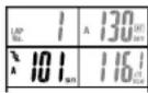
LAP A Average lap cadence
Indicates the average cadence for that lap.
Indicated when viewing lap data.

LAP Lap calorie consumption *1
Indicates the estimated calorie consumption for a given lap.
Indicated when viewing lap data.

LAP TM Lap time
Indicates the lap time. Display alternates between the lap time and the split time.
Appears during the lap recording (for about five seconds) and the viewing of lap data.

LAP AVS Average lap speed
Indicates your average lap speed; appears alternating with the lap distance.
Appears during the lap recording (for about five seconds) and the viewing of lap data.

s LAF Split time
Indicates the total time elapsed from the start of the exercise. Display alternates between the split time and the lap time.
Appears during the lap recording (for about five seconds) and the viewing of lap data.
S LAP DST Trip lap distance
Indicates the lap distance. Display alternates between the lap distance and the average lap speed. Appears during the lap recording (for about five seconds) and the viewing of lap data.
Functions of main unit
Heart rate zone / Cadence zone
You can set target heart rate and cadence zones and view the time in zone data at any time. The zone value will flash when the target zones are on and the value is out of your target zone. An alarm will sound if the sound feature is turned on.
Heart rate zone alert

• Heart rate zone alert
Four heart rate zones can be set with range and target. The range of each zone may overlap. The zone value will flash when the target zones are on and the value is out of your target zone. An alarm will also sound if the sound feature is turned on. You can check the time in and out of the heart rate zones, set the target and change the range in "Heart rate zone (page 36)" on the menu screen for each zone.
Heart rate 60 80 100 120 140 160 180 200
For example, if your target is 140 to 160 bpm, turn on the target in Zone 3 as shown at right. If the heart rate goes out of this range during measurement, the heart rate on Display-2 flashes.
| Zone.1 | Heart rate zone | ||
| Zone.2 | |||
| Zone.3 | Target training zone → Zone.3 | Target alert setting | |
| Zone.4 | Zone.4 | ||
Cadence zone alert

• Cadence zone alert
TR100 has one cadence zone besides the four heart rate zones. The zone value will flash when the target zones are on and the value is out of your target zone. An alarm will also sound if the sound feature is turned on. You can check the time in the cadence zone, set the target and change the range in "Cadence zone (page 34)" on the menu screen.
Alert when both heart rate and cadence go out of respective zones

NOTE: When both the heart rate and the cadence are turned on and go out of the respective zones, the heart rate and cadence values flash.

Auto-mode (auto-start / stop)
When the Auto-mode function is on, the computer automatically starts and stops measuring with the movement of the wheel. When the auto-mode function is turned on, an AT icon appears on the display.
Current speed Heart rate
Cadence
Pace functions
The pace arrow icons on Displays 1, 2 and 3 indicate whether the current speed, heart rate and cadence are above or below the respective average values.
▲ : Appears when the speed (heart rate, cadence) is above the average. ▼ : Appears when the speed (heart rate, cadence) is below the average. ▲ ▼ : Appears when the speed (heart rate, cadence) equals the average.
Not illuminating: When the speed (heart rate, cadence) is zero.
![graph TD A["Measuring Screen"] --> B["LAP"] B --> C["Recording lap date"] C --> D["Lat time"] D --> E["Average lap speed"] E --> F["Split time"] F --> G["Trip lap distance"] G --> H["Alternating data display"] H --> I["Up/No"] I --> J["Up time"] J --> K["Up time"] K --> L["Up time"] L --> M["Up time…](/content/2026/06/1304628/images/42290b841d483ef5e528e42e55e1ee3167acfe8f820e2ac9e9ab818b2fa2d87f.jpg)
Lap function
- Recording lap data
Pressing the Lap button on the main display while riding records lap data. Immediately after recording, the lap number is displayed, alternating between 'lap time' / 'average lap speed' and 'split time' / 'lap distance'.
NOTE: • Up to 199 laps can be recorded.
- Lap times cannot be shorter than 5 seconds; pressing the LAP button consecutively within 5 seconds will not result in a new lap. New laps can not be recorded when viewing recorded lap data.
- The lap function does not record lap intervals longer than 100 hours or 9999.99 (six 9's) km.
NOTE: Viewing lap data depends on the on/off status of "data storage."
- When 'data storage' is on:
The recorded lap data can be viewed on the main unit display, and is also saved in a data file. It disappears from the display when the main (or all) data is reset, but it is stored in the data file and can be transferred to a personal computer. Lap data will remain in the computer as long as the data file is not deleted. To obtain more free space for laps, data files will need to be deleted (see "Data file" on page 39).
- When 'data storage' is off:
The recorded lap data can be viewed on the main unit display. It is deleted as soon as the main measurement data or all measurement data is reset. The data cannot be transferred to a personal computer.
![graph TD A["Measuring Screen"] --> B["Recording lap data"] B --> C["Alternating data display"] C --> D["Split time"] D --> E["Average lap speed"] E --> F["Lap time"] F --> G["Average lap speed"] G --> H["Mode-1 + Mode-2"] H --> I["Mode-1 + Mode-2"]](/content/2026/06/1304628/images/02a1cc59528cbc91e1e5d79009a6efaeb1308687a5b0b05232cfb07e2515f221.jpg)
- Reading lap data
Press the MODE-1 and MODE-2 buttons simultaneously to view recorded lap data. The lap recall screen displays the most recent laps first. Use MODE-1 or MODE-2 buttons to cycle through the laps. Pressing MODE-1 and MODE-2 simultaneously will exit from the lap recall screen.
NOTE: • The lap recall screen will not appear if there is no lap data recorded.
The recorded lap data is deleted when the main measurement data or all measurement data is reset. Leaving the lap viewing screen idle for one minute will return automatically to the measuring screen.
![graph LR A["Start"] --> B{Lap time} B --> C["1"] B --> D["2"] C --> E["Split time"] D --> E F["mus-1"] --> G["1"] H["mus-2"] --> I["2"] J[" changing lap numbers "] --> K["1"] L[" changing lap numbers "] --> M["2"] N[" changing lap numbers "] --> O["3"]](/content/2026/06/1304628/images/1aa92d62e157d3e8f7f110c357dff510ff572bf081e13e90d8bbde3669c57bae.jpg)
• Lap time and split time
• Lap time and split time
The lap time indicates the time elapsed between two consecutive pressings of the LAP button.
The split time indicates the total elapsed time from the start of the exercise.

Data storage function
Data storage allows you to create data files that are downloadable to your personal computer, allowing for analysis of recorded training data. Data recorded includes speed, heart rate, cadence, trip distance, and elapsed time. The data is recorded in time intervals (memory timing) selected by the user.
- When Data Storage is on, the M icon will be on (the default setting is on). Recorded data is stored in a data file as soon as initial set-up has been performed and data is being measured.
- Lap data. HR and Cadence data recorded during data storage are all recorded on a data file.
- Up to 99 files can be stored within the memory capacity of the TR100. These files can be downloaded to a personal computer using the download kit (optional accessory).
- Without the download kit
The default setting for data storage is 'on'. However, to download to a personal computer, the optional download kit is required. If you do not wish to download data to your personal computer, be sure to turn the Data Storage setting off on the menu screen to avoid unnecessary memory consumption (see page 41).
- With the download kit:
Follow the steps below for data storage.
Set the data recording interval for data storage
See "Data storage" on page 41.
View and delete files when finished to manage remaining memory
See "Data file" on page 39.
Record and store data
- Up to 99 data files can be stored until the remaining memory is 0%.
- When the remaining memory is at 0% while data is being recorded, the M icon will flash, alerting full memory. Delete old data files to use more memory.
- Before recording and storing data, select an appropriate recording interval for sufficient memory space.
View stored data
See "Checking data file" on page 39.
Download to personal computer
See "PC Link" on page 42.
![graph TD A["Menu screens at a glance"] --> B["Power select"] B --> C["Torque *2"] C --> D["PC Link *2"] D --> E["Data storage *4"] E --> F["Data file *4"] subgraph Main display G["Main display"] H["Wheel selection"] I["Tire circumference input"] J["Auto-mode Date"] K["Sound"] L["Setting clock"] M["M…](/content/2026/06/1304628/images/a61f18bd3b86d015857b4456fbebc1f6854ac171406d6aa6a3af9cdb2e6d0617.jpg)
28 CC-TR100
![graph TD A["Power select menu screen"] --> B["MODE-1"] A --> C["MODE-2"] B --> D["Wheel selection menu screen"] C --> D D --> E["SELECT"] E --> F["S/S/E"] F --> G["2096"] G --> H["MODE-1 or MODE-2"] H --> I["S/S/E Select"] J["Tire circumference input menu screen"] --> K["CHANGE 2096"] K --> L["S/S/E…](/content/2026/06/1304628/images/4197b18b472a6957309ecf661db1fe3330922bb2db6c106d6063d25712f59a1f.jpg)
CC-TR102 29
![graph TD A["Auto-mode menu screen"] --> B["Mode-1"] B --> C["Select Auto"] C --> D["Mode-2"] D --> E["Mode-1 Select"] E --> F["Sound menu screen"] F --> G["Mode-1"] G --> H["Mode-2"] H --> I["Date menu screen"] I --> J["30 CC-TR100"] K["Auto-mode on/off"] --> L["On OFF"] L --> M["On OFF MODE1 or MOD…](/content/2026/06/1304628/images/81b142d6a86543b977290974256c19cbc861cae3a0be11d04e9cf5a7fa7239f3.jpg)
![graph TD A["Sound menu screen"] --> B["MODE-1"] A --> C["MODE-2"] B --> D["Date menu screen"] C --> D D --> E["SET"] E --> F["S/SE"] F --> G["m. d', y d, m'. y y', m. d"] G --> H["Switch data display format"] H --> I["MODE-1"] I --> J["MODE-2"] J --> K["MODE-1"] K --> L["Set year Set month Set day"]…](/content/2026/06/1304628/images/4f02fd62ecf8491a32d73290e631b6c284277cb03097c22dd54684bcfab290f1.jpg)
Setting clock menu screen


For basic information on how to use the menu screen, refer to page 28.
Manual odometer input
Enter any numeric value as the "odometer value (Odo)". This allows the input of past data even when data has been erased by formatting or when replacing from another cycle computer. The odometer value cannot be changed while the bicycle is in motion.
Manual odometer input menu screen
![graph LR A["Input"] --> B["S/VE"] B --> C["InPut 000000"] C --> D["Mode-1"] D --> E["InPut 000000"] E --> F["Select"] G["ODO"] --> A H["MODE-2"] --> C I["Mode-1"] --> E J["Digit shift"] --> C](/content/2026/06/1304628/images/aad049e46ed7b88bb0b6104fae468b08279211ac58b0e1cd56a27e0b6a87845f.jpg)
Speed unit
Switch between speed units between km/h and mph. After switching, the odometer value is converted into the new unit automatically. NOTE: Before changing units, you must stop the bicycle and reset all measured data.

32 CC-TR100
![graph LR A["S/S/E"] --> B["K"] B --> C["MODE-1 or MODE-2"] C --> D["S/S/E Select"] B --> E["K: km/h\nM: mph"] E --> C](/content/2026/06/1304628/images/c46ce70b978bf379c5953bc16c7db4ecab014728f901d4d335f567bcd16c6b45.jpg)
Speed unit menu screen

Defining remote button setting menu screen
![graph TD A["MODE-1"] --> B["Select button 1 Select IWDEN 2"] C["MODE-2"] --> D["Select button 1 Select IWDEN 2"] B --> E["MO-1"] D --> F["MO-2"] E --> G["MODE-1"] F --> H["MODE-2"] G --> I["MO-1"] H --> J["MO-2"] I --> K["MODE-1"] J --> L["MODE-2"] style A fill:#f9f,stroke:#333 style C fill:#f9f,str…](/content/2026/06/1304628/images/12bce7de55d36904aef9b03e248572e7404414023096cc3ea7830de50c09772e.jpg)

For basic information on how to use the menu screen, refer to page 28.
Defining remote button setting
Specify the functions to be assigned to buttons 1 and 2. In the initial setup, button 1 is assigned to MODE-1 and button 2 to MODE-2.
M01 = MODE-1
MO2 = MODE-2
S-S = START/STOP/ENTER
LAP = LAP
Lt = LIGHT
![graph TD A["Defining remote button menu screen"] --> B["Cadence zone menu screen"] B --> C["Set target"] C --> D["Select S/S/E"] D --> E["Changing the lower limit value"] E --> F["First digit MODE-1 + 2 Reset all measurements"] F --> G["Second digit MODE-1 Digit shift"] G --> H["Third digit MODE-1 D…](/content/2026/06/1304628/images/f80219040824884c59962318eb89fd629daebda638cc3878e3fb2b8ed1b7f471.jpg)
![graph TD A["Cadence zone menu screen"] --> B["MODE-1"] A --> C["MODE-2"] B --> D["Heart rate zone menu screen"] C --> D D --> E["HEC"] E --> F["Heart rate sensor ID menu screen"] F --> G["MODE-1"] F --> H["MODE-2"]](/content/2026/06/1304628/images/ee03f13890c7e6830ec6e9f38a155b0528a269c23ef0d517228ab47534210c3f.jpg)
36 CC-TR100

For basic information on how to use the menu screen, refer to page 28.
Heart rate zone
You can select the HR zone, check the time in zone, turn the HR target on/off, and change the HR zone ranges.
- Checking the time in target zone
You can check the time in HR zone by pressing START/STOP/ENTER while on the menu screen.
There are four heart rate zones. The zone number is displayed with its lower and upper limits, time in zone, and target setting status. To switch the zone, press the MODE-2 button.
NOTE: When the computer is reset, all data for time in zones is reset to zero.
- Turning on/off the target
You can select whether or not to set a zone as a target (alert setting in range) by pressing MODE-1.
NOTE: Targets can be set for more than one zone.
When using more than one target zone, the computer will only alert you if you are outside ALL your target zones.
• Changing the heart rate zone
Display 3 indicates the zone lower limit while Display 4 indicates the upper limit.
When MODE-1 button is pressed, the lower and upper limits flash in alternating order.
When MODE-2 button is pressed while upper/lower limit is flashing, the first digit will begin to flash.
To change a value and shift the digit, see the illustrations below. After entering the desired value, press the MODE-1 button to cause all the numeric characters to flash, and press the START/STOP/ENTER button to finish the setting operation.
The default settings are shown below:
Zone 1 : Lower - 100 bpm; Upper - 120 bpm
Zone 2 : Lower - 120 bpm; Upper - 140 bpm
Zone 3 : Lower - 140 bpm; Upper - 160 bpm
Zone 4 : Lower - 160 bpm; Upper - 180 bpm
NOTE: • To change the upper or lower limits, all data must be reset to zero and the bicycle cannot be in motion. Press MODE-1, MODE-2, and START/STOP/ENTER buttons simultaneously to reset all data.
- Not resetting all measured data causes the "PLEASE RESET" message to be displayed, making selection impossible.
- When a lower limit value greater than the upper limit value is entered, the upper limit value is automatically adjusted to the value of the lower limit value plus one. When a wrong upper limit value is entered, the same adjustment is made.
The range of each zone may overlap.
![graph TD A["CHECK"] --> B["S/S/E"] B --> C["Select zone no."] C --> D["Lower limit: 1/2/3 MODE-2"] D --> E["Time in heart rate zone: 100 120"] E --> F["Zone no."] F --> G["Mode-1"] G --> H["On OFF"] H --> I["MODE-2"] I --> J["Set target"] J --> K["Mode-1"] K --> L["Changing the lower limit value: 10…](/content/2026/06/1304628/images/1e706e1550bfd638b2bcf2d311abd6ddadf396189c5839486769f8d9b92e9b51.jpg)
![graph TD A["Heart rate zone menu screen"] --> B["MODE-1"] A --> C["MODE-2"] B --> D["Heart rate sensor ID menu screen"] C --> D D --> E["Present ID number"] E --> F["CHECK ID"] F --> G["After ID checking, the ID viewing screen reappears automatically"] G --> H["5 Sec Heart rate sensor reset button"]…](/content/2026/06/1304628/images/8bbf7ec160d144036b06fd4c2bcb039f67b75986d56ea2d7eba852e5c3525fdb.jpg)

- Deleting a data file
Display the data file number that you wish to delete and press MODE-1 and START/STOP/ENTER buttons simultaneously. Only the displayed file will be deleted.
NOTE: When a data file is deleted, the numbering sequence of the remaining files is advanced.
- Deleting all data files
Display "Data file" on the menu screen, and press the MODE-1 and START/STOP/ENTER buttons simultaneously to delete all data files.
A message will appear to confirm whether or not you wish to delete all data files. To delete them press MODE-1 and START/STOP/ENTER buttons simultaneously again.
NOTE: To cancel deleting all data files, simply press MODE-1 or MODE-2.
![graph TD A["CHECK"] --> B["S/VE"] B --> C["15: t-1, 20: t-1, 03:1:30, 04:20"] C --> D["S/VE MODE-1 Deleting a data file"] D --> E["S/VE MODE-1"] E --> F["100:1 Data file check screen"] F --> G["S/VE MODE-1"] G --> H["S/VE MODE-1"] H --> I["Message to confirm deletion of all data files."] I --> J["S/…](/content/2026/06/1304628/images/f1e4a3ec17f4c3466ebb4c84fb583b6d0b433b169293cdf06cba1f252330d5d4.jpg)
![graph TD A["MODE-1"] --> B["Data file menu screen"] C["MODE-2"] --> B B --> D["Output"]](/content/2026/06/1304628/images/e1666e2801650a74e7fd845a1c0d3fe912a96720db57c9a3569ea74866b8a6bc.jpg)

For the basic information on how to use the menu screen, refer to page 28.
Data storage
You can select the recording interval and turn the data storage on or off.
For data storage function, see "data storage function" on page 27.
NOTE: • Before selecting recording interval or turning data storage on or off, it is necessary to stop the measurement and reset all measured data.
- Not resetting all measured data causes the "PLEASE rESEt" message to be displayed, making selection impossible.
- Selecting recording interval
Specify the interval of memory recording in seconds.
Display 1 indicates the timing in seconds, and Display-5 indicates how much data can be stored with the remaining memory, in the specified memory interval.
The maximum data storage times are listed below with their respective intervals:
1 second intervals: ...... Maximum 5 hours
5 seconds: Max. 25 hours
10 seconds: Max. 50 hours
30 seconds: ...... Max. 150 hours
• Turning data storage on/off
When data storage is on, data files can be created, and the ☐on on the main display will light up.
NOTE: • When the remaining memory is 0%, or 99 files have already been stored, further data storage cannot be performed.
- When the remaining memory indicates 0% while the data storage is in progress, a data file is created at that point. Measurement after that is switched to the regular measurement from the data storage. When the regular measurement is performed even though the data storage is turned on, the Moon flashes.
![graph TD A["Select a SELECT"] --> B["Select recording interval"] B --> C["On/OFF mode 5"] C --> D["On/OFF mode 10"] D --> E["On/OFF mode 30"] E --> F["On/OFF mode 1"] F --> G["On/OFF mode 2"] G --> H["On/OFF mode 2"] H --> I["On/OFF mode 1"] I --> J["On/OFF mode 1"] J --> K["On/OFF mode 2"] K --> L[…](/content/2026/06/1304628/images/10de2c61d8deaf2e5b16f286dc6e3cbacdfceeb7d18dc1ae630afbc6fc61c2b7.jpg)
![graph TD A["Data storage menu screen"] --> B["PC Link menu screen"] B --> C{Connect to the computer} C -->|After 10 seconds| D["PC Link menu screen reappears automatically"] D --> E{When downloading is completed, the PC Link menu screen reappears automatically?} E -->|Yes| F["Online power measuremen…](/content/2026/06/1304628/images/648685265fae6d81fe7e081b64aba4397dadda31a0fb59affd67111d9b5859b1.jpg)
42 CC-TR100
![graph TD A["PC link menu screen"] --> B["MODE-1"] A --> C["MODE-2"] B --> D["Torque menu screen"] C --> D D --> E["26. tf"] D --> F["StArt 0h45"] E --> G["TO"] F --> G G --> H["MODE-1"] G --> I["MODE-2"] H --> J["Power select menu screen"] I --> J J --> K["OFF"] J --> L["SELECT PW"] K --> M["MODE-SM…](/content/2026/06/1304628/images/35fe3fc0aeddc4ff0821d74eb0ed972d1ce08f51b8e3ab55cc6c001e30c36110.jpg)
CC-TR102 43
Heart rate training
This section is just a general overview of training with heart rate data. For more complete information, there are books and websites with more in-depth information.
Generally, the heart rate increases during exercise, getting higher in conjunction with the intensity of the workout. Measuring the rate of your heart beat is a good indicator of the intensity of your workout. By setting target HR (heart rate) zones and sticking to pre-set exercises, you will be able to work out more efficiently. Before beginning a training program, be sure to first consult a medical specialist or sports trainer.
1. Improving general fitness
Bicycling is one of the best activities to improve your general fitness. To improve your overall fitness through bicycling, set a target heart rate zone from between 30% and 70% of your maximum HR, depending on your physical strength. For best results, exercise consistently in this zone for periods of at least 20-30 minutes, 3 or more times a week.
To obtain your target zone, see the table below, which illustrates the correlation between heart rate and training level. For beginners, it is recommended to start with the level of 30% of your max. From this point, gradually increase the level according to your fitness level and experience. Training at levels over 70% of your HR max will focus more on anaerobic exercise, and less on aerobic exercise. Weight loss usually occurs through longer rides (over 1 hour) at lower HR levels.

2. Training for competition
Measure your resting heart rate just after waking in the morning and your maximum heart rate (perhaps during competition). Then set your target zone according to your goal:
A) For recovery, endurance training, and weight loss : 60% - 70% (aerobic exercise) B) For quality endurance and tempo training : 70% - 80% (aerobic exercise) C) For increasing TT and race ability, and V02 max : 85% + (anaerobic exercise) D) For anaerobic capacity and sprinting : 92.5% + (anaerobic exercise)
(Target heart rate) - (Resting heart rate)
- Training level (%) = x 100 (Maximum heart rate) - (Resting heart rate)
- Target heart rate = (Maximum heart rate - Resting heart rate)
Training level (%)
x + Resting heart rate 100


- Resting heart rate
Your resting heart rate is usually the lowest recorded rate soon after waking up in the morning.
• Maximum heart rate
The following calculations are generally used: (220 - age) or (204 - 0.69 x age). For a more precise figure, consult a training specialist.
Troubleshooting
If a malfunction occurs, check the following before contacting CatEye or your retailer for repair or service.
Trouble on display
| Trouble / Check Items / Remedy |
| Display motion becomes slower.Is the surrounding temperature low (below zero centigrade/32 farenheit)?Temperatures below freezing may result in slower screen response. |
| All numeric characters displayed in two lines on Display-5 flash.The remaining battery capacity for the main unit is low.Replace it with a new battery (CR2450) immediately. After replacement, be sure to perform the restarting operation (page 11), check the HR sensor ID, and set the date and time. |
| No displays appear.Is the battery for the main unit empty?Replace it with a new battery (CR2450). After replacement, be sure to perform the restarting operation (page 11), check the HR sensor ID, and set the date and time. |
| Meaningless display appearsPerform the restarting operation (page 11), check the HR sensor ID, and set the date and time. |
| Cannot measure the trip speed (Cadence zone)Check whether the distance between the speed sensor and the magnet is too large. (Cadence zone)Is the indication line of the speed sensor off the center of the magnet? (Cadence zone)Adjust the position of the speed sensor and that of the magnet correctly. (See "Installing the unit on your bicycle" on page 8.) (Cadence zone)Check for a break in the wire of the speed and cadence sensors.Replace the speed/cadence sensor kit with a new one. |
| Heart rate signals are not received.Is the main unit mounted to the HR receiver?It must be mounted to the HR receiver to receive the HR sensor signals.Has the power-saving function been activated, showing only time on the screen?Press any other button than RESTART to cancel the power-saving mode.Has the rubber surface of the electrode pad come off?Adjust the electrode pad with its rubber surface to be in close contact with the body.Dry skin (particularly in winter)Slightly moisten the electrode pad of the heart rate sensor.Is the battery for the heart rate sensor used up?Replace it with a new one (CR2032).Is the battery for the main unit used up?Replace it with a new one (CR2450). Be sure to perform the restarting operation after replacement (page 11).Is the electrode pad overly worm and damaged after long use?Replace it with a new heart rate sensor. |
| Abnormal values appear.Are there any objects emitting electromagnetic waves (railway tracks, transmitting stations for television, etc.) nearby?Keep the unit away from any object that may be causing interference, and reset the data. |
| Fluctuation in the heart rate indicator, for example it returns to zero and then the heart rate is measured again.Is the electrode pad being worn correctly?To wear the electrode pad correctly, follow the instructions for wearing the heart rate sensor (page 14).Moving the main unit away from your body will prevent measurement of the heart rate.The battery for the heart rate sensor or the main unit is used up.Replace it with a new one. Be sure to perform the restarting operation after replacement (page 11). |
| Pressing the LIGHT button dims the display.The remaining battery capacity for the main unit is very weak.Replace it with a new battery (CR2450) as soon as possible. After replacement, be sure to perform the restarting operation (page 11), check the heart rate sensor ID, and set the date and time. |
Trouble on operation
| Trouble / Check Items / Remedy |
| Pressing the START/STOP/ENTER button does not start or stop measurement. Check whether the auto-mode is turned on (with the AOn illuminating). When the ATo icon illuminates, the auto-mode is on; you cannot start or stop measurement by pressing the button. Turn off the auto-mode. (See "Auto-mode" on page 30.) |
| The HR sensor ID failed ([E] is displayed on Display 2) Is the main unit mounted to the HR receiver? It must be mounted to the HR receiver to receive the heart rate sensor signals. When performing the ID check, is the main unit within 20-80 cm distance of the sensor? The battery for the heart rate sensor is possibly depleted. After replacing the battery with a new one (CR2032), check the heart rate sensor ID again (page 36). |
| Lap data cannot be stored. Have you already completed 199 laps? Up to 199 laps can be recorded in the data files. Reset the computer data, or delete data files that contain several laps in order to obtain free space for lap recording. Is the lap time over 100 hours (Or is the trip distance in one interval over 9989.99 km)? With these values exceeded, the lap cannot be measured. Is the lap screen currently displayed? When the lap screen is on - for example, immediately after lap recording or while you are on the lap data viewing screen. |
| Cannot perform data storage Does "data file" on the menu screen indicate 0% for the remaining memory, or 99 for the data file number? (See "Data file" on page 39) Delete unnecessary data files to increase the remaining memory or decrease the number of data files. |
| In menu mode, cannot change settings is the computer currently measuring time and/or speed? Some settings cannot be changed when measurement is in progress Make sure that the timer and/or speed measurement are stopped (Some menu screens require all data to be reset). |
Replacing battery
Warning!!!
Safely dispose of the old batteries, and do not place them within reach of children. If a battery is swallowed, consult a doctor immediately.
The product comes with factory installed batteries. When a battery is empty, replace it with a new one according to the following instructions:
Main unit
Battery life: Approx. 3 months (if used for 1 hour a day)
* The battery life shown in this manual is not definitive and it varies depending on the use environment.
Replace the old batteries with new lithium batteries (CR2450). Place two batteries with the + sign up, as shown in the illustration, and firmly close the battery cover.


NOTE: After replacement, be sure to perform the restarting operation (page 11), check the HR sensor ID (page 31), and set the date and time (page 31).
Heart rate sensor
Battery life: Approximately 6 months when worn for 1 hour per day.
Using a coin or similar object, turn and remove the battery cover on the surface of the heart rate sensor transmitter. Replace the used battery with a new lithium battery (CR2032). Place the battery with the + sign upwards as shown in the illustration, and firmly close the battery cover.
NOTE: • The heart rate sensor consumes power when worn. Remove the heart rate sensor whenever measurement is not required.
- When replacing the batteries in the sensor, it is critical to correctly seat the O-ring seal. Failure to do so may result in water leakage and sensor malfunction.
- After replacement, be sure to check the HR sensor ID again (page 36).

Maintenance
Daily care of the TR100
- When the main unit, HR sensor, and speed sensor are dirty, wash them with water or wipe them with a soft cloth dampened with diluted neutral detergent, then wipe with a dry cloth. Do not use solvents such as paint thinner or rubbing alcohol as they may damage the surfaces.
- The fastening belt absorbs sweat easily, and leaving it as such is unsanitary. Wash with a neutral detergent.
- Regularly check that the positions of the magnets and sensors are correct.
Maintenance
Spare accessories
Standard accessories
Parts kit 169-9150
Bracket kit 169-9153


HR Strap 169-9274


SPD/CDC sensor 169-9156


Wheel magnet 169-9691


169-9180

Remote button kit 169-9205

Heart beat sensor kit 169-9271
Optional accessories
Neck strap 169-9277

Magnet for composite wheel
169-9760

Hi-Power Wheel Magnet 169-9690

PC download kit 169-9210
Including: e-Train Data™ Ver.3 (Windows 98/ME/2000/XP compatible)

Power unit 169-9220
Including: e-Train Data Data™ Ver.3 (Windows 98/ME/2000/XP compatible)
Specifications
| Display functions | |
| Display-1 | |
| Current speed 0.0(4.0) - 199.9 km/h [0.0(3.0) - 125.0 mph]For 27-inch tire size | |
| Lap number 1 - 199 | |
| Display-2 | |
| Heart rate 0(30) - 260 bpm | |
| Average heart rate *1 0 - 260 bpm | |
| Maximum heart rate 0(30) - 260 bpm | |
| Display-3 | |
| Cadence 0(20) - 299 rpm | |
| Average cadence *2 0 - 299 rpm | |
| Maximum cadence 0(20) - 299 rpm | |
| Pedal count 0 - 99990 rotations | |
| Display-4 *3 | |
| Calorie consumption 0 - 99990 kcal (Calculation-based estimation only) | |
| Display-5 | |
| Elapsed time 0:00'00'0 - 9:59'50"9 / 10:00'00" - 99:59'59" | |
| Trip distance 0.00 - 9999.99 km [mile] | |
| Clock time 0.00 - 23:59 [AM 1:00- P/M 12:59](Both 12 and 24-hour modes can be selected) | |
| Average speed *4 0.0 - 199.9 km/h [0.0 - 125.0 mph] | |
| Date 00'01.01 - 99°12.31 (Display format can be switched) | |
| Maximum speed 0.0(4.0) - 199.9 km/h [0.0(3.0) - 65.9 mph] | |
| Total time 0.00 - 9999.59 h | |
| Odometer 0.0 - 999999 km [mile] | |
| Lap Lap number, Average lap heart rate, Average lap cadence, Lab calorie consumption, Lap time, Average lap speed, Split time, Lap distance | |
| Second measurement | |
| Elapsed time, Trip distance, Average speed | |
| Control system: | 8-bit one-chip microcomputer, crystal oscillator |
| Display system: | Liquid crystal display (With white-LED backlight) |
| Speed/Cadence sensor signal detection system: Noncontact magnetic sensor | |
| Heart rate sensor signal transmission and reception: Electromagnetic Induction radio system (With the ID function) | |
| Heart rate signal receiving distance: | From 20 cm to about 80 cm or less |
| Operating temperature range: | 32°F - 104°F [0°C - 40°C] |
| Storage temperature range: | -4°F - 122°F [-20°C - 50°C] |
| Wheel circumference set range: | 0100 - 3999 mm |
| Power supply/battery life: Main unit : | CR2/450 x 2 / Approx. 3 months (When using 1 hour/day) |
| Heart rate sensor : CR2/32 x 1 / Approx. 6 months (When worn about 1 hour per day) | |
| Dimensions/Weight: | Main unit : 2-19/32" x 1-25/32" x 1-5/32" / 1.94 oz(65.5 x 45 x 29 mm / 55 g) (With the batteries) |
| Heart rate sensor : 10-41/34" x 1-5/16" x 51/34" / 1.13 oz(270 x 33 x 20 mm / 32 g) | |
| *1 When the elapsed time exceeds 100 hours. [E] is displayed for the average heart rate.*2 When the total pedal count exceeds 100,000, or when the elapsed time exceeds 100 hours, [E] is displayed for the average cadence.*3 This manual mainly describes usage of the TR100 without the power unit.When the power unit is used, some of the operations will vary. For details of usage of the TR100 with the power meter, refer to the power unit instruction manual.*4 When the trip distance exceeds 10,000 km, or when the elapsed time exceeds 100 hours, [E] is displayed for the average speed.* Designs and specifications are subject to change without notice, due to modifications or improvements. | |
Registration
CATEYE Web Site (http://www.cateye.com)
For warranty service you must register your product. Please register your TR100 as soon as possible. CATEYE provides you technical support and new product information as much as possible.
Please register on-line through our web site, or send the registration card below directly to our Customer Service Department. For registration, please fill in the product's serial number (the 7-digits number marked on on the battery cover of main unit).

Limited warranty
Applies only to: Main unit, HR receiver and Heart Rate Sensor
(Excluding depletion of batteries and wire damage)
Should the main unit, HR receiver or Heart Rate Sensor fail under normal condition of use, we will repair or replace it free of charge. The warranty service will be performed directly by the CATEYE CO., LTD.. When sending in a warranty item, please enter your name, address and date of purchase on the warranty card along with a description of the problem. Although we will not reimburse you for the freight charges, we will pay for the return air delivery. Please note that the warranty does not cover battery depletion or accessories such as the bracket, SPD/CDC sensor, remote button, or attachment belt. Customers are requested to purchase such parts at their local CarEye dealer.
(Address for service)
CATEYE CO.,LTD.
Service & Research Address for United States Consumers:
CATEYE Service & Research Center
1705 14 th St. 115 Boulder CO 80302
Phone: 303-443-4595 FAX: 303-473-0006
Toll Free: 800-5 CATEYE URL: http://www.cateye.com
Japan Office:
2-8-25 Kuwazu Higashi Sumiyoshi-ku, Osaka 546-0041 Japan
Attn: CATEYE Customer Service Section
Tire circumference reference table
| Tire size | L (mm) | L (mm) | Tire size | |
| 12 x 1.75 | 935 | 26 x 1.75 | 2023 | |
| 14 x 1.50 | 1020 | 26 x 1.95 | 2050 | |
| 14 x 1.75 | 1055 | 26 x 2.00 | 2055 | |
| 16 x 1.50 | 1185 | 26 x 2.10 | 2068 | |
| 16 x 1.75 | 1195 | 26 x 2.125 | 2070 | |
| 18 x 1.50 | 1340 | 26 x 2.35 | 2083 | |
| 18 x 1.75 | 1350 | 26 x 3.00 | 2170 | |
| 20 x 1.75 | 1515 | 27 x 1 | 2145 | |
| 20 x 1-3/8 | 1615 | 27 x 1-1/8 | 2155 | |
| 22 x 1-3/8 | 1770 | 27 x 1-1/4 | 2161 | |
| 22 x 1-1/2 | 1785 | 27 x 1-3/8 | 2169 | |
| 24 x 1 | 1753 | 650 x 35A | 2090 | |
| 24 x 3/4 Tubular | 1785 | 650 x 38A | 2125 | |
| 24 x 1-1/8 | 1795 | 650 x 38B | 2105 | |
| 24 x 1-1/4 | 1905 | 650 x 23C | 1935 | |
| 24 x 1.75 | 1890 | 700 x 18C | 2070 | |
| 24 x 2.00 | 1925 | 700 x 19C | 2080 | |
| 24 x 2.125 | 1965 | 700 x 20C | 2086 | |
| 26 x 7/8 | 1920 | 700 x 23C | 2096 | |
| 26 x 1(59) | 1913 | 700 x 25C | 2105 | |
| 26 x 1(65) | 1952 | 700 x 28C | 2136 | |
| 26 x 1.25 | 1953 | 700 x 30C | 2146 | |
| 26 x 1-1/8 | 1970 | 700 x 32C | 2155 | |
| 26 x 1-3/8 | 2068 | 700C Tubular | 2130 | |
| 26 x 1-1/2 | 2100 | 700 x 35C | 2168 | |
| 26 x 1.40 | 2005 | 700 x 38C | 2180 | |
| 26 x 1.50 | 2010 | 700 x 40C | 2200 |
*The tire size is marked on both sides of the tire.
U. S. Pat. Nos. 5236759/5904442/Pending and Des. Pat. No. D499973
Copyright© 2005 CATEYE Co., Ltd.
CCTR1E-050727

- IMPORTANT
- MODIFICATIONS
- ABOUT THE MANUALS
- BASIC INSTALLATION AND OPERATION
- COMPLETE DESCRIPTION OF COMPUTER FUNCTIONS
- PAGE
- HOW TO CHANGE AND CUSTOMIZE SETTINGS
- USING THE DEVICE IN SPECIAL WAYS
- THE MEANING OF ICONS IN THIS MANUAL
- REGISTRATION
- CONTENTS
- PROPER USE OF THE CATEYE CC-TR
- WARNING
- CAUTION
- HEART RATE SENSOR
- NOTE
- DESCRIPTION OF COMPUTER AND ITS PARTS
- MAIN UNIT
- ACCESSORIES
- SCREEN DISPLAY
- DISPLAY-1 (MAIN SPEED DISPLAY)
- DISPLAY-2 (MAIN HEART RATE DISPLAY)
- DISPLAY-3 (MAIN CADENCE DISPLAY)
- DISPLAY
- (CALORIE DISPLAY [ALSO DISPLAYS POWER WHEN OPTIONAL POWER UNIT IS INSTALLED].)
- DISPLAY-5 (DISPLAYS SELECTED FUNCTIONS.)
- INSTALLING THE UNIT ON YOUR BICYCLE
- MOUNT THE BRACKET AND HR RECEIVER, AND THEN ATTACH THE MAIN UNIT
- MOUNT THE CADENCE MAGNET AND CADENCE SENSOR
- MOUNT THE WHEEL MAGNET AND SPEED SENSOR
- SECURE THE SENSOR WIRE
- INSTALLING THE REMOTE BUTTONS
- WHEN INSTALLING THE REMOTE BUTTON ONTO ROAD BICYCLES
- WHEN INSTALLING THE BUTTON ONTO A FLAT HANDLEBAR
- MAIN UNIT SET-UP
- PULL OUT BATTERY INSULATION SHEET
- FORMATTING / RESTARTING OPERATIONS
- RESTARTING OPERATION
- CHECKING HEART RATE SENSOR ID
- SELECTING SPEED UNIT
- TIRE CIRCUMFERENCE INPUT
- OPERATION TEST
- COMPLETION OF INITIAL SET-UP
- HEART RATE FUNCTION
- BEFORE WEARING THE HEART RATE SENSOR
- WEARING THE HEART RATE SENSOR
- USING THE HR STRAP
- WHEN A SPORTS BRA IS WORN
- HEART RATE SENSOR TEST
- BASIC OPERATIONS
- MAIN COMPUTER FUNCTIONS
- STARTING / STOPPING MAIN MEASUREMENT
- SWITCHING DISPLAYED DATA
- SWITCHING DATA ON DISPLAY-2 AND DISPLAY
- SWITCHING DATA ON DISPLAY
- LAP
- BACKLIGHT
- SECOND MEASUREMENT
- RESETTING OPERATION
- RESETTING ALL MEASURED ITEMS OF DATA
- RESETTING THE MAIN MEASUREMENT DATA
- RESETTING THE SECOND MEASUREMENT DATA
- POWER-SAVING FUNCTION
- MEASURED DATA
- ∞ CURRENT SPEED
- KCAL CALORIE CONSUMPTION
- HEART RATE
- CADENCE
- ♥ A AVERAGE HEART RATE
- A AVERAGE CADENCE
- ♥ M MAXIMUM HEART RATE
- M MAXIMUM CADENCE
- TOTAL PEDAL COUNT
- TM-1 ELAPSED TIME
- DST-1 TRIP DISTANCE
- CLOCK
- AVS 1 AVERAGE SPEED
- DATE DATE
- MXS MAXIMUM SPEED
- TTM TOTAL TIME
- ODO TOTAL DISTANCE
- LAP SCREEN DISPLAY
- LAP NO. LAP NUMBER
- LAP A AVERAGE LAP HEART RATE
- LAP A AVERAGE LAP CADENCE
- LAP LAP CALORIE CONSUMPTION
- LAP TM LAP TIME
- LAP AVS AVERAGE LAP SPEED
- S LAF SPLIT TIME
- S LAP DST TRIP LAP DISTANCE
- FUNCTIONS OF MAIN UNIT
- HEART RATE ZONE / CADENCE ZONE
- HEART RATE ZONE ALERT
- CADENCE ZONE ALERT
- AUTO-MODE (AUTO-START / STOP)
- PACE FUNCTIONS
- LAP FUNCTION
- RECORDING LAP DATA
- READING LAP DATA
- LAP TIME AND SPLIT TIME
- DATA STORAGE FUNCTION
- WITHOUT THE DOWNLOAD KIT
- WITH THE DOWNLOAD KIT
- RECORD AND STORE DATA
- VIEW STORED DATA
- DOWNLOAD TO PERSONAL COMPUTER
- MANUAL ODOMETER INPUT
- SPEED UNIT
- DEFINING REMOTE BUTTON SETTING
- HEART RATE ZONE
- CHECKING THE TIME IN TARGET ZONE
- TURNING ON/OFF THE TARGET
- CHANGING THE HEART RATE ZONE
- DELETING A DATA FILE
- DELETING ALL DATA FILES
- DATA STORAGE
- SELECTING RECORDING INTERVAL
- TURNING DATA STORAGE ON/OFF
- HEART RATE TRAINING
- IMPROVING GENERAL FITNESS
- TRAINING FOR COMPETITION
- RESTING HEART RATE
- MAXIMUM HEART RATE
- TROUBLESHOOTING
- REPLACING BATTERY
- MAINTENANCE
- SPARE ACCESSORIES
- STANDARD ACCESSORIES
- OPTIONAL ACCESSORIES
- CATEYE WEB SITE (HTTP://WWW.CATEYE.COM)
- LIMITED WARRANTY
- APPLIES ONLY TO: MAIN UNIT, HR RECEIVER AND HEART RATE SENSOR
- CATEYE CO.,LTD
Brand : Cateye
Model : CC-TR100
Category : Meter