
ZM75 - Mixer SAMSON - Free user manual and instructions
Find the device manual for free ZM75 SAMSON in PDF.


| Product Type | Analog Mixer |
| Model | ZM75 |
| Brand | Samson |
| Number of Channels | 6 (4 mono + 1 stereo) |
| Input Connectors | XLR, 1/4" TRS, RCA |
| Output Connectors | Main Out XLR, Monitor Out 1/4" TRS, Headphone 1/4" |
| Frequency Response | 20 Hz - 20 kHz |
| Equalizer | 3-band EQ per channel |
| Phantom Power | +48V switchable |
| Effects | Built-in digital effects processor |
| Power Supply | External 12V DC adapter |
| Dimensions (W x D x H) | 250 mm x 200 mm x 60 mm |
| Weight | 1.5 kg |
| Construction | Metal chassis with plastic knobs |
| Included Accessories | Power adapter, user manual |
| Compliance | CE, RoHS |
Frequently Asked Questions - ZM75 SAMSON
User questions about ZM75 SAMSON
0 question about this device. Answer the ones you know or ask your own.
Ask a new question about this device
Download the instructions for your Mixer in PDF format for free! Find your manual ZM75 - SAMSON and take your electronic device back in hand. On this page are published all the documents necessary for the use of your device. ZM75 by SAMSON.
USER MANUAL ZM75 SAMSON
5-Zone Public Address Amplifier
ZM SERIES
SAMSON®


natural_image
Two solid color blocks: white top row and black bottom row (no text or symbols)

Safety Instructions/Consignes de sécurité/Sicherheitsvorkehrungen/Instrucciones de seguridad
WARNING
DO NOT EXPOSE THIS EQUIPMENT
TO RAIN OR MOISTURE
AVIS
RISQUE DE CHOC ELECTRONIQUE
NE PAS OUVRIR
CAUTION
FOR CONTINUED PROTECTION AGAINST RISK
OF FIRE. REPLACE ONLY WITH SAME TYPE FUSE
ATTENTION
UTILISER UN FUSIBLE DE
RECHANGE DE MÊME TYPE

CAUTION
RISK OF ELECTRIC SHOCK
DO NOT OPEN

WARNING: To reduce the risk of fire or electric shock, do not expose this unit to rain or moisture. To reduce the hazard of electrical shock, do not remove cover or back. No user serviceable parts inside. Please refer all servicing to qualified personnel. The lightning flash with an arrowhead symbol within an equilateral triangle, is intended to alert the user to the presence of uninsulated "dangerous voltage" within the products enclosure that may be of sufficient magnitude to constitute a risk of electric shock to persons. The exclamation point within an equilateral triangle is intended to alert the user to the presence of important operating and maintenance (servicing) instructions in the literature accompanying the product.
Important Safety Instructions
- Please read all instructions before operating the unit.
- Keep these instructions for future reference.
- Please heed all safety warnings.
- Follow manufacturers instructions.
- Do not use this unit near water or moisture.
- Clean only with a damp cloth.
- Do not block any of the ventilation openings. Install in accordance with the manufacturers instructions.
- Do not install near any heat sources such as radiators, heat registers, stoves, or other apparatus (including amplifiers) that produce heat.
- Do not defeat the safety purpose of the polarized or grounding-type plug. A polarized plug has two blades with one wider than the other. A grounding type plug has two blades and a third grounding prong. The wide blade or third prong is provided for your safety. When the provided plug does not fit your outlet, consult an electrician for replacement of the obsolete outlet.
- Protect the power cord from being walked on and pinched particularly at plugs, convenience receptacles and at the point at which they exit from the unit.
- Unplug this unit during lightning storms or when unused for long periods of time.
- Refer all servicing to qualified personnel. Servicing is required when the unit has been damaged in any way, such as power supply cord or plug damage, or if liquid has been spilled or objects have fallen into the unit, the unit has been exposed to rain or moisture, does not operate normally, or has been dropped.
ZM Series Features 2
ZM Series Layout - Front Panel....3
ZM Series Layout - Rear Panel....4
Designing an Installation Plan....5
Operating The ZM Series 8
Operating The ZM Series 9
Operating The ZM Series 10
ZM Series System Set Up ....11
ZM Series Input Wiring Guide....12
ZM Series Output Wiring Guide....13
Specifications....14
Block Diagram 15
Copyright 2007
Printed December, 2007 v1.0
Samson Technologies Corp.
45 Gilpin Avenue
Hauppauge, New York 11788-8816
Phone: 1-800-3-SAMSON (1-800-372-6766)
Fax: 631-784-2201
www.samsontech.com
Introduction
Thank you for purchasing the ZM series mixer/amplifier from Samson Technologies! The ZM series mixers provide an ideal solution for small to medium size commercial sound system installations. This manual covers two models: the ZM75 and the ZM125. Both ZM series models feature a built in constant voltage power amplifier capable of running at 25, 70 or 100 volts or at low impedance 4-ohm operation. The ZM75 provides 75 watts, while the ZM125 provides 125 watts of clean power. Six input channels with individual level controls are provided so connecting sound sources is simple thanks to the available XLR, 1/4-inch and RCA connectors. In addition, both models feature five selectable speaker Zone outputs. The ZM75 and ZM125 are ideal for distributing music and announcements throughout different rooms in an installation and the dedicated paging microphone input allows you to setup a distant paging station (for a hostess in the restaurant, for example). There's even an onboard Chime, with four selectable tones, to alert the listeners of an upcoming page. For businesses that want to improve their customers telephone experience, a MOH (Music on Hold) facility is also included. When interfaced with a business telecom system, music or valuable pre-recorded announcements are heard while customers are on Hold. To control the overall tonal response of the sound system, the ZM series employ a seven-band graphic equalizer. A Master level control and five segment level meters allow you to set a clean signal at the correct volume. For added flexibility you can add the optional Samson TCM-3 sound module with FM tuner and CD player that can play MP3 recordings. The ZM75 and ZM125 can be table-top or mounted in a standard 19-inch equipment rack using the included rack mount ears. The sleek black finish matches just about any décor, plus the steel chassis adds to it durability and reliability. Perfect for schools, restaurants, office buildings, small factories, or just about any place good quality, distributed sound is needed, the ZM75 and ZM125 offer excellent sound and great value.
In this manual, you'll find a detailed description of the features of the ZM Series Amplifiers, as well as a guided tour through the front and rear panels, step-by-step instructions for using the unit, suggested applications and full specifications.
You'll also find a warranty card enclosed—please don't forget to fill it out and mail it so that you can receive online technical support and so we can send you updated information about other Samson products in the future. Also, be sure to check out our website (www.samsontech.com) for complete information about our full line of Samson audio products.
With proper care and adequate air circulation, your ZM Series amplifier will operate trouble free for many years. We recommend you record your serial number in the space provided below for future reference.
Serial number: ____
Date of purchase: ____
Should your unit ever require servicing, a Return Authorization number (RA) must be obtained before shipping your unit to Samson. Without this number, the unit will not be accepted. Please call Samson at 1-800-3SAMSON (1-800-372-6766) for a Return Authorization number prior to shipping your unit. Please retain the original packing materials and if possible, return the unit in the original carton and packing materials. If you purchased your Samson product outside the United States, please contact your local distributor for warranty information and service.
ZM Series Features

The ZM75 and ZM125 powered zone mixers are perfect for small to medium size commercial sound system installations. Here are some of their main features:
- Connecting sound sources is easy thanks to the six mic/line inputs on 1/4-inch XLR and RCA connectors, which accommodate a wide range of audio devices' input levels.
- The ZM series provide plenty of available power, with 75 watts ZM75 and 125 watts for the ZM125.
- A built-in seven-band graphic equalizer is included to adjust the sound system's overall tonal response.
- The ZM75 and ZM125 have an intelligent, three layer priority muting system ensuring important announcements are heard throughout the entire installation.
- The ZM series feature a remote microphone connection on a convenient Euroblock terminal to control the mute.
- For paging, the ZM series feature a built-in announcement Chime with four selectable tones.
• M.O.H. (Music On Hold) input and output allows you to connect a music source or pre-recorded announcement to your telephone system. -
A convenient telephone paging input on a Euroblock terminal allows you to interface your PBX system for handset paging.
-
Phantom power is supplied on Mic channels 1 and 2 for connecting condenser microphones.
- To insure long-term reliability, the ZM series feature advanced amplifier protection including current limiting, over current and thermal protection.
- ZM systems can be expanded with an external mixer or power amplifier using their LINK and Pre-amp terminals.
- The ZM series features advanced electric circuit design with high quality op-amps providing low distortion and low noise.
- Setting up the ZM series amplifiers is easy as the compact units can be configured for table-top or for standard19-inch rack mount installation.
- Ideal solution for commercial sound and industrial applications.
- Expansion bay for adding optional Samson TCM-3 music source module.
• Extended three-year warranty.
ZM Series Layout - Front Panel
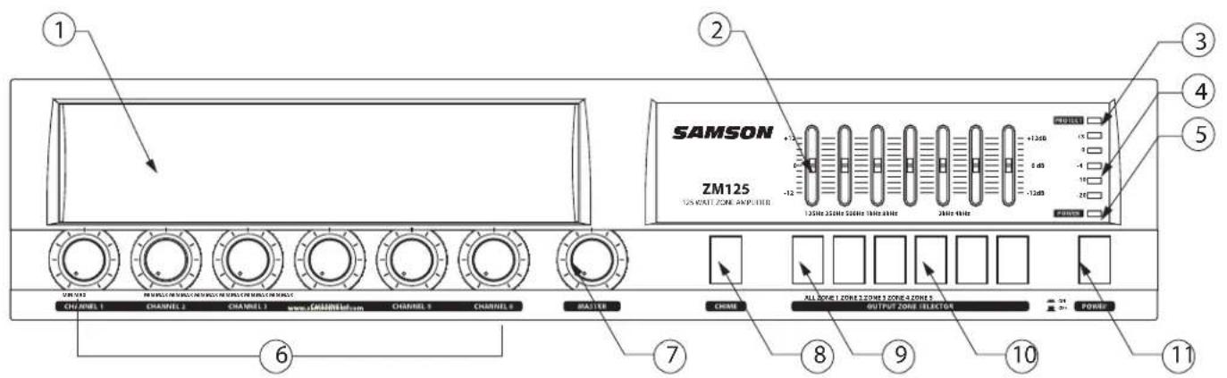
- EXPANSION BAY – You can add background music or pre-recorded announcements by installing the optional Samson TCM-3 CD and MP3 player with AM/FM tuner module in this compartment.
- GRAPHIC EQUALIZER - Used to control the overall system frequency response with filters at 125Hz, 250Hz, 500Hz, 1kHz, 2kHz, 4kHz and 8kHz with 12dB of cut or boost.
- PROTECT (LED indicator) – When illuminated, the unit is in Protect mode and the outputs will be muted.
- OUTPUT LEVEL (LED indicators) – This five segment LED bar meter display the system output level.
- POWER (LED indicator) – When illuminated, the unit is powered up and ready for operation.
- LEVEL (control knob) – The six control knobs are used to set the individual level of the input sources.
-
MASTER (control knob) – This control knob adjusts the overall system volume.
-
CHIME (switch) – When pressed, the ZM series will play a selectable Chime to used as a "pre-announcement" for paging.
- ALL (switch) - Used to simultaneously assign the input sources to each of the speaker zone outputs.
- ZONE 1 - 5 (output switches) - Used to assign the input sources to the individual speaker zone outputs.
- POWER (switch) - Use this to power the ZM75 and ZM125 on or off. The POWER LED lights whenever the ZM series is powered on.
ZM Series Layout - Rear Panel

1- 25V, 70V and 100V (output connector) - Ten-contact Euroblock connector for connecting the 25V, 70V and 100V constant voltage outputs.
2 - LO-Z (output connector) - Two-contact Euroblock connector for connecting the 4-Ohm speaker output.
3 - AMP IN and PRE-AMP OUT (connectors) – These 1/4-inch phone jacks are used to connect an external effect processor.
4 - MOH VOLUME (control knob) –This control knob allows you to adjust the level of the Music on Hold sound source.
5 - MOH (selection switch) – The slide switch is used to chose the Music on Hold sound source from the output of the internal mixer or an external sound source (like a CD or MP3 player).
6 - CHIME VOLUME - (control knob) – The control knob is used to adjust the level of the Chime tone.
7 - GAIN (control knobs) – The trim knobs are used to set the input sensitivity for each input channel.
8 - PRIORITY MIC (switch) – When set to on, this slide switch configures mic channels 1 and/or 2 to mute the other input channels when a signal is present on the connected microphones.
9 - PHANTOM POWER (switch) – Used this slide switch to activate the phantom power on mic channels 1 and/or 2.
10 - MIC/LINE INPUTS (connectors) – Channels 1 and 2 employ combination connectors with XLR and 1/4-inch inputs, which can accept either mic or line signals.
11 - MIC INPUTS (connectors) – Channels 3 and 4 are microphone level inputs on standard XLR connectors.
12 - MIC/LINE INPUTS (connectors) – Input channels 5 and 6 feature 1/4-inch and RCA connectors for mic or line level input signals.
13 - REMOTE MIC input connector – Connect the paging microphone to this four-contact Euroblock connector.
14 - REMOTE MIC GAIN (control knob) – This trim control is used to set the input sensitivity for the remote microphone input.
15 - TELE PAGING (connector) – This three-contact Euroblock connector is used to connect the ZM series to a business telecom system so that pages can be made from any handset.
16 - MOH OUTPUT (connector) - This three-contact Euroblock connector is used to attach an external sound source for the Music on Hold system.
17 - LINK IN and LINK OUT (connectors) - Use these connectors to expand your system by adding a second ZM series mixer/amplifier.
18 - VOLTAGE SELECTION (switch) - Used to select the operation voltage for either 115 or 230 Volts. Be sure to check the correct operating voltage for your particular country.
19 - AC INLET- Connect the supplied IEC power cable here.
Designing an Installation Plan
Designing an Installation Plan
If you are a professional installer, you'll probably want to skip over this section, however if you are setting up your system for the first time, this section can help make your installation a little bit easier.
Before you start plugging, stripping and connecting wires, it is a good idea to have a clear installation plan. To create your installation plan, you need to consider several design parameters including what sound sources will be used, if announcement paging in necessary, which rooms need to have sound, if a remote paging mic is required, which type of speakers will do the best job for the room they are covering, and your wiring plan.
Selecting the Sound Sources
If you are using multiple sound sources, you'll need some type of mixer and for fixed installations, a zone mixer like the Samson ZM series is ideal. The ZM series provides six input channels with the ability to connect up to six input sources. On input Channel's 1 and 2 there is an input for connecting microphones with phantom power to operate condenser type mics. The ZM series also has a special priority feature so when you speak on the microphone, the music is automatically muted. You can connect line level signals on four input channels, so signals from TAPE, CD, DVD or Karaoke players, Audio/Video TV monitors, Radio Tuners, DJ mixers or any other line level device can be used as a sound source. You may also be able to connect the output from a Home Hi-fi receiver if it's equipped with a line level output.
Creating the Audio Zones
You can create separate audio environments using up to five ZM series's outputs, each connected to an input channel on the ZM75 or ZM125 amplifier. You can connect one or more speakers with a total load impedance of 4 ohms or more to each output of the ZM Series amplifier. Obviously, (or perhaps not so obviously) we call an output a zone on the ZM series, but a zone is also the area where you want to have sound. So, think about where you want to distribute the sound. The ZM series can accomplish all of this easily. In addition, the ZM series let's you easily connect a remote microphone for paging.

flowchart
graph TD
    A["12 watt tap"] --> B["Dining Room 1"]
    C["12 watt tap"] --> D["Dining Room 2"]
    E["12 watt tap"] --> F["LOBBY"]
    G["12 watt tap"] --> H["Hostess Paging Mic"]
    I["12 watt tap"] --> J["Video"]
    K["12 watt tap"] --> L["Paging Mic"]
    M["25 watt tap"] --> N["BAR"]
Designing an Installation Plan
Now, take some time to consider where you need to have sound in your particular installation. After you have decided where you need to create sound zones, you can consider your speaker selection, but first decide where you are going to locate your equipment rack.
Locating Your Equipment Rack
Since the ZM Series amplifiers and ZM series are standard 19-inch rack mount devices, you should consider using an equipment rack, such as one of the Samson SRK series. To select a good location for your equipment rack, you should consider several points including the proximity to each of the sound zones, if the users need to access the gear to change CD's or to adjust a volume level and if you have a convenient location to the electrical service, to name a few. You will need to consider the length of wire runs and routing necessary to make the connections from the equipment rack to the various sound zones. Depending on the speakers you choose, and the length of cable runs you need to make, you may choose to run speaker level or line level to the sound zones. If you are using passive (non-powered) speakers, you will need to connect the output channels of the ZM series to an input channel of the ZM Series amplifier and run speaker wire. However, you need to be careful to pay attention to the wire gauge and total length of the wire run. If you are using powered (active) speakers you can run long distances using the balanced outputs directly from the ZM series. Since the ZM series's output connections are terminated using Euroblock connectors, the wiring can easily be run in advance of the equipment installation.
Another type of installation is one that uses speakers and amplifiers (like the ZM Series) with 70-volt transformers, which are commonly referred to as Constant Voltage systems. The benefit of a constant voltage system is you can run long lengths of wire and have many speakers connected to a single amplifier. You can also balance the level of each speaker by using one of the available transformer settings. The ZM series mixer/amplifiers are ideal for this thanks to their built-in 25/70/100 volt output transformers.
Selecting Speakers for Each Zone
To select the speakers, you need to consider a few important issues like where you are going to place your power amplifiers, using powered or un-powered speakers, or if you need to run a 70-volt distributed sound system. The following sections provide a brief overview on how to connect active and passive speakers or a constant voltage system in a typical installation.
Using Passive Speakers
If you are using passive (un-powered) speakers, you need to first decide where you will place your ZM series mixer/amplifier. If the speakers in a particular sound zone are less than 100 feet away, connect the wires from the amplifier to your passive speakers directly.
NOTE: This type of wiring is known as "home-run wiring" since you are making a direct connection from the amplifiers in the equipment rack to the speakers located in the sound zone room.
Be sure to check the impedance of the speakers you are using. The ZM Series amplifiers can run at 4 ohms, so connect one 4 ohm or two 8 ohm speakers on the ZM Series 4-Ohm output. If the speakers in a particular sound zone are further than 100 feet, you should consider placing the amplifier in the same room as the sound zone or use a constant voltage speaker system.
Using A Constant Voltage Speaker System
If your installation requires multiple speakers and long cable runs you should consider running a 70 volt, constant voltage system. Constant voltage systems became the installation standard in the mid-1900's offering a cost effective solution for installations using multiple speakers and long cable runs. The idea was borrowed from the cross-country power grid where voltage is stepped up and therefore the current is reduced allowing huge amounts of power to run over long distances on relatively small, lower cost cable. Ultimately the voltage is stepped down and delivered to the customer over a short, heavy gauge cable.
Designing an Installation Plan
Using A Constant Voltage Speaker System - continued
The same principle is applied in constant voltage audio systems where a transformer is connected to the amplifier's output to step up the voltage while lowering the output current, which allows you to use long runs of smaller gauge wire to connect to a series of speakers with step down transformers. For further cost savings, the 70 volt standard was adopted in the US since UL requires the use of conduit on lines over 100 volts peak. In addition to 70 volt operation, the ZM Series amplifiers can also operate 100 volt systems which is a standard in Europe. Commercial sound systems, like those installed in schools, office buildings and restaurants, commonly make use of constant voltage distributed sound systems when a large number of ceiling speakers are used to cover several different sound zones.
Today, there are a large number of installation speakers available from various manufacturers that include onboard transformers for constant voltage systems. Many of these models, like the Samson dB300i, include selectable power taps on the transformer allowing you to distribute the power efficiently through the number of installed speakers and also adjust some speakers to different output levels. The ZM Series amplifiers have built in transformers on each channel that step up the output voltage and reduce the current allowing you to connect to a series of speakers with step down transformers over long cable runs. Constant voltage systems can use 14 to 18 gauge wire, while smaller gauge (larger diameter) cable should be used for longer runs.
A simple way to think about using constant voltage is to divide the total watts available by the number of speakers you want to use. You could also add up the speaker's step up transformer wattage to equal 100 watts or less. For example, if you want to use ten ceiling speakers on one channel of the ZM Series amplifier, use a ceiling speaker with a 12-watt transformer tap (120 watts divided by 10 speakers equals 12-watts per speaker).
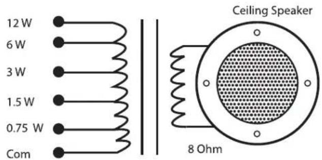
Typical ceiling speaker with onboard transformer and six power taps. These power taps also control volume level for sound balancing.
Another example is connecting four of the Samson dB300i with the transformers wired for 25 watts to each channel of the ZM Series amplifier.
Following the wiring diagram on the rear of the dB300i, connect the ground to Common, the Hot lead to 70 volt input, and finally, run a jumper from 8 ohms to the 25 watt connection as shown in the diagram below.
Set up each of the dB300i they same way so that the four connected speakers equal 100 watts.

The dB300i's rear panel is configured for 70 volt 25 watt operation.
Now connect the four speakers to each of the ZM125's output as shown in the diagram below.

Operating The ZM Series
Setting up the ZM series
Setting up your ZM Series is a simple procedure, which takes only a few minutes:
Remove all packing materials (save them in case of need for future service) and decide where the amplifier is to be physically placed—it can be used table-top or mounted in a standard 19" rack (like the SRK equipment racks from Samson), requiring only two rack spaces.
Install the rack ears by aligning them to the side of the unit, flush to the front and install the supplied screws. Be careful not to cross thread the screws. Then, remove the feet to allow the unit to fit the 2 rack spaces.
When installed, make sure that both the front and rear panels are unobstructed and that there is good ventilation around the entire unit (we recommend the use of spacer panels, especially if multiple amplifiers are used in a rack.
Connecting the Speakers to the ZM Amplifier
Make the speaker connections, using the Euroblock output connectors on the rear panel. It is never a good idea to power up any amplifier that is not connected to loudspeakers. When operating using the 4-ohm output, any loudspeakers with a minimum impedance load of 4 ohms (that is, 4 ohms or greater) can be used.

For 70-volt operation, connect the positive input of the speaker to the 70 Volt terminals and connect the negative input the COM (ground) terminal.

The constant voltage output is set for either 70 or 100 Volts depending on the country, however if can be changed by reconfiguring the internal transformer wires. Locate the T10, T11, T12 and T13 terminals as per the diagram below.

Now follow the wiring chart below to select the required operating voltage for constant voltage output.
| T10 | T11 | T12 | T13 | |
| 100V | RED wire | BLUE wire | GREEN wire | BLACK wire |
| 70V | GREEN wire | RED wire | BLUE wire | BLACK wire |
| 25V | BLUE wire | GREEN wire | RED wire | BLACK wire |
Operating The ZM Series
Connecting the Input Sources
Next, make the signal input connections, using the Euroblock input connectors on the rear panel. If your mixer has balanced outputs, we recommend the use of three-conductor cabling and connectors (unbalanced two-conductor connections can also be used, but you'll get better signal quality and less outside noise and hum if you use balanced lines).
On the front panel of the ZM Series, turn all the Channel input controls fully counterclockwise (to their "MIN" setting). Then connect the supplied heavy-gauge 3-pin "IEC" cable to the rear panel IEC connector and to any grounded AC socket.
Press the front panel Power switch in order to turn on the ZM Series. The Power LED will light and the Protection LED will go on. After approximately five seconds, the Protection LED will go off (you'll hear a click when this occurs).

Apply an input signal to the ZM Series at or about +4dBu. Now set the channel level to about half way up.

While the input signal is present, slowly raise the Master level control until the desired sound level is achieved. The SIGNAL and PEAK LED indicators will show you the
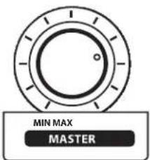
continuous power output of the ZM Series as signal is being passed. For the best signal-to-noise ratio, the ZM Series should normally be run with the Master level control at or near maximum (fully clockwise, at the "MAX" position) and the PEAK segments should light occasionally (but not frequently) during peak levels. If the signal is too loud, use the Input level controls attenuate the signals as necessary to achieve the desired speaker level.
Pre Announcement Chime
The ZM series mixer offers a useful Chime function to alert listeners of an upcoming page. Simply press the front panel Chime switch to play the chime.

In addition, the ZM series mixer can be set for one of four selectable Chime tones by moving the internal shorting jumpers as show in the figure below:

Priority Control
Channel 1 and 2 can be set for Priority operation. When microphone channel 1 and 2's Priority switch is set to the "ON" position, the other input channels will mute whenever signal is present on the microphones connected to Channel 1 and 2.

Priority Mic Muting
In addition to the priority muting on microphones connected to Channels 1 and 2, there are three levels of priority muting which is always active. The priority muting is set in three groups in the following order.
Chime and Tele page Remote Mic Channels 1 through 6
This means if there is a Tele-page or the Chime switch is pressed, the Remote Mic and input Channels 1 through 6 are muted. If there is a signal on the Remote Mic, Channel 1 through 6 will be muted. The signals in the same priority group will stay on together.
Operating The ZM Series
Using Music On Hold
The ZM series include a MOH (Music On Hold) function allowing you to connect the ZM series to a business telephone system. With MOH, when customers call in to the business and are put on hold, they hear background music from an external source or from the internal source if the optional TCM-3 tuner/CD player is installed. You can make the call-in experience more pleasant or take advantage of valuable time by playing a pre-recorded commercial message using MOH.

You can set the volume of the MOH signal using the MOH Level control.

Using the TELE-Paging function
You can connect the ZM75 and ZM 125 to a business telephone system using the TELE PAGING CONNECTOR allowing announcement paging from any telephone. Usually, the telephone system provides a dedicated output and has the ability to send a page using a certain extension number. Check the manufacturer's operating manual of the telephone system for operation detail.

Using External Effects AMP IN and PRE-AMP OUT
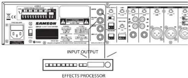
The ZM series provides a convenient patch point between the mixer and power amp allowing you to connect an external
signal processor like dynamics (like the Samson S com plus), equalizer (like the Samson D2500 digital equalizer) or feedback management systems (like the Samson D3500). Connect the PRE-AMP OUT to the input of the signal processor. Then, connect the output of the signal processor to the AMP IN to complete the circuit.
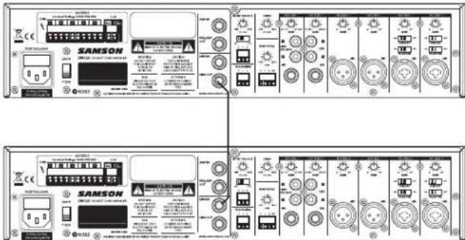
Expanding The ZM system using LINK IN / LINK OUT
If the system installation requires more inputs and outputs, you can use an external mixer or additional ZM series mixer/amplifiers using the LINK IN and LINK OUT connectors. Connect the LINK out of the first ZM mixer/amp to the LINK in of the second.
Using The Graphic Equalizer
The ZM75 and ZM125 feature an onboard seven-band equalizer for adjusting the systems overall frequency response. The Equalizer includes seven filters, providing 12 dB of cut and boost at 125Hz, 250Hz, 500Hz, 1kHz, 2kHz, 4kHz and 8kHz. You can use the equalizer to contour the system response for music or speech. The Graphic EQ can also be useful for removing feedback. If feedback occurs, try lowering the mid range frequencies 1k and 2K.

If you encounter difficulty with any aspect of setting up or using your ZM Series, contact your local Samson dealer. If purchased in the United States, you can call Samson Technical Support (1-800-372-6766) between 9 AM and 5 PM EST.
ZM Series System Set Up
The following is a typical constant voltage system setup for a small restaurant using the ZM125 mixer/amplifier feeding several audio zones with paging and music. The first two ZM Series constant voltage outputs are connected to two ceiling speakers in each of the Dining Rooms with their transformers set to a 12 watt tap. The third constant voltage output powers two speakers in the outside Bar area with their transformers set to 25 watt. (The db300i's are specially treated so they're suitable for indoor and outdoor use.) The fourth ZM Series amp channel powers small speakers in the lobby with a 12 watt tap.

flowchart
graph TD
    A["12 watt tap"] --> B["Dining Room 1"]
    B --> C["12 watt tap"]
    C --> D["Dining Room 2"]
    D --> E["12 watt tap"]
    E --> F["12 watt tap"]
    F --> G["12 watt tap"]
    G --> H["12 watt tap"]
    H --> I["12 watt tap"]
    I --> J["12 watt tap"]
    J --> K["12 watt tap"]
    K --> L["12 watt tap"]
    L --> M["12 watt tap"]
    M --> N["12 watt tap"]
    N --> O["12 watt tap"]
    O --> P["12 watt tap"]
    P --> Q["12 watt tap"]
    Q --> R["12 watt tap"]
    R --> S["12 watt tap"]
    S --> T["12 watt tap"]
    T --> U["12 watt tap"]
    U --> V["12 watt tap"]
    V --> W["12 watt tap"]
    W --> X["12 watt tap"]
    X --> Y["12 watt tap"]
    Y --> Z["12 watt tap"]
    Z --> AA["12 watt tap"]
    AA --> AB["12 watt tap"]
    AB --> AC["12 watt tap"]
    AC --> AD["12 watt tap"]
    AD --> AE["12 watt tap"]
    AE --> AF["12 watt tap"]
    AF --> AG["12 watt tap"]
    AG --> AH["12 watt tap"]
    AH --> AI["12 watt tap"]
    AI --> AJ["12 watt tap"]
    AJ --> AK["12 watt tap"]
    AK --> AL["12 watt tap"]
    AL --> AM["12 watt tap"]
    AM --> AN["12 watt tap"]
    AN --> AO["12 watt tap"]
    AO --> AP["12 watt tap"]
    AP --> AQ["12 watt tap"]
    AQ --> AR["12 watt tap"]
    AR --> AS["12 watt tap"]
    AS --> AT["12 watt tap"]
    AT --> AU["12 watt tap"]
    AU --> AV["12 watt tap"]
    AV --> AW["12 watt tap"]
    AW --> AX["12 watt tap"]
    AX --> AY["12 watt tap"]
ZM Series Input Wiring Guide
ZM Series Input Wiring Guide
There are several ways to interface the ZM Series amplifiers, depending on your exact system set-up. Follow the cable diagrams below for connecting to the input of your amplifier.
Male XLR to Female XLR (balanced)

Male XLR to 1/4-inch (Balanced)

Male XLR to 1/4-inch (Unbalanced)

Male XLR to RCA (Unbalanced)

ZM Series Output Wiring Guide
ZM Series Output Wiring Guide
There are several ways to interface the ZM Series amplifiers, depending on your exact system set-up. For most small to medium installations, 14 to 16 gauge zip cord can be used. Follow the cable diagrams below for connecting to the input of your amplifier.
4 Ohm Wiring Guide

Constant Voltage Wiring Guide

Follow the guidelines below to select the appropriate size wire based on the distance from the amplifier to the speaker. The wire sizes apply to the 4-ohm tap.
Distance Wire Size
Up to 25 ft. 16 AWG
26\~40 ft. 14 AWG
41\~60 ft. 12AWG
61\~100 ft. 10AWG
101ft\~150ft. 8AWG
151\~200 ft. 6AWG
NOTE: Custom wiring should only be performed by licensed and insured, qualified personnel. Class 2 wiring is required.
CAUTION: Never use shielded cable for output power wiring.

SHOCK HAZARD SYMBOL
WARNING!!! - PAY ATTENTION TO THE WARNING SYMBOL AND AVOID ELECTRICAL SHOCK. DO NOT HOLD OR TOUCH THE COMMON AND 70 OR 100 VOLT WIRE CONNECTION WHILE OPERATING THE AMPLIFIER.
Specifications
| ZM75 ZM125 | |||
| Input Sensitivity for full output at maxi-mum gain | Balanced Microphone Channels -50dBV ± 3dB | ||
| Balanced Line Channels -22dBV ± 3dB | |||
| Balanced Remote Microphone Station -50dBV ± 3dB | |||
| Balanced Telephone Paging -21dBV ± 3dB | |||
| Unbalanced Link-In -17dBV ± 3dB | |||
| Unbalanced Amp-In 0dB ± 3dB | |||
| Frequency Response at | watt from speaker out tap.100Hz~10kHz +1.5dB / -3dB | ||
| Graphic Equalizer | 125Hz,250Hz,500Hz,1kHz,2kHz,4kHz,8kHz ±12dB ±3dB | ||
| Amplifier | Signal to Noise Ratio at rated power output Better than 90dB | ||
| Crosstalk at all control maximum | -70dB at 1kHz | ||
| Rated Output Power at THD 0.36% | 60Watts | 120Watts | |
| Total Harmonic Distortion(THD) at 1kHz rated power | Less than 0.5% | ||
| Phantom Power | 15VDC | ||
| Power Bandwidth from speaker out tap | 80Hz~15kHz with less than 0.5% THD | ||
| DC Output Offset | Less than ±3mV | ||
| Operating Temperature/Humidity at non-con-densing | 34°~104°F (0°~40°C) at 95% humidity | ||
| Output Voltage and Impedance | 4Ω | 15.5V | 22V |
| 25V | 10Ω | 5.2Ω | |
| 70V | 82Ω | 41Ω | |
| 100V | 165Ω | 83Ω | |
| Construction | Cooling | Convection Cooled | |
| Dimensions (Width/Height/Depth) | 16.5(W) x 3.5(H) x 13.5(D) inches420(W) x 88(H) x 343(D) mm | ||
| Net Weight 19.21 lb. (8.72 kg) 21.5 lb. (9.76 kg) | |||
Specifications are subject to change without notice.
Block Diagram

flowchart
graph TD
    A["Top Management"] --> B["Department 1"]
    A --> C["Department 2"]
    A --> D["Department 3"]
    B --> E["Sub-Management Unit 1"]
    C --> F["Sub-Management Unit 2"]
    D --> G["Sub-Management Unit 3"]
    E --> H["Sub-Management Center"]
    F --> I["Sub-Management Center"]
    G --> J["Sub-Management Center"]
    H --> K["Sub-Management Center"]
    I --> L["Sub-Management Center"]
    J --> M["Sub-Management Center"]
    K --> N["Sub-Management Center"]
    L --> O["Sub-Management Center"]
    M --> P["Sub-Management Center"]
    N --> Q["Sub-Management Center"]
    O --> R["Sub-Management Center"]
    P --> S["Sub-Management Center"]
    Q --> T["Sub-Management Center"]
    R --> U["Sub-Management Center"]
    S --> V["Sub-Management Center"]
    T --> W["Sub-Management Center"]
Samson Technologies Corp.
45 Gilpin Avenue
Hauppauge, New York 11788-8816
Phone: 1-800-3-SAMSON (1-800-372-6766)
Fax: 631-784-2201
www.samsontech.com

- ZM SERIES
- Safety Instructions/Consignes de sécurité/Sicherheitsvorkehrungen/Instrucciones de seguridad
- WARNING
- AVIS
- CAUTION
- ATTENTION
- Important Safety Instructions
- Introduction
- ZM Series Features
- ZM Series Layout - Front Panel
- ZM Series Layout - Rear Panel
- Designing an Installation Plan
- Selecting the Sound Sources
- Creating the Audio Zones
- Locating Your Equipment Rack
- Selecting Speakers for Each Zone
- Using Passive Speakers
- Using A Constant Voltage Speaker System
- Using A Constant Voltage Speaker System - continued
- Operating The ZM Series
- Setting up the ZM series
- Connecting the Speakers to the ZM Amplifier
- Connecting the Input Sources
- Pre Announcement Chime
- Priority Control
- Priority Mic Muting
- Using Music On Hold
- Using the TELE-Paging function
- Using External Effects AMP IN and PRE-AMP OUT
- Expanding The ZM system using LINK IN / LINK OUT
- Using The Graphic Equalizer
- ZM Series System Set Up
- ZM Series Input Wiring Guide
- ZM Series Output Wiring Guide
- Ohm Wiring Guide
- Distance Wire Size
- SHOCK HAZARD SYMBOL
Brand : SAMSON
Model : ZM75
Category : Mixer