
AMP523 - Receiver Audac - Free user manual and instructions
Find the device manual for free AMP523 Audac in PDF.


| Product Type | Audio/Video Receiver |
| Brand | Audac |
| Model | AMP523 |
| Dimensions (W x H x D) | 430 x 90 x 320 mm |
| Weight | 8.5 kg |
| Power Supply | AC 220-240V, 50/60Hz |
| Power Consumption | 350W |
| Output Power | 5 x 100W RMS (8 ohms) |
| Impedance | 4-8 ohms |
| Audio Inputs | 4x RCA, 2x Optical, 1x Coaxial |
| Audio Outputs | 5.1 channels, Pre-out |
| Video Inputs | 2x HDMI, 1x Component, 1x Composite |
| Video Outputs | 1x HDMI (ARC), 1x Composite |
| Connectivity | Bluetooth, USB |
| Tuner | FM/AM with RDS |
| Audio Decoding | Dolby Digital, DTS |
| Maintenance | Clean with soft dry cloth; avoid moisture |
| Safety | Do not expose to water; unplug before cleaning |
| Accessories Included | Remote control, FM antenna, power cable |
| Repairability | Professional repair recommended; spare parts available on request |
| Operating Temperature | 0-40°C |
Frequently Asked Questions - AMP523 Audac
User questions about AMP523 Audac
0 question about this device. Answer the ones you know or ask your own.
Ask a new question about this device
Download the instructions for your Receiver in PDF format for free! Find your manual AMP523 - Audac and take your electronic device back in hand. On this page are published all the documents necessary for the use of your device. AMP523 by Audac.
USER MANUAL AMP523 Audac
This manual is put together with much care, and is as complete as could be on the publication date. However, updates on the specifications, functionality or software may have occurred since publication. To obtain the latest version of both manual and software, please visit the Audac website @ www.audac.eu.

Introduction 05
Web-based mini stereo amplifier 05
Precautions 06
Chapter 1 08
Connections and connectors 08
Chapter 2 010
Overview AMP523MK2 010
Chapter 3 012
AMP523MK2 Quick start guide 012
Connecting the AMP523MK2 012
Ready 013
Chapter 4 014
User interface & configuration 014
AUDAC TOUCH™2 015
Login screen 017
Main screen 017
Configuration screen 019
Configuration >> Network settings 020
Configuration >> Wall panel settings 021
Configuration >> Input settings 022
Configuration >> Output settings 023
Configuration >> Priority settings 023
Configuration >> Password settings 026
Configuration >> Factory settings 027
Chapter 5 028
Peripheral connections 028
Chapter 6 029
Additional information 029
IP Basics 029
Technical specifications 030
The AMP523MK2 is a mini stereo amplifier with network controls controlled through AUDAC Touch featuring four stereo line inputs and one balanced microphone input with phantom power. It has an output power of 2 x 15 Watt.
The simple and compact but versatile functionalities makes it perfectly suited for small speaker systems requiring compact and economical audio solutions which are comprehensive and easily controllable. Some typical applications are classrooms where the audio system will be used in combination with a smartboard, offices and meeting rooms where the music should switch automatically from background music to speech or playback when the presentation starts, .... and many other similar applications.
The compact size and very high efficiency even makes it possible to hide it in a closet, on a false ceiling or mount it under a desk or table. The various stereo line inputs allow simultaneous connections for different sources such as computers, laptops, smartphones and tablets while having a microphone connected.
The switching between the inputs, volume regulation and other function controls can be done with the use of the AUDAC Touch™2 app. RS232 connection makes it possible to control the AMP523MK2 with any device supporting serial communication such as a computer or even a home or industrial automation system. Using the freely available AUDAC Touch™2 application for smart devices guarantees total system control and configuration from any device on any location and at any time.
To make the installation even more complete, an optional MWX45 wall panel can be installed to control the signal routing and volume level from one or multiple fixed locations. The Class-D amplifier technology, standby mode and included switching power supply makes this device compliant to the highest energy efficiency and environmental requirements.
READ FOLLOWING INSTRUCTIONS FOR YOUR OWN SAFETY
ALWAYS KEEP THESE INSTRUCTIONS. NEVER THROW THEM AWAY
ALWAYS HANDLE THIS UNIT WITH CARE
HEED ALL WARNINGS
FOLLOW ALL INSTRUCTIONS
NEVER EXPOSE THIS EQUIPMENT TO RAIN, MOISTURE, ANY DRIPPING OR SPLASHING LIQUID. AND NEVER PLACE AN OBJECT FILLED WITH LIQUID ON TOP OF THIS DEVICE
NO NAKED FLAME SOURCES, SUCH AS LIGHTED CANDLES, SHOULD BE PLACED ON THE APPARATUS
DO NOT PLACE THIS UNIT IN AN ENCLOSED ENVIRONMENT SUCH AS A BOOKSHELF OR CLOSET. ENSURE THERE IS ADEQUATE VENTILATION TO COOL THE UNIT. DO NOT BLOCK THE VENTILATION OPENINGS.
DO NOT STICK ANY OBJECTS THROUGH THE VENTILATION OPENINGS.
DO NOT INSTALL THIS UNIT NEAR ANY HEAT SOURCES SUCH AS RADIATORS OR OTHER APPARATUS THAT PRODUCE HEAT
DO NOT PLACE THIS UNIT IN ENVIRONMENTS WHICH CONTAIN HIGH LEVELS OF DUST, HEAT, MOISTURE OR VIBRATION
THIS UNIT IS DEVELOPED FOR INDOOR USE ONLY. DO NOT USE IT OUTDOORS
PLACE THE UNIT ON A STABLE BASE OR MOUNT IT IN A STABLE RACK
ONLY USE ATTACHMENTS & ACCESSORIES SPECIFIED BY THE MANUFACTURER
UNPLUG THIS APPARATUS DURING LIGHTNING STORMS OR WHEN UNUSED FOR LONG PERIODS OF TIME
ONLY CONNECT THIS UNIT TO A MAINS SOCKET OUTLET WITH PROTECTIVE EARTHING CONNECTION
THE MAINS PLUG OR APPLIANCE COUPLER IS USED AS THE DISCONNECT DEVICE, SO THE DISCONNECT DEVICE SHALL BE READILY OPERABLE
USE THE APPARATUS ONLY IN MODERATE CLIMATES
CAUTION
The symbols shown are internationally recognized symbols that warn about potential hazards of electrical products. The lightning flash with arrow point in an equilateral triangle means that the unit contains dangerous voltages. The exclamation point in an equilateral triangle indicates that it is necessary for the user to refer to the users manual.

CAUTION RISK OF ELECTRIC SHOCK DO NOT OPEN

These symbols warn that there are no user serviceable parts inside the unit. Do not open the unit. Do not attempt to service the unit yourself. Refer all servicing to qualified personnel. Opening the chassis for any reason will void the manufacturer's warranty. Do not get the unit wet. If liquid is spilled on the unit, shut it off immediately and take it to a dealer for service. Disconnect the unit during storms to prevent damage.

CAUTION - SERVICING
This product contains no user serviceable parts. Refer all servicing to qualified service personnel. Do not perform any servicing (unless you are qualified to)
EC DECLARATION OF CONFORMITY
This product conforms to all the essential requirements and further relevant specifications described in following directives: 2014/30/EU (EMC), 2014/35/EU (LVD).
WASTE ELECTRICAL AND ELECTRONIC EQUIPMENT (WEEE)
The WEEE marking indicates that this product should not be disposed with regular household waste at the end of its life cycle. This regulation is created to prevent any possible harm to the environment or human health.
This product is developed and manufactured with high quality materials and components which can be recycled and/or reused. Please dispose this product at your local collection point or recycling centre for electrical and electronic waste. This will make sure that it will be recycled in an environmentally friendly manner, and will help to protect the environment in which we all live.
Connections and connectors
CONNECTION STANDARDS
The in- and output connections for AUDAC audio equipment are performed according to international wiring standards for professional audio equipment
RCA (COAXIAL):
Unbalanced analogue audio input connections

Tip:
Signal
Sleeve:
Ground
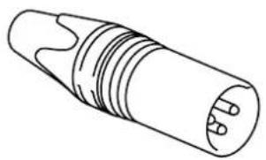
XLR
For balanced line input connections
natural_image
Line drawing of a cylindrical electronic component with internal ridges and leads (no text or symbols)PIN 1:
Ground
PIN 2:
Signal +
PIN 3:
Signal -
3-Pin Terminal block:
For balanced signal input connections

natural_image
Technical line drawing of a mechanical connector housing (no text or symbols)Left:
Signal -
Center:
Signal +
Right:
Ground
For mic input connections

natural_image
Technical diagram of a green electrical connector with mounting holes and internal wiring (no text or symbols)For unbalanced signal input connections

natural_image
3D diagram of a green electrical connector with labeled ports (R, L) and mounting holes (no text or symbols beyond labels)RS232 (serial connection interface):
For connection with home automation systems, or other remote control equipment
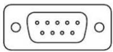
Connection Standard RS232
PIN 2 AMP523MK2 TX
PIN 3 AMP523MK2 RX
PIN 5 GND
Settings
19200 Baud
8
B
i
t
1 Stop bit
N O
p
a
r
i
t y
N
O
H
a
n
d
S
h
a
RS232 & TCP/IP
The AMP523MK2 RS232 and TCP/IP ports accept the same commands. The complete command set is available in the AMP523MK2 commands user manual which is freely available on www.audac.eu
RJ45
(Audio,
+24V
DC)
For connection to Wall Panels

Pin 1
White-Orange
Signal line +
Pin 2
Orange
Signal line -
Pin 3
White-Green
+24V DC
Pin 4
Blue
RS485 A
Pin 5
White-Blue
RS485 B
Pin 6
Green
GND
Pin 7
White-Brown
Signal mic +
Pin 8
Brown
Signal mic -
Overview AMP523MK2
Front panel
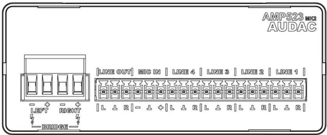
The front panel of the AMP523MK2 contains the audio in- and output connections.
The available inputs are 4 stereo unbalanced line-level inputs and one balanced microphone input (with phantom power). These all are performed using an 18-pins terminal block connector (combined with the line-level audio output). All audio sources such as computers, smartphones, tablets, ... shall be connected to the line-level inputs, while microphones can be connected to the microphone connection. When using condenser microphones, phantom power possibility should be enabled (by software).
Two audio outputs are implemented, both carrying the identical audio signal but with various output levels. The output on the left side (4-pin terminal block) marked with 'AMP OUT' connects the internal class D amplifier with an output power of 2 x 15 Watt, which allows direct connection of loudspeakers.
The audio output marked as 'LINE OUT' connected on the 18-pin terminal block connector is a standard line level output allowing connection of the AMP523 to any device with a line-level input, such as amplifier, pre-amplifier, active speaker system, ...
Rear panel

All the control and configuration ports are located on the rear panel of the AMP523MK2, including the 24 Volts power connection.
1) 24 Volts power connector:
The 24 Volts power supply connection is provided on the left side of the AMP523 MK2's rear panel. The included power supply (PSD241) should be connected to the terminal block connectors. Pay attention to the polarity when connecting the power supply.
2) Run LED:
This LED shows the operation mode of the device. When the device is running in normal mode, this LED will blink at a constant frequency.
3) RS485 + audio RJ45 connector:
An additional wall panel controller (MWX45) and Wall Line or Wall Microphone input (WMI and WU units) can be connected to this input. This way, the volume and the signal routing can be adjusted by means of a wall panel and additional local Line and Microphone inputs can be connected.
4) RS232 control port:
With this connector, the AMP523MK2 can be connected to external control hardware using RS232. This makes it possible to control the AMP523MK2 by means of an home automation system.
5) Ethernet connection:
The AMP523MK2 can be connected to an Ethernet network with this RJ45 connector. This makes it possible to control the AMP523MK2 functions over ethernet, by simply using any device with AT2 support such as computers, smartphone, ...
AMP523MK2 Quick start guide
This chapter guides you through the setup process for a basic AMP523MK2 project where to a line level audio source and a microphone are connected directly. An external volume controller and remote wall mixer are installed remotely.

flowchart
graph TD
    A["WiFi"] --> B["LaptopTabletSmartphone"]
    C["Smartphone"] --> B
    D["Automation system"] --> E["RS232"]
    E --> F["TCP/IP"]
    F --> G["2 x 15 W"]
    G --> H["EPA254"]
    I["XMP44"] --> J["Line input"]
    K["XMP44"] --> L["Line input"]
    M["Balanced mlc input"] --> N["Line output"]
    O["Stereo line input"] --> P["Stereo line input"]
    Q["Stereo line input"] --> R["Stereo line input"]
Overview of the AMP523MK2 setup
Connecting the AMP523MK2
1) Connecting audio inputs
Connect all your audio sources (CD-players, tuners, mp3 players, microphones, ...) to the audio inputs of the AMP523MK2. All the direct audio inputs are connected through the 18-pins terminal block. The pin layout for the 18-pins connector is shown at the front panel overview at page 10 of this user manual. The wiring diagram for connecting stereo line sources and microphones is shown at page 10 of this user manual.
2) Connecting audio outputs
Two different audio outputs are implemented. Depending of your application requirements, the line level output, speaker level output, or both shall get connected. If an external amplifier or pre-amplifier is used, connect it to the corresponding 'LINE OUT' terminals of the 18-pin terminal block connector. When using the internal amplifier, connect the speakers to the 'AMP OUT' 4-pin terminal block connector.
3) Connecting the power supply
The included power supply should be connected to the 2-pin terminal block connector. Mind the polarity when connecting the power supply.
4) Connecting a computer
A computer can be connected to the AMP523MK2 through ethernet connection. This shall be connected to UTP CAT5E (or better) cabling, connected to the RJ45 connector marked with 'Ethernet'.
Download the AUDAC TOUCH™ 2 app in the App-store, Google Play or on audac.eu/touch.
In the Audac Touch™2 app you can scan for the AMP523. It will be found if properly connected.
The default password for the AMP523MK2 is: 'AMP523'.
Changing the IP address
This step can be skipped when the default IP address "192.168.0.193" is not in use by another device in your network, and is OK for you. If the IP address needs to be changed this can be done under 'Network' in the Device settings of the AMP523MK2 in the AUDAC TOUCH™ 2 app.
Ready
Your system is now ready for use. Go to the main screen of the AMP523MK2 and you are in full control of all the functions.
User interface & configuration
To get access to the control and configuration settings, the AMP523MK2 should be connected to a computer or an Ethernet LAN network. For more information about network connections and settings, see IP basics in chapter 6.
For using Audac-Touch interface, the AMP523MK2 shall be connected to an ethernet LAN network and accessed by its IP address. The standard (factory default) IP address of the AMP523MK2 is 192.168.0.193, make sure this address is within the IP range of the connected ethernet LAN network (subnetmask 255.255.255.0).
Each device (computer, laptop, tablet, ...) with an internet connection has the possibility to download the AUDAC TOUCH™ 2 app in the App-store, Google Play or audac.eu/touch.
When application specific or total system control is required, the AMP523MK2 can be controlled using the Audac Touch™2 application. This application allows to custom configure your control panel (Dashboard) according to project or user specific requirements.

When the Audac Touch™2 app is opened, the dashboard window opens. Here control panels can be created as desired using widgets.

Navigate through the menu to devices. The menu appears by clicking on the menu icon at the top left of the screen.

On this page all connected devices are shown. Available devices can be found by using the scan button on the right side of the screen.
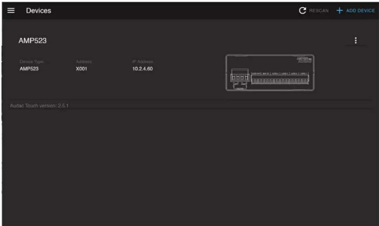
In this list you select the device you want to control.
First the login screen will be displayed.
A password should be entered to get access to the interface. Once the correct password is entered, click the "OK" button, and you will be redirected to the main screen of the AMP523MK2. (The factory default password for the AMP523MK2 is 'AMP523')
NOTE
The password can be changed in the device menu in the app >> Settings >> Device
Main screen

Main screen for AMP523MK2
This window shows the selection buttons for all 5 inputs (CH1 - CH4 and WLI-WMI/MIC). Left side includes mixing faders for the WLI and MIC/WMI channels, while a master volume control combined with a mute button in the bottom position.
Input channel selection
The input channel routing can be selected using the selection buttons in center position of the main screen. Various selection buttons including 'OFF', direct line inputs channel 1 to channel 4 (indicated as 'CH1' to 'CH4'), and the microphone input mixed with the remote input units (WLI and WMI).
Mute button
Underneath the volume control is a MUTE button located, allowing complete suppression of the output signal. When muted, this button will be indicated in red colour. Toggling between mute and unmute is done by clicking this button again.
Volume control
The output volume can be set by moving the master fader (indicated by 'Master') up and down. The volume can also be raised and lowered in steps of 1 dB using both buttons on top and bottom of the fader.
Mixing faders for WLI and MIC/WMI
The left side of the main screen includes two mixing faders for mixing the microphone input and the remote inputs. The mixing with WLI and MIC/WMI channels is 50% and the level can be adjusted with both faders between 0 dB and -∞ dB. This can be easily done by sliding the faders up and down or by pressing the arrowed buttons on top and bottom of the faders.
Configuration menu
The top right corner indicates a setup button which redirects you to the general configuration menu of the AMP523MK2.
Save
Use the 'Save zone settings' button in the top right corner when made any changes to the main screen configuration. If not saved the device will start with the default/previously saved settings.
The settings control panel comes up after clicking the "SETTINGS" button in the top right corner of the main screen.
In this window, all settings for the AMP523MK2 can be configured, including network settings, wall panel address settings (optional), input gain, output tone, phantom power and priority for the microphone input and password settings.

Configuration screen for AMP523MK2
Press the corresponding icon for redirecting to the desired settings screen.
Back
Click the "CONTROL" button to return back to the main screen.
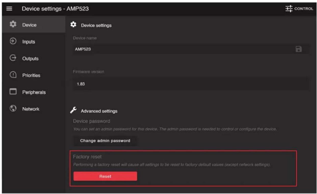
In the 'Device' panel there is the possibility to change the password. Select the 'Change admin password' button.


To change the password, enter the old password in the provided field and enter the new password twice in the fields below. After this is entered, push the "OK button. If the old password is correct, and the new password filled in both fields match, the old password will be changed into the new password.
The factory default password is "AMP523".
ATTENTION
BE CAREFUL to press this button. It really will recall the ORIGINAL factory settings!
It does not recall the previously saved settings, but it recalls the original factory setting and the previously made settings will be lost.
Click the "OK" button to reset the settings to factory default.
This window, input settings such as input gain adjustment and phantom power enabling can be made.

Network settings screen for AMP523MK2
Input gain
The left side shows all input channels combined with a slider whereby the input gain can get adjusted. Default gain for every input is set to 0 dB. It can be adjusted within a range of -4 dB and +10 dB, in steps of 2 dB. This is done by clicking the circles and selecting the desired gain adjustment factor. When selected, changes will take effect immediately.
Phantom power
To get to the settings menu for Phantom power, click on the cogwheel with the name 'WLI-WMI/MIC'.
Here you can choose to enable the Phantom power and to name it.
In this window, output settings such as two band tone control and switching between mono and stereo can be made.

Network settings screen for AMP523MK2
Two band tone control
To get the two-band tone control one must click on the icon under 'Tone'. This will bring up a window with two faders (Bass and Treble) for the two-band tone control adjustment. The adjustment for both treble and bass is possible in steps of 1 dB within a range of +14 dB and -14 dB.
Mono/Stereo
To choose between Stereo and Mono please click on the settings icon in front of 'AMP523'. This will display a new menu where the choice is possible. In this menu there is also the function to edit, delete and add different inputs.
There is the possibility to make a selection of all inputs that can be connected to the output. This can also be found under the settings button.
Configuration >> Priority settings
In this window you can make priority settings such as sensitivity and level adjustment for the microphone inputs. When applying a signal to the microphone input (when someone is talking in the microphone), all other signal sources will be suppressed.
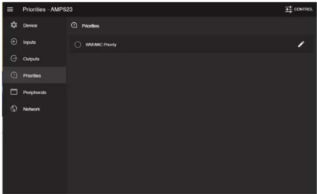
In the "priorities" tab, a choice is made as to which device will be prioritized. Select the edit icon next to the priority item to make adjustments. Activated priorities are indicated by a blue dot.

Enable
The priority can be enabled by clicking the "Enabled" button on top. This button will turn blue when priority is enabled.
Sensitivity
The sensitivity for the priority channel can be put on "High", "Medium" or "Low". Hereby, the trigger level for switching to the priority channel can be set. When it's set to "High", it will switch to the microphone channel when only a small signal is applied to the microphone input (when the talker is speaking very softly). When it's set to "Low", it will switch to the microphone input when a large signal is applied to the microphone input (when the talker is speaking very loud). The "Medium" setting is in between "High" and "Low". The correct setting for your application depends on the microphone being used, the background noise, the person who's talking, ...
Input level
The level of the priority input can be set through this slider or can be entered. The correct level depends on the used microphone, and should be set correctly so the microphone signal is not overdriven.
Output level
The sound level of the priority signal can be adjusted with the slider or can be entered. This way, the volume can change when a priority announcement is made. For example, to make sure a priority message is always heard at the maximum volume, ... The default output level for priority messages is set to 0 dB and can be adjusted between 0 dB and -∞ dB, in steps of 1 dB.
Configuration >> Wall panel settings
This window allows you to adjust the address and input selection settings for the (optionally) connected wall panels.

Wall panel settings screen for AMP523MK2
Factory default, the wall panel address is always set correctly and doesn't need to get changed. This step only needs to be done when the wall panel has been used in another application with a different configuration. When experiencing any problems when connecting and configuring wall panels, we recommend to follow wall panel configuration procedure as below.
Add wallpanel / All-in-one wallpanel
Connect the MWX45 wall panel to the "RS485 + AUDIO" RJ45 input on the AMP523MK2. Once connected, press the 'Add wallpanel' button on the 'Peripherals' menu. The message 'Push the upper button on the wall panel to confirm the address' will appear and the LED's on the wall panel will start blinking.
Once pressed the upper button on the wall panel, the correct address will be assigned. An additional message will appear temporarily to indicate that the programming was successful.
Configuration >> Network settings
This window allows you to adjust the network settings of the AMP523MK2. The IP address is default set to 192.168.0.193 and the subnetmask is default set to 255.255.255.0.
The settings can be changed by adjusting the parameters in the shown fields. To confirm the settings, press the SAVE button. The changed settings will take effect immediately.
For more information about network connections and settings, see IP basics in Chapter 6.

Network settings screen for AMP523MK2
Peripheral connections
In addition to the direct line and microphone inputs on the AMP523MK2, additional wall line and microphone inputs can be connected. It provides the possibility for connecting one additional wall line input unit (WLI) and one additional wall microphone input unit (WMI). For controlling the standard functions like input selection and general volume control, an additional MMX45 wall panel can get added to the system.
The additional units must be connected to the "RS485 + AUDIO" RJ45 input connection. The data transfer between both audio input units and the control units is done over a single CAT5 (or better) cable. The wiring should be straight, according to the wire colour coding as shown in "Chapter 1: Pin connections and connectors" of this user manual.
The signal coming from the wall microphone input is combined with the direct microphone input and priority settings also affect the wall microphone input signal. Both inputs are mixed and the volume for each channel can be set separately by using the fader on the Audac Touch™ app.
The wiring between the different units simply needs to be linked-through. An example diagram of how the system including the additional wall audio inputs and control panel should be connected is shown in the diagram below.

flowchart
graph LR
    A["AMP523MK2"] -->|CAT5E| B["WU"]
    B --> C["WMI"]
    C --> D["MMX45"]
Additional information
IP Basics
Many AUDAC products are controllable by Ethernet. The Ethernet connection which is used on the AUDAC products is TCP/IP based, like 99% of the computer networks. There are some basics which you need to know to successfully make a TCP/IP Ethernet connection.
The data in TCP/IP networks is always send in packages, all these packages must be delivered at an unique address, just like the mailman delivers mail at your home mailbox. In TCP/IP networks, this address is called the "IP address". The IP address is always a number in the following format "192.168.000.001". As you can see, this address consists of 4 separate numbers ranging from "000" to "255".
In simple terms, only the latest number of an IP address can be different within a network, so there is a maximum of 254 unique addresses within a network, ranging from "xxx.xxx.xxx.001" to "xxx.xxx.xxx.254". The first three numbers must be the same to make communication between several devices possible, else the devices can not communicate with each other.
Example:
Device 1: IP address: 192.168.000.001
Device 2: IP address: 192.168.000.002
Device 3: IP address: 192.16 8.0 01.003
In this example, Device 1 can communicate with Device 2, but not with Device 3, because the first three numbers must be the same. These first three parts are called the "IP range", so the devices must be in the same "IP range" to communicate with each other.
The "IP range" of home and office networks are defined by the network administrator, this means that the IP range of your home or office network can be different from another network. AUDAC products have the following IP address as default: "192.168.0.xxx", this means the standard IP range of AUDAC products is "192.168.000.xxx". If your network is using a different IP range, the AUDAC products will not be accessible from your network. You can change the IP address of the AUDAC products to make them work properly in your network. This can be done in the settings menu, and is described extensively in the "Settings" chapter of this user manual.
Of course, to make changes to the settings menu of the AUDAC products, you need to have access to the user interface on the product's webpage. This can be done by temporarily giving your computer an IP address within the IP range of the AUDAC product, for example "192.168.0.193". After the IP address of your computer is within the IP range of the product, the user interface is accessible and the IP address of the product can be changed to an IP address within the IP range of your network. If the IP address of the product is within the IP range of your network, you can change the IP address of your computer to it's former IP address and the product should work properly in your home or office network. Ask your network administrator for help if you are not familiar with networks.
Ask your network administrator for help if you are not familiar with networks.
SUMMARY
- All devices must have an unique IP address
- All devices must be within the same IP range
| Inputs Inputs | 4 x Stereo unbalanced line | |
| Connectors 12-pin terminal block ~ 3.81 mm | ||
| Impedance 20 k Ohm | ||
| Sensitivity - 10 dBV ~ + 4dBv | ||
| Type | Balanced microphone | |
| Connectors 3-pin terminal block ~ 3.81 mm | ||
| Impedance 47 k Ohm | ||
| Sensitivity -34 dBV ~ -18 dBV | ||
| Outputs Type | Stereo unbalanced line | |
| Connectors 3-pin terminal block ~ 3.81 mm | ||
| Output level -∞ dBV ~ 0 dBV | ||
| Type | Stereo loudspeaker output | |
| Connectors 4-pins terminal block ~ 5.08 mm | ||
| Impedance Min load of 4 Ohm | ||
| Power 2 x 7.5 Watt @ 8 Ohm Stereo | ||
| 2 x 15 Watt @ 4 Ohm Stereo | ||
| 1 x 30 Watt @ 8 Ohm Bridge | ||
| THD+N < 0.1% | ||
| Crosstalk - 75 dB | ||
| Signal / Noise ratio >95 dB | ||
| Power consumption Standby 2.6 Watt | ||
| Idle 3.7 Watt | ||
| Nominal (I/S MUP) | 7.1 Watt | |
| NOTE: MUP stand for Maximum Und started Power | 1/8 MUP | 36.8 Watt |
| Efficiency 1/8 MUP | 70% | |
| MUP | 87% | |
| Auto Power Down | Minimum signal | -46 dB |
| Timing | Max 90 Seconds | |
| Power supply | 24V DC | |
| PSD241 switching power supply included | ||
| 100 ~ 240V AC / 47 63 Hz | ||
| Cooling | Passive | |
| Protection | Over - heat | |
| Short circuit | ||
| Limiter | ||
| Dimensions (WxHxD) | 108 x 44 x 164 mm | |
| Weight | 0.4 Kg | |
Packaging carton box
Shipping weight & Volume 1.00 Kg - 0.0072 Cbm
Compatible devices MWX45 Digital wall controller
WU18 Wall line input unit
WM18 Wall microphone input unit
Optional Accessories MBS1xx Mounting brackets
TR3030 100V Line Transformer 30 Watt

- Introduction 05
- Precautions 06
- Chapter 1 08
- Chapter 2 010
- Chapter 3 012
- Chapter 4 014
- Chapter 5 028
- Chapter 6 029
- Technical specifications 030
- READ FOLLOWING INSTRUCTIONS FOR YOUR OWN SAFETY
- CAUTION
- CAUTION RISK OF ELECTRIC SHOCK DO NOT OPEN
- CAUTION - SERVICING
- EC DECLARATION OF CONFORMITY
- WASTE ELECTRICAL AND ELECTRONIC EQUIPMENT (WEEE)
- Connections and connectors
- CONNECTION STANDARDS
- RCA (COAXIAL):
- XLR
- 3-Pin Terminal block:
- RS232 (serial connection interface):
- RS232 & TCP/IP
- Overview AMP523MK2
- Rear panel
- 1) 24 Volts power connector:
- 2) Run LED:
- 3) RS485 + audio RJ45 connector:
- 4) RS232 control port:
- 5) Ethernet connection:
- AMP523MK2 Quick start guide
- Connecting the AMP523MK2
- 1) Connecting audio inputs
- 2) Connecting audio outputs
- 3) Connecting the power supply
- 4) Connecting a computer
- The default password for the AMP523MK2 is: 'AMP523'.
- Changing the IP address
- Ready
- User interface & configuration
- NOTE
- Main screen
- Input channel selection
- Mute button
- Volume control
- Mixing faders for WLI and MIC/WMI
- Configuration menu
- Save
- Back
- ATTENTION
- Input gain
- Phantom power
- Two band tone control
- Mono/Stereo
- Configuration >> Priority settings
- Enable
- Sensitivity
- Input level
- Output level
- Configuration >> Wall panel settings
- Add wallpanel / All-in-one wallpanel
- Configuration >> Network settings
- Peripheral connections
- Additional information
- IP Basics
- SUMMARY
Brand : Audac
Model : AMP523
Category : Receiver