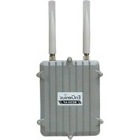
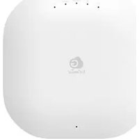
M9000 - Access Point ENGENIUS - Free user manual and instructions
Find the device manual for free M9000 ENGENIUS in PDF.


| Type de produit | Point d'accès sans fil |
| Dimensions | Environ 20 x 15 x 5 cm |
| Poids | Environ 800 g |
| Alimentation | PoE (Power over Ethernet) 802.3af/at |
| Normes sans fil | IEEE 802.11a/b/g/n/ac/ax |
| Bandes de fréquence | 2.4 GHz et 5 GHz |
| Débit maximal | Jusqu'à 2,4 Gbps (bande combinée) |
| Ports | 1 port Gigabit Ethernet (PoE in) |
| Antennes | 4 antennes internes |
| Gestion | Interface web, SNMP, CLI |
| Sécurité | WPA2/WPA3, filtrage MAC, RADIUS |
| Température de fonctionnement | 0°C à 40°C |
| Humidité de fonctionnement | 10% à 90% sans condensation |
| Certifications | FCC, CE, RoHS |
| Garantie | 1 an |
| Entretien | Nettoyer avec un chiffon sec et doux |
| Réparabilité | Pièces détachées disponibles auprès du fabricant |
| Consommation électrique | 12 V DC, 1 A max. (via adaptateur ou PoE) |
| Contenu de l'emballage | Point d'accès, kit de montage, guide rapide |
Frequently Asked Questions - M9000 ENGENIUS
User questions about M9000 ENGENIUS
0 question about this device. Answer the ones you know or ask your own.
Ask a new question about this device
Download the instructions for your Access Point in PDF format for free! Find your manual M9000 - ENGENIUS and take your electronic device back in hand. On this page are published all the documents necessary for the use of your device. M9000 by ENGENIUS.
USER MANUAL M9000 ENGENIUS
EnGenius Mesh AP M9000

natural_image
Exterior view of a gray EnCenius device with two metal leads (no visible text or symbols on body)User Manual
Version: 1.0
Table of Content
1 Document History 4
2 Overview 5
3 EnGenius Mesh Web-based Interface 6
4 System 11
4.1 System > System 11
4.2 System > Syslog 13
4.3 System > Advance 14
4.4 System > Profile 17
5 Network 18
5.1 Network > Network 18
5.2 Network > WAN 19
5.3 Network > VLAN 23
5.4 Network > Mesh 25
5.5 Network > Wireless 30
5.6 Network > Route 33
5.7 Network > IPSEC 35
5.8 Network > L2TPC 36
5.9 Network > OLSR 37
6 Service
39
6.1 Service > DHCPD 39
6.2 Service > Firewall 42
6.3 Service > MAC Access 45
6.4 Service > NAT 47
6.5 Service > NTP 49
6.6 Service > Traffic Shaping 51
6.7 Service > PPTP Server 53
6.8 Service > AutolP 55
6.9 Service > Captive Portal 56
6.10 Service > RADIUS 58
6.11 Service > Dynamic DNS 60
6.12 Service > Zero Config 61
6.13 Service > Mobile IP 62
6.14 Service > Route Watchdog 63
6.15 Service > Linux Kernel Watchdog 64
6.16 Service > SSHD 65
6.17 Service > WME 66
6.18 Service > DHCP Relay 69
7 Management
71
7.1 Management > HTTPD 71
7.2 Management >Configuration 73
7.3 Management > SNMP 76
7.4 Management > Firmware 79
7.5 Management > Trap 80
7.6 Management > User group 83
7.7 Management > Database 85
7.8 Management > Webspace 87
7.9 Management > Customize Login 88
7.10 Management > NMS Addresses 90
7.11 Management > Reboot 92
8 Tools 93
8.1 Tools > Ping 93
8.2 Tools > Ifconfig 94
8.3 Tools > Route 95
8.4 Tools > TFTP 96
9 Status
9.1 Status > Status 97
9.2 Status > Interfaces 97
9.3 Status > Services 99
9.4 Status >Users 101
9.5 Status > System Log 103
9.6 Status > Topology 104
9.7 Status > Mobile IP 105
9.8 Status > Neighbor 106
10 Help
107
1 Document History
| Revision Date Remark Authors | |||
| 1.0 23 Sep, 2007 Initial Version Ivy | |||
| 1.1 13 <ug, 2009 Second Draft Version:Webpage Interface Update | Mingl | ||
2 Overview
The purpose of this document is to describe the detail features of EnGenius Mesh <ccess Point (M9000), and also the procedure and methodology of configuring and the use of EnGenius M9000.
3 EnGenius Mesh Web-based Interface
Web-based configuration interface is accessible with computer with TCP/IP capability and web browser (e.g. Safari, Firefox, Mozilla or IE). To access web-based configuration interface, enter
https://
In the browser URL/Location field.
You will see an authentication page display as shown in Figure 3.1.1.

Figure >.1.1: Windows authentication page
Type "admin" in User Name and Password field, then click OK button.
*Obtain default IP address for EnGenius Mesh <P for different Interfaces:
Interface Default IP Notes
| WDHCP <dministrator needs to checktheir DHCP server lease to obtain device IP address | <uto IP Connect a DHCP client | their DHCP server lease to obtain device IP address |
| VL< N/L<P | <uto IP Connect a DHCP client | computer/laptop to EnGenius Mesh <P's L(with cross cable) or wireless interface. Device IP address is the 'Gateway' address given to DHCP client (computer/laptop) |
EnGenius Mesh page has six main menus: System, Network, Services, Management,
Tools and Status. Each main menu also will have its submenu.
Welcome
System
System System settings
Syslog Syslog settings
Advance Advance tuning
Network
Network Network settings
WAN WAN settings
VLAN VLAN settings
Mesh Mesh settings
Wireless Wireless settings
Route Route settings
IPSEC IPSEC settings
L2TPC L2TPC settings
OLSR OLSR settings
Services
DHCPD DHCP server settings
DHCRelay DHCP relay settings
Firewall Firewall settings
MAC Access Filter MAC address
NAT Network Address Translation
NTP Network Time Protocol
Traffic Shaping Bandwidth management
PPTP Server PPTP server settings
AutoIP AutoIP settings
Captive Portal Captive Portal settings
RADIUS RADIUS client settings
Dynamic DNS DDNS settings
Zero Config Zero Config settings
Mobile IP Mobile IP settings
Route Watchdog Route watchdog settings
Linux Kernel Watchdog Linux Kernel Watchdog settings
SSHD SSHD Configuration
WME WME Settings
Management
HTTPD Internal webserver settings
Configuration Configuration management
SNMP SNMP settings
Firmware Firmware maintenance
Trap Trap settings
User Group User group maintenance
Database Database settings
Webspace Webspace maintenance
Customize Login Customize Login Page
NMS Addresses Network Management System notifying settings.
Reboot Reboot device
Tools
Ping Ping
Ifconfig Ifconfig
Route Route
TFTP TFTP
Status
Status System status
Interfaces Interfaces statistics
Services Services status
Users Users details
System Log System logging
Topology Simple topology view
Mobile IP Simple mobile IP status
Neighbor Mesh node status
Help
4 System
4.1 System > System
M9000 supports different type of operation mode in one firmware. Supported operations are Layer 3 and Layer 2 oriented mesh network. Gateway, Relay, and Client Relay are those operate in layer 3. Layer 2 Gateway and Layer 2 Relay are those fall in layer 2 operation. Figure 4.1.1 illustrates the System Information Configuration page.
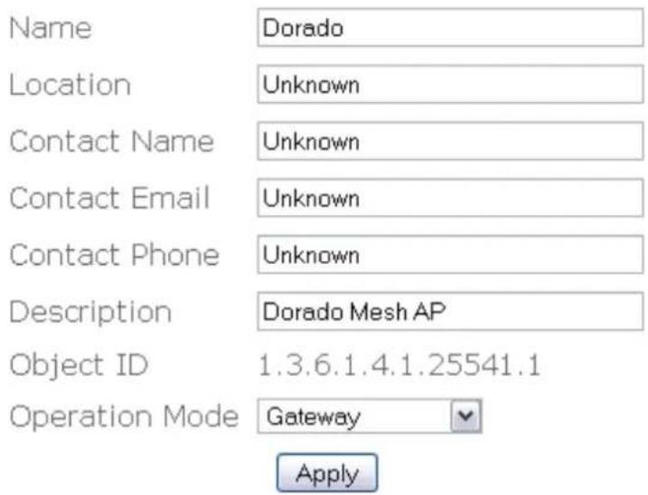
Figure 4.1.1: System Information Configuration page
System Information Configuration page contains the following parameters:
- Name – Name of the device.
- Location – Location name that device located.
- Contact Name – Name of the contact person for consulting about the device.
- Contact Email – Email address of the contact person.
-
Contact Phone – Phone number of the contact person.
• Description – Description of the device. -
Object ID – Display SNMP MIB object identification (OID) of the device.
- Operation Mode – Type of operation mode such as “Gateway”, “Relay”, “Client Relay”, “Layer 2 Gateway”, or “Layer 2 Relay”.
- "Apply" button to save any changes made. New settings are active after the device reboot.
4.2 System > Syslog
Certain system message is useful to understand the problem behind any undesired result. M9000 is enabled with Syslog server that can log message locally and remotely.
Figure 4.2.1 illustrates the Syslog configuration page.

Figure 4.2.1: Syslog configuration page
Syslog contains the following parameters:
• Active – Enable or disable system logging feature.
- Klog – Enable or disable kernel logging feature.
- Level – 8 levels of logging : emergency, alert, critical, error, warning, notice, info and debug.
- Remote Syslog – Enable or disable remote syslog server.
- Remote Server Address – <address of remote syslog server when remote syslog is enabled.
- "Apply" button to save any changes made. New settings are active after the device reboot.
4.3 System > Advance
In this advance feature, networking and some wireless fine tune done. Figure 4.3.1 illustrates the advance configuration page.
Networking-CONNTRACK
| Maximum session | 10000 | (4096~200000) |
| Generic Timeout | 600 | (50~1200s) |
| ICMP Timeout | 30 | (10~60s) |
| TCP Close Timeout | 10 | (5~30s) |
| TCP Close Wait Timeout | 60 | (10~120s) |
| TCP Established Timeout | 3600 | (600~864000s) |
| TCP Finished Wait Timeout | 120 | (10~3600s) |
| TCP Last ACK Timeout | 30 | (10~60s) |
| TCP SYN Receive Timeout | 60 | (10~120s) |
| TCP SYN Sent Timeout | 120 | (10~240s) |
| TCP Time Wait Timeout | 120 | (10~240s) |
| UDP Timeout | 30 | (10~60s) |
| UDP Stream Timeout | 180 | (10~360s) |
Wireless
| Radio 1 distance | 1000 | (100~30000m) |
| Radio 1 ack timeout | 29 | |
| Radio 2 distance | 1000 | (100~30000m) |
| Radio 2 ack timeout | 29 | |
| Country | United States | |
| Outdoor Mode | Enable | |
| External Channel Mode | Disable | |
| Preamble Type | Short | |
| Extended Range Mode | Enable | (Hardware not supported) |
Fast Frame Mode
Enable
Compression Mode
Enable
Bandwidth Mode
Normal (20Mhz)
Mesh Minimum Signal Strength:
15
Apply Reset
Figure 4.>.1: Advance configuration page
<dvance configuration have the following parameters:
- Maximum Session – Maximum connection tracking session, a higher value is desired to support large number of local users.
- Generic Timeout – Generic timeout for a connection tracking instance
- ICMP Timeout – ICMP timeout
- TCP Close Timeout – TCP close timeout
- TCP Close Wait Timeout – TCP close wait timeout
• TCP Established Timeout – TCP established timeout - TCP Finished Wait Timeout – TCP finished wait timeout
- TCP <ast Ack Timeout – Last acknowledgement timeout
- TCP SYN Receive Timeout – TCP SYN receive timeout
- TCP SYN Sent Timeout – TCP SYN sent timeout
- TCP Time Wait Timeout – TCP Time wait timeout
- UDP Timeout – UDP timeout
- UDP Stream Timeout – UDP stream timeout
- Radio 1 distance – Desired operating distance for radio 1 (usually refer to mesh radio)
• Radio 1 ack timeout – <CK timeout for radio 1 - Radio 2 distance – Desired operating distance for radio 2 (usually refer to client access radio)
• Radio 2 ack timeout – <CK timeout for radio 2 - Country – List of supported country available from the wireless interface.
- Outdoor Mode – Enable or disable use of outdoor mode on the wireless
interface.
- External Channel Mode – Enable or disable use of external channel mode of the wireless interface
- Preamble Type – Type of preamble
- Extended Range Mode – Enable or disable of extended range mode (depend on hardware supported)
- Fast Frame Mode – Enable or disable of fast frame mode (depend on hardware supported)
- Compression Mode – Enable or disable of compression mode (depend on hardware supported)
- Bandwidth Mode – Select different type of bandwidth (depend on hardware supported)
- "Apply" button to save any changes made. New settings are active after reboot.
- "Reset" button to restore the settings on advance page back to factory default settings.
4.4 System > Profile
Different settings on System > Advance, Network > Wireless and Network > Mesh (Wireless) will be profiled as a unique settings. User can switch to different profile as ease. Figure 4.4.1 illustrates the profile configuration page.
Profile
Please configure the
*System -> Advance
*Network -> Wireless
*Network -> Mesh ( Wireless )
before saving a profile.
Note that activating a profile will need a system reboot to enable new settings.
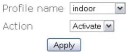
Figure 4.1.1 Profile settings.
Profile page has the following parameters:
• Profile name – Select different profile name
• Action – Select different action such as "Activate", "Save", and "Delete"
- "Apply" button to save any changes made. New settings are active after reboot.
5 Network
5.1 Network > Network
Figure 5.1.1 illustrates the network configuration page.
Note that static DNS will overwrite DHCP settings.

Figure 5.1.1: Network configuration page
Network contains the following parameters:
- Primary DNS – Primary Domain Name Server used to translates domain names to IP addresses. Edit this field to match your ISP DNS address or leave it unchanged to use received DNS address from your ISP.
- Secondary DNS – Secondary Domain Name Server used to translates domain names to IP addresses. < backup DNS address to primary DNS. Specify the Secondary DNS address.
- Domain – Specify the Domain name of network.
- Gateway – IP address of router or nodes that serves as an entrance to another network, and vice-versa. Edit this field to match your ISP settings or leave it unchanged to use defaults from your ISP.
- "Apply" button to save any changes made. New settings are active after the device reboot.
5.2 Network > WAN
W<N (Wide <rea Network) are used to connect local area networks (L<Sn) to other networks through your ISP (Internet Service Provider). Figure 5.2.1 illustrates the W<N configuration page.
WAN Interface: Ethernet
Static
DHCP
○ PPPoE

Figure 5.2.1: WAN configuration page
To configure W<N:
- Choose option either for Static, DHCP or PPPoE.
- Click on "Apply" button.
- If choose for Static option, Static IP configuration page is shown in Figure 5.2.2.
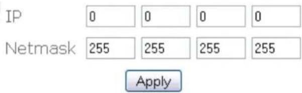
Figure 5.2.2: Static IP configuration page
Static IP configuration page contains the following parameters:
- IP – IP address is a unique address used to identify and communicate with different device on a computer network utilizing the Internet
Protocol standard. Specify the Static IP address.
- Netmask – Specify subnet mask for this IP.
- “Save changes” button – Click on “Save changes” button if you have made any changes. New settings are active after the device reboot.
- If ISP or network assigns the IP address dynamically using a DHCP server. Select this radio button and press "Apply". Using this option, all the network related configuration will be provided by ISP or network. You might need to remove any changes done in the Network Configuration..
Configuration saved. Please reboot to enable new settings.
Warning: An early DNS servers configuration found. Please remove those settings in network menu if dns server assigned by DHCP server is needed. Warning: An early default gateway configuration found. Please remove the settings in network menu if gateway assigned by DHCP server is needed.
Figure 5.2.>: DHCP Client configuration page
- PPPoE, Point-to-Point Protocol over Ethernet, is a network protocol for encapsulating PPP frames in Ethernet compression. Widely adapted by <DSL service provider. Basic authentication based on username and password is required for this type of connection. Select this radio button and press "Apply" to configure the following fields as shown in Figure 5.2.4.
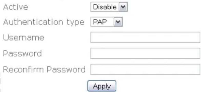
Figure 5.2.4: PPPoE configuration page
PPPoE configuration page contain the following parameters:
- "Active" - Click on "Active" drop down menu to select enable or disable PPPoE service.
-
Username – Specify PPPoE service username.
-
Password – Specify PPPoE service password.
- Reconfirm password – Re-enter PPPoE service password to confirm it.
- "Apply" button - Click on "Save changes" button if you have made any changes. New settings are active after the device reboot.
To <dd VL<N Tag to W<N:
- Click on "Add V<AN Tag" button.
- Click on "Action" drop down menu to select "Add", "Edit" or "Delete" VL<N Tag.
- Click on "Apply" to add, edit, or delete VL<N Tag.
- If select to add new VL<N Tag, VL<N Tag – add page will display as shown in Figure 5.2.5.

Figure 5.2.5: V<AN Tag - add configuration page
<dd VL<N Tag – add page contain the following parameter:
- ID – Enter the VL<N ID.
- Type - Click on "Type" drop down menu to select "Static" or "DHCP".
o IP - Specify the VL<N IP address. - Netmask – Specify the network mask for IP.
- Comments – Specify VL<N comments.
○ Active – Click on "Active" drop down menu to select enable or
disable VL<N.
- "Apply" button - Click on "Save changes" button if you have made any changes. New settings are active after the device reboot.
- If select to edit existing VL<N Tag, a page similar to Figure 5.2.5 with configured settings will be displayed
- If select to delete existing VL<N Tag, a page similar to Figure 5.2.5 with configured settings will be displayed.
5.3 Network > VLAN
Virtual L<N is a method of creating independent networks within a physical network. Several VL<Sn can co-exist within such a network. This VL<N implementation is based on the IEEE 802.1Q tagging protocol. Figure 5.3.1 illustrates the VL<N configuration page.

Figure 5.3.1: VLAN configuration page
To configure VL<N:
- <active VL<N list all activated VL<N. By default, only VL<N0 is active. Click on "Edit" button to edit active VL<N.
- VL<N0 – edit page will display as shown in Figure 5.3.2.

Figure 5.3.2: VLAN0 – edit page
VL<N0 - edit page contain the following parameter:
○ ID – Enter the VL<N ID.
- Type – Click on "Type" drop down menu to select "Static" or "DHCP".
- IP – Specify the VL<N IP address.
- Netmask – Specify the network mask for this IP.
- Routed – Click on "Routed" drop down menu to select "Routable address" or "N<T address". < routeable network is visible to other Mesh Node.
- Comments – Specify VL<N comments.
○ Active – Click on "Active" drop down menu to select enable or disable VL<N.
- “Apply” button to save any changes made. New settings are active after the device reboot.
- To edit inactive VL<N, click on "Inactive V<AN" drop down menu, select on VL<N you want to edit. For example, select VL<N1. Click on bottom "Edit" button to edit inactive VL<N1.
- VL<N1 – edit page will display as shown in Figure 5.3.2
5.4 Network > Mesh
This device will form a wireless mesh network with other device provided the correct configuration. Each of the mesh will have its own IP address. If two device with the same IP, one is not visible to each other in the mesh routing table. Hence, an initial network planning is needed to plan the whole mesh network.
<utoIP service could be used for simplicity and easy deployment of the mesh network. The following fields will change accordingly if <utoIP is used. However, if you plan to use the configured IP and Netmask, please disable <utoIP service. Figure
5.4.1 illustrates the mesh configuration page.
Please disable autoIP to configure static mesh IP

Figure 5.4.1: Mesh configuration page
Mesh configuration page contains the following parameters:
- IP – Specify the Mesh IP address.
• Network – Specify the Network mask for this IP. - Comments – Optional comments.
• Active – Enable or disable Mesh interface.
- "Apply" button to save any changes made. New settings are active after the
device reboot.
- Click on "Wireless settings" button to edit Mesh – wireless. Mesh – wireless configuration page will display as shown in Figure 5.4.2.

* Power value begin with "x" indicate that the power value is not supported by the hardware.

Figure 5.4.2: Mesh - wireless configuration page
Mesh – wireless page contain the following parameter:
- MAC address – Display the M<C address of Mesh – wireless interface.
○ Mode – Click on “Mode” drop down menu to select “<P”, “ST<”, “<DHOC” or “WDS” operating mode. AP mode will bring the wireless device to <ccess Point mode. Under this mode, it can connect multiple
wireless communication devices together to form a wireless network and can relay data between wireless and wired devices.
STA mode will bring the wireless device to Station mode. Under this mode, it needs to connect to an <P to join the wireless network.
ADHOC mode will bring the wireless device to adhoc mode where no <P is required. The connection is established for the duration of one session by discovering others device within range.
WDS mode will bring the wireless device to form a wireless distribution system that connects to other <P to form a larger network. Data can be relayed between 2 stations.
Only ADHOC mode is allowed in mesh network. Mode other than <DHOC is disabled and not supported.
- Band – Click on “Band” drop down menu to select “802.11a”, “802.11b” or “802.11g” operating band. Choose 802.11a if you want to operates mesh network under the 5GHz spectrum and up to 54Mbps. However, make sure your hardware is supported for this kind of operation. Choose 802.11b for operation under 2.4 GHz spectrums for rates up to 11Mbps. Choose 802.11g for operation under 2.4GHz that are backward compatible with 802.11b band. It can support rates up to 54Mbps.
- ESSID – Extended Service Set Identifier is a code attached to all packets on a wireless network to identify each packet as part of that network. This entry is case sensitive text string which consists of a maximum of 32 alphanumeric characters. Enter your ESSID into this field that consistent with other mesh so that it can join or form the mesh network.
- Frequency – Click on "Frequency" drop down menu to select operating frequency of wireless network in GHz.
- Beacon Interval – Beacon are management packets sent by an <ccess Point to manage and synchronize a wireless network. Value in the range of 20 to 1000 milliseconds is permitted. The default value is set to 100 milliseconds.
- RTS Threshold – Request to Send management packet. With smaller RTS length value, the wireless network can recover from interference and collisions quicker at a cost of reducing the maximum throughput. Network with heaving loading or interference is advised to use smaller value of RTS.
- Fragmentation Threshold – Fragmentation of packet into desired length. Network with high packet error should use smaller value. Use of small value will results in lower throughput due to more overheads is introduced.
DTIM Interval – Delivery Traffic Indication Message is a countdown mechanism for informing associated stations of the next window for listening to broadcast and multicast messages. When the <P has buffered broadcast or multicast messages, it sends the next DTIM with a DTIM interval value. Clients hear the beacons and awaken to receive the broadcast and multicast messages. < range of value 1 to 255 is permitted. The default value is 1.
○ Datarate – Click on “Datarate” drop down menu to select wireless network datarate. For example, 1 Mbps, 2 Mps, 5.5 Mbps.....
- Tx antenna – Click on “Tx antenna” drop down button to select “Diversity”, “Card Default”, “Port 1”, or “Port 2”.
- Rx antenna - Click on "Rx antenna" drop down button to select "Diversity", "Card Default", "Port 1", or "Port 2".
- Current Maximum Tx Power (dBm) – Display current maximum Tx power.
o Maximum Tx Power (dBm) - Click on "Maximum Tx Power" drop down button to select maximum Tx power.
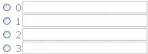
- Security – <dd security features to the wireless network. Click on "Security" drop down button to select "Open", "WEP" or "<ES". Only when select "WEP" or "<ES" will display "Encryption Key" field as shown in Figure 5.4.3.
Security
Encryption key
WEP
* Power value begin with "x" indicate that the power value is not supported by the hardware.
Apply
Figure 5.4.>: Mesh - wireless configuration page (with encryption key)
- Open-no encryption or security is applied.
- WEP-Wired Equivalent Privacy. <n encryption using either 64-bit or 128-bit to encrypt the network packets.
- <ES-<dvanced Encryption Standard. <n encryption scheme that uses 128-bit to encrypt the network packets.
- "Apply" button to save any changes made. New settings are active after the device reboot.
5.5 Network > Wireless
Figure 5.5.1 illustrates the <P configuration page.

* Power value begin with "x" indicate that the power value is not supported by the hardware.
Apply
Active Virtual AP

Figure 5.5.1: AP configuration page
Wireless <P contains the following parameters:
• MAC address – Displays the M<C address of the wireless interface.
- Mode – Only <P mode is available in M9000 4000.
- Band – “802.11a”, “802.11b” or “802.11g” operating band.
• Frequency – Operating frequency of the wireless network in Ghz.
- Tx antenna – Select "Diversity", "Port 1", "Port 2" or "Card Default".
- Rx antenna – Select "Diversity", "Port 1", "Port 2" or "Card Default".
- Current Maximum Tx Power – Displays current transmit power of the wireless card due to regulatory limitation.
• Maximum Tx Power (dBm) – Select transmit power of the <P wireless card.
- "Apply" button to save any changes made. New settings are active after the device reboot.
- "Edit" button to edit <ctive Virtual <P. <P configuration – edit page is shown in Figure 5.5.2.

Figure 5.5.2: AP configuration – edit page
APO configuration with wep key security selected.
Security
WPA Type
802.1x
Encryption key
WPA(1 & 2)


Figure 5.5.4: APO configuration – edit page (WPA (1 & 2))
- Open-no encryption or security is applied.
■ WEP-Wired Equivalent Privacy. < encryption using either 64-bit or 128-bit to encrypt the network packets.
- WP<-Wi-fi Protected 5.8 Network > L2TPC
Layer 2 Tunneling Protocol (L2TP) is a tunneling protocol used to support virtual private networks (VPN). L2TPC serves as a L2TP client that creates a tunnel through existing network to the designated peer computer or network. Figure 5.8.1 illustrates the L2TCP configuration page.

Figure 5.8.1: L2TPC configuration page
L2TPC configuration page contains the following parameters:
• Active – Enable or disable L2TPC service.
• L2TP LNS address – Enter the L2TP LNS address.
- Username – Enter L2TP username.
- Password – Enter L2TP password.
- Password Confirm – Re-enter L2TP password to confirm.
- "Apply" button to save any changes made. New settings are active after the device reboot.
5.9 Network > OLSR
Optimized Link State Routing protocol is a protocol to connect mobile ad-hoc networks. It is a link-state routing protocol that collects data about available network and then calculates an optimized routing table. Figure 5.9.1 illustrates the OLSR configuration page.

Figure 5.9.1: OLSR configuration page
OLSR configuration page contains the following parameters:
• Active – Enable or disable OLSR service.
- TOS value – Enter the value of TOS. Type Of Service (TOS). Value for the IP header of control traffic.
0 : normal service.
2 : minimize monetary cost.
4 : maximize reliability.
8 : maximize throughput.
16 : minimize delay. (Default)
\- Willingness – Enable or disable Willingness. Willingness will be calculated dynamically if disabled.
\- Willingness level – Enter the Willingness level.
\- Hysteresis – Hysteresis adds more robustness to the link sensing but delays neighbor registration. Enable or disable hysteresis.
\- Hysteresis Scaling – Enter the Hysteresis Scaling.
\- Hysteresis THR High – Enter the Hysteresis THR High value.
\- Hysteresis THR 6.1 Service > DHCPD
DHCP is a protocol used by networked computers (clients) to obtain unique IP addresses, and other parameters such as default router, subnet mask, and IP addresses for DNS server from a DHCP server. Figure 6.1.1 illustrates the DHCPD configuration page.
Active Enable
Apply
DHCPD List
New Entry
Figure 6.1.1: DHCPD configuration page
DHCPD configuration page contains the following parameters:
• Active – Enable or disable DHCPD service.
- "Apply" button to save any changes made.
- "Modify" button to edit current selection.
- "Remove" button to delete current selection.
- "New Entry" button to add new entry to the service.
Figure 6.1.2 illustrates the configuration page when new entry is added or edited.

Figure 6.1.2: DHCPD – edit or new entry page
DHCPD – add or edit page contain the following parameters:
- Interface – Click on "Interface" drop down menu to select interface.
- Subnet – Enter the interface network address.
• IP Start – Enter the IP address of IP start.
- IP End – Enter the IP address of IP end.
- Netmask – Enter the network mask for this network address.
- Max Interface Subnet Netmask Comment Active Configure vlan0 172.23.203.0 255.255.255.0 Default DHCP server Enabled Modify Remove flowchart
graph TD
    A["MAC 0a:11:5d:c9:87:ee"] --> B["Type"]
    B --> C["Comments"]
    C --> D["Active"]
    D --> E["Configuration"]
    F["deny"] --> G["Block User"]
    H["Enabled"] --> I["Modify"]
    J["Remove"] --> K["New Entry"]
    L["Browse Active Users"]
6.4 Service > NAT
Network address translation (NProtocol Port IP Comments Active Configure tcp and udp 21 172.23.203.254 NAT To FTP Server Enabled Modify Remove 6.6 Service > Traffic Shaping
Traffic Shaping will limit bandwidth allocated to each user. Figure 6.6.1 illustrates the traffic shaping configuration page.


Figure 6.6.1: Traffic Shaping configuration page
Traffic shaping configuration page contains the following parameters:
• Active – Enable or disable traffic shaping
• WAN Uplink Speed – Uplink speed of the device
- WAN Downlink Speed – Downlink speed of the device
- User Uplink Speed – Default user uplink speed.
- User Downlink Speed – Default user downlink speed.
- "Apply" button to save any changes made.
- "Modify" button to edit current selection.
- "Remove" button to delete current selection.
- "New Entry" button to add traffic shaping list.
Figure 6.6.2 illustrates the add or edit page for traffic shaping.

Figure 6.6.2: Traffic Shaping – add or edit page
Traffic Shaping - add or edit page contain the following parameter:
- Protocol – Click on “Protocol” drop down menu to select “tcp”, “udp”, or “both” protocol of Traffic Shaping.
- Port – Enter the Traffic Shaping port number.
- Min Size – Enter the minimum packet size of Traffic Shaping.
- Max Size – Enter the maximum packet size of Traffic Shaping.
- Priority – Click on "Priority" drop down menu to select priority "Background", "Video", "Voice" or "Best effort".
- Comments – Enter Traffic Shaping comments.
• Active – Click on "Active" drop down menu to enable or disable this entry.
- "Apply" button to save any changes made. New settings are active after the device reboot.
6.7 Service > PPTP Server
Point-to-Point Tunneling Protocol (PPTP) is a method for implementing virtual private networks (VPN). Figure 6.7.1 illustrates the PPTP Server configuration page.

PPTP User List

New Entry
Figure 6.7.1: PPTP Server configuration page
PPTP Server configuration page contains the following parameters:
• Active – Enable or disable PPTP Server service.
• Server IP – Enter the PPTP Server IP address.
- Client IP Start – Enter the start of IP address for client.
- Client IP End – Enter the end of IP address for client.
- "Apply" button to save any changes made. New settings are active after the device reboot.
- "Modify" button to edit current selection.
- "Remove" button to delete current selection.
- "New Entry" button to add new entry
Figure 6.7.2 illustrates the add or edit page for PPTP server

Figure 6.7.2: PPTP User – add or edit page
PPTP User - add page contain the following parameter:
- Username – Enter the PPTP username.
- Password – Enter the PPTP password.
- Reconfirm Password - Re-enter PPTP password to confirm it.
\- IP – Enter the PPTP IP address.
\- Comments – Enter the PPTP comments.
• Active – Click on "Active" drop down menu to enable or disable this PPTP.
\- "Apply" button to save any changes made. New settings are active after the device reboot.
6.8 Service >AutoIP
Figure 6.10.1: RADIUS client configuration page
RName Type Port Comments Active Configure 192.168.1.81 1 1812 Authentication Enabled Modify Remove 192.168.1.81 2 1813 Accounting Enabled Modify Remove New Entry 6.12 Service > Zero Config
Figure 6.12.1 illustrates the Zero Config configuration page.

Figure 6.12.1: Zero Config configuration page
Zero Config configuration page contains the following parameters:
• Active – Enable or disable Zero Config service.
- Handle Client Proxy – Enable or disable handling of proxy clients.
- Proxy Login Port – Enter the port number used in Proxy Login.
- Handle Static IP Client – Enable or disable handling of client with static IP.
- "Apply" button to save any changes made. New settings are active after the device reboot.
6.13 Service > Mobile IP
Mobile IP provide client with IP roaming capability. Client will have same IP no matter which node it reside. Figure 6.13.1 illustrates the mobile IP configuration page.

Figure 6.13.1: Mobile IP configuration page
Mobile IP configuration page contains the following parameters:
• Active – Enable or disable Mobile IP service.
- Netname – Enter the Mobile IP network name.
• Network – Select the interface mobile ip should attached to.
- MLRD IP – Enter the IP address of the Mobile Location Register server.
- "Apply" button to save any changes made. New settings are active after the device reboot.
6.14 Service > Route Watchdog
Route watchdog will probe for default route periodically. If not default route is detected, it'll change the essid of active wireless radio to a desired value such as "ServiceDown". Figure 6.14.1 illustrates the route watchdog configuration page.

Figure 6.14.1: Routedog configuration page
Routedog configuration page contains the following parameters:
• Active – Enable or disable routedog service.
- Alert SSID – Specify the desired 6.16 Service > SSHD
SSHD provides remote management using command line interface (CLI). Figure
6.16.1 illustrates the SSHD configuration page.

Figure 6.16.1: SSHD configuration page
SSHD configuration page contains the following parameters:
• Active – Enable or disable this service.
- Port – Specify the TCP/IP port that the SSHD will listen for incoming connection.
- "Apply" button to save any changes. Please reboot to enable new settings.
6.17 Service > WME
Based on 802.11e draft standard. It provides basic quality of service (QoS) features to 802.11 networks. WMM prioritizes traffic according to 4 7.1 Management > HTTPD
Webbased configuration management is done through the secure HTTP. Figure 7.1.1 illustrates the HTTPD server configuration page.

Access Control List

Figure 7.1.1: HTTPD server configuration page
HTTPD server configuration page contains the following parameters:
• Active – Enable or disable HTTPD server.
- Port – Enter the HTTPD port number.
- Username – Enter the HTTPD username.
- Password – Enter the HTTPD password.
- Reconfirm Password – Re-enter password to confirm it.
- Certificate Password – Enter the certificate password.
- Reconfirm Certificate Password – Re-enter certificate password to confirm it.
- Access Control – Enable or disable access control.
- "Apply" button to save any changes made. Please reboot to enable new settings.
- "Modify" button to edit current selection.
- "Remove" button to edit current selection.
- "New Entry" button to add entry to the access control table.
Figure 7.1.2 illustrates the access control configuration page.

Figure 7.1.2: HTTPD Access Control – add or edit page
HTTPD Local Certificate
Existing local certificate:
None
Existing root certificate authority:
None
Upload certificate as PKCS 12 file (Extension \*.p12):
Browse...
Upload
Remote Certificate
This certificate is required as it will be used to authenticate the server.
Existing Certificate:
None
Upload remote certificate as PEM file (Extension \*.pem):
Browse.
Upload
Figure 7.2.>: IPSEC Management – x509 page
IPSEC Management – x509 page contain the following parameter:
- 7.5 Management > Trap
Trap used to report an alert or other asynchronous event about managed system.
Figure 7.5.1 illustrates the trap configuration page.

Figure 7.5.1: Trap configuration page
Trap configuration page contains the following parameters:
• Active – Enable or disable trap report.
- Configuration – Enable or disable report on configuration issue.
• Security – Enable or disable security trap report.
- Wireless – Enable or disable wireless trap report.
- Operational – Enable or disable operational trap report.
- Flash – Enable or disable flash trap report.
- Tftp – Enable or disable tftp trap report.
• Image – Enable or disable image trap report.
- Auth failure – Enable or disable authentication failure trap report.
- "Apply" button to save any changes made. Please reboot to enable new settings.
- "Modify" button to edit trap server entry.
- "Remove" button to delete trap server entry.
- "New Entry" button to add new server entry.
Figure 7.5.2 illustrates the configuration page for add or delete trap server.

Figure 7.5.2: Trap server – add or edit page
Trap server – add or edit page contain the following parameter:
- IP – Enter destination IP to send trap.
• Community – Enter community of trap.
- Reconfirm Community – Re-enter community to confirm it.
- v>Username – Enter v3 username.
- v> Password – Enter v3 user password.
- Reconfirm v> Password – Re-enter password to confirm it.
- v> Passphrase – Enter v3 user passphrase.
- Reconfirm v> Passphrase – Re-enter passphrase to confirm it.
- Version – SNMP Version.
- Comments – Enter Trap comments.
• Active – Enable or disable this entry.
- "Apply" button to save any changes made. Please reboot to enable new settings.
7.6 Management > User group
Users within a predefined user group will share the commons parameter of the group. This allows administrator to create various type of user group depending on their needs. Figure 7.6.1 illustrates the user group configuration page.

Figure 7.6.1 User Group configuration
There are one default group which is listed on figure 7.6.1. To configure the default parameters for default group:-
- Default Upload Speed Limit – Upload speed limit in kbps for users in this group.
- Default Download Speed Limit – Download speed limit in kbps for users in this group.
- Default Idle Timeout – 7.9 Management > Customize Login
Customize login page is used to modify look and feel for the captive portal login page of EnGenius Mesh. Figure 7.9.1 illustrates the customize login page.
Existing files
Directory: /lang
File
Description
Actions
Common Directory, containing language independent files that are displayed before login.
English Directory for language English.
Delete
style.css User file
Delete
Upload File
Filename:
Browse...
Upload
Add Language
New Language:
Add
Default Language
Login Language
English
(If not supplied by the RADIUS):
Change
Figure 7.9.1: Customize Login configuration page.
Customize Login configuration page contains the following parameters:
- Existing files – display existing login file.
- "Delete" button to delete existing login file.
- "Browse" button to search login file that want to upload.
- "Upload" button to upload login file.
- New 8 Tools
8.1 Tools > Ping
Figure 8.1.1 illustrates the ping page.

Figure 8.1.1: Ping page
Ping page contains the following parameters:
- Ping – Enter the IP address to ping.
• Number of pings – Enter the number of pings to send.
- "Ping" button to ping and display output of ping command.
- "Output" text area display result of the ping command.
8.2 Tools > Ifconfig
Ifconfig page is used to collect verbose information about device network interfaces.
Figure 8.2.1 illustrates the ifconfig page.

Figure 8.2: Ifconfig page
Ifconfig page contains the following parameters:
- "Ifconfig" button to call ifconfig command.
- "Output" text area to display the output of the command.
8.3 Tools > Route
Route page is used to collect information about device's routing table. Figure 8.3.1 illustrates the route page.
Route
Output
Figure 8.3.1: Route page
Route page contains the following parameters:
- "Route" button to display output of route command.
- "Output" text area display result of the route command.
Kernel IP routing table Destination Gateway Genmask Flags Metric Ref Use Iface 192.168.1.0 0.0.0.0 255.255.255.0 U 0 0 0 ixp1 172.23.203.0 0.0.0.0 255.255.255.0 U 0 0 0 vlan0 10.0.0.0 0.0.0.0 255.0.0.0 U 0 0 0 ath0 127.0.0.0 0.0.0.0 255.0.0.0 U 0 0 0 lo 224.0.0.0 0.0.0.0 240.0.0.0 U 0 0 0 ixp1 0.0.0.0 192.168.1.2 0.0.0.0 UG 0 0 0 ixp1 8.4 Tools > TFTP
Figure 8.4.1 illustrates the TFTP page.
Use TFTP to get or put file to a remote TFTP server
Getting of firmware will result in firmware upgrade follow by system reboot.
Getting of config will result in configuration upgrade.

Figure 8.4.1: TFTP page
TFTP contains the following parameters:
- TFTP to – Enter the destination IP address of remote TFTP server.
- Operation – Select "put", "get" or "get and reboot" file to remote TFTP server.
- File Name – Enter the File Name to put or get.
- Type of File – Select "config", "firmware", "ipsec x509 local", "ipsec x509 remote", or "ipsec rsa" file.
• Execute button to perform directed action.
9 Status
9.1 Status > Status
Status page will display current system status of Mesh System Uptime: 0 days, 0 hrs, 3 minutes CPU Speed: 527.56 Average CPU usage:(Since boot) 83.00 % Average CPU usage:(Last two seconds) 14.77 % Free RAM: 48340992 byte Firmware Release Version mesh-2.1.12 9.2 Status > Interfaces
Figure 9.2.1 illustrates the interface page. Hardware Address: 00:11:A4:1F:00:73 IP Type: dhcp IP Address: 192.168.1.111 Broadcast Address: 192.168.1.255 Netmask: 255.255.255.0 MTU: 1500 Rx bytes: 38800 (37.8 KB) Tx bytes: 9716 (9.4 KB) Rx packets: 504 Tx packets: 101 Rx errors: 0 Tx errors: 0 Rx dropped: 0 Tx dropped: 0 9.3 Status > Services
Figure 9.3.1 illustrates the status of each service running in the device.
Status
Figure 9.3.1: Services page
Services page display status of each service. Services page contains the following parameters:
- DHCP Server
- DNS Server
- Dynamic DNS
• IPSEC
• L2TPC
- Mobile IP
- NTP Client
• OLSR
- PPPoE
- PPTP Server
- Routedog
- SSHD
- SNMP Server
- Syslog Server
- Traffic Shaping
- Webservers
Service Status DHCP Server O.k. DNS Server O.k. Dynamic DNS Disabled IPSEC Disabled L2TPC Disabled MobileIP Disabled NTP Client O.k. OLSR O.k. PPPoE Disabled PPTP Server O.k. Routedog Disabled SSHD O.k. SNMP Server O.k. Syslog Server O.k. Traffic shaping O.k. Webservers O.k. 9.4 Status > Users
Figure 9.4.1 illustrates the status of logged in users.
List of Users
Username IP Address Actions
user 172.23.203.254 Logout
Figure 9.4.1: Users status page
Users status page contains the following parameters:
• List of Users – list of authenticated users
-
User details page contains the following parameters:
\- IP – IP currently being used by the authenticated user.
\- User Name – Name of the authenticated user.
• MAC Address – MUser Name: user MAC Address: 00:13:02:B0:4A:8F Auth Mode: prep Auth Message: Start Page www.google.com Language English Customizable Info: Login During 0:03:22 Idle: 0:00:03 Session Timeout: 1083 min Idle Timeout 5 min Tx bytes: 4449B Rx bytes: 0B
Figure 9.5.1: System Log page
System log page contains the following parameters:
- "Get log" button to display output of system log command.
- "Output" text area to display the result of the output.
May 18 08:01:02 dorado daemon.notice mini_httpd[1794]: mini_httpd/1.19 19dec2003 starting on dorado.dorado, port 3002
May 18 08:01:02 dorado daemon.notice mini_httpd[1791]: mini_httpd/1.19 19dec2003 starting on dorado.dorado, port 443
May 18 08:01:05 dorado local0.warn dnsmasq: ignoring nameserver 127.0.0.1 - local interface
May 18 08:01:08 dorado user.notice root: Restore boot flag
May 18 08:01:11 dorado user.notice root: Starting routedog...
May 7 15:45:26 dorado daemon.crit ntpd[1932]: IMSG_HOST_DNS but addr != NULL!
May 7 15:45:26 dorado daemon.crit ntpd[1932]: IMSG_HOST_DNS but addr != NULL!
May 7 15:45:26 dorado daemon.crit ntpd[1925]: adjtime failed: Invalid argument
May 7 15:46:39 dorado daemon.crit ntpd[1925]: adjtime failed: Invalid argument
May 7 15:46:44 dorado daemon.crit ntpd[1925]: adjtime failed: Invalid argument
9.6 Status > Topology
Figure 9.6.1 illustrates the simple topology view of the mesh network.
Reload
Output
Figure 9.6.1: Simple Topology page
Simple topology page contains the following parameters:
- "Reload" button to reload output content of topology command.
- "Output" text area to display the result of the "Reload" button.
Links (10.23.203.1) -> (10.25.205.1)| Gateway n/a 9.7 Status > Mobile IP
Figure 9.7.1 illustrates the status of the mobile IP client in this device.
Get status
Output
Mobile IP Disabled
Figure 9.7.1 Mobile IP Status
Mobile IP page contains the following parameters:
- "Get Status" button to display mobile IP status.
- "Output" text area to display the result of "Get Status" button.
9.8 Status > Neighbor
Neighbor status page will show the mesh node status. It shows neighbor with details such as rate, rss, timeout. Figure 9.8.1 illustrates the neighbor status page.
List of Neighbors
MAC Address Rate (Mbps) RSSI (dBm) Timeout (Seconds) Mac Table 00:0b:6b:2b:ee:35 36M 63 120 View 00:0b:6b:2b:ee:63 36M 63 123 View View All Macs Figure 9.8.1: Neighbor Status page
Neighbor Status page contains the following parameters:
• List of Neighbors – display a list of connected neighbor
- Neighbor MAC Address Timeout (Seconds) 00:0b:6b:2b:ee:35 00:0b:6b:2b:ee:35 120 00:0b:6b:2b:ee:63 00:0b:6b:2b:ee:35 120 10 Help
Help page provide links to specific help related to configuration and some description according to each submenu of the configuration..

- EnGenius Mesh AP M9000
- User Manual
- Table of Content
- Document History 4
- Overview 5
- EnGenius Mesh Web-based Interface 6
- System 11
- Network 18
- Service
- Management
- Tools 93
- Status
- Help
- Document History
- Overview
- EnGenius Mesh Web-based Interface
- Welcome
- System
- Network
- Services
- Tools
- Status
- Help
- System
- System > System
- System > Syslog
- System > Advance
- System > Profile
- Profile
- Network
- Network > Network
- Network > WAN
- Figure 5.2.>: DHCP Client configuration page
- Network > VLAN
- Network > Mesh
- illustrates the mesh configuration page.
- Figure 5.4.>: Mesh - wireless configuration page (with encryption key)
- Network > Wireless
- Network > Route Routing refers to selecting paths in a network along which to send data. Figure 5.6.1 illustrates the route configuration page.  text_image Routes List IP Netmask Using Comments Active Configure 192.168.2.0 255.255.255.0 VLAN0 New Route Enabled Modify Remove New Entry Figure 5.6.1: Route configuration page Route contains the following parameters: - Routes List – Display list of routes. - "Modify" button to edit the current selection - "Remove" button to delete the current selection - "New Entry" button to add new entry. Figure 5.6.2 illustrates the add or edit page for route entry.  text_image Subnet Netmask Direct Device Comments Active Apply Figure 5.6.2: Routes – add or edit page Routes – add page contain the following parameter: \- Subnet – Enter the IP address of destination subnet. - Netmask – Enter the IP address of destination subnet network mask. - Gateway – Enter the gateway address. - Direct – Click on "Direct" drop down menu to select "Direct" or "Indirect" route. - Device – Click on "Device" drop down menu to select device. For example, W
- Network > OLSR
- Service 6.1 Service > DHCPD
- Service > Firewall Firewall is used to allow or deny data either in or out. Figure 6.2.1 illustrates the firewall configuration page.  text_image Active Enable Apply Firewall List Target Source IP Source mask Destination IP Destination Mask Protocol Start port End port User Group Comments Active Configure Deny 172.23.203.0 255.255.255.0 192.168.1.81 255.255.255.255 tcp and ucp 21 21 n/a Block FTP Enabled Modify Remove New Entry Figure 6.2.1: Firewall configuration page Firewall configuration contains the following parameters: • Active – Enable or disable firewall service - "Apply" button to save any changes made. - "Modify" button to edit the current selection. - "Remove" button to delete the current selection. - "New entry" button to add new entry to the firewall. Figure 6.2.2 illustrates the configuration page to edit or add new entry to the firewall.  text_image Target Allow Source Interface any Destination Interface any Source IP Source Netmask Destination IP Destination Netmask Protocol Both tcp and udp Start Port ( -1 ~ 65535 ) End Port ( -1 ~ 65535 ) User Group: Default Comments Active Enable Apply Figure 6.2.2: Firewall – add page Firewall - add page contains the following parameters: - Target – Click on "Target" drop down menu to allow, deny, or free target. - Source Interface – Click on “Source Interface” drop down menu to select source interface. For example, W
- Service > NTP Network Time Protocol (NTP) is a protocol for synchronizing the system clocks over data networks. Figure 6.5.1 illustrates the NTP configuration page.  text_image Active Enable Time Zone TW-Asia/Taipei Daylight Saving Disable Apply  text_image NTP Servers Server Comment Active Configuration 0.asia.pool.ntp.org Default Server 1 Enabled Modify Remove 1.asia.pool.ntp.org Default Server 2 Enabled Modify Remove New Entry Figure 6.5.1: NTP configuration page NTP configuration page contains the following parameters: • Active – Enable or disable NTP feature - Time Zone – Select the correct time zone. - Daylight Saving – Enable or disable daylight saving. - "Apply" button to save any changes made. - "Modify" button to edit current selection. - "Remove" button to delete current selection. - "New Entry" button to add new entry to the NTP. Figure 6.5.2 illustrates the configuration page for add or edit NTP server settings.  text_image Server Comments Active Enable Apply Figure 6.5.2: NTP – add or edit page NTP add or edit page contains the following parameters: - Server – Enter the NTP server name. • Comments - Enter NTP server comments. - Active – Click on "Active" drop down menu to enable or disable this NTP server. - "Apply" button to save any changes made. New settings are active after the device reboot. 6.6 Service > Traffic Shaping
- Service > PPTP Server
- Service >AutoIP
- Service > Captive Portal Captive portal forces an HTTP client on a network to see a special authentication web page before surfing the Internet normally. Figure 6.9.1 illustrates the captive portal configuration page.  text_image Webbased Authentication Disable Redirect to URL POP3 Email Push Enable External Login Server Disable External Server URL Default Idle Timeout 300 (0 ~ 3000000s) Default Session Timeout 65000 (0 ~ 3000000s) Login using HTTP Enable HTTP Port 3000 (1000 ~ 65535) Login Using HTTPS Enable HTTPS Port 3001 (1000 ~ 65535) Internal Web Space Enable Web Space Port 3002 (1000 ~ 65535) Default Language English Multiple Login Disable 1X LOGIN Enable Apply Figure 6.9.1: Captive Portal configuration page Captive portal configuration page contains the following parameters: - Webbased Authentication – Enable or disable Webbased
- Service > Mobile IP
- Service > Route Watchdog
- Service > Linux Kernel Watchdog Linux kernel watchdog will constantly monitor the integrity of the system. During system locked up, kernel watchdog will trigger a system reboot to recover the system from failure. Figure 6.15.1 illustrates the linux kernel watchdog configuration page.  text_image Active Enable Interval 60 (10 ~ 60 s) Apply Figure 6.15.1: Lindog configuration page Linux kernel watchdog configuration page contains the following parameters: • Active – Enable or disable this service. - Interval – Specify the interval watchdog will pool for system status. - "Apply" button to save any changes made. Please reboot to enable new settings. 6.16 Service > SSHD
- Service > WME
- Service > DHCP Relay For a dynamic network, M9000 4000 is able to forward the DHCP request to a backend DHCP server when operating in layer 2 mode. Figure 6.18.1 illustrates the configuration page for DHCP Relay.  text_image Active Enable Port 67 (1 ~ 65535) Hop count 10 (1 ~ 255) Max packet size 1400 (600 ~ 1400) Apply  text_image DHCRELAY List Server/Interface Extra Comment Active Configure Interface vlan0 DHCP Relay Enabled Modify Remove New Entry Figure 6.18.1 DHCP Relay Settings DHCP Relay contains the following parameters: • Active: Enable or disable DHCP Relay feature. • Port: Port to listen for DHCP packet. Default value is 67. - Hop count: Number of hop the DHCP discover packet can travel before it is dropped by this device. Default value is 10. - Max packet size: Maximum packet size of the DHCP discover packet. Normally specify a large number of packet size is recommended. Default value is 1400. - "Apply" button to save any changes made. Please reboot to enable new settings. - "Modify" button to edit current selection. - "Remove" button to delete current selection. - "New Entry" button to add server IP or Interface. Figure 6.18.2 illustrates the add or edit configuration page.  text_image Type Interface Interface Name MESH Comments Active Enable Apply Figure 6.18.2 Server or Interface configuration page. The add or edit configuration page contains the following parameters. • Type – Server IP or interface list - Interface Name – Once the “type” drop down menu is changed to interface, interface name selection drop down menu will appear for the users to make selection on the interface where the DHCP server can be reach. The interface also must include the interface where the client can be reach. - IP – Specify the IP address of the backend DHCP server. - Comments –
- Management > Configuration Under this configuration menu, you can perform the following action. Figure 7.2.1 illustrates the configuration page. Restore Factory Settings Default Backup configuration settings Backup Restore Last Good Configuration Restore Restore configuration Select a configuration file to restore (config.cfg) Browse... Upload Upload New Webserver Certificate Upload certificate as PEM file (\*.pem): Browse... Upload IPSEC Management Manage RSA Manage x509 Figure 7.2.1: Configuration page Configuration page contains the following parameters: - "Default" button to restore factory default settings. - "Backup" button to save configuration settings file (config.cfg). - "Restore" button to restore configuration to last good configuration. - "Browse" & "Upload" button to perform file searching and uploading. - "Manage RSA" button to manage RS< certificates. - "Manage x509" button to manage x509 related certificates. Figure 7.2.2 illustrates the IPSEC management configuration page.  text_image Existing Public Key Local Public RSA Key in RFC 2537 Format Upload Key-Pair Please select a Private RSA key to upload: Browse... Upload Figure 7.2.2: IPSEC Management – RSA page IPSEC Management – RS< page contain the following parameter: - Existing Public Key – Display the local public RS< key format. - Upload Key-Pair – Click on "Browse..." button to browse and select private RS< key. Then, click on "Upload" button to upload selected private RS< key. Figure 7.2.3 illustrates the IPSEC Management x509 configuration page. Local Certificate
- Remote Certificate
- Management > SNMP Simple Network Management Protocol (SNMP) used to monitor devices for conditions that warrant administrative attention. Figure 7.3.1 illustrates the SNMP configuration page.  text_image Active Version all Port 161 ( 1 ~ 65535 ) v2 Read Community Reconfirm v2 Read Community v2 Read-write Community Reconfirm v2 Read-write Community v3 Read Username v3 Read-write Username v3 Password Reconfirm v3 Password v3 Passphrase Reconfirm v3 Passphrase Access Control Enable Apply Access Control List  text_image Device Subnet Netmask Comments Active Configure MESH - - Mesh Enabled Modify Remove WAN - - WAN Enabled Modify Remove VLANO - - VLAN Enabled Modify Remove  Figure 7.3.1: SNMP configuration page SNMP configuration page contains the following parameters: • Active – Enable or disable SNMP management. - Version – Select "v1 or v2c", "v3", or "all" SNMP version. - Port – Enter the SNMP port number. • v2 Read Community – Enter the v2 Read Community. - Reconfirm v2 Read Community – Re-enter v2 Read Community to verify. • v2 Read-write Community – Enter the v2 Read-write Community. - Reconfirm v2 Read-write Community – Re-enter v2 Read-write Community for verification. - v> Read Username – Enter the v3 Read Username. - v> Read-write Username – Enter the v3 Read-write Username. - v> Password – Enter the v3 Password. - Reconfirm v> Password – Re-enter v3 Password for verification. - v> Passphrase – Enter the v3 Passphrase. - Reconfirm v> Passphrase – Re-enter v3 Passphrase for verification. - Access control – Enable or disable SNMP access control. - "Apply" button to save any changes made. Please reboot to enable new settings. - "Modify" button to edit access control entry. - "Remove" button to remove access control entry. - "New Entry" button to add new access control rule. Figure 7.3.2 illustrates the access control configuration page for SNMPD  text_image Device WAN Using Device Comments Active Enable Apply Figure 7.>.2: SNMP Access Control – add or edit page SNMP
- Management > User group
- Management > Database Database contains list of local users that are currently configured to the database. Database - Users page is shown in Figure 7.7.1. List of Users Username user Group Default Configure Modify Remove Add new user Add user Figure 7.7.1: Database - Users page Database configuration page contains the following parameters: - List of Users – Display list of users currently in the database. - "Modify" button to edit the selected user. - "Remove" button to delete the selected user. - "Add user" button to add new user to database. Figure 7.7.2 illustrates the configuration page for add or edit user.  text_image Username: New Password: New Password (confirm): User Group: Add Default Figure 7.7.2: Database – Add user page
- Management > NMS Addresses NMS address is used for the system to report back to Network Management System located outside of the network. Figure 7.10.1 illustrates the NMS server address configuration page.  text_image NMS Address List Address Port Interval Comments Active Configuration 192.168.1.81 8188 60 NMS Server Enabled Modify Remove New Entry Figure 7.10.1 NMS Address List NMS address configuration page contains the following parameters: • NMS Address List – List of NMS server. - "Modify" button to edit the selected entry. - "Remove" button to delete the selected entry. - "New Entry" button to add new entry to the NMS server. Figure 7.10.2 illustrates the NMS address configuration page for add or edit.  text_image Address Port 8188 Interval 60 (60-300000s) Comments Active Enable Save changes Figure 7.10.2: NMS Addresses – add or edit page NMS
- Tools > Ping
- Tools > Ifconfig
- Tools > Route
- Tools > TFTP
- Status > Status
- Status > Interfaces
- Status > Services
- Status > Users
- Status > System Log Figure 9.5.1 illustrates the system log page. Get log Output May 18 08:01:02 dorado daemon.notice mini_httpd[1794]: mini_httpd/1.19 19dec2003 starting on dorado.dorado, port 3002 May 18 08:01:02 dorado daemon.notice mini_httpd[1791]: mini_httpd/1.19 19dec2003 starting on dorado.dorado, port 443 May 18 08:01:05 dorado local0.warn dnsmasq: ignoring nameserver 127.0.0.1 - local interface May 18 08:01:08 dorado user.notice root: Restore boot flag May 18 08:01:11 dorado user.notice root: Starting routedog... May 7 15:45:26 dorado daemon.crit ntpd[1932]: IMSG_HOST_DNS but addr != NULL! May 7 15:45:26 dorado daemon.crit ntpd[1932]: IMSG_HOST_DNS but addr != NULL! May 7 15:45:26 dorado daemon.crit ntpd[1925]: adjtime failed: Invalid argument May 7 15:46:39 dorado daemon.crit ntpd[1925]: adjtime failed: Invalid argument May 7 15:46:44 dorado daemon.crit ntpd[1925]: adjtime failed: Invalid argument Figure 9.5.1: System Log page System log page contains the following parameters: - "Get log" button to display output of system log command. - "Output" text area to display the result of the output. 9.6 Status > Topology
- Status > Mobile IP
- Status > Neighbor
- Figure 9.8.1: Neighbor Status page
Brand : ENGENIUS
Model : M9000
Category : Access Point