
P400X4 - Receiver Rockford Fosgate - Free user manual and instructions
Find the device manual for free P400X4 Rockford Fosgate in PDF.


| Product Type | 4-Channel Car Audio Amplifier |
| Brand | Rockford Fosgate |
| Model | P400X4 |
| Power Output (RMS) | 100W x 4 @ 4 ohms, 150W x 4 @ 2 ohms |
| Power Output (Max) | 400W |
| Frequency Response | 20 Hz - 20 kHz |
| Signal-to-Noise Ratio | >100 dB |
| Input Sensitivity | 250 mV - 6 V |
| Dimensions (L x W x H) | 13.78 x 8.98 x 2.05 inches |
| Weight | 4.5 lbs |
| Power Supply | 12V DC (10-16V) |
| Crossover | Variable high-pass/low-pass (50-250 Hz) |
| Protection Circuits | Thermal, short circuit, over-voltage, under-voltage |
| Number of Channels | 4 |
| Bridged Output | Yes (2 channels: 300W x 2 @ 4 ohms) |
| Recommended Fuse | 40A (external) |
| Input Type | RCA (4-channel) |
| Speaker Impedance | 4 ohms (2 ohms stable per channel) |
| Cleaning Instructions | Wipe with dry cloth; avoid harsh chemicals |
| Safety Warning | Disconnect battery before installation; professional install recommended |
| Spare Parts Availability | Contact Rockford Fosgate or authorized dealers for replacement parts |
| Warranty | 1 year limited warranty |
Frequently Asked Questions - P400X4 Rockford Fosgate
User questions about P400X4 Rockford Fosgate
0 question about this device. Answer the ones you know or ask your own.
Ask a new question about this device
Download the instructions for your Receiver in PDF format for free! Find your manual P400X4 - Rockford Fosgate and take your electronic device back in hand. On this page are published all the documents necessary for the use of your device. P400X4 by Rockford Fosgate.
USER MANUAL P400X4 Rockford Fosgate
P300X1 • P300X2 • P400X1
P400X2 • P400X4 • P500X1BD
P500X2 • P600X4 • P1000X1BD
P1000X2 • P1000X5
Introduction
Specifications
Dear Customer,
Congratulations on your purchase of the world's finest brand of car audio products. At Rockford Fosgate we are fanatics about musical reproduction at its best, and we are pleased you chose our product. Through years of engineering expertise, hand craftsmanship and critical testing procedures, we have created a wide range of products that reproduce music with all the clarity and richness you deserve.
For maximum performance we recommend you have your new Rockford Fosgate product installed by an Authorized Rockford Fosgate Dealer, as we provide specialized training through Rockford Technical Training Institute (RTTI). Please read your warranty and retain your receipt and original carton for possible future use.
Great product and competent installations are only a piece of the puzzle when it comes to your system. Make sure that your installer is using 100% authentic installation accessories from Rockford Fosgate in your installation. Rockford Fosgate has everything from RCA cables and speaker wire to power wire and battery connectors. Insist on it! After all, your new system deserves nothing but the best.
To add the finishing touch to your new Rockford Fosgate image order your Rockford accessories, which include everything from T-shirts to jackets.
Visit our web site for the latest information on all Rockford products; www.rockfordfosgate.com
or, in the U.S. call 1-800-669-5699 or FAX 1-800-398-3985. For all other countries, call +001-180-967-3585 or FAX -001-180-966-3983.
Table of Content
2 Introduction
3 Specifications
4-5 Design Features
6-17 Installation
Installation Considerations
Mounting Locations
Battery and Charging
Wiring the Sustera
18-19 Operation
Clip Indicator Setup
Adjusting Crossover Frequency
2/4 Channel Switch
Subwoofer Input Switch
Infrasonic Filler
Punch EQ
20 Troubleshooting
21 Limited Warranty Information
ll, after reading your manual, you still have questions regarding this product, we recommend that you see your Rockfort Fsggate dealer. If you need further assistance, you can call us direct at 1-800-669-9899. Be sure to have your serial number, model number and date of purchase available when you call.
PRACTICE SAFE SOUND
Continuous exposure to sound pressure levels over 100dB may cause permanent hearing loss. High powered auto sound systems may produce sound pressure levels well over 100dB. Use common sense and practice safe sound.
Safety
This symbol with "WARNING" is intended to alert the user in the presence of important instructions. Failure to heed the instructions will result in severe injury or death.
This symbol with "CAUTION" is intended to alert the user to the presence of important instructions. Failure to head the instructions can result in injury or unit damage.
WARNING
CAUTION
instructions in this manual. We want you to enjoy this system, not get a headache.
by a qualified Rockford Fosgate technician.
prevent damage to the unit, fire and/or possible injury
2018 Rockford Corporation. All Rights Reserved ROCKFORD FOSICATE, FUNCH, and associated logos where applicable are registered trademarks of Rockford Corporation in the United States and/or other countries. All other trademarks are the property at their respective owners. Specifications subject to change without notice.
| PROVEE PEACE FACTOR PROVEE PROVEE PROVEE PROVEE PROVEE PROVEE PROVEE PROVEE PROVEE PROVEE PROVEE PROVEE PROVEE PROVEE PROVEE PROVEE PROVEE PROVEE PROVEE PROVEE PROVEE PROVEE PROVEE PROVEE PROVEE PROVEE PROVEE PROVEE PROVEE PROVEE PROVEE PROVEE PROVEE PROVEE |
| 1204-07-2018 1205-07-2019 1206-07-2020 1207-07-2021 1208-07-2022 1209-07-2023 1210-07-2024 1211-07-2025 1212-07-2026 1213-07-2027 1214-07-2028 1215-07-2029 1216-07-2030 1217-07-2031 1218-07-2032 1219-07-2033 1220-07-2034 1221-07-2035 1222-07-2036 1223-07-2037 1224-07-2038 1225-07-2039 1226-07-2040 1227-07-2041 1228-07-2042 1229-07-2043 1230-07-2044 1231-07-2045 1232-07-2046 1233-07-2047 1234-07-2048 1235-07-2049 1236-07-2050 1237-07-2051 1238-07-2052 1239-07-2053 1240-07-2054 1241-07-2055 1242-07-2056 1243-07-2057 1244-07-2058 1245-07-2059 1246-07-2060 1247-07-2061 1248-07-2062 1249-07-2063 1250-07-2064 1251-07-2065 1252-07-2066 1253-07-2067 1254-07-2068 1255-07-2069 1256-07-2070 1257-07-2071 1258-07-2072 1259-07-2073 1260-07-2074 1261-07-2075 1262-07-2076 1263-07-2077 1264-07-2078 1265-07-2079 1266-07-2080 1267-07-2081 1268-07-2082 1269-07-2083 1270-07-2084 1271-07-2085 1272-07-2086 1273-07-2087 1274-07-2088 1275-07-2089 1276-07-2090 1277-07-2091 1278-07-2092 1279-07-2093 1280-07-2094 1281-07-2095 1282-07-2096 1283-07-2097 1284-07-2098 1285-07-2099 1286-07-2099 1287-07-2099 1288-07-2099 1289-07-2099 1290-07-2099 1291-07-2099 1292-07-2099 1293-07-2099 1294-07-2099 1295-07-2099 1296-07-2099 1297-07-2099 1298-07-2099 1299-07-2099 1300-07-2099 1301-07-2099 1302-07-2099 1303-07-2099 1304-07-2099 1305-07-2099 1306-07-2099 1307-07-2099 1308-07-2099 1309-07-2099 1310-07-2099 1311-07-2099 1312-07-2099 1313-07-2099 1314-07-2099 1315-07-2099 1316-07-2099 1317-07-2099 1318-07-2099 1319-07-2099 1320-07-2099 1321-07-2099 1322-07-2099 1323-07-2099 1324-07-2099 1325-07-2099 1326-07-2099 1327-07-2099 1328-07-2099 1329-07-2099 1330-07-2099 1331-07-2099 1332-07-2099 1333-07-2099 1334-07-2099 1335-07-2099 1336-07-2099 1337-07-2099 1338-07-2099 1339-07-2099 1340-07-2099 1341-07-2099 1342-07-2099 1343-07-2099 1344-07-2099 1345-07-2099 1346-07-2099 1347-07-2099 1348-07-2099 1349-07-2099 1350-07-2099 1351-07-2099 1352-07-2099 1353-07-2099 1354-07-2099 1355-07-2099 1356-07-2099 1357-07-2099 1358-07-2099 1359-07-2099 1360-07-2099 1361-07-2099 1362-07-2099 1363-07-2099 1364-07-2099 1365-07-2099 1366-07-2099 1367-07-2099 1368-07-2099 1369-07-2099 1370-07-2099 1371-07-2099 1372-07-2099 1373-07-2099 1374-07-2099 1375-07-2099 1376-07-2099 1377-07-2099 1378-07-2099 1379-07-2099 1380-07-2099 1381-07-2099 1382-07-2099 1383-07-2099 1384-07-2099 1385-07-2099 1386-07-2099 1387-07-2099 1388-07-2099 1389-07-2099 1390-07-2099 1391-07-2099 1392-07-2099 1393-07-2099 1394-07-2099 1395-07-2099 1396-07-2099 1397-07-2099 1398-07-2099 1399-07-2099 1400-07-2099 1401-07-2099 1402-07-2099 1403-07-2099 1404-07-2099 1405-07-2099 1406-07-2099 1407-07-2099 1408-07-2099 1409-07-2099 1410-07-2099 1411-07-2099 1412-07-2099 1413-07-2099 1414-07-2099 1415-07-2099 1416-07-2099 1417-07-2099 1418-07-2099 1419-07-2099 1420-07-2099 1421-07-2099 1422-07-2099 1423-07-2099 1424-07-2099 1425-07-2099 1426-07-2099 1427-07-2099 1428-07-2099 1429-07-2099 1430-07-2099 1431-07-2099 1432-07-2099 1433-07-2099 1434-07-2099 1435-07-2099 1436-07-2099 1437-07-2099 1438-07-2099 1439-07-2099 1440-07-2099 1441-07-2099 1442-07-2099 1443-07-2099 1444-07-2099 1445-07-2099 1446-07-2099 1447-07-2099 1448-07-2099 1449-07-2099 1450-07-2099 1451-07-2099 1452-07-2099 1453-07-2099 1454-07-2099 1455-07-2099 1456-07-2099 1457-07-2099 1458-07-2099 1459-07-2099 1460-07-2099 1461-07-2099 1462-07-2099 1463-07-2099 1464-07-2099 1465-07-2099 1466-07-2099 1467-07-2099 1468-07-2099 1469-07-2099 1470-07-2099 1471-07-2099 1472-07-2099 1473-07-2099 1474-07-2099 1475-07-2099 1476-07-2099 1477-07-2099 1478-07-2099 1479-07-2099 1480-07-2099 1481-07-2099 1482-07-2099 1483-07-2099 1484-07-2099 1485-07-2099 1486-07-2099 1487-07-2099 1488-07-2099 1489-07-2099 1490-07-2099 1491-07-2099 1492-07-2099 1493-07-2099 1494-07-2099 1495-07-2099 1496-07-2099 1497-07-2099 1498-07-2099 1499-07-2099 1500-07-2099 1501-07-2099 1502-07-2099 1503-07-2099 1504-07-2099 1505-07-2099 1506-07-2099 1507-07-2099 1508-07-2099 1509-07-2099 1510-07-2099 1511-07-2099 1512-07-2099 1513-07-2099 1514-07-2099 1515-07-2099 1516-07-2099 1517-07-2099 1518-07-2099 1519-07-2099 1520-07-2099 1521-07-2099 1522-07-2099 1523-07-2099 1524-07-2099 1525-07-2099 1526-07-2099 1527-07-2099 1528-07-2099 1529-07-2099 1530-07-2099 1531-07-2099 1532-07-2099 1533-07-2099 1534-07-2099 1535-07-2099 1536-07-2099 1537-07-2099 1538-07-2099 1539-07-2099 1540-07-2099 1541-07-2099 1542-07-2099 1543-07-2099 1544-07-2099 1545-07-2099 1546-07-2099 1547-07-2099 1548-07-2099 1549-07-2099 1550-07-2099 1551-07-2099 1552-07-2099 1553-07-2099 1554-07-2099 1555-07-2099 1556-07-2099 1557-07-2099 1558-07-2099 1559-07-2099 1560-07-2099 1561-07-2099 1562-07-2099 1563-07-2099 1564-07-2099 1565-07-2099 1566-07-2099 1567-07-2099 1568-07-2099 1569-07-2099 1570-07-2099 1571-07-2099 1572-07-2099 1573-07-2099 1574-07-2099 1575-07-2099 1576-07-2099 1577-07-2099 1578-07-2099 1579-07-2099 1580-07-2099 1581-07-2099 1582-07-2099 1583-07-2099 1584-07-2099 1585-07-2099 1586-07-2099 1587-07-2099 1588-07-2099 1589-07-2099 1590-07-2099 1591-07-2099 1592-07-2099 1593-07-2099 1594-07-2099 1595-07-2099 1596-07-2099 1597-07-2099 1598-07-2099 1599-07-2099 1600-07-2099 1601-07-2099 1602-07-2099 1603-07-2099 1604-07-2099 1605-07-2099 1606-07-2099 1607-07-2099 1608-07-2099 1609-07-2099 1610-07-2099 1611-07-2099 1612-07-2099 1613-07-2099 1614-07-2099 1615-07-2099 1616-07-2099 1617-07-2099 1618-07-2099 1619-07-2099 1620-07-2099 1621-07-2099 1622-07-2099 1623-07-2099 1624-07-2099 1625-07-2099 1626-07-2099 1627-07-2099 1628-07-2099 1629-07-2099 1630-07-2099 1631-07-2099 1632-07-2099 1633-07-2099 1634-07-2099 1635-07-2099 1636-07-2099 1637-07-2099 1638-07-2099 1639-07-2099 1640-07-2099 1641-07-2099 1642-07-2099 1643-07-2099 1644-07-2099 1645-07-2099 1646-07-2099 1647-07-2099 1648-07-2099 1649-07-2099 1650-07-2099 1651-07-2099 1652-07-2099 1653-07-2099 1654-07-2099 1655-07-2099 1656-07-2099 1657-07-2099 1658-07-2099 1659-07-2099 1660-07-2099 1661-07-2099 1662-07-2099 1663-07-2099 1664-07-2099 1665-07-2099 1666-07-2099 1667-07-2099 1668-07-2099 1669-07-2099 1670-07-2099 1671-07-2099 1672-07-2099 1673-07-2099 1674-07-2099 1675-07-2099 1676-07-2099 1677-07-2099 1678-07-2099 1679-07-2099 1680-07-2099 1681-07-2099 1682-07-2099 1683-07-2099 1684-07-2099 1685-07-2099 1686-07-2099 1687-07-2099 1688-07-2099 1689-07-2099 1690-07-2099 1691-07-2099 1692-07-2099 1693-07-2099 1694-07-2099 1695-07-2099 1696-07-2099 1697-07-2099 1698-07-2099 1699-07-2099 1700-07-2099 1701-07-2099 1702-07-2099 1703-07-2099 1704-07-2099 1705-07-2099 1706-07-2099 1707-07-2099 1708-07-2099 1709-07-2099 1710-07-2099 1711-07-2099 1712-07-2099 1713-07-2099 1714-07-2099 1715-07-2099 1716-07-2099 1717-07-2099 1718-07-2099 1719-07-2099 1720-07-2099 1721-07-2099 1722-07-2099 1723-07-2099 1724-07-2099 1725-07-2099 1726-07-2099 1727-07-2099 1728-07-2099 1729-07-2099 1730-07-2099 1731-07-2099 1732-07-2099 1733-07-2099 1734-07-2099 1735-07-2099 1736-07-2099 1737-07-2099 1738-07-2099 1739-07-2099 1740-07-2099 1741-07-2099 1742-07-2099 1743-07-2099 1744-07-2099 1745-07-2099 1746-07-2099 1747-07-2099 1748-07-2099 1749-07-2099 1750-07-2099 1751-07-2099 1752-07-2099 1753-07-2099 1754-07-2099 1755-07-2099 1756-07-2099 1757-07-2099 1758-07-2099 1759-07-2099 1760-07-2099 1761-07-2099 1762-07-2099 1763-07-2099 1764-07-2099 1765-07-2099 1766-07-2099 1767-07-2099 1768-07-2099 1769-07-2099 1770-07-2099 1771-07-2099 1772-07-2099 1773-07-2099 1774-0 |
"Heal power when amplifier is wired in a broad composition."

| No. | Description |
| 1 | LPG-2003 |
| 2 | LPG-2004 |
| 3 | LPG-2005 |
| 4 | LPG-2006 |
| 5 | LPG-2007 |
| 6 | LPG-2008 |
| 7 | LPG-2009 |
| 8 | LPG-2010 |
| 9 | LPG-2011 |
| 10 | LPG-2012 |
| 11 | LPG-2013 |
| 12 | LPG-2014 |
| 13 | LPG-2015 |
| 14 | LPG-2016 |
| 15 | LPG-2017 |
| 16 | LPG-2018 |
| 17 | LPG-2019 |
| 18 | LPG-2020 |
| 19 | LPG-2021 |
| 20 | LPG-2022 |
| 21 | LPG-2023 |
| 22 | LPG-2024 |
| 23 | LPG-2025 |
| 24 | LPG-2026 |
| 25 | LPG-2027 |
| 26 | LPG-2028 |
| 27 | LPG-2029 |
| 28 | LPG-2030 |
| 29 | LPG-2031 |
| 30 | LPG-2032 |
| 31 | LPG-2033 |
| 32 | LPG-2034 |
| 33 | LPG-2035 |
| 34 | LPG-2036 |
| 35 | LPG-2037 |
| 36 | LPG-2038 |
| 37 | LPG-2039 |
| 38 | LPG-2040 |
| 39 | LPG-2041 |
| 40 | LPG-2042 |
| 41 | LPG-2043 |
| 42 | LPG-2044 |
| 43 | LPG-2045 |
| 44 | LPG-2046 |
| 45 | LPG-2047 |
| 46 | LPG-2048 |
| 47 | LPG-2049 |
| 48 | LPG-2050 |
| 49 | LPG-2051 |
| 50 | LPG-2052 |
| 51 | LPG-2053 |
| 52 | LPG-2054 |
| 53 | LPG-2055 |
| 54 | LPG-2056 |
| 55 | LPG-2057 |
| 56 | LPG-2058 |
| 57 | LPG-2059 |
| 58 | LPG-2060 |
| 59 | LPG-2061 |
| 60 | LPG-2062 |
| 61 | LPG-2063 |
| 62 | LPG-2064 |
| 63 | LPG-2065 |
| 64 | LPG-2066 |
| 65 | LPG-2067 |
| 66 | LPG-2068 |
| 67 | LPG-2069 |
| 68 | LPG-2070 |
| 69 | LPG-2071 |
| 70 | LPG-2072 |
| 71 | LPG-2073 |
| 72 | LPG-2074 |
| 73 | LPG-2075 |
| 74 | LPG-2076 |
| 75 | LPG-2077 |
| 76 | LPG-2078 |
| 77 | LPG-2079 |
| 78 | LPG-2080 |
| 79 | LPG-2081 |
| 80 | LPG-2082 |
| 81 | LPG-2083 |
| 82 | LPG-2084 |
| 83 | LPG-2085 |
| 84 | LPG-2086 |
| 85 | LPG-2087 |
| 86 | LPG-2088 |
| 87 | LPG-2089 |
| 88 | LPG-2090 |
| 89 | LPG-2091 |
| 90 | LPG-2092 |
| 91 | LPG-2093 |
| 92 | LPG-2094 |
| 93 | LPG-2095 |
| 94 | LPG-2096 |
| 95 | LPG-2097 |
| 96 | LPG-2098 |
| 97 | LPG-2099 |
| 98 | LPG-2100 |
| 99 | LPG-2101 |
| 100 | LPG-2102 |
| 10.2.2017 |
| Henderson |
| 2018 |
| 2019 |
| 2020 |
| 2021 |
| 2022 |
| 2023 |
| 2024 |
| 2025 |
| 2026 |
| 2027 |
| 2028 |
| 2029 |
| 2030 |
| 2031 |
| 2032 |
| 2033 |
| 2034 |
| 2035 |
| 2036 |
| 2037 |
| 2038 |
| 2039 |
| 2040 |
| 2041 |
| 2042 |
| 2043 |
| 2044 |
| 2045 |
| 2046 |
| 2047 |
| 2048 |
| 2049 |
| 2050 |
| 2051 |
| 2052 |
| 2053 |
| 2054 |
| 2055 |
| 2056 |
| 2057 |
| 2058 |
| 2059 |
| 2060 |
| 2061 |
| 2062 |
| 2063 |
| 2064 |
| 2065 |
| 2066 |
| 2067 |
| 2068 |
| 2069 |
| 2070 |
| 2071 |
| 2072 |
| 2073 |
| 2074 |
| 2075 |
| 2076 |
| 2077 |
| 2078 |
| 2079 |
| 2080 |
| 2081 |
| 2082 |
| 2083 |
| 2084 |
| 2085 |
| 2086 |
| 2087 |
| 2088 |
| 2089 |
| 2090 |
| 2091 |
| 2092 |
| 2093 |
| 2094 |
| 2095 |
| 2096 |
| 2097 |
| 2098 |
| 2099 |
| 2100 |
| 2101 |
| 2102 |
| 2103 |
| 2104 |
| 2105 |
| 2106 |
| 2107 |
| 2108 |
| 2109 |
| 2110 |
| 2111 |
| 2112 |
| 2113 |
| 2114 |
| 2115 |
| 2116 |
| 2117 |
| 2118 |
| 2119 |
| 2120 |
| 2121 |
| 2122 |
| 2123 |
| 2124 |
| 2125 |
| 2126 |
| 2127 |
| 2128 |
| 2129 |
| 2130 |
| 2131 |
| 2132 |
| 2133 |
| 2134 |
| 2135 |
| 2136 |
| 2137 |
| 2138 |
| 2139 |
| 2140 |
| 2141 |
| 2142 |
| 2143 |
| 2144 |
| 2145 |
| 2146 |
| 2147 |
| 2148 |
| 2149 |
| 2150 |
| 2151 |
| 2152 |
| 2153 |
| 2154 |
| 2155 |
| 2156 |
| 2157 |
| 2158 |
| 2159 |
| 2160 |
| 2161 |
| 2162 |
| 2163 |
| 2164 |
| 2165 |
| 2166 |
| 2167 |
| 2168 |
| 2169 |
| 2170 |
| 2171 |
| 2172 |
| 2173 |
| 2174 |
| 2175 |
| 2176 |
| 2177 |
| 2178 |
| 2179 |
| 2180 |
| 2181 |
| 2182 |
| 2183 |
| 2184 |
| 2185 |
| 2186 |
| 2187 |
| 2188 |
| 2189 |
| 2190 |
| 2191 |
| 2192 |
| 2193 |
| 2194 |
| 2195 |
| 2196 |
| 2197 |
| 2198 |
| 2199 |
| 2200 |
| 2201 |
| 2202 |
| 2203 |
| 2204 |
| 2205 |
| 2206 |
| 2207 |
| 2208 |
| 2209 |
| 2210 |
| 2211 |
| 2212 |
| 2213 |
| 2214 |
| 2215 |
| 2216 |
| 2217 |
| 2218 |
| 2219 |
| 2220 |
| 2221 |
| 2222 |
| 2223 |
| 2224 |
| 2225 |
| 2226 |
| 2227 |
| 2228 |
| 2229 |
| 2230 |
| 2231 |
| 2232 |
| 2233 |
| 2234 |
| 2235 |
| 2236 |
| 2237 |
| 2238 |
| 2239 |
| 2240 |
| 2241 |
| 2242 |
| 2243 |
| 2244 |
| 2245 |
| 2246 |
| 2247 |
| 2248 |
| 2249 |
| 2250 |
| 2251 |
| 2252 |
| 2253 |
| 2254 |
| 2255 |
| 2256 |
| 2257 |
| 2258 |
| 2259 |
| 2260 |
| 2261 |
| 2262 |
| 2263 |
| 2264 |
| 2265 |
| 2266 |
| 2267 |
| 2268 |
| 2269 |
| 2270 |
| 2271 |
| 2272 |
| 2273 |
| 2274 |
| 2275 |
| 2276 |
| 2277 |
| 2278 |
| 2279 |
| 2280 |
| 2281 |
| 2282 |
| 2283 |
| 2284 |
| 2285 |
| 2286 |
| 2287 |
| 2288 |
| 2289 |
| 2290 |
| 2291 |
| 2292 |
| 2293 |
| 2294 |
| 2295 |
| 2296 |
| 2297 |
| 2298 |
| 2299 |
| 2300 |
| 2301 |
| 2302 |
| 2303 |
| 2304 |
| 2305 |
| 2306 |
| 2307 |
| 2308 |
| 2309 |
| 2310 |
| 2311 |
| 2312 |
| 2313 |
| 2314 |
| 2315 |
| 2316 |
| 2317 |
| 2318 |
| 2319 |
| 2320 |
| 2321 |
| 2322 |
| 2323 |
| 2324 |
| 2325 |
| 2326 |
| 2327 |
| 2328 |
| 2329 |
| 2330 |
| 2331 |
| 2332 |
| 2333 |
| 2334 |
| 2335 |
| 2336 |
| 2337 |
| 2338 |
| 2339 |
| 2340 |
| 2341 |
| 2342 |
| 2343 |
| 2344 |
| 2345 |
| 2346 |
| 2347 |
| 2348 |
| 2349 |
| 2350 |
| 2351 |
| 2352 |
| 2353 |
| 2354 |
| 2355 |
| 2356 |
| 2357 |
| 2358 |
| 2359 |
| 2360 |
| 2361 |
| 2362 |
| 2363 |
| 2364 |
| 2365 |
| 2366 |
| 2367 |
| 2368 |
| 2369 |
| 2370 |
| 2371 |
| 2372 |
| 2373 |
| 2374 |
| 2375 |
| 2376 |
| 2377 |
| 2378 |
| 2379 |
| 2380 |
| 2381 |
| 2382 |
| 2383 |
| 2384 |
| 2385 |
| 2386 |
| 2387 |
| 2388 |
| 2389 |
| 2390 |
| 2391 |
| 2392 |
| 2393 |
| 2394 |
| 2395 |
| 2396 |
| 2397 |
| 2398 |
| 2399 |
| 2400 |
| 2401 |
| 2402 |
| 2403 |
| 2404 |
| 2405 |
| 2406 |
| 2407 |
| 2408 |
| 2409 |
| 2410 |
| 2411 |
| 2412 |
| 2413 |
| 2414 |
| 2415 |
| 2416 |
| 2417 |
| 2418 |
| 2419 |
| 2420 |
| 2421 |
| 2422 |
| 2423 |
| 2424 |
| 2425 |
| 2426 |
| 2427 |
| 2428 |
| 2429 |
| 2430 |
| 2431 |
| 2432 |
| 2433 |
| 2434 |
| 2435 |
| 2436 |
| 2437 |
| 2438 |
| 2439 |
| 2440 |
| 2441 |
| 2442 |
| 2443 |
| 2444 |
| 2445 |
| 2446 |
| 2447 |
| 2448 |
| 2449 |
| 2450 |
| 2451 |
| 2452 |
| 2453 |
| 2454 |
| 2455 |
| 2456 |
| 2457 |
| 2458 |
| 2459 |
| 2460 |
| 2461 |
| 2462 |
| 2463 |
| 2464 |
| 2465 |
| 2466 |
| 2467 |
| 2468 |
| 2469 |
| 2470 |
| 2471 |
| 2472 |
| 2473 |
| 2474 |
| 2475 |
| 2476 |
| 2477 |
| 2478 |
| 2479 |
| 2480 |
| 2481 |
| 2482 |
| 2483 |
| 2484 |
| 2485 |
| 2486 |
| 2487 |
| 2488 |
| 2489 |
| 2490 |
| 2491 |
| 2492 |
| 2493 |
| 2494 |
| 2495 |
| 2496 |
| 2497 |
| 2498 |
| 2499 |
| 2500 |
| 2501 |
| 2502 |
| 2503 |
| 2504 |
| 2505 |
| 2506 |
| 2507 |
| 2508 |
| 2509 |
| 2510 |
| 2511 |
| 2512 |
| 2513 |
| 2514 |
| 2515 |
| 2516 |
| 2517 |
| 2518 |
| 2519 |
| 2520 |
| 2521 |
| 2522 |
| 2523 |
| 2524 |
| 2525 |
| 2526 |
| 2527 |
| 2528 |
| 2529 |
| 2530 |
| 2531 |
| 2532 |
| 2533 |
| 2534 |
| 2535 |
| 2536 |
| 2537 |
| 2538 |
| 2539 |
| 2540 |
| 2541 |
| 2542 |
| 2543 |
| 2544 |
| 2545 |
| 2546 |
| 2547 |
| 2548 |
| 2549 |
| 2550 |
| 2551 |
| 2552 |
| 2553 |
| 2554 |
| 2555 |
| 2556 |
| 2557 |
| 2558 |
| 2559 |
| 2560 |
| 2561 |
| 2562 |
| 2563 |
| 2564 |
| 2565 |
| 2566 |
| 2567 |
| 2568 |
| 2569 |
| 2570 |
| 2571 |
| 2572 |
| 2573 |
| 2574 |
| 2575 |
| 2576 |
| 2577 |
| 2578 |
| 2579 |
| 2580 |
| 2581 |
| 2582 |
| 2583 |
| 2584 |
| 2585 |
| 2586 |
| 2587 |
| 2588 |
| 2589 |
| 2590 |
| 2591 |
| 2592 |
| 2593 |
| 2594 |
| 2595 |
| 2596 |
| 2597 |
| 2598 |
| 2599 |
| 2600 |
CEA 2008 Power ratings on Rockline FOGATE oscillators conform to CE4 2006 industry standards. These guide investors meet your oscillator's current power ratings are RAI POWER numbers, not inflated marketing ratings.


Installation Installation
| Contents |
| Installation Manual) |
Installation Considerations
The following is a list of tools needed for installation:
specifications for fuse rating)
Wire
Turn-on Wire
Grounding Wire
This section focuses on some of the vehicle considerations for installing your new amplifier. Pre-planning your system layout and best wiring routes will save installation time. When deciding on the layout of your new system, be sure that each component will be easily accessible for making adjustments.
CAUTION If you feel unsure about installing this system yourself, have it installed by a qualified technician.
CAUTION Before installation, disconnect the battery negative (-) terminal to prevent damage to the unit, fire and/or possible injury.
Before beginning any installation, follow these simple rules.
-
Be sure to carefully read and understand the instructions before attempting to install the unit.
-
For safety, disconnect the negative lead from the battery prior to beginning the installation.
-
For easier assembly, we suggest you run all wires prior to mounting your unit in place.
-
Route all of the RCA cables close together and away from any high current wires.
-
Use high quality connectors for a reliable installation and to minimize signal or power loss.
-
Think before you drill Be careful not to cut or drill into gas tanks, fuel lines, brake or hydraulic lines, vacuum lines or electrical wiring when working on any vehicle.
-
Never run wires underneath the vehicle. Running the wires inside the vehicle provides the best protection.
-
Avoid running wires over or through sharp edges. Use rubber or plastic grommets to protect any wires routed through metal, especially the firewall.
-
ALWAYS protect the battery and electrical system from damage with proper fusing. Install the appropriate fuse holder and fuse on the +12V power wire within 18" (45.7 cm) of the battery terminal.
-
When grounding to the chassis of the vehicle, scrape all paint from the metal to ensure a good, clear ground connection. Grounding connections should be as short as possible and always be connected to metal that is welded to the main body, or chassis, of the vehicle. Seatbell bolts should never be used for connecting to ground.
Mounting Locations
To ensure optimal performance, mount the amplifier with at least 1" (2.54cm) of air gap around the amplifier's heat sink to provide proper cooling.
Amplifier Centering Indicators
Centering indicators have been incorporated into the amplifier's healsink to aid in the installation process.
Trunk Mounting
Mounting the amplifier vertically or inverted will provide adequate cooling of the amplifier. Mounting the amplifier on the floor of the trunk will provide the best cooling of the amplifier.
Passenger Compartment Mounting
Mounting the amplifier in the passenger compartment will work as long as you provide a sufficient amount of air for the amplifier to cool itself. If you are going to mount the amplifier under the seal of the vehicle, you must have at least 1° (2.54cm) of air gap around the amplifier's heat sink.
CAUTION Never mount this unit in the engine compartment. Mounting the unit in the engine compartment will void your warranty.
Battery and Charging
Amplifiers will put an increased load on the vehicle's battery and charging system. We recommend checking your alternator and battery condition to ensure that the electrical system has enough capacity to handle the increased load of your stereo system. Stock electrical systems which are in good condition should be able to handle the extra load of any Prime Series amplifier without problems, although battery and alternator life can be reduced slightly. To maximize the performance of your amplifier, we suggest the use of a heavy duty battery and an energy storage capacitor
Wiring the System
CAUTION If you do not feel comfortable with wiring your new unit, please see your local Authorized Rockford Fosgate Dealer for installation.
CAUTION Before installation, disconnect the battery negative (-) terminal to prevent damage to the unit, fire and/or possible injury.
CAUTION Avoid running power wires near the low level input cables, antenna, power leads, sensitive equipment or harnesses. The power wires carry substantial current and could induce noise into the audio system.
-
Plan the wire routing. Keep RCA cables close together but isolated from the amplifier's power cables and any high power auto accessories, especially electric motors. This is done to prevent coupling the noise from radiated electrical fields into the audio signal. When leading the wires through the firewall or any metal barrier, protect them with plastic or rubber grammels to prevent short circuits. I have the wires long at this point to adjust for a precise hit at a later time.
-
Prepare the RLD wire (power cable) for attachment to the amplifier by stripping 1/2" of insulation from the end of the wire. Insert the band wire into the B+ terminal and tighten the set screw to secure the cable in place.
NOTE: The B+ cable MUST be fused 18" or less from the vehicle's battery. Install the fuse holder under the hood and ensure connections are water tight.
-
Trim the RED wire (power cable) within 18 st of the battery and splice in a inline fuse holder (not supplied). See Specifications for the rating of the fuse to be used. DO NOT install the fuse at this time.
-
Strip 1/2" from the battery end of the power cable and crimp an appropriate side ring terminal to the cable. Use the ring terminal to connect to the battery positive terminal.
-
Prepare the BLACK wire (Ground cable) for attachment to the amplifier by stripping 1/2" of insulation from the end of the wire. Insert the bare wire into the GROUND terminal and lighton the soil screw to secure the cable in place. Prepare the chassis ground by scraping any paint from the motor surface and thoroughly clean the area of all dirt and grease. Strip the other end of the wire and attach a ring connector. Fasten the cable to the chassis using a non-analyzed screw and a star washer. NOTE: Keep the length of the BLACK wire (Ground) as short as possible. Always less than 30".
-
Prepare the Remote turn-on wire for attachment to the amplifier by stripping 1/2" of Insulation from the end or the wire. Insert the bared wire into the REMOTE terminal and lighten the set screw to secure the wire in place. Connect the other end of the Remote wire to a switched 12 volt positive scumba. The switched voltage is usually taken from the
source unit's remote amp on load. If the source unit does not have this output available, the recommended solution is to wire a mechanical switch in line with a 12 volt source to activate the amplifier.
NOTE: When utilizing high-level for input signal the auto turn-on feature is active. With the auto turn-on active, the REM becomes an output to turn on/off up to two additional amplifiers or other accessories.
-
Securely mount the amplifier to the vehicle or ramp rack. Be careful not to mount the amplifier on cardboard or plastic panels. Doing so may enable the screws to pull out from the panel due to road vibration or sudden vehicle stops.
-
Connect from source signal by plugging into the RCA input jacks at the amplifier. The input sensitivity ranges from 150mV-12V to accommodate signal from other high-level(speaker) to low-level(RCA).
NOTE: All 'ACTIVE' inputs must have RCA jacks connected. Switch in 2CHL position, "ACTIVE" - Front channel inputs only. Switch in 4CHL position, "ACTIVE" - All Front and Rear channel inputs. Switch in FRONT position, "ACTIVE" - Front channel inputs only for sub cutout. Switch in SUB position, "ACTIVE" - Sub inputs for sub output. When connecting to the 5-Channel Inputs, be sure to route front, rear and sub RCA cables lightly together.
CAUTION Always ensure power is off or disconnected at the amplifier before connecting RCA cables. Failure to do so may cause damage to the amplifier and/or connected components.
-
Connect the speakers. Strip the speaker wires 1/2" and insert into the speaker terminal and tighten the set screw to secure into place. Be sure to maintain proper speaker polarity. DC NOT chassis ground any of the speaker leads as unstable operation may result.
-
Perform a final check of the completed system wiring to ensure that all connections are accurate. Check all power and ground connections for frayed wires and loose connections which could cause problems. Install inline fuse near battery connection.
NOTE: Follow the diagrams for proper signal polarity.
CAUTION This amplifier is not recommended for impedance loads below 2-Ohm stereo/4-Ohm bridged for the multi-channel amplifiers and 1-ohm for mono amplifiers.
Installation Installation
2-Channel (Stereo)
P300X2, P400X2, P500X2, P1000X2
Source Unit

2-Channel (Mono)
P300X2, P400X2, P500X2, P1000X2
Source Unit
(1) - 24
B


1.2
5
Installation Installation
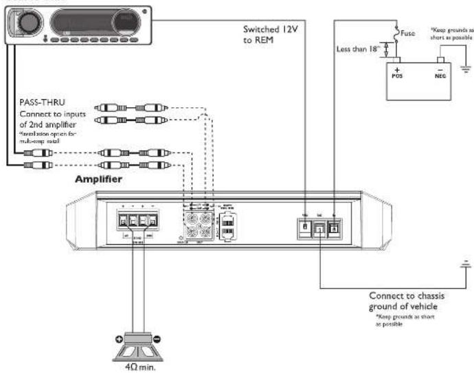
4-Channel (Stereo)
P400X4, P600X4
Source Unit
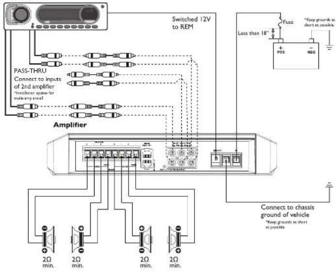
4-Channel (2ch Stereo & 1ch Mono-Bridged)
P400X4, P600X4
Source Unit

10-27 10-6
10


11
Installation Installation
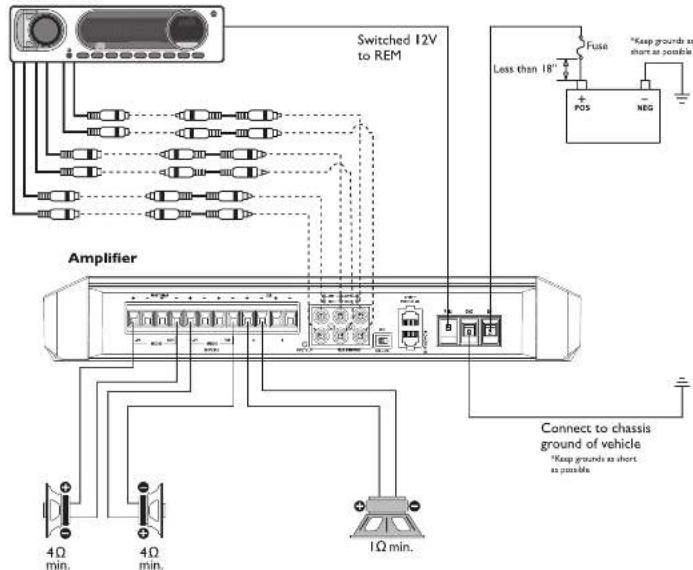
4-Channel (2ch Mono-Bridged)
P400X4, P600X4
Source Unit

3-Channel (2ch bridged & 1ch Mono)
P1000X5
Source Unit
10-25
12


1.2
13
Installation
Installation
5-Channel (4ch Stereo & 1ch Mono)
P1000X5


Parallel Wiring (Full Range Capable)
P300X1, P400X1


1.2
Installation
Installation
Mono Wiring
P300X1, P400X1, P500X1BD, P1000X1BD
Source Unit

Parallel Wiring
P500X1BD. P1000X1BD
Source Unit

102-29
18


1.1.2
17
Operation Operation
Input Clip Indicator Setup
Step 1. Be sure to disconnect all speakers from the amplifier


CAUTION
Failure to comply may cause damage to connected components and/or amplifier.
Step 2. Turn on the source unit with volume set to zero.

Step 3. Adjust the Bass & Treble levels on the source unit to flat.

Step 4. Insert test tone or music CD to play for setup.

Note: Use the 40Hz @ 0dB tone (Track 5) for more amplifier applications or the 16 Hz @ 0dB tone (Track 7) for multi-channel amplifier applications. Be sure your x-over is switched to the appropriate filter setting.
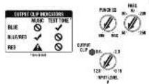
Step 5. Increase the source unit volume until the Input Clip Indicator II-lumirales red

Note: Input Clip can be viewed remotely with optional PLC2.
Step 6. Decrease the source unit volume slightly until the light turns completely oil. This establishes your maximum source unit volume for adjusting the Output Clip Indicator.

Note. Some source units will not clip
Output Clip Indicator Setup
Step 7. Be sure to disconnect Punch Level Control - PLC (if equipped) from the amplifier.
Step 8. Adjust the Input Level knob until the Output Clip Indicator Illuminales to the appropriate solar. Repeat for all channel levels of Input.
Step 9. Turn the source unit volume down.

Step 10. Recognizes all speakers and Punch Level Control PLC (It equipped) to the amplifier. Be sure to maintain proper speaker polarity.

Adjusting Crossover Frequency
Do the following individually for each channel.


Placing the crossover switch in the HP
position sells the amplifier to the High Pass mode, enabling frequencies above the cut-off point to pass, adjustable between 50-250Hz.
Placing the crossover switch in the AP position sets the amplifier to the All Pass mode, preventing any crossover adjustment, allowing all frequencies to pass.
Placing the crossover switch in the LP position sets the amplifier to the Low Pass mode, enabling frequencies below the cut-off point to pass, adjustable between 50-250Hz.
Turn the crossover adjustment knob all the way down. With the system playing, turn the crossover adjustment knob up slowly until the desired crossover point is achieved.
2/4 Channel Switch
Setting this switch to the 2CH position, switches the inputs to a 2-channel mode, allowing connection to only the front inputs with a 4-channel output.
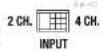
Output controls function the same as if the amplifier was in 4-channel mode.
All "ACTIVE" inputs must have RCA jacks connected.
Switch in 2CH. position, "ACTIVE" - Front channel inputs only. Switch in 4CH. position, "ACTIVE" - All Front and Rear channel inputs.
NOTE. When connecting to the 4 Channel inputs, be sure to route both front and rear RCA cables lightly together.
Subwoofer Input Switch (P1000X5)
Setting this switch to the On position, utilizes the front inputs, allowing connection to only the front inputs with a subcooler output. Setting this switch to the On position uses sub input.

Output controls function the same as if the amplifier was in 5-channel mode.
All "ACTIVE" inputs must have RCA jacks connected.
Switch in FRONT, position, "ACTIVE" - Front channel inputs only for sub output. Switch in SUB position, "ACTIVE" - Sub inputs for sub output.
NOTE: When connecting to the 5 Channel Inputs, be sure to route front, rear and sub RCA cables lightly together.
High Level Input
Connect from source signal by plugging into the RCA input, jacks at the amplifier. The input sensitivity ranges from 150mV-12V to accommodate signal from high-level(speaker) input. When utilizing high-level for input
signal the auto turn-on feature is active. With the auto turn-on active, the RFM becomes an output to turn on/off up to two additional amplifiers or other accessories.
Pass Thru
The pass-thru RCA's are passive, including full input signal range and auto turn-on functionality when active. When utilizing Pass Thru jacks, up to two additional amplifiers can be connected together.
Inlasonic Filter
The 28Hz 12dB/octave intrasonic filter limits the amount of low frequency information going to the wacker.

NOTE: We recommend using the infrasonic filter when using vented enclosures with this amplifier.
Punch EQ
This works along with the crossover switch on the amplifier. When set to Low-Pass (LF) operation, this is a variable Bass Boost. When set to High-Pass (HP) operation, this is a variable Mid-Bass and Treble Boost. When set to All-Pass (AP) operation, both the Bass and Treble frequencies are boosted. Set this to your personal preference while listening to the system.

line
| Frequency (Hz) | Power (dB) | | -------------- | ---------- | | 0 | 16 | | 50 | 10 | | 100 | 2 | | 150 | -2 | | 200 | -4 | | 250 | -6 | | 300 | -8 | | 350 | -10 | | 400 | -12 | | 450 | -14 | | 500 | -16 | | 550 | -18 | | 600 | -20 | | 650 | -18 | | 700 | -16 | | 750 | -14 | | 800 | -12 | | 850 | -10 | | 900 | -8 | | 950 | -6 | | 1000 | -4 | | 1050 | -2 | | 1100 | 0 | | 1150 | 2 | | 1200 | 4 | | 1250 | 6 | | 1300 | 8 | | 1350 | 10 | | 1400 | 12 | | 1450 | 14 | | 1500 | 16 | | 1550 | 18 | | 1600 | 20 | | 1650 | 18 | | 1700 | 16 | | 1750 | 14 | | 1800 | 12 | | 1850 | 10 | | 1900 | 8 | | 1950 | 6 | | 2000 | 4 | | 2050 | 2 | | 2100 | 0 | | 2150 | -2 | | 2200 | -4 | | 2250 | -6 | | 2300 | -8 | | 2350 | -10 | | 2400 | -12 | | 2450 | -14 | | 2500 | -16 | | 2550 | -18 | | 2600 | -20 | | 2650 | -18 | | 2700 | -16 | | 2750 | -14 | | 2800 | -12 | | 2850 | -10 | | 2900 | -8 | | 2950 | -6 | | 3000 | -4 | | 3050 | -2 | | 3100 | 0 | | 3150 | 2 | | 3200 | 4 | | 3250 | 6 | | 3300 | 8 | | 3350 | 10 | | 3400 | 12 | | 3450 | 14 | | 3500 | 16 | | 3550 | 18 | | 3600 | 20 | | 3650 | 18 | | 3700 | 16 | | 3750 | 14 | | 3800 | 12 | | 3850 | 10 | | 3900 | 8 | | 3950 | 6 | | 4000 | 4 | | 4050 | 2 | | 4100 | 0 | | 4150 | -2 | | 4200 | -4 | | 4250 | -6 | | 4300 | -8 | | 4350 | -10 | | 4400 | -12 | | 4450 | -14 | | 4500 | -16 | | 4550 | -18 | | 4600 | -20 | | 4650 | -18 | | 4700 | -16 | | 4750 | -14 | | 4800 | -12 | | 4850 | -10 | | 4900 | -8 | | 4950 | -6 | | 5000 | -4 | | 5050 | -2 | | 5100 | 0 | | 5150 | 2 | | 5200 | 4 | | 5250 | 6 | | 5300 | 8 | | 5350 | 10 | | 5400 | 12 | | 5450 | 14 | | 5500 | 16 | | 5550 | 18 | | 5600 | 20 | | 5650 | 18 | | 5700 | 16 | | 5750 | 14 | | 5800 | 12 | | 5850 | 10 | | 5900 | 8 | | 5950 | 6 | | 6000 | 4 | | 6050 | 2 | | 6100 | 0 | | 6150 | -2 | | 6200 | -4 | | 6250 | -6 | | 6300 | -8 | | 6350 | -10 | | 6400 | -12 | | 6450 | -14 | | 6500 | -16 | | 6550 | -18 | | 6600 | -20 | | 6650 | -18 | | 6700 | -16 | | 6750 | -14 | | 6800 | -12 | | 6850 | -10 | | 6900 | -8 | | 6950 | -6 | | 7000 | -4 | | 7050 | -2 | | 7100 | 0 | | 7150 | 2 | | Note: The actual values may vary due to the random nature of the data generation. The minimum value is calculated based on the formula 'Minimum Plot' and the maximum value is calculated by the formula 'MAX'. The minimum plot is labeled 'Minimum Plot'.
CAUTION
Over excursion and subsequent damage may occur at high levels of boost.
Remote Punch Level Control (Option)
NOTE: Previous(prior to 2013) FEQ, PunchBassandPara-Punch remoles will not work with these amplifiers.
Quick Install:
- Using the screws supplied, install the mounting clip
- Slip the remote onto the mounting clip until it snaps into place.
- Route and connect the cable to the remote and amplifier.
Operation:
- When connected, the "Level Control" is linked and allows you to remotely control the output level of the amplifier from the dash or center console.
NOTE: Use the instructions that came with the remote for a variety of mountings that fill your preference.
Troubleshooting
NOTE: If you are having problems after installation follow the Troubleshooting procedures below.
Check Amplifier for proper connections. Verify that POWER light is on. If POWER light is on skip to Step 3, if not continue.
- Check in-line luse on battery positive cable. Replace if necessary.
- Check fuse(s) on amplifier. Replace if necessary.
- Verify that Ground connection is connected to clean metal on the vehicle's chassis. Repair/replace if necessary.
- Verify there is 9 to 14.4 Volts present at the positive battery and remote turn-on cable. Verify quality corrections for both cables at amplifier, stereo, and battery/tusenolter. Repair/replace if necessary. Protect light is on.
- If the Protect light is on, this is a sign of a possible short in the speaker connections. Check for proper speaker connections and use a bell/chim melor to check for possible shorts in the speaker wiring. Too low of a speaker impedance may also cause Protect to light.
- Verify good RCA input connections at stereo and amplifier. Check entire length of cables for kinks, splices, etc. Test RCA inputs for AC volts with stereo on. Repair/replace if necessary.
- Disconnect RCA input from amplifier. Connect RCA input from test stereo directly to amplifier input.
Check Amplifier for audio output.
Check Amplifier if you experience Turn-on Pop.
- Disconnect input signal to amplifier and turn amplifier on and off.
- If the noise is eliminated, connect the REMOTE lead of amplifier to source unit with a delay turn-on module.
OR
- Use a different 12 Volt source for REMOTE lead of amplifier
Check Amplifier if you experience excess Engine Noise.
- Route all signal carrying wires (RGA, Speaker cables) away from power and ground wires.
OR - Bypass any and all electrical components between the stereo and the amplifier(s). Connect stereo directly to input of amplifier. If noise goes away the unit being bypassed is the cause of the noise.
OR - Remove existing ground wires for all electrical components. Reground wires to different locations. Verify that grounding location is clean, shiny metal tree of paint, rust etc.
OR - Add secondary ground cable from negative battery terminal to the chassis metal or engine block of vehicle.
OR - Have allemator and battery load issued by your mechanic. Verify good working order of vehicle electrical system including distributor, spark plugs, spark plug wires, voltage regulator etc.
Remote not functioning.
- BD amplifiers remote switch in "ON" position.
OR - Remote plugged into remote PLC "IN" port
Remote Lights not functioning - Remote plugged into remote PLC "IN" port
Rockford Corporation offers a limited warranty on Rockford Fosgate products on the following terms:
Length of Warranty
Speakers, Signal Processors, PRIME and PUNCH Amplifiers - 1 Year
POWER Amplifiers - 2 Years
Any Factory Refurbished Product - 90 days (receipt required)
What is Covered
This warranty applies only to Rockford Fosgate products sold to consumers by Authorized Rockford Fosgate Dealers in the United States of America or its possessions. Product purchased by consumers from an Authorized Rockford Fosgate Dealer in another country are covered only by that country's Distributor and not by Rockford Corporation.
Who is Covered
This warranty covers only the original purchaser of Rockford product purchased from an Authorized Rockford Fosgate Dealer in the United States. In order to receive service, the purchaser must provide Rockford with a copy of the receipt stating the customer name, dealer name, product purchased and date of purchase.
Products found to be defective during the warranty period will be repaired or replaced (with a product deemed to be equivalent) at Rockfords discretion.
What is Not Covered
- Damage caused by accident, abuse, improper operations, water, theft, shipping.
- Any cost of expense related to the removal or reinstallation of product.
- Service performed by enterprise class, then Backfast or an Authorized Res
- Service penchined by anyone other than Rockfield or an Authorized Rockford Busgate Service Center.
- My product which has used the serial number detected, altered, or ten oves.
- Exogenous damage to other components
- Subsequent damage to other components.
- Any product purchased, whichever the U.S.
- Any product not purchased from an Audi
Limit on Implied Warranties
Any implied warranties including warranties of fitness for use and merchantability are limited in duration to the period of the express warranty set forth above. Some states do not allow limitations on the length of an implied warranty, so this limitation may not apply. No person is authorized to assume for Rockford Iogate any other liability in connection with the sale of the product.
How to Obtain Service
Contact the Authorized Rockford Fosgate Dealer you purchased this product from. If you need further assistance, call 1-600-669-3899 for Rockford Customer Service. You must obtain an HA# (Return Authorization number) to return any product to Rockford Fosgate. You are responsible for shipment of product to Rockford.
EU Warranty
This product meets the current EU warranty requirements, see your Authorized dealer for details.
Installation assistance available at:
RFTECH
www.rockfordfosgate.com/rftech
- Introduction
- Specifications
- Dear Customer,
- Table of Content
- PRACTICE SAFE SOUND
- Safety
- WARNING
- CAUTION
- Mounting Locations
- Amplifier Centering Indicators
- Trunk Mounting
- Passenger Compartment Mounting
- Battery and Charging
- Wiring the System
- 2-Channel (Stereo)
- 2-Channel (Mono)
- Mono Wiring
- Parallel Wiring
- Operation Operation
- Input Clip Indicator Setup
- Output Clip Indicator Setup
- Adjusting Crossover Frequency
- 2/4 Channel Switch
- Subwoofer Input Switch (P1000X5)
- High Level Input
- Pass Thru
- Inlasonic Filter
- Punch EQ
- Remote Punch Level Control (Option)
- Quick Install:
- Operation:
- Troubleshooting
- Check Amplifier for audio output.
- Check Amplifier if you experience Turn-on Pop.
- Check Amplifier if you experience excess Engine Noise.
- Remote not functioning.
- Rockford Corporation offers a limited warranty on Rockford Fosgate products on the following terms:
- Length of Warranty
- What is Covered
- Who is Covered
- What is Not Covered
- Limit on Implied Warranties
- How to Obtain Service
- EU Warranty
- RFTECH
Brand : Rockford Fosgate
Model : P400X4
Category : Receiver