
NS-SW050 - Subwoofer YAMAHA - Free user manual and instructions
Find the device manual for free NS-SW050 YAMAHA in PDF.


| Product type | Active subwoofer |
| Brand | Yamaha |
| Model | NS-SW050 |
| Output power | 50 W (RMS) |
| Speaker | 1 x 20 cm (8") paper cone |
| Radiator type | Bass reflex (front port) |
| Frequency response | 28 Hz – 200 Hz |
| Crossover frequency | 50 Hz – 150 Hz (adjustable) |
| Input impedance | 12 kΩ (line) |
| Inputs | 1 x RCA (line), 1 x speaker terminal (high level) |
| Outputs | Speaker terminal (high-pass) |
| Dimensions (W x H x D) | 290 x 290 x 327 mm |
| Weight | 7.5 kg |
| Power supply | 220-240 V, 50/60 Hz, 50 W |
| Power consumption | 45 W (max), 0.5 W (standby) |
| Main features | Volume control, adjustable crossover frequency, phase switch (0/180°), auto standby mode |
| Cabinet materials | MDF with black vinyl finish |
| Maintenance and cleaning | Dust with a soft dry cloth. Do not use abrasive or liquid products. |
| Safety | Do not expose to moisture, do not block ventilation openings, unplug before cleaning. |
| Spare parts and repairability | Spare parts available from Yamaha authorized service. Professional repair recommended. |
| General information | Indoor use only. Operating temperature: 0-40°C. |
Frequently Asked Questions - NS-SW050 YAMAHA
User questions about NS-SW050 YAMAHA
0 question about this device. Answer the ones you know or ask your own.
Ask a new question about this device
Download the instructions for your Subwoofer in PDF format for free! Find your manual NS-SW050 - YAMAHA and take your electronic device back in hand. On this page are published all the documents necessary for the use of your device. NS-SW050 by YAMAHA.
USER MANUAL NS-SW050 YAMAHA
User Manual of Product 1:
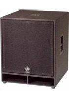
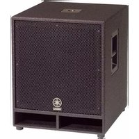
YAMAHA 8" 100W Powered Subwoofer - Black (NS-SW050BL)
User Manual of Product 2:
YAMAHA RX-V385 5.1-Channel 4K Ultra HD AV Receiver with Bluetooth
Subwoofer
Caisson de grave
NS-SW100/NS-SW050

Advanced
Y·S·T

TWISTED
FLARE
PORT

• Explanation of Graphical Symbols

The lightning flash with arrowhead symbol, within an equilateral triangle, is intended to alert you to the presence of uninsulated "dangerous voltage" within the product's enclosure that may be of sufficient magnitude to constitute a risk of electric shock to persons.

The exclamation point within an equilateral triangle is intended to alert you to the presence of important operating and maintenance (servicing) instructions in the literature accompanying the appliance.
IMPORTANT
Please record the serial number of this system in the space below.
Model:
Serial No.:
The serial number is located on the rear of the main unit.
Retain this Owner's Manual in a safe place for future reference.
1 Read these instructions.
2 Keep these instructions.
3 Heed all warnings.
4 Follow all instructions.
5 Do not use this apparatus near water.
6 Clean only with dry cloth.
7 Do not block any ventilation openings. Install in accordance with the manufacturer's instructions.
8 Do not install near any heat sources such as radiators, heat registers, stoves, or other apparatus (including amplifiers) that produce heat.
9 Do not defeat the safety purpose of the polarized or grounding-type plug. A polarized plug has two blades with one wider than the other. A grounding type plug has two blades and a third grounding prong. The wide blade or the third prong are provided for your safety. If the provided plug does not fit into your outlet, consult an electrician for replacement of the obsolete outlet.
10 Protect the power cord from being walked on or pinched particularly at plugs, convenience receptacles, and the point where they exit from the apparatus.
11 Only use attachments/accessories specified by the manufacturer.
12 Use only with the cart, stand, tripod, bracket, or table specified by the manufacturer, or sold with the apparatus. When a cart is used, use caution when moving the cart/ apparatus combination to avoid injury from tip-over.

13 Unplug this apparatus during lightning storms or when unused for long periods of time.
14 Refer all servicing to qualified service personnel. Servicing is required when the apparatus has been damaged in any way, such as power-supply cord or plug is damaged, liquid has been spilled or objects have fallen into the apparatus, the apparatus has been exposed to rain or moisture, does not operate normally, or has been dropped.
We Want You Listening For A Lifetime
YAMAHA and the Electronic Industries Association's Consumer Electronics Group want you to get the most out of your equipment by playing it at a safe level. One that lets the sound come through loud and clear without annoying blaring or distortion – and, most importantly, without affecting your sensitive hearing.
Since hearing damage from loud sounds is often undetectable until it is too late, YAMAHA and the Electronic Industries Association's Consumer Electronics Group recommend you to avoid prolonged exposure from excessive volume levels.

CAUTION: Read this before operating your unit
Please read the following operating precautions before use. Yamaha will not be held responsible for any damage and/or injury caused by not following the cautions below.
- To assure the finest performance, please read this manual carefully. Keep it in a safe place for future reference.
- Install this unit in a cool, dry, clean place - away from windows, heat sources, sources of excessive vibration, dust, moisture and cold. Avoid sources of humming (transformers, motors). To prevent fire or electrical shock, do not expose this unit to rain or water.
- The voltage to be used must be the same as that specified on the rear panel. Using this unit with a higher voltage than specified is dangerous and may cause a fire and/or electric shock.
- Do not use force on switches, controls or connection wires. When moving the unit, first disconnect the power plug and the wires connected to other equipment. Never pull the wires themselves.
- When not planning to use this unit for a long period (ie., vacation, etc.), disconnect the AC power plug from the wall outlet.
- To prevent lightning damage, disconnect the AC power plug when there is an electric storm.
- Since this unit has a built-in power amplifier, heat will radiate from the rear panel. Place the unit apart from the walls, allowing at least 20 cm of space above, behind and on both sides of the unit to prevent fire or damage. Furthermore, do not position with the rear panel facing down on the floor or other surfaces.
- Do not cover the rear panel of this unit with a newspaper, a tablecloth, a curtain, etc., in order not to obstruct heat radiation. If the temperature inside the unit rises, it may cause fire, damage to the unit and/or personal injury.
- Do not place the following objects on this unit:
- Glass, china, small metallic, etc. If glass, etc., falls as a result of vibrations and breaks, it may cause bodily injury.
- A burning candle etc. If the candle falls as a result of vibration, it may cause fire and bodily injury.
- A vessel containing water If the vessel falls as a result of vibration and water spills, it may cause damage to the speaker, and/or you may get an electric shock.
- Do not place this unit where foreign material, such as dripping water. It might cause fire, damage to this unit, and/or personal injury.
- Never put a hand or a foreign object into the YST port located on the right side of this unit. When moving this unit, do not hold the port, as it might cause personal injury and/or damage to this unit.
- Never place a fragile object near the YST port of this unit. If the object falls or drops as a result of the air pressure, it may cause damage to the unit and/or personal injury.
- Never open the cabinet. It might cause an electric shock, since this unit uses a high voltage. It might also cause personal injury and/or damage to this unit. If something drops into the set, contact your dealer.
- When using a humidifier, be sure to avoid condensation inside this unit by allowing enough space around this unit or avoiding excess humidification. Condensation might cause fire, damage to this unit, and/or electric shock.
- Super-bass frequencies reproduced by this unit may cause a turntable to generate a howling sound. In such a case, move this unit away from the turntable.
- This unit may be damaged if certain sounds are continuously output at high volume level. For example, if 20 Hz - 50 Hz sine waves from a test disc, bass sounds from electronic instruments, etc., are continuously output, or when the stylus of a turntable touches the surface of a disc, reduce the volume level to prevent this unit from being damaged.
- If you hear distortion (i.e., unnatural, intermittent “rapping” or “hammering” sounds) coming from this unit, reduce the volume level. Extremely loud playing of a movie soundtrack’s low frequency, bass-heavy sounds or similarly loud popular music passages can damage this speaker system.
- Vibration generated by super-bass frequencies may distort images on a TV. In such a case, move this unit away from the TV set.
- Do not attempt to clean this unit with chemical solvents as this might damage the finish. Use a clean, dry cloth.
- Be sure to read the “TROUBLESHOOTING” section regarding common operating errors before concluding that the unit is faulty.
- Install this unit near the wall outlet and where the AC power plug can be reached easily.
- Secure placement or installation is the owner's responsibility. Yamaha shall not be liable for any accident caused by improper placement or installation of speakers.
WARNING
TO REDUCE THE RISK OF FIRE OR ELECTRIC SHOCK, DO NOT EXPOSE THIS APPLIANCE TO RAIN OR MOISTURE.
• VOLTAGE SELECTOR
(Asia and General models only)
The voltage selector switch on the rear panel of this unit must be set to your local main voltage BEFORE plugging this unit into the AC main supply. Voltages are 110-120/220-240 V AC, 50/60 Hz.
This unit is not disconnected from the AC power source as long as it is connected to the wall outlet, even if this unit itself is turned off. In this state, this unit is designed to consume a very small quantity of power.
For Canadian Customers
To prevent electric shock, match wide blade of plug to wide slot and fully insert.
CAN ICES-3 (B)/NMB-3 (B)
This unit's speakers use magnets. Do not place items that are sensitive to magnetism, such as CRT-type TVs, clocks, credit cards, floppy disks, etc., on or beside this unit.
Taking care of the subwoofer
- When you wipe this unit, do not use chemical solvents (e.g., alcohol or thinners, etc.): this might damage the finish. Use a clean, dry cloth. For difficult soils, dampen a soft cloth in water, wring it out, and then wipe with the cloth.
- (For polish-finished model) Bumping the surface of the instrument with metal, porcelain, or other hard objects can cause the finish to crack or peel. Use caution.
CONTENTS
FEATURES.... 1
CONTROLS AND THEIR FUNCTIONS.... 1
PLACEMENT.... 2
CONNECTIONS.... 3
Connecting to such as subwoofer output terminal or line output (pin jack) terminals of the amplifier..... 3
Plug in the subwoofer to the AC outlet.... 3
ADJUSTING THE SUBWOOFER BEFORE USE.... 4
ADVANCED YAMAHA ACTIVE SERVO
TECHNOLOGY II.... 5
TWISTED FLARE PORT ....5
TROUBLESHOOTING.... 6
SPECIFICATIONS....7
Frequency characteristic.... 7
FEATURES
- This subwoofer employs Advanced Yamaha Active Servo Technology II, which Yamaha has developed for the production of higher quality, super-bass sound. (Refer to page 5 for details on Advanced Yamaha Active Servo Technology II.) This super-bass sound adds a more realistic, theater-in-the-home effect to your audio system.
- Equipped with the smooth super-bass reproducing Twisted Flare Port.
The flared, gently twisting shape diffuses the vortex of air generated around the edge of the port, creating a smooth flow of air. This reduces extraneous noise not present in the original input signal, and provides clear, accurate low frequency reproduction.
CONTROLS AND THEIR FUNCTIONS


Rear
①Twisted Flare Port
Outputs super-bass sound.
②VOLUME control
Adjusts the volume level. Turn the control clockwise to increase the volume, and counterclockwise to decrease the volume.
③Power indicator
Lights up Green when the POWER switch is turned ON; turns off when the POWER switch is turned OFF.
④INPUT (FROM AMPLIFIER) terminal
Used to connect the subwoofer with the subwoofer terminal of the amplifier.
(Refer to "CONNECTIONS" for details.)
⑤POWER switch
Press this switch to the ON position to turn on the power to the subwoofer. Press this switch again to set it to the OFF position to turn off the power of the subwoofer.
⑥VOLTAGE SELECTOR switch
(Asia and General models only)
If the preset setting of the switch is incorrect, set the switch to the proper voltage (110-120/220-240V) of your area.
Consult your dealer if you are unsure of the correct setting.
WARNING
Be sure to unplug the subwoofer before setting the VOLTAGE SELECTOR switch correctly.
PLACEMENT
Since the low-end frequencies of audio signals feature long wavelengths, they are almost non-directional to human ears. The super-bass range does not create a stereo image. Therefore, a single subwoofer may be enough to produce a high-quality super-bass sound.
A
![graph TD A["Square Node"] --> B{Decision} B -->|Yes| C["Process"] B -->|No| D["End"]](/content/2026/06/1287637/images/a5930972902e59293b0f5a1bdf86383c500ae15a8e14a3236b57ed86d8bb6eae.jpg)
or
![graph TD A["Square"] --> B["Right Arrow"] C["Square"] --> D["Right Arrow"]](/content/2026/06/1287637/images/ff412cc2c86004e178bb45f76faf710f5fc023046adf7f62dbdb1545642a29ab.jpg)
B
![graph TD A[" "] --> B[" "] C[" "] --> D[" "] E[" "] --> F[" "]](/content/2026/06/1287637/images/44b0accc63cb4ea2cfc1a05cce6f72dcae59c1b9405175ea1fd1cc252d83d507.jpg)
or
![graph TD A["Decision"] --> B["Empty Square"] A --> C["Empty Square"]](/content/2026/06/1287637/images/171cae272a3865b841637f1ebbb400c9e38d6cbcb977034dcb85be27f3720c4f.jpg)
( : subwoofer, : front speaker)
Note
The placement shown in the figure on the right is also possible. However, if the subwoofer system is placed directly facing a wall, the bass effect may suffer due to phase cancellation caused by the interference between the direct and reflected sounds. To prevent this from happening, place the subwoofer system at an angle.
(Figures A an)
![graph TD A[" "] --> C[" "] B[" "] --> C[" "] C --> D[" "] style C stroke-dasharray: 5 5](/content/2026/06/1287637/images/7ff97527c2fa04a095726ba9e3b605d7c16f9663bb5394f76b53989f342200d8.jpg)
Note
There may be a case that you cannot obtain enough super-bass sound from the subwoofer due to standing waves.
Note
- Placing the subwoofer too close to a CRT-type TV may impair the picture color or cause a buzzing noise. In this case, place the subwoofer and TV at a separated position where these effects do not occur. This is not an issue with LCD and plasma TVs.
- If the speaker volume is very loud, furniture or window glass may resonate and the subwoofer itself may vibrate. In this case, lower the volume level. To limit resonance, use a thick curtain or similar cloth that tends to absorb sound vibrations effectively. Also, changing the subwoofer position may be helpful.
CONNECTIONS
Note
- Unplug the subwoofer and other audio/video components before making connections, and do not plug them in until all connections are completed.
- Connecting methods and terminal names on your component (such as an amplifier or receiver) may be different from those used in this book. Please refer to the owner's manual that came with your component.
• After connecting, make sure that cable is connected firmly.
Connecting to such as subwoofer output terminal or line output (pin jack) terminals of the amplifier
Connect to the subwoofer output terminal of the amplifier (or AV receiver) using commercially available audio pin cable.
If the amplifier (or AV receiver) has no subwoofer output terminal, connect to the line output (such as PRE OUT) terminal.
Amplifier (The rear panel of various amplifiers may differ in appearance.)

Plug in the subwoofer to the AC outlet
After all connections are completed, plug the subwoofer and other audio/video components into AC outlets.

ADJUSTING THE SUBWOOFER BEFORE USE
Before using the subwoofer, adjust the subwoofer to obtain the optimum volume balance between the subwoofer and the front speakers by following the procedure described below.


1 Set the VOLUME control to minimum (0).
2 Turn on the power of all the other components.
3 Make sure that the POWER switch is set to the ON position.
* The Power indicator lights up in green.
4 Play a source containing low-frequency components and adjust the amplifier's volume control to the desired listening level.
5 Increase the volume gradually to adjust the volume balance between the subwoofer and the front speakers. To enjoy natural bass sound, keep the subwoofer volume at a level where it is barely distinguishable from other speakers.
Note
It is recommended to set the VOLUME control about in the middle position when using in a multi channel home theater system.

ADVANCED YAMAHA ACTIVE SERVO TECHNOLOGY II
In 1988, Yamaha brought to the marketplace speaker systems utilizing YST (Yamaha Active Servo Technology) to give powerful, high quality bass reproduction. This technique uses a direct connection between the amplifier and speaker, allowing accurate signal transmission and precise speaker control.
As this technology uses speaker units controlled by the negative impedance drive of the amplifier and resonance generated between the speaker cabinet volume and port, it creates more resonant energy (the “air woofer” concept) than the standard bass reflex method. This allows for bass reproduction from much smaller cabinets than was previously possible.
Yamaha's newly developed Advanced YST II adds many refinements to Yamaha Active Servo Technology, allowing better control of the forces driving the amplifier and speaker. From the amplifier's point of view, the speaker impedance changes depending on the sound frequency. Yamaha developed a new circuit design combining negative-impedance and constant-current drives, which provides a more stable performance and clear bass reproduction, without any murkiness.
![graph TD A["High-amplitude bass sound"] --> B["Air woofer (Helmholtz resonator)"] B --> C["Advanced impedance Converter"] C --> D["Active Servo Processing Amplifier"] D --> E["Signals"] F["Cabinet"] --> G["Port"] G --> H["Signals of low amplitude"] H --> I["Signal"] I --> D](/content/2026/06/1287637/images/b9010019ce1c69769346ae02429c85e5c39f4502a555b7d24844b9dfa0d980d5.jpg)
TWISTED FLARE PORT
Today's bass reflex speakers use a Helmholtz resonator to improve their bass reproduction.
However when reproducing bass that is in the frequency region of this Helmholtz resonator, air moves violently in and out through the port between the interior and exterior of the speaker, sometimes producing noise due to the turbulent air flow at the end of the port.
The port and the cabinet resonate at a frequency that is determined by their dimensions and shape. On the other hand, turbulence in the air flow at the end of the port contains a broad range of frequency components that are not present in the input signal. This noise occurs because the broad range of frequency components includes components that match the resonant frequencies of the port and cabinet, causing strong resonance.

The Twisted Flare Port developed by Yamaha changes the way in which the port widens toward its end, and also adds a “twist” to suppress airflow turbulence at each end of the port and thus prevent noise from occurring.
This eliminates the “muddy sound” and “wind noise” that until now have been characteristic of bass reflex speakers, allowing bass to be reproduced clearly.

Air turbulence on both ends of the port creates noise
TROUBLESHOOTING
Refer to the chart below if this unit does not function properly.
If the instructions given below do not help, or if the problem you are experiencing is not listed below, turn off the power to the unit, disconnect the power cord and contact an authorized Yamaha dealer or service center.
| Problem Cause What to Do | ||
| Power is not supplied even though the POWER switch is set to the ON position. | The power plug is not securely connected. | Connect it securely. |
| No sound. The volume is set to minimum. | Raise the volume up. | |
| Connections are faulty (or the connections are incomplete). | Connect them securely. | |
| The sound is interrupted. | The volume is too loud. | Since the output is excessive, reduce the volume level. |
| Sound level is too low. A source sound with little bass frequency content is being played. | Play a source sound with bass frequencies. | |
| It is influenced by standing waves. Reposition the subwoofer or break up parallel surfaces by placing bookshelves, etc., along the walls. | ||
SPECIFICATIONS
NS-SW100
Type .....Advanced Yamaha Active Servo Technology II
Driver....25 cm (10") cone woofer Non magnetic shielding type
Amplifier Output (100 Hz, 5 ohms, 10% THD)... 50 W
Dynamic Power 100 W, 5 Ω
Frequency Response 25 Hz - 180 Hz
Power Supply
USA and Canada models.... AC 120V, 60 Hz Asia and General models ..... AC 110-120/220-240 V, 50/60 Hz
Power Consumption 40 W
Dimensions (W × H × D) ... 351 mm × 352 mm × 408 mm (13-7/8" × 13-7/8" × 16-1/8")
Weight.... 12 kg (26.5 lbs.)
NS-SW050
Type..... Advanced Yamaha Active Servo Technology II
Driver 20 cm (8") cone woofer Non magnetic shielding type
Amplifier Output (100 Hz, 5 ohms, 10% THD)...50 W
Dynamic Power 100 W, 5 Ω
Frequency Response 28 Hz - 200 Hz
Power Supply
USA and Canada models....AC 120V, 60 Hz Asia and General models .....AC 110-120/220-240 V, 50/60 Hz
Power Consumption 40 W
Dimensions (W × H × D) ...291 mm × 292 mm × 341 mm (11-1/2" × 11-1/2" × 13-3/8")
Weight....8.5 kg (18.7 lbs.)
* The contents of this manual apply to the latest specifications as of the publishing date. To obtain the latest manual, access the Yamaha website then download the manual file.
Frequency characteristic
This subwoofer's frequency characteristic
[NS-SW100]

[NS-SW050]

* This diagram does not depict actual frequency response characteristics.
INSTRUCTIONS DE SÉCURITÉ IMPORTANTES

Remarque
Type .....Technologie Advanced Yamaha Active Servo II
(100 Hz, 5 ohms, 10% THD)....50 W
(100 Hz, 5 ohms, 10% THD)....50 W
B
![graph TD A[" "] --> B[" "] C[" "] --> D[" "] E[" "] --> F[" "]](/content/2026/06/1287637/images/0d6cb78b85c761e5dfe9f5311791e309191613c231eeed7bd151a6ed4e2ad3a3.jpg)
0
![graph TD A["Decision"] --> B["Empty Square"] A --> C["Empty Square"]](/content/2026/06/1287637/images/5449835f6befa4d5bd20a6adb76622ec706df5a22d9085dfefa71291ed8a2233.jpg)
Nota
Manual Development Department
© 2016 Yamaha Corporation
Published 06/2016 IP-A0
Printed in Indonesia
ZV03070
YAMAHA
RX-485 RDS/385 /385 RDS
Natural Sound Stereo Receiver
Natural Sound Stereoreceiver
Natural Sound Stereoreceiver
RX-485 RDS

RX-385, RX-385 RDS

- Indoor FM Antenna
• Antenne FM intérieure - UKW-Innenantenne
• FM inomhusantenn - Antenna FM per interni
-
Antena FM interior
• FM Binnenantenne -
AM Loop Antenna
- Antenne AM à boucle
• MW-Rahmenantenne - AM ramantenn
• Antenna AM ad anello - Antena de cuadro de AM
• AM Lusantenne

• Remote Control Transmitter
• Emetteur de télécommande
• Fernbedienungsgeber
• Fjärrkontrollsändare
- Telecomando
• Transmisor del control remoto
- Afstandbediening
- Remote Control Transmitter
- Emetteur de télécommande
- Fernbedienungsgeber
- Fjärrkontrollsändare
- Telecomando
- Transmisor del control remoto
- Afstandbediening
• Batteries (size AA, R6, UM-3)
• Piles (taille AA, R6, UM-3)
• Batterien (größ AA, R6, UM-3)
• Batterier (storlek AA, R6, UM-3)
• Batterie (dimensioni AA, R6, UM-3)
• Pilas (tamaño AA, R6, UM-3)
• Batterijen (maat AA, R6, UM-3)

This product complies with the radio frequency interference requirements of the Council Directive 82/499/EEC and/or 87/308/EEC.
- RX-485 RDS 65W + 65W (8Ω) RMS Output Power, 0.04% THD, 20 – 20,000 Hz
RX-385 and RX-385 RDS
40W + 40W (8Ω) RMS Output Power, 0.04% THD, 20 - 20,000 Hz
- High Dynamic Power, Low Impedance Drive Capability
• Continuously Variable Loudness Control
• 40-Station Random Preset Tuning
• Automatic Preset Tuning -
Preset Station Shifting Capability
-
IF Count Direct PLL Synthesizer Tuning System
- Remote Control Capability
RX-485 RDS and RX-385 RDS only
- Multi-Functions for RDS Broadcast Reception
RX-485 RDS only
- Pure Direct Switch to Reproduce the Purest Source Sound
CONTENTS
Supplied Accessories ......2
Caution 4
Connections 5
Operations 9
Tuning Operations 12
Preset tuning ....13
Receiving RDS Stations
RX-485 RDS and RX-385 RDS only .....16
Remote Control Transmitter ....21
Notes about the Remote Control Transmitter ....22
Troubleshooting 23
Specifications 24
How to Use This Manual
This manual describes three YAMAHA receivers, RX-385, RX-385 RDS and RX-485 RDS. There are some differences between those three models. Especially, RX-385 RDS and RX-485 RDS contain the functions for receiving special data on RDS network stations.
RX-385, on the other hand, is a receiver with a usual FM/AM tuning function.
Several places in the manual refer to differences in features between the three models. Be sure to follow the procedure for the model you are using.
* RDS is a data transmitting service system in network which is employed by FM stations. RDS stations are increasing in many countries (especially in Europe).
- To assure the finest performance, please read this manual carefully. Keep it in a safe place for future reference.
- Install this unit in a cool, dry, clean place – away from windows, heat sources, sources of excessive vibration, dust, moisture and cold. Avoid sources of humming (transformers, motors). To prevent fire or electrical shock, do not expose the unit to rain or water.
- Never open the cabinet. If something drops into the set, contact your dealer.
- Do not use force on switches, controls or connection wires. When moving the unit, first disconnect the power plug and the wires connected to other equipment. Never pull the wires themselves.
- The openings on the cabinet assure proper ventilation of the unit. If these openings are obstructed, the temperature inside the cabinet will rise rapidly and eventually damage the circuits. Therefore, avoid placing objects against these openings and do not install the unit where the flow of air through the ventilation openings could be impeded.
- Always set the VOLUME control to “−∞” before starting the audio source play. Increase the volume gradually to an appropriate level after playback has been started.
- Do not attempt to clean the unit with chemical solvents; this might damage the finish. Use a clean, dry cloth.
- Be sure to read the "TROUBLESHOOTING" section regarding common operating errors before concluding that the unit is faulty.
- When not planning to use this unit for long periods of time (ie., vacation, etc.), disconnect the AC power plug from the wall outlet.
- To prevent lightning damage, disconnect the AC power plug and disconnect the antenna cable when there is an electrical storm.
- Grounding or polarization – Precautions should be taken so that the grounding or polarization of an appliance is not defeated.
- AC outlet Do not connect audio equipment to the AC outlet on the rear panel if that equipment requires more power than the outlet is rated to provide.
- Voltage Selector (General Model only) The voltage selector on the rear panel of this unit must be set for your local main voltage BEFORE plugging into the AC main supply. Voltages are 110/120/220/240V AC, 50/60 Hz.
IMPORTANT
Please record the serial number of this unit in the space below.
Serial No.:
The serial number is located on the rear of the unit.
Retain this Owner's Manual in a safe place for future reference.
WARNING
TO REDUCE THE RISK OF FIRE OR ELECTRIC SHOCK, DO NOT EXPOSE THIS UNIT TO RAIN OR MOISTURE.
CAUTION (FOR CANADA MODEL)
TO PREVENT ELECTRIC SHOCK, MATCH WIDE BLADE OF PLUG TO WIDE SLOT AND FULLY INSERT.
FOR CANADIAN CUSTOMER
THIS DIGITAL APPARATUS DOES NOT EXCEED THE "CLASS B" LIMITS FOR RADIO NOISE EMISSIONS FROM DIGITAL APPARATUS SET OUT IN THE RADIO INTERFERENCE REGULATION OF THE CANADIAN DEPARTMENT OF COMMUNICATIONS.
The apparatus is not disconnected from the AC power source as long as it is connected to the wall outlet, even if the apparatus itself is turned off.
For U.K. customers
If the socket outlets in the home are not suitable for the plug supplied with this appliance, it should be cut off and an appropriate 3 pin plug fitted. For details, refer to the instructions described below.
Note: The plug severed from the mains lead must be destroyed, as a plug with bared flexible cord is hazardous if engaged in a live socket outlet.
SPECIAL INSTRUCTIONS FOR U.K. MODEL
IMPORTANT:
The wire in the mains lead are coloured in accordance with the following code:
Blue: NEUTRAL
Brown: LIVE
The colours of the wires in the mains lead of this apparatus may not correspond with the coloured markings identifying the terminals in your plug. Proceed as follows: the wire which is coloured BLUE must be connected to the terminal which is marked with the letter N or coloured BLACK. The wire which is coloured BROWN must be connected to the terminal which is marked with the letter L or coloured RED. Making sure that neither core is connected to the earth terminal of the three pin plug.
FREQUENCY STEP switch (General Model only)
Because the interstation frequency spacing differs in different areas, set the FREQUENCY STEP switch (located at the rear) according to the frequency spacing in your area. Before setting this switch, disconnect the AC power plug of this unit from the AC outlet.
CONNECTIONS
ANTENNA CONNECTIONS
• Each antenna should be connected to the designated terminals correctly, referring to the following figure.
- Both AM and FM indoor antennas are included with this unit. In general, these antennas will probably provide sufficient signal strength. Nevertheless, a properly installed outdoor antenna will give clearer reception than an indoor one. If you experience poor reception quality, an outdoor antenna may result in improvement.

Connecting the AM loop antenna


Orient so that the best reception is obtained.
* The AM loop antenna should be placed apart from the main unit. The antenna may be hung on a wall.
* The AM loop antenna should be kept connected, even if an outdoor AM antenna is connected to this unit.
GND terminal
For maximum safety and minimum interference, connect the GND terminal to a good earth ground. A good earth ground is a metal stake driven into moist earth.
Notes
- When connecting the indoor FM antenna, make sure that the grooved part of the connector hole is facing downward.
- If you need an outdoor FM antenna to improve FM reception quality, either 300-ohm feeder or coaxial cable may be used. In locations troubled by electrical interference, coaxial cable is preferable.

Before attempting to make any connections to or from this unit, be sure to first switch OFF the power to this unit and to any other components to which connections are being made.
AUDIO CONNECTIONS
When making connections between this unit and other components, be sure all connections are made correctly, that is to say L (left) to L, R (right) to R, “+” to “+” and “-” to “-”. Also, refer to the owner's manual for each component to be connected to this unit.
RX-485 RDS
![graph TD A["Turntable Compact disc player Tape deck 1"] -->|GND OUTPUT| B["Audio OUT"] A -->|OUTPUT| C["Turntable Compact disc player Tape deck 2"] A -->|LINE OUT| D["Turntable Compact disc player Tape deck 3"] A -->|LINE IN| E["Turntable Compact disc player Tape deck 4"] A -->|LINE OUT| F["Turntabl…](/content/2026/06/1287637/images/222eec1c160162b0f20f25a11138367a8b955ef650015a647afee53831337169.jpg)
* : Refer to "ABOUT THE ACCESSORY TERMINALS" on page 8.
RX-385, RX-385 RDS
![graph TD A["Turntable Compact disc player Tape deck"] -->|GND OUTPUT| B["Video cassette player etc."] A -->|OUTPUT| C["THOMO CD OUT"] A -->|LINE OUT| D["THAPE OUT"] A -->|LINE IN| E["THOMO OUT"] B --> F["Speaker A"] C --> G["Speaker B"] D --> H["Speaker B"] F --> I["Right Left"] F --> J["Right Left"…](/content/2026/06/1287637/images/56bfe1f5d2ab5e67b44924b993a5f886ddda120eb791dbeaec4a1de6e98626f2.jpg)
* : Refer to "ABOUT THE ACCESSORY TERMINALS" on page 8.
CONNECTING SPEAKERS
Connect the SPEAKERS terminals to your speakers with wire of the proper gauge, cut to be as short as possible. If the connections are faulty, no sound will be heard from the speakers. Make sure that the polarity of the speaker wires is correct, that is, + and - markings are observed. If these wires are reversed, the sound will be unnatural and will lack bass. Do not let the bare speaker wires touch each other and do not let them touch the metal parts of this unit as this could damage this unit and/or speakers.
- One or two speaker systems can be connected to this unit. If you connect only one speaker system, connect it to either the SPEAKERS A or B terminals.
- Use speakers with the specified impedance shown on the rear of this unit.
How to Connect:
Red: positive (+)
Black: negative (−)

①Press up the tab.
②Insert the bare wire. [Remove approx. 5mm (1/4") insulation from the speaker wires.]
③Press down the tab and secure the wire.
ABOUT THE ACCESSORY TERMINALS
AC OUTLET(S)
(Europe model) ......2 SWITCHED OUTLETS
(U.K. model) ......1 SWITCHED OUTLET
Use these to connect the power cords from your components to this unit.
The power to the SWITCHED outlets is controlled by this unit's POWER switch or the provided remote control transmitter's POWER key. These outlets will supply power to any component whenever this unit is turned on.
The maximum power (total power consumption of components) that can be connected to the SWITCHED AC OUTLET(S) is 100 watts.
REMOTE CONTROL (PHONO) connector
RX-485 RDS only
If you have a YAMAHA turntable with a terminal for remote control, connect it to this connector by using the cable provided with the turntable. This connection allows you to control the turntable from the provided remote control transmitter.
GND terminal (For turntable use)
Connecting the ground wire of the turntable to this terminal will normally minimize hum, but in some cases better results may be obtained with the ground wire disconnected.
OPERATIONS

TO PLAY A SOURCE
1

2

3
Select a desired input source.

* The name of the selected input source will appear in the display.
* Note that pressing on each input selector button selects the source which is connected to the corresponding input terminals on the rear panel.
4
Select the speakers to be used.
SPEAKERS

* If you use two speaker systems, press both the A and B switches.
5
Play the source. (For detailed information on the tuning operations, refer to the page 12.)
6

7
If desired, adjust the BASS, TREBLE, BALANCE and LOUDNESS controls, etc. (Refer to page 11.)
Notes
RX-485 RDS only
- If you select AUX, TUNER, CD or PHONO, be sure that TAPE 1 and/or TAPE 2 are not being selected.
- If you select TAPE 1 and TAPE 2 at the same time, the result will be the sound from the tape deck 1.
- For TAPE 1 and TAPE 2, whenever the button is pressed, the corresponding input source is selected or canceled alternately.
RX-385 and RX-385 RDS only
- If both TAPE MONITOR and another input selector button are selected, TAPE MONITOR has priority.

TO RECORD A SOURCE TO TAPE
RX-485 RDS
1
Select the source to be recorded.

* To dub from tape to tape, refer to the "Notes" shown below.
* When you select AUX, TUNER, CD or PHONO, be sure that TAPE 1 and/or TAPE 2 are not also selected.
2
Play the source and then turn the VOLUME control up to confirm the input source. (For detailed information on the tuning operations, refer to the page 12.)
3
Begin recording on the tape deck.
4
To monitor the audio signals being recorded, press the input selector button for the tape deck being used to make the recording.

Notes
• VOLUME, BASS, TREBLE, BALANCE and LOUDNESS control settings have no effect on the material being recorded.
- To dub from tape to tape, only the following method of dubbing can be performed.
| SOURCE | RECORDER |
| Tape deck connected to the TAPE 2 terminals. → | Tape deck connected to the TAPE 1 terminals. |
TO RECORD A SOURCE TO TAPE
RX-385, RX-385 RDS
1
Select the source to be recorded.


* When you select AUX, TUNER, CD or PHONO, be sure that TAPE MONITOR is not also selected.
2
Play the source and then turn the VOLUME control up to confirm the input source. (For detailed information on the tuning operations, refer to the page 12.)
3
Begin recording on the tape deck.
4
To monitor the audio signals being recorded, press the TAPE MONITOR.


Note
VOLUME, BASS, TREBLE, BALANCE and LOUDNESS
control settings have no effect on the material being recorded.
Adjusting the BALANCE control Selecting the SPEAKER system
Adjust the balance of the output volume to the left and right speakers to compensate for sound imbalance caused from speaker location or listening room conditions.

Adjusting the BASS and TREBLE controls


BASS : Turn this clockwise to increase (or counterclockwise to decrease) the low frequency response.
TREBLE : Turn this clockwise to increase (or counterclockwise to decrease) the high frequency response.
Because one or two speaker systems can be connected to this unit, the SPEAKERS switches allow you to select speaker system A or B, or both at once.

Adjusting the continuously variable LOUDNESS control
This control provides compensation for the human ears' loss of sensitivity to high and low-frequency ranges at low volume. This control is adjustable to retain full tonal range at any volume level.
1

Set to the "FLAT" position.
2

Set to the loudest listening level that you would listen to.
3

Turn so that the desired volume can be achieved.
Using the PURE DIRECT switch
RX-485 RDS only
You can enjoy the purest possible sound from your audio sources by setting this switch ON. By doing so, the audio signal bypasses the BASS, TREBLE, BALANCE and LOUDNESS controls, eliminating any alterations to the audio signal.

When you listen with headphones
Connect the headphones to the PHONES jack. When listening with headphones privately, set both the SPEAKERS A and B switches to the OFF position.

TUNING OPERATIONS
Normally, if station signals are strong and there is no interference, quick automatic-search tuning (AUTOMATIC TUNING) is possible. However, if signals of the station you want to select are weak, you must tune to it manually (MANUAL TUNING).

AUTOMATIC TUNING MANUAL TUNING
1 Select the reception band (FM or AM) while watching the display.


To tune to a higher frequency, press the right side once. To tune to a lower frequency, press the left side once.
* If the station where tuning search stopped is not the desired one, press again.
* If the tuning search does not stop at the desired station (because the signals of the station are weak), change to the MANUAL TUNING method.
1 Select the reception band (FM or AM) while watching the display.


3 Tune to a desired station manually.

Note
If you tune to an FM station manually, it is received in monaural mode automatically to increase the signal quality.
Display information
RX-385

RX-485 RDS, RX-385 RDS

① Displays the band and frequency of the received station.
RX-485 RDS and RX-385 RDS only
If an RDS station is received, the frequency is then replaced by the station name. (However, if the PS data cannot be received within 5 seconds, "NO PS" flashes, and then it returns to the frequency display.) Refer to page 17 for details.
② Illuminates when an FM stereo broadcast is received in stereo.
③ Indicates the signal level of the received station.
PRESET TUNING
MANUAL PRESET TUNING
This unit can store station frequencies selected by tuning operation. With this function, you can recall any desired station by only selecting the preset station number where it is stored. Up to 40 stations (8 stations x 5 pages) can be stored.

To store stations To recall a preset station
1
Tune to a desired station.
(Refer to the previous page for tuning procedures.)
2


Flashes on and off for about 5 seconds.
3
Select a desired page (A - E) of preset stations while watching the display.
A/B/C/D/E


4
Select a preset station number (1–8) while watching the display before "MEMORY" goes off from the display.

5
RX-385


Shows the displayed station has been programmed to A1.
RX-485 RDS, RX-385 RDS

* In the same way, program other stations to A2, A3 ... A8.
* You can program more stations on other pages in the same way by selecting other pages in step 3.
1
Select the page where the preset station is stored.

2

Select the preset station number.
Notes
- A new setting can be programmed in place of the former one.
- For presets, the setting of the reception mode (stereo or monaural) is stored along with the station frequency.
Memory back-up
The memory back-up circuit prevents the programmed data from being lost even if the POWER switch is set off or the power plug is disconnected from the AC outlet or the power is cut due to temporary power failure. If, however, the power is cut for more than one week, the memory may be erased. If so, it can be re-programmed by simply following the PRESET TUNING steps.
AUTOMATIC PRESET TUNING
You can also make use of an automatic preset tuning function for FM stations only. By this function, this unit performs automatic tuning and stores FM stations with strong signals sequentially. Up to 40 stations are stored automatically in the same way as in the manual preset tuning method on page 13.
RX-485 RDS and RX-385 RDS only
* Only RDS stations can be stored by this function.

To store stations
1


2
![graph TD A["Press and hold for about 3 seconds."] --> B["AND"] B --> C["AUTO TUNING"]](/content/2026/06/1287637/images/73fd072f1f44ff09f1ea97ea95f083b5f577eb399454f02e7bee61db072bcf2d.jpg)
Flashes. Flashes.
After 5 seconds, the automatic preset tuning begins from A1. Received stations are programmed to A1, A2 ... A8 sequentially.
* If more than 8 stations are received, they are also programmed to the preset station numbers on other pages (B, C, D and E) in that order.
If you want to store the first station received by the automatic preset tuning to a desired preset station number.
If, for example, you want to store the received first station to C5, select "C5" by using the A/B/C/D/E button and the PRESET STATIONS button soon after the display begins flashing on/off in step 2. After a few seconds, the automatic preset tuning begins. The received first station is stored to C5, and next stations to C6, C7 ... sequentially. If stations are stored up to E8, the automatic preset tuning is finished automatically.
When the automatic preset tuning is finished
The display shows the frequency of the last preset station. Check the contents and the number of preset stations by following the procedure of the section "To recall a preset station" on page 13.
To recall a preset station
Simply follow the procedure of the section "To recall a preset station" on page 13.
RX-485 RDS and RX-385 RDS only
* A recalled station is shown by the frequency or station name on the display.
Notes
- You can replace a preset station by another FM or AM station manually by simply following the procedure of the section "To store stations" on page 13.
RX-385 only
- If the number of received stations is not enough to be stored up to E8, the search is finished automatically when it reaches the highest frequency after searching through all frequencies.
- With this function, only FM stations with sufficient signal strength are stored automatically. If the station you want to program is week in signal strength, tune to it in monaural manually and program it by following the procedure of the section "To store stations" on page 13.
RX-485 RDS and RX-385 RDS only
- The automatic preset tuning search will be performed through all RDS network frequencies until stations are stored up to E8. If the number of received stations is not enough to be stored up to E8, the search is finished automatically after searching through all frequencies.
- With this function, only RDS stations with sufficient signal strength are stored automatically. If the station you want to program is weak in signal strength, tune to it in monaural manually and program it by following the procedure of the section "To store stations" on page 13.
* There may be a case that this function cannot receive a station which could be received by the automatic tuning method. This is because this function receives a large volume of PI (Program Identification) data along with the station.
EXCHANGING PRESET STATIONS
You can exchange the places of two preset stations each other by easy operations.

Example)
If you want to shift the preset station on E1 to A5, and vice versa.
1 Recall the preset station on E1 (by following the method of "To recall a preset station" on page 13).

3 Next, recall the preset station on A5 by following the same method with step 1.


RECEIVING RDS STATIONS
RX-485 RDS and RX-385 RDS only
RDS (Radio Data System) is a data transmission system gradually being introduced by FM stations in many countries. Stations using this system transmit an inaudible stream of data in addition to the normal radio signal.
RDS data contains various information, such as AF (Alternative Frequencies for the same program station), PI (Program Identification), PS (Program Service station name), PTY (Program Type name), etc.
RDS function is carried out among the network stations.
* This unit utilizes AF, PI, PS and PTY to receive RDS broadcast stations.
Displaying RDS data
This unit can be turned into the following two modes to display RDS data.
PS (Program Service station name) mode:
Displays the name of the RDS station now being received instead of the frequency.
BBC R3
PTY (Program Type name) mode:
Displays the program type of the RDS station now being received. There are 15 program types to classify RDS stations as follows.
| NEWS | News:Short accounts of facts, events and publicly expressed views, reportage and actuality. | VARIED | Varied:Used for mainly speech-based programs usually of light-entertainment nature, not covered by above categories. Examples are: quizzes, panel games, personality interviews, comedy and satire. |
| AFFAIRS | Current affairs:Topical program expanding or enlarging upon the news, generally in different presentation style or concept, including documentary debate, or analysis | POP M | Pop:Commercial music, which would generally be considered to be of current popular appeal, often featuring in current or recent record sales charts. |
| INFO | Information:Program whose purpose is to impart advice in the widest sense, including meteorological reports and forecasts, consumer affairs, medical help, etc. | ROCK M | Rock:Contemporary modern music, usually written and performed by young musicians. |
| SPORT | Sport:Program concerned with any aspect of sport. | MOR M | M.O.R.:(Middle of the Road Music). Common term to describe music considered to be “easy-listening”, as opposed to Pop, Rock or Classical. Music in this category is often but not always, vocal, and usually of short duration (<5 min.) |
| EDUCATE | Education:Program intended primarily to educate, of which the formal element is fundamental. | ||
| DRAMA | Drama:All radio plays and serials. | LIGHT M | Light classics:Classical Musical for general, rather than specialist appreciation. Examples of music in this category are instrumental music, and vocal or choral works. |
| CULTURE | Culture:Programs concerned with any aspect of national or regional culture, including religious affairs, philosophy, social science, language, theatre, etc. | CLASSICS | Serious classics:Performances of major orchestral works, symphonies, chamber music etc., and including Grand Opera. |
| SCIENCE | Science:Programs about the natural sciences and technology. | OTHER M | Other music:Musical styles not fitting into any of the above categories. Particularly used for specialist music, of which Jazz, Rhythm & |
To turn the unit into the PS mode or PTY mode
Press the FREQ/PS/PTY button. Whenever pressed, the mode changes into the PS mode, PTY mode and returns to usual mode in turn.
* When an RDS station is received, the display is automatically turned into the PS mode. Do not press the FREQ/PS/PTY button until the display is turned into the PS mode. If the button is pressed before the display mode is changed, it may occur that "NO PS" flashes on the display. This is because the unit has not received all of the RDS data on the station yet.
![graph TD A["PS/PTY SEEK"] --> B["PS mode The name of the station being received is displayed."] B --> C["If the station is not an RDS station, "NO PS" flashes on the display and then returns to usual mode."] A --> D["PTY mode A program type for the station being received is displayed."] D…](/content/2026/06/1287637/images/891d07326614ebaffa362b3558650e96d32cdecbf4aad7d0090532c5142277d5.jpg)
Note
When PS or PTY data reception is not possible due to poor reception conditions, "NO PS" or "NO PTY" flashes on the display in each mode. In such a case, press the TUNING MODE button so that "AUTO TUNING" goes off from the display. Though the reception mode is changed to monaural by this operation, when you changes to the PS or PTY mode, PS or PTY data may be displayed.
Calling a preset RDS station by the station name (PS SEEK)
You can call a desired RDS station stored in this unit by only inputting the name of the station in the PS mode. By this operation, this unit searches all preset stations for the station. You do not have to input a full name, even only the first letter can be used for calling. As many as 8 letters and/or numerals can be selected for inputting a name.

1


2
Turn the unit into the PS mode.

* If "NO PS" flashes, proceed to the next step while flashing. If "NO PS" disappears before you proceed to the next step, press the FREQ/PS/PTY button again.
3
![graph TD A["PS/PTY SEEK"] --> B["FRG/PS/PTY SHIFT ENTER"] B --> C["Flash generation step"] C --> D["Flashes"]](/content/2026/06/1287637/images/9eec8f6b4da2f05bdff49934817d25870e8ef084ee02b6d1cd561299daaa4e4e.jpg)
4
Select the first letter or numeral of the station name.

* By pressing the TUNING button repeatedly or by pressing and holding it, the display will change letters and numerals in sequence.
* If you will not input the second letter, skip to step 7.
5
When the first letter or numeral of the station name appears, press the SHIFT button to proceed to the selection of the next letter or numeral.

6
Repeat steps 4 and 5 for other letters and/or numerals, if necessary.
7
When inputting the name is finished, press the ENTER button.

8

Press once.
The unit begins searching for the station, and it is continued until the station is found.
You do not have to input a full name for searching for the station
You may input only the first letter of the station name. If doing so, you can skip steps 5 and 6. In step 8, the unit searches for and calls a nearest station which has the letter you input. If the station is not the desired one, press the PRESET STATIONS button again. The unit will begin searching for another station which has the same letter.
To cancel this function
Press the AF, FREQ/PS/PTY, SHIFT, ENTER, FM/AM or MEMORY button.
Notes
- If no station is found by this function after searching all preset stations, "NO PS" flashes for about 3 seconds on the display, and then it returns to the mode which had been obtained before the searching was performed.
- This function is useful especially for calling a station with weak signals which cannot be received by the automatic tuning method. By only storing such a station, you can call it any time easily.
Calling a preset RDS station by the program type (PTY SEEK)
By designating a program type, the unit automatically searches all preset stations for RDS stations of that program type.
* There are 15 program types to classify RDS stations. For details, refer to page 16.

1 Turn the unit into the PTY mode.

* If "NO PTY" flashes, proceed to the next step while flashing. If "NO PTY" disappears before you proceed to the next step, press the FREQ/PS/PTY button once or twice.

The program type of the station now being received or "NEWS" flashes on the display.
3 Select the desired program type.

* By pressing the TUNING button repeatedly or by pressing and holding it, the display will change program types in sequence.
4 When the desired program type appears, press the ENTER button.


The unit begins searching all preset stations, and calls a station of the program type if such a station is found.
* When the right side of the PRESET STATIONS button is pressed, the search is performed from "A1" toward higher numbers of the preset stations (A1, A2 ... A8, B1, B2, ...). If, however, "A3" is currently being called for example, the search begins from the next station "A4". When the left side of the PRESET STATIONS button is pressed, the search is performed in reverse order.
If the called station is not the desired one, press the PRESET STATIONS button again to search for another station of the same program type.
To cancel this function
Press the AF, FREQ/PS/PTY, SHIFT, ENTER, FM/AM or MEMORY button.
Note
If no station is found by this function, after searching all preset stations, "NO PTY" flashes for about 3 seconds on the display, and then it returns to the mode which had been obtained before the searching was performed.
Calling the best quality RDS station which broadcasts the same program (AF SEEK)
This function automatically searches for and calls another RDS station of the best reception quality which broadcasts the same program now you are listening to.
This function utilizes AF (Alternative Frequencies for the same program station) and PI (Program Identification) of RDS data service. The search is carried out among the RDS network stations.

1 Tune to a desired RDS station.
* Wait for about 10 seconds before proceeding to the next step. This is for making this unit carry out searching more stations.
2

The unit searches network stations for other stations with the same program.
* If the station is not an RDS station, or there is no other station with the same program, "NO AF" flashes.

Stations with the same program are all stored and numbered from the best quality station in sequence.
![graph TD A["AF SEEK 1"] --> B["AF SEEK 2"] B --> C["..."] C --> D["AF SEEK 5"]](/content/2026/06/1287637/images/71c6baf44383b9d7126579d1f7e625f1380dee1fc412550421c5a6f5f876ae11.jpg)
When the search is finished, the best quality station is called.
3 If desired, you can call the second station by pressing the AF button.

Whenever the AF button is pressed, stored stations are called in sequence.
When pressed after the last station is selected, the first one is restored.
To cancel this function
Press a button other than the AF button.
All of the stored stations will be also cleared.
REMOTE CONTROL TRANSMITTER
The remote control transmitter provided with this unit is designed to control all the most commonly used functions of the unit. If the CD player, turntable and tape deck connected to this unit are YAMAHA components, then this remote control transmitter will also control various functions of each component.
KEY FUNCTIONS
For Control of This Unit

For Other Component Control
Identify the remote control transmitter keys with your component's keys. If these keys are identical, their function will be the same. On each key function, refer to the corresponding instruction on your component's manual.

Illustrations : RX-485 RDS
* PLAY/CUT is equipped only on RX-485 RDS.
* TAPE 1 and TAPE 2 are equipped only on RX-485 RDS. On RX-385 and RX-385 RDS, they are replaced by TAPE only.
STANDBY mode (Europe model only)
While the power is on, pressing the POWER key on the remote control transmitter switches the unit to the STANDBY mode. (In this mode, the standby indicator on the front panel is half illuminated.)
![graph TD A["POWER on mode"] --> B["STANDBY mode"] B --> A C["Hand icon pointing to device"] --> A](/content/2026/06/1287637/images/846c8aead049da65ecc5ae5d0a99451d4f7a12221efc7ffabc15df8aa9e1947c.jpg)
NOTES ABOUT THE REMOTE CONTROL TRANSMITTER
Battery installation

Battery replacement
If you find that the remote control transmitter must be used closer to the main unit, the batteries are weak. Replace both batteries with new ones.
Notes
• Use only AA, R6, UM-3 batteries for replacement.
- Be sure the polarities are correct. (See the illustration inside the battery compartment.)
- Remove the batteries if the remote control transmitter will not be used for an extended period of time.
- If batteries leak, dispose of them immediately. Avoid touching the leaked material or letting it come in contact with clothing, etc. Clean the battery compartment thoroughly before installing new batteries.
Remote control transmitter operation range

Notes
- There should be no large obstacles between the remote control transmitter and the main unit.
- If the remote control sensor is directly illuminated by strong lighting (especially an inverter type of fluorescent lamp etc.), it might cause the remote control transmitter not to work correctly. In this case, reposition the main unit to avoid direct lighting.
If the unit fails to operate normally, check the following points to determine whether the fault can be corrected by the simple measures suggested. If it cannot be corrected, or if the fault is not listed in the SYMPTOM column, disconnect the power cord and contact your authorized YAMAHA dealer or service center for help.
| SYMPTOM | CAUSE | REMEDY | |
| AmplifierFMAM | The unit falls to turn on when the POWER switch is pressed. | Power cord is not plugged in or is not completely inserted. | Firmly plug in the power cord. |
| No sound. | Incorrect output cord connections. | Connect the cords properly. If the problem persists, the cords may be defective. | |
| Appropriate input selector button is not pressed. | Press the appropriate input selector button corresponding to the input source. | ||
| The sound suddenly goes off. | The protection circuit has activated because of short circuit etc. | Turning the unit off and then on will reset the protection circuit. | |
| Only one side speaker outputs the sound. | Incorrect setting of the BALANCE control | Adjust it to the appropriate position. | |
| Incorrect cord connection. | Connect the cord properly. If the problem persists, the cables may be defective. | ||
| Sound “hums”. | Incorrect cord connections. | Firmly connect the audio plugs. If the problem persists, the cord may be defective. | |
| No connection from the turntable to the GND terminal. | Make the GND connection between the turntable and this unit. | ||
| The volume level is low while playing a record. | The record is being played on a turntable with an MC cartridge. | The player should be connected to the receiver through the MC head amplifier. | |
| The volume level cannot be increased, or sound is distorted. | The power to the component connected to the REC OUT terminals of this unit is off. | Turn the power to the component on. | |
| FM stereo reception is noisy. | Because of the characteristics of FM stereo broadcasts, this is limited to cases where the transmitter is too far or the antenna input is poor. | Check the antenna connections.Try using a multiple element FM antenna. | |
| There is distortion and clear reception cannot be obtained even with a good FM antenna. | There is multipath interference. | Adjust antenna placement to eliminate multipath interference. | |
| A desired station cannot be tuned in with Auto tuning. | The station is too weak. | Use Manual tuning mode.Use high quality directional FM antenna. | |
| A desired station cannot be tuned in with Auto tuning. | Weak signal or loose antenna connections. | Use Manual tuning mode. | |
| Tighten the AM loop antenna connections and rotate it for best reception. | |||
| There are continuous crackling and hissing noises. | Noises will result from litning, fluorescent lamps, motors, thermostats and other electrical equipment. | Use an outdoor antenna and a ground wire. This will help somewhat but it is difficult to eliminate all noises. | |
| There are buzzing and whining noises (especially in the evening). | A television set is being used nearby. | Relocate this unit away from the TV. | |
| Remote control transmitter | The remote control transmitter does not work. | Direct sunlight or lighting (of an inverter type of fluorescent lamp etc.) is striking the remote control sensor of the main unit. | Change position of the main unit. |
| The batteries of this remote control transmitter are too weak. | Replace the batteries with new ones. | ||
| Others | The sound is degraded when monitoring is performed by using the headphones connected to the compact disc player or cassette deck which are connected with this unit. | The power to this unit is off. | Turn the power to this unit on. |
AUDIO SECTION
Minimum RMS Output Power per Channel
8 ohms, 20 Hz to 20 kHz, 0.04% THD
[U.S.A. and Canada models].....45W+45W
[Australia, U.K., Europe and
General models]....40W+40W
6 ohms, 20 Hz to 20 kHz, 0.06% THD
[U.S.A. and Canada models].....48W+48W
Dynamic Power per Channel
(by IHF Dynamic Headroom measuring
method)
8/6/4/2 ohms....95/115/135/150W
[U.S.A., Canada and General models]
8/6/4/2 ohms....69/78/90/98W
[Australia, Europe and U.K. models]
8/6/4/2 ohms....68/75/85/95W
DIN Standard Output Power per Channel
4 ohms, 1 kHz, 0.7% THD
[Europe model only]
IEC Power
8 ohms, 1 kHz, 0.04% THD
[Europe model only]....75W
8 ohms, 1 kHz, 0.04% THD
[Europe model only]......50W
Damping Factor
8 ohms, 20 Hz to 20 kHz .....80
Input Sensitivity/Impedance
PHONO MM 2.5 mV/47 k-ohms
CD/TAPE/AUX....150 mV/47 k-ohms
Maximum Input Signal (1 kHz, 0.01% THD)
PHONO MM 80 mV
Headphone Jack Rated Output/Impedance
8 ohms, 20 Hz to 20 kHz, 0.04% THD
Output Level
Impedance
Frequency Response (20 Hz to 20 kHz)
CD/TAPE/AUX....0±0.5 dB
RIAA Equalization Deviation
PHONO MM....0±0.5 dB
Total Harmonic Distortion (20 Hz to 20 kHz)
PHONO MM to REC OUT (1V) 0.02%
CD/TAPE/AUX to SP OUT
(32.5W/8 ohms) 0.02%
(22.5W/8 ohms)....0.02%
Signal-to-Noise Ratio (IHF-A Network)
PHONO MM (5 mV Input Shorted).....82 dB
CD/TAPE/AUX (Input Shorted) ......105 dB
Residual Noise (IHF-A Network)....100 ∝ V
Channel Separation (Vol. -30 dB)
PHONO MM (Input Shorted 1 kHz)......60 dB
CD/TAPE/AUX
(Input 5.1 k-ohms Terminated 1 kHz)....60 dB
Tone Control Characteristics
BASS: Boost/cut ....±10 dB (50 Hz)
(Turnover frequency)
(350 Hz)
TREBLE: Boost/cut.....±10 dB (20 kHz)
(Turnover frequency)
(3.5 kHz)
Continuous Loudness Control
-30 dB (1 kHz)
(Level related equalization)
FM SECTION
Tuning Range
[U.S.A.. Canada and General models]
87.5 to 107.9 MHz
[Australia, Europe, U.K. and General
models] 87.5 to 108.0 MHz
50 dB Quieting Sensitivity (IHF, 75 ohms)
[Except Europe model]
Mono....1.55 ∝ V (15.1 dBf)
Stereo 21 ×V (37.7 dBf)
Mono....1.55 ∝ V (15.1 dBf)
Stereo 21 ×V (37.7 dBf)
Usable Sensitivity (75 ohms)
(30 dB S/N Quieting, 1 kHz, 100% mod.)
[Except Europe model]
.0.8 ×V (9.3 dBf)
DIN, Mono (S/N 26 dB) [Europe model]
.9 ∝ V
DIN, Stereo (S/N 46 dB) [Europe model]
24 ∝ V
[Except Europe and U.K. models]
.0.8 ∝ V (9.3 dBf)
DIN, Mono (S/N 26 dB)
[Europe and U.K. models] 0.9 ∝ V
DIN, Stereo (S/N 46 dB)
[Europe and U.K. models] 24 ∝ V
Image Response Ratio
[Except Europe and U.K. models]......45 dB
[Europe model] 80 dB
[Except Europeand U.K. models]......45 dB
[Europe and U.K. models]....80 dB
IF Response Ratio 80 dB
Spurious Response Ratio 70 dB
AM Suppression Ratio 55 dB
Capture Ratio....1.5 dB
Alternate Channel Selectivity
[Except Europe model] 85 dB
[Except Europe and U.K. models]......85 dB
Selectivity (two signals, 40 kHz Dev.)
[Europe model] 70 dB
[Europe and U.K. models]....70 dB
Signal-to-Noise Ratio
(IHF) Mono/Stereo
[Except Europe model]......80 dB/75 dB
(DIN-Weighted, 40 kHz Dev.) Mono/Stereo
[Europe model]....74 dB/69 dB
(IHF) Mono/Stereo
[Except Europe and U.K. models]
.80 dB/75 dB
[Except Europe model]....0.1/0.2%
Mono/Stereo (40 kHz Dev.)
[Europe model]....0.1/0.2%
Mono/Stereo (1 kHz)
[Except Europe and U.K. models]
/0.2%
Mono/Stereo (40 kHz Dev.)
[Europe and U.K. models] 0.1/0.2%
Stereo Separation
[Except Europe and U.K. models]
(1 kHz)....50 dB
[Europe and U.K. models]
(40 kHz Dev.) 50 dB
Frequency Response
20 Hz to 15 kHz....0 ±1.5 dB
AM SECTION
Tuning Range
[U.S.A., Canada and General models]
.530 to 1,710 kHz
[Australia, U.K., Europe and General
models] 531 to 1,611 kHz
Usable Sensitivity 100 ∝ V/m
Selectivity....32 dB
Signal-to-Noise Ratio....50 dB
Image Response Ratio 40 dB
Spurious Response Ratio 50 dB
Harmonic Distortion....0.3%
AUDIO SECTION
Output Level/Impedance
FM (100% mod., 1 kHz)
[Except Europe model]
500 mV/2.2 k-ohms
[Europe model (40 kHz Dev.)]
400 mV/2.2 k-ohms
AM (30% mod., 400 Hz)
150 mV/2.2 k-ohms
FM (100% mod., 1 kHz)
[Except Europe and U.K. models]
500 mV/2.2 k-ohms
[Europe and U.K. models (40 kHz Dev.)]
400 mV/2.2 k-ohms
AM (30% mod., 400 Hz)
150 mV/2.2 k-ohms
GENERAL
Power Supply
[U.S.A. and Canada models]
AC 120V, 60 Hz
[Australia and U.K. models]
AC 240V, 50 Hz
[Europe model]......AC 230V, 50 Hz
[General model]
AC 110/120/220/240V, 50/60 Hz
Power Consumption
[U.S.A. model]......155W
[Canada model]....250 VA, 205W
[Europe, Australia and General models]
135W
[Canada model] 170W
[U.S.A., Australia, Europe, U.K. and
General models] 120W
AC Outlets
2 SWITCHED OUTLETS
[U.S.A., Canada, Europe and
General models]....100W max. total
1 SWITCHED OUTLET
[Australia and U.K. models]
100W max. total
Dimensions (W x H x D)
.435 x 126 x 298 mm
(17-1/8" x 4-15/16" x 11-3/4")
Weight
Accessories......AM loop antenna
Indoor FM antenna
Remote control transmitter
Batteries
Specifications are subject to change without notice.
YAMAHA

- USER MANUAL OF PRODUCT 1
- USER MANUAL OF PRODUCT 2
- NS-SW100/NS-SW050
- IMPORTANT
- WE WANT YOU LISTENING FOR A LIFETIME
- CAUTION: READ THIS BEFORE OPERATING YOUR UNIT
- WARNING
- VOLTAGE SELECTOR
- FOR CANADIAN CUSTOMERS
- TAKING CARE OF THE SUBWOOFER
- CONTENTS
- FEATURES
- CONTROLS AND THEIR FUNCTIONS
- PLACEMENT
- NOTE
- CONNECTIONS
- CONNECTING TO SUCH AS SUBWOOFER OUTPUT TERMINAL OR LINE OUTPUT (PIN JACK) TERMINALS OF THE AMPLIFIER
- PLUG IN THE SUBWOOFER TO THE AC OUTLET
- ADJUSTING THE SUBWOOFER BEFORE USE
- ADVANCED YAMAHA ACTIVE SERVO TECHNOLOGY II
- TWISTED FLARE PORT
- TROUBLESHOOTING
- SPECIFICATIONS
- NS-SW100
- POWER SUPPLY
- NS-SW050
- FREQUENCY CHARACTERISTIC
- INSTRUCTIONS DE SÉCURITÉ IMPORTANTES
- REMARQUE
- NOTA
- YAMAHA
- RX-485 RDS/385 /385 RDS
- RX-385 AND RX-385 RDS
- RX-485 RDS AND RX-385 RDS ONLY
- RX-485 RDS ONLY
- HOW TO USE THIS MANUAL
- CAUTION (FOR CANADA MODEL)
- FOR CANADIAN CUSTOMER
- FOR U.K. CUSTOMERS
- SPECIAL INSTRUCTIONS FOR U.K. MODEL
- FREQUENCY STEP SWITCH (GENERAL MODEL ONLY)
- ANTENNA CONNECTIONS
- GND TERMINAL
- NOTES
- AUDIO CONNECTIONS
- RX-485 RDS
- RX-385, RX-385 RDS
- CONNECTING SPEAKERS
- HOW TO CONNECT
- ABOUT THE ACCESSORY TERMINALS
- AC OUTLET(S)
- REMOTE CONTROL (PHONO) CONNECTOR
- GND TERMINAL (FOR TURNTABLE USE)
- OPERATIONS
- TO PLAY A SOURCE
- RX-385 AND RX-385 RDS ONLY
- TO RECORD A SOURCE TO TAPE
- 1
- 2
- 3
- 4
- ADJUSTING THE BALANCE CONTROL SELECTING THE SPEAKER SYSTEM
- ADJUSTING THE BASS AND TREBLE CONTROLS
- ADJUSTING THE CONTINUOUSLY VARIABLE LOUDNESS CONTROL
- USING THE PURE DIRECT SWITCH
- WHEN YOU LISTEN WITH HEADPHONES
- TUNING OPERATIONS
- AUTOMATIC TUNING MANUAL TUNING
- DISPLAY INFORMATION
- RX-385
- RX-485 RDS, RX-385 RDS
- PRESET TUNING
- MANUAL PRESET TUNING
- TO STORE STATIONS TO RECALL A PRESET STATION
- 5
- MEMORY BACK-UP
- AUTOMATIC PRESET TUNING
- TO STORE STATIONS
- IF YOU WANT TO STORE THE FIRST STATION RECEIVED BY THE AUTOMATIC PRESET TUNING TO A DESIRED PRESET STATION NUMBER
- WHEN THE AUTOMATIC PRESET TUNING IS FINISHED
- TO RECALL A PRESET STATION
- RX-385 ONLY
- EXCHANGING PRESET STATIONS
- EXAMPLE)
- RECEIVING RDS STATIONS
- DISPLAYING RDS DATA
- PS (PROGRAM SERVICE STATION NAME) MODE
- BBC R3
- PTY (PROGRAM TYPE NAME) MODE
- TO TURN THE UNIT INTO THE PS MODE OR PTY MODE
- CALLING A PRESET RDS STATION BY THE STATION NAME (PS SEEK)
- YOU DO NOT HAVE TO INPUT A FULL NAME FOR SEARCHING FOR THE STATION
- TO CANCEL THIS FUNCTION
- CALLING A PRESET RDS STATION BY THE PROGRAM TYPE (PTY SEEK)
- 1 TURN THE UNIT INTO THE PTY MODE
- 3 SELECT THE DESIRED PROGRAM TYPE
- 4 WHEN THE DESIRED PROGRAM TYPE APPEARS, PRESS THE ENTER BUTTON
- CALLING THE BEST QUALITY RDS STATION WHICH BROADCASTS THE SAME PROGRAM (AF SEEK)
- 1 TUNE TO A DESIRED RDS STATION
- 3 IF DESIRED, YOU CAN CALL THE SECOND STATION BY PRESSING THE AF BUTTON
- REMOTE CONTROL TRANSMITTER
- KEY FUNCTIONS
- FOR OTHER COMPONENT CONTROL
- ILLUSTRATIONS : RX-485 RDS
- STANDBY MODE (EUROPE MODEL ONLY)
- NOTES ABOUT THE REMOTE CONTROL TRANSMITTER
- BATTERY REPLACEMENT
- AUDIO SECTION
- FM SECTION
- AM SECTION
- GENERAL
Brand : YAMAHA
Model : NS-SW050
Category : Subwoofer