
MHL510 150.516 - Effect machine BeamZ - Free user manual and instructions
Find the device manual for free MHL510 150.516 BeamZ in PDF.


| Product Type | Fog Machine |
| Model | MHL510 150.516 |
| Brand | BeamZ |
| Dimensions (L x W x H) | Approx. 400 x 250 x 250 mm |
| Weight | Approx. 4.5 kg |
| Power Supply | AC 230V, 50/60 Hz |
| Power Consumption | 1500 W |
| Warm-Up Time | Approx. 2-3 minutes |
| Output Volume | Approx. 100 m³/min |
| Fluid Tank Capacity | 1.5 L |
| Fluid Type | Water-based fog fluid |
| Control Modes | Manual, remote control, DMX512 |
| DMX Channels | 1 or 2 |
| Remote Control | Wired remote with on/off and timer |
| Heater Type | Heater block |
| Maintenance | Regular cleaning of heater and tank; use distilled water to flush |
| Safety Features | Thermal cut-off, low fluid shutdown |
| Spare Parts | Heater element, pump, fluid tank, remote control |
| Repairability | Modular design for easy part replacement |
| Certifications | CE, RoHS |
Frequently Asked Questions - MHL510 150.516 BeamZ
User questions about MHL510 150.516 BeamZ
0 question about this device. Answer the ones you know or ask your own.
Ask a new question about this device
Download the instructions for your Effect machine in PDF format for free! Find your manual MHL510 150.516 - BeamZ and take your electronic device back in hand. On this page are published all the documents necessary for the use of your device. MHL510 150.516 by BeamZ.
USER MANUAL MHL510 150.516 BeamZ
INSTRUCTION MANUAL
GEBRUIKSAANWIJZING
GEBRAUCHSANLEITUNG
Congratulations to the purchase of this Beamz light effect. Please read this manual thoroughly prior to using the unit in order to benefit fully from all features.
Read the manual prior to using the unit. Follow the instructions in order not to invalidate the warranty. Take all precautions to avoid fire and/or electrical shock. Repairs must only be carried out by a qualified technician in order to avoid electrical shock. Keep the manual for future reference.
- Prior to using the unit, please ask advice from a specialist. When the unit is switched on for the first time, some smell may occur. This is normal and will disappear after a while.
- The unit contains voltage carrying parts. Therefore do NOT open the housing.
- Do not place metal objects or pour liquids into the unit This may cause electrical shock and malfunction.
- Do not place the unit near heat sources such as radiators, etc. Do not place the unit on a vibrating surface. Do not cover the ventilation holes.
- The unit is not suitable for continuous use.
- Be careful with the mains lead and do not damage it. A faulty or damaged mains lead can cause electrical shock and malfunction.
- When unplugging the unit from a mains outlet, always pull the plug, never the lead.
- Do not plug or unplug the unit with wet hands.
- If the plug and/or the mains lead are damaged, they need to be replaced by a qualified technician.
- If the unit is damaged to such an extent that internal parts are visible, do NOT plug the unit into a mains outlet and DO NOT switch the unit on. Contact your dealer. Do NOT connect the unit to a rheostat or dimmer.
- To avoid fire and shock hazard, do not expose the unit to rain and moisture.
- All repairs should be carried out by a qualified technician only.
- Connect the unit to an earthed mains outlet (220-240Vac/50Hz) protected by a 10-16A fuse.
- During a thunderstorm or if the unit will not be used for a longer period of time, unplug it from the mains. The rule is: Unplug it from the mains when not in use.
- If the unit has not been used for a longer period of time, condensation may occur. Let the unit reach room temperature before you switch it on. Never use the unit in humid rooms or outdoors.
-
During operation, the housing becomes very hot. Do not touch it during operation and immediately after.
-
To prevent accidents in companies, you must follow the applicable guide lines and follow the instructions.
- Secure the unit with an extra safety chain if the unit is ceiling mount. Use a truss system with clamps. Make sure nobody stands in the mounting area. Mount the effect at least 50cm away from inflammable material and leave at least 1 meter space on every side to ensure sufficient cooling.
- This unit contains high intensity LEDs. Do not look into the LED light to prevent damage to your eyes.
- Do not repeatedly switch the fixture on and off. This shortens the life time.
- Keep the unit out of the reach of children. Do not leave the unit unattended.
- Do not use cleaning sprays to clean switches. The residues of these sprays cause deposits of dust and grease. In case of malfunction, always seek advice from a specialist.
- Only operate the unit with clean hands.
- Do not force the controls.
- If the unit has fallen, always have it checked by a qualified technician before you switch the unit on again.
- Do not use chemicals to clean the unit. They damage the varnish. Only clean the unit with a dry cloth.
- Keep away from electronic equipment that may cause interference.
- Only use original spares for repairs, otherwise serious damage and/or dangerous radiation may occur.
- Switch the unit off prior to unplugging it from the mains and/or other equipment. Unplug all leads and cables prior to moving the unit.
- Make sure that the mains lead cannot be damaged when people walk on it. Check the mains lead before every use for damages and faults!
- The mains voltage is 220-240Vac/50Hz. Check if power outlet match. If you travel, make sure that the mains voltage of the country is suitable for this unit.
- Keep the original packing material so that you can transport the unit in safe conditions

This mark attracts the attention of the user to high voltages that are present inside the housing and that are of sufficient magnitude to cause a shock hazard.

This mark attracts the attention of the user to important instructions that are contained in the manual and that he should read and adhere to.

DO NOT LOOK DIRECTLY INTO THE LENS. This can damage your eyes. Persons who are subject to epileptic attacks should be aware of the effects that this light effect may have on them.
The unit has been certified CE. It is prohibited to make any changes to the unit. They would invalidate the CE certificate and their guarantee!
NOTE: To make sure that the unit will function normally, it must be used in rooms with a temperature between 5° C/41°F and 35° C/95°F.

Electric products must not be put into household waste. Please bring them to a recycling centre. Ask your local authorities or your dealer about the way to proceed. The specifications are typical. The actual values can slightly change from one unit to the other. Specifications can be changed without prior notice.
NEDERLANDS
CAUTION: Please consider the respective national norms during the installation! The installation must only be carried out by an authorized employee or dealers!

Attention:
- The installation of the fixture has to be built and constructed in a way that it can hold 10 times the weight for 1 hour without any harming deformation.
- The installation must always be secured with a secondary safety attachment, e.g. an appropriate catch net. This secondary safety attachment must be constructed in a way that no part of the installation can fall down if the main attachment fails.
- Make sure the area below the installation place is free from unwanted persons during rigging, de-rigging and servicing.
- The operator has to make sure that safety-relating and machine-technical installations are approved by an expert before taking into operation for the first time and after changes before taking into operation another time.
- The operator has to make sure that safety-relating and machine-technical installations are approved by a skilled person once a year.
- The fixture should be installed in the position where persons cannot reach and where persons may walk by or be seated.

CAUTION: When installing the device, make sure there is no highly in inflammable material (decoration articles, etc.) in between a distance of min 0.5 meter.

POWERSUPPLY
On the label on the backside of the light effect is indicated on this type of power supply must be connected. Check that the mains voltage corresponds to this, all other voltages than specified, the light effect can be irreparably damaged. The light effect must also be directly connected to the mains and may be used. No dimmer or adjustable power supply.
FIXTURE CLEANING
The cleaning of internal and external optical lenses and/or mirrors must be carried out periodically to optimize light output. Cleaning frequency depends on the environment in which the fixture operates: damp, smoky or particularly dirty surrounding can cause greater accumulation of dirt on the unit's optics.
• Make sure the area below the installation place is free from unwanted persons during servicing
- Housings, fixations and installations spots( ceiling, truss, suspensions) should be totally free from any deformation
- The mains cables must be in impeccable condition and should be replaced immediately when even a small problem is detected
- In order to protect the fixture from overheat the cooling fans (if any) and ventilation openings should be cleaned monthly.
- The interior of the fixture should be cleaned annually using a vacuum cleaner or air-jet.
- Clean with soft cloth using normal glass cleaning fluid.
• Always dry the parts carefully.
- Clean the external optics at least every 20 days. Clean the internal optics at least every 30/60 days.
ATTENTION: We strongly recommend internal cleaning to be carried out by qualified worker!
DISPLAY AND PANEL
MENU


ENTER
LCD DISPLAY

UP


DOWN
| MENU | Switch menu function |
| UP | On function: page upOn numerical value: increase value |
| DOWN | On function: page downOn numerical value: reduce value |
| ENTER | Settle selected function and value |
| Operation Display Description | ||
| MENU1: | Dmx512 | UP/DOWN to choose 1-512, press ENTER to save |
| Dmx512 | 17CH: xxx | |
| PRESS | Dmx512 | UP/DOWN to choose 1-512, press ENTER to save |
| ENTER | 12CH: xxx | |
| MENU2: | Tilt | Y clockwise, press ENTER to save |
| Tilt | No | |
| PRESS | Tilt | Y anti-clockwise, press ENTER to save |
| ENTER | Yes | |
| MENU3: | Manual | |
| Manual | CH01 : xxx | UP/DOWN to adjust value 0-255, press ENTER to save.(CH01 to CH17respects for 17CH same function as DMX512 console |
| PRESS | ... | |
| ENTER | Manual | |
| CH17:xxx | ||
| MENU4: | Test MAuto:x | UP/DOWN to choose Y RUN auto model 1-9, press ENTER to save |
| Test | Test Auto:x | UP/DOWN to choose Y off auto model 1-9, press ENTER to save |
| Press | Test MSound:x | UP/DOWN to choose Y RUN sound-active 1-9,press ENTER to save |
| ENTER | Test Sound:x | UP/DOWN to choose Y off sound active model 1-9, press ENTER to save |
| Test Tilt:xxx | UP/DOWN to adjust Y value address, press ENTER to save.(only active with Auto:x and Sound:x) | |
| MENU5: | PassWord | Password---unlock. set up three-digit-number password. ENTER→UP/DOWN to choose digit(0-9)→ENTER. Default password is 988. Power off fixture to active password unlock function |
| PassWord | UnLock | |
| Press | PassWord | Password-lock. Password---unlock. set up three-digit-number password. ENTER→UP/DOWN to choose digit(0-9)→ENTER. Default password is 988. Power off fixture to active password lock function. |
| ENTER | Lock | |
| MENU6: | ENTER TO RESET factory defaults | |
| Re- Def- | ||
| MENU7:Reset | ENTER to RESET | |
Comment: Press MENU to back to the last option. Press ENTER to save.
How to erase password: Please press MENU→UP/ DOWN→MENU SYS-SET→ENTER→UP/ DOWN→SYS-SET
Password→ENTER→UP/ DOWN→NO→ENTER→password(default 988)→ENTER
12 Channels
| Channel | Function | Value Description | |
| 1 | Y | 000-255 | |
| 2 | Y-16bil | 000-255 | |
| 3 | Dimming 000-255 From dark to bri | ght | |
| 4 | Red 000-255 From dark to bri | ght | |
| 5 | Green 000-255 From dark to bri | ght | |
| 6 | Blue 000-255 From dark to bri | ght | |
| 7 | White 000-255 From dark to bri | ght | |
| 8 | Strobe 000-255 From slow to fast | ||
| 9 | Stand-alone/sound-active | 001-007 Y stand-alone 1 | |
| 008-014 Y stand-alone 2 | |||
| 015-021 Y stand-alone 3 | |||
| 022-028 Y stand-alone 4 | |||
| 029-035 Y stand-alone 5 | |||
| 036-042 Y stand-alone 6 | |||
| 043-049 Y stand-alone 7 | |||
| 050-056 Y stand-alone 8 | |||
| 057-063 Y stand-alone 9 | |||
| 064-070 Y off stand-alone 1 | |||
| 071-077 Y off stand-alone 2 | |||
| 078-084 Y off stand-alone 3 | |||
| 085-091 Y off stand-alone 4 | |||
| 092-098 Y off stand-alone 5 | |||
| 099-105 Y off stand-alone 6 | |||
| 106-112 Y off stand-alone 7 | |||
| 113-119 Y off stand-alone 8 | |||
| 120-126 Y off stand-alone 9 | |||
| 127-133 Y sound-active 1 | |||
| 134-140 Y sound-active 2 | |||
| 141-147 Y sound-active 3 | |||
| 148-154 Y sound-active 4 | |||
| 155-161 Y sound-active 5 | |||
| 162-168 Y sound-active 6 | |||
| 169-175 Y sound-active 7 | |||
| 176-182 Y sound-active 8 | |||
| 183-189 Y sound-active 9 | |||
| 190-196 Y off sound-active 1 | |||
| 197-203 Y off sound-active 2 | |||
| 204-210 Y off sound-active 3 | |||
| 211-217 Y off sound-active 4 | |||
| 218-224 Y off sound-active 5 | |||
| 225-231 Y off sound-active 6 | |||
| 232-238 Y off sound-active 7 | |||
| 239-245 Y off sound-active 8 | |||
| 246-255 Y off sound-active 9 | |||
| 10 | Stand alone speed | 000-255 From slow to fast | |
| 11 | Y Run speed | 000-255 From fast to slow | |
| 12 | Reset | 000-254 not a pplicable | |
| 255 Reset after 2 second intervals | |||
| 2 | Y-16bit | 000-255 | |
| 3 | Dimming 000-255 From dark to bri ght | ||
| 4 | Red 000-255 From dark to bri ght | ||
| 5 | Green 000-255 From dark to bri ght | ||
| 6 | Blue 000-255 From dark to bri ght | ||
| 7 | White 000-255 From dark to bri ght | ||
| 8 | Strobe 000-255 From slow to fast | ||
| 9 | Stand-alone/sound-active | 001-007 Y stand-alone 1 | |
| 008-014 Y stand-alone 2 | |||
| 015-021 Y stand-alone 3 | |||
| 022-028 Y stand-alone 4 | |||
| 029-035 Y stand-alone 5 | |||
| 036-042 Y stand-alone 6 | |||
| 043-049 Y stand-alone 7 | |||
| 050-056 Y stand-alone 8 | |||
| 057-063 Y stand-alone 9 | |||
| 064-070 Y off stand-alone 1 | |||
| 071-077 Y off stand-alone 2 | |||
| 078-084 Y off stand-alone 3 | |||
| 085-091 Y off stand-alone 4 | |||
| 092-098 Y off stand-alone 5 | |||
| 099-105 Y off stand-alone 6 | |||
| 106-112 Y off stand-alone 7 | |||
| 113-119 Y off stand-alone 8 | |||
| 120-126 Y off stand-alone 9 | |||
| 127-133 Y sound-active 1 | |||
| 134-140 Y sound-active 2 | |||
| 141-147 Y sound-active 3 | |||
| 148-154 Y sound-active 4 | |||
| 155-161 Y sound-active 5 | |||
| 162-168 Y sound-active 6 | |||
| 169-175 Y sound-active 7 | |||
| 176-182 Y sound-active 8 | |||
| 183-189 Y sound-active 9 | |||
| 190-196 Y off sound-active 1 | |||
| 197-203 Y off sound-active 2 | |||
| 204-210 Y off sound-active 3 | |||
| 211-217 Y off sound-active 4 | |||
| 218-224 Y off sound-active 5 | |||
| 225-231 Y off sound-active 6 | |||
| 232-238 Y off sound-active 7 | |||
| 239-245 Y off sound-active 8 | |||
| 246-255 Y off sound-active 9 | |||
| 10 | Stand alone speed | 000-255 From slow to fast | |
| 11 | Y Run speed | 000-255 From fast to slow | |
| 12 | LED 1 | 002-031 Red | |
| 032-061 Green | |||
| 062-091 Blue | |||
| 092-121 White | |||
| 122-151 Red + Green | |||
| 152-181 Red + Blue | |||
| 182-211 Green + Blue | |||
| 212-241 Red + Green | |||
| 242-255 Red + Green + Blue White | |||
| 13 | LED 2 | 002-031 Red | |
| 032-061 Green | |||
| 062-091 Blue | |||
| 092-121 White | |||
| 122-151 Red + Green | |||
| 152-181 Red + Blue | |||
| 182-211 Green + Blue Green + Blue | |||
| 212-241 Red + Green | |||
| 242-255 Red + Green + Blue White | |||
| 14 | LED 3 | 002-031 Red | |
| 032-061 Green | |||
| 062-091 Blue | |||
| 092-121 White | |||
| 122-151 Red + Green | |||
| 152-181 Red + Blue | |||
| 182-211 Green + Blue | |||
| 212-241 Red + Green | |||
| 242-255 Red + Green + Blue White | |||
| 15 | LED 4 | 002-031 Red | |
| 032-061 Green | |||
| 062-091 Blue | |||
| 092-121 White | |||
| 122-151 Red + Green | |||
| 152-181 Red + Blue | |||
| 182-211 Green + Blue | |||
| 2 12 - 241 Red + Green | |||
| 242-255 Red + Green + Blue White | |||
| 16 | LED 5 | 002-031 Red | |
| 032-061 Green | |||
| 062-091 Blue | |||
| 092-121 White | |||
| 122-151 Red + Green | |||
| 152-181 Red + Blue | |||
| 182-211 Green + Blue | |||
| 2 12 - 241Red + Green | |||
| 242-255 Red + Green + Blue White | |||
| 17 | Reset | 000-254 not a pplicable | |
| 255 Reset after 2 second intervals | |||
DMX-512 CONNECTION
If you are using a standard DMX controller, you can connect the DMX output of the controller directly to the DMX input of the first unit in a DMX chain. If you wish to connect a DMX controller with other XLR outputs you will need to use adapter cables.
Connect the DMX output of the first unit in a DMX chain with the DMX input of the next unit in the chain. Always connect the output of one unit with the input of the next unit until all units are connected. If you use a controller with 5 pin DMX connection you will need to use a 5 pin to 3 pin adapter.

DMX Input
3-Pin XLR Socket

DMX Output
3-Pin XLR Socket
1: Ground
2: Signal (-)
3: Signal (+)
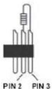
Caution at the unit, the DMX cable has to be terminated with a terminator. Solder a 120 Ohm resistor between signal (-) and signal (+) into a 3-pin XLR connector and plug this into the DMX output of the last unit in the chain.
DMX MODE
This mode allows you to use universal DMX-512 console to operate.
- Install the units in a suitable position.
- Use standard XLR cable to connect your units together via the XLR connector on the rear of the units. For longer cable we suggest a terminator at the last fixture.
- Assign a DMX address to each the unit using the display or dipswitches.
- Turn on all units. Use DMX console to control your units.
TROUBLE SHOOTING
| Trouble Probable cause(s) Remedy | ||
| No response from fixture when power is applies | No power to fixture Check | power cables |
| Primary fuse blown Replace fuse | ||
| Secondary fuse blown Replace fuse | ||
| Fixture resets but does not respond correctly to controller(DMX mode operation) | Controller not connected | Connect controller |
| Incorrect addressing of the fixtures | Check address setting on fixture and controller | |
| Bad data link connection | Inspect cables and correct poor connections and/or broken cables. | |
| Conflict between tracking and vector control | Eliminate scene cross-fade on controller | |
| Data link not terminated | Insert termination plug in output of last fixture | |
| Defective fixture or 2 devices transmitting on link | Bypass fixtures one at a time until normal operation is regained:unplug both connectors and connect them directly together | |
| Colors cannot be mixed | Random color mixing is on | Turn off random color mixing |
| Fixture does not reset correctly | Electronic or mechanical failure | Contact service technician |
| No light, lamp cuts out intermittently,or burns out too quickly | Lamp missing or blown | Disconnect fixture and replace lamp |
| Fixture or lamp is too hot | Allow fixture to cool. If problem persists,contact service technician | |
TECHNICAL SPECIFICATION
Rated voltage : AC110\~240V 50/60Hz
Rated power : 120W
LED 5x 10W RGBW 4in1
Control Signal : DMX signal
DMX Channel : 12/17 Channels
Function : DMX, Auto, Sound active and Master-Slave.
Dimensions per unit : 85 x 600 x 165mm
Weight (per unit) : 7.15Kg
The specifications are typical. The actual values can slightly change from one unit to the other. Specifications can be changed without prior notice.

tronios
Sound & Light
CE Declaration of Conformity
Importer:
TRONIOS
BV
Product Description:
MHL510 LED Beam Bar 5x 10W Quad
Regulatory Requirement: EN 60598-1/-2-17:2009
EN 55015:2007
EN 61547:2009
EN 61000-3-2/-3-3
The product meets the requirements stated in Directives 2006/95 and 2004/108/EC and conforms to the above mentioned Declarations.
Almelo,
21-09-2014
Signature :

Specifications and design are subject to change without prior notice..
www.tronios.com
Copyright © 2014 by TRONIOS the Netherlands


Brand : BeamZ
Model : MHL510 150.516
Category : Effect machine