
NETRS2322P - Server StarTech.com - Free user manual and instructions
Find the device manual for free NETRS2322P StarTech.com in PDF.


| Product Type | Serial Device Server |
| Model Number | NETRS2322P |
| Ports | 2 x RS-232 DB9 Male |
| Ethernet Interface | 10/100 Mbps RJ45 |
| Dimensions | 10.0 x 6.5 x 2.5 cm (3.9 x 2.6 x 1.0 in) |
| Weight | 200 g (7.1 oz) |
| Power Supply | 5V DC via USB or included adapter |
| Power Consumption | 2.5W (max) |
| Supported Protocols | TCP, UDP, HTTP, DHCP, ARP, ICMP |
| Serial Baud Rate | 300 bps to 230.4 kbps |
| Data Bits | 5, 6, 7, 8 |
| Parity | None, Even, Odd, Mark, Space |
| Stop Bits | 1, 1.5, 2 |
| Flow Control | None, XON/XOFF, RTS/CTS |
| Operating Temperature | 0°C to 60°C (32°F to 140°F) |
| Storage Temperature | -20°C to 85°C (-4°F to 185°F) |
| Humidity | 5% to 90% non-condensing |
| LED Indicators | Power, Ethernet Link/Act, Serial Tx/Rx |
| Configuration | Web-based, Telnet, or serial console |
| Compatibility | Windows, Linux, macOS |
| Maintenance | Keep dry and free from dust; clean with soft cloth |
| Safety | Use only with provided power adapter; avoid liquid exposure |
| Spare Parts & Repairability | No user-serviceable parts; contact support for repairs |
| Warranty | 2 years limited warranty |
Frequently Asked Questions - NETRS2322P StarTech.com
User questions about NETRS2322P StarTech.com
0 question about this device. Answer the ones you know or ask your own.
Ask a new question about this device
Download the instructions for your Server in PDF format for free! Find your manual NETRS2322P - StarTech.com and take your electronic device back in hand. On this page are published all the documents necessary for the use of your device. NETRS2322P by StarTech.com.
USER MANUAL NETRS2322P StarTech.com
2-Port Serial-to-IP Ethernet Device Server - RS232
NETRS2322P

*actual product may vary from photos
For the latest information, technical specifications, and support for this product, please visit www.startech.com/NETRS2322P
FCC Compliance Statement
This equipment has been tested and found to comply with the limits for a Class B digital device, pursuant to part 15 of the FCC Rules. These limits are designed to provide reasonable protection against harmful interference in a residential installation. This equipment generates, uses and can radiate radio frequency energy and, if not installed and used in accordance with the instructions, may cause harmful interference to radio communications. However, there is no guarantee that interference will not occur in a particular installation. If this equipment does cause harmful interference to radio or television reception, which can be determined by turning the equipment off and on, the user is encouraged to try to correct the interference by one or more of the following measures:
• Reorient or relocate the receiving antenna.
- Increase the separation between the equipment and receiver.
- Connect the equipment into an outlet on a circuit different from that to which the receiver is connected.
- Consult the dealer or an experienced radio/TV technician for help
This device complies with part 15 of the FCC Rules. Operation is subject to the following two conditions: (1) This device may not cause harmful interference, and (2) this device must accept any interference received, including interference that may cause undesired operation.
Changes or modifications not expressly approved by StarTech.com could void the user's authority to operate the equipment.
Industry Canada Statement
This Class B digital apparatus complies with Canadian ICES-003.
Use of Trademarks, Registered Trademarks, and other Protected Names and Symbols
This manual may make reference to trademarks, registered trademarks, and other protected names and/or symbols of third-party companies not related in any way to StarTech.com. Where they occur these references are for illustrative purposes only and do not represent an endorsement of a product or service by StarTech.com, or an endorsement of the product(s) to which this manual applies by the third-party company in question. Regardless of any direct acknowledgement elsewhere in the body of this document, StarTech.com hereby acknowledges that all trademarks, registered trademarks, service marks, and other protected names and/or symbols contained in this manual and related documents are the property of their respective holders.
Table of Contents
Introduction......1
Packaging contents....1
Requirements 1
Product diagram 2
Front view 2
Rear view....2
DB9 RS232 connector pinout .... 2
Install the device server ....3
Install the device server using the power adapter....3
Install the device server using the terminal block 3
Configure the device server ....4
Install and configure the EMT Connection Wizard (Windows only) 4
Use the EMT software....4
Configure using the web GUI (Windows, Mac, and Linux)....5
Reset the device server to factory settings....5
Surface or wall mounting 6
Technical support....7
Warranty information....7
Introduction
Packaging contents
• 1x 2-port serial device server
• 1x terminal block (2-wire)
• 1x universal power adapter (NA/EU/UK/AU)
- 1x software CD
- 1x quick start guide
Requirements
• 10/100Mbps network equipment (for example, a switch or a router)
- UTP Cat5e or higher Ethernet cable, terminated with RJ45 connectors
- RS232 serial cables
• Available AC electrical outlet
- Terminal block power input (optional, for redundant power)
- Flat-head screwdriver
- Any of the following operating systems (for provided Virtual COM software – Windows® only):
o Windows 10 (32-bit or 64-bit)
o Windows 8 / 8.1 (32-bit or 64-bit)
o Windows 7 (32-bit or 64-bit)
o Windows Vista (32-bit or 64-bit)
o Windows Server® 2012, 2008 R2
Note: The device server's hardware is compatible with Mac OS and Linux®. However, the provided Virtual COM software is not compatible with these operating systems. When used with a Mac or Linux operating system, the device server can only be configured using the web GUI.
Operating system requirements are subject to change. For the latest requirements, please visit www.startech.com/NETRS2322P.
Product diagram
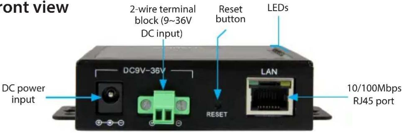
Front view
Rear view

DB9 RS232 connector pinout

Pin 1 NC
Pin 2 RXD
Pin 3 TXD
Pin 4 DTR
Pin 5 GND
Pin 6 DSR
Pin 7 RTS
Pin 8 CTS
Pin 9 NC
About the LED indicators
| LED | Behavior Indication | |
| Status (Green) | Solid | Status is normal, the device server is powered |
| Blinking | Internal software is loaded but not running | |
| Status (Red) | Blinking | Internal software is not loaded or is damaged |
| Status (Green and Red) | Blinking and alternating | Firmware is not loaded or is damaged |
| Port 1 (Red) | Solid Data is being received | |
| Off Data is not being received | ||
| Port 1 (Green) | Solid Data is being sent | |
| Off Data is not being sent | ||
| Port 2 (Red) | Solid Data is being received | |
| Off Data is not being received | ||
| Port 2 (Green) | Solid Data is being sent | |
| Off Data is not being sent | ||
Install the device server
The device server can be powered using the provided power adapter, or using the terminal block power input (9\~36V DC). You can also use redundant power input by connecting both the power adapter and terminal block power.
If one of your power sources fails, the device server will switch to the secondary power source.
Install the device server using the power adapter
- Turn off any equipment that will be connected to the device server.
- Connect up to two RS232 serial devices to the device server's DB9 RS232 ports, using a straight-through serial cable (not provided).
- Connect your network equipment to the device server's 10/100Mbps RJ45 port, using RJ45 Cat5e (or higher) Ethernet cable (not provided).
- Select the appropriate power clip for your region and connect it to the power adapter.
- Connect the power adapter to an AC electrical outlet and to the device server's DC power input port. The Status LED (power) will light up solid (green), and the device server will beep once.
- Turn any equipment that was turned off in step 1 back on (networking and serial devices).
Install the device server using the terminal block
- Repeat steps 1 through 3 from the Install using the power adapter section.
- If already inserted, remove the terminal block connector from the device server. The two screws located on the left and right side of the terminal block connector may need to be loosened using a small, flat-head screwdriver (not provided).
- Loosen the two screws on the top of the terminal block connector using a small, flat-head screwdriver.
- Connect the positive and negative wires from your DC power source to the proper terminal block connectors and tighten the screws. The terminals are marked on the device server's casing.
Note: Ensure that the polarity of the input power — positive (+) and negative (-) — is correctly matched with the terminal block pins to ensure proper function.
- Reinsert the terminal block into the device server and tighten the screws that were loosened in step 2. The Status LED (power) will light up solid (green), and the device server will beep once.
Configure the device server
You can configure the device server by using the EMT Connection Wizard software or by using a web browser to access the GUI (Graphical User Interface).
Install and configure the EMT Connection Wizard (Windows only)
- To download the latest software, use a web browser and navigate to http://www.startech.com/NETRS2322P.
- Click the Support tab.
- Download the software.
- When the download is complete, extract the contents of the compressed file(s) that you downloaded.
Note: Alternatively, you may use the provided software CD to install the software. However, it is highly recommended that you download the latest software from the StarTech.com website.
-
Double-click the appropriate software .exe file for the version of Windows that you're running. For 64-bit operating systems, run the file in the x64 folder. For 32-bit operating systems, run the file in the x86 folder.
-
Follow the on-screen instructions to complete the installation.
Note: You may be asked to restart your computer to complete the installation.
-
Once installed, launch the EMT Connection Wizard by selecting the icon on your Windows desktop or Start menu.
-
Follow the on-screen instructions to configure the device server and your connected serial device(s).
Use the EMT software
Before using the EMT software, ensure the device server and your computer are on the same network.
- Once the software is installed, launch the EMT Connection Wizard by selecting the icon on your Windows desktop or Start menu.
- Click the Elevate button to run the wizard in Administrator mode, then click Next.
- Select the kind of link you want to create. The type of link you want to create depends entirely on the application you are using the device server for. In most cases you should select the first option, Create a link between a Virtual Serial Port and a Device.
- Create a new VSP (Virtual Serial Port) by selecting the Create new VSP option, then select a port name (for example, COM1). Then click Next.
-
Click Select from the list. The device server should show in the Auto-Discovery list. Double click it to select it.
-
On the following screen, click Next.
- Select a Channel and click Next. Channel 1 is for the device server's serial port 1, Channel 2 is for the device server's serial port 2.
- Select which side will need to send the data first (for example, setting the device server as a client or as a host). Click Next.
- Continue to follow the on-screen instructions, entering any further settings (for example, gateway and netmask settings, serial settings, and so on) that are referenced. Click Next to navigate to the next screen.
- Click Configure, then click Finish.
Notes:
- You can use the EMT DS Manager to manage settings without having to use the web interface and to make sure that the computer can see the device server on the network.
- The EMT DS Manager software is used for configuration of the device server itself, while the VSP Manager can be used for configuration of the serial port(s).
Configure using the web GUI (Windows, Mac, and Linux)
- Use a web browser, and type the following in the address bar: http://192.168.1.40
Note: You must be on the same subnet (192.168.1.xxx) in order to use the address referenced in step #1. If you are having problems connecting to the device, check your network infrastructure to ensure the device server is on the same subnet. - Leave the password field blank, and then click Login.
- Set up and customize the device server's settings as needed.
Web GUI Defaults:
Default IP: 192.168.1.40
Password:
Reset the device server to factory settings
To reset the device server, do the following:
- Disconnect any power sources from the device server.
- Open the device server's housing by removing the two screws from the device server (one screw is on each side of the device server).
- Press and hold the Reset button until the device server beeps twice.
Note: The Reset button on the outside of the device server is a hardware reset that reboots the device server.
Surface or wall mounting
- Use the device server's integrated mounting holes and screws (not provided) to fasten and secure the device server to a wall or surface.
Technical support
StarTech.com's lifetime technical support is an integral part of our commitment to provide industry-leading solutions. If you ever need help with your product, visit www.startech.com/support and access our comprehensive selection of online tools, documentation, and downloads.
For the latest drivers/software, please visit www.startech.com/downloads
Warranty information
This product is backed by a two-year warranty.
StarTech.com warrants its products against defects in materials and workmanship for the periods noted, following the initial date of purchase. During this period, the products may be returned for repair, or replacement with equivalent products at our discretion. The warranty covers parts and labor costs only. StarTech.com does not warrant its products from defects or damages arising from misuse, abuse, alteration, or normal wear and tear.
Limitation of Liability
In no event shall the liability of StarTech.com Ltd. and StarTech.com USA LLP (or their officers, directors, employees or agents) for any damages (whether direct or indirect, special, punitive, incidental, consequential, or otherwise), loss of profits, loss of business, or any pecuniary loss, arising out of or related to the use of the product exceed the actual price paid for the product. Some states do not allow the exclusion or limitation of incidental or consequential damages. If such laws apply, the limitations or exclusions contained in this statement may not apply to you.
Hard-to-find made easy. At StarTech.com, that isn't a slogan. It's a promise.
StarTech.com is your one-stop source for every connectivity part you need. From the latest technology to legacy products — and all the parts that bridge the old and new — we can help you find the parts that connect your solutions.
We make it easy to locate the parts, and we quickly deliver them wherever they need to go. Just talk to one of our tech advisors or visit our website. You'll be connected to the products you need in no time.
Visit www.startech.com for complete information on all StarTech.com products and to access exclusive resources and time-saving tools.
StarTech.com is an ISO 9001 Registered manufacturer of connectivity and technology parts. StarTech.com was founded in 1985 and has operations in the United States, Canada, the United Kingdom and Taiwan servicing a worldwide market.


- 2-Port Serial-to-IP Ethernet Device Server - RS232
- FCC Compliance Statement
- Industry Canada Statement
- Use of Trademarks, Registered Trademarks, and other Protected Names and Symbols
- Table of Contents
- Introduction......1
- Product diagram 2
- Install the device server ....3
- Configure the device server ....4
- Reset the device server to factory settings....5
- Surface or wall mounting 6
- Technical support....7
- Warranty information....7
- Introduction
- Packaging contents
- Requirements
- Product diagram
- Install the device server
- Install the device server using the power adapter
- Install the device server using the terminal block
- Configure the device server
- Install and configure the EMT Connection Wizard (Windows only)
- Use the EMT software
- Notes:
- Configure using the web GUI (Windows, Mac, and Linux)
- Web GUI Defaults:
- Reset the device server to factory settings
- Surface or wall mounting
- Technical support
- Warranty information
- Limitation of Liability
Brand : StarTech.com
Model : NETRS2322P
Category : Server