
7 Inch Surface Prep Kit - Grinder METABO - Free user manual and instructions
Find the device manual for free 7 Inch Surface Prep Kit METABO in PDF.


| Product Type | Surface Grinder |
| Brand | Metabo |
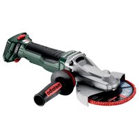
| Model | 7 Inch Surface Prep Kit |
| Disc Diameter | 7 inches (175 mm) |
| Rated Power | 1500 W |
| No-Load Speed | 3000 - 6000 rpm (variable) |
| Weight | 5.5 kg |
| Dimensions (L×W×H) | 400 × 200 × 150 mm |
| Supply Voltage | 230 V / 50 Hz |
| Main Functions | Grinding, sanding, surface preparation |
| Speed Variator | Yes, electronic |
| Spindle Lock | Yes, for quick disc change |
| Overload Protection | Yes, with automatic reset |
| Soft Start | Yes |
| Safety Switch | Paddle switch with lock |
| Additional Handle | Side handle included |
| Included Disc | 7 inch grinding disc |
| Protective Guard | Yes, adjustable |
| Dust Extraction System | Connection for external extraction |
| Maintenance | Clean ventilation slots after each use |
| Spare Parts Available | Carbon brushes, discs, guards, handle |
| Warranty | 2 years (according to conditions) |
Frequently Asked Questions - 7 Inch Surface Prep Kit METABO
User questions about 7 Inch Surface Prep Kit METABO
0 question about this device. Answer the ones you know or ask your own.
Ask a new question about this device
Download the instructions for your Grinder in PDF format for free! Find your manual 7 Inch Surface Prep Kit - METABO and take your electronic device back in hand. On this page are published all the documents necessary for the use of your device. 7 Inch Surface Prep Kit by METABO.
USER MANUAL 7 Inch Surface Prep Kit METABO
natural_image
Black metal mixing power tool labeled 'metabo' with coiled cable, shown against white background (no text beyond brand name)
Operating Instruction For W24-230 Grinder ..... 6
Operating Instructions for Dust Shroud 42
metabo®
Made in Germany
W 22-180
W 22-230
W 24-180
W 24-230
W 26-180
W 26-230

natural_image
Exterior view of a metalworking power tool with a circular base (no text or symbols visible)
Operating Instructions
Dear Customer,
Thank you for the trust you have placed in us by buying a Metabo power tool. Each Metabo power tool is carefully tested and subject to strict quality controls by Metabo's quality assurance. Nevertheless, the service life of a power tool depends to a great extent on you. Please observe the information contained in these instructions and the enclosed documentation. The more carefully you treat your Metabo power tool, the longer it will provide dependable service.
Contents
1 Specified Use
2 General Safety Instructions
3 Special Safety Instructions
4 Overview
5 Special Product Features
6 Commissioning
7 Attaching the Grinding Wheel
8 Use
9 Cleaning
10 Troubleshooting
11 Accessories
12 Repairs
13 Environmental Protection
14 Technical Specifications
1 Specified Use
Machines fitted with original Metabo accessories are suitable for grinding, sanding, separating and wire brushing metal, concrete, stone and similar materials without the use of water.
The user bears sole responsibility for any damage caused by improper use.
Generally accepted accident prevention regulations and the enclosed safety information must be observed.
2 General Safety Instructions

WARNING – Reading the operating instructions will reduce the risk of injury.

For your own protection and for the protection of your power tool pay attention to all parts of the text that are marked with this symbol!
General Power Tool Safety Warnings

WARNING Read all safety warnings and
all instructions. Failure to follow the warn-
ings and instructions may result in electric shock,
fire and/or serious injury. Save all warnings and instructions for future reference! The term "power tool" in the warnings refers to your mains-operated (corded) power tool or battery-operated (cordless) power tool.
1) Work area safety
a) Keep work area clean and well lit. Cluttered or dark areas invite accidents.
b) Do not operate power tools in explosive atmospheres, such as in the presence of flammable liquids, gases or dust. Power tools create sparks which may ignite the dust or fumes.
c) Keep children and bystanders away while operating a power tool. Distractions can cause you to lose control.
2) Electrical safety
a) Power tool plugs must match the outlet. Never modify the plug in any way. Do not use any adapter plugs with earthed (grounded) power tools. Unmodified plugs and matching outlets will reduce risk of electric shock.
b) Avoid body contact with earthed or grounded surfaces, such as pipes, radiators, ranges and refrigerators. There is an increased risk of electric shock if your body is earthed or grounded.
c) Do not expose power tools to rain or wet conditions. Water entering a power tool will increase the risk of electric shock.
d) Do not abuse the cord. Never use the cord for carrying, pulling or unplugging the power tool. Keep cord away from heat, oil, sharp edges or moving parts. Damaged or entangled cords increase the risk of electric shock.
e) When operating a power tool outdoors, use an extension cord suitable for outdoor use. Use of a cord suitable for outdoor use reduces the risk of electric shock.
f) If operating a power tool in a damp location is unavoidable, use a residual current device (RCD) protected supply. Use of an RCD reduces the risk of electric shock.









ENG ENGLISH
3) Personal safety
a) Stay alert, watch what you are doing and use common sense when operating a power tool. Do not use a power tool while you are tired or under the influence of drugs, alcohol or medication. A moment of inattention while operating power tools may result in serious personal injury.
b) Use personal protective equipment. Always wear eye protection. Protective equipment such as dust mask, non-skid safety shoes, hard hat, or hearing protection used for appropriate conditions will reduce personal injuries.
c) Prevent unintentional starting. Ensure the switch is in the off-position before connecting to power source and/or battery pack, picking up or carrying the tool. Carrying power tools with your finger on the switch or energising power tools that have the switch on invites accidents.
d) Remove any adjusting key or wrench before turning the power tool on. A wrench or a key left attached to a rotating part of the power tool may result in personal injury.
e) Do not overreach. Keep proper footing and balance at all times. This enables better control of the power tool in unexpected situations.
f) Dress properly. Do not wear loose clothing or jewellery. Keep your hair, clothing and gloves away from moving parts. Loose clothes, jewellery or long hair can be caught in moving parts.
g) If devices are provided for the connection of dust extraction and collection facilities, ensure these are connected and properly used. Use of dust collection can reduce dust-related hazards.
4) Power tool use and care
a) Do not force the power tool. Use the correct power tool for your application. The correct power tool will do the job better and safer at the rate for which it was designed.
b) Do not use the power tool if the switch does not turn it on and off. Any power tool that cannot be controlled with the switch is dangerous and must be repaired.
c) Disconnect the plug from the power source and/or the battery pack from the power tool before making any adjustments, changing accessories, or storing power tools. Such preventive safety measures reduce the risk of starting the power tool accidentally.
d) Store idle power tools out of the reach of children and do not allow persons unfamiliar with the power tool or these
instructions to operate the power tool. Power tools are dangerous in the hands of untrained users.
e) Maintain power tools. Check for misalignment or binding of moving parts, breakage of parts and any other condition that may affect the power tool's operation. If damaged, have the power tool repaired before use. Many accidents are caused by poorly maintained power tools.
f) Keep cutting tools sharp and clean. Properly maintained cutting tools with sharp cutting edges are less likely to bind and are easier to control.
g) Use the power tool, accessories and tool bits etc. in accordance with these instructions, taking into account the working conditions and the work to be performed. Use of the power tool for operations different from those intended could result in a hazardous situation.
5) Service
a) Have your power tool serviced by a qualified repair person using only identical replacement parts. This will ensure that the safety of the power tool is maintained.
3 Special Safety Instructions
3.1 Safety Warnings Common for Grinding, Sanding, Wire Brushing or Abrasive Cutting-Off Operations:
a) This power tool is intended to function as a grinder, sander, wire brush or cut-off tool. Read all safety warnings, instructions, illustrations and specifications provided with this power tool. Failure to follow all instructions listed below may result in electric shock, fire and/or serious injury.
b) Operations such as polishing are not recommended to be performed with this power tool. Operations for which the power tool was not designed may create a hazard and cause personal injury.
c) Do not use accessories which are not specifically designed and recommended by the tool manufacturer. Just because the accessory can be attached to your power tool, it does not assure safe operation.
d) The rated speed of the accessory must be at least equal to the maximum speed marked on the power tool. Accessories running faster than their rated speed can break and fly apart.
e) The outside diameter and the thickness of your accessory must be within the capacity rating of your power tool. Incorrectly sized






ENGLISH
ENG
accessories cannot be adequately guarded or controlled.
f) The arbour size of wheels, flanges, backing pads or any other accessory must properly fit the spindle of the power tool. Accessories with arbour holes that do not match the mounting hardware of the power tool will run out of balance, vibrate excessively and may cause loss of control.
g) Do not use a damaged accessory. Before each use inspect the accessory such as abrasive wheels for chips and cracks, backing pad for cracks, tear or excess wear, wire brush for loose or cracked wires. If a power tool or accessory is dropped, inspect for damage or install an undamaged accessory. After inspecting and installing an accessory, position yourself and bystanders away from the plane of the rotating accessory and run the power tool at maximum no-load speed for one minute. Damaged accessories will normally break apart during this test time.
h) Wear personal protective equipment. Depending on application, use face shield, safety goggles or safety glasses. As appropriate, wear dust mask, hearing protectors, gloves and workshop apron capable of stopping small abrasive or workpiece fragments. The eye protection must be capable of stopping flying debris generated by various operations. The dust mask or respirator must be capable of filtering particles generated by your operation. Prolonged exposure to high intensity noise may cause hearing loss.
i) Keep bystanders a safe distance away from work area. Anyone entering the work area must wear personal protective equipment. Fragments of workpiece or of a broken accessory may fly away and cause injury beyond immediate area of operation.
j) Hold power tool by insulated gripping surfaces only, when performing an operation where the cutting accessory may contact hidden wiring or its own cord. A cutting accessory contacting a "live" wire may make exposed metal parts of the power tool "live" and give the operator an electric shock.
k) Position the cord clear of the spinning accessory. If you lose control, the cord may be cut or snagged and your hand or arm may be pulled into the spinning accessory.
I) Never lay the power tool down until the accessory has come to a complete stop. The spinning accessory may grab the surface and pull the power tool out of your control.
m) Do not run the power tool while carrying it at your side. Accidental contact with the spinning accessory could snag your clothing, pulling the accessory into your body.
n) Regularly clean the power tool's air vents. The motor's fan will draw the dust inside the housing and excessive accumulation of powdered metal may cause electrical hazards.
o) Do not operate the power tool near flammable materials. Sparks could ignite these materials.
p) Do not use accessories that require liquid coolants. Using water or other liquid coolants may result in electrocution or shock.
3.2 Kickback and Related Warnings
Kickback is a sudden reaction to a pinched or snagged rotating wheel, backing pad, brush or any other accessory. Pinching or snagging causes rapid stalling of the rotating accessory which in turn causes the uncontrolled power tool to be forced in the direction opposite of the accessory's rotation at the point of the binding.
For example, if an abrasive wheel is snagged or pinched by the workpiece, the edge of the wheel that is entering into the pinch point can dig into the surface of the material causing the wheel to climb out or kick out. The wheel may either jump toward or away from the operator, depending on direction of the wheel's movement at the point of pinching. Abrasive wheels may also break under these conditions.
Kickback is the result of power tool misuse and/or incorrect operating procedures or conditions and can be avoided by taking proper precautions as given below.
a) Maintain a firm grip on the power tool and position your body and arm to allow you to resist kickback forces. Always use the auxiliary handle, if provided, for maximum control over kickback or torque reaction during start-up. The operator can control torque reactions or kickback forces, if proper precautions are taken.
b) Never place your hand near the rotating accessory. Accessory may kickback over your hand.
c) Do not position your body in the area where power tool will move if kickback occurs. Kickback will propel the tool in direction opposite to the wheel's movement at the point of snagging.
d) Use special care when working corners, sharp edges etc. Avoid bouncing and snagging the accessory. Corners, sharp edges or bouncing have a tendency to snag the rotating accessory and cause loss of control or kickback.
e) Do not attach a saw chain woodcarving blade or toothed saw blade. Such blades create frequent kickback and loss of control.





ENG ENGLISH
3.3 Safety Warnings Specific for Grinding and Cutting-Off Operations:
a) Use only wheel types that are recommended for your power tool and the specific guard designed for the selected wheel. Wheels for which the power tool was not designed cannot be adequately guarded and are unsafe.
b) The guard must be securely attached to the power tool and positioned for maximum safety, so the least amount of wheel is exposed towards the operator. The guard helps to protect operator from broken wheel fragments and accidental contact with wheel.
c) Wheels must be used only for recommended applications.
For example: do not grind with the side of cut-off wheel. Abrasive cut-off wheels are intended for peripheral grinding, side forces applied to these wheels may cause them to shatter.
d) Always use undamaged wheel flanges that are of correct size and shape for your selected wheel. Proper wheel flanges support the wheel thus reducing the possibility of wheel breakage. Flanges for cut-off wheels may be different from grinding wheel flanges.
e) Do not use worn down wheels from larger power tools. Wheels intended for larger power tools are not suitable for the higher speed of a smaller tool and may burst.
3.4 Additional Safety Warnings Specific for Abrasive Cutting-Off Operations:
a) Do not "jam" the cut-off wheel or apply excessive pressure. Do not attempt to make an excessive depth of cut. Overstressing the wheel increases the loading and susceptibility to twisting or binding of the wheel in the cut and the possibility of kickback or wheel breakage.
b) Do not position your body in line with and behind the rotating wheel. When the wheel, at the point of operation, is moving away from your body, the possible kickback may propel the spinning wheel and the power tool directly at you.
c) When wheel is binding or when interrupting a cut for any reason, switch off the power tool and hold the power tool motionless until the wheel comes to a complete stop. Never attempt to remove the cut-off wheel from the cut while the wheel is in motion otherwise kick-back may occur. Investigate and take corrective action to eliminate the cause of wheel binding.
d) Do not restart the cutting operation in the workpiece. Let the wheel reach full speed and carefully reenter the cut. The wheel may bind, walk up or kickback if the power tool is restarted in the workpiece.
e) Support panels or any oversized workpiece to minimize the risk of wheel pinching and kick-
back. Large workpieces tend to sag under their own weight. Supports must be placed under the workpiece near the line of cut and near the edge of the workpiece on both sides of the wheel.
f) Use extra caution when making a "pocket cut" into existing walls or other blind areas. The protruding wheel may cut gas or water pipes, electrical wiring or objects that can cause kickback.
3.5 Safety Warnings Operations: Specific for Sanding
a) Do not use excessively oversized sanding disc paper. Follow manufacturer's recommendations when selecting sanding paper. Larger sanding paper extending beyond the sanding pad presents a laceration hazard and may cause snagging, tearing of the disc or kickback.
3.6 Safety Warnings Specific for Wire Brushing Operations:
a) Be aware that wire bristles are thrown by the brush even during ordinary operation. Do not overstress the wires by applying excessive load to the brush. The wire bristles can easily penetrate light clothing and/or skin.
b) If the use of a guard is recommended for wire brushing, do not allow any interference of the wire wheel or brush with the guard. Wire wheel or brush may expand in diameter due to work load and centrifugal forces.
3.7 Additional Safety Instructions
Use elastic cushioning layers if they have been supplied with the abrasive and if required.
Observe the specifications of the tool or accessory manufacturer! Protect the discs from grease or impacts!
Grinding discs must be stored and handled with care in accordance with the manufacturer's instructions.
Never use parting grinder discs for roughing work! Do not apply pressure to the side of parting grinder discs.
The workpiece must lay flat and be secured against slipping, e.g. using clamps. Large workpieces must be sufficiently supported.
If accessories with threaded inserts are used, the end of the spindle may not touch the base of the hole on the grinding tool. Make sure that the thread in the accessory is long enough to accommodate the full length of the spindle. The thread in the accessory must match the thread on the spindle. See page 2 and chapter 14 Technical Specifications for more information on the spindle length and thread.

ENGLISH
ENG

Always wear protective goggles.

During machining, of metals in particular, conductive dust can inside the machine. This can lead to electrical energy onto the machine as an mean a temporary danger of 10% . This is why it is necessary when running to blow compressed air or ventilation slots of the machineently and thoroughly. Here, the machine be held firmly.
form deposits inside the machine. This can lead to the transfer of electrical energy onto the machine housing. This can mean a temporary danger of electric shocks. This is why it is necessary when the machine is running to blow compressed air through the rear ventilation slots of the machine regularly, frequently and thoroughly. Here, the machine must be held firmly.
It is recommended to use a stationary extraction system and to place a ground fault circuit interrupter (GFCI) downstream. When the angle grinder is shut down via the FI circuit breaker, it must be checked and cleaned. See chapter 9 Cleaning for more information on cleaning the motor.
Dust from material such as paint containing lead, some wood species, minerals and metal may be harmful. Contact with or inhalation of the dust may cause allergic reactions and/or respiratory diseases to the operator or bystanders. Certain kinds of dust are classified as carcinogenic such as oak and beech dust especially in conjunction with additives for wood conditioning (chromate, wood preservative). Material containing asbestos must only be treated by specialists.
- Where the use of a dust extraction device is possible it shall be used.
- The work place must be well ventilated.
- The use of a dust mask of filter class P2 is recommended.
Follow national requirements for the materials you want to work with.
Materials that generate dusts or vapours that may be harmful to health (e.g. asbestos) must not be processed.
When working in dusty conditions, ensure that ventilation openings are not blocked. If it becomes necessary to remove dust, first disconnect the power tool from the mains supply (use non-metallic objects) and avoid damaging internal components.
Damaged, eccentric or vibrating tools must not be used.
Avoid damage to gas or water pipes, electrical cables and loadbearing walls (static).
Connect a FI circuit-breaker with max. release current (30 mA) upstream when using the machine outdoors!
Pull the plug out of the socket before making any adjustments, converting or servicing the machine.
A damaged or cracked additional handle must be replaced. Never operate a machine with a defective additional handle.
A damaged or cracked safety guard must be replaced. Never operate a machine with a defective safety guard.
Do not switch on the machine if tool parts or guard devices are missing or defective.
Machines with a soft start (indicated by an "X" in the model designation): An electronic error occurs if the machine accelerates to maximum speed very quickly when switched on. Other safety-related electronic functions are no longer available. Have the machine repaired immediately (see 12).
Symbols on the tool:
☐ ......Class II Construction
V.....volts
A.....amperes
Hz......hertz
.../min .....revolutions per minute
\~......alternating current
≈......alternating current /direct current
n ......rated speed
The "C" and "US" indicators adjacent to the CSA Mark signify that the product has been evaluated to the applicable CSA and ANSI/UL Standards, for use in Canada and the U.S., respectively.
4 Overview
See page 3 (please unfold).
1 Spindle
2 Spindle locking button
3 Electronic signal indicator *
4 Lock (to prevent the machine from being switched on unintentionally, or for continuous operation) *
5 Trigger ( for switching on and off)
6 Button (to turn the main handle) *
7 Main handle
8 Additional handle / Additional handle with vibration damping *
9 Safety guard
10 Support flange * (CANADA)
11 Clamping nut * (CANADA)
12 2-hole spanner * (CANADA)
13 Lever (to adjust safety guard without the use of tools)
* depending on equipment/not in scope of delivery







ENG
ENGLISH
5 Special Product Features
- Main handle that can be rotated without the use of tools
- Safety guard that is locked into position, can be adjusted in seconds without the use of tools
- Metabo VibraTech (MVT): Integrated vibration-restricting damping systems at all handles
- Metabo safety switch: Lock to prevent the machine from being switched on unintentionally
- Dead man function: Machine switches off immediately if the user releases the switch
• Auto-stop carbon brushes
(The special product features listed depend on the equipment)
6 Commissioning

Before plugging in, check to see that the rated mains voltage and mains frequency,
specified on the rating label, match your power supply.
6.1 Attaching the additional handle

Always work with the additional handle attached (8)! Manually screw in the addi
handle securely in the left, centre or right threaded hole (depending on requirements).
6.2 Attaching the safety guard
(for work involving grinding wheels)

Prior to commissioning: Fit the protective cover.

For reasons of safety, the safety guard (9) should always be attached when roughing
work is performed.

For reasons of safety, the special parting guard should always be attached before
parting work is performed (see chapter 11 Accessories).
See illustration E on page 3.
- Push and hold the lever (13). Place the safety guard (9) in the position indicated.
- Release the lever and turn the safety guard until the lever engages.
- Push the lever and turn the safety guard until the closed section is facing the operator.
- Make sure that the guard is seated securely: the lever must engage and you should not be able to turn the safety guard.
6.3 Rotatable main handle (depending on features)

Only work with the main handle (7) engaged.
See illustration B on page 3.
- Push in the button (6).
- The main handle (7) can now be turned 90° to both sides and can be engaged.
- Make sure that it is securely positioned: the main handle (7) must be engaged and it should not be possible to move it.
6.4 Power supply
The mains sockets must be protected using time-delay fuses or circuit breakers.
7 Attaching the grinding wheel

Disconnect the mains plug before changing any accessories. The machine must be
hed off and the spindle at a standstill

For reasons of safety, attach the parting guard before performing parting work (see
chapter 11 Accessories).
7.1 Locking the spindle

Press in the spindle locking button (2) only when the spindle is stationary!
- Press in the spindle locking button (2) and turn the spindle (1) by hand until you feel the spindle locking button engage.
7.2 Placing the grinding wheel in position
See illustration C on page 3.
- Fit the support flange (10) on the spindle. The flange should not turn on the spindle when properly attached.
- Position the grinding wheel on the support flange (10) as shown in illustration C. The grinding wheel must lay flat on the supporting flange. The metal flange on the parting grinder disc must lay flat on the support flange.
7.3 Securing/Releasing the clamping nut (depending on features)

Securing the clamping nut (11):
The 2 sides of the clamping nut are different. Screw the clamping nut onto the spindle as follows:







ENGLISH
ENG
See illustration D on page 3.
- A) For thin grinding wheels: The edge of the clamping nut (11) faces upwards so that the thin grinding wheel can be attached securely.
B) For thick grinding wheels:
The edge of the clamping nut (11) faces downwards so that the clamping nut can be attached securely to the spindle.
- Lock the spindle. Turn the clamping nut (11) clockwise using the 2-hole spanner (12) to secure.
Releasing the clamping nut:
- Lock the spindle (see chapter 7.1). Turn the clamping nut (11) anticlockwise using the 2-hole spanner (12) to unscrew.
8 Use
8.1 Switching On and Off

Always guide the machine with both hands.
Switch on first, then guide the accessory towards the workpiece.

The machine must not be allowed to draw in additional dust and shavings. When
switching the machine on and off, keep it away from dust deposits. After switching off the machine, only place it down when the motor has come to a standstill.

Avoid inadvertent starts: always switch the tool off when the plug is removed from the socket or if there has been a power cut.

In continuous operation, the machine continues running if it is forced out of your
hands. Therefore, always hold the machine with both hands at the intended handles, take a secure stance and concentrate on the work.
See illustration A on page 3.
Torque activation
Switching on: Slide the lock (4) in the direction of the arrow and press the trigger (5).
Switching off: Release the trigger (5).
Continuous operation (depending on features)
Switching on: Slide the lock (4) in the direction of the arrow, press the trigger (5) and keep it pressed. The machine is now switched on. Now slide the lock (4) in the direction of the arrow once more to lock the trigger (5) (continuous operation).
Switching off: Press the trigger (5) and release.
8.2 Working instructions
Grinding:
Press down the machine evenly on the surface and move back and forth so that the surface of the workpiece does not become too hot.
Roughing: position the machine at an angle of 30^ - 40^ for the best working results.
Separating:
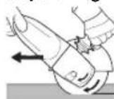
Always work against the run of the disc (see illustration). Otherwise there is the danger of the machine kicking back from the cut out of control. Guide the machine evenly at
a speed suitable for the material being processed. Do not tilt, apply excessive force or sway from side to side.
Sanding:
Press down the machine evenly on the surface and move back and forth so that the surface of the workpiece does not become too hot.
Wire brushing:
Press down the machine evenly.
9 Cleaning
Motor cleaning: blow compressed air through the rear ventilation slots of the machine regularly, frequently and thoroughly. Here, the machine must be held firmly.
Button (6) for adjustment of the handle (depending on features): Occasionally blow compressed air through the button (when pressed, in all 3 main handle positions).
10 Troubleshooting
- Switching on procedures produce brief reductions in voltage. Unfavourable power conditions can be detrimental to other devices. Power impedances smaller than 0.2 ohm should not cause any malfunction.
11 Accessories
Use only genuine Metabo accessories.
If you need any accessories, check with your dealer.
The dealer needs to know the exact model designation of your power tool in order to select the correct accessory.
See page 4.
A Wheels with an included hub
B Parting safety guard.


ENG ENGLISH
C Raised support flange
D Diamond discs (always use with safety guard or parting safety guard attached)
E Adjusting nut (11)
F 2-hole spanner
G Roughing disc (always use with safety guard attached)
H Louver disc (always use with safety guard attached)
I Parting disc (always use with parting safety guard attached)
J Cup wheel guard (place on machine and secure with screws (f)). Secure cup wheel as described in chapter 7. Use an offset 2-hole spanner if necessary. Use the wing screws to adjust the safety guard until the cup wheel protrudes between 0.5 cm - 1 cm.
K Cup wheels (always use with cup wheel safety guard attached)
L Offset 2-hole spanner (for securing/loosening the clamping nut (11) on cup wheels)
M Parting safety guard with guide slot (place on machine and secure with screws.) (with adapter for connection to a suitable dust extractor for extraction of stone dust generated when cutting stone slabs.)
N Hand guard (for attaching under the additional side-mounted handle.)
O Supporting disc for fibre discs (always attach using the supporting disc clamping nut supplied.) (always use with the hand guard attached.)
P Fibre discs (always use with the hand guard attached.)
Q Steel wire brushes (always use with the hand guard attached.)
R Bench cut-off stand
For complete range of accessories, see www.metabo.com or refer to the main catalogue.
12 Repairs

Repairs to electrical tools must be carried out by qualified electricians ONLY!
Any Metabo power tool in need of repair can be sent to one of the addresses listed in the spare parts list.
Please enclose a description of the fault to the power tool.
13 Environmental Protection
The sanding dust generated may contain hazardous materials: do not dispose of with the household waste, but at a special collection point for hazardous waste.
Metabo packaging is 100% recycled. Scrap power tools and accessories contain large amounts of valuable resources and plastics that can be recycled.
These instructions are printed on chlorine-free bleached paper.
14 Technical Specifications
Explanation of details on page 2. Subject to changes serving technical progress.
D_max = Maximum sanding disc diameter t_max,1 = max. permitted thickness of clamping shank on accessory when using clamping nut (11)
t_max,3 = Roughing disc/Parting disc: max. permitted thickness of accessory
M = Spindle thread
I = Length of the grinding spindle
n = No-load speed (maximum speed)
I_120 V = Current at 120 V
HP = Horse power
m = Weight without mains cable

Wear ear protectors!
The technical specifications quoted are subject to tolerances (in compliance with the relevant valid standards).






Mode d'emploi
Cher client,
natural_image
Close-up of a black, glossy, mechanical component with a curved top (no visible text or symbols)
BEFORE PLACING THE SHROUD INTO SERVICE USER MUST READ AND UNDERSTAND THIS INSTRUCTION SHEET
!Silica Dust Warning!
Grinding / Cutting / Drilling of masonry, stone, concrete materials can generate dust known to cause serious injury or illness which can result in death. You must be familiar with the risks associated with the materials being worked. Review the material safety data sheets and consult your employer, supplier, and / or governmental agencies such as OSHA and NIOSH, or agencies on a local or state level. Control dust at the source where possible, use good work practices and follow the recommendations of OSHA / NIOSH and occupational / trade associations. ALWAYS wear appropriate and approved respirator for the dust being generated.


For use with 7" diamond cup wheels NOT FOR USE WITH BONDED ABRASIVE WHEELS
This shroud is designed to fit Metabo 7" or 9" Angle Grinders Models W23-180, W23-230, W25-230, W21-230, W2280, W2230, W2530, W2030
For best dust evacuation, use a dust collector with a minimum of 80 CFM Minimum hose diameter 1-1/2"with 2-1/4" connection
Installing the shroud onto the grinder
! Unplug tool from power source before proceeding
- Place band clamp loosely onto neck of the shroud; do not tighten
- Position shroud with convertible cut out toward the front of the grinder
- Put grinder into shroud, angled as shown; with steady force, push grinder forward and down so that the shroud completely engages the aluminum gear flange
- Tighten band clamp

natural_image
Mechanical device with lever and base mount, no visible text or symbolsMounting diamond cup wheel
Using shim washers provided, mount wheel so that diamond segments extend beyond bottom of shroud approx. 1/16"
Convertible feature for grinding into corner
Turn off grinder and unplug from power source
Raise cut out section of shroud to expose diamond wheel

Loop Handle sold separately; order no. 630342000
Metabo Corporation
1231 Wilson Drive
West Chester, PA 19380 USA
Phone 800-638-2264
Fax 800-638-2261
www.metabousa.com
info@metabousa.com
metabo
work. don't play.
US877 022009
metabo®
Colector de Polvo 7" Cubierta Convertible
natural_image
Close-up of a black, glossy, brushstroke-shaped object with a small white mark on top (no text or symbols visible)
natural_image
Close-up of a hand operating a mechanical device with a label 'sailbro' visible (no other text or symbols)metabo

- metabo®
- Operating Instructions
- Contents
- Specified Use
- General Safety Instructions
- General Power Tool Safety Warnings
- 1) Work area safety
- 2) Electrical safety
- ENG ENGLISH
- 3) Personal safety
- 4) Power tool use and care
- 5) Service
- Special Safety Instructions
- Safety Warnings Common for Grinding, Sanding, Wire Brushing or Abrasive Cutting-Off Operations:
- ENGLISH
- ENG
- Kickback and Related Warnings
- Safety Warnings Specific for Grinding and Cutting-Off Operations:
- Additional Safety Warnings Specific for Abrasive Cutting-Off Operations:
- Safety Warnings Operations: Specific for Sanding
- Safety Warnings Specific for Wire Brushing Operations:
- Additional Safety Instructions
- Overview
- Special Product Features
- Commissioning
- Attaching the additional handle
- Attaching the safety guard
- Rotatable main handle (depending on features)
- Power supply
- Attaching the grinding wheel
- Locking the spindle
- Placing the grinding wheel in position
- Securing/Releasing the clamping nut (depending on features)
- Releasing the clamping nut:
- Use
- Switching On and Off
- Torque activation
- Continuous operation (depending on features)
- Working instructions
- Grinding:
- Separating:
- Sanding:
- Wire brushing:
- Cleaning
- Troubleshooting
- Accessories
- Repairs
- Environmental Protection
- Technical Specifications
- Wear ear protectors!
- Mode d'emploi
- !Silica Dust Warning!
- Installing the shroud onto the grinder
- ! Unplug tool from power source before proceeding
- Mounting diamond cup wheel
- Convertible feature for grinding into corner
- metabo
Brand : METABO
Model : 7 Inch Surface Prep Kit
Category : Grinder