
1032VSR - Drill BOSCH - Free user manual and instructions
Find the device manual for free 1032VSR BOSCH in PDF.


| Product type | Corded drill |
| Brand | Bosch |
| Model | 1032VSR |
| Rated power | 750 W |
| Supply voltage | 230 V ~ 50 Hz |
| No-load speed | 0 – 2800 rpm |
| Drilling capacity (steel) | 13 mm |
| Drilling capacity (wood) | 40 mm |
| Chuck | Keyless chuck 13 mm |
| Speed control | Yes, electronic |
| Forward/reverse | Yes, with stop |
| Weight | 1.7 kg |
| Dimensions (L×W×H) | 275 × 65 × 200 mm |
| Cable length | 2.5 m |
| Protection class | Double insulation (class II) |
| Maintenance | Clean with a dry cloth, check carbon brushes every 50 hours |
| Spare parts | Carbon brushes, chuck, switch available |
| Repairability | Repairability index 7.8/10 |
Frequently Asked Questions - 1032VSR BOSCH
User questions about 1032VSR BOSCH
0 question about this device. Answer the ones you know or ask your own.
Ask a new question about this device
Download the instructions for your Drill in PDF format for free! Find your manual 1032VSR - BOSCH and take your electronic device back in hand. On this page are published all the documents necessary for the use of your device. 1032VSR by BOSCH.
USER MANUAL 1032VSR BOSCH
IMPORTANT: Read Before Using

Operating/Safety Instructions
1011VSR 1012VSR 1013VSR 1014VSR 1030VSR 1031VSR 1032VSR 1033VSR 1034VSR 1035VSR

BOSCH
Consumer Information
Toll Free Number: 1-877-BOSCH99 (1-877-267-2499) http://www.boschtools.com
Power Tool Safety Rules
WARNING
Read and understand all instructions. Failure to follow all instructions listed below may result in electric shock, fire and/or serious personal injury.
SAVE THESE INSTRUCTIONS
Work Area
Keep your work area clean and well lit. Cluttered benches and dark areas invite accidents.
Do not operate power tools in explosive atmospheres, such as in the presence of flammable liquids, gases, or dust. Power tools create sparks which may ignite the dust or fumes.
Keep bystanders, children, and visitors away while operating a power tool. Distractions can cause you to lose control.
Electrical Safety
Grounded tools must be plugged into an outlet properly installed and grounded in accordance with all codes and ordinances. Never remove the grounding prong or modify the plug in any way. Do not use any adaptor plugs. Check with a qualified electrician if you are in doubt as to whether the outlet is properly grounded. If the tools should electrically malfunction or break down, grounding provides a low resistance path to carry electricity away from the user. Improper grounding can shock, burn or electrocute. Grounded tools are equipped with three conductor cord and three prong type plugs. Before plugging in the tool be certain the outlet voltage supplied is within the voltage marked on the nameplate. Do not use "AC only" rated tools with a DC power supply.
Avoid body contact with grounded surfaces such as pipes, radiators, ranges and refrigerators. There is an increased risk of electric shock if your body is grounded. If operating the power tool in damp locations is unavoidable, a Ground Fault Circuit Interrupter must be used to supply the power to your tool. Electrician's rubber gloves and footwear will further enhance your personal safety.
Don't expose power tools to rain or wet conditions. Water entering a power tool will increase the risk of electric shock.
Do not abuse the cord. Never use the
cord to carry the tools or pull the plug from an outlet. Keep cord away from heat, oil, sharp edges or moving parts. Replace damaged cords immediately. Damaged cords increase the risk of electric shock.
When operating a power tool outside, use an outdoor extension cord marked "W-A" or "W." These cords are rated for outdoor use and reduce the risk of electric shock. Refer to "Recommended sizes of Extension Cords" in the Accessory section of this manual.
Personal Safety
Stay alert, watch what you are doing and use common sense when operating a power tool. Do not use tool while tired or under the influence of drugs, alcohol, or medication. A moment of inattention while operating power tools may result in serious personal injury.
Dress properly. Do not wear loose clothing or jewelry. Contain long hair. Keep your hair, clothing, and gloves away from moving parts. Loose clothes, jewelry, or long hair can be caught in moving parts. Keep handles dry, clean and free from oil and grease.
Avoid accidental starting. Be sure switch is "OFF" before plugging in. Carrying tools with your finger on the switch or plugging in tools that have the switch "ON" invites accidents.
Remove adjusting keys or wrenches before turning the tool "ON". A wrench or a key that is left attached to a rotating part of the tool may result in personal injury.
Do not overreach. Keep proper footing and balance at all times. Proper footing and balance enables better control of the tool in unexpected situations.
Use safety equipment. Always wear eye protection. Dust mask, non-skid safety shoes, hard hat, or hearing protection must be used for appropriate conditions.
Tool Use and Care
Use clamps or another practical way to secure and support the workpiece to a stable platform. Holding the work by hand or against your body is unstable and may lead to loss of control.
Do not force the tool. Use the correct tool for your application. The correct tool will do the job better and safer at the rate for which it is designed. Do not use the tool if the switch does not turn it "ON" or "OFF". Any tool that cannot be controlled with the switch is dangerous and must be repaired.
Disconnect the plug from the power source before making any adjustments, changing accessories, or storing the tool. Such preventive safety measures reduce the risk of starting the tool accidentally.
Store idle tools out of reach of children and other untrained persons. Tools are dangerous in the hands of untrained users.
Maintain tools with care. Keep cutting tools sharp and clean. Properly maintained tools with sharp cutting edges are less likely to bind and are easier to control. Any alteration or modification is a misuse and may result in a dangerous condition.
Check for misalignment or binding of moving parts, breakage of parts, and any other condition that may affect the tool's operation. If damaged, have the tool serviced before using. Many accidents are caused by poorly maintained tools. Develop a periodic maintenance schedule for your tool.
Use only accessories that are recommended by the manufacturer for your model. Accessories that may be suitable for one tool may become hazardous when used on another tool.
Service
Tool service must be performed only by qualified repair personnel. Service or maintenance performed by unqualified personnel could result in a risk of injury. For example: internal wires may be misplaced or pinched, safety guard return springs may be improperly mounted.
When servicing a tool, use only identical replacement parts. Follow instructions in the Maintenance section of this manual. Use of unauthorized parts or failure to follow Maintenance Instructions may create a risk of electric shock or injury. Certain cleaning agents such as gasoline, carbon tetrachloride, ammonia, etc. may damage plastic parts.
Safety Rules for Drills
Hold the tool by insulated gripping surfaces when performing an operation where the cutting tools may contact hidden wiring or its own cord. Contact with a "live" wire will make exposed metal parts of the tool "live" and shock the operator. Do not drill, fasten, or break into existing walls or other blind areas where electrical wiring may exist. If this situation is unavoidable, disconnect all fuses or circuit breakers feeding this worksite.
Always use the auxiliary handle for maximum control over torque reaction or kick-back. High torque 3/8" and larger chuck capacity drills are equipped with auxiliary handles.
Always wear safety goggles or eye protection when using this tool. Use a dust mask or respirator for applications that generate dust.
Secure the material being drilled. Never hold it in your hand or across your legs. Unstable support can cause the drill bit to bind, resulting in loss of control and injury.
Never leave the trigger locked "ON". Before plugging in the tool, check that the trigger lock is "OFF". Accidental start-ups could cause injury.
Position the cord clear of the rotating bit. Do not wrap the cord around your arm or wrist. If you lose control and have the cord wrapped around your arm or wrist, it may entrap you and cause injury.
Position yourself to avoid being caught between the tool or side handle and walls or posts. Should the bit become bound or jammed in the work, the reaction torque of the tool could crush your hand or leg.
If the bit becomes bound in the workpiece, release the trigger immediately, reverse the direction of rotation, and slowly squeeze the trigger to back out the bit. Be ready for a strong reaction torque. The drill body will tend to twist in the opposite direction as the drill bit is rotating.
Do not grasp the tool or place your hands too close to the spinning chuck or drill bit. Your hand may be lacerated.
Do not use the switch "Lock-ON" feature in situations where drill bit binding is likely. (For example: just before the bit is ready to break through the material, anytime when using a "Hole Saw", auger bits, etc.) When the bit binds, the drill's body will twist or kick back in the opposite direction, and the release of the trigger "Lock-ON" may be difficult.
Be aware of the location and setting of the switch "Lock-ON" button. If the switch is locked "ON" during use, be ready for emergency situations to switch it "OFF" by first pulling the trigger then immediately releasing it without pressing the "Lock-ON" button.
When installing a drill bit, insert the shank of the bit well within the jaws of the chuck. If the bit is not inserted deep enough, the grip of the jaws over the bit is reduced and the loss of control is increased.
Do not use dull or damaged bits and accessories. Dull or damaged bits have a greater tendency to bind in the workpiece.
When removing the bit from the tool, avoid contact with skin and use proper protective gloves when grasping the bit or accessory. Accessories may be hot after prolonged use.
Check to see that keys and adjusting wrenches are removed from the drill before switching the tool "ON". Keys or wrenches can fly away at high velocity, striking you or a bystander.
Do not run the drill while carrying it at your side. A spinning drill bit could become entangled with clothing and injury may result.
This tool may be used with sanding and polishing disks, grinding wheels, wire wheels, and wire cup brushes. These accessories must be rated for at least the speed recommended on the tool warning label. Wheels and other accessories running over rated speed can fly apart and cause injury.
Avoid bouncing and snagging the wheels, discs, or brushes, especially when working corners, sharp edges, etc. This can cause loss of control and kickback.
WARNING: Some dust created by power sanding, sawing, grinding, drilling, and other construction activities contains chemicals known to cause cancer, birth defects, or other reproductive harm. Some examples of these chemicals are:
- Lead from lead-based paints,
- Crystalline silica from bricks and cement and other masonry products, and
- Arsenic and chromium from chemically-treated lumber.
Your risk from these exposures varies, depending on how often you do this type of work. To reduce your exposure to these chemicals: work in a well-ventilated area, and work with approved safety equipment, such as dust masks that are specially designed to filter out microscopic particles.
Symbols
IMPORTANT: Some of the following symbols may be used on your tool. Please study them and learn their meaning. Proper interpretation of these symbols will allow you to operate the tool better and safer.
| Symbol Name Designation/Explanation | ||
| V Volts Voltage (potential) | ||
| A Amperes Current | ||
| Hz Hertz Frequency (cycles per second) | ||
| W Watt Power | ||
| kg Kilograms Weight | ||
| min Minutes Time | ||
| s Seconds Time | ||
| ∅ | Diameter Size of drill bits, grinding wheels, etc. | |
| n0 | No load speed | Rotational speed, at no load |
| .../min | Revolutions or reciprocation per minute | Revolutions, strokes, surface speed, orbits etc. per minute |
| 0 Off position Zero speed, zero torque... | ||
| 1, 2, 3, ...I, II, III, | Selector settings | Speed, torque or position settings.Higher number means greater speed |
| 0 | Infinitely variable selector with off | Speed is increasing from 0 setting |
| → | Arrow Action in the direction of arrow | |
| ~ | Alternating current | Type or a characteristic of current |
| == | Direct current | Type or a characteristic of current |
| ~ | Alternating or direct current | Type or a characteristic of current |
| □ | Class II construction | Designates Double Insulated Construction tools. |
| ⊕ | Earthing terminal | Grounding terminal |
| ⚠️ | Warning symbol | Alerts user to warning messages |
| Ni-Cad RBRC seal | Designates Ni-Cad battery recycling program | |

This symbol designates that this tool is listed by Underwriters Laboratories.

This symbol designates that this tool is listed to Canadian Standards by Underwriters Laboratories.


This symbol designates
that
this tool
complies
to NOM
Mexican
Standards.

This symbol designates that this tool is listed by the Canadian Standards Association.

This symbol designates that this tool is listed by Underwriters Laboratories, and listed to Canadian Standards by Underwriters Laboratories.
Functional Description and Specifications
WARNING: Disconnect the plug from the power source before making any assembly, adjustments or changing accessories. Such preventive safety measures reduce the risk of starting the tool accidentally.
Drills
MAXIMUM CAPACITIES WOOD APPLICATION STEEL APPLICATION
Model Amperage No load Screw Spade Self Hole Auger Twist Hole No. rating speed Sizes Bit Feed Saw Bit Bit Saw
| 1011VSR | 6.5 | A0 0-1,100/min | #8 x 3" | 1-1/2" | 1" | 2-1/12" | 1" | 3/8" | 1-1/2" |
| 1012VSR * 6.5 A n | 0-1,100/min | #8 x 3" | 1-1/2" | 1" | 2-1/12" | 1" | 3/8" | 1-1/2" | |
| 1013VSR | 6.5 A | n0 0-850/min | #8 x 3" | 1-1/2" | 2-1/4" | 3-5/8" | 1-3/8" | 1/2" | 2" |
| 1014VSR * 6.5 A | n | 0-850/min | #8 x 3" | 1-1/2" | 2-1/4" | 3-5/8" | 1-3/8" | 1/2" | 2" |
| 1030VSR | 7.5 A n | 0-2,100/min | #8 x 3" | 1" | NR | 1-3/8" | NR | 3/8" | 1-3/8" |
| 1031VSR | 7.5 A n | 0-1,100/min | #8 x 3" | 1-1/2" | 1" | 2-1/2" | 1" | 3/8" | 1-3/4" |
| 1032VSR * 7.5 A n | 0-1,100/min | #8 x 3" | 1-1/2" | 1" | 2-1/2" | 1" | 3/8" | 1-3/4" | |
| 1033VSR | 8.0 A | n0 0-850/min | #8 x 3" | 1-1/2" | 2-9/16" | 3-5/8" | 1-1/2" | 1/2" | 2-1/2" |
| 1034VSR | 8.0 A | n0 0-550/min | #8 x 3" | 1-1/2" | 2-9/16" | 4-1/4" | 1-1/2" | 1/2" | 3" |
| 1035VSR * 8.0 A | n | 0-850/min | #8 x 3" | 1-1/2" | 2-9/16" | 3-5/8" | 1-1/2" | 1/2" | 2-1/2" |
Voltage rating (all models)
120 V~50 - 60Hz
NR = Not recommended
* Keyless Chuck
Operating Instructions
TRIGGER CONTROLLED VARIABLE SPEED
Your tool is equipped with a variable speed trigger switch. The tool speed can be controlled from minimum to maximum nameplate rated RPM by the pressure you apply to the trigger. Apply more pressure to increase the speed and release pressure to decrease speed (Fig. 1).
"LOCK-ON" BUTTON
The "Lock-ON" button, located in the handle of your tool, allows for continuous operation at maximum RPM without holding the trigger.
TO LOCK TRIGGER "ON": squeeze the trigger, depress the button, and release the trigger.
TO UNLOCK THE TRIGGER: squeeze the trigger and release it without depressing the "Lock-ON" button.
WARNING
If the "Lock-ON" button is continuously being depressed, the trigger cannot be released.
REVERSING SWITCH BUTTON
The reversing switch button is located above the trigger switch and is used to reverse the rotation of the bit. For forward rotation (with the chuck pointed away from you), move the button to the far left. For reverse rotation, move the button to the far right.
CAUTION: Do not change the direction of rotation until the tool comes to a complete stop. Shifting during rotation of the chuck can cause damage to the tool.
AUXILIARY HANDLE
The auxiliary handle provides additional control, support, and guidance for the tool. The handle is adjustable around the 360° handle collar mount. To mount, loosen the wing knob, slide the handle completely over the chuck onto the collar mount, and tighten the wing knob (Fig. 1).
INSERTING BIT
For small bits, open the jaws enough to insert the bit up to the flutes. For large bits, insert the bit as far as it will go. Center the bit as you close the jaws by hand. This positions the bit properly, giving maximum contact between the chuck jaws and the bit shank.
KEYED MODELS
To tighten the chuck, insert the key into each of the three key holes in succession and tighten clockwise firmly. The chuck can be released by using only one hole (Fig. 2).
KEYLESS MODELS
To tighten the chuck, rotate the chuck sleeve clockwise and securely tighten it by hand (Fig. 3).
WARNING
To prevent friction burns or possible hand injury, do not
loosen or tighten the chuck by using the power of the drill.
REMOVING CHUCK
Open the chuck all the way, remove the left-hand thread screw inside the chuck by turning it clockwise. Insert the short arm of a 3/8" hex key wrench and close the jaws on the flats of the wrench. Strike the long arm of the wrench sharply counterclockwise, remove the wrench, and unthread the chuck from the spindle (Fig. 4).
INSTALLING CHUCK
Always keep the spindle threads, the threads of the chuck, and the securing screw free of debris. To install a chuck, reverse the "removing the chuck" procedure.
FIG. 2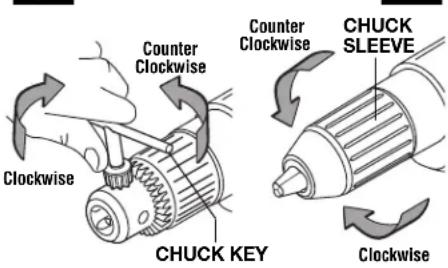
FIG. 4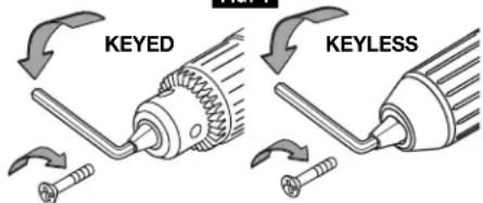
CHUCK KEY & STORAGE AREA
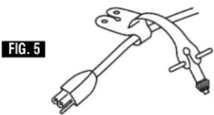
Keyed models are equipped with a chuck key that can be conveniently located on the cord protector where it is always handy and unlikely to get lost or misplaced (Fig. 5).
DEPTH GAUGE (Optional Accessory)
Your drilling depth can be pre-set and/or repeated by using the depth gauge (optional accessory), not included.
Setting depth: After the auxiliary handle is installed, push down on the depth gauge release lever, slide the depth gauge to desired depth and release pressure on lever to lock the depth gauge in place (Fig. 1).
Operating Tips
You will extend the life of your bits and do neater work if you always put the bit in contact with the work before pulling the trigger. During the operation, hold the tool firmly and exert light, steady pressure. Too much pressure at low speed will stall the tool. Too little pressure will keep the bit from cutting and cause excess friction by sliding over the surface. This can be damaging to both tool and bit.
DRILLING WITH VARIABLE SPEED
The trigger controlled variable speed feature will eliminate the need for center punches in hard materials. The variable speed trigger
allows you to slowly increase RPM. By using a slow starting speed, you are able to keep the bit from "wandering". You can increase the speed as the bit "bites" into the work by squeezing the trigger.
DRIVING WITH VARIABLE SPEED
Variable speed drills will double as a power screwdriver by using a screwdriver bit in the drill mode. The technique is to start slowly, increasing the speed as the screw runs down. Set the screw snugly by slowing to a stop. Prior to driving screws, pilot and clearance holes should be drilled.
FASTENING WITH SCREWS
The procedure shown in (Fig. 6) will enable you to fasten materials together with your hammer drill in the drill mode without stripping, splitting or separating the material.
First, clamp the pieces together and drill the first hole 2/3 the diameter of the screw. If the material is soft, drill only 2/3 the proper length. If it is hard, drill the entire length.
Second, unclamp the pieces and drill the second hole the same diameter as the screw shank in the first or top piece of wood.
Third, if flat head screw is used, countersink the hole to make the screw flush with the surface. Then, simply apply even pressure when driving the screw. The screw shank clearance hole in the first piece allows the screw head to pull the pieces tightly together.
The adjustable screw drill accessory will do all of these operations quickly and easily. Screw drills are available for screw sizes No. 6, 8, 10 and 12.

DRILL BITS
Always inspect drill bits for excessive wear. Use only bits that are sharp and in good condition.
TWIST BITS: Available with straight and reduced shanks for wood and light duty metal drilling. High speed bits cut faster and last longer on hard materials.
CARBIDE TIPPED BITS: Used for drilling stone, concrete, plaster, cement and other unusually hard nonmetals. Use continuous heavy feed pressure when employing carbide tip bits.
DRILLING WOOD
Be certain workpiece is clamped or anchored firmly. Always apply pressure in a straight line with the drill bit. Maintain enough pressure to keep the drill "biting".
When drilling holes in wood, twist bits can be used. Twist bits may overheat unless pulled out frequently to clear chips from flutes.
Use a "back-up" block of wood for work that is likely to splinter, such as thin materials.
You will drill a cleaner hole if you ease up on the pressure just before the bit breaks through the wood. Then complete the hole from the back side.
DRILLING METAL
There are two rules for drilling hard materials. First, the harder the material, the greater the pressure you need to apply to the tool. Second, the harder the material, the slower the speed. Here are a couple of tips for drilling in metal. Lubricate the tip of the bit occasionally with cutting oil except when drilling soft metals such as aluminum, copper or cast iron. If the hole to be drilled is fairly large, drill a smaller hole first, then enlarge to the required size, it's often faster in the long run. Maintain enough pressure to assure that the bit does not just spin in the hole. This will dull the bit and greatly shorten its life.
DRILLING MASONRY
Soft materials such as brick are relatively easy to drill. Concrete however, will require much more pressure to keep the bit from spinning. Be sure to use carbide tip bits for all masonry work.
WARNING
Before using an accessory, be certain that its maximum
safe operating speed is not exceeded by the nameplate speed of the tool. Do not exceed the recommended wheel diameter.
SANDING AND POLISHING
You will find the "Lock-ON" button feature a convenience for the continuous operation required for rough sanding. Fine sanding and polishing require "touch". Select the most efficient speed.
When using polishing bonnets, always be sure the excess string that secures the bonnet is tucked well within the bonnet during operation.
WIRE BRUSHES
Work with brushes requires high speeds. Use of the "Lock-ON" button feature will provide a much easier operation.
BRUSHING PRESSURE
- Remember, the tips of a wire brush do the work. Operate the brush with the lightest pressure so only the tips of the wire come in contact with the work.
- If heavier pressures are used, the wires will be overstressed, resulting in a wiping action; and if this is continued, the life of the brush will be shortened due to wire fatigue.
- Apply the brush to the work in such a way that as much of the brush face as possible is in full contact with the work. Applying the side or edge of the brush to the work will result in wire breakage and shortened brush life.
CORRECT: Wire tips doing the work.
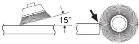
INCORRECT: Excessive pressure can cause wire breakage.


RUNNING NUTS AND BOLTS
Variable speed control must be used with caution for driving nuts and bolts with socket set attachments. The technique is to start slowly, increasing speed as the nut or bolt runs down. Set the nut or bolt snugly by slowing the drill to a stop. If this procedure is not followed, the tool will have a tendency to torque or twist in your hands when the nut or bolt seats.
Maintenance
Service
WARNING
Preventive maintenance performed by unauthorized personnel may result in misplacing of internal wires and components which could cause serious hazard. We recommend that all tool service be performed by a Bosch Factory Service Center or Authorized Bosch Service Station.
Preventive maintenance performed by unauthorized personnel may result in misplacing of internal wires and components which could cause serious hazard. We recommend that all tool service be performed by a Bosch Factory Service Center or Authorized Bosch Service Station.
TOOL LUBRICATION
Your Bosch tool has been properly lubricated and is ready to use. It is recommended that tools with gears be regreased with a special gear lubricant at every brush change.
CARBON BRUSHES
The brushes and commutator in your tool have been engineered for many hours of dependable service. To maintain peak efficiency of the motor, we recommend every two to six months the brushes be examined. Only genuine Bosch replacement brushes specially designed for your tool should be used.
BEARINGS
After about 300-400 hours of operation, or at every second brush change, the bearings
After about 300-400 hours of operation, or at every second brush change, the bearings should be replaced at Bosch Factory Service Center or Authorized Bosch Service Station. Bearings which become noisy (due to heavy load or very abrasive material cutting) should be replaced at once to avoid overheating or motor failure.
Cleaning
WARNING
To avoid accidents always disconnect the tool from
the power supply before cleaning or performing any maintenance. The tool may be cleaned most effectively with compressed dry air. Always wear safety goggles when cleaning tools with compressed air.
Ventilation openings and switch levers must be kept clean and free of foreign matter. Do not attempt to clean by inserting pointed objects through openings.
CAUTION
Certain cleaning agents and solvents damage
plastic parts. Some of these are: gasoline, carbon tetrachloride, chlorinated cleaning solvents, ammonia and household detergents that contain ammonia.
Accessories
WARNING
If an extension cord is necessary, a cord with
adequate size conductors that is capable of carrying the current necessary for your tool must be used. This will prevent excessive voltage drop, loss of power or overheating. Grounded tools must use 3-wire extension cords that have 3-prong plugs and receptacles.
NOTE: The smaller the gauge number, the heavier the cord.
RECOMMENDED SIZES OF EXTENSION CORDS 120 VOLT ALTERNATING CURRENT TOOLS
| Tool's Ampere Rating | Cord Size in A.W.G. | Wire Sizes in mm2 |
| Cord Length in Feet 25 50 100 150 15 30 60 120 | Cord Length in Meters | |
| 3-6 | 18 16 16 14 0.75 0.75 1.5 | 2.5 |
| 6-8 | 18 16 14 12 0.75 1.0 2.5 | 4.0 |
| 8-10 | 18 16 14 12 0.75 1.0 2.5 | 4.0 |
| 10-12 | 16 16 14 12 1.0 2.5 4.0 | |
| 12-16 | 14 12 — — — — — — |
| 1011VSR | 6.5 A | n0 0-1 100/min | #8 x 75mm | 38mm | 25mm | 65mm | 25mm | 10mm | 38mm |
| 1012VSR * | 6.5 A | n0 0-1 100/min | #8 x 75mm | 38mm | 25mm | 65mm | 25mm | 10mm | 38mm |
| 1013VSR | 6.5 A | n0 0-850/min | #8 x 75mm | 38mm | 57mm | 90mm | 35mm | 13mm | 50mm |
| 1014VSR * | 6.5 A | n0 0-850/min | #8 x 75mm | 38mm | 57mm | 90mm | 35mm | 13mm | 50mm |
| 1030VSR | 7.5 A | n0 0-2 100/min | #8 x 75mm | 25mm | NR | 35mm | NR | 10mm | 35mm |
| 1031VSR | 7.5 A | n0 0-1 100/min | #8 x 75mm | 38mm | 25mm | 65mm | 25mm | 10mm | 45mm |
| 1032VSR * | 7.5 A | n0 0-1 100/min | #8 x 75mm | 38mm | 25mm | 65mm | 25mm | 10mm | 45mm |
| 1033VSR | 8.0 A | n0 0-850/min | #8 x 75mm | 38mm | 65mm | 90mm | 38mm | 13mm | 65mm |
| 1034VSR | 8.0 A | n0 0-550/min | #8 x 75mm | 38mm | 65mm | 105mm | 38mm | 13mm | 75mm |
| 1035VSR * | 8.0 A | n0 0-850/min | #8 x 75mm | 38mm | 65mm | 90mm | 38mm | 13mm | 65mm |
INSTALLING NUTS AND BOLTS
Robert Bosch Tool Corporation ("Seller") warrants to the original purchaser only, that all BOSCH portable and benchtop power tools will be free from defects in material or workmanship for a period of one year from date of purchase. SELLER'S SOLE OBLIGATION AND YOUR EXCLUSIVE REMEDY under this Limited Warranty and, to the extent permitted by law, any warranty or condition implied by law, shall be the repair or replacement of parts, without charge, which are defective in material or workmanship and which have not been misused, carelessly handled, or misrepair by persons other than Seller or Authorized Service Station. To make a claim under this Limited Warranty, you must return the complete portable or benchtop power tool product, transportation prepaid, to any BOSCH Factory Service Center or Authorized Service Station. For Authorized BOSCH Power Tool Service Stations, please refer to your phone directory.
THIS LIMITED WARRANTY DOES NOT APPLY TO ACCESSORY ITEMS SUCH AS CIRCULAR SAW BLADES, DRILL BITS, ROUTER BITS, JIGSAW BLADES, SANDING BELTS, GRINDING WHEELS AND OTHER RELATED ITEMS.
ANY IMPLIED WARRANTIES SHALL BE LIMITED IN DURATION TO ONE YEAR FROM DATE OF PURCHASE. SOME STATES IN THE U.S., SOME CANADIAN PROVINCES DO NOT ALLOW LIMITATIONS ON HOW LONG AN IMPLIED WARRANTY LASTS, SO THE ABOVE LIMITATION MAY NOT APPLY TO YOU.
IN NO EVENT SHALL SELLER BE LIABLE FOR ANY INCIDENTAL OR CONSEQUENTIAL DAMAGES (INCLUDING BUT NOT LIMITED TO LIABILITY FOR LOSS OF PROFITS) ARISING FROM THE SALE OR USE OF THIS PRODUCT. SOME STATES IN THE U.S. AND SOME CANADIAN PROVINCES DO NOT ALLOW THE EXCLUSION OR LIMITATION OF INCIDENTAL OR CONSEQUENTIAL DAMAGES, SO THE ABOVE LIMITATION OR EXCLUSION MAY NOT APPLY TO YOU.
THIS LIMITED WARRANTY GIVES YOU SPECIFIC LEGAL RIGHTS, AND YOU MAY ALSO HAVE OTHER RIGHTS WHICH VARY FROM STATE TO STATE IN THE U.S., PROVINCE TO PROVINCE IN CANADA AND FROM COUNTRY TO COUNTRY.
THIS LIMITED WARRANTY APPLIES ONLY TO PORTABLE AND BENCHTOP ELECTRIC TOOLS SOLD WITHIN THE UNITED STATES OF AMERICA, CANADA AND THE COMMONWEALTH OF PUERTO RICO. FOR WARRANTY COVERAGE WITHIN OTHER COUNTRIES, CONTACT YOUR LOCAL BOSCH DEALER OR IMPORTER.
BOSCH PORTABLE AND BENCHTOP POWER TOOLS LIMITED WARRANTY
© Robert Bosch Tool Corporation 1800 W. Central Road Mt. Prospect, IL 60056 -2230
Exported by: Robert Bosch Tool Corporation Mt. Prospect, IL 60056 -2230, U.S.A.

- BOSCH
- POWER TOOL SAFETY RULES
- WARNING
- SAVE THESE INSTRUCTIONS
- WORK AREA
- ELECTRICAL SAFETY
- PERSONAL SAFETY
- TOOL USE AND CARE
- SERVICE
- SAFETY RULES FOR DRILLS
- SYMBOLS
- FUNCTIONAL DESCRIPTION AND SPECIFICATIONS
- OPERATING INSTRUCTIONS
- TRIGGER CONTROLLED VARIABLE SPEED
- LOCK-ON" BUTTON
- REVERSING SWITCH BUTTON
- AUXILIARY HANDLE
- INSERTING BIT
- KEYED MODELS
- KEYLESS MODELS
- REMOVING CHUCK
- INSTALLING CHUCK
- CHUCK KEY & STORAGE AREA
- DEPTH GAUGE (OPTIONAL ACCESSORY)
- OPERATING TIPS
- DRILLING WITH VARIABLE SPEED
- DRIVING WITH VARIABLE SPEED
- FASTENING WITH SCREWS
- DRILL BITS
- DRILLING WOOD
- DRILLING METAL
- DRILLING MASONRY
- SANDING AND POLISHING
- WIRE BRUSHES
- BRUSHING PRESSURE
- RUNNING NUTS AND BOLTS
- MAINTENANCE
- TOOL LUBRICATION
- CARBON BRUSHES
- BEARINGS
- CLEANING
- CAUTION
- ACCESSORIES
- INSTALLING NUTS AND BOLTS
- BOSCH PORTABLE AND BENCHTOP POWER TOOLS LIMITED WARRANTY
Brand : BOSCH
Model : 1032VSR
Category : Drill