
EM4351UH - String Trimmer MAKITA - Free user manual and instructions
Find the device manual for free EM4351UH MAKITA in PDF.


| Product Type | String Trimmer |
| Brand | Makita |
| Model | EM4351UH |
| Engine | 4-stroke, 43 cc |
| Power | 1.8 kW |
| Fuel Type | Unleaded gasoline |
| Fuel Tank Capacity | 0.6 L |
| Engine Oil Type | SAE 10W-30 Oil |
| Weight | 5.8 kg |
| Cutting Width | 45 cm |
| Shaft Diameter | 26 mm |
| Cutting Head Type | 3-tooth blade or trimmer head |
| Ignition System | Electronic ignition |
| Starting System | Recoil starter |
| Sound Level (LWA) | 96 dB(A) |
| Vibration (front hand) | 4.5 m/s² |
| Vibration (rear hand) | 6.0 m/s² |
| Safety | Protection bar, safety switch, anti-kickback guard |
| Maintenance | Air filter cleaning, oil change, blade sharpening |
| Spare Parts Available | Blade, cutting head, air filter, spark plug, throttle cable |
| Warranty | 2 years |
Frequently Asked Questions - EM4351UH MAKITA
User questions about EM4351UH MAKITA
0 question about this device. Answer the ones you know or ask your own.
Ask a new question about this device
Download the instructions for your String Trimmer in PDF format for free! Find your manual EM4351UH - MAKITA and take your electronic device back in hand. On this page are published all the documents necessary for the use of your device. EM4351UH by MAKITA.
USER MANUAL EM4351UH MAKITA
Read this instruction manual carefully before putting the Petrol Brushcutter into operation and strictly observe the safety regulations! Preserve instruction manual carefully!
Important :
(Original instructions)
Thank you very much for purchasing the MAKITA Outdoor Power Equipment. We are pleased to recommend to you the MAKITA product which is the result of a long development program and many years of knowledge and experience. Please read this booklet which refers in detail to the various points that will demonstrate its outstanding performance. This will assist you to obtain the best possible result from your MAKITA product.

Table of Contents Page
Symbols....2
Safety instructions....3
Technical data....7
Designation of parts....8
Mounting of handle....9
Mounting of protector....10
Mounting of metal blade or nylon cutting head....12
Before start of operation....13
Correct handling of machine....15
Points in operation and how to stop 17
Resharpening the cutting tool....20
Servicing instructions....23
Storage....26
SYMBOLS
You will note the following symbols when reading the instructions manual.

Read instruction manual and follow the warnings and safety precautions!

Take Particular care and attention!

Forbidden!

Keep distance!

Flying object hazard!

Kickback!

No smoking!

No open flame!

Protective gloves must be worn!

Wear sturdy boots with nonslip soles. Steeltoed safety boots are recommended!

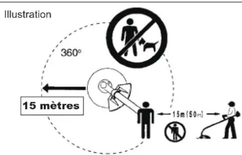
Keep the area of operation clear of all persons and pets!

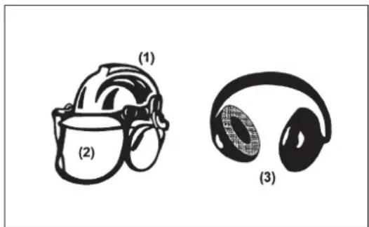
Wear protective helmet, eye and ear protection!

Top permissible tool speed

Fuel (Gasoline)
Engine-manual start

Emergency stop

First Aid

ON/START

OFF/STOP

THROTTLE LOCK POSITION
SAFETY INSTRUCTIONS
General Instructions
- Read this instruction manual to become familiar with handling of the equipment. Users insufficiently informed will risk danger to themselves as well as others due to improper handling.
– It is recommended only to lend the equipment to people who have proven to be experienced.
Always hand over the instruction manual. - First users should ask the dealer for basic instructions to familiarize oneself with the handling of brushcutters.
– Children and young persons aged under 18 years must not be allowed to operate this equipment. Persons over the age of 16 years may however use the device for the purpose of being trained while under supervision of a qualified trainer.
– Use with the utmost care and attention. - Operate only if you are in good physical condition. Perform all work calmly and carefully. The user has to accept liability for others.
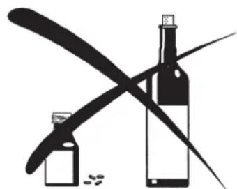
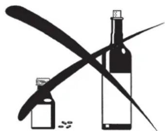
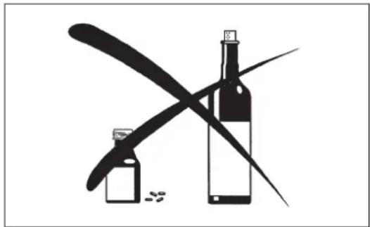
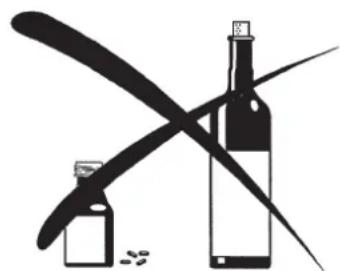
– Never use this equipment after consumption of alcohol or drugs, or if feeling tired or ill.
– National regulation can restrict the use of the machine.
Intended use of the machine
- This equipment is only intended for cutting grass, weeds, bushes, undergrowth. It should not be used for any other purpose such as edging or hedge cutting as this may cause injury.
Personal protective equipment
- The clothing worn should be functional and appropriate, i.e. it should be tight-fitting but not cause hindrance. Do not wear either jewelry or clothing which could become entangled with bushes or shrubs.
- In order to avoid either head-, eye-, hand-or foot injuries as well as to protect your hearing the following protective equipment and protective clothing must be used during operation.
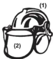
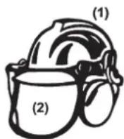
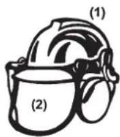
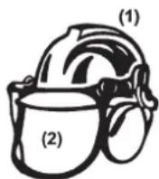
– Always wear a helmet where there is a risk of falling objects. The protective helmet (1) is to be checked at regular intervals for damage and is to be replaced at the latest after 5 years. Use only approved protective helmets.
– The visor (2) of the helmet (or alternatively goggles) protects the face from flying debris and stones. During operation always wear goggles, or a visor to prevent eye injuries. - Wear adequate noise protection equipment to avoid hearing impairment (ear muffs (3), ear plugs etc.).
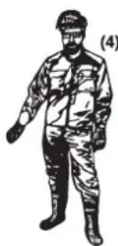
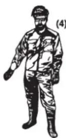
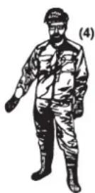
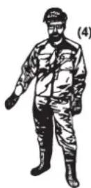
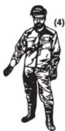
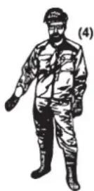
– The work overalls (4) protect against flying stones and debris. We strongly recommend that the user wears work overalls.
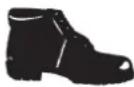
– Gloves (5) are part of the prescribed equipment and must always be worn during operation. - When using the equipment, always wear sturdy shoes (6) with a non-slip sole. This protects against injuries and ensures a good footing.
Starting up the brushcutter
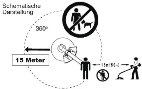
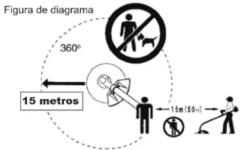
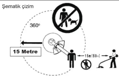
- Please make sure that there are no children or other people within a working range of 15 meters (50 ft), also pay attention to any animals in the working vicinity.
– Before use always check the equipment is safe for operation: Check the security of the cutting tool, the throttle lever for easy action and check for proper functioning of the throttle lever lock. - Rotation of the cutting tool during idling speed is not allowed. Check with your dealer for adjustment if in doubt. Check for clean and dry handles and test the function of the start/stop switch.



(3)

(5)

(6)

Start the brushcutter only in accordance with the instructions.
- Do not use any other methods for starting the engine!
- Use the brushcutter and the tools only for such applications as specified.
- Only start the engine, after the entire assembly is done. Operation of the device is only permitted after all the appropriate accessories are attached!
- Before starting make sure that the cutting tool has no contact with hard objects such as branches, stones etc. as the cutting tool will revolve when starting.
- The engine is to be switched off immediately in case of any engine problems.
- Should the cutting tool hit stones or other hard objects, immediately switch off the engine and inspect the cutting tool.
- Inspect the cutting tool at short regular intervals for damage (detection of hairline cracks by means of tapping-noise test).
- If the equipment gets heavy impact or fall, check the condition before continuing work. Check the fuel system for fuel leakage and the controls and safety devices for malfunction. If there is any damage or doubt, ask our authorized service center for the inspection and repair.
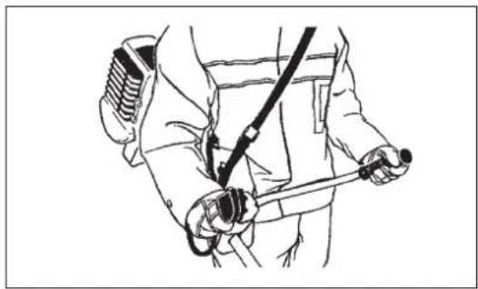
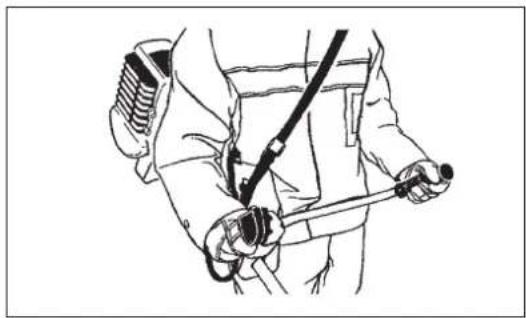
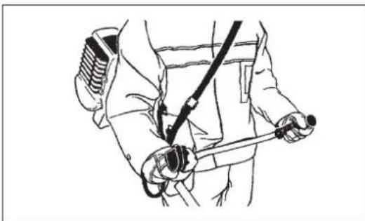
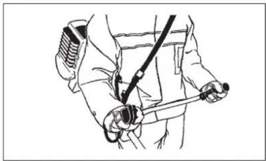
- Operate the equipment only with the shoulder harness attached which is to be suitably adjusted before putting the brushcutter into operation. It is essential to adjust the shoulder harness according to the user size to prevent fatigue occurring during use. Never hold the cutter with one hand during use.
– During operation always hold the brushcutter with both hands. Always ensure a safe footing.
- Operate the equipment in such a manner as to avoid inhalation of the exhaust gases. Never run the engine in enclosed rooms (risk of gas poisoning). Carbon monoxide is an odorless gas.
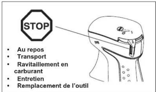
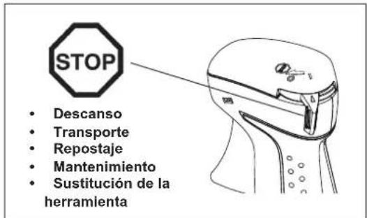
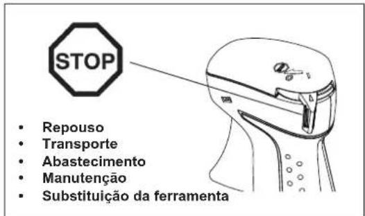
- Switch off the engine when resting and when leaving the equipment unattended, and place it in a safe location to prevent danger to others or damage to the machine.
- Never put the hot brushcutter onto dry grass or onto any combustible materials.
- Always install the approved cutting tool guard onto the equipment before starting the engine. Otherwise contact with the cutting tool may cause serious injury.
- All protective installations and guards supplied with the machine must be used during operation.
- Never operate the engine with faulty exhaust muffler.
- Shut off the engine during transport.
- When transporting the equipment, always attach the cover to the metal blade.
- Ensure safe position of the equipment during car transportation to avoid fuel leakage.
- When transporting, ensure that the fuel tank is completely empty.
- When unloading the equipment from the truck, never drop the Engine to the ground or this may severely damage the fuel tank.
– Except in case of emergency, never drop or cast the equipment to the ground or this may severely damage the equipment.
– Remember to lift the entire equipment from the ground when moving the equipment. Dragging the fuel tank is highly dangerous and will cause damage and leakage of fuel, possibly causing fire.
Refueling
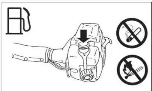
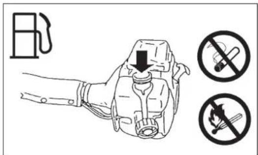
- Shut off the engine during refueling, keep away from open flames and do not smoke.
- Avoid skin contact with mineral oil products. Do not inhale fuel vapor. Always wear protective gloves during refueling. Change and clean protective clothing at regular intervals.
- Take care not to spill either fuel or oil in order to prevent soil contamination (environmental protection). Clean the brushcutter immediately after fuel has been spilt.
- Avoid any fuel contact with your clothing. Change your clothing instantly if fuel has been spilt on it (to prevent clothing catching fire).
- Inspect the fuel cap at regular intervals making sure that it can be securely fastened and does not leak.
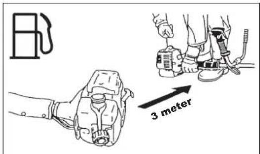
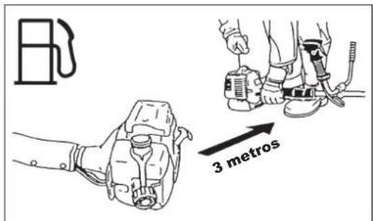
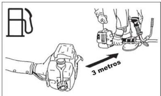
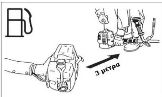
- Carefully tighten the fuel tank cap. Change location to start the engine (at least 3 meters away from the place of refueling).
- Never refuel in closed rooms. Fuel vapors accumulate at ground lever (risk of explosions).
- Only transport and store fuel in approved containers. Make sure the fuel stored is not accessible to children.
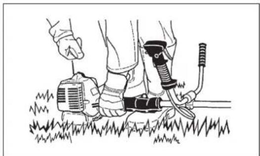


Method of operation
- Only use in good light and visibility. During the winter season beware of slippery or wet areas, ice and snow (risk of slipping). Always ensure a safe footing.
– Never cut above waist height.
- Never stand on a ladder.
- Never climb up into trees to perform cutting operation.
– Never work on unstable surfaces.
- Remove sand, stones, nails etc. found within the working range.
Foreign particles may damage the cutting tool and can cause dangerous kick-backs.
– Before commencing cutting, the cutting tool must have reached full working speed.
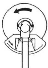
- When using metal blades, swing the tool evenly in half-circle from right to left, like using a scythe.
If grass or branches get caught between the cutting tool and guard, always stop the engine before cleaning. Otherwise unintentional blade rotation may cause serious injury.
- Take a rest to prevent loss of control caused by fatigue. We recommend to take a 10 to 20-minute rest every hour.
Cutting Tools
– Use an applicable cutting tool for the job in hand.
Nylon cutting heads (string trimmer heads) are suitable for trimming lawn grass.
Metal blades are suitable for cutting weeds, high grasses, bushes, shrubs, underwood, thicket, and the like.
Never use other blades including metal multi-piece pivoting chains and flail blades. Otherwise serious injury may result.
- When using metal blades, avoid "kickback" and always prepare for an accidental kickback. See the section "Kickback" and "Kickback prevention."
Kickback (blade thrust)
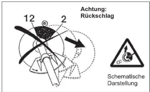
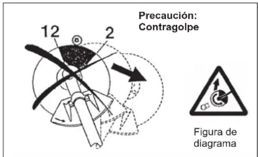
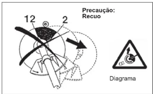
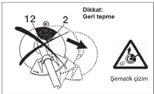
– Kickback (blade thrust) is a sudden reaction to a caught or bound metal blade. Once it occurs, the equipment is thrown sideway or toward the operator at great force and it may cause serious injury.
– Kickback occurs particularly when applying the blade segment between 12
and 2 o'clock to solids, bushes and trees with 3 cm or larger diameter.
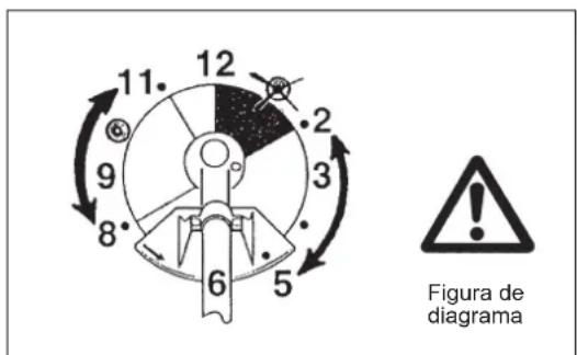
- To avoid kickback:
- Apply the segment between 8 and 11 o'clock;
- Never apply the segment between 12 and 2 o'clock;
- Never apply the segment between 11 and 12 o'clock and between 2 and 5 o'clock, unless the operator is well trained and experienced and does it at his/her own risk;
- Never use metal blades close to solids, such as fences, walls, tree trunks and stones;
- Never use metal blades vertically, for such operations as edging and trimming hedges.
Vibration
- People with poor circulation who are exposed to excessive vibration may experience injury to blood vessels or the nervous system. Vibration may cause the following symptoms to occur in the fingers, hands or wrists: "Falling asleep" (numbness), tingling, pain, stabbing sensation, alteration of skin color or of the skin. If any of these symptoms occur, see a physician!
- To reduce the risk of "white finger disease", keep your hands warm during operation and well maintain the equipment and accessories.
Maintenance instructions
- Have your equipment serviced by our authorized service center, always using only genuine replacement parts. Incorrect repair and poor maintenance can shorten the life of the equipment and increase the risk of accidents.
- The condition of the cutter, in particular of the cutting tool of the protective devices and also of the shoulder harness must be checked before commencing work. Particular attention is to be paid to the metal blades which must be correctly sharpened.
- Turn off the engine and remove spark plug connector when replacing or sharpening cutting tools, and also when cleaning the cutter or cutting tool.


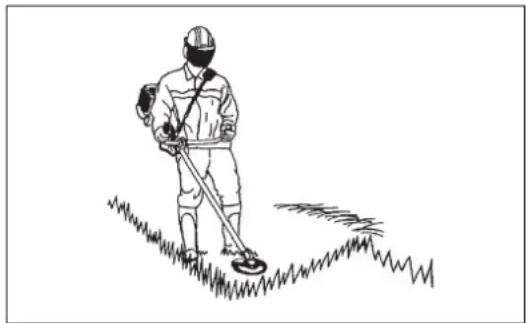
Never straighten or weld damaged cutting tools.
- Pay attention to the environment. Avoid unnecessary throttle operation for less pollution and noise emissions. Adjust the carburetor correctly.
- Clean the equipment at regular intervals and check that all screws and nuts are well tightened.
- Never service or store the equipment in the vicinity of naked flames.
- Always store the equipment in locked rooms and with an emptied fuel tank.
- When cleaning, servicing and storing the equipment, always attach the cover to the metal blade.
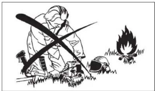
Observe the relevant accident prevention instructions issued by the relevant trade associations and by the insurance companies.
Do not perform any modifications to the equipment as this will endanger your safety.
The performance of maintenance or repair work by the user is limited to those activities as described in the instruction manual. All other work is to be done by an Authorized Service Agent. Use only genuine spare parts and accessories released and supplied by MAKITA.
Use of non-approved accessories and tools means increased risk of accidents.
MAKITA will not accept any liability for accidents or damage caused by the use of non-approved cutting tools and fixing devices of cutting tools, or accessories.
First Aid
In case of accident make sure that a first-aid box is available in the vicinity of the cutting operations. Immediately replace any item taken from the first aid box.
When asking for help, please give the following information:
- Place of accident
- What happened
– Number of injured persons - Kind of injuries
- Your name

EC Declaration of Conformity
For European countries only
The EC declaration of conformity is included as Annex A to this instruction manual.
TECHNICAL DATA EM4351UH, EM4350UH, EM4350LH
| Model EM4351UH EM4350UH EM4350LH | |||||||||
| Handle type Bike handle Bike handle Loop handle | |||||||||
| Dimensions: length x width x height (without cutting tool) mm 1,812 x | 618 x 528 1,812 x 635 x | 460 1,812 x 339 x 250 | |||||||
| Mass (without plastic guard and cutting tool) kg 8.6 8.3 7.9 | |||||||||
| Volume (fuel tank) L 0.6 | |||||||||
| Volume (oil tank) L | 0.1 | ||||||||
| Engine displacement cm3 | 43.0 | ||||||||
| Maximum engine performance kW | 1.5 at 7,500 min-1 | ||||||||
| Engine speed at recommended max. spindle speed min-1 | 10,500 | ||||||||
| Maximum spindle speed (corresponding) min-1 | 7,200 | ||||||||
| Idling speed min-1 | 3,000 | ||||||||
| Clutch engagement speed min-1 | 4,000 | ||||||||
| Carburetor | Diaphragm type | ||||||||
| Ignition system | Non-contact, magnet type | ||||||||
| Spark plug type | NGK CMR6A | ||||||||
| Electrode gap mm | 0.7 - 0.8 | ||||||||
| CUTTER BLADE | NYLON CUTTING HEAD | CUTTER BLADE | NYLON CUTTING HEAD | CUTTER BLADE | NYLON CUTTING HEAD | ||||
| Vibration per ISO 22867 | Right handle (Rear grip) | ahv eq m/s2 | 2.2 | 2.5 | 3.1 | 4.0 | 4.2 | 2.6 | |
| Uncertainty K m/s2 | 0.5 | 0.3 | 0.5 | 0.7 | 1.1 | 0.7 | |||
| Left handle (Front grip) | ahv eq m/s2 | 1.7 | 2.6 | 4.8 | 5.0 | 3.8 | 3.7 | ||
| Uncertainty K m/s2 | 0.5 | 1.3 | 2.9 | 0.6 | 1.0 | 1.4 | |||
| Sound pressure level average to ISO 22868 | LPAeq dBA | 92.4 | 99.8 | 91.2 | 99.1 | 92.8 | 94.9 | ||
| Uncertainty K dBA | 1.8 | 1.0 | 2.2 | 1.3 | 1.6 | 2.1 | |||
| Sound power level average to ISO 22868 | LWAeq dBA | 104.8 114.3 106.0 113.8 106.4 110.7 | |||||||
| Uncertainty K dBA | 1.8 | 1.5 | 1.1 | 1.1 | 1.5 | 1.2 | |||
| Fuel | Automobile gasoline (petrol) | ||||||||
| Engine Oil | API grade SF class or higher, SAE 10W-30 oil (automobile 4-stroke engine oil) | ||||||||
| Cutting tools (cutter blade dia.) mm | 305 (with three blades) | ||||||||
| Gear ratio | 13/19 | ||||||||
EM4350LHEM4351UH EN
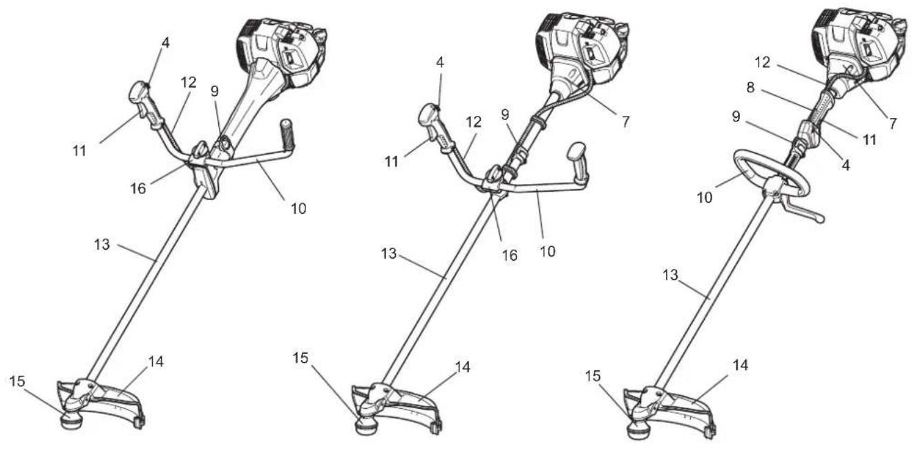

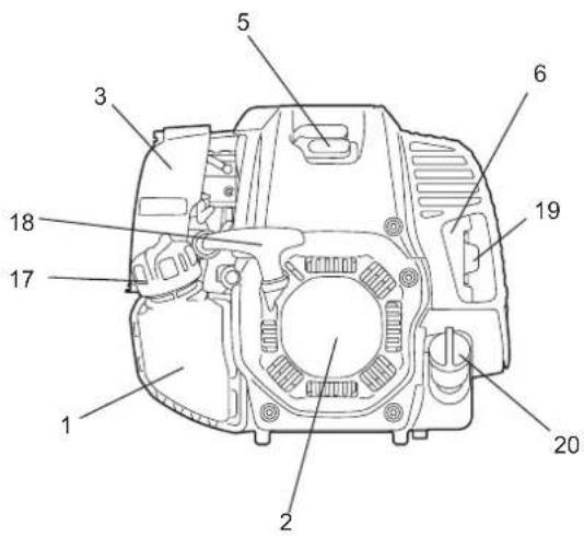
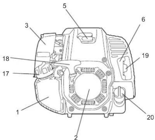
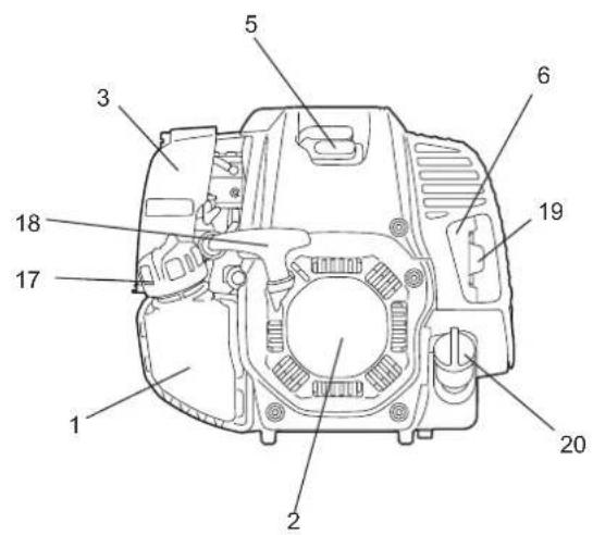
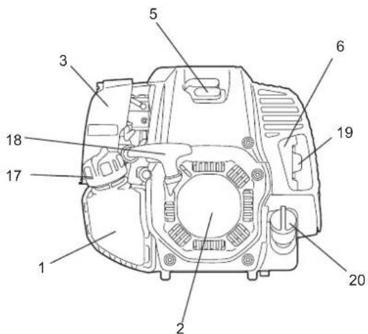
| GB DESIGNATION OF PARTS | |
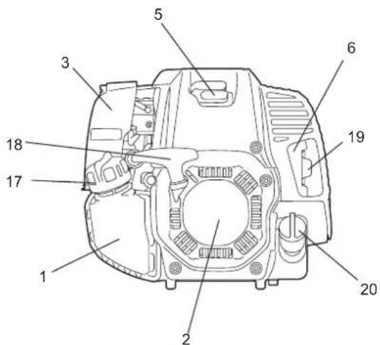
| 1 Fuel tank | |
| 2 Recoil starter | |
| 3 Air cleaner | |
| 4 | I-O and throttle lock switch (on/off) |
| 5 Spark plug | |
| 6 Exhaust muffler | |
| 7 Clutch case | |
| 8 Rear grip | |
| 9 Hanger | |
| 10 Handle | |
| 11 Throttle lever | |
| 12 Control cable | |
| 13 Shaft | |
| 14 Protector (Cutting tool guard) | |
| 15 Gear Case/Head case | |
| 16 Handle holder | |
| 17 Fuel tank cap | |
| 18 Starter knob | |
| 19 Exhaust pipe | |
| 20 Oil cap | |
MOUNTING OF HANDLE
CAUTION: Before doing any work on the equipment, always stop the engine and pull the spark plug connector off the spark plug.
Always wear protective gloves!
CAUTION: Start the engine only after having assembled it completely.
1. For model EM4351UH, EM4350UH (with solid-type handle)
Insert the shaft of the handle into the grip as shown. Align the screw hole in the grip with the one in the shaft. Tighten the screw securely.
- Loosen knob (1).
- Place handle (4) between handle clamp (2) and handle holder (3).
- Adjust handle (4) to an angle that provides a comfortable working position and then secure by firmly hand-tightening knob (1).
CAUTION: Do not forget to mount spring (5).
2. For model EM4351UH, EM4350UH (with separate-type handle) (country specific)
Insert the shaft of the handle into the grip as shown. Align the screw hole in the grip with the one in the shaft. Tighten the screw securely.
- Place the handle with the throttle lever on the handle holder on the right side (to be held by the right hand) and the other on the left side.
- Fit the handle edge to the handle holder groove, and provisionally fix the upper side (1) of the handle holder by four bolts M5 x 25 (2).
- Adjust the handle to an angle easy to manipulate, and tighten the bolt (2) uniformly on the right and left sides.
3. For model EM4350LH
- Fix the loop handle on the shaft with four screws.
- To keep a proper distance between the grips, place the spacer (1) between the loop handle and the hanger (2).


MOUNTING OF PROTECTOR
To meet the applicable safety provisions, only the tool/protector combinations as indicated in the table must be used.
Be sure to use genuine MAKITA metal blades (including saw blade and cutter blade) or nylon cutting head.
- The metal blade must be well polished, free of cracks or breakage. If the metal blade hits against a stone during operation, stop the engine and check the blade immediately.
- Polish or replace the metal blade every three hours of operation.
- If the nylon cutting head hits against a stone during operation, stop the engine and check the nylon cutting head immediately.
CAUTION: The appropriate protector must always be installed, for your own safety and in order to comply with accident prevention regulations.
Operation of the equipment without the guard being in place is not permitted.
The outside diameter of the cutter blade must be 300 mm (12") or smaller. Never use any blades exceeding 300 mm (12") in outside diameter.
Use 200 mm saw-blade protector only when using 200 mm saw-blade.
Use 225 mm saw-blade protector only when using 225 mm saw-blade.
Do not apply other combination when using saw-blade.
NOTE: The standard combination of cutting tool differs from county to country.
NOTE: When using this protector on Model EM4350LH in combination with the nylon cutting heads (B&F Z5L or B&F Eco6L), use balance washer (P/N:326755*2) between receiver washer and the nylon cutting head. (See page 12 as a reference to mounting.)

Cutter blade

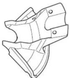
Protector for metal blades

200 mm saw blade

Protector for 200 mm saw blade

225 mm saw blade

Protector for 225 mm saw blade
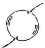
Nylon cutting head
Protector for nylon cutting head
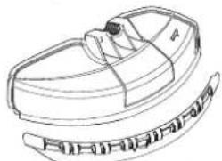
Protector for nylon cutting head

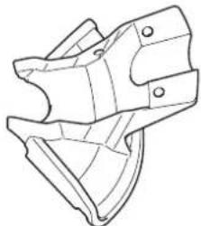
- In use of the metal blade, fix the protector (3) to the clamp (2) with two bolts (1).
NOTE: Tighten the right and left bolts evenly so that the gap between the clamp (2) and the protector (3) will be constant.
Otherwise, the protector sometimes may not function as specified.


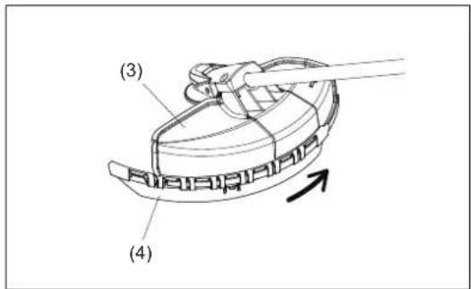
- In cases where the nylon cord cutter is to be used, be sure to mount the nylon cord cutter protector (4) onto the metal blade protector (3).
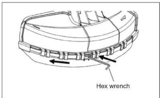
- Mount the nylon cord cutter protector (4) by sliding it into place from the flank of the metal blade protector (3) as shown.
- Remove tape adhered to cutter, which cuts nylon cord, on nylon cord cutter protector (4).
CAUTION: Be sure to push in nylon cord cutter protector (4) until it is fully inserted.
Take care not to injure yourself on the cutter for cutting the nylon cord.
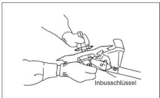
- To remove the nylon cord cutter protector (4), apply a hex wrench into the notch on the metal blade protector (3), push it in and meanwhile slide the nylon cord cutter protector (4).
MOUNTING OF METAL BLADE OR NYLON CUTTING HEAD
Be sure to use genuine MAKITA metal blades or nylon cutting head.
- The metal blade must be well polished, free of cracks or breakage. If the metal blade hits against a stone during operation, stop the engine and check the blade immediately.
- Polish or replace the metal blade every three hours of operation.
- If the nylon cutting head hits against a stone during operation, stop the engine and check the nylon cutting head immediately.
CAUTION: The appropriate protector must always be installed, for your own safety and in order to comply with accident-prevention regulations.
Operation of the equipment without the guard being in place is not permitted.
The outside diameter of the cutter blade must be 300 mm (12") or less. Never use any blades exceeding 300 mm (12") in outside diameter.
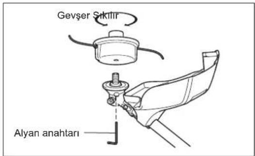
Turn the machine upside down, and you can replace the metal blade or nylon cutting head easily.
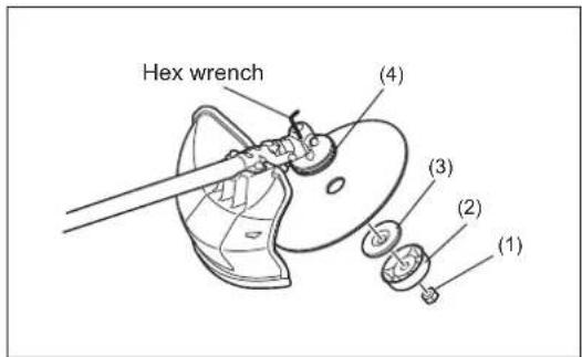
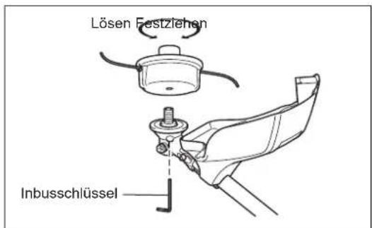
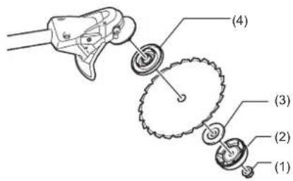
- Insert the hex wrench through the hole in the gear case and rotate the receiver washer (4) until it is locked with the hex wrench.
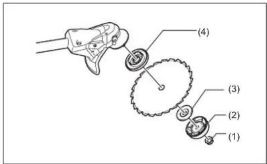
- Loosen the nut (1) (left-hand thread) with the socket wrench and remove the nut (1), cup (2), and clamp washer (3).
Mounting of metal blade with the hex wrench still in place
- Mount the metal blade onto the shaft so that the guide of the receiver washer (4) fits in the arbor hole in the metal blade. Install the clamp washer (3), cup (2), and secure the metal blade with the nut (1). [Tightening torque: 20 - 30 N-m]
NOTE: Always wear gloves when handling the metal blade.
NOTE: The metal blade-fastening nut (with spring washer) is a consumable part. If there appears any wear or deformation on the spring washer, replace the nut.
Mounting of nylon cutting head
- The clamp washer (3), cup (2), and nut (1) are not necessary for mounting the nylon cutting head. The nylon cutting head should go on top of the receiver washer (4).
- Insert the hex wrench through the hole in the gear case and rotate the receiver washer (4) until it is locked with the hex wrench.
- Then screw the nylon cutting head onto the shaft by turning it counterclockwise.
- Remove the hex wrench.





Inspection and refill of engine oil
- Perform the following procedure, with the engine cooled down.
- Assure that the engine is on a flat horizontal surface and confirm if the oil level is between the lower or upper limit of the oil indicator.
- If the oil level is below the lower limit, remove the oil cap and add oil.
- The area surrounding the external marks is transparent, so the amount of oil inside can be checked without having to remove the oil cap. However, if oil pipe becomes extremely dirty, visibility may be lost, and oil level will have to be checked against stepped section on inside of oil pipe.
- You may need to refill oil approximately every 10 operating hours (every 10 refuelings).
If the oil changes in color or mixes with dirt, replace it with new one. (For the interval and method of replacement, refer to P 23.)
Recommended oil: SAE 10W-30 oil of API Classification, Class SF or higher (4-stroke engine for automobile)
Oil volume: Approx. 0.10L
NOTE: If the engine is not positioned as illustrated on a horizontal surface, an inaccurate indication of oil level may occur and oil may be overfilled. Filling oil above the upper limit may cause oil contamination and/or white smoke.
Replacement of oil: "Oil cap"
- Remove dust or dirt near the oil refill port, and detach the oil cap.
- Keep the detached oil cap free of sand or dust. Otherwise, any sand or dust adhering to the oil cap may cause irregular oil circulation or wear on the engine parts, which will result in troubles.

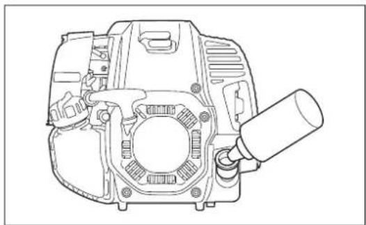
(1) Keep the engine level, and detach the oil cap.

(2) Fill with oil to upper limit mark. Use oil bottle when filling.
(3) Securely tighten the oil cap. Insufficient tightening may cause oil leakage.
Note
- Do not replace oil with the engine in a tilted position.
- Filling with oil while engine is tilted leads to overfilling which causes oil contamination and/or white smoke.
After refilling oil
– Wipe with a rag any spilled oil immediately.
REFUELING
Handling of fuel
It is necessary to handle fuel with utmost care. Fuel may contain substances similar to solvents. Refueling must be performed in a sufficiently ventilated room or in the open air. Never inhale fuel vapor, and keep fuel away from you. If you touch fuel repeatedly or for a long time, the skin becomes dry, which may cause skin disease or allergy. If fuel enters into the eye, clean the eye with fresh water. If your eye remains still irritated, consult your doctor.
Storage period of fuel
Fuel should be used within a period of 4 weeks, even if it is kept in a special container in a well-ventilated and shaded area. Otherwise, fuel may deteriorate in one day.
STORAGE OF MACHINE AND REFILL TANK
- Keep the machine and tank at a cool place free from direct sunshine.
– Never keep the fuel in a car.
Fuel
The engine is a four-stroke engine. Be sure to use an unleaded automobile gasoline 87 or higher octane ((R+M)/2). It may contain no more than 10% alcohol (E-10).
Points for fuel
- Never use a gasoline mixture which contains engine oil. Otherwise, it will cause excessive carbon accumulation or mechanical troubles.
– Use of deteriorated oil will cause irregular start-up.
Refueling
WARNING: Shut off the engine before refueling, keep away from open flames and do not smoke.
- Loosen the tank cap a little to release the tank pressure.
- Detach the tank cap, and refuel, discharging air by tilting the fuel tank so that the refuel port will be oriented upward. DO NOT fill fuel up to the top of the tank.
– Wipe the outside of the tank cap to prevent debris from entering into the fuel tank.
– After refueling, securely tighten the tank cap.
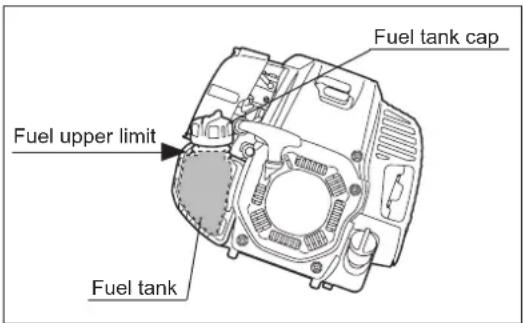
- If there is any flaw or damage on the tank cap, replace it.
- The tank cap wears out in course of time. Replace it every two to three years.
• DO NOT put fuel in the oil fill port.
CORRECT HANDLING OF MACHINE
Attachment of shoulder harness
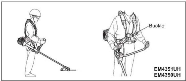
- Adjust the strap length so that the metal blade will be kept parallel with the ground.
For EM4351UH, EM4350UH
Hold the harness on your back, attach it with the buckle, and adjust the length of the bands.
NOTE: Be careful not to trap clothing, etc., in the buckle.
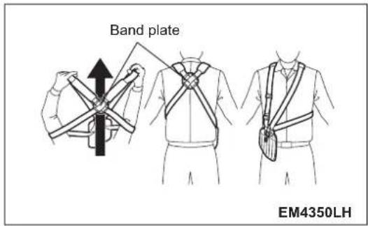
For EM4350LH
1) Stand as the band plate closer to you. And let your arms and head pass through the band.
2) The band plate sits on your back and the adjustors and hook comes on the right side of your body when you appropriately equip the harness.
Releasing the machine
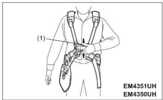
For EM4351UH, EM4350UH
- To release the machine, squeeze the sides of the buckle (1) and take off the shoulder harness.
Be extremely careful to maintain control of the machine at this time. Do not allow the machine to be deflected toward you or anyone in the work vicinity.
WARNING: Failure to maintain complete control of the machine at all could result in serious bodily injury or DEATH.

For EM4350LH
- To release the machine, release the emergency detachment lever (2) by pulling strongly with fingers.
Be extremely careful to maintain control of the machine at this time. Do not allow the machine to be deflected toward you or anyone in the work vicinity.
WARNING: Failure to maintain complete control of the machine at all could result in serious bodily injury or DEATH.

Hanging ring
For EM4351UH
- You can use the ring for hanging something weighing less than 2 kg (4.4 lbs).
NOTICE: Do not hang anything weighing more than 2 kg(4.4 lbs) on the ring. Anything heavier on the ring can cause it to fail and the item to be damaged.
CAUTION: Do not hang anything on the ring that can become entangled with bushes or shrubs. Entanglement can cause loss of balance and control resulting in personal injury.

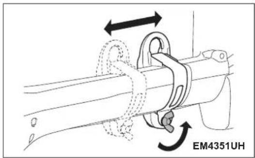
Weight balance adjustment
The machine's weight balance can be adjusted by moving location of the hanger forward or backward.
Adjust the height of the cutting tool appropriately for operation.

POINTS IN OPERATION AND HOW TO STOP
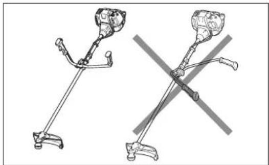
Observe the applicable accident prevention regulations!

Before starting the engine, always set the handle in the proper position. Otherwise the cutting tool may turn suddenly and cause injury, because the throttle cable may be pulled or bent, and open the throttle.
STARTING
Move at least 3 m away from the place of refueling. Place the unit on the ground taking care that the cutting tool does not come into contact with the ground or any other objects.
A: Cold start
1) Set this machine on a flat space.
2) Set the I-O switch (1) to OPERATION.

3) Choke lever
Close the choke lever.
Choke opening:
- Full closing in cold or when the engine is cold.
- Full or half opening if the engine is a bit warm, such as restarting engine just after stopping during warm-up operation.

4) Primer pump
Continue to push the primer pump until fuel comes into the primer pump. (In general, 7 to 10 pushes.)
If the primer pump is pushed excessively, an excess of gasoline returns to the fuel tank.

5) Recoil starter
Make sure you have a firm footing.
Hold the unit with your left hand and press it down firmly.
CAUTION: Do not stand or kneel on the throttle cable. The internal wire may be pulled and the cutting tool may start rotating unintentionally.
Do not open the throttle.
Pull the starter knob gently until a certain resistance is felt. Then, return the starter knob, and pull it strongly.
Never pull the rope to the full extension. Once the starter knob is pulled, never release your hand immediately. Hold the starter knob until it returns to its original point.


6) Choke lever
Once engine starts, set choke lever to the OPEN position.
- Open the choke lever gradually while checking the engine operation. Be sure to open the choke lever to the full in the end.
- In cold or when the engine is cooled down, never open the choke lever suddenly. Otherwise the engine may stop.
7) Warm-up operation
Continue warm-up operation for 2 to 3 minutes.
NOTICE: Do not pull the throttle lever unnecessarily while the engine is not running. It may cause fuel leak from the air cleaner. If it happens, wipe leaked fuel off. Also, open the air cleaner cover and clean the element and the air cleaner plate.

NOTE:
- Do not pull the throttle lever unnecessarily when the engine is not running. It may cause flooding of fuel in the engine, and may cause the engine difficult to start up.
- In case of flooding of the fuel, remove the spark plug and pull the starter handle slowly to remove excess fuel. Also, dry the electrode section of the spark plug.
- If the engine fires and stops, or stops soon after starting, return the choke lever to the OPEN position, and pull the starter knob a few times again to start the engine.
- If the choke lever is left in the CLOSE position, and the starter knob merely pulled repeatedly, too much fuel will be sucked in, and the engine will become difficult to start.
- Do not race the engine in warm-up operation unnecessarily.
B: Warm start
1) Keep the choke lever full open.
2) Push the primer pump repeatedly.
3) Keep the throttle lever at the idling position.
4) Pull the recoil starter strongly.
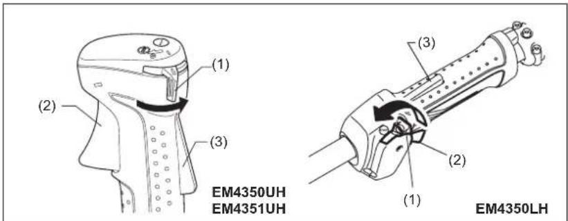
5) If it is difficult to start the engine, release the lock-off lever (3), pull the throttle lever (2), and move the I-O switch (1) to the throttle lock position. With holding the I-O switch (1), release the throttle lever (2) and the lock-off lever (3). Then pull the starter knob.
WARNING: Pay attention that the cutting tool rotates immediately.
6) Once the engine starts, release the lock-off lever (3) and pull the throttle lever (2), and release them to make the engine idle.
STOPPING
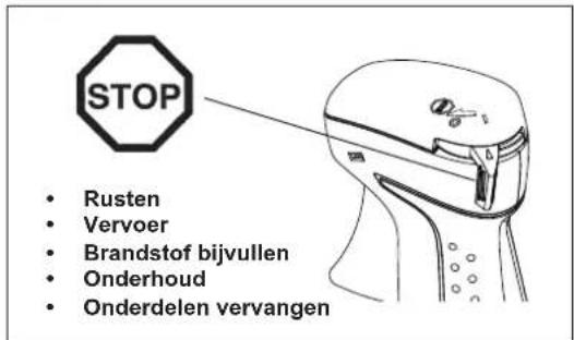
1) Release the throttle lever (2) fully, and when the engine rpm has lowered, set the I-O switch (1) to STOP the engine will now stop.
2) The cutting tool continues to rotate a while after stopping the engine. Wait until it stops completely.

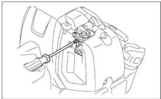
ADJUSTMENT OF IDLE SPEED
When it is necessary to adjust the idle speed, perform it by the carburetor adjusting screw.
CHECKUP OF IDLE SPEED
- Set the idle speed to 3,000 min.
If it is necessary to change the idle speed, use a phillips head screw driver on the screw illustrated on the right. - To increase the idle speed, turn the adjusting screw clockwise.
To reduce the idle speed, turn the adjusting screw counterclockwise. - The carburetor is factory adjusted. However, after several use the idle speed need to be re-adjusted.
PREVENTION FROM CARBURETOR ICING
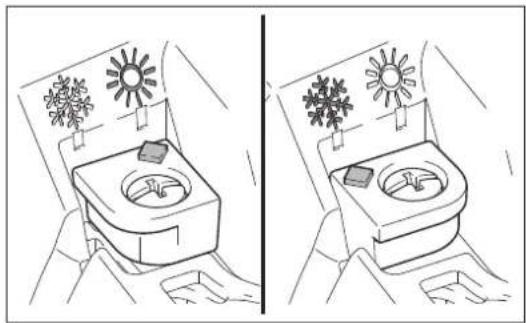
CAUTION: When environmental temperature is higher than 10° C, always return the shutter to normal (sun mark) setting. Otherwise the engine may be damaged by overheating.
When the environmental temperature is low and humidity is high, water vapor may freeze inside the carburetor and the engine drives unsteadily (carburetor icing). Change the setting of the shutter as follows if necessary.
- Remove the screw (1).
- Change the direction of the shutter (2) as follows:
- Environment temperature is higher than 10°C : Set the shutter in normal position (sun mark).
- Environment temperature is equal or lower than 10° C: Set the shutter in anti-icing position (snow mark).
- Tighten the screw.

RESHARPENING THE CUTTING TOOL
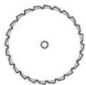
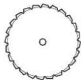
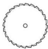
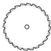
CAUTION: The cutting tools shown in the illustration are not to be sharpened. Manual resharpening will result in imbalances of the cutting tool causing vibrations and damage to the equipment.
NOTE: To increase the service life of the cutter blade it may be turned over once, until both cutting edges have become blunt.
NYLON CUTTING HEAD
The nylon cutting head is a dual line trimmer head that has bump & feed mechanism.
The nylon cutting head will feed out the proper length of nylon line after tapping the nylon cutting head on the ground by changes in centrifugal force caused by increasing or decreasing rpms.
Operation
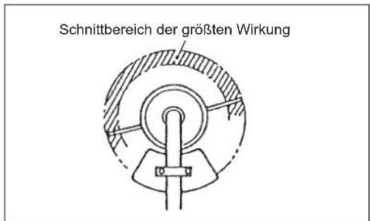
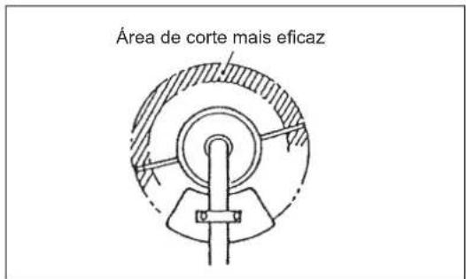
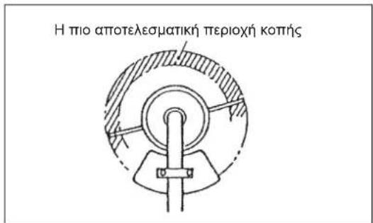
- Increase the nylon cutting head speed to approx. 6,000 m/h. Bump the nylon cutting head lightly on the ground.
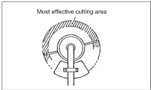
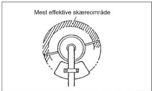
- The most effective cutting area is shown by the shaded area.
- If the nylon cord does not feed out, rewind/replace the nylon cord by following the procedures described under "Replacing the nylon cord."
Replacing the nylon cord (BUMP & FEED)
WARNING: Make sure that the cover of the nylon cutting head is secured to the housing properly as described below. Failure to properly secure the cover may cause the nylon cutting head to fly apart resulting in serious personal injury.
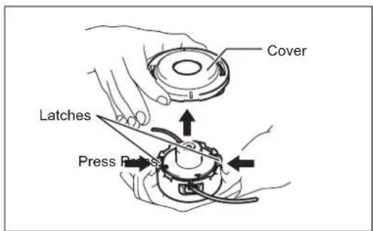
Press inward on the housing latches and lift upward to remove the cover. Discard any of the remaining nylon cord.
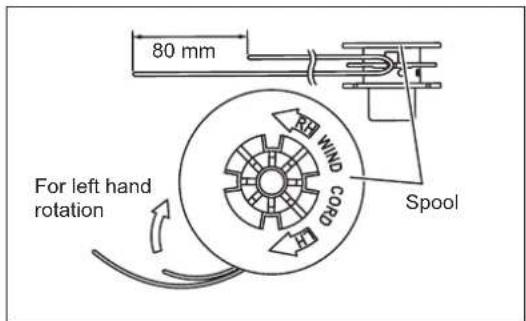
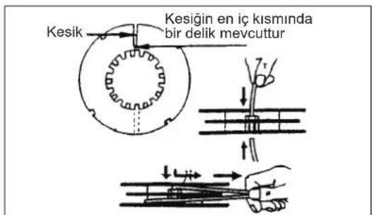
Hook the middle of the new nylon cord to the notch located at the center of the spool between the 2 channels provided for the nylon cord. One side of the cord should be about 80 mm longer than the other side.
Wind both ends firmly around the spool in the direction marked on the head for left hand direction indicated by LH.
Wind all but about 100 mm of the cords, leaving the ends temporarily hooked through a notch on the side of the spool.


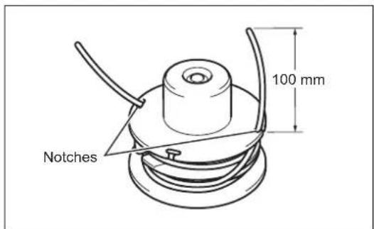
Mount the spool in the housing so that the grooves and protrusions on the spool match up with those in the housing. Keep the side with letters on the spool visible on the top. Now, unhook the ends of the cord from their temporary position and feed the cords through the eyelets to come out of the housing.
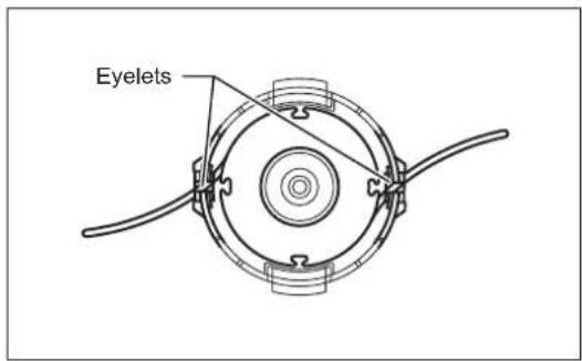
Align the protrusion on the underside of the cover with the slots of the eyelets. Then push cover firmly onto the housing to secure it. Make sure the latches fully spread in the cover.

Replacing the nylon cord (ULTRA AUTO)
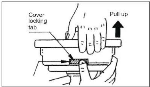
- Put off cover from housing, pressing two cover locking tabs located oppositely on side of the housing.
- Take off tab knob and spool from the housing.
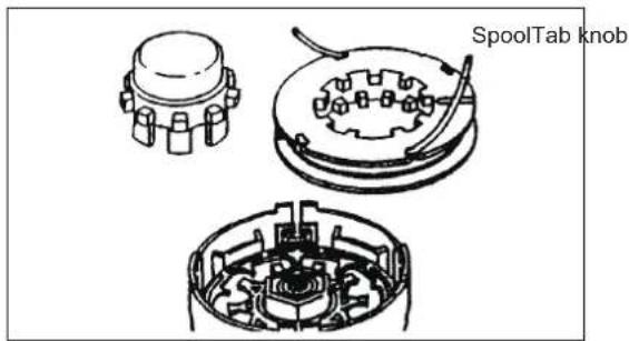
- Put each one end of two cutting lines into each holes at innermost of the slot on one of spool outer flanges. Put the lines into spool gutters through each slit on the flanges.
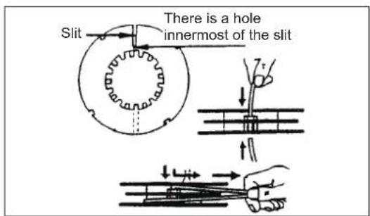
- Wind the lines up firmly to the direction slown by left-hand (LH) arrow on the flange. Do not cross the lines.
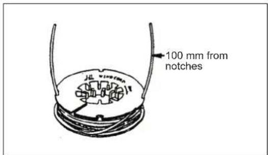
- Wind all but about 100 mm (3-15/16") of the Cords, leaving the end temporarily hooked through a notch on the side of the spool.
- Put tab knob onto the housing hub, positioning it can freely move up and down against spring tension. Put the spool into the housing, aligning the teeth on spool and tap knob alternately like gears.
- Put in the cutting lines through the slot of eyelets.
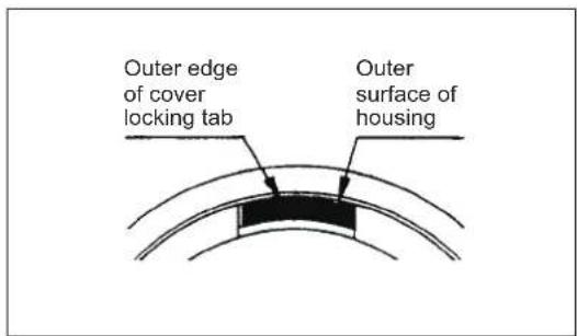
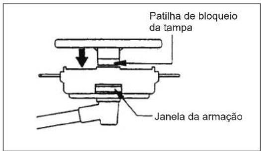
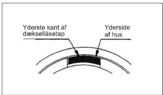
- Put the cover onto the housing, aligning the tabs on cover and the windows on housing. Make sure the cover is secured exactly to the housing. Outer edge of cover locking tab and outer surface of the housing should be on same circumference.



SERVICING INSTRUCTIONS
CAUTION: Before doing any work on the equipment, always stop the engine and pull the plug cap off the spark plug (see "checking the spark plug").
Always wear protective gloves!
To ensure a long service life and to avoid any damage to the equipment, the following servicing operations should be performed at regular intervals.
Daily checkup and maintenance
- Before operation, check the machine for loose screws or missing parts. Pay particular attention to the tightness of the metal blade or nylon cutting head.
– Before operation, always check for clogging of the cooling air passage and the cylinder fins.
Clean them if necessary.
- Perform the following work daily after use:
- Clean the equipment externally and inspect for damage.
- Clean the air filter. When working under extremely dusty conditions, clean the filter the several times a day.
- Check the blade or the nylon cutting head for damage and make sure it is firmly mounted.
- Check that there is sufficient difference between idling and engagement speed to ensure that the cutting tool is at a standstill while the engine is idling (if necessary reduce idling speed).
If under idling conditions the tool should still continue to run, consult your nearest Authorized Service Agent.
- Check the functioning of the I-O switch, the lock-off lever, the throttle lever, and the lock button.
REPLACEMENT OF ENGINE OIL
Deteriorated engine oil will shorten the life of the engine. Be sure to check the oil and level regularly.

WARNING: The engine and engine oil is still hot just after stopping engine. Allow sufficient time for the engine and engine oil to cool down. Otherwise a skin burn may result.
NOTE: If the oil filled above the limit, it may be contaminated or may catch fire with white smoke. Allow sufficient time after stopping engine for the engine oil to return to the oil tank to ensure accurate reading of the oil level.
Interval of replacement: After first 20 operating hours, followed by every 50 operating hours.
Recommended oil: SAE10W-30 oil of API Classification SF Class or higher (4-stroke engine oil for automobile)
In replacement, perform the following procedure.
1) Make sure that the fuel tank cap is tightened securely.
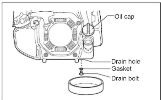
2) Place large container (pan, etc.) under drain hole.
3) Remove drain bolt and then remove oil cap to drain out oil from drain hole. At this time, be sure not to lose drain bolt's gasket, or get dirty any of the removed components.
4) Once all the oil has been drained, install gasket and drain bolt, and tightly secure drain bolt, so that it will not loosen and cause leaks.
[Tightening torque: 5 N-m]
* Use cloth to fully wipe off any oil attached to bolt and equipment.
Alternative draining method
Remove oil cap, tilt the equipment toward oil filler hole, and drain out oil. Collect oil in container.
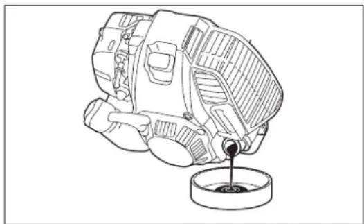
5) Set the engine level, and gradually fill up to upper limit mark with new oil.
6) After filling, tightly secure oil cap, so that it will not loosen and cause leaks. If oil cap is not tightly secured, it may leak.
POINTS ON OIL
- Never discard replaced engine oil in garbage, earth or sewage ditch. Disposal of oil is regulated by law. In disposal, always follow the relevant laws and regulations. For any points remaining unknown, contact Authorized Service Agent.
– Oil will deteriorate even when it is kept unused. Perform inspection and replacement at regular intervals (replace with new oil every 6 months).
CLEANING OF AIR CLEANER

WARNING: Shut off the engine, keep away from open flames and do not smoke.
Interval of Cleaning and Inspection: Daily (every 10 operating hours)
- Turn the choke lever to the full close side, and keep the carburetor off from dust or dirt.
Removing air cleaner cover
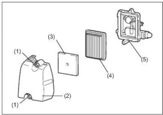
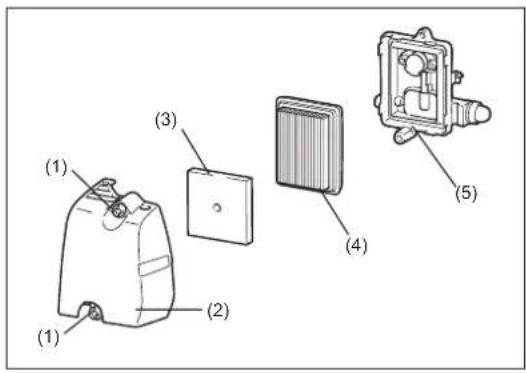
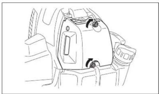
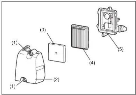
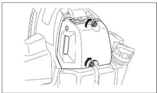
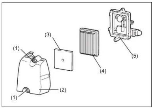
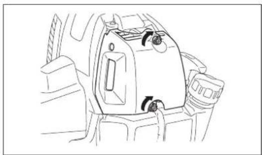
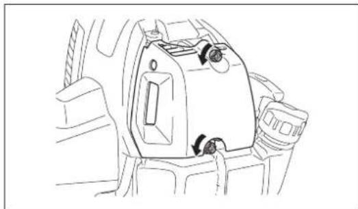
- Loosen two fixing bolts (1).
– Pull and remove the air cleaner cover (2).
Cleaning element
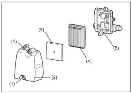
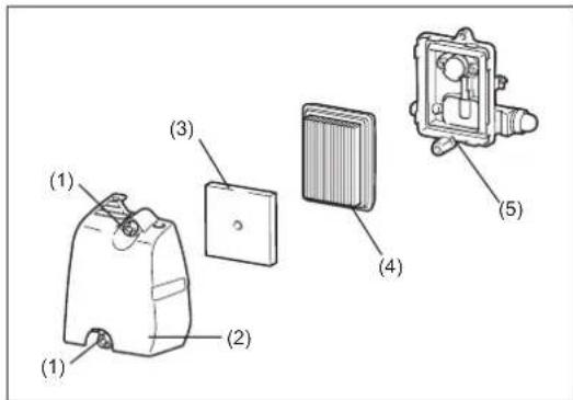
- Remove the elements (3, 4) and tap them to remove dirt.
- For heavy contamination:
1) Remove the element (sponge) (3), immerse it in warm water or in water diluted neutral detergent, and dry it completely. Do not squeeze or rub it when washing.
2) Clean the element (paper) (4) by tapping it gently. If you can use an air blow gun, blow the compressed air onto the inside of the element (paper). Do not wash the element (paper).
- Before attaching the element (sponge), be sure to dry it completely.
Insufficient drying of the element (sponge) may lead to difficult start-up.
- Wipe out oil adhering around the air cleaner cover and separator plate (5) with waste cloth.
Attaching air cleaner cover
- Fit the element (sponge) and element (paper). Insert the element (sponge) all the way into the air cleaner cover.
- Tighten the air cleaner cover with two fixing bolts.
NOTICE:
- Clean the elements several times a day, if excessive dust adheres to it. Dirty elements reduce engine power and make starting engine difficult.
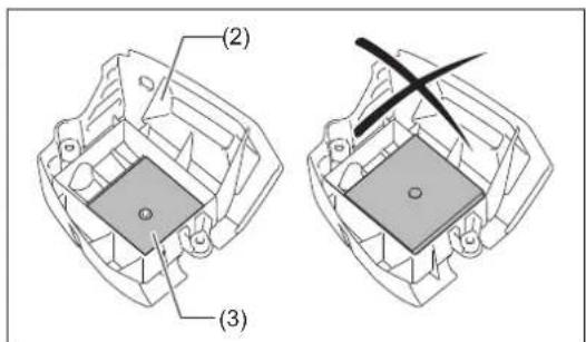
- Remove oil on the elements. If operation continues with the elements remaining not cleared of oil, oil in the air cleaner may fall outside, resulting in contamination of the environment.
- Do not put the elements on the ground or dirty place. Otherwise they pick up dirt or debris and it may damage the engine.
- Never use fuel for cleaning the elements. Fuel may damage them.


CHECKING THE SPARK PLUG
- Only use the supplied universal wrench to remove or to install the spark plug.
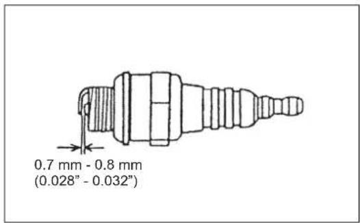
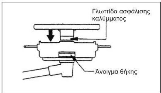
- The gap between the two electrodes of the spark plug should be 0.7 - 0.8 mm (0.028" - 0.032"). If the gap is too wide or too narrow, adjust it. If the spark plug is clogged or contaminated, clean it thoroughly or replace it.
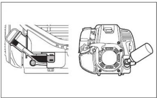
Place the plug cap properly as illustrated after checking.
CAUTION: Never touch the spark plug connector while the engine is running (danger of high voltage electric shock).
SUPPLY OF GREASE TO GEAR CASE
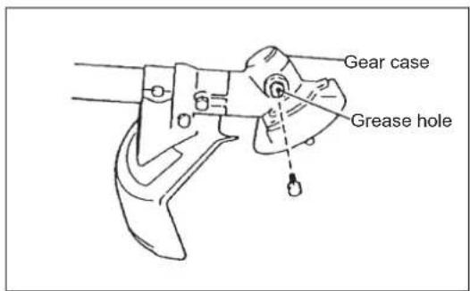
– Supply grease (Shell Alvania 2 or equivalent) to the gear case through the grease hole every 30 hours. (Genuine MAKITA grease may be purchased from your MAKITA dealer.)
CLEANING OF FUEL FILTER
WARNING: INFLAMMABLES STRICTLY PROHIBITED
Interval of Cleaning and Inspection: Monthly (every 50 operating hours)
Suction head in the fuel tank
- The fuel filter (1) of the suction head is used to filter the fuel required by the carburetor.
- A periodical visual inspection of the fuel filter is to be conducted. Open the tank cap, use a wire hook and pull out the suction head through the tank opening. If the filter is hard or clogged up, replace it.
- Replace the fuel filter at least quarterly to ensure an enough fuel supply to the carburetor. Otherwise an insufficient fuel supply will cause the engine start failure and limited maximum speed.
- After checking, cleaning or replacing, fix the fuel filter onto the fuel pipe (3) with the hose clamp (2). Push the fuel filter in all the way to the bottom of the fuel tank.



REPLACEMENT OF FUEL PIPE
CAUTION: INFLAMMABLES STRICTLY PROHIBITED
Interval of Cleaning and Inspection: Daily (every 10 operating hours)
Replacement: Annually (every 200 operating hours)
Replace the fuel pipe every year, regardless of operating frequency. Fuel leakage may lead to fire.
If any leakage is detected during inspection, replace the fuel pipe immediately.
INSPECTION OF BOLTS, NUTS AND SCREWS
– Retighten loose bolts, nuts, etc.
- Check the fuel cap and oil cap for tightness. Check for fuel and oil leakage.
– Replace damaged parts with new ones for safety operation.
CLEANING OF PARTS
- Always keep the engine clean by wiping down with a cloth rag.
- Keep the cylinder fins free of dust or dirt. Dust or dirt adhering to the fins will cause piston seizure.
REPLACEMENT OF GASKETS AND PACKINGS
Replace gaskets and packings if the engine is disassembled.
Any maintenance or adjustment work that is not included and described in this manual is only to be performed by Authorized Service Agents.

STORAGE

WARNING: The engine is still hot just after stopping engine. When draining the fuel, allow sufficient time for the engine to cool down after stopping it. Otherwise a skin burn and/or fire may result.

DANGER: When the machine is kept out of operation for a long time, drain all fuel from the fuel tank and carburetor, and keep it at a dry and clean place.
- Drain fuel from the fuel tank and carburetor according to the following procedure:
1) Remove the fuel tank cap, and drain fuel completely.
If there is any foreign matter remaining in the fuel tank, remove it completely.
2) Pull out the fuel filter from the refill port using a wire.
3) Push the primer pump until fuel is drained from there, and drain fuel coming into the fuel tank.
4) Put the filter to the fuel tank, and securely tighten the fuel tank cap.
5) Then, continue to operate the engine until it stops.
- Remove the spark plug, and drip several drops of engine oil through the spark plug hole.
- Gently pull the starter handle so that engine oil will spread over the engine, and attach the spark plug.
- Attach the cover to the metal blade.
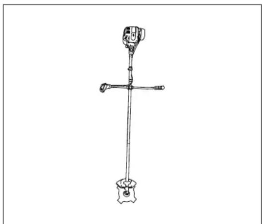
– In general, store the machine in horizontal position, or if it is not possible, place the machine as the cutting tool comes below the engine. Pay full attention how to store the machine to prevent the machine from falling. Otherwise it may result in personal injury. - Keep the drained fuel in a special container in a well-ventilated shade.
Attention after long-time storage
- Before startup after long-time shutdown, be sure to replace oil (refer to P 23). Oil will deteriorate while the machine is kept out of operation.
| Operating time Item | Before operation | After refuleling | Daily (10h) | 30h 50h | 200h | Before storage | Corresponding P | ||
| Engine oil | Inspect/clean | ○ | 13 | ||||||
| Replace | ○*1 | 23 | |||||||
| Tightening parts (bolt, nut) | Inspect | ○ | 25 | ||||||
| Fuel tank | Clean/inspect | ○ | — | ||||||
| Drain fuel | ○*3 | 26 | |||||||
| Throttle lever Check function | ○ | — | |||||||
| Stop switch Check function | ○ | 23 | |||||||
| Cutting tool Inspect | ○ | ○ | 10 | ||||||
| Idle speed Inspect/adjust | ○ | 19 | |||||||
| Air cleaner Clean | ○ | 24 | |||||||
| Spark plug Inspect | ○ | 25 | |||||||
| Cooling air passage and cylinder fins | Clean/inspect | ○ | 26 | ||||||
| Fuel pipe | Inspect | ○ | 26 | ||||||
| Replace | ○*2 | — | |||||||
| Gear-case grease Refill | ○ | 25 | |||||||
| Fuel filter Clean/replace | ○ | 25 | |||||||
| Valve clearance (intake valve and exhaust valve) | Inspect/adjust | ○*2 | — | ||||||
| Carburetor Drain fuel | ○*3 | 26 |
*1 Perform initial replacement after 20h operation.
*2 For the 200 operating hour inspection, request Authorized Service Agent or a machine shop.
*3 After emptying the fuel tank, continue to run the engine and drain fuel in the carburetor.
TROUBLESHOOTING
Before making a request for repairs, check for trouble by yourself. If any abnormality is found, control your machine according to the description of this manual. Never tamper or dismount any part contrary to the description. For repairs, contact Authorized Service Agent or local dealership.
| State of abnormality Probable cause (malfunction) Remedy | ||
| Engine does not start | I-O switch is set to STOP. Set the I-O switch to | OPERATION. |
| Failure to operate primer pump Push 7 to 10 times | ||
| Low pulling speed of starter rope Pull strongly | ||
| Lack of fuel Feed fuel | ||
| Clogged fuel filter Clean | ||
| Broken fuel tube Straighten fuel tube | ||
| Deteriorated fuel Deteriorated fuel makes starting more difficult.Replace with new fuel. (Recommended replacement: 1 month) | ||
| Excessive suction of fuel Set throttle lever from | medium speed to high speed, and pull starter handle until engine starts.Once engine starts, metal blade starts rotating. Pay full attention to metal blade.If engine will not start still, remove spark plug, dry the electrode, and reassemble them as they originally are. Then, start as specified. | |
| Detached plug cap Attach securely | ||
| Contaminated spark plug Clean | ||
| Abnormal clearance of spark plug Adjust clearance | ||
| Other abnormality of spark plug Replace | ||
| Abnormal carburetor | Make request for inspection and maintenance. | |
| Starter rope cannot be pulled | Make request for inspection and maintenance. | |
| Abnormal drive system | Make request for inspection and maintenance. | |
| Engine stops soonEngine speed does not increase | Insufficient warm-up | Perform warm-up operation |
| Choke lever is set to “CLOSE” although engine is warmed up. | Set to “OPEN” | |
| Clogged fuel filter Clean | ||
| Contaminated or clogged air cleaner | Clean | |
| Abnormal carburetor | Make request for inspection and maintenance. | |
| Abnormal drive system | Make request for inspection and maintenance. | |
| Metal blade does not rotate↓Stop engine immediately | Loosened metal blade-tightening nut | Tighten securely |
| Twigs caught by metal blade or dispersion-preventing cover. | Remove foreign matter | |
| Abnormal drive system | Make request for inspection and maintenance. | |
| Main unit vibrates abnormally↓Stop engine immediately | Broken, bent or worn metal blade | Replace metal blade |
| Loosened metal blade-tightening nut | Tighten securely | |
| Shifted convex part of metal blade and metal blade support fitting. | Attach securely | |
| Abnormal drive system | Make request for inspection and maintenance. | |
| Metal blade does not stop immediately↓Stop engine immediately | High idling rotation | Adjust |
| Detached throttle wire | Attach securely | |
| Abnormal drive system | Make request for inspection and maintenance. | |
| Engine does not stop↓Run engine at idling, and set choke lever to CLOSE | Detached connector | Attach securely |
| Abnormal electric system | Make request for inspection and maintenance. | |
When the engine does not start after warm-up operation:
If there is no abnormality found for the check items, open the throttle by about 1/3 and start the engine.
Français
(Instructions d'origine)
SOUS TENSION/DÉMARRAGE

HORS TENSION/ARRÊT

POSITION DE VERROUILLAGE DE L'ACCÉLÉRATEUR
CONSIGNES DE SÉCURITÉ



(3)

(5)

(6)


Mode d'emploi


Lame de scie de 200 mm

Lame de scie de 225 mm
DÉMARRAGE
PRÉVENTION DU GIVRAGE DU CARBURATEUR
RÉAFFÛTAGE DE L'OUTIL DE COUPE



VÉRIFICATION DE LA BOUGIE



(3)

(5)
(6)


Handhabung

MONTIEREN DES GRIFFS
MONTIEREN DES SCHUTZES
Sägeblatt 200 mm

Sägeblatt 225 mm

Nylon-Schneidkopf

MONTIEREN DES METALLBLATTS | NYLON-SCHNEIDKOPFS

STARTEN
6) Choke-Hebel
Alternative Ablassmethode



ÜBERPRÜFEN DER ZÜNDKERZE


(3)


(5)

(6)



Lama a sega 200 mm

Lama a sega 225 mm

AVVIAMENTO
AFFILATURA DELL'UTENSILE DA TAGLIO


CONTROLLO DELLA CANDELA



(3)

(5)

(6)



Gebruiksmethode


DE HANDGREEP MONTEREN
DE BESCHERMKAP MONTEREN
Zaagblad van 200 mm
Zaagblad van 225 mm

Nylondraad-snijkop

VÓÓR HET BEGIN VAN HET WERK
STARTEN
IJSVORMING IN CARBURATEUR VOORKOMEN
HET SNIJGARNITUUR SLIJPEN




DE BOUGIE CONTROLEREN
Zuigkop in brandstoftank


(3)

(5)

(6)

Método de trabajo

MONTAJE DEL PROTECTOR
Cuchilla de sierra de 200 mm
Cuchilla de sierra de 225 mm


Rotación
ANTES DEL USO
ARRANQUE




(3)

(5)

(6)


Nunca alise ou solde ferramentas de corte danificadas.
MONTAGEM DO PROTECTOR
Lâmina de serra de 225 mm

Protector para lâmina de serra de 225 mm
MONTAGEM DA LÂMINA METÁLICA OU DA CABEÇA DE CORTE EM NYLON


INÍCIO
VOLTAR A AFIAR A FERRAMENTA DE CORTE


VERIFICAR A VELA DE IGNICÃO


(3)


(5)

(6)


Betjeningsmetode

MONTERING AF SKÆRM
Skærm til metalklinger
200 mm savklinge
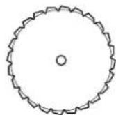
225 mm savklinge

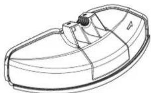
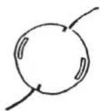
Nylontrimmerhoved
Skærm til
nylontrimmerhoved

Skærm til
nylontrimmerhoved

START
FORHINDRING AF TILISNING AF KARBURATOR
SLIBNING AF SKÆREVÆRKT∅JET



KONTROL AF TÆNDR∅RET






Πριονόδισκος 200 mm

Πριονόδισκος 225 mm

EEKINHMA
6) Μοχλός τσοκ


ΕΛΕΓΧΟΣ ΤΟΥ ΜΠΟΥΖΙ

(3)


(5)

(6)


Çalıştırma yöntemi
KORUYUCUNUN TAKILMASI
ÇALIŞTIRMA
KARBÜRATÖR BUZLANMASININ ÖNLENMESİ
KESİCİ PARÇANIN BİLENMESİ



BUJİNİN KONTROLÜ





- IMPORTANT
- TABLE OF CONTENTS PAGE
- SYMBOLS
- SAFETY INSTRUCTIONS
- GENERAL INSTRUCTIONS
- INTENDED USE OF THE MACHINE
- PERSONAL PROTECTIVE EQUIPMENT
- STARTING UP THE BRUSHCUTTER
- REFUELING
- METHOD OF OPERATION
- CUTTING TOOLS
- KICKBACK (BLADE THRUST)
- VIBRATION
- MAINTENANCE INSTRUCTIONS
- NEVER STRAIGHTEN OR WELD DAMAGED CUTTING TOOLS
- FIRST AID
- WHEN ASKING FOR HELP, PLEASE GIVE THE FOLLOWING INFORMATION
- EC DECLARATION OF CONFORMITY
- MOUNTING OF HANDLE
- FOR MODEL EM4351UH, EM4350UH (WITH SOLID-TYPE HANDLE)
- FOR MODEL EM4351UH, EM4350UH (WITH SEPARATE-TYPE HANDLE) (COUNTRY SPECIFIC)
- FOR MODEL EM4350LH
- MOUNTING OF PROTECTOR
- BE SURE TO USE GENUINE MAKITA METAL BLADES (INCLUDING SAW BLADE AND CUTTER BLADE) OR NYLON CUTTING HEAD
- MOUNTING OF METAL BLADE OR NYLON CUTTING HEAD
- BE SURE TO USE GENUINE MAKITA METAL BLADES OR NYLON CUTTING HEAD
- MOUNTING OF METAL BLADE WITH THE HEX WRENCH STILL IN PLACE
- MOUNTING OF NYLON CUTTING HEAD
- INSPECTION AND REFILL OF ENGINE OIL
- REPLACEMENT OF OIL: "OIL CAP
- NOTE
- AFTER REFILLING OIL
- HANDLING OF FUEL
- STORAGE PERIOD OF FUEL
- STORAGE OF MACHINE AND REFILL TANK
- FUEL
- POINTS FOR FUEL
- WARNING: SHUT OFF THE ENGINE BEFORE REFUELING, KEEP AWAY FROM OPEN FLAMES AND DO NOT SMOKE
- CORRECT HANDLING OF MACHINE
- ATTACHMENT OF SHOULDER HARNESS
- FOR EM4351UH, EM4350UH
- FOR EM4350LH
- RELEASING THE MACHINE
- HANGING RING
- FOR EM4351UH
- WEIGHT BALANCE ADJUSTMENT
- POINTS IN OPERATION AND HOW TO STOP
- STARTING
- A: COLD START
- CHOKE LEVER
- PRIMER PUMP
- RECOIL STARTER
- WARM-UP OPERATION
- B: WARM START
- STOPPING
- ADJUSTMENT OF IDLE SPEED
- CHECKUP OF IDLE SPEED
- PREVENTION FROM CARBURETOR ICING
- RESHARPENING THE CUTTING TOOL
- NYLON CUTTING HEAD
- OPERATION
- REPLACING THE NYLON CORD (BUMP & FEED)
- REPLACING THE NYLON CORD (ULTRA AUTO)
- SERVICING INSTRUCTIONS
- DAILY CHECKUP AND MAINTENANCE
- REPLACEMENT OF ENGINE OIL
- ALTERNATIVE DRAINING METHOD
- POINTS ON OIL
- CLEANING OF AIR CLEANER
- REMOVING AIR CLEANER COVER
- CLEANING ELEMENT
- ATTACHING AIR CLEANER COVER
- NOTICE
- CHECKING THE SPARK PLUG
- SUPPLY OF GREASE TO GEAR CASE
- CLEANING OF FUEL FILTER
- WARNING: INFLAMMABLES STRICTLY PROHIBITED
- SUCTION HEAD IN THE FUEL TANK
- REPLACEMENT OF FUEL PIPE
- CAUTION: INFLAMMABLES STRICTLY PROHIBITED
- INSPECTION OF BOLTS, NUTS AND SCREWS
- CLEANING OF PARTS
- REPLACEMENT OF GASKETS AND PACKINGS
- STORAGE
- ATTENTION AFTER LONG-TIME STORAGE
- TROUBLESHOOTING
- FRANÇAIS
- CONSIGNES DE SÉCURITÉ
- MODE D'EMPLOI
- DÉMARRAGE
- PRÉVENTION DU GIVRAGE DU CARBURATEUR
- RÉAFFÛTAGE DE L'OUTIL DE COUPE
- VÉRIFICATION DE LA BOUGIE
- HANDHABUNG
- MONTIEREN DES GRIFFS
- MONTIEREN DES SCHUTZES
- MONTIEREN DES METALLBLATTS | NYLON-SCHNEIDKOPFS
- STARTEN
- ALTERNATIVE ABLASSMETHODE
- ÜBERPRÜFEN DER ZÜNDKERZE
- AVVIAMENTO
- AFFILATURA DELL'UTENSILE DA TAGLIO
- CONTROLLO DELLA CANDELA
- GEBRUIKSMETHODE
- DE HANDGREEP MONTEREN
- DE BESCHERMKAP MONTEREN
- VÓÓR HET BEGIN VAN HET WERK
- IJSVORMING IN CARBURATEUR VOORKOMEN
- HET SNIJGARNITUUR SLIJPEN
- DE BOUGIE CONTROLEREN
- ZUIGKOP IN BRANDSTOFTANK
- MÉTODO DE TRABAJO
- MONTAJE DEL PROTECTOR
- ANTES DEL USO
- ARRANQUE
- NUNCA ALISE OU SOLDE FERRAMENTAS DE CORTE DANIFICADAS
- MONTAGEM DO PROTECTOR
- MONTAGEM DA LÂMINA METÁLICA OU DA CABEÇA DE CORTE EM NYLON
- INÍCIO
- VOLTAR A AFIAR A FERRAMENTA DE CORTE
- VERIFICAR A VELA DE IGNICÃO
- BETJENINGSMETODE
- MONTERING AF SKÆRM
- START
- FORHINDRING AF TILISNING AF KARBURATOR
- SLIBNING AF SKÆREVÆRKT∅JET
- KONTROL AF TÆNDR∅RET
- EEKINHMA
- ΕΛΕΓΧΟΣ ΤΟΥ ΜΠΟΥΖΙ
- ÇALIŞTIRMA YÖNTEMI
- KORUYUCUNUN TAKILMASI
- ÇALIŞTIRMA
- KARBÜRATÖR BUZLANMASININ ÖNLENMESİ
- KESİCİ PARÇANIN BİLENMESİ
- BUJİNİN KONTROLÜ
Brand : MAKITA
Model : EM4351UH
Category : String Trimmer