
DA3596 - Range hood MIELE - Free user manual and instructions
Find the device manual for free DA3596 MIELE in PDF.


| Product Type | Chimney Extractor Hood |
| Brand | Miele |
| Model | DA3596 |
| Width | 60 cm |
| Depth | 50 cm |
| Height (min-max) | 65-110 cm |
| Weight | Approx. 15 kg |
| Power Supply | 220-240 V, 50 Hz |
| Total Connected Load | 220 W |
| Motor Power | 150 W |
| Max Extraction Rate | 620 m³/h |
| Max Noise Level | 65 dB(A) |
| Grease Filter Type | Stainless steel, dishwasher safe |
| Number of Grease Filters | 2 |
| Charcoal Filter (optional) | Yes, for recirculation mode |
| Lighting | 2 x 3 W LED |
| Controls | Electronic push buttons |
| Energy Efficiency Class | A+ |
| Air Duct Diameter | 150 mm |
| Installation Type | Wall-mounted |
| Safety Features | Automatic switch-off, thermal protection |
| Materials | Stainless steel |
| Accessories Included | Mounting kit, instruction manual |
| Repairability | Spare parts available for 10 years |
| Energy Consumption | 50 kWh/year |
Frequently Asked Questions - DA3596 MIELE
User questions about DA3596 MIELE
0 question about this device. Answer the ones you know or ask your own.
Ask a new question about this device
Download the instructions for your Range hood in PDF format for free! Find your manual DA3596 - MIELE and take your electronic device back in hand. On this page are published all the documents necessary for the use of your device. DA3596 by MIELE.
USER MANUAL DA3596 MIELE
Operating and installation instructions Cooker hood

natural_image
Black-and-white photo of a cooking pot with steam rising, no visible text or symbolsTo prevent the risk of accidents or damage to the appliance, it is essential to read these instructions before it is installed and used for the first time.
Warning and Safety instructions .... 4
Caring for the environment....13
Modes of operation....14
Con@ctivity 2.0 function 15
Guide to the appliance.... 16
Operation (Automatic mode).... 18
Cooking with Con@ctivity 2.0 (Automatic mode).... 18
Leaving automatic mode temporarily.... 20
Returning to automatic mode 20
Operation (Manual mode)....21
Cooking without Con@ctivity 2.0 (Manual mode).... 21
Selecting the power level.... 21
Selecting the run-on time.... 22
Switching the hob lighting on/off.... 22
Power management.... 23
Operation (Automatic and Manual modes).... 24
Operating hours counters 24
Altering the operating hours counter for the grease filters 24
Activating and altering the charcoal filter operating hours counter.... 25
Reading the filter operating hours counter 25
Energy saving tips....26
Cleaning and care 27
Casing 27
Grease filters 28
Charcoal filters 30
Resetting the charcoal filter operating hours counter 31
Disposing of the charcoal filters 31
Installation 32
Appliance dimensions.... 32
Safety distance between hob and cooker hood (S).... 34
Installation recommendations.... 35
Before installation 35
Assembly parts 36
Exhaust socket 45
Setting up for recirculation mode 46
Electrical connection.... 47
Electrical connection....48
Connection for air extraction.... 49
Condensate trap 50
Silencer 50
Activating Con@ctivity 2.0....52
Installing the Con@ctivity 2.0 Stick....52
Activating Con@ctivity 2.0 52
Activating the cooker hood.... 52
Activating the hob....53
Activation failed 53
Deactivating Con@ctivity 2.0 53
After Sales / Guarantee 54
Position of the data plate....54
Technical data 55
Conformity declaration.... 55
This appliance complies with all relevant local and national safety requirements. Inappropriate use can, however, lead to personal injury and damage to property.
To avoid the risk of accidents and damage to the appliance, please read these instructions carefully before using it for the first time. They contain important notes on the safety, installation, use and maintenance of the appliance. Miele cannot be held liable for non-compliance with these instructions.
Keep these instructions in a safe place and ensure that all users are familiar with the contents. Pass them on to any future owner of the appliance.
Correct application
This cooker hood is intended for use in domestic households and similar working and residential environments.
The cooker hood is not intended for outdoor use.
It must only be used as a domestic appliance to extract vapours and remove odours from cooking.
Any other usage is not supported by the manufacturer and could be dangerous.
▶ Where a recirculation cooker hood is fitted above a gas hob, please ensure that there is an adequate supply of fresh air into the room in which it is installed. Please seek the advice of a qualified gas fitter (e.g. GasSafe in the UK) if necessary.
The cooker hood can only be used by people with reduced physical, sensory or mental capabilities, or lack of experience and knowledge, if they are supervised whilst using it, or have been shown how to use it in a safe way and recognise and understand the consequences of incorrect operation.
Safety with children
Children under 8 years of age must be kept away from the cooker hood unless they are constantly supervised.
Children 8 years and older may only use the cooker hood unsupervised if they have been shown how to use it safely and recognise and understand the consequences of incorrect operation.
Children must not be allowed to clean or maintain the cooker hood unsupervised.
▶ Please supervise children in the vicinity of the cooker hood and do not let them play with it.
Danger of suffocation. Packaging, e.g. plastic wrappings, must be kept out of the reach of babies and children. Whilst playing, children could become entangled in packaging or pull it over their head and suffocate.
Technical safety
▶ Unauthorised installation, maintenance and repairs can cause considerable danger for the user. Installation, maintenance and repairs must only be carried out by a Miele authorised technician.
▶ A damaged appliance can be dangerous. Check it for visible signs of damage. Do not use a damaged appliance.
The electrical safety of this appliance can only be guaranteed when correctly earthed. It is essential that this standard safety requirement is met. If in any doubt please have the electrical installation tested by a qualified electrician.
▶ Reliable and safe operation of this cooker hood can only be assured if it has been connected to the mains electricity supply.
Before connecting the appliance to the mains supply, ensure that the connection data on the data plate (voltage and frequency) match the mains electricity supply. This data must correspond in order to avoid the risk of damage to the appliance. Consult a qualified electrician if in any doubt.
Do not connect the appliance to the mains electricity supply by a multi-socket unit or an extension lead. These are a fire hazard and do not guarantee the required safety of the appliance.
For appliances with an external motor fitted (...EXT models) the connection of the two units must be made using the connection cable and the plug connectors.
These models may only be combined with a Miele external motor.
For safety reasons, this appliance may only be used after it has been built in.
The cooker hood must not be used in a non-stationary location (e.g. on a ship).
▶ Tampering with electrical connections or components and mechanical parts is highly dangerous to the user and can cause operational faults.
Only open the housing as described in the instructions given in the installation sheet and in the Cleaning and care section of this booklet. Under no circumstances should any other parts of the housing be opened.
The manufacturer's warranty will be invalidated if the appliance is not repaired by a Miele approved service technician.
▶ Miele can only guarantee the safety of the appliance when genuine original Miele replacement parts are used. Faulty components must only be replaced by Miele spare parts.
If the electrical connection cable is faulty it must only be replaced by a Miele authorised service technician to protect the user from danger.
During installation, maintenance and repair work, the appliance must be disconnected from the mains electricity supply.
Using at the same time as other heating appliances that depend on the air from the room
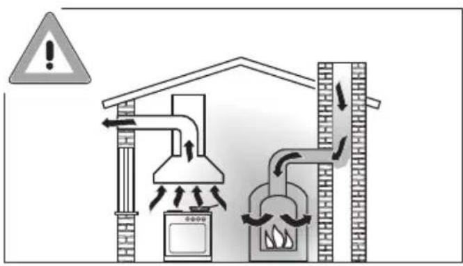
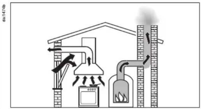
⚠ Warning - danger of toxic fumes
Great care should be taken when using the cooker hood at the same time and in the same room or area of the house as another heating appliance which depends on the air in the room.
Such appliances include gas, oil, wood or coal-fired boilers and heaters, continuous flow or other water heaters, gas hobs, cookers or ovens which draw air in from the room and duct exhaust gases out through a chimney or extraction ducting.
When used in extraction mode, with or without an external motor fitted, or in recirculation mode with a recirculation box installed outside the room, the appliance draws air in from the room in which it is installed and from neighbouring rooms.
If there is insufficient air, an underpressure will occur. The heating appliance will be starved of oxygen, impairing combustion.
Harmful gases could be drawn out of the chimney or extraction ducting back into the room, with potentially fatal consequences.
In order to ensure safe operation, and to prevent gases given off by the heating appliances from being drawn back into the room when the cooker hood and the heater are in operation simultaneously, an underpressure in the room of 0.04 mbar (4 pa) is the maximum permissible.
Ventilation can be maintained by air inlets which cannot be blocked, in windows, doors or outside wall vents, or by other technical measures, such as ensuring that the cooker hood can only be switched on when the heating appliance is switched off or vice versa. A ventilation brick alone is not generally sufficient to ensure safe ventilation.
The overall ventilation condition of the dwelling must be taken into account. If in any doubt, the advice of a competent builder or, for gas a qualified gas fitter (registered with an official gas safety body in accordance with national safety regulations, GasSafe in the UK) must be sought.
If the cooker hood is used in recirculation mode, where the air is directed back into the room in which it is located, operating a heating appliance which depends on the room air at the same time is no cause for concern.
Correct use
▶ Never use a naked flame beneath the cooker hood. To avoid the danger of fire, do not flambé or grill over a naked flame.
When switched on, the cooker hood could draw flames into the filter. Fat deposits could ignite, presenting a fire hazard.
The cooker hood can become damaged when exposed to excessive heat.
- When using the cooker hood over a gas hob, ensure that any burners in use are always covered by a pan. Switch the cooking zone off when a pan is removed, even for a short time.
- Select a pan which is suitable for the size of the burner.
- Regulate the flame so that it does not burn up the sides of the pan.
- Avoid overheating the pan (e.g. when cooking with a wok).
▶ Always switch the cooker hood on when a cooking zone is in use, otherwise condensation may collect in the hood, which could cause corrosion.
When cooking with oil or fat, chip pans and deep fat fryers etc, do not leave the pans unattended. Never leave an open grill unattended when grilling. Overheated oil and fat can ignite and could set the cooker hood on fire.
Do not use the cooker hood without the filters in place. This way you will avoid the risk of grease and dirt getting into the appliance and hindering its smooth operation.
There is a risk of fire if the cooker hood is not cleaned as described in these operating instructions.
The cooker hood can get very hot during cooking due to heat rising from the hob.
Do not touch the housing or the grease filters until the cooker hood has cooled down.
Correct installation
▶ Refer to the cooker or hob manufacturer's instructions as to whether a cooker hood may be operated above the cooker/hob.
▶ Safety regulations prohibit the fitting of a cooker hood over solid fuel stoves.
Insufficient distance between the cooker or hob and the cooker hood can result in damage to the hood.
The minimum safety distances between the top of the cooker or hob and the bottom of the cooker hood given in the "Installation" section must be maintained, unless the hob manufacturer states that a greater distance is required.
If more than one cooking appliance is fitted beneath the cooker hood, and they have different minimum safety distances to the cooker hood, select the greater distance.
The distances given in "Installation" must be observed when fitting the cooker hood.
Exhaust ducting must be of non-inflammable material. Suitable material is available from Miele specialist dealers or the Miele Spares Dept.
The appliance must not be connected to a chimney or flue which is in use. Neither should it be connected to ducting which ventilates rooms with fireplaces.
If exhaust air is to be extracted into a chimney or ventilation duct no longer used for other purposes, seek professional advice.
Cleaning and care
Do not use a steam cleaning appliance to clean this appliance. The steam could reach electrical components and cause a short circuit.
Accessories
▶ Only use genuine original Miele accessories with this appliance. Using accessories from other manufacturers will invalidate the guarantee, and Miele cannot accept liability.
Disposal of the packing material
The packaging is designed to protect the appliance from damage during transportation. The packaging materials used are selected from materials which are environmentally friendly for disposal and should be recycled.
Recycling the packaging reduces the use of raw materials in the manufacturing process and also reduces the amount of waste in landfill sites.
Disposal of your old appliance
Electrical and electronic appliances often contain valuable materials. They also contain materials which, if handled or disposed of incorrectly, could be potentially hazardous to human health and to the environment. They are, however, essential for the correct functioning of your appliance. Please do not therefore dispose of it with your household waste.

natural_image
Symbol of a trash bin crossed with two crossed lines and a black rectangle below (no text or labels)Please dispose of it at your local community waste collection / recycling centre or contact your Dealer for advice.
Ensure that it presents no danger to children while being stored for disposal.
Depending on the model of the cooker hood, the following options are available:
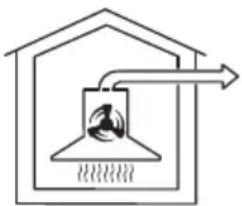
Extraction mode
natural_image
Simple line drawing of a roof structure with a chimney and airflow direction arrow (no text or symbols)doi:04945
The air is drawn in and cleaned by the grease filters and directed outside.
Non-return flap
The non-return flap is designed to prevent the exchange of room and outside air taking place.
The flap is closed when the cooker hood is switched off.
When the cooker hood is switched on, the non-return flap opens for the cooking vapours to be blown directly outside.
If the on-site ventilation system does not have a non-return flap, the non-return flap supplied must be fitted in the exhaust socket in the motor unit.
Recirculation mode
(recirculation mode cooker hoods require a conversion kit and charcoal filters: see "Technical Data")

natural_image
Simple line drawing of a house with a central object and arrows indicating airflow or circulation (no text or symbols)dai0494b
The air is drawn in and cleaned first by the grease filters and then by the charcoal filters. The cleaned air is then recirculated back into the kitchen.
Operation with an external motor
(...EXT model cooker hoods)

natural_image
Simple line drawing of a house interior with a chimney and airflow path (no text or symbols)doi:0494c
Cooker hoods set up for operation with an external motor have to be connected to a Miele external motor located in a suitable position outside the room in which the cooker hood is installed. The external motor is linked to the cooker hood via a connection cable and then operated using Con@ctivity 2.0 or via the controls on the remote control or the cooker hood.
Con@ctivity 2.0 function
Automatic control
The cooker hood has a communication facility which enables the automatic operation of the cooker hood depending on the operational state of the hob.

To make use of the communication facility, the hob must be fitted with a Con@ctivity 2.0 Stick ①.
Please refer to the installation instructions for the Con@ctivity 2.0 stick to check whether it is compatible with your hob.
To use the Con@ctivity 2.0 function, a wireless connection must be established between the hob and the cooker hood (see "Activating Con@ctivity 2.0").
The hob transmits information about its operational status via a wireless signal to the cooker hood.
- The hob lighting will switch on automatically.
- With the deflector plate pulled out, during cooking, the cooker hood automatically sets the power level according to the number of cooking zones in operation and their power levels.
- After the hob has been switched off, the cooker hood fan and the hob lighting will switch off automatically.
See "Operation" for detailed information about this function.
Guide to the appliance

natural_image
Line drawing of a rectangular box with a side panel and a small curved mark on the front face (no text or symbols)dai3017



| - 1 2 3 IS + | 5 15 | |||
| 9 | 10 | 11 | 12 | 13 |
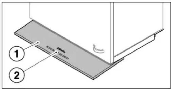
① Pull-out deflector plate
② Controls
③ Grease filters
④ Hob lighting
⑤ Exhaust socket
The exhaust socket can also be fitted at the back.
⑥ Slots for the charcoal filters
⑦ Slots for the grease filters
⑧ Charcoal filters
Accessory required for recirculation mode
⑨ Hob lighting button
⑩ On/Off button for fan
⑪ Buttons for setting the fan power level
⑫ Button for the run-on option
⑬ Operating hours button
When Con@ctivity 2.0 is activated, the cooker hood always works in automatic mode (see "Activating Con@ctivity 2.0").
To operate the cooker hood manually, see "Cooking without Con@ctivity 2.0".
Cooking with Con@ctivity 2.0 (Automatic mode)
■ Switch a cooking zone on at the power level you want.
The cooker hood lighting will come on.
■ Bll out the deflector plate.
The fan will come on at power level 2.
The cooker hood selects the power level automatically during cooking.
This is determined by the total output of the hob, i.e., the number of cooking zones in operation and the power levels selected.
■ If you select a higher power level or are using several cooking zones, the cooker hood will switch to a higher power level.
■ When you reduce the power level or the number of cooking zones on the hob, the cooker hood power level is also reduced.


Examples for power levels 1 to 4
Reaction time
The cooker hood reacts with a slight delay because altering the power level on the hob does not immediately result in a reduction or increase in cooking vapours.
Because the hob transmits the information to the cooker hood at intervals, this can also cause delays.
The reaction can vary from a few seconds to a couple of minutes.
Cooking process
If for example you switch on a cooking zone at the highest power level to heat a pan for frying and reduce the power level after approx. 60 to 90 seconds*, a cooking process is recognised (*60 seconds to 5 minutes for a HiLight hob).
The cooker hood switches itself on and when the hob power level has been reduced, the hood switches to power level 3 and remains at that level for approx. 5 minutes.
After that the cooker hood power level is determined automatically by the Con@ctivity function.
■ ǒu can select another power level manually before then.
Switching off
■ Switch off all cooking zones.
The cooker hood fan will reduce its power level over the next few minutes and will eventually switch itself off.
This helps to neutralise any lingering vapours and odours in the air.
- From the intensive setting 4, the fan switches immediately to level 3.
- If the fan is operating at level 3, it will switch to level 2 after approx. 1 minute.
- From level 2, the fan switches to level 1 after 2 minutes.
- After 2 minutes at level 1 the fan switches itself off.
- After another 30 seconds the lighting switches off.
The cooking process is then finished.
If the deflector plate remains pulled out, the cooker hood will switch on automatically the next time the hob is switched on:
a few seconds after the hob is switched on, the cooker hood fan will switch on, first at level 2 briefly before switching immediately to level 1. Thereafter operation will be carried out automatically.
Leaving automatic mode temporarily
To leave automatic mode temporarily during cooking:
■ Manally select a different power level, or
■ Manally switch the cooker hood off, or
■ Activate the run-on option ^5015 on the cooker hood. The fan will switch off after the selected time and the lighting remains switched on.
The cooker hood can now be operated manually (see "Cooking without Con@ctivity 2.0").
Returning to automatic mode
The cooker hood returns to automatic mode:
■ if the coaker hood has not been used for approx. 5 minutes after selecting a power level manually, or
■ if the manally selected fan power level corresponds to the automatic one again, or
■ if the coaker hood fan and the hob have been switched off for at least 30 seconds.
Automatic mode will resume next time the hob is switched on.
If you wish operate the cooker hood manually for a complete cooking process, switch on the cooker hood fan before switching on the hob.
If the cooker hood and the hob have been switched off for at least 30 seconds after cooking, automatic mode will resume the next time the hob is switched on.
Cooking without Con@ctivity 2.0 (Manual mode)
The cooker hood can be operated manually if:
- Con@ctivity 2.0 is not activated.
- You have temporarily deactivated Con@ctivity 2.0 (see "Leaving automatic mode temporarily").
natural_image
Illustration of a hand inserting a small object into a rectangular panel (no text or symbols)■ Bll the deflector plate downwards slightly and then towards you.
The fan will switch on at level 2. The ① symbol and 2 will light up in the power level display.
Selecting the power level
For light to heavy cooking vapours and odours, select from power levels 1 to 3.
When frying or cooking food with a very strong aroma, select the Intensive setting IS.
■ For a lower power level, press the "-" control, or "+" for a higher level.
Reducing power on the intensive setting
If Power management is activated (default), the fan automatically switches to level 3 after 5 minutes.
Selecting the run-on time
It is advisable to run the fan for a few minutes after cooking has finished to neutralise any lingering vapours and odours in the air.
With the run-on option the fan switches itself off automatically after a pre-selected time.
■ After you have finished cooking, press the run-on option control 5 🎨15
- Once: the fan will switch itself off after 5 minutes (5 lights up).
- Twice: the fan will switch itself off after 15 minutes (15 lights up).
- If you press the run-on option control 5 🎩15 again, the fan will remain on (5 🔊15 will go out).
■ Bsh the deflector plate back in.
The next time the deflector plate is pulled out, the cooker hood will operate at power level 2 again.
■ Or switch the fan off with the On/Off button ①.
The ① symbol will go out.
Switching the hob lighting on/off
■ You can switch the hob lighting on and off by pulling the deflector plate out and pushing it in.
■ When the coker hood deflector plate is pulled out, you can switch the hob lighting on and off with the lighting button ⚙️.
Power management
The cooker hood features a power management system to help save energy. The fan power level is reduced and the lighting is switched off automatically.
- If the Intensive setting is selected, the fan automatically switches to level 3 after 5 minutes.
- From levels 3, 2 or 1 the power will be reduced by one level after 2 hours and then in 30 minutes stages until the fan finally switches off.
- The hob lighting will switch off automatically after 12 hours.
Switching Power management on/off
You can deactivate Power management.
This can result in increased electricity consumption.
■ Switch off the fan and the lighting.
■ Press the run-on option button 5 ✪15 for approx. 10 seconds, until 1 lights up in the power level display.
■ The press in turn,
- the lighting button ⚙,
- the "—" button and then
- the lighting button - again.
If Power management is switched on, the 1 and IS indicators will light up constantly.
If it is switched off, 1 and IS will flash.
■ Pess "—" to switch Power management off.
The 1 and IS indicators will flash.
■ switch it on, press "+".
The 1 and IS indicators will light up constantly.
■ Confirm the setting with the run-on option button 5 📁15.
All the indicator lamps will go out
If you do not confirm within 4 minutes, the cooker hood will revert to the old setting.
Operating hours counters
The number of hours the appliance has been in operation is stored in memory.
When the Grease filter symbol 📍 or the Charcoal filter symbol 🔒 lights up, the operating hours counters are signalling that the filters need to be cleaned or changed. Further information about cleaning and changing the filters and resetting the operating hours counter can be found under "Cleaning and care".
Altering the operating hours counter for the grease filters
You can set the operating hours counter for the grease filters to suit the type of cooking you do.
The grease filter operating hours counter is set at the factory for 30 hours.
- Select a shorter time of 20 hours if you roast or fry a lot.
- If you only cook occasionally we recommend that you still select a short time because grease which has built up gradually over a long period of time will harden on the filters and make cleaning more difficult.
- Select a longer time of 40 or 50 hours if you use very little fat for cooking.
■ Use the On/Off control ① to switch the fan off.
■ Pess the run-on control 515 and the operating hours control ⚙️ at the same time.
The grease filter symbol Ⓧ and one of the fan power level indicators flash.
Fan power level indicators 1 to IS show the time set:
1.... 20 hours
2.... 30 hours
3.... 40 hours
IS 50 hours
■ Press the "-" symbol for a shorter operating time, or the "+" symbol to select a longer operating time.
■ Confirm the selection by pressing the operating hours control ⚙️.
All the indicators will go out
If you do not confirm within 4 minutes, the cooker hood will revert to the old setting.
Activating and altering the charcoal filter operating hours counter
Charcoal filters are needed for recirculation mode.
The charcoal filter operating hours counter needs to be activated once and the operating time needs to be set to suit the kind of cooking you do:
■ Use the On/Off control ① to switch the fan off.
■ Pess the "+" symbol and the operating hours control ⏻ at the same time.
The Charcoal filter symbol ⚙ and one of the fan power levels will flash.
Fan power level indicators 1 to IS show the time set:
1.... 120 hours
2.... 180 hours
- 240 hours
IS ...... Deactivated
■ Pess the "-" symbol for a shorter operating time, or the "+" symbol to select a longer operating time.
■ Confirm your choice by pressing the operating hours control 🔒.
All the indicator lamps will go out.
If you do not confirm within 4 minutes, the cooker hood will revert to the old setting.
Reading the filter operating hours counter
To check the percentage of time set already used
■ Use the On/Off control ① to switch the fan on.
■ Pess and hold the operating hours control 🌐
- Once, to read the Grease filter operating hours. The grease filter symbol lights up.
- Twice, to read the Charcoal filter operating hours. The Charcoal filter symbol lights up.
One or more of the power level indicators will flash.
The number of fan power level indicators flashing shows the percentage of the operating time which has already been used up.
1 25%
1 and 2 50 %
1 to 3 75 %
1 to IS 100 %
The number of operating hours used remains in the memory, even when the appliance is switched off or there is a power cut.
This cooker hood operates very efficiently and economically. The following will help you to save even more energy when using it:
- Ensure that there is sufficient ventilation in the kitchen when cooking. In extraction mode, if there is insufficient air flow the cooker hood cannot operate efficiently and this causes increased operating noise levels.
- Always cook with the lowest possible setting. This produces fewer cooking vapours, so you can use a lower cooker hood power level and therefore benefit from reduced energy consumption.
- Use the Con@ctivity function. The cooker hood will switch on and off automatically at the optimum power level for the cooking you are doing, which ensures low energy consumption.
- If you are operating the cooker hood manually, please note the following:
- Check the power level selected on the cooker hood. A lower power level is generally sufficient for the majority of cooking. Only use the intensive setting when necessary.
- When a large volume of cooking vapours are being produced, switch to a high power level in good time. This is more efficient than operating the cooker hood for longer to try to capture cooking vapours which have already been distributed throughout the kitchen.
- Make sure that you switch the cooker hood off after use. If cooking vapours and odours still
need to be removed from the kitchen air after cooking, use the run-on function. The fan will switch off automatically after the selected run-on time.
- Clean or change the filters at regular intervals. Heavily soiled filters reduce performance, increase the risk of fire and are unhygienic.
Casing
General information
The surfaces and controls are susceptible to scratches and abrasion. Please observe the following cleaning instructions.
■ All eternal surfaces and controls can be cleaned using hot water with a small amount of washing-up liquid applied with a well wrung-out soft sponge or cloth.
Do not let moisture get into the cooker hood.
Only use a damp cloth when cleaning. This is particularly important around the controls.
■ After cleaning, wipe the surfaces dry using a soft cloth.
Do not use:
- cleaning agents containing soda, acids, chlorides or solvents,
- abrasive cleaning agents, e.g. powder cleaners or cream cleaners and abrasive sponges, as well as pot scourers or sponges which have been used previously with abrasive cleaning agents. These will damage the surface material.
Important for appliances with stainless steel surfaces
(This information does not apply to the controls).
■ Stainless steel surfaces can be cleaned with a proprietary non-abrasive cleaning agent designed specifically for use on stainless steel.
- help prevent re-soiling, a proprietary conditioning agent for stainless steel (available from Miele) can also be used. Follow the manufacturer's instructions on the packaging.
Important for the controls
Do not leave soiling on the controls for any length of time.
Otherwise they may suffer discolouration or damage.
Remove soiling straight away.
- Please observe the general notes on cleaning earlier in this section.
Do not use stainless steel cleaning agents on the controls.
Grease filters
The re-usable metal grease filters in the appliance remove solid particles (grease, dust, etc.) from the kitchen vapours, preventing soiling of the cooker hood.
⚠️ An oversatated filter is a fire hazard.
Cleaning interval
The grease filters should be cleaned regularly (at least every 3 - 4 weeks) to avoid a build-up of grease.
Clean them immediately if the Grease filter operating hours symbol ⚙ lights up.
■ You can set the operating hours counter for the grease filters to suit the type of cooking you do (see "Operation").
Removing a grease filter
The grease filter can fall out when you are handling it.
This can result in damage to the filter and the hob below.
Make sure you hold the filter securely at all times when handling it.

natural_image
Diagram showing a hand inserting a tray into two storage compartments (no text or symbols visible)■ Remove the grease filters from the slots on the front of the housing
Cleaning the grease filters by hand
■ Clen the filters with a soft nylon brush in a mild solution of hot water and a small amount of washing-up liquid. Do not use "neat" washing up liquid.
Unsuitable cleaning agents
Unsuitable cleaning agents can cause damage to the surface of the filters if used regularly.
Do not use:
- cleaning agents containing descaling agents
- powder cleaners, cream cleaners
– aggressive multi-purpose cleaning agents or spray cleaners for grease - oven sprays
Cleaning the grease filters in the dishwasher
■ Place the filters as upright as possible in the lower basket, with the short sides upright, ensuring the spray arm is not obstructed.
■ Use a proprietary household dishwasher detergent.
■ Select a dishwasher programme with a wash temperature between 50°C and 65°C.
Depending on the cleaning agent used, cleaning the filters in a dish-washer can cause permanent discolouration to the surface. However, this will not affect the functioning of the filters in any way.
After cleaning
■ After cleaning, leave the filters to dry on an absorbent surface before replacing them.
■ When removing the filters for cleaning, also clean off any residues of oil or fat from the now accessible housing to prevent the risk of these catching fire.
■ Rsh the grease filters back in.
Resetting the grease filter operating hours counter
After cleaning, the operating hours counter needs to be re-set.
■ Whilst the fan is switched on, pass the operating hours control Ⓧ for approx. 3 seconds, until only the 1 is flashing.
The grease filter symbol Ⓧ goes out.
If you want to clean the grease filter(s) before the operating hours counter has reached its maximum,
■ Pess the operating hours control Ⓧ for approx. 6 seconds, until only the 1 is flashing.
Charcoal filters
With recirculation mode, two charcoal filters must be fitted in addition to the grease filters. These are designed to absorb cooking odours.
Charcoal filters can be obtained from your Miele dealer or via the internet at www.miele-shop.com. See end of this booklet for contact details, and "Technical data" for type and reference number.
Fitting/replacing charcoal filters
The slots for the charcoal filters are located above above the grease filters.
natural_image
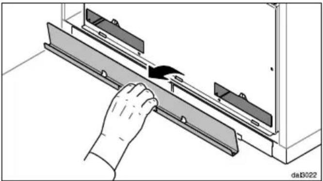
Illustration of a hand inserting a component into a metal bracket (no text or symbols visible)■ Remove the cover. It is held in place by magnets.
■ like the charcoal filters out of their packaging.

natural_image
Technical diagram of a mechanical assembly with two rectangular components and directional arrows indicating motion (no text or symbols)■ Insert the charcoal filters in the slots.
■ Replace the cover.
■ When fitting for the first time, activate the operating hours counter (see "Operation").
When to change the charcoal filters
■ Always replace the charcoal filters when they no longer absorb kitchen odours effectively.
They should, however be replaced at least every 6 months.
The charcoal filter operating hours symbol ⚙ will light up to remind you to change the charcoal filters.
■ The charcoal filter operating hours counter needs to be activated before using for the first time (see "Operation").
Resetting the charcoal filter operating hours counter
After changing the charcoal filters, the operating hours counter needs to be reset.
■ do this, with the fan switched on, press the operating hours control ☐ once, then press it again and hold it for approx. 3 seconds until only the 1 is flashing. The Charcoal filter symbol ☐ will go out.
If you want to replace the charcoal filters before the operating hours counter has reached its maximum:
■ Pess the operating hours control ☐ twice and hold it for approx. 6 seconds until only the 1 is flashing.
Disposing of the charcoal filters
■ Used charcoal filters can be disposed of with the normal household waste.
Appliance dimensions


① Extraction, recirculation with conversion kit DUU 150.
② The wall unit carcase needs to be 38 mm shorter than the wall unit door.
③ Installation is also possible in a 600 mm wide unit. In this case the unit door must open upwards to allow access to the grease filters. This also applies for adjacent units.
④ The ducting can also be connected at the back.
⑤ After installation the wall unit can be fitted with an interim panel. If this is done make sure that the slots for the grease filters and, for recirculation mode, the charcoal filters remain easily accessible.
⑥ Alternatively the wall unit can be fitted with side sections.
⑦ If the hood is installed in a wall unit with a base, openings must be provided to enable adjustment of the retaining force of the deflector plate. For example:
- The wall unit has side sections, as shown.
- The cooker hood is installed in a 600 mm wide unit with units at either side.
The height of the wall unit and cut-out dimensions must take account of any accessories fitted, e.g. silencer, DSM module.
Safety distance between hob and cooker hood (S)
When planning the installation height of your cooker hood, the minimum safety distance between the top of a cooker or hob and the bottom of the cooker hood is as follows, unless a greater distance is specified by the manufacturer of your cooking appliance.
See "Warning and Safety" instructions for further information.
| Cooking appliance Minimum distance S | |
| Electric hob 450 mm | |
| Electric grill, deep fat fryer (electric) 650 mm | |
| Multi-burner gas hob,total output ≤ 12.6 kW, no burner > 4.5 kW | 650 mm |
| Multi-burner gas hob,total output > 12.6 kW and ≤ 21.6 kW,no burner > 4.8 kW. | 760 mm |
| Multi-burner gas hob,total output > 21.6 kW,or multi-burner gas hob where one burner > 4.8 kW. | Not possible |
| Single burner gas hob, output ≤ 6 kW. | 650 mm |
| Single burner gas hob, output > 6 kW and ≤ 8.1 kW. | 760 mm |
| Single burner gas hob, output > 8.1 kW | Not possible |
Installation recommendations
- To achieve optimum vapour extraction, the cooker hood must cover the hob. It should be positioned centrally over the hob, not to the side of it.
- The hob should be no wider than the cooker hood, and if possible, it should be narrower.
- The installation area must be easily accessible. The cooker hood should be easily accessible and easy to dismantle in the event that service is required. This should be taken into consideration when planning the position of cupboards, shelves, ceilings or features in the vicinity of the cooker hood.
Before installation
⚠️ Before installation, it is important to read the information given on the following pages as well as the "Warning and Safety instructions" at the beginning of this booklet.
Assembly parts

dal3026
① 1 collar for exhaust ducting ∅ 150 mm.
② 1 reducing collar for exhaust ducting ∅ 125 mm.
③ 1 non-return flap for fitting into the exhaust socket on the motor unit (not needed for recirculation mode)
④ 2 covers for the brackets.
⑤ 2 brackets to support the appliance in the wall unit.
⑥ 1 cover for the charcoal filter slots.
⑦ 1 spacer strip to conceal the gap between the rear of the appliance and the wall.
⑧ Conversion kit for recirculation mode (the conversion kit is not supplied, but is available as an optional accessory - see "Technical data"). The kit contains an exhaust grille and flexible aluminium hose with hose clips.

01056271
12 screws 4 x 15 mm for securing the cooker hood into the wall unit.
07602740
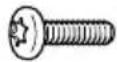
4 screws M4 x 16 mm for securing the cooker hood to the brackets and for securing the spacer strip.

08095672
4 screws M4 x 8 mm for securing the spacer strip.

natural_image
Technical line drawing of a screw and pin assembly (no text or symbols)500+DideBd
2 screws 4 x 40 mm,
2 plugs 6 x 36 mm for securing the cooker hood to the wall (only when fitting into a 900 mm wide wall unit).
07203680
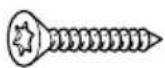
4 screws 4 x 25 mm for securing a 900 mm wide cooker hood.

08161800
4 adhesive covers to conceal the fixing holes which are not required.

natural_image
Simple line drawing of a bent pipe or tube with a handle and end cap (no text or symbols)08276500
1 x T 20 angled key

Repositioning the ducting
The motor unit can be rotated to allow the ducting to be fitted at the back of the cooker hood. This may be necessary if the cooker hood is being fitted in a reduced height wall unit, for example. Repositioning is carried out before installing the cooker hood.
The cooker hood must be disconnected from the mains.
■ Udo the fixing screws on the front panel of the cooker hood housing and remove the panel.
■ Udo the screws from the cover on the back of the cooker hood housing and remove the cover.
■ Unscrew the fixing screws on the motor unit.
■ Urn the motor unit towards the rear and position the exhaust socket in the cut-out in the back panel of the cooker hood housing. Ensure when
turning the motor unit that the connection cable does not become detached.
■ Secure the motor unit in its new position.
■ Now secure the cover taken from the back panel to the top of the housing.
■ Refit the font panel and secure it using the screws.
EXT models
On appliances with an external motor (EXT models), the exhaust socket (not the motor unit) needs to be repositioned.
■ Unscrew the fixing screws and pull the top and bottom sections of the socket apart.
■ Bsition the top section of the socket over the cut-out in the back panel of the cooker hood housing and attach the bottom section to it from inside. Secure the exhaust socket with the fixing screws.

■ Bll the grease filters out of the slots in the front of the cooker hood housing.
The spacer strip needs to be attached to the back of the cooker hood housing before the cooker hood is installed in the wall unit. The spacer strip can be attached to the upper ① or lower edge ② of the deflector plate.
■ Calculate the measurement T for the spacer strip
- Cut the spacer stripø measurement T. Score along the groove for the smaller measurement as shown, and remove the surplus.
■ Screw the spacer strip to the back of the cooker hood at the required position. Use the screws supplied. To attach the spacer strip to the lower edge ② use the screws previously removed from the housing unit.

■ Sow the brackets onto the right and left inside walls of the housing unit so that they are flush with the bottom edges of the unit. The brackets are designed for 16 and 19 mm thick unit sides. Orientate the bracket so that the vertical depth matches the thickness of the unit side, as shown.

■ Fit the screws for attaching the cooker hood so that they protrude by about 5 mm, as shown. Only use the front screws when fitting a 900 mm wide cooker hood in a 600 mm wide wall unit.

natural_image
Technical diagram of a mechanical assembly with directional arrows indicating movement, showing internal components and a magnified inset (no text or symbols)■ Fithe cooker hood into the wall unit from below. Guide it back over the safety notch until it is correctly hung in the wall unit.
natural_image
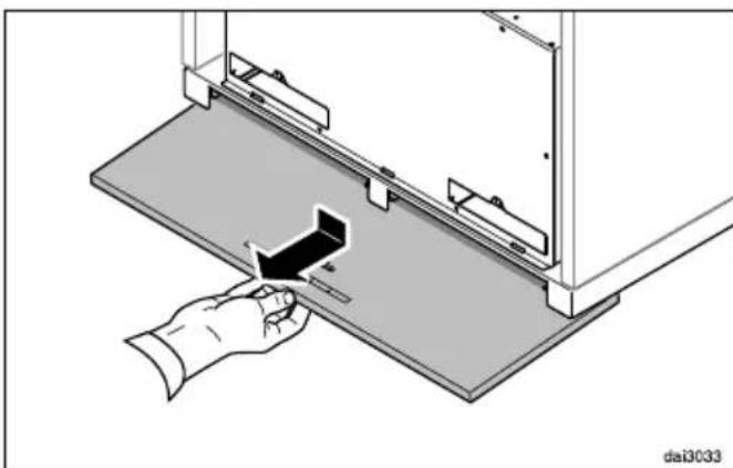
Diagram of a hand inserting a component into a device on a flat base, with no visible text or symbols.■ All the deflector plate downwards slightly and then towards you.
■ Tighten the four fixing screws from below.

■ When fitting a 900 mm wide cooker hood in a 600 mm wide wall unit, insert the two rear screws at this stage. If the wall unit has side sections, you will also need to secure it to the base on either side.
■ Bsh the deflector plate back in.
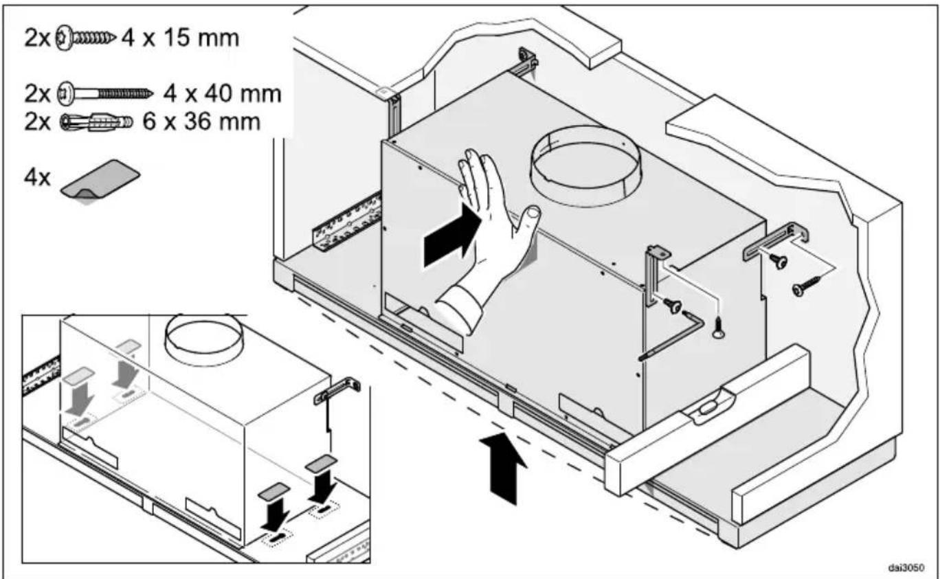
When fitting a 900 mm wide cooker hood into a 900 mm wide housing unit without side base supports, the retaining brackets supplied are used to align the cooker hood and provide additional support. The retaining brackets are secured to the back panel of the wall unit. If the wall unit does not have a solid back panel, the cooker hood can be secured directly to the wall using the screws and plugs supplied.
An angled key is supplied in case the screws are difficult to access.
■ Loosen the retaining bracket screws and push the brackets back against the rear wall.
■ Alig the cooker hood and mark the position of the fixing holes in the wall unit.
■ Now secure the brackets to the wall unit.
■ Reign the cooker hood and tighten up the screws on the casing.
■ Alternatively, the retaining brackets can be secured to the top of the housing unit. To do this, secure the retaining brackets to the front fixing points on the casing.
■ Use the adhesive covers supplied to conceal the fixing holes on the deflector plate which are not used.
Installation
When retracted, the deflector plate is held in place by magnets.
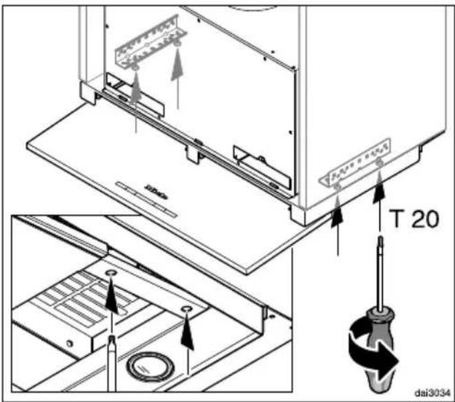
The retaining force of the magnets can be adjusted. The magnets should be adjusted so that the deflector plate is held in place securely on the left and right hand side and can be lowered slightly. An angled key is supplied for adjusting the magnets.

■ Adjust both sides equallyTurn in stages by a half turn each time and check the adjustment by lowering and raising the deflector plate.
- Turning the adjusting screws clockwise increases the magnetic retaining force.
- Turning the adjusting screws anti-clockwise reduces the magnetic retaining force.

■ The covers for the brackets are designed for 16 mm and 19 mm thick unit sides. Turn the covers so that they are in the appropriate position and fit them onto the brackets.

■ Secure the spacer strip to the bottom of the wall unit as well.

■ Take the grease filters out and remove any protective foil. Replace the grease filters.

natural_image
Technical diagram of a multi-panel electronic device with an arrow indicating rotation or assembly (no text or symbols present)■ Insérthe cover for the charcoal filter slots as shown and close it. It is held in place by magnets.
Exhaust socket

natural_image
Diagram of a mechanical device with a rotating base and a curved component, no visible text or symbols■ Insert the non-return flap, if required. Make sure that it opens easily and closes again by itself.
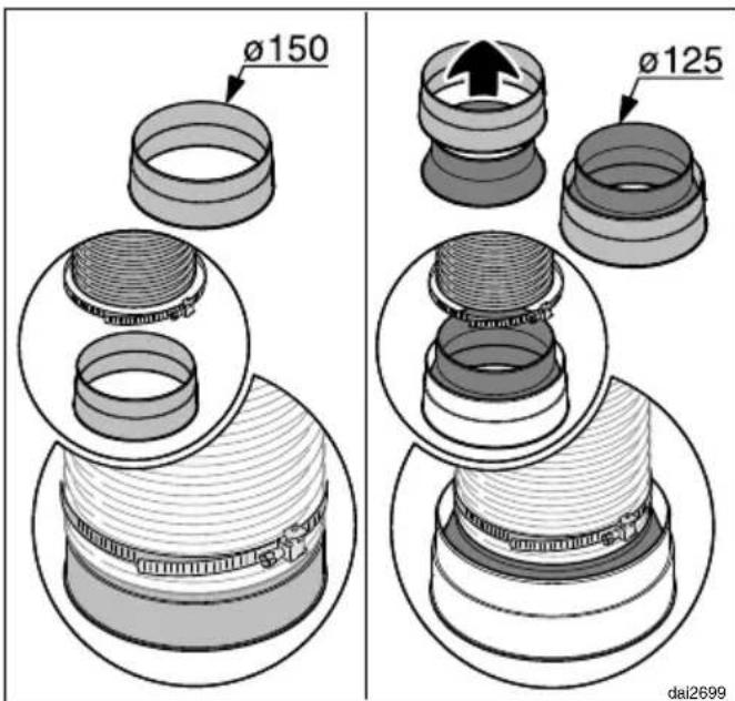
■ Attach the exhaust ducting, e.g. flexible hose, to the exhaust socket using a hose clip (available as an optional accessory). When using ∅ 125 mm ducting, fit the reducing collar supplied into the exhaust socket (see "Connection for air extraction").

natural_image
Diagram of a mechanical press or clamping device with a downward arrow and circular base, no text or symbols present.■ Attach the exhaust ducting to the exhaust socket on the cooker hood.
■ See "Conaction for air extraction" for further instructions on fitting the ducting.
Setting up for recirculation mode
If site conditions are not suitable for the cooker hood to be used with air extraction, the appliance must be set up for
recirculation. A conversion kit, available through your dealer of from Miele is required for operating the cooker hood in recirculation mode. You will also need two charcoal filters (see "Technical data").

natural_image
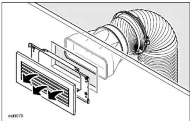
Technical line drawing of a mechanical assembly with coiled spring and housing (no text or symbols)Conversion kit DUU 150 with a plastic grille is suitable for fitting in a non-visible area at the top of the wall unit.
natural_image
Technical illustration of a mechanical assembly with a coiled hose and internal components (no text or symbols)Conversion kit DUU 151 with a stainless steel grille is recommended if the grille is to be fitted in an area which is visible.
■ Fit the conversion kit as described in the installation instructions supplied with the kit. Make sure that the slats in the exhaust grille point towards the centre of the room and not towards a
wall or the ceiling.
A non-return flap is not used in recirculation mode.
■ Fithe charcoal filters (see "Cleaning and care").
Electrical connection
Refer to the notes in “Electrical connection” and “Warning and Safety instructions” before connecting to the electricity supply.
■ 6r appliances connected to an external motor (EXT models):
Connect the cooker hood and the external motor using the connection cable and the six-pole plug connector.
■ Conect the cooker hood to the electricity supply.
All electrical work should be undertaken by a suitably qualified and competent person in strict accordance with current national and local safety regulations (BS 7671 in the UK).
Installation, repairs and other work by unqualified persons could be dangerous, for which the manufacturer cannot be held liable.
Ensure power is not supplied to the appliance until after installation or repair work has been carried out.
Do not connect the appliance to the mains electricity supply by an extension lead. These do not guarantee the required safety of the appliance.
The connection data is given on the data plate. This is visible when the grease filters have been removed. Ensure that this data matches the household mains supply.
Connection of this appliance should be made via a suitable isolator or a double pole fused spur connection unit which complies with national and local safety regulations and the On-Off switch should be easily accessible after the appliance has been built in. When switched off there must be an all-pole contact gap of 3 mm in the switch (including switch, fuses and relays according to EN 60335).
If the switch is not accessible after installation (depending on country), an additional means of disconnection must be provided for all poles.
For extra safety it is advisable to protect the appliance with a suitable residual current device (RCD). Contact a qualified electrician for advice.
Important
This appliance is supplied for connection to an a.c. 230 V single phase 50 Hz supply. The wires in the mains lead are coloured in accordance with the following code:
Green/yellow earth
Blue....neutral
Brown.....live
WARNING:
THIS APPLIANCE MUST BE EARTH- ED
⚠ f this cooker hood is used at the same time as a heating appliance that relies on oxygen from the same room there is a risk in certain circumstances of toxic fumes building up. It is essential that the "Warning and Safety" instructions are observed. The cooker hood should be installed according to local and national building regulations. Seek approval from the building inspector where necessary.
■ Use smooth or flexible ducting made from approved non-flammable materials for exhaust ducting.
■ When using an external motor, make sure that the exhaust ducting is sufficiently rigid. The external motor can cause an underpressure which can result in the exhaust ducting distorting.
■ achieve the most efficient air extraction with the lowest noise levels, please note the following:
- To ensure efficient air extraction, the diameter of the exhaust ducting should not be less than 150 mm.
- If flat ducting is being used, the cross section must not be smaller than the cross sectional area of the exhaust socket.
- The exhaust ducting should be as short and straight as possible.
- Only use wide radius bends.
- The exhaust ducting must not be kinked or compressed.
- Ensure that all connections are strong and airtight.
Remember that any constriction of the air flow will reduce extraction performance and increase operating noise.
If the exhaust is ducted through an outside wall, a telescopic wall vent or a roof vent (available as an optional accessory) is recommended.


natural_image
Diagram of a pipe system with two vertical brick walls and one side pipe, showing airflow direction (no text or labels)If the exhaust air is to be ducted into a flue, the ducting must be directed in the flow direction of the flue.
■ When ducting is horizontal it must be laid to slope away at at least 1 cm per metre. This is to ensure that condensate cannot drain back into the appliance.
If the exhaust ducting is to run through rooms, ceiling space etc. where there may be great variations in temperature between the different areas, the problem of condensation will need to be addressed. The exhaust ducting will need to be suitably insulated.
Condensate trap

In addition to insulating the exhaust ducting, we recommend that a suitable condensate trap is also installed to collect and evaporate any condensate which may occur.
Condensate traps for 125 mm or 150 mm ducting are available as optional accessories.
■ When instling a condensate trap, ensure that it is positioned vertically and as closely as possible above the exhaust socket.
The arrow on the housing indicates the direction of air-flow.
A condensate trap is integrated in cooker hoods which are designed for connection to an external motor (model.....EXT).
Silencer

To achieve even further reductions in noise levels, a special silencer (optional accessory) can be fitted in the ducting system.
Extraction mode

The silencer not only reduces noise from the motor outside the house, but also sounds from outside (e.g. traffic noise). For this reason the silencer must be positioned as close as possible to the ducting exit ①.
Recirculation mode

The silencer needs to be positioned between the exhaust socket and the exhaust grille ②. Ensure there is adequate space for fitting it.
Extraction mode with external motor

flowchart
graph LR
    A["④"] --> B["③"]
    B --> C["⑤"]
    C --> D["→"]
    style A fill:#f9f,stroke:#333
    style B fill:#ccf,stroke:#333
    style C fill:#cfc,stroke:#333
    style D fill:#fcc,stroke:#333
To minimise noise from the motor in the kitchen, the silencer should be positioned in front of the external motor ③ if possible, or, if the ducting is long, above the exhaust socket on the cooker hood ④. In the case of an external motor located inside the house, fitting a silencer behind the external motor ⑤ reduces the noise of the motor outside the house.
Installing the Con@ctivity 2.0 Stick
In order to use the Con@ctivity 2.0 function, the hob must first be fitted with the Con@ctivity 2.0 Stick.
■ Please read the separate installation instructions supplied with the Con@ctivity 2.0 Stick.
Activating Con@ctivity 2.0
Wireless connection must be activated between the hob and the cooker hood before the Con@ctivity 2.0 function can be used.
Both appliances must be installed and operational.
Wireless connection must be activated on the cooker hood and the hob at the same time. Activation on the cooker hood is described below.
Activation on the hob is described in the relevant Operating and installation instructions. Please refer to the Operating instructions before starting.
Activate the cooker hood first, then the hob.
Activating the cooker hood
■ Thehob and cooker hood must be switched off.
■ Press the run-on option button 5♦15 for approx. 10 seconds until the indicator for power level 1 lights up.
■ The press in turn,
- the "—" button,
- then the "+" butt on,
- then the lighting button ⚙️.
The cooker hood is now in signing on/off mode.
If a wireless connection has not yet been established 2 and 3 will flash at the same time.
If a wireless connection has already been established, 2 and 3 will light up constantly (Con@ctivity 2.0 is already activated or a remote control is signed on).
■ Φ activate Con@ctivity 2.0, press the "+" button.
The search for a signal will start.
■ Meanwhile, start activating the hob.
Activating the hob
■ While the cober hood is searching for a signal, start activating the hob. More information about this can be found in the Operating instructions for the hob.
■ When the hb registers that connection has been established, confirm activation on the cooker hood with the run-on option control 515. All indicators will go out.
■ Confirm activation on the hob.
Con@ctivity 2.0 is now ready to use.
If you do not confirm within 4 minutes, activation will not take place.
You only need to carry out the activation procedure once. If the appliances are disconnected from the electricity supply, during a power cut for example, they will still remain activated.
Activation failed
If connection cannot be established despite activating the Con@ctivity function on the cooker hood and hob, the function must be deactivated on both appliances and then the procedure repeated.
Deactivating Con@ctivity 2.0
■ Deactivation on the cooker hood is carried out in the same way as activation, by selecting "-" instead of "+".
■ deactivate the hob, please refer to the Operating instructions supplied with it.
Please bear in mind that disabling the signal will also disable any remote control function and this will have to be activated again.
In the event of a fault which you cannot remedy yourself, please contact your Miele dealer or the Miele Service Department.
Contact details for Miele are given at the back of this manual. N.B. A call-out charge will be applied to service visits where the problem could have been resolved as described in these instructions.
When contacting your dealer or Miele, please quote the model and serial number of your appliance.
These are shown on the data plate.
Position of the data plate
The data plate is located on the casing of the cooker hood and is visible when the cover for the charcoal filter slots is removed.
Guarantee: U.K.
In the U.K., the appliance is guaranteed for 2 years from the date of purchase.
However, you must activate your cover by calling 0330 160 6640 or registering online at www.miele.co.uk.
Guarantee: Other countries
For information on the appliance guarantee specific to your country please contact Miele. See end of this booklet for contact details.
| Fan motor* 90 W | |
| Hob lighting | |
| DA 3566 2 x 4.5 W | |
| DA 3596 3 x 4.5 W | |
| Total connected load* | |
| DA 3566 99 W | |
| DA 3596 103.5 W | |
| Voltage, frequency AC 230 V, 50 Hz | |
| Fuse rating 5 A | |
| Mains connection cable length 1.5 m | |
| Weight | |
| DA 3566 15 kg | |
| DA 3596 18 kg | |
| DA 3566 EXT 13 kg | |
| DA 3596 EXT 16 kg | |
* For EXT models, the connected load will depend on the type of external motor fitted. Length of connection cable to external motor: 1.9 m
Special accessories for recirculation mode:
Conversion kit DUU 150 or DUU 151 and Miele charcoal filter set DKF 19-1. Contains two charcoal filters.
Conformity declaration
Miele hereby declares that the cooker hoods listed at the end of this booklet comply with the basic requirements and other relevant regulations of Guideline 1999/5/EC.
A copy of the full Declaration of Conformity can be obtained from the address at the end of this booklet.
Data sheet for domestic cooker hoods
In acc. with delegated regulation (EU) No. 65/2014 and regulation (EU) No. 66/2014
| MIELE | |
| Model name / identifier DA 3566 | |
| Annual Energy Consumption (AEC _hood ) 31,5 kWh/year | |
| Energy efficiency class | |
| A+ (most efficient) to F (least efficient) A+ | |
| Energy efficiency index (EEI _hood ) 41,5 | |
| Fluid Dynamic Efficiency (FDE _hood ) 36,8 | |
| Fluid Dynamic Efficiency class | |
| A (most efficient) to G (least efficient) A | |
| Lighting Efficiency (LE _hood ) 46,7 lx/W | |
| Lighting Efficiency class | |
| A (most efficient) to G (least efficient) A | |
| Grease Filtering Efficiency 82,8 % | |
| Grease Filtering Efficiency class | |
| A (most efficient) to G (least efficient) C | |
| Airflow at best efficiency point | 333,0 m ^3 /h |
| Air flow (min. speed) | 220 m ^3 /h |
| Air flow (max. speed) | 400 m ^3 /h |
| Air flow (intensive or boost setting) | 640 m ^3 /h |
| Max. air flow (Q _max ) | 640 m ^3 /h |
| Air pressure at best efficiency point 402 Pa | |
| Airborne acoustical A-weighted sound power emissions (min. speed) 39 dB | |
| Airborne acoustical A-weighted sound power emissions (max. speed) 51 dB | |
| Airborne acoustical A-weighted sound power emissions (intensive or boost setting) | 63 dB |
| Electrical power input at best efficiency point 101,0 W | |
| Power consumption in off mode (P _o ) | W |
| Power consumption in standby mode (P _s ) 0,15 W | |
| Nominal power of lighting system | 9,0 W |
| Average illumination of the lighting system on the cooking surface | 420 lx |
| Time increase factor | 0,7 |
Data sheet for domestic cooker hoods
In acc. with delegated regulation (EU) No. 65/2014 and regulation (EU) No. 66/2014
| MIELE | |
| Model name / identifier DA 3566 EXT | |
| Annual Energy Consumption (AEC _hood ) 6,6 kWh/year | |
| Energy efficiency class | |
| A+ (most efficient) to F (least efficient) A+ | |
| Energy efficiency index (EEI _hood ) 32,4 | |
| Fluid Dynamic Efficiency (FDE _hood ) | |
| Fluid Dynamic Efficiency class | |
| A (most efficient) to G (least efficient) - | |
| Lighting Efficiency (LE _hood ) 46,7 lx/W | |
| Lighting Efficiency class | |
| A (most efficient) to G (least efficient) A | |
| Grease Filtering Efficiency % | |
| Grease Filtering Efficiency class | |
| A (most efficient) to G (least efficient) - | |
| Airflow at best efficiency point | m ^3 /h |
| Air flow (min. speed) | m ^3 /h |
| Air flow (max. speed) | m ^3 /h |
| Air flow (intensive or boost setting) | m ^3 /h |
| Max. air flow (Q _max ) | m ^3 /h |
| Air pressure at best efficiency point Pa | |
| Airborne acoustical A-weighted sound power emissions (min. speed) dB | |
| Airborne acoustical A-weighted sound power emissions (max. speed) 0 dB | |
| Airborne acoustical A-weighted sound power emissions (intensive or boost setting) | dB |
| Electrical power input at best efficiency point W | |
| Power consumption in off mode (P _o ) | W |
| Power consumption in standby mode (P _s ) 0,15 W | |
| Nominal power of lighting system | 9,0 W |
| Average illumination of the lighting system on the cooking surface | 420 lx |
| Time increase factor |
Data sheet for domestic cooker hoods
In acc. with delegated regulation (EU) No. 65/2014 and regulation (EU) No. 66/2014
| MIELE | |
| Model name / identifier DA 3596 | |
| Annual Energy Consumption (AEC _hood ) 34,7 kWh/year | |
| Energy efficiency class | |
| A+ (most efficient) to F (least efficient) A+ | |
| Energy efficiency index (EEI _hood ) 44,4 | |
| Fluid Dynamic Efficiency (FDE _hood ) 36,8 | |
| Fluid Dynamic Efficiency class | |
| A (most efficient) to G (least efficient) A | |
| Lighting Efficiency (LE _hood ) 40,0 lx/W | |
| Lighting Efficiency class | |
| A (most efficient) to G (least efficient) A | |
| Grease Filtering Efficiency 82,8 % | |
| Grease Filtering Efficiency class | |
| A (most efficient) to G (least efficient) C | |
| Airflow at best efficiency point | 333,0 m ^3 /h |
| Air flow (min. speed) | 220 m ^3 /h |
| Air flow (max. speed) | 400 m ^3 /h |
| Air flow (intensive or boost setting) | 640 m ^3 /h |
| Max. air flow (Q _max ) | 640 m ^3 /h |
| Air pressure at best efficiency point 402 Pa | |
| Airborne acoustical A-weighted sound power emissions (min. speed) 39 dB | |
| Airborne acoustical A-weighted sound power emissions (max. speed) 51 dB | |
| Airborne acoustical A-weighted sound power emissions (intensive or boost setting) | 63 dB |
| Electrical power input at best efficiency point 101,0 W | |
| Power consumption in off mode (P _o ) | W |
| Power consumption in standby mode (P _s ) 0,15 W | |
| Nominal power of lighting system | 13,5 W |
| Average illumination of the lighting system on the cooking surface | 540 lx |
| Time increase factor | 0,7 |
Data sheet for domestic cooker hoods
In acc. with delegated regulation (EU) No. 65/2014 and regulation (EU) No. 66/2014
| MIELE | |
| Model name / identifier DA 3596 EXT | |
| Annual Energy Consumption (AEC _hood ) 9,9 kWh/year | |
| Energy efficiency class | |
| A+ (most efficient) to F (least efficient) A+ | |
| Energy efficiency index (EEI _hood ) 43,4 | |
| Fluid Dynamic Efficiency (FDE _hood ) | |
| Fluid Dynamic Efficiency class | |
| A (most efficient) to G (least efficient) - | |
| Lighting Efficiency (LE _hood ) 40,0 lx/W | |
| Lighting Efficiency class | |
| A (most efficient) to G (least efficient) A | |
| Grease Filtering Efficiency % | |
| Grease Filtering Efficiency class | |
| A (most efficient) to G (least efficient) - | |
| Airflow at best efficiency point | m ^3 /h |
| Air flow (min. speed) | m ^3 /h |
| Air flow (max. speed) | m ^3 /h |
| Air flow (intensive or boost setting) | m ^3 /h |
| Max. air flow (Q _max ) | m ^3 /h |
| Air pressure at best efficiency point Pa | |
| Airborne acoustical A-weighted sound power emissions (min. speed) dB | |
| Airborne acoustical A-weighted sound power emissions (max. speed) 0 dB | |
| Airborne acoustical A-weighted sound power emissions (intensive or boost setting) | dB |
| Electrical power input at best efficiency point W | |
| Power consumption in off mode (P _o ) | W |
| Power consumption in standby mode (P _s ) 0,15 W | |
| Nominal power of lighting system | 13,5 W |
| Average illumination of the lighting system on the cooking surface | 540 lx |
| Time increase factor |
United Kingdom
Miele Co. Ltd.
Fairacres, Marcham Road
Abingdon, Oxon, OX14 1TW
Customer Contact Centre Tel: 0330 160 6600
E-mail: mielecare@miele.co.uk
Internet: www.miele.co.uk
Australia
Miele Australia Pty. Ltd.
ACN 005 635 398
ABN 96 005 635 398
1 Gilbert Park Drive, Knoxfield, VIC 3180
Tel: 1300 464 353
Internet: www.miele.com.au
China
Miele (Shanghai) Trading Ltd.
1-3 Floor, No. 82 Shi Men Yi Road
Jing' an District
200040 Shanghai, PRC
Tel: +86 21 6157 3500, Fax: +86 21 6157 3511
E-mail: info@miele.cn, Internet: www.miele.cn
Miele (Hong Kong) Limited
41/F - 4101, Manhattan Place
23 Wang Tai Road
Kowloon Bay, Hong Kong
Tel: (852) 2610 1331, Fax: (852)2610 1013
Email: mielehk@miele.com.hk
India
Miele India Pvt. Ltd.
Ground Floor, Copia Corporate Suites
Plot No. 9, Jasola
New Delhi - 110025
Tel: 011-46 900 000, Fax: 011-46 900 001
E-mail: customercare@miele.in, Internet: www.miele.in
Ireland
Miele Ireland Ltd.
2024 Bianconi Avenue
Citywest Business Campus, Dublin 24
Tel: (01) 461 07 10, Fax: (01) 461 07 97
E-Mail: info@miele.ie, Internet: www.miele.ie
Manufacturer: Miele & Cie. KG
Miele New Zealand Limited
IRD 98 463 631
Level 2, 10 College Hill
Freemans Bay, Auckland 1011, NZ
Tel: 0800 464 353
Internet: www.miele.co.nz
Singapore
Miele Pte. Ltd.
163 Penang Road
# 04 - 03 Winsland House II
Singapore 238463
Tel: +65 6735 1191, Fax: +65 6735 1161
E-Mail: info@miele.com.sg
Internet: www.miele.sg
South Africa
Miele (Pty) Ltd
63 Peter Place, Bryanston 2194
P.O. Box 69434, Bryanston 2021
Tel: (011) 875 9000, Fax: (011) 875 9035
E-mail: info@miele.co.za
Internet: www.miele.co.za
United Arab Emirates
Miele Appliances Ltd.
P.O. Box 11 47 82
Gold & Diamond Park, Sheikh Zayed Road
Building 6 / Offices Nos. 6-214 to 6-220
Dubai
Tel: +971-4-341 84 44
Fax: +971-4-341 88 52

- Operating and installation instructions Cooker hood
- Correct application
- Safety with children
- Technical safety
- Correct use
- Correct installation
- Cleaning and care
- Accessories
- Disposal of the packing material
- Disposal of your old appliance
- Extraction mode
- Non-return flap
- Recirculation mode
- Operation with an external motor
- Con@ctivity 2.0 function
- Guide to the appliance
- Cooking with Con@ctivity 2.0 (Automatic mode)
- Reaction time
- Cooking process
- Switching off
- Leaving automatic mode temporarily
- Returning to automatic mode
- Cooking without Con@ctivity 2.0 (Manual mode)
- Selecting the power level
- Reducing power on the intensive setting
- Selecting the run-on time
- Switching the hob lighting on/off
- Power management
- Switching Power management on/off
- Operating hours counters
- Altering the operating hours counter for the grease filters
- Activating and altering the charcoal filter operating hours counter
- Reading the filter operating hours counter
- Casing
- General information
- Important for appliances with stainless steel surfaces
- Important for the controls
- Grease filters
- Cleaning interval
- Removing a grease filter
- Cleaning the grease filters by hand
- Unsuitable cleaning agents
- Cleaning the grease filters in the dishwasher
- After cleaning
- Resetting the grease filter operating hours counter
- Charcoal filters
- Fitting/replacing charcoal filters
- When to change the charcoal filters
- Resetting the charcoal filter operating hours counter
- Disposing of the charcoal filters
- Safety distance between hob and cooker hood (S)
- Installation recommendations
- Before installation
- Repositioning the ducting
- EXT models
- Installation
- Setting up for recirculation mode
- Electrical connection
- Important
- Installing the Con@ctivity 2.0 Stick
- Activating Con@ctivity 2.0
- Activating the cooker hood
- Activating the hob
- Activation failed
- Deactivating Con@ctivity 2.0
- Position of the data plate
- Guarantee: U.K.
- Guarantee: Other countries
- Conformity declaration
- Data sheet for domestic cooker hoods
- United Kingdom
- Australia
- China
- Miele (Hong Kong) Limited
- India
- Ireland
- Singapore
- South Africa
- United Arab Emirates
Brand : MIELE
Model : DA3596
Category : Range hood